Инструкция и руководство для
Yamaha mg12  на русском

32 страницы подробных инструкций и пользовательских руководств по эксплуатации
 05:43
05:43
ЧТО ТАКОЕ МИКШЕРНЫЙ ПУЛЬТ yamaha mg166c
 04:07
04:07
YAMAHA MG10XU — микшерный пульт с процессором эффектов и USB
 02:28
02:28
Yamaha MG12 Analog Mixing Console
 15:07
15:07
Best Home Studio Mixer / Yamaha Mixer MG12XU Unboxing, Sound Test and Review
 35:03
35:03
FULL TUTORIAL YAMAHA MG 12XU
 05:36
05:36
Обзор Микшерный пульт Yamaha MG12XU Музыкальное оборудование Музыкальный магазин unboxing
 07:33
07:33
YAMAHA MG12 Mixer anschließen Tutorial / Stream Setup / Playstation Experience
 02:24
02:24
Yamaha MG12 канальный микшерный пульт (Хусрав )
МИКШEPНАЯ КОНСОЛЬ
Pуководство пользователя
MG16/4
MG12/4
Полнофункциональный микшер
Стр. 6 — 17
P

Техника безопасности, Безопасность работы, Вниманиe
Мepы пpeдостоpожности
- Изображение
- Текст
MG16/4, MG12/4
2
Техника безопасности
—Безопасность работы—
ВНИМАНИE
●
Подключайте адаптер переменного тока устройства
только к розетке того типа, который указан в этом
руководстве или на устройстве. Иначе возможен пожар
и поражение электрическим током.
●
Не допускайте намокания устройства и попадания воды
внутрь его. Это может привести к пожару или
поражению электрическим током.
●
Не ставьте на устройство емкости с жидкостью и не
кладите мелкие металлические предметы. Это может
привести к пожару или поражению электрическим
током.
●
Не
ставьте
тяжелые
предметы,
включая
само
устройство, на кабель питания. Это может привести к
пожару или поражению электрическим током. Будьте
особенно внимательны, если кабель питания закрыт
ковром.
●
Нельзя царапать, сгибать, крутить, растягивать или
нагревать кабель питания. Поврежденный кабель
может
быть
причиной
пожара
или
поражения
электрическим током.
●
Не открывайте крышку устройства. Это может
привести к поражению электрическим током. Eсли
требуется
внутренний
осмотр,
техническое
обслуживание или ремонт устройства, обратитесь к
представителю фирмы.
●
Не модифицируйте устройство. Это может привести к
пожару и поражению электрическим током.
●
При первых признаках пожара немедленно выключите
устройство и выньте кабель питания из электрической
розетки.
●
Не касайтесь вилки шнура питания, которая вставлена в
розетку, если есть опасность удара молнии. Это может
привести к поражению электрическим током.
●
Используйте только адаптер переменного тока PA-20,
поставляемый вместе с устройством. Использование
других типов адаптеров может привести к пожару и
поражению электрическим током.
●
Eсли кабель питания поврежден (обрезан или видны
открытые
провода),
обратитесь
для
замены
к
представителю фирмы. Эксплуатация устройства с
поврежденным кабелем может привести к пожару или
поражению электрическим током.
●
При падении устройства и адаптера переменного тока
или при повреждении корпуса выключите устройство,
выньте вилку кабеля питания из розетки и обратитесь к
представителю фирмы. Несоблюдение этих инструкций
может
привести
к
пожару
или
поражению
электрическим током.
●
В случае обнаружения каких-либо аномалий (дыма,
странного запаха или шума), а также в случае
попадания внутрь устройства посторонних предметов
или жидкости немедленно выключите устройство.
Выньте вилку кабеля питания из розетки. Для ремонта
обратитесь к представителю фирмы. Эксплуатация
устройства в таком состоянии может привести к пожару
или поражению электрическим током.
МEPЫ ПPEДОСТОPОЖНОСТИ
●
Не устанавливайте устройство:
— В местах, где возможно попадание масляных брызг
или пара на устройство, например вблизи кухонных
плит, увлажнителей и т.д.
— На
неустойчивых
поверхностях,
например
на
шатающихся или наклонных столах.
— В местах, где возможен перегрев устройства,
например в салоне автомобиля с закрытыми окнами
или под прямыми солнечными лучами.
— В местах с повышенным содержанием влаги или
пыли.
●
Отсоединяя шнур питания от розетки, держите его за
вилку. Никогда не тяните за кабель. Повреждение
кабеля может привести к пожару или поражению
электрическим током.
●
Не прикасайтесь к вилке кабеля питания влажными
руками.
Это
может
привести
к
поражению
электрическим током.
●
Eсли требуется переместить устройство, выключите
его, выньте вилку кабеля питания из розетки и
отсоедините все подключенные кабели. Повреждение
кабеля может привести к пожару или поражению
электрическим током.
●
Не накрывайте адаптер переменного тока куском ткани
или одеялом. Перегрев адаптера может привести к
оплавлению
корпуса
или
пожару.
Используйте
устройство
только
в
хорошо
проветриваемых
помещениях.
●
Eсли вы знаете, что не будете использовать устройство
в течение длительного времени, например во время
отпуска, выньте вилку кабеля питания из розетки. В
противном случае возможен пожар.
Установка
Порядок действий
Внештатные ситуации
Установка
Эксплуатация

Техника безопасности
MG16/4, MG12/4
3
—Для правильной работы—
●
Pазъемы XLR-типа имеют следующую разводку:
контакт 1 — земля, контакт 2 — «горячий» (+), контакт
3 — «холодный» (–).
●
Вставляемые штекеры TRS-типа имеют следующую
разводку: рукав — земля, наконечник — посыл, кольцо
— возврат.
●
Компоненты с движущимися контактами, например
переключатели, вращающиеся регуляторы, фейдеры и
разъемы, со временем изнашиваются. Интенсивность
износа зависит от условий эксплуатации, но совсем
избежать износа нельзя. По вопросам замены
неисправных
компонентов
обращайтесь
к
представителю фирмы.
●
Eсли сотовый (мобильный) телефон используется
вблизи устройства, может возникнуть шум. В этом
случае не следует пользоваться телефоном рядом с
микшером.
Копирование коммерческих звукозаписей разрешается только для личного пользования.
Приведенные примеры и иллюстрации предназначены только для объяснения. Во время эксплуатации компоненты устройства могут
выглядеть по другому.
Названия компаний и продуктов в этом руководстве пользователя являются торговыми марками или зарегистрированными
товарными знаками соответствующих компаний.
• Это относится только к оборудованию, распространяемому корпорацией Yamaha-Kemble Music (U.K.) Ltd. (2 провода)
Схема контактов разъемов
Замена абразивных частей
Использование сотового телефона
●
Всегда выключайте микшер, когда он не используется.
●
Даже если выключатель питания находится в положении STANDBY, устройство продолжает потреблять
электроэнергию в минимальных количествах. Eсли устройство не используется длительное время, отсоедините
кабель адаптера переменного тока от розетки.
ВАЖНАЯ ИНФОPМАЦИЯ ДЛЯ ПОЛЬЗОВАТEЛEЙ В ВEЛИКОБPИТАНИИ
Подключение к электросети и кабель питания
ВНИМАНИE! Провода в кабеле питания имеют следующие цвета:
ГОЛУБОЙ
: НEЙТPАЛЬНЫЙ
КОPИЧНEВЫЙ : АКТИВНЫЙ
Поскольку цвета проводов кабеля питания данного устройства могут не соответствовать цветной маркировке клемм штекера,
соблюдайте следующие правила:
Провод ГОЛУБОГО цвета должен быть подсоединен к клемме, помеченной буквой N или имеющей ЧEPНЫЙ цвет.
Провод КОPИЧНEВОГО цвета должен быть подсоединен к клемме, помеченной буквой L или имеющей КPАСНЫЙ цвет.
Обязательно удостоверьтесь в том, что ни одна жила не подсоединена к клемме «земля» трехконтактного штекера.

Введение Благодарим за покупку микшерной консоли YAMAHA…
Страница 4
- Изображение
- Текст
MG16/4, MG12/4
4
Введение
Благодарим за покупку микшерной консоли YAMAHA MG16/4 или MG12/4. Удобство
эксплуатации и универсальность делают эту микшерную консоль идеальной для
небольших студий, установленных систем и множества других подобных случаев
применения.
Внимательно прочтите это руководство пользователя, прежде чем приступать к
эксплуатации, чтобы максимально использовать превосходные возможности микшера
и наслаждаться его безотказной работой в течение многих лет.
●
В MG16/4 предусмотрено 16 входных каналов, которые
можно назначать стереовыходу или групповому выходу.
●
В MG12/4 предусмотрено 12 входных каналов, которые
можно назначать выходу Stereо или Grоup.
●
Монитор оснащен удобным разъемом C-R OUT. Этот
разъем можно использовать для отслеживания сигнала
основного стереовыхода, PFL-сигнала или сигналов
шин Grоup 1-2.
●
В микшер входят сдвоенные разъемы AUX SEND и
один разъем RETURN. Две независимых шины AUX
можно использовать в качестве посылов на внешние
процессоры эффектов и в системы мониторинга.
●
Источник фантомного питания удобно подключается к
конденсаторным микрофонам с внешним питанием.
●
В микшере предусмотрены разъемы INSERT I/O для
входных каналов 1 — 8 (MG16/4) или 1 — 4 (MG12/4).
Они позволяют вставлять процессоры эффектов в
разные каналы.
●
Входные каналы 1 — 8, 9/10 и 11/12 (MG16/4), а также
1 — 4, 5/6 и 7/8 (MG12/4) имеют входной микрофонный
разъем XLR-типа и линейный штекер TRS-типа.
Входные каналы 13/14 и 15/16 (MG16/4), а также 9/10 и
11/12 (MG12/4) имеют входной линейный разъем
TRS-типа и RCA-типа. Широкий выбор разъемов
позволяет подключать прибор ко множеству различных
устройств
—
от
микрофонов
до
устройств
радиотрансляции и синтезаторов со стереовыходом.
Введение ………………………………………………………… 4
Возможности ……………………………………………… 4
Содержание ………………………………………………. 4
Прежде чем включать микшер …………………… 5
Включение устройства ……………………………….. 5
Полнофункциональный микшер ………………………. 6
1
Место для всего и все на своем месте
…….
7
2
Куда идет сигнал, когда попадает
в устройство ………………………………………….10
3
Первые шаги на пути к великолепному
качеству звука ……………………………………….11
4
Внешние процессоры эффектов, миксы
мониторинга и группы …………………………… 13
5
Как сделать лучший микс
………………………
16
Передняя и задняя панели ……………………………. 18
Секция регуляторов каналов ……………………. 18
Секция главных регуляторов ……………………. 20
Секция входов/выходов задней панели …….. 22
Настройка …………………………………………………….. 24
Процедура настройки ……………………………….. 24
Примеры настройки …………………………………. 24
Монтаж стойки …………………………………………. 26
Приложение ………………………………………………….. 27
Технические характеристики …………………….. 27
Габариты ………………………………………………….. 29
Принципиальная схема и диаграмма
уровней ……………………………………………………. 30
Возможности
Содержание

Прежде чем включать микшер, Включение устройства, Введение
Страница 5
- Изображение
- Текст
Введение
MG16/4, MG12/4
5
(1) Удостоверьтесь в том, что выключатель питания
микшера находится в положении STANDBY.
Используйте только адаптер типа PA-20,
поставляемый
вместе
с
микшером.
Использование
другого
адаптера
может
привести
к
повреждению
оборудования,
перегреву или пожару.
(2)
Подключите адаптер к разъему AC ADAPTOR IN
(
1
)
на задней панели микшера, затем поверните
крепежное кольцо по часовой стрелке
(
2
)
, чтобы
—
закрепить подключение.
(3) Вставьте адаптер питания в стандартную бытовую
розетку.
Обязательно отключайте адаптер от сети, если
микшер не используется, а также при грозе.
Нажмите на выключатель питания микшера, чтобы
перевести его в положение ON. Когда вы готовы
выключить устройство, нажмите на выключатель, чтобы
перевести его в положение STANDBY.
Обратите внимание, что, когда переключатель
находится
в
положении
STANDBY,
ток
продолжает поступать. Eсли микшер не будет
использоваться в течение долгого времени,
обязательно выньте кабель питания адаптера
из розетки.
Прежде чем включать микшер
1
2
Включение устройства

MG16/4, MG12/4
6
Полнофункциональный микшер
Введение
Итак, вы приобрели микшер и готовы пользоваться им.
Подключили все необходимое, покрутили регуляторы и —
можно начинать … ? Конечно, если вы делали это раньше, проблем
не будет, но если вы видите микшер впервые, лучше прочитать этот
небольшой учебник и научиться азам микширования, которые в
будущем позволят вам создавать миксы по вашему вкусу.

Место для всего и все на своем месте, Полнофункциональный микшер, 7 место для всего и все на своем месте
Страница 7
- Изображение
- Текст
Полнофункциональный микшер
MG16/4, MG12/4
7
Место для всего и все на своем месте
1-1. Изобилие разъемов: что для чего?
Вот типичные вопросы, которые возникают, когда вы впервые настраиваете систему: «Зачем
нужны все эти разъемы на задней панели микшера?» и «В чем разница между ними?».
Начнем с самых распространенных типов разъемов.
Штырьковый разъем RCA-типа
Это «бытовой разъем», уже многие годы используемый в домашних
звуковых системах. Называется также «фоно»-разъемом (сокращение от
«фонограмма»), но в наши дни этот термин используется редко.
Штырьковые разъемы RCA-типа всегда несимметричны и обычно несут
нагрузку линейного сигнала в –10 дБ (номинал). Скорее всего, вы будете
использовать
этот
тип
разъема
при
подключении
к
микшеру
проигрывателя компакт-дисков или другой домашней звуковой системы, а
также при подключении выхода микшера к кассетному магнитофону или
подобному устройству.
Гибкий штекерный разъем
Название «штекерный разъем» (или «разъем телефонного
типа») возникло из-за того, что впервые эта разводка была
использована в телефонных коммутаторах. Штекерные
разъемы коварны, поскольку по внешнему виду не всегда
можно определить, для обработки какого типа сигнала они
предназначены. Это может быть несимметричный моно-,
несимметричный стерео-, симметричный моносигнал, либо
этот штекер используется для вставки сигнала в разрыв.
Надпись на разъеме обычно содержит сведения о типе
обрабатываемого сигнала, как и данное руководство (вы
ведь храните все инструкции в безопасном месте?).
Штекерный разъем, предназначенный для обработки
симметричных сигналов, часто называют разъемом TRS-
типа. TRS — это сокращение от Tip-Ring-Sleeve (наконечник-
кольцо-рукав),
описывающее
разводку
используемого
штекера.
XLR-разъем
Этот тип разъема обычно называют «разъемом XLR-типа», и он почти
всегда переносит симметричный сигнал. Но если схемотехника
спроектирована правильно, разъемы XLR-типа будут обрабатывать и
несимметричные сигналы. Обычно эти разъемы используются в
микрофонных кабелях, а также на входах и выходах профессиональных
звуковых устройств.
1
Белый
Красный
Телефонный штекерный
стереоразъем/TRS
Телефонный штекерный
моноразъем
Штекер
Гнездо

Полнофункциональный микшер
MG16/4, MG12/4
8
1-2. Симметричный и несимметричный сигнал: в чем разница?
Eсли коротко — это «шум». Смысл симметричных линий в том, что они подавляют шумы и
делают это очень хорошо. Любой отрезок провода является антенной, принимающей
хаотичное электромагнитное излучение, которым мы постоянно окружены: это радио- и
телевизионные сигналы, а также помехи от линий электропередач, двигателей,
электроприборов, компьютерных мониторов и множества других источников. Чем длиннее
провод, тем больше помех он принимает. Поэтому симметричные линии являются оптимальным
выбором для протяженных кабельных трасс. Eсли ваша «студия» находится прямо на рабочем
столе, а подключенные устройства находятся на расстоянии не более одного-двух метров,
подойдут и несимметричные линии (если уровень электромагнитных помех не слишком велик).
Eще одно место, где практически всегда используются симметричные линии, — это
микрофонные кабели. Причина в том, что выходной сигнал большинства микрофонов очень
слаб, поэтому даже незначительные помехи будут для них относительно серьезны, а после
прохождения предварительного усилителя микшера усилятся до опасной степени.
Подведем итоги:
Микрофоны:
Используются симметричные линии.
Короткие линейные трассы:
Можно использовать несимметричные линии,
если уровень помех относительно небольшой.
Протяженные линейные трассы: Выбор типа линии зависит в основном от уровня
внешних электромагнитных помех, но лучше
использовать симметричные линии.
■
Как симметричные линии фильтруют помехи?
** Пропустите этот раздел, если не хотите вникать в технические подробности. **
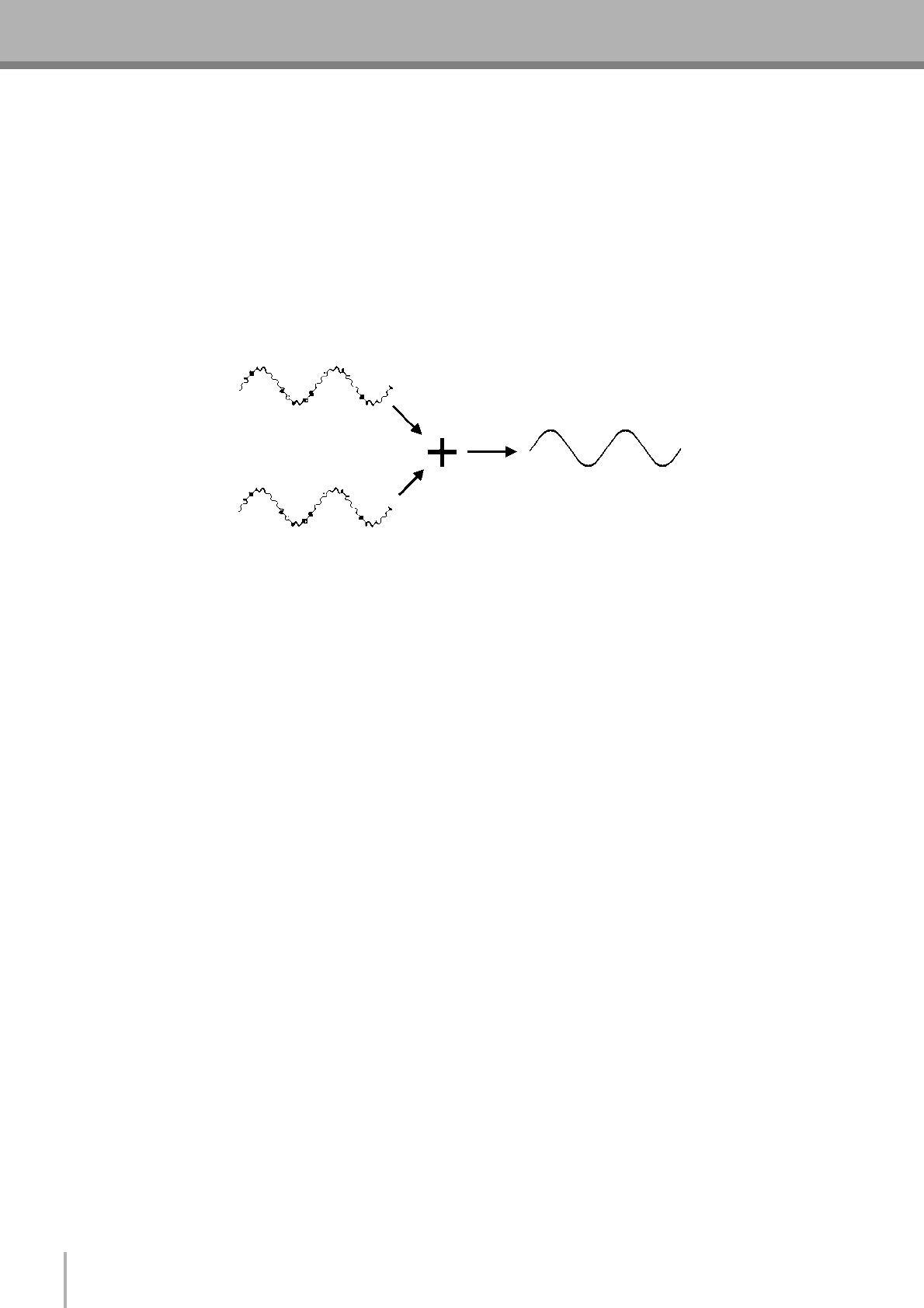
Функционирование симметричных линий основано на принципе подавления фаз: если
добавляется два идентичных сигнала не в фазе (т.е. один сигнал инвертирован таким образом,
что его пики соответствуют провалам в другом сигнале), в результате … не будет ничего.
Плоская линия. Сигналы подавляют друг друга.
Нормально-фазовый сигнал.
Сигнал с обратной фазой.
Сигнал отсутствует.
(Подавление фаз)

Полнофункциональный микшер, 3. уровни сигналов и децибелы
Страница 9
- Изображение
- Текст
Полнофункциональный микшер
MG16/4, MG12/4
9
В симметричном кабеле три провода:
1) Заземленный провод, не несущий сигнала. Это просто опорная «земля» или «0», вокруг
которых колеблется сигнал других проводов.
2) «Горячий» провод (или «+»), несущий нормально-фазированный звуковой сигнал.
3) «Xолодный» провод (или «–»), несущий звуковой сигнал с обратной фазой.
Поскольку нужные звуковые сигналы в «горячем» и «холодном» проводе не в фазе, все
накладываемые помехи в линии будут совершенно одинаковыми для обоих проводов, а
следовательно, синфазными. Xитрость в том, что фаза одного сигнала реверсирована на
приемном конце линии, поэтому нужные звуковые сигналы становятся синфазными, а
накладываемые помехи вдруг рассинхронизируются по фазе. Помехи «не в фазе»
эффективно подавляются, тогда как звуковой сигнал остается неизменным. Здорово,
правда?
1-3. Уровни сигналов и децибелы
С момента начала работы со звуком вы сталкиваетесь с понятием «децибел» и сокращением
«дБ». Здесь возможна путаница, поскольку децибелы являются очень гибкими единицами,
используемыми для измерения уровней как акустического звукового давления, так и
электронного сигнала. К тому же существует несколько вариаций децибел: dBu, dBV, dBm. К
счастью, вам не нужно быть экспертами в этой области. Вот некоторые основные вещи,
которые необходимо иметь в виду:
●
«Бытовые» устройства (например домашнее звуковое оборудование) обычно имеют
линейные входы и выходы с номинальным (средним) уровнем сигнала в –10 дБ.
●
Профессиональные звуковые устройства обычно имеют линейные входы и выходы с
номинальным уровнем сигнала в +4 дБ.
●
На вход в –10 дБ необходимо подавать сигнал в –10 дБ. Eсли подать на этот вход сигнал
+4 дБ, возможна перегрузка.
●
На вход +4 дБ следует всегда подавать сигнал в +4 дБ. Сигнал –10 дБ слишком слаб для
этого входа, поэтому производительность обработки звука будет в этом случае очень низкой.
●
На входах и/или выходах многих профессиональных и полупрофессиональных устройств
предусмортены переключатели уровня сигнала, позволяющие выбрать значение –10 дБ или
+4 дБ. Всегда устанавливайте их в соответствии с уровнем сигнала подключенного
оборудования.
●
Входы, где есть элемент управления усилением (например моноканальные входы на микшере
Yamaha), могут принимать входные сигналы самого разного уровня, поскольку с помощью
этого регулятора можно установить соответствие между чувствительностью входа и
сигналом. Подробнее об этом см. ниже.
Нормально-фазовый сигнал
+ нормально-фазовые помехи.
Нормально-фазовый сигнал
+ помехи с обратной фазой.
Нужный сигнал
без помех.

Куда идет сигнал, когда попадает в устройство, Полнофункциональный микшер
Страница 10
- Изображение
- Текст
Полнофункциональный микшер
MG16/4, MG12/4
10
Куда идет сигнал, когда попадает в устройство
На первый взгляд принципиальная схема даже самого скромного микшера выглядит как схема
космической станции. Но в действительности принципиальные схемы помогают понять, как проходит
сигнал в микшере. Далее представлена сильно упрощенная принципиальная схема абстрактного
микшера, которая поможет разобраться в некоторых вещах.
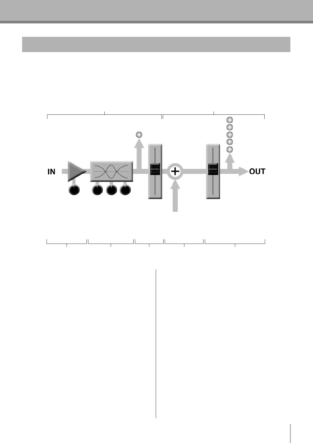
2-1. Упрощенная принципиальная схема микшера
■
Входной канал
1
Предварительный усилитель
В любом микшере это самая первая и
обычно
единственная
стадия
со
значительным «усилением» или «преду-
силением». Предварительный усилитель
имеет регулятор усиления сигнала,
который настраивает чувствительность
входа в соответствии с уровнем сигнала
источника. Слабые сигналы (например
микрофонные) усиливаются, а сильные
— ослабляются.
2
Эквалайзер
Это могут быть просто регуляторы
нижних и верхних частот, а может быть и
полнофункциональный
4-полосный
пара-метрический
эквалайзер.
При
увеличении сигнала возрастает и фаза
эквалайзера.
В
действительности
можно перегрузить входной канал, если
задать слишком большое усиление
эквалайзером. Обычно лучше ослаблять
сигнал, чем усиливать.
3
Индикатор пикового уровня и
фейдер канала
Индикатор
пикового
уровня
канала
является
самым
важным
средством
настройки усиления входного сигнала.
Обратите внимание, что он находится
после предусилителя и эквалайзера.
■
Главная секция
4
Суммирующий усилитель
Именно здесь происходит фактическое
«микширование» сигнала. Здесь сигналы
со всех входных каналов микшера
«суммируются» (смешиваются).
5
Мастер-фейдер и измеритель
уровня
Мастер-фейдер стерео-, моноканала или
шины и измеритель уровня сигнала
основного
выхода
микшера.
В
зависимости от конструкции микшера
(например от числа имеющихся шин и
выходов) может быть несколько видов
мастер-фейдеров.
2
1
2
3
4
5
Входной канал
Главная секция
Сигналы с других входных
каналов микшера (если они
назначены этому главному
выходу или «шине»).

Комментарии
MIXING CONSOLE
MIXING CONSOLE
Owner’s Manual
Owner’s Manual
Making the Most Of Your Mixer
Pages 6 to 16
EN

MG12/4FX
2
PRECAUTIONS
PLEASE READ CAREFULLY BEFORE PROCEEDING
* Please keep this manual in a safe place for future reference.
WARNING
Always follow the basic precautions listed below to avoid the possibility of serious injury or even death from electrical
shock, short-circuiting, damages, fire or other hazards. These precautions include, but are not limited to, the following:
• Only use the voltage specified as correct for the device. The required voltage is
printed on the name plate of the device.
• Use only the specified AC power adaptor (PA-20 or an equivalent recommended
by Yamaha).
• Do not place the power cord near heat sources such as heaters or radiators, and
do not excessively bend or otherwise damage the cord, place heavy objects on
it, or place it in a position where anyone could walk on, trip over, or roll anything
over it.
• Do not open the device or attempt to disassemble the internal parts or modify
them in any way. The device contains no user-serviceable parts. If it should
appear to be malfunctioning, discontinue use immediately and have it inspected
by qualified Yamaha service personnel.
• Do not expose the device to rain, use it near water or in damp or wet conditions,
or place containers on it containing liquids which might spill into any openings.
• Never insert or remove an electric plug with wet hands.
• If the power cord or plug becomes frayed or damaged, or if there is a sudden
loss of sound during use of the device, or if any unusual smells or smoke
should appear to be caused by it, immediately turn off the power switch,
disconnect the electric plug from the outlet, and have the device inspected by
qualified Yamaha service personnel.
• If this device or the AC power adaptor should be dropped or damaged,
immediately turn off the power switch, disconnect the electric plug from the
outlet, and have the device inspected by qualified Yamaha service personnel.
CAUTION
Always follow the basic precautions listed below to avoid the possibility of physical injury to you or others, or damage
to the device or other property. These precautions include, but are not limited to, the following:
• Remove the electric plug from the outlet when the device is not to be used for
extended periods of time, or during electrical storms.
• When removing the electric plug from the device or an outlet, always hold the
plug itself and not the cord. Pulling by the cord can damage it.
•To avoid generating unwanted noise, make sure there is 50 cm or more
between the AC power adaptor and the device.
• Do not cover or wrap the AC power adaptor with a cloth or blanket.
• Before moving the device, remove all connected cables.
•Avoid setting all equalizer controls and faders to their maximum. Depending on
the condition of the connected devices, doing so may cause feedback and may
damage the speakers.
• Do not expose the device to excessive dust or vibrations, or extreme cold or heat
(such as in direct sunlight, near a heater, or in a car during the day) to prevent
the possibility of panel disfiguration or damage to the internal components.
• Do not place the device in an unstable position where it might accidentally fall
over.
• Do not use the device in the vicinity of a TV, radio, stereo equipment, mobile
phone, or other electric devices. Otherwise, the device, TV, or radio may
generate noise.
• Before connecting the device to other devices, turn off the power for all devices.
Before turning the power on or off for all devices, set all volume levels to
minimum.
• Do not insert your fingers or hand in any gaps or openings on the device.
•Avoid inserting or dropping foreign objects (paper, plastic, metal, etc.) into any
gaps or openings on the device. If this happens, turn off the power immediately
and unplug the power cord from the AC outlet. Then have the device inspected
by qualified Yamaha service personnel.
• Do not use the device or headphones for a long period of time at a high or
uncomfortable volume level, since this can cause permanent hearing loss. If you
experience any hearing loss or ringing in the ears, consult a physician.
• Do not rest your weight on the device or place heavy objects on it, and avoid use
excessive force on the buttons, switches or connectors.
Power supply/Power cord
Do not open
Water warning
If you notice any abnormality
Power supply/Power cord
Location
Connections
Handling caution

MG12/4FX
3
Always turn the power off when the device is not in use.
Even when the power switch is in the “STANDBY” position, electricity is still flowing to the device at the minimum level. When you are not using the device for a long time,
make sure you unplug the power cord from the wall AC outlet.
The performance of components with moving contacts, such as switches, volume controls, and connectors, deteriorates over time. Consult qualified Yamaha service
personnel about replacing defective components.
Copying of the commercially available music data and/or digital audio files is strictly prohibited except for your personal use.
Illustration examples shown herein are for explanatory purposes only, and may not match actual appearance during operation.
The company names and product names in this Owner’s Manual are the trademarks or registered trademarks of their respective companies.
•This applies only to products distributed by Yamaha-Kemble Music (U.K.) Ltd. (2 wires)
* This applies only to products distributed by YAMAHA CORPORATION OF AMERICA. (class B)
XLR-type connectors are wired as follows (IEC60268 standard): pin 1: ground, pin 2: hot (+), and pin 3: cold (–).
Insert TRS phone jacks are wired as follows: sleeve: ground, tip: send, and ring: return.
Yamaha cannot be held responsible for damage caused by improper use or modifications to the device.
IMPORTANT NOTICE FOR THE UNITED KINGDOM
Connecting the Plug and Cord
IMPORTANT. The wires in this mains lead are coloured in accordance with the following code:
BLUE : NEUTRAL
BROWN : LIVE
As the colours of the wires in the mains lead of this apparatus may not correspond with the coloured makings identifying the terminals in your
plug proceed as follows:
The wire which is coloured BLUE must be connected to the terminal which is marked with the letter N or coloured BLACK.
The wire which is coloured BROWN must be connected to the terminal which is marked with the letter L or coloured RED.
Making sure that neither core is connected to the earth terminal of the three pin plug.
FCC INFORMATION (U.S.A.)
1. IMPORTANT NOTICE: DO NOT MODIFY THIS UNIT!
This product, when installed as indicated in the instructions
contained in this manual, meets FCC requirements. Modifica-
tions not expressly approved by Yamaha may void your author-
ity, granted by the FCC, to use the product.
2. IMPORTANT: When connecting this product to accessories
and/or another product use only high quality shielded cables.
Cable/s supplied with this product MUST be used. Follow all
installation instructions. Failure to follow instructions could void
your FCC authorization to use this product in the USA.
3. NOTE: This product has been tested and found to comply with
the requirements listed in FCC Regulations, Part 15 for Class
“B” digital devices. Compliance with these requirements pro-
vides a reasonable level of assurance that your use of this
product in a residential environment will not result in harmful
interference with other electronic devices. This equipment gen-
erates/uses radio frequencies and, if not installed and used
according to the instructions found in the users manual, may
cause interference harmful to the operation of other electronic
devices. Compliance with FCC regulations does not guarantee
that interference will not occur in all installations. If this product
is found to be the source of interference, which can be deter-
mined by turning the unit “OFF” and “ON”, please try to elimi-
nate the problem by using one of the following measures:
Relocate either this product or the device that is being affected
by the interference.
Utilize power outlets that are on different branch (circuit
breaker or fuse) circuits or install AC line filter/s.
In the case of radio or TV interference, relocate/reorient the
antenna. If the antenna lead-in is 300 ohm ribbon lead, change
the lead-in to co-axial type cable.
If these corrective measures do not produce satisfactory
results, please contact the local retailer authorized to distribute
this type of product. If you can not locate the appropriate
retailer, please contact Yamaha Corporation of America, Elec-
tronic Service Division, 6600 Orangethorpe Ave, Buena Park,
CA90620
The above statements apply ONLY to those products distrib-
uted by Yamaha Corporation of America or its subsidiaries.

Introduction
MG12/4FX
4
Introduction
Thank you for your purchase of the YAMAHA MG12/4FX mixing console. The MG12/4FX features input channels suitable for
a wide range of usage environments, and includes high-quality built-in digital effects that can provide some very serious sound.
The mixer combines ease of operation with support for multiple usage environments.
Please read through this manual carefully before beginning use, so that you will be able to take full advantage of this mixer’s
superlative features and enjoy trouble-free operation for years to come.
Contents
Introduction 4
Contents …………………………………………………….. 4
Features ……………………………………………………… 4
Before Turning on the Mixer …………………………… 5
Tu r ning the Power On …………………………………… 5
Making the Most Of Your Mixer 6
1. A Place For Everything and
Everything In Its Place……………………………… 6
2. Where Your Signal Goes Once
It’s Inside the Box ……………………………………. 9
3. The First Steps in Achieving
Great Sound …………………………………………. 10
4. External Effects, Monitor Mixes,
and Groups …………………………………………… 12
5. Making Better Mixes………………………………. 15
Front & Rear Panels 17
Channel Control Section ……………………………… 17
Master Control Section ……………………………….. 19
Rear Input/Output Section …………………………… 21
Setting Up 23
Setup Procedure ………………………………………… 23
Setup Examples …………………………………………. 23
Rack Mounting …………………………………………… 25
Appendix 26
Specifications …………………………………………….. 26
Dimensional Diagrams ………………………………… 28
Block Diagram and Level Diagram ……………….. 29
Features
Input Channels………………………….. page 21
With up to six mic/line inputs or up to four stereo
inputs, the MG12/4FX can simultaneously connect to
a wide range of devices: microphones, line-level
devices, stereo synthesizers, and more. For exam-
ple, you can connect four microphones and four ste-
reo devices, or six microphones and two stereo
devices.
Phantom Power (+48 V) ……………… page 19
A single switch turns phantom power on or off for all
six mic inputs. Phantom power enables easy con-
nection to condenser microphones that require exter-
nal power.
High-quality digital effects…………. page 20
With digital effects built in, the MG12/4FX can deliver
a wide range of sound variations all by itself. The unit
also includes an EFFECT SEND jack that can be
used to connect an external effector.
AUX Sends and Stereo
AUX Return………………………….. page 17, 19
You can use the AUX SEND jack to feed the
post-fader signal to an external signal processor, and
then return the processed stereo signal through the
RETURN jack. Alternatively, you can use the PRE
switch on each channel to send that channel’s
pre-fader signal out through the AUX SEND jack for
monitoring.
Rack Mounting………………………….. page 25
The mixer provides two metal rack-mount supports,
and integrates easily into a wide variety of setups.
Introduction
MG12/4FX
5
Before Turning on the Mixer
Be sure that the mixer’s power switch is in the
STANDBY position.
Use only the PA-20 adaptor included with this
mixer. Use of a different adaptor may result in
equipment damage, overheating, or fire.
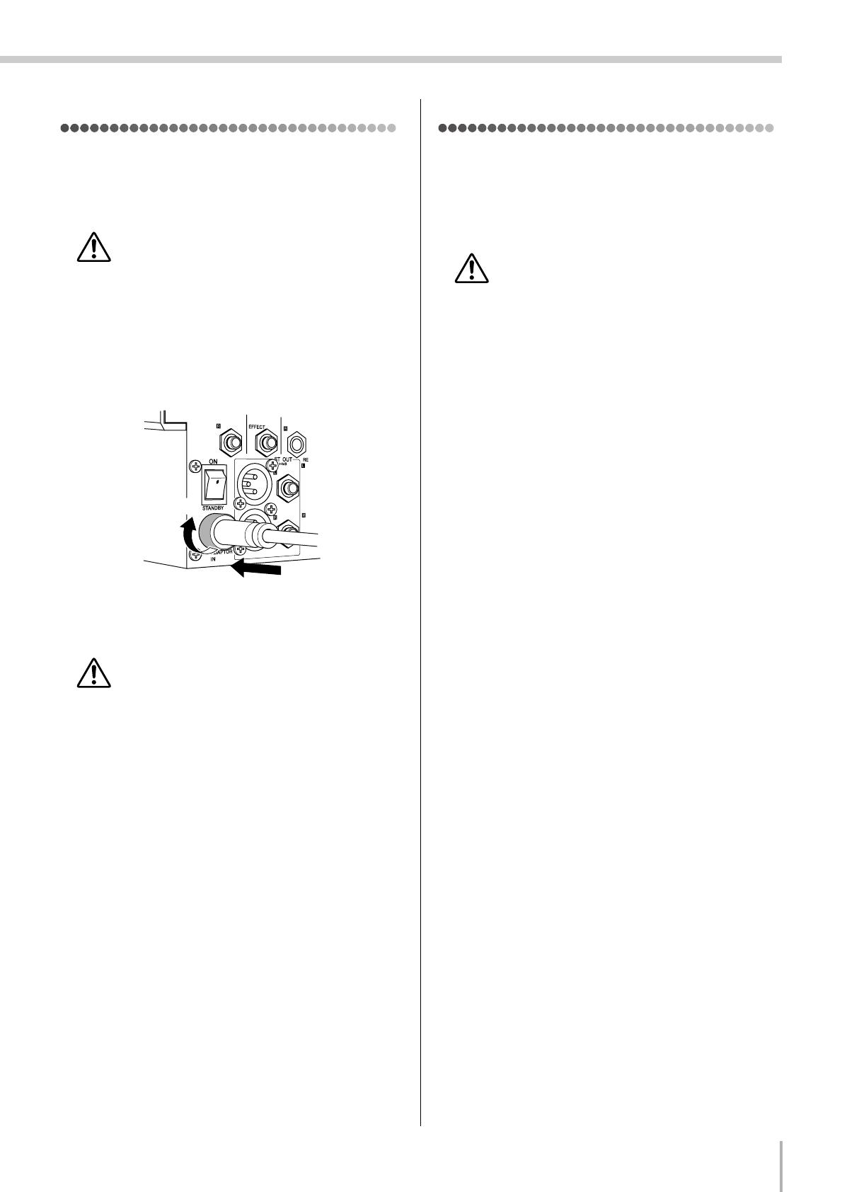
Connect the power adaptor to the AC ADAPTOR IN
connector (
1
) on the rear of the mixer, and then turn
the fastening ring clockwise (
2
) to secure the connec-
tion.
Plug the power adaptor into a standard household
power outlet.
• Be sure to unplug the adaptor from the outlet
when not using the mixer, or when there are light-
ning storms in the area.
• To avoid generating unwanted noise, make sure
there is 50 cm or more between the power adaptor
and the mixer.
Turning the Power On
Press the mixer’s power switch to the ON position. When
you are ready to turn the power off, press the power switch to
the STANDBY position.
Note that trace current continues to flow while the
switch is in the STANDBY position. If you do not
plan to use the mixer again for a long while, please
be sure to unplug the adaptor from the wall outlet.
1
2
1
2
3
MG12/4FX
6
Making the Most Of Your Mixer
Making the Most Of Your Mixer
■ An Introduction
You’ve got yourself a mixer and now you’re ready to use it.
Just plug everything in, twiddle the controls, and away you go … right?
Well, if you’ve done this before you won’t have any problems, but if this is
the first time you’ve ever used a mixer you might want to read through this lit-
tle tutorial and pick up a few basics that will help you get better performance
and make better mixes.
1-1. A Plethora Of Connectors—What Goes Where?
Questions you’re likely to encounter when setting up a system for the first time might include “Why all these different types of
connectors on the back of my mixer?” and “What’s the difference?”.
Let’s start by taking a look at the most common connector types.
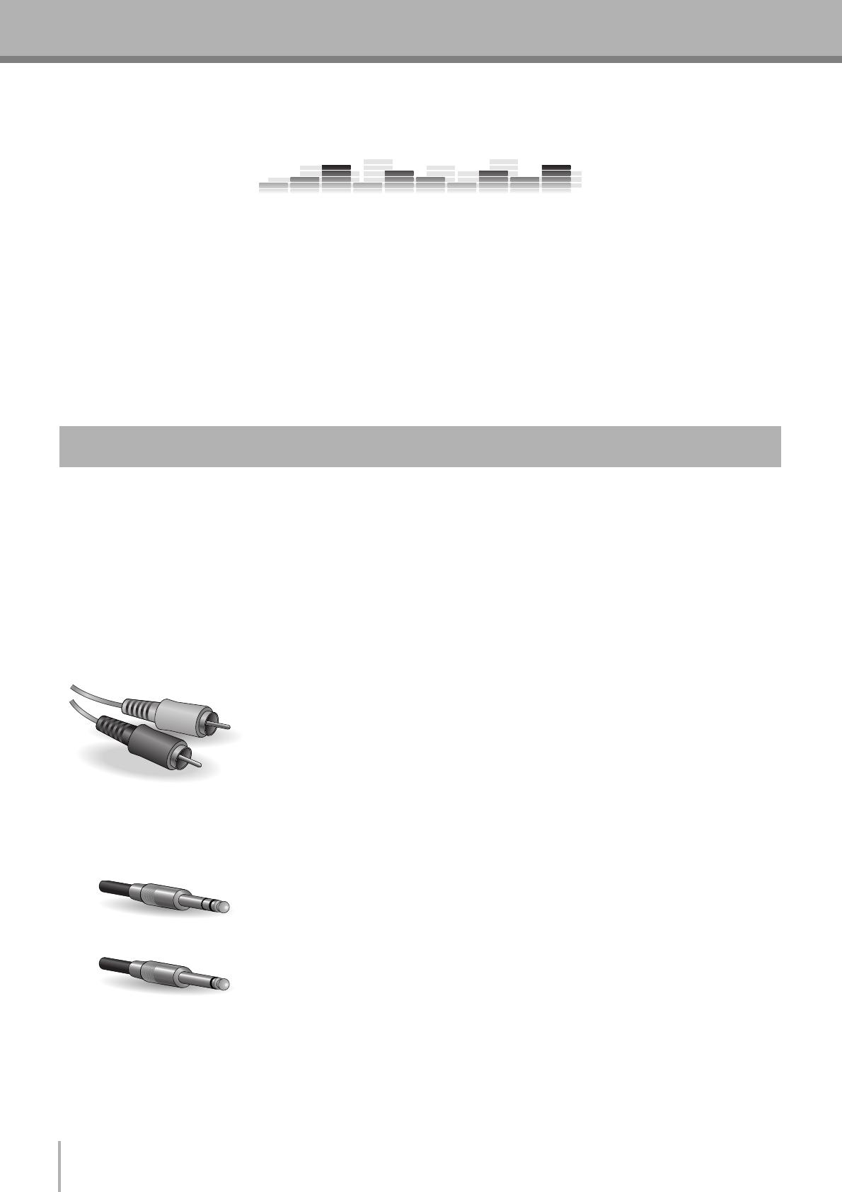
■ The Venerable RCA Pin Jack
This is the “consumer connector,” and the one that has been most commonly used on
home audio gear for many years. Also known as “phono” jacks (short for “phonogram”),
but the term isn’t used much these days—besides, it’s too easily confusable with
“phone” jacks, below. RCA pin jacks are always unbalanced, and generally carry a
line-level signal at –10 dB, nominal. You’re most likely to use this type of connector
when connecting a CD player or other home audio type source to your mixer, or when
connecting the output of your mixer to a cassette recorder or similar gear.
■ The Versatile Phone Jack
The name “phone jack” arose simply because this configuration was first used in
telephone switchboards. Phone jacks can be tricky because you can’t always tell what
type of signal they’re designed to handle just by looking at them. It could be unbalanced
mono, unbalanced stereo, balanced mono, or an insert patch point. The connector’s label
will usually tell you what type of signal it handles, as will the owner’s manual (you do
keep your manuals in a safe place, don’t you?). A phone jack that is set up to handle
balanced signals is also often referred to as a “TRS” phone jack. “TRS” stands for
Tip-Ring-Sleeve, which describes the configuration of the phone plug used.
1. A Place For Everything and Everything In Its Place
White
Red
Stereo/TRS phone plug
Mono phone plug
Making the Most Of Your Mixer
MG12/4FX
7
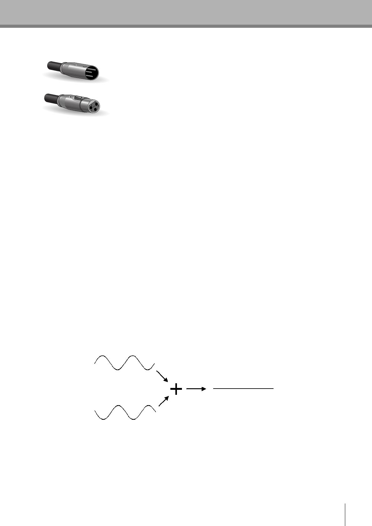
■ The Sturdy XLR
This type of connector is generally referred to as “XLR-type,” and almost always carries
a balanced signal. If the corresponding circuitry is designed properly, however,
XLR-type connectors will also handle unbalanced signals with no problem. Microphone
cables usually have this type of connector, as do the inputs and outputs of most
professional audio gear.
1-2. Balanced, Unbalanced—What’s the Difference?
In a word: “noise.” The whole point of balanced lines is noise rejection, and it’s something they’re very good at. Any length of
wire will act as an antenna to pick up the random electromagnetic radiation we’re constantly surrounded by: radio and TV
signals as well as spurious electromagnetic noise generated by power lines, motors, electric appliances, computer monitors, and
a variety of other sources. The longer the wire, the more noise it is likely to pick up. That’s why balanced lines are the best
choice for long cable runs. If your “studio” is basically confined to your desktop and all connections are no more than a meter or
two in length, then unbalanced lines are fine—unless you’re surrounded by extremely high levels of electromagnetic noise.
Another place balanced lines are almost always used is in microphone cables. The reason for this is that the output signal from
most microphones is very small, so even a tiny amount of noise will be relatively large, and will be amplified to an alarming
degree in the mixer’s high-gain head amplifier.
To summarize:
Microphones: Use balanced lines.
Short line-level runs: Unbalanced lines are fine if you’re in a relatively noise-free environment.
Long line-level runs: The ambient electromagnetic noise level will be the ultimate deciding factor, but balanced is
best.
■ How Do Balanced Lines Reject Noise?
** Skip this section if technical details make you queasy. **
Balanced lines work on the principle of “phase cancellation”: if you add two identical signals out of phase (i.e. one signal is
inverted so its peaks coincide with the troughs in the other signal), the result is … nothing. A flat line. The signals cancel each
other out.
Male
Female
Normal-phase signal.
Reverse-phase signal.
No signal.
(Phase cancellation)
MG12/4FX
8
Making the Most Of Your Mixer
A balanced cable has three conductors:
1) A ground conductor which carries no signal, just the “ground” or “0” reference against which the signal in the other
conductors fluctuates.
2) A “hot” or “+” conductor which carries the normal-phase audio signal.
3) A “cold” or “–” conductor which carries the reverse-phase audio signal.
While the desired audio signals in the hot and cold conductors are out of phase, any noise induced in the line will be exactly the
same in both conductors, and thus in phase. The trick is that the phase of one signal is reversed at the receiving end of the line so
that the desired audio signals become in-phase, and the induced noise suddenly finds itself out of phase. The out-of-phase noise
signal is effectively canceled while the audio signal is left intact. Clever, eh?
1-3. Signal Levels—Decibel Do’s and Don’ts
From the moment you start dealing with things audio, you’ll have to deal with the term “decibel” and its abbreviation, “dB”.
Things can get confusing because decibels are a very versatile unit of measure used to describe acoustic sound pressure levels as
well as electronic signal levels. To make matters worse there are a number of variations: dBu, dBV, dBm. Fortunately, you don’t
need to be an expert to make things work. Here are a few basics you should keep in mind:
● “Consumer” gear (such as home audio equipment) usually has line inputs and outputs with a nominal (average) level of
–10 dB.
● Professional audio gear usually has line inputs and outputs with a nominal level of +4 dB.
● You should always feed –10 dB inputs with a –10 dB signal. If you feed a +4 dB signal into a –10 dB input you are likely to
overload the input.
● You should always feed +4 dB inputs with a +4 dB signal. A –10 dB signal is too small for a +4 dB input, and will result in
less-than-optimum performance.
● Many professional and semi-professional devices have level switches on the inputs and/or outputs that let you select –10 or
+4 dB. Be sure to set these switches to match the level of the connected equipment.
● Inputs that feature a “Gain” control—such as the mono-channel inputs on your Yamaha mixer—will accept a very wide range
of input levels because the control can be used to match the input’s sensitivity to the signal. More on this later.
Normal-phase signal
+ normal-phase noise.
Normal-phase signal
+ reverse-phase noise.
Desired signal
with no noise.
Making the Most Of Your Mixer
MG12/4FX
9
At first glance the block diagram of even a modest mixer can look like a space-station schematic. In reality, block diagrams are
a great aid in understanding how the signal flows in any mixer. Here’s a greatly simplified block diagram of a generic mixer to
help you become familiar with the way these things work.
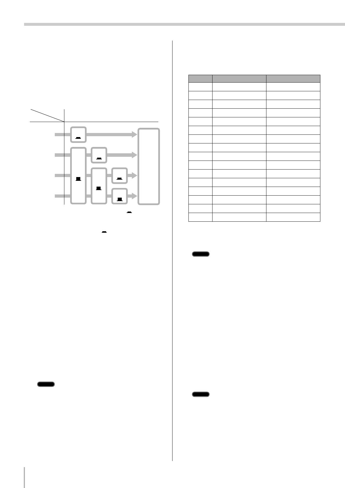
2-1. Greatly Simplified Mixer Block Diagram
■ Input Channel
1 Head Amp
The very first stage in any mixer, and usually the only
stage with significant “gain” or “amplification.” The head
amp has a “gain” control that adjusts the mixer’s input
sensitivity to match the level of the source. Small signals
(e.g. mics) are amplified, and large signals are attenuated.
2 Equalizer
Could be simple bass and treble controls or a full-blown
4-band parametric EQ. When boost is applied the EQ
stage also has gain. You can actually overload the input
channel by applying too much EQ boost. It’s usually
better to cut than boost.
3 Channel Peak LED & Fader
The channel peak LED is your most valuable tool for
setting the input “gain” control for optimum
performance. Note that it is located after the head amp
and EQ stage.
■ Master Section
4 Summing Amplifier
This is where the actual “mixing” takes place. Signals
from all of the mixer’s input channels are “summed”
(mixed) together here.
5 Master Fader & Level Meter
A stereo, mono, or bus master fader and the mixer’s main
output level meter. There could be several master faders
depending on the design of the mixer—i.e. the number of
buses or outputs it provides.
2. Where Your Signal Goes Once It’s Inside the Box
1234 5
Input Channel Master Section
Signals from the mixer’s
other input channels
(if they are assigned to this
master output or “bus”).
MG12/4FX
10
Making the Most Of Your Mixer
Before you even consider EQ and effects, or even the overall mix, it is important to make sure that levels are properly set for
each individual source. This can’t be stressed enough—initial level setup is vitally important for achieving optimum perfor—
mance from your mixer! Here’s why … and how.
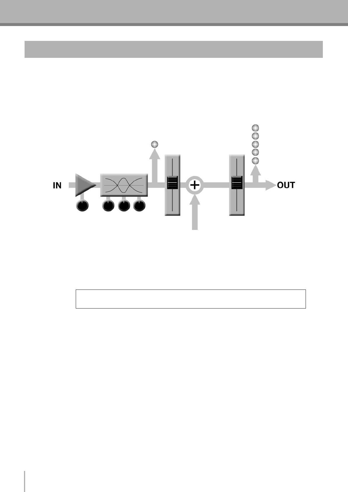
3-1. The Head Amplifier “Gain” Control Is the Key!
Let’s review our simplified mixer block diagram:
Each and every “stage” in the mixer’s signal path will add a certain amount of noise to the signal: the head amp, the EQ stage,
the summing amplifier, and the other buffer and gain stages that exist in the actual mixer circuit (this applies to analog mixers in
particular). The thing to keep in mind is that the amount of noise added by each stage is usually not dependent to any significant
degree on the level of the audio signal passing through the circuit. This means that the bigger the desired signal, the smaller the
added noise will be in relation to it. In tech-speak this gives us a better “signal-to-noise ratio”—often abbreviated as “S/N ratio.”
All of this leads to the following basic rule:
In our mixer, that means the head amplifier. If you don’t get the signal up to the desired level at the head amplifier stage, you will
need to apply more gain at later stages, which will only amplify the noise contributed by the preceding stages. Just remember
that too much initial gain is bad too, because it will overload our channel circuitry and cause clipping.
3. The First Steps in Achieving Great Sound
To achieve the best overall system S/N ratio, amplify the input to the desired average level as
early as possible in the signal path.

Making the Most Of Your Mixer
MG12/4FX
11
3-2. Level Setup Procedure For Optimum Performance
Now that we know what we have to do, how do we do it? If you take another quick look at the mixer block diagram you’ll notice
that there’s a peak indicator located right after the head amplifier and EQ stages, and therein lays our answer! Although the exact
procedure you use will depend on the type of mixer you use and the application, as well as your personal preferences, here’s a
general outline:
Start by setting all level controls to their minimum: master faders, group faders (if provided), channel faders, and input
gain controls. Also make sure that no EQ is applied (no boost or cut), and that all effects and dynamic processors included
in the system are defeated or bypassed.
Apply the source signal to each channel one at a time: have singers sing, players play, and playback devices play back at
the loudest expected level. Gradually turn up the input gain control while the signal is being applied to the corresponding
channel until the peak indicator begins to flash, then back off a little so that the peak indicator flashes only occasionally.
Repeat for each active channel.
Raise your master fader(s)—and group faders if available—to their nominal levels (this will be the “0” markings on the
fader scale).
Now, with all sources playing, you can raise the channel faders and set up an initial rough mix.
That’s basically all there is to it. But do keep your eyes on the main output level meters while setting up the mix to be sure you
don’t stay in the “peak zone” all the time. If the output level meters are peaking constantly you will need to lower the channel
faders until the overall program falls within a good range—and this will depend on the “dynamic range” of your program
material.
1
2
3
4
MG12/4FX
12
Making the Most Of Your Mixer
4-1. AUX Buses For Monitor Sends
and Overall Effects
There are a number of reasons why you might want to “tap”
the signal flowing through your mixer at some point before
the main outputs: the two most common being 1) to create a
monitor mix that is separate from the main mix, and 2) to
process the signal via an external effect unit and then bring it
back into the mix. Both of these functions, and more, can be
handled by the mixer’s AUX (Auxiliary) buses and level con-
trols. If the mixer has two AUX buses, then it can handle
both functions at the same time. Larger mixing consoles can
have 6, 8, or even more auxiliary buses to handle a variety of
monitoring and processing needs.
Using the AUX buses and level controls is pretty straightfor—
ward. The only thing you need to consider is whether you
need a “pre-fader” or “post-fader” send. AUX sends often
feature a switch that allows you to configure them for pre- or
post-fader operation.
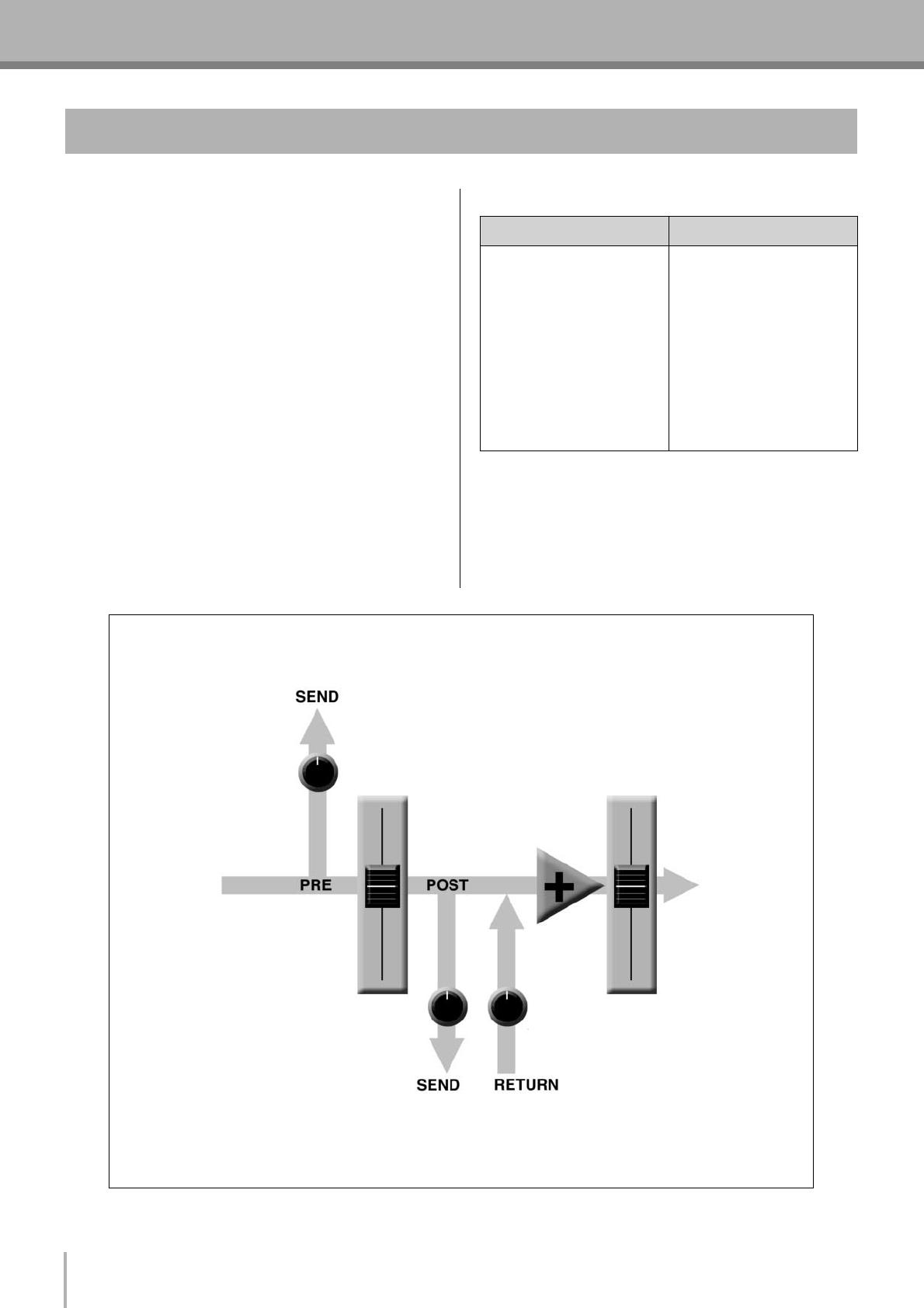
Pre/Post—What’s the difference?
4. External Effects, Monitor Mixes, and Groups
pre post
A “pre-fader” signal is taken
from a point before the
channel fader, so the send
level is affected only by the
AUX send level control and
not by the channel fader.
Pre-fader sends are most
commonly used to provide
monitor mixes.
A “post-fader” signal is
taken from a point after the
channel fader, so its level
will be affected by both the
AUX send level control and
the channel fader.
Post-fader sends are most
commonly used in conjunc-
tion with the mixer’s AUX or
effect returns for external
effect processing.
Pre-fader send for a monitor mix. The send signal is fed to the monitor power amplifier and speaker system.
The channel fader does not affect the send level so the monitor mix remains independent of the main mix. No
return signal is used in this case.
Post-fader send for external effects processing. The send signal is fed to the external effect unit—a reverb
unit, for example—and the output from the effect unit is returned to the AUX Return jack and mixed back into the
main program. The send level is affected by the channel fader so the effect level always remains in proportion to
the channel signal.
Channel
Fader
Master
Fader
AUX Send
Level
AUX Send Level AUX Return Level
Making the Most Of Your Mixer
MG12/4FX
13
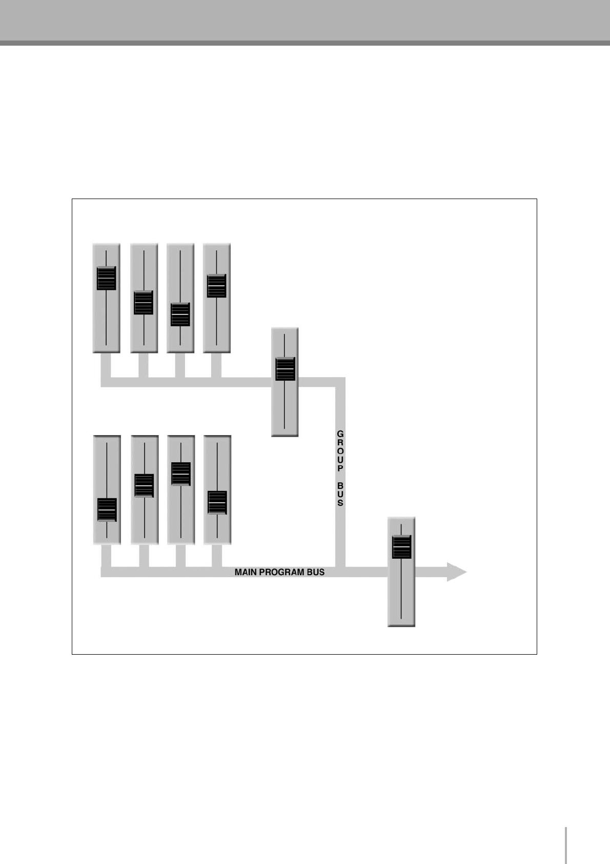
4-2. Using Groups
Group buses and faders can greatly simplify the mixing process—particularly in live situations in which changes have to be
made as quickly as possible. If you have a group of channels that need to be adjusted all together while maintaining their relative
levels, grouping is the way to go. Simply assign the group to a group bus, and make sure that group is also assigned to the main
program bus. Then you can adjust the overall level of the group using a single group fader, rather than having to attempt to
control multiple channels faders simultaneously.
Group buses usually also have their own outputs, so you can send the group signal to a different external destination from the
main mix.
Channel faders Assigned to Group
(Controlled As a Group)
Stereo
Master
Fader
Group
Fader
Channel faders Assigned to Stereo
(Controlled Individually)
A group of channels whose levels need to main-
tain the same relationship—a drum mix, for
example—can be assigned to a group bus. Usu-
ally the group bus signal can be output indepen-
dently via “Group” outputs, or it can be assigned
to the main program (stereo) bus to be mixed in
with the main stereo program.
Once the mix between the channels assigned to
the group is established via the channel faders,
the overall level of the entire group can be conve-
niently adjusted via a single group fader.
MG12/4FX
14
Making the Most Of Your Mixer
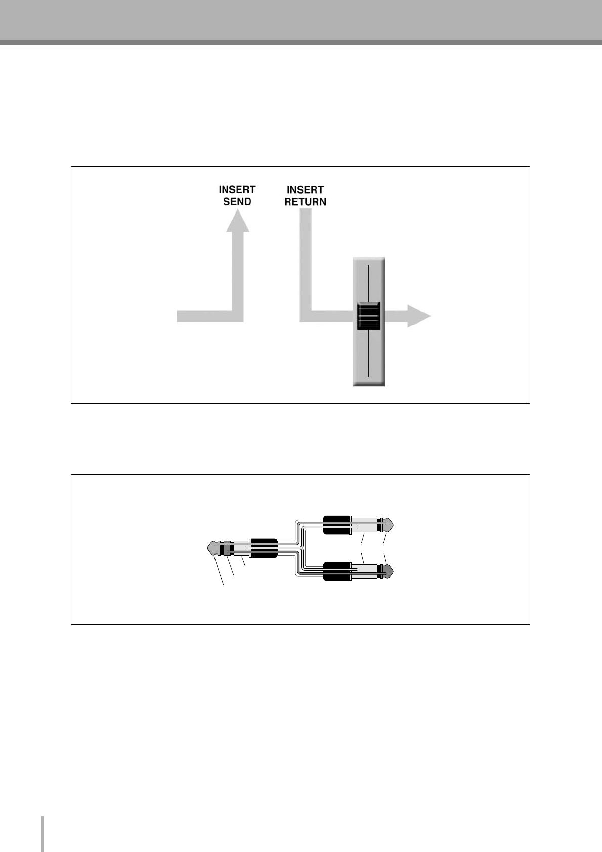
4-3. Channel Inserts for Channel-specific Processing
Another way to get the mixer’s signal outside the box is to use the channel inserts. The channel inserts are almost always located
before the channel fader and, when used, actually “break” the mixer’s internal signal path. Unlike the AUX sends and returns,
the channel insert only applies to the corresponding channel. Channel inserts are most commonly used for applying a dynamics
processor such as a compressor or limiter to a specific channel—although they can be used with just about any type of in/out
processor.
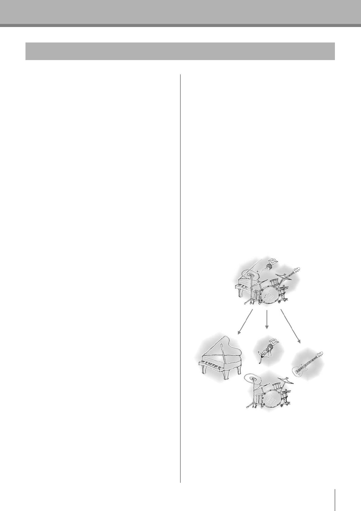
Channel insert jacks must be used with a special insert cable that has a TRS phone jack on one end and mono phone jacks on the
split “Y” end. One of the mono phone jacks carries the “send” signal to be fed to the input of the external processor, and the
other carries the “return” signal from the output of the processor.
Channel
Fader
When a plug is inserted into the channel insert jack, the inter-
nal signal path is interrupted and sent outside the mixer for
external processing.
Tip
Ring
Sleeve
To the INSERT I/O jack
To the input jack of the
external processor
To the output jack of
the external processor
TipSleeve
Making the Most Of Your Mixer
MG12/4FX
15
5-1. Approaching the Mix—Where
Do You Start?
Mixing is easy, right? Just move the faders around until it
sounds right? Well, you can do it that way, but a more sys-
tematic approach that is suited to the material you’re mixing
will produce much better results, and faster. There are no
rules, and you’ll probably end up developing a system that
works best for you. But the key is to develop a system rather
than working haphazardly. Here are a few ideas to get you
started:
■ Faders Down
It might sound overly simple, but it is usually a good idea to
start with all channel faders off—all the way down. It’s also
possible to start with all faders at their nominal settings, but
it’s too easy to lose perspective with this approach. Start with
all faders down, then bring them up one by one to fill out the
mix. But which channel should you start with?
Example1:
Vocal Ballad Backed by Piano Trio
What are you mixing? Is it a song in which the vocals
are the most important element? If so you might want to
build the mix around the vocals. This means bringing
the vocal channel up to nominal first (if your level setup
procedure has been done properly this will be a good
starting point), and then adding the other instruments.
What you add next will depend on the type of material
you are working with and your approach to it. If the
vocals are backed by a piano trio and the song is a bal-
lad, for example, you might want to bring in the piano
next and get the vocal/piano relationship just right, then
bring in the bass and drums to support the overall
sound.
Example2:
Funky R&B Groove
The approach will be totally different if you’re mixing a
funky R&B number that centers on the groove. In this
case most engineers will start with the drums, and then
add the bass. The relationship between the drums and
bass is extremely important to achieve the “drive” or
groove the music rides on. Pay particular attention to
how the bass works with the kick (bass drum). They
should almost sound like a single instrument—with the
kick supplying the punch and the bass supplying the
pitch. Once again, there are no rules, but these are con-
cepts that have been proven to work well.
■ Music First—Then Mix
In any case, the music comes first. Think about the music
and let it guide the mix, rather than trying to do things the
other way around. What is the music saying and what instru-
ment or technique is being used to drive the message? That’s
where the focus of your mix should be. You’re using a
high-tech tool to do the mixing, but the mix itself is as much
art as the music. Approach it that way and your mixes will
become a vital part of the music.
5-2. Panning For Cleaner Mixes
Not only does the way you pan your individual channels
determine where the instruments appear in the stereo sound
field, but it is also vital to give each instrument it’s own
“space” so that it doesn’t conflict with other instruments.
Unlike live sound in a real acoustic space, recorded stereo
sound is basically 2-dimensional (although some types of
surround sound are actually very 3-dimensional), and instru-
ments positioned right on top of each other will often get in
each other’s way—particularly if they are in the same fre-
quency range or have a similar sound.
5. Making Better Mixes

MG12/4FX
16
Making the Most Of Your Mixer
■ Spread them Out!
Position your instruments so they have room to “breathe,”
and connect in the most musical way with other instruments.
Sometimes, however, you’ll want to deliberately pan sounds
close together, or even right on top of one another, to empha-
size their relationship. There are no hard-and-fast rules. Nor-
mally (but this is not a rule), bass and lead vocals will be
panned to center, as will the kick drum if the drums are in
stereo.
5-3. To EQ Or Not To EQ
In general: less is better. There are many situations in which
you’ll need to cut certain frequency ranges, but use boost
sparingly, and with caution. Proper use of EQ can eliminate
interference between instruments in a mix and give the over-
all sound better definition. Bad EQ—and most commonly
bad boost—just sounds terrible.
■ Cut For a Cleaner Mix
For example: cymbals have a lot of energy in the mid and
low frequency ranges that you don’t really perceive as musi-
cal sound, but which can interfere with the clarity of other
instruments in these ranges. You can basically turn the low
EQ on cymbal channels all the way down without changing
the way they sound in the mix. You’ll hear the difference,
however, in the way the mix sounds more “spacious,” and
instruments in the lower ranges will have better definition.
Surprisingly enough, piano also has an incredibly powerful
low end that can benefit from a bit of low-frequency roll-off
to let other instruments—notably drums and bass—do their
jobs more effectively. Naturally you won’t want to do this if
the piano is playing solo.
The reverse applies to kick drums and bass guitars: you can
often roll off the high end to create more space in the mix
without compromising the character of the instruments.
You’ll have to use your ears, though, because each instru-
ment is different and sometimes you’ll want the “snap” of a
bass guitar, for example, to come through.
■ Boost With Caution
If you’re trying to create special or unusual effects, go ahead
and boost away as much as you like. But if you’re just trying
to achieve a good-sounding mix, boost only in very small
increments. A tiny boost in the midrange can give vocals
more presence, or a touch of high boost can give certain
instruments more “air.” Listen, and if things don’t sound
clear and clean try using cut to remove frequencies that are
cluttering up the mix rather than trying to boost the mix into
clarity.
One of the biggest problems with too much boost is that it
adds gain to the signal, increasing noise and potentially over-
loading the subsequent circuitry.
5-4. Ambience
Judicious application of reverb and/or delay via the mixer’s
AUX busses can really polish a mix, but too much can “wash
out” the mix and reduce overall clarity. The way you set up
your reverb sound can make a huge difference in the way it
meshes with the mix.
■ Reverb/Delay Time
Different reverb/delay units offer different capabilities, but
most offer some means of adjusting the reverb time. A little
extra time spent matching the reverb time to the music being
mixed can mean the difference between great and merely
average sound. The reverb time you choose will depend to a
great degree on the tempo and “density” of the mix at hand.
Slower tempos and lower densities (i.e. sparser mixes with
less sonic activity) can sound good with relatively long
reverb times. But long reverb times can completely wash out
a faster more active piece of music. Similar principles
applies to delay.
■ Reverb Tone
How “bright” or “bassy” a reverb sound is also has a huge
impact on the sound of your mix. Different reverb units offer
different means of controlling this—balance between the
high- and low-frequency reverb times, simple EQ, and oth-
ers. A reverb that is too bright will not only sound unnatural,
but it will probably get in the way of delicate highs you want
to come through in your mix. If you find yourself hearing
more high-end reverb than mix detail, try reducing the
brightness of the reverb sound. This will allow you to get
full-bodied ambience without compromising clarity.
■ Reverb Level
It’s amazing how quickly your ears can lose perspective and
fool you into believing that a totally washed-out mix sounds
perfectly fine. To avoid falling into this trap start with reverb
level all the way down, then gradually bring the reverb into
the mix until you can just hear the difference. Any more than
this normally becomes a “special effect.” You don’t want
reverb to dominate the mix unless you are trying to create the
effect of a band in a cave—which is a perfectly legitimate
creative goal if that’s the sort of thing you’re aiming for.
5-5. Built-in Effects
Your MG mixer features a high-performance internal effect
system offers extraordinary sound-processing power and
versatility without the need for external equipment. The
internal DSP (Digital Signal Processor) lets you individually
add reverb and delay to each channel in the same way that
you can with an external effect unit – but you don’t need to
wire up any extra gear, and won’t suffer the signal quality
loss that external connections sometimes entail. For details
see page 20.
Front & Rear Panels
MG12/4FX
17
Front & Rear Panels
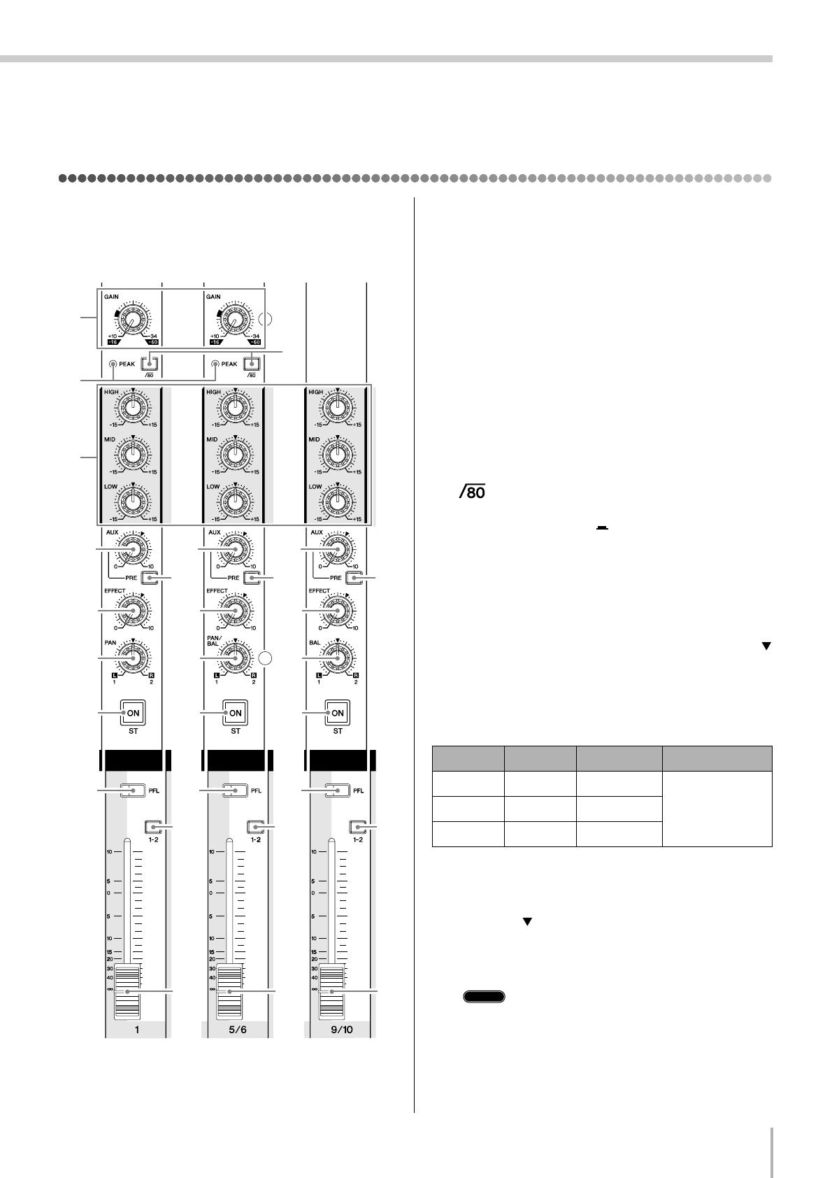
Channel Control Section
1 GAIN Control
Adjusts the input signal level.
To get the best balance between the S/N ratio and the
dynamic range, adjust the level so that the PEAK indica-
tor (2) comes on only at about maximum input level.
The –60 to –16 scale indicates the MIC input adjustment
level. The –34 to +10 scale indicates the LINE input
adjustment level.
2 PEAK Indicator
Detects the peak level of the post-EQ signal, and lights
up red when the level reaches 3 dB below the clipping
level. For XLR-equipped stereo input channels (5/6 and
7/8), detects both post-EQ and post-mic-amp peak lev-
els, and lights red if either of these levels reaches 3 dB
below the clipping level.
3 Switch (High Pass Filter)
This switch toggles the HPF on or off. To turn the HPF
on, press the switch in ( ). The HPF cuts frequencies
below 80 Hz. (But note that regardless of the switch set-
ting, the mixer does not apply this HPF to the line inputs
of stereo input channels.)
4 Equalizer (HIGH, MID, and LOW)
This three-band equalizer adjusts the channel’s high,
mid, and low frequency bands. Setting the knob to the
position produces a flat frequency response. Turning the
knob to the right boosts the corresponding frequency
band, while turning to the left attenuates the band. The
following table shows the EQ type, base frequency, and
maximum cut/boost for each of the three bands.
5 AUX Control
The AUX knob controls the signal level that the channel
sends to the AUX bus. The knob should generally be set
close to the position.
If you are using stereo channels, the signals from the L
(odd) and R (even) channels are mixed and sent to the
AUX bus.
Allows you to output the signal to the buses
regardless of the setting of the ST switch
9.
1
6
A
B
7
9
0
5
8
3
4
2
6
A
B
7
9
0
5
8
6
A
B
7
9
0
5
8
Channels
1 to 4
(Monaural)
Channels
5/6 and 7/8
(Stereo)
Channels
9/10 and 11/12
(Stereo)
Band Type Base Frequency Maximum Cut/Boost
HIGH Shelving 10 kHz
±15 dBMID Peaking 2.5 kHz
LOW Shelving 100 Hz
NOTE
Front & Rear Panels
MG12/4FX
18
6 PRE Switch
Selects whether the pre-fader or the post-fader signal is
fed to the AUX bus. If you set the switch on ( ), the
mixer sends the pre-fader signal (the signal prior to pas-
sage through channel fader B) to the AUX bus, so that
AUX output is not affected by the fader. If you set the
switch off ( ) the mixer sends the post-fader signal to
the AUX bus.
7 EFFECT Controls
Adjusts the level of the signal sent from the channel to
the EFFECT bus. Note that the signal level to the bus is
also affected by the fader. If you are using stereo chan-
nels (CHs 5/6, 7/8, 9/10, or 11/12), the signals from the
L (odd) and R (even) channels are mixed and then sent to
the EFFECT bus.
8 PAN Control (1 to 4)
PAN/BAL Control (5/6 and 7/8)
BAL Control (9/10 and 11/12)
The PAN control determines the positioning of the chan-
nel’s signal on the Group 1 and 2 buses or on the Stereo
L and R buses.
The BAL control knob sets the balance between left and
right channels. Signals into to the L input (odd channel)
feed to the Group 1 bus or to the Stereo L bus; signals
into the R input (even channel) feed to the Group 2 bus
or the Stereo R bus.
On channels where this knob provides both PAN
and BAL controls (5/6 and 7/8), the knob operates
as a PAN control if you are inputting through the
MIC jack or into the L (MONO) input only, and
operates as a BAL control if you are inputting into
both L and R inputs.
9 ST Switch
This switch assigns the channel’s signal to the Stereo L
and R buses. To send the signal to the Stereo bus, set the
switch on by pressing it in ( ). The switch lights up
orange to indicate that it is on.
0 PFL (Pre-Fader Listen) Switch
This switch lets you monitor the channel’s pre-fader sig-
nal. To set the switch on, press it in ( ) so that it lights
up. When the switch is on, the mixer outputs the chan-
nel’s pre-fader signal to the PHONES and C-R OUT
jacks, for monitoring.
A GROUP Switch
Use this switch to assign the channel’s signal to the
Group output. Press the switch in ( ) to output the sig-
nal to the Group 1 and 2 buses.
Allows you to output the signal to the buses
regardless of the setting of the ST switch
9.
B Channel Fader
Adjusts the output level of the signal being input to the
channel. Use these faders to adjust the volume balance
among the various channels.
To reduce noise, set the fader sliders for unused
channels all the way down.
NOTE
NOTE
NOTE
Front & Rear Panels
MG12/4FX
19
Master Control Section
1 ST Master Fader
Adjusts the signal level to the ST OUT jacks.
2 GROUP 1-2 Fader
Adjusts the signal level to the GROUP OUT 1 and
GROUP OUT 2 jacks.
3 TO ST Switch
If this switch is on ( ), the mixer sends the signals pro-
cessed by the GROUP 1-2 fader (2) onto the Stereo bus.
The Group 1 signal goes to Stereo L and the Group 2 sig-
nal goes to Stereo R.
4 Master SEND
• Master AUX Control
Adjusts the signal level to the corresponding AUX
SEND jack.
• Master EFFECT Control
Adjusts the level of the signal on the EFFECT bus. This
is the signal that is output through the EFFECT jack.
These Master SEND controls do not affect the
level of the signal sent from the EFFECT bus to
the internal digital effector.
5 RETURN
•AUX Control
Adjust the level of the mixed L/R signal sent from the
RETURN jacks (L (MONO) and R) to the AUX bus.
• ST Control
Adjust the level of the signal sent from the RETURN
jacks (L (MONO) and R) to the Stereo bus.
If you supply a signal to the RETURN L (MONO)
jack only, the mixer outputs the identical signal to
both the L and R Stereo buses.
6 2TR IN Control
Adjusts the level of the signal sent from the 2TR IN jack
to the Stereo bus.
7 PHANTOM +48 V Switch
This switch toggles phantom power on and off. If you set
the switch on, the mixer supplies power to all channels
that provide XLR mic input jacks (CHs 1–4, 5/6, 7/8).
Set this switch on when using one or more condenser
microphones.
When this switch is on, the mixer supplies DC
+48 V power to pins 2 and 3 of all XLR-type MIC
INPUT jacks.
• Be sure to leave this switch off ( ) if you do not
need phantom power.
• When tuning the switch on ( ), be sure that
only condenser mics are connected to the XLR
input jacks (CHs: 1 to 7/8). Devices other than
condenser mics may be damaged if connected to
the phantom power supply. Note, however, that
the switch may be left on without problem when
connecting to balanced dynamic microphones.
• To avoid damage to speakers, be sure to turn off
amplifiers (or powered speakers) before turning
this switch on or off. We also recommend that you
turn all output controls (ST master fader, GROUP
1-2 fader, etc.) to minimum settings before oper-
ating the switch, to avoid risk of loud noises that
could cause hearing loss or device damage.
12C
B
A
9
4
5
0
8
3
7
6
NOTE
NOTE
NOTE
Front & Rear Panels
MG12/4FX
20
8 Level-Meter Signal Switches (ST-GROUP
Toggle Switch and 2TR IN Switch)
These level-meter switches, together with the channel
PFL switches, select the signal that is sent through the
C-R/PHONES control to the C-R OUT jacks, the
PHONES jack, and the level meter
The following illustration shows how the switch settings
correspond to the signal selection.
*1 If the input channel’s PFL switch is on ( ), then only the
channel’s PFL output it sent to the C-R OUT jacks, PHONES
jacks, and level meter.
*2 If the 2TR IN switch is ON ( ), the signal supplied to the
2TR IN jack is sent to the C-R OUT jacks, PHONE jacks,
and level meter. If the 2TR IN switch is OFF, then the Group
or Stereo signal is sent instead (as determined by the
ST-GROUP toggle switch).
9 C-R/PHONES Control
Controls the level of the signal output to the PHONES
jack and the C-R L and R jacks.
0 Level Meter
This LED display shows the level of the signal selected
by the selection switches described in 8 above (the level
to the C-R OUT and PHONES jacks). The “0” point cor—
responds to the standard output level. The indicator
lights up red when the output hits the clipping level.
A POWER Indicator
This indicator lights up when the mixer’s power is ON.
B PHONES Jack
Connector for headphones. This is a stereo phone-type
output jack.
The signal monitored by these jacks is selected by
the settings of the ST-GROUP toggle switch, the
2TR IN switch, and the PFL switches on the input
channels.
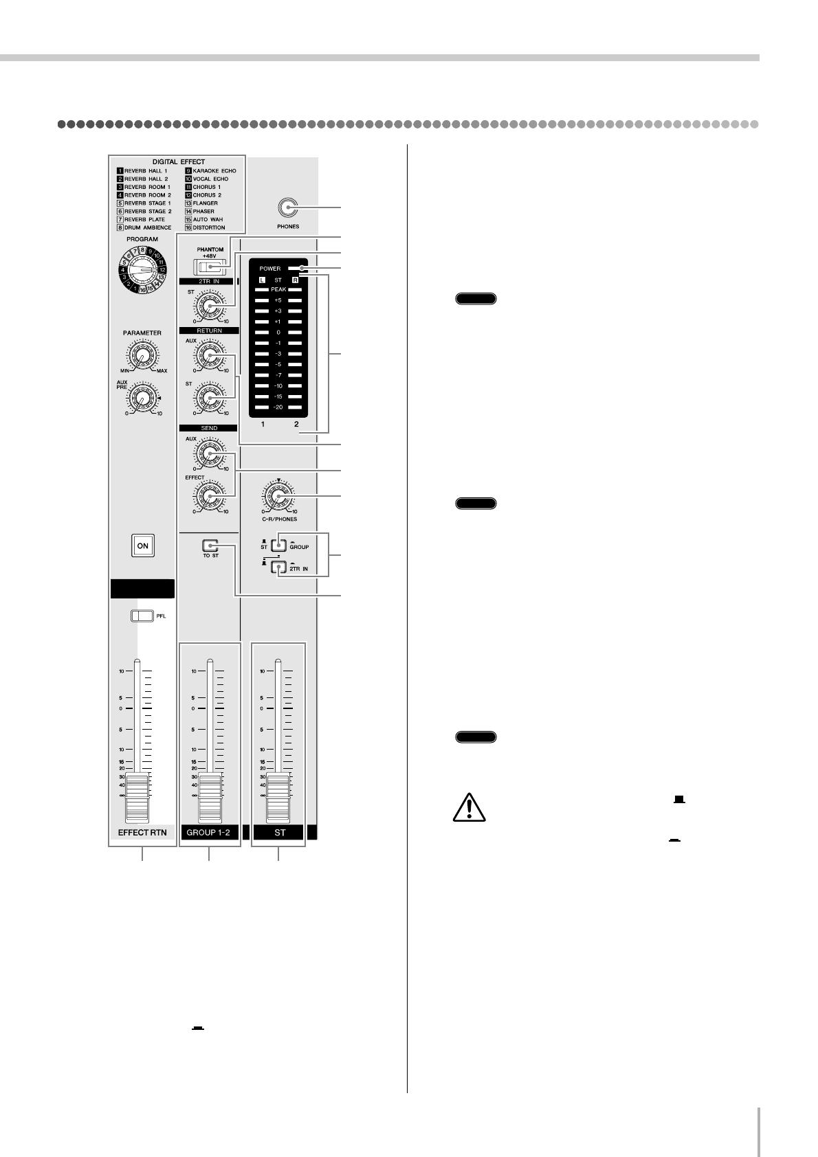
C DIGITAL EFFECT
•PROGRAM Dial
Selects the internal digital effect to be applied. You can
select from 16 effects, as shown in the table.
•PARAMETER Control
Adjusts the parameter (depth, speed, etc.) for the
selected effect.
The mixer saves the last value used with each
effect type.
When you change to a different effect type, the
mixer automatically restores the value that was
previously used with the newly selected effect
(regardless of the current position of the PARAM-
ETER Control knob).
These parameter values are retained even after
power-off.
•AUX PRE Control
Adjust the level of the signal sent from the internal dig-
ital effector to the AUX bus.
• ON Switch
Switches use of the internal effect on or off. The inter-
nal effect is applied only if this switch is turned on. The
switch lights up orange to indicate that it is on.
With the (separately sold) YAMAHA FC5 foot switch
connected, you can use your foot to toggle the digital
effects ON and OFF.
When you turn on the power, the ON switch lights up
and the internal effector becomes active.
• PFL Switch
Set this switch on if you wish to output the effect signal
to the PFL bus.
• EFFECT RTN Fader
Adjusts the signal level from the internal digital effec-
tor to the STEREO bus.
2TR IN
2TR IN
PFL
PFL
GROUP
ST-GROUP
ST
ON
OFF
ON
ON
OFF
OFF
C-R OUT
&
PHONES
Signal
Switch
*1
*2
NOTE
No Program Parameter
1
REVERB HALL 1 REVERB TIME
2
REVERB HALL 2 REVERB TIME
3
REVERB ROOM 1 REVERB TIME
4
REVERB ROOM 2 REVERB TIME
55
55
REVERB STAGE 1 REVERB TIME
66
66
REVERB STAGE 2 REVERB TIME
77
77
REVERB PLATE REVERB TIME
88
88
DRUM AMBIENCE REVERB TIME
9
KARAOKE ECHO DELAY TIME
0
VOCAL ECHO DELAY TIME
A
CHORUS 1 LFO FREQ
B
CHORUS 2 LFO FREQ
CC
CC
FLANGER LFO FREQ
DD
DD
PHASER LFO FREQ
EE
EE
AUTO WAH LFO FREQ
FF
FF
DISTORTION DRIVE
NOTE
NOTE
- Manuals
- Brands
- Yamaha Manuals
- Music Mixer
- MG12/4FX
Manuals and User Guides for Yamaha MG12/4FX. We have 3 Yamaha MG12/4FX manuals available for free PDF download: Service Manual, Owner’s Manual
Yamaha MG12/4FX Service Manual (79 pages)
Brand: Yamaha
|
Category: Music Mixer
|
Size: 12.91 MB
Table of Contents
-
Contents
1
-
Safety Precautions
2
-
Electrical Characteristics
3
-
General Specifications
3
-
Input Specifications
4
-
Output Specifications
4
-
Dimensions
7
-
Panel Layout
8
-
Master Control Section
9
-
Rear Input/Output Section
10
-
Connector Polarities
11
-
Circuit Board Layout
12
-
Wiring
13
-
Disassembly Procedure
14
-
Rack Mount Angle
14
-
Bottom Cover
14
-
Side Cover
15
-
DSP Circuit Board, Shield DSP 12
16
-
Power Switch and AC Connector
17
-
JACK Circuit Board, MAIN Circuit Board
17
-
Lsi Pin Description
19
-
IC Block Diagram
20
-
Circuit Boards Index
22
-
DSP Circuit Board
22
-
PS Circuit Board
23
-
Jack Circuit Board
24
-
MAIN Circuit Board
28
-
Inspections
30
-
Scope
30
-
Power Source
30
-
Preparation
30
-
Indicator Inspection
31
-
Gain
31
-
Frequency Characteristics
32
-
Hpf
32
-
Channel Equalizer Characteristics
32
-
Crosstalk
33
-
PEAK LED Light-Up Level
33
-
Distortion Factor
33
-
Equivalent Input Noise
33
-
Residual Noise
34
-
Phantom
34
-
Digital Effect
34
-
Preparation of Delivery
34
-
Parts List Contents
40
-
Overall Assembly
41
-
Electrical Parts
44
-
Circuit Diagram Contents
68
-
Block Diagram
69
-
Level Diagram
69
-
Overall Circuit Diagram
70
Advertisement
Yamaha MG12/4FX Owner’s Manual (32 pages)
Yamaha MG124FX Audio Mixers: Owners Manual
Brand: Yamaha
|
Category: Music Mixer
|
Size: 2.24 MB
Table of Contents
-
Introduction
4
-
Table of Contents
4
-
Contents
4
-
Features
4
-
Before Turning on the Mixer
5
-
Turning the Power on
5
-
-
Making the most of Your Mixer
6
-
A Place for Everything and Everything in Its Place
6
-
How Do Balanced Lines Reject Noise
7
-
A Balanced Cable Has Three Conductors
8
-
-
Where Your Signal Goes Once It’s Inside the Box
9
-
Simplified Mixer Block Diagram
9
-
The First Steps in Achieving Great Sound
10
-
Head Amplifier “Gain” Control Is Key
10
-
External Effects, Monitor Mixes, and Groups
12
-
Using Groups
13
-
Channel Inserts for Channel-SpecifiC Processing
14
-
-
Making Better Mixes
15
-
-
Front & Rear Panels Channel Control Section
17
-
AUX Sends and Stereo AUX Return
17
-
Master Control Section
19
-
-
Phantom Power (+48 V)
19
-
High-Quality Digital Effects
20
-
Rear Input/Output Section
21
-
-
Input Channels
21
-
Setting up
23
-
Setup Procedure
23
-
Setup Examples
23
-
Sound Reinforcement for Live Performance
24
-
Rack Mounting
25
-
-
Appendix
26
-
Specifications
26
-
Dimensional Diagrams
28
-
Block Diagram and Level Diagram
29
-
(Japanese) Yamaha MG12/4FX Owner’s Manual (32 pages)
Yamaha Mixing Console Owner’s Manual
Brand: Yamaha
|
Category: Music Mixer
|
Size: 2.92 MB
Table of Contents
-
Table of Contents
5
-
はじめに
5
-
電源の準備
6
-
電源を入れる
6
-
ステップアップガイド
7
-
ミキサーの基礎知識
7
-
入力された信号の流れ
11
-
クリアなミックス」にするためのレベル調整
12
-
外部エフェクト、モニターミックス、グループについて
14
-
より良いミックスのためのノウハウ
16
-
Mg12/4Fx の内蔵エフェクターを使う
18
-
チャンネルコントロール部
19
-
各部の名称と機能
19
-
マスターコントロール部
21
-
リア入出力部
23
-
セットアップ
25
-
セットアップにあたって
25
-
セットアップ例
25
-
ラックマウント
27
-
付録
29
-
仕様
29
-
寸法図
30
-
ブロック / レベルダイアグラム
31
-
内蔵のエフェクトを使用すると、Mg12/4Fx だけでもバリエー
31
Advertisement
Advertisement
Related Products
-
Yamaha MG12
-
Yamaha MG12/4
-
Yamaha MG12XU
-
Yamaha MG12FX
-
Yamaha MG12XUK
-
Yamaha MG12X
-
Yamaha MG12X CV
-
Yamaha MG166CX
-
Yamaha MG10XUF
-
Yamaha MG16X CV
Yamaha Categories
Motorcycle
Musical Instrument
Electronic Keyboard
Receiver
Amplifier
More Yamaha Manuals
Manuals Directory
Manualsdir.ru — Онлайн поиск инструкций и руководств
Музыкальные инструменты Yamaha
Эта инструкция подходит к следующим моделям:
mg16_4
MG16/4 MG12/4
Введение
Благодарим за покупку микшерной консоли YAMAHA MG16/4 или MG12/4 Удобство эксплуатации и универсальность делают эту микшерную консоль идеальной для небольших студий установленных систем и множества других подобных случаев применения.
Внимательно прочтите это руководство пользователя прежде чем приступать к эксплуатации чтобы максимально использовать превосходные возможности микшера и наслаждаться его безотказной работой в течение многих лет.
В MG16/4 предусмотрено 16 входных каналов которые можно назначать стереовыходу или групповому выходу.
В MG12/4 предусмотрено 12 входных каналов которые можно назначать выходу Stereо или Grоup.
Монитор оснащен удобным разъемом C-R OUT Этот разъем можно использовать для отслеживания сигнала основного стереовыхода PFL-сигнала или сигналов шин Grоup 1-2.
В микшер входят сдвоенные разъемы AUX SEND и один разъем RETURN Две независимых шины AUX можно использовать в качестве посылов на внешние процессоры эффектов и в системы мониторинга.
Источник фантомного питания удобно подключается к конденсаторным микрофонам с внешним питанием.
В микшере предусмотрены разъемы INSERT I/O для входных каналов 1 8 (MG16/4) или 1 4 (MG12/4). Они позволяют вставлять процессоры эффектов в разные каналы
Входные каналы 1 8 9/10 и 11/12 (MG16/4) а также 1 4 5/6 и 7/8 (MG12/4) имеют входной микрофонный разъем XLR-типа и линейный штекер TRS-типа Входные каналы 13/14 и 15/16 (MG16/4) а также 9/10 и 11/12 (MG12/4) имеют входной линейный разъем TRS-типа и RCA-типа Широкий выбор разъемов позволяет подключать прибор ко множеству различных устройств
от микрофонов до устройств радиотрансляции и синтезаторов со стереовыходом.
Введение 4
Возможности 4
Содержание 4
Прежде чем включать микшер 5
Включение устройства 5
Полнофункциональный микшер 6
Место для всего и все на своем месте
Куда идет сигнал когда попадает в устройство 10
Первые шаги на пути к великолепному качеству звука 11
Внешние процессоры эффектов миксы мониторинга и группы 13
Как сделать лучший микс
Передняя и задняя панели 18
Секция регуляторов каналов 18
Секция главных регуляторов 20
Секция входов/выходов задней панели 22
Настройка 24
Процедура настройки 24
Примеры настройки 24
Монтаж стойки 26
Приложение 27
Технические характеристики 27
Габариты 29
Принципиальная схема и диаграмма уровней 30
Возможности
Содержание
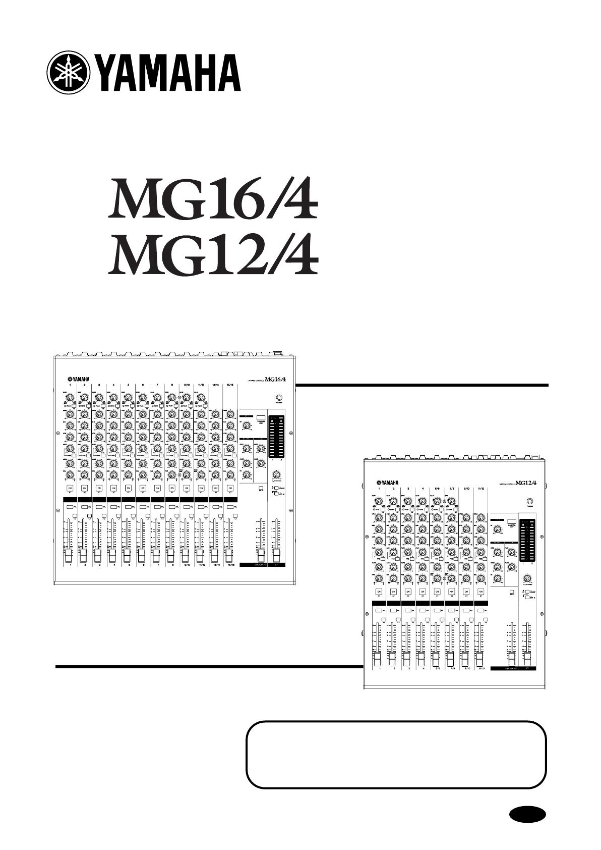
MIXING CONSOLE
Owner’s Manual
MG16/4
MG12/4
Making the Most Of Your Mixer
Pages 6 to 17
E
MG12-16_E.book Page 1 Monday, May 26, 2003 1:14 PM
MG16/4, MG12/4
2
Precautions
—For safe operation—
WARNING
●
Connect this unit’s AC power adaptor only to an AC outlet of the
type stated in this Owner’s Manual or as marked on the unit.
Failure to do so is a fire and electrical shock hazard.
●
Do not allow water to enter this unit or allow the unit to become
wet. Fire or electrical shock may result.
●
Do not place a container with liquid or small metal objects on
top of this unit. Liquid or metal objects inside this unit are a fire
and electrical shock hazard.
●
Do not place heavy objects, including this unit, on top of the
power cord. A damaged power cord is a fire and electrical shock
hazard. In particular, be careful not to place heavy objects on a
power cord covered by a carpet.
●
Do not scratch, bend, twist, pull, or heat the power cord. A dam-
aged power cord is a fire and electrical shock hazard.
●
Do not remove the unit’s cover. You could receive an electrical
shock. If you think internal inspection, maintenance, or repair is
necessary, contact your dealer.
●
Do not modify the unit. Doing so is a fire and electrical shock
hazard.
●
If lightning begins to occur, turn off the power switch of the unit
as soon as possible, and unplug the power plug from the electri-
cal outlet.
●
If there is a possibility of lightning, do not touch the power plug
if it is still connected. Doing so may be an electrical shock haz-
ard.
●
Use only the included AC power adaptor (PA-20) for this unit.
Using other types may be a fire and electrical shock hazard.
●
If the power cord is damaged (i.e., cut or a bare wire is exposed),
ask your dealer for a replacement. Using the unit with a damaged
power cord is a fire and electrical shock hazard.
●
Should this unit and AC adaptor be dropped or the cabinet be
damaged, turn the power switch off, remove the power plug from
the AC outlet, and contact your dealer. If you continue using the
unit without heeding this instruction, fire or electrical shock may
result.
●
If you notice any abnormality, such as smoke, odor, or noise, or
if a foreign object or liquid gets inside the unit, turn it off imme-
diately. Remove the power plug from the AC outlet. Consult your
dealer for repair. Using the unit in this condition is a fire and
electrical shock hazard.
CAUTION
●
Keep this unit away from the following locations:
— Locations exposed to oil splashes or steam, such as near cook-
ing stoves, humidifiers, etc.
— Unstable surfaces, such as a wobbly table or slope.
— Locations exposed to excessive heat, such as inside a car with
all the windows closed, or places that receive direct sunlight.
— Locations subject to excessive humidity or dust accumulation.
●
Hold the power plug when disconnecting it from an AC outlet.
Never pull the cord. A damaged power cord is a potential fire and
electrical shock hazard.
●
Do not touch the power plug with wet hands. Doing so is a
potential electrical shock hazard.
●
To relocate the unit, turn the power switch off, remove the power
plug from the AC outlet, and remove all connecting cables. Dam-
aged cables may cause fire or electrical shock.
●
Do not cover or wrap the AC power adaptor with a cloth or blan-
ket. Heat may build up under the cloth or blanket, melting the
case, or causing fire. Use only in a well-ventilated environment.
●
If you know you will not use this unit for a log period of time,
such as when going on vacation, remove the power plug from the
AC outlet. Leaving it connected is a potential fire hazard.
Installation
Operation
In case an abnormality occurs during operation
Installation
Operation
MG12-16_E.book Page 2 Monday, May 26, 2003 1:14 PM

Precautions
MG16/4, MG12/4
3
—For correct operation —
●
XLR-type connectors are wired as follows: pin 1: ground, pin 2:
hot (+), and pin 3: cold (–).
●
Insert TRS phone jacks are wired as follows: sleeve: ground, tip:
send, and ring: return.
●
The performance of components with moving contacts, such
switches, rotary controls, faders, and connectors, deteriorates
over time. The rate of deterioration depends on the operating
environment and is unavoidable. Consult your dealer about
replacing defective components.
●
Using a cell phone (mobile telephone) near this unit may induce
noise. If noise occurs, use the telephone away from the unit.
Copying of the commercially available music data and/or digital audio files is strictly prohibited except for your personal use.
Illustration examples shown herein are for explanatory purposes only, and may not match actual appearance during operation.
The company names and product names in this Owner’s Manual are the trademarks or registered trademarks of their respective companies.
• This applies only to products distributed by Yamaha-Kemble Music (U.K.) Ltd. (2 wires)
Connector pin assignments
Replacing abrasive parts
Influence on cell phone usage
●
Always turn the power off when the mixer is not in use.
●
Even when the power switch is in the “STANDBY” position, electricity is still flowing to the mixer at the minimum level. When you are
not using the mixer for a long time, make sure you unplug the AC power adaptor from the wall AC outlet.
IMPORTANT NOTICE FOR THE UNITED KINGDOM
Connecting the Plug and Cord
IMPORTANT. The wires in this mains lead are coloured in accordance with the following code:
BLUE : NEUTRAL
BROWN : LIVE
As the colours of the wires in the mains lead of this apparatus may not correspond with the coloured makings identifying the terminals in your
plug proceed as follows:
The wire which is coloured BLUE must be connected to the terminal which is marked with the letter N or coloured BLACK.
The wire which is coloured BROWN must be connected to the terminal which is marked with the letter L or coloured RED.
Making sure that neither core is connected to the earth terminal of the three pin plug.
MG12-16_E.book Page 3 Monday, May 26, 2003 1:14 PM

MG16/4, MG12/4
4
Introduction
Thank you for your purchase of the YAMAHA MG16/4 or MG12/4 mixing console. This mixing
console combines ease of operation with support for multiple usage environments, and is
ideal for SR setups, installed systems, and many other such applications.
Please read through this Owner’s Manual carefully before beginning use, so that you will be
able to take full advantage of the mixer’s superlative features and enjoy trouble-free operation
for years to come.
●
The MG16/4 provides 16 input channels that can assign to Ste-
reo or Group output.
●
The MG12/4 provides 12 input channels that can assign to Ste-
reo or Group output.
●
The monitor includes a convenient C-R OUT jack. This jack can
be used to monitor the main Stereo output, the PFL signal, or the
Group 1-2 signals.
●
The mixer includes dual AUX SEND jacks and a single
RETURN jack. The two independent AUX buses may be used as
sends to external effectors and monitor systems.
●
Phantom power supply enables easy connection to condenser
microphones that run on external power.
●
The mixer provides channel-specific INSERT I/O jacks for input
channels 1 to 8 (MG16/4) or 1 to 4 (MG12/4). These jacks make
it possible to insert different effectors into different channels.
●
Input channels 1 to 8, 9/10, and 11/12 (MG16/4), and 1 to 4, 5/6,
and 7/8 (MG12/4) are each equipped with both an XLR mic
input jack and a TRS phone-type line jack. Input channels 13/14
and 15/16 (MG16/4), and 9/10 and 11/12 (MG12/4) are each
equipped with both a TRS line input jack and an RCA line input
jack. This wide assortment of connectors enables connection to
many different devices, from microphones to line-level devices
to stereo-output synthesizers.
Introduction ……………………………………………………… 4
Features ……………………………………………………… 4
Contents …………………………………………………….. 4
Before Turning on the Mixer …………………………… 5
Turning the Power On …………………………………… 5
Making the Most Of Your Mixer …………………………… 6
1
A Place For Everything and Everything
In Its Place ………………………………………………. 7
2
Where Your Signal Goes Once It’s Inside
the Box …………………………………………………. 10
3
The First Steps in Achieving Great Sound …. 11
4
External Effects, Monitor Mixes,
and Groups ……………………………………………. 13
5
Making Better Mixes………………………………… 16
Front & Rear Panels ………………………………………… 18
Channel Control Section ……………………………… 18
Master Control Section ……………………………….. 20
Rear Input/Output Section …………………………… 22
Setting Up ……………………………………………………… 24
Setup Procedure ………………………………………… 24
Setup Examples ………………………………………… 24
Rack Mounting …………………………………………… 26
Appendix ……………………………………………………….. 27
Specifications ……………………………………………. 27
Dimensional Diagrams ………………………………… 29
Block Diagram and Level Diagram ……………….. 30
Features
Contents
MG12-16_E.book Page 4 Monday, May 26, 2003 1:14 PM
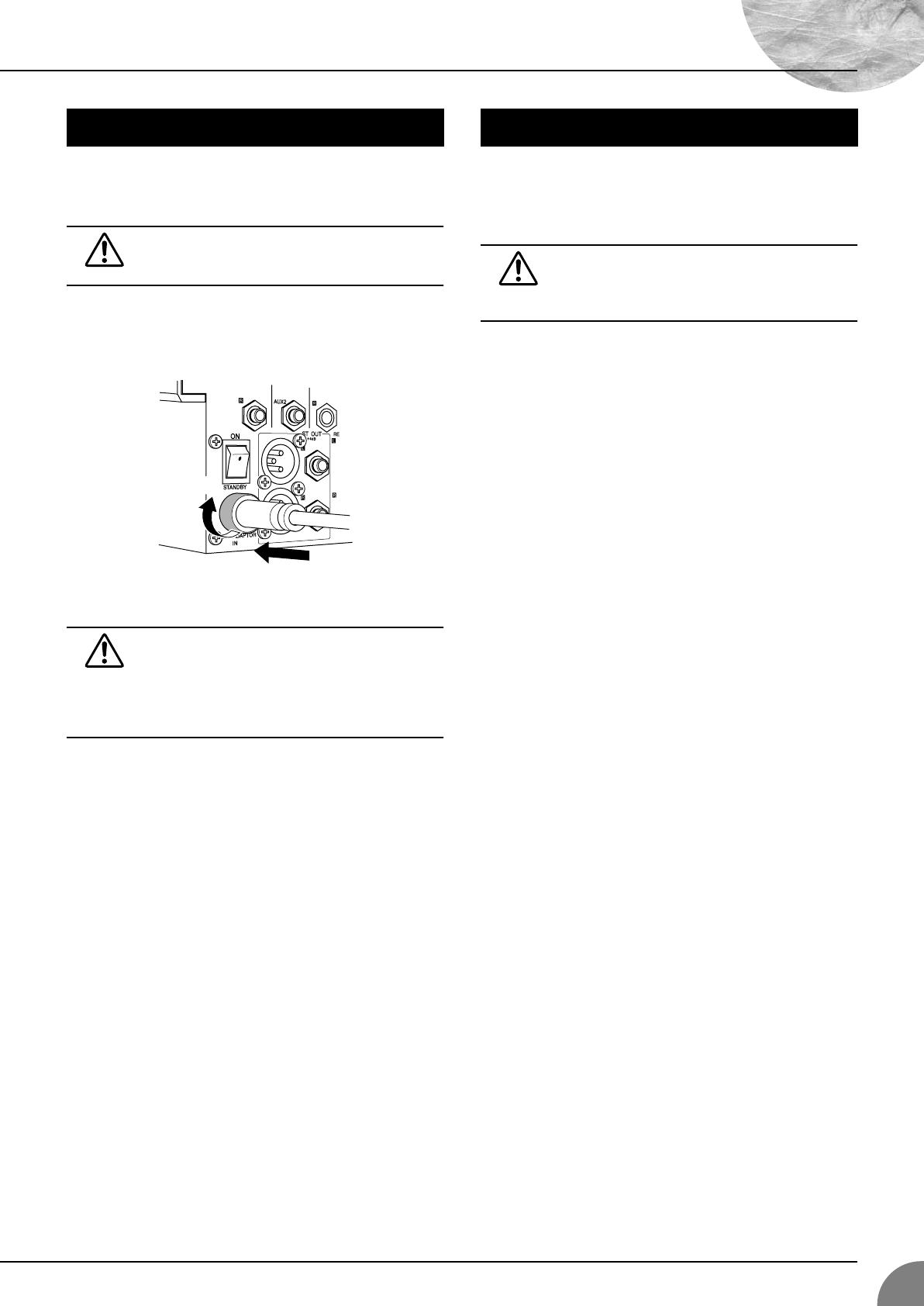
Introduction
MG16/4, MG12/4
5
(1) Be sure that the mixer’s power switch is in the STANDBY
position.
Use only the PA-20 adaptor included with this mixer.
Use of a different adaptor may result in equipment
damage, overheating, or fire.
(2) Connect the power adaptor to the AC ADAPTOR IN con-
nector (
1
) on the rear of the mixer, and then turn the fas-
tening ring clockwise (
2
) to secure the connection.
(3) Plug the power adaptor into a standard household power outlet.
• Be sure to unplug the adaptor from the outlet when
not using the mixer, or when there are lightning
storms in the area.
• To avoid generating unwanted noise, make sure
there is adequate distance between the power
adaptor and the mixer.
Press the mixer’s power switch to the ON position. When you are
ready to turn the power off, press the power switch to the
STANDBY position.
Note that trace current continues to flow while the
switch is in the STANDBY position. If you do not plan
to use the mixer again for a long while, please be sure
to unplug the adaptor from the wall outlet.
Before Turning on the Mixer
1
2
Turning the Power On
MG12-16_E.book Page 5 Monday, May 26, 2003 1:14 PM
MG16/4, MG12/4
6
Making the Most Of Your Mixer
An Introduction
You’ve got yourself a mixer and now you’re ready to use it.
Just plug everything in, twiddle the controls, and away you go … right?
Well, if you’ve done this before you won’t have any problems, but if this is
the first time you’ve ever used a mixer you might want to read through this
little tutorial and pick up a few basics that will help you get better
performance and make better mixes.
MG12-16_E.book Page 6 Monday, May 26, 2003 1:14 PM
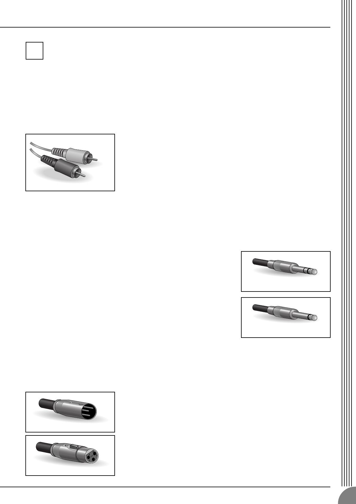
Making the Most Of Your Mixer
MG16/4, MG12/4
7
A Place For Everything and Everything In Its Place
1-1. A Plethora Of Connectors—What Goes Where?
Questions you’re likely to encounter when setting up a system for the first time might include “Why all
these different types of connectors on the back of my mixer?” and “What’s the difference?”.
Let’s start by taking a look at the most common connector types.
The Venerable RCA Pin Jack
This is the “consumer connector,” and the one that has been most commonly used
on home audio gear for many years. Also known as “phono” jacks (short for
”phonogram”), but the term isn’t used much these days—besides, it’s too easily
confusable with “phone” jacks, below. RCA pin jacks are always unbalanced, and
generally carry a line-level signal at –10 dB, nominal. You’re most likely to use this
type of connector when connecting a CD player or other home audio type source
to your mixer, or when connecting the output of your mixer to a cassette recorder
or similar gear.
The Versatile Phone Jack
The name “phone jack” arose simply because this configuration was first
used in telephone switchboards. Phone jacks can be tricky because you
can’t always tell what type of signal they’re designed to handle just by
looking at them. It could be unbalanced mono, unbalanced stereo,
balanced mono, or an insert patch point. The connector’s label will
usually tell you what type of signal it handles, as will the owner’s manual
(you
do
keep your manuals in a safe place, don’t you?). A phone jack that
is set up to handle balanced signals is also often referred to as a “TRS”
phone jack. “TRS” stands for Tip-Ring-Sleeve, which describes the
configuration of the phone plug used.
The Sturdy XLR
This type of connector is generally referred to as “XLR-type,” and almost always
carries a balanced signal. If the corresponding circuitry is designed properly,
however, XLR-type connectors will also handle unbalanced signals with no
problem. Microphone cables usually have this type of connector, as do the inputs
and outputs of most professional audio gear.
1
White
Red
Stereo/TRS phone plug
Mono phone plug
Male
Female
MG12-16_E.book Page 7 Monday, May 26, 2003 1:14 PM
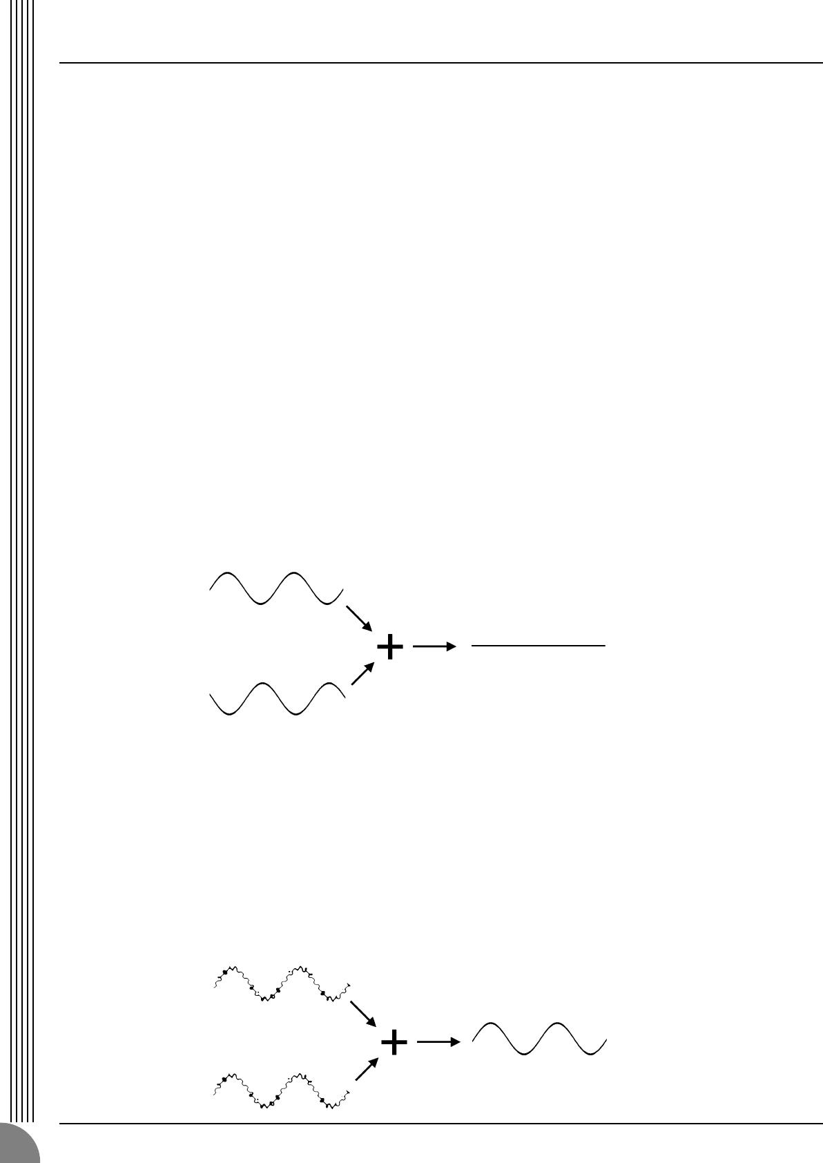
Making the Most Of Your Mixer
MG16/4, MG12/4
8
1-2. Balanced, Unbalanced—What’s the Difference?
In a word: “noise.” The whole point of balanced lines is noise rejection, and it’s something they’re very
good at. Any length of wire will act as an antenna to pick up the random electromagnetic radiation we’re
constantly surrounded by: radio and TV signals as well as spurious electromagnetic noise generated by
power lines, motors, electric appliances, computer monitors, and a variety of other sources. The longer
the wire, the more noise it is likely to pick up. That’s why balanced lines are the best choice for long
cable runs. If your “studio” is basically confined to your desktop and all connections are no more than a
meter or two in length, then unbalanced lines are fine—unless you’re surrounded by extremely high lev-
els of electromagnetic noise. Another place balanced lines are almost always used is in microphone
cables. The reason for this is that the output signal from most microphones is very small, so even a tiny
amount of noise will be relatively large, and will be amplified to an alarming degree in the mixer’s high-
gain head amplifier.
To summarize:
Microphones: Use balanced lines.
Short line-level runs: Unbalanced lines are fine if you’re in a relatively noise-free environment.
Long line-level runs: The ambient electromagnetic noise level will be the ultimate deciding factor, but
balanced is best.
■
How Do Balanced Lines Reject Noise?
** Skip this section if technical details make you queasy. **
Balanced lines work on the principle of “phase cancellation”: if you add two identical signals out of
phase (i.e. one signal is inverted so its peaks coincide with the troughs in the other signal), the result is …
nothing. A flat line. The signals cancel each other out.
A balanced cable has three conductors:
1) A ground conductor which carries no signal, just the “ground” or “0” reference against which the
signal in the other conductors fluctuates.
2) A “hot” or “+” conductor which carries the normal-phase audio signal.
3) A “cold” or “–” conductor which carries the reverse-phase audio signal.
While the desired audio signals in the hot and cold conductors are out of phase, any noise induced in
the line will be exactly the same in both conductors, and thus in phase. The trick is that the phase of
one signal is reversed at the receiving end of the line so that the desired audio signals become in-
phase, and the induced noise suddenly finds itself out of phase. The out-of-phase noise signal is effec-
tively canceled while the audio signal is left intact. Clever, eh?
Normal-phase signal.
Reverse-phase signal.
No signal.
(Phase cancellation)
Normal-phase signal
+ normal-phase noise.
Normal-phase signal
+ reverse-phase noise.
Desired signal
with no noise.
MG12-16_E.book Page 8 Monday, May 26, 2003 1:14 PM

Making the Most Of Your Mixer
MG16/4, MG12/4
9
1-3. Signal Levels—Decibel Do’s and Don’ts
From the moment you start dealing with things audio, you’ll have to deal with the term “decibel” and its
abbreviation, “dB”. Things can get confusing because decibels are a very versatile unit of measure used
to describe acoustic sound pressure levels as well as electronic signal levels. To make matters worse there
are a number of variations: dBu, dBV, dBm. Fortunately, you don’t need to be an expert to make things
work. Here are a few basics you should keep in mind:
●
“Consumer” gear (such as home audio equipment) usually has line inputs and outputs with a nomi-
nal (average) level of –10 dB.
●
Professional audio gear usually has line inputs and outputs with a nominal level of +4 dB.
●
You should always feed –10 dB inputs with a –10 dB signal. If you feed a +4 dB signal into a –10 dB
input you are likely to overload the input.
●
You should always feed +4 dB inputs with a +4 dB signal. A –10 dB signal is too small for a +4 dB
input, and will result in less-than-optimum performance.
●
Many professional and semi-professional devices have level switches on the inputs and/or outputs
that let you select –10 or +4 dB. Be sure to set these switches to match the level of the connected
equipment.
●
Inputs that feature a “Gain” control—such as the mono-channel inputs on your Yamaha mixer—will
accept a very wide range of input levels because the control can be used to match the input’s sensi-
tivity to the signal. More on this later.
MG12-16_E.book Page 9 Monday, May 26, 2003 1:14 PM
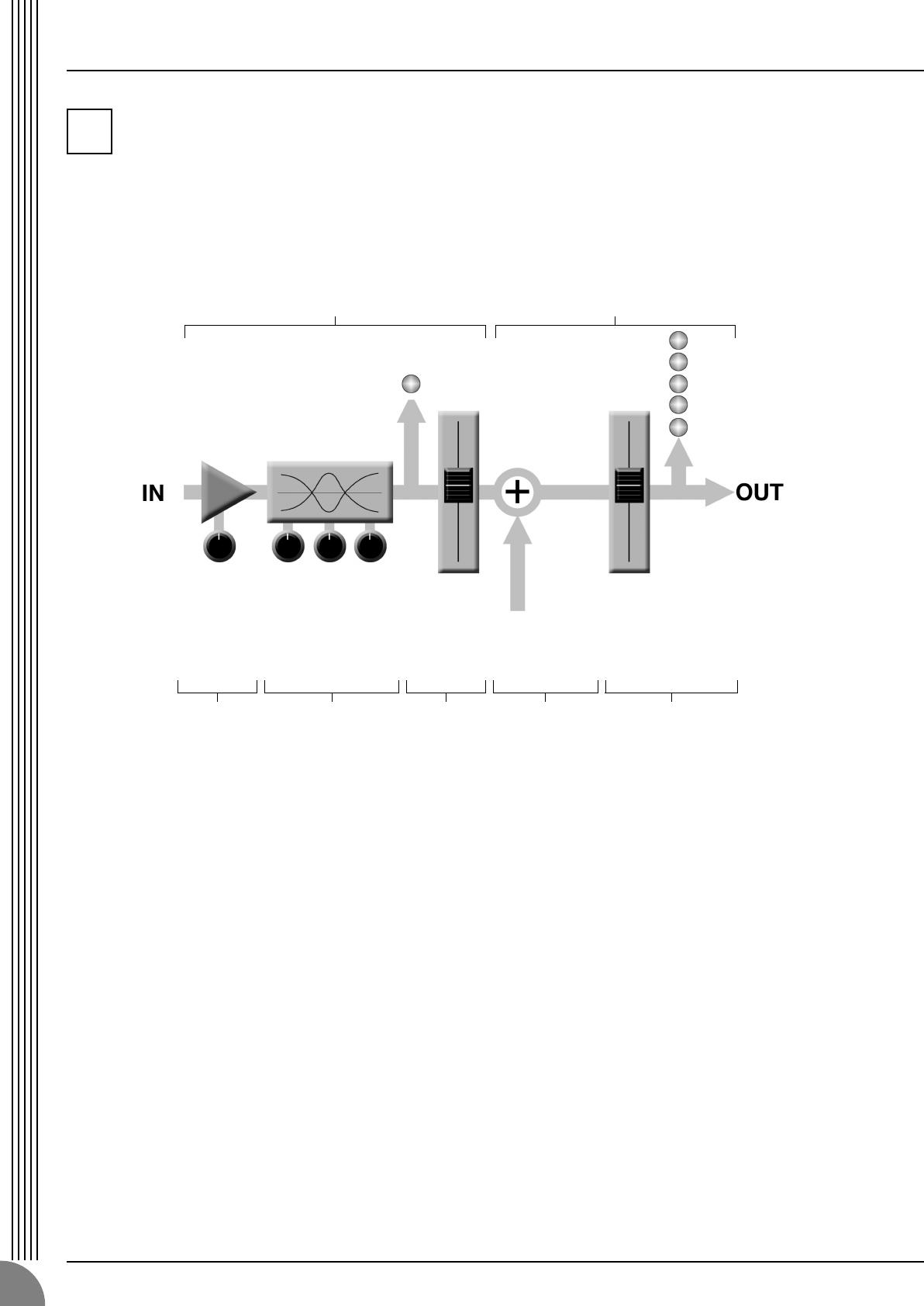
Making the Most Of Your Mixer
MG16/4, MG12/4
10
Where Your Signal Goes Once It’s Inside the Box
At first glance the block diagram of even a modest mixer can look like a space-station schematic. In reality,
block diagrams are a great aid in understanding how the signal flows in any mixer. Here’s a greatly simplified
block diagram of a generic mixer to help you become familiar with the way these things work.
2-1. Greatly Simplified Mixer Block Diagram
■
Input Channel
1
Head Amp
The very first stage in any mixer, and
usually the only stage with significant
“gain” or “amplification.” The head
amp has a “gain” control that adjusts
the mixer’s input sensitivity to match the
level of the source. Small signals (e.g.
mics) are amplified, and large signals
are attenuated.
2
Equalizer
Could be simple bass and treble con-
trols or a full-blown 4-band parametric
EQ. When boost is applied the EQ stage
also has gain. You can actually overload
the input channel by applying too much
EQ boost. It’s usually better to cut than
boost.
3
Channel Peak LED & Fader
The channel peak LED is your most
valuable tool for setting the input “gain”
control for optimum performance. Note
that it is located after the head amp and
EQ stage.
■
Master Section
4
Summing Amplifier
This is where the actual “mixing” takes
place. Signals from all of the mixer’s
input channels are “summed” (mixed)
together here.
5
Master Fader & Level Meter
A stereo, mono, or bus master fader and
the mixer’s main output level meter.
There could be several master faders
depending on the design of the mixer—
i.e. the number of buses or outputs it
provides.
2
1234 5
Input Channel Master Section
Signals from the mixer’s
other input channels (if
they are assigned to this
master output or “bus”).
MG12-16_E.book Page 10 Monday, May 26, 2003 1:14 PM
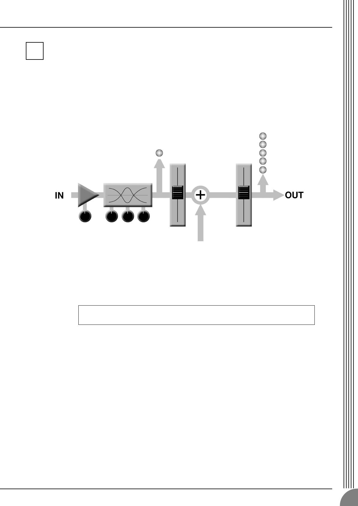
Making the Most Of Your Mixer
MG16/4, MG12/4
11
The First Steps in Achieving Great Sound
Before you even consider EQ and effects, or even the overall mix, it is important to make sure that levels are
properly set for each individual source. This can’t be stressed enough—initial level setup is vitally important for
achieving optimum performance from your mixer! Here’s why … and how.
3-1. The Head Amplifier “Gain” Control Is the Key!
Let’s review our simplified mixer block diagram:
Each and every “stage” in the mixer’s signal path will add a certain amount of noise to the signal: the
head amp, the EQ stage, the summing amplifier, and the other buffer and gain stages that exist in the
actual mixer circuit (this applies to analog mixers in particular). The thing to keep in mind is that the
amount of noise added by each stage is usually not dependent to any significant degree on the level of
the audio signal passing through the circuit. This means that the bigger the desired signal, the smaller the
added noise will be in relation to it. In tech-speak this gives us a better “signal-to-noise ratio”—often
abbreviated as “S/N ratio.” All of this leads to the following basic rule:
In our mixer, that means the head amplifier. If you don’t get the signal up to the desired level at the head
amplifier stage, you will need to apply more gain at later stages, which will only amplify the noise con-
tributed by the preceding stages. Just remember that too much initial gain is bad too, because it will over—
load our channel circuitry and cause clipping.
To achieve the best overall system S/N ratio, amplify the input to the desired average
level as early as possible in the signal path.
3
MG12-16_E.book Page 11 Monday, May 26, 2003 1:14 PM

Making the Most Of Your Mixer
MG16/4, MG12/4
12
3-2. Level Setup Procedure For Optimum Performance
Now that we know what we have to do, how do we do it? If you take another quick look at the mixer
block diagram you’ll notice that there’s a peak indicator located right after the head amplifier and EQ
stages, and therein lays our answer! Although the exact procedure you use will depend on the type of
mixer you use and the application, as well as your personal preferences, here’s a general outline:
That’s basically all there is to it. But do keep your eyes on the main output level meters while setting up
the mix to be sure you don’t stay in the “peak zone” all the time. If the output level meters are peaking
constantly you will need to lower the channel faders until the overall program falls within a good range—
and this will depend on the “dynamic range” of your program material.
1
Start by setting all level controls to their minimum: master fad-
ers, group faders (if provided), channel faders, and input gain
controls. Also make sure that no EQ is applied (no boost or
cut), and that all effects and dynamic processors included in
the system are defeated or bypassed.
2
Apply the source signal to each channel one at a time: have
singers sing, players play, and playback devices play back at
the loudest expected level. Gradually turn up the input gain
control while the signal is being applied to the corresponding
channel until the peak indicator begins to flash, then back off
a little so that the peak indicator flashes only occasionally.
Repeat for each active channel.
3
Raise your master fader(s)—and group faders if available—to
their nominal levels (this will be the “0” markings on the fader
scale).
4
Now, with all sources playing, you can raise the channel fad-
ers and set up an initial rough mix.
MG12-16_E.book Page 12 Monday, May 26, 2003 1:14 PM
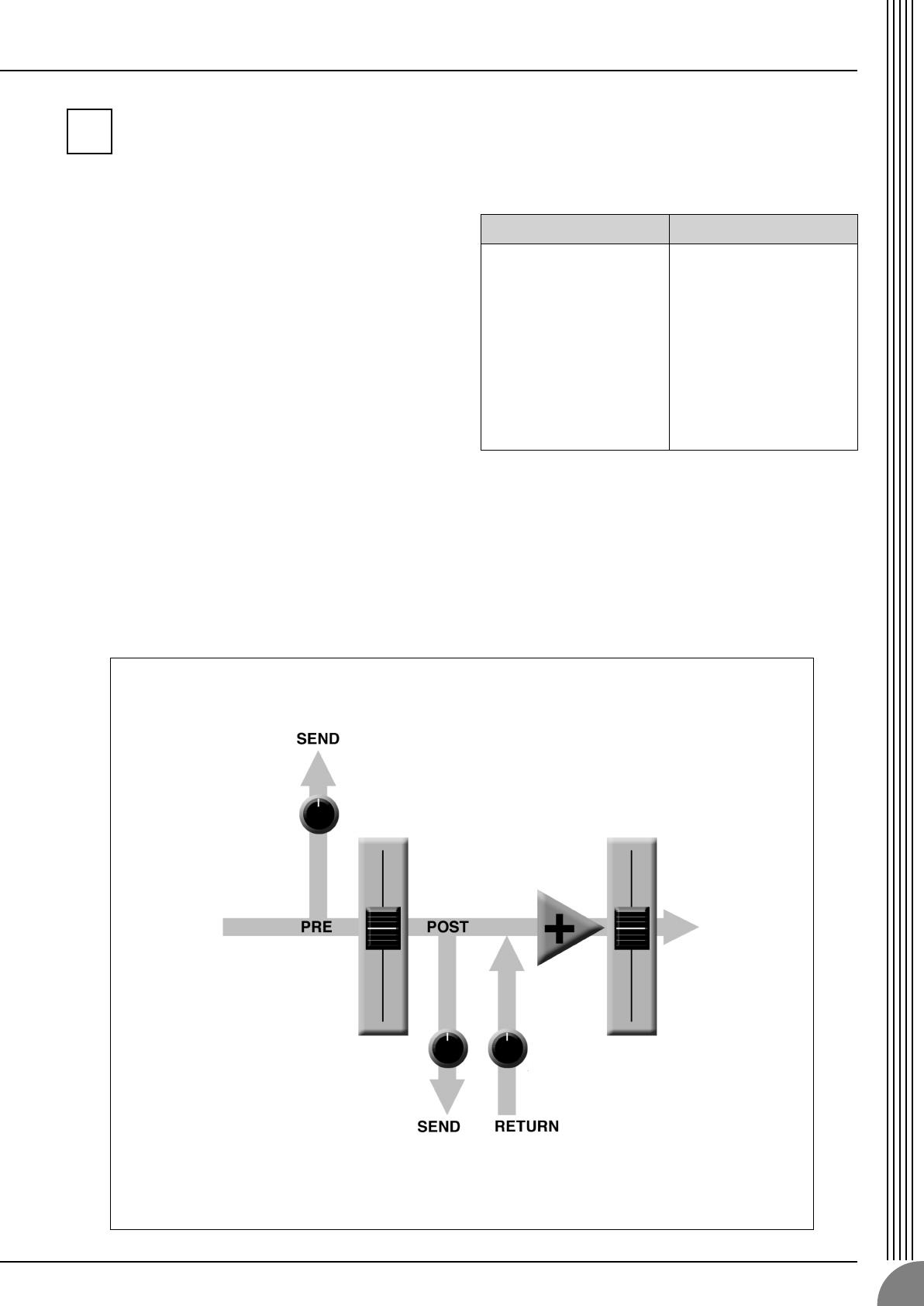
Making the Most Of Your Mixer
MG16/4, MG12/4
13
External Effects, Monitor Mixes, and Groups
4-1. AUX Buses For Monitor Sends and
Overall Effects
There are a number of reasons why you might
want to “tap” the signal flowing through your
mixer at some point before the main outputs: the
two most common being 1) to create a monitor
mix that is separate from the main mix, and 2) to
process the signal via an external effect unit and
then bring it back into the mix. Both of these func-
tions, and more, can be handled by the mixer’s
AUX (Auxiliary) buses and level controls. If the
mixer has two AUX buses, then it can handle both
functions at the same time. Larger mixing con-
soles can have 6, 8, or even more auxiliary buses
to handle a variety of monitoring and processing
needs.
Using the AUX buses and level controls is pretty
straightforward. The only thing you need to con-
sider is whether you need a “pre-fader” or “post-
fader” send. AUX sends often feature a switch that
allows you to configure them for pre- or post-
fader operation.
Pre/Post—What’s the difference?
4
pre post
A “pre-fader” signal is taken
from a point before the
channel fader, so the send
level is affected only by the
AUX send level control and
not by the channel fader.
Pre-fader sends are most
commonly used to provide
monitor mixes.
A “post-fader” signal is
taken from a point after the
channel fader, so its level
will be affected by both the
AUX send level control and
the channel fader.
Post-fader sends are most
commonly used in conjunc-
tion with the mixer’s AUX or
effect returns for external
effect processing.
Pre-fader send for a monitor mix. The send signal is fed to the monitor power amplifier and speaker system.
The channel fader does not affect the send level so the monitor mix remains independent of the main mix. No
return signal is used in this case.
Post-fader send for external effects processing. The send signal is fed to the external effect unit—a reverb
unit, for example—and the output from the effect unit is returned to the AUX Return jack and mixed back into the
main program. The send level is affected by the channel fader so the effect level always remains in proportion to
the channel signal.
Channel
Fader
Master
Fader
AUX Send
Level
AUX Send Level AUX Return Level
MG12-16_E.book Page 13 Monday, May 26, 2003 1:14 PM
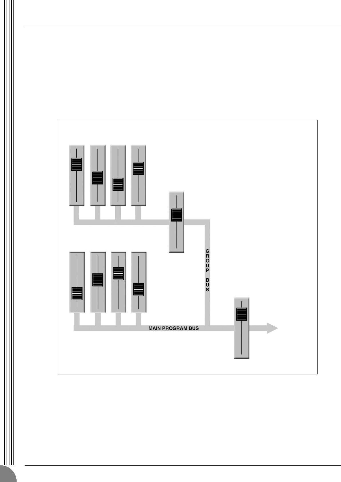
Making the Most Of Your Mixer
MG16/4, MG12/4
14
4-2. Using Groups
Group buses and faders can greatly simplify the mixing process—particularly in live situations in which
changes have to be made as quickly as possible. If you have a group of channels that need to be adjusted
all together while maintaining their relative levels, grouping is the way to go. Simply assign the group to a
group bus, and make sure that group is also assigned to the main program bus. Then you can adjust the
overall level of the group using a single group fader, rather than having to attempt to control multiple
channels faders simultaneously.
Group buses usually also have their own outputs, so you can send the group signal to a different external
destination from the main mix.
Channel faders Assigned to Group
(Controlled As a Group)
Stereo
Master
Fader
Group
Fader
Channel faders Assigned to Stereo
(Controlled Individually)
A group of channels whose levels need to
maintain the same relationship—a drum mix, for
example—can be assigned to a group bus.
Usually the group bus signal can be output
independently via “Group” outputs, or it can be
assigned to the main program (stereo) bus to be
mixed in with the main stereo program.
Once the mix between the channels assigned to
the group is established via the channel faders,
the overall level of the entire group can be
conveniently adjusted via a single group fader.
MG12-16_E.book Page 14 Monday, May 26, 2003 1:14 PM
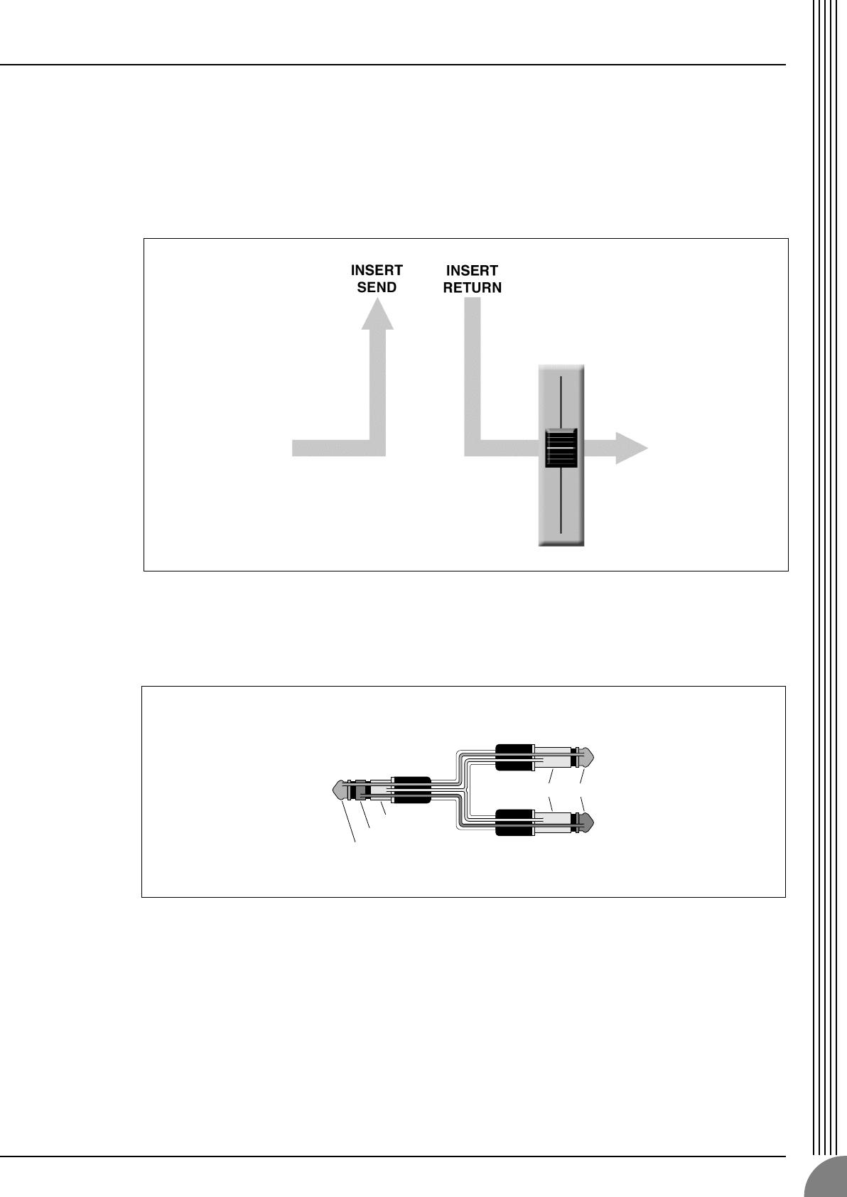
Making the Most Of Your Mixer
MG16/4, MG12/4
15
4-3. Channel Inserts for Channel-specific Processing
Another way to get the mixer’s signal outside the box is to use the channel inserts. The channel inserts are
almost always located before the channel fader and, when used, actually “break” the mixer’s internal sig-
nal path. Unlike the AUX sends and returns, the channel insert only applies to the corresponding chan-
nel. Channel inserts are most commonly used for applying a dynamics processor such as a compressor or
limiter to a specific channel—although they can be used with just about any type of in/out processor.
Channel insert jacks must be used with a special insert cable that has a TRS phone jack on one end and
mono phone jacks on the split “Y” end. One of the mono phone jacks carries the “send” signal to be fed
to the input of the external processor, and the other carries the “return” signal from the output of the pro-
cessor.
Channel
Fader
When a plug is inserted into the channel insert jack, the inter-
nal signal path is interrupted and sent outside the mixer for
external processing.
Tip
Ring
Sleeve
To the INSERT I/O jack
To the input jack of the
external processor
To the output jack of
the external processor
TipSleeve
MG12-16_E.book Page 15 Monday, May 26, 2003 1:14 PM
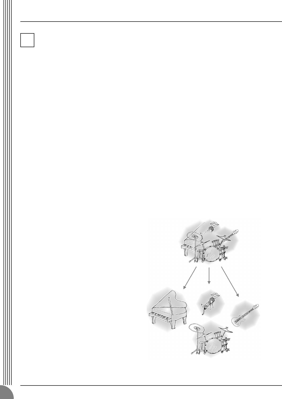
Making the Most Of Your Mixer
MG16/4, MG12/4
16
Making Better Mixes
5-1. Approaching the Mix—Where Do
You Start?
Mixing is easy, right? Just move the faders around
until it sounds right? Well, you can do it that way,
but a more systematic approach that is suited to
the material you’re mixing will produce much
better results, and faster. There are no rules, and
you’ll probably end up developing a system that
works best for you. But the key is to develop a
system rather than working haphazardly. Here are
a few ideas to get you started:
Faders Down
It might sound overly simple, but it is usually a
good idea to start with all channel faders off—all
the way down. It’s also possible to start with all
faders at their nominal settings, but it’s too easy to
lose perspective with this approach. Start with all
faders down, then bring them up one by one to fill
out the mix. But which channel should you start
with?
Example1:
Vocal Ballad Backed by Piano Trio
What are you mixing? Is it a song in which the
vocals are the most important element? If so you
might want to build the mix around the vocals.
This means bringing the vocal channel up to
nominal first (if your level setup procedure has
been done properly this will be a good starting
point), and then adding the other instruments.
What you add next will depend on the type of
material you are working with and your approach
to it. If the vocals are backed by a piano trio and
the song is a ballad, for example, you might want
to bring in the piano next and get the vocal/piano
relationship just right, then bring in the bass and
drums to support the overall sound.
Example2:
Funky R&B Groove
The approach will be totally different if you’re
mixing a funky R&B number that centers on the
groove. In this case most engineers will start with
the drums, and then add the bass. The relation-
ship between the drums and bass is extremely
important to achieve the “drive” or groove the
music rides on. Pay particular attention to how
the bass works with the kick (bass drum). They
should almost sound like a single instrument—
with the kick supplying the punch and the bass
supplying the pitch. Once again, there are no
rules, but these are concepts that have been
proven to work well.
Music First—Then Mix
In any case, the music comes first. Think about
the music and let it guide the mix, rather than try-
ing to do things the other way around. What is the
music saying and what instrument or technique is
being used to drive the message? That’s where the
focus of your mix should be. You’re using a high-
tech tool to do the mixing, but the mix itself is as
much art as the music. Approach it that way and
your mixes will become a vital part of the music.
5-2. Panning For Cleaner Mixes
Not only does the way you pan your individual
channels determine where the instruments appear
in the stereo sound field, but it is also vital to give
each instrument it’s own “space” so that it doesn’t
conflict with other instruments. Unlike live sound
in a real acoustic space, recorded stereo sound is
basically 2-dimensional (although some types of
surround sound are actually very 3-dimensional),
and instruments positioned right on top of each
other will often get in each other’s way—particu-
larly if they are in the same frequency range or
have a similar sound.
5
MG12-16_E.book Page 16 Monday, May 26, 2003 1:14 PM

Making the Most Of Your Mixer
MG16/4, MG12/4
17
Spread them Out!
Position your instruments so they have room to
“breathe,” and connect in the most musical way
with other instruments. Sometimes, however,
you’ll want to deliberately pan sounds close
together, or even right on top of one another, to
emphasize their relationship. There are no hard-
and-fast rules. Normally (but this is not a rule),
bass and lead vocals will be panned to center, as
will the kick drum if the drums are in stereo.
5-3. To EQ Or Not To EQ
In general: less is better. There are many situations
in which you’ll need to cut certain frequency
ranges, but use boost sparingly, and with caution.
Proper use of EQ can eliminate interference
between instruments in a mix and give the overall
sound better definition. Bad EQ—and most com-
monly bad boost—just sounds terrible.
Cut For a Cleaner Mix
For example: cymbals have a lot of energy in the
mid and low frequency ranges that you don’t
really perceive as musical sound, but which can
interfere with the clarity of other instruments in
these ranges. You can basically turn the low EQ
on cymbal channels all the way down without
changing the way they sound in the mix. You’ll
hear the difference, however, in the way the mix
sounds more “spacious,” and instruments in the
lower ranges will have better definition. Surpris-
ingly enough, piano also has an incredibly power—
ful low end that can benefit from a bit of low-
frequency roll-off to let other instruments—nota-
bly drums and bass—do their jobs more effec-
tively. Naturally you won’t want to do this if the
piano is playing solo.
The reverse applies to kick drums and bass gui-
tars: you can often roll off the high end to create
more space in the mix without compromising the
character of the instruments. You’ll have to use
your ears, though, because each instrument is dif-
ferent and sometimes you’ll want the “snap” of a
bass guitar, for example, to come through.
Boost With Caution
If you’re trying to create special or unusual
effects, go ahead and boost away as much as you
like. But if you’re just trying to achieve a good-
sounding mix, boost only in very small incre-
ments. A tiny boost in the midrange can give
vocals more presence, or a touch of high boost
can give certain instruments more “air.” Listen,
and if things don’t sound clear and clean try using
cut to remove frequencies that are cluttering up
the mix rather than trying to boost the mix into
clarity.
One of the biggest problems with too much boost
is that it adds gain to the signal, increasing noise
and potentially overloading the subsequent cir—
cuitry.
5-4. Ambience
Judicious application of reverb and/or delay via
the mixer’s AUX busses can really polish a mix,
but too much can “wash out” the mix and reduce
overall clarity. The way you set up your reverb
sound can make a huge difference in the way it
meshes with the mix.
Reverb/Delay Time
Different reverb/delay units offer different capabil-
ities, but most offer some means of adjusting the
reverb time. A little extra time spent matching the
reverb time to the music being mixed can mean
the difference between great and merely average
sound. The reverb time you choose will depend
to a great degree on the tempo and “density” of
the mix at hand. Slower tempos and lower densi-
ties (i.e. sparser mixes with less sonic activity) can
sound good with relatively long reverb times. But
long reverb times can completely wash out a
faster more active piece of music. Similar princi-
ples applies to delay.
Reverb Tone
How “bright” or “bassy” a reverb sound is also
has a huge impact on the sound of your mix. Dif-
ferent reverb units offer different means of con-
trolling this—balance between the high- and low-
frequency reverb times, simple EQ, and others. A
reverb that is too bright will not only sound unnat-
ural, but it will probably get in the way of delicate
highs you want to come through in your mix. If
you find yourself hearing more high-end reverb
than mix detail, try reducing the brightness of the
reverb sound. This will allow you to get full-bod-
ied ambience without compromising clarity.
Reverb Level
It’s amazing how quickly your ears can lose per—
spective and fool you into believing that a totally
washed-out mix sounds perfectly fine. To avoid
falling into this trap start with reverb level all the
way down, then gradually bring the reverb into
the mix until you can just hear the difference. Any
more than this normally becomes a “special
effect.” You don’t want reverb to dominate the
mix unless you are trying to create the effect of a
band in a cave—which is a perfectly legitimate
creative goal if that’s the sort of thing you’re aim-
ing for.
MG12-16_E.book Page 17 Monday, May 26, 2003 1:14 PM
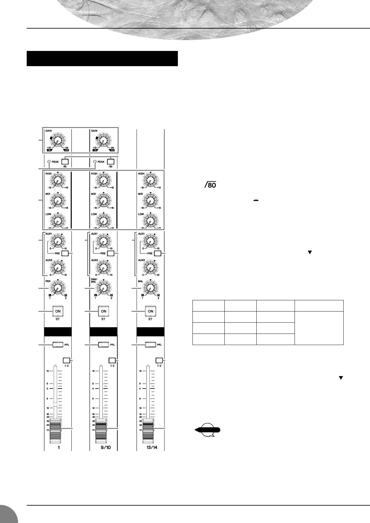
MG16/4, MG12/4
18
Front & Rear Panels
Note: Within this manual, all panel illustrations show the
MG16/4 panel.
1 GAIN Control
Adjusts the input signal level.
To get the best balance between the S/N ratio and the dynamic
range, adjust the level so that the peak indicator (
2) comes on
only at about maximum input level.
The –60 to –16 scale indicates the MIC input adjustment level.
The –34 to +10 scale indicates the LINE input adjustment
level.
2 PEAK Indicator
Detects the peak level of the post-EQ signal, and lights up red
when the level reaches 3 dB below the clipping level. For
XLR-equipped stereo input channels (9/10 and 11/12 on the
MG16/4; 5/6 and 7/8 on the MG12/4), detects both post-EQ
and post-mic-amp peak levels, and lights red if either of these
levels reaches 3 dB below the clipping level.
3 Switch (High Pass Filter)
This switch toggles the HPF on or off. To turn the HPF on,
press the switch in ( ). The HPF cuts frequencies below
80 Hz. (But note that regardless of the switch setting, the mixer
does not apply this HPF to the line inputs of stereo input chan-
nels.)
4 Equalizer (HIGH, MID, and LOW)
This three-band equalizer adjusts the channel’s high, mid, and
low frequency bands. Setting the knob to the position pro-
duces a flat frequency response. Turning the knob to the right
boosts the corresponding frequency band, while turning to the
left attenuates the band. The following table shows the EQ
type, base frequency, and maximum cut/boost for each of the
three bands.
5 AUX1 and AUX2 Controls
The AUX1 knob controls the signal level that the channel sends
to the AUX1 bus; the AUX2 knob controls the signal level to
the AUX2 bus. The knob should generally be set close to the
position.
If you are using stereo channels, the signals from the L (odd)
and R (even) channels are mixed and sent to the AUX1 and
AUX2 buses.
Allows you to output the signal to the buses regard-
less of the setting of the ST switch 8.
Channel Control Section
1
7
8
9
5 5 5
6 6 6
A
0
7
8
9
0
7
8
9
0
A A
3
4
2
Channels
1 to 8 (MG16/4)
1 to 4 (MG12/4)
(Monaural)
Channels
13/14 and 15/16
(MG16/4)
9/10 and 11/12
(MG12/4)
(Stereo)
Channels
9/10 and 11/12
(MG16/4)
5/6 and 7/8
(MG12/4)
(Stereo)
Band Type Base Frequency Maximum Cut/Boost
HIGH Shelving 10 kHz
±15 dBMID Peaking 2.5 kHz
LOW Shelving 100 Hz
NOTE
MG12-16_E.book Page 18 Monday, May 26, 2003 1:14 PM
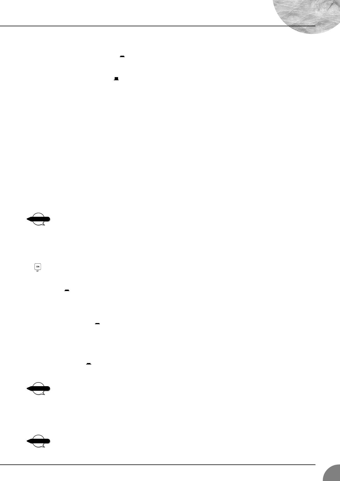
Front & Rear Panels
MG16/4, MG12/4
19
6 PRE Switch
Selects whether the pre-fader or the post-fader signal is fed to
the AUX1 bus. If you set the switch on ( ), the mixer sends
the pre-fader signal (the signal prior to passage though channel
fader
A) to the AUX1 bus, so that AUX1 output is not affected
by the fader. If you set the switch off ( ) the mixer sends the
post-fader signal to the AUX1 bus.
Note that this switch applies to AUX1 only. The signal to the
AUX2 bus always passes through the channel fader first.
7 PAN Control (MG16/4: CHs 1 to 8.
MG12/4: 1 to 4.)
PAN/BAL Control (MG16/4: 9/10 and 11/12.
MG12/4: 5/6 and 7/8.)
BAL Control (MG16/4: 13/14 and 15/16.
MG12/4: 9/10 and 11/12.)
The PAN control determines the positioning of the channel’s
signal on the Group 1 and 2 buses or on the Stereo L and R
buses.
The BAL control knob sets the balance between left and right
channels. Signals into to the L input (odd channel) feed to the
Group 1 bus or to the Stereo L bus; signals into the R input
(even channel) feed to the Group 2 bus or the Stereo R bus.
On channels where this knob provides both PAN
and BAL controls (9/10 and 11/12 on the MG16/4;
5/6 and 7/8 on the MG12/4), the knob operates as a
PAN control if you are inputting through the MIC
jack or into the L (MONO) input only, and operates
as a BAL control if you are inputting into both L and
R inputs.
8 ST Switch
This switch assigns the channel’s signal to the Stereo L and R
buses. To send the signal to the Stereo bus, set the switch on by
pressing it in ( ). The switch lights up orange to indicate that
it is on.
9 PFL (Pre-Fader Listen) Switch
This switch lets you monitor the channel’s pre-fader signal. To
set the switch on, press it in ( ) so that it lights up. When the
switch is on, the mixer outputs the channel’s pre-fader signal to
the PHONES and C-R OUT jacks, for monitoring.
0 GROUP Switch
Use this switch to assign the channel’s signal to the Group out-
put. Press the switch in ( ) to output the signal to the Group
1 and 2 buses.
Allows you to output the signal to the buses regard-
less of the setting of the ST switch
8.
A Channel Fader
Adjusts the output level of the signal being input to the chan-
nel. Use these faders to adjust the volume balance among the
various channels.
To reduce noise, set the fader sliders for unused
channels all the way down.
NOTE
NOTE
NOTE
MG12-16_E.book Page 19 Monday, May 26, 2003 1:14 PM

Front & Rear Panels
MG16/4, MG12/4
20
1
ST Master Fader
Adjusts the signal level to the ST OUT jacks.
2
GROUP 1-2 Fader
Adjusts the signal level to the GROUP OUT 1 and GROUP
OUT 2 jacks.
3
TO ST Switch
If this switch is on ( ), the mixer sends the signals processed
by the GROUP 1-2 fader (
2
) onto the Stereo bus. The Group 1
signal goes to Stereo L and the Group 2 signal goes to Stereo
R.
4
Master SEND (AUX1 and AUX2 Controls)
Adjust the signal level, respectively. These are the signals that
are output to the AUX1 and AUX2 SEND jacks.
5
RETURN (AUX1, AUX2, and ST Controls)
•AUX1 and AUX2 Controls
Adjust the level of the mixed L/R signal sent from the
RETURN jacks (L (MONO) and R) to the AUX1 and AUX2
buses.
• ST Control
Adjust the level of the signal sent from the RETURN jacks (L
(MONO) and R) to the Stereo bus.
If you supply a signal to the RETURN L (MONO)
jack only, the mixer outputs the identical signal to
both the L and R Stereo buses.
6
2TR IN Control
Adjusts the level of the signal sent from the 2TR IN jack to the
Stereo bus.
7
PHANTOM +48 V Switch
This switch toggles phantom power on and off. If you set the
switch on, the mixer supplies power to all channels that provide
XLR mic input jacks (CHs 1–8, 9/10, 11/12 on MG16/4, 1–4,
5/6, 7/8 on MG12/4). Set this switch on when using one or
more condenser microphones.
When this switch is on, the mixer supplies DC +48 V
power to pins 2 and 3 of all XLR-type MIC INPUT
jacks.
• Be sure to leave this switch OFF when you are not
using phantom power. Humming or damage may
result if you connect to an unbalanced device or to
an ungrounded transformer while this switch is on.
But note that the switch may be left on without
problem when connecting to balanced dynamic
microphones.
•To avoid damage to speakers, be sure to turn off
amplifiers (or powered speakers) before turning this
switch on or off.
Master Control Section
B
76
A
9
4
3
2
1
5
0
8
NOTE
NOTE
MG12-16.fm Page 20 Thursday, December 11, 2003 9:03 AM