-
Contents
-
Table of Contents
-
Troubleshooting
-
Bookmarks
Quick Links
U
HTR-5940
AV Receiver
OWNER’S MANUAL
Related Manuals for Yamaha HTR-5940 AV
Summary of Contents for Yamaha HTR-5940 AV
-
Page 1
HTR-5940 AV Receiver OWNER’S MANUAL… -
Page 2: Important Safety Instructions
IMPORTANT SAFETY INSTRUCTIONS IMPORTANT SAFETY INSTRUCTIONS CAUTION RISK OF ELECTRIC SHOCK DO NOT OPEN CAUTION: TO REDUCE THE RISK OF ELECTRIC SHOCK, DO NOT REMOVE COVER (OR BACK). NO USER-SERVICEABLE PARTS INSIDE. REFER SERVICING TO QUALIFIED SERVICE PERSONNEL. • Explanation of Graphical Symbols The lightning flash with arrowhead symbol, within an equilateral triangle, is intended to alert you to the presence of uninsulated “dangerous voltage”…
-
Page 3
This product, when installed as indicated in the instructions contained in this manual, meets FCC requirements. Modifications not expressly approved by Yamaha may void your authority, granted by the FCC, to use the product. 2 IMPORTANT: When connecting this product to accessories and/or another product use only high quality shielded cables. -
Page 4
– and, most importantly, without affecting your sensitive hearing. Since hearing damage from loud sounds is often undetectable until it is too late, YAMAHA and the Electronic Industries Association’s Consumer Electronics Group recommend you to avoid prolonged exposure from excessive volume levels. -
Page 5: Table Of Contents
INTRODUCTION FEATURES… 2 GETTING STARTED… 3 Supplied accessories … 3 Installing batteries in the remote control … 3 CONTROLS AND FUNCTIONS … 4 Front panel … 4 Remote control… 6 Front panel display … 9 Rear panel … 11 PREPARATION CONNECTIONS …
-
Page 6: Features
Center: 90 W Surround: 90 W + 90 W Surround back: 90 W Sound field features Proprietary YAMAHA technology for the creation of sound fields Dolby Digital/Dolby Digital EX decoder DTS/DTS-ES Matrix 6.1, Discrete 6.1, DTS Neo:6, DTS 96/24 decoder…
-
Page 7: Getting Started
Supplied accessories Check that you received all of the following parts. Remote control Batteries (2) (AA, R6, UM-3) CODE SET TRANSMIT POWER POWER STANDBY POWER SLEEP CD-R MULTI CH IN TUNER V-AUX SOURCE TV VOL TV CH VOLUME TV MUTE TV INPUT MUTE STEREO…
-
Page 8: Controls And Functions
CONTROLS AND FUNCTIONS CONTROLS AND FUNCTIONS Front panel Note The XM Satellite Radio controlling functions in the following buttons (SEARCH MODE, CATEGORY, PRESET/TUNING/CH l / h, MEMORY, and DISPLAY) are only applicable to the U.S.A. model and are operational only when “XM” is selected as the input source. For details, see “XM Satellite Radio controls and functions”…
-
Page 9: Front Panel Display
8 Front panel display Shows information about the operational status of this unit (see page 9). 9 TUNING MODE (AUTO/MAN’L) Switches between automatic tuning (the AUTO indicator is turned on) and manual tuning (the AUTO indicator is turned off) (see page 44). 0 VOLUME Controls the output level of all audio channels.
-
Page 10
CONTROLS AND FUNCTIONS Remote control This section describes the function of each control on the remote control used to control this unit. To operate other components, see “REMOTE CONTROL FEATURES” on page 86. Notes • The XM Satellite Radio controlling functions in the following buttons (XM, XM MEMORY, SRCH MODE, DISPLAY, cursor buttons u / d / j / i, numeric buttons and ENT.) are only applicable to the U.S.A. -
Page 11
8 Cursor buttons u / d / j / i, ENTER Select and adjust the sound field program parameters or the “SET MENU” parameters. 9 RETURN Returns to the previous menu level when adjusting the “SET MENU” parameters. 0 TRANSMIT indicator Flashes while the remote control is sending infrared signals. -
Page 12: Using The Remote Control
CONTROLS AND FUNCTIONS Controlling the TUNER functions Set the component selector switch to SOURCE and then press TUNER to select “TUNER” as the input source. 4 Numeric buttons Use numbers 1 through 8 to select preset stations. 7 BAND Switches the reception band between FM and AM (see page 44).
-
Page 13
Front panel display Note The XM is only applicable to the U.S.A. model and the cursor on the left of the XM indicator lights up only when “XM” is selected as the input source. For details, see “Basic XM Satellite Radio operations” on page 54. MATRIX DISCRETE VIRTUAL STANDARD… -
Page 14
CONTROLS AND FUNCTIONS F Headphones indicator Lights up when headphones are connected (see page 32). G NIGHT indicator Lights up when you select a night listening mode (see page 32). H HiFi DSP indicator Lights up when you select a HiFi DSP sound field program (see page 63). -
Page 15: Rear Panel
Rear panel AUDIO AUDIO MULTI CH INPUT SURROUND CD-R FRONT (PLAY) (REC) DTV/CBL MONITOR DTV/CBL VIDEO S VIDEO TUNER FM ANT FRONT 75Ω UNBAL. 1 Video component jacks See pages 18 and 19 for connection information. 2 Audio component jacks See page 21 for connection information.
-
Page 16: Connections
Subwoofer (SW) The use of a subwoofer with a built-in amplifier, such as the YAMAHA Active Servo Processing Subwoofer System, is effective not only for reinforcing bass frequencies from any or all channels, but also for hi-fi stereo reproduction of the LFE (low-frequency effect) channel included in Dolby Digital and DTS sources.
-
Page 17: Connecting Speakers
Connecting speakers Be sure to connect the left channel (L), right channel (R), “+” (red) and “–” (black) properly. If the connections are faulty, no sound will be heard from the speakers, and if the polarity of the speaker connections is incorrect, the sound will be unnatural and lack bass.
-
Page 18
Connect surround speakers (4, 5) to these terminals. SURROUND BACK terminals Connect a surround back speaker (6) to these terminals. SUBWOOFER jack Connect a subwoofer with a built-in amplifier (7) (such as the YAMAHA Active Servo Processing Subwoofer System) to this jack. Speaker layout… -
Page 19
Connecting the speaker cable Remove approximately 10 mm (0.4 in) of insulation from the end of each speaker cable and then twist the exposed wires of the cable together to prevent short circuits. 10 mm (0.4 in) Loosen the knob. Red: positive (+) Black: negative (–) Insert one bare wire into the hole on the side… -
Page 20: Information On Jacks And Cable Plugs
CONNECTIONS Information on jacks and cable plugs Audio jacks and cables AUDIO PORTABLE DIGITAL AUDIO (White) (Red) (Orange) Left and right Stereo Coaxial analog audio analog digital cable plug audio audio cable mini cable plug Audio jacks This unit has four types of audio jacks. Connection depends on the availability of audio jacks on your other components.
-
Page 21: Audio And Video Signal Flow
Audio and video signal flow Audio signal flow for AUDIO OUT (REC) AUDIO PORTABLE Analog output Note This unit handles digital and analog signals independently. Thus, audio signals input at the analog jacks are output only at the analog AUDIO OUT (REC) jacks. Video signal flow for MONITOR OUT Input COMPONENT…
-
Page 22: Connecting A Tv
CONNECTIONS Connecting a TV Connect your TV to the VIDEO MONITOR OUT jack, the S VIDEO MONITOR OUT jack or the COMPONENT VIDEO MONITOR OUT jacks of this unit. CAUTION Do not connect this unit or other components to the AC power supply until all connections between components are complete.
-
Page 23: Connecting A Dvd Player, A Dvd Recorder, A Vcr Or An Stb
Connecting a DVD player, a DVD recorder, a VCR or an STB Connect your DVD player, DVD player, VCR or STB (set-top box) using the same type of video connections as those made for your TV (see page 18). The cable TV receiver and the satellite receiver are examples of the STB. CAUTION Do not connect this unit or other components to the AC power supply until all connections between components are complete.
-
Page 24
CONNECTIONS Connecting a DVD recorder or a VCR AUDIO VIDEO S VIDEO Audio in Video in Video out Audio out Connecting an STB Cable TV receiver or Audio out Video out S-video out AUDIO DTV/CBL DTV/CBL VIDEO S VIDEO S-video out S-video in Component video out DVD recorder or… -
Page 25: Connecting A Cd Player, An Md Player Or A Tape Deck
Connecting a CD player, an MD player or a tape deck Connect your CD player, MD player or tape deck via analog connection. CAUTION Do not connect this unit or other components to the AC power supply until all connections between components are complete.
-
Page 26: Connecting A Multi-Format Player Or An External Decoder
CONNECTIONS Connecting a multi-format player or an external decoder This unit is equipped with 6 additional input jacks (FRONT L/R, CENTER, SURROUND L/R and SUBWOOFER) for discrete multi-channel input from a multi-format player, external decoder, sound processor or pre-amplifier. Connect the output jacks on your multi- format player or external decoder to the MULTI CH INPUT jacks.
-
Page 27: Connecting The Fm And Am Antennas
• A properly installed outdoor antenna provides clearer reception than an indoor one. If you experience poor reception quality, install an outdoor antenna. Consult the nearest authorized YAMAHA dealer or service center about outdoor antennas. AM loop antenna (supplied) Indoor FM antenna (supplied) (U.S.A.
-
Page 28: Connecting The Power Cable
CONNECTIONS Connecting the power cable Once all connections are complete, plug the power cable into the AC wall outlet. CAUTION VOLTAGE SELECTOR (Asia and General models only) The VOLTAGE SELECTOR on the rear panel of this unit must be set for your local voltage BEFORE plugging the power cable into the AC wall outlet.
-
Page 29: Setting The Speaker Impedance
Setting the speaker impedance CAUTION If you are to use 4 or 6 ohm speakers, set “SP IMP.” to “6ΩMIN” as follows BEFORE using this unit. STANDBY PRESET/TUNING FM/AM A/B/C/D/E l PRESET/TUNING/CH h MEMORY CATEGORY SEARCH MODE EDIT NEXT LEVEL MAN’L/AUTO FM INPUT STRAIGHT…
-
Page 30: Turning On This Unit Or Setting It To The Standby Mode
CONNECTIONS Turning on this unit or setting it to the standby mode When all connections are complete, turn on this unit. STANDBY/ON STANDBY l PRESET/TUNING/CH h PRESET/TUNING FM/AM A/B/C/D/E MEMORY SEARCH MODE CATEGORY EDIT NEXT LEVEL MAN’L/AUTO FM STRAIGHT PROGRAM PHONES SPEAKERS INPUT MODE…
-
Page 31: Basic Setup
The “BASIC SETUP” feature is a useful way to set up your system quickly and with minimal effort. Notes • Make sure you disconnect your headphones from this unit. • If you wish to configure this unit manually using more precise adjustments, use the detailed parameters in “SOUND MENU” (see page 78).
-
Page 32
BASIC SETUP Press d to select “SUBWOOFER” and then j / i to select the desired setting. PRESET/CH ENTER A-E/CAT. A-E/CAT. A-E/CAT. SUBWOOFER .. YES Choices: YES, NONE • Select “YES” if you have a subwoofer in your system. • Select “NONE” if you do not have a subwoofer in your system. -
Page 33
Press j / i to select the desired setting. PRESET/CH ENTER A-E/CAT. A-E/CAT. CHECK OK? .. YES Choices: YES, NO • Select “YES” to complete the setup procedure if the test tone levels from each speaker were satisfactory. • Select “NO” to proceed to the speaker level adjustment menu to balance the output level of each speaker. -
Page 34: Playback
PLAYBACK CAUTION Extreme caution should be exercised when you play back CDs encoded in DTS. If you play back a CD encoded in DTS on a DTS-incompatible CD player, you will only hear some unwanted noise that may damage your speakers. Check whether your CD player supports CDs encoded in DTS. Also, check the sound output level of your CD player before you play back a CD encoded in DTS.
-
Page 35
Rotate VOLUME on the front panel (or press VOLUME +/– on the remote control) to adjust the volume to the desired output level. VOLUME Front panel Press TONE CONTROL on the front panel repeatedly to select “TREBLE” or “BASS” and then press BASS/TREBLE +/– buttons to adjust the corresponding frequency response level. -
Page 36: Using Other Features
USING OTHER FEATURES Using SILENT CINEMA SILENT CINEMA allows you to enjoy multi-channel music or movie sound, including Dolby Digital and DTS sources, through ordinary headphones. SILENT CINEMA activates automatically whenever you connect headphones to the PHONES jack while listening to CINEMA DSP or HiFi DSP sound field programs (see page 63).
-
Page 37: Selecting The Input Mode
“NIGHT:CINEMA” and “NIGHT:MUSIC” adjustments are stored independently. Notes • You cannot use the night listening modes when the “DIRECT STEREO” program (see page 38) is selected or when the component connected to the MULTI CH INPUT jacks is selected as the input source (see page 37) even though the NIGHT indicator lights up when “DIRECT STEREO”…
-
Page 38: Using The Sleep Timer
USING OTHER FEATURES Using the sleep timer Use this feature to automatically set this unit to the standby mode after a certain amount of time. The sleep timer is useful when you are going to sleep while this unit is playing or recording a source. The sleep timer also automatically turns off any external components connected to AC OUTLET(S) (see page 24).
-
Page 39: Adjusting The Speaker Level
Adjusting the speaker level You can adjust the output level of each speaker while listening to a music source. This is also possible when playing sources input at the MULTI CH INPUT jacks. Note This operation will override the level adjustments made in “BASIC SETUP”…
-
Page 40: Selecting The Compressed Music Enhancer Mode
USING OTHER FEATURES Selecting the Compressed Music Enhancer mode Compression artifacts (such as the MP3 format) are created by a lossy compression scheme where the audio is resampled to lower the bitrate and to remove sounds that are indistinguishable to typical human hearing. The Compressed Music Enhancer feature of this unit enhances your listening experience by regenerating the missing harmonics in a compression artifact.
-
Page 41: Selecting The Multi Ch Input Component
Selecting the MULTI CH INPUT component Use this feature to select the component connected to the MULTI CH INPUT jacks (see page 22) as the input source. Press MULTI CH INPUT on the front panel (or MULTI CH IN on the remote control) so that “MULTI CH INPUT”…
-
Page 42: Enjoying Pure Hi-Fi Stereo Sound
USING OTHER FEATURES Enjoying pure hi-fi stereo sound The “DIRECT STEREO” mode allows sources to bypass the decoders and DSP processors of this unit so that you can enjoy pure hi-fi sound from 2-channel PCM and analog sources. Set the component selector switch to AMP and then press DIRECT ST.
-
Page 43: Playing Video Sources In The Background
The following information appears in the front panel display for a few seconds. Signal format Signal format display. When this unit cannot detect a digital signal, it automatically switches to analog input. Display status: Analog, Digital, Dolby Digital, DTS, PCM, Unknown Digital Note “Unknown Digital”…
-
Page 44: Enjoying Surround Sound
ENJOYING SURROUND SOUND ENJOYING SURROUND SOUND Enjoying multi-channel sources in surround If you connected a surround back speaker, use this feature to enjoy 6.1-channel playback for multi-channel sources using the Dolby Pro Logic IIx, Dolby Digital EX or DTS-ES decoders. Set the component selector switch to AMP and then press EXTD SUR.
-
Page 45: Enjoying 2-Channel Sources In Surround
Enjoying 2-channel sources in surround Signals input from 2-channel sources can also be played back on multi-channels. Set the component selector switch to AMP and then press STANDARD on the remote control repeatedly to switch between the “SUR. STANDARD” and “SUR. ENHANCED” programs or press MOVIE to select the “MOVIE THEATER”…
-
Page 46: Using Virtual Cinema Dsp
ENJOYING SURROUND SOUND Using Virtual CINEMA DSP Virtual CINEMA DSP allows you to enjoy the CINEMA DSP programs without surround speakers. It creates virtual speakers to reproduce the natural sound field. If you set “SUR. LR” NONE” (see page 78), Virtual to “…
-
Page 47: Recording
Recording adjustments and other operations are performed from the recording components. Refer to the operating instructions for those components. Notes • When this unit is set to the standby mode, you cannot record between other components connected to this unit. •…
-
Page 48: Fm/Am Tuning
FM/AM TUNING There are 2 tuning methods: automatic and manual. Automatic tuning is effective when station signals are strong and there is no interference. If the signal from the station you want to select is weak, tune into it manually. You can also use the automatic and manual preset tuning features to store up to 40 stations (A1 to E8: 8 preset station numbers in each of the 5 preset station groups).
-
Page 49: Manual Tuning
Manual tuning If the signal received from the station you want to select is weak, tune into it manually. Note Manually tuning into an FM station automatically switches the tuner to monaural reception to increase the signal quality. STANDBY l PRESET/TUNING/CH h PRESET/TUNING FM/AM A/B/C/D/E…
-
Page 50: Automatic Preset Tuning
FM/AM TUNING Automatic preset tuning You can use the automatic preset tuning feature to store FM stations with strong signals up to 40 (A1 to E8: 8 preset station numbers in each of the 5 preset station groups) of those stations in order. You can then recall any preset station easily by selecting the preset station number.
-
Page 51: Manual Preset Tuning
Automatic preset tuning options You can specify the preset number from which this unit stores FM stations and/or begins tuning toward lower frequencies. Note First carry out steps 1 through 3 in “Automatic preset tuning” on page 46. • Press A/B/C/D/E and then PRESET/TUNING/ CH l / h to select the preset station number under which the first station will be stored.
-
Page 52: Selecting Preset Stations
FM/AM TUNING Press PRESET/TUNING/CH l / h to select a preset station number (1 to
 while the MEMORY indicator is flashing. • Press h to select a higher preset station number. • Press l to select a lower preset station number. l PRESET/TUNING/CH h LEVEL V-AUX…
 -
Page 53: Exchanging Preset Stations
Press PRESET/TUNING/CH l / h on the front panel (or PRESET/CH u / d on the remote control) to select the desired preset station number (1 to 8). The preset station group and number appear in the front panel display along with the station band and frequency.
-
Page 54
FM/AM TUNING Select preset station “A5” using A/B/C/D/E and PRESET/TUNING/CH l / h. “A5” and the MEMORY indicator flash in the front panel display. See “Selecting preset stations” on page 48. PRESET/TUNING A/B/C/D/E SEARCH MODE CATEGORY NEXT V-AUX DTV/CBL A5:FM 90.6 MHz Flashes Press EDIT again. -
Page 55: Xm ® Satellite Radio Tuning
® XM Satellite Radio is the satellite radio service with millions of listeners across the United States, broadcasting live daily. The XM Satellite Radio channel lineup includes more than 150 digital channels of choice from coast to coast: 67 commercial-free music channels, featuring hip hop to opera, classical to country, bluegrass to blues; 33 channels of premier sports, talk, comedy, children’s and entertainment programming;…
-
Page 56: Xm Satellite Radio Controls And Functions
XM® SATELLITE RADIO TUNING XM Satellite Radio controls and functions Note The following controls are available only when “XM” is selected as the input source. Rotate the INPUT selector on the front panel (or set the component selector switch to SOURCE and then press XM on the remote control) to select “XM” as the input source. Front panel functions (U.S.A.
-
Page 57: Activating Xm Satellite Radio
Activating XM Satellite Radio To sign up for an account with the XM Satellite Radio service, an XM Satellite Radio ID number is required. Follow the procedure below to check your ID number, and then visit the website at “http://activate.xmradio.com” or call “1-800-XM-RADIO (1-800-967-2346)”…
-
Page 58: Basic Xm Satellite Radio Operations
XM® SATELLITE RADIO TUNING Basic XM Satellite Radio operations SLEEP CD-R MULTI CH IN TUNER V-AUX SOURCE TV VOL TV CH VOLUME TV MUTE TV INPUT MUTE STEREO MUSIC ENTERTAIN MOVIE (U.S.A. model) Set the component selector switch to SOURCE and then press XM on the remote control to select “XM”…
-
Page 59: Selecting The Xm Satellite Radio Search Mode
Selecting the XM Satellite Radio search mode You can search for the desired channel using one of the three search modes (All Channel Search, Category Search, and Preset Search modes). You can also enter the channel number directly to select the desired channel by using the Direct Number Access mode (see page 58).
-
Page 60: Category Search Mode
XM® SATELLITE RADIO TUNING Category Search mode STANDBY l PRESET/TUNING/CH h PRESET/TUNING FM/AM A/B/C/D/E MEMORY SEARCH MODE CATEGORY EDIT NEXT LEVEL MAN’L/AUTO FM INPUT STRAIGHT PROGRAM PHONES SPEAKERS INPUT MODE EFFECT TONE CONTROL BASS/TREBLE SILENT CINEMA STEREO SLEEP CD-R MULTI CH IN STANDARD TUNER SPEAKERS…
-
Page 61
Preset Search mode Prior to selecting a preset channel in the Preset Search mode, you must preset XM Satellite Radio channels. For details, see “Setting the XM Satellite Radio preset channels” on page 59. All preset channels (A1 to E8) recalls “001 Preview” by the initial factory setting. -
Page 62: Direct Number Access Mode
XM® SATELLITE RADIO TUNING Direct Number Access mode STEREO SLEEP CD-R MULTI CH IN STANDARD TUNER SPEAKERS V-AUX LEVEL TITLE SOURCE BAND TV VOL TV CH VOLUME A-E/CAT. RETURN TV MUTE TV INPUT MUTE XM MEMORY STEREO MUSIC ENTERTAIN MOVIE (U.S.A.
-
Page 63: Setting The Xm Satellite Radio Preset Channels
Setting the XM Satellite Radio preset channels You can use this feature to store up to 40 XM Satellite Radio channels (A1 to E8: 8 preset channel numbers in each of the 5 preset channel groups). You can then recall any preset channel easily by selecting the preset channel group and number as described in “Preset Search mode”…
-
Page 64: Displaying The Xm Satellite Radio Information
XM® SATELLITE RADIO TUNING Press PRESET/TUNING/CH l / h on the front panel (or PRESET/CH u / d on the remote control) repeatedly to select a preset channel number (1 to
while the MEMORY indicator is flashing. The preset channel number appears in the front panel display. -
Page 65
When the channel number / name is displayed: V-AUX DTV/CBL MD/CD-R [040] Deep Tra When the channel category is displayed: V-AUX DTV/CBL MD/CD-R <CAT>Rock When the artist name / song title is displayed: V-AUX DTV/CBL MD/CD-R Coldplay / Clo • The front panel display can indicate up to 14 alphanumeric characters at once. -
Page 66: Sound Field Programs
The acoustics in your room could be changed to those of a concert hall, a dance floor, or a room with virtually any size at all. This ability to create sound fields at will is exactly what YAMAHA has done with the digital sound field processor.
-
Page 67: Sound Field Program Descriptions
(DSP) chip containing several sound field programs which you can use to enhance your playback experience. The YAMAHA CINEMA DSP modes are compatible with all Dolby Digital, DTS, and Dolby Surround sources. Set “INPUT MODE” to “AUTO” (see page 33) to enable this unit to automatically switch to the appropriate digital decoder according to the input signal.
-
Page 68: For Music Sources
SOUND FIELD PROGRAMS Remote control Sound FIeld Program button MOVIE THEATER Spectacle MOVIE THEATER Sci-Fi MOVIE THEATER Adventure MOVIE THEATER General SUR. STANDARD SUR. ENHANCED For music sources You can select from the following sound fields when playing music sources, like CD, FM/AM broadcasting, tapes, etc. Press the PROGRAM l / h buttons on the front panel (or set the component selector switch to AMP and then press one of the sound field program selector buttons on the remote control) to select the desired sound field program (see page 62).
-
Page 69: Changing Sound Field Parameter Settings
Changing sound field parameter settings You can enjoy good quality sound with the initial factory settings. Although you do not have to change the initial factory settings, you can change some of the parameters to better suit the input source or your listening room. Notes •…
-
Page 70: Sound Field Parameter Descriptions
SOUND FIELD PROGRAMS Sound field parameter descriptions You can adjust the values of certain digital sound field parameters so that the sound fields are recreated accurately in your listening room. Not all of the following parameters are found in every program. To change sound field parameter settings to suit your listening environment, see page 65 for details.
-
Page 71
Sound field parameter ROOM SIZE Room size. Presence, surround and surround back room size. Adjusts the apparent size of the surround sound field. The larger the value, the larger the surround sound field becomes. As the P.ROOM SIZE sound is repeatedly reflected around a room, the larger the hall is, the longer the time between S.ROOM SIZE the original reflected sound and the subsequent reflections. -
Page 72
SOUND FIELD PROGRAMS Sound field parameter REV.TIME Reverberation time. Adjusts the amount of time taken for the dense, subsequent reverberation sound to decay by 60 dB at 1 kHz. This changes the apparent size of the acoustic environment over an extremely wide range. Set a longer reverberation time for “dead” sources and listening room environments, and a shorter time for “live”… -
Page 73
Sound field parameter REV.LEVEL Reverberation level. Adjusts the volume of the reverberation sound. The larger the value, the stronger the reverberation becomes. Control range: 0 to 100% 2ch Stereo 2-channel stereo direct. Bypasses the decoders and DSP processors of this unit for pure hi-fi stereo sound when playing 2-channel analog sources. -
Page 74
SOUND FIELD PROGRAMS Sound field parameter PRO LOGIC IIx Music Pro Logic IIx Music and Pro Logic II Music panorama. Sends stereo signals to the surround speakers as well as the front speakers for a wraparound effect. PRO LOGIC II Music PANORAMA Choices: OFF, ON PRO LOGIC IIx Music… -
Page 75: Sound Field Program Speaker Layouts
Sound field program speaker layouts Sound output from each speaker depends on the type of audio signals being input. Refer to the diagrams in the table below to understand the speaker layout for each sound field program. Note Be advised that there may be no or not enough sound output from speakers depending on the type of input source being played back. Furthermore, there may be some channels that can only be used partially when they are adjusted to specific aspects of movies, such as special sound effects, etc.
-
Page 76: Sound Field Programs Sound Field Programs
SOUND FIELD PROGRAMS Sound field program MOVIE THEATER Spectacle Sci-Fi Adventure General SUR. STANDARD DOLBY DIGITAL PRO LOGIC SUR. STANDARD PLII Movie PLII Music PLII Game PLIIx Movie PLIIx Music PLIIx Game SUR. STANDARD Neo:6 Cinema Neo:6 Music SUR. STANDARD Neural Sur.
-
Page 77: Dolby Digital
2-channel audio Sound field program SUR. ENHANCED DOLBY DIGITAL PRO LOGIC SUR. ENHANCED PLII Movie PLIIx Movie SUR. ENHANCED Neo:6 Cinema STRAIGHT Monaural playback DIRECT STEREO Monaural playback 2-channel audio (monaural) (stereo) Pro Logic Pro Logic Pro Logic II Pro Logic IIx SOUND FIELD PROGRAMS 5.1/6.1-channel audio *…
-
Page 78: Set Menu
SET MENU You can use the following parameters in “SET MENU” to adjust a variety of system settings and customize the way this unit operates. Change the initial settings (indicated in bold under each parameter) to reflect the needs of your listening environment.
-
Page 79
Option menu 3 OPTION MENU Use this menu to manually adjust the optional system parameters. Parameter A)DISPLAY SET Adjusts the brightness of the display. B)MEMORY GUARD Locks sound field program parameters and other “SET MENU” settings. C)PARAM. INI Initializes the parameters of a group of sound field programs. D)MULTI ZONE Specifies the location of the speakers connected to the SPEAKERS B terminals. -
Page 80: Using Set Menu
SET MENU Using SET MENU Use the remote control to access and adjust each parameter. STEREO SLEEP CD-R STANDARD MULTI CH IN TUNER SPEAKERS V-AUX LEVEL TITLE SOURCE BAND TV VOL TV CH VOLUME A-E/CAT. RETURN TV MUTE TV INPUT MUTE XM MEMORY STEREO…
-
Page 81
Press u / d repeatedly and then press ENTER to select and enter the desired submenu. Repeat steps 5 and 6 to navigate to and enter the items you want to adjust. To return to the previous menu level, press RETURN. PRESET/CH ENTER A-E/CAT. -
Page 82: Sound Menu
SET MENU 1 SOUND MENU Use this menu to manually adjust any speaker settings or compensate for video signal processing delays when using LCD monitors or projectors. Speaker settings A)SPEAKER SET Use this feature to manually adjust any speaker settings. If you are not satisfied with the bass sounds from your speakers, you can change these settings according to your preference.
-
Page 83
LFE/Bass out BASS OUT Use this feature to select the speakers that output the LFE (low-frequency effect) and the low-frequency signals. Choices: SWFR, FRNT, BOTH • Select “SWFR” (subwoofer) if you connected a subwoofer. The LFE signals as well as the low- frequency signals of other speakers set to “SML”… -
Page 84
SET MENU Speaker distance C)SP DISTANCE Use this feature to manually adjust the distance of each speaker and the delay applied to the respective channel. Ideally, each speaker should be the same distance from the main listening position. However, this is not possible in most home situations. -
Page 85: Input Menu
Dynamic range F)D. RANGE Use this feature to select the amount of dynamic range compression to be applied to your speakers or headphones. This setting is effective only when this unit is decoding Dolby Digital and DTS signals. Speaker SP D.R Adjusts the speaker compression.
-
Page 86
SET MENU Input mode B)INPUT MODE Use this feature to set this unit to reset “INPUT MODE” back to “AUTO” (see page 33) regardless of the previous setting or to recall the last input mode (“AUTO”, “DTS”, or “ANALOG”) used for that source whenever you turn on this unit. -
Page 87: Option Menu
3 OPTION MENU Use this menu to adjust the optional system parameters. Display settings A)DISPLAY SET Dimmer DIMMER Use this feature to adjust the brightness of the front panel display. Control range: – 4 to 0 Control step: 1 • Press j to make the front panel display dimmer. •…
-
Page 88: Advanced Setup
ADVANCED SETUP This unit has additional menus that are displayed in the front panel display. The advanced setup menu offers additional operations to adjust and customize the way this unit operates. Change the initial settings (indicated in bold under each parameter) to reflect the needs of your listening environment.
-
Page 89
Speaker impedance SP IMP. Use this feature to set the speaker impedance of this unit so that it matches that of your speakers. Choices: 8ΩMIN, 6ΩMIN • Select “8ΩMIN” to set the speaker impedance to 8 Ω. • Select “6ΩMIN” to set the speaker impedance to 6 Ω. SP IMP. -
Page 90: Remote Control Features
REMOTE CONTROL FEATURES In addition to controlling this unit, the remote control can also operate other audiovisual components made by YAMAHA and other manufacturers. To control your TV or other components, you must set the appropriate remote control code for each input source (see page 88).
-
Page 91: Controlling Other Components
Controlling other components Set the component selector switch to SOURCE to control other components selected with the input selector buttons, , or . You must set the appropriate remote control code for each input source (see page 88). The following table shows the function of each control button used to control other components assigned to each input selector button,…
-
Page 92: Setting Remote Control Codes
Note You may not be able to operate your YAMAHA component even if a YAMAHA remote control code is initially set as listed above. In this case, try setting other YAMAHA remote control codes. Press one of the input selector buttons or set up.
-
Page 93: Setting Library Codes
Setting library codes You can operate multiple YAMAHA receivers or amplifiers in the same room with the supplied remote control simultaneously. Set the appropriate library code to select and operate the desired component with the supplied remote control. Setting remote control AMP ID library…
-
Page 94: Resetting All Remote Control Codes
• You need to set the corresponding remote control XM ID of this unit in the advanced setup(see page 85). • When using multiple YAMAHA receivers/amplifiers, you may be able to operate the other components simultaneously with the default code setting. In this case, set one of the alternative codes to operate this unit separately.
-
Page 95: Resetting The System
RESETTING THE SYSTEM Use this feature to reset all the parameters of this unit to the initial factory settings. Notes • This procedure completely resets all the parameters of this unit including the “SET MENU” parameters. However, the advanced setup menu parameters will not be initialized.
-
Page 96: Troubleshooting
Refer to the table below when this unit does not function properly. If the problem you are experiencing is not listed below or if the instruction below does not help, set this unit to the standby mode, disconnect the power cable, and contact the nearest authorized YAMAHA dealer or service center. General…
-
Page 97
Problem The sound suddenly The protection circuitry has been activated goes off. because of a short circuit, etc. The sleep timer has turned off this unit. The sound is muted. Sound is heard from Incorrect cable connections. the speaker on one side only. -
Page 98
TROUBLESHOOTING Problem Dolby Digital or DTS The connected component is not set to sources cannot be output Dolby Digital or DTS digital played. (Dolby Digital signals. or DTS indicator in “INPUT MODE” is set to “ANALOG”. the front panel display does not light up.) A humming sound is Incorrect cable connections. -
Page 99
Tuner Problem FM stereo reception is The characteristics of FM stereo noisy. broadcasts may cause this problem when the transmitter is too far away or the antenna input is poor. There is distortion, and There is multi-path interference. clear reception cannot be obtained even with a good FM antenna. -
Page 100
TROUBLESHOOTING Remote control Problem The remote control Wrong distance or angle. does not work nor function properly. Direct sunlight or lighting (from an inverter type of fluorescent lamp, etc.) is striking the remote control sensor of this unit. The batteries are weak. The remote control code is not correctly set. -
Page 101: Glossary
Audio information Dolby Digital Dolby Digital is a digital surround sound system that gives you completely independent multi-channel audio. With 3 front channels (front L/R and center), and 2 surround stereo channels, Dolby Digital provides 5 full-range audio channels. With an additional channel especially for bass effects, called LFE (Low Frequency Effect), the system has a total of 5.1-channels (LFE is counted as 0.1 channel).
-
Page 102: Video Information
GLOSSARY LFE 0.1 channel This channel reproduces low-frequency signals. The frequency range of this channel is from 20 Hz to 120 Hz. This channel is counted as 0.1 because it only enforces a low-frequency range compared to the full-range reproduced by the other 5/6 channels in Dolby Digital or DTS 5.1/6.1-channel systems.
-
Page 103: Sound Field Program Information
SILENT CINEMA YAMAHA has developed a natural, realistic sound effect DSP algorithm for headphones. Parameters for headphones have been set for each sound field so that accurate representations of all the sound field programs can be enjoyed on headphones.
-
Page 104: Specifications
SPECIFICATIONS AUDIO SECTION • Minimum RMS Output Power for Front, Center, Surround, Surround back 20 Hz to 20 kHz, 0.06% THD, 8 Ω … 90 W • Maximum Power (EIAJ) [Asia, China, Korea and General models] 1 kHz, 10% THD, 8 Ω … 130 W •…
-
Page 105: List Of Remote Control Codes
LIST OF REMOTE CONTROL CODES CABLE TV RECEIVER CABLE/PVR COMBINATION 10003, 10008, 10014, 10017, AMERICAST 10899 10033 DIGEO AMERICAST 10899 GENERAL INSTRUMENT BELL & HOWELL 10014 JERROLD BELL SOUTH 10899 MOTOROLA CLEARMASTER 10883 PACE CLEARMAX 10883 PIONEER COOLMAX 10883 DIGEO 11187 SCIENTIFIC ATLANTA DIGI…
-
Page 106
ROKU 11486 CURTIS MATHES SAMSUNG 11190, 11490 SASEM 11641 SENSORY SCIENCE 11126 SHARP 11010 11456 SONY 11272, 11324, 11364 STACK 9 11272 DAEWOO STREAMZAP 11309 SYLVANIA 11563 SYSTEMAX 11272 TAGAR SYSTEMS DELL 11272 TELEMANN 11604 DENON TOSHIBA 11272 DUMONT TOUCH 11272 DURABRAND 20171, 20178, VIEWSONIC… -
Page 107
20178, 20866, ASHA 21156 AUDIOVOX WAYCON 20156 BEAUMARK WESTINGHOUSE BELL & HOWELL 20451, 20889 WHITE WESTINGHOUSE BROKSONIC 30002, 30121, 20463, 20623 YAMAHA 20030, 20650, 20769, 20833, CALIX 20839, 21405, CANON 21406, 21407 CARVER ZENITH 20017, 20092, 20178, 20463, CITIZEN 21145, 21904,… -
Page 108: Dvd Player
FUNAI WARDS 30035, 30042, GATEWAY 30047, 30048, 30060, 30072, 30081, 30149, GO VIDEO 30240 WHITE WESTINGHOUSE 30072, 30209 XR-1000 30035, 30072 YAMAHA 30038 GO VISION ZENITH 30033, 30039, GOLDSTAR 30209, 30479, 31139 GRADIENTE 40490 ZT GROUP 31972 GREENHILL GRUNDIG HARMAN/KARDON…
-
Page 109
51158 QUASAR SHARP 50675, 51550, 51556, 50630 SONY 51033, 51069, 51070, 51431 REALISTIC SYLVANIA 50675 TOSHIBA 51510 ROTEL VICTOR 51275 YAMAHA 51544 SANSUI ZENITH 50741 SANYO SHARP SHERWOOD CD PLAYER SONIC FRONTIERS AIWA 60157 ARCAM 60157 SONY BURMESTER 60420 SUGDEN… -
Page 110
TECHNICS 80039, 80309, 81308, 81518 THORENS 81189 TOSHIBA 80135 VICTOR 80074 WARDS 80014, 80054, 80158, 80189 81406, 81414 YAMAHA 80176, 81176, 81276, 81331, 81375, 81908, (TUNER ID1) 81916 (TUNER ID2) 81917 (XM ID1) 81918 (XM ID 2) 81919 APPENDIX-vi… -
Page 111
YAMAHA ELECTRONICS (UK) LTD. YAMAHA HOUSE, 200 RICKMANSWORTH ROAD WATFORD, HERTS WD18 7GQ, ENGLAND YAMAHA SCANDINAVIA A.B. J A WETTERGRENS GATA 1, BOX 30053, 400 43 VÄSTRA FRÖLUNDA, SWEDEN YAMAHA MUSIC AUSTRALIA PTY, LTD. 17-33 MARKET ST., SOUTH MELBOURNE, 3205 VIC., AUSTRALIA… -
Page 112
Thank you for choosing a Yamaha speaker system. Caution ■ Read the following before using the speaker: • To assure the finest performance, please read this manual carefully. Keep it in a safe place for future reference. • Install the speakers in a cool, dry, clean place away from windows, heat sources, sources of excessive vibration, dust, moisture and cold. -
Page 113
Precautions When Positioning the Speakers The speaker is constructed with the majority of the weight located in its upper portion, and is thus susceptible to falling over if proper care is not taken to insure its stability. If the speaker falls over, it may damage the speaker or be the cause of injury (or even death) to persons and/or damage to personal property. -
Page 114: Placing The Speakers
Placing the Speakers Place the speakers on a sturdy, vibration-free surface. ■ Using as Normal Stereo Speakers To get the best stereo performance, angle the speakers inward so as to create a triangle, with the listener at the apex. ■ Using as Front Speakers in a Surround Sound System Position the speakers both side of your TV.
-
Page 115: Connecting Your Speakers
Connecting Your Speakers Always turn off your amplifier or receiver before making any connections. ■ Preparing Your Speaker Cables Carefully remove 10 mm (3/8 ”) of insulation from both ends of your speaker cables and twist the bare wires tightly, as shown. 10 mm (3/8 ”) Good…
-
Page 116
YAMAHA ELECTRONICS (UK) LTD. YAMAHA HOUSE, 200 RICKMANSWORTH ROAD WATFORD, HERTS WD18 7GQ, ENGLAND YAMAHA SCANDINAVIA A.B. J A WETTERGRENS GATA 1, BOX 30053, 400 43 VÄSTRA FRÖLUNDA, SWEDEN YAMAHA MUSIC AUSTRALIA PTY, LTD. 17-33 MARKET ST., SOUTH MELBOURNE, 3205 VIC., AUSTRALIA Specifications Type … -
Page 117
U G R NS-P70 (NS-P70: NS-E56 + NS-C55) HOME CINEMA CENTER & EFFECT SPEAKERS SYSTEME D’ENCEINTES CENTRALE ET D’EFFETS AUDIO/VIDEO OWNER’S MANUAL MODE D’EMPLOI… -
Page 118
UNPACKING DEBALLAGE Rear/rear center speakers Enceintes arrière/arrière centrale Center speaker Enceinte centrale Speaker cable (10m) 3 Câble d’enceinte (10m) 3 Speaker cable (4m) 1 Câble d’enceinte (4m) 1 Fastener 2 Fixation 2 After unpacking, check that the following items are contained. Après le déballage, vérifier que les pièces suivantes sont incluses. -
Page 119
YAMAHA service personnel when any service is needed. The cabinet should never be opened for any reasons. • Secure placement or installation is the owner’s responsibility. YAMAHA shall not be liable for any accident caused by improper placement or installation of speakers..4 … 5… -
Page 120: Setting Up The Speakers
SETTING UP THE SPEAKERS Before making connections, place all speakers in their respective positions. The positioning of the speakers is important because it controls the whole sound quality of this system. Place the speakers depending on your listening position by following the instructions below. Speaker configuration The rear and rear center speakers are used for surround sounds, and the center speaker is for center sounds (dialog…
-
Page 121
Placing the center speaker Place the speaker on the TV whose top is flat or on the floor under the TV or inside the TV rack so that it is stabilized. When placing the speaker on top of the TV, to prevent the speaker from falling down, put the provided fasteners at two points on both bottom of the speaker and top of the TV. -
Page 122
An example of basic connections Rear center speaker VIDEO CONNECTIONS SPEAKERS MAIN REAR CENTER CENTER – – – REAR (SURROUND) OUTPUT REAR MAIN CENTER REAR (SURROUND) Right Rear speakers Center speaker – – CENT Amplifier Left… -
Page 123: Connecting Speaker Cables
Connecting speaker cables BEFORE MAKING CONNECTIONS, MAKE SURE THAT THE AMPLIFIER IS SWITCHED OFF. CONNECTIONS • Connect the screw-type input terminals at the rear of the speakers to the speaker output terminals of the amplifier (or receiver) with the provided speaker cables. •…
-
Page 124: Specifications
SPECIFICATIONS NS-E56 Type … 2-way acoustic-suspension speaker system Driver … 10 cm (4”) cone woofer Impedance … 6Ω Frequency Response … 80 Hz to 30 kHz Nominal Input Power … 50W Maximum Input Power … 150W Sensitivity … 90 dB/2.83V/m Crossover Frequency …
-
Page 125
YAMAHA ELECTRONIQUE FRANCE S.A. RUE AMBROISE CROIZAT BP70 CROISSY-BEAUBOURG 77312 MARNE-LA-VALLEE CEDEX02, FRANCE YAMAHA ELECTRONICS (UK) LTD. YAMAHA HOUSE, 200 RICKMANSWORTH ROAD WATFORD, HERTS WD1 7JS, ENGLAND YAMAHA SCANDINAVIA A.B. J A WETTERGRENS GATA 1, BOX 30053, 400 43 VASTRA FRÖLUNDA, SWEDEN Printed in Indonesia V914930 YAMAHA MUSIC AUSTRALIA PTY, LTD. -
Page 126
YST-SW216 Subwoofer System OWNER’S MANUAL… -
Page 127
IMPORTANT SAFETY INSTRUCTIONS Explanation of Graphical Symbols The lightning flash with arrowhead symbol, within an equilateral triangle, is intended to alert you to the presence of uninsulated «dangerous voltage» within the product’s enclosure that may be of sufficient magnitude to constitute a risk of electric shock to persons. -
Page 128
Yamaha Electronics Corp., U.S.A. 6660 Orangethorpe Ave, Buena Park, CA 90620. The above statements apply ONLY to those products distributed by Yamaha Corporation of America or its subsidiaries. We Want You Listening For A Lifetime YAMAHA and the Electronic Industries Association’s… -
Page 129
Thank you for selecting this YAMAHA subwoofer system. CAUTION: Read this before operating your unit Please read the following operating precautions before use. YAMAHA will not be held responsible for any damage and/or injury caused by not following the cautions below. -
Page 130
TECHNOLOGY II … 11 TROUBLESHOOTING … 12 SPECIFICATIONS … 13 FEATURES • This subwoofer system employs Advanced Yamaha Active Servo Technology II which Yamaha has developed for reproducing higher quality super-bass sound. (Refer to page 11 for details on Advanced Yamaha Active Servo Technology II.) This super-bass… -
Page 131
: subwoofer, : front speaker) PLACEMENT One subwoofer will have a good effect on your audio system, however, the use of two subwoofers is recommended to obtain more effect. If using one subwoofer, it is recommended to place it on the outside of either the right or the left front speaker. -
Page 132: Caution
Connecting to line output (pin jack) terminals of the amplifier • To connect with a YAMAHA DSP amplifier (or AV receiver), connect the SUBWOOFER (or LOW PASS etc.) terminal on the rear of the DSP amplifier (or AV receiver) to the •…
-
Page 133
CONNECTIONS Using one subwoofer Subwoofer OUTPUT INPUT HIGH TO SPEAKERS /MONO VOLUME HIGH LOW INPUT 1 FROM AMPLIFIER POWER To AC outlet Amplifier Using two subwoofers OUTPUT INPUT TO SPEAKERS /MONO HIGH LOW INPUT 1 FROM AMPLIFIER OUTPUT INPUT HIGH TO SPEAKERS /MONO VOLUME… -
Page 134: Connecting To Speaker Output Terminals Of The Amplifier
Connecting to speaker output terminals of the amplifier Select this method if your amplifier has no line output (pin jack) terminal. If your amplifier has two sets of front speaker output terminals and both terminals can output sound signals simultaneously. •…
-
Page 135
CONNECTIONS If your amplifier has only one set of front speaker output terminals. Connect the speaker output terminals of the amplifier to the INPUT 1 terminals of the subwoofer, and connect the OUTPUT terminals of the subwoofer to the front speakers. Using one subwoofer (with speaker cables) Right front speaker Subwoofer… -
Page 136: Connecting To The Input 1/Output Terminals Of The Subwoofer
Connecting to the INPUT 1/OUTPUT terminals of the subwoofer For connection, keep the speaker cables as short as possible. Do not bundle or roll up the excess part of the cables. If the connections are faulty, no sound will be heard from the subwoofer or the speakers, or both of them.
-
Page 137: Controls And Their Functions
CONTROLS AND THEIR FUNCTIONS Subwoofer rear panel POWER switch Press this switch to the ON position to turn on the power to the subwoofer. When the power of the subwoofer is on, the power indicator (4) on the rear panel light up in green. Press this switch again to set it to OFF position to turn off the power of the subwoofer.
-
Page 138: Adjusting The Subwoofer Before Use
ADJUSTING THE SUBWOOFER BEFORE USE Before using the subwoofer, adjust the subwoofer to obtain the optimum volume and tone balance between the subwoofer and the front speakers by following the procedures described below. Subwoofer rear panel Set the VOLUME control to minimum (0). Turn on the power of all the other components.
-
Page 139
ADJUSTING THE SUBWOOFER BEFORE USE The frequency response of this subwoofer The figures below show the optimum adjustment of each control and the frequency characteristics when this subwoofer is combined with a typical front speaker system. EX.1 When combined with a 4” or 6.5” (10 cm or 16 cm) acoustic suspension, 2 way system front speakers *This diagram does not depict actual frequency response characteristics accurately. -
Page 140: Advanced Yamaha Active Servo Technology Ii
ADVANCED YAMAHA ACTIVE SERVO TECHNOLOGY II In 1988, Yamaha brought to the marketplace speaker systems utilizing YST (Yamaha Active Servo Technology) to give powerful, high quality bass reproduction. This technique uses a direct connection between the amplifier and speaker, allowing accurate signal transmission and precise speaker control.
-
Page 141: Troubleshooting
Refer to the chart below when this unit does not function properly. If the problem you are experiencing is not listed below or if the instructions given below do not help, disconnect the power cord and contact your authorized YAMAHA dealer or service center.
-
Page 142: Specifications
Type …Advanced Yamaha Active Servo Technology II Driver…25 cm (10”) cone woofer Magnetic shielding type Output Power … 50 W (100 Hz, 5 Ω 10 %T.H.D) Dynamic Power … 100 W, 5 Ω Input Impedance … 12 KΩ Frequency Response … 25 Hz — 180 Hz (–10 dB) Input Sensitivity …50 mV (100 Hz, 50 W/5 Ω)
-
Page 145
YAMAHA ELECTRONICS (UK) LTD. YAMAHA HOUSE, 200 RICKMANSWORTH ROAD WATFORD, HERTS WD18 7GQ, ENGLAND YAMAHA SCANDINAVIA A.B. J A WETTERGRENS GATA 1, BOX 30053, 400 43 VÄSTRA FRÖLUNDA, SWEDEN YAMAHA MUSIC AUSTRALIA PTY, LTD. 17-33 MARKET ST., SOUTH MELBOURNE, 3205 VIC., AUSTRALIA… -
Page 146
YST-SW315 YST-SW215 Subwoofer System OWNER S MANUAL… -
Page 147
IMPORTANT SAFETY INSTRUCTIONS Explanation of Graphical Symbols The lightning flash with arrowhead symbol, within an equilateral triangle, is intended to alert you to the presence of uninsulated «dangerous voltage» within the product’s enclosure that may be of sufficient magnitude to constitute a risk of electric shock to persons. -
Page 148
Yamaha Electronics Corp., U.S.A. 6660 Orangethorpe Ave, Buena Park, CA 90620. The above statements apply ONLY to those products distributed by Yamaha Corporation of America or its subsidiaries. We Want You Listening For A Lifetime YAMAHA and the Electronic Industries Association’s… -
Page 149
CAUTION: Read this before operating your unit Please read the following operating precautions before use. YAMAHA will not be held responsible for any damage and/or injury caused by not following the cautions below. • To assure the finest performance, please read this manual carefully. -
Page 150
Connecting to speaker output terminals of the amplifier … 8 Connecting to the INPUT1/ OUTPUT terminals of the subwoofer …12 Plug in the subwoofer to the AC outlet …12 CONTROLS AND THEIR FUNCTIONS … 13 AUTOMATIC POWER-SWITCHING FUNCTION … 15 ADJUSTING THE SUBWOOFER BEFORE USE … 16 Frequency characteristics …17 ADVANCED YAMAHA ACTIVE SERVO TECHNOLOGY … 18 TROUBLESHOOTING … 19 SPECIFICATIONS …20… -
Page 151: This Subwoofer System Employs Advanced Yamaha
• This subwoofer system employs Advanced Yamaha Active Servo Technology which Yamaha has developed for reproducing higher quality super-bass sound. (Refer to page 18 for details on Advanced Yamaha Active Servo Technology.) This super-bass sound adds a more realistic, theater-in-the-home effect to your stereo system.
-
Page 152: Placement
: subwoofer, : main speaker) PLACEMENT One subwoofer will have a good effect on your audio system, however, the use of two subwoofers is recommended to obtain more effect. If using one subwoofer, it is recommended to place it on the outside of either the right or the left main speaker.
-
Page 153: Connections
Connecting to line output (pin jack) terminals of the amplifier • To connect with a YAMAHA DSP amplifier (or AV receiver), connect the SUBWOOFER (or LOW PASS etc.) terminal on the rear of the DSP amplifier (or AV receiver) to the •…
-
Page 154
■ Using one subwoofer <YST-SW315> Subwoofer To AC outlet Amplifier <YST-SW215> Subwoofer To AC outlet Amplifier CONNECTIONS Mono pin cable (not included) Audio pin cable (not included) Mono pin cable (not included) Audio pin cable (not included) -
Page 155
CONNECTIONS ■ Using two subwoofers <YST-SW315> To AC outlet <YST-SW215> To AC outlet To AC outlet To AC outlet Mono pin cable (not included) Mono pin cable (not included) Amplifier Mono pin cable (not included) Mono pin cable (not included) Amplifier… -
Page 156: Connecting To Speaker Output Terminals Of The Amplifier
Connecting to speaker output terminals of the amplifier Select this method if your amplifier has no line output (pin jack) terminal. If your amplifier has two sets of main speaker output terminals and both terminals can output sound signals simultaneously. •…
-
Page 157
CONNECTIONS ■ Using two subwoofers (with speaker cables) <YST-SW315> Right main speaker Speaker output terminals Subwoofer To AC outlet <YST-SW215> Right main speaker Speaker output terminals Subwoofer To AC outlet Left main speaker Amplifier Subwoofer To AC outlet Left main speaker Amplifier Subwoofer To AC outlet… -
Page 158
If your amplifier has only one set of main speaker output terminals. Connect the speaker output terminals of the amplifier to the INPUT1 terminals of the subwoofer, and connect the OUTPUT terminals of the subwoofer to the main speakers. ■ Using one subwoofer (with speaker cables) <YST-SW315>… -
Page 159
CONNECTIONS ■ Using two subwoofers (with speaker cables) <YST-SW315> Right main speaker Subwoofer To AC outlet <YST-SW215> Right main speaker Subwoofer To AC outlet Speaker output terminals Speaker output terminals Left main speaker Subwoofer Amplifier To AC outlet Left main speaker Subwoofer Amplifier To AC outlet… -
Page 160: Connecting To The Input1/Output Terminals Of The Subwoofer
Connecting to the INPUT1/OUTPUT terminals of the subwoofer For connection, keep the speaker cables as short as possible. Do not bundle or roll up the excess part of the cables. If the connections are faulty, no sound will be heard from the subwoofer or the speakers, or both of them.
-
Page 161: Controls And Their Functions
CONTROLS AND THEIR FUNCTIONS <YST-SW315> <YST-SW215> Front panel Rear panel (General model) Front panel Rear panel (General model)
-
Page 162
1 Power indicator Lights up in green while the subwoofer is on. Lights up in red while the subwoofer is set in the standby mode by the operation of the automatic power- switching function. Goes off when the subwoofer is set in the standby mode. -
Page 163: Automatic Power-Switching Function
AUTOMATIC POWER-SWITCHING FUNCTION If the source being played is stopped and the input signal is cut off for 7 to 8 minutes, the subwoofer automatically switches to the standby mode. (When the subwoofer switches to the standby mode by the automatic power- switching function, the power indicator lights up in red.) When you play a source again, the power of the subwoofer turns on automatically by sensing audio signals input to the…
-
Page 164: Adjusting The Subwoofer Before Use
ADJUSTING THE SUBWOOFER BEFORE USE Before using the subwoofer, adjust the subwoofer to obtain the optimum volume and tone balance between the subwoofer and the main speakers by following the procedures described below. <YST-SW315> <YST-SW215> Set the VOLUME control to minimum (0). Turn on the power of all the other components.
-
Page 165: Frequency Characteristics
ADJUSTING THE SUBWOOFER BEFORE USE This subwoofer’s frequency characteristics <YST-SW315> HIGH CUT 40 Hz HIGH CUT 90 Hz The figures below show the optimum adjustment of each control and the frequency characteristics when this subwoofer is combined with a typical main speaker system. ■…
-
Page 166: Advanced Yamaha Active Servo Technology
ADVANCED YAMAHA ACTIVE SERVO TECHNOLOGY The theory of Yamaha Active Servo Technology has been based upon two major factors, the Helmholtz resonator and negative-impedance drive. Active Servo Processing speakers reproduce the bass frequencies through an “air woofer”, which is a port or opening in the speaker’s cabinet.
-
Page 167: Troubleshooting
Refer to the chart below when this unit does not function properly. If the problem you are experiencing is not listed below or if the instructions given below do not help, disconnect the power cord and contact your authorized YAMAHA dealer or service center.
-
Page 168: Specifications
Type … Advanced Yamaha Active Servo Technology Driver <YST-SW315>…25 cm (10”) cone woofer (JA2564) <YST-SW215>…20 cm (8”) cone woofer (JA2165) Amplifier Output (100 Hz, 5 ohms, 10% THD) <YST-SW315>… 250W <YST-SW215>… 120W Frequency Response <YST-SW315>… 20 Hz — 160 Hz (–10 dB) <YST-SW215>… 28 Hz — 200 Hz (–10 dB) Power Supply USA and Canada models … AC 120V, 60 Hz U.K.
-
Page 169
Printed in Indonesia WB35910-1…
YAMAHA ELECTRONICS CORPORATION, USA 6660 ORANGETHORPE AVE., BUENA PARK, CALIF. 90620, U.S.A.
YAMAHA CANADA MUSIC LTD. 135 MILNER AVE., SCARBOROUGH, ONTARIO M1S 3R1, CANADA
YAMAHA ELECTRONIK EUROPA G.m.b.H. SIEMENSSTR. 22-34, 25462 RELLINGEN BEI HAMBURG, GERMANY
YAMAHA ELECTRONIQUE FRANCE S.A. RUE AMBROISE CROIZAT BP70 CROISSY-BEAUBOURG 77312 MARNE-LA-VALLEE CEDEX02, FRANCE
YAMAHA ELECTRONICS (UK) LTD. YAMAHA HOUSE, 200 RICKMANSWORTH ROAD WATFORD, HERTS WD18 7GQ, ENGLAND
YAMAHA SCANDINAVIA A.B. J A WETTERGRENS GATA 1, BOX 30053, 400 43 VÄSTRA FRÖLUNDA, SWEDEN
YAMAHA MUSIC AUSTRALIA PTY, LTD. 17-33 MARKET ST., SOUTH MELBOURNE, 3205 VIC., AUSTRALIA
© 2006 All rights reserved.
HTR-5940
HTR-5940
AV Receiver
OWNER’S MANUAL
U
Printed in Malaysia
WG73630
HTR-5940_U_cv.fm Page 1 Monday, December 12, 2005 7:35 PM

OWNER’S MANUAL
IMPORTANT SAFETY INSTRUCTIONS
|
CAUTION |
|
RISK OF ELECTRIC SHOCK |
|
DO NOT OPEN |
|
CAUTION: TO REDUCE THE RISK OF |
|
ELECTRIC SHOCK, DO NOT REMOVE |
|
COVER (OR BACK). NO USER-SERVICEABLE |
|
PARTS INSIDE. REFER SERVICING TO |
|
QUALIFIED SERVICE PERSONNEL. |
•Explanation of Graphical Symbols
The lightning flash with arrowhead symbol, within an equilateral triangle, is intended to alert you to the presence of uninsulated “dangerous voltage” within the product’s enclosure that may be of sufficient magnitude to constitute a risk of electric shock to persons.
The exclamation point within an equilateral triangle is intended to alert you to the presence of important operating and maintenance (servicing) instructions in the literature accompanying the appliance.
1Read Instructions – All the safety and operating instructions should be read before the product is operated.
2Retain Instructions – The safety and operating instructions should be retained for future reference.
3Heed Warnings – All warnings on the product and in the operating instructions should be adhered to.
4Follow Instructions – All operating and use instructions should be followed.
5Cleaning – Unplug this product from the wall outlet before cleaning. Do not use liquid cleaners or aerosol cleaners.
6Attachments – Do not use attachments not recommended by the product manufacturer as they may cause hazards.
7Water and Moisture – Do not use this product near water – for example, near a bath tub, wash bowl, kitchen sink, or laundry tub; in a wet basement; or near a swimming pool; and the like.
8Accessories – Do not place this product on an unstable cart, stand, tripod, bracket, or table. The product may fall, causing serious injury to a child or adult, and serious damage to the product. Use only with a cart, stand, tripod, bracket, or table recommended by the manufacturer, or sold with the product. Any mounting of the product should follow the manufacturer’s instructions, and should use a mounting accessory recommended by the manufacturer.
9A product and cart combination should be moved with care. Quick stops, excessive force, and uneven surfaces may cause the product and cart combination to
overturn.
10Ventilation – Slots and openings in the cabinet are provided for ventilation and to ensure reliable operation of the product and to protect it from overheating, and these openings must not be blocked or covered. The openings should never be blocked by placing the product on a bed, sofa, rug, or other similar surface. This product should not be placed in a built-in installation such as a bookcase or rack unless proper ventilation is provided or the manufacturer’s instructions have been adhered to.
11Power Sources – This product should be operated only from the type of power source indicated on the marking label. If you are not sure of the type of power supply to your home, consult your product dealer or local power company. For products intended to operate from battery power, or other sources, refer to the operating instructions.
12Grounding or Polarization – This product may be equipped with a polarized alternating current line plug (a plug having one blade wider than the other). This plug will fit into the power outlet only one way. This is a safety feature. If you are unable to insert the plug fully into the outlet, try reversing the plug. If the plug should still fail to fit, contact your electrician to replace your obsolete outlet. Do not defeat the safety purpose of the polarized plug.
13Power-Cord Protection – Power-supply cords should be routed so that they are not likely to be walked on or pinched by items placed upon or against them, paying particular attention to cords at plugs, convenience receptacles, and the point where they exit from the product.
14Lightning – For added protection for this product during a lightning storm, or when it is left unattended and unused for long periods of time, unplug it from the wall outlet and disconnect the antenna or cable system. This will prevent damage to the product due to lightning and power-line surges.
15Power Lines – An outside antenna system should not be located in the vicinity of overhead power lines or other electric light or power circuits, or where it can fall into such power lines or circuits. When installing an outside antenna system, extreme care should be taken to keep from touching such power lines or circuits as contact with them might be fatal.
16Overloading – Do not overload wall outlets, extension cords, or integral convenience receptacles as this can result in a risk of fire or electric shock.
17Object and Liquid Entry – Never push objects of any kind into this product through openings as they may touch dangerous voltage points or short-out parts that could result in a fire or electric shock. Never spill liquid of any kind on the product.
18Servicing – Do not attempt to service this product yourself as opening or removing covers may expose you to dangerous voltage or other hazards. Refer all servicing to qualified service personnel.
19Damage Requiring Service – Unplug this product from the wall outlet and refer servicing to qualified service personnel under the following conditions:
a)When the power-supply cord or plug is damaged,
b)If liquid has been spilled, or objects have fallen into the product,
c)If the product has been exposed to rain or water,
i
d)If the product does not operate normally by following the operating instructions. Adjust only those controls that are covered by the operating instructions as an improper adjustment of other controls may result in damage and will often require extensive work by a qualified technician to restore the product to its normal operation,
e)If the product has been dropped or damaged in any way, and
f)When the product exhibits a distinct change in perfor-
mance — this indicates a need for service.
20Replacement Parts – When replacement parts are required, be sure the service technician has used replacement parts specified by the manufacturer or have the same characteristics as the original part. Unauthorized substitutions may result in fire, electric shock, or other hazards.
21Safety Check – Upon completion of any service or repairs to this product, ask the service technician to perform safety checks to determine that the product is in proper operating condition.
22Wall or Ceiling Mounting – This unit should be mounted to a wall or ceiling only as recommended by the manufacturer.
23Heat – The product should be situated away from heat sources such as radiators, heat registers, stoves, or other products (including amplifiers) that produce heat.
Note to CATV system installer:
This reminder is provided to call the CATV system installer’s attention to Article 820-40 of the NEC that provides guidelines for proper grounding and, in particular, specifies that the cable ground shall be connected to the grounding system of the building, as close to the point of cable entry as practical.
IMPORTANT SAFETY INSTRUCTIONS
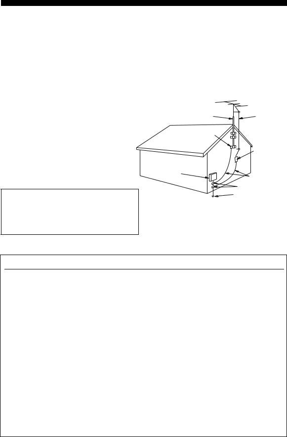
24Outdoor Antenna Grounding – If an outside antenna or cable system is connected to the product, be sure the antenna or cable system is grounded so as to provide some protection against voltage surges and built-up static charges. Article 810 of the National Electrical Code, ANSI/NFPA 70, provides information with regard to proper grounding of the mast and supporting structure, grounding of the lead-in wire to an antenna discharge unit, size of grounding conductors, location of antenna discharge unit, connection to grounding electrodes, and requirements for the grounding electrode.
EXAMPLE OF ANTENNA GROUNDING
|
MAST |
ANTENNA |
|
LEAD IN |
|
|
WIRE |
|
|
GROUND |
|
|
CLAMP |
|
|
ANTENNA |
|
|
DISCHARGE UNIT |
|
|
(NEC SECTION 810–20) |
|
|
ELECTRIC |
|
|
SERVICE |
|
|
EQUIPMENT |
GROUNDING CONDUCTORS |
|
(NEC SECTION 810–21) |
|
|
GROUND CLAMPS |
|
|
POWER SERVICE GROUNDING |
|
|
ELECTRODE SYSTEM |
|
|
(NEC ART 250. PART H) |
|
|
NEC – NATIONAL ELECTRICAL CODE |
FCC INFORMATION (for US customers)
1IMPORTANT NOTICE: DO NOT MODIFY THIS UNIT!
This product, when installed as indicated in the instructions contained in this manual, meets FCC requirements. Modifications not expressly approved by Yamaha may void your authority, granted by the FCC, to use the product.
2IMPORTANT: When connecting this product to accessories and/or another product use only high quality shielded cables. Cable/s supplied with this product MUST be used. Follow all installation instructions. Failure to follow instructions could void your FCC authorization to use this product in the USA.
3NOTE: This product has been tested and found to comply with the requirements listed in FCC Regulations, Part 15 for Class “B” digital devices. Compliance with these requirements provides a reasonable level of assurance that your use of this product in a residential environment will not result in harmful interference with other electronic devices.
This equipment generates/uses radio frequencies and, if not installed and used according to the instructions found in the users manual, may cause interference harmful to the operation of other electronic devices.
Compliance with FCC regulations does not guarantee that interference will not occur in all installations. If this product is found to be the source of interference, which can be determined by turning this unit “OFF” and “ON”, please try to eliminate the problem by using one of the following measures:
Relocate either this product or the device that is being affected by the interference.
Utilize power outlets that are on different branch (circuit breaker or fuse) circuits or install AC line filter/s.
In the case of radio or TV interference, relocate/reorient the antenna. If the antenna lead-in is 300 ohm ribbon lead, change the lead-in to coaxial type cable.
If these corrective measures do not produce satisfactory results, please contact the local retailer authorized to distribute this type of product. If you can not locate the appropriate retailer, please contact Yamaha Electronics Corp., U.S.A. 6660 Orangethorpe Ave, Buena Park, CA 90620.
The above statements apply ONLY to those products distributed by Yamaha Corporation of America or its subsidiaries.
ii

CAUTION: READ THIS BEFORE OPERATING YOUR UNIT.
1To assure the finest performance, please read this manual carefully. Keep it in a safe place for future reference.
2Install this sound system in a well ventilated, cool, dry, clean place – away from direct sunlight, heat sources, vibration, dust, moisture, and/or cold. Allow ventilation space of at least 30 cm on the top, 20 cm on the left and right, and 20 cm on the back of this unit.
3Locate this unit away from other electrical appliances, motors, or transformers to avoid humming sounds.
4Do not expose this unit to sudden temperature changes from cold to hot, and do not locate this unit in a environment with high humidity (i.e. a room with a humidifier) to prevent condensation inside this unit, which may cause an electrical shock, fire, damage to this unit, and/or personal injury.
5Avoid installing this unit where foreign object may fall onto this unit and/or this unit may be exposed to liquid dripping or splashing. On the top of this unit, do not place:
–Other components, as they may cause damage and/or discoloration on the surface of this unit.
–Burning objects (i.e. candles), as they may cause fire, damage to this unit, and/or personal injury.
–Containers with liquid in them, as they may fall and liquid may cause electrical shock to the user and/or damage to this unit.
6Do not cover this unit with a newspaper, tablecloth, curtain, etc. in order not to obstruct heat radiation. If the temperature inside this unit rises, it may cause fire, damage to this unit, and/or personal injury.
7Do not plug in this unit to a wall outlet until all connections are complete.
8Do not operate this unit upside-down. It may overheat, possibly causing damage.
9Do not use force on switches, knobs and/or cords.
10When disconnecting the power cable from the wall outlet, grasp the plug; do not pull the cord.
11Do not clean this unit with chemical solvents; this might damage the finish. Use a clean, dry cloth.
12Only voltage specified on this unit must be used. Using this unit with a higher voltage than specified is dangerous and may cause fire, damage to this unit, and/or personal injury. YAMAHA will not be held responsible for any damage resulting from use of this unit with a voltage other than specified.
13To prevent damage by lightning, keep the power cable and outdoor antennas disconnected from a wall outlet or this unit during a lightning storm.
14Do not attempt to modify or fix this unit. Contact qualified YAMAHA service personnel when any service is needed. The cabinet should never be opened for any reasons.
15When not planning to use this unit for long periods of time (i.e. vacation), disconnect the AC power plug from the wall outlet.
16Install this unit near the AC wall outlet where the power cable plug can be reached easily.
17Be sure to read the “TROUBLESHOOTING” section on common operating errors before concluding that this unit is faulty.
18Before moving this unit, press STANDBY/ON to set this unit in the standby mode, and then disconnect the power cable from the AC wall outlet.
19VOLTAGE SELECTOR (Asia and General models only) The VOLTAGE SELECTOR on the rear panel of this unit must be set for your local main voltage BEFORE plugging into the AC wall outlet. Voltages are:
Asia model ………………………. 220/230–240 V AC, 50/60 Hz General model …….. 110/120/220/230–240 V AC, 50/60 Hz
WARNING
TO REDUCE THE RISK OF FIRE OR ELECTRIC SHOCK, DO NOT EXPOSE THIS UNIT TO RAIN OR MOISTURE.
This unit is not disconnected from the AC power source as long as it is connected to the wall outlet, even if this unit itself is turned off. In this state, this unit is designed to consume a very small quantity of power.
FOR CANADIAN CUSTOMERS
To prevent electric shock, match wide blade of plug to wide slot and fully insert.
This Class B digital apparatus complies with Canadian ICES-003.
IMPORTANT
Please record the serial number of this unit in the space below.
MODEL:
Serial No.:
The serial number is located on the rear panel of this unit. Retain this Owner’s Manual in a safe place for future reference.
We Want You Listening For A Lifetime
YAMAHA and the Electronic Industries Association’s Consumer Electronics Group want you to get the most out of your equipment by playing it at a safe level. One that lets the sound come through loud and clear without annoying blaring or distortion – and, most importantly, without affecting your sensitive hearing.
Since hearing damage from loud sounds is often undetectable until it is too late, YAMAHA and the Electronic Industries Association’s Consumer Electronics Group recommend you to avoid prolonged exposure from excessive volume levels.
iii

CONTENTS
|
INTRODUCTION |
|
|
FEATURES……………………………………………………. |
2 |
|
GETTING STARTED…………………………………….. |
3 |
|
Supplied accessories ………………………………………….. |
3 |
|
Installing batteries in the remote control ………………. |
3 |
|
CONTROLS AND FUNCTIONS ……………………. |
4 |
|
Front panel ……………………………………………………….. |
4 |
|
Remote control………………………………………………….. |
6 |
|
Front panel display ……………………………………………. |
9 |
|
Rear panel ………………………………………………………. |
11 |
|
PREPARATION |
|
|
CONNECTIONS ………………………………………….. |
12 |
|
Placing speakers………………………………………………. |
12 |
|
Connecting speakers ………………………………………… |
13 |
|
Information on jacks and cable plugs …………………. |
16 |
|
Audio and video signal flow……………………………… |
17 |
|
Connecting a TV……………………………………………… |
18 |
|
Connecting a DVD player, |
|
|
a DVD recorder, a VCR or an STB………………… |
19 |
|
Connecting a CD player, an MD player |
|
|
or a tape deck………………………………………………. |
21 |
|
Connecting a multi-format player |
|
|
or an external decoder ………………………………….. |
22 |
|
Connecting a game console, |
|
|
a video camera or a portable audio player……….. |
22 |
|
Connecting the FM and AM antennas ………………… |
23 |
|
Connecting the power cable………………………………. |
24 |
|
Setting the speaker impedance…………………………… |
25 |
|
Turning on this unit or setting it |
|
|
to the standby mode……………………………………… |
26 |
|
BASIC SETUP ……………………………………………… |
27 |
|
BASIC OPERATION |
|
|
PLAYBACK…………………………………………………. |
30 |
|
USING OTHER FEATURES………………………… |
32 |
|
Using SILENT CINEMA …………………………………. |
32 |
|
Muting the audio output……………………………………. |
32 |
|
Selecting the night listening mode……………………… |
32 |
|
Selecting the input mode ………………………………….. |
33 |
|
Using the sleep timer ……………………………………….. |
34 |
|
Adjusting the speaker level……………………………….. |
35 |
|
Selecting the Compressed Music |
|
|
Enhancer mode ……………………………………………. |
36 |
|
Selecting the MULTI CH INPUT component……… |
37 |
|
Enjoying multi-channel sources |
|
|
in 2-channel stereo……………………………………….. |
37 |
|
Enjoying unprocessed input sources…………………… |
37 |
|
Enjoying pure hi-fi stereo sound………………………… |
38 |
|
Displaying the input source information …………….. |
38 |
|
Playing video sources in the background ……………. |
39 |
|
ENJOYING SURROUND SOUND ………………… |
40 |
|
Enjoying multi-channel sources in surround ……….. |
40 |
|
Enjoying 2-channel sources in surround……………… |
41 |
|
Using Virtual CINEMA DSP ……………………………. |
42 |
|
RECORDING……………………………………………….. |
43 |
|
FM/AM TUNING………………………………………….. |
44 |
|
Automatic tuning …………………………………………….. |
44 |
|
Manual tuning…………………………………………………. |
45 |
|
Automatic preset tuning……………………………………. |
46 |
|
Manual preset tuning ……………………………………….. |
47 |
|
Selecting preset stations……………………………………. |
48 |
|
Exchanging preset stations ……………………………….. |
49 |
|
XM® SATELLITE RADIO TUNING…………….. |
51 |
|
Connecting the XM Connect-and-Play |
|
|
digital antenna accessory………………………………. |
51 |
|
XM Satellite Radio controls and functions………….. |
52 |
|
Activating XM Satellite Radio ………………………….. |
53 |
|
Basic XM Satellite Radio operations………………….. |
54 |
|
Selecting the XM Satellite Radio search mode ……. |
55 |
|
Setting the XM Satellite Radio preset channels …… |
59 |
|
Displaying the XM Satellite Radio information…… |
60 |
|
SOUND FIELD PROGRAMS |
|
|
SOUND FIELD PROGRAMS ……………………….. |
62 |
|
Selecting sound field programs …………………………. |
62 |
|
Sound field program descriptions………………………. |
63 |
|
Changing sound field parameter settings…………….. |
65 |
|
Sound field program speaker layouts …………………. |
71 |
|
ADVANCED OPERATION |
|
|
SET MENU …………………………………………………… |
74 |
|
Using SET MENU…………………………………………… |
76 |
|
1 SOUND MENU……………………………………………. |
78 |
|
2 INPUT MENU……………………………………………… |
81 |
|
3 OPTION MENU…………………………………………… |
83 |
|
ADVANCED SETUP …………………………………….. |
84 |
|
REMOTE CONTROL FEATURES ………………. |
86 |
|
Controlling this unit, a TV, |
|
|
or other components …………………………………….. |
86 |
|
Setting remote control codes …………………………….. |
88 |
|
Setting library codes ………………………………………… |
89 |
|
Resetting all remote control codes……………………… |
90 |
|
RESETTING THE SYSTEM…………………………. |
91 |
|
ADDITIONAL INFORMATION |
|
|
TROUBLESHOOTING ………………………………… |
92 |
|
GLOSSARY………………………………………………….. |
97 |
|
Audio information …………………………………………… |
97 |
|
Video information……………………………………………. |
98 |
|
Sound field program information ………………………. |
99 |
|
SPECIFICATIONS……………………………………… |
100 |
|
INTRODUCTION |
|
|
PREPARATION |
|
|
OPERATION |
BASIC |
|
PROGRAMS |
FIELD SOUND |
|
OPERATION |
ADVANCED |
|
INFORMATION |
ADDITIONAL |
1

FEATURES
Built-in 6-channel power amplifier
Minimum RMS output power (0.06% THD, 20 Hz to 20 kHz, 8 Ω)
Front: 90 W + 90 W Center: 90 W Surround: 90 W + 90 W Surround back: 90 W
Sound field features
Proprietary YAMAHA technology for the creation of sound fields
Dolby Digital/Dolby Digital EX decoder
DTS/DTS-ES Matrix 6.1, Discrete 6.1, DTS Neo:6, DTS 96/24 decoder
Dolby Pro Logic/Dolby Pro Logic II/ Dolby Pro Logic IIx decoder
Neural Surround decoder (U.S.A. and Canada models only)
Virtual CINEMA DSP
SILENT CINEMA™
Sophisticated AM/FM tuner
40-station random and direct preset tuning
Automatic preset tuning
Preset station shifting capability (preset editing)
Notes
XM Satellite Radio (U.S.A. model only)
XM Satellite Radio tuning capability (using the “XM Connect-and-Play digital antenna accessory” sold separately)
Neural Surround decoder to play back the surround sound content of the XM Satellite Radio broadcasts in multi-channels, resulting in a full surround sound experience
Other features
192-kHz/24-bit D/A converter
6 additional input jacks for discrete multi-channel input
S-video signal input/output capability
Component video input/output capability
(3 COMPONENT VIDEO INs and 1 MONITOR OUT)
Optical and coaxial digital audio signal jacks
Sleep timer
Cinema and music night listening modes
Remote control with preset remote control codes, backlighting input selector buttons
PORTABLE mini analog input jack on the front panel for a portable audio player
Compressed Music Enhancer mode to improve the sound quality of compression artifacts (such as the MP3 format) to that of a high-quality stereo
•yindicates a tip for your operation.
•Some operations can be performed by using either the buttons on the front panel or the ones on the remote control. In case the button names differ between the front panel and the remote control, the button name on the remote control is given in parentheses.
•This manual is printed prior to production. Design and specifications are subject to change in part as a result of improvements, etc. In case of differences between the manual and product, the product has priority.
“
Manufactured under license from Dolby Laboratories. “Dolby”, “Pro Logic”, and the double-D symbol are trademarks of Dolby Laboratories.
Manufactured under license from Digital Theater Systems, Inc. “DTS”, “DTS-ES”, “NEO:6”, and “DTS 96/24” are trademarks of Digital Theater Systems, Inc. Copyright 1996, 2003 Digital Theater Systems, Inc. All right reserved.
“SILENT CINEMA” is a trademark of YAMAHA CORPORATION.
The XM name and related logos are registered trademarks of XM Satellite Radio Inc.
Neural Surround™ name and related logos are trademarks owned by Neural Audio Corporation.
2
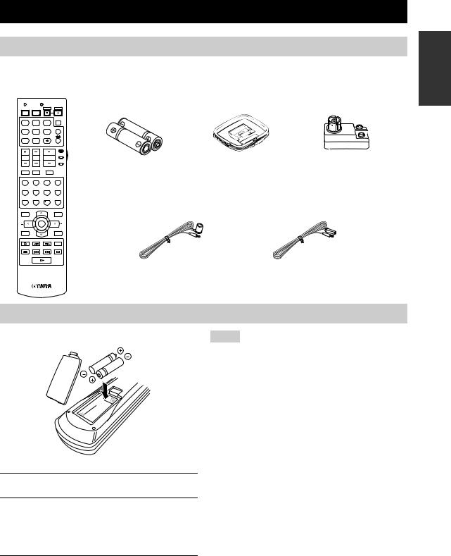
GETTING STARTED
Supplied accessories
Check that you received all of the following parts.
Remote control
CODE SET TRANSMIT
|
POWER |
POWER |
STANDBY |
POWER |
|
TV |
AV |
||
|
MD |
SLEEP |
||
|
CD |
CD-R |
XM |
|
|
CBL |
MULTI CH IN |
||
|
DVD |
DTV |
TUNER |
|
|
V-AUX |
DVR |
||
|
AMP |
|||
|
SOURCE |
|||
|
TV VOL |
TV CH |
VOLUME |
|
|
TV |
|||
|
TV MUTE |
TV INPUT |
MUTE |
|
|
STEREO |
MUSIC |
ENTERTAIN |
MOVIE |
|
1 |
2 |
3 |
4 |
|
STANDARD |
SELECT |
EXTD SUR. |
DIRECT ST. |
|
5 |
6 |
7 |
8 |
|
SPEAKERS |
ENHANCER |
NIGHT |
STRAIGHT |
|
9 |
0 |
10 |
ENT. |
|
EFFECT |
|||
|
LEVEL |
PRESET/CH |
SET MENU |
|
|
TITLE |
MENU |
||
|
BAND |
SRCH MODE |
||
|
ENTER |
|||
|
A-E/CAT. |
A-E/CAT. |
||
|
RETURN |
DISPLAY |
||
|
XM MEMORY |
|||
|
REC |
AUDIO
DISC SKIP
|
Batteries (2) |
AM loop antenna |
75-ohm/300-ohm antenna |
||||||
|
(AA, R6, UM-3) |
adapter (U.K. model only) |
|||||||
|
Indoor FM antenna |
Indoor FM antenna |
|
(U.S.A., Canada, China, Asia |
(U.K., Europe, Australia |
|
and General models) |
and Korea models) |
INTRODUCTION
Installing batteries in the remote control
1
 3
3
2
1Take off the battery compartment cover.
2Insert the two supplied batteries
(AA, R6, UM-3) according to the polarity markings (+ and –) on the inside of the battery compartment.
Notes
•Change all of the batteries if you notice the following conditions:
–The operation range of the remote control decreases.
–The TRANSMIT indicator does not flash or its light becomes dim.
•Do not use an old battery together with a new one.
•Do not use different types of batteries (such as alkaline and manganese batteries) together. Read the packaging carefully as these different types of batteries may have the same shape and color.
•If the batteries have leaked, dispose of them immediately. Avoid touching the leaked material or letting it come into contact with clothing, etc. Clean the battery compartment thoroughly before installing new batteries.
•Do not throw away batteries with general house waste; dispose of them correctly in accordance with your local regulations.
•If the remote control is without batteries for more than 2 minutes, or if exhausted batteries remain in the remote control, the contents of the memory may be cleared. When the memory is cleared, insert new batteries, set up the remote control code and program any acquired functions that may have been cleared.
3Snap the battery compartment cover back into place.
3
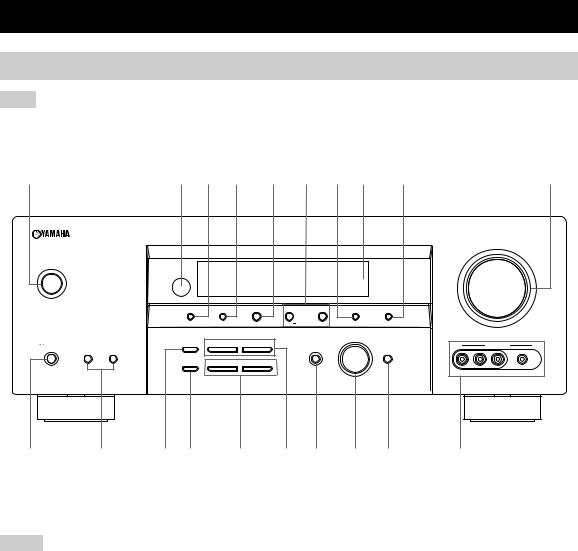
CONTROLS AND FUNCTIONS
Front panel
Note
The XM Satellite Radio controlling functions in the following buttons (SEARCH MODE, CATEGORY, PRESET/TUNING/CH l/ h, MEMORY, and DISPLAY) are only applicable to the U.S.A. model and are operational only when “XM” is selected as the input source. For details, see “XM Satellite Radio controls and functions” on page 52.
|
1 |
2 3 |
4 |
5 |
6 |
7 8 |
9 |
0 |
|
VOLUME |
||||||||||
|
STANDBY |
||||||||||
|
/ON |
||||||||||
|
PRESET/TUNING |
FM/AM |
A/B/C/D/E |
l PRESET/TUNING/CH h |
MEMORY |
TUNING MODE |
|||||
|
SEARCH MODE |
CATEGORY |
DISPLAY |
||||||||
|
EDIT |
NEXT |
LEVEL |
MAN’L/AUTO FM |
AUTO/MAN’L |
||||||
|
INPUT |
||||||||||
|
PHONES |
SPEAKERS |
STRAIGHT |
l |
PROGRAM h |
VIDEO AUX |
|||||
|
A |
B |
INPUT MODE |
MULTI CH |
|||||||
|
INPUT |
||||||||||
|
EFFECT |
||||||||||
|
TONE CONTROL |
BASS/TREBLE |
|||||||||
|
SILENT CINEMA |
VIDEO |
L AUDIO R |
PORTABLE |
(U.S.A. model)
1 STANDBY/ON
Turns on this unit or set it to the standby mode (see page 26).
Notes
•In the standby mode, this unit consumes a small amount of power in order to receive infrared signals from the remote control.
•When you turn on this unit, there will be a 4 to 5-second delay before this unit can reproduce sound.
2 Remote control sensor
Receives signals from the remote control (see page 8).
3 PRESET/TUNING, EDIT
•Switches the function of PRESET/TUNING/CH l/ h between selecting preset station numbers and selecting the tuning frequency.
•Edits the assignments of preset stations (see page 49).
4 FM/AM
Switches the reception band between FM and AM when “TUNER” is selected as the input source (see page 44).
5 A/B/C/D/E, NEXT
•Selects one of the 5 preset station groups (A to E) when “TUNER” is selected as the input source (see page 44).
•Selects the speaker channel whose output level you want to adjust when “TUNER” is not selected as the input source (see page 35).
6PRESET/TUNING/CH l / h, LEVEL +/– buttons
•Selects one of the 8 preset station numbers (1 to  when “TUNER” is selected as the input source. The colon (:) is displayed in the front panel display
(see page 48).
•Selects the tuning frequency when “TUNER” is selected as the input source. The colon (:) is not displayed in the front panel display (see page 45).
•Adjusts the level of the speaker channel selected using NEXT when “TUNER” is not selected as the input source (see page 35).
7 MEMORY (MAN’L/AUTO FM)
Stores a preset station in the memory. Hold down this button for more than 3 seconds to start automatic preset tuning (see page 46).
4

8 Front panel display
Shows information about the operational status of this unit (see page 9).
9 TUNING MODE (AUTO/MAN’L)
Switches between automatic tuning (the AUTO indicator is turned on) and manual tuning (the AUTO indicator is turned off) (see page 44).
0 VOLUME
Controls the output level of all audio channels.
y
This does not affect the AUDIO OUT (REC) level.
A  PHONES (SILENT CINEMA) jack
Outputs audio signals for private listening with headphones (see page 32).
Notes
•When you connect headphones, no signals are output at the SUBWOOFER OUTPUT jack or the speaker terminals.
•All Dolby Digital and DTS audio signals are mixed down to the left and right headphone channels.
B SPEAKERS A/B buttons
Turns on or off the set of front speakers connected to the A and/or B terminals on the rear panel each time the corresponding button is pressed.
C STRAIGHT (EFFECT)
Turns the sound field programs off or on. When “STRAIGHT” is selected, 2-channel or multi-channel input signals are output directly from their respective speakers without effect processing (see page 37).
D TONE CONTROL
Selects “BASS” or “TREBLE” to adjust the total balance of the front left and right speakers in conjunction with the BASS/TREBLE +/– buttons (see page 31).
E BASS/TREBLE +/– buttons
Adjust the bass/treble balance of the front left and right speakers in conjunction with TONE CONTROL
(see page 31).
F PROGRAM l / h buttons
Selects sound field programs (see page 62).
G INPUT MODE
Selects either digital or analog input signals exclusively or sets this unit to automatically detect the type of input signals and select the corresponding input signals when one component is connected via both digital and analog connections (see page 33).
H INPUT selector
Selects the desired input source.
CONTROLS AND FUNCTIONS
I MULTI CH INPUT
Selects the input source connected to the MULTI CH INPUT jacks (see page 37).
Note
The input source connected to the MULTI CH INPUT jacks takes priority over the source selected with the INPUT selector on the front panel (or the input selector buttons on the remote control).
J VIDEO AUX jacks
Input audio and video signals from a portable external source such as a game console, a video camera or a portable audio player (see page 22).
y
To reproduce the source signals input at these jacks, select “V-AUX” as the input source.
Note
The audio signals input at the PORTABLE mini jack take priority over the ones input at the AUDIO L/R jacks.
INTRODUCTION
5
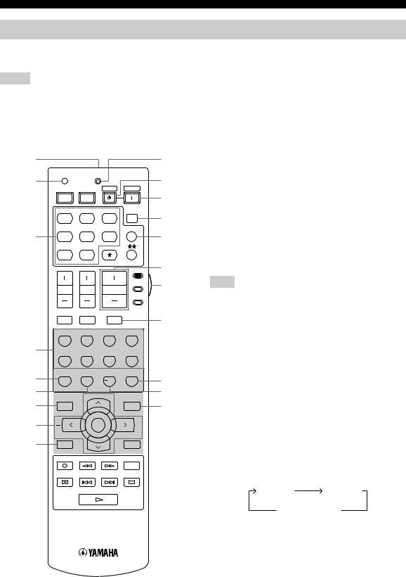
CONTROLS AND FUNCTIONS
Remote control
This section describes the function of each control on the remote control used to control this unit. To operate other components, see “REMOTE CONTROL FEATURES” on page 86.
t
Notes
•The XM Satellite Radio controlling functions in the following buttons (XM, XM MEMORY, SRCH MODE, DISPLAY, cursor buttons u/ d/ j/ i, numeric buttons and ENT.) are only applicable to the U.S.A. model and are operational only when “XM” is selected as the input source. For details, see “XM Satellite Radio controls and functions” on page 52.
•The operation mode of the remote control buttons in the shaded area below depends on the component selector switch position. Set the component selector switch to AMP to control this unit. To control the TUNER functions, set the component selector switch to SOURCE and then press TUNER to select the “TUNER” as the input source.
■Controlling this unit
|
0 |
|||
|
CODE SET |
TRANSMIT |
A |
|
|
POWER |
POWER |
STANDBY |
POWER |
|
TV |
AV |
B |
|
|
MD |
SLEEP |
Set the component selector switch to AMP to control this unit.
1 Infrared window
Outputs infrared control signals. Aim this window at the component you want to operate (see page 8).
|
CD |
CD-R |
XM |
|
CBL |
MULTI CH IN |
|
3 |
DVD |
DTV |
TUNER |
|
V-AUX |
DVR |
||
|
AMP |
|||
|
SOURCE |
|||
|
TV VOL |
TV CH |
VOLUME |
|
|
TV |
|||
|
TV MUTE |
TV INPUT |
MUTE |
DUse to set up remote control codes (see page 88).
3 Input selector buttons
ESelect the input source.
FNote
The corresponding input selector button for the currently selected input source lights up for approximately 5 seconds after you press
Gany buttons on the remote control, showing which source component is currently being operated.
|
STEREO |
MUSIC |
ENTERTAIN |
MOVIE |
|
1 |
2 |
3 |
4 |
4 Sound field program selector buttons
|
4 |
STANDARD |
SELECT |
EXTD SUR. DIRECT ST. |
Select sound field programs (see page 62). |
|||
|
5 |
6 |
7 |
8 |
– Use SELECT to play back 2-channel sources in |
|||
|
5 |
SPEAKERS |
ENHANCER |
NIGHT |
STRAIGHT |
H |
surround (see page 41). |
|
|
9 |
0 |
10 |
ENT. |
– Use EXTD SUR. to switch between 5.1 and 6.1- |
|||
|
6 |
EFFECT |
I |
channel playback of multi-channel sources (see |
||||
|
LEVEL |
PRESET/CH |
SET MENU |
|||||
|
7 |
J |
page 40). |
|||||
|
TITLE |
MENU |
||||||
|
BAND |
SRCH MODE |
– Use DIRECT ST. to play back 2-channel sources in |
|||||
|
8 |
ENTER |
hi-fi stereo sound (see page 38). |
|||||
|
A-E/CAT. |
A-E/CAT. |
5 SPEAKERS |
|||||
|
9 |
RETURN |
DISPLAY |
|||||
|
Turns on or off the set of front speakers connected to the |
|||||||
|
XM MEMORY |
|||||||
|
REC |
FRONT A and/or B terminals on the rear panel. Press this |
||||||
|
AUDIO |
|||||||
|
button repeatedly to toggle as follows: |
|||||||
|
DISC SKIP |
|||||||
|
A on |
B on |
||||||
|
A and B off |
6 ENHANCER
Turns on or off the Compressed Music Enhancer mode (see page 36).
7 LEVEL
Selects the speaker channel to be adjusted (see page 35).
(U.S.A. model)
6
![]()
8 Cursor buttons u / d / j / i, ENTER
Select and adjust the sound field program parameters or the “SET MENU” parameters.
9 RETURN
Returns to the previous menu level when adjusting the “SET MENU” parameters.
0 TRANSMIT indicator
Flashes while the remote control is sending infrared signals.
A STANDBY
Sets this unit to the standby mode (see page 26).
B POWER
Turns on this unit (see page 26).
C SLEEP
Sets the sleep timer (see page 34).
D MULTI CH IN
Selects the component connected to the MULTI CH INPUT jacks as the input source when using an external decoder, etc. (see page 37).
E VOLUME +/–
Increases or decreases the volume level.
CONTROLS AND FUNCTIONS
F Component selector switch
Selects the operation mode of the remote control buttons in the shaded area.
AMP
Operates this unit.
SOURCE
Operates the component selected with an input selector button (see page 87).
TV
Operates the TV assigned to either DTV/CBL or  (see page 86).
Notes
•To set the remote control codes for other components, see page 88.
•When you set the remote control codes for both DTV/CBL and
 (see page 87), priority is given to the one set for DTV/ CBL.
G MUTE
Mutes the audio output. Press again to restore the audio output to the previous volume level (see page 32).
H STRAIGHT (EFFECT)
Turns the sound field programs off or on. When “STRAIGHT” is selected, 2-channel or multi-channel input signals are output directly from their respective speakers without effect processing (see page 37).
I NIGHT
Turns on or off the night listening modes (see page 32).
J SET MENU
Enters “SET MENU” (see page 76).
INTRODUCTION
7

CONTROLS AND FUNCTIONS
■ Controlling the TUNER functions
Set the component selector switch to SOURCE and then press TUNER to select “TUNER” as the input source.
4 Numeric buttons
Use numbers 1 through 8 to select preset stations.
7 BAND
Switches the reception band between FM and AM (see page 44).
8 A–ECAT. j / i, PRESET/CH u / d
Press A–ECAT. j/ ito select a preset station group
(A to E) and PRESET/CH u/ dto select a preset station number (1 to (see page 48).
■ Using the remote control
The remote control transmits a directional infrared ray. Be sure to aim the remote control directly at the remote control sensor on the main unit during operation.
(U.S.A. model)
Approximately 6 m (20 ft)
30 30
Notes
•Do not spill water or other liquids on the remote control.
•Do not drop the remote control.
•Do not leave or store the remote control in the following types of conditions:
–places of high humidity, such as near a bath
–places of high temperatures, such as near a heater or stove
–places of extremely low temperatures
–dusty places
8
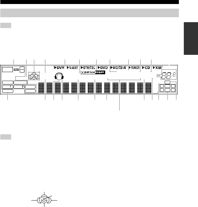
CONTROLS AND FUNCTIONS
Front panel display
Note
The XM is only applicable to the U.S.A. model and the cursor on the left of the XM indicator lights up only when “XM” is selected as the input source. For details, see “Basic XM Satellite Radio operations” on page 54.
|
1 2 3 4 |
5 6 |
7 8 |
9 0 A |
B |
||||
|
t 2496 |
VIRTUAL |
SP SILENT CINEMA |
AUTO TUNED STEREO MEMORY |
VOLUME |
||||
|
MATRIX DISCRETE |
HiFi DSP |
|||||||
|
ENHANCER |
STANDARD |
A B |
NIGHT |
PTY HOLD PS PTY RT CT EON SLEEP |
MUTE |
dB |
||
|
q EX qDIGITAL |
ft |
96/24 LFE |
||||||
|
q PL x q PL |
L C R |
|||||||
|
q PL |
mS |
|||||||
|
PCM |
neural |
SL SB SR |
||||||
|
dB |
||||||||
|
C |
D E F G |
H I |
J K L M N |
|
O (U.K. and Europe models only) |
|
|
1 Decoder indicators |
7 CINEMA DSP indicator |
|
The respective indicator lights up when any of the |
Lights up when you select a CINEMA DSP sound field |
|
decoders of this unit function. |
program (see page 63). |
Note
The neural indicator is only applicable to the U.S.A. and Canada models and lights up only when the Neural Surround decoder is selected (see pages 41).
2 ENHANCER indicator
Lights up when the Compressed Music Enhancer mode is
8 AUTO indicator
Lights up when this unit is in the automatic tuning mode (see page 44).
9 TUNED indicator
Lights up when this unit is tuned into a station (see page 44).
turned on (see page 36).
3 Sound field indicators
Light up to indicate the active DSP sound fields.
Presence DSP sound field
Listening position
|
Surround left |
Surround right |
|
|
DSP sound field |
||
|
DSP sound field |
||
|
Surround back DSP sound field |
4 VIRTUAL indicator
Lights up when Virtual CINEMA DSP is active (see page 42).
5 Input source indicators
The corresponding cursor lights up to show the currently selected input source.
6 SILENT CINEMA indicator
Lights up when headphones are connected and a sound field program is selected (see page 32).
0 STEREO indicator
Lights up when this unit is receiving a strong signal for an FM stereo broadcast while the AUTO indicator is lit
(see page 44).
A MEMORY indicator
Flashes to show that a station can be stored (see page 46).
BVOLUME level indicator
Indicates the current volume level.
CPCM indicator
Lights up when this unit is reproducing PCM (Pulse Code Modulation) digital audio signals.
D STANDARD indicator
Lights up when the “SUR. STANDARD” or “SUR. ENHANCED” programs are selected (see page 41).
E SP A B indicators
Light up according to the set of front speakers selected.
INTRODUCTION
9

CONTROLS AND FUNCTIONS
F Headphones indicator
Lights up when headphones are connected (see page 32).
G NIGHT indicator
Lights up when you select a night listening mode (see page 32).
H HiFi DSP indicator
Lights up when you select a HiFi DSP sound field program (see page 63).
I Multi-information display
Shows the name of the current sound field program and other information when adjusting or changing settings.
J SLEEP indicator
Lights up while the sleep timer is on (see page 34).
K MUTE indicator
Flashes while the MUTE function is on (see page 32).
L 96/24 indicator
Lights up when a DTS 96/24 signal is input to this unit.
M Input channel indicators
Indicate the channel components of the current digital input signal (see page 28).
N LFE indicator
Lights up when the input signal contains the LFE signal.
ORadio Data System indicators (U.K. and Europe models only)
Lights up when the Radio Data System data is being received.
EON
Lights up when the EON data service is being received.
PTY HOLD
Lights up while searching for the Radio Data System stations in the PTY SEEK mode.
10
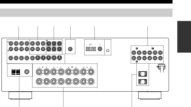
CONTROLS AND FUNCTIONS
Rear panel
|
1 |
2 |
3 |
4 |
5 |
6 |
7 |
|||||||||||||||
|
AUDIO |
AUDIO |
MULTI CH INPUT |
CENTER |
OUTPUT |
DIGITAL INPUT |
XM |
|||||||||||||||
|
DVD |
DTV/CBL |
DVD |
|||||||||||||||||||
|
COMPONENT VIDEO |
|||||||||||||||||||||
|
DVD |
DVR |
||||||||||||||||||||
|
Y |
PB |
PR |
Y |
PB |
PR |
||||||||||||||||
|
CD |
IN |
MD/ |
OUT |
FRONT |
SURROUND |
SUB |
SUB |
OPTICAL |
COAXIAL |
||||||||||||
|
(PLAY) CD-R (REC) |
WOOFER |
WOOFER |
|||||||||||||||||||
|
DVD |
DTV/CBL |
IN |
DVR OUT |
MONITOR |
DVD |
DTV/CBL |
IN |
DVR OUT |
MONITOR |
DTV/CBL |
MONITOR OUT |
||||||||||
|
VIDEO |
OUT |
S VIDEO |
OUT |
||||||||||||||||||
|
TUNER |
SPEAKERS |
AC OUTLETS |
|||||||||||||||||||
|
AM |
FM ANT |
FRONT |
SURROUND |
||||||||||||||||||
|
ANT |
GND |
75Ω |
|||||||||||||||||||
|
UNBAL. |
|||||||||||||||||||||
|
A |
|||||||||||||||||||||
|
B |
|||||||||||||||||||||
|
CENTER |
SURROUND BACK |
(U.S.A. model)
1 Video component jacks
See pages 18 and 19 for connection information.
2 Audio component jacks
See page 21 for connection information.
3 MULTI CH INPUT jacks
See page 22 for connection information.
4SUBWOOFER OUTPUT jack
See page 14 for connection information.
5DIGITAL INPUT jacks
See page 19 for connection information.
6 XM jack (U.S.A. model only)
See page 51 for connection information.
7 COMPONENT VIDEO jacks
See pages 18 and 19 for connection information.
8 Antenna terminals
See page 23 for connection information.
9 Speaker terminals
See page 13 for connection information.
0 AC OUTLET(S)
Use to supply power to your other audiovisual components.
See page 24 for details.
■VOLTAGE SELECTOR
(Asia and General models only)
See page 24 for details.
INTRODUCTION
11
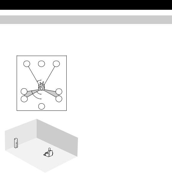
CONNECTIONS
Placing speakers
The speaker layout below shows the standard ITU-R* speaker setting. You can use it to enjoy CINEMA DSP and multi-channel audio sources.
*ITU-R is the radio communication sector of the ITU (International Telecommunication Union).
30˚
|
SL |
SR |
|
|
60˚ |
||
|
SL |
80˚ |
SR |
|
SB |
|
FR |
|
|
FL |
SW |
|
SR |
|
|
C |
|
|
SL |
SB |
|
1.8 m (6 ft) |
Front speakers (FL and FR)
The front speakers are used for the main source sound plus effect sounds. Place these speakers at an equal distance from the ideal listening position. The distance of each speaker from each side of the video monitor should be the same.
Center speaker (C)
The center speaker is for the center channel sounds (dialog, vocals, etc.). If for some reason it is not practical to use a center speaker, you can do without it. Best results, however, are obtained with the full system. Place the center speaker centrally between the front speakers and as close to the monitor as possible, such as directly over or under it.
Surround speakers (SL and SR)
The surround speakers are used for effect and surround sounds. Place these speakers behind your listening position, facing slightly inwards, about 1.8 m (6 ft) above the floor.
Surround back speaker (SB)
The surround back speaker supplements the surround speakers and provides more realistic front-to-back transitions. Place this speaker directly behind the listening position and at the same height as the surround speakers.
Subwoofer (SW)
The use of a subwoofer with a built-in amplifier, such as the YAMAHA Active Servo Processing Subwoofer System, is effective not only for reinforcing bass frequencies from any or all channels, but also for hi-fi stereo reproduction of the LFE (low-frequency effect) channel included in Dolby Digital and DTS sources. The position of the subwoofer is not so critical, because low bass sounds are not highly directional. But it is better to place the subwoofer near the front speakers. Turn it slightly toward the center of the room to reduce wall reflections.
12
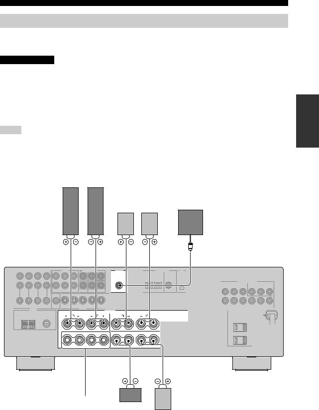
CONNECTIONS
Connecting speakers
Be sure to connect the left channel (L), right channel (R), “+” (red) and “–” (black) properly. If the connections are faulty, no sound will be heard from the speakers, and if the polarity of the speaker connections is incorrect, the sound will be unnatural and lack bass.
CAUTION
•Before connecting the speakers, make sure that this unit is in the standby mode (see page 26).
•Do not let the bare speaker wires touch each other or do not let them touch any metal part of this unit. This could damage this unit and/or speakers.
•Use magnetically shielded speakers. If this type of speakers still creates the interference with the monitor, place the speakers away from the monitor.
•If you are to use 4 or 6 ohm speakers, be sure to set “SP IMP.” to “6ΩMIN” before using this unit
(see page 25).
Notes
•A speaker cord is actually a pair of insulated cables running side by side. Cables are colored or shaped differently, perhaps with a stripe, groove or ridge. Connect the striped (grooved, etc.) cable to the “+” (red) terminals of this unit and your speaker. Connect the plain cable to the “–” (black) terminals.
•The low-frequency signals of other speakers set to “SML” (or “SMALL”) or to “NONE” in “SPEAKER SET” (see pages 78 and 79) are directed to the speakers selected in “BASS OUT” (see page 79).
Front speakers (A)
|
Right |
Left |
|||
|
Surround speakers |
Subwoofer |
|||
|
Right |
Left |
|||
|
1 |
2 |
4 |
5 |
7 |
PREPARATION
OUTPUT
SPEAKERS
A
B
|
CLASS 2 WIRING |
CENTER |
SURROUND BACK |
(U.S.A. model)
|
3 |
6 |
|
|
Front |
||
|
speakers |
Center |
|
|
(B) |
speaker |
Surround back |
speaker
13

CONNECTIONS
|
FRONT terminals |
|||
|
Connect one or two front speaker systems (1, 2) to these |
|||
|
terminals. If you use only one front speaker system, |
|||
|
connect it to the FRONT A or B terminal. |
|||
|
CENTER terminals |
1 |
||
|
Connect a center speaker (3) to these terminals. |
|||
|
7 |
|||
|
SURROUND terminals |
4 |
||
|
2 |
|||
|
Connect surround speakers (4, 5) to these terminals. |
3 |
||
|
SURROUND BACK terminals |
5 |
6 |
|
|
Connect a surround back speaker (6) to these terminals. |
|||
SUBWOOFER jack
Connect a subwoofer with a built-in amplifier (7) (such as the YAMAHA Active Servo Processing Subwoofer
|
System) to this jack. |
Speaker layout |
14
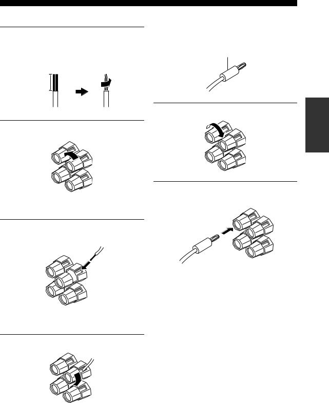
■ Connecting the speaker cable
1Remove approximately 10 mm (0.4 in) of insulation from the end of each speaker cable and then twist the exposed wires of the cable together to prevent short circuits.
10 mm (0.4 in)
CONNECTIONS
■ Connecting the banana plug
(except U.K., Europe and Asia models)
The banana plug is a single-pole electrical connector widely used to terminate speaker cables.
Banana plug
2 Loosen the knob.
Red: positive (+)
Black: negative (–)
3Insert one bare wire into the hole on the side of each terminal.
Red: positive (+)
Black: negative (–)
4 Tighten the knob to secure the wire.
Red: positive (+)
Black: negative (–)
1 Tighten the knob.
2Insert the banana plug connector into the end of the corresponding terminal.
PREPARATION
15
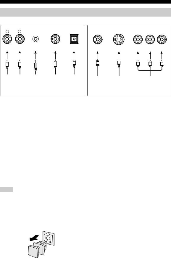
CONNECTIONS
Information on jacks and cable plugs
|
Audio jacks and cables |
Video jacks and cables |
||||||||
|
AUDIO |
PORTABLE |
DIGITAL AUDIO DIGITAL AUDIO |
COMPONENT VIDEO |
||||||
|
L |
R |
COAXIAL |
OPTICAL |
VIDEO |
S VIDEO |
Y |
PB |
PR |
|
|
(White) |
(Red) |
(Orange) |
(Yellow) |
(Green) |
(Blue) |
(Red) |
|||
|
L |
R |
M |
C |
O |
V |
S |
Y |
PB |
PR |
|
Left and right |
Stereo |
Coaxial |
Optical |
Composite |
S-video |
Component |
|||
|
analog audio |
analog |
digital |
digital |
||||||
|
video cable |
cable plug |
video cable |
|||||||
|
cable plug |
audio |
audio cable |
audio cable |
||||||
|
plug |
plug |
||||||||
|
mini cable |
plug |
plug |
|||||||
|
plug |
■ Audio jacks
This unit has four types of audio jacks. Connection depends on the availability of audio jacks on your other components.
AUDIO jacks
For conventional analog audio signals transmitted via left and right analog audio cables. Connect red plugs to the right jacks and white plugs to the left jacks.
PORTABLE jack
For analog audio signals transmitted via stereo analog audio mini cables.
DIGITAL AUDIO COAXIAL jacks
For digital audio signals transmitted via coaxial digital audio cables.
DIGITAL AUDIO OPTICAL jacks
For digital audio signals transmitted via optical digital audio cables.
Notes
•You can use the digital jacks to input PCM, Dolby Digital and DTS bitstreams. When you connect components to both the COAXIAL and OPTICAL jacks, priority is given to the signals input at the COAXIAL jack. All digital input jacks are compatible with 96-kHz sampling digital signals.
•Pull out the cap from the optical jack before you connect the fiber optic cable. Do not discard the cap. When you are not using the optical jack, be sure to put the cap back in place. This cap protects the jack from dust.
■ Video jacks
This unit has three types of video jacks. Connection depends on the availability of input jacks on your video monitor.
VIDEO jacks
For conventional composite video signals transmitted via composite video cables.
S VIDEO jacks
For S-video signals, separated into the luminance (Y) and chrominance (C) video signals transmitted on separate wires of S-video cables.
COMPONENT VIDEO jacks
For component video signals, separated into the luminance (Y) and chrominance (PB, PR) video signals transmitted on separate wires of component video cables.
16
![]()
CONNECTIONS
P
Audio and video signal flow
■ Audio signal flow for AUDIO OUT (REC)
|
Input |
Output |
|||
|
AUDIO OUT (REC) |
||||
|
L |
R |
L |
R |
|
Analog audio
AUDIO
PORTABLE
Analog output
Note
This unit handles digital and analog signals independently. Thus, audio signals input at the analog jacks are output only at the analog AUDIO OUT (REC) jacks.
■ Video signal flow for MONITOR OUT
|
Input |
Output |
|
|
(MONITOR OUT) |
||
|
Y PB PR |
Y PB PR |
|
|
COMPONENT |
||
|
VIDEO |
||
|
S VIDEO |
Analog video |
|
|
VIDEO |
||
|
Through |
PREPARATION
17
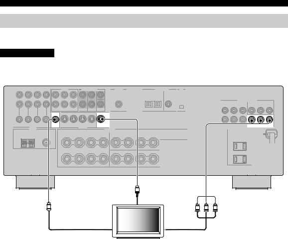
CONNECTIONS
Connecting a TV
Connect your TV to the VIDEO MONITOR OUT jack, the S VIDEO MONITOR OUT jack or the COMPONENT VIDEO MONITOR OUT jacks of this unit.
CAUTION
Do not connect this unit or other components to the AC power supply until all connections between components are complete.
|
COMPONENT VIDEO |
|||
|
Y |
PB |
PR |
|
|
MONITOR |
MONITOR |
MONITOR OUT |
|
|
OUT |
OUT |
||
|
VIDEO |
S VIDEO |
|
S |
|
|
(U.S.A. model) |
|
|
S-video in |
|
|
V |
Y PB PR |
|
Video in |
Component video in |
|
TV |
18
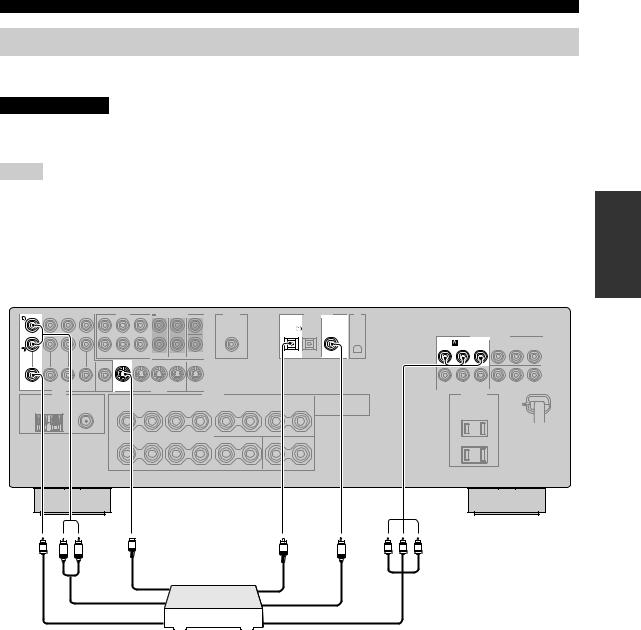
CONNECTIONS
Connecting a DVD player, a DVD recorder, a VCR or an STB
Connect your DVD player, DVD player, VCR or STB (set-top box) using the same type of video connections as those made for your TV (see page 18). The cable TV receiver and the satellite receiver are examples of the STB.
CAUTION
Do not connect this unit or other components to the AC power supply until all connections between components are complete.
Notes
•Be sure to make the same type of video connections as those made for your TV (see page 18). For example, if you connected your TV to the VIDEO MONITOR OUT jack of this unit, connect your other components to the VIDEO jacks.
•To make a digital connection to a component other than the default component assigned to each DIGITAL INPUT jack, select the corresponding setting for “OPTICAL IN”, or “COAXIAL IN” in “INPUT ASSIGN” (see page 81).
•If you connect your DVD player to both the DIGITAL INPUT (OPTICAL) and the DIGITAL INPUT (COAXIAL) jacks, priority is given to the signals input at the DIGITAL INPUT (COAXIAL) jack
■ Connecting a DVD player
|
AUDIO |
DIGITAL INPUT |
|||
|
DVD |
DVD |
|||
|
COMPONENT VIDEO |
||||
|
DVD |
||||
|
Y |
PB |
PR |
||
|
OPTICAL |
COAXIAL |
|||
|
DVD |
DVD |
|||
|
VIDEO |
S VIDEO |
(U.S.A. model)
V R L S O Y PB PR
C
|
Optical audio out |
||||
|
S-Video out |
||||
|
Audio out |
Coaxial audio out |
|||
|
Video out |
Component video out |
|||
|
DVD Player |
||||
PREPARATION
19
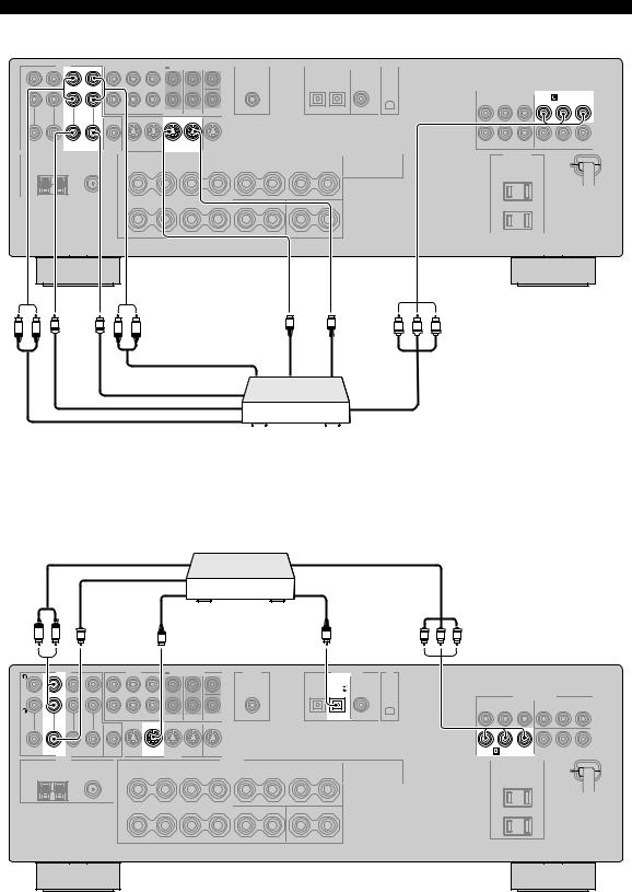
CONNECTIONS
■ Connecting a DVD recorder or a VCR
AUDIO
COMPONENT VIDEO
DVR
Y PB PR
|
IN DVR OUT |
IN DVR OUT |
|
VIDEO |
S VIDEO |
(U.S.A. model)
|
V |
V |
S |
S |
Y PB |
PR |
|
|
R L |
R L |
|||||
|
S-video out |
S-video in |
|
Audio in |
||
|
Video in |
||
|
Video out |
Component video out |
|
|
Audio out |
||
|
DVD recorder or |
||
|
VCR |
■ Connecting an STB
Cable TV receiver or satellite receiver
|
Audio out |
Component video out |
|||
|
Video out |
||||
|
Optical audio out |
||||
|
S-video out |
||||
|
R L |
V |
S |
O |
Y PB PR |
|
AUDIO |
DIGITAL INPUT |
|||
|
DTV/CBL |
COMPONENT VIDEO
|
Y |
PB |
PR |
||
|
OPTICAL |
||||
|
DTV/CBL |
DTV/CBL |
DTV/CBL |
||
|
VIDEO |
S VIDEO |
(U.S.A. model)
20
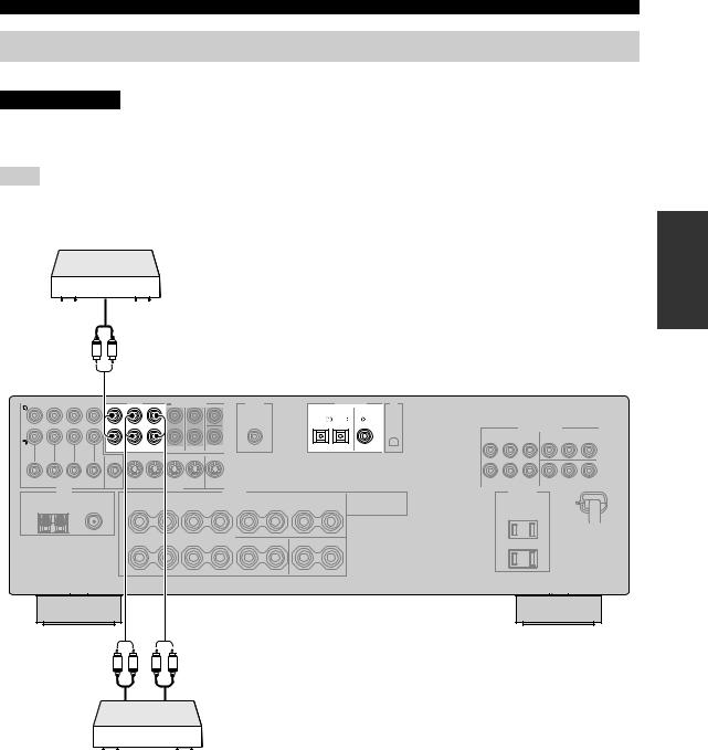
CONNECTIONS
Connecting a CD player, an MD player or a tape deck
Connect your CD player, MD player or tape deck via analog connection.
CAUTION
Do not connect this unit or other components to the AC power supply until all connections between components are complete.
Note
To make a digital connection to a component other than the default component assigned to each DIGITAL INPUT jack, select the corresponding setting for “OPTICAL IN” or “COAXIAL IN” in “INPUT ASSIGN” (see page 81).
CD Player
Audio out
R L
|
AUDIO |
DIGITAL INPUT |
||||
|
DVD |
DTV/CBL |
DVD |
|||
|
CD |
IN MD/ |
OUT |
OPTICAL |
COAXIAL |
|
|
(PLAY) CD-R (REC) |
|||||
|
(U.S.A. model) |
|||||
|
R |
L |
R |
L |
MD recorder or tape deck
PREPARATION
21
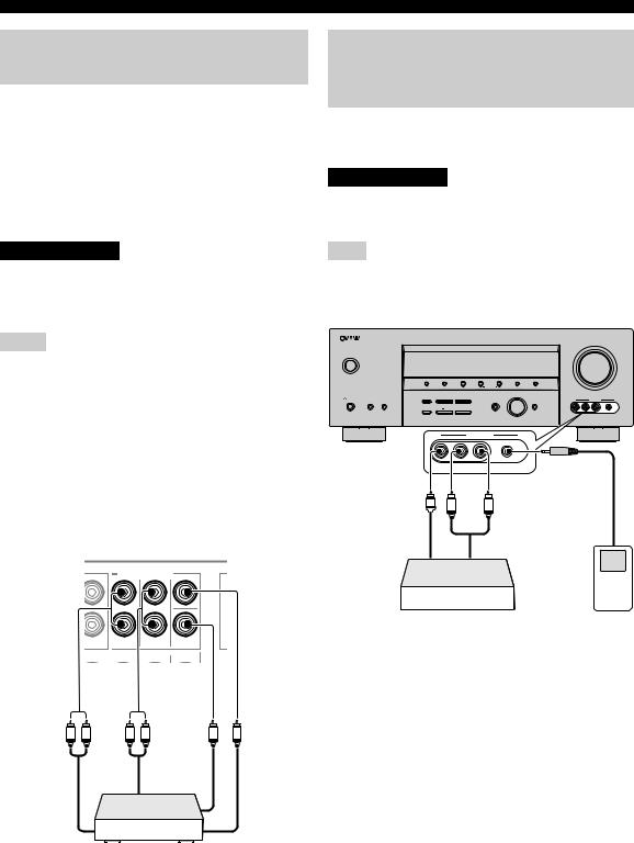
CONNECTIONS
Connecting a multi-format player or an external decoder
This unit is equipped with 6 additional input jacks (FRONT L/R, CENTER, SURROUND L/R and SUBWOOFER) for discrete multi-channel input from a multi-format player, external decoder, sound processor or pre-amplifier. Connect the output jacks on your multiformat player or external decoder to the MULTI CH INPUT jacks. Be sure to match the left and right output jacks to the left and right input jacks for the front and surround channels.
CAUTION
Do not connect this unit or other components to the AC power supply until all connections between components are complete.
Notes
•When you select the component connected to the MULTI CH INPUT jacks as the input source (see page 37), this unit automatically turns off the digital sound field processor, and you cannot select sound field programs.
•This unit does not redirect signals input at the MULTI CH INPUT jacks to accommodate for missing speakers. We recommend that you connect at least a 5.1-channel speaker system before using this feature.
•When headphones are used, signals are output only from the front left and right channels.
MULTI CH INPUT CENTER
SUB
FRONT SURROUND WOOFER
|
L R |
L |
R |
|
|
Front out |
Surround |
Subwoofer |
Center |
|
out |
out |
out |
Connecting a game console,
a video camera or a portable audio player
Use the VIDEO AUX jacks on the front panel to connect a game console, a video camera or a portable audio player to this unit.
CAUTION
Be sure to turn off the volume of this unit and other components before making connections.
Note
The audio signals input at the PORTABLE mini jack take priority over the ones input at the AUDIO L/R jacks.
(U.S.A. model)
|
VOLUME |
||||||||
|
STANDBY |
||||||||
|
/ON |
||||||||
|
PRESET/TUNING |
FM/AM |
A/B/C/D/E |
l PRESET/TUNING/CH h MEMORY |
TUNING MODE |
||||
|
INPUT |
||||||||
|
PHONES |
SPEAKERS |
STRAIGHT |
l |
PROGRAM |
h |
VIDEO AUX |
||
|
A B |
INPUT MODE |
MULTI CH |
||||||
|
INPUT |
||||||||
|
TONE CONTROL |
BASS/TREBLE |
|||||||
|
SILENT CINEMA |
VIDEO L AUDIO R PORTABLE |
|||||||
|
VIDEO AUX |
||||||||
|
M |
||||||||
|
VIDEO |
L |
AUDIO |
R |
PORTABLE |
||||
|
V |
L |
R |
||||||
|
Audio |
||||||||
|
out |
||||||||
|
Video out |
Audio out |
|
Game console or |
Portable audio |
|
video camera |
player |
Multi-format player or external decoder
22
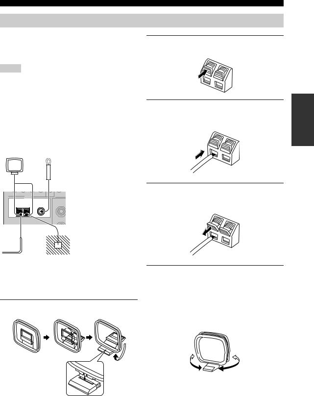
CONNECTIONS
Connecting the FM and AM antennas
Both FM and AM indoor antennas are supplied with this unit. In general, these antennas should provide sufficient signal strength. Connect each antenna correctly to designated terminals.
Notes
•Be sure to set the tuner frequency step (Asia and General models only) according to the frequency spacing in your area (see page 85).
•The AM loop antenna should be placed away from this unit.
•The AM loop antenna should always be connected, even if an outdoor AM antenna is connected to this unit.
•A properly installed outdoor antenna provides clearer reception than an indoor one. If you experience poor reception quality, install an outdoor antenna. Consult the nearest authorized YAMAHA dealer or service center about outdoor antennas.
AM loop antenna (supplied)
Indoor FM antenna (supplied)
(U.S.A. model)
TUNER
|
AM |
FM ANT |
|
75Ω |
|
|
ANT GND |
UNBAL. |
Outdoor AM antenna
Use a 5 to 10 m (16.4 to 32.8 ft) of vinyl-covered wire extended outdoors from a window.
Ground
For maximum safety and minimum interference, connect the antenna GND terminal to a good earth ground. A good earth ground is a metal stake driven into moist earth.
■ Connecting the AM loop antenna
1 Set up the AM loop antenna.
2Press and hold the tab of the AM ANT terminal.
3Insert one of the AM loop antenna lead wires into the AM ANT terminal.
4Release the tab of the AM ANT terminal back into place.
5Repeat steps 2 through 4 to connect the other lead wire to the GND terminal.
y
Once you have properly connected the AM loop antenna to this unit, orient the AM loop antenna for the best reception when you tune into AM stations (see page 44).
PREPARATION
23
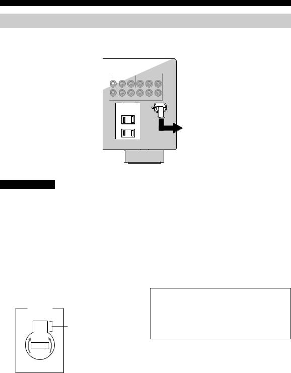
CONNECTIONS
Connecting the power cable
Once all connections are complete, plug the power cable into the AC wall outlet.
(U.S.A. model)
AC OUTLETS
To the AC wall outlet
CAUTION
VOLTAGE SELECTOR
(Asia and General models only)
The VOLTAGE SELECTOR on the rear panel of this unit must be set for your local voltage BEFORE plugging the power cable into the AC wall outlet. Improper setting of the VOLTAGE SELECTOR may cause damage to this unit and create a potential fire hazard.
Rotate the VOLTAGE SELECTOR clockwise or counterclockwise to the correct position using a straight slot screwdriver.
Voltages are as follows:
|
Asia model ……………………. |
220/230–240 V AC, 50/60 Hz |
|
General model ….. |
110/120/220/230–240 V AC, 50/60 Hz |
|
VOLTAGE |
|
|
SELECTOR |
|
|
230- |
Voltage indication |
|
240V |
|
AC OUTLET(S) (SWITCHED) |
|
|
U.K. and Australia models………………………………. |
1 outlet |
|
Korea model……………………………………………………… |
None |
|
Other models………………………………………………… |
2 outlets |
Use these outlet(s) to supply power to any connected components. Connect the power cable of your other components to these outlet(s). Power to these outlet(s) is supplied when this unit is turned on. However, power to these outlet(s) is cut off when this unit is in the standby mode or the power cable of this unit is disconnected from the AC wall outlet. For information on the maximum power or the total power consumption of the components that can be connected to these outlet(s), see “SPECIFICATIONS” on page 100.
Memory back-up
The memory back-up circuit prevents the stored data from being lost even if this unit is in the standby mode. However, the stored data will be lost in case the power cable is disconnected from the AC wall outlet or if the power supply is cut off for more than one week.
24
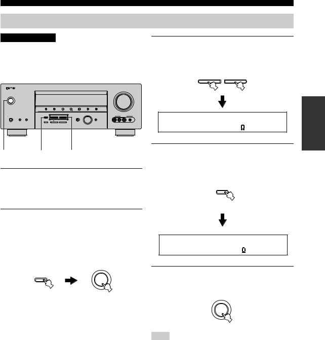
CONNECTIONS
Setting the speaker impedance
CAUTION
If you are to use 4 or 6 ohm speakers, set “SP IMP.” to “6ΩMIN” as follows BEFORE using this unit.
(U.S.A. model)
|
VOLUME |
||||||||||
|
STANDBY |
||||||||||
|
/ON |
||||||||||
|
PRESET/TUNING |
FM/AM |
A/B/C/D/E |
l PRESET/TUNING/CH h |
MEMORY |
TUNING MODE |
|||||
|
INPUT |
||||||||||
|
PHONES |
SPEAKERS |
STRAIGHT |
l |
PROGRAM h |
VIDEO AUX |
|||||
|
A |
B |
INPUT MODE |
MULTI CH |
|||||||
|
INPUT |
||||||||||
|
TONE CONTROL |
BASS/TREBLE |
|||||||||
|
SILENT CINEMA |
VIDEO |
L AUDIO R |
PORTABLE |
2,5 2,4 3
1Make sure this unit is set to the standby mode.
See page 26 for details about turning on this unit or standby mode.
2Press and hold STRAIGHT (EFFECT) on the front panel and then press STANDBY/ON to turn on this unit.
This unit turns on, and the advanced setup menu appears in the front panel display.
While holding down
STRAIGHT
STANDBY /ON
EFFECT
3Press PROGRAM l / hbuttons on the front panel to select “SP IMP.”.
The following display appears in the front panel display.
l PROGRAM h
SP IMP.-8 MIN
4Press STRAIGHT (EFFECT) on the front panel repeatedly to select “6ΩMIN”.
The following display appears in the front panel display.
STRAIGHT
EFFECT
SP IMP.-6 MIN
5Press STANDBY/ON on the front panel to save the new setting and set this unit to the standby mode.
STANDBY /ON
Note
The setting you made is reflected next time you turn on this unit.
PREPARATION
25
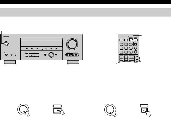
CONNECTIONS
Turning on this unit or setting it to the standby mode
When all connections are complete, turn on this unit.
|
S |
||||||||
|
STANDBY/ON |
(U.S.A. model) |
(U.S.A. model) |
||||||
|
CODE SET |
TRANSMIT |
STANDBY |
||||||
|
VOLUME |
POWER |
POWER |
STANDBY POWER |
POWER |
||||
|
TV |
AV |
|||||||
|
MD |
SLEEP |
|||||||
|
STANDBY |
||||||||
|
/ON |
CD |
CD-R |
XM |
|||||
|
CBL |
MULTI CH IN |
|||||||
|
PRESET/TUNING |
FM/AM |
A/B/C/D/E l PRESET/TUNING/CH h |
MEMORY TUNING MODE |
|||||
|
DVD |
DTV |
TUNER |
||||||
|
INPUT |
V-AUX |
DVR |
||||||
|
PHONES SPEAKERS |
STRAIGHT |
l |
PROGRAM h |
VIDEO AUX |
||||
|
A B |
INPUT MODE |
MULTI CH |
||||||
|
INPUT |
||||||||
|
TONE CONTROL |
BASS/TREBLE |
AMP |
||||||
|
SILENT CINEMA |
VIDEO L AUDIO R PORTABLE |
|||||||
|
SOURCE |
||||||||
|
TV VOL |
TV CH |
VOLUME |
||||||
|
TV |
|
■ Turning on the power |
■ Setting this unit to the standby mode |
|
Press STANDBY/ON on the front panel (or |
Press STANDBY/ON on the front panel again (or |
|
POWER on the remote control) to turn on this |
STANDBY on the remote control) to set this unit |
|
unit. |
to the standby mode. |
|
Front panel |
Remote control |
Front panel |
Remote control |
26
![]()
BASIC SETUP
The “BASIC SETUP” feature is a useful way to set up your system quickly and with minimal effort.
Notes
•Make sure you disconnect your headphones from this unit.
•If you wish to configure this unit manually using more precise adjustments, use the detailed parameters in “SOUND MENU” (see page 78).
•Altering any parameters in “BASIC SETUP” resets all parameters manually adjusted in “SOUND MENU” (see page 78).
•Initial settings are indicated in bold under each parameter.
•Press RETURN on the remote control to return to the previous menu level.
|
STEREO |
MUSIC |
ENTERTAIN MOVIE |
3 Press ENTER to enter “BASIC SETUP”. |
|||||
|
CODE SET |
TRANSMIT |
1 |
2 |
3 |
4 |
|||
|
POWER |
POWER |
STANDBY |
POWER |
STANDARD SELECT |
EXTD SUR. DIRECT ST. |
|||
|
TV |
AV |
5 |
6 |
7 |
8 |
|||
|
MD |
SLEEP |
SPEAKERS |
ENHANCER |
NIGHT |
STRAIGHT |
PRESET/CH |
||
|
CD |
CD-R |
XM |
9 |
0 |
10 |
ENT. |
|
CBL |
MULTI CH IN |
EFFECT |
2,12 |
|||
|
V-AUX |
DVR |
BAND |
PRESET/CH |
|||
|
SRCH MODE |
||||||
|
DVD |
DTV |
TUNER |
LEVEL |
SET MENU |
||
|
1 |
TITLE |
MENU |
3-11 |
|||
|
A-E/CAT. |
A-E/CAT. |
|||||
|
ENTER |
||||||
|
AMP |
||||||
|
SOURCE |
RETURN |
DISPLAY |
ENTER |
|||
|
TV VOL TV CH VOLUME |
XM MEMORY |
A-E/CAT. |
A-E/CAT. |
|
TV |
REC |
AUDIO
(U.S.A. model)
The “ROOM” appears in the front panel display.
1 Set the component selector switch to AMP.
4 Press j / ito select the desired setting.
AMP
PRESET/CH
SOURCE
TV
ENTER
A-E/CAT. A-E/CAT
2Press SET MENU.
“BASIC SETUP” appears in the front panel display.
ROOM: S >M L
|
SET MENU |
.BASIC SETUP |
|
MENU |
|
|
SRCH MODE |
Select the size of the room where you have installed your speakers. In general, the room sizes are defined as follows:
Choices: S, M, L
[U.S.A. and Canada models]
|
S (small) |
16 x 13ft, 200ft2 (4.8 x 4.0m, 20m2) |
|
M (medium) |
20 x 16ft, 300ft2 (6.3 x 5.0m, 30m2) |
|
L (large) |
26 x 19ft, 450ft2 (7.9 x 5.8m, 45m2) |
|
[Other models] |
|
|
S (small) |
3.6 x 2.8m, 10m2 |
|
M (medium) |
4.8 x 4.0m, 20m2 |
|
L (large) |
6.3 x 5.0m, 30m2 |
PREPARATION
27

BASIC SETUP
|
5 Press d to select “SUBWOOFER” and then |
7 Press d once and then j / i to select the |
||||||
|
j / i to select the desired setting. |
desired setting. |
||||||
|
PRESET/CH |
PRESET/CH |
||||||
|
PRESET/CH |
PRESET/CH |
||||||
|
ENTER |
ENTER |
||||||
|
ENTER |
ENTER |
A-E/CAT. |
A-E/CAT. |
A-E/CAT. |
A-E/CAT |
||
|
A-E/CAT. |
A-E/CAT. |
A-E/CAT. |
A-E/CAT |
|
SUBWOOFER..YES |
>SET |
CANCEL |
|||
|
Choices: YES, NONE |
|||||
|
• Select “YES” if you have a subwoofer in your |
Choices: SET, CANCEL |
||||
|
system. |
• Select “SET” to apply the settings you made. |
||||
|
• Select “NONE” if you do not have a subwoofer in |
• Select “CANCEL” to cancel the setup procedure |
||||
|
your system. |
without making any changes. |
||||
|
6 Press dto select “SPEAKERS” and then j/ i |
y |
||||
|
You can also press SET MENU to cancel the setup |
|||||
|
to select the number of speakers connected |
procedure. |
||||
|
to this unit. |
8 Press ENTER to confirm your selection. |
||||
|
PRESET/CH |
PRESET/CH |
||||
|
PRESET/CH |
|||||
|
ENTER |
ENTER |
||||
|
A-E/CAT. |
A-E/CAT. |
A-E/CAT. |
A-E/CAT |
||
|
ENTER |
|||||
|
A-E/CAT. |
A-E/CAT. |
SPEAKERS..6spk
|
Choice Display |
Speakers |
||
|
2spk |
L C R |
Front L/R |
|
|
SL |
SB SR |
||
|
3spk |
L C R |
Front L/R, Center |
|
|
SL |
SB SR |
||
If you selected “SET” in step 7, each speaker outputs a test tone twice in turn. “CHECK:TestTone” appears in the front panel display for a few seconds and then “CHECK OK?” appears in the front panel display.
CHECK:TestTone
y
Check the speaker connections (see page 13) and adjust the “SPEAKERS” settings back in step 6, if necessary.
|
4spk |
L C R |
Front L/R, Surround L/R |
|
|
SL |
SB SR |
||
|
5spk |
L C R |
Front L/R, Center, Surround L/R |
|
|
SL |
SB SR |
||
Front L/R, Center, Surround L/R, Surround back
28

9 Press j/ i to select the desired setting.
PRESET/CH
ENTER
A-E/CAT. A-E/CAT
BASIC SETUP
11Press d/ uto select a speaker and then j/ i to adjust the balance.
The selected speaker and the front left speaker or the surround left speaker output a test tone in turn.
•Press ito increase the value.
•Press jto decrease the value.
CHECK OK? ..YES
Choices: YES, NO
•Select “YES” to complete the setup procedure if the test tone levels from each speaker were satisfactory.
•Select “NO” to proceed to the speaker level adjustment menu to balance the output level of each speaker.
10 Press ENTER to confirm your selection.
PRESET/CH
ENTER
A-E/CAT. A-E/CAT.
•If you selected “YES” in step 9, the setup procedure is completed and the display returns to the top “SET MENU” display.
•If you selected “NO” in step 9, the front speaker level adjustment display appears in the front panel display.
|
ENTER |
ENTER |
||
|
A-E/CAT. |
A-E/CAT. |
A-E/CAT. |
A-E/CAT |
FR —-||—-
•Select “FR” to adjust the balance between the front left and right speakers.
•Select “C” to adjust the balance between the front left and center speakers.
•Select “SL” to adjust the balance between the front left and surround left speakers.
•Select “SB” to adjust the balance between the surround left and surround back speakers.
•Select “SR” to adjust the balance between the surround left and surround right speakers.
•Select “SWFR” to adjust the balance between the front left speaker and the subwoofer.
12Press SET MENU to exit from “BASIC SETUP”.
SET MENU
MENU
SRCH MODE
PREPARATION
29

—
PLAYBACK
CAUTION
Extreme caution should be exercised when you play back CDs encoded in DTS. If you play back a CD encoded in DTS on a DTS-incompatible CD player, you will only hear some unwanted noise that may damage your speakers. Check whether your CD player supports CDs encoded in DTS. Also, check the sound output level of your CD player before you play back a CD encoded in DTS.
(U.S.A. model)
|
VOLUME |
||||||||||
|
STANDBY |
||||||||||
|
/ON |
||||||||||
|
PRESET/TUNING |
FM/AM |
A/B/C/D/E |
l PRESET/TUNING/CH h |
MEMORY |
TUNING MODE |
|||||
|
INPUT |
||||||||||
|
PHONES |
SPEAKERS |
STRAIGHT |
l |
PROGRAM h |
VIDEO AUX |
|||||
|
A |
B |
INPUT MODE |
MULTI CH |
|||||||
|
INPUT |
||||||||||
|
TONE CONTROL |
BASS/TREBLE |
|||||||||
|
SILENT CINEMA |
VIDEO |
L AUDIO R |
PORTABLE |
|
2 |
6 |
6 |
7 |
3 |
5 |
|
TV MUTE TV INPUT |
MUTE |
|
CODE SET |
TRANSMIT |
STEREO |
MUSIC |
ENTERTAIN |
MOVIE |
7 |
||||
|
1 |
2 |
3 |
4 |
|||||||
|
POWER |
POWER |
STANDBY |
POWER |
STANDARD |
SELECT |
EXTD SUR. |
DIRECT ST. |
|||
|
TV |
AV |
|||||||||
|
5 |
6 |
7 |
8 |
|||||||
|
MD |
SLEEP |
2 |
||||||||
|
CD |
CD-R |
XM |
SPEAKERS |
ENHANCER |
NIGHT |
STRAIGHT |
||||
|
3 |
MULTI CH IN |
9 |
0 |
10 |
ENT. |
|||||
|
CBL |
||||||||||
|
DVD |
DTV |
TUNER |
PRESET/CH |
EFFECT |
||||||
|
LEVEL |
SET MENU |
|||||||||
|
TITLE |
MENU |
|||||||||
|
2 |
V-AUX |
DVR |
BAND |
SRCH MODE |
||||||
|
AMP |
ENTER |
A-E/CAT. A-E/CAT.
|
SOURCE |
5 |
RETURN |
DISPLAY |
|||
|
TV VOL |
TV CH |
VOLUME |
||||
|
TV |
XM MEMORY |
|||||
|
REC |
||||||
|
AUDIO |
||||||
|
TV MUTE |
TV INPUT |
MUTE |
DISC SKIP |
|||
(U.S.A. model)
1Turn on the video monitor connected to this unit.
2Press SPEAKERS A or B on the front panel (or set the component selector switch to AMP and then press SPEAKERS on the remote control repeatedly).
Each time you press SPEAKERS A or B on the front panel, the respective speakers are turned on or off.
SPEAKERS
A B
Front panel
or
AMP
|
SPEAKERS |
|
|
SOURCE |
9 |
|
TV |
|
|
Remote control |
3Rotate the INPUT selector on the front panel (or press one of the input selector buttons on the remote control) to select the desired input source.
|
INPUT |
MD |
SLEEP |
|
CD |
CD-R |
XM |
|
or |
CBL |
MULTI CH IN |
|
DVD |
DTV |
TUNER |
|
V-AUX |
DVR |
|
|
Front panel |
Remote control |
The name of the currently selected input source appears in the front panel display for a few seconds.
Available input sources
|
DVR V-AUX |
DTV/CBL pDVD MD/CD-R TUNER CD XM |
|
VOLUME |
|
|
SP |
|
|
A |
dB |
|
DVD |
AUTO |
L R |
|
Currently selected input |
Currently selected |
|
|
source |
input mode |
Notes
•If you are to select an input source connected via digital connections, set “INPUT MODE” to “AUTO” or “DTS” (see page 33).
•For details about controlling XM Satellite Radio when “XM” is selected as the input source, see page 54.
4Start playback on the selected source component or select a broadcast station.
Refer to the operating instructions for the source component.
See page 44 for details about tuning instructions.
30

5Rotate VOLUME on the front panel (or press VOLUME +/– on the remote control) to adjust the volume to the desired output level.
VOLUME
or VOLUME
|
Front panel |
Remote control |
6Press TONE CONTROL on the front panel repeatedly to select “TREBLE” or “BASS” and then press BASS/TREBLE +/– buttons to adjust the corresponding frequency response level.
|
DVR V-AUX DTV/CBL pDVD MD/CD-R TUNER CD |
XM |
|
|
VOLUME |
||
|
SP |
||
|
A |
dB |
|
|
TREBLE |
0dB |
L R |
•Select “TREBLE” to adjust the high-frequency response.
•Select “BASS” to adjust the low-frequency response.
Notes
•Speaker and headphone adjustments are stored independently.
•When “TC.BYPASS” is set to “AUTO” (see page 81), and “BASS” and “TREBLE” are set to 0 dB, audio output automatically bypasses the tone control circuitry of this unit.
•If you increase or decrease the high-frequency or lowfrequency sound to an extreme level, the tonal quality of the surround speakers may not match that of the front left and right speakers.
•TONE CONTROL is not effective when the “DIRECT STEREO” mode (see page 38) is selected or when “MULTI CH INPUT” (see page 37) is selected as the input source.
•To enjoy multi-channel sources in surround, see page 40 for details.
PLAYBACK
7Press PROGRAM l / hbuttons on the front panel (or press one of the sound field program selector buttons on the remote control repeatedly) to select the desired sound field program.
The name of the selected sound field program appears in the front panel display.
See page 63 for details about sound field programs.
l PROGRAM h
Front panel
or
|
STEREO |
MUSIC |
ENTERTAIN |
MOVIE |
|
|
1 |
2 |
3 |
4 |
|
|
STANDARD |
SELECT |
EXTD SUR. |
DIRECT ST. |
|
|
5 |
6 |
7 |
8 |
|
|
SPEAKERS |
ENHANCER |
NIGHT |
STRAIGHT |
|
|
9 |
0 |
10 |
ENT. |
|
|
EFFECT |
||||
|
Remote control |
||||
|
DVR |
V-AUX DTV/CBL pDVD |
MD/CD-R TUNER CD XM |
||
|
VOLUME |
||||
|
SP |
||||
|
A |
Sports |
dB |
||
|
TV |
L R |
Currently selected surround field program
Notes
•Choose a sound field program based on your listening preference, not merely on the name of the program.
•When you select an input source, this unit automatically selects the last sound field program used with the corresponding input source.
•Sound field programs cannot be selected when the component connected to the MULTI CH INPUT jacks is selected as the input source (see page 37).
•Sampling frequencies higher than 48 kHz (except for DTS 96/24 signals) are sampled down to 48 kHz and then sound field programs are applied.
•To display information about the currently selected input source in the front panel display, see page 38 for details.
31

USING OTHER FEATURES
|
Using SILENT CINEMA |
Selecting the night listening mode |
SILENT CINEMA allows you to enjoy multi-channel music or movie sound, including Dolby Digital and DTS sources, through ordinary headphones. SILENT CINEMA activates automatically whenever you connect headphones to the PHONES jack while listening to CINEMA DSP or HiFi DSP sound field programs (see page 63). When activated, the SILENT CINEMA indicator lights up in the front panel display.
Notes
•SILENT CINEMA does not activate when “MULTI CH INPUT” is selected as the input source (see page 37).
•SILENT CINEMA is not effective when the “DIRECT STEREO” (see page 38) or “2ch Stereo” mode (see page 37) is selected, or when this unit is in the “STRAIGHT” mode (see page 37).
Muting the audio output
Press MUTE on the remote control to mute the audio output. Press MUTE again to resume the audio output.
MUTE
y
•You can also rotate VOLUME on the front panel or VOLUME +/– on the remote control to resume the audio output.
•You can adjust the muting level by using the “MUTING TYP.” parameter in “SOUND MENU” (see page 81).
•The MUTE indicator flashes in the front panel display when the audio output is muted and disappears from the front panel display when the audio output is resumed.
The night listening modes are designed to improve listenability at lower volumes or at night. Choose either “NIGHT:CINEMA” or “NIGHT:MUSIC” depending on the type of material you are playing.
1Set the component selector switch to AMP and then press NIGHT on the remote control repeatedly to select “NIGHT:CINEMA” or “NIGHT:MUSIC”.
AMP
NIGHT
SOURCE
10
TV
Choices: NIGHT:CINEMA, NIGHT:MUSIC, OFF
•Select “NIGHT:CINEMA” when watching films to reduce the dynamic range of film soundtracks and make dialog easier to hear at lower volumes.
•Select “NIGHT:MUSIC” when listening to music sources to preserve ease-of-listening for all sounds.
•Select “OFF” if you do not want to use this feature.
y
When a night listening mode is selected, the NIGHT indicator lights up in the front panel display.
2Press j/ ion the remote control to adjust the effect level while “NIGHT:CINEMA” or “NIGHT:MUSIC” is displayed in the front panel display.
PRESET/CH
Note
|
ENTER |
||
|
If you change the input source or the sound field program while |
A-E/CAT. |
A-E/CAT |
the audio output is being muted, this unit resumes the audio
output.
Remote control
Effect.Lvl:MID
Choices: MIN, MID, MAX
• Select “MIN” for minimum compression.
• Select “MID” for standard compression.
• Select “MAX” for maximum compression.
32

USING OTHER FEATURES
y
“NIGHT:CINEMA” and “NIGHT:MUSIC” adjustments are 2 Press INPUT MODE on the front panel
|
stored independently. |
repeatedly to select the desired input mode. |
Notes
•You cannot use the night listening modes when the “DIRECT STEREO” program (see page 38) is selected or when the component connected to the MULTI CH INPUT jacks is selected as the input source (see page 37) even though the NIGHT indicator lights up when “DIRECT STEREO” is selected.
•The night listening modes may vary in effectiveness depending on the input source and surround sound settings you use.
Selecting the input mode
This unit comes with a variety of input jacks. Do the following to select the type of input signals you want to use.
y
You can adjust the default input mode of this unit by using the “INPUT MODE” parameter in “INPUT MENU” (see page 82).
Notes
•To play DTS-encoded DVDs and CDs, (when using a digital audio connection, be sure to set “INPUT MODE” to “DTS”.
•If the digital output data of the player has been processed in any way, you may not be able to perform DTS decoding depending on the player even if you make a digital connection between this unit and the player.
1Rotate the INPUT selector on the front panel to select the desired input source.
INPUT MODE
Available input sources
|
DVR V-AUX |
DTV/CBL pDVD MD/CD-R TUNER CD XM |
|
VOLUME |
|
|
SP |
|
|
A |
dB |
|
DVD |
AUTO |
L R |
|||||||||
|
Currently selected input |
Currently selected input |
||||||||||
|
source |
mode |
||||||||||
|
AUTO |
Automatically selects input signals in |
||||||||||
|
the following order: |
|||||||||||
|
1) Digital signals |
|||||||||||
|
2) Analog signals |
|||||||||||
|
DTS |
Selects only digital signals encoded in |
||||||||||
|
DTS. If no DTS signals are input, no |
|||||||||||
|
sound is output. |
|||||||||||
|
ANALOG |
Selects only analog signals. If no |
||||||||||
|
analog signals are input, no sound is |
|||||||||||
|
output. |
Notes
•When “INPUT MODE” is set to “AUTO”, this unit automatically switches to the appropriate decoder if a Dolby Digital or DTS signal is detected.
•We recommend setting “INPUT MODE” to “AUTO” in most cases.
INPUT
33

USING OTHER FEATURES
Using the sleep timer
Use this feature to automatically set this unit to the standby mode after a certain amount of time. The sleep timer is useful when you are going to sleep while this unit is playing or recording a source. The sleep timer also automatically turns off any external components connected to AC OUTLET(S) (see page 24).
1Press one of the input selector buttons on the remote control to select the desired input source.
|
MD |
SLEEP |
|
|
CD |
CD-R |
XM |
|
CBL |
MULTI CH IN |
|
|
DVD |
DTV |
TUNER |
|
V-AUX |
DVR |
2Start playback on the selected source component or select a broadcast station.
Refer to the operating instructions for the source component.
See page 44 for details about tuning instructions.
3Press SLEEP on the remote control repeatedly to set the amount of time.
Each time you press SLEEP, the front panel display changes as shown below.
SLEEP
|
SLEEP 120min |
SLEEP 90min |
|
SLEEP OFF SLEEP |
30min SLEEP 60min |
The SLEEP indicator flashes while you are switching the amount of time for the sleep timer. Once the sleep timer is set, the SLEEP indicator lights up in the front panel display, and the display returns to the selected sound field program.
|
DVR V-AUX |
DTV/CBL DVD MD/CD-R TUNER pCD |
XM |
|
VOLUME |
||
|
SP |
||
|
A |
SLEEP |
dB |
SLEEP 120min L R
L R
Flashes
|
DVR V-AUX |
DTV/CBL DVD MD/CD-R TUNER pCD |
XM |
|
VOLUME |
||
|
SP |
||
|
A |
SLEEP |
dB |
STRAIGHT  L R
L R
Lights up
4To cancel the sleep timer, press SLEEP on the remote control repeatedly until “SLEEP OFF” appears in the front panel display.
SLEEP
DVR V-AUX DTV/CBL DVD MD/CD-R TUNER pCD XM
The SLEEP indicator turns off, and “SLEEP OFF” disappears from the front panel display after a few seconds.
y
The sleep timer setting can also be canceled by pressing STANDBY on the remote control (or STANDBY/ON on the front panel) to set this unit to the standby mode.
34

Adjusting the speaker level
You can adjust the output level of each speaker while listening to a music source. This is also possible when playing sources input at the MULTI CH INPUT jacks.
Note
This operation will override the level adjustments made in “BASIC SETUP” (see page 27) and “SP LEVEL” (see page 79).
y
This operation can also be performed using the control buttons on the front panel. Press NEXT on the front panel repeatedly to select the speaker channel whose output level you want to adjust and then press LEVEL +/– on the front panel to adjust the output level.
|
TV VOL |
TV CH |
SOURCEAMP |
1 |
||
|
VOLUME |
|||||
|
TV |
|||||
|
TV MUTE |
TV INPUT |
MUTE |
|||
|
STEREO |
MUSIC |
ENTERTAIN |
MOVIE |
||
|
1 |
2 |
3 |
4 |
||
|
STANDARD |
SELECT |
EXTD SUR. |
DIRECT ST. |
||
|
5 |
6 |
7 |
8 |
||
|
SPEAKERS |
ENHANCER |
NIGHT |
STRAIGHT |
||
|
9 |
0 |
10 |
ENT. |
||
|
1 |
EFFECT |
||||
|
LEVEL |
PRESET/CH |
SET MENU |
|||
|
TITLE |
MENU |
3 |
|||
|
BAND |
SRCH MODE |
||||
|
ENTER |
|||||
|
A-E/CAT. |
A-E/CAT. |
||||
|
RETURN |
DISPLAY |
2 |
|||
|
XM MEMORY |
|||||
|
REC |
|||||
|
AUDIO |
(U.S.A. model)
1Set the component selector switch to AMP and then press LEVEL on the remote control repeatedly to select the speaker you want to adjust.
AMP
BAND
TV
•Select “FRONT L” to adjust the front left speaker output level.
•Select “CENTER” to adjust the center speaker output level.
•Select “FRONT R” to adjust the front right speaker output level.
•Select “SUR. R” to adjust the surround right speaker output level.
•Select “SUR. B” to adjust the surround back speaker output level.
•Select “SUR. L” to adjust the surround left speaker output level.
•Select “SWFR” to adjust the subwoofer output level.
y
Once you press LEVEL on the remote control, you can also select the speaker by pressing u/ d.
USING OTHER FEATURES
2Press j/ ion the remote control to adjust the speaker output level.
•Press ito increase the value.
•Press jto decrease the value.
Control range: –10 dB to +10 dB
PRESET/CH
ENTER
A-E/CAT. A-E/CAT
3Press ENTER on the remote control when you have completed your adjustment.
PRESET/CH
ENTER
A-E/CAT. A-E/CAT.
35

USING OTHER FEATURES
Selecting the Compressed Music Enhancer mode
Compression artifacts (such as the MP3 format) are created by a lossy compression scheme where the audio is resampled to lower the bitrate and to remove sounds that are indistinguishable to typical human hearing. The Compressed Music Enhancer feature of this unit enhances your listening experience by regenerating the missing harmonics in a compression artifact. As a result, flattened complexity due to the loss of high-frequency fidelity as well as lack of bass due to the loss of low-frequency bass is compensated, providing the improved performance of the overall sound system.
Notes
•The Compressed Music Enhancer mode is compatible with the PCM signals (32 kHz, 44.1 kHz and 48 kHz) and the analog 2-channel input sources.
•The Compressed Music Enhancer mode is not effective with any of the sound field programs.
•When the Compressed Music Enhancer mode is turned on while an incompatible input source is being played back, “Not Available” appears in the front panel display.
•When the input source is changed to an incompatible input source while the Compressed Music Enhancer mode is turned on, the Compressed Music Enhancer mode is automatically turned off and the incompatible input source is played back in 2-channel or 6-channel stereo.
y
The ENHANCER indicator lights up in the front panel display when one of the Compressed Music Enhancer modes is selected.
1Set the component selector switch and then press ENHANCER on the remote control repeatedly to select the desired Compressed Music Enhancer mode.
The following display is shown in the front panel display and the ENHANCER indicator lights up in the front panel display.
AMP
|
ENHANCER |
||
|
SOURCE |
0 |
|
|
TV |
||
|
Lights up |
||
|
DVR V-AUX |
DTV/CBL DVD MD/CD-R TUNER CD XM |
|
|
VOLUME |
||
|
SP |
||
|
ENHANCER |
A |
dB |
ENHANCER 2CH L R
Choices: 2ch Stereo, 6ch Stereo, Off
•Select “2ch Stereo” to play back compression artifacts in 2-channel stereo.
•Select “6ch Stereo” to play back compression artifacts in 6-channel stereo.
•Select “Off” to turn off the Compressed Music Enhancer mode.
Note
When you select “Off”, this unit returns to the previously selected sound field program.
2Press j/ ion the remote control to select the desired effect level.
PRESET/CH
ENTER
A-E/CAT. A-E/CAT
Choices: HIGH, LOW
•Select “HIGH” for a high effect level.
•Select “LOW” for a low effect level.
Note
Set the effect level to “HIGH” or “LOW” according to the characteristics of a source. The high-frequency signals of some sources may be emphasized too much. In this case, se the effect level to “LOW”.
36
 Loading…
Yamaha HTR-5940 Receiver PDF User Guides and Manuals for Free Download: Found (4) Manuals for Yamaha HTR-5940 Device Model (Owner’s Manual, Service Manual)
More Receiver Device Models:
-
Hyundai
Santa Fe
OWNER’S MANUALOperationMaintenanceSpecificationsAll information in this Owner’s Manual is current at the time of publica-tion. However, HYUNDAI reserves the right to make changes at any timeso that our policy of continual product improvement may be carried out.This manual applies to all models of this vehicle …
Santa Fe Automobile, 682
-
Philips
HTS3105MKI
Published by KC-TE 0634 AV Systems Printed in the Netherlands Subject to modification EN 3139 785 31952HTS3105MKI/98/75HTS3105MKII/98/75DVD ReceiverCLASS 1LASER PRODUCT1 Technical Specifications and Connection Facilities 22 Measurements Setup, Service Aid & Lead Free Requirements 4 Service Hints 83 …
HTS3105MKI Receiver, 45
-
Chamberlain
955CB
Universal Receiver Model 955CBOWNER’S MANUALINSTALLATION• Unplug the opener before proceeding.• OPEN RECEIVER: Insert a small screwdriver in slot on receiverfront panel as shown. Twist up actuator cover.• CONNECT RECEIVER AND OPENER: Remove about 1/4″ (6mm) of insulation from each end of the 2-strand be …
955CB Receiver, 2
-
Jensen
VX7020A
What’s in the BoxThe following items are supplied with the VX7020A:• VX7020A Head Unit• Trim Rings• Hardware• Power / Speaker Output / Accessory Harness• Remote Control• External Microphone• GPS Antenna• Operation / Navigation Manual / Warranty Card• Installation GuideWARNING! Never install this uni …
VX7020A Receiver, 4
Recommended Documentation:
-
Yamaha HTR-5940 — page 1
YAMAHA ELECTRONICS CORPORATION, USA 6660 ORANGETHO RPE AVE., BUEN A PARK, CALIF. 90620, U.S.A. YAMAHA CANADA MUSIC LTD. 135 MILNER AVE., SCARBO ROUGH, ONTARIO M1S 3R1, CAN ADA YAMAHA ELECTRONIK EUROPA G.m.b.H. SIEMENSSTR. 22-34, 25462 RE LLINGEN BEI HAMBURG , GERMANY YAMAHA ELECTRONIQUE FRANCE S.A. RUE AMBROISE CROIZA T BP70 CROISSY-BEAUB OURG 7731 …
-
Yamaha HTR-5940 — page 2
IMPORTANT SAFETY INSTRUCTIONS i • Explanation of Graphical Symbols The lightning flash wit h arrowhead symbol, within an equilateral tr iangle, is in tended to alert yo u to the presence of uninsulated “dangerous voltage” within the product’ s enclosure that may be of sufficient magnitude to constitute a risk of electric shock to person s. …
-
Yamaha HTR-5940 — page 3
IMPORTANT SAFETY INSTRUCTIONS ii EXAMPLE OF ANTENNA GROUNDING MAST GROUND CLAMP ANTENNA LEAD IN WIRE ANTENNA DISCHARGE UNIT (NEC SECTION 810–20) GROUNDING CONDUCTORS (NEC SECTION 810–21) GROUND CLAMPS POWER SERVICE GROUNDING ELECTRODE SYSTEM (NEC ART 250. PART H) ELECTRIC SERVICE EQUIPMENT NEC – NATIONAL ELECTRICAL CODE d) If the product does …
-
Yamaha HTR-5940 — page 4
CAUTION: READ THIS BEFO RE OPERATING YOUR UNIT. iii 1 T o assure the finest performance, please read this manual carefully . K eep it in a safe place for f uture reference. 2 Install this sound system in a well ventilated, cool, dry , c lean place – away fro m direct sunlight, heat sources, vibration, dust, moisture, and/or cold. Allow ventilatio …
-
Yamaha HTR-5940 — page 5
1 PREP ARA TION INTRODUCTION BAS I C OPERA TION SOUND FIELD PROGRAMS AD V ANCED OPERA TION ADDITIONAL INFORMA TION FEATU RES …. ……… ………… ………. ………… ………. …. 2 GETTING STARTED … ………. ………… ………… ……. 3 Supplied accessories ………….. ……………. …………… ….. 3 Installing …
-
Yamaha HTR-5940 — page 6
FEATURES 2 Built-in 6-channel power amplifier ◆ Minimum RMS output po wer (0.06% THD, 20 Hz to 20 kHz, 8 Ω ) Front: 90 W + 90 W Center: 90 W Surround: 90 W + 90 W Surround back: 90 W Sound field features ◆ Proprietary Y AMAHA technology for the creation of sound fields ◆ Dolby Digita l/Dolb y Digital EX decoder ◆ DTS/DTS-ES Matrix 6.1, Di …
-
Yamaha HTR-5940 — page 7
GETTING STARTED 3 INTRODUCTION Check that you recei ved all of the follo wing parts. 1 T ake off the battery compar tment cover . 2 Insert the two supplied batteries (AA, R6, UM-3) accor ding to the polarity markings (+ and –) on the inside of the battery compartment. 3 Snap the battery comp artment co ver bac k into place. • Change all of the …
-
Yamaha HTR-5940 — page 8
CONTROLS AND FUNCTIONS 4 The XM Satellite Radio controlling func tions in the following b uttons (SEARCH MODE, CA TEGOR Y, PRESET/TUNING/CH l / h , MEMOR Y , and DISPLA Y ) are only applicable to the U.S.A. model and are oper ational only when “XM” is selected as the input source . For details, see “XM Satellite Radio controls and functions? …
-
Yamaha HTR-5940 — page 9
CONTROLS AND FUNCTIONS 5 INTRODUCTION 8 Fro nt panel displa y Show s information about the oper ational statu s of this unit (see page 9). 9 TUNING MODE (A UT O/MAN’L) Switches between automatic tu ning (the A UT O indicator is turned on) and manual tuni ng (the A UTO indicator is turned of f) (see page 44). 0 VO L U M E Controls the output le ve …
-
Yamaha HTR-5940 — page 10
CONTROLS AND FUNCTIONS 6 This section describes the function of ea ch control on the remote control used to control this unit. T o operate other components, see “REMO TE CONTR OL FEA TURES” on page 86. t • The XM Satellite Radio controlling functions in the followi ng b uttons (XM, XM MEMOR Y , SRCH MODE, DISPLA Y, cursor buttons u / d / j / …
-
Yamaha HTR-5940 — page 11
CONTROLS AND FUNCTIONS 7 INTRODUCTION 8 Cursor buttons u / d / j / i , ENTER Select and adjust the sound field program parameters or the “SET MENU” para meters. 9 RETURN Returns to the pre vious menu le ve l when adjusting the “SET MENU” parame ters. 0 TRANSMIT indicato r Flashes while the remote control is sending infrared signals. A ST AN …
-
Yamaha HTR-5940 — page 12
CONTROLS AND FUNCTIONS 8 ■ Contr olling the TUNER functions Set the component selector sw itch to SOURCE and then press TUNER to select “T UNER” as the input source. 4 Numeric buttons Use numbers 1 through 8 to select preset stations. 7 BAND Switches the reception ba nd between FM and AM (see page 44). 8 A–ECA T . j / i , PRESET/CH u / d Pr …
-
Yamaha HTR-5940 — page 13
CONTROLS AND FUNCTIONS 9 INTRODUCTION The XM is only applicable to the U.S.A. m odel and the cursor on the left of the XM in dicator lights up only when “XM” is select ed as the input source. For details, see “Basic XM Satellite Radio operations” on pa ge 54. 1 Decoder indicator s The respectiv e indicator lights up when any of the decoders …
-
Yamaha HTR-5940 — page 14
CONTROLS AND FUNCTIONS 10 F Headphones indicator Lights up when headphones are connected (see page 32). G NIGHT indica tor Lights up when you select a night listening mode (see page 32). H HiFi DSP indicator Lights up when you select a HiFi DSP sound field program (see page 63). I Multi-inf ormation disp lay Show s the name of the current sound fie …
-
Yamaha HTR-5940 — page 15
CONTROLS AND FUNCTIONS 11 INTRODUCTION 1 Video component jac ks See pages 18 and 19 for connection information. 2 A udio component jac ks See page 21 for connection information. 3 MUL TI CH INPUT jacks See page 22 for connection information. 4 SUBWOOFER OUTPUT jac k See page 14 for connection information. 5 DIGIT AL INPUT jacks See page 19 for conn …
-
Yamaha HTR-5940 — page 16
CONNECTIONS 12 The speaker layout belo w sho ws the standard ITU-R * speaker setting. Y ou can use it to enjo y CINEMA DSP and multi-channel audio sources. * ITU-R is the radio commun ication sector of the ITU (International T e lecommunication Union). Fro nt speaker s (FL and FR) The front speak ers are used fo r the main source sound plus effect …
-
Yamaha HTR-5940 — page 17
13 CONNECTIONS PREP ARA TION Be sure to connec t the left cha nnel (L), right ch annel (R), “+” (red) and “–” ( black) properly . If the connections are f aulty , no sound will be heard from th e speakers, and if the polarity of the speake r connections is incorrect, the sound will be unnatural and lack bass. • Before connecting the spe …
-
Yamaha HTR-5940 — page 18
14 CONNECTIONS FRONT terminals Connect one or two front spea ker systems (1, 2) to these terminals. If you use only one front speaker system, connect it to the FR ONT A or B terminal. CENTER terminals Connect a center speaker (3) to these terminals. SURROUND terminals Connect surround speakers (4, 5) to these terminals. SURROUND B A CK terminals Co …
-
Yamaha HTR-5940 — page 19
15 CONNECTIONS PREP ARA TION ■ Connecting the speaker cab le 1 Remove ap pro ximately 10 mm (0.4 in) of insulation from the end of each speaker cable and then twist the exposed wires of the cable together to pr e vent short circuits. 2 Loosen the knob. 3 Insert one bare wire into the hole on the side of each terminal. 4 Tighten the knob to secure …
-
Yamaha HTR-5940 — page 20
16 CONNECTIONS ■ Aud i o j a cks This unit has four types of audio jacks. Connection depends on the a vailability of audio jacks on your other components. A UDIO jacks For con ventional analog audio si gnals transmitted via left and right analog audio cables . Connect red plugs to the right jacks and white pl ugs to the left jacks. PORT ABLE jack …
-
Yamaha HTR-5940 — page 21
17 CONNECTIONS PREP ARA TION P ■ A udio signal flow f or A UDIO OUT (REC) This unit handles digital and analog signals independently . Thus, audio signals inp ut at the analog jacks ar e output only at th e analog A UDIO OUT (REC) jacks. ■ Video signal flo w f or MONIT OR OUT Audio and video signal flow Note L R R L PORT ABLE A UDIO Output A UD …
-
Yamaha HTR-5940 — page 22
18 CONNECTIONS Connect your TV to the VIDEO MONIT OR OUT jack, the S VIDEO MONITOR OUT jack or the COMPONENT VIDEO MONITOR OUT jacks of this unit. Do not connect this unit or othe r components to the A C power supply until all connections between components are complete . Connecting a TV CA UTION MONITOR OUT COMPONENT VIDEO VIDEO S VIDEO MONITOR OU …
-
Yamaha HTR-5940 — page 23
19 CONNECTIONS PREP ARA TION Connect your D VD player , D VD player , VCR or STB (set-top bo x) using the same type of video connecti ons as those made for your TV (see page 18) . The cable TV recei v er and the sate llite recei v er are e xamples of the STB. Do not connect this u nit or other components to the A C power suppl y until al l connecti …
-
Yamaha HTR-5940 — page 24
20 CONNECTIONS ■ Connecting a D VD recorder or a VCR ■ Connecting an STB AUDIO DVR COMPONENT VIDEO IN OUT DVR IN OUT DVR VIDEO S VIDEO P R P B Y V S V S R L R L P R P B Y D VD recor der or VCR V ideo out S-video out S-video in Component v ideo out Audio out V i deo in Audio in (U .S.A. model) AUDIO DIGIT AL INPUT DTV/CBL DTV/CBL COMPONENT VIDEO …
-
Yamaha HTR-5940 — page 25
21 CONNECTIONS PREP ARA TION Connect your CD player , MD player or tape deck via analog connection. Do not connect this u nit or other components to the A C power suppl y until al l connections between componen ts are com plete. T o make a digital connection to a component other than the de fault component assigned to each DIGIT AL INPUT jack, sele …
-
Yamaha HTR-5940 — page 26
22 CONNECTIONS This unit is equipped with 6 additional inp ut jacks (FR ONT L/R, CENTER, SURR OUND L/R and SUBWOOFER) for discrete mu lti-channel input from a multi-format player , exter nal decoder , sound processor or pre-amplifier . Connect th e output jacks on your multi- format player or external decoder to the MUL TI CH INPUT jacks. Be sure t …
-
Yamaha HTR-5940 — page 27
23 CONNECTIONS PREP ARA TION Both FM and AM indoor ante nnas are supplied with this unit. In genera l, these anten n as should provi de suf fici ent signal strength. Connect ea ch antenna correctly to designated terminals. • Be sure to set the tuner fre qu ency step (Asia and General models only) according to th e fr equency spacing in your area …
-
Yamaha HTR-5940 — page 28
24 CONNECTIONS Once all connections are co mplete, plug the power cabl e into the A C wall outlet. V O L T A GE SELECT OR (Asia and General models only) The V OL T A GE SELECTOR on the rear panel of this unit must be set for your loca l voltage BEFORE plugging the power c able into the A C wa ll outlet. Improper setting of the V OL T A GE SELECTOR …
-
Yamaha HTR-5940 — page 29
25 CONNECTIONS PREP ARA TION If you are to use 4 or 6 ohm speakers, set “SP IMP .” to “6 Ω MIN” as follo ws BEFORE using this unit. 1 Make sure this unit is set to the standby mode. See page 26 for details abo ut turning on this unit or standby mode. 2 Press and hold STRAIG HT (EFFECT) on the front panel and then press ST ANDBY/ON to turn …
-
Yamaha HTR-5940 — page 30
26 CONNECTIONS When all connections are complete, turn on this un it. ■ T urning on the power Press ST ANDBY/ON on the fr ont panel (or PO WER on the re mote cont rol) to turn on this unit. ■ Setting this unit to the standb y mode Press ST ANDBY/ON on the front panel again (or ST ANDBY on the remote co ntrol) to set this unit to the standby mod …
-
Yamaha HTR-5940 — page 31
BASIC SETUP 27 PREP ARA TION The “B ASIC SETUP” feature is a useful way to set up your system quickly and with minimal effort. • Make sure you disconnect your headp hones from this unit. • If you wish to configur e this unit manually using more pr ecise adjustments, use the detaile d parameters in “SOUND MENU” (see page 78). • Alterin …
-
Yamaha HTR-5940 — page 32
28 BASIC SETUP 5 Press d to select “SUBWOOFER” and then j / i to select the desired setting. Choices: YES , NONE • Select “YES” if you hav e a subwoofer in your system. • Select “NONE” if you do not hav e a subwoofer in your system. 6 Press d to select “SPEAKERS” and then j / i to select the number of speakers connected to this …
-
Yamaha HTR-5940 — page 33
29 BASIC SETUP PREP ARA TION 9 Press j / i to select the desired setting. Choices: YES , NO • Select “YES” to compl ete the setup procedure if the test tone le v els from each speaker were satisfactory . • Select “NO” to proc eed to the speak er le vel adjustment menu to balance the output le vel of each speaker . 10 Press ENTER to conf …
-
Yamaha HTR-5940 — page 34
PLAYBACK 30 — Extreme caution should be exer cised when y ou play bac k CDs encoded in DTS. If y ou pla y bac k a CD encoded in DTS on a DTS-in compatible CD player , you will onl y hear some unwanted noise that ma y damage your speakers. Check whether your CD pla y er supports CDs encoded in DTS. Also, check the sound output le vel of y our CD p …
-
Yamaha HTR-5940 — page 35
31 PLAYBACK BAS I C OPERA TION 5 Rotate V OLUME on the front panel (or press V OLUME +/– on the remote control) to adjust the v olume to the de sired output level. 6 Press T ONE CONTROL on the front panel repeatedly to select “TREBLE” or “B ASS” and then press B ASS/TREBLE +/– buttons to adjust the corresponding frequency response level …
-
Yamaha HTR-5940 — page 36
USING OTHER FEATURES 32 SILENT CINEMA allows you to enjo y multi-channel music or movie sound, includ ing Dolby Digital and DTS sources, through ordinary headphones. SILENT CINEMA acti vates automatic ally whene v er you connect headphones to the PHONES jack while listening to CINEMA D SP or HiFi DSP sound field programs (see page 63). When acti va …
-
Yamaha HTR-5940 — page 37
33 USING OTHER FEATURES BAS I C OPERA TION y “NIGHT :CINEMA” and “NIGHT :MUSIC” adjustments are stored independently . • Y ou cannot use the night listening modes when the “DIRECT STEREO” program (see page 38) is selected or when the componen t connected to the MUL TI CH INPUT jacks is selected as the input source (see page 37) even t …
-
Yamaha HTR-5940 — page 38
34 USING OTHER FEATURES Use this feature to automa tically set this unit to th e standby mode after a certain amount of time. The sleep timer is useful when you are goi ng to sleep while this unit is playing or recording a s ource. The sleep timer also automatically turns of f an y external components connected to A C OUTLET(S) (see page 24). 1 Pre …
-
Yamaha HTR-5940 — page 39
35 USING OTHER FEATURES BAS I C OPERA TION Y ou can adjust the output level of each speaker while listening to a music source. This is also possible when playing sources input at the MUL TI CH INPUT jacks. This operation will override the level adjustments made in “B ASIC SETUP” (see page 27) a nd “SP LEVEL” (see page 79). y This operation …
-
Yamaha HTR-5940 — page 40
36 USING OTHER FEATURES Compression artif acts (such as the MP3 format) are created by a lossy compressi on scheme where the audio is resampled to lo wer the bitrate and to remov e sounds that are indistinguishable to t ypical human hearing. The Compressed Music Enhancer feat ure of this unit enhances your listening experience by re generating the …
-
Yamaha HTR-5940 — page 41
37 USING OTHER FEATURES BAS I C OPERA TION t Use this feature to select th e component connected to the MUL TI CH INPUT jacks (see page 22) as the input source. Press MUL TI CH INPUT on the fr ont panel (or MUL TI CH IN on the remote contr ol) so that “MUL TI CH INPUT” appears in the fron t panel display . MULTI CH INPUT When “MUL TI CH INPUT …
-
Yamaha HTR-5940 — page 42
38 USING OTHER FEATURES The “DIRECT STEREO” mod e allo ws sources to bypass the decoders and DSP processo rs of this unit so that you can enjoy pure hi-fi sound from 2-channel PCM and analog sources. Set the component selector switch to AMP and then press DIRECT ST . on the remote control to select “DIRECT STEREO”. • T o av oid unexpected …
-
Yamaha HTR-5940 — page 43
39 USING OTHER FEATURES BAS I C OPERA TION The following information a ppears in the front panel display for a few seconds. Signal format Signal format display . When this unit cannot detect a digital signal, it automati cally switches to analog input. Display status: Analog, Digi tal, Dolb y Digital, DTS, PCM, Unkno wn Digital “Unknown Digital? …
-
Yamaha HTR-5940 — page 44
ENJOYING SURROUND SOUND 40 If you connected a surround back speaker , use this feature to enjoy 6.1-channel playback for multi-channel sources using the Dolby Pro Logic IIx, Dolby Digital EX or DTS-ES decoders. 1 Set the component selector switch to AMP and then press EXTD SUR. on the remote control repeatedl y to switch between 5.1 and 6.1-cha nne …
-
Yamaha HTR-5940 — page 45
41 ENJOYING SURROUND SOUND BAS I C OPERA TION Signals input from 2-channel sources can also be played back on multi-channels. 1 Set the compon ent selector switch to AMP and then press ST AN D ARD on the remote control repeatedl y to switch between the “SUR. ST AND ARD” and “SUR. ENHANCED” programs or press MO VIE to select the “MO VIE TH …
-
Yamaha HTR-5940 — page 46
42 ENJOYING SURROUND SOUND V irtual CINEMA DSP allows you to enjoy the CINEMA DSP programs without surround speak ers. It creates virtual speakers to reproduc e the natural sound fi eld. If you set “SUR. LR” to “ NONE” (see page 78), V irtual CINEMA DSP activ a tes au tomatically whene v er you select a CINEMA DSP sound fi eld program (see …
-
Yamaha HTR-5940 — page 47
RECORDING 43 BAS I C OPERA TION Recording adjustments and other operati ons are performed fr om the recordi ng components. Refer to the operating instructions for those components. • When this unit is set to the standby mode, you cannot r ecord between other componen ts connected to this unit. • The setting of the TONE CONTROL (see page 31), V …
-
Yamaha HTR-5940 — page 48
FM/AM TUNING 44 There are 2 tuning methods: automatic a nd manual. Automatic tuning is ef fecti ve when st ation signals are strong and there is no interference. If the signal from the station you w ant to select is weak, tu ne into it manually . Y ou can also use the automatic and manual preset tun ing features to store up to 40 stations (A1 to E8 …
-
Yamaha HTR-5940 — page 49
45 FM/AM TUNING BAS I C OPERA TION If the signal recei ved from the station you w ant to select is weak, tune into it manually . Manually tuning into an FM st ation automa tically switches the tuner to monaural reception to increase the signal quality . 1 Rotate the INPUT selector to select “TUNER” as the input source. 2 Press FM/AM to select t …
-
Yamaha HTR-5940 — page 50
46 FM/AM TUNING Y ou ca n use the auto matic pres et tuning feature to store FM stations with strong signals up to 40 (A1 to E8: 8 preset station numbers in ea ch of the 5 preset station groups) of those stations in order . Y ou can then recall any preset statio n easily by sele cting the preset station number . 1 Rotate the INPUT selector to selec …
-
Yamaha HTR-5940 — page 51
47 FM/AM TUNING BAS I C OPERA TION ■ A utomatic preset tu ning options Y ou can specify the preset number from which this unit stores FM stations and/or be gins tuning to ward lo wer frequencies. First carry out steps 1 through 3 in “ Automatic preset tuning ” on page 46. • Press A/B/C/D/E an d then PRESET/TUNING/ CH l / h to select the pre …
-
Yamaha HTR-5940 — page 52
48 FM/AM TUNING 4 Press PRESET/TUNING/CH l / h to select a preset station number (1 to
while the MEMOR Y indicato r is flashing. • Press h to select a higher preset station number . • Press l to select a lower preset station numb er . 5 Press MEMOR Y (MAN’L/A UT O FM) while the MEMOR Y indicato r is flashing. The station band and frequenc … -
Yamaha HTR-5940 — page 53
49 FM/AM TUNING BAS I C OPERA TION 2 Press PRESET/TUNING/CH l / h on the front panel (or PRESET/CH u / d on the remote control) to select the desired preset station number (1 to 8). The preset station group a nd number appear in the front panel display along w ith the station band and frequency . y Y ou can select the desired preset st ation number …
-
Yamaha HTR-5940 — page 54
50 FM/AM TUNING 3 Select preset station “A5” using A/B/C/D/E and PRESET/TUNING/CH l / h . “A5” and the MEMOR Y indi cator flash i n the front panel display . See “Selecti ng preset stations” on page 48. 4 Press EDIT again. “EDIT E1–A5” appears in the front panel display and the assignments of the two preset stations are exchanged. …
-
Yamaha HTR-5940 — page 55
XM® SATELLITE RADIO TUNING 51 BAS I C OPERA TION XM Satellite Radio is the satell ite radio service with milli ons of listeners across the United Stat es, broadcasting li v e daily . The XM Satellite Radio channel li neup includes more than 150 di gital channels of choice from coast to coast: 67 commercial-free music cha nnels, featuring hip hop t …
-
Yamaha HTR-5940 — page 56
52 XM® SATELLITE RADIO TUNING The following controls are av ailable only wh en “XM” is selected as the input source. Rotate the INPUT selector on the front pan el (or set the component selector switch to SOURCE and then press XM on the remote control) to se lect “XM” as the input sour ce. ■ Front pa nel functions 1 SEARCH MODE Changes th …
-
Yamaha HTR-5940 — page 57
53 XM® SATELLITE RADIO TUNING BAS I C OPERA TION T o sign up for an account w ith the XM Satellite Radio service, an XM Sa tellite Radio ID number is requ ired. Follo w the procedure belo w to check your ID number , and then visit the website at “http://acti v ate.xmrad io.com” or call “1-800-XM-RADIO (1-800-967-2346)” with a major credit …
-
Yamaha HTR-5940 — page 58
54 XM® SATELLITE RADIO TUNING 1 Set the component selector switch to SOURCE and then press XM on the remote control to select “XM” as the input sour ce. The cursor on the left of the XM indicator lights up in the front panel display a nd the XM Satellite Radio information (such as cha nnel number , channel name, category , artist name, or song …
-
Yamaha HTR-5940 — page 59
55 XM® SATELLITE RADIO TUNING BAS I C OPERA TION Y ou can search for the desired channel using one of the three search modes (Al l Channel Search, Category Search, and Preset Search mo des). Y ou can also enter the cha nnel number directly to select th e desired channel by using the Direct Number Access mode (see page 58). ■ All Channel Sear ch …
-
Yamaha HTR-5940 — page 60
56 XM® SATELLITE RADIO TUNING ■ Category Sear ch mode 1 Rotate the INPU T selector on the fro nt panel (or set the component selector switch to SOURCE and then press XM on the remote control) to select “XM” as the input source. 2 Press SEARCH MODE on the front panel (or SRCH MODE on th e remote contr ol) repeatedly to select “CA T SEARCH? …
-
Yamaha HTR-5940 — page 61
57 XM® SATELLITE RADIO TUNING BAS I C OPERA TION ■ Preset Sear ch mo de Prior to selecting a preset cha nnel in the Preset Search mode, you must preset XM Sa tellite Radio channels. For details, see “Setting th e XM Satellite Radio preset channels” on page 59. y All preset channels (A1 to E8) recalls “001 Previe w” by the initial factory …
-
Yamaha HTR-5940 — page 62
58 XM® SATELLITE RADIO TUNING ■ Direct Number Acces s mode 1 Set the component selector switch to SOURCE and then press XM on the remote control to select “XM” as the input sour ce. 2 Press SRCH MODE on the remote control repeatedly to select “ALL CH SEARCH” or “CA T SEARCH”. 3 Press the numeric buttons on the remote control to enter …
-
Yamaha HTR-5940 — page 63
59 XM® SATELLITE RADIO TUNING BAS I C OPERA TION Y ou can use this feature to store up to 40 XM Satellite Radio channels (A1 to E8: 8 preset channel numbers in each of the 5 preset channel groups). Y ou can th en recall any preset channel easily by selecting the preset channel group and number as described in “Preset Search mode” on page 57. 1 …
-
Yamaha HTR-5940 — page 64
60 XM® SATELLITE RADIO TUNING 4 Press PRESET/TUNING/CH l / h on the front panel (or PRESET/CH u / d on the remote control) repeated ly to select a preset channel number (1 to
while the MEMOR Y indicator is flashing. The preset cha nnel number appears in the front panel display . 5 Press MEMOR Y on the fr ont panel (or XM MEMOR Y on the remote c … -
Yamaha HTR-5940 — page 65
61 XM® SATELLITE RADIO TUNING BAS I C OPERA TION When the c hannel number / name is displa yed: When the channel category is displayed: When the artist name / song title is displa yed: y • The front panel display can in dicate up to 14 alphanumeric characters at once. Y ou can set whether to display the XM Satellite Radio information in the fr o …
-
Yamaha HTR-5940 — page 66
SOUND FIELD PROGRAMS 62 What really crea tes the rich, full tones of a live instrument are the multiple reflections from the walls o f the room. In addition to making the sound liv e, these reflec tions enable us to tell where the player is situated as we ll as the size and shape of the room in which we are sitting. ■ Elements of a sound field Th …
-
Yamaha HTR-5940 — page 67
63 SOUND FIELD PROGRAMS SOUND FIELD PROGRAMS This unit is equipped with a variety of precise digital de coders that allo w you to enjoy multi-channel playback from almost any stereo or multi-channel sound source. This unit is also equipped with a Y AMAHA digital sound field processing (DSP) chip containing sev era l sound field programs which you c …
-
Yamaha HTR-5940 — page 68
64 SOUND FIELD PROGRAMS ■ For music source s Y ou can select from the following sound f i elds when playing music sources, like CD, FM/AM broadcasting, tapes, etc. y Press the PR OGRAM l / h buttons on the front panel (or set the component sel ector switch to AMP and then press one of the sound field program selector buttons on the remote contr o …
-
Yamaha HTR-5940 — page 69
65 SOUND FIELD PROGRAMS SOUND FIELD PROGRAMS Y ou can enjoy good quality sou nd with the initial f actory settings. Although you do not ha v e to change the initial factory settings, you can change some of the parameters to better suit the input source or your listening room. • Use the “P ARAM. INI” feature in “OPTIO N MENU” to initialize …
-
Yamaha HTR-5940 — page 70
66 SOUND FIELD PROGRAMS ■ Sound field parame ter descriptions Y ou can adjust the v alues of certain digi tal sound f ield parameters so that the sound f ields are recreated accurately in your listening room. Not all of the follo wing parameters are found in e v ery program. y T o change sound field par ameter settings to suit yo ur listening en …
-
Yamaha HTR-5940 — page 71
67 SOUND FIELD PROGRAMS SOUND FIELD PROGRAMS ROOM SIZE P.ROOM SIZE S.ROOM SIZE SB RM SIZE Room size. Presence, su rround and s urround back r oom size . Adjusts the apparent size of the surround sound f ield. The lar ger the v alue, the larger the su rround sound f ield becomes. As the sound is repeatedly reflected ar ound a room, the la rger the h …
-
Yamaha HTR-5940 — page 72
68 SOUND FIELD PROGRAMS REV.TIME Re verberation time. Adjusts the amount of time taken for the dense, subsequent re verberation sound to decay by 60 dB at 1 kHz. This chan ges the apparent size of the acoustic environment over an e xtremely wide range. Set a longe r re v erberation time for “dead” sources and listening room en vironments, and a …
-
Yamaha HTR-5940 — page 73
69 SOUND FIELD PROGRAMS SOUND FIELD PROGRAMS REV.LEVEL Re verberation le vel. Adjusts the volume of the rev erberation so und. The larger the v alue, the stronger the rev erberation becomes. Control range: 0 to 100% 2ch Stereo DIRECT 2-channel stereo direct. Bypasses the decoders and DSP processors of this unit for pure hi-f i stereo sound when pla …
-
Yamaha HTR-5940 — page 74
70 SOUND FIELD PROGRAMS y The “Pro Logic IIx Music”, “Pro Logic II Music”, and DTS Neo:6 Music” para meters can be set only when “SUR. ST ANDARD” is selected. Set the component selector switch to AMP and then press ST ANDARD on the re mote control repeatedly to select “S UR. ST AND ARD” (see pag e 41). Sound field pa rameter Featu …
-
Yamaha HTR-5940 — page 75
71 SOUND FIELD PROGRAMS SOUND FIELD PROGRAMS Sound output from each speaker de pends on the type of audio signals being input. Refer to the diagrams in the table below to understand the speaker layout for each sound f ield program. Be advised that there may be no or not eno ugh sound output from speaker s depending on the type of input source being …
-
Yamaha HTR-5940 — page 76
72 SOUND FIELD PROGRAMS MOVIE THEATER Spectacle Sci-Fi Adventure General SUR. STANDARD DOLBY DIGITAL PRO LOGIC DTS Pro Logic Pro Logic SUR. STANDARD PLII Movie PLII Music PLII Game PLIIx Movie PLIIx Music PLIIx Game Pro Logic II/Pro Logic IIx Pro Logic II Pro Logic IIx SUR. STANDARD Neo:6 Cinema Neo:6 Music Cinema Cinema/Music Music SUR. STANDARD N …
-
Yamaha HTR-5940 — page 77
73 SOUND FIELD PROGRAMS SOUND FIELD PROGRAMS SUR. ENHANCED DOLBY DIGITAL PRO LOGIC DTS Pro Logic Pro Logic SUR. ENHANCED PLII Movie PLIIx Movie Pro Logic II Pro Logic IIx SUR. ENHANCED Neo:6 Cinema STRAIGHT Monaural playback DIRECT STEREO Monaural playback Sound fiel d prog ram 2-channel audio (monaural) 2-channel audio (stereo) 5.1/6.1-channel aud …
-
Yamaha HTR-5940 — page 78
SET MENU 74 Y ou can use the follo wing parameters in “SET MENU” to adj ust a variet y of syst em settings and cust omize the w ay this unit operates. Change the ini tial settings (indicated in bold under ea ch parameter) to reflect the needs of your listening en vironment. ■ BA SIC SETUP BASIC SETUP Use this feature to set up yo ur system qu …
-
Yamaha HTR-5940 — page 79
75 SET MENU AD V ANCED OPERA TION Option menu 3 OPTION MENU Use this menu to manually adjust the optional system parameters. The “XM RADIO SET” parameter is onl y applicable to the U.S.A. model. Par a m e te r Features Pag e A)DISPLAY SET Adjusts the bright ness of the display . 83 B)MEMORY GUARD Locks sound field program param eters and o ther …
-
Yamaha HTR-5940 — page 80
76 SET MENU Use the remote control to access an d adjust each parameter . y • Y ou can change the “SET MENU” parameters while this unit is reproducing soun d. • If you pr ess one of th e sound field prog ram selector buttons during the “SET MENU ” operation, the “SET ME NU” operation is canceled. • Repeat the following procedur e …
-
Yamaha HTR-5940 — page 81
77 SET MENU AD V ANCED OPERA TION 5 Press u / d repeatedly and then press ENTER to select and enter the desired submenu. Repeat steps 5 and 6 to na vigate to and ent er the items you want to adjust. T o return to the previous menu le vel, press RETURN. 6 Press u / d to select the desired parameter and then j / i to change the parameter settings. ? …
-
Yamaha HTR-5940 — page 82
78 SET MENU Use this menu to manually adjust any speaker settings or compensate for video signal proces sing delays when using LCD monitors or projectors. ■ Speaker sett ings A)SPEAKER SET Use this feature to manual ly adjust an y speaker setti ngs. y If you are not satisfied with the bass sounds from your speakers, you can change these settings …
-
Yamaha HTR-5940 — page 83
79 SET MENU AD V ANCED OPERA TION LFE/Bass out BASS OUT Use this feature to sele ct the speak ers that output the LF E (low- frequency ef fect) and the lo w-frequency signals. Choices: SW FR, FRNT, BO TH • Select “SWFR” (subwoofe r) if you connected a subwoofer . The LFE signals as well as the lo w- frequency sign als of other speak ers set t …
-
Yamaha HTR-5940 — page 84
80 SET MENU ■ Speaker distan ce C)SP DISTANCE Use this feature to manual ly adjust the distance of each speaker and the delay applied to the respecti ve channe l. Ideally , each speaker should be the same distance from the main listening position. Howe ve r , this is not possible in most home situati ons. Thus, a certain amount o f delay must be …
-
Yamaha HTR-5940 — page 85
81 SET MENU AD V ANCED OPERA TION ■ Dynamic range F)D. RANGE Use this feature to select the amount of dynamic range compression to be applied to your speakers or headphones. This setting is ef fecti v e only when this unit is decoding Dolby Digital and DTS signals. Speaker SP D.R Adjusts th e speak er compression. Headphone HP D.R Adjusts the hea …
-
Yamaha HTR-5940 — page 86
82 SET MENU ■ Input mode B)INPUT MODE Use this feature to set this unit to reset “I NPUT MODE” back to “A UTO” (see page 33) regardless of the pre vious setting or to recall the last input mode (“A UT O”, “DTS”, or “AN ALOG”) used for that source whene ver you turn on this unit. Choices: AU T O , LAST • Select “A UTO” to …
-
Yamaha HTR-5940 — page 87
83 SET MENU AD V ANCED OPERA TION Use this menu to adjust the optional system par ameters. ■ Display settings A)DISPLAY SET Dimmer DIMMER Use this feature to adjust the brightness of the front panel display . Control range: – 4 to 0 Control step: 1 •P r e s s j to make the front panel display dimmer . •P r e s s i to make the front panel di …
-
Yamaha HTR-5940 — page 88
ADVANCED SETUP 84 This unit has additional menus th at are displayed in the front panel disp lay . The adv anced setup menu of fers additional operations to adjust and cust omize the way this unit operate s. Change the init ial settings (indicate d in bold under each parameter) to reflect the need s of your listening en vironment. • The settings …
-
Yamaha HTR-5940 — page 89
85 ADVANCED SETUP AD V ANCED OPERA TION ■ Speaker impedance SP IMP. Use this feature to set the speak er impedance of this unit so that it matches that of your speakers. Choices: 8 Ω MIN , 6 Ω MIN • Select “8 Ω MIN” to set the speaker impedance to 8 Ω. • Select “6 Ω MIN” to set the speaker impedance to 6 Ω. * The Canada mo …
-
Yamaha HTR-5940 — page 90
REMOTE CONTROL FEATURES 86 In addition to controlling this unit, the remote control can also operate other audiovisual component s made by Y AMAHA and other manufacture rs. T o control your TV or other components, you mu st set the appropriate re mote control code for each input source (see page 8 8). ■ Controlling this unit Set the component sel …
-
Yamaha HTR-5940 — page 91
87 REMOTE CONTROL FEATURES AD V ANCED OPERA TION ■ Controlling other compone nts Set the component selector sw itch to SOURCE to control other components sele cted with the input selector buttons, , or . Y ou must set the appropriate remote control code for each input source (see page 88). The follo wing table show s the function of each control …
-
Yamaha HTR-5940 — page 92
88 REMOTE CONTROL FEATURES Y ou can control your TV and other components by setting the appropriate remote control code for each inpu t source. For a complete list of availabl e remote cont ro l codes, refer to “LIST OF REMOTE CONTR OL CODES” at the end of this manual. The following table sho ws the default component in the “Library” (compo …
-
Yamaha HTR-5940 — page 93
89 REMOTE CONTROL FEATURES AD V ANCED OPERA TION Y ou can operate multiple Y AMAHA receivers or amplifiers in the same room wi th the supplied remot e control simulta neously . Set the appropriate library code to select and operate the de sired compone nt with the supplied remote control. ■ Setting remote control AMP ID library codes Select one o …
-
Yamaha HTR-5940 — page 94
90 REMOTE CONTROL FEATURES ■ Setting remote control XM ID library codes (U .S.A. model only ) Select one oF the follo wing codes to set the remote cont rol XM ID library code for the component you want to use. 1 Press XM to select “XM” as the input source. 2 Press CODE SET using a ballpoint pen or a similar object. The TRANSMIT indicato r on …
-
Yamaha HTR-5940 — page 95
RESETTING THE SYSTEM 91 AD V ANCED OPERA TION Use this feature to reset all the para meters of this unit to the initial f actory sett ings. • This procedure completely resets all the parameters of this unit including the “SET MENU” parameters. Howeve r , the advanced se tup menu parameters will not be initialized. • The initial factory set …
-
Yamaha HTR-5940 — page 96
TROUBLESHOOTING 92 Refer to the table below when this un it does not function properly . If the proble m you are experiencing is not listed belo w or if the instruc tion belo w does not help, set this unit t o th e standb y mode, disconnect the power cable, and contact the nearest authorized Y AMAHA dealer or s ervice center . ■ General TROUBLESH …
-
Yamaha HTR-5940 — page 97
93 TROUBLESHOOTING ADDITIONAL INFORMA TION Prob lem Cause Remed y See page The sound su ddenly goes off. The protect ion circuitr y has been act iv ated because of a short circu it, etc. Check that the speaker i mpedance set ting is corr ect. 25 Check that the speaker wir es are not t ouching eac h other and the n turn this uni t back on. — The s …
-
Yamaha HTR-5940 — page 98
94 TROUBLESHOOTING Problem Ca use Remedy See page Dolby Digital or DTS sources cannot be played. (Dolb y Digital or DTS indicator in the front panel display does not ligh t up.) The connecte d componen t is not se t to output Dolby Dig ital or DTS digital signals. Make an appropriat e setting fol lowing the operating instruct ions for your componen …
-
Yamaha HTR-5940 — page 99
95 TROUBLESHOOTING ADDITIONAL INFORMA TION ■ T uner ■ XM Satellite Radio (U.S.A. model only) If an operation takes longer than usual or an error occurs, one of the follo wing messages may appear in the front panel display . In this case, read the caus e and follo w the co rresponding remedies. Prob lem Cause Remed y See page FM FM stereo r ecep …
-
Yamaha HTR-5940 — page 100
96 TROUBLESHOOTING ■ Remote contr ol Problem Ca use Remedy See page The remote control does not work nor function properly . Wrong dist ance or ang le. The remote control fu nctions within a max imum range of 6 m (20 ft) an d no more than 30 degrees off- axis from the fron t panel. 8 Direct sun light or ligh ting (from an inv erter type of fluore …
-
Yamaha HTR-5940 — page 101
GLOSSARY 97 ADDITIONAL INFORMA TION ■ Dolby Digital Dolby Digital is a digital surround sound system that giv es you completely independent mu lti-channel audio. W ith 3 front channels (front L/R and center), and 2 surround stereo channels, Dolb y Digita l pro vides 5 full-range audio channels. W ith an additional channel especially for bass ef f …
-
Yamaha HTR-5940 — page 102
98 GLOSSARY ■ LFE 0.1 channel This channel reproduces lo w-frequenc y signals. The frequency range of this channe l is from 20 Hz to 120 Hz. This channel is counted as 0. 1 because it only enforces a low-frequenc y range compared to the full-range reproduced by the other 5/6 ch annels in Dolby Digital or DTS 5.1/6.1-ch annel systems. ■ Neo:6 Ne …
-
Yamaha HTR-5940 — page 103
99 GLOSSARY ADDITIONAL INFORMA TION ■ CINEMA DSP Since the Dolby Surround and DTS systems were originally designed for use in mo vie theaters, their ef fect is best felt in a t heater havi ng man y speakers designed for acoustic effects. Since home conditions, such as room size, wall material, number of speakers, and so on, can dif fer so widely …
-
Yamaha HTR-5940 — page 104
SPECIFICATIONS 100 A UDIO SECTION • Mi nimum RMS Ou tput Power for Front, C enter, Surround, Surround ba ck 20 Hz to 20 kHz, 0.06% THD, 8 Ω ……. ………………….. …….. 90 W • Maximum Power (EIAJ) [Asia, China, K orea a nd General models] 1 kHz, 10% THD, 8 Ω ………………………… ………………. …… 130 W • D y …
-
Yamaha HTR-5940 — page 105
APPENDIX-i LIST OF REMO TE CONTROL CODES CABLE TV RECEIVER ABC 10003, 10008, 10014, 10017, 10033 AMERICAST 10899 BELL & HOWELL 10014 BELL SOUTH 10899 CLEARMASTER 10883 CLEARMAX 10883 COOLMAX 10883 DIGEO 11187 DIGI 10637 DIRECTOR 10476 DUMONT 10637 GENERAL INSTR UMENT 10003, 10276, 10476, 10810 GOLDST AR 10144 HAMLIN 10009, 10273 I3 MICRO 11602 …
-
Yamaha HTR-5940 — page 106
APPENDIX-ii R OKU 11486 SAMSUNG 111 90, 11490 SASEM 11641 SENSOR Y SCIENCE 11126 SHARP 11010 SMC 11456 SONY 11272, 11324, 11364 ST A CK 9 11272 STREAMZAP 11309 SYL V ANIA 11563 SYSTEMAX 11272 T AGAR SYSTEMS 11272 TELEMANN 11604 TOSHIB A 11272 TOUCH 11272 VIEWSONIC 11272, 11329 VIZIO 11126 V OODOO 11272 ZT GROUP 11272 TV ADMIRAL 20093, 20463 AD VENT …
-
Yamaha HTR-5940 — page 107
APPENDIX-iii SQUAREVIEW 20171 SSS 20180 ST ARLITE 20180 STUDIO EXPERIENCE 20843 SUPERSCAN 20093, 20864 SUPREME 2000 0 SV A 20587, 20748, 20865, 20870, 20871, 20872 SYL V A NIA 20030, 20054, 20171, 21931, 21944 SYMPHONIC 20171, 20 180, 21904 T AND Y 20093 T A TUNG 21756 TECHNICS 20051, 20250 TECHVIEW 20847 TECHWOOD 20051 TEKNIKA 20054, 20060, 20092, …
-
Yamaha HTR-5940 — page 108
APPENDIX-iv STS 30042 SYL V ANIA 30035, 3 0043, 30081, 30593, 31593 SYMPHONIC 30593, 3 1593 SYSTEMAX 31972 T AGAR SYSTEMS 31972 T A TUNG 30041 TEAC 30041 TECHNICS 30035, 30162 TEKNIKA 30035, 30037 TIV O 30618, 30636, 30739, 31503 TMK 30240 TOSHIB A 300 43, 30045, 30209, 31008, 31972, 31988 TO TEVISION 30037, 30240 TOUCH 31972 UNITECH 30240 VECTOR 3 …
-
Yamaha HTR-5940 — page 109
APPENDIX-v P ANASONIC 50490, 51010, 51011 PHILIPS 50646 PIONEER 50631, 51475, 51476 POLAROID 51086 RCA 50522 SAMSUNG 50490 SENSOR Y SCIENCE| 51158 SHARP 50675, 51550, 51556, 50630 SONY 51033, 51069, 51070, 51431 SYL V A NIA 50675 TOSHIB A 51510 VICTOR 51275 Y AMAHA 51544 ZENITH 50741 CD PLA YER AIW A 60157 ARCAM 60157 BURMESTER 60420 CALIFORNIA A U …
-
Yamaha HTR-5940 — page 110
APPENDIX-vi TECHNICS 80039, 80309, 81308, 81518 THORENS 81189 TOSHIB A 80135 VICTOR 80074 W ARDS 80014, 80054, 80158, 80189 XM 81406, 8 1414 Y AMAHA 80176, 81176, 81276, 81331, 81375, 81908, (TUNER ID1) 81916 (TUNER ID2) 81917 (XM ID1) 81918 (XM ID 2) 81919 …
-
Yamaha HTR-5940 — page 111
YAMAHA ELECTRONICS CORPORATION, USA 6660 ORANGETHO RPE AVE., BUEN A PARK, CALIF. 90620, U.S.A. YAMAHA CANADA MUSIC LTD. 135 MILNER AVE., SCARBO ROUGH, ONTARIO M1S 3R1, CAN ADA YAMAHA ELECTRONIK EUROPA G.m.b.H. SIEMENSSTR. 22-34, 25462 RE LLINGEN BEI HAMBURG , GERMANY YAMAHA ELECTRONIQUE FRANCE S.A. RUE AMBROISE CROIZA T BP70 CROISSY-BEAUB OURG 7731 …
-
Yamaha HTR-5940 — page 112
NS- P430/ NS- P436 (NS-P430/NS-P436: NX-430P + NX-C430 + YST -SW015) HOME CINEMA 5.1CH SPEAKER P ACKAGE/ HOME CINEMA 6.1CH SPEAKER P ACKAGE O WNER’S MANU AL U B NS-P430-436(UB)-PREc 03.2.28, 7:02 PM 1 …
-
Yamaha HTR-5940 — page 113
II • Explanation of Graphical Symbols The lightning flash with arrowhead symbol, within an equilateral triangle, is intended to aler t you to the presence of uninsulated “dangerous voltage” within the product’s enclosure that may be of sufficient magnitude to constitute a risk of electric shock to persons. The exclamation point within an eq …
-
Yamaha HTR-5940 — page 114
III W e W ant Y ou Listening For A Lifetime Y AMAHA and the Electronic Industr ies Association ’ s Consumer Electronics Group want y ou to get the most out of your equipment b y pla ying it at a safe le vel. One that lets the sound come through loud and clear without annoying blaring or distor tion – and, most impor tantly , without affecting y …
-
Yamaha HTR-5940 — page 115
IV Speaker cab les Subwoof er cable F asteners (f or NX-C430) Nonskid pads (for YST -SW015) Main and rear speakers (and rear center speaker f or NS-P436) Center speaker Subwoof er UNP A CKING Please check to mak e sure all listed items are included. [4m] [15m] X 2 X 3 NX-430P NX-C430 YST -SW015 X 2 < NS-P430 > X 3 < NS-P436 > X 4 < N …
-
Yamaha HTR-5940 — page 116
English E- 1 ● T o assure the finest perf ormance, please read this manual carefully . K eep it in a safe place for future ref erence. ● Install the speakers in a cool, dry , clean place – awa y from windows, heat sources , sources of e xcessive vibr ation, dust, moisture and cold. Avoid sources of humming (tr ansf ormers, motors). T o prev e …
-
Yamaha HTR-5940 — page 117
E- 2 CONTENTS IMPORT ANT SAFETY INSTR UCTIONS …….. II UNP A CKING ………………………………………….. IV CA UTION ………………………………………………… 1 COMPONENTS OF THE P ACKA GE ………….. 2 SETTING UP THE SPEAKERS …………………. 3 Placing the subwoof er …………………………….. 4 Pl …
-
Yamaha HTR-5940 — page 118
English E- 3 SETTING UP THE SPEAKERS Before making connections , place all speak ers in their respective positions . The positioning of the speak ers is important because it controls the whole sound quality of this system. Place the speakers depending on y our listening position by f ollowing the instructions below . Speaker configuration < NS-P …
-
Yamaha HTR-5940 — page 119
E- 4 䡵 Placing the subw oofer It is recommended to place the subwoof er on the outside of either the right or the left main speaker . (See fig. Å .) The placement shown in fig. ı is also possible, ho we v er , if the subwoof er system is placed directly f acing the wall, the bass eff ect may die because the sound from it and the sound reflected …
-
Yamaha HTR-5940 — page 120
English E- 5 䡵 Mounting the main/rear/center speaker s (and rear center speaker f or NS-P436) on the wall Y ou can mount the main, rear and/or center speakers (and/ or rear center speaker f or NS-P436) on a wall. T o mount the speakers on a wall, use the holes of the brac kets attached on the speak ers ’ back panels. 1 F asten two scre ws into …
-
Yamaha HTR-5940 — page 121
E- 6 The front cov er is f astened to the enclosure at f our points and can be remov ed if desired. T o remove the co ver , hold on to both sides and slowly pull str aight awa y from the speaker . T o reattach, line up the f our holes on the inner surface of the co v er with the f our corresponding pegs on the speaker and push gently . Note When th …
-
Yamaha HTR-5940 — page 122
English E- 7 SPEAKERS MAIN OUTPUT SUB WOOFER CENTER REAR CENTER L R L R L R A — — + + — + — + — + B REAR (SURROUND) INPUT /MONO OFF LOW HIGH AUTO STANDBY NORM REV PHASE POWER ON OFF 110V – 120V 220V – 240V VOLTAGE SELECTOR INPUT /MONO OFF LOW HIGH AUTO STANDBY NORM REV PHASE CENTER CENTER FRONT R FRONT R FRONT L FRONT L REAR C REAR C …
-
Yamaha HTR-5940 — page 123
E- 8 ● Connect the main, center and rear speakers (and rear center speaker f or NS-P436) to the speak er output terminals of your amplifier with the provided speak er cables. * The provided speak er cables ha v e labels marked FRONT L, FR ONT R, CENTER, REAR L, REAR R (and REAR C f or NS-P436). Connect each speaker cable to the corresponding spea …
-
Yamaha HTR-5940 — page 124
English E- 9 Main speakers Center speaker Use the provided speak er cables (4 m). One side of the speaker cab le is red and the other side is blac k. Connect the (+) terminals on both the speaker and the amplifier using the red side of the cable . Connect the ( – ) terminals on both components using the black side. Red: positiv e (+) Black: negat …
-
Yamaha HTR-5940 — page 125
E- 10 USING THE SUBW OOFER (YST -SW015) 䡵 Contr ols and their functions 1 P ow er indicator Lights up in green while the subwoof er is on. Lights up in red while the subwoof er is set in the standby mode b y the operation of the automatic po wer- s witching function. Goes off when the subwoof er is set in the standby mode. 2 ST ANDBY/ON button Pr …
-
Yamaha HTR-5940 — page 126
English E- 11 7 PO WER s witch Normally , set this switch to the ON position to use the subwoof er . In this state, y ou can turn on the subwoofer or turn the subwoofer into the standb y mode by pressing the ST ANDBY/ON ( 2 ) button. Set this switch to the OFF position to completely cut off the subwoof er ’ s power supply from the AC line . 8 INP …
-
Yamaha HTR-5940 — page 127
E- 12 1 Set the V OLUME control to minimum (0). 2 T ur n on the power of all the other components. 3 Make sure that the PO WER s witch is set to the ON position, then press the ST ANDBY/ ON button to turn on the subwoof er . * The P o wer indicator lights up in green. 4 Pla y a source containing low-frequency components and adjust the amplifier ’ …
-
Yamaha HTR-5940 — page 128
English E- 13 䡵 Frequency c haracteristics Adjustment of the V OLUME control, the HIGH CUT control and the PHASE s witch should be changed depending on the room size, the distance from the subw oof er to the main speakers , sources, etc. Follo wing figures show the optim um adjustment of each control and the frequency characteristics when this su …
-
Yamaha HTR-5940 — page 129
E- 14 AD V ANCED Y AMAHA A CTIVE SER V O TECHNOLOGY (f or YST -SW015) The theory of Y amaha Active Servo T echnology has been based upon two major f actors, the Helmholtz resonator and negative-impedance driv e. Active Servo Processing speakers reproduce the bass frequencies through an “ air woof er ” , which is a por t or opening in the speake …
-
Yamaha HTR-5940 — page 130
English E- 15 Prob lem No sound. Sound level is too lo w . What to Do Connect them securely . Connect them correctly , that is L (left) to L, R (right) to R, “ + ” to “ + ” and “–” to “–” . Cause Speaker cab les are not connected securely . Speaker cab les are not connected correctly . TR OUBLESHOO TING Refer to the chart below …
-
Yamaha HTR-5940 — page 131
E- 16 SPECIFICA TIONS 䡵 NX-430P , NX-C430 T ype …………… 2-wa y acoustic-suspension speaker system Magnetic shielding type Driver < NX-430P > ………………….. Coaxial 2-way [5 cm (2”) cone and 1.3 cm (1/2”) dome] speaker x 1 5 cm (2”) full range cone speak er x 1 < NX-C430 > …………………. Coaxial 2-way [5 …