MT6051iP MT8051iP series
Installation and Startup Guide
1
This document covers the installation of MT6051/8051iP Series HMI, for the detailed specifications and
operation, please refer to Brochure and EasyBuilder Pro User Manual.
Install Environment:
NEMA Rating
MT6051/8051iP
Series HMI is NEMA 4 rated (Indoor Only).
MT6051/8051iP
Series has been tested to conform to European CE
Electrical
requirements. This means that the circuitry is designed to resist the effects of
Environment
electrical noise. This does not guarantee noise immunity in severe cases. Proper
wire routing and grounding will insure proper operation.
(1) Make sure that the displays are installed correctly and that the operating
limits are followed. Avoid installing units in environments where severe
mechanical vibration or shocks are present.
(2)
Do not operate the unit in areas subject to explosion hazards due to
flammable gases, vapors or dusts.
Environmental
(3) Do not install the unit where acid gas, such as SO2 exists.
Considerations
(4)
This device should be mounted in the vertical position and for use on the flat
surface enclosure.
(5)
Conform to UL508 (ISBN 0-7629-0404-6) machine safety for use in
Pollution Degree 2 Environment.
(6)
Relative Humidity: 10% ~ 90% (non-condensing)
2
Unpacking the Unit
Unpack and check the delivery. If damage is found, notify the supplier.
NOTE:
Place the operator panel on a stable surface during installation. Dropping it or letting it fall
may cause damage.
(1) Installation Instruction, 2-sided A4 *1
(2) Human Machine Interface *1
(3) Power Connector *1
(4) Brackets & Screws *1 pack
3
Installation Instructions
Secure the operator panel in position, using all
the fastening holes and the provided brackets
and screws. Screw Torque: 2.6 ~ 3.9 lbf.in.
(For reaching waterproof effect and preventing
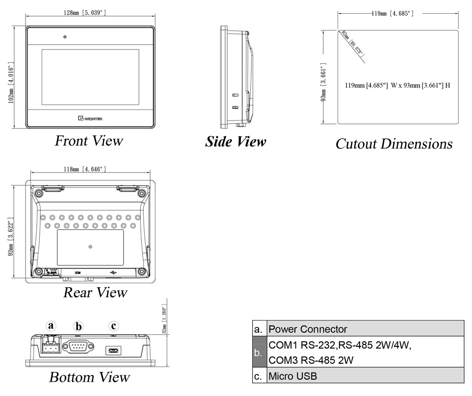
the panel from being deformed.) Panel Cutout:
119 mm x 93 mm
4
Installation Instruction
5
6
Power Connections
NOTE:
1. Connect positive DC line to the ‘+’ terminal and
the DC ground to the ‘-‘ terminal.
2. When downloading project using a USB cable,
do not connect HMI with PLC and PC
simultaneously, for electric potential difference
may result in damage to HMI or PC.
System Settings
When HMI is powered up and displays image,
click the system setting button.
(Default System Password: 111111)
It is necessary
to connect the HMI to
your network through a RJ-45 cable.
(N/A for MT6051iP)
EasyBuilder Pro Software Settings
Launch EasyBuilder Pro software, select your project file, press F7 shortcut key to open the download
dialog box:
For MT6051iP, select USB cable /
For MT8051iP, select Ethernet > IP tab > Enter your HMI IP > Click Download to download this project file
to HMI.
Using screensaver and backlight saver is recommended in order to avoid image persistence caused by
displaying the same image on HMI for a long time.
(Please refer to EasyBuilder Pro User Manual for software operation details.)
Go to the Network tab, you may choose
to auto get DHCP IP, or designate your
own IP.
MT6051iP MT8051iP series
Installation and Startup Guide
1
This document covers the installation of MT6051/8051iP Series HMI, for the detailed specifications and
operation, please refer to Brochure and EasyBuilder Pro User Manual.
Install Environment:
NEMA Rating
MT6051/8051iP
Series HMI is NEMA 4 rated (Indoor Only).
MT6051/8051iP
Series has been tested to conform to European CE
Electrical
requirements. This means that the circuitry is designed to resist the effects of
Environment
electrical noise. This does not guarantee noise immunity in severe cases. Proper
wire routing and grounding will insure proper operation.
(1) Make sure that the displays are installed correctly and that the operating
limits are followed. Avoid installing units in environments where severe
mechanical vibration or shocks are present.
(2)
Do not operate the unit in areas subject to explosion hazards due to
flammable gases, vapors or dusts.
Environmental
(3) Do not install the unit where acid gas, such as SO2 exists.
Considerations
(4)
This device should be mounted in the vertical position and for use on the flat
surface enclosure.
(5)
Conform to UL508 (ISBN 0-7629-0404-6) machine safety for use in
Pollution Degree 2 Environment.
(6)
Relative Humidity: 10% ~ 90% (non-condensing)
2
Unpacking the Unit
Unpack and check the delivery. If damage is found, notify the supplier.
NOTE:
Place the operator panel on a stable surface during installation. Dropping it or letting it fall
may cause damage.
(1) Installation Instruction, 2-sided A4 *1
(2) Human Machine Interface *1
(3) Power Connector *1
(4) Brackets & Screws *1 pack
3
Installation Instructions
Secure the operator panel in position, using all
the fastening holes and the provided brackets
and screws. Screw Torque: 2.6 ~ 3.9 lbf.in.
(For reaching waterproof effect and preventing
the panel from being deformed.) Panel Cutout:
119 mm x 93 mm
4
Installation Instruction
5
6
Power Connections
NOTE:
1. Connect positive DC line to the ‘+’ terminal and
the DC ground to the ‘-‘ terminal.
2. When downloading project using a USB cable,
do not connect HMI with PLC and PC
simultaneously, for electric potential difference
may result in damage to HMI or PC.
System Settings
When HMI is powered up and displays image,
click the system setting button.
(Default System Password: 111111)
It is necessary
to connect the HMI to
your network through a RJ-45 cable.
(N/A for MT6051iP)
EasyBuilder Pro Software Settings
Launch EasyBuilder Pro software, select your project file, press F7 shortcut key to open the download
dialog box:
For MT6051iP, select USB cable /
For MT8051iP, select Ethernet > IP tab > Enter your HMI IP > Click Download to download this project file
to HMI.
Using screensaver and backlight saver is recommended in order to avoid image persistence caused by
displaying the same image on HMI for a long time.
(Please refer to EasyBuilder Pro User Manual for software operation details.)
Go to the Network tab, you may choose
to auto get DHCP IP, or designate your
own IP.
Table of Contents for weintek MT6051iP Series:
-
Communication Connections NOTE: COM1 RS-485 2W supports MPI 187.5K. 9 Pin, Male, D-sub COM1 [RS232] COM1 [RS485] COM3 [RS485] Jumper Settings Please prepare a jumper cap for setting the jumpers. Another way to enter touch screen calibration mode is: Press and hold anywhere on the screen for more than 2 seconds when HMI starts. Battery Replacement Battery replacement shall be performed by qualified personnel only and care must be taken when handling lithium batteries. For more informatio
Questions, Opinions and Exploitation Impressions:
You can ask a question, express your opinion or share our experience of weintek MT6051iP Series device using right now.


Под заказ
Цена по запросу
Дисплей: 4.3″
Разрешение: 480 x 272
Память: 128
COM-порт: 2
Рабочая температура: 0°~50°C (32°~122°F)
Температура хранения: -20°~60°C (-4°~140°F)
Питание: 24±20%
Габариты: 128 x 102 x 32
Скачать инструкции
-
Описание
| Дисплей | Размер экрана | 4.3 дюйма |
| Разрешение | 480 × 272 | |
| Яркость | 400 кд / м 2 | |
| Цвет | 16.7 М | |
| Тип подсветки | LED | |
| Ресурс подсветки | >30000 часов | |
| Место хранения | Flash | 128 MB |
| ОЗУ | 128 MB | |
| Порты ввода / вывода | USB-хост | USB 2.0 x 1 |
| Серийный порт | COM1 | RS-232/RS-485 2W/4W |
| COM2 | – | |
| COM3 | RS-485 2W |
|
| Ethernet | 10/100 Base-Tx1 | |
| Питание | Напряжение | 10.5-28 В DC |
| Потребляемая электроэнергия | 800 мА@12 В DC 400 мА@24 В DC |
|
| измерение | Материал корпуса | Пластик |
| Размер (мм) | 128 × 102 H × 32 D | |
| Монтажный размер (мм) | 192.0W×138.0H | |
| Вес (кг) | 0.25 | |
| Рабочая среда | защита | IP65 (передняя панель) |
| Температура хранения | -20 ℃ ~ 60 ℃ |
|
| Рабочая температура |
0 ℃ ~ 50 ℃ | |
| Влажность | 10 ~ 90% относительной влажности (без конденсации) | |
| Сертификация | СЕ |
Маркировка СЕ |
|
weintek MT6051iP Series Installation Instruction Document Information:
|
|
|
Pages Preview: |
Note for Owners:
Guidesimo.com webproject is not a service center of weintek trademark and does not carries out works for diagnosis and repair of faulty weintek MT6051iP Series equipment. For quality services, please contact an official service center of weintek company. On our website you can read and download documentation for your weintek MT6051iP Series device for free and familiarize yourself with the technical specifications of device.
-
QOLSYS IQ PANEL 2
The Qolsys IQ Panel 2 is a 7” touchscreen built with an Android operating system, providing full security and smart home functionality in an easy to use interface.INSTALLATION MANUALQolsys IQ Panel 2 Software Version 2.0.6 …
IQ PANEL 2 Touchscreen, 57
-
AMX MST-1001
Instruction ManualModero S Series Touch PanelsModero S SeriesTouch PanelsMST-1001/MSD-1001-L — 10.1″ Modero S Series Touch PanelsMST-701/MSD-701-L — 7″ Modero S Series Touch PanelsMST-431/MSD-431-L — 4.3″ Modero S Series Touch PanelsLast Revised: 10/08/2014 …
MST-1001 Touch Panel, 48
-
Donaldson Filter Minder Indicator
Donaldson T.R.A.P.™ Filter Minder® Indicator Installation InstructionsBy installing a Filter Minder® restriction indicator in an accessible location, operators can easily monitor the T.R.A.P. breather’s airflow restriction in graduated increments to maximize T.R.A.P. breather life and effectively meet service intervals.This kit provides the convenience of monitoring your T.R.A.P. breather …
Filter Minder Indicator Touch Panel, 2
-
TESTO 510
Bedienungsanleitung deInstruction manual enMode d’emploi frManual de instrucciones esManuale di istruzioni itManual de instruções ptÐóêîâîäñòâî ïîëüçîâàòåëÿ rutesto 510 …
510 Measuring Instruments, 60
-
Siko AP05
93/22AP05Absolute / elektronische PositionsanzeigeOriginalmontageanleitung Deutsch Seite2Absolute / Electronic Position IndicatorTranslation of the Original Installation Instructions English page23 …
AP05 Measuring Instruments, 44
-
Seametrics FT420
FT420 Flow ComputerInstructionsThe FT420 is a loop-powered microcontroller-basedtransmitter/indicator. It displays rate and total, and pro-vides a 4-20 mA analog signal proportional to flow. Aprogrammable pulse output, high flow or low flow alarmare also standard for metering pump control or datalogging.The rugged cast-aluminum housing is gasketed for maxi-mum environmental protection, and the e …
FT420 Measuring Instruments, 4
-
Panasonic TY-TP65P8-S — Touch-screen — Wired
Operating InstructionsTouch PanelModel No.Before connecting, operating or adjusting this product, please read these instructions completely.Please keep this manual for future reference.EnglishTQZW433TY-TP65P8-S® …
TY-TP65P8-S — Touch-screen — Wired Accessory, 36
-
Transcell Technology NEPTUNE 4500
NEPTUNE 4500 Digital Indicator Setup / Operation Manual Revision 0.3 February 6, 2003 2003 Transcell Technology, Inc. Contents subject to change without notice. Transcell Technology, Inc. 975 Deerfield Parkway Buffalo Grove, IL 60089 Tel (847) 419-9180 Fax (847) 419-1515 E-mail: [email protected] Web: www.transcell.net …
NEPTUNE 4500 Touch Panel, 34
Popular Touch Panel User Guides:
7
Communication Connections
NOTE: COM1 RS-485 2W supports MPI 187.5K.
9 Pin, Male, D-sub
COM1 [RS232]
PIN#
COM1 [RS485]
COM3 [RS485]
Jumper Settings
8
1-2
Short
Open
Open
Please prepare a jumper cap for setting the jumpers.
Another way to enter touch screen calibration mode is: Press and hold anywhere on the screen for more
than 2 seconds when HMI starts.
Battery Replacement
9
Battery replacement shall be performed by qualified personnel only and care must be taken when handling
lithium batteries. For more information on battery replacement and disposal considerations, please refer to
the following link:
http://www.weintek.com/download/MT8000/eng/FAQ/FAQ_103_Replace_Battery_en.pdf
COM1 [RS485]
COM1
[RS232]
4 wire
2 wire
1
Rx-
Data-
2
Rx+
Data+
3
Tx-
4
TX+
5
GND
6
TxD
7
8
9
RxD
3-4
Mode
Open
Touch Screen Calibration Mode
Short
Boot Loader Mode
Open
Normal
CAUTION
Power
Fusing
Require-
COM3
ments
[RS485]
High Voltage
Emergency Stop
Supply Voltage
Condition
Data-
Data+
Wire Routing
DANGER
Hardware
Considerations
Programming
Considerations
Limited Warranty
This product is limited warranted against defects in design and manufacture.
The proven defective product will either be repaired or replaced, at Weintek’s discretion.
This warranty shall not cover any product which is
(a) Out of warranty period which is 12 months from the manufacturing month of the HMI products.
(b) Damage caused by Force Majeure, accident, negligence, improper installation or misuse.
(c) Product has been repaired or taken apart by unauthorized technicians.
(d) Products whose identification markings have been removed or damaged.
NOTE: Make sure that all local and national electrical standards are met when
installing the unit. Contact your local authorities to determine which codes apply.
The unit can be powered by DC power only, voltage range: 10.5~28VDC, compatible with most
controller DC systems. The power conditioning circuitry inside the unit is accomplished by a
switching power supply. The peak starting current can be as high as 2A.
If the display does not come on within 5 seconds of power up, remove power. An internal fuse
will prevent damage if the polarity of the DC power is incorrect. Check wiring for proper
connections and try to power up again.
An Internal fuse will prevent damage for overcurrent condition however it isn’t guaranteed. DC
voltage sources should provide proper isolation from main AC power and similar hazards.
A Hard-wired EMERGENCY STOP should be fitted in any system using an HMI to comply with
ICS Safety Recommendations.
Do not power the unit and inductive DC loads, or input circuitry to the controller, with the same
power supply. Note: The 12 or 24 VDC output from some controllers may not have enough
current to power the unit.
a. Power wire length should be minimized (Max: 500m shielded, 300m unshielded).
b. Please use twisted pair cables for power wire and signal wire and conform to the
impedance matching.
c. If wiring is to be exposed to lightning or surges, use appropriate surge suppression
devices.
d. Keep AC, high energy, and rapidly switching DC power wiring separated from signal wires.
e.
Add a resistor and capacitor in the parallel connection between the ungrounded DC power
supply and the frame ground. This provides a path for static and high frequency
dissipation. Typical values to use are 1M Ohm and 4700pF
The system designer should be aware that devices in Controller systems could fail and
thereby create an unsafe condition. Furthermore, electrical interference in an operator
interface can lead to equipment start-up, which could result in property damage and/or
physical injury to the operator.
If you use any programmable control systems that require an operator, be aware that this
potential safety hazard exists and take appropriate precautions. Although the specific design
steps depend on your particular application, the following precautions generally apply to
installation of solid-state programmable control devices, and conform to the guidelines for
installation of Controllers recommended in NEMA ICS 3-304 Control Standards.
To conform with ICS Safety Recommendations, checks should be placed in the controller to
ensure that all writable registers that control critical parts of plant or machinery have limit
checks built into the program, with an out-of-limit safe shut down procedure to ensure safety of
personnel.
GME6851P2_MT6051_8051iP1_V2.0_Installation_171129
-
Avalue Technology LPC-1009 Series
Part No. E2017L090A0R LPC-1009/1209/1509/ 1709/1909 Series Fanless Multifunctional Touch Panel Computer Quick Reference Guide 1st Ed – 11 November 2014 Copyright Notice Copyright 2014 Avalue Technology Inc., ALL RIGHTS RESERVED. …
LPC-1009 Series Touch Panel, 24
-
AMX MXT-1901-PAN
Quick Start GuideMXT-1901-PAN 19.4″ Modero X Series® G5Panoramic Tabletop Touch PanelOverviewIn the MXT-1901-PAN 19.4” Modero X Series G5 Panoramic Tabletop Touch Panel (FG5968-41), the most elegant interface designed specifically for dedicated room control has been significantly enhanced to include a new G5 Gr …
MXT-1901-PAN Touch Panel, 2
-
berlinger Fridge-tag 2
USER MANUALFridge-tag 2Fridge-tag 2 EInternal/external sensor Berlinger & Co. AGMitteldorfstrasse 29608 GanterschwilSwitzerlandTel. +41 71 982 88 [email protected] � …
Fridge-tag 2 Data Loggers, 121
-
Eelectron HORIZONE VS05H WEB Series
VS0XHY0WEBFI00010100.DOCX VS05HxxWEB — VS08HxxWEB QUICK START GUIDE INSTALLAZIONE 1. Installare la scatola da incasso a muro, in base al modello di dispositivo (Vedere SCATOLE E DIMENSIONI) 2. Applicare la cornice in dotazione sopra la scatola a muro 3. L’alimentazione avviene tramite POE (Power Over Ethe …
HORIZONE VS05H WEB Series Touch Panel, 2
-
Forenex FES101E6-R/K39 SS Series
-1- FES101E6 User Manual FES101E6 ARM based Panel PC User Manual (Preliminary) Fanless ultra-compact Dual Core Cortex A72+Quad core Cortex A53 ARM system for Industrial/Door-Control/Medical-care Applicable Models: FES101E6-R/K39xxxSS, FES101E6-R/K39xxxPS FES101E6-R/K39xxxSA, FES101E6-R/K39xxxPA FES1 …
FES101E6-R/K39 SS Series Touch Panel, 21
-
Vivint SkyControl
Vivint&SkyControl&Support&!Add&user&code&»#!$%%!$!&'()!*#%(!+#!,#&)!+#&*-‘*)((.!/$.(01!*#2/0(+(!+-(!3#00#45.6!’+(/’7!89 :#!+#!,#&)!+#&*-‘*)((.!/$.(09!;9 <+!+-(!=#2(!’*)((.1!*-##'(!>(++5.6’9!?9 @.+()!$!A$05%!$%25.5’+)$ …
SkyControl Home Automation, 6
-
Hirschmann PAT DS 350GM
!!!»#$%&’#()**»‘+(,HIRSCHMANN,,-./,012310032403221,567,8,9,0:.02.;002,,,,<5=>?@6AB==<C/D,E8/>8@LOAD MOMENT INDICATOR DS 350GM,, 38 Years Specializingin Crane Electronic Repair & Parts Sales Call Us. We are glad to help Bode Te …
PAT DS 350GM Touch Panel, 56
Технические
характеристики панели оператора Weintek MT6051iP
Дисплей
| Диагональ экрана | 4.3 ″ |
| Разрешение | 480×272 |
| Яркость | 400 кд/м2 |
| Контрастность | 500:1 |
| Тип подсветки | LED |
| Время жизни подсветки | 30000 час. |
| Цветность | 16.7 млн |
| Угол обзора | 30/50/50/50 |
Сенсор
| Тип сенсора | 4х проводной резистивный |
Параметры
| Процессор | Cortex A8 |
| Частота | 600 МГц |
| Объем ОЗУ | 128 Мб |
| Flash (встроенный) | 0.125 Гб |
| RTC ( часы реального времени ) | Есть |
Интерфейсы
| USB клиент | USB 2.0 (micro) |
| Последовательный интерфейс | COM1 (RS232,RS485,2W/4W), COM3 (RS485 2W) |
Конструкция
| Материал корпуса | Пластик |
| Степень защиты лицевой панели | IP65 |
| Охлаждение | безвентиляторное |
| Посадочное отверстие | 119×93 мм |
| Габариты | 128x102x32 мм |
| Вес (нетто) | 0.25 кг |
| Крепление на стену | есть |
| Комплект поставки | крепежные элементы, предохранитель, разъем питания, инструкция |
ПO
| ПО для разработки проектов | EasyBuilderPro |
| Codesys | Нет |
| Максимальный размер проекта | 16 Мб |
| Объем памяти для сохранения архивов в панели | 48 Мб |
Эксплуатация и хранение
| Рабочая температура | 0~50 ℃ |
| Температура хранения | -20~60 ℃ |
| Потребляемый ток | 0.3 |
| Напряжение питания | 10.8~28VDC |
| Виброустойчивость | 10 ~ 25Hz (3 напр 2G 30 мин) |
| Сертификаты | CE |
Габариты панели оператора Weintek MT6051iP
Габариты: 128x102x32 мм
Посадочное
отверстие: 119×93 мм
Схема
соединения Weintek MT6051iP
Название разъема:
COM1[RS232]
Тип:
DB-9 M ( Папа )
| Pin # | COM1 (RS232) |
|---|---|
| 1 | |
| 2 | |
| 3 | |
| 4 | |
| 5 | GND |
| 6 | TXD |
| 7 | |
| 8 | |
| 9 | RXD |
Название разъема:
COM1/COM3[RS485]
Тип:
DB-9 F ( Мама )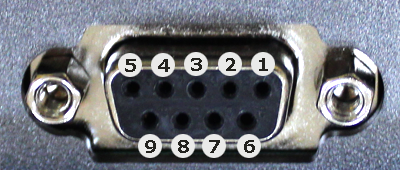
| Pin # | COM1 (RS485 2W) | COM1 (RS485 4W) | COM3 (RS485) |
|---|---|---|---|
| 1 | Data-(B) | RX- | |
| 2 | Data+(A) | RX+ | |
| 3 | TX- | ||
| 4 | TX+ | ||
| 5 | GND | GND | GND |
| 6 | |||
| 7 | Data-(B) | ||
| 8 | DATA+(A) | ||
| 9 |
Файлы для работы
с Weintek MT6051iP
| Файл | Дата | Размер | Язык |
|---|---|---|---|
|
EasyBuilderPro — windows-приложение для программирования панелей оператора Weintek Программное обеспечение EasyBuilderPro применяется для создания пользовательских проектов для операторских панелей Weintek всех серий. |
Eng | ||
|
Руководство к ПО EasyBuilderPro Приложение EasyBuilderPro применяется для создания пользовательских проектов для операторских панелей Weintek |
28-12-2022 | 30.42 МБ | Eng |
|
Онлайн руководство пользователя EasyBuilder Pro на английском языке Приложение EasyBuilderPro применяется для создания пользовательских проектов для операторских панелей Weintek |
рус | ||
|
Руководство по подключению контроллеров (PLC) к панели оператора Weintek В руководстве описано подключение к более, чем 100 PLC различных производителей, даны схемы распайки кабелей для подключения панели оператора к этим PLC, описаны регистры, к которым дают доступ драйвера данных PLC. |
07-02-2018 | 31.1 МБ | Eng |
| Document’s Content and Additional Information | Share Manual |
|---|---|
|
weintek MT6051iP Series Installation instruction
Pages Preview: Document Transcription:
See Details |

