- Manuals
- Brands
- Viessmann Manuals
- Boiler
- VITOTRONIC 200
Manuals and User Guides for Viessmann VITOTRONIC 200. We have 18 Viessmann VITOTRONIC 200 manuals available for free PDF download: Service Instructions Manual, Installation And Service Instructions For Contractors, Installation And Service Instructions Manual, Operating Instructions Manual, Operating Instructions For The System User, Technical Data Manual, Quick Reference Manual, Quick Start Programming Manual

Viessmann VITOTRONIC 200 Service Instructions Manual (336 pages)
Heat pump control unit
Brand: Viessmann
|
Category: Control Unit
|
Size: 7.87 MB
Table of Contents
-
Index Index
4
-
Table of Contents
4
-
-
Introduction Scope of Functions
16
-
Version
17
-
Sion
20
-
Refrigerant Circuit Controller
23
-
Setting Levels
24
-
Programming Unit
25
-
Primary Source, Ice Store/Solar
26
-
Operation with External Heat Generator (Not for Compact Appliances)
27
-
Heating Water Buffer Cylinder
28
-
Switching on the Compressor
28
-
-
Heat Pump Cascade
29
-
Central Cooling
30
-
Central Heating
30
-
DHW Heating
30
-
Integrating a Heat Pump Control Unit into LON
30
-
Swimming Pool Heating
30
-
Calling up Heat Pumps
31
-
Shutting down Heat Pumps
32
-
-
External Hook-Up for Heating/Cooling Circuits
33
-
Signal Effects
34
-
-
Smart Grid
35
-
Connection to Heat Pump Control Unit
36
-
-
Booster Heaters
37
-
External Heat Generator
38
-
Instantaneous Heating Water Heater
39
-
DHW Heating
40
-
DHW Reheating with Booster Heaters
42
-
Solar DHW Heating
43
-
Overview of Buffer Cylinders
44
-
Buffer Cylinder in Conjunction with Heat Pump Cascade
45
-
Heating the Buffer Cylinder with Booster Heaters
46
-
Frost Protection
47
-
-
Heating Circuits/Cooling Circuits
48
-
Weather-Compensated Control
50
-
Room Temperature-Dependent Control
51
-
Starting Central Heating
52
-
Deactivating Central Cooling
53
-
Central Heating with Booster Heaters
54
-
-
Natural Cooling Function (NC)
55
-
System with Heating Water/Coolant Buffer Cylinder
56
-
Connections at EA1 Extension
57
-
-
Mechanical Ventilation with Vitovent 200-C/300-F
58
-
Passive Heating
59
-
Passive Cooling
60
-
Vitovent 200-C: Frost Protection
61
-
Vitovent 300-F: Frost Protection
63
-
Protection against Excessively High Temperatures
64
-
-
Mechanical Ventilation with Vitovent 200-W/300-C/300-W
65
-
Passive Cooling
66
-
Cooling Via Geothermal Heat Exchanger
67
-
Protection against Excessively High Temperatures
68
-
-
Photovoltaics
69
-
Enabling Utilisation of Power Generated on Site
70
-
Buffer Cylinder Heating
71
-
Cooling the Heating Water/Coolant Buffer Cylinder
72
-
Troubleshooting Overview
74
-
-
Message Overview
75
-
Elec. Heating Blocked
77
-
Refrigerant Circuit
78
-
Outside Temp. Sensor
79
-
Flow Sensor Secondary
80
-
Flow Sensor Primary
81
-
Hot Gas Temp Sensor 2
82
-
Flow Sensor HC2
83
-
Flow Sensor HC3
84
-
Cylinder Sensor Top
85
-
Buffer Outlet Temp
86
-
Room Temp. Sensor HC1
87
-
Room Temp. Sensor HC1
88
-
Solar Module Sensor 10
89
-
C Cylinder Sensor Solar
90
-
A2 Compressor 2
91
-
A8 Heating Circ. Pump HC1
92
-
AA Cancel Defrost
93
-
AD Mixer Heating/Dhw
94
-
B4 AD Converter
95
-
C2 Power Supply
96
-
CA Protectn Device Primry
97
-
CB Flow Temp. Primary
98
-
D3 Low Pressure
99
-
D5 Contact Humidistat
100
-
D6 Flow Switch
101
-
E6 Fault at LON Subscbr
102
-
Diagnosis Diagnosis (Service Scans)
104
-
System Overview
110
-
-
System
120
-
Integrals
121
-
Logbook
123
-
-
Ventilation
128
-
Ventilation
130
-
Message History Vitovent 200-C/300-F
132
-
Vitovent 200-W/300-C/300-W Message History
135
-
-
Heat Pump
136
-
Refrigerant Circuit
137
-
Compressor Travel
146
-
Compressor Path
147
-
Message History [2]
148
-
Message History [4]
153
-
Message History [4-6] / [4-7]
164
-
Message History [6]
172
-
-
Energy Statement
178
-
Calling up the Energy Statement
179
-
Photovoltaics
180
-
DHW Loading Statistics
181
-
Output Curves
182
-
System Information
183
-
-
Actuator Test (Testing Outputs)
185
-
LON Subscriber Check
187
-
Enter Vitocom PIN Code
188
-
Saving/Loading Settings
192
-
-
Coding Level 1 in the Service Menu
193
-
-
Temperature
194
-
Setting Parameters
194
-
Restoring Delivered Condition (Reset)
195
-
Calling up the Parameter Group
196
-
-
Interval for Long Term Average Outside Temperature
197
-
Temperature Differential for Calculating the Cooling Limit
198
-
Swimming Pool
199
-
External Extension
200
-
Bit
201
-
Fig. 53
201
-
-
Operating Status for External Changeover
201
-
Heating Circuit Without Mixer
202
-
-
Effect of External Demand on Heat Pump/Heating Circuits
202
-
Vitocom 100
203
-
Bit
204
-
-
B Common Flow Temperature Sensor System
204
-
Number of Lag Heat Pumps
205
-
Minimum Temp. for Solar Absorber Primary Source
206
-
Absorber Circuit Monitoring
207
-
Bit
208
-
-
Holiday Program Effect
208
-
Evaporator Temperature for Defrost End
209
-
Output Compressor Stage
210
-
B01 Priority Ext. Heat Source/Instant. Heating Water Heater
211
-
B03 Start Threshold External Heat Source
212
-
B07 Run-On Time External Heat Source
213
-
B0E Dual Mode Heat Pump Operation
214
-
B11 Enable Boiler Water Temperature Sensor
215
-
Parameter Group DHW Calling up the Parameter Group
216
-
-
Hysteresis DHW Temperature Heat Pump
217
-
Start Optimisation for DHW Heating
218
-
E Temperature Sensor at Bottom of DHW Cylinder
219
-
Enable Electric Heaters for DHW Heating
220
-
F Cylinder Primary Pump Enable
221
-
Max. Interruption DHW Heating
222
-
Calling up the Parameter Group
223
-
Calling up the Parameter Group
224
-
Enable Instant. Heating Water Heater for Central Heating
225
-
A Output for Instant. Heating Water Heater at Power-OFF
226
-
Calling up the Parameter Group
227
-
C Flow Temperature for External Demand
228
-
D Enable 3-Way Diverter Valve Heating/Dhw
229
-
Compressor Performance at Max. Outside Temperature
230
-
Rated Output Secondary Pump (PWM)
231
-
Starting Time High Efficiency Circulation Pump
232
-
Screed Program End Day
233
-
Calling up the Parameter Group
234
-
Min. Primary Circuit Inlet Temperature in Operation
235
-
Calling up the Parameter Group
236
-
Max. Temperature Buffer Cylinder
237
-
Stop Hysteresis, Heating Water Buffer Cylinder
238
-
A Min. Temperature Coolant Buffer Cylinder
239
-
Calling up the Parameter Group
241
-
Room Temperature Control
242
-
A Influence Room Temperature Hook-Up
243
-
Room Temperature in Party Mode
244
-
Influence Room Temperature Hook-Up Cooling Circuit
245
-
Parameter Group Cooling Calling up the Parameter Group
246
-
-
Influence Room Temperature Hook-Up Cooling Circuit
247
-
Enable Flow Temperature Sensor Cooling Circuit
248
-
Dew Point Monitor
249
-
D01 Enable Preheater Bank Electric
250
-
D04 Enable Target Temperature Control
251
-
D0A Flow Rate Reduced Ventilation
252
-
D18 CO2 Value for Raising the Flow Rate
253
-
D1B Intensive Ventilation Duration
254
-
D27 Control Voltage Matching
255
-
D2F Installation Position
256
-
D71 Control Voltage Matching, Supply Air Fan
257
-
D72 Control Voltage Matching, Exhaust Air Fan
258
-
C101 Preheater Coil
259
-
C106 CO2 Sensor
260
-
C10B Standard Ventilation
261
-
C18A Reduced Ventilation, Second Fan Duct
262
-
C1A0 Bypass Mode
263
-
C1A3 Specified Imbalance
264
-
C1AA Min. Temperature, Geothermal Heat Exchanger
265
-
C1C1 Min. Voltage, Input 2
266
-
E02 Prop. of External Current
267
-
E04 Threshold for Electrical Power
268
-
E12 Enable Own Energy Consumptn for Heating Water Buffer Cyl
269
-
E21 Raise Set DHW Cylinder Temperature PV
270
-
E82 Smart Grid Enable Elec Heat
271
-
E91 Smart Grid Set Value Increase for DHW Heating
272
-
C00 to 7C06 Automatic Changeover Summertime — Wintertime
273
-
Calling up the Parameter Group
274
-
-
C Interval for Data Transfer Via LON
275
-
FF Send Time
276
-
Calling up the Parameter Group
277
-
-
Overview of the Pcbs
278
-
Heat Pumps with Separate Indoor and Outdoor Unit
279
-
-
Main and Expansion PCB
280
-
Expansion PCB on Main PCB
284
-
Connections for DHW Heating
287
-
-
Vitocal 300-A Cross Connect PCB
289
-
Luster Terminals, Vitocal 100-S/200-A/200-S
292
-
Luster Terminals, Vitocal 111-S/222-A/222-S
294
-
Luster Terminals Vitocal 200-A
296
-
Vitocal 222-G/333-G Luster Terminals
299
-
Vitocal 100-S/200-A/200-S/300-A Controller and Sensor PCB
300
-
Vitocal 111-S/222-A/222-S/222-G/333-G Controller and Sensor PCB
302
-
Inverter
305
-
Eev Pcb [4-3] / [4-4]
307
-
Eev Pcb [4-6] / [4-7]
308
-
Vitocal 222-G
309
-
Controller PCB: Type AWO 301.A25 to A60
310
-
EEV PCB: Type AWO 301.A60
311
-
Main PCB [7] / [7-1]
312
-
Jumper ID (Blue)
313
-
-
-
Temperature Sensors
314
-
Viessmann Pt500A (Green Marking)
316
-
Pressure Sensors
321
-
Declarations of Conformity for Heat Pumps
323
-
-
-
Advertisement

Viessmann VITOTRONIC 200 Service Instructions Manual (188 pages)
Vitotronic 200 Type WO1A Heat pump control unit
Brand: Viessmann
|
Category: Control Unit
|
Size: 1.19 MB
Table of Contents
-
Safety Instructions
2
-
Table of Contents
4
-
Scope of Functions
9
-
Setting Levels
9
-
Programming Unit
10
-
Function Description
12
-
Heat Pump Cascade
12
-
Heat Pump Stage
12
-
Externally Switched Functions
17
-
Buffer Cylinder
19
-
-
Dhw Heating
21
-
Solar Dhw Heating
24
-
-
Heating Water Buffer Cylinder/Low Loss Header
25
-
Heating Circuits/Cooling Circuit
26
-
Cooling Functions
30
-
-
S
35
-
Scanning Messages
35
-
-
Troubleshooting
93
-
Testing Outputs (Actuator Test)
93
-
Function Check
94
-
Lon Subscriber Check
95
-
No Display in Programming Unit
96
-
-
Control Unit Settings
97
-
Coding Level 1 in Service Menu
97
-
-
Parameter Group System Definition
98
-
System Scheme
98
-
Temperature Differential for Calculating the Heating Limit
100
-
A Cascade Control
102
-
Number of Lag Heat Pumps in Cascade
102
-
Swimming Pool
103
-
-
B Output Lag Heat Pump
103
-
Heating Circuit Without Mixer A1
105
-
-
Operating Status for External Changeover
106
-
Duration of External Changeover
107
-
Heating Circuit with Mixer M2
108
-
Heating Circuit with Mixer M3
108
-
-
Effect of External Demand on Heat Pump/Heating Circuits
108
-
Effect of Ext. Blocking on Heat Pump/Heating Circuits
108
-
A Effect of External Blocking on Pumps/Compressor
109
-
B Common Flow Temperature Sensor System
111
-
-
Parameter Group External Heat Source
114
-
B00 Enable External Heat Source
114
-
B01 Priority Ext. Heat Source/Instant. Heating Water Heater
114
-
B02 Dual Mode Temperature External Heat Source
114
-
B0D Enable External Heat Source for Dhw Heating
115
-
-
Parameter Group Dhw
116
-
Set Dhw Temperature
116
-
Min. Dhw Temperature
116
-
Hysteresis Dhw Temperature Heat Pump
117
-
Hysteresis Dhw Temperature Instant. Heating Water Heater
118
-
Start Optimisation for Dhw Heating
118
-
C Set Dhw Temperature
119
-
E Temperature Sensor at Bottom of Dhw Cylinder
119
-
Enable Booster Heaters for Dhw Heating
120
-
Enable Electric Heaters for Dhw Heating
120
-
Priority Dhw Heating with Combi Cylinder
120
-
Start Attempts for Dhw after High Pressure Shutdown
121
-
Operating Mode Cylinder Primary Pump
122
-
-
Parameter Group Solar
123
-
A00 Type Solar Control Unit
123
-
A01 Max. Collector Temperature
123
-
A02 Start Hysteresis Solar Circuit Pump
123
-
A03 Stop Hysteresis Solar Circuit Pump
124
-
A07 Flow Rate Solar Circuit for Calculating Solar Yield
124
-
A09 Display Message Incorrect Circulation
124
-
-
Parameter Group Electric Booster Heater
125
-
Parameter Group Electric Heater
125
-
Enable Instantaneous Heating Water Heater
125
-
Enable Instant. Heating Water Heater for Central Heating
125
-
Max. Output Instantaneous Heating Water Heater
126
-
A Output for Instant. Heating Water Heater at Power-Off
126
-
B Dual Mode Temp. Instant. Heating Water Heater
126
-
-
Parameter Group Internal Hydraulics
128
-
Heat Pump for Drying a Building
128
-
C Flow Temperature for External Demand
130
-
D Enable Three-Way Diverter Valve Heating/Dhw
131
-
Operating Mode Primary Pump
131
-
Operating Mode Secondary Pump
132
-
-
Parameter Group Buffer Cylinder
133
-
Enable Buffer Cylinder/ Low Loss Header
133
-
Temp. in Operating Status Fixed Value for Buffer Cyl
133
-
Hysteresis Temperature Heating Buffer Cylinder
133
-
Max. Temperature Buffer Cylinder
134
-
Temp. Limit Op. Status Fixed Value for Buffer Cylinder
135
-
-
R
136
-
Parameter Group Heating Circuits/Cooling Circuit
136
-
Standard Room Temperature
136
-
Reduced Room Temperature
136
-
Remote Control
136
-
Heating Curve Level
137
-
Heating Curve Slope
137
-
A Influence Room Temperature Hook-Up
138
-
B Room Temperature Hook-Up
138
-
E Max. Flow Temperature Heating Circuit
139
-
Room Temperature in Party Mode
139
-
-
Parameter Group Cooling
140
-
Cooling Function
140
-
Set Room Temperature Separate Cooling Circuit
141
-
Min. Flow Temperature Cooling
141
-
Influence Room Temperature Hook-Up Cooling Circuit
141
-
Cooling Curve Level
142
-
Cooling Curve Slope
142
-
Fe Enable Active Cooling Mode
142
-
-
Parameter Group Time
143

Viessmann VITOTRONIC 200 Installation And Service Instructions Manual (120 pages)
Weather-compensated, digital boiler control unit
Brand: Viessmann
|
Category: Control Unit
|
Size: 2.68 MB
Table of Contents
-
Table of Contents
4
-
Installing the Control Unit Base
8
-
Fitting the Top of the Control Unit for Type KO1B
8
-
Opening the Control Unit
9
-
Type KO1B
9
-
Type KO2B
10
-
-
Plugging in the Coding Card
10
-
Adjusting the High Limit Safety Cut-Out (if Required)
10
-
Type KO1B
11
-
Type KO2B
12
-
-
Adjusting the Temperature Controller (if Required)
13
-
Type KO1B
14
-
Type KO2B
14
-
-
Overview of Electrical Connections
15
-
Inserting Cables/Leads and Applying Strain Relief
16
-
Connecting the Sensors
16
-
Fitting and Connecting an Outside Temperature Sensor
16
-
-
Connecting the Pumps
17
-
Available Pump Connections
17
-
Pumps 230 V
17
-
Pumps 400 V
18
-
-
External Burner Start
18
-
Provisional Burner Operation
18
-
External Demand Via Switching Contact
19
-
Connection
19
-
Codes
19
-
External Demand Via
19
-
Input
19
-
-
External Demand Via 0
20
-
External Blocking Via Switching Contact
20
-
Codes
21
-
-
Connecting a Pressure-Jet Oil/Gas Burner
21
-
Extending Two-Stage/Modulating Burners, Part No. 7404 960
21
-
Connecting an Atmospheric Burner
22
-
Extension, Two-Stage Burner, Part No. 7827 417
23
-
-
Power Supply
24
-
Power Supply for Several Accessories
25
-
Control Unit Power Supply
26
-
-
-
Testing the High Limit Safety Cut-Out
27
-
Type KO1B
27
-
Type KO2B
27
-
Changing the Language
27
-
Setting the Date and Time
28
-
Adjusting Coding Addresses
28
-
Adjusting Heating Curves
28
-
Set Room Temperature, Adjusting
29
-
Changing the Slope and Level
30
-
-
Connecting the Control Unit to the LON
31
-
Example of a Single Boiler System with Vitotronic 200-H and Vitocom 200
31
-
Carrying out a LON Subscriber Check
32
-
-
Entering a Service PIN for LON Subscribers
32
-
Entering a PIN for Vitocom 100, Type GSM2
32
-
Coding Level
33
-
-
Calling up Coding Levels
33
-
Leaving the Coding Level
33
-
Resetting Codes to Their Delivered Condition
33
-
-
General» Group
34
-
Coding
34
-
Boiler» Group
35
-
Coding
35
-
-
DHW» Group
36
-
Coding
36
-
-
Solar» Group
36
-
Heating Circuit 1″, «Heating Circuit 2», «Heating Circuit 3» Group
37
-
Coding
37
-
-
Coding Level 1
37
-
-
«General» Group
41
-
Coding
41
-
Boiler» Group
44
-
Coding
44
-
-
DHW» Group
46
-
Coding
46
-
-
Solar» Group
47
-
Coding
47
-
-
Heating Circuit 1″, «Heating Circuit 2», «Heating Circuit 3» Group
50
-
Coding
50
-
-
Service Scans Calling up the Service Menu
55
-
Closing the Service Menu
55
-
Scanning Operating Data
55
-
Brief Scan
56
-
Resetting Operating Data
56
-
Carrying out an Actuator Test
57
-
Checking the Sensors
58
-
Service Indicator
58
-
Acknowledging the Service Display
58
-
Calling up Acknowledged Service Messages
59
-
-
-
Troubleshooting Fault Display
60
-
Acknowledging a Fault Display
60
-
Calling up Acknowledged Fault Messages
60
-
Calling up Fault Codes from the Fault Memory (Fault History)
60
-
Fault Messages
60
-
Faults that Are Not Displayed at the Programming Unit
65
-
Boiler Cold, Burner Does Not Start
65
-
Boiler Water Temperature Is too High or too Low
65
-
Boiler Hot Enough, but the Heating Circuit Pump Connected to the Control Unit Is Not Running
65
-
-
-
-
Parts Lists Ordering Parts
67
-
Parts List Type KO1B
68
-
Parts List Type KO2B
72
-
-
Function Description Boiler Water Temperature Control
76
-
Brief Description
76
-
Functions
76
-
Control Sequence for Burner Switching Hysteresis of 4 K
77
-
Heating Circuit Control Unit
77
-
Brief Description
77
-
Functions
77
-
Control Sequence
81
-
-
Cylinder Temperature Control
82
-
Brief Description
82
-
Functions
82
-
Control Sequence
83
-
-
-
Components
84
-
Fuse
84
-
Sensors
84
-
Boiler Water, Cylinder, Buffer, Flow and Room Temperature Sensors
84
-
Outside Temperature Sensor
85
-
Flue Gas Temperature Sensor, Part No. 7452 531
85
-
-
Radio Clock Receiver
86
-
Connection
86
-
Checking the Reception
87
-
Specification
87
-
-
Mixer Extension Kit
87
-
Rotary Selector Setting
88
-
Specification
89
-
Mixer Motor, Part No. 7450 657
89
-
Checking the Rotational Direction of the Mixer Motor
89
-
Changing the Rotational Direction of the Mixer Motor
90
-
-
Temperature Limiter for Restricting the Maximum Temperature
90
-
EA1 Extension, Part No. 7452 091
91
-
Digital Inputs DE1 to DE3
91
-
Analogue Input 0
92
-
Output Abj
92
-
-
External Extension H5, Part No. 7199 249
93
-
External Burner Blocking
93
-
External Safety Equipment
93
-
Temporary Operation (Burner Stage 1)
93
-
Motorised Flue Gas Damper
94
-
-
Vitoair Draught Stabiliser, Part No. 7338 725, 7339 703
95
-
Function Check
95
-
Motor Faulty
95
-
-
Advertisement

Viessmann VITOTRONIC 200 Installation And Service Instructions Manual (112 pages)
Digital boiler control unit
Brand: Viessmann
|
Category: Thermostat
|
Size: 2.33 MB
Table of Contents
-
Safety, Installation and Warranty Requirements
2
-
Product Information
2
-
Table of Contents
3
-
About These Instructions
5
-
For Your Safety
6
-
System Example
7
-
Preparing for Installation System Example
8
-
Installation Information for the Vitotronic 200
8
-
Installing a Cascade Communication Module — Vitodens 200-W
8
-
Preparing Boilers for Cascade Mode — Vitodens 200-W
9
-
Cu3A
12
-
Configure Boilers for Cascade Mode
14
-
Overview of Electrical Connections, Vitotronic 300-K
15
-
Inserting the LON Communication Module
17
-
Mounting the Control Unit
17
-
Inserting Cables/Leads and Applying Strain Relief
18
-
Connecting Sensors
18
-
Connecting Pumps
19
-
External Connection
20
-
Connecting Actuators
21
-
Connecting the Central Fault Message Facility
22
-
External Blocking Via Switching Contact
22
-
External Demand Via 0-10V Input
23
-
External Blocking Via Switching Contact
23
-
External «Mixing Valve Closed»/»Mixing Valve Open
24
-
External Heating Program Changeover
24
-
Making the LON Connection
25
-
Power Supply
27
-
Fitting the Control Unit Front
28
-
Opening the Control Unit
29
-
Changing the Language
30
-
System
30
-
Selecting the Boiler Sequence (if Required)
31
-
Connecting the Control Unit to the LON System
31
-
Testing Actuators on the Vitotronic 200
35
-
Scanning Operating Details at the Vitotronic 200
36
-
Testing Actuators and Sensors on the Vitotronic 300-K
36
-
Adjusting the Heating Curve
37
-
Calling up the Service Level — Vitotronic 200
39
-
Leaving the Service Level — Vitotronic 200
39
-
Scanning Operating Data — Vitotronic 200
40
-
Brief Scan — Vitotronic 200
40
-
Calling up the Service Menu — Vitotronic 300-K
41
-
Leaving the Service Menu — Vitotronic 300-K
42
-
Change Passwords — Vitotronic 300-K
42
-
Vitotronic 300-K
42
-
Scanning Operating Data — Vitotronic 300-K
43
-
Resetting Operating Data — Vitotronic 300-K
43
-
Brief Scan — Vitotronic 300-K
44
-
Maintenance Display
45
-
Fault Display
46
-
Fault Codes
47
-
Boiler Water Temperature Control of the Vitotronic 200
53
-
Cascade Control of the Vitotronic 300-K
53
-
Heating Circuit Control Unit of the Vitotronic 300-K
58
-
DHW Tank Temperature Control
63
-
Calling up Coding Level 1
65
-
General» Group
66
-
Boiler» Group
66
-
General» Group
67
-
Calling up Coding Level 2
67
-
Boiler» Group
71
-
Calling up Coding Levels
72
-
Resetting Coding to Their Factory Set Condition
72
-
General» Group
73
Viessmann VITOTRONIC 200 Installation And Service Instructions Manual (132 pages)
Brand: Viessmann
|
Category: Control Unit
|
Size: 6.38 MB
Table of Contents
-
Safety Instructions
2
-
System Version
6
-
Single Boiler System with Therm-Control
6
-
System Extension
11
-
Overview of Electrical Connections
15
-
Inserting Cables and Applying Strain Relief
16
-
Inserting the Boiler Coding Card
18
-
Changing the High Limit Safety Cut-Out Setting (if Required)
18
-
Changing the Control Thermostat Setting (if Required)
20
-
Connecting Sensors
21
-
Connecting Pumps
22
-
External Burner Blocking
27
-
External Heating Program Changeover
28
-
External Changeover of Multi-Stage/Modulating Burners
29
-
External Demand
30
-
Connecting Central Fault Messaging to Plug Gö
30
-
Connecting an AC Burner
30
-
Power Supply
35
-
Display and Control Elements
39
-
Changing the Language
40
-
Testing the High Limit Safety Cut-Out
40
-
Matching the Coding Addresses to the System Version
40
-
Checking Outputs (Actuators) and Sensors
42
-
Carrying out a Relay Test
42
-
Service Level Summary
50
-
Temperatures, Boiler Coding Card and Brief Scans
51
-
Operating Conditions
53
-
Resetting Parameters
54
-
Scanning and Resetting the «Service» Display
55
-
Checking and Acknowledging Faults
56
-
Calling up Fault Codes from the Fault Memory (Fault History)
57
-
Boiler Water Temperature Control
66
-
Brief Description
66
-
Control Sequence
70
-
Heating Circuit Control
72
-
Cylinder Temperature Control
77
-
Connection and Wiring Diagram
101
-
Components from the Parts List
105
-
Main PCB Low Voltage
105
-
Power Supply Pcb
105
-
Programming Unit
106
-
Safety Assembly
106
-
High Limit Safety Cut-Out
107
-
Outside Temperature Sensor
111
-
Specification
114
-
Remote Control
115
-
Boiler Coding Card
118
-
Function Check
123
-
Emergency Mode
123
-
Parts Lists
124

Viessmann VITOTRONIC 200 Installation And Service Instructions For Contractors (136 pages)
Weather-compensated control unit
Brand: Viessmann
|
Category: Control Unit
|
Size: 9.92 MB
Table of Contents
-
Safety Instructions
3
-
Disposal of Packaging
11
-
Symbol Meaning
11
-
Intended Use
11
-
Product Information
12
-
System Examples
12
-
Installation Sequence
13
-
Adjusting the High Limit Safety Cut-Out (if Required)
14
-
Inserting Cables and Applying Strain Relief
17
-
Overview of Electrical Connections
19
-
Connecting Sensors
21
-
Outside Temperature Sensor
22
-
Connecting Pumps
22
-
External Functions
26
-
External Operating Program Changeover
27
-
Connecting External Safety Equipment
31
-
Provisional Burner Operation
32
-
Connecting an AC Burner
32
-
Making the LON Connection
36
-
Connection Variants
37
-
Power Supply
38
-
Commissioning the System
41
-
Required Parameters
41
-
Adjusting the Heating Curve
45
-
Testing the High Limit Safety Cut-Out
46
-
Parameter Levels
49
-
Cylinder Priority Control
77
-
Start Optimisation
81
-
Calling up the Service Menu
87
-
Change Passwords
88
-
Service Display
91
-
Fault Messages
92
-
Troubleshooting
93
-
Checking Temperature Sensors
107
-
Checking the Fuses
108
-
Boiler Water Temperature Control
109
-
Control Sequence
110
-
Auxiliary Circuits
117
-
Connection and Wiring Diagrams
123
-
Ordering Parts
129
-
Declaration of Conformity
133
-
Keyword Index
136
Viessmann VITOTRONIC 200 Installation And Service Instructions Manual (92 pages)
Type HO1B & MW2B, Digital boiler control unit & Weather-compensated, digital cascade control unit
Brand: Viessmann
|
Category: Control Unit
|
Size: 1.82 MB
Table of Contents
-
Safety, Installation and Warranty Requirements
2
-
Product Documentation
2
-
Licensed Professional Heating Contractor
2
-
Advice to Owner
2
-
Warranty
2
-
Operating and Service Documentation
2
-
Table of Contents
3
-
-
System Example
5
-
Preparing Boilers for Cascade Mode
7
-
Overview of Electrical Connections, Vitotronic 300-K
11
-
Mounting the Control Unit
13
-
Installing the Heating Circuit Ext. Mod., Heating Circuits 2 and 3 (Accessory)
13
-
Inserting Cables/Leads and Applying Strain Relief
14
-
Connecting Sensors
14
-
Connecting Pumps
15
-
External Connection
16
-
Connecting Actuators
17
-
Connecting the Central Fault Message Facility
18
-
External Demand Via Switching Contact
18
-
External Demand Via 0-10V Input
19
-
External Blocking Via Switching Contact
19
-
External «Mixing Valve Closed»/»Mixing Valve Open
20
-
External Heating Program Changeover
20
-
Making the LON Connection
21
-
Power Supply
23
-
Fitting the Front Part of the Control Unit
24
-
Opening the Control Unit
24
-
Changing the Language
25
-
Setting the Time and Date
25
-
Configuring a Multi Boiler System
25
-
Connecting the Control Unit to the LON System
27
-
Checking the Heating Circuit Assignment
27
-
Matching Coding Addresses to the System Version
28
-
Selecting the Boiler Sequence (if Required)
28
-
Checking Outputs Actuators and Sensors
29
-
Calling up Coding Level 1 — Vitotronic 200
32
-
Boiler» Group
33
-
General» Group
33
-
Calling up Coding Level 1 — Vitotronic 300-K
34
-
General» Group
35
-
Cascade» Group
36
-
DHW» Group
36
-
Solar» Group
37
-
Heating Circuit 1, Heating Circuit 2, Heating Circuit 3″ Group
38
-
Calling up Coding Level 2 — Vitotronic 200
42
-
General» Group
43
-
Calling up Coding Level 2 — Vitotronic 300-K
46
-
General» Group
47
-
Cascade» Group
52
-
DHW» Group
54
-
Solar» Group
56
-
Heating Circuit 1, Heating Circuit 2, Heating Circuit 3″ Group
59
-
Calling up the Service Level
64
-
Scanning Operating Data
65
-
Brief Scan Vitotronic 200
66
-
Brief Scan Vitotronic 300-K
67

Viessmann VITOTRONIC 200 Operating Instructions Manual (109 pages)
Heating system and mechanical ventilation system with heat pump control unit
Brand: Viessmann
|
Category: Heating System
|
Size: 4.31 MB
Table of Contents
-
For Your Safety
3
-
Safety Instructions
3
-
Intended Use
8
-
Appliance Description
9
-
Introductory Information
9
-
Your System Is Preset at the Factory
12
-
Energy Saving Tips
13
-
Opening the Control Unit
15
-
Operation
15
-
Programming Unit
15
-
Symbols on the Display
16
-
Standard Menu
17
-
How to Use the Controls
18
-
Operating Program
19
-
Time Program
21
-
Starting the Heat Pump
25
-
Shutting down the Heat Pump
25
-
Room Temperature
26
-
Flow Temperature
30
-
Holiday Program
31
-
DHW Heating
33
-
Mechanical Ventilation
41
-
Smart Grid
47
-
Setting the Display Brightness
48
-
Language Selection
49
-
Calling up Information
51
-
Solar Energy
51
-
Daily Log
52
-
Screed Drying
52
-
Calling up Messages
54
-
Flow Temperature
54
-
Rooms Are too Cold
58
-
Rooms Are too Hot
59
-
There Is no Hot Water
59
-
«External Hook-Up» Is Displayed
60
-
«External Program» Is Displayed
60
-
«Controls Locked Out» Is Displayed
60
-
Doors/Windows Bang When Opened
61
-
Maintenance
63
-
Cleaning the Mechanical Ventilation System
63
-
Cleaning or Replacing Filters
64
-
Overview of Extended Menu
77
-
Underfloor Heating
87
-
Cooling Mode
92
-
Cooling Functions
93
-
Cooling Circuit
93
-
Central Cooling
94
-
Smart Grid (SG)
94
-
Information on Disposal
98
-
Your Contact
108

Viessmann VITOTRONIC 200 Operating Instructions Manual (72 pages)
Heating system and domestic ventilation system with heat pump control unit
Vitotronic 200, type WO1C
Brand: Viessmann
|
Category: Network Router
|
Size: 1.22 MB
Table of Contents
-
Operating Instructions
1
-
For Your Safety
2
-
Safety Instructions
2
-
Table of Contents
3
-
Introductory Information Commissioning
6
-
Energy Saving Tips
7
-
Programming Unit
9
-
Operating Info
10
-
-
Standard Menu
11
-
Extended Menu
12
-
Operating Program
13
-
Operating Programs for Ventilation
15
-
Example
16
-
Setting the Time Program Efficiently
17
-
Start-Up/Shutdown Starting the Heat Pump
18
-
-
Stopping the Heat Pump
19
-
Setting the Reduced Room Temperature for Heating/Cooling
20
-
Time Program
21
-
Heating Curve/Cooling Curve
22
-
-
Switching off Central Heating/Central Cooling
23
-
Energy Saving Function «Economy Mode
24
-
Cancelling or Deleting the «Holiday Program
25
-
DHW Heating DHW Temperatures
26
-
Setting the Start Optimisation
27
-
-
DHW Heating Outside the Time Program
28
-
Heating System with Elec
29
-
Enabling and Blocking Active Cooling Mode
30
-
System
31
-
-
Starting Ventilation
32
-
Setting the Operating Program for Ventilation
33
-
Comfort Function «Intensive Operation
34
-
Ending «Economy Mode
35
-
Own Consumption of Power
36
-
-
-
Setting the Display Contrast
37
-
Setting the Preferred Heating/Cooling Circuit for the Standard Menu
38
-
System
39
-
-
Calling up Information
40
-
Calling up Messages
41
-
System
42
-
-
Manual Mode
43
-
Special System Versions
44
-
Rooms Are too Cold
45
-
Rooms Are too Hot
46
-
Is Flashing and «Note» Is Displayed
47
-
-
Doors/Windows Bang When Opened
48
-
In Conjunction with a Brine/Water or Water/Water Heat Pump
49
-
Potable Water Filter (if Installed)
50
-
-
Replacing Filters in the Extract Air Valves
51
-
Resetting the Service Display
53
-
-
Viessmann VITOTRONIC 200 Operating Instructions Manual (73 pages)
Brand: Viessmann
|
Category: Controller
|
Size: 3.34 MB
Table of Contents
-
Safety Instructions
3
-
Installation Room Requirements
4
-
Introductory Information
9
-
Intended Use
9
-
Operating Principles
12
-
Control Unit Operation
13
-
Special Operating Programs
18
-
Setting the Room Temperature
22
-
Stopping Central Heating
24
-
Setting the «Time Program» for DHW Heating
28
-
Switching off DHW Heating
30
-
Further Adjustments
31
-
Setting the Display Brightness
31
-
Locking the Controls
32
-
Naming Heating Circuits
34
-
Calling up Help Messages
36
-
Calling up Information
36
-
Burner Faults
38
-
Scanning Fault Messages
39
-
Control Unit Controls
41
-
Without Frost Protection Monitoring (Shutdown)
42
-
Rooms Are too Cold
43
-
Rooms Are too Hot
44
-
There Is no Hot Water
45
-
«External Hook-Up» Is Displayed
47
-
«External Program» Is Displayed
47
-
Inspection and Maintenance
48
-
DHW Cylinder (if Installed)
48
-
Potable Water Filter (if Installed)
48
-
Damaged Cables / Lines
49
-
Maintenance
49
-
Fuel Oil Additives
50
-
Combustion Improvers
50
-
Buttons and Icons
51
-
Main Menu Overview
53
-
Heating Circuit Pump
65
-
Information on Disposal
67
-
Your Contact
72
Viessmann VITOTRONIC 200 Operating Instructions Manual (48 pages)
Vitotronic 200, type H01B Digital boiler control unit Vitotronic 300-K, type MW2B Weather-compensated, digital cascade control unit
Brand: Viessmann
|
Category: Control Unit
|
Size: 2.6 MB
Table of Contents
-
Operating Instructions
1
-
Safety, Installation and Warranty Requirements
2
-
Table of Contents
3
-
About These Instructions
5
-
For Your Safety
5
-
Where to Find the Controls
8
-
Controls, Vitotronic 200
8
-
How to Use the Controls, Vitotronic 200
9
-
Controls, Vitotronic 300-K
10
-
Menu, Vitotronic 300-K
11
-
How to Use the Controls, Vitotronic 300-K
12
-
Controls Overview
14
-
Start-Up/Standby/Shutdown
15
-
Required Settings
16
-
Selecting a Heating Circuit
16
-
Setting the Room Temperature
17
-
Setting the Heating Program for Central Heating
17
-
Setting the Time Program for Central Heating
18
-
Changing the Heating Curve
19
-
Stopping the Central Heating
19
-
Selecting Comfortfunction «Party Mode
20
-
Selecting Energy Saving Function «Economy Mode
20
-
Selecting Energy Saving Function «Holiday Program
21
-
Required Setings (DHW Heating)
22
-
Setting the DHW Temperature
22
-
Setting the Heating Program for DHW Heating
22
-
Setting the Time Program for DHW Heating
23
-
Stopping DHW Heating
24
-
Selecting the Boiler Sequence
25
-
Setting the Display Contrast
25
-
Setting the Display Brightness
25
-
Entering Names for the Heating Circuit
26
-
Selecting the Language
26
-
Setting the Time and Date
27
-
Setting the Temperature Unit ( O C/ O F)
27
-
Restoring the Factory Settings
27
-
Calling up the Service Level
28
-
Diagnostics
29
-
Checking Outputs (Relay Tests)
31
-
Scanning Information
32
-
Scanning Service Maessages
33
-
Scanning Fault Messages
33
-
Emissions Test Mode
34
-
Emmissions Test Mode
34
-
Rooms Are too Cold
35
-
Rooms Are too Hot
36
-
The DHW Is too Hot
36
-
OFF» Is Displayed at the Vitotronic 200
37
-
Is Displayed at the Vitotronic 200
37
-
There Is no Hot Water
37

Viessmann VITOTRONIC 200 Operating Instructions For The System User (73 pages)
Heat pump control unit
Brand: Viessmann
|
Category: Control Unit
|
Size: 0.99 MB
Table of Contents
-
Device Description
7
-
Introductory Information
7
-
Your System Is Preset at the Factory
7
-
Energy Saving Tips
9
-
Operation
11
-
Opening the Control Unit
11
-
Programming Unit
14
-
How to Operate
16
-
Starting the Heat Pump
19
-
With Frost Protection Monitoring
22
-
Heating Circuit
25
-
Setting the Room Temperature
25
-
Changing the Heating Curve
29
-
Selecting Party Mode
31
-
Comfort and Energy Saving Functions
31
-
Selecting Economy Mode
32
-
Selecting the Holiday Program
32
-
Start Optimisation
37
-
Stop Optimisation
37
-
DHW Heating Outside the Time Program
38
-
Switching off DHW Heating
41
-
Setting the Display Contrast
44
-
Language Selection
45
-
Scanning Information
47
-
Scanning Messages
48
-
Rooms Are too Cold
51
-
Rooms Are too Hot
51
-
There Is no Hot Water
52
-
«External Program» Is Displayed
53
-
Inspection and Maintenance
54
-
Your Contact
72
Viessmann VITOTRONIC 200 Installation And Service Instructions For Contractors (104 pages)
Weather-compensated, digital boiler control unit
Brand: Viessmann
|
Category: Control Unit
|
Size: 4.49 MB
Viessmann VITOTRONIC 200 Operating Instructions Manual (20 pages)
Vitodens 200-W, B2HA
Models 45 to 150
Wall-mounted, gas-fired condensing boiler in conjunction
with the Vitotronic 300-K MW2C cascade control
For operation with natural gas and liquid propane gas
Heating input 55 to 530 MBH
16 to 150 kW
Read and s
Brand: Viessmann
|
Category: Boiler
|
Size: 0.39 MB
Table of Contents
-
Operating Instructions
1
-
Safety, Installation and Warranty Requirements
2
-
Table of Contents
3
-
About These Instructions
4
-
For Your Safety
4
-
Where to Find the Controls
7
-
Controls, Vitotronic 200
7
-
How to Use the Controls, Vitotronic 200
7
-
Controls Overview
8
-
Start-Up/Standby/Shutdown
9
-
Setting the Display Contrast
10
-
Setting the Display Brightness
10
-
Selecting the Language
10
-
Setting the Time and Date
11
-
Setting the Temperature Unit
11
-
Restoring Factory Settings
11
-
Calling up the Service Level
12
-
Diagnostics
13
-
Checking Outputs (Relay Test)
14
-
Scanning Service Messages
15
-
Scanning Fault Messages
15
-
Emissions Test Mode
16
-
OFF» Is Displayed at the Vitotronic 200
17
-
Is Displayed at the Vitotronic 200
17
-
E» Is Displayed at the Vitotronic 200
17
-
Maintenance
18
-
Terminology
18
Viessmann VITOTRONIC 200 Technical Data Manual (8 pages)
Weather-responsive indoor/outdoor, digital boiler control for heating systems with one or more heating circuits
Brand: Viessmann
|
Category: Remote Control
|
Size: 0.32 MB
Table of Contents
-
Product Information
2
-
Standard Equipment
2
-
Application
2
-
Structure and Operation
3
-
Modular Structure
3
-
Boiler-Specific Functions
3
-
Technical Data
3
-
Digital Timer of Operating Unit
4
-
Heating Curve Adjustment
4
-
Adjusting the Operating System
4
-
Freeze-Up Protection Function
4
-
Accessories
5
Viessmann VITOTRONIC 200 Operating Instructions Manual (13 pages)
Heat pump control unit demo model
Brand: Viessmann
|
Category: Control Unit
|
Size: 0.28 MB
Table of Contents
-
Safety Instructions
3
-
Introductory Information
5
-
Displaying the Software Version
6
-
Operation
7
-
Menu Overview
9
-
Your Contact
10
Viessmann VITOTRONIC 200 Quick Reference Manual (8 pages)
Brand: Viessmann
|
Category: Remote Control
|
Size: 0.27 MB
Table of Contents
-
Room Temperature Settings
2
-
Domestic Hot Water Temperature Setting
2
-
Heating Curve Adjustment
2
-
Time Programs
3
-
Relay Test
4
-
Operating Status
4
-
Quick Reference
8
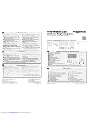
Viessmann VITOTRONIC 200 Quick Start Programming Manual (2 pages)
Vitodens 200, Programming unit with Vitotronic 200, H01 on-board control
Brand: Viessmann
|
Category: Controller
|
Size: 0.74 MB
Advertisement
Related Products
-
Viessmann Vitotron 100 Series
-
Viessmann Vitotron 100
-
Viessmann Vitotwin 300-W
-
Viessmann VITODENS 300-W
-
Viessmann VITOROND 200
-
Viessmann VITOGAS 100
-
Viessmann Vitodens 100
-
Viessmann Vitocrossal 100 CI1 twin boiler
-
Viessmann Vitoplex 200 Series
-
Viessmann VITOCELL 100-W
Viessmann Categories
Boiler
Toy
Control Unit
Heat Pump
Solar panel
More Viessmann Manuals
Alubox
Alubox X-treme
Alucon
Antifrogen
Aquacarbon
Aquahome
Atola
CeraCell
Condensola
Dekamatik
Divicon
EOMIX
EON
Eurola
Fauch
HoriCell
IS1500
Kospel EKCO
Kospel VSWK
Litola
Litola-CL
MatriX
Paromat
Pendola
Rondomat
RudoCell
SpiroTech
ST250
SW250
SW250LD
Trimatik
Turbomat
Ultrabox
Unit-P
Unomatik
VertiCell
VICare
Vitoair
Vitobloc 200
Vitocal
Vitocal 100-S/111-S
Vitocal 200-G
Vitocal 222-G
Vitocal 242-G
Vitocal 300
Vitocal 300-G
Vitocal 300-G Pro
Vitocal 300-G/350-G
Vitocal 300-G/W Pro
Vitocal 300-W Pro
Vitocal 333-G
Vitocal 343-G
Vitocal 350-G
Vitocal 350-G Pro
Vitocell
Vitocell 050-E
Vitocell 100
Vitocell 100-B
Vitocell 100-B/100-W
Vitocell 100-E
Vitocell 100-H
Vitocell 100-L
Vitocell 100-U
Vitocell 100-V
Vitocell 100-V/-W
Vitocell 100-W
Vitocell 100-W 100 л
Vitocell 100-W 80 л
Vitocell 120-E
Vitocell 140-E
Vitocell 160-E
Vitocell 300-B
Vitocell 300-H
Vitocell 300-V
Vitocell 300-V/-W
Vitocell 300-V/300-W
Vitocell 300-W
Vitocell 333
Vitocell 333/353
Vitocell 340-M
Vitocell 340?M/360?M
Vitocell 353
Vitocell 360-M
Vitocell-W 100
Vitocell-W 300
Vitoclima 230-S
Vitocom 100
Vitocom 200
Vitocom 300
Vitoconnect
Vitocrossal
Vitocrossal 100
Vitocrossal 200
Vitocrossal 300
Vitodens
Vitodens 050-W
Vitodens 100-W
Vitodens 111-F
Vitodens 111-W
Vitodens 141-F
Vitodens 200-W
Vitodens 200-W/300-W/333-W
Vitodens 200?W
Vitodens 222-F
Vitodens 222-W
Vitodens 222/333
Vitodens 242-F
Vitodens 300-W
Vitodens 333
Vitodens 333-F
Vitoflame 100
Vitoflame 200
Vitoflame 300
Vitogas
Vitogas 050
Vitogas 100
Vitogas 100-F
Vitogate 200
Vitogate 300
Vitola
Vitola 100
Vitola 200
Vitola-biferral
Vitola-comferral
Vitoladens
Vitoladens 300-C
Vitoladens 300-T
Vitoladens 300-W
Vitolig 150
Vitoligno 100-S
Vitomax
Vitomax 100
Vitomax 100-HS
Vitomax 100-LW
Vitomax 200
Vitomax 200-HS
Vitomax 200-HW
Vitomax 200-LW
Vitomax 300
Vitomax 300-HS
Vitomax 300-HW
Vitomax 300-LT
Vitomax 300-LW
Vitomax HS
Vitomax HW
Vitomax LCB
Vitomax LW
Vitomax-HS
Vitopend
Vitopend 050-W
Vitopend 100
Vitopend 100-W
Vitopend 100-W/200-W
Vitopend 111-W
Vitopend 200-W
Vitopend 222-W
Vitoplex
Vitoplex 100
Vitoplex 100-LS
Vitoplex 200
Vitoplex 300
Vitoplex 300 895-1750 кВт
Vitoplex/Vitorond/Vitomax
Vitoplus
Vitoradial
Vitoradial 300-T
Vitorond
Vitorond 100
Vitorond 111
Vitorond 200
Vitorondens 200-T
Vitorondens 222-F
Vitoset
Vitosoft 300
Vitosol
Vitosol 100
Vitosol 100-F
Vitosol 100-F/-FM
Vitosol 100-FM
Vitosol 141-FM
Vitosol 200
Vitosol 200-F
Vitosol 200-FM
Vitosol 200-T
Vitosol 200-TM
Vitosol 300
Vitosol 300-T
Vitosol 300-TM
Vitosolar 300-F
Vitosolic 100
Vitosolic 200
Vitotherm
Vitotrans
Vitotrans 100
Vitotrans 100-LW
Vitotrans 200
Vitotrans 200-LW
Vitotrans 222
Vitotrans 300/333
Vitotrans 300/333 1860-6600 кВт
Vitotrans 300/333 575-2000 кВт
Vitotrans 353
Vitotrol 100
Vitotrol 200-A
Vitotrol 200-E
Vitotrol 300
Vitotrol 300-A
Vitotrol 300-B
Vitotrol 300-E
Vitotron 100
Vitotronic
Vitotronic 050
Vitotronic 100
Vitotronic 100 HC1B
Vitotronic 100/200/300
Vitotronic 100/333
Vitotronic 200
Vitotronic 200 HO1B
Vitotronic 200 WPR3. Контроллер теплового насоса Vitocal
Vitotronic 200-H
Vitotronic 200. Контроллер теплового насоса Vitocal
Vitotronic 300
Vitotronic 300-K
Vitotronic 333
Vitotronic SPS
Vitovent 050-D
Vitovent 100-D
Vitovent 200-C
Vitovent 300-F
Vitovent 300-W
Vitplex
Vitоdens 200-W
Wallcon X-treme
WBS Ligna 050
ZONT H-2000/2000+
Адаптер электрических подключений
Блок управления приводом смесителя OpenTherm
Горелки
Горелки Bluetwin
Горелки Bluetwin/Unit
Датчик СО2 Vitovent 300-W
Дополнительный комплект/манометр
Комнатный термостат ST-BSOP/ST-PSOP
Контроллер KR
Контроллер SR
Контроллер Vitotrans 353
Модуль управления гелиоустановкой SDIO/SM1A
Насосные группы PAW
Нормативные показатели качества воды
Панель управления системой вентиляции
Платформа для техобслуживания котла
Примеры схем отопительных установок. Часть I
Примеры схем отопительных установок. Часть II
Примеры схем отопительных установок. Часть III
Примеры схем установок Vitosolic 100
Принадлежности
Принадлежности Vitotronic
Регулятор температуры помещения OpenTherm
Системы воздухораспределения Vitovent 300-W
Сифон Aquahome
Смесители отопительных контуров
Термическая станция водоподготовки Деаэратор
Универсальные радиаторы
Шкаф управления Vitocontrol
Шлюз WAGO MB/TCP-MB/RTU
Штиль ИнСтаб IS550
Штиль ИнСтаб SW250SL
Экономические показатели котельных установок
![]()

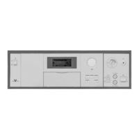
| KC3 | — для однокотельных установок; — для одного отопительного контура без смесителя; — для одноступенчатой горелки. |
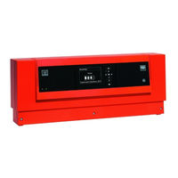
| KC4B | — для однокотельных установок; — для одного отопительного контура без смесителя — для одно- или двухступенчатой горелки — с цифровым индикатором — автоматический режим приготовления горячей воды — интегрированная система диагностик |
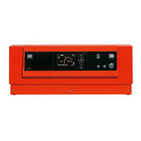
| KO2B | — для однокотельных установок; — для одного отопительного контура без смесителя и одного отопительного контура со смесителем; — для одноступенчатой, двухступенчатой или модулируемой горелки; — автоматический режим приготовления горячей воды; — программируемое переключение суточных и недельных режимов работы; — раздельная настройка циклограмм переключения режимов, заданных значений и отопительных характеристик для отопительных контуров; — отдельные циклограммы переключения режимов для отопления помещений, приготовления горячей воды и циркуляционного насоса контура водоразбора ГВС; — интегрированная система диагностики |
| Функции | Vitotronic 100 | Vitotronic 200 |
|---|---|---|
| Поддержание постоянной заданной температурой котловой воды | x | |
| Программируемая и погодозависимая теплогенерация с переменной температурой теплоносителя | x | |
| Управление 1-м/2-мя контурами со смесителем | x | |
| Plug & Work функция автоматического распознавания и адаптации датчиков и сенсоров системной оснастки | x | x |
| Уведомление о необходимом интервале сервисного и технического обслуживания | x | x |
| Цифровой таймер для ежедневного и еженедельного управления | x | |
| Автоматическое переключение режима Зима-Лето | x | |
| Режим выходного дня | x | |
| Уведомление о расходе топлива | x | |
| Программируемый режим «теплого пола» для отопительного контура со смесителем | x | |
| Удаленный доступ с помощью Vitocom 100 | x | x |
| Дистанционный контроль и управление Vitocom 200/300 | x |
Здесь можно скачать инструкции к контроллерам Vitotronic 200
 Инструкция Vitotronic 200 KW4 Инструкция Vitotronic 200 KW5