- Manuals
- Brands
- Carel Manuals
- Humidifier
- humiSteam x-plus
- User manual
-
Contents
-
Table of Contents
-
Bookmarks
Quick Links
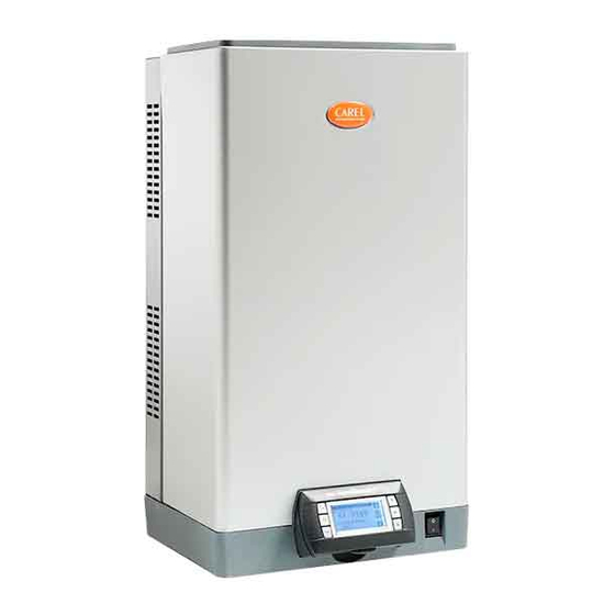
humiSteam x-plus
steam humidifi ers
User manual
I n t e g r a t e d C o n t r o l S o l u t i o n s & E n e r g y S a v i n g s
Related Manuals for Carel humiSteam x-plus
Summary of Contents for Carel humiSteam x-plus
-
Page 1: User Manual
User manual I n t e g r a t e d C o n t r o l S o l u t i o n s & E n e r g y S a v i n g s…
-
Page 3
WARNINGS The liability of CAREL in relation to its products is specifi ed in the CAREL general contract conditions, available on the website www.carel.com and/or by specifi c agreements with customers; specifi cally, to the extent where allowed by applicable legislation, in no case will CAREL, its employees or subsidiaries be liable… -
Page 5: Table Of Contents
3.2 CAREL linear distributors for air ducts (DP***DRU) ……. 13 11.1 Spare parts for models UE001 to UE018 ………..30 3.3 CAREL steam blowers (VSDU0A*, models UE001 to UE018 only) ..13 11.2 Spare parts for models UE025 to UE065 ……….33 3.4 Steam hoses ………………….
-
Page 6
UE xxx x x x 0 1 3 4 5 6 7 ID prefi x; mod. production rated instant steam production 1.5/3.3 in kg/h / lbr/h: 3/6.6 5/11 8/17.6 9/19.8 10/22 15/33 18/39.7 25/55.1 35/77.2 45/99.2 65/143.3 90/198.4 130/286.6 type of control: X= X-plus controller type — power supply: type U= 208… -
Page 7: Introduction And Assembly
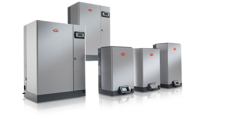
1. INTRODUCTION AND ASSEMBLY 1.1 humiSteam x-plus (UEX*) UE090 UE130 dimensions 1150 (45.3) 1150 (45.3) Range of isothermal immersed electrode humidifi ers with liquid crystal mm (in) 465 (18.3) 465 (18.3) display for the control and distribution of steam. 890 (35.0) 890 (35.0)
-
Page 8: Removing The
Fig. 1.e Fig. 1.i Spacing of the holes on the wall Models UE001 to UE018 turn oval-shaped label with the Carel logo, revealing the head of the earth screw below; remove the screw using a screwdriver; distance Models hold the cover by the sides and tilt;…
-
Page 9: Fitting The
(keeping it slightly oblique), until it rests on the rear edges, paying attention to the positioning holes on the side; tighten the earth screw using a screwdriver; turn the red oval-shaped plate with the CAREL logo until covering the fastening hole below. Models UE025 to UE130 …
-
Page 10: Water Connections
UE0018, use a hose with 3/4’’G fi ttings (see par. “Technical tank of the humidifi er (this can run into the drain funnel/air gap specifi cations” page 41, compatible CAREL hose: code reducer coupling). FWH3415000). On models UE025 to UE130 connect the hose with …
-
Page 11
Models UE001 to UE018 Models UE025 to UE130 Key: supply water inlet drain water outlet bottom tank drain water outlet (models UE025 to UE130 only) supply water inlet drain tempering valve. Note: Double cylinder units UE090-130 have 2 drain tempering connections Fig. -
Page 12: Supply Water
2.1 Supply water Only use main water with: • pressure between 0.1 and 0.8 MPa (14.5 and 116 PSI), temperature between 1 and 40 °C (33.8 and104 °F) and an instant fl ow-rate no lower than the rated fl ow of the fi ll solenoid valve, the connection is G3/4M (see par.
-
Page 13: Steam Distribution
3.4 Steam hoses • use CAREL hoses (max. 4 m ( max. 13 feet)) long, see “Models of steam hoses”, page 47). Rigid pipes may break and cause steam leaks; dimensioni in mm •…
-
Page 14: Condensate Drain Hose
To drain the condensate, connect a drain hose with a drain trap and a incline of 2° upwards (see Fig. 3.c); minimum slope of 5° to the bottom of the humidifi er (see Fig. 3.d). CAREL the ends of the hose are tightened to the fi ttings with metal clamps;…
-
Page 15: Electrical Connections
4. ELECTRICAL CONNECTIONS 4.1 Preparing the electric cableways Single-phase models Three-phase models Models UE001 to UE018 outside unit, bottom view inside unit, top view L1 L2 L3 Fig. 4.c (view inside unit, electrical compartment) Important: Important: connect the yellow-green cable to the earth point (GND). 4.3 Control signals ( M2.1 — M2.8;…
-
Page 16
Fig. 4.i PROPORTIONAL EXTERNAL CONTROLLER jumper outputs M2.7 and M2.8 or connect to a remote contact • CONTROL WITH CAREL MAIN PROBE AND LIMIT PROBE connect outputs M2.1 and M2.2 to an external controller • • jumper outputs M2.7 and M2.8 or connect to a remote contact The humidifi er can be programmed to receive one of the following •… -
Page 17: Alarm Contact (M6.1 — M6.3)
• industrial: DPPC112000 and DPPC212000 4.5 Dehumidifi cation contact (M5.1 — M5.2) If non-CAREL probes are used, check: When the humidifi er is used in the control modes with main probe or main • voltage signal: 0 to 1 Vdc, 0 to 10 Vdc, 2 to 10 Vdc, terminal M2.1 (GND: probe plus limit probe, a contact (NO — normally open — voltage free) can be M2.2);…
-
Page 18: Remote Terminal And Supervisory Network
(code 0907858AXX) (see Fig. 5.a); via RS232 serial lines or FTT10 LON using the optional cards shown in the • up to 200 meters: two CAREL TCONN6J000 boards, 6-wire telephone following table. cables and an AWG20-22 shielded cable with 3 twisted pairs (for the…
-
Page 19: Modbus® Protocol
CONTROL OF PRODUCTION FROM SERIAL PORT STOP PRODUCTION FROM SERIAL PORT (BMS) You can stop the output from the serial port. (BMS) In addition to the detention serial, there are also the following stops: You can set the electronic control to use as a primary control signal value -on/off Terminal from the serial port instead of the electrical terminals.
-
Page 20: Cascading Control Of Other Units
5. 4 Cascading control of other units Example 3 The steam production reached can exceed the maximum capacity of the master unit by connecting one or more slaves UEX-plus / UE X- plus P0 = 100% UE X-plus current production = 70% — Master: UEX unit with analogue output to control the other units;…
-
Page 21: Starting And User Interface
6. STARTING AND USER INTERFACE Before starting the humidifi er, check: (6) DOWN circular navigation inside the menus, the screens, the parameters and the values of the parameters from the “main” screen access an “INFO” screens 6.1 Starting 6.5 “Main” screen if the cylinder is new, run a pre-wash cycle (the cylinder is fi lled and emptied three times, cleaning the inside walls from impurities, see menu maintanance >change cylinder >…
-
Page 22: Set» Screen
• 6.7 “SET” mask OFF by Keyb.: steam production disabled by keyboard (see “SET” mask); Used to set the main values for the humidifi er. • Manual Proc.: humidifi er functions managed manually (maintenance To access, press ENTER from the “Main” screen, to move from one value to the menu >…
-
Page 23: Main Menu
6.8 Main menu To access press PRG from the main screen Buttons: • UP and DOWN: navigation inside the sub-menus, screens, and range of values and settings; • ENTER: confi rm and save the changes made; • ESC: to go back (pressed repeatedly returns to the “Main” screen). User Main probe threshold 1.
-
Page 24: User Menu
7. USER MENU From the main screen press: • PRG to access the main menu, Always OFF • ENTER to select and access the menu user. User menu screens: Fig. 7.1 1. Alarm thresholds 2. System clock 7.5 Weekly scheduler 3.
-
Page 25: Installer Menu
8. INSTALLER MENU • ENTER, 8.3 Operating options • ENTER, Operating options (1/2) • UP or DOWN to enter the password “77”, • ENTER to confi rm and access the installer menu. parameter range default UOM % rH % rH Select data view on main mask Installer menu screens: °C-°F…
-
Page 26: Supervisor
8.6 Supervisor parameter range def. 0 to 200 identifi cation number for BMS network 1200, 2400, 4800, 9600, 19200 Com. speed 19200 CAREL, MODBUS, LON, CAREL Protocol RS232, WINLOAD YES/NO Enable On/OFF from supervisor “UEX-PLUS” +03U0040EN — Rel. 1.35 — 10.05.2013…
-
Page 27: Maintenance Menu
9. MAINTENANCE MENU Important: the operations described in this menu must only be In the models with two cylinders, there is a second screen for the second carried out by qualifi ed personnel. cylinder (with the same functions and procedures as the fi rst). From the main screen press: 9.4 Change cylinder •…
-
Page 28: Table Of Alarms
In these conditions, pressing the alarm button once displays the type of type of fault, while the message displayed is reset manually (see the table alarm (and the code, in line with the CAREL humidifi er standard). below). Even if no longer active, the alarm status continues to be displayed until the “reset display”…
-
Page 29
Limit probe limit probe high check the operation of the limit probe Automatic signal only. Warning: E= humidity humidity reading High humidity limit active warning probe Main probe main probe not check the connection of the probe, and the Automatic Stop Alarm: active… -
Page 30: Maintenance And Spare Parts
11. MAINTENANCE AND SPARE PARTS 11.1 Spare parts for models UE001 to UE018 fi ll tank internal tubing kit fi ll solenoid and drain tempering valve kit cylinder manifold with drain pump plastic base plastic humidifi er top TAM (transformer for measuring the current) transformer contactor fuse holder…
-
Page 31
01,..,90 Kg/h A3=130 Kg/h v: voltage i: 0 single packing; 1: multiple packing For items not listed, please refer to CAREL, your local branch or agent. Table of spare part codes, single-phase cylinders UE001 to 009, electrode and gasket kit Model… -
Page 32
Table of spare part codes, three-phase cylinders UE003 to 018, electrode and gasket kit Model UE003 UE005 UE008 UE010 UE015 UE018 STANDARD 208/230 VAC 3~, conductivity 350 to 1250 μS/cm BL0T1B00H2 BL0T2A00H2 BL0T2A00H2 BL0T3A00H2 BL0T3A00H2 disposable 460 VAC 3~, conductivity 350 to 750 μS/cm BL0T1D00H2 BL0T2D00H2 BL0T2D00H2… -
Page 33: Spare Parts For Models Ue025 To Ue065
11.2 Spare parts for models UE025 to UE065 Key: drain circuit fi ll solenoid valve kit internal tubing kit conductivity meter drain pump kit manifold drain pump hose cylinder TAM (transformer for measuring the current) contactor transformer pump control relay fuse holder electronic controller power terminals…
-
Page 34
0 single packing; 1: multiple packing For items not listed, please refer to CAREL, your local branch or agent. Table of spare parts for standard and special cylinders UE025 to UE065 “UEX-PLUS” +03U0040EN — Rel. 1.35 — 10.05.2013… -
Page 35
Description UE025 UE035 UE045 UE065 STANDARD disposable cylinders 208V 3ph cylinder, conductivity 350 to 1250 μS/cm BL0T4C00H2 BL0T4B00H2 BL0T5A00H1 230V 3ph cylinder, conductivity 350 to 1250 μS/cm BL0T4C00H2 BL0T4B00H2 BL0T5B00H0 460V 3ph cylinder, conductivity 350 to 1250 μS/cm BL0T4D00H2 BL0T4D00H2 BL0T4D00H2 BL0T5D00H0 575V 3ph cylinder, conductivity 350 to 1250 μS/cm… -
Page 36: Spare Parts For Models Ue090 To Ue130
11.3 Spare parts for models UE090 to UE130 Key: drain circuit fi ll solenoid valve kit internal tubing kit conductivity meter drain pump kit manifold drain pump hose cylinder TAM (transformer for measuring the current) contactor transformer pump control relay fuse holder electronic controller power terminals…
-
Page 37
01,..,90 Kg/h A3=130 Kg/h v: voltage i: 0 single packing; 1: multiple packing For items not listed, please refer to CAREL, your local branch or agent Table of spare parts for standard and special cylinders UE090 to UE130 Description UE090… -
Page 38: Cleaning And Maintenance Of The Cylinder
11.4 Cleaning and maintenance of the cylinder 11.5 Mechanically draining the water in the cylinder Replacement Drain due to gravity without activating the humidifi er, recommended if: Important: the cylinder must be only be replaced by qualifi ed • humidifi er decommissioned; personnel, and with the humidifi er disconnected from the power •…
-
Page 39: Cylinder Connection
11.6 Cylinder connection 11.7 Cleaning and maintenance of the other components Three-phase models UE025 to UE130 Important: production conductivity (μS/cm) power supply (V) (kg/h) 208-230 460-575 • when cleaning plastic components do not use detergents or solvents; 25 /model 75/350 μS/cm •…
-
Page 40: Wiring Diagrams
12. WIRING DIAGRAMS 12.1 Diagram of single-phase models UE001 to UE009(208-230V) key: terminal block contactor F1-F2 primary fuses fuse protection drain pump secondary fuse transformer manual switch fi ll valve drain pump high level electrodes conductivity meter external TAM valve drain tempering (**) Attention: for TAM confi gurations and connections see par.
-
Page 41: Diagram Of Three-Phase Models Ue003 To Ue018 (208-230-460-575V)
12.2 Diagram of three-phase models UE003 to UE018 (208-230-460-575V) key: terminal block contactor F1-F2 primary fuses fuse protection drain pump secondary fuse transformer manual switch fi ll valve drain pump high level electrodes conductivity meter external TAM valve drain tempering “UEX-PLUS”…
-
Page 42: Diagram Of Three-Phase Models Ue025(208-230-460-575V), Ue35(208-230-460-575V) And Ue045(460-575V)
12.3 Diagram of three-phase models UE025(208-230-460-575V), UE35(208-230-460-575V) and UE045(460-575V) key: terminal block contactor F1-F2 primary fuses fuse protection drain pump secondary fuse transformer manual switch fi ll valve drain pump valve drain tempering high level electrodes conductivity meter external TAM (**) Attention: for TAM confi gurations and connections see par.
-
Page 43: Diagram Of Three-Phase Models Ue045 (208-230 V) And Ue065 (460-575 V)
12.4 Diagram of three-phase models UE045 (208-230 V) and UE065 (460-575 V) key: terminal block contactor F1-F2 primary fuse fuse protection drain pump secondary fuses transformer manual switch fi ll valve drain pump valve drain tempering high level electrodes conductivity meter external TAM (**) Attention: for TAM confi gurations and connections see par.
-
Page 44: Diagram Of Three-Phase Models Ue090 To Ue130
12.5 Diagram of three-phase models UE090 to UE130 key: terminal block contactor F1-F2 primary fuses fuse protection drain pump secondary fuse transformer manual switch FV 1-2 fi ll valve DP 1-2 drain pump LS 1-2 high level electrodes CS 1-2 conductivity meter TAM 1-2 external TAM DT 1-2…
-
Page 45: General Features And Models
13. GENERAL FEATURES AND MODELS 13.1 humiSteam models and electrical specifi cations power supply nominal specifi cations model steam power code voltages current TAM confi guration cable recommended wiring production (2; 4) (kW) (V — type) External fuses diagram (kg/hr) (AWG) sizes (Fig.)
-
Page 46
TAM confi gurations and connections (transformer for measuring the current) Important: the confi gurations and connections are already made by CAREL, and no changes are required. The following diagrams represent possible connection modes and may be useful in the event of serious electrical malfunctions on the humidifi er. -
Page 47: Technical Specifi Cations
1/1.5 kg/h (lb/h) (2.2/3.3) (6.6) (11) (17.6) (19.8) (22) (33) (39.7) (55.1) (77.2) (99.2) (143.3) (198.4) (286.6) CAREL steam hoses code ID mm (in) SHOSE00022 22 (0.9”) √ √ SHOSE00030 30 (1.2”) √ √ √ √ √ √ SHOSE00040 40 (1.6”) √…
-
Page 48: Models Of Concentrated Jet Steam Distributors
** = use CAREL “Y” kit code UEKY000000 (40 mm/1.6” inlet and 2 x 30 mm/1.2” outlets) *** = use one CAREL “Y” kit code UEKY40X400 (40 mm/1.6” inlet and 2 x 40 mm/1.6” outlets) and two CAREL “Y” kit code UEKY000000 (40 mm/1.6” inlet and 2 x 30 mm/1.2” outlets) 13.5 Models of linear distributors…
-
Page 49
“UEX-PLUS” +03U0040EN — Rel. 1.35 — 10.05.2013… -
Page 50: Controlling The Board Via Network
OTHERWISE THE OPERATION OF THE HUMIDIFIER MAY BE AFFECTED. “A” read (R)/ analogue variables* (Modbus®: REGISTERS) write (W) CAREL — Modbus® room probe/external regulator: demand room probe/external regulator: minimum (calibration) room probe/external regulator: maximum (calibration) room probe/external regulator: off set (calibration)
-
Page 51
high conductivity alarm high conductivity warning cylinder 1: high current alarm cylinder 1: low current alarm cylinder 1: lack of water alarm cylinder 1: low production alarm cylinder 1: drain alarm cylinder 1: full without demand alarm cylinder 1: maintenance-due alarm (timed) cylinder 1: pre-exhaustion warning cylinder 1: foam warning cylinder 1: totally exhausted warning… -
Page 52
4 = %rh control with external probe + limit probe; 5 = temperature control room probe/ext. regulator: type of signal 0 = 0-1 v; 1 = 0-10 v; 2 = 2-10 v; 3 = 0-20 ma; 4 = 4-20 ma; 5 = ntc carel standard limit probe: type of signal 0 = 0-1 V;… -
Page 53
system timer: month (can be edited for updating the sistem timer!) system timer: year (can be edited for updating the sistem timer!) cylinder 1: hour counter cylinder 2: hour counter voltage type (v): 0 = 200; 1 = 208; 2 = 230; 3 = 400; 4 = 460; 5 = 575 humidifi er type lista modelli umidifi catori parameter Installer/Supervisor/Supervisor connect/Reg. -
Page 54: Technical Appendix
14. TECHNICAL APPENDIX available only in models UE090…UE130 . 14.1 Operating principle Proportional control with limit probe (see Figs. 14.1 and Immersed electrode humidifi ers produce steam by boiling the water 14.3) contained inside the cylinder. The heat required to boil the water is produced See “proportional control”, with the addition of a limit probe, generally by passing an electrical current through the water in the cylinder.
-
Page 55: Operation With Two Cylinders (Only Ue090
If this mode is activated, if the probe limit is disconnected, (alarm E4) steam Overriding the conductivity of the supply water production will continue according to read only the main probe. In conditions where the supply water has relatively low conductivity, a higher conductivity value can be set (installer menu >…
-
Page 56: Automatic Insuffi Cient Supply Water Management
To set “cylinder exhaustion warning” (maximum operating hours): installer menu > options > cylinder lifetime warning (setting “0” disables the alarm). CAREL reserves the right to modify or change its products without prior notice. “UEX-PLUS” +03U0040EN — Rel. 1.35 — 10.05.2013…
-
Page 60
Samsennok, Huaykwang, Bangkok 10310 Thailand e-mail: sales@carel.com.au — www.carel.com.au Tel: (+66) 2 513 5610 Fax: (+66) 2 513 5611 CAREL China — CAREL Electronic (Suzhou) Co. Ltd. e-mail: info@carel.co.th — www.carel.co.th No. 26, 369 Lushan Road, Suzhou City, Jiangsu Province, CAREL Spol (Czech and Slovakia) s.r.o.
Посмотреть инструкция для Carel humiSteam x-plus бесплатно. Руководство относится к категории увлажнители, 1 человек(а) дали ему среднюю оценку 9.5. Руководство доступно на следующих языках: русский. У вас есть вопрос о Carel humiSteam x-plus или вам нужна помощь? Задайте свой вопрос здесь
Не можете найти ответ на свой вопрос в руководстве? Вы можете найти ответ на свой вопрос ниже, в разделе часто задаваемых вопросов о Carel humiSteam x-plus.
Инструкция Carel humiSteam x-plus доступно в русский?
Да, руководствоCarel humiSteam x-plus доступно врусский .
Не нашли свой вопрос? Задайте свой вопрос здесь
UEX*
General characteristics
Type «X» humiSteam humidifiers represent CAREL’s high-end solution in immersed electrode humidifiers. They have a built-in controller with graphic display and keypad for programming and controlling operation.
The following modes can be selected at any time:
- ON/OFF by external humidistat;
- proportional to external signal;
- proportional to external signal plus a maximum humidity limit probe in the duct;
- modulating based on set point and humidity probe reading ;
- modulating based on set point and humidity probe reading and limit probe in the duct.
Steam flow-rate is modulated continuously from 20 to 100% of maximum capacity (10 to 100% in the 90 and 130 kg/h models), except for in ON/OFF mode, where production is all or nothing.
Type «X» humiSteam humidifiers can accept the following external signals, selected on the keypad: voltage-free contact from humidistat, 0-1 V, 0-10 V, 2-10 V, 0-20 mA, 4-20 mA.
Type «X» controllers exploit all the advantages of pCO technology, the family of CAREL programmable controllers:
- easy to use, graphic display with clear messages in different languages;
- operation based on daily and weekly time bands with variable set points;
- BMS connectivity via various types of LAN (e.g.: Modbus® (standard), BACnet™, LON®);
- complete diagnostics with text messages, alarm log with time stamping;
- remote diagnostics via GSM (optional);
- automatic drain due to inactivity.
Plus
- AFS system (Anti Foaming System): detects foam to prevent droplets of water being carried by the steamcylinders with galvanised electrodes and anti-scale filter at bottom, openable cylinders also availabsteam production with continuous modulation from 20% to maximum rating (10% for 90 & 130 kg/h models);
- built-in conductivity sensor and control software to optimise energy efficiency and maintenance costs, with constant performance throughout cylinder life.
- automatic water drain after 3 days of inactivity
Documentation
Technical
-
BIM files
Code Description Language Date * Release Code
BIM files humiSteamDescription
Language
ALLDate
15/05/2020
Release
R1
-
Manuals
Code Description Language Date * Release Code
+0300040DEDescription
humiSteam x-plusLanguage
GERDate
13/10/2021
Release
1.7
Code
+0300040ENDescription
humiSteam x-plus-User manualLanguage
ENGDate
13/10/2021
Release
1.7
Code
+0300040ESDescription
humiSteam x-plus- Manual del usuarioLanguage
SPADate
13/10/2021
Release
1.7
Code
+0300040FIDescription
humiSteam x-plus- KäyttöohjekirjaLanguage
FINDate
13/10/2021
Release
1.7
Code
+0300040FRDescription
humiSteam x-plus-Manuel d’utilisationLanguage
FREDate
13/10/2021
Release
1.7
Code
+0300040ITDescription
humiSteam x-plus-Manuale d’usoLanguage
ITADate
13/10/2021
Release
1.7
Code
+0300040RUDescription
humiSteam x-plus-Руководство пользователяLanguage
RUSDate
13/10/2021
Release
1.7
Code
+0300040PTDescription
humiSteam x-plus
humidifiersLanguage
PORDate
13/10/2021
Release
1.7
Code
+0300040ETDescription
humiSteam x-plus
niisutidLanguage
ESTDate
13/10/2021
Release
1.7
Code
+030220310Description
humiSet
Humidifier Programming ToolLanguage
ITADate
01/09/2014
Release
2.2
Code
+030220311Description
HumisetLanguage
ENGDate
01/09/2014
Release
2.2
Code
+0300040ZHDescription
humiSteam x-plus
加湿器Language
CHIDate
10/05/2013
Release
1.3
Code
+0300041ENDescription
humiSteam x-plus
Addendum manualLanguage
ENGDate
24/08/2012
Release
1.1
Code
+030220620Description
humiSteam x-plus
Manuale d’usoLanguage
ITADate
04/08/2009
Release
1.4
Code
+030220621Description
humiSteam x-plus
humidifiersLanguage
ENGDate
04/08/2009
Release
1.4
Code
+030220622Description
humiSteam x-plus
humidificateursLanguage
FREDate
04/08/2009
Release
1.4
Code
+030220623Description
humiSteam x-plus
BefeuchterLanguage
GERDate
04/08/2009
Release
1.4
Code
+030220624Description
humiSteam x-plus
humidificadoresLanguage
SPADate
04/08/2009
Release
1.4
Code
+030220625Description
humiSteam x-plus
паровые увлажнители воздухаLanguage
RUSDate
04/08/2009
Release
1.4
-
Technical Leaflets
Code Description Language Date * Release Code
+050001350Description
BL0*/BLC*1 — 2 — 3: Cilindri con perni a testa sagomata / Cylinders with snap-onLanguage
ENG
ITADate
02/04/2021
Release
1.3
-
Tender Texts
Code Description Language Date * Release Code
humiSteam UE_DEDescription
Language
GERDate
30/04/2021
Release
R0
Code
humiSteam UE _ENDescription
Language
ENGDate
30/04/2021
Release
R0
Code
humiSteam UE _ITADescription
Language
ITADate
29/04/2021
Release
R0
Code
humiSteam UE _FRDescription
Language
FREDate
29/04/2021
Release
R0
Code
humiSteam UE_ESDescription
Language
SPADate
29/04/2021
Release
R0
Commercial
-
Brochure
Code Description Language Date * Release Code
+3000095ITDescription
humiSteam la scelta razionale adatta ad ogni applicazioneLanguage
ITADate
16/12/2021
Release
2.0
Code
+3000095ENDescription
humiSteam the rational choice for any applicationLanguage
ENGDate
16/12/2021
Release
2.0
Code
+3000095FRDescription
humiSteam le choix rationnel adapté à chaque applicationLanguage
FREDate
16/12/2021
Release
2.0
Code
+3000095DEDescription
humiSteam Die vernünftige Wahl für jede AnwendungLanguage
GERDate
16/12/2021
Release
2.0
Code
+3000095ESDescription
humiSteam la elección racional adecuada para cualquier aplicaciónLanguage
SPADate
16/12/2021
Release
2.0
Code
+3000095RUDescription
humiSteam the rational choice for any applicationLanguage
RUSDate
16/12/2021
Release
2.0
Code
+3000095PLDescription
humiSteam
racjonalny wybór dla każdego z zastosowańLanguage
POLDate
16/12/2021
Release
2.0
Code
+3000095NL.pdfDescription
humiSteam
De rationele keuze, geschikt voor elke toepassingLanguage
DUTDate
16/12/2021
Release
2.0
Code
+3000095PTDescription
humiSteam a escolha racional adequada a todas as aplicaçõesLanguage
PORDate
17/03/2015
Release
1.0
Code
+3000095ETDescription
humiSteam
humiSteam Mõistlik valik kõikide paigaldiste jaoksLanguage
ESTDate
17/03/2015
Release
1.0
Code
+3000095KRDescription
humiSteamLanguage
KORDate
17/03/2015
Release
1.0
-
Other related documentation
Code Description Language Date * Release Code
+800004030Description
Soluzioni per Unità Trattamento Aria: Tecnologia e competenza per la qualità dell’aria e il risparmio energeticoLanguage
ITADate
05/04/2023
Release
1.2
Code
+800004031Description
Solutions for Air Handling Units: Technology and expertise for indoor air quality and energy savingLanguage
ENGDate
05/04/2023
Release
1.2
Code
+3000224ITDescription
Educational — Utilizzare nel modo migliore tecnologie e sistemi delle applicazioni HVAC/RLanguage
ITADate
24/01/2022
Release
1.1
Code
+3000224ENDescription
Educational — Make the best use of HVAC/R application technologies and systemsLanguage
ENGDate
24/01/2022
Release
1.1
Code
+3000223ITDescription
Soluzione completa di servizi dedicata agli umidificatori CARELLanguage
ITADate
21/12/2021
Release
1.0
Code
+3000223ENDescription
Complete services solution for CAREL humidifiersLanguage
ENGDate
21/12/2021
Release
1.0
Code
+3000223ESDescription
Solución completa de servicios dedicada a los humidificadores CARELLanguage
SPADate
21/12/2021
Release
1.0
Code
+3000223FRDescription
Solution complète de services pour les humidificateurs CARELLanguage
FREDate
21/12/2021
Release
1.0
Code
+3000223PLDescription
Kompletne rozwiązanie serwisowe dla nawilżaczy CARELLanguage
POLDate
21/12/2021
Release
1.0
Code
+3000018PLDescription
Nawilżanie ma znaczenie! Rozwiązania CAREL dla twoich potrzeb nawilżaniaLanguage
POLDate
15/09/2020
Release
4.1
Images
-
High resolution images
Code Description Language Date * Release Code
PH08LUE301-humisteam-range.jpgDescription
CAREL-humiSteam Basic-Immersed electrocode humidifier-Isothermal HumidifierLanguage
ALLDate
01/07/2021
Release
R.0
-
Page 1: User Manual
User manual I n t e g r a t e d C o n t r o l S o l u t i o n s & E n e r g y S a v i n g s…
-
Page 3
WARNINGS The liability of CAREL in relation to its products is specifi ed in the CAREL general contract conditions, available on the website www.carel.com and/or by specifi c agreements with customers; specifi cally, to the extent where allowed by applicable legislation, in no case will CAREL, its employees or subsidiaries be liable… -
Page 5: Table Of Contents
3.2 CAREL linear distributors for air ducts (DP***DRU) ……. 13 11.1 Spare parts for models UE001 to UE018 ………..30 3.3 CAREL steam blowers (VSDU0A*, models UE001 to UE018 only) ..13 11.2 Spare parts for models UE025 to UE065 ……….33 3.4 Steam hoses ………………….
-
Page 6
UE xxx x x x 0 1 3 4 5 6 7 ID prefi x; mod. production rated instant steam production 1.5/3.3 in kg/h / lbr/h: 3/6.6 5/11 8/17.6 9/19.8 10/22 15/33 18/39.7 25/55.1 35/77.2 45/99.2 65/143.3 90/198.4 130/286.6 type of control: X= X-plus controller type — power supply: type U= 208… -
Page 7: Introduction And Assembly
1. INTRODUCTION AND ASSEMBLY 1.1 humiSteam x-plus (UEX*) UE090 UE130 dimensions 1150 (45.3) 1150 (45.3) Range of isothermal immersed electrode humidifi ers with liquid crystal mm (in) 465 (18.3) 465 (18.3) display for the control and distribution of steam. 890 (35.0) 890 (35.0)
-
Page 8: Removing The
Fig. 1.e Fig. 1.i Spacing of the holes on the wall Models UE001 to UE018 turn oval-shaped label with the Carel logo, revealing the head of the earth screw below; remove the screw using a screwdriver; distance Models hold the cover by the sides and tilt;…
-
Page 9: Fitting The
(keeping it slightly oblique), until it rests on the rear edges, paying attention to the positioning holes on the side; tighten the earth screw using a screwdriver; turn the red oval-shaped plate with the CAREL logo until covering the fastening hole below. Models UE025 to UE130 …
-
Page 10: Water Connections
UE0018, use a hose with 3/4’’G fi ttings (see par. “Technical tank of the humidifi er (this can run into the drain funnel/air gap specifi cations” page 41, compatible CAREL hose: code reducer coupling). FWH3415000). On models UE025 to UE130 connect the hose with …
-
Page 11
Models UE001 to UE018 Models UE025 to UE130 Key: supply water inlet drain water outlet bottom tank drain water outlet (models UE025 to UE130 only) supply water inlet drain tempering valve. Note: Double cylinder units UE090-130 have 2 drain tempering connections Fig. -
Page 12: Supply Water
2.1 Supply water Only use main water with: • pressure between 0.1 and 0.8 MPa (14.5 and 116 PSI), temperature between 1 and 40 °C (33.8 and104 °F) and an instant fl ow-rate no lower than the rated fl ow of the fi ll solenoid valve, the connection is G3/4M (see par.
-
Page 13: Steam Distribution
3.4 Steam hoses • use CAREL hoses (max. 4 m ( max. 13 feet)) long, see “Models of steam hoses”, page 47). Rigid pipes may break and cause steam leaks; dimensioni in mm •…
-
Page 14: Condensate Drain Hose
To drain the condensate, connect a drain hose with a drain trap and a incline of 2° upwards (see Fig. 3.c); minimum slope of 5° to the bottom of the humidifi er (see Fig. 3.d). CAREL the ends of the hose are tightened to the fi ttings with metal clamps;…
-
Page 15: Electrical Connections
4. ELECTRICAL CONNECTIONS 4.1 Preparing the electric cableways Single-phase models Three-phase models Models UE001 to UE018 outside unit, bottom view inside unit, top view L1 L2 L3 Fig. 4.c (view inside unit, electrical compartment) Important: Important: connect the yellow-green cable to the earth point (GND). 4.3 Control signals ( M2.1 — M2.8;…
-
Page 16
Fig. 4.i PROPORTIONAL EXTERNAL CONTROLLER jumper outputs M2.7 and M2.8 or connect to a remote contact • CONTROL WITH CAREL MAIN PROBE AND LIMIT PROBE connect outputs M2.1 and M2.2 to an external controller • • jumper outputs M2.7 and M2.8 or connect to a remote contact The humidifi er can be programmed to receive one of the following •… -
Page 17: Alarm Contact (M6.1 — M6.3)
• industrial: DPPC112000 and DPPC212000 4.5 Dehumidifi cation contact (M5.1 — M5.2) If non-CAREL probes are used, check: When the humidifi er is used in the control modes with main probe or main • voltage signal: 0 to 1 Vdc, 0 to 10 Vdc, 2 to 10 Vdc, terminal M2.1 (GND: probe plus limit probe, a contact (NO — normally open — voltage free) can be M2.2);…
-
Page 18: Remote Terminal And Supervisory Network
(code 0907858AXX) (see Fig. 5.a); via RS232 serial lines or FTT10 LON using the optional cards shown in the • up to 200 meters: two CAREL TCONN6J000 boards, 6-wire telephone following table. cables and an AWG20-22 shielded cable with 3 twisted pairs (for the…
-
Page 19: Modbus® Protocol
CONTROL OF PRODUCTION FROM SERIAL PORT STOP PRODUCTION FROM SERIAL PORT (BMS) You can stop the output from the serial port. (BMS) In addition to the detention serial, there are also the following stops: You can set the electronic control to use as a primary control signal value -on/off Terminal from the serial port instead of the electrical terminals.
-
Page 20: Cascading Control Of Other Units
5. 4 Cascading control of other units Example 3 The steam production reached can exceed the maximum capacity of the master unit by connecting one or more slaves UEX-plus / UE X- plus P0 = 100% UE X-plus current production = 70% — Master: UEX unit with analogue output to control the other units;…
-
Page 21: Starting And User Interface
6. STARTING AND USER INTERFACE Before starting the humidifi er, check: (6) DOWN circular navigation inside the menus, the screens, the parameters and the values of the parameters from the “main” screen access an “INFO” screens 6.1 Starting 6.5 “Main” screen if the cylinder is new, run a pre-wash cycle (the cylinder is fi lled and emptied three times, cleaning the inside walls from impurities, see menu maintanance >change cylinder >…
-
Page 22: Set» Screen
• 6.7 “SET” mask OFF by Keyb.: steam production disabled by keyboard (see “SET” mask); Used to set the main values for the humidifi er. • Manual Proc.: humidifi er functions managed manually (maintenance To access, press ENTER from the “Main” screen, to move from one value to the menu >…
-
Page 23: Main Menu
6.8 Main menu To access press PRG from the main screen Buttons: • UP and DOWN: navigation inside the sub-menus, screens, and range of values and settings; • ENTER: confi rm and save the changes made; • ESC: to go back (pressed repeatedly returns to the “Main” screen). User Main probe threshold 1.
-
Page 24: User Menu
7. USER MENU From the main screen press: • PRG to access the main menu, Always OFF • ENTER to select and access the menu user. User menu screens: Fig. 7.1 1. Alarm thresholds 2. System clock 7.5 Weekly scheduler 3.
-
Page 25: Installer Menu
8. INSTALLER MENU • ENTER, 8.3 Operating options • ENTER, Operating options (1/2) • UP or DOWN to enter the password “77”, • ENTER to confi rm and access the installer menu. parameter range default UOM % rH % rH Select data view on main mask Installer menu screens: °C-°F…
-
Page 26: Supervisor
8.6 Supervisor parameter range def. 0 to 200 identifi cation number for BMS network 1200, 2400, 4800, 9600, 19200 Com. speed 19200 CAREL, MODBUS, LON, CAREL Protocol RS232, WINLOAD YES/NO Enable On/OFF from supervisor “UEX-PLUS” +03U0040EN — Rel. 1.35 — 10.05.2013…
-
Page 27: Maintenance Menu
9. MAINTENANCE MENU Important: the operations described in this menu must only be In the models with two cylinders, there is a second screen for the second carried out by qualifi ed personnel. cylinder (with the same functions and procedures as the fi rst). From the main screen press: 9.4 Change cylinder •…
-
Page 28: Table Of Alarms
In these conditions, pressing the alarm button once displays the type of type of fault, while the message displayed is reset manually (see the table alarm (and the code, in line with the CAREL humidifi er standard). below). Even if no longer active, the alarm status continues to be displayed until the “reset display”…
-
Page 29
Limit probe limit probe high check the operation of the limit probe Automatic signal only. Warning: E= humidity humidity reading High humidity limit active warning probe Main probe main probe not check the connection of the probe, and the Automatic Stop Alarm: active… -
Page 30: Maintenance And Spare Parts
11. MAINTENANCE AND SPARE PARTS 11.1 Spare parts for models UE001 to UE018 fi ll tank internal tubing kit fi ll solenoid and drain tempering valve kit cylinder manifold with drain pump plastic base plastic humidifi er top TAM (transformer for measuring the current) transformer contactor fuse holder…
-
Page 31
01,..,90 Kg/h A3=130 Kg/h v: voltage i: 0 single packing; 1: multiple packing For items not listed, please refer to CAREL, your local branch or agent. Table of spare part codes, single-phase cylinders UE001 to 009, electrode and gasket kit Model… -
Page 32
Table of spare part codes, three-phase cylinders UE003 to 018, electrode and gasket kit Model UE003 UE005 UE008 UE010 UE015 UE018 STANDARD 208/230 VAC 3~, conductivity 350 to 1250 μS/cm BL0T1B00H2 BL0T2A00H2 BL0T2A00H2 BL0T3A00H2 BL0T3A00H2 disposable 460 VAC 3~, conductivity 350 to 750 μS/cm BL0T1D00H2 BL0T2D00H2 BL0T2D00H2… -
Page 33: Spare Parts For Models Ue025 To Ue065
11.2 Spare parts for models UE025 to UE065 Key: drain circuit fi ll solenoid valve kit internal tubing kit conductivity meter drain pump kit manifold drain pump hose cylinder TAM (transformer for measuring the current) contactor transformer pump control relay fuse holder electronic controller power terminals…
-
Page 34
0 single packing; 1: multiple packing For items not listed, please refer to CAREL, your local branch or agent. Table of spare parts for standard and special cylinders UE025 to UE065 “UEX-PLUS” +03U0040EN — Rel. 1.35 — 10.05.2013… -
Page 35
Description UE025 UE035 UE045 UE065 STANDARD disposable cylinders 208V 3ph cylinder, conductivity 350 to 1250 μS/cm BL0T4C00H2 BL0T4B00H2 BL0T5A00H1 230V 3ph cylinder, conductivity 350 to 1250 μS/cm BL0T4C00H2 BL0T4B00H2 BL0T5B00H0 460V 3ph cylinder, conductivity 350 to 1250 μS/cm BL0T4D00H2 BL0T4D00H2 BL0T4D00H2 BL0T5D00H0 575V 3ph cylinder, conductivity 350 to 1250 μS/cm… -
Page 36: Spare Parts For Models Ue090 To Ue130
11.3 Spare parts for models UE090 to UE130 Key: drain circuit fi ll solenoid valve kit internal tubing kit conductivity meter drain pump kit manifold drain pump hose cylinder TAM (transformer for measuring the current) contactor transformer pump control relay fuse holder electronic controller power terminals…
-
Page 37
01,..,90 Kg/h A3=130 Kg/h v: voltage i: 0 single packing; 1: multiple packing For items not listed, please refer to CAREL, your local branch or agent Table of spare parts for standard and special cylinders UE090 to UE130 Description UE090… -
Page 38: Cleaning And Maintenance Of The Cylinder
11.4 Cleaning and maintenance of the cylinder 11.5 Mechanically draining the water in the cylinder Replacement Drain due to gravity without activating the humidifi er, recommended if: Important: the cylinder must be only be replaced by qualifi ed • humidifi er decommissioned; personnel, and with the humidifi er disconnected from the power •…
-
Page 39: Cylinder Connection
11.6 Cylinder connection 11.7 Cleaning and maintenance of the other components Three-phase models UE025 to UE130 Important: production conductivity (μS/cm) power supply (V) (kg/h) 208-230 460-575 • when cleaning plastic components do not use detergents or solvents; 25 /model 75/350 μS/cm •…
-
Page 40: Wiring Diagrams
12. WIRING DIAGRAMS 12.1 Diagram of single-phase models UE001 to UE009(208-230V) key: terminal block contactor F1-F2 primary fuses fuse protection drain pump secondary fuse transformer manual switch fi ll valve drain pump high level electrodes conductivity meter external TAM valve drain tempering (**) Attention: for TAM confi gurations and connections see par.
-
Page 41: Diagram Of Three-Phase Models Ue003 To Ue018 (208-230-460-575V)
12.2 Diagram of three-phase models UE003 to UE018 (208-230-460-575V) key: terminal block contactor F1-F2 primary fuses fuse protection drain pump secondary fuse transformer manual switch fi ll valve drain pump high level electrodes conductivity meter external TAM valve drain tempering “UEX-PLUS”…
-
Page 42: Diagram Of Three-Phase Models Ue025(208-230-460-575V), Ue35(208-230-460-575V) And Ue045(460-575V)
12.3 Diagram of three-phase models UE025(208-230-460-575V), UE35(208-230-460-575V) and UE045(460-575V) key: terminal block contactor F1-F2 primary fuses fuse protection drain pump secondary fuse transformer manual switch fi ll valve drain pump valve drain tempering high level electrodes conductivity meter external TAM (**) Attention: for TAM confi gurations and connections see par.
-
Page 43: Diagram Of Three-Phase Models Ue045 (208-230 V) And Ue065 (460-575 V)
12.4 Diagram of three-phase models UE045 (208-230 V) and UE065 (460-575 V) key: terminal block contactor F1-F2 primary fuse fuse protection drain pump secondary fuses transformer manual switch fi ll valve drain pump valve drain tempering high level electrodes conductivity meter external TAM (**) Attention: for TAM confi gurations and connections see par.
-
Page 44: Diagram Of Three-Phase Models Ue090 To Ue130
12.5 Diagram of three-phase models UE090 to UE130 key: terminal block contactor F1-F2 primary fuses fuse protection drain pump secondary fuse transformer manual switch FV 1-2 fi ll valve DP 1-2 drain pump LS 1-2 high level electrodes CS 1-2 conductivity meter TAM 1-2 external TAM DT 1-2…
-
Page 45: General Features And Models
13. GENERAL FEATURES AND MODELS 13.1 humiSteam models and electrical specifi cations power supply nominal specifi cations model steam power code voltages current TAM confi guration cable recommended wiring production (2; 4) (kW) (V — type) External fuses diagram (kg/hr) (AWG) sizes (Fig.)
-
Page 46
TAM confi gurations and connections (transformer for measuring the current) Important: the confi gurations and connections are already made by CAREL, and no changes are required. The following diagrams represent possible connection modes and may be useful in the event of serious electrical malfunctions on the humidifi er. -
Page 47: Technical Specifi Cations
1/1.5 kg/h (lb/h) (2.2/3.3) (6.6) (11) (17.6) (19.8) (22) (33) (39.7) (55.1) (77.2) (99.2) (143.3) (198.4) (286.6) CAREL steam hoses code ID mm (in) SHOSE00022 22 (0.9”) √ √ SHOSE00030 30 (1.2”) √ √ √ √ √ √ SHOSE00040 40 (1.6”) √…
-
Page 48: Models Of Concentrated Jet Steam Distributors
** = use CAREL “Y” kit code UEKY000000 (40 mm/1.6” inlet and 2 x 30 mm/1.2” outlets) *** = use one CAREL “Y” kit code UEKY40X400 (40 mm/1.6” inlet and 2 x 40 mm/1.6” outlets) and two CAREL “Y” kit code UEKY000000 (40 mm/1.6” inlet and 2 x 30 mm/1.2” outlets) 13.5 Models of linear distributors…
-
Page 49
“UEX-PLUS” +03U0040EN — Rel. 1.35 — 10.05.2013… -
Page 50: Controlling The Board Via Network
OTHERWISE THE OPERATION OF THE HUMIDIFIER MAY BE AFFECTED. “A” read (R)/ analogue variables* (Modbus®: REGISTERS) write (W) CAREL — Modbus® room probe/external regulator: demand room probe/external regulator: minimum (calibration) room probe/external regulator: maximum (calibration) room probe/external regulator: off set (calibration)
-
Page 51
high conductivity alarm high conductivity warning cylinder 1: high current alarm cylinder 1: low current alarm cylinder 1: lack of water alarm cylinder 1: low production alarm cylinder 1: drain alarm cylinder 1: full without demand alarm cylinder 1: maintenance-due alarm (timed) cylinder 1: pre-exhaustion warning cylinder 1: foam warning cylinder 1: totally exhausted warning… -
Page 52
4 = %rh control with external probe + limit probe; 5 = temperature control room probe/ext. regulator: type of signal 0 = 0-1 v; 1 = 0-10 v; 2 = 2-10 v; 3 = 0-20 ma; 4 = 4-20 ma; 5 = ntc carel standard limit probe: type of signal 0 = 0-1 V;… -
Page 53
system timer: month (can be edited for updating the sistem timer!) system timer: year (can be edited for updating the sistem timer!) cylinder 1: hour counter cylinder 2: hour counter voltage type (v): 0 = 200; 1 = 208; 2 = 230; 3 = 400; 4 = 460; 5 = 575 humidifi er type lista modelli umidifi catori parameter Installer/Supervisor/Supervisor connect/Reg. -
Page 54: Technical Appendix
14. TECHNICAL APPENDIX available only in models UE090…UE130 . 14.1 Operating principle Proportional control with limit probe (see Figs. 14.1 and Immersed electrode humidifi ers produce steam by boiling the water 14.3) contained inside the cylinder. The heat required to boil the water is produced See “proportional control”, with the addition of a limit probe, generally by passing an electrical current through the water in the cylinder.
-
Page 55: Operation With Two Cylinders (Only Ue090
If this mode is activated, if the probe limit is disconnected, (alarm E4) steam Overriding the conductivity of the supply water production will continue according to read only the main probe. In conditions where the supply water has relatively low conductivity, a higher conductivity value can be set (installer menu >…
-
Page 56: Automatic Insuffi Cient Supply Water Management
To set “cylinder exhaustion warning” (maximum operating hours): installer menu > options > cylinder lifetime warning (setting “0” disables the alarm). CAREL reserves the right to modify or change its products without prior notice. “UEX-PLUS” +03U0040EN — Rel. 1.35 — 10.05.2013…
-
Page 60
Samsennok, Huaykwang, Bangkok 10310 Thailand e-mail: sales@carel.com.au — www.carel.com.au Tel: (+66) 2 513 5610 Fax: (+66) 2 513 5611 CAREL China — CAREL Electronic (Suzhou) Co. Ltd. e-mail: info@carel.co.th — www.carel.co.th No. 26, 369 Lushan Road, Suzhou City, Jiangsu Province, CAREL Spol (Czech and Slovakia) s.r.o.
UE018


Carel UE018 User manual,
84 pages
humiDisk

Carel humiDisk User manual,
60 pages
UE025
Carel UE025 User manual,
60 pages
UE020
Carel UE020 User manual,
72 pages
compactSteam XL
Carel compactSteam XL User manual,
54 pages
UE035
Carel UE035 User manual,
80 pages
heaterStream-UR
Carel heaterStream-UR User manual [en] ,
60 pages
UE025
Carel UE025 User manual,
36 pages
SD
Carel Humisteam Brochure,
6 pages
humiDisk
Carel humiDisk User manual,
32 pages
UE005

Carel humiSteam.indd,
12 pages
UE005
Carel UE005 User manual,
32 pages
UE015
Carel UE015 User manual,
101 pages
UE009
Carel UE009 User manual [en] ,
84 pages
UE055
Carel UE055 User manual [en] ,
60 pages
SD
Carel SD User guide,
48 pages
UE008
Carel UE008 User manual,
52 pages
UE011
8008 Monitor Routines — SCELBI Computer Museum,
63 pages
UE008
Carel UE008 User manual,
10 pages
UE008
Carel UE008 User manual,
80 pages