
3/98
Версия программного обеспечения 6.97.003.00
Ультразвуковые
расходомеры
ALTOSONIC
Инструкция по
эксплуатации и
установке
UFM 400 K/F
UFM 500 K/F
7.30787.33.
UFM 500 K, DN65 – 3000 (2½” – 120”)
UFM 500 K, DN25 – 50 (1” – 2”)

3/98
ALTOSONIC
Ultrasonic
Flowmeters
Installation and operating instructions
UFM 400 K/F UFM 500 K/F
software version 6.97.003.00
|
UFM 500 K, DN65 – 3000 (2 ½” – 120”) |
UFM 500 K, DN25 – 50 (1” – 2”) |
0.32.30787.7
|
Contents |
|||||
|
Part A |
System installation and start-up |
||||
|
1. |
Installation in the pipeline |
5-7 |
|||
|
1.1 |
Preliminary information |
5-6 |
|||
|
1.2 |
Pipe flanges |
6 |
|||
|
1.3 |
Grounding |
6 + 7 |
|||
|
1.3.1 |
Standard grounding |
6 |
|||
|
1.3.2 |
Grounding with measuring ground M |
6 + 7 |
|||
|
1.3.3 |
Grounding in hazardous areas |
7 |
|||
|
1.4 |
Pipes with cathodic protection |
7 |
|||
|
2. |
Electrical connection |
7-11 |
|||
|
2.1 |
Compact flowmeters UFM 400 K and UFM 500 K |
7 |
|||
|
2.1.1 |
Installation location and cable diameter |
7 |
|||
|
2.1.2 |
Connection to power |
8 |
|||
|
2.2 |
Signal converters UFC 400 F and UFC separate systems |
8 + 9 |
|||
|
2.2.1 |
Location |
8 |
|||
|
2.2.2 |
Connection to power |
8 |
|||
|
2.2.3 |
Connection diagrams |
9 |
|||
|
2.3 |
Outputs |
9-11 |
|||
|
2.3.1 |
Abbreviations |
9 |
|||
|
2.3.2 |
Current output I |
10 |
|||
|
2.3.3 |
Frequency (pulse) output F |
10 |
|||
|
2.3.4 |
Status output S |
10 |
|||
|
2.3.5 |
Connection diagrams for outputs |
10+11 |
|||
|
3. |
(Initial) Start-up |
11 |
|||
|
Part B |
Signal converter UFC 500… |
||||
|
4. |
Operation of the signal converter |
12-22 |
|||
|
4.1 |
Operating and check elements |
12 |
|||
|
4.2 |
KROHNE operator control concept |
12-15 |
|||
|
4.2.1 |
Description |
12 |
|||
|
4.2.2 |
Overview of functions |
13 |
|||
|
4.2.3 |
Function of keys |
14 |
|||
|
4.2.4 |
Example for setting the signal converter |
15 |
|||
|
4.2.5 |
Reset/Quit-menu, reset totalizers and delete error messages |
16 |
|||
|
4.3 |
Setting table |
17-20 |
|||
|
4.4 |
Error messages |
21+22 |
|||
|
4.4.1 |
Description of errors as shown in display |
21 |
|||
|
4.4.2 |
Error display during measuring (display) mode |
22 |
|||
|
4.4.3 |
Error list in Reset/Quit-menu |
22 |
|||
|
5. |
Description of functions |
22-32 |
|||
|
5.1 |
Physical units |
22 |
|||
|
5.2 |
Numerical format |
22 |
|||
|
5.3 |
Full-scale range Q100% and meter size |
22 |
|||
|
5.4 |
Flow direction |
23 |
|||
|
5.5 |
Display |
23 |
|||
|
5.6 |
Internal electronic totalizer |
24 |
|||
|
5.7 |
Current output I |
25-27 |
|||
|
5.7.1 |
Application I (fct. 3.3.1) |
25 |
|||
|
5.7.2 |
Other functions for I |
25 |
|||
|
5.7.3 |
Characteristics of current output I |
26+27 |
|||
|
5.8 |
Frequency output F |
28-30 |
|||
|
5.8.1 |
Application F (fct. 3.4.1) |
28 |
|||
|
5.8.2 |
Other functions for F |
28+29 |
|||
|
5.8.3 |
Characteristics of frequency output F |
29+30 |
|||
|
5.9 |
Status output S |
30 |
|||
|
5.9.1 |
Application S |
30 |
|||
|
5.10 |
Low-flow cutoff (SMU) for I + F |
30 |
|||
|
5.11 |
F/R operation for I or F |
31 |
|||
|
5.12 |
Language of display texts |
31 |
|||
|
5.13 |
Coding desired for entry into setting level? |
31 |
|||
|
5.14 |
Behavior of outputs during setting |
31 |
|||
|
5.15 |
User-defined unit |
31+32 |
|||
|
5.16 |
Primary constant GK |
32 |
|||
|
5.17 |
Sound velocity measurement for product identification |
32 |
|||
|
5.18 |
Tag name (measuring point identification) |
32 |
Part C Special applications, functional check and service
|
6. |
Special applications |
33 |
|
6.1 |
Use in hazardous areas |
33 |
|
6.2 |
Empty measuring tube |
33 |
|
6.3 |
High-temperature version (> 180°C / > 356 °F) |
33 |
|
6.4 |
Magnetic sensors, setting with hand-held bar magnet |
33 |
|
7. |
Functional checks |
34-36 |
|
7.1 |
Test functions of UFC 500… signal converter, fct. 2.1 to 2.4 |
34 |
|
7.1.1 |
Display test, fct. 2.1 |
34 |
|
7.1.2 |
Test, current output I, fct. 2.2 |
34 |
|
7.1.3 |
Test, frequency output F, fct. 2.3 |
34 |
|
7.1.4 |
Test status output S, fct. 2.4 |
34 |
|
7.1.5 |
Test, microprocessor, fct. 2.5 |
34 |
|
7.2 |
Zero check with UFC 500… signal converter |
34 |
|
7.2.1 |
Measure zero value |
34 |
|
7.2.2 |
Fixed zero value |
34 |
|
7.3 |
System check-out |
35+36 |
|
8. |
Service |
37+38 |
|
8.1 |
Replacement of electronic unit of signal converter |
37 |
|
8.2 |
Replacement of primary head in separate systems |
37 |
|
8.3 |
Change of power fuse F1 |
37 |
|
8.4 |
Turning the display circuit board |
38 |
|
8.5 |
Turning the signal converter housing |
38 |
|
8.6 |
Available versions of compact flowmeters UFM 400 K and UFM 500 K |
38 |
|
9. |
Voltage settings and spare parts |
38 |
Part D Technical data, measuring principle, block diagram
|
10. |
Technical data |
39-46 |
||
|
10.1 |
Versions, measuring ranges, accuracies |
39 |
||
|
10.2 |
Primary head UFS 500 |
40 |
||
|
10.3 |
Signal converters UFC 400 and UFC 500 |
40-42 |
||
|
10.4 |
Dimensions and weights UFM 400 / 500 single beam |
43+44 |
||
|
10.5 |
Dimensions and weights UFM 500 / 500 double beam |
45+46 |
||
|
11. |
Measuring principle |
47 |
||
|
12. |
Block diagrams |
48 |
||
|
12.1 |
Signal converter UFC 400… |
48 |
||
|
12.2 |
Signal converter UFC 500… |
48 |
||
|
Part E |
Index |
49+50 |
How to use these Operating Instructions
∙These installation and operating instructions are divided into 5 parts for easy use.
∙Only Part A (pages 4 — 11) is needed for installation and initial start-up.
∙All ultrasonic flowmeters are factory-set to your order specifications. Therefore, no further adjustments are necessary prior to initial start-up.
Part A Install flowmeter in the pipeline (sect.1), connect up (sect. 2), power the flowmeter (sect. 3), that’s all!
The system is operative.
Part B Operator control and action of the UFC 500… signal converter.
Part C Special applications, service, and functional checks.
Part D Technical data, dimensions, block diagram and measuring principle.
Part E Index.
The purchaser is solely responsible for suitability in accordance with the technical regulations and applicability of our instruments
Warranty may be voided unless these instructions are followed
Available versions
|
Compact systems |
Signal converter |
Local display |
Primary head |
|
UFM 400 K |
UFC 400 |
no |
UFS 500 |
|
UFM 500 K |
UFC 500 |
yes |
UFS 500 |
|
UFM 500 K-EEx |
UFC 500-EEx |
yes |
UFS 500 |
|
Remote systems |
|||
|
UFM 400 F |
UFC 400 F |
no |
UFS 500 F |
|
UFM 500 F |
UFC 500 F |
yes |
UFS 500 F |
|
UFM 500 F-EEx |
UFC 500 F-EEx |
yes |
UFS 500 F-EEx |
All versions are available as single or double beam flowmeter. The available meter sizes for all versions range from DN 25 (1”) to DN 3000 (120”).
System description
The UFM 400… and UFM 500… ultrasonic flowmeters are precision instruments designed for linear flow measurement of fluids.
The full scale range can be set (factory setting for UFM 400…) between 0.9 and 450 000 m3 per hour or between 3.9 and 1987 200 US gallons per minute, dependent on the meter size DN 25 through 3000 / 1” to 120”. This corresponds to a flow velocity of 0.5 to 18 m/s, which is equivalent to 1.6 to 59 ft/sec.
Items included with supply
|
Compact |
Separate units |
||
|
− Flowmeter |
− Primary head |
see |
|
|
UFM 400 |
K or |
− Signal converter |
Table |
|
UFM 500 |
K |
− Signal cable |
above |
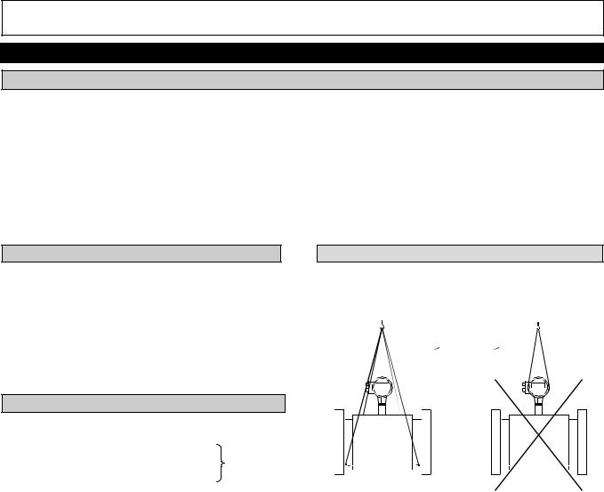
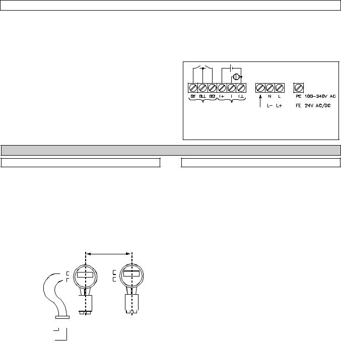
Transporting the compact flowmeter
Important: Never lift UFM 400 K and UFM 500 K compact flowmeters sized DN 100 (4”) and larger by the mounted signal converter housing!
> DN100 (> 4″)
|
− Installation and operating instructions |
Correct |
Wrong |
|
|
− Certificate of system calibration data |
|||
|
− Report on factory setting of the signal converter |
4
5
Horizontal pipe run
Install in slightly ascending pipe section. If not possible, ensure adequate
velocity
to prevent air, gas or vapor from
Open discharge
Highest point of pipe run
(Air bubbles that are collected in the
measuring tube cause faulty
Preferred
Locations
Downpipe
“Zero“ flow
Velocity.
Lined drained. Faulty measurements
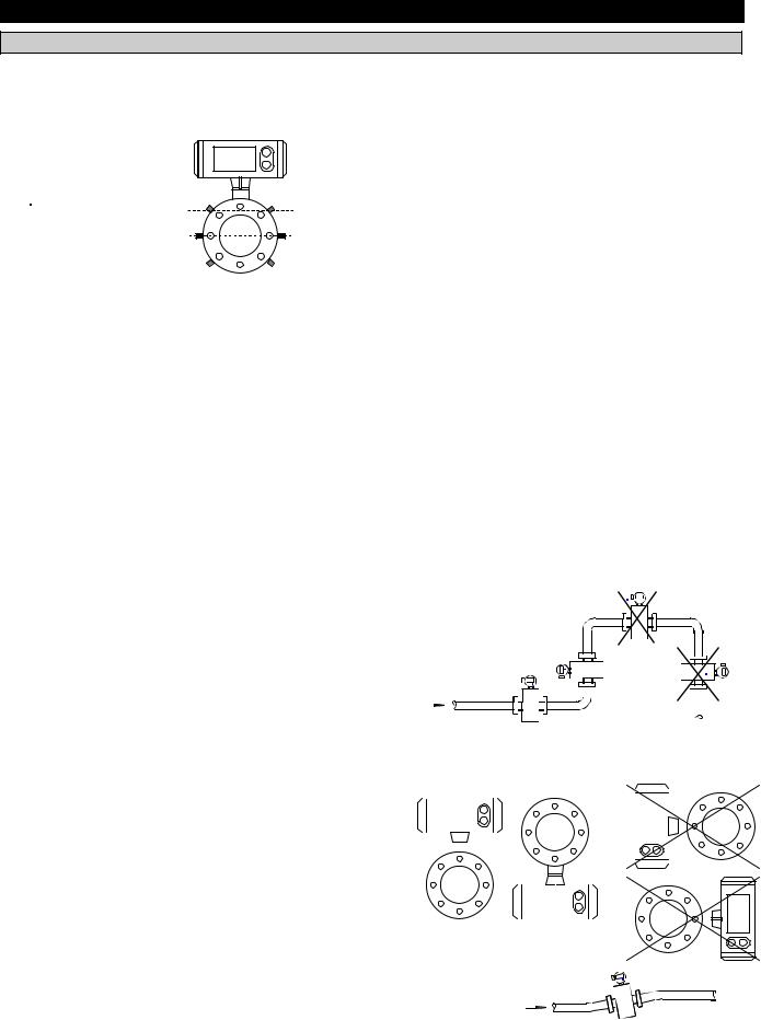
Horizontal and slightly ascending pipelines Always install signal converter (and terminal box) on the top or underside of the pipe,
10. Zero setting is normally not necessary, but it can be checked under flowing conditions as outlined in sect 7.2. Shutoff valves should therefore be provided upstream and/or downstream of the primary head unless the pipe configuration already rules out the possibility of the primary head being drained of fluid. (For zero check see section 7.2).
11. Mixing different fluid products. Install the flowmeter upstream of mixing point or at an adequate distance downstream, minimum distance 30x DN (DN = meter size), otherwise output/display may be unsteady.
12. Ambient temperature:
product temperature ≤ 60 °C/140°F
all systems: -25 to +60°C/ -13 to +140°F product temperature > 60 °C/140 °F
compact systems: -25 to +40 °C/ -13 to +104 °F separate systems: -25 to +60 °C/ -13 to +140 °F
13. Pipeline along a wall: where possible, the distance between pipe centerline and wall must be more than 0.5 m (1.6 ft) for the UFM 400 K and UFM 500 K flowmeters. If less, first connect all cables to the terminals in the terminal compartment (power supply and outputs), and install an intermediate connection box before installing flowmeter in pipeline.
14. Insulated pipeline: do not insulate UFM 400 K and UFM 500 K compact flowmeters.
15. Suggestions for installation
To avoid measuring errors due to air inclusion, please observe the following:
Part A System installation and start-up
1. Installation in the pipeline
1.1 Preliminary information
1.Location and position as required, but sensor axis must be approximately horizontal if flowmeter is installed in slightly ascending or horizontal pipe runs.
2.Hard-to-reach locations
Sensor axis (2 beams)
Sensor axis (1 beam)
Where UFM 400 K and UFM 500 K compact flowmeters have not been ordered and supplied in accordance with Versions 1 to 10 (see sect. 8.6), the configuration can be changed subsequently:
∙Turn the indicating circuit board through ± 90° or 180° to obtain horizontal positioning of the display (see sect. 8.4)
∙Turn signal converter housing through ± 90° (see sect. 8.5)
3.Measuring tube must be completely filled at all times.
4.Flow direction +/-: note arrows on flowmeter and also fct. 3.1.7 (refer to sections 4.3 and 5.4).
5.Bolts and nuts: to install make sure there is sufficient room next to the pipe flanges.
6.Vibration: support the pipeline on both sides of the flowmeter.
7.Large meter sizes, DN>200 (8”): use adapter pipes to permit axial shifting of counter flanges to facilitate installation.
8.Inlet and outlet sections
(DN = meter size)
|
Inlet section |
single beam |
double beam |
|||||||||||||||||||||||||||||
|
− Downstream of |
|||||||||||||||||||||||||||||||
|
50 × DN |
15 × DN |
||||||||||||||||||||||||||||||
|
pump |
|||||||||||||||||||||||||||||||
|
− Downstream of fully |
50 × DN |
10 × DN |
|||||||||||||||||||||||||||||
|
opened control valve |
|||||||||||||||||||||||||||||||
|
− Downstream of 2 |
40 × DN |
10 × DN |
|||||||||||||||||||||||||||||
|
quarter bends on |
|||||||||||||||||||||||||||||||
|
different levels |
|||||||||||||||||||||||||||||||
|
− Downstream of 2 |
25 × DN |
10 × DN |
|||||||||||||||||||||||||||||
|
quarter bends on one |
|||||||||||||||||||||||||||||||
|
level |
|||||||||||||||||||||||||||||||
|
− Downstream of 1 |
20 × DN |
10 × DN |
|||||||||||||||||||||||||||||
|
quarter bend |
|||||||||||||||||||||||||||||||
|
− Downstream of |
15 × DN |
no additional |
|||||||||||||||||||||||||||||
|
reducer (α/2 = 7°) |
inlet section |
||||||||||||||||||||||||||||||
|
− Outlet section |
5 × DN |
5 × DN |
9.Vortex or corkscrew flow: increase inlet and outlet sections or install flow straighteners.
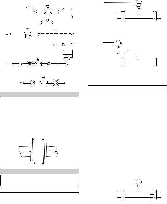
(Suggestions for installation continued):
Open feed or discharge
Install meter in low
|
Open |
|||||||||||||||||||||||||||
|
Downpipe over 5 m (16 ft) length |
|||||||||||||||||||||||||||
|
discharg |
|||||||||||||||||||||||||||
|
Install air valve downstream of |
|||||||||||||||||||||||||||
|
flowmeter (cavitation). |
|||||||||||||||||||||||||||
> 5 m (16 ft)
Long pipeline
Always install control and shutoff valves
Pump
Never install flowmeter on pump suction side (cavitation,
1.2 Pipe flanges
Flange spacing
Refer to dimensional drawings (section 10.4 and 10.5), in addition allow for thickness of gaskets.
Position of flanges
·Install flowmeter in line with pipe axis.
·Pipe flange faces must be parallel to each other, max. permissible deviation: Lmax — Lmin £ 0.5 mm (0.02”).
Lmax
Lmin
1.3 Grounding
Warning
Instrument should be properly grounded to avoid personnel shock hazard!
1.3.1 Standard grounding
The flowmeter must normally be grounded via the protective conductor PE incorporated in the power supply cable. Connect the protective conductor to the separate U-clamp terminal in the terminal compartment of the signal converter. See sect. 2.1.2 for the compact flowmeters, and sect. 2.2.2 for the separate systems.
Standard grounding of compact flowmeters UFM
400 K / 500 K
PE
PE Protective conductor incorporated in the power supply cable, see sect. 2.1.2.
Standard grounding of separate system flowmeters UFM 400 F / 500 F
PE
MR 02
MR 04
|
PE |
|||||||||||
|
Protective conductor incorporated in power |
|||||||||||
|
supply cable, see sect. 2.2.2 |
|||||||||||
|
MR 02/04 |
Sensor cables, factory supplied, see sect. |
2.2.3for connection.
1.3.2Grounding with measuring ground M
This type of grounding must be employed if at least one of the two following operating conditions occurs:
A If large potential differences occur between protective ground and electric furnaces or electrolysis plants.
BIf a protective ground conductor is not provided, e.g. for DC voltage operation.
Observe the following when grounding with separate measuring ground M:
Do not connect up the protective ground conductor PE in the terminal box if measuring ground M is connected.
If the AC supply voltage exceeds 50 Vrms, then the measuring ground simultaneously acts as the protective
ground conductor (combined protective/functional ground). Refer to appropriate national codes for specific requirements for this type of installation, which may require the addition of a ground fault detection circuit interrupter.
Grounding with measuring ground M for compact flowmeters UFM 400 K / 500 K
Do not connect up protective conductor PE incorporated in the power supply cable, see sect. 2.1.2!
 M
M
MMeasuring ground; ground conductor, cross-section ³ 4 mm2 (AWG 10) Cu with M6 cable lugs, customer supplied. Threaded hole in housing M4 by 6 mm.
6
Grounding with measuring ground M for separate system flowmeters UFM 400 F / UFM 500 F
Do not connect up protective conductor PE incorporated in the power supply cable, see sect. 2.2.2!
V
MR 02 
MR 04
 M
M
MR 02/04 Sensor cables, factory supplied, see sect. 2.2.3 for connection.
·The bolts for the flange connections must be insulated. Use sleeves and washers that made of insulating material. Must be provided by customer.
5
V Connecting cable, cross-section ³ 4 mm2 (AWG 10) Cu, equip with M6 cable lugs, customer supplied.
MMeasuring ground; ground conductor, cross-section ³ 4 mm2 (AWG 10) Cu, equip with M6 cable lugs, customer supplied. Threaded hole in housing M4, 6 mm (0.24”) deep.
1.3.3 Grounding in hazardous areas
Special regulations are applicable, refer to sect. 6.1, and the special “Ex” installation instructions.
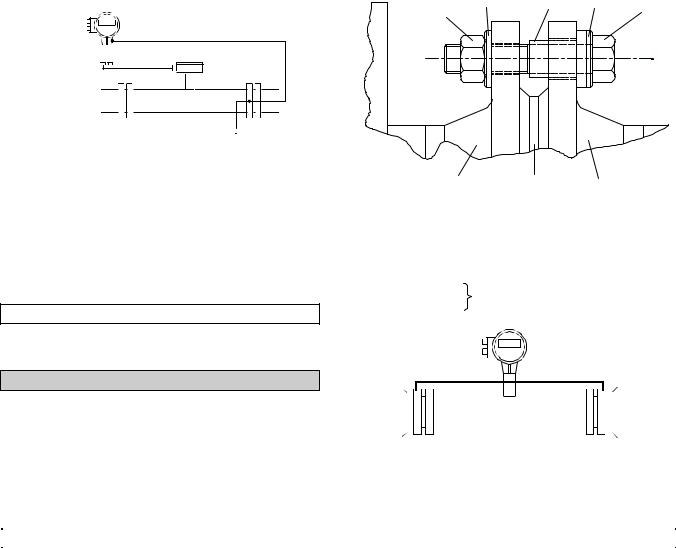
1.4 Pipes with cathodic protection
·Pipes with electric corrosion protection are generally insulated inside and outside so that the fluid has no conductive connection to ground. The primary head must be insulated from the pipe. Note the following when installing the flowmeter:
·The pipe flanges must be connected to each other using a copper cable (L), but must not be connected to the primary head.
|
1 |
2 |
3 |
|||||
|
1 |
Flange of |
3 |
Pipe flange |
6 |
Washer |
||
|
Primary head |
4 |
Bolt |
7 |
Insulating |
|||
|
2 |
Gasket |
5 |
Nut |
sleeve |
|||
|
· |
Grounding |
Not included with meter, must |
|||||
|
I |
Insulated bolts |
||||||
|
L |
Copper cables |
be provided by customer. |
|||||
|
L |
||||||
|
I |
I |
|||||
|
I |
I |
|||||||||||||
For grounding, be sure to read the instructions given in sect. 1.3.1 and 1.3.2!
|
2. |
Electrical connection |
||||
|
2.1 Compact flowmeters UFM 400 K, UFM 500 K |
|||||
|
2.1.1 Installation location and cable diameter |
|||||
|
Location |
· Fit blanking plug Pg 16 and apply sealant to unused |
||||
|
· |
Do not expose the compact flowmeter to direct |
cable entries. |
|||
|
sunlight. Install a sunshade if necessary. |
· Do not kink cables directly at conduit entries. |
||||
|
· Do not expose to intensive vibration. If necessary, |
· Provide water drip point (U-bend in cable). |
||||
|
support the pipeline to the left and right of the |
Conduit installation, general wiring consideration |
||||
|
flowmeter. |
|||||
|
Cable diameter |
· When electrical |
codes require conduit, it |
must be |
||
|
installed in such |
a manner that the meter |
terminal |
|||
|
To conform to protection category requirements, observe |
|||||
|
compartment remains dry at all times. |
|||||
|
the following recommendations: |
|||||
|
· Power and output wiring should be run in |
separate |
||||
|
· Cable diameter: 8 to 13 mm (0.31” to 0.51”). |
|||||
|
conduit. |
|||||
|
· |
Enlarge inside diameter by removing the appropriate |
||||
|
· Use twisted pairs for output wiring. |
|||||
|
onion ring(s) from the seal of the screwed conduit |
|||||
|
entry only if cables have extremely tight fit. |
Warning: Power wiring should utilize a grounded |
||||
|
neutral conductor to avoid possible shock hazard / |
|||||
|
damage to component parts. |
|||||
7
Ri
A
Rmax
2.1.2 Connection to power
·Note information given on the instrument nameplate (voltage, frequency)!
·Electrical connection in conformity with VDE 0100 “Regulations governing heavy-current installations with rated voltages up to 1000V” or equivalent national standard.
·Special regulations apply to installation in hazardous areas. Refer to sect. 6.1 and special “Ex” installation instructions.
·The PE protective ground conductor for supply power
Þmust be connected to the separate U-clamp terminal in the terminal box of the signal converter in case of “standard grounding” see sect. 1.3.1, point 1,
Þmust not be connected in case of “grounding with measuring ground M”, see sect. 1.3.2, point 3.
·Do not cross or loop the cables in the terminal box of the signal converter. Use separate Pg or NPT screwed conduit entries for power and output cables.
·Ensure that the screw thread of the round cover on the terminal box is well greased at all times.
Connection to power
|
Binary |
Current |
for |
|
output |
output |
|
|
internal |
||
|
use only |
||
|
(PE = Protective Earth) |
||
|
(FE = Functional Earth) |
2.2 Signal converters UFC 400 F and UFC 500 F separate systems
2.2.1 Location
·Do not expose signal converter to direct sunlight. Install a sunshade if necessary.
·Do not expose to intensive vibration
·Install signal converter as closely as possible to the primary head.
·The rotating design of the housing makes it easier to connect the two cables for power and outputs to the terminals in the rear terminal box.
·Cable routing
>280 mm (> 11,02″)
|
Power s upply |
S ens or cable with |
||||||||||||||||||||||||
|
Coaxial-entry plugs |
|||||||||||||||||||||||||
|
Outputs |
·On normal customer orders, the GK (primary constant) of the signal converter is factoryprogrammed to match that of the primary head with which it is ordered. The GK is engraved on the primary head nameplate and also shown on the converter nameplate. These instruments should be installed together, otherwise reprogramming of the converter is required (see sect. 4.3 and 8.2, fct. 3.1.1, 3.1.5 and 3.1.6, only possible with UFC 500 F signal converter).
·Electrical connection between primary head and signal converter by way of factory-supplied sensor cables MR02 (for single-beam versions) or MR04 (for double-beam version). Refer to sect. 2.2.3 for the connection diagrams.
2.2.2 Connection to power
·Note the information given on the instrument nameplate on the signal converter (voltage, frequency)!
·Electrical connection in conformity with VDE 0100
“Regulations governing heavy-current installations with rated voltages up to 1000 V” or equivalent national standard. Refer to sect. 6.1 and special “Ex” installation instructions.
·Special regulations apply to installation in hazardous areas.
R efer to sect. 6.1 and special “Ex” installation instructions.
·The PE protective ground conductor for supply power
Þmust be connected to the separate U -clamp terminal in the terminal box of the signal converter in the case of “standard grounding”, see sect. 1.3.1, point 1,
Þmust not be connected up in the case of “grounding with measuring ground M”, see sect. 1.3.2, point 3.
·Line resistance for 24 VDC and 21, 24, 42 and 48 VAC
Max. internal resistance Rmax of voltage supply (transformer or DC voltage source and cable)
|
24 Volt DC / 24 Volt AC: |
Rmax 24 £ 1.6 ohms |
|
42 Volt AC: |
Rmax 42 £ 2.8 ohms |
Maximum length Lmax of power cable. Lmax = 28 x A (Rmax — Ri)
C ross-section of pow er cable in m m 2 copper w ire. Internal resistance of voltage supply
Rmax 24 or Rmax 42, see above.
Internal resistance of transformer or DC voltage source.
Example:
42 VAC/A = 1.5 mm2 / Ri = 0.2 ohm / Rmax 42 = 2.8W
Lmax = [28 x 1.5 x (2.8 — 0.2)] = 109.2 m 109.2 m x 3.3 ft/m » 360 ft
C on n ection of several sign al con verters to 1 tran sform er (n = n u m ber of con verters)
Separate pow er cable: R i increases by factor “n” (R i x n) Common power cable: Lmax decreases by factor “n” (Lmax/n).
8
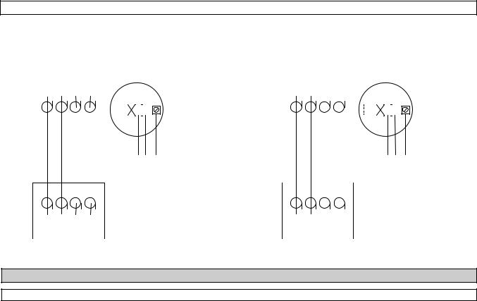
2.2.3 Connections diagrams
|
1-beam system, sensor cable MR 02 |
2-beam system, sensor cable MR 04 |
|||||||||||||||||||||||||
|
UFM 400 F, all meter sizes |
UFM 500 F, meter size ³ DN 50 / ³ 2”. |
|||||||||||||||||||||||||
|
UFM 500 F, meter size £ DN 40 / £ 1½” |
||||||||||||||||||||||||||
|
UFC 400 F |
UFC 500 F |
|||||||||||||||||||||||||
|
UFC 500 F |
||||||||||||||||||||||||||
|
1 |
2 |
3 |
4 |
1 |
2 |
3 |
4 |
|||||||||||||||||||
|
N |
L |
N |
L |
|||||||||||||||||||||||
|
MR 02 |
N L PE |
AC |
MR 04 |
N L PE |
AC |
|||||||||||||||||||||
|
L- L+ |
DC, 24 Volts |
L- L+ |
DC, 24 Volts |
|||||||||||||||||||||||
|
1 |
2 |
3 |
4 |
1 |
2 |
3 |
4 |
|
|
UFS 400/500 |
UFS 400/500 |
2.3 Outputs
2.3.1 Abbreviations
|
Abbreviation |
Stands for |
Setting via fct. no. … |
Description |
|
|
see sect. … |
||||
|
EC |
Electronic counter |
— |
5.8 |
+ 2.3.5 |
|
EMC |
Electro-mechanical counter |
— |
5.8 |
+ 2.3.5 |
|
F |
Frequency (pulse) output |
3.4.1 & seq. |
5.8 |
|
|
F100 % |
Pulses for Q = 100% flowrate or pulse value |
3.4.2 + 3.4.3 |
5.8 |
|
|
Fmax |
Pulses at Q higher than 100% flow |
— |
5.8 |
|
|
(max. 125% of F100%) |
||||
|
I |
Current output |
3.3.1 & seq. |
5.7 |
|
|
I0% |
Current at Q = 0% flow |
3.3.2 + 3.3.3 |
5.7 |
|
|
I100% |
Current at Q = 100% flow |
3.3.2 + 3.3.4 |
5.7 |
|
|
Imax |
Current at Q = over 100% flow |
3.3.5 |
5.7 |
|
|
Q0% |
0% flowrate |
— |
5.3 |
(5.7 + 5.8) |
|
Q100% |
Full-scale range, 100% flowrate |
F: 3.1.1 / R: 3.1.2 + 3.1.3 |
5.3 |
(5.7 + 5.8) |
|
Qmax |
Max. flow, Q greater than 100% |
— |
5.3 |
(5.7 + 5.8) |
|
corresponding to Imax + Fmax |
I: 3.3.7 / F: 3.4.6 |
|||
|
SMU |
Low-flow cutoff for I + F |
5.10 |
||
|
SMU-I |
Low-flow cutoff I / on value |
3.3.8 |
5.10 |
|
|
off value |
3.3.9 |
5.10 |
||
|
SMU-F |
Low-flow cutoff F /on value |
3.4.7 |
5.10 |
|
|
off value |
3.4.8 |
5.10 |
||
|
S.VELO |
Sound velocity of ultrasonic waves in the |
3.1.8 + 3.1.9 / 3.2.4 |
5.17 / 5.5 |
|
|
product. |
I: 3.3.1 & seq. |
5.7 |
||
|
F: 3.4.1 & seq. |
5.8 |
|||
|
F/R |
Forward/reverse flow |
— |
5.11 |
9

2.3.2 Current output I
∙The current output I can be used passively or actively. If used passively it is galvanically insulated from all other input and output circuits.
∙All functions and operating data can be set, see sect. 4 + 5.7 (not applicable to UFC 400 … signal converter).
∙Factory-set data and functions are listed in the enclosed report on settings. This can also be used to record any changes made to the operating parameters.
∙Maximum load at terminals I+, I, I
Maximum load in ohms ≤ 680.
∙Time constant I, adjustable between 0.04 and 3600 seconds (fct. 3.3.6), refer to sect. 5.7.
∙Low flow cutoff SMU-I, can be set independently of SMU-F (frequency output). Cut-off “on” value between 1 and 19% of Q100% (fct. 3.3.7 + 3.3.8), cut-off “off” value from 2 to 20% of Q 100% (fct. 3.3.7 + 3.3.9), refer to sect. 5.10.
∙Connection diagrams, see below.
2.3.3 Frequency (pulse) output F
∙The pulse output is galvanically insulated from the current output if the current output is used passively. Furthermore, the pulse output is galvanically insulated from all other circuits except for the status output with which it shares a common (ground).
∙All functions and operating data can be set, see sect. 4 + 5.8 (not applicable to UFC 400… signal converter).
∙Factory-set data and functions are listed in the enclosed report on settings. This can also be used to record any changes made to the operating parameters.
∙Active frequency output, for electro-mechanical totalizers EMC (terminals B1/B ) or for electronic totalizers EC (terminals B1/B ), 10 to 3,600,000 pulses/hr (0.0028 to 1000 Hz), voltage between 19 to 32 VDC. Note that the total current for the active frequency/pulse and status outputs together (drawn from I+) may not exceed 50 mA. (see connection diagram 3 below).
∙Passive frequency output, open collector output for connection of active electronic counters EC or switchgear (terminals B1/B ), input voltage ≤ 32 VDC / ≤ 24 VAC, load current max. 150 mA.
∙Time constant F, adjustable to 0.04 seconds or same as current output I (fct. 3.4.5)
∙Low-flow cutoff SMU-F, can be set independently of SMU-I (current output). Cut-off “on” value between 1 and 99% of Q100% (fct. 3.4.6 + 3.4.7), cut-off “off” value from 2 to 20% of Q 100% (fct. 3.4.6 + 3.4.8), refer to sect. 5.10.
∙Connection diagrams, see below.
∙The following table shows the possible pulse widths for F ≤ 10 Hz:
|
F100% |
Pulse-width |
|
|
F100% |
≤ 10 Hz |
30 or 50 ms |
|
F100% |
≤ 5 Hz |
100 ms |
|
F100% |
≤ 2.5 Hz |
200 ms |
|
F100% |
≤ 1.0 Hz |
500 ms |
If F100% > 10 Hz and ≤ 1000 Hz, the pulse-width duty cycle is 50%.
2.3.4 Status output S
∙The status output is galvanically insulated from the current output if the status output is used passively. Furthermore the status output is galvanically insulated from all other circuits except for the status output with which it shares a common (ground).
∙All functions and operating data can be set, see sect. 5.9 (not applicable to UFC 400… signal converter).
∙Factory-set data and functions are listed in the enclosed report on settings. This can also be used to record any changes made to the operating parameters.
∙Active status output, for electromechanical indicators or for electronic indicators, voltage between 19 to 32 VDC. Note that the total current for the active frequency/pulse and status outputs together (drawn from I+) may not exceed 50 mA. (see connection diagram 3 below).
∙Passive status output, open collector output for connection of electronic indicators, input voltage ≤ 32 VDC / ≤ 24 VAC, load current max. 150 mA.
∙Connection diagrams, see below.
2.3.5 Connection diagrams for outputs
B1 pulse output (P)
B2 status outputs (S)
Electrical connection in conformity with VDE 0100 “Regulations governing heavy current installations with mains voltages up to 1000 V” or an equivalent national standard.
10
![]()
In case the meter is to be connected to a functional extra-low voltage source of ≤ 18 VDC, protective separation in conformity with VDE 0100, part 410 or an equivalent national standard must be ensured.
The connection diagrams are shown by the figures below.
|
Current output (I) |
Fig. 1 |
||||||||||||||
|
Passive |
Active |
||||||||||||||
|
Ri £ 680W mA |
Ri £ 680W mA |
|||||||
Uext £ 18 VDC
|
Pulse output (P) |
Passive |
Fig. 2 |
Pulse output (P) |
Active |
Fig. 3 |
||||
|
Status output (S) |
|||||||||
|
B1 B |
B2 |
Status output (S) |
B1 B |
B2 |
I+ |
I |
I- |
||
|
Uext |
B1 |
||||||||
|
output A |
|||||||||
|
I |
Ÿ |
I |
B |
||||||
|
output B |
|||||||||
|
000 |
B2 |
||||||||
|
Σ |
R1 |
R2 |
I £ 150 mA |
||||||
|
P |
S |
Output voltage U: 19 V* £ U £ 32 V |
|||||||
|
Electronic |
e.g. |
|
or electro- |
signal |
Remark: In case of one active output (A or B), the |
|
mechanical |
indicator |
|
|
totalizer |
resistance R1 or R2 ³ 650 W. |
|
|
Uext ≤ 32 VDC/24 VAC |
In case of two active outputs the equivalent |
|
|
I ≤ 150 mA |
resistance of R1 and R2 ³ 650 W. |
* 19 V at full load on all active outputs
3. (Initial) Start-up
∙Check that the system has been correctly installed as described in sect. 1 and 2.
∙With separate systems, check before initial start-up that the following details on the primary head nameplate agree with the data specified in the report of settings for the signal converter. If not, new setting will be necessary:
Order No., see instrument nameplates Meter size (DN), fct. 3.1.5, sect. 5.3 Primary constant GK, fct. 3.1.6, sect. 5.16 Flow direction, fct. 3.1.7, sect. 5.4
∙Before every start-up it is advisable to carry out a zero check if the flow can be zeroed, as described in sect. 7.2.
∙When powered, the signal converter operates in the measuring mode. TEST, NO ERROR and IDENT NO.
_ _ _ _ _ _ _ of the signal converter appear in succession in the display. This is followed by display of the actual flowrate and/or the internal count on a continuous or alternating basis (depends on setting, see report on settings)
If the compass field flashes (see sect. 4.4) on flowmeters UFM 500… it may prove necessary to change the system grounding, see sect. 1.3.2.
11
Display 3rd (bottom) line: Arrows ( ) to identify actual display.
Flowrate actual flowrate Sonic.velo Sound velocity
+ Totalizer (Forward flow) — Totalizer (Reverse flow) Σ Sum totalizer (+ and -)
Part B Signal converter UFC 500 …
4. Operation of the signal converter
This section 4 is repeated in the form of pull-out condensed operating instructions (pages 17-20).
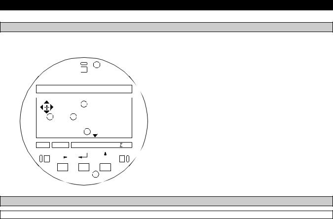
4.1 Operating and check elements
The operating elements are accessible after removing the cover of the electronics section using the special wrench. Caution: Do not damage the screw thread, never allow dirt to accumulate, and make sure it is well greased at all times.
|
5 |
Display 1st (top) and 2nd (middle) lines. |
|||||||
|
KROHNE |
U FC500 |
1 49627
 6
6  2
2
3 Liter
|
flow rate |
s onic velo. |
total |
|||||||||||||||||||||
 4
4
Keys for setting the signal converter, refer to “Setting diagram” (on the right) and sect. 4.2.2
Magnetic sensors to set the converter by means of a hand-held bar magnet (optional) without having to open the housing, refer to sect. 6.4. Function of sensors same as keys .
Compass field, see sect. 4.4.
4.2 KROHNE operator control concept
4.2.1 Description
The operator control concept for the UFC 500… signal converter consists of 3 levels (horizontal), see below.
|
Setting level: |
This level is subdivided into 3 main menus. |
|
Fct. 1.0 OPERATION: This menu contains only the most important parameters and functions of |
|
|
menu 3 to allow rapid changes to be made during the measuring mode. |
|
|
Fct. 2.0 TEST: Test menu for checking the signal converter. |
|
|
Fct. 3.0 INSTALL.: All flow measurementand flowmeter-specific parameters and functions can be |
|
|
set in this menu. |
|
|
Parameter check |
Fct. 4.0 PARAM.ERROR: This level is not selectable. After exiting from the “setting level”, the |
|
level: |
signal converter checks new data for plausibility (inconsistency). If an error is established, the signal |
|
converter reverts to menu 4. In this menu, all functions can be scanned and those, that are |
|
|
inconsistent, changed. |
|
|
Reset/acknowledge This menu has two tasks and is selected via Entry Code 2 ( −→), see sect. 4.2.5 |
|
|
level: |
1) Separate resetting of totalizers, provided that resetting is enabled by setting “YES” under fct. |
|
3.6.10 ENABL.RESET. |
2) Error scanning and acknowledgment (Quit)
Errors that have occurred since the last acknowledgment are indicated in a list. After acknowledgment and elimination of the cause(s), these errors are deleted from the list.
12
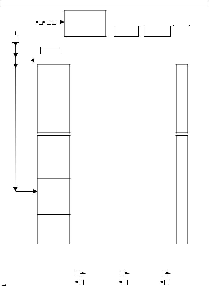
4.2.2 Overview of functions
|
measuring mode |
STATUS.LIST. |
ERROR |
QUIT. |
YES |
|||||||||
|
210.50 |
QUIT |
||||||||||||
|
− |
→ |
Error lists |
QUIT. |
NO |
|||||||||
|
m³/hr |
|||||||||||||
|
RESETTING TOTALIZER |
TOTAL. |
— |
RESET. |
YES |
|||||||||
|
TOTAL. |
+ |
RESET. |
NO |
||||||||||
→


 CodE 1 When this is displayed type in 9 key-stroke entry-code, see fct. 3.6.2 and
  3.6.3: → → →− − −
4.0 PARAM.ERROR
3.0 INSTALL.
2.0 TEST
1.0 OPERATION
|
4.12.0 V.S. min > |
|||||
|
4.12.1- |
|||||
|
max. |
4.12.2 |
||||
|
_ _ _ _ _ _ _ _ |
|||||
|
— — — — |
|||||
|
_ _ _ _ _ _ _ _ |
|||||
|
— — — — |
|||||
|
_ _ _ _ _ _ _ _ |
|||||
|
— — — — |
|||||
|
_ _ _ _ _ _ _ _ |
|||||
|
— — — — |
|||||
|
_ _ _ _ _ _ _ _ |
|||||
|
— — — — |
|||||
|
_ _ _ _ _ _ _ _ |
|||||
|
— — — — |
|||||
|
_ _ _ _ _ _ _ _ |
|||||
|
— — — — |
|||||
|
4.1.0 |
FLOW VELOC. |
||||
|
4.1.1-4.1.2 |
|||||
|
3.6.0 |
USER DATA |
||||
|
3.6.1-3.6.13 |
|||||
|
3.5.0 |
STAT.OUTP.S |
||||
|
3.5.1-3.5.3 |
|||||
|
3.4.0 |
FREQ.OUTP.F |
||||
|
3.4.1-3.4.8 |
|||||
|
3.3.0 |
CUR.OUTP. I |
||||
|
3.3.1-3.3.9 |
|||||
|
3.2.0 |
DISPLAY |
||||
|
3.2.1-3.2.6 |
|||||
|
3.1.0 |
BASIS. PARAM. |
||||
|
3.1.1-3.1.9 |
|||||
|
2.5 PROCESSOR |
|||||
|
2.4 TEST STATUS |
|||||
|
2.3 TEST F |
|||||
|
2.2 TEST I |
|||||
|
2.1 TEST DISP. |
|||||
|
1.4.0 |
FREQ. OUTP. F |
||||
|
1.4.1-1.4.4 |
|||||
|
1.3.0 |
CUR. OUTP. I |
||||
|
1.3.1-1.3.4 |
|||||
|
1.2.0 |
DISPLAY |
||||
|
1.2.1-1.2.5 |
|||||
|
1.1.0 |
BASIS. PARAM. |
||||
|
1.1.1-1.1.2 |
Possible direction of keys in menu levels and sub-levels
The flashing part of the display (cursor) can be changed, here in “bold” type.
CHECK-PARAMETER
LEVEL SETTING
|
Param. -Check |
|||||||||||||||||||||
|
Main menu |
Submenu |
Function |
Data |
||||||||||||||||||
|
and return to |
|||||||||||||||||||||
|
→ |
→ |
→ |
|||||||||||||||||||
|
choose with |
choose with |
choose with |
set with following |
||||||||||||||||||
|
measuring |
|||||||||||||||||||||
|
following key |
following key |
following key |
keys |
||||||||||||||||||
|
mode |
|||||||||||||||||||||
|
− |
− |
− |
→ − |
||||||||||||||||||
13
4.2.3 Function of keys
The gray areas in the following text represent the flashing part of the display, the cursor.
|
To start |
|||||||
|
Measuring mode |
Operating mode |
||||||
|
13.571 |
Fct. 1.0 |
||||||
|
→ |
|||||||
|
OPERATION |
|||||||
|
3 |
/ h |
||||||
|
m |
|||||||
PLEASE NOTE: When ENTRY CODE ‘YES’ is set in fct. 3.6.2, then, after pressing the → key, the display will show: “CodE 1 — — — — — — -”. Now type in the 9 key-stroke the entry-code: Factory setting → → → − − − (Each key-stroke is represented by a “ ” in the display).
Function of the keys in the 3 levels
|
Cursor |
Is the flashing part of the display. This can be a digit, a text, a unit or a sign. |
|
|
→ |
The cursor key shifts the cursor to a new (different) position in the display. For the menu columns (see |
|
|
diagram in sect. 4.2.2) this means: transfer to the next “right” column, i.e. from left or right, up to the data |
||
|
column. Only in the data column parameters can be changed and functions can be initiated. |
||
|
− |
The select key changes the contents (digit, text) of the flashing cursor. |
|
|
— Digit |
Increase value by “1”. |
|
|
(With fct. _ _ _, display next main or submenu or next function). |
||
|
— Text/unit: Display (select) next text/unit from a list. |
||
|
— Sign: |
Change from “+” to “-“ or, with exponents, from “E” to “E-”, and vice versa. |
|
|
The accept key (return key) is used for: |
||
|
— acceptance of new parameters, |
||
|
— acknowledgment of displayed error messages in the reset/ackn. Menu, and |
||
|
— execution of displayed functions. |
||
|
For the menu columns (see diagram in sect. 4.2.2) this means: transfer to the next “left” column, i.e. from |
||
|
right to left, up to the main menu column. Only from the main menu column it is possible to exit the 3 |
||
|
levels and return to the measuring mode. |
||
|
Important |
∙ If numerical values are set, which are outside the permissible input range, the display will flash after the |
|
|
“Accept” key has been pressed. |
||
|
1st line: permissible minimum or maximum value displayed. |
||
|
2nd line: TOO LOW or TOO HIGH. |
||
|
The incorrect numerical value is displayed again after pressing the key; set correct numerical value. |
||
|
∙ Time-out function: if the signal converter is in the setting level and if no key-strokes are set for approx. 15 minutes, the |
||
|
signal converter will automatically revert to the measuring mode without accepting any previously changed data. |
To terminate
Keep pressing until menu fct. 1.0 OPERATION, fct. 2.0 TEST, or fct. 3.0 INSTALL. is
|
S TO RE |
YES |
|||||
Storing the new parameters
Acknowledge with , display shows: “PARAM.CHECK”.
When no errors occur, the measuring mode will continue with the new parameters.
In case of an error, the display will show: “Fct. 4.0 PARAM.ERROR”. In this menu all functions that are inconsistent can be scanned. For this turn to sect. 4.2.2 and 4.3.
Do not store new parameters
Press the− key, display shows “STORE NO”. After pressing the key the measuring mode will continue with the “old” parameters.
14
Changing the numbers.
|
97 |
. |
35 |
97 |
. |
45 |
|||
|
− |
||||||||
|
m3 / |
h r |
m3 / |
h r |
|||||
|
Moving the cursor (blinking part) to the |
||||||||
|
97 |
. 35 |
97 . |
35 |
|||||
|
→ |
||||||||
|
m3 / h r |
m3 / h r |
|||||||
Changing the texts (units).
When the units are changed, the totalizer value is automatically converted.
|
97350 |
||||||||
|
− |
||||||||
|
Li t er / h r |
||||||||
|
Changing from text (unit) to totalizer setting. |
||||||||
|
13 . 571 |
||||||||
|
→ |
||||||||
|
m3 / h r |
||||||||
|
Changing from totalizer setting back to text. |
||||||||
|
1 3 . 5 71 |
||||||||
|
→ |
||||||||
|
m3 / h r |
||||||||
|
Return to display of functions. |
||||||||
|
10 . |
3 |
|||||||
|
S ec |
||||||||
7 . 1437 U S . G a l / S ec
13 . 571 m3 / h r
13 . 571
m3 / h r
Fct . 1 . 3 . 1
TIM ECONS T . I
4.2.4 Example for setting the signal converter
The following example shows how to change the pulse rate of the frequency output (function: fct. 3.4.3 PULSRATE, see sect. 4.3). The cursor (flashing part of display) is shown here in “ bold” type.
|
— “old” setting: |
1 pulse per second |
(1.000 |
E 0 |
PuLSe/Sec) |
|
— change to: |
1000 pulses per hour |
(1.000 |
E 3 |
PuLSe/hr) |
|
Keys |
Display |
Explanation |
||
|
1st line |
2nd line |
|||
|
— — — — — |
— — — — — — -/ — — |
Measuring mode |
||
|
→ |
Fct. 1.0 |
OPERATION |
When ENTRY CODE 1 |
|
|
“YES” is set in fct. 3.6.2 |
||||
|
the 9 key-stroke “CodE 1” |
||||
|
must be typed in. |
||||
|
Factory setting |
||||
|
→ → → − − − |
||||
|
Main menu operation |
||||
|
2 x − Fct. 3.0 |
INSTALL. |
Main menu setting |
||
|
→ |
Fct. 3.1 |
BASIS |
Submenu Frequency output |
|
|
PARAM |
||||
|
3 x − Fct. 3.4 |
FREQ.OUTP. |
|||
|
F |
→Fct. 3.4.1 FUNCTION F
|
2 x − |
Fct. 3.4.3 |
PULSRATE |
Change pulse rate |
|
→ |
1.0000 E |
PuLSe/Sec |
|
Keys |
Display |
Explanation |
||
|
1st line |
2nd line |
|||
|
− |
6.0000E 1 |
PuLSe/min |
Change pulse rate |
|
|
− |
3.6000E 3 |
PuLSe/hr |
(Continuation) |
|
|
→ |
3.6000E 3 |
PuLSe/hr |
||
|
8 x − |
1.6000E 3 |
PuLSe/hr |
||
|
→ |
1.6000E 3 |
PuLSe/hr |
||
|
4 x − |
1.0000E 3 |
PuLSe/hr |
||
|
Fct. 3.4.3 |
PULSRATE |
Return to measuring |
||
|
Fct. 3.4 |
FREQ.OUTP.F |
mode |
||
|
Fct. 3.0 |
INSTALL. |
|||
|
STORE YES |
||||
|
PARAM.CHEC |
If fct. 4.0 PARAM.ERR. |
|||
|
K |
should appear: |
|||
|
plausibility error, see |
||||
|
sect. 4.3 |
||||
|
— — — — — — — |
— — — — — — — / — — — |
Measuring mode |
15

4.2.5 RESET / QUIT Menu, reset totalizers and delete error messages
Resetting totalizers
|
Keys |
Display |
Description |
|
|
— — — — — — — |
— — — — — — / — — — |
Measuring mode. |
|
|
CodE 2 |
— — |
Type in entry-code 2 for RESET/QUIT-menu: − →. |
|
|
− → |
TOTAL.RESET |
Totalizer menu only appears when ENABL.RESET “YES” is set in |
|
|
fct. 3.6.10, if not display will show “ERROR LIST”, see next section. |
|||
|
→ |
TOTAL. + |
||
|
(− ) |
(TOTAL. -) |
If necessary, choose “-Totalizer” with − key. |
|
|
→ |
RESET NO |
Do not reset totalizer, press 3 times to return to measuring mode. |
|
|
− |
RESET YES |
Reset totalizer. |
|
|
TOTAL. + (-) |
“+” (or “-“) totalizer has been reset. |
||
|
If necessary choose the other totalizer with − key and reset as well. |
|||
|
TOTAL.RESET |
|||
|
— — — — — — — |
— — — — — — / — — — |
Return to measuring mode. |
|
|
Displaying and deleting error messages |
|||
|
Keys |
Display |
Description |
|
|
— — — — — — — |
— — — — — — / — — — |
Measuring mode. |
|
|
CodE 2 |
— — |
Type in entry-code 2 for RESET/QUIT-menu: − →. |
|
|
− → |
TOTAL.RESET |
Totalizer menu only appears when ENABL.RESET “YES” is set in |
|
|
fct. 3.6.10, if not display will show “ERROR.LIST”, see next section. |
|||
|
− |
ERROR.LIST |
Menu for status messages. |
|
|
→ |
— — — — — — — — — — — |
1. Error message is displayed. |
|
|
− |
— — — — — — — — — — — |
2. Error message is displayed. |
|
|
−, −, … |
— — — — — — — — — — — |
Further error messages are displayed, if present at the end of the list. |
|
|
ERROR.LIST |
ERRORLIST is displayed. |
||
|
→ |
QUIT.NO |
Do not delete error messages, |
|
|
press key three times = return to measuring mode. |
|||
|
− |
QUIT.YES |
Delete error messages. |
|
|
ERROR QUIT |
Error messages have been deleted. |
||
|
ERROR.LIST |
|||
|
— — — — — — / — — — |
Return to measuring mode. |
16
 Loading…
Вы здесь
Каталог инструкций » K » KROHNE » Оборудование KROHNE » KROHNE UFM 500 RU » Страница инструкции 1
-

1
-
2
-
3
-
4
-
5
-
6
-
7
-
8
-
9
-
10
-
11
-
12
-
13
-
14
-
15
-
16
-
17
-
18
-
19
-
20
-
21
-
22
-
23
-
24
-
25
-
26
-
27
-
28
-
29
-
30
-
31
-
32
-
33
-
34
-
35
-
36
-
37
-
38
-
39
-
40
-
41
-
42
-
43
-
44
-
45
-
46
-
47
-
48
-
49
-
50


- 1
- 2
- ››
Распечатать
Страница 1 из
- << Предыдущая
- Следующая >>

Ультразвуковые расходомеры altosonic в инструкции по эксплуатации KROHNE UFM 500 RU
3/98
Версия программного обеспечения 6.97.003.00
Ультразвуковые расходомеры ALTOSONIC
Инструкция по эксплуатации и установке
UFM 400 K/F
UFM 500 K/F
7.30787.33.
UFM 500 K DN65 – 3000 (2½” – 120”)
UFM 500 K DN25 – 50 (1” – 2”)
- << Предыдущая
- Следующая >>
More products and manuals for Equipment Krohne
| Models | Document Type |
|---|---|
|
CORIMASS E P MFM 2081 EEx EN |
User Manual
10 pages |
|
CORIMASS E P MFM 2081 EEx DE |
User Manual
10 pages |
|
CORIMASS E P MFM 2081 EEx FR |
User Manual
10 pages |
|
UFM 600T EN |
User Manual
93 pages |
|
UFM 600T RU |
User Manual
130 pages |
|
UFM 600T DE |
User Manual
93 pages |
|
CORIMASS MFC 85 EN |
User Manual
26 pages |
|
CORIMASS MFC 85 DE |
User Manual
26 pages |
|
CORIMASS MFC 85 FR |
User Manual
26 pages |
|
CORIMASS MFC 85 Interface EN |
User Manual
35 pages |
|
CORIMASS MFC 85 Modis EN |
User Manual
18 pages |
|
CORIMASS MFC 85 Interface DE |
User Manual
35 pages |
|
CORIMASS MFC 85 Modis DE |
User Manual
18 pages |
|
CORIMASS MFC 85 Modis IT |
User Manual
15 pages |
|
CORIMASS MFC 85 Modis FR |
User Manual
19 pages |
|
OPTISOUND 3040 C 4wire EN |
User Manual
52 pages |
|
OPTISOUND 3040 C 4wire DE |
User Manual
52 pages |
|
OPTISOUND 3040 C 4wire FR |
User Manual
56 pages |
|
OPTIMASS Sensors ATEX with MFC050 FR |
User Manual
59 pages |
|
OPTISOUND 3040 C 4wire RU |
User Manual
52 pages |


Contents
Part A System installation and start-up
1.
Installation in the pipeline
5-7
1.1
Preliminary information
5-6
1.2
Pipe flanges
6
1.3
Grounding
6 + 7
1.3.1
Standard grounding
6
1.3.2
Grounding with measuring ground M
6 + 7
1.3.3
Grounding in hazardous areas
7
1.4
Pipes with cathodic protection
7
2.
Electrical connection
7-11
2.1
Compact flowmeters UFM 400 K and UFM 500 K
7
2.1.1
Installation location and cable diameter
7
2.1.2
Connection to power
8
2.2
Signal converters UFC 400 F and UFC separate systems
8 + 9
2.2.1
Location
8
2.2.2
Connection to power
8
2.2.3
Connection diagrams
9
2.3
Outputs
9-11
2.3.1
Abbreviations
9
2.3.2
Current output I
10
2.3.3
Frequency (pulse) output F
10
2.3.4
Status output S
10
2.3.5
Connection diagrams for outputs
10+11
3.
(Initial) Start-up
11
Part B Signal converter UFC 500…
4.
Operation of the signal converter
12-22
4.1
Operating and check elements
12
4.2
KROHNE operator control concept
12-15
4.2.1
Description
12
4.2.2
Overview of functions
13
4.2.3
Function of keys
14
4.2.4
Example for setting the signal converter
15
4.2.5
Reset/Quit-menu, reset totalizers and delete error messages
16
4.3
Setting table
17-20
4.4
Error messages
21+22
4.4.1
Description of errors as shown in display
21
4.4.2
Error display during measuring (display) mode
22
4.4.3
Error list in Reset/Quit-menu
22
5.
Description of functions
22-32
5.1
Physical units
22
5.2
Numerical format
22
5.3
Full-scale range Q
100%
and meter size
22
5.4
Flow direction
23
5.5
Display
23
5.6
Internal electronic totalizer
24
5.7
Current output I
25-27
5.7.1
Application I (fct. 3.3.1)
25
5.7.2
Other functions for I
25
5.7.3
Characteristics of current output I
26+27
5.8
Frequency output F
28-30
5.8.1
Application F (fct. 3.4.1)
28
5.8.2
Other functions for F
28+29
5.8.3
Characteristics of frequency output F
29+30
5.9
Status output S
30
5.9.1
Application S
30
5.10
Low-flow cutoff (SMU) for I + F
30
5.11
F/R operation for I or F
31
5.12
Language of display texts
31
5.13
Coding desired for entry into setting level?
31
5.14
Behavior of outputs during setting
31
5.15
User-defined unit
31+32
5.16
Primary constant GK
32
5.17
Sound velocity measurement for product identification
32
5.18
Tag name (measuring point identification)
32