Quick-Start Guide — TBS CROSSFIRE Nano RX
The CROSSFIRE Nano RX has much of the same feature set as the TBS CROSSFIRE Micro RX but on a
smaller form factor and without connectors.
The small size allows you to save space and weight, while still retaining the key features that make the
CROSSFIRE system flexible and reliable.
Key features:
●
Same feature set like regular CROSSFIRE Micro receiver (SBUS, PPM, PWM, CRSF, SmartAudio,
MAVLInk, Serial Bridge)
●
Telemetry support
Full range receiver
●
●
5V voltage input
2.54mm pitch front connector and 2mm pitch side connector
●
●
Compact, only 11 x 18 mm
Note:
*** Firmware 2.24 or newer required! ***
1
Revision 2018-02-16
ExpressLRS — это система радиоуправления на большие расстояния с открытым исходным кодом, разработанная Алессандро Карчоне (он же AlessandroAU) и рядом других разработчиков.
Содержание
- О системе
- Настройка ExpressLRS в OpenTX
- Настройка модуля ExpressLRS с помощью LUA скрипта
- Конфигуратор ExpressLRS
- Возможные проблемы при запуске скрипта и решения
- Как прошить или обновить модуль и приемник ExpressLRS
- Подготовка (компиляция) прошивки ExpressLRS
- Компиляция прошивки модуля передатчика (TX)
- Прошивка / обновление ExpressLRS TX через Wi-Fi
- Прошивка / обновление ExpressLRS TX через UART
- Компиляция (сборка) прошивки приемника (RX) ExpressLRS
- Прошивка / обновление ExpressLRS RX (приемник) через Wi-Fi
- Прошивка / обновление приемника ExpressLRS через Betaflight Passthaught
- Как привязать приемник ExpressLRS
- Как подключить приемник ExpressLRS к полетному контроллеру
- Как настроить приемник ExpressLRS в Betaflight
- Заключение
О системе
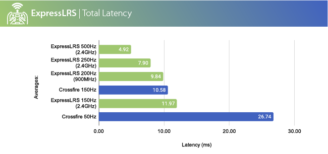
ExpressLRS разработал Alessandro Carcione (AlessandroAU), у него получилось добиться максимальной дальности передачи и приема сигнала и при этом все работает с очень маленькой задержкой благодаря оптимизированным пакетам данных, которые передаются для обмена между оборудованием.
Небольшой недостаток: есть только базовая телеметрия, которая включает в себя VBAT, нисходящий/восходящий LQ и нисходящий/восходящий RSSI, но уже ведутся работы для поддержки полной телеметрии.
Посмотрите на картинку ниже, здесь вы можете сравнить систему с CrossFire и убедиться в значительном отличии задержек:
Читайте также: Приемники и передатчики работающие на ExpressLRS, список
Настройка ExpressLRS в OpenTX
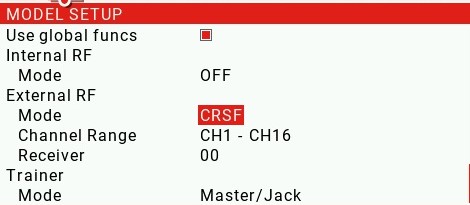
Система использует последовательный протокол CRSF для связи между радиопередатчиком и модулем. Чтобы установить протокол CRSF, перейдите к настройкам выбранной модели, на вкладке Model Setup включите External TX и выберите CRSF в качестве протокола:
Все изменения в конфигурации модуля можно делать с помощью LUA скрипта.
Скачать скрипт можно по этой ссылке: https://github.com/ExpressLRS/ExpressLRS/blob/master/src/lua/ELRS.lua (правой кнопкой мыши — сохранить ссылку как)
Конфигуратор ExpressLRS
У протокола для конфигурации систем на которой он работает, есть свой конфигуратор.
Скачать конфигуратор можно здесь: https://www.expresslrs.org/
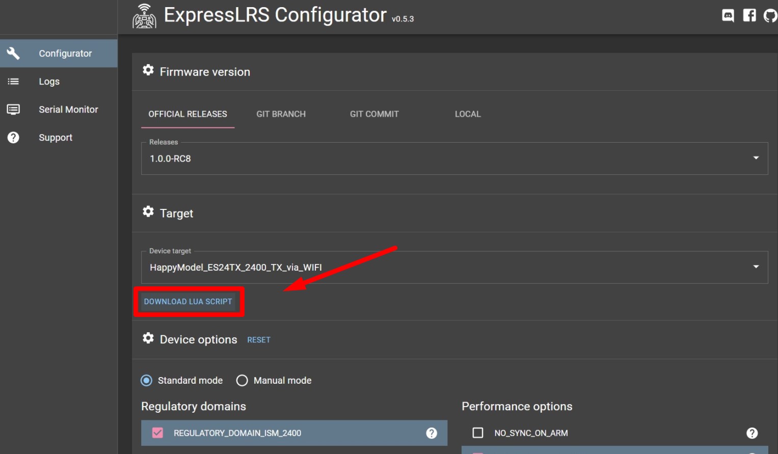
Скачать скрипт LUA можно прямо из этого конфигуратора:
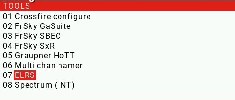
Скопируйте файл сценария ELRS.lua в папку SCRIPTS TOOLS на SD-карту аппаратуры.
Можно запустить конфигуратор ExpressLRS LUA , нажав и удерживая кнопку настроек на аппаратуре (SYS) и выбрав сценарий Lua ELRS из списка:
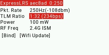
Когда сценарий запустится, вы увидите такую информацию:
Возможные проблемы при запуске скрипта и решения
Если сценарий LUA показывает на экране только сообщение «Connecting…», это значит, что LUA не взаимодействует с передатчиком.
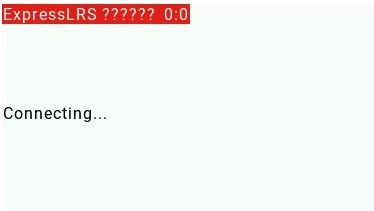
Возможные причины и способы решения этой проблемы:
- Модуль неправильно подключен к отсеку для внешнего модуля JR . Попробуйте переустановить модуль в отсек / корпус JR. На работающем модуле должен гореть красный светодиод.
- Вы используете версию OpenTX старше 2.3.12. Нужно обновиться как минимум до 2.3.12 версия для того, чтобы ExpressLRS мог работать.
- Вы не установили для External RF значение CRSF в настройке модели. Перейдите к настройке модели и проверьте настройки. Внутренний приемник (Internal RF) должен быть выключен.
- Передатчик находится в режиме обновления WiFi . Чтобы запустить модуль ExpressLRS в нормальном режиме, необходимо выключить и снова включить аппаратуру управления.
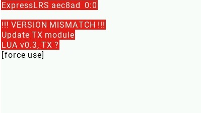
Если скрипт LUA показывает предупреждение об ошибке: «!!! VERSION MISMATCH !!!«(несоответствие версий), это означает, что вам необходимо обновить прошивку модуля TX.
Как прошить или обновить модуль и приемник ExpressLRS
Существует несколько способов прошивки ExpressLRS в модулях TX (передатчик) и RX (приемники). Это зависит от оборудования, которое вы используете и его возможностей — есть ли у него USB-разъем, есть ли чип WiFi ESP32 и так далее.
- Для модуля TX (передатчик) доступны методы по WiFi и через UART.
- Для модулей RX (приемники) доступны методы через BF, по WiFi и через UART.
Если TX или RX имеет на борту чип ESP, то доступно обновление по WiFi. Если модуль TX имеет разъем USB, тогда доступен метод обновления UART. Любой приемник может быть обновлен с помощью последовательной передачи BF или метода обновления UART.
Список возможных методов прошивки для каждого оборудования можно посмотреть здесь: https://github.com/ExpressLRS/ExpressLRS/wiki/Flashing-ExpressLRS
Для прошивки модуля TX или RX вам необходимо подготовить (скомпилировать) прошивку.
Подготовка (компиляция) прошивки ExpressLRS
Шаг 1. Загрузите и установите конфигуратор.
Скачать конфигуратор можно отсюда: https://github.com/ExpressLRS/ExpressLRS-Configurator/releases
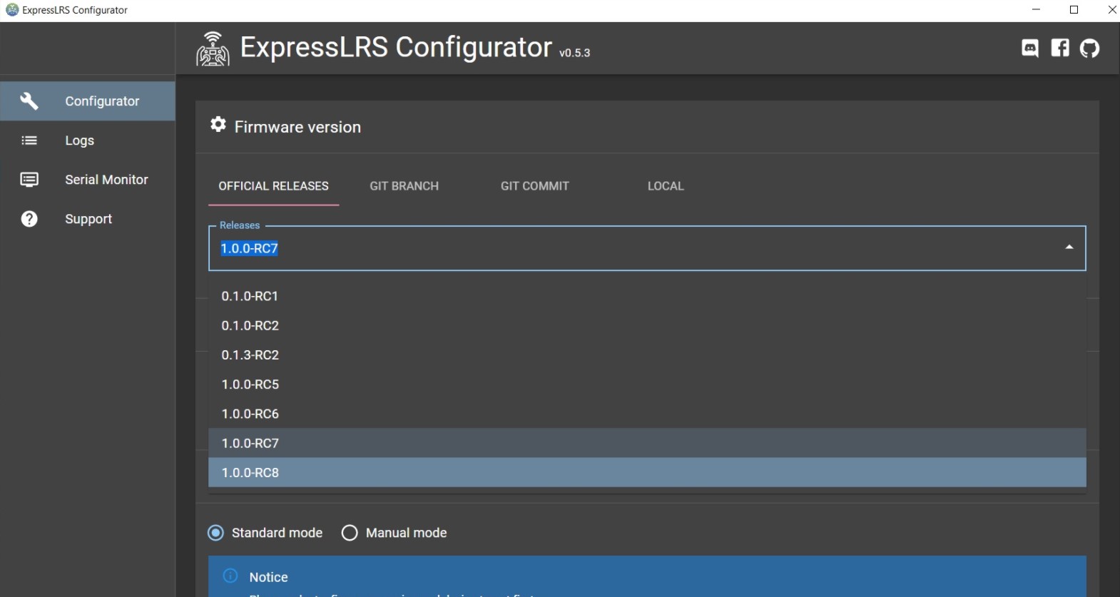
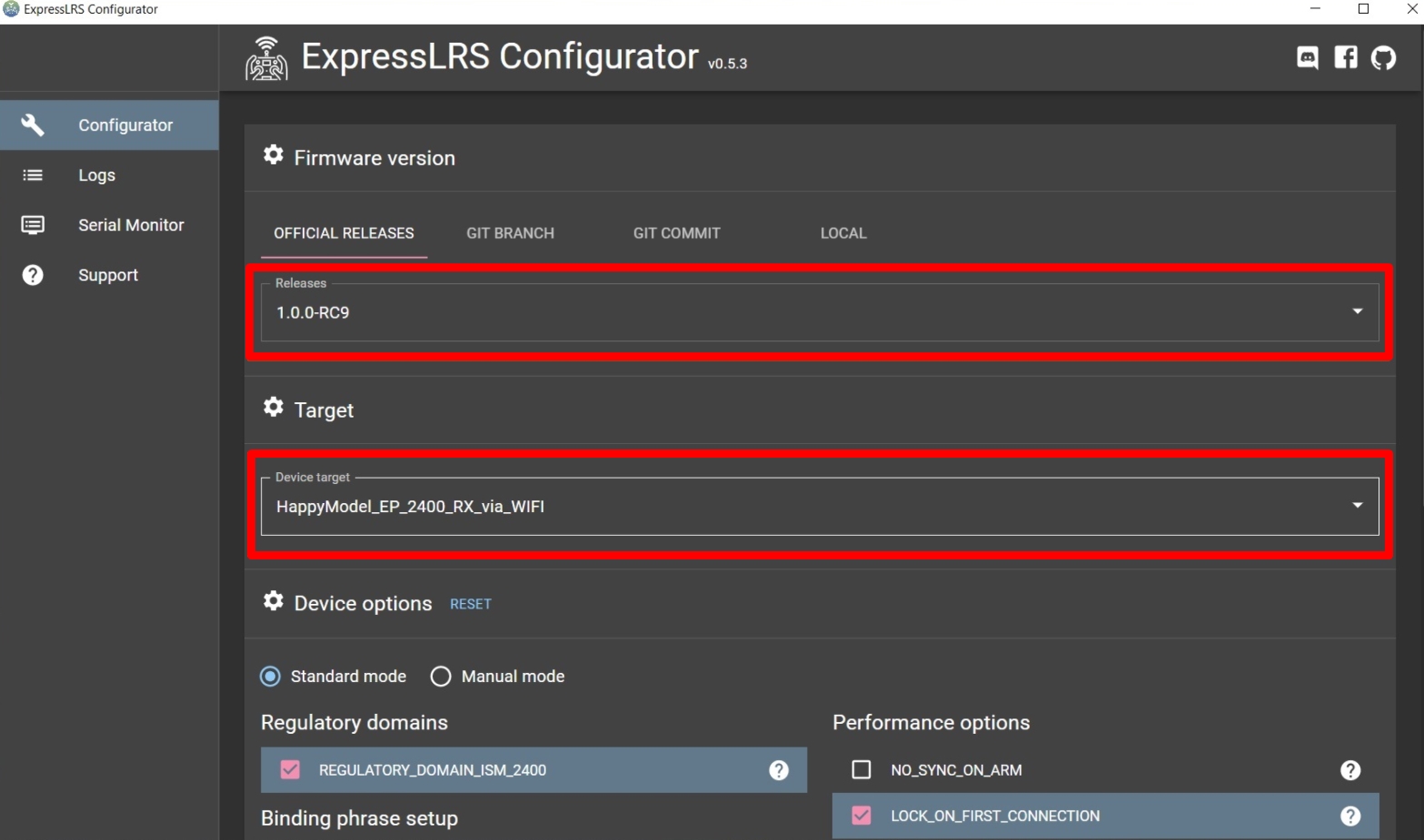
Шаг 2. Запустите конфигуратор и выберите версию прошивки. Дополнение «RC» к номеру выпуска означает, что это версия Release Candidate. То есть, кандидат в релиз и такую версию не рекомендуется устанавливать, так как возможны ошибки в работе. Лучше использовать стабильные версии, такие как «1.0.0» и выше.
Следующие инструкции сделаны для обновления модулей радиопередатчиков Happymodel ES24TX и приемников EP1 / EP2. Инструкции аналогичны для других модулей ExpressLRS TX и RX, которые уже есть на рынке.
Компиляция прошивки модуля передатчика (TX)
Шаг 1. Выберите свое название оборудования с типом обновления, версию прошивки и скачайте скрипт LUA:
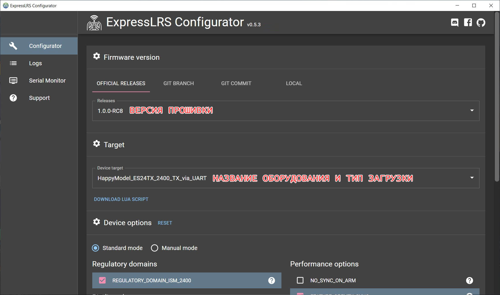
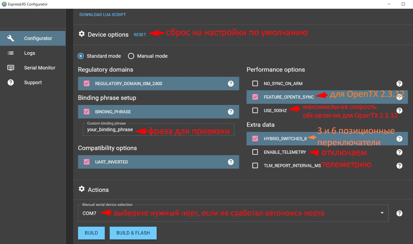
Шаг 2. После того, как устройство выбрано, вам нужно установить параметры устройства, относящиеся к выбранному оборудованию:
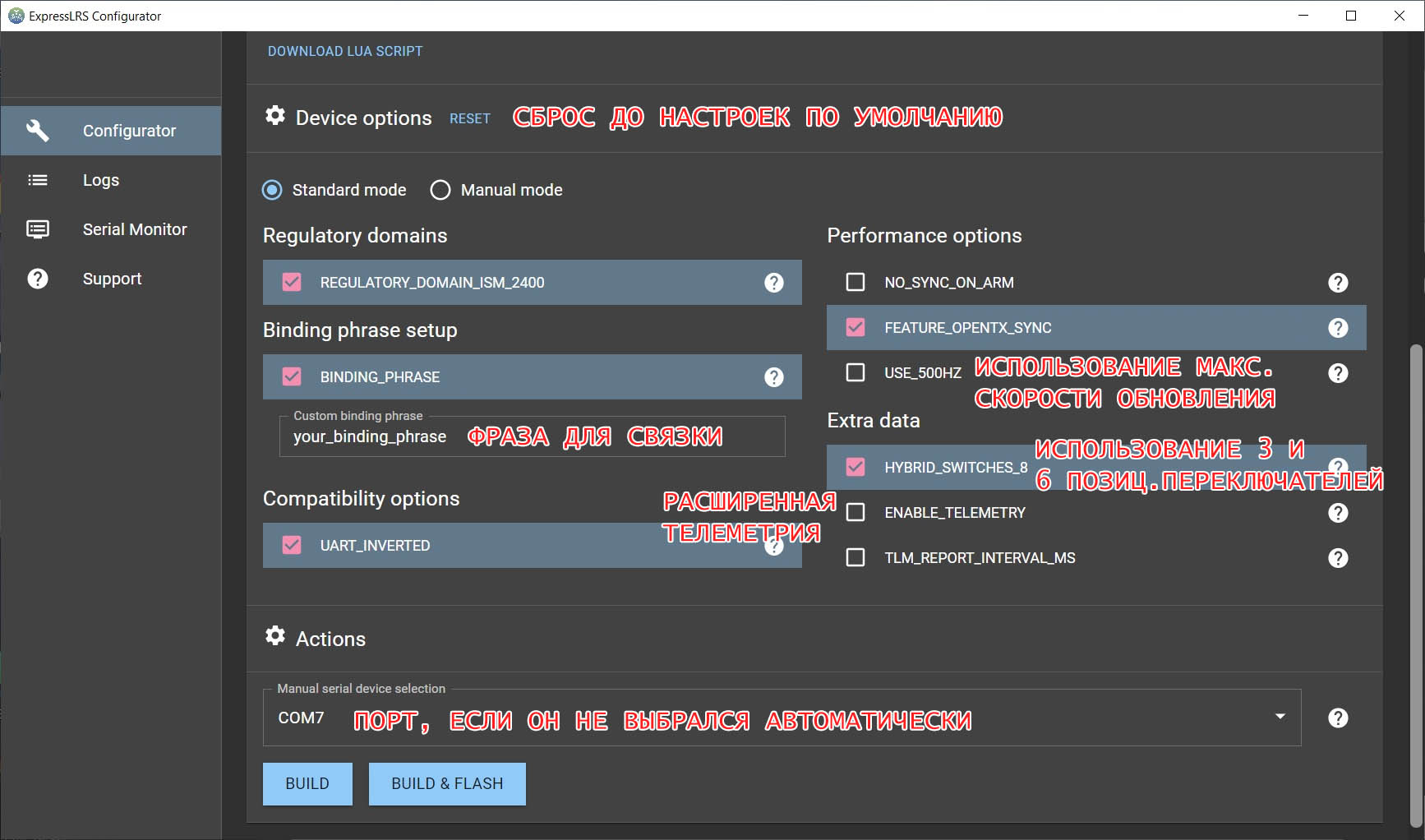
Расшифровка параметров:
- USE_500HZ — включает скорость обновления 500 Гц (эта опция удалена в поздних версиях)
- HYBRID_SWITCHES_8 — разрешает использование 3 и 6-позиционных переключателей (по умолчанию ExpressLRS передает только двухсторонние (On-Off) переключатели в данных канала).
- ENABLE_TELEMETRY — включает дополнительную телеметрию, такую как напряжение аккумулятора, ток, данные GPS , режим полета (базовая телеметрия, такая как RSSI, качество связи, передается всегда)
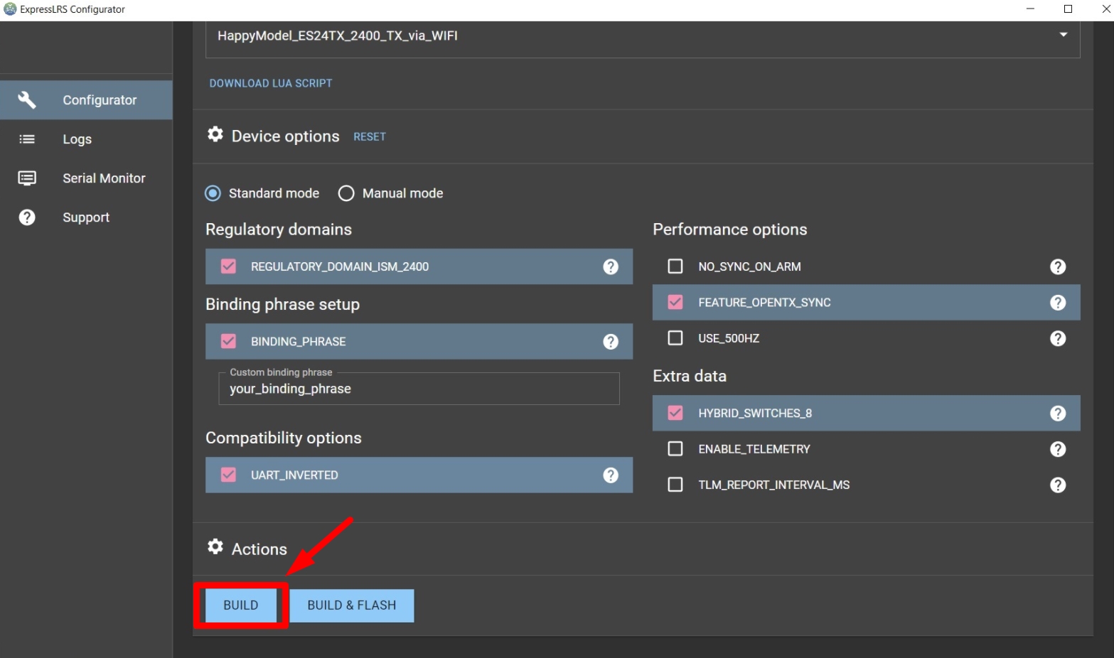
Шаг 3. После того, как все настроено, нажмите кнопку BUILD:
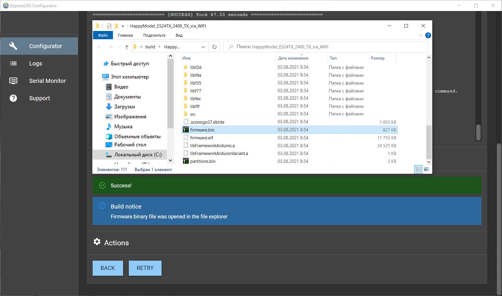
Шаг 4. По окончании компиляции Конфигуратор откроет папку с скомпилированным файлом firmware.bin:
Прошивка / обновление ExpressLRS TX через Wi-Fi
Обновление через WiFi самый удобный способ прошивки и обновления.
Шаг 1. Сначала вам нужно перевести передатчик в режим обновления WiFi. Перейдите к скрипту ELRS Lua на передатчике, долго зажав SYS (кнопка системных настроек).
Шаг 2. Затем подключитесь к сети Wi-Fi под названием «ExpressLRS TX Module«. Пароль сети Wi-Fi — «expresslrs«. Не путайте с сетью Wi-Fi «ESP WiFiManager» — это чип ESP, создающий свою сеть точек доступа и в настоящее время (начиная с версии прошивки 1.0) не используется. Подробнее об этой сети ниже в примечаниях.
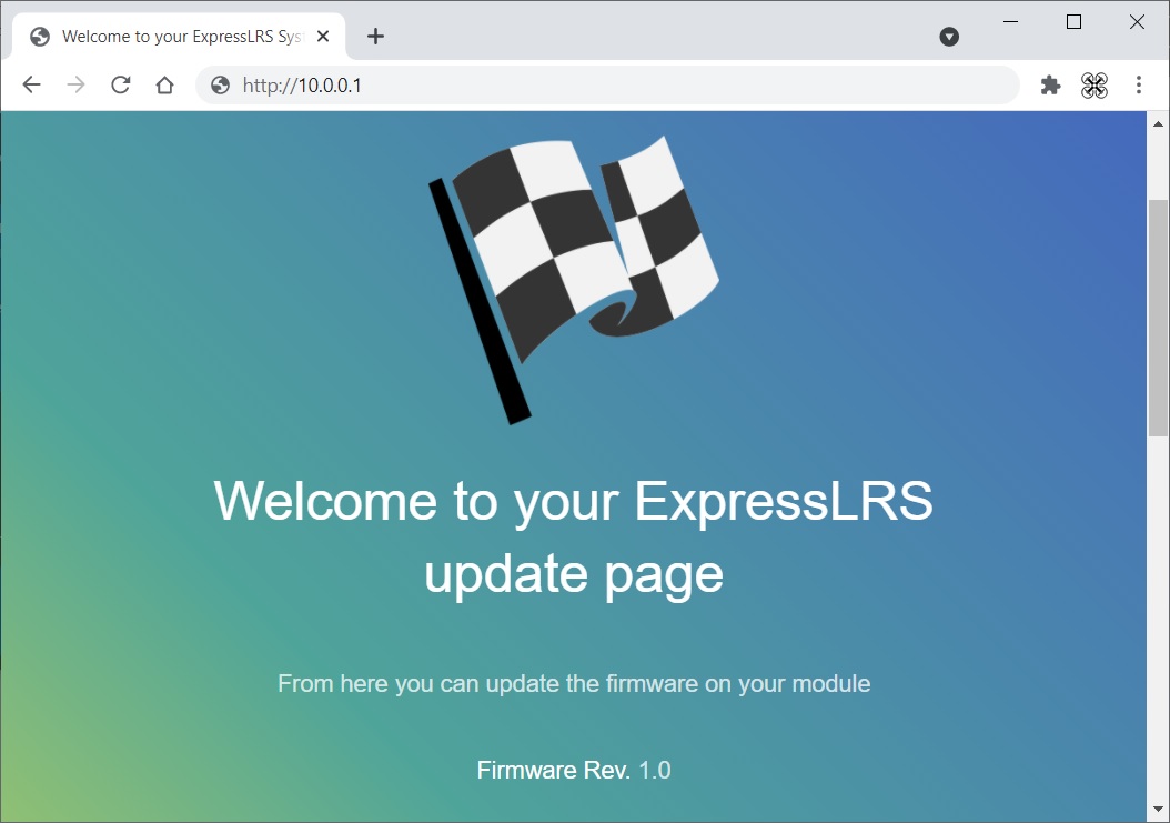
Шаг 3. После подключения к сети «ExpressLRS TX Module«, откройте в браузере адрес: http://10.0.0.1
Вы увидите экран приветствия:
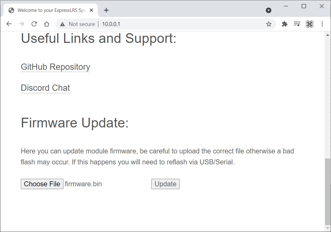
Шаг 4. Прокрутите страницу вниз, выберите скомпилированный файл прошивки firmware.bin, нажав кнопку «Choose file«. Нажмите кнопку «Update«, чтобы начать процесс обновления.
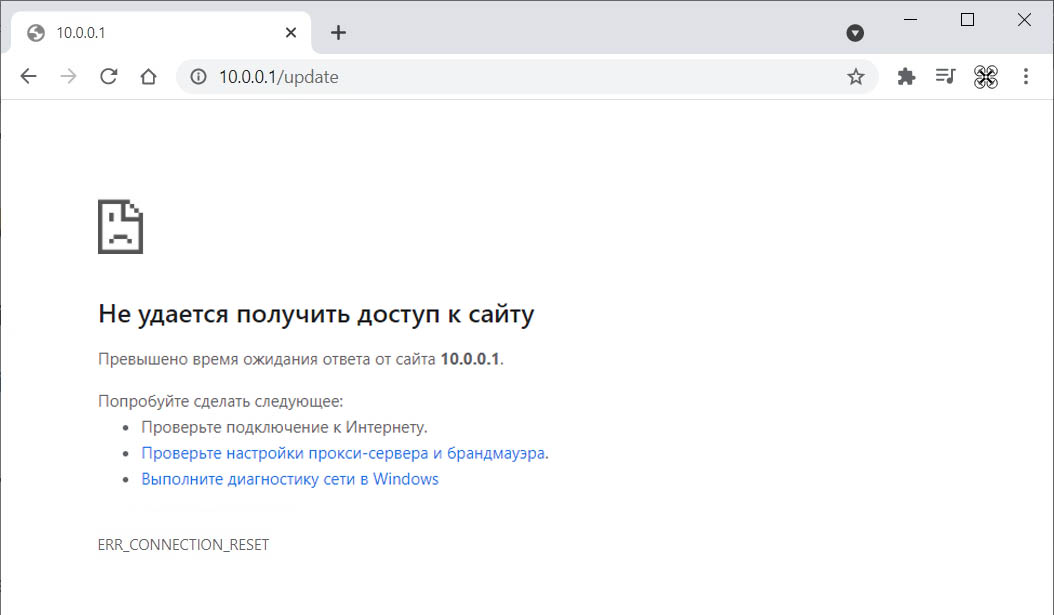
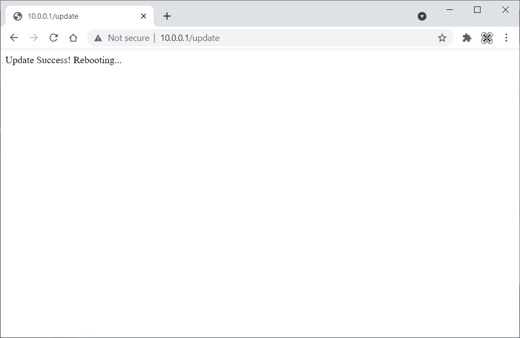
Шаг 5. После этого дождитесь, когда страница начнет перенаправлять на http://10.0.0.1/update.
Тут нужно ждать. Браузер будет ругаться подобной страницей, но нужно подождать еще немного:
Прошивка / обновление ExpressLRS TX через UART
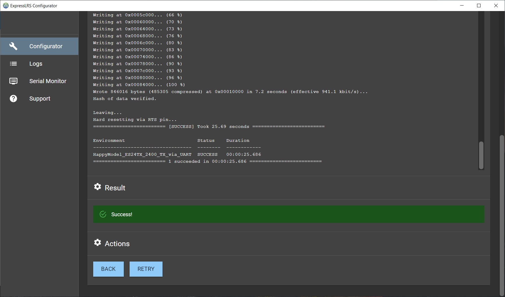
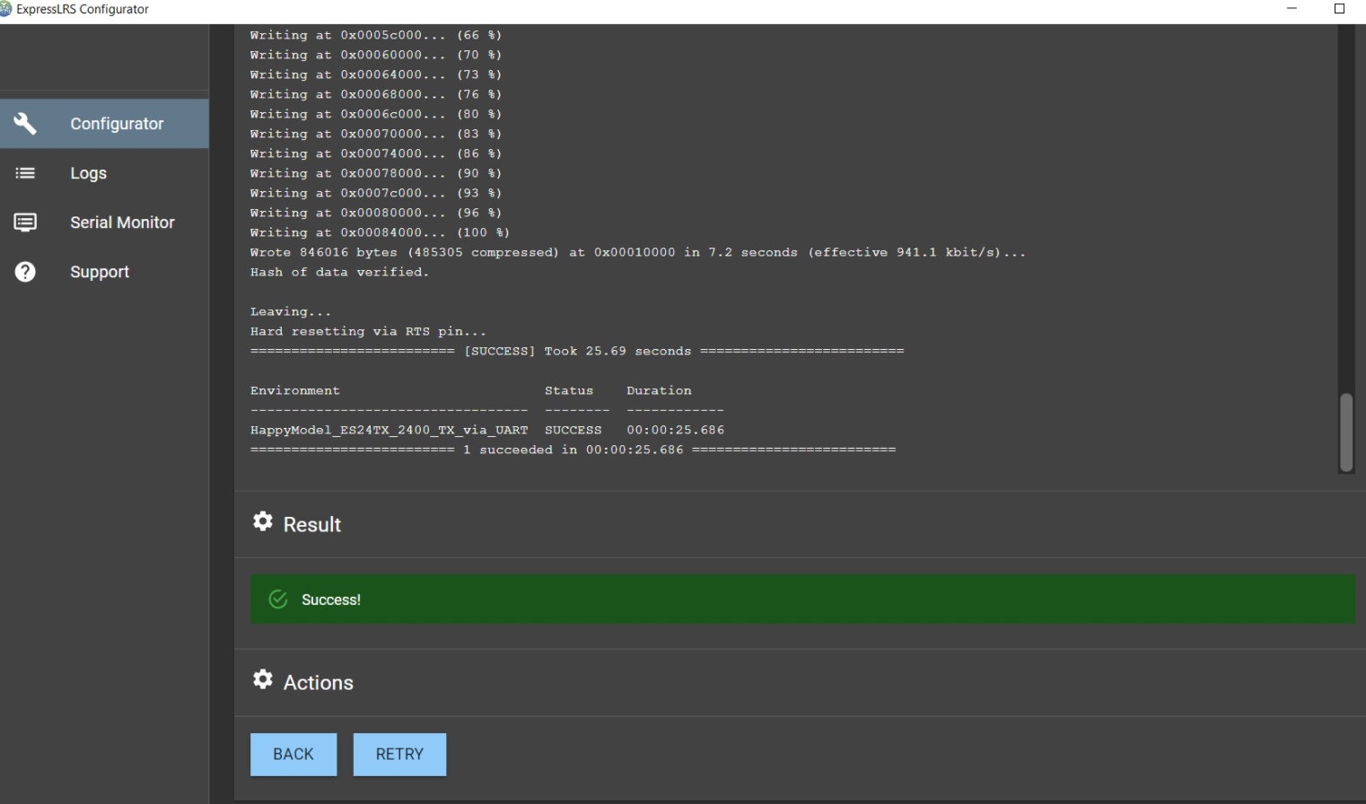
Если вы выбрали прошивку через «_via_UART», то можете сразу нажать кнопку [ BUILD & FLASH ], чтобы собрать и прошить модуль. Перед этим шагом модуль передатчика должен быть подключен к ПК через USB-кабель.
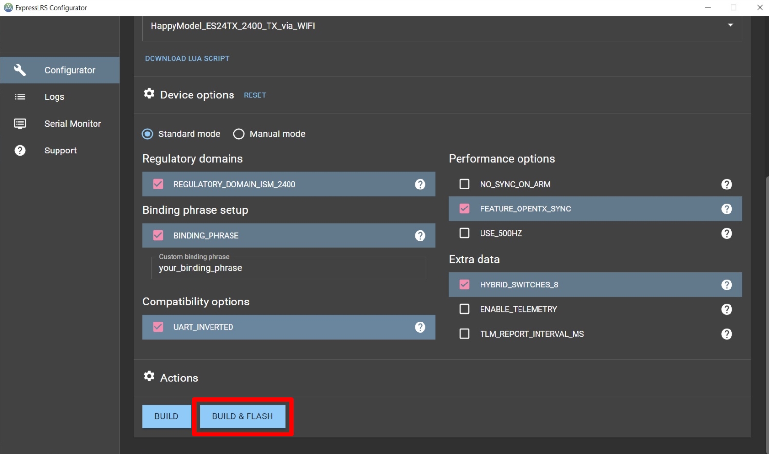
Конфигуратор соберет прошивку, а затем автоматически обнаружит последовательный порт, модуль передатчика должен быть подключен. Как только все будет собрано и порт обнаружен, начнется автоматическая прошивка.
Если сборка и прошивка прошли успешно, вы увидите это:
Если конфигуратор не «увидит» модуль, то будет такая ошибка:
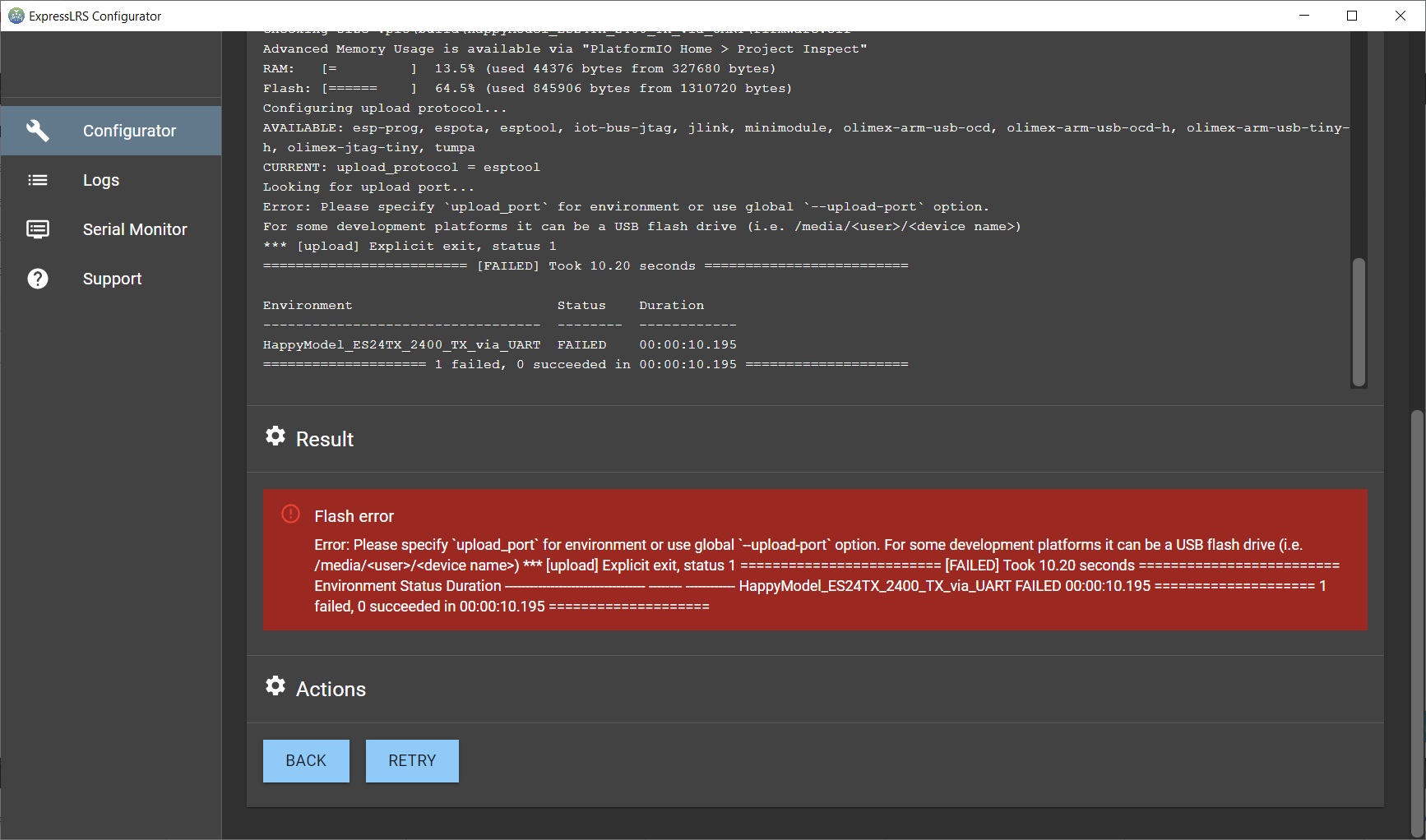
Для исправления проверьте подключение, а затем в ручную выберите нужный порт. Чтобы узнать какой назначен порт, откройте Диспетчер устройств и найдите подключенное устройство:
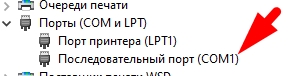
Выбрать порт нужно в самом низу программы:
Компиляция (сборка) прошивки приемника (RX) ExpressLRS
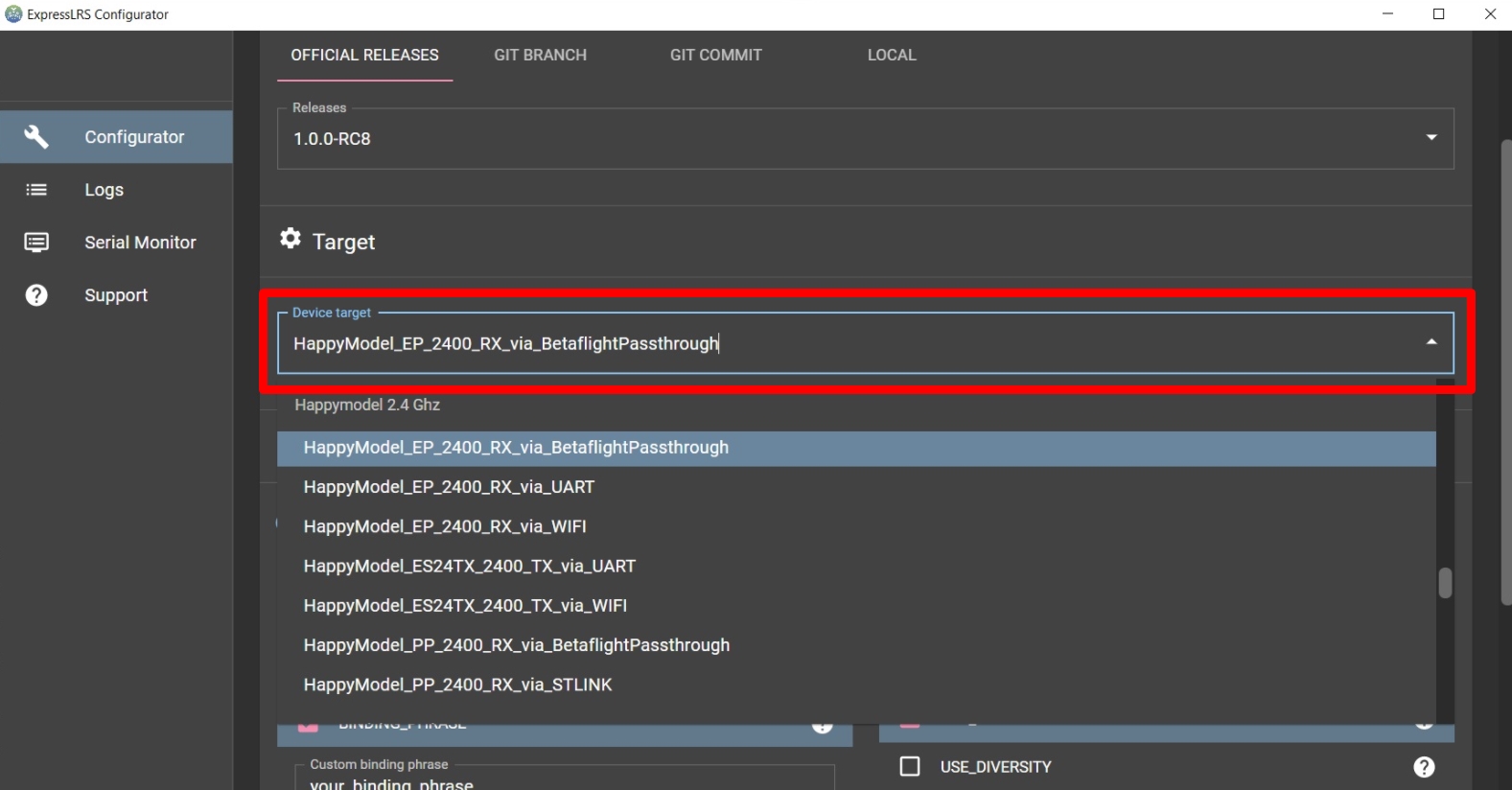
Шаг 1. Здесь все аналогично. Выбираем свой приемник и тип прошивки:
Шаг 2. После выбора устройства, нужно включить такие настройки:
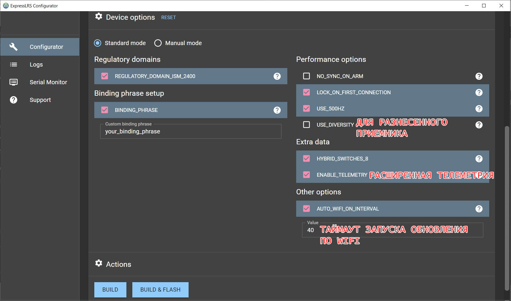
Расшифровка значений:
USE_500HZ — включает скорость обновления 500 Гц (эта опция удалена в более поздних версиях)
HYBRID_SWITCHES_8 — включает использование 3 и 6-позиционных переключателей (по умолчанию система передает только двухсторонние (On-Off) переключатели в данных канала).
ENABLE_TELEMETRY — включает дополнительную телеметрию, такую как напряжение аккумулятора, ток, данные GPS, режим полета (базовая телеметрия, такая как RSSI, качество связи, передается всегда)
AUTO_WIFI_ON_INTERVAL — включает автоматический запуск обновления WiFi при запуске. Значение тайм-аута можно настроить (по умолчанию 40 секунд).
Прошивка / обновление ExpressLRS RX (приемник) через Wi-Fi
Обновление приемника через Wi-Fi все также самый удобный способ.
Шаг 1. Сначала нужно перевести приемник в режим обновления WiFi. Для этого необходимо включить приемник без включения аппаратуры. Приемник перейдет в автоматический режим обновления через 40 секунд (настраивается в строке AUTO_WIFI_ON_INTERVAL).
Шаг 2. Затем подключитесь к сети Wi-Fi под названием «ExpressLRS RX Module«. Пароль сети Wi-Fi — «expresslrs».
Шаг 3. После подключения к сети «ExpressLRS RX Module«, откройте в браузере адрес: http://10.0.0.1
Вы увидите экран приветствия на странице обновления ExpressLRS WiFi:
Шаг 4. Прокрутите страницу вниз, выберите скомпилированный файл прошивки firmware.bin, нажав кнопку «Choose file«. Нажмите кнопку «Update«, чтобы начать процесс обновления.
Шаг 5. После этого дождитесь, когда страница начнет перенаправлять на http://10.0.0.1/update.
Прошивка / обновление приемника ExpressLRS через Betaflight Passthaught
Если вы выбрали прошивку » _via_BetaflightPassthaught», то вы можете сразу нажать кнопку [ BUILD & FLASH ], чтобы собрать прошивку и прошить приемник. Перед этим приемник должен быть подключен к полетному контроллеру, а полетный контроллер должен быть подключен к ПК через USB-кабель.
После этого начнется процедура сборки прошивки, поиска порта полетного контроллера и перевода его в режим Betaflight Passthrough.
Если все пройдет удачно, будет знакомое окно:
Как привязать приемник ExpressLRS
Приемники можно связать двумя способами — автоматически при использовании одной и той же фразы связывания или обычным способом, переведя TX (передатчик) и RX (приемник) в режим связывания.
Приемник автоматически связывается с модулем передатчика, если оба модуля TX и RX прошиты с одной и той же фразой привязки. Можно задать свою фразу в конфигураторе, об этом в начале руководства.
Вам необходимо скомпилировать и обновить прошивку для TX и RX с одной и той же связывающей фразой. Не нужно использовать опцию привязки в сценарии Lua ELRS, TX и RX должны связываться автоматически.
В качестве альтернативы вы можете привязать любой приемник ExpressLRS к любому передатчику ExpressLRS, переведя оба устройства в режим привязки.
Для этого нужно включить и выключить приемник 3 раза и он перейдет в режим привязки.
Модуль передатчика можно перевести в режим привязки, выбрав опцию [Bind] в скрипте ERLS Lua.
На некоторых передатчиках есть кнопка Bind, что упрощает перевод в нужный режим.
Как подключить приемник ExpressLRS к полетному контроллеру
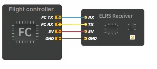
Эти приемники используют протокол CRSF для обмена данными с полетным контроллером.
Поэтому приемники должны подключаться так же, как приемники TBS Crossfire.
Любая схема подключения приемника Crossfire подходит и для приемника ExpressLRS. Более того, приемники эти имеют ту же распиновку, что и приемники TBS Crossfire Nano, поэтому их можно напрямую установить (припаять) на плату ПК или платы адаптера, как и у TBS Crossfire Nano RX.
Общая схема для подключения приемника:
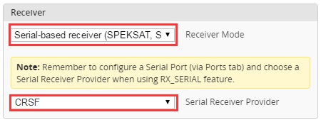
Как настроить приемник ExpressLRS в Betaflight
Тут тоже все просто, открываем Betaflight и выбираем последовательный приемник и ниже кросфайр:
Заключение
Ответим на частые вопросы

Сергей
Пилот как съемочного, так и гоночного квадрокоптеров
Как правильно включать оборудование?
Первым всегда включайте передатчик (аппаратуру управления) и только потом приемник (дрон).
Если сделать наоборот и замешкаться, приемник может перейти в режим обновления по WiFi. Можно конечно увеличить время с 40 секунд на большее и тогда проблемы не будет.
Почему так важно использовать AUX1 для снятия с охраны? (арминг)
Когда опция HYBRID_SWITCHES_8 включена, то пакеты отправляются только по каналу AUX1.
Использование AUX1 для постановки на охрану обеспечивает максимально быструю отправку команды снятия с охраны. AUX1 — это просто канал AUX с наименьшей задержкой в ExpressLRS.
Если вы не используете HYBRID_SWITCHES_8, то вы можете использовать любой канал для ARM / DISARM. Но, все каналы будут только 2-позиционными.
CRSFShot или Sync Pulses?
CRSFShot — это то, что ExpressLRS использует для повышения скорости.
CRSFShot снижает задержку до 25%, а также снижает переменную задержку на 95%.
На самом деле вы можете увидеть, что CRSFShot называется по-разному.
OpenTX называет это «Sync Pulses», а поддержка начинается с OpenTX версии 2.3.12.
CRSFShot также может называться как «Mixersync».
Wiring receiver
The receiver does not come with any connectors on-board, this is with intention to allow for flexible and
more varied setups, i.e. it is easier to add a connector than to remove a pre-soldered one.
Use normal servo-wires to either connect directly to the soldering pads/vias or use pin header to mount it
to a motherboard. The antenna uses a U.FL connector. Use heat-shrink tubing to protect the receiver.
Binding
Binding the transmitter and receiver is super simple.
1. Just power up the TBS CROSSFIRE transmitter
2. On the standard transmitter, enter the configuration menu by pressing and holding the joystick for
3 seconds, select «General» and «Binding» — a message «Binding» will start blinking, waiting for the
receiver. On the micro transmitter, a short press on the button will initiate binding mode.
3. Now, power up the receiver (without pressing the Bind button!), if your receiver has not been
previously bound, it will automatically bind. Otherwise, press and release the «BIND» button on the
receiver to initiate binding. On the receiver is a timeout of one minute for after power up to enter
bind mode. If the status LED will start blinking slowly the receiver has switched successfully to bind
mode.
4. Within a few seconds the process will finish with a «Binding complete» message on the standard
transmitter, or a solid green LED on the micro transmitter. The receiver has now stored the unique
serial number of that particular CROSSFIRE transmitter. If it doesn’t bind, please verify that your
firmware is to the newest version on both the receiver and the transmitter.
2
TBS Crossfire is a fantastic choice for your FPV radio link and it is likely that you will be using the TBS Nano Rx in one or even many FPV builds!
However for both newcomers and experienced builders, the wiring can get a little confusing without a good reference.
If you are using TBS Nano Diversity Receiver, check out this guide instead.
In this guide we will look at common ways to wire the TBS Nano receiver. I will also provide some clear diagram and channel mapping references that you can use to simplify your build.
If you are using TBS Crossfire, don’t forget to bookmark this page (control + D) so that you can refer back to the diagrams on this page.
If you are just looking for a quick reference wiring diagram / pinout to aid you with a build, check out the wiring overview.
Table Of Contents
- Prerequisite
- TBS Nano Receiver Wiring Overview
- TBS Nano Pinout
- TBS Nano Channel Mapping
- TBS Nano Typical Wiring Diagram
- CRSF and Video Transmitters (TBS Fusion)
- Antenna Configuration
- How To Mount TBS Nano Antenna on an FPV drone
- External References
Prerequisite
This guide aims to help you understand some of the many various configuration options available for the TBS Nano receiver.
You will need a TBS Nano receiver and one of the compatible Crossfire transmitter modules.
Whether you are new to the TBS Crossfire ecosphere or you already have a good understanding, there is some good information here worth checking out too!
TBS Nano Receiver Wiring Overview
The following reference diagrams are for the TBS Nano receiver and aim to provide a clear reference to assist in your build.
You can also consult the TBS Crossfire manual and TBS Nano quickstart guide for further information.
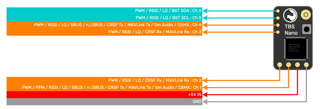
TBS Nano Pinout
The following diagram shows the pinout for the TBS Nano. It shows the available functions for each pin.
This diagram is designed to be used as an easy reference when wiring the receiver. Some functions are duplicated and in these cases you can choose whatever pin you prefer to use.
TBS Nano Channel Mapping
The following table shows the various functions that are available for each channel on the TBS Nano receiver.
In order to choose the function that you want to operate on a particular pin, use the channel mapping menu accessible from your TBS Crossfire transmitter module (either Lua script or OLED display on the full sized Crossfire).
You can sort the table by clicking the column headers. For example if you wish to connect CRSF Tx, simply click the header to sort the table and show all suitable pins at the top.
You can also scroll the table left and right to reveal all of the functions. The table shows which functions are compatible with each pin.
| Receiver Pin |
PWM | PPM | CRSF Rx |
CRSF Tx |
SBUS inv. |
SBUS n.inv. |
MAVLink Rx |
MAVLink Tx |
RSSI | LQ | RSSI/ LQ |
DSMX | Smart Audio |
BST SCL |
BST SDA |
|---|---|---|---|---|---|---|---|---|---|---|---|---|---|---|---|
| Ch. 1 | ✅ | ✅ | ✅ | ✅ | ✅ | ✅ | ✅ | ✅ | ✅ | ✅ | ✅ | ||||
| Ch. 2 | ✅ | ✅ | ✅ | ✅ | ✅ | ✅ | |||||||||
| Ch. 3 | ✅ | ✅ | ✅ | ✅ | ✅ | ✅ | |||||||||
| Ch. 4 | ✅ | ✅ | ✅ | ✅ | ✅ | ✅ | ✅ | ✅ | ✅ | ✅ | |||||
| Ch. 5 | ✅ | ✅ | ✅ | ✅ | ✅ | ||||||||||
| Ch. 6 | ✅ | ✅ | ✅ | ✅ | ✅ |
TBS Nano Typical Wiring Diagram
The following diagram shows typical wiring between TBS Nano Rx, a flight controller and TBS Pro Nano video transmitter.
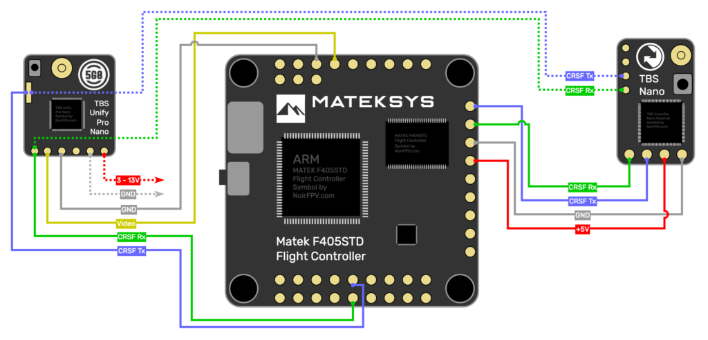
CRSF and Video Transmitters (TBS Fusion)
If you are planning to use a TBS video transmitter (VTx), such as the Unify Pro Nano shown in the diagram, you have two options for wiring:
- CRSF Tx and CRSF Rx from the VTx can be wired to a spare UART (serial port) on the flight controller. This allows data to be passed between the Unify and Crossfire system via the flight controller.
- CRSF Tx and CRSF Rx can be wired directly to an additional UART on the TBS Nano receiver for direct communication between the receiver and the VTx (shown above with the dotted line).
When your TBS gear onboard the drone is connected using the CRSF, it allows for some awesome additional functionality.
For example, if you are using TBS Fusion as your video receiver (VRx) then it is possible to use CRSF to synchronize the video settings automatically between the VTx and VRx.
Antenna Configuration
The TBS Nano receiver has a single antenna connector that you can use to attach various different types of antenna.
The placement of the antenna very much depends on which antenna you wish to use. Some examples of the most common antenna choices for an FPV quad are as follows.
For more information on how to choose the best antenna for your FPV drone, I have a section about it in the ultimate Crossfire FAQ.
How To Mount TBS Nano Antenna on an FPV drone
If you are flying short to medium range and plan to be racing or doing FPV freestyle, antenna durability is probably of greater concern than range.
For this type of flying you will rarely encounter a loss of control link. Video reception is usually more of an issue.
I won’t go too deep into the science of antenna placement as I do not believe it is necessary when using the TBS Nano in most circumstances.
It becomes more important to consider antenna placement when flying ultra long range, however it would then also be worth considering the TBS Nano Diversity receiver instead.
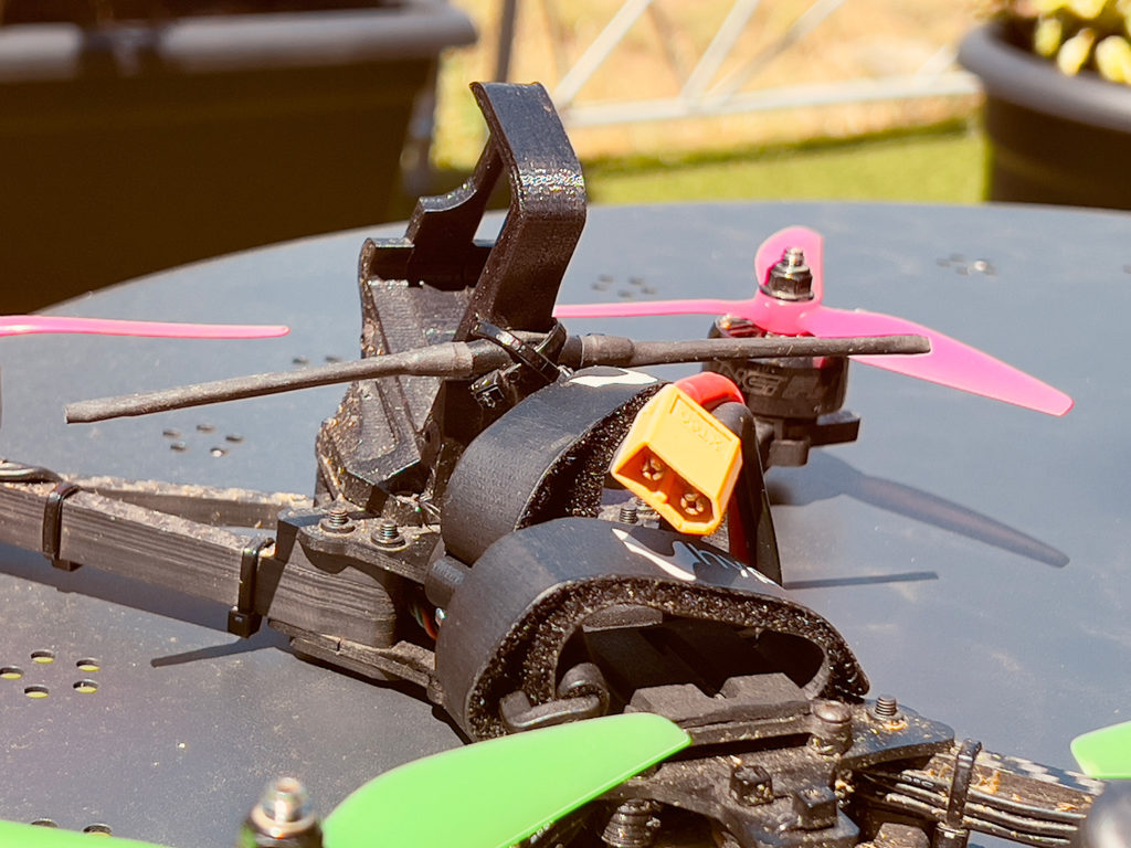
Here are some tips for mounting your antenna:
- Keep the antenna away from propellers where possible. If the antenna can be bent into a prop during a crash, it can get slashed quite badly.
- Add protection to antennas that can be caught up in props during a crash. Foam and shrink tube work well for this.
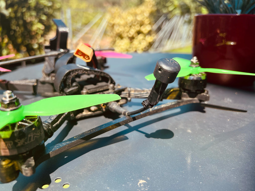
- Mounting the antenna upright will give the best result, however it is not always practical or easy to achieve. Mounting the antenna flat will work perfectly well when flying short and medium distance.
- Keep the antenna away from carbon fibre as much as possible and note that carbon fibre can block line of sight.
- Try and keep the antenna away from ‘noisy’ components, such as motors, ESCs and other antennas.
- Mount the antenna on something 3D printed (non-metal / non-carbon). If you don’t have a dedicated mount, the GoPro mount can work well.
- Use cable tie offcuts to strengthen antenna. Affix in place with shrink tube. Works great on the Immortal-T.
External References
- TBS Crossfire Manual: https://www.team-blacksheep.com/tbs-crossfire-manual.pdf
- TBS Nano quickstart: https://www.team-blacksheep.com/tbs-crossfire-nano-quickstart.pdf
- TBS Nano on Amazon [affiliate link]: https://amzn.to/3auoi3E
- Ultimate TBS Crossfire FAQ: https://noirfpv.com/tbs-crossfire-faq/
-
#1
Перешёл с 2,4 на Кросс. Пока не совсем понятно как правильно подключить приёмник Crossfire nano RX к полётнику Омнибус Ф4 Про V2.

-
#2
Добрый день. Как и любые другие через rx-tx, за небольшим исключением:
у вас схема:

Получается, что вам нельзя подключать к rx1 и tx1, надо найти любой другой свободный UART порт. Ну и далее в видео он показывает какие именно провода куда паять, с субтитрами все понятно.
-
#4
Спасибо за ответ. Сразу замечу, я не сильно продвинут во всём этом. На всех схемах по Омнибусу, не видел что бы были подписаны разьёмы с UART портами. Приходится гадать. У меня такой Омнибус. https://aliexpress.ru/item/32871043…ef3941426d8831b6d273dd14c6&sku_id=66523447850
UART-порт это TX-RX на плате, на схеме по ссылке вижу только rx1-tx1, куда судя по видео нельзя подключаться. Сделайте скрин из Betaflight, вкладка Порты.
Это первый приемник вообще? Или другой стоял? Куда его подключали? Возможно ошибаюсь и вы обычный приемник подключали к SBUS, а где TX1-RX1 порт был свободен.
Обычный приемник вроде на вашем сюда подключается:

Значит tx1-rx1 можно использовать для кроссфайр
-
#5
Да. Не первый. Сначала был приёмник от Флайскай, сейчас приёмник от QCZEK RLS (Lora), на 433. Именно в том самом предусмотренном для него разьёме. SBUS , PPM.
-
#6
У меня не Бетафлай. А Инав.
-
#7
-

FALKON.jpg
274.3 KB
· Просмотры: 158
-
#8
2 порта UART свободные у вас и UART1т похоже просто так включен. У вас к RX1 и TX1 что-то припаяно? Если нет, должно с ним работать.
-
#9
По схеме, в разьёме J10, у меня GPS подключен. В разьёме же J5, там где TX1,RX1,5V,GND нет ничего. Да и не было. Получается, скорее всего туда и пробовать.
-
#10
По схеме, в разьёме J10, у меня GPS подключен. В разьёме же J5, там где TX1,RX1,5V,GND нет ничего. Да и не было. Получается, скорее всего туда и пробовать.
да
-
#11
Спасибо за советы. Как придёт приёмник, буду пробовать.
This tutorial explains how to setup TBS Crossfire for OpenTX radios such as the TX16S. I will also show you how to connect Crossfire receiver to a flight controller and configure it in Betaflight. Tracer is similar to Crossfire when it comes to setup, so most of the steps in this guide also apply.

Some of the links on this page are affiliate links. I receive a commission (at no extra cost to you) if you make a purchase after clicking on one of these affiliate links. This helps support the free content for the community on this website. Please read our Affiliate Link Policy for more information.
Further Reading: How to choose radio transmitter?
What’s TBS Crossfire?
TBS Crossfire is a popular radio control link for FPV drones, which is known to be reliable, easy to setup and great for long range flying.
Crossfire is an external RF module that can be installed directly on the back of a radio transmitter (i.e. JR module bay). The TBS Tango 2 radio also has Crossfire built in.
Rather than using the more common 2.4GHz, Crossfire operates on the 900MHz band. The low frequency is better at signal penetration through obstacles. Many pilots prefer Crossfire even though they don’t intent to fly long range but for the stable link connection and resistance to failsafe in challenging environment. Range can largely depend on the conditions of the environment, but based on personal experience, I can fly 5 miles out easily using 250mW, and I wasn’t even pushing the limit there. One of the main downsides of Crossfire is perhaps the larger receiver antennas which can be challenging to mount on smaller FPV drones.
Crossfire TX Modules
I think the Micro V2 module is more than capable for most people flying freestyle and racing. The built-in screen in the full size module is no big deal as you can change pretty much all the settings in the radio. The additional features of the full size module are not really that useful to be honest for most pilots. The only advantage IMO is having the 2W output power option, and I don’t remember a time I need more than 250mW 
TX Antennas
Receivers
| Crossfire Diversity Nano RX |
 |
| Dual antennas allows better range; Additional features to existing RX |
| Amazon | GetFPV | AliExpress |
RX Antennas
| Mini Immortal T |
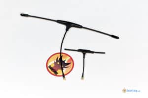 |
| 2g lighter than Immortal T and much smaller, great for micro drones, but range is largely reduced compared to full size antenna |
| Review (Discontinued) |
Updating EdgeTX
Before we begin setting up Crossfire, it’s always a good idea to make sure your radio’s operating system (i.e. OpenTX or EdgeTX) is up to date for bug fixes and improvements.
- how to update OpenTX
- how to update EdgeTX
Make sure to update SD card content as well as it contains the latest Crossfire LUA script for configuring Crossfire module and receivers.
Updating TBS Crossfire Firmware
The first thing you should do is to update the firmware on your Crossfire TX module for the latest features and bug fixes.
Back in the days (before 2020), we had to download and install TBS Agent on our computers, but now we can use a web based tool to do flash firmware on our Crossfire module which is super handy.
The online tool is called AgentM, it’s basically just a website: https://www.team-blacksheep.com/agentm/ (Note: it only supports Google Chrome and Microsoft Edge browsers at the moment)
Login with the same account that you use on TBS’s website, username should be your email address. If you don’t have a login, just register on TBS’s website (https://www.team-blacksheep.com).

Connect your Crossfire TX module to the computer using a USB cable. No need to power on your radio for this to work, the module gets power from USB.

And in Agent M, click “link USB device”, you will be prompted to connect to TBS Crossfire.

Once connected, you will land on a new page where you can configure the Crossfire TX module.
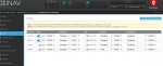
To update the firmware, click the “Firmware” button at the bottom, you should see a list of available firmware. The firmware version you are currently on will be marked with a blue tag “Current”.

The update should only take a minute or two to complete.
Every time you update the firmware on your TX module, you also need to update the firmware on your receivers – this cannot get any simpler, just power on your radio and your quad, try to bind them again and you should be prompted to update firmware on the receiver (wirelessly).
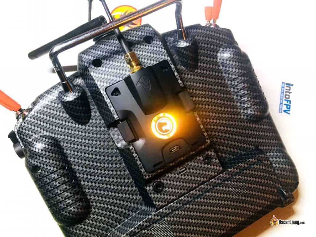
Installing Crossfire TX module in the Radio
You can install the Crossfire TX module directly in the external JR module bay on the back of the radio. Insert the module carefully, make sure all the pins go into the sockets of the Crossfire module properly.
![]()
The Crossfire module is fully compatible with radios with a JR module bay such as the Frsky Taranis X9D+, Jumper T18, T16, the RadioMaster TX16S and Radiomaster Boxer.
It also works with Taranis Q X7, and Horus X10S, but there are some minor issues due to these radios’ inability to operate at full baud rate, causing problems such as constant warning of “telemetry lost”. There is a DIY mod you can do to fix it, but it’s quite difficult to do (involves soldering to the main processor) and therefore I don’t recommend using these radios with Crossfire. Update: by flashing EdgeTX to these radios, you no longer need to do this hardware mod.
Setup Radio to Enable Crossfire TX Module
You will have to create a new model in the radio for Crossfire. A simple way is to duplicate an existing model and rename it to “Crossfire”. If you want to set it up from scratch, here is a tutorial on how to.
Short press the Menu button to enter the Model Setup page, scroll down to “Internal RF” and set mode to “OFF“.
Next set the mode under “External RF” to “CRSF” and change “Channel Range” to “CH1-16“.

Once you’ve done this and exit this menu, the Crossfire TX module should power up (LED lights up on the back).
RX and FC Connection
Remember that almost all of the pins on the Crossfire receiver can be mapped in software. This means you can configure them to output whatever you want, and so there are more than 1 way to connect your RX to the flight controller.
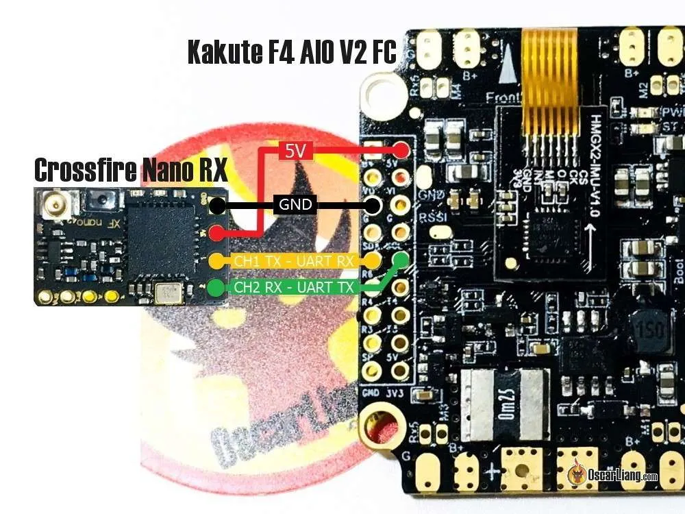
The way I show you here is kind of the standard way that most people use, here are the connections:
- 5V to 5V
- GND to GND
- CH1 (Crossfire TX) to UART RX (FC)
- CH2 (Crossfire RX) to UART TX (FC)
You can use any spare UART on the flight controller.
Tutorial: How to setup Crossfire to output SBUS instead of CRSF
You can also configure Crossfire receiver to output SBUS, this allows you to connect only CH1 to an RX pin on the FC, and leave CH2 unconnected. This is useful if you don’t have a TX pin on the FC, but CRSF is a better protocol than SBUS because it’s faster and also allows telemetry and that’s what I would recommend.
You must not use Soft Serial for Crossfire receiver because it’s not fast enough to handle CRSF signal.
In this example, I am connecting the Crossfire receiver to the UART 6 of the Kakute F4 AIO V2 FC.
Crossfire Micro Receiver:
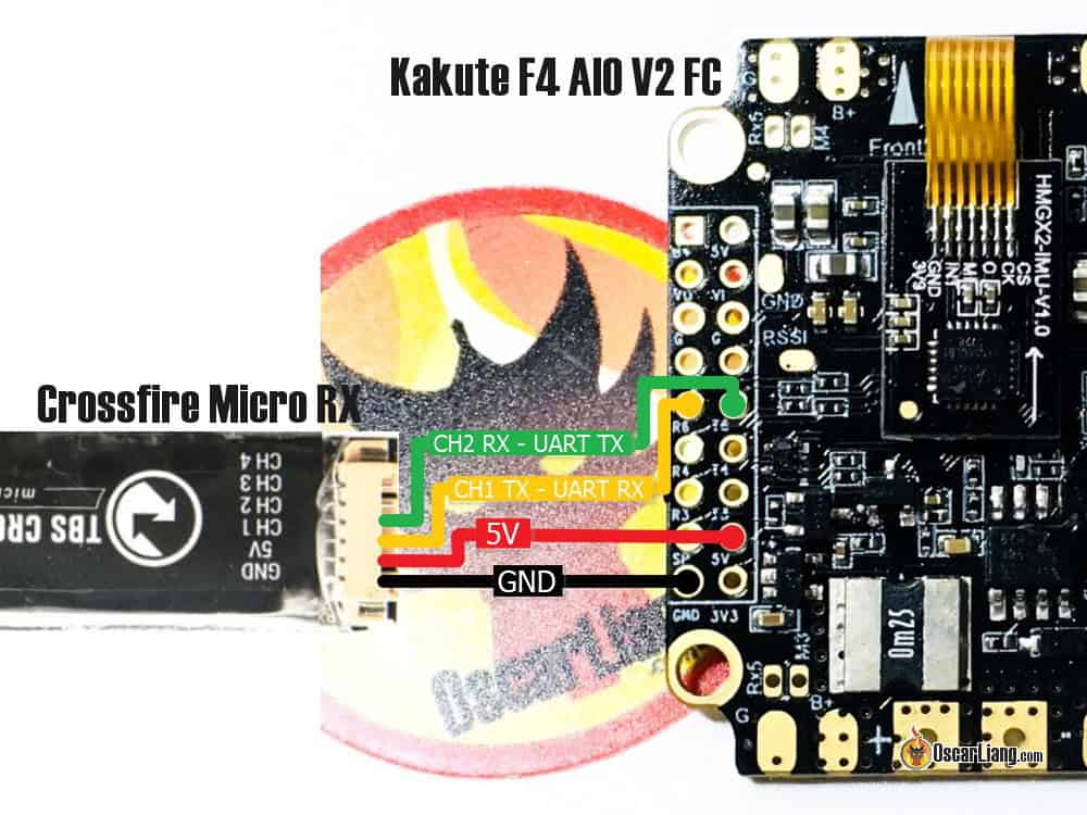
Crossfire Nano Receiver:
Binding Crossfire Receiver
Crossfire Receiver Binding is very simple (most of the times), you can activate binding mode in the Crossfire LUA script. This LUA script comes with the latest version of EdgeTX and OpenTX, so you DO NOT need to download anything.

TBS Crossfire “Full” Module Installed on the back of the Horus X10
Here are the steps to bind the Crossfire TX module and RX:
- Power on the RX, it should be flashing green, which indicates it’s waiting to bind (if it’s LED stays red, press the bind button on the RX, it should start flashing green)
- Turn on your radio, long press the System button to go to Radio Setup
- On the “Tools” page, select “TBS Agent Lite”

In the next screen, select “XF Micro TX” (that’s your TX module).

In the next screen, select the second option “Bind”.

You will be prompted the message “Binding…”, It should only take a few seconds to bind.
If the RX has outdated firmware, you will be prompted to update it, which will take a few minutes. Once it’s done, the receiver will flash green rapidly for a few seconds (loading firmware), then the green lights on both the RX and TX module will become solid. If update got stuck or fail, just try again.

When binding is complete the radio will automatically exit binding mode, and the receiver LED should turn from red to green (solid).
Hit the exit button on your radio to configure the Crossfire Nano receiver.
Configuring RX from Radio
Once your receiver is bound, you can now configure both the TBS Crossfire TX module and receiver from your radio’s Crossfire Configure Tool. If you don’t see the option “XF Micro/Nano RX”, it means your receiver is either not bound or it’s powered off.
The first thing you want to configure would be your receiver output mapping to get it talking to your flight controller.
To do this, select “XF Nano RX“, scroll down to “Output Map“, and change “Output 1” to “CRSF TX“, “Output 2” to “CRSF RX“. That’s it


Now you can configure the TX module.
Region
Leaving the “Region” setting to “Open” will allow maximum output power regardless which frequency you select.


Credit: Crossfire Manual
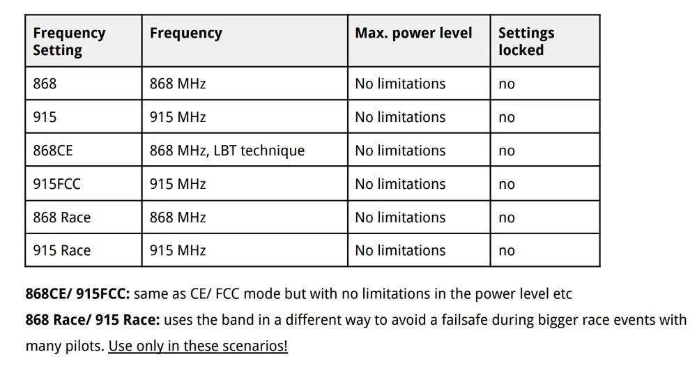
Frequency
It’s important to make sure you are using the correct frequency depends on where you fly. You have two options, 868MHz and 915MHz, one of these frequency will be used by the cellular system, which you should avoid otherwise you will get interference from cellular system, causing dropouts and failsafe.
According to the Crossfire manual, the Blue and Purple regions should be using 915MHz while the Yellow region should be using 868MHz. For example, US should be using 915MHz while Europe should be using 868MHz.

Credit: Crossfire Manual
Here are the different frequency options. Only use the Race frequencies if you are actually racing as they sacrifice range for bandwidth for more consistent data packets. LBT means “listen before talk”.
 Region and frequency are not available for Tracer as it’s on 2.4GHz which the same frequency band worldwide.
Max Power
Higher output power means more range, but you don’t always want to run at max output power.
Firstly, higher output power drains the battery faster. Secondly if you fly with other people (especially if you are all using Crossfire or other 900MHz systems), it can interfere with other pilots and cause signal dropouts and failsafe if all are using max output power. For short distance (such as racing), it’s probably a good idea to use 25mW.
For a typical FPV drone setup, setting power to around 250mW is adequate in most situations, which can give you miles of range in line of sight.
Dyn. Power
The dynamic output power option can help mitigate some of the problems mentioned with maximum output power. It dynamically adjusts the output power depending on signal strength. Beware that as soon as you unplug the quad, the transmitter will automatically go to maximum output power, which is not a good idea when you fly with other people who are also using Crossfire.
In Tracer, you have 25mW, 100mW and Ludicrous which is about 1W. Because Tracer doesn’t have as much range as Crossfire most people would just run Ludicrous with Dynamic power enabled so it brings the power down when you are flying nearby.
Receiver Mode
There’s one more settings you want to change, which is “Mode” in Receiver settings. You can only access receiver option when you have your receiver bound to the transmitter and powered on. These options are saved per receiver, so you have to set these for every quad you have.
Mode is the number of channels you want to use, you have two options, 8 Ch and 12 Ch.
Just select 12 channels.
You will get four more channels to use. Maybe you don’t need them, but 8Ch mode and 12Ch modes have basically no difference in terms of performance, the extra 4 channels will come in handy when you need them.
However for fixed wings if you want all channels to have full resolution, you should leave it at 8Ch instead. But for multirotor it’s fine to use 12ch.
Make sure telemetry is on, and set Failsafe to Cut so that the motors stop spinning in the event of signal loss, and your quad will drop out of the sky to minimize damage.
RF Profile
You can select which packet rate you want to run, options are 50Hz, 150Hz or Dynamic.
It depends on if you want lower latency or long distance. 50Hz will have higher latency but gives you way more range because it has higher receiver sensitivity and also uses LORA modulation while 150Hz has lower latency but less range.
You can set it to dynamic, it will shift to the lower latency as your signal gets weaker. However Betaflight devs actually don’t recommend using Dynamic due to RC signal smoothing in the FC firmware which is tied to a fixed packet rate value, it won’t work properly with dynamically changing packet rate. If you fly long range, lock it to 50Hz, if you do racing or just in close range, 150Hz should be fine.
Configure Betaflight for Crossfire
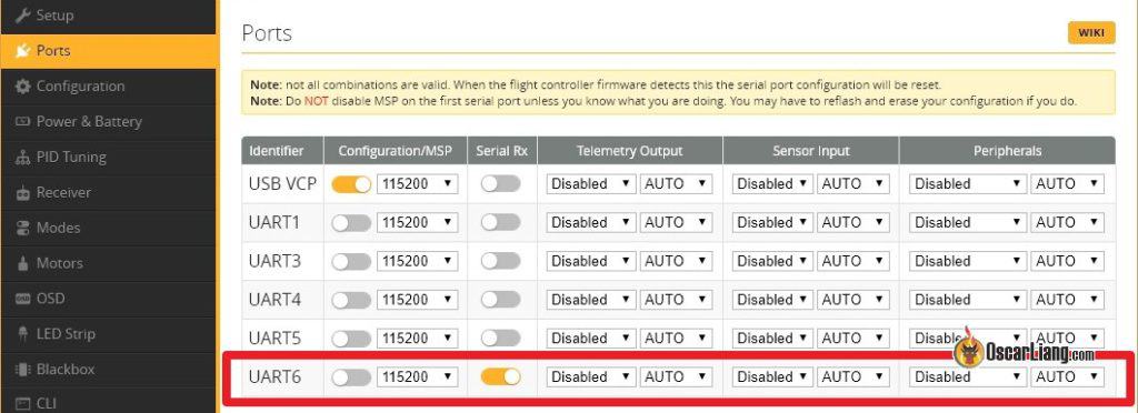
The last step in our software setup is enabling Crossfire protocol in Betaflight.
Go to the “Ports” tab in the Betaflight configurator, and enable “Serial RX” in the UART you’ve connected to the TBS Crossfire receiver. Press “Save”.
Now go to the “Receiver” tab, under the “Receiver” Section, select “Serial (via UART)“, and select “CRSF” in the second option. Don’t forget to enable “Telemetry” as well before pressing “Save“.

That’s it, you have successfully setup Crossfire in Betaflight
Go back to the “Receiver” tab, you should now see response from stick movement. This means your receiver is working! If the channels are in the wrong order, just try a different “Channel Map”.
Check if end points (1000 and 2000) and mid points (1500) are correct, see this guide how to adjust if they aren’t correct.
No stick movement? Try this command in CLI: set serialrx_inverted = OFF
If you are still not getting any stick response, go back and check your wiring, Output Map setting in the receiver, and Betaflight configurations. Still nothing? Get some help over at IntoFPV.com!
Telemetry
To make sure Telemetry is working correctly, go to the Telemetry page in the radio, and select the option “Discover new sensors”, it should begin to pick up data from the flight controller including RxBt (drone battery voltage).
Here is a list of available Crossfire Telemetry data, and what each means. To name a few frequently used ones: RxBt = Battery voltage, RQly = Link Quality, RFMD = Update Rate.

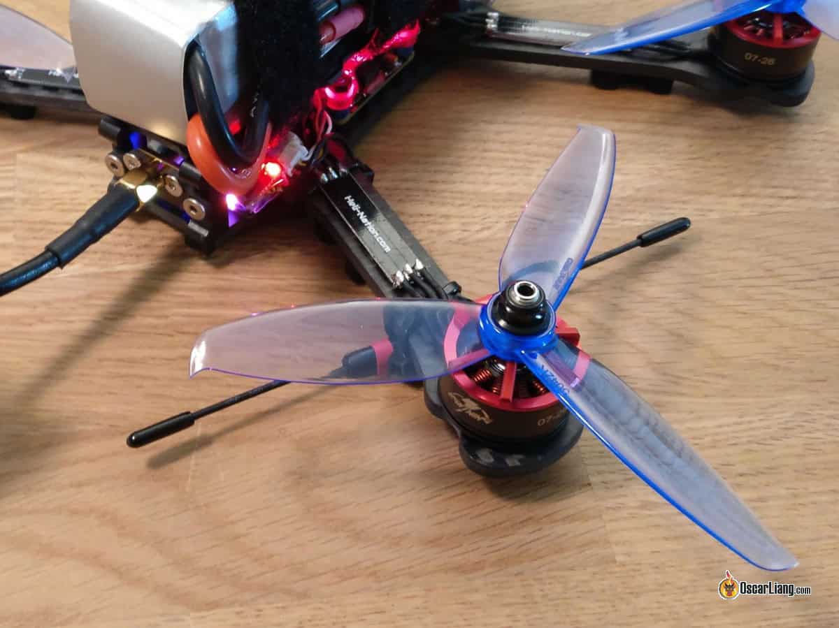
Mounting Crossfire Receiver Antenna
If you have been using other radio systems, the first problem you are going to run into is mounting the unusually large receiver antenna. Learn about the different ways of mounting Crossfire antenna and their effects.
LQ and RSSI
LQ and RSSI are the two measurements of how good your radio signal is. I have a detail tutorial explaining how to read LQ and RSSI in Crossfire. In this tutorial I will also explain how to display them on your Betaflight OSD, and setup voice warning in your radio.
How many people can fly on Crossfire?
According to TBS, theoretically, up to 50 people can fly at the same time using Crossfire. Real life tests have shown when 12 people are flying at the same time, radio link quality becomes noticeably worse but still flyable, so TBS don’t recommend any more than that flying at the same time
Edit History
- Mar 2018 – Guide created
- Jan 2019 – Updated product links and setup detail
- Dec 2019 – Added screenshots for Jumper T16
- Jun 2020 – Updated Agent X new version, Crossfire LUA script changed to Tools in OpenTX, added Micro TX V2
- Feb 2023 – Updated instructions and product links