
Foreword
Congratulations on choosing a SUBARU vehicle. This Owner!s
Manual has all the information necessary to keep your SUBARU in
excellent condition and to properly maintain the emission control
system for minimizing emission pollutants. We urge you to read
this manual carefully so that you may understand your vehicle and
its operation. For information not found in this Owner!s Manual,
such as details concerning repairs or adjustments, please contact
the dealer from whom you purchased your SUBARU or the nearest
SUBARU dealer.
The information, specifications and illustrations found in this man-
ual are those in effect at the time of printing. FUJI HEAVY INDUS-
TRIES LTD. reserves the right to change specifications and de-
signs at any time without prior notice and without incurring any ob-
ligation to make the same or similar changes on vehicles previous-
ly sold. This Owner!s Manual applies to all models and covers all
equipment, including factory installed options. Some explanations,
therefore may be for equipment not installed in your vehicle.
Please leave this manual in the vehicle at the time of resale. The
next owner will need the information found herein.
FUJI HEAVY INDUSTRIES LTD., TOKYO, JAPAN
is a registered trademark of FUJI HEAVY INDUSTRIES LTD.
© copyright 2005 FUJI HEAVY INDUSTRIES LTD.
Смотреть руководство для Subaru Impreza (2006) ниже. Все руководства на ManualsCat.com могут просматриваться абсолютно бесплатно. Нажав кнопку «Выбор языка» вы можете изменить язык руководства, которое хотите просмотреть.

MANUALSCAT | RU
Вопросы и ответы
У вас есть вопрос о Subaru Impreza (2006), но вы не можете найти ответ в пользовательском руководстве? Возможно, пользователи ManualsCat.com смогут помочь вам и ответят на ваш вопрос. Заполните форму ниже — и ваш вопрос будет отображаться под руководством для Subaru Impreza (2006). Пожалуйста, убедитесь, что вы опишите свои трудности с Subaru Impreza (2006) как можно более детально. Чем более детальным является ваш вопрос, тем более высоки шансы, что другой пользователь быстро ответит на него. Вам будет автоматически отправлено электронное письмо, чтобы проинформировать вас, когда кто-то из пользователей ответит на ваш вопрос.
Задать вопрос о Subaru Impreza (2006)
- Бренд:
- Subaru
- Продукт:
- автомобили
- Модель/название:
- Impreza (2006)
- Тип файла:
- Доступные языки:
- английский
Сопутствующие товары Subaru Impreza (2006)
Manufacturer: SUBARU, Model Year: 2006,
Model line: IMPREZA,
Model: SUBARU IMPREZA 2006 2.G
Pages: 365, PDF Size: 7.09 MB
Trending: wheel, window, fuel cap, ESP, oil, transmission, Engine
- Load previous 10 pages
Page 41 of 365

Page 42 of 365

The shoulder belt anchor height should be
adjusted to")
Page 43 of 365

Page 44 of 365
 at-
tached at the webbing end into the buckle
on the right")
Page 45 of 365

on the right-hand side and push it in, and
the connector (tongue)")
Page 46 of 365

Page 47 of 365

Page 48 of 365

Page 49 of 365

Page 50 of 365

- Load next 10 pages
Trending: reset, ignition, oil, Trans, trailer, checking oil, spare wheel
View, print and download for free: SUBARU IMPREZA 2006 2.G Service Manual, 365 Pages, PDF Size: 7.09 MB. Search in SUBARU IMPREZA 2006 2.G Service Manual online. CarManualsOnline.info is the largest online database of car user manuals. SUBARU IMPREZA 2006 2.G Service Manual PDF Download. 1-14 Seat, seatbelt and SRS airbags
Unfastening the seatbelt
Push the button on the buckle.
Before closing the door, make sure that
the belts are ret
All product names, logos, and brands are property of their respective owners.
Privacy Policy | About Us & Contact
![]()
Maintenance schedule …………………………………
Maintenance precautions …………………………….
Before checking or servicing in the engine
compartment ………………………………………………..
When you do checking or servicing in the engine
compartment while the engine is running ………
Engine hood ……………………………………………….
Engine compartment overview …………………….
Non-turbo models ……………………………………………
Turbo models ………………………………………………….
Engine oil ……………………………………………………
Checking the oil level ………………………………………
Changing the oil and oil filter …………………………..
Recommended grade and viscosity …………………
Recommended grade and viscosity under
severe driving conditions ………………………………
Synthetic oil ……………………………………………………
Cooling system …………………………………………..
Cooling fan, hose and connections ………………….
Engine coolant ………………………………………………..
Air cleaner element ……………………………………..
Replacing the air cleaner element …………………….
Spark plugs …………………………………………………
Recommended spark plugs ……………………………..
Drive belts …………………………………………………..
Manual transmission oil ………………………………
Checking the oil level ………………………………………
Recommended grade and viscosity …………………
11-3
11-3
11-4
11-4
11-4
11-6
11-6
11-7
11-8
11-8
11-8
11-10
11-11
11-11
11-12
11-12
11-12
11-15
11-15
11-17
11-17
11-18
11-18
11-18
11-19
Maintenance and service
|
Automatic transmission fluid ………………………. |
11-20 |
||
|
Checking the fluid level …………………………………… |
11-20 |
||
|
Recommended fluid ……………………………………….. |
11-21 |
||
|
Front differential gear oil (AT vehicles) ………… |
11-21 |
||
|
Checking the oil level ……………………………………… |
11-21 |
||
|
Recommended grade and viscosity ………………… |
11-22 |
||
|
Rear differential gear oil ……………………………… |
11-22 |
||
|
Checking the gear oil level ……………………………… |
11-22 |
||
|
Recommended grade and viscosity ………………… |
11-23 |
||
|
Power steering fluid ……………………………………. |
11-24 |
||
|
Checking the fluid level …………………………………… |
11-24 |
||
|
Recommended fluid ……………………………………….. |
11-24 |
||
|
Brake fluid ………………………………………………….. |
11-25 |
||
|
Checking the fluid level …………………………………… |
11-25 |
||
|
Recommended brake fluid ………………………………. |
11-25 |
||
|
Clutch fluid (MT vehicles) ……………………………. |
11-26 |
||
|
Checking the fluid level …………………………………… |
11-26 |
||
|
Recommended clutch fluid ……………………………… |
11-26 |
||
|
Brake booster …………………………………………….. |
11-27 |
||
|
Brake pedal ………………………………………………… |
11-27 |
||
|
Checking the brake pedal free play …………………. |
11-27 |
||
|
11 |
|||
|
Checking the brake pedal reserve distance ……… |
11-27 |
||
|
Clutch pedal (MT vehicles) ………………………….. |
11-28 |
||
|
Checking the clutch function ………………………….. |
11-28 |
||
|
Checking the clutch pedal free play ………………… |
11-28 |
||
|
Replacement of brake pad and lining …………… |
11-28 |
||
|
Breaking-in of new brake pads and linings ………. |
11-29 |
||
|
Parking brake stroke …………………………………… |
11-29 |

Maintenance and service
Tires and wheels …………………………………………
Types of tires ………………………………………………….
Tire inspection ………………………………………………..
Tire pressures and wear ………………………………….
Wheel balance ………………………………………………..
Wear indicators ……………………………………………….
Tire rotation …………………………………………………….
Tire replacement ……………………………………………..
Wheel replacement ………………………………………….
Aluminum wheels ………………………………………..
Intercooler water spray (WRX-STI) ……………….
Windshield washer fluid ………………………………
Replacement of wiper blades ……………………….
Windshield wiper blades assembly ………………….
Windshield wiper blade rubber ………………………..
Rear window wiper blade assembly …………………
Rear window wiper blade rubber ……………………..
Battery ………………………………………………………..
Fuses ………………………………………………………….
Main fuse …………………………………………………….
Installation of accessories …………………………..
Replacing bulbs …………………………………………..
Headlights (WRX-STI) ………………………………………
Headlights (Except WRX-STI) …………………………..
Front turn signal light bulbs …………………………….
Parking light ……………………………………………………
Front fog light …………………………………………………
Rear combination lights …………………………………..
License plate light …………………………………………..
Dome light, map light and cargo area light ……….
11-30
11-30
11-30
11-30
11-32
11-33
11-33
11-33
11-34
11-35
11-35
11-36
11-37
11-37
11-38
11-38
11-39
11-40
11-41
11-43
11-43
11-44
11-45
11-46
11-48
11-48
11-48
11-48
11-50
11-50
|
Trunk light ……………………………………………………… |
11-51 |
|
High mount stop light …………………………………….. |
11-51 |
Maintenance schedule
The scheduled maintenance items required to be serviced at regular intervals are shown in the Warranty and Maintenance Booklet .
For details of your maintenance schedule, read the separate Warranty and Maintenance Booklet .
Maintenance precautions
When maintenance and service are required, it is recommended that all work be done by an authorized SUBARU dealer.
If you perform maintenance and service by yourself, you should familiarize yourself with the information provided in this section on general maintenance and service for your SUBARU.
Incorrect or incomplete service could cause improper or unsafe vehicle operation. Any problems caused by improper maintenance and service performed by you are not eligible for warranty coverage.
Testing of an All-Wheel Drive vehicle must NEVER be performed on a single two-wheel dynamometer or similar apparatus. Attempting to do so will result in transmission damage and in uncontrolled vehicle movement and may cause an accident or injuries to persons nearby.
Always select a safe area when performing maintenance on your vehicle.
Maintenance and service 11-3
Always be very careful to avoid injury when working on the vehicle. Remember that some of the materials in the vehicle may be hazardous if improperly used or handled, for example, battery acid.
Your vehicle should only be serviced by persons fully competent to do so. Serious personal injury may result to persons not experienced in servicing vehicles.
Always use the proper tools and make certain that they are well maintained.
Never get under the vehicle supported only by a jack. Always use a safety stands to support the vehicle.
Never keep the engine running in a poorly ventilated area, such as a garage or other closed areas.
Do not smoke or allow open flames around the fuel or battery. This will cause a fire.
Because the fuel system is under pressure, replacement of the fuel filter should be performed only by your SUBARU dealer.
CONTINUED

11-4 Maintenance and service
Wear adequate eye protection to guard against getting oil or fluids in your eyes. If something does get in your eyes, thoroughly wash them out with clean water.
Do not tamper with the wiring of the SRS airbag system or seatbelt pretensioner system, or attempt to take its connectors apart, as that may activate the system or it can render it inoperative. The wiring and connectors of these systems are yellow for easy identification. NEVER use a circuit tester for these wiring.
If your SRS airbag or seatbelt pretensioner needs service, consult your nearest SUBARU dealer.
Before checking or servicing in the engine compartment
Always stop the engine and set the parking brake firmly to prevent the vehicle from moving.
Always let the engine cool down. Engine parts become very hot when the engine is running and remain hot for some time after the engine is stopped.
Do not spill engine oil, engine coolant, brake fluid or any other fluid on hot engine components. This may cause a fire.
Always remove the key from the ignition switch. When the ignition switch is in the ON position, the cooling fan may operate suddenly even when the engine is stopped.
When you do checking or servicing in the engine compartment while the engine is running
A running engine can be dangerous. Keep your fingers, hands, clothing, hair and tools away from the cooling fan, belts and any other moving engine parts. Removing rings, watches and ties is advisable.
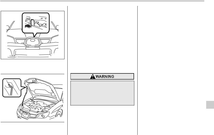
Engine hood
To open the hood:
B00002
1. If the wiper blades are lifted off the windshield, return them to their original positions.
2. Pull the hood release knob under the instrument panel.
B00447
3. Release the secondary hood release located under the front grille by moving the lever toward the left.
B00448
Lift up the hood, release the hood prop from its retainer and put the end of the
Maintenance and service 11-5
hood prop into the slot in the hood. To close the hood:
1. Lift the hood slightly and remove the hood prop from the slot in the hood and return the prop to its retainer.
2. Lower the hood until it approaches approximately 12 in (30 cm) from the closed position and let it drop.
After closing the hood, be sure the hood is securely locked.
If this does not close the hood, release it from a slightly higher position. Do not push the hood forcibly to close it. It could deform the metal.
Always check that the hood is properly locked before you start driving. If it is not, it might fly open while the vehicle is moving and block your view, which may cause an accident and serious bodily injury.

|
11-6 Maintenance and service |
|||||||
|
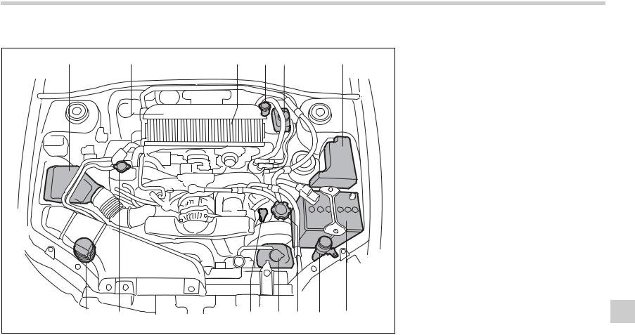
Engine compartment overview |
1) |
Air cleaner element (page 11-15) |
|||||
|
Non-turbo models |
2) |
Manual transmission oil level gauge |
|||||
|
(MT) (page 11-18) or Differential gear |
|||||||
|
oil level gauge (AT) (page 11-21) |
|||||||
|
3) |
Clutch fluid reservoir (page 11-26) |
||||||
|
1 |
2 |
3 |
4 |
5 |
6 |
4) |
Automatic transmission fluid level |
|
gauge (page 11-20) |
|||||||
|
5) |
Brake fluid reservoir (page 11-25) |
||||||
|
6) |
Fuse box (page 11-41) |
||||||
|
7) |
Battery (page 11-40) |
||||||
|
|
Windshield washer tank (page 11-36) |
||||||
|
9) |
Engine coolant reservoir (page 11- |
||||||
|
12) |
|||||||
|
10) |
Engine oil level gauge (page 11-8) |
||||||
|
11) |
Engine oil filler cap (page 11-8) |
||||||
|
12) |
Radiator cap (page 11-12) |
||||||
|
13) |
Power steering fluid reservoir (page |
||||||
|
11-24) |
 Turbo models
1 2 3 4 5 6
|
13 |
12 |
11 |
10 |
9 |
8 |
7 |
B00466 |
Maintenance and service 11-7
1)Air cleaner element (page 11-15)
2)Manual transmission oil level gauge (MT) (page 11-18) or Differential gear oil level gauge (AT) (page 11-21)
3)Automatic transmission fluid level gauge (page 11-20)
4)Clutch fluid reservoir (page 11-26)
5)Brake fluid reservoir (page 11-25)
6)Fuse box (page 11-41)
7)Battery (page 11-40)
 Windshield washer tank (page 11-36)
9)Engine oil filler cap (page 11-8)
10)Engine coolant reservoir (page 1112)
11)Engine oil level gauge (page 11-8)
12)Radiator cap (page 11-12)
13)Power steering fluid reservoir (page 11-24)

11-8 Maintenance and service
Engine oil
Checking the oil level
Check the engine oil level at each fuel stop.
1. Park the vehicle on a level surface and stop the engine.
|
B00467 |
||
|
2. |
Pull out the dipstick, wipe it clean, and |
|
|
insert it again. |
||
|
3. |
Be sure the dipstick is correctly insert- |
|
|
ed |
until it stops with the graphic |
|
|
symbol |
on its top appearing as |
shown in the illustration.
1
2 
3 

B00418
1)Notch
2)Upper level
3)Lower level
4.Pull out the dipstick again and check the oil level on it. If it is below the lower level, add oil to bring the level up to the upper level.
Use only engine oil with the recommended grade and viscosity. Be careful not to spill engine oil when adding it. If oil touches the exhaust pipe, it may cause a bad smell, smoke, and/or a fire. If engine oil gets on the exhaust pipe, be sure to wipe it off.
If you check the oil level just after stopping the engine, wait a few minutes for the oil to drain back into the oil pan before checking the level.
Just after driving or while the engine is warm, the engine oil level reading may be in a range between the upper level and the notch mark. This is caused by thermal expansion of the engine oil.
To prevent overfilling the engine oil, do not add any additional oil above the upper level when the engine is cold.
Changing the oil and oil filter
Change the oil and oil filter according to the maintenance schedule in the Warranty and Maintenance Booklet .
The engine oil and oil filter must be changed more frequently than listed in the maintenance schedule when driving on dusty roads, when short trips are frequently made, or when driving in extremely cold whether.
1. Warm up the engine by letting the engine idle for approximately 10 minutes to ease draining the engine oil.
2. Park the vehicle on a level surface and stop the engine.
3. Remove the oil filler cap.

B00449
Turbo models
B00450
Non-turbo models
4. Drain out the engine oil by removing the drain plug while the engine is still
warm. The used oil should be drained into an appropriate container and disposed of properly.
Be careful not to burn yourself with hot engine oil.
5. Wipe the seating surface of the drain plug with a clean cloth and tighten it securely with a new sealing washer after the oil has completely drained out.
6. Remove under cover.
B00451
Turbo models
Maintenance and service 11-9
B00452
Non-turbo models
7. Remove the oil filter with an oil filter wrench.
8. Before installing a new oil filter, apply a thin coat of engine oil to the seal.
9. Clean the rubber seal seating area of the bottom of engine and install the oil filter by hand turning. Be careful not to twist or damage the seal.
10.Tighten the oil filter by the amount indicated in the following table after the seal makes contact with the bottom of engine.
CONTINUED
11-10 Maintenance and service
|
Oil filter color |
Part number |
Amount of ro- |
|
tation |
||
|
Black |
15208AA100 |
1 rotation |
|
White |
15208AA09A |
2/3 3/4 rota- |
|
tion |
Never over tighten the oil filter because that can result in an oil leak. Thoroughly wipe off any engine oil that has spilled over the exhaust pipe and/or under-cover. If left unremoved, the oil could catch fire.
11.Reinstall under cover.
12.Pour engine oil through the filler neck.
Oil capacity (guideline):
4.2 US qt (4.0 liters, 3.5 Imp qt)
The oil quantity indicated above is only guideline.
The necessary quantity of oil depends on the quantity of oil that has been drained. The quantity of drained oil differs slightly depending on the temperature of the oil and the time the oil is left flowing out. After
|
refilling the engine with oil, therefore, you |
container. |
|||||||||||||||
|
must the dipstick to confirm that the level |
RVI |
|||||||||||||||
|
is correct. |
1 |
|||||||||||||||
|
13.Start the engine and make sure that no |
E |
C |
||||||||||||||
|
oil leaks appear around the filter s rubber |
S |
E |
||||||||||||||
|
P |
||||||||||||||||
|
I |
S |
|||||||||||||||
|
A |
||||||||||||||||
|
seal and drain plug. |
2 |
|||||||||||||||
|
14.Run the engine until it reaches the nor- |
SAE |
|||||||||||||||
|
mal operating temperature. Then stop the |
||||||||||||||||
|
engine and wait a few minutes to allow the |
5W-30 |
G |
||||||||||||||
|
oil drain back. Check the oil level again |
||||||||||||||||
|
and if necessary, add more engine oil. |
E |
|||||||||||||||
|
N |
IN |
|||||||||||||||
|
R |
V |
|||||||||||||||
|
R |
||||||||||||||||
|
G |
||||||||||||||||
|
3 |
Y |
CON |
||||||||||||||
|
B00446 |
||||||||||||||||
|
Be careful not to spill engine oil |
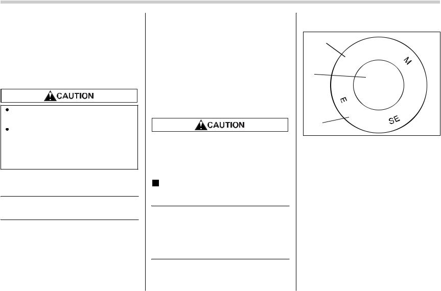
API Service label |
|||||||||||||||
|
when adding it. If oil touches the ex- |
||||||||||||||||
|
1) Indicates the oil quality by API designa- |
||||||||||||||||
|
haust pipe, it may cause a bad smell, |
tions |
|||||||||||||||
|
smoke, and/or a fire. |
2) Indicates the SAE oil viscosity grade |
|||||||||||||||
|
3) Indicates that the oil has fuel saving ca- |
||||||||||||||||
|
Recommended grade and |
||||||||||||||||
|
pabilities |
||||||||||||||||
|
viscosity |
Oil grade:
ILSAC GF-4, which can be identified with the ILSAC certification mark (Starburst mark)
or API classification SM with the words ENERGY CONSERVING
These recommended oil grades can be identified by looking for either or both of the following marks displayed on the oil
![]()
ILSAC Certification Mark (StarburstB00014
Mark)
In choosing an oil, you want the proper quality and viscosity, as well as one that will add to fuel economy. The following table lists the recommended viscosities and applicable temperatures.
When adding oil, different brands may be used together as long as they are the same API classification and SAE viscosity as those recommended by SUBARU.
|
-30 -20 |
-10 |
0 |
10 20 |
30 |
40 |
|
|
-20 |
0 |
20 |
40 |
60 |
80 |
100 |
|
5W-30* |
||||||
|
10W-30, 10W-40 |
B00522
SAE viscosity No. and applicable temperature
*: 5W-30 is recommended.
Engine oil viscosity (thickness) affects fuel economy. Oils of lower viscosity provide better fuel economy. However, in hot weather, oil of higher viscosity is required to properly lubricate the engine.
Use only engine oil with the recommended grade and viscosity.
Recommended grade and viscosity under severe driving conditions
If the vehicle is used in desert areas, in ar-
Maintenance and service 11-11
eas with very high temperatures, or used for heavy-duty applications such as towing a trailer, use of oil with the following grade and viscosities is recommended.
API classification SM (or SL):
SAE viscosity No.: 30, 40, 10W-50, 20W-40, 20W-50
Synthetic oil
You can use synthetic engine oil that meets the same requirements given for conventional engine oil. When using synthetic oil, you must use oil of the same classification, viscosity and grade shown in this owner s manual, and must follow the oil and filter changing intervals shown in the maintenance schedule.

11-12 Maintenance and service
Cooling system
Never attempt to remove the radiator cap until the engine has been shut off and has cooled down completely. Since the coolant is under pressure, you may suffer serious burns from a spray of boiling hot coolant when the cap is removed.
The cooling system has been filled at the factory with a high quality, corrosion-inhibiting, yeararound coolant which provides protection against freezing down to 33 F ( 36 C). For adding, use genuine SUBARU coolant or an equivalent: a mixture of 50% soft water and 50% ethylene-glycol basis coolant. Use of improper coolants may result in corrosion in the cooling system. It is important to maintain protection against freezing and corrosion, even if freezing temperatures are not expected. Never mix different kinds of coolant.
Do not splash the engine coolant over painted parts. The alcohol contained in the engine coolant may damage the paint surface.
Cooling fan, hose and connections
Your vehicle employs an electric cooling fan which is thermostatically controlled to operate when the engine coolant reaches a specific temperature.
If the radiator cooling fan does not operate even when the engine coolant temperature gauge exceeds the normal operating range, the cooling fan circuit may be defective. Check the fuse and replace it if necessary. If the fuse is not blown, have the cooling system checked by your SUBARU dealer.
If frequent addition of coolant is necessary, there may be a leak in the engine cooling system. It is recommended that the cooling system and connections be checked for leaks, damage, or looseness.
Engine coolant
 Checking the coolant level
 1
1
FULL
LOW
 2
2
B00468
1) FULL level mark
2) LOW level mark
Check the coolant level at each fuel stop. 1. Check the coolant level on the outside of the reservoir while the engine is cool.
2. If the level is close to or lower than theLOW level mark, add coolant up to theFULL level mark. If the reserve tank is empty, remove the radiator cap and refill as required.
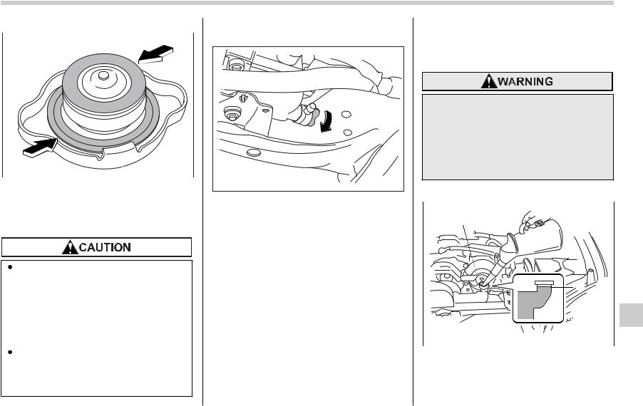
B00018
3. After refilling the reserve tank and the radiator, reinstall the caps and check that the rubber gaskets inside the radiator cap are in the proper position.
Be careful not to spill engine coolant when adding it. If coolant touches the exhaust pipe, it may cause a bad smell, smoke, and/or a fire. If engine coolant gets on the exhaust pipe, be sure to wipe it off.
Do not splash the engine coolant over painted parts. The alcohol contained in the engine coolant may damage the paint surface.
 Changing the coolant
B00019
Always add genuine Subaru cooling system conditioner whenever the coolant is replaced.
Change the engine coolant and add genuine Subaru cooling system conditioner using the following procedures according to the maintenance schedule.
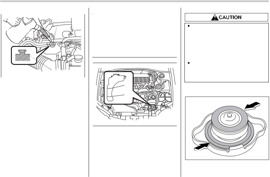
1. Remove the under cover.
2. Place a proper container under the drain plug and loosen the drain plug.
3. Loosen the radiator cap to drain the coolant from the radiator. Then drain the coolant from the reserve tank. Tighten the drain plug securely.
NOTE (Turbo model only)
The cap (without tabs) on top of the radiator does not need to be removed. To
Maintenance and service 11-13
add coolant, remove the cap (with tabs) on the coolant tank on top of the engine.
Never attempt to remove the radiator cap until the engine has been shut off and has cooled down completely. Since the coolant is under pressure, you may suffer serious burns from a spray of boiling hot coolant when the cap is removed.
4. Install the under cover.
1
2
Non-turbo models
B00453
1) Filler neck
2) Fill up to this level
CONTINUED
11-14 Maintenance and service
1
|
2 |
B00454 |
|
|
Turbo models |
||
|
1) |
Filler neck |
|
|
2) |
Fill up to this level |
5. Slowly pour the coolant and fill up to just below the filler neck, allowing enough room to add genuine Subaru cooling system conditioner in the radiator. Add genuine Subaru cooling system conditioner until the coolant level reaches the filler neck. Do not pour the coolant too quickly, as this may lead to insufficient air bleeding and trapped air in the system.
Guideline of coolant quantity (including cool- ant in reservoir tank):
Non-turbo models:
MT. 7.4 US qt (7.0 liters, 6.2 Imp qt) AT. 7.3 US qt (6.9 liters, 6.1 Imp qt)
Turbo models:
MT. 8.1 US qt (7.7 liters, 6.8 Imp qt) AT. 8.0 US qt (7.6 liters, 6.7 Imp qt)
 1
1
FULL
LOW
 2
2
B00468
1)FULL level mark
2)LOW level mark
Be careful not to spill engine coolant when adding it. If coolant touches the exhaust pipe, it may cause a bad smell, smoke, and/or a fire. If engine coolant gets on the exhaust pipe, be sure to wipe it off.
Do not splash the engine coolant over painted parts. The alcohol contained in the engine coolant may damage the paint surface.
6. Pour the coolant and fill to the reservoir tank s FULL level mark.
B00018
1)Rubber gaskets
7.Put the radiator cap back on and tight-

en firmly. At this time, make sure that the rubber gasket in the radiator cap is correctly in place.
8. Start and run the engine for more than five minutes at 2,000 to 3,000 rpm.
9. Stop the engine and wait until the coolant cools down (122 to 140 F [50 to 60 C]). If there is any loss of coolant, add coolant to the radiator s filler neck and to the reserve tank s FULL level.
10.Put the radiator cap and reservoir cap back on and tighten firmly.
Air cleaner element
The air cleaner element functions as a filter screen. When the element is perforated or removed, engine wear will be excessive and engine life shortened.
The air cleaner element is a viscous type. It is unnecessary to clean or wash the element.
Do not operate the engine with the air cleaner element removed. The air cleaner element not only filters intake air but also stops flames if the engine backfires. If the air cleaner element is not installed when the engine backfires, you could be burned.
Replacing the air cleaner element
Replace the air cleaner element according to the maintenance schedule in the Warranty and Maintenance Booklet . Under extremely dusty conditions, replace it more frequently. It is recommended that you always use genuine SUBARU parts.
Maintenance and service 11-15
 Turbo models
B00024
1. Unsnap the two clamps holding the air cleaner case cover.
B00025
2. Open the air cleaner case cover and remove the air cleaner element.
CONTINUED

11-16 Maintenance and service
3. Clean the inside of the air cleaner cover and case with a damp cloth and install a new air cleaner element.
B00026
4. To install the air cleaner case cover, insert the two projections on the air cleaner case cover into the slits on the air cleaner case and then snap the two clamps on the air cleaner case cover.
 Non-turbo models
B00361
1. Unsnap the two clamps holding the air cleaner case cover.
B00362
2. Push the air cleaner case cover in the direction of the arrow shown in the draw-
ing.
1
2
B00363
1)Air cleaner case cover
2)Air cleaner element
3.Open the air cleaner case cover and remove the air cleaner element.
4.Clean the inside of the air cleaner cover and case with a damp cloth and install a new air cleaner element.
 Loading…
You can only view or download manuals with
Sign Up and get 5 for free
Upload your files to the site. You get 1 for each file you add
Get 1 for every time someone downloads your manual
Buy as many as you need
- Manuals
- Brands
- Subaru Manuals
- Automobile
- 2006 Impreza
- Diagnostics
-
Bookmarks
Quick Links
Related Manuals for Subaru Impreza 2006
Summary of Contents for Subaru Impreza 2006
-
Page 1
ABS (DIAGNOSTICS) -
Page 2
1) Turn the ignition switch to OFF. 2) Connect the Subaru Select Monitor to data link connector. 3) Turn the ignition switch to ON and Subaru Select Monitor power switch to ON. NOTE: If the communication function of the Subaru Se- lect Monitor cannot be executed normally, check the communication circuit. -
Page 3
Diagnostic Trouble Code (DTC).> 2) Fix the wrong part. 3) Perform clear memory mode. <Ref. to ABS(diag)-17, CLEAR MEMORY MODE, OPERATION, Subaru Select Monitor.> 4) Perform the inspection mode. <Ref. to ABS(diag)-25, Inspection Mode.> 5) Read the DTC. <Ref. to ABS(diag)-16, READ DIAGNOSTIC TROUBLE CODE (DTC), OPERATION, Subaru Select Monitor.>… -
Page 4
Check List for Interview ABS (DIAGNOSTICS) 2. Check List for Interview A: CHECK Check the following items about the vehicle’s state. 1. STATE OF ABS WARNING LIGHT ❏ Always ABS warning light ❏ Sometimes comes on. ❏ Only once ❏ Not come on •… -
Page 5
Check List for Interview ABS (DIAGNOSTICS) 2. STATE OF BRAKE WARNING LIGHT ❏ Always Brake warning light ❏ Sometimes comes on. ❏ Only once ❏ Not come on ❏ When pulling the parking brake lever up. ❏ When releasing the parking brake lever down. •… -
Page 6
Check List for Interview ABS (DIAGNOSTICS) 3. SYMPTOMS ❏ Does not move. ABS operating condi- tion ❏ Operates only when applying an abrupt brake. Vehicle speed: km/h • How to step on brake pedal: a) Operating time: Sec. b) Operating noise: ❏ Occurs. / ❏ Does not occur. •… -
Page 7
Check List for Interview ABS (DIAGNOSTICS) 4. CONDITIONS UNDER WHICH TROUBLE OCCURS ❏ Fine Environment a) Weather ❏ Cloudy ❏ Rainy ❏ Snowy ❏ Others: °C (°F) b) Ambient temperature ❏ Inner city c) Road ❏ Suburbs ❏ Highway ❏ Local street ❏… -
Page 8
General Description ABS (DIAGNOSTICS) 3. General Description 6. BRAKE PAD AND ROTOR Check the brake pad and rotor. A: CAUTION • FRONT <Ref. to BR-19, INSPECTION, Front 1. SUPPLEMENTAL RESTRAINT SYSTEM Brake Pad.> <Ref. to BR-21, INSPECTION, Front Disc Rotor.> “AIRBAG”… -
Page 9
TOOL NUMBER DESCRIPTION REMARKS 18482AA010 CARTRIDGE Troubleshooting for electrical systems. (Newly adopted tool) ST18482AA010 22771AA030 SUBARU SELECT Troubleshooting for electrical systems. MONITOR KIT ST22771AA030 2. GENERAL PURPOSE TOOL TOOL NAME REMARKS Circuit tester Used for measuring resistance, voltage and amperage. -
Page 10
(STI model) Connector Wheel cylinder ABS warning light G sensor (13) Yaw rate & lateral G sensor (STI model) Data link connector (for Subaru Stop light switch Select Monitor) (10) Master cylinder (14) Transmission control module (AT model) -
Page 11
Electrical Component Location ABS (DIAGNOSTICS) (11) ABS00563 ABS00798 ABS00658 EN-01150 FRONT REAR ABS00659 ABS00660 (13) ABS00651 ABS(diag)-11… -
Page 12
Control Module I/O Signal ABS (DIAGNOSTICS) 5. Control Module I/O Signal A: ELECTRICAL SPECIFICATION B301 7 8 9 10 11 16 17 18 22 23 24 25 26 ABS00409 ABS control module and hydraulic control unit (ABSCM&H/U) con- nector NOTE: •… -
Page 13
8 — 15 1.5 seconds and less than 1.5 V after 1.5 seconds passed. Less than 1.5 V when no data is received. Subaru Select Monitor 7 — 15 0 ←→ 12 V pulse (in communication) Power supply *1 18 — 15 When the ignition switch is ON, 10 —… -
Page 14
Control Module I/O Signal ABS (DIAGNOSTICS) B: WIRING DIAGRAM (30) (29) (28) (16) (17) (18) (26) (27) (19) (20) (21) (10) (11) (12) (22) (13) (23) (14) (24) (15) (25) ABS00882 Battery (12) Rear inlet solenoid valve LH (23) Front ABS wheel speed sensor Ignition switch (13) Rear outlet solenoid valve LH… -
Page 15
Control Module I/O Signal ABS (DIAGNOSTICS) C: WAVEFORM 20 Hz : 0.12 20 Hz ABS00034 (1) ABS wheel speed sensor (2) Terminal No. (3) Standard output voltage ABS(diag)-15… -
Page 16
• For detailed concerning the DTC, refer to the LIST OF DTC. <Ref. to ABS(diag)-34, List of Diag- ABS00112 nostic Trouble Code (DTC).> 4) Connect the Subaru Select Monitor to data link • A maximum of 3 DTCs are displayed in order of connector. occurrence. -
Page 17
ABS OK B Signal ABS system normal/abnormal is displayed. ON or OFF NOTE: For detailed operation procedure, refer to the “SUBARU SELECT MONITOR OPERATION MANUAL”. 3. CLEAR MEMORY MODE NOTE: For detailed operation procedure, refer to the 1) On the «Main Menu» display screen, select the “SUBARU… -
Page 18
• If freeze frame data is not properly stored in memory (due to a drop in ABSCM power supply, etc.), a DTC, preceded by a question mark “?”, ap- pears on the Subaru Select Monitor display. This shows it may be an unreliable reading. Display screen… -
Page 19
Subaru Select Monitor ABS (DIAGNOSTICS) B: INSPECTION 1. COMMUNICATION FOR INITIALIZING IMPOSSIBLE DETECTING CONDITION: Faulty harness connector TROUBLE SYMPTOM: Communication cannot be executed between ABS and Subaru select monitor. WIRING DIAGRAM: BATTERY GENERATOR B108 IGNITION SWITCH DATA LINK CONNECTOR : TURBO MODEL… -
Page 20
LECT MONITOR. tem displayed on Subaru 1) Turn the ignition switch to ON. Select Monitor? 2) Using the Subaru Select Monitor, check whether communication to other system can be executed normally. CHECK COMMUNICATION OF SUBARU SE- Are the name and year of sys- Replace the Go to step 6. -
Page 21
• ABS warning light remains on. • “NO TROUBLE CODE” displayed on the Subaru Select Monitor. NOTE: When the ABS warning light is OFF and “NO TROUBLE CODE” is displayed on Subaru Select Monitor, the system is in normal condition. ABS(diag)-21… -
Page 22
Subaru Select Monitor ABS (DIAGNOSTICS) WIRING DIAGRAM: BATTERY SBF-1 B108 IGNITION SWITCH No.13 : AUTO A/C MODEL : MANUAL A/C MODEL COMBINATION METER STI MODEL : A2 EXCEPT STI MODEL : A1 ST : STI MODEL : EXCEPT STI MODEL… -
Page 23
Subaru Select Monitor ABS (DIAGNOSTICS) Step Check DATA CHECK SUBARU SELECT MONITOR. Is “ON” indicated? Replace the Go to step 2. 1) Select {Current Data Display & Save} in ABSCM only. Subaru Select Monitor. <Ref. to ABS-7, 2) Read the condition of “ABS warning light”. -
Page 24
Read Diagnostic Trouble Code (DTC) ABS (DIAGNOSTICS) 7. Read Diagnostic Trouble Code (DTC) A: OPERATION Refer to SUBARU SELECT MONITOR for details about reading of DTCs. <Ref. to ABS(diag)-16, Subaru Select Monitor.> ABS(diag)-24… -
Page 25
Inspection Mode ABS (DIAGNOSTICS) 8. Inspection Mode A: PROCEDURE Reproduce the condition under which the problem has occurred as much as possible. Drive the vehicle at a speed more than 40 km/h (25 MPH) for at least 1 minute. ABS(diag)-25… -
Page 26
Clear Memory Mode ABS (DIAGNOSTICS) 9. Clear Memory Mode A: OPERATION Refer to SUBARU SELECT MONITOR for details about how to clear DTC. <Ref. to ABS(diag)-16, Subaru Select Monitor.> ABS(diag)-26… -
Page 27
ABS Warning Light/Brake Warning Light Illumination Pattern ABS (DIAGNOSTICS) 10.ABS Warning Light/Brake Warning Light Illumination Pattern A: INSPECTION IG SW ABS00606 Start Illuminates Parking brake ABS warning light About 2 sec. Release Goes out Brake warning light (EBD warning light) 1) When the ABS warning light does not illuminate in accordance with this illumination pattern, there must be an electrical malfunction. -
Page 28
ABS Warning Light/Brake Warning Light Illumination Pattern ABS (DIAGNOSTICS) B: ABS WARNING LIGHT DOES NOT COME ON DETECTING CONDITION: • Defective combination meter • Defective harness TROUBLE SYMPTOM: When the ignition switch is turned to ON (engine OFF), ABS warning light does not come on. WIRING DIAGRAM: BATTERY SBF-1… -
Page 29
ABS Warning Light/Brake Warning Light Illumination Pattern ABS (DIAGNOSTICS) Step Check CHECK ILLUMINATION OF OTHER LIGHTS. Do other warning lights illumi- Go to step 2. Check the combi- Turn the ignition switch to ON. (engine OFF) nate? nation meter. READ DTC. Is DTC displayed? Perform the diag- Go to step 3. -
Page 30
ABS Warning Light/Brake Warning Light Illumination Pattern ABS (DIAGNOSTICS) C: ABS WARNING LIGHT DOES NOT GO OFF DETECTING CONDITION: • Defective combination meter • Open in harness TROUBLE SYMPTOM: When starting the engine, the ABS warning light is kept on. WIRING DIAGRAM: BATTERY SBF-1… -
Page 31
ABS Warning Light/Brake Warning Light Illumination Pattern ABS (DIAGNOSTICS) Step Check READ DTC. Is DTC displayed? Perform the diag- Go to step 2. Read the DTC. <Ref. to ABS(diag)-24, Read nosis according to Diagnostic Trouble Code (DTC).> DTC. CHECK WIRING HARNESS. Is the resistance less than 0.5 Go to step 3. -
Page 32
ABS Warning Light/Brake Warning Light Illumination Pattern ABS (DIAGNOSTICS) D: BRAKE WARNING LIGHT DOES NOT GO OFF DETECTING CONDITION: • Brake warning light circuit is shorted. • Defective sensor/connector TROUBLE SYMPTOM: After starting the engine, the brake warning light is kept on though the parking lever is released. WIRING DIAGRAM: BATTERY SBF-4… -
Page 33
ABS Warning Light/Brake Warning Light Illumination Pattern ABS (DIAGNOSTICS) Step Check CHECK INSTALLATION OF ABSCM&H/U Is the connector correctly Go to step 2. Insert the CONNECTOR. inserted? ABSCM&H/U con- 1) Turn the ignition switch to OFF. nector until the 2) Check that the ABSCM&H/U connector is clamp locks onto inserted to ABSCM&H/U until the clamp locks onto it. -
Page 34
<Ref. to ABS(diag)-19, COMMUNICATION FOR INITIALIZING — tializing impossible communication failure IMPOSSIBLE, INSPECTION, Subaru Select Monitor.> Although no DTC appears on the Subaru <Ref. to ABS(diag)-21, NO TROUBLE CODE, INSPECTION, Subaru — No DTC Select Monitor display, Select Monitor.> the ABS warning light remains on. -
Page 35
List of Diagnostic Trouble Code (DTC) ABS (DIAGNOSTICS) Display screen Contents of diagnosis Index No. <Ref. to ABS(diag)-53, DTC 36 REAR RIGHT OUTLET VALVE MAL- Rear outlet valve RH Rear outlet valve RH FUNCTION, Diagnostic Procedure with Diagnostic Trouble Code malfunction malfunction (DTC).>… -
Page 36
Diagnostic Procedure with Diagnostic Trouble Code (DTC) ABS (DIAGNOSTICS) 12.Diagnostic Procedure with Diagnostic Trouble Code (DTC) A: DTC 21 OPEN OR SHORT CIRCUIT IN FRONT RIGHT ABS WHEEL SPEED SENSOR CIRCUIT NOTE: For the diagnostic procedure, refer to DTC 27. <Ref. to ABS(diag)-37, DTC 27 OPEN OR SHORT CIRCUIT IN REAR LEFT ABS WHEEL SPEED SENSOR CIRCUIT, Diagnostic Procedure with Diagnostic Trouble Code (DTC).>… -
Page 37
Diagnostic Procedure with Diagnostic Trouble Code (DTC) ABS (DIAGNOSTICS) D: DTC 27 OPEN OR SHORT CIRCUIT IN REAR LEFT ABS WHEEL SPEED SEN- SOR CIRCUIT DIAGNOSIS: • Faulty ABS wheel speed sensor (Broken wire, input voltage too high) • Faulty harness connector TROUBLE SYMPTOM: ABS does not operate. -
Page 38
Subaru Select Monitor. the steering wheel is in 2) Read the ABS wheel speed sensor output straight-ahead position? corresponding to faulty system in the Subaru Select Monitor data display mode. CHECK INSTALLATION OF ABS WHEEL Are the ABS wheel speed sen- Go to step 3. -
Page 39
Diagnostic Procedure with Diagnostic Trouble Code (DTC) ABS (DIAGNOSTICS) Step Check CHECK ABS WHEEL SPEED SENSOR. Is the resistance as following Go to step 9. Replace the ABS 1) Turn the ignition switch to OFF. value? Front: 1 — 1.5 kΩ Rear: wheel speed sen- 2) Disconnect the connector from ABS wheel 1.025 —… -
Page 40
Diagnostic Procedure with Diagnostic Trouble Code (DTC) ABS (DIAGNOSTICS) Step Check CHECK BATTERY SHORT OF HARNESS. Is the voltage less than 1 V? Go to step 13. Repair the har- Measure the voltage between ABSCM&H/U ness between connector and chassis ground. ABSCM&H/U and Connector &… -
Page 41
Diagnostic Procedure with Diagnostic Trouble Code (DTC) ABS (DIAGNOSTICS) Step Check CHECK GROUND SHORT OF ABS WHEEL Is the resistance more than 1 Go to step 18. Replace the ABS SPEED SENSOR. MΩ? wheel speed sen- 1) Turn the ignition switch to ON. sor and 2) Measure the resistance between ABS ABSCM&H/U. -
Page 42
Diagnostic Procedure with Diagnostic Trouble Code (DTC) ABS (DIAGNOSTICS) E: DTC 22 FRONT RIGHT ABNORMAL ABS WHEEL SPEED SENSOR SIGNAL NOTE: For the diagnostic procedure, refer to DTC 28. <Ref. to ABS(diag)-43, DTC 28 REAR LEFT ABNORMAL ABS WHEEL SPEED SENSOR SIGNAL, Diagnostic Procedure with Diagnostic Trouble Code (DTC).> F: DTC 24 FRONT LEFT ABNORMAL ABS WHEEL SPEED SENSOR SIGNAL NOTE: For the diagnostic procedure, refer to DTC 28. -
Page 43
Diagnostic Procedure with Diagnostic Trouble Code (DTC) ABS (DIAGNOSTICS) H: DTC 28 REAR LEFT ABNORMAL ABS WHEEL SPEED SENSOR SIGNAL DIAGNOSIS: • Faulty ABS wheel speed sensor signal (noise, irregular signal, etc.) • Faulty harness/connector TROUBLE SYMPTOM: ABS does not operate. WIRING DIAGRAM: B301 ABSCM &… -
Page 44
Subaru Select Monitor. the steering wheel is in 2) Read the ABS wheel speed sensor output straight-ahead position? corresponding to faulty system in the Subaru Select Monitor data display mode. CHECK POOR CONTACT IN CONNECTORS. Is there poor contact in con- Repair the con- Go to step 3. -
Page 45
Diagnostic Procedure with Diagnostic Trouble Code (DTC) ABS (DIAGNOSTICS) Step Check CHECK ABS WHEEL SPEED SENSOR SIG- Is the waveform pattern on Go to step 14. Go to step 11. NAL. oscilloscope as shown in the 1) Raise all four wheels off ground. figure? 2) Turn the ignition switch to OFF. -
Page 46
Diagnostic Procedure with Diagnostic Trouble Code (DTC) ABS (DIAGNOSTICS) Step Check CHECK RESISTANCE OF ABS WHEEL Is the resistance as following Go to step 15. Replace the ABS SPEED SENSOR. value? Front: 1 — 1.5 kΩ Rear: wheel speed sen- 1) Turn the ignition switch to OFF. -
Page 47
Diagnostic Procedure with Diagnostic Trouble Code (DTC) ABS (DIAGNOSTICS) Step Check CHECK SOURCES OF SIGNAL NOISE. Is the car telephone or the Go to step 21. Properly install the wireless transmitter properly car telephone or installed? wireless transmit- ter. CHECK SOURCES OF SIGNAL NOISE. Are noise sources (such as an Install the noise Go to step 22. -
Page 48
Diagnostic Procedure with Diagnostic Trouble Code (DTC) ABS (DIAGNOSTICS) WIRING DIAGRAM: B301 ABSCM & H/U FRONT FRONT REAR REAR SENSOR LH SENSOR RH SENSOR LH SENSOR RH B301 4 5 6 7 8 9 10 11 13 14 16 17 18 19 20 21 22 23 24 25 26 8 9 10 11 12 13 14 15 16 17 18 19 20 21 22 23 24… -
Page 49
Diagnostic Procedure with Diagnostic Trouble Code (DTC) ABS (DIAGNOSTICS) Step Check CHECK IF THE WHEELS HAVE TURNED Is the wheels have been turned The ABS is nor- Go to step 2. FREELY FOR A LONG TIME. freely for more than one mal. -
Page 50
Diagnostic Procedure with Diagnostic Trouble Code (DTC) ABS (DIAGNOSTICS) Step Check CHECK DAMAGE OF ABS WHEEL SPEED Are there broken or damaged Replace the ABS Go to step 11. SENSOR OR TONE WHEEL. teeth in the ABS wheel speed wheel speed sen- sensor piece or tone wheel? sor or tone wheel. -
Page 51
Diagnostic Procedure with Diagnostic Trouble Code (DTC) ABS (DIAGNOSTICS) J: DTC 31 FRONT RIGHT INLET VALVE MALFUNCTION NOTE: For the diagnostic procedure, refer to DTC 37. <Ref. to ABS(diag)-51, DTC 37 REAR LEFT INLET VALVE MALFUNCTION, Diagnostic Procedure with Diagnostic Trouble Code (DTC).> K: DTC 33 FRONT LEFT INLET VALVE MALFUNCTION NOTE: For the diagnostic procedure, refer to DTC 37. -
Page 52
Diagnostic Procedure with Diagnostic Trouble Code (DTC) ABS (DIAGNOSTICS) WIRING DIAGRAM: BATTERY GENERATOR B108 IGNITION SWITCH SHORT CONNECTOR B264 B301 ABSCM & H/U B301 B264 4 5 6 7 8 9 10 11 13 14 16 17 18 19 20 21 22 23 24 25 26 ABS00836 ABS(diag)-52… -
Page 53
Diagnostic Procedure with Diagnostic Trouble Code (DTC) ABS (DIAGNOSTICS) Step Check CHECK INPUT VOLTAGE OF ABSCM&H/U. Is the voltage 10 — 15 V? Go to step 2. Repair the har- 1) Turn the ignition switch to OFF. ness connector 2) Disconnect the connector from ABSCM& between battery, H/U. -
Page 54
Diagnostic Procedure with Diagnostic Trouble Code (DTC) ABS (DIAGNOSTICS) WIRING DIAGRAM: BATTERY GENERATOR B108 IGNITION SWITCH SHORT CONNECTOR B264 B301 ABSCM & H/U B301 B264 4 5 6 7 8 9 10 11 13 14 16 17 18 19 20 21 22 23 24 25 26 ABS00836 ABS(diag)-54… -
Page 55
Diagnostic Procedure with Diagnostic Trouble Code (DTC) ABS (DIAGNOSTICS) Step Check CHECK INPUT VOLTAGE OF ABSCM&H/U. Is the voltage 10 — 15 V? Go to step 2. Repair the har- 1) Turn the ignition switch to OFF. ness connector 2) Disconnect the connector from ABSCM& between battery, H/U. -
Page 56
Diagnostic Procedure with Diagnostic Trouble Code (DTC) ABS (DIAGNOSTICS) R: DTC 41 ABS CONTROL MODULE MALFUNCTION DIAGNOSIS: Faulty ABSCM&H/U TROUBLE SYMPTOM: • ABS does not operate. • EBD does not operate. NOTE: In addition to the ABS warning light, brake warning light illuminates. WIRING DIAGRAM: B301 ABSCM &… -
Page 57
Diagnostic Procedure with Diagnostic Trouble Code (DTC) ABS (DIAGNOSTICS) Step Check CHECK GROUND CIRCUIT OF ABSCM&H/U. Is the resistance less than 0.5 Go to step 2. Repair the Ω? 1) Turn the ignition switch to OFF. ABSCM&H/U 2) Disconnect the connector from ABSCM& ground harness. -
Page 58
Diagnostic Procedure with Diagnostic Trouble Code (DTC) ABS (DIAGNOSTICS) WIRING DIAGRAM: BATTERY GENERATOR B108 IGNITION SWITCH SHORT CONNECTOR B264 B301 ABSCM & H/U B301 B264 4 5 6 7 8 9 10 11 13 14 16 17 18 19 20 21 22 23 24 25 26 ABS00836 ABS(diag)-58… -
Page 59
Diagnostic Procedure with Diagnostic Trouble Code (DTC) ABS (DIAGNOSTICS) Step Check CHECK GENERATOR. Is the voltage 10 — 17 V? Go to step 2. Repair the genera- 1) Start the engine. tor. <Ref. to 2) Idle after warm-up. SC(H4SO)-14, 3) Measure the voltage between generator B Generator.>… -
Page 60
Diagnostic Procedure with Diagnostic Trouble Code (DTC) ABS (DIAGNOSTICS) T: DTC 47 IMPROPER CAN COMMUNICATION DIAGNOSIS: CAN communication circuit is damaged or shorted. TROUBLE SYMPTOM: • ABS does not operate. (STI model) • Tight corner braking phenomenon occurs. (AT model) WIRING DIAGRAM: DRIVER’S CONTROL CENTER DIFFERENTIAL… -
Page 61
Diagnostic Procedure with Diagnostic Trouble Code (DTC) ABS (DIAGNOSTICS) Step Check CHECK MODEL TYPE. Is the vehicle STI model? Go to step 2. Go to step 11. CHECK HARNESS CONNECTOR BETWEEN Is the resistance less than 0.5 Go to step 3. Repair or replace Ω? ABSCM AND DRIVER’S CONTROL CENTER… -
Page 62
Diagnostic Procedure with Diagnostic Trouble Code (DTC) ABS (DIAGNOSTICS) Step Check CHECK POOR CONTACT IN DRIVER’S Is there poor contact? Repair poor con- Replace the CONTROL CENTER DIFFERENTIAL CON- tact in driver’s con- driver’s control TROL MODULE CONNECTOR. trol center center differential differential control control module. -
Page 63
Diagnostic Procedure with Diagnostic Trouble Code (DTC) ABS (DIAGNOSTICS) Step Check CHECK POOR CONTACT IN ABSCM CON- Is there poor contact? Repair poor con- Replace the NECTOR. tact in ABSCM ABSCM. <Ref. to connector. ABS-6, ABS Con- trol Module and Hydraulic Control Unit (ABSCM&H/ U).>… -
Page 64
Diagnostic Procedure with Diagnostic Trouble Code (DTC) ABS (DIAGNOSTICS) WIRING DIAGRAM: BATTERY SBF-3 SBF-1 IGNITION SWITCH SHORT CONNECTOR B264 B301 ABSCM & H/U VALVE RELAY MOTOR RELAY B264 B301 1 2 3 4 4 5 6 7 8 9 10 11 13 14 5 6 7 8 16 17 18 19 20… -
Page 65
Diagnostic Procedure with Diagnostic Trouble Code (DTC) ABS (DIAGNOSTICS) Step Check CHECK INPUT VOLTAGE OF ABSCM&H/U. Is the voltage 10 — 15 V? Go to step 2. Repair the har- 1) Turn the ignition switch to OFF. ness connector 2) Disconnect the connector from ABSCM& between battery H/U. -
Page 66
Diagnostic Procedure with Diagnostic Trouble Code (DTC) ABS (DIAGNOSTICS) V: DTC 52 MOTOR / MOTOR RELAY ON FAILURE DIAGNOSIS: • Faulty motor • Faulty motor relay • Faulty harness connector • Insufficient tightening of earth bolt TROUBLE SYMPTOM: • ABS does not operate. •… -
Page 67
Diagnostic Procedure with Diagnostic Trouble Code (DTC) ABS (DIAGNOSTICS) WIRING DIAGRAM: BATTERY SBF-1 IGNITION SWITCH SHORT CONNECTOR B264 B301 ABSCM & H/U VALVE RELAY MOTOR RELAY B264 B301 1 2 3 4 4 5 6 7 8 9 10 11 13 14 5 6 7 8 16 17 18 19 20… -
Page 68
Diagnostic Procedure with Diagnostic Trouble Code (DTC) ABS (DIAGNOSTICS) Step Check CHECK INPUT VOLTAGE OF ABSCM&H/U. Is the voltage 10 — 15 V? Go to step 2. Repair the har- 1) Turn the ignition switch to OFF. ness/connector 2) Disconnect the connector from ABSCM& between battery H/U. -
Page 69
Diagnostic Procedure with Diagnostic Trouble Code (DTC) ABS (DIAGNOSTICS) W: DTC 54 STOP LIGHT SWITCH SIGNAL CIRCUIT MALFUNCTION DIAGNOSIS: Faulty stop light switch WIRING DIAGRAM: BATTERY STOP LIGHT SWITCH B301 ABSCM & H/U B301 4 5 6 7 8 9 10 11 16 17 18 19 20 21 22 23 24 25 26… -
Page 70
USING SUBARU SELECT MONITOR. 1) Select “Current data display & Save” on the Subaru Select Monitor. 2) Release the brake pedal. 3) Read the stop light switch signal in Subaru Select Monitor data display. CHECK OUTPUT OF STOP LIGHT SWITCH Is “ON” indicated? Go to step 5. -
Page 71
Diagnostic Procedure with Diagnostic Trouble Code (DTC) ABS (DIAGNOSTICS) X: DTC 56 FAULTY G SENSOR OUTPUT VOLTAGE OR OUTPUT SIGNAL DIAGNOSIS: Faulty G sensor TROUBLE SYMPTOM: ABS does not operate. WIRING DIAGRAM: B301 ABSCM & H/U B292 G SENSOR B301 B292 4 5 6 7 8 9 10 11… -
Page 72
SUBARU SELECT MONITOR. 1) Select {Current Data Display & Save} in sensor is horizontal? Subaru Select Monitor. 2) Read the G sensor output on Subaru Select Monitor. CHECK POOR CONTACT IN CONNECTORS. Is there poor contact in con- Repair the con- Go to step 4. -
Page 73
Diagnostic Procedure with Diagnostic Trouble Code (DTC) ABS (DIAGNOSTICS) Step Check CHECK G SENSOR. Is the voltage 2.1 — 2.5 V Go to step 10. Replace the G 1) Connect the connector to G sensor. when G sensor is on a level? sensor. -
Page 74
Diagnostic Procedure with Diagnostic Trouble Code (DTC) ABS (DIAGNOSTICS) Y: DTC 73 LATERAL G SENSOR OUTPUT VOLTAGE OR OUTPUT SIGNAL MALFUNCTION DIAGNOSIS: Faulty Lateral G sensor TROUBLE SYMPTOM: ABS does not operate. WIRING DIAGRAM: DRIVER’S CONTROL CENTER DIFFERENTIAL CONTROL MODULE B380 : NON-TURBO MODEL : TURBO MODEL… -
Page 75
1) Select “Current data display & Save” on the izontal position? Subaru Select Monitor. 2) Read the Subaru Select Monitor display. CHECK OUTPUT OF YAW RATE & LATER- Go to step 4. Replace the yaw Is the voltage 6.8 —… -
Page 76
Diagnostic Procedure with Diagnostic Trouble Code (DTC) ABS (DIAGNOSTICS) Step Check CHECK GROUND SHORT OF HARNESS. Is the resistance more than 1 Go to step 10. Repair the har- Measure the resistance between ABSCM&H/U MΩ? ness between yaw connector and chassis ground. rate &… -
Page 77
General Diagnostic Table ABS (DIAGNOSTICS) 13.General Diagnostic Table A: INSPECTION Symptom Probable faulty units/parts • ABSCM&H/U (solenoid valve) • ABS wheel speed sensor • Brake (caliper & piston, pads) Vehicle pulls to either side. • Wheel alignment • Tire specifications, tire wear and air pressures •… -
Page 78
General Diagnostic Table ABS (DIAGNOSTICS) ABS(diag)-78…