-
Contents
-
Table of Contents
-
Bookmarks
Quick Links
Original instructions
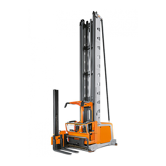
Order picking truck
MX-X
2332 2334
5231 804 2502 EN — 11/2017
Related Manuals for Still MX-X
Summary of Contents for Still MX-X
-
Page 1
Original instructions Order picking truck MX-X 2332 2334 5231 804 2502 EN — 11/2017… -
Page 3: Table Of Contents
Table of contents Foreword General …………2 EC declaration of conformity .
-
Page 4
Table of contents Intended use …………27 Description of truck . -
Page 5
Table of contents Securing the load support ……….74 Emergency operation . -
Page 6
Table of contents Regular care and maintenance Regular care and maintenance ……… . 86 Regular maintenance . -
Page 7: Foreword
Foreword…
-
Page 8: General
Foreword General General Our industrial trucks comply with applicable European regulations. Any other applicable country-specific regulations or operating conditions for the use of industrial trucks must also be observed. The aim of this manual is to inform you about how to safely handle your industrial truck and how to keep it operational.
-
Page 9: Ec Declaration Of Conformity
Foreword EC declaration of conformity EC declaration of conformity Declaration STILL GmbH Berzeliusstraße 10 D-22113 Hamburg Germany We declare that the according to these operating instructions Industrial truck according to these operating instructions Model conforms to the most recent version of EC Machinery Directive 2006/42/EC and the most recent version of EMC Directive 2014/30/EU for industrial trucks implemented in accordance with harmonised standard EN 12895:2015.
-
Page 10: Safety Instructions
Foreword Safety instructions Safety instructions Explanations of the terms used in this manual: DANGER There is the risk of fatality to the operator. The procedures indicated should be complied with in full in order to avoid this danger. WARNING There is a hazard that could cause major damage to property or to the health of the operator.
-
Page 11: Truck Identification, Factory Nameplate
Foreword Truck identification, Factory nameplate Truck identification, Factory nameplate The nameplate is fitted in the area of the driving seat and contains the following details: Factory nameplate CE symbol. The CE symbol confirms that Nominal loading capacity the EU machine guidelines and all the Unladen weight relevant guidelines, which are valid for this Battery voltage…
-
Page 12: Product Documentation
Foreword Product documentation Product documentation This includes: • Spare parts list • Operating and maintenance manual • Any additional documentation for the driver’s seat • Any additional documentation for an attach- ment • Any additional documentation for the battery • Any additional order-related documentation Rules for the operating company of industrial trucks In addition to these operating instructions,…
-
Page 13: Safe-Keeping And Passing On
Safe-keeping and passing on Internet address and QR code The information can be accessed at any time by pasting the address https://m.still.de/vdma in a web browser or by scanning the QR code. Safe-keeping and passing on • These operating and maintenance instruc- tions must be kept safely so that the opera- tor always has access to them.
-
Page 14: Form Of Address
Foreword Form of address Form of address Our products are suitable for use by male or • The ergonomic conditions may be less female operators. However, these instruc- favourable tions use only the masculine form of address, • It may not possible for the operator to reach hereinafter «operator», to simplify the text.
-
Page 15: Safety
Safety…
-
Page 16: Working Safely
Safety Working safely Working safely • The industrial truck must be operated control system when leaving the industrial exclusively from the driver’s compartment truck. • If industrial trucks are equipped for pedes- trian mode or with external operating pan- Safe working environment els, the industrial trucks may be operated •…
-
Page 17: Non-Ionising Radiation
Safety Non-ionising radiation Operational safety takes priority over working speed! Non-ionising radiation WARNING Risk of injury Persons with active or non-active medically implan- ted devices must take it upon themselves to ensure that they are not exposed to dangerous electroma- gnetic radiation.
-
Page 18
Safety Vibrations than 2.5 m/s . There are therefore no mea- surement guidelines for these measurements. The personal vibration load on the driver over a working day shall be determined in accordance with the Directive 2002/44/EC by the operating company at the actual place of use, in order to consider all additional influences, such as driving route, intensity of use etc. -
Page 19: Special Safety Information About Load Pick Up
Safety Special safety information about load pick up Special safety information about load pick up Recognising danger is half the battle! • Before every load pick up, make sure that the load to be picked up does not exceed the load capacity of the truck (refer to the load capacity diagram) or the maximum permissible dimensions as specified on the datasheet.
-
Page 20: Safe Handling Of Operating Media
Safety Safe handling of operating media Safe handling of operating media The following operating media are used in this truck: • Gear oill • Hydraulic oil • Battery acid The handling of these materials is governed by comprehensive safety regulations. The most important points include: For gear and hydraulic oil DANGER…
-
Page 21
DANGER Danger of explosion – When charging batteries, an explosive gas mixture can be generated which can still remain present for a long period after completion of the charging process. Ensure adequate ventilation. – Within a 2 metre area of charged batteries, smoking, fires and open flames are strictly… -
Page 22: Risk Assessment
Safety Risk assessment Risk assessment Within the scope of validity of the CE guide- lines, the operating company must create operating instructions on the basis of a risk assessment. The purpose of the risk assess- ment is to identify dangers and the associated risks that could occur due to the product or the application of the product in the specific place of use and under the application condi-…
-
Page 23: Application Area
Safety Application area be used. You are responsible for doing so as operating company of the truck. Application area The floor in the application area must have sufficient strength to bear the weight of the truck. The wheel loads / floor loads specific to your truck will be made available by your responsible sales representative.
-
Page 24: Original Parts
Safety Original parts (e.g. mobile or stationary protective equip- ment to EN 2006/42/EG and EN ISO 13849) which prevent the possibility of collisions oc- curring between persons and vehicles, or which prevent persons and other vehicles also being present at that time. In Europe it is the owner’s responsibility to ensure that EU guidelines and stipulations are complied with.
-
Page 25: Alterations To Industrial Trucks
Safety Alterations to industrial trucks the operating company, you are responsible for ensuring that this requirement is fulfilled. We recommend that you contact your branch or specialist representative. They will be able to offer you the relevant training and tests required to obtain your driver’s licence.
-
Page 26
Safety Personal protective equipment 5231 804 2502 EN — 11/2017… -
Page 27: Overview
Overview…
-
Page 28: View Of The Truck
Overview View of the truck View of the truck (1) Overhead guard (2) Operating panel (3) Auxiliary lift mast (4) Load forks (5) Load wheel (6) Front guide rollers (7) Rear guide roller and support screws (8) Battery compartment or battery compart- ment doors* (9) Barrier or cab doors* (10) Control compartment…
-
Page 29: Standard Design Of Labelling
Overview Standard design of labelling Standard design of labelling Danger! High voltage c. It is not permitted for people to sit or stand Foot switch on the load, on the load support, underneath a. Do not transport people on the load or on a raised load or to be carried as passengers.
-
Page 30
Overview Standard design of labelling It is not permitted for people to sit or stand Storage space for the abseil system underneath a raised load, or underneath a Risk of crushing feet raised driver’s platform. Disconnect the battery male connector Lifting point for crane loading before removing the control compartment The container is under hydraulic pressure,… -
Page 31: Labelling For Special Equipment
Overview Labelling for special equipment Labelling for special equipment It is not permitted for people to sit or stand on Risk of crushing hands the load or the load support, or to be carried Seat heater on/off switch as passengers Switch in «switched off»…
-
Page 32
Overview Labelling for special equipment The speed of the truck is limited based on the order. Truck with customised software. Only the customer’s special version and not the standard software may be installed in the truck control unit. The pictograms shown here replace the pictograms for the standard version or are fitted in addition to the standard pictograms. -
Page 33: Intended Use
Overview Intended use Intended use The order picker truck is designed for narrow aisle operation. It permits pallets to be entered into and removed from storage, as well as order picking from the rack compartments. Observe the instructions in the paragraph «safety».
-
Page 34: Operating Panel
Overview Operating panel favourable deposit height when carrying out order picking work. The auxiliary lift must always remain in the lowest position when travelling. Outside the aisles (transfer aisle), the indus- trial trucks can be driven freely with the load lowered (transportation mode).
-
Page 35
Overview Operating panel (3) Enable button (for example, as a brake (15) Selection key for lifting or lowering the release button in an automatic braking system cab lift and auxiliary lift together, in connection or as bridging for the intermediate lift cut with pulling or pushing operating lever (1), out and to acknowledge errors that can be or the selection key for swivelling the fork… -
Page 36: Displays
Overview Displays Displays Emergency off switch pressed Not used Foot switch required *MPSE in operation Two-hand operation on the left *MPSE has detected a fault required Two-hand operation on the right Not used required Barrier open *Navigation, combination operation *Navigation, destination is located on the PIN entry expected left-hand side *Navigation, located on the right-hand…
-
Page 37: Operating Display
Overview Operating display Operating display NOTE To emphasise the functionality, the following images have been simplified. Display in the operating panel Display in the case of split operation Function Operating statuses and information relevant for operation are shown on the display. Using the display, it may be possible to switch functions on and off or to switch between defined statuses.
-
Page 38
Overview Operating display Half of the display can be occupied by a mes- sage window (1). This window is automati- cally inserted from the right-hand side. The information which was previously displayed centrally is then shown in the left-hand section of the display. -
Page 39
Overview Operating display Time Date Language Status bar Left field Centre field Right field Configure favourites Truck settings Lift height preselection Approach lift heights Enter lift heights Clear lift heights Service Message list Top status bar The status bar at the top of the display is divided into three fields: •… -
Page 40
Overview Operating display Procedure – Push button (7). The menu in area (1) opens. – Press key sequence (6), (3) and (5). – Select the status bar field using button (2), (3) or (4). – In the list, use buttons (2) to (6) to select the desired information. -
Page 41
Overview Operating display Changes the view to the main page with the menu shown in the right-hand menu bar. If a settings page is displayed, the current setting can be saved. The function of membrane keys (1) to (10) is shown directly next to the keys in the display. -
Page 42
Overview Operating display Scrolling through the menu bar If an arrow appears in area (1) or (2), then the list contains additional entries. The arrow keys (3) can be used to scroll through the menu. If there is no longer an arrow in area (1), the start of the list has been reached. -
Page 43
Overview Operating display Procedure – Push button (7). The menu in area (1) opens. – Press key sequence (6) and (4). – Use buttons (1)(10) to select the position for the favourite function. – Select the desired function in the list using buttons (6) to (10). -
Page 44: Swivel Shift Fork
Overview Swivel shift fork Brightness setting The brightness is automatically adjusted by a light sensor (1) below the display. NOTE For the automatic brightness feature to function correctly, the sensor must not be covered or contaminated. Swivel shift fork The movements of swivel shift fork are braked automatically before they reach their me- chanical and stop.
-
Page 45: Operation
Operation…
-
Page 46: General Commissioning
Operation General commissioning General commissioning Commissioning If the vehicle is delivered only partially assem- bled, ensure before commissioning that the whole truck has been professionally assem- bled. All hydraulic and electrical connections have to be checked. The connections, which must be disassembled for shipping should be reassembled carefully.
-
Page 47
Operation General commissioning Delivery in units Specified weights apply only to the standard design. Determine or request the weights of special designs. Narrow aisle trucks can be disassembled into the following units: attachment, driver’s cab including carriage, lift mast, battery and chassis. -
Page 48: Transporting And Loading
Operation General commissioning Overall mast height Weight <2,900 kg <5 m <3,500 kg <6 m <4,300 kg >6 m Weight of the battery The weight of the battery is specified on the nameplate on the battery. NOTE The installed battery must as a minimum weigh the value stipulated on the nameplate on the truck.
-
Page 49
Operation General commissioning Hooking on the lift mast To hook the lift mast onto the crane hook, use the bores intended for this purpose at the top end of the lift mast (1). Harnesses suitable for this purpose must be used (shackle or lifting device). -
Page 50
Operation General commissioning Hooking the lift mast on horizontally If the lift mast has to be crane-loaded in a horizontal position (2), suitable shackles must be used in the indicated bores at the top end of the mast (3). 5231 804 2502 EN — 11/2017… -
Page 51
Operation General commissioning Lift mast, lower lifting point At the lower end, a textile strap can be wound around the middle crosspiece in the beam support of the cab (4). Loading the chassis Electronic elements such as sensors and antennas can be installed at different places in the chassis according to the truck design. -
Page 52
Operation General commissioning Transportation safety device on glass doors Cab doors made of glass* are supplied with a transportation safety device. This transportation safety device prevents the glass doors from inadvertently opening during transportation and becoming damaged as a result. –… -
Page 53: Support Screws
Operation General commissioning Wheel nuts WARNING Wheel nuts can loosen after initial commissioning. After the first eight operating hours, tighten the wheel nuts to 195 Nm. Support screws The setting of the support screws must be checked during initial commissioning and each time maintenance is performed.
-
Page 54: Safe Handling Of The Traction Battery
Operation General commissioning Safe handling of the traction battery The dangers described below can arise individually or collectively depending on the type of battery in use. Batteries with liquid electrolyte DANGER Risk of explosion – An explosive gas mixture can form when char- ging batteries.
-
Page 55
Operation General commissioning 80-V version WARNING In the 80-V version, there is risk of electric shock if the live connections are touched. Before removing the control compartment cover or the battery compartment cover, disconnect the battery male connector. Handling the battery The installation, removal and transport of traction batteries always involves the handling of heavy weights. -
Page 56: Battery Compartment Cover
Operation General commissioning Battery compartment cover The battery compartment cover covers the entire battery compartment. The cover rests loosely over the compartment. All that is needed to operate the battery male connector is to open the service flap. NOTE As an option, the industrial truck can be equipped with lateral battery compartment doors.
-
Page 57
Operation General commissioning structures, suitable battery chargers must be used. NOTE Batteries are subject to special charging, maintenance and handling instructions. Observe the instructions from the respective manufacturer. WARNING Risk to life Lithium-ion batteries may only be used in industrial trucks that have a design and a controller intended for use with such batteries. -
Page 58: Permitted Batteries
Operation General commissioning separately to the industrial truck, check the following: • The nominal voltage • The minimum required weight • The model and design of the battery male connector fitted • The minimum required cross-section and the connection type of the battery cable CAUTION Risk of damage to property Observe the information and guidelines from the…
-
Page 59: Replacing The Battery
Operation General commissioning Replacing the battery Battery replacement using forklift truck The battery rests in a recess (1) as standard. The battery is intended to be replaced using a truck. The truck used must be suitable for this purpose. • The fork must be of sufficient length for the prevailing load centre of gravity.
-
Page 60: Function Check
Operation General commissioning WARNING Risk of damage to property, risk of crushing Observe the information in the section entitled Safe handling of the traction battery. Before starting each shift, check that the battery lock is in good working order and that it functions correctly.
-
Page 61: Daily Commissioning
Operation Daily commissioning Daily commissioning Checklist before starting work Before starting work, the driver must make Checking the access control sure that the truck is in a safe operating – Check that the switch key can be pulled out condition. when it is in the 0 position.
-
Page 62: Access To The Driver’s Compartment
Operation Access to the driver’s compartment Driver’s cab with glass doors and front panel – Check the function of the lighting devices. glazing or all-rounding glazing: – Check that all covers and flaps are closed. – Check that there are no chips or cracks in –…
-
Page 63: Operating Devices
Operation Operating devices Doors The glass doors feature a recess on the inside of the handle. Only this area of the handle may be used to open and close the glass doors. The glass doors feature a folding hinge in the centre.
-
Page 64
Operation Operating devices Initial driving exercises WARNING Risk of accidents In order to become familiarised with the driving and braking characteristics of these trucks, driving exercises must first be carried out in a flat, obstacle- free area of the warehouse. Switching on the controller Plug in the battery male connector. -
Page 65: Adjusting The Position Of The Operating Panel
Operation Operating devices * Option Adjusting the position of the operat- ing panel WARNING The clamping device that is released for the set- tings described below must be retightened before starting work. In order to be able to optimally adapt the operating panel to driver requirements, the panel can be adjusted by height, by tilting the console and by tilting the operating panel.
-
Page 66: Adjusting The Driver’s Seat
Operation Operating devices Adjusting the driver’s seat WARNING Risk of accident Only apply settings in a stationary truck. Adjusting the height of the driver’s seat Place body weight on driver’s seat. Pull lever (1) and move the driver’s seat to the required height by applying to it or removing pressure.
-
Page 67: Driving
Operation Driving Driving Braking, driving and steering Releasing the brake After entering the driver’s cab, close the barriers or cab doors. Pressing the foot switch (1) once confirms your presence. Continuously actuating the foot switch triggers the electromagnetic parking brake. NOTE The foot switch must be pressed again after each time the barriers or doors are opened…
-
Page 68
Operation Driving Driving The drive direction and the driving speed are selected using the right-hand operating lever. Move the operating lever in the direction of the fork (2) until the required driving speed in the fork direction has been reached. Move the operating lever in the direction of the lift mast (3) until the required driving speed in the direction of the lift mast has been reached. -
Page 69
Operation Driving Two-hand driving operation Operation of the industrial truck with two hands is required within the aisles once the controller has detected the corresponding sensor system. To also drive with your left hand, touch the sensor surface on the left-hand end of the operating panel (5). -
Page 70: Moving The Load
NOTE This combined hydraulic function can still be combined with the driving function. To do this, move the right-hand operating lever as well. 5231 804 2502 EN — 11/2017…
-
Page 71
Operation Driving Ancillary movements All movements of the load apart from the main lift are categorised as ancillary movements. Standard functions are: • Sliding the fork. • Swivelling the fork. • Lifting the auxiliary lift. Touch the right-hand sensor surface(4) and move the left-hand operating lever in the direction (5) or (6) to trigger the reach movement to the left or right. -
Page 72
Operation Driving Swivelling and sliding the swivel fork 90° synchronously This function moves the turret head to the front position through a synchronised movement involving shifting and swivelling. This means that the swivelling function automatically stops at a swivel angle of 90 and the sideshift automatically stops in a central position in front of the cab. -
Page 73: Types Of Guidance
Operation Driving Underside of the operating panel On the top of the operating panel, there are four buttons on the right-hand end that are operated using the thumb on your right hand. There are also four buttons (18) and (19) on the underside of the operating panel.
-
Page 74: Mechanical Guidance Mzf
Operation Driving to make use of the guidance system. The op- erator’s right hand selects the driving speed and drive direction. The operator’s left hand is used to actuate a sensor or a function. As a general rule, the truck switches over to using the guidance system automatically.
-
Page 75
Operation Driving the rail guidance, the new mode of operation is automatically selected: Exiting the aisle The truck is to be driven completely out of the aisle. The sensor system for the aisle detection recognises the truck’s location and re-enables the steering. Changing the aisle If the truck is to be driven out of one aisle and into another, the following notes must be… -
Page 76: Picking Up A Load
Operation Picking up a load Picking up a load Load capacity diagram Depending on the job, a load capacity diagram may be generated and mounted in the cab. To ensure that the stability of the industrial truck is not jeopardised in any way, the load capac- ity diagram and the load capacity restrictions specified on this diagram for certain applica- tion conditions must be observed.
-
Page 77: Adjustable Fork Arms
Operation Emergency operation Adjustable fork arms The standard design features forged fork arms that are manually adjustable. Pallets with different dimensions can therefore be picked As an option, this industrial truck can also be equipped with hydraulically adjustable fork arms. The distance between the fork arms must be sufficient so that the load cannot fall and that there is support centrally below the load centre of gravity.
-
Page 78
Operation Emergency operation Removing the control compartment hood DANGER Danger of electric shock (80-V version) Disconnect the battery male connec- tor before removing the control com- partment hood. – Open the two screw plugs (1). – Hold the hood at the ventilation openings (2), lift it off and then place it to one side. -
Page 79
Operation Emergency operation DANGER Risk of physical injury If the emergency lowering function has to be used because the operator has fallen unconscious, make sure that all parts of the operator’s body are fully within the driver’s cab so that there is therefore no risk he may be injured during the lowering procedure. -
Page 80: Securing The Load Support
Operation Emergency operation Securing the load support In order to secure the load support against lowering during maintenance work, the lowering movement can be locked by closing the shut-off valves. A notch in the block section indicates the valve position. •…
-
Page 81
Operation Emergency operation Removing the control compartment hood DANGER Danger of electric shock (80-V version) Before the control compartment hood is removed, the battery male connector must be disconnected. – Rotate the two screw plugs (1) in a clock- wise direction and remove them. –… -
Page 82
* Option Towing with operational steering If the steering of the industrial truck is still operational, once the brake has been released the industrial truck can be towed either with a rope or with the tow bar. -
Page 83
Operation Emergency operation Towing with non-operational steering WARNING Emergency steering movements may be carried out only when the truck is at a standstill. Make sure that the industrial truck is switched off. These industrial trucks are equipped with a mechanical emergency steering device. A shaft with a pinion gear is provided for this purpose. -
Page 84
Operation Emergency operation Attachment points (5) for towing with the drive unit leading, (6) for towing with the fork leading 5231 804 2502 EN — 11/2017… -
Page 85: Emergency Abseil System
Operation Emergency operation Emergency abseil system Exiting the raised driver’s compartment in the event of an emergency NOTE An emergency abseil system is only required if the driver’s compartment can be raised higher than 3000 mm above the ground. NOTE Two versions are available.
-
Page 86
Operation Emergency operation DANGER Risk of falling – Before using the very narrow-aisle truck, the operator must be instructed in using the abseil system by a technical expert. – The operating instructions located in the ruck- sack must be read and followed. –… -
Page 87
Operation Emergency operation The upper end is attached to the eyelet pro- vided in the overhead guard via a carabiner. The rucksack itself is sealed using a plastic seal. The original system must not be used for practice, because this causes a certain amount of wear and the seal no longer serves as a monitoring element. -
Page 88: Parking, Decommissioning
Operation Parking, decommissioning and the system must be stored in optimum conditions. Once the last numbered seal has been used, the entire system must be replaced. Two-person cab Industrial trucks which feature a cab that permits two operators must also be equipped with two abseil systems.
-
Page 89: Decommissioning
Operation Parking, decommissioning Decommissioning ponents are disposed of in accordance with ENVIRONMENT NOTE the valid guidelines. The used consumables If the industrial truck described here has to be in particular are to be recycled or disposed of taken out of operation, make sure that all com- correctly.
-
Page 90
Operation Parking, decommissioning 5231 804 2502 EN — 11/2017… -
Page 91
Regular care and maintenance… -
Page 92: Regular Care And Maintenance
Regular care and maintenance Regular care and maintenance Regular care and mainte- nance NOTE The regular care and maintenance of the • industrial truck will ensure that the truck is ready for operation and will maintain its value. WARNING Risk of injury and damage to property –…
-
Page 93
Regular care and maintenance Regular care and maintenance Maintenance In contrast, maintenance work must be performed only by appropriately trained personnel. Special tools and the current service software are required. Therefore, these activities are described only briefly in the maintenance schedule. Original parts We recommend that you use only genuine spare parts. -
Page 94: Regular Maintenance
Regular care and maintenance Regular maintenance Replacement interval for lifting chains CAUTION Risk of accidents The main lift chains and the auxiliary lift chain must be replaced when the wear limit is reached or if impermissible damage is present. The technical condition of the chains from a safety perspective must be assessed by a competent person using the manufacturer’s documentation.
-
Page 95
Regular care and maintenance Maintenance schedule At operating hours 1000 h 2000 h 3000 h 4000 h 5000 h Carried out 6000 h 7000 h 8000 h 9000 h 10000 h Drive unit: check the tightness of the screw connection to the chassis (ensure the appropriate torque). -
Page 96
Regular care and maintenance Maintenance schedule At operating hours 1000 h 2000 h 3000 h 4000 h 5000 h Carried out 6000 h 7000 h 8000 h 9000 h 10000 h MZF: function check. IZF: check for central positioning and accuracy of the guidance in relation to the guide wire. -
Page 97
Regular care and maintenance Maintenance schedule At operating hours 1000 h 2000 h 3000 h 4000 h 5000 h Carried out 6000 h 7000 h 8000 h 9000 h 10000 h Battery cables, battery connectors, battery male connectors: check the condition and check for secure attachment. -
Page 98: Maintenance Schedule
Regular care and maintenance Maintenance schedule At operating hours 1000 h 2000 h 3000 h 4000 h 5000 h Carried out 6000 h 7000 h 8000 h 9000 h 10000 h Load chains: lubricate with chain spray. Chain rollers: check for ease of movement. Mast channels: check the surfaces for wear.
-
Page 99: Battery Maintenance
Regular care and maintenance Battery maintenance Battery maintenance DANGER instructions from the respective manufacturer must be observed. Incorrect handling or incorrect use of batteries and chargers can cause serious damage. This can also lead to serious hazards for the operator. Li-ion batteries For each type of battery, the instructions provided To ensure safe operation, industrial trucks…
-
Page 100: Lubricants
Regular care and maintenance Lubricants Lubricants CAUTION Risk of damage to property Trucks for cold store operation must be lubricated using different lubricants. Refer to the operating instructions for cold store trucks. The following lubricants must be used: Hydraulic system •…
-
Page 101: General Information About Fuses
Regular care and maintenance General information about fuses General information about fuses If a fuse needs to be replaced: • Disconnect the system by pulling out the battery male connector • Only use fuses that are identical in size and type •…
-
Page 102
Regular care and maintenance Removing the control compartment hood 5231 804 2502 EN — 11/2017… -
Page 103
Technical data… -
Page 104: Technical Data
Technical data Technical data Technical data The technical data for this truck depends on the order. You will therefore receive a datasheet specially prepared for your truck when it is delivered. Please use this accompa- nying datasheet to find all the technical data. Sound level, driver’s ear 66dB(A) 5231 804 2502 EN — 11/2017…
-
Page 105: Special Equipment
Special equipment…
-
Page 106: Enabling Options
Special equipment Enabling options Enabling options Certain options can only be permanently activated at a later time by loading a new truck configuration file. Modified VLF files are made to order, shipped and invoiced by Service Support. The following options can be enabled: •…
-
Page 107
Special equipment Split operating panel to select synchronously swivelling the forks 180° to the left or right. Hold this button while simultaneously actuating the operating lever (1) to the left or right. (16) Selection of a menu display (17) Selection within a menu (18) Go back one step in the menu or confirm a selection (19) Back to the main menu… -
Page 108: Inductive Guidance (Izf)
Special equipment Inductive guidance (IZF) Inductive guidance (IZF) System description General If your industrial truck is guided using inductive steering control, press the shift button (1) before the truck is driven into and out of the aisle. All other operation processes correspond to the standard design.
-
Page 109
Special equipment Inductive guidance (IZF) – Continue towards the wire groove. The driving speed is automatically reduced. – When the control system detects the induction track via the first antenna, the control system switches to automatic mode. – An acoustic signal will be heard. –… -
Page 110
Special equipment Inductive guidance (IZF) Automatic driving within the aisle To operate the industrial truck in automatic driving mode, the left-hand sensor surface for two-hand operation (7) and the right-hand operating lever (6) must be actuated. If the cab lift needs to be lifted or lowered at the same time as this, both operating levers must be actuated accordingly. -
Page 111: Intermediate Lift Cut Out
Special equipment Intermediate lift cut out Intermediate lift cut out Lifting operation is stopped at a previously determined lift height. The ring around the enable button (1) lights up. This cut out can be overridden once the enable button has been pressed.
-
Page 112
Special equipment Aisle entry assistant A storage area in which the aisle entry as- sistant is to be used is therefore fitted with a guide wire for inductive guidance in the centre of the aisle and with guide rails for mechan- ical guidance. -
Page 113: Safe Handling Of The Traction Battery
Special equipment Safe handling of the traction battery Safe handling of the traction battery The dangers described below can arise individually or collectively depending on the type of battery in use. Batteries with liquid electrolyte DANGER Risk of explosion – An explosive gas mixture can form when char- ging batteries.
-
Page 114
Special equipment Safe handling of the traction battery 80-V version WARNING In the 80-V version, there is risk of electric shock if the live connections are touched. Before removing the control compartment cover or the battery compartment cover, disconnect the battery male connector. -
Page 115: Battery On A Roller Channel
Special equipment Battery on a roller channel Battery on a roller channel Description The battery rests on roller channels and can be installed and removed from the side of the truck using a battery change frame*. The battery is secured with clamping devices on both sides and held in position in this way.
-
Page 116
Special equipment Battery on a roller channel Setting the battery lock CAUTION Risk of crushing and damage to property An improperly fixed battery may fall out of the truck when cornering and put people and property at risk. If the battery cannot be clamped securely, the responsible service centre must be called. -
Page 117
The truck must not be used if the battery is not securely locked. Doing so would result in the risk of accidents and damage. – When the clamping has been carried out, a thread must still be visible at (5) and (6). 5231 804 2502 EN — 11/2017… -
Page 118: Personal Protection System (Mpse)
Special equipment Personal protection system (MPSE) Personal protection system (MPSE) Mobile personal protection systems help to protect people who have entered the braking area of the truck unplanned. One safety laser scanner for each drive direction scans the braking area and triggers braking in the truck as soon as a person or object is detected in this area (protective field).
-
Page 119: Telescopic Table
Special equipment Telescopic table Interface X99 The plug X99 represents the interface be- tween the truck control unit and the personal protection system. All signals defined by us are allocated in this plug. The scope of deliv- ery of a very narrow aisle truck includes the bridging plug X99, which can be fitted instead of the MPSE connector plug if an internal de- fect in the MPSE controller has caused truck…
-
Page 120: Two-Person Cab
Special equipment Two-person cab WThe telescopic table has a high stability due to it being maintenance-free and having very large guide rollers and side cable guides. The top table is driven to the middle table via 2 chains. The telescopic table is a precise machine part. The following information must therefore be considered: •…
-
Page 121
Special equipment Two-person cab CAUTION Risk of accident The additionally installed safety equipment must not be altered in any way. If safety equipment is defective or its function is impaired, the truck must not be operated in ride-on mode until it has been repaired by a professional. -
Page 122
Special equipment Two-person cab Handholds Two handholds (3) are provided so that the passenger is able to hold on with both hands at all times and thus keep his body in a safe position. To monitor this, the passenger must always actuate both buttons (4). -
Page 123: Tilt Barrier
Special equipment Tilt barrier Foot switch One or two additional foot switches (5) force the passenger to adopt a safe position. If the passenger releases one of the foot switches during travel, the truck will stop immediately. Further equipment Depending on lift mast design and the cab dimensions, protection against contact can be installed for the lift cylinder situated behind the cab.
-
Page 124: Mirror And Lighting Module
Special equipment Mirror and lighting module • One of the barriers is opened • The foot switch and the drive operating lever is actuated • The main lift function is selected • The truck is not in an aisle NOTE If the truck is in an aisle and one of the two barriers is opened and then closed again, the tilt barrier is locked.
-
Page 125: Trucks For Use In Cold Storage
Special equipment Trucks for use in cold storage Switching on the fan Press the corresponding push button on the operating panel. NOTE Switch to fan level 2 using switch (1). A blind plugs (2) is fitted on the other side of the fan. Switching on workplace lighting Press the corresponding push button on the operating panel.
-
Page 126: Mms Interface
Special equipment MMS interface MMS interface Additional components in the driver’s cab require galvanically isolated power supplies. Each power supply has a separate fuse. The customer’s printer or terminals can therefore be supplied with voltage. The mounting position and number, as well as the voltage supplied, are order-specific.
-
Page 127
Index Care ……86 Chain lubricant ….94 Abseil system . -
Page 128
Index Emergency abseil system … . 79 Guidance ……67 Emergency abseil system for different operators . -
Page 129
Index Main lift ….61, 64, 100 Maintenance ….4, 86 Parking brake . -
Page 130
Index Sensor surface … . . 61, 64, 100 Traction motor brake ….74 Service flap ….. . 50 Traffic supervisor . -
Page 132
STILL GmbH 5231 804 2502 EN – 11/2017…
В этом разделе сайта мы собрали наиболее важные документы касающиеся технической документации по автопогрузчикам, электропогрузчикам, самоходным штабелерам, ричтракам, гидравлическим и самоходным тележки таких ведущих мировых производителей, как: Mitsubishi, TOYOTA, Волжский Погрузчик, Komatsu, XILIN, LEMA
Данные руководства содержат инструкции по использованию и поддержанию погрузчиков, ричтраков, штабелеров, тележек в надлежащем состоянии, а также рекомендации и указания по безопасной и эффективной эксплуатации.
-
Mitsubishi Caterpillar Forklift Europe B.V. и Mitsubishi Nichiyu Forklift Co., Ltd.JAPAN
-
Руководство на русском языке по эксплуатации и техобслуживанию дизельных и бензиновых погрузчиков Mitsubishi серии:
FG15N/FG15T/FGE15T FD15N/FD15T/FDE15T
FG18N/FG18T/FGE18T FD18N/FD18T/FDE18T
FG20CN/FG20CNT/FGE20CNT FD20CN/FD20CNT/FDE20CNT
FG20N/FG20T/FGE20T FD20N/FD20T/FDE20T
FG25N/FG25T/FGE25T FD25N/FD25T/FDE25T
FG30N/FG30T/FGE30T FD30N/FD30T/FDE30T
FG35N/FG35T/FGE35T FD35N/FD35T/FDE35T

-
TOYOTA
-
Руководство водителя на русском языке по эксплуатации погрузчиков TOYOTA серии:
30(32) — 8FG10, 15, 20, 25, 30 32 — 8FG18
60(62) — 8FD10, 15, 20, 25, 30 62 — 8FD18
70(72) — 8FD20, 25, 30
32 — 8FGK20, 25, 30
62 — 8FGK20, 25, 30
30(32) — 8FGJ35
70(72) — 8FDJ35
-
Noblelift Intelligent Equipment Co.,Ltd
- Руководство по эксплуатации и обслуживанию электрических вилочных погрузчиков с противовесом серии FE4P16-20 Q на русском языке.
-
Волжский Погрузчик
- Руководство по эксплуатации и обслуживанию электрических погрузчиков моделей VP FB производства ООО «Волжский Погрузчик»
-
Komatsu
- Руководство на русском языке по эксплуатации и обслуживанию электрических погрузчиков Komatsu моделей:
FB10/14-12
FB15/18-12
FB 15G/18G-12
FB20A/20AG-12
- Руководство на русском языке по эксплуатации и обслуживанию бензинового и дизельного погрузчика Komatsu серии: FG(D)10 — 18-20, FG20 — 35A-16, FD20 — 35A-17
-
XILIN
- Руководство на русском языке по эксплуатации и обслуживанию тележки электрической самоходной XILIN CBD20R-II
- Инструкция на русском языке по эксплуатации и обслуживанию штабелера электрического самоходного Xilin серии CDDK
-
LEMA
- Руководство на русском языке по эксплуатации и обслуживанию ричтрака LEMA модельный ряд XR
- STILL
- Инструкция по эксплуатации от производителя Still электротележки для поддонов EXU — 16/18/20/22
- Инструкция по эксплуатации от производителя Still электрический погрузчик RX20 14–20 и RX20 14-20/Li-Ion
Мы полагаем данные руководства по эксплуатации и техобслуживанию помогут операторам в работе на погрузчиках:
- познакомят с основных компонентами погрузчика и их расположением
- помогут более досконально разобраться в устройстве погрузчика, дадут понимание о приборной панели, расположении датчиков, переключателей их применении на погрузчиках
- познакомят с правилами техники безопасности, с основными правила вождения погрузчика — парковка, буксировка груза, штабелировка, снятие груза со штабеля
- познакомят с графиком планового техобслуживания
Требуется руководство для вашей Still ECV 10 Вилочный погрузчик? Ниже вы можете просмотреть и загрузить бесплатно руководство в формате PDF. Кроме того, приведены часто задаваемые вопросы, рейтинг изделия и отзывы пользователей, что позволит оптимально использовать ваше изделие. Если это не то руководство, которое вы искали, – свяжитесь с нами.
Ваше устройство неисправно, и в руководстве отсутствует решение? Перейдите в Repair Café для получения бесплатных ремонтных услуг.
Руководство

Рейтинг
Сообщите нам, что вы думаете о Still ECV 10 Вилочный погрузчик, оставив оценку продукта. Хотите поделиться вашими впечатлениями от данного изделия или задать вопрос? Вы можете оставить комментарий в нижней части страницы.
Довольны ли вы данным изделием Still?
Да Нет
Будьте первым, кто оценит это изделие
0 голоса
-
Page 1
Original instructions Order picking truck MX-X 2332 2334 5231 804 2502 EN — 11/2017… -
Page 3: Table Of Contents
Table of contents Foreword General …………2 EC declaration of conformity .
-
Page 4
Table of contents Intended use …………27 Description of truck . -
Page 5
Table of contents Securing the load support ……….74 Emergency operation . -
Page 6
Table of contents Regular care and maintenance Regular care and maintenance ……… . 86 Regular maintenance . -
Page 7: Foreword
Foreword…
-
Page 8: General
Foreword General General Our industrial trucks comply with applicable European regulations. Any other applicable country-specific regulations or operating conditions for the use of industrial trucks must also be observed. The aim of this manual is to inform you about how to safely handle your industrial truck and how to keep it operational.
-
Page 9: Ec Declaration Of Conformity
Foreword EC declaration of conformity EC declaration of conformity Declaration STILL GmbH Berzeliusstraße 10 D-22113 Hamburg Germany We declare that the according to these operating instructions Industrial truck according to these operating instructions Model conforms to the most recent version of EC Machinery Directive 2006/42/EC and the most recent version of EMC Directive 2014/30/EU for industrial trucks implemented in accordance with harmonised standard EN 12895:2015.
-
Page 10: Safety Instructions
Foreword Safety instructions Safety instructions Explanations of the terms used in this manual: DANGER There is the risk of fatality to the operator. The procedures indicated should be complied with in full in order to avoid this danger. WARNING There is a hazard that could cause major damage to property or to the health of the operator.
-
Page 11: Truck Identification, Factory Nameplate
Foreword Truck identification, Factory nameplate Truck identification, Factory nameplate The nameplate is fitted in the area of the driving seat and contains the following details: Factory nameplate CE symbol. The CE symbol confirms that Nominal loading capacity the EU machine guidelines and all the Unladen weight relevant guidelines, which are valid for this Battery voltage…
-
Page 12: Product Documentation
Foreword Product documentation Product documentation This includes: • Spare parts list • Operating and maintenance manual • Any additional documentation for the driver’s seat • Any additional documentation for an attach- ment • Any additional documentation for the battery • Any additional order-related documentation Rules for the operating company of industrial trucks In addition to these operating instructions,…
-
Page 13: Safe-Keeping And Passing On
Safe-keeping and passing on Internet address and QR code The information can be accessed at any time by pasting the address https://m.still.de/vdma in a web browser or by scanning the QR code. Safe-keeping and passing on • These operating and maintenance instruc- tions must be kept safely so that the opera- tor always has access to them.
-
Page 14: Form Of Address
Foreword Form of address Form of address Our products are suitable for use by male or • The ergonomic conditions may be less female operators. However, these instruc- favourable tions use only the masculine form of address, • It may not possible for the operator to reach hereinafter «operator», to simplify the text.
-
Page 15: Safety
Safety…
-
Page 16: Working Safely
Safety Working safely Working safely • The industrial truck must be operated control system when leaving the industrial exclusively from the driver’s compartment truck. • If industrial trucks are equipped for pedes- trian mode or with external operating pan- Safe working environment els, the industrial trucks may be operated •…
-
Page 17: Non-Ionising Radiation
Safety Non-ionising radiation Operational safety takes priority over working speed! Non-ionising radiation WARNING Risk of injury Persons with active or non-active medically implan- ted devices must take it upon themselves to ensure that they are not exposed to dangerous electroma- gnetic radiation.
-
Page 18
Safety Vibrations than 2.5 m/s . There are therefore no mea- surement guidelines for these measurements. The personal vibration load on the driver over a working day shall be determined in accordance with the Directive 2002/44/EC by the operating company at the actual place of use, in order to consider all additional influences, such as driving route, intensity of use etc. -
Page 19: Special Safety Information About Load Pick Up
Safety Special safety information about load pick up Special safety information about load pick up Recognising danger is half the battle! • Before every load pick up, make sure that the load to be picked up does not exceed the load capacity of the truck (refer to the load capacity diagram) or the maximum permissible dimensions as specified on the datasheet.
-
Page 20: Safe Handling Of Operating Media
Safety Safe handling of operating media Safe handling of operating media The following operating media are used in this truck: • Gear oill • Hydraulic oil • Battery acid The handling of these materials is governed by comprehensive safety regulations. The most important points include: For gear and hydraulic oil DANGER…
-
Page 21
DANGER Danger of explosion – When charging batteries, an explosive gas mixture can be generated which can still remain present for a long period after completion of the charging process. Ensure adequate ventilation. – Within a 2 metre area of charged batteries, smoking, fires and open flames are strictly… -
Page 22: Risk Assessment
Safety Risk assessment Risk assessment Within the scope of validity of the CE guide- lines, the operating company must create operating instructions on the basis of a risk assessment. The purpose of the risk assess- ment is to identify dangers and the associated risks that could occur due to the product or the application of the product in the specific place of use and under the application condi-…
-
Page 23: Application Area
Safety Application area be used. You are responsible for doing so as operating company of the truck. Application area The floor in the application area must have sufficient strength to bear the weight of the truck. The wheel loads / floor loads specific to your truck will be made available by your responsible sales representative.
-
Page 24: Original Parts
Safety Original parts (e.g. mobile or stationary protective equip- ment to EN 2006/42/EG and EN ISO 13849) which prevent the possibility of collisions oc- curring between persons and vehicles, or which prevent persons and other vehicles also being present at that time. In Europe it is the owner’s responsibility to ensure that EU guidelines and stipulations are complied with.
-
Page 25: Alterations To Industrial Trucks
Safety Alterations to industrial trucks the operating company, you are responsible for ensuring that this requirement is fulfilled. We recommend that you contact your branch or specialist representative. They will be able to offer you the relevant training and tests required to obtain your driver’s licence.
-
Page 26
Safety Personal protective equipment 5231 804 2502 EN — 11/2017… -
Page 27: Overview
Overview…
-
Page 28: View Of The Truck
Overview View of the truck View of the truck (1) Overhead guard (2) Operating panel (3) Auxiliary lift mast (4) Load forks (5) Load wheel (6) Front guide rollers (7) Rear guide roller and support screws (8) Battery compartment or battery compart- ment doors* (9) Barrier or cab doors* (10) Control compartment…
-
Page 29: Standard Design Of Labelling
Overview Standard design of labelling Standard design of labelling Danger! High voltage c. It is not permitted for people to sit or stand Foot switch on the load, on the load support, underneath a. Do not transport people on the load or on a raised load or to be carried as passengers.
-
Page 30
Overview Standard design of labelling It is not permitted for people to sit or stand Storage space for the abseil system underneath a raised load, or underneath a Risk of crushing feet raised driver’s platform. Disconnect the battery male connector Lifting point for crane loading before removing the control compartment The container is under hydraulic pressure,… -
Page 31: Labelling For Special Equipment
Overview Labelling for special equipment Labelling for special equipment It is not permitted for people to sit or stand on Risk of crushing hands the load or the load support, or to be carried Seat heater on/off switch as passengers Switch in «switched off»…
-
Page 32
Overview Labelling for special equipment The speed of the truck is limited based on the order. Truck with customised software. Only the customer’s special version and not the standard software may be installed in the truck control unit. The pictograms shown here replace the pictograms for the standard version or are fitted in addition to the standard pictograms. -
Page 33: Intended Use
Overview Intended use Intended use The order picker truck is designed for narrow aisle operation. It permits pallets to be entered into and removed from storage, as well as order picking from the rack compartments. Observe the instructions in the paragraph «safety».
-
Page 34: Operating Panel
Overview Operating panel favourable deposit height when carrying out order picking work. The auxiliary lift must always remain in the lowest position when travelling. Outside the aisles (transfer aisle), the indus- trial trucks can be driven freely with the load lowered (transportation mode).
-
Page 35
Overview Operating panel (3) Enable button (for example, as a brake (15) Selection key for lifting or lowering the release button in an automatic braking system cab lift and auxiliary lift together, in connection or as bridging for the intermediate lift cut with pulling or pushing operating lever (1), out and to acknowledge errors that can be or the selection key for swivelling the fork… -
Page 36: Displays
Overview Displays Displays Emergency off switch pressed Not used Foot switch required *MPSE in operation Two-hand operation on the left *MPSE has detected a fault required Two-hand operation on the right Not used required Barrier open *Navigation, combination operation *Navigation, destination is located on the PIN entry expected left-hand side *Navigation, located on the right-hand…
-
Page 37: Operating Display
Overview Operating display Operating display NOTE To emphasise the functionality, the following images have been simplified. Display in the operating panel Display in the case of split operation Function Operating statuses and information relevant for operation are shown on the display. Using the display, it may be possible to switch functions on and off or to switch between defined statuses.
-
Page 38
Overview Operating display Half of the display can be occupied by a mes- sage window (1). This window is automati- cally inserted from the right-hand side. The information which was previously displayed centrally is then shown in the left-hand section of the display. -
Page 39
Overview Operating display Time Date Language Status bar Left field Centre field Right field Configure favourites Truck settings Lift height preselection Approach lift heights Enter lift heights Clear lift heights Service Message list Top status bar The status bar at the top of the display is divided into three fields: •… -
Page 40
Overview Operating display Procedure – Push button (7). The menu in area (1) opens. – Press key sequence (6), (3) and (5). – Select the status bar field using button (2), (3) or (4). – In the list, use buttons (2) to (6) to select the desired information. -
Page 41
Overview Operating display Changes the view to the main page with the menu shown in the right-hand menu bar. If a settings page is displayed, the current setting can be saved. The function of membrane keys (1) to (10) is shown directly next to the keys in the display. -
Page 42
Overview Operating display Scrolling through the menu bar If an arrow appears in area (1) or (2), then the list contains additional entries. The arrow keys (3) can be used to scroll through the menu. If there is no longer an arrow in area (1), the start of the list has been reached. -
Page 43
Overview Operating display Procedure – Push button (7). The menu in area (1) opens. – Press key sequence (6) and (4). – Use buttons (1)(10) to select the position for the favourite function. – Select the desired function in the list using buttons (6) to (10). -
Page 44: Swivel Shift Fork
Overview Swivel shift fork Brightness setting The brightness is automatically adjusted by a light sensor (1) below the display. NOTE For the automatic brightness feature to function correctly, the sensor must not be covered or contaminated. Swivel shift fork The movements of swivel shift fork are braked automatically before they reach their me- chanical and stop.
-
Page 45: Operation
Operation…
-
Page 46: General Commissioning
Operation General commissioning General commissioning Commissioning If the vehicle is delivered only partially assem- bled, ensure before commissioning that the whole truck has been professionally assem- bled. All hydraulic and electrical connections have to be checked. The connections, which must be disassembled for shipping should be reassembled carefully.
-
Page 47
Operation General commissioning Delivery in units Specified weights apply only to the standard design. Determine or request the weights of special designs. Narrow aisle trucks can be disassembled into the following units: attachment, driver’s cab including carriage, lift mast, battery and chassis. -
Page 48: Transporting And Loading
Operation General commissioning Overall mast height Weight <2,900 kg <5 m <3,500 kg <6 m <4,300 kg >6 m Weight of the battery The weight of the battery is specified on the nameplate on the battery. NOTE The installed battery must as a minimum weigh the value stipulated on the nameplate on the truck.
-
Page 49
Operation General commissioning Hooking on the lift mast To hook the lift mast onto the crane hook, use the bores intended for this purpose at the top end of the lift mast (1). Harnesses suitable for this purpose must be used (shackle or lifting device). -
Page 50
Operation General commissioning Hooking the lift mast on horizontally If the lift mast has to be crane-loaded in a horizontal position (2), suitable shackles must be used in the indicated bores at the top end of the mast (3). 5231 804 2502 EN — 11/2017… -
Page 51
Operation General commissioning Lift mast, lower lifting point At the lower end, a textile strap can be wound around the middle crosspiece in the beam support of the cab (4). Loading the chassis Electronic elements such as sensors and antennas can be installed at different places in the chassis according to the truck design. -
Page 52
Operation General commissioning Transportation safety device on glass doors Cab doors made of glass* are supplied with a transportation safety device. This transportation safety device prevents the glass doors from inadvertently opening during transportation and becoming damaged as a result. –… -
Page 53: Support Screws
Operation General commissioning Wheel nuts WARNING Wheel nuts can loosen after initial commissioning. After the first eight operating hours, tighten the wheel nuts to 195 Nm. Support screws The setting of the support screws must be checked during initial commissioning and each time maintenance is performed.
-
Page 54: Safe Handling Of The Traction Battery
Operation General commissioning Safe handling of the traction battery The dangers described below can arise individually or collectively depending on the type of battery in use. Batteries with liquid electrolyte DANGER Risk of explosion – An explosive gas mixture can form when char- ging batteries.
-
Page 55
Operation General commissioning 80-V version WARNING In the 80-V version, there is risk of electric shock if the live connections are touched. Before removing the control compartment cover or the battery compartment cover, disconnect the battery male connector. Handling the battery The installation, removal and transport of traction batteries always involves the handling of heavy weights. -
Page 56: Battery Compartment Cover
Operation General commissioning Battery compartment cover The battery compartment cover covers the entire battery compartment. The cover rests loosely over the compartment. All that is needed to operate the battery male connector is to open the service flap. NOTE As an option, the industrial truck can be equipped with lateral battery compartment doors.
-
Page 57
Operation General commissioning structures, suitable battery chargers must be used. NOTE Batteries are subject to special charging, maintenance and handling instructions. Observe the instructions from the respective manufacturer. WARNING Risk to life Lithium-ion batteries may only be used in industrial trucks that have a design and a controller intended for use with such batteries. -
Page 58: Permitted Batteries
Operation General commissioning separately to the industrial truck, check the following: • The nominal voltage • The minimum required weight • The model and design of the battery male connector fitted • The minimum required cross-section and the connection type of the battery cable CAUTION Risk of damage to property Observe the information and guidelines from the…
-
Page 59: Replacing The Battery
Operation General commissioning Replacing the battery Battery replacement using forklift truck The battery rests in a recess (1) as standard. The battery is intended to be replaced using a truck. The truck used must be suitable for this purpose. • The fork must be of sufficient length for the prevailing load centre of gravity.
-
Page 60: Function Check
Operation General commissioning WARNING Risk of damage to property, risk of crushing Observe the information in the section entitled Safe handling of the traction battery. Before starting each shift, check that the battery lock is in good working order and that it functions correctly.
-
Page 61: Daily Commissioning
Operation Daily commissioning Daily commissioning Checklist before starting work Before starting work, the driver must make Checking the access control sure that the truck is in a safe operating – Check that the switch key can be pulled out condition. when it is in the 0 position.
-
Page 62: Access To The Driver’s Compartment
Operation Access to the driver’s compartment Driver’s cab with glass doors and front panel – Check the function of the lighting devices. glazing or all-rounding glazing: – Check that all covers and flaps are closed. – Check that there are no chips or cracks in –…
-
Page 63: Operating Devices
Operation Operating devices Doors The glass doors feature a recess on the inside of the handle. Only this area of the handle may be used to open and close the glass doors. The glass doors feature a folding hinge in the centre.
-
Page 64
Operation Operating devices Initial driving exercises WARNING Risk of accidents In order to become familiarised with the driving and braking characteristics of these trucks, driving exercises must first be carried out in a flat, obstacle- free area of the warehouse. Switching on the controller Plug in the battery male connector. -
Page 65: Adjusting The Position Of The Operating Panel
Operation Operating devices * Option Adjusting the position of the operat- ing panel WARNING The clamping device that is released for the set- tings described below must be retightened before starting work. In order to be able to optimally adapt the operating panel to driver requirements, the panel can be adjusted by height, by tilting the console and by tilting the operating panel.
-
Page 66: Adjusting The Driver’s Seat
Operation Operating devices Adjusting the driver’s seat WARNING Risk of accident Only apply settings in a stationary truck. Adjusting the height of the driver’s seat Place body weight on driver’s seat. Pull lever (1) and move the driver’s seat to the required height by applying to it or removing pressure.
-
Page 67: Driving
Operation Driving Driving Braking, driving and steering Releasing the brake After entering the driver’s cab, close the barriers or cab doors. Pressing the foot switch (1) once confirms your presence. Continuously actuating the foot switch triggers the electromagnetic parking brake. NOTE The foot switch must be pressed again after each time the barriers or doors are opened…
-
Page 68
Operation Driving Driving The drive direction and the driving speed are selected using the right-hand operating lever. Move the operating lever in the direction of the fork (2) until the required driving speed in the fork direction has been reached. Move the operating lever in the direction of the lift mast (3) until the required driving speed in the direction of the lift mast has been reached. -
Page 69
Operation Driving Two-hand driving operation Operation of the industrial truck with two hands is required within the aisles once the controller has detected the corresponding sensor system. To also drive with your left hand, touch the sensor surface on the left-hand end of the operating panel (5). -
Page 70: Moving The Load
NOTE This combined hydraulic function can still be combined with the driving function. To do this, move the right-hand operating lever as well. 5231 804 2502 EN — 11/2017…
-
Page 71
Operation Driving Ancillary movements All movements of the load apart from the main lift are categorised as ancillary movements. Standard functions are: • Sliding the fork. • Swivelling the fork. • Lifting the auxiliary lift. Touch the right-hand sensor surface(4) and move the left-hand operating lever in the direction (5) or (6) to trigger the reach movement to the left or right. -
Page 72
Operation Driving Swivelling and sliding the swivel fork 90° synchronously This function moves the turret head to the front position through a synchronised movement involving shifting and swivelling. This means that the swivelling function automatically stops at a swivel angle of 90 and the sideshift automatically stops in a central position in front of the cab. -
Page 73: Types Of Guidance
Operation Driving Underside of the operating panel On the top of the operating panel, there are four buttons on the right-hand end that are operated using the thumb on your right hand. There are also four buttons (18) and (19) on the underside of the operating panel.
-
Page 74: Mechanical Guidance Mzf
Operation Driving to make use of the guidance system. The op- erator’s right hand selects the driving speed and drive direction. The operator’s left hand is used to actuate a sensor or a function. As a general rule, the truck switches over to using the guidance system automatically.
-
Page 75
Operation Driving the rail guidance, the new mode of operation is automatically selected: Exiting the aisle The truck is to be driven completely out of the aisle. The sensor system for the aisle detection recognises the truck’s location and re-enables the steering. Changing the aisle If the truck is to be driven out of one aisle and into another, the following notes must be… -
Page 76: Picking Up A Load
Operation Picking up a load Picking up a load Load capacity diagram Depending on the job, a load capacity diagram may be generated and mounted in the cab. To ensure that the stability of the industrial truck is not jeopardised in any way, the load capac- ity diagram and the load capacity restrictions specified on this diagram for certain applica- tion conditions must be observed.
-
Page 77: Adjustable Fork Arms
Operation Emergency operation Adjustable fork arms The standard design features forged fork arms that are manually adjustable. Pallets with different dimensions can therefore be picked As an option, this industrial truck can also be equipped with hydraulically adjustable fork arms. The distance between the fork arms must be sufficient so that the load cannot fall and that there is support centrally below the load centre of gravity.
-
Page 78
Operation Emergency operation Removing the control compartment hood DANGER Danger of electric shock (80-V version) Disconnect the battery male connec- tor before removing the control com- partment hood. – Open the two screw plugs (1). – Hold the hood at the ventilation openings (2), lift it off and then place it to one side. -
Page 79
Operation Emergency operation DANGER Risk of physical injury If the emergency lowering function has to be used because the operator has fallen unconscious, make sure that all parts of the operator’s body are fully within the driver’s cab so that there is therefore no risk he may be injured during the lowering procedure. -
Page 80: Securing The Load Support
Operation Emergency operation Securing the load support In order to secure the load support against lowering during maintenance work, the lowering movement can be locked by closing the shut-off valves. A notch in the block section indicates the valve position. •…
-
Page 81
Operation Emergency operation Removing the control compartment hood DANGER Danger of electric shock (80-V version) Before the control compartment hood is removed, the battery male connector must be disconnected. – Rotate the two screw plugs (1) in a clock- wise direction and remove them. –… -
Page 82
* Option Towing with operational steering If the steering of the industrial truck is still operational, once the brake has been released the industrial truck can be towed either with a rope or with the tow bar. -
Page 83
Operation Emergency operation Towing with non-operational steering WARNING Emergency steering movements may be carried out only when the truck is at a standstill. Make sure that the industrial truck is switched off. These industrial trucks are equipped with a mechanical emergency steering device. A shaft with a pinion gear is provided for this purpose. -
Page 84
Operation Emergency operation Attachment points (5) for towing with the drive unit leading, (6) for towing with the fork leading 5231 804 2502 EN — 11/2017… -
Page 85: Emergency Abseil System
Operation Emergency operation Emergency abseil system Exiting the raised driver’s compartment in the event of an emergency NOTE An emergency abseil system is only required if the driver’s compartment can be raised higher than 3000 mm above the ground. NOTE Two versions are available.
-
Page 86
Operation Emergency operation DANGER Risk of falling – Before using the very narrow-aisle truck, the operator must be instructed in using the abseil system by a technical expert. – The operating instructions located in the ruck- sack must be read and followed. –… -
Page 87
Operation Emergency operation The upper end is attached to the eyelet pro- vided in the overhead guard via a carabiner. The rucksack itself is sealed using a plastic seal. The original system must not be used for practice, because this causes a certain amount of wear and the seal no longer serves as a monitoring element. -
Page 88: Parking, Decommissioning
Operation Parking, decommissioning and the system must be stored in optimum conditions. Once the last numbered seal has been used, the entire system must be replaced. Two-person cab Industrial trucks which feature a cab that permits two operators must also be equipped with two abseil systems.
-
Page 89: Decommissioning
Operation Parking, decommissioning Decommissioning ponents are disposed of in accordance with ENVIRONMENT NOTE the valid guidelines. The used consumables If the industrial truck described here has to be in particular are to be recycled or disposed of taken out of operation, make sure that all com- correctly.
-
Page 90
Operation Parking, decommissioning 5231 804 2502 EN — 11/2017… -
Page 91
Regular care and maintenance… -
Page 92: Regular Care And Maintenance
Regular care and maintenance Regular care and maintenance Regular care and mainte- nance NOTE The regular care and maintenance of the • industrial truck will ensure that the truck is ready for operation and will maintain its value. WARNING Risk of injury and damage to property –…
-
Page 93
Regular care and maintenance Regular care and maintenance Maintenance In contrast, maintenance work must be performed only by appropriately trained personnel. Special tools and the current service software are required. Therefore, these activities are described only briefly in the maintenance schedule. Original parts We recommend that you use only genuine spare parts. -
Page 94: Regular Maintenance
Regular care and maintenance Regular maintenance Replacement interval for lifting chains CAUTION Risk of accidents The main lift chains and the auxiliary lift chain must be replaced when the wear limit is reached or if impermissible damage is present. The technical condition of the chains from a safety perspective must be assessed by a competent person using the manufacturer’s documentation.
-
Page 95
Regular care and maintenance Maintenance schedule At operating hours 1000 h 2000 h 3000 h 4000 h 5000 h Carried out 6000 h 7000 h 8000 h 9000 h 10000 h Drive unit: check the tightness of the screw connection to the chassis (ensure the appropriate torque). -
Page 96
Regular care and maintenance Maintenance schedule At operating hours 1000 h 2000 h 3000 h 4000 h 5000 h Carried out 6000 h 7000 h 8000 h 9000 h 10000 h MZF: function check. IZF: check for central positioning and accuracy of the guidance in relation to the guide wire. -
Page 97
Regular care and maintenance Maintenance schedule At operating hours 1000 h 2000 h 3000 h 4000 h 5000 h Carried out 6000 h 7000 h 8000 h 9000 h 10000 h Battery cables, battery connectors, battery male connectors: check the condition and check for secure attachment. -
Page 98: Maintenance Schedule
Regular care and maintenance Maintenance schedule At operating hours 1000 h 2000 h 3000 h 4000 h 5000 h Carried out 6000 h 7000 h 8000 h 9000 h 10000 h Load chains: lubricate with chain spray. Chain rollers: check for ease of movement. Mast channels: check the surfaces for wear.
-
Page 99: Battery Maintenance
Regular care and maintenance Battery maintenance Battery maintenance DANGER instructions from the respective manufacturer must be observed. Incorrect handling or incorrect use of batteries and chargers can cause serious damage. This can also lead to serious hazards for the operator. Li-ion batteries For each type of battery, the instructions provided To ensure safe operation, industrial trucks…
-
Page 100: Lubricants
Regular care and maintenance Lubricants Lubricants CAUTION Risk of damage to property Trucks for cold store operation must be lubricated using different lubricants. Refer to the operating instructions for cold store trucks. The following lubricants must be used: Hydraulic system •…
-
Page 101: General Information About Fuses
Regular care and maintenance General information about fuses General information about fuses If a fuse needs to be replaced: • Disconnect the system by pulling out the battery male connector • Only use fuses that are identical in size and type •…
-
Page 102
Regular care and maintenance Removing the control compartment hood 5231 804 2502 EN — 11/2017… -
Page 103
Technical data… -
Page 104: Technical Data
Technical data Technical data Technical data The technical data for this truck depends on the order. You will therefore receive a datasheet specially prepared for your truck when it is delivered. Please use this accompa- nying datasheet to find all the technical data. Sound level, driver’s ear 66dB(A) 5231 804 2502 EN — 11/2017…
-
Page 105: Special Equipment
Special equipment…
-
Page 106: Enabling Options
Special equipment Enabling options Enabling options Certain options can only be permanently activated at a later time by loading a new truck configuration file. Modified VLF files are made to order, shipped and invoiced by Service Support. The following options can be enabled: •…
-
Page 107
Special equipment Split operating panel to select synchronously swivelling the forks 180° to the left or right. Hold this button while simultaneously actuating the operating lever (1) to the left or right. (16) Selection of a menu display (17) Selection within a menu (18) Go back one step in the menu or confirm a selection (19) Back to the main menu… -
Page 108: Inductive Guidance (Izf)
Special equipment Inductive guidance (IZF) Inductive guidance (IZF) System description General If your industrial truck is guided using inductive steering control, press the shift button (1) before the truck is driven into and out of the aisle. All other operation processes correspond to the standard design.
-
Page 109
Special equipment Inductive guidance (IZF) – Continue towards the wire groove. The driving speed is automatically reduced. – When the control system detects the induction track via the first antenna, the control system switches to automatic mode. – An acoustic signal will be heard. –… -
Page 110
Special equipment Inductive guidance (IZF) Automatic driving within the aisle To operate the industrial truck in automatic driving mode, the left-hand sensor surface for two-hand operation (7) and the right-hand operating lever (6) must be actuated. If the cab lift needs to be lifted or lowered at the same time as this, both operating levers must be actuated accordingly. -
Page 111: Intermediate Lift Cut Out
Special equipment Intermediate lift cut out Intermediate lift cut out Lifting operation is stopped at a previously determined lift height. The ring around the enable button (1) lights up. This cut out can be overridden once the enable button has been pressed.
-
Page 112
Special equipment Aisle entry assistant A storage area in which the aisle entry as- sistant is to be used is therefore fitted with a guide wire for inductive guidance in the centre of the aisle and with guide rails for mechan- ical guidance. -
Page 113: Safe Handling Of The Traction Battery
Special equipment Safe handling of the traction battery Safe handling of the traction battery The dangers described below can arise individually or collectively depending on the type of battery in use. Batteries with liquid electrolyte DANGER Risk of explosion – An explosive gas mixture can form when char- ging batteries.
-
Page 114
Special equipment Safe handling of the traction battery 80-V version WARNING In the 80-V version, there is risk of electric shock if the live connections are touched. Before removing the control compartment cover or the battery compartment cover, disconnect the battery male connector. -
Page 115: Battery On A Roller Channel
Special equipment Battery on a roller channel Battery on a roller channel Description The battery rests on roller channels and can be installed and removed from the side of the truck using a battery change frame*. The battery is secured with clamping devices on both sides and held in position in this way.
-
Page 116
Special equipment Battery on a roller channel Setting the battery lock CAUTION Risk of crushing and damage to property An improperly fixed battery may fall out of the truck when cornering and put people and property at risk. If the battery cannot be clamped securely, the responsible service centre must be called. -
Page 117
The truck must not be used if the battery is not securely locked. Doing so would result in the risk of accidents and damage. – When the clamping has been carried out, a thread must still be visible at (5) and (6). 5231 804 2502 EN — 11/2017… -
Page 118: Personal Protection System (Mpse)
Special equipment Personal protection system (MPSE) Personal protection system (MPSE) Mobile personal protection systems help to protect people who have entered the braking area of the truck unplanned. One safety laser scanner for each drive direction scans the braking area and triggers braking in the truck as soon as a person or object is detected in this area (protective field).
-
Page 119: Telescopic Table
Special equipment Telescopic table Interface X99 The plug X99 represents the interface be- tween the truck control unit and the personal protection system. All signals defined by us are allocated in this plug. The scope of deliv- ery of a very narrow aisle truck includes the bridging plug X99, which can be fitted instead of the MPSE connector plug if an internal de- fect in the MPSE controller has caused truck…
-
Page 120: Two-Person Cab
Special equipment Two-person cab WThe telescopic table has a high stability due to it being maintenance-free and having very large guide rollers and side cable guides. The top table is driven to the middle table via 2 chains. The telescopic table is a precise machine part. The following information must therefore be considered: •…
-
Page 121
Special equipment Two-person cab CAUTION Risk of accident The additionally installed safety equipment must not be altered in any way. If safety equipment is defective or its function is impaired, the truck must not be operated in ride-on mode until it has been repaired by a professional. -
Page 122
Special equipment Two-person cab Handholds Two handholds (3) are provided so that the passenger is able to hold on with both hands at all times and thus keep his body in a safe position. To monitor this, the passenger must always actuate both buttons (4). -
Page 123: Tilt Barrier
Special equipment Tilt barrier Foot switch One or two additional foot switches (5) force the passenger to adopt a safe position. If the passenger releases one of the foot switches during travel, the truck will stop immediately. Further equipment Depending on lift mast design and the cab dimensions, protection against contact can be installed for the lift cylinder situated behind the cab.
-
Page 124: Mirror And Lighting Module
Special equipment Mirror and lighting module • One of the barriers is opened • The foot switch and the drive operating lever is actuated • The main lift function is selected • The truck is not in an aisle NOTE If the truck is in an aisle and one of the two barriers is opened and then closed again, the tilt barrier is locked.
-
Page 125: Trucks For Use In Cold Storage
Special equipment Trucks for use in cold storage Switching on the fan Press the corresponding push button on the operating panel. NOTE Switch to fan level 2 using switch (1). A blind plugs (2) is fitted on the other side of the fan. Switching on workplace lighting Press the corresponding push button on the operating panel.
-
Page 126: Mms Interface
Special equipment MMS interface MMS interface Additional components in the driver’s cab require galvanically isolated power supplies. Each power supply has a separate fuse. The customer’s printer or terminals can therefore be supplied with voltage. The mounting position and number, as well as the voltage supplied, are order-specific.
-
Page 127
Index Care ……86 Chain lubricant ….94 Abseil system . -
Page 128
Index Emergency abseil system … . 79 Guidance ……67 Emergency abseil system for different operators . -
Page 129
Index Main lift ….61, 64, 100 Maintenance ….4, 86 Parking brake . -
Page 130
Index Sensor surface … . . 61, 64, 100 Traction motor brake ….74 Service flap ….. . 50 Traffic supervisor . -
Page 132
STILL GmbH 5231 804 2502 EN – 11/2017…
![]()
Originalinstructions
Electricforklifttruck
RX50-10
RX50-13
RX50-15
RX50-16
5060 5061 5063 5065 5066
55048011501EN-02/2018

Preface
Addressofmanufacturerand contactdetails
STILL GmbH Berzeliusstraße 10 22113Hamburg,Germany Tel. +49 (0)407339-0 Fax: +49(0)407339-1622 Email: info@still.de Website: http://www.still.de
Rules for the operating companyofindustrialtrucks
In addition to these operating instructions, a code of practice containing additional information for the operating companies of industrialtrucksisalsoavailable.
This guide provides information for handling industrialtrucks:
•Information on how to select suitable industrial trucks for a particular area of application
•Prerequisites for the safe operation of industrialtrucks
•Informationontheuseofindustrialtrucks
•Information on transport, initial commissioningandstorageofindustrialtrucks
InternetaddressandQRcode
Theinformation canbeaccessedatanytime bypastingtheaddresshttps://m.still.de/vdma inawebbrowserorbyscanningtheQRcode.

|
Table of contents |
||
|
1 |
Foreword |
|
|
Yourtruck . . . . . . . . . . . . . . . . . . . . . . . . . . . . . . . . . . . . . . . . . . . . . . . . . . . . . . . . . . |
2 |
|
|
Descriptionofthetruck . . . . . . . . . . . . . . . . . . . . . . . . . . . . . . . . . . . . . . . . . . . . . . . . . |
2 |
|
|
General . . . . . . . . . . . . . . . . . . . . . . . . . . . . . . . . . . . . . . . . . . . . . . . . . . . . . . . . . . . . |
4 |
|
|
CElabelling . . . . . . . . . . . . . . . . . . . . . . . . . . . . . . . . . . . . . . . . . . . . . . . . . . . . . . . . . |
5 |
|
|
ECdeclarationofconformityinaccordancewithMachineryDirective . . . . . . . . . . . . . . . |
6 |
|
|
Accessories . . . . . . . . . . . . . . . . . . . . . . . . . . . . . . . . . . . . . . . . . . . . . . . . . . . . . . . . . |
6 |
|
|
Overview . . . . . . . . . . . . . . . . . . . . . . . . . . . . . . . . . . . . . . . . . . . . . . . . . . . . . . . . . . . |
8 |
|
|
Nameplate . . . . . . . . . . . . . . . . . . . . . . . . . . . . . . . . . . . . . . . . . . . . . . . . . . . . . . . . . . |
9 |
|
|
Productionnumber . . . . . . . . . . . . . . . . . . . . . . . . . . . . . . . . . . . . . . . . . . . . . . . . . . |
10 |
|
|
StVZO(RoadTrafficLicensingRegulations)information . . . . . . . . . . . . . . . . . . . . . . . |
10 |
|
|
Useoftruck . . . . . . . . . . . . . . . . . . . . . . . . . . . . . . . . . . . . . . . . . . . . . . . . . . . . . . . . |
10 |
|
|
Commissioning . . . . . . . . . . . . . . . . . . . . . . . . . . . . . . . . . . . . . . . . . . . . . . . . . . . . . |
10 |
|
|
Properusage . . . . . . . . . . . . . . . . . . . . . . . . . . . . . . . . . . . . . . . . . . . . . . . . . . . . . . . |
11 |
|
|
Properuseduringtowing . . . . . . . . . . . . . . . . . . . . . . . . . . . . . . . . . . . . . . . . . . . . . . |
11 |
|
|
Impermissibleuse . . . . . . . . . . . . . . . . . . . . . . . . . . . . . . . . . . . . . . . . . . . . . . . . . . . |
12 |
|
|
Placeofuse . . . . . . . . . . . . . . . . . . . . . . . . . . . . . . . . . . . . . . . . . . . . . . . . . . . . . . . . |
12 |
|
|
Parkingintemperaturesbelow-10°C . . . . . . . . . . . . . . . . . . . . . . . . . . . . . . . . . . . . . |
13 |
|
|
Usingworkingplatforms . . . . . . . . . . . . . . . . . . . . . . . . . . . . . . . . . . . . . . . . . . . . . . . |
14 |
|
|
Informationaboutdocumentation . . . . . . . . . . . . . . . . . . . . . . . . . . . . . . . . . . . . . . . . |
15 |
|
|
Documentationscope . . . . . . . . . . . . . . . . . . . . . . . . . . . . . . . . . . . . . . . . . . . . . . . . |
15 |
|
|
Supplementarydocumentation . . . . . . . . . . . . . . . . . . . . . . . . . . . . . . . . . . . . . . . . . . |
16 |
|
|
Issuedateandtopicalityoftheoperatinginstructions . . . . . . . . . . . . . . . . . . . . . . . . . . |
17 |
|
|
Copyrightandtrademarkrights . . . . . . . . . . . . . . . . . . . . . . . . . . . . . . . . . . . . . . . . . . |
17 |
|
|
Explanationofinformationsymbolsused . . . . . . . . . . . . . . . . . . . . . . . . . . . . . . . . . . |
17 |
|
|
Listofabbreviations . . . . . . . . . . . . . . . . . . . . . . . . . . . . . . . . . . . . . . . . . . . . . . . . . . |
18 |
|
|
Definitionofdirections . . . . . . . . . . . . . . . . . . . . . . . . . . . . . . . . . . . . . . . . . . . . . . . . |
20 |
|
|
Schematicviews . . . . . . . . . . . . . . . . . . . . . . . . . . . . . . . . . . . . . . . . . . . . . . . . . . . . |
20 |
|
|
Environmentalconsiderations . . . . . . . . . . . . . . . . . . . . . . . . . . . . . . . . . . . . . . . . . . |
22 |
|
|
Packaging . . . . . . . . . . . . . . . . . . . . . . . . . . . . . . . . . . . . . . . . . . . . . . . . . . . . . . . . . |
22 |
|
|
Disposalofcomponentsandbatteries . . . . . . . . . . . . . . . . . . . . . . . . . . . . . . . . . . . . . |
22 |
|
|
2 |
Safety |
|
|
Definitionofresponsiblepersons . . . . . . . . . . . . . . . . . . . . . . . . . . . . . . . . . . . . . . . . |
24 |
|
|
Operatingcompany . . . . . . . . . . . . . . . . . . . . . . . . . . . . . . . . . . . . . . . . . . . . . . . . . . |
24 |
|
|
Specialist . . . . . . . . . . . . . . . . . . . . . . . . . . . . . . . . . . . . . . . . . . . . . . . . . . . . . . . . . . |
24 |
|
|
Drivers . . . . . . . . . . . . . . . . . . . . . . . . . . . . . . . . . . . . . . . . . . . . . . . . . . . . . . . . . . . |
25 |
|
|
Essentialsforsafeoperation . . . . . . . . . . . . . . . . . . . . . . . . . . . . . . . . . . . . . . . . . . . |
27 |
|
|
Insurancecoveroncompanypremises . . . . . . . . . . . . . . . . . . . . . . . . . . . . . . . . . . . . |
27 |
|
|
Changesandretrofitting . . . . . . . . . . . . . . . . . . . . . . . . . . . . . . . . . . . . . . . . . . . . . . . |
27 |
|
|
55048011501EN-02/2018 |
III |

|
Tableof contents |
|
|
Changestotheoverheadguardandroofloads . . . . . . . . . . . . . . . . . . |
. . . . . . . . . . . . 30 |
|
Warningregardingnon-originalparts . . . . . . . . . . . . . . . . . . . . . . . . . |
. . . . . . . . . . . . 30 |
|
Damage,defectsandmisuseofsafetysystems . . . . . . . . . . . . . . . . . . . |
. . . . . . . . . . . 31 |
|
Tyres . . . . . . . . . . . . . . . . . . . . . . . . . . . . . . . . . . . . . . . . . . . . . . . . . . |
. . . . . . . . . . . 31 |
|
Medicalequipment . . . . . . . . . . . . . . . . . . . . . . . . . . . . . . . . . . . . . . . . |
. . . . . . . . . . . 32 |
|
Exercisecautionwhenhandlinggasspringsandaccumulators . . . . . . . |
. . . . . . . . . . . 33 |
|
Lengthoftheforkarms . . . . . . . . . . . . . . . . . . . . . . . . . . . . . . . . . . . . . |
. . . . . . . . . . . 33 |
|
Residualrisk . . . . . . . . . . . . . . . . . . . . . . . . . . . . . . . . . . . . . . . . . . . . |
. . . . . . . . . . . 35 |
|
Residualdangers,residualrisks . . . . . . . . . . . . . . . . . . . . . . . . . . . . . . |
. . . . . . . . . . . 35 |
|
Specialrisksassociatedwithusingthetruckandattachments . . . . . . . . |
. . . . . . . . . . . 36 |
|
Overviewofhazardsandcountermeasures . . . . . . . . . . . . . . . . . . . . . . |
. . . . . . . . . . . 38 |
|
Dangertoemployees . . . . . . . . . . . . . . . . . . . . . . . . . . . . . . . . . . . . . . |
. . . . . . . . . . . 41 |
|
Safetytests . . . . . . . . . . . . . . . . . . . . . . . . . . . . . . . . . . . . . . . . . . . . . |
. . . . . . . . . . . 42 |
|
Regularsafetyinspectionofthetruck . . . . . . . . . . . . . . . . . . . . . . . . . . |
. . . . . . . . . . . 42 |
|
Insulationtesting . . . . . . . . . . . . . . . . . . . . . . . . . . . . . . . . . . . . . . . . . |
. . . . . . . . . . . 42 |
|
Safetyregulationsforhandlingconsumables . . . . . . . . . . . . . . . . . . . . |
. . . . . . . . . . . 44 |
|
Permissibleconsumables . . . . . . . . . . . . . . . . . . . . . . . . . . . . . . . . . . |
. . . . . . . . . . . 44 |
|
Oils . . . . . . . . . . . . . . . . . . . . . . . . . . . . . . . . . . . . . . . . . . . . . . . . . . . |
. . . . . . . . . . . 44 |
|
Hydraulicfluid . . . . . . . . . . . . . . . . . . . . . . . . . . . . . . . . . . . . . . . . . . . |
. . . . . . . . . . . 45 |
|
Batteryacid . . . . . . . . . . . . . . . . . . . . . . . . . . . . . . . . . . . . . . . . . . . . . |
. . . . . . . . . . . 46 |
|
Brakefluid . . . . . . . . . . . . . . . . . . . . . . . . . . . . . . . . . . . . . . . . . . . . . . |
. . . . . . . . . . . 47 |
|
Disposalofconsumables . . . . . . . . . . . . . . . . . . . . . . . . . . . . . . . . . . . |
. . . . . . . . . . . 49 |
Emissions . . . . . . . . . . . . . . . . . . . . . . . . . . . . . . . . . . . . . . . . . . . . . . . . . . . . . . . . . 50
3Overviews
|
Fullview . . . . . . . . . . . . . . . . . . . . . . . . . . . . . . . . . . . . . . . . . . . . . . . . . . . . . . . . . . |
54 |
|
|
Generalviewofdriver’scompartment . . . . . . . . . . . . . . . . . . . . . . . . . . . . . . . . . . . . . |
56 |
|
|
Shelfandcupholder . . . . . . . . . . . . . . . . . . . . . . . . . . . . . . . . . . . . . . . . . . . . . . . . . |
57 |
|
|
Operatingdevicesanddisplayelements . . . . . . . . . . . . . . . . . . . . . . . . . . . . . . . . . . . |
58 |
|
|
Displayoperatingunit . . . . . . . . . . . . . . . . . . . . . . . . . . . . . . . . . . . . . . . . . . . . . . . . . |
58 |
|
|
Operatingdevicesforhydraulicandtractionfunctions . . . . . . . . . . . . . . . . . . . . . . . . . |
59 |
|
|
Multi-lever . . . . . . . . . . . . . . . . . . . . . . . . . . . . . . . . . . . . . . . . . . . . . . . . . . . . . . . . . |
60 |
|
|
Doublemini-lever . . . . . . . . . . . . . . . . . . . . . . . . . . . . . . . . . . . . . . . . . . . . . . . . . . . . |
61 |
|
|
Three-waymini-lever . . . . . . . . . . . . . . . . . . . . . . . . . . . . . . . . . . . . . . . . . . . . . . . . . |
62 |
|
|
Four-waymini-lever . . . . . . . . . . . . . . . . . . . . . . . . . . . . . . . . . . . . . . . . . . . . . . . . . . |
63 |
|
|
Joystick4Plus . . . . . . . . . . . . . . . . . . . . . . . . . . . . . . . . . . . . . . . . . . . . . . . . . . . . . . |
64 |
|
|
Fingertip . . . . . . . . . . . . . . . . . . . . . . . . . . . . . . . . . . . . . . . . . . . . . . . . . . . . . . . . . . |
65 |
|
|
Miniconsole . . . . . . . . . . . . . . . . . . . . . . . . . . . . . . . . . . . . . . . . . . . . . . . . . . . . . . . |
66 |
|
|
IV |
55048011501EN-02/2018 |

|
Table of contents |
|
|
4 Operation |
|
|
Checksandtasksbeforedailyuse . . . . . . . . . . . . . . . . . . . . . . . . . . . . . . . . . . . |
. . . . 68 |
|
Visualinspectionsandfunctionchecking . . . . . . . . . . . . . . . . . . . . . . . . . . . . . . |
. . . . 68 |
|
Climbingon/off . . . . . . . . . . . . . . . . . . . . . . . . . . . . . . . . . . . . . . . . . . . . . . . . . . |
. . . . 71 |
|
AdjustingtheMSG65/MSG75driver’sseat . . . . . . . . . . . . . . . . . . . . . . . . . . . . |
. . . . 72 |
|
Seatbelt . . . . . . . . . . . . . . . . . . . . . . . . . . . . . . . . . . . . . . . . . . . . . . . . . . . . . . |
. . . . 76 |
|
Adjustingthearmrest . . . . . . . . . . . . . . . . . . . . . . . . . . . . . . . . . . . . . . . . . . . . . |
. . . . 79 |
|
Unlockingtheemergencyoffswitch . . . . . . . . . . . . . . . . . . . . . . . . . . . . . . . . . . |
. . . . 80 |
|
Switchingonthekeyswitch . . . . . . . . . . . . . . . . . . . . . . . . . . . . . . . . . . . . . . . . |
. . . . 81 |
|
AccessauthorisationwithPINcode(variant) . . . . . . . . . . . . . . . . . . . . . . . . . . . . |
. . . . 84 |
|
Operatingthesignalhorn . . . . . . . . . . . . . . . . . . . . . . . . . . . . . . . . . . . . . . . . . . |
. . . . 94 |
|
Checkingthebrakesystemforcorrectfunction . . . . . . . . . . . . . . . . . . . . . . . . . . |
. . . . 95 |
|
Checkingthesteeringsystemforcorrectfunction . . . . . . . . . . . . . . . . . . . . . . . . |
. . . . 96 |
|
Checkingtheemergencystopfunction . . . . . . . . . . . . . . . . . . . . . . . . . . . . . . . . |
. . . . 97 |
|
Checkingtheverticalliftmastposition(variant)forcorrectfunction . . . . . . . . . . . . |
. . . . 98 |
|
Zeroadjustmentoftheloadmeasurement(variant) . . . . . . . . . . . . . . . . . . . . . . . |
. . . . 98 |
|
Checkingtheconditionofthewheelsandtyres . . . . . . . . . . . . . . . . . . . . . . . . . . |
. . . . 100 |
|
Display-operatingunit . . . . . . . . . . . . . . . . . . . . . . . . . . . . . . . . . . . . . . . . . . . . |
. . . . 101 |
|
Indicators . . . . . . . . . . . . . . . . . . . . . . . . . . . . . . . . . . . . . . . . . . . . . . . . . . . . . |
. . . . 101 |
|
Adjustingthedisplays . . . . . . . . . . . . . . . . . . . . . . . . . . . . . . . . . . . . . . . . . . . . |
. . . . 103 |
|
Symbolsinthedisplay . . . . . . . . . . . . . . . . . . . . . . . . . . . . . . . . . . . . . . . . . . . . |
. . . . 105 |
|
Settingthedateortime . . . . . . . . . . . . . . . . . . . . . . . . . . . . . . . . . . . . . . . . . . . . |
. . . . 110 |
|
Resettingthedailykilometresanddailyoperatinghours . . . . . . . . . . . . . . . . . . . |
. . . . 110 |
|
Settingthelanguage . . . . . . . . . . . . . . . . . . . . . . . . . . . . . . . . . . . . . . . . . . . . . |
. . . . 111 |
|
Softkeysforoperatingvariousequipmentvariants . . . . . . . . . . . . . . . . . . . . . . . . |
. . . . 111 |
|
Blue-Qefficiencymode . . . . . . . . . . . . . . . . . . . . . . . . . . . . . . . . . . . . . . . . . . . |
. . . . 113 |
|
Functionaldescription . . . . . . . . . . . . . . . . . . . . . . . . . . . . . . . . . . . . . . . . . . . . |
. . . . 113 |
|
Switchingoffadditionalconsumers . . . . . . . . . . . . . . . . . . . . . . . . . . . . . . . . . . . |
. . . . 114 |
|
SwitchingefficiencymodeBlue-Qonandoff . . . . . . . . . . . . . . . . . . . . . . . . . . . . |
. . . . 114 |
|
ConfiguringBlue-Qefficiencymode . . . . . . . . . . . . . . . . . . . . . . . . . . . . . . . . . . |
. . . . 115 |
|
Driving . . . . . . . . . . . . . . . . . . . . . . . . . . . . . . . . . . . . . . . . . . . . . . . . . . . . . . . . |
. . . . 117 |
|
Safetyregulationswhendriving . . . . . . . . . . . . . . . . . . . . . . . . . . . . . . . . . . . . . |
. . . . 117 |
|
Driveways . . . . . . . . . . . . . . . . . . . . . . . . . . . . . . . . . . . . . . . . . . . . . . . . . . . . . |
. . . . 119 |
|
Settingthedriveprograms . . . . . . . . . . . . . . . . . . . . . . . . . . . . . . . . . . . . . . . . . |
. . . . 122 |
|
Specialoverheadguardfordrive-inracks(variant) . . . . . . . . . . . . . . . . . . . . . . . |
. . . . 122 |
|
Selectingthedrivedirection . . . . . . . . . . . . . . . . . . . . . . . . . . . . . . . . . . . . . . . . |
. . . . 124 |
|
Actuatingthedrivedirectionswitch,multiple-leverversion . . . . . . . . . . . . . . . . . . |
. . . . 125 |
|
Actuatingthedrivedirectionswitch,mini-leverversion . . . . . . . . . . . . . . . . . . . . . |
. . . . 125 |
|
Actuatingtheverticalrockerswitchforthe»drivedirection»,joystick4Plusversion |
. . . . 126 |
|
Actuatethedrivedirectionswitch,fingertipversion . . . . . . . . . . . . . . . . . . . . . . . |
. . . . 126 |
|
Actuatingthedrivedirectionswitch,mini-consoleversion . . . . . . . . . . . . . . . . . . |
. . . . 127 |
|
55048011501EN-02/2018 |
V |

|
Tableof contents |
||
|
Startingdrivemode . . . . . . . . . . . . . . . . . . . . . . . . . . . . . . . . . . . . . . |
. . . . . . . . . . . . 127 |
|
|
Startingdrivemode,dual-pedalversion(variant) . . . . . . . . . . . . . . . . . . |
. . . . . . . . . . . 129 |
|
|
Operatingtheservicebrake . . . . . . . . . . . . . . . . . . . . . . . . . . . . . . . . . |
. . . . . . . . . . . 132 |
|
|
Actuatingthemechanicalparkingbrake . . . . . . . . . . . . . . . . . . . . . . . . |
. . . . . . . . . . . 133 |
|
|
Steering . . . . . . . . . . . . . . . . . . . . . . . . . . . . . . . . . . . . . . . . . . . . . . . . |
. . . . . . . . . . . 134 |
|
|
Reducingspeedwhenturning(CurveSpeedControl) . . . . . . . . . . . . . . |
. . . . . . . . . . . 135 |
|
|
Reducingspeedwitharaisedload(variant) . . . . . . . . . . . . . . . . . . . . . |
. . . . . . . . . . . 136 |
|
|
Parking . . . . . . . . . . . . . . . . . . . . . . . . . . . . . . . . . . . . . . . . . . . . . . . . |
. . . . . . . . . . . 137 |
|
|
Parkingthetrucksecurelyandswitchingitoff . . . . . . . . . . . . . . . . . . . . |
. . . . . . . . . . . 137 |
|
|
Wheelchock(variant) . . . . . . . . . . . . . . . . . . . . . . . . . . . . . . . . . . . . . |
. . . . . . . . . . . 138 |
|
|
Lifting . . . . . . . . . . . . . . . . . . . . . . . . . . . . . . . . . . . . . . . . . . . . . . . . . |
. . . . . . . . . . . 139 |
|
|
Liftingsystemvariants . . . . . . . . . . . . . . . . . . . . . . . . . . . . . . . . . . . . . |
. . . . . . . . . . . 139 |
|
|
Typesofliftmast . . . . . . . . . . . . . . . . . . . . . . . . . . . . . . . . . . . . . . . . . |
. . . . . . . . . . . 139 |
|
|
Liftingsystemoperatingdevices . . . . . . . . . . . . . . . . . . . . . . . . . . . . . . |
. . . . . . . . . . . 140 |
|
|
Multi-leverliftingsystem . . . . . . . . . . . . . . . . . . . . . . . . . . . . . . . . . . . . |
. . . . . . . . . . . 142 |
|
|
Controllingtheliftingsystemusingadoublemini-lever . . . . . . . . . . . . . . |
. . . . . . . . . . . 143 |
|
|
Controllingtheliftingsystemusingatriplemini-lever . . . . . . . . . . . . . . . |
. . . . . . . . . . . 144 |
|
|
Controllingtheliftingsystemusingaquadruplemini-lever . . . . . . . . . . . |
. . . . . . . . . . . 145 |
|
|
Controllingtheliftingsystemusingthejoystick4Plus . . . . . . . . . . . . . . . |
. . . . . . . . . . . 146 |
|
|
Controllingtheliftingsystemwiththefingertipconsole . . . . . . . . . . . . . . |
. . . . . . . . . . . 148 |
|
|
Changingtheforkarms . . . . . . . . . . . . . . . . . . . . . . . . . . . . . . . . . . . . |
. . . . . . . . . . . 149 |
|
|
Forkextension(variant) . . . . . . . . . . . . . . . . . . . . . . . . . . . . . . . . . . . . |
. . . . . . . . . . . 151 |
|
|
Operationwithreversibleforkarms(variant) . . . . . . . . . . . . . . . . . . . . . |
. . . . . . . . . . . 153 |
|
|
Malfunctionsduringliftingmode . . . . . . . . . . . . . . . . . . . . . . . . . . . . . . |
. . . . . . . . . . . 154 |
|
|
Hydraulicblockingfunction . . . . . . . . . . . . . . . . . . . . . . . . . . . . . . . . . . |
. . . . . . . . . . . 155 |
|
|
Automaticliftcutout(variant) . . . . . . . . . . . . . . . . . . . . . . . . . . . . . . . . |
. . . . . . . . . . . 156 |
|
|
Liftmastverticalposition(variant) . . . . . . . . . . . . . . . . . . . . . . . . . . . . . |
. . . . . . . . . . . 157 |
|
|
Workingwithloads . . . . . . . . . . . . . . . . . . . . . . . . . . . . . . . . . . . . . . . . |
. . . . . . . . . . . 162 |
|
|
Safetyregulationswhenhandingloads . . . . . . . . . . . . . . . . . . . . . . . . . |
. . . . . . . . . . . 162 |
|
|
Beforetakingupload . . . . . . . . . . . . . . . . . . . . . . . . . . . . . . . . . . . . . . |
. . . . . . . . . . . 163 |
|
|
Loadmeasurement(variant) . . . . . . . . . . . . . . . . . . . . . . . . . . . . . . . . |
. . . . . . . . . . . 164 |
|
|
Pickinguploads . . . . . . . . . . . . . . . . . . . . . . . . . . . . . . . . . . . . . . . . . . |
. . . . . . . . . . . 167 |
|
|
Dangerarea . . . . . . . . . . . . . . . . . . . . . . . . . . . . . . . . . . . . . . . . . . . . |
. . . . . . . . . . . 168 |
|
|
Transportingpallets . . . . . . . . . . . . . . . . . . . . . . . . . . . . . . . . . . . . . . . |
. . . . . . . . . . . 169 |
|
|
Transportingsuspendedloads . . . . . . . . . . . . . . . . . . . . . . . . . . . . . . . |
. . . . . . . . . . . 169 |
|
|
Pickingupaload . . . . . . . . . . . . . . . . . . . . . . . . . . . . . . . . . . . . . . . . . |
. . . . . . . . . . . 170 |
|
|
Transportingloads . . . . . . . . . . . . . . . . . . . . . . . . . . . . . . . . . . . . . . . . |
. . . . . . . . . . . 174 |
|
|
Settingdownloads . . . . . . . . . . . . . . . . . . . . . . . . . . . . . . . . . . . . . . . . |
. . . . . . . . . . . 175 |
|
|
Drivingonascendinganddescendinggradients . . . . . . . . . . . . . . . . . . |
. . . . . . . . . . . 177 |
|
|
Drivingonlifts . . . . . . . . . . . . . . . . . . . . . . . . . . . . . . . . . . . . . . . . . . . |
. . . . . . . . . . . 178 |
|
|
Drivingonloadingbridges . . . . . . . . . . . . . . . . . . . . . . . . . . . . . . . . . . |
. . . . . . . . . . . 179 |
|
|
VI |
55048011501EN-02/2018 |

|
Table of contents |
|
|
Attachments . . . . . . . . . . . . . . . . . . . . . . . . . . . . . . . . . . . . . . . . . . . . . . . . . . . . . . . |
180 |
|
Fittingattachments . . . . . . . . . . . . . . . . . . . . . . . . . . . . . . . . . . . . . . . . . . . . . . . . . . |
180 |
|
Releasingthepressurefromthehydraulicsystem . . . . . . . . . . . . . . . . . . . . . . . . . . . . |
182 |
|
Generalinstructionsforcontrollingattachments . . . . . . . . . . . . . . . . . . . . . . . . . . . . . |
186 |
|
Controllingattachmentsusingmulti-leveroperation . . . . . . . . . . . . . . . . . . . . . . . . . . . |
188 |
|
Controllingattachmentsusingmulti-leveroperationandthe5thfunction . . . . . . . . . . . |
189 |
|
Controllingattachmentsusingadoublemini-lever . . . . . . . . . . . . . . . . . . . . . . . . . . . . |
191 |
|
Controllingattachmentsusingthedoublemini-leverandthe5thfunction . . . . . . . . . . . |
193 |
|
Controllingattachmentsusingatriplemini-lever . . . . . . . . . . . . . . . . . . . . . . . . . . . . . |
195 |
|
Controllingattachmentsusingthetriplemini-leverandthe5thfunction . . . . . . . . . . . . . |
197 |
|
Controllingattachmentsusingaquadruplemini-lever . . . . . . . . . . . . . . . . . . . . . . . . . |
199 |
|
Controllingattachmentsusingthequadruplemini-leverandthe5thfunction . . . . . . . . . |
201 |
|
Controllingattachmentsviathejoystick4Plus . . . . . . . . . . . . . . . . . . . . . . . . . . . . . . . |
203 |
|
ControllingattachmentsusingtheJoystick4Plusandthe5thfunction . . . . . . . . . . . . . |
204 |
|
Controllingtheattachmentswithfingertip . . . . . . . . . . . . . . . . . . . . . . . . . . . . . . . . . . |
206 |
|
Controllingattachmentswithfingertipandthe5thfunction . . . . . . . . . . . . . . . . . . . . . . |
207 |
|
Clamplockingmechanism(variant) . . . . . . . . . . . . . . . . . . . . . . . . . . . . . . . . . . . . . . |
209 |
|
Takingupaloadusingattachments . . . . . . . . . . . . . . . . . . . . . . . . . . . . . . . . . . . . . . |
213 |
|
Auxiliaryequipment . . . . . . . . . . . . . . . . . . . . . . . . . . . . . . . . . . . . . . . . . . . . . . . . . . |
214 |
|
Switchingthelightingonandoff . . . . . . . . . . . . . . . . . . . . . . . . . . . . . . . . . . . . . . . . . |
214 |
|
Switchingtheworkingspotlightforreversetravelonandoff . . . . . . . . . . . . . . . . . . . . . |
215 |
|
Switchingtherotatingbeacononandoff . . . . . . . . . . . . . . . . . . . . . . . . . . . . . . . . . . . |
215 |
|
Switchingthehazardwarningsystemonandoff . . . . . . . . . . . . . . . . . . . . . . . . . . . . . |
216 |
|
Switchingdirectionindicatorsonandoff . . . . . . . . . . . . . . . . . . . . . . . . . . . . . . . . . . . |
216 |
|
Switchingthedoubleworkingspotlightsonandoff. . . . . . . . . . . . . . . . . . . . . . . . . . . . 219 |
|
|
STILLSafetyLight(variant) . . . . . . . . . . . . . . . . . . . . . . . . . . . . . . . . . . . . . . . . . . . . . |
221 |
|
Operatingthewindscreenwiper/washer . . . . . . . . . . . . . . . . . . . . . . . . . . . . . . . . . . . |
222 |
|
Fillingthewashersystem . . . . . . . . . . . . . . . . . . . . . . . . . . . . . . . . . . . . . . . . . . . . . . |
222 |
|
FleetManager(variant) . . . . . . . . . . . . . . . . . . . . . . . . . . . . . . . . . . . . . . . . . . . . . . . . |
223 |
|
Shockrecognition(variant) . . . . . . . . . . . . . . . . . . . . . . . . . . . . . . . . . . . . . . . . . . . . . |
223 |
|
Driverrestraintsystems(variants) . . . . . . . . . . . . . . . . . . . . . . . . . . . . . . . . . . . . . . . |
223 |
|
Clipboard(variant) . . . . . . . . . . . . . . . . . . . . . . . . . . . . . . . . . . . . . . . . . . . . . . . . . . . |
224 |
|
Ceilingsensor(variant) . . . . . . . . . . . . . . . . . . . . . . . . . . . . . . . . . . . . . . . . . . . . . . . |
224 |
|
Traileroperation . . . . . . . . . . . . . . . . . . . . . . . . . . . . . . . . . . . . . . . . . . . . . . . . . . . . |
230 |
|
Towedload . . . . . . . . . . . . . . . . . . . . . . . . . . . . . . . . . . . . . . . . . . . . . . . . . . . . . . . . |
230 |
|
TowcouplingRO*230 . . . . . . . . . . . . . . . . . . . . . . . . . . . . . . . . . . . . . . . . . . . . . . . . |
231 |
|
TowcouplingRO*244 . . . . . . . . . . . . . . . . . . . . . . . . . . . . . . . . . . . . . . . . . . . . . . . . |
233 |
|
Towingtrailers . . . . . . . . . . . . . . . . . . . . . . . . . . . . . . . . . . . . . . . . . . . . . . . . . . . . . . |
237 |
|
Coldstoreapplication . . . . . . . . . . . . . . . . . . . . . . . . . . . . . . . . . . . . . . . . . . . . . . . . . |
238 |
|
Displaymessages . . . . . . . . . . . . . . . . . . . . . . . . . . . . . . . . . . . . . . . . . . . . . . . . . . . |
241 |
|
Displaycontent . . . . . . . . . . . . . . . . . . . . . . . . . . . . . . . . . . . . . . . . . . . . . . . . . . . . . |
241 |
|
55048011501EN-02/2018 |
VII |

|
Tableof contents |
||
|
Errorcodetable . . . . . . . . . . . . . . . . . . . . . . . . . . . . . . . . . . . . . . . . . |
. . . . . . . . . . . . 241 |
|
|
Generalmessages . . . . . . . . . . . . . . . . . . . . . . . . . . . . . . . . . . . . . . . . |
. . . . . . . . . . . 244 |
|
|
Drive-specificmessages . . . . . . . . . . . . . . . . . . . . . . . . . . . . . . . . . . . |
. . . . . . . . . . . 253 |
|
|
Behaviourinemergencies . . . . . . . . . . . . . . . . . . . . . . . . . . . . . . . . . . |
. . . . . . . . . . . 256 |
|
|
Emergencyshutdown . . . . . . . . . . . . . . . . . . . . . . . . . . . . . . . . . . . . . |
. . . . . . . . . . . 256 |
|
|
Procedureiftrucktipsover . . . . . . . . . . . . . . . . . . . . . . . . . . . . . . . . . . |
. . . . . . . . . . . 257 |
|
|
Emergencylowering . . . . . . . . . . . . . . . . . . . . . . . . . . . . . . . . . . . . . . |
. . . . . . . . . . . 257 |
|
|
Towing . . . . . . . . . . . . . . . . . . . . . . . . . . . . . . . . . . . . . . . . . . . . . . . . |
. . . . . . . . . . . 259 |
|
|
Connectinganddisconnectingthebatterymaleconnector . . . . . . . . . . . |
. . . . . . . . . . . 263 |
|
|
Connectingthebatterymaleconnector . . . . . . . . . . . . . . . . . . . . . . . . . |
. . . . . . . . . . . 263 |
|
|
Disconnectingthebatterymaleconnector . . . . . . . . . . . . . . . . . . . . . . . |
. . . . . . . . . . . 263 |
|
|
Handlingthebattery . . . . . . . . . . . . . . . . . . . . . . . . . . . . . . . . . . . . . . . |
. . . . . . . . . . . 265 |
|
|
Safetyregulationswhenhandlingthebattery . . . . . . . . . . . . . . . . . . . . |
. . . . . . . . . . . 265 |
|
|
Maintainingthebattery . . . . . . . . . . . . . . . . . . . . . . . . . . . . . . . . . . . . . |
. . . . . . . . . . . 268 |
|
|
Checkingthebatterycondition,acidlevelandaciddensity . . . . . . . . . . . |
. . . . . . . . . . . 270 |
|
|
Checkingthebatterychargestatus . . . . . . . . . . . . . . . . . . . . . . . . . . . . |
. . . . . . . . . . . 271 |
|
|
Chargingthebattery . . . . . . . . . . . . . . . . . . . . . . . . . . . . . . . . . . . . . . . |
. . . . . . . . . . . 271 |
|
|
Equalisingchargetopreventadeepdischargeofthebattery . . . . . . . . . |
. . . . . . . . . . . 274 |
|
|
Replacingandtransportingthebattery . . . . . . . . . . . . . . . . . . . . . . . . . |
. . . . . . . . . . . 275 |
|
|
Generalinformationonreplacingthebattery . . . . . . . . . . . . . . . . . . . . . |
. . . . . . . . . . . 275 |
|
|
Batteryinstallationorbatteryreplacementwithoutonboarddevices . . . . |
. . . . . . . . . . . 276 |
|
|
Changingtoadifferentbatterytype . . . . . . . . . . . . . . . . . . . . . . . . . . . . |
. . . . . . . . . . . 277 |
|
|
Openingandclosingthebatteryhood . . . . . . . . . . . . . . . . . . . . . . . . . . |
. . . . . . . . . . . 277 |
|
|
Opening/closingthebatterydoor . . . . . . . . . . . . . . . . . . . . . . . . . . . . . |
. . . . . . . . . . . 282 |
|
|
Batteryreplacementusingabridge . . . . . . . . . . . . . . . . . . . . . . . . . . . . |
. . . . . . . . . . . 284 |
|
|
Changingthebatteryusingtheinternalrollerchannel . . . . . . . . . . . . . . |
. . . . . . . . . . . 291 |
|
|
Batteryreplacementusinganexternalrollerchannel . . . . . . . . . . . . . . . |
. . . . . . . . . . . 294 |
|
|
Batterytransportwithcrane . . . . . . . . . . . . . . . . . . . . . . . . . . . . . . . . . |
. . . . . . . . . . . 299 |
|
|
Cleaningthetruck . . . . . . . . . . . . . . . . . . . . . . . . . . . . . . . . . . . . . . . . |
. . . . . . . . . . . 300 |
|
|
Cleaningthetruck . . . . . . . . . . . . . . . . . . . . . . . . . . . . . . . . . . . . . . . . |
. . . . . . . . . . . 300 |
|
|
Cleaningtheelectricalsystem . . . . . . . . . . . . . . . . . . . . . . . . . . . . . . . |
. . . . . . . . . . . 302 |
|
|
Cleaningloadchains . . . . . . . . . . . . . . . . . . . . . . . . . . . . . . . . . . . . . . |
. . . . . . . . . . . 303 |
|
|
Afterwashing . . . . . . . . . . . . . . . . . . . . . . . . . . . . . . . . . . . . . . . . . . . . |
. . . . . . . . . . . 304 |
|
|
Transportingthetruck . . . . . . . . . . . . . . . . . . . . . . . . . . . . . . . . . . . . . |
. . . . . . . . . . . 305 |
|
|
Transporting . . . . . . . . . . . . . . . . . . . . . . . . . . . . . . . . . . . . . . . . . . . . |
. . . . . . . . . . . 305 |
|
|
Craneloading . . . . . . . . . . . . . . . . . . . . . . . . . . . . . . . . . . . . . . . . . . . |
. . . . . . . . . . . 307 |
|
|
Decommissioning . . . . . . . . . . . . . . . . . . . . . . . . . . . . . . . . . . . . . . . . |
. . . . . . . . . . . 311 |
|
|
Decommissioningandstoringthetruck . . . . . . . . . . . . . . . . . . . . . . . . . |
. . . . . . . . . . . 311 |
|
|
Returningtoserviceafterdecommissioning . . . . . . . . . . . . . . . . . . . . . |
. . . . . . . . . . . 313 |
|
|
VIII |
55048011501EN-02/2018 |
![]()
|
Table of contents |
|
|
5 Maintenance |
|
|
Safetyregulationsformaintenance . . . . . . . . . . . . . . . . . . . . . . . . . . . . . . . . . . . . . . . |
316 |
|
Generalinformation . . . . . . . . . . . . . . . . . . . . . . . . . . . . . . . . . . . . . . . . . . . . . . . . . . |
316 |
|
Workingonthehydraulicequipment . . . . . . . . . . . . . . . . . . . . . . . . . . . . . . . . . . . . . . |
316 |
|
Workingontheelectricalequipment . . . . . . . . . . . . . . . . . . . . . . . . . . . . . . . . . . . . . . |
316 |
|
Safetydevices . . . . . . . . . . . . . . . . . . . . . . . . . . . . . . . . . . . . . . . . . . . . . . . . . . . . . . |
317 |
|
Setvalues . . . . . . . . . . . . . . . . . . . . . . . . . . . . . . . . . . . . . . . . . . . . . . . . . . . . . . . . . |
317 |
|
Liftingandjackingup . . . . . . . . . . . . . . . . . . . . . . . . . . . . . . . . . . . . . . . . . . . . . . . . . |
317 |
|
Workingatthefrontofthetruck . . . . . . . . . . . . . . . . . . . . . . . . . . . . . . . . . . . . . . . . . . |
318 |
|
Generalmaintenanceinformation . . . . . . . . . . . . . . . . . . . . . . . . . . . . . . . . . . . . . . . . |
320 |
|
Personnelqualifications . . . . . . . . . . . . . . . . . . . . . . . . . . . . . . . . . . . . . . . . . . . . . . . |
320 |
|
Informationforcarryingoutmaintenance . . . . . . . . . . . . . . . . . . . . . . . . . . . . . . . . . . |
320 |
|
Maintenance—1000hours/annually . . . . . . . . . . . . . . . . . . . . . . . . . . . . . . . . . . . . . |
323 |
|
Maintenance-3000hours/everytwoyears . . . . . . . . . . . . . . . . . . . . . . . . . . . . . . . . . |
327 |
|
Orderingsparepartsandwearingparts . . . . . . . . . . . . . . . . . . . . . . . . . . . . . . . . . . . . |
327 |
|
Qualityandquantityoftherequiredoperatingmaterials . . . . . . . . . . . . . . . . . . . . . . . . |
327 |
|
Lubricationplan . . . . . . . . . . . . . . . . . . . . . . . . . . . . . . . . . . . . . . . . . . . . . . . . . . . . . |
329 |
|
Maintenancedatatable . . . . . . . . . . . . . . . . . . . . . . . . . . . . . . . . . . . . . . . . . . . . . . . |
331 |
|
Providingaccesstomaintenancepoints . . . . . . . . . . . . . . . . . . . . . . . . . . . . . . . . . . . |
333 |
|
Removing/installingthevalvecover . . . . . . . . . . . . . . . . . . . . . . . . . . . . . . . . . . . . . . |
333 |
|
Removing/installingthebottomplate . . . . . . . . . . . . . . . . . . . . . . . . . . . . . . . . . . . . . |
333 |
|
Removing/installingthebottomplatefordualpedaloperation(variant) . . . . . . . . . . . . . |
335 |
|
Remainingreadyforoperation . . . . . . . . . . . . . . . . . . . . . . . . . . . . . . . . . . . . . . . . . . |
337 |
|
Lubricatingjointsandcontrols . . . . . . . . . . . . . . . . . . . . . . . . . . . . . . . . . . . . . . . . . . |
337 |
|
Checkingthebatteryhoodlock . . . . . . . . . . . . . . . . . . . . . . . . . . . . . . . . . . . . . . . . . . |
337 |
|
Maintainingtheseatbelt . . . . . . . . . . . . . . . . . . . . . . . . . . . . . . . . . . . . . . . . . . . . . . . |
338 |
|
Checkingthedriver’sseat . . . . . . . . . . . . . . . . . . . . . . . . . . . . . . . . . . . . . . . . . . . . . |
340 |
|
Servicingwheelsandtyres . . . . . . . . . . . . . . . . . . . . . . . . . . . . . . . . . . . . . . . . . . . . . |
340 |
|
Checkingthedriveaxleforoillevel,leaksandgeneralcondition . . . . . . . . . . . . . . . . . . |
342 |
|
Checkingthebrakefluidlevel . . . . . . . . . . . . . . . . . . . . . . . . . . . . . . . . . . . . . . . . . . . |
343 |
|
Checkingthebrakefluidlevelsensor . . . . . . . . . . . . . . . . . . . . . . . . . . . . . . . . . . . . . |
344 |
|
Checkingthebattery . . . . . . . . . . . . . . . . . . . . . . . . . . . . . . . . . . . . . . . . . . . . . . . . . |
345 |
|
Checkingthefuses . . . . . . . . . . . . . . . . . . . . . . . . . . . . . . . . . . . . . . . . . . . . . . . . . . . |
345 |
|
Changingfuses . . . . . . . . . . . . . . . . . . . . . . . . . . . . . . . . . . . . . . . . . . . . . . . . . . . . . |
347 |
|
Checkingthehydraulicoillevel . . . . . . . . . . . . . . . . . . . . . . . . . . . . . . . . . . . . . . . . . . |
348 |
|
Checkingthehydraulicsystemforleaks . . . . . . . . . . . . . . . . . . . . . . . . . . . . . . . . . . . |
350 |
|
Lubricatingtheliftmastandrollertrack . . . . . . . . . . . . . . . . . . . . . . . . . . . . . . . . . . . . |
351 |
|
Maintainingthetowcoupling . . . . . . . . . . . . . . . . . . . . . . . . . . . . . . . . . . . . . . . . . . . . |
351 |
|
Maintenancefortrucksusedincoldstores . . . . . . . . . . . . . . . . . . . . . . . . . . . . . . . . . |
352 |
|
1000-hourmaintenance/Annualmaintenance . . . . . . . . . . . . . . . . . . . . . . . . . . . . . . |
353 |
|
Othertasks . . . . . . . . . . . . . . . . . . . . . . . . . . . . . . . . . . . . . . . . . . . . . . . . . . . . . . . . |
353 |
|
55048011501EN-02/2018 |
IX |

|
Tableof contents |
|
|
Checkingthecableconnections . . . . . . . . . . . . . . . . . . . . . . . . . . . . . |
. . . . . . . . . . . . 353 |
|
Checkingacceleratorpedalandbrakepedal . . . . . . . . . . . . . . . . . . . . . |
. . . . . . . . . . . 353 |
|
Checkingthebrakesystemforcorrectoperationandleaks . . . . . . . . . . |
. . . . . . . . . . . 353 |
|
Checkingtheliftcylindersandconnectionsforleaks . . . . . . . . . . . . . . . |
. . . . . . . . . . . 354 |
|
Checkingforkarms . . . . . . . . . . . . . . . . . . . . . . . . . . . . . . . . . . . . . . . |
. . . . . . . . . . . 354 |
|
Checkingthereversibleforkarms . . . . . . . . . . . . . . . . . . . . . . . . . . . . . |
. . . . . . . . . . . 355 |
|
Checkingthedualpedal . . . . . . . . . . . . . . . . . . . . . . . . . . . . . . . . . . . . |
. . . . . . . . . . . 355 |
6Technical data
Dimensions . . . . . . . . . . . . . . . . . . . . . . . . . . . . . . . . . . . . . . . . . . . . . . . . . . . . . . . . 358
VDIdatasheet: RX50-10andRX50-13 . . . . . . . . . . . . . . . . . . . . . . . . . . . . . . . . . . . . 359
VDIdatasheet: RX50-15andRX50-16 . . . . . . . . . . . . . . . . . . . . . . . . . . . . . . . . . . . . 363
Ergonomicdimensions . . . . . . . . . . . . . . . . . . . . . . . . . . . . . . . . . . . . . . . . . . . . . . . . 368
Batteryspecifications . . . . . . . . . . . . . . . . . . . . . . . . . . . . . . . . . . . . . . . . . . . . . . . . . 369
Fuseassignment . . . . . . . . . . . . . . . . . . . . . . . . . . . . . . . . . . . . . . . . . . . . . . . . . . . . 373

1
Foreword

Your truck
Your truck
Descriptionofthetruck
General
TheSTILLRX5010-16isanelectricallydriven counterbalanced truck. The truck has a load capacityofupto1.6tonneswithaloadcentre of gravity of 500 mm. The truck can reach speedsofupto12.5km/hwithoutaload.
It is suitable for interior use and for outdoor use.
The display-operating unitmanagesallfunctions that are not called up by the operating devicesfordrivefunctionsandhydraulicfunctions. All messages and driving condition information are issued via the display. The display-operatingunitusesthecurrentbattery charge state and the selected drive program tocalculatethe remainingavailabletimeuntil the batteryhas to be recharged and displays this information.
The trucksupportsallfunctionsofFleetManager4.0 (variant).
Brakesystem
Thebrakesystemofthetruckcomprisesthree differentbrakes:
•Service brake
•Regenerativebrake
•Parking brake
Theservicebrakeisbasedonadrumbrakeon thefrontaxle. Thisdrumbrake isusedasthe servicebrakeforheavybrakingoremergency brakingwiththebrakepedal. Whenthebrake pedal is operated, the electric traction motor is automatically actuated as a regenerative brake. The regenerative brake converts the accelerationenergyofthetruckintoelectrical energy. Thiscausesthetrucktodecelerateas soon as the accelerator pedal is released. Completely removing your foot from the accelerator pedal causes the truck to brake until it comes to a standstill. A mechanical parkingbrakeensuresthatthetruckremains securelyinplacewhenparked.

Your truck
Hydraulicsystem
Thesteeringsystem,theliftcylindersandthe tilt cylinders in the lift mast are supplied with power via a hydraulic pump operated by an electricmotor.
The proportional valve technology provides particularly sensitive movements and safe handling ofthe load. The hydraulicfunctions can be parameterised individually by the authorised servicecentre.
Up to three hydraulic circuits can be used to activateattachments(variant). Dependingon theequipment,ahydraulicaccumulatorisalso availableintheliftingcircuitforthepurposeof dampening pressure peaks in the hydraulic system.
Driveconcept
The STILL RX50 10-16 is driven via the rear wheel by a maintenance-free three-phase drivewith24-volttechnology.
Lead-acidbatteriesthatcanbereplacedfrom thesidesupplythe power.
The driver can help to influence the energy consumption and performance of the truck using the «Blue-Q» efficiency mode, which allows the required setting for each current application to be called up via the displayoperating unit.
Steering
The kickback-free, hydraulic rear-wheel steering with «Curve Speed Control» (CSC) ensures driving stability when cornering, allowing the truck to achieve a small turning circleandnegotiatenarrowaislewidths.
Operation
A multi-lever, Fingertip, mini-lever and the Joystick 4Plus are available as operating devices for the hydraulic functions. These operating devices enable precise operation andsmoothcontroloftheliftingspeedthanks to directly controlled valvesand proportional valve technology.

Your truck
For drive mode, the truck features either single-pedal or dual-pedal operation. The accelerator pedal is used to accelerate and brake(electricbrake)thetruck. Inemergency situations or when carrying heavy loads, the driver can also brake the truck using the service brake by pressing the brake pedal. In dual-pedal operation, the truck has one pedal for the «Forwards» drive direction and one pedal for the «Reverse» drive direction. Acceleration and braking behaviour can be individually selected from five different drive programmes.
General
Thetruckdescribedintheseoperatinginstructionscorrespondstotheapplicablestandards andsafetyregulations.
Ifthetruckistobeoperatedonpublicroads,it mustconform to the existing nationalregulationsforthe countryinwhich itisbeing used. The driving permitmustbeobtained from the appropriate office.
The truck has been fitted with state-of-the- art technology. Following these operating instructions willallow the truck to be handled safely. Bycomplyingwiththespecificationsin theseoperatinginstructions,thefunctionality andtheapprovedfeaturesofthetruckwillbe retained.
Get to know the technology, understand it anduseitsafely-theseoperatinginstructions providethenecessaryinformationandhelpto avoidaccidentsandtokeepthetruckreadyfor operationbeyondthewarrantyperiod.
Therefore:
–Before commissioning the truck, read the operating instructions and follow the instructions.
–Always follow all of the safety information containedintheoperatinginstructionsand on the truck.

Your truck
CE labelling
The manufacturer uses CE labelling to indicatethatthetruckcomplieswiththestandards andregulationsvalidatthetimeofmarketing. ThisisconfirmedbytheissuedECdeclaration ofconformity. TheCElabellingisattachedto the nameplate.
Anindependentstructuralchangeoraddition to the truck can compromise safety, thus invalidatingtheECdeclarationofconformity.
The EC declaration of conformity must be carefully stored and made available to the responsibleauthorities.
CE-Symbol

Your truck
ECdeclarationofconformityinaccordancewithMachineryDirective
Declaration
STILL GmbH
Berzeliusstraße 10
D-22113 Hamburg Germany
|
We declare thatthe |
|
|
Industrialtruck |
accordingtotheseoperatinginstructions |
|
Model |
accordingtotheseoperatinginstructions |
conformstothelatestversionoftheMachineryDirective2006/42/EC.
Personnelauthorisedtocompilethetechnicaldocuments:
See EC compliance declaration
STILL GmbH
Accessories
•Keyforkeyswitch(twopieces)
•Hexagon socket wrench for emergency lowering

Your truck

|
18 |
17 |
1 |
|
|
12 |
8 |
||
|
17 |
|||
|
16 |
|||
|
4 |
15 |
||
|
13 |
|||
|
3 |
|||
|
15 |
|||
|
DANGER |
5 |
||
|
15 |
14 |
||
|
2 |
|||
|
AssistanceATCTruck Control |
18 |
||
|
6 |
|
ACHTUNG — ATTENTION ! |
|
|
Zum Öffnen der Haube den Fahrersitz |
|
|
und die Armlehne ganz nach hinten |
|
|
schieben und letztere zusätzlich in |
7 |
|
unterste Position bringen |
|
|
To open the batteryhood the driver seat |
|
|
and the armrest must be moved |
|
|
completely back and the last one |
|
|
has to be placed in the lowest position |
|
14 |
20xx |
|
|
Type-Modèle-Typ / Serial no.-No. de série-Serien-Nr. / year-année-Baujahr |
||
|
Rated capacity |
Unladen mass |
|
|
Capacité nominale |
kg Masse à vide |
kg |
|
Nenn-Tragfähigkeit |
Leergewicht |
|
|
Battery voltage |
max |
kg |
|
Tension batterie |
V |
kg |
|
Batteriespannung |
min.* |
|
|
Rated drive power |
* |
|
|
Puissance motr.nom. |
kW |
kg |
|
Nenn-Antriebsleist. |
||
|
* see Operating instructions |
||
|
voir Mode d’emploi |
||
|
siehe Betriebsanleitung |
Foreword
|
5060_003-175_V2 |
||||
|
2 |
3 |
4 |
5 |
|
|
4 |
||||
|
6 |
||||
|
7 |
||||
|
8 |
||||
|
9 |
||||
|
2 |
||||
|
4 |
||||
|
10 |
||||
|
11 |
||||
|
12 |
||||
|
13 |
||||
|
1 |
||||
|
10 |
11 |
|||
|
STILL GmbH Hamburg |
||||
|
Regelmäßige Prüfung |
BATTERIESERVICE |
|||
|
(FEM 4.004) |
Nächste Prüfung |
|||
|
nach nationalen Vorschriften |
||||
|
basierend auf den EG-Richtlinien: |
||||
|
2009/104/EG, 99/92/EG |
Nächste Prüfung
Ihr STILL Service
STILL Hamburg
Berzeliusstr. 10
Die Prüfplakette ersetzt nicht das Prüfprotokoll
22113 Hamburg
Mitglied der:
Tel.: 01804 / 784 55 24
Fédération
Européene
de la Manutention
![]()
|
Foreword |
1 |
|||
|
Your truck |
||||
|
1 |
Decalinformation: Actionstobeperformed |
12 |
Decalinformation: Hydraulicoiltank |
|
|
when replacing battery using a bridge |
13 |
Warningsign: Donotstandunderneaththe |
||
|
(variant) |
fork/Donotstandonthefork |
|||
|
2 |
Decalinformation: AssistanceTruckControl |
14 |
Decalinformation: Nameplate |
|
|
3 |
Warning sign: Risk of short circuit due to |
15 |
Warningsign: Donotstandunderneaththe |
|
|
shearing |
fork/Donotstandonthefork/Dangerdueto |
|||
|
4 |
Warningsign: Riskofcrushing |
shearing/Dangerduetohighfluidpressure |
||
|
5 |
Warning sign: Cleaning electrical system |
16 |
Decal information: Caution/Read the op- |
|
|
partswithwaterisforbidden |
erating instructions/Fastenseatbelt/Apply |
|||
|
6 |
Decalinformation: Actionstobeperformed |
parking brakewhen leaving the truck/Pas- |
||
|
beforeopeningthebatteryhood |
sengers are notallowed/Do not jump offif |
|||
|
7 |
Decalinformation: Coldstoreapplication |
thetruckistippingover/Leanintheopposite |
||
|
8 |
Decalinformation: Liftinggearattachment |
directiontowhichthetruckistipping |
||
|
point |
17 |
Manufacturer’slabeltext |
||
|
9 |
Decalinformation: Capacityratingplate |
18 |
Decalinformation: Caution/readoperating |
|
|
10 |
Decalinformation: FEMtest |
instructions/driveslowlywithraisedload |
||
|
11 |
Decalinformation: Batterytest |
Nameplate
The truck can be identified from the informationon thenameplate.
The information for the battery weights (5, 6) and the ballast weight (7) only applies to electricforklifttrucks.
|
1 |
2 |
3 |
|||||||||||||
|
4 |
|||||||||||||||
|
13 |
Type-Modèle-Typ / Serial no.-No. de série-Serien-Nr. / year-année-Baujahr |
||||||||||||||
|
Rated capacity |
Unladen mass |
||||||||||||||
|
kg |
kg |
||||||||||||||
|
12 |
Capacité nominale |
Masse à vide |
|||||||||||||
|
Nenn-Tragfähigkeit |
Leergewicht |
5 |
|||||||||||||
|
Battery voltage |
max |
kg |
|||||||||||||
|
11 |
Tension batterie |
V |
|||||||||||||
|
Batteriespannung |
* |
min.* |
kg |
6 |
|||||||||||
|
Rated drive power |
|||||||||||||||
|
Puissance motr.nom. |
kW |
kg |
|||||||||||||
|
Nenn-Antriebsleist. |
* see Operating instructions |
D-22113 Hamburg |
7 |
||||||||||||
|
voir Mode d’emploi |
Berzeliusstr. 10 |
||||||||||||||
|
siehe Betriebsanleitung |
|||||||||||||||
|
10 |
9 |
8 |
|||||||||||||
|
6210_921-003_V3 |
1Type
2 Productionnumber
3 Yearofmanufacture
4Tareweightinkg
5Max. permissiblebatteryweightinkg
6Min. permissiblebatteryweightinkg
7Ballastweightinkg
8Addressofmanufacturer
9Refer to the technical data listed in these operating instructions for more detailed information
10CElabelling
11NominaldrivepowerinkW
12BatteryvoltageinV
13Ratedcapacity inkg

1
Use of truck
Production number
 NOTE
NOTE
Theproductionnumberisusedtoidentifythe truck. It can be found on the nameplate and mustbereferredtoinalltechnicalquestions.
Theproductionnumbercontainsthefollowing codedinformation:
(1)Productionlocation
(2)Model
(3)Yearofmanufacture
(4)Sequentialnumber
StVZO (Road Traffic Licensing Regulations)information
Thislabel includesinformation on the weight andloaddistributionofthetruck.
Use of truck
Commissioning
Commissioning is the initial intended use of the truck.
Foreword
xx xxxx x xxxxx
1
2
3
4
7090_921-004
1 2
5 3 4
7094_003-098
1Tareweight(inkg)
2Permittedtotalweight(inkg)
3Permittedfrontaxleweight(inkg)
|
4 |
Permittedrearaxleweight(inkg) |
5Payload(inkg)

Use of truck
The necessary steps for the commissioning varydependingon the modeland equipment ofthetruck. Thesestepsrequire preparatory workandadjustmentworkthatcannotbeperformed by the operating company. See also thechapterentitled»Definition ofresponsible persons».
–To commission the truck, contact the authorisedservicecentre.
Properusage
The truck described in these operating instructions is suitable for lifting, transporting and stackingloads.
The truck may only be used for its proper purpose as set out and described in these operatinginstructions.
If the truck is to be used for purposes other than those specified in the operating instructions,theapprovalofthemanufacturerand,if applicable,therelevantregulatoryauthorities mustbeobtainedbeforehandtopreventhazards.
Themaximumloadtobe liftedisspecifiedon the capacity rating plate (load diagram) and must not be exceeded; see also the chapter entitled»Beforepickingupaload».
Properuseduringtowing
Thistruckissuitablefortheoccasionaltowing oftrailersandisequippedwithatowingdevice forthispurpose. Thisoccasionaltowingmay not exceed 2% ofthe daily operating time. If the truck is to be used for towing on a more regular basis, the manufacturer should be consulted.
The regulations regarding trailer operation must be observed; see chapter «Trailer operation».

Use of truck
Impermissibleuse
Theoperatingcompanyordriver,and notthe manufacturer,isliableforanyhazardscaused byimproperuse.
 NOTE
NOTE
Please observethedefinitionofthefollowing responsible persons: «operating company» and «driver».
Useforpurposesotherthan those described intheseoperatinginstructionsisprohibited.
 DANGER
Thereisariskoffatalinjuryfromfalling offthetruckwhileitismoving!
– Itisprohibitedtocarrypassengers on thetruck.
Thetruckmaynotbeoperatedinareaswhere thereisariskoffire,explosionorcorrosion,or inareasthatareparticularlydusty.
Stacking orunstacking is notpermissible on inclinedsurfacesorramps.
Place ofuse
The truck can be used both outside and in buildings. Operation on public roads is only permittedifthe»StVZO»(GermanRoadTraffic Licensing Regulations) equipment variantis installed.
Ifthe truckis to be operated on publicroads, thetruckmustconformtothenationalregulationsforthecountryinwhichitisbeingused.
The ground must have an adequate load capacity (concrete, asphalt) and a rough surface. Roadways,working areasand aisle widths must conform to the specifications in theseoperating instructions;see the chapter entitled «Roadways».
Driving on upward and downward gradients is permitted provided the specified data and specificationsareobserved,see the»Routes «chapter.

Use of truck
The truck is suitable for indoor and outdoor use in countries ranging from the Tropics to Nordicregions (temperature range: -20°C to +40°C).
Ifthetruckistobeusedinacoldstore,itmust be configured accordingly and,ifnecessary, approved for such an environment; see the chapterentitled»Coldstoreapplication».
 CAUTION
Batteriescanfreeze!
If thetruckisparked in anambient temperature of below-10°C foran extended period, the batteries will cool down. The electrolyte may freeze and damagethe batteries. The truckisthen notready foroperation.
–At ambient temperatures of below -10°C, only parkthetruckforshortperiodsoftime.
Theoperatingcompanymustensuresuitable fire protection for the relevant application in the truck’s surroundings. Depending on the application,additionalfireprotectionmustbe provided on the truck. Ifindoubt,contactthe relevantauthorities.
 NOTE
NOTE
Please observe thedefinitionofthe following responsibleperson: «operatingcompany».
Parkingin temperaturesbelow -10°C
 CAUTION
Batteriescanfreeze!
If the truck is parked in an ambient temperature below-10°C foran extended period, the batteries will cool down. The electrolyte may freeze and damagethe batteries. The truckisthen notready foroperation.
–Whentheambienttemperature isbelow-10°C, onlyparkthetruckforshortperiodsoftime.

Use of truck
Usingworkingplatforms
 WARNING
The use of working platforms is regulated by national law. The use of working platforms is only permittedbyvirtueofthejurisdictioninthecountry of use.
–Observenationallegislation.
–Before using working platforms, consult the nationalregulatoryauthorities.

Foreword
Informationaboutdocumentation
Documentationscope
•Originaloperatinginstructions
•Original operating instructions for attachments(variant)
•Spare partslist
•Depending onthetruckequipment,»UPA» operatinginstructionsmayalsobeprovided
 NOTE
NOTE
Refer to the additional information in the section entitled «Rules for the operating companyofindustrialtrucks».
These operating instructions describe all measures necessary for the safe operation and proper maintenance of the truck in all possible variants available at the time of printing. Special versions to meet customer requirements (UPA) are documented in separate operating instructions. If you have anyquestions,pleasecontactyourauthorised service centre.
Enter the production number and year of manufacturefromthenameplateinthespace provided:
Productionnumber:
Yearofmanufacture:
Please quote the production number in all technicalenquiries.
Each truck comes with a set of operating instructions. These instructions must be stored carefully and mustbe available to the driver and operating company at all times. Thestoragelocationisspecifiedinthechapter entitled»Overviews».
If the operating instructions are lost, the operating company mustobtain a replacement fromthemanufacturerimmediately.
Theoperatinginstructionsareincludedinthe spare parts list and can be reordered as a spare part.
1
Informationaboutdocumentation

Informationaboutdocumentation
The personnelresponsible foroperating and maintaining the equipment must be familiar withtheseoperatinginstructions.
The operating company mustensure thatall users have received, read and understood theseoperatinginstructions.
Safelystorethecompletedocumentationand passontothesubsequentoperatingcompany whentransferringorsellingthetruck.
 NOTE
NOTE
Please observethedefinitionofthefollowing responsible persons: «operating company» and «driver».
Thank you for reading and complying with theseoperating instructions. Ifyou have any questions or suggestions forimprovements, orifyouhavefoundanyerrors,pleasecontact theauthorisedservicecentre.
Supplementarydocumentation
This industrial truck can be fitted with unplanned equipment () that deviates from the standardequipmentand/orthevariants.UPA
TheUPAmaybe,forexample:
•Specialsensors
•Specialattachments
•Towingdevices
•Customisedattachments
Inthiscase,theindustrialtruckhasadditional documentation. Thismaybeintheformofan insertorseparateoperatinginstructions.
The original operating instructions for this industrial truck are valid for the operation of standard equipment and variants without restriction. The operationaland safety information in the original operating instructions continuestobevalid in itsentirety unlessitis countermandedinthisadditionaldocumentation.
The requirements for the qualification of personnelaswellasthetimeformaintenance

Foreword
may vary. This is defined in the additional documentation.
–If you have any questions, please contact yourauthorisedservicecentre.
Issue date and topicality of the operatinginstructions
Theissuedateoftheseoperatinginstructions canbefoundonthetitlepage.
STILL is constantly engaged in the further development of trucks. These operating instructions are subject to change, and any claims based on the information and/or illustrations contained in them cannot be asserted.
Pleasecontactyourauthorisedservicecentre fortechnicalsupportrelatingtoyourtruck.
Copyrightandtrademarkrights
These instructions must notbe reproduced, translated or made accessible to third par- ties—including asexcerpts—exceptwith the expresswrittenapprovalofthemanufacturer.
Explanation ofinformationsymbols used
 DANGER
Indicatesproceduresthatmustbestrictlyadhered toinordertopreventtheriskoffatalities.
 WARNING
Indicatesproceduresthatmustbestrictlyadhered toinordertopreventtheriskofinjuries.
 CAUTION
Indicatesproceduresthatmustbestrictlyadhered to in order to prevent material damage and/or destruction.
1
Informationaboutdocumentation

Informationaboutdocumentation
 NOTE
NOTE
For technical requirements that require specialattention.
 ENVIRONMENTNOTE
Topreventenvironmentaldamage.
Listofabbreviations
 NOTE
NOTE
This list of abbreviations applies to all types ofoperatinginstructions. Notalloftheabbreviations that are listed here will necessarily appearintheseoperatinginstructions.
|
Abbrevi- |
Meaning |
Explanation |
|
|
ation |
|||
|
ABE |
Displayoperatingunit |
||
|
ArbSchG |
Arbeitsschutzgesetz |
German implementation of EU occupa- |
|
|
tionalhealthandsafetydirectives |
|||
|
Betr- |
Betriebssicherheitsverordnung |
GermanimplementationoftheEUworking |
|
|
SichV |
equipmentdirective |
||
|
BG |
Berufsgenossenschaft |
German insurance company forthe com- |
|
|
panyand employees |
|||
|
BGG |
BerufsgenossenschaftlicherGrundsatz |
German principlesandtestspecifications |
|
|
foroccupationalhealthandsafety |
|||
|
BGR |
BerufsgenossenschaftlicheRegel |
German rules and recommendations for |
|
|
occupationalhealthandsafety |
|||
|
DGUV |
BerufsgenossenschaftlicheVorschrift |
Germanaccidentpreventionregulations |
|
|
CE |
CommunautéEuropéenne |
Confirmsconformitywith product-specific |
|
|
Europeandirectives(CEmark) |
|||
|
CEE |
CommissionontheRulesfortheApproval |
International commission on the rules for |
|
|
oftheElectricalEquipment |
theapprovalofelectricalequipment |
||
|
DC |
DirectCurrent |
Directcurrent |
|
|
DFÜ |
Datenfernübertragung |
Remotedatatransmission |
|
|
DIN |
DeutschesInstitutfürNormung |
Germanstandardisationorganisation |
|
|
EG |
EuropeanCommunity |
||
|
EN |
Europeanstandard |
||
|
FEM |
FédérationEuropéenedelaManutention |
European Federation of Materials Han- |
|
|
dlingandStorageEquipment |
|||
|
Fmax |
maximum Force |
Maximum power |
|
![]()
|
Foreword |
1 |
|||
|
Informationaboutdocumentation |
||||
|
Abbrevi- |
Meaning |
Explanation |
||
|
ation |
||||
|
German authority for monitoring/issuing |
||||
|
GAA |
Gewerbeaufsichtsamt |
regulationsforworkerprotection,environ- |
||
|
mental protection, and consumerprotec- |
||||
|
tion |
||||
|
GPRS |
GeneralPacketRadioService |
Transfer of data packets in wireless |
||
|
networks |
||||
|
IDno. |
ID number |
|||
|
ISO |
International Organization for Standard- |
Internationalstandardisationorganisation |
||
|
ization |
||||
|
LAN |
LocalAreaNetwork |
Localareanetwork |
||
|
KpA |
Uncertainty of measurement of sound |
|||
|
pressure levels |
||||
|
LED |
LightEmittingDiode |
Lightemitting diode |
||
|
Lp |
Soundpressurelevelattheworkplace |
|||
|
LpAZ |
Averagecontinuoussoundpressurelevel |
|||
|
inthedriver’scompartment |
||||
|
LSP |
Loadcentre ofgravity |
Distanceofthecentreofgravityoftheload |
||
|
fromthefrontfaceoftheforkbacks |
||||
|
MAK |
Maximumworkplaceconcentration |
Maximum permissible airconcentrations |
||
|
ofasubstanceattheworkplace |
||||
|
Max. |
Maximum |
Highestvalueofanamount |
||
|
Min. |
Minimum |
Lowestvalueofanamount |
||
|
PIN |
PersonalIdentificationNumber |
Personalidentificationnumber |
||
|
PPE |
Personalprotectiveequipment |
|||
|
SE |
Super-Elastic |
Superelastictyres(solidrubbertyres) |
||
|
SIT |
Snap-In Tyre |
Tyres for simplified assembly, without |
||
|
loose rimparts |
||||
|
StVZO |
Straßenverkehrs-Zulassungs-Ordnung |
German regulations for approval of vehi- |
||
|
clesonpublicroads |
||||
|
TRGS |
TechnischeRegelfürGefahrstoffe |
Ordinance on hazardousmaterials appli- |
||
|
cableintheFederalRepublicofGermany |
||||
|
VDE |
Verband der Elektrotechnik Elektronik |
Germantechnical/scientificassociation |
||
|
Informationstechnik |
||||
|
VDI |
VereinDeutscherIngenieure |
Germantechnical/scientificassociation |
||
|
VDMA |
Verband Deutscher Maschinenund |
GermanMechanicalEngineeringIndustry |
||
|
Anlagenbaue.V. |
Association |
|||
|
WLAN |
WirelessLAN |
Wirelesslocalareanetwork |
||

1
Informationaboutdocumentation
Definitionofdirections
Thedirections»forwards»(1),»backwards»(3), «right»(2)and»left»(4)refertothe installation position ofthe partsasseenfromthedriver’s compartment;theloadistothefront.
Foreword
1
4 2
3
6210_001-031
Schematicviews
Viewoffunctionsandoperations
This documentation explains the (usually sequential)chainofcertainfunctionsoroperations. Schematic diagrams ofa counterbalancetruckare used to illustratethese procedures.
 NOTE
NOTE
Theseschematicdiagramsarenotrepresentativeofthestructuralstateofthedocumented truck. The diagrams are used solely for the purposeofclarifyingprocedures.
6210_003-062

Informationaboutdocumentation
Viewofthedisplayoperatingunit
 NOTE
NOTE
Views of operating statuses and values in the display of the display operating unit are examples and partly dependent on the truck equipment. As a result, the displays shown of the actual operating statuses and values can vary. Information that is not relevant for descriptionsisnotshown.

Environmentalconsiderations
Environmentalconsiderations
Packaging
During delivery of the truck, certain parts are packaged to provide protection during transport. This packaging mustbe removed completelypriortoinitialstart-up.
 ENVIRONMENTNOTE
The packaging material mustbe disposed of properlyafterdeliveryofthetruck.
Disposal of components and batteries
Thetruckiscomposedofdifferentmaterials. If componentsorbatteriesneedto bereplaced anddisposedof,theymustbe:
•disposed of,
•treated or
•recycled in accordance with regional and nationalregulations.
 NOTE
NOTE
The documentation provided by the battery manufacturermustbeobserved whendisposing ofbatteries.
 ENVIRONMENTNOTE
Werecommend working with a waste managementcompanyfordisposalpurposes.

2
Safety

Definitionofresponsiblepersons
Definitionofresponsiblepersons
Operatingcompany
Theoperatingcompanyisthenaturalorlegal personorgroupwhooperatesthetruckoron whoseauthoritythetruckisused.
Theoperatingcompanymustensurethatthe truckisonlyusedforitsproperpurposeandin compliancewiththesafetyregulationssetout intheseoperatinginstructions.
The operating company must ensure that all users read and understand the safety information.
Theoperatingcompanyisresponsibleforthe schedulingandcorrectperformanceofregular safetychecks.
Werecommendthatthenationalperformance specificationsareadheredto.
Specialist
A qualified person is defined as a service engineerora person who fulfilsthe following requirements:
•A completed vocational qualification that demonstrably proves their professional expertise. This proof should consist of a vocational qualification or a similar document.
•Professional experience indicating that the qualified person has gained practical experience of industrial trucks over a proven period during their career During this time, this person has become familiar withawiderangeofsymptomsthatrequire checks to be carried out, such as based on theresultsofahazard assessmentora daily inspection
•Recent professional involvement in the field of the industrial truck testin question and an appropriate further qualification are essential. The qualified person must have experience of carrying out the test in question orof carrying outsimilartests. Moreover, this person must be aware of the latest technological developments

Safety
regarding the industrial truck to be tested andtheriskbeingassessed
Drivers
Thistruckmayonlybedrivenbysuitablepersons who are at least 18 years of age, have been trained in driving, have demonstrated their skills in driving and handling loads to the operatingcompanyoran authorised representative, and have been specifically instructedtodrivethetruck. Specificknowledge ofthetrucktobeoperatedisalsorequired.
The training requirements under §3 of the Health and Safety at Work Act and §9 of the plantsafety regulations are deemed to have beensatisfiedifthedriverhasbeentrainedin accordance with BGG (General Employers’ Liability Insurance Association Act) 925.
Observe the national regulations for your country.
Driver rights, duties and rules of behaviour
The driver must be trained in his rights and duties.
Thedrivermustbegrantedtherequiredrights.
The driver must wear protective equipment (protection suit, safety footwear, safety helmet, industrial goggles and gloves) that is appropriate for the conditions, the job and theloadtobelifted. Solidfootwearshouldbe worntoensuresafedrivingandbraking.
Thedrivermustbefamiliarwiththeoperating instructions and have access to them at all times.
Thedrivermust:
•have read and understood the operating manual
•have familiarised himself with safe operation ofthe truck
•bephysicallyandmentallyabletodrivethe trucksafely
2
Definitionofresponsiblepersons

Definitionofresponsiblepersons
 DANGER
Theuseofdrugs,alcoholormedicationsthataffect reactionsimpairtheabilitytodrivethetruck!
Individualsundertheinfluenceoftheaforementionedsubstancesarenotpermittedtoperformwork ofanykindonorwiththetruck.
Prohibition of use by unauthorised persons
The driveris responsible for the truck during working hours. He must not allow unauthorisedpersonstooperatethetruck.
Whenleavingthetruck,thedrivermustsecure itagainstunauthoriseduse,e.g. bypullingout the key.

Essentialsfor safeoperation
Essentialsforsafeoperation
Insurance cover on company premises
In many cases, company premises are restrictedpublictrafficareas.
 NOTE
NOTE
The business liability insurance should be reviewed to ensure that, in the event of any damage caused in restricted public traffic areas,thereisinsurancecoverforthetruckin respectofthirdparties.
Changesandretrofitting
If the truck is used for work that is not listed in the guidelines or in these instructions and hastobeconvertedorretrofittedaccordingly, youmustnotethatanychangetoitsstructural state can affect the handling and stability of thetruck,whichinturncanleadtoaccidents.
You should therefore contact your service centre beforehand.
Changes that will adversely affect stability, load capacity and safety systems, among other things, must not be made without the manufacturer’sapproval.
The truck can only be converted with written approval from the manufacturer. Approval from the responsible authority must be obtained ifnecessary.
Changes to the brakes, steering, control elements, circumferential view, equipment variants (e.g. attachments)mustalso notbe madewithoutthepriorwrittenapprovalofthe manufacturer.
We warn against the installation and use of restraint systems not approved by the manufacturer.

|
2 |
Safety |
|
|
Essentialsforsafeoperation |
||
|
DANGER |
||
|
Riskofinjuryiftrucktipsover! |
Even when using an approved restraint system, there is some residual risk that the driver might be injured if the truck tipsover. This riskof injurycan be reducedthrough the combined use of a restraint systemandtheseatbelt. In addition, the seat belt protects against the consequences of rear-end collisions andfallingoffaramp.
– Usetheseatbelttoo.
When carrying out welding work on the truck, it is essential that the battery and all connectionstotheelectroniccontrolcardsare disconnected. Contacttheauthorisedservice centre onthismatter.
 DANGER
Riskofexplosionfromadditionalholes inthebatteryhood!
Explosive gases can escape and leadtopotentiallyfatalinjuriesifthey explode. Sealing holes with plugs is not sufficient to prevent gas from escaping.
–Donotdrillanyholesinthebattery hood.
 DANGER
Riskofaccidentfromadditionalholesinthebattery hood!
The rigidity of the battery hood is impaired and the battery hood may fracture. The driver’s seat may collapse, leading to a risk of accident due to uncontrolledsteeringmovementswhilstdriving.
– Donotdrillanyholesinthebatteryhood.
![]()
Essentialsfor safeoperation
 DANGER
Risktolifefromfallingload!
Ifthetruckisnotequippedwithanoverheadguard, thereisarisktothedriver’slife,ashemaybestruck by a load falling from a lift height of 1800 mm or greater.
Operationofthetruckwithoutanoverheadguardat aliftheightofover1800mmisprohibited.
–Forliftheightsof1800 mm andabove,onlyuse truckswithanoverheadguard.
In the event of the manufacturer going into liquidation and the company notbeing taken over by another legal person, the operating companycanmakechangestothetruck.
To do so, the operating company must fulfil thefollowingprerequisites:
Construction documents, test documents and assembly instructions associated with the change must be archived and remain accessible atalltimes.
Checkthatthecapacityrating plate,decalinformation,hazardwarningsandtheoperating instructionsare consistentwith regard to the changesandmodifyifnecessary.
The change must be designed, checked and implemented by a design office that specialises in industrialtrucksinaccordance with the standards and directives valid atthe timethechangesare made.
Decalinformationwiththefollowingdatamust be permanently affixed to the truck so it is clearlyvisible:
–Typeofchange
–Date ofchange
–Name and addressofthe companyimplementing the change.

Essentialsforsafeoperation
Changestotheoverheadguardand roofloads
 DANGER
In the event of the overhead guard failing due to a falling load or the truck tipping over, there are potentiallyfatalconsequencesforthedriver. There isa riskto life!
Welding and drilling on the overhead guard changesthe materialcharacteristicsand the structural design of the overhead guard. Excessive forces causedbyfallingloadsorthetrucktippingovermay result in buckling of the modified overhead guard andnoprotectionforthedriver.
–Donotperformweldingontheoverheadguard.
–Donotperformdrillingontheoverheadguard.
 CAUTION
Heavyroofloadsdamagetheoverheadguard!
To ensure the stability of the overhead guard at all times, a roof load may onlybe mounted on the overhead guard if the structural design has been testedandthemanufacturerhasgivenapproval.
–Seekadvicefromtheauthorisedservicecentre forthemountingofroofloads.
Warningregardingnon-originalparts
Original parts, attachmentsand accessories are specially designed for this truck. We specificallydrawyourattentiontothefactthat parts,attachmentsand accessoriessupplied byothercompanieshavenotbeentestedand approved bySTILL.
 CAUTION
Installationand/oruseofsuchproductsmaythereforehaveanegativeimpactonthedesignfeatures of the truck and thus impair active and/orpassive driving safety.
Werecommendthatyouobtain approvalfromthe manufacturerand, ifnecessary, from therelevant regulatoryauthoritiesbefore installingsuch parts. The manufacturer accepts no liability for any damage causedbythe use ofnon-originalpartsand accessorieswithoutapproval.

Essentialsfor safeoperation
Damage, defects and misuse of safetysystems
Damage or other defects on the truck or attachmentmustbereportedtothesupervisor orresponsible fleetmanagerimmediatelyso thattheycanhavethedefectrectified.
Trucksandattachmentsthatarenotfunctional orsafetodrivemaynotbeuseduntiltheyhave been properlyrepaired.
Do notremove ordeactivate safety systems and switches.
Fixedsetvaluesmayonlybechangedwiththe approvalofthemanufacturer.
Workontheelectricalsystem(e.g. connecting a radio, additional headlights etc.) is only permitted with the manufacturer’s written approval. All electrical system interventions mustbe documented.
Even ifthey are removable, roofpanels may not be removed, as they are designed to protectagainstsmallfallingobjects.
Tyres
 DANGER
Risktostability!
Failure to observe the following information and instructionscanleadtoalossofstability. Thetruck maytipover,riskofaccident!
The following factors can lead to a loss of stabilityandarethereforeprohibited:
•Different tyres on the same axle, e.g. pneumatictyresandsuperelastictyres
•Tyresnotapprovedbythemanufacturer
•Excessive tyrewear
•Tyresofinferiorquality
•Changingrimwheelparts
•Combining rim wheel parts from different manufacturers

Essentialsforsafeoperation
The following rules must be observed to ensure stability:
•Only use tyres with equal and permitted levelsofwearonthesameaxle
•Onlyusewheelsandtyresofthesametype on the same axle, e.g. only superelastic tyres
•Onlyusewheelsandtyresapprovedbythe manufacturer
•Onlyusehigh-qualityproducts
Wheels and tyres approved by the manufacturer can be found on the spare parts list. If other wheels or tyres are to be used, authorisation from the manufacturer must be obtainedbeforehand.
–Contact the authorised service centre on thismatter.
When changing wheels or tyres, always ensure that this does not cause the truck to tilt to one side (e.g. always replace righthand and left-hand wheels at the same time). Changesmustonlybemade following consultationwiththemanufacturer.
Ifthetypeoftyreusedonan axleischanged, forexample from superelastic tyres to pneumatictyres,theloaddiagrammustbechanged accordingly.
–Contact the authorised service centre on thismatter.
Medicalequipment
 WARNING
Electromagneticinterferencemayoccuronmedical devices!
Only use equipment that is sufficiently protected againstelectromagneticinterference.
Medical equipment, such as pacemakers or hearingaids,maynotworkproperlywhenthe truckisin operation.
–Ask your doctor or the manufacturer of the medical equipment to confirm that the medicalequipmentissufficientlyprotected againstelectromagneticinterference.

Safety
Exercisecautionwhenhandlinggas springsandaccumulators
 WARNING
Gas springs are under high pressure. Improper removalresultsinanelevatedriskofinjury.
For ease of operation, various functions on the truckcanbesupportedbygassprings. Gassprings are complexcomponentsthat are subject to high internalpressures(upto300bar). Theymayunder no circumstancesbe opened unless instructed to do so, and may be installed only when not under pressure. Ifrequired,theauthorisedservicecentre willdepressurisethegasspringinaccordancewith theregulationsbeforeremoval. Gasspringsmust bedepressurisedbeforerecycling.
–Avoiddamage,lateralforces,buckling, temperaturesover80°Candheavycontamination.
–Damaged or defective gas springs must be changedimmediately.
–Contacttheauthorisedservicecentre.
 WARNING
Accumulators are underhigh pressure. Improper installationofanaccumulatorresultsinanelevated riskof injury.
Beforestartingworkontheaccumulatoritmustbe depressurised.
– Contacttheauthorisedservicecentre.
Lengthoftheforkarms
 DANGER
Risk of accident due to the incorrect selection of forkarms!
– Theforkarmsmustmatchthedepthoftheload.
If the fork arms are too short, the load may fall off the arms after it has been picked up. In addition, be aware that the load centre of gravitymayshiftasaresultofdynamicforces, such as braking. A load that is otherwise resting safely on the fork arms may move forwardsand fall.
If the fork arms are too long, they can catch on loading units behind the load thatis to be
2
Essentialsfor safeoperation

Essentialsforsafeoperation
pickedup. Theseotherloadingunitsthen fall overwhentheloadisraised.
–Forhelpwithselectingthecorrectforkarms, contacttheauthorisedservicecentre.

Safety
Residualrisk
Residualdangers,residualrisks
Despitecarefulworking andcompliancewith standards and regulations, the occurrence ofotherriskswhen usingthetruckcannotbe entirelyexcluded.
The truck and all other system components comply with current safety requirements. Nevertheless, even when the truck is used for its proper purpose and all instructions are followed, some residual risk cannot be excluded.
Evenbeyondthenarrow dangerareasofthe truckitself,aresidualriskcannotbeexcluded. Persons in this area around the truck must exercise a heightened degreeofawareness, sothattheycanreactimmediatelyintheevent ofanymalfunction,incidentorbreakdownetc.
 WARNING
All persons that are in the vicinity of the truck mustbeinstructedregardingtheserisksthatarise throughuseofthetruck.
Inaddition,wedrawattentiontothesafetyregulationsintheseoperatinginstructions.
Riskscan include:
•Escape of consumables due to leakages, ruptureoflinesandcontainersetc.
•Riskofaccidentwhen driving overdifficult ground such as gradients, smooth or irregular surfaces, or with poor visibility etc.
•Falling, tripping etc. when moving on the truck, especially in wet weather, with leakingconsumablesoronicysurfaces
•Fireandexplosionrisksduetobatteriesand electricalvoltages
•Human error resulting from failure to observethesafetyregulations,
•Unrepaireddamageordefectiveand worn components,
•Insufficientmaintenanceandtesting
•Useofincorrectconsumables
•Exceedingtestintervals

Residualrisk
The manufacturerisnotheld responsible for accidents involving the truck caused by the failure of the operating company to comply with these regulations either intentionally or carelessly.
Stability
Thestabilityofthetruckhasbeentestedtothe latesttechnologicalstandardsand isguaranteed provided thatthe truck is used properly andaccordingtoitsintendedpurpose. These standardsonlytakeintoaccountthedynamic andstatictippingforcesthatcan ariseduring specified use in accordance with the operatingrulesandintendedpurpose. However,the dangerofexceedingthemomentoftiltdueto improperuseorincorrectoperationandlosing stabilitycanneverbeexcluded.
The loss of stability can be avoided or minimisedbythefollowingactions:
–Always secure the load against slipping, e.g. bylashing.
–Alwaystransportunstableloadsinsuitable containers.
–Alwaysdriveslowlywhencornering.
–Drivewiththeloadlowered.
–Even with sideshifts, align the load as centrally as possible with the truck and transportinthisposition.
–Avoidturninganddiagonallydrivingacross slopesorgradients.
–Never have the load facing downhillwhen travellingonslopesorgradients.
–Pickuponlyloadsoftheapprovedwidth.
–Always take greatcare when transporting suspended loads.
–Donotdriveoverrampedgesorsteps.
Specialrisks associated with using thetruckandattachments
Approval from the manufacturer and attachment manufacturer must be obtained each

Residualrisk
time the truck is used in a manner that falls outsidethescopeofnormaluse,andincases wherethedriverisnotcertainthathecanuse thetruckcorrectlyandwithouttheriskofaccidents.

Residualrisk
Overview of hazards and countermeasures
 NOTE
NOTE
This table is intended to help evaluate the hazardsinyourfacilityandappliestoalldrive types. Itdoesnotclaimtobecomplete.
–Observe the national regulations for the countryinwhichthetruckisbeingused.
|
Hazard |
Measure |
Checknote |
Notes |
|
√ Complete |
|||
|
-Notapplicable |
|||
|
Truckequipmentdoes |
Test |
O |
If in doubt, consult |
|
not comply with local |
competent factory |
||
|
regulations |
inspectorate or |
||
|
employers’ liability |
|||
|
insuranceassociation |
|||
|
Lack of skills and |
Driver training (sit-on |
O |
BGG925 |
|
qualificationofdriver |
andstand-on) |
VDI3313driverpermit |
|
|
Usagebyunauthorised |
Access with key only |
O |
|
|
persons |
forauthorisedpersons |
||
|
Truck not in a safe |
Recurrenttesting and |
O |
GermanOrdinanceon |
|
condition |
rectificationofdefects |
Industrial Safety and |
|
|
Health(BetrSichV) |
|||
|
Risk of falling when |
Compliance with |
O |
German Ordinance |
|
using working |
nationalregulations |
on Industrial Safety |
|
|
platforms |
(differentnationallaws) |
andHealth(BetrSichV) |
|
|
andemployer’sliability |
|||
|
insuranceassociations |
|||
|
Impaired visibility due |
Resourceplanning |
O |
GermanOrdinanceon |
|
to load |
Industrial Safety and |
||
|
Health(BetrSichV) |
|||
|
Contamination of |
Assessmentof diesel |
O |
TechnicalRegulations |
|
respiratoryair |
exhaustgases |
for Hazardous |
|
|
Substances (TRGS) |
|||
|
554 and the German |
|||
|
OrdinanceonIndustrial |
|||
|
Safety and Health |
|||
|
(BetrSichV) |
|||
|
Assessment of LPG |
O |
Germanthresholdlimit |
|
|
exhaustgases |
valueslist(MAK-Liste) |
||
|
and the German |
|||
|
OrdinanceonIndustrial |
|||
|
Safety and Health |
|||
|
(BetrSichV) |
 Loading…