-
Contents
-
Table of Contents
-
Bookmarks
Quick Links
System Manual · 02/2008
SIRIUS 3RA6 Compact Starter
SIRIUS Infeed System for 3RA6
sirius
COMPACT STARTER
Related Manuals for Siemens Sirius Series
Summary of Contents for Siemens Sirius Series
-
Page 1
System Manual · 02/2008 SIRIUS 3RA6 Compact Starter SIRIUS Infeed System for 3RA6 sirius COMPACT STARTER… -
Page 3
Introduction Product-specific information System description SIRIUS industrial switchgear Configuration Load feeders, motor and soft starters Communication via AS-Interface SIRIUS 3RA6 Compact Starter Description of the hardware System Manual Functions Installation/Removal Connecting Commissioning Diagnostics Accessories Service Technical data Dimension drawings Circuit diagrams 02/2008 Appendix GWA 4NEB 560 0601-02 DS 02… -
Page 4
Trademarks All names identified by ® are registered trademarks of the Siemens AG. The remaining trademarks in this publication may be trademarks whose use by third parties for their own purposes could violate the rights of the owner. -
Page 5: Table Of Contents
Table of contents Introduction…………………………9 Product-specific information……………………11 Standards/Regulations/Approvals ………………..11 Use as prescribed ……………………12 System description ……………………..13 System overview ……………………..13 System configuration ……………………15 3.2.1 System configuration without optional AS-i mounting module………….16 3.2.2 System configuration with optional AS-i mounting module…………17 System components ……………………18 Configuration ……………………….
-
Page 6
Table of contents Removing the SIRIUS 3RA6 compact starter and AS-i mounting module ……… 64 8.2.1 Removing the compact starter from a DIN rail…………….64 8.2.2 Removing the compact starter from a level surface (screw fastening)……..65 8.2.3 Removing the compact starter from a SIRIUS infeed system for 3RA6 ……..66 8.2.4 Removing the AS-i mounting module ……………… -
Page 7
Table of contents 12.6 Terminal for Type E combination motor controller, UL 508 …………127 12.6.1 Installing the terminal for a Type E self-protected combination motor controller (UL 508)..127 12.6.2 Connecting the terminal for a Type E self-protected combination motor controller (UL 508) ……………………….128 12.7 Door-coupling rotary operating mechanism…………….129… -
Page 8
Table of contents Tables Table 1-1 Chapter overview …………………….. 9 Table 1-2 Symbols……………………….10 Table 3-1 Compact starter communication options………………13 Table 3-2 Accessories for the 3RA6 compact starter……………… 14 Table 3-3 Control circuit (configuration) …………………. 15 Table 4-1 Maximum rated current (3RA6 compact starter)…………….. 26 Table 4-2 Maximum rated current (infeed system for 3RA6) ………….. -
Page 9
Table of contents Table 12-5 Screw-type infeed (25/35 mm²) (L1, L2, L3) and PE infeed, 25/35 mm², with screw-type connection technology …………………..114 Table 12-6 Screw-type infeed (50/70 mm²) (L1, L2, L3) …………….114 Table 12-7 Spring-loaded infeed (L1, L2, L3) and PE infeed, 25/35 mm², with spring-loaded connection technology …………………..115 Table 12-8 Screw-type infeed (25/35 mm²) (T1, T2, T3), screw-type infeed (50/70 mm²) (T1, T2, T3),… -
Page 10
Table of contents Figure 12-7 Configuration involving 3-phase busbar………………118 Figure 12-8 Configuration involving 3-phase busbar to UL 508 (Type E) ………… 119 Figure 12-9 Installing the door-coupling rotary operating mechanism …………129 Figure 12-10 Door-coupling rotary operating mechanism; operating information ………. 131 Figure 12-11 Door-coupling rotary operating mechanism, securing ………….. -
Page 11: Introduction
Introduction Purpose of this manual This SIRIUS 3RA6 Compact Starter Manual describes the compact starter and its functions. It contains information about configuration, commissioning and servicing. As well as providing information about the compact starter itself, the manual also deals with compatible infeed systems.
-
Page 12: Table 1-2 Symbols
Introduction Chapter Contents Accessories Provides information about accessories (control kit, auxiliary switch block for compact starter, infeed system for 3RA6, 3-phase busbar, 8US busbar adapter, type E terminal, door-coupling rotary operating mechanism). This information includes a description of the hardware as well as the installation/removal and connection processes.
-
Page 13: Product-Specific Information
US market. Confirmation of approvals, test certificates and characteristic curves is available via the Internet: www.siemens.de/lowvoltage/technical-assistance Compact starter degree of protection The compact starter’s degree of protection is IP20. In the terminal area it features IP00 degree of protection.
-
Page 14: Use As Prescribed
IEC / EN 60204-1. Characteristic curves If required, you can request the characteristic curves for all setting ranges by sending an e- mail to our Technical Assistance team: technical-assistance@siemens.com. Alternatively, you can get them by visiting the following website: www.siemens.de/lowvoltage/technical-assistance…
-
Page 15: System Description
System description System overview General The SIRIUS 3RA6 compact starter is a universal motor feeder that meets the requirements of IEC / EN 60947-6-2 (weld-free). It combines the functions of a circuit breaker, a solid-state overload relay and a contactor within a single housing and can be used in any application involving the direct starting of standard induction motors with a rating of up to 32 A (approx.
-
Page 16: Table 3-2 Accessories For The 3Ra6 Compact Starter
System description 3.1 System overview Accessories As well as providing details of the compact starter and AS-i mounting module, this document also describes the following accessories: Table 3-2 Accessories for the 3RA6 compact starter Accessories Description Chapter Auxiliary switch block for Optional auxiliary switch block in External auxiliary switch block compact starter…
-
Page 17: System Configuration
System description 3.2 System configuration System configuration Main circuit The following supply options are available for the compact starter’s main circuit: ● Parallel wiring ● Infeed system for 3RA6 (For additional information, please refer to «SIRIUS infeed system for 3RA6 (Page 95)».) ●…
-
Page 18: System Configuration Without Optional As-I Mounting Module
System description 3.2 System configuration 3.2.1 System configuration without optional AS-i mounting module Configuration The compact starter is connected to the control system via parallel wiring. Control takes place via the following terminals: ● Direct starter: A1+, A2- ● Reversing starter: A1+, A2/B2-, B1+ View WARNING WARNING…
-
Page 19: System Configuration With Optional As-I Mounting Module
System description 3.2 System configuration 3.2.2 System configuration with optional AS-i mounting module The compact starter with 24 V control voltage can be controlled via an AS-Interface. The actuator sensor interface (AS-Interface) is a modular networking system for sensors and actuators at the lowest field level.
-
Page 20: System Components
System description 3.3 System components System components SIRIUS 3RA6 compact starter System component Order number Image 3RA61 compact starter 3RA61 direct starter 3RA62 compact starter 3RA62 reversing starter Main conductor terminal (2 terminals/package for incoming and outgoing terminals) — Screw-type connection technology 3RA6920-1A — Spring-loaded connection 3RA6920-2A…
-
Page 21
System description 3.3 System components System component Order number Image Auxiliary switch block for compact starter — Screw-type connection technology: 2 NO contacts 3RA6911-1A 2 NC contacts 3RA6912-1A 1 NO contact + 1 NC contact 3RA6913-1A — Spring-loaded connection technology: 2 NO contacts 3RA6911-2A 2 NC contacts… -
Page 22
System description 3.3 System components SIRIUS infeed system for 3RA6 System component Order number Image Left infeed, 50/70 mm² screw terminal with three slots, outgoing terminals with — Screw-type connection technology 3RA6813-8AB — Spring-loaded connection 3RA6813-8AC technology Incl. PE bar (for installing Type E starters in accordance with UL 508) Left infeed, 25/35 mm²… -
Page 23
System description 3.3 System components System component Order number Image Extension module with three slots, outgoing terminals with — Screw-type connection technology 3RA6823-0AB — Spring-loaded connection 3RA6823-0AC technology Incl. PE bar Left or right infeed, 25/35 mm², 3RA6830-5AC with spring-loaded connection technology PE infeed, 25/35 mm², with — Screw-type connection technology… -
Page 24
System description 3.3 System components System component Order number Image 45 mm adapter for infeed system for 3RA6890-0BA 3RA6 (for mounting size S0 circuit breakers (max. 12.5 A / 400 V; I < 53 kA) on the infeed system for 3RA6) Extension connector for 3RV19 3RA6890-1AA (connects SIRIUS infeed system for… -
Page 25
System description 3.3 System components System component Order number Image 3-phase infeed terminal 3RV1925-5EB for installing Type E starters, UL 508 with screw-type connection technology 8US busbar adapter System component Order number Image Busbar adapter 8US1211-1NS10 for 60 mm system Device holder for side mounting on 8US1250-1AA10 busbar adapter… -
Page 26
System description 3.3 System components Door-coupling rotary operating mechanism System component Order number Image Door-coupling rotary operating mechanism — 130 mm long 3RV1926-0B EMERGENCY OFF door-coupling rotary operating mechanism — 130 mm long 3RV1926-0C SIRIUS 3RA6 Compact Starter System Manual, 02/2008, GWA 4NEB 560 0601-02 DS 02… -
Page 27: Configuration
Configuration SIRIUS 3RA6 compact starter Assembly group installation The module can be installed horizontally (i.e. on a vertically installed DIN rail) or vertically (i.e. on a horizontally installed DIN rail). Safe isolation The following limit values must be observed to ensure safe isolation of the compact starters in accordance with IEC / EN 60947-1: ●…
-
Page 28: Table 4-1 Maximum Rated Current (3Ra6 Compact Starter)
Configuration 4.1 SIRIUS 3RA6 compact starter Required control power supply Depending on the version, the compact starter requires the following control power supply (AC/DC): ● 24 V ● 42 to 70 V ● 110 to 240 V Operating temperature The compact starter has been designed for use with ambient temperatures ranging from — 20 °C to + 40 °C.
-
Page 29: Figure 4-1 Distance Of Compact Starter From Neighboring Components (Dimensions In Mm)
Configuration 4.1 SIRIUS 3RA6 compact starter Short-circuit protection The compact starter has a rated ultimate short-circuit breaking capacity I of 53 kA at 400 V. If the short-circuit current at the installation point exceeds the compact starter’s specified rated ultimate short-circuit breaking capacity, then you will need to use a backup fuse.
-
Page 30: Supply Possibilities In Main Circuit
Configuration 4.2 Supply possibilities in main circuit Supply possibilities in main circuit The following supply options are available for the compact starter’s main circuit: ● Infeed via parallel wiring of individual compact starters ● Infeed via SIRIUS infeed system for 3RA6 ●…
-
Page 31
Configuration 4.2 Supply possibilities in main circuit WARNING Danger, high voltage! The maximum rated current for the extension connector is 63 A, regardless of the infeed block. If the rated current is exceeded, the extension connector will be damaged beyond repair. -
Page 32: Figure 4-2 Multi-Tier Configuration Of The Infeed System For 3Ra6
Configuration 4.2 Supply possibilities in main circuit Configuration The infeed system for 3RA6 can be installed horizontally or vertically. The main conductors can be connected to the screw-type infeeds of the infeed system from both the top and the bottom. Therefore, the infeed system for 3RA6 is particularly suitable for multi-tier configuration.
-
Page 33: Table 4-3 Short-Circuit Protection For Sirius Infeed System For 3Ra6
Configuration 4.2 Supply possibilities in main circuit Distance from neighboring components When installing the infeed system, the following distances from grounded or live parts and from neighboring components must be observed. ● Lateral distance from grounded parts: 10 mm ● Arcing space, top and bottom: 30 mm Figure 4-3 Distance of infeed system for 3RA6 from neighboring components (dimensions in mm) The installation guidelines for compact starters and circuit breakers/fuseless load feeders…
-
Page 34: Table 4-4 Short-Circuit Protection For Terminal Block (3Rv1917-5D)
Configuration 4.2 Supply possibilities in main circuit Conductor cross-sections Recommendation regarding upstream d,max short-circuit protection device (53 kA/400 VAC) Short-circuit protection for — Left infeed, 25/35 mm² screw terminal with three slots, outgoing terminals with screw-type connection technology, incl. PE bar (3RA6812-8AB) — Left infeed, 50/70 mm²…
-
Page 35: Figure 4-4 Combination With Other Sizes (Sirius Infeed System For 3Ra6)
Configuration 4.2 Supply possibilities in main circuit Options for combining the equipment with other products from the SIRIUS modular system Figure 4-4 Combination with other sizes (SIRIUS infeed system for 3RA6) The SIRIUS infeed system for 3RA6 combined with: The 3RV19 infeed system using the extension connector for 3RV19 (3RA6890-1AA). SIRIUS size S0 circuit breakers (max.
-
Page 36: 3-Phase Busbar
Configuration 4.2 Supply possibilities in main circuit 4.2.2 3-phase busbar Rated current/operating voltage ● Rated operating voltage: 690 V ● Rated current: 63 A Combination with other sizes The compact starters can be combined with size S0 circuit breakers using the 3-phase busbar (3RV1915-1.B) as well as with size S00 circuit breakers using the connection piece (3RV1915-5DB).
-
Page 37: 8Us Busbar Adapter
Configuration 4.2 Supply possibilities in main circuit 4.2.3 8US busbar adapter The compact starters are mounted on the 8US busbar adapter and connected on the line side. This ready-to-use unit plugs directly onto the busbar systems, thereby taking care of mechanical fastening and electrical connection at the same time.
-
Page 38: Infeed In Accordance With Ul 508 (Type E)
Configuration 4.2 Supply possibilities in main circuit 4.2.4 Infeed in accordance with UL 508 (Type E) According to UL 508 and CSA 22.2, a motor feeder is required to fulfill 4 sub-functions: Table 4-5 Sub-functions of motor feeders according to UL 508 and CSA 22.2 Sub-function Description Disconnect…
-
Page 39: Figure 4-7 Terminals For Infeed In Accordance With Ul 508 (Type E)
Configuration 4.2 Supply possibilities in main circuit The following supply possibilities are available for ensuring that the creepage and clearance requirements of UL 508 are met: Figure 4-7 Terminals for infeed in accordance with UL 508 (Type E) Type of infeed Infeed terminal (in accordance with UL 508, Type E) Order number Parallel wiring…
-
Page 40
Configuration 4.2 Supply possibilities in main circuit SIRIUS 3RA6 Compact Starter System Manual, 02/2008, GWA 4NEB 560 0601-02 DS 02… -
Page 41: Communication Via As-Interface
Communication via AS-Interface The actuator sensor interface (AS-Interface) is a modular networking system for sensors and actuators at the lowest field level. As far as the program in the control system is concerned, it makes no difference whether parallel wiring is used or whether the AS-Interface is used. As a result, it is possible to switch over to the AS-Interface even on existing systems, as you can continue to use any programs that are already installed.
-
Page 42
For additional information on addressing, please refer to «Addressing via AS-Interface (Page 82)». Certification by the AS-International association Siemens AS-Interface products are tested at an accredited test laboratory in accordance with the relevant testing regulations and certified by the AS-International association. SIRIUS 3RA6 Compact Starter… -
Page 43: Description Of The Hardware
Description of the hardware SIRIUS 3RA61 compact starter direct starter Features The 3RA61 compact starter direct starter is made up of the following components: ● Direct starter ● Two removable main conductor terminal blocks ● Two 6-pin removable auxiliary and control conductor terminal blocks (A1+/A2-, «overload»…
-
Page 44
Description of the hardware 6.1 SIRIUS 3RA61 compact starter direct starter 3RA61 compact starter direct starter Front view Function «Overload trip» mechanical display «Reset overload trip» button «Manual/auto reset» selector switch WARNING «Current setting I » setting wheel SIRIUS «Overload trip class» selector switch «Overload protection»… -
Page 45
Description of the hardware 6.1 SIRIUS 3RA61 compact starter direct starter Function Marking Description OFF: Compact starter is out of service Device status • • READY OFF and eye for padlock pulled out: Compact • • starter is out of service and secured against TRIPPED •… -
Page 46: Sirius 3Ra62 Compact Starter Reversing Starter
Description of the hardware 6.2 SIRIUS 3RA62 compact starter reversing starter SIRIUS 3RA62 compact starter reversing starter Features The 3RA62 compact starter reversing starter is made up of the following components: ● Reversing starter ● Two removable main conductor terminal blocks ●…
-
Page 47
Description of the hardware 6.2 SIRIUS 3RA62 compact starter reversing starter Configuration of 3RA62 compact starter reversing starter Front view Function «Overload trip» mechanical display «Reset overload trip» button «Manual/auto reset» selector switch WARNING «Current setting I » setting wheel «Overload trip class»… -
Page 48
Description of the hardware 6.2 SIRIUS 3RA62 compact starter reversing starter Function Marking Description OFF: Compact starter is out of service Device status • • READY OFF and eye for padlock pulled out: Compact • • starter is out of service and secured against TRIPPED •… -
Page 49: As-I Mounting Module For Compact Starter
Description of the hardware 6.3 AS-i mounting module for compact starter AS-i mounting module for compact starter Features The AS-i mounting module is mounted on the compact starter with 24 V control voltage, thereby enabling it to be controlled via an AS-Interface. The following components are required for this purpose: ●…
-
Page 50
Description of the hardware 6.3 AS-i mounting module for compact starter Configuration of AS-i mounting module with 2 local inputs for safe shutdown (3RA6970-3B) View Function 24 VDC PELV power supply unit connection AS-i data cable connection AS-i/Fault LED AUX Power LED Addressing unit connection Terminal for connecting a limit switch Display elements and operator controls on the AS-i mounting module… -
Page 51: Functions
Functions Normal switching duty Compact starters are mainly used for switching and protecting motors and also as main switches and disconnectors. The actuator can be used to switch the compact starter manually; together with the «ON I» LED it indicates the compact starter’s current status. The actuator has three positions: ●…
-
Page 52: Table 7-2 Actuator Display Elements Off (Reversing Starter)
Functions 7.1 Normal switching duty When the actuator is in the OFF position, the 3RA62 compact starter reversing starter can adopt the following statuses: Table 7-2 Actuator display elements OFF (reversing starter) Actuator LEDs Compact starter status ON I 1 ON I 2 A1/A2 B1/B2…
-
Page 53: Table 7-4 Actuator Display Elements Ready (Reversing Starter)
Functions 7.1 Normal switching duty When the actuator is in the READY position, the 3RA62 compact starter reversing starter can adopt the following statuses: Table 7-4 Actuator display elements READY (reversing starter) Actuator LEDs Compact starter status ON I 1 ON I 2 A1/A2 B1/B2…
-
Page 54
Functions 7.1 Normal switching duty Note Turning the actuator manually to the TRIPPED position The actuator can also be moved to the TRIPPED position manually. In this case, it is not possible to say whether a short circuit has occurred or whether the actuator has been moved to the TRIPPED position manually simply by looking at the display elements. -
Page 55: Overload Protection Function
Functions 7.2 Overload protection function Overload protection function Function The compact starter protects three-phase motors against overload. Consequently, the compact starter can shut down without the breaker latching mechanism having to open. The compact starter is also equipped with phase failure protection in order to minimize heating of the load in the event of a phase failure during single-phase operation.
-
Page 56: Figure 7-1 Manual/Auto Reset Following An Overload Trip
Functions 7.2 Overload protection function Manual/auto reset Figure 7-1 Manual/auto reset following an overload trip Overload trip Auto reset Manual reset (t < 3 minutes following overload trip) Manual reset (t < 3 minutes following overload trip) Overload trip Manual reset (t > 3 minutes following overload trip) If the «Manual/auto reset»…
-
Page 57
Functions 7.2 Overload protection function NOTICE Risk of a new overload trip! If a manual reset is performed within 3 minutes of the overload trip and the compact starter switches on, there is a risk of a new overload trip occurring immediately due to the fact that the motor/motor model may not yet have had a chance to cool down sufficiently (curve (4)). -
Page 58: Short-Circuit Protection Function
Functions 7.3 Short-circuit protection function Short-circuit protection function Function The SIRIUS 3RA6 compact starter’s short-circuit releases are designed to isolate the faulty load feeder from the supply system in the event of a short circuit in order to prevent any further damage.
-
Page 59: Shutdown On Malfunction
Functions 7.4 Shutdown on malfunction Shutdown on malfunction Type of malfunction There is a patented mechanism for detecting malfunctions, which opens the main contacts. The following malfunctions can be detected: ● End of service life – Worn switching contacts. (For additional information on electrical endurance, please refer to «Technical data (Page 145)».) –…
-
Page 60: Disabling The Actuator
Functions 7.5 Disabling the actuator Disabling the actuator Disabling the actuator You can disable the actuator to protect it against unauthorized closing by locking it with a padlock (shackle diameter 3.5 — 4.5 mm). Before you can do this, the actuator must be set to OFF position and the actuator eye must be pulled out.
-
Page 61: Installation/Removal
Installation/Removal Installing the SIRIUS 3RA6 compact starter and AS-i mounting module The sections below explain how to install the SIRIUS 3RA6 compact starter on: ● A DIN rail ● A level surface (screw fastening) ● The infeed system for 3RA6 The process of installing the AS-i mounting module on the compact starter (24 V) is also described.
-
Page 62: Installing The Compact Starter On A Level Surface (Screw Fastening)
Installation/Removal 8.1 Installing the SIRIUS 3RA6 compact starter and AS-i mounting module 8.1.2 Installing the compact starter on a level surface (screw fastening) Requirements ● Look up the order numbers pertaining to the adapters for screw fastening by referring to the list in «System components (Page 18)».
-
Page 63: Figure 8-1 Installing A 3Ra62 Compact Starter On A Level Surface (Screw Fastening)
Installation/Removal 8.1 Installing the SIRIUS 3RA6 compact starter and AS-i mounting module Virtually the same process is used for installing the reversing starter on a level surface as for the direct starter. However, in this case 2 additional adapters just need to be snapped onto the reversing starter and a single lug is used for surface mounting.
-
Page 64: Installing The Compact Starter On A Sirius Infeed System For 3Ra6
Installation/Removal 8.1 Installing the SIRIUS 3RA6 compact starter and AS-i mounting module 8.1.3 Installing the compact starter on a SIRIUS infeed system for 3RA6 Requirements ● The SIRIUS infeed system for 3RA6 must be correctly installed. For additional information on installing the infeed system, please refer to «SIRIUS infeed system for 3RA6 (Page 95)».
-
Page 65: Installing The As-I Mounting Module
Installation/Removal 8.1 Installing the SIRIUS 3RA6 compact starter and AS-i mounting module 8.1.4 Installing the AS-i mounting module Requirements NOTICE There is a risk of damage to the AS-i mounting module. If you install the AS-i mounting module on a compact starter that has a control voltage of more than 24 V, the AS-i mounting module will be supplied with too much power.
-
Page 66: Removing The Sirius 3Ra6 Compact Starter And As-I Mounting Module
Installation/Removal 8.2 Removing the SIRIUS 3RA6 compact starter and AS-i mounting module Removing the SIRIUS 3RA6 compact starter and AS-i mounting module The sections below explain how to remove the SIRIUS 3RA6 compact starter from: ● A DIN rail ● A level surface (screw fastening) ●…
-
Page 67: Removing The Compact Starter From A Level Surface (Screw Fastening)
Installation/Removal 8.2 Removing the SIRIUS 3RA6 compact starter and AS-i mounting module 8.2.2 Removing the compact starter from a level surface (screw fastening) Requirements ● The compact starter must be switched off (actuator set to OFF position). ● The control and auxiliary conductor terminals must be disconnected. DANGER Danger, high voltage! If removing the compact starter when the system is live, you must remember to set the…
-
Page 68: Removing The Compact Starter From A Sirius Infeed System For 3Ra6
Installation/Removal 8.2 Removing the SIRIUS 3RA6 compact starter and AS-i mounting module 8.2.3 Removing the compact starter from a SIRIUS infeed system for 3RA6 Requirements ● Screwdriver with max. diameter of 7.5 mm and minimum shaft length of 100 mm for releasing the compact starter ●…
-
Page 69
Installation/Removal 8.2 Removing the SIRIUS 3RA6 compact starter and AS-i mounting module When removing a reversing starter, you will need to insert two screwdrivers into the neighboring openings at the same time. Step Instructions Image Insert 2 screwdrivers into the opening above the reversing starter. -
Page 70: Removing The As-I Mounting Module
Installation/Removal 8.2 Removing the SIRIUS 3RA6 compact starter and AS-i mounting module 8.2.4 Removing the AS-i mounting module Requirements NOTICE There is a risk of damage to the AS-i mounting module. When removing the AS-i mounting module, please observe the ESD regulations, as electrostatic charging can damage it.
-
Page 71: Connecting
Connecting General connection information The SIRIUS 3RA6 compact starter is universally available with screw-type and spring-loaded connection technology. Stripping lengths A stripping length of 10 mm applies in respect of the main, auxiliary and control conductor connections. The terminals are marked to make it easier to determine the stripping length. The correct stripping length can be achieved by lining the conductor up with this marking.
-
Page 72: Figure 9-2 Test Probe Openings On The 3Ra6 Compact Starter
Connecting 9.1 General connection information Openings for test probes On the compact starter with screw-type connection technology, the test probes are attached to the terminal screws. On the compact starter with spring-loaded connection technology, all terminals are equipped with special test probe openings. Figure 9-2 Test probe openings on the 3RA6 compact starter Openings for test probes on…
-
Page 73: Table 9-1 Conductor Cross-Sections Of Main Conductor Terminals
Connecting 9.1 General connection information Conductor cross-sections of main conductor terminals Table 9-1 Conductor cross-sections of main conductor terminals Compact starter … 12 A 8 … 32 A … 12 A 8 … 32 A 8WA2 803 ∅ 6 mm/PZ 2 (3.5 x 0.5) mm 2 ……
-
Page 74: Table 9-2 Conductor Cross-Sections Of Auxiliary Conductor Terminals
Connecting 9.1 General connection information Conductor cross-sections of auxiliary and control conductor terminals Table 9-2 Conductor cross-sections of auxiliary conductor terminals (0.5 x 3.0) mm ∅ 6 mm/PZ 2 DIN ISO 2380-1A 0.8 … 1.2 Nm (7 to 10.3 lb·in) 1 x (0.5 ……
-
Page 75: Connecting Terminal Blocks
Connecting 9.2 Connecting terminal blocks Connecting terminal blocks DANGER Danger, high voltage! Electrical voltage can result in electric shocks or burns. Before starting work, disconnect the system and devices from the power supply. Requirements for screw terminals ● The connection cables must have been bared correctly. ●…
-
Page 76
Connecting 9.2 Connecting terminal blocks Requirements for spring-loaded terminals ● Main conductor terminals: Flat-head screwdriver with (3.5 x 0.5 mm) blade (8WA2 803) ● Auxiliary conductor terminals: Flat-head screwdriver with (3.0 x 0.5 mm) blade (DIN ISO 2380-1A) Procedure for spring-loaded terminal block Step Instructions Image… -
Page 77: Connecting The Compact Starter Without Optional As-I Mounting Module
Connecting 9.3 Connecting the compact starter without optional AS-i mounting module Connecting the compact starter without optional AS-i mounting module Connection method All auxiliary and control conductor connections on the compact starter converge at the same central point: the outgoing terminal. The terminals are universally available with screw-type or spring-loaded connection technology.
-
Page 78: Table 9-4 Pin Assignments For 3Ra62 Compact Starter Reversing Starter
Connecting 9.3 Connecting the compact starter without optional AS-i mounting module Table 9-4 Pin assignments for 3RA62 compact starter reversing starter Terminal Description Image 1L1, 3L2, 5L3 Main conductor terminals (line side) A1+, A2/B2-, B1+ Control voltage connection (AC/DC 24 V, 42 — 70 V or 110 — 240 V) A: Direction of rotation 1 B: Direction of rotation 2 WARNING…
-
Page 79: Connecting The Compact Starter (24 V) With Optional As-I Mounting Module
Connecting 9.4 Connecting the compact starter (24 V) with optional AS-i mounting module Connecting the compact starter (24 V) with optional AS-i mounting module To enable communication via an AS-Interface, the AS-i mounting module must first be installed on the compact starter (24 V). Then the AS-i mounting module can be connected to the AS-Interface using the AS-i cables.
-
Page 80: Connecting Limit Switches
Connecting 9.4 Connecting the compact starter (24 V) with optional AS-i mounting module 9.4.2 Connecting limit switches The AS-i mounting module for compact starters with two local inputs for safe shutdown (3RA6970-3B) can have equipment such as a limit switch connected to it. Consequently, safe shutdown up to category 2 in accordance with EN ISO 13849-1 is supported.
-
Page 81: Disconnecting Terminal Blocks
Connecting 9.5 Disconnecting terminal blocks Disconnecting terminal blocks Requirements ● The compact starter must be switched off (actuator set to OFF position). DANGER Danger, high voltage! Electrical voltage can result in electric shocks or burns. Before starting work, disconnect the system and devices from the power supply. Procedure for screw terminals Step Instructions…
-
Page 82
Connecting 9.5 Disconnecting terminal blocks Procedure for spring-loaded terminals Step Instructions Image Insert the flat-head screwdriver into the square opening of the spring-loaded terminal as far as it will go. Please observe a 10° horizontal angular deviation of the screwdriver to the oval opening. -
Page 83: Commissioning
Commissioning 10.1 Settings on the compact starter All settings are made on the device itself. CLASS 10/20 The CLASS (overload trip class) indicates the tripping time t of the compact starter (from cold) at 7.2 times the current setting I .
-
Page 84: As-Interface
Commissioning 10.2 AS-Interface 10.2 AS-Interface 10.2.1 Addressing via AS-Interface Before it can participate in data exchange with the master, each module must be assigned an individual address on the AS-Interface. Each address can only be used once on each AS-i network. On the AS-i mounting module, an extended master can be used to access the extended address mode (A/B technology).
-
Page 85
Commissioning 10.2 AS-Interface Procedure The AS-i mounting module is addressed via an addressing socket, e.g. using the AS-Interface addressing unit. The connecting cable is used to connect this unit to the addressing socket. Step Instructions Image If the AS-i mounting module on the compact starter is to be addressed via the addressing socket, remember to switch off the AS-i voltage. -
Page 86: Process Data And Process Images
Commissioning 10.2 AS-Interface 10.2.2 Process data and process images Process image The process image is used for buffering input and output data. When the control system starts cyclic program execution, the signal states of the compact starter are transferred to the process input image of the higher-level control system.
-
Page 87: Diagnostics
Diagnostics 11.1 Compact starter diagnostics Direct starter display concept Table 11-1 Display concept of the 3RA61 compact starter direct starter Compact starter status Actuator LED display Mechanical display ON I A1/A2 RLT 0% TRIP Switched off (delivery condition) Control voltage present with actuator set to OFF Ready READY…
-
Page 88: Table 11-2 Display Concept Of The 3Ra62 Compact Starter Reversing Starter
Diagnostics 11.1 Compact starter diagnostics Reversing starter display concept Table 11-2 Display concept of the 3RA62 compact starter reversing starter Compact starter status Actuator LED display Mechanical display ON I 1 ON I 2 A1/A2 RLT 0% TRIP B1/B2 Switched off (delivery condition) Attempt to switch on (direction of rotation 1 or 2)
-
Page 89: As-I Mounting Module Diagnostics
Diagnostics 11.2 AS-i mounting module diagnostics 11.2 AS-i mounting module diagnostics The status of the AS-i mounting module is indicated by means of two LEDs, which will either light up continuously or flash. Making straightforward diagnostics available directly on the AS-i mounting module in this way enables the user to troubleshoot quickly and efficiently.
-
Page 90
Diagnostics 11.2 AS-i mounting module diagnostics SIRIUS 3RA6 Compact Starter System Manual, 02/2008, GWA 4NEB 560 0601-02 DS 02… -
Page 91: Accessories
Accessories 12.1 Control kit 12.1.1 Description of the hardware Features The control kit is a tool for checking the wiring of the main and auxiliary circuits as well as the motor direction. The control kit is installed on the compact starter and bypasses the electromechanical operating mechanism so that electrical control can be simulated for the compact starter.
-
Page 92
Accessories 12.1 Control kit Requirements ● The compact starter must be switched off (actuator set to OFF position). Procedure Step Instructions Image Turn the actuator to the OFF position. Plug the control kit into the connection point (2a), inserting it from the bottom at an angle. -
Page 93: External Auxiliary Switch Block
Accessories 12.2 External auxiliary switch block 12.2 External auxiliary switch block 12.2.1 Description of the hardware An auxiliary switch block can be mounted on the 3RA61 compact starter direct starter. Two auxiliary switch blocks can be mounted on the 3RA62 compact starter reversing starter. The contacts of the auxiliary switch open and close along with the main contacts.
-
Page 94
Accessories 12.2 External auxiliary switch block Installing the auxiliary switch block Step Instructions Image Insert the auxiliary switch block into the location holes on the compact starter. Push the auxiliary switch block up until it engages. Removing the auxiliary switch block Step Instructions Image… -
Page 95: Connecting The Auxiliary Switch Block For Compact Starter
Accessories 12.2 External auxiliary switch block 12.2.3 Connecting the auxiliary switch block for compact starter The terminals on the auxiliary switch block are available with screw-type or spring-loaded connection technology. For additional information on the connection systems, please refer to «Connecting terminal blocks (Page 73)».
-
Page 96: Table 12-2 Conductor Cross-Section Of The Terminals On The Auxiliary Switch Block For Compact Starter
Accessories 12.2 External auxiliary switch block Conductor cross-sections Table 12-2 Conductor cross-section of the terminals on the auxiliary switch block for compact starter 3RA691.-1A 3RA691.-2A 8WA2 807 ∅ 6 mm/PZ 2 (2.5 x 0.4) mm 0.8 … 1.2 Nm (7 to 10.3 lb·in) 2 x (0.5 …
-
Page 97: Sirius Infeed System For 3Ra6
Accessories 12.3 SIRIUS infeed system for 3RA6 12.3 SIRIUS infeed system for 3RA6 12.3.1 Description of the hardware Features The SIRIUS infeed system for 3RA6 is a pre-wired infeed system for the compact starter. The infeed system for 3RA6 is characterized by the permanent wiring of the main circuit, the PE infeed and PE tap.
-
Page 98: Figure 12-1 Infeed System For 3Ra6
Accessories 12.3 SIRIUS infeed system for 3RA6 Figure 12-1 Infeed system for 3RA6 Screw-type infeed (25/35 mm Screw-type infeed (50/70 mm Spring-loaded infeed Extension block SIRIUS 3RA6 Compact Starter System Manual, 02/2008, GWA 4NEB 560 0601-02 DS 02…
-
Page 99: Coding The Sirius Infeed System For 3Ra6
Accessories 12.3 SIRIUS infeed system for 3RA6 Combination with other sizes The infeed system for 3RA6 can be connected to the SIRIUS 3RV19 infeed system using the extension connector for 3RV19 (3RA6890-1AA). SIRIUS size S0 circuit breakers (max. 12.5 A / 400 V; I <…
-
Page 100: Figure 12-3 Coding The Sirius Infeed System For 3Ra6
Accessories 12.3 SIRIUS infeed system for 3RA6 Each slot is individually coded for compact starters with a particular current setting range. Figure 12-3 Coding the SIRIUS infeed system for 3RA6 Slot 1 coding Slot 4 coding Slot 2 coding Slot 5 coding Slot 3 coding The following options are available for coding the infeed system slots: Coding…
-
Page 101: Installing The Sirius Infeed System For 3Ra6 On A Din Rail
Accessories 12.3 SIRIUS infeed system for 3RA6 12.3.3 Installing the SIRIUS infeed system for 3RA6 on a DIN rail Requirements ● A 35-mm mounting rail in accordance with IEC / EN 60715 must be properly secured at the installation location. Mounting the screw-type infeed on the DIN rail The procedure for installing the 25/35 mm²…
-
Page 102
Accessories 12.3 SIRIUS infeed system for 3RA6 WARNING Danger, high voltage! The maximum rated current for the extension connector is 63 A, regardless of the infeed block. If the maximum rated current is exceeded, the extension connector will be damaged beyond repair. -
Page 103
Accessories 12.3 SIRIUS infeed system for 3RA6 Expanding the SIRIUS infeed system for 3RA6 by means of additional extension modules Screw-type infeeds and extension blocks can be expanded by adding additional 3-slot and 2-slot extension modules. The screw-type infeeds can only be expanded by adding modules to the right. With spring-loaded connection technology, the extension module can be added to the right or left, depending on which side the spring-loaded infeed has been installed. -
Page 104
Accessories 12.3 SIRIUS infeed system for 3RA6 Step Instructions Image Use the 3 link wedges to establish a mechanical connection between the 2 modules. Use an extension connector to establish an electrical connection between the 2 modules. Attach the end cover to the additional extension module. -
Page 105: Installing The Sirius Infeed System For 3Ra6 On A Level Surface (Screw Fastening)
Accessories 12.3 SIRIUS infeed system for 3RA6 12.3.4 Installing the SIRIUS infeed system for 3RA6 on a level surface (screw fastening) Requirements ● Drill holes with thread or plug on the level surface. For details of the distances between the drilled holes, please refer to the relevant dimension drawing in «Dimension drawings (Page 161)».
-
Page 106: Installing The Accessories For A Sirius Infeed System For 3Ra6
Accessories 12.3 SIRIUS infeed system for 3RA6 12.3.5 Installing the accessories for a SIRIUS infeed system for 3RA6 Installing PE accessories The PE infeeds and taps are available with screw-type or spring-loaded connection technology. The PE infeed can be mounted to the right or left of the screw-type infeeds and extension modules.
-
Page 107
Accessories 12.3 SIRIUS infeed system for 3RA6 Step Instructions Image Push the PE infeed against the right-hand/left-hand side of the screw-type infeed or extension module and then push it upwards. Press the link wedge down. Use the PE extension connector to connect the PE infeed and screw-type infeed/extension module. -
Page 108
Accessories 12.3 SIRIUS infeed system for 3RA6 Installing the terminal block The terminal block is available with spring-loaded connection technology. It can be installed on the right or left-hand side of the extension module. Step Instructions Image Remove the end cover from the extension module. -
Page 109
Accessories 12.3 SIRIUS infeed system for 3RA6 Installing the 45 mm adapter for infeed system for 3RA6 Step Instructions Image Snap the back of the circuit breaker onto the upper edge of the DIN rail, connecting it to the 45 mm adapter for 3RA6 infeed systems. -
Page 110: Removing The Accessories For A Sirius Infeed System For 3Ra6
Accessories 12.3 SIRIUS infeed system for 3RA6 12.3.6 Removing the accessories for a SIRIUS infeed system for 3RA6 Requirements DANGER Danger, high voltage! Electrical voltage can result in electric shocks or burns. Before starting work, disconnect the system and devices from the power supply. ●…
-
Page 111: Removing The Sirius Infeed System For 3Ra6 From A Din Rail
Accessories 12.3 SIRIUS infeed system for 3RA6 12.3.7 Removing the SIRIUS infeed system for 3RA6 from a DIN rail The infeed system for 3RA6 is either installed on a DIN rail or on a level surface (screw fastening). The removal process is basically the same for both mounting types. The only difference between the two is how the extension modules are fastened.
-
Page 112
Accessories 12.3 SIRIUS infeed system for 3RA6 Removing a spring-loaded infeed with extension module from a DIN rail The spring-loaded infeed is mounted on the right or left of a 3-slot or 2-slot extension module. WARNING Danger, high voltage! Removing the extension connector from the infeed system for 3RA6 while the system is live can damage both the extension connector and infeed system and can also result in an electric shock. -
Page 113
Accessories 12.3 SIRIUS infeed system for 3RA6 Removing additional extension modules Screw-type and spring-loaded infeeds can be expanded by means of additional 3-slot and 2-slot extension modules. Screw-type infeeds can only be expanded by adding modules to the right. Spring-loaded infeeds can be expanded by adding modules to the right or left, depending on which side the spring-loaded infeed has been installed. -
Page 114: Connecting The Sirius Infeed System For 3Ra6
Accessories 12.3 SIRIUS infeed system for 3RA6 12.3.8 Connecting the SIRIUS infeed system for 3RA6 The SIRIUS infeed system for 3RA6 is available with screw-type and spring-loaded connection technology. The main conductors (L1, L2, L3) can be connected to the screw-type infeed (25/35 mm and screw-type infeed (50/70 mm ) from both the top and the bottom.
-
Page 115: Figure 12-6 Test Probe Openings On The Infeed System
Accessories 12.3 SIRIUS infeed system for 3RA6 Openings for test probes On the infeed system with screw-type connection technology, the test probes are attached to the terminal screws. On the infeed system with spring-loaded connection technology, all terminals are equipped with special test probe openings.
-
Page 116: Connection Technology
Accessories 12.3 SIRIUS infeed system for 3RA6 Conductor cross-sections Table 12-5 Screw-type infeed (25/35 mm²) (L1, L2, L3) and PE infeed, 25/35 mm², with screw-type connection technology 3RA6812-8AB (L1, L2, L3) 3RA6812-8AC (L1, L2, L3) 3RA6860-6AB 3 … 4.5 Nm (27 ……
-
Page 117
Accessories 12.3 SIRIUS infeed system for 3RA6 Table 12-7 Spring-loaded infeed (L1, L2, L3) and PE infeed, 25/35 mm², with spring-loaded connection technology 3RA6830-5AC 3RA6860-5AC 8WA2 806 (5.5 x 0.8 mm) 4 … 35 mm 6 … 25 mm 4 … 25 mm 10 to 3 Table 12-8 Screw-type infeed (25/35 mm²) (T1, T2, T3), screw-type infeed (50/70 mm²) (T1, T2, T3), 2-slot/3-slot… -
Page 118: Table 12-10 Terminal Block
Accessories 12.3 SIRIUS infeed system for 3RA6 Table 12-9 PE tap, 6/10 mm , with spring-loaded connection technology 3RA6870-3AC 8WA2 803 (3.5 x 0.5 mm) 1.5 … 10 mm 1.5 … 6 mm 1.5 … 6 mm 16 to 10 1 x 8 Table 12-10 Terminal block 3RV1917-5D…
-
Page 119: 3-Phase Busbar
Accessories 12.4 3-phase busbar 12.4 3-phase busbar 12.4.1 Description of the hardware 3-phase busbars enable several compact starters to be fed using a single infeed terminal. The 3-phase busbars are finger-safe in terms of touch protection. They have been dimensioned to withstand the level of short-circuit stress that can occur on the output side of the connected compact starters.
-
Page 120
Accessories 12.4 3-phase busbar Accessories ● Connection piece (3RV1915-5DB): A connection piece is used to connect two 3-phase busbars with 45 mm modular spacing if you are using compact starters together with size S00 circuit breakers. ● Cover cap for terminal lugs (3RV1915-6AB): Cover caps provide touch protection for reserved slots as well as any that are not in use (e.g. -
Page 121
Accessories 12.4 3-phase busbar Configuration involving 3-phase busbar and 3-phase infeed terminal for installing Type E starters, UL 508 Figure 12-8 Configuration involving 3-phase busbar to UL 508 (Type E) SIRIUS 3RA6 Compact Starter System Manual, 02/2008, GWA 4NEB 560 0601-02 DS 02… -
Page 122: Connecting The 3-Phase Busbar
Accessories 12.4 3-phase busbar 12.4.2 Connecting the 3-phase busbar The 3-phase infeed terminals are available with screw-type connection technology. 3-phase infeed terminals There are 3 supply possibilities available for the 3-phase busbar: ● 3-phase infeed terminal, connection from the top, with screw-type connection technology (3RV1925-5AB) ●…
-
Page 123: 8Us Busbar Adapter
Accessories 12.5 8US busbar adapter 12.5 8US busbar adapter 12.5.1 Description of the hardware To save space when installing compact starters and to save time as far as the infeed is concerned, busbar adapters are used to mount the compact starters directly onto busbar systems.
-
Page 124: Installing The 8Us Busbar Adapter Plus Sirius 3Ra6 Compact Starter
Accessories 12.5 8US busbar adapter 12.5.2 Installing the 8US busbar adapter plus SIRIUS 3RA6 compact starter Requirements ● The compact starter must be switched off (actuator set to OFF position). ● The busbars must be disconnected from the power supply when the 8US busbar adapter is mounted on the busbars.
-
Page 125
Accessories 12.5 8US busbar adapter Procedure for 3RA61 compact starter direct starter Note The 8US busbar adapter plus compact starters must be arranged side by side on the busbar system without any space in between in order to meet the specified vibratory load and shock load requirements. -
Page 126
Accessories 12.5 8US busbar adapter Step Instructions Image Push the mounting lug into the adapter from the bottom. Snap the compact starter onto the DIN rail, connecting it to the busbar adapter. Insert each of the screws through the relevant holes in the mounting lug and screw the compact starter onto the busbar adapter. -
Page 127
Accessories 12.5 8US busbar adapter Step Instructions Image Click the adapter for screw fastening the reversing starter into position behind the lower main conductor terminal. Snap the reversing starter onto the DIN rail, connecting it to the busbar adapter and device holder. Push the mounting lug into the adapter from the bottom. -
Page 128: Removing The 8Us Busbar Adapter Plus Sirius 3Ra6 Compact Starter
Accessories 12.5 8US busbar adapter 12.5.3 Removing the 8US busbar adapter plus SIRIUS 3RA6 compact starter Requirements ● The compact starter must be switched off (actuator set to OFF position). ● The busbars must be disconnected from the power supply when the 8US busbar adapter is removed from the busbars.
-
Page 129: Terminal For Type E Combination Motor Controller, Ul 508
Accessories 12.6 Terminal for Type E combination motor controller, UL 508 12.6 Terminal for Type E combination motor controller, UL 508 12.6.1 Installing the terminal for a Type E self-protected combination motor controller (UL 508) According to UL 508 (Type E), line-side clearances of 1 and 2 inches are required for Type E combination motor controllers.
-
Page 130: Connecting The Terminal For A Type E Self-Protected Combination Motor Controller (Ul 508)
Accessories 12.6 Terminal for Type E combination motor controller, UL 508 12.6.2 Connecting the terminal for a Type E self-protected combination motor controller (UL 508) Conductor cross-sections Table 12-13 Conductor cross-sections of the terminal for a self-protected combination motor controller (Type E) to UL 508 3RV1928-1H 2.5 ……
-
Page 131: Door-Coupling Rotary Operating Mechanism
Accessories 12.7 Door-coupling rotary operating mechanism 12.7 Door-coupling rotary operating mechanism 12.7.1 Description of the hardware Door-coupling rotary operating mechanisms consist of a lockable rotary operating mechanism with a removable door coupling, an extension shaft and a connection piece that joins onto the switch mechanism.
-
Page 132: Commissioning The Door-Coupling Rotary Operating Mechanism
Accessories 12.7 Door-coupling rotary operating mechanism 12.7.3 Commissioning the door-coupling rotary operating mechanism Opening the door The following table explains how to open the control cabinet door with the door-coupling rotary operating mechanism. Instructions Image To open the control cabinet door, set the compact starter to the OFF position.
-
Page 133: Figure 12-10 Door-Coupling Rotary Operating Mechanism; Operating Information
Accessories 12.7 Door-coupling rotary operating mechanism Figure 12-10 Door-coupling rotary operating mechanism; operating information The extension shaft then needs to be attached to the compact starter and door-coupling rotary operating mechanism as described below: Step Instructions Image Switch off the compact starter ( OFF) and turn the rotary switch of the door-coupling rotary operating mechanism to…
-
Page 134: Figure 12-11 Door-Coupling Rotary Operating Mechanism, Securing
Accessories 12.7 Door-coupling rotary operating mechanism Locking In the OFF position, the rotary operating mechanism can be secured using up to 3 locks, e.g. while maintenance work is carried out on the system. Figure 12-11 Door-coupling rotary operating mechanism, securing SIRIUS 3RA6 Compact Starter System Manual, 02/2008, GWA 4NEB 560 0601-02 DS 02…
-
Page 135: Service
Service The SIRIUS 3RA6 compact starter and SIRIUS infeed system for 3RA6 have been designed to be maintenance-free. 13.1 Installing/Removing main conductor terminal blocks Requirements DANGER Danger, high voltage! Electrical voltage can result in electric shocks or burns. Before starting work, disconnect the systems and devices from the power supply. ●…
-
Page 136
Service 13.1 Installing/Removing main conductor terminal blocks Installing main conductor terminal blocks Step Instructions Image Insert the removable main conductor terminal block into the device’s mechanically coded guiderail from the back. Then push it forwards until you hear it engage. SIRIUS 3RA6 Compact Starter System Manual, 02/2008, GWA 4NEB 560 0601-02 DS 02… -
Page 137: Installing/Removing Auxiliary And Control Conductor Terminal Blocks
Service 13.2 Installing/Removing auxiliary and control conductor terminal blocks 13.2 Installing/Removing auxiliary and control conductor terminal blocks Installing auxiliary and control conductor terminal blocks on the compact starter The auxiliary and control conductor terminals are mechanically coded to prevent mix-ups. The terminals are marked as follows: Figure 13-1 Coding of auxiliary and control conductor terminals…
-
Page 138
Service 13.2 Installing/Removing auxiliary and control conductor terminal blocks Installing auxiliary and control conductor terminal blocks on the compact starter Step Instructions Image Insert the removable terminal block into the device’s mechanically coded guiderail from the bottom. Push the terminal block up and then back until you hear it engage. -
Page 139: Malfunction (E.g. End Of Service Life Reached)
Service 13.3 Malfunction (e.g. end of service life reached) 13.3 Malfunction (e.g. end of service life reached) The SIRIUS 3RA6 compact starter features a patented mechanism for detecting malfunctions. If a malfunction is detected, it could mean, for example, that the compact starter has reached the end of its service life.
-
Page 140: Replacing The Sirius 3Ra6 Compact Starter
Service 13.4 Replacing the SIRIUS 3RA6 compact starter 13.4 Replacing the SIRIUS 3RA6 compact starter When service work becomes necessary or there is a malfunction (e.g. end of service life reached), the SIRIUS 3RA6 compact starter will need to be replaced. The permanent wiring means that the main conductor terminals will be disconnected automatically when the compact starter is removed.
-
Page 141
Service 13.4 Replacing the SIRIUS 3RA6 compact starter Requirements when the compact starter is installed on a DIN rail or level surface (screw fastening) DANGER Danger, high voltage! Electrical voltage can result in electric shocks or burns. Before starting work, disconnect the system and devices from the power supply. ●… -
Page 142: Order Numbers
Service 13.5 Order numbers 13.5 Order numbers 13.5.1 Order numbers for the SIRIUS 3RA6 compact starter Overview of order numbers The SIRIUS 3RA6 compact starter order number is made up of a fixed series of characters plus a number of variables (①, ②, ③, ④ and ⑤): 3RA6 ①…
-
Page 143: Order Numbers For Accessories
Service 13.5 Order numbers Example Options 3RA6 ① 0 — ② ③ ④ ⑤ SIRIUS 3RA6 compact starter Compact starter: Direct starter version ① ➜ 12 Terminal connection type All terminals with screw-type connection technology ② ➜ 1 Current setting range 1 to 4 A ③…
-
Page 144: With Screw-Type
Service 13.5 Order numbers SIRIUS infeed system for 3RA6 System component Order number Left infeed, 50/70 mm² screw terminal with three slots, outgoing terminals with — Screw-type connection technology 3RA6813-8AB — Spring-loaded connection technology 3RA6813-8AC Incl. PE bar (for installing Type E starters in accordance with UL 508) Left infeed, 25/35 mm²…
-
Page 145
Service 13.5 Order numbers 3-phase busbar System component Order number 3-phase busbar — 2 partitions 3RV1915-1AB — 3 partitions 3RV1915-1BB — 4 partitions 3RV1915-1CB — 5 partitions 3RV1915-1DB 3-phase infeed terminal, 3RV1915-5B connection from the bottom, with screw-type connection technology Connection piece 3RV1915-5DB for connecting compact starters to size S00 circuit breakers… -
Page 146
Service 13.5 Order numbers SIRIUS 3RA6 Compact Starter System Manual, 02/2008, GWA 4NEB 560 0601-02 DS 02… -
Page 147: Technical Data
Technical data 14.1 SIRIUS 3RA6 compact starter General technical data Order number 3RA61 3RA62 Device standard IEC / EN 60947-6-2 Number of poles Permissible ambient temperature Storage According to IEC / EN 60721-3-1 °C -55 to +80 Shipping According to IEC / EN 60721-3-2 °C -55 to +80 Operation…
-
Page 148
Technical data 14.1 SIRIUS 3RA6 compact starter Order number 3RA61 3RA62 Power loss P of all 0.1 … 0.4 A v max main current paths 0.32 … 1.25 A 19.1 in accordance with rated current I 1 … 4 A (top setting range) 3 … -
Page 149
Technical data 14.1 SIRIUS 3RA6 compact starter Order number 3RA61 3RA62 Surge suppressor Varistor (ready-integrated) Degree of pollution Safe isolation According to IEC / EN 60947-1 Control circuit to internal auxiliary circuit Internal auxiliary/control circuit to internal auxiliary/control circuit Internal auxiliary/control circuit to external auxiliary circuit Main circuit to internal auxiliary circuit Main circuit to external auxiliary circuit Max. -
Page 150
Technical data 14.1 SIRIUS 3RA6 compact starter Order number 3RA61 3RA62 24 V, DC operation — Up to 12 A Holding current Active power 2.45 Apparent power 2.75 cos φ 0.88 — 8 to 32 A Holding current Active power Apparent power cos φ… -
Page 151
Technical data 14.1 SIRIUS 3RA6 compact starter Order number 3RA61 3RA62 Holding current and holding power valid for working range 110 V to 240 V 110 V, AC operation — Up to 12 A Holding current Active power Apparent power cos φ… -
Page 152
Technical data 14.1 SIRIUS 3RA6 compact starter Main circuit Order number 3RA61 3RA62 Switching frequency At AC-41 At AC-43 Making capacity 12 x I Breaking capacity 10 x I Service life — Mechanical endurance Switching cycles 10 million — Electrical endurance Switching cycles 1.52 million (I = 0.9 I… -
Page 153
Technical data 14.1 SIRIUS 3RA6 compact starter Order number 3RA61 3RA62 3RA691.-.A Service life External auxiliary switch block, internal auxiliary switch — Mechanical endurance Switching cycles 10 million — Electrical endurance AC-15, 230 V At 6 A Switching cycles 200,000 At 3 A Switching cycles 500,000… -
Page 154
Technical data 14.1 SIRIUS 3RA6 compact starter Order number 3RA61 3RA62 3RA691.-.A Short-circuit protection Short circuit signaling switch Fuse links gL/gG NEOZED 5SE, DIAZED 5SB, NH 3NA ≤ 1.1 kA) Miniature circuit breakers up to 230 V with C characteristic Short-circuit current I <… -
Page 155
Technical data 14.1 SIRIUS 3RA6 compact starter Conductor cross-sections of main conductor terminals Order number 3RA6920-1A 3RA6920-2A Type of connection Screw connection Spring-loaded connection Rated current I … 12 A 8 … 32 A … 12 A 8 … 32 A Tool Pozidriv, size 2 Pozidriv, size 2… -
Page 156
Technical data 14.1 SIRIUS 3RA6 compact starter Conductor cross-sections of external auxiliary switch block for compact starter Order number 3RA691.-1A 3RA691.-1A Type of connection Screw connection Spring-loaded connection Tool Pozidriv, size 2 8WA2 807 (2.5 x 0.4) mm Specified tightening torque 0.8 … -
Page 157: As-I Mounting Module
Technical data 14.2 AS-i mounting module 14.2 AS-i mounting module General technical data Order number 3RA6970-3A 3RA6970-3B Permissible ambient temperature Storage/shipping According to IEC / EN 60721-3-1 °C -25 to +70 (storage), IEC / EN 60721-3-2 (shipping) Degree of protection According to IEC / EN 60947-1 IP20 EMC interference immunity…
-
Page 158: Sirius Infeed System For 3Ra6
Technical data 14.3 SIRIUS infeed system for 3RA6 14.3 SIRIUS infeed system for 3RA6 General data Order number 3RA68. Frequency 50/60 Hz Permissible ambient temperature Storage / transport °C -55 … +80 operation °C -20 … +60 Permissible rated current of compact starter at the following internal control cabinet temperatures: + 40 °C…
-
Page 159
Technical data 14.3 SIRIUS infeed system for 3RA6 Order number 3RA68. Short-circuit protection for screw-type infeed 3RV1041-3MA10 (25/35 mm ) and NH gL/gG 3NA3, 315 A screw-type infeed (50/70 mm Short-circuit protection for terminal block 1.5 mm² < 7.5 kA d,max 2.5 mm²… -
Page 160
Technical data 14.3 SIRIUS infeed system for 3RA6 Conductor cross-sections of spring-loaded infeed (L1, L2, L3) and PE infeed, 25/35 mm , with spring-loaded connection technology Order number 3RA6830-5AC, 3RA6860-5AC Type of connection Spring-loaded connection Tool 8WA2 806 (5.5 x 0.8 mm) Conductor cross-sections Solid, stranded 4 … -
Page 161: With Spring-Loaded Connection Technology
Technical data 14.3 SIRIUS infeed system for 3RA6 Conductor cross-sections of PE tap, 6/10 mm , with spring-loaded connection technology Order number 3RA6870-3AC Type of connection Spring-loaded connection Tool 8WA2 803 (3.5 x 0.5) mm Conductor cross-sections Solid 1,5 … 10 Finely stranded without end sleeve 1,5 …
-
Page 162
Technical data 14.3 SIRIUS infeed system for 3RA6 SIRIUS 3RA6 Compact Starter System Manual, 02/2008, GWA 4NEB 560 0601-02 DS 02… -
Page 163: Dimension Drawings
Dimension drawings 15.1 SIRIUS 3RA6 compact starter 15.1.1 Dimensions (in mm) 3RA6 compact starter (screw-type connection technology) Figure 15-1 Side view of the 3RA6 compact starter (screw-type connection technology) Push-in lug for screw fastening Adapter for screw fastening SIRIUS 3RA6 Compact Starter System Manual, 02/2008, GWA 4NEB 560 0601-02 DS 02…
-
Page 164: Figure 15-2 Side View Of The 3Ra6 Compact Starter (Spring-Loaded Connection Technology)
Dimension drawings 15.1 SIRIUS 3RA6 compact starter 3RA6 compact starter (spring-loaded connection technology) Figure 15-2 Side view of the 3RA6 compact starter (spring-loaded connection technology) Push-in lug for screw fastening Adapter for screw fastening SIRIUS 3RA6 Compact Starter System Manual, 02/2008, GWA 4NEB 560 0601-02 DS 02…
-
Page 165: Minimum Distances From Neighboring Components (Dimensions In Mm)
Dimension drawings 15.1 SIRIUS 3RA6 compact starter 15.1.2 Minimum distances from neighboring components (dimensions in mm) Distance from neighboring components When installing compact starters, the following distances from grounded or live parts and from neighboring components must be observed in accordance with IEC / EN 60947-6-2. Note The lateral distances are minimum distances from grounded components.
-
Page 166: Sirius Infeed System For 3Ra6
Dimension drawings 15.2 SIRIUS infeed system for 3RA6 15.2 SIRIUS infeed system for 3RA6 15.2.1 Dimensions (in mm) 3RA6813-8AB Figure 15-3 Dimension drawing of screw-type infeed (50/70 mm ) featuring outgoing terminals with screw-type connection technology 3RA6812-8AB Figure 15-4 Dimension drawing of screw-type infeed (25/35 mm ) featuring outgoing terminals with screw-type connection technology 3RA6 compact starter…
-
Page 167
Dimension drawings 15.2 SIRIUS infeed system for 3RA6 3RA6813-8AC Figure 15-5 Dimension drawing of screw-type infeed (50/70 mm ) featuring outgoing terminals with spring-loaded connection technology 3RA6812-8AC Figure 15-6 Dimension drawing of screw-type infeed (25/35 mm ) featuring outgoing terminals with spring-loaded connection technology 3RA6 compact starter SIRIUS 3RA6 Compact Starter… -
Page 168: Figure 15-7 Dimension Drawing Of Spring-Loaded Infeed
Dimension drawings 15.2 SIRIUS infeed system for 3RA6 3RA6830-5AC Figure 15-7 Dimension drawing of spring-loaded infeed 3RA6823-0AC, 3RA6822-0AC Figure 15-8 Dimension drawing of extension blocks featuring outgoing terminals with spring-loaded connection technology SIRIUS 3RA6 Compact Starter System Manual, 02/2008, GWA 4NEB 560 0601-02 DS 02…
-
Page 169: Figure 15-9 Dimension Drawing Of Extension Blocks Featuring Outgoing Terminals With Screw-Type Connection Technology
Dimension drawings 15.2 SIRIUS infeed system for 3RA6 3RA6823-0AB, 3RA6822-0AB Figure 15-9 Dimension drawing of extension blocks featuring outgoing terminals with screw-type connection technology SIRIUS 3RA6 Compact Starter System Manual, 02/2008, GWA 4NEB 560 0601-02 DS 02…
-
Page 170: Minimum Distances From Neighboring Components (Dimensions In Mm)
Dimension drawings 15.2 SIRIUS infeed system for 3RA6 15.2.2 Minimum distances from neighboring components (dimensions in mm) Distance from neighboring components When installing the infeed system for 3RA6, the following distances from neighboring parts must be observed. Figure 15-10 Distances from neighboring components (infeed system for 3RA6) Note The lateral distances are minimum distances from grounded components.
-
Page 171: Circuit Diagrams
Circuit diagrams 16.1 Main circuit of 3RA6 compact starter 3RA61 compact starter direct starter 3RA6911 .A 33 43 1L1 3L2 5L3 98 96 34 44 3RA6912 .A 13 21 31 41 14 22 32 42 3RA6913 .A 31 43 32 44 2T1 4T2 6T3 Figure 16-1 Main circuit of 3RA61 compact starter direct starter…
-
Page 172
Circuit diagrams 16.1 Main circuit of 3RA6 compact starter 3RA62 compact starter reversing starter 1L1 3L2 5L3 98 96 3RA6911 .A 3RA6911 .A 53 63 23 33 24 34 54 64 3RA6912 .A 3RA6912 .A 51 61 21 31 52 62 22 32 3RA6913 .A 3RA6913 .A… -
Page 173: Control Circuit For 3Ra6 Compact Starter
Circuit diagrams 16.2 Control circuit for 3RA6 compact starter 16.2 Control circuit for 3RA6 compact starter 3RA61 compact starter direct starter Figure 16-3 Control circuit of 3RA61 compact starter direct starter Pushbutton switch control Maintained-contact operation Overload release, breaker latching mechanism SIRIUS 3RA6 Compact Starter System Manual, 02/2008, GWA 4NEB 560 0601-02 DS 02…
-
Page 174
Circuit diagrams 16.2 Control circuit for 3RA6 compact starter 3RA62 compact starter reversing starter Figure 16-4 Control circuit of 3RA62 compact starter reversing starter Pushbutton switch control Maintained-contact operation Overload release, breaker latching mechanism SIRIUS 3RA6 Compact Starter System Manual, 02/2008, GWA 4NEB 560 0601-02 DS 02… -
Page 175: Appendix
In addition to this manual, please refer to the operating instructions and manuals for any accessories. You can download the relevant documentation from the Internet (www.siemens.de/automation/csi/manual). Simply enter the order number of the relevant item into the search field. Operating instructions…
-
Page 176: List Of Abbreviations
Appendix A.2 List of abbreviations List of abbreviations Abbreviation/Symbol Term Conductor, solid and stranded Conductor, finely stranded without end sleeve Conductor, finely stranded with end sleeve LED not illuminated LED illuminated green No mechanical display Mechanical display is white Screw-type infeed (50/70 mm Left infeed, 50/70 mm²…
-
Page 177: Glossary
Glossary 3-phase busbar The 3-phase busbar enables several compact starters to be fed using a single infeed terminal. 8US busbar adapter The 8US busbar adapter enables the compact starter to be mechanically fastened and electrically connected to a busbar system. Adapter for screw fastening The adapters for screw fastening enable you to install the compact starter on a level surface.
-
Page 178
Glossary Motor model The electronics calculate the motor temperature continuously in accordance with the operating time and current load and store this information in a thermal motor model. Process image The process image is used for buffering input and output data. When the control system starts cyclic program execution, the signal states of the compact starter are transferred to the process input image of the higher-level control system. -
Page 179: Index
Index Auxiliary switch block for compact starter, 94 Compact starter, 71, 72 Infeed system for 3RA6, 114 Limit switch, 78 3-phase busbar, 14, 34, 117 Terminal for Type E, 128 3-phase infeed terminal, 120 Configuration 3RA19 infeed system, 106 3-phase busbar, 118 3RA61 compact starter direct starter, 41 Control circuit, 15 3RA62 compact starter reversing starter, 44…
-
Page 180
Index Coding, 97 Stripping lengths, 112 Rated current Isolating features, 11 3-phase busbar, 34, 117 Infeed system for 3RA6, 28 Reset Auto reset, 53, 54, 81 Limit switch, 78 Manual reset, 53, 54, 81 Reversing starter, 44 Main conductor terminal block, 133, 134 Main switch and EMERGENCY STOP function, 12 Screw terminal, 73, 79 Manual reset, 53, 54, 81… -
Page 182
Siemens AG Automation and Drives Low-Voltage Controls and Distribution Postfach 48 48 90327 NUERNBERG GERMANY www.siemens.com/compactstarter 3RA6992-0A…
![]()
- Небольшие размеры;
- Простота в использовании;
- Простота монтажа и обслуживания;
- Полупроводниковая защита от перегрузки;
- Внутренняя защита устройства;
- Настраиваемое ограничение тока;
- Встроенная шунтирующая контактная система для минимизации потерь энергии;
- Широкий диапазон температуры от -25 до + 60 °C;
|
Мощность электродвигателя Рн, кВт, Uпит=380 В, 3Ф |
Ток номинальный, А |
Код устройства |
Масса, кг |
|
|
Двигателя |
УПП |
|||
|
5,5 |
10.4 |
12,5 |
3RW4024-1BB14 |
0,8 |
|
7,5 |
13.8 |
25 |
3RW4026-1BB14 |
0,8 |
|
11 |
20.0 |
|||
|
15 |
26.5 |
32 |
3RW4027-1BB14 |
0,8 |
|
18,5 |
32.0 |
38 |
3RW4028-1BB14 |
0,8 |
|
22 |
40.5 |
45 |
3RW4036-1BB14 |
1,4 |
|
30 |
54.0 |
63 |
3RW4037-1BB14 |
1,4 |
|
37 |
65.0 |
72 |
3RW4038-1BB14 |
1,4 |
|
45 |
79.0 |
80 |
3RW4046-1BB14 |
1,9 |
|
55 |
96.0 |
106 |
3RW4047-1BB14 |
1,9 |
|
75 |
130 |
134 |
3RW4055-6BB44 |
5 |
|
90 |
154 |
162 |
3RW4056-6BB44 |
7 |
|
110 |
190 |
230 |
3RW4073-6BB44 |
9 |
|
132 |
225 |
|||
|
160 |
265 |
280 |
3RW4074-6BB44 |
9 |
|
200 |
325 |
356 |
3RW4075-6BB44 |
5 |
|
250 |
415 |
432 |
3RW4076-6BB44 |
7 |
Рекомендуется для работы в составе:
- Вентиляторы
- Насосы
- Строительные машины
- Прессы
- Эскалаторы
- Транспортеры
- Системы кондиционирования воздуха
- Сборочные линии
- Компрессоры и охладители
- Рабочие механизмы
- Мешалки
- Центрифуги
Устройство плавного пуска SIRIUS 3RW40 оснащено встроенной шунтирующей контактной системой, которая снижает потери электроэнергии во время работы, в результате чего составные элементы не перегреваются. 4-шаговый поворотный переключатель позволяет устанавливать время отключения при перегрузке.
Рабочие параметры Siemens Sirius 3RW4076-6BB44

Варианты исполнения и применения Siemens Sirius 3RW40

Электроника управления и силовая

Варианты схем управления и подключения Siemens 3RW4076-6BB44

Примеры включения в главную цепь

Габаритные размеры Siemens Sirius 3RW4076-6BB44

Упраление и эксплуатации устройства

Рекомендуемые режимы работы

Допустимые установленные значения тока в двигателя

Кривые характеристик срабатывания

Модельный ряд устройств плавного пуска Siemens Sirius серии 3RW

Устройства плавного пуска SIRIUS 3RW40 обладают такими же преимуществами, как и 3RW30/31, но дополнительно оснащены функциями, уникальными в данном диапазоне мощности: полупроводниковая защита от перегрузки двигателя и встроенная защита устройства, регулируемые ограничения тока и двухфазный метод управления (баланс полярности). Устройства плавного пуска SIRIUS 3RW40 являются частью модульной системы SIRIUS. В результате этого, они имеют идентичные размеры и схемы подключения. Благодаря своим особо компактным размерам, устройства плавного пуска SIRIUS 3RW40 занимают в два раза меньше пространства в шкафу управления по сравнению с устройствами пуска «звезда-треугольник» Устройства плавного пуска SIEMENS серии SIRIUS 3RW40 мощностью до 250 кВт (при 400 В) примняются в 3-фазных сетях и предназначены для плавного пуска/остановки 3-фазных асинхронных двигателей. Применение этих устройств плавного пуска обеспечивает отсутствие бросков тока и вращающего момента, которые возникают при использовании устройств пуска «звезда-треугольник».
SIRIUS
Sanftstarter 3RW40
Soft starter 3RW40
Démarreur progressif 3RW40
Arrancador suave 3RW40
Avviatore dolce 3RW40
Chave de partida suave 3RW40
Yumuşak yol verici 3RW40
Устройство плавного пуска 3RW40
软启动器 3RW40
Sanftstarter 3RW40
DE
Betriebsanleitung — Bestell-Nr.: 3ZX1012-0RW40-1AA1
Grafiken
Sicherheits- und Inbetriebnahmehinweise für explosionsgefährdete Bereiche — Bestell-Nr.: 3ZX1012-0RW40-1CA1
Soft starter 3RW40
EN
Operating Instructions — Order No.: 3ZX1012-0RW40-1AA1
Graphics
Safety and commissioning instructions for hazardous areas — Order No.: 3ZX1012-0RW40-1CA1
Démarreur progressif 3RW40
FR
Instructions de service — N° de référence : 3ZX1012-0RW40-1AA1
Graphiques
Consignes de sécurité et de mise en service pour les zones explosibles — N° de référence : 3ZX1012-0RW40-1CA1
Arrancador suave 3RW40
ES
Instructivo — Referencia: 3ZX1012-0RW40-1AA1
Gráficos
Instrucciones de seguridad y puesta en servicio en entornos con peligro de explosión — Referencia: 3ZX1012-0RW40-1CA1
Avviatore dolce 3RW40
IT
Istruzioni operative — N° di ordinaz.: 3ZX1012-0RW40-1AA1
Grafiche
Indicazioni di sicurezza e per la messa in servizio in aree con pericolo d’esplosione — N° di ordinaz.: 3ZX1012-0RW40-1CA1
Chave de partida suave 3RW40
PT
Instruções de Serviço — Nº de enc.: 3ZX1012-0RW40-1AA1
Gráficos
Indicações de segurança e de colocação em funcionamento para áreas apresentando risco de explosão —
Nº de enc.: 3ZX1012-0RW40-1CA1
Yumuşak yol verici 3RW40
TR
İşletme kılavuzu — Sipariş no.: 3ZX1012-0RW40-1AA1
Grafikler
Patlama tehlikesi altında bulunan bölgeler için emniyet ve hizmete alma bilgileri — Sipariş no.: 3ZX1012-0RW40-1CA1
Устройство плавного пуска 3RW40
PY
Инструкция по эксплуатации — № заказа: 3ZX1012-0RW40-1AA1
Графики
Указания по технике безопасности и вводу в эксплуатацию во взрывоопасных зонах — № заказа: 3ZX1012-0RW40-1CA1
软启动器 3RW40
操作规程 — 订货号:3ZX1012-0RW40-1AA1
中文
图表
用于受爆炸威胁区域的安全及首次启动运行说明 — 订购编号 : 3ZX1012-0RW40-1CA1
www.siemens.com/lowvoltage/manuals
SIRIUS-Systemhandbuch / SIRIUS system manual : http://www.siemens.de/sirius-systemhandbuch
Technical Assistance: Telephone: +49 (0) 911-895-5900 (8°° — 17°° CET)
E-mail:
Internet:
GWA 4NEB 535 2193-60 DS 01
technical-assistance@siemens.com
www.siemens.de/lowvoltage/technical-assistance
EN/IEC 60947-4-2
和 29 — 36 页
Fax: +49 (0) 911-895-5907
Last update: 08 October 2009
3RW40 5
3RW40 7
Seite
2 — 4
29 — 36
Page
5 — 7
29 — 36
Page
8 — 10
29 — 36
Página
11 — 13
29 — 36
Pagina
14 — 16
26 — 36
Página
17 — 19
29 — 36
Sayfa
20 — 22
29 — 36
Cтраница
23 — 25
29 — 36
第 26 — 28
SIRIUS
Sanftstarter
Soft starter
agodny rozruch
Arrancador suave
Avviatore dolce
Chave de partida suave
Betriebsanleitung
Operating Instructions
Instructivo
Istruzioni di servizio
Vor der Installation, dem Betrieb oder der Wartung des Geräts muss diese Anleitung gelesen und verstanden werden.
Read and understand these instructions before installing, operating, or maintaining the equipment.
Przeczytaj i zrozum poni sz instrukcj przed monta em, uruchomieniem i eksploatacj .
Leer y comprender este instructivo antes de la instalación, operación o mantenimiento del equipo.
Leggere con attenzione questi istruzioni prima di installare, utilizzare o eseguire manutenzione su questa apparecchiatura.
Ler e compreender estas instruções antes da instalação, operação ou manutenção do equipamento.
GEFAHR
!
Gefährliche Spannung. Lebensgefahr
oder Gefahr schwerer Verletzung.
Vor Beginn der Arbeiten Anlage und
Gerät spannungsfrei schalten.
!
PELIGRO
Tensión peligrosa.
Puede causar la muerte o lesiones
graves.
Desconectar la alimentación eléctrica
antes de trabajar en el equipo.
Eine sichere Gerätefunktion ist nur mit zertifizierten Komponenten gewährleistet.
Reliable functioning of the equipment is only ensured with certified components.
Niezawodne funkcjonowanie urz dzenia jest zapewnione tylko z autoryzowanymi komponentami.
El funcionamiento seguro del aparato sólo está garantizado con componentes certificados.
Il funzionamento sicuro dell’apparecchiatura viene garantito soltanto con componenti certificati.
O funcionamento seguro do aparelho apenas pode ser garantido se forem utilizados os componentes certificados.
Gefährliche Spannung.
Lebensgefahr oder schwere Verletzungsgefahr.
Um elektrischen Stro m sc hlagoder Verbrennungen zu
vermeiden, dürfen die Kl em m en des Motorsteuergeräts nicht
berührt werden, wenn das Gerät mit Spannung versorgt wird.
An den Ausgangskl em me n steht auch im AUS-Zu st and d es
Motorsteuergerä ts S pann ung an.
Niebezpieczne napi cie.
Mo e spowodowa mier lub powa ne obra enia.
Ab y unikn
dotyka zacisków aparatu, kiedy napi cie jest podane na
urz dzenia. Zaciski wyj cio we s pod napi cie m nawet, kiedy
urz dzenie jest wy czone.
Tensione pericolosa.
Può provocare morte o lesioni gravi.
Per evitare pericoli difolgorazione o di ustione, nontoccare i
morsetti dell’avviatore qua ndo l’apparecchiatura è sotto ten-
sione. I morsetti d’uscita sono sotto tensione anche quando
l’avviatore è disinserito.
GWA 4NEB 535 2193-10a
Instukcja obs ugi
Instruções de Serviço
DANGER
!
Hazardous voltage.
Will cause death or serious injury.
Disconnect power before working on
equipment.
!
PERICOLO
Tensione pericolosa.
Può provocare morte o lesioni gravi.
Scollegare l’alimentazione prima di
eseguire eventuali interventi
all’equipaggiamento.
GEFAHR
Niebezpiecze stwo
pora enia pr dem elektrycznym lu b poparzenia nie
PERICOLO
Bestell-Nr./Order No.: 3ZX1012-0RW40-1AA1
Niebezpiecze stwo
!
Niebezpieczne napi cie
Mo e spowodowa
obra enia.
Wy czy zasilanie przed prac przy
urz dzeniu.
!
PERIGO
Tensão perigosa.
Perigo de morte ou ferimentos graves.
Desligue a corrente antes de trabalhar
no equipamento.
DANGER
HAZARDOUS VOLTAGE.
Will cause death or serious injury.
To avoid electrical shock or burn, do not touch soft starter
terminals when voltage is applied t o the soft starter. Output
terminals will have voltage present evenw hen soft st arter is
O F F.
PELIGRO
Tensión peligrosa.
Puede causar la muerte o lesiones graves.
Para evitar todo riesgo de electrocución o de quema dura s,
no tocar los bornes del arrancador mientras estén bajo ten-
sión. Los bornes desalida están bajo tensión aunque el
arrancador esté desconectado (OF F).
PERIGO
Tensão perigosa.
Perigo de morte ou de ferimentos graves.
Para evitar qualqu e r risco de eletro cussão ou de queimadu-
ras, não toca r nos borne s do softstarter enqu anto este esti-
ver sob tensão. Os born e s de sa ída estão sob tensã o m esmo
quand o o softstarter está desligado (OFF).
Ostatnia zmiana: 24 Marzec 2005
3RW40
EN/IEC 60947-4-2
mier lub powa ne
- Manuals
- Brands
- Siemens Manuals
- Remote Starter
- SIRIUS 3RW40
Manuals and User Guides for Siemens SIRIUS 3RW40. We have 8 Siemens SIRIUS 3RW40 manuals available for free PDF download: Manual, Operating Instructions Manual

Siemens SIRIUS 3RW40 Manual (212 pages)
Soft starters
Brand: Siemens
|
Category: Controller
|
Size: 14.08 MB
Table of Contents
-
-
Before Commencing Work: Isolating the Equipment from the Supply System and Ensuring that It Cannot be Reconnected
13
-
Five Safety Rules for Work in or on Electrical Systems
13
-
-
-
Basic Physical Principles of a Three-Phase Induction Motor
15
-
Three-Phase Induction Motor
15
-
Functional Principle of the SIRIUS 3RW30 and 3RW40 Soft Starters
17
-
Method of Operation of a Two-Phase Controlled Soft Starter
20
-
Starting Current Asymmetry
21
-
Comparison of Device Functions
24
-
4 Product Combinations
25
-
-
Current Limiting and Ramp-Up Detection (3RW40 Only)
29
-
Stop Without Load (3RW30 and 3RW40)
31
-
Soft Stop (3RW40 Only)
31
-
Motor Protection / Intrinsic Device Protection (3RW40 Only)
32
-
Motor Protection Function
32
-
Intrinsic Device Protection (3RW40 Only)
35
-
Functions of the RESET Buttons
36
-
SIRIUS 3RW40 2, 3RW40 3, and 3RW40 4 Soft Starters
36
-
SIRIUS 3RW40 5 and 3RW40 7 Soft Starters
38
-
Other Functions of the RESET Button
39
-
Functions of the Inputs
40
-
Start Input (Terminal 1) on 3RW30 and 3RW40 2 to 3RW40 4
40
-
Start Input (Terminal 3) on 3RW40 5 and 3RW40 7
40
-
Thermistor Input / Connection on 3RW40 2 to 3RW40 4
41
-
Functions of the Outputs
41
-
3RW30: Output Terminal 13 / 14 on
41
-
3RW40: Output Terminals 13 / 14 on / RUN and 23 / 24 BYPASSED
42
-
3RW40: Group Fault Output at Terminal 95 / 96 / 98 OVERLOAD / FAILURE
43
-
Diagnostics and Fault Signals
44
-
3RW30: Leds and Troubleshooting
44
-
3RW40: Leds and Troubleshooting
46
-
6 Application Planning
51
-
Roller Conveyor Application
51
-
Hydraulic Pump Application
52
-
-
Installing the Soft Starter
53
-
Permissible Mounting Position
53
-
Mounting Dimensions, Clearances, and Assembly Type
54
-
Assembly Type: Standalone Assembly, Side-By-Side Assembly, Direct Mounting
55
-
Installation Requirements
56
-
-
8 Installation / Mounting
57
-
Five Safety Rules for Work in or on Electrical Systems
58
-
General Feeder Assembly (Type of Coordination 1)
59
-
Soft Starter with Line Contactor (Type of Coordination 1)
60
-
Soft Starter Assembly with Type of Coordination 2
61
-
Capacitors to Improve the Power Factor
62
-
-
Control and Auxiliary Terminals
65
-
Main Circuit Connection
65
-
-
Operator Controls, Displays, and Connections on the 3RW30
69
-
Operator Controls, Displays, and Connections on the 3RW40
70
-
-
-
Configuration in General
73
-
Configuration Procedure
73
-
Selecting the Optimum Soft Starter
74
-
Application Examples for Normal Starting (CLASS 10) with 3RW30 and 3RW40
77
-
Application Examples for Heavy-Duty Starting (CLASS 20): 3RW40 Only
78
-
ON Time and Switching Frequency
79
-
Reducing the Rated Data
80
-
Installation Altitude and Ambient Temperature
80
-
Calculating the Permissible Switching Frequency
81
-
Table of Permissible Assembly Combinations with Switching Frequency Factors
81
-
Calculating the Switching Frequency (Example)
84
-
Win-Soft Starter Selection and Simulation Software
86
-
SIRIUS Soft Starter Training Course (SD-SIRIUSO)
87
-
Order Number System for the 3RW30
88
-
Order Number System for the 3RW40
89
-
-
-
Before Commencing Work: Isolating the Equipment from the Supply System and Ensuring that It Cannot be Reconnected
91
-
Commissioning the 3RW30
92
-
Commissioning Procedure
92
-
Quick Commissioning of the 3RW30 and Optimization of the Parameters
93
-
Setting the Soft Start Function
94
-
Setting the Starting Voltage
95
-
3RW30: Leds and Troubleshooting
97
-
Commissioning the 3RW40
98
-
Commissioning Procedure
99
-
Quick Commissioning of the 3RW40 and Optimization of the Parameters
100
-
Setting the Soft Start Function
101
-
Setting the Starting Voltage
102
-
Setting the Ramp Time
102
-
Current Limiting in Conjunction with a Starting Voltage Ramp and Ramp-Up Detection
103
-
Setting the Motor Current
103
-
Setting the Current Limiting Value
104
-
Setting the Soft Stop Function
105
-
Setting the Ramp-Down Time
105
-
Setting the Motor Protection Function
105
-
Setting the Electronic Motor Overload Protection
106
-
Motor Current Settings
107
-
Motor Protection Acc. to ATEX
107
-
Thermistor Motor Protection
108
-
Motor Protection Trip Test
108
-
Functions of the Outputs
109
-
Functions of the BYPASSED and on / RUN Outputs
109
-
Parameterizing the 3RW40 Outputs
110
-
Function of the FAILURE / OVERLOAD Output
112
-
RESET MODE and Functions of the RESET / TEST Button
113
-
SIRIUS 3RW40 2. to 3RW40 4. Soft Starters
113
-
SIRIUS 3RW40 5. to 3RW40 7. Soft Starters
115
-
3RW40: Leds and Troubleshooting
117
-
-
-
Selection and Ordering Data for Standard Applications and Normal Starting
122
-
3Rw30 13, 14, 16, 17, 18-.Bb
124
-
3Rw30 36, 37, 38, 46, 47-.Bb
125
-
3RW30 Main Conductor Cross-Sections
126
-
3RW30 Auxiliary Conductor Cross-Sections
127
-
Electromagnetic Compatibility According to en 60947-4-2
127
-
Types of Coordination
128
-
Fused Version (Line Protection Only)
130
-
Fused Version with SITOR 3NE1 Fuses
131
-
Fused Version with SITOR 3NE3/4/8 Fuses
132
-
Selection and Ordering Data for Standard Applications and Normal Starting (CLASS 10)
135
-
Selection and Ordering Data for Standard Applications and Normal Starting (CLASS 10) (with Thermistor Motor Protection Evaluation)
137
-
Selection and Ordering Data for Standard Applications and Normal Starting (CLASS 10)
139
-
Selection and Ordering Data for Standard Applications and Heavy-Duty Starting (CLASS 20)
141
-
Selection and Ordering Data for Standard Applications and Heavy-Duty Starting (CLASS 20)
143
-
3RW40 2., 3., 4. Control Electronics
145
-
3RW40 5., 7. Control Electronics
145
-
3RW40 2., 3., 4. Control Electronics
146
-
3RW40 5., 7. Control Electronics
146
-
3RW40 Protection Functions
147
-
3RW40 Control Times and Parameters
147
-
3RW40 2. to 7. Power Electronics
148
-
3RW40 24, 26, 27, 28 Power Electronics
149
-
3RW40 36, 37, 38, 46, 47 Power Electronics
150
-
3RW40 55, 56, 73, 74, 75, 76 Power Electronics
151
-
3RW40 2., 3., 4. Main Conductor Cross-Sections
152
-
3RW40 5., 7. Main Conductor Cross-Sections
153
-
Electromagnetic Compatibility According to en 60947-4-2
154
-
Types of Coordination
155
-
Fused Version (Line Protection Only)
157
-
Fused Version with SITOR 3NE1 Fuses
158
-
Fused Version with SITOR 3NE3/4/8 Fuses
159
-
Motor Protection Tripping Characteristics for 3RW40 (with Symmetry)
161
-
Motor Protection Tripping Characteristics for 3RW40 (with Asymmetry)
161
-
Win-Soft Starter Selection and Simulation Software
162
-
14 Dimension Drawings
163
-
3RW30 for Standard Applications
163
-
3RW40 for Standard Applications
164
-
-
15 Typical Circuit Diagrams
167
-
Typical Circuit for the Optional Thermistor Motor Protection Evaluation
167
-
Control by Pushbutton
168
-
Control of the 3RW30 by Pushbutton
168
-
Control of the 3RW40 by Pushbutton
169
-
Control of the 3RW30 by Switch
170
-
Control of the 3RW40 by Switch
171
-
Control in Automatic Mode
172
-
Control of the 3RW30 in Automatic Mode
172
-
Control of the 3RW40 in Automatic Mode
173
-
Control of the 3RW30 with 24 V DC by PLC
175
-
Control of the 3RW40 by PLC
176
-
Control with an Optional Main / Line Contactor
177
-
Control of the 3RW30 with a Main Contactor
177
-
Control of the 3RW40 with a Main Contactor
178
-
3RW30 Reversing Circuit
180
-
3RW40 Reversing Circuit
181
-
Control of a Magnetic Parking Brake
183
-
3RW30 Motor with Magnetic Parking Brake
183
-
3RW40 2 to 3RW40 4, Control of a Motor with a Magnetic Parking Brake
184
-
3RW40 5 to 3RW40 7, Control of a Motor with a Magnetic Parking Brake
185
-
3RW30 Emergency Stop and 3TK2823 Safety Relay
186
-
3RW40 2 to 3RW40 4 Emergency Stop and 3TK2823 Safety Relay
187
-
3RW40 5 to 3RW40 7 Emergency Stop and 3TK2823 Safety Relay
189
-
3RW and Contactor for Emergency Starting
191
-
3RW30 and Contactor for Emergency Starting
191
-
3RW40 and Contactor for Emergency Starting
192
-
Dahlander / Multispeed Motor
194
-
3RW30 and Dahlander Motor Starting
194
-
3RW40 2 to 3RW40 4 and Dahlander Motor Starting
195
-
3RW40 5 to 3RW40 7 and Dahlander Motor Starting
197
-
-
-
Box Terminal Blocks for Soft Starters
199
-
Auxiliary Conductor Terminals
199
-
Covers for Soft Starters
199
-
Link Modules to 3RV10 Motor Starter Protectors
201
-
Link Modules to 3RV20 Motor Starter Protectors
201
-
Optional Fan to Increase the Switching Frequency (3RW40 2. to 3RW40 4.)
202
-
Spare Parts for Fans (3RW40 5., 3RW40 7.)
202
-
Operating Instructions
202
-
-
-
A.1 Configuration Data
203
-
Table of Parameters Used
205
Advertisement
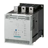
Siemens SIRIUS 3RW40 Manual (204 pages)
Industrial Controls
Brand: Siemens
|
Category: Controller
|
Size: 24.82 MB
Table of Contents
-
-
Additional Documentation
11
-
Siemens Industry Online Support
13
-
Siemens Industry Online Support App
15
-
-
Reactive Power Compensation
19
-
Electromagnetic Compatibility (EMC) According to IEC 60947-4-1
19
-
Recycling and Disposal
21
-
Before Commencing Work: Isolating the Equipment from the Supply System and Ensuring that It Cannot be Reconnected
21
-
Five Safety Rules for Work in or on Electrical Systems
22
-
-
Functional Principle of the SIRIUS 3RW30 and 3RW40 Soft Starters
24
-
Method of Operation of a Two-Phase Controlled Soft Starter
26
-
Starting Current Asymmetry
28
-
Comparison of Device Functions
30
-
Accessories for 3RW30 Soft Starters
31
-
Accessories for 3RW40 Soft Starters
32
-
4 Product Combinations
33
-
-
Current Limiting and Ramp-Up Detection (3RW40 Only)
38
-
Stop Without Load (3RW30 and 3RW40)
40
-
Soft Stop (3RW40 Only)
41
-
Motor Protection / Intrinsic Device Protection (3RW40 Only)
42
-
Motor Protection Function
42
-
Intrinsic Device Protection (3RW40 Only)
45
-
Functions of the RESET Buttons
47
-
SIRIUS 3RW402, 3RW403 and 3RW404 Soft Starters
47
-
Setting the RESET MODE
47
-
SIRIUS 3RW405 and 3RW407 Soft Starters
49
-
Setting the RESET MODE
49
-
Other Functions of the RESET Button
50
-
Motor Protection Trip Test
50
-
Reparameterizing the on / RUN Output Contact
51
-
Reset Options for Fault Acknowledgement
51
-
Functions of the Inputs
52
-
Start Input (Terminal 1) on 3RW30 and 3RW402 to 3RW404
52
-
Start Input (Terminal 3) on 3RW405 and 3RW407
53
-
Thermistor Input / Connection on 3RW402 to 3RW404
53
-
Functions of the Outputs
54
-
3RW30: Output Terminal 13 / 14 on
54
-
3RW40: Output Terminals 13 / 14 on / RUN and 23 / 24 BYPASSED
54
-
3RW40: Group Fault Output at Terminal 95 / 96 / 98 OVERLOAD / FAILURE
56
-
6 Messages and Diagnosis
57
-
3RW30: Troubleshooting
58
-
3RW402 / 3RW403 / 3RW404: Leds
59
-
3RW40: Troubleshooting
63
-
7 Application Planning
65
-
Roller Conveyor Application
65
-
Hydraulic Pump Application
66
-
-
Installing the Soft Starter
67
-
Permissible Mounting Position
67
-
Mounting Dimensions, Clearances, and Assembly Type
68
-
Assembly Type: Standalone Assembly, Side-By-Side Assembly, Direct Mounting
69
-
Installation Requirements
70
-
-
9 Installation / Mounting
71
-
General Feeder Assembly (Type of Coordination 1)
72
-
Soft Starter with Line Contactor (Type of Coordination 1)
73
-
Soft Starter Assembly with Type of Coordination 2
74
-
Capacitors to Improve the Power Factor
76
-
-
Control and Auxiliary Terminals
77
-
Main Circuit Connection
77
-
-
Operator Controls, Displays, and Connections on the 3RW30
81
-
Operator Controls, Displays, and Connections on the 3RW40
82
-
Effects on Changing the Potentiometer Settings
84
-
-
-
Configuration in General
85
-
Configuration Procedure
86
-
Selecting the Optimum Soft Starter
86
-
Application Examples for Normal Starting (CLASS 10) with 3RW30 and 3RW40
90
-
Application Examples for Heavy-Duty Starting (CLASS 20): 3RW40 Only
91
-
ON Time and Switching Frequency
92
-
Reducing the Rated Data
93
-
Dimensioning of Soft Starters for Motors with High Starting Current Conditions
93
-
Installation Altitude and Ambient Temperature
94
-
Calculating the Permissible Switching Frequency
95
-
Table of Permissible Assembly Combinations with Switching Frequency Factors
95
-
Calculating the Switching Frequency (Example)
98
-
Selection of the Soft Starter Using the Simulation Tool for Soft Starters
100
-
Article Number System for the 3RW30
101
-
Article Number System for the 3RW40
102
-
-
-
Commissioning the 3RW30
103
-
Commissioning Procedure
103
-
Quick Commissioning of the 3RW30 and Optimization of the Parameters
104
-
Setting the Soft Start Function
105
-
Setting the Starting Voltage
106
-
Setting the Ramp Time
106
-
Commissioning the 3RW40
109
-
Commissioning Procedure
109
-
Quick Commissioning of the 3RW40 and Optimization of the Parameters
110
-
Setting the Soft Start Function
111
-
Setting the Starting Voltage
112
-
Setting the Ramp Time
112
-
Current Limiting in Conjunction with a Starting Voltage Ramp and Ramp-Up Detection
113
-
Setting the Motor Current
114
-
Setting the Current Limiting Value
114
-
Optimized Setting Ranges for Current Limiting
116
-
Setting the Soft Stop Function
118
-
Setting the Ramp-Down Time
118
-
Setting the Motor Protection Function
119
-
Setting the Electronic Motor Overload Protection
119
-
Motor Current Settings
120
-
Motor Protection Acc. to ATEX
120
-
Thermistor Motor Protection
121
-
Motor Protection Trip Test
121
-
Functions of the Outputs
122
-
Functions of the BYPASSED and on / RUN Outputs
122
-
Parameterizing the 3RW40 Outputs
123
-
Function of the FAILURE / OVERLOAD Output
125
-
-
-
Technical Data in Siemens Industry Online Support
127
-
3Rw30 13, 14, 16, 17, 18-.Bb
130
-
3Rw30 36, 37, 38, 46, 47-.Bb
131
-
3RW30 Main Conductor Cross-Sections
132
-
3RW30 Auxiliary Conductor Cross-Sections
133
-
Electromagnetic Compatibility According to en 60947-4-2
133
-
Types of Coordination
134
-
Fused Version (Line Protection Only)
136
-
Fused Version with SITOR 3NE1 Fuses
137
-
Fused Version with SITOR 3NE3/4/8 Fuses
138
-
3RW40 2., 3., 4. Control Electronics
141
-
3RW40 5., 7. Control Electronics
142
-
3RW40 2., 3., 4. Control Electronics
142
-
3RW40 5., 7. Control Electronics
143
-
3RW40 Protection Functions
143
-
3RW40 Control Times and Parameters
144
-
3RW40 2. to 7. Power Electronics
145
-
3RW40 24, 26, 27, 28 Power Electronics
146
-
3RW40 36, 37, 38, 46, 47 Power Electronics
147
-
3RW40 55, 56, 73, 74, 75, 76 Power Electronics
148
-
3RW40 2., 3., 4. Main Conductor Cross-Sections
149
-
3RW40 5., 7. Main Conductor Cross-Sections
150
-
Electromagnetic Compatibility According to en 60947-4-2
151
-
Types of Coordination
152
-
Fused Version (Line Protection Only)
154
-
Fused Version with SITOR 3NE1 Fuses
155
-
Fused Version with SITOR 3NE3/4/8 Fuses
156
-
Motor Protection Tripping Characteristics for 3RW40 (with Symmetry)
157
-
Motor Protection Tripping Characteristics for 3RW40 (with Asymmetry)
158
-
-
15 Dimension Drawings
159
-
16 Typical Circuit Diagrams
161
-
Typical Circuit for the Optional Thermistor Motor Protection Evaluation
161
-
Control by Pushbutton
162
-
Control of the 3RW30 by Pushbutton
162
-
Control of the 3RW40 by Pushbutton
163
-
Control of the 3RW30 by Switch
165
-
Control of the 3RW40 by Switch
166
-
Control in Automatic Mode
168
-
Control of the 3RW30 in Automatic Mode
168
-
Control of the 3RW40 in Automatic Mode
169
-
Control of the 3RW30 with 24 V DC by PLC
171
-
Control of the 3RW40 by PLC
172
-
Control with an Optional Main / Line Contactor
174
-
Control of the 3RW30 with a Main Contactor
174
-
Control of the 3RW40 with a Main Contactor
175
-
3RW30 Reversing Circuit
177
-
3RW40 Reversing Circuit
178
-
Control of a Magnetic Parking Brake
180
-
3RW30 Motor with Magnetic Parking Brake
180
-
3RW402 — 3RW404, Control of a Motor with a Magnetic Parking Brake
181
-
3RW405 — 3RW407, Control of a Motor with a Magnetic Parking Brake
182
-
3RW30 EMERGENCY STOP and 3TK2823 Safety Relay
183
-
3RW402 — 3RW404 EMERGENCY STOP and 3TK2823 Safety Relay
185
-
3RW405 — 3RW407 EMERGENCY STOP and 3TK2823 Safety Relay
187
-
3RW and Contactor for Emergency Starting
189
-
3RW30 and Contactor for Emergency Starting
189
-
3RW40 and Contactor for Emergency Starting
190
-
Dahlander / Multispeed Motor
192
-
3RW30 and Dahlander Motor Starting
192
-
3RW402 — 3RW404 and Dahlander Motor Starting
194
-
3RW405 — 3RW407 and Dahlander Motor Starting
195
-
-
-
A.1 Configuration Data
197
-
Table of Parameters Used
199
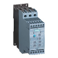
Siemens SIRIUS 3RW40 Operating Instructions Manual (32 pages)
Brand: Siemens
|
Category: Controller
|
Size: 2.01 MB
Advertisement
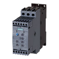
Siemens SIRIUS 3RW40 Operating Instructions Manual (32 pages)
Brand: Siemens
|
Category: Controller
|
Size: 1.41 MB
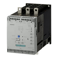
Siemens SIRIUS 3RW40 Operating Instructions Manual (18 pages)
SIRIUS series
Brand: Siemens
|
Category: Controller
|
Size: 0.66 MB
Siemens SIRIUS 3RW40 Operating Instructions Manual (17 pages)
Brand: Siemens
|
Category: Controller
|
Size: 2.21 MB

Siemens SIRIUS 3RW40 Operating Instructions Manual (15 pages)
Brand: Siemens
|
Category: Controller
|
Size: 2.04 MB
Siemens SIRIUS 3RW40 Operating Instructions Manual (12 pages)
Soft starter
Brand: Siemens
|
Category: Remote Starter
|
Size: 1.59 MB
Advertisement
Related Products
-
Siemens SIRIUS 3RW40 2
-
Siemens SIRIUS 3RW40 3
-
Siemens SIRIUS 3RW40 4
-
Siemens SIRIUS 3RW40 7
-
Siemens SIRIUS 3RW40 5
-
Siemens SIRIUS 3RW40 24 Series
-
Siemens SIRIUS 3RW40 26 Series
-
Siemens SIRIUS 3RW40 27 Series
-
Siemens SIRIUS 3RW40 28 Series
-
Siemens SIRIUS 3RW40 36 Series
Siemens Categories
Controller
Control Unit
Industrial Equipment
![]()
Washer
![]()
Switch
More Siemens Manuals
Table of Contents for Siemens SIRIUS 3RW40:
-
3ZX1012-0RW40-1CA1 13 SIRIUS Yumuşak yol verici (Softstarter) Patlama tehlikesi altı nda bulunan bölgeler için emniyet ve hizmete alma bilgileri 3RW40 EN / IEC 60947-4-2 Kullanım kılavuzuna ek Sipariş-No: 3ZX1012-0RW40-1CA1 Türkçe 3RW40 kullanım kılavuzuna ilaveten hazırlanan bu ekte, patlama tehlikesi altında bulunan bölgeler için emniyet ve hizmete alma bilgilerini bulacaksınız. Patlama tehlikesi altındaki bölge-lerde motorları koruma altın
-
Technische Änderungen vorbehalten. Zum späteren Gebrauch aufbewahren. Subject to change without prior notice. Store for use at a later date. © Siemens AG 2005 Bestell-Nr./Order No.: 3ZX1012-0RW40-1CA1 Printed in the Federal Republic of Germany Technical Assistance: Telephone: +49 (0) 911-895-5900 (8°° — 17°° CET) Fax: +49 (0) 911-895-5907 E-mail: [email protected] Internet: www.siemens.de/lowvo
-
3ZX1012-0RW40-1CA1 5 SIRIUS Démarreur progressif Consignes de sécurité et de mise en service pour les zones explosibles 3RW40 EN / IEC 60947-4-2 Complément aux instructions de service N° de réf. : 3ZX1012-0RW40-1CA1 Français Ce complément aux instructions de service 3RW40 traite des consignes de sécurité et de mise en service pour les zones explosibles. Vous devez les respecter strictement si vous devez protéger des moteurs en zone
-
3ZX1012-0RW40-1CA1 15 Устройство плавного запуска SIRIUS Указания по технике безопасности и вводу в эксплуатацию во взрывоопасных зонах 3RW40 EN / IEC 60947-4-2 Дополнение к инструкции по эксплуатации № заказа: 3ZX1012-0RW40-1CA1 Русский В данном дополнении к инструкции по эксплуатации устройства 3RW40 содержатся указания по техни
-
16 3ZX1012-0RW40-1CA1 Тест должен проводиться при вводе в эксплуатацию и, затем, с переодичностью не реже одного раза в 36 месяцев. Тест представляет собой полный функциональный тест и может быть произведен при включенном или выключенном дви
-
SIRIUS Sanftstarter Sicherheits- und Inbetriebnahmehinweise für explosionsgefährdete Bereiche 3RW40 EN / IEC 60947-4-2 Ergänzung zur Betriebsanleitung Bestell-Nr.: 3ZX1012-0RW40-1CA1 Deutsch GWA 4NEB 535 2192-10 DS 02 Last update: 26 February 2008 In dieser Ergänzung zur 3RW40-Betriebsanleitung erhalten Sie Sicherheits- und Inbetriebnahmehinweise für explosionsgefähr- dete Bereiche. Diese müssen Sie unbedingt beachten, wenn Sie Motoren in explosionsgefährdeten Bereichen schützen müssen. Diese Er
-
3ZX1012-0RW40-1CA1 7 SIRIUS Arrancador suave Instrucciones de seguridad y puesta en servicio en entornos con peligro de explosión 3RW40 EN / IEC 60947-4-2 Suplemento al manual de instrucciones Referencia: 3ZX1012-0RW40-1CA1 Español Este suplemento al manual de instrucciones 3RW40 incluye ins- trucciones sobre la seguridad y la puesta en servicio en entor- nos con peligro de explosión. Es imprescindible respetar dichas instrucciones para asegurar el funcionamiento seguro de moto- res en entornos con peligro de explosión. Este suplemento está
-
10 3ZX1012-0RW40-1CA1 Durante la messa in servizio e ciclicamente, al più tardi ogni 36 mesi, eseguire un test! Il test include un completo test di funzionalità e può essere ese- guito con motore disinserito o inserito. È necessario eseguire le tre seguenti fasi di test (vedere tabella): •Test LED • Test della rilevazione della corrente in ciascuna delle tre fasi • Disinserzione di prova della protezione motore, nel quale viene testata l’intera catena di comando com
-
12 3ZX1012-0RW40-1CA1 Execute um teste depois da colocação em funcionamento e regularmente após, no máximo, a cada 36 meses! O teste abrange um teste funcional completo e pode ser reali- zado com motor ligado ou desligado. É necessário executar as seguintes três fases de teste (ver a tabela): • teste de LEDs • teste de detecção de corrente em todas as três fases • teste de desligamento da proteção do motor, no qual é testada toda a cadeia de
-
SIRIUS 软启动器 在有爆炸危险区域的安全及首次开机运行说明 3RW40 EN / IEC 60947-4-2 操作指南的补充说明 订购号 : 3ZX1012-0RW40-1CA1 中文 3ZX1012-0RW40-1CA1 17 在此 3RW40- 操作指南的补充说明里您将获得有关在爆 炸危险区域的安全及首次开机运行的提示信息。如果 您要在有爆炸危险的区域保护电机,您就务必要对本 说明内容加以注意。 此补充说
-
3ZX1012-0RW40-1CA1 11 SIRIUS Chave de partida suave Indicações de segurança e de serviço para áreas apresentando risco de explosão 3RW40 EN / IEC 60947-4-2 Suplemento da instrução de serviço Nº de enc.: 3ZX1012-0RW40-1CA1 Português O suplemento da instrução de serviço do 3RW40 contém indicações de segurança e de serviço para áreas que apresentam risco de explosão. É imprescindível observar estas indicações quando é necessário proteger motores em áreas com risco de exp
-
3ZX1012-0RW40-1CA1 9 SIRIUS Avviatore dolce Indicazioni di sicurezza e per la messa in servizio in aree con pericolo d’esplosione 3RW40 EN / IEC 60947-4-2 Integrazione delle istruzioni per l’uso N. ordinazione: 3ZX1012-0RW40-1CA1 Italiano In questa integrazione delle istruzioni per l’uso per il 3RW40- troverete le indicazioni di sicurezza e per la messa in sevizio in aree con pericolo d’esplosione. Vanno assolutamente osservate per la protezione di motori in aree con peri
-
2 3ZX1012-0RW40-1CA1 Führen Sie bei der Inbetriebnahme und zyklisch spätestens alle 36 Monate einen Test durch! Der Test umfasst einen vollständigen Funktionstest und kann bei aus- oder eingeschaltetem Motor durchgeführt werden. Folgende drei Testphasen (siehe Tabelle) müssen durchlaufen werden: •LED-Test • Test der Stromerfassung in allen drei Phasen • Motorschutztestabschaltung, bei der die gesamte Steuerkette inklusive der Schaltel
Questions, Opinions and Exploitation Impressions:
You can ask a question, express your opinion or share our experience of Siemens SIRIUS 3RW40 device using right now.