- Manuals
- Brands
- JUKI Manuals
- Sewing Machine
- DDL-8700
- Instruction manual
-
Contents
-
Table of Contents
-
Troubleshooting
-
Bookmarks
Quick Links
Related Manuals for JUKI DDL-8700
Summary of Contents for JUKI DDL-8700
-
Page 1
ENGLISH… -
Page 2: Table Of Contents
CONTENTS 1. SPECIFICATIONS ………………1 2. SET-UP ………………… 1 1. Installing the motor unit ………………1 2. Installing the control box ………………1 3. Installing the belt ………………..2 4. Adjusting the pulley cover ………………2 5. Installation and adjustment for the protecting pin and the belt slip-off preventing bracket …………..
-
Page 3: Specifications
Input 390VA (LZ-228* : 460VA) 390VA (LZ-228* : 460VA) 390VA (LZ-228* : 460VA) (Caution) 1. Indication of the power consumption is the mean power consumption when DDL-8700 is mounted in accordance with the operating conditions JUKI specifies. 2. The power consumption changes in accordance with the operating conditions and the mounted machine head.
-
Page 4: Installing The Belt
3. Installing the belt 1) The belt distance, between sewing machine pulley and motor pulley, must be parallel. 2) The belt tension should be adjusted by turning the tension adjust nuts to change height of the motor, so that the belt sinks down by about 15 mm (9.8N) 15mm (9.8N) when it is depressed by band at the center of the belt span.
-
Page 5: Installation And Adjustment For The Protecting Pin And The Belt Slip-Off Preventing Bracket
5. Installation and adjustment for the protecting pin and the belt slip-off preventing bracket WARNING : To protect against possible personal injury due to abrupt start of the machine, be sure to start the following work after turning the power off and ascertaining that the motor is at rest. 1) Attaching hole for the protecting pin To attach protecting pin 1, select either attaching hole A or attaching hole B in the motor pulley cover…
-
Page 6: Connecting The Cords
6. Connecting the cords WARNING : • To prevent personal injury caused by abrupt start of the sewing machine, carry out the work after turning OFF the power switch and a lapse of 5 minutes or more. • To prevent damage of device caused by maloperation and wrong specifications, be sure to connect all the corresponding connectors to the specified places.
-
Page 7
1) Pass the cords of the thread trimming solenoid, 2) Loosen setscrew 5 in front cover 4. reverse-stitching solenoid, etc., and the cords of 3) Pressing the side of front cover 4 in the direction the synchronizer , machine head 4P connector of the arrow, open the front cover toward you. -
Page 8
[ Connection of the connector for CP panel ] Exclusive connectors are prepared for connection of the connector for CP-160. Paying attention to the orientation of the connector !2 , connect it to connector !3 located on the circuit board. After connecting, securely lock the connector. 9) After inserting the connector, put all cords together with cable clip band !4 located on the side of the box. -
Page 9
10) Close front cover 4 while paying attention to 12) Connect connector 4P !5 to connector !6 located pinching of the wire. on the side of the box. 11) After that, fix it with the screw 5. 13) Connect motor output cord !7 of the power switch to connector !8 . -
Page 10
[ For CE specifications only ] 1) Remove three screws 1 located on the side of the control box. 2) Set power source cover installing plate 2 supplied with the unit as accessories to the control box main unit with the three screws which have been removed. -
Page 11
10) Insert connector 6 coming from the motor to the connector of the control box from the inside. 11) Securely fix power source cover 7 supplied with the unit as accessories to power source cover installing plate 2 with two screws 8 supplied with the unit as accessories while being careful that the cord is not caught by the cover. -
Page 12
[ For LA specifications only ] 2) Set power source cover installing plate 2 supplied 1) Remove three screws 1 located on the side of the with the unit as accessories to the control box main control box. unit with the three screws which have been removed. -
Page 13: Attaching The Connecting Rod
7. Attaching the connecting rod WARNING : To protect against possible personal injury due to abrupt start of the machine, be sure to start the following work after turning the power off and a lapse of 5 minutes or more. 1) Fix connecting rod 1 to installing hole B of pedal lever 2 with nut 3.
-
Page 14
6) When operation panel 7 is connected, various sewing patterns such as reverse feed stitching at sewing start, reverse feed stitching at sewing end, etc. can be set. Refer to the Instruction Manual for the operation panel for the details. 7) When pressing touch-back switch 8, reverse feed can be performed. -
Page 15: Explanation Of The Operation Panel
2. Explanation of the operation panel switch Used for determining the contents of setting. When this switch is pressed, flashing stops and the contents of setting are determined. switch Used for changing the contents of setting. When this switch is pressed, changeable positions flash on and off. By pressing the switch, flashing position shifts in the right direction.
-
Page 16
Operating procedure of the sewing pattern (1) Reverse stitching pattern Reverse stitching patterns below can be set by using the operation panel. Reverse stitching patterns that can be set Reverse stitching at start display Sewing pattern Reverse stitching at end display [ Setting procedure of the reverse stitching ] Reverse stitching pattern Overlapped stitching pattern… -
Page 17
switch 1 to make number of 5) Press stitches display 6 flash on and off, and set the number of stitches for the respective processes of the stitching. switch 3 or switch 4 to 6) Press change the number of stitches. The number of stitches can be changed up to as many as 15 stitches for the A, B, C, and D processes respectively. -
Page 18
(3) Special setting For material end sensor function, automatic thread trimming function, one-shot automatic stitching function and thread trimming prohibition function which are displayed in the front panel, it is possible to change the set value by directly moving to the function setting mode while the power is turned ON in addition to the normal function setting procedure. [ Moving procedure to the function setting mode ] switch 1, and press 1) Hold pressing… -
Page 19
(Caution) When the specified number of stitches is insufficient, there is a case where the sewing machine cannot stop within the specified number of stitches depending on the speed of rotation of the sewing machine. 4 One-shot automatic stitching setting function (Function setting No. -
Page 20: Setting For Functions Of Sc-500
3. Setting for functions of SC-500 Functions can be selected and specified by means of the four setting switches and light emitting diode located inside the front cover of the SC-500. Specified value Specified No. 1 Switch for entering specified value changed 3 Down switch (DOWN) 4 Up switch (UP) and updating setting No.
-
Page 21
4) When you want to advance the setting No., press switch 2 to advance the setting No. Specified When you want to return the setting No., press switch 1 to return the setting No. (Caution) When switch 1 (switch 2) is held pressing, the setting No. -
Page 22: Function Setting List
If it is necessary to change the set value, please purchase the Engineer’s Manual and follow the instructions. (Descriptions of setting in this list are the standard values at the time of delivery of DDL-8700.) However, contents of function setting are subject to change for improvement of function and performance without notice.
-
Page 23
If it is necessary to change the set value, please purchase the Engineer’s Manual and follow the instructions. (Descriptions of setting in this list are the standard values at the time of delivery of DDL-8700.) However, contents of function setting are subject to change for improvement of function and performance without notice. -
Page 24
If it is necessary to change the set value, please purchase the Engineer’s Manual and follow the instructions. (Descriptions of setting in this list are the standard values at the time of delivery of DDL-8700.) However, contents of function setting are subject to change for improvement of function and performance without notice. -
Page 25
If it is necessary to change the set value, please purchase the Engineer’s Manual and follow the instructions. (Descriptions of setting in this list are the standard values at the time of delivery of DDL-8700.) However, contents of function setting are subject to change for improvement of function and performance without notice. -
Page 26: Detailed Explanation Of Selection Of Functions
5. Detailed explanation of selection of functions 1 Selection of the soft-start function (Function setting No. 1) The needle thread may fail to interlace with the bobbin thread at the start of sewing when the stitching pitch (stitch length) is small or a thick needle is used. To solve such problem, this function (called “soft-start”) is used to limit the sewing speed, thereby assuring successful formation of the starting stitches.
-
Page 27
7 Sound of click of the key switch mounted on the PSC box (Function setting No. 11) This function selects whether the sound is effective or ineffective when operating the four key switches mounted on the PSC box. 0 : off The sound of click is ineffective. 1 : on The sound of click is effective. -
Page 28
!1 Function of changeover of compensating switch on the operation panel function (Function setting No. 22) Function of compensation switch on the operation panel of CP-160 can be changed over to needle up / down compensating stitching or one stitch compensating stitching. 0 : Needle up / down compensating stitching 1 : One stitch compensating stitching !2 Thread trimming motion condition (Function setting No. -
Page 29
!6 Function of reverse feed stitching on the way (Function setting Nos. 30 to 33) Functions of the limit of number of stitches and thread trimming command can be added to the touch back switch on the sewing machine head. Function setting No. -
Page 30
!7 Number of rotation of one-shot stitching (Function setting No. 38) This function can set, by the pedal operation of one time, the sewing speed of one-shot stitching when the sewing machine continues stitching until completing the number of stitches specified or detecting the material end. Setting range 150 to MAX. -
Page 31
@0 Foot lift function after thread trimming (Function setting No. 55) This function can automatically lift the presser foot after thread trimming.This function is effective only when it is used in combination with the AK device. 0 : off Function of automatically lifting the presser foot is not provided. (Presser foot does not automatically go up after thread trimming.) 1 : on Function of automatically lifting the presser foot is provided. -
Page 32
@5 Function of stop immediately after the reverse feed stitching at the start of sewing (Function setting No. 60) This function temporarily stops the sewing machine even when keeping depressing the front part of the pedal at the time of completion of process of reverse feed stitching at the start of sewing. It is used when sewing a short length by reverse feed stitching at the start of sewing. -
Page 33
@9 Retry function (Function setting No. 73) When the retry function is used, if the sewing material is thick and not piereced with needle, this function makes the needle pierce in the material with ease. 0 : Normal 1 : Retry function is provided. #0 One-shot function up to material end (Function setting No. -
Page 34: Automatic Compensation Of Neutral Point Of The Pedal Sensor
6. Automatic compensation of neutral point of the pedal sensor Whenever the pedal sensor, spring, etc. are replaced, be sure to perform following operation : 1) Pressing switch 2, turn ON the power switch. 2) Indication on the screen will be as illustrated in 6. At this time, the value indicated in the 7 segments of four figures is the compensation value.
-
Page 35: Setting Of The Auto Lifter Function
9. Setting of the auto lifter function When the auto-lifter device (AK) is attached, this function makes the function of auto-lifter work. 1) Turn ON the power switch while pressing switch 3 inside the control box. 2) LED display is turned to 5, 6 (FL ON) with “beep”, and the function of auto-lifter becomes effective.
-
Page 36: Initialization Of The Setting Data
11. Initialization of the setting data All contents of function setting of SC-500 can be returned to the standard set values. 1) Pressing all switches 2, 3 and 4, turn ON the power switch. 2) LED displays indication 6 with the sound “peep”, and initialization starts.
-
Page 37
3) Loosen setscrew 1 in front cover 2. 4) Pressing the side of front cover 2 in the direction of the arrow, open the front cover toward you. Note : Be sure to open / close the front cover with your hands. -
Page 38: Changing Procedure Between 100V To 120V And 200V To 240V (Possible Only For The Voltage Changeover Type)
2. Changing procedure between 100V to 120V and 200V to 240V (Possible only for the voltage changeover type) WARNING : To prevent personal injuries caused by electric shock hazards or abrupt start of the sewing machine, carry out the work after turning OFF the power switch and a lapse of 5 minutes or more. To prevent accidents caused by unaccustomed work or electric shock, request the electric expert or engineer of our dealers when adjusting the electrical components.
-
Page 39: Error Codes
3. Error codes In case of the following, check again before you judge the case as trouble. Cause Corrective measure Phenomenon When tilting the sewing machine When tilting the sewing machine, the Tilt the sewing machine after turning OFF without turning OFF the power switch, buzzer beeps and the sewing the power.
-
Page 40: Error Code List
n addition, there are the following error codes in this device. These error codes interlock (or limit function) and inform the problem so that the problem is not enlarged when any problem is discovered. When you request our service, please confirm the error codes. Checking procedure of the error code 1) Pressing switch 1 in the control box, turn ON the power switch.
This manual is also suitable for:
Sc-500
Посмотреть инструкция для Juki DDL-8700 бесплатно. Руководство относится к категории швейные машины, 12 человек(а) дали ему среднюю оценку 9.1. Руководство доступно на следующих языках: русский. У вас есть вопрос о Juki DDL-8700 или вам нужна помощь? Задайте свой вопрос здесь
Швейная машина Juki DDL-8700 — это профессиональный инструмент для шитья. Машина оснащена мощным двигателем, который обеспечивает высокую скорость шитья до 5500 оборотов в минуту, и точным системой контроля натяжения нити. Использование технологии глубокого шва позволяет создавать прочные стежки даже на тонких тканях.
Juki DDL-8700 имеет компактный и эргономичный дизайн, что удобно для работы в небольших мастерских. Машина оснащена регулируемой системой подачи ткани, которая позволяет правильно регулировать скорость шитья в соответствии с материалом и техникой работы.
Машина изготовлена из высококачественных материалов и имеет долговечную конструкцию. Устройство обеспечивает надежную и плавную работу в течение многих лет. Возможность использования ряда запасных частей, таких как ножницы и иглы, делает ремонт и обслуживание Juki DDL-8700 удобными и доступными.
Juki DDL-8700 — отличный вариант для профессиональных портных, ремонтных мастерских и производственных предприятий, которые требуют высокой точности и скорости шитья.
Главная
| Juki | |
| DDL-8700 | DDL-8700 | |
| швейная машина | |
| русский | |
| Руководство пользователя (PDF), Инструкция по установке (PDF) |
Не можете найти ответ на свой вопрос в руководстве? Вы можете найти ответ на свой вопрос ниже, в разделе часто задаваемых вопросов о Juki DDL-8700.
Какой размер иглы лучше всего использовать?
Наиболее подходящий размер иглы зависит от используемой толщины ткани. С плотной тканью следует использовать толстую иглу. Подходящие типы тканей указываются на упаковке с иглами.
Какой срок службы у швейной иглы?
Как правило, срок службы швейной иглы составляет от 7 до 9 часов.
Что может повредить иглу при шитье?
Причин повреждения иглы может быть несколько: — Использование неподходящей иглы для определенного типа ткани — Установка иглы слишком низко — Неправильное расположение ткани — Неправильно установленный шпульный колпачок
Инструкция Juki DDL-8700 доступно в русский?
Да, руководствоJuki DDL-8700 доступно врусский .
Не нашли свой вопрос? Задайте свой вопрос здесь
![]()
ENGLISH
DDL-8700
Instruction Manual
CONTENTS |
||
|
1. |
SPECIFICATIONS…………………………………………………………………………………………. |
1 |
|
2. |
INSTALLATION…………………………………………………………………………………………….. |
1 |
|
3. |
INSTALLING THE BELT COVER AND THE BOBBIN WINDER………………………….. |
2 |
|
4. |
ADJUSTING THE HEIGHT OF THE KNEE LIFTER…………………………………………… |
2 |
|
5. |
INSTALLING THE THREAD STAND……………………………………………………………….. |
3 |
|
6. |
LUBRICATION………………………………………………………………………………………………. |
3 |
|
7. |
ADJUSTING THE AMOUNT OF OIL (OIL SPLASHES) IN THE HOOK……………….. |
4 |
|
8. |
ATTACHING THE NEEDLE……………………………………………………………………………. |
5 |
|
9. |
SETTING THE BOBBIN INTO THE BOBBIN CASE………………………………………….. |
5 |
|
10. |
ADJUSTING THE STITCH LENGTH………………………………………………………………… |
5 |
|
11. |
PRESSER FOOT PRESSURE………………………………………………………………………… |
6 |
|
12. |
HAND LIFTER………………………………………………………………………………………………. |
6 |
|
13. |
ADJUSTING THE HEIGHT OF THE PRESSER BAR…………………………………………. |
6 |
|
14. |
THREADING THE MACHINE HEAD………………………………………………………………… |
7 |
|
15. |
THREAD TENSION……………………………………………………………………………………….. |
8 |
|
16. |
THREAD TAKE-UP SPRING…………………………………………………………………………… |
8 |
|
17. |
ADJUSTING THE THREAD TAKE-UP STROKE………………………………………………. |
8 |
|
18. |
NEEDLE-TO-HOOK RELATIONSHIP………………………………………………………………. |
9 |
|
19. |
HEIGHT OF THE FEED DOG………………………………………………………………………….. |
9 |
|
20. |
TILT OF THE FEED DOG……………………………………………………………………………… |
10 |
|
21. |
ADJUSTING THE FEED TIMING…………………………………………………………………… |
10 |
|
22. |
ADJUSTING THE FEED TIMING (DDL-8700L)……………………………………………….. |
11 |
|
23. |
MOTOR PULLEYS AND BELTS……………………………………………………………………. |
12 |
1. SPECIFICATIONS
|
DDL-8700 |
DDL-8700A |
DDL-8700H |
|||||
|
Application |
General fabrics, light-weight |
General fabris, light-weight |
Medium-weight materials, |
||||
|
and medium-weight materials |
materials |
heavy-weight materials |
|||||
|
Sewing speed |
Max. 5,500 sti/min |
Max. 4,000 sti/min |
Max. 4,000 sti/min |
||||
|
Stitch length |
Max. 5 mm |
Max. 4 mm |
Max. 5 mm |
||||
|
Needle |
DB x 1 #9 to #18 (134 #65 to #110) |
DAx 1 #9 to #11 (134 #65 to #75) |
DB x 1 #20 to #23 (134 #125 to #160) |
||||
|
Presser foot lift (by knee lifter) |
10 mm (Standard) 13 mm (Max.) |
9 mm (Max.) |
10 mm (Standard) 13 mm (Max.) |
||||
|
Lubricating oil |
JUKI New Defrix Oil No. 1 |
||||||
|
Noise |
— Equivalent continuous emission sound pressure level (LpA) at the workstation : |
||||||
|
A-weighted value of 83.5 dB; (Includes KpA = 2.5 dB); according to ISO 10821- C.6.2 -ISO 11204 |
|||||||
|
GR2 at 5,000 sti/min. |
|||||||
|
— Sound power level (LWA) ; |
|||||||
|
A-weighted value of 88.0 dB; (Includes KWA = 2.5 dB); according to ISO 10821- C.6.2 -ISO 3744 |
|||||||
|
GR2 at 5,000 sti/min. |
|||||||
|
DDL-8700L |
|||||||
|
Application |
For heavy-weight materials |
||||||
|
Sewing speed |
3,000 sti/min |
Max. 4,000 sti/min (for feed pitch of 5 mm or less) |
|||||
|
Max. 3,200 sti/min (for feed pitch of 5 mm or more) |
|||||||
|
Stitch length |
Max. 7 mm |
||||||
|
Needle |
DB x 1 #20 to #23 (DP x 5 #16 to #18) |
||||||
|
Presser foot lift (by knee lifter) |
13 mm (Max.) |
||||||
|
Lubricating oil |
JUKI New Defrix Oil No. 1 |
— Equivalent continuous emission sound pressure level (LpA) at the workstation :
Noise A-weighted value of 83.5 dB; (Includes KpA = 2.5 dB); according to ISO 10821- C.6.2 -ISO 11204 GR2 at 5,000 sti/min.
—Sound power level (LWA) ;
A-weighted value of 88.0 dB; (Includes KWA = 2.5 dB); according to ISO 10821- C.6.2 -ISO 3744 GR2 at 5,000 sti/min.
2. INSTALLATION
|
3 |
||||||
|
3 |
3 |
|||||
|
3 |
3 |
|||||
|
1 |
1 |
|||||
|
4 |
||||||
|
3 |
||||||
|
1 |
||||||
14
|
22.5 mm |
18.5 mm |
||||
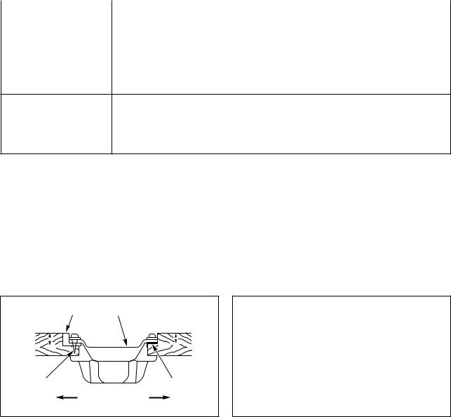
(1)Installing the under cover
1)The under cover should rest on the four corners of the machine table groove.
2)Two rubber seats 1 for supporting the head portion on the operator side A are fixed on the extended portion of the table by hitting the nail 2 , and the other two rubber cushion seats 3 on the hinge side
B are fixed by using a rubber-based adhesive. Then, oil pan 4 is placed.
3)Fit hinge 1 into the opening in the machine bed, and fit the machine head to table rubber hinge 2 before placing the machine head on cushions 3 on the four corners.
––
3. INSTALLING THE BELT COVER AND THE BOBBIN WINDER
|
WARNING : |
||||||
|
To protect against possible personal injury due to abrupt start of the machine, be sure to start the |
||||||
|
following work after turning the power off and ascertaining that the motor is at rest. |
||||||
|
(mm) |
(DDL-8700L) |
(mm) |
||||
|
47 |
||||||
|
33 |
||||||
|
33 |
62 |
|||||
|
62 |
||||||
|
63.5 |
||||||
|
75.5 |
||||||
4. ADJUSTING THE HEIGHT OF THE KNEE LIFTER
WARNING :
To protect against possible personal injury due to abrupt start of the machine, be sure to start the following work after turning the power off and ascertaining that the motor is at rest.
1
2
3
1)The standard height of the presser foot lifted using the knee lifter is 10 mm.
2)You can adjust the presser foot lift up to 13 mm using knee lifter adjust screw 1. (Max. 9 mm for A type)
3)When you have adjusted the presser foot lift to over 10 mm, be sure that the bottom end of needle bar
2 in its lowest position does not hit presser foot 3.
––

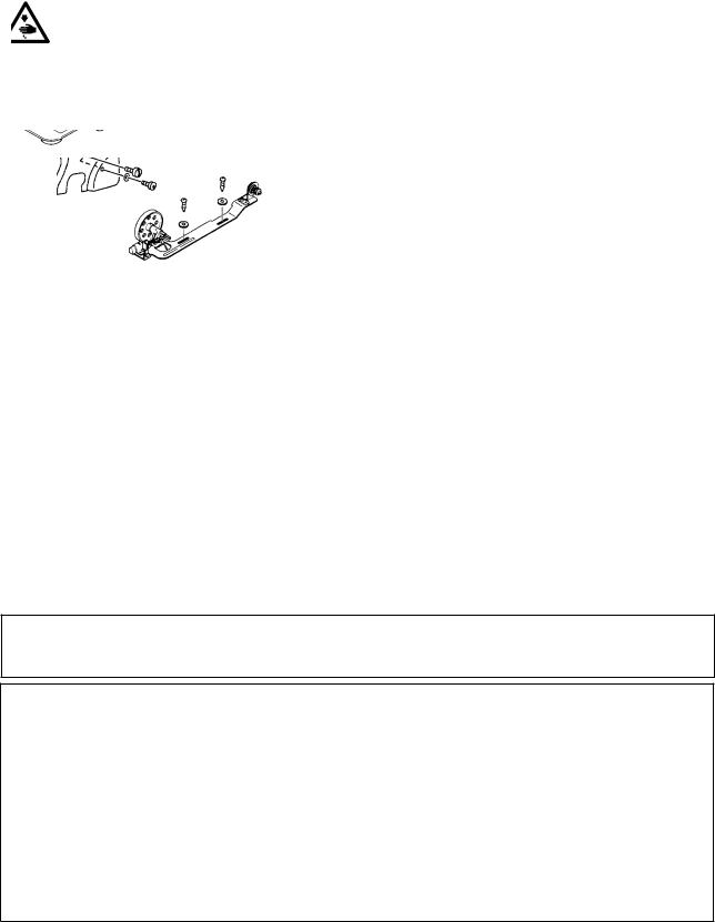
5. INSTALLING THE THREAD STAND
6. LUBRICATION
WARNING :
To protect against possible personal injury due to abrupt start of the machine, be sure to start the following work after turning the power off and ascertaining that the motor is at rest.
(1) Information on lubrication
1) Fill oil pan 1 with JUKI New Defrix Oil No. 1 up to HIGH mark A.
2) When the oil level lowers below LOW mark B, refill the oil pan with the specified oil.
3) When you operate the machine after lubrication, you will see splashing oil through oil sight window
2 if the lubrication is adequate.
4) Note that the amount of the splashing oil is unrelated to the amount of the lubricating oil.
When you first operate your machine after setup or after an extended period of disuse, run your machine at 3,000 sti/min. for about 10 minutes for the purpose of break-in.
(2) Adjusting the amount of oil supplied to the face plate parts
1) Adjust the amount of oil supplied to the thread take-up and needle bar crank 2 by turning adjust pin 1.
2) The minimum amount of oil is reached when marker dot A is brought close to needle bar crank 2 by turning the adjust pin in direction B.
3) The maximum amount of oil is reached when marker dot A is brought to the position just opposite from the needle bar crank by turning the adjust pin in direction C.
––
 Loading…