Комментарии
31
Войдите или зарегистрируйтесь, чтобы писать комментарии, задавать вопросы и участвовать в обсуждении.

А нет ли у кого схем на правый руль?


Я езжу на Toyota RAV4 (III)
Просит пароль j32 не катит 🤷♂️

Проверил всё работает, на английском j32
Я езжу на Toyota RAV4 (III)
Ребят помогите! Теана вд 10г, при торможении сидушка прокатывается на 0,5-1см, очень напрягает, где искать проблему? И кто скажет, как снять задний пассажирский плафон освещения? Заранее спасибо!

Не подскажите где можно найти книгу по ремонту для полноприводного рестайлинга?

Я езжу на Nissan Teana (J32)
Спасибо огромное! Мир не без добрых людей! Очень помогли.


Спасибо, добрый человек! Аж зарегался, чтоб коммент тебе написать

Да не за что! Пользуйтесь наздоровье.


СПС за мануалы, добрый человек!

Ссылка на первую книгу не работает ((( можно повторить?
Все комментарии
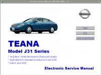
Мультимедийное руководство на английском языке по техническому обслуживанию и ремонту автомобиля Nissan Teana серии J31.
- Автор: —
- Издательство: Nissan
- Год издания: 2006
- Страниц: —
- Формат: —
- Размер: 71,7 Mb
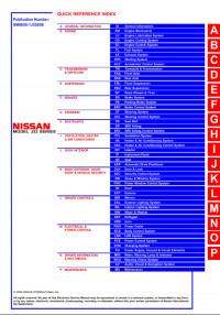
Руководство на английском языке по техническому обслуживанию и ремонту автомобиля Nissan Teana серии J32.
- Автор: —
- Издательство: Nissan International
- Год издания: 2008
- Страниц: —
- Формат: PDF
- Размер: 61,6 Mb
Руководство по эксплуатации и техническому обслуживанию автомобиля Nissan Teana 2012 года выпуска.
- Автор: —
- Издательство: Nissan International
- Год издания: 2011
- Страниц: 335
- Формат: PDF
- Размер: 2,3 Mb

Руководство по эксплуатации и техническому обслуживанию автомобиля Nissan Teana с 2006 года выпуска.
- Автор: —
- Издательство: MoToR
- Год издания: —
- Страниц: 204
- Формат: —
- Размер: —
Руководство по эксплуатации навигационной системы автомобиля Nissan Teana с 2006 года выпуска.
- Автор: —
- Издательство: Nissan
- Год издания: —
- Страниц: —
- Формат: PDF
- Размер: 6,1 Mb
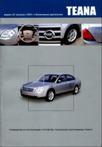
Руководство по эксплуатации, техническому обслуживанию и ремонту автомобиля Nissan Teana серии J31 с 2003 года выпуска с бензиновыми двигателями.
- Автор: —
- Издательство: Автонавигатор
- Год издания: 2008
- Страниц: 632
- Формат: —
- Размер: —

Руководство по эксплуатации, техническому обслуживанию и ремонту автомобиля Nissan Teana серии J31 с 2003 года выпуска с бензиновыми двигателями
- Автор: —
- Издательство: Автонавигатор
- Год издания: —
- Страниц: 376
- Формат: —
- Размер: —
Руководство по эксплуатации, техническому обслуживанию и ремонту автомобиля Nissan Teana серии J32 с 2008 года выпуска с бензиновыми двигателями объемом 2,5/3,5 л.
- Автор: —
- Издательство: Автонавигатор
- Год издания: —
- Страниц: 552
- Формат: —
- Размер: —

Руководство по эксплуатации, техническому обслуживанию и ремонту автомобиля Nissan Teana серии J33 с 2014 года выпуска с бензиновым двигателем объемом 2,5 л.
- Автор: —
- Издательство: Автонавигатор
- Год издания: —
- Страниц: 566
- Формат: —
- Размер: —

Руководство по эксплуатации, техническому обслуживанию и ремонту автомобиля Nissan Teana серии J33 с 2014 года выпуска с бензиновым двигателем объемом 3,5 л.
- Автор: —
- Издательство: Автонавигатор
- Год издания: —
- Страниц: 558
- Формат: —
- Размер: —

NISSAN
TEANA
Модели J32 выпуска с 2008 г. с бензиновыми
двигателями VQ25DE, VQ35DE
Руководство по эксплуатации, устройство,
техническое обслуживание, ремонт
Руководство по эксплуатации
Техническое обслуживание
Механическая часть двигателя
Система смазки и система охлаждения двигателя
Система управления двигателем
Акселератор, топливная система и система выпуска
Бесступенчатая автоматическая коробка передач (вариатор) (CVT)
Передняя ось и подвеска
Задняя ось и подвеска
Тормозная система
Рулевое управление
Система пассивной безопасности
Система вентиляции, отопления и кондиционирования воздуха
Интерьер, экстерьер, двери, люк и система безопасности
Элементы управления для водителя
Информационная система водителя и мультимедийная система
Электрооборудование
Э
■
1
■
2
■
3
5
■
6
8
9
14
16
Nissan Teana 2003-2012 Factory Service Repair Manual PDF.
| Nissan Teana J31 2003-2008 Service Manual 61 Mb Download |
| Nissan Teana J32 2008-2012 Service Manual 62 Mb Download |
| Nissan Teana 2013 Service Manual Also called Nissan Altima 2013 167 Mb Download |
| Nissan Teana 2014 Service Manual Also called Nissan Altima 2014 105 Mb Download |
Comments on this entry are closed.
Pagini
- Nissan Owner Manuals
- Nissan Parts Catalog
- Nissan Service Manuals

BODY EXTERIOR, DOORS, ROOF & VEHICLE SECURITY
C
D
E
SECTION DLKA
B
DOOR & LOCK
F
G
H
I
J
L
M
LK
N
O
P
CONTENTS
D
WITH INTELLIGENT KEY SYSTEM
BASIC INSPECTION ……………………………… 7
DIAGNOSIS AND REPAIR WORKFLOW ………. 7Work Flow ………………………………………………………..7
INSPECTION AND ADJUSTMENT ………………..10
ADDITIONAL SERVICE WHEN REPLACING CONTROL UNIT ………………………………………………..10
ADDITIONAL SERVICE WHEN REPLACING CONTROL UNIT : Description …………………………..10ADDITIONAL SERVICE WHEN REPLACING CONTROL UNIT : Special Repair Requirement …..10
FUNCTION DIAGNOSIS …………………………11
POWER DOOR LOCK SYSTEM ……………………11System Diagram ………………………………………………11System Description ………………………………………….11Component Parts Location ………………………………12Component Description ……………………………………12
INTELLIGENT KEY SYSTEM ……………………….14
INTELLIGENT KEY SYSTEM ……………………………..14INTELLIGENT KEY SYSTEM : System Diagram ….14INTELLIGENT KEY SYSTEM : System Descrip-tion ………………………………………………………………..14INTELLIGENT KEY SYSTEM : Component Parts Location ………………………………15INTELLIGENT KEY SYSTEM : Component Description ……………………………………16
DOOR LOCK FUNCTION ……………………………………16DOOR LOCK FUNCTION : System Diagram ………17DOOR LOCK FUNCTION : System Description …..17DOOR LOCK FUNCTION : Component Parts Location ………………………………19DOOR LOCK FUNCTION : Component Description ……………………………………20
TRUNK OPEN FUNCTION ………………………………….20TRUNK OPEN FUNCTION : System Diagram ……..21TRUNK OPEN FUNCTION : System Description ….21TRUNK OPEN FUNCTION : Component Parts Location ………………………………23TRUNK OPEN FUNCTION : Component Description ……………………………………24
REMOTE KEYLESS ENTRY FUNCTION ………………24REMOTE KEYLESS ENTRY FUNCTION : Sys-tem Diagram ……………………………………………………25REMOTE KEYLESS ENTRY FUNCTION : Sys-tem Description ………………………………………………..25REMOTE KEYLESS ENTRY FUNCTION : Component Parts Location ………………………………27REMOTE KEYLESS ENTRY FUNCTION : Component Description ……………………………………28
KEY REMINDER FUNCTION ………………………………28KEY REMINDER FUNCTION : System Descrip-tion …………………………………………………………………28KEY REMINDER FUNCTION : Component Parts Location ………………………………30
WARNING FUNCTION ……………………………………….31WARNING FUNCTION : System Description ……….31WARNING FUNCTION : Component Parts Location ………………………………36
TRUNK OPEN FUNCTION ………………………….38System Diagram ………………………………………………38System Description …………………………………………..38Component Parts Location ………………………………38Component Description ……………………………………39
FUEL FILLER LID OPENER ………………………..40Component Parts Location ………………………………..40
DIAGNOSIS SYSTEM (BCM) ………………………41
COMMON ITEM …………………………………………………41
DLK-1

COMMON ITEM : CONSULT-III Function (BCM — COMMON ITEM) ……………………………………………. 41
DOOR LOCK ……………………………………………………. 42DOOR LOCK : CONSULT-III Function (BCM — DOOR LOCK) ………………………………………………… 42
INTELLIGENT KEY …………………………………………… 43INTELLIGENT KEY : CONSULT-III Function (BCM — INTELLIGENT KEY) …………………………….. 43
TRUNK ……………………………………………………………. 46TRUNK : CONSULT-III Function (BCM — TRUNK) … 46
COMPONENT DIAGNOSIS …………………… 48
U1000 CAN COMM CIRCUIT ………………………. 48
BCM ………………………………………………………………… 48BCM : Description …………………………………………… 48BCM : DTC Logic ……………………………………………. 48BCM : Diagnosis Procedure …………………………….. 48
U1010 CONTROL UNIT (CAN) ……………………. 49
BCM ………………………………………………………………… 49BCM : DTC Logic ……………………………………………. 49BCM : Diagnosis Procedure …………………………….. 49BCM : Special Repair Requirement …………………… 49
B2621 INSIDE KEY ANTENNA 1 …………………. 50Description …………………………………………………….. 50DTC Logic ……………………………………………………… 50Diagnosis Procedure ………………………………………. 50
B2622 INSIDE KEY ANTENNA 2 …………………. 52Description …………………………………………………….. 52DTC Logic ……………………………………………………… 52Diagnosis Procedure ………………………………………. 52
B2623 INSIDE KEY ANTENNA 3 …………………. 54Description …………………………………………………….. 54DTC Logic ……………………………………………………… 54Diagnosis Procedure ………………………………………. 54
POWER SUPPLY AND GROUND CIRCUIT ….. 56
BCM (BODY CONTROL MODULE) ……………………. 56BCM (BODY CONTROL MODULE) : Diagnosis Procedure ……………………………………………………… 56
DOOR SWITCH …………………………………………. 57Description …………………………………………………….. 57Component Function Check …………………………… 57Diagnosis Procedure ………………………………………. 57Component Inspection …………………………………….. 59
DOOR LOCK AND UNLOCK SWITCH …………. 60Description …………………………………………………….. 60Component Function Check …………………………… 60Diagnosis Procedure ………………………………………. 60
DOOR LOCK ACTUATOR ………………………….. 61
DRIVER SIDE …………………………………………………… 61DRIVER SIDE : Description ……………………………… 61DRIVER SIDE : Component Function Check …….. 61DRIVER SIDE : Diagnosis Procedure ………………… 61
PASSENGER SIDE …………………………………………… 61PASSENGER SIDE : Description ……………………… 62PASSENGER SIDE : Component Function Check ……………………………. 62PASSENGER SIDE : Diagnosis Procedure ………… 62
REAR LH …………………………………………………………. 62REAR LH : Description ……………………………………. 62REAR LH : Component Function Check …………… 63REAR LH : Diagnosis Procedure ………………………. 63
REAR RH …………………………………………………………. 63REAR RH : Description ……………………………………. 63REAR RH : Component Function Check …………… 63REAR RH : Diagnosis Procedure ……………………… 64
TRUNK LID OPENER ACTUATOR ……………… 65Description …………………………………………………….. 65Component Function Check ……………………………. 65Diagnosis Procedure ……………………………………….. 65
REMOTE KEYLESS ENTRY RECEIVER ……… 67Description …………………………………………………….. 67Component Function Check ……………………………. 67Diagnosis Procedure ……………………………………….. 67
TRUNK LID OPENER SWITCH …………………… 70Description …………………………………………………….. 70Component Function Check ……………………………. 70Diagnosis Procedure ……………………………………….. 70Component Inspection …………………………………….. 71
DOOR REQUEST SWITCH …………………………. 72Description …………………………………………………….. 72Component Function Check ……………………………. 72Diagnosis Procedure ……………………………………….. 72Component Inspection …………………………………….. 73
TRUNK LID OPENER REQUEST SWITCH …… 74Description …………………………………………………….. 74Component Function Check ……………………………. 74Diagnosis Procedure ……………………………………….. 74Component Inspection …………………………………….. 75
TRUNK ROOM LAMP SWITCH …………………… 76Description …………………………………………………….. 76Component Function Check ……………………………. 76Diagnosis Procedure ……………………………………….. 76Component Inspection …………………………………….. 77
UNLOCK SENSOR …………………………………….. 78Description …………………………………………………….. 78Component Function Check ……………………………. 78Diagnosis Procedure ……………………………………….. 78Component Inspection …………………………………….. 79
OUTSIDE KEY ANTENNA ………………………….. 80
DLK-2

C
D
E
F
G
H
I
J
L
M
A
B
LK
N
O
P
D
Description ……………………………………………………..80Component Function Check …………………………….80Diagnosis Procedure ………………………………………..80
INTELLIGENT KEY WARNING BUZZER ……….82Description ……………………………………………………..82Component Function Check …………………………….82Diagnosis Procedure ………………………………………..82Component Inspection ……………………………………..83
INTELLIGENT KEY ……………………………………..84Description ……………………………………………………..84Component Function Check …………………………….84Diagnosis Procedure ………………………………………..84Component Inspection ……………………………………..84Special Repair Requirement ……………………………..85
KEY SLOT ………………………………………………….86Description ……………………………………………………..86Component Function Check …………………………….86Diagnosis Procedure ………………………………………..86Component Inspection ……………………………………..87
KEY SLOT ILLUMINATION ………………………….88Description ……………………………………………………..88Component Function Check …………………………….88Diagnosis Procedure ………………………………………..88Component Inspection ……………………………………..89
HORN FUNCTION ……………………………………….91Description ……………………………………………………..91Component Function Check …………………………….91Diagnosis Procedure ……………………………………….91
COMBINATION METER DISPLAY FUNC-TION ………………………………………………………….93
Description ……………………………………………………..93Component Function Check …………………………….93Diagnosis Procedure ………………………………………..93
BUZZER (COMBINATION METER) ……………….94Description ……………………………………………………..94Component Function Check …………………………….94Diagnosis Procedure ………………………………………..94
KEY WARNING LAMP …………………………………95Description ……………………………………………………..95Component Function Check …………………………….95Diagnosis Procedure ………………………………………..95
HAZARD FUNCTION …………………………………..96Description ……………………………………………………..96Component Function Check …………………………….96Diagnosis Procedure ………………………………………..96
POWER DOOR LOCK SYSTEM ……………………97Wiring Diagram — POWER DOOR LOCK SYSTEM — …………………………………………………………………….97
INTELLIGENT KEY SYSTEM …………………….. 104Wiring Diagram — INTELLIGENT KEY SYSTEM — .. 104
TRUNK LID OPENER ………………………………. 116Wiring Diagram — TRUNK LID OPENER — ………….116
FUEL FILLER LID OPENER ……………………… 119Wiring Diagram — FUEL LID OPENER — …………….119
ECU DIAGNOSIS ………………………………… 121
BCM (BODY CONTROL MODULE) …………… 121Reference Value …………………………………………….121Wiring Diagram — BCM — ………………………………….144Fail-safe ………………………………………………………..150DTC Inspection Priority Chart ………………………..152DTC Index …………………………………………………….153
SYMPTOM DIAGNOSIS ………………………. 155
DOOR DOES NOT LOCK/UNLOCK WITH DOOR LOCK AND UNLOCK SWITCH ………. 155
ALL DOOR ………………………………………………………155ALL DOOR : Diagnosis Procedure ……………………155
DRIVER SIDE …………………………………………………..155DRIVER SIDE : Diagnosis Procedure ……………….155
PASSENGER SIDE …………………………………………..155PASSENGER SIDE : Diagnosis Procedure ……….156
REAR LH …………………………………………………………156REAR LH : Diagnosis Procedure ………………………156
REAR RH ………………………………………………………..156REAR RH : Diagnosis Procedure ……………………..156
VEHICLE SPEED SENSING AUTO LOCK OPERATION DOES NOT OPERATE …………. 157
Diagnosis Procedure ………………………………………157
DOOR DOES NOT LOCK/UNLOCK WITH IN-TELLIGENT KEY …………………………………….. 158
Description …………………………………………………….158Diagnosis Procedure ………………………………………158
HAZARD AND HORN REMINDER DOES NOT OPERATE ……………………………………….. 159
Description …………………………………………………….159Diagnosis Procedure ………………………………………159
AUTO DOOR LOCK OPERATION DOES NOT OPERATE ………………………………………………. 160
Description …………………………………………………….160Diagnosis Procedure ………………………………………160
DOOR DOES NOT LOCK/UNLOCK WITH DOOR REQUEST SWITCH ………………………. 161
DRIVER SIDE …………………………………………………..161DRIVER SIDE : Description ……………………………..161DRIVER SIDE : Diagnosis Procedure ……………….161
PASSENGER SIDE …………………………………………..161PASSENGER SIDE : Description ……………………..161
DLK-3

PASSENGER SIDE : Diagnosis Procedure ……….162
TRUNK ……………………………………………………………162TRUNK : Description ………………………………………162TRUNK : Diagnosis Procedure …………………………163
TRUNK LID DOES NOT OPEN WITH TRUNK LID OPENER SWITCH ……………………………… 164
Description …………………………………………………….164Diagnosis Procedure ………………………………………164
TRUNK LID DOES NOT OPEN WITH INTEL-LIGENT KEY ……………………………………………. 165
Description …………………………………………………….165Diagnosis Procedure ………………………………………165
TRUNK LID DOES NOT OPEN WITH TRUNK LID OPENER REQUEST SWITCH ……………… 166
Description …………………………………………………….166Diagnosis Procedure ………………………………………166
HAZARD AND BUZZER REMINDER DOES NOT OPERATE ……………………………………….. 167
Description …………………………………………………….167Diagnosis Procedure ………………………………………167
KEY REMINDER FUNCTION DOES NOT OP-ERATE ……………………………………………………. 168
Description …………………………………………………….168Diagnosis Procedure ………………………………………168
KEY WARNING DOES NOT OPERATE ……… 169Description …………………………………………………….169Diagnosis Procedure ………………………………………169
OFF POSITION WARNING DOES NOT OP-ERATE ……………………………………………………. 170
Description …………………………………………………….170Diagnosis Procedure ………………………………………170
P POSITION WARNING DOES NOT OPER-ATE ………………………………………………………… 171
Description …………………………………………………….171Diagnosis Procedure ………………………………………171
ACC WARNING DOES NOT OPERATE ……… 173Description …………………………………………………….173Diagnosis Procedure ………………………………………173
TAKE AWAY WARNING DOES NOT OPER-ATE ………………………………………………………… 174
DOOR IS OPEN ……………………………………………….174DOOR IS OPEN : Description ………………………….174DOOR IS OPEN : Diagnosis Procedure …………….174
ANY DOOR OPEN TO ALL DOORS CLOSED …….175ANY DOOR OPEN TO ALL DOORS CLOSED : Description …………………………………………………….175ANY DOOR OPEN TO ALL DOORS CLOSED : Diagnosis Procedure ………………………………………175
PUSH-BUTTON IGNITION SWITCH OPERATION . 175PUSH-BUTTON IGNITION SWITCH OPERA-TION : Description ………………………………………… 176PUSH-BUTTON IGNITION SWITCH OPERA-TION : Diagnosis Procedure …………………………… 176
INTELLIGENT KEY IS REMOVED FROM KEY SLOT …………………………………………………………….. 176
INTELLIGENT KEY IS REMOVED FROM KEY SLOT : Description ………………………………………… 176INTELLIGENT KEY IS REMOVED FROM KEY SLOT : Diagnosis Procedure ………………………….. 177
INTELLIGENT KEY LOW BATTERY WARN-ING DOES NOT OPERATE …………………………178
Description …………………………………………………… 178Diagnosis Procedure ……………………………………… 178
DOOR LOCK OPERATION WARNING DOES NOT OPERATE WITH DOOR REQUEST SWITCH ……………………………………………………179
Description …………………………………………………… 179Diagnosis Procedure ……………………………………… 179
KEY ID WARNING DOES NOT OPERATE …..180Description …………………………………………………… 180Diagnosis Procedure ……………………………………… 180
INTELLIGENT KEY LOW BATTERY WARN-ING DOES NOT OPERATE …………………………181
Description …………………………………………………… 181Diagnosis Procedure ……………………………………… 181
SQUEAK AND RATTLE TROUBLE DIAG-NOSES ……………………………………………………..182
Work Flow ……………………………………………………. 182Inspection Procedure …………………………………….. 184Diagnostic Worksheet ……………………………………. 186
PRECAUTION …………………………………….188
PRECAUTIONS …………………………………………188Precaution for Supplemental Restraint System (SRS) «AIR BAG» and «SEAT BELT PRE-TEN-SIONER» ……………………………………………………… 188Precaution for Procedure without Cowl Top Cover . 188Precaution Necessary for Steering Wheel Rota-tion after Battery Disconnect …………………………… 188Work ……………………………………………………………. 189
PREPARATION …………………………………..190
PREPARATION …………………………………………190Commercial Service Tools ……………………………… 190
ON-VEHICLE REPAIR …………………………191
HOOD ………………………………………………………191
HOOD ASSEMBLY …………………………………………. 191HOOD ASSEMBLY : Exploded View ……………….. 191
DLK-4

C
D
E
F
G
H
I
J
L
M
A
B
LK
N
O
P
D
HOOD ASSEMBLY : Removal and Installation ….. 192HOOD ASSEMBLY : Adjustment …………………….. 193
HOOD HINGE …………………………………………………. 193HOOD HINGE : Exploded View ………………………. 194HOOD HINGE : Removal and Installation …………. 194
HOOD SUPPORT ROD ……………………………………. 194HOOD SUPPORT ROD : Exploded View …………. 195HOOD SUPPORT ROD : Removal and Installa-tion ……………………………………………………………… 195
RADIATOR CORE SUPPORT ……………………. 196Exploded View ……………………………………………… 196Removal and Installation ………………………………… 196
FRONT FENDER ………………………………………. 199Exploded View ……………………………………………… 199Removal and Installation ………………………………… 199
FRONT DOOR ………………………………………….. 201
DOOR ASSEMBLY …………………………………………. 201DOOR ASSEMBLY : Exploded View ……………….. 201DOOR ASSEMBLY : Removal and Installation ….. 202DOOR ASSEMBLY : Adjustment …………………….. 203
DOOR STRIKER ……………………………………………… 203DOOR STRIKER : Exploded View …………………… 203DOOR STRIKER : Removal and Installation …….. 204
DOOR HINGE …………………………………………………. 204DOOR HINGE : Exploded View ………………………. 204DOOR HINGE : Removal and Installation …………. 204
DOOR CHECK LINK ……………………………………….. 205DOOR CHECK LINK : Exploded View ……………… 205DOOR CHECK LINK : Removal and Installation .. 205
REAR DOOR ……………………………………………. 207
DOOR ASSEMBLY …………………………………………. 207DOOR ASSEMBLY : Exploded View ……………….. 207DOOR ASSEMBLY : Removal and Installation ….. 208DOOR ASSEMBLY : Adjustment …………………….. 209
DOOR STRIKER ……………………………………………… 209DOOR STRIKER : Exploded View …………………… 209DOOR STRIKER : Removal and Installation …….. 210
DOOR HINGE …………………………………………………. 210DOOR HINGE : Exploded View ………………………. 210DOOR HINGE : Removal and Installation …………. 210
DOOR CHECK LINK ……………………………………….. 211DOOR CHECK LINK : Exploded View ……………… 211DOOR CHECK LINK : Removal and Installation .. 211
TRUNK LID ………………………………………………. 213
TRUNK LID ASSEMBLY ………………………………….. 213TRUNK LID ASSEMBLY : Exploded View ………… 213TRUNK LID ASSEMBLY : Removal and Installa-tion ……………………………………………………………… 214
TRUNK LID ASSEMBLY : Adjustment ………………215
TRUNK LID STRIKER ………………………………………215TRUNK LID STRIKER : Exploded View …………….216TRUNK LID STRIKER : Removal and Installation ..216
TRUNK LID HINGE …………………………………………..216TRUNK LID HINGE : Exploded View ………………..217TRUNK LID HINGE : Removal and Installation …..217
TRUNK LID STAY …………………………………………….217TRUNK LID STAY : Exploded View ………………….218TRUNK LID STAY : Removal and Installation …….218
TRUNK LID WEATHER-STRIP ………………………….219TRUNK LID WEATHER-STRIP : Exploded View ..219TRUNK LID WEATHER-STRIP : Removal and In-stallation ……………………………………………………….219
HOOD LOCK …………………………………………… 220Exploded View ……………………………………………….220Removal and Installation …………………………………220Inspection ……………………………………………………..221
FRONT DOOR LOCK ………………………………. 222
DOOR LOCK ……………………………………………………222DOOR LOCK : Exploded View …………………………222DOOR LOCK : Removal and Installation ……………222
INSIDE HANDLE ………………………………………………223INSIDE HANDLE : Exploded View ……………………223INSIDE HANDLE : Removal and Installation ………223
OUTSIDE HANDLE …………………………………………..223OUTSIDE HANDLE : Exploded View ………………..224OUTSIDE HANDLE : Removal and Installation …..224
REAR DOOR LOCK …………………………………. 227
DOOR LOCK ……………………………………………………227DOOR LOCK : Exploded View …………………………227DOOR LOCK : Removal and Installation ……………227
INSIDE HANDLE ………………………………………………227INSIDE HANDLE : Exploded View ……………………228INSIDE HANDLE : Removal and Installation ………228
OUTSIDE HANDLE …………………………………………..228OUTSIDE HANDLE : Exploded View ………………..229OUTSIDE HANDLE : Removal and Installation …..229
TRUNK LID LOCK …………………………………… 231Exploded View ……………………………………………….231Removal and Installation …………………………………231
FUEL FILLER LID OPENER ……………………… 232Exploded View ……………………………………………….232Removal and Installation …………………………………232
DOOR SWITCH ……………………………………….. 234Exploded View ……………………………………………….234Removal and Installation …………………………………234
DLK-5

INSIDE KEY ANTENNA ……………………………. 235
INSTRUMENT CENTER ……………………………………235INSTRUMENT CENTER : Exploded View ………….235INSTRUMENT CENTER : Removal and Installa-tion ……………………………………………………………….235
CONSOLE ……………………………………………………….235CONSOLE : Exploded View …………………………….236CONSOLE : Removal and Installation ……………….236
TRUNK ROOM …………………………………………………236TRUNK ROOM : Exploded View ………………………237TRUNK ROOM : Removal and Installation …………237
OUTSIDE KEY ANTENNA ………………………… 238
DRIVER SIDE …………………………………………………..238DRIVER SIDE : Exploded View ………………………..238DRIVER SIDE : Removal and Installation ………….238
PASSENGER SIDE …………………………………………..238PASSENGER SIDE : Exploded View ………………..238PASSENGER SIDE : Removal and Installation ….238
REAR BUMPER ……………………………………………….238
REAR BUMPER : Exploded View ……………………. 238REAR BUMPER : Removal and Installation ……… 238
INTELLIGENT KEY WARNING BUZZER ……..240Exploded View ……………………………………………… 240Removal and Installation ………………………………… 240
KEY SLOT ………………………………………………..241Exploded View ……………………………………………… 241Removal and Installation ………………………………… 241
TRUNK LID OPENER REQUEST SWITCH …..242Exploded View ……………………………………………… 242Removal and Installation ………………………………… 242
TRUNK LID OPENER SWITCH …………………..243Exploded View ……………………………………………… 243Removal and Installation ………………………………… 243
REMOTE KEYLESS ENTRY RECEIVER ……..244Exploded View ……………………………………………… 244Removal and Installation ………………………………… 244
INTELLIGENT KEY BATTERY ……………………245Removal and Installation ………………………………… 245
DLK-6

DIAGNOSIS AND REPAIR WORKFLOW[WITH INTELLIGENT KEY SYSTEM]
C
D
E
F
G
H
I
J
L
M
A
B
LK
N
O
P
< BASIC INSPECTION >
D
BASIC INSPECTIONDIAGNOSIS AND REPAIR WORKFLOW
Work Flow INFOID:0000000003794729
OVERALL SEQUENCE
DETAILED FLOW
JMKIA2754GB
DLK-7

[WITH INTELLIGENT KEY SYSTEM]DIAGNOSIS AND REPAIR WORKFLOW
< BASIC INSPECTION >
1.GET INFORMATION FOR SYMPTOM
Get the detailed information from the customer about the symptom (the condition and the environment whenthe incident/malfunction occurred).
>> GO TO 2.
2.CHECK DTC
1. Check DTC for BCM.2. Perform the following procedure if DTC is displayed.- Record DTC and freeze frame data (print them out with CONSULT-III).- Erase DTC.- Study the relationship between the cause detected by DTC and the symptom described by the customer.3. Check related service bulletins for information.Is any symptom described and any DTC detected?Symptom is described, DTC is displayed>>GO TO 3.Symptom is described, DTC is not displayed>>GO TO 4.Symptom is not described, DTC is displayed>>GO TO 5.
3.CONFIRM THE SYMPTOM
Confirm the symptom described by the customer.Connect CONSULT-III to the vehicle in “DATA MONITOR” mode and check real time diagnosis results.Verify relation between the symptom and the condition when the symptom is detected.
>> GO TO 5.
4.CONFIRM THE SYMPTOM
Confirm the symptom described by the customer.Connect CONSULT-III to the vehicle in “DATA MONITOR” mode and check real time diagnosis results.Verify relation between the symptom and the condition when the symptom is detected.
>> GO TO 6.
5.PERFORM DTC CONFIRMATION PROCEDURE
Perform DTC Confirmation Procedure for the displayed DTC, and then check that DTC is detected again.At this time, always connect CONSULT-III to the vehicle, and check diagnostic results in real time.If two or more DTCs are detected, refer to DLK-152, «DTC Inspection Priority Chart» (BCM) determine trou-ble diagnosis order.NOTE:Perform Component Function Check if DTC Confirmation Procedure is not included in Service Manual. Thissimplified check procedure is an effective alternative though DTC cannot be detected during this check.If the result of Component Function Check is NG, it is the same as the detection of DTC by DTC ConfirmationProcedure.Is DTC detected?YES >> GO TO 7.NO >> Refer to GI-35, «Intermittent Incident».
6.DETECT MALFUNCTIONING SYSTEM BY SYMPTOM DIAGNOSIS
Detect malfunctioning system according to SYMPTOM DIAGNOSIS based on the confirmed symptom in step4, and determine the trouble diagnosis order based on possible causes and symptom.
>> GO TO 7.
7.DETECT MALFUNCTIONING PART BY DIAGNOSTIC PROCEDURE
Inspect according to Diagnostic Procedure of the system.NOTE:The Diagnostic Procedure described based on open circuit inspection. A short circuit inspection is alsorequired for the circuit check in the Diagnostic Procedure.
DLK-8

DIAGNOSIS AND REPAIR WORKFLOW[WITH INTELLIGENT KEY SYSTEM]
C
D
E
F
G
H
I
J
L
M
A
B
LK
N
O
P
< BASIC INSPECTION >
D
Is malfunctioning part detected?YES >> GO TO 8.NO >> Check voltage of related BCM terminals using CONSULT-III.
8.REPAIR OR REPLACE THE MALFUNCTIONING PART
1. Repair or replace the malfunctioning part.2. Reconnect parts or connectors disconnected during Diagnostic Procedure again after repair and replace-
ment.3. Check DTC. If DTC is displayed, erase it.
>> GO TO 9.
9.FINAL CHECK
When DTC was detected in step 2, perform DTC Confirmation Procedure or Component Function Checkagain, and then check that the malfunction has been repaired securely.When symptom was described from the customer, refer to confirmed symptom in step 3 or 4, and check thatthe symptom is not detected.Does the symptom reappear?YES (DTC is detected)>>GO TO 7.YES (Symptom remains)>>GO TO 6.NO >> INSPECTION END
DLK-9

[WITH INTELLIGENT KEY SYSTEM]INSPECTION AND ADJUSTMENT
< BASIC INSPECTION >
INSPECTION AND ADJUSTMENTADDITIONAL SERVICE WHEN REPLACING CONTROL UNIT
ADDITIONAL SERVICE WHEN REPLACING CONTROL UNIT : DescriptionINFOID:0000000003794732
Perform the system initialization when replacing BCM, replacing Intelligent Key or registering an additionalIntelligent Key.
ADDITIONAL SERVICE WHEN REPLACING CONTROL UNIT : Special Repair Re-quirement INFOID:0000000003794733
Refer to the CONSULT-III operation manual for the initialization procedure.
DLK-10

POWER DOOR LOCK SYSTEM[WITH INTELLIGENT KEY SYSTEM]
C
D
E
F
G
H
I
J
L
M
A
B
LK
N
O
P
< FUNCTION DIAGNOSIS >
D
FUNCTION DIAGNOSISPOWER DOOR LOCK SYSTEM
System Diagram INFOID:0000000003794734
System Description INFOID:0000000003794735
DOOR LOCK FUNCTION• The door lock and unlock switch (driver side) are build into power window main switch.• Interlocked with the locking operation of door lock and unlock switch, door lock actuators of all doors are
locked.• Interlocked with the unlocking operation of door lock and unlock switch, door lock actuators of all doors and
are unlocked.• When ignition switch is ON and BCM receives air bag deployment signal, it operates automatically to unlock
all doors. Air bag diagnosis sensor unit sends the air bag deployment signal to BCM.
Door Key Cylinder• With the door key inserted in the door key cylinder on driver side, turning the door key cylinder to “LOCK”,
locks door lock actuator of driver side door.• With the door key inserted in the door key cylinder on driver side, turning the door key cylinder to “UNLOCK”,
unlocks door lock actuator of driver side door.
JMKIA2372GB
DLK-11

[WITH INTELLIGENT KEY SYSTEM]POWER DOOR LOCK SYSTEM
< FUNCTION DIAGNOSIS >
Component Parts Location INFOID:0000000003794736
Component Description INFOID:0000000003794737
1. BCM M118, M119, M121, M122, M123 2. TCM F23 3. Combination meter M34
4. Key slot M99 5. Power window main switch(door lock and unlock switch) D5, D6
6. Front door switch (driver side) B34
7. Front door lock assembly (driver side) D9
A. Behind the combination meter B. Engine room LH C. View with front door finisher re-moved
JMKIA2373ZZ
Item Function
BCM Controls the door lock function and room lamp function.
Door lock and unlock switch Inputs lock or unlock signal to BCM.
Front door lock assembly (door lock actu-ator)
Outputs lock/unlock signal from BCM and locks/unlocks each door.
DLK-12

POWER DOOR LOCK SYSTEM[WITH INTELLIGENT KEY SYSTEM]
C
D
E
F
G
H
I
J
L
M
A
B
LK
N
O
P
< FUNCTION DIAGNOSIS >
D
Front door lock assembly (unlock sensor) Detects door lock condition of driver door.
Door switch Inputs door open/close condition to BCM.
Key slot Inputs key insert/remove signal to BCM.
Combination meter• Receives buzzer signal from BCM via CAN communication line, and sounds the buzzer.• Transmits vehicle speed signal to CAN communication line.
TCM Transmits shift position signal to BCM via CAN communication line.
Item Function
DLK-13

[WITH INTELLIGENT KEY SYSTEM]INTELLIGENT KEY SYSTEM
< FUNCTION DIAGNOSIS >
INTELLIGENT KEY SYSTEMINTELLIGENT KEY SYSTEM
INTELLIGENT KEY SYSTEM : System Diagram INFOID:0000000003794738
INTELLIGENT KEY SYSTEM : System Description INFOID:0000000003794739
• The Intelligent Key system is a system that makes it possible to lock and unlock the door locks (door lock/unlock function) by carrying the Intelligent Key, which operates based on the results of electronic ID verifica-tion using two-way communications between the Intelligent Key and the vehicle (BCM).CAUTION:The driver should always carry the Intelligent Key
• The settings for each function can be changed with the CONSULT-III.• If an Intelligent Key is lost, a new Intelligent Key can be registered. A maximum of 4 Intelligent Keys can be
registered.• It is possible to perform a diagnosis on the system and register an Intelligent Key with CONSULT-III.
JMKIA2374GB
Function Description Refer
Door lock function Lock/unlock can be performed by pressing the request switch. DLK-17
Remote keyless entry func-tion
Lock/unlock can be performed by pressing the remote controller button of the In-telligent Key.
DLK-25
Trunk lid open functionThe trunk lid can be opened by carrying the Intelligent Key and pressing the trunk lid opener request switch.
DLK-21
Key reminder functionThe key reminder buzzer sounds a warning if the door is locked with the key left inside the vehicle.
DLK-28
Warning functionIf an action that does not meet the operating condition of the Intelligent Key sys-tem is taken, the buzzer sounds to inform the driver.
DLK-31
Engine start function The engine be turned on while carrying the Intelligent Key. SEC-9
DLK-14

INTELLIGENT KEY SYSTEM[WITH INTELLIGENT KEY SYSTEM]
C
D
E
F
G
H
I
J
L
M
A
B
LK
N
O
P
< FUNCTION DIAGNOSIS >
D
INTELLIGENT KEY SYSTEM : Component Parts Location INFOID:0000000003794740
1. BCM M118, M119, M120, M121, M122, M123
2. TCM F23 3. IPDM E/R E10, E11
4. Intelligent Key warning buzzer E25 5. Remote keyless entry receiver M78 6. Combination meter M34
7. Key slot M99 8. Control device (detention switch) M57
9. Inside key antenna (console) M262
JMKIA2375ZZ
DLK-15

[WITH INTELLIGENT KEY SYSTEM]INTELLIGENT KEY SYSTEM
< FUNCTION DIAGNOSIS >
INTELLIGENT KEY SYSTEM : Component Description INFOID:0000000003794741
DOOR LOCK FUNCTION
10. Inside key antenna (instrument cen-ter) M105
11. Inside key antenna (trunk room) B86 12. Outside key antenna (rear bumper) D85
13. Front outside handle LH (request switch) D11
14. Front outside handle LH(outside key antenna) D12
15. Trunk lid lock assembly(trunk lid opener actuator) T5
16. Front door switch (driver side) B34
A. Behind the combination meter B. Engine room (LH) C. Behind the instrument lower panel RH
D. Behind the center console E. Behind the audio unit F. View with rear bumper removed
1. Front door lock assembly (driver side) D9
2. Rear door lock assembly LH D85 3. Trunk lid opener request switch T6
A. View with front door finisher removed B. View with rear door finisher removed C. View with trunk lid
JMKIA2376ZZ
Item Function
BCM Controls the Intelligent Key system.
Front door lock assembly (door lock actuator)
Outputs lock/unlock signal from BCM and locks/unlocks each door.
Front door lock assembly (unlock sensor)
Detects door lock condition of driver door.
Door switch Inputs door open/close condition to BCM.
Remote keyless entry receiver Receives lock/unlock signal from the Intelligent Key, and then transmits to BCM.
Request switch Inputs lock/unlock operation to BCM.
Intelligent Key Transmits button operation to remote keyless entry receiver.
Outside key antenna Detects if Intelligent Key is outside the vehicle.
Inside key antenna Detects if Intelligent Key is inside the vehicle.
Intelligent Key warning buzzer Warns the user of the lock/unlock condition and inappropriate operations with the buzzer sound.
DLK-16

INTELLIGENT KEY SYSTEM[WITH INTELLIGENT KEY SYSTEM]
C
D
E
F
G
H
I
J
L
M
A
B
LK
N
O
P
< FUNCTION DIAGNOSIS >
D
DOOR LOCK FUNCTION : System Diagram INFOID:0000000003794742
DOOR LOCK FUNCTION : System Description INFOID:0000000003794743
Only when pressing the request switch, it is possible to lock and unlock the door by carrying the IntelligentKey.
OPERATION DESCRIPTION• When the BCM detects that each door request switch is pressed, it activates the outside key antenna and
inside key antenna corresponding to the pressed door request switch and transmits the request signal to theIntelligent Key. And then, check that the Intelligent Key is near the door.
• If the Intelligent Key is within the outside key antenna detection area, it receives the request signal andtransmits the key ID signal to the BCM via remote keyless entry receiver.
• BCM receives the key ID signal and compares it with the registered key ID.• BCM lock/unlock each door and sounds Intelligent Key warning buzzer (lock: 2 time, unlock: 1 times) at the
same time as a reminder.
OPERATION CONDITIONIf the following conditions are satisfied, door lock/unlock operation is performed when the request switch isoperated.
*: Even with a registered Intelligent Key remaining inside the vehicle, door locks can be unlocked from outside of the vehicle with a spareIntelligent Key as long as key IDs are different.
OUTSIDE KEY ANTENNA DETECTION AREA
JMKIA1993GB
Each request switch operation Operation condition
Lock operation
• All doors are closed• Ignition switch is in the OFF position• Intelligent Key is out of key slot• Intelligent Key is outside the vehicle• Intelligent Key is within outside key antenna detection area
Unlock Operation• Intelligent Key is outside the vehicle• Intelligent Key is within outside key antenna detection area *
DLK-17

[WITH INTELLIGENT KEY SYSTEM]INTELLIGENT KEY SYSTEM
< FUNCTION DIAGNOSIS >The outside key antenna detection area of door lock/unlock functionis in the range of approximately 80 cm (31.50 in) surrounding thedriver and passenger door handles and (1) and trunk lid openerrequest switch (2). However, this operating range depends on theambient conditions.
HAZARD AND BUZZER REMINDER FUNCTIONDuring lock, unlock, operation by each request switch, the hazard warning lamps and Intelligent Key warningbuzzer will blink or honk as a reminder.When doors are locked, unlocked by each request switch, BCM honks Intelligent Key warning buzzer as areminder and blinks.
Operating Function of Hazard and Buzzer Reminder
How to Change Hazard and Buzzer Reminder ModeRefer to SEC-22, «INTELLIGENT KEY : CONSULT-III Function (BCM — INTELLIGENT KEY)».
AUTO DOOR LOCK FUNCTIONWhen all doors are locked, ignition switch is in OFF position and key switch is OFF (Intelligent Key is notinserted in key slot). Doors are unlocked with door request switch.When BCM does not receive the following signals within 60 seconds, all doors are locked.• Door switch is ON (door is opened)• Door is locked• Ignition switch is ON (ignition switch is pressed)• Key switch is ON (Intelligent Key is inserted in key slot)Auto door lock mode can be changed by “AUTO LOCK SET” mode in “WORK SUPPORT”. Refer to SEC-22,»INTELLIGENT KEY : CONSULT-III Function (BCM — INTELLIGENT KEY)».
LIST OF OPERATION RELATED PARTSThe operation related parts are marked with ×.
JMKIA2511ZZ
Operation Hazard warning lamp flash Intelligent Key warning buzzer honk
Unlock Once Once
Lock Twice Twice
Door lock function
Inte
llige
nt K
ey
Key
slo
t
Rem
ote
keyl
ess
entr
y re
ceiv
er
Doo
r sw
itch
Doo
r re
ques
t sw
itch
Doo
r lo
ck a
ctua
tor
Insi
de k
ey a
nten
na
Out
side
key
ant
enna
Inte
llige
nt K
ey w
arni
ng b
uzze
r
CA
N c
omm
unic
atio
n sy
stem
BC
M
Haz
ard
war
ning
lam
p
Pus
h-bu
tton
igni
tion
switc
h
Com
bina
tion
met
er
Door lock/unlock function by request switch × × × × × × × × ×
Hazard and buzzer reminder function for door lock/un-lock operation
× × × × ×
Key reminder function × × × × × × × × × × ×
Auto door lock function × × × × × × ×
DLK-18

INTELLIGENT KEY SYSTEM[WITH INTELLIGENT KEY SYSTEM]
C
D
E
F
G
H
I
J
L
M
A
B
LK
N
O
P
< FUNCTION DIAGNOSIS >
D
DOOR LOCK FUNCTION : Component Parts Location INFOID:0000000003841720
1. BCM M118, M119, M120, M121, M122, M123
2. TCM F23 3. IPDM E/R E10, E11
4. Intelligent Key warning buzzer E25 5. Remote keyless entry receiver M78 6. Combination meter M34
7. Key slot M99 8. Control device (detention switch) M57
9. Inside key antenna (console) M262
JMKIA2375ZZ
DLK-19

[WITH INTELLIGENT KEY SYSTEM]INTELLIGENT KEY SYSTEM
< FUNCTION DIAGNOSIS >
DOOR LOCK FUNCTION : Component Description INFOID:0000000003794745
TRUNK OPEN FUNCTION
10. Inside key antenna (instrument cen-ter) M105
11. Inside key antenna (trunk room) B86 12. Outside key antenna (rear bumper) D85
13. Front outside handle LH (request switch) D11
14. Front outside handle LH(outside key antenna) D12
15. Trunk lid lock assembly(trunk lid opener actuator) T5
16. Front door switch (driver side) B34
A. Behind the combination meter B. Engine room (LH) C. Behind the instrument lower panel RH
D. Behind the center console E. Behind the audio unit F. View with rear bumper removed
1. Front door lock assembly (driver side) D9
2. Rear door lock assembly LH D85 3. Trunk lid opener request switch T6
A. View with front door finisher removed B. View with rear door finisher removed C. View with trunk lid
JMKIA2376ZZ
Item Function
BCM Controls the door lock function.
Front door lock assembly (door lock actuator)
Output lock/unlock signal from BCM and locks/unlocks each door.
Front door lock assembly (unlock sensor)
Detects door lock condition of driver door.
Door switch Input door open/close condition to BCM.
Remote keyless entry receiver Receives lock/unlock signal from the Intelligent Key, and then transmits to BCM.
Request switch Input lock/unlock operation to BCM.
Intelligent Key Transmits button operation to remote keyless entry receiver.
Outside key antenna Detects if Intelligent Key is outside the vehicle.
Inside key antenna Detects if Intelligent Key is inside the vehicle.
Combination meter Receives hazard warning lamp signal from BCM and blinks turn signal indicators.
Intelligent Key warning buzzer Warns the user of the lock/unlock condition and inappropriate operations with the buzzer sound.
DLK-20

INTELLIGENT KEY SYSTEM[WITH INTELLIGENT KEY SYSTEM]
C
D
E
F
G
H
I
J
L
M
A
B
LK
N
O
P
< FUNCTION DIAGNOSIS >
D
TRUNK OPEN FUNCTION : System Diagram INFOID:0000000003794746
TRUNK OPEN FUNCTION : System Description INFOID:0000000003794747
TRUNK LID OPENER• When the BCM detects that trunk lid opener request switch is pressed, it activates the outside key antenna
(rear bumper) and inside key antenna and transmits the request signal to the Intelligent Key. And then,check that the Intelligent Key is near the trunk lid.
• If the Intelligent Key is within the outside key antenna detection area, it receives the request signal andtransmits the key ID signal to the BCM via remote keyless entry receiver.
• BCM receives the key ID signal and compares it with the registered key ID.• BCM opens the trunk lid and sounds Intelligent Key warning buzzer and blinks hazard warning lamp at the
same time as a reminder.
TRUNK LID OPENER OPERATIONWhen trunk lid opener switch is ON, BCM opens trunk opener actuator.BCM can open trunk lid opener actuator when• vehicle speed is less than 5 km/h (3MPH)• vehicle security system is disarmed or in the pre-armed phaseBCM does not open trunk lid opener actuator when• vehicle speed is more than 5 km/h (3MPH)• vehicle security system is armed or in the alarm phase• Intelligent Key is inserted in key slot
OUTSIDE KEY ANTENNA DETECTION AREAThe outside key antenna detection area of trunk lid open function isin the range of approximately 80 cm (31.50 in) surrounding the trunklid opener request switch (1). However, this operating rangedepends on the ambient conditions.
HAZARD AND BUZZER REMINDER FUNCTIONWhen trunk lid opening operation is performed by trunk lid opener request switch, the hazard warning lampsblink and Intelligent Key warning buzzer sounds as a reminder.
LIST OF OPERATION RELATED PARTSThe operation related parts are marked with ×.
JMKIA2474GB
JMKIA2512ZZ
DLK-21

[WITH INTELLIGENT KEY SYSTEM]INTELLIGENT KEY SYSTEM
< FUNCTION DIAGNOSIS >
Door lock function
Inte
llige
nt K
ey
Key
slo
t
Rem
ote
keyl
ess
entr
y re
ceiv
er
Doo
r sw
itch
Doo
r re
ques
t sw
itch
Doo
r lo
ck a
ctua
tor
Insi
de k
ey a
nten
na
Out
side
key
ant
enna
(R
ear
bum
per)
Inte
llige
nt K
ey w
arni
ng b
uzze
r
CA
N c
omm
unic
atio
n sy
stem
BC
M
Haz
ard
war
ning
lam
p
Trun
k lid
ope
ner
requ
est s
witc
h
Trunk lid opener function by trunk lid opener switch(Carrying Intelligent Key)
× × × × × × × × × × ×
Hazard and buzzer reminder function for door lock/unlock operation
× × × ×
DLK-22

INTELLIGENT KEY SYSTEM[WITH INTELLIGENT KEY SYSTEM]
C
D
E
F
G
H
I
J
L
M
A
B
LK
N
O
P
< FUNCTION DIAGNOSIS >
D
TRUNK OPEN FUNCTION : Component Parts Location INFOID:0000000003841721
1. BCM M118, M119, M120, M121, M122, M123
2. TCM F23 3. IPDM E/R E10, E11
4. Intelligent Key warning buzzer E25 5. Remote keyless entry receiver M78 6. Combination meter M34
7. Key slot M99 8. Control device (detention switch) M57
9. Inside key antenna (console) M262
JMKIA2375ZZ
DLK-23

[WITH INTELLIGENT KEY SYSTEM]INTELLIGENT KEY SYSTEM
< FUNCTION DIAGNOSIS >
TRUNK OPEN FUNCTION : Component Description INFOID:0000000003794749
REMOTE KEYLESS ENTRY FUNCTION
10. Inside key antenna (instrument cen-ter) M105
11. Inside key antenna (trunk room) B86 12. Outside key antenna (rear bumper) D85
13. Front outside handle LH (request switch) D11
14. Front outside handle LH(outside key antenna) D12
15. Trunk lid lock assembly(trunk lid opener actuator) T5
16. Front door switch (driver side) B34
A. Behind the combination meter B. Engine room (LH) C. Behind the instrument lower panel RH
D. Behind the center console E. Behind the audio unit F. View with rear bumper removed
1. Front door lock assembly (driver side) D9
2. Rear door lock assembly LH D85 3. Trunk lid opener request switch T6
A. View with front door finisher removed B. View with rear door finisher removed C. View with trunk lid
JMKIA2376ZZ
Item Function
BCM Controls the trunk lid opener function and room lamp function.
Trunk lid opener switch Inputs press/degrees signal to BCM.
Door lock actuator Receives lock/unlock signal from BCM and locks/unlocks each door.
Door switch Inputs door open/close condition to BCM.
Remote keyless entry receiver Receives lock/unlock signal from the Intelligent Key, and then transmits to BCM.
Trunk lid opener request switch Inputs lock/unlock operation to BCM.
Intelligent Key Transmits button operation to remote keyless entry receiver.
Outside key antenna (rear bumper) Detects if Intelligent Key is outside the vehicle.
Inside key antenna Detects if Intelligent Key is inside the vehicle.
Intelligent Key warning buzzerWarns the user of the trunk lid opener/close condition and inappropriate operations with the buzzer sound.
DLK-24

INTELLIGENT KEY SYSTEM[WITH INTELLIGENT KEY SYSTEM]
C
D
E
F
G
H
I
J
L
M
A
B
LK
N
O
P
< FUNCTION DIAGNOSIS >
D
REMOTE KEYLESS ENTRY FUNCTION : System Diagram INFOID:0000000003794750
REMOTE KEYLESS ENTRY FUNCTION : System Description INFOID:0000000003794751
The Intelligent Key has the same functions as the remote control entry system. Therefore, it can be used in thesame manner as the remote controller by operating the door lock/unlock button.
OPERATIONRemote keyless entry system controls operation of the following items• Door lock/unlock• Trunk lid open• Hazard and horn reminder• Auto door lock
OPERATION AREATo ensure the Intelligent Key works effectively, use within 1 m (3 ft) range of each door, however the operablerange may differ according to surroundings.
DOOR LOCK/UNLOCK FUNCTION• When door lock/unlock button of the Intelligent Key is pressed, lock signal or unlock signal is transmitted
from Intelligent Key to BCM via remote keyless entry receiver.• When BCM receives the door lock/unlock signal, it operates door lock actuator, blinks the hazard lamp (lock:
2 time, unlock: 1 times) and inputs horn chirp signal to IPDM E/R at the same time as a reminder.• IPDM E/R honks horn (lock: 2 time) as a reminder
OPERATION CONDITION
TRUNK LID OPENER FUNCTIONWhen trunk lid button of Intelligent Key is pressed for more than 1 second, trunk lid open. For a detaileddescription, refer to DLK-21, «TRUNK OPEN FUNCTION : System Description».
HAZARD AND HORN REMINDER FUNCTIONWhen doors are locked or unlocked by Intelligent Key, BCM blinks hazard warning lamps as a reminder.The hazard and horn reminder has a horn chirp mode (C mode) and a non-horn chirp mode (S mode).
Operating Function of Hazard and Horn Reminder
JMKIA2480GB
Remote controller operation Operation condition Operation
Lock All doors closed All doors lock
Unlock Intelligent Key is out of key slot All doors unlock
DLK-25

[WITH INTELLIGENT KEY SYSTEM]INTELLIGENT KEY SYSTEM
< FUNCTION DIAGNOSIS >
Hazard and horn reminder does not operate if any door switch is ON (any door is OPEN).
How to Change Hazard and Horn Reminder Mode
With CONSULT-IIIRefer to SEC-22, «INTELLIGENT KEY : CONSULT-III Function (BCM — INTELLIGENT KEY)».
Without CONSULT-IIIWhen LOCK and UNLOCK signals are sent from the Intelligent Key for more than 2 seconds at the same time,the hazard and horn reminder mode is changed and hazard warning lamp blinks and horn sounds as follows:
AUTO DOOR LOCK FUNCTIONWhen all doors are locked, ignition switch is OFF (ignition switch is not pressed) and key switch is OFF (Intel-ligent Key is not inserted in key slot), doors are unlocked with Intelligent Key button. When BCM does notreceive the following signals within 30 seconds, all doors are locked.• Door switch is ON (door is opened)• Door is locked• Ignition switch is ON• Key switch is ON (Intelligent Key is inserted in key slot)Auto door lock mode can be changed by “AUTO LOCK SET” mode in “WORK SUPPORT”. Refer to SEC-22,»INTELLIGENT KEY : CONSULT-III Function (BCM — INTELLIGENT KEY)».
LIST OF OPERATION RELATED PARTSThe operation related parts are marked with ×.
C mode S mode
Intelligent Key operation Lock Unlock Lock Unlock
Hazard warning lamp flash Twice Once Twice —
Horn sound Once — — —
JMKIA2755GB
Remote keyless entry functions
Inte
llige
nt K
ey
Key
slo
t
Doo
r re
ques
t sw
itch
Doo
r sw
itch
Doo
r lo
ck a
ctua
tor
CA
N c
omm
unic
atio
n sy
stem
BC
M
Com
bina
tion
met
er
Haz
ard
war
ning
lam
p
Hor
n
IPD
M E
/R
Door lock/unlock function by remote control button × × × × × ×
Hazard and horn reminder function × × × × × × ×
Auto door lock function × × × ×
DLK-26

INTELLIGENT KEY SYSTEM[WITH INTELLIGENT KEY SYSTEM]
C
D
E
F
G
H
I
J
L
M
A
B
LK
N
O
P
< FUNCTION DIAGNOSIS >
D
REMOTE KEYLESS ENTRY FUNCTION : Component Parts Location INFOID:0000000003841722
1. BCM M118, M119, M120, M121, M122, M123
2. TCM F23 3. IPDM E/R E10, E11
4. Intelligent Key warning buzzer E25 5. Remote keyless entry receiver M78 6. Combination meter M34
7. Key slot M99 8. Control device (detention switch) M57
9. Inside key antenna (console) M262
JMKIA2375ZZ
DLK-27

[WITH INTELLIGENT KEY SYSTEM]INTELLIGENT KEY SYSTEM
< FUNCTION DIAGNOSIS >
REMOTE KEYLESS ENTRY FUNCTION : Component Description INFOID:0000000003794753
KEY REMINDER FUNCTION
KEY REMINDER FUNCTION : System Description INFOID:0000000003794754
Key reminder is the function that prevents the key from being left in the vehicle.
10. Inside key antenna (instrument cen-ter) M105
11. Inside key antenna (trunk room) B86 12. Outside key antenna (rear bumper) D85
13. Front outside handle LH (request switch) D11
14. Front outside handle LH(outside key antenna) D12
15. Trunk lid lock assembly(trunk lid opener actuator) T5
16. Front door switch (driver side) B34
A. Behind the combination meter B. Engine room (LH) C. Behind the instrument lower panel RH
D. Behind the center console E. Behind the audio unit F. View with rear bumper removed
1. Front door lock assembly (driver side) D9
2. Rear door lock assembly LH D85 3. Trunk lid opener request switch T6
A. View with front door finisher removed B. View with rear door finisher removed C. View with trunk lid
JMKIA2376ZZ
Item Function
BCM Controls the door lock function and room lamp function.
Door lock actuator Outputs lock/unlock signal from BCM and locks/unlocks each door.
Remote keyless entry receiver Receives lock/unlock signal from the Intelligent Key, and then transmits to BCM.
Intelligent Key Transmits button operation to remote keyless entry receiver.
JMKIA1996GB
DLK-28

INTELLIGENT KEY SYSTEM[WITH INTELLIGENT KEY SYSTEM]
C
D
E
F
G
H
I
J
L
M
A
B
LK
N
O
P
< FUNCTION DIAGNOSIS >
D
Key reminder has the following 3 functions.
*:If the door closing impact shocks the door lock knob or makes contact with baggage comma the door lock knob might activate the doorlocks accidentally comma but unlock operation will be perform in these cases.
CAUTION:• The above function operates when the Intelligent Key is inside the vehicle. However, there may be
times when the Intelligent Key cannot be detected, and this function will not operate when the Intelli-gent Key is on the instrument panel, or in the glove box. Also, this system sometimes does not oper-ate if the Intelligent Key is in the door pocket of an open door.
• Key reminder function is operated when the trunk lid is open/closed and the buzzers sound. If thefollowing operations are performed, the key reminder function is cleared and buzzer sounds arestopped.
— Remote controller door lock button operation of Intelligent Key- Remote controller door unlock button operation of Intelligent Key- When the trunk lid is closed, the Intelligent Key is not inside the vehicle- When any door is open
Key remainder function Operation condition Operation
Driver door closed*
Right after driver side door is closed under the following conditions• Door lock operation is performed• Driver side door is opened• Driver side door is in lock state
All doors unlock
Door is open or closed
Right after all doors are closed under the following conditions• Intelligent Key is inside the vehicle• Any door is opened• All doors are locked by door lock and unlock switch or door lock knob
• All doors unlock• Sound Intelligent Key warn-
ing buzzer
Trunk lid is closed
Right after trunk lid is closed under the following conditions• Intelligent Key is inside vehicle• All doors are closed• All doors are locked
• All doors unlock• Trunk lid can open with trunk
lid opener switch• Sound Intelligent Key warn-
ing buzzer
DLK-29

[WITH INTELLIGENT KEY SYSTEM]INTELLIGENT KEY SYSTEM
< FUNCTION DIAGNOSIS >
KEY REMINDER FUNCTION : Component Parts Location INFOID:0000000003841723
1. BCM M118, M119, M120, M121, M122, M123
2. TCM F23 3. IPDM E/R E10, E11
4. Intelligent Key warning buzzer E25 5. Remote keyless entry receiver M78 6. Combination meter M34
7. Key slot M99 8. Control device (detention switch) M57
9. Inside key antenna (console) M262
JMKIA2375ZZ
DLK-30

INTELLIGENT KEY SYSTEM[WITH INTELLIGENT KEY SYSTEM]
C
D
E
F
G
H
I
J
L
M
A
B
LK
N
O
P
< FUNCTION DIAGNOSIS >
D
WARNING FUNCTION
WARNING FUNCTION : System Description INFOID:0000000003794756
OPERATION DESCRIPTIONThe warning function are as per the following and are given to the user as warning information and warningsusing combinations of Intelligent Key warning buzzer, KEY warning lamp, key slot illumination and informationdisplay in combination meter.• Intelligent Key system malfunction• OFF position warning• P position warning• ACC warning• Take away warning• Door lock operation warning• Key warning• Intelligent Key insert information• Engine start information• Steering lock information• Intelligent key low battery warning• Key ID warning
OPERATION CONDITIONOnce one of the following conditions below is established, alert or warning will be executed.
10. Inside key antenna (instrument cen-ter) M105
11. Inside key antenna (trunk room) B86 12. Outside key antenna (rear bumper) D85
13. Front outside handle LH (request switch) D11
14. Front outside handle LH(outside key antenna) D12
15. Trunk lid lock assembly(trunk lid opener actuator) T5
16. Front door switch (driver side) B34
A. Behind the combination meter B. Engine room (LH) C. Behind the instrument lower panel RH
D. Behind the center console E. Behind the audio unit F. View with rear bumper removed
1. Front door lock assembly (driver side) D9
2. Rear door lock assembly LH D85 3. Trunk lid opener request switch T6
A. View with front door finisher removed B. View with rear door finisher removed C. View with trunk lid
JMKIA2376ZZ
Warning/Information functions Operation procedure
Intelligent Key system malfunction When a malfunction is detected in BCM, “KEY” warning lamp will illuminate.
DLK-31

[WITH INTELLIGENT KEY SYSTEM]INTELLIGENT KEY SYSTEM
< FUNCTION DIAGNOSIS >
WARNING METHODThe following table shows the alarm or warning methods with chime.Information display (combination meter), “KEY” indicator or key slot illumination when the warning conditionsare met.
OFF position warning
For internal• Ignition switch: ACC position.• Door switch (driver side): ON (Door is open).
For external
OFF position warning (for internal) is in active mode, driver side door is closed.NOTE:OFF position (for external) active only when each of the sequence has oc-curred as per the following: P position warning → ACC warning → OFF posi-tion warning (for internal) → OFF position warning (for internal)
P position warning• Shift position: Any position except the P position.• Engine is running to stopped (ignition switch is ON to OFF).
ACC warning• When P position warning is in active mode, shift position changes from the
P position.• Ignition switch: ACC position.
Take away warning
Door is open to close• Ignition switch: Any position except the LOCK position.• Door switch: ON to OFF (door is open to close).• Intelligent Key can not be detected inside the vehicle.
Door is open• Door switch: ON (door is open).• Key ID verification every 5 seconds when registered Intelligent Key can not
be detected inside the vehicle.
Push button-ignition switch operation
• Ignition switch: Any position except the LOCK position.• Press push-button ignition switch.• Intelligent Key can not be detected inside the vehicle.
Intelligent Key is removed from key slot
When Intelligent Key is removed from key slot, Intelligent Key can not be de-tected inside the vehicle.
Door lock operation warn-ing
Request switch operation
When request switch is pushed (lock operation) under the following conditions.• All doors are closed.• All doors are unlocked.• Intelligent Key is inside vehicle.
Intelligent Key button op-eration
When Intelligent Key button is pushed (lock operation) under the following con-ditions.• Door switch: ON (any door is open).• For 3 seconds after Intelligent Key is removed from key slot.
Key warning• Ignition switch is in the OFF position.• Driver side door switch: ON (driver side door is open).• Intelligent Key is inserted in key slot.
Intelligent Key insert information
• Door switch: ON to OFF (door is open to close).• Ignition switch: OFF to ON position.• Intelligent Key is out of key slot.• Intelligent Key can not be detected inside the vehicle.
Engine start information
Ignition switch is in the ON position
• Ignition switch: ON position.• Shift position: P position.• Engine is stopped.
Ignition switch is in any position except the ON position
• Ignition switch: Any position except the ON position.• Shift position: P position.• Intelligent Key is inserted in key slot or Intelligent Key can be detected inside
the vehicle.
Steering lock information When steering lock can not be released after ignition switch is turned ON.
Intelligent Key low battery warningWhen Intelligent Key is battery low, BCM is detected after ignition switch is turned ON.
Key ID warningWhen registered Intelligent Key can not be detected inside the vehicle after ig-nition switch is turned ON.
Warning/Information functions Operation procedure
DLK-32

INTELLIGENT KEY SYSTEM[WITH INTELLIGENT KEY SYSTEM]
C
D
E
F
G
H
I
J
L
M
A
B
LK
N
O
P
< FUNCTION DIAGNOSIS >
D
Warning/Information functions“KEY” warn-
ing lampInformation display(combination meter)
Key slot il-lumination
Warning chime
Combination meter buzzer
Intelligent Key warning
buzzer
Intelligent Key system malfunction Illuminate — — — —
OFF position warn-ing
For internal — — — Activate —
For external — — — — Activate
P position warning — — Activate —
ACC warning — — — —
Take away warning
Door is open to close
— Blink Activate Activate
Door is open — Flash — —
Push-ignition switch operation
— Flash Activate —
Intelligent Key is removed from key slot
— Flash — —
Door lock operation warning
Request switch operation
— — — — Activate
Intelligent Key operation
— — — — Activate
Key ID warning — — — —
Key warning — Flash Activate —
JMKIA0037GB
JMKIA0047GB
JMKIA0036GB
JMKIA0036GB
JMKIA0035GB
DLK-33

[WITH INTELLIGENT KEY SYSTEM]INTELLIGENT KEY SYSTEM
< FUNCTION DIAGNOSIS >
LIST OF OPERATION RELATED PARTSParts marked with × are the parts related to operation.
Intelligent Key insert information — Flash — —
Engine start information — — — —
Steering lock information — — — —
Intelligent Key low battery warning — — — —
Warning/Information functions“KEY” warn-
ing lampInformation display(combination meter)
Key slot il-lumination
Warning chime
Combination meter buzzer
Intelligent Key warning
buzzer
JMKIA0034GB
JMKIA0032GB
JMKIA0033GB
JMKIA0048GB
Warning function
Inte
llige
nt K
ey
Key
slo
t
Igni
tion
switc
h
Doo
r sw
itch
Doo
r re
ques
t sw
itch
Insi
de k
ey a
nten
na
Out
side
key
ant
enna
Inte
llige
nt K
ey w
arni
ng b
uzze
r
Com
bina
tion
met
er w
arni
ng b
uzze
r
CA
N c
omm
unic
atio
n sy
stem
BC
M
Com
bina
tion
met
er d
ispl
ay
Key
slo
t illu
min
atio
n
Par
k po
sitio
n sw
itch
“KE
Y”
war
ning
lam
p
Intelligent Key system malfunction × × ×
OFF position warningFor internal × × × ×
For external × × ×
P position warning × × × × × ×
ACC warning × × × × × ×
DLK-34

INTELLIGENT KEY SYSTEM[WITH INTELLIGENT KEY SYSTEM]
C
D
E
F
G
H
I
J
L
M
A
B
LK
N
O
P
< FUNCTION DIAGNOSIS >
D
Take away warning
Door is open or close × × × × × × × × ×
Door is open × × × × × × ×
Push-ignition switch oper-ation
× × × × × × × ×
Intelligent Key is removed from key slot
× × × × × × ×
Door lock operation warning × × × × × × × ×
Key ID warning × × × × × × ×
Key warning × × × × × × × ×
Intelligent Key insert information × × × × × × × × ×
Engine start information
Ignition switch is in the ON position
× × × × × × × ×
Ignition switch is in any position except the ON position
× × × × × × ×
Steering lock information × × × ×
Intelligent Key low battery warning × × × × ×
Warning function
Inte
llige
nt K
ey
Key
slo
t
Igni
tion
switc
h
Doo
r sw
itch
Doo
r re
ques
t sw
itch
Insi
de k
ey a
nten
na
Out
side
key
ant
enna
Inte
llige
nt K
ey w
arni
ng b
uzze
r
Com
bina
tion
met
er w
arni
ng b
uzze
r
CA
N c
omm
unic
atio
n sy
stem
BC
M
Com
bina
tion
met
er d
ispl
ay
Key
slo
t illu
min
atio
n
Par
k po
sitio
n sw
itch
“KE
Y”
war
ning
lam
p
DLK-35

[WITH INTELLIGENT KEY SYSTEM]INTELLIGENT KEY SYSTEM
< FUNCTION DIAGNOSIS >
WARNING FUNCTION : Component Parts Location INFOID:0000000003841724
1. BCM M118, M119, M120, M121, M122, M123
2. TCM F23 3. IPDM E/R E10, E11
4. Intelligent Key warning buzzer E25 5. Remote keyless entry receiver M78 6. Combination meter M34
7. Key slot M99 8. Control device (detention switch) M57
9. Inside key antenna (console) M262
JMKIA2375ZZ
DLK-36

INTELLIGENT KEY SYSTEM[WITH INTELLIGENT KEY SYSTEM]
C
D
E
F
G
H
I
J
L
M
A
B
LK
N
O
P
< FUNCTION DIAGNOSIS >
D
10. Inside key antenna (instrument cen-ter) M105
11. Inside key antenna (trunk room) B86 12. Outside key antenna (rear bumper) D85
13. Front outside handle LH (request switch) D11
14. Front outside handle LH(outside key antenna) D12
15. Trunk lid lock assembly(trunk lid opener actuator) T5
16. Front door switch (driver side) B34
A. Behind the combination meter B. Engine room (LH) C. Behind the instrument lower panel RH
D. Behind the center console E. Behind the audio unit F. View with rear bumper removed
1. Front door lock assembly (driver side) D9
2. Rear door lock assembly LH D85 3. Trunk lid opener request switch T6
A. View with front door finisher removed B. View with rear door finisher removed C. View with trunk lid
JMKIA2376ZZ
DLK-37

[WITH INTELLIGENT KEY SYSTEM]TRUNK OPEN FUNCTION
< FUNCTION DIAGNOSIS >
TRUNK OPEN FUNCTION
System Diagram INFOID:0000000003853925
System Description INFOID:0000000003853926
TRUNK LID OPENER OPERATIONWhen trunk lid opener switch is ON, BCM opens trunk opener actuator.BCM can open trunk lid opener actuator when • vehicle speed is less than 5 km/h (3MPH)• vehicle security system is in the disarmed or pre-armed phaseBCM does not open trunk lid opener actuator when• vehicle speed is more than 5 km/h (3MPH)• vehicle security system is in the armed or alarm phase• Intelligent Key is inserted in key slot
Component Parts Location INFOID:0000000003853927
JMKIA2377GB
1. BCM M118, M119, M120, M121, M122
2. Trunk lid opener switch M25 3. Trunk lid lock assembly(trunk lid opener actuator) T5
A. Behind the combination meter
JMKIA2572ZZ
DLK-38

TRUNK OPEN FUNCTION[WITH INTELLIGENT KEY SYSTEM]
C
D
E
F
G
H
I
J
L
M
A
B
LK
N
O
P
< FUNCTION DIAGNOSIS >
D
Component Description INFOID:0000000003853928
Item Function
BCM Controls trunk lid open operation.
Trunk lid opener switch Transmits trunk open operation to BCM.
Trunk lid lock assembly (trunk lid opener ac-tuator)
Opens the trunk with the open signal from BCM
DLK-39

[WITH INTELLIGENT KEY SYSTEM]FUEL FILLER LID OPENER
< FUNCTION DIAGNOSIS >
FUEL FILLER LID OPENER
Component Parts Location INFOID:0000000003794762
1. Fuel lid opener switch M108 2. Fuel lid opener actuator B58
JMKIA2479ZZ
DLK-40

DIAGNOSIS SYSTEM (BCM)[WITH INTELLIGENT KEY SYSTEM]
C
D
E
F
G
H
I
J
L
M
A
B
LK
N
O
P
< FUNCTION DIAGNOSIS >
D
DIAGNOSIS SYSTEM (BCM)COMMON ITEM
COMMON ITEM : CONSULT-III Function (BCM — COMMON ITEM) INFOID:0000000003941328
APPLICATION ITEMCONSULT-III performs the following functions via CAN communication with BCM.
SYSTEM APPLICATIONBCM can perform the following functions for each system.NOTE:It can perform the diagnosis modes except the following for all sub system selection items.
×: Applicable item
NOTE:
*: This item is displayed, but is not used.
FREEZE FRAME DATA (FFD) AND IGN COUNTER
Freeze Frame Data
Diagnosis mode Function Description
Work Support Changes the setting for each system function.
Self Diagnostic Result Displays the diagnosis results judged by BCM.
CAN Diag Support MonitorMonitors the reception status of CAN communication viewed from BCM. Refer to CONSULT-III opera-tion manual.
Data Monitor The BCM input/output signals are displayed.
Active Test The signals used to activate each device are forcibly supplied from BCM.
Ecu Identification The BCM part number is displayed.
Configuration• Read and save the vehicle specification.• Write the vehicle specification when replacing BCM.
System Sub system selection itemDiagnosis mode
Work Support Data Monitor Active Test
Door lock DOOR LOCK × × ×
Rear window defogger REAR DEFOGGER × ×
Warning chime BUZZER × ×
Interior room lamp timer INT LAMP × × ×
Exterior lamp HEAD LAMP × × ×
Wiper and washer WIPER × × ×
Turn signal and hazard warning lamps FLASHER × × ×
— AIR CONDITONER*
• Intelligent Key system• Engine start system
INTELLIGENT KEY × × ×
Combination switch COMB SW ×
Body control system BCM ×
NVIS — NATS IMMU × ×
Interior room lamp battery saver BATTERY SAVER × × ×
Trunk lid opener system TRUNK × ×
Vehicle security system THEFT ALM × × ×
— RETAINED PWR* ×
Signal buffer system SIGNAL BUFFER × ×
— TPMS (AIR PRESSURE MONITOR)* × × ×
DLK-41

[WITH INTELLIGENT KEY SYSTEM]DIAGNOSIS SYSTEM (BCM)
< FUNCTION DIAGNOSIS >The BCM records the following condition at the moment a particular DTC is detected.• Vehicle Speed• Odo/Trip Meter• Vehicle Condition (BCM detected condition)
IGN CounterIGN counter indicates the number of times that ignition switch is turned ON after DTC is detected.• The number is 0 when a malfunction is detected now.• The number increases like 1 → 2 → 3…38 → 39 after returning to the normal condition whenever ignition
switch OFF → ON.• The number is fixed to 39 until the self-diagnosis results are erased if it is over 39.DOOR LOCK
DOOR LOCK : CONSULT-III Function (BCM — DOOR LOCK) INFOID:0000000003794765
BCM CONSULT-III FUNCTIONCONSULT-III performs the following functions via CAN communication with BCM.
WORK SUPPORT
CONSULT screen terms Description
SLEEP>LOCKWhile turning BCM status from low power consumption mode to normal mode (Power supply position is “LOCK”.)
SLEEP>OFFWhile turning BCM status from low power consumption mode to normal mode (Power supply position is “OFF”.)
LOCK>ACC While turning power supply position from “LOCK” to “ACC”
ACC>ON While turning power supply position from “ACC” to “IGN”
RUN>ACCWhile turning power supply position from “RUN” to “ACC” (Vehicle is stopping and selector lever is except P position.)
CRANK>RUNWhile turning power supply position from “CRANKING” to “RUN” (From cranking up the en-gine to run it)
RUN>URGENT While turning power supply position from “RUN“ to “ACC” (Emergency stop operation)
ACC>OFF While turning power supply position from “ACC” to “OFF”
OFF>LOCK While turning power supply position from “OFF” to “LOCK”
OFF>ACC While turning power supply position from “OFF” to “ACC”
ON>CRANK While turning power supply position from “IGN” to “CRANKING”
OFF>SLEEPWhile turning BCM status from normal mode (Power supply position is “OFF”.) to low power consumption mode
LOCK>SLEEPWhile turning BCM status from normal mode (Power supply position is “LOCK”.) to low pow-er consumption mode
LOCK Power supply position is “LOCK” (Ignition switch OFF with steering is locked.)
OFF Power supply position is “OFF” (Ignition switch OFF with steering is unlocked.)
ACC Power supply position is “ACC” (Ignition switch ACC)
ON Power supply position is “IGN” (Ignition switch ON with engine stopped)
ENGINE RUN Power supply position is “RUN” (Ignition switch ON with engine running)
CRANKING Power supply position is “CRANKING” (At engine cranking)
Diagnosis mode Function Description
WORK SUPPORT Changes the setting for each system function.
DATA MONITOR The BCM input/output signals are displayed.
ACTIVE TEST The signals used to activate each device are forcibly supplied from BCM.
DLK-42

DIAGNOSIS SYSTEM (BCM)[WITH INTELLIGENT KEY SYSTEM]
C
D
E
F
G
H
I
J
L
M
A
B
LK
N
O
P
< FUNCTION DIAGNOSIS >
D
DATA MONITOR
ACTIVE TEST
INTELLIGENT KEY
INTELLIGENT KEY : CONSULT-III Function (BCM — INTELLIGENT KEY) INFOID:0000000003887872
BCM CONSULT-III FUNCTIONCONSULT-III performs the following functions via CAN communication with BCM.
WORK SUPPORT
Monitor item Description
DOOR LOCK-UNLOCK SETSelective unlock function mode can be changed to operate (WITH) or not operate (WITHOUT) with this mode.
Monitor Item Contents
REQ SW-DR Indicates [ON/OFF] condition of door request switch (driver side).
REQ SW-AS Indicates [ON/OFF] condition of door request switch (passenger side).
REQ SW-BD/TR Indicates [ON/OFF] condition of trunk lid opener request switch.
DOOR SW-DR Indicates [ON/OFF] condition of front door switch (driver side).
DOOR SW-AS Indicates [ON/OFF] condition of front door switch (passenger side).
DOOR SW-RR Indicates [ON/OFF] condition of rear door switch RH.
DOOR SW-RL Indicates [ON/OFF] condition of rear door switch LH.
DOOR SW-BKNOTE:This item is displayed, but cannot be monitored.
CDL LOCK SW Indicates [ON/OFF] condition of lock signal from door lock unlock switch.
CDL UNLOCK SW Indicates [ON/OFF] condition of unlock signal from door lock unlock switch.
KEY CYL LK-SW Indicates [ON/OFF] condition of lock signal from door key cylinder.
KEY CYL UN-SW Indicates [ON/OFF] condition of unlock signal from door key cylinder.
Test item Description
DOOR LOCK
This test is able to check door lock/unlock operation.• The all door lock actuators are locked when “ALL LCK” on CONSULT-III screen is touched.• The all door lock actuators are unlocked when “ALL UNLK” on CONSULT-III screen is touched.• The door lock actuator (driver side) is unlocked when “DR UNLK” on CONSULT-III screen is
touched.• The door lock actuator (passenger side) is unlocked when “AS UNLK” on CONSULT- III screen
is touched.• The door lock actuator (rear LH and RH) is unlocked when “OTR ULK” on CONSULT-III screen
is touched.
Diagnosis mode Function Description
WORK SUPPORT Changes the setting for each system function.
SELF-DIAG RESULTS Displays the diagnosis results judged by BCM.
DATA MONITOR The BCM input/output signals are displayed.
ACTIVE TEST The signals used to activate each device are forcibly supplied from BCM.
DLK-43

[WITH INTELLIGENT KEY SYSTEM]DIAGNOSIS SYSTEM (BCM)
< FUNCTION DIAGNOSIS >
SELF-DIAG RESULTRefer to DLK-153, «DTC Index».
DATA MONITOR
Monitor item Description
REMO CONT ID CONFIR It can be checked whether Intelligent Key ID code is registered or not in this mode.
AUTO LOCK SET
Auto door lock time can be changed in this mode.• MODE 1: 1 minute• MODE 2: 5 minutes• MODE 3: 30 seconds• MODE 4: 2 minutes
LOCK/UNLOCK BY I-KEYDoor lock/unlock function by door request switch (driver side and passenger side) mode can be changed to operate (WITH) or not operate (WITHOUT) in this mode.
ENGINE START BY I-KEYEngine start function mode can be changed to operate (WITH) or not operate (WITHOUT) in this mode.
TRUNK/GLASS HATCH OPENBuzzer reminder function mode by trunk lid opener request switch can be changed to operate (WITH) or not operate (WITHOUT) in this mode.
PANIC ALARM SETNOTE:This item is displayed, but cannot be used.
PW DOWN SETNOTE:This item is displayed, but cannot be used.
TRUNK OPEN DELAY
Trunk button pressing on Intelligent Key button can be selected as per the following in this mode.• MODE 1: Press and hold• MODE 2: Press twice• MODE 3: Press and hold, or press twice
LO-BATT OF KEY FOB WARNIntelligent Key low battery warning mode can be changed to operate (WITH) or not operate (WITH-OUT) in this mode.
ANTI KEY LOCK IN FUNCTIKey reminder function mode can be changed to operate (WITH) or not operate (WITHOUT) in this mode.
HAZARD ANSWER BACK
Hazard reminder function mode can be selected from the following in this mode.• LOCK ONLY: Door lock operation only• UNLOCK ONLY: Door unlock operation only• LOCK/UNLOCK: Lock/unlock operation• OFF: Non-operational
ANS BACK I-KEY LOCK
Buzzer reminder function (lock operation) mode by door request switch (driver side and passenger side) can be selected from the following is this mode. • Horn chirp: Sound horn• Buzzer: Sound Intelligent Key warning buzzer• OFF: Non-operational
ANS BACK I-KEY UNLOCKBuzzer reminder function (unlock operation) mode by door request switch can be changed to op-erate (ON) or not operate (OFF) in this mode.
SHORT CRANKING OUTPUT
Starter motor can operate during the times below.• 70 msec• 100 msec• 200 msec
INSIDE ANT DIAGNOSIS This function allows inside key antenna self-diagnosis.
HORN WITH KEYLESS LOCKHorn reminder function mode by Intelligent Key button can be changed to operate (ON) or not op-erate (OFF) in this mode.
Monitor Item Condition
REQ SW -DR Indicates [ON/OFF] condition of door request switch (driver side).
REQ SW -AS Indicates [ON/OFF] condition of door request switch (passenger side).
REQ SW -BD/TR Indicates [ON/OFF] condition of trunk lid opener request switch.
PUSH SW Indicates [ON/OFF] condition of push-button ignition switch.
IGN RLY2 -F/B Indicates [ON/OFF] condition of ignition relay 2.
DLK-44

DIAGNOSIS SYSTEM (BCM)[WITH INTELLIGENT KEY SYSTEM]
C
D
E
F
G
H
I
J
L
M
A
B
LK
N
O
P
< FUNCTION DIAGNOSIS >
D
ACTIVE TEST
CLUCH SWNOTE:This item is displayed, but cannot be monitored.
BRAKE SW 1 Indicates [ON/OFF] condition of brake switch.
DETE/CANCL SW Indicates [ON/OFF] condition of the P position.
SFT PN/N SW Indicates [ON/OFF] condition of the P or N position.
S/L -LOCK Indicates [ON/OFF] condition of steering lock unit (LOCK).
S/L -UNLOCK Indicates [ON/OFF] condition of steering lock unit (UNLOCK).
S/L RELAY -F/B Indicates [ON/OFF] condition of steering lock relay.
UNLK SEN -DR Indicates [ON/OFF] condition of driver door UNLOCK status.
PUSH SW -IPDM Indicates [ON/OFF] condition of push-button ignition switch.
IGN RLY1 -F/B Indicates [ON/OFF] condition of ignition relay 1.
DETE SW -IPDM Indicates [ON/OFF] condition of the P position.
SFT PN -IPDM Indicates [ON/OFF] condition of the P or N position.
SFT P -MET Indicates [ON/OFF] condition of the P position.
SFT N -MET Indicates [ON/OFF] condition of the N position.
ENGINE STATE Indicates [STOP/STALL/CRANK/RUN] condition of engine states.
S/L LOCK-IPDM Indicates [ON/OFF] condition of steering lock unit (LOCK).
S/L UNLK-IPDM Indicates [ON/OFF] condition of steering lock unit (UNLOCK).
S/L RELAY-REQ Indicates [ON/OFF] condition of steering lock relay.
VEH SPEED 1 Displays the vehicle speed signal received from combination meter by numerical value [Km/h].
VEH SPEED 2 Displays the vehicle speed signal received from ABS, VDC or CVT by numerical value [Km/h].
DOOR STAT-DR Indicates [LOCK/READY/UNLK] condition of driver side door status.
DOOR STAT-AS Indicates [LOCK/READY/UNLK] condition of passenger side door status.
ID OK FLAG Indicates [SET/RESET] condition of key ID.
PRMT ENG STRT Indicates [SET/RESET] condition of engine start possibility.
PRMT RKE STRTNOTE:This item is displayed, but cannot be monitored.
KEY SW -SLOT Indicates [ON/OFF] condition of key slot.
TRNK/HAT MNTR Indicates [ON/OFF] condition of trunk lid.
RKE-LOCK Indicates [ON/OFF] condition of LOCK signal from Intelligent Key.
RKE-UNLOCK Indicates [ON/OFF] condition of UNLOCK signal from Intelligent Key.
RKE-TR/BD Indicates [ON/OFF] condition of TRUNK OPEN signal from Intelligent Key.
RKE-PANICNOTE:This item is displayed, but cannot be monitored.
RKE-P/W OPENNOTE:This item is displayed, but cannot be monitored.
RKE-MODE CHG Indicates [ON/OFF] condition of MODE CHANGE signal from Intelligent Key.
RKE OPE COUN1When remote keyless entry receiver receives the signal transmitted while operating on Intelligent Key, the numerical values start changing.
RKE OPE COUN2NOTE:This item is displayed, but cannot be monitored.
Monitor Item Condition
DLK-45

[WITH INTELLIGENT KEY SYSTEM]DIAGNOSIS SYSTEM (BCM)
< FUNCTION DIAGNOSIS >
TRUNK
TRUNK : CONSULT-III Function (BCM — TRUNK) INFOID:0000000003794767
BCM CONSULT-III FUNCTIONCONSULT-III performs the following functions via CAN communication with BCM.
Test item Description
BATTERY SAVERThis test is able to check interior room lamp operation.The interior room lamp will be activated when “ON” on CONSULT-III screen is touched.
PW REMOTO DOWN SETNOTE:This item is displayed, but cannot be used.
OUTSIDE BUZZERThis test is able to check Intelligent Key warning buzzer operation.The Intelligent Key warning buzzer will be activated when “ON” on CONSULT-III screen is touched.
INSIDE BUZZER
This test is able to check warning chime in combination meter operation.• Take away warning chime sounds when “TAKE OUT” on CONSULT-III screen is touched.• Key warning chime sounds when “KEY” on CONSULT-III screen is touched.• P position warning chime sounds when “KNOB” on CONSULT-III screen is touched.
INDICATORThis test is able to check warning lamp operation.• “KEY” Warning lamp illuminates when “RED ON” on CONSULT-III screen is touched.• “KEY” Warning lamp blinks when “RED IND” on CONSULT-III screen is touched.
INT LAMPThis test is able to check interior room lamp operation.The interior room lamp will be activated when “ON” on CONSULT-III screen is touched.
LCD
This test is able to check meter display information• Engine start information displays when “BP N” on CONSULT-III screen is touched.• Engine start information displays when “BP I” on CONSULT-III screen is touched.• Key ID warning displays when “ID NG” on CONSULT-III screen is touched.• Steering lock information displays when “ROTAT” on CONSULT-III screen is touched.• P position warning displays when “SFT P” on CONSULT-III screen is touched.• Intelligent Key insert information displays when “INSRT” on CONSULT-III screen is touched.• Intelligent Key low battery warning displays when “BATT” on CONSULT-III screen is touched.• Take away warning displays when “OUTKEY” on CONSULT-III screen is touched.• OFF position warning displays when “LK WN” on CONSULT-III screen is touched.
TRUNK/GLASS HATCHThis test is able to check trunk lid opener actuator open operation.This actuator opens when “OPEN” on CONSULT-III screen is touched.
FLASHERThis test is able to check security hazard lamp operation.The hazard lamps will be activated when “RH” or “LH”on CONSULT-III screen is touched.
HORNThis test is able to check horn operation.The horn will be activated when “ON” on CONSULT-III screen is touched.
P RANGEThis test is able to check control device power supplyControl device power is supplied when “ON” on CONSULT-III screen is touched.
ENGINE SW ILLUMIThis test is able to check push-ignition switch illumination operation.Push-ignition switch illumination illuminates when “ON” on CONSULT-III screen is touched.
LOCK INDICATORThis test is able to check LOCK indicator in push-ignition switch operation.LOCK indicator in push-ignition switch illuminates when “ON” on CONSULT-III screen is touched.
ACC INDICATORThis test is able to check ACC indicator in push-ignition switch operation.ACC indicator in push-ignition switch illuminates when “ON” on CONSULT-III screen is touched.
IGNITION ON INDThis test is able to check ON indicator in push-ignition switch operation.ON indicator in push-ignition switch illuminates when “ON” on CONSULT-III screen is touched.
KEY SLOT ILLUMIThis test is able to check key slot illumination operation.Key slot illumination illuminates when “ON” on CONSULT-III screen is touched.
TRUNK/BACK DOORThis test is able to check trunk lid opener actuator open operation.This actuator opens when “OPEN” on CONSULT-III screen is touched.
DLK-46

DIAGNOSIS SYSTEM (BCM)[WITH INTELLIGENT KEY SYSTEM]
C
D
E
F
G
H
I
J
L
M
A
B
LK
N
O
P
< FUNCTION DIAGNOSIS >
D
DATA MONITOR
ACTIVE TEST
Diagnosis mode Function Description
DATA MONITOR The BCM input/output signals are displayed.
ACTIVE TEST The signals used to activate each device are forcibly supplied from BCM.
Monitor Item Contents
PUSH SW Indicates [ON/OFF] condition of push-button ignition switch.
UNLK SEN -DRNOTE:This item is displayed, but cannot be monitored.
VEH SPEED 1 Indicates [km/h] condition of vehicle speed signal from combination meter.
KEY CYL SW-TRNOTE:This item is displayed, but cannot be monitored.
TR CANCEL SWNOTE:This item is displayed, but cannot be monitored.
TR/BD OPEN SW Indicates [ON/OFF] condition of trunk lid opener switch.
TRNK/HAT MNTRNOTE:This item is displayed, but cannot be monitored.
RKE-TR/BDNOTE:This item is displayed, but cannot be monitored.
Test item Description
TRUNK/GLASS HATCH This test is able to check trunk lid opener actuator open operation.
DLK-47

[WITH INTELLIGENT KEY SYSTEM]U1000 CAN COMM CIRCUIT
< COMPONENT DIAGNOSIS >
COMPONENT DIAGNOSISU1000 CAN COMM CIRCUITBCM
BCM : Description INFOID:0000000003794769
CAN (Controller Area Network) is a serial communication line for real time applications. It is an on-vehicle mul-tiplex communication line with high data communication speed and excellent error detectability. Modern vehi-cles are equipped with many electronic control units, and each control unit shares information and links withother control units during operation (not independent). In CAN communication, control units are connectedwith 2 communication lines (CAN H-line, CAN L-line) allowing a high rate of information transmission with lesswiring. Each control unit transmits/receives data but selectively reads required data only.CAN Communication Signal Chart. Refer to LAN-22, «CAN Communication Signal Chart».
BCM : DTC Logic INFOID:0000000003794770
DTC DETECTION LOGIC
BCM : Diagnosis Procedure INFOID:0000000003794771
1.PERFORM SELF DIAGNOSTIC
1. Turn ignition switch ON and wait for 3 seconds or more.2. Check “Self Diagnostic Result”.Is “CAN COMM CIRCUIT” displayed?YES >> Refer to LAN-14, «Trouble Diagnosis Flow Chart».NO >> Refer to GI-35, «Intermittent Incident».
DTC No.
Trouble diagnosis name
DTC detecting condition Possible cause
U1000 CAN COMM CIRCUITWhen BCM cannot communicate CAN com-munication signal continuously for 2 seconds or more.
CAN communication system
DLK-48

U1010 CONTROL UNIT (CAN)[WITH INTELLIGENT KEY SYSTEM]
C
D
E
F
G
H
I
J
L
M
A
B
LK
N
O
P
< COMPONENT DIAGNOSIS >
D
U1010 CONTROL UNIT (CAN)BCM
BCM : DTC Logic INFOID:0000000003794775
DTC DETECTION LOGIC
BCM : Diagnosis Procedure INFOID:0000000003794776
1.REPLACE BCM
When DTC [U1010] is detected, replace BCM.
>> Replace BCM. Refer to BCS-78, «Removal and Installation»
BCM : Special Repair Requirement INFOID:0000000003794777
1.REQUIRED WORK WHEN REPLACING BCM
Initialize control unit. Refer to CONSULT-III operation manual NATS-IVIS/NVIS.
>> Work end.
DTC No.
Trouble diagnosis name DTC detecting condition Possible cause
U1010 CONTROL UNIT (CAN) BCM detected internal CAN communication circuit malfunction. BCM
DLK-49

[WITH INTELLIGENT KEY SYSTEM]B2621 INSIDE KEY ANTENNA 1
< COMPONENT DIAGNOSIS >
B2621 INSIDE KEY ANTENNA 1
Description INFOID:0000000003794823
Detects whether Intelligent Key is inside the vehicle.Installed in the instrument center.
DTC Logic INFOID:0000000003794824
DTC DETECTION LOGIC
DTC CONFIRMATION PROCEDURE
1.PERFORM DTC CONFIRMATION PROCEDURE
With CONSULT-III1. Perform inside key antenna (“INSIDE ANT DIAGNOSIS”) on Work Support” in “INTELLIGENT KEY”.2. Perform “INTELLIGENT KEY” Self Diagnostic Result.Is inside key antenna DTC detected?YES >> Refer to DLK-50, «Diagnosis Procedure».NO >> Inside key antenna (instrument center) is OK.
Diagnosis Procedure INFOID:0000000003794825
1.CHECK INSIDE KEY ANTENNA INPUT SIGNAL 1
1. Turn ignition switch OFF.2. Check signal between BCM harness connector and ground with oscilloscope.
Is the inspection result normal?YES >> GO TO 4.NO >> GO TO 2.
2.CHECK INSIDE KEY ANTENNA CIRCUIT
DTC No.Trouble diagnosis
nameDTC detecting condition Possible cause
B2621INSIDE ANTENNA 1 CIRCUIT
An excessive high or low voltage from inside anten-na is sent to BCM.
• Inside key antenna (instrument center)
• Between BCM and Inside key an-tenna (instrument center)
(+)
(–) ConditionSignal
(Reference value.)BCM
Connector Terminal
M122 78, 79 Ground
Place Intelligent Key inside the vehi-cle.
Place Intelligent Key outside the ve-hicle.
JMKIA0062GB
JMKIA0063GB
DLK-50

B2621 INSIDE KEY ANTENNA 1[WITH INTELLIGENT KEY SYSTEM]
C
D
E
F
G
H
I
J
L
M
A
B
LK
N
O
P
< COMPONENT DIAGNOSIS >
D
1. Disconnect BCM and inside key antenna connector (instrument center).2. Check continuity between BCM harness connector and inside key antenna (instrument center) harness
connector.
3. Check continuity between BCM harness connector and ground.
Is the inspection result normal?YES >> GO TO 3.NO >> Repair or replace harness.
3.CHECK INSIDE KEY ANTENNA INPUT SIGNAL 2
1. Replace inside key antenna (instrument center). (New antenna or other antenna)2. Connect BCM and inside key antenna (instrument center) connector.3. Check signal between BCM harness connector and ground with oscilloscope.
Is the inspection result normal?YES >> Replace inside key antenna (instrument center). Refer to DLK-235, «INSTRUMENT CENTER :
Removal and Installation».NO >> Replace BCM. Refer to BCS-78, «Removal and Installation».
4.CHECK INTERMITTENT INCIDENT
Refer to GI-35, «Intermittent Incident».
>> INSPECTION END
BCM Inside key antenna (instrument center)Continuity
Connector Terminal Connector Terminal
M12278
M1052
Existed79 1
BCM
Ground
Continuity Connector Terminal
M12278
Not existed79
(+)
(–) ConditionSignal
(Reference value.)BCM
Connector Terminal
M122 78, 79 Ground
Place Intelligent Key inside the vehi-cle.
Place Intelligent Key outside the ve-hicle.
JMKIA0062GB
JMKIA0063GB
DLK-51

[WITH INTELLIGENT KEY SYSTEM]B2622 INSIDE KEY ANTENNA 2
< COMPONENT DIAGNOSIS >
B2622 INSIDE KEY ANTENNA 2
Description INFOID:0000000003794826
Detects whether Intelligent Key is inside the vehicle.Installed in the console.
DTC Logic INFOID:0000000003794827
DTC DETECTION LOGIC
DTC CONFIRMATION PROCEDURE
1.PERFORM DTC CONFIRMATION PROCEDURE
With CONSULT-III1. Perform inside key antenna (“INSIDE ANT DIAGNOSIS”) on “Work Support” in “INTELLIGENT KEY”.2. Perform “INTELLIGENT KEY” Self Diagnostic Result.Is inside key antenna DTC detected?YES >> Refer to DLK-52, «Diagnosis Procedure».NO >> Inside key antenna (console) is OK.
Diagnosis Procedure INFOID:0000000003794828
1.CHECK INSIDE KEY ANTENNA INPUT SIGNAL 1
1. Turn ignition switch OFF.2. Check signal between BCM harness connector and ground with oscilloscope.
Is the inspection result normal?YES >> GO TO 4.NO >> GO TO 2.
2.CHECK INSIDE KEY ANTENNA CIRCUIT
1. Disconnect BCM and inside key antenna (console) connector.
DTC No.Trouble diagnosis
nameDTC detecting condition Possible cause
B2622INSIDE ANTENNA 2 CIRCUIT
An excessive high or low voltage from inside anten-na is sent to BCM.
• Inside key antenna (console)• Between BCM and Inside key an-
tenna (console)
(+)
(–) ConditionSignal
(Reference value.)BCM
Connector Terminal
M122 72, 73 Ground
Place Intelligent Key inside the vehi-cle.
Place Intelligent Key outside the vehi-cle.
JMKIA0062GB
JMKIA0063GB
DLK-52

B2622 INSIDE KEY ANTENNA 2[WITH INTELLIGENT KEY SYSTEM]
C
D
E
F
G
H
I
J
L
M
A
B
LK
N
O
P
< COMPONENT DIAGNOSIS >
D
2. Check continuity between BCM harness connector and inside key antenna (console) harness connector.
3. Check continuity between BCM harness connector and ground.
Is the inspection result normal?YES >> GO TO 3.NO >> Repair or replace harness.
3.CHECK INSIDE KEY ANTENNA INPUT SIGNAL 2
1. Replace inside key antenna (console). (New antenna or other antenna)2. Connect BCM and inside key antenna (console) connector.3. Check signal between BCM harness connector and ground with oscilloscope.
Is the inspection result normal?YES >> Replace inside key antenna (console). Refer to DLK-236, «CONSOLE : Removal and Installation».NO >> Replace BCM. Refer to BCS-78, «Removal and Installation».
4.CHECK INTERMITTENT INCIDENT
Refer to GI-35, «Intermittent Incident».
>> INSPECTION END
BCM Inside key antenna (console)Continuity
Connector Terminal Connector Terminal
M12272
M2622
Existed73 1
BCM
Ground
Continuity Connector Terminal
M12272
Not existed73
(+)
(–) ConditionSignal
(Reference value.)BCM
Connector Terminal
M122 72, 73 Ground
Place Intelligent Key inside the vehi-cle.
Place Intelligent Key outside the vehi-cle.
JMKIA0062GB
JMKIA0063GB
DLK-53

[WITH INTELLIGENT KEY SYSTEM]B2623 INSIDE KEY ANTENNA 3
< COMPONENT DIAGNOSIS >
B2623 INSIDE KEY ANTENNA 3
Description INFOID:0000000003794829
Detects whether Intelligent Key is inside the vehicle.Installed in the trunk room.
DTC Logic INFOID:0000000003794830
DTC DETECTION LOGIC
DTC CONFIRMATION PROCEDURE
1.PERFORM DTC CONFIRMATION PROCEDURE
With CONSULT-III1. Perform inside key antenna (“INSIDE ANT DIAGNOSIS”) on “Work Support” in “INTELLIGENT KEY”.2. Perform “INTELLIGENT KEY” Self Diagnostic Result.Is inside key antenna DTC detected?YES >> Refer to DLK-54, «Diagnosis Procedure».NO >> Inside key antenna (trunk room) is OK.
Diagnosis Procedure INFOID:0000000003794831
1.CHECK INSIDE KEY ANTENNA INPUT SIGNAL 1
1. Turn ignition switch OFF.2. Check signal between BCM harness connector and ground with oscilloscope.
Is the inspection result normal?YES >> GO TO 4.NO >> GO TO 2.
2.CHECK INSIDE KEY ANTENNA CIRCUIT
1. Disconnect BCM and inside key antenna (trunk room) connector.
DTC No.Trouble diagnosis
nameDTC detecting condition Possible cause
B2623INSIDE ANTENNA 3 CIRCUIT
An excessive high or low voltage from inside anten-na is sent to BCM.
• Inside key antenna (trunk room)• Between BCM and Inside key an-
tenna (trunk room)
(+)
(–) ConditionSignal
(Reference value.)BCM
Connector Terminal
M121 34, 35 Ground
Place Intelligent Key inside the vehi-cle.
Place Intelligent Key outside the ve-hicle.
JMKIA0062GB
JMKIA0063GB
DLK-54

B2623 INSIDE KEY ANTENNA 3[WITH INTELLIGENT KEY SYSTEM]
C
D
E
F
G
H
I
J
L
M
A
B
LK
N
O
P
< COMPONENT DIAGNOSIS >
D
2. Check continuity between BCM harness connector and inside key antenna (trunk room) harness connec-tor.
3. Check continuity between BCM harness connector and ground.
Is the inspection result normal?YES >> GO TO 3.NO >> Repair or replace harness.
3.CHECK INSIDE KEY ANTENNA INPUT SIGNAL 2
1. Replace inside key antenna (trunk room). (New antenna or other antenna)2. Connect BCM and inside key antenna (trunk room) connector.3. Check signal between BCM harness connector and ground with oscilloscope.
Is the inspection result normal?YES >> Replace inside key antenna (trunk room). Refer to DLK-237, «TRUNK ROOM : Removal and
Installation».NO >> Replace BCM. Refer to BCS-78, «Removal and Installation».
4.CHECK INTERMITTENT INCIDENT
Refer to GI-35, «Intermittent Incident».
>> INSPECTION END
BCM Inside key antennaContinuity
Connector Terminal Connector Terminal
M12134
B862
Existed35 1
BCM
GroundContinuity Connector Terminal
M12134
Not existed35
(+)
(–) ConditionSignal
(Reference value.)BCM
Connector Terminal
M121 34, 35 Ground
Place Intelligent Key inside the ve-hicle.
Place Intelligent Key outside the vehicle.
JMKIA0062GB
JMKIA0063GB
DLK-55

[WITH INTELLIGENT KEY SYSTEM]POWER SUPPLY AND GROUND CIRCUIT
< COMPONENT DIAGNOSIS >
POWER SUPPLY AND GROUND CIRCUITBCM (BODY CONTROL MODULE)
BCM (BODY CONTROL MODULE) : Diagnosis Procedure INFOID:0000000003794832
1.CHECK FUSE AND FUSIBLE LINK
1. Turn ignition switch OFF.2. Check that the following fuse and fusible link are not fusing.
Is the fuse fusing?YES >> Replace the blown fuse or fusible link after repairing the affected circuit if a fuse or fusible link is
blown.NO >> GO TO 2.
2.CHECK POWER SUPPLY CIRCUIT
1. Disconnect BCM connectors.2. Check voltage between BCM harness connector and ground.
Is the inspection result normal?YES >> GO TO 3.NO >> Repair or replace harness.
3.CHECK GROUND CIRCUIT
Check continuity between BCM harness connector and ground.
Is the inspection result normal?YES >> INSPECTION ENDNO >> Repair or replace harness.
Terminal No. Signal name Fuse and fusible link No.
1Battery power supply
I (40A)
11 10 (10A)
(+)
(−)Voltage
(Approx.)BCM
Connector Terminal
M118 1Ground Battery voltage
M119 11
BCM
GroundContinuity
Connector Terminal
M119 13 Existed
DLK-56

DOOR SWITCH[WITH INTELLIGENT KEY SYSTEM]
C
D
E
F
G
H
I
J
L
M
A
B
LK
N
O
P
< COMPONENT DIAGNOSIS >
D
DOOR SWITCH
Description INFOID:0000000003794834
Detects door open/close condition.
Component Function Check INFOID:0000000003794835
1.CHECK FUNCTION
With CONSULT-IIICheck door switches (“DOOR SW-DR”, “DOOR SW-AS”, “DOOR SW-RL”, “DOOR SW-RR” and “DOOR SW-BK”) in Data Monitor” mode with CONSULT-III.
Is the inspection result normal?YES >> Door switch is OK.NO >> Refer to DLK-57, «Diagnosis Procedure».
Diagnosis Procedure INFOID:0000000003794836
1.CHECK DOOR SWITCH INPUT SIGNAL
1. Turn ignition switch OFF.2. Disconnect malfunctioning door switch connector.3. Check signal between malfunctioning door switch harness connector and ground with oscilloscope.
Monitor item Condition
DOOR SW-DR
CLOSE → OPEN: OFF → ONDOOR SW-AS
DOOR SW-RL
DOOR SW-RR
DLK-57

[WITH INTELLIGENT KEY SYSTEM]DOOR SWITCH
< COMPONENT DIAGNOSIS >
Is the inspection result normal?YES >> GO TO 3.NO >> GO TO 2.
2.CHECK DOOR SWITCH CIRCUIT
1. Disconnect BCM connector.2. Check continuity between BCM harness connector and door switch harness connector.
3. Check continuity between BCM harness connector and ground.
(+)
(–)Signal
(Reference value)Door switch
Connector Terminal
Driver side B34 2
Ground
Passenger side B220 2
Rear LH B71 2
Rear RH B221 2
JPMIA0011GB
JPMIA0011GB
JPMIA0011GB
JPMIA0011GB
BCM Door switchContinuity
Connector Terminal Connector Terminal
M123150 B34 (Driver side)
2 Existed124 B220 (Passenger side)
M12169 B71 (Rear LH)
68 B221 (Rear RH)
DLK-58

DOOR SWITCH[WITH INTELLIGENT KEY SYSTEM]
C
D
E
F
G
H
I
J
L
M
A
B
LK
N
O
P
< COMPONENT DIAGNOSIS >
D
Is the inspection result normal?YES >> Replace BCM. Refer to BCS-78, «Removal and Installation».NO >> Repair or replace harness.
3.CHECK DOOR SWITCH
Refer to DLK-59, «Component Inspection».Is the inspection result normal?YES >> GO TO 4.NO >> Replace malfunctioning door switch. Refer to DLK-234, «Removal and Installation».
4.CHECK INTERMITTENT INCIDENT
Refer to GI-35, «Intermittent Incident».
>> INSPECTION END
Component Inspection INFOID:0000000003896358
1.CHECK DOOR SWITCH
1. Turn ignition switch OFF.2. Disconnect malfunction front door switch connector.3. Check front door switch.
Is the inspection result normal?YES >> Door switch is OK.NO >> Replace malfunctioning door switch. Refer to DLK-234, «Removal and Installation».
BCM
Ground
Continuity Connector Terminal
M123150 (Driver side)
Not existed124 (Passenger side)
M12169 (Rear LH)
68 (Rear RH)
(+)
(-) Condition ContinuityDoor switch
Connector Terminal
Driver side B34
2Ground
part of front door switch
Door switch
pressed Not exists
released Exists
Passenger side B220 pressed Not exists
released Exists
Rear LH B71 pressed Not exists
released Exists
Rear RH B221 pressed Not exists
released Exists
DLK-59

[WITH INTELLIGENT KEY SYSTEM]DOOR LOCK AND UNLOCK SWITCH
< COMPONENT DIAGNOSIS >
DOOR LOCK AND UNLOCK SWITCH
Description INFOID:0000000003794842
Transmits door lock/unlock operation to BCM.
Component Function Check INFOID:0000000003794843
1.CHECK FUNCTION
With CONSULT-IIICheck (“CDL LOCK SW ”, “CDL UNLOCK SW”) in Data Monitor mode with CONSULT-III.
Is the inspection result normal?YES >> Door lock and unlock switch is OK.NO >> Refer to DLK-60, «Diagnosis Procedure».
Diagnosis Procedure INFOID:0000000003794844
1.CHECK POWER WINDOW MAIN SWITCH
1. Turn ignition switch ON.2. Check door lock and unlock operation.Is the inspection result normal?YES >> Replace power window main switch.NO >> Go to PWC-74, «Diagnosis Procedure».
Monitor item Condition
CDL LOCK SW LOCK : ON
UNLOCK : OFF
CDL UNLOCK SW LOCK : OFF
UNLOCK : ON
DLK-60

DOOR LOCK ACTUATOR[WITH INTELLIGENT KEY SYSTEM]
C
D
E
F
G
H
I
J
L
M
A
B
LK
N
O
P
< COMPONENT DIAGNOSIS >
D
DOOR LOCK ACTUATORDRIVER SIDE
DRIVER SIDE : Description INFOID:0000000003794848
Locks/unlocks the door with the signal from BCM.
DRIVER SIDE : Component Function Check INFOID:0000000003794849
1.CHECK FUNCTION
1. Use CONSULT-III to perform Active Test (“DOOR LOCK”).2. Touch “ALL LCK” or “ALL UNLK” to check that it works normally.Is the inspection result normal?YES >> Door lock actuator is OK.NO >> Refer to DLK-61, «DRIVER SIDE : Diagnosis Procedure».
DRIVER SIDE : Diagnosis Procedure INFOID:0000000003794850
1.CHECK DOOR LOCK ACTUATOR OUTPUT SIGNAL
1. Turn ignition switch OFF.2. Disconnect front door lock assembly (driver side) connector.3. Check voltage between front door lock assembly (driver side) harness connector and ground.
Is the inspection result normal?YES >> Replace front door lock assembly (driver side). Refer to DLK-202, «DOOR ASSEMBLY : Removal
and Installation».NO >> GO TO 2.
2.CHECK DOOR LOCK ACTUATOR CIRCUIT
1. Disconnect BCM connector.2. Check continuity between BCM harness connector and front door lock assembly (driver side) harness
connector.
3. Check continuity between BCM harness connector and ground.
Is the inspection result normal?YES >> Replace BCM. Refer to BCS-78, «Removal and Installation».NO >> Repair or replace harness.
PASSENGER SIDE
(+)
(–) ConditionVoltage (V)(Approx.)
Front door lock assembly (driver side)
Connector Terminal
D91
GroundDoor lock and un-lock switch
LOCK 0 → Battery voltage → 0
2 UNLOCK 0 → Battery voltage → 0
BCM Front door lock assembly (driver side)Continuity
Connector Terminal Connector Terminal
M1198
D91
Existed9 2
BCM
Ground
Continuity Connector Terminal
M1198
Not existed9
DLK-61

[WITH INTELLIGENT KEY SYSTEM]DOOR LOCK ACTUATOR
< COMPONENT DIAGNOSIS >
PASSENGER SIDE : Description INFOID:0000000003794851
Locks/unlocks the door with the signal from BCM.
PASSENGER SIDE : Component Function Check INFOID:0000000003794852
1.CHECK FUNCTION
1. Use CONSULT-III to perform Active Test (“DOOR LOCK”).2. Touch “ALL LCK” or “ALL UNLK” to check that it works normally.Is the inspection result normal?YES >> Door lock actuator is OK.NO >> Refer to DLK-62, «PASSENGER SIDE : Diagnosis Procedure».
PASSENGER SIDE : Diagnosis Procedure INFOID:0000000003794853
1.CHECK DOOR LOCK ACTUATOR OUTPUT SIGNAL
1. Turn ignition switch OFF.2. Disconnect front door lock assembly (passenger side).3. Check voltage between front door lock assembly (passenger side) harness connector and ground.
Is the inspection result normal?YES >> Replace front door lock assembly (passenger side). Refer to DLK-222, «DOOR LOCK : Removal
and Installation».NO >> GO TO 2.
2.CHECK DOOR LOCK ACTUATOR CIRCUIT
1. Disconnect BCM connector. 2. Check continuity between BCM harness connector and front door lock assembly (passenger side) har-
ness connector.
3. Check continuity between BCM harness connector and ground.
Is the inspection result normal?YES >> Replace BCM. Refer to BCS-78, «Removal and Installation».NO >> Repair or replace harness.
REAR LH
REAR LH : Description INFOID:0000000003794854
Locks/unlocks the door with the signal from BCM.
(+)
(–) ConditionVoltage (V)(Approx.)
Front door lock assembly (passenger side)
Connector Terminal
D481
GroundDoor lock and unlock switch
UNLOCK 0 → Battery voltage → 0
2 LOCK 0 → Battery voltage → 0
BCM Front door lock assembly (passenger side)Continuity
Connector Terminal Connector Terminal
M1195
D481
Existed8 2
BCM
Ground
Continuity Connector Terminal
M1195
Not existed8
DLK-62

DOOR LOCK ACTUATOR[WITH INTELLIGENT KEY SYSTEM]
C
D
E
F
G
H
I
J
L
M
A
B
LK
N
O
P
< COMPONENT DIAGNOSIS >
D
REAR LH : Component Function Check INFOID:0000000003794855
1.CHECK FUNCTION
1. Use CONSULT-III to perform Active Test (“DOOR LOCK”).2. Touch “ALL LCK” or “ALL UNLK” to check that it works normally.Is the inspection result normal?YES >> Door lock actuator is OK.NO >> Refer to DLK-63, «REAR LH : Diagnosis Procedure».
REAR LH : Diagnosis Procedure INFOID:0000000003794856
1.CHECK DOOR LOCK ACTUATOR OUTPUT SIGNAL
1. Turn ignition switch OFF.2. Disconnect rear door lock assembly LH.3. Check voltage between rear door lock assembly LH harness connector and ground.
Is the inspection result normal?YES >> Replace rear door lock assembly LH. Refer to DLK-202, «DOOR ASSEMBLY : Removal and
Installation».NO >> GO TO 2.
2.CHECK DOOR LOCK ACTUATOR CIRCUIT
1. Disconnect BCM connector. 2. Check continuity between BCM harness connector and rear door lock assembly LH harness connector.
3. Check continuity between BCM harness connector and ground.
Is the inspection result normal?YES >> Replace BCM. Refer to BCS-78, «Removal and Installation».NO >> Repair or replace harness.
REAR RH
REAR RH : Description INFOID:0000000003794857
Locks/unlocks the door with the signal from BCM.
REAR RH : Component Function Check INFOID:0000000003794858
1.CHECK FUNCTION
(+)
(–) ConditionVoltage (V)(Approx.)
Rear door lock assembly LH
Connector Terminal
D851
GroundDoor lock and unlock switch
LOCK 0 → Battery voltage → 0
2 UNLOCK 0 → Battery voltage → 0
BCM Rear door lock assembly LHContinuity
Connector Terminal Connector Terminal
M1198
D851
Existed10 2
BCM
Ground
Continuity Connector Terminal
M1198
Not existed10
DLK-63

[WITH INTELLIGENT KEY SYSTEM]DOOR LOCK ACTUATOR
< COMPONENT DIAGNOSIS >1. Use CONSULT-III to perform Active Test (“DOOR LOCK”).2. Touch “ALL LCK” or “ALL UNLK” to check that it works normally.Is the inspection result normal?YES >> Door lock actuator is OK.NO >> Refer to DLK-64, «REAR RH : Diagnosis Procedure».
REAR RH : Diagnosis Procedure INFOID:0000000003794859
1.CHECK DOOR LOCK ACTUATOR OUTPUT SIGNAL
1. Turn ignition switch OFF.2. Disconnect rear door lock assembly RH.3. Check voltage between rear door lock assembly RH harness connector and ground.
Is the inspection result normal?YES >> Replace rear door lock assembly RH. Refer to DLK-208, «DOOR ASSEMBLY : Removal and
Installation».NO >> GO TO 2.
2.CHECK DOOR LOCK ACTUATOR CIRCUIT
1. Disconnect BCM connector. 2. Check continuity between BCM harness connector and rear door lock assembly RH harness connector.
3. Check continuity between BCM harness connector and ground.
Is the inspection result normal?YES >> Replace BCM. Refer to BCS-78, «Removal and Installation».NO >> Repair or replace harness.
(+)
(–)Condition of door lock and
unlock switchVoltage (V)(Approx.)
Rear door lock assembly RH
Connector Terminal
D1051
GroundUNLOCK 0 → Battery voltage → 0
2 LOCK 0 → Battery voltage → 0
BCM Rear door lock assembly RHContinuity
Connector Terminal Connector Terminal
M1198
D1052
Existed10 1
BCM
Ground
Continuity Connector Terminal
M1198
Not Existed10
DLK-64

TRUNK LID OPENER ACTUATOR[WITH INTELLIGENT KEY SYSTEM]
C
D
E
F
G
H
I
J
L
M
A
B
LK
N
O
P
< COMPONENT DIAGNOSIS >
D
TRUNK LID OPENER ACTUATOR
Description INFOID:0000000003794860
Trunk lid opener actuator open trunk lid from BCM.
Component Function Check INFOID:0000000003794861
1.CHECK FUNCTION
1. Perform Active Test (“TRUNK/GLASS HATCH”) with CONSULT-III.2. Touch “OPEN” and check that trunk lid opens.Is the inspection result normal?YES >> Trunk lid opener actuator is OK.NO >> Refer to DLK-65, «Diagnosis Procedure».
Diagnosis Procedure INFOID:0000000003794862
1.CHECK TRUNK LID OPENER INPUT SIGNAL
1. Turn ignition switch OFF.2. Disconnect trunk lid lock assembly.3. Check voltage between trunk lid lock assembly harness connector and ground.
Is the inspection result normal?YES >> GO TO 3.NO >> GO TO 2.
2.CHECK TRUNK LID OPENER ACTUATOR CIRCUIT
1. Disconnect BCM connector.2. Check continuity between BCM harness connector and trunk lid lock assembly (trunk lid opener actuator)
harness connector.
3. Check continuity between BCM harness connector and ground.
Is the inspection result normal?YES >> Replace BCM. Refer to BCS-78, «Removal and Installation».NO >> Repair or replace harness.
3.CHECK TRUNK LID OPENER ACTUATOR GROUND CIRCUIT
Check continuity between trunk lid lock assembly (trunk lid opener actuator) harness connector and ground.
(+)
(–) ConditionVoltage (V)(Approx.)
Trunk lid lock assembly (trunk lid opener actuator)
Connector Terminal
T5 2 Ground Trunk lid opener switch is ON 0 → Battery voltage → 0
BCMTrunk lid lock assembly
(trunk lid opener actuator) Continuity
Connector Terminal Connector Terminal
M120 23 T5 2 Existed
BCM
GroundContinuity
Connector Terminal
M120 23 Not existed
DLK-65

[WITH INTELLIGENT KEY SYSTEM]TRUNK LID OPENER ACTUATOR
< COMPONENT DIAGNOSIS >
Is the inspection normal?YES >> Replace trunk lid lock assembly. Refer to DLK-214, «TRUNK LID ASSEMBLY : Removal and
Installation»NO >> Repair or replace harness.
Trunk lid lock assembly
GroundContinuity
Connector Terminal
T5 3 Existed
DLK-66

REMOTE KEYLESS ENTRY RECEIVER[WITH INTELLIGENT KEY SYSTEM]
C
D
E
F
G
H
I
J
L
M
A
B
LK
N
O
P
< COMPONENT DIAGNOSIS >
D
REMOTE KEYLESS ENTRY RECEIVER
Description INFOID:0000000003794867
Receives Intelligent Key operation and transmits to BCM.
Component Function Check INFOID:0000000003794868
1.CHECK FUNCTION
With CONSULT-IIICheck remote keyless entry receiver (“RKE OPE COUN1”) in Data Monitor mode with CONSULT-III.
Is the inspection result normal?YES >> Remote keyless entry receiver is OK.NO >> Refer to DLK-67, «Diagnosis Procedure».
Diagnosis Procedure INFOID:0000000003794869
1.CHECK REMOTE KEYLESS ENTRY RECEIVER OUTPUT SIGNAL
1. Turn ignition switch OFF.2. Check signal between remote keyless entry receiver harness connector and ground with oscilloscope.
Is the inspection result normal?YES >> GO TO 2.NO >> GO TO 3.
2.CHECK REMOTE KEYLESS ENTRY RECEIVER CIRCUIT 1
1. Disconnect BCM connector and remote keyless entry receiver connector.2. Check continuity between BCM harness connector and remote keyless entry receiver harness connector.
3. Check continuity between BCM harness connector and ground.
Monitor item Condition
RKE OPE COUN1 Checks whether value changes when operating Intelligent Key.
(+)
(–) ConditionSignal
(Reference value)Remote keyless entry receiver
Connector Terminal
M78 2 Ground
Waiting(All doors closed)
When signal is received(All doors closed)
JMKIA0064GB
JMKIA0065GB
BCM Remote keyless entry receiverContinuity
Connector Terminal Connector Terminal
M122 83 M78 2 Existed
DLK-67

[WITH INTELLIGENT KEY SYSTEM]REMOTE KEYLESS ENTRY RECEIVER
< COMPONENT DIAGNOSIS >
Is the inspection result normal?YES >> INSPECTION END.NO >> Repair or replace harness.
3.CHECK REMOTE KEYLESS ENTRY RECEIVER POWER SUPPLY
Check signal between remote keyless entry receiver harness connector and ground with oscilloscope.
Is the inspection result normal?YES >> GO TO 5.NO >> GO TO 4.
4.CHECK REMOTE KEYLESS ENTRY RECEIVER CIRCUIT 2
1. Disconnect BCM connector and remote keyless entry receiver.2. Check continuity between BCM harness connector and remote keyless entry receiver harness connector.
3. Check continuity between BCM harness connector and ground.
Is the inspection result normal?YES >> Replace BCM. Refer to BCS-78, «Removal and Installation».NO >> Repair or replace harness.
5.CHECK REMOTE KEYLESS ENTRY RECEIVER CIRCUIT 1
1. Disconnect BCM connector and remote keyless entry receiver.2. Check continuity between BCM connector and remote keyless entry receiver connector.
3. Check continuity between BCM harness connector and ground.
BCM
GroundContinuity
Connector Terminal
M122 83 Not existed
(+)
(–)Signal
(Reference value)Remote keyless entry receiver
Connector Terminal
M78 4 Ground
JMKIA0064GB
BCM Remote keyless entry receiverContinuity
Connector Terminal Connector Terminal
M122 103 M78 4 Existed
BCM
GroundContinuity
Connector Terminal
M122 103 Not existed
BCM Remote keyless entry receiverContinuity
Connector Terminal Connector Terminal
M123 137 M78 1 Existed
DLK-68

REMOTE KEYLESS ENTRY RECEIVER[WITH INTELLIGENT KEY SYSTEM]
C
D
E
F
G
H
I
J
L
M
A
B
LK
N
O
P
< COMPONENT DIAGNOSIS >
D
Is the inspection result normal?YES >> GO TO 6.NO >> Repair or replace harness.
6.CHECK REMOTE KEYLESS ENTRY RECEIVER GROUND CIRCUIT 2
1. Connect remote keyless entry receiver connector.2. Check continuity between remote keyless entry receiver harness connector and ground.
Is the inspection result normal?YES >> Replace remote keyless entry receiver. Refer to DLK-244, «Removal and Installation».NO >> Replace BCM. Refer to BCS-78, «Removal and Installation».
BCM
GroundContinuity
Connector Terminal
M122 137 Not existed
Remote keyless entry receiver
GroundContinuity
Connector Terminal
M78 1 Existed
DLK-69

[WITH INTELLIGENT KEY SYSTEM]TRUNK LID OPENER SWITCH
< COMPONENT DIAGNOSIS >
TRUNK LID OPENER SWITCH
Description INFOID:0000000003794870
Output trunk lid open signal to BCM.
Component Function Check INFOID:0000000003794871
1.CHECK FUNCTION
Check trunk lid opener switch (“TR/BD OPEN SW”) in “Data Monitor mode with CONSULT-III.
Is the inspection result normal?YES >> Trunk lid opener switch is OK.NO >> Refer to DLK-70, «Diagnosis Procedure».
Diagnosis Procedure INFOID:0000000003794872
1.CHECK TRUNK LID OPENER INPUT SIGNAL
1. Turn ignition switch OFF.2. Disconnect trunk lid opener switch connector.3. Check signal between trunk lid opener switch harness connector and ground with oscilloscope.
Is the inspection result normal?YES >> GO TO 3.NO >> GO TO 2.
2.CHECK TRUNK LID OPENER SWITCH CIRCUIT
1. Disconnect BCM connector.2. Check continuity between BCM harness connector and trunk lid opener switch harness connector.
3. Check continuity between BCM harness connector and ground.
Is the inspection result normal?YES >> Replace BCM. Refer to BCS-78, «Removal and Installation».
Monitor item Condition
TR/BD OPEN SWTrunk lid opener switch is pressed: ON
Trunk lid opener switch is released: OFF
(+)
(–)Signal
(Reference value)Trunk lid opener switch
Connector Terminal
M25 1 Ground
JPMIA0011GB
BCM Trunk lid opener switchContinuity
Connector Terminal Connector Terminal
M121 67 M25 1 Existed
BCM
GroundContinuity
Connector Terminal
M121 67 Not existed
DLK-70

TRUNK LID OPENER SWITCH[WITH INTELLIGENT KEY SYSTEM]
C
D
E
F
G
H
I
J
L
M
A
B
LK
N
O
P
< COMPONENT DIAGNOSIS >
D
NO >> Repair or replace harness.
3.CHECK TRUNK LID OPENER SWITCH GROUND CIRCUIT
Check continuity between trunk lid opener switch harness connector and ground.
Is the inspection result normal?YES >> GO TO 4.NO >> Repair or replace harness.
4.CHECK TRUNK LID OPENER SWITCH
Refer to DLK-71, «Component Inspection».Is the inspection result normal?YES >> GO TO 5.NO >> Replace trunk lid opener switch. Refer to DLK-243, «Removal and Installation».
5.CHECK INTERMITTENT INCIDENT
Refer to GI-35, «Intermittent Incident».
>> INSPECTION END
Component Inspection INFOID:0000000003794873
1.CHECK TRUNK LID OPENER SWITCH
1. Turn ignition switch OFF.2. Disconnect trunk lid opener switch connector.3. Check continuity between trunk lid opener switch terminal.
Is the inspection result normal?YES >> INSPECTION ENDNO >> Replace trunk lid opener switch. Refer to DLK-243, «Removal and Installation».
Trunk lid opener switch
GroundContinuity
Connector Terminal
M25 2 Existed
Trunk lid opener switchCondition Continuity
Terminal
1 2ON (press and hold) Existed
OFF (release) Not existed
DLK-71

[WITH INTELLIGENT KEY SYSTEM]DOOR REQUEST SWITCH
< COMPONENT DIAGNOSIS >
DOOR REQUEST SWITCH
Description INFOID:0000000003794874
Transmits lock/unlock operation to BCM.
Component Function Check INFOID:0000000003794875
1.CHECK FUNCTION
Check door request switch (“REQ SW-DR” or “REQ SW-AS”) in Data Monitor mode.
Is the inspection result normal?YES >> Door request switch is OK.NO >> Refer to DLK-72, «Diagnosis Procedure».
Diagnosis Procedure INFOID:0000000003794876
1.CHECK BCM OUTPUT SIGNAL
1. Turn ignition switch OFF.2. Disconnect malfunctioning front outside handle (request switch) connector.3. Check signal between malfunctioning front outside handle (request switch) harness connector and ground
with oscilloscope.
Is the inspection result normal?YES >> GO TO 3.NO >> GO TO 2.
2.CHECK DOOR REQUEST SWITCH CIRCUIT
1. Disconnect BCM connector.2. Check continuity between BCM harness connector and malfunctioning front outside handle (request
switch) harness connector.
3. Check continuity between BCM harness connector and ground.
Monitor item Condition
DR REQ SWAS REQ SW
Door request switch is pressed: ON
Door request switch is released: OFF
(+)
(–)Signal
(Reference value)Front outside handle (request switch)
Connector Terminal
LH D11
1 GroundRH D50
JMKIA0059GB
BCM Front outside handle (request switch)Continuity
Connector Terminal Connector Terminal
M122101 LH D11
1 Existed100 RH D50
DLK-72

DOOR REQUEST SWITCH[WITH INTELLIGENT KEY SYSTEM]
C
D
E
F
G
H
I
J
L
M
A
B
LK
N
O
P
< COMPONENT DIAGNOSIS >
D
Is the inspection result normal?YES >> Replace BCM. Refer to BCS-78, «Removal and Installation».NO >> Repair or replace harness.
3.CHECK DOOR REQUEST SWITCH GROUND CIRCUIT
Check continuity between malfunctioning front outside handle (request switch) harness connector and ground.
Is the inspection result normal?YES >> GO TO 4.NO >> Repair or replace harness.
4.CHECK DOOR REQUEST SWITCH
Refer to DLK-73, «Component Inspection».Is the inspection result normal?YES >> GO TO 5.NO >> Replace malfunctioning front outside handle. Refer to DLK-224, «OUTSIDE HANDLE : Removal
and Installation».
5.CHECK INTERMITTENT INCIDENT
Refer to GI-35, «Intermittent Incident».
>> INSPECTION END
Component Inspection INFOID:0000000003794877
1.CHECK DOOR REQUEST SWITCH
1. Turn ignition switch OFF.2. Disconnect front outside handle (request switch) connector.3. Check front outside handle (request switch).
Is the inspection result normal?YES >> INSPECTION ENDNO >> Replace front outside handle. Refer to DLK-224, «OUTSIDE HANDLE : Removal and Installation».
BCM
Ground
Continuity Connector Terminal
M122101
Not existed100
Front outside handle (request switch)
Ground
Continuity Connector Terminal
LH D112 Existed
RH D50
Front outside handle (request switch)Door request switch condition Continuity
Terminal
1 2Pressed Existed
Released Not existed
DLK-73

[WITH INTELLIGENT KEY SYSTEM]TRUNK LID OPENER REQUEST SWITCH
< COMPONENT DIAGNOSIS >
TRUNK LID OPENER REQUEST SWITCH
Description INFOID:0000000003794878
Performs trunk lid open request when it is pressed.
Component Function Check INFOID:0000000003794879
1.CHECK FUNCTION
Check trunk lid opener request switch (“REQ SW -BD/TR ”) in Data Monitor mode.
Is the inspection result normal?YES >> Trunk lid opener request switch is OK.NO >> Refer to DLK-74, «Diagnosis Procedure».
Diagnosis Procedure INFOID:0000000003794880
1.CHECK TRUNK LID OPENER SWITCH OUTPUT SIGNAL
1. Turn ignition switch OFF.2. Disconnect trunk lid opener request switch connector.3. Check signal between trunk lid opener request switch harness connector and ground with oscilloscope.
Is the inspection result normal?YES >> GO TO 3.NO >> GO TO 2.
2.CHECK TRUNK LID OPENER REQUEST SWITCH CIRCUIT
1. Disconnect BCM connector.2. Check continuity between BCM harness connector and trunk lid opener request switch harness connec-
tor.
3. Check continuity between BCM harness connector and ground.
Is the inspection result normal?
Monitor item Condition
REQ SW -BD/TR Trunk lid opener request switch is pressed: ON
Trunk lid opener request switch is released: OFF
(+)
(–)Signal
(Reference value)Trunk lid opener request switch
Connector Terminal
T6 1 Ground
JPMIA0016GB
BCM Trunk lid opener request switchContinuity
Connector Terminal Connector Terminal
M121 61 T6 1 Existed
BCM
GroundContinuity
Connector Terminal
M121 61 Not existed
DLK-74

TRUNK LID OPENER REQUEST SWITCH[WITH INTELLIGENT KEY SYSTEM]
C
D
E
F
G
H
I
J
L
M
A
B
LK
N
O
P
< COMPONENT DIAGNOSIS >
D
YES >> Replace BCM. Refer to BCS-78, «Removal and Installation».NO >> Repair or replace harness.
3.CHECK TRUNK LID OPENER REQUEST SWITCH GROUND CIRCUIT
Check continuity between trunk lid opener request switch harness connector and ground.
Is the inspection result normal?YES >> GO TO 4.NO >> Repair or replace harness.
4.CHECK TRUNK LID OPENER REQUEST SWITCH
Refer to DLK-75, «Component Inspection».Is the inspection result normal?YES >> GO TO 5.NO >> Replace trunk lid opener request switch. Refer to DLK-242, «Removal and Installation».
5.CHECK INTERMITTENT INCIDENT
Refer to GI-35, «Intermittent Incident».
>> INSPECTION END
Component Inspection INFOID:0000000003794881
1.CHECK TRUNK LID OPENER REQUEST SWITCH
1. Turn ignition switch OFF.2. Disconnect trunk lid opener request switch connector.3. Check trunk lid opener request switch.
Is the inspection result normal?YES >> INSPECTION ENDNO >> Replace trunk lid opener request switch. Refer to DLK-242, «Removal and Installation».
Trunk lid opener request switch
GroundContinuity
Connector Terminal
T6 2 Existed
Trunk lid opener request switchCondition Continuity
Terminal
1 2Trunk lid opener request switch
Pressed Existed
Released Not existed
DLK-75

[WITH INTELLIGENT KEY SYSTEM]TRUNK ROOM LAMP SWITCH
< COMPONENT DIAGNOSIS >
TRUNK ROOM LAMP SWITCH
Description INFOID:0000000003840907
Detects trunk lid open/close condition.
Component Function Check INFOID:0000000003840908
1.CHECK FUNCTION
With CONSULT-IIICheck (“TRNK/HAT MNTR”) in Data Monitor mode with CONSULT-III.
Is the inspection result normal?YES >> Trunk room lamp switch is OK.NO >> Refer to DLK-77, «Component Inspection».
Diagnosis Procedure INFOID:0000000003840909
1.CHECK TRUNK ROOM LAMP SWITCH INPUT SIGNAL
1. Turn ignition switch OFF.2. Disconnect trunk lid lock assembly.3. Check signal between BCM connector and ground with oscilloscope.
Is the inspection result normal?YES >> GO TO 3.NO >> GO TO 2.
2.CHECK TRUNK ROOM LAMP SWITCH CIRCUIT
1. Disconnect BCM connector.2. Check continuity between BCM connector and trunk lid lock assembly connector.
3. Check continuity between BCM connector and ground.
Monitor item Condition
TRNK/HAT MNTROPEN : ON
CLOSE : OFF
(+)
(–)Trunk
conditionSignal
(Reference value)Trunk lid lock assembly
Connector Terminal
T5 1 Ground
OPEN 0
CLOSE
JPMIA0011GB
BCM Trunk lid lock assemblyContinuity
Connector Terminal Connector Terminal
M121 50 T5 1 Existed
BCM
GroundContinuity
Connector Terminal
M121 50 Not existed
DLK-76

TRUNK ROOM LAMP SWITCH[WITH INTELLIGENT KEY SYSTEM]
C
D
E
F
G
H
I
J
L
M
A
B
LK
N
O
P
< COMPONENT DIAGNOSIS >
D
Is the inspection result normal?YES >> Replace BCM. Refer to BCS-78, «Removal and Installation».NO >> Repair or replace harness.
3.CHECK TRUNK ROOM LAMP SWITCH GROUND CIRCUIT
Check continuity between trunk lid lock assembly connector and ground.
Is the inspection result normal?YES >> GO TO 4.NO >> Repair or replace harness.
4.CHECK TRUNK ROOM LAMP SWITCH
Refer to DLK-77, «Component Inspection».Is the inspection result normal?YES >> GO TO 5.NO >> Replace trunk lid lock assembly. Refer to DLK-214, «TRUNK LID ASSEMBLY : Removal and
Installation».
5.CHECK INTERMITTENT INCIDENT
Refer to GI-35, «Intermittent Incident».
>> INSPECTION END.
Component Inspection INFOID:0000000003840910
1.CHECK TRUNK ROOM LAMP SWITCH
1. Turn ignition switch OFF.2. Disconnect trunk lid lock assembly connector.3. Check trunk room lamp switch.
Is the inspection result normal?YES >> INSPECTION END.NO >> Replace trunk lid lock assembly. Refer to DLK-214, «TRUNK LID ASSEMBLY : Removal and
Installation».
Trunk lid lock assembly
GroundContinuity
Connector Terminal
T5 3 Existed
Trunk lid lock assemblyCondition Continuity
Terminal
1 3 Trunk lidOPEN Existed
CLOSE Not existed
DLK-77

[WITH INTELLIGENT KEY SYSTEM]UNLOCK SENSOR
< COMPONENT DIAGNOSIS >
UNLOCK SENSOR
Description INFOID:0000000003794882
Detects door lock condition of driver door.
Component Function Check INFOID:0000000003794883
1.CHECK FUNCTION
Check unlock sensor (“DOOR STAT-DR”) in “Data Monitor” mode.
Is the inspection result normal?YES >> Unlock sensor is OK.NO >> Refer to DLK-78, «Diagnosis Procedure».
Diagnosis Procedure INFOID:0000000003794884
1.CHECK BCM OUTPUT SIGNAL
1. Turn ignition switch OFF.2. Disconnect front door lock assembly (driver side) (unlock sensor) connector.3. Check signal between front door lock assembly (driver side) (unlock sensor) harness connector and
ground with oscilloscope.
Is the inspection result normal?YES >> GO TO 3.NO >> GO TO 2.
2.CHECK UNLOCK SENSOR CIRCUIT
1. Disconnect BCM connector.2. Check continuity between BCM harness connector and front door lock assembly (driver side) (unlock sen-
sor) harness connector.
3. Check continuity between BCM harness connector and ground.
Monitor item Condition
DOOR STAT-DRFront door lock (driver side) LOCK: OFF
Front door lock (driver side) UNLOCK: ON
(+)
(–)Signal
(Reference value)Front door lock assembly (driver side) (unlock sensor)
Connector Terminal
D9 3 Ground
JPMIA0012GB
BCMFront door lock assembly
(driver side) (unlock sensor) Continuity
Connector Terminal Connector Terminal
M123 119 D9 3 Existed
BCM
GroundContinuity
Connector Terminal
M123 119 Not existed
DLK-78

UNLOCK SENSOR[WITH INTELLIGENT KEY SYSTEM]
C
D
E
F
G
H
I
J
L
M
A
B
LK
N
O
P
< COMPONENT DIAGNOSIS >
D
Is the inspection result normal?YES >> Replace BCM. Refer to BCS-78, «Removal and Installation».NO >> Repair or replace harness.
3.CHECK UNLOCK SENSOR GROUND CIRCUIT
Check continuity between front door lock assembly (driver side) (unlock sensor) harness connector andground.
Is the inspection result normal?YES >> GO TO 4.NO >> Repair or replace harness.
4.CHECK UNLOCK SENSOR
Refer to DLK-79, «Component Inspection». Is the inspection result normal?YES >> GO TO 5.NO >> Replace front door lock assembly (driver side). Refer to DLK-214, «TRUNK LID ASSEMBLY :
Removal and Installation».
5.CHECK INTERMITTENT INCIDENT
Refer to GI-35, «Intermittent Incident».
>> INSPECTION END
Component Inspection INFOID:0000000003794885
1.CHECK UNLOCK SENSOR
1. Turn ignition switch OFF.2. Disconnect front door lock assembly (driver side) (unlock sensor).3. Check front door lock assembly (driver side) (unlock sensor) terminals.
Is the inspection result normal?YES >> INSPECTION ENDNO >> Replace front door lock assembly (driver side). Refer to DLK-202, «DOOR ASSEMBLY : Removal
and Installation».
Front door lock assembly (driver side) (unlock sensor)
GroundContinuity
Connector Terminal
D9 4 Existed
Front door lock assembly(driver side) (unlock sensor) Condition Continuity
Terminal
3 4Front door lock assembly(driver side) (unlock sensor)
Unlock Existed
Lock Not existed
DLK-79

[WITH INTELLIGENT KEY SYSTEM]OUTSIDE KEY ANTENNA
< COMPONENT DIAGNOSIS >
OUTSIDE KEY ANTENNA
Description INFOID:0000000003794886
Detects whether Intelligent Key is outside the vehicle.Integrated in front outside handle (LH, RH) and installed in rear bumper.
Component Function Check INFOID:0000000003794887
1.CHECK OUTSIDE KEY ANTENNA FUNCTION
Check that Intelligent Key is in each outside key antenna detection range.Does door lock/unlock when each request switch is pressed?YES >> Outside key antenna is OK.NO >> Refer to DLK-80, «Diagnosis Procedure».
Diagnosis Procedure INFOID:0000000003794888
1.CHECK OUTSIDE KEY ANTENNA INPUT SIGNAL 1
1. Turn ignition switch OFF.2. Check signal between BCM harness connector and ground with oscilloscope.
Is the inspection result normal? YES >> Replace BCM. Refer to BCS-78, «Removal and Installation»NO >> GO TO 2.
2.CHECK OUTSIDE KEY ANTENNA CIRCUIT
1. Disconnect BCM connector and malfunctioning outside key antenna connector.2. Check continuity between BCM harness connector and outside key antenna harness connector.
(+)
(–) ConditionSignal
(Reference value.)BCM
Connector Terminal
M122
Front LH 76, 77
Ground
Door request switch or trunk lid opener re-
quest switch is pushed
When Intelligent Key is in the antenna de-tection area.Front RH 74, 75
M121Rear
bumper38, 39
When Intelligent Key is not in the antenna detection area.
JMKIA0062GB
JMKIA0063GB
DLK-80

OUTSIDE KEY ANTENNA[WITH INTELLIGENT KEY SYSTEM]
C
D
E
F
G
H
I
J
L
M
A
B
LK
N
O
P
< COMPONENT DIAGNOSIS >
D
3. Check continuity between BCM harness connector and ground.
Is the inspection result normal?YES >> GO TO 3.NO >> Repair or replace harness.
3.CHECK OUTSIDE KEY ANTENNA INPUT SIGNAL 2
1. Replace malfunctioning outside key antenna. Refer to DLK-238, «DRIVER SIDE : Removal and Installa-tion» or DLK-238, «REAR BUMPER : Removal and Installation», DLK-238, «PASSENGER SIDE : Removaland Installation».
2. Connect BCM connector and outside key antenna connector.3. Check signal between BCM harness connector and ground with oscilloscope.
Is the inspection result normal?YES >> INSPECTION ENDNO >> Replace BCM. Refer to BCS-78, «Removal and Installation».
BCM Outside key antennaContinuity
Connector Terminal Connector Terminal
M122
77D12 (front LH)
1
Existed
76 2
75D52 (front RH)
1
74 2
M12139
B85 (rear bumper)1
38 2
BCM
Ground
Continuity Connector Terminal
M122
74
Not existed
75
76
77
M12138
39
(+)
(–) ConditionSignal
(Reference value.)BCM
Connector Terminal
M122
Front LH 76, 77
Ground
Door request switch or trunk lid opener re-
quest switch is pushed
When Intelligent Key is in the antenna de-tection area.Front RH 74, 75
M121 Rear bumper 38, 39When Intelligent Key is not in the antenna detection area.
JMKIA0062GB
JMKIA0063GB
DLK-81

[WITH INTELLIGENT KEY SYSTEM]INTELLIGENT KEY WARNING BUZZER
< COMPONENT DIAGNOSIS >
INTELLIGENT KEY WARNING BUZZER
Description INFOID:0000000003794889
Answers back and warns for an inappropriate operation.
Component Function Check INFOID:0000000003794890
1.CHECK FUNCTION
Check Intelligent Key warning buzzer (“OUTSIDE BUZZER”) in Active Test mode.Is the inspection result normal?YES >> Intelligent Key warning buzzer (engine room) is OK.NO >> Refer to DLK-82, «Diagnosis Procedure».
Diagnosis Procedure INFOID:0000000003794891
1.CHECK FUSE
1. Turn ignition switch OFF.2. Check 10 A fuse, [No.6, located in fuse block (J/B)].Is fuse fusing?YES >> Replace the blown fuse after repairing the affected circuit if a fuse is blown.NO >> GO TO 2.
2.CHECK INTELLIGENT KEY WARNING BUZZER POWER SUPPLY CIRCUIT
1. Disconnect Intelligent Key warning buzzer connector.2. Check voltage between Intelligent Key warning buzzer harness connector and ground.
Is the inspection result normal?YES >> GO TO 3.NO >> Repair or replace Intelligent Key warning buzzer power supply circuit.
3.CHECK INTELLIGENT KEY WARNING BUZZER CIRCUIT
1. Disconnect BCM connector.2. Check continuity between BCM harness connector and Intelligent Key warning buzzer harness connector.
3. Check continuity between BCM harness connector and ground.
Is the inspection result normal?YES >> GO TO 4.NO >> Repair or replace harness.
4.CHECK INTELLIGENT KEY WARNING BUZZER
Check DLK-83, «Component Inspection».Is the inspection result normal?
(+)
(–)Voltage (V)(Approx.)
Intelligent Key warning buzzer
Connector Terminal
E25 1 Ground Battery voltage
BCM Intelligent Key warning buzzerContinuity
Connector Terminal Connector Terminal
M121 64 E25 3 Existed
BCM
GroundContinuity
Connector Terminal
M121 64 Not existed
DLK-82

INTELLIGENT KEY WARNING BUZZER[WITH INTELLIGENT KEY SYSTEM]
C
D
E
F
G
H
I
J
L
M
A
B
LK
N
O
P
< COMPONENT DIAGNOSIS >
D
YES >> Replace BCM. Refer to BCS-78, «Removal and Installation».NO >> Replace Intelligent Key warning buzzer. Refer to DLK-240, «Removal and Installation».
Component Inspection INFOID:0000000003794892
1.CHECK INTELLIGENT KEY WARNING BUZZER
Connect battery power supply to Intelligent Key warning buzzer terminals 1 and 3, and check the operation.
Is the inspection result normal?YES >> INSPECTION ENDNO >> Replace Intelligent Key warning buzzer. Refer to DLK-240, «Removal and Installation».
Intelligent key warning buzzer
OperationConnector
Terminal
(+) (−)
E25 1 3 Buzzer sounds
DLK-83

[WITH INTELLIGENT KEY SYSTEM]INTELLIGENT KEY
< COMPONENT DIAGNOSIS >
INTELLIGENT KEY
Description INFOID:0000000003794893
The following functions are available when having and carrying electronic ID.• Door lock/unlock• Trunk lid open• Engine startRemote control entry function and panic alarm function have specific buttons.
Component Function Check INFOID:0000000003794894
1.CHECK FUNCTION
Check remote keyless entry receiver (“RKE OPE COUN1”) in Data Monitor mode with CONSULT-III.
Is the inspection result normal?YES >> Intelligent Key is OK.NO >> Refer to DLK-84, «Diagnosis Procedure».
Diagnosis Procedure INFOID:0000000003794895
1.CHECK INTELLIGENT KEY BATTERY
Check by connecting a resistance (approximately 300 Ω) so that thecurrent value becomes about 10 mA.
Is the measurement value within the specification?YES >> Replace Intelligent Key. NO >> Replace Intelligent Key battery. Refer to DLK-84, «Com-
ponent Inspection».
Component Inspection INFOID:0000000003794896
1. REPLACE INTELLIGENT KEY BATTERY
1. Release the lock knob at the back of the Intelligent Key and remove the mechanical key.2. Insert a flat-bladed screwdriver (A) wrapped with a cloth into the
slit of the corner and twist it to separate the upper part from thelower part.CAUTION:• Never touch the circuit board or battery terminal.• The key fob is water-resistant. However, if it does get wet,
immediately wipe it dry.
3. Replace the battery with new one.
Monitor item Condition
RKE OPE COUN1 Check that the numerical value is changing while operating on the Intelligent Key.
Standard : Approx. 2.5 — 3.0 V
OCC0607D
PIIB6221E
DLK-84

INTELLIGENT KEY[WITH INTELLIGENT KEY SYSTEM]
C
D
E
F
G
H
I
J
L
M
A
B
LK
N
O
P
< COMPONENT DIAGNOSIS >
D
4. Align the tips of the upper and lower parts, and then push themtogether until it is securely closed.CAUTION:• When replacing battery, keep dirt, grease, and other for-
eign matter off the electrode contact area.• After replacing the battery, check that all Intelligent Key
functions work normally.Is the inspection result normal?YES >> Intelligent Key is OK.NO >> Check remote keyless entry receiver. Refer to DLK-67,
«Component Function Check».
Special Repair Requirement INFOID:0000000003794897
Refer to CONSULT-III Operation Manual NATS-IVIS/NVIS.
PIIB6222E
DLK-85

[WITH INTELLIGENT KEY SYSTEM]KEY SLOT
< COMPONENT DIAGNOSIS >
KEY SLOT
Description INFOID:0000000003794898
Detect whether Intelligent Key is inserted.Immobilizer antenna amp checks Intelligent Key transponder.
Component Function Check INFOID:0000000003794899
1.CHECK FUNCTION
Check key slot (“KEY SW -SLOT”) in Data Monitor mode with CONSULT-III.
Is the inspection result normal?YES >> Key slot is OK.NO >> Refer to DLK-86, «Diagnosis Procedure».
Diagnosis Procedure INFOID:0000000003794900
1.CHECK FUSE
1. Turn ignition switch OFF.2. Check 10 A fuse, [No.9, located in fuse block (J/B)].Is fuse fusing?YES >> Replace the blown fuse after repairing the affected circuit if a fuse is blown.NO >> GO TO 2.
2.CHECK KEY SLOT POWER SUPPLY CIRCUIT
1. Disconnect key slot connector.2. Check voltage between slot harness connector and ground.
Is the inspection result normal?YES >> GO TO 3.NO >> Repair or replace key slot power supply circuit.
3.CHECK KEY SLOT GROUND CIRCUIT
Check continuity between key slot harness connector and ground.
Is the inspection result normal?YES >> GO TO 4.NO >> Repair or replace harness.
4.CHECK KEY SLOT CIRCUIT
1. Disconnect BCM connector.2. Check continuity between BCM harness connector and key slot harness connector.
Monitor item Condition
KEY SW-SLOTKey is inserted in key slot: ON
Key is removed from key slot: OFF
(+)
(–)Voltage (V)(Approx.)
Key slot
Connector Terminal
M99 1 Ground Battery voltage
Key slot
GroundContinuity
Connector Terminal
M99 7 Existed
DLK-86

KEY SLOT[WITH INTELLIGENT KEY SYSTEM]
C
D
E
F
G
H
I
J
L
M
A
B
LK
N
O
P
< COMPONENT DIAGNOSIS >
D
3. Check continuity between BCM harness connector and ground.
Is the inspection result normal?YES >> GO TO 5.NO >> Repair or replace harness.
5.CHECK KEY SLOT
Refer to DLK-87, «Component Inspection».Is the inspection result normal?YES >> GO TO 6.NO >> Replace key slot. Refer to DLK-241, «Removal and Installation».
6.CHECK INTERMITTENT INCIDENT
Refer to GI-35, «Intermittent Incident».
>> INSPECTION END
Component Inspection INFOID:0000000003794901
1.CHECK KEY SLOT
1. Turn ignition switch OFF.2. Disconnect key slot connector.3. Check key slot.
Is the inspection result normal?YES >> INSPECTION ENDNO >> Replace key slot. Refer to DLK-241, «Removal and Installation».
BCM Key slotContinuity
Connector Terminal Connector Terminal
M123 121 M99 11 Existed
BCM
GroundContinuity
Connector Terminal
M123 121 Not existed
Key slotCondition Continuity
Terminal
1 11Intelligent Key inserted Existed
Intelligent Key removed Not existed
DLK-87

[WITH INTELLIGENT KEY SYSTEM]KEY SLOT ILLUMINATION
< COMPONENT DIAGNOSIS >
KEY SLOT ILLUMINATION
Description INFOID:0000000003794902
Blinks when Intelligent Key insertion is required.
Component Function Check INFOID:0000000003794903
1.CHECK FUNCTION
Check key slot illumination (“KEY SLOT ILLUMI”) Active Test mode.
Is the inspection result normal?YES >> Key slot illumination is OK.NO >> Refer to DLK-88, «Diagnosis Procedure».
Diagnosis Procedure INFOID:0000000003794904
1.CHECK FUSE
1. Turn ignition switch OFF.2. Check 10 A fuse, [No.6, located in fuse block (J/B)].Is fuse fusing?YES >> Replace the blown fuse after repairing the affected circuit if a fuse is blown.NO >> GO TO 2.
2.CHECK KEY SLOT ILLUMINATION OUTPUT SIGNAL
Check voltage between key slot connector and ground.
Is the inspection result normal?YES >> GO TO 5.NO >> GO TO 3.
3.CHECK KEY SLOT CIRCUIT
1. Disconnect BCM and key slot connector.2. Check continuity between BCM harness connector and key slot harness connector.
3. Check continuity between BCM harness connector and ground.
Is the inspection result normal?YES >> GO TO 4.NO >> Repair or replace harness.
4.CHECK KEY SLOT POWER SUPPLY CIRCUIT
Check voltage between key slot harness connector and ground.
(+)
(–) ConditionKey slot
illuminationVoltage (V) (Approx.)
Key slot
Connector Terminal
M99 6 GroundIntelligent Key inserted OFF Battery voltage
Intelligent Key removed ON 0
BCM Key slotContinuity
Connector Terminal Connector Terminal
M122 92 M99 6 Existed
BCM
GroundContinuity
Connector Terminal
M122 92 Not existed
DLK-88

KEY SLOT ILLUMINATION[WITH INTELLIGENT KEY SYSTEM]
C
D
E
F
G
H
I
J
L
M
A
B
LK
N
O
P
< COMPONENT DIAGNOSIS >
D
Is the inspection result normal?YES >> GO TO 8.NO >> Repair or replace harness.
5.CHECK KEY SLOT GROUND CIRCUIT 1
Check continuity between key slot harness connector and ground.
Is the inspection result normal?YES >> GO TO 6.NO >> Repair or replace harness.
6.CHECK KEY SLOT
Refer to DLK-89, «Component Inspection».Is the inspection result normal?YES >> GO TO 7.NO >> Replace key slot. Refer to DLK-241, «Removal and Installation».
7.CHECK INTERMITTENT INCIDENT
Refer to GI-35, «Intermittent Incident».
>> INSPECTION END
8.CHECK KEY SLOT GROUND CIRCUIT 2
Check continuity between key slot harness connector and ground.
Is the inspection result normal?YES >> Repair or replace BCM. Refer to BCS-78, «Removal and Installation».NO >> Repair or replace harness.
Component Inspection INFOID:0000000003794905
1.CHECK KEY SLOT ILLUMINATION
1. Turn ignition switch OFF.2. Disconnect key slot connector.3. Connect battery power supply to key slot terminals 5 and 6, and check the operation.
Is the inspection result normal?YES >> INSPECTION END
(+)
(–)Voltage (V)(Approx.)
Key slot
Connector Terminal
M99 5 Ground Battery voltage
Key slot
GroundContinuity
Connector Terminal
M99 7 Existed
Key slot
GroundContinuity
Connector Terminal
M99 7 Existed
Key slot
OperationConnector
Terminal
(+) (−)
M99 5 6 Key slot illuminates
DLK-89

[WITH INTELLIGENT KEY SYSTEM]KEY SLOT ILLUMINATION
< COMPONENT DIAGNOSIS >NO >> Replace key slot. Refer to DLK-241, «Removal and Installation».
DLK-90

HORN FUNCTION[WITH INTELLIGENT KEY SYSTEM]
C
D
E
F
G
H
I
J
L
M
A
B
LK
N
O
P
< COMPONENT DIAGNOSIS >
D
HORN FUNCTION
Description INFOID:0000000003794906
Perform answer-back for each operation with horn.
Component Function Check INFOID:0000000003794907
1.CHECK FUNCTION
1. Select “HORN” in “ACTIVE TEST” mode with CONSULT-III.2. Check the horn (high/low) operation.
Is the operation normal?YES >> Horn function is OK.NO >> Go to DLK-91, «Diagnosis Procedure».
Diagnosis Procedure INFOID:0000000003794908
1.CHECK HORN FUNCTION
Check horn function with horn switchDo the horns sound?YES >> GO TO 2.NO >> Go to HRN-2, «Wiring Diagram — HORN -«.
2.CHECK HORN RELAY POWER SUPPLY
1. Turn ignition switch ON.2. Perform “ACTIVE TEST” (“HORN”) with CONSULT-Ill.3. Check voltage between horn relayconnector and ground.
Is the inspection result normal?YES >> GO TO 4.NO >> GO TO 3.
3.CHECK HORN RELAY CIRCUIT
1. Turn ignition switch OFF.2. Disconnect IPDM E/R connector and horn relay.3. Check continuity between IPDM E/R harness connector and horn relay connector.
4. Check continuity between driver seat control unit harness connector and ground.
Is the inspection result normal?
Test item Description
HORN ON Horn relay ON (for 20 ms)
Horn relay
Ground
Test itemVoltage (V)(Approx.)Connector Terminal
E5 1 HORNON
Battery voltage → 0 → Battery voltage
Other than above Battery voltage
IPDM E/R Horn relayContinuity
Connector Terminal Connector Terminal
E11 44 E5 1 Existed
IPDM E/R
GroundContinuity
Connector Terminal
E11 44 Not existed
DLK-91

[WITH INTELLIGENT KEY SYSTEM]HORN FUNCTION
< COMPONENT DIAGNOSIS >YES >> Replace IPDM E/R. Refer to PCS-34, «Removal and Installation».NO >> Repair or replace harness.
4.CHECK INTERMITTENT INCIDENT
Refer to GI-35, «Intermittent Incident».Is the inspection result normal?
>> INSPECTION END
DLK-92

COMBINATION METER DISPLAY FUNCTION[WITH INTELLIGENT KEY SYSTEM]
C
D
E
F
G
H
I
J
L
M
A
B
LK
N
O
P
< COMPONENT DIAGNOSIS >
D
COMBINATION METER DISPLAY FUNCTION
Description INFOID:0000000003794909
Displays each operation method guide and warning for system malfunction.
Component Function Check INFOID:0000000003794910
1.CHECK FUNCTION
Check the operation with (“LCD”) in the Active Test.
Is the inspection result normal?YES >> Meter display is OK.NO >> Refer to DLK-93, «Diagnosis Procedure».
Diagnosis Procedure INFOID:0000000003794911
1.CHECK COMBINATION METER
Refer to MWI-67, «DTC Index».Is the inspection result normal?YES >> GO TO 2.NO >> Check combination meter. Refer to MWI-4, «Work flow».
2.CHECK INTERMITTENT INCIDENT
Refer to GI-35, «Intermittent Incident».
>> INSPECTION END
Is each warning displayed on meter display?
DLK-93

[WITH INTELLIGENT KEY SYSTEM]BUZZER (COMBINATION METER)
< COMPONENT DIAGNOSIS >
BUZZER (COMBINATION METER)
Description INFOID:0000000003794912
Performs operation method guide and warning with buzzer.
Component Function Check INFOID:0000000003794913
1.CHECK FUNCTION
1. Check the operation with “INSIDE BUZZER” in the Active Test.2. Touch “TAKE OUT”, “KNOB”or “KEY”on screen.Is the inspection result normal?Yes >> Warning buzzer in combination meter is OK.No >> Refer to DLK-94, «Diagnosis Procedure».
Diagnosis Procedure INFOID:0000000003794914
1.CHECK METER BUZZER CIRCUIT
Refer to WCS-21, «Component Function Check».Is the inspection result normal?Yes >> GO TO 2.No >> Repair or replace meter buzzer circuit.
2.CHECK INTERMITTENT INCIDENT
Refer to GI-35, «Intermittent Incident».
>> INSPECTION END
DLK-94

KEY WARNING LAMP[WITH INTELLIGENT KEY SYSTEM]
C
D
E
F
G
H
I
J
L
M
A
B
LK
N
O
P
< COMPONENT DIAGNOSIS >
D
KEY WARNING LAMP
Description INFOID:0000000003794915
Performs operation method guide and warning together with buzzer.
Component Function Check INFOID:0000000003794916
1.CHECK FUNCTION
Check the operation with “INDICATOR” in “Active Test” mode with CONSULT-III.
Is the inspection result normal?YES >> Key warning lamp in combination meter is OK.NO >> Refer to DLK-95, «Diagnosis Procedure».
Diagnosis Procedure INFOID:0000000003794917
1.CHECK KEY WARNING LAMP
Refer toMWI-4, «Work flow».Is the inspection result normal?Yes >> GO TO 2.No >> Repair or replace key warning lamp circuit.
2.CHECK INTERMITTENT INCIDENT
Refer to GI-35, «Intermittent Incident».
>> INSPECTION END
Test item Condition
INDICATORRED ON Key warning lamp (red) illuminates
RED IND Key warning lamp (red) flashes
DLK-95

[WITH INTELLIGENT KEY SYSTEM]HAZARD FUNCTION
< COMPONENT DIAGNOSIS >
HAZARD FUNCTION
Description INFOID:0000000003794918
Perform answer-back for each operation with number of blinks.
Component Function Check INFOID:0000000003794919
1.CHECK FUNCTION
Check hazard warning lamp (“FLASHER”) in Active Test.Is the inspection result normal?YES >> Hazard warning lamp circuit is OK.NO >> Refer to DLK-96, «Diagnosis Procedure».
Diagnosis Procedure INFOID:0000000003794920
1.CHECK HAZARD SWITCH CIRCUIT
Refer to EXL-90, «Wiring Diagram — TURN AND HAZARD WARNING LAMPS -» (For xenon type) or EXL-262,»Wiring Diagram — TURN AND HAZARD WARNING LAMPS -» (For halogen type) Is the inspection result normal?YES >> GO TO 2.NO >> Repair or replace hazard warning switch circuit. Refer to EXL-328, «Symptom Table».
2.CHECK INTERMITTENT INCIDENT
Refer to GI-35, «Intermittent Incident».
>> INSPECTION END
DLK-96

POWER DOOR LOCK SYSTEM[WITH INTELLIGENT KEY SYSTEM]
C
D
E
F
G
H
I
J
L
M
A
B
LK
N
O
P
< COMPONENT DIAGNOSIS >
D
POWER DOOR LOCK SYSTEM
Wiring Diagram — POWER DOOR LOCK SYSTEM — INFOID:0000000003940917
JCKWM1180GB
DLK-97

[WITH INTELLIGENT KEY SYSTEM]POWER DOOR LOCK SYSTEM
< COMPONENT DIAGNOSIS >
JCKWM1181GB
DLK-98

POWER DOOR LOCK SYSTEM[WITH INTELLIGENT KEY SYSTEM]
C
D
E
F
G
H
I
J
L
M
A
B
LK
N
O
P
< COMPONENT DIAGNOSIS >
D
JCKWM1182GB
DLK-99

[WITH INTELLIGENT KEY SYSTEM]POWER DOOR LOCK SYSTEM
< COMPONENT DIAGNOSIS >
JCKWM1183GB
DLK-100

POWER DOOR LOCK SYSTEM[WITH INTELLIGENT KEY SYSTEM]
C
D
E
F
G
H
I
J
L
M
A
B
LK
N
O
P
< COMPONENT DIAGNOSIS >
D
JCKWM1184GB
DLK-101

[WITH INTELLIGENT KEY SYSTEM]POWER DOOR LOCK SYSTEM
< COMPONENT DIAGNOSIS >
JCKWM1185GB
DLK-102

POWER DOOR LOCK SYSTEM[WITH INTELLIGENT KEY SYSTEM]
C
D
E
F
G
H
I
J
L
M
A
B
LK
N
O
P
< COMPONENT DIAGNOSIS >
D
JCKWM1186GB
DLK-103

[WITH INTELLIGENT KEY SYSTEM]INTELLIGENT KEY SYSTEM
< COMPONENT DIAGNOSIS >
INTELLIGENT KEY SYSTEM
Wiring Diagram — INTELLIGENT KEY SYSTEM — INFOID:0000000003940918
JCKWM1187GB
DLK-104

INTELLIGENT KEY SYSTEM[WITH INTELLIGENT KEY SYSTEM]
C
D
E
F
G
H
I
J
L
M
A
B
LK
N
O
P
< COMPONENT DIAGNOSIS >
D
JCKWM1188GB
DLK-105

[WITH INTELLIGENT KEY SYSTEM]INTELLIGENT KEY SYSTEM
< COMPONENT DIAGNOSIS >
JCKWM1189GB
DLK-106

INTELLIGENT KEY SYSTEM[WITH INTELLIGENT KEY SYSTEM]
C
D
E
F
G
H
I
J
L
M
A
B
LK
N
O
P
< COMPONENT DIAGNOSIS >
D
JCKWM1190GB
DLK-107

[WITH INTELLIGENT KEY SYSTEM]INTELLIGENT KEY SYSTEM
< COMPONENT DIAGNOSIS >
JCKWM1191GB
DLK-108

INTELLIGENT KEY SYSTEM[WITH INTELLIGENT KEY SYSTEM]
C
D
E
F
G
H
I
J
L
M
A
B
LK
N
O
P
< COMPONENT DIAGNOSIS >
D
JCKWM1192GB
DLK-109

[WITH INTELLIGENT KEY SYSTEM]INTELLIGENT KEY SYSTEM
< COMPONENT DIAGNOSIS >
JCKWM1193GB
DLK-110

INTELLIGENT KEY SYSTEM[WITH INTELLIGENT KEY SYSTEM]
C
D
E
F
G
H
I
J
L
M
A
B
LK
N
O
P
< COMPONENT DIAGNOSIS >
D
JCKWM1194GB
DLK-111

[WITH INTELLIGENT KEY SYSTEM]INTELLIGENT KEY SYSTEM
< COMPONENT DIAGNOSIS >
JCKWM1195GB
DLK-112

INTELLIGENT KEY SYSTEM[WITH INTELLIGENT KEY SYSTEM]
C
D
E
F
G
H
I
J
L
M
A
B
LK
N
O
P
< COMPONENT DIAGNOSIS >
D
JCKWM1196GB
DLK-113

[WITH INTELLIGENT KEY SYSTEM]INTELLIGENT KEY SYSTEM
< COMPONENT DIAGNOSIS >
JCKWM1197GB
DLK-114

INTELLIGENT KEY SYSTEM[WITH INTELLIGENT KEY SYSTEM]
C
D
E
F
G
H
I
J
L
M
A
B
LK
N
O
P
< COMPONENT DIAGNOSIS >
D
JCKWM1198GB
DLK-115

[WITH INTELLIGENT KEY SYSTEM]TRUNK LID OPENER
< COMPONENT DIAGNOSIS >
TRUNK LID OPENER
Wiring Diagram — TRUNK LID OPENER — INFOID:0000000003940919
JCKWM1199GB
DLK-116

TRUNK LID OPENER[WITH INTELLIGENT KEY SYSTEM]
C
D
E
F
G
H
I
J
L
M
A
B
LK
N
O
P
< COMPONENT DIAGNOSIS >
D
JCKWM1200GB
DLK-117

[WITH INTELLIGENT KEY SYSTEM]TRUNK LID OPENER
< COMPONENT DIAGNOSIS >
JCKWM1201GB
DLK-118

FUEL FILLER LID OPENER[WITH INTELLIGENT KEY SYSTEM]
C
D
E
F
G
H
I
J
L
M
A
B
LK
N
O
P
< COMPONENT DIAGNOSIS >
D
FUEL FILLER LID OPENER
Wiring Diagram — FUEL LID OPENER — INFOID:0000000003794970
JCKWM1202GB
DLK-119

[WITH INTELLIGENT KEY SYSTEM]FUEL FILLER LID OPENER
< COMPONENT DIAGNOSIS >
JCKWM1203GB
DLK-120

BCM (BODY CONTROL MODULE)[WITH INTELLIGENT KEY SYSTEM]
C
D
E
F
G
H
I
J
L
M
A
B
LK
N
O
P
< ECU DIAGNOSIS >
D
ECU DIAGNOSISBCM (BODY CONTROL MODULE)
Reference Value INFOID:0000000003904112
VALUES ON THE DIAGNOSIS TOOL
CONSULT-III MONITOR ITEM
Monitor Item Condition Value/Status
FR WIPER HIOther than front wiper switch HI Off
Front wiper switch HI On
FR WIPER LOWOther than front wiper switch LO Off
Front wiper switch LO On
FR WASHER SWFront washer switch OFF Off
Front washer switch ON On
FR WIPER INTOther than front wiper switch INT Off
Front wiper switch INT On
FR WIPER STOPFront wiper is not in STOP position Off
Front wiper is in STOP position On
INT VOLUME Wiper intermittent dial is in a dial position 1 — 7 Wiper intermittent dial position
TURN SIGNAL ROther than turn signal switch RH Off
Turn signal switch RH On
TURN SIGNAL LOther than turn signal switch LH Off
Turn signal switch LH On
TAIL LAMP SWOther than lighting switch 1ST and 2ND Off
Lighting switch 1ST or 2ND On
HI BEAM SWOther than lighting switch HI Off
Lighting switch HI On
HEAD LAMP SW 1Other than lighting switch 2ND Off
Lighting switch 2ND On
HEAD LAMP SW 2Other than lighting switch 2ND Off
Lighting switch 2ND On
PASSING SWOther than lighting switch PASS Off
Lighting switch PASS On
AUTO LIGHT SWOther than lighting switch AUTO Off
Lighting switch AUTO On
FR FOG SWFront fog lamp switch OFF Off
Front fog lamp switch ON On
RR FOG SWRear fog lamp switch OFF Off
Rear fog lamp switch ON On
DOOR SW-DRDriver door closed Off
Driver door opened On
DOOR SW-ASPassenger door closed Off
Passenger door opened On
DOOR SW-RRRear RH door closed Off
Rear RH door opened On
DLK-121

[WITH INTELLIGENT KEY SYSTEM]BCM (BODY CONTROL MODULE)
< ECU DIAGNOSIS >
DOOR SW-RLRear LH door closed Off
Rear LH door opened On
DOOR SW-BKNOTE:The item is indicated, but not monitored.
Off
CDL LOCK SWOther than power door lock switch LOCK Off
Power door lock switch LOCK On
CDL UNLOCK SWOther than power door lock switch UNLOCK Off
Power door lock switch UNLOCK On
KEY CYL LK-SWNOTE:The item is indicated, but not monitored.
Off
KEY CYL UN-SWNOTE:The item is indicated, but not monitored.
Off
KEY CYL SW-TRNOTE:The item is indicated, but not monitored.
Off
HAZARD SWHazard switch is OFF Off
Hazard switch is ON On
REAR DEF SWNOTE:At model with BOSE au-dio system this item is in-dicated, but is not monitored.
Rear window defogger switch is OFF Off
Rear window defogger switch is ON On
TR CANCEL SWNOTE:The item is indicated, but not monitored.
Off
TR/BD OPEN SWTrunk lid opener switch OFF Off
While the trunk lid opener switch is turned ON On
TRNK/HAT MNTRTrunk lid closed Off
Trunk lid opened On
RKE-LOCKLOCK button of the key is not pressed Off
LOCK button of the key is pressed On
RKE-UNLOCKUNLOCK button of the key is not pressed Off
UNLOCK button of the key is pressed On
RKE-TR/BDTRUNK OPEN button of the key is not pressed Off
TRUNK OPEN button of the key is pressed On
RKE-PANICNOTE:The item is indicated, but not monitored.
Off
RKE-P/W OPENNOTE:The item is indicated, but not monitored.
Off
RKE-MODE CHG
LOCK/UNLOCK button of the key is not pressed and held simulta-neously
Off
LOCK/UNLOCK button of the key is pressed and held simulta-neously
On
OPTICAL SENSORBright outside of the vehicle Close to 5 V
Dark outside of the vehicle Close to 0 V
REQ SW -DRDriver door request switch is not pressed Off
Driver door request switch is pressed On
REQ SW -ASPassenger door request switch is not pressed Off
Passenger door request switch is pressed On
Monitor Item Condition Value/Status
DLK-122

BCM (BODY CONTROL MODULE)[WITH INTELLIGENT KEY SYSTEM]
C
D
E
F
G
H
I
J
L
M
A
B
LK
N
O
P
< ECU DIAGNOSIS >
D
REQ SW -RRNOTE:The item is indicated, but not monitored.
Off
REQ SW -RRNOTE:The item is indicated, but not monitored.
Off
REQ SW -BD/TRTrunk lid opener request switch is not pressed Off
Trunk lid opener request switch is pressed On
PUSH SWPush-button ignition switch (push switch) is not pressed Off
Push-button ignition switch (push switch) is pressed On
IGN RLY2 -F/BIgnition switch in OFF or ACC position Off
Ignition switch in ON position On
CLUCH SWNOTE:The item is indicated, but not monitored.
Off
BRAKE SW 1The brake pedal is not depressed On
The brake pedal is depressed Off
DETE/CANCL SWSelector lever in P position Off
Selector lever in any position other than P On
SFT PN/N SWSelector lever in any position other than P and N Off
Selector lever in P or N position On
S/L -LOCKSteering is locked Off
Steering is unlocked On
S/L -UNLOCKSteering is unlocked Off
Steering is locked On
S/L RELAY-F/BIgnition switch in OFF or ACC position Off
Ignition switch in ON position On
UNLK SEN -DRDriver door is unlocked Off
Driver door is locked On
PUSH SW -IPDMPush-button ignition switch (push-switch) is not pressed Off
Push-button ignition switch (push-switch) is pressed On
IGN RLY1 -F/BIgnition switch in OFF or ACC position Off
Ignition switch in ON position On
DETE SW -IPDMSelector lever in P position Off
Selector lever in any position other than P On
SFT PN -IPDMSelector lever in any position other than P and N Off
Selector lever in P or N position On
SFT P -METSelector lever in any position other than P Off
Selector lever in P position On
SFT N -METSelector lever in any position other than N Off
Selector lever in N position On
ENGINE STATE
Engine stopped Stop
While the engine stalls Stall
At engine cranking Crank
Engine running Run
S/L LOCK-IPDMSteering is locked Off
Steering is unlocked On
Monitor Item Condition Value/Status
DLK-123

[WITH INTELLIGENT KEY SYSTEM]BCM (BODY CONTROL MODULE)
< ECU DIAGNOSIS >
S/L UNLK-IPDMSteering is unlocked Off
Steering is locked On
S/L RELAY-REQIgnition switch in OFF or ACC position Off
Ignition switch in ON position On
VEH SPEED 1 While driving Equivalent to speedometer reading
VEH SPEED 2 While driving Equivalent to speedometer reading
DOOR STAT-DR
Driver door is locked LOCK
Wait with selective UNLOCK operation (5 seconds) READY
Driver door is unlocked UNLOCK
DOOR STAT-AS
Passenger door is locked LOCK
Wait with selective UNLOCK operation (5 seconds) READY
Passenger door is unlocked UNLOCK
ID OK FLAGIgnition switch in ACC or ON position Reset
Ignition switch in OFF position Set
PRMT ENG STRTThe engine start is prohibited Reset
The engine start is permitted Set
PRMT RKE STRTNOTE:The item is indicated, but not monitored.
Reset
KEY SW -SLOTThe key is not inserted into key slot Off
The key is inserted into key slot On
RKE OPE COUN1 During the operation of the key Operation frequency of the key
RKE OPE COUN2NOTE:The item is indicated, but not monitored.
—
CONFRM ID ALL
The key ID that the key slot receives does not accord with any key ID registered to BCM.
Yet
The key ID that the key slot receives accords with any key ID regis-tered to BCM.
Done
CONFIRM ID4
The key ID that the key slot receives does not accord with the fourth key ID registered to BCM.
Yet
The key ID that the key slot receives accords with the fourth key ID registered to BCM.
Done
CONFIRM ID3
The key ID that the key slot receives does not accord with the third key ID registered to BCM.
Yet
The key ID that the key slot receives accords with the third key ID registered to BCM.
Done
CONFIRM ID2
The key ID that the key slot receives does not accord with the sec-ond key ID registered to BCM.
Yet
The key ID that the key slot receives accords with the second key ID registered to BCM.
Done
CONFIRM ID1
The key ID that the key slot receives does not accord with the first key ID registered to BCM.
Yet
The key ID that the key slot receives accords with the first key ID registered to BCM.
Done
TP 4The ID of fourth key is not registered to BCM Yet
The ID of fourth key is registered to BCM Done
TP 3The ID of third key is not registered to BCM Yet
The ID of third key is registered to BCM Done
Monitor Item Condition Value/Status
DLK-124

BCM (BODY CONTROL MODULE)[WITH INTELLIGENT KEY SYSTEM]
C
D
E
F
G
H
I
J
L
M
A
B
LK
N
O
P
< ECU DIAGNOSIS >
D
TERMINAL LAYOUT
TP 2The ID of second key is not registered to BCM Yet
The ID of second key is registered to BCM Done
TP 1The ID of first key is not registered to BCM Yet
The ID of first key is registered to BCM Done
Monitor Item Condition Value/Status
JPMIA0062ZZ
DLK-125

[WITH INTELLIGENT KEY SYSTEM]BCM (BODY CONTROL MODULE)
< ECU DIAGNOSIS >
PHYSICAL VALUES
Terminal No.(Wire color)
Description
ConditionValue
(Approx.)Signal nameInput/ Output+ –
1(W/B)
GroundBattery power sup-ply
Input Ignition switch OFF Battery voltage
2(R/Y)
GroundP/W power supply (BAT)
Output Ignition switch OFF Battery voltage
3(L/W)
GroundP/W power supply (IGN)
Output Ignition switch ON Battery voltage
4(P/W)
GroundInterior room lamp power supply
Output
Interior room lamp battery saver is activated.(Cuts the interior room lamp power supply)
0 V
Interior room lamp battery saver is not activat-ed.(Outputs the interior room lamp power supply)
Battery voltage
5(G/Y)
GroundPassenger door UNLOCK
Output Passenger door
UNLOCK (Actuator is ac-tivated)
Battery voltage
Other than UNLOCK (Ac-tuator is not activated)
0 V
7(R/W)
Ground Step lamp Output Step lampON 0 V
OFF Battery voltage
8(V)
Ground All doors LOCK Output All doors
LOCK (Actuator is acti-vated)
Battery voltage
Other than LOCK (Actua-tor is not activated)
0 V
9(G)
GroundDriver door UN-LOCK
Output Driver door
UNLOCK (Actuator is ac-tivated)
Battery voltage
Other than UNLOCK (Ac-tuator is not activated)
0 V
10(G/Y)
GroundRear RH door and rear LH door UN-LOCK
OutputRear RH door and rear LH door
UNLOCK (Actuator is ac-tivated)
Battery voltage
Other than UNLOCK (Ac-tuator is not activated)
0 V
11(Y/R)
GroundBattery power sup-ply
Input Ignition switch OFF Battery voltage
13(B)
Ground Ground — Ignition switch ON 0 V
15(Y)
Ground ACC indicator lamp Output Ignition switch
OFF (LOCK indicator is not illuminated)
Battery voltage
ACC or ON 0 V
17(G/B)
GroundTurn signal RH (Front and door mir-ror)
OutputIgnition switch ON
Turn signal switch OFF 0 V
Turn signal switch RH
6.5 VPKID0926E
DLK-126

BCM (BODY CONTROL MODULE)[WITH INTELLIGENT KEY SYSTEM]
C
D
E
F
G
H
I
J
L
M
A
B
LK
N
O
P
< ECU DIAGNOSIS >
D
18(G/Y)
GroundTurn signal LH (Front and door mir-ror)
OutputIgnition switch ON
Turn signal switch OFF 0 V
Turn signal switch LH
6.5 V
19(Y)
GroundRoom lamp timer control
OutputInterior room lamp
OFF Battery voltage
ON 0 V
20(G/B)
GroundTurn signal RH (Rear)
OutputIgnition switch ON
Turn signal switch OFF 0 V
Turn signal switch RH
6.5 V
23(R)
Ground Trunk lid opening Output Trunk lid
OPEN (Trunk lid opener actuator is activated)
Battery voltage
Other than OPEN (Trunk lid opener actuator is not activated)
0 V
24(G)
Ground Rear fog lamp Output Rear fog lampOFF 0 V
ON Battery voltage
25(G/Y)
GroundTurn signal LH (Rear)
OutputIgnition switch ON
Turn signal switch OFF 0 V
Turn signal switch LH
6.5 V
30(V/W)
Ground Trunk room lamp Output Trunk room lampOFF 0 V
ON Battery voltage
Terminal No.(Wire color)
Description
ConditionValue
(Approx.)Signal nameInput/ Output+ –
PKID0926E
PKID0926E
PKID0926E
DLK-127

[WITH INTELLIGENT KEY SYSTEM]BCM (BODY CONTROL MODULE)
< ECU DIAGNOSIS >
34(B)
GroundTrunk room antenna (-)
OutputIgnition switch OFF
When Intelligent Key is in the passenger compart-ment
When Intelligent Key is not in the passenger compartment
35(W)
GroundTrunk room antenna (+)
OutputIgnition switch OFF
When Intelligent Key is in the passenger compart-ment
When Intelligent Key is not in the passenger compartment
38(L/O)
GroundRear bumper anten-na (-)
Output
When the trunk lid opener request switch is operat-ed with ignition switch OFF
When Intelligent Key is in the antenna detection area
When Intelligent Key is not in the antenna detec-tion area
Terminal No.(Wire color)
Description
ConditionValue
(Approx.)Signal nameInput/ Output+ –
JMKIA0062GB
JMKIA0063GB
JMKIA0062GB
JMKIA0063GB
JMKIA0062GB
JMKIA0063GB
DLK-128

BCM (BODY CONTROL MODULE)[WITH INTELLIGENT KEY SYSTEM]
C
D
E
F
G
H
I
J
L
M
A
B
LK
N
O
P
< ECU DIAGNOSIS >
D
39(BR/W)
GroundRear bumper anten-na (+)
Output
When the trunk lid opener request switch is operat-ed with ignition switch OFF
When Intelligent Key is in the antenna detection area
When Intelligent Key is not in the antenna detec-tion area
47(BR/W)
GroundIgnition relay (IPDM E/R) control
Output Ignition switchOFF or ACC Battery voltage
ON 0 V
50(W)
GroundTrunk room lamp switch
InputTrunk room lamp switch
OFF (When trunk lid clos-es)
11.8 V
ON (When trunk lid opens)
0 V
52(R)
Ground Starter relay control Output
Ignition switch ON
When selector lever is in P or N position
Battery voltage
When selector lever is not in P or N position
0.3 V
Ignition switch OFF 0 V
61(G/R)
GroundTrunk lid request switch
InputTrunk lid request switch
ON (Pressed) 0 V
OFF (Not pressed)
1.0 V
64(GR)
GroundRequest switch buzzer
OutputRequest switch buzzer
Sounding 0 V
Not sounding Battery voltage
Terminal No.(Wire color)
Description
ConditionValue
(Approx.)Signal nameInput/ Output+ –
JMKIA0062GB
JMKIA0063GB
JPMIA0011GB
JPMIA0016GB
DLK-129

[WITH INTELLIGENT KEY SYSTEM]BCM (BODY CONTROL MODULE)
< ECU DIAGNOSIS >
67(L/R)
GroundTrunk lid opener switch
InputTrunk lid opener switch
Pressed 0 V
Not pressed
11.8 V
68(R/W)
GroundRear RH door switch
InputRear RH door switch
OFF (When rear RH door closes)
11.8 V
ON (When rear RH door opens)
0 V
69(R/B)
Ground Rear LH door switch InputRear LH door switch
OFF (When rear LH door closes)
11.8 V
ON (When rear LH door opens)
0 V
72(B/R)
GroundRoom antenna 2 (-) (center console)
OutputIgnition switch OFF
When Intelligent Key is in the passenger compart-ment
When Intelligent Key is not in the passenger compartment
Terminal No.(Wire color)
Description
ConditionValue
(Approx.)Signal nameInput/ Output+ –
JPMIA0011GB
JPMIA0011GB
JPMIA0011GB
JMKIA0062GB
JMKIA0063GB
DLK-130

BCM (BODY CONTROL MODULE)[WITH INTELLIGENT KEY SYSTEM]
C
D
E
F
G
H
I
J
L
M
A
B
LK
N
O
P
< ECU DIAGNOSIS >
D
73(W/R)
GroundRoom antenna 2 (+) (center console)
OutputIgnition switch OFF
When Intelligent Key is in the passenger compart-ment
When Intelligent Key is not in the passenger compartment
74(B/Y)
GroundPassenger door an-tenna (-)
Output
When the pas-senger door re-quest switch is operated with ig-nition switch OFF
When Intelligent Key is in the antenna detection area
When Intelligent Key is not in the antenna detec-tion area
75(LG)
GroundPassenger door an-tenna (+)
Output
When the pas-senger door re-quest switch is operated with ig-nition switch OFF
When Intelligent Key is in the antenna detection area
When Intelligent Key is not in the antenna detec-tion area
Terminal No.(Wire color)
Description
ConditionValue
(Approx.)Signal nameInput/ Output+ –
JMKIA0062GB
JMKIA0063GB
JMKIA0062GB
JMKIA0063GB
JMKIA0062GB
JMKIA0063GB
DLK-131

[WITH INTELLIGENT KEY SYSTEM]BCM (BODY CONTROL MODULE)
< ECU DIAGNOSIS >
76(V)
GroundDriver door antenna (-)
Output
When the driver door request switch is operat-ed with ignition switch OFF
When Intelligent Key is in the antenna detection area
When Intelligent Key is not in the antenna detec-tion area
77(P)
GroundDriver door antenna (+)
Output
When the driver door request switch is operat-ed with ignition switch OFF
When Intelligent Key is in the antenna detection area
When Intelligent Key is not in the antenna detec-tion area
78(R)
GroundRoom antenna 1 (-) (instrument panel)
OutputIgnition switch OFF
When Intelligent Key is in the passenger compart-ment
When Intelligent Key is not in the passenger compartment
Terminal No.(Wire color)
Description
ConditionValue
(Approx.)Signal nameInput/ Output+ –
JMKIA0062GB
JMKIA0063GB
JMKIA0062GB
JMKIA0063GB
JMKIA0062GB
JMKIA0063GB
DLK-132

BCM (BODY CONTROL MODULE)[WITH INTELLIGENT KEY SYSTEM]
C
D
E
F
G
H
I
J
L
M
A
B
LK
N
O
P
< ECU DIAGNOSIS >
D
79(G)
GroundRoom antenna 1 (+) (instrument panel)
OutputIgnition switch OFF
When Intelligent Key is in the passenger compart-ment
When Intelligent Key is not in the passenger compartment
80(G/O)
GroundNATS antenna amp (built in key slot)
Input/Output
During waitingIgnition switch is pressed while inserting the key into the key slot.
Just after pressing ignition switch. Pointer of tester should move.
81(O)
GroundNATS antenna amp (built in key slot)
Input/Output
During waitingIgnition switch is pressed while inserting the key into the key slot.
Just after pressing ignition switch. Pointer of tester should move.
82(R/B)
GroundIgnition relay [fuse block (J/B)] control
Output Ignition switchOFF or ACC 0 V
ON Battery voltage
83(L/O)
GroundRemote keyless en-try receiver commu-nication
Input/Output
During waiting
When operating either button on the key
Terminal No.(Wire color)
Description
ConditionValue
(Approx.)Signal nameInput/ Output+ –
JMKIA0062GB
JMKIA0063GB
JMKIA0064GB
JMKIA0065GB
DLK-133

[WITH INTELLIGENT KEY SYSTEM]BCM (BODY CONTROL MODULE)
< ECU DIAGNOSIS >
87(R/Y)
GroundCombination switch INPUT 5
InputCombination switch
All switch OFF(Wiper intermittent dial 4)
1.4 V
Front fog lamp switch ON(Wiper intermittent dial 4)
1.3 V
Rear fog lamp switch ON(Wiper intermittent dial 4)
1.2 V
Any of the conditions be-low with all switch OFF• Wiper intermittent dial
1• Wiper intermittent dial
2• Wiper intermittent dial
6• Wiper intermittent dial
7 1.3 V
Terminal No.(Wire color)
Description
ConditionValue
(Approx.)Signal nameInput/ Output+ –
JPMIA0041GB
JPMIA0037GB
JPMIA0142GB
JPMIA0040GB
DLK-134

BCM (BODY CONTROL MODULE)[WITH INTELLIGENT KEY SYSTEM]
C
D
E
F
G
H
I
J
L
M
A
B
LK
N
O
P
< ECU DIAGNOSIS >
D
88(R/G)
GroundCombination switch INPUT 3
InputCombination switch
All switch OFF(Wiper intermittent dial 4)
1.4 V
Lighting switch HI(Wiper intermittent dial 4)
1.3 V
Lighting switch 2ND(Wiper intermittent dial 4)
1.3 V
Any of the conditions be-low with all switch OFF• Wiper intermittent dial
1• Wiper intermittent dial
2• Wiper intermittent dial
31.3 V
89(BR)
GroundPush-button ignition switch (push switch)
InputPush-button igni-tion switch (push switch)
Pressed 0 V
Not pressed Battery voltage
90(P)
Ground CAN-LInput/ Output
— —
91(L)
Ground CAN-HInput/ Output
— —
92(R/L)
Ground Key slot illumination OutputKey slot illumina-tion
OFF Battery voltage
Blinking
6.5 V
ON 0 V
Terminal No.(Wire color)
Description
ConditionValue
(Approx.)Signal nameInput/ Output+ –
JPMIA0041GB
JPMIA0036GB
JPMIA0037GB
JPMIA0040GB
JPMIA0015GB
DLK-135

[WITH INTELLIGENT KEY SYSTEM]BCM (BODY CONTROL MODULE)
< ECU DIAGNOSIS >
93(Y)
Ground ON indicator lamp Output Ignition switch
OFF (LOCK indicator is not illuminated)
Battery voltage
ON or ACC 0 V
95(L)
Ground ACC relay control Output Ignition switchOFF 0 V
ACC or ON Battery voltage
96(Y/R)
GroundControl device (de-tention switch) pow-er supply
Output — Battery voltage
97(L/O)
GroundSteering lock condi-tion No. 1
Input Steering lockLOCK status 0 V
UNLOCK status Battery voltage
98(G/R)
GroundSteering lock condi-tion No. 2
Input Steering lockLOCK status Battery voltage
UNLOCK status 0 V
99(G/B)
GroundSelector lever P po-sition switch
Input Selector leverP position 0 V
Any position other than P Battery voltage
100(P/L)
GroundPassenger door re-quest switch
InputPassenger door request switch
ON (Pressed) 0 V
OFF (Not pressed)
1.0 V
101(B/W)
GroundDriver door request switch
InputDriver door re-quest switch
ON (Pressed) 0 V
OFF (Not pressed)
1.0 V
102(Y)
GroundBlower fan motor re-lay control
Output Ignition switchOFF or ACC 0 V
ON Battery voltage
103(L/R)
GroundRemote keyless en-try receiver power supply
Output Ignition switch OFF Battery voltage
106(G/Y)
GroundSteering wheel lock unit power supply
Output Ignition switchOFF or ACC Battery voltage
ON 0 V
Terminal No.(Wire color)
Description
ConditionValue
(Approx.)Signal nameInput/ Output+ –
JPMIA0016GB
JPMIA0016GB
DLK-136

BCM (BODY CONTROL MODULE)[WITH INTELLIGENT KEY SYSTEM]
C
D
E
F
G
H
I
J
L
M
A
B
LK
N
O
P
< ECU DIAGNOSIS >
D
107(R/W)
GroundCombination switch INPUT 1
Input
Combination switch(Wiper intermit-tent dial 4)
All switch OFF
1.4 V
Turn signal switch LH
1.3 V
Turn signal switch RH
1.3 V
Front wiper switch LO
1.3 V
Front washer switch ON
1.3 V
Terminal No.(Wire color)
Description
ConditionValue
(Approx.)Signal nameInput/ Output+ –
JPMIA0041GB
JPMIA0037GB
JPMIA0036GB
JPMIA0038GB
JPMIA0039GB
DLK-137

[WITH INTELLIGENT KEY SYSTEM]BCM (BODY CONTROL MODULE)
< ECU DIAGNOSIS >
108(P/B)
GroundCombination switch INPUT 4
InputCombination switch
All switch OFF(Wiper intermittent dial 4)
1.4 V
Lighting switch AUTO(Wiper intermittent dial 4)
1.3 V
Lighting switch 1ST(Wiper intermittent dial 4)
1.3 V
Any of the conditions be-low with all switch OFF• Wiper intermittent dial
1• Wiper intermittent dial
5• Wiper intermittent dial
61.3 V
Terminal No.(Wire color)
Description
ConditionValue
(Approx.)Signal nameInput/ Output+ –
JPMIA0041GB
JPMIA0038GB
JPMIA0036GB
JPMIA0039GB
DLK-138

BCM (BODY CONTROL MODULE)[WITH INTELLIGENT KEY SYSTEM]
C
D
E
F
G
H
I
J
L
M
A
B
LK
N
O
P
< ECU DIAGNOSIS >
D
109(R/B)
GroundCombination switch INPUT 2
Input
Combination switch(Wiper intermit-tent dial 4)
All switch OFF
1.4 V
Lighting switch PASS
1.3 V
Lighting switch 2ND
1.3 V
Front wiper switch INT
1.3 V
Front wiper switch HI
1.3 V
110(G/O)
Ground Hazard switch Input Hazard switch
ON 0 V
OFF
1.1 V
Terminal No.(Wire color)
Description
ConditionValue
(Approx.)Signal nameInput/ Output+ –
JPMIA0041GB
JPMIA0037GB
JPMIA0036GB
JPMIA0038GB
JPMIA0040GB
JPMIA0012GB
DLK-139

[WITH INTELLIGENT KEY SYSTEM]BCM (BODY CONTROL MODULE)
< ECU DIAGNOSIS >
111(L/Y)
GroundSteering lock unit communication
Input/Output
Steering lock
LOCK status Battery voltage
LOCK or UNLOCK
For 15 seconds after UN-LOCK
Battery voltage
15 seconds or later after UNLOCK
0 V
113(P/B)
Ground Optical sensor InputIgnition switch ON
When bright outside of the vehicle
Close to 5 V
When dark outside of the vehicle
Close to 0 V
115(L)
Ground Shock sensor Input Ignition switch
OFF 0 V
ACC 5.0 V
ON
2.5 V
116(R/W)
GroundFuse check (Stop lamp switch)
Input — Battery voltage
118(O/L)
Ground Stop lamp switch Input Stop lamp switch
OFF (Brake pedal is not depressed)
0 V
ON (Brake pedal is de-pressed)
Battery voltage
119(G/W)
GroundFront door lock as-sembly driver side (unlock sensor)
Input Driver door
LOCK status (unlock sen-sor switch OFF)
1.1 V
UNLOCK status (unlock sensor switch ON)
0 V
121(Y)
Ground Key slot switch InputWhen the key is inserted into key slot Battery voltage
When the key is not inserted into key slot 0 V
122(V/R)
Ground ACC feedback Input Ignition switchOFF 0 V
ACC or ON Battery voltage
123(G/W)
Ground IGN feedback Input Ignition switchOFF or ACC 0 V
ON Battery voltage
Terminal No.(Wire color)
Description
ConditionValue
(Approx.)Signal nameInput/ Output+ –
JMKIA0066GB
JPMIA1034GB
JPMIA0012GB
DLK-140

BCM (BODY CONTROL MODULE)[WITH INTELLIGENT KEY SYSTEM]
C
D
E
F
G
H
I
J
L
M
A
B
LK
N
O
P
< ECU DIAGNOSIS >
D
124(R/B)
GroundPassenger door switch
InputPassenger door switch
OFF (When passenger door closes)
11.8 V
ON (When passenger door opens)
0 V
128(GR)
GroundDoor lock and un-lock switch LOCK
Input
Door lock and un-lock switch [pow-er window main switch or front power window switch (passen-ger side)]
NEUTRAL position
11.8 V
LOCK position 0 V
130*(GR/W)
GroundRear window defog-ger switch
InputIgnition switch ON
Rear window defogger switch OFF
1.1 V
Rear window defogger switch ON
0 V
131(GR/R)
GroundDoor lock and un-lock switch UN-LOCK
Input
Door lock and un-lock switch [pow-er window main switch or front power window switch (passen-ger side)]
NEUTRAL position
11.8 V
UNLOCK position 0 V
133(W)
GroundPush-button ignition switch illumination
OutputPush-button igni-tion switch illumi-nation
ON 9.5 V
OFF 0 V
134(R)
GroundLOCK indicator lamp
OutputLOCK indicator lamp
OFF Battery voltage
ON 0 V
137(P)
GroundReceiver and sen-sor ground
Input Ignition switch ON 0 V
138(V/W)
GroundReceiver and sen-sor power supply output
Output Ignition switchOFF 0 V
ACC or ON 5.0 V
140(R/G)
GroundSelector lever P/N position
Input Selector leverP or N position Battery voltage
Except P and N positions 0 V
Terminal No.(Wire color)
Description
ConditionValue
(Approx.)Signal nameInput/ Output+ –
JPMIA0011GB
JPMIA0011GB
JPMIA0012GB
JPMIA0011GB
DLK-141

[WITH INTELLIGENT KEY SYSTEM]BCM (BODY CONTROL MODULE)
< ECU DIAGNOSIS >
141(L/O)
Ground Security indicator Output Security indicator
ON 0 V
Blinking
11.3 V
OFF Battery voltage
142(LG/B)
GroundCombination switch OUTPUT 5
Output
Combination switch(Wiper intermit-tent dial 4)
All switch OFF 0 V
Lighting switch 1ST
10.7 V
Lighting switch HI
Lighting switch 2ND
Turn signal switch RH
143(L/W)
GroundCombination switch OUTPUT 1
OutputCombination switch
All switch OFF(Wiper intermittent dial 4)
0 V
Front wiper switch HI(Wiper intermittent dial 4)
10.7 V
Any of the conditions be-low with all switch OFF• Wiper intermittent dial
1• Wiper intermittent dial
2• Wiper intermittent dial
3• Wiper intermittent dial
6• Wiper intermittent dial
7
144(G/B)
GroundCombination switch OUTPUT 2
OutputCombination switch
All switch OFF(Wiper intermittent dial 4)
0 V
Front washer switch ON(Wiper intermittent dial 4)
10.7 V
Any of the conditions be-low with all switch OFF• Wiper intermittent dial
1• Wiper intermittent dial
5• Wiper intermittent dial
6
Terminal No.(Wire color)
Description
ConditionValue
(Approx.)Signal nameInput/ Output+ –
JPMIA0014GB
JPMIA0031GB
JPMIA0032GB
JPMIA0033GB
DLK-142

BCM (BODY CONTROL MODULE)[WITH INTELLIGENT KEY SYSTEM]
C
D
E
F
G
H
I
J
L
M
A
B
LK
N
O
P
< ECU DIAGNOSIS >
D
NOTE:
*: Without BOSE audio system
145(LG/R)
GroundCombination switch OUTPUT 3
Output
Combination switch(Wiper intermit-tent dial 4)
All switch OFF 0 V
Front wiper switch INT
10.7 V
Front wiper switch LO
Lighting switch AUTO
Rear fog lamp switch ON
146(G/Y)
GroundCombination switch OUTPUT 4
Output
Combination switch(Wiper intermit-tent dial 4)
All switch OFF 0 V
Front fog lamp switch ON
10.7 V
Lighting switch 2ND
Lighting switch PASS
Turn signal switch LH
150(SB)
Ground Driver door switch Input Driver door switch
OFF (When driver door closes)
11.8 V
ON (When driver door opens)
0 V
151(G/R)
GroundRear window defog-ger relay
OutputRear window de-fogger
Active 0 V
Not activated Battery voltage
Terminal No.(Wire color)
Description
ConditionValue
(Approx.)Signal nameInput/ Output+ –
JPMIA0034GB
JPMIA0035GB
JPMIA0011GB
DLK-143

[WITH INTELLIGENT KEY SYSTEM]BCM (BODY CONTROL MODULE)
< ECU DIAGNOSIS >
Wiring Diagram — BCM — INFOID:0000000003904113
JCMWM1671GB
DLK-144

BCM (BODY CONTROL MODULE)[WITH INTELLIGENT KEY SYSTEM]
C
D
E
F
G
H
I
J
L
M
A
B
LK
N
O
P
< ECU DIAGNOSIS >
D
JCMWM1672GB
DLK-145

[WITH INTELLIGENT KEY SYSTEM]BCM (BODY CONTROL MODULE)
< ECU DIAGNOSIS >
JCMWM1673GB
DLK-146

BCM (BODY CONTROL MODULE)[WITH INTELLIGENT KEY SYSTEM]
C
D
E
F
G
H
I
J
L
M
A
B
LK
N
O
P
< ECU DIAGNOSIS >
D
JCMWM1674GB
DLK-147

[WITH INTELLIGENT KEY SYSTEM]BCM (BODY CONTROL MODULE)
< ECU DIAGNOSIS >
JCMWM1675GB
DLK-148

BCM (BODY CONTROL MODULE)[WITH INTELLIGENT KEY SYSTEM]
C
D
E
F
G
H
I
J
L
M
A
B
LK
N
O
P
< ECU DIAGNOSIS >
D
JCMWM1676GB
DLK-149

[WITH INTELLIGENT KEY SYSTEM]BCM (BODY CONTROL MODULE)
< ECU DIAGNOSIS >
Fail-safe INFOID:0000000003904114
FAIL-SAFE CONTROL BY DTCBCM performs fail-safe control when any DTC is detected.
JCMWM1677GB
DLK-150

BCM (BODY CONTROL MODULE)[WITH INTELLIGENT KEY SYSTEM]
C
D
E
F
G
H
I
J
L
M
A
B
LK
N
O
P
< ECU DIAGNOSIS >
D
Display contents of CONSULT Fail-safe Cancellation
B2013: ID DISCORD BCM-S/L Inhibit engine cranking Erase DTC
B2014: CHAIN OF S/L-BCM Inhibit engine cranking Erase DTC
B2190: NATS ANTENNA AMP Inhibit engine cranking Erase DTC
B2191: DIFFERENCE OF KEY Inhibit engine cranking Erase DTC
B2192: ID DISCORD BCM-ECM Inhibit engine cranking Erase DTC
B2193: CHAIN OF BCM-ECM Inhibit engine cranking Erase DTC
B2557: VEHICLE SPEED Inhibit steering lockWhen normal vehicle speed signals have been received from ABS actuator and electric unit (control unit) for 500 ms
B2560: STARTER CONT RELAY Inhibit engine cranking
500 ms after the following CAN signal communication status has become consistent• Starter control relay signal• Starter relay status signal
B2601: SHIFT POSITION Inhibit steering lock
500 ms after the following signal reception status becomes consis-tent• Selector lever P position switch signal• P range signal (CAN)
B2602: SHIFT POSITION Inhibit steering lock
5 seconds after the following BCM recognition conditions are ful-filled• Ignition switch is in the ON position• Selector lever P position switch signal: Except P position (battery
voltage)• Vehicle speed: 4 km/h (2.5 MPH) or more
B2603: SHIFT POSI STATUS Inhibit steering lock
500 ms after the following BCM recognition conditions are fulfilled• Ignition switch is in the ON position• Selector lever P position switch signal: Except P position (battery
voltage)• Selector lever P/N position signal: Except P and N positions (0 V)
B2604: PNP SW Inhibit steering lock
500 ms after any of the following BCM recognition conditions is ful-filled• Status 1- Ignition switch is in the ON position- Selector lever P/N position signal: P and N position (battery volt-
age)- P range signal or N range signal (CAN): ON• Status 2- Ignition switch is in the ON position- Selector lever P/N position signal: Except P and N positions (0 V)- P range signal and N range signal (CAN): OFF
B2605: PNP SW Inhibit steering lock
500 ms after any of the following BCM recognition conditions is ful-filled• Ignition switch is in the ON position- Power position: IGN- Selector lever P/N position signal: Except P and N positions (0 V)- Interlock/PNP switch signal (CAN): OFF• Status 2- Ignition switch is in the ON position- Selector lever P/N position signal: P or N position (battery volt-
age)- PNP switch signal (CAN): ON
B2606: S/L RELAY Inhibit engine cranking
500 ms after the following CAN signal communication status has become consistent• Steering lock relay signal (Request signal)• Steering lock relay signal (Condition signal)
B2607: S/L RELAY Inhibit engine cranking
500 ms after the following CAN signal communication status has become consistent• Steering lock relay signal (Request signal)• Steering lock relay signal (Condition signal)
DLK-151

[WITH INTELLIGENT KEY SYSTEM]BCM (BODY CONTROL MODULE)
< ECU DIAGNOSIS >
HIGH FLASHER OPERATIONBCM detects the turn signal lamp circuit status by the current value.BCM increases the turn signal lamp blinking speed if the bulb or harness open is detected with the turn signallamp operating.NOTE:The blinking speed is normal while activating the hazard warning lamp.
DTC Inspection Priority Chart INFOID:0000000003904115
If some DTCs are displayed at the same time, perform inspections one by one based on the following prioritychart.
B2608: STARTER RELAY Inhibit engine cranking
500 ms after the following signal communication status becomes consistent• Starter motor relay control signal• Starter relay status signal (CAN)
B2609: S/L STATUS• Inhibit engine cranking• Inhibit steering lock
When the following steering lock conditions agree• BCM steering lock control status• Steering lock condition No. 1 signal status• Steering lock condition No. 2 signal status
B260A: IGNITION RELAY Inhibit engine cranking
500 ms after the following conditions are fulfilled• IGN relay (IPDM E/R) control signal: OFF (Battery voltage)• Ignition ON signal (CAN to IPDM E/R): OFF (Request signal)• Ignition ON signal (CAN from IPDM E/R): OFF (Condition signal)
B260F: ENG STATE SIG LOSTMaintains the power supply position attained at the time of DTC detection
When any of the following conditions is fulfilled• Power position changes to ACC• Receives engine status signal (CAN)
B2612: S/L STATUS• Inhibit engine cranking• Inhibit steering lock
When any of the following conditions is fulfilled• Steering lock unit status signal (CAN) is received normally• The BCM steering lock control status matches the steering lock
status recognized by the steering lock unit status signal (CAN from IPDM E/R)
B2617: STARTER RELAY CIRC Inhibit engine cranking1 second after the starter motor relay control inside BCM becomes normal
B2618: BCM Inhibit engine cranking1 second after the ignition relay (IPDM E/R) control inside BCM be-comes normal
B2619: BCM Inhibit engine cranking1 second after the steering lock unit power supply output control in-side BCM becomes normal
B261E: VEHICLE TYPE Inhibit engine cranking BCM initialization
B26E1: ENG STATE NO RES Inhibit engine crankingWhen any of the following conditions is fulfilled• Power position changes to ACC• Receives engine status signal (CAN)
B26E9: S/L STATUS• Inhibit engine cranking• Inhibit steering lock
When BCM transmits the LOCK request signal to steering lock unit, and receives LOCK response signal from steering lock unit, the fol-lowing conditions is fulfilled• Steering condition No. 1 signal: LOCK (0 V)• Steering condition No. 2 signal: LOCK (Battery voltage)
Display contents of CONSULT Fail-safe Cancellation
Priority DTC
1 B2562: LOW VOLTAGE
2• U1000: CAN COMM CIRCUIT• U1010: CONTROL UNIT (CAN)
3
• B2190: NATS ANTENNA AMP• B2191: DIFFERENCE OF KEY• B2192: ID DISCORD BCM-ECM• B2193: CHAIN OF BCM-ECM
DLK-152

BCM (BODY CONTROL MODULE)[WITH INTELLIGENT KEY SYSTEM]
C
D
E
F
G
H
I
J
L
M
A
B
LK
N
O
P
< ECU DIAGNOSIS >
D
DTC Index INFOID:0000000003904116
NOTE:The details of time display are as follows.• CRNT: A malfunction is detected now.• PAST: A malfunction was detected in the past.IGN counter is displayed on Freeze Frame Data. For details of Freeze Frame Data and IGN Counter, refer toBCS-16, «COMMON ITEM : CONSULT-III Function (BCM — COMMON ITEM)».
4
• B2013: ID DISCORD BCM-S/L• B2014: CHAIN OF S/L-BCM• B2553: IGNITION RELAY• B2555: STOP LAMP • B2556: PUSH-BTN IGN SW• B2557: VEHICLE SPEED• B2560: STARTER CONT RELAY• B2601: SHIFT POSITION• B2602: SHIFT POSITION• B2603: SHIFT POSI STATUS• B2604: PNP SW• B2605: PNP SW• B2606: S/L RELAY• B2607: S/L RELAY• B2608: STARTER RELAY• B2609: S/L STATUS• B260A: IGNITION RELAY• B260B: STEERING LOCK UNIT• B260C: STEERING LOCK UNIT• B260D: STEERING LOCK UNIT• B260F: ENG STATE SIG LOST• B2612: S/L STATUS• B2614: ACC RELAY CIRC• B2615: BLOWER RELAY CIRC• B2616: IGN RELAY CIRC• B2617: STARTER RELAY CIRC• B2618: BCM• B2619: BCM• B261A: PUSH-BTN IGN SW• B261E: VEHICLE TYPE• B26E1: ENG STATE NO RES• B26E9: S/L STATUS• B26EA: KEY REGISTRATION• U0415: VEHICLE SPEED SIG
5• B2621: INSIDE ANTENNA • B2622: INSIDE ANTENNA • B2623: INSIDE ANTENNA
Priority DTC
CONSULT display Fail-safe Freeze Frame DataIntelligent Key warn-
ing lamp ONReference page
No DTC is detected.further testingmay be required.
— — — —
U1000: CAN COMM CIRCUIT — — — BCS-33
U1010: CONTROL UNIT (CAN) — — — BCS-34
U0415: VEHICLE SPEED SIG — — — BCS-35
B2013: ID DISCORD BCM-S/L × × — SEC-46
B2014: CHAIN OF S/L-BCM × × — SEC-47
B2190: NATS ANTENNA AMP × — — SEC-39
B2191: DIFFERENCE OF KEY × — — SEC-42
DLK-153

[WITH INTELLIGENT KEY SYSTEM]BCM (BODY CONTROL MODULE)
< ECU DIAGNOSIS >
B2192: ID DISCORD BCM-ECM × — — SEC-43
B2193: CHAIN OF BCM-ECM × — — SEC-45
B2553: IGNITION RELAY — × — PCS-49
B2555: STOP LAMP — × — SEC-50
B2556: PUSH-BTN IGN SW — × × SEC-52
B2557: VEHICLE SPEED × × × SEC-54
B2560: STARTER CONT RELAY × × × SEC-55
B2562: LOW VOLTAGE — × — BCS-36
B2601: SHIFT POSITION × × × SEC-56
B2602: SHIFT POSITION × × × SEC-59
B2603: SHIFT POSI STATUS × × × SEC-61
B2604: PNP SW × × × SEC-64
B2605: PNP SW × × × SEC-67
B2606: S/L RELAY × × × SEC-69
B2607: S/L RELAY × × × SEC-70
B2608: STARTER RELAY × × × SEC-72
B2609: S/L STATUS × × × SEC-74
B260A: IGNITION RELAY × × × PCS-51
B260B: STEERING LOCK UNIT — × × SEC-78
B260C: STEERING LOCK UNIT — × × SEC-79
B260D: STEERING LOCK UNIT — × × SEC-80
B260F: ENG STATE SIG LOST × × × SEC-81
B2612: S/L STATUS × × × SEC-85
B2614: ACC RELAY CIRC — × × PCS-53
B2615: BLOWER RELAY CIRC — × × PCS-55
B2616: IGN RELAY CIRC — × × PCS-57
B2617: STARTER RELAY CIRC × × × SEC-89
B2618: BCM × × × PCS-59
B2619: BCM × × × SEC-91
B261A: PUSH-BTN IGN SW — × × SEC-92
B261E: VEHICLE TYPE × × × (Turn ON for 15 seconds)
SEC-95
B2621: INSIDE ANTENNA — × — DLK-50
B2622: INSIDE ANTENNA — × — DLK-52
B2623: INSIDE ANTENNA — × — DLK-54
B26E1: ENG STATE NO RES × × × SEC-82
B26E9: S/L STATUS × × × (Turn ON for 15 seconds)
SEC-83
B26EA: KEY REGISTRATION — × × (Turn ON for 15 seconds)
SEC-84
CONSULT display Fail-safe Freeze Frame DataIntelligent Key warn-
ing lamp ONReference page
DLK-154

DOOR DOES NOT LOCK/UNLOCK WITH DOOR LOCK AND UNLOCK SWITCH[WITH INTELLIGENT KEY SYSTEM]
C
D
E
F
G
H
I
J
L
M
A
B
LK
N
O
P
< SYMPTOM DIAGNOSIS >
D
SYMPTOM DIAGNOSISDOOR DOES NOT LOCK/UNLOCK WITH DOOR LOCK AND UNLOCKSWITCHALL DOOR
ALL DOOR : Diagnosis Procedure INFOID:0000000003941945
1.CHECK POWER SUPPLY AND GROUND CIRCUIT
Check power supply and ground circuit.Refer to DLK-56, «BCM (BODY CONTROL MODULE) : Diagnosis Procedure» (BCM).Is the inspection result normal?YES >> GO TO 2.NO >> Repair or replace the malfunctioning parts.
2.CHECK DOOR LOCK AND UNLOCK SWITCH
Check door lock and unlock switch.Refer to DLK-60, «Component Function Check». Is the inspection result normal?YES >> GO TO 3.NO >> Repair or replace the malfunctioning parts.
3.CHECK DOOR LOCK ACTUATOR
Check door lock actuator .Refer to DLK-61, «DRIVER SIDE : Component Function Check» (driver side), DLK-62, «PASSENGER SIDE :Component Function Check» (passenger side), Refer to DLK-63, «REAR LH : Component Function Check»(rear LH), DLK-63, «REAR RH : Component Function Check» (rear RH).Is the inspection result normal?YES >> GO TO 4.NO >> Repair or replace the malfunctioning parts.
4.CONFIRM THE OPERATION
Confirm the operation again.Is the result normal?YES >> Check intermittent incident. Refer to GI-35, «Intermittent Incident».NO >> GO TO 1.
DRIVER SIDE
DRIVER SIDE : Diagnosis Procedure INFOID:0000000003941946
1.CHECK DOOR LOCK ACTUATOR
Check door lock actuator (driver side).Refer to DLK-61, «DRIVER SIDE : Component Function Check».Is the inspection result normal?YES >> GO TO 2.NO >> Repair or replace the malfunctioning parts.
2.CONFIRM THE OPERATION
Confirm the operation again.Is the result normal?YES >> Check intermittent incident. Refer to GI-35, «Intermittent Incident».NO >> GO TO 1.
PASSENGER SIDE
DLK-155

[WITH INTELLIGENT KEY SYSTEM]DOOR DOES NOT LOCK/UNLOCK WITH DOOR LOCK AND UNLOCK SWITCH
< SYMPTOM DIAGNOSIS >
PASSENGER SIDE : Diagnosis Procedure INFOID:0000000003941947
1.CHECK DOOR LOCK ACTUATOR
Check door lock actuator (passenger side).Refer to DLK-62, «PASSENGER SIDE : Component Function Check».Is the inspection result normal?YES >> GO TO 2.NO >> Repair or replace the malfunctioning parts.
2.CONFIRM THE OPERATION
Confirm the operation again.Is the result normal?YES >> Check intermittent incident. Refer to GI-35, «Intermittent Incident».NO >> GO TO 1.
REAR LH
REAR LH : Diagnosis Procedure INFOID:0000000003941948
1.CHECK DOOR LOCK ACTUATOR
Check door lock actuator (rear LH).Refer to DLK-63, «REAR LH : Component Function Check».Is the inspection result normal?YES >> GO TO 2.NO >> Repair or replace the malfunctioning parts.
2.CONFIRM THE OPERATION
Confirm the operation again.Is the result normal?YES >> Check intermittent incident. Refer to GI-35, «Intermittent Incident».NO >> GO TO 1.
REAR RH
REAR RH : Diagnosis Procedure INFOID:0000000003941949
1.CHECK DOOR LOCK ACTUATOR
Check door lock actuator (rear RH).Refer to DLK-63, «REAR RH : Component Function Check».Is the inspection result normal?YES >> GO TO 2.NO >> Repair or replace the malfunctioning parts.
2.CONFIRM THE OPERATION
Confirm the operation again.Is the result normal?YES >> Check intermittent incident. Refer to GI-35, «Intermittent Incident».NO >> GO TO 1.
DLK-156

VEHICLE SPEED SENSING AUTO LOCK OPERATION DOES NOT OPERATE[WITH INTELLIGENT KEY SYSTEM]
C
D
E
F
G
H
I
J
L
M
A
B
LK
N
O
P
< SYMPTOM DIAGNOSIS >
D
VEHICLE SPEED SENSING AUTO LOCK OPERATION DOES NOT OPER-ATE
Diagnosis Procedure INFOID:0000000003794988
1.CHECK POWER DOOR LOCK OPERATION
Check power door lock operation.Does door lock/unlock with door lock and unlock switch?YES >> GO TO 2.NO >> Go to DLK-60, «Diagnosis Procedure».
2.CHECK VEHICLE SPEED SIGNAL
Check combination meter.Refer to SEC-54, «DTC Logic».Is the inspection result normal?YES >> GO TO 3.NO >> Repair or replace the malfunctioning parts.
3.CONFIRM THE OPERATION
Confirm the operation again.Is the result normal?YES >> Check intermittent incident. Refer to GI-35, «Intermittent Incident».NO >> GO TO 1.
DLK-157

[WITH INTELLIGENT KEY SYSTEM]DOOR DOES NOT LOCK/UNLOCK WITH INTELLIGENT KEY
< SYMPTOM DIAGNOSIS >
DOOR DOES NOT LOCK/UNLOCK WITH INTELLIGENT KEY
Description INFOID:0000000003794992
NOTE:• Before performing the diagnosis in the following procedure, check “Work Flow”. Refer to DLK-7, «Work
Flow».• Check that vehicle is under the condition shown in “Conditions of vehicle” before starting diagnosis, and
check each symptom.
CONDITIONS OF VEHICLE (OPERATING CONDITIONS)• Intelligent Key is removed from key slot.• All doors are closed.
Diagnosis Procedure INFOID:0000000003794993
1.CHECK POWER DOOR LOCK OPERATION
Check power door lock operation.Does door lock/unlock with door lock and unlock switch?YES >> GO TO 2.NO >> Go to DLK-60, «Diagnosis Procedure».
2.CHECK REMOTE KEYLESS ENTRY RECEIVER
Check remote keyless entry receiver.Refer to DLK-67, «Component Function Check».Is the inspection result normal?YES >> GO TO 3.NO >> Repair or replace the malfunctioning parts.
3.CHECK INTELLIGENT KEY
Check Intelligent Key.Refer to DLK-84, «Component Function Check».Is the inspection result normal?YES >> GO TO 4.NO >> Repair or replace the malfunctioning parts.
4.CHECK KEY SLOT
Check key slot.Refer to DLK-86, «Component Function Check».Is the inspection result normal?YES >> GO TO 5.NO >> Repair or replace the malfunctioning parts.
5.CONFIRM THE OPERATION
Confirm the operation again.Is the result normal?YES >> Check intermittent incident. Refer to GI-35, «Intermittent Incident».NO >> GO TO 1.
DLK-158

HAZARD AND HORN REMINDER DOES NOT OPERATE[WITH INTELLIGENT KEY SYSTEM]
C
D
E
F
G
H
I
J
L
M
A
B
LK
N
O
P
< SYMPTOM DIAGNOSIS >
D
HAZARD AND HORN REMINDER DOES NOT OPERATE
Description INFOID:0000000003795000
NOTE:• Before performing the diagnosis following procedure, check “Work Flow”. Refer to DLK-7, «Work Flow».• Check that vehicle is under the condition shown in “Conditions of vehicle” before starting diagnosis, and
check each symptom.
CONDITIONS OF VEHICLE (OPERATION CONDITIONS)• Ignition switch is in the OFF or LOCK position.• Intelligent Key is removed from key slot.
Diagnosis Procedure INFOID:0000000003795001
1.CHECK “HAZARD ANSWER BACK” SETTING IN “WORK SUPPORT”
Check “HAZARD ANSWER BACK” setting in “WORK SUPPORT”.Refer to DLK-43, «INTELLIGENT KEY : CONSULT-III Function (BCM — INTELLIGENT KEY)».Is the inspection result normal?YES >> GO TO 2.NO >> Set “HAZARD ANSWER BACK” setting in “WORK SUPPORT”.
2.CHECK “HORN WITH KEYLESS LOCK” SETTING IN “WORK SUPPORT”.
Check “HORN WITH KEYLESS LOCK” setting in “WORK SUPPORT”.Refer to DLK-43, «INTELLIGENT KEY : CONSULT-III Function (BCM — INTELLIGENT KEY)».Is the inspection result normal?YES >> GO TO 3.NO >> Set “HORN WITH KEYLESS LOCK” setting in “WORK SUPPORT”.
3.CHECK HAZARD WARNING LAMP
Check hazard warning lamp.Refer to DLK-96, «Component Function Check».Is the inspection result normal?YES >> GO TO 4.NO >> Repair or replace the malfunctioning parts.
4.CHECK HORN
Check horn.Refer to DLK-91, «Component Function Check».Is the inspection result normal?YES >> GO TO 5.NO >> Repair or replace the malfunctioning parts.
5.CONFIRM THE OPERATION
Confirm the operation again.Is the result normal?YES >> Check intermittent incident. Refer to GI-35, «Intermittent Incident».NO >> GO TO 1.
DLK-159

[WITH INTELLIGENT KEY SYSTEM]AUTO DOOR LOCK OPERATION DOES NOT OPERATE
< SYMPTOM DIAGNOSIS >
AUTO DOOR LOCK OPERATION DOES NOT OPERATE
Description INFOID:0000000003795002
NOTE:• Before performing the diagnosis in the following procedure, check “Work Flow”. Refer to DLK-7, «Work
Flow».
Diagnosis Procedure INFOID:0000000003795003
1.CHECK “AUTO LOCK SET” SETTING IN “WORK SUPPORT”
Check “AUTO LOCK SET” setting in “WORK SUPPORT”.Refer to DLK-43, «INTELLIGENT KEY : CONSULT-III Function (BCM — INTELLIGENT KEY)».Is the inspection result normal?YES >> GO TO 2.NO >> Set “AUTO LOCK SET” setting in “WORK SUPPORT”.
2.CONFIRM THE OPERATION
Confirm the operation again.Is the result normal?YES >> Check intermittent incident. Refer to GI-35, «Intermittent Incident».NO >> GO TO 1.
DLK-160

DOOR DOES NOT LOCK/UNLOCK WITH DOOR REQUEST SWITCH[WITH INTELLIGENT KEY SYSTEM]
C
D
E
F
G
H
I
J
L
M
A
B
LK
N
O
P
< SYMPTOM DIAGNOSIS >
D
DOOR DOES NOT LOCK/UNLOCK WITH DOOR REQUEST SWITCHDRIVER SIDE
DRIVER SIDE : Description INFOID:0000000003795004
NOTE:• Before performing the diagnosis in the following procedure, check “Work Flow”. Refer to DLK-7, «Work
Flow».• Check that vehicle is under the condition shown in “Conditions of vehicle” before starting diagnosis, and
check each symptom.
CONDITIONS OF VEHICLE (OPERATING CONDITIONS)• Intelligent Key is removed from key slot.• Ignition switch is in OFF position.• No Intelligent Keys are inside the vehicle.
DRIVER SIDE : Diagnosis Procedure INFOID:0000000003795005
1.CHECK REMOTE KEYLESS ENTRY FUNCTION
Check remote keyless entry function.Does door lock/unlock with Intelligent Key button?YES >> GO TO 2.NO >> Go to DLK-158, «Description».
2.CHECK “LOCK/UNLOCK BY I-KEY” SETTING IN “WORK SUPPORT”
Check “LOCK/UNLOCK BY I-KEY” in “WORK SUPPORT”.Refer to DLK-43, «INTELLIGENT KEY : CONSULT-III Function (BCM — INTELLIGENT KEY)».Is the inspection result normal?YES >> GO TO 3.NO >> Set “LOCK/UNLOCK BY I-KEY” in “WORK SUPPORT”.
3.CHECK DOOR REQUEST SWITCH
Check door request switch (driver side).Refer to DLK-72, «Component Function Check».Is the inspection result normal?YES >> GO TO 4.NO >> Repair or replace the malfunctioning parts.
4.CHECK OUTSIDE KEY ANTENNA
Check outside key antenna (driver side).Refer to DLK-80, «Component Function Check».Is the inspection result normal?YES >> GO TO 5.NO >> Repair or replace the malfunctioning parts.
5.CONFIRM THE OPERATION
Confirm the operation again.Is the result normal?YES >> Check Intermittent Incident. Refer to GI-35, «Intermittent Incident».NO >> GO TO 1.
PASSENGER SIDE
PASSENGER SIDE : Description INFOID:0000000003795006
NOTE:• Before performing the diagnosis in the following procedure, check “Work Flow”. Refer to DLK-7, «Work
Flow».
DLK-161

[WITH INTELLIGENT KEY SYSTEM]DOOR DOES NOT LOCK/UNLOCK WITH DOOR REQUEST SWITCH
< SYMPTOM DIAGNOSIS >• Check that vehicle is under the condition shown in “Conditions of vehicle” before starting diagnosis, and
check each symptom.
CONDITIONS OF VEHICLE (OPERATING CONDITIONS)• Intelligent Key is removed from key slot.• Ignition switch is in the OFF position.• No Intelligent Keys are inside the vehicle.
PASSENGER SIDE : Diagnosis Procedure INFOID:0000000003795007
1.CHECK REMOTE KEYLESS ENTRY FUNCTION
Check remote keyless entry function.Does door lock/unlock with Intelligent key button?YES >> GO TO 2.NO >> Go to DLK-158, «Description».
2.CHECK “LOCK/UNLOCK BY I-KEY” SETTING IN “WORK SUPPORT”
Check “LOCK/UNLOCK BY I-KEY” in “WORK SUPPORT”.Refer to DLK-43, «INTELLIGENT KEY : CONSULT-III Function (BCM — INTELLIGENT KEY)».Is the inspection result normal?YES >> GO TO 3.NO >> Set “LOCK/UNLOCK BY I-KEY” in “WORK SUPPORT”.
3.CHECK DOOR REQUEST SWITCH
Check door request switch (passenger side).Refer to DLK-72, «Component Function Check».Is the inspection result normal?YES >> GO TO 4.NO >> Repair or replace the malfunctioning parts.
4.CHECK OUTSIDE KEY ANTENNA
Check outside key antenna (passenger side).Refer to DLK-80, «Component Function Check».Is the inspection result normal?YES >> GO TO 5.NO >> Repair or replace the malfunctioning parts.
5.CONFIRM THE OPERATION
Confirm the operation again.Is the result normal?YES >> Check Intermittent Incident. Refer to GI-35, «Intermittent Incident».NO >> GO TO 1.
TRUNK
TRUNK : Description INFOID:0000000003908231
NOTE:• Before performing the diagnosis in the following table, check “Work Flow”. Refer to DLK-7, «Work Flow».• Check that vehicle is under the condition shown in “Conditions of vehicle” before starting diagnosis, and
check each symptom.
CONDITIONS OF VEHICLE (OPERATING CONDITIONS)• Door lock function is normal.• Vehicle speed is less than 5 km/h (3MPH).• All doors are unlocked.
DLK-162

DOOR DOES NOT LOCK/UNLOCK WITH DOOR REQUEST SWITCH[WITH INTELLIGENT KEY SYSTEM]
C
D
E
F
G
H
I
J
L
M
A
B
LK
N
O
P
< SYMPTOM DIAGNOSIS >
D
TRUNK : Diagnosis Procedure INFOID:0000000003907977
1.CHECK REMOTE KEYLESS ENTRY FUNCTION
Check remote keyless entry function.Does door lock/unlock with Intelligent key button?YES >> GO TO 2.NO >> Go to DLK-67, «Description».
2.CHECK “LOCK/UNLOCK BY I-KEY” SETTING IN “WORK SUPPORT”
Check “LOCK/UNLOCK BY I-KEY” in “WORK SUPPORT”.Refer to DLK-43, «INTELLIGENT KEY : CONSULT-III Function (BCM — INTELLIGENT KEY)».Is the inspection result normal?YES >> GO TO 3.NO >> Set “LOCK/UNLOCK BY I-KEY” in “WORK SUPPORT”.
3.CHECK TRUNK LID OPENER REQUEST SWITCH
Check trunk lid opener request switch.Refer to DLK-74, «Component Function Check».Is the inspection result normal?YES >> GO TO 4.NO >> Repair or replace the malfunctioning parts.
4.CHECK OUTSIDE KEY ANTENNA
Check outside key antenna (trunk room).Refer to DLK-80, «Component Function Check».Is the inspection result normal?YES >> GO TO 5.NO >> Repair or replace the malfunctioning parts.
5.CONFIRM THE OPERATION
Confirm the operation again.Is the result normal?YES >> Check Intermittent Incident. Refer to GI-35, «Intermittent Incident».NO >> GO TO 1.
DLK-163

[WITH INTELLIGENT KEY SYSTEM]TRUNK LID DOES NOT OPEN WITH TRUNK LID OPENER SWITCH
< SYMPTOM DIAGNOSIS >
TRUNK LID DOES NOT OPEN WITH TRUNK LID OPENER SWITCH
Description INFOID:0000000003843873
NOTE:• Before performing the diagnosis in the following table, check “Work Flow”. Refer to DLK-7, «Work Flow».• Check that vehicle is under the condition shown in “Conditions of vehicle” before starting diagnosis, and
check each symptom.
CONDITIONS OF VEHICLE (OPERATING CONDITIONS)• Door lock function is normal.• Vehicle speed is less than 5 km/h (3 MPH).• All doors are unlocked.
Diagnosis Procedure INFOID:0000000003843874
1.CHECK TRUNK LID OPENER SWITCH
Check trunk lid opener switch.Refer to DLK-70, «Component Function Check».Is the inspection result normal?YES >> GO TO 2.NO >> Repair or replace the malfunctioning parts.
2.CHECK TRUNK LID OPENER ACTUATOR
Check trunk lid opener actuator.Refer to DLK-65, «Component Function Check».Is the inspection result normal?YES >> GO TO 3.NO >> Repair or replace the malfunctioning parts.
3.CONFIRM THE OPERATION
Confirm the operation again.Is the result normal?YES >> Check intermittent incident. Refer to GI-35, «Intermittent Incident».NO >> GO TO 1.
DLK-164

TRUNK LID DOES NOT OPEN WITH INTELLIGENT KEY[WITH INTELLIGENT KEY SYSTEM]
C
D
E
F
G
H
I
J
L
M
A
B
LK
N
O
P
< SYMPTOM DIAGNOSIS >
D
TRUNK LID DOES NOT OPEN WITH INTELLIGENT KEY
Description INFOID:0000000003843875
NOTE:• Before performing the diagnosis in the following table, check “Work Flow”. Refer to DLK-7, «Work Flow».• Check that vehicle is under the condition shown in “Conditions of vehicle” before starting diagnosis, and
check each symptom.
CONDITIONS OF VEHICLE (OPERATING CONDITIONS)• Door lock function is normal.• Vehicle speed is less than 5 km/h (3MPH).• All doors are unlocked.
Diagnosis Procedure INFOID:0000000003843876
1.CHECK “TRUNK OPEN DELAY” SETTING IN “WORK SUPPORT”
Check “TRUNK OPEN DELAY” setting in “WORK SUPPORT”.Refer to DLK-43, «INTELLIGENT KEY : CONSULT-III Function (BCM — INTELLIGENT KEY)».Is the inspection result normal?YES >> GO TO 2.NO >> Set “TRUNK OPEN DELAY” setting in “WORK SUPPORT”.
2.CONFIRM THE OPERATION
Confirm the operation again.Is the result normal?YES >> Check intermittent incident. Refer to GI-35, «Intermittent Incident».NO >> GO TO 1.
DLK-165

[WITH INTELLIGENT KEY SYSTEM]TRUNK LID DOES NOT OPEN WITH TRUNK LID OPENER REQUEST SWITCH
< SYMPTOM DIAGNOSIS >
TRUNK LID DOES NOT OPEN WITH TRUNK LID OPENER REQUESTSWITCH
Description INFOID:0000000003843877
NOTE:• Before performing the diagnosis in the following table, check “Work Flow”. Refer to DLK-7, «Work Flow».• Check that vehicle is under the condition shown in “Conditions of vehicle” before starting diagnosis, and
check each symptom.
CONDITIONS OF VEHICLE (OPERATING CONDITIONS)• Door lock function is normal.• Vehicle speed is less than 5 km/h (3 MPH).• All doors are unlocked.
Diagnosis Procedure INFOID:0000000003843878
1.CHECK “TRUNK OPEN DELAY” SETTING IN “WORK SUPPORT”
Check “TRUNK OPEN DELAY” setting in “WORK SUPPORT”.Refer to DLK-43, «INTELLIGENT KEY : CONSULT-III Function (BCM — INTELLIGENT KEY)».Is the inspection result normal?YES >> GO TO 2.NO >> Set “TRUNK OPEN DELAY” setting in “WORK SUPPORT”.
2.CHECK TRUNK LID OPENER REQUEST SWITCH
Check trunk lid opener request switch.Refer to DLK-74, «Component Function Check».Is the inspection result normal?YES >> GO TO 3.NO >> Repair or replace the malfunctioning parts.
3.CHECK OUTSIDE KEY ANTENNA (REAR BUMPER)
Check outside key antenna (rear bumper).Refer to DLK-80, «Component Function Check».Is the inspection result normal?YES >> GO TO 4.NO >> Repair or replace the malfunctioning parts.
4.CONFIRM THE OPERATION
Confirm the operation again.Is the result normal?YES >> Check intermittent incident. Refer to GI-35, «Intermittent Incident».NO >> GO TO 1.
DLK-166

HAZARD AND BUZZER REMINDER DOES NOT OPERATE[WITH INTELLIGENT KEY SYSTEM]
C
D
E
F
G
H
I
J
L
M
A
B
LK
N
O
P
< SYMPTOM DIAGNOSIS >
D
HAZARD AND BUZZER REMINDER DOES NOT OPERATE
Description INFOID:0000000003795012
NOTE:• Before performing the diagnosis in the following procedure, check “Work Flow”. Refer to DLK-7, «Work
Flow».• Check that vehicle is under the condition shown in “Conditions of vehicle” before starting diagnosis, and
check each symptom.
CONDITIONS OF VEHICLE (OPERATING CONDITIONS)• Intelligent Key is removed from key slot.• Ignition switch is in OFF position.• No Intelligent Keys are inside the vehicle.
Diagnosis Procedure INFOID:0000000003795013
1.CHECK “HAZARD ANSWER BACK” SETTING IN “WORK SUPPORT”
Check “HAZARD ANSWER BACK” setting in “WORK SUPPORT”.Refer to DLK-42, «DOOR LOCK : CONSULT-III Function (BCM — DOOR LOCK)».Is the inspection result normal?YES >> GO TO 2.NO >> Set “HAZARD ANSWER BACK” in “WORK SUPPORT”.
2.CHECK “ANS BACK I-KEY LOCK” SETTING IN “WORK SUPPORT”
Check “ANS BACK I-KEY LOCK” setting in “WORK SUPPORT”.Refer to DLK-42, «DOOR LOCK : CONSULT-III Function (BCM — DOOR LOCK)».Is the inspection result normal?YES >> GO TO 3.NO >> Set “ANS BACK I-KEY LOCK” in “WORK SUPPORT”.
3.CHECK “ANS BACK I-KEY UNLOCK” SETTING IN “WORK SUPPORT”
Check “ANS BACK I-KEY UNLOCK” setting in “WORK SUPPORT”.Refer to DLK-42, «DOOR LOCK : CONSULT-III Function (BCM — DOOR LOCK)».Is the inspection result normal?YES >> GO TO 4.NO >> Set “ANS BACK I-KEY UNLOCK” in “WORK SUPPORT”.
4.CHECK HAZARD WARNING LAMP
Check hazard warning lamp.Refer to DLK-96, «Component Function Check».Is the inspection result normal?YES >> GO TO 5.NO >> Repair or replace the malfunctioning parts.
5.CHECK INTELLIGENT KEY WARNING BUZZER
Check Intelligent Key warning buzzer.Refer to DLK-82, «Component Function Check».Is the inspection result normal?YES >> GO TO 6.NO >> Repair or replace the malfunctioning parts.
6.CONFIRM THE OPERATION
Confirm the operation again.Is the result normal?YES >> Check intermittent incident. Refer to GI-35, «Intermittent Incident».NO >> GO TO 1.
DLK-167

[WITH INTELLIGENT KEY SYSTEM]KEY REMINDER FUNCTION DOES NOT OPERATE
< SYMPTOM DIAGNOSIS >
KEY REMINDER FUNCTION DOES NOT OPERATE
Description INFOID:0000000003795014
NOTE:• Before performing the diagnosis in the following procedure, check “Work Flow”. Refer to DLK-7, «Work
Flow».• Understand how the operation when properly functions. Refer to DLK-28, «KEY REMINDER FUNCTION :
System Description».
Diagnosis Procedure INFOID:0000000003795015
1.CHECK “ANTI KEY LOCK IN FUNCTI” SETTING IN “WORK SUPPORT”
Check “ANTI KEY LOCK IN FUNCTI” setting in “WORK SUPPORT”.Refer to DLK-43, «INTELLIGENT KEY : CONSULT-III Function (BCM — INTELLIGENT KEY)».Is the inspection result normal?YES >> GO TO 2.NO >> Set “ANTI KEY LOCK IN FUNCTI” setting in “WORK SUPPORT”.
2.CHECK DOOR SWITCH
Check door switch.Refer to DLK-57, «Component Function Check».Is the inspection result normal?YES >> GO TO 3.NO >> Repair or replace the malfunctioning parts.
3.CHECK INSIDE KEY ANTENNA
Check inside key antenna.Refer to DLK-50, «DTC Logic» (instrument center).Refer to DLK-52, «DTC Logic» (console).Refer to DLK-54, «DTC Logic» (trunk room).Is the inspection result normal?YES >> GO TO 4.NO >> Repair or replace the malfunctioning parts.
4.CHECK UNLOCK SENSOR
Check unlock sensor.Refer to DLK-78, «Component Function Check».Is the inspection result normal?YES >> GO TO 5.NO >> Repair or replace the malfunctioning parts.
5.CONFIRM THE OPERATION
Confirm the operation again.Is the result normal?YES >> Check intermittent incident. Refer to GI-35, «Intermittent Incident».NO >> GO TO 1.
DLK-168

KEY WARNING DOES NOT OPERATE[WITH INTELLIGENT KEY SYSTEM]
C
D
E
F
G
H
I
J
L
M
A
B
LK
N
O
P
< SYMPTOM DIAGNOSIS >
D
KEY WARNING DOES NOT OPERATE
Description INFOID:0000000003795016
NOTE:• Before performing the diagnosis in the following procedure, check “Work Flow”. Refer to DLK-7, «Work
Flow».• Warning functions operating condition is extremely complicated, during operating confirmations, reconfirm
the list above twice in order to ensure proper operation. Refer to DLK-31, «WARNING FUNCTION : SystemDescription».
• Door lock function is normal.
Diagnosis Procedure INFOID:0000000003795017
1.CHECK BUZZER (COMBINATION METER)
Check buzzer (combination meter).Refer to DLK-94, «Component Function Check».Is the inspection result normal?YES >> GO TO 2.NO >> Repair or replace the malfunctioning parts.
2.CHECK DOOR SWITCH
Check door switch (driver side).Refer to DLK-57, «Component Function Check».Is the inspection result normal?YES >> GO TO 3.NO >> Repair or replace the malfunctioning parts.
3.CHECK KEY SLOT
Check key slot.Refer to DLK-86, «Component Function Check».Is the inspection result normal?YES >> GO TO 4.NO >> Repair or replace the malfunctioning parts.
4.CHECK COMBINATION METER DISPLAY
Check combination meter display.Refer to DLK-93, «Component Function Check».Is the inspection result normal?YES >> GO TO 5.NO >> Repair or replace the malfunctioning parts.
5.CHECK KEY SLOT ILLUMINATION
Check key slot illumination.Refer to DLK-88, «Component Function Check».Is the inspection result normal?YES >> GO TO 6.NO >> Repair or replace the malfunctioning parts.
6.CONFIRM THE OPERATION
Confirm the operation again.Is the result normal?YES >> Check intermittent incident. Refer to GI-35, «Intermittent Incident».NO >> GO TO 1.
DLK-169

[WITH INTELLIGENT KEY SYSTEM]OFF POSITION WARNING DOES NOT OPERATE
< SYMPTOM DIAGNOSIS >
OFF POSITION WARNING DOES NOT OPERATE
Description INFOID:0000000003795018
NOTE:• Before performing the diagnosis in the following procedure, check “Work Flow”. Refer to DLK-7, «Work
Flow».• Warning functions operating condition is extremely complicated, during operating confirmations, reconfirm
the list above twice in order to ensure proper operation. Refer to DLK-31, «WARNING FUNCTION : SystemDescription».
• Door lock function is normal.
Diagnosis Procedure INFOID:0000000003795019
1.CHECK POWER POSITION
Check if ignition switch position is changing or not.Does ignition switch position change?YES >> GO TO 2.NO >> Check DTC for BCM. Refer to DLK-153, «DTC Index».
2.CHECK BUZZER (COMBINATION METER)
Check buzzer (combination meter).Refer to DLK-94, «Component Function Check».Is the inspection result normal?YES >> GO TO 3.NO >> Repair or replace the malfunctioning parts.
3.CHECK INTELLIGENT KEY WARNING BUZZER
Check Intelligent Key warning buzzer.Refer to DLK-82, «Component Function Check».Is the inspection result normal?YES >> GO TO 4.NO >> Repair or replace the malfunctioning parts.
4.CHECK DOOR SWITCH
Check door switch (driver side).Refer to DLK-57, «Component Function Check».Is the inspection result normal?YES >> GO TO 5.NO >> Repair or replace the malfunctioning parts.
5.CONFIRM THE OPERATION
Confirm the operation again.Is the result normal?YES >> Check intermittent incident. Refer to GI-35, «Intermittent Incident».NO >> GO TO 1.
DLK-170

P POSITION WARNING DOES NOT OPERATE[WITH INTELLIGENT KEY SYSTEM]
C
D
E
F
G
H
I
J
L
M
A
B
LK
N
O
P
< SYMPTOM DIAGNOSIS >
D
P POSITION WARNING DOES NOT OPERATE
Description INFOID:0000000003795020
NOTE:• Before performing the diagnosis in the following procedure, check “Work Flow”. Refer to DLK-7, «Work
Flow».• Warning functions operating condition is extremely complicated, during operating confirmations, reconfirm
the list above twice in order to ensure proper operation. Refer to DLK-31, «WARNING FUNCTION : SystemDescription».
• Door lock function is normal.
Diagnosis Procedure INFOID:0000000003795021
1.CHECK DETENTION SWITCH
Check DTC for BCM.Refer to DLK-153, «DTC Index».Is the inspection result normal?YES >> GO TO 2.NO >> Repair or replace the malfunctioning parts.
2.CHECK BUZZER (COMBINATION METER)
Check buzzer (combination meter).Refer to DLK-94, «Component Function Check».Is the inspection result normal?YES >> GO TO 3.NO >> Repair or replace the malfunctioning parts.
3.CHECK INTELLIGENT KEY WARNING BUZZER
Check Intelligent Key warning buzzer.Refer to DLK-82, «Component Function Check».Is the inspection result normal?YES >> GO TO 4.NO >> Repair or replace the malfunctioning parts.
4.CHECK DOOR SWITCH
Check door switch (driver side).Refer to DLK-57, «Component Function Check».Is the inspection result normal?YES >> GO TO 5.NO >> Repair or replace the malfunctioning parts.
5.CHECK INSIDE KEY ANTENNA
Check inside key antenna.Refer to DLK-50, «DTC Logic» (instrument center).Refer to DLK-52, «DTC Logic» (console).Refer to DLK-54, «DTC Logic» (trunk room).Is the inspection result normal?YES >> GO TO 6.NO >> Repair or replace the malfunctioning parts.
6.CHECK COMBINATION METER DISPLAY
Check combination meter display.Refer to DLK-93, «Component Function Check».Is the inspection result normal?YES >> GO TO 7.NO >> Repair or replace the malfunctioning parts.
DLK-171

[WITH INTELLIGENT KEY SYSTEM]P POSITION WARNING DOES NOT OPERATE
< SYMPTOM DIAGNOSIS >
7.CONFIRM THE OPERATION
Confirm the operation again.Is the result normal?YES >> Check intermittent incident. Refer to GI-35, «Intermittent Incident».NO >> GO TO 1.
DLK-172

ACC WARNING DOES NOT OPERATE[WITH INTELLIGENT KEY SYSTEM]
C
D
E
F
G
H
I
J
L
M
A
B
LK
N
O
P
< SYMPTOM DIAGNOSIS >
D
ACC WARNING DOES NOT OPERATE
Description INFOID:0000000003795022
NOTE:• Before performing the diagnosis in the following procedure, check “Work Flow”. Refer to DLK-7, «Work
Flow».• Warning functions operating condition is extremely complicated, during operating confirmations, reconfirm
the list above twice in order to ensure proper operation. Refer to DLK-31, «WARNING FUNCTION : SystemDescription».
• Door lock function is normal.
Diagnosis Procedure INFOID:0000000003795023
1.CHECK POWER POSITION
Check if ignition switch position is changing or not.Does ignition switch position change?YES >> GO TO 2.NO >> Check DTC for BCM. Refer to DLK-153, «DTC Index».
2.CHECK BUZZER (COMBINATION METER)
Check buzzer (combination meter).Refer to DLK-94, «Component Function Check».Is the inspection result normal?YES >> GO TO 3.NO >> Repair or replace the malfunctioning parts.
3.CHECK COMBINATION METER DISPLAY FUNCTION
Check combination meter display function.Refer to DLK-93, «Component Function Check».Is the inspection result normal?YES >> GO TO 4.NO >> Repair or replace the malfunctioning parts.
4.CONFIRM THE OPERATION
Confirm the operation again.Is the result normal?YES >> Check intermittent incident. Refer to GI-35, «Intermittent Incident».NO >> GO TO 1.
DLK-173

[WITH INTELLIGENT KEY SYSTEM]TAKE AWAY WARNING DOES NOT OPERATE
< SYMPTOM DIAGNOSIS >
TAKE AWAY WARNING DOES NOT OPERATEDOOR IS OPEN
DOOR IS OPEN : Description INFOID:0000000003795024
NOTE:• Before performing the diagnosis in the following procedure, check “Work Flow”. Refer to DLK-7, «Work
Flow».• Warning functions operating condition is extremely complicated, during operating confirmations, reconfirm
the list above twice in order to ensure proper operation. Refer to DLK-31, «WARNING FUNCTION : SystemDescription».
• Door lock function is normal.
DOOR IS OPEN : Diagnosis Procedure INFOID:0000000003795025
1.CHECK POWER POSITION
Check if ignition switch position is changing or not.Does ignition switch position change?YES >> GO TO 2.NO >> Check DTC for BCM. Refer to DLK-153, «DTC Index».
2.CHECK BUZZER (COMBINATION METER)
Check buzzer (combination meter).Refer to DLK-94, «Component Function Check».Is the inspection result normal?YES >> GO TO 3.NO >> Repair or replace the malfunctioning parts.
3.CHECK COMBINATION METER DISPLAY
Check combination meter display.Refer to DLK-93, «Component Function Check».Is the inspection result normal?YES >> GO TO 4.NO >> Repair or replace the malfunctioning parts.
4.CHECK DOOR SWITCH
Check door switch (driver side).Refer to DLK-57, «Component Function Check».Is the inspection result normal?YES >> GO TO 5.NO >> Repair or replace the malfunctioning parts.
5.CHECK INTELLIGENT KEY WARNING BUZZER
Check Intelligent Key warning buzzer.Refer to DLK-82, «Component Function Check».Is the inspection result normal?YES >> GO TO 6.NO >> Repair or replace the malfunctioning parts.
6.CHECK INSIDE KEY ANTENNA
Check inside key antenna.Refer to DLK-50, «DTC Logic» (instrument center).Refer to DLK-52, «DTC Logic» (console).Refer to DLK-54, «DTC Logic» (trunk room).Is the inspection result normal?YES >> GO TO 7.NO >> Repair or replace the malfunctioning parts.
DLK-174

TAKE AWAY WARNING DOES NOT OPERATE[WITH INTELLIGENT KEY SYSTEM]
C
D
E
F
G
H
I
J
L
M
A
B
LK
N
O
P
< SYMPTOM DIAGNOSIS >
D
7.CHECK KEY SLOT ILLUMINATION
Check key slot illumination.Refer to DLK-88, «Component Function Check».Is the inspection result normal?YES >> GO TO 8.NO >> Repair or replace the malfunctioning parts.
8.CONFIRM THE OPERATION
Confirm the operation again.Is the result normal?YES >> Check intermittent incident. Refer to GI-35, «Intermittent Incident».NO >> GO TO 1.
ANY DOOR OPEN TO ALL DOORS CLOSED
ANY DOOR OPEN TO ALL DOORS CLOSED : Description INFOID:0000000003795026
NOTE:• Before performing the diagnosis in the following procedure, check “Work Flow”. Refer to DLK-7, «Work
Flow».• Warning functions operating condition is extremely complicated, during operating confirmations, reconfirm
the list above twice in order to ensure proper operation. Refer to DLK-31, «WARNING FUNCTION : SystemDescription».
• Door lock function is normal.
ANY DOOR OPEN TO ALL DOORS CLOSED : Diagnosis Procedure INFOID:0000000003795027
1.CHECK DOOR SWITCH
Check door switch (driver side).Refer to DLK-57, «Component Function Check».Is the inspection result normal?YES >> GO TO 2.NO >> Repair or replace the malfunctioning parts.
2.CHECK COMBINATION METER DISPLAY
Check combination meter display.Refer to DLK-93, «Component Function Check».Is the inspection result normal?YES >> GO TO 3.NO >> Repair or replace the malfunctioning parts.
3.CHECK INSIDE KEY ANTENNA
Check inside key antenna.Refer to DLK-50, «DTC Logic» (instrument center).Refer to DLK-52, «DTC Logic» (console).Refer to DLK-54, «DTC Logic» (trunk room).Is the inspection result normal?YES >> GO TO 4.NO >> Repair or replace the malfunctioning parts.
4.CONFIRM THE OPERATION
Confirm the operation again.Is the result normal?YES >> Check intermittent incident. Refer to GI-35, «Intermittent Incident».NO >> GO TO 1.
PUSH-BUTTON IGNITION SWITCH OPERATION
DLK-175

[WITH INTELLIGENT KEY SYSTEM]TAKE AWAY WARNING DOES NOT OPERATE
< SYMPTOM DIAGNOSIS >
PUSH-BUTTON IGNITION SWITCH OPERATION : Description INFOID:0000000003795028
NOTE:• Before performing the diagnosis in the following procedure, check “Work Flow”. Refer to DLK-7, «Work
Flow».• Warning functions operating condition is extremely complicated, during operating confirmations, reconfirm
the list above twice in order to ensure proper operation. Refer to DLK-31, «WARNING FUNCTION : SystemDescription».
• Door lock function is normal.
PUSH-BUTTON IGNITION SWITCH OPERATION : Diagnosis Procedure INFOID:0000000003795029
1.CHECK POWER POSITION
Check if ignition switch position is changing or not.Does ignition switch position change?YES >> GO TO 2.NO >> Check DTC for BCM. Refer to DLK-153, «DTC Index».
2.CHECK PUSH-BUTTON IGNITION SWITCH
Check push-button ignition switch.Refer to PCS-63, «Component Function Check».Is the inspection result normal?YES >> GO TO 3.NO >> Repair or replace the malfunctioning parts.
3.CHECK BUZZER (COMBINATION METER)
Check buzzer (combination meter).Refer to DLK-94, «Component Function Check».Is the inspection result normal?YES >> GO TO 4.NO >> Repair or replace the malfunctioning parts.
4.CHECK COMBINATION METER DISPLAY
Check combination meter display.Refer to DLK-93, «Component Function Check».Is the inspection result normal?YES >> GO TO 5.NO >> Repair or replace the malfunctioning parts.
5.CHECK INSIDE KEY ANTENNA
Check inside key antenna.Refer to DLK-50, «DTC Logic» (instrument center).Refer to DLK-52, «DTC Logic» (console).Refer to DLK-54, «DTC Logic» (trunk room).Is the inspection result normal?YES >> GO TO 6.NO >> Repair or replace the malfunctioning parts.
6.CONFIRM THE OPERATION
Confirm the operation again.Is the result normal?YES >> Check intermittent incident. Refer to GI-35, «Intermittent Incident».NO >> GO TO 1.
INTELLIGENT KEY IS REMOVED FROM KEY SLOT
INTELLIGENT KEY IS REMOVED FROM KEY SLOT : Description INFOID:0000000003795032
NOTE:
DLK-176

TAKE AWAY WARNING DOES NOT OPERATE[WITH INTELLIGENT KEY SYSTEM]
C
D
E
F
G
H
I
J
L
M
A
B
LK
N
O
P
< SYMPTOM DIAGNOSIS >
D
• Before performing the diagnosis in the following procedure, check “Work Flow”. Refer to DLK-7, «WorkFlow».
• Warning functions operating condition is extremely complicated, during operating confirmations, reconfirmthe list above twice in order to ensure proper operation. Refer to DLK-31, «WARNING FUNCTION : SystemDescription».
• Door lock function is normal.
INTELLIGENT KEY IS REMOVED FROM KEY SLOT : Diagnosis ProcedureINFOID:0000000003795033
1.CHECK KEY SLOT
Check key slot.Refer to DLK-86, «Component Function Check».Is the inspection result normal?YES >> GO TO 2.NO >> Repair or replace the malfunctioning parts.
2.CHECK COMBINATION METER DISPLAY
Check combination meter display.Refer to DLK-93, «Component Function Check».Is the inspection result normal?YES >> GO TO 3.NO >> Repair or replace the malfunctioning parts.
3.CHECK INSIDE KEY ANTENNA
Check inside key antenna.Refer to DLK-50, «DTC Logic» (instrument center).Refer to DLK-52, «DTC Logic» (console).Refer to DLK-54, «DTC Logic» (trunk room).Is the inspection result normal?YES >> GO TO 4.NO >> Repair or replace the malfunctioning parts.
4.CHECK KEY SLOT ILLUMINATION
Check key slot illumination.Refer to DLK-88, «Component Function Check».Is the inspection result normal?YES >> GO TO 5.NO >> Repair or replace the malfunctioning parts.
5.CONFIRM THE OPERATION
Confirm the operation again.Is the result normal?YES >> Check intermittent incident. Refer to GI-35, «Intermittent Incident».NO >> GO TO 1.
DLK-177

[WITH INTELLIGENT KEY SYSTEM]INTELLIGENT KEY LOW BATTERY WARNING DOES NOT OPERATE
< SYMPTOM DIAGNOSIS >
INTELLIGENT KEY LOW BATTERY WARNING DOES NOT OPERATE
Description INFOID:0000000003795034
NOTE:• Before performing the diagnosis in the following procedure, check “Work Flow”. Refer to DLK-7, «Work
Flow».• Warning functions operating condition is extremely complicated, during operating confirmations, reconfirm
the list above twice in order to ensure proper operation. Refer to DLK-31, «WARNING FUNCTION : SystemDescription».
Diagnosis Procedure INFOID:0000000003795035
1.CHECK “LO- BATT OF KEY FOB WARN” SETTING IN “WORK SUPPORT”
Check “LO- BATT OF KEY FOB WARN” setting in “WORK SUPPORT”.Refer to DLK-43, «INTELLIGENT KEY : CONSULT-III Function (BCM — INTELLIGENT KEY)».Is the inspection result normal?YES >> GO TO 2.NO >> Set “LO- BATT OF KEY FOB WARN” setting in “WORK SUPPORT”.
2.CHECK INTELLIGENT KEY BATTERY
Check Intelligent Key battery.Refer to DLK-84, «Component Function Check».Is the inspection result normal?YES >> GO TO 3.NO >> Repair or replace the malfunctioning parts.
3.CHECK COMBINATION METER DISPLAY
Check combination meter display.Refer to DLK-93, «Component Function Check».Is the inspection result normal?YES >> GO TO 4.NO >> Repair or replace the malfunctioning parts.
4.CHECK INSIDE KEY ANTENNA
Check inside key antenna.Refer to DLK-50, «DTC Logic» (instrument center).Refer to DLK-52, «DTC Logic» (console).Refer to DLK-54, «DTC Logic» (trunk room).Is the inspection result normal?YES >> GO TO 5.NO >> Repair or replace the malfunctioning parts.
5.CHECK KEY SLOT ILLUMINATION
Check key slot illumination.Refer to DLK-88, «Component Function Check».Is the inspection result normal?YES >> GO TO 6.NO >> Repair or replace the malfunctioning parts.
6.CONFIRM THE OPERATION
Confirm the operation again.Is the result normal?YES >> Check intermittent incident. Refer to GI-35, «Intermittent Incident».NO >> GO TO 1.
DLK-178

DOOR LOCK OPERATION WARNING DOES NOT OPERATE WITH DOOR RE-QUEST SWITCH
[WITH INTELLIGENT KEY SYSTEM]
C
D
E
F
G
H
I
J
L
M
A
B
LK
N
O
P
< SYMPTOM DIAGNOSIS >
D
DOOR LOCK OPERATION WARNING DOES NOT OPERATE WITH DOORREQUEST SWITCH
Description INFOID:0000000003795036
NOTE:• Before performing the diagnosis in the following procedure, check “Work Flow”. Refer to DLK-7, «Work
Flow».• Warning functions operating condition is extremely complicated, during operating confirmations, reconfirm
the list above twice in order to ensure proper operation. Refer to DLK-31, «WARNING FUNCTION : SystemDescription».
Diagnosis Procedure INFOID:0000000003795037
1.CHECK DOOR LOCK FUNCTION
Check door lock function by door request switch.Does door lock/unlock with door request switch?YES >> GO TO 2.NO >> • Go to DLK-161, «DRIVER SIDE : Description» (driver side).
• Go to DLK-161, «PASSENGER SIDE : Description» (passenger side).• Go to DLK-162, «TRUNK : Description» (trunk room).
2.CHECK DOOR SWITCH
Check door switch (driver side).Refer to DLK-57, «Component Function Check».Is the inspection result normal?YES >> GO TO 3.NO >> Repair or replace the malfunctioning parts.
3.CHECK INTELLIGENT KEY WARNING BUZZER
Check Intelligent Key warning buzzer.Refer to DLK-82, «Component Function Check».Is the inspection result normal?YES >> GO TO 4.NO >> Repair or replace the malfunctioning parts.
4.CHECK INSIDE KEY ANTENNA
Check inside key antenna.Refer to DLK-50, «DTC Logic» (instrument center).Refer to DLK-52, «DTC Logic» (console).Refer to DLK-54, «DTC Logic» (trunk room).Is the inspection result normal?YES >> GO TO 5.NO >> Repair or replace the malfunctioning parts.
5.CONFIRM THE OPERATION
Confirm the operation again.Is the result normal?YES >> Check intermittent incident. Refer to GI-35, «Intermittent Incident».NO >> GO TO 1.
DLK-179

[WITH INTELLIGENT KEY SYSTEM]KEY ID WARNING DOES NOT OPERATE
< SYMPTOM DIAGNOSIS >
KEY ID WARNING DOES NOT OPERATE
Description INFOID:0000000003795038
NOTE:• Before performing the diagnosis in the following procedure, check “Work Flow”. Refer to DLK-7, «Work
Flow».• Warning functions operating condition is extremely complicated, during operating confirmations, reconfirm
the list above twice in order to ensure proper operation. Refer to DLK-31, «WARNING FUNCTION : SystemDescription».
Diagnosis Procedure INFOID:0000000003795039
1.CHECK INTELLIGENT KEY
Check Intelligent Key.Refer to DLK-84, «Component Function Check».Is the inspection result normal?YES >> GO TO 2.NO >> Repair or replace the malfunctioning parts.
2.CHECK COMBINATION METER DISPLAY FUNCTION
Check combination meter display function.Refer to DLK-93, «Component Function Check».Is the inspection result normal?YES >> GO TO 3.NO >> Repair or replace the malfunctioning parts.
3.CONFIRM THE OPERATION
Confirm the operation again.Is the result normal?YES >> Check intermittent incident. Refer to GI-35, «Intermittent Incident».NO >> GO TO 1.
DLK-180

INTELLIGENT KEY LOW BATTERY WARNING DOES NOT OPERATE[WITH INTELLIGENT KEY SYSTEM]
C
D
E
F
G
H
I
J
L
M
A
B
LK
N
O
P
< SYMPTOM DIAGNOSIS >
D
INTELLIGENT KEY LOW BATTERY WARNING DOES NOT OPERATE
Description INFOID:0000000003795040
NOTE:• Before performing the diagnosis in the following procedure, check “Work Flow”. Refer to DLK-7, «Work
Flow».• Warning functions operating condition is extremely complicated, during operating confirmations, reconfirm
the list above twice in order to ensure proper operation. Refer to DLK-31, «WARNING FUNCTION : SystemDescription».
Diagnosis Procedure INFOID:0000000003795041
1.CHECK INTELLIGENT KEY
Check Intelligent Key.Refer to DLK-84, «Component Function Check».Is the inspection result normal?YES >> GO TO 2.NO >> Repair or replace the malfunctioning parts.
2.CHECK COMBINATION METER DISPLAY FUNCTION
Check combination meter display function.Refer to DLK-93, «Component Function Check».Is the inspection result normal?YES >> GO TO 3.NO >> Repair or replace the malfunctioning parts.
3.CONFIRM THE OPERATION
Confirm the operation again.Is the result normal?YES >> Check intermittent incident. Refer to GI-35, «Intermittent Incident».NO >> GO TO 1.
DLK-181

[WITH INTELLIGENT KEY SYSTEM]SQUEAK AND RATTLE TROUBLE DIAGNOSES
< SYMPTOM DIAGNOSIS >
SQUEAK AND RATTLE TROUBLE DIAGNOSES
Work Flow INFOID:0000000003941377
CUSTOMER INTERVIEWInterview the customer if possible, to determine the conditions that exist when the noise occurs. Use the Diag-nostic Worksheet during the interview to document the facts and conditions when the noise occurs and any ofthe customer’s comments; refer to DLK-186, «Diagnostic Worksheet». This information is necessary to dupli-cate the conditions that exist when the noise occurs.• The customer may not be able to provide a detailed description or the location of the noise. Attempt to obtain
all the facts and conditions that exist when the noise occurs (or does not occur).• If there is more than one noise in the vehicle, be sure to diagnose and repair the noise that the customer is
concerned about. This can be accomplished by a test drive with the customer. • After identifying the type of noise, isolate the noise in terms of its characteristics. The noise characteristics
are provided so the customer, service adviser and technician are all speaking the same language whendefining the noise.
• Squeak – (Like tennis shoes on a clean floor)Squeak characteristics include the light contact/fast movement/brought on by road conditions/hard surfaces= higher pitch noise/softer surfaces = lower pitch noises/edge to surface = chirping
• Creak – (Like walking on an old wooden floor)Creak characteristics include firm contact/slow movement/twisting with a rotational movement/pitch depen-dent on materials/often brought on by activity.
• Rattle – (Like shaking a baby rattle)Rattle characteristics include the fast repeated contact/vibration or similar movement/loose parts/missingclip or fastener/incorrect clearance.
• Knock – (Like a knock on a door)Knock characteristics include hollow sounding/sometimes repeating/often brought on by driver action.
• Tick – (Like a clock second hand)Tick characteristics include gentle contacting of light materials/loose components/can be caused by driveraction or road conditions.
• Thump – (Heavy, muffled knock noise)Thump characteristics include softer knock/dead sound often brought on by activity.
• Buzz – (Like a bumble bee)Buzz characteristics include high frequency rattle/firm contact.
• Often the degree of acceptable noise level will vary depending upon the person. A noise that a technicianmay judge as acceptable may be very irritating to the customer.
• Weather conditions, especially humidity and temperature, may have a great effect on noise level.
DUPLICATE THE NOISE AND TEST DRIVEIf possible, drive the vehicle with the customer until the noise is duplicated. Note any additional information onthe Diagnostic Worksheet regarding the conditions or location of the noise. This information can be used toduplicate the same conditions when the repair is reconfirmed.
SBT842
DLK-182

SQUEAK AND RATTLE TROUBLE DIAGNOSES[WITH INTELLIGENT KEY SYSTEM]
C
D
E
F
G
H
I
J
L
M
A
B
LK
N
O
P
< SYMPTOM DIAGNOSIS >
D
If the noise can be duplicated easily during the test drive, to help identify the source of the noise, try to dupli-cate the noise with the vehicle stopped by doing one or all of the following:1) Close a door.2) Tap or push/pull around the area where the noise appears to be coming from.3) Rev the engine.4) Use a floor jack to recreate vehicle “twist”.5) At idle, apply engine load (electrical load, half-clutch on M/T model, drive position on A/T model).6) Raise the vehicle on a hoist and hit a tire with a rubber hammer.• Drive the vehicle and attempt to duplicate the conditions the customer states exist when the noise occurs.• If it is difficult to duplicate the noise, drive the vehicle slowly on an undulating or rough road to stress the
vehicle body.
LOCATE THE NOISE AND IDENTIFY THE ROOT CAUSE1. Narrow down the noise to a general area. To help pinpoint the source of the noise, use a listening tool
(Engine Ear or mechanics stethoscope).2. Narrow down the noise to a more specific area and identify the cause of the noise by:• Removing the components in the area that is are suspected to be the cause of the noise.
Do not use too much force when removing clips and fasteners, otherwise clips and fastener can be brokenor lost during the repair, resulting in the creation of new noise.
• Tapping or pushing/pulling the component that is are suspected to be the cause of the noise.Do not tap or push/pull the component with excessive force, otherwise the noise will be eliminated only tem-porarily.
• Feeling for a vibration by hand by touching the component(s) that is are suspected to be the cause of thenoise.
• Placing a piece of paper between components that is are suspected to be the cause of the noise.• Looking for loose components and contact marks.
Refer to DLK-184, «Inspection Procedure».
REPAIR THE CAUSE • If the cause is a loose component, tighten the component securely.• If the cause is insufficient clearance between components:- Separate components by repositioning or loosening and retightening the component, if possible.- Insulate components with a suitable insulator such as urethane pads, foam blocks, felt cloth tape or ure-
thane tape. These insulators are available through the authorized Nissan Parts Department.CAUTION:Never use excessive force as many components are constructed of plastic and may be damaged.NOTE:• URETHANE PADS
Insulates connectors, harness, etc.• INSULATOR (Foam blocks)
Insulates components from contact. Can be used to fill space behind a panel.• INSULATOR (Light foam block)• FELT CLOTHTAPE
Used to insulate where movement does not occur. Ideal for instrument panel applications.The following materials, not available through NISSAN Parts Department, can also be used to repairsqueaks and rattles.
• UHMW(TEFLON) TAPE Insulates where slight movement is present. Ideal for instrument panel applications.
• SILICONE GREASEUsed in place of UHMW tape that is be visible or does not fit.Note: Will only last a few months.
• SILICONE SPRAYUsed when grease cannot be applied.
• DUCT TAPEUsed to eliminate movement.
CONFIRM THE REPAIRConfirm that the cause of a noise is repaired by test driving the vehicle. Operate the vehicle under the sameconditions as when the noise originally occurred. Refer to the notes on the Diagnostic Worksheet.
DLK-183

[WITH INTELLIGENT KEY SYSTEM]SQUEAK AND RATTLE TROUBLE DIAGNOSES
< SYMPTOM DIAGNOSIS >
Inspection Procedure INFOID:0000000003941378
Refer to Table of Contents for specific component removal and installation information.
INSTRUMENT PANELMost incidents are caused by contact and movement between:1. Cluster lid A and instrument panel2. Acrylic lens and combination meter housing3. Instrument panel to front pillar garnish4. Instrument panel to windshield5. Instrument panel mounting pins6. Wiring harnesses behind the combination meter 7. A/C defroster duct and duct jointThese incidents can usually be located by tapping or moving the components to duplicate the noise or bypressing on the components while driving to stop the noise. Most of these incidents can be repaired by apply-ing felt cloth tape or silicon spray (in hard to reach areas). Urethane pads can be used to insulate wiring har-ness.CAUTION:Never use silicone spray to isolate a squeak or rattle. If the area is saturated with silicone, the recheckof repair becomes impossible.
CENTER CONSOLEComponents to pay attention to include:1. Shifter assembly cover to finisher2. A/C control unit and cluster lid C3. Wiring harnesses behind audio and A/C control unitThe instrument panel repair and isolation procedures also apply to the center console.
DOORSPay attention to the following:1. Finisher and inner panel making a slapping noise2. Inside handle escutcheon to door finisher3. Wiring harnesses tapping 4. Door striker out of alignment causing a popping noise on starts and stopsTapping or moving the components or pressing on them while driving to duplicate the conditions can isolatemany of these incidents. The areas can usually be insulated with felt cloth tape or insulator foam blocks torepair the noise.
TRUNKTrunk noises are often caused by a loose jack or loose items put into the trunk by the customer.In addition look for the following:1. Trunk lid dumpers out of adjustment2. Trunk lid striker out of adjustment 3. Trunk lid torsion bars knocking together4. A loose license plate or bracketMost of these incidents can be repaired by adjusting, securing or insulating the item(s) or component(s) caus-ing the noise.
SUNROOF/HEADLININGNoises in the sunroof/headlining area can often be traced to one of the following:1. Sunroof lid, rail, linkage or seals making a rattle or light knocking noise2. Sunvisor shaft shaking in the holder3. Front or rear windshield touching headlining and squeaking Again, pressing on the components to stop the noise while duplicating the conditions can isolate most of theseincidents. Repairs usually consist of insulating with felt cloth tape.
DLK-184

SQUEAK AND RATTLE TROUBLE DIAGNOSES[WITH INTELLIGENT KEY SYSTEM]
C
D
E
F
G
H
I
J
L
M
A
B
LK
N
O
P
< SYMPTOM DIAGNOSIS >
D
SEATSWhen isolating seat noise it is important to note the position the seat is in and the load placed on the seatwhen the noise occurs. These conditions should be duplicated when verifying and isolating the cause of thenoise.Cause of seat noise include: 1. Headrest rods and holder 2. A squeak between the seat pad cushion and frame 3. Rear seatback lock and bracket These noises can be isolated by moving or pressing on the suspected components while duplicating the con-ditions under which the noise occurs. Most of these incidents can be repaired by repositioning the componentor applying urethane tape to the contact area.
UNDERHOODSome interior noise may be caused by components under the hood or on the engine wall. The noise is thentransmitted into the passenger compartment.Causes of transmitted underhood noise include:1. Any component mounted to the engine wall2. Components that pass through the engine wall3. Engine wall mounts and connectors4. Loose radiator mounting pins5. Hood bumpers out of adjustment 6. Hood striker out of adjustmentThese noises can be difficult to isolate since they cannot be reached from the interior of the vehicle. The bestmethod is to secure, move or insulate one component at a time and test drive the vehicle. Also, engine RPMor load can be changed to isolate the noise. Repairs can usually be made by moving, adjusting, securing, orinsulating the component causing the noise.
DLK-185

[WITH INTELLIGENT KEY SYSTEM]SQUEAK AND RATTLE TROUBLE DIAGNOSES
< SYMPTOM DIAGNOSIS >
Diagnostic Worksheet INFOID:0000000003941379
PIIB8740E
DLK-186

SQUEAK AND RATTLE TROUBLE DIAGNOSES[WITH INTELLIGENT KEY SYSTEM]
C
D
E
F
G
H
I
J
L
M
A
B
LK
N
O
P
< SYMPTOM DIAGNOSIS >
D
PIIB8742E
DLK-187

[WITH INTELLIGENT KEY SYSTEM]PRECAUTIONS
< PRECAUTION >
PRECAUTIONPRECAUTIONS
Precaution for Supplemental Restraint System (SRS) «AIR BAG» and «SEAT BELT PRE-TENSIONER» INFOID:0000000003941991
The Supplemental Restraint System such as “AIR BAG” and “SEAT BELT PRE-TENSIONER”, used alongwith a front seat belt, helps to reduce the risk or severity of injury to the driver and front passenger for certaintypes of collision. Information necessary to service the system safely is included in the “SRS AIRBAG” and“SEAT BELT” of this Service Manual.WARNING:• To avoid rendering the SRS inoperative, which could increase the risk of personal injury or death in
the event of a collision which would result in air bag inflation, all maintenance must be performed byan authorized NISSAN/INFINITI dealer.
• Improper maintenance, including incorrect removal and installation of the SRS, can lead to personalinjury caused by unintentional activation of the system. For removal of Spiral Cable and Air BagModule, see the “SRS AIRBAG”.
• Never use electrical test equipment on any circuit related to the SRS unless instructed to in this Ser-vice Manual. SRS wiring harnesses can be identified by yellow and/or orange harnesses or harnessconnectors.
Precaution for Procedure without Cowl Top Cover INFOID:0000000003795058
When performing the procedure after removing cowl top cover, coverthe lower end of windshield with urethane, etc.
Precaution Necessary for Steering Wheel Rotation after Battery DisconnectINFOID:0000000003845516
NOTE:• Before removing and installing any control units, first turn the push-button ignition switch to the LOCK posi-
tion, then disconnect both battery cables.• After finishing work, confirm that all control unit connectors are connected properly, then re-connect both
battery cables.• Always use CONSULT-III to perform self-diagnosis as a part of each function inspection after finishing work.
If a DTC is detected, perform trouble diagnosis according to self-diagnosis results.This vehicle is equipped with a push-button ignition switch and a steering lock unit.If the battery is disconnected or discharged, the steering wheel will lock and cannot be turned.If turning the steering wheel is required with the battery disconnected or discharged, follow the procedurebelow before starting the repair operation.
OPERATION PROCEDURE1. Connect both battery cables.
NOTE:Supply power using jumper cables if battery is discharged.
2. Turn the push-button ignition switch to ACC position.(At this time, the steering lock will be released.)
3. Disconnect both battery cables. The steering lock will remain released with both battery cables discon-nected and the steering wheel can be turned.
4. Perform the necessary repair operation.
PIIB3706J
DLK-188

PRECAUTIONS[WITH INTELLIGENT KEY SYSTEM]
C
D
E
F
G
H
I
J
L
M
A
B
LK
N
O
P
< PRECAUTION >
D
5. When the repair work is completed, re-connect both battery cables. With the brake pedal released, turnthe push-button ignition switch from ACC position to ON position, then to LOCK position. (The steeringwheel will lock when the push-button ignition switch is turned to LOCK position.)
6. Perform self-diagnosis check of all control units using CONSULT-III.
Work INFOID:0000000003795060
• After removing and installing the opening/closing parts, be sure to carry out fitting adjustments to check theiroperational.
• Check the lubrication level, damage, and wear of each part. If necessary, grease or replace it.
DLK-189

[WITH INTELLIGENT KEY SYSTEM]PREPARATION
< PREPARATION >
PREPARATIONPREPARATION
Commercial Service Tools INFOID:0000000003795062
Tool name Description
Engine ear Locating the noise
Remover tool Removes the clips, pawls, and metal clips
Power tool
SIIA0995E
PIIB7923J
PIIB1407E
DLK-190

HOOD[WITH INTELLIGENT KEY SYSTEM]
C
D
E
F
G
H
I
J
L
M
A
B
LK
N
O
P
< ON-VEHICLE REPAIR >
D
ON-VEHICLE REPAIRHOODHOOD ASSEMBLY
HOOD ASSEMBLY : Exploded View INFOID:0000000003813383
REMOVAL
ADJUSTMENT
1. Hood insulator 2. Hood hinge (RH/LH) 3. Hood seal (front) (RH/LH)
4. Radiator core seal 5. Grommet 6. Hood support rod
7. Clamp 8. Hood assembly 9. Hood bumper rubber (lower) (RH/LH)
10. Hood bumper rubber (side) (RH/LH)
Refer to GI-4, «Components» for symbols in the figure.
JMKIA2380ZZ
DLK-191

[WITH INTELLIGENT KEY SYSTEM]HOOD
< ON-VEHICLE REPAIR >
HOOD ASSEMBLY : Removal and Installation INFOID:0000000003813384
CAUTION:Operate with two workers, because of its heavy weight.
REMOVAL1. Remove hood insulator.2. Remove washer nozzle and washer tube. Refer to WW-102, «Removal and Installation».3. Support hood assembly with a proper material to prevent it from falling.
WARNING:Bodily injury may occur if no supporting rod is holding the hood open when removing the hoodstay.
4. Remove hood hinge mounting nuts on the hood to remove the hood assembly.5. Remove the following parts after removing the hood assembly.
• Radiator core seal• Hood bumper rubber (lower, side)• Hood seal (front)
1. Hood assembly 2. Hood bumper rubber 3. Hood lock assembly
4. Hood hinge 5. Front bumper fascia 6. Front combination lamp
7. Front fender
Refer to GI-4, «Components» for symbols in the figure.
JMKIA2391GB
DLK-192

HOOD[WITH INTELLIGENT KEY SYSTEM]
C
D
E
F
G
H
I
J
L
M
A
B
LK
N
O
P
< ON-VEHICLE REPAIR >
D
• Front grille: Refer to EXT-18, «Removal and Installation».
INSTALLATIONInstall in the reverse order of removal.CAUTION:• After installing, perform hood fitting adjustment. Refer to DLK-193, «HOOD ASSEMBLY : Adjust-
ment».• After installing, perform front washer nozzle and tube inspection and adjustment. Refer to WW-102,
«Inspection and Adjustment».
HOOD ASSEMBLY : Adjustment INFOID:0000000003813385
Check the clearance and the surface height between hood and each part visually and by touching. (Fittingstandard dimension in the table below should be satisfied.If the clearance and the surface height are out of specification, adjust them according to the proceduresshown below.
Unit: mm (in)
1. Remove hood lock and adjust the height by rotating hood bumper rubber (side, lower) until hood becomes1 to1.5 mm (0.039 to 0.059 in) lower than fender.
2. Temporarily tighten hood lock assembly, and position by engaging it with hood striker. Check hood lockand striker for looseness and adjust the clearance and evenness with striker to satisfy the specification.
3. Adjust A and B shown in the figure to the following value with hood’s own weight by dropping it fromapproximately 200 mm (7.874 in) height or by pressing hood lightly [approximately 29 N (3.0 kg, 6.5 lb)].
4. After adjustment, tighten lock bolts to the specified torque.
HOOD HINGE
Portion StandardDifference
(RH/LH, MAX)
Hood – Front bumper fascia
A – A D Clearance3.7 – 8.3
(0.146 – 0.315)2.0
(0.079)
Hood – Front combina-tion lamp
B – B E Clearance2.4 – 6.8
(0.094 – 0.268)2.5
(0.098)
Hood – Front fender C – CF Clearance
3.1 – 6.1(0.122 – 0.240)
2.0(0.079)
G Surface height−1.5 – 1.5
(−0.059 – 0.059)—
1. Hood striker 2. Primary latch 3. Secondary striker
4. Secondary latch
A : 20.0 mm (0.787 in)B : 6.8 mm (0.268 in)
JMKIA2399ZZ
DLK-193

[WITH INTELLIGENT KEY SYSTEM]HOOD
< ON-VEHICLE REPAIR >
HOOD HINGE : Exploded View INFOID:0000000003819555
HOOD HINGE : Removal and Installation INFOID:0000000003813387
REMOVAL1. Remove hood assembly. Refer to DLK-192, «HOOD ASSEMBLY : Removal and Installation».2. Remove front fender. Refer to DLK-199, «Removal and Installation».3. Remove hood hinge mounting bolts, and then remove hood hinge.
INSTALLATIONInstall in the reverse order of removal.CAUTION:• After installation, apply touch-up paint (the body color) onto the head of the hinge mounting bolts
and nuts.• After installation, perform hood fitting adjustment. Refer to DLK-193, «HOOD ASSEMBLY : Adjust-
ment».HOOD SUPPORT ROD
1. Hood insulator 2. Hood hinge (RH/LH) 3. Hood seal (front) (RH/LH)
4. Radiator core seal 5. Grommet 6. Hood support rod
7. Clamp 8. Hood assembly 9. Hood bumper rubber (lower) (RH/LH)
10. Hood bumper rubber (side) (RH/LH)
Refer to GI-4, «Components» for symbols in the figure.
JMKIA2380ZZ
DLK-194

HOOD[WITH INTELLIGENT KEY SYSTEM]
C
D
E
F
G
H
I
J
L
M
A
B
LK
N
O
P
< ON-VEHICLE REPAIR >
D
HOOD SUPPORT ROD : Exploded View INFOID:0000000003819556
HOOD SUPPORT ROD : Removal and Installation INFOID:0000000003813389
REMOVAL1. Support hood assembly with a proper material to prevent it from falling.
WARNING:Bodily injury may occur if no supporting rod is holding the hood open when removing the hoodsupport rod.
2. Pull hood support rod from grommet and remove.
INSTALLATIONInstall in the reverse order of removal.
1. Hood insulator 2. Hood hinge (RH/LH) 3. Hood seal (front) (RH/LH)
4. Radiator core seal 5. Grommet 6. Hood support rod
7. Clamp 8. Hood assembly 9. Hood bumper rubber (lower) (RH/LH)
10. Hood bumper rubber (side) (RH/LH)
Refer to GI-4, «Components» for symbols in the figure.
JMKIA2380ZZ
DLK-195

[WITH INTELLIGENT KEY SYSTEM]RADIATOR CORE SUPPORT
< ON-VEHICLE REPAIR >
RADIATOR CORE SUPPORT
Exploded View INFOID:0000000003795070
Removal and Installation INFOID:0000000003795071
REMOVAL1. Use refrigerant collecting equipment to discharge the refrigerant. Refer to HA-24, «Collection and
Charge».2. Remove front under cover. Refer to EXT-28, «Removal and Installation».3. Drain engine coolant from radiator. Refer to CO-8, «Draining».4. Remove front bumper fascia, energy absorber and bumper reinforcement. Refer to EXT-12, «Removal
and Installation».5. Remove mounting clips and remove air duct cover.6. Remove hood lock opener and hood lock. Refer to DLK-220, «Removal and Installation».7. Disconnect connector of horn (HIGH/LOW), and then remove horn (HIGH/LOW). Refer to HRN-6,
«Removal and Installation».8. Disconnect connector of gas sensor, and then remove gas sensor (with intelligent air conditioner system).
Refer to VTL-82, «WITH INTELLIGENT AIR CONDITIONER SYSTEM : Removal and Installation».9. Remove bumper retainer assembly. Refer to EXT-12, «Removal and Installation».10. Remove air guide (RH/LH).11. Remove front combination lamp (RH/LH). Refer to EXL-181, «Removal and Installation» (XENON TYPE)
or EXL-343, «Removal and Installation» (HALOGEN TYPE).12. Disconnect connector of ambient sensor. Refer to VTL-24, «Removal and Installation» (WITHOUT 7 INCH
DISPLAY) or VTL-81, «Removal and Installation» (WITH 7 INCH DISPLAY).
1. Radiator upper hose bracket 2. Hood switch bracket 3. Air duct cover
4. Air guide (RH/LH) 5. Radiator core support
: Pawl
JMKIA2382ZZ
DLK-196

RADIATOR CORE SUPPORT[WITH INTELLIGENT KEY SYSTEM]
C
D
E
F
G
H
I
J
L
M
A
B
LK
N
O
P
< ON-VEHICLE REPAIR >
D
13. Disconnect connector of refrigerant pressure sensor. Refer to HA-50, «Exploded View».14. Remove mounting bolt, and then remove engine coolant reservoir tank. Refer to CO-13, «Exploded View».15. Remove mounting bolts, and then disconnect condenser pipe assembly. Refer to HA-48, «Exploded
View».16. Remove condenser. Refer to HA-46, «Removal and Installation».17. Remove mounting nut of radiator upper hose from radiator core support, and then remove radiator upper
hose and hood switch bracket. Refer to CO-25, «Exploded View».18. Disconnect radiator upper hose from radiator pipe (upper). Refer to CO-25, «Exploded View».19. Disconnect radiator lower hose (3). Refer to CO-25, «Exploded View».20. Disconnect CVT fluid cooler hose on radiator side. Refer to TM-165, «Exploded View» (CVT: RE0F09B) or
TM-329, «Exploded View» (CVT: RE0F10A).21. Remove power steering oil cooler pipe from radiator core sup-
port at point shown by arrows in the figure.
22. Disconnect connectors of the following parts.• Cooling fan (RH/LH). Refer to CO-16, «Exploded View».• Crash zone sensor. Refer to SR-18, «Removal and Installation».
23. Remove radiator upper clip. Refer to CO-13, «Exploded View».24. Remove all harness clips from radiator core support.
CAUTION:Never damage radiator.
25. Support hood assembly with a proper material to prevent it from falling.WARNING:Bodily injury may occur if no supporting rod is holding the hood open when removing the hoodstay.
26. Remove hood support rod. Refer to DLK-195, «HOOD SUPPORT ROD : Removal and Installation».27. Remove mounting bolts, and then remove radiator core support.
CAUTION:• Operate with two workers, because of its heavy weight.• Never damage power steering oil cooler pipe.
28. Remove the following parts after removing radiator core support.• Radiator lower hose, radiator upper hose, radiator pipe. Refer to CO-25, «Exploded View». • Radiator. Refer to CO-13, «Exploded View».• Cooling fan (RH/LH). Refer to CO-16, «Exploded View».• Crash zone sensor. Refer to SR-18, «Exploded View».• Power steering oil cooler pipe clip. Refer to ST-34, «Exploded View».
INSTALLATIONInstall in the reverse order of removal.
JMKIA2395ZZ
: harness clip
JMKIA2396ZZ
DLK-197

[WITH INTELLIGENT KEY SYSTEM]RADIATOR CORE SUPPORT
< ON-VEHICLE REPAIR >CAUTION:• After installation, inspection and replenish the following.- Engine coolant. Refer to CO-8, «Inspection», CO-9, «Refilling».- CVT fluid. Refer to TM-142, «Inspection», TM-143, «Changing» (CVT: RE0F09B) or TM-304, «Inspec-
tion», TM-305, «Changing» (CVT: RE0F10A).• After installation, adjust the following parts.- Front combination lamp. EXL-174, «Aiming Adjustment Procedure (Low Beam)», EXL-175, «Aiming
Adjustment Procedure (High Beam)» (XENON TYPE) or EXL-337, «Aiming Adjustment Procedure(Low Beam)», EXL-338, «Aiming Adjustment Procedure (High Beam)» (HALOGEN TYPE).
DLK-198

FRONT FENDER[WITH INTELLIGENT KEY SYSTEM]
C
D
E
F
G
H
I
J
L
M
A
B
LK
N
O
P
< ON-VEHICLE REPAIR >
D
FRONT FENDER
Exploded View INFOID:0000000003813392
Removal and Installation INFOID:0000000003813393
CAUTION:Use a shop cloth to protect the body from being damaged during removal and installation.
REMOVAL1. Remove clips (A) of hood seal assembly (side) (1).
2. Remove fender protector. Refer to EXT-22, «FENDER PROTECTOR : Removal and Installation».3. Remove front bumper fascia. Refer to EXT-12, «Removal and Installation».4. Remove front combination lamp. Refer to EXL-181, «Removal and Installation» (XENON TYPE) or EXL-
343, «Removal and Installation» (HALOGEN TYPE).5. Remove front fender cover.6. Remove center mud guard. Refer to EXT-26, «Removal and Installation».
1. Front fender cover 2. Hood seal assembly (side) 3. Front fender
: Pawl
JMKIA2383ZZ
JMKIA2397ZZ
DLK-199

[WITH INTELLIGENT KEY SYSTEM]FRONT FENDER
< ON-VEHICLE REPAIR >7. Remove mounting bolts and remove front fender.CAUTION:A viscous urethane foam is installed on the back surface of front fender. When removing the frontfender, peel of the urethane foam bit at a time, and carefully to remove it.
INSTALLATIONInstall in the reverse order of removal.CAUTION:• After installation, check front fender adjustment. Refer to DLK-193, «HOOD ASSEMBLY : Adjust-
ment» and DLK-203, «DOOR ASSEMBLY : Adjustment».• After installation, apply the touch-up paint (the body color) onto the head of front fender mounting
bolts.• Adjust the following part.- Front combination lamp: Refer to EXL-174, «Aiming Adjustment Procedure (Low Beam)», EXL-175,
«Aiming Adjustment Procedure (High Beam)» (XENON TYPE) or EXL-337, «Aiming Adjustment Pro-cedure (Low Beam)», EXL-338, «Aiming Adjustment Procedure (High Beam)» (HALOGEN TYPE).
DLK-200

FRONT DOOR[WITH INTELLIGENT KEY SYSTEM]
C
D
E
F
G
H
I
J
L
M
A
B
LK
N
O
P
< ON-VEHICLE REPAIR >
D
FRONT DOORDOOR ASSEMBLY
DOOR ASSEMBLY : Exploded View INFOID:0000000003813394
REMOVAL
ADJUSTMENT
1. Front door panel 2. Grommet 3. Door striker
4. TORX bolt 5. Bumper rubber 6. Door check link
7. Door hinge (lower) 8. Door hinge (upper)
Refer to GI-4, «Components» for symbols in the figure.
JMKIA2384ZZ
DLK-201

[WITH INTELLIGENT KEY SYSTEM]FRONT DOOR
< ON-VEHICLE REPAIR >
DOOR ASSEMBLY : Removal and Installation INFOID:0000000003813395
CAUTION:• Perform work with 2 workers, because of its heavy weight.• When removing and installing front door assembly, support door with a jack and cloth to protect
door and body.
REMOVAL1. Remove mounting bolts of door check link on the vehicle.2. Remove front door harness grommet, and then pull out the harness from the vehicle.3. Disconnect front door harness connector.4. Remove door hinge mounting nuts (door side), and then remove front door assembly.
INSTALLATIONInstall in the reverse order of removal.CAUTION:• Check front door open/close, lock/unlock operation after installation.
1. Front fender 2. Front door 3. Rear door
4. Body side outer 5. Door striker 6. TORX bolt
7. Front door hinge 8. Rear door hinge (upper) 9. Rear door hinge (lower)
Refer to GI-4, «Components» for symbols in the figure.
JMKIA2392GB
DLK-202

FRONT DOOR[WITH INTELLIGENT KEY SYSTEM]
C
D
E
F
G
H
I
J
L
M
A
B
LK
N
O
P
< ON-VEHICLE REPAIR >
D
• Check door hinge rotating part for poor lubrication. If necessary, apply body grease.• After installation, perform the fitting adjustment. Refer to DLK-203, «DOOR ASSEMBLY : Adjust-
ment».• After installation, apply touch-up paint (the body color) onto the head of door hinge mounting nuts.
DOOR ASSEMBLY : Adjustment INFOID:0000000003813396
Check the clearance and surface height between front door and each part by visually and touching. If the clearance and the surface height are out of specification, adjust them according to the proceduresshown below.
Unit: mm (in)
1. Remove front fender. Refer to DLK-199, «Removal and Installation».2. Loosen door hinge mounting nuts on door side.3. Adjust the surface height of front door according to the fitting standard dimension.4. Temporarily tighten door hinge mounting nuts on door side.5. Loosen door hinge mounting bolts on body side. 6. Raise front door at rear end to adjust clearance of the front door according to the fitting standard dimen-
sion.7. After adjustment tighten bolts and nuts to the specified torque.8. Install front fender. Refer to DLK-199, «Removal and Installation».
DOOR STRIKER ADJUSTMENTAdjust door striker so that it becomes parallel with door lock insertion direction.DOOR STRIKER
DOOR STRIKER : Exploded View INFOID:0000000003819380
Portion Clearance Surface height
Front fender – Front door A – A 2.6 – 4.6 (0.102 – 0.181) −1.0 – 1.0 (−0.039 – 0.039)
Front door – Rear door B – B 3.6 – 5.6 (0.142 – 0.220) −1.0 – 1.0 (−0.039 – 0.039)
JMKIA2384ZZ
DLK-203

[WITH INTELLIGENT KEY SYSTEM]FRONT DOOR
< ON-VEHICLE REPAIR >
DOOR STRIKER : Removal and Installation INFOID:0000000003813398
REMOVALRemove TORX bolts, and then remove door striker.
INSTALLATIONInstall in the reverse order of removal.CAUTION:• Check front door open/close, lock/unlock operation after installation.• After installation, perform the fitting adjustment. Refer to DLK-203, «DOOR ASSEMBLY : Adjust-
ment».DOOR HINGE
DOOR HINGE : Exploded View INFOID:0000000003819407
DOOR HINGE : Removal and Installation INFOID:0000000003813400
REMOVAL1. Remove front fender. Refer to DLK-199, «Removal and Installation»2. Remove front door assembly. Refer to DLK-202, «DOOR ASSEMBLY : Removal and Installation».
1. Front door panel 2. Grommet 3. Door striker
4. TORX bolt 5. Bumper rubber 6. Door check link
7. Door hinge (lower) 8. Door hinge (upper)
Refer to GI-4, «Components» for symbols in the figure.
1. Front door panel 2. Grommet 3. Door striker
4. TORX bolt 5. Bumper rubber 6. Door check link
7. Door hinge (lower) 8. Door hinge (upper)
Refer to GI-4, «Components» for symbols in the figure.
JMKIA2384ZZ
DLK-204

FRONT DOOR[WITH INTELLIGENT KEY SYSTEM]
C
D
E
F
G
H
I
J
L
M
A
B
LK
N
O
P
< ON-VEHICLE REPAIR >
D
3. Remove front door hinge mounting bolts, and then remove front door hinge.
INSTALLATIONInstall in the reverse order of removal.CAUTION:• Check front door open/close, lock/unlock operation after installation.• Check door hinge rotating part for poor lubrication. If necessary, apply body grease.• After installation, perform the fitting adjustment. Refer to DLK-203, «DOOR ASSEMBLY : Adjust-
ment».• After installation, apply touch-up paint (the body color) onto the head of door hinge mounting nuts
and bolts.DOOR CHECK LINK
DOOR CHECK LINK : Exploded View INFOID:0000000003819408
DOOR CHECK LINK : Removal and Installation INFOID:0000000003813402
REMOVAL1. Remove front door finisher. Refer to INT-30, «DRIVER SIDE : Removal and Installation» (driver side) or
INT-33, «PASSENGER SIDE : Removal and Installation» (passenger side).2. Fully close the front door window.3. Remove front door speaker.4. Remove mounting bolts of door check link on the vehicle.5. Remove mounting bolts of door check link on door panel.6. Take door check link out from the hole of door panel.
INSTALLATION
1. Front door panel 2. Grommet 3. Door striker
4. TORX bolt 5. Bumper rubber 6. Door check link
7. Door hinge (lower) 8. Door hinge (upper)
Refer to GI-4, «Components» for symbols in the figure.
JMKIA2384ZZ
DLK-205

[WITH INTELLIGENT KEY SYSTEM]FRONT DOOR
< ON-VEHICLE REPAIR >Install in the reverse order of removal.CAUTION:Check front door open/close operation after installation.
DLK-206

REAR DOOR[WITH INTELLIGENT KEY SYSTEM]
C
D
E
F
G
H
I
J
L
M
A
B
LK
N
O
P
< ON-VEHICLE REPAIR >
D
REAR DOORDOOR ASSEMBLY
DOOR ASSEMBLY : Exploded View INFOID:0000000003813403
REMOVAL
ADJUSTMENT
1. Rear door panel 2. Grommet 3. Door striker
4. TORX bolt 5. Bumper rubber 6. Door check link
7. Door hinge (lower) 8. Door hinge (upper)
Refer to GI-4, «Components» for symbols in the figure.
JMKIA2385ZZ
DLK-207

[WITH INTELLIGENT KEY SYSTEM]REAR DOOR
< ON-VEHICLE REPAIR >
DOOR ASSEMBLY : Removal and Installation INFOID:0000000003813404
CAUTION:• Perform work with 2 workers, because of it’s heavy weight.• When removing and installing rear door assembly, support door with a jack and cloth to protect door
and body.
REMOVAL1. Remove mounting bolts of door check link on the vehicle.2. Remove rear door harness grommet, and then pull out door harness from the vehicle.3. Disconnect rear door harness connector.4. Remove door hinge mounting nuts (door side), and then remove rear door assembly.
INSTALLATIONInstall in the reverse order of removal.CAUTION:• Check rear door open/close, lock/unlock operation after installation.
1. Front fender 2. Front door 3. Rear door
4. Body side outer 5. Door striker 6. TORX bolt
7. Front door hinge 8. Rear door hinge (upper) 9. Rear door hinge (lower)
Refer to GI-4, «Components» for symbols in the figure.
JMKIA2392GB
DLK-208

REAR DOOR[WITH INTELLIGENT KEY SYSTEM]
C
D
E
F
G
H
I
J
L
M
A
B
LK
N
O
P
< ON-VEHICLE REPAIR >
D
• Check door hinge rotating part for poor lubrication. If necessary, apply body grease.• After installation, perform the fitting adjustment. Refer to DLK-209, «DOOR ASSEMBLY : Adjust-
ment».• After installation, apply touch-up paint (the body color) onto the head of door hinge mounting nuts.
DOOR ASSEMBLY : Adjustment INFOID:0000000003813405
Check the clearance and surface height between rear door and each part by visually and touching. If the clearance and surface height are out of specification, adjust them according to the procedures shownbelow.
Unit: mm (in)
1. Remove center pillar lower garnish. Refer to INT-39, «Removal and Installation».2. Loosen door hinge mounting nuts on door side.3. Adjust the surface height of rear door according to the fitting standard dimension.4. Temporarily tighten door hinge mounting nuts on door side.5. Loosen door hinge mounting nuts and bolts on body side. 6. Raise rear door at rear end to adjust clearance of the rear door according to the fitting standard dimen-
sion.7. After adjustment, tighten bolts and nuts to the specified torque.8. Install center pillar lower garnish. Refer to INT-39, «Removal and Installation».
DOOR STRIKER ADJUSTMENTAdjust door striker so that it becomes parallel with door lock insertion direction.DOOR STRIKER
DOOR STRIKER : Exploded View INFOID:0000000003819605
Portion Clearance Surface height
Front door – Rear door B – B 3.6 – 5.6 (0.142 – 0.220) -1.0 – 1.0 (-0.039 – 0.039)
Rear door – Body side outer C – C 2.6 – 4.6 (0.102 – 0.181) -1.0 – 1.0 (-0.039 – 0.039)
JMKIA2385ZZ
DLK-209

[WITH INTELLIGENT KEY SYSTEM]REAR DOOR
< ON-VEHICLE REPAIR >
DOOR STRIKER : Removal and Installation INFOID:0000000003813407
REMOVALRemove TORX bolts, and then remove door striker.
INSTALLATIONInstall in the reverse order of removal.CAUTION:• Check rear door open/close, lock/unlock operation after installation.• After installation, perform the fitting adjustment. Refer to DLK-209, «DOOR ASSEMBLY : Adjust-
ment».DOOR HINGE
DOOR HINGE : Exploded View INFOID:0000000003819608
DOOR HINGE : Removal and Installation INFOID:0000000003813409
REMOVAL1. Remove center pillar lower garnish. Refer to INT-39, «Removal and Installation».2. Remove rear door assembly. Refer to DLK-208, «DOOR ASSEMBLY : Removal and Installation».
1. Rear door panel 2. Grommet 3. Door striker
4. TORX bolt 5. Bumper rubber 6. Door check link
7. Door hinge (lower) 8. Door hinge (upper)
Refer to GI-4, «Components» for symbols in the figure.
1. Rear door panel 2. Grommet 3. Door striker
4. TORX bolt 5. Bumper rubber 6. Door check link
7. Door hinge (lower) 8. Door hinge (upper)
Refer to GI-4, «Components» for symbols in the figure.
JMKIA2385ZZ
DLK-210

REAR DOOR[WITH INTELLIGENT KEY SYSTEM]
C
D
E
F
G
H
I
J
L
M
A
B
LK
N
O
P
< ON-VEHICLE REPAIR >
D
3. Remove rear door hinge mounting bolts and nuts (body side), and then remove door hinge.
INSTALLATIONInstall in the reverse order of removal.CAUTION:• Check rear door open/close, lock/unlock operation after installation.• Check door hinge rotating part for poor lubrication. If necessary, apply body grease.• After installation, rear door assembly, perform the fitting adjustment. Refer to DLK-209, «DOOR
ASSEMBLY : Adjustment».• After installing, apply the touch-up paint (the body color) onto the head of door hinge mounting nuts.DOOR CHECK LINK
DOOR CHECK LINK : Exploded View INFOID:0000000003819609
DOOR CHECK LINK : Removal and Installation INFOID:0000000003813411
REMOVAL1. Remove rear door finisher. Refer to INT-36, «Removal and Installation».2. Fully close the rear door window.3. Remove rear door speaker.4. Remove mounting bolts of the door link on the vehicle.5. Remove mounting bolts of the door link on door panel.6. Take door check link out from the hole of door panel.
INSTALLATIONInstall in the reverse order of removal.CAUTION:
1. Rear door panel 2. Grommet 3. Door striker
4. TORX bolt 5. Bumper rubber 6. Door check link
7. Door hinge (lower) 8. Door hinge (upper)
Refer to GI-4, «Components» for symbols in the figure.
JMKIA2385ZZ
DLK-211

[WITH INTELLIGENT KEY SYSTEM]REAR DOOR
< ON-VEHICLE REPAIR >Check rear door open/close operation after installation.
DLK-212

TRUNK LID[WITH INTELLIGENT KEY SYSTEM]
C
D
E
F
G
H
I
J
L
M
A
B
LK
N
O
P
< ON-VEHICLE REPAIR >
D
TRUNK LIDTRUNK LID ASSEMBLY
TRUNK LID ASSEMBLY : Exploded View INFOID:0000000003813412
REMOVAL
ADJUSTMENT
1. Trunk lid 2. Trunk lid weather-strip 3. Cap
4. Stopper 5. Trunk lid hinge 6. Trunk lid striker
7. Bumper rubber 8. Trunk lid lock assembly 9. Trunk lid stay
A : Center mark (upper) B. : Center mark (lower)
Refer to GI-4, «Components» for symbols in the figure.
JMKIA2389GB
DLK-213

[WITH INTELLIGENT KEY SYSTEM]TRUNK LID
< ON-VEHICLE REPAIR >
TRUNK LID ASSEMBLY : Removal and Installation INFOID:0000000003813413
CAUTION:Operate with two workers, because of its heavy weight.
REMOVAL1. Remove the trunk lid finisher inner. Refer to INT-59, «Removal and Installation»2. Disconnect the connectors in the trunk lid, and remove the harness clamps to pull the harness out of the
trunk lid.3. Remove trunk lid stay at trunk lid side. Refer to DLK-218, «TRUNK LID STAY : Removal and Installation».4. Remove the trunk lid hinge mounting bolts on trunk lid side and remove the trunk lid assembly.
INSTALLATIONInstall in the reverse order of removal.CAUTION:• After installing, apply touch-up paint (the body color) onto the head of the hinge mounting bolts.• Check trunk lid open/close, lock/unlock operation after installation.• After installation, perform fitting adjustment. Refer to DLK-215, «TRUNK LID ASSEMBLY : Adjust-
ment».
1. Trunk lid assembly 2. Trunk lid hinge 3. Trunk lid striker
4. Body side outer 5. Rear combination lamp 6. Rear bumper fascia
Refer to GI-4, «Components» for symbols in the figure.
JMKIA2393GB
DLK-214

TRUNK LID[WITH INTELLIGENT KEY SYSTEM]
C
D
E
F
G
H
I
J
L
M
A
B
LK
N
O
P
< ON-VEHICLE REPAIR >
D
TRUNK LID ASSEMBLY : Adjustment INFOID:0000000003813414
Check the clearance and surface height between trunk lid and each part by visually and touching.If the clearance and surface height are out of specification, adjust them according to the procedures shownbelow.
Unit: mm (in)
1. Loosen trunk lid hinge mounting bolts (trunk lid side).2. Remove trunk rear finisher. Refer to INT-57, «Removal and Installation».3. Loosen trunk lid striker mounting bolts.4. Lift up trunk lid approximately 100 – 150 mm (3.937 – 5.906 in) height then close it lightly and check that it
is engaged firmly with trunk lid closed.5. Check the clearance and surface height.6. Finally tighten trunk lid hinge and trunk lid striker.7. Install trunk rear finisher. Refer to INT-57, «Removal and Installation».
TRUNK LID STRIKER ADJUSTMENTAdjust trunk lid striker so that it becomes parallel with trunk lid lock insertion direction.TRUNK LID STRIKER
Portion StandardDifference
(RH/LH, MAX)
Trunk lid – Body side outer A – AD Clearance
2.5 – 4.5(0.098 – 0.177)
1.0 (0.039)
ESurface height
−1.5 – 0.5(−0.059 – 0.020)
1.4 (0.055)
Trunk lid – Rear combina-tion lamp
B – BF Clearance
2.9 – 6.5(0.114 – 0.256)
2.0 (0.079)
GSurface height
−2.3 – 1.3(−0.091 – 0.051)
2.0 (0.079)
Trunk lid – Rear bumper fas-cia
C – C H Clearance5.0 – 9.0
(0.197 – 0.354)—
DLK-215

[WITH INTELLIGENT KEY SYSTEM]TRUNK LID
< ON-VEHICLE REPAIR >
TRUNK LID STRIKER : Exploded View INFOID:0000000003819763
TRUNK LID STRIKER : Removal and Installation INFOID:0000000003813416
REMOVAL1. Remove trunk rear finisher. Refer to INT-57, «Removal and Installation».2. Remove mounting bolts, and then remove trunk lid striker.
INSTALLATIONInstall in the reverse order of removal.CAUTION:• Check trunk lid open/close, lock/unlock operation after installation.• When removing and installing trunk lid striker, perform the fitting adjustment. Refer to DLK-215,
«TRUNK LID ASSEMBLY : Adjustment».TRUNK LID HINGE
1. Trunk lid 2. Trunk lid weather-strip 3. Cap
4. Stopper 5. Trunk lid hinge 6. Trunk lid striker
7. Bumper rubber 8. Trunk lid lock assembly 9. Trunk lid stay
A : Center mark (upper) B. : Center mark (lower)
Refer to GI-4, «Components» for symbols in the figure.
JMKIA2389GB
DLK-216

TRUNK LID[WITH INTELLIGENT KEY SYSTEM]
C
D
E
F
G
H
I
J
L
M
A
B
LK
N
O
P
< ON-VEHICLE REPAIR >
D
TRUNK LID HINGE : Exploded View INFOID:0000000003819765
TRUNK LID HINGE : Removal and Installation INFOID:0000000003813418
REMOVAL1. Remove trunk lid assembly. Refer to DLK-214, «TRUNK LID ASSEMBLY : Removal and Installation». 2. Remove trunk lid stay from trunk lid hinge. Refer to DLK-218, «TRUNK LID STAY : Removal and Installa-
tion».3. Remove trunk lid hinge mounting nuts (body side), and then remove trunk lid hinge.
INSTALLATIONInstall in the reverse order of removal.CAUTION:• Check trunk lid open/close, lock/unlock operation after installation.• Check trunk lid hinge rotating part for poor lubrication. If necessary, apply body grease.• When removing and installing trunk lid assembly, perform the fitting adjustment. Refer to DLK-215,
«TRUNK LID ASSEMBLY : Adjustment».• After installation, apply touch-up paint (the body color) onto the head of trunk lid hinge mounting
bolts.TRUNK LID STAY
1. Trunk lid 2. Trunk lid weather-strip 3. Cap
4. Stopper 5. Trunk lid hinge 6. Trunk lid striker
7. Bumper rubber 8. Trunk lid lock assembly 9. Trunk lid stay
A : Center mark (upper) B. : Center mark (lower)
Refer to GI-4, «Components» for symbols in the figure.
JMKIA2389GB
DLK-217

[WITH INTELLIGENT KEY SYSTEM]TRUNK LID
< ON-VEHICLE REPAIR >
TRUNK LID STAY : Exploded View INFOID:0000000003819766
TRUNK LID STAY : Removal and Installation INFOID:0000000003813420
REMOVAL1. Support trunk lid with the proper material to prevent it from falling.
WARNING:Bodily injury may occur if no supporting rod is holding the trunk lid open when removing the trunklid stay.
2. Remove the metal clip (3) located on the connection betweenthe trunk lid stay (1) and the stud ball (2) (trunk lid side) by usinga flat-bladed screwdriver (A).
3. Remove trunk lid stay (trunk lid side).
4. In the same way, remove trunk lid stay (body side).
INSTALLATIONInstall in the reverse order of removal.
1. Trunk lid 2. Trunk lid weather-strip 3. Cap
4. Stopper 5. Trunk lid hinge 6. Trunk lid striker
7. Bumper rubber 8. Trunk lid lock assembly 9. Trunk lid stay
A : Center mark (upper) B. : Center mark (lower)
Refer to GI-4, «Components» for symbols in the figure.
JMKIA2389GB
JMKIA2255ZZ
DLK-218

TRUNK LID[WITH INTELLIGENT KEY SYSTEM]
C
D
E
F
G
H
I
J
L
M
A
B
LK
N
O
P
< ON-VEHICLE REPAIR >
D
CAUTION:Check trunk lid open/close operation after installation.TRUNK LID WEATHER-STRIP
TRUNK LID WEATHER-STRIP : Exploded View INFOID:0000000003819767
TRUNK LID WEATHER-STRIP : Removal and Installation INFOID:0000000003813422
REMOVALPull up and remove engagement with body from weather-strip joint.CAUTION:Never pull strongly on weather-strip.
INSTALLATION1. Working from the upper section, align weather-strip center mark (upper) with vehicle center position mark
and install weather-strip onto the vehicle.2. For the lower section, align weather-strip center mark (lower) with center of trunk lid striker.3. Pull weather-strip gently to ensure that there is no loose section.
NOTE:Check that weather-strip fits tightly in each corner.
1. Trunk lid 2. Trunk lid weather-strip 3. Cap
4. Stopper 5. Trunk lid hinge 6. Trunk lid striker
7. Bumper rubber 8. Trunk lid lock assembly 9. Trunk lid stay
A : Center mark (upper) B. : Center mark (lower)
Refer to GI-4, «Components» for symbols in the figure.
JMKIA2389GB
DLK-219

[WITH INTELLIGENT KEY SYSTEM]HOOD LOCK
< ON-VEHICLE REPAIR >
HOOD LOCK
Exploded View INFOID:0000000003813423
Removal and Installation INFOID:0000000003813424
REMOVALCAUTION:Check wiring of hood lock control cable before removal.1. Remove mounting bolts, and then remove hood lock assembly
(1). NOTE:Press the lever downward to avoid pin (A), then pull out hoodlock assembly upward.
2. Disconnect hood lock control cable (2) from hood lock assembly.
3. Disconnect bell crank assembly cable from hood lock assembly.4. Remove air duct (inlet). Refer to EM-26, «Removal and Installation».5. Disconnect hood switch connector and remove hood lock assembly.6. Remove bolts and remove bell crank assembly.
1. Hood lock 2. Hood switch 3. Bell crank assembly
4. Hood lock control cable 5. Hood lock opener
: Clip
Refer to GI-4, «Components» for symbols in the figure.
JMKIA2381ZZ
JMKIA1914ZZ
DLK-220

HOOD LOCK[WITH INTELLIGENT KEY SYSTEM]
C
D
E
F
G
H
I
J
L
M
A
B
LK
N
O
P
< ON-VEHICLE REPAIR >
D
7. Disconnect hood lock control cable from instrument lower panel (LH).8. Remove fender protector (LH). Refer to EXT-22, «FENDER PROTECTOR : Removal and Installation».9. Remove hood lock control cable clamp.10. Remove grommet on the lower dash, and pull the hood lock control cable toward the passenger compart-
ment.CAUTION:While pulling, never damage (peeling) the outside of hood lock control cable.
INSTALLATIONInstall in the reverse order of removal.CAUTION:• Never bend cable too much. Keeping the radius 100 mm (3.937 in) or more.• Check that cable is not offset from the positioning grommet,
and apply the sealant to the grommet (A) properly.
• Check that hood lock control cable is properly engaged with hood lock.• After installation, perform hood fitting adjustment. Refer to DLK-193, «HOOD ASSEMBLY : Adjust-
ment».• After installation, perform hood lock control inspection. Refer to DLK-221, «Inspection».
Inspection INFOID:0000000003813425
NOTE:If the hood lock cable is bent or deformed, replace it.1. Check that secondary latch is properly engaged with secondary striker [6.8 mm (0.268 in)] by hood
weight.2. While operating hood opener, carefully check that the front end of hood is raised by approximately 20.0
mm (0.787 in). Also check that hood opener returns to the original position.3. Check that hood opener operating is condition 49 N (5.0 kg, 11.0 lb) or below.4. Install so that static closing force of hood is 94 – 490 N (9.6 – 50.0 kg, 21.1 – 110 lb).
NOTE:• Exert vertical force on right side and left side of hood lock.• Do not simultaneously press both sides.
5. Check the hood lock lubrication condition. If necessary, apply body grease to hood lock.
JMKIA2398ZZ
DLK-221

[WITH INTELLIGENT KEY SYSTEM]FRONT DOOR LOCK
< ON-VEHICLE REPAIR >
FRONT DOOR LOCKDOOR LOCK
DOOR LOCK : Exploded View INFOID:0000000003813426
DOOR LOCK : Removal and Installation INFOID:0000000003813427
REMOVAL1. Remove front door finisher. Refer to INT-30, «DRIVER SIDE : Removal and Installation» (driver side) or
INT-33, «PASSENGER SIDE : Removal and Installation» (passenger side).2. Remove front door glass. Refer to GW-17, «Removal and Installation».3. Remove front door module assembly. Refer to GW-20, «Removal and Installation».4. Remove outside handle and outside handle bracket. Refer to DLK-224, «OUTSIDE HANDLE : Removal
and Installation».5. Remove door lock assembly TORX bolts.6. Disconnect door lock actuator connector, and then remove door lock assembly.7. Remove key rod from door lock assembly.
INSTALLATIONInstall in the reverse order of removal.
1. Outside handle 2. Door key cylinder assembly (driver side)Outside handle escutcheon (passen-ger side)
3. Rear gasket
4. TORX bolt 5. Key rod (driver side) 6. Door lock assembly
7. Inside handle escutcheon 8. Inside handle 9. Seal
10. Outside handle bracket 11. Front gasket
: Vehicle front
Refer to GI-4, «Components» for symbols in the figure.
JMKIA2386GB
DLK-222

FRONT DOOR LOCK[WITH INTELLIGENT KEY SYSTEM]
C
D
E
F
G
H
I
J
L
M
A
B
LK
N
O
P
< ON-VEHICLE REPAIR >
D
CAUTION:• When installing each rod, rotate rod holder until a click is felt.• Check door open/close, lock/unlock operation after installation. INSIDE HANDLE
INSIDE HANDLE : Exploded View INFOID:0000000003817716
INSIDE HANDLE : Removal and Installation INFOID:0000000003813429
REMOVAL1. Remove front door finisher. Refer to INT-30, «DRIVER SIDE : Removal and Installation» (driver side) or
INT-33, «PASSENGER SIDE : Removal and Installation» (passenger side).2. Disconnect inside handle cable.3. Remove inside handle mounting screws, and then remove the inside handle.
INSTALLATIONInstall in the reverse order of removal.CAUTION:Check door open/close, lock/unlock operation after installation.OUTSIDE HANDLE
1. Outside handle 2. Door key cylinder assembly (driver side)Outside handle escutcheon (passen-ger side)
3. Rear gasket
4. TORX bolt 5. Key rod (driver side) 6. Door lock assembly
7. Inside handle escutcheon 8. Inside handle 9. Seal
10. Outside handle bracket 11. Front gasket
: Vehicle front
Refer to GI-4, «Components» for symbols in the figure.
JMKIA2386GB
DLK-223

[WITH INTELLIGENT KEY SYSTEM]FRONT DOOR LOCK
< ON-VEHICLE REPAIR >
OUTSIDE HANDLE : Exploded View INFOID:0000000003817718
OUTSIDE HANDLE : Removal and Installation INFOID:0000000003813431
REMOVAL1. Remove front door finisher. Refer to INT-30, «DRIVER SIDE : Removal and Installation» (driver side) or
INT-33, «PASSENGER SIDE : Removal and Installation» (passenger side).2. Remove front door glass. Refer to GW-17, «Removal and Installation».3. Remove front door module assembly. Refer to GW-20, «Removal and Installation».4. Disconnect door antenna and door request switch connector and remove harness clamp (models with
Intelligent Key system) on outside handle bracket.
1. Outside handle 2. Door key cylinder assembly (driver side)Outside handle escutcheon (passen-ger side)
3. Rear gasket
4. TORX bolt 5. Key rod (driver side) 6. Door lock assembly
7. Inside handle escutcheon 8. Inside handle 9. Seal
10. Outside handle bracket 11. Front gasket
: Vehicle front
Refer to GI-4, «Components» for symbols in the figure.
JMKIA2386GB
DLK-224

FRONT DOOR LOCK[WITH INTELLIGENT KEY SYSTEM]
C
D
E
F
G
H
I
J
L
M
A
B
LK
N
O
P
< ON-VEHICLE REPAIR >
D
5. Remove door side grommet, and loosen TORX bolt from grom-met hole.CAUTION:Never remove TORX bolt forcibly.
6. Reach in to separate key rod (2) connection [on the door keycylinder assembly (1)] (driver side).
7. While pulling outside handle, remove door key cylinder assem-bly (driver side) or outside handle escutcheon (passenger side).
8. While pulling outside handle (1), slide toward rear of vehicle toremove outside handle.
9. Remove front gasket and rear gasket.
: TORX bolt
JMKIA2094ZZ
JMKIA0553ZZ
JMKIA0560ZZ
JMKIA0524ZZ
DLK-225

[WITH INTELLIGENT KEY SYSTEM]FRONT DOOR LOCK
< ON-VEHICLE REPAIR >10. While pulling outside handle bracket, slide toward rear of vehicle
to remove outside handle bracket.
11. Reach in to separate outside handle cable connection on outside handle bracket.
INSTALLATIONInstall in the reverse order of removal.CAUTION:• When installing each rod, rotate rod holder until a click is felt.• Check door open/close, lock/unlock operation after installation.
JMKIA2303ZZ
DLK-226

REAR DOOR LOCK[WITH INTELLIGENT KEY SYSTEM]
C
D
E
F
G
H
I
J
L
M
A
B
LK
N
O
P
< ON-VEHICLE REPAIR >
D
REAR DOOR LOCKDOOR LOCK
DOOR LOCK : Exploded View INFOID:0000000003813432
DOOR LOCK : Removal and Installation INFOID:0000000003813433
REMOVAL1. Remove outside handle. Refer to DLK-229, «OUTSIDE HANDLE : Removal and Installation».2. Remove rear door finisher. Refer to INT-36, «Removal and Installation».3. Remove sealing screen. Refer to GW-23, «Removal and Installation».4. Remove corner piece assembly. Refer to GW-23, «Exploded View».5. Fully close the rear door glass.6. Reach in to separate outside handle cable connection on outside handle bracket.7. Remove door lock TORX bolts.8. Remove door lock assembly.
INSTALLATIONInstall in the reverse order of removal.CAUTION:Check door open/close, lock/unlock operation after installation. INSIDE HANDLE
1. Outside handle 2. Outside handle escutcheon 3. Rear gasket
4. TORX bolt 5. Door lock assembly 6. Inside handle escutcheon
7. Inside handle 8. Seal 9. Outside handle bracket
10. Front gasket
: Vehicle front
Refer to GI-4, «Components» for symbols in the figure.
JMKIA2387GB
DLK-227

[WITH INTELLIGENT KEY SYSTEM]REAR DOOR LOCK
< ON-VEHICLE REPAIR >
INSIDE HANDLE : Exploded View INFOID:0000000003817719
INSIDE HANDLE : Removal and Installation INFOID:0000000003813435
REMOVAL1. Remove rear door finisher. Refer to INT-36, «Removal and Installation».2. Disconnect inside handle cable.3. Remove inside handle mounting screws, and then remove inside handle.
INSTALLATIONInstall in the reverse order of removal.CAUTION:Check door open/close, lock/unlock operation after installation. OUTSIDE HANDLE
1. Outside handle 2. Outside handle escutcheon 3. Rear gasket
4. TORX bolt 5. Door lock assembly 6. Inside handle escutcheon
7. Inside handle 8. Seal 9. Outside handle bracket
10. Front gasket
: Vehicle front
Refer to GI-4, «Components» for symbols in the figure.
JMKIA2387GB
DLK-228

REAR DOOR LOCK[WITH INTELLIGENT KEY SYSTEM]
C
D
E
F
G
H
I
J
L
M
A
B
LK
N
O
P
< ON-VEHICLE REPAIR >
D
OUTSIDE HANDLE : Exploded View INFOID:0000000003817720
OUTSIDE HANDLE : Removal and Installation INFOID:0000000003813437
REMOVAL1. Remove door side grommet, and loosen TORX bolt from grom-
met hole.CAUTION:Never remove TORX bolt forcibly.
1. Outside handle 2. Outside handle escutcheon 3. Rear gasket
4. TORX bolt 5. Door lock assembly 6. Inside handle escutcheon
7. Inside handle 8. Seal 9. Outside handle bracket
10. Front gasket
: Vehicle front
Refer to GI-4, «Components» for symbols in the figure.
JMKIA2387GB
: TORX bolt
JMKIA1467ZZ
DLK-229

[WITH INTELLIGENT KEY SYSTEM]REAR DOOR LOCK
< ON-VEHICLE REPAIR >2. While pulling outside handle, remove outside handle escutch-
eon.
3. While pulling outside handle (1), slide toward rear of vehicle toremove outside handle.
4. Remove rear door finisher. Refer to INT-36, «Removal and Installation».5. Remove sealing screen. Refer to GW-23, «Removal and Installation».6. Fully close rear door glass.7. Remove front gasket and rear gasket.8. While pulling outside handle bracket, slide toward rear of vehicle
to remove outside handle bracket.
9. Reach in to separate outside handle cable connection on outside handle bracket.
INSTALLATIONInstall in the reverse order of removal.CAUTION:Check door open/close, lock/unlock operation after installation.
JMKIA0560ZZ
JMKIA0524ZZ
JMKIA2303ZZ
DLK-230

TRUNK LID LOCK[WITH INTELLIGENT KEY SYSTEM]
C
D
E
F
G
H
I
J
L
M
A
B
LK
N
O
P
< ON-VEHICLE REPAIR >
D
TRUNK LID LOCK
Exploded View INFOID:0000000003819768
Removal and Installation INFOID:0000000003813439
REMOVAL1. Remove trunk lid finisher inner. Refer to INT-59, «Removal and Installation».2. Disconnect trunk lid opener cable.3. Disconnect trunk lid lock assembly and trunk lid opener switch connectors.4. Remove mounting bolts and remove trunk lid lock assembly.
INSTALLATIONInstall in the reverse order of removal.CAUTION:Check trunk lid open/close, lock/unlock operation after installation.
1. Trunk lid 2. Trunk lid weather-strip 3. Cap
4. Stopper 5. Trunk lid hinge 6. Trunk lid striker
7. Bumper rubber 8. Trunk lid lock assembly 9. Trunk lid stay
A : Center mark (upper) B. : Center mark (lower)
Refer to GI-4, «Components» for symbols in the figure.
JMKIA2389GB
DLK-231

[WITH INTELLIGENT KEY SYSTEM]FUEL FILLER LID OPENER
< ON-VEHICLE REPAIR >
FUEL FILLER LID OPENER
Exploded View INFOID:0000000003813440
Removal and Installation INFOID:0000000003813441
NOTE:When fuel filler lid opener actuator (1) is malfunctioning, pull the rodto open fuel filler lid.
REMOVAL 1. Remove mounting screws, and then remove fuel filler lid.2. Rotate lock nut counterclockwise, and then remove lock nut.3. Push fuel filler lid opener actuator behind the vehicle, while pushing the pawl.4. Remove rear wheel house finisher (LH). Refer to INT-57, «Removal and Installation».5. Disconnect harness connector and remove fuel filler lid opener actuator.
INSTALLATION Install in the reverse order of removal.CAUTION:
1. Fuel filler lid assembly 2. Bumper rubber 3. Lock nut
4. Fuel filler lid opener actuator
JMKIA2390ZZ
JMKIA1960ZZ
DLK-232

FUEL FILLER LID OPENER[WITH INTELLIGENT KEY SYSTEM]
C
D
E
F
G
H
I
J
L
M
A
B
LK
N
O
P
< ON-VEHICLE REPAIR >
D
After installation, apply the touch-up paint (the body color) onto the head of the mounting screws.
DLK-233

[WITH INTELLIGENT KEY SYSTEM]DOOR SWITCH
< ON-VEHICLE REPAIR >
DOOR SWITCH
Exploded View INFOID:0000000003795126
Removal and Installation INFOID:0000000003795127
REMOVAL1. Remove the door switch trox bolt (A), and then remove door
switch (1).
INSTALLATIONInstall in the reverse order of removal.
1. Door switch 2. Trox bolt
JMKIA2569GB
JMKIA2173ZZ
DLK-234

INSIDE KEY ANTENNA[WITH INTELLIGENT KEY SYSTEM]
C
D
E
F
G
H
I
J
L
M
A
B
LK
N
O
P
< ON-VEHICLE REPAIR >
D
INSIDE KEY ANTENNAINSTRUMENT CENTER
INSTRUMENT CENTER : Exploded View INFOID:0000000003795128
INSTRUMENT CENTER : Removal and Installation INFOID:0000000003795129
REMOVAL1. Remove the AV C/U (audio unit). Refer to AV-37, «Removal and Installation».2. Remove the key antenna (instrument center) mounting screws
(A), and then remove inside key antenna (instrument center) (1).
INSTALLATIONInstall in the reverse order of removal.CONSOLE
1. Inside key antenna (instrument center)
JMKIA2438ZZ
JMKIA2441ZZ
DLK-235

[WITH INTELLIGENT KEY SYSTEM]INSIDE KEY ANTENNA
< ON-VEHICLE REPAIR >
CONSOLE : Exploded View INFOID:0000000003795130
CONSOLE : Removal and Installation INFOID:0000000003795131
REMOVAL1. Remove the console pocket and rear finisher. Refer to IP-22, «Removal and Installation».2. Remove the inside key antenna (console) mounting screws (A),
and then remove inside key antenna (console) (1) from consolerear finisher (2).
INSTALLATIONInstall in the reverse order of removal.TRUNK ROOM
1. Inside key antenna (console)
JMKIA2437ZZ
JMKIA2442ZZ
DLK-236

INSIDE KEY ANTENNA[WITH INTELLIGENT KEY SYSTEM]
C
D
E
F
G
H
I
J
L
M
A
B
LK
N
O
P
< ON-VEHICLE REPAIR >
D
TRUNK ROOM : Exploded View INFOID:0000000003795132
TRUNK ROOM : Removal and Installation INFOID:0000000003795133
REMOVAL1. Remove the inside key antenna (trunk room) mounting clips (A),
and then remove inside key antenna (trunk room) (1).
INSTALLATIONInstall in the reverse order of removal.
1. Inside key antenna (trunk room)
JMKIA2439ZZ
JMKIA2440ZZ
DLK-237

[WITH INTELLIGENT KEY SYSTEM]OUTSIDE KEY ANTENNA
< ON-VEHICLE REPAIR >
OUTSIDE KEY ANTENNADRIVER SIDE
DRIVER SIDE : Exploded View INFOID:0000000003795134
Refer to DLK-224, «OUTSIDE HANDLE : Exploded View».
DRIVER SIDE : Removal and Installation INFOID:0000000003795135
REMOVALRemove the front outside handle LH. Refer to DLK-224, «OUTSIDE HANDLE : Removal and Installation».
INSTALLATIONInstall in the reverse order of removal.PASSENGER SIDE
PASSENGER SIDE : Exploded View INFOID:0000000003795136
Refer to DLK-224, «OUTSIDE HANDLE : Exploded View».
PASSENGER SIDE : Removal and Installation INFOID:0000000003795137
REMOVALRemove the front outside handle RH. Refer to DLK-224, «OUTSIDE HANDLE : Removal and Installation».
INSTALLATIONInstall in the reverse order of removal.REAR BUMPER
REAR BUMPER : Exploded View INFOID:0000000003795138
REAR BUMPER : Removal and Installation INFOID:0000000003795139
REMOVAL1. Remove the rear bumper fascia. Refer to EXT-16, «Removal and Installation».
1. Outside key antenna (rear bumper)
JMKIA2436ZZ
DLK-238

OUTSIDE KEY ANTENNA[WITH INTELLIGENT KEY SYSTEM]
C
D
E
F
G
H
I
J
L
M
A
B
LK
N
O
P
< ON-VEHICLE REPAIR >
D
2. Remove the outside key antenna (rear bumper) mounting clips(A), and then remove outside key antenna (rear bumper) (1).
INSTALLATIONInstall in the reverse order of removal.
JMKIA2444ZZ
DLK-239

[WITH INTELLIGENT KEY SYSTEM]INTELLIGENT KEY WARNING BUZZER
< ON-VEHICLE REPAIR >
INTELLIGENT KEY WARNING BUZZER
Exploded View INFOID:0000000003795140
Removal and Installation INFOID:0000000003795141
REMOVAL1. Remove the Intelligent Key warning buzzer mounting nut (A),
and then remove the Intelligent Key warning buzzer (1).
INSTALLATIONInstall in the reverse order of removal.
1. Intelligent Key warning buzzer
JMKIA2435ZZ
JMKIA2445ZZ
DLK-240

KEY SLOT[WITH INTELLIGENT KEY SYSTEM]
C
D
E
F
G
H
I
J
L
M
A
B
LK
N
O
P
< ON-VEHICLE REPAIR >
D
KEY SLOT
Exploded View INFOID:0000000003795142
Removal and Installation INFOID:0000000003795143
REMOVAL1. Remove the instrument lower panel LH. Refer to IP-12, «Removal and Installation».2. Disconnect key slot connector.3. Remove the key slot mounting screws (A), and then remove key
slot (1) from instrument lower panel LH.
INSTALLATIONInstall in the reverse order of removal.
1. Key slot 2. Instrument lower panel
JMKIA1820ZZ
JMKIA2351ZZ
DLK-241

[WITH INTELLIGENT KEY SYSTEM]TRUNK LID OPENER REQUEST SWITCH
< ON-VEHICLE REPAIR >
TRUNK LID OPENER REQUEST SWITCH
Exploded View INFOID:0000000003846685
Refer to EXT-38, «Exploded View».
Removal and Installation INFOID:0000000003846686
REMOVAL1. Remove the trunk lid finisher outer. Refer to EXT-38, «Removal and Installation».2. Remove the trunk lid opener request switch mounting pawl (A),
and then remove trunk lid opener request switch (1) from innerbracket.
INSTALLATIONInstall in the reverse order of removal.
: Pawl
JMKIA2446ZZ
DLK-242

TRUNK LID OPENER SWITCH[WITH INTELLIGENT KEY SYSTEM]
C
D
E
F
G
H
I
J
L
M
A
B
LK
N
O
P
< ON-VEHICLE REPAIR >
D
TRUNK LID OPENER SWITCH
Exploded View INFOID:0000000003846687
Refer to EXT-38, «Exploded View».
Removal and Installation INFOID:0000000003846688
REMOVAL1. Remove the instrument lower panel. Refer to IP-12, «Removal and Installation».2. Remove the trunk lid opener switch from instrument driver lower
panel, and then remove pawl. Press trunk lid opener switch frontside to disengage from instrument driver lower panel.
INSTALLATIONInstall in the reverse order of removal.
: Pawl
JMKIA2443ZZ
DLK-243

[WITH INTELLIGENT KEY SYSTEM]REMOTE KEYLESS ENTRY RECEIVER
< ON-VEHICLE REPAIR >
REMOTE KEYLESS ENTRY RECEIVER
Exploded View INFOID:0000000003795146
Removal and Installation INFOID:0000000003795147
REMOVAL1. Remove the instrument lower panel RH. Refer to IP-12, «Removal and Installation».2. Remove the remote keyless entry receiver mounting screws (A),
and then remove remote keyless entry receiver (1).
INSTALLATIONInstall in the reverse order of removal.
1. Remote keyless entry receiver
JMKIA2178ZZ
JMKIA2171ZZ
DLK-244

INTELLIGENT KEY BATTERY[WITH INTELLIGENT KEY SYSTEM]
C
D
E
F
G
H
I
J
L
M
A
B
LK
N
O
P
< ON-VEHICLE REPAIR >
D
INTELLIGENT KEY BATTERY
Removal and Installation INFOID:0000000003795148
1. Release the lock knob at the back of the Intelligent Key and remove the mechanical key.
2. Insert a flat-bladed screwdriver (A) wrapped with a cloth into theslit of the corner and twist it to separate the upper part from thelower part.CAUTION:• Never touch the circuit board or battery terminal.• The key fob is water-resistant. However, if it does get wet,
immediately wipe it dry.
3. Replace the battery with new one.
4. Align the tips of the upper and lower parts, and then push themtogether until it is securely closed.CAUTION:• When replacing battery, keep dirt, grease, and other for-
eign matter off the electrode contact area.• After replacing the battery, check that all Intelligent Key
functions work normally.
PIIB6221E
Battery replacement :Coin-type lithium battery (CR2025)
PIIB6222E
DLK-245