-
Contents
-
Table of Contents
-
Bookmarks
Quick Links
PM130 PLUS Powermeter Series
PM130P/PM130E/PM130EH
Installation and Operation Manual
BG0425 Rev. A18
Related Manuals for Satec PM130 PLUS
Summary of Contents for Satec PM130 PLUS
-
Page 1
PM130 PLUS Powermeter Series PM130P/PM130E/PM130EH Installation and Operation Manual BG0425 Rev. A18… -
Page 2
Only qualified personnel familiar with the instrument and its associated electrical equipment must perform setup procedures. Do not open the instrument under any circumstances when it is connected to a power source. PM130 PLUS Powermeter Series… -
Page 3
Failure to observe precautions can result in serious or even fatal injury or damage to equipment. This equipment does not require cleaning for proper operation All trademarks are property of their respective owners. Copyright 2007-2017 PM130 PLUS Powermeter Series… -
Page 4
Quick Start Guide This section can be used by a licensed electrician to install and perform basic PM130 PLUS setup. For more detailed PM130 PLUS setup and use instructions, see the following chapters in this manual. This quick start guide will assist you to have the unit running for the first time. -
Page 5
Mounting two PM130 PLUS side by side Connecting the PM130 PLUS Unit To connect the PM130 PLUS: Ensure that all incoming power sources are OFF. Check that you have the appropriate power supply. Connect to the external CT by passing the external CT wire through the meter CT core. -
Page 6
Common Wiring Mode: 4LL3 or 4Ln3 CT wiring To connect an Option module: Assemble the module on the meter. PM130 PLUS Powermeter Series… -
Page 7
Assembling a module To operate the PM130 PLUS: Perform device diagnostics. Configure the device through the PM130 PLUS unit front panel display. Configuring the PM130 PLUS remotely Install the PAS application software on your PC. Configure the PAS database for your meter. -
Page 8
Configure Billing/TOU registers. At this stage, the PM130 PLUS should be ready for operation. PM130 PLUS Powermeter Series… -
Page 9: Table Of Contents
Device Diagnostics ………………..46 Numeric LED Display ………………… 46 Load Bar Graph ………………..47 Energy Pulse LED ………………..47 Port Activity LEDs ………………..47 Navigation Buttons ………………..47 Data Display ……………………47 Display Features ………………..47 Navigation Buttons ………………..49 PM130 PLUS Powermeter Series…
-
Page 10
Preparing Setups for the Meter …………….65 Downloading Setups to the Meter …………….66 Uploading Setups from the Meter …………….66 Authorization ………………….67 Chapter 5 Configuring the PM130 PLUS …………68 Configuring Communications ………………68 Setting Up Serial Communication Ports …………..68 Setting Up Ethernet ………………..69 Setting Up GPRS Network ……………… -
Page 11
Appendix E Billing/TOU Profile Log File …………157 Appendix F Data Scales ………………159 Appendix G Device Diagnostic Codes …………. 160 Index ……………………161 Designations used throughout the manual: E — available in the PM130E EH — available in the PM130EH PM130 PLUS Powermeter Series… -
Page 12: Chapter 1 General Information
The PM130 PLUS comprises of three types of models: PM130P: the basic model which offers standard voltage, current, power and frequency measurements, and control capabilities. A special amp-demand version can be ordered with a simplified display layout especially suitable for current measurements.
-
Page 13
Digital I/O Optional four, eight or twelve digital inputs with 1-ms scan time; automatic recording of last five digital input change events with timestamps (see the PM130 PLUS Modbus Reference Guide) PM130 PLUS Powermeter Series… -
Page 14: Available Options
PAS – free meter configuration and data acquisition tool eXpertPower – SATEC proprietary Internet services 1.2 Available Options The PM130 PLUS can be provided with an optional expansion module from the following list: Digital I/O Analog outputs …
-
Page 15: Digital I/O
1-cycle update time. Analog Output The PM130 PLUS analog output (AO) expansion module provides: 4 optically isolated analog outputs with an internal power supply; …
-
Page 16: Customized Options
kvar per phase kVA per phase Power Factor per phase Total kW Total kvar PM130 PLUS Powermeter Series…
-
Page 17
Voltage harmonics per phase up to order 40 Current harmonics per phase up to order 40 Voltage harmonic angles up to order 40 Current harmonic angles up to order 40 Fundamental Component PM130 PLUS Powermeter Series… -
Page 18
Day and Time Pulse Counters Digital Inputs (optional) Relay Outputs (optional) Remote Relay Control (optional) Alarm Triggers/Setpoints Self-diagnostics PM130 PLUS Powermeter Series… -
Page 19: Chapter 2 Installation
Electrical requirements: as specified in Technical Specifications in Appendix A Technical Specifications in Appendix A for more details 2.2 Package Contents The PM130 PLUS Powermeter package contains the following items: PM130 PLUS Powermeter unit Technical Documentation CD …
-
Page 20: Mechanical Installation
C hapter 2 Installation Mechanical I N S T A L L A T I O N 2.3 Mechanical Installation Refer to the figures provided in this section to properly perform the mechanical installation. Figure 2 -1. Dimensions PM130 PLUS Powermeter Series…
-
Page 21: Panel Mounting
Affix the meter using washers and nuts. (Add short text on Panel Mounting, a heading should always have text) Figure 2 -2. Mounting DIN Rail Mounting The PM130 can be mounted on a 35-mm DIN rail. Figure 2 -3. Dimensions PM130 PLUS Powermeter Series…
-
Page 22
C hapter 2 Installation Mechanical I N S T A L L A T I O N Figure 2 -4. DIN Rail Mounting Figure 2 -5 PM130 PLUS with 12DI/4RO module PM130 PLUS Powermeter Series… -
Page 23: Electrical Installation
Before installing, ensure that all incoming power sources are shut OFF. Failure to observe this practice can result in serious or even fatal injury and damage to equipment. Typical Installation Figure 2 -6 Typical Installation Diagram PM130 PLUS Powermeter Series…
-
Page 24: Terminals
To connect an AC power supply: Connect the Line wire to terminal L/+. Connect the Neutral wire to terminal N/-. To connect to a DC power supply: Connect the positive wire to terminal L/+ Connect the negative wire to terminal N/-. PM130 PLUS Powermeter Series…
-
Page 25: Voltage Input Connection
2-10. Current Input Connection The PM130 does not have current terminals. Using internal CT, the PM130 PLUS does not have current terminals Using external CT (HACS – High Accuracy SATEC Current Sensor), the PM130 PLUS provides current terminals…
-
Page 26: Wiring Diagrams
3-wire/4-wire connection using the current from one phase (1 CT) and the L-L voltage from the other two phases 1LL3 2-19/20 3-wire/4-wire connection using the current from one phase (1 CT) and the L-L voltage from the other two phases PM130 PLUS Powermeter Series…
-
Page 27
I N S T A L L A T I O N Figure 2 -9 3-Wire 2-Element Delta Direct Connection Using 2 CTs (Wiring Mode = 3dir2) Figure 2 -10 4-Wire Wye 3-Element Direct Connection Using 3 CTs (Wiring Mode = 4LL3 or 4Ln3) PM130 PLUS Powermeter Series… -
Page 28
Figure 2 -11 4-Wire Wye 3-Element Connection Using 3 PTs, 3 CTs (Wiring Mode = 4LL3 or 4Ln3) Figure 2 -12 3-Wire 2-Element Open Delta Connection Using 2 PTs, 2 CTs (Wiring Mode = 3OP2) PM130 PLUS Powermeter Series… -
Page 29
Figure 2 -13 4-Wire Wye 2½-Element Connection Using 2 PTs, 3 CTs (Wiring Mode = 3LL3 or 3Ln3) Figure 2 -14 3-Wire 2½-Element Open Delta Connection Using 2 PTs, 3 CTs (Wiring Mode = 3OP3) PM130 PLUS Powermeter Series… -
Page 30
Figure 2 -15 4-Wire 3-Element Delta Direct Connection Using 3 CTs (Wiring Mode = 4LL3 or 4Ln3) Figure 2 -16 3-Wire 2½-Element Broken Delta Connection Using 2 PTs, 3 CTs (Wiring Mode = 3bLn3 or 3bLL3) PM130 PLUS Powermeter Series… -
Page 31
(Wiring mode = 2LL1) Figure 18: 3-wire/4-wire connection with PT using the current from one phase (1 CT) and the L-L voltage from the other two phases (Wiring mode = 2LL1) PM130 PLUS Powermeter Series… -
Page 32
V1 connected to Neutral (Wiring mode = 1LL3) Figure 20: 3-wire/4-wire connection with PT using the current from one phase (1 CT) and the V23 voltage with V1 connected to Neutral (Wiring mode = 1LL3) PM130 PLUS Powermeter Series… -
Page 33: I/O Connections
Figure 2 -21 Module Connector Cover – Before Module Assembly For I/O ratings, see Technical Specifications in Appendix A. 4DI/2DO Module Figure 2 -22 4DI/2DO Module Assembly Relay Outputs There are two relay outputs provided for energy pulsing, alarms, or remote control. PM130 PLUS Powermeter Series…
-
Page 34
C O N N E C T I O N S Figure 2 -23 Relay Output Connection Digital Inputs Four optically isolated status inputs are provided for status monitoring, pulse counting, external power demand period, and time synchronization. Figure 2 -24 Digital Input Connection PM130 PLUS Powermeter Series… -
Page 35: Di Module
The 12DI/4RO module can be equipped with optional communication port COM2 – ETHERNET or RS-422/485. Figure 2 -26 12DI/4RO Module Relay Outputs There are four electro-mechanic relay outputs provided for energy pulsing, alarms, or remote control. PM130 PLUS Powermeter Series…
-
Page 36
Figure 2 -27 Relay Output Connection Digital Inputs 12 optically isolated status inputs are provided for status monitoring, pulse counting, external power demand period, and time synchronization. Figure 2 -28 12 Digital Input Connection PM130 PLUS Powermeter Series… -
Page 37: 4Ao Module — Analog Outputs
14 AWG (up to 1.5 mm2) The type of equipment that might be connected to the TERMINAL is: o Programmable Logic Controller for automation – PLC o Digital or Analog meter PM130 PLUS Powermeter Series…
-
Page 38: Tou Module — Rtc And 4 Digital Inputs
To replace the CR1632 RTC battery: Remove the TOU module from the PM130 PLUS compartment Open the TOU MODULE case by applying a flat screwdriver at three snap-in slit (1, 2 and 3), as shown in Figure 2 -31.
-
Page 39: Communications Connections
RS-232 or RS-422/485 A connection to the Ethernet connector is made through a cable adaptor provided with your meter. A full description of the communication protocols is found in the PM130 protocol guides that come with your meter. PM130 PLUS Powermeter Series…
-
Page 40: Com1 Rs-485 Connection
C hapter 2 Installation Communications C O N N E C T I O N S COM1 RS-485 Connection Figure 2 -32 COM1 RS-485 2-Wire Connection The connector is removable with three captured-wire terminals. PM130 PLUS Powermeter Series…
-
Page 41: Eth Module — Com2 Ethernet Connection
SINGLE FAULT CONDITION The external equipment TERMINAL connection type is RJ-45 The type of equipment that might be connected to the TERMINAL is: Personal Computer – PC or LAPTOP 10/100Base-T LAN HUB and/or Switch PM130 PLUS Powermeter Series…
-
Page 42: Pro Module — Com2 Profibus Connection
SINGLE FAULT CONDITION The external equipment TERMINAL connection type is DB9 The type of equipment that might be connected to the TERMINAL is: Programmable Logic Controller for automation – PLC PM130 PLUS Powermeter Series…
-
Page 43: Rs-232/422-485 Module — Com2 Connection
C hapter 2 Installation Communications C O N N E C T I O N S RS-232/422-485 module – COM2 Connection Figure 2 -35: COM2 RS-232 connection PM130 PLUS Powermeter Series…
-
Page 44
14 AWG (up to 1.5 mm²) – RS-422/485 port and DB9 male-to- female cable more than 22 AWG (0.3mm²) The type of equipment that might be connected to the TERMINAL is: Personal Computer – PC or LAPTOP PM130 PLUS Powermeter Series… -
Page 45: Connecting A Gsm/Gprs Modem
The GPRS modem module can be equipped with two different antennas: internal Antenna for installation into plastic closet or no-metallic environment. For metallic installation use external antenna Setting Up GPRS Network in Chapter 5 for information on configuring GPRS communications in your meter. PM130 PLUS Powermeter Series…
-
Page 46: Chapter 3 Using Front Display
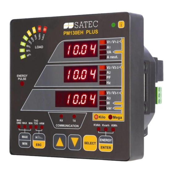
A N D C O N T R O L S Chapter 3 Using Front Display This chapter provides PM130 PLUS Power meter series front panel information and operating procedures. Figure 3 -1: PM130 PLUS Unit 3.1 Indicators and Controls…
-
Page 47: Load Bar Graph
Configuring the Display). Display Features Measurement Units The PM130 PLUS has a selectable resolution for volts, amps and powers presented on the front display and via communications. See Device Options in Chapter 5 for information on selecting the data resolution in the PM130 PLUS.
-
Page 48
If no buttons are pressed for 30 seconds while in the common measurements display, and the Auto Scroll option is enabled in the meter, the display automatically scrolls through all available pages. The scroll interval can be adjusted through the display setup (see Configuring the Display). PM130 PLUS Powermeter Series… -
Page 49: Navigation Buttons
Total and phase energies: select a total energy, or a phase energy page from the Energy Display. While holding the SELECT button down, press and hold the ENTER button for about 5 seconds. The displayed data is reset to zero. PM130 PLUS Powermeter Series…
-
Page 50: Common Measurements Display
Fundamental phase L1 powers (PM130EH, if enabled) kW/MW H1.L2 Fundamental phase L2 powers (PM130EH, if enabled) kW/MW H1.L3 Fundamental phase L3 powers (PM130EH, if enabled) kW/MW U.Unb V% unb Voltage unbalance, percent C.Unb I% unb Current unbalance, percent PM130 PLUS Powermeter Series…
-
Page 51: Min/Max And Maximum Demand Display
Minimum total var V1/V12 Minimum volts V2/V23 V3/V31 Maximum amps kVA/MVA Maximum total VA Maximum total PF (absolute) kW/MW Maximum total W Maximum neutral current Maximum frequency kvar/Mvar Maximum total var V1/V12 Maximum volt demands V2/V23 PM130 PLUS Powermeter Series…
-
Page 52: Harmonics Display (Pm130Eh)
I3 TDD I1 K-Factor Current K-Factor I2 K-Factor I3 K-Factor Table 8: Individual Voltage Harmonics V1/V12 HD% Order 3 harmonic distortion V2/V23 HD% V3/V31 HD% V1/V12 HD% Order 5 harmonic distortion V2/V23 HD% V3/V31 HD% … PM130 PLUS Powermeter Series…
-
Page 53: Energy Display (Pm130E/Eh)
56789 Ac.E Total kWh export 1234 56789 rE.E Total kvarh export 1234 56789 Ac.i 1 Phase L1 kWh import 1234 56789 rE.i 1 Phase L1 kvarh import 1234 56789 AP. 1 Phase L1 kVAh 1234 56789 PM130 PLUS Powermeter Series…
-
Page 54: Status Display
1234 56789 … r4.t8 Tariff 8 reading 1234 56789 3.3 Status Display The meter has a separate status information display accessible through the primary meter menu. See Using the Menus for information on navigating in menus. PM130 PLUS Powermeter Series…
-
Page 55
Counter #2 value (a time counter – in <hour> 0.1 hour units) 12345 Cnt.3 Counter #3 value (a time counter – in <hour> 0.1 hour units) 12345 Cnt.4 Counter #4 value (a time counter – in <hour> 0.1 hour units) 12345 PM130 PLUS Powermeter Series… -
Page 56: Pulse And Time Counters
5 seconds until the alarm code is reset to none. Diagnostics Display The diagnostics display shows a list of the device diagnostic codes recorded as a result of the meter self-test diagnostics during start-up and PM130 PLUS Powermeter Series…
-
Page 57: Using The Menus
5 seconds until the diagnostic message is reset to none. 3.4 Using the Menus Navigation Buttons The PM130 PLUS has a menu-driven setup. Press and release the SELECT button to access the meter menus. See the following table for button operations in menus.
-
Page 58: Entering The Password
Adjust the remaining digits in the same manner. Press ENTER to confirm the password. If the password you entered is correct, you are moved to the Main menu, otherwise you return back to the primary menu. PM130 PLUS Powermeter Series…
-
Page 59: Selecting A Menu Entry
Scroll through the parameter list with the UP or DOWN arrow buttons until the required parameter name appears. To change the selected parameter: Press the SELECT button to highlight the lower item. Figure 3 -6: Changing a Parameter PM130 PLUS Powermeter Series…
-
Page 60
Press the ENTER button to store your selection or press the ESC button to leave the parameter unchanged. You return to the middle window and can continue scrolling through the remaining parameters or return to the main menu. Press ESC to exit the menu. PM130 PLUS Powermeter Series… -
Page 61: Chapter 4 Using Pas Software
PM130 PLUS features, monitor your meters on-line, retrieve recorded files and view reports. PAS can communicate with your PM130 PLUS via a serial port and via the Ethernet. This chapter gives information on how to install and run PAS on your computer, and how to prepare information for your meter using PAS.
-
Page 62
Type a site name for your device in the File name box, click New, and then click OK. On the Instrument Setup tab, select PM130 PLUS in the Model box. PAS automatically selects the appropriate instrument options for your meter. -
Page 63: Setting Up Communications
C O M M U N I C A T I O N S 4.3 Setting up Communications You can communicate with the PM130 PLUS via a PC RS-232 serial port or through the Internet. To configure communications with the PM130 PLUS:…
-
Page 64: Communicating Through The Internet
DNP3/TCP connections on port 20000. The host port is set automatically as you select the protocol. Select Modbus RTU/TCP for Modbus/TCP or DNP3 for DNP3/TCP. In the Wait for answer box, adjust the time that PAS waits for a connection before announcing an error. PM130 PLUS Powermeter Series…
-
Page 65: Setting Up The Meter
Select the target database from the file pane. Click OK. You can also reuse a setup from another site by copying it to your present site database. To copy a setup from another site’s database: Click Open. Select the desired source site database. PM130 PLUS Powermeter Series…
-
Page 66: Downloading Setups To The Meter
Click Receive if you wish to retrieve the meter setup once again. To store the setup to the meter site database, click Save As, and then click OK. Batch Upload To upload all setups from the device to the site database at once: PM130 PLUS Powermeter Series…
-
Page 67: Authorization
OK. If your authorization was successful, you are not prompted for the password again until you close the dialog box. Configuring Meter Security in Chapter 5 for more information on the meter password security. PM130 PLUS Powermeter Series…
-
Page 68: Chapter 5 Configuring The Pm130 Plus
Select Communications Setup from the Meter Setup menu, and then click on the Serial Ports Setup tab. In the Port box, select the desired device port. Figure 5 -1: Communication Setup Dialog Box – Serial Ports Setup Tab PM130 PLUS Powermeter Series…
-
Page 69: Setting Up Ethernet
Ethernet module is plugged into the meter. It allows you to set up the meter network address and the default gateway. Viewing and Changing Setup Options in Chapter 3 for information on configuring parameters via the front display. PM130 PLUS Powermeter Series…
-
Page 70
The table below lists available network options. Table 15: Ethernet Setup Options Display Label Parameter Options Default Device IP Address 192.168.0.203 Network Subnet Mask 255.255.255.0 Network Default Gateway 192.168.0.1 TCP Service Port 502 = Modbus/TCP 20000 = DNP3/TCP PM130 PLUS Powermeter Series… -
Page 71: Setting Up Gprs Network
You may need to wait some additional time until PAS restores a connection with your device. Setting Up GPRS Network The PM130 PLUS can provide wireless GPRS communications with the remote Modbus/TCP server via GPRS modem module. See Connecting a…
-
Page 72: Setting Up Expertpower Client
Device Control dialog in PAS (see Viewing Communication Status and Statistics). Setting Up eXpertPower Client The PM130 PLUS has an embedded eXpertPower client that provides communications with the eXpertPower server – the SATEC proprietary Internet services. Connections to the eXpertPower server are handled on a periodic basis.
-
Page 73: Setting Up Tcp Notification Client
Modbus/TCP server and send notification messages either on events, or periodically on a time basis. To set up communications with a remote TCP Notification server, select Communication Setup from the Meter Setup menu, and then click on the TCP Notification Client Setup tab. PM130 PLUS Powermeter Series…
-
Page 74
«Notification» action setpoint action list (see Configuring Alarm/Control Setpoints). See the PM130 PLUS Modbus Reference guide for more information on operation of the notification client and the notification message structure. PM130 PLUS Powermeter Series… -
Page 75: General Meter Setup
S E T U P 5.2 General Meter Setup Basic Meter Setup This section describes how to configure the PM130 PLUS for your particular environment and application. Before operating your meter, provide the device with basic information about your electrical network.
-
Page 76
4-wire Wye using 3 PTs (3 element), line-to-neutral voltage readings 3DIR2 3-wire Delta Direct Connection using 2 CTs (2 element) 4LL3 4-wire Wye using 3 PTs (3 element), line-to-line voltage readings 3OP3 3-wire Open Delta using 3 CTs (2½ element) PM130 PLUS Powermeter Series… -
Page 77: Device Options
Calculation tESt Energy Test Mode OFF = disabled Disabled Setting this option puts the E, EH Ac.Ei = Wh pulses meter into the energy test mode rE.Ei = varh pulses (see Energy Pulse LED Chapter 3) PM130 PLUS Powermeter Series…
-
Page 78
This mode is recommended for electrical networks with low harmonic distortion, commonly with THD < 5% for volts, and THD < 10% for PM130 PLUS Powermeter Series… -
Page 79: Configuring Digital Inputs
Configuring Digital Inputs The PM130 PLUS can be provided with four, eight or twelve digital inputs that can be linked to control setpoints to give an indication on input status change (see Configuring Alarm/Control Setpoints), or can be linked to…
-
Page 80
The debounce time is applied the same for all digital inputs. If you change the debounce time for a digital input, the same debounce time is automatically assigned to the others. PM130 PLUS Powermeter Series… -
Page 81: Configuring Relay Outputs
General M E T E R S E T U P Configuring Relay Outputs The PM130 PLUS can be provided with two optional relay outputs. Each relay can be operated either locally from the alarm/control setpoints in response event remote…
-
Page 82
InS = INVERTING energized in its active (operated) state. (N.C.) Inverting polarity: the relay is normally energized in its non-active state and is de- energized in its active (operated) state. It is called failsafe relay operation. PM130 PLUS Powermeter Series… -
Page 83: Configuring Analog Outputs
To store your new settings: Press the ENTER button when the middle window is highlighted. You are returned to the upper window and can select another analog output or exit the menu. Press ESC to exit the menu. PM130 PLUS Powermeter Series…
-
Page 84
(1 or 20 mA) When you select an output parameter for the analog output channel, the default engineering scales are set automatically. They correspond to the maximum available scales. If the parameter actually covers a lower range, PM130 PLUS Powermeter Series… -
Page 85: Configuring Counters
0 to 120V, set the 1 mA scale to 60V; then the 120V reading will be scaled to 2 mA. Configuring Counters The PM130 PLUS has four six-digit general counters that can count pulses delivered through the device digital inputs with a programmable scale PM130 PLUS Powermeter Series…
-
Page 86
Links a digital input to the DIGITAL INPUT counter #1 — #12 SCAL Multiplier 1-9999 The value added to the counter when a pulse is detected on the pulse source input Counter Value Displays the present counter contents PM130 PLUS Powermeter Series… -
Page 87: Configuring Alarm/Control Setpoints
Type in the required value into the Counter Value field. Click Send. Configuring Alarm/Control Setpoints The PM130 PLUS has an embedded logical controller that can perform different actions in response to user-defined internal and external events. Unlike a PLC, the meter uses a simplified programming technique based on setpoints that allows the user to define a logical expression based on measured analog and digital values that produce a required action.
-
Page 88
Not applicable for digital triggers. Release limit The threshold (in primary units) at which the conditional expression would be evaluated to false. Defines the hysteresis for analog triggers. Not applicable for digital triggers. PM130 PLUS Powermeter Series… -
Page 89
Binary (digital) triggers like digital inputs and relays are tested for ON/CLOSED or OFF/OPEN status. In the PM130, the binary events are level-sensitive events. An event is asserted all the time while the corresponding condition exists. PM130 PLUS Powermeter Series… -
Page 90: Configuring The Display
Using the Front Display Select the diSP entry from the main menu. See Viewing and Changing Setup Options in Chapter 3 for information on configuring parameters via the front display. See Table 27 for the available options. PM130 PLUS Powermeter Series…
-
Page 91: Local Time Settings
Select rtc from the main menu. See Viewing and Changing Setup Options in Chapter 3 for information on configuring parameters via the front display. Using PAS Select General Setup from the Meter Setup menu, and then click on the Local Settings tab. PM130 PLUS Powermeter Series…
-
Page 92
DST End Hour The hour when Daylight Hour Saving Time ends. SYnC Time None None The external port receiving Synchronization di.1 = DI1 the time synchronization di.2 = DI2 Input pulses di.3 = DI3 di.4 = DI4 PM130 PLUS Powermeter Series… -
Page 93: Configuring Meter Security
ON enables password protection and OFF disables password protection. Press ENTER to confirm your new setting, or ESC to discard changes. Press ESC to exit the menu. When password protection is enabled, you are not able to change device settings through display PM130 PLUS Powermeter Series…
-
Page 94
Figure 5 -14: Password Setup Dialog Box To change the password: Type in a new 4-digit password Repeat the password in the Confirm new password box Check Enable password protection to enable password checking Click Send. PM130 PLUS Powermeter Series… -
Page 95: Configuring Billing/Tou
Configure the daily tariff schedule using the TOU daily profiles for all types of days and seasons. Configure the season tariff schedule using the TOU calendar. Configuring Billing/Tariff Registers To configure the billing/TOU registers in your meter: Select Energy/TOU from the Meter Setup menu. PM130 PLUS Powermeter Series…
-
Page 96
DI1-DI4 Multiplier 0.001 to 100.000 1.000 The multiplication factor for the energy source. Unchangeable for internal energy sources. Target Reg#1- Reg#4 None Defines the target billing register for the energy source. It is set automatically. PM130 PLUS Powermeter Series… -
Page 97: Configuring The Daily Tariff Schedule
TOU daily profiles. Configuring the Season Tariff Schedule To configure your season tariff schedule, select Energy/TOU from the Meter Setup menu, and then click on the TOU Calendar tab. PM130 PLUS Powermeter Series…
-
Page 98
The above picture shows a typical single-season tariff schedule with two daily tariff profiles configured for working days, and weekends and the designated U.S.A. holidays. PM130 PLUS Powermeter Series… -
Page 99: Configuring Recorders
The size of the file record for a single channel or a single section. It is set automatically depending on the file and on the number of parameters in the data records Parameters The number of parameters in a single data log record PM130 PLUS Powermeter Series…
-
Page 100
Events Event log 3200 200 last events Data log #1 46080 5760 5760 15-min data profile for 15 days 17 Data log #16 8640 Daily billing/TOU profile for 90 days, 4 registers, totals + 3 tariffs PM130 PLUS Powermeter Series… -
Page 101: Configuring The Event Recorder
To create a new data log file or re-configure an existing file: Double click on the file partition with the left mouse button. Select a partition type for your file. PM130 PLUS Powermeter Series…
-
Page 102
The file is organized as a multi-section file that has a separate section of the same structure for each billing energy and maximum demand register. The number of sections is taken automatically from the Billing/TOU Registers setup (see Configuring Billing/Tariff Registers). If the maximum demand PM130 PLUS Powermeter Series… -
Page 103
Periodic recording data is triggered by Setpoint #1 that is linked to the meter clock. To change the periodic rate at which data is recorded, change the time interval for the MINUTE INTERVAL trigger in Setpoint #1 (see Configuring Alarm/Control Setpoints). PM130 PLUS Powermeter Series… -
Page 104
Data log #16 is pre-configured for daily billing energy and maximum demand recording for the last 90 days. It is automatically updated once a day. Billing Profile Log File in Appendix E for the file record structure. PM130 PLUS Powermeter Series… -
Page 105: Configuring Communication Protocols
Configuring Modbus Modbus Point Mapping The PM130 PLUS provides 120 user assignable registers at addresses 0 to 119. You can re-map any register available in the meter to any assignable register so that registers found at different locations may be accessed with a single request by re-mapping them to adjacent addresses.
-
Page 106: Configuring Dnp3
Table 30: DNP Options Parameter Options Default Description Binary Inputs (BI) Binary Input Object Single-bit Single-bit The default BI object variation for With Status requests with qualifier code 06 when no specific variation is requested Analog Inputs (AI) PM130 PLUS Powermeter Series…
-
Page 107
Time Sync Period elapses. The master should synchronize the time in the meter by sending the Time and Date object to clear this bit. The meter does not send time synchronization requests if the Time Sync Period is set to 0. PM130 PLUS Powermeter Series… -
Page 108
Class 0 response. Click Send to download your setup to the meter. The factory-set Class 0 point ranges are shown in the picture below. Figure 5 -22: Protocol Setup Dialog Box – DNP Class 0 Points Tab PM130 PLUS Powermeter Series… -
Page 109: Chapter 6 Device Control And Upgrading
Clears Min/Max log Clears all counters Cnt1 – Cnt4 Clears counter #1-#4 diAG Clears device diagnostics Using PAS Ensure that the On-line button on the PAS toolbar is checked, and then select Reset from the Monitor menu. PM130 PLUS Powermeter Series…
-
Page 110: Updating The Meter Clock
Check the corresponding boxes, and then click OK. Figure 6 -2: Reset Maximum Demands Dialog Box 6.2 Updating the Meter Clock Using the Front Display Select the rtc entry from the main menu. PM130 PLUS Powermeter Series…
-
Page 111
PAS toolbar. The RTC dialog box displays the current PC time and the time in your meter. Figure 6 -3: Real Time Clock Window To synchronize the meter clock with the PC clock, click Set. PM130 PLUS Powermeter Series… -
Page 112: Viewing And Clearing Device Diagnostics
To clear the device diagnostics events, click on Clear. 6.4 Viewing Communication Status and Statistics Ensure that the On-line button on the PAS toolbar is checked, select Device Control from the Monitor menu, and then click on the Communications tab. PM130 PLUS Powermeter Series…
-
Page 113: Remote Relay Control
To access the relay control dialog, ensure that the On-line button on the PAS toolbar is checked, select Device Control from the Monitor menu, and then click on the Remote Relay Control tab. PM130 PLUS Powermeter Series…
-
Page 114: Upgrading Device Firmware
Ensure that the On-line button on the PAS toolbar is checked, and then select Flash Downloader from the Monitor menu and confirm downloading. Point to the firmware upgrade file for your meter, click Open, and then confirm upgrading the meter. PM130 PLUS Powermeter Series…
-
Page 115
115,200 bps to download the file to the meter. After upgrading firmware is completed, the meter restarts, so communications can be temporarily lost. You may need to wait a short duration until PAS restores a connection with your device. PM130 PLUS Powermeter Series… -
Page 116: Chapter 7 Monitoring Meters
You can view acquired data in a tabular form or in a graphical form as a data trend. PM130 PLUS Powermeter Series…
-
Page 117
PAS supports 33 programmable data sets with up to 40 data parameters. Set #0 is intended for simple meters, which have a limited number of parameters, and is not recommended for the use with the PM130 PLUS. To re-organize data sets, select RT Data Sets from the Monitor menu or click on the button on the local toolbar. -
Page 118: Viewing Real-Time Min/Max Log
Select the device site from the list box on the PAS toolbar. Point to RT Min/Max Log on the Monitor menu, and then select a data set you want to view. Ensure that the On-line button on the PAS toolbar is checked. Click on the Poll button PM130 PLUS Powermeter Series…
-
Page 119: Viewing Real-Time Waveforms
When you open a new file, PAS shows you a waveform graph with non- overlapped waveforms as shown in the picture above. Click on the button on the local toolbar to see overlapped waveforms. Click on the button for non-overlapped waveforms. PM130 PLUS Powermeter Series…
-
Page 120
To enable or disable the symmetrical components, click on the waveform window with the right mouse button, select Options…, check or uncheck PM130 PLUS Powermeter Series… -
Page 121: Viewing Real-Time Harmonic Spectrum
Harmonics can be displayed as a spectrum chart for a selected channel or in a table. PAS can also synthesize waveforms based on the harmonic spectrum to let you view a shape of the voltage and current waveforms in your network. PM130 PLUS Powermeter Series…
-
Page 122
To change a phase, click on the window with the right mouse button, select Options…, check the phase you want displayed, and then click OK. PM130 PLUS Powermeter Series… -
Page 123
To select the channels you want to view, click with the right mouse button on the waveform window, select “Channels…”, check the channels for the phase you want displayed, and then click OK. PM130 PLUS Powermeter Series… -
Page 124
M E T E R S R E A L — T I M E H A R M O N I C S P E C T R U M Figure 7 -6: RT Harmonic Monitor – Synthesized Waveforms PM130 PLUS Powermeter Series… -
Page 125: Chapter 8 Retrieving And Storing Files
If you wish to retrieve data starting with a known date, check the “From” box and select the start date for retrieving data. If you wish to retrieve data recorded before a known date, check the “To” box and select the last date for retrieving data. Click OK. PM130 PLUS Powermeter Series…
-
Page 126: Using The Upload Scheduler
Click Browse and select a database for storing retrieved data, or type the name for a new database, select a directory where you want to save it, and then click OK. Click Configure or double click on the site row. PM130 PLUS Powermeter Series…
-
Page 127
When the Upload Scheduler fails to retrieve data from the device, or some data is missing, or another problem occurs, it puts an error message to the log file. To review this file, select System Log from the View menu. PM130 PLUS Powermeter Series… -
Page 128: Viewing Files On-Line
To manually convert your waveforms or a data log into COMTRADE or PQDIF format: Click on the Export button on the PAS toolbar. Select the database and a data log table you want to export, and then click Open. PM130 PLUS Powermeter Series…
-
Page 129
Select a folder where you want to store converted files, type in the converted file’s name, select a desired output file format, and then click on Save. Repeat the same for all tables you wish to be converted. Click OK. PM130 PLUS Powermeter Series… -
Page 130: Exporting Files In Excel Format
Check the Enable box and select a periodic schedule for archiving your files for this site. Click OK. To avoid archiving partially updated data, archiving is performed in a day after expiring a scheduled period and not before 2 hours a.m. PM130 PLUS Powermeter Series…
-
Page 131: Chapter 9 Viewing Files
If you have an application that does not support this format, you may instruct PAS to drop milliseconds. To change the way PAS records and displays the timestamp: Select Options from the Tools menu and click on the Preferences tab. Select the preferred timestamp format. PM130 PLUS Powermeter Series…
-
Page 132: Working With Tables
OK. Checkboxes for channels that are not available in the present view are dimmed. Selecting Primary and Secondary Units Voltages and currents can be displayed in primary or secondary units. PM130 PLUS Powermeter Series…
-
Page 133
To disable delta measurements, click on the Delta button once again. Using a Zoom You can use a horizontal and, for waveforms, also a vertical, zoom to change size of your graph. PM130 PLUS Powermeter Series… -
Page 134: Viewing The Event Log
The Event log is displayed in a tabular view, one event per row. Use the scroll bar to view the entire log contents. Figure 9 -1: Event Log Window Working with Tables for more information on viewing options. PM130 PLUS Powermeter Series…
-
Page 135: Viewing The Data Log
To view data in a graphical form, click on the Data Trend button on the local toolbar. To change the time range for your graph, click on the Time Range button on the local toolbar, and then select the desired date and time range. PM130 PLUS Powermeter Series…
-
Page 136: Appendix A Technical Specifications
Input to ground: 2500 VAC 12 VDC Option: Rated input: 9.5-18 VDC, Burden 4VA Isolation: 1500VDC 24/48 VDC Option: Rated input: 18.5-58 VDC, Burden 4VA Isolation: 1500VDC Wire size: up to 12 AWG (up to 3.5 mm2) PM130 PLUS Powermeter Series…
-
Page 137
A ppendix A Technical Specifications Input Ratings Voltage Inputs – Installation category III Measurement operating range: 690VAC line-to-line, 400VAC line-to-neutral Direct input and input via PT (up to 828VAC line-to-line, up to 480VAC line-to- neutral) Input impedance: 1000 k Burden for 400V: <… -
Page 138
Isolation: 2500 VAC 1 min Power supply: internal Accuracy: 0.5% FS Update time: 1 cycle Connector type: removable, 5 pins. Wire size: 14 AWG (up to 1.5 mm2) Communication Ports COM1 RS-485 optically isolated port Isolation: 3000 VAC 1 min PM130 PLUS Powermeter Series… -
Page 139
A ppendix A Technical Specifications Baud rate: up to 115.2 kbps. Supported protocols: Modbus RTU, DNP3, and SATEC ASCII. Connector type: removable, 3 pins. Wire size: up to 14 AWG (up to 1.5 mm2). COM2 (Optional module) Ethernet Port Transformer-isolated 10/100BaseT Ethernet port. -
Page 140
Comply with IEC 61000-6-4: Radiated/Conducted class A Comply with IEC CISPR 22: Radiated/Conducted class A Safety/Construction: UL File no. E236895 Meets IEC 61010-1: 2006 AC and Impulse Insulation: Comply with IEC 62052-11: 2500 VAC during 1 minute 6KV/500Ω @ 1.2/50 μs impulse PM130 PLUS Powermeter Series… -
Page 141
A ppendix A Technical Specifications A.12 Measurement Specifications Table 33: Measurement Specifications Parameters Parameter Full Scale @ Input Accuracy Range Range % FS Conditions Reading Voltage 120VxPT @ 120V 0.02 10% to 120% FS 0 to 1,150,000 V 400VxPT @ 690V Starting voltage 1.5-5.0% FS (selectable) Line current… -
Page 142
A ppendix A Technical Specifications Measurement error is typically less than the maximum error indicated. PM130 PLUS Powermeter Series… -
Page 143: Appendix B Analog Output Parameters
PF LEAD AVR Total PF Lead 1-Sec Auxiliary Values A.nEU.C In AVR In Current Ar. Fr FREQ AVR Frequency E, EH Demands Acd.P.i kW IMP ACD Accumulated kW import demand Acd.P.E kW EXP ACD Accumulated kW export demand PM130 PLUS Powermeter Series…
-
Page 144
EXP ACD Accumulated kvar export demand Acd.S kVA ACD Accumulated kVA demand In 4LN3, 3LN3 and 3BLN3 wiring modes, the voltages will be line-to- neutral; for any other wiring mode, they will be line-to-line voltages. PM130 PLUS Powermeter Series… -
Page 145: Appendix C Setpoint Triggers And Actions
1-Sec Values on any Phase A.Hi. U High voltage HI VOLT AVR A.Lo. U Low voltage LO VOLT AVR A.Hi. C HI AMPS AVR High current A.Lo. C LO AMPS AVR Low current 1-Sec Total Values PM130 PLUS Powermeter Series…
-
Page 146
Operate relay RO1 r2 On OPERATE RELAY #2 Operate relay RO2 r1 OFF RELEASE RELAY #1 Release latched relay RO1 r2 OFF RELEASE RELAY #2 Release latched relay RO2 In.Cn.1 INC CNT #1 Increment counter #1 PM130 PLUS Powermeter Series… -
Page 147
TIME CNT #3 Count operation time using counter #3 ti.Cn.4 TIME CNT #4 Count operation time using counter #4 notiF NOTIFICATION Send a notification message dLoG1 DATA LOG #1 Record data to Data Log #1 PM130 PLUS Powermeter Series… -
Page 148: Appendix D Parameters For Data Monitoring And Logging
I2 THD I2 Current THD I3 THD I3 Current THD I1 KF I1 K-Factor I2 KF I2 K-Factor I3 KF I3 K-Factor I1 TDD I1 Current TDD I2 TDD I2 Current TDD I3 TDD I3 Current TDD PM130 PLUS Powermeter Series…
-
Page 149
V2 THD V2/V23 Voltage THD V3 THD V3/V31 Voltage THD I1 THD I1 Current THD I2 THD I2 Current THD I3 THD I3 Current THD I1 KF I1 K-Factor I2 KF I2 K-Factor I3 KF I3 K-Factor PM130 PLUS Powermeter Series… -
Page 150
I3 Ampere demand kW IMP BD kW import block demand kvar IMP BD kvar import block demand kVA BD kVA block demand kW IMP SD kW import sliding window demand kvar IMP SD kvar import sliding window demand PM130 PLUS Powermeter Series… -
Page 151
L1 kWh IMP L2 kWh import L2 kWh IMP L3 kWh import L3 kvarh IMP L1 kvarh import L1 kvarh IMP L2 kvarh import L2 kvarh IMP L3 kvarh import L3 kVAh L1 kVAh total L1 PM130 PLUS Powermeter Series… -
Page 152
V3 H01 ANG H01 Harmonic angle V3 H02 ANG H02 Harmonic angle … V3 H40 ANG H40 Harmonic angle ANG I1 I1 Harmonic Angles I1 H01 ANG H01 Harmonic angle I1 H02 ANG H02 Harmonic angle PM130 PLUS Powermeter Series… -
Page 153
I3 MIN I3 Current MIN TOTAL Minimum 1-Cycle Total Values kW MIN Total kW kvar MIN Total kvar kVA MIN Total kVA PF MIN Total PF MIN AUX Minimum 1-Cycle Auxiliary Values In MIN In Current PM130 PLUS Powermeter Series… -
Page 154
REG1 TRF1 Tariff #1 register REG1 TRF2 Tariff #2 register … … REG1 TRF8 Tariff #8 register TOU REG2 E, EH Billing TOU Energy Register #2 REG2 TRF1 Tariff #1 register REG2 TRF2 Tariff #2 register PM130 PLUS Powermeter Series… -
Page 155
Long Data Name Description Name kW IMP ACD kW IMP ACC DMD Accumulated demand kW IMP PRD kW IMP PRD DMD Predicted sliding window demand PF IMP@kVA MD PF IMP@kVA MXDMD PF (import) at maximum kVA demand PM130 PLUS Powermeter Series… -
Page 156
TOU REG1 TRF1 Billing tariff energy register REG1 TRF1 MD DMD1 TRF1 MAX Billing tariff register maximum demand TRF1 SEASON TRF1 Generic billing tariff energy register TRF1 MD SEASON TRF1 Generic billing tariff register maximum demand PM130 PLUS Powermeter Series… -
Page 157: Appendix E Billing/Tou Profile Log File
Tariff #3 max. demand reading TRF4 MD Tariff #4 max. demand reading TRF5 MD Tariff #5 max. demand reading TRF6 MD Tariff #6 max. demand reading TRF7 MD Tariff #7 max. demand reading TRF8 MD Tariff #8 max. demand reading PM130 PLUS Powermeter Series…
-
Page 158
P R O F I L E L O G F I L E The number of parameters in each section is automatically configured depending on the number of actual tariffs you defined in the TOU Daily Profiles. PM130 PLUS Powermeter Series… -
Page 159: Appendix F Data Scales
Appendix F Data Scales The maximum values for volts, amps and power in the PM130 PLUS setup and in communications are limited by the voltage and current scale settings. See Device Options in Chapter 4 on how to change the voltage and current scales in your meter.
-
Page 160: Appendix G Device Diagnostic Codes
The clock time has been lost Lo.bAt Low battery (with a Battery replacement is battery backup unit) required EEPr EEPROM fault Hardware failure Diagnostics Display in Chapter 3 for more information on the PM130 PLUS built-in diagnostics. PM130 PLUS Powermeter Series…
-
Page 161: Index
Total Demand Distortion, 138 70, 110 Total Harmonic Distortion, 138 TOU, 93 TOU module, 15, 36 High Resolution Option, 46 Wiring Mode, 6, 27, 28, 29, 30, 73, 74 inputs, 18 Wye, 26, 27, 28, 29, 74, 75 PM130 PLUS Powermeter Series…
(Ocr-Read Summary of Contents of some pages of the Satec PM130 series Document (Main Content), UPD: 24 February 2023)
-
18, 17 Table 5-5 User Assignable Registers Data index (hex) Register contents Length Direction Range 8000h User definable data 0 c c c 8001h User definable data 1 c c c 8002h … User definable data 2 … c … c c 8077h User definable data 119 c c c c — depends on the mapped register Table 5-6 User Assignable Register Map Data index (hex) Register contents Length Directi…
-
15, 14 4.9 Min/Max Log The Min/Max log read request is supported only for compatibility with other models of instruments. Because the Min/Max log is not time stamped in the PM130, this request returns you only values of the Min/Max log parameters which you can read directly via extended data registers (see Table 5-7). Table 4-19 Read Request Message type (ASCII) O Message body (hexadecimal) Request Field Offset Length Parameter Range 1 0 4 Start Min/Max par…
-
12, 11 4.4 Reset/Clear Functions These operations can be also performed by using the direct write requests instead of the specific request ‘4’ (see Section 5.11). Table 4-7 Write Request Message type (ASCII) 4 Message body (hexadecimal) Request/Response Field Offset Length Parameter Range 1 0 1 Reset function see Table 4-8 2 1 2 Target see Table 4-8 (the field can be omitted if it is equal to 0) Table 4-8 Reset/Clear Functions Function Description Target…
-
21, 20 Parameter Data index Length Direc- tion Unit Range c kvarh import (inductive) L2 1804h 8 R kvarh 0 to 10 8 -1 kvarh import (inductive) L3 1805h 8 R kvarh 0 to 10 8 -1 kVAh L1 1806h 8 R kVAh 0 to 10 8 -1 kVAh L2 1807h 8 R kVAh 0 to 10 8 -1 kVAh L3 1808h 8 R kVAh 0 to 10 8 -1 Reserved Reserved 2900h 8 R Reserved 2901h 8 R Reserved 2902h 8 R Reserved 2903h 8 R Reserved 2904h 8 R Reserved 2905h 8 R Reserved 2906h 8 R Reserved 2907…
-
8, Satec PM130 series 7 3 EXCEPTION RESPONSES The instrument will send the following error codes in the message body in response to incorrect host requests: XK — the instrument is in programming mode XM — invalid request type or illegal operation XP — invalid data address or data value, or data is not available NOTE When a check or framing error is detected, the instrument will not act on or respond to th…
-
27, 26 10-15 Reserved Options 2 0-2 Number of relays — 1 3-15 Reserved 5.9 Extended Status Registers Table 5-19 Extended Status Registers Parameter Data index Length Direction Range Relay status 7D00h 4 R see Table 4-12 Reserved 7D01h 4 R read as 0000 Reserved 7D02h 4 R read as 0000 Setpoint status 7D03h 4 R see Table 4-13 Log status 7D04h 4 R see Table 4-14 5.10 Alarm Status Registers Table 5-20 Alarm Status Registers Parameter Data…
-
13, 12 4.7 Extended Instrument Status Table 4-11 Read Request Message type (ASCII) ? Message body (hexadecimal) Request — no body Response Field Offset Length Parameter Range 1 0 4 Relay status see Table 4-12 2 4 4 Not used 0 3 8 4 Not used 0 4 12 4 Setpoints status see Table 4-13 5 16 4 Log status see Table 4-14 6 20 36 Not used 0 Table 4-12 Relay Status Bit Description 0 Relay status 1-15 Not used (permanently set to 0) Bit meaning…
-
23, 22 Parameter Data index Length Direction Range Reserved 8607h 4 R Read as 65535 The number of demand periods (E) 8608h 4 R/W 1 to 15 Reserved 8609h 4 R Read as 65535 Reserved 860Ah 4 R Read as 65535 Nominal frequency 860Bh 4 R/W 50, 60 Hz Reserved 860Ch 4 R Read as 65535 c For the wiring mode options, see Note to Table 4-4 d Synchronization of power demand interval can be…
-
11, Satec PM130 series 10 Parameter Identifier Range CT primary current I17 1 to 50000 A Power demand period (E) D11 1,2,5,10,15,20,30,60 min 255 = external synchronization d The number of demand periods (E) F47 1 — 15 Volt/ampere demand period C12 0 to 1800 sec Averaging buffer size S41 8, 16, 32 Reset enable/disable R42 0 = disable, 1 = enable Nominal frequency Q51 50, 60 Reserved Q52 c The wiring mode options are as follows: 3OP2 — 3-wire open delta using 2 CTs (2 elem…
-
4, 3 Table of Contents 1 GENERAL………………………………………………………………………………………… 4 2 ASCII FRAMING ………………………………………………………………………………. 5 3 EXCEPTION RESPONSES ………………………………………………………………… 7 4 SPECIFIC ASCII REQUESTS……………………………………………………………… 8 4.1 Basic Data…………………
-
7, 6 Check sum Arithmetic sum, calculated in a 2-byte word over fields #2, #3, #4 and #5 to produce a one-byte check sum in the range of 22h to 7Eh (hexadecimal) as follows: [ Σ (each byte — 22H)] mod 5CH + 22H Trailer Two ASCII characters CR (ASCII 13) and LF (ASCII 10). NOTE Fields #3 and #4 of the instrument response are always the same as those in the host request. Table 2-1 Specific ASCII Requests Message type Description Char ASCII Hex 0 30h…
-
22, 21 Parameter Data index Length Direc- tion Unit Range c Voltage L1/L12 f 3400h 8 R V 0 to Vmax Voltage L2/L23 f 3401h 8 R V 0 to Vmax Voltage L3/L31 f 3402h 8 R V 0 to Vmax Current L1 (P) 3403h 8 R A 0 to Imax Current L2 (P) 3404h 8 R A 0 to Imax Current L3 (P) 3405h 8 R A 0 to Imax Maximum real-time total values (M) (P) Total kW 3500h 8 R kW -Pmax to Pmax Total kvar 3501h 8 R kvar -Pmax to Pmax Total kVA 3502h 8 R kV…
-
25, 24 Trigger parameter Trigger index (hex) Unit Range c Low current 8D01h A 0 to Imax Reserved 0E07h Reserved 0E08h Reserved 0E09h Reserved 0E0Ah High/low real-time auxiliary values High frequency e 1002h 0.01 Hz 0 to 10000 Low frequency e 9002h 0.01 Hz 0 to 10000 High/low average values per phase High current L1 1103h A 0 to Imax High current L2 1104h A 0 to Imax High…
-
19, Satec PM130 series 18 Parameter Data index Length Direc- tion Unit Range c kVA L3 0C0Eh 8 R kVA 0 to Pmax Power factor L1 0C0Fh 4 R 0.001 -999 to 1000 Power factor L2 0C10h 4 R 0.001 -999 to 1000 Power factor L3 0C11h 4 R 0.001 -999 to 1000 Reserved 0C12h 4 R Reserved 0C13h 4 R Reserved 0C14h 4 R Reserved 0C15h 4 R Reserved 0C16h 4 R Reserved 0C17h 4 R Reserved 0C18h 4 R Reserved 0C19h 4 R Reserved 0C…
-
9, 8 4 SPECIFIC ASCII REQUESTS 4.1 Basic Data Table 4-1 Read Request Message type (ASCII) 0 Message body (decimal) Request — no body Response Field Offset Length Parameter Unit Range c 1 0 4 Voltage L1/L12 h V/kV d 0 to Vmax 2 4 4 Voltage L2/L21 h V/kV d 0 to Vmax 3 8 4 Voltage L3/L31 h V/kV d 0 to Vmax 4 12 5 Current L1 A 0 to Imax 5 17 5 Current L2 A 0 to Imax 6 22 …
 |
[Page 1] Satec PM130 series PM130 Powermeters Reference Guide Modbus Communications Protocol BG0310 Rev. A1 |
 |
[Page 2] Satec PM130 series SERIES PM130 POWERMETERS COMMUNICATIONS Modbus Communications Protocol REFERENCE GUIDE |
 |
[Page 3] Satec PM130 series 2 Every effort has been made to ensure that the material herein is complete and accurate. However, the manufacturer is not responsible for any mistakes in printing or faulty instructions contained in this book. Notification of any errors or mispri… |
 |
[Page 4] Satec PM130 series 3 Table of Contents 1 GENERAL ………………………………………………………………………………… 4 2 MODBUS FRAMING ………………………………………………………………….. 5 2.1 Transmission… |
 |
[Page 5] Satec PM130 series 4 1 GENERAL This document specifies a subset of the Modbus serial communications protocol used to transfer data between a master computer station and the PM130. The document provides the complete information necessary to develop a third-party… |
 |
[Page 6] Satec PM130 series 5 2 MODBUS FRAMING 2.1 Transmission Mode The protocol uses the Modbus Remote Terminal Unit (RTU) transmission mode. In RTU mode, data is sent in 8-bit binary characters. The 8 bit even parity or 8 bit no parity data format must be selected whe… |
 |
[Page 7] Satec PM130 series 6 Code (decimal) Meaning in Modbus Action 06 Preset single register Write single register 16 Preset multiple registers Write multiple registers 08 Loop-back test Communications test NOTE Broadcast mode available only for … |
 |
[Page 8] Satec PM130 series 7 3 MODBUS MESSAGE FORMATS 3.1 Function 03 — Read Multiple Registers This command allows the user to obtain contents of up to 125 contiguous registers from a single data table. Request Instrument Address Function (03) Starting Address … |
 |
[Page 9] Satec PM130 series 8 Response The normal response is the retransmission of the write request. 3.4 Function 16 — Write Multiple Registers This request allows the user to write the contents of multiple contiguous registers to a single data table where registers can… |
 |
[Page 10] Satec PM130 series 9 3.6 Exception Responses The instrument sends an exception response when errors are detected in the received message. To indicate that the response is notification of an error, the high order bit of the function code is set to 1. Exception… |
 |
[Page 11] Satec PM130 series 10 4 PROTOCOL IMPLEMENTATION 4.1 Modbus Register Addresses The PM130 Modbus registers are referred to by using addresses in the range of 0 to 65535. From within the Modbus applications, the PM130 Modbus registers can be accessed by simulating… |
 |
[Page 12] Satec PM130 series 11 Decimal Scaling Decimal pre-scaling can be used to accommodate fractional numbers to an integer register format. Fractional numbers pre-multiplied by 10 in power N, where N is the number of digits in the fractional part. For example, the fre… |
 |
[Page 13] Satec PM130 series 12 Table 4-1 User Assignable Registers Register contents Address Size, byte Direction Range User definable data 0 0 c c c User definable data 1 1 c c c User definable data 2 … 2 … c … c … c … User defina… |
 |
[Page 14] Satec PM130 series 13 5 POWERMETER REGISTERS DESCRIPTION 5.1 Basic Data Registers Table 5-1 Basic Data Registers Parameter Add- Size, Direc- Unit Scale c Con- ress byte tion Low High version Voltage L1/L12 g 256 2 R V 0 Vmax LIN3 Volt… |
 |
[Page 15] Satec PM130 series 14 Parameter Add- Size, Direc- Unit Scale c Con- ress byte tion Low High version -kvarh net (low) e (E) 293 2 R/W kvarh 0 9999 NONE -kvarh net (high) e (E) 294 2 R/W kvarh x10 4 0 999 x10 4 Reserved 295 2 R … |
 |
[Page 16] Satec PM130 series 15 Parameter Add- ress Size, byte Direc- tion Range Power demand period (E) 2307 2 R/W 1,2,5,10,15,20,30,60 min, 255 = external synchronization d Volt/ampere demand period 2308 2 R/W 0 to 1800 sec Averaging buffer size 2309 … |
 |
[Page 17] Satec PM130 series 16 5.4 Communications Setup Table 5-4 Communications Setup Registers Parameter Add- ress Size, byte Direc- tion Range Reserved 2344 2 R Read as 65535 Interface 2345 2 R/W 2 = RS-485 (not changeable) Address 2346 2 R/W 1 to 247 … |
 |
[Page 18] Satec PM130 series 17 5.6 Instrument Status Table 5-6 Instrument Status Registers Parameter Address Size, Direc — Unit Range byte tion Instrument reset register c 2560 2 R/W 0 (when read) 65535 (when written) = reset the instrument Rese… |
 |
[Page 19] Satec PM130 series 18 Table 5-10 Relay Status Bit Description 0 Relay status 1-15 Not used (permanently set to 0) Bit meaning: 0 = relay released, 1 = relay operated Table 5-11 Setpoints Status Bit Description 0 Setpoint # 1 status 1 Setpoint # 2 sta… |
 |
[Page 20] Satec PM130 series 19 The setpoint alarm register stores the status of the operated setpoints by setting the appropriate bits to 1. The alarm status bits can be reset all together by writing zero to the setpoint alarm register. It is possible to reset each alarm s… |
 |
[Page 21] Satec PM130 series 20 Table 5-16 Extended Data Registers Parameter 16-bit Register 32-bit Data Dir. Unit d Range/Scale c Reg. Conv. Register ID Low High None None 6656 11776-11777 0 R 0 0 Relays Relay status (see Table 5-10) 6976 128… |
 |
[Page 22] Satec PM130 series 21 Parameter 16-bit Register 32-bit Data Dir. Unit d Range/Scale c Reg. Conv. Register ID Low High Total PF 7259 LIN3 13702-13703 3843 R 0.001 -1.000 1.000 Reserved 7260 13704-13705 3844 R 0 Reserved 7261 13706-13707 … |
 |
[Page 23] Satec PM130 series 22 Parameter 16-bit Register 32-bit Data Dir. Unit d Range/Scale c Reg. Conv. Register ID Low High Voltage unbalance (P) 7499 LIN3 14470-14471 5379 R 1% 0 300 Current unbalance (P) 7500 LIN3 14472-14473 5380 R 1% 0 … |
 |
[Page 24] Satec PM130 series 23 Parameter 16-bit Register 32-bit Data Dir. Unit d Range/Scale c Reg. Conv. Register ID Low High kWh import L2 7618 7619 14850-14851 6145 R kWh 0 10 8 -1 kWh import L3 7620 7621 14852-14853 6146 R kWh 0 10 8 -1 kvarh i… |
 |
[Page 25] Satec PM130 series 24 Parameter 16-bit Register 32-bit Data Dir. Unit d Range/Scale c Reg. Conv. Register ID Low High Total kvar 8777 LIN3 18562-18563 13569 R kvar -Pmax Pmax Total kVA 8778 LIN3 18564-18565 13570 R kVA 0 Pmax Total PF … |
 |
[Page 26] Satec PM130 series 25 Table 5-17 Setpoint Setup Registers Parameter Offset Size, byte Direction Range Trigger parameter ID +0 2 R/W see Table 5-18 Action +1 2 R/W see Table 5-19 Operate delay +2 2 R/W 0-9999 (× 0.1 sec) Release delay +3 2 R/W 0… |
 |
[Page 27] Satec PM130 series 26 Trigger parameter Trigger Size, Unit Limit/scale c Con- ID byte Low High version Low current L3 37125 2 A 0 Imax LIN3 High/low average values on any phase High voltage f 4864 2 V 0 Vmax LIN3 Low voltage f 37376 2 V … |
 |
[Page 28] Satec PM130 series 27 Action ID Increment counter #4 16387 Count operating time using counter #1 c 17408 Count operating time using counter #2 c 17409 Count operating time using counter #3 c 17410 Count operating time using counter #4 c 17411 c Th… |
 |
[Page 29] Satec PM130 series 28 Table 5-24 Relay Operation Status Operation status Value Normal operation 0 Force operate 1 Force release 2 5.12 Min/Max Log The Min/Max log registers are supported only for compatibility with other models of instruments. Because the… |
-
Contents
-
Table of Contents
-
Bookmarks
Quick Links
PM130
Powermeters
Reference Guide
Modbus
Communications
Protocol
BG0310 Rev. A1
Related Manuals for Satec PM130
Summary of Contents for Satec PM130
-
Page 1
PM130 Powermeters Reference Guide Modbus Communications Protocol BG0310 Rev. A1… -
Page 2
SERIES PM130 POWERMETERS COMMUNICATIONS Modbus Communications Protocol REFERENCE GUIDE… -
Page 3
Every effort has been made to ensure that the material herein is complete and accurate. However, the manufacturer is not responsible for any mistakes in printing or faulty instructions contained in this book. Notification of any errors or misprints will be received with appreciation. For further information regarding a particular installation, operation or maintenance of equipment, contact the manufacturer or your local representative or distributor. -
Page 4: Table Of Contents
Table of Contents 1 GENERAL ………………… 4 2 MODBUS FRAMING …………….5 2.1 Transmission Mode ………………..5 2.2 The RTU Frame Format ………………5 2.3 Address Field………………….5 2.4 Function Field ………………….5 2.5 Data Field ………………….. 6 2.6 Error Check Field………………..6 3 MODBUS MESSAGE FORMATS …………
-
Page 5: General
1 GENERAL This document specifies a subset of the Modbus serial communications protocol used to transfer data between a master computer station and the PM130. The document provides the complete information necessary to develop a third-party communications software capable of communication with the Series PM130 Powermeters.
-
Page 6: Modbus Framing
06 and 16). In this case all instruments receive the message and take action on the request, but do not issue a response. In the PM130, the broadcast mode is supported only for register addresses 287-294 and 301-302 (reset energies and maximum demands), 3404-3415 (reset/clear registers), and 4352-4358 (real-time clock registers).
-
Page 7: Data Field
Code Meaning in Modbus Action (decimal) Preset single register Write single register Preset multiple registers Write multiple registers Loop-back test Communications test NOTE Broadcast mode available only for functions code 06 and 16. 2.5 Data Field The data field contains information needed by the instrument to perform a specific function, or data collected by the instrument in response to a query.
-
Page 8: Modbus Message Formats
3 MODBUS MESSAGE FORMATS 3.1 Function 03 — Read Multiple Registers This command allows the user to obtain contents of up to 125 contiguous registers from a single data table. Request Instrument Function Starting Word Count Error Check Address (03) Address 1 byte 1 byte…
-
Page 9: Function 16 — Write Multiple Registers
Response The normal response is the retransmission of the write request. 3.4 Function 16 — Write Multiple Registers This request allows the user to write the contents of multiple contiguous registers to a single data table where registers can be written. Request Instrument Function…
-
Page 10: Exception Responses
3.6 Exception Responses The instrument sends an exception response when errors are detected in the received message. To indicate that the response is notification of an error, the high order bit of the function code is set to 1. Exception Response Instrument Function (high Exception…
-
Page 11: Protocol Implementation
4 PROTOCOL IMPLEMENTATION 4.1 Modbus Register Addresses The PM130 Modbus registers are referred to by using addresses in the range of 0 to 65535. From within the Modbus applications, the PM130 Modbus registers can be accessed by simulating holding registers of the Modicon 584, 884 or 984 Programmable Controller, using a 5-digit “4XXXX”…
-
Page 12: 32-Bit Modulo 10000 Format
Section 4.2.1). 4.3 User Assignable Registers The PM130 contains the 120 user assignable registers in the address range of 0 to 119 (see Table 4-1), any of which you can map to either register address accessible in the instrument. Registers that reside in different locations may be accessed by a single request by re-mapping them to adjacent addresses in the user assignable registers area.
-
Page 13
Table 4-1 User Assignable Registers Register contents Address Size, byte Direction Range User definable data 0 User definable data 1 User definable data 2 User definable data 119 — depends on the mapped register Table 4-2 User Assignable Register Map Register contents Address Size, byte Direction Range Register address for user data 0 120… -
Page 14: Powermeter Registers Description
5 POWERMETER REGISTERS DESCRIPTION 5.1 Basic Data Registers Table 5-1 Basic Data Registers Parameter Add- Size, Direc- Unit Scale Con- ress byte tion High version Voltage L1/L12 Vmax LIN3 Voltage L2/L23 Vmax LIN3 Voltage L3/L31 Vmax LIN3 Current L1 Imax LIN3 Current L2 Imax…
-
Page 15: Basic Setup
Parameter Add- Size, Direc- Unit Scale Con- ress byte tion High version -kvarh net (low) kvarh 9999 NONE kvarh x10 4 0 x10 4 -kvarh net (high) Reserved Reserved Reserved Reserved Reserved Reserved kVAh (low) (E) kVAh 9999 NONE kVAh x10 4 0 x10 4 kVAh (high) (E) 9999…
-
Page 16: User Selectable Options Setup
0 = disable, 1 = enable mode (E) (P) available in the PM130P and PM130E (read as 65535 in the PM130) (E) available in the PM130E (read as 65535 in the PM130 and PM130P) For short energy registers (see Table 5-1), the maximum roll value will be 1×10 for positive readings and 1×10…
-
Page 17: Communications Setup
5.4 Communications Setup Table 5-4 Communications Setup Registers Parameter Add- Size, Direc- Range ress byte tion Reserved 2344 2 Read as 65535 Interface 2345 2 RS-485 (not changeable) Address 2346 2 1 to 247 Baud rate 2347 2 0 = 110 bps 1 = 300 bps 2 = 600 bps 3 = 1200 bps…
-
Page 18: Instrument Status
5.6 Instrument Status Table 5-6 Instrument Status Registers Parameter Address Size, Direc Unit Range byte tion Instrument reset 2560 0 (when read) register 65535 (when written) = reset the instrument Reserved 2561 Read as 0 Relay status 2562 see Table 5-7 Reserved 2563 Read as 0…
-
Page 19
Table 5-10 Relay Status Description Relay status 1-15 Not used (permanently set to 0) Bit meaning: 0 = relay released, 1 = relay operated Table 5-11 Setpoints Status Description Setpoint # 1 status Setpoint # 2 status Setpoint # 3 status Setpoint # 4 status Setpoint # 5 status Setpoint # 6 status… -
Page 20: Extended Data Registers
The setpoint alarm register stores the status of the operated setpoints by setting the appropriate bits to 1. The alarm status bits can be reset all together by writing zero to the setpoint alarm register. It is possible to reset each alarm status bit separately by writing back the contents of the alarm register with a corresponding alarm bit set to 0.
-
Page 21
Table 5-16 Extended Data Registers Parameter 16-bit Register 32-bit Data Dir. Unit Range/Scale Reg. Conv. Register High None None 6656 11776-11777 0 Relays Relay status 6976 12800-12801 2048 (see Table 5-10) Event/time counters Counter #1 7056 13056-13057 2560 99999 7057 Counter #2 7058 13058-13059 2561… -
Page 22
Parameter 16-bit Register 32-bit Data Dir. Unit Range/Scale Reg. Conv. Register High Total PF 7259 LIN3 13702-13703 3843 0.001 -1.000 1.000 Reserved 7260 13704-13705 3844 Reserved 7261 13706-13707 3845 Real-time auxiliary values Reserved 7296 13824-13825 4096 Neutral current 7297 LIN3 13826-13827 4097 Imax Frequency… -
Page 23
Parameter 16-bit Register 32-bit Data Dir. Unit Range/Scale Reg. Conv. Register High Voltage unbalance (P) 7499 LIN3 14470-14471 5379 Current unbalance (P) 7500 LIN3 14472-14473 5380 Present demands Volt demand L1/L12 (P) 7536 LIN3 14592-14593 5632 Vmax Volt demand L2/L23 (P) 7537 LIN3 14594-14595 5633… -
Page 24
Parameter 16-bit Register 32-bit Data Dir. Unit Range/Scale Reg. Conv. Register High kWh import L2 7618 14850-14851 6145 7619 kWh import L3 7620 14852-14853 6146 7621 kvarh import L1 7622 14854-14855 6147 kvarh 7623 kvarh import L2 7624 14856-14857 6148 kvarh 7625 kvarh import L3… -
Page 25: Alarm/Event Setpoints
Parameter 16-bit Register 32-bit Data Dir. Unit Range/Scale Reg. Conv. Register High Total kvar 8777 LIN3 18562-18563 13569 R kvar -Pmax Pmax Total kVA 8778 LIN3 18564-18565 13570 R Pmax Total PF 8779 LIN3 18566-18567 13571 R 0.001 1.000 Maximum real-time auxiliary values (M) Reserved 8816 18688-18689 13824 R…
-
Page 26
Table 5-17 Setpoint Setup Registers Parameter Offset Size, Direction Range byte Trigger parameter ID see Table 5-18 Action see Table 5-19 Operate delay 0-9999 (× 0.1 sec) Release delay 0-9999 (× 0.1 sec) Operate limit see Table 5-18 Release limit see Table 5-18 The setpoint is disabled when its trigger parameter is set to NONE. -
Page 27
Trigger parameter Trigger Size, Unit Con- Limit/scale byte High version Low current L3 37125 Imax LIN3 High/low average values on any phase High voltage 4864 Vmax LIN3 Low voltage 37376 Vmax LIN3 High current 4865 Vmax LIN3 Low current 37377 Vmax LIN3 High/low average total values (P) -
Page 28: Pulsing Setpoints
Action Increment counter #4 16387 Count operating time using counter #1 17408 Count operating time using counter #2 17409 Count operating time using counter #3 17410 Count operating time using counter #4 17411 This action converts a common event counter to the time counter which measures time at 0.1 hour resolution while the setpoint is in the operated state.
-
Page 29: Min/Max Log
The Min/Max log registers are supported only for compatibility with other models of instruments. Because the Min/Max log is not time stamped in the PM130, reading these registers returns you only values of the Min/Max log parameters which you can read directly via extended data registers (see Table 5-15).
-
Bookmarks
Quick Links
PM130 PLUS Quick Start Manual
This Quick Start Manual is a short guide on how to mount, connect, configure and operate the
PM130 PLUS. It is not intended to replace reading the full User Manual – and particularly the
safety precautions. The manual is available on the Product Documentation CD.
Mounting, electrical connection and settings of the PM130 shall be made in
accordance with all applicable laws and/or regulations and be performed by
authorized personnel only.
MOUNTING
Position the PM130 meter in 92×92mm square or 4″ round cutout (Figure 1). If two PM130 are
positioned side by side, keep at least 150mm (5.9″) between their centers to allow installation
of add-on modules (140mm/5.5″ if only small form modules will be used).
Attach the PM130 unit using washers and nuts. Make sure that the unit is securely attached
into the wall or cabinet fixture.
Figure 1
BG0441 REV.A9 ENGLISH
PM130 PLUS QuickStart
www.satec-global.com
Summary of Contents for Satec PM130 PLUS
Table of Contents for Satec PM130 PLUS:
-
4 PM130 PLUS Powermeter Series Quick Start Guide This section can be used by a licensed electrician to install and perform basic PM130 PLUS setup. For more detailed PM130 PLUS setup and use instructions, see the following chapters in this manual. This quick start guide will assist you to have the unit running for the first time. During the operation of the meter, hazardous voltages are present in the input terminals. Failure to observe precautions can result in serious or even fatal injury, or damage to equipment. For complete and acc
-
Chapter 2 Installation Electrical I N S T A L L A T I O N PM130 PLUS Powermeter Series 25 Voltage Input connection The equipment installation shall conform to the following instructions: a) a switch or circuit-breaker shall be included in the building installation; b) It shall be in close proximity to the equipment and within easy reach of the OPERATOR; c) It shall be marked as the disconnecting device for the equipment. Before installing, ensure that all incoming power sources are shut OFF. Failure to observe
-
Chapter 5 Configuring T H E P M 1 3 0 P L U S Configuring M E T E R S E C U R I T Y PM130 PLUS Powermeter Series 93 Daylight Saving Time When the daylight saving time is enabled, the meter automatically advances the device clock by one hour when daylight saving time begins and puts the clock back one hour when it ends. The default daylight saving time change points are preset for the U.S.A. The d
-
Chapter 2 Installation I/ O C O N N E C T I O N S PM130 PLUS Powermeter Series 35 8 DI module Eight optically isolated status inputs are provided for status monitoring, pulse counting, external power demand period, and time synchronization Figure 2-25 8 DI — Digital Input Connection 12DI/4RO Module Before I/O Module installation ensure that all incoming power sources are shut OFF. Failu
-
Chapter 2 Installation Communications C O N N E C T I O N S PM130 PLUS Powermeter Series 45 Connecting a GSM/GPRS modem A GSM/GPRS modem module can be connected to the meter COM2 port to provide communications with the remote MODBUS/TCP server via a wireless GPRS network. The GSM/GPRS SIM must not have any incoming voice call. The customer must require from the Service Provider for DATA services only The GPRS modem module can be equipped with two different antenn
-
Chapter 3 Using F R O N T D I S P L A Y Using T H E M E N U S PM130 PLUS Powermeter Series 57 operation. When there are recorded diagnostic messages, the “i” diagnostic LED on the front display briefly flashes two times to indicate that the meter may require servicing. The diagnostic LED can be disabled or enabled via the display setup menu (see Configuring the Display). Use the UP and DOWN arrow buttons to scroll through the diagnostic message list. See Device Diagno
-
Appendix A Technical Specifications 140 PM130 PLUS Powermeter Series A.11 Standards Compliance Accuracy: Complies IEC62053-22, class 0.5S Meets ANSI C12.20 –1998, class 10 0.5% Electromagnetic Immunity: Comply with IEC 61000-6-2: IEC 61000-4-2 level 3: Electrostatic Discharge IEC 61000-4-3 level 3: Radiated Electromagnetic RF Fields IEC 61000-4-4 level 3: Electric Fast Transient IEC 61000-4-5 level 3: Surge IEC 61000-4-6 level 3: Conducted Radio Frequency IEC 61000-4-8: Power Frequency Magnetic Field Meets ANSI/IEEE C37.90
-
Chapter 6 Device C O N T R O L A N D U P G R A D I N G Updating T H E M E T E R C L O C K 110 PM130 PLUS Powermeter Series Figure 6-1: Reset Dialog To reset the desired values or files: 1. Click on the corresponding button, and then confirm your command. 2. If an entry has more than one target, you are allowed to select targets to reset. 3. Check the corresponding boxes, and then click OK. Figure 6-2: Reset Maximum Demands Dialog Box
-
Chapter 5 Configuring T H E P M 1 3 0 P L U S Configuring C O M M U N I C A T I O N P R O T O C O L S 108 PM130 PLUS Powermeter Series 1. Select Protocol Setup from the Meter Setup menu and click on the DNP Class 0 Points tab. 2. Select the object and variation type for a point range. 3. Specify the start point index and the number of points in the range. Refer to the PM
-
10 PM130 PLUS Powermeter Series Simple Reset of Accumulated Data ……………………………………………………………….. 49 Common Measurements Display ………………………………………………………………….. 50 Min/Max and Maximum Demand Display ……………………………………………………….. 51 Harmonics Display (PM130EH) …………………………………………………….
-
Chapter 3 Using F R O N T D I S P L A Y Using T H E M E N U S 58 PM130 PLUS Powermeter Series The menu has three entries: StA: Status Display entry (see the Status Display section) OPS: Main setup menu entry allowing to review setup options CHG: Main setup menu entry allowing changing setups, updating the clock and resetting accumulated values. To access the Status Display: 1. If the StA window is not highlighted, use the SELECT button to
-
Chapter 2 Installation Electrical I N S T A L L A T I O N PM130 PLUS Powermeter Series 31 Figure 17: 3-wire/4-wire connection using the current from one phase (1 CT) and the L-L voltage from the other two phases (Wiring mode = 2LL1) Figure 18: 3-wire/4-wire connection with PT using the current from one phase (1 CT) and the L-L voltage from the other two phases (Wiring mode = 2LL1)
Questions, Opinions and Exploitation Impressions:
You can ask a question, express your opinion or share our experience of Satec PM130 PLUS device using right now.

PM130 PLUS Powermeter Series
PM130P/PM130E/PM130EH
Installation and Operation Manual
BG0425 Rev. A15
Specifications:
|
Accompanying Data:
Satec PM130P Measuring Instruments PDF Installation And Operation Manual (Updated: Friday 3rd of February 2023 05:52:46 AM)
Rating: 4.5 (rated by 88 users)
Compatible devices: PM171 series, PM135, PM174 Series, C191HM, Expertmeter Series, PM135P, PRO PM335, PM130 series.
Recommended Documentation:
Satec PM130P: Text of Installation And Operation Manual
(Ocr-Read Version Summary of Contents, UPD: 03 February 2023)
-
48, Chapter 6 Viewing Status Information 41 Chapter 6 Viewing Status Information 6. Through the Status Information Menu (STA), it is possible to view the status of various instrument features. 6.1 The Status Information Menu To enter the Status Information Menu: From the display mode, press to enter the Primary Selectio…
-
27, Chapter 4 Setup Menus 20 Code Parameter Options Description ConF Wiring mode 3OP3 3-wire open delta using 3 CTs (2½ element) 3Ln3 4-wire Wye using 2 PTs (2½ element), line to neutral voltage readings 3LL3 4-wire Wye using 2 PTs (2½ element), line to line voltage readings Pt PT ratio 1.0∗ — 6,500.0 The potential transformer ratio Ct CT primary cu…
-
53, Appendix: Technical Specifications 46 Accuracy, % Range Display resolution (%Rdg) Parameter Full scale Rdg FS Conditions @ range Neutral (unbalanced) current CT PRIMARY CURRENT 0.6 2% to 150% FS 0 to 60,000 A 1 A @ 1A to 9,999 A ≤0.1% @ 10,000 A to 60,000 A Ampere demand same as for current kW dem…
-
36, Chapter 4 Setup Menus 29 4.7 User Selectable Options Menu This menu allows you to change options which relate to the instrument features and functionality. Table 4-8 lists all available options with their code names and applicable ranges. To select an option: Press to ac…
-
31, Chapter 4 Setup Menus 24 Use the up/down arrow keys to scroll to the desired setup option. The value associated with this option is displayed in the lower window. To change the selected setup option: Press to activate the lower window. Use the up/down arrow keys to scroll to the desired value. Press to store the new value. P…
-
28, Chapter 4 Setup Menus 21 4.2 Communications Port Setup Menu This menu allows you to access the communications port options that the PM130 uses to communicate with a master computer. Table 4-2 lists the communications options, their code names and applicable choices. Activat…
-
3, i LIMITED WARRANTY The manufacturer offers the customer an 24-month functional warranty on the instrument for faulty workmanship or parts from date of dispatch from the distributor. In all cases, this warranty is valid for 36 months from the date of production. This warranty is on a return to factory basis. The manufacturer does not accept liability for any damag…
-
26, Chapter 4 Setup Menus 19 Chapter 4 Setup Menus 4. CHAPTER 3 SETUP MENUS NOTE: Instrument setup can be performed directly on the front panel using the setup menus or via communications using PComTest communication software. PComTest is supplied with your instrument and provides full setup capabilities for your instrument. For information on using PComTest, refer to…
-
16, Chapter 2 Installation 9 2.2.2 Current Inputs To ensure accurate readings, the input current should not exceed 1.5A RMS for the 1A CT secondary, or 7.5A RMS for the 5A CT secondary. The PM130 does not have current terminals. To connect to the external CT, you must pass the external CT wire through the instrument CT core (see Figure 2-4). In the case of a re…
-
37, Chapter 4 Setup Menus 30 4.8 Access Control Menu This menu can be only accessed via the Setup Change Menu (CHG). It is used in order to: • change the user password • enable or disable password check To view an option setting: Press to activa…
-
42, Chapter 5 Data Display 35 Page Window Indicato r LED Parameter Digit s Unit Min/Max Measurements MIN 1 1 V1/V1-2 Min. real-time voltage L1/L12 4 V/kV 1 2 V2/V2-3 Min. real-time voltage L2/L23 4 V/kV 1 3 V3/V3-1 Min. real-time voltage L3/L31 4 V/kV MAX 2 1 V1/V1-2 Max. real-time voltage L1/L12 …
-
21, Chapter 2 Installation 14 Figure 2-10 Four Wire Wye Connection Using 2 PTs, 3 CTs (2½-element) Wiring Mode = 3LL3 or 3Ln3 Note This configuration will provide accurate power measurements only if the voltages are balanced. Figure 2-9 Three Wire Open Delta Connection Using 2 PTs, 3 CTs (2½-element) Wiring Mode = 3OP3
… -
38, Chapter 4 Setup Menus 31 4.9 Reset/Synchronization Menu This menu allows you to reset to zero the accumulators and Min/Max registers in your instrument, and also to synchronize the power demand interval in the PM130E. The menu can be only accessed via the Setup Change Menu (CHG). If the res…
-
32, Chapter 4 Setup Menus 25 Table 4-5 Setpoint Triggers (lower window, when middle window is triG) Code Parameter Unit Range nonE Setpoint disabled Phase Reversal POS.ro. Positive phase rotation reversal NEG.ro. Negative phase rotation reversal Real-time Values on any Phase r. Hi. U High voltage V 0 to Vma…
Satec PM130P: Recommended Instructions
DPS 7405 GB5, 96279, 820, Argenta SLR7312, KGRS807SSS02


-
MANUAL NUMBERCPrinted in JapanADVANTEST CORPORATIONAll rights reserved.R3267 SeriesSpectrum AnalyzerOperation Manual (Vol.1)FOE-8335033G001998 First printing October 1, 1998Applicable modelsR3264R3267R3273Cover …
R3267 series 398
-
1 OF 8 NEXT 1 INTRODUCTION AND GENERAL DESCRIPTION Introduction …………………………………………………………………………….. 2Features ………………………………………………………………………………….. 3General Specifications ………………………………………………………………. 5 …
Clinitek Status 172
-
HALO RB-10 UV-VIS SPECTROPHOTOMETER HALO RB-10 Spectrophotometer Instruction Manual Please read through this manual carefully and store it in a safe place. Before using the instrument, please read the safety instructions and precautions carefully Keep this manual in a safe place nearby to access …
HALO RB-10 86
-
© 2 0 1 7 b y E L B R O A G / G i o r g i o B o v e n z i TESTY 2 S e i t e 1 / 20 Instruction Manual TESTY 2 with additional RCD test allowing the functioning of the RCD protection EN 61010-1 (DIN VDE 0411-1) CAT III / 300V AC 230V N PE = L TESTED NOT READY TESTY2 Test FI mA 10mA 30mA 100mA 300mA 500mA FI OK OPEN …
TESTY 2 20
-
installaon manualMacR6 N1• 2 — Necessary accessories• 4 — Watermeter assembly• 3 — SIM card assembly and slot sealing• Torx T10 screwdriver • 1 — Contents of package• Watermeter adapter kit• MacR6 N• 6 Torx T10 M12 screws• 2 plasc tack rivets• H-type silicone gel in syringe• Smartphone or tablet with NFC support• Data Loggers Congur …
MacR6 N 2
-
CZGB 253924.41.02 „01“ – OEZ130327v01 (Číslo výkresu / drawing no) Strana 1 (celkem 2) Page 1 of 2 BETA Monitorovací relé reziduálního proudu (RCM) Residual current monitor (RCM) 5SV8 001-6KK Provozní a montážní pokyny Operating and Mounting Instructions Vydáno: 10/2008 Issued: October 2008 Stav přepnutí / Switching status C1: Výstraha /alarm (sta …
BETA 5SV8 001-6KK 6
-
1www.UsePhoenix.com • [email protected] 1-800-533-7533Owner’s Manual — Humiport 05Installation, Operation & Service InstructionsRead and Save These InstructionsSpecifications subject to change without notice.TS-38112/10The Phoenix Humiport line of ThermoHygrometers offers the restoration professional the optimum balance between cost, a …
Humiport 05 5
-
Signal/PowerConnectorsThe VSE-1100 is equipped with dual F-connectors for differential signal analysis and a power input on the left side. 12VDC power can be supplied to the unit from the included AC power adapter or 12VDC power cable.On the right side are the control connectors — a USB connector for direct atachment to the tablet and an Ethernet port connector.W …
VSE-1100 4
-
1Measuring current transformerIntended useMeasuring current transformers 7LQ3 353 are preferably used forthe monitoring of power supply in medically used areas. Therethey measure the load current and convert it into a signal usablefor evaluating devices.Safety information Installation, connection and commissioning of electrical equip-ment shall only be carried o …
7LQ3 353 4
-
TI354F/00/en71114957Technical InformationLiquiphant S FTL70, FTL71VibronicHigh-temperature point level switch for all kinds of liquids ApplicationThe Liquiphant S is a point level switch which can be used in all liquids– for process temperatures between –60 °C and 280 °C (300 C for max. 50 h cumulative; without thermal shock restriction)– for pressures up to 1 …
Liquiphant S FTL70-**********L Series 40
Additional Information:
Popular Right Now:
Operating Impressions, Questions and Answers:
PM130 PLUS Powermeter Series
PM130P/PM130E/PM130EH
Installation and Operation Manual
BG0425 Rev. A15