


![]()
![]()
Выбор технологов-программистов
Документация
Ниже вы найдете документацию по CIMCO Edit на разных языках. Документация на русском языке доступна для зарегистрированных пользователей CIMCO.
Руководства пользователя
English
| CIMCO Edit | ||
| CIMCO Edit 6 User Guide | 5.50 MB | |
| CIMCO Edit 6 User Guide with NC-Base | 2.21 MB | |
| CIMCO Edit 7 User Guide | 3.57 MB |
Deutsch
| CIMCO Edit | ||
| CIMCO Edit 6 User Guide | 2.18 MB | |
| CIMCO Edit 6 User Guide with NC-Base | 3.76 MB | |
| CIMCO Edit 7 User Guide | 3.83 MB |
Français
| CIMCO Edit | ||
| CIMCO Edit 6 User Guide | 2.62 MB | |
| CIMCO Edit 6 User Guide with NC-Base | 6.39 MB | |
| CIMCO Edit 7 User Guide | 3.66 MB |
Español
| CIMCO Edit | ||
| CIMCO Edit 6 User Guide | 3.17 MB | |
| CIMCO Edit 6 User Guide with NC-Base | 5.76 MB |
Брошюры
English
| CIMCO Edit | ||
| CIMCO Edit Brochure | 7.26 MB | |
| CIMCO Edit Heidenhain Simulation Brochure | 1.67 MB | |
| CIMCO Mazatrol Viewer Brochure | 0.80 MB |
Deutsch
| CIMCO Edit | ||
| CIMCO Edit Brochure | 7.16 MB | |
| CIMCO Edit Heidenhain Simulation Brochure | 1.68 MB |
Français
| CIMCO Edit | ||
| CIMCO Edit Brochure | 5.96 MB | |
| CIMCO Edit Heidenhain Simulation Brochure | 0.79 MB |
Español
| CIMCO Edit | ||
| CIMCO Edit Brochure | 3.63 MB | |
| CIMCO Edit Heidenhain Simulation Brochure | 6.90 MB | |
| CIMCO Mazatrol Viewer Brochure | 0.80 MB |
Контакты
- Обратный звонок
Продукты
- CIMCO Edit
- CIMCO DNC-Max
- CIMCO MDC-Max
- CIMCO NC-Base
- CIMCO MDM
- CIMCO CNC-Calc
- CIMCO TeachWare
- CIMCO NFS/FTP
- CIMCO Filter
- CIMCO MACHINE SIMULATION
Поддержка
- Печатная документация
- Системные требования
- FAQ
Новости
- Последние новости
О компании
- Наши заказчики
- Наши партнеры
Introduction
This section describes the software user interface and the functionality that it provides.
Toolbar icons
An installation of CIMCO Edit Verify automatically adds the icons to the Mastercam toolbar.
![]()
Setup
Setup allows you to determine which geometry and whether machine simulation will be used within CIMCO Edit Verify prior to launch.
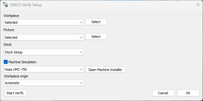
Workpiece, Fixture and Stock
Under Workpiece, Fixture and Stock, from the dropdown menu, choose the option for how the geometry should be selected.
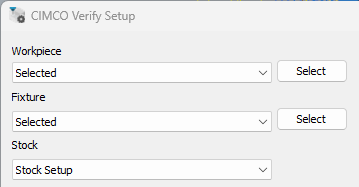
None = No geometry will be selected
Selected = Select geometry from the Mastercam window
External STL = Select geometry from an external folder
From level = Select the geometry from a level
Stock Setup = Use the stock setup within Mastercam
Machine Simulation
Determines whether CIMCO Edit Verify will load a Machine on launch.
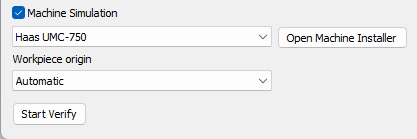
Use the check box beside Machine Simulation to indicate whether Machine Simulation will be used or not.

Checked = Machine Simulation will be used at launch. (can still be toggled on/off within CIMCO Edit Verify as the machine is already loaded)
Use the Open Machine Installer to access available machines and download them from the machine server. The machines available to download depends on which machines have been included on a user CIMCO Edit Verify license.
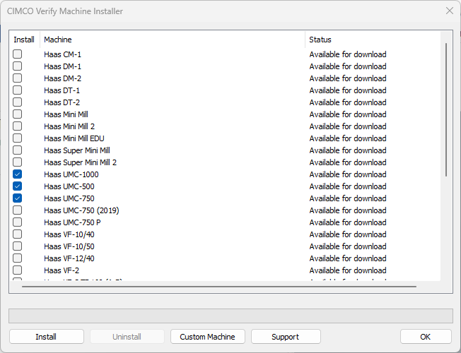
Install = Select the machines you wish to install. Select the install option to begin downloading the machine. After the machine has been downloaded it will become available through the machine selection drop down menu.
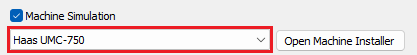
Uninstall = Select this option to uninstall a machine.
Custom Machine = Select this option to import a .CimcoSimBundle. A .CimcoSimBundle will be provided to a user who has requested a custom machine build from CIMCO. If a specific machine is not available on the server, a custom build will need to be used. Please contact [email protected] for further information.
Support = Select this option for further information on how to contact support.
Workpiece Origin
Determine the origin within Mastercam to be used as the zero position on the machine table.
Automatic = Uses World and takes the lowest point of fixture/workpiece and stock
World = Select this option to use the World origin
WCS = Select this option to use the WCS origin
Selected = Select this option to manually select the origin
User Interface
Launch CIMCO Edit Verify to utilise the powerful advancements CIMCO Edit Verify’s Backplotter, Stock and Machine Simulation add-in.
Taskbar
The taskbar contains many functions and features from toolpath animations to Stop Conditions.

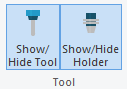
Tool
Show/Hide Tool = Select this option to toggle between showing and hiding the tool.
Show/Hide Holder = Select this option to toggle between showing and hiding the holder.
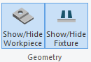
Geometry
Show/Hide Workpiece = Select this option to toggle between showing and hiding the workpiece.
Show/Hide Fixture = Select this option to toggle between showing and hiding the fixture.
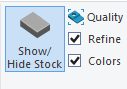
Stock
Show/Hide Stock = Toggle between showing and hiding the stock.
Quality = Determine the quality of the stock. The quality of stock chosen will alter the speed/performance of Verify.
Refine = Enable stock refine.
Colours = Enable a unique colour by tool.
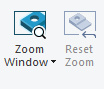
Zoom Window = Increase the accuracy of the stock by creating a cut out of the stock that covers the window.
Zoom Selection = Increase the accuracy of the stock by creating a cut out of the stock that covers a user’s selection.
Reset Zoom = Reset the cut out of the stock to the original stock.
Compare = Compare the simulated stock to the design model. The stock is coloured on the distance to the design model to easily identify any inaccuracies, whether too much stock has been removed (the tool gauges the design model) or where not enough stock has been machined.

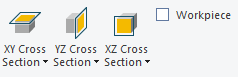
XY Cross Section = Cross section view of current stock in XY plane.
- Z+ = Cross section view by Z+ plane
- Z- = Cross section view by Z- plane
- Off = Disable cross section
YZ Cross Section = Cross section view of current stock in YZ plane.
- X+ = Cross section view by X+ plane
- X- = Cross section view by X- plane
- Off = Disable cross section
XZ Cross Section = Cross section view of current stock in XZ plane.
- Y+ = Cross section view by Y+ plane
- Y- = Cross section view by Y- plane
- Off = Disable cross section
Workpiece = Check this item to apply the cross section view to workpiece as well as the simulated stock. When checked, the stock can be easily compared to the workpiece on the cross section plane.
Save as STL = Save and export the stock in its current form as an STL file.

Toolpath
Toolpath = Toggle toolpath view settings.
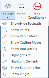
Mode = Toggle toolpath mode animations.
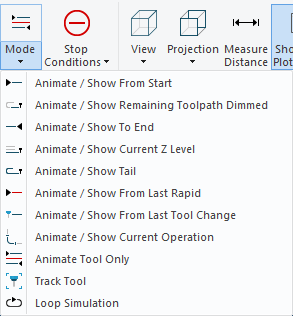
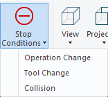
Stop Conditions = Toggle Stop Conditions. Stop the simulation process at user specific trigger events.
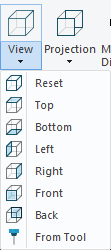
View
View = Select the view in which the simulation contents will be displayed.
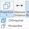
Projection = Select the projection view in which the simulation contents will be displayed.
-
Perspective = Renders the scene using a camera position and a field of view. This projection is in perspective view, the camera can move through geometries which is useful to bring it inside the holes or similar places when inspecting fine details. It is even possible to bring the camera inside the tool which is useful to see the exact overlap with geometries during collisions. However, geometries far away appears smaller on the screen, making it harder to compare the relative size of objects.
-
Orthographic = Projects the scene onto the screen while preserving the relative size of the geometries. This makes it easier to compare the geometries at different depths. The camera position is always far away from the scene, it cannot be freely positioned.
Measure Distance = Measure the distance between any two points on a toolpath and geometries.
Show/Hide Plot Control = Show/Hide the simulation plot control bar.
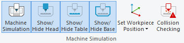
Machine Simulation
Machine Simulation will detect machine collisions and limit errors. Toggle between Verify and Machine Simulation without having to restart CIMCO Edit Verify.
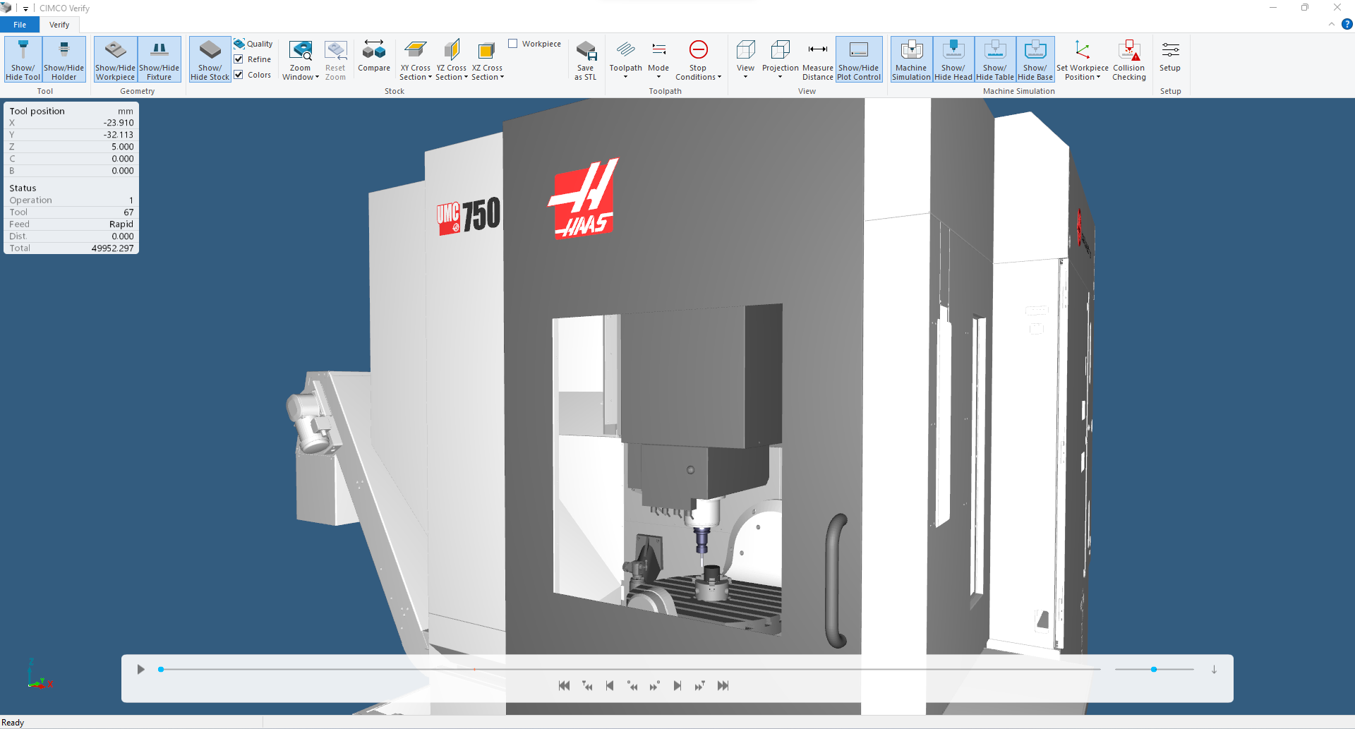
Machine Simulation = Enable/Disable the Machine Simulation mode
Show/Hide Head = Show/Hide the machine head components
Show/Hide Table = Show/Hide the machine table components
Show/Hide Base = Show/Hide the machine base components
Set Workpiece Position = Select this option to manually define the workpiece position
Reset to default = Reset workpiece position to default
Collision Checking = Show machine collisions and limit errors
After selecting Collision Checking, a Collision Checking Dialog will open. This dialog reports any collisions and limit errors found within the program.
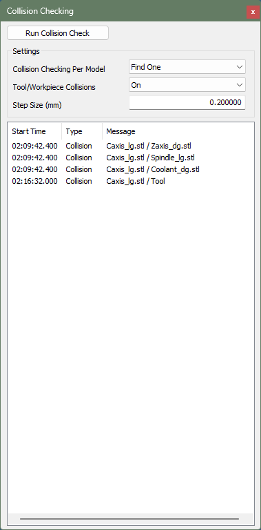
Run Collision Check = Starts the collision checking process. Any collisions or limit errors found will be reported in the dialog below. Collisions will be reported with the following information:
- Start Time = The time in which the collision occurs
- Type = Whether it is a collision or limit error
- Message = Outlines what specific components are colliding, and which specific machine components are exceeding their travel limit
- Collision checking per model = Find one will report a collision if found (faster). Find All will report all collisions if found (slower)
- Tool/Workpiece Collisions = Toggle whether collisions between the tool and workpiece are reported
- Step size = Set the distance with which the toolpath is sampled when collision checking
Setup
Setup = Update setup. This will open the CIMCO Edit Verify Setup dialog.


Обзор Cimco Edit, CNC-Calc, Machine Simulation, NC-Base и MDM

Русский интерфейс для Cimco Edit, CNC-Calc, NC-Base, MDC-Max, DNC-Max
1 CIMCO Edit user Guide March 2017 | Copyright 1991-2017 CIMCO A/S | Web: | E-mail: 2 Contents Contents License Information .. 5 Introduction .. 7 What’s New .. 9 Overview .. 10 Installation .. 13 System Requirements .. 15 CIMCO Software Activation .. 16 Program Tabs .. 22 1. Editor .. 23 File .. 23 File Type .. 26 Edit .. 27 Find .. 29 Bookmarks .. 32 Window .. 34 Help .. 36 2. NC Functions .. 37 Block Numbers .. 37 Insert / Remove .. 38 Transform .. 41 Info .. 54 Macros .. 55 Macro Setup .. 58 Macro Setup Dialog .. 59 Area 1: List of defined macros .. 59 Area 2: Macro structure .. 62 Area 3: Parameter monitoring / Additional options .. 67 Formulas in Macros .. 70 Hiding the Formula Results .. 72 Formatting of Formula Values .. 75 Outputting Fanuc Macro B Variables .. 76 Multi Channel .. 77 CIMCO Edit user Guide 3 3. Backplot .. 78 File.
2 79 View .. 80 Toolpath .. 83 Tool .. 84 Tool Setup Dialog .. 85 Milling Tools .. 85 Turning Tools .. 87 Load/Save Tool Library .. 88 Solid .. 88 Other .. 91 Find .. 94 Information Bar .. 94 4. File Compare .. 97 File Compare .. 97 Go To .. 98 Sync .. 98 Other .. 99 5. Transmission .. 102 Transmission .. 102 Machine .. 103 Setup .. 106 6. Editor Setup .. 107 General Program Settings .. 107 Editor Settings .. 110 Printing .. 114 File Types .. 116 Colors .. 118 Block Numbers .. 121 Load / Save .. 126 File Compare .. 129 Machine .. 131 Backplot .. 134 Tool Scanning .. 137 Insert tool definition .. 139 4 Contents Multi Channel .. 143 Tool List .. 145 Other .. 147 Global Colors .. 149 External Commands .. 150 Mazatrol Viewer .. 152 Font settings .. 153 Plugins .. 153 7. DNC Settings .. 156 Port Setup .. 158 Transmit Settings .. 162 Receive Settings.
3 165 Directory Settings .. 167 Version Info .. 169 8. Using Editor Help .. 170 Using Help in Dialogs .. 170 Printing Help Information .. 171 CIMCO Edit user Guide 5 License Information Information in this document is subject to change without notice and does not represent a commitment on the part of CIMCO A/S. The software described in this document may be used or copied only in accordance with the terms of the license. The purchaser may make one copy of the software for a backup, but no part of this user manual may be reproduced, stored in a retrieval system, or transmitted in any form or by any means electronically or mechanically, including photocopying and recording for any purpose other than the purchaser’s personal use, without prior written permission from CIMCO A/S. TERMS OF USE FOR: Software: CIMCO Edit V8 Version: Date: March 2017 Copyright Notice CIMCO A/S reserves the right to make improvements to the CIMCO Edit V8 Software at any time and without notice.
4 Software License You have the right to use the number of licenses of the enclosed software which you have bought from CIMCO A/S. You may not distribute copies of the software or related documentation to any persons or companies. You may not modify or translate the software or related documentation without the prior written consent of CIMCO A/S. Disclaimer of all Warranties and Liability CIMCO A/S makes no warranties, either express or implied, with respect to the software, its quality, performance, merchantability, or fitness for any particular purpose. The entire risk as to its quality and performance is with the buyer. Should the CIMCO Edit V8 software prove defective following its purchase, the buyer (and not CIMCO A/S, its distributor, or its retailer) assumes the entire cost of all necessary servicing, repair, of correction and any incidental or consequential damages.
5 In no event will CIMCO A/S be liable for direct, indirect, or consequential damages resulting from any defect in the software, even if CIMCO A/S has been advised of the possibility of such damages. Some jurisdictions do not allow the exclusion or limitation of implied warranties or liability for incidental or consequential damages, so the above limitation or exclusion may not apply to you. CIMCO A/S uses open source projects and other open source software. For individual project licenses see ‘License ‘ located in the installation directory. 6 Contents Notice: The accompanying software is confidential and proprietary to CIMCO A/S. No use or disclosure is permitted other than as expressly set forth by written license with CIMCO A/S. Copyright Copyright. All rights reserved. This software contains confidential information and trade secrets of CIMCO A/S. Use, disclosure, or reproduction is prohibited without the prior express written permission of CIMCO A/S.
6 CIMCO Software, CIMCO Edit, CIMCO DNC-Max, CIMCO MDC-Max, CIMCO NC-Base, CIMCO MDM, CIMCO CNC-Calc, CIMCO Software Manager, CIMCO NFS Server, CIMCO FTP Server, CIMCO Filter, and the CIMCO Logo are trademarks of CIMCO A/S. Microsoft and Windows are either registered trademarks or trademarks of Microsoft Corporation in the United States and/or other countries. Other brand and product names are trademarks or registered trademarks of their respective holders. Contact CIMCO A/S Vermundsgade 38A, 3 2100 Copenhagen Denmark CIMCO Americas, LLC 651 S Sutton Road, Suite 276 Streamwood, IL 60107 USA Tel: +45 4585 6050 Fax: +45 4585 6053 Tel: +1 704 644 3587 Fax: +1 704 943 0514 E-mail: Web: E-mail: Web: CIMCO Edit user Guide 7 Introduction CIMCO Edit V8 is the latest version of the most popular CNC program editor on the market.
7 With over 100,000 licenses distributed in the past few years, CIMCO Edit is the editor-of-choice for professional CNC programmers who demand a full-featured and reliable, cost-effective professional editing and communication tool. Every aspect of CIMCO Edit V8 is new, from the multi-pane tabbed layout to the dynamic toolbars and menus. CIMCO Edit V8 also includes new and powerful tools such as an enhanced file compare utility, a reengineered graphical backplotter, and the new NC-Assistant programming tool. Full-featured CNC editor CIMCO Edit V8 provides a comprehensive set of essential editing tools necessary for meeting the demands of modern CNC program editing. It has no program size limitations and includes CNC code specific options such as line numbering / renumbering, character handling and XYZ range finder. It also features math functions including basic math, rotate, mirror, tool compensation, and translate.
8 CIMCO Edit V8 offers all the functions expected from an editor including drag-and-drop text editing. Best of all CIMCO Edit V8 is completely configurable and is easily adapted to any existing CNC program editing environment. Faster editing with NC-Assistant The NC-Assistant makes editing NC code faster and easier than ever. Point at any M or G code and the NC-Assistant will identify the code allowing you to modify values using an interactive interface linked to the CNC code. Input the desired values for any register and the NC-Assistant updates the CNC code automatically. The NC-Assistant in CIMCO Edit V8 allows you to quickly insert and edit complex cycles and operations. CIMCO Edit V8 includes built-in cycles and macros for the most common operations such as program start, program stop and tool change. You can also record or create custom cycles and macros for the operations most common to your own specific setups and applications.
9 8 Introduction Graphical Backplotter The 3D Mill / 2D Lathe backplotter handles your 3-axis Mill and 2-axis lathe CNC programs with step and continuous forward and reverse plotting. Edit the CNC program and the update is automatically reflected in the plot. Analyze the plot with dynamic zoom, pan, rotate and measuring functions. CIMCO Edit V8 supports solid visualization of NC code with toolholder collision check and gouge detection. The Solid Animation function allows you to see the material being removed. Intelligent File Compare CIMCO Edit V8 features a fast and fully configurable side-by-side file compare, allowing the user to quickly identify CNC program changes. The file compare identifies changed and deleted / inserted lines, but ignores trivial format changes like block renumbering and spacing. Differences are displayed one line at a time, all at once or printed side-by-side for offline review CNC Communications and DNC CIMCO Edit V8 includes DNC capabilities for reliable RS-232 and FTP communications with a variety of CNC controls.
10 With the DNC option you can send and receive CNC programs to multiple machines simultaneously from inside CIMCO Edit V8. Support for Mazatrol Files View Mazatrol Program files directly in CIMCO Edit V8 instead of on the Mazak Control in the workshop. Quickly verify and review program changes with Mazatrol file-compare. CNC-Calc — 2D CAD add-in for CIMCO Edit V8 CNC-Calc is a fully featured 2D CAD solution that works inside CIMCO Edit V8. This add-on is a fast and effective solution for solving problems with complex 2D geometry. Users can draw or import (DXF) 2D geometry, specify cut depths, lead-in, lead-out, and other tool path variables and quickly generate CNC code in ISO and other conversational formats for contours and drilling. CIMCO Edit user Guide 9 What’s New This version of CIMCO Edit includes a number of improvements over previous versions. New user interface.
![]()
Turning operations – макросы для для наиболее распространенных токарных операций
Finish turning – чистовое точение
Face turning – торцевое точение
End Drilling – торцевое сверление, сверление центровых отверстий
Roughing turning – черновое точение
Cutoff – отрезание (для готовой детали при изготовлении из прутка) Threading horizontal —
Grooving – точение канавки канавочным резцом
Zoom – команды по увеличению и уменьшению масштаба в графическом редакторе
Раздел Backplot – предназначен для запуска симуляции обработки
Рис.6 Раздел Backplot
Backplot Window – запуск окна симулятора
Backplot file – открытие файла для симулятора
Close Backplot – закрыть симулятор
Set view – установить параметры отображения (направление взгляда при обработке)
Simulation mode – вид симуляции. В данном разделе отображаются параметры анимации при обработке: отображение инструмента, траектории,показ симуляции обработки только одним инструментом и т. д.
Measure Distance – измерить заданное расстояние
Show\Hide Toolpath – показать траекторию движения инструмента
Tool Setup – настройки отображения инструмента
Show\Hide Solid Model – отображать твердотельную модель в симуляторе
Solid Setup – Настройки модели
Zoom\Regenerate Solid – масштабирование отображения и регенерация модели
Backplot Setup – настройки симулятора
Раздел File Compare – сравнение файлов, необходим для работы с открытыми файлами
Next Difference – следующие различие
Previous Difference – предыдущее различие
Sync Right – Синхронизация с правым файлом
Sync Left – Синхронизация с левым файлом
Go to Last Difference – перейти к последнему различию
Go to First Difference – перейти к первому различию
Compare with Window – сравнение в одном окне
Compare With file – сравнить с файлом
Compare File with File – сравнить файл с файлом
Save Compare File – сохранить файл сравнения
Раздел Setup — для настройки всех элементов программы Раздел Window – раздел для настройки размещения открытых окон
Cascade – размещение окон каскадом
The Horizontallyгоризонтальное размещение
The Vertically – вертикальное размещение
CIMCO редактор позволяет написать управляющую программу несколькими способами. Первый – непосредственный набор кода программы в редакторе и второй по созданной траектории во встроенном редакторе «Drawing».

В верхней части окна программы сгруппированы по назначению все команды. Ниже расположена панель быстрого запуска на которой расположены наиболее частые выполняемые команды.
Что бы создать файл управляющей программы необходимо нажать File\New
Для удобства набора кода программы в CIMCO редакторе имеются макросы и готовые G- коды
Рис.7
Окно редактора УП и макрос старта программ
Для того что бы открыть редактор кода на панели быстрого
запуска имеется ярлык  -«Hide the NC – Assistant»

Для того что бы заполнить текст программы необходимо два раза кликнуть на одном из готовых G-кодов и ввести требуемую информацию.
Например команда старта и конца управляющей программы, после ввода необходимых параметров и их подвтерждения в окне редактора появляется текст программы.
При наведении курсора на какой либо из G-кодов выводятся подсказки, что облегчает изучение параметров при написании управляющей программы.
Второй более удобный для начинающих пользователей способ набора управляющей
программы является обратный путь. В графическом окне при нажатии ярлыка  «Drawing Window» можно создавать траектории движения инструмента.
В верхней части окна располагаются кнопки для создания траектории движения инструмента.
Рис.8 Инструментарий графического окна
Ниже находятся набор кнопок для выбора направления обработки, выбора инструмента, режимов резания, координат и других параметров.
Рис.9 Стандартные циклы обработки
Для визуального контроля траектории инструмента в программе предусмотрен визуальный редактор. В визуальном редакторе можно просмотреть инструмент и его траекторию движения.
Симуляция включается командой Backplot\Backplot Window. В этом же разделе Backplot представлены настройки симуляции, такие как выбор вида систем координат, вид показываемого инструмента, зуммирование, измерение дистанции, отображение твердотельной модели с ее настройками и т.д.
Рис. 10 Панель управления симуляции обработки
В окне симуляции в левой части представлен код управляющей программы а в правой части окно симуляции. Под окном симуляции находятся кнопки управления – старт симуляции, скорость, координаты положения инструмента и его номер в управляющей программе. В самом окне симуляции отображается инструмент, ноль инструмента, траектория и система координат.

Для удобства редактирования кода программы предусмотрена ассоциация кадра управляющей программы и позиции инструмента соответствующий этому кадру, тем самым упрощая нахождение нужного кадра при необходимости его правки.
Рис. 12 Симулятор обработки
Начальные настройки редактора
Использование макросов
Вопросы для самопроверки
Занятие 3 (часть 2)
Визуализация кода управляющей программы
Переход в режим визуализации. Интерфейс программы
Вопросы для самопроверки

Занятие 4 (часть 1)
Разработка элементов управляющей программы в визуальном режиме
Назначение режима: разработка части программы, связанной с обработкой замкнутого контура, формирование траектории, управляющих кодов и запись кодов в текстовый файл или память (clipboard) для вставки в нужное место файла управляющей программы.
Визуальное программирование предназначено, в основном, для простой обработки (одним инструментом, поверхностей с постоянной высотой и без серьезного контроля безопасности обработки). Тем не менее, при доработках, ремонте, программировании «у станка» режим полезен. Следует заметить, что по идеологии визуальное программирование повторяет встраиваемые в систему ЧПУ станка «мини CAM системы».
Рисунок 10 Типовая последовательность разработки элементов управляющей программы в визуальном режиме
Далее предполагается, что редактор запущен, включен режим работы в редакторе кода, установлен один из постпроцессоров фрезерной обработки (в примере – постпроцессор ISO Mill), сгенерирован «скелет» программы (выполнен макрос «Program Start and End»), программа сохранена на жесткий диск.

Рисунок 11 Начало работы
Переход в режим графического программирования. Интерфейс программы
Для перехода в режим графического программирования можно использовать или раздел меню CNC-Calc или кнопку на панели инструментов. Далее команды выбираются через инструментальные панели, однако их всегда можно продублировать через меню.
Рисунок 12 Переход в режим визуального программирования
После включения нового режима интерфейс программы несколько меняется: открывается новое окно под вывод графики (изначально пустое), активизируется ряд инструментальных панелей с инструментами для работы с графикой, в левой части экрана отображается область настроек текущего элемента или команды.

Рисунок 13 Интерфейс программы в режиме визуального программирования16. 1 – область графического вывода, 2 – панели инструментов, 3 – область настроек/параметров.
Обратите внимание на панель управления областью просмотра:  , назначение кнопок аналогично режиму Backplot (слева направо: увеличить/уменьшить масштаб, показать весь чертеж, выбрать область отображения при помощи окна).
Создание и редактирование графических примитивов
Графические примитивы можно создавать по координатам, редактируя значения параметров, но для комфортной работы удобно включить привязки (snap) к характерным элементам геометрии. Проще всего включать и выключать все привязки разом (см. рисунок), впрочем, привязку к сетке часто приходится отключать.
Рисунок 14 Привязки. 1 – включить все, 2 – отключить все
16 Может отличаться для конкретных настроек

Виды привязок (слева направо): к сетке, точкам, центра м дуг или окружностей, конечным точкам линий, точкам пересечения примитивов.
Про рамма позволяет создавать: точки, лини и, окружности и дуги окружностей, наборы (паттерны) точек – мест под сверление, контуры букв под последующую гравировку. Инструменты соответствуют им еющимся в большинстве САПР, поэтому дал ее рассматриваются лишь конспективн о.
Таблица 3 Панель инструментов «Отрезки»
|
Отдельная точка |
Касательная к двум объектам |
||||
|
Произвольный о трезок прямой |
Касательная к окружности или |
||||
|
по двум точкам |
дуге под углом |
||||
|
Верти кальный/горизонтальный |
Касательная из заданной точки |
||||
|
отрезок прямой заданной длины |
|||||
|
Отрезок от точки под |
Прямоугольник |
||||
|
заданным углом |
|||||
|
Перпендикулярный/параллель |
Биссектриса ме жду двумя |
||||
|
ный отрезок |
прямы ми |
Таблица 4 Панель инструментов «Дуги и окружности»
|
Окружность по центру и |
Окружность, касательная к трем объектам |
||||
|
радиусу |
|||||
|
Окружность по двум точкам |
Дуга по двум точкам и радиусу |
||||
|
на ее диаметре |
|||||
|
Окружность по трем точкам |
Дуга по трем точкам |
||||
|
Касательная окружность к |
Дуга по центру, радиусу и углам наклона |
||||
|
двум объектам |
стартового и конечного радиусов |
||||
|
(задан радиус) |
|||||
|
Окружность, касательная к |
Касательная дуга к одному из элементов и |
||||
|
одной линии |
через заданную точ ку |
||||
|
и с центром на другой |
|||||
|
Касательная окружность |
Прямоугольный и круговой массивы |
||||
|
через точку |
центров по сверле ние в стандартном |
||||
|
цикле |
Практическая работа
Нарисуйте, используя размеры и привязки, п оказанны е ниже эле менты (ра змеры и оси сим метрии не чертить):

Ориентировочный порядок построения:
1)Построить прямоугольник по размерам (см. Рисунок 16);
2)Включить все привязки (если они не включены);
3)Построить окружность по центру и радиусу, в качестве центра выбрать начало координат, радиус – 20 мм – ввести в окне параметров;
4)Отключить привязку «по сетке»;
5)Построить окружность по центру и радиусу, задав радиус 12,5 мм. Четыре раза щелкнуть мышью по серединам сторон прямоугольника, используя привязку «к средней точке»
6)Завершить построение, нажав клавишу «Esc»
Пример данных для построения прямоугольника и окружностей показан ниже:
Рисунок 16 1 – данные для построения прямоугольника, 2 – окружность ф40, 3 – диаметром 12,5 мм
Обратите внимание, что параметры можно вводить в виде дробей (120/2=60).
Сохраните контур для дальнейшего использования.
Построенная геометрия используется в дальнейшем в качестве контура обработки. При построении контура требуется построить лишь геометрию, по которой в дальнейшем можно «пройти» замкнутую цепочку элементов. Обход контура выполняется по следующему алгоритму:
Соседние файлы в папке CIMCO_EDIT
- #
- #
05.03.20161.14 Кб109programa.txt