Инструкция по эксплуатации плоттера
Раздел 1
Обслуживание
Прежде чем начать пользоваться плоттером, необходимо знать следующие требования:
1. Недопустимо располагать рядом с плоттером любые магнитные устройства.
2. Недопустимо попадание в оборудование инородных тел (болты, шурупы и т.д.).
3. Если вы знаете, что не будете пользоваться аппаратом длительное время, вытащите вилку питания из сети.
4. Запрещено при включенном питании плоттера подключать или отключать дополнительные USB кабеля.
5. Прижимные ролики не должны оставаться прижатыми, когда устройство не находится в рабочем состоянии.
6. Шнур питания аппарата подключается к розетке с заземлением.
7. Недопустимо перемещать каретку ручным способом.
8. Запрещено любое прикосновение к любым подвижным частям плоттера (каретка, резец, металлический ролик) во время его работы.
9. Устанавливать плоттер следует на ровной, устойчивой, не подверженной электромагнитным излучениям и вибрациям поверхности. Помещение, в котором будет находиться плоттер, не должно быть перенасыщено влагой или пылью. Также нежелательно для устройства попадание на него прямых солнечных лучей.
10. Категорически запрещено оказывать любое давление на верхнюю перекладину и поднимать черную перекладину плоттера.
Раздел 2
Установка
2-1 Упаковка
Внимательно проверьте все изделия после вскрытия упаковки. Оборудование поставляется в следующей комплектности:
• Плоттер.
• Комплектующие (в пакете).
• Комплект деталей для стенда.
2-2 Комплектация
| Номер | Наименование | Количество |
| 1 | Сетевой шнур | 1 |
| 2 | Инструкция по эксплуатации (на диске) | 1 |
| 3 | Держатель для ножа | 1 |
| 4 | Нож | 3 |
| 5 | Стержень | 1 |
| 6 | Шестигранный ключ | 1 |
| 7 | Последовательный кабель (COM) | 1 |
| 8 | Параллельный кабель (опционально) | 1 |
| 9 | USB-кабель (опционально) | 1 |
| 10 | Защитный чехол для плоттера | 1 |
| 11 | Диск с драйвером для CorelDraw и USB порта | 1 |
| 12 | ПО «Artcut 2009», на диске (опционально) | 1 |
2-3 Комплектация стенда
| Номер | Наименование | Кол-во | Номер | Наименование | Кол-во |
| 1 | Левая стойка | 1 | 6 | Ролики для пленки | 2 |
| 2 | Правая стойка | 1 | 7 | Держатель для пленки | 2 |
| 3 | Поперечная перекладина | 1 | 8 | Плита для крепления | 2 |
| 4 | Опора | 2 | 9 | Винт M4х20 | 10/12 |
| 5 | Колесики опоры | 4 | 10 | Винт M4х8 | 8 |
2-4 Сборка стенда
Примечания по чертежу:
Подходит лишь для моделей, имеющих ширину не менее 780 мм

Шаг 1: Прикрепите винтами опоры к левой и правой стойке.
Шаг 2: Соедините правую и левую стойки поперечной перекладиной при помощи винтов.
Шаг 3: Присоедините держатели для пленки с внешнней части левой и правой стоек при помощи винтов.
Шаг 4: Присоедините плиту для крепления к верхней части левой и правой стойки при помощи винтов.
Шаг 5: Поместите плоттер на плиту крепления и вставьте опоры в панель для присоединения плоттера.
Шаг 6: Поместите ролики для рулонов на держатель.
Раздел 3 Основные операции
3-1 Установка и подключение
1. Установите плоттер на ровную поверхность, в просторном месте.
2. Подключите сигнальный кабель к порту COM1,COM2 или USB компьютера.
3. Проверьте напряжение питания и наличие заземления и убедитесь в соблюдении всех условий.
3-2 Установка ножа
3-2.1 Части держателя ножа и комплектующие

Поворотом установочного винта отрегулируйте длину ножа таким образом, чтобы он не прорезал нижний слой.
• Нож (диаметр — 2 мм)
• Кожух держателя ножа
• Установочный винт
• Корпус держателя ножа
3-2.2 Установка и регулировка лезвия
1. Перед установкой ножа тщательно протрите корпус держателя ножа и руки. Даже незначительное загрязнение может сказаться на работе ножа. Для удобства держания ножа в руках используйте захваты из мягкого пластика или резины. Аккуратно вставьте нож в корпус держателя. Он должен примагнититься к нему.
2. Поверните кожух держателя ножа и выставьте такую длину ножа, чтобы длина лезвия не превышала толщину клейкого слоя.
3. Во избежание травмы запрещается касаться лезвия пальцами.

3-2.3 Компоненты и структура стержня
Закрепите шариковую ручку в стержне (см.рисунок).
• Поверните колпачок.
• Установите шариковую ручку на нужную длину.
• Закройте стержень при помощи колпачка. Вкрутите их в корпус
3-2.4 Установка
1. Отключите питание
2. Ослабьте крепежный болт суппорта, установите в него держатель ножа или стержень. По достижении нужного положения закрутите крепежный болт по часовой стрелке.
3-2.5 Максимальное использование ресурса ножа
Ресурс ножа ограничен, но его можно максимально использовать.
Примечание:
1. Помните, что при повышенных усилиях реза сокращаются ресурсы ножа. В процессе резки избегайте прорезания нижнего слоя.
2. Исходя из вышеупомянутого, следует применять рез с минимально возможными усилиями. Только при затуплении ножа, увеличение усилия реза оправдано.
3. Нож нужно менять вовремя. Тогда когда он затупился или производительность оборудования упала. Если требуется срочная замена ножа, можно его заточить с помощью небольшого кусочка кожи (наподобие того, как затачивается бритва).
4. Выставляя большую длину ножа, вы значительно сокращаете его ресурс. По возможности в процессе резке не допускайте прорезывания нижних слоев.
5. Помните, что разные материалы требуют разной остроты ножа.
6. Ресурс ножей также зависит и от их производителя.
Раздел 4 Установка через USB-порт
Установка 340 USB драйвера
1. Установка USB-порта:
Внимание: Перед установкой диска не подключайте плоттер к ПК.
Вставьте установочный CD с драйвером в привод CD-ROM. На диске найдите данный файл. Выберите его двойным нажатием мыши.

Выбрать «NEXT» (Далее) для автоматической установки драйвера.

Нажать «OK». Драйвер успешно установлен.

Теперь подключите USB-кабель режущего плоттера к USB-порту ПК. В «диспетчере утройств» USB-устройство будет определено как «COM3». Это свидетельствует об успешном подключении плоттера к ПК.

2. Установка порта в ПО «Artcut»:

В окошке «Link to» выберите COM 3 для USB-порта.

В «Sequential Control» отметьте DTR/DSR и RTS/CTS.

3. По завершении настроек выполните перезагрузку компьютера.
Раздел 5 Инструкция по эксплуатации
5-1 Названия и функции деталей
5-1.1 Составные части
Тип_0

1. Левая крышка
2. Металлический ролик
3. Скоба для ножа
4. Держатель ножа
5. Каретка
6. Крышка направляющей
7. Прижимной ролик
8. Ручка регулировки положения
9. Панель управления
10. Правая крышка
11. Опора
12. Параллельный порт (опция)
13. Последовательный порт
14. Разъем питания
15. Разъем с плавким предохранителем
16. Выключатель питания
Типы_1

1. Левая крышка
2. Металлический ролик
3. Скоба для ножа
4. Держатель ножа
5. Каретка
6. Крышка направляющей
7. Прижимной ролик
8. Панель управления
9. Ручка регулировки положения
10. Правая крышка
11. Опора
12. Разъем питания
13. Разъем с плавким предохранителем
14. Выключатель питания
15. Переходник USB/СОМ (опция)
16. Последовательный порт
17. Параллельный порт (опция)
5-1.2 Панель управления
Тип_0

Тип_1

1. ЖК-дисплей
2. Сброс параметров
3. Автономный режим /Пауза
4. Настройка
5. Тестирование
6. Кнопка установки исходной точки
7. Увеличение усилия
8. Уменьшение скорости реза
9. Увеличние скорости реза
10. Уменьшение усилия
5-2 Основные операции
5-2.1 Включение плоттера
1. Выключатель питания должен находиться в положении OFF (выкл.);
2. Подключите сетевой шнур к разъему питания плоттера, включите питание выключателем;
3. После включения ЖК-дисплея на нем отображается процесс подготовки и следующая информация:

4. По окончании подготовки загорается красная лампа. Плоттер находится в состоянии онлайн и может работать под управлением с ПК.
5-2.2 Установка материалов
1 Загрузка материалов
1. Необходимо приподнять рукоять прижимных роликов. Затем убрать их с металлических роликов.
2. Взять рулон виниловой пленки и вставить его между прижимными и металлическими роликами. Направление пленки должно быть от задней части крышки плоттера к передней.
3. Прежде чем преступить к работе, еще раз тщательно осмотрите пленку на предмет ее правильного расположения в плоттере. В случае ошибочной установки произойдет отклонение в процессе резки. Если вы обнаружили, что виниловая пленка расположена неровно, плавно поднимите прижимный ролик и поправьте ее, отпустите ролик в начальное положение. Рекомендуется перед началом основной работы сделать несколько проверочных прогонов. Таким образом, вы минимизируете возможные неточности и отклонения.
2 Регулировка прижимных роликов по ширине пленки
Любой режущий плоттер укомплектован, как правило, 2-4 прижимными роликами. Такие ролики можно двигать по направляющей. Прежде чем вы начнете их двигать, поднимите рукоятки прижимных роликов. Затем возьмитесь за их заднюю часть и плавно потяните влево или вправо. Не следует тянуть ролики вперед, может ухудшиться точность.
3 Требования к положению роликов:
1. Прижимные ролики всегда должны быть расположены на расстоянии от 10 до 50 мм от краев бумажного полотна.
2. Недопустимо располагать прижимные ролики в одной зоне с сопряжением двух металлических роликов.
3. Не следует располагать прижимные ролики в области рисунка.
5.2.3 Пробный запуск (проверка усилия и ножа)
1. Пробная резка
После того, как вы установили нож и поместили в аппарат пленку, сделайте проверочный тест, с целью посмотреть, каким будет усилие реза ножа. Для этого нужно нажать кнопку, расположенную на корпусе прибора, ?TEST?. После, на дисплее плоттера отобразится следующая информация, и прибор начнет тестовую резку.

2. Регулировка усилия реза
Необходимо снять вырезанный рисунок. Если вы не можете его снять, значит нужно продолжить его резку. Судя по всему, длина или давление ножа были недостаточными. Если же повреждена (прорезана) основа, то наоборот давление и длинна ножа были избыточными. Нужно запомнить, что выступающая длина ножа должны быть не более 0,5 мм или две третьих от толщины пленки. Следует регулировать давление и длину ножа после тестового среза. Степень давления настраивается с помощью кнопок «F-«, «F+». Каждое нажатие той или иной кнопки увеличивает или уменьшает давление ножа на 1 уровень.
Внимание:
Обязательно выполняйте тестовую резку для проверки давления ножа при каждом использовании нового вида пленки.
5-3 Инструкция по эксплуатации
5-3.1 Функция «Сброс параметров» (Reset)
При включении плоттера происходит его автоматическое обнуление (сброс параметров). Загорается красный индикатор и плоттер переходит в режим готовности получения данных с ПК. При этом на ЖК-дисплее отображается следующее:

Заводские параметры:
• Скорость передачи данных: 9600
• Скорость резки: 350мм/сек
• Давление ножа: 100г
• Исходная точка резки — согласно заводским настройкам
Вышеуказанная информация может быть изменена в ходе работы.
При нажатии кнопки RESET в режиме работы плоттер отменяет текущее задание и выполняет переход к заводским настройкам.
5-3.2 Функция «Под управлением ПК» (Online)
После перезагрузки светится красный индикатор. Если плоттер получает данные с компьютера, он находится в онлайн режиме.
Теперь Вы можете изменить скорость резки при помощи кнопок V+ или V- и отрегулировать давление ножа кнопками F+ или F.

При нажатии кнопки RESET в рабочем режиме, плоттер возвращается к заводским настройкам и переходит в режим сброса параметров (удаляет заданную информацию) и выполняет подготовку к новому заданию.

5-3.3 Функция «Автономный режим/Пауза» (Offline/Pause)
Для перехода в автономный режим нажмите кнопку OFFLINE. Включится желтый индикатор. При этом, на дисплее появится сообщение «Motion, X= xxx, Y= yyy», указывающее на текущее местоположение (координаты) ножа.

Перемещение каретки влево/вправо производится нажатием кнопок V+ или V-. Перемещение пленки вперед/назад выполняется кнопками F+ или F-. В данном режиме Вы можете выполнить перемещение ножа в исходную позицию. При этом будет пошагово изменяться значение координат «X, Y» на ЖК-дисплее.

При нажатии кнопки «Pause» в режиме работы происходит остановка плоттера. Для возобновления работы необходимо повторно нажать кнопку «Pause».
5-3.4 Установка исходной точки
При перемещении ножа в исходную позицию нажмите кнопку «Origin». Новая исходная точка задана — плоттер начнет построение с новой исходной точки.

5-3.5 Функция настройки (Setup)
В режиме «ONLINE» при нажатии кнопки «SETUP» загорается зеленый индикатор и Вы можете изменить скорость передачи через серийный порт. Повторное нажатие кнопки SETUP приводит к сохранению в онлайн-режиме.

Внимание:
Изменение данных настроек непрофессиональными техниками не рекомендуется.
5-3.6 Функция повторного резания (Copy)
При нажатии кнопок OFFLINE, SETUP и ORIGIN плоттер выполнит повторное резание последнего задания. При мигающем зеленом индикаторе RESET повторное резание невозможно, так как это свидетельствует о превышении емкости оперативной памяти. Для повторного запуска задания нажмите кнопку RESET.
Внимание:
При появлении признаков сбоя и невозможности отключения плоттера, выключите его питание или выдерните вилку из розетки.
5-3.7 По завершении работы
1. Уберите бумагу.
2. Снимите держатель ножа или стержень, протрите его мягкой тканью и поместите на хранение.
3. Отключите питание и выдерните шнур питания (если не планируете использовать плоттер длительное время).
4. Накройте плоттер тканью или чехлом.
5-4 Таблица параметров
| Технические характеристики (тип_0) | |||||
| Модель | 360 | 720 | 870 | 1100 | 1350 |
| Макс.ширина материала | 365мм | 720мм | 870мм | 1100мм | 1350мм |
| Макс.область резки | 275мм | 630мм | 780мм | 1010мм | 1260мм |
| Скорость резки | 50-800мм/сек 50-800mm/s 50-800mm/s 50-800mm/s |
||||
| Давление ножа | 50-500г 50-500g 50-500g 50-500g |
||||
| Объем памяти | 1M 1M 1M 1M |
||||
| ЖК-дисплей | Опционально Optional Optional Optional |
||||
| Процессор | 8-bit CPU | ||||
| Полоска плоттера | Пластиковый лист | ||||
| Двигатель | Шаговый | ||||
| Мин.матрица знаков | Высота ~5мм [0.2»] | ||||
| Тип лезвия | Особая сталь [1,2 мм и 2,0 мм] | ||||
| Материалы | Самоклеящаяся виниловая пленка, флуоресцентная пленка, отражающая пленка, бумага | ||||
| Панель дисплея | 8 символов X 2 строки, ЖК | ||||
| Интерфейсы | Параллельный, последовательный, USB (опционально) | ||||
| Напряжение | 90-260В | ||||
| Точность повтора | 0,0127мм | ||||
| Разрешение | 0.0254мм/шаг | ||||
| Набор команд | DMPL / HPGL | ||||
| Рабочая температура | 0-350С | ||||
| Влажность | 5%-65%, без конденсации |
| Технические характеристики (тип_1 ) | |||||
| Модель | 361 | 721 | 871 | 1101 | 1351 |
| Макс.ширина материала | 365мм | 720мм | 870мм | 1100мм | 1350мм |
| Макс.область резки | 275мм | 630мм | 780мм | 1010мм | 1260мм |
| Скорость резки | 50-800мм/сек | ||||
| Давление ножа | 50-500г | ||||
| Объем памяти | 1-4M | ||||
| ЖК-дисплей | Имеется | ||||
| Процессор | 8-bit | ||||
| Специальные настройки | Двухпозиционное крепление ножа | ||||
| Полоска плоттера | Пластиковый лист | ||||
| Двигатель | Пошаговый | ||||
| Мин.матрица знаков | Примерно 5 мм [0.2»] в высоту | ||||
| Тип лезвия | Особая сталь [1,2мм и 2,0мм] | ||||
| Материалы | Самоклеящаяся виниловая пленка, флуоресцентная пленка, отражающая пленка, бумага | ||||
| Панель дисплея | 8 символов X 2 строки, ЖК | ||||
| Интерфейсы | Параллельный, последовательный, USB | ||||
| Напряжение | 90-260В | ||||
| Точность повтора | 0.0127мм | ||||
| Разрешение | 0.0254мм/шаг | ||||
| Набор команд | DMPL / HPGL | ||||
| Рабочая температура | 0-350С |
Раздел 6 Неисправности и их устранение
Если рисунок не завершен или деформирован:
1. Давление ножа не отрегулировано, чрезмерная длина лезвия, грязный стол, слишком мягкая пленка — все это влияет на сопротивляемость двух сторон пленки, поэтому она попадает за вращающийся ролик, что приводит к деформации рисунка.
2. Неправильно установлено программное обеспечение.
3. Ремень каретки ослаблен. Металлический ролик и электрический механизм не совмещаются.
4. Двигатель не делает все нужные шаги.
5. Установлено слишком маленькое значение коррекции, которое может привести к незавершению резки при нормальном рисунке.
Если плоттер вычерчивает неправильно:
1. Программное обеспечение несовместимо. Важно установить правильный набор команд. Указать соответствующее значение коррекции на инструмент.
2. Сбой программного обеспечения плоттера.
3. ПО повреждено либо ПК заражен вирусами.
Если происходят отклонения материала:
1. Неправильно установленная пленка.
2. Грязная рабочая поверхность (стол) — сопротивление с обеих сторон не может быть сбалансированным при перемещении материала.
3. Прижимные ролики деформированы, не соответствуют рабочим параметрам.
4. Недостаточно усилия прижима прижимных роликов, материал слишком чувствителен к прилагаемому усилию прижима.
5. Вес пленки неуравновешен.
Если происходят пропуски при прорезании букв:
1. Вероятно, пленка имеет чрезмерное натяжение, или она слишком тяжелая.
2. Металлический ролик засорен. На него попало какое-либо инородное вещество, например, виниловые обрезки.
3. Чрезмерная длина лезвия ножа, чрезмерное давление ножа, завышенная скорость резки.
4. Из-за высокого давления на прижимный ролик или сверхвысокого натяжения синхронизирующего ремня.
5. Металлический ролик сломан, неисправен. Для того чтобы отремонтировать или заменить вышедший из строя металлический ролик вам следует обратиться к местному поставщику по вопросу ремонта и замены.
Если буквы в одной строке имеют разную глубину реза:
1. Держатель ножа не закреплен. Требуется его закрепить.
2. Лезвие ножа не закреплено в держателе.
Если присутствует волнистость букв:
1. Чрезмерная скорость резки. Она не должна превышать 480мм/сек (за исключением случаев резки букв и знаков большого размера).
2. Нож поврежден, требует замены.
3. Держатель ножа не закреплен. Необходимо его затянуть.
Резка букв малого размера
Чем меньше буквы вам нужны, тем минимальней должны быть выставлены значения давления и длины лезвия ножа.
Резка букв большого размера
Для очень больших букв выбираем предельное значение давления ножа. При резке букв большого размера функцию Sharp Angle в программе «Artcut» можно не применять.
- Manuals
- Brands
- Gerber Technology Manuals
- Plotter
- GERBERplotter MP Series
- User manual
-
Contents
-
Table of Contents
-
Troubleshooting
-
Bookmarks
Quick Links
GERBER plotter™ MP Series
User Manual
Related Manuals for Gerber Technology GERBERplotter MP Series
Summary of Contents for Gerber Technology GERBERplotter MP Series
-
Page 1
GERBER plotter™ MP Series User Manual… -
Page 3
GERBER plotter™ MP Series User Manual… -
Page 5
Copyright Notice Copyright© 2014 by Gerber Technology, a business unit of Gerber Scientific, Inc. All rights reserved. This docu- ment may not be reproduced by any means, in whole or in part, without the written permission of the copyright owner. This document is part of the proprietary articles furnished to document the GERBERplotter™ MP Series. -
Page 6
GERBERplotter MP Series User Manual… -
Page 7: Table Of Contents
Table of contents 1. INTRODUCTION 1.1 About the GERBERplotter MP Series 1.2 Customer support 1.3 Customer solution centers 1.4 Advanced technology centers 1.5 Waste Electrical and Electronic Equipment (WEEE) 1.6 Health and safety 2. HARDWARE ASSEMBLY 2.1 GERBERplotter MP Series description 2.2 Hardware assembly…
-
Page 8
6.1.11 Sending jobs automatically 6.1.12 Calibration from User Manager 6.1.13 Plugins and options 6.2 Plotter server (Server Manager) 6.2.1 Running Server Manager 6.2.2 Main window of Server Manager 6.2.3 Language settings 6.2.4 Information about versions GERBERplotter MP Series User Manual… -
Page 9
7.2.2 Updating firmware 7.2.3 Versions 7.2.4 Configuration backup 7.2.5 Restoring the configuration 7.2.6 Replacing the main board 8. TROUBLESHOOTING 8.1 Plotter error list 8.1.1 Error messages on display 8.2 Software 8.3 Mechanics & electronics 9. GLOSSARY GERBERplotter MP Series User Manual… -
Page 10
GERBERplotter MP Series User Manual… -
Page 11: Introduction
Introduction Technical datasheet Customer support Health and safety GERBERplotter MP Series User Manual…
-
Page 12
GERBERplotter MP Series User Manual… -
Page 13: About The Gerberplotter Mp Series
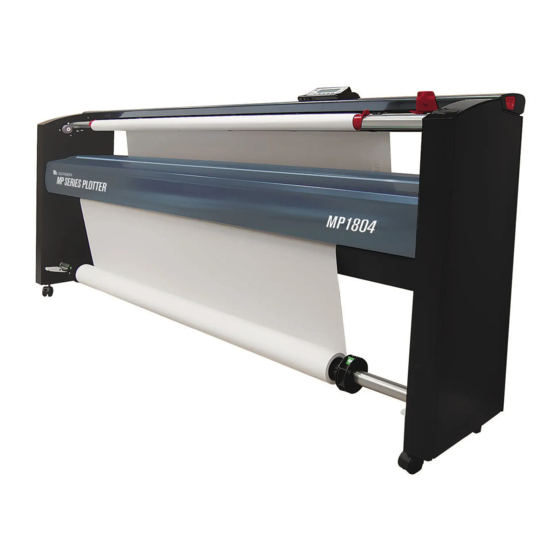
1.1 About the GERBERplotter MP Series The GERBERplotter MP Series are ideal for plotting in an ultrawide format, yet are small enough to fit into any de- sign pattern making area. These plotters are quiet, easy to install, use minimal floor space, and can be conveniently set against a wall.
-
Page 14: Customer Solution Centers
All Gerber equipment is labeled as required by the Waste Electrical and Electronic Equipment (WEEE) Directive 2002/96/EC for products released after August 13, 2005. The WEEE Directive mandates the collection and treat- ment of electrical and electronic equipment at end of life. Refer to the Directive’s specific regional requirements. GERBERplotter MP Series User Manual…
-
Page 15: Health And Safety
1.6 Health and safety Safety instructions Read and understand all safety instructions before operating the GERBERplotter MP Series, to prevent personal injury, death, or equipment damage. Safety labels Safety Labels are located at various parts of the GERBERplotter MP Series.
-
Page 16
If removed from the ink cartridge, the ink may have the following effects: · Contact with skin or eyes may cause irritation. · Inhalation may cause drowsiness or dizziness. · Ingestion may cause nausea, vomiting, and/or diarrhea. GERBERplotter MP Series User Manual… -
Page 17: Hardware Assembly
Hardware assembly GERBERplotter MP Series description Hardware assembly GERBERplotter MP Series User Manual…
-
Page 18
GERBERplotter MP Series User Manual… -
Page 19: Gerberplotter Mp Series Description
2.1 GERBERplotter MP Series description Rapid Paper Exchange Paper output Rapid paper roll exchange Ultralight aluminum take-up bar system is specifically de- (up to 200 mm diameter, 7.874 signed for the present-day Customized software inch) or free-paper-on-front marker-to-cut manufacturing and display.
-
Page 20: Hardware Assembly
To assemble the plotter, you need the following tools: No. 4 and 6 Allen or hex keys, 10, 13, and 17 mm wrenches, a Torx T20 and T30, and a bubble level. keys wrench Torx T30 No.3, 4, 5, and 6 Allen 10mm/13mm/17mm Level GERBERplotter MP Series User Manual…
-
Page 21
CN319 (Box CN308 (Box 1) CN309 (Box 2) CN139 (Box 6) CN111 (Bag 4) x 12 CN316 (Box 7) CN211 CN107 (Bag 5) Documentation CN212 ALLEN 4 and 6 10, 13, 17 TORX T20 and T30 GERBERplotter MP Series User Manual… -
Page 22: Assembly Procedure
This section details the assembly procedure for your plotter. Each step identifies which components are needed, and all steps must be done in order. Always use two people to assemble the plotter. Bag CN052 (Bag 1) located on the CN227 GERBERplotter MP Series User Manual…
-
Page 23
Step 1 of 17 Disassemble sides CN227 CN229 Separate panels and covers. Assemble the right- and left-side panel and covers. Push cover tabs from the bottom. Pull the cover. Remove the cover. GERBERplotter MP Series User Manual… -
Page 24
Position the mounting notches in CN231 over the existing mounting bolts on CN227. Tilt CN227 until it is perpendicular to CN231. Install eight bolts and washers using the No. 4 Allen key and Bag 1. GERBERplotter MP Series User Manual… -
Page 25
Raise the left side of CN231. Position the mounting notches in CN231 over the mounting bolts on CN229. Tilt CN229 until it is positioned perpendicular to CN231. Install eight bolts and washers using the No. 4 Allen key and Bag GERBERplotter MP Series User Manual… -
Page 26
Wheels let you move the plotter easily, while support bases are used to adjust its height. Depending on the floor, you might use a bubble level to help adjust each support base to achieve a desired, level operat- ing height. GERBERplotter MP Series User Manual… -
Page 27
Remove the plastic shaft from the panel. Place the end of CN221 in the left-side panel (CN227). Fit the plastic shaft into the hole of the rear bar. Turn the plastic shaft to until it clicks into working position. CLICK GERBERplotter MP Series User Manual… -
Page 28
Without damaging the encoder strip, separate the protector from the bridge. Place the protector in the rear of the bridge. Anchor the encoder protector. Pass the longitudinal cable through the slot in the right-side panel (CN227). GERBERplotter MP Series User Manual… -
Page 29
Fit the inverter in the upper hole of the left-side panel (CN229). On both side panels, mount the two buffers. Buffers help the front cover close smoothly. The position of the inverter determines the direction of the paper take-up bar when the plotter is printing. GERBERplotter MP Series User Manual… -
Page 30
Torx T30 + CN107 (Bag 5): Fix bolt and washer to the left-side panel. The bolt used in the previous step is very important, because it discharges static electricity pro- duced by the movement and friction of the paper. GERBERplotter MP Series User Manual… -
Page 31
Position CN212 to the front of the assembly at the same height as the rear cover, and slide CN212 towards the rear until it fits in CN227 and CN229. Open the cover completely. Push the shaft and slide it completely to the end. Close the cover. GERBERplotter MP Series User Manual… -
Page 32
Slide CN207 towards the shaft located next to the inverter on the left-side panel. No.4 Allen key + CN049 (Bag 7): Position the motor as indicated, and fix it to the right-side panel from the inside using the three bolts and washers supplied. GERBERplotter MP Series User Manual… -
Page 33
Place CN201 above the traction bar. Pass the cables of CN201 through the right-side panel (CN227). Torx T20 + CN348 (Bag 8): Install the cover using two screws for each side. Close the cover. CLICK GERBERplotter MP Series User Manual… -
Page 34
To prepare for printing again, advance the paper by pressing the PAPER button on the plotter keyboard and secure the paper using the two red fastening clips at the sides and the white holding clip in the center. GERBERplotter MP Series User Manual… -
Page 35
As an option, you can supply an additional paper support bar that allows the operator to switch between different types of paper or to have a greater quantity of the same paper readily available. The loading pro- cedure is identical for both paper support bars. GERBERplotter MP Series User Manual… -
Page 36
Cables for the lower motor, RFID antennas, and top cover are already in the side panel. The following steps connect the electronics for the plotter. In the right side panel, there are eleven cables. Connect these to the electronics that control the plotter. GERBERplotter MP Series User Manual… -
Page 37
Coming from the upper motor (paper tensioner) is a cable labeled · CON3. Connect the green and yellow earth cable from the top cover to the · earth connection of the traction bar motor (top motor, inclined). GERBERplotter MP Series User Manual… -
Page 38
CN319 (box 3) Install the electronic panel. CLICK CLICK CLICK CLICK Place the electronic panel connections hub into the lateral leg connection hole (CH). Turn and push the connection panel to clip it in place. GERBERplotter MP Series User Manual… -
Page 39
Connect the black cable from the lower motor to the CON22 connector. If your plotter has a giant collector bar option (GCB), connect the GCB cable to CON4. GERBERplotter MP Series User Manual… -
Page 40
Step 15 of 17 Connections CON 10 CON 9 CON 8 GERBERplotter MP Series User Manual… -
Page 41
Step 15 of 17 Connections CON 43 CON 23 CON 3 CON 28 CON 29 CON 22 CON 5 GERBERplotter MP Series User Manual… -
Page 42
To finish the assembly of the plotter, install covers on both side panels. Secure each cover using six washers and bolts. Fit the cover to the right-side panel. Put the square into the centering holes. Repeat the same procedure for the left-side panel. GERBERplotter MP Series User Manual… -
Page 43
Step 17 of 17 Feet CLICK Orient the part as shown in the picture. Insert the part as shown until you hear a click. GERBERplotter MP Series User Manual… -
Page 44
GERBERplotter MP Series User Manual… -
Page 45
Software installation and configuration Introduction Installation Configuration GERBERplotter MP Series User Manual… -
Page 46
GERBERplotter MP Series User Manual… -
Page 47: Introduction
Optional: Internet connection for software updates Installing Server Manager and User Manager automatically installs the following components (if necessary): Minimum software requirements Microsoft Windows Installer 3.1 Microsoft Visual C++ 2008 Redistributable Microsoft Dot NET 3.5 Framework GERBERplotter MP Series User Manual…
-
Page 48: Installation
When necessary, see the documentation for your firewall and antivirus systems. USB cable Do not connect the USB cable until after the installation finishes. GERBERplotter MP Series User Manual…
-
Page 49
You should start the installation when logged on us- ing an authorized user account, but you can right-click update.exe, select Run as administrator, and enter the appropriate password. GERBERplotter MP Series User Manual… -
Page 50
The following pictures show the process for installing Windows Framework and Windows C++ Redistributable. Some security warning messages requesting permission to make changes to the computer might appear during the installation process. Since you are performing a controlled installation, you can accept these requests. GERBERplotter MP Series User Manual… -
Page 51
During the installation process, dialog boxes display messages about installation status, errors, or both. GERBERplotter MP Series User Manual… -
Page 52
The installer automatically starts an installation wizard to guide you through the process. Follow the instructions, accept the terms of the contract, and start the process. After the installation is complete, close the installation wizard. Most installation systems, such as .NET framework, follow a similar procedure. GERBERplotter MP Series User Manual… -
Page 53
After the installation, a message notifies you that the driver has been installed successfully and is activated when you connect the computer to the plotter. GERBERplotter MP Series User Manual… -
Page 54: Configuration
Server Manager installation. For a detailed description on using the User Manager and Server Manager, please see the User Interface (User Man- ager) and Plotter server (Server Manager) sections. server configuration GERBERplotter MP Series User Manual…
-
Page 55: Server Manager Server Settings
3.3.1 Server Manager Server settings From the main screen of Server Manager, you can access the connection configuration (default setting UWP-DE- FAULT) by clicking the icon: This dialog box lets you edit the connection configuration: GERBERplotter MP Series User Manual…
-
Page 56
Returns the settings to their default states e.g., the default port and the multiplotter option. Set default set- tings Selects the way that Server Manager is used to connect with the plotter. USB / Ethernet GERBERplotter MP Series User Manual… -
Page 57: Server Manager (Ip Manager)
Adds the IP address and IP mask values to the list. Select an IP address and click Delete to remove it from the list. After the IP address is removed, Server Delete Manager does not consider it when allowing or denying connections. GERBERplotter MP Series User Manual…
-
Page 58: Server Manager (Additional Connections)
You cannot delete the last connection, because a minimum of one connection is required. By default, the installation User Manager defines a connection as PLOTTER-DEFAULT, which establishes a link to the Server Manager server located in the local computer (whose IP address is 127.0.0.1). connection set- tings GERBERplotter MP Series User Manual…
-
Page 59: User Manager (Configuration Settings)
This value and the port number must be entered into the Server Manager configuration to let User Manager work with the corresponding plotter. Restores the default settings. Set default GERBERplotter MP Series User Manual…
-
Page 60: User Manager Configuration Samples
In this case, you do not need to know the IP address of the computer or the identification of the plotter. Here are some examples of how to edit the basic configuration of User Manager and Server Manager. GERBERplotter MP Series User Manual…
-
Page 61
Define a Plotter ID value that corresponds to that particular plotter. Define a unused port. Open User Manager. Click Program Options / Connections. Add a new plotter. Enable the multiplotter option. Select the same server port used by Server Manager. GERBERplotter MP Series User Manual… -
Page 62
Clear the Server and user in the same computer check box. Enter the IP address of the computer that has Server Manager installed. Select the same number of server ports of the Server Manager. Clear the Multiplotter check box. GERBERplotter MP Series User Manual… -
Page 63
Clear the Server and user in the same computer check box. Input the corresponding IP value. Enter the same port number for the plotter you want to use the Server Manager. Enable the Multiplotter check box. GERBERplotter MP Series User Manual… -
Page 64: License Registration
Contact your Gerber Representative and provide your preactivation code. Your Gerber Representative will pro- vide you the final activation code. Click Register offline. Enter the final activation code in the field at the bottom of the dialog box (e.g., 014F0E0DWKJ7AU22). Click Accept to complete the registration. GERBERplotter MP Series User Manual…
-
Page 65: Updating Winplot Or Accumark
Updating WinPlot or AccuMark GERBERplotter MP Series User Manual…
-
Page 66
GERBERplotter MP Series User Manual… -
Page 67: Introduction
Log on to the computer that has WinPlot or AccuMark using an administrator account. 4.3 Installing the Software Update To install the update, you need the USB drive that was included with the GERBERplotter MP Series and from which you installed User Manager and Server Manager.
-
Page 68
When prompted, run the setup. This adds the GERBERplotter MP Series as a selection for AccuMark and Win- Plot. Run the setup file a) When prompted to run or save the file, click Run. Unknown publisher dialog box b) When prompted that the publisher could not be verified, click Run to run the update. -
Page 69
Installing the Wplotter update h) When prompted, click Finish to close the setup dialog box. Configure Windows to make the GERBERplotter MP Series available. a) Open Windows Control Panel. The steps to do this vary based on your version of Windows. -
Page 70
Click Hardware and Sound. Accessing GerberDevices d) Click GerberDevices (32-bit). e) When prompted to allow changes to the computer, click Yes. The Gerber Device Configuration dialog box opens. f) Click the Plotter tab. Gerber Device Configuration dialog box GERBERplotter MP Series User Manual… -
Page 71: Using Winplot And Accumark
Reboot the computer. 4.4 Using WinPlot and AccuMark To use the GERBERplotter MP Series with WinPlot or AccuMark after you install the update: If it is not automatically running, open the Server Manager software. If it is not automatically running, open the User Manager software.
-
Page 72
GERBERplotter MP Series User Manual… -
Page 73: Plotter Operation
Plotter operation Loading a roll of paper Paper run Removing the paper Display Pre-printing checklist GERBERplotter MP Series User Manual…
-
Page 74
GERBERplotter MP Series User Manual… -
Page 75: Loading A Roll Of Paper
When the paper origin is set to the left- side, remove the right cone instead of the left and slide in the support bar from the left side of the paper roll. GERBERplotter MP Series User Manual…
-
Page 76
(so that both ends of the paper roll support bar sit properly). 2 Slide the bar into the bottom of plotter. GERBERplotter MP Series User Manual… -
Page 77: Paper Run
Step 1 of 5 Preparation Open the top cover of the plotter by pushing the red lock button on the right side. Open the front cover of the printer bridge. GERBERplotter MP Series User Manual…
-
Page 78
Check the tension on both sides of the paper. The tension should be uniform and sufficient to keep the paper taut. 3 Leave approximately 0.5 meters (19.68 inches) of paper hanging from the rear of the plotter. GERBERplotter MP Series User Manual… -
Page 79
Put the paper to the front evenly, maintaining a uniform tension throughout. You should have enough paper to go over and to go to the bottom of the paper take-up bar. GERBERplotter MP Series User Manual… -
Page 80
Inverter in standard position. In this position, the printed side is on the inside, so the print is not visible until it has been unrolled. GERBERplotter MP Series User Manual… -
Page 81
The paper enters through the up- per gap in the wing of the fastener, running over the wing on the inside of the paper support bar, and passes underneath the wing on the other side. GERBERplotter MP Series User Manual… -
Page 82
When the inverter is in the inverted position, the steps for loading the paper take-up bar are similar to those previ- ously detailed. However, the paper must be fed underneath the take-up bar, and consequently the side fastening clips must be fitted upside down. Inverter in inverted position. GERBERplotter MP Series User Manual… -
Page 83
The paper enter through the lower gap in the wings of the fastener, run over the wing on the inside of the paper support bar and pass underneath the wing on the other side. GERBERplotter MP Series User Manual… -
Page 84: Feeding Paper And Removing The Paper Roll
You can place a cut modifier during the printing job. This · is done with the CUT, CUT PLUS, and CUT PAUSE modifiers, as explained in 5.3.2 Automatic advance. You should cut and remove the paper roll. GERBERplotter MP Series User Manual…
-
Page 85: Manual Advance
This function is enabled from the main window of User Manager when adding jobs to the print queue. You can also add the modifiers CUT and CUT PLUS, which indicate when the previous job has finished and facili- tate paper roll removal. GERBERplotter MP Series User Manual…
-
Page 86
PRINT take-up bar. PAUSE When the paper stops, hold the paper using the side and center clips. After the paper is fastened, push PRINT/PAUSE to PRINT restart the print job. PAUSE GERBERplotter MP Series User Manual… -
Page 87
When the paper stops, hold the paper using the side and center clips. Finally, press the PRINT/PAUSE button to exit the PRINT paused state and let the plotter receive and print new jobs. PAUSE GERBERplotter MP Series User Manual… -
Page 88
PAUSE After printing a few centimeters, the plotter stops again. Fasten the paper using the side and center clips. Finally, press the PRINT/PAUSE button to exit the PRINT paused state and print new jobs. PAUSE GERBERplotter MP Series User Manual… -
Page 89: Removal Of The Printed Paper Roll
If necessary, to remove the take-up bar and the paper roll completely, slide the cable to the upper side of the hole, which lets you release the top end of the cable. Remove the paper from the plotter (3d). GERBERplotter MP Series User Manual…
-
Page 90: Display
Increases the selected value. From the main menu, moves the print head to the left side of the plotter. · Reduces the selected value. · From the main menu, moves the plotter print head to the origin defined during configuration (4.4.5). GERBERplotter MP Series User Manual…
-
Page 91: Start And Self Test
(black (K), cyan (C), yellow (Y), blue (B), red (R), white (W), green (G), and magenta (M)) of these icons indicates the state of each option. For Finance, the color varies depending on the financing state of the machine. Service Saver Service Saver not enabled Warranty OK Warranty not OK Warranty grace period GERBERplotter MP Series User Manual…
-
Page 92: Print Settings
The OK button allows access to the submenu of the selected option (which is highlighted using a thicker border). The +/- button lets you alternate be- tween the different values, which vary according to the option selected. GERBERplotter MP Series User Manual…
-
Page 93
The arrow button selects the next available option. 2790 2790 GERBERplotter MP Series User Manual… -
Page 94: Print Tests
This option checks that all the print heads function correctly. 19:49 MENU MENU MENU MENU Prints unidirectional continuous lines. This verifies the print in one direction. PRINT PAUSE Continuous lines in one or both print directions. GERBERplotter MP Series User Manual…
-
Page 95
Prints bidirectional continuous lines. This verifies the print in two directions. PRINT PAUSE Prints unidirectional continuous diagonal lines. This verifies the print diagonally. PRINT PAUSE Diagonal lines. GERBERplotter MP Series User Manual… -
Page 96: Length Adjust
Use the arrow key to select the L1 desired and L2 real length. Press the +/- buttons to increase or decrease the selected length. When you have finished entering the L1 and L2 values, validate the changes and press OK to exit the LENGTH ADJUST screen. GERBERplotter MP Series User Manual…
-
Page 97: User Adjust Calibration
Adjusting screw, situated in the lower left steps, all the print heads (2 or 4 depending on the plot- part of the print head carriage. ter) are used to achieve a more accurate adjustment, after the other settings have been changed. GERBERplotter MP Series User Manual…
-
Page 98
The plotter screen shows you the direction to turn the adjusting screw in the print head carriage to obtain continu- ous vertical lines (with respect to the movement of the print head). The plotter screen also shows the buttons to use while making these adjustments (PRINT/PAUSE and OK): GERBERplotter MP Series User Manual… -
Page 99
Pressing +/- increases or decreases the adjustment value. Pressing PRINT/PAUSE repeats the printing to verify that the changes work. Press the OK button to accept the value entered and access the next adjustment stage. PRINT OVERLAP PH 1-2 PAUSE GERBERplotter MP Series User Manual… -
Page 100
When all three adjustment values are entered, press PRINT/PAUSE to repeat the print test. Press OK to finish the adjustment. PRINT PH1-2: PH2-3: PH3-4: PAUSE PRINT PH1-2: PH2-3: PH3-4: PAUSE PRINT PH1-2: PH2-3: PH3-4: PAUSE GERBERplotter MP Series User Manual… -
Page 101
29) that best shows a continuous horizontal line (in this case, 7). Only values near to the value selected in the previous step appear. PRINT PAPER PAUSE Press +/- to increase or decrease the adjustment value. Press PRINT/PAUSE to repeat the print. Press OK to accept the value entered and access the next adjustment stage. GERBERplotter MP Series User Manual… -
Page 102
(when the lines join together). If printing to the left produces more displaced lines compared to printing to the right, then the actual value of 2 WAY OFFSET for the print head is too small. GERBERplotter MP Series User Manual… -
Page 103
A series of three lines are printed with the following values: chosen value-1, chosen value, and chosen value+1. Compare all three and choose the most continuous line. GERBERplotter MP Series User Manual… -
Page 104
Press +/- increases or decreases the adjustment value, press PRINT/PAUSE again in order to repeat the test. Press OK to accept the value and access the next adjustment stage. PRINT PAUSE Offset 2 PHs Verify. GERBERplotter MP Series User Manual… -
Page 105
On a plotter with four print heads, the adjustments are repeated to make the necessary changes for the rest of the paired print heads (PH 2-3 and PH 3-4). PRINT PH2-3: PAUSE PRINT PH2-3: PAUSE PRINT PH3-4: PAUSE PRINT PH3-4: PAUSE PRINT OFFSET PH 2-3 PAUSE PH 2-3 PRINT OFFSET PH 3-4 PAUSE PH 3-4 GERBERplotter MP Series User Manual… -
Page 106
When prompted, select yes if changes were made in the previous steps, and then perform the previous steps again. GERBERplotter MP Series User Manual… -
Page 107
Decrease (-) the adjustment value. Set the plotter in pause mode. Press +/- to increase or decrease the adjustment value. Press PRINT/PAUSE to confirm the change. Press OK to accept the value and access the next adjustment stage. GERBERplotter MP Series User Manual… -
Page 108: Auto Test
5.4.6 Auto test The self-test option enables a general plotter verifying system. 19:49 MENU MENU MENU Press OK to start the self-test. Wait until it finishes. TEST 5 SUCCEEDED GERBERplotter MP Series User Manual…
-
Page 109: Test Motor X (Print Head Movement)
-The average current consumption at a constant speed by motor X. 19:49 MENU MENU MENU MENU STOP PRINT HEADS MOTOR Finalize the X motor AV: 0.0 A Start the motor X test PK: 3.7 A test CS: 0.5 A PAUSE GERBERplotter MP Series User Manual…
-
Page 110: Test Motor Y (Paper Movement)
-The average current consumption at a constant speed by the paper motor and GCB motor. 19:49 MENU MENU MENU MENU STOP PRINT PAPER MOTOR GCB MOTOR Finalize the Y motor Start the Y motor test AV: 0.0A AV: 0.0A PK: 0.6A PK: 0.8A test CS: 0.0A CS: 0.1A PAUSE GERBERplotter MP Series User Manual…
-
Page 111: Test Encoder Strip
If the test finds a fault, call your Gerber Representative to replace the encoder strip. 19:49 MENU MENU MENU MENU PRESS PRINT PRINT Start test PAUSE TESTING . . . MENU ENCODER OK ENCODER KO AT ACTUAL POSITION GERBERplotter MP Series User Manual…
-
Page 112: Configuration
IP address to be used for a network connection. Use this menu to see the firmware version and warranty code of the plotter. 19:49 MENU MENU MENU GERBERplotter MP Series User Manual…
-
Page 113
Language Use the LANG option to change the language of the display. Select one of the languages available in the plotter firmware. 19:49 MENU MENU MENU MENU GERBERplotter MP Series User Manual… -
Page 114
Date / time setting Use the SET TIME option to change date and time. 19:49 MENU MENU MENU MENU 1 6 : 5 5 : 1 8 0 1 — 0 7 — 1 4 GERBERplotter MP Series User Manual… -
Page 115
IP address Use the IP ADDRESS option to change the IP address of your plotter. 19:49 MENU MENU MENU MENU 192.168.0.165 GERBERplotter MP Series User Manual… -
Page 116
Warranty Use the ABOUT option to access plotter ID and warranty status. 19:49 MENU MENU MENU MENU MENU BNQ549VF GERBERplotter MP Series User Manual… -
Page 117
Use the ABOUT option to access FIRMWARE VERSION for all MCUs in the plotter. 19:49 MENU MENU MENU MENU MENU FIRMWARE VERSIONS MCU 1: 5.5.0 MCU 4: 1.2.3 MCU 2: 2.3.1 MCU 5: 1.2.3 MCU 3: 0.0.0 MCU 6: 1.2.3 GERBERplotter MP Series User Manual… -
Page 118
Plug-ins Use the ABOUT option to access the PLUG-INs option, to see all the current installed options. 19:49 MENU MENU MENU MENU GERBERplotter MP Series User Manual… -
Page 119
To activate a plug-in, bring the RFID card within range of the antenna, near the top of the right-side cover, and wait for the OK symbol. Range of antenna. Approach the card and wait. OK symbol, the plug-in is active. GERBERplotter MP Series User Manual… -
Page 120: Pre-Printing Checklist
Ensure that the brakes are installed correctly. Ensure that the cones for holding the paper roll on the paper support bar are correctly aligned (see step 2 of the loading paper section on 5.1 Loading a roll of paper). GERBERplotter MP Series User Manual…
-
Page 121: Using The Software
Using the software User interface (User Manager) Plotter server (Server Manager) GERBERplotter MP Series User Manual…
-
Page 122
GERBERplotter MP Series User Manual… -
Page 123: User Interface (User Manager)
Server Manager running (minimized). 6.1.1 User Manager main window The User Manager main window is arranged into various sections: Main menu, status indicators, and job queue. Main menu Main Menu Status indicators Print queue Jobs queue. GERBERplotter MP Series User Manual…
-
Page 124
Check to see if the status indicators show some type of error, such as front cover open, ink cartridges not found, paper feed error, or that it is necessary to remove the paper from the paper take-up bar. GERBERplotter MP Series User Manual… -
Page 125
Paper take-up Bobbin full. Working properly. Paper feed Check that paper is correctly Working properly. loaded. Front cover closed. Close the front cover to continue printing. Indicator lights show when the plotter is not connected. GERBERplotter MP Series User Manual… -
Page 126
Finally, the queue displays the status of three plotter options: Finance, Warranty and Service Saver. Service Saver not Service Saver Kit Service Saver After you buy an option for the plotter, you receive a service note that explains the option. Warranty Warranty not Finance GERBERplotter MP Series User Manual… -
Page 127
The Refresh option in the Queue menu initiates an attempt to connect to Server Manager. When the automatic refresh (Ctrl+R) option is active, User Manager keeps trying to connect with Server Manager until the connection is es- tablished. GERBERplotter MP Series User Manual… -
Page 128
An asterisk is added to the beginning of the file name if a cut from the original file is sent. The measurements for the cut you want to print appear in the W x L column. GERBERplotter MP Series User Manual… -
Page 129
User Manager encounters a CLEAN modifier, User Manager sends a small print job to the plotter to clean the print heads. Add text to print Add text to print lets you send text to the queue. You can change the text thickness, size, and orientation. Only standard HPGL characters are supported. GERBERplotter MP Series User Manual… -
Page 130
Lets you send text to print. Only standard HPGL characters are supported. Adds a marker to stop printing. Lets you modify the settings of the selected element. Adds a marker to clean the ink cartridges. GERBERplotter MP Series User Manual… -
Page 131
A progress bar indicates the percentage of data sent to the plotter along with the job name. The current Resume paused job. copy being printed is shown in parentheses with the total number of copies to be printed. GERBERplotter MP Series User Manual… -
Page 132: Connecting To A Server
User Manager lets you send jobs to the plotter. Use the Print options menu to send jobs to the plotter. Direct print Use this option to place a file directly into the jobs queue using default parameters. GERBERplotter MP Series User Manual…
-
Page 133
Preview The dialog box lets you view the contents of the file, limit the print area, and rotate or flip the job. To do this, see the pictures. Cut / Rotation / … GERBERplotter MP Series User Manual… -
Page 134
You can generate a preview of the composition. When the file list is complete, send the resulting compo- sition to the job queue. If needed, assign a name to the job. GERBERplotter MP Series User Manual… -
Page 135
An HPGL vector file is rasterized when sent to a plotter for printing. Click Compose and print to rasterize the composition and add it to the job queue using default parameters and the GERBERplotter MP Series User Manual… -
Page 136
Files that produce a rasterizing error are not added to the job queue. Rasterization can fail if the original file is not HPGL or ISO, contains unrecognized commands, or has coordinates of scale that are too large. GERBERplotter MP Series User Manual… -
Page 137: Default Settings
Click Program options / Default settings to set the default settings that are used when sending files directly to the job queue. The Direct print option uses these defaults. The table in the next page describes all the options in the dialog box. GERBERplotter MP Series User Manual…
-
Page 138
There is a small amount of overlap. Triangles. First section. Second section. GERBERplotter MP Series User Manual… -
Page 139: Extensions
Format Lets you change the size of a marker, indicating the units and the divisor that are used Resolution for the coordinate system (by default, HPGL uses 40 units per mm, 1016 per inch). Format GERBERplotter MP Series User Manual…
-
Page 140: File Settings
The Print Preview, Print and Composition, and print options let you modify the default settings before sending a job to the print queue. The file dialog box uses the User Manager settings established in Program options and Default settings. Changes made in the dialog box apply only to the selected file. GERBERplotter MP Series User Manual…
-
Page 141: Language And Units
The first list contains all the languages detected by User Manager, while the second lets you choose between millimeters and inches. list of installed languages mm / inches The changes made in the previous dialog box automatically modify the language and units used by User Manager. GERBERplotter MP Series User Manual…
-
Page 142
(for example) and modify the file definitions of the new file. You must do the translation in both the messages folder (miss) and the programs folder (prog). The select languages dialog box automatically lists the new language. GERBERplotter MP Series User Manual… -
Page 143: Information About Versions
If you use inch / 40, each inch has 40 points. The dialog box also has controls that limit both sides of the file,. The job sent to the plotter is cut according to these limits. Left limiter for file section to be sent to plotter Right limiter for file section to be sent to plotter GERBERplotter MP Series User Manual…
-
Page 144: History
The file cannot be sent to the server, probably because it has been stopped, Can’t send file paused or User Manager cannot connect to it. The server has stopped before finishing the rasterizing process. Server closed before raster GERBERplotter MP Series User Manual…
-
Page 145
Incidence: Low power mode Slight excess motor consumption for electrical or mechanical rea- Incidence: motor overcurrent protection sons. Error in reading the encoder strip. The encoder strip is dirty or defec- Incidence: encoder strip tive. GERBERplotter MP Series User Manual… -
Page 146: Sending Jobs Automatically
Automatic send folder (located by default Location of automatic send folder. on the Windows desktop) and to activate pattern Select the folder dialog box. detection. GERBERplotter MP Series User Manual…
-
Page 147
Use the automatic send option to configure the programs from which HPGL and ISO files for printing are generated (HPGL/ISO,…). You can configure these to use the automatic folders, so files are sent to the job queue automatically and are ready to be sent to a plotter. GERBERplotter MP Series User Manual… -
Page 148
To use the automatic pattern detection folder, follow the procedure as shown. Remember that when selecting the Manual composition option, detected patterns must be selected using the Manual composition dialog box. To open the Manual composition dialog box, click Print options / Pattern print from folder. GERBERplotter MP Series User Manual… -
Page 149: Calibration From User Manager
Access the calibration dialog …and press calibrate From the entered values, User Manager calculates the necessary correction and applies them to the next set of jobs sent to the plotter. GERBERplotter MP Series User Manual…
-
Page 150
If you cannot connect to the server or the entered values are invalid, User Manager displays this error message. If the calibration process is successful, a reprint of the reference marker should produce a result where the desired values match the obtained values. GERBERplotter MP Series User Manual… -
Page 151: Plugins And Options
This menu shows the options currently on the connected plotter. Access to other options (Finance, Warranty, and Service Saver) is only available after purchase. After you have purchased an option, you receive a service note that explains the option. GERBERplotter MP Series User Manual…
-
Page 152: Plotter Server (Server Manager)
9999 to communicate with User Manager. When the Server Manager application is minimized, it appears as an icon in the taskbar. Double-click the icon to open the main dialog box. GERBERplotter MP Series User Manual…
-
Page 153: Running Server Manager
A warning message telling you that winusb.dll has not been found means that the driver installation re- mains pending until a plotter is connected. You must connect a plotter using a USB cable and turn it on in order to complete the installation. GERBERplotter MP Series User Manual…
-
Page 154: Main Window Of Server Manager
Manager using initial values. Doing so lets you re- default solve any errors caused by changes made to this settings configuration. Language Allows you to choose the language used by the Lan- Server Manager interface. guage GERBERplotter MP Series User Manual…
-
Page 155
Server Manager. Server Manager (additional connections) describes how to define additional connections. Double click. Configure server. Connections list. Managing the firmware. The icons allow you to modify the parameters for each connection and to manage the firmware of the plotter. GERBERplotter MP Series User Manual… -
Page 156: Language Settings
The method used to change languages or to add a new language is similar to that explained in section 6.1.7, except that you must work with files from the folders derived from the plotter Server Manager instead of plotter User Man- ager. GERBERplotter MP Series User Manual…
-
Page 157: Information About Versions
Click the question mark icon in the options menu to get information about Server Manager. Click the icon in the left corner of the job queue section for Server Manager version information. Server Manager version. GERBERplotter MP Series User Manual…
-
Page 158
GERBERplotter MP Series User Manual… -
Page 159: Operation And Maintenance
Operation and maintenance Managing software Managing firmware Cleaning and preventative maintenance GERBERplotter MP Series User Manual…
-
Page 160
GERBERplotter MP Series User Manual… -
Page 161: Managing Software
Run update.exe to start the installation. Choose the second option on the list (Select options to install or uninstall) to open the installation wizard. Updating the software used by the plotter is similar to the original installation. GERBERplotter MP Series User Manual…
-
Page 162
As the installation proceeds, messages appear showing tasks that are completed. As needed, accept licenses, allow changes, run additional software wizards, and close message dialog boxes. After the installation is complete, click the End button. GERBERplotter MP Series User Manual… -
Page 163
The following are examples of some messages that might appear when updating Server Manager or User Manager. GERBERplotter MP Series User Manual… -
Page 164
The procedures described in this section apply to a problem-free update. When trying to resolve an error, firstly uninstall the programs and reboot the system. Secondly, reinstall the programs. If this doesn’t work, contact your Gerber Representative. GERBERplotter MP Series User Manual… -
Page 165: Other Actions
This action allows to you to erase the User Manager and Server Manager settings (for example, all servers in the Server Man- ager, queue file status from User Manager, and anything you can change or create). Example 1 GERBERplotter MP Series User Manual…
-
Page 166
Example 2 During a trouble-free update, the last step of the installation wizard ends with messages similar to the ones shown here, so you can see that Server Manager and User Manager have installed correctly. GERBERplotter MP Series User Manual… -
Page 167: Managing The Firmware
Use Server Manager to update the plotter firmware. Server Manager must be connected by a USB cable to the plot- ter you are updating, and only one plotter can be active. Accessing the management options in Server Manager by selecting a configuration from the list and clicking the manage firmware icon. GERBERplotter MP Series User Manual…
-
Page 168: Firmware Back-Up
4 If the plotter is turned on and connected to Server Man- ager, click the backup icon to transfer the plotter firm- ware to the computer and create a file in the selected location. GERBERplotter MP Series User Manual…
-
Page 169: Updating Firmware
If the plotter is turned on and connected to Server Manager, click the firmware update icon to perform the update. On a plotter with a deprogrammed or incorrectly configured main board, contact your Gerber Representative for more assistance. GERBERplotter MP Series User Manual…
-
Page 170: Versions
If you need to replace the plotter main board, you should back up this information. This is similar to backing up firmware, except that it is done from the Printer settings section of the Printer Manager. GERBERplotter MP Series User Manual…
-
Page 171: Restoring The Configuration
Restore the configurations from the copy made in the first step (see section 7.2.5 Restoring the configuration). If the configuration of the new main board is incorrect, the plotter warns you that the main board is not suitable. If this happens, contact your Gerber Representative to resolve the problem. GERBERplotter MP Series User Manual…
-
Page 172
GERBERplotter MP Series User Manual… -
Page 173: Troubleshooting
Troubleshooting Plotter error list Software Mechanics & electronics GERBERplotter MP Series User Manual…
-
Page 174
GERBERplotter MP Series User Manual… -
Page 175: Plotter Error List
U1….U2….U3….U4….U5 Error For any of the problems listed above, contact your Gerber Representative. Do not handle the plot- ter on your own to avoid further damage. GERBERplotter MP Series User Manual…
-
Page 176: Software
Then, run User Manager and set the automatic refresh to get the plotter information. If you can’t connect, try to shut down the plotter, disconnect the USB, and restart everything again. GERBERplotter MP Series User Manual…
-
Page 177
You can send files in which the width exceeds the pa- per width as long as the Enable split option is enabled. Why is the scale percent red? When the scale is not 100%, a file is shown in red. GERBERplotter MP Series User Manual… -
Page 178: Mechanics & Electronics
Verify the top-cover wheels are loose and turn There are wrinkles in the paper easily. Verify that the cones are correctly installed. Paper has different tension in both sides Change the main board. There are dot and lines in the display GERBERplotter MP Series User Manual…
-
Page 179
Glossary GERBERplotter MP Series User Manual… -
Page 180
GERBERplotter MP Series User Manual… -
Page 181
Optional plotter accessory that collects more paper than GCB (Giant Collector Bar) the standard bar. Physical elements that comprise a computer. Hardware Primary printer control language used as a standard for HPGL (Hewlett-Packard Graphics Lan- almost all plotters. guage) GERBERplotter MP Series User Manual… -
Page 182
Computer programs and related data that instruct a com- Software puter what to do and how to do it. A program that allows you to send jobs to one or more User Manager plotters controlled by Server Manager. GERBERplotter MP Series User Manual… -
Page 184
Corporate Headquarters: Gerber Scientific, Inc. 24 Industrial Park Road West, Tolland, CT 06084, USA Tel: +1 860 871 8082 Fax: +1 860 871 3820 www.gerbertechnology.com PN v1.0.3 10/14…
Инструкция по эксплуатации плоттера
Раздел 1
Обслуживание
Перед началом эксплуатации оборудования внимательно изучите следующие требования:
- Запрещается размещать вблизи плоттера (особенно рядом с кареткой) магнитные устройства.
- Избегайте попадания внутрь плоттера инородных тел (болты, небольшие шурупы и т.п.)
- При длительном неиспользовании оборудования вилка питания должна быть отключена от розетки.
- Запрещается подключать и отключать последовательный/параллельный/usb кабель при включенном питании
- Запрещается оставлять прижимные ролики прижатыми, если устройство не используется.
- Разрешается подключение шнура питания только к заземленной розетке.
- Запрещается перемещение каретки вручную.
- Запрещается дотрагиваться до каретки, металлического ролика, резца и любых подвижных частей при работающем устройстве.
- Установка оборудования производится на устойчивой поверхности, не подверженной вибрации, электромагнитному излучению. Не устанавливайте устройство в пыльных, влажных помещениях. Избегайте попадания на него прямых солнечных лучей.
Запрещается давить на верхнюю перекладину и поднимать черную перекладину.
Раздел 2
Установка
2-1 Упаковка
Внимательно проверьте все изделия после вскрытия упаковки. Оборудование поставляется в следующей комплектности:
- Плоттер.
- Комплектующие (в пакете).
- Комплект деталей для стенда.
2-2 Комплектация
| № | Наименование | Количество |
|
1 |
Сетевой шнур |
1 |
|
2 |
Инструкция по эксплуатации (на диске) |
1 |
|
3 |
Держатель для ножа |
1 |
|
4 |
Нож |
3 |
|
5 |
Стержень |
1 |
|
6 |
Шестигранный ключ |
1 |
|
7 |
Последовательный кабель (COM) |
1 |
|
8 |
Параллельный кабель (опционально) |
1 |
|
9 |
USB-кабель (опционально) |
1 |
|
10 |
Защитный чехол для плоттера |
1 |
|
11 |
Диск с драйвером для CorelDraw и USB порта |
1 |
|
12 |
ПО «Artcut 2009», на диске (опционально) |
1 |
2-3 Комплектация стенда
| № |
Наименование |
Кол-во |
№ |
Наименование |
Кол-во |
|
1 |
Левая стойка |
1 |
6 |
Ролики для пленки |
2 |
|
2 |
Правая стойка |
1 |
7 |
Держатель для пленки |
2 |
|
3 |
Поперечная перекладина |
1 |
8 |
Плита для крепления |
2 |
|
4 |
Опора |
2 |
9 |
Винт M4×20 |
10/12 |
|
5 |
Колесики опоры |
4 |
10 |
Винт M4×8 |
8 |
2-4 Сборка стенда
Примечания по чертежу:
— Подходит лишь для моделей, имеющих ширину не менее 780 мм

Шаг 1: Прикрепите винтами опоры к левой и правой стойке.
Шаг 2: Соедините правую и левую стойки поперечной перекладиной при помощи винтов.
Шаг 3: Присоедините держатели для пленки с внешнней части левой и правой стоек при помощи винтов.
Шаг 4: Присоедините плиту для крепления к верхней части левой и правой стойки при помощи винтов.
Шаг 5: Поместите плоттер на плиту крепления и вставьте опоры в панель для присоединения плоттера.
Шаг 6: Поместите ролики для рулонов на держатель.
Раздел 3 Основные операции
3-1 Установка и подключение
1 Установите плоттер на ровную поверхность, в просторном месте
2 Подключите сигнальный кабель к порту COM1,COM2 или USB компьютера
3 Проверьте напряжение питания и наличие заземления и убедитесь в соблюдении всех условий
3-2 Установка ножа
3-2.1 Части держателя ножа и комплектующие

Поворотом установочного винта отрегулируйте длину ножа таким образом, чтобы он не прорезал нижний слой.
- Нож (диаметр – 2 мм)
- Кожух держателя ножа
- Установочный винт
- Корпус держателя ножа
3-2.2 Установка и регулировка лезвия
1.Перед установкой ножа тщательно протрите корпус держателя ножа и руки. Даже незначительное загрязнение может сказаться на работе ножа. Для удобства держания ножа в руках используйте захваты из мягкого пластика или резины. Аккуратно вставьте нож в корпус держателя. Он должен примагнититься к нему.
2 Поверните кожух держателя ножа и выставьте такую длину ножа, чтобы длина лезвия не превышала толщину клейкого слоя
3. Во избежание травмы запрещается касаться лезвия пальцами
 3-2.3 Компоненты и структура стержня
Закрепите шариковую ручку в стержне (см.рисунок).
- Поверните колпачок.
- Установите шариковую ручку на нужную длину.
- Закройте стержень при помощи колпачка. Вкрутите их в корпус
3-2.4 Установка
1. Отключите питание
2. Ослабьте крепежный болт суппорта, установите в него держатель ножа или стержень. По достижении нужного положения закрутите крепежный болт по часовой стрелке.
3-2.5 Максимальное использование ресурса ножа
Ресурс ножа ограничен, но его можно максимально использовать.
Примечание:
1. Выставление большей длины ножа приводит к сокращению его ресурса. В процессе резки избегайте прорезания нижнего слоя.
2. Большее усилие реза приводит к сокращению ресурса ножа.
3. Для разных материалов требуется разная степень остроты ножа.
4. Применяйте минимальное усилие реза, насколько это возможно; увеличение усилия необходимо лишь при затуплении ножа.
5. Ножи разных производителей имеют разный ресурс.
6. Производите своевременную замену ножа по мере его затупления или ухудшении производительности плоттера. При необходимости срочной замены для заточки ножа можно использовать кусочек кожи (аналогично тому, как затачивают бритву).
Раздел 4 Установка через USB-порт
Установка 340 USB драйвера
- Установка USB-порта:
Внимание: Перед установкой диска не подключайте плоттер к ПК
Вставьте установочный CD с драйвером в привод CD-ROM. На диске найдите данный файл. Выберите его двойным нажатием мыши

Выбрать «NEXT» (Далее) для автоматической установки драйвера.

Нажать «OK». Драйвер успешно установлен

Теперь подключите USB-кабель режущего плоттера к USB-порту ПК. В «диспетчере утройств» USB-устройство будет определено как «COM3». Это свидетельствует об успешном подключении плоттера к ПК

2. Установка порта в ПО «Artcut»

В окошке «Link to» выберите COM 3 для USB-порта

В “Sequential Control” отметьте DTR/DSR и RTS/CTS

3. По завершении настроек выполните перезагрузку компьютера
Раздел 5 Инструкция по эксплуатации
5-1 Названия и функции деталей
5-1.1 Составные части
Тип_0

1. Левая крышка
2. Металлический ролик
3. Скоба для ножа
4. Держатель ножа
5. Каретка
6. Крышка направляющей
7. Прижимной ролик
8. Ручка регулировки положения
9. Панель управления
10. Правая крышка
11. Опора
12. Параллельный порт (опция)
13. Последовательный порт
14. Разъем питания
15. Разъем с плавким предохранителем
16. Выключатель питания
Типы_1

1. Левая крышка
2. Металлический ролик
3. Скоба для ножа
4. Держатель ножа
5. Каретка
6. Крышка направляющей
7. Прижимной ролик
8. Панель управления
9. Ручка регулировки положения
10. Правая крышка
11. Опора
12. Разъем питания
13. Разъем с плавким предохранителем
14. Выключатель питания
15. Переходник USB/СОМ (опция)
16. Последовательный порт
17. Параллельный порт (опция)
5-1.2 Панель управления
Тип_0

Тип_1

1. ЖК-дисплей
2. Сброс параметров
3. Автономный режим /Пауза
4. Настройка
5. Тестирование
6. Кнопка установки исходной точки
7. Увеличение усилия
8. Уменьшение скорости реза
9. Увеличние скорости реза
10. Уменьшение усилия
5-2 Основные операции
5-2.1 Включение плоттера
1. Выключатель питания должен находиться в положении OFF (выкл.);
2. Подключите сетевой шнур к разъему питания плоттера, включите питание выключателем;
3. После включения ЖК-дисплея на нем отображается процесс подготовки и следующая информация:

4 По окончании подготовки загорается красная лампа. Плоттер находится в состоянии онлайн и может работать под управлением с ПК
5-2.2 Установка материалов
1 Загрузка материалов
1. Поднимите рукоятки прижимных роликов и уберите их с металлических роликов.
2. Вставьте рулон с виниловой пленкой между металлическими роликами и прижимными роликами по направлению от задней крышки плоттера к передней.
3. Перед началом работы внимательно проверьте правильность расположения пленки во избежание отклонений при резке. Если пленка расположена неровно, поднимите прижимные ролики с одной стороны, поправьте пленку и опустите ролики. Перед началом работы необходимо выполнить несколько пробных прогонов для минимизации отклонений.
2 Регулировка прижимных роликов по ширине пленки
Режущий плоттер имеет 2-4 прижимных ролика, которые можно передвигать по направляющей. Перед началом перемещения прижимных роликов поднимите их рукоятки, держа заднюю часть ролика потяните его вправо или влево. Во избежание ухудшения точности не тяните ролики вперед.
3 Требования к положению роликов:
1.Прижимные ролики не должны находиться в пределах области рисунка.
2.Прижимные ролики должны находиться на расстоянии 10-50 мм от краев бумаги.
3.Прижимные ролики не должны находиться в зоне сопряжения двух металлических роликов.
5.2.3 Пробный запуск (проверка усилия и ножа)
1 Пробная резка
По завершении установки ножа и пленки выполните предварительный пробный запуск для проверки усилия реза ножа. Для этого нажмите кнопку TEST. На дисплее отобразится следующая информация, после чего плоттер автоматически произведет резку.

2 Регулировка усилия реза
Снимите вырезанный рисунок. Если сделать это не получается, рисунок нуждается в дальнейшей резке из-за слишком низкого давления ножа или из-за слишком маленькой длины ножа. Прорезание основы говорит о слишком большой длине ножа и слишком большом давлении ножа. Длина выступающей части ножа должна составлять не более 0,5 мм или 2/3 толщины виниловой пленки. Отрегулируйте длину и давление ножа по результатам пробного реза. Давление ножа увеличивается/уменьшается на один уровень при помощи кнопок F+ или F-.
Внимание:
Выполняйте пробную резку каждый раз при использовании нового типа пленки, для проверки давления ножа.
5-3 Инструкция по эксплуатации
5-3.1 Функция «Сброс параметров» (Reset)
При включении плоттера происходит его автоматическое обнуление (сброс параметров). Загорается красный индикатор и плоттер переходит в режим готовности получения данных с ПК. При этом на ЖК-дисплее отображается следующее:

Заводские параметры:
·Скорость передачи данных: 9600
·Скорость резки: 350мм/сек
·Давление ножа: 100г
·Исходная точка резки – согласно заводским настройкам
Вышеуказанная информация может быть изменена в ходе работы.
При нажатии кнопки RESET в режиме работы плоттер отменяет текущее задание и выполняет переход к заводским настройкам.
5-3.2 Функция «Под управлением ПК» (Online)
После перезагрузки светится красный индикатор. Если плоттер получает данные с компьютера, он находится в онлайн режиме.
Теперь Вы можете изменить скорость резки при помощи кнопок V+ или V- и отрегулировать давление ножа кнопками F+ или F

При нажатии кнопки RESET в рабочем режиме, плоттер возвращается к заводским настройкам и переходит в режим сброса параметров (удаляет заданную информацию) и выполняет подготовку к новому заданию.

5-3.3 Функция «Автономный режим/Пауза» (Offline /Pause)
Для перехода в автономный режим нажмите кнопку OFFLINE. Включится желтый индикатор. При этом, на дисплее появится сообщение «Motion, X= xxx, Y= yyy», указывающее на текущее местоположение (координаты) ножа.

Перемещение каретки влево/вправо производится нажатием кнопок V+ или V-. Перемещение пленки вперед/назад выполняется кнопками F+ или F-. В данном режиме Вы можете выполнить перемещение ножа в исходную позицию. При этом будет пошагово изменяться значение координат «X, Y» на ЖК-дисплее.

При нажатии кнопки «Pause» в режиме работы происходит остановка плоттера. Для возобновления работы необходимо повторно нажать кнопку «Pause».
5-3.4 Установка исходной точки
При перемещении ножа в исходную позицию нажмите кнопку «Origin». Новая исходная точка задана – плоттер начнет построение с новой исходной точки.

5-3.5 Функция настройки (Setup)
В режиме «ONLINE» при нажатии кнопки «SETUP» загорается зеленый индикатор и Вы можете изменить скорость передачи через серийный порт. Повторное нажатие кнопки SETUP приводит к сохранению в онлайн-режиме.

Внимание:
Изменение данных настроек непрофессиональными техниками не рекомендуется.
5-3.6 Функция повторного резания (Copy)
При нажатии кнопок OFFLINE, SETUP и ORIGIN плоттер выполнит повторное резание последнего задания. При мигающем зеленом индикаторе RESET повторное резание невозможно, так как это свидетельствует о превышении емкости оперативной памяти. Для повторного запуска задания нажмите кнопку RESET.
Внимание:
При появлении признаков сбоя и невозможности отключения плоттера, выключите его питание или выдерните вилку из розетки
5-3.7 По завершении работы
По завершении работы:
1.Уберите бумагу
2.Снимите держатель ножа или стержень, протрите его мягкой тканью и поместите на хранение
3.Отключите питание и выдерните шнур питания (если не планируете использовать плоттер длительное время)
4.Накройте плоттер тканью или чехлом
5-4 Таблица параметров
|
Технические характеристики ( тип_0) |
|||||
|
Модель |
360 |
720 |
870 |
1100 |
1350 |
|
Макс.ширина материала |
365мм |
720мм |
870мм |
1100мм |
1350мм |
|
Макс.область резки |
275мм |
630мм |
780мм |
1010мм |
1260мм |
|
Скорость резки |
50-800мм/сек 50-800mm/s |
||||
|
Давление ножа |
50-500г 50-500g |
||||
|
Объем памяти |
1M 1M |
||||
|
ЖК-дисплей |
Опционально Optional |
||||
|
Процессор |
8-bit CPU |
||||
|
Полоска плоттера |
Пластиковый лист |
||||
|
Двигатель |
Шаговый |
||||
|
Мин.матрица знаков |
Высота ~5 мм [0.2»] |
||||
|
Тип лезвия |
Особая сталь [1,2 мм и 2,0 мм] |
||||
|
Материалы |
Самоклеящаяся виниловая пленка, флуоресцентная пленка, отражающая пленка, бумага |
||||
|
Панель дисплея |
8 символов X 2 строки, ЖК |
||||
|
Интерфейсы |
Параллельный, последовательный, USB (опционально) |
||||
|
Напряжение |
90-260В |
||||
|
Точность повтора |
0,0127мм |
||||
|
Разрешение |
0.0254мм/шаг |
||||
|
Набор команд |
DMPL / HPGL |
||||
|
Рабочая температура |
0-350С |
||||
|
Влажность |
5%-65%, без конденсации |
|
Технические характеристики ( тип_1 ) |
|||||
|
Модель |
361 |
721 |
871 |
1101 |
1351 |
|
Макс.ширина материала |
365мм |
720мм |
870мм |
1100мм |
1350мм |
|
Макс.область резки |
275мм |
630мм |
780мм |
1010мм |
1260мм |
|
Скорость резки |
50-800мм/сек |
||||
|
Давление ножа |
50-500г |
||||
|
Объем памяти |
1-4M |
||||
|
ЖК-дисплей |
Имеется |
||||
|
Процессор |
8-bit |
||||
|
Специальные настройки |
Двухпозиционное крепление ножа |
||||
|
Полоска плоттера |
Пластиковый лист |
||||
|
Двигатель |
Пошаговый |
||||
|
Мин.матрица знаков |
Примерно 5 мм [0.2»] в высоту |
||||
|
Тип лезвия |
Особая сталь [1,2мм и 2,0мм] |
||||
|
Материалы |
Самоклеящаяся виниловая пленка, флуоресцентная пленка, отражающая пленка, бумага |
||||
|
Панель дисплея |
8 символов X 2 строки, ЖК |
||||
|
Интерфейсы |
Параллельный, последовательный, USB |
||||
|
Напряжение |
90-260В |
||||
|
Точность повтора |
0.0127мм |
||||
|
Разрешение |
0.0254мм/шаг |
||||
|
Набор команд |
DMPL / HPGL |
||||
|
Рабочая температура |
0-350С |
Раздел 6 Неисправности и их устранение
Рисунок деформирован или незавершен
- Слишком высокое давление ножа, слишком большая длина лезвия, загрязненный стол, слишком мягкая пленка – все это может стать причиной сопротивляемости двух сторон пленки, вследствие чего она попадает за вращающийся ролик – это приводит к деформации рисунка.
- Неправильно установленное ПО.
- Ослаблен ремень каретки, или металлический ролик не совмещается с электрическим механизмом
- Двигатель не выполняет все шаги.
- Слишком малое значение коррекции может привести к незавершению резки при нормальном рисунке.
Плоттер вычерчивает несоответствующим образом
- Несовместимость программного обеспечения – необходимо установить верный набор команд или указать надлежащее значение коррекции на инструмент.
- Сбой в работе программного обеспечения плоттера.
- Повреждение ПО или наличие вирусов в ПК.
Отклонения материала
- Пленка установлена ненадлежащим образом.
- Слишком грязный стол – сопротивление с двух сторон не может быть сбалансировано при перемещении материала.
- Деформация или несоответствие прижимных роликов.
- Слишком низкое усилие прижима прижимных роликов, материал слишком чувствителен к прилагаемому усилию.
- Неуравновешенный вес пленки.
Пропуски при прорезании букв
- Слишком тяжелая виниловая пленка, слишком большое натяжение пленки. На металлический ролик попали инородные вещества или виниловые обрезки.
- Слишком высокая скорость резки, слишком высокое давление ножа, слишком большая длина лезвия.
- Слишком большое натяжение синхронизирующего ремня, или слишком высокое давление на прижимной ролик.
- Поломка металлического ролика. Обратитесь к местному дистрибьютору по вопросу ремонта и замены.
Разные буквы в одной строке имеют разную глубину реза
- Держатель ножа не закреплен. Необходимо закрепить его
- Лезвие ножа не закреплено в держателе.
Волнистость букв
- Слишком большая скорость резки. Скорость не должна превышать значения 480мм/сек (кроме случаев резки крупных букв и знаков)
- Низкое качество или повреждение лезвия ножа. Требуется замена
- Держатель ножа не закреплен. Требуется его затягивание
Резка букв малого размера
При резке букв небольшого размера установите скорость резки и давление ножа на минимальное значение. Аналогичным образом, длина лезвия ножа должна быть минимальной, насколько это возможно.
Резка букв большого размера
Чем больше размер букв, тем большее значение выставляют для давления ножа. При резке букв большого размера функцию Sharp Angle в программе «Artcut» можно не применять.