Exterior Appearance
2
Model Code
5
Model Line-Up
6
Front View
7
Rear View
8
Side View
9
Tire & Disc Wheel
10
Interior
11
Instrument Panel
12
Steering Wheel
13
Steering Pad Switch Function
13
Front Seat
14
Rear Seat
15
Luggage
15
Deck under Tray
17
Luggage Cover
17
Equipment
18
Multi Display
18
Navigation System
18
Trip Information
18
Audio System
19
Head Unit Specifications
19
Speaker’s Specification
19
Audio System Location
20
Multi-Information Display
20
Air Conditioner System
22
Power Heater System
22
Windshield & Door Glass
23
Rear Sunshade
24
Power Outlet
24
Wiper System
24
Performance
25
Power Train
25
Transaxle
26
Chassis
27
Front Suspension
27
Rear Suspension
27
Brake
27
Safety
28
SRS (Supplemental Restraint System) Airbag System
28
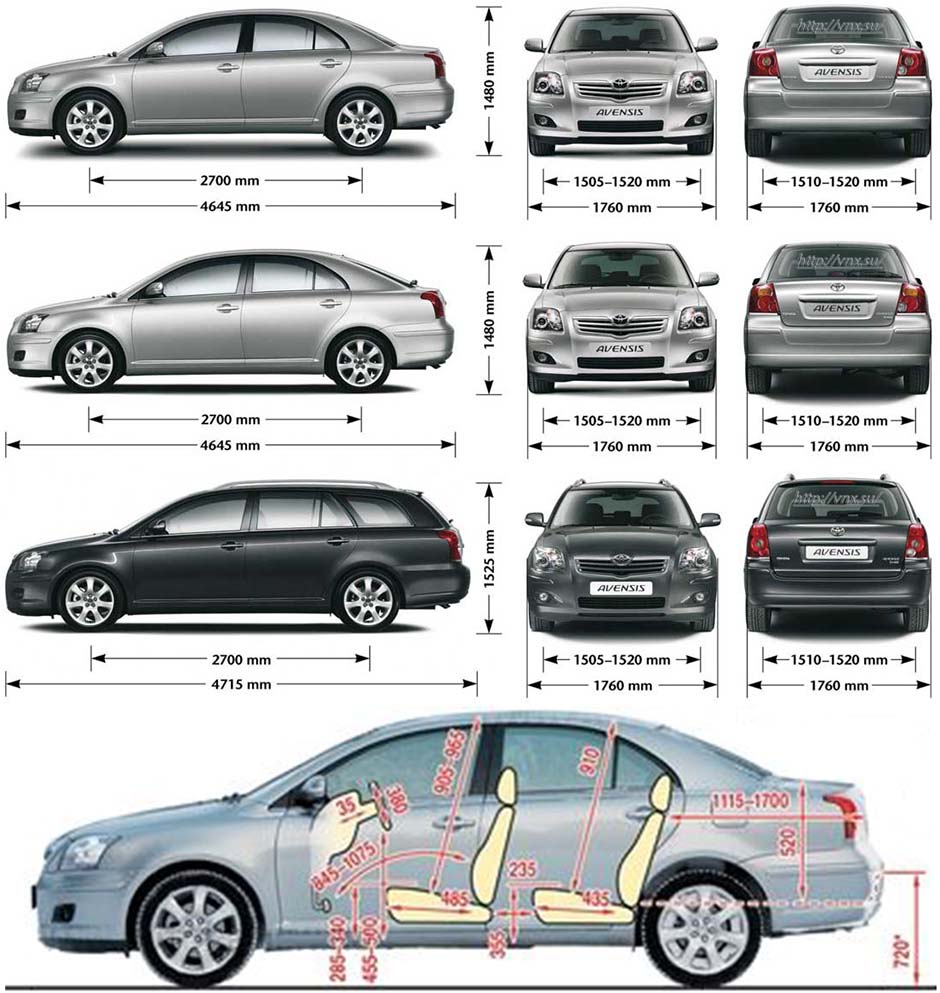
Dimensions
29
Equipment List
30
Major Technical Specifications
33
Electronic Circuit Inspection Procedure
51
Resistance Measuring Condition of Electronic Parts
51
Handling of Connector
51
Connector Checking Points
51
Repair Method of Connector Terminal
52
Handling of Wire Harness
52
Check Open Circuit
52
Check the Continuity
53
Check Short Circuit
54
Check and Replace ECU
55
How to Troubleshoot ECU Controlled Systems
56
For Using Hand-Held Tester
56
Table of Contents
56
Introduction – How to Troubleshoot Ecu Controlled
57
Customer Problem Analysis
59
Symptom Confirmation and Diagnostic Trouble Code
60
ABS with EBD System
60
Symptom Simulation
62
Diagnostic Trouble Code Chart
64
Problem Symptoms Table
65
Circuit Inspection
66
How to Use this Manual
67
Vehicle Identification and Serial Numbers
70
Identification Information
70
Repair Instruction
71
Jacking up and Supporting Vehicle
72
Bolts, Nuts, Screws and Fuses
72
Clips
73
Removal and Installation of Vacuum Hoses
74
For Vehicles Equipped with SRS Airbag and Seat Belt Pretensioner
75
Torque When Using Torque Wrench with Extension Tool
75
Spiral Cable
76
Horn Button Assembly (with Airbag)
76
Instrument Panel Passenger Airbag Assembly
77
Front Seat Airbag Assembly
78
Instrument Panel Lower Airbag Assembly
79
Curtain Shield Airbag Assembly
79
Seat Belt Pretensioner
80
Battery Terminal Removal and Installation
81
Airbag Sensor Assembly
81
SRS Wire Harness and Connector
81
Fuel Control Parts Removal and Installation
82
Engine Intake Parts Removal and Installation
82
Handling of Electronic Parts
82
Handling of Hose Clamps
83
For Vehicles Equipped with Mobile Communication Systems
83
For Vehicles Equipped with Traction Control (TRC) System
83
For Vehicles Equipped with Catalytic Converter
84
Vehicle Lift and Support Locations
85
Notice for Using Swing Arm Type Lift
86
Abbreviations Used in this Manual
87
Glossary of SAE and Toyota Terms
92
Preparation — Audio and Visual System
95
Preparation — Automatic Transmission/Trans
96
Preparation — Brake
100
Preparation — Clutch
102
Preparation — Communication System
103
Preparation — Cooling
104
Preparation — Diagnostics
106
ABS with EBD & BA & TRC & VSC System
107
Preparation — Drive Shaft / Propeller Shaft
108
Preparation — Engine Control System
112
Preparation — Engine Hood/Door
113
Preparation — Engine Mechanical
114
Preparation — Exhaust
123
Preparation — Exterior/Interior Trim
124
Preparation — Front Suspension
125
Preparation — Fuel
126
Preparation — Heater and Air Conditioner
129
Preparation — Ignition
134
Preparation — Instrument Panel/Meter
135
Intake Preparation
136
Preparation — Lubrication
137
Preparation — Manual Transmission/Transaxle
140
Preparation — Parking Brake
143
Preparation — Power Steering
144
Preparation — Rear Suspension
146
Preparation — Seat
148
Preparation — Sliding Roof/Convertible
149
Preparation — Starting and Charging
150
Preparation — Steering Column
151
Preparation — Supplemental Restraint System
152
Preparation — Tire and Wheel
154
Preparation — Vehicle Control System
155
Preparation — Windshield/Window Glass/Mirror
156
Preparation — Wiper and Washer
157
Audio and Visual System Torque Specification
158
Automatic Transmission/Transaxle Service Data
159
Brake Service Data
166
Clutch Service Data
168
Communication System Torque Specification
170
Cooling Service Data
171
Drive Shaft/Propeller Shaft/Axle Service Data
174
Emission Control Service Data
176
Engine Control System Service Data
177
Engine Hood/Door Torque Specification
180
Engine Mechanical Service Data
182
Exhaust Service Data
191
Exterior/Interior Trim Torque Specification
193
Front Suspension Service Data
194
Fuel Service Data
196
Heater and Air Conditioning Service Data
199
Ignition Service Data
201
Instrument Panel/Meter Torque Specification
203
Intake Service Data
204
Lighting Torque Specification
206
Lubrication Service Data
207
Manual Transmission/Transaxle Service Data
210
Parking Brake Service Data
213
Power Steering Service Data
215
Rear Suspension Service Data
217
Seat Torque Specification
219
Seat Belt Torque Specification
220
Sliding Roof/Convertible Torque Specification
221
Standard Bolt — How to Determine Bolt Strength
222
How to Determine Nut Strength
223
Specified Torque for Standard Bolts
224
Starting and Charging Service Data
225
Steering Column Service Data
227
Supplemental Restraint System Torque Specification
229
Tire and Wheel Service Data
230
Windshield/Window Glass/Mirror Torque Specification
231
Wiper and Washer Torque Specification
232
Accelerator Pedal Assy (1AZ–FSE/1CD–FTV) Replacement
233
Camshaft Position Sensor (1CD–FTV) Replacement
234
Crankshaft Position Sensor (1CD–FTV) Replacement
235
Crankshaft Position Sensor (1CD–FTV) Inspection
236
Inspect Mass Air Flow Meter
236
Inspect Intake Shutter Assy
236
Inspect Diesel Engine Coolant Temperature Sensor
237
Inspect Injection or Supply Pump Assy
237
Inspect Diesel Turbo Inlet Air Temperature Sensor
237
Inspect Crankshaft Position Sensor
238
Inspect Camshaft Position Sensor
238
Inspect EDU Relay
238
Inspect EFI Main Relay
239
Inspect Accelerator Pedal Relay
239
ECD System (1CD–FTV) On-Vehicle Inspection
240
Inspect Intake Shutter
240
Inspect Accelerator Pedal Position Sensor
241
ECM Replacement
242
Intake Shutter Assy (1CD–FTV) Components
243
Intake Shutter Assy Removal, Installation, Disassembly, Reassembly
244
Knock Sensor Components
246
Knock Sensor Replacement
250
Knock Sensor (1AZ–FE) Components
253
Knock Sensor (1AZ–FE) Replacement
257
Knock Sensor (1AZ–FSE) Components
260
Knock Sensor (1AZ–FSE) Replacement
265
Knock Sensor (1ZZ–FE/3ZZ–FE) Replacement
267
SFI System Inspection
268
Inspect Throttle Position Sensor
269
Inspect Engine Coolant Temperature Sensor
270
Inspect Knock Sensor
270
Inspect EFI Relay
270
Inspect Circuit Opening Relay
271
SFI System (1AZ–FE) On-Vehicle Inspection
272
Inspect Power Steering Oil Pressure Sensor
272
Inspect Idle Air Control Valve
273
SFI System (1AZ–FSE)
274
Inspect Camshaft Timing Oil Control Valve Assy
274
Inspect Throttle Body Assy
274
SFI System (1AZ–FSE) On-Vehicle Inspection
277
Inspect Throttle Body
278
SFI System (1ZZ–FE/3ZZ–FE) Inspection
279
SFI System (1ZZ–FE/3ZZ–FE) On-Vehicle Inspection
283
Throttle Body Assy (1AZ–FE) Components
285
Throttle Body Assy (1AZ–FE) Removal/Installation/Disassembly
287
Throttle Body Assy (1AZ–FSE)
291
Throttle Body Assy (1AZ–FSE) Replacement
293
Throttle Body Assy (1ZZ–FE) Components
296
Throttle Body Assy (1ZZ–FE) Removal, Installation, Disassembly
298
Throttle Body Assy (3ZZ–FE) Components
302
Throttle Body Assy (3ZZ–FE) Removal, Installation, Disassembly
304
Common Rail Assy (1CD–FTV) Components
306
Common Rail Assy (1CD–FTV) Replacement
308
Fuel Filter Assy (1CD–FTV) Replacement
312
Fuel Injector Assy Components
314
Fuel Injector Assy Replacement
316
Fuel Injector Assy (1AZ–FSE) Components
319
Fuel Injector Assy (1ZZ–FE/3ZZ–FE) Components
324
Fuel Injector Assy (1ZZ–FE/3ZZ–FE) Replacement
325
Fuel Pressure Pulsation Damper Assy Replacement
329
Fuel Pump Assy Components
330
Fuel Pump Assy Replacement
333
Fuel Pump Assy (Gasoline) Components
337
Fuel Pump Assy (Gasoline) Replacement
338
Fuel Pump Assy (Gasoline) Inspection
342
Fuel System On-Vehicle Inspection
344
Check Fuel Pressure
344
Check Fuel Pump Operation and Fuel Tank
345
Fuel System (1AZ–FE) Precaution
347
Fuel System (1CD–FTV) Inspection
351
Fuel System (1ZZ–FE/3ZZ–FE) Inspection
353
Fuel System (1ZZ–FE/3ZZ–FE) On-Vehicle Inspection
355
Fuel System (1ZZ–FE/3ZZ–FE) Precaution
358
Fuel System (1AZ–FSE) Inspection
362
Fuel System (1AZ–FSE) Precaution
366
Fuel Tank Assy (Diesel) Components
369
Fuel Tank Assy (Diesel) Removal, Installation, Disassembly
372
Fuel Tank Assy (Gasoline) Components
379
Fuel Tank Assy (Gasoline) Removal, Installation, Disassembly
383
Injection or Supply Pump Assy (1CD–FTV) Components
391
Injection or Supply Pump Assy (1CD–FTV) Replacement
394
Injector Assy (1CD–FTV) Components
401
Injector Assy (1CD–FTV) Replacement
403
Emission Control
409
EGR System (1CD–FTV) Inspection
409
EGR System (1CD–FTV) On-Vehicle Inspection
411
Emission Control System (1AZ–FE) Inspection
412
Inspect Charcoal Canister Assy
412
Inspect Ventilation Valve Sub-Assy
412
Inspect Fuel Tank Cap Assy
412
Inspect Vacuum Switching Valve Assy No.1
413
Inspect Air Fuel Ratio Sensor
413
Inspect Heated Oxygen Sensor
414
Emission Control System (1AZ–FE) On-Vehicle Inspection
415
Inspect Air-Fuel Ratio Compensation System
415
Inspect Fuel Cut off RPM
415
Inspect Evaporative Emission Control System
415
Emission Control System (1AZ–FSE)
417
Emission Control System (1AZ–FSE) On-Vehicle Inspection
420
Emission Control System (1CD–FTV) On-Vehicle Inspection
422
Emission Control System (1ZZ–FE/3ZZ–FE) Inspection
423
Intake Air Control System (1AZ–FSE) Inspection
428
Inspect Intake Air Control Valve Assy
428
Intercooler Assy (1CD–FTV) Replacement
430
Turbo Charger System (1CD–FTV) Inspection
432
Turbo Charger System (1CD–FTV) Precaution
435
Turbocharger Sub-Assy (1CD–FTV) Components
437
Turbocharger Sub-Assy (1CD–FTV) Replacement
440
Camshaft (1AZ–FE) Components
447
Camshaft (1AZ–FE) Replacement
450
Camshaft (1AZ–FSE) Components
457
Camshaft (1AZ–FSE) Replacement
460
Camshaft (1CD–FTV) Components
466
Camshaft (1CD–FTV) Replacement
470
Camshaft (1ZZ–FE/3ZZ–FE) Components
478
Camshaft (1ZZ–FE/3ZZ–FE) Replacement
482
Chain Sub-Assy (1AZ–FE) Components
494
Chain Sub-Assy (1AZ–FE) Replacement
498
Chain Sub-Assy (1AZ–FSE) Components
526
Chain Sub-Assy (1ZZ–FE/3ZZ–FE) Components
530
Crankshaft Seal (1CD–FTV) Replacement
534
Cylinder Head Gasket (1AZ–FE) Components
537
Cylinder Head Gasket (1AZ–FE) Replacement
544
Cylinder Head Gasket (1AZ–FSE) Replacement
552
Cylinder Head Gasket (1CD–FTV) Components
561
Cylinder Head Gasket (1CD–FTV) Replacement
567
Cylinder Head Gasket (1ZZ–FE/3ZZ–FE) Components
577
Cylinder Head Gasket (1ZZ–FE/3ZZ–FE) Replacement
582
Drive Belt (1CD–FTV) Replacement
597
Engine (1AZ–FE) Inspection
598
Engine (1AZ–FSE) Inspection
602
Engine (1CD–FTV) Inspection
606
Engine (1ZZ–FE/3ZZ–FE) Inspection
609
Engine Rear Oil Seal (1AZ–FE) Replacement
613
Engine Rear Oil Seal (1AZ–FSE) Replacement
614
Engine Rear Oil Seal (1CD–FTV) Replacement
615
Engine Rear Oil Seal (1ZZ–FE/3ZZ–FE) Replacement
617
Fan and Generator V Belt (1AZ–FE) Replacement
620
Fan and Generator V Belt (1AZ–FSE) Replacement
621
Fan and Generator V Belt (1ZZ–FE/3ZZ–FE) Replacement
622
Partial Engine Assy (1AZ–FE) Components
623
Partial Engine Assy (1AZ–FE) Replacement
633
Partial Engine Assy (1CD–FTV) Components
647
Partial Engine Assy (1CD–FTV) Replacement
656
Partial Engine Assy (1ZZ–FE/3ZZ–FE) Components
675
Partial Engine Assy (1ZZ–FE/3ZZ–FE) Replacement
683
Timing Belt (1CD–FTV) Components
701
Timing Belt (1CD–FTV) Replacement
703
Timing Gear Cover Oil Seal (1ZZ–FE/3ZZ–FE) Replacement
710
Timing Gear Case or Timing Chain Case Oil Seal (1AZ–FE) Replacement
712
Timing Gear Case or Timing Chain Case Oil Seal (1AZ–FSE) Replacement
714
Valve Clearance (1AZ–FE) Adjustment
716
Valve Lifter Selection Chart (Intake)
718
Valve Lifter Selection Chart (Exhaust)
719
Valve Clearance (1ZZ–FE/3ZZ–FE) Adjustment
721
1ZZ-FE, 3ZZ-FE: Valve Lifter Selection Chart (Intake)
727
1ZZ-FE, 3ZZ-FE: Valve Lifter Selection Chart (Exhaust)
728
Exhaust Pipe Assy (1AZ–FE/1AZ–FSE) Components
734
Exhaust Pipe Assy (1AZ–FE/1AZ–FSE) Removal, Disassembly
735
Exhaust Pipe Assy (1CD–FTV) Components
737
Exhaust Pipe Assy (1CD–FTV) Removal, Installation, Disassembly
738
Exhaust Assy (1ZZ–FE/3ZZ–FE) Components
741
Exhaust Assy (1ZZ–FE/3ZZ–FE) Removal, Installation, Disassembly
742
Water Pump Assy (1ZZ–FE/3ZZ–FE) Inspection
746
Cylinder Block (1ZZ–FE/3ZZ–FE) Components
747
Cylinder Block (1ZZ–FE/3ZZ–FE) Overhaul
748
Cylinder Head Assy (1ZZ–FE/3ZZ–FE) Components
763
Cylinder Head Assy (1ZZ–FE/3ZZ–FE) Overhaul
764
Partial Engine Assy (1ZZ–FE/3ZZ–FE) Overhaul
777
Terms (1ZZ–FE/3ZZ–FE)
800
How to Use this Manual (1ZZ–FE/3ZZ–FE)
805
Repair Instruction (1NZ–FE/2NZ–FE)
811
Oil Pump Assy (1ZZ–FE/3ZZ–FE) Components
814
Oil Pump Assy (1ZZ–FE/3ZZ–FE) Overhaul
815
Generator Assy (1ZZ–FE/3ZZ–FE) Components
840
Generator Assy (1ZZ–FE/3ZZ–FE) Overhaul
841
Starter Assy (1ZZ–FE/3ZZ–FE) Components
847
Starter Assy (1ZZ–FE/3ZZ–FE) Overhaul
848
Cooling Fan System (1AZ–FE) On-Vehicle Inspection
855
Cooling Fan System (1AZ–FE) Inspection
856
Cooling Fan System (1AZ–FSE) On-Vehicle Inspection
857
Cooling Fan System (1AZ–FSE) Inspection
858
Cooling Fan System (1CD–FTV) On-Vehicle Inspection
859
Cooling Fan System (1CD–FTV) Inspection
860
Cooling Fan System (1ZZ–FE/3ZZ–FE) On-Vehicle Inspection
862
Cooling Fan System (1ZZ–FE/3ZZ–FE) Inspection
863
Radiator Assy (1ZZ–FE/3ZZ–FE) Replacement
864
Cooling System (1AZ–FE) On-Vehicle Inspection
866
Cooling System (1AZ–FE) Inspection
868
Cooling System (1AZ–FSE) On-Vehicle Inspection
870
Cooling System (1AZ–FSE) Inspection
872
Cooling System (1CD–FTV) On-Vehicle Inspection
874
Cooling System (1CD–FTV) Inspection
876
Cooling System (1ZZ–FE/3ZZ–FE) On-Vehicle Inspection
878
Cooling System (1ZZ–FE/3ZZ–FE) Inspection
880
Engine Coolant (1AZ–FE) Replacement
882
Engine Coolant (1AZ–FSE) Replacement
884
Engine Coolant (1CD–FTV) Replacement
886
Engine Coolant (1ZZ–FE/3ZZ–FE) Replacement
888
Radiator Assy (1AZ–FE) Replacement
890
Radiator Assy (1AZ–FSE) Replacement
891
Radiator Assy (1CD–FTV)
892
Thermostat (1AZ–FSE) Replacement
895
Thermostat (1CD–FTV) Replacement
896
Thermostat (1ZZ–FE/3ZZ–FE) Replacement
897
Thermostat (1AZ–FE) Replacement
898
Water Pump Assy (1AZ–FE) Replacement
899
Water Pump Assy (1AZ–FSE) Replacement
901
Water Pump Assy (1CD–FTV) Replacement
903
Water Pump Assy (1ZZ–FE/3ZZ–FE) Replacement
907
Lubrication System (1AZ–FE) On-Vehicle Inspection
908
Lubrication System (1AZ–FSE) On-Vehicle Inspection
910
Lubrication System (1CD–FTV) On-Vehicle Inspection
912
Lubrication System (1ZZ–FE/3ZZ–FE) On-Vehicle Inspection
914
Oil Cooler Assy (1CD–FTV) Replacement
916
Oil Filter Sub-Assy (1AZ–FE) Replacement
917
Oil Filter Sub-Assy (1AZ–FSE) Replacement
918
Oil Filter Sub-Assy (1CD–FTV) Replacement
919
Oil Filter Sub-Assy (1ZZ–FE/3ZZ–FE) Replacement
921
Oil Pump Assy (1AZ–FE) Replacement
923
Oil Pump Assy (1AZ–FSE) Replacement
927
Oil Pump Assy (1CD–FTV) Replacement
931
Oil Pump Assy (1ZZ–FE/3ZZ–FE) Replacement
939
Camshaft Position Sensor (1AZ–FE/1AZ–FSE) Replacement
940
Camshaft Position Sensor (1ZZ–FE/3ZZ–FE) Replacement
941
Crankshaft Position Sensor (1AZ–FE/1AZ–FSE) Replacement
942
Crankshaft Position Sensor (1ZZ–FE/3ZZ–FE) Replacement
943
Ignition System (1AZ–FE) On-Vehicle Inspection
944
Ignition System (1AZ–FE) Inspection
946
Ignition System (1AZ–FSE) On-Vehicle Inspection
949
Ignition System (1AZ–FSE) Inspection
951
Inspect Spark Plug
951
Ignition System (1ZZ–FE/3ZZ–FE) On-Vehicle Inspection
953
Ignition System (1ZZ–FE/3ZZ–FE) Inspection
955
Charging System (1AZ–FE) Precautions
957
Charging System (1AZ–FE) On-Vehicle Inspection
958
Check Battery Electrolyte Level
958
Check Battery Voltage
958
Inspect Drive Belt
958
Inspect Charging Circuit
959
Charging System (1AZ–FSE) Precaution
960
Charging System (1AZ–FSE) On-Vehicle Inspection
961
Charging System (1CD–FTV) Precaution
963
Charging System (1CD–FTV) On-Vehicle Inspection
964
Charging System (1ZZ–FE/3ZZ–FE) Precaution
967
Charging System (1ZZ–FE/3ZZ–FE) On-Vehicle Inspection
968
Generator Assy Replacement
970
Glow Plug Assy Replacement
974
Pre-Heating System On-Vehicle Inspection
975
Pre-Heating System Inspection
977
Starter Assy Replacement
978
Starting System Inspection
982
Front Shock Absorber with Coil Spring Overhaul
990
Dispose of Shock Absorber Assy Front LH
995
Front Suspension Components
996
Front Suspension Arm Sub-Assy Lower No.1 LH Replacement
1000
Front Suspension System Problem Symptoms Table
1008
Front Wheel Adjustment
1009
Measure Vehicle Height
1009
Inspect Toe-In
1009
Adjust Toe-In
1009
Inspect Wheel Angle
1010
Inspect Camber, Caster and Steering Axis Inclination
1010
Adjust Camber
1011
Lower Ball Joint Assy Front LH Replacement
1013
Stabilizer Bar Front Replacement
1015
Lower Control Arm Assy LH Replacement
1018
Rear Shock Absorber with Coil Spring Ovehaul
1021
Dispose of Shock Absorber Assy Rear LH
1027
Rear Suspension Components
1028
Rear Suspension Arm Assy No. 1 LH Overhaul
1030
Rear Suspension System Problem Symptoms Table
1039
Rear Wheel Adjustment
1040
Stabilizer Bar Rear Replacement
1044
Upper Control Arm Assy Replacement
1046
Wheel and Tire System Inspection
1048
Drive Shaft, Propeller Shaft, Axle Problem Symptoms Table
1050
Drive Shaft, Propeller Shaft, Axle On-Vehicle Inspection
1051
Front Axle Hub Sub-Assy LH Components
1052
Front Axle Hub Sub-Assy LH Replacement
1053
Front Axle LH Hub Bolt Replacement
1060
Front Drive Shaft Components
1061
Rear Axle Carrier Sub-Assy LH Components
1064
Rear Axle Carrier Sub-Assy LH Replacement
1065
Rear Axle LH Hub Bolt Replacement
1070
Brake Actuator Assy (W/ VSC) On-Vehicle Inspection
1071
Brake Actuator Assy Replacement
1073
Brake Booster Assy On-Vehicle Inspection
1075
Brake Booster Assy Components
1076
Brake Booster Assy Replacement
1077
Brake Fluid Bleeding
1091
Brake Master Cylinder Sub-Assy Components
1093
Brake Master Cylinder Sub-Assy Replacement
1095
Brake Pedal Sub-Assy Adjustment
1099
Brake Pedal Sub-Assy Components
1101
Brake Pedal Sub-Assy Replacement
1102
Brake System Precaution
1104
Brake System Problem Symptoms Table
1105
Front Brake Components
1107
Front Brake Overhaul
1108
Rear Disc Brake Components
1113
Rear Disc Brake Overhaul
1114
Skid Control Sensor Replacement
1120
Speed Sensor Front LH Replacement
1122
Steering Sensor Replacement
1124
Vacuum Pump Assy On-Vehicle Inspection
1127
Vacuum Pump Assy Components
1128
Vacuum Pump Assy Overhaul
1129
Yawrate Sensor Replacement
1134
Parking Brake Assy Components
1138
Parking Brake Assy Overhaul
1139
Parking Brake Cable Assy No.1 Components
1145
Parking Brake Cable Assy No.1 Replacement
1146
Parking Brake Cable Assy No.3 Components
1148
Parking Brake Cable Assy No.3 Replacement
1149
Parking Brake Lever Sub-Assy Components
1152
Parking Brake Lever Sub-Assy Replacement
1153
Parking Brake System Problem Symptoms Table
1155
Parking Brake System Adjustments
1156
Floor Shift Shift Lever Assy Components
1157
Floor Shift Shift Lever Assy Replacement
1158
Front Differential Oil Seal Replacement
1160
Manual Transaxle Assy Components
1164
Manual Transaxle Assy Replacement
1166
Manual Transaxle Oil On-Vehicle Inspection
1185
Manual Transaxle System Problem Symptoms Table
1186
Transmission Control Cable Assy Replacement
1187
Clutch Accumulator Assy Components
1190
Clutch Accumulator Assy Replacement
1191
Clutch Master Cylinder Assy Components
1192
Clutch Master Cylinder Assy Replacement
1193
Clutch Pedal Sub-Assy Adjustment
1196
Clutch Pedal Sub-Assy Components
1198
Clutch Pedal Sub-Assy Replacement
1200
Clutch Release Cylinder Assy Components
1206
Clutch Release Cylinder Assy Overhaul
1207
Clutch System Problem Symptoms Table
1211
Clutch Unit Componets
1212
Clutch Unit Overhaul
1215
Steering Column
1219
Power Steering ECU Assy Replacement
1219
Steering Column Assy Components
1222
Electric Power Steering Diagram
1224
Steering Column Assy Overhaul
1226
Steering System Precaution
1237
Steering System Problem Symptoms Table
1238
Electric Power Steering
1239
Steering System On-Vehicle Inspection
1240
Power Steering System Precaution
1241
Power Steering System Problem Symptoms Table
1242
Power Steering System On-Vehicle Inspection
1244
Rack and Pinion Power Steering Gear Assy Components
1248
Rack and Pinion Power Steering Gear Assy Overhaul
1250
Steering Gear Assy Components
1260
Steering Gear Assy Overhaul
1261
Vane Pump Assy Components
1267
Vane Pump Assy Overhaul
1268
Vane Pump Assy (AZ Series) Components
1276
Vane Pump Assy (AZ Series) Overhaul
1277
Air Conditioning Control Assy Components
1286
Air Conditioning Control Assy Overhaul
1288
Air Conditioning Radiator Assy Components
1291
Air Conditioning System Precaution
1293
Air Conditioning System On-Vehicle Inspection
1295
Air Conditioning System Problem Symptoms Table
1298
Air Conditioning System Problem Inspection
1299
Blower Assy Components
1305
Blower Assy Overhaul
1306
Combustion Type Power Heater System On-Vehicle Inspection
1310
Combustion Type Power Heater System Diagnostic Trouble Code Chart
1312
Combustion Type Power Heater System Inspection
1314
Inspect Heater Assy
1314
Inspect Heater Switch Assy
1315
Combustion Type Power Heater System Problem Symptoms Table
1317
Heater Assy Replacement
1321
Hot Gas Type Power Heater System On-Vehicle Inspection
1323
Hot Gas Type Power Heater System Inspection
1324
Refrigerant On-Vehicle Inspection
1325
Inspect Refrigerant Volume
1332
Inspect Refrigerant Pressure with Manifold Gauge Set
1333
Refrigerant Replacement
1339
Refrigerant Line Components
1340
V (Cooler Compressor to Crankshaft Pulley) Belt No.1 Replacement
1347
W/Pulley Compressor Assy On-Vehicle Inspection
1349
W/Pulley Compressor Assy Replacement
1350
W/Receiver Condenser Assy On-Vehicle Inspection
1370
W/Receiver Condenser Assy Components
1371
W/Receiver Condenser Assy Overhaul
1373
Supplemental Restraint System
1390
Air Bag Sensor Assy Center Components
1390
Air Bag Sensor Assy Center Replacement
1391
Air Bag Sensor Front LH Components
1392
Air Bag Sensor Front LH Replacement
1393
Air Bag Sensor Rear LH Components
1394
Air Bag Sensor Rear LH Replacement
1395
Curtain Shield Air Bag Assy LH Components
1396
Curtain Shield Air Bag Assy LH Replacement
1398
Curtain Shield Air Bag Assy LH Disposal
1401
Front Seat Airbag Assy LH Disposal
1407
Steering Wheel Assy Components
1413
Steering Wheel Assy Replacement
1414
Horn Button Assy Disposal
1416
Instrument Panel Air Bag Assy Components
1423
Instrument Panel Air Bag Assy Replacement
1424
Instrument Panel Air Bag Assy Disposal
1425
Instrument Panel Passenger Air Bag Assy Components
1431
Instrument Panel Passenger Air Bag Assy Replacement
1432
Instrument Panel Passenger Air Bag Assy Disposal
1433
Seat Position Air Bag Sensor Components
1439
Seat Position Air Bag Sensor Replacement
1440
Side Air Bag Sensor Assy LH Components
1441
Side Air Bag Sensor Assy LH Replacement
1442
Spiral Cable Sub-Assy Replacement
1443
Supplemental Restraint System Precaution
1445
Audio System
1446
SRS Connectors
1447
Supplemental Restraint System On-Vehicle Inspection
1455
Seat Belts
1460
Front Seat Belt Precautions
1460
Front Seat Belt Components
1461
Front Seat Belt Replacement
1462
Front Seat Belt Disposal
1464
Rear Seat Belt (Liftback Models) Components
1469
Rear Seat Belt (Liftback Models) Replacement
1470
Rear Seat Belt (Sedan Models) Components
1473
Rear Seat Belt (Sedan Models) Replacement
1474
Rear Seat Belt (Wagon Models) Components
1478
Rear Seat Belt (Wagon Models) Replacement
1479
Seat Belt Warning System Location
1482
Seat Belt Warning System Symptoms Table
1483
Seat Belt Warning System Inspection
1484
Center Stop Lamp Assy Replacement
1486
Fog Lamp Assy LH Replacement
1487
Fog Lamp Assy LH Adjustment
1488
Headlamp Dimmer Switch Assy Replacement
1489
Headlamp Leveling ECU Assy Replacement
1490
Headlamp Unit LH Components
1491
Headlamp Unit LH Replacement
1492
Headlamp Unit LH Adjustment
1495
Height Control Sensor Sub-Assy FR RH Replacement
1497
Height Control Sensor Sub-Assy Rear RH Replacement
1498
License Plate Lamp Assy Replacement
1499
Lighting System Precaution
1500
Headlight System Problem Symptoms Table
1501
Illuminated Entry System
1502
Lighting System On-Vehicle Inspection
1504
Headlamp Auto Levering Operation Check
1506
Headlamp Dimmer Switch Assy Inspection
1508
Hazard Warning Signal Switch Assy Inspection
1508
Front Door Courtesy Lamp Switch Assy Check
1509
Rear Door Courtesy Lamp Switch Assy Check
1509
Back Door Lock Assy Check
1509
Relays Check
1510
Transponder Key Amplifier Check
1510
Map Lamp Assy Check
1511
Room Lamp Assy No.2 Check
1511
Glove Box Lamp Assy Check
1511
LH Visor Assy Check
1511
Headlamp Leveling Switch Check
1512
Stop Lamp Switch Assy (W/O Cruise Control) Check
1512
Back up Lamp Switch Assy Check
1512
Height Control Sensor Sub-Assy FR RH Check
1513
Height Control Sensor Sub-Assy Rear RH Check
1513
Rear Combination Lamp Assy LH Replacement
1514
Side Turn Signal Lamp Assy LH Replacement
1515
Headlamp Washer Actuator Sub-Assy LH Replacement
1516
Rain Sensor Replacement
1517
Rear Wiper Motor Assy Replacement
1519
Rear Wiper Rubber Replacement
1521
Washer Nozzle Sub-Assy Adjustment
1523
Windshield Wiper Motor Assy Replacement
1525
Windshield Wiper Switch Assy Replacement
1529
Wiper and Washer System Precaution
1530
Wiper and Washer System Problem Symptoms Table
1531
Wiper and Washer System On-Vehicle Inspection
1533
Wiper and Washer System Inspection
1535
Wiper Rubber LH Replacement
1542
Amplifier Antenna Assy Replacement
1543
Navigation System
1544
Antenna Cord Sub-Assy Replacement
1550
Antenna Cord Sub-Assy No.3 Replacement
1551
Audio and Visual System Precaution
1554
Audio and Visual System Components
1555
Cigarette Lighter Assy Replacement
1558
Front No.1 Speaker Assy Replacement
1561
Front No.2 Speaker Assy Replacement
1563
Multi-Display (CRT Display) Replacement
1564
Navigation Antenna Assy Replacement
1568
Navigation ECU Replacement
1569
Power Point Socket Assy Replacement
1570
Radio Receiver Assy Replacement
1571
Rear Speaker Assy Replacement
1572
Rear Speaker Assy No.2 Replacement
1574
Window Glass (Antenna Wire) Repair
1575
Power Source Location
1576
High Pitched Horn Assy Replacement
1583
Horn System Location
1584
Horn System Problem Symptoms Table
1585
Horn System Inspection
1586
Low Pitched Horn Assy Replacement
1587
Back Door Glass Components
1588
Back Door Glass Replacement
1589
Inner Rear View Mirror Assy Replacement
1607
Outer Rear View Mirror Assy LH Replacement
1608
Power Mirror Control System On-Vehicle Inspection
1609
Power Mirror Control System Location
1611
Power Mirror Control System Problem Symptoms Table
1612
Power Mirror Control System Inspection
1613
Power Mirror Control System Reset
1630
Quarter Window Assy LH Components
1631
Quarter Window Assy LH Replacement
1632
Window Defogger System Location
1636
Window Defogger System Problem Symptom Table
1639
Window Defogger System Inspection
1640
Windshield Glass Components
1645
Windshield Glass Replacement
1646
Combination Meter Problem Symptoms Table
1653
Combination Meter On-Vehicle Inspection
1655
Inspect Speedometer
1655
Inspect Output Signal of Vehicle Speed
1655
Inspect Tachometer
1656
Inspect Fuel Receiver Gauge
1656
Inspect Fuel Level Warning
1656
Inspect Coolant Temperature Receiver Gauge Warning Light
1656
Inspect Seat Belt Warning Light and Buzzer
1657
Inspect Low Oil Pressure Warning Light
1657
Inspect Brake Warning Light
1657
Inspect Brake Fluid Level Warning Switch
1657
Inspect Key Reminder Warning Buzzer
1658
Combination Meter Assy Overhaul
1659
Instrument Panel/Meter Components
1660
Instrument Panel Sub-Assy Lower Precaution
1663
Multi-Display (CRT Display) Display Replacement
1664
Front Power Seat Control System Location
1665
Front Power Seat Control System Problem Symptoms Table
1667
Front Power Seat Control System On-Vehicle Inspection
1668
Front Power Seat Control System Inspection
1670
Driver Side
1670
Front Seat Assembly LH (Manual Seat Type) Components
1674
Front Seat Assembly LH (Manual Seat Type) Overhaul
1675
Front Seat Assembly (Power Seat Type) Components
1678
Front Seat Assembly (Power Seat Type) Overhaul
1679
Rear Seat Assy (40/60 Folding Flip-Up Cushion) Components
1683
Rear Seat Assy (40/60 Folding Flip-Up Cushion) Overhaul
1685
Rear Seat Assy (40/60 Folding) Components
1689
Rear Seat Assy (40/60 Folding) Overhaul
1691
Rear Seat Assy (United Fixed) Components
1695
Rear Seat Assy (United Fixed) Overhaul
1696
Seat Heater System Location
1698
Seat Heater System Problem Symptoms Table
1700
Seat Heater System Inspection
1701
Fuel Lid Opener System Location
1704
Fuel Lid Opener System Problem Symptoms Table
1706
Fuel Lid Opener System Inspection
1707
Key Reminder Warning System On-Vehicle Inspection
1708
Power Door Lock Control System On-Vehicle Inspection
1709
Power Door Lock Control System Inspection
1711
Theft Deterrent System On-Vehicle Inspection
1722
Active Arming Mode
1723
Forced Door Lock Control
1725
Alarm Memory Function
1725
Security Indicator Output
1725
Intrusion (Theft Warning) Sensor
1726
Theft Warning (Self-Power) Siren
1726
Transmitter Battery Replacement
1727
Transmitter Sub-Assy Module Set Door Control Replacement
1728
Transmitter Sub-Assy Module Set Door Control Inspection
1729
Register Recognition Code
1731
Flow Chart of Recognition Code Registration
1732
Wireless Door Lock Control System Precaution
1736
Wireless Door Lock Control System On-Vehicle Inspection
1737
Sliding Roof Components
1739
Sliding Roof Replacement
1746
Sliding Roof System Location
1747
Sliding Roof System On-Vehicle Inspection
1749
Sliding Roof System Problem Symptoms Table
1751
Sliding Roof System Problem Inspection
1752
Reset Sliding Roof Motor
1753
Back Door Components
1754
Back Door Adjustment
1755
Back Door Overhaul
1757
Back Door Stay Replacement
1764
Back Door Stay Disposal
1765
Front Door Components
1766
Front Door Adjustment
1768
Front Door Overhaul
1770
Hood Components
1780
Hood Adjustment
1781
Luggage Compartment Door Components
1783
Luggage Compartment Door Adjustment
1784
Luggage Door Hinge Torsion Bar Replacement
1786
Backdoor Garnish Sub-Assy Outside Replacement
1788
Front Bumper Components
1790
Front Bumper Replacement
1792
Front Floor Footrest Replacement
1794
Fuel Lid Lock Control Assy Components
1796
Fuel Lid Lock Control Assy Replacement
1799
Luggage Compartment Door Garnish Sub-Assy Outside Replacement
1802
Name Plate Replacement
1803
Outside Moulding LH Replacement
1807
Rear Bumper Components
1809
Rear Bumper Replacement
1810
Rear Door Belt Moulding Assy LH Replacement
1815
Rear Spoiler Replacement
1816
Rocker Panel Moulding LH Replacement
1818
Roof Drip Side Finish Moulding Center LH Replacement
1819
Roof Handling Assy Components
1820
Roof Handling Assy Replacement
1823
Ignition or Starter Switch Assy Replacement
1848
Ignition or Starter Switch Assy Inspection
1849
Manual B — How to Use
1851
Troubleshooting
1860
Voltage Check
1860
Continuity and Resistance Check
1860
Finding a Short Circuit
1861
Disconnection of Male and Female Connectors
1861
How to Replace Terminal
1862
Abbreviations
1865
Glossary of Terms and Symbols
1866
Relay Locations
1868
Engine Compartment
1868
Electrical Wiring Routing
1880
Power Source
1906
Starting
1909
Charging
1910
Ignition
1912
Engine Control
1913
Engine Immobiliser System
1926
Engine Immobiliser System Electrical Diagram
1944
Multiplex Communication System (Communication Bus) Electrical Diagram
1945
Multiplex Communication System (RHD) Electrical Diagram
1946
Headlight (W/ Daytime Running Light) Electrical Diagram
1957
Headlight (W/O Daytime Running Light) Electrical Diagram
1961
Front Fog Light Electrical Diagram
1963
Rear Fog Light Electrical Diagram
1964
Taillight Electrical Diagram
1965
Turn Signal and Hazard Warning Light
1967
Stop Light Electrical Diagram
1969
Back–Up Light Electrical Diagram
1970
Illumination Electrical Diagram
1971
Interior Light (RHD) Electrical Diagram
1976
Headlight Beam Level Control (W/ HID) Electrical Diagram
1980
Headlight Beam Level Control (W/O HID) Electrical Diagram
1982
Headlight Cleaner (W/ HID) Electrical Diagram
1984
Headlight Cleaner (W/O HID) Electrical Diagram
1985
Key Reminder and Light Reminder Electrical Diagram
1986
Seat Belt Warning Electrical Diagram
1988
ECT and A/T Indicator Electrical Diagram
1990
Cruise Control Electrical Diagram
2004
VSC Electrical Diagram
2012
ABS Electrical Diagram
2018
SRS Electrical Diagram
2022
EPS Electrical Diagram
2026
Door Lock Control (RHD) and Theft Deterrent Electrical Diagram
2028
Wireless Door Lock Control (RHD) Electrical Diagram
2037
Double Locking Electrical Diagram
2041
Power Window (RHD) Electrical Diagram
2046
Front Wiper and Washer (W/ Auto Wiper System) Electrical Diagram
2050
Front Wiper and Washer (W/O Auto Wiper System) Electrical Diagram
2052
Rear Wiper and Washer Electrical Diagram
2054
Moon Roof Electrical Diagram
2055
Shift Lock Electrical Diagram
2057
Horn Electrical Diagram
2058
Fuel Lid Opener Electrical Diagram
2059
Fuel Heater Electrical Diagram
2060
Automatic Glare – Resistant EC Mirror Electrical Diagram
2061
Cigarette Lighter Electrical Diagram
2062
Power Outlet Electrical Diagram
2063
Front Window Deicer Electrical Diagram
2064
Rear Window Defogger Electrical Diagram
2065
Mirror Heater Electrical Diagram
2067
Remote Control Mirror Electrical Diagram
2068
Power Seat Electrical Diagram
2069
Seat Heater Electrical Diagram
2071
Navigation System (Map Type) Electrical Diagram
2073
Multi–Display (W/O Navigation System Map Type) Electrical Diagram
2077
Radio and Player Electrical Diagram
2079
Combination Meter
2081
Radiator Fan and Condenser Fan Electrical Diagram
2087
Air Conditioner (Automatic A/C) Electrical Diagram
2090
Power Heater (Hot Gas Type Automatic A/C) Electrical Diagram
2091
Power Heater (Hot Gas Type Manual A/C) Electrical Diagram
2097
Heater Electrical Diagram
2098
Power Heater (Electrical Type) Electrical Diagram
2101
Power Heater (Combustion Type) Electrical Diagram
2103
Ground Point
2104
Power Source (Current Flow Chart)
2111
Driver Side J/B
2113
Engine Room R/B No.1 (1CD–FTV)
2116
Engine Room R/B No.1 (Gasoline)
2117
Engine Room R/B No.2
2118
Engine Room R/B No.3
2118
Engine Room R/B No.4
2119
Fuse Block
2120
Connector List
2123
Part Number of Connectors
2137
Overall Electrical Wiring Diagram
2143
Toyota Avensis T250 с бензиновыми двигателями: 3ZZ-FE 1.6 л (1598 см³) 108 л.с./79,4 кВт, 1ZZ-FE 1.8 л (1794 см³) 129 л.с./95 кВт, 1AZ-FE LG 2.0 л (1998 см³) 135 л.с./99 кВт, 1AZ-FSE 2.0 л D-4 (1998 см³) 147 л.с./108 кВт, 2AZ-FSE 2.4 л D-4 (2362 см³) 163 л.с./120 кВт; Руководство по эксплуатации, техническому обслуживанию и ремонту, технические характеристики, электросхемы, контрольные размеры кузова, устройство, диагностика. Тойота Авенсис модели второго поколения с кузовами пятидверный хэтчбек/liftback, универсал/estate и седан/saloon выпуска с 2003 по 2009 год
ЕСЛИ ВЫ ВИДИТЕ ОШИБКУ 406 Not Acceptable и не видите документ, то скорей всего у Вас IP РФ и его надо сменить, на любой другой страны, с помощью VPN ( Scribd и SlideShare блокируют посетителей с Российским IP).
Видео Toyota Avensis замена салонного фильтра и передних тормозных колодок, дисков/ how to replace disc brakes (Тойота Авенсис 03-09)
Toyota Avensis T250 Mark II общая информация (Тойота Авенсис 2003-2009)
В 2003 году компания Toyota Motor Corporation выпустила второе поколение автомобиля среднего класса D Toyota Avensis. Автомобиль был спроектирован во французском дизайн-центре Toyota. В самом начале продаж автомобиль был представлен с тремя бензиновыми и одним дизельным моторами. Бензиновые двигатели объемом 1.6, 1.8 и 2.0 л развивали мощность 110, 129 и 147 л.с. соответственно и оснащались механизмом изменяемых фаз газораспределения VVТ-i.
В 2006 году был представлен обновленный Toyota Avensis. Автомобиль получил новую решетку радиатора, новые фары и задние фонари. Небольшие изменения произошли и в интерьере. Линейка моторов пополнилась бензиновым двигателем объемом 2,4 л, мощностью 163 л.с. На автомобили устанавливали 5-ступенчатые механические и 4-ступенчатые автоматические коробки передач. Автомобили Toyota Avensis выпускались с кузовами седан, хэтчбек и универсал.
Автомобиль поставлялся на российский рынок с четырехцилиндровыми рядными 16-клапанными бензиновыми двигателями объемом 1,8 л (129 л.с.), 2,0 л (147 л.с.) и 2,4 л (163 л.с.) с механизмом изменяемых фаз газораспределения VVT-i и предлагался в трех комплектациях с кузовом седан и универсал:
— Terra (только двигатель 1,8 л, МКП, кузов седан, ABS+EBD, система курсовой устойчивости (VSC), система автоматического противопробуксовывания колес (TRC), система помощи при экстренном торможении (ВА), кондиционер, электроусилитель руля, рулевая колонка с регулировкой по высоте и вылету, 6 подушек безопасности, система подсветки приборов Optitron, боковые зеркала заднего вида со встроенными указателями поворотов и электроприводом, радио/ СD-аудиосистема с 8 динамиками и возможностью воспроизведения файлов в формате МР3 и WMA, стальные диски колес 205/55 R16, электростеклоподъемники на всех дверях, складывающиеся задние сиденья, иммобилизатор, система дистанционного управления замками дверей);
— Sol (двигатель 1,8 и 2,0 л с механической или автоматической коробкой переключения передач, кузов седан или универсал, дополнительно к оборудованию Terra — раздельный климат-контроль, 9 подушек безопасности, гидроусилитель (с двигателем 2,0 л) руля, круиз — контроль, мультиинформационный дисплей, обогрев передних сидений и боковых зеркал, электропривод складывания боковых зеркал, противотуманные фары, омыватели фар, датчик дождя, обтянутое кожей рулевое колесо, регулировка положения передних сидений по 6 направлениям);
— Lux (двигатель 2,0 и 2,4 л с автоматической коробкой передач, кузов — седан, дополнительно к оборудованию Sol — кожаный салон, ксеноновые фары, электрические регулировки передних сидений, CD-чейнджер на 6 дисков, электрическая шторка заднего окна, регулировка положения поясничного подпора на сиденье водителя). В комплектацию автомобилей Toyota Avensis для российского рынка входят: защита картера двигателя и порогов, брызговики всех колес и полноразмерное запасное колесо.
Кузова всех модификаций автомобилей Toyota Avensis несущие, цельнометаллические, сварной конструкции с навесными передними крыльями, дверьми, капотом и крышкой багажника. Ветровое и заднее стекла вклеенные. Сиденье водителя регулируется в продольном направлении, по наклону спинки и высоте, сиденье переднего пассажира — в продольном направлении и по наклону спинки. Передние и задние сиденья оборудованы регулируемыми по высоте подголовниками. Спинка заднего сиденья может быть сложена по частям в пропорции 40:60.
Трансмиссия выполнена по переднеприводной схеме с приводами колес, оснащенными шарнирами равных угловых скоростей. Передняя подвеска независимая, пружинная, на поперечных рычагах, со стабилизатором поперечной устойчивости, с гидравлическими амортизаторными стойками. Задняя подвеска независимая, многорычажная, с гидравлическими амортизаторными стойками и стабилизатором поперечной устойчивости. Тормозные механизмы передних колес дисковые, вентилируемые, с плавающей скобой, задних колес — дисковые, с плавающей скобой. Тормозная система оснащена вакуумным усилителем и системой помощи при экстренном торможении.
Рулевое управление травмобезопасное, с рулевым механизмом типа шестерня-рейка, с гидроусилителем или электроусилителем. Рулевая колонка регулируется по вылету и углу наклона. В ступице рулевого колеса расположена фронтальная подушка безопасности. Все автомобили оснащены инерционными диагональными ремнями безопасности для водителя, переднего пассажира и пассажиров на заднем сиденье. Для переднего пассажира предусмотрена фронтальная подушка безопасности.
| № | Спецификация / Specs | Данные |
| Габариты (мм/mm) и масса (кг/kg) / Dimensions and Weight | ||
| 1 | Длина / Length | 4645 |
| 2 | Ширина (без/с зеркалами) / Width | 1760 |
| 3 | Высота (загружен/пустой) / Height | 1480 |
| 4 | Колёсная база / Wheelbase | 2700 |
| 5 | Дорожный просвет (клиренс) / Ground clearance | 140 |
| 6 | Снаряжённая масса / Total (curb) weight | 1410 |
| Полная масса / Gross (max.) weight | 1900 | |
|
Двигатель / Engine |
||
| 7 | Тип / Engine Type, Code | Бензиновый, жидкостного охлаждения, четырехтактный, 2AZ-FSE D-4 |
| 8 | Количество цилиндров / Cylinder arrangement: Total number of cylinders, of valves | 4-цилиндровый, 16V, рядный, DOHC с верхним расположением двух распределительных валов, VVT-i |
| 9 | Диаметр цилиндра / Bore | 88.5 мм |
| 10 | Ход поршня / Stroke | 96.0 мм |
| 11 | Объём / Engine displacement | 2362 см³ |
| 12 | Система питания / Fuel supply, Aspiration | Распределенный впрыск топлива MPI — Toyota TCCS |
| Атмосферный | ||
| 13 | Степень сжатия / Compression ratio | 11.0:1 |
| 14 | Максимальная мощность / Max. output power kW (HP) at rpm | 120 кВт (163 л.с.) при 5800 об/мин |
| 15 | Максимальный крутящий момент / Max. torque N·m at rpm | 230 Нм при 3800 об/мин |
|
Трансмиссия / Transmission |
||
| 16 | Сцепление / Clutch type | Гидротрансформатор |
| 17 | КПП / Transmission type | U151E АКПП 5 Автоматическая, пятиступенчатая, гидромеханическая, адаптивная |
О Книге
- Название: Toyota Avensis T250 Руководство по эксплуатации, техническому обслуживанию и ремонту
- Бензиновые двигатели: 3ZZ-FE 1.6 л (1598 см³) 108 л.с./79,4 кВт, 1ZZ-FE 1.8 л (1794 см³) 129 л.с./95 кВт, 1AZ-FE LG 2.0 л (1998 см³) 135 л.с./99 кВт, 1AZ-FSE 2.0 л D-4 (1998 см³) 147 л.с./108 кВт, 2AZ-FSE 2.4 л D-4 (2362 см³) 163 л.с./120 кВт
- Выпуск с 2003 года
- Серия: «Ремонт Автомобилей»
- Год издания: 2007
- Автор: Коллектив авторов
- Издательство: «Ассоциация независимых издателей»
- Формат: PDF
- Страниц в книге: 519
- Размер: 162.51 МБ
- Язык: Русский
- Количество электросхем: 93

Сборник руководств на английском языке по техническому обслуживанию и ремонту автомобиля Toyota Avensis 1998-2002 годов выпуска.
- Автор: —
- Издательство: Toyota Motor Corporation
- Год издания: —
- Страниц: —
- Формат: PDF
- Размер: 651,2 Mb

Сборник руководств на английском языке по техническому обслуживанию и ремонту автомобиля Toyota Avensis 2003-2009 годов выпуска.
- Автор: —
- Издательство: Toyota Motor Corporation
- Год издания: —
- Страниц: —
- Формат: PDF, ISO
- Размер: 659,3 Mb

Руководство по техническому обслуживанию и ремонту автомобиля Toyota Avensis 1998-2003 годов выпуска.
- Автор: —
- Издательство: Алфамер
- Год издания: —
- Страниц: 336
- Формат: —
- Размер: —
Руководство по эксплуатации и техническому обслуживанию автомобиля Toyota Avensis 2005 года выпуска.
- Автор: —
- Издательство: Toyota Motor Corporation
- Год издания: 2004
- Страниц: 364
- Формат: PDF
- Размер: 66,4 Mb
Руководство по эксплуатации, техническому обслуживанию и ремонту + каталог расходных запчастей автомобиля Toyota Avensis 1997-2003 годов выпуска с бензиновыми двигателями объемом 1,6/1,8/2,0 л.
- Автор: —
- Издательство: Легион-Автодата
- Год издания: —
- Страниц: 456
- Формат: —
- Размер: —
Руководство по эксплуатации, техническому обслуживанию и ремонту + каталог расходных запчастей автомобиля Toyota Avensis 2003-2008 годов выпуска с бензиновыми двигателями объемом 1,6/1,8/2,0/2,4 л.
- Автор: —
- Издательство: Легион-Автодата
- Год издания: —
- Страниц: 456
- Формат: —
- Размер: —

Руководство по эксплуатации, техническому обслуживанию и ремонту автомобиля Toyota Avensis с 2003 года выпуска.
- Автор: —
- Издательство: Монолит
- Год издания: —
- Страниц: 268
- Формат: —
- Размер: —

Руководство по эксплуатации и ремонту автомобилей Toyota Avensis с 2003 года выпуска с бензиновыми и дизельными двигателями.
- Автор: —
- Издательство: Гуси-Лебеди
- Год издания: —
- Страниц: 404
- Формат: —
- Размер: —

Руководство по эксплуатации и ремонту автомобиля Toyota Avensis с 2009 года выпуска с бензиновыми и дизельными двигателями.
- Автор: —
- Издательство: Монолит
- Год издания: —
- Страниц: 428
- Формат: —
- Размер: —

Руководство по эксплуатации и техническому обслуживанию автомобиля Toyota Avensis с 2002 года выпуска.
- Автор: —
- Издательство: MoToR
- Год издания: —
- Страниц: 372
- Формат: —
- Размер: —

![]()
|
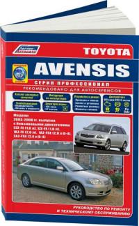
BODY PANEL REPLACEMENT |
BP-1 |
RADIATOR UPPER SUPPORT (ASSY)
REMOVAL
F14459-A
F14459
|
BP-2 |
BODY PANEL REPLACEMENT |
INSTALLATION
STemporarily install the new parts and measure each part of the new parts in accordance with the body dimension diagram. (See the body dimension diagram)
SInspect the fitting of the related parts around the new parts before welding. This affects the appearance of the finish.
SAfter welding, apply the polyurethane foam to the corresponding parts.
SAfter welding, apply body sealer and under-coating to the corresponding parts.
SAfter applying the top coat layer, apply anti-rust agent to the inside of the necked section structural weld spots.
F14460
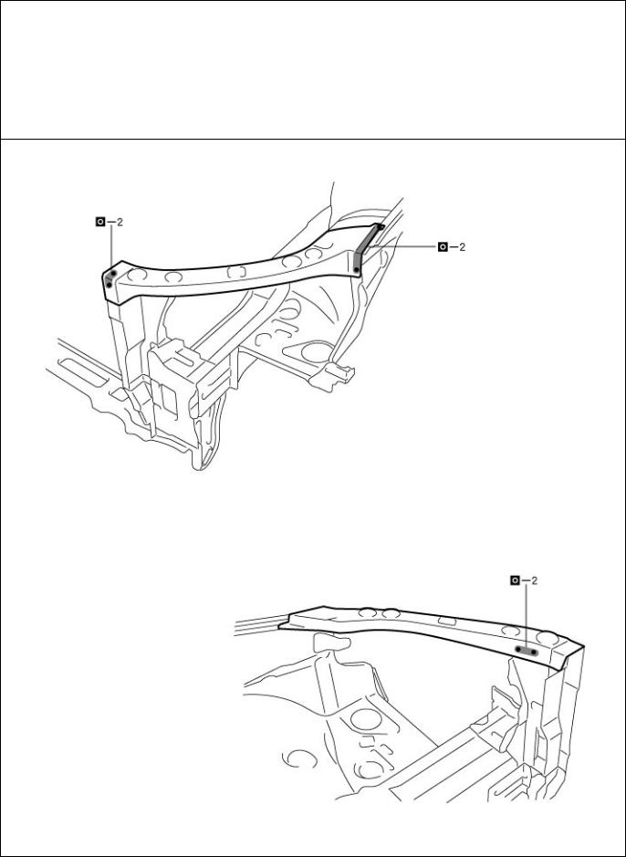
BODY PANEL ANTI-CHIPPING PAINT APPLICATION AREAS
HINT:
1)Anti-chipping paint should be applide to some areas before the second coat and to others after the top coat.
2)If other areas are accidentally coated, wipe of the paint immediately with a rag soaked in grease, wax and silicone remover.
PVC Chipping Primer
Urethane Primer
Soft — Chip Primer (Poly Olefine)
F14419
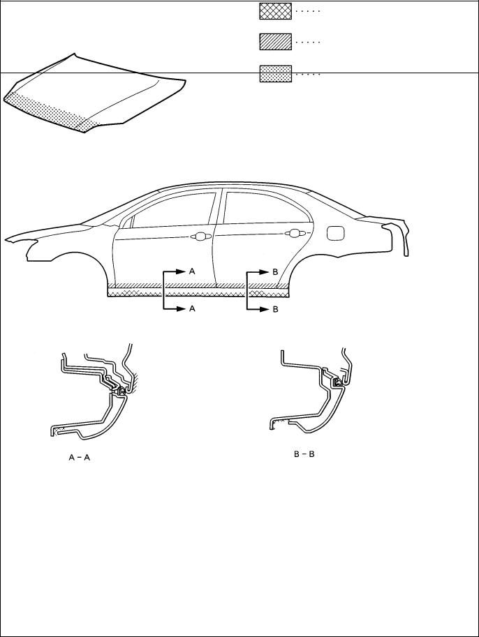
SILENCER SHEET INSTALLATION AREAS
Thickness of Asphalt Sheet
1.6mm (0.063in.)
1.8mm (0.071in.)
3.0mm (0.118in.)
F14418
BODY PANEL ANTI-RUST AGENT (WAX) APPLICATION AREAS
HINT:
1)Whenever adjusting the doors and hoods, apply anti-rust agent (wax) around the hinges.
2)Even if partially repairing a part, apply anti-rust agent (wax) over the entire application area of the part.
3)Wipe off the anti-rust agent immediately with a rag soaked in a grease, wax and silicone remover, if accidently applied to other areas.
[Sedan]
F14412
F14414

F14413

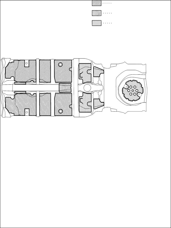
FOAMED MATERIAL APPLICATION AREAS
The sections shown in the figure below are filled with foamed material to provide noise insullation. After repairing these sections or their peripheries, refill with foamed materials
HINT:
1)Use the service holes located on the reverse side of the body panel to refill with foamed materials.
2)When handling foamed material, follow the directions of the material’s manufacturer.
[Sedan]
F14415
F14417
F14416
![]()
BODY PANEL UNDERCOATING AREAS
HINT:
1)First wipe off any dirt, grease or oil with a rag soaked in a grease, wax and silicone remover.
2)Cover the surrounding areas with masking paper to avoid coating unnecessary areas. If other areas are accidently coated, wipe off the coating immediately.
3)Apply the first coating of undercoat to all welded areas and panel joints, then apply a second coat over the entire area.
4)Do not coat parts which become hot, such as the tailpipe, or moving parts, such as the propeller shaft.
5)Besides the locations described below, apply undercoating to all weld points under the body to insure corrosion prevention.
6)Be sure to seal the edge of the flange of the member and bracket with undercoating.
7)If undercoat is damaged by peeling, cracks, etc., be sure to repair as necessary.
 Before the undercoat apply sealer allowing rust prevention to be attained.
F14411
REFERENCE
Referring to the notes above, undercoating should be applied according to the specifications for your country.
Antilock Brake System Air Conditioner assembly
Electronic Controlled Transmission Electronic Control Unit
Exempli Gratia (for Example) Except
Front Wheel Drive Vehicles
Four Wheel Drive Vehicles inch
Left-hand Left-hand Drive Metal Inert Gas Model Year
Progressive Power Steering Right-hand
Right-hand Drive Supplemental Restraint System Special Service Materials
with without
ABBREVIATIONS USED IN THIS MANUAL
For convenience, the following abbreviations are used in this manual.
ABS
A/C assy ECT ECU e.g.
Ex.
FWD 4WD in.
LH
LHD
MIG
M/Y
PPS
RH
RHD
SRS
SSM w/ w/o
IN-16
INTRODUCTION
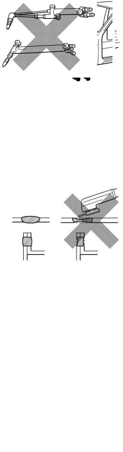
PRECAUTIONS FOR REPAIRING BODY STRUCTURE PANELS
1.HEAT REPAIR FOR BODY STRUCTURE PANELS
Toyota prohibits the use of the heat repair method on body structure panels when repairing a vehicle damaged in a collision.
Panels that have high strength and rigidity, as well as a long life span for the automobile body are being sought after. At Toyota, in order to fulfill these requirement, we use high tensile strength steel sheets and rust preventive steel sheets on the body.
High tensile steel sheets are made with alloy additives and a special heat treatment in order to improve the strength. To prevent the occurrence of rust for a long period of time, the surface of the steel is coated with a zinc alloy.
If a body structure parts are heat repaired with an acetylene torch or other heating source, the crystalline organization of the steel sheet will change and the strength of the steel sheet will be reduced.
The ability of the body to resist rust is significantly lowered as well since the rust resistant zinc coating is destroyed by heat and the steel sheet surface is oxidized.
2.STRUCTURE PANEL KINKS
A sharp deformation angle on the panel that cannot be returned to its original shape by pulling or hammering is called a kink.
Since structure parts were designed to exhibit a 100% performance when they were in their original shape, if they are deformed in an accident, or if the deformed parts are repaired and reused, they become unable to exhibit the same performance as intended in the design.
It is necessary to replace the part where the kink has occurred.
3.IMPACT BEAM REPAIR
The impact beam and bracket are necessary and important parts in maintaining a survival space for passengers in a side collision.
For impact beam, we use special high tensile strength steel.
The high tensile strength steel maintains its special crystalline organization by heat treatment or alloy additives. Since these parts were designed to exhibit a 100% performance when they were in their original shape, if they are deformed in an accident, or if the deformed parts are repaired and reused, they become unable to exhibit the same performance as intended in the design.
It is necessary to replace the door assembly when impact beam or bracket is damaged.

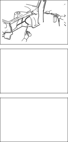
HANDLING PRECAUTIONS ON RELATED COMPONENTS
1.BRAKE SYSTEM
The brake system is one of the most important safety components. Always follow the directions and notes given in section BR of the repair manual for the relevant model when handling brake system parts.
NOTICE: When repairing the brake master cylinder or TRAC system, bleed the air out of the TRAC system.
2.DRIVE TRAIN AND CHASSIS
The drive train and chassis are components that can have great effects on the running performance and vibration resistance of the vehicle. After installing components in the sections listed in the table below, perform alignments to ensure correct mounting angles and dimensions. Particularly accurate repair of the body must also be done to ensure correct alignment.
HINT: Correct procedures and special tools are required for alignment. Always follow the directions given in the repair manual for the relevant model during alignment and section DI of this section.
|
Component to be aligned |
Section of repair manual |
|
|
for relevant model |
||
|
Front Wheels |
Front Suspension (26) section |
|
|
Rear Wheels |
Rear Suspension (27) section |
3.COMPONENTS ADJACENT TO THE BODY PANELS
Various types of component parts are mounted directly on or adjacently to the body panels. Strictly observe the following precautions to prevent damaging these components and the body panels during handling.
SBefore repairing the body panels, remove their components or apply protective covers over the components.
SBefore prying components off using a screwdriver or a scraper, etc., attach protective tape to the tool tip or blade to prevent damaging the components and the body paint.
SBefore removing components from the outer surface of the body, attach protective tape to the body to ensure no damage to painted areas.
HINT: Apply touch-up paint to any damaged paint surfaces.
SBefore drilling or cutting sections, make sure that there are no wires, etc. on the reverse side.
4.ECU (ELECTRONIC CONTROL UNIT)
Many ECUs are mounted in this vehicle.
Take the following precautions during body repair to prevent damage to the ECUs.
SBefore starting electric welding operations, disconnect the negative (–) terminal cable from the battery.
When the negative (–) terminal cable is disconnected from the battery, memory of the clock and audio systems will be cancelled. So before starting work, make a record of the contents memorized by each memory system. Then when work is finished, reset the clock and audio systems as before.
When the vehicle has tilt and telescopic steering, power seat and outside rear view mirror, which are all equipped with memory function, it is not possible to make a record of the memory contents.
So when the operation is finished, it will be necessary to explain this fact to the customer, and request the customer to adjust the features and reset the memory.
SDo not expose the ECUs to ambient temperatures above 80_C (176_F).
NOTICE: If it is possible the ambient temperature may reach 80_C (176_F) or more, remove the ECUs from the vehicle before starting work.
SBe careful not to drop the ECUs and not to apply physical shocks to them.
PROPER AND EFFICIENT WORK
PROCEDURES
1.REMOVAL
(a)PRE-REMOVAL MEASURING
(1)Before removal or cutting operations, take measurements in accordance with the dimension diagram. Always use a puller to straighten a damaged body or frame.
F10007
Cutting Okay
Reinforcement
Corners
F10008A
(b)CUTTING AREA
(1)Always cut in a straight line and avoid reinforced area.
(c)PRECAUTIONS FOR DRILLING OR CUTTING
(1)Check behind any area to be drilled or cut to insure that there are no hoses, wires, etc., that may be damaged.
HINT: See “Handling Precautions on Related Components” on page IN-15.
(d)REMOVAL OF ADJACENT COMPONENTS
(1)When removing adjacent components, apply protective tape to the surrounding body and your tools to prevent damage.
HINT: See “Handling Precautions on Related Components” on page IN-15.
F10010
Less than 3mm
2.PREPARATION FOR INSTALLATION
(a)SPOT WELD POINTS
(1)When welding panels with a combined thickness of over 3mm (0.12in.), use a MIG (Metal Inert Gas) welder for plug welding.
HINT: Spot welding will not provide sufficient durability for panels over 3mm (0.12in.) thick.
F10011A
(b)APPLICATION OF WELD-THROUGH PRIMER (SPOT SEALER)
(1)Remove the paint from the portion of the new parts and body to be welded, and apply weld-through primer.
F10012
(c)MAKING HOLES FOR PLUG WELDING
(1)For areas where a spot welder cannot be used, use a puncher or drill to make holes for plug welding.
|
REFERENCE: |
mm (in.) |
||
|
Thickness of welded portion |
Size of plug hole |
||
|
Puncher |
1.0 (0.04) under |
5 (0.20) ø over |
|
|
1.0 (0.04) – 1.5 (0.06) |
6.4 (0.26) ø over |
||
|
F10013A |
1.5 (0.06) over |
8 (0.31) ø over |
|
(d)SAFETY PRECAUTIONS FOR ELECTRICAL COMPONENTS
(1)When welding, there is a danger that electrical components will be damaged by the electrical current flowing through the body.
(2)Before starting work, disconnect the negative terminal of the battery and ground the welder near the welding location of the body.
F10014
|
20 X 30mm |
|
|
Air Saw |
Overlap |
F10015A
(e)ROUGH CUTTING OF JOINTS
(1)For joint areas, rough cut the new parts, leaving 20 – 30mm (0.79 – 1.18in.) overlap.
|
Body |
|
|
Measurement |
|
|
Diagrams |
F10016A |
|
WRONG |
F10017A |
|
CORRECT |
WRONG |
|
F10018A |
|
|
Tip Cutter |
F10019A |
|
New Spot |
|
|
Old |
Locations |
|
Spot |
|
|
Locations |
|
|
F10020A |
3.INSTALLATION
(a)PRE-WELDING MEASUREMENTS
(1)Always take measurements before installing underbody or engine components to insure correct assembly. After installation, confirm proper fit.
(b)WELDING PRECAUTIONS
(1)The number of welding spots should be as follows.
Spot weld: 1.3 X No. of manufacturer’s spots. Plug weld: More than No. of manufacturer’s plugs.
(2)Plug welding should be done with a MIG (Metal Inert Gas) welder. Do not gas weld or braze panels at areas other than specified.
(c)POST-WELDING REFINISHING
(1)Always check the welded spots to insure they are secure.
(2)When smoothing out the weld spots with a disc grinder, be careful not to grind off too much as this would weaken the weld.
(d)SPOT WELD LOCATIONS
(1)Try to avoid welding over previous spots.
(e)SPOT WELDING PRECAUTIONS
(1)The shape of the welding tip point has an effect on the strength of the weld.
(2)Always insure that the seams and welding tip are free of paint.
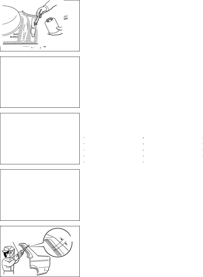
4.ANTI-RUST TREATMENT
(a)BODY SEALER APPLICATION
(1)For water-proofing and anti-corrosion measures, always apply the body sealer to the body panel seams and hems of the doors, hoods, etc.
(b)UNDERCOAT APPLICATION
(1)To prevent corrosion and protect the body from damage by flying stones, always apply sufficient undercoat to the bottom surface of the under body and inside of the wheel housings.
F10022
5.ANTI-RUST TREATMENT AFTER PAINTING PROCESS
(a)ANTI-RUST AGENT (WAX) APPLICATION
(1)To preserve impossible to paint areas from corrosion, always apply sufficient anti-rust agent (wax) to the inside of the hemming areas of the doors and hoods, and around the hinges, or the welded surfaces inside the boxed cross-section structure of the side member, body pillar, etc.
F10023
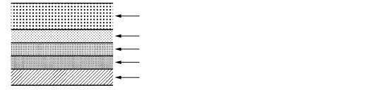
6.ANTI-RUST TREATMENT BY PAINTING
REFERENCE:
Painting prevents corrosion and protect the sheet metal from damage. In this section, anti-chipping paint only for anti-corrosion purpose is described.
(a)ANTI-CHIPPING PAINT
(1)To prevent corrosion and protect the body from damage by flying stones, etc., apply anti-chipping paint to the rocker panel, wheel arch areas, balance panel, etc.
HINT:
Depending on the model or the application area, there are cases where the application of anti-chipping paint is necessary before the second coat or after the top coat.
|
S Apply the anti-chipping paint after |
S |
Apply the anti-chipping paint before |
|
the top coat. |
the second coat. |
|
|
Anti-Chipping Paint |
Top Coat |
|
|
Second Coat |
||
|
Top Coat |
||
|
Anti-Chipping Paint |
||
|
Second Coat |
||
|
Under Coat (ED Primer) |
Under Coat (ED Primer) |
|
|
Steel Metal |
Steel Metal |
|
|
F10024A |
![]()
HOW TO USE THIS MANUAL
1.BODY PANEL REPLACEMENT THIS MANUAL
|
BP-34 |
BODY PANEL REPLACEMENT |
A QUARTER PANEL (CUT)
REMOVAL
C
B
I
K
A
D
I
J
POINT
1 Remove the A at the same time.
A Fuel Filler Opening Lid
A : REPLACEMENT PART AND METHOD
QUARTER PANEL (CUT)
Replacement method
(ASSY) … Assembly replacement
(CUT) … Major cutting (less than 1 / 2 of part used) (CUT-H) … Half cutting (about 1 / 2 of part used) (CUT-P) … Partial cutting (most of part used)
Replacement part
B: REMOVAL CONDTIONS
C: PART LOCATION
D: REMOVAL DIAGRAM
Describes in detail removal of the damaged part involving repair by cutting.
E : REMOVAL GUIDE
Provides additional information to more efficiently help you perform the removal.
F13890A
|
BODY PANEL REPLACEMENT |
BP-35 |
INSTALLATION
STemporaily install the new parts and measure each part of the new parts in accordance with the body dimension diagram. (See the body dimension diagram)
SInspect the fiting of the related parts around the new parts before welding. This affects the appearance of the finish.
SAfter welding, apply the polyurethane foam to the corresponding parts.
SAfter welding, apply body sealer and under-coating to the corresponding parts.
SAfter applying the top coat layer, apply anti-rust agent to the inside of the necked section structural weld spots.
I
J
I
1Before temporarily installing the new parts, apply body sealer to the wheel arch.
HINT:
1)Apply body sealer about 5mm (0.20in.) front the flange, avoiding any oozing.
2)Apply sealer evenly, about 3 – 4mm (0.12 – 0.16in.) in diameter.
3)For other sealing points, refer to section PC.
H
PART NAME
|
A Fuel Filler Opening Lid |
B Waterproof Rivet |
F: INSTALLATION CONDITIONS
G: INSTALLATION DIAGRAM
Describes in detail installation to the new part involving repair by welding and / or cutting, but excluding painting.
H : INSTALLATIOLN GUIDE
Provides additional information to more efficiently help you perform the installation.
I : SYMBOLS
(See page IN-7)
J : ILLUSTRATION OF WELD POINTS
Weld method and panel position symbols (See page IN-9)
K : PART NAME
F13891A
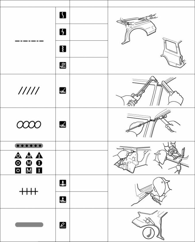
2.SYMBOLS
The following symbols are used in the welding diagrams in section BP of this manual to indicate cutting areas and the types of weld required.
|
SYMBOLS |
MEANING |
ILLUSTRATION |
CUT AND JOIN LOCATION
(SAW CUT)
CUT AND JOIN LOCATION (Cut Location for
Supply Parts)
CUT LOCATION
CUT WITH DISC
SANDER, ETC.
BRAZE (Removal)
BRAZE (Installation)
—WELD POINTS
SPOT WELD OR
—MIG PLUG WELD (See Page IN-9)
CONTINUOUS MIG WELD (BUTT WELD)
CONTINUOUS MIG WELD (TACK WELD)
BODY SEALER
F13893A
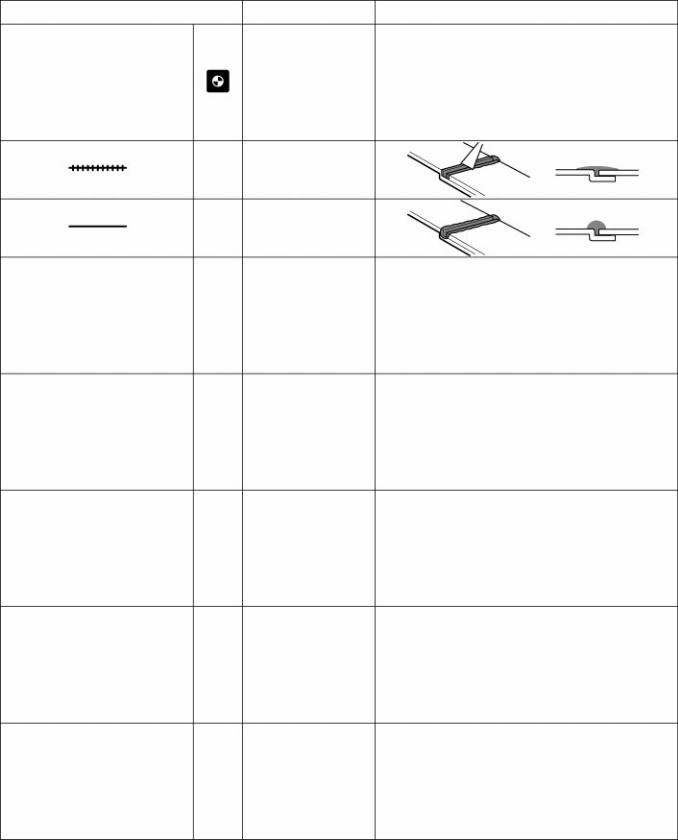
|
SYMBOLS |
MEANING |
ILLUSTRATION |
BODY SEALER
—(Flat Finishing)
BODY SEALER
—(No flat Finishing)
F13894A

3. ILLUSTRATION OF WELD POINT SYMBOLS EXAMPLE:
Weld points
Remove weld point and panel position
|
SYMBOLS MEANING |
ILLUSTRATION |
Remove
Weld
Points
(Outside)
(Middle)
(Inside)
HINT: Panel position symbols are as seen from the working posture.
Weld points
Weld method and panel position
|
SYMBOLS MEANING |
ILLUSTRATION |
Spot Weld
MIG Plug
Weld
Spot MIG
Weld
F13892A
Glass Cover
Seat Cover
F10001A
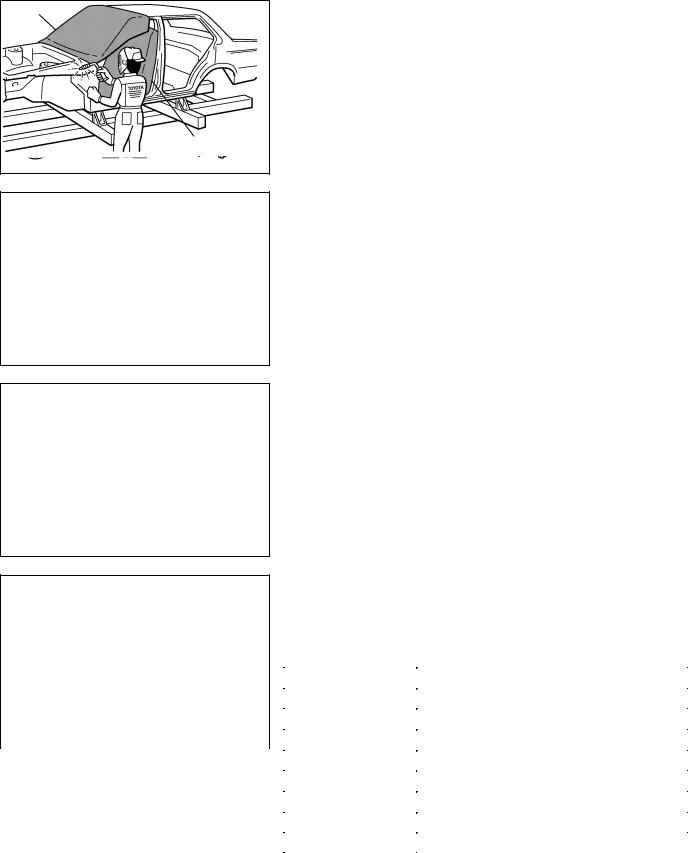
GENERAL REPAIR INSTRUCTIONS
1.WORK PRECAUTIONS
(a)VEHICLE PROTECTION
(1)When welding, protect the painted surfaces, windows, seats and carpet with heat resistant, fire-proof covers.
(b)SAFETY
(1)Never stand in direct line with the chain when using a puller on the body or frame, and be sure to attach a safety cable.
WRONG
F10002A
(2)Before performing repair work, check for fuel leaks. If a leak is found, be sure to close the opening totally.
(3)If it is necessary to use a flame in the area of the fuel tank, first remove the tank and plug the fuel line.
(c)SAFETY WORK CLOTHES
(1)In addition to the usual mechanic’s wear, cap and safety shoes, the appropriate gloves, head protector, glasses, ear plugs, face protector, dust-prevention mask, etc. should be worn as the situation demands.
|
Code |
Name |
||
|
A |
Dust-Prevention Mask |
||
|
B |
Face Protector |
||
|
F10004 |
C |
Eye Protector |
|
|
D |
Safety Shoes |
||
|
E |
Welder’s Glasses |
||
|
F |
Ear Plugs |
||
|
G |
Head Protector |
||
|
H |
Welder’s Gloves |

2.HANDLING PRECAUTIONS OF PLASTIC BODY PARTS
(1)The repair procedure for plastic body parts must conform with the type of plastic material.
(2)Plastic body parts are identified by the codes in the following table.
(3)When repairing metal body parts adjoining plastic body parts (by brazing, frame cutting, welding, painting etc.), consideration must be given to the property of the plastic.
|
Heat* |
|||||
|
Code |
Material |
resistant |
Resistance to |
Notes |
|
|
name |
temperature |
alcohol or gasoline |
|||
|
limit _C (_F) |
|||||
|
Acrylonitrile |
80 |
Alcohol is harmless if applied only for |
Avoid gasoline and organic |
||
|
AAS |
short time in small amounts (e.g., quick |
||||
|
Acrylic Styrene |
(176) |
or aromatic solvents. |
|||
|
wiping to remove grease). |
|||||
|
Acrylonitrile |
80 |
Alcohol is harmless if applied only for |
Avoid gasoline and organic |
||
|
ABS |
short time in small amounts (e.g., quick |
||||
|
Butadiene Styrene |
(176) |
or aromatic solvents. |
|||
|
wiping to remove grease). |
|||||
|
Acrylonitrile |
80 |
Alcohol is harmless if applied only for |
Avoid gasoline and organic |
||
|
AES |
short time in small amounts (e.g., quick |
||||
|
Ethylene Styrene |
(176) |
or aromatic solvents. |
|||
|
wiping to remove grease). |
|||||
|
Acrylonitrile |
80 |
Alcohol is harmless if applied only for |
Avoid gasoline and organic |
||
|
ASA |
Styrene |
short time in small amounts (e.g., quick |
|||
|
(176) |
or aromatic solvents. |
||||
|
Acrylate |
wiping to remove grease). |
||||
|
Cellulose |
80 |
Alcohol is harmless if applied only for |
Avoid gasoline and organic |
||
|
CAB |
short time in small amounts (e.g., quick |
||||
|
Acetate |
(176) |
or aromatic solvents. |
|||
|
wiping to remove grease). |
|||||
|
Ethylene |
100 |
Alcohol is harmless. |
Most solvents are harmless |
||
|
EPDM |
Gasoline is harmless if applied only for |
but avoid dipping in gasoline, |
|||
|
Propylene |
(212) |
||||
|
short time in small amounts. |
solvents, etc. |
||||
|
Fiber |
180 |
||||
|
FRP |
Reinforced |
Alcohol and gasoline are harmless. |
Avoid alkali. |
||
|
(356) |
|||||
|
Plastics |
|||||
|
Ethylene |
70 |
Alcohol is harmless if applid only for short |
Avoid gasoline and organic |
||
|
EVA |
time in small amounts (e.g., quick wiping |
||||
|
Acetate |
(158) |
or aromatic solvents. |
|||
|
to remove grease). |
|||||
|
PA |
Polyamide |
80 |
Alcohol and gasoline are harmless. |
Avoid battery acid. |
|
|
(Nylon) |
(176) |
||||
|
PBT |
Polybutylene |
160 |
Alcohol and gasoline are harmless. |
Most solvents are harmless. |
|
|
Terephthalate |
(320) |
||||
|
120 |
Avoid gasoline brake fluid, |
||||
|
PC |
Polycarbonate |
Alcohol is harmless. |
wax, wax removers and |
||
|
(248) |
|||||
|
organic solvents. Avoid alkali. |
|||||
*Temperatures higher than those listed here may result in material deformation during repair.

|
INTRODUCTION |
IN-3 |
||||
|
Heat* |
|||||
|
Code |
Material |
resistant |
Resistance to |
Notes |
|
|
name |
temperature |
alcohol or gasoline |
|||
|
limit _C (_F) |
|||||
|
PE |
Polyethylene |
80 |
Alcohol and gasoline are harmless. |
Most solvents are harmless. |
|
|
(176) |
|||||
|
PET |
Polyethylene |
75 |
Alcohol and gasoline are harmless. |
Avoid dipping in water. |
|
|
Terephthalate |
(167) |
||||
|
Polymethyl |
80 |
Alcohol is harmless if applied only for |
Avoid dipping or immersing |
||
|
PMMA |
in alcohol, gasoline, |
||||
|
Methacrylate |
(176) |
short time in small amounts. |
|||
|
solvents, etc. |
|||||
|
POM |
Polyoxymethylene |
100 |
Alcohol and gasoline are harmless. |
Most solvents are harmless. |
|
|
(Polyacetal) |
(212) |
||||
|
PP |
Polypropylene |
80 |
Alcohol and gasoline are harmless. |
Most solvents are harmless. |
|
|
(176) |
|||||
|
Modified |
100 |
Gasoline is harmless if |
|||
|
PPO |
Polyphenylene |
Alcohol is harmless. |
applied only for quick wiping |
||
|
(212) |
|||||
|
Oxide |
to remove grease. |
||||
|
60 |
Alcohol and gasoline are harmless if |
Avoid dipping or immersing |
|||
|
PS |
Polystyrene |
applied only for short time in small |
in alcohol, gasoline, |
||
|
(140) |
|||||
|
amounts. |
solvents, etc. |
||||
|
80 |
Alcohol is harmless if applied only for very |
Avoid dipping or immersing |
|||
|
PUR |
Polyurethane |
short time in small amounts (e.g., quick |
in alcohol, gasoline, |
||
|
(176) |
|||||
|
wiping to remove grease). |
solvents, etc. |
||||
|
Alcohol and gasoline are harmless if |
Avoid dipping or immersing |
||||
|
Polyvinylchloride |
80 |
applied only for short time in small |
|||
|
PVC |
in alcohol, gasoline, |
||||
|
(Vinyl) |
(176) |
amounts (e.g., quick wiping to remove |
|||
|
solvents, etc. |
|||||
|
grease). |
|||||
|
Styrene |
80 |
Alcohol is harmless if applied only for |
Avoid dipping or immersing |
||
|
SAN |
short time in small amounts (e.g., quick |
in alcohol, gasoline, solvents |
|||
|
Acrylonitrile |
(176) |
||||
|
wiping to remove grease). |
etc. |
||||
|
Thermoplastic |
80 |
Alcohol is harmless. |
Most solvents are harmless |
||
|
TPO |
Gasoline is harmless if applied only for |
but avoid dipping in gasoline, |
|||
|
Olefine |
(176) |
||||
|
short time in small amounts. |
solvents, etc. |
||||
|
Thermoplastic |
80 |
Alcohol is harmless if applied only for |
Avoid dipping or immersing |
||
|
TPU |
short time in small amounts (e.g., quick |
in alcohol, gasoline, |
|||
|
Polyurethane |
(176) |
||||
|
wiping to remove grease). |
solvents, etc. |
||||
|
TOYOTA |
80 |
||||
|
TSOP |
Super |
Alcohol and gasoline are harmless. |
Most solvents are harmless. |
||
|
(176) |
|||||
|
Olefine Polymer |
|||||
|
UP |
Unsaturated |
110 |
Alcohol and gasoline are harmless. |
Avoid alkali. |
|
|
Polyester |
(233) |
||||
*Temperatures higher than those listed here may result in material deformation during repair.

3.LOCATION OF PLASTIC BODY PARTS
|
Parts Name |
Code |
|
Radiator Grille |
ABS/ASA |
|
Front Bumper Cover |
TSOP |
|
Front Spoiler |
TSOP |
|
Front Bumper Side Moulding |
TSOP |
|
Headlight Washer Nozzle Cover |
PC/ABS |
|
Headlight |
PC/PP |
|
Fog light |
PP |
|
Side Turn Signal Light |
PMMA/ABS |
|
Outer Rear View Mirror |
ASA |
|
Roof Rack Leg Cover (Wagon Only) |
ABS |
|
Door Outside Handle |
PC/PBT/PA |
|
Door Outside Moulding |
PP/EPDM |
|
Body Rocker Panel Moulding |
PP |
|
Rear Combination Light |
PMMA/PC/ABS |
|
Rear Spoiler (Wagon Only) |
ABS |
|
Center Stop Light (Wagon Only) |
PMMA/ABS |
|
Luggage Compartment Door Outside Garnish |
ABS |
|
License Plate Light |
PMMA/ABS |
|
Rear Bumper Cover |
TSOP |
|
Rear Bumper Side Moulding |
TSOP |
|
D Resin material differs with model. |
|
|
/ Made up of 2 or more kinds of materials. |
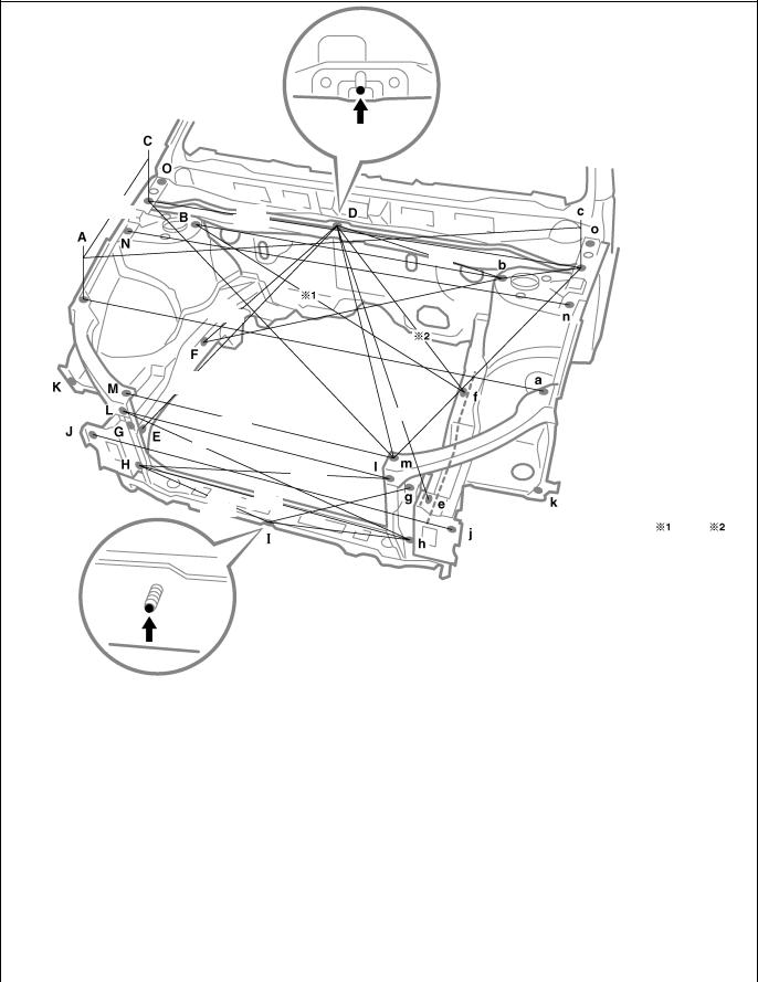
BODY DIMENSION DRAWINGS
ENGINE COMPARTMENT
(Three-Dimensional Distance)
467
(18.39) 1,427
(56.18)
647
(25.47)
851
(33.50)
760
(29.92)
|
854 |
760 |
||||
|
(33.62) |
(29.92) |
838
444 (32.99)
(17.48)
|
1,478 |
||||||||||||||||||||||||||||||||||||||||||||||||
|
(58.19) |
||||||||||||||||||||||||||||||||||||||||||||||||
|
523 |
||||||||||||||||||||||||||||||||||||||||||||||||
|
1,023 |
||||||||||||||||||||||||||||||||||||||||||||||||
|
1,410 |
(20.59) |
|||||||||||||||||||||||||||||||||||||||||||||||
|
(40.28) |
||||||||||||||||||||||||||||||||||||||||||||||||
|
210 |
||||||||||||||||||||||||||||||||||||||||||||||||
|
(55.51) |
||||||||||||||||||||||||||||||||||||||||||||||||
|
(6.27) |
||||||||||||||||||||||||||||||||||||||||||||||||
|
1,038 |
||||||||||||||||||||||||||||||||||||||||||||||||
|
(40.87) |
||||||||||||||||||||||||||||||||||||||||||||||||
|
817 |
||||||||||||||||||||||||||||||||||||||||||||||||
|
1,378 |
(32.17) |
|||||||||||||||||||||||||||||||||||||||||||||||
|
(54.25) |
||||||||||||||||||||||||||||||||||||||||||||||||
|
1,323 |
||||||||||||||||||||||||||||||||||||||||||||||||
|
768 |
||||||||||||||||||||||||||||||||||||||||||||||||
|
(52.09) |
||||||||||||||||||||||||||||||||||||||||||||||||
|
(30.24) |
||||||||||||||||||||||||||||||||||||||||||||||||
|
834 |
||||||||||||||||||||||||||||||||||||||||||||||||
|
(32.83) |
||||||||||||||||||||||||||||||||||||||||||||||||
|
874 |
||||||||||||||||||||||||||||||||||||||||||||||||
|
(34.41) |
537 |
|||||||||||||||||||||||||||||||||||||||||||||||
|
(21.14) |
||||||||||||||||||||||||||||||||||||||||||||||||
|
1,089 |
||||||||||||||||||||||||||||||||||||||||||||||||
|
422 |
(42.87) |
Engine |
||||||||||||||||||||||||||||||||||||||||||||||
|
(16.61) |
Model |
|||||||||||||||||||||||||||||||||||||||||||||||
|
AZ |
1,022 |
625 |
||||||||||||||||||||||||||||||||||||||||||||||
|
(40.24) |
(24.61) |
|||||||||||||||||||||||||||||||||||||||||||||||
|
ZZ, CD |
1,010 |
606 |
||||||||||||||||||||||||||||||||||||||||||||||
|
Vehicle Dimensions |
(39.76) |
(23.86) |
||||||||||||||||||||||||||||||||||||||||||||||
|
B-c |
C-n |
C-N |
C-O |
G-g |
G-h |
g-H |
||||||||||||||||||||||||||||||||||||||||||
|
or |
or |
or |
or |
|||||||||||||||||||||||||||||||||||||||||||||
|
b-C |
c-N |
c-n |
c-o |
|||||||||||||||||||||||||||||||||||||||||||||
|
1,227 |
1,428 |
159 |
113 |
828 |
854 |
876 |
||||||||||||||||||||||||||||||||||||||||||
|
(48.31) |
(56.22) |
(6.26) |
(4.45) |
(32.60) |
(33.62) |
(34.49) |
||||||||||||||||||||||||||||||||||||||||||
|
I-j |
I-J |
J-L |
j-l |
K-k |
N-o |
N-O |
||||||||||||||||||||||||||||||||||||||||||
|
or |
or |
|||||||||||||||||||||||||||||||||||||||||||||||
|
n-O |
n-o |
|||||||||||||||||||||||||||||||||||||||||||||||
|
593 |
607 |
250 |
240 |
1,439 |
1,452 |
272 |
||||||||||||||||||||||||||||||||||||||||||
|
(23.35) |
(23.90) |
(9.84) |
(9.45) |
(56.65) |
(57.17) |
(10.71) |
mm (in.) |
|
Symbol |
Name |
Hole dia. |
Symbol |
Name |
Hole dia. |
|||
|
A, |
a |
Front fender installation nut |
6 (0.24) nut |
I |
Hood lock brace installation bolt |
6 (0.24) bolt |
||
|
B, |
b |
Front spring support hole-inner |
11 (0.43) |
J, |
j |
Front side member rear plate standard hole |
13 (0.51) |
|
|
C, |
c |
Front fender installation nut |
6 (0.24) nut |
K, |
k |
Front fender extention standard hole |
7 (0.28) |
|
|
D |
Cowl top inner panel standard hole |
— |
L, |
l |
Radiator upper support installation nut |
6 (0.24) nut |
||
|
E, |
e |
Front side member standard hole |
18 (0.71) |
M, |
m |
Radiator upper support installation nut |
6 (0.24) nut |
|
|
F, |
Front side member standard hole |
12 (0.47) |
N, |
n |
Front apron to cowl side upper member |
10 (0.39) |
||
|
f |
Engine mounting installation nut |
10 (0.39) nut |
standard hole |
|||||
|
G, |
g |
Radiator support standard hole |
10 (0.39) |
O, |
o |
Hood hinge installation nut |
8 (0.31) nut |
|
|
H, |
h |
Front crossmember side gusset standard hole |
10 (0.39) |
— |
— |
— |
![]()
BODY OPENING AREAS (Side View: Front)
All
(Three-Dimensional Distance)
1,097
(43.19)
|
874 |
|||||||||||||||||||||||||
|
(34.41) |
|||||||||||||||||||||||||
|
1,475 |
|||||||||||||||||||||||||
|
(58.07) |
|||||||||||||||||||||||||
|
1,219 |
|||||||||||||||||||||||||
|
845 |
|||||||||||||||||||||||||
|
(47.99) |
|||||||||||||||||||||||||
|
(33.27) |
|||||||||||||||||||||||||
|
912 |
|||||||||||||||||||||||||
|
(35.91) |
|||||||||||||||||||||||||
|
1,286 |
|||||||||||||||||||||||||
|
1,096 |
|||||||||||||||||||||||||
|
866 |
|||||||||||||||||||||||||
|
(50.63) |
(43.15) |
||||||||||||||||||||||||
|
(34.09) |
|||||||||||||||||||||||||
995
(39.17)
831
(32.72)
1,053
(41.46)
Vehicle Dimensions Left $ Right
|
E-e |
F-f |
G-g |
H-h |
I-i |
J-j |
K-k |
||||||||||||
|
1,323 |
1,411 |
1,419 |
1,419 |
1,157 |
1,265 |
1,420 |
||||||||||||
|
(52.09) |
(55.55) |
(55.87) |
(55.87) |
(45.55) |
(49.80) |
(55.91) |
||||||||||||
|
E-f |
E-h |
E-j |
F-j |
F-k |
H-i |
J-k |
||||||||||||
|
or |
or |
or |
or |
or |
or |
or |
||||||||||||
|
e-F |
e-H |
e-J |
f-J |
f-K |
h-I |
j-K |
||||||||||||
|
1,493 |
1,621 |
1,545 |
1,808 |
1,641 |
1,622 |
1,540 |
||||||||||||
|
(58.78) |
(63.82) |
(60.83) |
(71.18) |
(64.61) |
(63.86) |
(60.63) |
||||||||||||
|
mm (in.) |
||||||||||||||||||
|
Symbol |
Name |
Hole dia. |
Symbol |
Name |
Hole dia. |
|||||||||||||
|
A, |
a |
Roof panel corner |
— |
H, |
h |
Rocker panel assembly mark |
— |
|||||||||||
|
B, |
b |
Wiper link installation nut |
6 (0.24) nut |
I, |
i |
Roof side rail assembly mark |
— |
|||||||||||
|
C, |
c |
Front door hinge installation nut |
8 (0.31) nut |
J, |
j |
Center body pillar assembly mark |
— |
|||||||||||
|
D, |
d |
Front door hinge installation nut |
8 (0.31) nut |
K, |
k |
Center body pillar assembly mark |
— |
|||||||||||
|
E, |
e |
Front body pillar assembly mark |
— |
L, |
l |
Rear door hinge installation nut |
8 (0.31) nut |
|||||||||||
|
F, |
f |
Front body pillar assembly mark |
— |
M, |
m |
Rear door hinge installation nut |
8 (0.31) nut |
|||||||||||
|
G, |
g |
Rocker panel assembly mark |
— |
— |
— |
— |

BODY OPENING AREAS (Side View: Rear)
Sedan, Liftback
(Three-Dimensional Distance)
812
(31.97)
884
(34.80)
1,106
(43.54)
1,011 1,052
(39.80) (41.42)
667
(26.26)
Vehicle Dimensions Left $ Right
|
N-n |
O-o |
P-p |
Q-q |
R-r |
S-s |
|
|
1,267 |
1,420 |
1,419 |
1,151 |
1,309 |
1,409 |
|
|
(49.88) |
(55.91) |
(55.87) |
(45.31) |
(51.54) |
(55.47) |
|
|
G-p |
I-q |
N-r |
N-s |
O-s |
P-q |
R-s |
|
or |
or |
or |
or |
or |
or |
or |
|
g-P |
i-Q |
n-R |
n-S |
o-S |
p-Q |
r-S |
|
1,759 |
1,338 |
1,522 |
1,602 |
1,564 |
1,630 |
1,496 |
|
(69.25) |
(52.68) |
(59.92) |
(63.07) |
(61.57) |
(64.17) |
(58.90) |
|
mm (in.) |
||||||||
|
Symbol |
Name |
Hole dia. |
Symbol |
Name |
Hole dia. |
|||
|
G, |
g |
Rocker panel assembly mark |
— |
P, |
p |
Rocker panel assembly mark |
— |
|
|
I, |
i |
Roof side rail assembly mark |
— |
Q, |
q |
Roof side rail assembly mark |
— |
|
|
N, |
n |
Center body pillar assembly mark |
— |
R, |
r |
Quarter panel assembly mark |
— |
|
|
O, |
o |
Center body pillar assembly mark |
— |
S, |
s |
Quarter panel assembly mark |
— |

BODY OPENING AREAS (Side View: Rear)
Wagon
(Three-Dimensional Distance)
852
(33.54)
884
(34.80) 1,136
(44.72)
1,075
1,021 (42.32)
(40.20)
667
(26.26)
Vehicle Dimensions Left $ Right
|
N-n |
O-o |
P-p |
Q-q |
R-r |
S-s |
|
|
1,267 |
1,420 |
1,419 |
1,140 |
1,311 |
1,409 |
|
|
(49.88) |
(55.91) |
(55.87) |
(44.88) |
(51.61) |
(55.47) |
|
|
G-p |
I-q |
N-r |
N-s |
O-s |
P-q |
R-s |
|
or |
or |
or |
or |
or |
or |
or |
|
g-P |
i-Q |
n-R |
n-S |
o-S |
p-Q |
r-S |
|
1,759 |
1,333 |
1,545 |
1,602 |
1,564 |
1,631 |
1,502 |
|
(69.25) |
(52.48) |
(60.83) |
(63.07) |
(61.57) |
(64.21) |
(59.13) |
|
mm (in.) |
||||||||
|
Symbol |
Name |
Hole dia. |
Symbol |
Name |
Hole dia. |
|||
|
G, |
g |
Rocker panel assembly mark |
— |
P, |
p |
Rocker panel assembly mark |
— |
|
|
I, |
i |
Roof side rail assembly mark |
— |
Q, |
q |
Roof side rail assembly mark |
— |
|
|
N, |
n |
Center body pillar assembly mark |
— |
R, |
r |
Quarter panel assembly mark |
— |
|
|
O, |
o |
Center body pillar assembly mark |
— |
S, |
s |
Quarter panel assembly mark |
— |

BODY OPENING AREAS (Rear View)
Sedan
(Three-Dimensional Distance)
1,047
(41.22)
|
620 |
||||||||||||||||||||||||||||||||||||||||||||||
|
1,295 |
||||||||||||||||||||||||||||||||||||||||||||||
|
(24.41) |
||||||||||||||||||||||||||||||||||||||||||||||
|
(50.98) |
||||||||||||||||||||||||||||||||||||||||||||||
|
1,574 |
||||||||||||||||||||||||||||||||||||||||||||||
|
(61.97) |
||||||||||||||||||||||||||||||||||||||||||||||
|
1,236 |
||||||||||||||||||||||||||||||||||||||||||||||
|
1,233 |
||||||||||||||||||||||||||||||||||||||||||||||
|
(48.66) |
||||||||||||||||||||||||||||||||||||||||||||||
|
1,217 |
||||||||||||||||||||||||||||||||||||||||||||||
|
(48.54) |
||||||||||||||||||||||||||||||||||||||||||||||
|
(47.91) |
||||||||||||||||||||||||||||||||||||||||||||||
|
548 |
||||||||||||||||||||||||||||||||||||||||||||||
|
1,147 |
||||||||||||||||||||||||||||||||||||||||||||||
|
(21.57) |
||||||||||||||||||||||||||||||||||||||||||||||
|
(45.16) |
||||||||||||||||||||||||||||||||||||||||||||||
|
1,480 |
||||||||||||||||||||||||||||||||||||||||||||||
|
(58.27) |
||||||||||||||||||||||||||||||||||||||||||||||
|
968 |
||||||||||||||||||||||||||||||||||||||||||||||
|
1,252 |
(38.11) |
|||||||||||||||||||||||||||||||||||||||||||||
|
1,048 |
(49.29) |
1,035 |
||||||||||||||||||||||||||||||||||||||||||||
|
(41.26) |
(40.75) |
|||||||||||||||||||||||||||||||||||||||||||||
|
833 |
||||||||||||||||||||||||||||||||||||||||||||||
|
(32.80) |
Vehicle Dimensions Left $ Right
|
D-d |
H-h |
|
1,084 |
754 |
|
(42.68) |
(29.69) |
|
mm (in.) |
||||||||
|
Symbol |
Name |
Hole dia. |
Symbol |
Name |
Hole dia. |
|||
|
A, |
a |
Roof panel corner |
— |
E, |
e |
Quarter panel standard hole |
10 (0.39) |
|
|
B, |
b |
Upper back reinforcement / Quarter panel |
— |
F, |
f |
Body lower back panel reinforcement / Quarter |
— |
|
|
adjoining portion |
panel end housing adjoining portion |
|||||||
|
C, |
c |
Quarter panel / Upper back reinforcement |
— |
G, |
g |
Back door lock striker installation nut |
8 (0.31) nut |
|
|
adjoining portion |
H, |
h |
Deck hook installation nut |
6 (0.24) nut |
||||
|
D, |
d |
Quarter panel end housing / Luggage |
— |
I, |
i |
Center body pillar assembly mark |
— |
|
|
compartment opening trough adjoining portion |
— |
— |
— |
|||||

BODY OPENING AREAS (Rear View)
Liftback
(Three-Dimensional Distance)
|
1,112 |
|||||||||||||||||||||||||||||||||||||||||||||||||||||||||||
|
1,597 |
|||||||||||||||||||||||||||||||||||||||||||||||||||||||||||
|
(43.78) |
1,112 |
||||||||||||||||||||||||||||||||||||||||||||||||||||||||||
|
(62.87) |
|||||||||||||||||||||||||||||||||||||||||||||||||||||||||||
|
1,386 |
734 |
||||||||||||||||||||||||||||||||||||||||||||||||||||||||||
|
(43.78) |
823 |
||||||||||||||||||||||||||||||||||||||||||||||||||||||||||
|
(54.57) |
|||||||||||||||||||||||||||||||||||||||||||||||||||||||||||
|
(28.90) |
|||||||||||||||||||||||||||||||||||||||||||||||||||||||||||
|
1,287 |
|||||||||||||||||||||||||||||||||||||||||||||||||||||||||||
|
1,216 |
(32.40) |
(50.67) |
|||||||||||||||||||||||||||||||||||||||||||||||||||||||||
|
480 |
(47.87) |
1,485 |
|||||||||||||||||||||||||||||||||||||||||||||||||||||||||
|
1,190 |
|||||||||||||||||||||||||||||||||||||||||||||||||||||||||||
|
(18.90) |
(58.46) |
||||||||||||||||||||||||||||||||||||||||||||||||||||||||||
|
1,122 |
|||||||||||||||||||||||||||||||||||||||||||||||||||||||||||
|
(46.85) |
|||||||||||||||||||||||||||||||||||||||||||||||||||||||||||
|
(44.17) |
|||||||||||||||||||||||||||||||||||||||||||||||||||||||||||
|
605 |
|||||||||||||||||||||||||||||||||||||||||||||||||||||||||||
|
1,244 |
|||||||||||||||||||||||||||||||||||||||||||||||||||||||||||
|
(23.82) |
|||||||||||||||||||||||||||||||||||||||||||||||||||||||||||
|
(48.98) |
|||||||||||||||||||||||||||||||||||||||||||||||||||||||||||
|
1,489 |
|||||||||||||||||||||||||||||||||||||||||||||||||||||||||||
|
(58.62) |
|||||||||||||||||||||||||||||||||||||||||||||||||||||||||||
|
1,163 |
1,063 |
||||||||||||||||||||||||||||||||||||||||||||||||||||||||||
|
1,077 |
880 |
||||||||||||||||||||||||||||||||||||||||||||||||||||||||||
|
(45.79) |
(41.85) |
||||||||||||||||||||||||||||||||||||||||||||||||||||||||||
|
(42.40) |
(34.65) |
||||||||||||||||||||||||||||||||||||||||||||||||||||||||||
Vehicle Dimensions Left $ Right
|
E-e |
G-i |
G-I |
I-i |
|
or |
or |
||
|
g-I |
g-i |
||
|
1,165 |
1,290 |
937 |
896 |
|
(45.87) |
(50.79) |
(36.89) |
(35.28) |
|
mm (in.) |
||||||||
|
Symbol |
Name |
Hole dia. |
Symbol |
Name |
Hole dia. |
|||
|
A, |
a |
Back door hinge installation hole-outer |
12 (0.47) |
F, |
f |
Quarter panel standard hole |
10 (0.39) |
|
|
B, |
b |
Back door damper stay installation nut |
6 (0.24) nut |
G, |
g |
Deck side rear garnish installation hole |
8.5 (0.335) |
|
|
C, |
c |
Luggage compartment trim side cover |
8.5 (0.335) |
H, |
h |
Back door lock striker installation nut |
8 (0.31) nut |
|
|
installation hole |
I, |
i |
Deck hook installation nut |
6 (0.24) nut |
||||
|
D, |
d |
Back door stopper installation nut |
5 (0.20) nut |
J, |
j |
Center body pillar assembly mark |
— |
|
|
E, |
e |
Quarter panel end housing standard hole |
10 (0.39) |
— |
— |
— |

BODY OPENING AREAS (Rear View)
Wagon
(Three-Dimensional Distance)
|
1,040 |
|||||||||||||||||||||||||||||||||||||||||||||||||||||
|
(40.94) |
|||||||||||||||||||||||||||||||||||||||||||||||||||||
|
595 |
|||||||||||||||||||||||||||||||||||||||||||||||||||||
|
1,172 |
|||||||||||||||||||||||||||||||||||||||||||||||||||||
|
(23.43) |
|||||||||||||||||||||||||||||||||||||||||||||||||||||
|
1,379 |
(46.14) |
||||||||||||||||||||||||||||||||||||||||||||||||||||
|
1,597 |
897 |
||||||||||||||||||||||||||||||||||||||||||||||||||||
|
1,190 |
|||||||||||||||||||||||||||||||||||||||||||||||||||||
|
(54.29) |
|||||||||||||||||||||||||||||||||||||||||||||||||||||
|
(62.87) |
(35.31) |
||||||||||||||||||||||||||||||||||||||||||||||||||||
|
(46.85) |
|||||||||||||||||||||||||||||||||||||||||||||||||||||
|
1,132 |
|||||||||||||||||||||||||||||||||||||||||||||||||||||
|
1,144 |
(44.57) |
||||||||||||||||||||||||||||||||||||||||||||||||||||
|
1,490 |
|||||||||||||||||||||||||||||||||||||||||||||||||||||
|
896 |
(45.04) |
(58.66) |
292 |
||||||||||||||||||||||||||||||||||||||||||||||||||
|
(35.28) |
(11.50) |
||||||||||||||||||||||||||||||||||||||||||||||||||||
|
1,094 |
947 |
||||||||||||||||||||||||||||||||||||||||||||||||||||
|
(37.28) |
|||||||||||||||||||||||||||||||||||||||||||||||||||||
|
(43.07) |
|||||||||||||||||||||||||||||||||||||||||||||||||||||
|
1,080 |
1,294 |
||||||||||||||||||||||||||||||||||||||||||||||||||||
|
(42.52) |
1,108 |
(50.94) |
|||||||||||||||||||||||||||||||||||||||||||||||||||
|
(43.62) |
867
(34.13)
|
mm (in.) |
||||||||
|
Symbol |
Name |
Hole dia. |
Symbol |
Name |
Hole dia. |
|||
|
A, |
a |
Back door hinge installation hole |
12 (0.47) |
E, |
e |
Deck side rear garnish installation hole |
8.5 (0.335) |
|
|
B, |
b |
Back door damper stay installation nut |
6 (0.24) nut |
F, |
f |
Deck side rear garnish installation hole |
7 (0.28) |
|
|
C, |
c |
Roof side inner panel / Roof side inner lower |
— |
G, |
g |
Back door lock striker installation nut |
8 (0.31) nut |
|
|
panel adjoining portion |
H, |
h |
Deck hook installation nut |
6 (0.24) nut |
||||
|
D, |
d |
Quarter panel standard hole |
10 (0.39) |
I, |
i |
Center body pillar assembly mark |
— |

UNDER BODY
(Three-Dimensional Distance)
|
798 |
||||||||||||||||
|
(31.42) |
||||||||||||||||
|
531 |
437 |
860 |
546 |
391 |
304 |
|||||||||||
|
(20.91) |
(21.50) |
(15.39) |
(11.97) |
|||||||||||||
|
1,045 |
(17.20) |
(33.86) |
684 |
969 |
||||||||||||
|
669 |
||||||||||||||||
|
1,080 |
(26.93) |
(38.15) |
||||||||||||||
|
(41.14) |
1,230 |
989 |
1,228 |
(26.34) |
1,007 |
1,016 |
||||||||||
|
786 |
(42.52) |
1,029 |
||||||||||||||
|
(48.43) |
(38.94) |
(48.35) |
(39.65) |
(40.00) |
||||||||||||
|
(30.94) |
912 |
870 |
1,223 |
870 |
(40.51) |
1,217 |
1,017 |
1,057 |
||||||||
|
(35.91) |
904 |
1,243 |
||||||||||||||
|
(35.59) |
(34.25) |
(48.15) |
(34.25) |
(48.94) |
(47.91) |
(40.04) |
(41.61) |
|||||||||
|
1,093 |
1,135 |
1,169 |
964 |
874 |
||||||||||||
|
985 |
(43.03) |
1,241 |
(44.69) |
(46.02) |
(37.95) |
(34.41) |
909 |
1,170 |
||||||||
|
730 |
||||||||||||||||
|
(38.78) |
(48.86) |
639 |
(35.79) |
(46.06) |
||||||||||||
|
(28.74) |
636 |
|||||||||||||||
|
530 |
(25.16) |
|||||||||||||||
|
(20.87) |
629 |
(25.04) |
||||||||||||||
|
(24.76) |
||||||||||||||||
|
797 |
||||||||||||||||
|
(31.38) |
||||||||||||||||
|
Front |
|
1 |
2 |
3 |
|
100 |
100 |
100 |
|
(3.94) |
(3.94) |
(3.94) |
|
452 |
154 |
325 |
236 |
132 |
62 |
53 |
150 |
144 |
300 |
300 |
302 |
294 |
|
(17.80) (6.06) |
(12.80) |
(9.29) |
(5.20) |
(2.44) |
(2.09) |
(5.91) |
(5.67) |
(11.81) (11.81) |
(11.89) |
(11.57) |
Imaginary
Standard
Line
|
mm (in.) |
||||||||
|
Symbol |
Name |
Hole dia. |
Symbol |
Name |
Hole dia. |
|||
|
A, |
a |
Front bumper reinforcement installation nut |
10 (0.39) nut |
H, |
h |
Rear floor side member standard hole |
25 (0.98) |
|
|
B, |
b |
Center member installation nut |
10 (0.39) nut |
I, |
i |
Rear suspension arm installation nut |
12 (0.47) nut |
|
|
C, |
c |
Front side member standard hole |
18 (0.71) |
J, |
j |
Rear floor No.2 crossmember standard hole |
10 (0.39) |
|
|
D, |
d |
Front suspension member installation nut |
16 (0.63) nut |
K, |
k |
Rear suspension member installation nut |
14 (0.55) nut |
|
|
E, |
e |
Front suspension member installation nut |
14 (0.55) nut |
L, |
l |
Rear floor side member standard hole |
18 (0.71) |
|
|
F, |
f |
Front side member standard hole |
18 (0.71) |
M, |
m |
Transport hook installation nut |
12 (0.47) nut |
|
|
G, |
g |
Front floor under reinforcement standard hole |
10 (0.39) |
— |
— |
— |

UNDER BODY (Cont’d)
(Three-Dimensional Distance)
|
2,162 |
1,086 |
||||||
|
(85.12) |
(42.76) |
||||||
|
2,236 |
2,064 |
1,542 |
1,291 |
0 |
507 |
1,020 |
1,610 |
|
(88.03) |
(81.26) |
(60.71) |
(50.83) |
(19.96) |
(40.16) |
(63.39) |
|
530 |
||||||||||||||||||||||||||||||||||||||||||||||||||||||||||
|
536 |
||||||||||||||||||||||||||||||||||||||||||||||||||||||||||
|
(20.87) |
614 |
|||||||||||||||||||||||||||||||||||||||||||||||||||||||||
|
504 |
||||||||||||||||||||||||||||||||||||||||||||||||||||||||||
|
500 |
(21.10) |
|||||||||||||||||||||||||||||||||||||||||||||||||||||||||
|
456 |
452 |
435 |
(24.17) |
|||||||||||||||||||||||||||||||||||||||||||||||||||||||
|
(19.84) |
||||||||||||||||||||||||||||||||||||||||||||||||||||||||||
|
20 |
(19.69) |
|||||||||||||||||||||||||||||||||||||||||||||||||||||||||
|
(17.95) |
(17.80) |
(17.13) |
||||||||||||||||||||||||||||||||||||||||||||||||||||||||
|
(0.79) |
188 |
|||||||||||||||||||||||||||||||||||||||||||||||||||||||||
|
80 |
(7.40) |
|||||||||||||||||||||||||||||||||||||||||||||||||||||||||
|
(3.15) |
||||||||||||||||||||||||||||||||||||||||||||||||||||||||||
|
265 |
||||||||||||||||||||||||||||||||||||||||||||||||||||||||||
|
626 |
(10.43) |
|||||||||||||||||||||||||||||||||||||||||||||||||||||||||
|
435 |
435 |
437 |
||||||||||||||||||||||||||||||||||||||||||||||||||||||||
|
485 |
||||||||||||||||||||||||||||||||||||||||||||||||||||||||||
|
(24.65) |
508 |
|||||||||||||||||||||||||||||||||||||||||||||||||||||||||
|
(17.13) |
||||||||||||||||||||||||||||||||||||||||||||||||||||||||||
|
(17.13) |
(17.20) |
|||||||||||||||||||||||||||||||||||||||||||||||||||||||||
|
(19.09) |
||||||||||||||||||||||||||||||||||||||||||||||||||||||||||
|
621 |
(20.00) |
|||||||||||||||||||||||||||||||||||||||||||||||||||||||||
|
515 |
||||||||||||||||||||||||||||||||||||||||||||||||||||||||||
|
(20.28) |
(24.45) |
|||||||||||||||||||||||||||||||||||||||||||||||||||||||||
|
2,236 |
2,064 |
1,539 |
860 |
0 |
644 |
1,020 |
1,225 |
1,914 |
|
(88.03) |
(81.26) |
(60.59) |
(33.86) |
(25.35) |
(40.16) (48.23) |
(75.35) |
||
|
2,162 |
||||||||
|
(85.12) |
Front
|
1 |
2 |
3 |
|||
|
Wheel base |
2,700 (106.30) |
||||
|
100 |
100 |
100 |
|||
|
(3.94) |
(3.94) |
(3.94) |
|||
|
452 |
154 |
325 |
236 |
740 |
132 |
62 |
53 |
150 |
144 |
300 |
409 |
300 |
302 |
294 |
|
(17.80) (6.06) |
(12.80) |
(9.29) (29.13)(5.20) |
(2.44) |
(2.09) |
(5.91) |
(5.67) (11.81) (16.10) (11.81) |
(11.89) |
(11.57) |
Imaginary
Standard
Line
|
mm (in.) |
||||||||
|
Symbol |
Name |
Hole dia. |
Symbol |
Name |
Hole dia. |
|||
|
A, |
a |
Front bumper reinforcement installation nut |
10 (0.39) nut |
I, |
i |
Reaer floor side member standard hole |
25 (0.98) |
|
|
B, |
b |
Center member installation nut |
10 (0.39) nut |
J, |
j |
Rear suspension arm installation nut |
12 (0.47) nut |
|
|
C, |
c |
Front side member standard hole |
18 (0.71) |
K, |
k |
Rear floor No.2 crossmember standard hole |
10 (0.39) |
|
|
D, |
d |
Front suspension member installation nut |
16 (0.63) nut |
L, |
l |
Rear spring support hole-rear outer |
15 (0.59) |
|
|
E, |
e |
Front spring support hole-outer |
11 (0.43) |
M, |
m |
Rear suspension member installation nut |
14 (0.55) nut |
|
|
F, |
f |
Front suspension member installation nut |
14 (0.55) nut |
N, |
n |
Rear floor side member standard hole |
18 (0.71) |
|
|
G, |
g |
Front side member standard hole |
18 (0.71) |
O, |
o |
Transport hook installation nut |
12 (0.47) nut |
|
|
H, |
h |
Front floor under reinforcement standard hole |
10 (0.39) |
— |
— |
— |

Three-dimensional Center-to-center distance straight-line
distance
GENERAL INFORMATION
1.BASIC DIMENSIONS
(a)There are two types of dimensions in the diagram.
(1)(Three-dimensional distance)
SStraight-line distance between the centers of two measuring points.
Two-dimensional Center-to-center distance Horizontal distance
in forward / rearward
|
Vertical distance |
Vertical distance |
|
in center |
in lower surface |
Imaginary Standard Line
Under Surface of
The Rocker Panel
Imaginary Standard Line
(2) (Two-dimensional distance)
SHorizontal distance in forward/rearward between the centers of two measuring points.
SThe height from an imaginary standard line.
(b)In cases in which only one dimension is given, left and right are symmetrical.
(c)The dimensions in the following drawing indicate actual distance. Therefore, please use the dimensions as a reference.
(d)The line that connects the places listed below is the imaginary standard line when measuring the height. (The dimensions are printed in the text.)
1
The place that was lowered A mm from the under surface of the rocker panel centered on the front jack up point.
2
The place that was lowered B mm from the under surface of the rocker panel centered between 1 and 3.
3
The place that was lowered C mm from the under surface of the rocker panel centered on the rear jack up point.

Plate Looseness
Body Looseness
Pointer Looseness
Pointer
Master Gauge
Pointer
2.MEASURING
(a)Basically, all measurements are to be done with a tracking gauge. For portions where it is not possible to use a tracking gauge, a tape measure should be used.
(b)Use only a tracking gauge that has no looseness in the body, measuring plate, or pointers.
HINT:
1)The height of the left and right pointers must be equal.
2)Always calibrate the tracking gauge before measuring or after adjusting the pointer height.
3)Take care not to drop the tracking gauge or otherwise shock it.
4)Confirm that the pointers are securely in the holes.
Front Spring Support Inner Hole
Tape Measure
Along Body
Surface
Front Suspension Member Rear Side
Upper Installation Hole
(c)When using a tape measure, avoid twists and bends in the tape.
(d)When tracking a diagonal measurement from the front spring support inner hole to the suspension member upper rear installation hole, measure along the front spring support panel surface.
![]()
|
BODY PANEL REPLACEMENT |
BP-103 |
ROOF PANEL (ASSY): Sedan w/ Sun Roof
REMOVAL
F14449-A
[If reusing the roof panel reinforcement]
Hemming Location
Disk Sander
F14449

|
BP-104 |
BODY PANEL REPLACEMENT |
INSTALLATION
STemporarily install the new parts and measure each part of the new parts in accordance with the body dimension diagram. (See the body dimension diagram)
SInspect the fitting of the related parts around the new parts before welding. This affects the appearance of the finish.
SAfter welding, apply the polyurethane foam to the corresponding parts.
SAfter welding, apply body sealer and under-coating to the corresponding parts.
SAfter applying the top coat layer, apply anti-rust agent to the inside of the necked section structural weld spots.
Cloth Tape
Wooden Hammer
F14450
POINT
1Before temporarily installing the new parts, apply body sealer to the windshield header panel, roof panel reinforcement and back window frame.
HINT:
1)Apply just enough sealer for the new parts to make contact.
2Bend the flange hem with a wooden hammer and dolly.
HINT
1)Perform hemming three steps, being careful not to warp the panel.

|
BODY PANEL REPLACEMENT |
BP-105 |
ROOF PANEL (ASSY): Liftback w/ Sun Roof
REMOVAL
F14453-A
[If reusing the roof panel reinforcement]
Hemming Location
Disk Sander
F14453

|
BP-106 |
BODY PANEL REPLACEMENT |
INSTALLATION
STemporarily install the new parts and measure each part of the new parts in accordance with the body dimension diagram. (See the body dimension diagram)
SInspect the fitting of the related parts around the new parts before welding. This affects the appearance of the finish.
SAfter welding, apply the polyurethane foam to the corresponding parts.
SAfter welding, apply body sealer and under-coating to the corresponding parts.
SAfter applying the top coat layer, apply anti-rust agent to the inside of the necked section structural weld spots.
Cloth Tape
wooden Hammer
F14454
POINT
1Before temporarily installing the new parts, apply body sealer to the windshield header panel, roof panel reinforcement and back door opening frame.
HINT:
1)Apply just enough sealer for the new parts to make contact.
2Bend the flange hem with a wooden hammer and dolly.
HINT
1)Perform hemming three steps, being careful not to warp the panel.
 Loading…

Models: Avensis ZZT250, ZZT251 AZT250, CDT250
Engines: 3ZZ-FE, 1ZZ-FE, 1AZ-FE, 1AZ-FSE, 1CD-FTV,
The publication contains an operation manual, detailed on car maintenance, diagnostics, repair and adjustment of engine system elements (including distributed and direct fuel injection systems
(D-4), valve timing (VVT) changes, lubrication and cooling systems, ignition, starting and charging), elements of mechanical (manual transmission) and automatic (automatic transmission)
transmissions, elements of the brake system (including anti-lock braking system (ABS), electronic brake force distribution (EBD), traction control (TRC), directional stability system (VSC)),
steering (including electric power steering (EPS)), suspension, bodywork, air conditioning (AC) and ventilation systems, passive restraint systems (SRS).
Instructions are provided for diagnosing 12 electronic systems: engine management (distributed and direct injection), automatic transmission, EPS, ABS, VSC, AC, SRS, cruise
control, immobilizer, audio system, Multiplex.
609 fault codes P0, P1, P2, C0, C1, B1, B2, Flash are described in detail; conditions of their occurrence and possible causes.
Possible malfunctions and methods for their elimination, the mating dimensions of the main parts and the limits of their permissible wear, the recommended lubricants, working fluids and catalog
numbers of spare parts required for maintenance, the sizes of the recommended tires and wheels are given.
TOYOTA AVENSIS 03-09 INTRODUCTION Download
TOYOTA AVENSIS 03-09 PREPARATION Download
TOYOTA AVENSIS 03-09 SERVICE SPECIFICATIONS Download
TOYOTA AVENSIS 03-09 ENGINE CONTROL SYSTEM Download
TOYOTA AVENSIS 03-09 FUEL Download
TOYOTA AVENSIS 03-09 EMISSION CONTROL Download
TOYOTA AVENSIS 03-09 INTAKE Download
TOYOTA AVENSIS 03-09 ENGINE MECHANICAL Download
TOYOTA AVENSIS 03-09 EXHAUST Download
TOYOTA AVENSIS 03-09 ENGINE REPAIR MANUAL Download
TOYOTA AVENSIS 03-09 COOLING SYSTEM Download
TOYOTA AVENSIS 03-09 LUBRICATION Download
TOYOTA AVENSIS 03-09 IGNITION Download
TOYOTA AVENSIS 03-09 STARTING & CHARGING Download
TOYOTA AVENSIS 03-09 FRONT SUSPENSION Download
TOYOTA AVENSIS 03-09 REAR SUSPENSION Download
TOYOTA AVENSIS 03-09 TIRE & WHEEL Download
TOYOTA AVENSIS 03-09 DRIVE SHAFT & PROPELLER SHAFT Download
TOYOTA AVENSIS 03-09 BRAKE Download
TOYOTA AVENSIS 03-09 PARKING BRAKE Download
TOYOTA AVENSIS 03-09 MANUAL TRANSMISSION & TRANSAXLE Download
TOYOTA AVENSIS 03-09 CLUTCH Download
TOYOTA AVENSIS 03-09 STEERING COLUMN Download
TOYOTA AVENSIS 03-09 POWER STEERING Download
TOYOTA AVENSIS 03-09 HEATER & AIR CONDITIONER Download
TOYOTA AVENSIS 03-09 SUPPLEMENTAL RESTRAINT SYSTEM Download
TOYOTA AVENSIS 03-09 SEAT BELT Download
TOYOTA AVENSIS 03-09 LIGHTING Download
TOYOTA AVENSIS 03-09 WIPER & WASHER Download
TOYOTA AVENSIS 03-09 AUDIO & VISUAL SYSTEM Download
TOYOTA AVENSIS 03-09 COMMUNICATION SYSTEM Download
TOYOTA AVENSIS 03-09 WINDSHIELD, WINDOW GLASS & MIRROR Download
TOYOTA AVENSIS 03-09 INSTRUMENT PANEL Download
TOYOTA AVENSIS 03-09 SEAT – POWERED Download
TOYOTA AVENSIS 03-09 THEFT DETERRENT & DOOR LOCK Download
TOYOTA AVENSIS 03-09 SUDING ROOF OR CONVERTIBLE Download
TOYOTA AVENSIS 03-09 ENGINE HOOD & DOOR Download
TOYOTA AVENSIS 03-09 EXTERIOR AND INTERIOR TRIM Download
TOYOTA AVENSIS 2003-09 WIRING Download
TOYOTA AVENSIS 2003-09 WIRING DIAGRAM (EWD526E) Download