- Manuals
- Brands
- Cisco Manuals
- Switch
- Catalyst 2960 Series
- Getting started manual
-
Contents
-
Table of Contents
-
Troubleshooting
-
Bookmarks
Quick Links
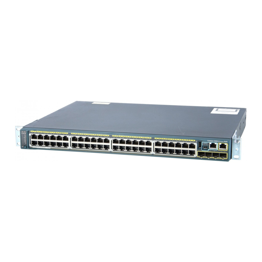
Catalyst 2960 Switch
Getting Started Guide
Americas Headquarters
Cisco Systems, Inc.
170 West Tasman Drive
San Jose, CA 95134-1706
USA
http://www.cisco.com
Tel:
408 526-4000
800 553-NETS (6387)
Fax:
408 527-0883
Text Part Number: OL-9368-03
Related Manuals for Cisco Catalyst 2960
Summary of Contents for Cisco Catalyst 2960
-
Page 1
Catalyst 2960 Switch Getting Started Guide Americas Headquarters Cisco Systems, Inc. 170 West Tasman Drive San Jose, CA 95134-1706 http://www.cisco.com Tel: 408 526-4000 800 553-NETS (6387) Fax: 408 527-0883 Text Part Number: OL-9368-03… -
Page 2
DAMAGES. Cisco and the Cisco Logo are trademarks of Cisco Systems, Inc. and/or its affiliates in the U.S. and other countries. A listing of Cisco’s trademarks can be found at www.cisco.com/go/trademarks. Third party trademarks mentioned are the property of their respective owners. The use of the word partner does not imply a partnership relationship between Cisco and any other company. -
Page 3: About This Guide
Cisco.com. When using the online publications, refer to the documents that match the Cisco IOS software version running on the switch. The software version is on the Cisco IOS label on the switch rear panel.
-
Page 4: Taking Out What You Need
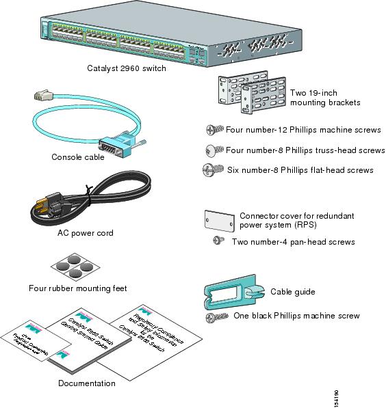
Verify that you have received the items shown in the “Shipping Box Contents” section. If any item is missing or damaged, contact your Cisco representative or reseller for instructions. Some switch models might include additional items that are not shown.
-
Page 5: Shipping Box Contents
Four number-8 Phillips truss-head screws Six number-8 Phillips flat-head screws AC power cord Connector cover for redundant power system (RPS) Two number-4 pan-head screws Four rubber mounting feet Cable guide One black Phillips machine screw Documentation Catalyst 2960 Switch Getting Started Guide OL-9368-03…
-
Page 6: Running Express Setup
Verify that POST has completed by confirming that the SYST LED rapidly blinks green. If the switch fails POST, the SYST LED turns amber. POST errors are usually fatal. Call Cisco Systems immediately if your switch fails POST. Step 5 Press and hold the Mode button for 3 seconds.
-
Page 7
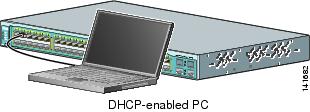
29 60 switch front panel and to the Ethernet SER IES port on the PC. DHCP-enabled PC Step 8 Verify that the LEDs on both Ethernet ports are green. Step 9 Wait 30 seconds. Catalyst 2960 Switch Getting Started Guide OL-9368-03… -
Page 8
Enter. The Express Setup page appears. If it does not appear, see the “In Case of Difficulty” section on page 1-18 for help. Note: all entries must be in English letters and numbers. Catalyst 2960 Switch Getting Started Guide OL-9368-03… -
Page 9
MIB objects. Embedded spaces are not allowed in SNMP community strings. When you set the SNMP read community, you can access SNMP information, but cannot modify it. When you set the SNMP write community, you can access and modify SNMP information. Catalyst 2960 Switch Getting Started Guide OL-9368-03… -
Page 10: Refreshing The Pc Ip Address
Managing the Switch After completing Express Setup and installing the switch in your network, use the device manager, Cisco Network Assistant, or another of the management options described in this section for further configuration. Using the Device Manager The simplest way to manage the switch is by using the device manager that is in the switch memory.
-
Page 11: Downloading Cisco Network Assistant
Follow these steps: Go to this Web address: http://www.cisco.com/go/NetworkAssistant. You must be a registered Cisco.com user, but you need no other access privileges. Find the Network Assistant installer. Download the Network Assistant installer, and run it. (You can run it directly from the Web if your browser offers this choice.)
-
Page 12: Other Management Options
This section covers basic 19-inch rack-mounting and switch port connections. As an example, all the illustrations show the Catalyst 2960G-48TC-L switch. You can install and connect the Catalyst 2960G-48TC-L or other Catalyst 2960 switches as shown in these illustrations. For alternate mounting procedures, such as…
-
Page 13: Equipment That You Supply
(SFP) modules, see the documentation AC power cord can reach from – that shipped with the module. the AC power outlet to the connector on the switch rear panel. Catalyst 2960 Switch Getting Started Guide 1-11 OL-9368-03…
-
Page 14: Installation Warning Statements
This section includes the basic installation warning statements. Translations of these warning statements appear in the Regulatory Compliance and Safety Information for the Catalyst 2960 Switch guide. Warning Only trained and qualified personnel should be allowed to install, replace, or service this equipment.
-
Page 15
A restricted access area can be accessed only through the use of a special tool, lock and key or other means of security. Statement 1072 Catalyst 2960 Switch Getting Started Guide 1-13 OL-9368-03… -
Page 16: Attaching The Brackets
Chapter 1 Getting Started Guide Rack-Mounting Attaching the Brackets Use four Phillips flat-head screws to attach the long side of the brackets to Catalyst 2960 switches in one of three mounting positions. SYS T STA T DU PLX SPE ED…
-
Page 17: Rack-Mount The Switch
Number-12 Phillips machine screws SYS T STA T DUP LX SPE ED MO DE C at al ys t 29 60 SE RIE Mid-rack-mounting position (telco rack) CO NS OL Rear-mounting position Catalyst 2960 Switch Getting Started Guide 1-15 OL-9368-03…
-
Page 18: Connect To The Switch Ports
IEEE 802.3af. They also provide Cisco prestandard PoE support for Cisco IP Phones and Cisco Aironet Access Points. Each of the Catalyst 2960-24PC-L switch 10/100 ports and ports 1 to 8 on the Catalyst 2960-24LT-L deliver 15.4 W of PoE.
-
Page 19
2 9 6 0 S E R IE SFP module port For a list of supported modules, see the release notes on Cisco.com. For detailed instructions on installing, removing, and connecting to SFP modules, see the documentation that came with the SFP module. -
Page 20: In Case Of Difficulty
In Case of Difficulty If you experience difficulty, help is available here and on Cisco.com. This section includes Express Setup troubleshooting, how to reset the switch, how to access help online, and where to find more information.
-
Page 21: Resetting The Switch
7 more seconds, and then the switch reboots. The switch now behaves like an unconfigured switch. You can enter the switch IP information by using Express Setup as described in the “Running Express Setup” section on page 1-4. Catalyst 2960 Switch Getting Started Guide 1-19 OL-9368-03…
-
Page 22: Accessing Help Online
Cisco.com). Regulatory Compliance and Safety Information for the Catalyst 2960 Switch • (order number DOC-7816880=). Release Notes for the Catalyst 2960 Switch (not orderable but available on • Cisco.com) Catalyst 2960 Switch Software Configuration Guide (not orderable but •…
-
Page 23: Obtaining Documentation And Submitting A Service Request
Subscribe to the What’s New in Cisco Product Documentation as a Really Simple Syndication (RSS) feed and set content to be delivered directly to your desktop using a reader application. The RSS feeds are a free service and Cisco currently supports RSS Version 2.0.
-
Page 24
Chapter 1 Getting Started Guide Cisco Warranty Information Catalyst 2960 Switch Getting Started Guide 1-22 OL-9368-03…
This manual is also suitable for:
Catalyst 2960
Table Of Contents
Getting Started Guide
About This Guide
Taking Out What You Need
Equipment That You Supply to Run Express Setup
Shipping Box Contents
Running Express Setup
Refreshing the PC IP Address
Managing the Switch
Using the Device Manager
Downloading Cisco Network Assistant
Command-Line Interface
Other Management Options
Rack-Mounting
Equipment That You Supply
Before You Begin
Installation Warning Statements
Attaching the Brackets
Rack-Mount the Switch
Connect to the Switch Ports
Connect to the 10/100 and 10/100/1000 Ports
Install the SFP Modules and Connect to the Ports
Verify Port Connectivity
In Case of Difficulty
Troubleshooting Express Setup
Resetting the Switch
Accessing Help Online
For More Information
Obtaining Documentation
Cisco.com
Product Documentation DVD
Ordering Documentation
Documentation Feedback
Cisco Product Security Overview
Reporting Security Problems in Cisco Products
Obtaining Technical Assistance
Cisco Technical Support & Documentation Website
Submitting a Service Request
Definitions of Service Request Severity
Obtaining Additional Publications and Information
Cisco Limited Lifetime Hardware Warranty Terms
Getting Started Guide
About This Guide
This guide provides instructions on how to use Express Setup to initially configure your Catalyst switch. Also covered are switch management options, basic rack-mounting procedures, port and module connections, power connection procedures, and troubleshooting help.
For additional installation and configuration information for Catalyst 2960 switches, see the Catalyst 2960 documentation on Cisco.com. For system requirements, important notes, limitations, open and resolved bugs, and last-minute documentation updates, see the release notes, also on Cisco.com.
When using the online publications, refer to the documents that match the Cisco IOS software version running on the switch. The software version is on the Cisco IOS label on the switch rear panel.
For translations of the warnings that appear in this publication, see the Regulatory Compliance and Safety Information for the Catalyst 2960 Switch that accompanies this guide.
Taking Out What You Need
Follow these steps:
1. ![]() Unpack and remove the switch and the accessory kit from the shipping box.
Unpack and remove the switch and the accessory kit from the shipping box.
2. ![]() Return the packing material to the shipping container, and save it for future use.
Return the packing material to the shipping container, and save it for future use.
3. ![]() Verify that you have received the items shown in the «Shipping Box Contents» section. If any item is missing or damaged, contact your Cisco representative or reseller for instructions. Some switch models might include additional items that are not shown.
Verify that you have received the items shown in the «Shipping Box Contents» section. If any item is missing or damaged, contact your Cisco representative or reseller for instructions. Some switch models might include additional items that are not shown.
Equipment That You Supply to Run Express Setup
You need to supply this equipment to run Express Setup:
•![]() PC
PC
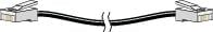
•![]() Ethernet (Category 5) straight-through cable (as shown)
Ethernet (Category 5) straight-through cable (as shown)
Shipping Box Contents
Running Express Setup
When you first set up the switch, you should use Express Setup to enter the initial IP information. This enables the switch to connect to local routers and the Internet. You can then access the switch through the IP address for further configuration.
To run Express Setup:
|
Step 1 |
Verify that no devices are connected to the switch, because during Express Setup, the switch acts as a DHCP server. If your PC has a static IP address, before you begin, you should change your PC settings to temporarily use DHCP. |
|
|
Step 2 |
Connect the AC power cord to the switch and to a grounded AC outlet. The power-on self-test (POST) begins. During POST, the LEDs blink while a series of tests verify that the switch functions properly. LED behavior during POST is unpredictable and might vary. |
|
|
Step 3 |
Wait for the switch to complete POST. It might take several minutes for the switch to complete POST. |
|
|
Step 4 |
Verify that POST has completed by confirming that the SYST LED rapidly blinks green. If the switch fails POST, the SYST LED turns amber. POST errors are usually fatal. Call Cisco Systems immediately if your switch fails POST. |
|
|
Step 5 |
Press and hold the Mode button for 3 seconds. When all of the LEDs above the Mode button turn green, release the Mode button. If the LEDs above the Mode button begin to blink after you press the button, release it. Blinking LEDs mean that the switch has already been configured and cannot go into Express Setup mode. For more information, see the «Resetting the Switch» section. |
|
|
Step 6 |
Verify that the switch is in Express Setup mode by confirming that all LEDs above the Mode button are green. (The RPS LED remains off on some switch models.) |
|
|
Step 7 |
Connect a straight-through Category 5 Ethernet cable (not provided) to any 10/100 or 10/100/1000 Ethernet port on the switch front panel and to the Ethernet port on the PC. |
|
|
Step 8 |
Verify that the LEDs on both Ethernet ports are green. |
|
|
Step 9 |
Wait 30 seconds. |
|
|
Step 10 |
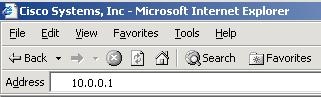
Launch a web browser on your PC. Enter the IP address 10.0.0.1 in the web browser, and press Enter. |
|
|
Step 11 |
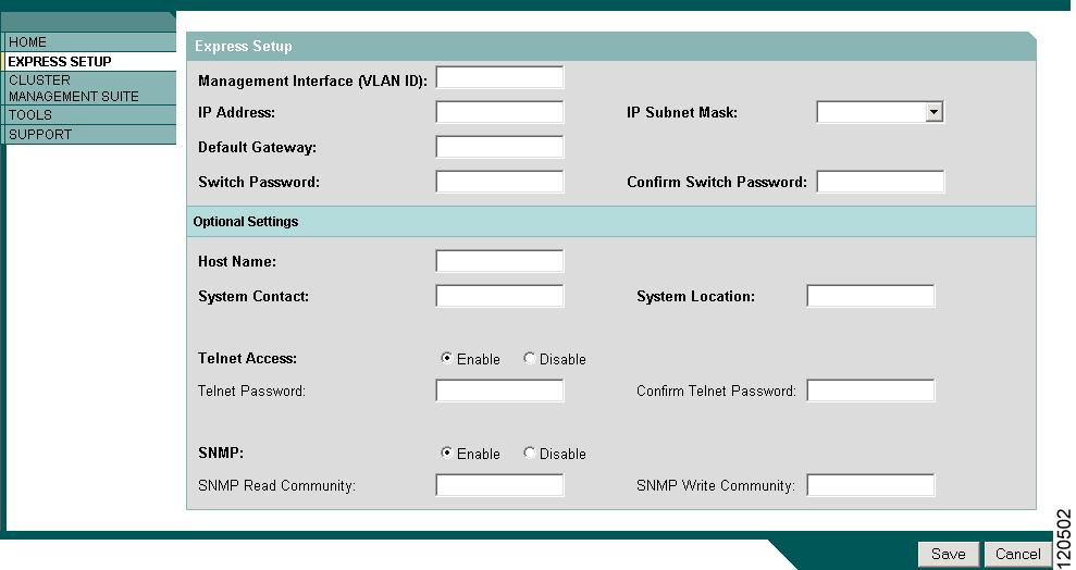
The Express Setup page appears. If it does not appear, see the «In Case of Difficulty» section for help. Note: all entries must be in English letters and numbers.
|
|
|
Step 12 |
Enter this information in the Network Settings fields: • • • • |
|
|
Step 13 |
(Optional) You can enter the Optional Settings information now or enter it later by using the device manager interface: • • • • • If you enable SNMP, you must enter a community string in the SNMP Read Community field, the SNMP Write Community field, or both. SNMP community strings authenticate access to MIB objects. Embedded spaces are not allowed in SNMP community strings. When you set the SNMP read community, you can access SNMP information, but cannot modify it. When you set the SNMP write community, you can access and modify SNMP information. |
|
|
Step 14 |
Click Submit to save your settings, or click Cancel to clear your settings. When you click Submit, the switch is configured and exits Express Setup mode. The PC displays a warning message and then attempts to connect with the new switch IP address. If you configured the switch with an IP address that is in a different subnet from the PC, connectivity between the PC and the switch is lost. |
|
|
Step 15 |
Disconnect the switch from the PC, and install the switch in your network. See the «Managing the Switch» section for information about configuring and managing the switch. If you need to rerun Express Setup, see the «Resetting the Switch» section. |

Refreshing the PC IP Address
After you complete Express Setup, you should refresh the PC IP address.
For a dynamically assigned IP address, disconnect the PC from the switch, and reconnect it to the network. The network DHCP server will assign a new IP address to the PC.
For a statically assigned IP address, change it to the previously configured IP address.
Managing the Switch
After completing Express Setup and installing the switch in your network, use the device manager, Cisco Network Assistant, or another of the management options described in this section for further configuration.
Using the Device Manager
The simplest way to manage the switch is by using the device manager that is in the switch memory. This is an easy-to-use web interface that offers quick configuration and monitoring. You can access the device manager from anywhere in your network through a web browser.
Follow these steps:
1. ![]() Launch a web browser on your PC or workstation.
Launch a web browser on your PC or workstation.
2. ![]() Enter the switch IP address in the web browser, and press Enter. The device manager page appears.
Enter the switch IP address in the web browser, and press Enter. The device manager page appears.
3. ![]() Use the device manager to perform basic switch configuration and monitoring. Refer to the device manager online help for more information.
Use the device manager to perform basic switch configuration and monitoring. Refer to the device manager online help for more information.
4. ![]() For a more advanced configuration, download and run the Cisco Network Assistant described in the next section.
For a more advanced configuration, download and run the Cisco Network Assistant described in the next section.
Downloading Cisco Network Assistant
Cisco Network Assistant is a free software program that you download from Cisco.com and run on your PC. Network Assistant offers advanced options for configuring and monitoring multiple devices, including switches, switch clusters, switch stacks, routers, and access points.
Follow these steps:
1. ![]() From the device manager page, select Network Assistant.
From the device manager page, select Network Assistant.
2. ![]() Follow the instructions to download the program to your PC.
Follow the instructions to download the program to your PC.
3. ![]() Use the Network Assistant to configure and monitor multiple switches and devices. Refer to the Network Assistant getting started guide and the online help for more information.
Use the Network Assistant to configure and monitor multiple switches and devices. Refer to the Network Assistant getting started guide and the online help for more information.
Command-Line Interface
You can enter Cisco IOS commands and parameters through the CLI. Access the CLI either by connecting your PC directly to the switch console port or through a Telnet session from a remote PC or workstation.
Follow these steps:
1. ![]() Connect the supplied RJ-45-to DB-9 adapter cable to the 9-pin serial port on the PC. Connect the other end of the cable to the console port on the switch.
Connect the supplied RJ-45-to DB-9 adapter cable to the 9-pin serial port on the PC. Connect the other end of the cable to the console port on the switch.
2. ![]() Start a terminal-emulation program on the PC.
Start a terminal-emulation program on the PC.
3. ![]() Configure the PC terminal emulation software for 9600 baud, 8 data bits, no parity, 1 stop bit, and no flow control.
Configure the PC terminal emulation software for 9600 baud, 8 data bits, no parity, 1 stop bit, and no flow control.
4. ![]() Use the CLI to enter commands to configure the switch. See the software configuration guide and the command reference for more information.
Use the CLI to enter commands to configure the switch. See the software configuration guide and the command reference for more information.
Other Management Options
You can use SNMP management applications such as CiscoWorks Small Network Management Solution (SNMS) and HP OpenView to configure and manage the switch. You also can manage it from an SNMP-compatible workstation that is running platforms such as HP OpenView or SunNet Manager.
The Cisco IE2100 Series Configuration Registrar is a network management device that works with embedded CNS agents in the switch software. You can use IE2100 to automate initial configurations and configuration updates on the switch.
See the «Accessing Help Online» section for a list of supporting documentation.
Rack-Mounting
This section covers basic 19-inch rack-mounting and switch port connections. As an example, all the illustrations show the Catalyst 2960G-48TC-L switch. You can install and connect the Catalyst 2960G-48TC-L or other Catalyst 2960 switches as shown in these illustrations. For alternate mounting procedures, such as installing the switch in a 24-inch rack or on a wall, and for additional cabling information, see the Catalyst 2960 Switch Hardware Installation Guide on Cisco.com.
Equipment That You Supply
You need to supply a number-2 Phillips screwdriver to rack-mount the switch.
Before You Begin
When determining where to install the switch, verify that these guidelines are met:
|
• • • • – – – |
• • • • |
Installation Warning Statements
This section includes the basic installation warning statements. Translations of these warning statements appear in the Regulatory Compliance and Safety Information for the Catalyst 2960 Switch document that shipped with the switch.

Warning ![]() Only trained and qualified personnel should be allowed to install, replace, or service this equipment. Statement 148
Only trained and qualified personnel should be allowed to install, replace, or service this equipment. Statement 148
Warning ![]() To prevent the switch from overheating, do not operate it in an area that exceeds the maximum recommended ambient temperature of 113°F (45°C). To prevent airflow restriction, allow at least 3 inches (7.6 cm) of clearance around the ventilation openings. Statement 17B
To prevent the switch from overheating, do not operate it in an area that exceeds the maximum recommended ambient temperature of 113°F (45°C). To prevent airflow restriction, allow at least 3 inches (7.6 cm) of clearance around the ventilation openings. Statement 17B
Warning ![]() Installation of the equipment must comply with local and national electrical codes. Statement 1074
Installation of the equipment must comply with local and national electrical codes. Statement 1074
Warning ![]() To prevent bodily injury when mounting or servicing this unit in a rack, you must take special precautions to ensure that the system remains stable. The following guidelines are provided to ensure your safety:
To prevent bodily injury when mounting or servicing this unit in a rack, you must take special precautions to ensure that the system remains stable. The following guidelines are provided to ensure your safety:
This unit should be mounted at the bottom of the rack if it is the only unit in the rack.
When mounting this unit in a partially filled rack, load the rack from the bottom to the top with the heaviest component at the bottom of the rack.
If the rack is provided with stabilizing devices, install the stabilizers before mounting or servicing the unit in the rack. Statement 1006
Warning ![]() This equipment is intended to be grounded. Ensure that the host is connected to earth ground during normal use. Statement 39
This equipment is intended to be grounded. Ensure that the host is connected to earth ground during normal use. Statement 39
Warning ![]() If a redundant power system (RPS) is not connected to the switch, install an RPS connector cover on the back of the switch. Statement 265
If a redundant power system (RPS) is not connected to the switch, install an RPS connector cover on the back of the switch. Statement 265
Warning ![]() Class 1 laser product. Statement 1008
Class 1 laser product. Statement 1008
Warning ![]() For connections outside the building where the equipment is installed, the following ports must be connected through an approved network termination unit with integral circuit protection: 10/100/1000 Ethernet. Statement 1044
For connections outside the building where the equipment is installed, the following ports must be connected through an approved network termination unit with integral circuit protection: 10/100/1000 Ethernet. Statement 1044
Attaching the Brackets
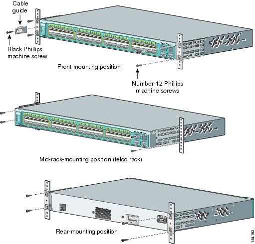
Use four Phillips flat-head screws to attach the long side of the brackets to Catalyst 2960 switches in one of three mounting positions.

Rack-Mount the Switch
Use the four number-12 Phillips machine screws to attach the brackets to the rack. Use the black Phillips machine screw to attach the cable guide to the left or right bracket.
Connect to the Switch Ports
This section describes how to connect to the fixed switch ports and to the SFP module ports.
Connect to the 10/100 and 10/100/1000 Ports
Follow these steps:
|
Step 1 |
When you connect to servers, workstations, IP phones, wireless access points, and routers, insert a straight-through, twisted four-pair, Category 5 cable in a switch 10/100 or 10/100/1000 port. Use a crossover, twisted four-pair, Category 5 cable when you connect to other switches, hubs, or repeaters. |
|
|
Step 2 |
Insert the other cable end into an RJ-45 connector on the other device. |


Note ![]() The automatic medium-dependent interface crossover (auto-MDIX) feature is enabled by default. The switch detects the required cable type for copper Ethernet connections and configures the interfaces accordingly. Therefore, you can use either a crossover or a straight-through cable for connections to a copper 10/100 or 10/100/1000 module port on the switch, regardless of the type of device on the other end of the connection.
The automatic medium-dependent interface crossover (auto-MDIX) feature is enabled by default. The switch detects the required cable type for copper Ethernet connections and configures the interfaces accordingly. Therefore, you can use either a crossover or a straight-through cable for connections to a copper 10/100 or 10/100/1000 module port on the switch, regardless of the type of device on the other end of the connection.
Install the SFP Modules and Connect to the Ports
Follow these steps:
|
Step 1 |
Grasp the module on the sides, and insert it into the switch slot until you feel the connector snap into place. |
|
|
Step 2 |
Insert an appropriate cable into the module port. Insert the other cable end into the other device. |
|

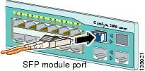
For a list of supported modules, see the release notes on Cisco.com. For detailed instructions on installing, removing, and connecting to SFP modules, see the documentation that came with the SFP module.

Caution
![]() Removing and installing an SFP module can shorten its useful life. Do not remove and insert SFP modules more often than is absolutely necessary.
Removing and installing an SFP module can shorten its useful life. Do not remove and insert SFP modules more often than is absolutely necessary.
Verify Port Connectivity
After you connect to the switch port and another device, the port LED turns amber while the switch establishes a link. This process takes about 30 seconds, and then the LED turns green when the switch and the target device have an established link. If the LED is off, the target device might not be turned on, there might be a cable problem, or there might be a problem with the adapter installed in the target device. See the «In Case of Difficulty» section for information about online assistance.
In Case of Difficulty
If you experience difficulty, help is available here and on Cisco.com. This section includes Express Setup troubleshooting, how to reset the switch, how to access help online, and where to find more information.
Troubleshooting Express Setup
If Express Setup does not run, or if the Express Setup page does not appear in your browser:
|
• |
If not, make sure that only the SYST and STAT LEDs are green before pressing the Mode button to enter the Express Setup mode. |
|
• |
If yes, wait until POST completes. Power cycle the switch. Wait until POST completes. Confirm that the SYST and STAT LEDs are green. Press the Mode button to enter Express Setup mode. |
|
• |
Verify that all LEDs above the Mode button are green. (The RPS LED is off.) If necessary, press the Mode button to enter Express Setup mode. |
|
• |
If yes, before connecting to the switch, change your PC settings to temporarily use DHCP. |
|
• |
If yes, connect a straight-through cable to an Ethernet port on the switch and the PC. Wait 30 seconds before entering 10.0.0.1 in the browser. |
|
• |
If yes, disconnect from the console port. Connect to an Ethernet port on the switch and the PC. Wait 30 seconds before entering 10.0.0.1 in the browser. |
|
• |
If not, wait 30 seconds, re-enter 10.0.0.1 in the browser, and press Enter. |
|
• |
If yes, re-enter 10.0.0.1 in the browser, and press Enter. |
Resetting the Switch
This section describes how to reset the switch by rerunning Express Setup. These are reasons why you might want to reset the switch:
•![]() You installed the switch in your network and cannot connect to it because you assigned the wrong IP address.
You installed the switch in your network and cannot connect to it because you assigned the wrong IP address.
•![]() You want to clear all configurations from the switch and assign a new IP address.
You want to clear all configurations from the switch and assign a new IP address.
•![]() You are trying to enter Express Setup mode, and the switch LEDs start blinking when you press the Mode button (which means that the switch is already configured with IP information).
You are trying to enter Express Setup mode, and the switch LEDs start blinking when you press the Mode button (which means that the switch is already configured with IP information).
Caution
![]() Resetting the switch deletes the configuration and reboots the switch.
Resetting the switch deletes the configuration and reboots the switch.
To reset the switch:
•![]() Press and hold the Mode button. The switch LEDs begin blinking after about 3 seconds. Continue holding down the Mode button. The LEDs stop blinking after 7 more seconds, and then the switch reboots.
Press and hold the Mode button. The switch LEDs begin blinking after about 3 seconds. Continue holding down the Mode button. The LEDs stop blinking after 7 more seconds, and then the switch reboots.
The switch now behaves like an unconfigured switch. You can enter the switch IP information by using Express Setup as described in the «Running Express Setup» section.
Accessing Help Online
First look for a solution to your problem in the troubleshooting section of the Catalyst 2960 Switch Hardware Installation Guide or the Catalyst 2960 Switch Software Configuration Guide on Cisco.com. You can also access the Cisco Technical Support and Documentation website for a list of known hardware problems and extensive troubleshooting documentation, including:
•![]() Factory defaults and password recovery
Factory defaults and password recovery
•![]() Recovery from corrupted or missing software
Recovery from corrupted or missing software
•![]() Switch port problems
Switch port problems
•![]() Network interface cards
Network interface cards
•![]() Troubleshooting tools
Troubleshooting tools
•![]() Field notices and security advisories
Field notices and security advisories
Follow these steps:
1. ![]() Open your browser, and go to http://www.cisco.com/.
Open your browser, and go to http://www.cisco.com/.
2. ![]() Click Technical Support and Documentation.
Click Technical Support and Documentation.
3. ![]() Under the Documentation section, click Switches.
Under the Documentation section, click Switches.
4. ![]() Under the LAN Switches section, click Cisco Catalyst 2960 Series Switches.
Under the LAN Switches section, click Cisco Catalyst 2960 Series Switches.
For More Information
For more information about the switch, see these documents on Cisco.com:
•![]() Catalyst 2960 Switch Hardware Installation Guide (not orderable, but available on Cisco.com).
Catalyst 2960 Switch Hardware Installation Guide (not orderable, but available on Cisco.com).
•![]() Regulatory Compliance and Safety Information for the Catalyst 2960 Switch (order number DOC-7816880=).
Regulatory Compliance and Safety Information for the Catalyst 2960 Switch (order number DOC-7816880=).
•![]() Release Notes for the Catalyst 2960 Switch (not orderable but available on Cisco.com)
Release Notes for the Catalyst 2960 Switch (not orderable but available on Cisco.com)
•![]() Catalyst 2960 Switch Software Configuration Guide (not orderable but available on Cisco.com).
Catalyst 2960 Switch Software Configuration Guide (not orderable but available on Cisco.com).
•![]() Catalyst 2960 Switch Command Reference (not orderable but available on Cisco.com).
Catalyst 2960 Switch Command Reference (not orderable but available on Cisco.com).
•![]() Catalyst 2960 Switch System Message Guide (not orderable but available on Cisco.com).
Catalyst 2960 Switch System Message Guide (not orderable but available on Cisco.com).
Obtaining Documentation
Cisco documentation and additional literature are available on Cisco.com. Cisco also provides several ways to obtain technical assistance and other technical resources. These sections explain how to obtain technical information from Cisco Systems.
Cisco.com
You can access the most current Cisco documentation at this URL:
http://www.cisco.com/techsupport
You can access the Cisco website at this URL:
http://www.cisco.com
You can access international Cisco websites at this URL:
http://www.cisco.com/public/countries_languages.shtml
Product Documentation DVD
The Product Documentation DVD is a comprehensive library of technical product documentation on a portable medium. The DVD enables you to access multiple versions of installation, configuration, and command guides for Cisco hardware and software products. With the DVD, you have access to the same HTML documentation that is found on the Cisco website without being connected to the Internet. Certain products also have .PDF versions of the documentation available.
The Product Documentation DVD is available as a single unit or as a subscription. Registered Cisco.com users (Cisco direct customers) can order a Product Documentation DVD (product number DOC-DOCDVD= or DOC-DOCDVD=SUB) from Cisco Marketplace at this URL:
http://www.cisco.com/go/marketplace/
Ordering Documentation
Registered Cisco.com users may order Cisco documentation at the Product Documentation Store in the Cisco Marketplace at this URL:
http://www.cisco.com/go/marketplace/
Nonregistered Cisco.com users can order technical documentation from 8:00 a.m. to 5:00 p.m. (0800 to 1700) PDT by calling 1 866 463-3487 in the United States and Canada, or elsewhere by calling 011 408 519-5055. You can also order documentation by e-mail at tech-doc-store-mkpl@external.cisco.com or by fax at 1 408 519-5001 in the United States and Canada, or elsewhere at 011 408 519-5001.
Documentation Feedback
You can rate and provide feedback about Cisco technical documents by completing the online feedback form that appears with the technical documents on Cisco.com.
You can submit comments about Cisco documentation by using the response card (if present) behind the front cover of your document or by writing to the following address:
Cisco Systems
Attn: Customer Document Ordering
170 West Tasman Drive
San Jose, CA 95134-9883
We appreciate your comments.
Cisco Product Security Overview
Cisco provides a free online Security Vulnerability Policy portal at this URL:
http://www.cisco.com/en/US/products/products_security_vulnerability_policy.html
From this site, you will find information about how to:
•![]() Report security vulnerabilities in Cisco products.
Report security vulnerabilities in Cisco products.
•![]() Obtain assistance with security incidents that involve Cisco products.
Obtain assistance with security incidents that involve Cisco products.
•![]() Register to receive security information from Cisco.
Register to receive security information from Cisco.
A current list of security advisories, security notices, and security responses for Cisco products is available at this URL:
http://www.cisco.com/go/psirt
To see security advisories, security notices, and security responses as they are updated in real time, you can subscribe to the Product Security Incident Response Team Really Simple Syndication (PSIRT RSS) feed. Information about how to subscribe to the PSIRT RSS feed is found at this URL:
http://www.cisco.com/en/US/products/products_psirt_rss_feed.html
Reporting Security Problems in Cisco Products
Cisco is committed to delivering secure products. We test our products internally before we release them, and we strive to correct all vulnerabilities quickly. If you think that you have identified a vulnerability in a Cisco product, contact PSIRT:
•![]() For Emergencies only — security-alert@cisco.com
For Emergencies only — security-alert@cisco.com
An emergency is either a condition in which a system is under active attack or a condition for which a severe and urgent security vulnerability should be reported. All other conditions are considered nonemergencies.
•![]() For Nonemergencies — psirt@cisco.com
For Nonemergencies — psirt@cisco.com
In an emergency, you can also reach PSIRT by telephone:
•![]() 1 877 228-7302
1 877 228-7302
•![]() 1 408 525-6532
1 408 525-6532

Tip ![]() We encourage you to use Pretty Good Privacy (PGP) or a compatible product (for example, GnuPG) to encrypt any sensitive information that you send to Cisco. PSIRT can work with information that has been encrypted with PGP versions 2.x through 9.x.
We encourage you to use Pretty Good Privacy (PGP) or a compatible product (for example, GnuPG) to encrypt any sensitive information that you send to Cisco. PSIRT can work with information that has been encrypted with PGP versions 2.x through 9.x.
Never use a revoked or an expired encryption key. The correct public key to use in your correspondence with PSIRT is the one linked in the Contact Summary section of the Security Vulnerability Policy page at this URL:
http://www.cisco.com/en/US/products/products_security_vulnerability_policy.htmlThe link on this page has the current PGP key ID in use.
If you do not have or use PGP, contact PSIRT at the aforementioned e-mail addresses or phone numbers before sending any sensitive material to find other means of encrypting the data.
Obtaining Technical Assistance
Cisco Technical Support provides 24-hour-a-day award-winning technical assistance. The Cisco Technical Support & Documentation website on Cisco.com features extensive online support resources. In addition, if you have a valid Cisco service contract, Cisco Technical Assistance Center (TAC) engineers provide telephone support. If you do not have a valid Cisco service contract, contact your reseller.
Cisco Technical Support & Documentation Website
The Cisco Technical Support & Documentation website provides online documents and tools for troubleshooting and resolving technical issues with Cisco products and technologies. The website is available 24 hours a day, at this URL:
http://www.cisco.com/techsupport
Access to all tools on the Cisco Technical Support & Documentation website requires a Cisco.com user ID and password. If you have a valid service contract but do not have a user ID or password, you can register at this URL:
http://tools.cisco.com/RPF/register/register.do
Note ![]() Use the Cisco Product Identification (CPI) tool to locate your product serial number before submitting a web or phone request for service. You can access the CPI tool from the Cisco Technical Support & Documentation website by clicking the Tools & Resources link under Documentation & Tools. Choose Cisco Product Identification Tool from the Alphabetical Index drop-down list, or click the Cisco Product Identification Tool link under Alerts & RMAs. The CPI tool offers three search options: by product ID or model name; by tree view; or for certain products, by copying and pasting show command output. Search results show an illustration of your product with the serial number label location highlighted. Locate the serial number label on your product and record the information before placing a service call.
Use the Cisco Product Identification (CPI) tool to locate your product serial number before submitting a web or phone request for service. You can access the CPI tool from the Cisco Technical Support & Documentation website by clicking the Tools & Resources link under Documentation & Tools. Choose Cisco Product Identification Tool from the Alphabetical Index drop-down list, or click the Cisco Product Identification Tool link under Alerts & RMAs. The CPI tool offers three search options: by product ID or model name; by tree view; or for certain products, by copying and pasting show command output. Search results show an illustration of your product with the serial number label location highlighted. Locate the serial number label on your product and record the information before placing a service call.
Submitting a Service Request
Using the online TAC Service Request Tool is the fastest way to open S3 and S4 service requests. (S3 and S4 service requests are those in which your network is minimally impaired or for which you require product information.) After you describe your situation, the TAC Service Request Tool provides recommended solutions. If your issue is not resolved using the recommended resources, your service request is assigned to a Cisco engineer. The TAC Service Request Tool is located at this URL:
http://www.cisco.com/techsupport/servicerequest
For S1 or S2 service requests, or if you do not have Internet access, contact the Cisco TAC by telephone. (S1 or S2 service requests are those in which your production network is down or severely degraded.) Cisco engineers are assigned immediately to S1 and S2 service requests to help keep your business operations running smoothly.
To open a service request by telephone, use one of the following numbers:
Asia-Pacific: +61 2 8446 7411 (Australia: 1 800 805 227)
EMEA: +32 2 704 55 55
USA: 1 800 553-2447
For a complete list of Cisco TAC contacts, go to this URL:
http://www.cisco.com/techsupport/contacts
Definitions of Service Request Severity
To ensure that all service requests are reported in a standard format, Cisco has established severity definitions.
Severity 1 (S1)—An existing network is down, or there is a critical impact to your business operations. You and Cisco will commit all necessary resources around the clock to resolve the situation.
Severity 2 (S2)—Operation of an existing network is severely degraded, or significant aspects of your business operations are negatively affected by inadequate performance of Cisco products. You and Cisco will commit full-time resources during normal business hours to resolve the situation.
Severity 3 (S3)—Operational performance of the network is impaired, while most business operations remain functional. You and Cisco will commit resources during normal business hours to restore service to satisfactory levels.
Severity 4 (S4)—You require information or assistance with Cisco product capabilities, installation, or configuration. There is little or no effect on your business operations.
Obtaining Additional Publications and Information
Information about Cisco products, technologies, and network solutions is available from various online and printed sources.
•![]() The Cisco Product Quick Reference Guide is a handy, compact reference tool that includes brief product overviews, key features, sample part numbers, and abbreviated technical specifications for many Cisco products that are sold through channel partners. It is updated twice a year and includes the latest Cisco offerings. To order and find out more about the Cisco Product Quick Reference Guide, go to this URL:
The Cisco Product Quick Reference Guide is a handy, compact reference tool that includes brief product overviews, key features, sample part numbers, and abbreviated technical specifications for many Cisco products that are sold through channel partners. It is updated twice a year and includes the latest Cisco offerings. To order and find out more about the Cisco Product Quick Reference Guide, go to this URL:
http://www.cisco.com/go/guide
•![]() Cisco Marketplace provides a variety of Cisco books, reference guides, documentation, and logo merchandise. Visit Cisco Marketplace, the company store, at this URL:
Cisco Marketplace provides a variety of Cisco books, reference guides, documentation, and logo merchandise. Visit Cisco Marketplace, the company store, at this URL:
http://www.cisco.com/go/marketplace/
•![]() Cisco Press publishes a wide range of general networking, training and certification titles. Both new and experienced users will benefit from these publications. For current Cisco Press titles and other information, go to Cisco Press at this URL:
Cisco Press publishes a wide range of general networking, training and certification titles. Both new and experienced users will benefit from these publications. For current Cisco Press titles and other information, go to Cisco Press at this URL:
http://www.ciscopress.com
•![]() Packet magazine is the Cisco Systems technical user magazine for maximizing Internet and networking investments. Each quarter, Packet delivers coverage of the latest industry trends, technology breakthroughs, and Cisco products and solutions, as well as network deployment and troubleshooting tips, configuration examples, customer case studies, certification and training information, and links to scores of in-depth online resources. You can access Packet magazine at this URL:
Packet magazine is the Cisco Systems technical user magazine for maximizing Internet and networking investments. Each quarter, Packet delivers coverage of the latest industry trends, technology breakthroughs, and Cisco products and solutions, as well as network deployment and troubleshooting tips, configuration examples, customer case studies, certification and training information, and links to scores of in-depth online resources. You can access Packet magazine at this URL:
http://www.cisco.com/packet
•![]() iQ Magazine is the quarterly publication from Cisco Systems designed to help growing companies learn how they can use technology to increase revenue, streamline their business, and expand services. The publication identifies the challenges facing these companies and the technologies to help solve them, using real-world case studies and business strategies to help readers make sound technology investment decisions. You can access iQ Magazine at this URL:
iQ Magazine is the quarterly publication from Cisco Systems designed to help growing companies learn how they can use technology to increase revenue, streamline their business, and expand services. The publication identifies the challenges facing these companies and the technologies to help solve them, using real-world case studies and business strategies to help readers make sound technology investment decisions. You can access iQ Magazine at this URL:
http://www.cisco.com/go/iqmagazine
or view the digital edition at this URL:
http://ciscoiq.texterity.com/ciscoiq/sample/
•![]() Internet Protocol Journal is a quarterly journal published by Cisco Systems for engineering professionals involved in designing, developing, and operating public and private internets and intranets. You can access the Internet Protocol Journal at this URL:
Internet Protocol Journal is a quarterly journal published by Cisco Systems for engineering professionals involved in designing, developing, and operating public and private internets and intranets. You can access the Internet Protocol Journal at this URL:
http://www.cisco.com/ipj
•![]() Networking products offered by Cisco Systems, as well as customer support services, can be obtained at this URL:
Networking products offered by Cisco Systems, as well as customer support services, can be obtained at this URL:
http://www.cisco.com/en/US/products/index.html
•![]() Networking Professionals Connection is an interactive website for networking professionals to share questions, suggestions, and information about networking products and technologies with Cisco experts and other networking professionals. Join a discussion at this URL:
Networking Professionals Connection is an interactive website for networking professionals to share questions, suggestions, and information about networking products and technologies with Cisco experts and other networking professionals. Join a discussion at this URL:
http://www.cisco.com/discuss/networking
•![]() World-class networking training is available from Cisco. You can view current offerings at this URL:
World-class networking training is available from Cisco. You can view current offerings at this URL:
http://www.cisco.com/en/US/learning/index.html
Cisco Limited Lifetime Hardware Warranty Terms
There are special terms applicable to your hardware warranty and various services that you can use during the warranty period. Your formal Warranty Statement, including the warranties and license agreements applicable to Cisco software, is available on Cisco.com. Follow these steps to access and download the Cisco Information Packet and your warranty and license agreements from Cisco.com.
1. ![]() Launch your browser, and go to this URL:
Launch your browser, and go to this URL:
http://www.cisco.com/univercd/cc/td/doc/es_inpck/cetrans.htm
The Warranties and License Agreements page appears.
2. ![]() To read the Cisco Information Packet, follow these steps:
To read the Cisco Information Packet, follow these steps:
a. ![]() Click the Information Packet Number field, and make sure that the part number 78-5235-03B0 is highlighted.
Click the Information Packet Number field, and make sure that the part number 78-5235-03B0 is highlighted.
b. ![]() Select the language in which you would like to read the document.
Select the language in which you would like to read the document.
c. ![]() Click Go.
Click Go.
The Cisco Limited Warranty and Software License page from the Information Packet appears.
d. ![]() Read the document online, or click the PDF icon to download and print the document in Adobe Portable Document Format (PDF).
Read the document online, or click the PDF icon to download and print the document in Adobe Portable Document Format (PDF).
Note ![]() You must have Adobe Acrobat Reader to view and print PDF files. You can download the reader from Adobe’s website: http://www.adobe.com
You must have Adobe Acrobat Reader to view and print PDF files. You can download the reader from Adobe’s website: http://www.adobe.com
3. ![]() To read translated and localized warranty information about your product, follow these steps:
To read translated and localized warranty information about your product, follow these steps:
a. ![]() Enter this part number in the Warranty Document Number field:
Enter this part number in the Warranty Document Number field:
78-6310-02C0
b. ![]() Select the language in which you would like to view the document.
Select the language in which you would like to view the document.
c. ![]() Click Go.
Click Go.
The Cisco warranty page appears.
d. ![]() Read the document online, or click the PDF icon to download and print the document in Adobe Portable Document Format (PDF).
Read the document online, or click the PDF icon to download and print the document in Adobe Portable Document Format (PDF).
You can also contact the Cisco service and support website for assistance:
http://www.cisco.com/public/Support_root.shtml.
Duration of Hardware Warranty
A Cisco product hardware warranty is supported for as long as the original end user continues to own or use the product, provided that the fan and power supply warranty is limited to five (5) years. In the event of a discontinuance of product manufacture, the Cisco warranty support is limited to five (5) years from the announcement of the discontinuance.
Replacement, Repair, or Refund Policy for Hardware
Cisco or its service center will use commercially reasonable efforts to ship a replacement part within ten (10) working days after receipt of the Return Materials Authorization (RMA) request. Actual delivery times can vary, depending on the customer location.
Cisco reserves the right to refund the purchase price as its exclusive warranty remedy.
To Receive a Return Materials Authorization (RMA) Number
Contact the company from whom you purchased the product. If you purchased the product directly from Cisco, contact your Cisco Sales and Service Representative.
Complete the information below, and keep it for reference.
|
Company product purchased from |
|
|
Company telephone number |
|
|
Product model number |
|
|
Product serial number |
|
|
Maintenance contract number |
На это странице вы найдете большую подборку руководств по настройке коммутаторов Cisco Catalyst 2600.
СОДЕРЖАНИЕ:
- Быстрый сброс Cisco 2960 на заводские настройки
- Сброс настроек (пароля) на Cisco 2960 с помощью командной строки
- Настройка коммутатора Cisco Catalyst 2960 с нуля
- Как прописать на различные порты Cisco определенные VLAN
- Создание и настройка VLAN в cisco packet tracer на коммутаторе Cisco Catalyst 2960
- Настройка ssh подключения к Cisco
- Как настроить ssh на Cisco Switch catalyst 2960 с помощью командной строки
- Настройка DHCP на роутере Cisco
- Настройка Cisco 2960 Netflow
- Конфигурирование Netflow на роутерах Cisco Router и Solar Winds netflow analyzer
- Настройка удаленного доступа на Cisco через Web интерфейс
- Настройка времени на Cisco 2960
- Настройка QoS очередей на платформах коммутаторов Cisco
- Настройка PoE на cisco 2960
Быстрый сброс Cisco 2960 на заводские настройки
Сброс настроек (пароля) на Cisco 2960 с помощью командной строки
Подключите терминал или PC с программой эмуляции терминала к консольному порту маршрутизатора. Если пароль на консольный доступ не установлен, наберите show version и запишите значение конфигурационного регистра в самом конце вывода этой команды. Обычно это 0x2102 or 0x102.
Выключите и включите маршрутизатор. Пошлите сигнал Break в течение первых 30 с после включения. Вы должны увидеть приглашение rommon> в командной строке. Если этого не произошло, значит, Вы не послали маршрутизатору сигнал Break. Полезно, кстати, проверить настройки терминального доступа Вашей программы. Они должны быть такими — 9600, 8-«n»-1, no flow control. Наберите confreg. Ответьте ««y»» на вопрос «Do you wish to change configuration[y/n]?» Отвечайте «n» на все остальные вопросы, пока не увидите вопрос «ignore system config info[y/n]?». Ответьте «y». Отвечайте «n» на все оставшиеся вопросы до тех пор, пока не увидите вопрос «change boot characteristics[y/n]?». Ответьте «y». Ответьте «no» на вопрос «Do you wish to change configuration [y/n]?». Напечатайте reset. После перезапуска ответьте «no» на приглашение начать процедуру Setup.
Наберите enable в строке Router>. Вы должны увидеть Router#. Теперь можете посмотреть на конфигурационный файл (команда show startup-config). Если пароль в нем зашифрован, то наберите copy startup-config running-config. Затем наберите conf t и enable secret [новый пароль]. Нажмите sZ. Наберите copy running config startup-config. Наберите config t. Наберите config register 0x2102 (или то значение, которое вы записали). Нажмите sZ. Наберите reload. После перезагрузки должен начать действовать Ваш новый пароль.
Настройка коммутатора Cisco Catalyst 2960 с нуля
Как прописать на различные порты Cisco определенные VLAN
Создание и настройка VLAN в cisco packet tracer на коммутаторе Cisco Catalyst 2960
Настройка ssh подключения к Cisco
Несмотря на то, что устройства Cisco и имеют GUI интерфейс управления, его никто не использует, так как соединение ssh надежнее и подтверждает, что человек, который по нему подключился как минимум знает, что делает. Еще одним из преимуществ является, то что ssh соединение, это просто консольный ввод команд, а значит он кушает меньше трафика и требует меньшую сетевую пропускную способность, в отличии от графического GUI интерфейса, а это означает, что вы легко сможете управлять устройством из мест, где очень слабый интернет.
Как настроить ssh на Cisco Switch catalyst 2960 с помощью командной строки
Настройка DHCP на роутере Cisco
Настройка динамической раздачи IP адресов с помощью сервера DHCP. Суть настройки. Подробная инструкция конфигурирования маршрутизатора. Необходимые настройки для автоматической выдачи IP адресов.
Настройка Cisco 2960 Netflow
Это видео покажет, как сконфигурировать роутер Cisco для экспорта данных NetFlow используя NetFlow version 9 так же известный как Flexible NetFlow.
Конфигурирование Netflow на роутерах Cisco Router и Solar Winds netflow analyzer
Настройка удаленного доступа на Cisco через Web интерфейс
Включение http сервера на оборудование Cisco.
Заходим в привилегированный режим.
Router> enable
Входим в режим конфигурирования.
Router# configure terminal
Создаем access-list 1, в дальнейшем будет использоваться для доступа с определенного ip-адреса.
Router(config)# access-list 1 permit 172.16.1.1
Заводим пользователея myuser с паролем UserPassWord.
Router(config)# username myuser privilege 15 secret UserPassWord
Включаем http сервер с локальной аутентификацией.
Router(config)# ip http server
Router(config)# ip http authentication local
Разрешаем доступ с определенного ip адреса, используя для этого созданный ранее access-list 1.
Router(config)# ip http access-class 1
Включение https сервера на оборудование Cisco
Заходим в привилегированный режим.
Router> enable
Входим в режим конфигурирования.
Router# configure terminal
Задаем имя устройству mycisco
Router(config)# hostname Bullmastiff
Задаем доменное имя — mydomain.com
mycisco(config)# ip domain-name mydomain.com
Создаем access-list 1, в дальнейшем будет использоваться для доступа с определенного ip-адреса.
mycisco(config)# access-list 1 permit 172.16.1.1
Заводим пользователея myuser с паролем UserPassWord.
mycisco(config)# username myuser privilege 15 secret UserPassWord
Выключаем http сервер и включаем https сервер с локальной аутентификацией.
mycisco(config)# no ip http server
mycisco(config)# ip http secure-server
mycisco(config)# ip http authentication local
Разрешаем доступ с определенного ip адреса, используя для этого созданный ранее access-list 1.
mycisco(config)# ip http access-class 1
Вот и все, настройка доступа через веб интерфейс на оборудование cisco завершена.
Настройка времени на Cisco 2960
Установка времени на Cisco производится из привилегированного режима в который вы попадаете командой enable, далее пишем вот такую команду:
clock set 13:53:00 28 nov 2018 где идет время потом месяц и год.
Сразу же сохраним и в память оборудования эту дату командой clock update-calendar иначе после перезагрузки у вас она слетит на 1993 год, работает данная команда не везде, где ее нет нужно использовать NTP сервер.
Для того, чтобы теперь посмотреть время на Cisco вы можете воспользоваться командой: sh clock
Настройка QoS очередей на платформах коммутаторов Cisco
Настройка PoE на cisco 2960
Варианты настройки:
Switch> enable
Switch# configure terminal
Switch(config)# interface gigabitethernet2/0/1
Switch(config-if)# power inline port poe-ha
Switch(config-if)# end
Включение / Выключение PoE на интерфейсе коммутатора:
#configure terminal
#interface interface-id
#power inline {auto | never}
Ввод auto (значение по умолчанию) настраивает интерфейс на автоматическое распознание требуемой мощности и предоставляет питание, если требуемая мощность доступна. Ввод never запрещает PoE на интерфейсе.
С настройками сетевых коммутаторов Cisco сталкивается большинство сетевых инженеров. Рассмотрим более подробно начальную настройку на примере коммутатора Cisco 2960.

Рис.1. Коммутатор Cisco Catalyst 2960-X 48 GigE PoE 740W, 2 x 10G SFP+, LAN Base
Для подключения коммутатора к компьютеру для первичной настройки понадобится консольный кабель из комплекта коммутатора. Кабель может быть как с COM-портом, так и с современным USB-портом. Кабель выбирается в зависимости от наличия требуемого порта на управляющем компьютере. Вместо USB-кабеля возможно использование USB-COM переходника.

Рис. 2 Кабель с COM-портом для подсоединения коммутатора CISCO к компьютеру

Рис. 3 Переходник COM-USB для подключения коммутатора CISCO к компьютеру
В последнее время Cisco комплектует коммутаторы кабелями MiniUSB-USB для прямого подключения через порт MiniUSB к современным компьютерам. В таком случае необходимо использовать Cisco USB Console Driver. Для работы на компьютере под управлением Windows можно использовать любую терминальную программу (Hyperterminal, PuTTY и т.п.).
Первоначальная настройка коммутатора Cisco 2960
После начала сеанса связи с компьютером нам предлагается выполнить начальную настройку по встроенному сценарию в коммутаторе. Необходимо ответить “no”
Would you like to enter the initial configuration dialog? [yes/no]: no
Press RETURN to get started!
Switch>
Теперь мы в командной строке коммутатора. Вначале убедимся, что все настройки коммутатора сброшены к базовым.
Switch>enable
Switch#show startup-config
startup-config is not present
Switch#
Из пользовательского режима переключаемся в привилегированный режим.
Переключаемся в режим глобального конфигурирования.
Switch#configure terminal
Enter configuration commands, one per line. End with CNTL/Z.
Switch(config)#
Задаем пароль для привилегированного режима.
Switch(config)#enable secret pass
Switch(config)#
Рекомендуется запретить несанкционированный поиск в DNS.
Switch(config)#no ip domain-lookup
Switch(config)#
Проверим настройку доступа по паролю. На экране ввода пароль не отображается.
Switch(config)#exit
Switch#exit
01:19:48: %SYS-5-CONFIG_I: Configured from console by consoleexit
Switch con0 is now available
Press RETURN to get started.
Unauthorized access is strictly prohibited.
Switch>en
Password:pass
Switch#
Для доступа к управлению коммутатором настроим IP-адрес на виртуальном интерфейсе VLAN.
Switch#conf t
Enter configuration commands, one per line. End with CNTL/Z.
Switch(config)#interface vlan1 1
Switch(config-if)#ip address 192.168.1.2 255.255.255.0
Switch(config-if)#no shutdown
Switch(config-if)exit
03:21:33: %LINK-3-UPDOWN: Interface Vlan1, changed state to up
03:21:34: %LINEPROTO-5-UPDOWN: Line protocol on Interface Vlan1, changed state to up
Switch(config)#
Установим пароль для доступа к консоли управления.
Switch(config)#line console 0
Switch(config-line)#password cisco
Switch(config-line)#login
Switch(config-line)#exit
Switch(config)#
Для разрешения удаленного доступа по Telnet настроим VTY (Virtual Teletype).
Switch(config)#line vty 0 4
Switch(config-line)#password cisco
Switch(config-line)#login
Switch(config-line)#end
Switch#
03:28:46: %SYS-5-CONFIG_I: Configured from console by console
Проверим состояние интерфейса SVI. Состояние интерфейса VLAN1 должно быть up/up, что указывает на его активное состояние и получение IP-адреса. Так как все порты коммутатора принадлежат VLAN1 по умолчанию, возможно обращаться к коммутатору на адрес, назначенный VLAN1.
Switch#show ip interface brief
Сохраним настройки.
Switch#copy running-config startup-config
Destination filename [startup-config]?
Building configuration…
[OK]
Switch#
Если необходима обратная задача – удаление текущих настроек коммутатора и возврат к настройкам по умолчанию, используем следующие команды.
Switch#erase startup-config
Erasing the nvram filesystem will remove all configuration files! Continue? [confirm]
[OK]
Erase of nvram: complete
Switch#
06:48:31: %SYS-7-NV_BLOCK_INIT: Initalized the geometry of nvramreload
Switch#reload
Proceed with reload? [confirm]
06:48:46: %SYS-5-RELOAD: Reload requested by console. Reload Reason: Reload Command
Для удаленного управления коммутатором по зашифрованному протоколу SSH используем следующие настройки.
Switch# conf t
Включаем ААА—протокол.
Switch(config)# aaa new-model
Создаем пользователя root с максимальным уровнем привилегий – 15, пароль pass0.
Switch(config)# username root privilege 15 secret pass1230
Создаем правило доступа с названием 01, дающее право заходить по ssh всем хостам сети 192.168.0.0/24; вместо адреса сети можно указать IP-адрес.
Switch(config)# access—list 01 permit 192.168.0 0.0.0.255
Конфигурируем терминальные линии.
Switch(config)# line vty 0 2
Разрешаем вход в привилегированный режим.
Switch(config—line)# privilege level 15
Привязываем правило доступа по ssh к терминальной линии.
Switch(config—line)# access—class 23 in
Вывод лога только после полного ввода команды.
Switch(config—line)# logging synchronous
Выход из режима конфигурирования.
Switch(config—line)# end
Сохраняем настройки.
Switch# copy running-config startup-config
Как найти порт коммутатора Cisco 2960 с подключенным хостом
Часто возникает необходимость найти необходимый коммутатор и порт с подключенным пользователем или необходимым устройством. Нет необходимости искать визуально данный порт. Достаточно узнать MAC-адрес пользователя. Любой коммутатор хранит информацию о всех активных адресах. Допустим, необходимо найти порт коммутатора, в который подключен пользователь Петров с IP-адресом 192.168.10.100. MAC-адрес можно определить двумя способами:
-
непосредственно на компьютере пользователя (под управлением Windows) с помощью команды ipconfig /all;

Рис. 4 Определение MAC-адреса на компьютере пользователя
-
если известен IP-адрес компьютера пользователя, возможно узнать его MAC-адрес дистанционно при условии доступа к маршрутизатору Cisco (являющегося шлюзом по умолчанию для хоста). Таблица ARP маршрутизатора будет содержать необходимые соответствия MAC и IP-адреса.
Для поиска применяется команда sh arp | inc x.x.x.x, где х.х.х.х – ip адрес искомого хоста. Команда подается маршрутизатору.
Router# sh arp | inc 192.168.10.100
|
Protocol |
Address |
Age (min) |
Hardware Addr |
Type |
Interface |
|
Internet |
192.168.10.100 |
236 |
78ac.c0bb.74f2 |
ARPA |
Vlan10 |
В протоколе видно, что устройство с ip адресом 192.168.10.100 имеет МАС-адрес 78ac.c0bb.74f2 и находится во Vlan 10. Определив МАС адрес устройства, проведем поиск его размещения на коммутаторе. Используем команду “show mac address-table”, которая выведет список всех МАС-адресов активных устройств, подключенных к коммутатору. Далее общаемся непосредственно с коммутатором.
Switch#sh mac address-table
Mac Address Table
——————————————-
Vlan Mac Address Type Ports
—- ———— ——— ——
1 1111.1111.1111 DYNAMIC Fa0/1
2 2222.2222.2222 DYNAMIC Fa0/2
3 3333.3333.3333 DYNAMIC Fa0/3
4 4444.4444.4444 DYNAMIC Fa0/4
Из-за значительного числа записей, которые присутствуют в этой таблице, рекомендуется использовать фильтр по нужному МАС адресу. Достаточно последних 4-х символов. В таком случае поиск МАС адреса 78ac.c0bb.74f2 выглядит так:
Switch#sh mac address-table | inc 74f2
10 78ac.c0bb.74f2 DYNAMIC Gi0/1
Хост находится во Vlan 10, подключен к порту коммутатора Gigabitethernet 0/1.
Системный интегратор ВИСТЛАН устанавливает и конфигурирует локальные сети любой сложности на оборудовании Cisco.
Read the article BASIC CONFIGURATION OF CISCO 2960 SWITCH in ![]() English
English
Рассмотрим простейший случай, когда требуется подключить 3 отдела фирмы в разные логические сети Vlan, используя один коммутатор уровня доступа Cisco 2960 (Иногда такие коммутаторы называются коммутаторами 2го уровня модели OSI) .
Требуется организовать следующие сети (Vlan):
— отдел продаж (192.168.10.0 255.255.255.0)
— бухгалтерия (192.168.20.0 255.255.255.0)
— администраторы (192.168.100.0 255.255.255.0)
— сеть для управления сетевым оборудованием (192.168.1.0 255.255.255.0)

Видео версия этой статьи на английском языке.
Для справки:
Устройства 2го уровня способны передавать данные только внутри одной сети и осуществляют передачу на основе информации о MAC адресах (например внутри сети 192.168.0.0 /24).
Устройства 3го уровня (например коммутатор Cisco 3560) способны маршрутизировать данные на основе информации об ip адресах и передавать их между различными сетями (например между сетью 192.168.1.0 /24 и сетью 192.168.2.0 /24).
Шаг 0. Очистка конфигурации
(Выполняется только с новым или тестовым оборудованием, так как ведет к полному удалению существующей конфигурации)
После извлечения коммутатора из коробки, подключаемся к нему с помощью консольного кабеля и очищаем текущую конфигурацию, зайдя в привилегированный режим и выполнив команду write erase. (Подробнее о режимах конфигурирования оборудования Cisco можно прочитать в этой статье)
Switch>enable

Switch# write erase

/подтверждение очистки конфигурации/

Switch# reload

/подтверждение/
После выполнения коммутатор должен перезагрузиться в течение 3ех минут, а при старте вывести запрос о начале настройки. Следует отказаться.
Would you like to enter the basic configuration dialog (yes/no): no
Шаг 1. Имя коммутатора
Присвоим коммутатору имя SW-DELTACONFIG-1. (SW – сокращение названия SWitch) Для этого зайдем в режим конфигурирования и введем следующие команды:
Switch #conf t

Enter configuration commands, one per line.  End with CNTL/Z.

Switch (config)# hostname SW-DELTACONFIG-1

SW-DELTACONFIG-1(config)#
Название устройства изменилось со «Switch» на «SW-DELTACONFIG-1».
Шаг 2. Интерфейс для удаленного управления
Настраиваем интерфейс для управления коммутатором. По умолчанию это Vlan 1. Для этого присваиваем ip адрес интерфейсу и включаем его командой no shutdown.
SW-DELTACONFIG-1(config)#

interface vlan 1

ip address 192.168.1.11 255.255.255.0

no shutdown
В дальнейшем коммутатор будет доступен именно под адресом 192.168.1.11

Шаг 3. Авторизация пользователей
Настраиваем авторизацию для доступа к устройству. Для этого задаем пароль доступа к привилегированному режиму (знак # рядом с названием устройства), а также создаем учетную запись пользователя и пароль для удаленного подключения.
Задаем пароль для доступа к привилегированному режиму #
SW-DELTACONFIG-1(config)#

enable secret XXXX
Создаем учетную запись для удаленного управления и пароль для нее
username admin secret YYYYY
Включение авторизации, с использованием локальной базы данных пользователей и паролей
SW-DELTACONFIG-1(config)#

line vty 0 4

login local
Для проверки доступности enable режима (#) после ввода этих команд выходим из всех режимов конфигурирования (командой exit или буквой Q в каждом из режимов или сочетанием клавиш Ctrl+Z), оказываемся в первоначальном режиме (обозначается знаком >) и пробуем вновь зайти в привилегированный режим (обозначается знаком #). На запрос пароля вводим тот, который только что задали.
Если ничего не напутали, то видим примерно следующее:
SW-DELTACONFIG-1>enable

Password:  XXXXX

SW-DELTACONFIG-1#
Проверку удаленного доступа можно осуществить , запустив из командной строки рабочей станции команду telnet 192.168.1.11. Должен появиться диалог запроса логина и пароля.
После того, как убедитесь, что устройство доступно по протоколу Telnet рекомендую настроить защищенный доступ по протоколу SSH. Подробные инструкции приведены в этой статье.
Шаг 4. Создание Vlan
Создаем Vlan для каждого из отделов и присваиваем им порядковые номера и названия.
SW-DELTACONFIG-1(config)#

vlan 10

name NET_SALES

vlan 20

name NET_ACCOUNT

vlan 100

name NET_ADMIN
Сеть Vlan 1 всегда присутствует на коммутаторе по умолчанию. Она будет использоваться для удаленного управления.
Проверить текущие настройки Vlan можно, выполнив команду sh vlan:
SW-DELTACONFIG-1# show vlan

VLAN Name                 Status    Ports

---- -------------------- -------- -------------------------------

1    default              active    Fa0/1, Fa0/2, /...вырезано.../

10  NET_SALES            active

20  NET_ACCOUNT          active

100  NET_ADMIN            active
Убеждаемся, что все созданные нами сети присутствуют в списке.
Шаг 5. Привязка портов
Соотносим порты доступа коммутатора (access port) нужным сетям. На коммутаторе из примера 24 порта FastEthernet и 2 порта Gigabit Ethernet. Для подключения пользователей будут использоваться только Fast Ethernet.
Распределим их следующим образом:
- первые 6 из них в сеть администраторов (Vlan 100)
- 12 в сеть отдела продаж (Vlan 10)
- 6 следующих в сеть для бухгалтерии (Vlan 20).
На каждом интерфейсе для удобства дальнейшего администрирования добавим примечания командой description. Это обычное текстовое поле, которое никак не влияет на другие настройки.
SW-DELTACONFIG-1(config)#

interface range fa 0/1 – 6

switchport access vlan 100

description NET_ADMIN

interface range fa 0/7 – 18

switchport access vlan 10

description NET_SALES

interface range fa 0/19 – 24

switchport access vlan 20

description NET_ACCOUNT
После этого рядом с каждым Vlan будут указаны принадлежащие ему порты, а вывод команды sh vlan должен стать примерно таким:
SW-DELTACONFIG-1# show vlan

VLAN Name            Status    Ports

---- ---------------- --------- -------------------------------

1    default          active

10  NET_SALES        active    Fa0/7, Fa0/8, Fa0/9, Fa0/10, Fa0/11, Fa0/12, Fa0/13, Fa0/14, Fa0/15, Fa0/16, Fa0/17, Fa0/18

20  NET_ACCOUNT      active    Fa0/19, Fa0/20, Fa0/21, Fa0/22, Fa0/23, Fa0/24

100  NET_ADMIN        active    Fa0/1, Fa0/2, Fa0/3, Fa0/4, Fa0/5, Fa0/6
Введенными командами мы разделили один физический коммутатор на 4 логических (Vlan 1, Vlan 10, Vlan 20 и Vlan 100).
Важно!
Взаимодействие без использования маршрутизатора будет осуществляться только(!) между портами, принадлежащими одному и тому же Vlan.
Рабочие станции, подключенные в порты, принадлежащие разным Vlan, не смогут взаимодействовать друг с другом даже если будет настроена адресация из одной сети.
Для взаимодействия всех 4ех сетей необходим маршрутизатор, подключенный к коммутатору с помощью trunk порта. Инструкцию по настройке вы найдете здесь. Отличие trunk интерфейса в том, что при передаче по нему трафика каждый пакет помечается номером Vlan, которому принадлежит. Это позволяет устройствам правильно перенаправлять пакеты. На самом коммутаторе порт настраивается следующим образом:
SW-DELTACONFIG-1(config)#

interface GigabitEthernet 0/1

switchport mode trunk

switchport trunk encapsulation dot1q
Если система не принимает последнюю строчку, то это значит, что режим dot1q – единственно возможный, и он настроен по умолчанию.
После выполнения всех описанных действий для проверки подключите две рабочие станции в порты, принадлежащие одному Vlan, например с номером 100, установите на них ip адреса 192.168.100.1 и 192.168.100.2, после чего запустите ping с одной из них на другую. Успешный ответ означает, что все работает как нужно.
Для справки:
Существуют модели коммутаторов 3го уровня модели OSI (Например Cisco 3560), которые объединяют в себе функции коммутатора 2го уровня (access или уровня доступа) и маршрутизатора (устройства 3го уровня). Устройства 3го уровня используются для передачи данных между различными сетями и руководствуются информацией об ip адресах.
Решение аналогичной задачи организации нескольких Vlan на таком коммутаторе рассмотрено в этой статье)
Важно!
Не забудьте сохранить конфигурацию на всех устройствах командой write или copy run start. Иначе после перезагрузки все изменения будут потеряны.
FW-DELTACONFIG-1#write

Building configuration...

[OK]