Инструкция для тахеометров Topcon ES-102/102L/103/105/105L
![]()
Руководство по эксплуатации тахеометров Topcon ES-102/102L/103/105/105L
-
Скачать -
Просмотр -
Подробности
Инструкция для тахеометров Topcon OS-101L/103L/105L
![]()
Руководство по эксплуатации тахеометров Topcon OS-101L/103L/105L
-
Скачать -
Просмотр -
Подробности
Инструкция для тахеометров Topcon GPT-3002/3003/3005/3007
![]()
Руководство по эксплуатации тахеометров Topcon GPT-3002/3003/3005/3007.
-
Скачать -
Просмотр -
Подробности
Инструкция для тахеометров Topcon GPT-3102N/3103N/3105N3107N
![]()
Руководство по эксплуатации тахеометров Topcon GPT-3102N/3103N/3105N3107N.
-
Скачать -
Просмотр -
Подробности
Инструкция для тахеометров Topcon GPT-7501/7503/7505 (GTS-751/753/755)
![]()
Руководство по эксплуатации тахеометров Topcon GPT-7501/7503/7505 (GTS-751/753/755).
-
Скачать -
Просмотр -
Подробности
Инструкция для тахеометров Topcon GPT-8200A
![]()
Руководство по эксплуатации тахеометров Topcon GPT-8201A/8202A/8203A/8205A.
-
Скачать -
Просмотр -
Подробности
Инструкция для тахеометров Topcon GTS 900A/ GPT-9000A
![]()
Руководство по эксплуатации тахеометров GTS-901A/GPT-9001A, GTS-903A/GPT-9003A, GTS-905A/GPT-9005A, GTS-901A/GPT-9001A, GTS-903A/GPT-9003A, GTS-905A/GPT-9005A.
-
Скачать -
Просмотр -
Подробности
Инструкция для тахеометров Topcon GTS-102/105
![]()
Руководство по эксплуатации тахеометров Topcon GTS-102N/105N.
-
Скачать -
Просмотр -
Подробности
Инструкция для тахеометров Topcon GTS-233N/235N/236N/239N
![]()
Руководство по эксплуатации тахеометров Topcon GTS-233N/235N/236N/239N.
-
Скачать -
Просмотр -
Подробности
КаталогПрайс-лист
Например: ГНСС, тахеометр, нивелир, теодолит, дальномер, штатив, рейка, рулетка
0
Инструкции
Тахеометры SOKKIA
- Тахеометры Sokkia серии iM (PDF, 10 Mb) Модели iM-102, iM-102L, iM-103, iM-105, iM-105L, iM-52, iM-55)
- Тахеометры Sokkia серии CX (PDF, 12.1 Mb) Модели CX-102, CX-102L, CX-105, CX-105L, CX-103, CX-106
- Тахеометры Sokkia серии CX-LN (PDF, 14.7 Mb) Модели CX-102 LN, CX-102 LNL, CX-105 LN, CX-105 LNL
- Тахеометры Sokkia серии FX (PDF, 7.7 Mb) Модели FX-101, FX-102, FX-105
- Краткое справочное руководство FX – Functional X-ellence Station (PDF, 2.8 Mb) Модели FX-101, FX-102, FX-105
- Тахеометры Sokkia серии DX (PDF, 2.5 Mb) Модели DX-101AC, DX-103AC, DX-105AC
- Тахеометры Sokkia серии PowerSet (PDF, 15.9 Mb) Модели SET1000, SET2000, SET3000, SET4000, SET400S
- Тахеометры Sokkia SET4110R (PDF, 1.1 Mb) Модель SET4110R
- Тахеометры Sokkia серии SETx00 (PDF, 6.16 Mb) Модели SET300, SET300s, SET500, SET500s, SET600, SET600s
- Тахеометры Sokkia серии SET10 (PDF, 9.0 Mb) Модели SET210, SET310, SET310S, SET510, SET510S, SET610, SET610S
- Тахеометры Sokkia серии SET30R (PDF, 7.5 Mb) Модели SET230R, SET330R, SET530R, SET530RS, SET630R
- Тахеометры Sokkia серии SET30RK (PDF, 11.6 Mb) Модели SET230RK, SET230RK3, SET330RK, SET330RK3, SET530RK, SET530RK3, SET630RK
- Тахеометры Sokkia серии SET50RX (PDF, 12.7 Mb) Модели SET250X, SET250RX, SET350X, SET350RX, SET550X, SET550RX, SET650X, SET650RX
- Тахеометры Sokkia серии SETX (PDF, 4.5 Mb) Модели SET1X, SET2X, SET3X, SET5X
Тахеометры TOPCON
- Тахеометры Topcon серии GM (PDF, 3 Mb) Модели GM-102, GM-105, GM-52, GM-55
- Тахеометры Topcon серии ES (PDF, 12.5 Mb) Модели ES-102L, ES-102, ES-103, ES-105L, ES-105
- Тахеометры Topcon серии ES-50 (PDF, 5.38 Mb) Модели ES-52, ES-52L, ES-55, ES-55L
- Тахеометры Topcon серии OS (PDF, 7.1 Mb) Модели OS-101L, OS-103L, OS-105L
- Тахеометры Topcon серии DS (PDF, 2.5 Mb) Модели DS-101, DS-103, DS-105
- Тахеометры Topcon серии IS-200 (PDF, 11.3 Mb) Модели IS-201, IS-203, IS-205
- Тахеометры Topcon серии IS-300 (PDF, 16.8 Mb) Модели IS-301, IS-303, IS-305
- Тахеометры Topcon серии GPT-3000 (PDF, 2.35 Mb) Модели GPT-3002, GPT-3003, GPT-3005, GPT-3007
- Тахеометры Topcon серии GPT-3100N (PDF, 2.38 Mb) Модели GPT-3102N, GPT-3103N, GPT-3105N, GPT-3107N
- Тахеометры Topcon серии GPT-7000 (PDF, 4.5 Mb) Модели GPT-7001, GPT-7002, GPT-7003, GPT-7005
- Тахеометры Topcon серии GPT-8200A (PDF, 3.65 Mb) Модели GPT-8201A, GPT-8202A, GPT-8203A, GPT-8203A
- Тахеометры Topcon серии GTS-100N (PDF, 2.2 Mb) Модели GTS-102N, GTS-105N
- Тахеометры Topcon серии GTS-230 (PDF, 3.5 Mb) Модели GTS-233, GTS-235, GTS-236, GTS-239
- Тахеометры Topcon серии GTS-230N (PDF, 1.5 Mb) Модели GTS-233N, GTS-235N, GTS-236N, GTS-239N
- Тахеометры Topcon серии GTS-720 (PDF, 2.1 Mb) Модели GTS-721, GTS-722, GTS-723, GTS-725
- Тахеометры Topcon серий GTS-750, GPT-7500 (PDF, 3.25 Mb) Модели GTS-751, GTS-753, GTS-755, GPT-7501, GPT-7503, GPT-7505
- Тахеометры Topcon серий GTS-900A, GPT-9000A (PDF, 4.65 Mb)
Нивелиры SOKKIA
- Оптические нивелиры Sokkia B20/B30/B40 (PDF, 0.8 Mb) Модели B20, B30-35, B40-35
- Оптические нивелиры Sokkia C300/310/320/330 (PDF, 2.35 Mb) Модели C300, C310, C320, C330
- Электронный нивелир Sokkia SDL50 (PDF, 2 Mb) Модель SDL50
- Электронный нивелир Sokkia SDL1X (PDF, 2.5 Mb) Модели SDL1X Standard, SDL1X Advanced
Полевые контроллеры TOPCON
- Полевой контроллер Topcon FC-200 (PDF, 0.6 Mb)
- Полевой контроллер Topcon FC-336 (PDF, 1.1 Mb)
- Полевой контроллер Topcon FC-500 (PDF, 2.1 Mb)
Полевые контроллеры SOKKIA
- Полевой контроллер Sokkia SHC336 (PDF, 1.1 Mb)
- Полевой контроллер Sokkia SHC-5000 (PDF, 15.6 Mb)
- Полевой контроллер Sokkia T-18 (PDF, 7.6 Mb)
- Полевой контроллер Sokkia Archer2 (PDF, 2.41 Mb)
ГНСС приемники SOKKIA
- Спутниковые приемники Sokkia GRX3 (PDF, 5.98 Mb)
- Спутниковые приемники Sokkia GRX2 (PDF, 3 Mb)
- Спутниковые приемники Sokkia GRX1 (PDF, 3.75 Mb)
- Спутниковые приемники Sokkia GSX2 (PDF, 1.5 Mb)
- Спутниковые приемники Sokkia GCX3 (PDF, 35.5 Mb)
- Выполнение RTK съемки приемниками GRX2 с GSM модемами (PDF, 1.1 Mb)
- Выполнение RTK съемки приемниками GRX2 с УВЧ модемами (PDF, 1.2 Mb)
- Подготовка приёмника Sokkia GRX1 (2) — Topcon HiPer II (V) для совместной работы с внешним радиомодемом Satelline Easy Pro 35W (PDF, 0.2 Mb)
- Настройка проекта съемки для GRX2 с внешним радиомодемом (PDF, 1.2 Mb)
- Создание проекта для выполнения RTK съемки ГНСС приемниками GRX2 (PDF, 2.2 Mb)
- Создание проекта MAGNET Field и выполнение съемки точек в режиме RTK ГНСС от базовых станций ГСИ (PDF, 2.4 Mb)
ГНСС приемники TOPCON
- Спутниковые приемники Topcon GR-3 (PDF, 2.8 Mb)
- Спутниковые приемники Topcon GR-5 (PDF, 6.65 Mb)
- Спутниковые приемники Topcon GRS-1 (PDF, 2.75 Mb)
- Спутниковые приемники Topcon Hiper (PDF, 0.3 Mb)
- Спутниковые приемники Topcon Hiper SR (PDF, 3.0 Mb)
- Спутниковые приемники Topcon Hiper V (PDF, 1.6 Mb)
- Выполнение RTK съемки приемниками GR-5 с GSM модемами (PDF, 1.2 Mb)
- Выполнение RTK съемки приемниками GR-5 с УВЧ модемами (PDF, 1.2 Mb)
- Руководство по созданию проекта RTK съемки ГНСС (PDF, 2.1 Mb)
- Создание проекта MAGNET Field и выполнение съемки точек в режиме RTK ГНСС от базовых станций ГСИ (PDF, 2.4 Mb)
ГНСС приемники COMNAV
- Руководство пользователя T300 Plus (pdf, 4 MB)
- Подключение к сети Topnet Live в ПО Survey Master GSM модем в контроллере (pdf, 0.7 MB)
- Подключение к сети Topnet Live в ПО Survey Master GSM модем в приемнике (pdf, 0.7 MB)
Программное обеспечние
- Программа PC-CDU (PDF, 3.2 Mb)
- Программа Topcon Tools (PDF, 21.1 Mb)
- Программа Magnet Office Tools Adv. Post processing (PDF, 3.36 Mb)
- Использование лазерного дальномера для определения координат недоступного объекта (PDF, 0.4 Mb)
Заполните поля формы, специалист в течении дня обработает Ваше сообщение и ответит на электронную почту, или перезвонит. Отправляя заявку, Вы соглашаетесь с обработкой собственных персональных данных в соответствии с Политикой конфиденциальности компании.
Имя*:
Телефон или E-mail*:
Сообщение:
Спасибо, Ваше сообщение отправлено!
-
Contents
-
Table of Contents
-
Bookmarks
Quick Links
INSTRUCTION MANUAL
ELECTRONIC TOTAL STATION
GTS-230
SERIES
GTS-233
GTS-235
GTS-236
GTS-239
Related Manuals for Topcon GTS-230 Series
Summary of Contents for Topcon GTS-230 Series
-
Page 1
INSTRUCTION MANUAL ELECTRONIC TOTAL STATION GTS-230 SERIES GTS-233 GTS-235 GTS-236 GTS-239… -
Page 3: General Handling Precautions
FOREWORD FOREWORD Thank you for purchasing the TOPCON Electronic Total Station, GTS-230 series. For the best performance of the instruments, please carefully read these instruc- tions and keep them in a convenient location for future reference. General Handling Precautions Before starting work or operation, be sure to check that the instrument is functioning correctly with normal performance.
-
Page 4: Display For Safe Use
•There is a risk of fire, electric shock or physical harm if you attempt to disassemble or repair the instrument yourself. This is only to be carried out by TOPCON or an authorized dealer, only! •Cause eye injury or blindness.
-
Page 5: User
FOREWORD CAUTION •Do not connect or disconnect equipment with wet hands, you are at risk of electric shocks if you •Risk of injury by overturn the carrying case. Do not stand or sit on the carrying cases. •Please note that the tips of tripod can be hazardous, be aware of this when setting up or carry- ing the tripod.
-
Page 6: Table Of Contents
FOREWORD Contents FOREWORD ……….1 General Handling Precautions .
-
Page 7
FOREWORD 6.1.3 Setting Z Coordinate of Occupied Point……. . 6-8 6.1.4 Area Calculation . -
Page 8
FOREWORD 11 SETTING THE PRISM CONSTANT VALUE ….11-1 12 SETTING ATMOSPHERIC CORRECTION ….12-1 12.1 Calculation of Atmospheric Correction . -
Page 9: Standard Set Composition
Standard Set Composition 1) GTS-230 series (with lens cap) ……. 1 each 2) On-board Battery BT-52QA .
-
Page 10: Nomenclature And Functions
1 NOMENCLATURE AND FUNCTIONS NOMENCLATURE AND FUNCTIONS 1.1 Nomenclature Handle locking screw Point guide (Point guide type only) Objective lens Instrument center mark Display unit Optical plummet (Only for GTS-233/235) telescope Circular level Adjustment screw for circular level Leveling screw Base Tribrach fixing lever…
-
Page 11
1 NOMENCLATURE AND FUNCTIONS Sighting collimator Battery locking lever Telescope focusing knob Telescope grip On-board battery BT-52QA Telescope eyepiece Instrument center mark *Vertical motion clamp *Vertical tangent screw Horizontal tangent screw Plate level Horizontal Display unit motion clamp Power supply connector Serial Signal connector… -
Page 12: Display
1 NOMENCLATURE AND FUNCTIONS 1.2 Display Display The display uses a dot matrix LCD which has 4 lines and 20 characters per line. In general, the upper three lines display measured data, and the bottom line displays the soft key function which changes with the measuring mode.
-
Page 13: Operating Key
1 NOMENCLATURE AND FUNCTIONS 1.3 Operating Key Keys Name of Key Function Star key mode is used for each presetting or displaying as follows. 1 Contrast of the display 2 Reticle illumination 3 Back Light Star key 4 Tilt correction 5 Point guide (Only for point guide model) 6 Set audio mode Coordinate Coordinate measurement mode…
-
Page 14: Function Key (Soft Key)
1 NOMENCLATURE AND FUNCTIONS 1.4 Function Key (Soft Key) The Soft Key message is displayed at the bottom line of display. The functions are according to the displayed message. Angle measurement mode Distance measurement mode V: 90°10’20» HR:120°30’40» HR:120°30’40» HD*[r] <<m ↓…
-
Page 15: Star Key Mode
1 NOMENCLATURE AND FUNCTIONS Coordinate measurement mode MEAS Start measuring MODE Sets a measuring mode, Fine/Coarse/Tracking Select set audio mode ↓ The function of soft keys is shown on next page (P2). R.HT Sets a prism height by input values. INSHT Sets an instrument height by input values.
-
Page 16
1 NOMENCLATURE AND FUNCTIONS Adjustment the contrast (0 to 9 ) of the display (CONT) This enable you to adjust the contrast of the display. Press the up or down arrow keys to adjust the contrast. Adjustment the reticle illumination (1 to 9 ) (RTCL) This enable you to adjust the reticle illumination. -
Page 17: Serial Signal Rs-232C Connector
1 NOMENCLATURE AND FUNCTIONS 1.6 Serial signal RS-232C connector The serial signal connector is used for connecting the GTS-230 series with a computer or TOPCON Data Collector, which enables the computer to receive measured data from the GTS-230 series or to send preset data of horizontal angle, etc.
-
Page 18: Preparation For Measurement
2 PREPARATION FOR MEASUREMENT PREPARATION FOR MEASUREMENT 2.1 Power Connection (unnecessary if on-board Ni-MH battery BT-52QA is used) See below for connecting the external battery pack. Battery pack BT-3Q Power cord , PC-5 is used. Large capacity battery pack BT-3L Power cord PC-6 is used.
-
Page 19: Setting Instrument Up For Measurement
Mount the instrument to the tripod. Level and center the instrument precisely to insure the best performance. Use tripods with a tripod screw of 5/8 in. diameter and 11 threads per inch, such as the Type E TOPCON wide- frame wooden tripod. Reference: Leveling and Centering the Instrument 1.
-
Page 20: Power Switch Key On
2 PREPARATION FOR MEASUREMENT 2.3 Power Switch Key ON Confirm the instrument is leveled. Turn the power switch ON. Power switch key ON TOPCON GTS-230 90°10’20» 0°00’00» Battery Power Remaining Display ↓ 0SET HOLD HSET Confirm the battery power remaining display. Replace with charged battery or charge when battery level is low or indicates “Battery empty”.
-
Page 21: Battery Power Remaining Display
2 PREPARATION FOR MEASUREMENT 2.4 Battery Power Remaining Display Battery power remaining display indicates the power condition. 90°10’20» 0°00’00» Measurement is possible. ↓ 0SET HOLD HSET The power is poor. The battery Battery power remaining display should be recharged or replaced. Blinking Measurement is impossible.
-
Page 22: Vertical And Horizontal Angle Tilt Correction
2 PREPARATION FOR MEASUREMENT 2.5 Vertical and Horizontal Angle Tilt Correction (GTS-239 has vertical angle tilt correction only.) When the tilt sensors are activated, automatic correction of vertical and horizontal angle for mislevelment is displayed. To ensure a precise angle measurement, tilt sensors must be turned on. The display can also be used to fine level the instrument.
-
Page 23
2 PREPARATION FOR MEASUREMENT Setting Tilt Correction by Soft Key To enable you to select tilt ON/OFF function. setting is not memorized after power is OFF. [Example] Setting X,Y Tilt OFF Operating procedure Option Display Press [F4] key to get the function page 2. 90°10’20″… -
Page 24: How To Enter Alphanumeric Characters
2 PREPARATION FOR MEASUREMENT 2.6 How to Enter Alphanumeric characters This enables you to enter alphanumeric characters such as the instrument height, prism height, occupied point, backsight point etc.. How to select a item [Example setting] Occupied point in the data collection mode. The arrow indicates a item to enter.
-
Page 25
2 PREPARATION FOR MEASUREMENT Press soft key to select a character. INS.HT: 0.000 m Example: [F4](T) key is pressed. MNOP QRST UVWX [ENT] =TOPCON-1 Select next character in the same manner. INS.HT : 0.000 m MNOP QRST UVWX [ENT] Press [F4](ENT) key. -
Page 26: Angle Measurement
3 ANGLE MEASUREMENT ANGLE MEASUREMENT 3.1 Measuring Horizontal Angle Right and Vertical Angle Make sure the mode is in Angle measurement. Operating procedure Operation Display Collimate the 1st target (A). Collimate A 90°10’20» HR: 120°30’40» ↓ 0SET HOLD HSET P1 Set horizontal angle of target A at 0°…
-
Page 27: Switching Horizontal Angle Right/Left
3 ANGLE MEASUREMENT 3.2 Switching Horizontal Angle Right/Left Make sure the mode is Angle measurement. Operating procedure Operation Display ↓ Press the [F4]( ) key twice to get the function 90°10’20» [F4] on page 3. twice HR: 120°30’40» ↓ 0SET HOLD HSET ↓…
-
Page 28: Setting A Horizontal Angle From The Keys
3 ANGLE MEASUREMENT 3.3.2 Setting a Horizontal Angle from the Keys Make sure the mode is Angle measurement. Operating procedure Operation Display Collimate the target. Collimate 90°10’20» HR: 170°30’20» ↓ 0SET HOLD HSET P1 Press the [F3](HSET) key. H ANGLE SET [F3] INPUT — — ENTER 1234 5678 90.-[ENT]…
-
Page 29: Repetition Angle Measurement
3 ANGLE MEASUREMENT 3.5 Repetition Angle Measurement Repetition angle measurement can be done by horizontal angle right measurement mode. Make sure the mode is Horizontal Angle Right measurement. Operating procedure Operation Display ↓ Press the [F4]( ) key to get the function on page 2. [F4] 90°10’20″…
-
Page 30: Buzzer Sounding For Horizontal Angle 90° Increments
3 ANGLE MEASUREMENT To return to the normal angle mode, press the [ESC] REPETITION ANGLE [F2](V/H) key or [ESC] key. Exit [F2] > OK? [YES][NO] Press the [F3](YES) key. [F3] 90°10’20» HR: 170°30’20» ↓ 0SET HOLD HSET P1 Horizontal angle can be accumulated up to (3600°00’00″…
-
Page 31: Compasses ( Vertical Angle)
3 ANGLE MEASUREMENT 3.7 Compasses ( vertical angle) Vertical angle is displayed as shown below. +90° 0° 0° LOCK LOCK -90° Operating procedure Operation Display ↓ Press the [F4]( ) key twice to get the function [F4] 98°10’20» on page 3. twice HR: 170°30’20″…
-
Page 32: Distance Measurement
4.2 Setting of the Correction for Prism Constant Topcon’s prism constant value is 0. Set correction for prism at 0. If the prism is of another manufacture, the appropriate constant shall be set beforehand. Refer to Chapter 11 “SETTING THE PRISM CONSTANT VALUE”.
-
Page 33: Distance Measurement (N-Time Measurement/Single Measurement)
4 DISTANCE MEASUREMENT 4.4 Distance Measurement (N-time Measurement/Single Measurement) When the number of times measurement is preset, the GTS-230 series measures the distance the set number of times. The average distance will be displayed. When presetting the number of times as 1, it does not display the average distance, because of single measurement.
-
Page 34: Fine Mode/Tracking Mode/Coarse Mode
4 DISTANCE MEASUREMENT Choose meter /feet / feet+inch unit by soft key It is possible to change the unit for distance measurement mode by soft key. This setting is not memorized after power off. Refer to 16 “SELECTING MODE” to set at the initial setting (memorized after power off).
-
Page 35: Stake Out (S.o)
4 DISTANCE MEASUREMENT 4.6 Stake Out (S.O) The difference between the measured distance and the input stake out distance is displayed. Measured distance — Stake out distance = Displayed value In stake out operation, you can select either horizontal distance (HD), relative elevation (VD) and slope distance (SD) Operating procedure Operation…
-
Page 36: Offset Measurement
4 DISTANCE MEASUREMENT 4.7 Offset Measurement There are four offset measurement modes in the Offset Measurement. Angle offset Distance offset Plane offset Column offset To show the offset measurement menu, press the [OFSET] soft key from distance or coordinate measurement mode. Example: Coordinate measurement Distance measurement…
-
Page 37: Angle Offset
4 DISTANCE MEASUREMENT 4.7.1 Angle Offset This mode is useful when it is difficult to set up the prism directly, for example at the center of a tree. Place the prism at the same horizontal distance from the instrument as that of point A0 to measure. To measure the coordinates of the center position, operate the offset measurement after setting the instrument height/prism height.
-
Page 38
4 DISTANCE MEASUREMENT The horizontal distance from the instrument to the OFFSET-MEASUREMENT prism will be measured. 110°20’30» 56.789 m >Measuring… After measuring, the result added offset value will OFFSET-MEASUREMENT be shown. 110°20’30» 56.789 m NEXT Collimate point A using the horizontal motion Collimate OFFSET-MEASUREMENT clamp and horizontal tangent screw. -
Page 39: Distance Offset Measurement
4 DISTANCE MEASUREMENT 4.7.2 Distance Offset Measurement Measuring distance and coordinate of the center of a pond or a tree of which the radius is known. Measuring the distance or coordinate till P0 point, input oHD value as an offset value and measure P1 point showing as following draw in distance offset measurement.
-
Page 40
4 DISTANCE MEASUREMENT After measuring, the result added offset value will DISTANCE OFFSET be shown. 80°30’40» 10.000 m NEXT Show the relative elevation of point P0. DISTANCE OFFSET Each time pressing the [ ] key, horizontal 80°30’40» distance, relative elevation and slope distance are 11.789 m shown in sequence. -
Page 41: Plane Offset Measurement
4 DISTANCE MEASUREMENT 4.7.3 Plane Offset Measurement Measuring will be taken for the place where direct measuring can not be done, for example distance or coordinate measuring for a edge of a plane. Three random prism points (P1, P2, P3) on a plane will be measured at first in the plane offset measurement to determine the measured plane.
-
Page 42
4 DISTANCE MEASUREMENT Collimate PLANE N003#: [F1] MEAS The instrument calculates and displays coordinate 80°30’40» and distance value of cross point between 54.321 m collimation axis and of the plane. *1),2) 10.000 m EXIT Collimate the edge (P0) of the plane. *3) ,4) 75°30’40″… -
Page 43: Column Offset Measurement
4 DISTANCE MEASUREMENT 4.7.4 Column Offset Measurement If it is possible to measure circumscription point (P1) of column directly, the distance to the center of the column (P0), coordinate and direction angle can be calculated by measured circumscription points (P2) and (P3).
-
Page 44
4 DISTANCE MEASUREMENT After the measurement, angle measuring display COLUMN OFFSET of the left side (P2) will be shown. Left 120°30’40» Collimate the left side of the column (P2) and Collimate COLUMN OFFSET press the [F4](SET) key. Right After the measurement, angle measuring display [F4] 180°30’40″… -
Page 45: Coordinate Measurement
5 COORDINATE MEASUREMENT COORDINATE MEASUREMENT 5.1 Setting Coordinate Values of Occupied Point Set the coordinates of the instrument (occupied point) according to coordinate origin, and the instrument automatically converts and displays the unknown point (prism point) coordinates following the origin. It is possible to retain the coordinates of the occupied point after turning the power off.
-
Page 46: Setting Height Of The Instrument
5 COORDINATE MEASUREMENT 5.2 Setting Height of the Instrument It is possible to retain the height of instrument after turning the power off. Refer to Chapter 16 “SELECTING MODE”. Operating procedure Operation Display ↓ Press the [F4]( ) key from the coordinate [F4] 123.456 m measurement mode to get the function on page 2.
-
Page 47: Execution Of Coordinate Measuring
5 COORDINATE MEASUREMENT 5.4 Execution of Coordinate Measuring Measure the coordinates by entering the instrument height and prism height, coordinates of unknown point will be measured directly. When setting coordinate values of occupied point, see Section 5.1 “Setting Coordinate Values of Occupied Point”…
-
Page 48: Special Mode (Menu Mode)
6 SPECIAL MODE (Menu Mode) SPECIAL MODE (Menu Mode) By pressing the [MENU] key, the instrument will be in MENU mode. In this mode, special measuring , setting and adjustment are possible. Normal measurement mode [MENU] [ESC] [F1] MENU «DATA COLLECTION MODE» F1:DATA COLLECT See Chapter 7 “DATA COLLECTION”.
-
Page 49: Application Measurement (Programs)
6 SPECIAL MODE (Menu Mode) 6.1 Application Measurement (PROGRAMS) 6.1.1 Remote Elevation measurement (REM) To obtain elevation of the point at which setting the target prism is not possible, place the prism at any point on the vertical line from the target then carry out REM procedure as follows. Target K Prism Prism height…
-
Page 50
6 SPECIAL MODE (Menu Mode) Horizontal distance (HD) between the instrument REM-1 and prism will be shown. <STEP-2> HD* 123.456 m >Measuring… After measuring, the prism position will be REM-1 decided. *2) 1.500 m ––– R.HT HD ––– Collimate target K. Collimate K REM-1 Vertical distance (VD) will be shown. -
Page 51
6 SPECIAL MODE (Menu Mode) After measuring, the prism position will be REM-2 decided. <STEP-2> V : 60°45’50» ––– ––– ––– Collimate ground point G. Collimate G REM-2 <STEP-2> V : 123°45’50» ––– ––– ––– Press the [F4](SET) key. [F4] REM-2 The position of point G will be decided. -
Page 52: Missing Line Measurement (Mlm)
6 SPECIAL MODE (Menu Mode) 6.1.2 Missing Line Measurement (MLM) Measurement for horizontal distance (dHD), slope distance (dSD), elevation (dVD) and horizontal bearing (HR) between two target prisms. It is possible to enter the coordinate value directly or calculate from coordinate data file. MLM mode has two modes.
-
Page 53
6 SPECIAL MODE (Menu Mode) Press the [F1] or [F2] key to select using [F2] GRID FACTOR. F1:MLM-1(A-B, A-C) [Example:F2 : DON’T USE] F2:MLM-2(A-B, B-C) Press the [F1] key. MLM-1(A-B, A-C) [F1] <STEP-1> MEAS R.HT ––– Collimate prism A, and press the [F1](MEAS) key. Collimate A MLM-1(A-B, A-C) Horizontal distance (HD) between the instrument… -
Page 54
6 SPECIAL MODE (Menu Mode) How to use coordinate data It is possible to input coordinate value directly or calculate from coordinate data file Operating procedure Operation Display To use coordinate data file, select “USE FILE” in step After procedure MLM-1(A-B, A-C) <STEP-1>… -
Page 55: Setting Z Coordinate Of Occupied Point
6 SPECIAL MODE (Menu Mode) 6.1.3 Setting Z Coordinate of Occupied Point Occupied point coordinate data and known point actual measuring data are utilized, z coordinate of occupied point is calculated and reset again. Known point data and coordinate data can use the coordinate data file. 1) Setting occupied coordinate [Example setting] Using coordinate data file.
-
Page 56
6 SPECIAL MODE (Menu Mode) 2) Z Coordinate Calculation from Known Point Measuring Data [Example setting] Using coordinate data file Operating procedure Operation Display ↓ After pressing [MENU] key, press [F4](P ) key to [MENU] MENU get the menu on page 2. [F4] F1:PROGRAMS F2:GRID FACTOR… -
Page 57
6 SPECIAL MODE (Menu Mode) HR: 120°30’40» 12.345 m 23.456 m NEXT ––– ––– CALC Press the [F4](CALC) key.*2) Z COORD. SETTING [F4] Z : Z coordinate 1.234 m dZ: Standard deviation dZ : 0.002 m ––– ––– Press the [F4](SET) key. *3) [F4] BACKSIGHT Z coordinate of the occupied point will be set. -
Page 58: Area Calculation
6 SPECIAL MODE (Menu Mode) 6.1.4 Area Calculation This mode calculate the area of a closed figure. There are two area calculation methods as follows. 1) Area Calculation from Coordinate data file 2) Area Calculation from Measured data Area is not calculated correctly if enclosed lines cross each other. It is impossible to calculate what a mix of coordinate file data and measured data.
-
Page 59
6 SPECIAL MODE (Menu Mode) When 3 or more points are set, the area AREA 0021 surrounded by the points is calculated and the 123.456 m.sq result will be shown. NEXT# :DATA-22 LIST UNIT NEXT *1) To set specify point, press the [F1](PT#) key. *2) To show the list of the coordinate data in the file, press the [F2](LIST) key. -
Page 60
6 SPECIAL MODE (Menu Mode) When 3 or more points are measured, the area AREA 0003 surrounded by the points is calculated and the 234.567 m.sq result will be shown. MEAS ––– UNIT ––– *1) Measurement is Fine N-times measurement mode. To change the display unit It is possible to change the displayed area unit. -
Page 61: Point To Line Measurement
6 SPECIAL MODE (Menu Mode) 6.1.5 Point to Line Measurement This mode is used to obtain the coordinate data with the origin point A(0,0,0) and the line AB as N axis. Place the 2 prisms at the points A and B on the line, and place the instrument at unknown point C. After measuring the 2 prisms , the coordinate data and the direction angle of the instrument will be calculated and restored.
-
Page 62
6 SPECIAL MODE (Menu Mode) Collimate prism P1 (Origin) and press [F3](YES) Collimate POINT TO LINE key. MEAS.P1 Measuring starts. *1) [F3] HD*[n] << m >Measuring… Input display of reflector B(P2) height will be REFLECTOR HEIGHT shown. INPUT R.HT: 0.000 m INPUT –––… -
Page 63: Setting The Grid Factor
6 SPECIAL MODE (Menu Mode) 6.2 Setting the GRID FACTOR GRID FACTOR can reset in this menu mode. For more information, refer to Section 8.1.1”Setting the GRID FACTOR” Operating procedure Operation Display ↓ After pressing the [MENU] key, press the [F4](P [MENU] MENU key to get the menu on page 2.
-
Page 64: Setting Illumination Of Display And Cross Hairs
6 SPECIAL MODE (Menu Mode) 6.3 Setting Illumination of Display and Cross Hairs Setting ON/OFF/LEVEL (1 to 9) for illumination of display (LCD) and reticle. Setting LEVEL (1 to 9) is only for reticle. [Example setting] LEVEL:2 and turn on the illumination. Operating procedure Operation Display…
-
Page 65: Setting Mode 1
6 SPECIAL MODE (Menu Mode) 6.4 Setting Mode 1 In this mode, the following settings are possible. 1. Setting Minimum Reading 2. Auto Power off 3. Vertical and Horizontal Angle Tilt Correction (Tilt ON/OFF) (GTS-239 has vertical angle tilt correction only.). 4.
-
Page 66: Auto Power Off
6 SPECIAL MODE (Menu Mode) Press the [F1] key and press the [F4](ENTER) key. [F1] MINIMUM READING [F4] F1:ANGLE F2:COARSE To return to previous mode, press the [ESC] key. 6.4.2 Auto Power Off If no key operation is given or no process of measurement is performed for more than 30 minutes ( No change exceeding 30”…
-
Page 67: Systematic Error Of Instrument Correction (Only For Gts-233/235/236)
6 SPECIAL MODE (Menu Mode) Press the [F3] key. [F3] TILT SENSOR:[XY-ON] The data previously set is shown. 0°02’10» If already ON, the display shows tilt correction 0°03’00» value. X-ON XY-ON OFF ENTER Press the [F1](X-ON) key or [F2](XY-ON) or [F1]~[F3] [F3](OFF) key, and press the [F4](ENTER) key.
-
Page 68: Heater On/Off
6 SPECIAL MODE (Menu Mode) Press the [F2] key. [F2] BATTERY TYPE [F1:Ni-MH F2:Ni-Cd ENTER Press the [F2] key to select Ni-Cd battery type. [F2] Then press the [F4](ENTER) key. [F4] 6.4.6 Heater ON/OFF The heater option for both display units can be turned OFF or ON. Operating procedure Operation Display…
-
Page 69: Data Collection
7 DATA COLLECTION DATA COLLECTION The GTS-230 is able to store the measured data into the internal memory. The internal memory is shared by the measured data files and the coordinate data files. Maximum 30 files can be generated. Measured data The collected data is memorized into a files.
-
Page 70
7 DATA COLLECTION Data collect menu operation By pressing the [MENU] key, the instrument will be in MENU 1/3 mode. Press the [F1](DATA COLLECT) key, the menu of data collect 1/2 will be shown. Normal measurement mode [ESC] [MENU] MENU F1:DATA COLLECT F2:LAYOUT ↓… -
Page 71: Preparation
7 DATA COLLECTION 7.1 Preparation 7.1.1 Selecting a File for Data Collection A file used by data collection mode must be selected at first. Select a file before beginning data collection mode because selection screen of a file is displayed. And a selection from data collection menu is possible in the mode.
-
Page 72: Selecting A Coordinate File For Data Collection
7 DATA COLLECTION 7.1.2 Selecting a Coordinate File for Data Collection When coordinate data in a coordinate data file are used for occupied point or backsight point, select a coordinate file from the data collect menu 2/2 beforehand. Operating procedure Operation Display DATA COLLECT…
-
Page 73
7 DATA COLLECTION →PT-11 Enter PT#, press [F4](ENT) key. *1) Enter PT# [F4] INS.HT: 0.000 m INPUT SRCH REC OCNEZ Enter ID, INS.HT in the same way. *2),3) Enter ID, :PT-11 INS.HT INS.HT→ 1.335 m INPUT SRCH REC OCNEZ >REC ? [YES][NO] Press [F3](REC) key. -
Page 74
7 DATA COLLECTION Example for setting the direction angle: The following is to memorize the data of the backsight after setting the backsight point from point number. Operating procedure Operation Display → Press the [F2](BACKSIGHT) key from the data [F2] collect menu 1/2. -
Page 75: Operational Procedure Of «Data Collect
:PT-01 PCODE → R.HT 0.000 m INPUT SRCH MEAS ALL Enter PCODE, R.HT in the same way. *2),3) →PT-01 [F1] Enter PCODE :TOPCON PCODE R.HT 1.200 m [F4] INPUT SRCH MEAS ALL [F1] NEZ OFSET Press the [F3](MEAS) key. EnterR.HT [F4] Collimate the target point.
-
Page 76
R.HT 1.200 m INPUT SRCH MEAS ALL While executing the DATA COLLECT mode, press [F2] SEARCH [TOPCON] [F2](SRCH) key. *1) F1:FIRST DATA F2:LAST DATA The using file name will appear on the top of the F3:PT# DATA right side of the display. -
Page 77
R.HT 1.200 m and press the [F4](ENT) key. Enter No 1234 5678 90.– [ENT] (Example) [F4] Register number, 32 = TOPCON :PT-02 PCODE :TOPCON → R.HT 1.200 m INPUT SRCH MEAS ALL Entering PCODE / ID from the list of PCODE You can also enter PCODE / ID from the list of PCODE. -
Page 78: Data Collect Offset Measurement Mode
To set this option, refer to Chapter 16 “SELECTING MODE”. Instrument height Occ.Point Operating procedure Operation Display Press the [F3](MEAS) key. →PT-11 [F3] PCODE :TOPCON R.HT 1.200 m INPUT SRCH MEAS ALL NEZ OFSET Press the [F4](OFSET) key. [F4] OFFSET F1:ANG. OFFSET F2:DIST. OFFSET ↓…
-
Page 79
] key, N,E and Z –12.345 m coordinate are shown in sequence. >OK? [YES][NO] →PT-12 Press the [F3](YES) key. [F3] PCODE :TOPCON R.HT 1.200 m The data is recorded and the next measuring point INPUT SRCH MEAS ALL is displayed. 7-11… -
Page 80: Distance Offset Measurement
Left direction offset value.*1) Enter HD INPUT FORWARD HD [F4] oHD: 0.000 m INPUT ––– SKP ENTER Press the [F1](INPUT) key and enter Forward [F1] :PT-11 direction offset value. *1) Enter HD PCODE : TOPCON [F4] R.HT 1.200 m ––– *SD ––– 7-12…
-
Page 81
N*[n] <<< m Example:[F3](NEZ) key Measuring starts. >measuring … >Calculating… →PT-12 The data is recorded and the next measuring point is displayed. PCODE :TOPCON R.HT 1.200 m INPUT SRCH MEAS ALL *1) To skip entering, press the [F3](SKP) key. 7-13… -
Page 82: Plane Offset Measurement
(Prism) (Prism) Prism heights of P1 to P3 is set to zero automatically. Operating procedure Operation Display →PT-11 PCODE :TOPCON R.HT 1.200 m INPUT SRCH MEAS ALL Press the [F3](MEAS) key. [F3] NEZ OFSET Press the [F4](OFSET) key. [F4] OFFSET F1:ANG.OFFSET…
-
Page 83
[F1] MEAS The display changes to PT# input in the plane PLANE offset measurement. *1) →PT-11 Input point number if necessary. PCODE :TOPCON INPUT SRCH — MEAS Press the [F4](MEAS) key. [F4] 80°30’40» The instrument calculates and displays coordinate 54.321 m and distance value of cross point between 10.000 m… -
Page 84: Column Offset Measurement
The direction angle of the center of the column is 1/2 of total direction angle of circumscription points (P2) and (P3). Prism Operating procedure Operation Display →PT-11 PCODE :TOPCON R.HT 1.200 m INPUT SRCH MEAS ALL Press the [F3](MEAS) key. [F3] NEZ OFSET Press the [F4](OFSET) key.
-
Page 85: Nez Auto Calculation
→PT-12 Press the [F3](YES) key. The display returns to the [F3] next point number in data collect mode. PCODE :TOPCON R.HT 1.200 m INPUT SRCH MEAS ALL 7.4 NEZ Auto Calculation As measured data is collected, coordinates are calculated and stored for traverse or topo collection.
-
Page 86: Editing Pcode Library [Pcode Input]
Operation Display DATA COLLECT F1:SELECT A FILE F2:PCODE INPUT ↓ F3:CONFIG. Press the [F2](PCODE INPUT) key from Data [F2] →001:TOPCON Collect menu 2/2. 002:TOKYO EDIT ––– ––– By pressing the following keys, the list will increase 011:URAH ]or[ →012:AMIDAT or decrease.
-
Page 87: Setting Parameter Of Data Collect [Config.]
7 DATA COLLECTION 7.6 Setting Parameter of Data Collect [CONFIG.] In this mode, the following settings of data collect mode are possible. Setting Items Menu Selecting Item Contents Select Fine /Coarse(1) /Coarse(10) mode in distance measurement mode. The unit to be displayed is as follows. FINE / CRS(1) / F1:DIST MODE CRS(10)
-
Page 88: Layout
8 LAYOUT LAYOUT LAYOUT mode has two functions which are setting of layout points and setting new points using coordinate data in the internal memory. Also, if the coordinate data is not stored in the internal memory, this can be input from key board. The coordinate data is loaded from PC to the internal memory via RS-232C.
-
Page 89
8 LAYOUT Layout menu operation By pressing the [MENU] key, the instrument will be in MENU 1/3 mode. Press the [F2](LAYOUT) key, the menu of layout 1/2 will be shown. Normal measurement mode [ESC] [MENU] MENU F1:DATA COLLECT F2:LAYOUT ↓ F3:MEMORY MGR. -
Page 90: Preparation
8 LAYOUT 8.1 Preparation 8.1.1 Setting the GRID FACTOR Calculation Formula 1) Elevation Factor : The average radius of the earth Elevation Factor = R+ELEV. ELEV. : The elevation above mean sea level 2) Scale Factor Scale Factor : Scale Factor at the surveying station 3) Grid Factor Grid Factor = Elevation Factor ×…
-
Page 91: Selecting Coordinate Data File
8 LAYOUT 8.1.2 Selecting Coordinate Data File You can execute a Layout from selected coordinate data file, also you can record New point measured data into the selected coordinate data file. The only coordinate data file existing can be selected and you can not make a new file in this mode. For more information about File, refer to Chapter 9 “MEMORY MANAGER MODE”.
-
Page 92: Setting Occupied Point
8 LAYOUT 8.1.3 Setting Occupied Point Occupied point can be set by two setting methods as follows. 1) Setting from the coordinate data stored in the internal memory. 2) Direct key input of coordinate data. Example setting :Setting the occupied point from the internal coordinate data file Operating procedure Operation Display…
-
Page 93: Setting Backsight Point
8 LAYOUT 8.1.4 Setting Backsight Point The following three setting methods for Backsight point can be selected. 1) Setting from the coordinate data file stored in the internal memory. 2) Direct key input of coordinate data. 3) Direct key input of setting angle. Example setting :Setting the backsight point from the internal coordinate data file Operating procedure Operation…
-
Page 94
8 LAYOUT Example setting: Setting the backsight point coordinates directly Operating procedure Operation Display Press the [F2](BACKSIGHT) key from the Layout [F2] BACKSIGHT menu 1/2. PT#: INPUT LIST NE/AZ ENT Press the [F3] (NE/AZ) key. [F3] N→ 0.000 m 0.000 m INPUT –––… -
Page 95: Executing A Layout
8 LAYOUT 8.2 Executing a Layout The following methods can be selected for executing a Layout: 1) Recalling points from internal memory by point number. 2) Direct key input of coordinate values. Example setting : Recalling point from internal memory. Operating procedure Operation Display…
-
Page 96
8 LAYOUT When the display value dHR, dHD and dZ are equal to 0, the layout point is established.*3 Press the [F3](NEZ) key. [F3] 100.000 m The coordinate data is shown. 100.000 m 1.015 m MODE ANGLE ––– NEXT Press the [F4](NEXT) key to set next layout point . LAYOUT [F4] PT# is automatically incremented. -
Page 97: Setting A New Point
8 LAYOUT 8.3 Setting a New Point New point is required for example when a layout point cannot be sighted from existing control points. 8.3.1 Side Shot Method Set up the instrument at a known point, and measure the coordinate of the new points by the side shot method Known Point B New Point…
-
Page 98
8 LAYOUT Press the [F4](ENTER) key. [F4] SIDE SHOT The file will be set . PT#: INPUT SRCH ––– ENTER Press the [F1](INPUT) key, and enter the new [F1] REFLECTOR HEIGHT point name. *4) Enter PT# INPUT Press the [F4](ENT) key. [F4] R.HT 0.000 m… -
Page 99: Resection Method
8 LAYOUT 8.3.2 Resection Method Set up the instrument at a new point, and calculate the coordinate of the new point using the coordinate data of maximum seven known points and the measurements made to these points. By following observation, resection is possible. •…
-
Page 100
8 LAYOUT Enter instrument height in the same way. [F1] NO01# Enter PT#: INS.HT [F4] INPUT LIST NEZ ENTER Enter the known point A number. *3) [F1] REFLECTOR HEIGHT Enter PT# INPUT [F4] R.HT 0.000 m INPUT ––– ––– ENTER Enter reflector height. -
Page 101
8 LAYOUT Press the [F4](CALC) key. *6) [F4] Standard Deviation Standard Deviation will be shown. 1.23 sec. Unit : (sec.) or (mGON) or (mMIL) ↓ ––– ––– ↓ Press the [F2]( ) key. SD(n) : 1.23 mm [F2] Standard Deviations of each coordinate will be SD(e) : 1.23 mm shown. -
Page 102
[Example: Executing Layout Mode] Operating procedure Operation Display LAYOUT PT#: INPUT LIST NEZ ENTER While executing the LAYOUT mode, press the [F2] [TOPCON →DATA-01 [F2](LIST) key. → The arrow( ) indicates selected data. DATA-02 VIEW SRCH ––– ENTER By pressing the following keys, the list will increase… -
Page 103: Memory Manager Mode
9 MEMORY MANAGER MODE MEMORY MANAGER MODE The following items for internal memory are available in this mode. 1) FILE STATUS Checking the number of stored data / Remaining internal memory capacity. 2) SEARCH Searching the recorded data. 3) FILE MAINTAN. Deleting files / Editing file name 4) COORD.
-
Page 104: Display Internal Memory Status
9 MEMORY MANAGER MODE 9.1 Display Internal Memory Status This mode is used to check the internal memory status. Operating procedure Operation Display Press the [F3](MEMORY MGR. ) key from the MEMORY MGR. [F3] menu 1/3. F1:FILE STATUS F2:SEARCH ↓ F3:FILE MAINTAN P Press the [F1](FILE STATUS) key.
-
Page 105: Searching Data
9 MEMORY MANAGER MODE 9.2 Searching Data This mode is used to search the recorded file data in the DATA COLLECT or LAYOUT mode. The following 3 search methods in each type of files can be selected. First data search Last data search Point number search(MEAS.DATA, COORD.DATA) Number search (PCODE LIB.)
-
Page 106
9 MEMORY MANAGER MODE To edit the data in searching mode Point name (PT#, BS#) , ID, PCODE and Height data (INS.HT, R.HT) can be corrected in the searching mode. Measured value can not be corrected. Operating procedure Operation Display … -
Page 107: Coordinate Data Searching
9 MEMORY MANAGER MODE 9.2.2 Coordinate Data Searching Example searching :Point number searching Operating procedure Operation Display Press the [F3](MEMORY MGR.) key from the [F3] MEMORY MGR. menu 1/3. F1:FILE STATUS F2:SEARCH ↓ F3:FILE MAINTAN Press the [F2](SEARCH) key. SEARCH [F2] F1:MEAS.
-
Page 108: Pcode Library Searching
9 MEMORY MANAGER MODE 9.2.3 PCODE LIBRARY Searching Example searching :Number searching Operating procedure Operation Display Press the [F3](MEMORY MGR.) key from the [F3] MEMORY MGR. menu 1/3. F1:FILE STATUS F2:SEARCH ↓ F3:FILE MAINTAN Press the [F2](SEARCH) key. SEARCH [F2] F1:MEAS.
-
Page 109: File Maintenance
9 MEMORY MANAGER MODE 9.3 FILE MAINTENANCE In this mode, the following items are available. Renaming file name / Searching data in a file / Deleting files FILE MAINTAN. menu MEMORY MGR. F1:FILE STATUS F2:SEARCH ↓ F3:FILE MAINTAN. P [ESC] [F3] @AMIDAT /C0123…
-
Page 110: Rename A File
9 MEMORY MANAGER MODE 9.3.1 Rename a File An existing file in internal memory can be renamed. Operating procedure Operation Display Press the [F3](FILE MAINTAN.) key from the [F3] Memory manager menu 1/3. →MEASD1 /M0123 COORD1 /C0056 SRCH ––– Select a file by pressing []or [] key.
-
Page 111: Deleting A File
9 MEMORY MANAGER MODE 9.3.3 Deleting a File This mode erases a file from internal memory. Only one file can be erased at a time. Operating procedure Operation Display Press the [F3](FILE MAINTAN.) key from the [F3] Memory manager menu 1/3. →MEASD1 /M0123 COORD1…
-
Page 112: Coordinate Data Direct Key Input
––– ENTER Enter coordinate data in the same way. [F1] COORD. DATA INPUT Enter COORD. PT#:TOPCON-102 Next input display is shown, point number (PT#) is [F4] automatically incremented. INPUT LIST ––– ENTER *1) Refer to Section 2.6 “How to Enter Alphanumeric characters”.
-
Page 113: Delete A Coordinate Data From A File
9 MEMORY MANAGER MODE 9.5 Delete a Coordinate Data from a File Coordinate data in a file can be erased. Operating procedure Operation Display Press the [F3](MEMORY MGR.) key from the MEMORY MGR. [F3] menu 1/3. F1:FILE STATUS F2:SEARCH ↓ F3:FILE MAINTAN ↓…
-
Page 114: Editing Pcode Library
Press the [F4](P ) key. [F4] MEMORY MGR. F1:COORD. INPUT F2:DELETE COORD. ↓ F3:PCODE INPUT Press the [F3](PCODE INPUT) key. [F3] →001:TOPCON 002:TOKYO EDIT ––– ––– By pressing the following keys, the list will increase 011:URAH ]or[ →012:AMIDAT or decrease. ]or[…
-
Page 115: Data Communications
9 MEMORY MANAGER MODE 9.7 Data Communications You can send a data file stored in the internal memory to a computer directly. Also, you can directly load a coordinate data file and PCODE Library data to the internal memory from the computer. 9.7.1 Sending Data Example: Sending a Measured data file Operating procedure…
-
Page 116: Loading Data
9 MEMORY MANAGER MODE 9.7.2 Loading Data Coordinate data files and PCODE Library data can be loaded from PC. Example: Loading a coordinate data file Operating procedure Operation Display Press the [F3](MEMORY MGR.) key from the MEMORY MGR. [F3] menu 1/3. F1:FILE STATUS F2:SEARCH ↓…
-
Page 117: Setting Parameter Of Data Communications
9 MEMORY MANAGER MODE 9.7.3 Setting Parameter of Data Communications Items of the Parameter Item Selecting Item Contents Setting Protocol [ACK/NAK], F1: Protocol [ONE WAY] [ACK/NAK] or [ONE WAY] communication Setting transfer speed 1200, 2400, 4800, F2: Baud rate 9600, 19200,38400 1200/2400/4800/9600 /19200/ 38400 baud rate Setting data length and parity.
-
Page 118: Initialization
9 MEMORY MANAGER MODE 9.8 Initialization This mode is used to initialize the internal memory. Following data can be initialized. FILE DATA :All files of measuring data and coordinate data PCODE DATA: PCODE LIST ALL DATA: FILE DATA and PCODE DATA Note that the following data are not initialized even if initialization is executed.
-
Page 119: Set Audio Mode
10 SET AUDIO MODE SET AUDIO MODE The light acceptance quantity level for the EDM (SIGNAL), the atmospheric correction value (PPM) and correction value of prism constant (PSM) are displayed in this mode. When reflected light from the prism is received a buzzer sounds. This function is good for easy collimation when the target is difficult to find.
-
Page 120: Setting The Prism Constant Value
11 SETTING THE PRISM CONSTANT VALUE SETTING THE PRISM CONSTANT VALUE The prism constant value of Topcon is set to zero. When using prisms other than Topcon’s, it is necessary to set the prism constant correction value of that specific prism.
-
Page 121: Setting Atmospheric Correction
12 SETTING ATMOSPHERIC CORRECTION SETTING ATMOSPHERIC CORRECTION The velocity of light through air is not constant and depends on the atmospheric temperature and pressure. The atmospheric correction system of this instrument corrects automatically when the correction value is set. 15°C/59°F, and 1013.25hPa / 760mmHg / 29.9 inHg is as a standard value for 0ppm in this instrument.
-
Page 122
12 SETTING ATMOSPHERIC CORRECTION How to Set the Atmospheric Correction Value Directly Measure the temperature and air pressure to find atmospheric correction value (PPM) from the chart or correction formula. Operating procedure Operation Display Press the [F3](S/A) key to set Set Audio Mode [F3] SET AUDIO MODE from distance or coordinate measurement mode. -
Page 123
12 SETTING ATMOSPHERIC CORRECTION Atmospheric Correction Chart (For your reference) The atmospheric correction value is obtained easily with the atmospheric correction chart. Find the measured temperature in horizontal, and pressure in vertical on the chart. Read the value from the diagonal line, which represents the required atmospheric correction value. Example: The measured temperature is +26°C The measured pressure is 1013 hPa… -
Page 124
12 SETTING ATMOSPHERIC CORRECTION 12-4… -
Page 125
12 SETTING ATMOSPHERIC CORRECTION 12-5… -
Page 126: Correction For Refraction And Earth Curvature
13 CORRECTION FOR REFRACTION AND EARTH CURVATURE CORRECTION FOR REFRACTION AND EARTH CURVATURE The instrument measures distance, taking into account correction for refraction and earth curvature. 13.1 Distance Calculation Formula Distance Calculation Formula; with correction for refraction and earth curvature taken into account. Follow the Formula below for converting horizontal and vertical distances.
-
Page 127: Power Source And Charging
14 POWER SOURCE AND CHARGING POWER SOURCE AND CHARGING 14.1 On-board Battery BT-52QA To remove Confirm that the instrument is turned off before removing the battery. Push the battery locking lever and pull out the BT-52QA on-board battery as shown below. To charge BT-52QA BC-27BR/CR…
-
Page 128
14 POWER SOURCE AND CHARGING To install Place the base of the on-board battery into the GTS-230 series, push the on-board battery toward the instrument side till the battery clicks into position. Do not charge or discharge continuously, otherwise the battery and the charger may be deteriorated. -
Page 129: Detach/Attach Of Tribrach
15 DETACH/ATTACH OF TRIBRACH DETACH/ATTACH OF TRIBRACH The instrument is easily detached or attached to the tribrach, with a tribrach locking lever loosened or tightened for this purpose. Detachment 1) Loosen the tribrach locking lever, by revolving it 180° or 200g in the counterclockwise direction (which will point the triangle mark upwards).
-
Page 130: Selecting Mode
16 SELECTING MODE SELECTING MODE 16.1 Items of the Selecting Mode The following modes are available. Menu Items Selecting item Display TEMP . & °C / °F Select the unit of temperature for atmospheric UNIT SET PRES. hPa / mmHg / correction.
-
Page 131
16 SELECTING MODE EDM OFF 0-99 The time when EDM is cut off from distance TIME measurement is completed can be changed. This function is effective for shortening the first time measuring time when distance measurement is started from distance measurement completing state. -
Page 132: How To Set Selecting Mode
16 SELECTING MODE CUT & FILL STANDARD / In the layout mode, CUT & FILL can be CUT&FILL displayed instead of dZ. ECHO BACK ON / OFF It is possible to output the data of echo back type. CONTRAST ON / OFF When the instrument is turned ON, it is possible MENU to display the screen which you can adjust…
-
Page 133
16 SELECTING MODE Press [F1] key. [F1] NEZ MEMORY [OFF] [ON] [OFF] ––– ENTER Press [F1](ON) key, and press [F4] (ENTER) key. OTHERS SET [F1] Returns to OTHERS SET menu. [F4] F1:NEZ MEMORY F2:REC TYPE ↓ F3:CR,LF Power off Power OFF Up or down arrow key can be used when there are four or more selection items. -
Page 134: Check And Adjustment
5) If using above procedure and no difference is found from the instrument constant at the factory or a difference of over 5mm is found, contact TOPCON or your TOPCON dealer. Note: The seal with which the value is written is stuck on the lower part of the instrument, or the battery removal side of the instrument.
-
Page 135: Checking The Optical Axis
Note: If displacement is more than one-fifth in the above case, and still remains so after rechecking the original line of sight, the instrument must be adjusted by competent technicians. Please contact TOPCON or your TOPCON dealer to adjust the instrument. Red light spot…
-
Page 136: Checking/Adjusting The Theodolite Functions
17 CHECK AND ADJUSTMENT 17.3 Checking/Adjusting the Theodolite Functions Pointers on the Adjustment 1) Adjust the eyepiece of the telescope properly prior to any checking operation which involves sighting through the telescope. Remember to focus properly, with parallax completely eliminated. 2) Carry out the adjustments in the order of item numbers, as the adjustments are dependent one upon another.
-
Page 137: Checking /Adjusting The Plate Level
17 CHECK AND ADJUSTMENT 17.3.1Checking /Adjusting the Plate Level Adjustment is required if the axis of the plate level is not perpendicular to the vertical axis. Check 1) Place the plate level parallel to a line running through the centers of two leveling screws, say, A and B.
-
Page 138: Adjustment Of The Vertical Cross-Hair
17 CHECK AND ADJUSTMENT 17.3.3 Adjustment of the Vertical Cross-hair Adjustment is required if the vertical cross-hair is not in a place perpendicular to the horizontal axis of the telescope ( since it must be possible to use any point on the hair for measuring horizontal angles or running lines).
-
Page 139: Collimation Of The Instrument
17 CHECK AND ADJUSTMENT 17.3.4Collimation of the Instrument Collimation is required to make the line of sight of the telescope perpendicular to the horizontal axis of the instrument, otherwise, it will not be possible to extend a straight line by direct means. Check Eyepiece 1) Set the instrument up with clear…
-
Page 140: Checking / Adjusting The Optical Plummet Telescope
17 CHECK AND ADJUSTMENT Note: 1 First, loosen the capstan adjustment screw on the side to which the vertical cross-hair line must be moved. Then tighten the adjustment screw on the opposite side by an equal amount which will leave the tension of the adjustment screws unchanged. Revolve in the counterclockwise direction to loosen and in the clockwise direction to tighten, but revolve as little as possible.
-
Page 141: Adjustment Of Vertical Angle 0 Datum
17 CHECK AND ADJUSTMENT 17.3.6Adjustment of Vertical Angle 0 Datum If when measuring the vertical angle of target A at telescope position normal (direct) and reverse settings, the amount of normal and reverse measurements combined is other than 360° (ZENITH-0), half of the difference from 360°…
-
Page 142: How To Set The Instrument Constant Value
17 CHECK AND ADJUSTMENT 17.4 How to Set the Instrument Constant Value To set the Instrument constant which is obtained in Section 17.1 “Check and adjusting of instrument constant”, follow as below. Operating procedure Operation Display While pressing the [F1] key, turn power switch [F1] ADJUSTMENT MODE F1:V ANGLE 0 POINT…
-
Page 143: Adjustment Of Compensation Systematic Error Of Instrument
17 CHECK AND ADJUSTMENT 17.5 Adjustment of Compensation Systematic Error of Instrument (Only for GTS-233/235/236) Operating procedure Operation Display Level the instrument properly with the ADJUSTMENT MODE [F1] plate level. F1:V ANGLE 0 POINT Power ON F2:INST. CONSTANT While pressing the [F1] key, turn power switch ON. ↓…
-
Page 144
17 CHECK AND ADJUSTMENT Press the [F4](SET) key. Repeat the procedures in step so that the count of measured COMPLETE times matches to the one in FACE(2). Then the display returns to main menu. To show the constant list of systematic error of ADJUSTMENT MODE instrument F1:V ANGLE 0 POINT… -
Page 145: Reference Frequency Check Mode
17 CHECK AND ADJUSTMENT 17.6 Reference frequency check mode The beam modulated by the reference frequency of EDM is emitted continuously. This mode is used for frequency test mainly. Operating procedure Operation Display While pressing the [F1] key, turn power switch [F1] ADJUSTMENT MODE F1:V ANGLE 0 POINT…
-
Page 146: Precautions
12) Even if any abnormality occurs, never attempt to disassemble or lubricate the instrument yourself. Always consult with TOPCON or your dealer. 13) To remove the dust on the case, never use thinner or benzine. Use a clean cloth moistened with neutral detergent.
-
Page 147: Special Accessories
19 SPECIAL ACCESSORIES SPECIAL ACCESSORIES MENU Large capacity battery pack BT-3L Data entry keyboard DK-7 Output voltage : DC 8.4V Occupied point, coordinate data and other data can be Capacity: 6AH input from DK-7. It is also possible to control GTS-330 External dimensions: series from DK-7.
-
Page 148
19 SPECIAL ACCESSORIES Diagonal eyepiece, Model 10 Solar filter, Model 6 A filter designed exclusively for direct collimation of Observation in an easy posture will be provided up to the zenith position the sun. Solar filter of flap-up type. Optical plummet tribrach Mini prism This is detachable tribrach having built-in optical The mini prism (25.4mm) is made from precision… -
Page 149
19 SPECIAL ACCESSORIES Prism unit case, Model 3 This is the plastic case to store and carry various sets of prisms. Prism unit case, Model 6 The case covers one of the following prism sets: Fixed 9 prisms unit or tilting 3 prisms unit can be Tilt single prism set stored in this case. -
Page 150: Battery System
In case of On-board battery In case of External battery Pack BT-52QA BT-3L PC-6 PC-3 PC-5 Car battery PC-6 AC-5 GTS-230 series GTS-230 series Charging Charging time Quick BC-27BR/CR BC-27BR for AC 120V use BC-27CR for AC 230V use Approx. 1.8h BT-52QA…
-
Page 151: Prism System
21 PRISM SYSTEM PRISM SYSTEM Arrangement according to your needs is possible. Target pole-2 (not used with 9 prisms) Prism-2 Tilting prism Tilting prism Single prism Triple prism Tilting triple prism holder-1 9 prism holder-2 holder-3 holder-2 holder-2 holder-2 with target plate-2 Tribrach Tribrach…
-
Page 152: Error Displays
Level the instrument then carry the angle 0-position is adjusted. adjustment work. Mainly at the time data transmission Confirm operation procedure is correct or the E80’s between GTS-230 series and external connection cables are correct. instrument. Abnormality in internal memory Repair is required. E90’s system.
-
Page 153
If this error code continues to display, repair is H ANGLE Abnormality in angle measuring system. ERROR required. VH ANGLE ERROR If error still persist after attempting to clear them, contact your local Topcon dealer or Topcon head office. 22-2… -
Page 154: Specifications
23 SPECIFICATIONS SPECIFICATIONS Telescope Length : 150mm Objective lens : 45mm (EDM 50mm) Magnification : 30× Image : Erect Field of view : 1°30′ Resolving power : 2.5″ Minimum focus : 1.3m Reticle illumination : Provided Distance measurement Measurement range Atmospheric conditions Model Prism…
-
Page 155
23 SPECIFICATIONS Electronic Angle Measurement Method : Absolute reading Detecting system: Horizontal angle GTS-233/235 : 2 sides GTS-236/239 : 1 side Vertical angle : 1 side Minimum reading GTS-233/235/236 : 5″ / 1″ (1mgon / 0.2mgon) reading GTS-239 : 10″ / 5″ (2mgon / 1mgon) reading Accuracy(Standard deviation based on DIN 18723 ) GTS-233 : 3″(1mgon ) -
Page 156
23 SPECIFICATIONS Battery BT-52QA (This battery does not contain mercury.) Out put voltage : 7.2 V Capacity : 2.7 AH (Ni-MH) Maximum operating time (when fully recharged) at +20°C (+68°F) Including distance measurement : 10hours (12,000 points) Angle measurement only : 45hours Weight : 0.3kg ( 0.7 lbs) -
Page 157
23 SPECIFICATIONS 23-4… -
Page 158: Appendix
APPENDIX APPENDIX Dual Axis Compensation Inclination of the vertical axis with respect to true vertical will result in incorrectly measured horizontal angles. The extent of the error in horizontal angle measurement due to axis tilt depends on three factors : the amount of the tilt of axis the elevation of the target the horizontal angle between the direction of till of the vertical axis and the target.
-
Page 159
APPENDIX It is clear from the table that dual axis compensation has the most benefit when the elevation of the target is greater then 30° and the axis is tilted more than 10″. The entries indicated in bold in the table show, in fact, that for many common surveying applications i.e. target elevation <30°… -
Page 160: Precaution When Charging Or Storing Batteries
APPENDIX Precaution when Charging or Storing Batteries The capacity of battery will be affected and its service life shortened in any of the following cases while it is recharged, dischrged or stored. 1) Recharging Fig. 1 shows how ambient temperature at recharging is related to charging efficiency or as affecting discharge capacity.
-
Page 161
APPENDIX 0.1C charge Discharge : 0.2, E.V.= Temperature at discharge : 20 Ambient temperature when charging i Fig.1 Recharging 0.2C discharge 1C discharge Charging : 0.1C ~16hours Charging temperature : 20 Ambient temperature i Fig. 2 Discharge Charging : 0.1C ~16hours Discharge : 0.2 C, E.V.=1.0V Storing period (month) -
Page 163
TOPCON (GREATBRITAIN) LTD. TOPCON POSITIONING SYSTEMS, INC. HEAD OFFICE 5758 West Las Positas Blvd., Pleasanton, CA 94588, U.S.A. Topcon House Kennet Side, Bone Lane, Newbury, Berkshire RG14 5PX U.K. Phone: 925-460-1300 Fax: 925-460-1315 www.topcon.com Phone: 44-1635-551120 Fax: 44-1635-551170 TOPCON CALIFORNIA survey.sales@topcon.co.uk laser.sales@topcon.co.uk…
![]()
РУКОВОДСТВО ПО ЭКСПЛУАТАЦИИ
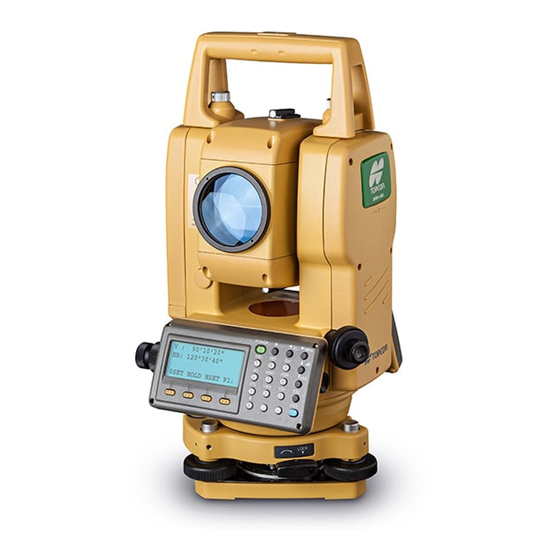
БЕЗОТРАЖАТЕЛЬНЫЙ ЭЛЕКТРОННЫЙ ТАХЕОМЕТР
СЕРИЯ GPT-3100N
GPT-3102N
GPT-3103N
GPT-3105N
GPT-3107N
♥ 2008 TOPCON Corporation
Перевод на русский язык выполнен ЗАО «ПРИН», 2008
ЗАО «ПРИН» — официальный дистрибьютор компании TOPCON Corp. в России и СНГ.
По всем вопросам о приобретении и технической поддержке оборудования фирмы TOPCON обращайтесь в ЗАО «ПРИН»:
125871, Москва, ГСП, Волоколамское шоссе, дом 4
Телефон: (495) 901-91-91 Телефакс: (495) 626-97-79 E-mail: survey@prin.ru Web: http://www.prin.ru

Предисловие
Благодарим Вас за приобретение электронного тахеометра серии GPT-3100N
фирмы TOPCON.
Для оптимальной работы инструмента прочтите внимательно эту инструкцию и
храните её для справки в удобном месте.
МЕРЫ ПРЕДОСТРОЖНОСТИ ПРИ РАБОТЕ
Не погружайте инструмент в воду.
Инструмент нельзя погружать в воду.
Инструмент соответствует стандарта IP66, и, соответственно, защищен от дождя.
Установка инструмента на штатив
При установке инструмента на штатив используйте, по возможности, деревянный штатив. При использовании металлического штатива возможно появление вибрации, что может сказаться на точности измерений.
Установка трегера
Если трегер установлен неправильно, это может сказаться на точности измерений. При случае, проверьте юстировочные винты на трегере. Убедитесь, что зажим трегера зафиксирован, а крепежные винты затянуты.
Предохранение инструмента от ударов
При транспортировке инструмента обеспечьте его защиту от ударов. Резкие толчки могут привести к дефектам при измерениях.
Переноска инструмента
Всегда держите инструмент за поперечину.
Воздействие высоких температур на инструмент
Не подвергайте инструмент высокотемпературному воздействию дольше, чем это необходимо. Это может отрицательно сказаться на его работоспособности.
Резкие колебания температур
Любое резкое изменение температуры инструмента или призмы, например, при выгрузке инструмента из нагретого автомобиля, может привести к уменьшению дальности измеряемого расстояния. Дайте инструменту адаптироваться к температуре окружающей среды.
Проверка уровня заряда батареи
Перед работой проверьте уровень заряда батареи.
Обращение с батареей питания
Не вынимайте батарею из корпуса инструмента при включенном питании. Это может привести к потере всех данных из памяти. Поэтому все операции с батареей следует делать после отключения питания.
При работе дальномерной части может иметь место некоторый шум. Это нормально и никак не сказывается на работоспособности самого инструмента.
I

ПАМЯТКА ПО БЕЗОПАСНОЙ РАБОТЕ
Чтобы обеспечить безопасную работу приборов и предотвратить угрозу для жизни оператора и других людей, а также, чтобы избежать повреждения имущества, к приборам и руководствам по их эксплуатации прилагаются важные памятки и предупреждения.
Перед ознакомлением с мерами предосторожности или чтением текста необходимо, чтобы поьзователь понимал, что означают следующие сообщения и пиктограммы.
|
Экран |
Смысловая нагрузка |
|
WARNING |
Пренебрежение или игнорирование данного сообщения может |
|
привести к смерти или серьезной травме. |
|
|
CAUTION |
Пренебрежение или игнорирование данного сообщения может |
|
привести к физической травме или к материальному ущербу. |
|
•Травма означает рану, ожог, электрошок и т.д.
•Материальный ущерб означает серьезное повреждение зданий, оборудования или мебели.
МЕРЫ ПРЕДОСТОРОЖНОСТИ
 WARNING
При попытке самостоятельно отремонтировать прибор можно получить ожог, удар током или нанести физический вред здоровью.
Ремонт прибора осуществляется только фирмой TOPCON или ее официальным дилером!
При неправильной работе с прибором лазерные лучи могут представлять опасность и повредить зрение.
Никогда не пытайтесь самостоятельно ремонтировать прибор.
Не смотрите долго на лазерный луч, т.к. это опасно для зрения.
Не направляйте инструмент прямо на солнце, поскольку это опасно для вашего зрения.
Не накрывайте зарядное устройство в процессе его работы.
Не используйте поврежденный кабель, вилку и розетку.
Не используйте отсыревшую батарею питания или зарядное устройство.
Не используйте инструмент в областях, где отмечаются скопление взрывоопасных газов, жидкостей, а также не используйте его в угольных шахтах.
Всегда защищайте инструмент от высокотемпературного воздействия.
На прямом солнце температура внутри инструмента легко может достичь 70°С и выше, что снижает срок службы прибора.
Следите, чтобы рабочее напряжение соответствовало бы значениям, заявленным фирмойпроизводителем.
Используйте только тот тип зарядного устройства, который указан фирмойпроизводителем.
Используйте только тот кабель, который указан фирмой-производителем.
Не допускайте короткого замыкания батареи питания в процессе ее хранения.
II

 CAUTION
Использование настроек или юстировок, а также выполнение процедур, отличных от тех, что указаны в настоящем Руководстве, может привести к опасности радиационного излучения.
Следите, чтобы в процессе работы лазерный луч не попал на кого-нибудь из людей. Если этого не избежать, то постарайтесь, чтобы лазерный луч не попал в голову. Если лазерный луч попадет в глаз, то может иметь место временная потеря зрения, и человек может не заметить другую опасность.
При подсоединении или отсоединении кабеля или вилки питания мокрыми руками вы рискуете получить удар током.
Вы рискуете получить повреждение при опрокидывании футляра для переноса. Не вставайте и не садитесь на футляр.
Помните об острых ножках штатива, поэтому будьте осторожны при его переноске или установке.
Следите, чтобы ремень, ручка и зажимы у кейса были исправны. Не переносите инструмент в неисправном кейсе.
Следите, чтобы кислота из батареи питания не попала на кожу или ткань. Если все же это произошло, смойте кислоту водой и обратитесь за медицинской помощью.
При неправильном использовании нитяного отвеса можно получить повреждение.
Убедитесь, что вы надежно установили батарею питания, в противном случае Вы рискуете получить повреждение при падении инструмента.
Убедитесь, что Вы правильно установили трегер, в противном случае Вы рискуете получить повреждение при падении инструмента.
Убедитесь, что Вы правильно прикрепили инструмент к трегеру и надежно установили эту конструкцию на штативе, в противном случае Вы рискуете получить повреждение при падении инструмента.
Вы рискуете получить повреждение при падении инструмента вниз вследствие слабой затяжки крепежного винта на штативе. Крепко затягивайте винт, когда Вы устанавливаете прибор на штативе.
Требования к пользователю
Этот продукт предназначен только для профессиональных геодезистов. Предполагается, что пользователь данного продукта имеет геодезическое образование или знаком с проведением геодезических работ, чтобы понять инструкции по работе с прибором.
При работе с прибором одевайте защитную одежду (ботинки, головной убор и проч.).
III

ОТКАЗ ОТ ОТВЕТСТВЕННОСТИ
Предполагается, что пользователь данного продукта будет следовать инструкциям по эксплуатации и периодически проверять работу инструмента.
Производитель или его представитель не несут никакой ответственности за неправильное использование прибора, в том числе за прямой, косвенный или последующий ущерб, а также за потерю прибыли.
Производитель или его представитель не несут никакой ответственности за ущерб и потерю прибыли, возникшие в результате обстоятельств непреодолимой силы (землетрясения, шторма, наводнения, пожара, несчастного случая и/или действия третьей стороны).
Производитель или его представитель не несут никакой ответственности за ущерб и потерю прибыли, возникшие в результате изменения или потери данных, сбоя в работе и т.д., которые могут быть вызваны при работе с прибором или использовании несовместимых продуктов.
Производитель или его представитель не несут никакой ответственности за ущерб и потерю прибыли, возникшие в результате нарушения пользователем инструкций по работе с прибором, которые изложены в настоящем Руководстве.
Производитель или его представитель не несут никакой ответственности за ущерб и потерю прибыли, возникшие в результате неаккуратного обращения с инструментом или подключения его к другим приборам.
НОРМЫ БЕЗОПАСНОСТИ ДЛЯ ЛАЗЕРНОГО ОБОРУДОВАНИЯ
•Измерение расстояний
Вприборах серии GPT-3100N для измерения расстояний используется невидимый лазерный луч. Приборы данной серии производятся и продаются в соответствии с нормативными документами “Технические характеристики для лазерных приборов“ (FDA/BRH 21 CFR 1040) или “Безопасность лазерных приборов на излучение, Классификация оборудования, Требования и Руководство по эксплуатации ” (МЭК, Издание 825), в которых изложены стандарты безопасности по работе с лазерным оборудованием.
Согласно вышеназванным стандартам приборы серии GPT-3100N классифицируются, как “Лазерные изделия КЛАССА 1М (I) ”.
Вслучае какого-либо сбоя в работе не разбирайте инструмент, а обратитесь в компанию TOPCON или к региональному дилеру, ЗАО «ПРИН».
•Лазерный указатель и лазерный отвес (последний поставляется на определенные рынки)
Вприборах серии GPT-3100N в лазерном указателе и лазерном отвесе используется видимый лазерный луч. Комплектные лазерные указатель и отвес производятся и продаются в соответствии с нормативными документами “Технические характеристики для лазерных приборов“ (FDA/BRH 21 CFR 1040) и “Безопасность лазерных приборов на излучение, Классификация оборудования, Требования и Руководство по эксплуатации” (МЭК, Издание 825), в которых изложены стандарты безопасности по работе с лазерным оборудованием.
Согласно вышеназванным стандартам лазерный отвес в приборах серии GPT-3100N классифицируется, как “Лазерное изделие КЛАССА 2 (II) ”.
В случае какого-либо сбоя в работе, не разбирайте инструмент, а обратитесь в компанию TOPCON или к региональному дилеру, ЗАО «ПРИН».
IV
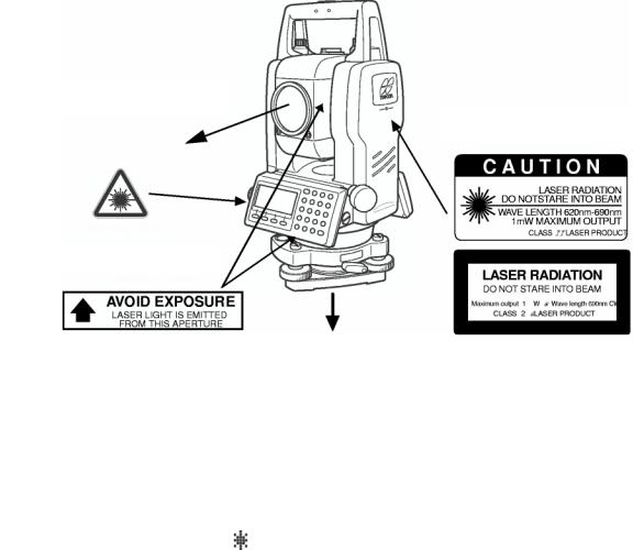
ЯРЛЫКИ
На корпусе прибора серии GPT-3100N с лазерным отвесом прикреплены ярлыки, предупреждающие о соблюдении требований по безопасной работе с прибором. При повреждении этих ярлыков, а также при их утере или истирании прикрепите такой же новый ярлык. Ярлыки можно приобрести в компании TOPCON или у ее регионального дилера ЗАО «ПРИН».
Прибор серии GPT-3100N с лазерным отвесом
Лазерный указатель
Предупреждающие ярлыки
Лазерный центрир
(только для приборов с лазерным отвесом)
СИМВОЛ, ОБОЗНАЧАЮЩИЙ РАБОТУ ЛАЗЕРА
При работе лазера справа во второй строке появляется следующий символ.
|
Компенсатор: [2 оси] |
Символ, обозначающий |
||
|
X:-0°00’25» |
|||
|
работу лазера. |
|||
|
Y: 0°00’20» |
|||
|
1ось 2оси Выкл Л.Отвес |
|||
V
СОДЕРЖАНИЕ
|
ПРЕДИСЛОВИЕ………………………………………………………………………………………………………… |
I |
|
МЕРЫ ПРЕДОСТОРОЖНОСТИ ПРИ РАБОТЕ……………………………………………………………. |
I |
|
ПАМЯТКА ПО БЕЗОПАСНОЙ РАБОТЕ……………………………………………………………………… |
II |
|
МЕРЫ ПРЕДОСТОРОЖНОСТИ………………………………………………………………………………… |
II |
|
НОРМЫ БЕЗОПАСНОСТИ ДЛЯ ЛАЗЕРНОГО ОБОРУДОВАНИЯ……………………………… |
IV |
|
СОДЕРЖАНИЕ……………………………………………………………………………………………………….. |
VI |
|
СОСТАВ СТАНДАРТНОГО КОМПЛЕКТА…………………………………………………………………… |
X |
|
1 КОНСТРУКТИВНЫЕ ЭЛЕМЕНТЫ И ОБЩИЕ ФУНКЦИИ …………….. |
1-1 |
|
|
1.1 |
Конструктивные элементы и общие функции………………………………………… |
1-1 |
|
1.2 |
Экран………………………………………………………………………………………………….. |
1-3 |
|
1.3 |
Клавиши управления……………………………………………………………………………. |
1-4 |
|
1.4 |
Функциональные (экранные) клавиши ………………………………………………….. |
1-5 |
|
1.5 |
Режим настройки (клавиша )……………………………………………………………… |
1-7 |
|
1.6 |
Разъем для подсоединения к последовательному порту RS-232C ………. |
1-10 |
|
1.7 |
Включение / Выключение лазерного отвеса ……………………………………….. |
1-11 |
|
2 ПОДГОТОВКА К ИЗМЕРЕНИЯМ………………………………………………… |
2-1 |
|
|
2.1 |
Подключение питания………………………………………………………………………….. |
2-1 |
|
2.2 |
Установка инструмента для выполнения измерений …………………………….. |
2-2 |
|
2.3 |
Кнопка включения питания…………………………………………………………………… |
2-3 |
|
2.4 |
Индикатор текущего состояния батареи питания………………………………….. |
2-4 |
2.5Компенсация отсчетов вертикальных и горизонтальных углов за наклон
|
инструмента…………………………………………………………………………………………. |
2-5 |
|||
|
2.6 |
Ввод буквенно-цифровых символов …………………………………………………….. |
2-7 |
||
|
3 |
ИЗМЕРЕНИЕ УГЛОВ…………………………………………………………………. |
3-1 |
||
|
3.1 |
Измерение вертикального и правого горизонтального углов …………………. |
3-1 |
||
|
3.2 |
Переключение режима «Правые» / «Левые» горизонтальные углы……….. |
3-2 |
||
|
3.3 |
Измерение от исходного дирекционного / ориентирного направления…… |
3-2 |
||
|
3.3.1 |
Установка ориентирного направления путем фиксации угла………… |
3-2 |
||
|
3.3.2 |
Установка ориентирного направления с помощью клавиатуры…….. |
3-3 |
||
|
3.4 |
Режим отображения уклона в процентах (%) ………………………………………… |
3-3 |
||
|
3.5 |
Измерение углов методом повторений…………………………………………………. |
3-4 |
||
|
3.6 |
Звуковой сигнал при увеличении горизонтального угла на каждые 90° ….. |
3-5 |
||
|
3.7 |
Направление счета вертикального угла ……………………………………………….. |
3-6 |
||
|
4 |
ИЗМЕРЕНИЕ РАССТОЯНИЙ……………………………………………………… |
4-1 |
||
|
4.1 |
Ввод поправки за атмосферу……………………………………………………………….. |
4-1 |
||
|
4.2 |
Ввод поправки за постоянную призмы………………………………………………….. |
4-2 |
||
|
4.3 |
Измерение расстояний (непрерывное измерение)………………………………… |
4-2 |
||
|
4.4 |
Измерение расстояний (многократные / единичные измерения) ……………. |
4-3 |
||
|
4.5 |
Точный Режим / Режим Слежения / Грубый Режим……………………………….. |
4-4 |
||
|
4.6 |
Вынос в натуру ……………………………………………………………………………………. |
4-5 |
||
|
4.7 |
Способы измерения промерами…………………………………………………………… |
4-6 |
||
|
4.7.1 |
Измерение с угловым промером …………………………………………………. |
4-7 |
||
|
4.7.2 |
Измерение с линейным промером ………………………………………………. |
4-9 |
||
|
4.7.3 |
Промер на плоскости………………………………………………………………… |
4-11 |
||
|
4.7.4 |
Промер до центра колонны……………………………………………………….. |
4-13 |
||
|
5 |
ОПРЕДЕЛЕНИЕ КООРДИНАТ …………………………………………………… |
5-1 |
||
|
5.1 |
Ввод координат пункта наблюдения …………………………………………………….. |
5-1 |
||
|
5.2 |
Ввод высоты инструмента……………………………………………………………………. |
5-2 |
||
|
5.3 |
Ввод высоты отражателя (призмы) ………………………………………………………. |
5-2 |
||
|
5.4 |
Процесс определения координат …………………………………………………………. |
5-3 |
VI
|
6 СПЕЦИАЛЬНЫЙ РЕЖИМ (Режим Меню)…………………………………… |
6-1 |
||
|
6.1 |
Прикладные задачи……………………………………………………………………………… |
6-1 |
|
|
6.1.1 |
Определение высот недоступных объектов…………………………………. |
6-2 |
|
|
6.1.2 |
Измерение неприступных расстояний …………………………………………. |
6-5 |
|
|
6.1.3 |
Определение высотной отметки пункта наблюдения……………………. |
6-8 |
|
|
6.1.4 |
Вычисление площади……………………………………………………………….. |
6-11 |
|
|
6.1.5 |
Определение координаты точки относительно базисной линии….. |
6-14 |
|
|
6.2 |
Масштабный коэффициент………………………………………………………………… |
6-16 |
|
|
6.3 |
Подсветка экрана и сетки нитей …………………………………………………………. |
6-18 |
|
|
6.4 |
Режим установок 1 …………………………………………………………………………….. |
6-19 |
|
|
6.4.1 |
Установка минимальной дискретности………………………………………. |
6-19 |
|
|
6.4.2 |
Автоматическое отключение питания………………………………………… |
6-20 |
|
|
6.4.3 |
Исправление вертикальных и горизонтальных углов за наклон |
||
|
инструмента……………………………………………………………………………… |
6-21 |
||
|
6.4.4 |
Учет инструментальных погрешностей инструмента |
||
|
(только для GPT-3102N/3103N/3105N)……………………………………….. |
6-21 |
||
|
6.4.5 |
Выбор типа батареи питания…………………………………………………….. |
6-22 |
|
|
6.4.6 |
Подогрев экрана……………………………………………………………………….. |
6-22 |
|
|
6.4.7 Подключение внешнего устройства к порту RS-232……………………. |
6-23 |
||
|
6.5 |
Регулировка контрастности экрана …………………………………………………….. |
6-24 |
|
|
6.6 |
Дорожные измерения…………………………………………………………………………. |
6-25 |
|
|
6.6.1 |
Ввод исходной точки…………………………………………………………………. |
6-26 |
|
|
6.6.2 |
Ввод дорожных элементов………………………………………………………… |
6-27 |
|
|
6.6.3 |
Поиск данных……………………………………………………………………………. |
6-31 |
|
|
6.6.4 |
Редактирование данных……………………………………………………………. |
6-31 |
|
|
6.6.5 |
Ввод станции и задней точки…………………………………………………….. |
6-32 |
|
|
6.6.6 |
Дорожная разбивка…………………………………………………………………… |
6-34 |
|
|
6.6.7 |
Выбор файла……………………………………………………………………………. |
6-35 |
|
|
6.6.8 |
Удаление дорожных измерений ………………………………………………… |
6-36 |
|
7 СЪЁМКА |
…………………………………………………………………………………. |
7-1 |
|
|
7.1 |
Подготовка к съёмке ……………………………………………………………………………. |
7-3 |
|
|
7.1.1 …………………………. |
Выбор файла для хранения результатов съёмки |
7-3 |
|
|
7.1.2 …………………………………………… |
Выбор файла координат для съёмки |
7-4 |
|
|
7.1.3 ………………………………………………………………. |
Станция и задняя точка |
7-4 |
|
|
7.2 |
Порядок ……………………………………………действий при проведении съёмки |
7-7 |
|
|
7.2.1 ………………………… |
Поиск записанных данных в памяти инструмента |
7-8 |
|
|
7.2.2 ………………….. |
Ввод кода точки с использованием библиотеки кодов |
7-9 |
|
|
7.2.3 …………………………………………………. |
Ввод кода точки из списка кодов |
7-9 |
|
|
7.3 |
Режим ……………………………………………………………..измерения промерами |
7-10 |
|
|
7.3.1 ……………………………………………….. |
Измерение с угловым промером |
7-10 |
|
|
7.3.2 …………………………………………….. |
Измерение с линейным промером |
7-12 |
|
|
7.3.3 ………………………………………………………………… |
Промер на плоскости |
7-14 |
|
|
7.3.4 ……………………………………………………….. |
Промер до центра колонны |
7-16 |
|
|
7.4 |
Автоматическое ………………………………………………вычисление координат |
7-17 |
|
|
7.5 |
Определение ……………………………..координат точки относительно линии |
7-18 |
|
|
7.5.1 .. |
Как определить координаты точки относительно базисной линии |
7-18 |
|
|
7.5.2 …………………………………………………………….. |
Выполнение измерений |
7-19 |
|
|
7.6 |
Редактирование ………………………………………………………библиотеки кодов |
7-20 |
|
|
7.7 |
Настройка …………………………………………………………….параметров съёмки |
7-21 |
|
8 РАЗБИВКА …………………………………………………………………………… |
8-1 |
||
|
8.1 |
Подготовка………………………………………………………………………………………….. |
8-3 |
|
|
8.1.1 |
Установка масштабного коэффициента ………………………………………. |
8-3 |
|
|
8.1.2 |
Выбор файла координат……………………………………………………………… |
8-4 |
|
|
8.1.3 |
Ввод координат станции …………………………………………………………….. |
8-5 |
|
|
8.1.4 |
Ввод координат задней точки ……………………………………………………… |
8-7 |
|
|
8.2 |
Выполнение разбивки………………………………………………………………………….. |
8-9 |
|
|
8.2.1 |
Вынос в натуру точек относительно базиса……………………………….. |
8-11 |
|
|
8.3 |
Определение координат новой точки………………………………………………….. |
8-12 |
|
|
8.3.1 |
Метод пикетов ………………………………………………………………………….. |
8-12 |
|
|
8.3.2 |
Метод обратной засечки……………………………………………………………. |
8-14 |
VII
|
9 |
РАБОТА С ПАМЯТЬЮ………………………………………………………………. |
9-1 |
||
|
9.1 |
Отображение информации о состоянии внутренней памяти………………….. |
9-2 |
||
|
9.2 |
Поиск данных………………………………………………………………………………………. |
9-3 |
||
|
9.2.1 |
Поиск результатов измерений…………………………………………………….. |
9-3 |
||
|
9.2.2 |
Поиск координат…………………………………………………………………………. |
9-5 |
||
|
9.2.3 |
Поиск в библиотеке кодов…………………………………………………………… |
9-6 |
||
|
9.3 |
Работа с файлами……………………………………………………………………………….. |
9-7 |
||
|
9.3.1 |
Переименование файла……………………………………………………………… |
9-8 |
||
|
9.3.2 |
Поиск данных в файле………………………………………………………………… |
9-8 |
||
|
9.3.3 |
Удаление файла…………………………………………………………………………. |
9-9 |
||
|
9.4 |
Ввод координат непосредственно с клавиатуры………………………………….. |
9-10 |
||
|
9.4.1 |
Ввод координат (X, Y, H)……………………………………………………………. |
9-10 |
||
|
9.4.2 |
Ввод координат точки в формате относительно базиса……………… |
9-11 |
||
|
9.5 |
Удаление координат точки из файла ………………………………………………….. |
9-12 |
||
|
9.6 |
Редактирование библиотеки кодов …………………………………………………….. |
9-13 |
||
|
9.7 |
Обмен данными…………………………………………………………………………………. |
9-14 |
||
|
9.7.1 |
Передача данных……………………………………………………………………… |
9-14 |
||
|
9.7.2 |
Загрузка данных……………………………………………………………………….. |
9-15 |
||
|
9.7.3 |
Настройка параметров связи…………………………………………………….. |
9-16 |
||
|
9.8 |
Очистка памяти………………………………………………………………………………….. |
9-17 |
||
|
10 |
РЕЖИМ НАВЕДЕНИЯ ПО ЗВУКОВОМУ СИГНАЛУ…………………… |
10-1 |
||
|
11 |
ПОПРАВКА В РАССТОЯНИЯ ЗА ПОСТОЯННУЮ ПРИЗМЫ / |
|||
|
ПОПРАВКА БЕЗ ПРИЗМЫ………………………………………………………. |
11-1 |
|||
|
12 |
ПОПРАВКА ЗА АТМОСФЕРУ ………………………………………………….. |
12-1 |
||
|
12.1 |
Расчет поправки за атмосферу…………………………………………………………… |
12-1 |
||
|
12.2 |
Ввод поправки за атмосферу……………………………………………………………… |
12-1 |
||
|
13 |
ПОПРАВКА ЗА РЕФРАКЦИЮ И КРИВИЗНУ ЗЕМЛИ………………… |
13-1 |
||
|
13.1 |
Формула для расчета расстояний ……………………………………………………… |
13-1 |
||
|
14 |
ИСТОЧНИК ПИТАНИЯ И ПОДЗАРЯДКА ………………………………….. |
14-1 |
||
|
15 ОТСОЕДИНЕНИЕ / ПРИСОЕДИНЕНИЕ ТРЕГЕРА…………………….. |
15-1 |
|||
|
16 |
РЕЖИМ НАСТРОЙКИ ИНСТРУМЕНТА …………………………………….. |
16-1 |
||
|
16.1 |
Меню настройки инструмента…………………………………………………………….. |
16-1 |
||
|
16.2 |
Как выполнять настройку инструмента……………………………………………….. |
16-4 |
||
|
17 |
ПОВЕРКИ И ЮСТИРОВКИ……………………………………………………… |
17-1 |
||
|
17.1 |
Проверка и юстировка постоянной инструмента …………………………………. |
17-1 |
||
|
17.2 |
Проверка оптической оси …………………………………………………………………… |
17-2 |
||
|
17.2.1 Проверка оптической оси светодальномера и оси визирования…. |
17-2 |
|||
|
17.2.2 Проверка оптической оси лазерного целеуказателя………………….. |
17-5 |
|||
|
17.3 |
Проверка / юстировка теодолитных функций………………………………………. |
17-7 |
||
|
17.3.1 Проверка / юстировка цилиндрического уровня…………………………. |
17-8 |
|||
|
17.3.2 Проверка / юстировка круглого уровня ……………………………………… |
17-8 |
|||
|
17.3.3 Юстировка сетки нитей…………………………………………………………….. |
17-9 |
|||
|
17.3.4 Коллимационная ошибка инструмента……………………………………. |
17-10 |
|||
|
17.3.5 Проверка / юстировка окуляра оптического отвеса………………….. |
17-11 |
|||
|
17.3.6 Проверка / юстировка лазерного отвеса …………………………………. |
17-12 |
|||
|
17.3.7 Юстировка места нуля вертикального круга ……………………………. |
17-13 |
|||
|
17.4 |
Как ввести значение постоянной инструмента…………………………………… |
17-14 |
||
|
17.5 |
Учет систематических ошибок инструмента………………………………………. |
17-15 |
||
|
17.6 |
Проверка работоспособности дальномера ……………………………………….. |
17-17 |
||
|
17.7 |
Методика поверки……………………………………………. |
17-23 |
||
|
17.7.1 Операции поверки………………………………………………………………….. |
17-23 |
|||
|
17.7.2 Средства поверки…………………………………………………………………… |
17-24 |
|||
|
17.7.3 Требования к квалификации поверителей………………………………. |
17-24 |
|||
|
17.7.4 Требования безопасности………………………………………………………. |
17-24 |
|||
|
17.7.5 Условия поверки…………………………………………………………………….. |
17-24 |
|||
|
17.7.6 Подготовка к поверке……………………………………………………………… |
17-24 |
|||
|
17.7.7 Проведение поверки………………………………………………………………. |
17-24 |
|||
|
17.7.8 Оформление результатов поверки………………………………………….. |
17-26 |
VIII
|
18 |
МЕРЫ ПРЕДОСТОРОЖНОСТИ……………………………………………….. |
18-1 |
|
19 |
ДОПОЛНИТЕЛЬНЫЕ ПРИНАДЛЕЖНОСТИ……………………………… |
19-1 |
|
20 |
ДОПОЛНИТЕЛЬНЫЕ ИСТОЧНИКИ ПИТАНИЯ…………………………. |
20-1 |
|
21 |
ПРИЗМЕННЫЕ СИСТЕМЫ………………………………………………………. |
21-1 |
|
22 |
СООБЩЕНИЯ ОБ ОШИБКАХ………………………………………………….. |
22-1 |
|
23 |
ОСНОВНЫЕ ТЕХНИЧЕСКИЕ ХАРАКТЕРИСТИКИ ……………………. |
23-1 |
|
ПРИЛОЖЕНИЕ |
||
|
1 |
Двухосевая компенсация………………………………………………… |
ПРИЛОЖЕНИЕ-1 |
|
2 |
Меры предосторожности при зарядке и |
|
|
хранении батарей………………………………………………………………. |
ПРИЛОЖЕНИЕ-3 |
IX
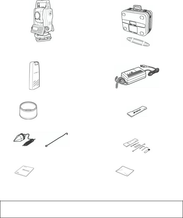
СОСТАВ СТАНДАРТНОГО КОМПЛЕКТА
|
Тахеометр серии GPT-3100N (с крышкой на |
Пластиковый ящик для транспортировки. |
|
объектив) – 1 шт. |
(Форма ящика может отличаться от |
|
представленной на рисунке) |
|
|
Батарея BT-52QA — 2 шт. |
Зарядное устройство ВС-27BR или BC-27CR – |
|
1 шт. |
|
|
Солнечный фильтр – 1 шт. |
Чехол от дождя – 1 шт. |
|
Нитяной отвес – 1 шт. |
Набор инструментов – 1 комплект. |
|
(юстировочная шпилька (2), отвертка (1), шестигранные |
|
|
ключи (2), щетка для чистки (1)). |
|
|
Крючок для нитяного отвеса входит в набор инструментов. |
|
|
Руководство пользователя – 1 шт. |
Силиконовая салфетка – 1 шт. |
(При покупке проверьте, что все перечисленные элементы входят в состав комплекта инструмента.)
Примечание : Зарядное устройство BC-27 в Северной Америке можно использовать только в сети переменного тока с напряжением 120 В.
X
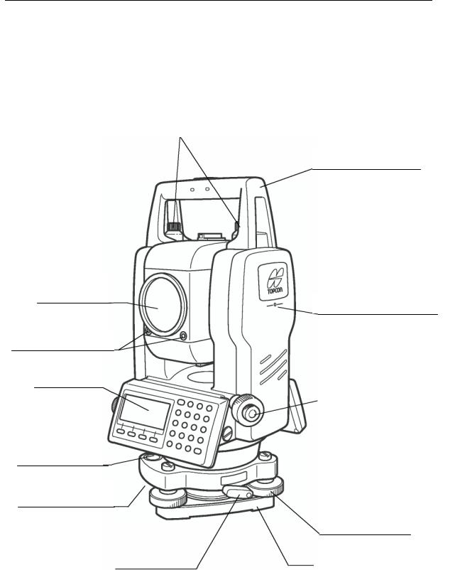
1КОНСТРУКТИВНЫЕ ЭЛЕМЕНТЫ И ОБЩИЕ ФУНКЦИИ
1.КОНСТРУКТИВНЫЕ ЭЛЕМЕНТЫ И ОБЩИЕ ФУНКЦИИ
1.1Конструктивные элементы
Линза объектива Лазерный указатель
Отверстие для лазерного луча
Указатель створа
Экран
(только у GPT3102N/3103N/3105N)
Круглый уровень
Юстировочный винт круглого уровня
Зажимный винт ручки для переноса Ручка для переноса
Метка высоты инструмента
Окуляр оптического отвеса
(только для приборов с оптическим отвесом)
Подъемный винт
|
Зажим |
Основание трегера |
|||
1 — 1

1 КОНСТРУКТИВНЫЕ ЭЛЕМЕНТЫ И ОБЩИЕ ФУНКЦИИ
Визир
Кремальера зрительной трубы
Устройство для захвата зрительной
Окуляр зрительной трубы
Закрепительный винт вертикального круга
Микрометренный винт вертикального круга
Цилиндрический
уровень
Экран
Зажим батареи питания
Батарея ВТ-52QA
Метка высоты инструмента
Микрометренный винт горизонтального круга
Закрепительный винт горизонтального круга
Разъем для подключения внешнего питания
Разъем подсоединения к последовательному порту
1 — 2

1 КОНСТРУКТИВНЫЕ ЭЛЕМЕНТЫ И ОБЩИЕ ФУНКЦИИ
1.2Экран
•Экран
В инструменте использован графический ЖК дисплей (4 строки по 20 символов). Как правило, в трех верхних строках отображаются данные измерений, а в нижней строке показаны функции экранных клавиш, которые изменяются вместе с режимом измерения.
•Контрастность и подсветка
Контрастность и подсветка экранов регулируются. См. Главу 6 «СПЕЦИАЛЬНЫЙ РЕЖИМ (Режим Меню)» или раздел 1.5 «Режим настройки (клавиша Ì).
•Пример
|
ВК |
: |
90o10’20» |
ГКп : |
120o30’40» |
||||||||
|
ГКп : |
120o30’40» |
S * |
65.432 m |
|||||||||
|
h |
: |
12.345 m |
||||||||||
|
0 ГК |
Фикс |
Ввод |
С1↓ |
Измр Режим |
БП/П С1↓ |
|||||||
|
Режим измерения углов |
Режим измерения расстояний |
|||||||||||
|
Вертик. угол |
: |
90o10’20» |
Гориз. угол |
: |
120 o 30’40» |
|||||||
|
Горизонт. угол : |
120o30’40» |
Гориз. проложение : 65.432м |
||||||||||
|
Превышение |
: |
12.345м |
||||||||||
|
Единица измерения футы |
Единица измерения футы и дюймы |
|||||||||||
|
ГКп : |
120o30’40» |
ГКп : |
120o30’40» |
|||||||||
|
S |
* |
123.45 f |
S |
* |
123.04.6f |
|||||||
|
h |
: |
12.34 f |
h |
: |
12.03.4f |
|||||||
|
Измр Режим БП/П |
С1↓ |
Измр Режим БП/П |
С1↓ |
|||||||||
|
Гориз. угол |
: |
120o30’40» |
Гориз. угол |
: |
120o30’40» |
|||||||
|
Гориз. проложение : |
123.45фт |
Гориз. проложение |
: |
123 фт 46/8дюйма |
||||||||
|
Превышение |
: |
12.34фт |
Превышение |
: |
12 фт 34/8дюйма |
Обозначения на экране
|
Экран |
Содержание |
Экран |
Содержание |
|
ВК |
Вертикальный угол |
¼ |
Работа дальномерной части |
|
ГКп |
Горизонтальный угол |
m |
Единица измерения |
|
«правый» |
метры |
||
|
ГКл |
Горизонтальный угол |
f |
Единица измерения футы / футы и |
|
«левый» |
дюймы |
||
|
S |
Горизонтальное проложение |
N/P |
Безотражательный режим |
|
h |
Превышение |
Символ, обозначающий работу |
|
|
лазера |
|||
|
D |
Наклонное расстояние |
||
|
X |
Координата (X) |
||
|
Y |
Координата (Y) |
||
|
Z |
Координата (Z) |
||
1 — 3

1КОНСТРУКТИВНЫЕ ЭЛЕМЕНТЫ И ОБЩИЕ ФУНКЦИИ
1.3Клавиши управления
Буквенно-цифровая клавиатура
|
Клавиши |
Название клавиш |
Функция |
|
|
Режим настройки (клавиша Ì) используется для |
|||
|
предварительной установки параметров или отображения |
|||
|
функций в следующей последовательности: |
|||
|
1- |
Регулировка контрастности экрана; |
||
|
2- |
Подсветка сетки нитей; |
||
|
Клавиша |
3- |
Подсветка экрана; |
|
|
«звёздочка» |
4- Режим измерения по призме / безотражательный режим; |
||
|
5- |
Лазерный указатель; |
||
|
6- |
Лазерный отвес; |
||
|
7- |
Компенсатор; |
||
|
8- Переключение функции указателя створа; |
|||
|
9- Определение уровня отраженного сигнала |
|||
|
Клавиша измерения |
Режим измерения координат |
||
|
координат |
|||
|
Клавиша измерения |
Режим измерения расстояний. |
||
|
расстояний |
|||
|
ANG |
Клавиша измерения |
Режим измерения углов |
|
|
углов |
|||
|
MENU |
Клавиша меню |
Переключает режим меню и стандартный режим. Установка |
|
|
прикладных измерений и юстировка в режиме меню. |
|||
|
• Возврат в режим измерений или на предыдущий уровень из |
|||
|
режима установок. |
|||
|
• Выход в режим съёмки (СЪЁМКА) и режим разбивки |
|||
|
ESC |
Клавиша выхода |
(РАЗБИВКА) непосредственно из стандартного режима |
|
|
измерений. |
|||
|
• Можно использовать, как клавишу Запись для записи |
|||
|
результатов измерений в режиме обычных измерений. |
|||
|
Для определения функции клавиши ESC см. Главу 16 |
|||
|
«РЕЖИМ НАСТРОЙКИ ИНСТРУМЕНТА». |
|||
|
ENT |
Клавиша ввода |
Нажмите эту клавишу, после того как набрали нужные |
|
|
значений |
значения для ввода в инструмент. |
||
|
POWER |
Кнопка включения/ |
Источник питания ВКЛ/ВЫКЛ |
|
|
выключения |
|||
|
питания |
|||
|
F1 F4 |
Экранные |
Выполняют функции, которые отображены на экране. |
|
|
(функциональные) |
|||
|
клавиши |
|||
|
1 — 4 |
1КОНСТРУКТИВНЫЕ ЭЛЕМЕНТЫ И ОБЩИЕ ФУНКЦИИ
1.4Функциональные (экранные) клавиши
Функции экранных клавиш отображаются в нижней строке дисплея в соответствии с выведенным режимом.
Режим измерения углов
|
ВК : 90o10’20» |
|||||||||||
|
ГКп : 120o30’40» |
|||||||||||
|
0°ГК ФИКС Ввод |
С1↓ |
||||||||||
|
Кмпн Повт ВК% |
С2↓ |
||||||||||
|
Зумер |
П/Л Накл |
С3↓ |
|||||||||
|
[F1] |
[F2] |
[F3] |
[F4] |
||||||||
Экранные клавиши
Режим измерения расстояний
ГКп: 120o30’40» S*[r] m
h:m
|
Измр Режим БП/П |
С1↓ |
|||||||
|
Промр |
Вынос |
Сигн |
С2↓ |
|||||
|
−−− |
м/ф/д |
−−− |
С3↓ |
|||||
Режим измерения координат
X:123.456 m
Y:34.567 m
H:78.912 m
|
Измр |
Режим |
БП/П |
С1↓ |
||
|
Hv |
Hi |
Cтнц |
С2↓ |
||
Промр м/ф/д Сигн С3↓
Режим измерения углов
|
Стр. |
Экр. |
Обозн. на |
Функция |
|
клавиша |
экране |
||
|
1 |
F1 |
0°ГК |
Установка отсчета по ГК 0o00’00» |
|
F2 |
Фикс |
Фиксация горизонтального угла |
|
|
F3 |
Ввод |
Установка требуемого значения горизонтального угла путем ввода |
|
|
цифровых значений. |
|||
|
F4 |
С1↓ |
Функции экранных клавиш показаны на следующей странице (С2) |
|
|
экрана. |
|||
|
2 |
F1 |
Кмпн |
Статус и настройка работы компенсатора |
|
F2 |
Повт |
Режим измерения углов методом повторений |
|
|
F3 |
ВК% |
Режим отображения уклона в процентах (%) |
|
|
F4 |
С2↓ |
Функции экранных клавиш показаны на следующей странице (С3) |
|
|
экрана. |
|||
|
3 |
F1 |
Зумер |
Включение звукового сигнала для значения горизонтального угла |
|
кратного 90° |
|||
|
F2 |
П/Л |
Переключение между правыми и левыми горизонтальными углами. |
|
|
F3 |
Накл |
Переключение (ВКЛ/ВЫКЛ) режима измерения вертикальных углов |
|
|
относительно горизонта |
|||
|
F4 |
С3↓ |
Функции экранных клавиш показаны на следующей странице (С1) |
|
|
экрана. |
1 — 5
|
1 КОНСТРУКТИВНЫЕ ЭЛЕМЕНТЫ И ОБЩИЕ ФУНКЦИИ |
||||
|
Режим измерения расстояний |
||||
|
1 |
F1 |
Измр |
Начать измерения |
|
|
F2 |
Режим |
Выбор режима измерения расстояний Точный/Грубый/Слежение |
||
|
F3 |
БП/П |
Переключение режимов измерения расстояний с отражателем / без |
||
|
отражателя. |
||||
|
F4 |
С1↓ |
Функции экранных клавиш показаны на следующей странице (С2) |
||
|
экрана. |
||||
|
2 |
F1 |
Промр |
Выбор вида промера |
|
|
F2 |
Вынос |
Выбор режима для выноса в натуру |
||
|
F3 |
Сигн |
Выбор режима наведения по уровню отраженного сигнала, ввод |
||
|
постоянных для работы по призме и без нее, ввод метеоданных. |
||||
|
F4 |
С2↓ |
Функции экранных клавиш показаны на следующей странице (С3) |
||
|
экрана. |
||||
|
3 |
F2 |
м/ф/д |
Переключение единиц измерения: метры, футы или футы и дюймы. |
|
|
F4 |
С3↓ |
Функции экранных клавиш показаны на следующей странице (С1) |
||
|
экрана. |
||||
|
Режим определения координат |
||||
|
1 |
F1 |
Измр |
Начать измерения |
|
|
F2 |
Режим |
Выбор режима измерения расстояний Точный/Грубый/Слежение |
||
|
F3 |
БП/П |
Переключение режимов измерения с отражателем / без отражателя. |
||
|
F4 |
С1↓ |
Функции экранных клавиш показаны на следующей странице (С2) |
||
|
экрана. |
||||
|
2 |
F1 |
Hv |
Ввод высоты визирования (наведения). |
|
|
F2 |
Hi |
Ввод высоты инструмента. |
||
|
F3 |
Стнц |
Ввод координат станции |
||
|
F4 |
С2↓ |
Функции экранных клавиш показаны на следующей странице (С3) |
||
|
экрана. |
||||
|
3 |
F1 |
Промр |
Выбор вида промера |
|
|
F2 |
м/ф/д |
Переключение единиц измерения: метры, футы или футы и дюймы. |
||
|
F3 |
Сигн |
Выбор режима наведения по уровню отраженного сигнала, ввод |
||
|
постоянных для работы по призме и без нее, ввод метеоданных. |
||||
|
F4 |
С3↓ |
Функции экранных клавиш показаны на следующей странице (С1) |
||
|
экрана. |
1 — 6
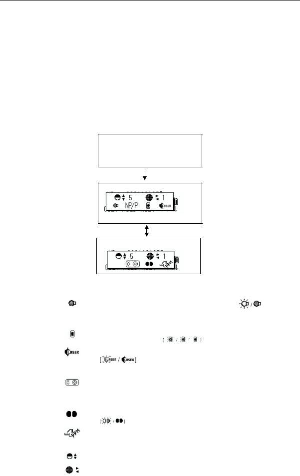
1КОНСТРУКТИВНЫЕ ЭЛЕМЕНТЫ И ОБЩИЕ ФУНКЦИИ
1.5Режим настройки (клавиша )
)
Нажмите клавишу (Ì) для просмотра экранного меню.
В режиме настройки (Ì) можно выбрать установку следующих параметров:
|
1. |
Регулировка контрастности экрана (от 0 до 9) [ S T ] |
|
2. |
Подсветка сетки нитей (от 1 до 9) [ W или X ] |
3.Подсветка экрана ВКЛ/Мигание/ВЫКЛ
4.Выбор режима измерения по призме или без призмы
5.Функция указателя работы лазера ВКЛ/ВЫКЛ
6.Функция лазерного отвеса ВКЛ/ВЫКЛ (Только для приборов с лазерным отвесом)
7.Поправка за наклон инструмента
8.Переключение функции указателя створа ВКЛ/ВЫКЛ
9.Определение уровня отраженного сигнала
Примечание: Режим настройки (клавиша Ì) не работает, если эта же функция вызвана в главном меню инструмента.
ВК : 77° 42’30» ГКп: 120°30’40»
Нажмите клавишу Ì
ВК : 77° 42’25»
Нажмите клавишу Ì
ВК : 77° 42’25»
|
клавиша |
Обознач. на |
Функция |
|
экране |
||
|
F1 |
Включение / выключение подсветки экрана. |
|
|
F2 |
NP/P |
Выбор режима измерения расстояний: |
|
NP (без призмы) / P (по призме) |
||
|
F3 |
Переключение функции указателя работы лазера: |
|
|
ВКЛ/Мигание/ВЫКЛ |
||
|
F4 |
Переключение функции лазерного отвеса ВКЛ / ВЫКЛ |
|
|
(только для приборов с лазерным отвесом) |
||
|
F1 |
—- |
—- |
|
Состояние и настройка работы компенсатора. Если функция |
||
|
F2 |
включена, то значение поправки за наклон инструмента |
|
|
отображается на экране, поправка для измеренных углов |
||
|
автоматически учитывается. |
||
|
F3 |
Переключение функции указателя створа ВКЛ /ВЫКЛ |
|
|
В данном режиме отображается уровень принимаемого |
||
|
F4 |
дальномерного сигнала (СИГНАЛ), поправка за атмосферу |
|
|
(PPM) и поправки для работы по призме и без нее (ПЗМ и БПР). |
||
|
S или T |
Регулировка контрастности экрана (0-9). |
|
|
W или X |
Настройка подсветки сетки нитей (1-9) |
|
|
Включение / выключение подсветки сетки нитей связано с |
||
|
переключением функции подсветки экрана. |
||
|
1 — 7 |
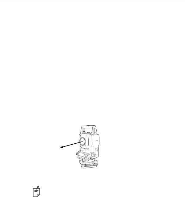
1КОНСТРУКТИВНЫЕ ЭЛЕМЕНТЫ И ОБЩИЕ ФУНКЦИИ
•Регулировка контрастности экрана (Кнтр): уровень 0 9
Нажмите клавишу [S] или [ T], чтобы увеличить или уменьшить контрастность экрана.
•Подсветка сетки нитей (Нити): уровень 1 9
Нажмите клавишу [W] или [X], чтобы отрегулировать подсветку сетки нитей. С каждым последующим нажатием клавиши будет меняться интенсивность подсветки.
•Подсветка экрана ВКЛ/ВЫКЛ
Для включения подсветки нажмите клавишу [F1]. Для отключения подсветки нажмите клавишу [F1] еще раз.
•Переключение режимов измерения расстояний по призме / без
призмы
Для переключения режимов измерения расстояний по призме / без призмы нажмите клавишу [F2] (БП/П). Более подробно об этом см. Главу 4 «ИЗМЕРЕНИЕ РАССТОЯНИЙ».
•Переключение функции указателя работы лазера ВКЛ / Мигание / ВЫКЛ
Всякий раз при нажатии клавиши [F3]  лазерный указатель последовательно загорается, мигает или гаснет. Видимый лазерный луч помогает быстрее навестись на цель.
Лазерный
указатель
•Лазерный указатель показывает точное направление на цель. Юстировка лазерного указателя описывается в разделе 17.2.2 «Поверка оптической оси лазерного указателя».
•Когда работает дальномерная часть, лазерный указатель мигает.
•Расстояние, на котором можно использовать функцию лазерного указателя, зависит от климатических и погодных условий, а также зрения оператора.
•Вы не можете видеть лазерный луч, если смотреть на него через окуляр зрительной трубы. Поэтому следите, куда он показывает, просто невооруженным глазом.
•При включенной функции лазерного указателя время работы прибора от внутренней батареи сокращается.
1 — 8
![]()
1КОНСТРУКТИВНЫЕ ЭЛЕМЕНТЫ И ОБЩИЕ ФУНКЦИИ
•Режимы работы компенсатора
Установка режима работы компенсатора (1 ось, 2 оси, ВЫКЛ), произведенная в этом режиме, не сохраняется в памяти прибора после отключения питания. Если Вы хотите, чтобы выбранный Вами режим сохранялся в памяти прибора и использовался после включения питания, см. инструкцию в разделе 6.4.3 «Исправление вертикальных и горизонтальных углов за наклон инструмента».
•Указатель створа
•Данная функция полезна для определения положения призмы, например при выносе в натуру. Человек, который держит призму, легко может определить направление оптической оси прибора (т.е. выйти в створ инструмента), с помощью 2 красных индикаторов – мигающего и горящего непрерывно. Если использовать функцию указателя створа, время работы прибора от внутренней батареи сокращается.
•Порядок работы
Для включения функции указателя створа нажмите клавишу [F3]. Если смотреть на окуляр зрительной трубы, то правый индикатор будет мигать, а левый – гореть непрерывно.
Указатель створа используется при работе на удалениях до 100м. Эффективность зависит от погодных условий и остроты зрения реечника.
Посмотрите на рисунок справа: если вы видите только горящий индикатор, то переместитесь вправо от тахеометра, а если вы видите только мигающий индикатор, то переместитесь влево. Положение посередине между двумя индикаторами при одинаковой их яркости и является створом инструмента.
Горит Мигает непрерывно


 Призма
Для выключения функции указателя створа, нажмите еще раз клавишу [F3].
•Отображение уровня отраженного сигнала
Вданном режиме отображается уровень принимаемого дальномерного сигнала. При приеме отраженного от призмы сигнала раздается звуковое предупреждение (если произведена соответствующая предварительная установка, см. Главу 16 «РЕЖИМ НАСТРОЙКИ ИНСТРУМЕНТА»). Эта функция особенно полезна при наведении на призму в условиях плохой видимости (туман, листва, трава и т.п.). Нажмите клавишу [F4] для перехода в экран уровня отраженного сигнала.
(1)Отключение этой функции описывается в Главе 16 «РЕЖИМ НАСТРОЙКИ ИНСТРУМЕНТА».
(2)Уровень отраженного сигнала можно также задать в режиме измерения расстояний.
В этом режиме можно просмотреть и ввести значения температуры, давления, поправку за атмосферу, поправку за постоянную призмы и постоянную безотражательного режима. Подробности см. в Главах 10 «РЕЖИМ НАВЕДЕНИЯ ПО ЗВУКОВОМУ СИГНАЛУ», 11 «ПОПРАВКА ЗА ПОСТОЯННУЮ ПРИЗМЫ / ПОПРАВКА БЕЗ ПРИЗМЫ» и 12 «ПОПРАВКА ЗА АТМОСФЕРУ».
1 — 9

1КОНСТРУКТИВНЫЕ ЭЛЕМЕНТЫ И ОБЩИЕ ФУНКЦИИ
1.6Разъем последовательного порта RS-232C
Разъем последовательного порта используется для подключения тахеометра серии GPT-3100N к компьютеру или накопителю данных фирмы TOPCON, что позволяет принимать на компьютере результаты измерений, передаваемые с прибора, или пересылать с компьютера на тахеометр предустановленные значения горизонтального угла и т.д.
•В каждом из режимов будут выводиться следующие данные.
|
Режим |
Выходные данные |
|
Режим измерения углов (ВК, ГКп или ГКл) |
ВК, ГКп или ГКл |
|
(ВК в процентах) |
|
|
Режим измерения горизонтальных |
ГКл, S, h |
|
проложений (ГКп, S, h) |
|
|
Режим измерения наклонных дальностей |
ВК, ГКп, D, S |
|
(ВК, ГКп, D) |
|
|
Режим измерения координат |
X, Y, H, ГКп (или ВК, ГКп, D, |
|
X, Y, H) |
|
•В грубом режиме данные на экране и на выходе в точности соответствуют тем, что представлены выше.
•В режиме слежения на выходе отображаются только результаты измерения расстояний.
Подробную информацию, необходимую для соединения накопителя данных с тахеометром серии GPT-3100N, можно получить из Руководства по интерфейсу, которое не входит в стандартный комплект поставки и заказывается дополнительно.
1 — 10
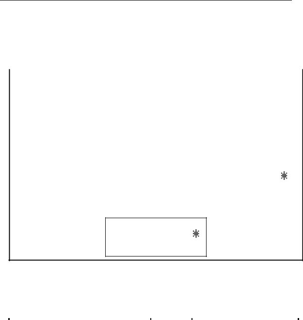
1КОНСТРУКТИВНЫЕ ЭЛЕМЕНТЫ И ОБЩИЕ ФУНКЦИИ
1.7Включение / Выключение лазерного отвеса
(только для приборов с лазерным отвесом)
Функция лазерного отвеса помогает легко отцентрировать инструмент над точкой. Вы можете использовать два способа, чтобы включить/выключить лазерный отвес.
•Включение/выключение лазерного отвеса функциональной клавишей на экране настройки работы компенсатора
|
Порядок действий |
Действие |
Экран |
|||||||||
|
(1) |
Нажмите клавишу [F4], чтобы получить |
ВК : |
90°10’20» |
||||||||
|
доступ к функции на стр. 2 экрана. |
ГКп: |
120°30’40» |
|||||||||
|
[F4] |
0° ГК |
Фикс |
Ввод |
С1↓ |
|||||||
|
Кмпн |
Повт |
ВК% |
С2↓ |
||||||||
|
(2) |
Нажмите клавишу [F1] (Кмпн). |
[F1] |
Компенсатор: |
[2 оси] |
|||||||
|
В случае, если уже было выбрано ВКЛ, то |
X: -0°00’25» |
||||||||||
|
на |
экране отображается |
значение |
Y: 0°00’20» |
||||||||
|
поправки за наклон инструмента. |
1ось |
2оси Выкл Л.Отвес |
|||||||||
|
(3) |
Нажмите клавишу [F4](Л.Отвес). |
[F3] |
Компенсатор: [2 оси] |
||||||||
|
При |
каждом |
нажатии |
клавиши |
X:-0°00’25» |
|||||||
|
[F4](Л.Отвес) функция лазерного отвеса |
Y: 0°00’20» |
Выкл |
Л.Отвес |
||||||||
|
будет |
попеременно включаться и |
1ось |
2оси |
||||||||
|
выключаться. |
|||||||||||
Каждый раз при работе лазера во второй строке справа появляется соответствующий символ.
Компенсатор: [2 оси]
X:-0°00’25» Y: 0°00’20»
1ось 2оси Выкл Л.Отвес
•Включение/выключение лазерного отвеса из главного меню (MENU)
|
Порядок действий |
Действие |
Экран |
|||||||
|
(1) Нажмите клавишу [MENU]. |
[MENU] |
MENU |
:Съёмка |
1/3 |
|||||
|
F1 |
|||||||||
|
F2 |
:Разбивка |
С1↓ |
|||||||
|
F3 |
:Память |
||||||||
|
(2) Нажмите |
клавишу [F4](С↓), |
чтобы |
[F4] |
MENU |
2/3 |
||||
|
получить |
доступ |
к |
функции на стр. 2 |
F1 |
:Программы |
||||
|
экрана. |
F2 |
:Масштб. коэф. |
|||||||
|
F3 |
:Лазерн. отвес P1↓ |
||||||||
|
(3) Нажмите клавишу [F3]. |
[F3] |
Лазерн. отвес |
[выкл] |
||||||
|
F1 |
:вкл |
||||||||
|
F2 |
:выкл |
||||||||
|
(4) Нажмите |
клавишу |
[F1] или |
[F2] для |
[F1] или [F2] |
Лазерн. отвес |
[выкл] |
|||
|
включения или |
выключения |
функции |
F1 |
:вкл |
|||||
|
лазерного отвеса. |
F2 |
:выкл |
|||||||
Автоматическое отключение функции лазерного отвеса
Вы можете задать автоматическое отключение функция лазерного отвеса через определенный промежуток времени (от 1 до 99 минут). По умолчанию этот промежуток времени равен 3 минутам. Вы можете также выключить функцию автоматического отключения лазерного отвеса, подробнее см. Главу 16 «РЕЖИМ НАСТРОЙКИ ИНСТРУМЕНТА».
1 — 11

2 ПОДГОТОВКА К ИЗМЕРЕНИЯМ
2 ПОДГОТОВКА К ИЗМЕРЕНИЯМ
2.1 Подключение питания
(не требуется при использовании встроенная Ni-MH батарея BT-52QА)
Подсоединение внешней батареи питания описывается ниже.
•Батарея питания большой емкости BT-3L
Используется кабель PC-6.
Концы разъема
Внешняя батарея
Кабель
PC-6
Примечание: Также можно использовать встраиваемую Ni-Cd батарею BT-32Q. В случае применения батареи BT-32Q необходимо изменить тип
используемых батарей в режиме установок (см. раздел 6.4.5 «Выбор типа батареи питания»).
2 — 1

2 ПОДГОТОВКА К ИЗМЕРЕНИЯМ
2.2Установка инструмента для выполнения измерений
Установите инструмент на штативе. Точно отнивелируйте и отцентрируйте инструмент. Используйте штативы со становым винтом диаметром 5/8 дюйма и шагом резьбы, 11 витков на дюйм, например штатив Type E фирмы TOPCON.
Для справки: Нивелирование и центрирование инструмента
1.Установка штатива
Выдвиньте ножки на удобную длину и закрепите их винтами.
2.Закрепление инструмента на штативе
Аккуратно установите инструмент на головку штатива. Слегка ослабив становой винт, сместите прибор так, чтобы нитяной отвес находился точно над центром пункта, после чего закрепите становой винт.
3.Грубое нивелирование инструмента по круглому уровню
(1)Вращайте подъемные винты А и В до положения, при котором пузырек будет лежать на линии перпендикулярной той, что проходит через центры двух подъемных винтов А и В.
Подъемный винт C
Подъемный Подъемный винт B винт A
(2)Вращайте подъемный винт С, чтобы поместить пузырек круглого уровня по центру.
4.Точное нивелирование инструмента по цилиндрическому уровню
(1)Используя микрометренный и закрепительный винты горизонтального круга, разверните инструмент так, чтобы цилиндрический уровень располагался параллельно линии, соединяющей подъемные винты А и В. Затем, поворачивая подъемные винты А и В, выведите пузырек цилиндрическогоуровнянацентр.
|
Подъемный винт A |
Подъемный |
|
винт B |
(2)Поверните инструмент на 90° вокруг вертикальной оси, а затем, вращая подъемный винт С, выведите пузырек на центр.
Подъемный винт C
90°
(3)Повторите процедуры (1) и (2) при каждом развороте инструмента на 90° и проверьте, находится ли пузырек в центре во всех четырех положениях.
5.Центрирование с использованием
оптического отвеса
Отрегулируйте окуляр оптического отвеса под ваше зрение.
Ослабив становой винт, передвиньте инструмент так, чтобы совместить центр пункта с центром оптического отвеса, после чего затяните становой винт. Аккуратно передвигайте инструмент, при этом не вращая его: это позволит добиться наименьшего смещения пузырька уровня.
Точка
Центр оптического отвеса
6.Окончательное нивелирование
инструмента
Точно отнивелируйте инструмент, выполняя те же действия, что и на этапе 4. Вращая инструмент, проверьте, что пузырек цилиндрического уровня находится по центру независимо от направления зрительной трубы, после чего крепко затяните становой винт.
2 — 2
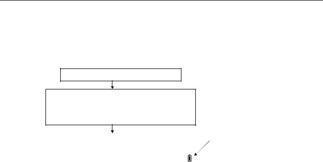
2 ПОДГОТОВКА К ИЗМЕРЕНИЯМ
2.3Кнопка включения питания
Убедитесь, что инструмент правильно отнивелирован.
Включите питание
Кнопка включения питания
TOPCON GPT-3100N
|
ВК : |
90°10’20» |
Индикатор текущего состояния |
||
|
батареи питания |
||||
|
ГКп : |
0°00’00» |
|||
|
0° ГК |
Фикс |
Ввод |
С1↓ |
По индикатору на экране проконтролируйте текущее состояние батареи питания. Установите новую заряженную батарею или зарядите старую, если индикатор указывает на разрядку батареи или на экран выведено сообщение «Battery empty». См. раздел 2.4 «Индикатор текущего состояния батареи питания».
Регулировка контрастности
При включении прибора Вы можете проверить значение постоянной отражателя (ПЗМ), постоянной для измерений без призмы (БПР), поправку за атмосферу (PPM), а также отрегулировать контрастность дисплея.
Вызов этой экранной формы описывается в Главе 16 «РЕЖИМ НАСТРОЙКИ ИНСТРУМЕНТА».
|
Контрастность |
|||
|
ПЗМ : |
0.0 |
PPM : 0 |
|
|
БПР : |
0.0 |
||
|
↓ |
↑ |
— |
ОК |
Нажимая клавишу [F1](↓) или [F2](↑), можно отрегулировать контрастность. Для сохранения установленного значения в энергонезависимой памяти прибора нажмите клавишу [F4] (ОК).
2 — 3
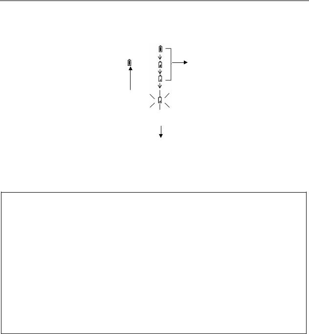
2 ПОДГОТОВКА К ИЗМЕРЕНИЯМ
2.4Индикатор текущего состояния батареи питания
Индикатор показывает текущее состояние батареи питания.
|
ВК |
: |
90°10’20» |
|||
|
ГКп |
: |
0°00’00» |
Можно проводить измерение |
||
|
0° ГК |
Фикс |
Ввод |
С1↓ |
||
|
Индикатор текущего состояния |
Питания недостаточно. Батарею |
||||
|
батареи питания |
следует подзарядить или заменить. |
|
Мигает |
|
|
Мигает |
|
|
<Батарея разряжена> |
Невозможно выполнить |
|
Другие сообщения исчезают с |
измерение. |
|
экрана. |
Необходимо подзарядить или |
заменить батарею.
Примечание : 1 Время работы от батареи зависит от внешних условий, таких как температура окружающей среды, время подзарядки, количество циклов заряд-разряд и т.д. Чтобы избежать перебоев в работе, рекомендуется заряжать батарею заранее или подготовить запасные полностью заряженные батареи.
2Сведения по общему использованию батареи содержатся в Главе 14 «ИСТОЧНИК ПИТАНИЯ И ПОДЗАРЯДКА».
3Индикатор текущего состояния батареи показывает уровень заряда по отношению к текущему режиму работы прибора.
Символ нормальной работоспособности батареи в режиме измерения углов не гарантирует, что эту же батарею можно использовать в режиме измерения расстояний.
При переключении из режима измерения углов в режим измерения расстояний может произойти остановка в работе, если для режима измерения расстояний недостаточно емкости батареи, поскольку в этом режиме энергии потребляется больше, чем в режиме измерения углов.
2 — 4
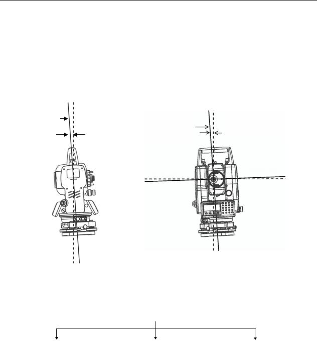
2 ПОДГОТОВКА К ИЗМЕРЕНИЯМ
2.5Компенсация отсчетов вертикальных и горизонтальных
углов за наклон инструмента
(GPT-3107N компенсирует только отсчет вертикального угла)
Когда датчики наклона включены, вертикальный и горизонтальный углы автоматически корректируются за отклонение инструмента от вертикального положения.
Для обеспечения точного измерения углов датчики наклона (компенсатор) должны быть включены. Экран, на котором отображается отклонение инструмента от вертикали, также можно использовать для точного нивелирования прибора. Если на экране появляется сообщение «ПРОВЕРЬТЕ УРОВЕНЬ», это значит, что инструмент отклонился за пределы работы автокомпенсатора и прибор необходимо отнивелировать вручную.
|
Зенит |
Зенит |
|||||||||||||
|
Вертикальная ось |
||||||||||||||
|
Ось вращения |
||||||||||||||
|
инструмента |
||||||||||||||
|
инструмента |
||||||||||||||
|
Поперечный наклон оси |
||||||||||||||
|
Продольный наклон оси |
||||||||||||||
|
вращения тахеометра |
||||||||||||||
|
оси вращения тахеометра |
||||||||||||||
|
Горизонт |
Ось вращения трубы |
|||||||||||||
•Тахеометры серии GPT-3100N компенсируют отсчеты как вертикальных, так и горизонтальных углов за наклон оси вращения в продольном и поперечном направлениях.
•Более подробная информация о двухосевой компенсации содержится в ПРИЛОЖЕНИИ 1 «Двухосевая компенсация».
При превышении пределов компенсации. (Предупреждение ПРОВЕРЬТЕ УРОВЕНЬ)
|
ВК : |
° |
‘ |
« |
ВК : |
º |
‘ |
« |
Вк : |
° |
‘ |
« |
||
|
ГКп: |
° |
‘ |
« |
ГКп: |
° |
‘ |
« |
ГКп : |
° |
‘ |
« |
||
|
<Продоль. наклон> |
<Поперечн. наклон> |
<Проверьте уровень> |
|||||||||||
|
Продольный наклон инструмента вне |
Поперечный наклон инструмента вне |
Наклон инструмента вне допуска |
|||||||||||
|
допуска |
допуска |
•Автоматическое включение компенсации за наклон инструмента при включении питания описывается в разделе 6.4.3 «Исправление вертикальных и горизонтальных углов за наклон инструмента».
•Когда инструмент работает в условиях вибрации или в ветреную погоду, отсчеты вертикальных или горизонтальных углов могут быть неустойчивыми. В этом случае вы можете отключить функцию автокомпенсации вертикальных / горизонтальных углов за наклон инструмента.
2 — 5

2 ПОДГОТОВКА К ИЗМЕРЕНИЯМ
•Включение компенсатора наклона с использованием экранной клавиши
Позволяет вам включить/отключить коррекцию за наклон. Обратите внимание на то, что после отключения питания данная установка в памяти не сохраняется.
[Пример] Отключение автокомпенсации (Кмпн выкл) по 2 осям (X,Y)
|
Порядок действий |
Действие |
Экран |
|||||||
|
(1) |
Нажмите клавишу [F4], чтобы |
получить |
ВК : |
90°10’20» |
|||||
|
доступ к функции на стр. 2 экрана. |
ГКп: |
120°30’40» |
|||||||
|
0° ГК |
Фикс |
Ввод |
С1↓ |
||||||
|
[F4] |
|||||||||
|
Кмпн |
Повт |
ВК% |
С2↓ |
||||||
|
(2) |
Нажмите клавишу [F1](Кмпн). |
[F1] |
Компенсатор: |
[2 оси] |
|||||
|
В случае если уже было выбрано (ВКЛ), то |
X :-0°00’25» |
||||||||
|
на экране отображается значение поправки |
Y : 0°00’20» |
−−− |
|||||||
|
за наклон. |
1 ось |
2 оси |
Выкл |
||||||
|
(3) |
Нажмите клавишу [F3](Выкл). |
[F3] |
Компенсатор: |
[Выкл] |
|||||
|
1 ось 2 оси |
Выкл |
−−− |
|||||||
|
(4) |
Нажмите клавишу [ESC]. |
[ESC] |
ВК : |
90°10’20» |
|||||
|
ГКп: |
120°30’40» |
||||||||
|
Кмпн |
Повт |
ВК% |
С2↓ |
||||||
• Представленный здесь режим установки не будет сохранен в памяти после отключения питания. Включение коррекции за наклон инструмента в набор параметров, используемых при включении (с сохранением в памяти после отключения питания), описывается в разделе 6.4.3 «Исправление вертикальных и горизонтальных углов за наклон инструмента».
2 — 6
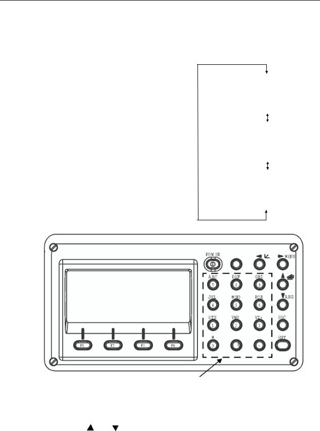
2 ПОДГОТОВКА К ИЗМЕРЕНИЯМ
2.6Ввод буквенно-цифровых символов
Вы можете вводить буквенно–цифровые символы, например высоту инструмента, высоту призмы, название точки стояния и задняя точка и т.д.
•Выбор поля для ввода данных
[Пример] Точка наблюдения в режиме сбора данных.
Стрелка указывает на поле ввода.
При нажатии клавиши [ ] или [
 ] стрелка перемещается вверх или вниз.
[ ] или [
 ]
]
|
Станц.# →ST-01 |
|||
|
Код |
: |
||
|
Hi |
: 0.000 m |
||
|
Ввод |
Поиск |
Сохр |
XYH |
|
Стнц# : ST-01 |
|||
|
Код |
→ |
||
|
Hi |
: 0.000 m |
||
|
Ввод |
Поиск |
Сохр |
XYH |
|
PT# |
: ST-01 |
||
|
Код |
: |
||
|
Hi |
→ 0.000 m |
||
|
Ввод |
Поиск |
Сохр |
XYH |
|
Клавиши для ввода букв и цифр |
||||
|
• Ввод символов |
||||
|
[Пример] TOPCON-1. |
||||
|
(1) Используя клавишу [ ] или [ ], |
Тчк# |
→ |
||
|
передвиньте стрелку для выбора поля |
Код |
: |
||
|
ввода. |
Hi |
: 0.000 m |
||
|
[Ввод] |
[Поиск] [Сохр] [XYH] |
|||
2 — 7
![]()
2 ПОДГОТОВКА К ИЗМЕРЕНИЯМ
(2)Нажмите клавишу [F1](Ввод). Стрелка заменяется знаком равенства
(=). Инструмент переключается в режим ввода цифр.
(3)Нажмите клавишу [F1](БУК). Инструмент переключается в режим ввода букв.
(4)Нажмите экранную клавишу, чтобы ввести соответствующую букву алфавита.
(5)Точно таким же образом введите остальные буквы названия.
(6)Нажмите снова клавишу [F1](ЦИФ). Инструмент вновь возвращается в режим ввода цифр.
(7)Нажмите экранную клавишу, чтобы ввести соответствующий цифровой символ.
Пример: Последовательно нажимается [-]
и [1].
(8)Нажмите клавишу [F4](OK).
Стрелка перемещается к следующему полю ввода.
Точно таким же образом введите остальные названия.
|
Тчк# |
= |
|||
|
Код |
: |
|||
|
Hi |
: |
0.000 m |
||
|
[БУК] |
[ПРБ] |
[ЧИС] |
[OK] |
|
|
Тчк# |
= |
|||
|
Код |
: |
|||
|
Hi |
: |
0.000 m |
||
|
[ЦИФ] |
[ПРБ] [ЧИС] |
[OK] |
||
|
Тчк# |
=T |
|||
|
Код |
: |
|||
|
Hi |
: |
0.000 m |
||
|
[БУК] |
[ПРБ] [ЧИС] |
[OK] |
||
|
Тчк# |
=TOPCON |
|||
|
Код |
: |
|||
|
Hi |
: |
0.000 m |
||
|
[ЦИФ] |
[ПРБ] [ЧИС] |
[OK] |
||
|
Тчк# |
=TOPCON |
|||
|
Код |
: |
|||
|
Hi |
: |
0.000 m |
||
|
[БУК] |
[ПРБ] [ЧИС] |
[OK] |
||
|
Тчк# |
=TOPCON-1 |
|||
|
Код |
: |
|||
|
Hi |
: |
0.000 m |
||
|
[БУК] |
[ПРБ] |
[ЧИС] |
[OK] |
|
•Чтобы исправить уже введенный символ, нажмите клавишу [ ] или [ ] и введите правильное значение.
2 — 8

3 ИЗМЕРЕНИЕ УГЛОВ
3ИЗМЕРЕНИЕ УГЛОВ
3.1 Измерение вертикального и правого горизонтального
углов
Убедитесь, что выбран режим измерения углов.
|
Порядок действий |
Действие |
Экран |
|||||
|
(1) Наведитесь на 1-ю цель (А). |
Набл. A |
||||||
|
ВК : |
90°10’20» |
||||||
|
ГКп: |
120°30’40» |
||||||
|
0° ГК |
Фикс |
Ввод |
С1↓ |
||||
|
(2) Установите отсчет по горизонтальному кругу |
[F1] |
||||||
|
Установка ГК=0 o |
|||||||
|
на цель А равный 0° 00′ 00″. |
>OK? |
||||||
|
Для этого нажмите клавишу [F1](0°ГК), а |
|||||||
|
затем клавишу [F3](Да). |
−−− |
−−− |
[Да] |
[Нет] |
|||
|
[F3] |
|||||||
|
ВК : |
90°10’20» |
||||||
|
Гкп: |
0°00’00» |
||||||
|
0° ГК |
Фикс |
Ввод |
С1↓ |
||||
|
(3) Наведитесь на 2-ю цель (В). |
Набл. B |
||||||
|
ВК : |
98°36’20» |
||||||
|
На экране отобразится искомое значение |
ГКп: |
160°40’20» |
|||||
|
вертикального/горизонтального угла на цель |
0° ГК |
Фикс |
Ввод |
С1↓ |
|||
|
В. |
|||||||
 Для справки Как правильно наводиться на цель
(1)Направьте зрительную трубу на светлый объект (например, на небо). Вращайте кольцо окуляра для наведения резкости до положения, когда перекрестье сетки нитей станет четко видно.
(Совет: при выполнении фокусировки, сначала поверните кольцо для наведения резкости по часовой стрелке, а затем фокусируйте, вращая кольцо против часовой стрелки.)
(2)По визиру наведитесь на цель. Для этого между визиром и вами должно быть некоторое расстояние.
(3)Сфокусируйтесь на цель, используя для этого кремальеру зрительной трубы.
Если при наблюдении в зрительную трубу возникает параллакс по вертикальной или горизонтальной оси между перекрестьем нитей и целью, это означает, что неправильно выполнена фокусировка или плохо наведена резкость. Это отрицательно сказывается на точности измерений. Устраните параллакс, тщательно выполнив фокусировку сетки нитей и цели.
Кремальера
Окуляр (Кольцо для наведения резкости)
3 — 1

3 ИЗМЕРЕНИЕ УГЛОВ
3.2 Переключение режима «Правые/Левые» горизонтальные углы
Убедитесь в том, что выбран режим измерения углов.
|
Порядок действий |
Действие |
Экран |
|||||||||
|
Дважды нажмите клавишу [F4](↓), чтобы |
|||||||||||
|
(1) |
ВК : |
90°10’20» |
|||||||||
|
получить доступ к функции на стр. 3 экрана. |
ГКп: |
120°30’40» |
|||||||||
|
0° ГК |
Фикс |
Ввод |
С1↓ |
||||||||
|
[F4] |
|||||||||||
|
Кмпн |
Повт |
ВК% |
С2↓ |
||||||||
|
дважды |
Зумер |
П/Л |
Накл |
С3↓ |
|||||||
|
(2) |
Нажмите клавишу [F2](П/Л). |
[F2] |
|||||||||
|
ВК : |
90°10’20» |
||||||||||
|
Режим |
измерения |
горизонтальных углов |
ГКп: |
239°29’20» |
|||||||
|
переключится из правых углов (ГКп) на |
Зумер |
П/Л |
Накл |
С3↓ |
|||||||
|
левые углы (ГКл). |
|||||||||||
|
(3) |
Выполните измерения так же, как и в |
||||||||||
|
режиме правых горизонтальных углов (ГКл). |
|||||||||||
|
• |
Каждый |
раз при |
нажатии клавиши |
[F2](П/Л) происходит |
переключение |
режима |
«Правые/Левые» горизонтальные углы (ГКп/ГКл).
3.3Измерение от исходного дирекционного / ориентирного направления
3.3.1Установка ориентирного направления путем фиксации угла
Убедитесь в том, что выбран режим измерения углов.
|
Порядок действий |
Действие |
Экран |
|
(1) |
С |
помощью микрометренного |
винта |
Отображение |
ВК : |
90°10’20» |
|||
|
горизонтального круга установите значение |
значения угла |
ГКп: |
130°40’20» |
||||||
|
исходного дирекционного направления |
на экране |
||||||||
|
0° ГК |
Фикс |
Ввод |
С1↓ |
||||||
|
(2) |
Нажмите клавишу [F2](Фикс). |
[F2] |
ГК зафиксирован |
||||||
|
ГКп: |
130°40’20» |
||||||||
|
>Установить? |
|||||||||
|
−−− |
−−− |
[Да] [Нет] |
|||||||
|
(3) |
Наведитесь на цель. |
Набл. цели |
|||||||
|
(4) |
Нажмите клавишу [F3](Да) для фиксации |
[F3] |
|||||||
|
ВК : |
90°10’20» |
||||||||
|
отсчета по горизонтальному кругу. *1) |
ГКп: |
130°40’20» |
|||||||
|
На |
экране вновь отображается |
обычный |
0° ГК |
Фикс |
Ввод |
С1↓ |
|||
|
режим измерения углов. |
|||||||||
|
1) |
Чтобы вернуться в предыдущий режим, нажмите клавишу [F4](Нет). |
3 — 2

3 ИЗМЕРЕНИЕ УГЛОВ
3.3.2Установка ориентирного направления с помощью клавиатуры
Убедитесь в том, что выбран режим измерения углов.
|
Порядок действий |
Действие |
Экран |
|||||||
|
(1) Наведитесь на цель. |
Набл. цели |
||||||||
|
ВК : |
90°10’20» |
||||||||
|
ГКп: |
170°30’20» |
||||||||
|
0° ГК |
Фикс |
Ввод |
С1↓ |
||||||
|
(2) Нажмите клавишу [F3](Ввод). |
[F3] |
Ввод отсчёта по ГК |
|||||||
|
ГКп: |
|||||||||
|
Формат: ГГГ.ММСС |
|||||||||
|
Ввод |
−−− |
−−− |
ОК |
||||||
|
(3) Нажмите клавишу F1 (Ввод) |
[F1] |
||||||||
|
Ввод отсчёта по ГК |
|||||||||
|
ГКп: |
|||||||||
|
Формат: ГГГ.ММСС |
|||||||||
|
−−− |
−−− |
[Чис] |
[ОК] |
||||||
|
(4) Введите с |
клавиатуры |
значение для |
70.4020 |
||||||
|
ВК : |
90°10’20» |
||||||||
|
исходного направления. *1) |
[F4] |
ГКп: |
70°40’20» |
||||||
|
Например:70°40’20» |
0° ГК |
Фикс |
Ввод |
С1↓ |
|||||
|
По завершении можно |
производить |
||||||||
|
стандартные |
измерения |
от исходного |
|||||||
|
горизонтального угла. |
|||||||||
|
1) См. раздел 2.6 «Ввод буквенно-цифровых символов». |
|||||||||
3.4Режим отображения уклона в процентах (%)
Убедитесь в том, что выбран режим отображения углов.
|
Порядок действий |
Действие |
Экран |
|||||||||
|
(1) |
Нажмите клавишу [F4](↓), чтобы перейти на |
ВК : |
90°10’20» |
||||||||
|
стр.2 экрана. |
ГКп: |
170°30’20» |
|||||||||
|
0° ГК |
Фикс |
Ввод |
С1↓ |
||||||||
|
[F4] |
Кмпн |
Повт |
ВК% |
С2↓ |
|||||||
|
(2) |
Нажмите клавишу [F3](ВК%). *1) |
[F3] |
ВК : |
-0.30 |
% |
||||||
|
ГКп: |
170°30’20» |
||||||||||
|
Кмпн |
Повт |
ВК% |
С2↓ |
||||||||
1)Каждый раз при нажатии клавиши [F3](ВК%) происходит переключение режима представления вертикальных углов.
•Когда измерения проводятся при значениях более ±45° (±100%) от горизонта, на экране отображается <Ошибка>.
3 — 3

3 ИЗМЕРЕНИЕ УГЛОВ
3.5Измерение углов методом повторений
•Измерение углов методом повторений можно выполнять и при правом положении горизонтального круга.
Убедитесь в том, что выбран режим измерения углов.
|
Порядок действий |
Действие |
Экран |
|||||||||||||
|
Нажмите клавишу [F4](↓), чтобы перейти на |
[F4] |
||||||||||||||
|
(1) |
ВК : |
90°10’20» |
|||||||||||||
|
стр. 2 экрана. |
ГКп: |
170°30’20» |
|||||||||||||
|
0° ГК |
Фикс |
Ввод |
С1↓ |
||||||||||||
|
Кмпн |
Повт |
ВК% |
С2↓ |
||||||||||||
|
(2) |
Нажмите клавишу [F2](Повт). |
[F2] |
Измерение угла методом |
||||||||||||
|
повторений |
|||||||||||||||
|
>OK ? |
|||||||||||||||
|
−−− |
−−− |
[Да] |
[Нет] |
||||||||||||
|
(3) |
Нажмите клавишу [F3](Да). |
[F3] |
Повт. угла |
Приём [ |
0] |
||||||||||
|
Сум: |
0°00’00» |
||||||||||||||
|
Гу: |
|||||||||||||||
|
0° ГК |
Вых |
Повт |
Фикс |
||||||||||||
|
(4) |
Наведитесь на цель А и нажмите клавишу |
Набл. A |
Метод повторений |
||||||||||||
|
[F1] (0°ГК). |
[F1] |
Установить ГК=0° ? |
|||||||||||||
|
−−− |
−−− |
[Да] |
[Нет] |
||||||||||||
|
(5) |
Нажмите клавишу [F3](Да). |
[F3] |
Повт. угла |
Приём [ |
0] |
||||||||||
|
Сум: |
0°00’00» |
||||||||||||||
|
ГУ : |
|||||||||||||||
|
0° ГК |
Вых |
Повт |
Фикс |
||||||||||||
|
(6) |
Наведитесь на цель В, вращая для этого |
Набл. B |
Повт. угла |
Приём [ |
1] |
||||||||||
|
закрепительный |
винт и |
микрометренный |
[F4] |
Сум: |
45°10’00» |
||||||||||
|
винт горизонтального круга. |
ГУ: |
45°10’00» |
|||||||||||||
|
Нажмите клавишу [F4](Фикс). |
0° ГК |
Вых |
Повт |
Фикс |
|||||||||||
|
(7) |
Повторно наведитесь на цель А, вращая для |
Повторное |
Повт. угла |
Приём [ |
1] |
||||||||||
|
этого |
закрепительный |
винт |
и |
набл. A |
Сум: |
45°10’00» |
|||||||||
|
микрометренный |
винт |
горизонтального |
[F3] |
ГУ : |
45°10’00» |
||||||||||
|
круга, и нажмите клавишу [F3](Повт). |
0° ГК |
Вых |
Повт |
Фикс |
|||||||||||
|
(8) |
Повторно наведитесь на цель В, вращая для |
Повторное |
Повт. угла |
Приём [ |
2] |
||||||||||
|
этого |
закрепительный |
винт |
и |
набл. B |
Сум: |
90°20’00» |
|||||||||
|
микрометренный |
винт |
горизонтального |
[F4] |
ГУ : |
45°10’00» |
||||||||||
|
круга, и нажмите клавишу [F4](Фикс). |
0° ГК |
Вых |
Повт |
Фикс |
|||||||||||
|
(9) |
Повторите процедуры (7) и (8) , чтобы |
Повт. угла |
Приём [ |
4] |
|||||||||||
|
выполнить |
измерения |
при желаемом |
Сум: |
180°40’00» |
|||||||||||
|
количестве повторений. |
ГУ : |
45°10’00» |
|||||||||||||
|
0° ГК |
Вых |
Повт |
Фикс |
||||||||||||
|
[Пример] 4 повтора |
|||||||||||||||
|
3 — 4 |

|
3 |
ИЗМЕРЕНИЕ УГЛОВ |
|||||||||
|
(10) |
Для возврата в стандартный режим |
[ESC] |
Метод повторений |
|||||||
|
измерения углов нажмите клавишу [F2](Вых) |
или |
Выйти из программы? |
||||||||
|
или клавишу [ESC]. |
[F2] |
|||||||||
|
−−− |
−−− |
[Да] [Нет] |
||||||||
|
[F3] |
||||||||||
|
(11) |
Нажмите клавишу [F3](Да). |
ВК : |
90°10’20» |
|||||||
|
ГКп: |
170°30’20» |
|||||||||
|
0° ГК |
Фикс |
Ввод |
С1↓ |
|||||||
• Горизонтальный угол с дискретностью отсчетов 1” может суммироваться до значения: 3600°00’00’’ для правых горизонтальных углов или 3600°00’00’’ для левых горизонтальных углов
В случае взятия отсчета с дискретностью в 5”, горизонтальный угол может суммироваться до значения ±3599°59’55’’.
• Если в итоге отклонение от первого результата измерения превышает ±30”, то на экране появляется сообщение об ошибке.
3.6Звуковой сигнал при увеличении горизонтального
угла на каждые 90°
Когда горизонтальный угол попадает в диапазон значений менее чем ±1° от 0°, 90°, 180° или 270° раздается звуковой сигнал. Звучание прекращается только, когда горизонтальный угол установлен на 0°00’00’’, 90°00’00’’, 180°00’00’’ или 270°00’00’’.
Данная установка не сохраняется в памяти после отключения питания. Включение её в набор параметров, сохраняемых в памяти инструмента, описывается в Главе 16 «РЕЖИМ НАСТРОЙКИ ИНСТРУМЕНТА».
Убедитесь в том, что выбран режим измерения углов.
|
Порядок действий |
Действие |
Экран |
||||||
|
Дважды нажмите клавишу [F4](↓), чтобы |
||||||||
|
(1) |
ВК : |
90°10’20» |
||||||
|
перейти на стр. 3 экрана. |
ГКп: |
170°30’20» |
||||||
|
[F4] |
0° ГК |
Фикс |
Ввод |
С1↓ |
||||
|
дважды |
||||||||
|
Кмпн |
Повт |
ВК% |
С2↓ |
|||||
|
Зумер П/Л |
Накл |
С3↓ |
||||||
|
(2) |
Нажмите клавишу [F1](Зумер). |
[F1] |
Звук. cигнал |
[Вык] |
||||
|
На экран выводится предыдущая установка. |
при отсчётах по ГК |
|||||||
|
кратных 90° |
−−− |
|||||||
|
[Вкл] |
[Вык] |
ОК |
||||||
|
(3) |
Нажмите клавишу [F1](Вкл) для включения |
[F1] или [F2] |
Звук. cигнал |
[Вкл] |
||||
|
звукового сигнала или клавишу [F2](Выкл) |
при отсчётах по ГК |
|||||||
|
для отключения звукового сигнала. |
кратных 90° |
−−− |
||||||
|
[Вкл] |
[Вык] |
ОК |
||||||
|
[F4] |
||||||||
|
(4) |
Нажмите клавишу [F4](ОК). |
ВК : |
90°10’20» |
|||||
|
ГКп: |
170°30’20» |
|||||||
|
0° ГК |
Фикс |
Ввод |
С1↓ |
|||||
3 — 5

3 ИЗМЕРЕНИЕ УГЛОВ
3.7Направление счета вертикального угла
Вертикальный угол отсчитываются следующим образом.
+90o
-90o
|
Порядок действий |
Действие |
Экран |
||||||
|
Нажмите клавишу [F4](↓) дважды, чтобы |
[F4] |
|||||||
|
(1) |
ВК : |
98°10’20» |
||||||
|
перейти на стр. 3 экрана. |
дважды |
ГКп: |
170°30’20» |
|||||
|
0° ГК |
Фикс |
Ввод |
С1↓ |
|||||
|
Кмпн |
Повт |
ВК% |
С2↓ |
|||||
|
Зумер |
П/Л |
Накл |
С3↓ |
|||||
|
Нажмите клавишу [F3](Накл) *1) |
[F3] |
|||||||
|
(2) |
ВК : |
— |
8°10’20» |
|||||
|
ГКп: |
170°30’20» |
|||||||
|
Зумер |
П/Л |
Накл |
С3↓ |
|||||
1) Каждый раз при нажатии клавиши [F3](Накл) происходит переключение режима экрана.
3 — 6

4 ИЗМЕРЕНИЕ РАССТОЯНИЙ
4 ИЗМЕРЕНИЕ РАССТОЯНИЙ
Расстояния менее 1 м и более 500 м в безотражательном режиме отображаться не будут.
Измерения по призме и без нее
Вы можете выбрать режим измерений по отражателю и на цель, не обрудованную отражателем.
•Независимо от того, используется ли лазерный указатель или нет, проведение измерений возможно в любом режиме: как по призме, так и без нее. Это значит, что если Вы работаете с прибором серии GPT-3100N на открытом воздухе, в условиях города и т.д., то функцию лазерного указателя можно отключить, чтобы прямой лазерный луч не повредил кому-нибудь зрение.
•При использовании отражательной пластины выполняйте измерения по призме.
•Чтобы выполнить измерения по призме, убедитесь, что именно этот режим выставлен Вами, в противном случае точность измерений не гарантируется.
•В безотражательном режиме вы можете выполнять все виды измерения дальностей, такие как измерение расстояний, координат, промеры и вынос в натуру.
•Для переключения в режим измерения по призме и обратно нажмите экранную клавишу [БП/П]. В безотражательном режиме в правом верхнем углу экрана отображается индикатор [NP].
Смена режимов должна производиться перед началом измерений.
|
Пример: |
Измерение расстояний |
|
|
ГКп: |
120o30’40» |
|
|
S : |
65.432 m NP |
|
|
h : |
12.345 m |
|
|
Измр |
Режим БП/П С1↓ |
|
Индикатор
безотражательного
режима
Определение координат
|
X: |
123.456 m |
|
Y: |
34.567 mNP |
|
H: |
12.345 m |
|
Измр Режим |
БП/П С1↓ |
Для смены режима нажмите экранную клавишу [БП/П].
•Вы можете задать, чтобы при включении прибора устанавливался безотражательный режим измерения расстояний. Более подробно об этом см. Главу 16 «РЕЖИМ НАСТРОЙКИ ИНСТРУМЕНТА».
•В случае наблюдения в безотражательном режиме близко стоящей призмы вы не получите никаких результатов из-за слишком высокого уровня отраженного сигнала.
4.1Ввод поправки за атмосферу
Для автоматического внесения в расстояния поправки за атмосферу определите ее значение по измеренным температуре и давлению. См. раздел 12.2 «Ввод поправки за атмосферу».
4.2Ввод поправки за постоянную призмы
Значение постоянной призмы фирмы Topcon равно 0, поэтому при ее использовании введите поправку для призмы: 0. При работе с призмой другой фирмы необходимо предварительно установить соответствующее значение постоянной для этой призмы. См. Главу 11 «ПОПРАВКА ЗА ПОСТОЯННУЮ ПРИЗМЫ». Установленное значение сохраняется в памяти после отключения питания.
Примечание: Перед выполнением измерений в безотражательном режиме введите значение постоянной призмы, равное 0.
4.3Измерение расстояний (непрерывное измерение)
Убедитесь в том, что выбран режим измерения углов.
4 — 1

|
4 |
ИЗМЕРЕНИЕ РАССТОЯНИЙ |
||||||||||||||||||||
|
Порядок действий |
Действие |
Экран |
|||||||||||||||||||
|
(1) |
Наведитесь на центр призмы. |
Набл. цели |
ВК : |
90°10’20» |
|||||||||||||||||
|
ГКп: |
120°30’40» |
||||||||||||||||||||
|
0° ГК |
Фикс |
Ввод |
С1↓ |
||||||||||||||||||
|
(2) |
Нажмите клавишу [ |
]. |
[ |
] |
ГКп: |
120°30’40» |
|||||||||||||||
|
S * [ 1 ] |
< < m |
||||||||||||||||||||
|
Начинается измерение расстояний. 1), 2) |
|||||||||||||||||||||
|
h : |
m |
||||||||||||||||||||
|
Измр |
Режим БП/П С1↓ |
||||||||||||||||||||
|
Результаты измерений |
отображаются |
на |
ГКп: |
120°30’40» |
|||||||||||||||||
|
экране. 3) 5) |
S * |
123.456 m |
|||||||||||||||||||
|
h : |
5.678 m |
||||||||||||||||||||
|
Измр |
Режим |
БП/П С1↓ |
|||||||||||||||||||
|
• |
|||||||||||||||||||||
|
При повторном нажатии |
клавиши |
[ |
] |
на |
[ |
] |
ВК : |
90°10’20» |
|||||||||||||
|
экране отображаются |
значения |
правого |
ГКп: |
120°30’40» |
|||||||||||||||||
|
горизонтального угла |
(ГКп), вертикального |
D* |
131.678 m |
||||||||||||||||||
|
угла (ВК) и наклонной дальности (D). 6) |
|||||||||||||||||||||
|
Измр |
Режим |
БП/П |
С1↓ |
||||||||||||||||||
1) При работе дальномерной части на экране появляется символ «*».
2) Для перехода из режима Точный в режим Грубый или Слежения, см. раздел 4.5 «Точный режим / Грубый режим / Режим слежения».
Чтобы при включении питания устанавливался режим измерения расстояний, см. Главу 16 «РЕЖИМ НАСТРОЙКИ ИНСТРУМЕНТА».
3) Указатель единицы измерения расстояний «m» (метр), «f» (фут или фут и дюйм) появляется и исчезает попеременно со звуковым сигналом при каждом обновлении данных по расстоянию.
4) Измерения могут повторяться в инструменте автоматически, если на результате сказывается вибрационное воздействие и т.д.
5) Для возврата из режима измерения расстояний в стандартный режим измерения углов нажмите клавишу [ANG].
6) Можно выбрать порядок отображения (ГКп,S,h) или (ВК,ГКп,D) для начального режима измерения расстояний. См. Главу 16 «РЕЖИМ НАСТРОЙКИ ИНСТРУМЕНТА».
4 — 2

4 ИЗМЕРЕНИЕ РАССТОЯНИЙ
4.4Измерение расстояний
(многократные / единичные измерения)
Когда заранее установлено количество повторов измерений, тахеометр серии GPT-3100N будет несколько раз измерять расстояние (согласно установленному значению), и отображать на экране среднее значение.
При установке количества повторов равного 1, среднее расстояние отображаться не будет, поскольку это единичное измерение. По умолчанию на заводе-изготовителе установлен режим единичных измерений.
Убедитесь в том, что выбран режим измерения углов.
|
Порядок действий |
Действие |
Экран |
|||||||||||||
|
(1) |
Наведитесь на центр призмы. |
||||||||||||||
|
ВК : |
90°10’20» |
||||||||||||||
|
ГКп: |
120°30’40» |
||||||||||||||
|
0° ГК |
Фикс |
Ввод |
С1↓ |
||||||||||||
|
(2) |
Нажмите клавишу [ |
]. |
[ |
] |
ГКп: |
120°30’40» |
|||||||||
|
S *[ 3 ] |
< < m |
||||||||||||||
|
Выполняется непрерывное измерение. 1) |
|||||||||||||||
|
h : |
m |
||||||||||||||
|
Измр |
Режим |
БП/П С1↓ |
|||||||||||||
|
[F1] |
|||||||||||||||
|
(3) |
Нажмите клавишу [F1](Измр), когда |
ГКп: |
120°30’40» |
||||||||||||
|
S *[ 3 ] |
< < |
m |
|||||||||||||
|
количество выполненных измерений будет |
h : |
m |
|||||||||||||
|
достаточным. 2) |
Измр |
Режим |
БП/П |
С1↓ |
|||||||||||
|
На экране отображается среднее значение, |
|||||||||||||||
|
а символ «*» исчезает. |
|||||||||||||||
|
• |
При работе дальномерной |
части |
вновь |
ГКп: |
120°30’40» |
||||||||||
|
S* |
123.456 m |
||||||||||||||
|
нажмите клавишу |
[F1](Измр), и |
данный |
|||||||||||||
|
h : |
5.678 m |
||||||||||||||
|
режим изменится |
на режим |
непрерывных |
|||||||||||||
|
Измр |
Режим |
БП/П |
С1↓ |
||||||||||||
|
измерений. |
|||||||||||||||
1) Можно сделать так, чтобы при включении питания устанавливался режим многократных измерений или режим непрерывных измерений. См. Главу 16 «РЕЖИМ НАСТРОЙКИ ИНСТРУМЕНТА».
2) Для установки количества раз (N-раз) измерений см. Главу 16 «РЕЖИМ НАСТРОЙКИ ИНСТРУМЕНТА».
4 — 3
![]()
4 ИЗМЕРЕНИЕ РАССТОЯНИЙ
Выбор единиц измерения с помощью экранной клавиши (метры /футы / футы+дюймы)
С помощью экранной клавиши можно изменить единицы измерения расстояний. Данная установка не сохраняется в памяти после отключения питания. Чтобы включить ее в инициализационную установку (которая сохраняется в памяти после отключения питания), см. Главу 16 «РЕЖИМ НАСТРОЙКИ ИНСТРУМЕНТА».
|
Порядок действий |
Действие |
Экран |
|||||||
|
ГКп: |
120°30’40» |
||||||||
|
S* |
2.000 m |
||||||||
|
(1) |
Дважды нажмите клавишу [F4](С1↓), чтобы |
[F4] |
h : |
3.000 m |
С1↓ |
||||
|
перейти на стр. 3 экрана. |
дважды |
Измр |
Режим |
БП/П |
|||||
|
Промр Вынос |
Сигн |
С2↓ |
|||||||
|
−−− |
м/ф/д −−− |
С3↓ |
|||||||
|
(2) |
При каждом нажатии клавиши [F2](м/ф/д) на |
[F2] |
|||||||
|
ГКп: |
120°30’40» |
||||||||
|
экране будет меняться единица измерения. |
S* |
6.560 |
ft |
||||||
|
• |
Каждое нажатие [F2](м/ф/д) вызывает |
h : |
9.845 |
ft |
|||||
|
−−− |
м/ф/д |
−−− |
С3↓ |
||||||
|
переключение единиц измерения. |
|||||||||
4.5Точный режим/Режим Слежения/Грубый режим
Эта установка не сохраняется в памяти после отключения питания. Включение его в набор параметров, используемых при подаче питания, описывается в Главе 16 «РЕЖИМ НАСТРОЙКИ ИНСТРУМЕНТА».
Точный режим : Это стандартный режим измерения расстояний.
Шаг измерения расстояния может быть изменен. Время измерения зависит от выбранного шага измерения расстояния.
|
Режим |
: |
В этом режиме на измерение уходит меньше времени, чем в точном |
|
слежения |
режиме. |
|
|
Этот режим очень эффективен при слежении за подвижными |
||
|
объектами или при выносе объектов в натуру. |
||
|
Грубый режим : |
В данном режиме на измерение уходит меньше времени, чем в |
|
|
точном режиме. |
Изменение используемого в точном режиме шага измерения расстояний описывается в разделе 6.4.1, “Установка минимальной дискретности”.
|
Порядок действий |
Действие |
Экран |
||||
|
ГКп: |
120°30’40» |
|||||
|
S: |
123.456 m |
|||||
|
h : |
5.678 m |
|||||
|
Измр |
Режим |
БП/П С1↓ |
||||
|
(1) Нажмите клавишу [F2](Режим) в режиме |
[F2] |
|||||
|
ГКп: |
120°30’40» |
|||||
|
измерения расстояний. 1) |
S: |
123.456 m |
||||
|
В правом нижнем углу экрана отображается |
h : |
5.678 m |
||||
|
первая буква установленного режима |
Точно |
Слеж |
Грубо |
Т |
||
|
(Т/С/Г). (Т:Точно, С:Слеж, Г:Грубо) |
||||||
|
(2) Нажмите клавишу [F1](Точно), [F2](Слеж) |
[F1] [F3] |
|||||
|
ГКп: |
120°30’40» |
|||||
|
или [F3](Грубо). |
S: |
123.456 |
m |
|||
|
h : |
5.678 m |
|||||
|
Измр |
Режим |
БП/П С1↓ |
||||
1) Для отмены установки нажмите клавишу [ESC].
4 — 4

4 ИЗМЕРЕНИЕ РАССТОЯНИЙ
4.6Вынос в натуру (Вынос)
При выносе в натуру на экране отображается разность между измеренным и проектным расстоянием.
Отображаемое значение = Измеренное расстояние – Проектное расстояние
•Для выноса в натуру вы можете выбрать либо горизонтальное проложение (S), либо превышение (h) и наклонное расстояние (D).
|
Порядок действий |
Действие |
Экран |
|||||||
|
(1) В режиме измерения расстояний нажмите |
ГКп: |
120°30’40» |
|||||||
|
S* |
123.456 m |
||||||||
|
клавишу [F4](↓) для перехода на стр. 2 |
h : |
5.678 m |
|||||||
|
экрана |
Измр |
Режим БП/П |
С1↓ |
||||||
|
[F4] |
|||||||||
|
Промр |
Вынос |
Сигн |
С2↓ |
||||||
|
(2) Нажмите клавишу [F2](Вынос). |
[F2] |
Вынос в натуру |
|||||||
|
На экране |
отображается |
предыдущая |
S |
: |
0.000 m |
||||
|
установка. |
S |
h |
D |
−−− |
|||||
|
(3) Выберите режим измерения, |
нажав для |
[F1] |
Вынос в натуру |
||||||
|
этого клавишу [F1] [F3]. |
S |
: |
0.000 m |
||||||
|
Пример : Горизонтальное проложение |
Ввод |
−−− |
−−− |
ОК |
|||||
|
(4)Введите расстояние для выноса в натуру. 1) |
|||||||||
|
[F1] |
Вынос в натуру |
||||||||
|
Ввод |
S |
: |
100.000 m |
||||||
|
данных |
|||||||||
|
[F4] |
Ввод |
−−− |
−−− |
ОК |
|||||
|
(5) Наведитесь на цель (призму). |
Набл. P |
||||||||
|
ГКп : |
120°30’40» |
||||||||
|
Выполняется измерение. |
dS *[ 3 ] |
< < m |
|||||||
|
h : |
m |
||||||||
|
Измр |
Режим |
БП/П С1↓ |
|||||||
|
На экране отображается разность между |
|||||||||
|
ГКп : |
120°30’40» |
||||||||
|
измеренным |
расстоянием и |
проектным |
dS* : |
23.456 m |
|||||
|
расстоянием, а также разность между |
h |
: |
5.678 m |
||||||
|
высотами. |
Измр |
Режим |
БП/П |
С1↓ |
|||||
(6)Перемещайте отражатель до тех пор, пока разности не будут равны 0.
1) См. раздел 2.6 «Ввод буквенно-цифровых символов».
•Чтобы вернуться в стандартный режим измерения расстояний, переустановите проектное расстояние на «0»м или отключите питание.
4 — 5

4 ИЗМЕРЕНИЕ РАССТОЯНИЙ
4.7Способы измерения промерами
Существуют четыре способа измерения промерами.
1Измерение с угловым промером
2Измерение с линейным промером
3Промер на плоскости
4Промер до центра колонны
Для отображения меню измерения промерами нажмите экранную клавишу [Промр] в режиме измерения координат или расстояний.
|
Пример: |
Измерение расстояний |
Определение координат |
|||||||||||||
|
ГКп: |
120o30’40» |
X: |
123.456 m |
||||||||||||
|
S : |
123.456 m |
Y: |
34.567 m |
||||||||||||
|
h : |
5.678 m |
H: |
78.912 m |
||||||||||||
|
Измр Режим БП/П С1↓ |
Измр |
Режим |
БП/П С1↓ |
||||||||||||
|
Промр Вынос Сигн |
С2↓ |
Hv |
Hi |
Стнц С2↓ |
|||||||||||
|
Нажмите клавишу [Промр]. |
Промр |
м / ф / д Сигн |
|||||||||||||
|
Меню измерения |
|||||||||||||||
|
Промер |
1/2 |
||||||||||||||
|
промерами |
F1: Угловой |
||||||||||||||
|
F2: Линейный |
С↓ |
||||||||||||||
|
F3: На плоскости |
|||||||||||||||
|
[F4] |
|||||||||||||||
|
Промер |
2/2 |
||||||||||||||
|
F1:Центр колонны |
|||||||||||||||
|
С↓ |
|||||||||||||||
Вывод результатов измерений
Результаты измерения промерами можно вывести на внешнее устройство.
Вы можете задать функцию вывода [ESC] для клавиши (Запись). В этом случае на экране вместе с результатом измерения отображается экранная клавиша [F3] (Запись). Более подробно установка этого параметра описывается в Главе 16 «РЕЖИМ НАСТРОЙКИ ИНСТРУМЕНТА».
Угловойпромер
|
ГКп: |
120o30’40» |
|
D: |
123.456 m |
|
След −−− |
Сохр −−− |
[F3]
Измерение расстояний в режиме измерения промерами
Измерение промерами возможно в режиме измерения расстояний (точный режим; многократные измерения).
Установка количества повторов измерений описана в главе 16 «РЕЖИМ НАСТРОЙКИ ИНСТРУМЕНТА».
4 — 6

4 ИЗМЕРЕНИЕ РАССТОЯНИЙ
4.7.1Измерение с угловым промером
Данный режим целесообразно использовать, когда невозможно выполнить измерение непосредственно на цель, например, на центр дерева. Чтобы выполнить измерение, расположите призму на том же горизонтальном проложении от инструмента, что и
точка A0.
Для измерения координат местоположения центра, введите высоту инструмента / высоту призмы и выполните измерение промером.
Призма P
A0
Высота призмы
A1
Высота инструмента
При измерении координат точки A1 у земной поверхности: Введите высоту инструмента / высоту призмы.
При измерении координат точки A0 : Введите только высоту инструмента. (Высоту призмы установите на
0).
При наблюдении точки A0 вы можете выбрать один из двух способов. Первый – зафиксировать вертикальный угол на центр призмы, даже если она расположена ниже оси зрительной трубы, а второй – задать изменение вертикального угла в зависимости от поворота зрительной трубы. Во втором случае, с поворотом зрительной трубы будут изменяться значения наклонной дальности и превышения.
Установка этого параметра описывается в главе 16 «РЕЖИМ НАСТРОЙКИ ИНСТРУМЕНТА».
Точка наблюдения
•Перед работой в режиме измерения промерами введите высоту инструмента / высоту призмы.
•При вводе значений координат для пункта наблюдения см. раздел 5.1 «Ввод координат пункта наблюдения».
|
Порядок действий |
Действие |
Экран |
||||||
|
ГКп: |
120°30’40» |
|||||||
|
(1) В режиме измерения расстояний нажмите |
S |
: |
123.456 m |
|||||
|
h |
: |
5.678 m |
||||||
|
клавишу [F4](С1↓) для перехода на стр. 2 |
||||||||
|
Измр |
Режим |
БП/П |
С1↓ |
|||||
|
экрана. |
||||||||
|
[F4] |
Промр |
Вынос |
Сигн |
С2↓ |
||||
|
(2) Нажмите клавишу [F1](Промр). |
[F1] |
Промер |
1/2 |
|||||
|
F1:Угловой |
||||||||
|
F2:Линейный |
С1↓ |
|||||||
|
F3:На плоскости |
||||||||
|
(3) Нажмите клавишу [F1](Угловой). |
[F1] |
Угловой промер |
||||||
|
ГКп : |
120°30’40» |
|||||||
|
S : |
m |
|||||||
|
Измр |
−−− БП/П −−− |
|||||||
4 — 7

4 ИЗМЕРЕНИЕ РАССТОЯНИЙ
|
(4) |
Наведитесь на призму Р и нажмите клавишу |
Набл. P |
Угловой промер |
||||||||||||||
|
[F1](Измр). |
[F1] |
ГКп : |
110°20’30» |
||||||||||||||
|
S * |
<< m |
||||||||||||||||
|
>Измерение . . . |
|||||||||||||||||
|
Будет |
измерено |
горизонтальное |
Угловой промер |
||||||||||||||
|
ГКп : |
110°20’30» |
||||||||||||||||
|
проложение от инструмента до призмы. |
|||||||||||||||||
|
S * |
56.789 m |
||||||||||||||||
|
След |
−−− |
−−− |
−−− |
||||||||||||||
|
(5) |
Наведитесь на точку A0. |
Набл. A0 |
Угловой промер |
||||||||||||||
|
ГКп : |
110°20’30» |
||||||||||||||||
|
S : |
56.789 m |
||||||||||||||||
|
След |
−−− |
−−− |
−−− |
||||||||||||||
|
(6) |
Покажите превышение точки A0. |
||||||||||||||||
|
[ |
] |
Угловой промер |
|||||||||||||||
|
ГКп : |
110°20’30» |
||||||||||||||||
|
h |
: |
34.567 m |
|||||||||||||||
|
След |
−−− |
−−− |
−−− |
||||||||||||||
|
(7) |
Покажите наклонную дальность точки A0. |
[ |
] |
Угловой промер |
|||||||||||||
|
• |
Каждый |
раз при нажатии |
клавиши |
[ |
]на |
ГКп : |
110°20’30» |
||||||||||
|
D : |
56. 948 m |
||||||||||||||||
|
экране |
последовательно |
отображаются |
|||||||||||||||
|
След |
−−− |
−−− |
−−− |
||||||||||||||
|
значения |
горизонтального проложения, |
||||||||||||||||
|
превышения и наклонной дальности. |
|||||||||||||||||
|
(8) |
Покажите Х координату точки A0 или A1. |
[ |
] |
Угловой промер |
|||||||||||||
|
• |
Каждый раз при нажатии клавиши [ |
] |
на |
ГКп : |
110°20’30» |
||||||||||||
|
экране |
последовательно |
отображаются |
Х |
: |
-12.345 m |
||||||||||||
|
координаты X, Y и H. |
След |
−−− |
−−− |
−−− |
|||||||||||||
|
• Чтобы вернуться к процедуре (4), нажмите клавишу [F1](След). |
|||||||||||||||||
|
• Чтобы вернуться в предыдущий режим, нажмите клавишу [ESC]. |
|||||||||||||||||
|
• |
Для переключения между режимом измерения по призме и безотражательным режимом |
||||||||||||||||
|
нажмите клавишу [F3](БП/П) после выполнения действия 3. |
|||||||||||||||||
4 — 8

4 ИЗМЕРЕНИЕ РАССТОЯНИЙ
4.7.2Измерение с линейным промером
Представляет собой определение координаты и расстояния до центра открытого колодца, столба или дерева, радиус которых известен.
При измерении расстояния или координаты до точки P0 введите значение горизонтального проложения (S) в качестве промера и выполните измерение на точку P1 , как показано на рисунке. На экране отображается координата или расстояние до точки P0.
P1
P0
°HD > 0
В случае если точка P1, на которую выполняется измерение, находится перед точкой P0, на которую необходимо выполнить измерение, значение промера следует вводить с положительным знаком, а если точка P1 находится за точкой P0, то с отрицательным.
•При вводе значений координат для пункта наблюдения см. раздел 5.1 «Ввод координат пункта наблюдения».
|
Порядок действий |
Действие |
Экран |
||||||||||
|
Гкп: |
120°30’40» |
|||||||||||
|
(1) |
В режиме измерения расстояний нажмите |
[F4] |
S |
: |
123.456 |
m |
||||||
|
клавишу [F4](С1↓), чтобы перейти на стр. 2 |
h |
: |
5.678 m |
|||||||||
|
экрана. |
Измр Режим |
БП/П |
С1↓ |
|||||||||
|
Промр |
Вынос |
Сигн |
С2↓ |
|||||||||
|
(2) |
Нажмите клавишу [F1](Промр). |
[F1] |
Промер |
1/2 |
||||||||
|
F1:Угловой |
||||||||||||
|
F2:Линейный |
С1↓ |
|||||||||||
|
F3:На плоскости |
||||||||||||
|
(3) |
Нажмите клавишу [F2](Линейный). |
[F2] |
Линейный промер |
|||||||||
|
Вдоль: |
||||||||||||
|
S: |
−−− |
0.000 m |
||||||||||
|
Ввод |
−−− |
ОК |
||||||||||
|
(4) |
Нажмите клавишу [F1](Ввод) и введите |
[F1] |
||||||||||
|
Линейный промер |
||||||||||||
|
значение промера. |
[F4](ОК) |
для |
Значение |
ГКп: |
80°30’40» |
m |
||||||
|
Нажмите |
клавишу |
промера |
S : |
|||||||||
|
подтверждения ввода. |
[F4] |
Измр |
−−− |
БП/П |
−−− |
|||||||
4 — 9

4 ИЗМЕРЕНИЕ РАССТОЯНИЙ
(5)Наведитесь на призму P1, затем нажмите клавишу [F1](Измр).
Выполняется измерение.
По окончании измерения результат отображается с учетом добавленного значения промера.
(6)Покажите превышение точки A0.
•Каждый раз при нажатии клавиши [  ]на экране последовательно отображаются значения горизонтального проложения, превышения и наклонной дальности.
•Чтобы просмотреть полученные с учетом промера координаты точки A0 нажмите клавишу [  ].
].
Набл. цели
[F1]
[  ]
]
|
Линейный промер |
|||
|
ГКп: |
80°30’40» |
||
|
S * |
< < m |
||
|
>Идет измерение . . . |
|||
|
Линейный промер |
|||
|
ГКп: |
80°30’40» |
||
|
S : |
10.000 m |
||
|
След |
−−− |
−−− |
−−− |
|
Линейный промер |
|||
|
ГКп: |
80°30’40» |
||
|
S : |
11.789 m |
||
|
След |
−−− |
−−− |
−−− |
|
Линейный промер |
|||
|
ГКп: |
80°30’40» |
||
|
D : |
11.789 m |
||
|
След |
−−− |
−−− |
−−− |
|
X: |
12.345 m |
||
|
Y: |
23.456 m |
||
|
H: |
1.345 m |
||
|
След |
−−− |
−−− |
−−− |
•Чтобы вернуться к процедуре (4), нажмите клавишу [F1](След).
•Чтобы вернуться в предыдущий режим, нажмите клавишу [ESC].
•Для переключения между режимом измерения по призме и безотражательным режимом нажмите клавишу [F3](БП/П) после выполнения действия 4.
4 — 10

4 ИЗМЕРЕНИЕ РАССТОЯНИЙ
4.7.3Промер на плоскости
Выполняется в том случае, когда невозможно выполнить прямое измерение, например, определить координаты или расстояние до края плоскости.
С целью определения координат точки (P0) на плоскости сначала следует выполнить измерения на три случайные точки (P1, P2, P3), лежащие на этой плоскости. После этого наведитесь на точку P0, и инструмент вычислит и отобразит значения координат и расстояния для этой точки.
P1
P0
•При вводе значений координат для пункта наблюдения см. раздел 5.1 «Ввод координат пункта наблюдения».
Пример: Измерение в безотражательном режиме
|
Порядок действий |
Действие |
Экран |
|||||
|
ГКп: |
120°30’40» |
||||||
|
(1) В режиме измерения расстояний нажмите |
[F4] |
S : |
123.456 m |
||||
|
h : |
5.678 m |
||||||
|
клавишу [F4](С1↓), чтобы перейти на стр. 2 |
|||||||
|
Измр Режим БП/П С1↓ |
|||||||
|
экрана. |
|||||||
|
Промр |
Вынос |
Сигн |
С2↓ |
||||
|
(2) Нажмите клавишу [F1](Промр). |
[F1] |
Промер |
1/2 |
||||
|
F1:Угловой |
|||||||
|
F2:Линейный |
С1↓ |
||||||
|
F3:На плоскости |
|||||||
|
(3) Нажмите клавишу [F3] (На плоскости). |
[F3] |
Задание плоскости |
|||||
|
Исх. точка №01 |
|||||||
|
D: |
−−− |
m |
−−− |
||||
|
Измр |
БП/П |
||||||
|
(4) Нажмите клавишу [F3](БП/П) для перехода в |
[F3] |
Задание плоскости |
N |
||||
|
безотражательный режим. |
Исх. точка №01 |
||||||
|
m |
P |
||||||
|
D: |
−−− |
−−− |
|||||
|
Измр |
БП/П |
||||||
4 — 11

4 ИЗМЕРЕНИЕ РАССТОЯНИЙ
|
(5) Наведитесь на точку P1 и нажмите клавишу |
Набл. P1 |
||
|
[F1](Измр). |
|||
|
Выполняется |
многократное |
(N-раз) |
[F1] |
|
измерение. |
(6)Точно таким же образом выполните Набл. P2 измерения на вторую и третью точки.
[F1]
Набл. P3
[F1]
Прибор вычисляет и отображает значения координат и расстояния до каждой из точек, на которую выполняется измерение. 1), 2)
(7)Наведитесь на недоступную точку P0, Набл. P0 лежащую на плоскости.
|
На |
экране |
отобразятся |
результаты |
[F1] |
||||
|
измерения на точку P0. 3), 4) |
||||||||
|
(8) Для отображения наклонной дальности (D) |
[ |
] |
||||||
|
нажмите [ |
], то же и для гориз. |
|||||||
|
проложения. |
•Чтобы просмотреть полученные с учетом промера координаты точки P0 нажмите клавишу [  ].
].
|
(9) Для выхода из режима промеров нажмите |
[F1] |
|
клавишу [F1](Выход). Экран возвращается в |
|
|
предыдущий режим. |
Задание плоскости
|
Исх. точка №01 |
N |
|||
|
P |
||||
|
D*[n] |
< < m |
|||
|
>Идет измерение . . . |
||||
|
Задание плоскости |
N |
|||
|
Исх. точка №02 |
||||
|
P |
||||
|
D: |
m |
|||
|
Измр |
−−− |
БП/П |
−−− |
|
|
Задание плоскости |
N |
|||
|
Исх. точка №03 |
||||
|
P |
||||
|
D: |
m |
|||
|
Измр |
−−− |
БП/П |
−−− |
|
|
ГКп: |
80°30’40» |
|||
|
S : |
54.321 mNP |
|||
|
h : |
10.000 m |
|||
|
Выход |
—— |
—— |
—— |
|
|
ГКп: |
75°30’40» |
|||
|
S : |
54.321 mNP |
|||
|
h : |
-0.487 m |
|||
|
Выход |
—— |
—— |
—— |
|
|
ВК: |
90°30’40» |
|||
|
ГКп: |
75°30’40»NP |
|||
|
D: |
56.602 m |
|||
|
Выход |
—— |
—— |
—— |
|
1) В случае если прибору не удается определить плоскость по трем измеренным точкам, появляется сообщение об ошибке. Измерения повторяются снова с первой точки.
2) Данные отображаются до выполнения промера по плоскости.
3) При наблюдении в направлении, которое не пересекается с определенной плоскостью, появляется сообщение об ошибке.
4) Высота точки, на которую выполняется наблюдение (P0), автоматически обнуляется.
4 — 12

4 ИЗМЕРЕНИЕ РАССТОЯНИЙ
4.7.4Промер до центра колонны
Если можно выполнить измерение на точку P1 , расположенную по центру внешней окружности колонны, то, выполнив измерения на точки P2 и P3, которые лежат на периферии внешней окружности колонны, можно определить расстояние до центра колонны, а также координату и дирекционный угол.
Дирекционный угол центра колонны равен 1/2 полного дирекционного угла точек P2 и P3, которые расположены на внешней окружности колонны.
•При вводе значений координат для пункта наблюдения см. раздел 5.1 «Ввод координат пункта наблюдения».
Пример: Измерение в безотражательном режиме
|
Порядок действий |
Действие |
Экран |
|||||
|
ГКп: |
120°30’40» |
||||||
|
(1) В режиме измерения расстояний нажмите |
[F4] |
S : |
123.456 m |
||||
|
h : |
5.678 m |
||||||
|
клавишу [F4](С1↓), чтобы перейти на стр. 2 |
|||||||
|
Измр Режим БП/П С1↓ |
|||||||
|
экрана. |
|||||||
|
Промр |
Вынос |
Сигн |
С2↓ |
||||
|
(2) Нажмите клавишу [F1](Промр). |
Промер |
1/2 |
|||||
|
F1:Угловой |
|||||||
|
F2:Линейный |
С1↓ |
||||||
|
F3:На плоскости |
|||||||
|
[F4] |
Промер |
2/2 |
|||||
|
(3) Нажмите клавишу [F4](С1↓). |
F1:Центр колонны |
||||||
|
C2↓ |
|||||||
|
(4) Нажмите клавишу [F1](Центр колонны). |
[F1] |
Центр колонны |
|||||
|
На центр |
|||||||
|
S: |
m |
||||||
|
Измр |
−−− |
БП/П |
−−− |
||||
4 — 13
 Loading…
-
Page 1
INSTRUCTION MANUAL PULSE TOTAL STATION GPT-3000 SERIES GPT-3002 GPT-3003 GPT-3005 GPT-3007… -
Page 3
FOREWORD Thank you for purchasing the TOPCON Pulse Total Station, GPT-3000 series. For the best performance of the instruments, please carefully read these instructions and keep them in a convenient location for future reference. -
Page 4: General Handling Precautions
General Handling Precautions Before starting work or operation, be sure to check that the instrument is functioning correctly with normal performance. Do not submerge the instrument into water. The instrument can not be submerged underwater. The instrument is designed based on the International Standard IP66, therefore it is protected from the normal rainfall.
-
Page 5: Display For Safe Use
•There is a risk of fire, electric shock or physical harm if you attempt to disassemble or repair the instrument yourself. This is only to be carried out by TOPCON or an authorized dealer, only! •Cause eye injury or blindness.
-
Page 6: User
CAUTION •Use of controls or adjustment or performance of procedures other than those specified herein may result in hazardous radiation exposure. •Let the laser beam reach the aimed object or the target without anybody else in the laser beam path. In case you operate laser beam open, avoid radiating laser beam to the height of man’s head.
-
Page 7: Laser Safety
Classification, Requirements and User`s Guide» (IEC Publication 825) provided on the safety standard for laser beam. As per the said standard, the GPT-3000 series plumb laser type is classified as «Class 2 (II) Laser Products». In case of any failure, do not disassemble the instrument. Contact TOPCON or your TOPCON dealer.
-
Page 8: Table Of Contents
Contents FOREWORD ……….1 General Handling Precautions .
-
Page 9
6.1 Application Measurement (PROGRAMS) ……..6-2 6.1.1 Remote Elevation measurement (REM) ……. 6-2 6.1.2 Missing Line Measurement (MLM) . -
Page 10
9.3.3 Deleting a File ……….. 9-9 9.4 Coordinate Data Direct Key Input . -
Page 11: Standard Set Composition
Standard Set Composition The numerical value in parentheses shows the quantity. GPT-3000 series (with lens cap) (1) Plastic carrying case(1) The form of a case will differ depending on a market. On-board Battery BT-52QA (2) Battery charger BC-27BR or BC-27CR (1)
-
Page 12: Nomenclature And Functions
1 NOMENCLATURE AND FUNCTIONS NOMENCLATURE AND FUNCTIONS 1.1 Nomenclature Handgrip locking screw Handgrip Objective lens Laser pointer Instrument center mark Laser aperture Point guide Display unit Optical plummet (Only for GPT-3002/ telescope 3003/3005) (Optical plummet telescope type only) Circular level Adjustment screw for circular level Leveling screw…
-
Page 13
1 NOMENCLATURE AND FUNCTIONS Sighting collimator Battery locking lever Telescope focusing knob Telescope grip On-board battery BT-52QA Telescope eyepiece Instrument center mark *Vertical motion clamp *Vertical tangent screw Horizontal tangent screw Plate level Horizontal Display unit motion clamp Power supply connector Serial Signal connector… -
Page 14: Display
1 NOMENCLATURE AND FUNCTIONS 1.2 Display ● Display The display uses a graphic LCD which has 4 lines and 20 characters per line. In general, the upper three lines display measured data, and the bottom line displays the soft key function which changes with the measuring mode.
-
Page 15: Operating Key
1 NOMENCLATURE AND FUNCTIONS 1.3 Operating Key Keys Name of Key Function Star key mode is used for each presetting or displaying as follows. 1 Contrast of the display 2 Reticle illumination 3 Back Light Star key 4 Non-prism/Prism 5 Laser pointer 6 Laser plummet 7 Tilt correction 8 Point guide 9 Set audio mode Coordinate…
-
Page 16: Function Key (Soft Key)
1 NOMENCLATURE AND FUNCTIONS 1.4 Function Key (Soft Key) The Soft Key message is displayed at the bottom line of displ a y. The functions are according to the displayed message. Angle measurement mode Distance measurement mode V: 90°10’20» HR:120°30’40» HR:120°30’40″…
-
Page 17
1 NOMENCLATURE AND FUNCTIONS Coordinate measurement mode MEAS Start measuring. MODE Sets a measuring mode, Fine/Coarse/Tracking. NP/P Switches non-prism mode or prism mode. ↓ The function of soft keys is shown on next page (P2). R.HT Sets a prism height by input values. INSHT Sets an instrument height by input values. -
Page 18: Star Key Mode
1 NOMENCLATURE AND FUNCTIONS 1.5 Star key mode Press the (★) key to view the instrument options. The following instrument options can be selected from the (★): 1.Adjustment the contrast of the display (0 to 9 steps) 2.Adjustment the reticle illumination (1 to 9 steps) [ 3.Turn the backlight of the display ON / Blink / OFF 4.Select Non-prism mode / Prism mode 5.Turn the Laser pointer option ON/OFF…
-
Page 19
1 NOMENCLATURE AND FUNCTIONS ● Adjustment the contrast (0 to 9 ) of the display (CONT) This enable you to adjust the contrast of the display. Press the up or down arrow keys to adjust the contrast. ● Adjustment the reticle illumination (1 to 9 ) (RTCL) This enable you to adjust the reticle illumination. -
Page 20
1 NOMENCLATURE AND FUNCTIONS ● Tilt correction The tilt setting mode performed here will not be memorized after powering OFF. To set TILT correction in the initialized setting (it is memorized after powering OFF), see Section 6.4.3 “Vertical and Horizontal Angle Tilt correction ( Tilt ON/OFF)” . ●… -
Page 21: Serial Signal Rs-232C Connector
1 NOMENCLATURE AND FUNCTIONS 1.6 Serial signal RS-232C connector The serial signal connector is used for connecting the GPT-3000 series with a computer or TOPCON Data Collector, which enables the computer to receive measured data from the GPT-3000 series or to send preset data of horizontal angle, etc.
-
Page 22: Preparation For Measurement
2 PREPARATION FOR MEASUREMENT PREPARATION FOR MEASUREMENT 2.1 Power Connection (unnecessary if on-board Ni-MH battery BT-52QA is used) See below for connecting the external battery pack. ● Battery pack BT-3Q Power cord , PC-5 is used. ● Large capacity battery pack BT-3L Power cord PC-6 is used.
-
Page 23: Setting Instrument Up For Measurement
Mount the instrument to the tripod. Level and center the instrument precisely to insure the best performance. Use tripods with a tripod screw of 5/8 in. diameter and 11 threads per inch, such as the Type E TOPCON wide- frame wooden tripod. Reference: Leveling and Centering the Instrument 1.
-
Page 24: Power Switch Key On
2 PREPARATION FOR MEASUREMENT 2.3 Power Switch Key ON Confirm the instrument is leveled. Press the power key.. Press the power key TOPCON GPT-3000 90°10’20» 0°00’00» Battery Power Remaining Display ↓ 0SET HOLD HSET ● Confirm the battery power remaining display. Replace with charged battery or charge when battery level is low or indicates “Battery empty”.
-
Page 25: Battery Power Remaining Display
2 PREPARATION FOR MEASUREMENT 2.4 Battery Power Remaining Display Battery power remaining display indicates the power condition. 90°10’20» 0°00’00» Measurement is possible. ↓ 0SET HOLD HSET The power is poor. The battery Battery power remaining display should be recharged or replaced. Blinking Measurement is impossible.
-
Page 26: Vertical And Horizontal Angle Tilt Correction
2 PREPARATION FOR MEASUREMENT 2.5 Vertical and Horizontal Angle Tilt Correction (GPT-3007 has vertical angle tilt correction only.) When the tilt sensors are activated, automatic correction of vertical and horizontal angle for mislevelment is displayed. To ensure a precise angle measurement, tilt sensors must be turned on. The display can also be used to fine level the instrument.
-
Page 27
2 PREPARATION FOR MEASUREMENT ● Setting Tilt Correction by Soft Key To enable you to select tilt ON/OFF function. setting is not memorized after power is OFF. [Example] Setting X,Y Tilt OFF Operating procedure Option Display Press [F4] key to get the function page 2. 90°10’20″… -
Page 28: How To Enter Alphanumeric Characters
2 PREPARATION FOR MEASUREMENT 2.6 How to Enter Alphanumeric characters This enables you to enter alphanumeric characters such as the instrument height, prism height, occupied point, backsight point etc.. ● How to select a item [Example setting] Occupied point in the data collection mode. The arrow indicates a item to enter.
-
Page 29: Point Guide
2 PREPARATION FOR MEASUREMENT Press soft key to select a character. INS.HT: 0.000 m Example: [F4](T) key is pressed. MNOP QRST UVWX [ENT] =TOPCON-1 Select next character in the same manner. INS.HT : 0.000 m MNOP QRST UVWX [ENT] Press [F4](ENT) key.
-
Page 30: Laser Plummet On/Off (Only For Laser Plummet Type)
2 PREPARATION FOR MEASUREMENT 2.8 Laser Plummet ON/OFF (Only for Laser Plummet type) Laser plummet option will help you to center the instrument easily onto the measurement point. There are two ways to turn on/off of laser plummet option as follows. ●…
-
Page 31: Angle Measurement
3 ANGLE MEASUREMENT ANGLE MEASUREMENT 3.1 Measuring Horizontal Angle Right and Vertical Angle Make sure the mode is in Angle measurement. Operating procedure Operation Display Collimate the 1st target (A). Collimate A 90°10’20» HR: 120°30’40» ↓ 0SET HOLD HSET P1 Set horizontal angle of target A at 0°…
-
Page 32: Switching Horizontal Angle Right/Left
3 ANGLE MEASUREMENT 3.2 Switching Horizontal Angle Right/Left Make sure the mode is Angle measurement. Operating procedure Operation Display ↓ Press the [F4]( ) key twice to get the function 90°10’20» [F4] on page 3. twice HR: 120°30’40» ↓ 0SET HOLD HSET ↓…
-
Page 33: Setting A Horizontal Angle From The Keys
3 ANGLE MEASUREMENT 3.3.2 Setting a Horizontal Angle from the Keys Make sure the mode is Angle measurement. Operating procedure Operation Display Collimate the target. Collimate 90°10’20» HR: 170°30’20» ↓ 0SET HOLD HSET P1 Press the [F3](HSET) key. H ANGLE SET [F3] INPUT — — ENTER 1234 5678 90.-[ENT]…
-
Page 34: Repetition Angle Measurement
3 ANGLE MEASUREMENT 3.5 Repetition Angle Measurement ● Repetition angle measurement can be done by horizontal angle right measurement mode. Make sure the mode is Horizontal Angle Right measurement. Operating procedure Operation Display ↓ Press the [F4]( ) key to get the function on page 2. [F4] 90°10’20″…
-
Page 35: Buzzer Sounding For Horizontal Angle 90° Increments
3 ANGLE MEASUREMENT To return to the normal angle mode, press the [ESC] REPETITION ANGLE [F2](V/H) key or [ESC] key. Exit [F2] > OK? [YES][NO] Press the [F3](YES) key. [F3] 90°10’20» HR: 170°30’20» ↓ 0SET HOLD HSET P1 ● Horizontal angle can be accumulated up to (3600°00’00″…
-
Page 36: Compasses ( Vertical Angle)
3 ANGLE MEASUREMENT 3.7 Compasses ( vertical angle) Vertical angle is displayed as shown below. +90° 0° 0° LOCK LOCK -90° Operating procedure Operation Display ↓ Press the [F4]( ) key twice to get the function [F4] 98°10’20» on page 3. twice HR: 170°30’20″…
-
Page 37: Distance Measurement
4.2 Setting of the Correction for Prism Constant / Non-prism Constant Topcon’s prism constant value is 0. Set correction for prism at 0. If the prism is of another manufacture, the appropriate constant shall be set beforehand. Refer to Chapter 11 “SETTING THE PRISM / NON- PRISM CONSTANT VALUE”.
-
Page 38
4 DISTANCE MEASUREMENT 4.3 Distance Measurement (Continuous Measurement) Make sure the mode displays angle measurement. Operating procedure Operation Display Collimate the center of prism. 90°10’20» Collimate P HR: 120°30’40» ↓ 0SET HOLD HSET P1 HR: 120°30’40» Press the [ ] key. HD*[r] <<… -
Page 39: Distance Measurement (N-Time Measurement/Single Measurement)
4 DISTANCE MEASUREMENT 4.4 Distance Measurement (N-time Measurement/Single Measurement) When the number of times measurement is preset, the GPT-3000 series measures the distance the set number of times. The average distance will be displayed. When presetting the number of times as 1, it does not display the average distance, because of single measurement.
-
Page 40: Fine Mode/Tracking Mode/Coarse Mode
4 DISTANCE MEASUREMENT ● Choose meter /feet / feet+inch unit by soft key It is possible to change the unit for distance measurement mode by soft key. This setting is not memorized after power off. Refer to 16 “SELECTING MODE” to set at the initial setting (memorized after power off).
-
Page 41: Stake Out (S.o)
4 DISTANCE MEASUREMENT 4.6 Stake Out (S.O) The difference between the measured distance and the input stake out distance is displayed. Measured distance — Stake out distance = Displayed value ● In stake out operation, you can select either horizontal distance (HD), relative elevation (VD) and slope distance (SD) Operating procedure Operation…
-
Page 42: Offset Measurement
4 DISTANCE MEASUREMENT 4.7 Offset Measurement There are four offset measurement modes in the Offset Measurement. ● Angle offset ● Distance offset ● Plane offset ● Column offset To show the offset measurement menu, press the [OFSET] soft key from distance or coordinate measurement mode.
-
Page 43: Angle Offset
4 DISTANCE MEASUREMENT 4.7.1 Angle Offset This mode is useful when it is difficult to set up the prism directl y , for example at the center of a tree. Place the prism at the same horizontal distance from the instrument as that of point A0 to measure. To measure the coordinates of the center position, operate the offset measurement after setting the instrument height/prism height.
-
Page 44
4 DISTANCE MEASUREMENT The horizontal distance from the instrument to the OFFSET-MEASUREMENT prism will be measured. 110°20’30» 56.789 m NEXT Collimate point A using the horizontal motion OFFSET-MEASUREMENT Collimate clamp and horizontal tangent screw. 113°30’50» 56.789 m NEXT Show the relative elevation of point A OFFSET-MEASUREMENT 113°20’30″… -
Page 45: Distance Offset Measurement
4 DISTANCE MEASUREMENT 4.7.2 Distance Offset Measurement Measuring distance and coordinate of the center of a pond or a tree of which the radius is known. Measuring the distance or coordinate till P0 point, input oHD value as an offset value and measure P1 point showing as following draw in distance offset measurement.
-
Page 46
4 DISTANCE MEASUREMENT After measuring, the result added offset value will DISTANCE OFFSET be shown. 80°30’40» 10.000 m NEXT Show the relative elevation of point P0. DISTANCE OFFSET ● Each time pressing the [ ] key, horizontal 80°30’40» distance, relative elevation and slope distance are 11.789 m shown in sequence. -
Page 47: Plane Offset Measurement
4 DISTANCE MEASUREMENT 4.7.3 Plane Offset Measurement Measuring will be taken for the place where direct measuring can not be done, for example distance or coordinate measuring for a edge of a plane. Three random prism points (P1, P2, P3) on a plane will be measured at first in the plane offset measurement to determine the measured plane.
-
Page 48
4 DISTANCE MEASUREMENT Measure the second and third points in the same Collimate PLANE way. N002#: [F1] MEAS NP/P — Collimate PLANE N003#: [F1] MEAS NP/P — The instrument calculates and displays coordinate 80°30’40» and distance value of cross point between 54.321 m collimation axis and of the plane. -
Page 49: Column Offset Measurement
4 DISTANCE MEASUREMENT 4.7.4 Column Offset Measurement If it is possible to measure circumscription point (P1) of column directly, the distance to the center of the column (P0), coordinate and direction angle can be calculated by measured circumscription points (P2) and (P3).
-
Page 50
4 DISTANCE MEASUREMENT Collimate the center of the column (P1) and press Collimate COLUMN OFFSET the [F1](MEAS) key. Center N-time measuring will start. [F1] HD* [n] << m After the measurement, angle measuring display >Measuring… of the left side (P2) will be shown. Collimate the left side of the column (P2) and Collimate COLUMN OFFSET… -
Page 51: Coordinate Measurement
5 COORDINATE MEASUREMENT COORDINATE MEASUREMENT 5.1 Setting Coordinate Values of Occupied Point Set the coordinates of the instrument (occupied point) according to coordinate origin, and the instrument automatically converts and displays the unknown point (prism point) coordinates following the origin. It is possible to retain the coordinates of the occupied point after turning the power off.
-
Page 52: Setting Height Of The Instrument
5 COORDINATE MEASUREMENT 5.2 Setting Height of the Instrument It is possible to retain the height of instrument after turning the power off. Refer to Chapter 16 “SELECTING MODE”. Operating procedure Operation Display ↓ Press the [F4]( ) key from the coordinate [F4] 123.456 m measurement mode to get the function on page 2.
-
Page 53: Execution Of Coordinate Measuring
5 COORDINATE MEASUREMENT 5.4 Execution of Coordinate Measuring Measure the coordinates by entering the instrument height and prism height, coordinates of unknown point will be measured directly. ● When setting coordinate values of occupied point, see Section 5.1 “Setting Coordinate Values of Occupied Point”…
-
Page 54: Special Mode (Menu Mode)
6 SPECIAL MODE (Menu Mode) SPECIAL MODE (Menu Mode) By pressing the [MENU] key, the instrument will be in MENU mode. In this mode, special measuring , setting and adjustment are possible. Normal measurement mode [ESC] [MENU] [ESC] [F1] MENU «DATA COLLECTION MODE»…
-
Page 55: Application Measurement (Programs)
6 SPECIAL MODE (Menu Mode) 6.1 Application Measurement (PROGRAMS) 6.1.1 Remote Elevation measurement (REM) To obtain elevation of the point at which setting the target prism is not possible, place the prism at any point on the vertical line from the target then carry out REM procedure as follows. Target K Prism Prism height…
-
Page 56
6 SPECIAL MODE (Menu Mode) Horizontal distance (HD) between the instrument REM-1 and prism will be shown. <STEP-2> HD* 123.456 m >Measuring… REM-1 1.500 m ––– R.HT HD ––– Collimate target K. Collimate K REM-1 Vertical distance (VD) will be shown. *2),3) VD: 10.456 m –––… -
Page 57
6 SPECIAL MODE (Menu Mode) The prism position will be decided. REM-2 <STEP-2> V : 60°45’50» ––– ––– ––– Collimate ground point G. Collimate G REM-2 <STEP-2> V : 123°45’50» ––– ––– ––– Press the [F4](SET) key. [F4] REM-2 The position of point G will be decided. *1) 0.000 m –––… -
Page 58: Missing Line Measurement (Mlm)
6 SPECIAL MODE (Menu Mode) 6.1.2 Missing Line Measurement (MLM) Measurement for horizontal distance (dHD), slope distance (dSD), elevation (dVD) and horizontal bearing (HR) between two target prisms. It is possible to enter the coordinate value directly or calculate from coordinate data file. MLM mode has two modes.
-
Page 59
6 SPECIAL MODE (Menu Mode) Press the [F1] or [F2] key to select using [F2] GRID FACTOR. F1:MLM-1(A-B, A-C) [Example:F2 : DON’T USE] F2:MLM-2(A-B, B-C) Press the [F1] key. MLM-1(A-B, A-C) [F1] <STEP-1> MEAS R.HT NEZ NP/P Collimate prism A, and press the [F1](MEAS) key. Collimate A MLM-1(A-B, A-C) Horizontal distance (HD) between the instrument… -
Page 60
6 SPECIAL MODE (Menu Mode) The horizontal distance (dHD) and relative MLM-1(A-B, A-C) elevation (dVD) between prism A and C. dHD : 234.567 m dVD : 23.456 m ––– ––– ––– To measure the distance between points A and D, repeat procedure 12 to14. -
Page 61: Setting Z Coordinate Of Occupied Point
6 SPECIAL MODE (Menu Mode) 6.1.3 Setting Z Coordinate of Occupied Point Occupied point coordinate data and known point actual measuring data are utilized, z coordinate of occupied point is calculated and reset again. Known point data and coordinate data can use the coordinate data file. 1) Setting occupied coordinate [Example setting] Using coordinate data file.
-
Page 62
6 SPECIAL MODE (Menu Mode) 2) Z Coordinate Calculation from Known Point Measuring Data [Example setting] Using coordinate data file Operating procedure Operation Display ↓ After pressing [MENU] key, press [F4](P ) key to [MENU] MENU get the menu on page 2. [F4] F1:PROGRAMS F2:GRID FACTOR… -
Page 63
6 SPECIAL MODE (Menu Mode) HR: 120°30’40» 12.345 m 23.456 m NEXT ––– ––– CALC Press the [F4](CALC) key.*2) Z COORD. SETTING [F4] Z : Z coordinate 1.234 m dZ: Standard deviation dZ : 0.002 m ––– ––– Press the [F4](SET) key. *3) [F4] BACKSIGHT Z coordinate of the occupied point will be set. -
Page 64: Area Calculation
6 SPECIAL MODE (Menu Mode) 6.1.4 Area Calculation This mode calculate the area of a closed figure. There are two area calculation methods as follows. 1) Area Calculation from Coordinate data file 2) Area Calculation from Measured data ● Area is not calculated correctly if enclosed lines cross each other. ●…
-
Page 65
6 SPECIAL MODE (Menu Mode) When 3 or more points are set, the area AREA 0021 surrounded by the points is calculated and the 123.456 m.sq result will be shown. NEXT# :DATA-22 LIST UNIT NEXT *1) To set specify point, press the [F1](PT#) key. *2) To show the list of the coordinate data in the file, press the [F2](LIST) key. -
Page 66
6 SPECIAL MODE (Menu Mode) When 3 or more points are measured, the area AREA 0003 surrounded by the points is calculated and the 234.567 m.sq result will be shown. MEAS ––– UNIT NP/P *1) Measurement is Fine N-times measurement mode. ●… -
Page 67: Point To Line Measurement
6 SPECIAL MODE (Menu Mode) 6.1.5 Point to Line Measurement This mode is used to obtain the coordinate data with the origin point A(0,0,0) and the line AB as N axis. Place the 2 prisms at the points A and B on the line, and place the instrument at unknown point C. After measuring the 2 prisms , the coordinate data and the direction angle of the instrument will be calculated and restored.
-
Page 68
6 SPECIAL MODE (Menu Mode) Collimate prism P1 (Origin) and press [F1](MEAS) Collimate POINT TO LINE key. MEAS.P1 Measuring starts. *1) [F1] HD*[n] << m >Measuring… Input display of reflector B(P2) height will be REFLECTOR HEIGHT shown. INPUT R.HT: 0.000 m INPUT –––… -
Page 69: Setting The Grid Factor
6 SPECIAL MODE (Menu Mode) 6.2 Setting the GRID FACTOR GRID FACTOR can reset in this menu mode. For more information, refer to Section 8.1.1 “Setting the GRID FACTOR”. Grid Factor can be applied to the following application programs. It is also possible to cancel the Grid factor function by selecting «DON’T USE» in “SELECTING MODE” . At this time the setting and selecting screens for Grid Factor will be omitted.
-
Page 70: Setting Illumination Of Display And Cross Hairs
6 SPECIAL MODE (Menu Mode) Press the [F3](YES) key. [F3] GRID FACTOR ELEV.→1000 m SCALE:0.999000 INPUT ––– ––– ENTER 1234 5678 90. –[ENT] Press the [F1] (INPUT) key and enter Elevation. [F1] Press the [F4](ENT) key. Enter ELEV. [F4] Enter Scale Factor in the same way. [F1] GRID FACTOR Enter Scale…
-
Page 71: Setting Mode 1
6 SPECIAL MODE (Menu Mode) 6.4 Setting Mode 1 In this mode, the following settings are possible. 1. Setting Minimum Reading 2. Auto Power off 3. Vertical and Horizontal Angle Tilt Correction (Tilt ON/OFF) (GPT-3007 has vertical angle tilt correction onl y .). 4.
-
Page 72: Auto Power Off
6 SPECIAL MODE (Menu Mode) Press the [F1] key and press the [F4](ENTER) key. [F1] MINIMUM READING [F4] F1:ANGLE F2:COARSE ● To return to previous mode, press the [ESC] key. 6.4.2 Auto Power Off If no key operation is given or no process of measurement is performed for more than 30 minutes ( No change exceeding 30”…
-
Page 73: Vertical And Horizontal Angle Tilt Correction ( Tilt On/Off)
6 SPECIAL MODE (Menu Mode) 6.4.3 Vertical and Horizontal Angle Tilt correction ( Tilt ON/OFF) (GPT-3007 has vertical angle tilt correction only.) In case the instrument is used in an unstable situation, constant indexing of vertical and horizontal angle may be impossible. In this case, the function of tilt correction can be stopped by selecting TILT OFF.
-
Page 74: Selecting Battery Type
6 SPECIAL MODE (Menu Mode) 6.4.5 Selecting Battery Type On-board battery BT-32Q can be also available for GPT-3000 series. When you use BT-32Q (Ni-Cd) battery, select [Ni-Cd] type of battery in this parameters 1 menu. If you select wrong type of battery, the battery remaining display may work incorrectly.
-
Page 75: Setting Rs-232C Communication With External Device
6 SPECIAL MODE (Menu Mode) 6.4.7 Setting RS-232C communication with external device you can set the parameters for RS-232C communication with external device from parameters setting menu . The following parameters can be set. Item Selecting items Baud rate 1200, 2400, 4800, 9600, 19200, 38400 Character bit/Parity 7/Even, 7/Odd, 8/None Stop bit…
-
Page 76: Setting Contrast Of Display
6 SPECIAL MODE (Menu Mode) 6.5 Setting Contrast of Display Setting level for contrast of display (LCD) Operating procedure Operation Display ↓ After pressing the [MENU] key, press the [F4](P MENU [MENU] key twice to get the menu on page 3. [F4] F1:PARAMETERS 1 [F4]…
-
Page 77: Data Collection
7 DATA COLLECTION DATA COLLECTION The GPT-3000 is able to store the measured data into the internal memory. The internal memory is shared by the measured data files and the coordinate data files. ● Measured data The collected data is memorized into a files. ●…
-
Page 78
7 DATA COLLECTION ● Data collect menu operation By pressing the [MENU] key, the instrument will be in MENU 1/3 mode. Press the [F1](DATA COLLECT) key, the menu of data collect 1/2 will be shown. Normal measurement mode [ESC] [MENU] MENU F1:DATA COLLECT F2:LAYOUT… -
Page 79: Preparation
7 DATA COLLECTION 7.1 Preparation 7.1.1 Selecting a File for Data Collection A file used by data collection mode must be selected at first. Select a file before beginning data collection mode because selection screen of a file is displayed. And a selection from data collection menu is possible in the mode.
-
Page 80: Selecting A Coordinate File For Data Collection
7 DATA COLLECTION 7.1.2 Selecting a Coordinate File for Data Collection When coordinate data in a coordinate data file are used for occupied point or backsight point, select a coordinate file from the data collect menu 2/2 beforehand. Operating procedure Operation Display DATA COLLECT…
-
Page 81
7 DATA COLLECTION Press the [F3](YES) key. →PT-11 [F3] INS.HT: 0.000 m INPUT SRCH REC OCNEZ Enter ID, INS.HT in the same way. *2),3) Enter ID, :PT-11 INS.HT INS.HT→ 1.335 m INPUT SRCH REC OCNEZ >REC ? [YES][NO] Press [F3](REC) key. [F3] Press [F3](YES) key. -
Page 82
7 DATA COLLECTION ● Example for setting the direction angle: The following is to memorize the data of the backsight after setting the backsight point from point number. Operating procedure Operation Display → Press the [F2](BACKSIGHT) key from the data [F2] collect menu 1/2. -
Page 83: Operational Procedure Of Data Collect
1234 5678 90.– [ENT] :PT-01 PCODE → R.HT 0.000 m INPUT SRCH MEAS ALL Enter PCODE, R.HT in the same way. *2),3) →PT-01 [F1] Enter PCODE :TOPCON PCODE R.HT 1.200 m [F4] INPUT SRCH MEAS ALL [F1] ↓ Press the [F3](MEAS) key. EnterR.HT [F4] Collimate the target point.
-
Page 84: Searching The Recorded Data
R.HT 1.200 m 1234 5678 90.– [ENT] Enter a register number linked with PCODE library Enter No :PT-02 and press the [F4](ENT) key. [F4] PCODE :TOPCON (Example) → R.HT 1.200 m Register number, 32 = TOPCON INPUT SRCH MEAS ALL…
-
Page 85: Entering Pcode / Id From The List Of Pcode
]:By ten Increasing or Decreasing. *1) EDIT ––– CLR ENTER Press the [F4](ENTER) key. [F4] :PT-02 PCODE :TOPCON → R.HT 1.200 m INPUT SRCH MEAS ALL *1) To edit the PCODE library, press the [F1](EDIT) key. To delete the PCODE registered with shown an arrow, press the [F3](CLR) key.
-
Page 86: Data Collect Offset Measurement Mode
To set this option, refer to Chapter 16 “SELECTING MODE”. Instrument height Occ.Point Operating procedure Operation Display →PT-11 PCODE :TOPCON R.HT 1.200 m INPUT SRCH MEAS ALL Press the [F3](MEAS) key and press the [F4]key to →PT-11 [F3] get to the next soft key page.
-
Page 87
] key, N,E and Z –12.345 m coordinate are shown in sequence. >OK? [YES][NO] →PT-12 Press the [F3](YES) key. [F3] PCODE :TOPCON R.HT 1.200 m The data is recorded and the next measuring point INPUT SRCH MEAS ALL is displayed. 7-11… -
Page 88: Distance Offset Measurement
When measuring coordinates of point A Set the instrument height only. (Set the prism height to 0 ). Operating procedure Operation Display →PT-11 PCODE :TOPCON R.HT 1.200 m INPUT SRCH MEAS ALL Press the [F3](MEAS) key and press the [F4]key to →PT-11 [F3] get to the next soft key page.
-
Page 89
7 DATA COLLECTION Press the [F1](INPUT) key and enter Forward [F1] :PT-11 direction offset value. *1) Enter HD PCODE : TOPCON [F4] R.HT 1.200 m ––– *SD NP/P Collimate the prism. Collimate P Press the [F2] or [F3] key. [F3] N*[n] <<<… -
Page 90: Plane Offset Measurement
Edge Target heights of P1 to P3 is set to zero automatically. Operating procedure Operation Display →PT-11 PCODE :TOPCON R.HT 1.200 m INPUT SRCH MEAS ALL Press the [F3](MEAS) key and press the [F4]key to →PT-11 [F3] get to the next soft key page.
-
Page 91
MEAS NP/P — The display changes to PT# input in the plane PLANE offset measurement. →PT-11 Input point number if necessary. PCODE :TOPCON INPUT SRCH — MEAS Press the [F4](MEAS) key. [F4] 80°30’40» The instrument calculates and displays coordinate 54.321 m and distance value of cross point between 10.000 m… -
Page 92: Column Offset Measurement
The direction angle of the center of the column is 1/2 of total direction angle of circumscription points (P2) and (P3). Example: Non-prism measurement Operating procedure Operation Display →PT-11 PCODE :TOPCON R.HT 1.200 m INPUT SRCH MEAS ALL Press the [F3](MEAS) key and press the [F4]key to →PT-11 [F3] get to the next soft key page.
-
Page 93: Nez Auto Calculation
→PT-12 Press the [F3](YES) key. The display returns to the [F3] next point number in data collect mode. PCODE :TOPCON R.HT 1.200 m INPUT SRCH MEAS ALL 7.4 NEZ Auto Calculation As measured data is collected, coordinates are calculated and stored for traverse or topo collection.
-
Page 94: Point To Line Measurement
OCC.PT Offset 7.5.1 To change to the point to line measurement Operating procedure Operation Display →PT-01 PCODE :TOPCON R.HT 1.500 m INPUT SRCH MEAS ALL Press the [F3](MEAS) key and press the [F4]key to →PT-01 [F3] get to the next soft key page.
-
Page 95: Executing A Point To Line Measurement
Display PT#PTL→PT-01 Conduct data measurement according to the same procedure as with ordinary FS/SS (ALL can also be PCODE :TOPCON selected). However, when you conduct observation in R.HT 1.500 m the angle mode, PTL data will not be displayed (only…
-
Page 96: Editing Pcode Library [Pcode Input]
Display DATA COLLECT F1:SELECT A FILE F2:PCODE INPUT ↓ F3:CONFIG. Press the [F2](PCODE INPUT) key from Data [F2] Collect menu 2/2. →001:TOPCON 002:TOKYO EDIT ––– ––– By pressing the following keys, the list will increase 011:URAH ]or[ or decrease. →012:AMIDAT…
-
Page 97: Setting Parameter Of Data Collect [Config.]
7 DATA COLLECTION 7.7 Setting Parameter of Data Collect [CONFIG.] In this mode, the following settings of data collect mode are possible. ● Setting Items Menu Selecting Item Contents Select Fine /Coarse(1) /Coarse(10) mode in distance measurement mode. The unit to be displayed is as follows. FINE / CRS(1) / F1:DIST MODE CRS(10)
-
Page 98: Layout
8 LAYOUT LAYOUT LAYOUT mode has two functions which are setting of layout points and setting new points using coordinate data in the internal memory. Also, if the coordinate data is not stored in the internal memory, this can be input from key board. The coordinate data is loaded from PC to the internal memory via RS-232C.
-
Page 99
8 LAYOUT ● Layout menu operation By pressing the [MENU] key, the instrument will be in MENU 1/3 mode. Press the [F2](LAYOUT) key, the menu of layout 1/2 will be shown. Normal measurement mode [ESC] [MENU] MENU F1:DATA COLLECT F2:LAYOUT ↓… -
Page 100: Preparation
8 LAYOUT 8.1 Preparation 8.1.1 Setting the GRID FACTOR ● Calculation Formula 1) Elevation Factor : The average radius of the earth Elevation Factor = R+ELEV. ELEV. : The elevation above mean sea level 2) Scale Factor Scale Factor : Scale Factor at the surveying station 3) Grid Factor Grid Factor = Elevation Factor ×…
-
Page 101: Selecting Coordinate Data File
8 LAYOUT 8.1.2 Selecting Coordinate Data File You can execute a Layout from selected coordinate data file, also you can record New point measured data into the selected coordinate data file. ● The only coordinate data file existing can be selected and you can not make a new file in this mode. For more information about File, refer to Chapter 9 “MEMORY MANAGER MODE”.
-
Page 102: Setting Occupied Point
8 LAYOUT 8.1.3 Setting Occupied Point Occupied point can be set by two setting methods as follow. 1) Setting from the coordinate data stored in the internal memory. 2) Direct key input of coordinate data. ● Example setting :Setting the occupied point from the internal coordinate data file Operating procedure Operation Display…
-
Page 103
8 LAYOUT ● Example setting :Setting Instrument point coordinates directly Operating procedure Operation Display Press the [F1](OCC.PT INPUT) key from the [F1] OCC.PT Layout menu 1/2. PT#: The previous data is shown. INPUT LIST NEZ ENTER Press the [F3] (NEZ) key. [F3] N→… -
Page 104: Setting Backsight Point
8 LAYOUT 8.1.4 Setting Backsight Point The following three setting methods for Backsight point can be selected. 1) Setting from the coordinate data file stored in the internal memory. 2) Direct key input of coordinate data. 3) Direct key input of setting angle. ●…
-
Page 105
8 LAYOUT ● Example setting: Setting the backsight point coordinates directly Operating procedure Operation Display Press the [F2](BACKSIGHT) key from the Layout [F2] BACKSIGHT menu 1/2. PT#: The previous data is shown. INPUT LIST NE/AZ ENT Press the [F3] (NE/AZ) key. [F3] N→… -
Page 106: Executing A Layout
8 LAYOUT 8.2 Executing a Layout The following methods can be selected for executing a Layout: 1) Recalling points from internal memory by point number. 2) Direct key input of coordinate values. Example setting : Recalling point from internal memory. Operating procedure Operation Display…
-
Page 107
8 LAYOUT When the display value dHR, dHD and dZ are equal to 0, the layout point is established.*3 ) Press the [F2](NEZ) key. [F2] 100.000 m The coordinate data is shown. 100.000 m 1.015 m MODE ANGLE NP/P NEXT Press the [F4](NEXT) key to set next layout point . -
Page 108: Layout Of Coordinates Of Point To Line
8 LAYOUT 8.2.1 Layout of Coordinates of Point to Line The coordinate data of point to line can be used during execution of layout. When a point name including PTL coordinates (including ‘From’ and ‘To’ data) is specified, the mode will change to PTL mode automatically.
-
Page 109: Setting A New Point
8 LAYOUT 8.3 Setting a New Point New point is required for example when a layout point cannot be sighted from existing control points. 8.3.1 Side Shot Method Set up the instrument at a known point, and measure the coordinate of the new points by the side shot method Known Point B New Point…
-
Page 110
8 LAYOUT Press the [F4](ENTER) key. [F4] SIDE SHOT The file will be set . PT#: INPUT SRCH ––– ENTER Press the [F1](INPUT) key, and enter the new [F1] REFLECTOR HEIGHT point name. *4) Enter PT# INPUT Press the [F4](ENT) key. [F4] R.HT 0.000 m… -
Page 111: Resection Method
8 LAYOUT 8.3.2 Resection Method Set up the instrument at a new point, and calculate the coordinate of the new point using the coordinate data of maximum seven known points and the measurements made to these points. By following observation, resection is possible. •…
-
Page 112
8 LAYOUT Enter instrument height in the same way. [F1] NO01# Enter PT#: INS.HT [F4] INPUT LIST NEZ ENTER Enter the known point A number. *3) [F1] REFLECTOR HEIGHT Enter PT# INPUT [F4] R.HT 0.000 m INPUT ––– ––– ENTER Enter reflector height. -
Page 113
8 LAYOUT Press the [F4](CALC) key. *6) [F4] Standard Deviation Standard Deviation will be shown. 1.23 sec. Unit : (sec.) or (mGON) or (mMIL) ↓ ––– ––– ↓ Press the [F2]( ) key. SD(n) : 1.23 mm [F2] Standard Deviations of each coordinate will be SD(e) : 1.23 mm shown. -
Page 114
[Example: Executing Layout Mode] Operating procedure Operation Display LAYOUT PT#: INPUT LIST NEZ ENTER While executing the LAYOUT mode, press the [F2] [TOPCON [F2](LIST) key. →DATA-01 → The arrow( ) indicates selected data. DATA-02 VIEW SRCH ––– ENTER By pressing the following keys, the list will increase… -
Page 115: Memory Manager Mode
9 MEMORY MANAGER MODE MEMORY MANAGER MODE The following items for internal memory are available in this mode. 1) FILE STATUS Checking the number of stored data / Remaining internal memory capacity. 2) SEARCH Searching the recorded data. 3) FILE MAINTAN. Deleting files / Editing file name 4) COORD.
-
Page 116: Display Internal Memory Status
9 MEMORY MANAGER MODE 9.1 Display Internal Memory Status This mode is used to check the internal memory status. Operating procedure Operation Display Press the [F3](MEMORY MGR. ) key from the MEMORY MGR. [F3] menu 1/3. F1:FILE STATUS F2:SEARCH ↓ F3:FILE MAINTAN P Press the [F1](FILE STATUS) key.
-
Page 117: Searching Data
9 MEMORY MANAGER MODE 9.2 Searching Data This mode is used to search the recorded file data in the DATA COLLECT or LAYOUT mode. The following 3 search methods in each type of files can be selected. First data search Last data search Point number search(MEAS.DATA, COORD.DATA) Number search (PCODE LIB.)
-
Page 118
9 MEMORY MANAGER MODE ● To edit the data in searching mode Point name (PT#, BS#) , ID, PCODE and Height data (INS.HT, R.HT) can be corrected in the searching mode. Measured value can not be corrected. Operating procedure Operation Display … -
Page 119: Coordinate Data Searching
9 MEMORY MANAGER MODE 9.2.2 Coordinate Data Searching Example searching :Point number searching Operating procedure Operation Display Press the [F3](MEMORY MGR.) key from the [F3] MEMORY MGR. menu 1/3. F1:FILE STATUS F2:SEARCH ↓ F3:FILE MAINTAN Press the [F2](SEARCH) key. SEARCH [F2] F1:MEAS.
-
Page 120: Pcode Library Searching
9 MEMORY MANAGER MODE 9.2.3 PCODE LIBRARY Searching Example searching :Number searching Operating procedure Operation Display Press the [F3](MEMORY MGR.) key from the [F3] MEMORY MGR. menu 1/3. F1:FILE STATUS F2:SEARCH ↓ F3:FILE MAINTAN Press the [F2](SEARCH) key. SEARCH [F2] F1:MEAS.
-
Page 121: File Maintenance
9 MEMORY MANAGER MODE 9.3 FILE MAINTENANCE In this mode, the following items are available. Renaming file name / Searching data in a file / Deleting files ● FILE MAINTAN. menu MEMORY MGR. F1:FILE STATUS F2:SEARCH ↓ F3:FILE MAINTAN. P [ESC] [F3] @AMIDAT…
-
Page 122: Rename A File
9 MEMORY MANAGER MODE 9.3.1 Rename a File An existing file in internal memory can be renamed. Operating procedure Operation Display Press the [F3](FILE MAINTAN.) key from the [F3] Memory manager menu 1/3. →MEASD1 /M0123 COORD1 /C0056 SRCH ––– Select a file by pressing []or [] key.
-
Page 123: Deleting A File
9 MEMORY MANAGER MODE 9.3.3 Deleting a File This mode erases a file from internal memory. Only one file can be erased at a time. Operating procedure Operation Display Press the [F3](FILE MAINTAN.) key from the [F3] Memory manager menu 1/3. →MEASD1 /M0123 COORD1…
-
Page 124: Coordinate Data Direct Key Input
[F4] INPUT LIST ––– ENTER Enter PCODE and press the [F4](ENTER). [F1] COORD. DATA INPUT Enter PCODE PT#:TOPCON-102 Next input display is shown, point number (PT#) is [F4] automatically incremented. INPUT ––– ––– ENTER *1) Refer to Section 2.6 “How to Enter Alphanumeric characters”.
-
Page 125: Ptl (Point To Line) Data Input
E: Elevation Enter PCODE , FROM and TO data and press the [F1] COORD. DATA INPUT [F4](ENTER).*2) Enter PCODE PT#:TOPCON-102 [F4] Next input display is shown, point number (PT#) is INPUT ––– ––– ENTER automatically incremented. *1) Refer to Section 2.6 “How to Enter Alphanumeric characters”.
-
Page 126: Delete A Coordinate Data From A File
9 MEMORY MANAGER MODE 9.5 Delete a Coordinate Data from a File Coordinate data in a file can be erased. Operating procedure Operation Display Press the [F3](MEMORY MGR.) key from the MEMORY MGR. [F3] menu 1/3. F1:FILE STATUS F2:SEARCH ↓ F3:FILE MAINTAN ↓…
-
Page 127: Editing Pcode Library
Press the [F4](P ) key. [F4] MEMORY MGR. F1:COORD. INPUT F2:DELETE COORD. ↓ F3:PCODE INPUT Press the [F3](PCODE INPUT) key. [F3] →001:TOPCON 002:TOKYO EDIT ––– ––– By pressing the following keys, the list will increase 011:URAH ]or[ or decrease. →012:AMIDAT ]or[…
-
Page 128: Data Communications
9 MEMORY MANAGER MODE 9.7 Data Communications You can send a data file stored in the internal memory to a computer directly. Also, you can directly load a coordinate data file and PCODE Library data to the internal memory from the computer. 9.7.1 Sending Data Example: Sending a Measured data file Operating procedure…
-
Page 129: Loading Data
9 MEMORY MANAGER MODE 9.7.2 Loading Data Coordinate data files and PCODE Library data can be loaded from PC. Example: Loading a coordinate data file Operating procedure Operation Display Press the [F3](MEMORY MGR.) key from the [F3] MEMORY MGR. menu 1/3. F1:FILE STATUS F2:SEARCH ↓…
-
Page 130: Setting Parameter Of Data Communications
9 MEMORY MANAGER MODE 9.7.3 Setting Parameter of Data Communications ● Items of the Parameter Item Selecting Item Contents Setting Protocol [ACK/NAK], F1: Protocol [ONE WAY] [ACK/NAK] or [ONE WAY] communication Setting transfer speed 1200, 2400, 4800, F2: Baud rate 9600, 19200, 38400 1200/2400/4800/9600/19200/38400 baud Setting data length and parity.
-
Page 131: Initialization
9 MEMORY MANAGER MODE 9.8 Initialization This mode is used to initialize the internal memory. Following data can be initialized. FILE DATA :All files of measuring data and coordinate data PCODE DATA: PCODE LIST ALL DATA: FILE DATA and PCODE DATA Note that the following data are not initialized even if initialization is executed.
-
Page 132: Set Audio Mode
10 SET AUDIO MODE SET AUDIO MODE The light acceptance quantity level for the EDM (SIGNAL), the atmospheric correction value (PPM), correction value of prism constant (PSM) and correction value of non-prism constant (NPM) are displayed in this mode. When reflected light from the prism is received a buzzer sounds. This function is good for easy collimation when the target is difficult to find.
-
Page 133: Setting The Prism / Non-Prism Constant Value
SETTING THE PRISM / NON-PRISM CONSTANT VALUE The prism constant value of Topcon is set to zero. When using prisms other than Topcon’s, it is necessary to set the prism constant correction value of that specific prism. Once you set the correction value for prism constant, it is retained after power is OFF.
-
Page 134: Setting Atmospheric Correction
12 SETTING ATMOSPHERIC CORRECTION SETTING ATMOSPHERIC CORRECTION The velocity of light through air is not constant and depends on the atmospheric temperature and pressure. The atmospheric correction system of this instrument corrects automatically when the correction value is set. 15°C/59°F, and 1013.25hPa / 760mmHg / 29.9 inHg is as a standard value for 0ppm in this instrument.
-
Page 135
12 SETTING ATMOSPHERIC CORRECTION ● How to Set the Atmospheric Correction Value Directly Measure the temperature and air pressure to find atmospheric correction value (PPM) from the chart or correction formula. Operating procedure Operation Display HR: 120°30’40» HD* 123.456 m 5.678 m Press the [F4] key to get the soft key page 2 in the [F4]… -
Page 136
12 SETTING ATMOSPHERIC CORRECTION Atmospheric Correction Chart (For your reference) The atmospheric correction value is obtained easily with the atmospheric correction chart. Find the measured temperature in horizontal, and pressure in vertical on the chart. Read the value from the diagonal line, which represents the required atmospheric correction value. Example: The measured temperature is +26°C The measured pressure is 1013 hPa… -
Page 137
12 SETTING ATMOSPHERIC CORRECTION 12-4… -
Page 138
12 SETTING ATMOSPHERIC CORRECTION 12-5… -
Page 139: Correction For Refraction And Earth Curvature
13 CORRECTION FOR REFRACTION AND EARTH CURVATURE CORRECTION FOR REFRACTION AND EARTH CURVATURE The instrument measures distance, taking into account correction for refraction and earth curvature. 13.1 Distance Calculation Formula Distance Calculation Formula; with correction for refraction and earth curvature taken into account. Follow the Formula below for converting horizontal and vertical distances.
-
Page 140: Power Source And Charging
14 POWER SOURCE AND CHARGING POWER SOURCE AND CHARGING 14.1 On-board Battery BT-52QA ● To remove Push the battery locking lever and pull out the BT-52QA on-board battery as shown below. ● To charge Outlet Battery BT-52QA Charger BC-27BR/CR Plug the charger into the outlet. Connect the charger connector to the battery, then charging will start.
-
Page 141
14 POWER SOURCE AND CHARGING ● To install Place the base of the on-board battery into the GPT-3000 series, push the on-board battery toward the instrument side till the battery clicks into position. ● Do not charge or discharge continuously, otherwise the battery and the charger may be deteriorated. -
Page 142: Detach/Attach Of Tribrach
15 DETACH/ATTACH OF TRIBRACH DETACH/ATTACH OF TRIBRACH The instrument is easily detached or attached to the tribrach, with a tribrach locking lever loosened or tightened for this purpose. ● Detachment Loosen the tribrach locking lever, by revolving it 180° or 200gon in the counterclockwise direction (which will point the triangle mark upwards).
-
Page 143: Selecting Mode
16 SELECTING MODE SELECTING MODE 16.1 Items of the Selecting Mode The following modes are available. Menu Items Selecting item Display TEMP . & °C / °F Select the unit of temperature for atmospheric UNIT SET PRES. hPa / mmHg / correction.
-
Page 144
16 SELECTING MODE EDM OFF 0-99 The time when EDM is cut off from distance TIME measurement is completed can be changed. This function is effective for shortening the first time measuring time when distance measurement is started from distance measurement completing state. -
Page 145: How To Set Selecting Mode
16 SELECTING MODE ACK MODE STANDARD / Set the procedure of the communication with OMITTED external device. STANDARD:Normal procedure OMITTED:Even though the [ACK] is omitted from the external device, the data is not sent again. GRID USE G.F. / Select using GRID FACTOR in calculation of FACTOR DON’T USE measurement data.
-
Page 146
16 SELECTING MODE Press [F3](OTHERS SET) key. [F3] OTHERS SET F1:H-ANGLE BUZZER F2:S/A BUZZER ↓ F3:W-CORRECTION ↓ Press [F4](P ) key, to get the function in page 2 . OTHERS SET [F4] F1:NEZ MEMORY F2:REC TYPE F3:CR,LF ↓ Press [F1] key. [F1] NEZ MEMORY [OFF]… -
Page 147: Check And Adjustment
5) If using above procedure and no difference is found from the instrument constant at the factory or a difference of over 5mm or over (Prism mode) or 10mm or over (Non-prism mode) is found, contact TOPCON or your TOPCON dealer. 17-1…
-
Page 148: Checking The Optical Axis
To check if the optical axis of EDM and theodolite are matched, follow the procedure below. It is especially important to check after adjustment of the eyepiece reticle is carried out. 1) Position a prism about 30 to 50m apart from GPT-3000 series . 2) Turn the power ON while pressing the [F1] key.
-
Page 149
17 CHECK AND ADJUSTMENT 7) Turn the horizontal tangent screw slowl y , and move the collimating point to the prism center gradually until at the position buzzer starts. Confirm the level of the signal (light quantity level) in display to adjust at the level of one to two as shown in below by turning the horizontal tangent screw. -
Page 150
Reading to prism center 90°08’50» Difference 20″ If the difference is more than mentioned value, contact with your Topcon dealer or Topcon. ● For non-prism mode If the instrument is in the hold mode, press the [F4](HOLD) key to release the hold mode. -
Page 151: Checking The Optical Axis Of Laser Pointer
17 CHECK AND ADJUSTMENT 17.2.2Checking the optical axis of Laser pointer Check whether the optical axis of the laser pointer coincides with the optical axis of the telescope by carrying out the following steps. e: The laser pointer indicates the approximate collimation position of the telescope. It does not indicate the exact collimation position.
-
Page 152
17 CHECK AND ADJUSTMENT About30 ° The direction of the laser pointer About30 ° As seen from above Adjustment screws when screws A, B and C are turned clockwise (the direction for tightening them), the laser pointer, as seen on the target from the standpoint of the GPT-3000, will move in the direction shown in the drawing. -
Page 153: Checking/Adjusting The Theodolite Functions
17 CHECK AND ADJUSTMENT 17.3 Checking/Adjusting the Theodolite Functions ● Pointers on the Adjustment 1) Adjust the eyepiece of the telescope properly prior to any checking operation which involves sighting through the telescope. Remember to focus properly, with parallax completely eliminated. 2) Carry out the adjustments in the order of item numbers, as the adjustments are dependent one upon another.
-
Page 154: Checking /Adjusting The Plate Level
17 CHECK AND ADJUSTMENT 17.3.1Checking /Adjusting the Plate Level Adjustment is required if the axis of the plate level is not perpendicular to the vertical axis. ● Check 1) Place the plate level parallel to a line running through the centers of two leveling screws, say, A and B.
-
Page 155: Adjustment Of The Vertical Cross-Hair
17 CHECK AND ADJUSTMENT 17.3.3Adjustment of the Vertical Cross-hair Adjustment is required if the vertical cross-hair is not in a place perpendicular to the horizontal axis of the telescope ( since it must be possible to use any point on the hair for measuring horizontal angles or running lines).
-
Page 156: Collimation Of The Instrument
17 CHECK AND ADJUSTMENT 17.3.4Collimation of the Instrument Collimation is required to make the line of sight of the telescope perpendicular to the horizontal axis of the instrument, otherwise, it will not be possible to extend a straight line by direct means. ●…
-
Page 157: Checking / Adjusting The Optical Plummet Telescope
17 CHECK AND ADJUSTMENT Note: 1 First, loosen the capstan adjustment screw on the side to which the vertical cross-hair line must be moved. Then tighten the adjustment screw on the opposite side by an equal amount which will leave the tension of the adjustment screws unchanged. Revolve in the counterclockwise direction to loosen and in the clockwise direction to tighten, but revolve as little as possible.
-
Page 158: Checking / Adjusting The Laser Plummet (For Laser Plummet Type)
17 CHECK AND ADJUSTMENT 17.3.6Checking / Adjusting the Laser Plummet (For Laser Plummet type) ● Check 1) Turn on the laser plummet and coincide the center of the laser with a measuring point. 2) Rotate the instrument 180° or 200g around the vertical axis and check the measuring point. If the laser is properly centered in the measuring point, adjustment is not required.
-
Page 159: Adjustment Of Vertical Angle 0 Datum
17 CHECK AND ADJUSTMENT 17.3.7Adjustment of Vertical Angle 0 Datum If when measuring the vertical angle of target A at telescope position normal (direct) and reverse settings, the amount of normal and reverse measurements combined is other than 360° (ZENITH-0), half of the difference from 360°…
-
Page 160: How To Set The Instrument Constant Value
17 CHECK AND ADJUSTMENT 17.4 How to Set the Instrument Constant Value To set the Instrument constant which is obtained in Section 17.1 “Check and adjusting of instrument constant”, follow as below. Note: Each of the Prism mode and Non-prism mode has instrument constant. You must check the instrument constants in each mode and obtain the instrument constants of Prism mode and Non-prism mode.
-
Page 161: Adjustment Of Compensation Systematic Error Of Instrument
17 CHECK AND ADJUSTMENT 17.5 Adjustment of Compensation Systematic Error of Instrument (Only for GPT-3002/3003/3005) Operating procedure Operation Display Level the instrument properly with the ADJUSTMENT MODE [F1] plate level. F1:V ANGLE 0 POINT Power ON F2:INST. CONSTANT While pressing the [F1] key, turn power switch ON. ↓…
-
Page 162: Edm Alignment Checking Mode
17 CHECK AND ADJUSTMENT Press the [F4](SET) key. Repeat the procedures in step so that the count of measured COMPLETE times matches to the one in FACE(2). Then the display returns to main menu. ● To show the constant list of systematic error of ADJUSTMENT MODE instrument F1:V ANGLE 0 POINT…
-
Page 163: Precautions
12) Even if any abnormality occurs, never attempt to disassemble or lubricate the instrument yourself. Always consult with TOPCON or your dealer. 13) To remove the dust on the case, never use thinner or benzine. Use a clean cloth moistened with neutral detergent.
-
Page 164: Special Accessories
19 SPECIAL ACCESSORIES SPECIAL ACCESSORIES MENU Data entry keyboard DK-7/DK-7W Occupied point, coordinate data and other data can be input from DK-7. It is also possible to control GPT-3000 series from DK-7. Power cord PC-6 (For AC-6) Auto Converter AC-6 ●…
-
Page 165
19 SPECIAL ACCESSORIES Optical plummet tribrach Mini prism This is detachable tribrach having built-in optical The mini prism (25.4mm) is made from precision plummet telescope. ground glass and mounted in high impact plastic (Compatible with Wild) housings. ● The mini has the unique capability of being positioned either at a «0»… -
Page 166
19 SPECIAL ACCESSORIES Wide-frame extension leg tripod, Type E (Wood) Aluminum extension leg tripod, Type E ● Flat head 5/8″ × 11 threads with adjustable legs. ● Flat head 5/8″ × 11 threads with adjustable legs. 19-3… -
Page 167: Battery System
20 BATTERY SYSTEM BATTERY SYSTEM In case of On-board battery BT-52QA GPT-3000 series In case of External battery Pack Battery pack BT-3L Cord PC-6 External 12V battery PC-6 AC-6 GPT-3000 series Charging Charger Battery pack Charging time Quick BC-27BR/CR BC-27BR for AC 120V use BC-27CR for AC 230V use Approx.
-
Page 168: Prism System
21 PRISM SYSTEM PRISM SYSTEM Arrangement according to your needs is possible. Target pole-2 (not used with 9 prisms) Prism-2 Tilting prism Tilting prism Single prism Triple prism Tilting triple prism holder-1 9 prism holder-2 holder-3 holder-2 holder-2 holder-2 with target plate-2 Tribrach Tribrach…
-
Page 169: Error Displays
Level the instrument then carry the angle 0-position is adjusted. adjustment work. Mainly at the time data transmission Confirm operation procedure is correct or the E80’s between GPT-3000 series and external connection cables are correct. instrument. Abnormality in internal memory Repair is required. E90’s system.
-
Page 170
If this error code continues to display, repair is H ANGLE Abnormality in angle measuring system. ERROR required. VH ANGLE ERROR ● If error still persist after attempting to clear them, contact your local Topcon dealer or Topcon head office. 22-2… -
Page 171: Specifications
23 SPECIFICATIONS SPECIFICATIONS Telescope Length : 150mm Objective lens : 45mm (EDM 50mm) Magnification : 30× Image : Erect Field of view : 1°30′ Resolving power : 2.8″ Minimum focus : 1.3m Reticle illumination : Provided Distance measurement Measurement range Non-prism mode Atmospheric conditions Target…
-
Page 172
23 SPECIFICATIONS Atmospheric Correction Range : –999.9 ppm to +999.9 ppm, in 0.1 ppm increments Prism Constant Correction Range : –99.9 mm to +99.9 mm, in 0.1 mm increments Coefficient Factor : Meter / Feet International feet 1meter = 3.2808398501 ft. US SURVEY feet 1meter = 3.2808333333 ft. -
Page 173
23 SPECIFICATIONS Laser Plummet (only for Laser plummet type) Light source : L.D (Visible laser) Wave length : 633nm Out put : 1mW maximum Laser class : Class 2(IEC Publication 825) : Class II(FDA/BHR 21 CFR 1040) Dimension : 336(H)×184(W)×174(L) mm (13.2(H)×7.2(W)×6.9(L) in) Weight Instrument… -
Page 174: Appendix
APPENDIX Dual Axis Compensation Inclination of the vertical axis with respect to true vertical will result in incorrectly measured horizontal angles. The extent of the error in horizontal angle measurement due to axis tilt depends on three factors : ● the amount of the tilt of axis ●…
-
Page 175
It is clear from the table that dual axis compensation has the most benefit when the elevation of the target is greater then 30° and the axis is tilted more than 10″. The entries indicated in bold in the table show, in fact, that for many common surveying applications i.e. target elevation <30°… -
Page 176: Precaution When Charging Or Storing Batteries
Precaution when Charging or Storing Batteries The capacity of battery will be affected and its service life shortened in any of the following cases while it is recharged, discharged or stored. 1) Recharging Fig. 1 shows how ambient temperature at recharging is related to charging efficiency or as affecting discharge capacity.
-
Page 177
0.1C charge Discharge : 0.2, E.V.=1.0V Temperature at Fig.1 Recharging APPENDIX-4… -
Page 178
EMC NOTICE In industrial locations or in proximity to industrial power installations, this instrument might be affected by electromagnetic noise. Under such conditions, please test the instrument performance befor use. This is a CLASS A product. Ina domestic environment this product may cause radio interference in which case the user may be required to take adequate measures. -
Page 180
TOPCON CORPORATION BEIRUT OFFICE P. O. BOX 70-1002 Antelias, BEIRUT-LEBANON. TOPCON (GREATBRITAIN) LTD. Phone: 961-4-523525/961-4-523526 Fax: 961-4-521119 Topcon House Kennet Side, Bone Lane, Newbury, Berkshire RG14 5PX U.K. TOPCON CORPORATION DUBAI OFFICE Phone: 44-1635-551120 Fax: 44-1635-551170 survey.sales@topcon.co.uk laser.sales@topcon.co.uk C/O Atlas Medical FZCO., P. O. Box 54304, C-25, Dubai Airport Free Zone,UAE…