![]()
C TRANSMISSION/TRANSAXLE
SECTION AT
AUTOMATIC TRANSAXLE
CONTENTS
|
INDEX FOR DTC ………………………………………………. |
5 |
|
Alphabetical Index …………………………………………… |
5 |
|
DTC No. Index ……………………………………………….. |
6 |
|
PRECAUTIONS ………………………………………………… |
7 |
|
Precautions for Supplemental Restraint System |
|
|
(SRS) “AIR BAG” and “SEAT BELT PRE-TEN- |
|
|
SIONER” ……………………………………………………….. |
7 |
|
PrecautionsforOnBoardDiagnostic(OBD)System |
|
|
of A/T and Engine …………………………………………… |
7 |
|
Precautions ……………………………………………………. |
7 |
|
Service Notice or Precautions …………………………… |
9 |
|
PREPARATION ……………………………………………….. |
10 |
|
Special Service Tools …………………………………….. |
10 |
|
Commercial Service Tools ………………………………. |
14 |
|
A/T FLUID ………………………………………………………. |
16 |
|
Checking A/T Fluid ………………………………………… |
16 |
|
Changing A/T Fluid ……………………………………….. |
17 |
|
A/T Fluid Cooler Cleaning ………………………………. |
17 |
|
A/T CONTROL SYSTEM ………………………………….. |
20 |
|
Cross-sectional View ……………………………………… |
20 |
|
Shift Mechanism ……………………………………………. |
21 |
|
TCM Function ……………………………………………….. |
30 |
|
CAN Communication ……………………………………… |
31 |
|
Input/Output Signal of TCM …………………………….. |
31 |
|
Line Pressure Control ……………………………………. |
32 |
|
Shift Control …………………………………………………. |
33 |
|
Lock-up Control …………………………………………….. |
34 |
|
Engine Brake Control (Overrun Clutch Control) …. |
35 |
|
Control Valve ………………………………………………… |
37 |
|
ON BOARD DIAGNOSTIC (OBD) SYSTEM ……….. |
38 |
|
Introduction ………………………………………………….. |
38 |
|
OBD-II Function for A/T System ………………………. |
38 |
|
One or Two Trip Detection Logic of OBD-II ……….. |
38 |
|
OBD-II Diagnostic Trouble Code (DTC) ……………. |
38 |
|
Malfunction Indicator Lamp (MIL) …………………….. |
41 |
|
TROUBLE DIAGNOSIS ……………………………………. |
42 |
|
DTC Inspection Priority Chart …………………………. |
42 |
|
Fail-safe ………………………………………………………. |
42 |
|
How to Perform Trouble Diagnoses for Quick and |
|
|
Accurate Repair ……………………………………………. |
44 |
|
A/T Electrical Parts Location …………………………… |
49 |
|
Circuit Diagram ……………………………………………… |
50 |
|
Inspections before Trouble Diagnosis ………………. |
51 |
|
Road Test …………………………………………………….. |
56 |
|
Check before Engine Is Started ……………………….. |
56 |
|
Check at Idle ………………………………………………….. |
57 |
|
Cruise Test — Part 1 ……………………………………. |
… 59 |
|
Cruise Test — Part 2 ……………………………………. |
… 62 |
|
Cruise Test — Part 3 ……………………………………. |
… 63 |
|
Vehicle Speed When Shifting Gears ………………… |
65 |
|
Vehicle Speed When Performing and Releasing |
|
|
Lock-up ………………………………………………………… |
65 |
|
Symptom Chart ……………………………………………… |
66 |
|
TCM Terminals and Reference Value ……………….. |
76 |
|
CONSULT-II Function (A/T) …………………………….. |
79 |
|
Diagnostic Procedure Without CONSULT-II ………. |
88 |
|
DTC U1000 CAN COMMUNICATION LINE …………. |
92 |
|
Description ……………………………………………………. |
92 |
|
On Board Diagnosis Logic ………………………………. |
92 |
|
Possible Cause ……………………………………………… |
92 |
|
DTC Confirmation Procedure ………………………….. |
92 |
|
Wiring Diagram — AT — CAN ……………………….. |
… 93 |
|
Diagnostic Procedure …………………………………….. |
94 |
|
DTC P0705 PARK/NEUTRAL POSITION (PNP) |
|
|
SWITCH ………………………………………………………….. |
95 |
|
Description ……………………………………………………. |
95 |
|
CONSULT-II Reference Value …………………………. |
95 |
|
On Board Diagnosis Logic ………………………………. |
95 |
|
Possible Cause ……………………………………………… |
95 |
|
DTC Confirmation Procedure ………………………….. |
95 |
|
Wiring Diagram — AT — PNP/SW …………………. |
… 96 |
|
Diagnostic Procedure …………………………………….. |
98 |
|
DTC P0710 A/T FLUID TEMPERATURE SENSOR |
|
|
CIRCUIT ……………………………………………………….. |
100 |
|
Description ………………………………………………….. |
100 |
|
CONSULT-II Reference Value ……………………….. |
100 |
|
On Board Diagnosis Logic …………………………….. |
100 |
|
Possible Cause ……………………………………………. |
100 |
|
DTC Confirmation Procedure ………………………… |
100 |
|
Wiring Diagram — AT — FTS ……………………….. |
. 101 |
|
Revision: 2006 July |
AT-1 |
2006 X-Trail |

|
Diagnostic Procedure …………………………………… |
102 |
|
Component Inspection ………………………………….. |
104 |
|
DTC P0720 VEHICLE SPEED SENSOR·A/T (REV- |
|
|
OLUTION SENSOR) ………………………………………. |
105 |
|
Description ………………………………………………….. |
105 |
|
CONSULT-II Reference Value ……………………….. |
105 |
|
On Board Diagnosis Logic …………………………….. |
105 |
|
Possible Cause ……………………………………………. |
105 |
|
DTC Confirmation Procedure ………………………… |
105 |
|
Wiring Diagram — AT — VSSA/T …………………… |
. 107 |
|
Diagnostic Procedure …………………………………… |
108 |
|
DTC P0725 ENGINE SPEED SIGNAL ……………… |
111 |
|
Description …………………………………………………… |
111 |
|
CONSULT-II Reference Value ………………………… |
111 |
|
On Board Diagnosis Logic ……………………………… |
111 |
|
Possible Cause …………………………………………….. |
111 |
|
DTC Confirmation Procedure …………………………. |
111 |
|
Wiring Diagram — AT — ENGSS …………………… |
. 112 |
|
Diagnostic Procedure …………………………………… |
113 |
|
DTC P0731 A/T 1ST GEAR FUNCTION ……………. |
115 |
|
Description ………………………………………………….. |
115 |
|
On Board Diagnosis Logic …………………………….. |
115 |
|
Possible Cause ……………………………………………. |
115 |
|
DTC Confirmation Procedure ………………………… |
115 |
|
Wiring Diagram — AT — 1STSIG …………………… |
. 117 |
|
Diagnostic Procedure …………………………………… |
118 |
|
DTC P0732 A/T 2ND GEAR FUNCTION …………… |
120 |
|
Description ………………………………………………….. |
120 |
|
On Board Diagnosis Logic …………………………….. |
120 |
|
Possible Cause ……………………………………………. |
120 |
|
DTC Confirmation Procedure ………………………… |
120 |
|
Wiring Diagram — AT — 2NDSIG ………………….. |
. 122 |
|
Diagnostic Procedure …………………………………… |
123 |
|
DTC P0733 A/T 3RD GEAR FUNCTION …………… |
125 |
|
Description ………………………………………………….. |
125 |
|
On Board Diagnosis Logic …………………………….. |
125 |
|
Possible Cause ……………………………………………. |
125 |
|
DTC Confirmation Procedure ………………………… |
125 |
|
Wiring Diagram — AT — 3RDSIG ………………….. |
. 127 |
|
Diagnostic Procedure …………………………………… |
128 |
|
DTC P0734 A/T 4TH GEAR FUNCTION …………… |
130 |
|
Description ………………………………………………….. |
130 |
|
CONSULT-II Reference Value ……………………….. |
130 |
|
On Board Diagnosis Logic …………………………….. |
130 |
|
Possible Cause ……………………………………………. |
130 |
|
DTC Confirmation Procedure ………………………… |
131 |
|
Wiring Diagram — AT — 4THSIG ………………….. |
. 132 |
|
Diagnostic Procedure …………………………………… |
133 |
|
DTC P0740 TORQUE CONVERTER CLUTCH |
|
|
SOLENOID VALVE ………………………………………… |
137 |
|
Description ………………………………………………….. |
137 |
|
CONSULT-II Reference Value ……………………….. |
137 |
|
On Board Diagnosis Logic …………………………….. |
137 |
|
Possible Cause ……………………………………………. |
137 |
|
DTC Confirmation Procedure ………………………… |
137 |
|
Wiring Diagram — AT — TCV ……………………….. |
. 138 |
|
Diagnostic Procedure …………………………………… |
139 |
|
Component Inspection ………………………………….. |
141 |
|
DTC P0744 A/T TCC S/V FUNCTION (LOCK-UP). 142 |
|
Description ………………………………………………….. |
142 |
|
CONSULT-II Reference Value ………………………… |
142 |
|
On Board Diagnosis Logic …………………………….. |
142 |
|
Possible Cause ……………………………………………. |
142 |
|
DTC Confirmation Procedure …………………………. |
143 |
|
Wiring Diagram — AT — TCCSIG ………………….. |
.144 |
|
Diagnostic Procedure ……………………………………. |
145 |
|
DTC P0745 LINE PRESSURE SOLENOID VALVE.150 |
|
|
Description ………………………………………………….. |
150 |
|
CONSULT-II Reference Value ………………………… |
150 |
|
On Board Diagnosis Logic …………………………….. |
150 |
|
Possible Cause ……………………………………………. |
150 |
|
DTC Confirmation Procedure …………………………. |
150 |
|
Wiring Diagram — AT — LPSV ……………………… |
.151 |
|
Diagnostic Procedure ……………………………………. |
152 |
|
Component Inspection ………………………………….. |
155 |
|
DTC P0750 SHIFT SOLENOID VALVE A ………….. |
156 |
|
Description ………………………………………………….. |
156 |
|
CONSULT-II Reference Value ………………………… |
156 |
|
On Board Diagnosis Logic …………………………….. |
156 |
|
Possible Cause ……………………………………………. |
156 |
|
DTC Confirmation Procedure …………………………. |
156 |
|
Wiring Diagram — AT — SSV/A …………………….. |
.157 |
|
Diagnostic Procedure ……………………………………. |
158 |
|
Component Inspection ………………………………….. |
160 |
|
DTC P0755 SHIFT SOLENOID VALVE B ………….. |
161 |
|
Description ………………………………………………….. |
161 |
|
CONSULT-II Reference Value ………………………… |
161 |
|
On Board Diagnosis Logic …………………………….. |
161 |
|
Possible Cause ……………………………………………. |
161 |
|
DTC Confirmation Procedure …………………………. |
161 |
|
Wiring Diagram — AT — SSV/B …………………….. |
.162 |
|
Diagnostic Procedure ……………………………………. |
163 |
|
Component Inspection ………………………………….. |
165 |
|
DTC P1705 ACCELERATOR PEDAL POSITION |
|
|
(APP) SENSOR ……………………………………………… |
166 |
|
Description ………………………………………………….. |
166 |
|
CONSULT-II Reference Value ………………………… |
166 |
|
On Board Diagnosis Logic …………………………….. |
166 |
|
Possible Cause ……………………………………………. |
166 |
|
DTC Confirmation Procedure …………………………. |
166 |
|
Wiring Diagram — AT — TPS ………………………… |
.168 |
|
Diagnostic Procedure ……………………………………. |
169 |
|
DTC P1760 OVERRUN CLUTCH SOLENOID |
|
|
VALVE …………………………………………………………… |
171 |
|
Description ………………………………………………….. |
171 |
|
CONSULT-II Reference Value ………………………… |
171 |
|
On Board Diagnosis Logic …………………………….. |
171 |
|
Possible Cause ……………………………………………. |
171 |
|
DTC Confirmation Procedure …………………………. |
171 |
|
Wiring Diagram — AT — OVRCSV ………………… |
.172 |
|
Diagnostic Procedure ……………………………………. |
173 |
|
Component Inspection ………………………………….. |
175 |
|
DTC VEHICLE SPEED SENSOR MTR ……………… |
176 |
|
Description ………………………………………………….. |
176 |
|
CONSULT-II Reference Value ………………………… |
176 |
|
On Board Diagnosis Logic …………………………….. |
176 |
|
Possible Cause ……………………………………………. |
176 |
|
DTC Confirmation Procedure …………………………. |
176 |
|
Revision: 2006 July |
AT-2 |
2006 X-Trail |

|
Wiring Diagram — AT — VSSMTR ………………… |
. 177 |
||
|
Diagnostic Procedure …………………………………… |
178 |
||
|
DTC BATT/FLUID TEMP SEN (A/T FLUID TEMP |
|||
|
SENSOR CIRCUIT AND TCM POWER SOURCE). 180 |
|||
|
Description …………………………………………………. |
180 |
||
|
CONSULT-II Reference Value ……………………….. |
180 |
||
|
On Board Diagnosis Logic ……………………………. |
180 |
||
|
Possible Cause …………………………………………… |
180 |
||
|
DTC Confirmation Procedure ………………………… |
180 |
||
|
Wiring Diagram — AT — BA/FTS ………………….. |
. 181 |
||
|
Diagnostic Procedure …………………………………… |
182 |
||
|
Component Inspection …………………………………. |
185 |
||
|
MAIN POWER SUPPLY AND GROUND CIRCUIT. 186 |
|||
|
Description …………………………………………………. |
186 |
||
|
On Board Diagnosis Logic ……………………………. |
186 |
||
|
Possible Cause …………………………………………… |
186 |
||
|
DTC Confirmation Procedure ………………………… |
186 |
||
|
Wiring Diagram — AT — MAIN ……………………… |
. 187 |
||
|
Diagnostic Procedure …………………………………… |
188 |
||
|
DTC CONTROL UNIT (RAM), CONTROL UNIT |
|||
|
(ROM) |
………………………………………………………….. |
190 |
|
|
Description …………………………………………………. |
190 |
||
|
On Board …………………………….Diagnosis Logic |
190 |
||
|
Possible ……………………………………………Cause |
190 |
||
|
DTC …………………………Confirmation Procedure |
190 |
||
|
Diagnostic ……………………………………Procedure |
190 |
||
|
DTC CONTROL ……………………..UNIT(EEPROM) |
191 |
||
|
Description …………………………………………………. |
191 |
||
|
On Board …………………………….Diagnosis Logic |
191 |
||
|
Possible ……………………………………………Cause |
191 |
||
|
DTC …………………………Confirmation Procedure |
191 |
||
|
Diagnostic ……………………………………Procedure |
191 |
||
|
TROUBLE ………DIAGNOSES FOR SYMPTOMS |
192 |
||
|
Wiring …………………Diagram — AT — NONDTC |
. 192 |
||
|
OD OFF Indicator Lamp Does Not Come On ….. 195 |
|||
|
Engine Cannot Be Started in “P” and “N” Position.197 |
|||
|
In“P”Position,VehicleMovesForwardorBackward |
|||
|
When ………………………………………………Pushed |
198 |
||
|
In “N” ……………………..Position, Vehicle Moves |
..199 |
||
|
Large …………………...Shock “N”→ “R” Position |
..201 |
||
|
Vehicle Does Not Creep Backward in “R” Position.202 |
|||
|
Vehicle Does Not Creep Forward in “D”, “2” or “1” |
|||
|
Position ……………………………………………………… |
205 |
||
|
Vehicle ………………..Cannot Be Started From D1 |
207 |
||
|
A/T Does Not Shift: D1 → D2 or Does Not Kickdown: |
|||
|
D4 → …………………………………………………….. |
D 2 |
210 |
|
|
A/T Does …………………………Not Shift: D2 → |
D3 |
213 |
|
|
A/T Does …………………………Not Shift: D3 → |
D4 |
216 |
|
|
A/T Does ………………………Not Perform Lock-up |
218 |
||
|
A/T Does …………….Not Hold Lock-up Condition |
219 |
||
|
Lock- ……………………………….up Is Not Released |
221 |
||
|
Engine Speed Does Not Return to Idle (Light Brak- |
|||
|
ing D ………………………………………………4 → D3 ) |
222 |
||
|
A/T Does Not Shift: D4 → |
D3 , When OD OFF … 224 |
||
|
A/T Does Not Shift: D3 → |
22 , When Selector Lever |
||
|
“D”→ ……………………………………... |
“2” Position |
..225 |
|
|
A/T Does Not Shift: 22 → |
11 , When Selector Lever |
||
|
“2”→ ………………………………….. |
“1” on Position |
..227 |
|
Vehicle Does Not Decelerate by Engine Brake … |
230 |
|
TCM Self-Diagnosis Does Not Activate …………… |
234 |
|
SHIFT CONTROL SYSTEM …………………………….. |
241 |
|
Control Device Removal and Installation …………. |
241 |
|
Adjustment of A/T Position ……………………………. |
242 |
|
Checking of A/T Position ………………………………. |
243 |
|
A/T SHIFT LOCK SYSTEM …………………………….. |
244 |
|
Description ………………………………………………….. |
244 |
|
Shift Lock System Electrical Parts Location …….. |
244 |
|
Wiring Diagram — AT — SHIFT …………………….. |
. 245 |
|
Diagnostic Procedure …………………………………… |
246 |
|
KEY INTERLOCK CABLE ………………………………. |
248 |
|
Components ……………………………………………….. |
248 |
|
Removal …………………………………………………….. |
248 |
|
Installation ………………………………………………….. |
249 |
|
ON-VEHICLE SERVICE ………………………………….. |
250 |
|
Control Valve Assembly and Accumulators ……… |
250 |
|
Park/Neutral Position (PNP) Switch ……………….. |
253 |
|
Differential Side Oil Seal Replacement …………… |
255 |
|
Revolution Sensor Replacement ……………………. |
257 |
|
AIR BREATHER HOSE ………………………………….. |
258 |
|
Removal and Installation ………………………………. |
258 |
|
TRANSAXLE ASSEMBLY ………………………………. |
259 |
|
Removal and Installation ………………………………. |
259 |
|
OVERHAUL ………………………………………………….. |
262 |
|
Components ……………………………………………….. |
262 |
|
Oil Channel …………………………………………………. |
268 |
|
Locations of Adjusting Shims, Needle Bearings, |
|
|
Thrust Washers and Snap Rings ……………………. |
269 |
|
DISASSEMBLY ……………………………………………… |
270 |
|
Disassembly ……………………………………………….. |
270 |
|
REPAIR FOR COMPONENT PARTS ……………….. |
286 |
|
Manual Shaft ………………………………………………. |
286 |
|
Oil Pump …………………………………………………….. |
289 |
|
Control Valve Assembly ………………………………… |
294 |
|
Control Valve Upper Body …………………………….. |
303 |
|
Control Valve Lower Body …………………………….. |
307 |
|
Reverse Clutch ……………………………………………. |
310 |
|
High Clutch …………………………………………………. |
315 |
|
Forward and Overrun Clutches ……………………… |
321 |
|
Low & Reverse Brake …………………………………… |
328 |
|
Rear Internal Gear, Forward Clutch Hub and Over- |
|
|
run Clutch Hub …………………………………………….. |
332 |
|
OutputShaft,IdlerGear,ReductionPinionGearand |
|
|
Bearing Retainer ………………………………………….. |
336 |
|
Band Servo Piston Assembly ………………………… |
342 |
|
Final Drive ………………………………………………….. |
348 |
|
ASSEMBLY …………………………………………………… |
352 |
|
Assembly (1) ……………………………………………….. |
352 |
|
Adjustment (1) …………………………………………….. |
353 |
|
Assembly (2) ……………………………………………….. |
358 |
|
Adjustment (2) …………………………………………….. |
365 |
|
Assembly (3) ……………………………………………….. |
368 |
|
SERVICE DATA AND SPECIFICATIONS (SDS) … |
375 |
|
General Specifications ………………………………….. |
375 |
|
Vehicle Speed When Shifting Gears ………………. |
375 |
|
Vehicle Speed When Performing and Releasing |
|
|
Look-up ………………………………………………………. |
375 |
|
Stall Revolution ……………………………………………. |
375 |
|
Revision: 2006 July |
AT-3 |
2006 X-Trail |
A
B
AT
D
E
F
G
H
I
J
K
L
M

|
Line Pressure ……………………………………………… |
375 |
Bearing Retainer ………………………………………….. |
382 |
|
Control Valves ……………………………………………… |
376 |
Total End Play ……………………………………………… |
382 |
|
Accumulator ………………………………………………… |
376 |
Reverse Clutch End Play ………………………………. |
382 |
|
Clutch and Brakes ……………………………………….. |
377 |
Removal and Installation ……………………………….. |
383 |
|
Final Drive ………………………………………………….. |
379 |
Shift Solenoid Valves ……………………………………. |
383 |
|
Planetary Carrier and Oil Pump ……………………… |
380 |
Solenoid Valves …………………………………………… |
383 |
|
Input Shaft ………………………………………………….. |
380 |
A/T Fluid Temperature Sensor ……………………….. |
383 |
|
Reduction Pinion Gear …………………………………. |
381 |
Revolution Sensor ………………………………………… |
383 |
|
Band Servo …………………………………………………. |
381 |
Dropping Resistor ………………………………………… |
383 |
|
Output Shaft ……………………………………………….. |
382 |
|
Revision: 2006 July |
AT-4 |
2006 X-Trail |

INDEX FOR DTC
|
INDEX FOR DTC |
PFP:00024 |
Alphabetical Index |
ACS008HT |
NOTE:
If DTC “U1000” is displayed with other DTC, first perform the trouble diagnosis for “DTC U1000 CAN COMMUNICATION LINE”. Refer to AT-92 .
|
Items |
DTC |
||
|
Reference page |
|||
|
CONSULT-II |
|||
|
(CONSULT-II screen terms) |
|||
|
GST*1 |
|||
|
A/T 1ST GR FNCTN |
P0731 |
AT-115 |
|
|
A/T 2ND GR FNCTN |
P0732 |
AT-120 |
|
|
A/T 3RD GR FNCTN |
P0733 |
AT-125 |
|
|
A/T 4TH GR FNCTN |
P0734 |
AT-130 |
|
|
A/T TCC S/V FNCTN |
P0744 |
AT-142 |
|
|
ATF TEMP SEN/CIRC |
P0710 |
AT-100 |
|
|
BATT/FLUID TEMP SEN |
— |
AT-180 |
|
|
CAN COMM CIRCUIT |
U1000 |
AT-92 |
|
|
CONTROL UNIT(RAM) |
— |
AT-190 |
|
|
CONTROL UNIT(ROM) |
— |
AT-190 |
|
|
CONT UNIT(EEPROM) |
— |
AT-191 |
|
|
ENGINE SPEED SIG |
P0725 |
AT-111 |
|
|
LINE PRESSURE S/V |
P0745 |
AT-150 |
|
|
OVERRUN CLUTCH S/V |
P1760 |
AT-171 |
|
|
PNP SW/CIRC |
P0705 |
AT-95 |
|
|
SHIFT SOLENOID/V A*2 |
P0750 |
AT-156 |
|
|
SHIFT SOLENOID/V B*2 |
P0755 |
AT-161 |
|
|
T/C CLUTCH SOL/V |
P0740 |
AT-137 |
|
|
THROTTLE POSI SEN*2 |
P1705 |
AT-166 |
|
|
VHCL SPEED SEN-A/T*3 |
P0720 |
AT-105 |
|
|
VHCL SPEED SEN-MTR |
— |
AT-176 |
|
*1: These numbers are prescribed by SAE J2012.
*2: When the fail-safe operation occurs, the MIL illuminates.
*3: The MIL illuminates when both the “Revolution sensor signal” and the “Vehicle speed sensor signal” meet the fail-safe condition at the same time.
A
B
AT
D
E
F
G
H
I
J
K
L
M
|
Revision: 2006 July |
AT-5 |
2006 X-Trail |

INDEX FOR DTC
NOTE:
If DTC “U1000” is displayed with other DTC, first perform the trouble diagnosis for “DTC U1000 CAN COMMUNICATION LINE”. Refer to AT-92 .
|
DTC |
Items |
||
|
Reference page |
|||
|
CONSULT-II |
|||
|
(CONSULT-II screen terms) |
|||
|
GST*1 |
|||
|
P0705 |
PNP SW/CIRC |
AT-95 |
|
|
P0710 |
ATF TEMP SEN/CIRC |
AT-100 |
|
|
P0720 |
VHCL SPEED SEN-A/T*3 |
AT-105 |
|
|
P0725 |
ENGINE SPEED SIG |
AT-111 |
|
|
P0731 |
A/T 1ST GR FNCTN |
AT-115 |
|
|
P0732 |
A/T 2ND GR FNCTN |
AT-120 |
|
|
P0733 |
A/T 3RD GR FNCTN |
AT-125 |
|
|
P0734 |
A/T 4TH GR FNCTN |
AT-130 |
|
|
P0740 |
T/C CLUTCH SOL/V |
AT-137 |
|
|
P0744 |
A/T TCC S/V FNCTN |
AT-142 |
|
|
P0745 |
LINE PRESSURE S/V |
AT-150 |
|
|
P0750 |
SHIFT SOLENOID/V A*2 |
AT-156 |
|
|
P0755 |
SHIFT SOLENOID/V B*2 |
AT-161 |
|
|
P1705 |
THROTTLE POSI SEN*2 |
AT-166 |
|
|
P1760 |
OVERRUN CLUTCH S/V |
AT-171 |
|
|
U1000 |
CAN COMM CIRCUIT |
AT-92 |
|
|
— |
BATT/FLUID TEMP SEN |
AT-180 |
|
|
— |
CONTROL UNIT(RAM) |
AT-190 |
|
|
— |
CONTROL UNIT(ROM) |
AT-190 |
|
|
— |
CONT UNIT(EEPROM) |
AT-191 |
|
|
— |
VHCL SPEED SEN-MTR |
AT-176 |
|
*1: These numbers are prescribed by SAE J2012.
*2: When the fail-safe operation occurs, the MIL illuminates.
*3: The MIL illuminates when both the “Revolution sensor signal” and the “Vehicle speed sensor signal” meet the fail-safe condition at the same time.
|
Revision: 2006 July |
AT-6 |
2006 X-Trail |

PRECAUTIONS |
|||
PRECAUTIONS |
PFP:00001 |
A |
|
|
Precautions for Supplemental Restraint System (SRS) “AIR BAG” and “SEAT |
|||
|
BELT PRE-TENSIONER” |
ACS007QJ |
|
The Supplemental Restraint System such as “AIR BAG” and “SEAT BELT PRE-TENSIONER”, used along B |
||
|
with a front seat belt, helps to reduce the risk or severity of injury to the driver and front passenger for certain |
||
|
types of collision. Information necessary to service the system safely is included in the SRS and SB section of |
||
|
this Service Manual. |
AT |
|
|
WARNING: |
||
●To avoid rendering the SRS inoperative, which could increase the risk of personal injury or death in the event of a collision which would result in air bag inflation, all maintenance must be per-
formed by an authorized NISSAN/INFINITI dealer.
●Improper maintenance, including incorrect removal and installation of the SRS, can lead to personal injury caused by unintentional activation of the system. For removal of Spiral Cable and Air
Bag Module, see the SRS section.
●Do not use electrical test equipment on any circuit related to the SRS unless instructed to in this Service Manual. SRS wiring harnesses can be identified by yellow and/or orange harnesses or
harness connectors.
Precautions for On Board Diagnostic (OBD) System of A/T and Engine ACS007QK
The ECM has an on board diagnostic system. It will light up the malfunction indicator lamp (MIL) to warn the driver of a malfunction causing emission deterioration.
CAUTION:
● Be sure to turn the ignition switch OFF and disconnect battery negative cable from battery negative terminal before any repair or inspection work. The open/short circuit of related switches, sensors, solenoid valves, etc. will cause the MIL to light up.
● Be sure to connect and lock the connectors securely after work. A loose (unlocked) connector will cause the MIL to light up due to an open circuit. (Be sure the connectors are free from water, grease, dirt, bent terminals, etc.)
● Be sure to route and secure the harnesses properly after work. Interference of the harness with a bracket, etc. may cause the MIL to light up due to a short circuit.
● Be sure to connect the rubber tubes properly after work. A misconnected or disconnected rubber tube may cause the MIL to light up due to a malfunction of the EGR system or fuel injection system, etc.
●Be sure to erase the unnecessary malfunction information (repairs completed) from the TCM and ECM before returning the vehicle to the customer.
Precautions
●Before connecting or disconnecting the TCM harness connector, turn ignition switch OFF and disconnect battery negative cable from battery negative terminal. Failure to do so may damage the TCM. Because battery voltage is applied to TCM even if ignition switch is turned off.
SEF289H
|
Revision: 2006 July |
AT-7 |
2006 X-Trail |

PRECAUTIONS
●When connecting or disconnecting pin connectors into or from TCM, take care not to damage pin terminals (bend or break).
Make sure that there are not any bends or breaks on TCM pin terminal, when connecting pin connectors.
●Before replacing TCM, perform TCM input/output signal inspection and make sure whether TCM functions properly or not. Refer to AT-76, «TCM Terminals and Reference Value» .
●After performing each TROUBLE DIAGNOSIS, perform “DTC (Diagnostic Trouble Code) Confirmation Procedure”. The DTC should not be displayed in the “DTC Confirmation Procedure” if the repair is completed.
●Before proceeding with disassembly, thoroughly clean the outside of the transaxle. It is important to prevent the internal parts from becoming contaminated by dirt or other foreign matter.
●Disassembly should be done in a clean work area.
●Use lint-free cloth or towels for wiping parts clean. Common shop rags can leave fibers that could interfere with the operation
●Place disassembled parts in order for easier and proper assembly.
●All parts should be carefully cleaned with a general purpose, non-flammable solvent before inspection or reassembly.
●Gaskets, seals and O-rings should be replaced any time the A/T is disassembled.
●It is very important to perform functional tests whenever they are indicated.
●The valve body contains precision parts and requires extreme care when parts are removed and serviced. Place disassembled valve body parts in order for easier and proper assembly. Care will also prevent springs and small parts from becoming scattered or lost.
●Properly installed valves, sleeves, plugs, etc. will slide along bores in valve body under their own weight.
●Before assembly, apply a coat of recommended ATF to all parts. Apply petroleum jelly to protect O-rings and seals, or hold bearings and washers in place during assembly. Do not use grease.
●Extreme care should be taken to avoid damage to O-rings, seals and gaskets when assembling.
●Clean or replace ATF cooler if excessive foreign material is found in oil pan or clogging strainer. Refer to AT-9, «ATF COOLER SERVICE» .
●After overhaul, refill the A/T with new ATF.
●When the A/T drain plug is removed, only some of the fluid is drained. Old A/T fluid will remain in torque converter and ATF cooling system.
Always follow the procedures under “Changing A/T Fluid” in the AT section when changing A/T fluid. Refer to “Changing A/T Fluid”,AT-16, «A/T FLUID» .
|
Revision: 2006 July |
AT-8 |
2006 X-Trail |

|
PRECAUTIONS |
|
Service Notice or Precautions |
ACS007QO |
ATF COOLER SERVICE |
If A/T fluid contains frictional material (clutches, bands, etc.), or if an A/T is repaired, overhauled, or replaced, inspect and clean the A/T oil cooler mounted in the radiator or replace the radiator. Flush cooler lines using cleaning solvent and compressed air after repair. Check Service Bulletins for latest A/T oil cooler cleaning procedure. For radiator replacement, refer to CO-11, «RADIATOR» , CO-14, «RADIATOR (ALUMINUM TYPE)» .
TORQUE CONVERTER SERVICE
The torque converter should be replaced under any of the following conditions: ● External leaks in the hub weld area.
● Converter hub is scored or damaged.
● Converter pilot is broken, damaged or fits poorly into crankshaft. ● Steel particles are found after flushing the cooler and cooler lines. ● Pump is damaged or steel particles are found in the converter.
● Vehicle has TCC shudder and/or no TCC apply. Replace only after all hydraulic and electrical diagnoses have been made. (Converter clutch material may be glazed.)
● Converter is contaminated with engine coolant containing antifreeze. ● Internal malfunction of stator roller clutch.
● Heavy clutch debris due to overheating (blue converter).
● Steel particles or clutch lining material found in fluid filter or on magnet indicates that lining material came from converter when no internal parts in unit are worn or damaged.
The torque converter should not be replaced if:
● The fluid has an odor, is discolored, and there is no evidence of metal or clutch facing particles. ● The threads in one or more of the converter bolt holes are damaged.
● A/T malfunction did not display evidence of damaged or worn internal parts, steel particles or clutch plate lining material in unit and inside the fluid filter.
●Vehicle has been exposed to high mileage (only). The exception may be where the torque converter clutch damper plate lining has seen excess wear by vehicles operated in heavy and/or constant traffic,
such as taxi, delivery or police use.
OBD-II SELF-DIAGNOSIS
●A/T self-diagnosis is performed by the TCM in combination with the ECM. The results can be read through
the blinking pattern of the OD OFF indicator lamp or the malfunction indicator lamp (MIL). Refer to the table on AT-81, «SELF-DIAGNOSTIC RESULT MODE» for the indicator used to display each self-diag- nostic result.
●The self-diagnostic results indicated by the MIL are automatically stored in both the ECM and TCM memories.
Always perform the procedure “HOW TO ERASE DTC” on AT-39, «HOW TO ERASE DTC» to complete the repair and avoid unnecessary blinking of the MIL.
●The following self-diagnostic items can be detected using ECM self-diagnostic results mode* only when the OD OFF indicator lamp does not indicate any malfunctions.
–PNP switch
–A/T 1st, 2nd, 3rd, or 4th gear function
*: For details of OBD-II, refer to AT-38, «ON BOARD DIAGNOSTIC (OBD) SYSTEM» .
●Certain systems and components, especially those related to OBD, may use a new style slidelocking type harness connector.
For description and how to disconnect, refer to PG-46, «HARNESS CONNECTOR» .
A
B
AT
D
E
F
G
H
I
J
K
L
M
|
Revision: 2006 July |
AT-9 |
2006 X-Trail |

PREPARATION |
|
|
PREPARATION |
PFP:00100 |
Special Service Tools |
ACS007QQ |
The actual shapes of Kent-Moore tools may differ from those of special service tools illustrated here.
Tool number
(Kent-Moore No.) Description Tool name
|
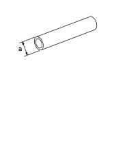
KV381054S0 |
● Removing differential side bearing outer race |
|
|
(J-34286) |
● Removing idler gear bearing outer race |
|
|
Puller |
||
|
a: 250 mm (9.84 in) |
||
|
b: 160 mm (6.30 in) |
||
|
NT414 |
||
|
ST33400001 |
● Installing differential side oil seal |
|
|
(J-26082) |
● Installing oil pump housing oil seal |
|
|
Drift |
||
|
a: 60 mm (2.36 in) dia. |
||
|
b: 47 mm (1.85 in) dia. |
||
|
NT086 |
||
|
KV40100621 |
Installing differential side oil seal (With AWD models) |
|
|
(J-25273) |
a: 60 mm (2.36 in) dia. |
|
|
Drift |
b: 47 mm (1.85 in) dia. |
|
NT086 |
|
|
ST2505S001 |
Measuring line pressure |
|
(J-34301) |
|
|
Oil pressure gauge set |
1.ST25051001 (J-34301)
Oil pressure gauge
2.ST25052000 (J-34301) Hose
3.ST25053000 (J-25695-3) Joint pipe
|
4. ST25054000 |
NT097 |
|
(J-25695-4) |
|
|
Adapter |
|
|
5. ST25055000 |
|
|
(J-25695-5) |
|
|
Adapter |
|
|
ST27180001 |
Removing idler gear |
|
(J-25726-A) |
a: 100 mm (3.94 in) |
|
Puller |
b: 110 mm (4.33 in) |
|
c: M8 x 1.25P |
|
|
NT424 |
|
Revision: 2006 July |
AT-10 |
2006 X-Trail |
![]()
|
PREPARATION |
|||||
|
Tool number |
|||||
|
(Kent-Moore No.) |
Description |
||||
|
Tool name |
|||||
|
ST23540000 |
Removing and installing parking rod plate and |
||||
|
(J-25689-A) |
manual plate retaining pins |
||||
|
Pin punch |
a: 2.3 mm (0.091 in) dia. |
||||
|
b: 4 mm (0.16 in) dia. |
|||||
|
NT442 |
|||||
|
ST25710000 |
Aligning groove of manual shaft and hole of |
||||
|
(J-25689-A) |
transaxle case |
||||
|
Pin punch |
a: 2 mm (0.08 in) dia. |
||||
|
NT410 |
|||||
|
KV32101000 |
● Installing manual shaft retaining pin |
||||
|
(J-25689-A) |
● Removing and installing pinion mate shaft lock pin |
||||
|
Pin punch |
|||||
|
a: 4 mm (0.16 in) dia. |
|||||
|
NT410 |
|||||
|
KV31102400 |
Removing and installing clutch return springs |
||||
|
(J-34285) |
a: 320 mm (12.60 in) |
||||
|
Clutch spring compressor |
b: 174 mm (6.85 in) |
||||
|
NT423 |
|||||
|
KV40100630 |
● Installing reduction pinion gear bearing inner race |
||||
|
(J-26092) |
● Installing idler gear bearing inner race |
||||
|
Drift |
|||||
|
a: 67.5 mm (2.657 in) dia. |
|||||
|
b: 44 mm (1.73 in) dia. |
|||||
|
c: 38.5 mm (1.516 in) dia. |
|||||
|
NT107 |
|||||
|
ST30720000 |
Installing idler gear bearing outer race |
||||
|
(J-25405) |
a: 77 mm (3.03 in) dia. |
||||
|
Bearing installer |
b: 55.5 mm (2.185 in) dia. |
||||
|
NT115 |
|||||
|
ST35321000 |
Installing output shaft bearing |
||||
|
( |
— |
) |
a: 49 mm (1.93 in) dia. |
||
|
Drift |
b: 41 mm (1.61 in) dia. |
||||
|
NT073 |
|||||
A
B
AT
D
E
F
G
H
I
J
K
L
M
|
Revision: 2006 July |
AT-11 |
2006 X-Trail |

|
PREPARATION |
|||||
|
Tool number |
|||||
|
(Kent-Moore No.) |
Description |
||||
|
Tool name |
|||||
|
ST33230000 |
Installing differential side bearing inner race |
||||
|
(J-25805-01) |
a: 51 mm (2.01 in) dia. |
||||
|
Drift |
b: 28.5 mm (1.122 in) dia. |
||||
|
NT084 |
|||||
|
ST33220000 |
Selecting differential side bearing adjusting shim |
||||
|
( |
— |
) |
a: 37 mm (1.46 in) dia. |
||
|
Drift |
b: 31 mm (1.22 in) dia. |
||||
|
c: 22 mm (0.87 in) dia. |
|||||
|
NT085 |
|||||
|
ST3306S001 |
Removing differential side bearing inner race |
||||
|
(J-22888-D) |
a: 38 mm (1.50 in) dia. |
||||
|
Differential side bearing |
b: 28.5 mm (1.122 in) dia. |
||||
|
puller set |
c: 130 mm (5.12 in) |
||||
|
1. ST33051001 |
d: 135 mm (5.31 in) |
||||
|
e: 100 mm (3.94 in) |
|||||
|
(J-22888-D) |
|||||
|
Puller |
|||||
|
2. ST33061000 |
|||||
|
(J-8107-2) |
AMT153 |
||||
|
Adapter |
|||||
|
ST3127S000 |
● Checking final drive assembly turning torque |
||||
|
(J-25765-A) |
● Checking reduction pinion gear turning torque |
||||
|
Preload gauge |
|||||
1.GG91030000 (J-25765-A) Torque wrench
2.HT62940000 ( — )
Socket adapter
|
NT124 |
||
|
3. HT62900000 |
||
|
( |
— |
) |
|
Socket adapter |
||
|
ST35271000 |
Installing idler gear |
|
|
(J-26091) |
a: 72 mm (2.83 in) dia. |
|
|
Drift |
b: 63 mm (2.48 in) dia. |
NT115
|
Revision: 2006 July |
AT-12 |
2006 X-Trail |

|
PREPARATION |
||
|
Tool number |
||
|
(Kent-Moore No.) |
Description |
|
|
Tool name |
||
|
KV38107700 |
Selecting differential side bearing adjusting shim |
|
|
(J-39713) |
||
|
Preload adapter |
|
NT087 |
||
|
KV38105210 |
● Selecting differential side bearing adjusting shim |
|
|
(J-39883) |
● Checking fluid drive assembly turning torque |
|
|
Preload adapter |
||
NT075
A
B
AT
D
E
F
G
H
I
J
K
L
M
|
Revision: 2006 July |
AT-13 |
2006 X-Trail |

|
PREPARATION |
||
Commercial Service Tools |
ACS007QR |
|
|
Tool name |
Description |
|
|
Power tool |
Loosening bolts and nuts |
|
|
PBIC0190E |
||
|
Puller |
Removing idler gear bearing inner race |
|
|
NT077 |
||
|
Puller |
Removing reduction pinion gear bearing inner |
|
|
race |
||
|
a: 60 mm (2.36 in) dia. |
||
|
b: 35 mm (1.38 in) dia. |
||
|
NT411 |
||
|
Drift |
Installing radial needle bearing on bearing |
|
|
retainer |
||
|
a: 36 mm (1.42 in) dia. |
||
|
NT083 |
||
|
Drift |
Installing manual shaft oil seal |
|
|
a: 22 mm (0.87 in) dia. |
||
|
NT083 |
||
|
Drift |
Removing radial needle bearing from bearing |
|
|
retainer |
||
|
a: 33.5 mm (1.319 in) dia. |
||
|
NT083 |
||
|
Revision: 2006 July |
AT-14 |
2006 X-Trail |
|
PREPARATION |
||||
|
Tool name |
Description |
A |
||
|
Drift |
Installing differential side bearing outer race |
|||
|
(RH side) |
||||
|
a: 75 mm (2.95 in) dia. |
B |
|||
|
NT083 |
AT |
|||
|
Drift |
Installing differential side bearing outer race |
|||
|
(LH side) |
D |
|||
|
a: 100 mm (3.94 in) dia. |
||||
|
E |
||||
|
NT083 |
||||
|
F |
||||
|
G |
||||
|
H |
||||
|
I |
||||
|
J |
||||
|
K |
||||
|
L |
||||
|
M |
|
Revision: 2006 July |
AT-15 |
2006 X-Trail |

A/T FLUID
A/T FLUID
Checking A/T Fluid
1.Warm up engine.
2.Check for A/T fluid leakage.
3.Before driving, A/T fluid level can be checked at A/T fluid temperatures of 30 to 50° C (86 to 122° F) using “COLD” range on A/ T fluid level gauge.
a.Park vehicle on level surface and set parking brake.
b.Start engine and move selector lever through each gear position. Leave selector lever in “P” position.
c.Check A/T fluid level with engine idling.
d.Remove A/T fluid level gauge and note reading. If level is at low side of either range, and A/T fluid to the A/T fluid charging pipe.
CAUTION:
When wiping away the A/T fluid level gauge, always use lint-free paper, not a cloth one.
e.Re-insert A/T fluid level gauge into A/T fluid charging pipe as far as it will go.
CAUTION:
Firmly fix the A/T fluid level gauge to the A/T fluid charging pipe using a stopper attached.
f.Remove A/T fluid level gauge and note reading. If reading is at low side of range, add ATF to the A/T fluid charging pipe.
CAUTION:
Do not overfill.
PFP:KLE40
ACS007QS
SCIA3451E
SMA051D
4.Drive vehicle for approximately 5 minutes in urban areas.
5.Recheck A/T fluid level at A/T fluid temperatures of 50 to 80° C (122 to 176° F) using “HOT” range on A/T fluid level gauge.
CAUTION:
●When wiping away the A/T fluid level gauge, always use lint-free paper, not a cloth one.
●Firmly fix the A/T fluid level gauge to the A/T fluid charging pipe using a stopper attached.
6.Check A/T fluid condition.
●If ATF is very dark or smells burned, checking operation of A/ T. Flush cooling system after repair of A/T.
●If ATF contains frictional material (clutches, bands, etc.), replace radiator and flush cooler line using cleaning solvent and compressed air after repair of A/T. Refer to CO-11, «RADIATOR» , CO-14, «RADIATOR (ALUMINUM TYPE)» .
7.Install the removed A/T fluid level gauge in the A/T fluid charging pipe.
CAUTION:
SAT638A
Firmly fix the A/T fluid level gauge to the A/T fluid charging pipe using a stopper attached.
|
Revision: 2006 July |
AT-16 |
2006 X-Trail |
A/T FLUID
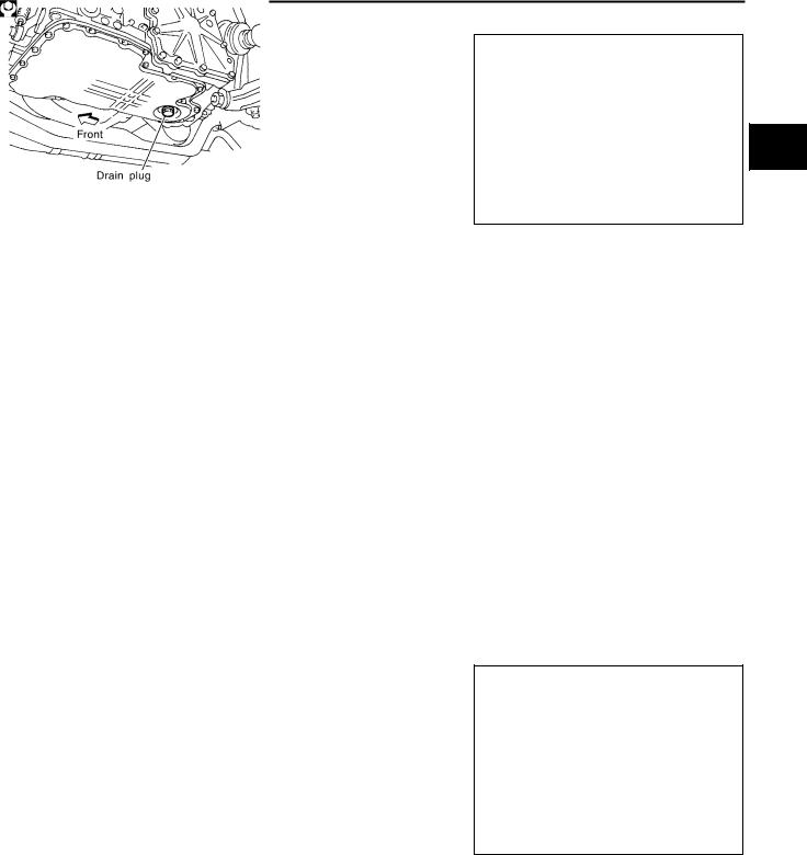
Changing A/T Fluid
1.Warm up ATF.
2.Stop engine.
3.Drain ATF from drain hole and refill with new ATF. Always refill same volume with drained fluid.
CAUTION:
Do not reuse drain plug gasket.
Fluid grade:
NISSAN Automatic Transmission Fluid (ATF),
DEXRONTM III/MERCONTM , or equivalent ATF. Refer to MA-10, «RECOMMENDED FLUIDS AND LUBRICANTS» .
Fluid capacity (With torque converter):
Approx. 8.5 (9 US qt, 7-1/2 lmp qt)
Drain plug
:34 N·m (3.5 kg-m, 25 ft-lb)
4.Run engine at idle speed for 5 minutes.
5.Check A/T fluid level and condition. Refer to AT-16, «Checking A/T Fluid» . If ATF is still dirty, repeat steps 2 through 5.
A/T Fluid Cooler Cleaning |
ACS008HQ |
Whenever an A/T is repaired, overhauled, or replaced, the A/T fluid cooler mounted in the radiator must be inspected and cleaned.
Metal debris and friction material, if present, can become trapped in the A/T fluid cooler. This debris can contaminate the newly serviced A/T or, in severe cases, can block or restrict the flow of ATF. In either case, malfunction of the newly serviced A/T may result.
Debris, if present, may build up as ATF enters the cooler inlet. It will be necessary to back flush the cooler through the cooler outlet in order to flush out any built up debris.
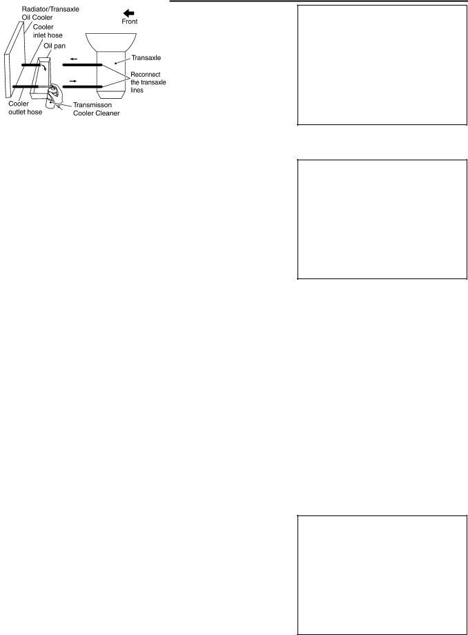
A/T FLUID COOLER CLEANING PROCEDURE
1.Position an oil pan under the A/T inlet and outlet cooler hoses.
2.Identify the inlet and outlet fluid cooler hoses.
3.Disconnect the A/T fluid cooler inlet and outlet rubber hoses from the steel cooler tubes or bypass valve.
NOTE:
Replace the cooler hoses if rubber material from the hose remains on the tube fitting.
4.Allow any ATF that remains in the cooler hoses to drain into the oil pan.
SCIA5628E
A
B
AT
D
E
F
G
H
I
J
K
L
M
|
Revision: 2006 July |
AT-17 |
2006 X-Trail |
A/T FLUID
5.Insert the extension adapter hose of a can of Transmission Cooler Cleaner (Nissan P/N 999MP-AM006) into the cooler outlet hose.
CAUTION:
●Wear safety glasses and rubber gloves when spraying the Transmission Cooler Cleaner.
●Spray Transmission Cooler Cleaner only with adequate ventilation.
●Avoid contact with eyes and skin.
●Do not breath vapors or spray mist.
SCIA5629E
6.Hold the hose and can as high as possible and spray Transmis-
sion Cooler Cleaner in a continuous stream into the cooler outlet hose until ATF flows out of the cooler inlet hose for 5 seconds.
7.Insert the tip of an air gun into the end of the cooler outlet hose.
8.Wrap a shop rag around the air gun tip and of the cooler outlet hose.
SCIA5630E
9.Blow compressed air regulated to 5 — 9 kg/cm2 (70 — 130 psi) through the cooler outlet hose for 10 seconds to force out any remaining ATF.
10.Repeat steps 5 through 9 three additional times.
11.Position an oil pan under the banjo bolts that connect the A/T fluid cooler steel lines to the A/T.
12.Remove the banjo bolts.
13.Flush each steel line from the cooler side back toward the A/T by spraying Transmission Cooler Cleaner in a continuous stream for 5 seconds.
14.Blow compressed air regulated to 5 — 9 kg/cm2 (70 — 130 psi) through each steel line from the cooler side back toward the A/T for 10 seconds to force out any remaining ATF.
15.Ensure all debris is removed from the steel cooler lines.
16.Ensure all debris is removed from the banjo bolts and fittings.
17.Perform AT-18, «A/T FLUID COOLER DIAGNOSIS PROCEDURE» .
A/T FLUID COOLER DIAGNOSIS PROCEDURE
NOTE:
Insufficient cleaning of the cooler inlet hose exterior may lead to inaccurate debris identification.
1.Position an oil pan under the A/T inlet and outlet cooler hoses.
2.Clean the exterior and tip of the cooler inlet hose.
3.Insert the extension adapter hose of a can of Transmission Cooler Cleaner (Nissan P/N 999MP-AM006) into the cooler outlet hose.
CAUTION:
●Wear safety glasses and rubber gloves when spraying the Transmission Cooler Cleaner.
●Spray Transmission Cooler Cleaner only with adequate ventilation.
●Avoid contact with eyes and skin.
●Do not breath vapors or spray mist.
SCIA5629E
|
Revision: 2006 July |
AT-18 |
2006 X-Trail |

A/T FLUID
4.Hold the hose and can as high as possible and spray Transmission Cooler Cleaner in a continuous
|
stream into the cooler outlet hose until ATF flows out of the cooler inlet hose for 5 seconds. |
A |
||
|
5. Tie a common white, basket-type coffee filter to the end of the |
|||
|
cooler inlet hose. |
|||
|
B |
|||
|
AT |
|||
|
D |
SCIA5631E
6.Insert the tip of an air gun into the end of the cooler outlet hose.
7.Wrap a shop rag around the air gun tip and end of cooler outlet hose.
8.Blow compressed air regulated to 5 — 9 kg/cm2 (70 — 130 psi) through the cooler outlet hose to force any remaining ATF into the coffee filter.
9.Remove the coffee filter from the end of the cooler inlet hose.
10.Perform AT-19, «A/T FLUID COOLER INSPECTION PROCEDURE» .
A/T FLUID COOLER INSPECTION PROCEDURE
1.Inspect the coffee filter for debris.
a.If small metal debris less than 1mm (0.040 in) in size or metal powder is found in the coffee filter, this is normal. If normal debris is found, the A/T fluid cooler/radiator can be re-used and the procedure is ended.
b.If one or more pieces of debris are found that are over 1mm (0.040 in) in size and/or peeled clutch facing material is found in the coffee filter, the A/T fluid cooler is not serviceable. The A/T fluid cooler/radiator must be replaced and the inspection procedure is ended. Refer to CO-11, «RADIATOR» .
SCIA5659E
A/T FLUID COOLER FINAL INSPECTION
After performing all procedures, ensure that all remaining oil is cleaned from all components.
|
Revision: 2006 July |
AT-19 |
2006 X-Trail |
A/T CONTROL SYSTEM
A/T CONTROL SYSTEM
Cross-sectional View
SCIA4112E
|
1. |
Band servo piston assembly |
2. |
Reverse clutch drum |
3. |
Converter housing |
|
4. |
Oil pump |
5. |
Brake band |
6. |
Reverse clutch |
|
7. |
High clutch |
8. |
Front planetary gear |
9. |
Low one-way clutch |
|
10. |
Rear planetary gear |
11. |
Forward clutch |
12. |
Overrun clutch |
|
13. |
Low & reverse brake |
14. |
Output gear |
15. |
Idler gear |
|
16. |
Forward one-way clutch |
17. |
Reduction pinion gear |
18. |
Final gear |
|
19. |
Differential case |
20. |
Input shaft |
21. |
Torque converter |
|
22. |
Side cover |
23. |
Transaxle case |
|
Revision: 2006 July |
AT-20 |
2006 X-Trail |
![]()
A/T CONTROL SYSTEM
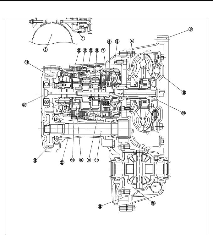
CONSTRUCTION
SAT998I
|
1. |
Torque converter |
2. |
Oil pump |
3. |
Input shaft |
|
4. |
Brake band |
5. |
Reverse clutch |
6. |
High clutch |
|
7. |
Front sun gear |
8. |
Front pinion gear |
9. |
Front internal gear |
|
10. |
Front planetary carrier |
11. |
Rear sun gear |
12. |
Rear pinion gear |
|
13. |
Rear internal gear |
14. |
Rear planetary carrier |
15. |
Forward clutch |
|
16. |
Forward one-way clutch |
17. |
Overrun clutch |
18. |
Low one-way clutch |
|
19. |
Low & reverse brake |
20. |
Parking pawl |
21. |
Parking gear |
|
22. |
Output shaft |
23. |
Idler gear |
24. |
Output gear |
FUNCTION OF CLUTCH AND BRAKE
|
Clutch and brake components |
Abbr. |
Function |
||
|
5 |
Reverse clutch |
R/C |
To transmit input power to front sun gear 7 . |
|
|
6 |
High clutch |
H/C |
To transmit input power to front planetary carrier 10 . |
|
|
15 |
Forward clutch |
F/C |
To connect front planetary carrier 10 with forward one-way clutch 16 . |
|
|
17 |
Overrun clutch |
O/C |
To connect front planetary carrier 10 with rear internal gear 13 . |
|
|
4 |
Brake band |
B/B |
To lock front sun gear 7 . |
|
|
16 |
Forward one-way clutch |
F/O.C |
When forward clutch 15 is engaged, to stop rear internal gear 13 from rotating |
|
|
in opposite direction against engine revolution. |
||||
|
18 |
Low one-way clutch |
L/O.C |
To stop front planetary carrier 10 from rotating in opposite direction against |
|
|
engine revolution. |
||||
|
19 |
Low & reverse brake |
L & R/B |
To lock front planetary carrier 10 . |
|
A
B
AT
D
E
F
G
H
I
J
K
L
M
|
Revision: 2006 July |
AT-21 |
2006 X-Trail |

A/T CONTROL SYSTEM
CLUTCH AND BAND CHART
|
Band servo |
||||||||||||||||||
|
Shift posi- |
R/C |
H/C |
F/C |
O/C |
F/O.C |
L/O.C |
L&R/B |
Lock- |
||||||||||
|
2nd |
3rd |
4th |
Remarks |
|||||||||||||||
|
tion |
5 |
6 |
15 |
17 |
16 |
18 |
19 |
up |
||||||||||
|
releas |
||||||||||||||||||
|
apply |
apply |
|||||||||||||||||
|
e |
||||||||||||||||||
|
P |
PARK |
|||||||||||||||||
|
POSITION |
||||||||||||||||||
|
R |
REVERSE |
|||||||||||||||||
|
POSITION |
||||||||||||||||||
|
N |
NEUTRAL |
|||||||||||||||||
|
POSITION |
||||||||||||||||||
|
Automatic |
||||||||||||||||||
|
D*4 |
1st |
*1D |
B |
B |
shift |
|||||||||||||
|
1 |
2 |
3 |
||||||||||||||||
|
4 |
||||||||||||||||||
|
2nd |
*1A |
B |
||||||||||||||||
|
3rd |
*1A |
*2C |
C |
B |
*1 |
|||||||||||||
|
4th |
C |
*3C |
C |
|||||||||||||||
|
1st |
B |
B |
Automatic |
|||||||||||||||
|
2 |
||||||||||||||||||
|
2nd |
B |
shift |
||||||||||||||||
|
1 |
2 |
3 |
||||||||||||||||
|
3rd |
*2C |
C |
B |
|||||||||||||||
|
1st |
B |
B |
Locks (held |
|||||||||||||||
|
1 |
stationary) |
|||||||||||||||||
|
2nd |
B |
|||||||||||||||||
|
in 1st speed |
||||||||||||||||||
|
3rd |
*2C |
C |
B |
1 |
2 |
3 |
||||||||||||
●*1: Operates when OD OFF. (OD OFF indicator lamp is on.)
●*2: Oil pressure is applied to both 2nd “apply” side and 3rd “release” side of band servo piston. However, brake band does notcontract because oil pressure area on the “release” side is greater than that on the “apply” side.
●*3: Oil pressure is applied to 4th “apply” side in condition *2 above, and brake band contracts.
●*4: A/T will not shift to 4th when OD OFF. (OD OFF indicator lamp is on.)
● : Operates.
●A: Operates when throttle opening is less than 3/16, activating engine brake.
●B: Operates during “progressive” acceleration.
●C: Operates but does not affect power transmission.
●D: Operates when throttle opening is less than 3/16, but does not affect engine brake.
|
Revision: 2006 July |
AT-22 |
2006 X-Trail |

A/T CONTROL SYSTEM
POWER TRANSMISSION |
|
“N” and “P” Positions |
A |
●“N” position
Power from the input shaft is not transmitted to the output shaft because the clutches do not operate.
|
● “P” position |
B |
|
|
Similar to the “N” position, the clutches do not operate. The parking pawl engages with the parking gear to |
||
|
mechanically hold the output shaft so that the power train is locked. |
||
AT
D
E
F
G
H
SAT991I
I
J
K
L
M
|
Revision: 2006 July |
AT-23 |
2006 X-Trail |
|
A/T CONTROL SYSTEM |
||
|
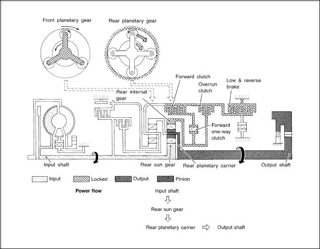
“11 ” Position |
||
|
● Forward clutch |
As overrun clutch engages, rear internal gear is locked by the operation of low and |
|
|
● Forward one-way clutch |
reverse brake. |
|
|
This is different from that of D1 and 21 . |
||
|
● Overrun clutch |
||
|
● Low & reverse brake |
||
|
Engine brake |
Overrun clutch always engages, therefore engine brake can be obtained when deceler- |
|
|
ating. |
||
SCIA1816E
|
Revision: 2006 July |
AT-24 |
2006 X-Trail |
|
A/T CONTROL SYSTEM |
||
|
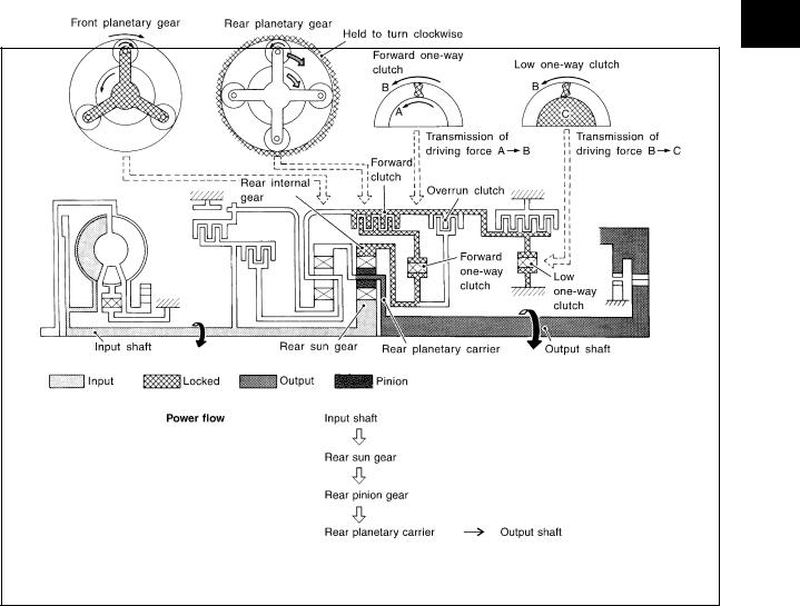
“D1 ” and “21 ” Positions |
||
|
● Forward one-way clutch |
Rear internal gear is locked to rotate counterclockwise because of the functioning of |
|
|
● Forward clutch |
these three clutches. |
|
|
● Low one-way clutch |
||
|
Overrun clutch |
D1 : OD OFF (OD OFF indicator lamp is on) and throttle opening is less than 3/16 |
|
|
21 : Always engaged |
||
|
engagement conditions |
||
|
At D1 and 21 positions, engine brake is not activated due to free turning of low one- |
||
|
(Engine brake) |
||
|
way clutch. |
||
SAT377J
A
B
AT
D
E
F
G
H
I
J
K
L
M
|
Revision: 2006 July |
AT-25 |
2006 X-Trail |

|
A/T CONTROL SYSTEM |
||
|
“D2 ”, “22 ” and “12 ” Positions |
||
|
● Forward clutch |
Rear sun gear drives rear planetary carrier and combined front internal gear. Front internal gear now |
|
|
● Forward one-way |
rotates around front sun gear accompanying front planetary carrier. |
|
|
As front planetary carrier transfers the power to rear internal gear through forward clutch and forward one- |
||
|
clutch |
||
|
way clutch, this rotation of rear internal gear increases the speed of rear planetary carrier compared with |
||
|
● Brake band |
||
|
that of the 1st speed. |
||
|
Overrun clutch |
D2 : OD OFF (OD OFF indicator lamp is on) and throttle opening is less than 3/16 |
|
|
engagement conditions |
22 and 12 : Always engaged |
|
SAT378J
|
Revision: 2006 July |
AT-26 |
2006 X-Trail |
|
A/T CONTROL SYSTEM |
||
|
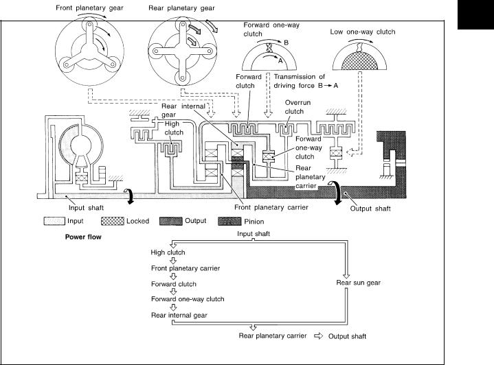
“D3 ”, “23 ” and “13 ” Positions |
||
|
● High clutch |
Input power is transmitted to front planetary carrier through high clutch. And front planetary carrier is con- |
|
|
● Forward clutch |
nected to rear internal gear by operation of forward clutch and forward one-way clutch. |
|
|
This rear internal gear rotation and another input (the rear sun gear) accompany rear planetary carrier to |
||
|
● Forward one-way |
||
|
turn at the same speed. |
||
|
clutch |
||
|
Overrun clutch |
D3 : OD OFF (OD OFF indicator lamp is on) and throttle opening is less than 3/16 |
|
|
engagement conditions |
23 and 13 : Always engaged |
|
SCIA7229E
A
B
AT
D
E
F
G
H
I
J
K
L
M
|
Revision: 2006 July |
AT-27 |
2006 X-Trail |
|
A/T CONTROL SYSTEM |
||
|
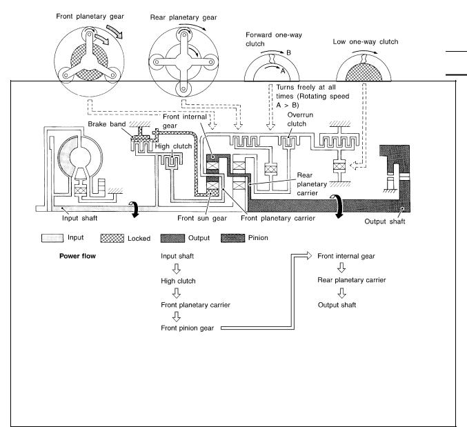
“D4 ” (OD) Position |
||
|
● High clutch |
Input power is transmitted to front carrier through high clutch. |
|
|
● Brake band |
This front carrier turns around the sun gear which is fixed by brake band and makes |
|
|
front internal gear (output) turn faster. |
||
●Forward clutch (Does not affect power transmission)
Engine brake
At D4 position, there is no one-way clutch in the power transaxle line and engine brake can be obtained when decelerating.
SAT380J
|
Revision: 2006 July |
AT-28 |
2006 X-Trail |
A/T CONTROL SYSTEM
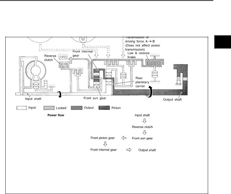
“R” Position
|
● Reverse clutch |
Front planetary carrier is stationary because of the operation of low and reverse brake. |
|
|
● Low & reverse brake |
Input power is transmitted to front sun gear through reverse clutch, which drives front |
|
|
internal gear in the opposite direction. |
||
|
Engine brake |
As there is no one-way clutch in the power transaxle line, engine brake can be |
|
|
obtained when decelerating. |
||
SAT381J
A
B
AT
D
E
F
G
H
I
J
K
L
M
|
Revision: 2006 July |
AT-29 |
2006 X-Trail |

A/T CONTROL SYSTEM
The function of the TCM is to:
●Receive input signals sent from various switches and sensors.
●Determine required line pressure, shifting point, lock-up operation, and engine brake operation.
●Send required output signals to the respective solenoids.
CONTROL SYSTEM OUTLINE
The automatic transmission senses vehicle operating conditions through various sensors or signals. It always controls the optimum shift position and reduces shifting and lock-up shocks.
|
SWITCHES & SENSORS |
TCM |
ACTUATORS |
||
|
PNP switch |
Shift control |
|||
|
Accelerator pedal position signal |
Line pressure control |
Shift solenoid valve A |
||
|
Closed throttle position signal |
Lock-up control |
|||
|
Shift solenoid valve B |
||||
|
Wide open throttle position signal |
Overrun clutch control |
|||
|
Overrun clutch solenoid valve |
||||
|
Engine speed signal |
Timing control |
|||
|
Torque converter clutch solenoid |
||||
|
A/T fluid temperature sensor |
Fail-safe control |
|||
|
valve |
||||
|
Revolution sensor |
Self-diagnosis |
|||
|
Line pressure solenoid valve |
||||
|
Vehicle speed sensor |
CONSULT-II communication line |
|||
|
OD OFF indicator lamp |
||||
|
Overdrive control switch signal |
control |
|||
|
Stop lamp switch signal |
Duet-EU control |
|||
CONTROL SYSTEM DIAGRAM
SCIA7349E
|
Revision: 2006 July |
AT-30 |
2006 X-Trail |
![]()
A/T CONTROL SYSTEM
CAN Communication |
ACS007JK |
SYSTEM DESCRIPTION
CAN (Controller Area Network) is a serial communication line for real time application. It is an on-vehicle multiplex communication line with high data communication speed and excellent error detection ability. Many electronic control units are equipped onto a vehicle, and each control unit shares information and links with other control units during operation (not independent). In CAN communication, control units are connected with 2 communication lines (CAN H line, CAN L line) allowing a high rate of information transmission with less wiring. Each control unit transmits/receives data but selectively reads required data only. For details, refer to LAN-21, «CAN Communication Unit» .
Input/Output Signal of TCM |
ACS007JL |
||||||||||
|
Line |
Vehicle |
Shift |
Lock-up |
Engine |
Fail-safe |
Self-diag- |
|||||
|
Control item |
pressure |
speed |
brake |
function |
nostics |
||||||
|
control |
control |
||||||||||
|
control |
control |
control |
(*3) |
function |
|||||||
|
Accelerator pedal position signal |
X |
X |
X |
X |
X |
X |
X |
||||
|
Vehicle speed sensor-A/T |
X |
X |
X |
X |
X |
X |
|||||
|
(Revolution sensor) |
|||||||||||
|
Vehicle speed sensor-MTR(*1) |
X |
X |
X |
X |
X |
||||||
|
Closed throttle position signal(*5) |
(*2) |
X |
(*2) |
X |
X |
(*4) |
X |
||||
|
Input |
Wide open throttle position signal(*5) |
(*2) |
X |
(*2) |
X |
(*4) |
X |
||||
|
Engine speed signal |
X |
X |
|||||||||
|
PNP switch |
X |
X |
X |
X |
X |
X |
(*4) |
X |
|||
|
Stop lamp switch signal(*5) |
X |
X |
X |
(*4) |
X |
||||||
|
A/T fluid temperature sensors |
X |
X |
X |
X |
X |
||||||
|
TCM power supply voltage signal |
X |
X |
|||||||||
|
Shift solenoid valve A/B |
X |
X |
X |
||||||||
|
Line pressure solenoid |
X |
X |
X |
||||||||
|
Out- |
Torque converter clutch solenoid |
X |
X |
X |
|||||||
|
put |
valve |
||||||||||
|
Overrun clutch solenoid valve |
X |
X |
X |
X |
|||||||
|
OD OFF indicator lamp signal(*6) |
X |
*1: Spare for vehicle speed sensor·A/T (revolution sensor) *2: Spare for accelerator pedal position signal
*3: If these input and output signals are different, the TCM triggers the fail-safe function.
*4: Used as a condition for starting self-diagnostics; if self-diagnostics are not started, it is judged that there is some kind of error. *5: Input by CAN communications.
*6: Output by CAN communications.
|
Revision: 2006 July |
AT-31 |
2006 X-Trail |

A/T CONTROL SYSTEM
Line Pressure Control |
ACS007JM |
●TCM has various line pressure control characteristics to match the driving conditions.
●An ON-OFF duty signal is sent to the line pressure solenoid valve based on TCM characteristics.
●Hydraulic pressure on the clutch and brake is electronically controlled through the line pressure solenoid valve to accommodate engine torque. This results in smooth shift operation.
NORMAL CONTROL
The characteristics of line pressure to throttle opening.
SAT003J
BACK-UP CONTROL (ENGINE BRAKE)
If the selector lever is shifted to “2” position while driving in D4 , D3 great driving force is applied to the clutch inside the transaxle. Clutch operating pressure (line pressure) must be increased to deal with this driving force.
SAT004J
DURING SHIFT CHANGE
The line pressure is temporarily reduced corresponding to a change in engine torque when shifting gears (that is, when the shift solenoid valve is switched for clutch operation) to reduce shifting shock.
SCIA4828E
|
Revision: 2006 July |
AT-32 |
2006 X-Trail |

A/T CONTROL SYSTEM
AT LOW FLUID TEMPERATURE
●A/T fluid viscosity and frictional characteristics of the clutch facing change with A/T fluid temperature. A Clutch engaging or band-contacting pressure is compensated for, according to A/T fluid temperature, to stabilize shifting quality.
●The line pressure is reduced below 60° C (140° F) to prevent shifting shock due to low viscosity of A/T fluid when temperature is low.
●Line pressure is increased to a maximum irrespective of the
throttle opening when A/T fluid temperature drops to − 10° C (14° F). This pressure rise is adopted to prevent a delay in clutch and brake operation due to extreme drop of A/T fluid viscosity at low temperature.
SCIA4830E
The shift is regulated entirely by electronic control to accommodate vehicle speed and varying engine operations. This is accomplished by electrical signals transmitted by the revolution sensor and the ECM (accelerator pedal position sensor). This results in improved acceleration performance and fuel economy.
CONTROL OF SHIFT SOLENOID VALVES A AND B
The TCM activates shift solenoid valves A and B according to signals from the accelerator pedal position sensor and revolution sensor to select the optimum gear position on the basis of the shift schedule memorized in the TCM.
The shift solenoid valve performs simple ON-OFF operation. When set to “ON”, the drain circuit closes and pilot pressure is applied to the shift valve.
SAT008J
RELATION BETWEEN SHIFT SOLENOID VALVES A AND B AND GEAR POSITIONS
|
Gear position |
1 |
2 |
3 |
4 |
|
Shift solenoid valve A |
ON (Closed) |
OFF (Open) |
OFF (Open) |
ON (Closed) |
|
Shift solenoid valve B |
ON (Closed) |
ON (Closed) |
OFF (Open) |
OFF (Open) |
|
Revision: 2006 July |
AT-33 |
2006 X-Trail |

A/T CONTROL SYSTEM
CONTROL OF SHIFT VALVES A AND B
SAT009J
Pilot pressure generated by the operation of shift solenoid valves A and B is applied to the end face of shift valves A and B.
The figure above shows the operation of shift valve B. When the shift solenoid valve is “ON”, pilot pressure applied to the end face of the shift valve overcomes spring force, moving the valve upward.
The torque converter clutch piston in the torque converter is locked to eliminate torque converter slip to increase power transmission efficiency. The solenoid valve is controlled by an ON-OFF duty signal sent from the TCM. The signal is converted to an oil pressure signal which controls the torque converter clutch piston.
CONDITIONS FOR LOCK-UP OPERATION
When vehicle is driven in 3rd and 4th gear positions, vehicle speed and throttle opening are detected. If the detected values fall within the lock-up zone memorized in the TCM, lock-up is performed.
|
OD |
ON |
OFF |
|
|
Selector lever |
“D” position |
||
|
Gear position |
D4 |
D3 |
|
|
Vehicle speed sensor |
More than set value |
||
|
Throttle position sensor |
Less than set opening |
||
|
Closed throttle position switch |
OFF |
||
|
A/T fluid temperature sensor |
More than 40° C (104° F) |
||
TORQUE CONVERTER CLUTCH SOLENOID VALVE CONTROL
Lock-up Control System Diagram
SCIA5623E
|
Revision: 2006 July |
AT-34 |
2006 X-Trail |

A/T CONTROL SYSTEM
Lock-up Released
●In the lock-up released state, the torque converter clutch control valve is set into the unlocked state by draining the torque converter clutch piston applying pressure and the torque converter clutch piston release pressure is generated.
In this way, the torque converter clutch piston is not coupled.
Lock-up Applied
●In the lock-up applied state, the torque converter clutch control valve is set into the locked state by generating the torque converter clutch piston applying pressure and the torque converter clutch piston release AT pressure is drained.
In this way, the torque converter clutch piston is pressed and coupled.
SMOOTH LOCK-UP CONTROL
When shifting from the lock-up released state to the lock-up applied state, the current output to the torque converter clutch solenoid is controlled with the TCM. In this way, when shifting to the lock-up applied state, the torque converter clutch is temporarily set to the half-clutched state to reduce the shock.
Half-clutched State
●The current output from the TCM to the torque converter clutch solenoid is varied to steadily increase the
torque converter clutch solenoid pressure.
In this way, the lock-up applying pressure gradually rises and while the torque converter clutch piston is put into half-clutched status, the torque converter clutch piston applying pressure is increased and the coupling is completed smoothly.
Engine Brake Control (Overrun Clutch Control) |
ACS007JP |
Forward one-way clutch is used to reduce shifting shocks in downshifting operations. This clutch transmits engine torque to the wheels. However, drive force from the wheels is not transmitted to the engine because the one-way clutch rotates idle. This means the engine brake is not effective.
The overrun clutch operates when the engine brake is needed.
OVERRUN CLUTCH OPERATING CONDITIONS
|
SCIA5658E |
|||||
|
Selector lever position |
Gear position |
Throttle opening |
|||
|
“D” position |
D1 , D2 , D3 gear position |
Less than 3/16 |
|||
|
“2” position |
12 , 22 |
gear position |
At any position |
||
|
“1” position |
1 , 12 |
gear position |
|||
|
Revision: 2006 July |
AT-35 |
2006 X-Trail |

A/T CONTROL SYSTEM
OVERRUN CLUTCH SOLENOID VALVE CONTROL
The overrun clutch solenoid valve is operated by an ON-OFF signal transmitted by the TCM to provide overrun clutch control (engine brake control).
When this solenoid valve is “ON”, the pilot pressure drain port closes. When it is “OFF”, the drain port opens.
During the solenoid valve “ON” pilot pressure is applied to the end face of the overrun clutch control valve.
SAT015J
OVERRUN CLUTCH CONTROL VALVE OPERATION
When the solenoid valve is “ON”, pilot pressure is applied to the overrun clutch control valve. This pushes up the overrun clutch control valve. The line pressure is then shut off so that the clutch does not engage.
When the solenoid valve is “OFF”, pilot pressure is not generated. At this point, the overrun clutch control valve moves downward by spring force. As a result, overrun clutch operation pressure is provided by the overrun clutch reducing valve. This causes the overrun clutch to engage.
In the “2” and “1” positions, the overrun clutch control valve remains pushed down so that the overrun clutch is engaged at all times.
SCIA5643E
|
Revision: 2006 July |
AT-36 |
2006 X-Trail |

A/T CONTROL SYSTEM
Control Valve |
ACS007JQ |
|||||
FUNCTION OF CONTROL VALVES |
||||||
|
Valve name |
Function |
|||||
|
Pressure regulator valve, plug and sleeve |
Regulates oil discharged from the oil pump to provide optimum line pressure for all driv- |
|||||
|
plug |
ing conditions. |
|||||
|
Pressure modifier valve and sleeve |
Used as a signal supplementary valve to the pressure regulator valve. Regulates pres- |
|||||
|
sure-modifier pressure (signal pressure) which controls optimum line pressure for all |
||||||
|
driving conditions. |
||||||
|
Pilot valve |
Regulates line pressure to maintain a constant pilot pressure level which controls lock-up |
|||||
|
mechanism, overrun clutch, shift timing. |
||||||
|
Accumulator control valve |
Regulates accumulator back-pressure to pressure suited to driving conditions. |
|||||
|
Manual valve |
Directs line pressure to oil circuits corresponding to select positions. |
|||||
|
Hydraulic pressure drains when the shift lever is in Neutral. |
||||||
|
Shift valve A |
Simultaneously switches three oil circuits using output pressure of shift solenoid valve A |
|||||
|
to meet driving conditions (vehicle speed, throttle opening, etc.). |
||||||
|
Provides automatic downshifting and upshifting (1st → |
2nd → |
3rd → |
4th gears/4th → |
|||
|
3rd → |
2nd → |
1st gears) in combination with shift valve B. |
||||
|
Shift valve B |
Simultaneously switches two oil circuits using output pressure of shift solenoid valve B in |
|||||
|
relation to driving conditions (vehicle speed, throttle opening, etc.). |
||||||
|
Provides automatic downshifting and upshifting (1st → |
2nd → |
3rd → |
4th gears/4th → |
|||
|
3rd → |
2nd → |
1st gears) in combination with shift valve A. |
||||
|
Overrun clutch control valve |
Switches hydraulic circuits to prevent engagement of the overrun clutch simultaneously |
|||||
|
with application of the brake band in D4 . (Interlocking occurs if the overrun clutch |
||||||
|
engages during D4 .) |
||||||
|
1st reducing valve |
Reduces low & reverse brake pressure to dampen engine-brake shock when downshift- |
|||||
|
ing from the 1st position 12 to 11 . |
||||||
|
Overrun clutch reducing valve |
Reduces oil pressure directed to the overrun clutch and prevents engine-brake shock. |
|||||
|
In the 1st and 2nd positions, line pressure acts on the overrun clutch reducing valve to |
||||||
|
increase the pressure-regulating point, with resultant engine brake capability. |
||||||
|
Torque converter relief valve |
Prevents an excessive rise in torque converter pressure. |
|||||
|
Torque converter clutch control valve, plug |
Activates or inactivates the lock-up function. |
|||||
|
and sleeve |
Also provides smooth lock-up through transient application and release of the lock-up |
|||||
|
system. |
||||||
|
1-2 accumulator valve and piston |
Lessens the shock find when the 2nd gear band servo contracts, and provides smooth |
|||||
|
shifting. |
||||||
|
3-2 timing valve |
Switches the pace that oil pressure is released depending on vehicle speed; maximizes |
|||||
|
the high clutch release timing, and allows for soft downshifting. |
||||||
|
Shuttle valve |
Determines if the overrun clutch solenoid valve should control the 3-2 timing valve or the |
|||||
|
overrun clutch control valve and switches between the two. |
||||||
|
Cooler check valve |
At low speeds and with a small load when a little heat is generated, saves the volume of |
|||||
|
cooler flow, and stores the oil pressure for lock-up. |
||||||
A
B
AT
D
E
F
G
H
I
J
K
L
M
|
Revision: 2006 July |
AT-37 |
2006 X-Trail |

ON BOARD DIAGNOSTIC (OBD) SYSTEM
ON BOARD DIAGNOSTIC (OBD) SYSTEM
Introduction
A/T system has two self-diagnostic systems.
The first is emission-related on board diagnostic system (OBD-II) performed by the TCM in combination with the ECM. The malfunction is indicated by the MIL (malfunction indicator lamp) and is stored as a DTC in the ECM memory but not the TCM memory.
The second is the TCM original self-diagnosis indicated by the OD OFF indicator lamp. The malfunction is stored in the TCM memory. The detected items are overlapped with OBD-II self-diagnostic items. For detail, refer to AT-81, «SELF-DIAGNOSTIC RESULT MODE» .
OBD-II Function for A/T System |
ACS007QV |
The ECM provides emission-related on board diagnostic (OBD-II) functions for the A/T system. One function is to receive a signal from the TCM used with OBD-related parts of the A/T system. The signal is sent to the ECM when a malfunction occurs in the corresponding OBD-related part. The other function is to indicate a diagnostic result by means of the MIL (malfunction indicator lamp) on the instrument panel. Sensors, switches and solenoid valves are used as sensing elements.
The MIL automatically illuminates in One or Two Trip Detection Logic when a malfunction is sensed in relation to A/T system parts.
One or Two Trip Detection Logic of OBD-II |
ACS007QW |
ONE TRIP DETECTION LOGIC
If a malfunction is sensed during the first test drive, the MIL will illuminate and the malfunction will be stored in the ECM memory as a DTC. The TCM is not provided with such a memory function.
TWO TRIP DETECTION LOGIC
When a malfunction is sensed during the first test drive, it is stored in the ECM memory as a 1st trip DTC (diagnostic trouble code) or 1st trip freeze frame data. At this point, the MIL will not illuminate. — 1st trip
If the same malfunction as that experienced during the first test drive is sensed during the second test drive, the MIL will illuminate. — 2nd trip
The “trip” in the “One or Two Trip Detection Logic” means a driving mode in which self-diagnosis is performed during vehicle operation.
OBD-II Diagnostic Trouble Code (DTC) |
ACS007QX |
HOW TO READ DTC AND 1ST TRIP DTC
DTC and 1st trip DTC can be read by the following methods.
( with CONSULT-II or
  GST) CONSULT-II or GST (Generic Scan Tool) Examples: P0705, P0720 etc. These DTC are prescribed by SAE J2012.
(CONSULT-II also displays the malfunctioning component or system.)
●1st trip DTC No. is the same as DTC No.
●Output of the diagnostic trouble code indicates that the indicated circuit has a malfunction. However, in case of the Mode II and GST, they do not indicate whether the malfunction is still occurring or occurred in the past and returned to normal.
CONSULT-II can identify them as shown below, therefore, CONSULT-II (if available) is recommended.
A sample of CONSULT-II display for DTC and 1st trip DTC is shown on the next page. DTC or 1st trip DTC of a malfunction is displayed in SELF-DIAGNOSTIC RESULTS mode for “ENGINE” with CON- SULT-II. Time data indicates how many times the vehicle was driven after the last detection of a DTC.
BCIA0031E
|
Revision: 2006 July |
AT-38 |
2006 X-Trail |

ON BOARD DIAGNOSTIC (OBD) SYSTEM
If the DTC is being detected currently, the time data will be “0”.
A
B
AT
SAT015K
D
If a 1st trip DTC is stored in the ECM, the time data will be “1t”.
E
F
G
SAT016K
Freeze Frame Data and 1st Trip Freeze Frame Data
The ECM has a memory function, which stores the driving condition such as fuel system status, calculated load value, engine coolant temperature, short term fuel trim, long term fuel trim, engine speed and vehicle speed at the moment the ECM detects a malfunction.
Data which are stored in the ECM memory, along with the 1st trip DTC, are called 1st trip freeze frame data, and the data, stored together with the DTC data, are called freeze frame data and displayed on CONSULT-II or GST. The 1st trip freeze frame data can only be displayed on the CONSULT-II screen, not on the GST. For detail, refer to EC-112, «CONSULT-II Function (ENGINE)» .
Only one set of freeze frame data (either 1st trip freeze frame data of freeze frame data) can be stored in the ECM. 1st trip freeze frame data is stored in the ECM memory along with the 1st trip DTC. There is no priority for 1st trip freeze frame data and it is updated each time a different 1st trip DTC is detected. However, once freeze frame data (2nd trip detection/MIL on) is stored in the ECM memory, 1st trip freeze frame data is no longer stored. Remember, only one set of freeze frame data can be stored in the ECM. The ECM has the following priorities to update the data.
|
Priority |
Items |
|||
|
1 |
Misfire — DTC: P0300 — P0306 |
|||
|
Freeze frame data |
Fuel Injection System Function — DTC: P0171, P0172, P0174, P0175 |
|||
|
2 |
Except the above items (Includes A/T related items) |
|||
|
3 |
1st trip freeze frame data |
|||
Both 1st trip freeze frame data and freeze frame data (along with the DTC) are cleared when the ECM memory is erased.
HOW TO ERASE DTC
The diagnostic trouble code can be erased by CONSULT-II, GST or ECM DIAGNOSTIC TEST MODE as described following.
●If the battery cable is disconnected, the diagnostic trouble code will be lost within 24 hours.
●When you erase the DTC, using CONSULT-II or GST is easier and quicker than switching the mode selector on the ECM.
The following emission-related diagnostic information is cleared from the ECM memory when erasing DTC related to OBD-II. For details, refer to EC-48, «Emission-Related Diagnostic Information» .
●Diagnostic trouble codes (DTC)
●1st trip diagnostic trouble codes (1st trip DTC)
●Freeze frame data
|
Revision: 2006 July |
AT-39 |
2006 X-Trail |

ON BOARD DIAGNOSTIC (OBD) SYSTEM
●1st trip freeze frame data
●System readiness test (SRT) codes
●Test values
HOW TO ERASE DTC (WITH CONSULT-II)
●If a DTC is displayed for both ECM and TCM, it is necessary to be erased for both ECM and TCM.
1.If the ignition switch stays ON after repair work, be sure to turn ignition switch OFF once. Wait at least 10 seconds and then turn it ON (engine stopped) again.
2.Turn CONSULT-II “ON” and touch “A/T”.
3.Touch “SELF-DIAG RESULTS”.
4.Touch “ERASE”. (The DTC in the TCM will be erased.) Then touch “BACK” twice.
5.Touch “ENGINE”.
6.Touch “SELF-DIAG RESULTS”.
7.Touch “ERASE”. (The DTC in the ECM will be erased.)
SCIA7155E
HOW TO ERASE DTC (WITH GST)
1.If the ignition switch stays ON after repair work, be sure to turn ignition switch OFF once. Wait at least 10 seconds and then turn it ON (engine stopped) again.
2.Perform “TCM SELF-DIAGNOSTIC PROCEDURE (No Tools)”. Refer toAT-88, «TCM SELF-DIAGNOS- TIC PROCEDURE» . (The engine warm-up step can be skipped when performing the diagnosis only to erase the DTC.)
3.Select Mode 4 with Generic Scan Tool (GST). For details, refer to EC-125, «Generic Scan Tool (GST) Function» .
|
Revision: 2006 July |
AT-40 |
2006 X-Trail |
![]()
ON BOARD DIAGNOSTIC (OBD) SYSTEM
HOW TO ERASE DTC (NO TOOLS)
The OD OFF indicator lamp is located on the combination meter.
1.If the ignition switch stays ON after repair work, be sure to turn ignition switch OFF once. Wait at least 10 seconds and then turn it ON (engine stopped) again.
2.Perform “TCM SELF-DIAGNOSTIC PROCEDURE (No Tools)”. Refer toAT-88, «TCM SELF-DIAGNOS- TIC PROCEDURE» . (The engine warm-up step can be skipped when performing the diagnosis only to erase the DTC.)
3.Perform “OBD-II SELF-DIAGNOSTIC PROCEDURE (No tools)”. Refer toEC-60, «How to Erase DTC» .
Malfunction Indicator Lamp (MIL) |
ACS007QY |
DESCRIPTION
The MIL is located on the instrument panel.
1.The MIL will light up when the ignition switch is turned ON without the engine running. This is a bulb check.
●If the MIL does not light up, refer to DI-24, «WARNING LAMPS» , or see EC-657, «MIL AND DATA LINK CONNECTOR» .
2.When the engine is started, the MIL should go off.
●If the MIL remains on, the on board diagnostic system has detected an engine system malfunction.
SEF217U
A
B
AT
D
E
F
G
H
I
J
K
L
M
|
Revision: 2006 July |
AT-41 |
2006 X-Trail |

TROUBLE DIAGNOSIS
TROUBLE DIAGNOSIS
DTC Inspection Priority Chart
If some DTCs are displayed at the same time, perform inspections one by one based on the following priority chart.
NOTE:
If DTC “CAN COMM CIRCUIT” is displayed with other DTCs, first perform the trouble diagnosis for “DTC U1000 CAN COMM CIRCUIT”. Refer to AT-92 .
|
Priority |
Detected items |
|
1 |
CAN communication line |
|
2 |
Except above |
Fail-safe |
ACS008HS |
The TCM has an electronic Fail-Safe (limp home mode). This allows the vehicle to be driven even if a major electrical input/output device circuit is damaged.
Under Fail-Safe, the vehicle always runs in third gear, even with a shift lever position of “1”, “2” or “D”. The customer may complain of sluggish or poor acceleration.
Always follow the “WORK FLOW”, refer toAT-44, «WORK FLOW» . The SELF-DIAGNOSIS results will be as follows:
●The first SELF-DIAGNOSIS will indicate damage to the vehicle speed sensor or the revolution sensor.
●During the next SELF-DIAGNOSIS, performed after checking the sensor, no damages will be indicated.
FAIL-SAFE FUNCTION
●The following fail-safe functions allow vehicles to be driven even when sensor, switch or solenoid malfunction occurs.
Vehicle Speed Sensor·A/T (Revolution Sensor)
●Vehicle speed sensor·MTR signal is input from combination meter.
Accelerator Pedal Position Sensor Signal
●If the accelerator pedal position sensor from ECM to TCM outputs an erratic signal, the control unit detects the throttle position by the closed throttle position signal and wide-open throttle position signal sent via the CAN communication from ECM.
If an unexpected signal is sent from the accelerator pedal position sensor to ECM, ECM controls engine to maintain vehicle operation.
|
Closed throttle position signal |
Wide open throttle position signal |
Throttle position |
|
– |
ON |
4/8 |
|
OFF |
OFF |
2/8 |
|
ON |
OFF |
0/8 |
|
Revision: 2006 July |
AT-42 |
2006 X-Trail |

TROUBLE DIAGNOSIS
PNP Switch
●When the multiple PNP switch signals are input to TCM, the priority of selector lever position becomes “D”, “N”, “R”, “2” and “1” in order by internal TCM determination.
The use of 4th gear is inhibited until normal operation resumes. Because the hydraulic circuit of the control valve is switched by manual valve according to the selector lever position, however, actual operating condition of vehicle becomes as follows.
|
Actual lever position |
PNP switch input signal |
Running status |
||
|
“P” |
“P” position and other position signals |
P |
||
|
“R” |
“R” position and other position signals |
R |
||
|
“N” |
“N” position and other position signals |
N |
||
|
“D” |
“D” position and other position signals |
1D D2 |
D3 D4 |
|
|
“2” |
“2” position and other position signals (Except “1” position) |
1 2 22 |
23 |
|
|
“2” position and “1” position signals |
1 2 |
22 |
||
|
“1” |
“1” position and other position signals (Except “2” position) |
1 1 12 |
13 |
|
|
“1” position and “2” position signals |
1 1 |
12 |
||
Shift Solenoid Valve A and B
●If non-standard solenoid signal is sent to TCM, use of certain gears is limited. Refer to chart shown below.
|
Normal |
Malfunction in solenoid |
Malfunction in solenoid |
Malfunction in solenoid |
||||||||||
|
Shift position |
valve A |
valve B |
valves A and B |
||||||||||
|
A |
B |
Gear |
A |
B |
Gear |
A |
B |
Gear |
A |
B |
Gear |
||
|
● |
● |
1st |
– |
●→× |
●→× |
– |
– |
– |
|||||
|
“D” position |
× |
● |
2nd |
– |
●→× |
× |
– |
– |
– |
||||
|
× |
× |
3rd |
– |
x |
× |
– |
– |
– |
|||||
|
● |
× |
4th |
– |
x |
●→× |
– |
– |
– |
|||||
|
● |
● |
1st |
– |
●→× |
3rd |
●→× |
– |
3rd |
– |
– |
3rd |
||
|
“2” position |
× |
● |
2nd |
– |
●→× |
× |
– |
– |
– |
||||
|
× |
× |
3rd |
– |
x |
× |
– |
– |
– |
|||||
|
● |
● |
1st |
– |
●→× |
●→× |
– |
– |
– |
|||||
|
“1” position |
× |
● |
2nd |
– |
●→× |
× |
– |
– |
– |
||||
|
× |
× |
3rd |
– |
x |
× |
– |
– |
– |
|||||
●: Solenoid ON
× : Solenoid OFF
–: Non-standard condition
Line Pressure Solenoid Valve
●If non-standard solenoid signal is sent to TCM, line pressure solenoid valve is turned OFF to achieve maximum oil pressure.
Torque Converter Clutch Solenoid Valve
●If non-standard solenoid signal is sent to TCM, torque converter clutch solenoid valve is turned OFF to release lock-up.
Overrun Clutch Solenoid Valve
●If non-standard solenoid signal is sent to TCM, overrun clutch solenoid valve is turned OFF to engage overrun clutch. This will result in more effective engine brake during deceleration.
|
Revision: 2006 July |
AT-43 |
2006 X-Trail |

TROUBLE DIAGNOSIS
How to Perform Trouble Diagnoses for Quick and Accurate Repair |
ACS007JT |
INTRODUCTION
The TCM receives a signal from the vehicle speed sensor, accelerator pedal position sensor or PNP switch and provides shift control or lock-up control via A/T solenoid valves.
Input and output signals must always be correct and stable in the operation of the A/T system. The A/T system must be in good operating condition and be free of valve seizure, solenoid valve malfunction, etc.
It is much more difficult to diagnose a malfunction that occurs intermittently rather than continuously. Most intermittent malfunctions are caused by poor electric connections or improper wiring. In this case, careful checking of suspected circuits may help prevent the replacement of good parts.
A visual check only, may not find the cause of the malfunctions. A road test with CONSULT-II or a circuit tester connected should be performed. Follow the AT-44, «WORK FLOW» .
Before undertaking actual checks, take a few minutes to talk with a customer who approaches with a drivability complaint. The customer can supply good information about such malfunctions, especially intermittent ones. Find out what symptoms are present and under what conditions they occur. A “DIAGNOSTIC WORKSHEET” like the example (AT-46, «DIAGNOSTIC WORKSHEET» ) should be used. Start your diagnosis by looking for “conventional” malfunctions first. This will help troubleshoot drivability malfunctions on an electronically controlled engine vehicle.
Also check related Service bulletins for information.
SEF234G
WORK FLOW
A good understanding of the malfunction conditions can make troubleshooting faster and more accurate. In general, each customer feels differently about a malfunction. It is important to fully understand the symptoms or conditions for a customer complaint.
Make good use of the two sheets provided, AT-46, «Information from Customer» and AT-47, «Diagnostic Worksheet» , to perform the best troubleshooting possible.
|
Revision: 2006 July |
AT-44 |
2006 X-Trail |

TROUBLE DIAGNOSIS
Work Flow Chart
A
B
AT
D
E
F
G
H
I
J
K
L
M
SAT086JI
|
*1 |
AT-46 |
*2 |
AT-47 |
*3 |
AT-9 |
|
*4 |
AT-16 |
*5 |
AT-51, AT-54 |
*6 |
AT-56 |
|
*7 |
AT-79 |
*8 |
AT-38 |
*9 |
AT-41 |
|
*10 |
AT-92 |
*11 |
AT-191 |
*12 |
AT-195 |
|
*13 |
AT-234 |
*14 |
AT-66 |
*15 |
AT-39 |
|
*16 |
AT-92 |
*17 |
AT-191 |
*18 |
EC-48 |
|
Revision: 2006 July |
AT-45 |
2006 X-Trail |

TROUBLE DIAGNOSIS
DIAGNOSTIC WORKSHEET
Information from Customer
KEY POINTS
●WHAT….. Vehicle & A/T models
●WHEN….. Date, Frequencies
●WHERE….. Road conditions
●HOW….. Operating conditions, Symptoms
|
Customer name MR./MS |
Model & Year |
VIN |
||||
|
Trans. model |
Engine |
Mileage |
||||
|
Malfunction Date |
Manuf. Date |
In Service Date |
||||
|
Frequency |
Continuous Intermittent (times a day) |
|||||
|
Symptoms |
Vehicle does not move. |
( Any position |
Particular position) |
|||
|
No up-shift ( 1st → 2nd |
2nd → |
3rd |
3rd → 4th) |
|||
|
No down-shift ( 4th → |
3rd |
3rd → |
2nd 2nd → 1st) |
|||
|
Lockup malfunction |
||||||
|
Shift point too high or too low. |
||||||
|
Shift shock or slip ( N → |
D |
N → |
R |
Lockup Any drive position) |
||
|
Noise or vibration |
||||||
|
No kick down |
||||||
|
No pattern select |
||||||
|
Others |
||||||
|
( |
) |
|||||
|
Malfunction indicator lamp (MIL) |
Continuously lit |
No lit |
||||
|
Revision: 2006 July |
AT-46 |
2006 X-Trail |

TROUBLE DIAGNOSIS
Diagnostic Worksheet
|
1. |
Read the Fail-safe and listen to customer complaints. |
AT-42, AT-46 |
|||
|
2. |
Check A/T fluid |
AT-16 |
|||
|
Leakage (Follow specified procedure) |
|||||
|
Fluid condition |
|||||
|
Fluid level |
|||||
|
3. |
Perform “STALL TEST” and “LINE PRESSURE TEST”. |
AT-51, |
|||
|
AT-54 |
|||||
|
“STALL TEST” — Mark possible damaged components/others. |
|||||
|
Torque converter one-way clutch |
Low & reverse brake |
||||
|
Reverse clutch |
Low one-way clutch |
||||
|
Forward clutch |
Engine |
||||
|
Overrun clutch |
Line pressure is low |
||||
|
Forward one-way clutch |
Clutches and brakes except high clutch and |
||||
|
brake band are OK |
|||||
|
“LINE PRESSURE TEST” — Suspected parts: |
|||||
|
4. |
Perform “Road Test”. |
AT-56 |
|||
|
4-1. |
“Check Before Engine is Started” |
AT-56 |
|||
|
AT-195, «OD OFF Indicator Lamp Does Not Come On» . |
|||||
|
Perform self-diagnostics. Enter checks for detected items. AT-81 , AT-88 . |
|||||
|
AT-92, «DTC U1000 CAN COMMUNICATION LINE» . |
|||||
|
AT-95, «DTC P0705 PARK/NEUTRAL POSITION (PNP) SWITCH» . |
|||||
|
AT-100, «DTC P0710 A/T FLUID TEMPERATURE SENSOR CIRCUIT» . |
|||||
|
AT-105, «DTC P0720 VEHICLE SPEED SENSOR·A/T (REVOLUTION SENSOR)» . |
|||||
|
AT-111, «DTC P0725 ENGINE SPEED SIGNAL» . |
|||||
|
AT-115, «DTC P0731 A/T 1ST GEAR FUNCTION» . |
|||||
|
AT-120, «DTC P0732 A/T 2ND GEAR FUNCTION» . |
|||||
|
AT-125, «DTC P0733 A/T 3RD GEAR FUNCTION» . |
|||||
|
AT-130, «DTC P0734 A/T 4TH GEAR FUNCTION» . |
|||||
|
AT-137, «DTC P0740 TORQUE CONVERTER CLUTCH SOLENOID VALVE» . |
|||||
|
AT-142, «DTC P0744 A/T TCC S/V FUNCTION (LOCK-UP)» . |
|||||
|
AT-150, «DTC P0745 LINE PRESSURE SOLENOID VALVE» . |
|||||
|
AT-156, «DTC P0750 SHIFT SOLENOID VALVE A» . |
|||||
|
AT-161, «DTC P0755 SHIFT SOLENOID VALVE B» . |
|||||
|
AT-166, «DTC P1705 ACCELERATOR PEDAL POSITION (APP) SENSOR» . |
|||||
|
AT-171, «DTC P1760 OVERRUN CLUTCH SOLENOID VALVE» . |
|||||
|
AT-176, «DTC VEHICLE SPEED SENSOR MTR» . |
|||||
|
AT-180, «DTC BATT/FLUID TEMP SEN (A/T FLUID TEMP SENSOR CIRCUIT AND TCM |
|||||
|
POWER SOURCE)» . |
|||||
|
AT-186, «MAIN POWER SUPPLY AND GROUND CIRCUIT» . |
|||||
|
AT-190, «DTC CONTROL UNIT (RAM), CONTROL UNIT (ROM)» . |
|||||
|
AT-191, «DTC CONTROL UNIT(EEPROM)» . |
|||||
A
B
AT
D
E
F
G
H
I
J
K
L
M
|
Revision: 2006 July |
AT-47 |
2006 X-Trail |

TROUBLE DIAGNOSIS
|
4. 4-2. “Check at Idle” |
AT-57 |
AT-197, «Engine Cannot Be Started in “P” and “N” Position» .
AT-198, «In “P” Position, Vehicle Moves Forward or Backward When Pushed» .
AT-199, «In “N” Position, Vehicle Moves» .
AT-201, «Large Shock “N” → “R” Position» .
AT-202, «Vehicle Does Not Creep Backward in “R” Position» .
AT-205, «Vehicle Does Not Creep Forward in “D”, “2” or “1” Position» .
|
4-3. “Cruise Test” |
AT-59 |
||||||||
|
Part 1 |
|||||||||
|
AT-207, «Vehicle Cannot Be Started From D1» . |
|||||||||
|
AT-210, «A/T Does Not Shift: D1 → |
D2 or Does Not Kickdown: D4 → D2» . |
||||||||
|
AT-213, «A/T Does Not Shift: D2 → |
D3» . |
||||||||
|
AT-216, «A/T Does Not Shift: D3 → |
D4» . |
||||||||
AT-218, «A/T Does Not Perform Lock-up» .
AT-219, «A/T Does Not Hold Lock-up Condition» .
AT-221, «Lock-up Is Not Released» .
|
AT-222, «Engine Speed Does Not Return to Idle (Light Braking D4 → |
D3 )» . |
|||||||||||||||
|
Part 2 |
AT-62 |
|||||||||||||||
|
AT-207, «Vehicle Cannot Be Started From D1» . |
||||||||||||||||
|
AT-210, «A/T Does Not Shift: D1 → |
D2 or Does Not Kickdown: D4 → |
D2» . |
||||||||||||||
|
AT-213, «A/T Does Not Shift: D2 → |
D3» . |
|||||||||||||||
|
AT-216, «A/T Does Not Shift: D3 → |
D4» . |
|||||||||||||||
|
Part 3 |
AT-63 |
|||||||||||||||
|
AT-224, «A/T Does Not Shift: D4 → |
D3 , When OD OFF» . |
|||||||||||||||
|
AT-225, «A/T Does Not Shift: D3 → |
22 , When Selector Lever “D” → |
“2” Position» . |
||||||||||||||
|
AT-227, «A/T Does Not Shift: 22 → |
11 , When Selector Lever “2” → |
“1” on Position» . |
||||||||||||||
AT-230, «Vehicle Does Not Decelerate by Engine Brake» .
Perform self-diagnostics. Enter checks for detected items. AT-81 , AT-88 .
AT-92, «DTC U1000 CAN COMMUNICATION LINE» .
AT-95, «DTC P0705 PARK/NEUTRAL POSITION (PNP) SWITCH» .
AT-100, «DTC P0710 A/T FLUID TEMPERATURE SENSOR CIRCUIT» .
AT-105, «DTC P0720 VEHICLE SPEED SENSOR·A/T (REVOLUTION SENSOR)» .
AT-111, «DTC P0725 ENGINE SPEED SIGNAL» .
AT-115, «DTC P0731 A/T 1ST GEAR FUNCTION» .
AT-120, «DTC P0732 A/T 2ND GEAR FUNCTION» .
AT-125, «DTC P0733 A/T 3RD GEAR FUNCTION» .
AT-130, «DTC P0734 A/T 4TH GEAR FUNCTION» .
AT-137, «DTC P0740 TORQUE CONVERTER CLUTCH SOLENOID VALVE» .
AT-142, «DTC P0744 A/T TCC S/V FUNCTION (LOCK-UP)» .
AT-150, «DTC P0745 LINE PRESSURE SOLENOID VALVE» .
AT-156, «DTC P0750 SHIFT SOLENOID VALVE A» .
AT-161, «DTC P0755 SHIFT SOLENOID VALVE B» .
AT-166, «DTC P1705 ACCELERATOR PEDAL POSITION (APP) SENSOR» .
AT-171, «DTC P1760 OVERRUN CLUTCH SOLENOID VALVE» .
AT-176, «DTC VEHICLE SPEED SENSOR MTR» .
AT-180, «DTC BATT/FLUID TEMP SEN (A/T FLUID TEMP SENSOR CIRCUIT AND TCM POWER SOURCE)» .
AT-186, «MAIN POWER SUPPLY AND GROUND CIRCUIT» .
AT-190, «DTC CONTROL UNIT (RAM), CONTROL UNIT (ROM)» .
AT-191, «DTC CONTROL UNIT(EEPROM)» .
|
5. |
For self-diagnosis NG items, inspect each component. Repair or replace the damaged parts. |
AT-250 |
|
6. |
Perform “Road Test”. |
AT-56 |
|
7. |
Perform the Diagnostic Procedures for all remaining items marked NG. Repair or replace the damaged parts. |
AT-81, AT-88 |
|
Refer to the Symptom Chart when you perform the procedures. (The chart also shows some other possible |
||
|
symptoms and the component inspection orders.) |
||
|
8. |
Erase DTC from TCM and ECM memories. |
AT-39, EC- |
|
60 |
||
|
Revision: 2006 July |
AT-48 |
2006 X-Trail |

TROUBLE DIAGNOSIS
A/T Electrical Parts Location
ACS007JU
A
B
AT
D
E
F
G
H
I
J
K
L
M
SCIA7350E
|
Revision: 2006 July |
AT-49 |
2006 X-Trail |

TROUBLE DIAGNOSIS
Circuit Diagram
|
Revision: 2006 July |
AT-50 |
2006 X-Trail |
Nissan (Устанавливались Primera, X-Trail) бензиновые четырехцилиндровые двигатели: QR20DE 2.0 л (1998 см³) Руководство по устройству, эксплуатации, техническому обслуживанию и ремонту. Ниссан Примера и Икс-Трейл модели с моторами QR выпуска с 2001 года
ЕСЛИ ВЫ ВИДИТЕ ОШИБКУ 406 Not Acceptable и не видите документ, то скорей всего у Вас IP РФ и его надо сменить, на любой другой страны, с помощью VPN ( Scribd и SlideShare блокируют посетителей с Российским IP).
Видео двигатели QR замена сальника коленвала и топливного насоса Nissan
Nissan двигатели QR общая информация
ДИАГНОСТИЧЕСКИЙ КОД Р0134.
1-й ПОДОГРЕВАЕМЫЙ КИСЛОРОДНЫЙ ДАТЧИК (HO2S1)
Подогреваемый кислородный датчик 1 установлен в выпускной трубе. Он реагирует на содержание кислорода в отработавших газах по отношению к содержанию кислорода в окружающем воздухе. 1-й подогреваемый кислородный датчик имеет закрытый с одной стороны цилиндр, выполненный из циркониевой керамики. На циркониевой керамике в условиях сгорания богатой смеси возникает напряжение около 1 В, и около 0 В при сгорании бедной смеси. Сигнал 1-го подогреваемого кислородного датчика поступает в блок управления двигателем (ЕСМ). Блок ЕСМ с учетом этого сигнала управляет величиной топливоподачи, обеспечивая поддержание стехиометрического состава топливовоздушной смеси. Стехиометрический состав смеси соответствует резкому изменению напряжения сигнала датчика между 1,0 и 0 В.
Логика системы бортовой диагностики
В условиях, когда на кислородном датчике 1 отсутствует выходной сигнал, цепи блока ЕСМ будут непрерывно формировать сигнал напряжения величиной около 0,3 В. Учитывая, что данной диагностической функцией проверяется продолжительность нахождения выходного сигнала напряжения в пределах от 200 до 400 мВ, то ей будет установлено, что это время необычно велико.
Процедура подтверждения диагностического кода
ВНИМАНИЕ: При управлении автомобилем всегда поддерживайте безопасную скорость.
ПРИМЕЧАНИЕ: Если «ПРОЦЕДУРА ПОДТВЕРЖДЕНИЯ ДИАГНОСТИЧЕСКОГОГО КОДА НЕИСПРАВНОСТИ (DTC)» была только что проведена, перед запуском новой процедуры всегда выключайте зажигание (поворачивайте ключ в положение «OFF») не менее чем на 10 секунд.
УСЛОВИЯ ПРОВЕДЕНИЯ ПРОВЕРКИ: Перед началом выполнения нижеприведенной процедуры убедитесь, что при работе двигателя на холостом ходу напряжение на аккумуляторной батарее составляет не менее 11 В.
С ДИАГНОСТИЧЕСКИМ ТЕСТЕРОМ CONSULT-II
1. Запустите и прогрейте двигатель до нормальной рабочей температуры.
2. Включите зажигание и выберите в режиме «DTC WORK SUPPORT» тестера CONSULT-II в разделе «HO2S1» параметр «HO2S1 (B1) P0134».
3. Нажмите «START».
4. Оставьте двигатель работать на холостом ходу в течение по крайней мере 3-х минут.
ПРИМЕЧАНИЕ: При выполнении последующих операций не повышайте частоту вращения коленчатого вала более 3 600 об/мин. Если частота вращения коленчатого вала двигателя превысит эту границу, вернитесь к этапу 4.
5. При соблюдении нижеуказанных условий на экране тестера CONSULT-II появляется сообщение «TESTING». Непрерывно поддерживайте требуемый режим работы двигателя, пока сообщение «TESTING» не сменится на «COMPLETED». (Это может занять от 10 до 60 секунд.)
6. Убедитесь, что после выбора «SELF-DIAG RESULTS» на экране появляется сообщение «ОК». Если на экране отображается «NG», обратитесь к «Процедура диагностики».
Общая функциональная проверка
Используйте эту процедуру для общей проверки функционирования цепи 1-го подогреваемого кислородного датчика. Во время этой проверки диагностический код появляться не должен.
Основные технические характеристики (General technical specifications) Nissan Primera 2003 хэтчбек с мотором 2.0 литра
| № | Спецификация / Specs | Данные |
| Габариты (мм/mm) и масса (кг/kg) / Dimensions and Weight | ||
| 1 | Длина / Length | 4567 |
| 2 | Ширина (без/с зеркалами) / Width | 1760 |
| 3 | Высота (загружен/пустой) / Height | 1482 |
| 4 | Колёсная база / Wheelbase | 2680 |
| 5 | Дорожный просвет (клиренс) / Ground clearance | 150 |
| 6 | Снаряжённая масса / Total (curb) weight | 1340 |
| Полная масса / Gross (max.) weight | 1840 | |
|
Двигатель / Engine |
||
| 7 | Тип / Engine Type, Code | Бензиновый, жидкостного охлаждения, четырехтактный, QR20DE |
| 8 | Количество цилиндров / Cylinder arrangement: Total number of cylinders, of valves | 4-цилиндровый, 16V, рядный, DOHC с верхним расположением двух распределительных валов |
| 9 | Диаметр цилиндра / Bore | 89.0 мм |
| 10 | Ход поршня / Stroke | 80.3 мм |
| 11 | Объём / Engine displacement | 1998 см³ |
| 12 | Система питания / Fuel supply, Aspiration | Распределенный впрыск топлива |
| Атмосферный | ||
| 13 | Степень сжатия / Compression ratio | 9.9:1 |
| 14 | Максимальная мощность / Max. output power kW (HP) at rpm | 103 кВт (140 л.с.) при 6000 об/мин |
| 15 | Максимальный крутящий момент / Max. torque N·m at rpm | 192 Нм при 4000 об/мин |
|
Трансмиссия / Transmission |
||
| 16 | Сцепление / Clutch type | Гидротрансформатор |
| 17 | КПП / Transmission type | АКПП 6 Автоматическая, шестиступенчатая, адаптивная |
О Книге
- Название: Nissan Двигатели серии QR Устройство, техническое обслуживание, ремонт
- Бензиновые двигатели: QR20DE 2.0 л (1998 см³)
- Выпуск с 2001 года
- Серия: «Авторемонт»
- Год издания: 2005
- Автор: Коллектив авторов
- Издательство: «Ассоциация независимых издателей»
- Формат: PDF
- Страниц в книге: 105
- Размер: 25.28 МБ
- Язык: Русский
- Количество электросхем: 2
Поиск по сайту
Остались вопросы или пожелания? Пишите на почту: support@vnx.su
Книга: Nissan X-Trail модели Т30 выпуска с 2000 года, двигатели QR20DE, QR25DE
Руководство по эксплуатации. Устройство. Техническое обслуживание и ремонт.
Год выпуска: 2005
Издательство: Автонавигатор
Формат издания: иллюстрированное руководство
Количество страниц: 476
В руководстве представлено описание эксплуатации, технического обслуживания и ремонта бензиновых
версий автомобилей марки Nissan X-Trail выпускающихся с 2000 года на базе двигателей QR20DE и QR25DE.
В подробном издании содержатся сведения по диагностике, регулировке и ремонту двигателей, систем ESP,
TCS, ABS. Детально описываются процедуры само-диагностики и рекомендации по регулировке и ремонту
механических и автоматических коробок передач, тормозной системы, рулевого управления и подвески.
Представлены иллюстрации электро-схемы и описание электрооборудования как леворульных,
так и праворульных моделей. Книга предназначена для владельцев популярной марки автомашины,
а также для персонала ремонтных и сервисных мастерских.
Содержание:
- Инструкция по эксплуатации
- Общие сведения
- Техническое обслуживание
- Механическая часть двигателя
- Система смазки
- Система охлаждения
- Система управления двигателем
- Топливная система, система управления акселератором, система выпуска
- Сцепление
- Механическая коробка передач
- Автоматическая коробка передач
- Раздаточная коробка, карданный вал, задняя главная передача, передний и задний мосты
- Передняя и задняя подвеска, колеса и шины
- Тормозная система
- Рулевое управление
- Кузов, замки и безопасность
- Кондиционер
- Электрооборудование
Примеры страниц из книги: (картинки кликабельны)
Книга Nissan X-Trail Т30
Комментарии
10
Войдите или зарегистрируйтесь, чтобы писать комментарии, задавать вопросы и участвовать в обсуждении.
Войти
Зарегистрироваться

Я езжу на Nissan X-Trail I
Можете закинут на Яндекс диск мануал на Xtrail T30, не как не разберусь с Dropbox…
4 месяца

Romanov-86
Я езжу на Nissan X-Trail II
спасибо. скачал.
6 лет

kyrok84
Я езжу на Jeep Grand Cherokee (WK2)
Есть книга Эксплуатация, обслуживание и ремонт Хитрого с 2007 г. и рестал 2011 г., кому надо пишите, залью куда-нить типа Яндекс диска…
6 лет

отличные ссылки. скачал — спасибо!
6 лет

Я езжу на Nissan X-Trail II
6 лет

Energy73RUS
Я езжу на Volkswagen Tiguan (2G)
Спасибо, в закладки!
6 лет

SKORPIONCIK
Я езжу на Nissan X-Trail II
а че подругому нельзя скачать?
6 лет
Я езжу на Nissan X-Trail II
Черкни куда залить и что именно)
6 лет

sibers42
Я езжу на Honda Stream
6 лет
Я езжу на Nissan X-Trail II
Всегда рад помочь)
Руководство на английском языке по техническому обслуживанию и ремонту двигателей Nissan моделей L13/L16/L20.
- Автор: —
- Издательство: Nissan Motor Co., Ltd.
- Год издания: —
- Страниц: 186
- Формат: PDF
- Размер: 36,8 Mb
Руководство на английском языке по техническому обслуживанию и ремонту двигателей Nissan моделей L16/L18.
- Автор: —
- Издательство: Nissan Motor Co., Ltd
- Год издания: 1973
- Страниц: 157
- Формат: PDF
- Размер: 29,9 Mb
Руководство на английском языке по техническому обслуживанию и ремонту двигателей Nissan моделей L20A/L24.
- Автор: —
- Издательство: Nissan Motor Co., Ltd
- Год издания: —
- Страниц: 198
- Формат: PDF
- Размер: 11,0 Mb
Руководство на английском языке по техническому обслуживанию и ремонту двигателя Nissan модели P.
- Автор: —
- Издательство: Nissan Motor Co., Ltd
- Год издания: —
- Страниц: 127
- Формат: PDF
- Размер: 4,6 Mb
Руководство на английском языке по техническому обслуживанию и ремонту двигателей Nissan моделей SD22/SD23/SD25/SD33.
- Автор: —
- Издательство: Nissan Motor Co., Ltd
- Год издания: —
- Страниц: 72
- Формат: GIF
- Размер: 9,7 Mb
Руководство на английском языке по техническому обслуживанию и ремонту двигателей Nissan серии SD
- Автор: —
- Издательство: Nissan Motor Co., Ltd
- Год издания: 1983
- Страниц: —
- Формат: PDF
- Размер: 58,4 Mb
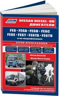
Руководство по техническому обслуживанию и ремонту дизельных двигателей Nissan моделей FE6/FE6A/FE6B/FE6C/FE6E/FE6T/FE6TA/FE6TB.
- Автор: —
- Издательство: Легион-Автодата
- Год издания: —
- Страниц: 186
- Формат: —
- Размер: —
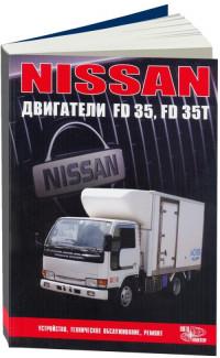
Руководство по техническому обслуживанию и ремонту дизельных двигателей Nissan моделей FD35/FD35T.
- Автор: —
- Издательство: Автонавигатор
- Год издания: —
- Страниц: 84
- Формат: —
- Размер: —
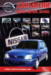
Руководство по техническому обслуживанию и ремонту бензиновых двигателей Nissan моделей GA14DE/GA15DE/GA16DE.
- Автор: —
- Издательство: Автонавигатор
- Год издания: 2003
- Страниц: 105
- Формат: —
- Размер: —
Руководство по техническому обслуживанию и ремонту дизельных двигателей Nissan моделей LD20/LD20T.
- Автор: —
- Издательство: Автонавигатор
- Год издания: 2004
- Страниц: 92
- Формат: —
- Размер: —
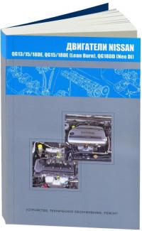
Руководство по техническому обслуживанию и ремонту бензиновых двигателей Nissan моделей QG13DE/QG15DE/QG18DE/QG18DD.
- Автор: —
- Издательство: Автонавигатор
- Год издания: —
- Страниц: 163
- Формат: —
- Размер: —
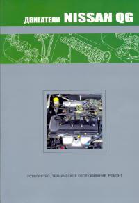
Руководство по техническому обслуживанию и ремонту бензиновых двигателей Nissan серии QG.
- Автор: —
- Издательство: Автонавигатор
- Год издания: 2005
- Страниц: 92
- Формат: —
- Размер: —
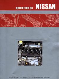
Руководство по техническому обслуживанию и ремонту бензиновых двигателей Nissan серии QR.
- Автор: —
- Издательство: Автонавигатор
- Год издания: 2005
- Страниц: 104
- Формат: PDF
- Размер: 23,6 Mb
Руководство по техническому обслуживанию и ремонту бензиновых двигателей Nissan модели HR16DE и Renault модели H4M объемом 1,6 л.
- Автор: —
- Издательство: Автонавигатор
- Год издания: —
- Страниц: 128
- Формат: —
- Размер: —
Руководство по техническому обслуживанию и ремонту бензинового двигателя Nissan модели MR20DD объемом 2,0 л с непосредственным впрыском топлива.
- Автор: —
- Издательство: Автонавигатор
- Год издания: —
- Страниц: 122
- Формат: —
- Размер: —
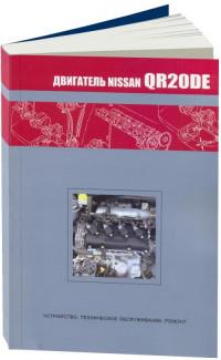
Руководство по техническому обслуживанию и ремонту бензинового двигателя Nissan модели QR20DE.
- Автор: —
- Издательство: Автонавигатор
- Год издания: —
- Страниц: 104
- Формат: —
- Размер: —
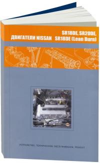
Руководство по техническому обслуживанию и ремонту бензиновых двигателей Nissan моделей SR18DE/SR20DE.
- Автор: —
- Издательство: Автонавигатор
- Год издания: 2007
- Страниц: 121
- Формат: —
- Размер: —
Руководство по техническому обслуживанию и ремонту дизельных двигателей Nissan моделей TD27Ti/TD27ETi.
- Автор: —
- Издательство: Автонавигатор
- Год издания: —
- Страниц: 96
- Формат: —
- Размер: —
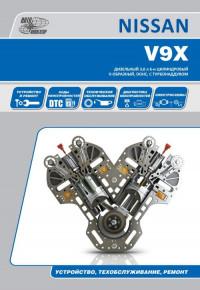
Руководство по техническому обслуживанию и ремонту дизельного двигателей Nissan модели V9X объемом 3,0 л.
- Автор: —
- Издательство: Автонавигатор
- Год издания: —
- Страниц: 112
- Формат: —
- Размер: —
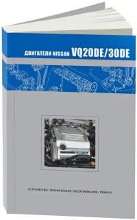
Руководство по техническому обслуживанию и ремонту бензиновых двигателей Nissan моделей VQ20DE/VQ30DE.
- Автор: —
- Издательство: Автонавигатор
- Год издания: —
- Страниц: 104
- Формат: —
- Размер: —
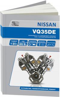
Руководство по техническому обслуживанию и ремонту бензинового двигателя Nissan модели VQ35DE объемом 3,5 л.
- Автор: —
- Издательство: Автонавигатор
- Год издания: —
- Страниц: 136
- Формат: —
- Размер: —
Руководство по техническому обслуживанию и ремонту бензинового двигателя Nissan модели VQ37VHR объемом 3,7 л.
- Автор: —
- Издательство: Автонавигатор
- Год издания: —
- Страниц: 136
- Формат: —
- Размер: —
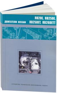
Руководство по техническому обслуживанию и ремонту бензиновых двигателей Nissan моделей RB20E/RB25DE/RB25DET/RB26DETT.
- Автор: —
- Издательство: Автонавигатор
- Год издания: 2006
- Страниц: 129
- Формат: —
- Размер: —
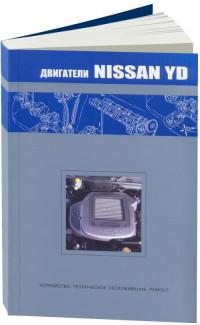
Руководство по техническому обслуживанию и ремонту дизельных двигателей Nissan серии YD.
- Автор: —
- Издательство: Автонавигатор
- Год издания: 2005
- Страниц: 94
- Формат: —
- Размер: —
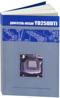
Руководство по техническому обслуживанию и ремонту дизельного двигателя Nissan модели YD25DDTi.
- Автор: —
- Издательство: Автонавигатор
- Год издания: —
- Страниц: 104
- Формат: —
- Размер: —

-
Автор темы
twistec
- Привык

- Всего сообщений: 125
- Зарегистрирован: 22.06.2015
- Откуда: Томск
- Авто: Nissan Serena TC24
- Возраст: 34

Книга по серене с qr20/25

Именно по qr,
Там расписаны ошибки которые отличаются от мануала только по двигателю.
Отправлено спустя 9 минут 14 секунд:


-
Автор темы
twistec
- Привык
- Всего сообщений: 125
- Зарегистрирован: 22.06.2015
- Откуда: Томск
- Авто: Nissan Serena TC24
- Возраст: 34
Re: Книга по серене с qr20/25
Сообщение
twistec » 07 апр 2016, 10:59
сканера нет, поэтому могу по надобности скидывать фото, кому понадобится
-

Mamlei30
- Ветром занесло
- Всего сообщений: 6
- Зарегистрирован: 30.04.2016
- Профессия: Водитель
- Откуда: Краснодар
- Авто: 1999, Nissan Serena, 2,5,дизель
- Возраст: 41

Re: Книга по серене с qr20/25
Сообщение
Mamlei30 » 04 май 2016, 21:54
Доброго вечера!!!
Отправлено спустя 51 секунду:
Можно страницу по ходовой!!! Перед и зад!!!
Отправлено спустя 3 минуты 32 секунды:
89181799797 если возможно по вотсап
-
Автор темы
twistec
- Привык
- Всего сообщений: 125
- Зарегистрирован: 22.06.2015
- Откуда: Томск
- Авто: Nissan Serena TC24
- Возраст: 34
Re: Книга по серене с qr20/25
Сообщение
twistec » 05 май 2016, 14:37
Mamlei30: Доброго вечера!!!
Отправлено спустя 51 секунду:
Можно страницу по ходовой!!! Перед и зад!!!Отправлено спустя 3 минуты 32 секунды:
89181799797 если возможно по вотсап
Доброго! у вас серена 1999г. и судя по подписи дизель, вам подойдет обычный мануал по серене 24, он есть в свободном доступе в интернет, и даже вроде тут на форуме, а вот у меня мануал для владельцев рестайловых серен, на которые мануал есть только в печатном виде, там основа от старого, но по каждому пункту идет отдельное дополнение для машин с 2001г.в. в некоторых и дополнительно с 2003г.в., ну и описаны двигателя qr20 и qr25
Отправлено спустя 3 минуты 2 секунды:
http://hdd.tomsk.ru/desk/afqsrnor вот ссылка на мануал если лень искать
-
Mamlei30
- Ветром занесло
- Всего сообщений: 6
- Зарегистрирован: 30.04.2016
- Профессия: Водитель
- Откуда: Краснодар
- Авто: 1999, Nissan Serena, 2,5,дизель
- Возраст: 41
Re: Книга по серене с qr20/25
Сообщение
Mamlei30 » 07 май 2016, 01:19
Не грузит ссылку ![]()
Отправлено спустя 2 минуты 6 секунд:
qr20 или qr 25 у меня??? Где это можно посмотреть???!
Отправлено спустя 2 минуты 48 секунд:
Братское сердце!!! Спасибо огромное за ссылку!!! Теперь у меня есть книга!!!!!
Отправлено спустя 2 минуты 30 секунд:
Ещё перечитал все темы про замену масла!, скажу так менял вчера масло через аппарат, ушло 15 литров. Кому нужно в Краснодаре подскажу толковое СТО!!! Полет нормальный!!!
Отправлено спустя 2 минуты 9 секунд:
Ощущение особо не чего не изменилось… но кажется стало лучше, и главное появилась уверенность что оно там новое и я знаю теперь что там, и 40 000 км теперь можно не переживать
Отправлено спустя 2 минуты 11 секунд:
Сразу же не отходя от кассы поменял охлаждающаю жидкость, оказалось от прежнего хозяина остался антифриз смешанный с водой…. Ушло 7 литров и теперь уверенность что я точно летом в пробке не закипит
Отправлено спустя 3 минуты 25 секунд:
После праздников заменется масло в двигателе!!! Машинка » Серенушка » очень нравиться и мне на ней ещё работать и работать!!! Думаю! Уверен не подведет!!!! ![]()
-
Автор темы
twistec
- Привык
- Всего сообщений: 125
- Зарегистрирован: 22.06.2015
- Откуда: Томск
- Авто: Nissan Serena TC24
- Возраст: 34
Re: Книга по серене с qr20/25
Сообщение
twistec » 07 май 2016, 14:07
Mamlei30: qr20 или qr 25 у меня??? Где это можно посмотреть???!
если у тебя дизель то у тебя точно YD25
ну а какой двигатель можно узнать по номеру кузова, а точнее по его буквам
TC24, TNC24 — qr20 с 2001г.в.
RC24 — qr25 c 2001г.в.
PC24, PNC24 — sr20
VC24, VNC24 — yd25 дизель
буква N в номере кузова означает наличие полного привода
-

Михаил младший
- Пустил корни
- Всего сообщений: 978
- Зарегистрирован: 30.08.2007
- Детей: 2
- Откуда: С-Пб
- Авто: не bus


Re: Книга по серене с qr20/25
Сообщение
Михаил младший » 07 май 2016, 19:19
twistec:…а какой двигатель можно узнать…
Заглянув на подкапотную табличку. Там указан двигатель.
Всем удачи на дорогах!!!
-
Mamlei30
- Ветром занесло
- Всего сообщений: 6
- Зарегистрирован: 30.04.2016
- Профессия: Водитель
- Откуда: Краснодар
- Авто: 1999, Nissan Serena, 2,5,дизель
- Возраст: 41
Re: Книга по серене с qr20/25
Сообщение
Mamlei30 » 11 май 2016, 21:11
Ребят подскажите что может быть…… Теряется мощность — давлю на педаль а она очень медленно набирает обороты, а иногда страшно давить рвёт прям с пробуксовкой
Отправлено спустя 37 секунд:
Что это такое может быть????
Краснодар, 89181799797
-
alexashko
- Привык
- Всего сообщений: 165
- Зарегистрирован: 05.03.2014
- Откуда: Геленджик
- Авто: Serena, 2004, tnc24, 4wd,газ + VwPassat b5.5, 2005, awx дизель мкпп
- Возраст: 34
Re: Книга по серене с qr20/25
Сообщение
alexashko » 24 май 2016, 11:21
Накопал у себя вышеуказанную книжку в pdf, видать когда перебирал автомат качал.
Залил на какой-то обменник [url=http://файлообменник.рф/aituvo6aey70.html]nissan_serena_1999_2005_hard_avtonavigator.pdf[/url]
Если кому будет надо — напишите почту, отправлю напрямую.
-
Михаил младший
- Пустил корни
- Всего сообщений: 978
- Зарегистрирован: 30.08.2007
- Детей: 2
- Откуда: С-Пб
- Авто: не bus
Re: Книга по серене с qr20/25
Сообщение
Михаил младший » 12 июн 2016, 13:39
alexashko: когда перебирал автомат
Сам перебирал? Что-то в память осталось: что было причиной переборки, что вышло из строя/износилось, что поменял, на что поменял, и прочее…
Всем удачи на дорогах!!!
-
alexashko
- Привык
- Всего сообщений: 165
- Зарегистрирован: 05.03.2014
- Откуда: Геленджик
- Авто: Serena, 2004, tnc24, 4wd,газ + VwPassat b5.5, 2005, awx дизель мкпп
- Возраст: 34
Re: Книга по серене с qr20/25
Сообщение
alexashko » 13 июн 2016, 12:07
Стандартно, на задней планетарке слизались шлицы, для пробега в 300 обычное дело. Тут же на форуме нашёл саму планетарку с разбора,
плюсом пришлось взять фрикционы одного пакета, т.к. подразбило шлицы у них.
около 1,5 железо, 800 или 1000 фрикционы, 2000 экспресс доставка. Ну ключ ещё дино купил, что бы собрать.
Перебирать саму коробку намного проще чем мкпп.
Снимал поставив на проставки авто, стремянку над капотом и через полиспаст опускалставил обратно.
-
avto-мобилист
- Задержался
- Всего сообщений: 16
- Зарегистрирован: 21.08.2011
- Детей: 3
- Профессия: инженер-конструктор
- Откуда: Екатеринбург
- Авто: Nissan Serena, 2002, TNC-24, QR-20, 4WD

Re: Книга по серене с qr20/25
Сообщение
avto-мобилист » 13 янв 2017, 21:16
Скиньте кто-нибудь ссылку на книгу с qr20, буду безмерно благодарен.
-

959 28rus
- Врос
- Всего сообщений: 772
- Зарегистрирован: 11.09.2012
- Детей: 1
- Профессия: закон и порядок!!!
- Откуда: Благовещенск
- Авто: NISSAN SERENA 1999г, SR20, PNC24, пока 2WD
- Возраст: 38

Re: Книга по серене с qr20/25
Сообщение
959 28rus » 15 янв 2017, 00:16
avto-мобилист: qr20
Есть в эл. виде, но не скидывается почему то, пишет много весит.
Кинь электронику, попробую на неё…
хочется в жизни простое желание — это мир во всём мире, но увы этого никогда не будет…
924тричетыре 044 пятьшесть Жека
-
avto-мобилист
- Задержался
- Всего сообщений: 16
- Зарегистрирован: 21.08.2011
- Детей: 3
- Профессия: инженер-конструктор
- Откуда: Екатеринбург
- Авто: Nissan Serena, 2002, TNC-24, QR-20, 4WD
Re: Книга по серене с qr20/25
Сообщение
avto-мобилист » 18 янв 2017, 19:50
Благодарю <959 28rus> за мануал по двигателям QR20. Но вопрос остается открытым по книге на nissan serena, где кроме двигателей SR20 расписано и про комплектации с двигателями QR20/QR25DE. Кто может поделиться большая просьба и одновременно благодарность.
-
MBP13
- Ветром занесло
- Всего сообщений: 2
- Зарегистрирован: 28.02.2016
- Откуда: Ижевск
- Авто: Nissan Serena c25 2008г.
Re: Книга по серене с qr20/25
Сообщение
MBP13 » 25 сен 2017, 18:28
Ссылки не работают, перезалейте пожалуйста мануал.
Зарание спасибо
Эту книгу можно купить в электронном виде и в виде привычного печатного издания .
n
Nissan бензиновые двигатели QR20DE. Устройство, техническое обслуживание, ремонт.
В данном руководстве представлено описание работ по техническому обслуживанию и ремонту бензиновых двигателей Nissan QR.
Данные в руководстве рекомендации позволят автовладельцам самостоятельно провести грамотный ремонт двигателя. В руководстве описаны возможные неисправности двигателя, методы их выявления и технология устранения. Также представлена информация по диагностике и ремонту системы управления и электрооборудования двигателя.
Пошаговое и наглядное описание ремонтных процедур, изобилие рисунков, обширные справочные эемонтные данные позволят квалифицированно подобрать варианты замены запчастей, произвести соответствующие регулировки, правку и т. д.
Книга предназначена для персонала СТО, ремонтных мастерских и автовладельцев.
n
Купить электронные книги по ремонту автомобилей на русском языке можно в любой стране Европейского союза (Австрия, Бельгия, Болгария, Великобритания, Венгрия, Германия, Греция, Дания, Ирландия, Испания, Италия, Кипр, Латвия, Литва, Люксембург, Мальта, Нидерланды, Польша, Португалия, Румыния, Словакия, Словения, Финляндия, Франция, Хорватия, Чехия, Швеция и Эстония.), а также странах СНГ ( Россия, Беларусь, Кыргызстан, Таджикистан, Узбекистан, Туркменистан, Молдова, Азербайджан, Армению, Казахстан.)
Оплатить выбранную книгу можно с помощью любой банковской карты (Visa, MasterCard и т.д.), а также PayPal, WebMoney и других популярных платёжных систем .
Книга: Nissan X-Trail модели Т30 выпуска с 2000 года, двигатели QR20DE, QR25DE
Руководство по эксплуатации. Устройство. Техническое обслуживание и ремонт.
Год выпуска: 2005
Издательство: Автонавигатор
Формат издания: иллюстрированное руководство
Количество страниц: 476
В руководстве представлено описание эксплуатации, технического обслуживания и ремонта бензиновых
версий автомобилей марки Nissan X-Trail выпускающихся с 2000 года на базе двигателей QR20DE и QR25DE.
В подробном издании содержатся сведения по диагностике, регулировке и ремонту двигателей, систем ESP,
TCS, ABS. Детально описываются процедуры само-диагностики и рекомендации по регулировке и ремонту
механических и автоматических коробок передач, тормозной системы, рулевого управления и подвески.
Представлены иллюстрации электро-схемы и описание электрооборудования как леворульных,
так и праворульных моделей. Книга предназначена для владельцев популярной марки автомашины,
а также для персонала ремонтных и сервисных мастерских.
Содержание:
- Инструкция по эксплуатации
- Общие сведения
- Техническое обслуживание
- Механическая часть двигателя
- Система смазки
- Система охлаждения
- Система управления двигателем
- Топливная система, система управления акселератором, система выпуска
- Сцепление
- Механическая коробка передач
- Автоматическая коробка передач
- Раздаточная коробка, карданный вал, задняя главная передача, передний и задний мосты
- Передняя и задняя подвеска, колеса и шины
- Тормозная система
- Рулевое управление
- Кузов, замки и безопасность
- Кондиционер
- Электрооборудование
Примеры страниц из книги: (картинки кликабельны)
Книга Nissan X-Trail Т30
Nissan Primera (2002+). Коды ошибок и неисправностей
Nissan Primera (2002+). Основные неисправности автомобиля — часть 1
Nissan Primera (2002+). Основные неисправности автомобиля — часть 2
Nissan Primera (2002+). ПОСТОРОННИЕ ШУМЫ И СТУКИ В ДВИГАТЕЛЕ
Nissan Primera (2002+). Сцепление не полностью включается (пробуксовывает)
Nissan Primera (2002+). Основные неисправности в коробке передач и их устранение
Nissan Primera (2002+). Основные неисправности тормозной системы и их устранение
Nissan Primera (2002+). Основные неисправности аккумуляторной батареи
Nissan Primera (2002+). Увод автомобиля от прямолинейного движения (на ровной дороге)
Nissan Primera (2002+). Стук и щелчки при поворотах автомобиля
Nissan Primera (2002+). Основные неисправности генератора
Nissan Primera (2002+). Посторонние стуки и шумы в двигателе
Nissan Primera (2002+). Сильная вибрация двигателя
Nissan Primera (2002+). Двигатель не развивает полной мощности
Nissan Primera (2002+). Основные неисправности рулевого управления
Nissan Primera (2002+). Двигатель перегревается (горит сигнализатор перегрева двигателя)
Nissan Primera (2002+). Использование детских сидений
Nissan Primera (2002+). Двигатель работает неустойчиво или глохнет на холостом ходу
Nissan Primera (2002+). Двигатель долго прогревается
Nissan Primera (2002+). Снижение уровня охлаждающей жидкости
Nissan Primera (2002+). Причины повышенного содержания вредных веществ в отработавших газах
Nissan Primera (2002+). Проверка состояния компонентов шатунно-поршневой группы двигателя
Nissan Primera (2002+). Диагностика неисправностей кривошипно-шатунного механизма двигателя
Nissan Primera (2002+). Постоянно работает вентилятор системы охлаждения двигателя (даже на холостом ходу)
Nissan Primera (2002+). Двигатель медленно сбрасывает обороты при отпускании педали газа
Nissan Primera (2002+). Двигатель медленно набирает обороты (причины и устранение)
Nissan Primera (2002+). Неисправности регулятора давления топлива двигателя
Nissan Primera (2002+). Почему гудит топливный насос
Nissan Primera (2002+). Неисправности топливного насоса (не качает бензин)
Nissan Primera (2002+). Двигатель громко или шумно работает
Nissan Primera (2002+). Стучат пальцы в двигателе
Nissan Primera (2002+). Скрежет, стук или свист во время запуска двигателя
Nissan Primera (2002+). Причины хлопков во впускном трубопроводе (коллекторе) двигателя
Nissan Primera (2002+). Выстрелы в глушителе двигателя
Nissan Primera (2002+). Повышенный расход масла в двигателе
Nissan Primera (2002+). Повышенный расход топлива
Nissan Primera (2002+). Недостаточное давление масла (горит сигнализатор недостаточного давления масла)
Nissan Primera (2002+). Двигатель не пускается в режимах «Р» или «N» (но запускается в других режимах)
Nissan Primera (2002+). Пропал холостой ход двигателя (возможные причины)
Nissan Primera (2002+). Пуск двигателя от внешних источников тока
Nissan Primera (2002+). Рывки при троганьи с места
Nissan Primera (2002+). На второй передаче машина дергается и возможны рывки на первой
Nissan Primera (2002+). Не работает (не включается) вентилятор охлаждения радиатора — причины
Nissan Primera (2002+). Двигатель не пускается — причины, поиск неисправностей
Nissan Primera (2002+). Стартер крутит, но двигатель не заводится
Nissan Primera (2002+). Двигатель не заводится после замены ремня или цепи ГРМ
Nissan Primera (2002+). Конденсат в двигателе
Nissan Primera (2002+). Бензин (топливо) попадает в картер двигателя
Nissan Primera (2002+). Течет тосол из расширительного бачка (падает уровень тосола)
Nissan Primera (2002+). Течь под капотом (лужи под капотом)
Nissan Primera (2002+). Основные причины троения двигателя
Nissan Primera (2002+). Пена в расширительном бачке
Nissan Primera (2002+). Антифриз кипит (бурлит) в расширительном бачке
Nissan Primera (2002+). Двигатель дымит
Nissan Primera (2002+). Часто включается вентилятор охлаждения двигателя (вентилятор радиатора)
Nissan Primera (2002+). Запах антифриза в салоне (основные причины)
Nissan Primera (2002+). Признаки износа двигателя (как узнать степень износа двигателя)
Nissan Primera (2002+). Перегрев двигателя зимой
Nissan Primera (2002+). Идёт пар из-под крышки расширительного бачка (белый дымок)
Nissan Primera (2002+). Шум работы клапанного механизма двигателя
Nissan Primera (2002+). Под машиной появляются лужи и пятна
Nissan Primera (2002+). Основные неисправности из за которых топливо попадает в моторное масло
Nissan Primera (2002+). Почему клинит двигатель
Nissan Primera (2002+). Коленчатый вал двигателя не проворачивается стартером
Nissan Primera (2002+). Пониженная температура масла в двигателе
Nissan Primera (2002+). Пониженная температура охлаждающей жидкости двигателя (ниже нормы)
Nissan Primera (2002+). Падает температура двигателя при езде
Nissan Primera (2002+). Высокая температура масла в двигателе (перегрев масла)
Nissan Primera (2002+). Утечка охлаждающей жидкости (антифриза)
Nissan Primera (2002+). Причины потери вязкости масла в двигателе
Nissan Primera (2002+). Потери моторного масла
Nissan Primera (2002+). Стуки в прогретом двигателе в режиме холостого хода
Nissan Primera (2002+). Кратковременные стуки сразу после пуска двигателя
Nissan Primera (2002+). Двигатель стучит «на холодную»
Nissan Primera (2002+). Стук на холодном двигателе, слышный в течении 2-3 минут после пуска
Nissan Primera (2002+). Повышенный шум газораспределительного механизма двигателя
Nissan Primera (2002+). Стук поршней двигателя
Nissan Primera (2002+). Стук шатунных подшипников двигателя
Nissan Primera (2002+). Провернуло шатунный вкладыш двигателя
Nissan Primera (2002+). Стук коренных подшипников коленчатого вала двигателя
Nissan Primera (2002+). Заправка автомобиля топливом (общие советы)
Nissan Primera (2002+). ПОЛЬЗОВАНИЕ ДОМКРАТОМ
Nissan Primera (2002+). БУКСИРОВКА АВТОМОБИЛЯ
Nissan Primera (2002+). ДВИГАТЕЛЬ НЕ ЗАВОДИТСЯ. ОБЩИЕ ПРИЕМЫ ПУСКА ДВИГАТЕЛЯ
Nissan Primera (2002+). ПРОКОЛ КОЛЕСА (ЗАМЕНА КОЛЕСА)
Nissan Primera (2002+). ПРОВЕРКА УРОВНЯ И ДОЛИВКА МАСЛА В СИСТЕМУ СМАЗКИ
Nissan Primera (2002+). ПРОВЕРКА УРОВНЯ И ДОЛИВКА ОХЛАЖДАЮЩЕЙ ЖИДКОСТИ
Nissan Primera (2002+). ПРОВЕРКА УРОВНЯ И ДОЛИВКА ТОРМОЗНОЙ ЖИДКОСТИ В БАЧОК ГИДРОПРИВОДА ТОРМОЗНОЙ СИСТЕМЫ
Nissan Primera (2002+). ПРОВЕРКА УРОВНЯ И ДОЛИВКА ЖИДКОСТИ В БАЧОК ОМЫВАТЕЛЕЙ
Nissan Primera (2002+). ПРОЧИСТКА ДРЕНАЖНЫХ ОТВЕРСТИЙ КУЗОВА
Nissan Primera (2002+). СМАЗКА АРМАТУРЫ КУЗОВА
Nissan Primera (2002+). Антенна (снятие и установка)
Nissan Primera (2002+). Управление коробкой передач (общие советы)
Nissan Primera (2002+). Проверка и регулировка углов установки колес
Nissan Primera (2002+). Регулировка света фар
Nissan Primera (2002+). Признаки прогара клапанов двигателя
Nissan Primera (2002+). Идут газы в расширительный бачок
Nissan Primera (2002+). Антифриз в турбине
Nissan Primera (2002+). Запах тосола в салоне
Nissan Primera (2002+). Запах из печки металлом или жженым маслом
Nissan Primera (2002+). Запах бензина в салоне, причины
Nissan Primera (2002+). Повышенная компрессия в двигателе: причины
Nissan Primera (2002+). Низкая компрессия в двигателе: причины
Nissan Primera (2002+). Пар с крышки радиатора охлаждения двигателя
Nissan Primera (2002+). Прыгают обороты двигателя на холостых
Nissan Primera (2002+). Двигатель коптит чёрным дымом
Nissan Primera (2002+). Двигатель закоксовался, нагар в двигателе
Nissan Primera (2002+). Бедная топливовоздушная смесь
Nissan Primera (2002+). Кипит тосол в расширительном бачке
Nissan Primera (2002+). Выкидывает тосол (антифриз) из расширительного бачка
Nissan Primera (2002+). Замена солнцезащитных козырьков
Nissan Primera (2002+). Маркировка шин
Nissan Primera (2002+). Проверка состояния колес и шин
Nissan Primera (2002+). Схема перестановки колес
Nissan Primera (2002+). Ремни безопасности
Nissan Primera (2002+). Ремонт бескамерной шины
Nissan Primera (2002+). Правила техники безопасности при ремонте и обслуживании системы кондиционирования
Nissan Primera (2002+). Мойка автомобиля
Nissan Primera (2002+). Полировка лакокрасочного покрытия
Nissan Primera (2002+). Мойка двигателя
Nissan Primera (2002+). Антикоррозионная защита кузова
Nissan Primera (2002+). Герметизация кузова
Nissan Primera (2002+). Замена стёкол кузова
Nissan Primera (2002+). Регулировка зазоров в приводе клапанов двигателя
Nissan Primera (2002+). Высокий выброс оксида азота
Nissan Primera (2002+). Причины токсичности выхлопных газов
Nissan Primera (2002+). Сцепление не полностью включается (буксует)
Nissan Primera (2002+). Признаки износа цепи ГРМ
Nissan Primera (2002+). Сцепление не выключается (ведет)
Nissan Primera (2002+). Педаль сцепления «проваливается»
Nissan Primera (2002+). Педаль сцепления не возвращается назад после нажатия
Nissan Primera (2002+). Шум при выключении или включении сцепления
Nissan Primera (2002+). Шум в коробке передач
Nissan Primera (2002+). Передачи включаются с трудом
Nissan Primera (2002+). Передачи самопроизвольно выключаются
Nissan Primera (2002+). Утечка масла из коробки передач
Nissan Primera (2002+). Утечка тормозной жидкости
Nissan Primera (2002+). Неисправности каталитического нейтрализатора
Nissan Primera (2002+). Неисправности глушителя
Nissan Primera (2002+). Неисправности кислородного датчика
Nissan Primera (2002+). Замена шарниров равных угловых скоростей
Nissan Primera (2002+). Вибрация при торможении
Nissan Primera (2002+). Увеличенный ход педали тормоза (педаль тормоза проваливается)
Nissan Primera (2002+). Увод или занос автомобиля при торможении
Nissan Primera (2002+). Причина ошибки P0100
Nissan Primera (2002+). Причина ошибки P0106
Nissan Primera (2002+). Причина ошибки P0116
Nissan Primera (2002+). Причина ошибки P0128
Nissan Primera (2002+). Причина ошибки P0130
Nissan Primera (2002+). Причина ошибки P0132
Nissan Primera (2002+). Причина ошибки P0133
Nissan Primera (2002+). Причина ошибки P0134
Nissan Primera (2002+). Причина ошибки P0300
Nissan Primera (2002+). Причина ошибки P0314
Nissan Primera (2002+). Причина ошибки P0325
Nissan Primera (2002+). Причина ошибки P0340
Nissan Primera (2002+). Причина ошибки P0341
Nissan Primera (2002+). Причина ошибки P0401
Nissan Primera (2002+). Причина ошибки P0402
Nissan Primera (2002+). Причина ошибки P0403
Nissan Primera (2002+). Причина ошибки P0410
Nissan Primera (2002+). Причина ошибки P0420
Nissan Primera (2002+). Причина ошибки P0505
Nissan Primera (2002+). Межвитковые уретановые проставки в пружины Jinke
Nissan Primera (2002+). Состав автомобильной аптечки (на 2020 год)
Nissan Primera (2002+). Какой огнетушитель должен быть в автомобиле для техосмотра в 2020 году
Nissan Primera (2002+). Набор автомобилиста Blast BCK-071
Nissan Primera (2002+). Набор автомобилиста АВТОСТОП H2
Nissan Primera (2002+). Автомобильный порошковый огнетушитель Меланти ОП-4 з АВСЕ
Nissan Primera (2002+). Техосмотр автомобиля в 2020 году
Nissan Primera (2002+). Техническое обслуживание двигателя
Nissan Primera (2002+). Неисправности датчика скорости
Nissan Primera (2002+). Замена датчика скорости
Nissan Primera (2002+). Автомобильная смазка OILRIGHT Литол-24
Nissan Primera (2002+). Автомобильная смазка Газпромнефть ЛИТОЛ-24
Nissan Primera (2002+). Vin-номер автомобиля
Nissan Primera (2002+). Полис ОСАГО (информация на 2020 год)
Nissan Primera (2002+). Автосигнализация TOMAHAWK 9.9 [9.9 автозапуск]
Nissan Primera (2002+). Автолампа OSRAM H7 55 PX26d 12V, 10,100 HIT 64210
Nissan Primera (2002+). Домкрат подкатной AVS FJ-3000L
Nissan Primera (2002+). Компрессор автомобильный AVS KS900
Nissan Primera (2002+). Прогорела прокладка ГБЦ двигателя
Nissan Primera (2002+). ELM327 bluetooth v.1.5 автосканер ELM327 obd2 для диагностики автомобиля
Nissan Primera (2002+). Датчик массового расхода воздуха: признаки неисправности
Nissan Primera (2002+). Заправка автомобиля бензином
Nissan Primera (2002+). Замена прокладки крышки головки блока цилиндров
Nissan Primera (2002+). Дефектовка распределительного вала двигателя
Nissan Primera (2002+). Признаки износа маслосъемных колпачков двигателя
Nissan Primera (2002+). Быстро загрязняется масло в двигателе (темнеет или чернеет)
Nissan Primera (2002+). Калильное зажигание (причины)
Nissan Primera (2002+). Причины износа направляющих втулок клапанов двигателя
Nissan Primera (2002+). Неисправности датчика температуры охлаждающей жидкости двигателя
Nissan Primera (2002+). Неисправности свечей зажигания
Nissan Primera (2002+). Неправильная регулировка угла опережения зажигания
Nissan Primera (2002+). Неисправности карданного вала
Nissan Primera (2002+). Неисправности раздаточной коробки
Nissan Primera (2002+). Течёт радиатор охлаждения двигателя (причины)
Nissan Primera (2002+). Неисправности стояночного тормоза
Nissan Primera (2002+). Как снять передний и задний бампер
Nissan Primera (2002+). Признаки износа или залегания поршневых колец двигателя
Nissan Primera (2002+). Неисправности системы охлаждения двигателя
Nissan Primera (2002+). Перегрев двигателя, особенно в жаркую погоду
Nissan Primera (2002+). Неисправности помпы системы охлаждения двигателя
Nissan Primera (2002+). Неисправности лямбда-зонда
Nissan Primera (2002+). Неисправности датчика распределительного вала
Nissan Primera (2002+). Дефектовка клапанов двигателя
Nissan Primera (2002+). Неисправности датчика коленчатого вала двигателя
Nissan Primera (2002+). SCHER-KHAN MAGICAR 7 система сигнализации
Nissan Primera (2002+). Зарядное устройство «Вымпел-57», автомат, сегментный ЖК индикатор, 0-20А, 7,4-18В
Nissan Primera (2002+). Зачем нужна дистиллированная вода для автомобиля
Nissan Primera (2002+). Зарядное устройство «Вымпел-20», автомат, стрелочный амперметр, 0-7А, 6/12/18В
Nissan Primera (2002+). Электронное зарядное устройство «Goodyear», для свинцово-кислотных аккумуляторов CH-4A
Nissan Primera (2002+). Пуско-зарядное устройство Berkut «JSL-12000»
Nissan Primera (2002+). Зарядное устройство «Вымпел-37», автомат, сегментный ЖК индикатор, 0-20А, 14,1/14,8/16В
Nissan Primera (2002+). Свеча зажигания двигателя (снятие, проверка, установка)
Nissan Primera (2002+). Забились соты радиатора (промывка радиатора)
Nissan Primera (2002+). Полис КАСКО (информация на 2020 год)
Nissan Primera (2002+). Ремонт бампера из пластика своими руками
Nissan Primera (2002+). Установка для тестирования и очистки форсунок LNC-029 LAUNCH CNC 603A
Nissan Primera (2002+). Мультимарочный сканер LAUNCH X431 PRO 2017
Nissan Primera (2002+). Как проверить расходомер воздуха
Nissan Primera (2002+). Причина ошибки P0101 (OBD-II)
Nissan Primera (2002+). Видеорегистратор Vehicle blackbox dvr FULL HD 1080p
Nissan Primera (2002+). Причина ошибки P0102 (OBD-II)
Nissan Primera (2002+). Забитый воздушный фильтр (признаки и причины)
Nissan Primera (2002+). Причина ошибки P0103 (OBD-II)
Nissan Primera (2002+). Причина ошибки P0104 (OBD-II)
Nissan Primera (2002+). Моменты затяжки ответственных резьбовых соединений
Nissan Primera (2002+). Расположение плавких предохранителей и их характеристика
Nissan Primera (2002+). Усилия затяжки ответственных соединений
Nissan Primera (2002+). Причина ошибки P0105 (OBD-II)
Nissan Primera (2002+). Причина ошибки P0107 (OBD-II)
Nissan Primera (2002+). Неисправности датчика положения дроссельной заслонки
Nissan Primera (2002+). Ремонт датчика положения дроссельной заслонки
Nissan Primera (2002+). Правила буксировки (ПДД РФ, 2020 год)
Nissan Primera (2002+). Обязанности водителей (ПДД РФ, 2020 год)
Nissan Primera (2002+). Проверка герметичности гидропривода тормозной системы
Nissan Primera (2002+). Эксплуатация прицепа. Правила движения с прицепом
Nissan Primera (2002+). Автосервис по ремонту авто в Москве, услуги и цены (2020 год)
Nissan Primera (2002+). Обильные картерные газы: причины
Nissan Primera (2002+). Установка и эксплуатация транспондера «T-pass»
Nissan Primera (2002+). Неисправности стартера и их причины
Nissan Primera (2002+). Неисправности реле стартера
Nissan Primera (2002+). Неисправности замка зажигания
Nissan Primera (2002+). Неисправности тросовых стеклоподъемников
Nissan Primera (2002+). Ремонт и замена замка зажигания
Nissan Primera (2002+). Диагностический автосканер Delphi DS150E
Nissan Primera (2002+). Бензин не поступает в двигатель
Nissan Primera (2002+). Трудный запуск горячего двигателя
Nissan Primera (2002+). Как установить транспондер
Nissan Primera (2002+). Автомобильный GPS навигатор NAVITEL DN505 MAGNETIC
Nissan Primera (2002+). Неисправности датчиков удара и подушек безопасности
Nissan Primera (2002+). Неисправности топливной рампы
Nissan Primera (2002+). Неисправности регулятора давления топлива
Nissan Primera (2002+). Автосигнализация Pandora DX 9X
Nissan Primera (2002+). Снятие и установка крышки люка наливной трубы топливного бака
Nissan Primera (2002+). Не работает свет в салоне
Nissan Primera (2002+). Плавают обороты двигателя
Nissan Primera (2002+). Стартер шумит и неровно вращается
Nissan Primera (2002+). Аккумулятор не заряжается
Nissan Primera (2002+). Причина ошибки P0108 (OBD-II)
Nissan Primera (2002+). Причина ошибки P0109 (OBD-II)
Nissan Primera (2002+). Неисправности топливного инжектора
Nissan Primera (2002+). Признаки неисправности ЭБУ
Nissan Primera (2002+). Дефекты протектора шин
Nissan Primera (2002+). Дефекты брекера шины
Nissan Primera (2002+). Дефекты боковины шины
Nissan Primera (2002+). Дефекты каркаса шины
Nissan Primera (2002+). Дефекты борта шины
Nissan Primera (2002+). Маркировка легковых и грузовых шин
Nissan Primera (2002+). Гарантийные обязательства изготовителей шин
Nissan Primera (2002+). Факторы, влияющие на работоспособность шин
Nissan Primera (2002+). Эксплуатация зимних автошин
Nissan Primera (2002+). Обязанности водителя (ПДД РФ, 2020 год)
Nissan Primera (2002+). Перевозка грузов на крыше
Nissan Primera (2002+). Неисправности гофры глушителя
Nissan Primera (2002+). Прогорела гофра глушителя
Nissan Primera (2002+). Прогар глушителя: причины
Nissan Primera (2002+). Неисправности электросистемы
Nissan Primera (2002+). Как выбрать прокладку ГБЦ
Nissan Primera (2002+). Неисправности системы вентиляции картера
Nissan Primera (2002+). Признаки прогара прокладки ГБЦ
Nissan Primera (2002+). Забитый глушитель: признаки
Nissan Primera (2002+). Как слить бензин из бака
Nissan Primera (2002+). Неисправности привода стартера (бендикса)
Nissan Primera (2002+). Как поменять бендикс на стартере
Nissan Primera (2002+). Причина ошибки P0110 (OBD-II)
Nissan Primera (2002+). Причина ошибки P0111 (OBD-II)
Nissan Primera (2002+). Машина кренится на одну сторону
Nissan Primera (2002+). Подскакивание или раскачивание машины
Nissan Primera (2002+). Вибрации руля и кузова
Nissan Primera (2002+). Биение рулевого колеса
Nissan Primera (2002+). Вибрация кузова
Nissan Primera (2002+). Выбор и установка межвитковых проставок
Nissan Primera (2002+). Тормозной путь
Nissan Primera (2002+). Причина ошибки P0112 (OBD-II)
Nissan Primera (2002+). Причина ошибки P0113 (OBD-II)
Nissan Primera (2002+). Причина ошибки P0114 (OBD-II)
Nissan Primera (2002+). Причина ошибки P0115 (OBD-II)
Nissan Primera (2002+). Причина ошибки P0117 (OBD-II)
Nissan Primera (2002+). Причина ошибки P0118 (OBD-II)
Nissan Primera (2002+). Причина ошибки P0119 (OBD-II)
Nissan Primera (2002+). Причина ошибки P0120 (OBD-II)
Nissan Primera (2002+). Причина ошибки P0121 (OBD-II)
Nissan Primera (2002+). Причина ошибки P0122 (OBD-II)
Nissan Primera (2002+). Причина ошибки P0123 (OBD-II)
Nissan Primera (2002+). Причина ошибки P0124 (OBD-II)
Nissan Primera (2002+). Причина ошибки P0125 (OBD-II)
Nissan Primera (2002+). Причина ошибки P0131 (OBD-II)
Nissan Primera (2002+). Причина ошибки P0135 (OBD-II)
Nissan Primera (2002+). Причина ошибки P0136 (OBD-II)
Nissan Primera (2002+). Причина ошибки P0137 (OBD-II)
Nissan Primera (2002+). Причина ошибки P0138 (OBD-II)
Nissan Primera (2002+). Причина ошибки P0139 (OBD-II)
Nissan Primera (2002+). Причина ошибки P0140 (OBD-II)
Nissan Primera (2002+). Причина ошибки P0141 (OBD-II)
Nissan Primera (2002+). Причина ошибки P0142 (OBD-II)
Nissan Primera (2002+). Причина ошибки P0143 (OBD-II)
Nissan Primera (2002+). Причина ошибки P0144 (OBD-II)
Nissan Primera (2002+). Причина ошибки P0145 (OBD-II)
Nissan Primera (2002+). Причина ошибки P0146 (OBD-II)
Nissan Primera (2002+). Причина ошибки P0147 (OBD-II)
Nissan Primera (2002+). Причина ошибки P0150 (OBD-II)
Nissan Primera (2002+). Причина ошибки P0151 (OBD-II)
Nissan Primera (2002+). Причина ошибки P0152 (OBD-II)
Nissan Primera (2002+). Причина ошибки P0153 (OBD-II)
Nissan Primera (2002+). Причина ошибки P0154 (OBD-II)
Nissan Primera (2002+). Причина ошибки P0155 (OBD-II)
Nissan Primera (2002+). Причина ошибки P0156 (OBD-II)
Nissan Primera (2002+). Причина ошибки P0157 (OBD-II)
Nissan Primera (2002+). Причина ошибки P0158 (OBD-II)
Nissan Primera (2002+). Причина ошибки P0159 (OBD-II)
Nissan Primera (2002+). Причина ошибки P0160 (OBD-II)
Nissan Primera (2002+). Причина ошибки P0161 (OBD-II)
Nissan Primera (2002+). Причина ошибки P0162 (OBD-II)
Nissan Primera (2002+). Причина ошибки P0163 (OBD-II)
Nissan Primera (2002+). Причина ошибки P0164 (OBD-II)
Nissan Primera (2002+). Причина ошибки P0165 (OBD-II)
Nissan Primera (2002+). Причина ошибки P0166 (OBD-II)
Nissan Primera (2002+). Причина ошибки P0167 (OBD-II)
Nissan Primera (2002+). Причина ошибки P0170 (OBD-II)
Nissan Primera (2002+). Причина ошибки P0171 (OBD-II)
Nissan Primera (2002+). Причина ошибки P0172 (OBD-II)
Nissan Primera (2002+). Причина ошибки P0173 (OBD-II)
Nissan Primera (2002+). Причина ошибки P0174 (OBD-II)
Nissan Primera (2002+). Причина ошибки P0175 (OBD-II)
Nissan Primera (2002+). Причина ошибки P0176 (OBD-II)
Nissan Primera (2002+). Причина ошибки P0177 (OBD-II)
Nissan Primera (2002+). Причина ошибки P0178 (OBD-II)
Nissan Primera (2002+). Причина ошибки P0179 (OBD-II)
Nissan Primera (2002+). Причина ошибки P0180 (OBD-II)
Nissan Primera (2002+). Причина ошибки P0181 (OBD-II)
Nissan Primera (2002+). Причина ошибки P0182 (OBD-II)
Nissan Primera (2002+). Причина ошибки P0183 (OBD-II)
Nissan Primera (2002+). Причина ошибки P0184 (OBD-II)
Nissan Primera (2002+). Причина ошибки P0185 (OBD-II)
Nissan Primera (2002+). Причина ошибки P0186 (OBD-II)
Nissan Primera (2002+). Причина ошибки P0187 (OBD-II)
Nissan Primera (2002+). Причина ошибки P0188 (OBD-II)
Nissan Primera (2002+). Причина ошибки P0189 (OBD-II)
Nissan Primera (2002+). Причина ошибки P0190 (OBD-II)
Nissan Primera (2002+). Причина ошибки P0191 (OBD-II)
Nissan Primera (2002+). Причина ошибки P0192 (OBD-II)
Nissan Primera (2002+). Причина ошибки P0193 (OBD-II)
Nissan Primera (2002+). Причина ошибки P0194 (OBD-II)
Nissan Primera (2002+). Причина ошибки P0195 (OBD-II)
Nissan Primera (2002+). Причина ошибки P0196 (OBD-II)
Nissan Primera (2002+). Причина ошибки P0197 (OBD-II)
Nissan Primera (2002+). Причина ошибки P0198 (OBD-II)
Nissan Primera (2002+). Причина ошибки P0199 (OBD-II)
Nissan Primera (2002+). Причина ошибки P0200 (OBD-II)
Nissan Primera (2002+). Причина ошибки P0201 (OBD-II)
Nissan Primera (2002+). Причина ошибки P0202 (OBD-II)
Nissan Primera (2002+). Причина ошибки P0203 (OBD-II)
Nissan Primera (2002+). Причина ошибки P0204 (OBD-II)
Nissan Primera (2002+). Причина ошибки P0205 (OBD-II)
Nissan Primera (2002+). Причина ошибки P0206 (OBD-II)
Nissan Primera (2002+). Причина ошибки P0207 (OBD-II)
Nissan Primera (2002+). Причина ошибки P0208 (OBD-II)
Nissan Primera (2002+). Причина ошибки P0209 (OBD-II)
Nissan Primera (2002+). Причина ошибки P0210 (OBD-II)
Nissan Primera (2002+). Причина ошибки P0211 (OBD-II)
Nissan Primera (2002+). Причина ошибки P0212 (OBD-II)
Nissan Primera (2002+). Причина ошибки P0213 (OBD-II)
Nissan Primera (2002+). Причина ошибки P0214 (OBD-II)
Nissan Primera (2002+). Причина ошибки P0215 (OBD-II)
Nissan Primera (2002+). Причина ошибки P0216 (OBD-II)
Nissan Primera (2002+). Причина ошибки P0217 (OBD-II)
Nissan Primera (2002+). Причина ошибки P0218 (OBD-II)
Nissan Primera (2002+). Причина ошибки P0219 (OBD-II)
Nissan Primera (2002+). Причина ошибки P0220 (OBD-II)
Nissan Primera (2002+). Причина ошибки P0221 (OBD-II)
Nissan Primera (2002+). Причина ошибки P0222 (OBD-II)
Nissan Primera (2002+). Причина ошибки P0223 (OBD-II)
Nissan Primera (2002+). Причина ошибки P0224 (OBD-II)
Nissan Primera (2002+). Причина ошибки P0225 (OBD-II)
Nissan Primera (2002+). Причина ошибки P0227 (OBD-II)
Nissan Primera (2002+). Причина ошибки P0228 (OBD-II)
Nissan Primera (2002+). Причина ошибки P0229 (OBD-II)
Nissan Primera (2002+). Причина ошибки P0230 (OBD-II)
Nissan Primera (2002+). Причина ошибки P0231 (OBD-II)
Nissan Primera (2002+). Причина ошибки P0232 (OBD-II)
Nissan Primera (2002+). Причина ошибки P0233 (OBD-II)
Nissan Primera (2002+). Причина ошибки P0234 (OBD-II)
Nissan Primera (2002+). Причина ошибки P0235 (OBD-II)
Nissan Primera (2002+). Причина ошибки P0236 (OBD-II)
Nissan Primera (2002+). Причина ошибки P0237 (OBD-II)
Nissan Primera (2002+). Причина ошибки P0238 (OBD-II)
Nissan Primera (2002+). Причина ошибки P0239 (OBD-II)
Nissan Primera (2002+). Причина ошибки P0240 (OBD-II)
Nissan Primera (2002+). Причина ошибки P0241 (OBD-II)
Nissan Primera (2002+). Причина ошибки P0242 (OBD-II)
Nissan Primera (2002+). Причина ошибки P0243 (OBD-II)
Nissan Primera (2002+). Причина ошибки P0244 (OBD-II)
Nissan Primera (2002+). Причина ошибки P0245 (OBD-II)
Nissan Primera (2002+). Причина ошибки P0246 (OBD-II)
Nissan Primera (2002+). Причина ошибки P0247 (OBD-II)
Nissan Primera (2002+). Причина ошибки P0248 (OBD-II)
Nissan Primera (2002+). Причина ошибки P0249 (OBD-II)
Nissan Primera (2002+). Причина ошибки P0250 (OBD-II)
Nissan Primera (2002+). Причина ошибки P0251 (OBD-II)
Nissan Primera (2002+). Причина ошибки P0252 (OBD-II)
Nissan Primera (2002+). Причина ошибки P0253 (OBD-II)
Nissan Primera (2002+). Причина ошибки P0254 (OBD-II)
Nissan Primera (2002+). Причина ошибки P0255 (OBD-II)
Nissan Primera (2002+). Причина ошибки P0256 (OBD-II)
Nissan Primera (2002+). Причина ошибки P0258 (OBD-II)
Nissan Primera (2002+). Причина ошибки P0259 (OBD-II)
Nissan Primera (2002+). Причина ошибки P0260 (OBD-II)
Nissan Primera (2002+). Причина ошибки P0261 (OBD-II)
Nissan Primera (2002+). Причина ошибки P0262 (OBD-II)
Nissan Primera (2002+). Причина ошибки P0263 (OBD-II)
Nissan Primera (2002+). Причина ошибки P0264 (OBD-II)
Nissan Primera (2002+). Причина ошибки P0265 (OBD-II)
Nissan Primera (2002+). Причина ошибки P0266 (OBD-II)
Nissan Primera (2002+). Причина ошибки P0267 (OBD-II)
Nissan Primera (2002+). Причина ошибки P0268 (OBD-II)
Nissan Primera (2002+). Причина ошибки P0269 (OBD-II)
Nissan Primera (2002+). Причина ошибки P0270 (OBD-II)
Nissan Primera (2002+). Причина ошибки P0271 (OBD-II)
Nissan Primera (2002+). Причина ошибки P0272 (OBD-II)
Nissan Primera (2002+). Причина ошибки P0273 (OBD-II)
Nissan Primera (2002+). Причина ошибки P0274 (OBD-II)
Nissan Primera (2002+). Причина ошибки P0275 (OBD-II)
Nissan Primera (2002+). Причина ошибки P0276 (OBD-II)
Nissan Primera (2002+). Причина ошибки P0277 (OBD-II)
Nissan Primera (2002+). Причина ошибки P0278 (OBD-II)
Nissan Primera (2002+). Причина ошибки P0279 (OBD-II)
Nissan Primera (2002+). Причина ошибки P0280 (OBD-II)
Nissan Primera (2002+). Причина ошибки P0281 (OBD-II)
Nissan Primera (2002+). Причина ошибки P0282 (OBD-II)
Nissan Primera (2002+). Причина ошибки P0283 (OBD-II)
Nissan Primera (2002+). Причина ошибки P0284 (OBD-II)
Nissan Primera (2002+). Причина ошибки P0285 (OBD-II)
Nissan Primera (2002+). Причина ошибки P0286 (OBD-II)