- Manuals
- Brands
- Polaris Manuals
- Snowmobiles
- 600 RMK
- Owner’s manual
2014
-
Contents
-
Table of Contents
-
Troubleshooting
-
Bookmarks
Quick Links
IMPORTANT NOTICE TO OWNER
Modifications to this snowmobile are not recommended
and may result in voided warranty coverage.
Please read the warranty section of this manual carefully.
600 PRO RMK
800 PRO RMK
800 RMK ASSAULT
Snowmobile Owner’s Manual
PMS 419
600 RMK
800 RMK
for Maintenance and Safety
Related Manuals for Polaris 600 RMK
Summary of Contents for Polaris 600 RMK
-
Page 1
IMPORTANT NOTICE TO OWNER Modifications to this snowmobile are not recommended and may result in voided warranty coverage. Please read the warranty section of this manual carefully. 600 RMK 600 PRO RMK 800 RMK 800 PRO RMK 800 RMK ASSAULT… -
Page 2
WARNING Read, understand, and follow all of the instructions and safety precautions in this manual and on all product labels. Failure to follow the safety precautions could result in serious injury or death. WARNING The engine exhaust from this product contains chemicals known to the State of California to cause cancer, birth defects or other reproductive harm. -
Page 3
WELCOME Thank you for purchasing a POLARIS vehicle, and welcome to our world-wide family of POLARIS enthusiasts. Be sure to visit us online at www.polaris.com for the latest news, new product introductions, upcoming events, career opportunities and more. Here at POLARIS we proudly produce an exciting line of utility and recreational products. -
Page 4
The original instructions for this vehicle are in English. Other languages are provided as translations of the original instructions. Printed in U.S.A. 600 RMK / 600 PRO RMK / 800 RMK / 800 PRO RMK / 800 RMK ASSAULT 2014 Owner’s Manual P/N 9924268… -
Page 5: Table Of Contents
Specifications ……118 POLARIS Products….. 122 Troubleshooting .
-
Page 7: Introduction
INTRODUCTION Important Notes for Owners and Drivers After reading this manual, store it in the snowmobile for convenient reference. It should remain with the snowmobile when the snowmobile is sold. Some of the illustrations and photos used in this manual are general representations.
-
Page 8: Air Pollution
POLARIS snowmobiles are engineered to conform to these SAE standards. Our muffler systems are designed to reduce noise levels and must not be altered or removed. The sound of your snowmobile may not be welcome to non-snowmobilers, so you have a responsibility to operate your snowmobile with concern for others.
-
Page 9: Vehicle Identification Numbers
Remove the spare key and store it in a safe place. Your key can be duplicated only by mating a POLARIS key blank with one of your existing keys, so if both keys are lost, the ignition switch must be replaced.
-
Page 10: Safety
SAFETY Operator Safety The following signal words and symbols appear throughout this manual and on your vehicle. Your safety is involved when these words and symbols are used. Become familiar with their meanings before reading the manual. The safety alert symbol indicates a potential personal injury hazard. DANGER A DANGER indicates a hazardous situation that, if not avoided, will result in death or serious injury.
-
Page 11
Always check major and vital safety components before every ride. All POLARIS snowmobiles are designed and tested to provide safe operation when used as directed. Failure of critical machine components may result from operation with any modifications, especially those that increase speed or power. -
Page 12: Riding Position
SAFETY Operator Safety Stay Clear of Track Your snowmobile is propelled by a revolving track that must be partially exposed for proper operation. Do not stand on the plastic flap. WARNING! Serious injuries may result if NO STEP hands, feet, or clothing become entangled in the track.
-
Page 13: Riding Apparel
Riding Apparel Helmet Wearing a helmet can prevent a severe head injury. Whenever riding a POLARIS vehicle, always wear a helmet that meets or exceeds established safety standards. Approved helmets in the USA and Canada bear a U.S. Department of Transportation (DOT) label.
-
Page 14: Disabled Operators
SAFETY Operator Safety Disabled Operators Safe operation of this rider-active vehicle requires good judgement and physical skills. Operators with cognitive or physical disabilities have an increased risk of loss of control, which could result in serious injury or death. Survival Preparation For your safety, always ride in a group of other snowmobilers.
-
Page 15: Rider Capacity
SAFETY Operator Safety Rider Capacity This snowmobile is designed for a single rider only. Never carry a passenger on this snowmobile. Excessive Speed WARNING! High speed driving, especially at night, could result in serious injury or death. Always reduce speed when driving at night or in inclement weather. Always observe all state and local laws governing snowmobile operation and speed limits.
-
Page 16: Driver Awareness
SAFETY Operator Safety Driver Awareness Slow down when traveling near poles, posts, or other obstacles. Be especially alert if you’re snowmobiling after dark. Always be on the alert for wire fences. Single strands are especially dangerous, since there may be a great distance between posts.
-
Page 17
SAFETY Operator Safety Avalanches Snowmobilers should always be properly trained and equipped before traveling in mountainous terrain: • Take an avalanche class • Travel with experienced people • Travel on designated trails • Make sure each person is equipped with a shovel, probe and avalanche beacon. -
Page 18: Ice And Snow Build-Up
SAFETY Operator Safety Ice and Snow Build-up WARNING! Ice and snow build-up may interfere with the steering of your snowmobile, resulting in serious injury or death. Keep the underhood area free of snow and ice. Before driving, manually turn the skis to the left and right to be sure ice and snow are not interfering with full left and right steering.
-
Page 19: Driving Downhill
SAFETY Operator Safety Driving Downhill When riding downhill, shift your weight to the rear of the snowmobile and reduce your speed to a minimum. Apply just enough throttle to keep the clutch engaged, allowing the engine’s compression to help slow the snowmobile and keep it from rolling freely downhill.
-
Page 20: Drive Belt
SAFETY Operator Safety Drive Belt Do not operate the engine with the drive belt removed. Any servicing that requires operation without a belt must be performed by your dealer. NOTICE: Operation of the engine with the belt removed may result in injury or damage to the engine.
-
Page 21: Driving Responsibly
SAFETY Operator Safety Driving Responsibly Every snowmobile handles differently, and even the most docile conditions may become dangerous if operators drive improperly. If you’re new to snowmobiling, acquaint yourself with the snowmobile and with what it will and won’t do under various conditions. Even seasoned drivers should spend some time getting the feel for a snowmobile before attempting ambitious maneuvers.
-
Page 22
SAFETY Operator Safety Windchill/Temperature Charts The following information is provided to help you determine when temperatures become dangerous for riding. WINDCHILL CHART (°F) Wind Actual Thermometer Reading (°F) Speed -10 -15 -20 -25 -30 -35 -40 -45 Equivalent Temperature (°F) Calm -10 -15 -20 -25 -30 -35 -40 -45 -11 -16 -22 -28 -34 -40 -46 -52 -57 -63… -
Page 23: Clutch Warning
If any label becomes illegible or comes off, contact your POLARIS dealer to purchase a replacement. Replacement safety labels are provided by POLARIS at no charge. The part number is printed on the label. Clutch Warning…
-
Page 24: Reverse Warning
SAFETY Safety Labels and Locations “No Passenger” Warning Reverse Warning “No Passenger” Warning Snowmobiles designed for a single rider only have the NO PASSENGER warning label on the lower left side of the console: WARNING This vehicle is designed for operator only. NO PASSENGER Reverse Warning The reverse warning label is located on the console, either beside the steering post or below the windshield:…
-
Page 25: Hot Surface Warning
WARNING Hot Surface Do Not Touch Burns may result. Entire top of tunnel may be hot. Install only accessories specifically approved for this model by POLARIS. Do not place clothing, bags or cargo on tunnel. Do not cover this label.
-
Page 26
• To avoid serious injury or death, read and understand all warnings and the Owner’s Manual before operation. If manual is missing, contact a POLARIS dealer for a replacement. • This vehicle is capable of high speeds. Buried objects or uneven terrain can cause loss of control. -
Page 27
SAFETY Safety Labels and Locations Operation Warning • When operating with a passenger (on approved models only) reduce speed and allow extra space for steering and stopping. A passenger reduces your ability to control the vehicle. • When operating on hard-packed snow, ice, or when crossing roads, steering and braking ability are greatly reduced. -
Page 28: Features
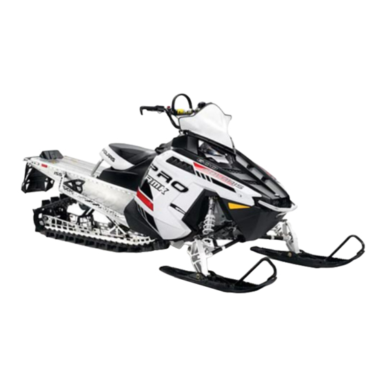
FEATURES 1. Nosepan 8. Operator Seat 2. Skis 9. Taillight 3. Front Bumper 10. Rear Bumper 4. Hood 11. Snow Flap 5. Headlight 12. Suspension 6. Windshield (accessory) 13. Track 7. Handlebar 14. Side Panel 15. Side Panel Fasteners…
-
Page 29
FEATURES 1. Fuel Filler Cap 2. Instrument Cluster 3. Ignition Switch 4. Engine Stop Switch 5. Throttle Control 6. Recoil Starter Handle 7. Brake Lever 8. Parking Brake Lock 9. Handlebar Grip Warmer Switch 10. Thumbwarmer Switch 11. Electronic Reverse Button 12 13 12. -
Page 30: Adjustable Headlights
FEATURES Storage Bag/Tool Kit A storage bag and tool kit Storage Bag is located under the left side panel between the oil bottle and console. Cargo Storage Never hang heavy items or fuel containers from the rear of the tunnel. Cargo may be stowed only under the seat and as far forward as possible…
-
Page 31: Quickdrive Belt
Maintenance Table beginning on page 80. See page 101 for inspection procedures. Special tools are required to remove and install the QUICKDRIVE belt. Please see your POLARIS dealer for this service, or refer to the instructions provided with the purchase of a new belt. Belt Handling •…
-
Page 32
FEATURES Accessories POLARIS offers a wide range of accessories for your snowmobile to help make each ride more enjoyable. Use only POLARIS parts and accessories on your POLARIS snowmobile. Use of unapproved parts and accessories may result in: • Non-compliance with government/industry requirements •… -
Page 33: Fuel Type Selection
FEATURES Fuel Type Selection Whenever using ethanol, MTBE or other forms of oxygenated gasolines, the fuel type designation setting must be changed to “Eth” in the gauge. When using the recommended 91 non-ethanol gasoline, always select the “91-non” setting. Whenever in doubt of your fuel purchase, use the “Eth”…
-
Page 34
FEATURES Detonation Elimination Technology (DET) The DET system prevents damage to the engine from detonation by going into an engine protection mode whenever the DET system is active. When excessive detonation is detected, the check engine light will illuminate and you may notice decreased engine performance and RPM when the DET system is activated. -
Page 35
Low fuel/no fuel in tank Refuel with recommended fuel Water in fuel Replace with recommended fuel Plugged fuel filter or tank pick-up sock See your POLARIS dealer for service Alcohol-based fuel additive used with Do not add deicers or additives that Ethanol fuel… -
Page 36
FEATURES Instrument Cluster Rider Information Center Check Engine High Beam Indicator Indicator Over-Tem- Park Brake perature Indi- Indicator cator Reverse Low Oil Indicator Indicator SELECT MODE Button Button The instrument cluster contains indicator lights and the rider information center. The information center can be controlled by either the MODE and SELECT buttons on the instrument cluster or by the… -
Page 37
FEATURES Instrument Cluster Indicators Check Engine Indicator This indicator appears if an EFI-related fault occurs. Do not operate the snowmobile if this warning appears. Serious engine damage could result. See your dealer. See page 48 for diagnostic code definitions. Over-Temperature Indicator This indicator illuminates to alert the operator that the engine is overheating. -
Page 38
FEATURES Instrument Cluster Rider Information Center The rider information center is located in the instrument cluster. The center displays vehicle speed, engine speed, odometer, resettable trip meters (2), total engine hours of operation, fuel level, engine temperature and diagnostic display mode. Setting changes must be made with the engine running or with the vehicle powered by an external DC power supply connector. -
Page 39
FEATURES Instrument Cluster Rider Information Center 1. Information Display Area — This area displays either engine speed or vehicle speed (whichever is not displayed in the speed display), engine temperature and maximum vehicle speed. To change the display, see page 38. 2. -
Page 40
FEATURES Instrument Cluster Rider Information Center Speed Display Area The speed display area displays either vehicle speed or engine speed. Vehicle speed is displayed in either miles per hour (MPH) or kilometers per hour (km/h). Engine speed is displayed in revolutions per minute (RPM). -
Page 41
FEATURES Instrument Cluster Rider Information Center Odometer/Engine Hour Display Area This area displays the odometer, Trip A meter, Trip B meter and engine hours meter. The odometer displays the total distance traveled by the vehicle since manufacture. Each trip meter records the distance traveled by the vehicle on a trip if the meter is reset before each trip. -
Page 42
FEATURES Instrument Cluster Rider Information Center Standard/Metric Display The odometer and temperature displays can be viewed in either standard or metric units of measurement. Both displays change if units are changed. The new settings will remain until changed by the operator. Change Method 1 1. -
Page 43
Security System (Ignition Lock System) This system is an optional feature and will not function until it has been activated by your authorized POLARIS dealer. If you have this feature activated, you can lock the ignition to prevent unauthorized use when leaving the snowmobile unattended. -
Page 44
TASK 1: Activate the security system See your authorized POLARIS dealer to have the optional security system feature activated in the electronic control unit (ECU). TASK 2: Lock the System the First Time 1. -
Page 45
FEATURES Instrument Cluster Rider Information Center Security System (Ignition Lock System) First Time Use of Your Security System TASK 3: Unlock the System 1. When the engine is running, the display will alternate between SECURE ON and ENTER CODE. Wait until ENTER CODE displays, then press and release SEL to advance the digit. -
Page 46
FEATURES Instrument Cluster Rider Information Center Security System (Ignition Lock System) Locking the System With Your Personal Security Code 1. Start the engine and lock the parking brake. 2. Press and hold the MODE and SEL buttons for 3 seconds, then release. SECURE OFF should be displayed. -
Page 47
FEATURES Instrument Cluster Rider Information Center Security System (Ignition Lock System) Unlocking the System With Your Personal Security Code 1. When the engine is running, the display will alternate between SECURE ON and ENTER CODE. Wait until ENTER CODE displays, then press and release SEL to advance the digit. -
Page 48
FEATURES Instrument Cluster Rider Information Center Security System (Ignition Lock System) Changing to a New Security Code Any time you wish to change your current security code to a new code, perform TASK 2 through TASK 4 of the First Time Use of Your Security System procedure beginning on page 42. -
Page 49: Diagnostic Display Mode
Diagnostic Display Mode The diagnostic display mode is for informational purposes only. Please see your POLARIS dealer for all major repairs. The diagnostic mode is accessible only when the check engine warning indicator is illuminated and a diagnostic code is active.
-
Page 50
FEATURES Instrument Cluster Rider Information Center Diagnostic Display Code Definitions Open Load: There is a break in the wires that lead to the item listed in the chart (injector, fuel pump, etc.), or the item has failed. Short-to-Ground: The wire is shorted to ground between the electronic control unit and the item listed in the chart. -
Page 51: Diagnostic Display Codes
FEATURES Instrument Cluster Rider Information Center Diagnostic Display Code Definitions Diagnostic Codes Component Condition ECU Memory Checksum/CRC Error Injector 1 (MAG) (Port Injector) Driver Circuit Open/Grounded Driver Circuit Short to B+ Injector 2 (PTO) (Port Injector) Driver Circuit Open/Grounded Driver Circuit Short to B+ Knock Sensor 1 Voltage Too Low Ignition Coil Primary Driver 1 (MAG)
-
Page 52: The Perfect Fit
THE PERFECT FIT Suspension Adjustments Factory settings, combined with user adjustments to the rear track shock spring (RTSS), should be all that’s necessary to provide the best riding experience for most riders. The primary adjustment for overall vehicle balance is RTSS preload. Perform this adjustment first. Always perform shock spring preload adjustments with the weight of the vehicle removed from the shock and with the shock at full extension.
-
Page 53: Suspension Adjustments
See page 50. TIP: If adjustments to the factory-installed springs are not sufficient for riders over 300 lbs. (136 kg), optional heavy springs are available. Please see your POLARIS dealer. Initial RTSS Preload Settings (Measure spring length with suspension off the ground)
-
Page 54
THE PERFECT FIT Suspension Adjustments Fine-Tuning Your Suspension Set-Up The primary adjustment for overall vehicle balance is RTSS preload. Adjust the factory-set preload to the recommended setting for your weight and then test ride. Additional minor adjustments can then be made to the spring preload to adjust the feel of the vehicle. -
Page 55
THE PERFECT FIT Suspension Adjustments Shock Compression Damping (RMK/ASSAULT RMK) The primary adjustment for overall vehicle balance is RTSS preload. Perform this adjustment first. See page 50. After adjusting RTSS preload to your satisfaction, compression damping adjustments can be made to control ride quality and bottoming resistance. 800 RMK Damping Screw Make the adjustments in half-turn… -
Page 56
THE PERFECT FIT Suspension Adjustments Independent Front Suspension and Front Track Shock Spring Preload (RMK/PRO-RMK) Factory settings, combined with user adjustments to the rear track shock spring, should be all that’s necessary to provide the best riding experience for most riders. The primary adjustment for overall vehicle balance is RTSS preload. -
Page 57: Handlebar Adjustments
THE PERFECT FIT Handlebar Adjustments Loosen top bolts to adjust handlebar angle Loosen bottom bolts to adjust handlebar position (if equipped) Handlebar Position (if equipped) 1. Loosen the four bolts on the bottom of the adjuster block. If necessary, pry the blocks apart with a screwdriver. 2.
-
Page 58: Pre-Ride Inspections
PRE-RIDE INSPECTIONS Pre-Ride Checklist Inspect all items on the checklist for proper operation or condition before each use of the snowmobile. Procedures are outlined on the referenced pages. Item See Page Drive Belt or QUICKDRIVE Belt Steering System Recoil Rope Coolant Level Chaincase Oil Level Injection Oil Level…
-
Page 59: Item See Page
PRE-RIDE INSPECTIONS Pre-Ride Suspension Inspection Loose nuts and bolts can reduce your snowmobile’s reliability and cause needless repairs and down time. Before beginning any snowmobile trip, a visual inspection will uncover potential problems. Check the following items on a weekly basis or before any long trip. Item See Page Check suspension mounting bolts for tightness.
-
Page 60: Throttle Lever
PRE-RIDE INSPECTIONS Before Starting the Engine Before starting the engine, always refer to all safety warnings pertaining to snowmobile operation. Never start the engine without checking all vehicle components to be sure of proper operation. WARNING! Operating the vehicle with worn, damaged, or malfunctioning components could result in serious injury or death.
-
Page 61
PRE-RIDE INSPECTIONS Before Starting the Engine Brakes Always check the following items for proper operation before starting the engine. Brake Lever Travel Squeeze the brake lever. It should move no closer to the 1/2 in. (1.3 cm) handgrip than 1/2 inch (1.3 cm). -
Page 62: Parking Brake Lever Lock
PRE-RIDE INSPECTIONS Before Starting the Engine Parking Brake Lever Lock Use the parking brake lever lock only when you want the snowmobile to remain stationary; for example, when parked on an incline for a period of five minutes or less. 1.
-
Page 63: Steering System
Recoil Rope Inspect the recoil rope and handle for excessive wear, and make sure the knot securing the rope inside the handle is secure. If excessive wear is found, see your POLARIS dealer for replacement.
-
Page 64
PRE-RIDE INSPECTIONS Start the Engine and Check Before starting the engine, always refer to all safety warnings pertaining to snowmobile operation. Never engage the starter when the engine is running. Never start the engine without checking all vehicle components to be sure of proper operation. See Before Starting the Engine beginning on page 58. -
Page 65: Operation
OPERATION Starting the Engine NOTICE: Engaging the starter when the engine is running WILL result in serious engine damage, especially if the transmission is in reverse. Never engage the starter when the engine is running. 1. Turn the key to the ON position. 2.
-
Page 66: Starting The Engine
OPERATION Starting the Engine Restarting an Engine If the rider stops the engine by pushing the engine stop switch down, restart the engine using the normal starting procedure. If the engine fails to start using the normal procedure: 1. Push the engine stop switch down to the OFF position. 2.
-
Page 67
Never mix brands of oil. Serious chemical reactions can cause injection system blockage, resulting in serious engine damage. Oils may also be incompatible and the result could be sludge formation, filter blockage, and reduced cold weather flow rates. All POLARIS oils are compatible with each other. Initial Fuel Premix Always premix fuel in 5-gallon (19-liter) increments in a separate fuel container. -
Page 68: Oil Injection System
NOTICE: Use of any lubricants other than those recommended by POLARIS may cause serious engine damage. We recommend the use of POLARIS lubricants for your vehicle.
-
Page 69
OPERATION Break-In Period Drive Belt/QUICKDRIVE Belt Break-In The length of the break-in period varies depending on the type of drive system. The break-in period for a new drive belt is 30 miles (48 km). The break-in period for a new QUICKDRIVE belt is 100 miles (160 km). -
Page 70: Track Warm-Up
OPERATION Track Warm-Up WARNING! A loose track or flying debris could cause serious injury or death. Stand clear of the front of the snowmobile and the moving track. Never hold the snowmobile up or stand behind it while warming up the track. Do not use excessive throttle during warm-up or when the track is free-hanging.
-
Page 71
OPERATION Fuel WARNING Gasoline is highly flammable and explosive under certain conditions. • Always exercise extreme caution whenever handling gasoline. • Always refuel outdoors or in a well-ventilated area. • Always turn off the engine before refueling. • Do not overfill the tank. Do not fill the tank neck. •… -
Page 72: Fuel Recommendation
OPERATION Fuel Recommendation For peak performance, POLARIS recommends the use of 91 octane fuel or higher, with no ethanol. Although 87 octane fuel is usable, some engine performance will be lost and fuel economy will decrease. Do not use lower than 87 octane fuel. Do not use fuel containing more than 10% ethanol.
-
Page 73: Low Oil Level
NOTICE: Operating the snowmobile without adequate engine lubrication can result in serious engine damage. Always check the oil level when refueling. Add oil as needed. The oil bottle cap is vented to allow proper oil flow. See your POLARIS dealer for recommended replacement parts.
-
Page 74: Engine Stop Switch
OPERATION Engine Stop Switch Push down on the engine stop switch to ground out the ignition and stop the engine Stop quickly. Pull the switch up to Switch the ON position to allow restarting. Throttle Safety Switch The throttle safety switch is designed to stop the engine whenever all pressure is removed from the throttle lever and the throttle cable or valves do not return to the normal closed position.
-
Page 75
When these switches are disconnected, the ignition key switch must be used to shut off the engine. DO NOT continue to operate the snowmobile with the throttle safety switch disconnected. Return the snowmobile to an authorized POLARIS dealer for service as soon as possible. -
Page 76
OPERATION Electronic Reverse (PERC) WARNING Improper reverse operation, even at low speeds, may cause loss of control, resulting in serious injury or death. Damage will occur to the chaincase or transmission if shifting is attempted when the engine is operating above idle speed. -
Page 77
OPERATION Electronic Reverse (PERC) Engaging Reverse 1. Stop the snowmobile and leave the engine idling. 2. Make sure the area behind your vehicle is clear. 3. Push the yellow reverse button on the left-hand control for one second, then release. The engine will automatically reduce RPM and start a reverse rotation. -
Page 78: Emergency Stopping
OPERATION Emergency Stopping The following chart lists methods for stopping the snowmobile in the event of an emergency. See page 72 for more information about the engine stop switch and throttle safety switch. SYSTEM WHAT IT DOES Ignition Switch Interrupts ignition circuit Brake Slows jackshaft Engine Stop Switch…
-
Page 79
OPERATION Daily Storage At the end of each ride, park the snowmobile on a level surface and support it at the rear with an appropriate track stand. The track should be suspended approximately 4 inches (10 cm) off the ground. Remove the key and cover the snowmobile. -
Page 80: Maintenance
Please read the Snowmobile Engine Emissions Limited Warranty, and read the maintenance section of your owner’s manual. You are responsible for ensuring that the specified maintenance is performed. POLARIS recommends that you contact an authorized POLARIS dealer to perform any service that may be necessary. Non-ionizing Radiation This vehicle emits some electromagnetic energy.
-
Page 81
MAINTENANCE POLARIS Recommended Maintenance Program To ensure many trouble-free miles of snowmobiling enjoyment, follow recommended regular maintenance and perform service checks as outlined in this manual. Record maintenance and service in the Maintenance Log beginning on page 135. The recommended maintenance schedule on your snowmobile calls for service and maintenance inspections at 150 miles (240 km), 500 miles (800 km) and 1000 miles (1600 km). -
Page 82: Coolant Level
The following chart is a guide based on average riding conditions. You may need to increase frequency based on riding conditions. When inspection reveals the need for replacement parts, always use genuine POLARIS parts, available from your POLARIS dealer. Item Frequency Page 150 mi.
-
Page 83: Ignition Switch
MAINTENANCE Periodic Maintenance Interval Table Item Frequency Page 150 mi. 500 mi. 1000 mi. 2000 mi. Pre- (240 km) (800 km) (1600 km) (3200 km) Season BRAKES Hose Routing Hose Condition Fluid Leaks Brake Pads Brake Disc Parking Brakes Brake System 59, 96 Brake Fluid FUEL MANAGEMENT…
-
Page 84: Suspension Mounting Bolts
I — Inspect (clean, adjust, tighten, lubricate, replace if necessary) C — Clean R — Replace L — Lubricate Bolt Torque Inspection To maintain proper chassis performance, see your POLARIS dealer for a bolt torque inspection every 1000 miles (1600 km). Item Description Engine Mounting Bolts…
-
Page 85
To remove an open side panel, pull the panel outward to release the tabs at the lower edge of the panel. Removing the hood is not recommended. Any service requiring the removal of the hood should be performed by an authorized POLARIS dealer. -
Page 86: Rear Suspension
MAINTENANCE Lubrication Rear Suspension Lubricate the suspension pivot shafts with POLARIS All Season Grease at the intervals outlined in the Periodic Maintenance Table beginning on page 80 and before seasonal storage. When operating in heavy, wet snow conditions, lubricate every 500 miles (800 km).
-
Page 87: Chaincase Oil
Check and change the chaincase oil at the intervals outlined in the maintenance charts beginning on page 79. Maintain the oil level at the top of the fill plug hole. POLARIS recommends the use of POLARIS Synthetic Chaincase Lube. See page 122 for the part numbers of POLARIS products.
-
Page 88
MAINTENANCE Lubrication Driveshaft Bearing (RMK/ASSAULT RMK) Inject grease into the fitting on the Fitting speedometer sensor housing until grease purges from the seal on the inside of the tunnel. This should take approximately two pumps. Do not use more than four pumps. -
Page 89: Intake Filters
Do not attempt to service the fuel pump. Fuel Filter/Fuel Lines See your POLARIS dealer for replacement of the fuel filter at the intervals outlined in the Periodic Maintenance Table beginning on page Contaminated or poor quality fuel will shorten the life of the fuel filter and result in poor engine performance.
-
Page 90: Spark Plugs
MAINTENANCE Spark Plugs Spark Plug Recommendations A new engine can cause temporary spark plug fouling due to the preservative added during the assembly process. Avoid prolonged idle speeds, which cause plug fouling and carbonization. Refer to the specifications section for the specific spark plug to be used in your snowmobile.
-
Page 91: Spark Plug Inspection
MAINTENANCE Spark Plugs Spark Plug Inspection Spark plug condition is indicative of engine operation. The spark plug firing end condition should be read after the engine has been warmed up and the vehicle has been driven at higher speeds. Immediately check the spark plug for correct color.
-
Page 92: Oil Lines
MAINTENANCE Oil Lines Inspect oil line condition every 1000 miles (1600 km) as outlined in the maintenance charts beginning on page 79. Oil Filter Please see your dealer for replacement of the in-line oil filter every 2000 miles (3200 km) as outlined in the maintenance charts beginning on page 79.
-
Page 93: Cooling System
Please see your POLARIS dealer. When adding or changing coolant, POLARIS recommends using POLARIS Antifreeze 60/40 Premix, which is already premixed and ready to use. Do not dilute with water. Never exceed a 60% antifreeze/ 40% water mixture. See page 122 for POLARIS products.
-
Page 94: Engine Overheating
This service must be performed when the engine is cold. Ask your POLARIS dealer to check the coolant when he performs the fall tune-up on your snowmobile.
-
Page 95
MAINTENANCE Cooling System Bleeding the Cooling System CAUTION! Steam and hot liquids will cause burns to your skin. Never bleed the cooling system or remove the pressure cap when the engine is warm or hot. Use of a non-standard pressure cap will not allow the recovery system to function properly. -
Page 96: Exhaust System
MAINTENANCE Exhaust System Check the exhaust system for wear or damage at approximately 2000 miles (3200 km). Always allow the engine and exhaust system to cool completely before inspecting. CAUTION! Hot exhaust system parts can cause burns. Allow adequate time for the exhaust system to cool.
-
Page 97
MAINTENANCE Drive Chain Tension (RMK/ASSAULT RMK) Check drive chain tension weekly and before each long trip. 1. Remove the side panels. 2. Rotate the driven clutch counter-clockwise to move all chain slack to the tensioner side. Lock the brake lever lock, or have an assistant hold the brake lever firmly. -
Page 98: Brake Components
POLARIS dealer for inspection and adjustment. TIP: The PRO RMK and RMK ASSAULT models are equipped with a lightweight brake disc that has vent holes. These holes may cause a high-pitched…
-
Page 99: Brake Fluid
If the fluid is sufficient, the sight glass will be black. If the sight glass is any color other than black, add brake fluid. Replace brake fluid at least every two years with POLARIS DOT 4 high temperature brake fluid. See page 122 for the part numbers of POLARIS products.
-
Page 100
MAINTENANCE Brakes Bleeding the Hydraulic Brake System Air in the hydraulic brake system will cause spongy brake lever action. Bleed the system before operating the snowmobile. WARNING! Operating the vehicle with a spongy brake lever can result in loss of brakes, which could cause an accident and lead to serious injury or death. -
Page 101: Headlight Lamp Replacement
MAINTENANCE Lights When servicing a halogen lamp, avoid touching the lamp with bare fingers. Oil from your skin leaves a residue, causing a hot spot that will shorten the life of the lamp. If fingers do touch a lamp, clean it with denatured alcohol.
-
Page 102: Clutch Alignment Offset
POLARIS dealer. Any unauthorized modifications to clutches, such as adding or removing weights, will void the warranty. NOTICE: The bushings in the weights and rollers of POLARIS clutches are made of a material that may be damaged if lubricated. Do not lubricate clutch bushings.
-
Page 103: Drive Belt Condition
Special tools are required to remove and install the QUICKDRIVE belt. Please see your POLARIS dealer for this service, or refer to the instructions provided with the purchase of a new belt. Improper track tension can result in track ratcheting, which will affect QUICKDRIVE belt durability.
-
Page 104: Drive Belt Deflection
MAINTENANCE Clutch System Drive Belt Deflection Measure belt deflection with both clutches at rest and in their full neutral position. Place a straight edge (1) on the belt and apply downward pressure while measuring at point 2. This measurement should be 1 1/4 inches (3.2 cm).
-
Page 105: Drive Belt Removal
MAINTENANCE Clutch System Drive Belt Removal NOTICE: Do not attempt to remove the drive belt after operating in reverse. The snowmobile must be stopped after forward motion to prevent damage to components during belt removal. Rotate the driven clutch counter- clockwise 1/4 turn by hand to ensure forward engagement before attempting to remove the belt.
-
Page 106: Drive Belt Installation
MAINTENANCE Clutch System Drive Belt Installation 1. With the L-wrench inserted into the threaded hole and the sheaves in the open position, install the drive belt. TIP: Install the belt so that the numbers can be read correctly on the left side of the vehicle, or in the direction in which the belt was originally installed.
-
Page 107
MAINTENANCE Track Maintenance Track Inspection WARNING! Broken track rods can cause a rotating track to come off the snowmobile, which could cause serious injury or death. Never operate with a damaged track. Never rotate a damaged track under power. 1. Using a hoist, safely lift and support the rear of the snowmobile off the ground. -
Page 108: Track Tension
MAINTENANCE Track Maintenance WARNING! Moving parts can cut and crush body parts. When performing the checks and adjustments recommended on the following pages, stay clear of all moving parts. Never perform track measurement or adjustments with the engine running. Track Tension Track adjustment is critical for proper handling.
-
Page 109
MAINTENANCE Track Maintenance Track Tension 5. Check for specified slack between the wear surface of the track clip and the plastic slider. Refer to the Track Tension Data Chart on page 106. If the track needs adjustment: 6. Loosen the rear idler shaft bolt. 7. -
Page 110: Track Alignment
MAINTENANCE Track Maintenance Track Alignment Periodically check that the track is centered and running evenly on the slide rails. Misalignment will cause excessive wear to the track and slide rail. 1. Safely support the rear of the snowmobile with the track off the ground.
-
Page 111: Steering Inspection
MAINTENANCE Steering System Steering Inspection Each week, or before a long ride, check all steering system fasteners and tighten if necessary.
-
Page 112: Ski Alignment
WARNING! Improper ski alignment or adjustment may cause loss of steering control, resulting in serious injury or death. Do not attempt to change the ski alignment or camber adjustment. See your POLARIS dealer. 1. Place the handlebars in a straight-ahead position.
-
Page 113: Ski Skags
MAINTENANCE Steering System Ski Skags WARNING! Worn skis and/or skags will adversely affect handling. Loss of vehicle control may result, causing serious injury or death. See your dealer’s studding chart for recommended skags. If you install longer or more aggressive carbide skags than the original equipment, it may also be necessary to add track studs to maintain proper vehicle control while turning on hard-packed snow or ice.
-
Page 114: Rail Slide Wear
MAINTENANCE Steering System Rail Slide Wear For ease of inspection, all POLARIS rail slides have a wear limit indicator Minimum groove to indicate the Thickness minimum permissible slide thickness. Replace the rail slides if they are worn to the top of the groove at any point along their length.
-
Page 115
MAINTENANCE Battery (if equipped) WARNING! Improperly connecting or disconnecting battery cables can result in an explosion and cause serious injury or death. When removing the battery, always disconnect the negative (black) cable first. When reinstalling the battery, always connect the negative (black) cable last. Battery Removal 1. -
Page 116
Check battery voltage each month during storage and recharge as needed to maintain a full charge. Tip: Battery charge can be maintained by using a POLARIS Battery Tender charger (PN 2871076) or by charging about once a month to make up for normal self-discharge. -
Page 117
MAINTENANCE Battery Battery Charging For a refresh charge, follow all instructions carefully. 1. Check the battery voltage with a voltmeter or multimeter. A fully charged battery will register 12.8 V or higher. 2. If the voltage is less than 12.8 volts, recharge the battery at 1.2 amps or less until the battery voltage is 12.8 or greater. -
Page 118: Transporting The Snowmobile
Extended Storage Off-season or extended storage of your snowmobile requires preventive measures to aid against deterioration and to prolong the useful life of many components. See page 122 for the part numbers of POLARIS products. Cleaning and Preservation Proper storage starts with cleaning, washing, and waxing the hood, side panels, chassis, and plastic parts.
-
Page 119: Controls And Linkage
MAINTENANCE Extended Storage Controls and Linkage Lubricate all bushings and cables as outlined in the Periodic Maintenance Table beginning on page 80. Clutch and Drive System Remove the drive belt and store in a cool dry location. Do not lubricate clutch components, except the driven clutch shaft bushing as outlined in the Master Repair Manual.
-
Page 120: Specifications
SPECIFICATIONS 600 RMK / 600 PRO RMK Capacities and Dimensions Body Style PRO-RIDE Rider Capacity Coolant Capacity 6 qts. (5.7 l) (RMK 144) 6.3 qts. (6.0 l) (RMK 155) 5.3 qts. (5.0 l) (PRO RMK 155) Chaincase Oil Capacity 9 oz. (266.2 ml) (600 RMK)
-
Page 121
SPECIFICATIONS 600 RMK 144 / 600 RMK 155 Clutching Chart ALTITUDE Chaincase Drive Clutch Drive Clutch Driven Clutch Driven Meters Gearing/ Shift Weight Spring Spring Helix (Feet) Pitch *Shaded cells indicate factory settings. LH BLK PUR (56/42/.36) 0-450 10-64 Black/Green… -
Page 122
SPECIFICATIONS 800 RMK / 800 PRO RMK / 800 RMK ASSAULT Capacities and Dimensions Body Style PRO-RIDE Rider Capacity Coolant Capacity 6.3 qts. (6.0 l) (RMK 155) 5.3 qts. (5.0 l) (PRO RMK 155) 5.3 qts. (5.0 l) (RMK ASSAULT 155) 5.5 qts. -
Page 123
SPECIFICATIONS 800 RMK 155 / 800 RMK ASSAULT 155 Clutching Chart ALTITUDE Chaincase Drive Clutch Drive Clutch Driven Clutch Driven Meters Gearing/ Shift Weight Spring Spring Helix (Feet) Pitch *Shaded cells indicate factory settings. (56/42/.36) 0-600 10-68 140/330 LH BLACK Team 20:42 LW ER (0-2000) -
Page 124: Polaris Products
All Season Grease (3 oz./89 ml cartridge) 2871423 All Season Grease (14 oz./414 ml cartridge) 2871329 Dielectric Grease (Nyogel™) Coolant 2871534 Polaris Antifreeze 60/40 Premix (qt./.95 l) 2871323 Polaris Antifreeze 60/40 Premix (gal./3.8 l) Additives/Miscellaneous 2871326 Carbon Clean 2870652 Fuel Stabilizer…
-
Page 125: Troubleshooting
TROUBLESHOOTING Engine Troubleshooting Problem Probable Cause Solution Erratic engine RPM Drive clutch binding • SEE YOUR DEALER. during acceleration Driven clutch • SEE YOUR DEALER. or load variations malfunction Engine doesn’t turn Seized engine • SEE YOUR DEALER. Seizure is a result of poor lubrication, inadequate fuel supply, broken parts or improper cooling.
-
Page 126
TROUBLESHOOTING Drive System Troubleshooting Problem Probable Cause Solution Machine fails to Clutch jammed • Check for twisted belt or broken move spring. SEE YOUR DEALER. Track jammed • Foreign object may be caught or the rail slide melted to the track clips due to lack of lubrication. -
Page 127
TROUBLESHOOTING Drive Belt Troubleshooting Belt Wear/Burn Diagnosis Causes Solutions Driving at low RPM • Drive at higher RPMs. Gear the machine down. Check belt deflection. Insufficient warm-up • Warm the engine at least five minutes. Take the drive belt off the snowmobile in extremely cold weather and warm it up. -
Page 128
TROUBLESHOOTING Suspension Troubleshooting Problem Solution Rear suspension • Refer to the suspension adjustment and set-up information bottoms too easily beginning on page 50. • Revalve rear track shock (see your dealer). Rides too stiff in rear • Refer to the suspension adjustment and set-up information beginning on page 50. -
Page 129: Warranty
Service and Warranty Information Obtaining Service and Warranty Assistance Read and understand the service data and the POLARIS warranty information contained in this manual. Contact your POLARIS dealer for replacement parts, service or warranty. Your dealer receives frequent updates on changes, modifications and tips on snowmobile maintenance, which may supercede information contained in this manual.
-
Page 130
POLARIS’ control. This warranty does not cover the use of unauthorized lubricants, chemicals, or fuels that are not compatible with the snowmobile. -
Page 131
• Two-year extended engine coverage • Two-year powertrain coverage • Extended service contract If you selected any type of extended warranty coverage as part of a POLARIS retail program, please contact any authorized POLARIS dealer for additional information. How to Obtain Warranty Service If your snowmobile requires warranty service, you must take it to a POLARIS dealer authorized to repair POLARIS snowmobiles. -
Page 132
In order to qualify for warranty, the product must have been properly set up and tested by a POLARIS Dealer (if applicable). Failure of any dealer to perform the required vehicle Pre-Delivery Inspection, perform all applicable service bulletins and have the consumer sign the PDI form prior to delivery may void the warranty. -
Page 133
How to Get Service In the Country where your vehicle was purchased: Warranty or Service Bulletin repairs must be done by an authorized POLARIS dealer. If you move or are traveling within the country where your vehicle was purchased, Warranty or Service Bulletin repairs may be requested from any authorized POLARIS dealer who sells the same line as your vehicle. -
Page 134
How to Get Service If Purchased From A Private Party: If you purchase a POLARIS product from a private citizen outside of the country in which the vehicle was originally purchased, all warranty coverage will be denied. You must nonetheless warranty register your vehicle under your name and address with a local POLARIS dealer in your country to ensure that you receive safety information and notices regarding your vehicle. -
Page 135
U.S.A. EPA Emissions Limited Warranty This emissions limited warranty is in addition to the POLARIS standard limited warranty for your vehicle. POLARIS Industries Inc. warrants that at the time it is first purchased, this emissions-certified vehicle is designed, built and equipped so it conforms with applicable U.S. -
Page 136
POLARIS dealer to perform any service that may be necessary for your vehicle. POLARIS also recommends that you use only Pure POLARIS parts. It is a potential violation of the Clean Air Act if a part supplied by an aftermarket parts manufacturer reduces the effectiveness of the vehicle’s emission controls. -
Page 137: Maintenance Log
MAINTENANCE LOG Present this section of your manual to your dealer each time your snowmobile is serviced. This will provide you and future owners with an accurate log of maintenance and services performed on the snowmobile. DATE MILES TECHNICIAN SERVICE PERFORMED / COMMENTS (KM) 150 mi.
-
Page 138
MAINTENANCE LOG DATE MILES TECHNICIAN SERVICE PERFORMED / COMMENTS (KM) -
Page 139: Index
Engine Break-In … . . 65-66 600 RMK/600 PRO RMK ..119 Engine Overheating … . . 92 800 RMK/800 PRO RMK/800 RMK Engine Protection for Storage.
-
Page 140
Instrument Cluster … . 34-49 Polaris Products and Part Numbers . 122 Intake Filters ….87 Pre-Ride Checklist. -
Page 141
Track Warning ….23 600 RMK ….118-119 Transporting the Snowmobile..116 800 RMK . -
Page 142
PMS 419 For your nearest Polaris dealer, call 1-800-POLARIS or visit www.polaris.com Polaris Sales Inc., 2100 Hwy. 55, Medina, MN 55340 Phone 1-888-704-5290 Part No. 9924268 Rev 01 Printed in USA *9924268…
Устройство:
Polaris 600 IQ Touring
Размер: 7,29 MB
Добавлено: 2014-04-04
Количество страниц: 141
Как пользоваться?
Наша цель — обеспечить Вам самый быстрый доступ к руководству по эксплуатации устройства Polaris 600 IQ Touring. Пользуясь просмотром онлайн Вы можете быстро просмотреть содержание и перейти на страницу, на которой найдете решение своей проблемы с Polaris 600 IQ Touring.
Для Вашего удобства
Если просмотр руководства Polaris 600 IQ Touring непосредственно на этой странице для Вас неудобен, Вы можете воспользоваться двумя возможными решениями:
- Полноэкранный просмотр -, Чтобы удобно просматривать инструкцию (без скачивания на компьютер) Вы можете использовать режим полноэкранного просмотра. Чтобы запустить просмотр инструкции Polaris 600 IQ Touring на полном экране, используйте кнопку Полный экран.
- Скачивание на компьютер — Вы можете также скачать инструкцию Polaris 600 IQ Touring на свой компьютер и сохранить ее в своем архиве. Если ты все же не хотите занимать место на своем устройстве, Вы всегда можете скачать ее из ManualsBase.
Polaris 600 IQ Touring Руководство по эксплуатации — Online PDF
Ознакомьтесь с подробным руководством пользователя для замечательного творения Polaris, модель 600 IQ Touring. Получите ценную информацию и инструкции, чтобы максимально использовать возможности вашего устройства и оптимизировать взаимодействие с пользователем. Раскройте весь потенциал своего устройства Polaris 600 IQ Touring с помощью этого подробного руководства пользователя, в котором содержатся пошаговые инструкции и советы экспертов, которые сделают работу с ним легкой и приятной.
Печатная версия
Многие предпочитают читать документы не на экране, а в печатной версии. Опция распечатки инструкции также предусмотрена и Вы можете воспользоваться ею нажав на ссылку, находящуюся выше — Печатать инструкцию. Вам не обязательно печатать всю инструкцию Polaris 600 IQ Touring а только некоторые страницы. Берегите бумагу.
Резюме
Ниже Вы найдете заявки которые находятся на очередных страницах инструкции для Polaris 600 IQ Touring. Если Вы хотите быстро просмотреть содержимое страниц, которые находятся на очередных страницах инструкции, Вы воспользоваться ими.
- Manuals
- Brands
- Polaris Manuals
- Motorcycle
- 600 Dragon SP
- Service manual
-
Contents
-
Table of Contents
-
Troubleshooting
-
Bookmarks
Related Manuals for Polaris SPORTSMAN 600
Summary of Contents for Polaris SPORTSMAN 600
-
Page 1
2004 SPORTSMAN 600/700 SERVICE MANUAL PN 9918803… -
Page 2
2004 Sportsman 600/700 ATV Service Manual (PN 9918803) ECopyright 2003 Polaris Sales Inc. All information contained within this publication is based on the latest product information at the time of publication. Due to constant improvements in the design and quality of production components, some minor discrepancies may result between the actual vehicle and the information presented in this publication. -
Page 3
NOTE: A NOTE provides key information to clarify instructions. Trademarks Polaris acknowledges the following products mentioned in this manual: FLEXLOC, Registered Trademark of SPS Technologies Loctite, Registered Trademark of the Loctite Corporation STA-BIL, Registered Trademark of Gold Eagle FOX, Registered Trademark of Fox Shox Nyogel, Trademark of Wm. -
Page 4
GENERAL MAINTENANCE ENGINE CARBURETION BODY AND STEERING CLUTCHING FINAL DRIVE TRANSMISSION BRAKES ELECTRICAL… -
Page 5: Table Of Contents
..2004 Sportsman Models / Dimensions ..1.4—1.5 Specifications — Early 2004 Sportsman 600 Specifications — Late 2004 Sportsman 600 Specifications — Early 2004 Sportsman 700 Specifications — Late 2004 Sportsman 700 .
-
Page 6: Model Identification
GENERAL INFORMATION MODEL IDENTIFICATION The machine model number must be used with any correspondence regarding warranty or service. Machine Model Number Identification A 0 4 C H 6 8 A A Emissions & Model Option Year Designation Basic Chassis Designation Engine Designation ENGINE DESIGNATION NUMBERS EH068OLE…
-
Page 7: Sportsman Models Identification
2004 SPORTSMAN MODEL IDENTIFICATION — — EARLY/LATE MODELS Mid—year changes were made to the 2004 Sportsman 600 & 700 models. When servicing your 2004 Sportsman it is important to identify which model you are working on. Throughout this service manual the different procedures (titles) are identified as “EARLY 2004”…
-
Page 8
GENERAL INFORMATION 2004 EARLY/LATE SPORTSMAN 600 MODEL: ..MODEL NUMBER: A04CH59 ENGINE MODEL: EH059OLE Category Dimension / Capacity Length 81 in./205.7 cm Width 46 in./116.8 cm Height 47 in./119.38 cm Wheel Base 50.75 in./128.9 cm… -
Page 9
GENERAL INFORMATION LATE 2004 SPORTSMAN 600 HUNTER EDITION MODEL: ..MODEL NUMBER: A04CH59 ENGINE MODEL: EH059LE Category Dimension / Capacity Length 81 in./205.7 cm Width 46 in./116.8 cm Height 47 in./119.38 cm Wheel Base 50.75 in./128.9 cm… -
Page 10: U 1/2
Lubrication Pressurized Wet Sump Front Suspension / Shock A- -arm / MacPherson Strut Oil Requirements / Capacity Polaris 0W- -40 2 qt. / 1.9 ltr Front Travel 6.7 in. / 17.02 cm Exhaust System Single Pipe Rear Suspension / Shock…
-
Page 11
GENERAL INFORMATION LATE 2004 SPORTSMAN 600 & HUNTER EDITION MODEL: ..MODEL NUMBER: A04CH59 EH059OLE ENGINE MODEL: Engine Drivetrain Platform Polaris Twin Cylinder Transmission Type Drumshift — — H/L/N/Rev/Park Engine Model Number… -
Page 12
Lubrication Pressurized Wet Sump Front Suspension / Shock A- -arm / MacPherson Strut Oil Requirements / Capacity Polaris 0W- -40 2 qt. / 1.9 ltr Front Travel 6.7 in. / 17.02 cm Exhaust System Single Pipe Rear Suspension / Shock… -
Page 13
Lubrication Pressurized Dry Sump Front Suspension / Shock A- -arm / MacPherson Strut Oil Requirements / Capacity Polaris 0W- -40 2 qt. / 1.9 ltr Front Travel 6.7 in. / 17.02 cm Exhaust System Single Pipe Rear Suspension / Shock… -
Page 14: Publication Numbers
GENERAL INFORMATION PUBLICATION NUMBERS Year Model Model No. Owner’s Parts Parts Manual Manual PN Micro Fiche 2004 Early Sportsman 600 A04CH59 9918540 9918610 9918611 2004 Early Sportsman 700 A04CH68 9918540 9918612 9918613 2004 Late Sportsman 600 A04CH59 9918724 9918731 9918732…
-
Page 15: Standard Torque Specifications
GENERAL INFORMATION STANDARD TORQUE SPECIFICATIONS The following torque specifications are to be used as a general guideline. There are exceptions in the steering, suspension, and engine areas. Always consult the exploded views in each manual section for torque values of fasteners before using standard torque.
-
Page 16: Conversion Table
GENERAL INFORMATION CONVERSION TABLE Unit of Measure Multiplied by Converts to ft. lbs. x 12 = in. lbs. in. lbs. x .0833 = ft. lbs. ft. lbs. x 1.356 = Nm in. lbs. x .0115 = kg-m x .7376 = ft.lbs. kg-m x 7.233 = ft.
-
Page 17
GENERAL INFORMATION SAE TAP DRILL SIZES DECIMAL EQUIVALENTS 1/64 ….0156 Thread Size/Drill Size Thread Size/Drill Size 1/32 … .0312 . -
Page 18: Glossary Of Terms
Center Distance: Distance between center of crankshaft and center of driven clutch shaft. Chain Pitch: Distance between chain link pins (No. 35 = 3/8″ or 1 cm). Polaris measures chain length in number of pitches. Crankshaft Run-Out: Run-out or “bend” of crankshaft measured with a dial indicator while crankshaft is supported between centers on V blocks or resting in crankcase.
-
Page 19
MAINTENANCE Periodic Maintenance Chart ….2.2-2.3 Pre-Ride Inspection ….. . Recommended Lubricants and Capacities . -
Page 20: Periodic Maintenance Chart
Change oil immediately and monitor level. If oil level begins to rise, discontinue use and determine cause.) E= Emission Control System Service (California). NOTE: Inspection may reveal the need for replacement parts. Always use genuine Polaris parts. ENGINE / COOLING / CONTROLS Item…
-
Page 21
MAINTENANCE PERIODIC MAINTENANCE CHART CONT’D ELECTRICAL Item Maintenance Interval Remarks (Whichever comes first) Spark Plug 100 hrs 12 months 1000 (1600) Inspect — Replace if necessary Wiring 100 hrs 12 months 1000 (1600) Inspect for abrasion, routing, security. » Apply Dielectric grease to connectors that are subjected to water, mud, etc. -
Page 22: Pre-Ride Inspection
MAINTENANCE PRE-RIDE / DAILY INSPECTION Perform the following pre-ride inspection daily, and when servicing the vehicle at each scheduled maintenance. Tires — check condition and pressures Fuel and oil tanks — fill both tanks to their proper level; Do not overfill oil tank All brakes — check operation and adjustment (includes auxiliary brake) Throttle — check for free operation Headlight/Taillight/Brakelight — check operation of all indicator lights and switches…
-
Page 23
MAINTENANCE POLARIS LUBRICANTS,MAINTENANCE AND SERVICE PRODUCTS Part No. Description Part No. Description Engine Lubricant Additives / Sealants / Thread Locking Agents / Misc. 2870791 Fogging Oil (12 oz. Aerosol) 2870585 Loctitet Primer N, Aerosol, 25 g 2871098 Premium 2 Cycle Engine Oil (Quart) (12… -
Page 24: Special Tools
MAINTENANCE SPECIAL TOOLS PART NUMBER TOOL DESCRIPTION CHAPTER TOOL USED IN PV- -43527 Oil Filter Wrench 2870872 Shock Spanner Wrench 2, 5 8712100 or 8712500 Tachometer 2,10 2200634 Valve Seat Reconditioning Kit PU- -45257 Valve Spring Compressor PU- -45652 Valve Pressure Hose 2871043 Flywheel Puller PU- -44693…
-
Page 25
Annually or 100 hours of operation (refer to Maintenance Schedule for additional information) © More often under severe conditions (operating in water or hauling heavy loads) Grease conforming to NLGI No. 2, such as Polaris Premium All Season Grease, Conoco Superlube M or ¢ Mobilegrease Special Ill. -
Page 26
Annually or 100 hours of operation (refer to Maintenance Schedule for additional information) © More often under severe conditions (operating in water or hauling heavy loads) Grease conforming to NLGI No. 2, such as Polaris Premium All Season Grease, Conoco Superlube M or ¢ Mobilegrease Special… -
Page 27: Front & Rear Gearcase Lubrication
Catch and discard used oil properly. G The correct front gearcase lubricant to use is 2. Clean and reinstall drain plug using a new sealing Polaris Premium Demand Hub Fluid. washer. The Late 2004 front gearcase has a NOTE: 3.
-
Page 28
G Be sure vehicle is level before proceeding. G Check vent hose to be sure it is routed properly and unobstructed. G The correct rear gearcase lubricant to use is Polaris ATV Angle Drive Fluid. REAR GEARCASE SPECIFICATIONS Specified Lubricant:… -
Page 29: Transmission Lubrication
Catch and discard used oil properly. 3. Clean and reinstall the drain plug with a new sealing washer. Torque to specification. 4. Remove fill plug. 5. Add Polaris AGL Gearcase Lubricant to proper View From Front level as described above. 6. Check for leaks.
-
Page 30
Fill Plug specification. 3. Remove fill plug. 4. Add 13.5 oz. of Polaris AGL Gearcase Lubricant or fill to top of the fill plug hole threads. 5. Check for leaks. 6. Reinstall fill plug and torque to 14 ft.lbs. (19.4 Nm). -
Page 31: Throttle Inspection
MAINTENANCE SHIFT LINKAGE INSPECTION be smooth and lever must return freely without binding. 1. Place the gear selector in neutral. NOTE: Shift rod is preset at time of manufacture. 2. Set parking brake. 3. Start the engine and let it idle. Shift Linkage Rod 4.
-
Page 32: Idle Speed Adjustment
MAINTENANCE PILOT SCREW Illustration of choke may vary with models. The pilot system supplies fuel during engine operation with the throttle valve closed or slightly opened. The fuel/air mixture is metered by pilot screw and discharged into the main bore through the pilot outlet. CAUTION: The pilot screw is calibrated at the factory to meet PEA / CRAB regulations for air quality standards and is sealed with a brass…
-
Page 33: Fuel System
MAINTENANCE FUEL SYSTEM THROTTLE CABLE / ELECTRONIC THROTTLE CONTROL (ETC SWITCH) ADJUSTMENT CONTEND WARNING 3. Start engine and set idle to specified RPM. Gasoline is extremely flammable and explosive under certain conditions. Always stop the engine and refuel outdoors or in a well ventilated area. Adjuster Boot Lock-…
-
Page 34: Compression Test
MAINTENANCE VENT LINES 3. Turn drain screw out two turns and allow fuel in the float bowl and fuel line to drain completely. Check fuel tank, oil tank, carburetor, battery and 4. Inspect the drained fuel for water or sediment. transmission vent lines…
-
Page 35: Battery Maintenance
MAINTENANCE BATTERY MAINTENANCE COMPRESSION TEST CONT’D A cylinder leakdown test is the best indication of engine condition. Follow manufacturer’s instructions to perform a cylinder leakage test. (Never use high WARNING pressure leakage testers, as crankshaft seals may dislodge and leak). Battery electrolyte is poisonous.
-
Page 36: Ignition Timing
MAINTENANCE To remove the battery: 5. Measure gap with a wire gauge. Refer to specifications for proper spark plug type and gap. 1. Disconnect holder strap and remove cover. Adjust gap if necessary by bending the side 2. Disconnect battery negative (-) (black) cable first, electrode carefully.
-
Page 37
Do not add straight antifreeze or straight water to the system. Straight water or antifreeze may cause the system to freeze, corrode, or overheat. Polaris 60/40 Anti-Freeze / Coolant (PN 2871323) 2.19… -
Page 38: Radiator Screen Removal
Cover 1. Remove reservoir cap. Verify the inner splash cap vent hole is clear and open. 2. Fill reservoir to upper mark with Polaris Premium 60/40 Anti Freeze / Coolant (PN 2871323) or a Rack mixture of antifreeze and distilled water as required for freeze protection in your area.
-
Page 39: Air Box Sediment Tube Service
MAINTENANCE AIR FILTER/PRE-FILTER NOTE: Apply a small amount of general purpose SERVICE grease to the sealing edges of the filter before reinstalling. It is recommended that the air filter and pre filter be replaced annually. When riding in extremely dusty conditions, replacement is required more often.
-
Page 40: Breather Filter
MAINTENANCE BREATHER HOSE 3. Reinstall drain plug. 1. Be sure breather line is routed properly and secured in place. CAUTION: Make sure lines are not kinked or pinched. PVT DRYING & PVT DRAIN PLUG NOTE: If operating the ATV in or through water, be sure to check the PVT cover and other components Sediment Tube for water ingestion.
-
Page 41: Oil Change/Filter
MAINTENANCE ENGINE OIL LEVEL crankcase, the oil level will read higher on the bottom side of the dipstick. Proper level indication is determined on the upper surface of the dipstick as it The 600/700 engine is a wet—sump engine, meaning is being removed, regardless of the level marks being the oil is contained in the bottom of the crankcase.
-
Page 42
12. Remove dipstick and fill sump with 2 quarts (1.9 l) damage. Also check to make sure all cotter pins are of Polaris Premium 4 Synthetic Oil (PN 2871281). in place. If cotter pins are removed, they must not be re-used. -
Page 43
( possible performed by an authorized Polaris MSD- -certi- loose wheel nuts or loose front hub fied technician when replacing worn or dam- components). -
Page 44: Wheel Alignment
MAINTENANCE WHEEL ALIGNMENT WHEEL ALIGNMENT METHOD 1: METHOD 2: CHALK STRAIGHTEDGE OR STRING 1. Place machine on a smooth level surface. 2. Set handlebars in a straight ahead position and Be sure to keep handlebars centered. See notes secure handlebars in this position. NOTE: The below.
-
Page 45
MAINTENANCE TOE ALIGNMENT EXHAUST PIPE ADJUSTMENT WARNING If toe alignment is incorrect, measure the distance between vehicle center and each wheel. This will tell G Do not perform clean out immediately after the engine has been run, as the ex- you which tie rod needs adjusting. -
Page 46: Brake Pad Inspection
HOSE/FITTING INSPECTION reservoir to the indicated level inside reservoir. Check brake system hoses and fittings for cracks, Use Polaris DOT 3 Brake Fluid (PN deterioration, abrasion, and leaks. Tighten any loose 2870990). fittings and replace any worn or damaged parts.
-
Page 47: Front Suspension
MAINTENANCE SUSPENSION: SPRING PRELOAD ADJUSTMENT Auxiliary Foot Brake Pedal Full Full Height Operator weight and vehicle loading affect Engagement suspensionspringpreloadrequirements. Adjustas necessary. Shock Spanner Wrench Floor (PN 2870872) Board Surface AUXILIARY BRAKE ADJUSTMENT (HYDRAULIC) FRONT SUSPENSION Use the following procedure to inspect the hydraulic Compress and release front suspension.
-
Page 48: Controls
MAINTENANCE CONTROLS WHEEL INSTALLATION Check controls for proper operation, positioning 1. With the transmission in gear and the parking and adjustment. brake locked, place the wheel in the correct position on the wheel hub. Be sure the valve stem is toward the outside and rotation arrows on the tire point toward forward rotation.
-
Page 49: Warn Winch Operation
MAINTENANCE The use of non-standard size or type The winch is located in the front bumper area. tires may affect ATV handling. Tire Tread Depth Always replace tires when tread depth is worn to 1/8″ (3 mm) or less. Tread Depth 1/8I (3 mm) The mini—rocker (IN/OUT) control controls the direction of the cable for the winch.
-
Page 50
MAINTENANCE When the winch is FREESPOOL, the winch allows the cable to be pulled out freely. NOTE: The switch on the handlebar does not have to be in the OUT position. FREESPOOL Thumb Warmer The hand warmer switch is located on the left side of the headlight pod. -
Page 51
ENGINE Engine Exploded Views ….. . 3.2—3.6 Special Tools ……. Piston Identification . -
Page 52: Engine Exploded Views
ENGINE ENGINE EXPLODED VIEW CRANKCASE Camshaftt Thrust Plate Journal Bearings Ball Bearing 115 ± 12 in. lbs. Balance Shaft (13 ± 1.35 Nm) Flange Seal 60 ± 6 in. lbs. (6.8 ± .68 Nm) Bushing Woodruff Key Crankshaft Oil Pickup Journal Bearings Baffle 60 ±…
-
Page 53
± (10.85 .35 Nm) ± 108 ± 12 in. lbs. (6.8 ± .68 Nm) Oil Pump Bolt Tighten Sequence TIMING MARKS Mag Cover Bolt Tighten Sequence Apply Polaris 0W—40 oil to component. Apply White GEAR TIMING AT TDC Lithium Grease. -
Page 54
ENGINE ENGINE EXPLODED VIEW Apply Polaris MAG SIDE Starter Grease. Apply Polaris 0W—40 oil to seal. Loctitet Pipe Sealant (PN 2871956) Bolts Water Pump Cover Bolt Gasket (Tighten Top Bolt First) Tighten Sequence (NO Grease or Oil!) 8 ft. lbs. -
Page 55: Top End
Apply 0W—40 to lifters. Pushrods Bushing Do not expansion plug install more than 1.5 mm inward. Expansion 1.5 mm Plug Cylinder Side View Piston Assembly Circlip UP for Install Gasket Hydraulic Lifter Apply Polaris 0W—40 oil. Apply Moly Lube Grease.
-
Page 56
ENGINE ENGINE EXPLODED VIEW OUTER COMPONENTS Screws 8 in. lbs. ± (9.5 0.9 Nm) ± Rocker Cover Breather O—ring Seal 5 in. lbs. ± Breather Bolts (2.5 0.55 Nm) ± Spark Plugs 24 in. lbs. ± (24.5 2.7 Nm) ± Carburetor Boot 24 in. -
Page 57: Special Tools
ENGINE SPECIAL TOOLS PART NUMBER TOOL DESCRIPTION PV- -43527 Oil Filter Wrench 2200634 Valve Seat Reconditioning Kit PU- -45257 Valve Spring Compressor PU- -45652 Valve Pressure Hose 2871043 Flywheel Puller 2870390 Piston Support Block PU- -45497- -2 Cam Gear Tooth Alignment Tool PU- -45497- -1 Cam Gear Spring Installation Kit (Tapered Pins) PU- -45498…
-
Page 58: Torque Specifications
ENGINE TORQUE SPECIFICATIONS TORQUE SPECIFICATIONS Fastener Size 600/700 600/700 in. Lbs. (Nm) ft.lbs. (Nm) Camshaft Gear 8 mm 22 ± 2 (30 ± 3) Camshaft Thrust Plate 6 mm 115-± 12 (13 ± 1.35) Carburetor Adaptor Bolts 8 mm 216 ± 24 (24.5-± 2.7) Counterbalance Gear 8 mm 22 ±…
-
Page 59: Engine Fastener Torque Patterns
ENGINE ENGINE FASTENER TORQUE PATTERNS Tighten cylinder head/cylinder base, and crankcase fasteners in the following sequence outlined below. CRANKCASE BOLT TIGHTEN SEQUENCE 2 ft. lbs. ± 3 Nm) ± CYLINDER HEAD BOLT TIGHTEN SEQUENCE Lubricate threads and between washer and underside of bolt with engine oil. Torque in sequence to spec provided, allow the gasket to set for 1 minute, then tighten in sequence 90°…
-
Page 60: 600 Engine Service Data
ENGINE 600 ENGINE SERVICE DATA Cylinder Head / Valve Engine No. — — EH059OLE Camshaft Cam lobe height In 0 .2170” ± 0.00236” (5.5118 ± 0.060 mm) 0 .2170” ± 0.00236” (5.5118 ± 0.060 mm) Camshaft journal OD 1.654” ± 0.00039” (42 ± 0.010 mm) Center 1.634”…
-
Page 61
ENGINE 600 ENGINE SERVICE DATA Cylinder / Piston / Connecting Rod Engine No. — — EH590ALOE Cylinder Surface warpage limit (mating with cyl- 0.004” (0.10 mm) inder head) Cylinder bore 3.0118” (76.5mm) Taper limit 0.00031” (0.008 mm) Out of round limit 0.00030”… -
Page 62
ENGINE 700 ENGINE SERVICE DATA Cylinder Head / Valve Engine No. — — EH68ALOE / EH068OLE Camshaft Cam lobe height In 0 .2170” ± 0.00236” (5.5118 ± 0.060 mm) 0 .2170” ± 0.00236” (5.5118 ± 0.060 mm) Camshaft journal OD 1.654”… -
Page 63
ENGINE 700 ENGINE SERVICE DATA Cylinder / Piston / Connecting Rod Engine No. — — EH68ALOE / EH068OLE Cylinder Surface warpage limit (mating with cyl- 0.004” (0.10 mm) inder head) Cylinder bore 3.1495” (80 mm) Taper limit 0.00031” (0.008 mm) Out of round limit 0.00030”… -
Page 64: Cooling System Specifications
2. The radiator cap relief pressure is 13 lbs. Replace damage. Polaris Premium 60/40 Antifreeze/Coolant is cap if it does not meet this specification. recommended for use in all cooling systems and comes Surge Tank pre-mixed, ready to use.
-
Page 65
ENGINE ENGINE REMOVE & INSTALL 12. Disconnect the coolant hoses. Properly dispose of any antifreeze from the engine or hoses. 1. Clean work area. 13. Refer to PVT System Chapter 6 to remove outer clutch cover, drive belt, drive clutch, driven clutch, 2. -
Page 66: Engine Installation Notes
ENGINE INSTALLATION NOTES Engine Break In Period The break in period for a Polaris ATV engine is defined After the engine is installed in the frame, review this as the first ten hours of operation, or the time it takes checklist and perform all steps that apply: to use two full tanks of gasoline.
-
Page 67
Rinse thoroughly, dry with compressed air, A finished cylinder should have a cross-hatch pattern and oil the bore immediately with Polaris 4 Cycle to ensure piston ring seating and to aid in the retention Lubricant to prevent the formation of surface rust. -
Page 68: Oil Flow
ENGINE OIL FLOW This chart describes the flow of oil through the EH68 and the EH059 engine. Beginning in the crankcase sump, the oil is drawn through an oil galley to the feed side of the oil pump. The oil is then pumped through the oil filter. If the oil filter is obstructed, a bypass valve contained in the filter allows oil to bypass the filter element.
-
Page 69: Rocker Arm/Pushrod Inspection
ENGINE ROCKER ARM INSPECTION 5. If the push rod (A) is visibly bent, it should be replaced. 1. Mark or tag rocker arms in order of disassembly to keep them in order for reassembly. CYLINDER HEAD REMOVAL 2. Inspect the wear pad at the valve end of the rocker arm for indications of scuffing or abnormal wear.
-
Page 70: Cylinder Head Disassembly/Inspection
ENGINE CYLINDER HEAD INSPECTION WARNING 1. Thoroughly clean cylinder head surface to Wear eye protection or a face shield during remove all traces of gasket material and carbon. cylinder head disassembly and reassembly. CAUTION: Use care not to damage sealing surface. 1.
-
Page 71
ENGINE CYLINDER HEAD DISASSEMBLY, CONT. Valve Spring Length: NOTE: Carefully remove the cylinder components. Place the hydraulic lifters (C), pushrods (D), and Std: 1.827I (46.40 mm) rocker arms (E) in a safe, clean area. Installed Height: 1.47” (37.34 mm) 6. Remove valve guide seals. IMPORTANT: It is recommended to replace seals whenever the cylinder head is disassembled. -
Page 72: Valve Inspection
ENGINE VALVE INSPECTION Valve Stem Diameter: 1. Remove all carbon from valves with a soft wire Intake: 0.2356” ± 0.00039” wheel or brush. (5.985 ± 0.01 mm) 2. Check valve face for runout, pitting, and burnt Exhaust: 0.2346” ± 0.00039” spots.
-
Page 73: Combustion Chamber
1. Install pilot into valve guide. VALVE SEAT RECONDITIONING Cylinder Head Reconditioning NOTE: Polaris recommends that the work be done by a local machine shop that specializes in this area. NOTE: The cylinder head valve guides cannot be replaced. WARNING Wear eye protection or a face shield during cylinder head disassembly and reassembly.
-
Page 74
ENGINE VALVE SEAT RECONDITIONING CONT’D If the seat is too narrow, widen using the 45° cutter and re-check contact If the contact area of the cutter is in point on the valve face and seat width the same place, the valve guide is after each cut. -
Page 75: Cylinder Head Assembly
ENGINE VALVE SEAT RECONDITIONING CONT”D 8. Clean all filings from the area with hot soapy water, rinse, and dry with compressed air. WARNING Wear eye protection or a face shield when working with compressed air during cylinder head disassembly and reassembly. 9.
-
Page 76: Valve Sealing Test
ENGINE VALVE SEALING TEST 1. Clean and dry the combustion chamber area (A). Refer to Page 3.23 for cleaning tips. 2. Pour a small amount of clean solvent onto the intake port and check for leakage around each intake valve. The valve seats should hold fluid with no seepage.
-
Page 77: Engine Head Reassembly
ENGINE ENGINE HEAD REASSEMBLY 4. Lubricate push rods (D) and install into lifters. Before reassembly, clean the bolts and bolt holes with Primer N (PN 2870585) to remove any debris. This will ensure proper sealing when installing bolts. 1. Install the head gasket (A) on the cylinder (B). 5.
-
Page 78
ENGINE ENGINE HEAD REASSEMBLY CONT’D 11. Install thermostat (J), O—ring, thermostat housing. Torque thermostat housing 8. Install breather reed (G) into rocker cover (H). bolts to 84 ± 8 in.lbs. (9.5 ± 0.9 Nm). Lightly apply black RTV sealant to the outer edges of the breather reed. -
Page 79: Cylinder Removal
ENGINE CYLINDER REMOVAL 4. Check the lifters for wear or scores. 5. Check the bottom end of lifter to make sure that it 1. Follow engine disassembly procedures to has a slight convex. remove rocker cover and cylinder head. 6. If the bottom surface has worn flat, it may be used 2.
-
Page 80: Cylinder Inspection
ENGINE apply heat to the piston rings. The ring may lose b) Remove the expander. radial tension. 3. Remove top compression ring: *Using a piston ring pliers: Carefully expand ring and lift it off the piston. CAUTION: Do not expand the Compression Rings ring more than the amount necessary to remove it…
-
Page 81
Cylinder Out of Round Limit: .002I (.05mm)Max. Standard Bore Size (Both Cylinders): Sportsman 700 : 3.1496I (80 mm) Sportsman 600: 3.0018” (76.50 mm) PISTON-TO-CYLINDER CLEARANCE 4. Inspect cylinder for taper and out of round with a telescoping gauge or a dial bore gauge. Measure… -
Page 82
ENGINE 2. Measure piston pin O.D. Replace piston and/or piston pin if out of tolerance. 5 mm Piston Piston Pin Piston Pin Measurement Locations Piston to Cylinder Clearance 600: .0022” ± .00067” (.055 ± .017 mm) Piston Pin O.D. 700: .0016” ± .00063” (.041 ± .016 mm) 0.7874”… -
Page 83: Piston Ring Installed Gap
ENGINE Piston Ring Installed Gap Piston Top Ring: 0.01181” ± 0.00393” (0.30 ± 0.10 mm) Ring Second Ring Limit: 0.01476” ± 0.00492” (0.375 ± 0.125 mm) Oil Ring Limit: 0.00984” ± .00393” (0.25 ± 0.10 mm) Top Ring Limit: 0.01083” ± 0.00295” Feeler Gauge (0.275 ±…
-
Page 84: Starter Bendix Removal/Inspection
ENGINE STARTER DRIVE/BENDIX 7. Inspect the bendix bushing (C) in the mag cover for wear. Replace as needed. REMOVAL/INSPECTION 1. Remove stator housing bolts and remove housing. 2. Remove the flywheel nut and washer. Install Flywheel Puller (PN 2871043) and remove flywheel.
-
Page 85: Flywheel/Stator Removal/Inspection
ENGINE FLYWHEEL/STATOR REMOVAL/INSPECTION 1. Remove stator housing bolts and remove housing. 5. Remove the bendix (E) if necessary. FLYWHEEL/STATOR INSTALLATION Remove Stator Cover NOTE: Before assembly, clean the bolts and bolt holes with Primer N (PN 2870585) to remove any 2.
-
Page 86: Engine Crankcase Disassembly/Inspection
ENGINE Stator Housing Bolt Torque: Flywheel Nut Torque: 96 ± 12 in.lbs. (1.85 ± 1.35 Nm) 65 ± 7 ft. lbs. (88 ± 9.50 Nm) *Torque Bolts In Sequence (Pg. 3.4) 5. Inspect the mating surface around the gear/stator housing cover and the crankcase for oil seepage. ENGINE CRANKCASE If there is seepage between the mating surfaces, DISASSEMBLY/INSPECTION…
-
Page 87
ENGINE bolts into the flywheel more than 1/4″ or stator coils may be damaged. 2871043 7. Note the positions of the gears in the photo. 5. Remove the starter bendix (G), wire holddown plate (H), and the woodruff key (I) from the Camshaft Gear crankshaft. -
Page 88
ENGINE NOTE: If replacing one of the gears, it is 11. The cam gear assembly contains three loaded recommended that all of the gears be replaced. A springs. To open the cam gear assembly: gear kit is available in the parts book. Place the cam gear on a flat surface with the timing mark side facing up. -
Page 89
ENGINE Inspect Teeth & Tabs PU- -45497- -1 Replace Three Springs To assemble: Cam Gear Reassembly Hold the spring with one finger. 15. Install the new springs into the grooves of the cam Start the pointed end of the tapered gear. -
Page 90
ENGINE (R) to align the teeth of the cam gears, as shown in the picture. Cam Gear Spring Installation Tool Kit: NOTE: Install the Cam Gear Alignment Tool (PU- -45497) (PU- -45497- -2) into one assembly hole counter clockwise from the timing mark. Tapered Pins: (PU- -45497- -1) Cam Gear Tooth Align Tool:… -
Page 91
ENGINE balance shaft gear. 2871043 2871043 23. Inspect the crankshaft gear (Q) for broken or worn Water/Oil Pump Removal/Disassembly teeth. If the crankshaft gear does not need to be replaced, it does not need to be removed. If the crankshaft gear is damaged, remove the 26. -
Page 92
ENGINE 28. Remove the oil pressure relief. The oil pressure DISASSEMBLY OF WATER/OIL PUMP SHAFT relief consists of a bolt, washer, spring, and valve (dowel). Inspect the the valve (dowel) for signs of WARNING Wear appropriate safety gear possible obstructions. Use compressed air to during this procedure. -
Page 93
ENGINE WATER/OIL PUMP REASSEMBLY CRANKCASE DISASSEMBLY CONT’D 33. Press new bearing onto the shaft. 36. Remove thrust plate (U). Bearing 34. Press the bearing/shaft assembly using the 37. Remove PTO end engine mount. Remove bearing’s outer race. Do not use the shaft to press crankcase bolts. -
Page 94: Camshaft Inspection
ENGINE CAMSHAFT INSPECTION 1. Thoroughly clean the cam shaft. 2. Visually inspect each cam lobe for wear, chafing or damage. 39. Remove balance shaft and crankshaft. Lobe height 3. Measure height of each cam lobe using a micrometer. Compare to specifications. Cam Lobe Height (Intake &…
-
Page 95: Engine Crankcase Assembly
ENGINE 1. Install oil pick up (A), if removed. Torque bolt to 60 ± 6 in. lbs. (6.8 ± 0.68 Nm). Camshaft Journal O.D. : A. (Mag): 1.654” ± .00039” (42 ± .010 mm) B. (Ctr.): 1.634” ± .00039” (41.50 ± .010 mm) C.
-
Page 96
ENGINE 4. Apply Moly Lube Grease to cam journals and 7. Assemble the crankcase halves. Apply LocTitet balance shaft bearing surfaces of the MAG case 242 (PN 2871949)to the threads and pipe sealant halve. Install cam and balance shafts. to the bolt flanges. Torque bolts to 22 ± 2 ft. lbs. (30 ±… -
Page 97
ENGINE 10. Lubricate connecting rods with 0W—40 engine oil. 13. Install piston assemblies into cylinder aligning the piston pin holes, to ensure proper alignment of the pistons to the connecting rods upon assembly. Partially install the piston pins into the pistons. Cylinder Installation 11. -
Page 98
ENGINE NOTE: While installing in piston pins, cover all engine passages. The clip could fall into the engine during installation. Line Up Marks 18. Apply moly lube, lubriplate, or oil to the rotors on the oil pump shaft. NOTE: The application of oil or lubriplate aids in priming the oil pump during initial engine start up. -
Page 99
ENGINE debris. This will ensure proper sealing when installing bolts and new Loctitet. 20. Install oil pump housing bolts (H). The new bolts contain patch lock, so Loctitet is not needed on the new bolts. Torque bolts to 84 ± 8 in.lbs. (9.50 ± 0.90 Nm) and follow the torque sequence on Pg. -
Page 100
ENGINE (PU- -45838). Torque to 22 ± 2 ft. lbs.(30 ± 3 Nm). PU- -45498 PU- -45838 27. Reinstall the camshaft gear; so the timing marks are properly aligned. Install the washer and bolt. Balance Shaft Gear Bolt Torque: Torque to 22 ± 2 ft. lbs.(30 ± 3 Nm). 22 ±… -
Page 101
ENGINE (no lubricant) during assembly. Use of lubricants (oil, soapy water, etc.) will not allow the seal to PU- -45543 wear- -in and seal properly. Do not touch seal surface or allow seal surface to come in contact with contaminates during installation. -
Page 102
ENGINE Important: Set PA- -45401 the direction of the paper seal lip PA- -45658 31. Carefully install the tapered end of the 33. Install the new gasket to the gear/stator housing Crankshaft Seal Protection Tool (PA- -45658) cover and crankcase. With the tools installed, through the paper side of the crankshaft seal. -
Page 103
ENGINE Gear/Stator Housing Bolt Torque: 96 ± 12 in. lbs. (10.85 ± 0.35 Nm) *Torque in Proper Sequence (Pg. 3.3) NOTE: Before assembly, clean the bolts and bolt holes with Primer N (PN 2870585) to remove any debris. This will ensure proper sealing when installing bolts. -
Page 104
ENGINE 39. Install water pump cover (R) with new O-ring seal. grommet (U) with Nyogelt Grease (PN Torque bolts to 96 ± 12 in. lbs. (10.85 ± 0.35 Nm) 2871329). in proper sequence (See Pg. 3.4). NOTE: Be sure the stator wires are routed properly under the wire hold down bracket. -
Page 105
46. Remove primer plug from the engine. Install the Oil System Priming Adapter (PU- -45778) into the oil plug hole. Push 3—5 oz. (approx.) of Polaris 0W—40 into the adapter until resistance is felt. Remove the adapter. Apply pipe dope or Teflon tape to the plug threads. -
Page 106: Troubleshooting
ENGINE TROUBLESHOOTING Spark Plug Fouling Spark plug cap loose or faulty Engine flooded Low compression (high cylinder Choke cable adjustment or leakage) plunger/cable sticking No spark (Spark plug fouled) Foreign material on choke plunger ignition component failure seat or plunger Engine Does Not Turn Over Incorrect spark plug heat range or Dead battery…
-
Page 107
ENGINE TROUBLESHOOTING, CONT Valve sticking Air leaks in intake Piston Failure — Scoring Lean condition Lack of lubrication COOLING SYSTEM Dirt entering engine through cracks in air filter or ducts TROUBLESHOOTING Engine oil dirty or contaminated Overheating Excessive Smoke and Carbon Buildup Low coolant level Excessive piston-to-cylinder clearance… -
Page 108
3. Always add coolant to the radiator first, filling to the top of the neck to replace air that has been purged from the system. Polaris Premium Antifreeze Fill the reservoir only after you have completely filled the cool- 2871534 Quart ing system at the radiator filler neck. -
Page 109
FUEL SYSTEM/CARBURETION Exploded View, Mikuni BST 34 Carburetor . . . Fuel Tank Asm. Exploded View … . Fuel Flow Diagram ….. . . Special Tool &… -
Page 110
FUEL SYSTEM/CARBURETION BST 34 CARBURETOR EXPLODED VIEW 1. Ring 2. E—Ring 3. Jet Needle 4. Ring 5. Diaphragm 6. Needle Jet 7. Screw 8. Spring Washer 9. Jet Block 10. Washer 11. Main Jet 12. Cap 13. Seal 14. Packing 15. -
Page 111: Fuel Flow Diagram
FUEL SYSTEM/CARBURETION FUEL TANK ASSEMBLY NOTE: Late—build 2004 Models equipped with a fuel sender have NO reserve feature. Gas Cap Early 2004 Models are NOT equipped with a sender Seal and have the reserve feature on fuel valve. Foam Fuel Sender Gasket On/Off Valve Tank…
-
Page 112: Carburetor Jetting
3130571 dense with reduced oxygen. 157.5 3130572 3131141 Polaris ATV Carburetors are calibrated for an altitude 162.5 3131142 0-6000 ft. (0-1800 meters) and ambient 3131143 temperatures between +40 and +80° F (+5° to +26°…
-
Page 113: Cv Carburetor System Function (4 Cycle)
FUEL SYSTEM/CARBURETION CV CARBURETOR SYSTEM VENT SYSTEMS — CV FUNCTION CARBURETOR The carburetor float bowl vent lines supply atmospheric pressure to the float bowl. The lines Carburetor Component Function must be free of kinks, restrictions and be properly System Main Main Main routed.
-
Page 114
FUEL SYSTEM/CARBURETION CARBURETOR OPERATION CONT’D When the throttle plate is opened and engine speed begins to increase, the pressure in the venturi (and therefore in the chamber above the diaphragm) becomes significantly lower than atmospheric. Atmospheric pressure in the chamber below the diaphragm forces the diaphragm upward, raising the slide against spring pressure. -
Page 115: Float System
FUEL SYSTEM/CARBURETION FLOAT SYSTEM Fuel enters the float chamber (3) by means of the inlet pipe and passage, through a screen on the back of the inlet needle seat (4), and around the inlet needle (2). As the fuel fills the float chamber, the float (1) rises and forces the inlet needle against the seat, shutting off the orifice in the seat.
-
Page 116
FUEL SYSTEM/CARBURETION PILOT SCREW may be permanently damaged. The pilot system supplies fuel during engine operation with the throttle valve closed or slightly opened. The fuel/air mixture is metered by pilot screw and discharged into the main bore through the pilot outlet. CAUTION: The pilot screw is calibrated at the factory to meet EPA / CARB regulations for air quality standards and is sealed with a brass… -
Page 117: Carburetor Inspection
FUEL SYSTEM/CARBURETION installed over the pilot screw cavity, it must be 1. Thoroughly clean the carburetor body, jets, and removed for access. all passages with carburetor cleaner or electrical contact cleaner. 2. If carburetor extremely dirty contaminated with fuel residue and varnish, soak for short periods only in carburetor cleaner, and rinse in hot water.
-
Page 118: Carburetor Assembly
FUEL SYSTEM/CARBURETION CARBURETOR ASSEMBLY pressure tested after assembly. Inspect the diaphragm (A) for holes, deterioration, or damage. Make sure the diaphragm is pliable but not Worn, Deposits Good Condition swollen. The diaphragm should fit properly in the carburetor body. Replace diaphragm assembly if diaphragm is damaged.
-
Page 119: Needle & Seat Leakage Test
FUEL SYSTEM/CARBURETION CARBURETOR ASSEMBLY CONT’D 3. If adjustment is necessary, bend the tongue slightly. Be sure float measurement is even on left 5. Install the pilot mixture screw, spring, washer, and and right side. O-ring as an assembly. Lubricate the O-Ring with oil or light grease before installation.
-
Page 120: Fuel Level
Remove the valve and wash with soap and water. Carburetor cleaner may be The Polaris Sportsman 600/700 is equipped with a used to clean the pump body when the check pressure regulated fuel pump (1-3 PSI). The pump is valves are removed.
-
Page 121: Fuel Sender Service
FUEL SYSTEM/CARBURETION LATE 2004 FUEL SENDER REMOVAL/INSTALL Fuel Sender Removal 1. Disconnect the negative battery cable. 2. Remove the side panels and front cab assembly. Refer to “COVER PANEL REMOVAL” in Chapter 5 for details. 3. Remove the gas tank cover vent hose. Be sure to properly route the vent hose upon reassembly.
-
Page 122
FUEL SYSTEM/CARBURETION TROUBLESHOOTING Loose jets Worn jet needle/needle jet or other FUEL STARVATION/LEAN MIXTURE carburetor parts Dirty carburetor (air bleed Symptoms: Hard start or no start, bog, backfire, passages or jets) popping through intake / exhaust, hesitation, Weak or damaged vacuum piston detonation, low power, spark plug erosion, engine return spring runs hot, surging, high idle, idle speed erratic. -
Page 123
BODY / STEERING / SUSPENSION Special Tools & Torque Specifications ..Cover/Panel Removal ….. . . Side Panel Removal . -
Page 124: Cover/Panel Removal
BODY / STEERING / SUSPENSION SPECIAL TOOLS COVER/PANEL REMOVAL To Remove: Seat TOOL PART NUMBER DESCRIPTION Pull release lever at the rear of the Ball Joint 2870871 seat Lift and pull seat rearward, Replacement Tool disengaging seat from tabs at the Shock Spanner 2870872 rear of the fuel tank…
-
Page 125: Side Panel Removal
BODY / STEERING / SUSPENSION SIDE PANEL REMOVAL NOTE:Side panel removal may be difficult until the Step 3. locking tabs and receivers have been snapped and unsnapped a few times. 1. Remove seat. Grasp rear of side panel near rear cab.
-
Page 126
BODY / STEERING / SUSPENSION FRONT RACK/BUMPER REAR RACK REMOVAL REMOVAL 1. Remove the four bolts that secure the rear rack to rear rack support. 1. Remove the four bolts from the top rack. Remove Bolts FRONT GRILL REMOVAL 2. Remove the bolt that secures the panel located in 1. -
Page 127: Body Assembly Exploded View
BODY / STEERING / SUSPENSION BODY ASSEMBLY EXPLODED VIEW Rear Cab Assembly Pull UP on rear of seat and back Seat Latch to disengage tabs at front of seat Release Seat Latch Storage Rear Cab Rear Mud Guard Frame Front Housing Wheelwell Front Cab Assembly Front Cover…
-
Page 128: Body Rack Assembly, Exploded View
BODY / STEERING / SUSPENSION BODY RACK EXPLODED VIEW Rear Rack Extender Rear Rack Rear Rack Support Front Rack Extender Front Rack Front Bumper Front Rack Support Panel Brush Guard Radiator Screen Side Shield Grill…
-
Page 129
BODY / STEERING / SUSPENSION WARN WINCH ASSEMBLY COMPONENTS (SPORTSMAN HUNTER PACKAGE) NOTE: The Warn Winch Assembly is only standard on the Hunter Package Sportsman ATV Winch Contactor Winch Switch Assembly Main Harness Front Harness Rack Support Mount Plate Winch Front Bumper Headlight… -
Page 130: Headlight Pod Exploded View
BODY / STEERING / SUSPENSION HEADLIGHT POD **Hand Warmer Switch EXPLODED VIEW Torque bolts evenly so gap is equal at front and rear of handlebar block **Thumb Warmer Switch 11-13 ft. lbs. (15-18 Nm) Clean knurling when repositioning handlebars Adjuster ** Models w/ thumb warmer and hand warmer standard.
-
Page 131: Steering/A—Arm Exploded View
BODY / STEERING / SUSPENSION STEERING/A- -ARM NOTE: To avoid damage to tie rods and other steering EXPLODED VIEW components, be sure to install tie rod end bolts in the proper direction. The steering post arm bolt (B) points up; the rod end bolts (A) point down.
-
Page 132: Rear Suspension Exploded View
BODY / STEERING / SUSPENSION REAR SUSPENSION EXPLODED VIEW 17 ft. lbs. (24 Nm) Stabilizer Support 17 ft. lbs. (24 Nm) 35 ft. lbs. (48 Nm) Forward Upper Control Skid Plate Strap Stabilizer Bar Arm 35 ft. lbs. (48 Nm) 30 ft.
-
Page 133: A-Arm Replacement
BODY / STEERING / SUSPENSION A-ARM REPLACEMENT 9. Attach A-arm to hub strut assembly. Tighten ball joint nut to 25 ft. lbs. (35 Nm). If cotter pin holes are not aligned, tighten nut slightly to align. Install 1. Elevate and safely support vehicle with weight a new cotter pin with open ends toward rear of removed from front wheel(s).
-
Page 134: Steering Post Assembly
BODY / STEERING / SUSPENSION STEERING POST ASSEMBLY 1. Torque to 75 ft. lbs. (101 Nm) 2. Align cotter pin hole. 3. Install cotter pin. 12 ft. lbs. (16 Nm) Bend both ends of cot- ter pin around nut in op- posite directions.
-
Page 135: Front Strut Assembly Exploded View
BODY / STEERING / SUSPENSION FRONT STRUT ASSEMBLY EXPLODED VIEW 15 ft. lbs. (21 Nm) Strut Bumper Spacer Rubber Washer Upper Pivot Ball Strut Washer Clamp 18 ft. lbs. Spacer (25 Nm) 15 ft. lbs. Bolt Lower Pivot Ball (21 Nm) Spring Retainer Lubrication Fitting Spring…
-
Page 136: Front Strut Cartridge Replacement
BODY / STEERING / SUSPENSION FRONT STRUT CARTRIDGE REPLACEMENT REFER TO ILLUSTRATION ON PAGE 5.13 1. Compress spring using strut spring compressor tools. Strut Spring Compressor Tools (PN 2871573) and (PN 2871574) 2. Hold strut rod and remove top nut. 7.
-
Page 137: Decal Replacement
BODY / STEERING / SUSPENSION DECAL REPLACEMENT BALL JOINT REPLACEMENT CONT’D 8. To install new ball joint: WARNING Remove extension cap and attach puller guide using short bolts The following procedure involves the use of an provided in the kit. open flame.
-
Page 138
BODY / STEERING / SUSPENSION NOTES 5.16… -
Page 139
CLUTCH Drive Clutch Exploded View ….PVT Sealing and Ducting Components ..EBS System Exploded View ….Special Tools, Supplies &… -
Page 140: Drive Clutch Exploded View
CLUTCH DRIVE CLUTCH EXPLODED VIEW Mark with permanent marker before disassembly One way clutch EBS Drive Clutch PVT SEALING AND DUCTING COMPONENTS Clutch Inlet Duct Transmission Cover Seal Inner Clutch Cover Clamps Boot Duct Clutch Cover Seal Inner Cover Seal Seal Retainer Bracket Clutch Cover…
-
Page 141
CLUTCH ENGINE BRAKING SYSTEM (EBS) EXPLODED VIEW Flat Spacer Drive Clutch Assembly Retaining Ring Ramp 2.25″ PTFE Washer One Way Clutch Drive Ramp Bushing Washer Brass Washer Shift Weights Compression Torque to Coil Spring 200 Ft. Lbs. Spring Bushing (271 Nm) Screw Spacer Sleeve Cover… -
Page 142: Pvt Operation Overview
2871226 control engagement (initial vehicle movement), clutch Replacement Tool upshift and backshift. During the development of a Polaris ATV, the PVT system is matched first to the Piston Pin Puller 2870386 engine power curve; then to average riding conditions EBS Clutch 2872292 and the vehicle’s intended usage.
-
Page 143
CLUTCH DRIVEN CLUTCH OPERATION CONT’D air ducts, as well as the inner and outer covers, must be properly sealed to ensure clean air is As engine RPM and horsepower increase, the load being used for cooling the PVT system. This also from the drive belt increases, resulting in the belt will prevent water and other contaminants from rotating up toward the outer diameter of the drive… -
Page 144: Pvt Overheating/Diagnosis
10 seconds. PVT seals should be inspected for damage if repeated leaking occurs. Clutch malfunction. Inspection/repair of clutch components should be performed by a certified Polaris MSD techinician.
-
Page 145: Pvt Disassembly
CLUTCH PVT DISASSEMBLY NOTE: Some fasteners and procedures will vary. Driven Clutch Puller (PN 2870913) Refer to the appropriate parts manual for proper fasteners and fastener placement. 1. Remove seat. 2. Remove or loosen rear cab fasteners as 8. Remove driven clutch offset spacers from the necessary to gain access to PVT outer cover.
-
Page 146: Pvt Assembly/Inspection
CLUTCH PVT ASSEMBLY/INSPECTION 7. Install clutch offset spacer(s) on transmission input shaft. 1. Inspect PVT inner cover-to-engine seal. Replace if cracked or damaged. Align the alignment mark on the cover with the mark on the engine seal. Seal this edge to cover on engine side Offset Spacer 8.
-
Page 147: Drive Clutch Spring Specifications
CLUTCH DRIVE CLUTCH SPRING SPECIFICATIONS The drive clutch spring has two NEUTRAL FULL UPSHIFT primary functions: ATV TRAVEL 1. Controls clutch engagement RPM. The springs which have a higher rate when the clutch is in neutral will increase clutch engagement RPM. 2.
-
Page 148: Shift Weights /Inspection
CLUTCH SHIFT WEIGHTS Shown below are optional shift weights which may be used in the PVT system. These shift weights have many different factors designed into them for controlling engagement RPM and shifting patterns. Shift weights should not be changed or altered without first having a thorough understanding the effects they have on belt to sheave clearance, clutch balance, engagement and shifting characteristics.
-
Page 149: Drive Clutch Disassembly/Inspection
Never replace parts with used parts from another clutch assembly! All PVT maintenance or repairs should be performed only by a certified Polaris Master Service Dealer (MSD) technician who has received the proper training and understands the procedures outlined in this manual.
-
Page 150
CLUTCH SPIDER REMOVAL DRIVE CLUTCH DISASSEMBLY CONT’D 2. Remove cover bolts evenly in a cross pattern and 1. Remove the limiter nut using the Clutch Spider remove cover plate. Nut Socket (PN 2870338). Install clutch in 3. Inspect cover bushing (A). The outer cover holding fixture… -
Page 151: Drive Clutch Reassembly
CLUTCH Moveable Sheave Bushing Inspection button is positioned toward the solid roller pin. It is recommended to switch all buttons to the rubber 2. Inspect the Teflont coating on the moveable version during service (if needed). sheave bushing. Moveable Sheave Bushing Inspection: DRIVE CLUTCH REASSEMBLY Replace the cover bushing if more brass NOTE: It is important that the same number and…
-
Page 152: Drive Belt Removal/Inspection
CLUTCH DRIVE CLUTCH REASSEMBLY CONT’D 8. Reinstall cover, aligning bosses on the tower and cover. Torque cover bolts evenly to specification 2. Install moveable sheave onto fixed sheave. 3. Install spider spacers. Use same quantity and thickness as were removed. 4.
-
Page 153
CLUTCH Place a straight edge on each side of the drive belt. Place another straight edge on top of belt. Measure the distance where the side straight edges intersect the top, as shown in the illustration. Projected Belt Width Belt Width: New 1.174 — 1.188″… -
Page 154: Drive Belt Installation
CLUTCH end of this chapter for possible causes. Offset Alignment Tool (PN 2872292) — EBS 1/8I +0 / — 1/16 Center 3.2mm +0 / — 1.6 mm) Distance Clutch Center Distance — 10″ +.1 / -.05 (254 +2.5 / -1.3mm) Belt Nominal Length — 40.875″±…
-
Page 155
CLUTCH shaft without slipping. If problems are noted in either direction, continue with disassembly. Shim Kit (PN 2200126) CLUTCH OFFSET Important: Inspect clutch alignment and center distance before adjusting offset. Offset is correct when rear of tool contacts rear of inner sheave with driven clutch pushed completely inward on shaft and bolt torqued. -
Page 156
CLUTCH MOVEABLE SHEAVE noted. BUSHING INSPECTION 1. Inspect the Teflont coating on the moveable sheave bushing. Inspect BOTH sheaves for signs of wear, grooving or cracking. Clean surfaces with a 3Mt pad if needed Moveable Sheave Bushing Inspection: Replace the cover bushing if more brass than Teflont is visible on the bushing. -
Page 157
CLUTCH compression spring only and has no torsional wind. Move Freely 2. When rotated clockwise, the outer sheave should lock to the shaft and inner sheave without NOTE: Rotating the moveable sheave so that the slipping. rollers are not in contact with either helix ramp surfaces will lessen the effort needed to push the helix inward. -
Page 158
CLUTCH contact the inside of the rollers. Do not lubricate the roller or roller pin. Heat Area Roller Lightly Apply Loctitet 680 To Tapered Portion Of Screw Dry Locking Agent Applied To New Screws 7. Inspect moveable sheave bushing for wear. Inspect BOTH sheaves for signs of wear, grooving or cracking. -
Page 159
CLUTCH EARLY 2004 — — EBS DRIVE 6. With towers pointing toward the vise, slide sheave onto puller rod. BUSHING SERVICE 7. Install removal tool (Item A/B) into center of sheave with “A side” toward sheave. EBS CLUTCH BUSHING REMOVAL AND 8. -
Page 160
CLUTCH EARLY 2004 — — EBS DRIVEN EBS Drive Clutch Cover Bushing Removal BUSHING SERVICE 1. Install main adapter (Item on puller. EBS Driven — Bushing Removal Nut (C) Removal Tool (3) 1. Install puller adapter (Item 10) onto puller. Adapter Reducer (9) Main Adapter…
 -
Page 161
CLUTCH 8. Remove nut (C) (left hand thread) from puller rod 7. Turn clutch sheave counterclockwise until and set aside. bushing is removed and sheave comes free. 9. Remove adapters from puller. 8. Remove nut (C) (left hand thread) from puller rod and set aside. -
Page 162
CLUTCH 8. Remove nut (C) (left hand thread) from puller rod the moveable sheave as the rollers move to the other and set aside. side of the ramp, providing instant EBS braking. Engine braking (EBS) continues until the drive clutch 9. -
Page 163
CLUTCH Mark Components Before Disassembly Mark Components Before Disassembly NOTE: Rotating the moveable sheave so that the rollers are not in contact with either helix ramp surfaces will lessen the effort needed to push the helix inward. 4. Remove helix (C), spring (D), and spring seat washer (E) and inspect for wear or damage. -
Page 164
CLUTCH Heat Area Roller Lightly Apply Loctitet 680 To Tapered Portion Of Screw Dry Locking Agent Applied To New Screws Roller 5. Inspect surface of rollers for flat spots and wear. Retaining Screw Rollers must rotate freely on pins without excessive clearance. -
Page 165
CLUTCH 7. Check for movement of the shaft in the stationary 9. Remove the snap ring (F). sheave. The shaft should rotate freely until the stop plate makes contact with the sheave casting. Some lateral movement is allowable. amount of movement shall be limited to prevent the plate from raising out of the sheave pocket. -
Page 166: Late 2004 Driven Clutch Inspection
CLUTCH LATE 2004 — — DRIVEN CLUTCH DRIVEN BUSHING SERVICE” later in this chapter for replacement of driven bushings . REASSEMBLY 2. Be sure to use the alignment marks for reassembly. 1. Simply reverse the steps of the disassembly process. Replace any parts needed. See “EBS LATE 2004 EBS DRIVEN CLUTCH EXPLODED VIEW 1.
-
Page 167
CLUTCH LATE 2004 — — EBS DRIVE 6. With towers pointing toward the vise, slide sheave onto puller rod. BUSHING SERVICE 7. Install removal tool (Item A/B) into center of sheave with “A side” toward sheave. EBS CLUTCH BUSHING REMOVAL AND 8. -
Page 168
CLUTCH LATE 2004 — — EBS DRIVEN EBS Drive Clutch Cover Bushing Removal BUSHING SERVICE 1. Install main adapter (Item on puller. EBS Driven — Bushing Removal Nut (C) Removal Tool (3) 1. Install puller adapter (Item 10) onto puller. Adapter Reducer (9) Main Adapter… -
Page 169
CLUTCH 8. Remove nut (C) (left hand thread) from puller rod 7. Turn clutch sheave counterclockwise until and set aside. bushing is removed and sheave comes free. 9. Remove adapters from puller. 8. Remove nut (C) (left hand thread) from puller rod and set aside. -
Page 170
CLUTCH 8. Remove nut (C) (left hand thread) from puller rod and set aside. 9. Remove installation tool and clutch sheave from puller. EBS Driven — Stationary Sheave (Inner) Bushing Removal 1. Install puller adapter onto puller. 2. Install adapter reducer. Bushing Tool (2) 3. -
Page 171: Troubleshooting
CLUTCH TROUBLESHOOTING Situation Probable Cause Remedy Engine RPM -Wrong or broken drive clutch spring. -Replace with recommended spring. below specified operating range -Drive clutch shift weight too heavy. -Install correct shift weight kit to match engine application. although engine is properly -Driven clutch spring broken or installed -Replace spring;…
-
Page 172
CLUTCH TROUBLESHOOTING Situation Probable Cause Remedy Belt slippage -Belt worn out -Replace belt. -Water ingestion -Inspect and seal PVT system. -Belt contaminated with oil or grease -Inspect and clean. Belt burnt, thin -Abuse (continued throttle application when -Caution operator to operate machine within guidelines. spots vehicle is stationary, excess load) -Dragging brake… -
Page 173
FINAL DRIVE AWD Axle/Propshaft Exploded Views ..Special Tools & Torque Specifications ..Front Hub Inspection ….. Front Drive Axle Removal . -
Page 174: Final Drive
FINAL DRIVE AWD FRONT DRIVE AXLE EXPLODED VIEW Front Drive Axle Components Circlip Boot CV Joint Assy Drive Axle U—Joint and Yoke Clamps Front Prop Shaft Components Propshaft Assembly O-Ring Prop Shaft Cross and Bearing Kit Yoke, Propshaft to Transmission Yoke, Front Gearcase Spring Pin…
-
Page 175: Front Hub Inspection
FINAL DRIVE SPECIAL TOOLS 7. Remove the two brake caliper attaching bolts. CAUTION: Do not hang the caliper by the brake PART NUMBER TOOL line. Use wire to hang the caliper to prevent DESCRIPTION possible damage to the brake line. 2872608 Roller Pin Removal Tool…
-
Page 176: Front Drive Axle Installation
FINAL DRIVE New Cotter Key Front Hub Retaining Nut Torque 11. With short, sharp jerks, remove drive shaft from front gearcase. 70 ft. lbs. (95 Nm) DRIVESHAFT AND CV JOINT HANDLING TIPS Care should be exercised during driveshaft removal or when servicing CV joints. Driveshaft components are precision parts.
-
Page 177
FINAL DRIVE FRONT DRIVE SHAFT CV JOINT BOOT REPLACEMENT Retaining ring 1. Remove wheel, brake caliper and wheel hub. Refer to Front Drive Axle Removal Page 7.3 for procedure. 2. Remove cotter pin and castle nut from A-arm ball joint. Pull shaft to remove from CV joint 7. -
Page 178: Front Hub Disassembly & Assembly
FINAL DRIVE bell, lift one edge of boot to let out excess air NOTE: Drive bearing out evenly by tapping on outer Secure with clamp. race only. Once bearing is at bottom of casting, support casting on outer edges so bearing can be removed.
-
Page 179: U-Joint Disassembly
FINAL DRIVE Roll Pin Remover Tool (PN 2872608) NOTE: If removing front housing, use roll pin removal tool to remove the pins from both front drive axles. U-JOINT DISASSEMBLY CAUTION: Wear eye protection at all times. 1. Remove internal or external snap ring from all bearing caps.
-
Page 180: Front Gearcase Removal/Install
FINAL DRIVE 2. Using a suitable arbor or vise, fully seat bearing cap in one side. Continually check for free movement of bearing cross as bearing caps are assembled. 7. When installation is complete, Yokes must pivot freely in all directions without binding. If the joint is stiff or binding, tap the yoke lightly to center the joint until it pivots freely in all directions.
-
Page 181
FINAL DRIVE CAUTION: Do not hang the caliper by the brake line. Use wire to hang the caliper to prevent possible Frame damage to the brake line. 6. Remove the front hub from the drive shaft. 7. Remove cotter pin, lower ball joint nut and A-arm from ball joint. -
Page 182
FINAL DRIVE EARLY 2004 — — FRONT Disengagement: As the front and rear wheels gain GEARCASE OPERATION — — traction, rotating very close to the same speed, the front wheels “overdrive” the output hubs and the CENTRALIZED HILLIARD) rollers are forced outward, disengaging the AWD. The vehicle is now back to rear wheel drive until the next loss of traction. -
Page 183
FINAL DRIVE Front Gearcase Coil Resistance: 22.8- -25.2 Ohms Gearcase Coil Resistance NOTE: To test the gearcase coils resistance, use the coil harness. The gearcase coils should measure between 22.8 ohms and 25.2 ohms. 3. Remove output shaft assembly. 7. Inspect the ring gear (C) for consistent wear patterns. -
Page 184
FINAL DRIVE 10. Inspect the armature plate (F) for a consistent wear pattern. Uneven wear of the armature plate (F) indicates a warped plate, which may cause intermittent operation. 11. Remove the thrust bearing (G) from the output hub (D). Inspect the thrust bearing (G) and the dowel (H). -
Page 185
FINAL DRIVE EARLY 2004 — — FRONT GEARCASE REASSEMBLY/INSPECTION 1. Replace O—rings, seals, worn components. 2. Press the pinion shaft seal into the pinion cover, until the seal is flush with the sealing surface. 3. Inspect bearings on output and pinion shafts. To replace, press new bearing on to shaft. -
Page 186
FINAL DRIVE 8. Install the shim onto the ring gear. 11. Install output cover with new o-ring and torque bolts to 14 ft. lbs. (19 Nm). 9. Install the armature plate onto the ring gear. Cover Bolts Torque 14 ft. lbs. (19 Nm) 12. -
Page 187
FINAL DRIVE present for proper operation. ILL. 1 Possible Wear Ring on Armature Plate OK Condition 3. Inspect the armature plate for a consistent wear Bad Condition pattern. There should one or two distinct wear (Wear from Coil bands (one band inside the other). If only one On Armature Plate) band of wear is present (or if there is wear between the two bands, inspect the coil area as… -
Page 188: Early 2004 Front Gearcase Exploded View
FINAL DRIVE EARLY 2004 — — FRONT GEARCASE EXPLODED VIEW Ref. Qty. Description Ref. Qty. Description 1 Asm., Mid Gearcase 1 O- — Ring 1 Cover, Output 1 Seal 1 O- — Ring 11 Kit, Bolt 1 Insert 1 Cover, Input 1 Coil 1 Bearing, Roller Ball 1 Kit, Shim Set (Incl.
-
Page 189: Late 2004 Front Gearcase Information
FINAL DRIVE LATE 2004 — — FRONT Roller Cage and Roller’s Rotate Inward and Grip the Output Hub for AWD Engagement GEARCASE OPERATION — — CENTRALIZED HILLIARD) Output Rollers Normal Operation: With the AWD switch off the vehicle drives only the rear wheels (2 wheel drive). When the AWD switch is activated it engages the Hilliard, locking both front axles into All Wheel Drive.
-
Page 190
FINAL DRIVE 7. Inspect the ring gear (C) for consistent wear patterns. The surfaces should be free of nicks Front Gearcase Coil Resistance: and scratches. 22.8- -25.2 Ohms Gearcase Coil Resistance NOTE: To test the gearcase coils resistance, use the coil harness. -
Page 191
FINAL DRIVE 10. Remove the spacer washer (D), armature plate (E), and rubber O—ring from the output cover. O—ring 13. Inspect the magnetic coil (I) in the output housing. 11. Inspect the armature plate (E) for a consistent NOTE: See “FRONT GEARCASE DIAGNOSIS” wear pattern. -
Page 192
FINAL DRIVE 18. Remove and replace the O—rings and seals from the assembly. 16. Remove the input cover (M), bearing (N), and the pinion gear (O). Inspect the pinion gear (O) for chipped, broken, or missing teeth. Replace the input cover O—ring. 17. -
Page 193
FINAL DRIVE LATE 2004 — — FRONT GEARCASE REASSEMBLY/INSPECTION 1. Replace O—rings, seals, worn components. 2. Press the pinion shaft seal into the pinion cover, until the seal is flush with the sealing surface. 3. Inspect bearings on output and pinion shafts. To replace, press new bearing on to shaft. -
Page 194
FINAL DRIVE 7. Install the armature plate (D) and spacer washer (E) into the output cover. NOTE: Be sure backlash plate is in place. Backlash Plate 11. Install the output cover assembly onto the main gearcase. 8. Install the retaining ring (F) into the output cover. NOTE: Be sure armature plate tabs are placed into Be sure the retaining ring is properly seated into the slots on roll cage. -
Page 195
FINAL DRIVE NOTE: Be sure the square O—ring is placed flat on the cover surface, if the O—ring is twisted fluid leakage may occur. 3. Inspect the armature plate for a consistent wear pattern. There should one or two distinct wear bands (one band inside the other). -
Page 196
FINAL DRIVE ILL. 1 Possible Wear Ring on Armature Plate Rollers OK Condition Bad Condition (Wear from Coil On Armature Plate) 4. Check to make sure the coil is seated in the U—shaped insert that is pressed into the gearcase cover. -
Page 197
FINAL DRIVE LATE 2004 FRONT GEARCASE — — CENTRALIZED HILLIARD EXPLODED VIEW Ref. Qty. Description Ref. Qty. Description 1 Asm., Mid Gearcase 1 O- — Ring 1 Cover, Output 1 Seal 1 O- — Ring 11 Kit, Bolt 1 Insert 1 Cover, Input 1 Coil 1 Bearing, Roller Ball… -
Page 198: Rear Hub Removal
FINAL DRIVE REAR HUB REMOVAL 1. Place the ATV in Park and lock the parking brake. Remove rear hub cap. 9. Remove hub. 2. Remove cotter pin. 3. Loosen the hub retaining nut. 4. Loosen the wheel nuts. 5. Safely support the rear of the ATV. CAUTION: Secure the machine.
-
Page 199: Rear Hub Installation
FINAL DRIVE 11. Remove both lower control arm bolts. Rear Hub Nut Torque: 80 ft. lbs. (109 Nm) 12. Remove bearing carrier. Rear Wheel Nut Torque 30 ft. lbs. (41 Nm) REAR HUB INSTALLATION 1. Insert bearing carrier on drive shaft. 5.
-
Page 200: Rear Hub Disassembly
FINAL DRIVE REAR HUB DISASSEMBLY REAR HUB ASSEMBLY 1. Support bottom of bearing carrier housing. 1. Remove outer snap ring. 2. Start bearing in housing. 2. From the back side, tap on the outer bearing race with a drift punch in the reliefs as shown. 3.
-
Page 201: Rear Driveshaft Removal
FINAL DRIVE CAUTION: Use an arbor press only on the outer race, as bearing damage may occur. 4. Install snap ring into groove. REAR DRIVE SHAFT REMOVAL 1. Remove rear hub and bearing carrier. (See Pages 7.26). 2. Tip hub outward and remove shaft from hub. 3.
-
Page 202: Driveshaft And Cv Joint Tips
FINAL DRIVE DRIVESHAFT AND CV JOINT 2. Apply anti-seize compound to splines of shaft. 3. Install a new lock ring and install the shaft. HANDLING TIPS 4. Lift bearing carrier into place and install bolt to upper control arm. Torque bolt to 35 ft. lbs. (48 Care should be exercised during driveshaft removal Nm).
-
Page 203: Rear Driveshaft Service
FINAL DRIVE REAR DRIVE SHAFT SERVICE Spread ends of snap ring to remove joint from shaft 1. Remove clamps from rubber boot(s) using the proper boot clamp pliers. Tap CV Housing Off Shaft 4. Place a new snap ring in the groove of the CV joint inner hub, with tabs facing the shaft as shown.
-
Page 204
FINAL DRIVE 5. Refit CV joint on interconnecting shaft by tapping NOTE: When replacing a damaged boot, check the with a plastic hammer on the joint housing. Take grease for contamination by rubbing it between two care not to damage threads on the outboard CV fingers. -
Page 205: Rear Gearcase Removal
FINAL DRIVE Tighten the rear gearcase as shown in illustration 1. Joint Capacity Joint Capacity 50 Grams 50 Grams 30 ft. lbs. (41 Nm) (2 bolts) INBOARD OUTBOARD 100g Total 80g Total Remove Propshaft Boot Capacity Boot Capacity 30 Grams 50 Grams NOTE: CV Joint Grease Capacity: 30 ft.
-
Page 206: Rear Gearcase Installation
2. Torque the installation bolts and nuts to the torques specified in Ill. 1 on previous page. 3. Refill the rear gearcase with 5 oz. (150 ml) of Polaris Premium Gearcase Lubricant (PN 2871653). Torque the fill plug to 14 ft. lbs. (19 Nm).
-
Page 207
FINAL DRIVE 6. Remove the input shaft cover and the pinion shaft from the gearcase housing. See next page. 2. Replace O—rings, seals, worn components. 7. Inspect the ring gear for abnormal wear, broken, or chipped teeth. Spin the bearing to check the ball bearings for smoothness. -
Page 208
FINAL DRIVE Pinion Shaft Cover Bolt Torque: 25 ft. lbs. (34 Nm) 4. Install the original shim(s), thrust button, and thrust button shims into the gearcase cover. 5. Apply Crankcase Sealant (PN 2871557) to surface of case and install cover bolts. Install the gearcase cover onto the gearcase housing. -
Page 209: Rear Gearcase Exploded View
FINAL DRIVE REAR GEARCASE EXPLODED VIEW Ref. Qty. Description Ref. Qty. Description 1 Asm., Rear Gearcase 1 10T Pinion Shaft 1 Cover, Output, LH 1 Ball Bearing 8 Screw 1 O- — ring 1 Tube Vent 1 Cover, Input 2 Washer 1 Seal 2 Plug 1 Rear Gearcase Housing…
-
Page 210
FINAL DRIVE NOTES 7.38… -
Page 211
TRANSMISSION Transmission, Exploded View ….8.2—8.5 Torque Specifications/Lubrication … Gear Shift Selector Removal ….Transmission Removal . -
Page 212: Transmission, Exploded View
14- -18 ft.lbs. (19- -24 Nm) FOR REASSEMBLY 27- -34 ft.lbs. (37- -46 Nm) Apply White Lithium 6- -12 ft.lbs. (8- -16 Nm) Based Grease. 14- -18 ft.lbs. (19- -24 Nm) Apply Polaris Crankcase Sealant Apply Loctitet 262 to the bolt threads.
-
Page 213
TRANSMISSION EARLY 2004 TRANSMISSION EXPLODED VIEW, CONT. Ref. Qty. Description Ref. Qty. Description 1 Asm., 4×4 Transmission 1 28T Gear 1 Nut 1 40T Gear 1 Washer 1 44T Gear 8 Screw 4 Screw 1 Cover 1 Cover Bearing 1 Detent Pawl 1 Ring 1 O- — ring 1 Ball Bearing… -
Page 214
Torque 12- — 18 fl.lbs. (16- — 24 Nm) Apply White Lithium Based Grease. 7- -9 ft.lbs. (9.5- -12 Nm) Apply Polaris 15- -19 ft.lbs. (20- -26 Nm) Crankcase Sealant 27- -34 ft.lbs. (37- -46 Nm) Apply Loctitet 262 to the bolt threads. -
Page 215
TRANSMISSION LATE 2004 TRANSMISSION EXPLODED VIEW, CONT. Ref. Qty. Description Ref. Qty. Description 1 22T Sprocket 1 Nut 1 19T Sprocket 1 Shift Drum Bellcrank 1 Silent Chain 5 Sector Cover Screws 1 Front Main Output Shaft 1 Sector Cover 1 10T Spiral Pinion Shaft 1 Sector Cover Gasket 1 Ball Bearing… -
Page 216: Torque Specifications/Lubrication
TRANSMISSION 2004 TRANSMISSION Transmission Mounting INFORAMTION The Early 2004 transmission is the same as the Late 2004 transmission, except for the location of the fill plug. Refer to Chapter 2 for fill plug locations. Front TORQUE SPECIFICATIONS COMPONENT FT. LBS. (IN.LBS.) Transmission Case Bolts 27—34…
-
Page 217: Transmission Installation
TRANSMISSION 7. Remove PVT outer cover, both drive and driven 10. Remove the park lock spring. clutch, and inner PVT cover (refer to Clutch Chapter 6). 8. Use the Roll Pin Removal Tool (PN 2872608) to Park Lock Spring remove the roll pins from the front prop shaft and the rear prop shaft.
-
Page 218: Transmission Disassembly
TRANSMISSION 4. Remove the five bolts that secure the cover. Remove the detent spring. Spring 5. Mark the detent gear with a white pen. Remove the detent gear from the case. Tighten Bolts In Sequence A through E TRANSMISSION DISASSEMBLY 1.
-
Page 219
TRANSMISSION NOTE: It may be helpful to place a mark just above the keyed spline for reference. 7. Remove the shift shaft and detent lever. 10. Lift shift rail 0.5—1” (12.70—25.40 mm). Then rotate the shift rail/forks and shift drum, so the the forks’… -
Page 220
TRANSMISSION 13. Set the upper gear cluster on a flat surface and inspect the components. 16. Remove the park lock engagement dog. Remove the wave spring and reverse engagement dog. Engagement Dogs 14. Remove the shift forks from the assembly. Note the correct position of each fork. -
Page 221
TRANSMISSION 18. Remove the snap ring and washer from the 22. Use a press to remove the gear from the shaft. reverse shaft. 23. Make note of the direction of the gear and hub 19. Remove low gear (33T) and the needle bearing. location. -
Page 222
TRANSMISSION 25. Slide off the shift dogs and wave springs. 29. Remove the front housing cover screws. 26. Remove the snap ring, washer, gear, and split bearing. 27. Remove bearing and the helical gear. 28. Remove the pinion shaft retainer plate and the pinion shaft. -
Page 223: Transmission Reassembly
TRANSMISSION 30. Remove the front housing cover, shim, thrust 34. Inspect engagement dogs of gears and replace if button, and thrust button shim. edges are rounded. 35. Inspect gear teeth for wear, cracks, chips or broken teeth. Note the location of the hubs on the gear.
-
Page 224
TRANSMISSION 3. Before installing the cover make sure the sealing 8. Apply Loctitet 262 (Red) (PN 2871951) to screw surfaces are clean and dry, and shafts are fully threads and torque screws to 6—12 ft. lbs. (8—16 seated in the transmission case. Apply Nm). -
Page 225
TRANSMISSION NOTE: Install a new snap ring at this time. When installing the new snap ring, open the the snap ring just far enough to go over the shaft, to avoid stressing the snap ring. If the snap ring is over—stressed, it could come off the shaft and cause internal damage to the transmission. -
Page 226
TRANSMISSION 16. Position the shift forks up and so the the pins point 19. Lift the shift rail slightly and rotate the rail/fork toward the 9 o’clock position, before installing the assembly so it meshes with the tracks on the shift drum assembly. -
Page 227
TRANSMISSION 24. Place a small amount of grease (PN 2871551) into the pocket before installing the sector gear. Install the shift gear (16T) on the shift drum shaft. Install the sector gear in the bushing pocket on the left side. Aligning the timing marks on the gears. 28. -
Page 228
NOTE: Rotate the bellcrank to line the flat side of the switch up to the flat side of the shaft. 34. Install transmission and add Polaris AGL Gearcase Lubricant (PN 2873602) in the recommended amount. Refer to Maintenance Chapter 2 for more information. -
Page 229
BRAKES Special Tools/Specifications/Torques … 2004 Brake Line Identification ….Brake System Service Notes ….Brake Noise Troubleshooting . -
Page 230
BRAKES SPECIAL TOOLS PART NUMBER TOOL DESCRIPTION 2870975 Mity Vact Pressure Test Tool SPECIFICATIONS Front Brake Caliper Item Standard Service Limit Brake Pad Thickness .298″ / 7.6mm .180″ / 4.6mm Brake Disc Thickness .150-.164″ / 3.810-4.166mm .140″ / 3.556mm Brake Disc Thickness Variance Between .002″… -
Page 231: 2004 Brake Line Identification
IDENTIFICATION NOTES NOTE: 2004 Sportsman ATVs have two different Polaris disc brake systems are light weight, low styles of brake lines. The two styles of brake lines maintenance and perform well in the conditions ATVs are “pipe fit” style and “banjo” style. Be sure to routinely encounter.
-
Page 232: Hydraulic Brake System Overview
Pad G compensating port restricted Educate operator Master cylinder pis- The Polaris disc brake system consists of the ton not returning com- following components or assemblies: brake lever; pletely master cylinder; hydraulic hose; brake calipers (slave cylinder); brake pads; and brake discs, which are Caliper piston(s) not secured to the drive line.
-
Page 233: Hydraulic Caliper Bleeding
BRAKE BLEEDING — FLUID When servicing Polaris ATV brake systems, use only Polaris DOT 3 Brake Fluid (PN 2870990). CHANGE WARNING: Once a bottle is opened, use what is…
-
Page 234
(PN 2870990) 11. Repeat procedure Steps 5-9 for the remaining caliper(s). 12. Add Polaris Dot 3 Brake Fluid (PN 2870990) to 6. Begin bleeding procedure with the caliper that is MAX level inside reservoir. farthest from the master cylinder. Install a box end wrench on caliper bleeder screw. -
Page 235: Master Cylinder Removal
Reservoir Cover Torque — parts. There are different brake master cylinders for the different Polaris ATV models. Refer to your parts 5 in. lbs. (0.56 Nm) manual or guide for the correct parts. The master cylinder is not serviceable and is replaced as a unit.
-
Page 236: Front Pad Removal
2-3 turns. 3. Remove caliper mounting bolts. 4. Push caliper piston into caliper bore slowly using a C-clamp or locking pliers with pads installed. Polaris DOT 3 Brake Fluid (PN 2870990) NOTE: Brake fluid will be forced through 4. Follow bleeding procedure on Pages 9.7-9.8.
-
Page 237: Front Pad Installation
5. Install the adjuster screw and turn clockwise until stationary pad contacts disc, then back off 1/2 FRONT PAD INSTALLATION turn (counterclockwise). 1. Lubricate mounting bracket pins with a light film of Polaris Premium All Season Grease, and install rubber dust boots.
-
Page 238: Brake Burnishing
BRAKES 6. Verify fluid level in reservoir is up to MAX line Brake Disc Thickness inside reservoir and install reservoir cap. .150-.164″ (3.810-4.166 mm) Service Limit .140″ / 3.556 mm Master Cylinder Fluid Up to MAX line inside reservoir Brake Disc Thickness Variance Service Limit: .002″…
-
Page 239: Front Caliper Removal
BRAKES FRONT CALIPER 2. Remove bolts and disc. 3. Clean mating surface of disc and hub. DISASSEMBLY 4. Install disc on hub. 5. Install new bolts and tighten to specified torque. 1. Remove brake pad adjuster screw. Front Brake Disc Mounting Bolt Torque 18 ft.
-
Page 240: Front Caliper Inspection
BRAKES FRONT CALIPER INSPECTION Remove Mounting Bracket 1. Inspect caliper body for nicks, scratches or wear. Measure bore size and compare to specifications. Replace if damage is evident or if worn beyond service limit. Front Caliper Piston Bore I.D. Std. 1.191-1.192″ (30.25-30.28 mm) Service Limit 1.193″…
-
Page 241: Front Caliper Reassembly
INSTALLATION 1. Install caliper on hub strut, and torque mounting bolts. 2. Coat piston with clean Polaris DOT 3 Brake Fluid (C). Install piston (D) with a twisting motion while pushing inward. Piston should slide in and out of bore smoothly, with light resistance.
-
Page 242
BRAKES NOTES 3. Install the adjuster screw and turn until stationary pad contacts disc, then back off 1/2 turn. 4. Follow brake bleeding procedure outlined on Pages 9.5-9.6. 5. Install wheels and torque wheel nuts to specification. Front Wheel Nut Torque 20 ft. -
Page 243: Front Caliper Exploded View
BRAKES FRONT BRAKE CALIPER EXPLODED VIEW APPLY POLARIS DOT 3 BRAKE FLUID TO COMPONENT APPLY POLARIS ALL PURPOSE GREASE Socket Set Screw Bushing Boot Square Piston O—Rings Bleeder Screw Brake Pads 35—60 IN. LBS. (4—6.5 NM) Caliper Assembly Boot Bushing…
-
Page 244: Rear Pad Removal
BRAKES REAR BRAKE PAD REMOVAL 5. Remove a slide bolt with a hex wrench. 1. Support the machine. Remove the rear tire. 6. Remove the brake pads from the caliper. 2. Remove caliper mounting bolts and lift caliper off Remove of disc.
-
Page 245: Rear Pad Installation
BRAKES REAR BRAKE PAD INSTALLATION 1. Install new brake pads in caliper body. Torque Mounting Install Pads Bolts Rear Brake Caliper Torque: 18 ft. lbs. (25 Nm) 2. Tighten the slide pin with a hex wrench. 5. Slowly pump the brake lever until pressure has 3.
-
Page 246: Rear Caliper Removal/Inspection
BRAKES REAR CALIPER 5. Remove the anvil bolts and separate caliper halves and remove pistons with piston pliers. REMOVAL/INSPECTION Caliper 1. Clean caliper area before removal. 2. Using a flare nut wrench, remove hand brake (inner) and auxiliary brake (outer) lines. Place a container to catch brake fluid draining from brake lines.
-
Page 247: Rear Caliper Assembly
BRAKES REAR CALIPER ASSEMBLY 3. Install brake pads in caliper body with friction material facing each other. Install the slide pins and the slide pin retaining ring. Torque the slide 1. Install new O-rings in the slide bolt bushing holes. pins to 30—35 ft.lbs.
-
Page 248: Rear Disc Inspection
BRAKES 5. Install brake line and tighten securely with a line 2. Use a 0-1″ micrometer and measure disc wrench. Torque the brake lines to the proper thickness at 8 different points around perimeter of torque specification. disc. Replace disc if worn beyond service limit. NOTE: See Page 9.3 to identify which style brake line your ATV has installed.
-
Page 249
BRAKES AUXILIARY BRAKE Remove the washers, bushings, and tension spring REMOVAL / INSTALL 2. Reverse the steps for installation, use a new cotter key during installation. Rear Brake Master Cylinder Removal / Install 1. If necessary, remove the rear brake line from the master cylinder. -
Page 250: Rear Caliper Exploded View
BRAKES REAR BRAKE CALIPER EXPLODED VIEW Anvil Bolts APPLY POLARIS DOT 3 BRAKE FLUID TO COMPONENT Torque 16—18 ft.lbs. Washers (22—25 Nm) Rear Caliper Bleed Piston Screws Torque 25—30 in. lbs. Bracket O—rings (2.80—3.40) Nm Seals Pads Slide Pins Torque Bushings 30—35 ft.lbs.
-
Page 251
ELECTRICAL Timing Check Procedure ….. 10.2 Gear Position Switch Test ….10.4 Instrument Cluster Overview . -
Page 252: Timing Check Procedure
The timing tag on the flywheel indicates the direction NOTE: 2004 Sportsman 600/700 ATVs were built of rotation and the scale for ignition timing. with either a Ducati ignition system or a Kokusan ignition system.
-
Page 253
ELECTRICAL TRIGGER COIL GAP 2004 Model Flywheel Identification Ducati Measure trigger coil gap with a feeler gauge. The gap Flywheel should be .022—.028 inch (.56—.71 mm). Timing Marks Measure Trigger Coil Gap Built Before Feb- ruary 20, 2003 Kokusan Flywheel Timing Marks Trigger Coil Gap: .022- -.028 inch (.56- -.71 mm) -
Page 254: Gear Position Switch Test
ELECTRICAL GEAR POSITION INDICATOR INSTRUMENT CLUSTER OVERVIEW SWITCH TEST NOTE: Also see “INSTRUMENT CLUSTER EARLY 2004 TROUBLESHOOTING” for gear switch re- (A) Speedo Needle (also flashes sistance. during warning condition) (B) Speedometer TRANSMISSION SWITCH in MPH/KPH High/Low/Neutral/Reverse/Park Switch High Range Low Range Neutral Reverse…
-
Page 255
“Cooling System Troubleshooting” for help with Refer to Illustration 1: diagnosis of overheating. The Polaris ATV Instrument Cluster is powered by battery voltage (12 VDC) and requires inputs from the engine RPM, transmission gear, and wheel speed sensor for proper operation. Two harnesses plug into the cluster head;… -
Page 256: Diagnostic Mode
ELECTRICAL Screen 1: The first screen indicates battery voltage. 6. AWD Indicator Refer to Ill. 2. Illuminates when the electrical portion of the AWD system is enabled. 7. Gear Indicator Specifies what position shift lever and transmission are in. This area is blank if a fault occurs. 8.
-
Page 257
ELECTRICAL Screen 4: Gear circuit diagnostic. This screen displays the resistance value (in ohms) being read at the gear switch input of the gauge. NOTE: 10- -20% variance from these readings is within normal parameters. 628 Ohms in High Screen 5: Programmable service interval. The purpose of the programmable service interval is to provide the consumer and dealer with a convenient reminder for routine maintenance. -
Page 258: Speedometer Removal/Installation
ELECTRICAL NOTE: If you scroll past the intended number, hold the button down until the count turns over to 0. You can then reset the number. Turn Service Interval OFF: 1. If the service interval is enabled (functioning) on your ATV and you wish to turn it off, toggle to the service interval mode.
-
Page 259
ELECTRICAL SPEEDOMETER INSTALLATION 2. Push the instrument cluster out from the backside of the pod, while securely holding the pod. 1. Spray a soap and water mixture onto the outer surface area of the instrument cluster. This will help the instrument cluster slide into the pod assembly more easily. -
Page 260: Speedometer Operation Troubleshooting
ELECTRICAL SPEEDOMETER TROUBLESHOOTING TEST 1 — — NO ALL WHEEL DRIVE Note: If AWD icon comes on, instru- START HERE — — ment cluster is O.K. Proceed to me- ENGINE OFF chanical tests (in Service Manual). — — KEY SWITCH ON Check the AWD icon on instrument clus- — — TRANSMISSION IN LOW ter to verify it’s operation.
-
Page 261
ELECTRICAL SPEEDOMETER TROUBLESHOOTING TEST 2 — — NO SPEEDOMETER AND/OR ODOMETER DISPLAY CHECK FOR REPLACE START HERE MINIMUM 6VDC SPEEDO ON PIN B TO PIN C KEY & STOP 3 Pin Connector SWITCHES ON REPLACE MEASURE SPEEDO BACK OF A: D.C. Power SPEEDO WITH B: Signal CONNECTORS… -
Page 262
ELECTRICAL SPEEDOMETER TROUBLESHOOTING TEST 4 — — NO AWD HUB SAFETY LIMIT NOTE: IF THE AWD ICON DOES NOT COME ON OR IF 12 VDC IS NOT REGISTERING AND AWD IS ENGAGING START HERE ABOVE 3100 RPM,IT MAY BE A MECHANICAL PROBLEM. SPEEDO ATV IN NEUTRAL CHECK… -
Page 263
ELECTRICAL SPEEDOMETER TROUBLESHOOTING TEST 5 REVERSE SPEED LIMITER ACTIVATED IN FORWARD GEAR (Engine loses spark when vehicle speed is above 7-9 mph.) START HERE 16 Pin Connector 1. Red- — 12V Ignition Switch 9. Blue White- — Engine Overheat Switch CHECK 2. -
Page 264
ELECTRICAL SPEEDOMETER TROUBLESHOOTING TEST 7 FUEL GAUGE DISPLAY NOT WORKING 16 Pin Connector START HERE 1. Red- — 12V Ignition Switch 9. Blue White- — Engine Overheat Switch 2. Red/White- — 12V ETC and AWD Switch 10. N/C 11. N/C 3. -
Page 265: Fan Motor Tests
1. Disconnect harness from fan switch on radiator. Fan Motor Current Draw: 2. Place a jumper wire between the Red/Blk and Org/Blk wires in the connector. Should Be Less Than 15 Amps NOTE: This fan motor current draw specification only applies to Sportsman 600/700. 10.15…
-
Page 266
ELECTRICAL FAN CONTROL SWITCH ETC OPERATION TEST OPERATION TEST Remove throttle block cover by carefully releasing all tabs around edge of cover. 1. Place switch in a water bath and submerse it to Place transmission in neutral and apply parking the base of the threads. -
Page 267: Flywheel Identification
Kokusan Flywheel EH059OLE24, EH068OLE15 4010899 300 W 600/700 — — DC / CDI IGNITION The Sportsman 600/700 has incorporated into it’s Operation Overview: design a DC/ CDI ignition system. The DC/CDI system relies on battery power for ignition. Some of the advantages of DC ignition are:…
-
Page 268
ELECTRICAL COMPONENTS OF 600/700 330 WATT ALTERNATOR IGNITION SYSTEM Ignition Controller (If Built After 2/20/03) NOTE: CDI boxes may look the Ignition Controller same but have different internal cir- (If Built Before to 2/20/03) cuitry. Be sure to always use the correct CDI box part number. -
Page 269: Ignition System Testing Flow Chart
ELECTRICAL IGNITION SYSTEM TESTING FLOW CHART Whenever troubleshooting an electrical problem, first check all terminal connections to be sure they are clean and tight. Also be sure that colors match when wires are connected. Use the following pages as a guide for troubleshooting.
-
Page 270: Ignition System Troubleshooting
Pulse Black and 3.3 DCV (Trigger) Excessive crankshaft runout on magneto (RH) end — should not exceed .0024″ 330 Watt 4 Stroke (Sportsman 600/700 Built After Faulty CDI module February 20, 2003) CDI OUTPUT TEST USING Coil Connect Meter Reading…
-
Page 271
ELECTRICAL Connect an ammeter in series with the negative amps (battery discharge). Reverse meter leads if battery cable. Check for current draw with the key off. a positive reading is indicated. If the draw is excessive, loads should be 4. Shift transmission into neutral and start the disconnected from the system one by one until the engine. -
Page 272
ELECTRICAL CHARGING SYSTEM TESTING FLOW CHART Whenever charging system problems are suspected, proceed with the following system check after verifying that all wires are in good condition, connected and not kinked or pinched. Using a multitester set on D.C. volts, mea- sure the battery open circuit voltage (See Remove the battery and properly ser- earlier test). -
Page 273: Battery Identification
ELECTRICAL BATTERY IDENTIFICATION BATTERY ACTIVATION (CONVENTIONAL) NOTICE: It is important to identify what type of battery you have installed in your ATV. Different types WARNING of batteries require different service procedures. Proper servicing and upkeep of your battery is very important for maintaining long battery life.
-
Page 274: Conventional Battery Installation
4. Remove the filler caps and add distilled water only as needed to bring each cell to the proper level. Do not overfill the battery. Use Polaris corrosion resistant Nyogelt grease (PN 2871329) on battery bolts. See Battery Installation on Refill using only distilled water.
-
Page 275
ELECTRICAL Following are three tests which can easily be made on OPEN CIRCUIT VOLTAGE a battery to determine its condition: OCV Test, State of Conventional YuMicront Specific Gravity Test and Load Test. charge Lead-acid Type 100% 12.60V 12.70V CONVENTIONAL BATTERY Charged 12.40V 12.50V… -
Page 276: Battery Check
ELECTRICAL Remove battery from 3. Install battery in vehicle with positive terminal machine and wash the case and toward the front. Coat threads of battery bolt with battery tray with a mild solution of a corrosion resistant dielectric grease. baking soda and water. Rinse with lots of fresh water after cleaning.
-
Page 277: Battery Charging
ELECTRICAL To service a Low Maintenance battery: 1. Remove battery from the vehicle 2. Test battery with a voltage meter or load tester to determine battery condition. This will determine the length of time required to charge the battery to full capacity.
-
Page 278: Battery Inspection
ELECTRICAL LOW MAINTENANCE LOW MAINTENANCE BATTERY INSPECTION/ BATTERY TESTING REMOVAL Whenever a service complaint is related to either the starting or charging systems, the battery should be The battery is located under the seat. checked first. Following are three tests which can easily be made on a battery to determine its condition: OCV Test, Specific Gravity Test and Load Test.
-
Page 279
ELECTRICAL NOTE: This test can only be performed on machines The chart below indicates freezing points by specific with electric starters. This test cannot be performed gravity. with an engine or starting system that is not working properly. Electrolyte Freezing Points A battery may indicate a full charge condition in the OCV Specific Gravity Freezing… -
Page 280: Bulb Replacement
ELECTRICAL 1. Place the vehicle on a level surface with the headlight approximately 25’ (7.6 m) from a wall. Remove 3 screws 25’ (7.6 m) Lamp Center Height 2″ (5.1 cm) 2. Measure the distance from the floor to the center of the headlight and make a mark on the wall at the same height.
-
Page 281
ELECTRICAL 5. Pull the headlight housing up to release from the 9. Adjust the headlight aim by turning the adjusting locking tabs. knob. Position Snap pins LOWER HEADLAMP knob in into tabs REMOVAL/INSTALLATION slot and secure in lock- ing tabs Lower Headlamps Route Adjustment… -
Page 282: Headlamp Switch
ELECTRICAL Brake Switch Locations: Un- der front cover close to CDI Lens Cover box. Bulb 1. From the rear of the taillight remove two screws holding lens cover in place and remove lens cover. 2. Remove lamp and replace it with recommended 2.
-
Page 283: Fuel Sender Service
ELECTRICAL FUEL SENDER TEST HAND/THUMB WARMER SWITCHES (SPORTSMAN 1. Remove the fuel sender from the fuel tank. Refer Chapter “FUEL SENDER HUNTER EDITION) REMOVAL/INSTALLATION”. 2. Stand the fuel sender on a flat surface. Button Removal / Installation 3. Hook up an ohm meter to the fuel sender harness 1.
-
Page 284
ELECTRICAL mounting bracket and the master cylinder clamp, next to the front spacer. 3. Reposition the spacers between the mini—rocker switch mounting bracket and the master cylinder clamp and reinstall the bolts to secure the switch. Torque the rear bolt first, then torque the front bolt. Torque to 25 in./lbs. -
Page 285
ELECTRICAL BASIC WARN WINCH WIRING (SPORTSMAN HUNTER EDITION) Cable Boot Blue Cable (6 ga.) Battery (20 ga.) Rocker Switch (IN/OUT) Black (6 ga.) Green Yellow Black Cable (6 ga.) Winch Contactor — Located under left rear fender. 12V Contact Red Cable (6 ga.) Mounting Hardware Fairlead Roller… -
Page 286: Starter System Troubleshooting
ELECTRICAL STARTER SYSTEM drop tests on the starter system. TROUBLESHOOTING Voltage should not exceed .1 DC volts per connection Starter Motor Does Not Turn Battery discharged. Low specific STARTER MOTOR REMOVAL/ gravity Loose or faulty battery cables or DISASSEMBLY corroded connections (see Voltage Drop Tests) NOTE: Use electrical contact cleaner to clean starter Related wiring loose, disconnected,…
-
Page 287
ELECTRICAL O—rings Shims NOTE: The shims will be replaced during 3. Slide positive brush springs to the side, pull reassembly. brushes out of their guides and remove brush plate. Slide brush end frame off end of starter. BRUSH NOTE: The electrical input post must stay with the field coil housing. -
Page 288
ELECTRICAL Brush Length Limit 5/16″ (8mm) Brush Replacement 1. Remove terminal nut with lock washer, flat washer, large phenolic washer, the small phenolic spacers, and sealing O-ring. Inspect O-ring and replace if damaged. 2. Inspect surface of commutator. Replace if excessively worn or damaged. -
Page 289
ELECTRICAL 6. Place armature in a growler. Turn growler on and position a hacksaw blade or feeler gauge lengthwise 1/8″ (.3 cm) above armature coil Roller Bearing laminates. Rotate armature 360°. If hacksaw blade is drawn to armature on any pole, the Seal armature is shorted and must be replaced. -
Page 290: Starter Drive
Washer To measure the resistance of the pull-in coil, connect one meter lead to the solenoid lead wire and the other Polaris Premium Starter Drive Grease to ground. The resistance should be 2.8-3.6 ohms. (PN 2871460) Refer to Electric Starter System Testing in this section to further test the solenoid.
-
Page 291
ELECTRICAL STARTER ASSEMBLY Ref. Ref. Description Description 1. Rubber Ring* Gear Assembly 2. Brush Spring Though Bolt 3. Thrust Washer Cover 4. Gear Assembly Stopper 5. O-Ring* Snap Ring 6. Brush Complete Washer 7. O-Ring* Flange Bolt 8. Thrust Washer Thrust Washer 9. -
Page 292: Starter System Testing Flow Chart
ELECTRICAL STARTER SYSTEM TESTING FLOW CHART Condition: Starter fails to turn motor. NOTE: Make sure engine crankshaft is free to turn before proceeding with dynamic testing of starter system. A digital multitester must be used for this test. With the tester on the VDC position, place the tes- ter’s black lead on the battery negative and the red Remove battery and properly service.
-
Page 293
ELECTRICAL WIRING DIAGRAM — — HAND AND THUMB WARMERS / WINCH (HUNTER EDITION) 10.43… -
Page 294
ELECTRICAL NOTES 10.44… -
Page 295
ELECTRICAL WIRING DIAGRAM EARLY 2004 SPORTSMAN 600/700 (BUILT BEFORE FEB. 20, 2003) -
Page 296
ELECTRICAL WIRING DIAGRAM EARLY 2004 SPORTSMAN 600/700 (BUILT BEFORE FEB. 20, 2003) -
Page 297
ELECTRICAL WIRING DIAGRAM LATE 2004 SPORTSMAN 600/700 (BUILT AFTER FEB. 20, 2003) -
Page 298
ELECTRICAL WIRING DIAGRAM LATE 2004 SPORTSMAN 600/700 (BUILT AFTER FEB. 20, 2003) -
Page 299
ELECTRICAL WIRING DIAGRAM LATE 2004 SPORTSMAN 600/700 (MODELS WITH FUEL GAUGE) -
Page 300
ELECTRICAL WIRING DIAGRAM LATE 2004 SPORTSMAN 600/700 (MODELS WITH FUEL GAUGE) -
Page 301
ELECTRICAL WIRING DIAGRAM 2004 SPORTSMAN 600/700 HUNTER EDT. (HAND WARM/WINCH) -
Page 302
Brake Pad Installation, Rear, 9.17 Brake Pad Removal, Front, A—Arm Replacement, 5.11 Brake Pad Removal, Rear, 9.16 Air Filter Service, 2.21 Brake System Inspection, 2.28 Alternator Output Test, 10.21 Brake System Operation, Auxiliary Brake Removal, 9.21 Brake, Auxiliary, Hydraulic, 2.29 Brake, Auxiliary, Testing, 2.28 Brakelight Lamp Replacement,… -
Page 303
Compression Test, 2.16 Controls Inspection, 2.30 EBS Drive Clutch Bushing Service, Early 2004, Coolant Level Inspection , 2.20 6.21 Coolant Strength, 2.19 EBS Drive Clutch Bushing Service, Late 2004, 6.29 Coolant Temperature Sensor, 10.15 EBS Drive Clutch Inspection, 6.17 Cooling System Hoses, 2.19 EBS Driven Clutch Bushing Service, Early 2004, Cooling System Overview ,… -
Page 304
Fan Control Switch Bypass Test, 10.15 Gear Position Switch Test, 10.4 Fan Control Switch Testing, 10.16 Gear Shift Selector Removal, Gearcase Assembly, Rear , 7.35 Fan Motor Current Draw Test, 10.15 Gearcase Coil Resistance, Front, 7.11, 7.18 Flywheel Identification, 10.17 Gearcase Disassembly, Rear , 7.34 Frame, Nuts, Bolts, Fasteners,… -
Page 305
PVT Assembly, PVT Disassembly, Load Test, 10.25, 10.28 PVT Drying, 2.22, Lubricants, PVT Maintenance, Lubrication Charts, 2.7, 2.8 PVT Operation, Lubrication, Transmission, PVT Overheating, Lubrication, Transmission, Early 2004, 2.11 PVT System Sealing/Ducting Components, Lubrication, Transmission, Late 2004, 2.12 PVT Troubleshooting, 6.33, 6.34 Mag Cover Seal Replacement, 3.50… -
Page 306
Specifications, Torque, Steering, Transmission Information, Specifications, Torque, Suspension, Transmission Installation, Transmission Reassembly, 8.13 Specifications, Torque, Transmission, Transmission Removal, Speedometer Installation, 10.9 Transmission, Exploded View, Early 2004, 8.2, Speedometer Troubleshooting, 10.10, 10.11, 10.12, 10.13, 10.14 Transmission, Exploded View, Late 2004, 8.4, 8.5 Speedometer Removal, 10.8 Trigger Coil Gap,… -
Page 307
Winch Switch Installation, 10.34 Winch Wiring, 10.35 Wiring Diagram, Hand / Thumb Warmer / Winch, 10.43… -
Page 308
PN 9918803 Printed in USA…
 on puller. EBS Driven — Bushing Removal Nut (C) Removal Tool (3) 1. Install puller adapter (Item 10) onto puller. Adapter Reducer (9) Main Adapter…
 -
Page 1
600 INDY 800 INDY Snowmobile Owner’s Manual for Maintenance and Safety… -
Page 2
The engine exhaust from this product contains chemicals known to the State of California to cause cancer, birth defects or other reproductive harm. For videos and more information about a safe riding experience with your Polaris vehicle, scan this QR code with your smartphone. -
Page 3
WELCOME Thank you for purchasing a POLARIS vehicle, and welcome to our world-wide family of POLARIS enthusiasts. Be sure to visit us online at www.polaris.com for the latest news, new product introductions, upcoming events, career opportunities and more. Here at POLARIS we proudly produce an exciting line of utility and recreational products. -
Page 4
INDY® PERC® Copyright 2014 POLARIS Industries Inc. All information contained within this publica- tion is based on the latest product information at the time of publication. Due to constant improvements in the design and quality of production components, some minor discrep- ancies may result between the actual vehicle and the information presented in this publi- cation. -
Page 5: Table Of Contents
Specifications ……108 POLARIS Products….. 112 Troubleshooting .
-
Page 7: Introduction
INTRODUCTION Important Notes for Owners and Drivers After reading this manual, store it in the snowmobile for convenient ref- erence. It should remain with the snowmobile when the snowmobile is sold. Some of the illustrations and photos used in this manual are general rep- resentations.
-
Page 8: Preservation Of The Environment
POLARIS snowmobiles are engineered to conform to these SAE stan- dards. Our muffler systems are designed to reduce noise levels and must not be altered or removed. The sound of your snowmobile may not be welcome to non-snowmobilers, so you have a responsibility to operate your snowmobile with concern for others.
-
Page 9: Vehicle Identification Numbers
Remove the spare key and store it in a safe place. Your key can be duplicated only by mating a POLARIS key blank with one of your existing keys, so if both keys are lost, the ignition switch must be replaced.
-
Page 10: Safety
SAFETY Operator Safety The following signal words and symbols appear throughout this manual and on your vehicle. Your safety is involved when these words and sym- bols are used. Become familiar with their meanings before reading the manual. The safety alert symbol indicates a potential personal injury hazard. DANGER A DANGER indicates a hazardous situation that, if not avoided, will result in death or serious injury.
-
Page 11
Always check major and vital safety components before every ride. All POLARIS snowmobiles are designed and tested to provide safe operation when used as directed. Failure of critical machine components may result from operation with any modifications, especially those that increase speed or power. -
Page 12: Riding Position
SAFETY Operator Safety Stay Clear of Track Your snowmobile is propelled by a revolving track that must be partially exposed for proper operation. Do not stand on the plastic flap. WARNING! Serious injuries may result if hands, feet, or clothing become entangled in the track.
-
Page 13: Riding Apparel
Riding Apparel Helmet Wearing a helmet can prevent a severe head injury. Whenever riding a POLARIS vehicle, always wear a helmet that meets or exceeds estab- lished safety standards. Approved helmets in the USA and Canada bear a U.S. Department of Transportation (DOT) label.
-
Page 14: Disabled Operators
SAFETY Operator Safety Disabled Operators Safe operation of this rider-active vehicle requires good judgement and physical skills. Operators with cognitive or physical disabilities have an increased risk of loss of control, which could result in serious injury or death. Survival Preparation For your safety, always ride in a group of other snowmobilers.
-
Page 15: Rider Capacity
SAFETY Operator Safety Rider Capacity This snowmobile is designed for a single rider only. Never carry a pas- senger on this snowmobile. Excessive Speed WARNING! High speed driving, especially at night, could result in serious injury or death. Always reduce speed when driving at night or in inclement weather. Always observe all state and local laws governing snowmobile opera- tion and speed limits.
-
Page 16: Driver Awareness
SAFETY Operator Safety Driver Awareness Slow down when traveling near poles, posts, or other obstacles. Be especially alert if you’re snowmobiling after dark. Always be on the alert for wire fences. Single strands are especially dangerous, since there may be a great distance between posts. Guy wires on utility poles are also difficult to distinguish.
-
Page 17
SAFETY Operator Safety Avalanches Snowmobilers should always be properly trained and equipped before traveling in mountainous terrain: • Take an avalanche class • Travel with experienced people • Travel on designated trails • Make sure each person is equipped with a shovel, probe and avalanche beacon. -
Page 18: Driving On Slippery Surfaces
SAFETY Operator Safety Ice and Snow Build-up WARNING! Ice and snow build-up may interfere with the steering of your snowmobile, resulting in serious injury or death. Keep the underhood area free of snow and ice. Before driving, manually turn the skis to the left and right to be sure ice and snow are not interfering with full left and right steering.
-
Page 19: Driving Downhill
SAFETY Operator Safety Driving Downhill When riding downhill, shift your weight to the rear of the snowmobile and reduce your speed to a minimum. Apply just enough throttle to keep the clutch engaged, allowing the engine’s compression to help slow the snowmobile and keep it from rolling freely downhill.
-
Page 20: Drive Belt
SAFETY Operator Safety Drive Belt Do not operate the engine with the drive belt removed. Any servicing that requires operation without a belt must be performed by your dealer. NOTICE: Operation of the engine with the belt removed may result in injury or damage to the engine.
-
Page 21: Driving Responsibly
SAFETY Operator Safety Driving Responsibly Every snowmobile handles differently, and even the most docile condi- tions may become dangerous if operators drive improperly. If you’re new to snowmobiling, acquaint yourself with the snowmobile and with what it will and won’t do under various conditions. Even seasoned driv- ers should spend some time getting the feel for a snowmobile before attempting ambitious maneuvers.
-
Page 22
SAFETY Operator Safety Windchill/Temperature Charts The following information is provided to help you determine when tem- peratures become dangerous for riding. WINDCHILL CHART (°F) Wind Actual Thermometer Reading (°F) Speed -10 -15 -20 -25 -30 -35 -40 -45 Equivalent Temperature (°F) Calm -10 -15 -20 -25 -30 -35 -40 -45 -11 -16 -22 -28 -34 -40 -46 -52 -57 -63… -
Page 23: Clutch Warning
If any label becomes illegible or comes off, contact your POLARIS dealer to purchase a replacement. Replacement safety labels are pro- vided by POLARIS at no charge. The part number is printed on the label. Clutch Warning…
-
Page 24
SAFETY Safety Labels and Locations No Passenger Warning/Fuel Recommendation Label WARNING This vehicle is designed for operator only. NO PASSENGER FUEL RECOMMENDED 91+ OCTANCE WITHOUT ETHANOL For maximum performance see decal on left hand side panel for proper gauge setting. Reverse Warning No Passenger Warning/Fuel Recommendation Label… -
Page 25: Hot Surface Warning
Hot Surface Warning WARNING Hot Surface Do Not Touch Burns may result. Entire top of tunnel may be hot. Install only accessories specifically Track approved for this model by Warning POLARIS.
-
Page 26: Operation Warning
• To avoid serious injury or death, read and understand all warnings and the Owner’s Manual before operation. If manual is missing, con- tact a POLARIS dealer for a replacement. • This vehicle is capable of high speeds. Buried objects or uneven terrain can cause loss of control.
-
Page 27
SAFETY Safety Labels and Locations Operation Warning • When operating with a passenger (on approved models only) reduce speed and allow extra space for steering and stopping. A passenger reduces your ability to control the vehicle. • When operating on hard-packed snow, ice, or when crossing roads, steering and braking ability are greatly reduced. -
Page 28: Features
FEATURES 1. Nosepan 9. Operator Seat 2. Skis 10. Taillight 3. Front Bumper 11. Rear Bumper 4. Hood 12. Snow Flap 5. Headlight 13. Suspension 6. Windshield (accessory) 14. Track 7. Handlebar 15. Side Panel 8. Fuel Filler Cap 16. Side Panel Fasteners…
-
Page 29: Features
FEATURES 1. Instrument Cluster 2. Ignition Switch 3. Engine Stop Switch 4. Recoil Starter Handle 5. Brake Lever 6. Parking Brake Lock 7. Handlebar Grip Warmer Switch 8. Thumbwarmer Switch 9. Electronic Reverse Button 10. MODE/SET Switch 11. Headlight Dimmer Switch 12.
-
Page 30: Adjustable Headlights
Do not exceed the weight limit. Accessories POLARIS offers a wide range of accessories for your snowmobile to help make each ride more enjoyable. Use only POLARIS parts and accessories on your POLARIS snowmo- bile. Use of unapproved parts and accessories may result in: •…
-
Page 31: Features
FEATURES Fuel Type Selection Whenever using ethanol, MTBE or other forms of oxygenated gaso- lines, the fuel type designation setting must be changed to “ETH” in the gauge. When using the recommended 91 non-ethanol gasoline, always select the “91-NON” setting. Whenever in doubt of your fuel purchase, use the “ETH”…
-
Page 32: Features
FEATURES Detonation Elimination Technology (DET) The DET system prevents damage to the engine from detonation by going into an engine protection mode whenever the DET system is active. When excessive detonation is detected, the check engine light will illuminate and you may notice decreased engine performance and RPM when the DET system is activated.
-
Page 33
Low fuel/no fuel in tank Refuel with recommended fuel Water in fuel Replace with recommended fuel Plugged fuel filter or tank pick-up sock See your POLARIS dealer for service Alcohol-based fuel additive used with Do not add deicers or additives that Ethanol fuel… -
Page 34: Instrument Cluster
FEATURES Instrument Cluster Indicator Speedometer Lamps Rider MODE Information Button Center The instrument cluster contains the speedometer, indicator lamps, MODE button and rider information center. NOTICE: Certain products will damage the lens and other plastic surfaces. Do not use alcohol to clean the instrument cluster. Immediately clean off any gasoline that splashes on the instrument cluster.
-
Page 35: Indicator Lamps
FEATURES Instrument Cluster Indicator Lamps Lamp Indicates Condition When standard mode is selected, speed Vehicle Speed displays in miles per hour. When metric mode is selected, speed displays in kilometers per hour. Reverse This indicator flashes when the transmis- sion is in reverse. See page 71. High Beam The high beam indicator illuminates when the lights are set to high beam.
-
Page 36: Rider Information Center
FEATURES Instrument Cluster Rider Information Center The information center can be controlled by either the MODE button on the instrument cluster or by the MODE/SET switch on the left handle- bar. Setting changes must be made with the engine running or with the vehicle powered by an external DC power supply connector.
-
Page 37: Features
FEATURES Instrument Cluster Rider Information Center Display Units (Standard/Metric) The display can be changed to display either standard or metric units of measurement. While in the engine temperature display, press and hold the MODE button to change units. Standard Display Metric Display Distance Miles…
-
Page 38: Features
Security System (Ignition Lock System) This system is an optional feature and will not function until it has been activated by your authorized POLARIS dealer. If you have this feature activated, you can lock the ignition to prevent unauthorized use when leaving the snowmobile unattended.
-
Page 39: Features
Security System (Ignition Lock System) This system is an optional feature and will not function until it has been activated by your authorized POLARIS dealer. If you have this feature activated, you can lock the ignition to prevent unauthorized use when leaving the snowmobile unattended.
-
Page 40: Features
FEATURES Instrument Cluster Rider Information Center Security System (Ignition Lock System) First Time Use of Your Security System TASK 3: Unlock the System 1. When the engine is running, the display will alternate between SECURE ON and ENTER. Wait until ENTER displays, then press and release SET to advance the digit.
-
Page 41: Features
FEATURES Instrument Cluster Rider Information Center Security System (Ignition Lock System) Locking the System With Your Personal Security Code 1. Start the engine and lock the parking brake. 2. Press and hold the MODE and SET buttons for 3 seconds, then release. SECURE OFF should be displayed.
-
Page 42: Features
FEATURES Instrument Cluster Rider Information Center Security System (Ignition Lock System) Unlocking the System With Your Personal Security Code 1. When the engine is running, the display will alternate between SECURE ON and ENTER. Wait until ENTER displays, then press and release SET to advance the digit. When the first digit of your security code is displayed, press and release MODE to accept the digit.
-
Page 43: Features
FEATURES Instrument Cluster Rider Information Center Security System (Ignition Lock System) Changing to a New Security Code Any time you wish to change your current security code to a new code, perform TASK 2 through TASK 4 of the First Time Use of Your Secu- rity System procedure beginning on page 37.
-
Page 44: Diagnostic Display Mode
Diagnostic Display Mode The diagnostic display mode is for informational purposes only. Please see your POLARIS dealer for all major repairs. If a system error occurs, the check engine indicator will illuminate. Do not stop the engine if you want to view an error code. When the engine is stopped, any codes are stored in the history of the electronic control unit (ECU).
-
Page 45: Features
FEATURES Instrument Cluster Rider Information Center Diagnostic Display Code Definitions Open Load: There is a break in the wires that lead to the item listed in the chart (injector, fuel pump, etc.), or the item has failed. Short-to-Ground: The wire is shorted to ground between the electronic control unit and the item listed in the chart.
-
Page 46: Diagnostic Codes
FEATURES Instrument Cluster Rider Information Center Diagnostic Display Code Definitions Diagnostic Codes Component Condition ECU Memory Checksum/CRC Error Injector 1 (MAG) (Port Injector) Driver Circuit Open/Grounded Driver Circuit Short to B+ Injector 2 (PTO) (Port Injector) Driver Circuit Open/Grounded Driver Circuit Short to B+ Knock Sensor 1 Voltage Too Low Ignition Coil Primary Driver 1 (MAG)
-
Page 47: The Perfect Fit
THE PERFECT FIT Front Suspension Adjustments Independent Front Suspension (IFS) Factory settings, combined with user adjustments to the rear shock spring, should be all that’s necessary to provide the best riding experi- ence for most riders. If all rear shock spring adjustments have been exhausted and rider weight is at the very high or very low weight range for the stock spring, additional adjustments are possible to the IFS.
-
Page 48: Shock Valving
Shocks contain high-pressure nitrogen gas. Use extreme caution when handling high-pressure service equipment. We recommend that this work be performed by a POLARIS dealer.
-
Page 49: Rear Suspension Adjustments
Bogie wheel kits are available from your dealer. • POLARIS offers track kits for improved flotation in deep snow. See your dealer for assistance. Tip: Keep the suspension pivot points lubricated. This will reduce moisture and rust build-up and ensure proper function of the suspension components.
-
Page 50
THE PERFECT FIT Rear Suspension Adjustments Initial Spring Preload Setting (Sag Method) To set up the rear suspension torsion spring preload, measure the distance between the ground and rear bumper. This is measurement X. Take the first measurement with no rider and with the rear suspension at full exten- sion. -
Page 51: Torsion Spring Preload
THE PERFECT FIT Rear Suspension Adjustments Torsion Spring Preload To adjust rear torsion spring preload, rotate the three-position cam using the engine spark plug tool. Adjustment is easiest when the cam is rotated from low to medium, and then to high. Rotating directly from low to high will require significantly more effort.
-
Page 52: Suspension Coupling
THE PERFECT FIT Rear Suspension Adjustments Suspension Coupling On all POLARIS snowmobile rear suspensions, there are two torque arms that control the movement of the rail beam. Prior to the advent of suspension coupling, these torque arms could move independently of each other.
-
Page 53
THE PERFECT FIT Rear Suspension Adjustments Suspension Coupling Rear To Front Coupling and the Rear Rear Scissor Stop (RRSS) The rear rear scissor stop (RRSS) couples the movement of the rear torque arm with the front torque arm and limits the amount of indepen- dent movement between the rear torque and the front torque arm. -
Page 54: Weight Transfer During Acceleration
THE PERFECT FIT Rear Suspension Adjustments Weight Transfer During Acceleration The preferred method for controlling HIGH weight transfer during acceleration is by adjusting the rear rear scissor stop (RRSS). The factory setting is the best for most trail riding conditions. MEDIUM To decrease weight transfer under acceleration (for improved corner-…
-
Page 55: Traction Products
THE PERFECT FIT Traction Products Carbide Skags A skag is a replaceable bar attached to the underside of the ski to assist in turning the snowmobile and to prevent ski wear caused by contact with roads and other bare terrain. Use carbide skags with studded tracks to help maintain proper vehicle steering and control.
-
Page 56: Handlebar Adjustments
THE PERFECT FIT Handlebar Adjustments Handlebar Position (if equipped) 1. Loosen the four bolts on the Loosen top bolts to adjust bottom of the adjuster block. If handlebar angle necessary, pry the blocks apart with a screwdriver. 2. Adjust the handlebar forward or rearward to the desired posi- tion.
-
Page 57: Pre-Ride Inspections
PRE-RIDE INSPECTIONS Pre-Ride Checklist Inspect all items on the checklist for proper operation or condition before each use of the snowmobile. Procedures are outlined on the refer- enced pages. Item See Page Drive Belt Condition Steering System Recoil Rope Coolant Level Chaincase Oil Level Injection Oil Level Parking Brake Lock/Brake Lever/Brake System…
-
Page 58
PRE-RIDE INSPECTIONS Pre-Ride Suspension Inspection Loose nuts and bolts can reduce your snowmobile’s reliability and cause needless repairs and down time. Before beginning any snowmobile trip, a visual inspection will uncover potential problems. Check the follow- ing items on a weekly basis or before any long trip. Item Check Page… -
Page 59: Before Starting The Engine
PRE-RIDE INSPECTIONS Before Starting the Engine Before starting the engine, always refer to all safety warnings pertaining to snowmobile operation. Never start the engine without checking all vehicle components to be sure of proper operation. WARNING! Operating the vehicle with worn, damaged, or malfunctioning components could result in serious injury or death.
-
Page 60
PRE-RIDE INSPECTIONS Before Starting the Engine Brakes Always check the following items for proper operation before starting the engine. Brake Lever Travel Squeeze the brake lever. It should move no closer to the 1/2 in. (1.3 cm) handgrip than 1/2 inch (1.3 cm). -
Page 61: Parking Brake Lever Lock
PRE-RIDE INSPECTIONS Before Starting the Engine Parking Brake Lever Lock Use the parking brake lever lock only when you want the snowmobile to remain stationary; for example, when parked on an incline for a period of five minutes or less. 1.
-
Page 62: Steering System
Recoil Rope Inspect the recoil rope and handle for excessive wear, and make sure the knot securing the rope inside the handle is secure. If excessive wear is found, see your POLARIS dealer for replacement.
-
Page 63: Start The Engine And Check
PRE-RIDE INSPECTIONS Start the Engine and Check Before starting the engine, always refer to all safety warnings pertaining to snowmobile operation. Never engage the starter when the engine is running. Never start the engine without checking all vehicle components to be sure of proper operation. See Before Starting the Engine beginning on page 57.
-
Page 64: Operation
OPERATION Starting the Engine NOTICE: Engaging the starter when the engine is running WILL result in serious engine damage, especially if the transmission is in reverse. Never engage the starter when the engine is running. 1. Turn the key to the ON position. 2.
-
Page 65: Break-In Period
Never mix brands of oil. Serious chemical reactions can cause injection system blockage, resulting in serious engine damage. Oils may also be incompatible and the result could be sludge formation, filter blockage, and reduced cold weather flow rates. All POLARIS oils are compatible with each other. Initial Fuel Premix Always premix fuel in 5-gallon (19-liter) increments in a separate fuel container.
-
Page 66: Oil Injection System
NOTICE: Use of any lubricants other than those recommended by POLARIS may cause serious engine damage. We recommend the use of POLARIS lubricants for your vehicle.
-
Page 67: Slide Rail And Track Cooling
OPERATION Track Warm-Up WARNING! A loose track or flying debris could cause serious injury or death. Stand clear of the front of the snowmobile and the moving track. Never hold the snowmobile up or stand behind it while warming up the track. Do not use excessive throttle during warm-up or when the track is free-hanging.
-
Page 68
OPERATION Fuel WARNING Gasoline is highly flammable and explosive under certain conditions. • Always exercise extreme caution whenever handling gasoline. • Always refuel outdoors or in a well-ventilated area. • Always turn off the engine before refueling. • Do not overfill the tank. Do not fill the tank neck. •… -
Page 69: Fuel Recommendation
Never use deicers or additives containing methanol. POLARIS recommends the use of Carbon Clean. See page 112 for the part numbers of POLARIS prod- ucts. If you use fuel with up to 10% ethanol (sometimes labeled “oxygen-…
-
Page 70: Low Oil Level
NOTICE: Operating the snowmobile without adequate engine lubrication can result in serious engine damage. Always check the oil level when refu- eling. Add oil as needed. The oil bottle cap is vented to allow proper oil flow. See your POLARIS dealer for recommended replacement parts.
-
Page 71
OPERATION Engine Stop Switch Push down on the engine stop switch to ground out the Stop ignition and stop the engine Switch quickly. Pull the switch up to the ON position to allow restarting. Throttle Safety Switch The throttle safety switch is designed to stop the engine whenever all pressure is removed from the throttle lever and the throttle cable or valves do not return to the normal closed position. -
Page 72
When these switches are disconnected, the ignition key switch must be used to shut off the engine. DO NOT continue to operate the snowmobile with the throttle safety switch disconnected. Return the snowmobile to an authorized POLARIS dealer for service as soon as possible. -
Page 73
OPERATION Electronic Reverse (PERC) WARNING Improper reverse operation, even at low speeds, may cause loss of control, resulting in serious injury or death. Damage will occur to the chaincase or trans- mission if shifting is attempted when the engine is operating above idle speed. •… -
Page 74: Emergency Stopping
OPERATION Electronic Reverse (PERC) Disengaging Reverse 1. Stop the snowmobile and leave the engine idling. NOTICE: Engaging the starter when the engine is running WILL result in serious engine damage, especially if the transmission is in reverse. Never engage the starter when the engine is running. 2.
-
Page 75: Daily Storage
OPERATION Daily Storage At the end of each ride, park the snowmobile on a level surface and sup- port it at the rear with an appropriate track stand. The track should be suspended approximately 4 inches (10 cm) off the ground. Remove the key and cover the snowmobile.
-
Page 76: Maintenance
Please read the Snowmobile Engine Emissions Limited Warranty, and read the maintenance section of your owner’s manual. You are responsi- ble for ensuring that the specified maintenance is performed. POLARIS recommends that you contact an authorized POLARIS dealer to perform any service that may be necessary.
-
Page 77
If you’re not familiar with safe service or adjustment procedures and the use of tools, or if you don’t feel comfort- able performing these tasks yourself, contact an authorized POLARIS dealer for service. NOTICE: Hot components can cause damage to plastic. Always make sure the exhaust system and engine have cooled before tipping the snowmo- bile on its side for service or inspection. -
Page 78
The following chart is a guide based on average riding conditions. You may need to increase frequency based on riding conditions. When inspection reveals the need for replacement parts, always use genuine POLARIS parts, available from your POLARIS dealer. Item Frequency Page 150 mi. -
Page 79
MAINTENANCE Periodic Maintenance Interval Table Item Frequency Page 150 mi. 500 mi. 1000 mi. 2000 mi. Pre- (240 km) (800 km) (1600 km) (3200 km) Season BRAKES Hose Routing Hose Condition Fluid Leaks Brake Pads Brake Disc Parking Brakes Brake System 58, 90 Brake Fluid FUEL MANAGEMENT… -
Page 80
I — Inspect (clean, adjust, tighten, lubricate, replace if necessary) C — Clean R — Replace L — Lubricate Bolt Torque Inspection To maintain proper chassis performance, see your POLARIS dealer for a bolt torque inspection every 1000 miles (1600 km). Item Description Engine Mounting Bolts… -
Page 81
To remove an open side panel, pull the panel outward to release the tabs at the lower edge of the panel. Removing the hood is not recommended. Any service requiring the removal of the hood should be performed by an authorized POLARIS dealer. -
Page 82: Rear Suspension
MAINTENANCE Lubrication Rear Suspension Lubricate the suspension pivot shafts with POLARIS All Season Grease at the intervals outlined in the Periodic Maintenance Table beginning on page 76 and before seasonal storage. When operating in heavy, wet snow conditions, lubricate every 500 miles (800 km).
-
Page 83: Chaincase Oil
75. Maintain the oil level at the top of the fill plug hole. POLARIS recommends the use of POLARIS Syn- thetic Chaincase Lube. See page 112 for the part numbers of POLARIS products. Oil Level Fill Plug 1.
-
Page 84: Spark Plugs
MAINTENANCE Spark Plugs Spark Plug Recommendations A new engine can cause temporary spark plug fouling due to the preser- vative added during the assembly process. Avoid prolonged idle speeds, which cause plug fouling and carbonization. Refer to the specifications section for the specific spark plug to be used in your snowmobile.
-
Page 85: Spark Plug Inspection
MAINTENANCE Spark Plugs Spark Plug Inspection Spark plug condition is indicative of engine operation. The spark plug firing end condition should be read after the engine has been warmed up and the vehicle has been driven at higher speeds. Immediately check the spark plug for correct color.
-
Page 86: Intake Filters
Do not attempt to service the fuel pump. Fuel Filter/Fuel Lines See your POLARIS dealer for replacement of the fuel filter at the inter- vals outlined in the Periodic Maintenance Table beginning on page 76. Contaminated or poor quality fuel will shorten the life of the fuel filter and result in poor engine performance.
-
Page 87: Cooling System
POLARIS recommends the use of POLARIS Antifreeze 50/50 Premix. This antifreeze is already premixed and ready to use. Do not dilute with water. See page 112 for the part numbers of POLARIS products. To ensure that the coolant maintains its ability to protect the engine, we recommend that the system be completely drained every five (5) years and fresh Antifreeze 50/50 Premix added.
-
Page 88: Engine Overheating
MAINTENANCE Cooling System Engine Overheating The over-temperature indicator on the instrument cluster will illuminate when the engine is overheating. The indicator will flash when engine temperature reaches critical levels. Illuminated Indicator Take action to cool the engine: • Drive in loose snow. •…
-
Page 89: Bleeding The Cooling System
MAINTENANCE Cooling System Bleeding the Cooling System CAUTION! Steam and hot liquids will cause burns to your skin. Never bleed the cooling system or remove the pressure cap when the engine is warm or hot. Use of a non-standard pressure cap will not allow the recovery system to function properly.
-
Page 90: Exhaust System
MAINTENANCE Exhaust System Check the exhaust system for wear or damage at approximately 2000 miles (3200 km). Always allow the engine and exhaust system to cool completely before inspecting. CAUTION! Hot exhaust system parts can cause burns. Allow adequate time for the exhaust system to cool.
-
Page 91: Drive Chain Tension
MAINTENANCE Drive Chain Tension Check drive chain tension weekly and before each long trip. 1. Remove the side panels. 2. Rotate the driven clutch coun- ter-clockwise to move all chain slack to the tensioner side. Lock the brake lever lock, or have an assistant hold the brake lever firmly.
-
Page 92: Hydraulic Brake Inspection
1/16 inch or 1.5 mm). 4. Anti-rattle springs (come with brake pad kit) Excessive Lever Travel Hydraulic brakes are self-adjust- ing, but if excessive brake pad clearance develops, bring the snowmobile to an authorized POLARIS dealer for inspection and adjustment.
-
Page 93: Brake Fluid
If the fluid is sufficient, the sight glass will be black. If the sight glass is any color other than black, add brake fluid. Replace brake fluid at least every two years with POLARIS DOT 4 high temperature brake fluid. See page 112 for the part numbers of POLARIS products.
-
Page 94: Bleeding The Hydraulic Brake System
MAINTENANCE Brakes Bleeding the Hydraulic Brake System Air in the hydraulic brake system will cause spongy brake lever action. Bleed the system before operating the snowmobile. WARNING! Operating the vehicle with a spongy brake lever can result in loss of brakes, which could cause an accident and lead to serious injury or death.
-
Page 95: Headlight Lamp Replacement
MAINTENANCE Lights When servicing a halogen lamp, avoid touching the lamp with bare fin- gers. Oil from your skin leaves a residue, causing a hot spot that will shorten the life of the lamp. If fingers do touch a lamp, clean it with denatured alcohol.
-
Page 96: Clutch System
POLARIS dealer. Any unauthorized modifications to clutches, such as adding or removing weights, will void the warranty. NOTICE: The bushings in the weights and rollers of POLARIS clutches are made of a material that may be damaged if lubricated. Do not lubri- cate clutch bushings.
-
Page 97: Drive Belt Condition
MAINTENANCE Clutch System Drive Belt Condition Periodically check the condition and tension of the drive belt. Inspect the belt for signs of excessive wear: frayed edges, missing cogs, cracks and excessive looseness. Replace the belt if any of these conditions exist.
-
Page 98: Drive Belt Removal
MAINTENANCE Clutch System Drive Belt Removal NOTICE: Do not attempt to remove the drive belt after operating in reverse. The snowmobile must be stopped after forward motion to prevent damage to components during belt removal. Rotate the driven clutch counter- clockwise 1/4 turn by hand to ensure forward engagement before attempting to remove the belt.
-
Page 99: Track Inspection
MAINTENANCE Track Maintenance Track Inspection WARNING! Broken track rods can cause a rotating track to come off the snowmobile, which could cause serious injury or death. Never operate with a damaged track. Never rotate a damaged track under power. 1. Using a hoist, safely lift and support the rear of the snow- mobile off the ground.
-
Page 100
MAINTENANCE Track Maintenance WARNING! Moving parts can cut and crush body parts. When performing the checks and adjustments recommended on the following pages, stay clear of all moving parts. Never perform track measurement or adjustments with the engine running. Track Tension Track adjustment is critical for proper handling. -
Page 101
MAINTENANCE Track Maintenance Track Tension 5. Check for specified slack between the wear surface of the track clip and the plastic slider. Refer to the Track Tension Data Chart on page If the track needs adjustment: 6. Loosen the rear idler shaft bolt. 7. -
Page 102: Track Alignment
MAINTENANCE Track Maintenance Track Alignment Periodically check that the track is centered and running evenly on the slide rails. Misalignment will cause excessive wear to the track and slide rail. 1. Safely support the rear of the snowmobile with the track off the ground.
-
Page 103: Steering Inspection
MAINTENANCE Steering System Steering Inspection Each week, or before a long ride, check all steering system fasteners and tighten if necessary.
-
Page 104: Ski Alignment
WARNING! Improper ski alignment or adjustment may cause loss of steering control, resulting in serious injury or death. Do not attempt to change the ski alignment or camber adjustment. See your POLARIS dealer. 1. Place the handlebars in a straight-ahead position.
-
Page 105: Ski Skags
4. Remove the rear end of the skag. Skag 5. Reverse the steps to install a skag. Rail Slide Wear For ease of inspection, all POLARIS rail slides have a wear limit indicator groove to indicate the minimum permissible slide thickness. Replace the rail slides if Minimum…
-
Page 106: Battery Removal
Check battery voltage each month during storage and recharge as needed to maintain a full charge. Tip: Battery charge can be maintained by using a POLARIS Battery Tender™ charger or by charging about once a month to make up for normal self- discharge.
-
Page 107: Battery Charging
MAINTENANCE Battery (if equipped) Battery Charging The following battery charging instructions apply only to the installation of a sealed battery. Read all instructions before proceeding with the installation of this battery. The sealed battery is already filled with electrolyte and has been sealed and fully charged at the factory.
-
Page 108: Transporting The Snowmobile
Extended Storage Off-season or extended storage of your snowmobile requires preventive measures to aid against deterioration and to prolong the useful life of many components. See page 112 for the part numbers of POLARIS products. Cleaning and Preservation Proper storage starts with cleaning, washing, and waxing the hood, side panels, chassis, and plastic parts.
-
Page 109: Controls And Linkage
MAINTENANCE Extended Storage Controls and Linkage Lubricate all bushings and cables as outlined in the Periodic Mainte- nance Table beginning on page 76. Clutch and Drive System Remove the drive belt and store in a cool dry location. Do not lubricate clutch components, except the driven clutch shaft bushing as outlined in the Master Repair Manual.
-
Page 110: Specifications
SPECIFICATIONS 600 INDY Capacities and Dimensions Body Style PRO-RIDE Rider Capacity Coolant Capacity 5 qts. (4.7 l) Chaincase Oil Capacity 9 oz. (266.2 ml) Fuel Tank Capacity 11.5 gal. (43.5 l) Gearcase Oil Capacity Oil Capacity 3.8 qts. (3.6 l) Height 48 in.
-
Page 111
SPECIFICATIONS 600 INDY (Non-Electric Start Models) Clutching Chart ALTITUDE Chaincase Drive Clutch Drive Clutch Driven Clutch Driven Meters Gearing/ Shift Weight Spring Spring Helix (Feet) Pitch *Shaded cells indicate factory settings. 56/42/36 0-600 10-64 120/310 RED/BLK 22:40 LWER (0-2000) (1321585) -
Page 112
SPECIFICATIONS 800 INDY Capacities and Dimensions Body Style PRO-RIDE Rider Capacity Coolant Capacity 5 qts. (4.7 l) Chaincase Oil Capacity 9 oz. (266.2 ml) Fuel Tank Capacity 11.5 gal. (43.5 l) Gearcase Oil Capacity Oil Capacity 3.8 qts. (3.6 l) Height 48 in. -
Page 113
SPECIFICATIONS 800 INDY Clutching Chart ALTITUDE Chaincase Drive Clutch Drive Clutch Driven Clutch Driven Meters Gearing/ Shift Weight Spring Spring Helix (Feet) Pitch *Shaded cells indicate factory settings. 0-600 10-66 120/310 Black RED/BLK (64/42/36) LW 22:39 (0-2000) (1321584) (7043681) (7043058) (5135401) 72 Pitch 600-1200… -
Page 114: Polaris Products
POLARIS PRODUCTS Part No. Description Engine Lubricants 2870791 Fogging Oil (12 oz. Aerosol) 2877882 VES 2-Cycle Oil (qt./.95 l) 2877953 VES 2-Cycle Engine Oil (2 qt./1.9 l) 2877883 VES 2-Cycle Engine Oil (gal./3.8 l) 2877884 VES 2-Cycle Engine Oil (2.5 gal./9.5 l)
-
Page 115: Troubleshooting
TROUBLESHOOTING Engine Troubleshooting Unless you have experience and training in two-cycle engine repair, see your dealer if technical problems arise. Problem Probable Cause Solution Erratic engine oper- Drive clutch binding • SEE YOUR DEALER. ating RPM during Driven clutch • SEE YOUR DEALER. acceleration or load malfunction variations…
-
Page 116
TROUBLESHOOTING Engine Troubleshooting Problem Probable Cause Solution Noise in drive Broken drive clutch • SEE YOUR DEALER. system components Bearing failure/ • SEE YOUR DEALER. chaincase, jackshaft, or front driveshaft Drive belt surface • Inspect and replace as needed. flat spots Drive chain loose •… -
Page 117
TROUBLESHOOTING Engine Troubleshooting Problem Probable Cause Solution Engine turns but fails Faulty ignition • Install new spark plug(s). If engine to start still fails to start, check for spark. If there’s no spark, SEE YOUR DEALER. No fuel to engine •… -
Page 118
TROUBLESHOOTING Rear Suspension Troubleshooting Problem Solution Rear suspension • Adjust torsion spring preload to achieve proper static sag bottoms too easily (see page 48). • Change torsion spring to stiffer optional spring (see your dealer). • Revalve rear track shock (see your dealer). •… -
Page 119: Drive Belt Troubleshooting
TROUBLESHOOTING Drive Belt Troubleshooting Belt Wear/Burn Diagnosis Causes Solutions Driving at low RPM • Drive at higher RPMs. Gear the machine down. Check belt deflection. Insufficient warm-up • Warm the engine at least five minutes. Take the drive belt off the snowmobile in extremely cold weather and warm it up.
-
Page 120: Warranty
Service and Warranty Information Obtaining Service and Warranty Assistance Read and understand the service data and the POLARIS warranty information contained in this manual. Contact your POLARIS dealer for replacement parts, service or warranty. Your dealer receives frequent updates on changes, modifications and tips on snowmobile maintenance, which may supersede information contained in this manual.
-
Page 121: Limited Warranty
This warranty is transferable to another owner during the warranty period through a POLARIS dealer, but any such transfer will not extend the original term of the warranty. The duration of this warranty may vary by international region based upon local laws and regulations.
-
Page 122
Warranty Coverage and Exclusions Limitations of Warranties and Remedies This POLARIS Limited Warranty excludes any failures that are not caused by a defect in material or workmanship. THIS WARRANTY DOES NOT COVER CLAIMS OF DEFECTIVE DESIGN. This warranty also does not cover acts of God, accidental damage, normal wear and tear, abuse or improper handling. -
Page 123
MATERIALS, COMPONENTS, OR PRODUCTS. THE REMEDIES SET FORTH IN THIS WARRANTY ARE THE ONLY REMEDIES AVAILABLE TO ANY PERSON FOR BREACH OF THIS WARRANTY. POLARIS SHALL HAVE NO LIABILITY TO ANY PERSON FOR INCIDENTAL, CONSEQUENTIAL OR SPECIAL DAMAGES OF ANY DESCRIPTION, WHETHER ARISING OUT OF EXPRESS OR IMPLIED WARRANTY OR ANY OTHER CONTRACT, NEGLIGENCE, OR OTHER TORT OR OTHERWISE. -
Page 124
If you purchase from a private party: If you purchase a POLARIS product from a private party, to be kept and used outside of the country in which the product was originally purchased, all warranty coverage will be denied. -
Page 125
SOLD OUTSIDE THE COUNTRY OF THE SELLING DEALER’S AUTHORIZED LOCATION. This policy does not apply to products that have received authorization for export from POLARIS. Dealers may not give authorization for export. You should consult an authorized dealer to determine this product’s warranty or service coverage if you have any questions. -
Page 126
U.S.A. EPA Emissions Limited Warranty This Emissions Limited Warranty is in addition to the POLARIS standard Limited Warranty for your vehicle. POLARIS Industries Inc. warrants that at the time it is first purchased, this emissions-certified vehicle is designed, built and equipped so it conforms with applicable U.S. -
Page 127
POLARIS dealer to perform any service that may be necessary for your vehicle. POLARIS also recommends that you use only POLARIS parts. It is a potential violation of the Clean Air Act if a part supplied by an aftermarket parts manufacturer reduces the effectiveness of the vehicle’s emission controls. -
Page 128: Maintenance Log
MAINTENANCE LOG Present this section of your manual to your dealer each time your snow- mobile is serviced. This will provide you and future owners with an accurate log of maintenance and services performed on the snowmobile. DATE MILES TECHNICIAN SERVICE PERFORMED / COMMENTS (KM) 150 mi.
-
Page 129
MAINTENANCE LOG DATE MILES TECHNICIAN SERVICE PERFORMED / COMMENTS (KM) -
Page 130: Index
INDEX Accessories ….28 Drive Belt Air Pollution ….6 Break-In .
-
Page 131
Ice and Snow Build-up … 16 Polaris Products and Part Numbers 112 IFS……45 Preload, IFS Shock Spring . -
Page 132
INDEX Safety Labels ….21-24 Tachometer ….35 Safety Symbols . -
Page 133
For your nearest Polaris dealer, call 1-800-POLARIS (765-2747) or visit www.polaris.com Polaris Industries Inc., 2100 Hwy. 55, Medina, MN 55340 Part No. 9925069 Rev 01 Printed in USA *9925069…