- Manuals
- Brands
- Dingsheng Tiangong Manuals
- Farm Equipment
- PY180H
- Operating manual
Grader
-
Contents
-
Table of Contents
-
Troubleshooting
-
Bookmarks
Quick Links
Operating Manual
Add:No.5 Haitai North & South Street,Huayuan Industry Zone of
Tianjin New Technology Industry Zone China
Postal code: 300384
Tel:0086-22-58396099
Fax:0086-22-58396090
The People’s Republic of China
Ding Sheng Tian Gong Construction Machinery Stock Co., Ltd
GRADER PY180H
Product name: Grader
Product specification: PY180H
Summary of Contents for Dingsheng Tiangong PY180H
-
Page 1
GRADER PY180H Operating Manual Product name: Grader Product specification: PY180H Add:No.5 Haitai North & South Street,Huayuan Industry Zone of Tianjin New Technology Industry Zone China Postal code: 300384 Tel:0086-22-58396099 Fax:0086-22-58396090 The People’s Republic of China Ding Sheng Tian Gong Construction Machinery Stock Co., Ltd… -
Page 2
Foreword This operating instructions is compiled for the grader operator, in order to find and avoid the personal injury and machine accident, the machine operator shall be familiar with different rules indicated in this instruction. The operator shall take this operating instructions when carrying out operation. The operation, repairs and maintenance shall be conducted by the qualified personnel. -
Page 3: Table Of Contents
Table of contents 1. Preamble ……………………….1 1.1 Warranty clause………………………1 1.2 Spare parts……………………..1 2. Sales service department…………………..1 3. Accident prevention ……………………1 4. Performance parameter of complete machine…………….3 4.1 Dimensions ……………………..3 4.2 Working weight …………………….3 4.3 Engine ……………………….3 4.4 Torque converter –Transmission ………………..4 4.5 Axle ………………………..4 4.6 Tandem box……………………..4 4.7 Speed……………………….4…
-
Page 4
7.6 Driving ……………………….28 8. Care and maintenance …………………….33 8.1 Safety rules……………………..33 8. 2 Lubrication chart ……………………34 8.3 Check oil level, change oil and filter ………………39 8.4 Maintenance system……………………45 8.5 Engine ……………………….48 8.6 Brake system……………………..50 8.7 Adjustment of the chain of tandem box ………………55 8.8 Lubrication and adjustment of front wheel bearing …………..56 8.9 Work device- Blade……………………57 8.10 Tyres……………………….59… -
Page 5: Preamble
1. Preamble Our corporation has accumulated an abundance of experiences in complete machines manufacture in engineering machinery; the grader manufactured by us has advanced design level and level of technology. If the grader can be used correctly and maintained properly, the service performance, production efficiency and service life of the grader will be more reliable, higher and longer respectively.
-
Page 6
2) The person who received the driver’s license for the grader and is fully familiar with the operation of the grader can operate the grader. 3) The grader driver must control the grader under good condition. 4) Before driving grader for each day, the driver must check the function of braking and steering devices. -
Page 7: Performance Parameter Of Complete Machine
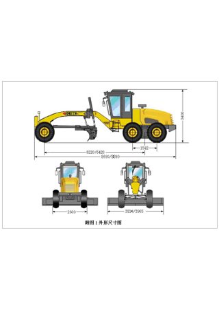
4. Performance parameter of complete machine 4.1 Dimensions (Fig.1) (Tyre 17.5-25) Fig.1 4.2 Working weight (Unit: kg) Complete machine Front axle Rear axle 15400 4600 10800 4.3 Engine Type 6CTA8.3-C215 Bore×stroke 114×135mm Total displacement of the pistons 8.27L Rated power 160kW…
-
Page 8: Torque Converter -Transmission
Rated speed 2200r/min Max. torque 872N.m Max. torque speed 1500r/min Operations sequence of different cylinders 1-5-3-6-2-4 Generator 24V/35A 4.4 Torque converter –Transmission Type: ZFW320 torque converter (with free wheeling) is integrated with 6WG200 transmission. Direction change (power gear shifting): Forward gear –neutral gear – reverse gear Speed gear (power gear shifting): Forward 6 speeds;…
-
Page 9: Hydraulic Working System
With wheel lean 10.4m 4.9.2 Articulated frame System: The articulation operation between front and rear frames is driven by double acting hydraulic cylinder. Articulating angle: Right and left sides 25° respectively. Min. turning radius with articulating steering: 7.8m over the front wheel. 4.10 Hydraulic working system System: Hydraulic system of double pumps and double circuits.
-
Page 10: Layout And Equipments
Batteries: every one 12V, 165AMP/h. Lights: head lights 2; tail lights 2; flashlamps 6; brake lamps 2; working lights 2; rear view lamps 2. Sound signal: horn 5. Layout and equipments Fig. 2 Frame and accessories: 1. Front frame 2. Rear frame 3. Articulation center 4. Engine cover 5. Splash guard 6.
-
Page 11: Description
19. Torque converter oil cooler 20. Front axle 21. Rear axle 22. Tandem box 23. Front wheel Steering: 24. Hydraulic steering-gear 25. Steering pump 26. Steering cylinder Work devices: 27. Swing frame, 6 adjustable positions 28.Traction frame 29. Tooth ring with rolling disc 30.
-
Page 12: Engine
6.1.1 Engine All driving devices (Engine-transmission) are fixed on the rear frame by 6 rubber vibration reduction housing. Viewed from the engine fan, the direction of the crankshaft is clockwise. The combustion air is drawn through an air filter. Lubrication of all bearings in the engine as well as cooling of some running engine parts is conducted by forced feed lubrication.
-
Page 13: Traveling Braking (Foot Braking) Hydraulic System
driving and sliding slope, the corresponding gear shall be controlled and the engine speed shall not be lower than 1200r/min to meet the needs of lubrication of each part of the transmession. The operating pump for suplying oil to torque converter and operating is mounted inside transmession and aslo controlled by pump wheel.
-
Page 14: Hydraulic Operating System And Hydraulic Steering System
When the pressure on the brake valve (10) drops below 100 bars, the indicator lamp on the instrument panel lights. This lamp is controlled by controlling the power switch. The pump is switched by brake service switch. When pressing down the brake valve (10), pressure oil in the accumulator circuit flows to the wheel-side brake (12).
-
Page 15
Fig. 9 Service brake, hydraulic operating and steering systems 1. Double-gang operating pump 9. Pressure limiting valve 2. Double-gang operating pump for 10. Braking valve steering and braking 11. Accumulator 3. Return oil cooler 12. Brake 4. Sealed type oil tank 13. -
Page 16
A3 电气接线图… -
Page 17
Fig.10 Electrical system 右转向示宽灯 Right-turn View-side lamp Right working light 右作业灯 电喇叭 Electric horn Right-front turning lamp 右前转向灯 Right head light 右前照灯 左照灯 Left light Left-front-turning lamp 左前转向灯 左前作业灯 Left-front working light left-turn View-side lamp 左转向示宽灯 插接器 Connector 插接器 Connector Connector 插接器… -
Page 18
Transmission case 变速箱 Connector 7 插接器七 倒车蜂鸣器 Astern running buzzer Right combined tail lamp 右组合后灯 蓄电池 Battery Back lamp 后照灯 Radio set 收音机 Rear wiper 后刮水器 Front wiper 前刮水器 顶灯 Overhead light Starting switch 起动开关 Switch for rear wiper 后刮水器开关 Flasher 闪光器… -
Page 19: Electrical Devices
插接器插头编号,从接线侧看: (二线,四线,六线,八线, 九线,十线,十二线方法相同): Viewed from connection side,number of c plug onnector ( The methods of lines 2, 4,6, 8, 9,10 and 12 are identical) 插接器插座编号,从接线侧看 : (二线,四线,六线,八线,九线,十线,十二线方法相同) Viewed from connection side,number of c plug: onnector (The methods of lines 2,4,6, 8, 9,10 and 12 are identical ) 技术要求:Technical requirements 凡图纸中未标注截面的面积为…
-
Page 20: Operation Instruction
7. Operation instruction 7.1 Adjust before operating for the first time Before unloading the grader, must check whether the machine has been damaged during transportation. If find out damage, shall contact with the transport company or commercial agent. The extent of damage or stolen extent shall be recorded on the freight bill.
-
Page 21
Fig. 11 1. Control lever for lifting left blade 16. Control lever for lifting right blade 2. Control lever for rotating blade 17. pedal of assistant vehicle ladder 3. Control lever for front wheel lean 18. Control device for hand brake 4. -
Page 22
7.3.1 Switches 1) Mains power switches Push the handle (Fig. 11/19) of power switch downwards the mains power will be switched on. 2) Starting switch (See Fig.11/28) If turn the starting switch by gear clockwise, all power supplies of instruments Ⅰ… -
Page 23
Fig. 12 1) Charge indicator lamp, red (Fig.12/1) The indicator lamp lights when the engine is running, which means that the charging line or alternator is at fault or the belt is loosened. The barratry is not charged, stop the engine and carry on troubleshoot. 2)Indicator lamp for brake service pressure, red (Fig.12/2) The indicator lamp lights when the engine is running;… -
Page 24
Fig. 13 1. Switch for working light 2. Switch for rear light 3. Overhead light switch in Driver’s cab 4. Switch for pilot light 5. Wiper switch for front window 6. Wiper switch for rear window 7.3.5 Comprehensive switch (Fig. 14) Fig. -
Page 25: Driver’s Cab
This pedal applies the wheel brake on the 4 rear wheels through the hydraulic system. Brake pressure depends on the pressure applied to the brake pedal. 7.3.8 Control device for hand brake (Fig. 15) Fig. 15 Pulling up the brake handle (Fig.15/1) to apply parking brake. To release the brake handle, pull it straightly up, press the knob (Fig.15/2) and push it down completely.
-
Page 26: Operation Of Operating Device
Fig.16 7.4.2 Driver’s seat (Fig.17) a) Backrest The angle of the backrest can be adjusted by the use of lever (1), the backrest shall be set with the lever (1) after adjustment. b) Seat height adjustment The lever (2) can be used to adjust the height of seat cushion and backrest. c) The lever (3) can be used to move the position of entire driver’s seat frontward and backwards.
-
Page 27
controlled, of which control methods are hydraulic driving (Except for teeth of scarifier). The different hydraulic devices can be driven by the following hydraulic cylinders and hydraulic motors. Fig.18 1. Hydraulic cylinder for front bulldozing plate ; 2. Hydraulic cylinder for front wheel lean; 3. -
Page 28
5. Wheel lean, left; 6. Wheel lean, right; 7. Articulation, left; 8. Articulation, right; 9. Back ripper, lower; 10. Back ripper, lift (Back ripper is unequipped) 11. Bulldozing plate , lower; 12. Bulldozing plate , lift; 13. Blade swing, right; 14. -
Page 29
Fig. 21 7.5.3 Blade adjustment By use of the swing hydraulic cylinders the blade with the scarifier can be positioned to suit all working conditions. The blade can be taken in and out to the left or right, and set at any angle. It can also be turned through 360º. Note: Make sure not to damage the vehicle frame ladder, hand wheel and echelon pull rod when moving blade. -
Page 30
Fig. 22 7.5.6 Back scarifier Note: The back scarifier has 5 teeth. Generally, 3 teeth are used to work on hard ground. Different teeth shall be used symmetrically, for example: use 1 tooth on the middle or 2 teeth outside or 3 teeth are used together. a. -
Page 31
1. Running position (Fig.24), swing the teeth in and lift the scarifier completely; 2. Scarifying position (Fig.25), in the figure the grade is in horizontal condition. The teeth are out and resting on the ground. The pointer of the indicator is in the middle position;… -
Page 32: Driving
Note: Before turning the grader and driving it in reverse, the back scarifier shall be lifted. 7.5.7 Bulldozing plate position indicator a. Bulldozing plate The control lever (See 7.5.1) controls the (lifting and lowering of) bulldozing plate. The bulldozing plate is connected with front frame by high strength bolts to enable the bulldozing plate mount and remove quickly.
-
Page 33
c. Check the engine filter; Check the indicator for intaking-resistance in the air filter is in normal condition or not; d. Check the oil level indicator of the hydraulic oil tank; Carry out this check after lowering the blade, hydraulic cylinder on the ground and cooling hydraulic oil (See 8.3.6.c);… -
Page 34
engine speed. While the temperature is below 0 , normal revolutions of 1/2 or 2/3 ℃ are not exceeded to prevent starting engine from over-loading, during the first 30 minutes of working. a. Temperature rise in transmission 1. Engage hand brake. 2. -
Page 35
have a braking effect when the speed of the turbine of torque converter is faster than pump gear linked with the engine. The traveling speed of the gear II is suitable for plain road or middle slope to travel down. For sharp slope, the gear I can be used for proper speed. With accelerating pedal, you can make the grader using foot brake with in minimum limit. -
Page 36
7.6.11 Parking the grader a. Engage the hand brake tightly. b. Set the operating devices on ground. c. Take off the ignition key and lock the driver’s cab door. Note: wheels shall be stopped if parks the grader on sloping field. 7.6.12 Drag running a. -
Page 37: Care And Maintenance
The articulation also allows the grader an action of self recovery in different conditions. 3. Further applications of the grader can be realized by installing the following equipment: a) Back scarifier; b) Front bulldozing plate ; c) Towing attachment, rear; d) Extra balance weights, front and rear.
-
Page 38: Lubrication Chart
5. Shut down the engine, never ignore this item. Except for the conditions that repairs and inspection cannot be carried out without engine running. 6. If the operating devices must be suspended, they must be supported firmly. 7. Fix the suspenders over the grader. 8.
-
Page 39
A3 润滑图… -
Page 40
推土板油缸轴承:Bearing of cylinder of bulldozing plate 推土板轴承:Bearing of bulldozing plate 推土板油缸轴承:Bearing of cylinder of bulldozing plate 前桥轴承:Bearing of front axle 前轮倾斜油缸轴承:Bearing of cylinder of front wheel lean 前桥轴承:Bearing of front axle 前轮倾斜拉杆:Pull rod of front wheel lean 前轮转向节:Steering knuckle of front wheel 转向油缸:Steering cylinder 牵引架轴承:Bearing of traction frame 摆动油缸轴承:Bearing of swing cylinder… -
Page 41
后桥加油口:Oil filler of rear axle 液压油加油过滤器:Filling strainer of hydraulic oil 液压油箱加油口:Oil filler of hydraulic tank Symbol description ● Oil cup Oil filling and filter Clean Grease Check oil level Bilateral symmetry Fig. 30 Lubrication chart of PY180H grader… -
Page 42
8.2.3 Firstly filling oil, change and maintenance of filter Do according to the following regulations: Working hours Work to be carried out After 50h Change oil for engine Replace engine filter element Tighten tightening screw on engine oil tank Tighten fixing clips of oil suction and drainage conduit on cylinder cap Tighten the loose parts of engine device Check clearance of valve, adjust if necessary… -
Page 43: Check Oil Level, Change Oil And Filter
8.2.5 Capacity table Note: All capacities given in the following table are approximate values. Subject to observing oil scale on inspection glass or control orifice. Part Approximate capacity Fuel tank 228L First filling oil for hydraulic system 130L First changing oil for hydraulic system Change and filtrate oil for engine 22.4L First filling oil for torque converter, transmission…
-
Page 44
Intervals of engine oil changing: Oil designation Intervals of oil changing (Operating hours) L-ECD 15W-40 Avoid mixing of different oils. 8.3.2 Transmission Please refer to the Item 6.1.2, Hydraulic torque converter-transmission (ZF6WG200) 8.3.3 Rear axle a. Note: Check oil level and change oil according to the lubrication chart (8.2). 1. -
Page 45
8.3.4 Tandem box a. Change oil 1. Unscrew the screw plug (Fig. 32/1), (Each tandem box has two screw plugs), drain oil into proper container, screw on the screw plug after drainage. 2. Clean the crew plug (Fig. 32/1), replace sealing ring to refit and retighten screw plug. -
Page 46
Fig. 33 Fig. 34 b. Check oil level 1. The turbine box of blade rotating shall be placed horizontally. 2. Oil level (Highest oil level) must be at the middle of inspection hole (Fig. 34/3). 3. Add oil from oil filling hole (Fig. 34/2) if necessary. 8.3.6 Hydraulic operating and steering systems Fig. -
Page 47
4. When no more air escapes, screw on the exhaust valve and refit the rubber cap. b. Change hydraulic oil Note: The oil should be changed after prescribed operating hours (Item 8.2). In two special conditions, the oil must be changed whenever the oil has become so contaminated that a drop specimen placed on a piece of filter or blotting paper leaves a sharply dark spot after a few hours. -
Page 48
Fig. 38 Note: Pay attention to proper sealing of the filter opening. Use new sealing ring, if necessary. Screw in filter cover (Fig.37/3) carefully in order to avoid damaging of the fine thread. Capacity: Approx.80L viewed from the inspection glass. c. -
Page 49: Maintenance System
Fig. 40 Fig. 39 8.4 Maintenance system The maintenance work must be conducted according to the specified interval. Operating hours Maintenance Engine: Daily maintenance 1. Check lubricating face of oil bath, governor and (10 operating hours ) injecting oil pump. If the oil level is not enough, fill up to the prescribed values;…
-
Page 50
Maintenance Operating hours First 100 operating Engine: hours 1. Drain the engine oil from engine oil filter and diesel oil (First maintenance ) from diesel oil filter and clean engine oil filter element and diesel oil filter element. 2. Carry out maintenance for air filter, remove the dusts in filter element and dust collector. -
Page 51
Operating hours Maintenance Engine: The following work shall be carried out except for After every the maintenance items to be conducted after 100h of operating hours operation: 1. Change lubricating oil of engine. 2. Adjust valve clearance. 3. Check the fuel injector for injection pressure and injection condition, clean and adjust if necessary. -
Page 52: Engine
Operating hours Maintenance Engine: The following work shall be carried out except for After every 3000 the maintenance items to be conducted after 100h of operating hours operation: 1. Clean the cooling system. 2. Clean the engine oil cooler. 3. Check the internal water seal of water pump and fill new lubricating grease.
-
Page 53
smoking and let fuel overflow. 8.5.2.1 Fuel, fuel tank a. Fuel The following fuels are approved to use: Diesel oil GB252-87 Operating in Winter: No. 0~-35 Operating in Summer: No. 0 or 10 b.Fuel tank The fuel tank is mounted on the right side behind the engine. 1. -
Page 54: Brake System
8.6 Brake system 8.6.1 Pliers disk brake 1. Piston 2. Friction disc assembly 3. Braking plate 4. T\Rectangular gasket 5. Locking screw 6. Pin 7. Exhaust vent 8. Bolt of cylinder cap 9. Cylinder cap 10. O-ring 11. Dust-proof ring a.
-
Page 55
Additionally, if the chains in the tandem box are too slack, adjust the brake after adjustment the chain tension to make the brake always assembled in the positions (Point 3 and point 9) where the exhaust vent is located. c. Disassembly (See attached figure) ○… -
Page 56
Cleaning the brake is the key for maintaining. Inspect the rubber pad for aging phenomenon, replace if necessary. Shoe type brake Brake system Note: Only professional staff can conduct repairs and maintenance. Check the thickness of brake lining in accordance with maintenance system (8.4);… -
Page 57
Fig. 56 Manually rotate the wheels and adjust with 22mm wrench at the shown “Tightening” direction (See Fig. 56) till the wheels have been locked. (Here, both brake shoes contact with brake drum). 4. Unscrew the adjusting bolt (Fig. 56/1) by about 3°at the “Release” direction; in this way, the clearance between both brake shoes and brake drum will be released to about 0.75mm. -
Page 58
The air bleeding has to be done by 2 personnel from all bleed valves of the wheel brakes. 1. Remove the gum cap of bolt for gas release (Fig. 50/1). 2. Place the hose (Fig.50/2) on bolt for gas release, the other side shall be placed into a clean container (Fig.50/32). -
Page 59: Adjustment Of The Chain Of Tandem Box
claw beam is stopped before braking force has not been achieved. 1. Loosen the bolt (Fig.52/5) and remove clamping plate (Fig.52/6); 2. Take out the baffle (Fig.52/7) along the direction of the claw beam (Fig.52/4); 3. Replace brake lining (The lining is along the direction of brake disc). Push in the baffle and fix bolt (Fig.52/5) with clamping plate, the anti-loosening glue must be applied to tighten.
-
Page 60: Lubrication And Adjustment Of Front Wheel Bearing
Take notice that the position of mark “0” of (4) and (7) shall be relatively consistent Note: When turning connecting plate (4) and cap (7), full attention must be drawn to prevent O-ring from damaging. Fig. 53 7. Reassemble the connecting plate (4) and cap (7) by the use of screw (3) and bolts (6), The bolts shall be tightened face to face crosswise.
-
Page 61: Work Device- Blade
6. Disassemble the wheel hub (Fig.54/1) by the use of proper drawing tools. Clean wheel hub, front wheel spindle, bearing and cap; if damaged, replace seal ring and bearing to be used on new cap. 7. Fill in new lubricating grease. Fig.
-
Page 62
Fig. 55 1. Place the blade on two pieces of wood. 2. Remove the baffle (Fig.55/2). 3. Disassemble the blade by means of sliding and inner bushing (Fig.55/1). 4. Install new inner bushing and fasten the baffle. 8.9.2 Replace guide plate (Fig. 56) Fig. -
Page 63: Tyres
exceeds 3mm and axial clearance 2.5mm. In case of gear-ring structure of rolling plate, the mentioned above adjustment is unnecessary. a. Axial adjustment of guide plate Fig. 57 Fig. 58 1. Measure the axial clearance between the tooth ring(Fig.58/1) and 4 guide plates (Fig.58/2) by the use of clearance gauge, guarantee that the clearance is ranged from0.6mm~0.8mm (Fig.58/3).
-
Page 64: Fasten And Change Wheel
and leads to raise air pressure. But this increased air pressure is a problem. So, you would not correct it and do not lower air pressure by releasing air. 8.10.2 Air pressure of tyre: Bar Tyre Layer Front wheel Rear wheel 17.5~25 2±0.3 2±0.3…
-
Page 65: Steering
thread is opposite. Note: As for some special operating conditions, an alternative arrangement of the wheel may be of advantage. However, it is recommended that follow the advice of the tyre manufacturer. 8.12 Steering Check the steering system for normal function regularly. a.
-
Page 66: Notes To Store The Grader
For the maintenance and notice items of this alternator, please refer to the Service manual for Aalternator. check for correct V-belt tension on driving device of the alternator regularly. In order to avoid damaging the three-phase alternator, the following must be observed: 1.
-
Page 67: Fault Analysis And Troubleshooting
If the grader is not used for about one year, hydraulic oil will be changed in the transmission, driving box of rear axle, tandem box and circle worn gear of the blade at the same time and change engine oil (see item 8.3.1). 1.
-
Page 68
3. Electrical problem a. Deficiency electrical Re-charge to reach the regulated power of battery requirement. Check if the connection is right b. Poor contact of electrical or tightened. connection Repair or replace starter brush and clean rectifier with fine sand c. -
Page 69
6. Air enters into oil supply Process according to items a and system or blocked. b of Section 1 of this chapter 7. Deficient oil supply. Check injection pump plunger and delivery valve seat 8. Bad atomization of fuel Check, clean and adjust pressure injector. -
Page 70
axial clearance of crank shaft 7. Mussy sound or light rhythmic slap at the cylinder cover can be Check piston and valve for heard as a result of broken valve collision and furthermore, check spring, bent pushing bar or too if marks of piston and gas much clearance of valve. -
Page 71
much oil injection and fail to burn completely. Engine oil is 1. Pressure gauge damaged or oil Replace the pressure gauge or underpressure pipe blocked. dredge the oil pipe. Fill in engine oil to the specified 2. Too low oil level in oil sump. oil level. -
Page 72
supply system. d. Spring of delivery valve is Replace spring. broken. 2. Nonuniform output of oil. a. There existing air in oil Drain air. supply system. b. Spring of delivery valve is Replace spring. broken. c. Sealing surface of delivery Replace parts or repair. -
Page 73
broken. b. Needle valve and valve seat Clean or replace parts. faces are damaged. c. Needle valve is clipped. Replace parts. d. Pressure map is deformed. Polish or replace parts. e. Joint face of fuel injector is Replace parts. uneven. 5. -
Page 74
a. Crank shaft and axle sleeve Check crank shaft and axle; blocked. Repair shaft and replace axle sleeve. Piston cylinder Replace the piston or the sleeve. blocked. 2. Crank shaft can turn freely. a. Air in fuel system Bleed air. b. -
Page 75
2.2 Too low shifting Oil level too low. Fill up to the specified pressure. pressure Notify the Sales & Service Dept. gears(See pressure Faults in operating pump of our company. gauge) Notify the Sales & Service Dept. Faults in gear shifting pressure. of our company. -
Page 76: Front Axle Drive Unit
(Notify Sales & Service Dept.) 10. Front axle drive unit (Applied to PY180) Compared with the others PY180 series graders, the PY180H grader is only equipped with the front axle drive unit additionally, the others parts are identical with PY180 series graders basically. Introduction to PY180 series graders has been made, here we will not describe.
-
Page 77: Front Driving Axle
Here, the section of the front axle drive is introduced in the operating instructions for PY180H grader, for the other sections please refer to chapter 7. The PY180H grader has three driving types as follows: full axle drive, only rear axle drive and only front axle drive.
-
Page 78
电子监测器 Electronic monitor 左转:Left turning 充电:Charge 制动:Brake 油率:oil rate 右转:Right turning 报警总灯:Main alarm lamp 供电电压:Supply voltage 冷却水温:Cooling water temperature 变矩油温:Torque converter oil temperature 静音:Silencing 机油压力:Engine oil pressure 变速油压:Transmission oil pressure 制动压力:Brake pressure Fig. 61 1. Indicator lamp of front axle drive 2. -
Page 79
Full axle drive: After switching off (Pressing) No. switch of full axle drive and when the transmission is on gear 1 and 2 of forward and gear 1 of reverse, the front axle drive will work, the front and rear axles are under driving state, the indicator lamp of No. -
Page 80: Care And Maintenance
10.4 Care and maintenance The care of the hydrostatic driving system of front axle can be conducted with reference to Chapter 8. The driving pump and driving motor can be started after being filled with hydraulic oil after installation and repairs, which shall be carried out under no load and then increase rotating speed and load subsequently.
Автогрейдеры Руководства и Инструкции по Ремонту и Эксплуатации Скачать Бесплатно

15,8 Мб
Автогрейдеры Caterpillar 140H, 160H: Руководство по
Формат: pdf
-
Год:
2000
-
Страниц:
182
-
Язык:
русский
-
Размер:
15,8 Мб
-
Категории:
Автогрейдеры
13,4 Мб
Каталог деталей автогрейдеров YTO PY180C-2, YTO PY180D-2 и
Формат: pdf
-
Год:
2008
-
Страниц:
102
-
Язык:
английский, китайский
-
Размер:
13,4 Мб
-
Категории:
Автогрейдеры

13,5 Мб
Руководство по эксплуатации автогрейдеров ЧСДМ ДЗ-98В
Формат: pdf
-
Год:
2018
-
Страниц:
119
-
Язык:
русский
-
Размер:
13,5 Мб
-
Категории:
Автогрейдеры
2,21 Мб
Руководство по эксплуатации автогрейдеров XGMA XG31651 и
Формат: doc
-
Год:
2007
-
Страниц:
45
-
Язык:
русский
-
Размер:
2,21 Мб
-
Категории:
Автогрейдеры

To re-order these
Operating Instructions
for
TG 190
Motor Grader
(RUSSIAN)
specify
Part Number: 15503450
Содержание
Введение 1
Предисловие 1.1
Для безопасности 1.2
Применение в соответствии с назначением 1.2.1
Организационные меры 1.2.2
Указания по безопасности — Таблички 1.2.3
Отбор персонала и его квалификация; основные обязанности 1.2.4
Указания по технике безопасности для определенных этапов работ 1.2.5
Указания по особым видам опасностей 1.2.6
Погрузочно-разгрузочные работы 1.2.7
Оригинальные части 1.2.8
Oбoзнaчeния 1.3
Фyнкции знaкoв, oпиcaниe, ycтpaнeниe нeиcпpaвнocтeй 1.3.1
Диагностика автомобиля 1.3.2
Дисплей на колонке рулевого управления 1.4
Установка времени 1.4.1
Вызов информации 1.4.2
Автоматический контролъ рабочего состояния 1.4.3
Установка счётчика суточного пробега на 0 1.4.4
Перед вводом машину в эксплуатацию 2
Отпирание капота двигателя 2.1
Пуск и останов двигателя 3
Запустить двигатель 3.1
Как происходит пуск двигателя 3.1.1
Пуск теплого двигателя 3.1.2
Пуск холодного двигателя без системы облегчения пуска двигателя 3.1.3
Запуск двигателя при температурах ниже -15°C с использованием системы подогрева воздуха 3.1.4
Останов двигателя 3.2
Режим транспорта 4
Переключение передач 4.1
Обкатка двигателя 4.2
Высота над уровнем моря 4.3
Торможение грейдера 4.4
Рулевое управление 4.5
Аварийное управление 4.6
Развал передних колес 4.7
Сигнальные устройства 4.8
Осветительные устройства 4.9
Вентиляция, обогрев и кондиционирование 4.10
Таймер стационарного обогрева (доппоставка) 4.11
Стеклоочиститель и система обмыва и очистки стекла 4.12
Управление изломом рамы 4.13
Система аварийной световой сигнализации на крыше 4.14
Система аварийной световой сигнализации 4.15
Остановка машины 4.16
Передвижение на машине 4.17
Буксировка машины 5
Фиксация шарнирной системы излома 7
Погрузка / выгрузка грейдера на железнодорожный транспорт 8
Работа на грейдере 9
Общие положения и основные правила 9.1
Углы установки отвала 9.2
Угол резания 9.2.1
Угол захвата 9.2.2
Угол наклона 9.2.3
Использование возможностей установки углов отвала 9.3
Установка отвала в транспортном положении 9.4
Предельные условия применения грейдера 9.5
Углы наклона машины 9.5.1
Твердость грунта 9.5.2
Предельные климатические условия 9.5.3
Рекомендуемые углы установки отвала 9.6
Правила безопасности при работе на грейдере 9.7
Указания по выполнению производственных задач 9.8
Поперечное перемещение грунта 9.8.1
Продольное перемещение грунта 9.8.2
Нарезка траншеи 9.8.3
Установка угла наклона 9.8.4
Работы, выполняемые на откосах 9.8.5
Работа с отвальным щитом 9.9
Работа с кирковщиком 9.10
Откидывание кабины для проведения сервисных работ 9.11
Управление кондиционером (доппоставка) 11
Включение кондиционера 11.1
Выключение кондиционера 11.2
Глазок и трехпозиционный дифференциальный манометрический выключатель 11.3
Контроль уровня охлаждающей жидкости 11.4
Конденсатор кондиционера 11.5
Коллектор охлаждающей жидкости 11.6
Компрессор 11.7
Указания по неисправностям и их устранению 11.8
Правила техники безопасности 11.9
Управление заправочным насосом с отключением (опция) 12
Сиденье водителя (с пневмоподвеской) 13
Указания 13.1
Указания по безопасности 13.2
Функция сиденья и обслуживание 13.3
Уход 13.4