-
Contents
-
Table of Contents
-
Bookmarks
Quick Links
BeneHeart D3
Defibrillator/Monitor
Operator’s Manual
Related Manuals for Mindray BeneHeart D3
Summary of Contents for Mindray BeneHeart D3
-
Page 1
BeneHeart D3 Defibrillator/Monitor Operator’s Manual… -
Page 3
© 2010 — 2013 Shenzhen Mindray Bio-Medical Electronics Co., Ltd. All rights reserved. For this Operator’s Manual, the issue date is 2013-09. -
Page 4
Mindray is strictly forbidden. are the trademarks, registered or otherwise, of Mindray in China and other countries. All other trademarks that appear in this manual are used only for informational or editorial purposes. They are the property of their respective owners. -
Page 5
Contents of this manual are subject to change without prior notice. All information contained in this manual is believed to be correct. Mindray shall not be liable for errors contained herein or for incidental or consequential damages in connection with the furnishing, performance, or use of this manual. -
Page 6
Mindray’s obligation or liability under this warranty does not include any transportation or other charges or liability for direct, indirect or consequential damages or delay resulting from the improper use or application of the product or the use of parts or accessories not approved by Mindray or repairs by people other than Mindray authorized personnel. -
Page 7
Preface Manual Purpose This manual contains the instructions necessary to operate the product safely and in accordance with its function and intended use. Observance of this manual is a prerequisite for proper product performance and correct operation and ensures patient and operator safety. This manual is based on the maximum configuration and therefore some contents may not apply to your product. -
Page 8
FOR YOUR NOTES… -
Page 9: Table Of Contents
Contents 1 Safety……………………………… 1-1 1.1 Safety Information………………………………..1-1 1.1.1 Dangers ………………………………….1-2 1.1.2 Warnings …………………………………..1-2 1.1.3 Cautions ………………………………….1-3 1.1.4 Notes ………………………………….1-3 1.2 Equipment Symbols………………………………..1-4 2 The Basics …………………………….2-1 2.1 Overview……………………………………2-1 2.2 Intended Use ………………………………….2-1 2.2.1 AED……………………………………2-2 2.2.2 Manual Defibrillation…………………………….2-2 2.2.3 Noninvasive Pacing ……………………………….2-2 2.2.4 ECG……………………………………2-2 2.2.5 Resp ……………………………………2-2 2.2.6 SpO…
-
Page 10
4 Managing Patients…………………………. 4-1 4.1 Overview ……………………………………4-1 4.2 Editing Patient Information …………………………….. 4-1 5 Alarms…………………………….. 5-1 5.1 Alarm Categories ………………………………… 5-1 5.2 Alarm Levels ………………………………….5-2 5.3 Alarm Indicators………………………………….. 5-2 5.3.1 Alarm Lamps ………………………………..5-2 5.3.2 Audible Alarms ………………………………. 5-3 5.3.3 Alarm Message ………………………………. -
Page 11
6.7.4 Changing Arrhythmia Threshold Settings ……………………..6-10 6.7.5 Initiating Arrhythmia Relearning Manually……………………..6-11 6.7.6 Automatic Arrhythmia Relearn…………………………6-11 6.8 Calibrating ECG…………………………………. 6-11 7 AED ………………………………7-1 7.1 Overview……………………………………7-1 7.2 Safety……………………………………..7-1 7.3 AED View……………………………………7-2 7.4 AED Procedure………………………………….7-3 7.5 Shock Advised………………………………….7-4 7.6 No Shock Advised (NSA)………………………………7-4 7.7 CPR ……………………………………..7-5 7.7.1 CPR Metronome ………………………………7-5 7.8 AED Sound Recording………………………………..7-6… -
Page 12
10.4.2 Changing Resp Wave Settings…………………………10-3 11 Monitoring PR …………………………..11-1 11.1 Overview ……………………………………11-1 11.2 Adjusting Pulse Tone Volume ……………………………..11-1 12 Monitoring SpO …………………………12-1 12.1 Introduction………………………………….12-1 12.2 Safety……………………………………12-2 12.3 Identifying SpO Modules…………………………….12-2 12.4 SpO Monitoring Procedure…………………………….12-2 12.5 Changing SpO Settings ……………………………….12-3 12.5.1 Setting SpO Sensitivity …………………………..12-3 12.5.2 Monitoring SpO… -
Page 13
16 Review …………………………….16-1 16.1 Reviewing Events ………………………………..16-1 16.2 Reviewing Tabular Trends…………………………….16-2 17 Data Management…………………………17-1 17.1 Introduction ………………………………….17-1 17.2 Reviewing Patient Events …………………………….17-2 17.3 Exporting Data ………………………………..17-2 18 Recording …………………………… 18-1 18.1 Using a Recorder………………………………..18-1 18.2 Recording Types……………………………….. -
Page 14
20.2 Installing the Batteries ………………………………20-2 20.3 Battery Alarms………………………………….20-2 20.3.1 No Battery Alarm……………………………….20-2 20.3.2 Low Battery Alarm …………………………….20-2 20.3.3 Battery Aged Alarm…………………………….20-3 20.3.4 Battery Error Alarm…………………………….20-3 20.4 Checking the Batteries………………………………20-3 20.5 Charging batteries………………………………..20-3 20.6 Storing Batteries………………………………..20-4 20.7 Recycling the Batteries………………………………20-4 21 Care and Cleaning…………………………21-1 21.1 General Points ………………………………….21-1 21.2 Cleaning …………………………………….21-2 21.3 Disinfecting ………………………………….21-2… -
Page 15
A.7 Alarm Specifications………………………………..A-10 A.8 Data Management Specifications …………………………..A-11 A.9 Environmental Specifications …………………………….A-11 B EMC………………………………B-1 C BeneHeart Defibrillator Shift Checklist ……………………C-1 D Alarm Messages …………………………..D-1 D.1 Physiological Alarm Messages …………………………….D-1 D.2 Technical Alarm Messages ………………………………D-2 E Electrical Safety Inspection……………………….E-1 E.1 Power Cord Plug…………………………………..E-1 E.2 Device Enclosure and Accessories…………………………..E-1 E.3 Device Labelling…………………………………..E-2… -
Page 16
FOR YOUR NOTES… -
Page 17: Safety
Safety 1.1 Safety Information DANGER Indicates an imminent hazard that, if not avoided, will result in death or serious injury. WARNING Indicates a potential hazard or unsafe practice that, if not avoided, could result in death or serious injury. CAUTION Indicates a potential hazard or unsafe practice that, if not avoided, could result in minor personal injury or product/property damage.
-
Page 18: Dangers
1.1.1 Dangers DANGER The equipment delivers up to 360 J of electrical energy. Unless properly used as described in these Operating Instructions, this electrical energy may cause serious injury or death. Do not attempt to operate this defibrillator unless thoroughly familiar with these operating instructions and the function of all controls, indicators, connectors, and accessories.
-
Page 19: Cautions
For the treatment of patients with implantable pacemakers, place therapy pads or paddles away from internal pacemaker generator if possible to help prevent damage to the pacemaker. To avoid inadvertent disconnection, route all cables in a way to prevent a stumbling hazard. Wrap and secure excess cabling to reduce risk of entanglement or strangulation by patients or personnel.
-
Page 20: Equipment Symbols
1.2 Equipment Symbols Caution (Attention, consult Status indicator accompanying documents) Alternating current Battery indicator Audio paused Alarm off Audio off Alarm paused Marker Lead select Gain select Event summary NIBP start/stop key Graphical recorder Menu Unlocking Network connector Shock button USB connector Input/Output Equipotentiality…
-
Page 21
Fragile Right side up Keep dry Maximum stacks Manufacturer Date of manufacture General symbol for recovery/recyclable Electrostatic sensitive devices Mark of conformity to European Medical Device Directive 93/42/EEC Authorised representative in the European community DEFIBRILLATION-PROOF TYPE CF APPLIED PART DEFIBRILLATION-PROOF TYPE BF APPLIED PART Dispose of in accordance to your country’s requirements… -
Page 22
FOR YOUR NOTES… -
Page 23: The Basics
The Basics 2.1 Overview The BeneHeart (hereinafter called the equipment) is a lightweight and portable defibrillator/monitor. It provides four operating modes: Monitor, Manual Defib, AED and Pacer. In Monitor Mode, the equipment is intended for monitoring, displaying, reviewing, storing and printing multiple physiological parameters and waveforms including ECG, pulse oximetry (SpO ), respiration (Resp), and non-invasive blood pressure (NIBP).
-
Page 24: Aed
2.2.1 AED The AED mode is to be used only on cardio arrest patients who are at least 8 years. The patients must be: Unresponsive Not breathing or not breathing normally 2.2.2 Manual Defibrillation Asynchronous defibrillation is the initial treatment for ventricular fibrillation and ventricular tachycardia in patients that are pulseless and unresponsive.
-
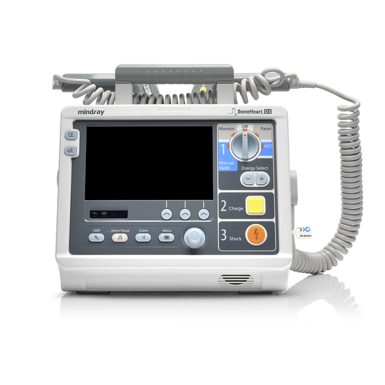
Page 25: Main Unit
2.3 Main Unit 2.3.1 Front View External paddle Handle Alarm lamp Area 1 Area 3 Microphone Area 2 Speaker…
-
Page 26
Area 1 Display screen AC power indicator Illuminated: when AC mains is connected. Off: when AC mains is not connected. Battery indicator Yellow: when the battery is being charged. Green: when the battery is fully charged or the equipment is run on battery. Off: when no battery is installed or battery fails. -
Page 27
Area 2 Lead Select button Press this button to select the lead of the first ECG waveform. Gain select button Press this button to select the size of the first ECG waveform. NIBP button (for equipments configured with NIBP function) Press this button to start or stop NIBP measurements. -
Page 28
Area 3 Mode Select knob Rotate this knob to select the operating mode or turn the equipment off. Energy Select button In Manual Defib mode, press this button to select energy level. Charge button Press this button to charge the defibrillator. Shock button Press this button to deliver a shock to the patient. -
Page 29
Recorder Start/Stop Key Press this key to start a recording or stop the current recording. Indicator Illuminated: when the recorder works correctly. Flashes: when an error occurred to the recorder, or the recorder runs out of paper. Paper outlet Recorder door Latch… -
Page 30: Side View
2.3.2 Side View Therapy port Therapy port is used to connect paddles cable or pads cable. Recorder ECG: ECG cable connector : SpO sensor connector NIBP: NIBP cuff connector…
-
Page 31: Rear View
2.3.3 Rear View Hook Battery Equipotential grounding terminal When the defibrillator/monitor and other devices are to be used together, their equipotential grounding terminals should be connected together to eliminate the potential difference between them. External power input It connects an AC power cord or a DC/AC adapter to run the equipment respectively on the external AC mains or DC power supply.
-
Page 32: External Paddles
2.3.4 External Paddles Sternum paddle Apex paddle Shock button Energy Select button Shock indicator Charge button Shock button 2-10…
-
Page 33: Display Views
2.4 Display Views A typical screen in Manual Defib Mode is shown below. Patient Information area This area shows patient name, patient category, paced status, and current date and time. : indicates that the patient has an implanted pacemaker. Alarm status symbols indicates alarms are paused;…
-
Page 34
Waveform area This area shows measurement waveforms. The waveform label is displayed at the upper left corner of the waveform. Parameter area This area shows measurement parameters. Each measurement module has a parameter block and the parameter name is displayed at the upper left corner. Manual Defib information area This area shows the selected defibrillation energy, shock counter as well as prompt related to manual defibrillation. -
Page 35: Basic Operations And Settings
Basic Operations and Settings 3.1 Installation WARNING The equipment shall be installed by personnel authorized by the manufacturer. The software copyright of the equipment is solely owned by the the manufacturer. No organization or individual shall resort to juggling, copying, or exchanging it or to any other infringement on it in any form or by any means without due permission.
-
Page 36: Environmental Requirements
3.1.2 Environmental Requirements The operating environment of the equipment must meet the requirements specified in this manual. The environment where the equipment is used shall be reasonably free from noises, vibration, dust, corrosive, flammable and explosive substances. If the equipment is installed in a cabinet, sufficient space in front and behind shall be left for convenient operation, maintenance and repair.
-
Page 37: Disconnecting From Power
3.2.3 Disconnecting from Power To disconnect the equipment from the AC power source, follow this procedure: Confirm that the patient monitoring or therapy is completed. Disconnect the patient cables and sensors from the patient. Make sure to save or clear the patient data as required. Turn the Mode Select Knob to Off.
-
Page 38: Adjusting The Screen Brightness
You can also set system time by selecting [Configuration >>]→[View Config]→[General Setup >>]. However, you cannot select date format and time format in this case. After the completion of setting system time, exit the configuration mode, and then the system will restart. 3.4.2 Adjusting the Screen Brightness Press the Main Menu button on the front panel, and then select [Others >>].
-
Page 39: Managing Patients
Managing Patients 4.1 Overview Patient information management function enables you to edit and manage information of the current patient. 4.2 Editing Patient Information You can edit patient information in Monitor, Manual Defib and Pacer mode. To edit patient information, Press the Main Menu button on the front panel, and then select [Patient Demographics >>] and then make changes as desired.
-
Page 40
FOR YOUR NOTES… -
Page 41: Alarms
Alarms Alarms, triggered by a vital sign that appears abnormal or by technical problems of the equipment, are indicated to the user by visual and audible alarm indications. WARNING A potential hazard exists if different alarm presets are used for the same or similar device in any single area, e.g.
-
Page 42: Alarm Levels
5.2 Alarm Levels By severity, alarms can be classified into three categories: high level alarms, medium level alarms and low level alarms. Physiological alarms Technical alarms High level Indicate that your patient is in a life Indicate a severe device malfunction or an improper operation, threatening situation, such as Asystole, which could make it possible that the equipment cannot detect Vfib/Vtac and so forth, and an…
-
Page 43: Audible Alarms
5.3.2 Audible Alarms The equipment uses different alarm tone patterns to match the alarm level: High level alarms triple+double+triple+double beeps. Medium level alarms triple beeps. Low level alarms single beep. 5.3.3 Alarm Message When an alarm occurs, the alarm message will appear in the technical or physiological alarm area. For physiological alarms, the asterisk symbols (*) before the alarm message match the alarm level as follows: High level alarms Medium level alarms…
-
Page 44: Alarm Tone Configuration
5.4 Alarm Tone Configuration 5.4.1 Changing the Alarm Volume → Alm Volume >>]. Press the Main Menu button on the front panel, and then select [Alarm Setup >>] [ Set [Alm Volume] to an appropriate level: If [Audio Off] is enabled, alarm volume can be set to a value between 0 and 10, in which 0 means audio off and 10 the maximum volume level.
-
Page 45: Setting Alarm Properties For All Parameters
5.5.1 Setting Alarm Properties for All Parameters → Para. Alarm >>] to enter the Para. Alarm setup menu, where you can In the main menu, select [Alarm Setup >>] [ review and set alarm limits, alarm switches, alarm level and alarm recordings for all parameters. When a parameter alarm is switched on, the equipment gives alarm indications in accordance with the preset alarm level and stores related waveforms and parameter values.
-
Page 46: Adjusting Alarm Limits Automatically
5.5.2 Adjusting Alarm Limits Automatically The defibrillator/monitor can automatically adjust the patient’s alarm limits according to the measured vital signs. When [Auto Limits] is selected, the equipment automatically calculates alarm limits based on the latest measured parameter values. To enable auto alarm limits, press the Main Menu button on the equipment’s front panel, and then select [Alarm Setup →…
-
Page 47: Pausing Alarms
5.6 Pausing Alarms You can temporarily disable alarm indicators by pressing the hardkey on the equipment’s front. When alarms are paused: For physiological alarms, no alarm indication is shown. New physiological alarm will not be presented. The remaining alarm pause time is displayed in the physiological alarm area. For technical alarms, alarm sounds are paused, but alarm lamps and alarm messages remain presented.
-
Page 48: Pausing Alarm Sounds
5.8 Pausing Alarm Sounds You can press the [Audio Pause] softkey to pause alarm tones. In this case, the symbol will be displayed in the sound symbol area indicating all system sounds are silenced temporarily. In the audio paused status, all alarm indicators except audible alarm tones works properly.
-
Page 49: Latching Alarms
5.11 Latching Alarms The latching setting for physiological alarms defines how alarm indicators behave when you do not acknowledge them. If an alarm is latched, alarm indications remain presented even though alarm conditions end, except that: The parameter reading and violated alarm limit stop flashing. The time when the alarm is last triggered is displayed behind the alarm message.
-
Page 50: When An Alarm Occurs
5.13 When an Alarm Occurs When an alarm occurs, observe the following steps and take proper actions: Check the patient’s condition. Confirm the alarming parameter or alarm category. Identify the alarm source. Take proper action to eliminate the alarm condition. Make sure the alarm condition is corrected.
-
Page 51: Monitoring Ecg
Monitoring ECG 6.1 Overview The electrocardiogram (ECG) measures the electrical activity of the heart and displays it as waveforms and numerics. The equipment enables ECG monitoring through 3-, 5- lead ECG sets, external paddles and multifunction electrode pads. If both ECG sets and paddles/pads are connected, the configured ECG waveforms are displayed in the waveform area. 6.2 Safety WARNING Periodically inspect the electrode application site to ensure skin quality.
-
Page 52: Monitoring View
6.3 Monitoring View You can access Monitor mode by switching the Mode Select knob to the Monitor position. When operating in Monitor mode, the equipment displays up to two ECG waveforms, the heart rate reading, other available parameter values and active alarm settings.
-
Page 53
5-Lead Placement The following is a typical AHA electrode placement for a 5-lead ECG set: RA placement: directly below the clavicle and near the right shoulder. LA placement: directly below the clavicle and near the left shoulder. RL placement: on the right lower abdomen. LL placement: on the left lower abdomen. -
Page 54: Ecg Monitoring With Paddles/Pads
6.4.2 ECG Monitoring with Paddles/Pads Prepare the patient’s skin. Apply the paddles/pads to the patient. If multifunction electrode pads are used, apply pads according to the instructions for use indicated on pads package. Use anterior-lateral placement. If external paddles are used, remove the paddle set from the paddle tray by grasping the handles and pulling them straight up.
-
Page 55: Checking Paced Status
6.4.3 Checking Paced Status It is important to set the paced status correctly when you start monitoring ECG. The paced symbol is displayed in the patient information area when the [Paced] is set to [Yes]. The pace pulse markers “︱” are shown on the ECG wave when the patient has a paced signal.
-
Page 56: Changing Ecg Settings
6.6 Changing ECG Settings 6.6.1 Changing Lead Settings 6.6.1.1 Selecting Lead Type Select the ECG parameter area to enter the [ECG Setup] menu. Select [Lead Set] and toggle between [3-lead] and [5-lead]. You can also set lead type in the configuration mode: →…
-
Page 57: Changing Ecg Wave Settings
6.6.2 Changing ECG Wave Settings You can select the ECG parameter area to enter the [ECG Setup] menu to set ECG cascade and wave speed. You can also select the hot keys above the ECG waveform to change ECG lead, size and filter. You can press the Lead Select button on the equipment’s front panel or use the Navigation knob to select the lead hot key above the first ECG waveform to select a lead.
-
Page 58: Adjusting Heartbeat Volume
6.6.4 Adjusting Heartbeat Volume In the case that ECG alarm is switched on, or both ECG alarm and PR alarm are switched off, heartbeat tone is issued. To adjust the heartbeat volume, → QRS Volume], or Select the ECG parameter window to enter the [ECG Setup] menu, and then select [Others >>] [ →…
-
Page 59: Switching Arrhythmia Analysis On And Off
Arrhythmia event Description Category Bigeminy A dominant rhythm of N, V,N, V, N, V. Trigeminy A dominant rhythm of N, N, V,N, N, V, N, N, V. R ON T R on T detected in normal heartbeats. Missed Beats* No beat detected for 1.75x average R-R interval for HR <120, or No beat for 1 second with HR >120 (for non-paced patients only), or No beat detected for more than the set pause threshold.
-
Page 60: Changing Arrhythmia Alarm Settings
6.7.3 Changing Arrhythmia Alarm Settings To change arrhythmia alarm settings, select the ECG parameter area to enter the [ECG Setup] menu, and then select [Arrhythmia >>]→[Arrh. Alarm] menu, where you can set alarm switch, alarm level and alarm record switch for all the arrhythmia events..
-
Page 61: Initiating Arrhythmia Relearning Manually
6.7.5 Initiating Arrhythmia Relearning Manually Normally arrhythmia relearning allows the equipment to learn new ECG patterns to correct arrhythmia alarms and heart rate value. We suggest you to manually initiate arrhythmia relearning when you suspect the result of arrhythmia analysis. To initiate relearning manually, select the ECG parameter window to enter the [ECG Setup] menu, select [Arrhythmia →…
-
Page 62
FOR YOUR NOTES 6-12… -
Page 63: Aed
7.1 Overview This chapter describes how to operate the equipment in AED Mode. While operating in AED Mode, the equipment analyses the patient’s ECG waveforms and guides you through the defibrillation process. The equipment starts analyzing the patient’s heart rhythm immediately after entering AED mode. When a shockable rhythm is detected, the equipment gives a prompt and automatically starts charging.
-
Page 64: Aed View
WARNING During defibrillation, air pockets between the skin and multifunction electrode pads can cause patient skin burns. To help prevent air pockets, make sure defibrillation pads are completely adhered to the skin. Do not use dried-out pads. In AED mode, this equipment is not designed to administer energy at pediatric joule settings. The American Heart Association recommends AEDs be used only on patients who are more than eight years old.
-
Page 65: Aed Procedure
7.4 AED Procedure Confirm that the patient is unresponsive, not breathing or not breathing normally. Then: Remove clothing from the patient’s chest. Wipe moisture from the patient’s chest and, if necessary, clip or shave excessive chest hair. Apply multifunction electrode pads to the patient as directed on the pads package. Use anterior-lateral placement. Connect the pads with pads cable, and then plug the pads cable in the equipment’s therapy port.
-
Page 66: Shock Advised
overcome to deliver an effective discharge of energy. The degree of impedance differs from patient to patient and is affected by several factors including the presence of chest hair, moisture, and lotions or powders on the skin. If the “Impedance too high. Shock not delivered” message appears, make sure that the patient’s skin has been washed and dried and that any chest hair has been clipped.
-
Page 67: Cpr
7.7 CPR If [Initial CPR Time] is not configured as Off, the system enters initial CPR if AED mode is entered. You can set [Initial CPR Time] to an appropriate time or switch it off through configuration management. After the shock series, ECG analysis pauses and the equipment enters the CPR status. Analysis resumes at the completion of the pause period or when you press the [Resume Analyzing] soft key in CPR status.
-
Page 68: Aed Sound Recording
Warning The CPR metronome sounds do not indicate information regarding the patient’s condition. Because patient status can change in a short time, the patient should be assessed at all times. Do not perform CPR on a patient who is responsive or is breathing normally. NOTE CPR metronome and its volume is affected by the settings of [Voice Prompt] and [Voice Volume] in the AED Setup menu.
-
Page 69: Manual Defibrillation
Manual Defibrillation 8.1 Overview This chapter explains how to prepare for and perform asynchronous defibrillation and synchronous cardioversion using multifunction electrode pads and external paddles. In Manual Defib Mode, you must assess the ECG waveforms, decide if defibrillation or cardioversion is indicated, select appropriate energy setting, charge the equipment, and deliver the shock.
-
Page 70
WARNING During synchronous cardioversion, if monitoring patient’s ECG through external paddles, artifact introduced by paddle movement may resemble an R-wave and trigger a defibrillation shock. Do not use conductive liquid. Use only conductive gel specified by the equipment manufacturer. If external paddles are used for defibrillation, apply the paddles tightly and evenly to the patient’s chest to ensure good skin contact. -
Page 71: Manual Defibrillation View
8.3 Manual Defibrillation View A typical screen in Manual Defib Mode is shown below. In the enlarged ECG area, an ECG waveform and related parameters are displayed. In the middle of the screen, defibrillation mode, synchronous icon, prompt message, selected energy, contact impedance indicator, and a shock counter are displayed.
-
Page 72
WARNING Hold only the insulating parts of the paddle handles to avoid shock hazard during charging or shock delivery. Turn the Mode Select knob to Manual Defib. You can access manual therapy directly, by confirmation or by password, which can be defined through configuration management. -
Page 73: Using Pediatric Paddles
NOTE Defibrillation is always performed through paddles or pads. However, during defibrillation you may choose to monitor the ECG using an alternate ECG source (3- or 5-lead monitoring electrodes). If an alternate ECG source is connected, any available lead may be displayed. When external paddles are used, the Shock button on the equipment’s front panel is disabled.
-
Page 74: Synchronized Cardioversion
NOTE When internal paddles are used for defibrillation, the energy selection is automatically limited to 50 joules because of possible cardiac damage from higher energies. Sterilize the internal paddles before each use. Otherwise, severe infection may result. Clean the internal paddles after each use. 8.5 Synchronized Cardioversion Synchronized Cardioversion allows you to synchronize delivery of the defibrillator shock with the R-wave of the ECG.
-
Page 75: Performing Synchronized Cardioversion
8.5.1 Performing Synchronized Cardioversion Connect the therapy cable and apply the multifunction electrode pads or external paddles to the patient. If ECG set is used for ECG monitoring, connect the ECG trunk cable and apply the ECG electrodes to the patient, referring to 6 Monitoring ECG.
-
Page 76: Remote Synchronized Cardioversion
8.6 Remote Synchronized Cardioversion The equipment can be configured to receive an ECG source from a remote patient monitor (such as a bedside patient monitor) to perform synchronized cardioversion. To do so, the remote patient monitor shall have a sync out connector and shall be connected to the defibrillator/monitor’s multifunctional connector with a synchronous cable.
-
Page 77: Contact Impedance Indicator
NOTE During remote synchronous defibrillation, the local defibrillator/monitor does not display the ECG waveform. To view the patient’s ECG, check the remote monitor. When you use an remote monitor as the ECG source, a biomedical technician must verify that the remote monitor and the defibrillator/monitor combination will deliver a synchronized shock within 60 ms of the peak of the R-wave.
-
Page 78
FOR YOUR NOTES 8-10… -
Page 79: Noninvasive Pacing
Noninvasive Pacing 9.1 Overview In pacer mode, the patient’s ECG is monitored through ECG lead set and pace pulses are delivered through multifunction electrode pads. The pads cannot be used to monitoring ECG rhythm and deliver pacing current at the same time. A white pacing marker is shown on the ECG waveform each time a pacer pulse is delivered to the patient.
-
Page 80: Pacing View
CAUTION Use of Pacer mode may be password protected. Make sure the operator knows and remembers the password as defined in Configuration. Failure to enter correct password will prevent the delivery of pacing therapy. For treatment of patients with implanted devices such as permanent pacemakers or cardioverter-defibrillators, consult a physician and the instructions for use provided by the device’s manufacturer Prolonged noninvasive pacing may cause patient skin irritation and burns.
-
Page 81: Demand Mode Versus Fixed Mode
9.4 Demand Mode versus Fixed Mode The equipment can deliver paced pulses in either demand or fixed mode. In demand mode, the pacer only delivers paced pulses when the patient’s heart rate is lower than the selected pacing rate. In fixed mode, the pacer delivers paced pulses at the selected rate. During pacing, you can change pacer mode.
-
Page 82: Demand Mode Pacing
9.5.1 Demand Mode Pacing To pace in demand mode: Turn the Mode Select knob to the Pacer position. Thus the pacing function is enabled in demand mode automatically. ECG waveform of Lead II is displayed in the waveform area by default. You can access manual therapy directly, by confirmation or by password, which can be defined through configuration management.
-
Page 83: Fixed Mode Pacing
Verify the presence of a peripheral pulse. You can temporarily withhold pacing pulse and observe the patient’s underlying rhythm by pressing and holding the [4:1] soft key. This causes pacing pulse to be delivered at 1/4 of the defined pacer rate. To resume pacing at set rate, release this key.
-
Page 84
WARNING Use care when handling the multifunction electrode pads on the patient to avoid shock hazard during pacing. If you are using the pacing function with battery power and the Low Battery alarm is presented, connect the equipment to external power or install a fully charged battery. CAUTION The monitoring or pacing function may be unstable in the presence of ESU or other electronic devices. -
Page 85: Monitoring Resp
Monitoring Resp 10.1 Overview Impedance respiration is measured across the thorax. When the patient is breathing or ventilated, the volume of air changes in the lungs, resulting in impedance changes between the electrodes. Respiration rate (RR) is calculated from these impedance changes, and a respiration waveform appears on the equipment screen. 10.2 Safety WARNING When monitoring the patient’s respiration, do not use ESU-proof ECG cables.
-
Page 86: Placing Resp Electrodes
10.4 Placing Resp Electrodes As the skin is a poor conductor of electricity, preparing the skin is necessary for a good Respiration signal. You can refer to the ECG section for how to prepare the skin. As the Respiration measurement adopts the standard ECG electrode placement, you can use different ECG cables (3-lead or 5-lead).
-
Page 87: Optimizing Lead Placement For Resp
10.4.1 Optimizing Lead Placement for Resp If you want to measure Resp and you are already measuring ECG, you may need to optimize the placement of the two electrodes between which Resp will be measured. Repositioning ECG electrodes from standard positions results in changes in the ECG waveform and may influence ST and arrhythmia interpretation.
-
Page 88
FOR YOUR NOTES 10-4… -
Page 89: Monitoring Pr
Monitoring PR 11.1 Overview The pulse numeric counts the arterial pulsations that result from the mechanical activity of the heart. You can display a pulse from SpO . The displayed pulse numeric is color-coded to match SpO parameter. PR unit PR alarm high limit PR value PR alarm low limit…
-
Page 90
FOR YOUR NOTES 11-2… -
Page 91: Monitoring Spo
Monitoring SpO 12.1 Introduction monitoring is a non-invasive technique used to measure the amount of oxygenated haemoglobin and pulse rate by measuring the absorption of selected wavelengths of light. The light generated in the probe passes through the tissue and is converted into electrical signals by the photodetector in the probe. The SpO module processes the electrical signal and displays a waveform and digital values for SpO and pulse rate.
-
Page 92: Safety
Change the application site every four hours. For neonates or patients with poor peripheral blood circulation or sensitive skin, inspect the sensor site more frequently. 12.3 Identifying SpO Modules The equipment can be configured with any of the following SpO modules. Mindray SpO module; Masimo SpO module; Nellcor SpO module.
-
Page 93: Changing Spo Settings
12.5.1 Setting SpO Sensitivity For Mindray SpO module, you can set [Sensitivity] to [High], [Med] or [Low] from the [SpO2 Setup] menu. For Masimo module, you can set [Sensitivity] to [Normal] or [High], in which [Normal] is equivalent to [Med].
-
Page 94: Sat-Seconds Alarm Management
12.5.4 Sat-Seconds Alarm Management With traditional alarm management, high and low alarm limits are set for monitoring oxygen saturation. During monitoring, as soon as an alarm limit is violated, an audible alarm immediately sounds. When the patient’s SpO value fluctuates near an alarm limit, the alarm sounds each time the limit is violated. Such frequent alarm can be distracting. The Sat-Seconds feature is available with the Nellcor SpO module to decrease the likelihood of false alarms caused by motion artifacts.
-
Page 95: Changing The Speed Of The Pleth Wave
12.5.5 Changing the Speed of the Pleth Wave In the [SpO2 Setup] menu, select [Sweep] and then select the appropriate setting. The faster the wave sweeps, the wider the wave is. 12.6 SpO Desat Alarm The defibrillator/monitor provides an SpO Desat alarm.
-
Page 96: Masimo Information
Inappropriate positioning of the SpO2 sensor, or use of incorrect SpO2 Drop of arterial blood flow to immeaurable level caused by shock, anemia, low temperature or vasoconstrictor. 12.9 Masimo Information Masimo Patents This device may be covered by one or more of the following US patents and foreign equivalents: 5,758,644, 6,011,986, 6,699,194, 7,215,986, 7,254,433, 7,530,955.
-
Page 97: Nibp
NIBP 13.1 Introduction Automatic non-invasive blood pressure monitoring uses the oscillometric method of measurement. It is intended for adult, pediatric and neonatal patients. To understand how this method works, we’ll compare it to the auscultative method. With auscultation, the clinician listens to the blood pressure and determines the systolic and diastolic pressures. The mean pressure can then be calculated with reference to these pressures as long as the arterial pressure curve is normal.
-
Page 98: Measurement Limitations
Do not use the NIBP cuff on a limb with an intravenous infusion or arterial catheter in place. This could cause tissue damage around the catheter when the infusion is slowed or blocked during cuff inflation. If you doubt the NIBP readings, determines the patient’s vital signs by alternative means and then verify that the equipment is working correctly.
-
Page 99: Starting And Stopping Nibp Measurements
Warning Continuous CUFF pressure due to connection tubing kinking may cause blood flow interference and resulting harmful injury to the patient. 13.5.2 Starting and Stopping NIBP Measurements You can start and stop NIBP measurements by using the hardkey on the equipment’s front panel. 13.5.3 Correcting the Measurement The cuffed limb should be at the same level as the patient’s heart.
-
Page 100: Understanding The Nibp Numerics
13.6 Understanding the NIBP Numerics The NIBP display shows numerics only as below. Your display may be configured to look slightly different. Measurement mode Pressure unit: mmHg or kPa NIBP alarm high limit NIBP alarm low limit Time of last measurement Systolic pressure Diastolic pressure Mean pressure at the completion of measurement, or cuff pressure during the measurement…
-
Page 101: Marking Events
Marking Events During patient monitoring or therapy, some events may exert effects on the patient and as a result change related waveforms and parameter values. To help analysing the waveforms or numerics at that time, you can mark these events. Before marking an event, you can define events A to H, for example, define event D as injecting Atropine.
-
Page 102
FOR YOUR NOTES 14-2… -
Page 103: Freezing Waveforms
Freezing Waveforms During patient monitoring, the freeze feature allows you to freeze the currently displayed waveforms on the screen so that you can have a close examination of the patient’s status. Besides, you can select any frozen waveform for recording. Waveforms can be frozen only in the Monitor Mode.
-
Page 104: Unfreezing Waveforms
15.3 Unfreezing Waveforms To unfreeze the frozen waveforms, you can either: Press the [Unfreeze] soft key, or Select [Exit] to return to the Main screen, or Perform any other action that causes the screen to be readjusted or opens a menu, such as plugging in or out a module, pressing the [Lead Select] or [Main Menu] button, etc.
-
Page 105: Review
Review 16.1 Reviewing Events The equipment can automatically record and save patient events. You can review patient events following this procedure: To review events, you can: In the Monitor, Manual Defib or Pacer mode, press the Main Menu button on the front panel, and then select [Review>>]→[Review Events >>] to enter the [Review Events] menu, or In the Monitor mode, repeatedly press the [Trends] soft key to enter the [Review Events] menu.
-
Page 106: Reviewing Tabular Trends
16.2 Reviewing Tabular Trends In the Monitor, Manual Defib o Pacer mode, press the Main Menu button on the front panel; select [Review>>]→[Trends>>] or, if you are operating in the Monitor mode, select the [Trends] soft key to enter the tabular trends menu, as shown below: 16-2…
-
Page 107: Data Management
Data Management 17.1 Introduction The data management function enables you to: Edit patient information; Review patient events; and Export patient data to USB memory. To access data management, press the Main Menu button on the front panel to enter the Main Menu, and then select →…
-
Page 108: Reviewing Patient Events
17.2 Reviewing Patient Events To view patient events, select a patient in the Archives Main screen, and then press the navigation knob to confirm the selection. In this case, you can select the [Return] soft key to return to the Archives Main screen. To edit patient information, select the [Patient Info] button and change the patient information as desired.
-
Page 109: Recording
Recording 18.1 Using a Recorder The thermal recorder records patient information, measurement numerics and up to three waveforms. 18.2 Recording Types By the way recordings are triggered, they can be classified into the following categories: Manually-triggered realtime waveform recordings. Event-triggered recordings. Alarm recordings triggered by an alarm limit violation or an arrhythmia event.
-
Page 110: Setting The Recorder
Automatic recordings will be triggered in the following conditions: If both [Alarm] and [Alm Rec] for a measurement are switched on, an alarm recording will be triggered automatically as an alarm occurs. When related event is triggered. To manually stop a recording, you can press the hardkey again.
-
Page 111: Changing The Recording Speed
18.4.4 Changing the Recording Speed Enter the [Record Setup] menu. Select [Paper Speed] and toggle among [6.25 mm/s], [12.5 mm/s], [25 mm/s] and [50 mm/s]. This setting is for all recordings containing waveforms. 18.4.5 Switching Gridlines On or Off Enter the [Record Setup] menu. Select [Gridlines] and toggle between [On] and [Off].
-
Page 112: Removing Paper Jam
18.6 Removing Paper Jam If the recorder works incorrectly or produces unusual sounds, check if there is a paper jam first. If a paper jam is detected, follow this procedure to remove it: Open the recorder door. Take out the paper and tear off the draped part. Reload the paper and close the recorder door.
-
Page 113: Configuration Management
Configuration Management 19.1 Introduction Configurations management enables you to customize you equipment to best meet your needs. With this function, you can: Change system configuration; Record system configuration; Restore the factory default configuration. After the system configurations have been changed, the equipment restarts and new configuration settings take effect immediately.
-
Page 114: General Setup Menu
Enter the required password and then select [OK] to enter the Configuration Main menu as shown below: Selecting [Factory Config] and confirming the selection restores all the current settings to factory default settings: Selecting [Record] records the settings of all system configurations. Selecting [Exit] pops up a dialog box as shown below: WARNING Never connect the equipment with the patient while performing configuration management.
-
Page 115: Manual Defib Setup Menu
Menu Item Options/Range Default Remark Year 2007 to 2099 2007 Month 01 to 12 01 to 31 System 24 h: 00 to 23 24 h: 00 Time Hour 12 h: 12AM to 11PM 12 h: 12AM Minute 00 to 59 Second 00 to 59 19.3.2 Manual Defib Setup Menu…
-
Page 116: Pacer Setup Menu
Menu Item Options/Range Default Remark Voice Prompts On, Off Voice Volume High, Med, Low High Voice Prompt Interval Off, 30s, 60s, 90s, 120s, 150s, 180s Voice Recording On, Off 19.3.4 Pacer Setup Menu Menu Item Options/Range Default Pacer Rate 40 to 170 ppm 70 ppm Pacer Output 0 to 200 mA…
-
Page 117
Menu Item Options/Range Default Remark Arrhythmia On, Off ARR Alarm On, Off ARR Alm Lev PVCs/min High, Med, Low R ON T VT>2 Couplet Vent. Rhythm Bigeminy Trigeminy Tachy Brady Missed Beat Multif. PVCs Nonsus. Vtac Pause Irr. Rhythim Asystole Delay 3 to 10 V-Tach Rate 100 to 200… -
Page 118: Resp Setup Menu
Desat Limit to (High-1) Desat 50 to (High-1) Averaging Masimo SpO 2-4s, 4-6s, 8s, 10s, 12s, 14s, 16s For Masimo SpO module only. Mindray SpO High, Med, Low Different options are available to Sensitivity match the SpO module used. Masimo SpO Normal, Maximum…
-
Page 119: Nibp Setup Menu
Menu Item Options/Range Default Remark PR Low 25 to (High-2) This setting is linked with the [QRS QRS Volume 0 to 10 Volume] setting in the [ECG Setup] menu 19.3.9 NIBP Setup Menu Menu Item Options/Range Default Remark Manual, 1 min, 2 min, 2.5 min, 3 min, 5 Interval min, 10 min, 15 min, 20 min, 30 min, 1 h, Manual…
-
Page 120: Alarm Setup Menu
19.3.10 Alarm Setup Menu Menu Item Options/Range Default Alarm Pause Time 1, 2, 3, 5, 10, 15 min, Permanent 2 min Audio Off Enabled, Disabled Disabled 0 to 10 (If Audio Off is enabled), Alarm Volume 1 to 10 (If Audio Off is disabled) Reminder Tone On, Off Reminder Volume…
-
Page 121: Mark Event Setup Menu
19.3.12 Mark Event Setup Menu Menu Item Options/Range Default Remark Event A Generic Generic Unchangeable Event B Adrenalin Adrenalin, Lidocaine, Atropine, Nitroglycerin, Event names that have been Event C Lidocaine Morphine, Intubation, IV Access, Adenosine, selected by previous events will Event D Atropine Amiodarone, Vasopressin, Isoprenaline,…
-
Page 122: User Test Setup Menu
19.3.15 User Test Setup Menu Menu Item Options/Range Default User Test Prompt On, Off 12h time format: 12:00 AM ~ 05:00 AM 03:00 AM Auto Test Time 24h time format: 00:00 ~ 05:00 03:00 19.3.16 Others Menu Menu Item Options/Range Default Brightness 1 to 10…
-
Page 123: Battery
Battery 20.1 Introduction The equipment is designed to operate on battery power when external power supply is not available. The battery is charged whenever the equipment is connected to AC mains or the DC power supply through an external DC/AC adapter, regardless of whether or not the equipment is currently turned on.
-
Page 124: Installing The Batteries
20.2 Installing the Batteries To install the batteries: Align a battery with the battery compartment. Insert the battery, and press until you hear it click into the place. To replace a battery, press the latch on the battery and push the battery to the right until you remove it. Insert a new battery into the battery compartment.
-
Page 125: Battery Aged Alarm
20.3.3 Battery Aged Alarm If the battery runtime is significantly shorter than the specification, a low level technological alarm “Battery Aged” will be presented. We recommend you to contact our company and replace it with a new one. 20.3.4 Battery Error Alarm In the situation that the battery has a failure, a high level technological alarm “Battery Err”…
-
Page 126: Storing Batteries
20.6 Storing Batteries When storing batteries, make sure that the battery terminals do not come into contact with metallic objects. If batteries are stored for an extended period of time, they should be placed in a cool place with a partial charge of 40% to 60% capacity (3 LEDs illuminated).
-
Page 127: Care And Cleaning
Care and Cleaning Use only the substances approved by the equipment manufacturer and methods listed in this chapter to clean or disinfect your equipment. Warranty does not cover damages caused by unapproved cleaning and disinfection substances or methods. We make no claims regarding the efficacy of the listed chemicals or methods as a means for controlling infection. For the method to control infection, consult your hospital’s infection control officer or epidemiologist.
-
Page 128: Cleaning
21.2 Cleaning Your equipment should be cleaned on a regular basis. If there is heavy pollution or lots of dust and sand in your place, the equipment should be cleaned more frequently. Before cleaning the equipment, consult your hospital’s regulations for cleaning the equipment.
-
Page 129: Maintenance And Testing
Maintenance and Testing WARNING Failure for the responsible individual, hospital or institution employing this equipment to implement a satisfactory maintenance schedule may cause undue equipment failure and possible health hazards. The safety checks or maintenance involving any disassembly of the equipment should be performed by professional servicing personnel.
-
Page 130: Maintenance And Testing Schedule
22.2 Maintenance and Testing Schedule The following tests, except recorder check and user test, shall be carried out by the service personnel only. Contact your service personnel if any maintenance is required. Make sure to clean and disinfect the equipment before any test and maintenance.
-
Page 131: Shift Check
Check the display of technical alarm area, prompt area and battery status indicator on the upper right corner of the main screen to judge whether the equipment runs normally. 22.3.2 Shift Check In order to ensure your defibrillator/monitor is ready when needed, we recommended you to inspect your equipment and complete a check list at the change of every shift.
-
Page 132: User Test
22.3.4 User Test WARNING Do not perform user test when a patient is connected to the equipment. User test covers the following items: Routine Test, Energy delivery test, and Controls test. NOTE Before user test or after each use, thoroughly clean the paddles and properly place them in the paddle tray. User test passes only when paddles properly contact the metal parts of the paddle tray.
-
Page 133
22.3.4.2 Routine Test Routine Test covers the following items: Batteries, Mainboard, Defib/Pacer function, and Monitor function If any of above items fails, the red status indicator will flash. If mainboard, Defib/Pacer function, or monitor function fails, a low level technical alarm “Last User Test Failed” will be displayed in the technical alarm area when the equipment is restarted. -
Page 134: Recorder Inspection
22.3.4.5 Test Summaries The results of User Test are automatically saved as summaries. You can select the [History] button from the User Test Main menu to review the test summaries. The equipment can store up to 300 historical test summaries which are listed in the sequence of time, with the latest on the top.
-
Page 135: Ecg Cable Test
22.3.6 ECG Cable Test It is recommended to perform ECG cable test once a year. Test tool: ECG simulator Follow this procedure to perform ECG cable test: Turn the Mode Select knob to “Monitor”. Connect the ECG cable to the defibrillator and the electrodes to the simulator. Turn on the simulator and select a normal ECG rhythm.
-
Page 136
Press the “Disarm” soft key to discharge the energy internally. Verify that a prompt “Charge Removed” appears on the screen and the charge done tone stops. Verify that the value measured by the analyzer is 0J or blank. 10. Enter the Configuration Main menu, select [Manual Therapy Setup] and set [Time to Auto Disarm] to [60s]. 11. -
Page 137: Pacing Test
22.3.8 Pacing Test Test tools: defibrillator/pacer analyzer Run the equipment on fully charged battery. Move the Mode Select knob to Pacer. Select Fixed mode.. Connect the pads cable to the equipment and properly place the pads on the defibrillator/pacer analyzer. Set the analyzer to Pacing Measurement mode.
-
Page 138
22.3.9.3 NIBP Accuracy Test The NIBP accuracy test is required at least once every two years or whenever you doubt the NIBP reading. Tools required: T-shape connector Tubing Balloon pump Metal Vessel, volume 500±25 ml Calibrated manometer for reference, accuracy superior to 1 mmHg Follow this procedure to perform the accuracy test: Connect the equipment as shown below. -
Page 139
22.3.9.4 NIBP Leakage Test The NIBP leakage test checks the integrity of the system and of the valve. It is required at least once every two years or whenever you doubt the NIBP reading. Tools required: An adult cuff An air tubing A correct sized cylinder Follow this procedure to perform the leakage test: Set the patient category to [Adu]. -
Page 140: Nibp Overpressure Protection Test
22.3.9.6 Formatting Storage Card You can format the storage card if data in the card is useless, or if the card has a failure. To format the storage card, select → Format] through the Installation Mode Main menu. Then a dialog box pops up as shown below: [Format Data Card] If storage card is formatted successfully, a prompt “Formatting is completed!”…
-
Page 141: Accessories
Accessories WARNING Use accessories specified in this chapter. Using other accessories may cause damage to the equipment or not meet the claimed specifications. Single-use accessories are not designed to be reused. Reuse may cause a risk of contamination and affect the measurement accuracy.
-
Page 142
Lead Sets 3-Electrode Lead Sets Type Compatible with Model Applicable patient Remark EL6302A 0010-30-42725 Adult, pediatric EL6304A 0010-30-42732 Long EL6306A Neonate 0010-30-42897 EL6308A Pediatric 0010-30-42899 Clip EL6301A 0010-30-42726 Adult, pediatric EL6303A 0010-30-42731 Long EL6305A Neonate 0010-30-42896 EL6307A Pediatric 0010-30-42898 EL6302B Adult, pediatric 0010-30-42733 EL6308B… -
Page 143: Spo 2 Accessories
23.2 SpO Accessories Extension Cables Module type Applicable patient Remark Mindray SpO module 0010-20-42710 040-000332-00 8 pins, purple connector Adult, pediatric, neonate Masimo SpO module 0010-30-42738 7 pins, white connector Nellcor SpO module 0010-20-42712 Sensors Mindray SpO module Type Model…
-
Page 144
9000-10-07308 OXI-A/N Adult, neonate 9000-10-07336 Wavelength of Mindray 518B, 512E, 512F, 512G and 512H SpO sensors: red light 660 nm, infrared light 905 nm. Wavelength of Masimo SpO sensors: red light: 660 nm, infrared light: 940 nm. Wavelength of Nellcor SpO sensors: red light: 660 nm, infrared light: 890 nm. -
Page 145: Nibp Accessories
23.3 NIBP Accessories Tubing Type Applicable patient Adult, pediatric 6200-30-09688 Reusable Neonate 6200-30-11560 Cuff Applicable Limb Circumference Bladder Type Model Applied site patient (cm) Width (cm) CM1201 Infant 10 to 19 0010-30-12157 CM1202 Pediatric 18 to 26 12.2 0010-30-12158 Upper arm CM1203 Adult 24 to 35…
-
Page 146: Miscellaneous
23.5 Miscellaneous Description Model Rechargeable lithium ion battery LI24I001A 022-000047-00 Test load MR6901 0651-20-77032 Test load MR6905 040-000413-00 Synchronous defibrillation input cable 009-001404-00 Grounding cable UL1015/14AWG 1000-21-00122 DC/AC adapter 0010-30-12471 Patient data management software kit 0651-30-77145 Carrying case and shield cover 115-018610-00 D3 back pouch 115-008708-00…
-
Page 147: A Specifications
Specifications A.1 General Specifications Class I, equipment energized from an external and internal electrical power source. Type of protection against If you suspect the integrity of the external protective earthing or the protective earthing electrical shock wire, you should run the equipment on internal electrical power supply (battery). Type BF defibrillation proof for external defibrillation.
-
Page 148: Defibrillator Specifications
Audio Indicator Gives alarm tones (45 to 85 dB), key tones, QRS tones; Speaker Supports PITCH TONE and multi-level tone modulation; Alarm tones comply with IEC60601-1-8. Multifunctional connector Standard Meets the requirements of EN60601-1 for short-circuit protection and leakage current Output impedance Typically 50Ω…
-
Page 149
360 J defibrillation waveform into impedance of 25Ω, 50Ω, 75Ω, 100Ω, 125Ω, 150Ω, 175Ω Time (MS) Selected energy accuracy Impedance 25Ω 50Ω 75Ω 100Ω 125Ω 150Ω 175Ω Accuracy Energy ±2J ±2J ±2J ±2J ±2J ±2J ±2J ±2J ±2J 10 J ±2J 15 J ±15%… -
Page 150
Charge time (Note: at 20 °C of ambient temperature) Manual Defib From initiation of From initial power From initial power on to Charge time rhythm analysis to on to charge done charge done charge done 200J 360J 200J 360J 200J 360J 200J 360J… -
Page 151: Pacer Specifications
A.3 Pacer Specifications Pacing mode Demand, fixed Monophasic square wave pulse Output waveform pulse width 20 ms Accuracy: ±5% 40ppm to 170ppm Pacing rate Accuracy: ±1.5% Resolution: 5 ppm 0mA to 200mA, Pacing output Accuracy: ±5% or ±5mA, whichever is greater Resolution: 5mA 200 to 300 ms (depending on pacing rate) Refractory period…
-
Page 152
Neonate 15 to 350 bpm HR measurement range Pediatric 15 to 350 bpm Adult 15 to 300 bpm HR accuracy ±1% or ±1bpm, which ever is greater HR resolution 1 bpm Measuring electrode: <0.1 μA Lead-off detection current Drive electrode: <1 μA Baseline recovery time <5 s (after defibrillation, in monitor mode and therapy mode) When the test is performed based on part 4.1.2.1 c) of ANSI/AAMI EC 13-2002,… -
Page 153
Difference input impedance >2.5 MΩ Apnea alarm time 10 s, 15 s, 20 s, 25 s, 30 s, 35 s, 40 s Mindray SpO Module *Measurement accuracy verification: The SpO accuracy has been verified in human experiments by comparing with arterial blood sample reference measured with a CO-oximeter. -
Page 154
Measurement range 20 to 254 bpm ±3 bpm (measured without motion) Accuracy ±5 bpm (measured with motion) Masimo SpO Module Measurement range 1 to 100% Resolution 70 to 100%: ±2% (measured without motion in adult/pediatric mode) 70 to 100%: ±3% (measured without motion in neonate mode) Accuracy 70 to 100%: ±3% (measured with motion) -
Page 155: Power Supply Specifications
NIBP Standards Meet standards of EN60601-2-30/IEC60601-2-30, EN1060-1, EN1060-3, EN1060-4 and SP10 Technique Oscillometry Mode of operation Manual, Auto and STAT Static pressure measurement 0kPa to 40.0kPa (0mmHg to 300mmHg) range Static pressure measurement ±0.4kPa (±3mmHg) accuracy 120s for adult and pediatric patients Maximum measurement time 90s for neonatal patients Adult…
-
Page 156: Recorder Specifications
Battery 14.8V/3Ah, smart lithium ion battery, rechargeable and free of maintenance, one battery Battery type can be configured Less than 2 hours to 80% and less than 3 hours to 100% with equipment power off; Charge time Less than 3.5 hours to 80% and less than 4.5 hours to 100% with equipment power on. New fully charged battery Testing condition Without recording, typical ECG…
-
Page 157: Data Management Specifications
A.8 Data Management Specifications Data Storage Internal CF card, 1G Bytes Marking Events 16 types of events, user customized Event recording Up to 1000 events for each patient. Waveform storage Up to 24 hours of consecutive ECG waveform Voice recording Max.
-
Page 158
Vibration Complies with requirements of 21.102, ISO9919. Bump Complies with the requirements of 6.3.4.2, EN1789. Peak acceleration: 15g Duration: 6ms Number of impacts: 1000 Impact direction: vertical impacts are applied when the equipment under test is placed at normal operating position. Free fall Complies with the requirements of 6.3.4.3, EN1789. -
Page 159
The equipment meets the requirements of IEC 60601-1-2. NOTE Use of accessories, transducers, and cables other than those specified may result in increased emission and/or decreased electromagnetic immunity of the defibrillator/monitor. The equipment or its components should not be used adjacent to or stacked with other devices. If adjacent or stacked use is necessary, the equipment should be observed to verify normal operation in the configuration in which it will be used. -
Page 160
Guidance and Declaration — Electromagnetic Immunity The equipment is suitable for use in the electromagnetic environment specified below. The customer or the user of the equipment should assure that it is used in such an environment. Immunity test IEC 60601 test level Compliance level Electromagnetic environment — guidance… -
Page 161
Guidance and Declaration — Electromagnetic Immunity The equipment is suitable for use in the electromagnetic environment specified below. The customer or the user of the equipment should assure that it is used in such an environment. IEC 60601 Immunity test Test level Compliance level Electromagnetic environment — guidance… -
Page 162
a The ISM (industrial, scientific, and medical) bands between 150 kHz and 80 MHz are 6.765 MHz to 6.795 MHz; 13.553 MHz to 13.567 MHz; 26.957 MHz to 27.283 MHz; and 40.66 MHz to 40.70 MHz. b Compliance level in the ISM frequency bands between 150 kHz to 80 MHz and in the frequency range 80 MHz to 2.5 GHz are intended to decrease the likelihood that portable/ mobile communication equipment could cause interference if it is inadvertently brought into patient areas. -
Page 163: C Beneheart Defibrillator Shift Checklist
BeneHeart Defibrillator Shift Checklist Inspect the defibrillator/monitor at the change of every shift. Place a “√” in the “Pass/Fail” box as you check the item , or place a “-” if not applicable. Describe the problem if there is any abnormity. Equipment Name: Serial Number: Department:…
-
Page 164
Perform this test only when automatic selftest is not performed using pads cable or when selftest fails. Perform this test only when automatic selftest is not performed using paddles or when selftest fails. NOTE Remember to disconnect the test load when the test is finished. Otherwise, delay could happen in patient treatment. -
Page 165: D Alarm Messages
Alarm Messages This chapter lists only the most important physiological and technical alarm messages. Some messages appearing on your equipment may not be included. In this chapter: The “I” column indicates how indications of technological alarms are cleared after the hardkey or [Audio Pause] softkey is pressed: “A”…
-
Page 166: Technical Alarm Messages
Measurement Alarm Message Cause and solution Nonsus. Vtac Pause Irr. Rhythm The pacer appears abnormal. Check the pacer. Resp Resp Apnea The respiration signal was so weak that the equipment cannot perform respiration analysis. Check the patient’s condition and the Resp connections. SpO2 SpO2 Desat The SpO…
-
Page 167
Measurement Alarm Message Cause and solution SpO2 Too Much Light There is too much light on the SpO sensor. Move the sensor to a place with lower level of ambient light or cover the sensor to minimize the ambient light. SpO2 Low Signal The SpO signal is too low or too weak. -
Page 168
Measurement Alarm Message Cause and solution Keyboard Comm Err An error occurred to the keypad board, or there is a problem with the communications between the keypad board and the host. Restart the equipment. Therapy Module Comm Err An error occurred to the therapy module, or there is a problem with the communications between the therapy module and the host. -
Page 169
Measurement Alarm Message Cause and solution Monitoring Monitor Module Selftest Err An error occurred during MPM module power-on self test. module Contact your service personnel. Monitor Module Reset Err MPM module reset abnormally. In this case, the MPM module restores to default configuration. You can ignore this problem. -
Page 170
FOR YOUR NOTES… -
Page 171: E Electrical Safety Inspection
Electrical Safety Inspection The following electrical safety tests are recommended as part of a comprehensive preventive maintenance program. They are a proven means of detecting abnormalities that, if undetected, could prove dangerous to either the patient or the operator. Additional tests may be required according to local regulations. All tests can be performed by using commercially available safety analyzer test equipment.
-
Page 172: Device Labelling
E.3 Device Labelling Check the labels provided by the manufacturer or the healthcare facilities are present and legible. Main unit label Integrated warning labels E.4 Protective Earth Resistance Plug the probes of the analyzer into the device’s protective earth terminal and protective earth terminal of the AC power cord.
-
Page 173: Patient Leakage Current
E.6 Patient Leakage Current Patient leakage currents are measured between a selected applied part and mains earth. All measurements have a true RMS only The following outlet conditions apply when performing the Patient Leakage Current test. normal polarity (Normal Condition) reverse polarity (Normal Condition) normal polarity with open neutral (Single Fault Condition) reverse polarity with open neutral (Single Fault Condition)
-
Page 174: Patient Auxiliary Current
E.8 Patient Auxiliary Current Patient Auxiliary currents are measured between any selected Applied Part connector and the remaining Applied Part connector s. All measurements may have a true RMS only response. The following outlet conditions apply when performing the Patient Auxiliary Current test. normal polarity (Normal Condition) reverse polarity (Normal Condition) normal polarity with open neutral (Single Fault Condition)
-
Page 175: F Symbols And Abbreviations
Symbols and Abbreviations F.1 Units μA microampere μV microvolt ampere ampere hour beat per minute bit per second ºC centigrade cubic centimeter centimeter decibel dyne second ºF fahrenheit gram gigahertz gutta hour hertz inch Joule kilo kilogram kilopascal litre pound meter Milliampere hour mega byte…
-
Page 176: Symbols
mmHg millimeters of mercury millisecond millivolt milliwatt MΩ megaohm nanometer breaths per minute second volt volt ampere Ω watt F.2 Symbols negative, minus – percent per; divide; or plus equal to < less than > greater than ≤ less than or equal to ≥…
-
Page 177
arterial left foot augmented lead left arm augmented lead right arm augmented lead awRR airway respiratory rate brachial aterial pressure bispectral index blood pressure BPSK binary phase shift keying body surface area blood temperature BTPS body temperature and pressure, saturated C.I. -
Page 178
ethylene oxide EtO2 end-tidal oxygen femoral arterial pressure Federal Communication Commission Food and Drug Administration FEV1.0% first second forced expiratory volume ratio fraction of inspired FiCO2 fraction of inspired carbon oxygen FiN2O fraction of inspired nitrous oxide FiO2 fraction of inspired oxygen FPGA field programmable gate array flow-volume… -
Page 179
MetHb methemoglobin magnetic resonance imaging expiratory minute volume inspiratory minute volume not applied neonate NIBP noninvasive blood pressure negative inspiratory pressure oxygen O2CI oxygen consumption index oxygen extraction ratio operating room oxyCRG oxygen cardio-respirogram pulmonary artery airway pressure PAWP pulmonary artery wedge pressure photodetector pediatric PEEP… -
Page 180
sevoflurane self-maintenance stroke index satellite module rack SpO2 arterial oxygen saturation from pulse oximetry signal quality index suppression ratio systolic time ratio systemic vascular resistance SVRI systemic vascular resistance index Sync synchronization systolic pressure Taxil axillary temperature temperature difference Temp temperature thoracic fluid content thoracic fluid index… -
Page 181: G Device Tracking
In order to provide high quality product and perform better service, we are going to track our product. Please contact us with the device tracking information when you have received your defibrillator/monitor: Please fill the information in the next page, cut the table and fax it to +86 755 26582934. You can also email your information to service@mindray.com.
-
Page 182
FOR YOUR NOTES… -
Page 186
P/N: 046-001653-00 (6.0)
-
8/17/2019 BeneHeart D6 Service Manual V8.0 En
1/168
BeneHeart D6
Defibrillator/Monitor
Service Manual
-
8/17/2019 BeneHeart D6 Service Manual V8.0 En
2/168
-
8/17/2019 BeneHeart D6 Service Manual V8.0 En
3/168
I
Intellectual Property Statement
SHENZHEN MINDRAY BIO-MEDICAL ELECTRONICS CO., LTD. (hereinafter
calledMindray) owns the intellectual property rights to this product
and this manual. This manualmay refer to information protected by copyrights or patents and
does not convey any licenseunder the patent rights of Mindray, nor the rights of others.
Mindray does not assume anyliability arising out of any infringements of patents or other
rights of third parties., , and are the registered trademarks or
trademarks owned by Mindray in China and other countries.
Revision History
This manual has a revision number. This revision number changes
whenever the manual isupdated due to software or technical specification change.
Contents of this manual are subjectto change without prior notice.
Version number 7.0
Release time: May 2011
© 2009-2011 Shenzhen Mindray Bio-Medical Electronics Co., Ltd.
All rights reserved.Company Contact
Manufacturer: Shenzhen Mindray Bio-Medical Electronics Co.,
Ltd.E-mail Address: [email protected]
Tel: +86 755 26582479, +86 755 26582888
Fax: +86 755 26582934, +86 755 26582500
-
8/17/2019 BeneHeart D6 Service Manual V8.0 En
4/168
II
Preface
Manual Purpose
This manual provides detailed information about the assembling,
dissembling, testing andtroubleshooting of the equipment to support effective
troubleshooting and repair. It is notintended to be a comprehensive, in-depth explanation of the
product architecture or technicalimplementation. Observance of the manual is a prerequisite for
proper equipmentmaintenance and prevents equipment damage and personnel
injury.Intended Audience
This manual is for biomedical engineers, authorized technicians
or service representativesresponsible for troubleshooting, repairing and maintaining the
defibrillator/ monitorsPasswords
Passwords may be required to access different modes. The
passwords are listed below:Installation mode: 888888
Service mode: 332888
Configuration mode: 315666
-
8/17/2019 BeneHeart D6 Service Manual V8.0 En
5/168
1
Contents
1
Safety…………………………………………………………………………………………………………………
1-11.1 Safety Information
…………………………………………………………………………………………….
1-11.1.1 Dangers
………………………………………………………………………………………………..
1-21.1.2
Warnings……………………………………………………………………………………………….
1-21.1.3 Cautions
……………………………………………………………………………………………….
1-21.1.4 Notes
……………………………………………………………………………………………………
1-31.2 Equipment Symbols
…………………………………………………………………………………………..
1-32 Theory of Operation
…………………………………………………………………………………………..
2-12.1 The Basics
………………………………………………………………………………………………………..
2-12.1.1
Overview………………………………………………………………………………………………
2-12.1.2 Main
Functions………………………………………………………………………………………
2-12.2 Components
……………………………………………………………………………………………………..
2-22.3 Main Unit
…………………………………………………………………………………………………………
2-22.4 Front Housing
Assembly…………………………………………………………………………………….
2-42.5 Paddle Tray
………………………………………………………………………………………………………
2-62.6 Rear Housing
Assembly……………………………………………………………………………………..
2-62.6.1 Power
System………………………………………………………………………………………..
2-62.6.2 Main Control System
……………………………………………………………………………..
2-72.6.3 Therapy
System……………………………………………………………………………………..
2-72.6.4 Parameter Measurement System
………………………………………………………………
2-72.7 External Device
Connectors………………………………………………………………………………..
2-83 Unpacking and Installation
…………………………………………………………………………………
3-13.1 Unpacking the
Equipment…………………………………………………………………………………..
3-13.2 Preparation for
Installation………………………………………………………………………………….
3-23.2.1 Preparation for Installation
Site………………………………………………………………..
3-23.2.2 Electrical Requirements
………………………………………………………………………….
3-33.3 Vehicle Mount Kit Installation
…………………………………………………………………………….
3-33.4 Installing Hook Kit or Conductive Gel Container
Kit…………………………………………….. 3-33.5 Preparation for Power
On……………………………………………………………………………………
3-33.6 User
Test…………………………………………………………………………………………………………..
3-44 Testing and
Maintenance…………………………………………………………………………………….
4-14.1
Introduction………………………………………………………………………………………………………
4-14.1.1 Test Report
……………………………………………………………………………………………
4-24.1.2 Preventative Maintenance
……………………………………………………………………….
4-24.1.3 Recommended
Frequency……………………………………………………………………….
4-34.2 Preventative Maintenance Procedures
………………………………………………………………….
4-4 -
8/17/2019 BeneHeart D6 Service Manual V8.0 En
6/168
2
4.2.1 Visual Test
…………………………………………………………………………………………….
4-44.2.2 NIBP
Tests…………………………………………………………………………………………….
4-44.2.3 CO2 Module
Tests…………………………………………………………………………………..
4-74.2.4 Preventative maintenance test
report…………………………………………………………
4-84.3 Power On Test
…………………………………………………………………………………………………..
4-94.4 User
Test…………………………………………………………………………………………………………
4-104.5 Password for Installation Mode
………………………………………………………………………….4-114.6 Module Performance
Tests…………………………………………………………………………………4-114.6.1 Manual Defibrillation Test
……………………………………………………………………..4-114.6.2 Pacing Test
………………………………………………………………………………………….
4-134.6.3 ECG Test
…………………………………………………………………………………………….
4-144.6.4 Resp Test
…………………………………………………………………………………………….
4-154.6.5 IBP
Tests……………………………………………………………………………………………..
4-154.6.6
SpO2 Test…………………………………………………………………………………………….
4-174.6.7 Temp Test
……………………………………………………………………………………………
4-174.7 Analogue Output
Test……………………………………………………………………………………….
4-184.8 Electrical Safety Tests
………………………………………………………………………………………
4-184.9 Recorder
Check……………………………………………………………………………………………….
4-184.10 Factory Service
……………………………………………………………………………………………..
4-184.10.1 Password for Service
Mode………………………………………………………………….
4-184.10.2 Accessing Service Mode Menu
…………………………………………………………….
4-194.10.3 Calibrating
NIBP………………………………………………………………………………..
4-194.10.4 Calibrating/Zeroing
Impedance…………………………………………………………….
4-194.10.5 Device Information
…………………………………………………………………………….
4-214.10.6 Checking Failure
Code………………………………………………………………………..
4-214.10.7 Inputting Serial
Number………………………………………………………………………
4-224.10.8 Paddle Open Circuit
Display………………………………………………………………..
4-224.10.9 Selecting Recorder Type
……………………………………………………………………..
4-225 Hardware and Software
Upgrade………………………………………………………………………..
5-15.1 Hardware Upgrade
…………………………………………………………………………………………….
5-15.1.1 Upgrading MPM module
………………………………………………………………………..
5-15.1.2 MPM Module upgrade procedure
…………………………………………………………….
5-55.1.3 Upgrade the Therapy
Module…………………………………………………………………..
5-75.1.4 Upgrade the Equipment with CO2
Module………………………………………………..
5-85.1.5 Upgrade the Recorder
…………………………………………………………………………..
5-105.2 Software Upgrade through a
PC…………………………………………………………………………
5-105.2.1 Installing Mindray Patient Monitor Software Upgrade
Tool………………………..5-115.2.2 Software Upgrade Procedure
…………………………………………………………………
5-135.3 Software Upgrade through a USB Memory
…………………………………………………………
5-145.3.1
Precautions………………………………………………………………………………………….
5-145.3.2 Software Upgrade Procedure
…………………………………………………………………
5-146
Troubleshooting………………………………………………………………………………………………….
6-1 -
8/17/2019 BeneHeart D6 Service Manual V8.0 En
7/168
3
6.1
Overview………………………………………………………………………………………………………….
6-16.2 Part Replacement
………………………………………………………………………………………………
6-16.3 Checking Defibrillator/Monitor
Status………………………………………………………………….
6-16.4 Checking Device
Information……………………………………………………………………………..
6-26.5 Checking Technical
Alarm………………………………………………………………………………….
6-26.6 Troubleshooting
Guide……………………………………………………………………………………….
6-36.6.1 Defibrillation
Problems…………………………………………………………………………..
6-36.6.2 Pacing
Problems…………………………………………………………………………………….
6-56.6.3 Power On/Off
Problems………………………………………………………………………….
6-56.6.4 Display Problems
…………………………………………………………………………………..
6-66.6.5 Alarm
Problems……………………………………………………………………………………..
6-76.6.6 Button and Knob Problems
……………………………………………………………………..
6-86.6.7 Recorder
Problems…………………………………………………………………………………
6-96.6.8 Output Interface Problems
………………………………………………………………………
6-96.6.9 CF Card
Problems………………………………………………………………………………..
6-106.6.10 Wireless Transmission Module Problems
……………………………………………… 6-106.6.11 Power Supply Problems
……………………………………………………………………….6-116.6.12 Software Upgrade
Problems…………………………………………………………………
6-126.7 Technical Alarm
Messages………………………………………………………………………………..
6-126.8 Error Codes
…………………………………………………………………………………………………….
6-136.8.1 Therapy Module Error
Codes…………………………………………………………………
6-136.8.2 Power Module Error
Codes……………………………………………………………………
6-146.8.3 Main Control Error
Codes……………………………………………………………………..
6-156.8.4 MPM Error Codes
………………………………………………………………………………..
6-157 Disassembly and Repair
……………………………………………………………………………………..
7-17.1 Tools Required
………………………………………………………………………………………………….
7-17.2 Preparations for
Disassembly………………………………………………………………………………
7-27.3 Disassembling the Main
Unit………………………………………………………………………………
7-37.3.1 Removing Hook
Mount…………………………………………………………………………..
7-37.3.2 Removing Paddle
Tray……………………………………………………………………………
7-47.3.3 Separating the Housing
…………………………………………………………………………..
7-57.3.4 Removing the Measurement Module Panel
………………………………………………. 7-67.3.5 Removing the Power Supply Assembly
…………………………………………………….
7-87.3.6 Discharging the
Capacitor……………………………………………………………………….
7-97.3.7 Removing the Therapy Module High-voltage
Board………………………………… 7-107.3.8 Disassembling the MPM
Module…………………………………………………………….7-117.3.9 Removing the CO2 Module
…………………………………………………………………..
7-127.3.10 Removing the CPU board
Assembly……………………………………………………..
7-127.3.11 Removing the Therapy Port
Assembly…………………………………………………..
7-137.3.12 Checking Waterproof Material on the Rear Housing
………………………………. 7-147.4 Disassembling the Front Housing
Assembly………………………………………………………..
7-157.4.1 Removing the Keypad
board………………………………………………………………….
7-157.4.2 Removing Display
Assembly…………………………………………………………………
7-17 -
8/17/2019 BeneHeart D6 Service Manual V8.0 En
8/168
4
7.4.3 Removing the Speaker
………………………………………………………………………….
7-207.4.4 Removing the Indicating Lamp Board and Alarm Lamp Board
…………………. 7-207.4.5 Removing the Mode Select Knob
…………………………………………………………..
7-217.4.6 Removing the Rotary Encoder
……………………………………………………………….
7-227.4.7 Removing the
Recorder…………………………………………………………………………
7-227.5 Disassembling the MPM
Module……………………………………………………………………….
7-237.5.1 Removing the Fan
………………………………………………………………………………..
7-237.5.2 Removing the SpO2 board
…………………………………………………………………….
7-247.5.3 Removing the MPM Module Analog Board
……………………………………………. 7-257.5.4 Removing the MPM Module Digital
Board…………………………………………….. 7-267.5.5 Removing the NIBP
Module………………………………………………………………….
7-277.6 Disassembling the Power Supply Assembly
………………………………………………………..
7-287.6.1 Removing the AC/DC board
………………………………………………………………….
7-287.6.2 Removing the Power Supply Sheet Metal and the Grounding
Terminal………. 7-297.7 Disassembling the CO2 Module
………………………………………………………………………..
7-307.7.1 Disassembling the Microstream CO2 Module
…………………………………………. 7-307.7.2 Disassembling Mindray CO2
Module……………………………………………………..
7-317.8 Disassembling the Measurement Module Panel
Assembly……………………………………. 7-327.8.1 Disassembling the Measurement Module Panel with Mindray
CO2 Module.. 7-327.8.2 Disassembling the Measurement Module Panel with
Microstream CO2 Module…………………………………………………………………………………………………………………..
7-337.8.3 Disassembling the Measurement Module Panel without CO2
Module ……….. 7-337.9 Disassembling the
Recorder………………………………………………………………………………
7-347.9.1 Disassembling the TR6F
Recorder………………………………………………………….
7-347.9.2 Disassembling the TR8A Recorder
…………………………………………………………
7-357.10 Disassembling the External
Paddle…………………………………………………………………..
7-377.10.1 Disassembling the Adult
Paddle……………………………………………………………
7-377.10.2 Disassembling the Apex Pediatric
Paddle………………………………………………
7-377.10.3 Disassembling the Sternum Pediatric
Paddle…………………………………………. 7-388 Parts
………………………………………………………………………………………………………………….
8-18.1
Introduction………………………………………………………………………………………………………
8-18.2 Main Unit
…………………………………………………………………………………………………………
8-28.2.1 Exploded View
………………………………………………………………………………………
8-28.2.2 Parts List
………………………………………………………………………………………………
8-28.3 Front Housing
Assembly…………………………………………………………………………………….
8-48.3.1 Exploded View
………………………………………………………………………………………
8-48.3.2 Parts List
………………………………………………………………………………………………
8-48.4 Rear Housing
Assembly……………………………………………………………………………………..
8-88.4.1 Exploded View
………………………………………………………………………………………
8-88.4.2 Parts List
………………………………………………………………………………………………
8-88.5 Rear
Housing…………………………………………………………………………………………………..
8-108.5.1 Exploded View
…………………………………………………………………………………….
8-108.5.2 Parts List
……………………………………………………………………………………………..8-11 -
8/17/2019 BeneHeart D6 Service Manual V8.0 En
9/168
5
8.6 Measurement Module Panel
Assembly……………………………………………………………….
8-128.6.1 Exploded View
…………………………………………………………………………………….
8-128.6.2 Parts List
…………………………………………………………………………………………….
8-128.7 Power Supply Assembly
…………………………………………………………………………………..
8-148.7.1 Exploded View
…………………………………………………………………………………….
8-148.7.2 Parts List
…………………………………………………………………………………………….
8-158.8 MPM
Module………………………………………………………………………………………………….
8-168.8.1 Exploded View
…………………………………………………………………………………….
8-168.8.2 Parts List
…………………………………………………………………………………………….
8-178.9 Capacitor Assembly
…………………………………………………………………………………………
8-188.9.1 Exploded View
…………………………………………………………………………………….
8-188.9.2 Parts List
…………………………………………………………………………………………….
8-188.10 Sidestream CO2 Module Kit
……………………………………………………………………………
8-198.10.1 Exploded View
…………………………………………………………………………………..
8-198.10.2 Parts List
…………………………………………………………………………………………..
8-198.11 Microstream CO2 Module Kit
…………………………………………………………………………
8-208.11.1 Exploded View
…………………………………………………………………………………..
8-208.11.2 Parts
List……………………………………………………………………………………………
8-208.12 Paddle Tray
Assembly…………………………………………………………………………………….
8-218.12.1 Exploded View
…………………………………………………………………………………..
8-218.12.2 Parts List
…………………………………………………………………………………………..
8-218.13 External Paddle
……………………………………………………………………………………………..
8-228.13.1 Exploded View
…………………………………………………………………………………..
8-228.13.2 Parts List
…………………………………………………………………………………………..
8-228.14 Sternum Pediatric Paddle Kit
…………………………………………………………………………..
8-238.14.1 Exploded View
…………………………………………………………………………………..
8-238.14.2 Parts List
…………………………………………………………………………………………..
8-238.15 Sternum Adult Paddle Kit
……………………………………………………………………………….
8-248.15.1 Exploded View
…………………………………………………………………………………..
8-248.15.2 Parts List
…………………………………………………………………………………………..
8-248.16 Apex Pediatric Paddle Kit
……………………………………………………………………………….
8-258.16.1 Exploded View
…………………………………………………………………………………..
8-258.16.2 Parts List
…………………………………………………………………………………………..
8-258.17 Apex Adult Paddle Kit
……………………………………………………………………………………
8-268.17.1 Exploded View
…………………………………………………………………………………..
8-268.17.2 Parts List
…………………………………………………………………………………………..
8-268.18 External Paddle Cable
…………………………………………………………………………………….
8-278.18.1 Exploded View
…………………………………………………………………………………..
8-278.18.2 Parts List
…………………………………………………………………………………………..
8-278.19 Hook Mount
………………………………………………………………………………………………….
8-288.19.1 Exploded View
…………………………………………………………………………………..
8-288.19.2 Parts List
…………………………………………………………………………………………..
8-288.20 Replacement
Parts………………………………………………………………………………………….
8-298.20.1 Main Unit
………………………………………………………………………………………….
8-29 -
8/17/2019 BeneHeart D6 Service Manual V8.0 En
10/168
6
8.20.2 Connecting Cables
……………………………………………………………………………..
8-32 -
8/17/2019 BeneHeart D6 Service Manual V8.0 En
11/168
1-1
1 Safety
1.1 Safety Information
DANGER
Indicates an imminent hazard that, if not avoided, will
result in death, seriouspersonal injury or property damage.
WARNING
Indicates a potential hazard or unsafe maintenance
practice that, if not avoided,could result in death, serious personal injury, product /
property damage.CAUTION
Indicates a potential hazard or unsafe maintenance
practice that, if not avoided,could result in minor personal injury or product/property
damageNOTE
Provides application tips or other useful information to
ensure that you can betterservice your product.
-
8/17/2019 BeneHeart D6 Service Manual V8.0 En
12/168
1-2
1.1.1 Dangers
WARNING
Do not open the equipment cases to avoid shock hazard.
All servicing and futureupgrades must be carried out by the personnel trained and
authorized by ourcompany only.
1.1.2 Warnings
WARNING
To avoid high voltage shock, disconnect the
defibrillator/monitor from AC adapterand remove the batteries before disassembly.
The equipment must be connected to a properly installed
power socket withprotective earth contacts only. If the installation does not
provide a protectiveearth conductor, do not use this socket and operate the
equipment on rechargeablebatteries.
When disposing of the packaging material, be sure to
observe the applicable wastecontrol regulations and keep it out of children’s reach.
1.1.3 Cautions
CAUTION
Make sure that no electromagnetic radiation interferes
with the performance of theequipment when preparing to carry out performance tests. Mobile
phone, X-rayequipment or MRI devices are a possible source of interference
as they may emithigher levels of electromagnetic radiation.
Before connecting the equipment to the power line, check
that the voltage andfrequency ratings of the power line are the same as those
indicated on theequipment’s label or in this manual.
Protect the equipment from damage caused by drop, impact,
strong vibration orother mechanical force during servicing.
-
8/17/2019 BeneHeart D6 Service Manual V8.0 En
13/168
1-3
1.1.4 Notes
NOTE
Refer to Operation Manual for detailed operation and
other information.1.2 Equipment Symbols
Attention: Please read thismanual carefully before
servicing.
Equipotential terminal
Danger: High-voltage Service indicator
Alternating current(AC) Network connector
Battery Video output
USB connector Analog input/out
ESD warning symbol for Electrostatic sensitive devices.
Type CF applied part. Defibrillator-proof protection against
electric shock.Type BF applied part. Defibrillator-proof protection against
electric shock. -
8/17/2019 BeneHeart D6 Service Manual V8.0 En
14/168
-
8/17/2019 BeneHeart D6 Service Manual V8.0 En
15/168
2-1
2 Theory of Operation
2.1 The Basics
2.1.1 Overview
BeneHeart D6 defibrillator/monitor (hereinafter called the
equipment) provides fouroperating modes: Manual Defib, AED, Pacer, and Monitor. The
equipment is for use inhospital and pre-hospital settings. It adopts the most advanced
biphasic defibrillationtechnology and can deliver up to 360J of defibrillation
energy.BeneHeart D6 has an 8.4″ LCD display.
2.1.2 Main Functions
The equipment has the following main functions:
Manual Defib Mode
In Manual Defib Mode, the operator analyzes the patient’s ECG,
and, if appropriate, followsthis procedure:
1 Select the Manual Defib mode, adjust the energy level if
necessary2 Charge; and
3 Deliver the shock.
Defibrillation may be performed through external paddles or
multifunction electrode pads. InManual Defib Mode, you can also perform synchronized
cardioversion.AED Mode
In AED mode, the equipment automatically analyzes the patient’s
ECG rhythm andindicates whether or not a shockable rhythm is detected. Voice
prompts provideeasy-to-follow instructions and patient information to guide you
through thedefibrillation process. Messages and flashing buttons are also
presented to reinforce thevoice prompts.
Pacer Mode
The Pacer Mode offers non-invasive transcutaneous pacing
therapy. Pace pulses aredelivered through multifunction electrode pads using a
monophasic square waveform. -
8/17/2019 BeneHeart D6 Service Manual V8.0 En
16/168
2-2
Monitor Mode
In Monitor Mode, the equipment is intended for monitoring,
displaying, reviewing,storing and printing multiple physiological parameters and
waveforms including ECG,pulse oximetry (SpO2), temperature (Temp), non-invasive
blood pressure (NIBP),invasive blood pressure (IBP) and carbon dioxide (CO2).
2.2 Components
The equipment consists of a main unit, accessories and PC
software.The main unit is the core of the equipment. It provides:
Overall system control;
System power supply;
Display;
Defibrillation and pacing;
AED ;
Man-mahcine interface;
Audible and visible alarms;
Multiple parameter measurements;
External connectors and communication; and
Recording, printing and data storage.
2.3 Main Unit
The main unit is composed of the front housing assembly, rear
housing assembly and thepaddle tray assembly. External paddles are rested in the
paddle tray.The front housing assembly mainly consists of LCD, keypad
board, recorder, speaker,microphone, Mode Select knob, navigation knob, backlight
inverter, alarm lamp board,indicating lamp board, front housing and front housing sheet
metal, etc.The rear housing assembly consists of CPU board, therapy
module, high voltagecapacitors, MPM module, CO2 module, power management board,
wireless networkadapter, fan, measurement module panel, therapy port, and rear
housing, etc.The paddle tray is for holding the external paddles.
-
8/17/2019 BeneHeart D6 Service Manual V8.0 En
17/168
2-3
The main unit consists of the following subsystem:
Input subsystem: Its input includes keypad board,
microphone, Mode Select knob,navigation knob, and paddle handle controls.
Output subsystem: includes display screen, alarm lamp board,
recorder, and speakerProcessing and communication subsystem: includes CPU
board, therapy module, MPMmodule, and CO2 module.
Power management subsystem: includes batteries, AC/DC
board and powermanagement board.
External device connection subsystem: includes USB
connector, network connector,VGA connector and multifunction connector for analog output and
synchronous input.System Structure
-
8/17/2019 BeneHeart D6 Service Manual V8.0 En
18/168
2-4
System Signal Flow
2.4 Front Housing Assembly
The front housing assembly consists of display assembly
(including the backlight inverter), akeypad board, a recorder, a speaker, a microphone, a Mode Select
knob, a navigation knob,an alarm lamp board, an indicating lamp board, a front housing
and front housing sheet metal,etc.
Navigation Knob
You can rotate the knob clockwise or counterclockwise and then
press it to confirm aselection. The knob is connected to the keypad board.
Mode Select Knob
A 8-position encoder is used to select the operating mode
(Monitor, Manual Defib, AED andPacer) and power-off. The unused positions are mechanically
disabled.Recorder
The recorder receives data from the CPU board and then sends the
data to a thermal head forprinting. The recorder front panel has a key for starting/
stopping the recorder and a greenindicator which is lit when working normally. The recorder is
connected to the keypad boardwhich board provides connection for the TR6F recorder. The block
diagram and functionalmodules of the recorder are shown as below.
-
8/17/2019 BeneHeart D6 Service Manual V8.0 En
19/168
2-5
Module Description
Power Interface Introduces DC power supply from the CPU
board.Recorder Power Module Adjusts input voltage to run each
module.Recorder CPUCoordinates module communication, controls and
processes modulestatus.
Keypad board InterfaceServes as the data communication channel
between the keypad boardand the recorder CPU.
Motor Drive CircuitReceives control signals sent by the recorder
CPU to drive the stepmotor.
Keypad and Indicator
Interface
Sends keypad commands to CPU and receives CPU commands to
control the indicator.
FPC InterfaceSends print head information to CPU and receives
CPU commands tocontrol the print head.
Speaker
The speaker emits alarm tones, key-stroke tone, heart beats and
PR sound. It supports thefunctions of PITCH TONE and the multi-level volume. The speaker
is connected to thekeypad board.
Microphone
It provides the function of voice recording.
Alarm Lamp Board
The keypad board interfaces with the alarm lamp board. The alarm
lamp transmits signals todrive the green and yellow alarm lamp.
Indicating Lamp Board
The keypad board interfaces with the indicating lamp board. On
the equipment’s front panel,there are 3 indicators: AC power indicator, battery indicator
and service indicator, each has anicon aside.
-
8/17/2019 BeneHeart D6 Service Manual V8.0 En
20/168
2-6
2.5 Paddle Tray
The paddle tray is used to hold paddles. It has a 50 Ω test
load inside. When the equipmentruns self tests, test current will pass through the test
load.2.6 Rear Housing Assembly
Rear housing assembly consists of the CPU board, the therapy
module, high voltagecapacitors, a MPM module, a CO2 module, a power management
board, a fan, a rear housing,a measurement module panel, and a therapy port, etc.
2.6.1 Power System
The power system consists of the following items:
AC/DC board: The AC mains is the input, and the outputs
is 18VDC.Battery: 14.8V, 4500mAh.
Power Management Board
It is intended for power transform and battery charge control.
The system outputs fourtypes of power supply: 18V (when AC mains is used) or 14.8V
(when a battery is used),12V, 5V, and 3.3V.
The priority of system power supply is rated in the order of AC
mains, Battery 1 andBattery 2. That is to say, when AC is not available, Battery 1
will be used; if Battery 1 isdefective or depleted, Battery 2 will be used.
-
8/17/2019 BeneHeart D6 Service Manual V8.0 En
21/168
2-7
2.6.2 Main Control System
The CPU board is connected with the power management board with
stacking connectors, asshown below.
The main control module mainly consists of the CPU and FPGA. CPU
is used to provideleast required internal storage, program memory, large capacity
non-volatile storage, and thewatch dog. It connects EEPROM and other peripheral ICs such as
Ethernet PHY chip. FPGAperforms the main functions of display and audio. Besides,
it has the function of adaptinginterfaces from CPU to MPM module, the keypad board and the
recorder. CPU controlsFPGA via Flexbus.
2.6.3 Therapy System
The therapy system provides the functions of defibrillation,
pacing and AED analysis. Thetherapy module is an unseparated assembly.
The therapy module adopts DSP+MCU framework. MCU is responsible
for therapy controlwhile DSP for ECG and impedance detection, AED algorithm,
monitoring algorithm, pacingalgorithm, auxiliary therapy control, etc.
2.6.4 Parameter Measurement System
MPM modules and the CO2 module are used to provide
parameter monitoring. However,ECG monitoring can also be implemented by the therapy module.
. -
8/17/2019 BeneHeart D6 Service Manual V8.0 En
22/168
2-8
2.7 External Device Connectors
1. Hook
2. Battery 2
3. Battery 1
4. External power input: It connects an AC power cord or a DC/AC
adapter to run theequipment respectively on the external AC mains or DC power
supply.5. Equipotential grounding terminal: When the
defibrillator/monitor and other devices areto be used together, their equipotential grounding terminals
should be connectedtogether to eliminate the potential difference between them.
6. USB connector: It connects the USB memory for data export.
Data stored in the internalCF card can be transferred to the USB memory and then export to
a PC via the datamanagement software.
7. Network connector: It is a standard RJ45 connector, through
which software can beupgraded.
8. Multifunctional connector: provides ECG analog output and
defibrillationsynchronization input.
9. VGA connector: connects an external VGA display.
1
2
4
3
6
7
8
9
5
-
8/17/2019 BeneHeart D6 Service Manual V8.0 En
23/168
3-1
3 Unpacking and InstallationThis chapter provides information
you need to install a defibrillator/monitor ready for use.3.1 Unpacking the Equipment
Open the package and take out the packing list. Check that all
the articles included in thepacking list are available and the quantity and
specification are correct.All the optional parts purchased by the customer shall
also be checked.Notify the supplier if provided components are not correct
as compared to the packinglist.
In case of damage during transportation, keep the packing
material and notify thesupplier immediately.
Keep the packing material till new equipment is
accepted.The following pictures show the defibrillator/monitor and
accessory packing.Main unit packing
Accessory packing
Main unitAccessory packing
-
8/17/2019 BeneHeart D6 Service Manual V8.0 En
24/168
3-2
3.2 Preparation for Installation
3.2.1 Preparation for Installation Site
1. Ensure that the site meets all safety, environmental and
power requirements2. Check that required power sockets are available.
3. Check that a network connector is available if the
defibrillator/monitor needs to beconnected to network.
WARNING
Only power cables provided with the system may be used.
For reasons of safety,power (mains) extension cables or adapters shall not be
used.Environmental Requirements
WARNING
To avoid explosion hazard, do not use the equipment in
the presence of flammableanaesthetics, vapours or liquids.
CAUTION
The environment where the defibrillator/monitor will be
used should be reasonablyfree from vibration, dust and corrosive substances. If these
conditions are not met,the accuracy of the system may be affected and damage may
occur.The environmental specification is as follows:
Operating Temperature
0 to 45℃ (without CO2 module)
5 to 35℃ (with sidestream CO2 module)
0 to 40ºC (with microstream CO2 module)
Operating humidity 15% to 95%, (non-condensing)
Operating altitude -381m to +4575 m (-1250 ft to 15000 ft, or
106.2kPa to 57kPa)Storage temperature -30 to 70℃
Storage humidity 10% to 95%, (non-condensing)
Storage altitude -381m to +4575 m (-1250 ft to 15000 ft, or
106.2kPa to 57kPa) -
8/17/2019 BeneHeart D6 Service Manual V8.0 En
25/168
3-3
3.2.2 Electrical Requirements
Check cables and power cords. Make sure that:
1. All system cables, power cords and power plugs are not
damaged, and pins are not loose.Otherwise, remove it from use.2. The insulation of patient cables and leadwires is not
damaged, and connectors are notloose.
WARNING
Only power sockets with protective grounding can be
used.The electrical specification is as follows:
Line voltage: 100 to 240VAC
Current: 1.8 to 0.8 A
Frequency: 50/60Hz
3.3 Vehicle Mount Kit Installation
Refer to BeneHeart D6/D5 Vehicle Mount Kit Instructions for
Use for the detailedinformation on how to install the equipment on the vehicle mount
kit.3.4 Installing Hook Kit or Conductive Gel Container Kit
Refer to Hook Kit and Conductive Gel Container Kit
Installation Guide to install the hookkit or conductive gel container kit.
3.5 Preparation for Power On
Before connecting the power cord to the defibrillator/monitor’s
power input, check thatThe mains voltage meets the requirement.
3-wire power cord is used. The power socket should be
3-wire also. This ensures that thedefibrillator/monitor is properly grounded. Do not use 2-wire
power cord or socket.The equipotential grounding terminals should be connected
together when thedefibrillator/monitor and other devices are to be used
together.The defibrillator/monitor is not placed under the
infusion bag or placed where theirmight be liquid spillage. This protects the
defibrillator/monitor from liquid ingress. -
8/17/2019 BeneHeart D6 Service Manual V8.0 En
26/168
-
8/17/2019 BeneHeart D6 Service Manual V8.0 En
27/168
4-1
4Testing and Maintenance
4.1 Introduction
To ensure the equipment always functions normally, qualified
service personnel shouldperform regular inspection, maintenance and test. This
chapter provides a checklist of thetesting procedures for the equipment with recommended test
equipment and frequency. Theservice personnel should perform the testing and maintenance
procedures as required and useappropriate test equipment.
The testing procedures provided in this chapter are intended to
verify that the equipmentmeets the performance specifications. If the equipment or a
module fails to perform asspecified in any test, repairs or replacement must be done to
correct the problem. If theproblem persists, contact our Customer Service
Department.CAUTION
All tests should be performed by qualified service
personnel only.Care should be taken to change the settings in
[Installation Mode] and [ServiceMode] menus to avoid loss of data.
Before testing, service personnel should acquaint
themselves with the test tools andmake sure that test tools and cables are applicable.
When testing monitoring parameters, move the Mode Select
knob to Monitor toaccess the Monitor Mode.
When performing therapy function tests, move the Mode
Select knob tocorresponding mode.
-
8/17/2019 BeneHeart D6 Service Manual V8.0 En
28/168
4-2
4.1.1 Test Report
After completing the tests, service personnel are required to
record test results and reportthem to Mindray Customer Service Department.
See the
Test Report at the end of this chapter.
4.1.2 Preventative Maintenance
Below are preventative maintenance tests which need to be
performed on thedefibrillator/monitor. See the following sections for detailed
maintenance procedures.Visual inspection
NIBP test and calibration
Microsteam and Sidestram CO2 test and calibration.
-
8/17/2019 BeneHeart D6 Service Manual V8.0 En
29/168
4-3
4.1.3 Recommended Frequency
Test itemAfter
repair
Function
suspected
6
months
12
months
24
months
Visual inspection ×
Power-on Test ×
User test ×
Recorder check ×
Charge/
discharge
Energy disarming
Manual
defibrillation
tests Synchronous
defibrillation
Pacing test
× × ×
Performance test × × × ECG
Module calibration × ×
Resp Performance test × × ×
SpO2 Performance test × × ×
Temp Performance test × × ×
Accuracy test
Leakage test NIBP
Module calibration
× × ×
Performance testIBP
Pressure calibration
Leakage test × × × CO2
Module calibration × × ×
NIBP overpressure protection test × ×
×Analog out test ×
Earth leakage current
Patient leakage
current
Electrical
safety tests as
per
IEC60601-1 Patient auxiliary
current
× ×
-
8/17/2019 BeneHeart D6 Service Manual V8.0 En
30/168
-
8/17/2019 BeneHeart D6 Service Manual V8.0 En
31/168
4-5
4. Compare the value of manometer with the value displayed on
the equipment’s screen.The difference should be no greater than 3 mmHg.
5. Raise the pressure in the metal vessel to 50 mmHg with the
balloon pump. Repeat steps3 and 4.
6. Raise the pressure in the metal vessel to 200 mmHg with the
balloon pump. Repeat steps3 and 4.
Note
You can replace the balloon pump and manometer with a
blood pressure simulatorto form a test system.
NIBP Leakage Test
Tools required:
An adult cuff
An air tubing
A correct sized cylinder
To perform the leakage test:
1. Connect the cuff to the equipment’s NIBP connector.
2. Wrap the cuff around the cylinder as shown below.
3. Press the Main menu button on the equipment’s front panel.
Select [Others>>]→[Installation Mode>>]→ enter the required
password→[Maintain NIBP]→ [StartLeakage Test].
After about 20 seconds, the equipment automatically deflates.
This means the leakage testfinishes.
When the accuracy test is completed, the result will be
displayed. If the message [NIBPPneumatic Leak ] is displayed, it indicates that the NIBP
airway may have leakages. Checkthe tubing and connections for leakages, and then perform a
leakage test again.Defibrillator/monitor
Connector for
NIBP cuf
Tubing
Cylinder
Cuff
-
8/17/2019 BeneHeart D6 Service Manual V8.0 En
32/168
4-6
Calibrating NIBP
Tools required:
T-shape connector
Tubing
Balloon pump
Metal Vessel, volume 500±25 ml
Calibrated manometer, accuracy higher than 1 mmHg
1. Connect the equipment as shown below
2. Before inflation, the reading of the manometer should be 0.
If not, disconnect theairway and reconnect it until the readings is 0
3. Press the Main menu button on the equipment’s front panel.
Select [Others>>]→[Service Mode>>]→ enter the required
password→[Calibrate NIBP].4. Calibrate pressure. To do so, set the calibration value to
150 mmHg and adjust the pumpoutput pressure to 150 mmHg. After the system is stable, click
the [Calibrate] button tostart calibration.
5. Calibrate overpressure. To do so,
set [Patient Cat.] to [Adu/Ped] and adjust pump output
pressure to 330 mmHg.Click the [Calibrate] button and start calibration. Or
set [Patient Cat.] to [Neo] and adjust pump output
pressure to 165 mmHg. Clickthe [Calibrate] button and start calibration.
All the calibration results will be displayed in the
[Calibrating NIBP] screen. If thecalibration fails, please check the connections and then perform
a calibration again.Defibrillator/monitor
Connector for
NIBP cuff
Manometer
Tubing
Balloon pumpMetal vessel
-
8/17/2019 BeneHeart D6 Service Manual V8.0 En
33/168
4-7
4.2.3 CO2 Module Tests
Leakage Check
1. Access the [CO2 Setup] menu and set [Operating
Mode] to [Measure].Wait for CO2warm-up.
2. Block the CO2 module gas inlet completely. This will
cause different reactions from theSidestream and Microstream CO2 modules.
Sidestream: Check that alarm message [CO2 Filter Line
Err] is displayed on thescreen in 3s. Block the gas inlet for another 30s, if the alarm
message does notdisappear, the module does not leak.
Microstream CO2 module: [CO2
Purging…] is displayed in 3s. Block the gas
inletfor another 30s, if the alarm message [CO2 Tubing Err] appears,
the module doesnot leak.
Module Calibration
Test tools
Gas cylinder, with 6% of CO2 and balance gas N2.
T-shape connector
Tubing
For sidestream CO2 module, zeroing is required before
calibration. Enter [CO2 Setup] menuand select [Zero] to perform zeroing.
To calibrate the CO2 module, follow this procedure:
1. Make sure that the CO2 module has been warmed up or
started up.2. Connect the gas cylinder with the tubing using a T-shape
connector as shown below.Check the airway and make sure there are no leaks.
Defibrillator
/monitor
Gas cylinder
To the air
Gas valveTubing
-
8/17/2019 BeneHeart D6 Service Manual V8.0 En
34/168
4-8
3. Vent the tubing to the CO2 by opening the gas valve.
4. Access the [Maintain CO2] menu. To do so, Press the Main Menu
button on theequipment’s front panel. Select [Others>>]→[Installation
Mode>>]→enter therequired password→ [Maintain CO2].
5. In the [Maintain CO2] menu, select a CO2 value equal to the
vented CO2concentration.
6. In the [Calibrate CO2] menu, the measured
CO2 concentration is displayed. Wait tillthe measured CO2 concentration becomes stable; select
[Calibrate] to start CO2calibrate.
The message [Calibration Completed!] is displayed after a
successful calibration. If thecalibration failed, the prompt [Calibration Failed!] will be
displayed. In this case, performanother calibration.
4.2.4 Preventative maintenance test report
Customer name
Customer address
Servicing person
Servicing company
Equipment under test
(EUT)
Model of EUT
SN of EUT
Hardware version
Software version
Test equipment Model/No. Effective date of calibration
-
8/17/2019 BeneHeart D6 Service Manual V8.0 En
35/168
4-9
Test items Test records Test results
(Pass/Failed)
Visual inspection
The case, display screen, buttons, knob, SMR, modules, power
cord, wall-mount bracket and accessories have no obvious
signsof damage.
The external connecting cables are not frayed and the
connectorpins are not loose and bent.
The external connectors are not loose or their pins are not
bent.The safety labels and data plate are clearly legible.
NIBP test
The difference is within ±3 mm when 0, 50 or 200 mmHg is set
for NIBP accuracy test.
There is no leakage with NIBP, or the manual leakage test
resultdoes not exceed 6mmHg/min.
Sidestream CO2 test
Block the gas inlet of the module or watertrap. The
sidestreamCO2 flowrate is slower than 10ml/min and an alarm of CO2
Filterline Err is given. It indicates that there is no
leakage.The displayed CO2 value is within 6±0.05%.
Microstream CO2 test
Block the gas inlet of the module or watertrap. An alarm of
CO2Filterline Err is given. It indicates that there is no
leakage.The displayed CO2 value is within 6±0.05%.
4.3 Power On TestThis test is to verify that the defibrillator/
monitor can power on normally. The test is passed if thedefibrillator/ monitor starts up by following this
procedure:1. Place the external paddles on paddle tray, insert the battery
(install both if two batteriesare configured) in the battery compartment, and then connect the
equipment with ACmains. In this case, both the AC indicator and battery indicator
shall light.2. Turn the Mode Select knob to Monitor. Check that the
equipment passes the self test andis turned on properly.
3. Check the display of technical alarm area, prompt area and
battery status indicator onthe upper right corner of the main screen to judge whether the
equipment runs normally. -
8/17/2019 BeneHeart D6 Service Manual V8.0 En
36/168
4-10
4.4 User Test
Follow this procedure to perform user test:
1. If you use external paddles, place them on the paddle tray;
if you use a pads cable,connect it to the 50 Ω test load.2. Insert the battery (2 if configured) into the equipment.
Connect the AC mains if nobattery is available.
3. Select the Main Menu button on the equipment’s front panel.
In the Main Menu, select[User Test>>]. Then a prompt “Enter user test?” pops up.
Select “Yes” to enter the UserTest screen.
4. Check the test items you want to perform and select [Start]
to start user testThe test results indicate the condition of the system. If any
item fails, the service indicatorflashes.
If you cannot pass User Test or the message “Connect paddles
cable, and place paddles inpaddle tray” is shown when paddle cable is connected and
paddles are placed in paddle tray,check paddles status.
Select the Monitor mode. Press and hold the [Event] hardkey, and
then press the [LeadSelect] hardkey on the front panel, the following screen
appears.Observe the reading of “Lead Stat”:
0 x 382: Paddles are properly placed in paddle tray.
0 x 182: The travel switch indicating paddle status may
fail, but impedance is correct.0 x 102 :Paddles are not properly placed in paddle tray
and the impedance value is notcorrect.
-
8/17/2019 BeneHeart D6 Service Manual V8.0 En
37/168
4-11
4.5 Password for Installation Mode
Accessing installation mode is password protected. The required
password is set to 888888before the equipment leaves the factory.
4.6 Module Performance Tests
4.6.1 Manual Defibrillation Test
Test tools:
Defibrillator/pacer analyzer
Charge/Discharge
1. Remove the batteries and connect the equipment with AC mains.
Turn the Mode Selectknob to Manual Defib.
2. Connect the external paddles to the equipment and place the
paddles on thedefibrillator/pacer analyzer.
3. Enter the Configuration-Main screen. From the Record Setup
menu set [Shock Event]to [On] so that shock events can be recorded automatically if
happened.4. Set the analyzer to Energy Measurement mode. In this case,
the energy value should bedisplayed as 0 or blank.
5. Select the energy level to 1J.
6. Charge/discharge the equipment to verify the energies
measured by the analyzer meetthe following accuracy:
Selected Energy (J) Measured Value (J)
1 0 to 3
100 85 to 115
360 306 to 414
7. Set the energy to 100J and 360J respectively. Repeat
Step 6.8. Disconnect the equipment from the AC mains. Run the equipment
on fully chargedbattery. Move the Mode Select knob to Manual Defib. Repeat
Steps 5 to 7.9. Use multifunctional electrode pads. Repeat Step 5 to Step
7.10. Verify that the equipment records the shock events
automatically and correctly. -
8/17/2019 BeneHeart D6 Service Manual V8.0 En
38/168
-
8/17/2019 BeneHeart D6 Service Manual V8.0 En
39/168
4-13
7. When charging finishes, press and hold the “Shock” button to
deliver a shock.8. Verify that synchronous discharge succeeds and the delivery
energy measured by theanalyzer is 10J±2J.
9. Verify that the delay time of synchronous defibrillation
measured by the analyzer is lessthan 60ms.
10. Verify that the synchronous discharge mark appears on the R
wave.11. Verify that the prompt messages are correct during
testing.12. Select lead II as ECG source and perform charging. Repeat
steps 7 to 11.13. Use multifunctional electrode pads. Repeat steps 2 to
12.4.6.2 Pacing Test
Test tools:
Defibrillator/pacer analyzer
1. Run the equipment on fully charged battery. Move the Mode
Select knob to Pacer. Set[Pacer Mode] to [Fixed].
2. Connect the pads cable to the equipment and properly place
the pads on thedefibrillator/pacer analyzer.
3. Set the analyzer to Pacing Measurement mode. Use test load of
50Ω.4. On the equipment, set [Pacer rate] to [70ppm] and [Pacer
Output] to [30mA].5. Press the [Start Pacing] soft key. Verify that the pacer rate
measured by the analyzer is70 ppm±1ppm and the pacer output measured is 30 mA±5mA.
6. Press the “Stop Pacing” soft key, and then set [Pacer rate]
to [170ppm] and [PacerOutput] to [200mA].
7. Press the [Start Pacing] soft key. Verify that the pacer rate
measured by the analyzer is170 ppm±2ppm, and the measured current is 200 mA±10mA.
-
8/17/2019 BeneHeart D6 Service Manual V8.0 En
40/168
4-14
4.6.3 ECG Test
Performance Test
Test tools
ECG simulator
1. Connect the simulator to the equipment’s ECG connector.
2. Configure the simulator as HR=80 bmp.
3. The displayed HR should not exceed 80±1 bmp;
ECG Calibration
1. Select the ECG parameter area to enter the [ECG Setup]
menu.2. Select [Others>>]→[Calibrate]. A waveform signals
appear on the screen and themessage [ECG Calibrating] is displayed in the prompt information
area in the lowerleft corner of the screen.
3. Compare the amplitude of the waveform with the wave scale.
The difference should bewithin 5%. If needed, you can also print out the waveform and
the wave scale.4. After ECG calibration is completed, select [Stop
Calibrating]. -
8/17/2019 BeneHeart D6 Service Manual V8.0 En
41/168
-
8/17/2019 BeneHeart D6 Service Manual V8.0 En
42/168
4-16
Pressure Calibration
Tools required:
Standard sphygmomanometer
Balloon pump
Tubing
T-shape connector
To perform a calibration:
1. Connect the 3-way stopcock, the sphygmomanometer and the
balloon pump through aT-shape connector, as shown below.
2. Zero the transducer. Then open the stopcock to the
sphygmomanometer.3. Press the Main menu button on the equipment’s
front panel. Select [Others>>]→[Installation Mode>>]→ enter the required
password→[Maintain IBP]. Thenconfigure IBP calibration value.
4. Inflate using the balloon pump until the reading of
sphygmomanometer approximatesthe preset calibration value.
5. Adjust the calibration value in the [Maintain IBP] menu until
it is equal to the readingof sphygmomanometer
6. Select the [Calibrate] button to start a calibration
7. The message [Calibration Completed!] is displayed after a
successful calibration. Ifthe calibration failed, the prompt [Calibration Failed!] will be
displayed.Sphygmomanometer
T-shape connector
3-way stopcock
Pressure transducer
Pressure adapter cable
IBP Module
-
8/17/2019 BeneHeart D6 Service Manual V8.0 En
43/168
4-17
4.6.6 SpO2 Test
Test tool
Patient simulator.
1. Connect the patient simulator to the equipment’s SpO2
connector .2. Select the model and manufacturer of the SpO2 module under
test. Configure theparameter as SpO2 96% and PR 80 bmp.
3. The displayed SpO2 and PR values should be within the ranges
listed belowSpO2 (%) PR (bmp)
Mindray 96% ±2% 80±3
Masimo 96% ±2% 80±3
MAX-A, MAX-AL, MAX-N, MAX-P, MAX-I,
MAX-FAST96% ±2%
OxiCliq A, OxiCliq N, OxiCliq P, OxiCliq I 96% ±2.5%
D-YS, DS-100A, OXI-A/N, OXI-P/I 96% ±3%
Nellcor
MAX-R, D-YSE, D-YSPD 96% ±3.5%
80±3
4.6.7 Temp Test
Test tools
Resistance box
1. Connect the two pins of any Temp connector on equipment to
the two ends of theresistance box using 2 wires.
2. Set the resistance box to 1354.9Ω (corresponding
temperature is 37 ). The displayed℃value on the equipment should not exceed 37±0.2 .℃
-
8/17/2019 BeneHeart D6 Service Manual V8.0 En
44/168
4-18
4.7 Analogue Output Test
Test tool:
Oscillograph
1. Connect the patient simulator to the equipment under test
using an ECG or IBP cable.2. Connect the oscillograph to the equipment’s multifunctional
connector.3. Verify that the waveforms displayed on the oscillograph is
identical with thosedisplayed on the defibrillator/ monitor.
4.8 Electr ical Safety Tests
See A Electrical Safety Inspection for electrical
safety tests..4.9 Recorder Check
Tools required:
None.
1. Print ECG waveforms. The recorder should print correctly and
the printout should beclear.
2. Simulate some recorder problems, such as out of paper, paper
jam, etc. the defibrillator/monitor should give corresponding prompt messages. After the
problem is removed, therecorder should be able to work correctly.
3. Switch automatic alarm recording for each parameter ON and
then set each parameter’slimit outside set alarm limits. Corresponding alarm recordings
should be triggered whenparameter alarms occur.
4.10 Factory Service
4.10.1 Password for Service Mode
Accessing service mode is password protected. The required
password is set to 332888before the equipment leaves the factory.
-
8/17/2019 BeneHeart D6 Service Manual V8.0 En
45/168
4-19
4.10.2 Accessing Service Mode Menu
To access the factory service menu, Press the Main menu button
on the equipment’s frontpanel. Select [Others>>]→ [Service
Mode>>]→ enter the required passwords. The ServiceMode-Main menu is shown below.
4.10.3 Calibrating NIBP
Refer to 4.2.2 NIBP Tests for calibrating NIBP.
4.10.4 Calibrating/Zeroing Impedance
Normally impedance calibration and zeroing is unnecessary.
However, you can performimpedance checking after replacing the therapy module.
1. If not pre-connected, connect the pads cable to the
equipment.2. Connect a test load of 300 ohms to the pads cable.
3. Start the equipment and select the Monitor mode. Press and
hold the [Event] hardkey,and then press the [Lead Select] hardkey on the front panel, the
following screenappears.
-
8/17/2019 BeneHeart D6 Service Manual V8.0 En
46/168
4-20
4. Verify that the reading of “RT Imped” is between
3000±450.NOTE
If 300 ohms test load is not available, you can use a 50
ohms test load to performimpedance checking. In this case, Verify that the reading of “RT
Imped” isbetween 500±75.
If the reading of “RT Imped” is not correct, perform impedance
calibration/zeroing.1. Press the Main menu button on the equipment’s front panel.
Select [Others>>]→ [Service Mode>>]→ enter
the required passwords→[Calibrate/Zero Impedance] toenter the Calibrate/Zero Impedance screen.
2. Connect a test load of 0 ohm to the pads cable; then select
“Zero”. A message “ZeroCompleted” shall be shown. If the message “Zero Failed” is
displayed, check theconnection of pads cable.
3. Connect a test load of 100 ohms to the pads cable; then
select “Calibrate”. A message“Calibration Completed” shall be shown. If the message
“Calibration Failed” isdisplayed, check the connection of pads cable.
Replace the therapy module if impedance calibration/zeroing
fails. -
8/17/2019 BeneHeart D6 Service Manual V8.0 En
47/168
4-21
4.10.5 Device Information
Press the Main menu button on the equipment’s front panel.
Select [Others>>]→ [ServiceMode>>]→ enter the required passwords→ [Device
Information]. In the DeviceInformation list, you can view the device information such as
software version, system status,and etc, as shown below.
In the Device Information screen, you can select [Export] to
export error codes and shockdelivery data to a USB flash memory.
4.10.6 Checking Failure Code
Press the Main Menu button on the equipment’s front panel.
Select [Others>>]→ [ServiceMode>>]→ enter the required passwords→ [Failure
Code] to check error codes. This helpsthe service personnel to identify failures.
Refer to 6.8 Error Codes for the description of each error
code. -
8/17/2019 BeneHeart D6 Service Manual V8.0 En
48/168
4-22
4.10.7 Inputt ing Serial Number
Press the Main Menu button on the equipment’s front panel.
Select [Others>>]→ [ServiceMode>>]→ enter the required passwords→ [Input
Serial Number] to input the equipment’sserial number.
After inputting the serial number, you can view it by accessing
Installation Mode and select[Version].
4.10.8 Paddle Open Circuit Display
This [Paddle Open Circuit Display] switch is for testing only.
In normal operation, it shouldbe set to [Off ]].
4.10.9 Selecting Recorder Type
BeneHeart D6 defibrillator/monitor can be configured with a 50
mm recorder or an 80 mmrecorder. You can choose the recorder type in the service mode
by selecting [ Recorder Type]and toggle between [50 mm Recorder] and [80 mm Recorder].
-
8/17/2019 BeneHeart D6 Service Manual V8.0 En
49/168
4-23
Test Report
Customer name
Customer address
Servicing person
Servicing company
Equipment under test
(EUT)
Model of EUT
SN of EUT
Hardware version
Software version
Test equipment Model/No. Effective date of calibration
-
8/17/2019 BeneHeart D6 Service Manual V8.0 En
50/168
4-24
Test items Test recordsTest results
(Pass/Failed)
Visual inspection
The case, display screen, buttons, knob, modules, power cord,
andaccessories have no obvious signs of damage.
The external connecting cables are not frayed and the connector
pinsare not loose and bent.
The external connectors are not loose or their pins are not
bent.The safety labels and data plate are clearly legible.
Power-on test
The power-on test is passed. The power indicator and alarm
systemwork correctly and the equipment start up properly.
Performance test
Manual Defibrillation Test
When running on AC mains and external paddles are used, the
equipment can be properly charged and discharged; the energy
delivered meets accuracy requirement, and shock information
iscorrectly recorded.
When running on fully charged battery and external paddles are
used,the equipment can be properly charged and discharged; the
energydelivered meets accuracy requirement, and shock information
iscorrectly recorded.
When running on AC mains and multifuncational electrode pads
areused, the equipment can be properly charged and discharged;
theenergy delivered meets accuracy requirement, and shock
informationis correctly recorded.
When running on fully charged battery and multifuncational
electrode pads are used, the equipment can be properly charged
anddischarged; the energy delivered meets accuracy requirement,
andshock information is correctly recorded.
When external paddles are used, charge tone is correctly issued
whenthe equipment is being charged. The prompt «Charged Removed»
isshown on the screen and charge done tone stops when the
Disarmhotkey is pressed. The equipment does not discharge
externally.When [Time to Auto Disarm] is set to [60s], the prompt
«ChargedRemoved» is shown on the screen and the charge done tone
stopsafter 60 seconds at the completion of charging. The equipment
doesnot discharge externally.
When pads are used, the charge tone is correctly issued when
theequipment is being charged. The prompt «Charged Removed» is -
8/17/2019 BeneHeart D6 Service Manual V8.0 En
51/168
-
8/17/2019 BeneHeart D6 Service Manual V8.0 En
52/168
4-26
Test items Test recordsTest results
(Pass/Failed)
not exceed 6mmHg/min.
Temp test
The value displayed for each Temp channel of the monitor is
within37±0.1ºC.
IBP test
The static pressure value displayed for each IBP channel is
within200±2 mmHg.
The ART and LV waves for each IBP channel are displayed
correctly.Sidestream CO2 test
Block the gas inlet of the module or watertrap. The sidestream
CO2flowrate is slower than 10ml/min and an alarm of CO2 Filterline
Erris given. It indicates that there is no leakage.
The displayed CO2 value is within 6±0.05%.
Miscrostream CO2 test
Block the gas inlet of the module or watertrap. An alarm of
CO2Filterline Err is given. It indicates that there is no
leakage.The displayed CO2 value is within 6±0.05%
Analog output performance test
The waves displayed on the oscillograph are identical with
thosedisplayed on the monitor.
SpO2 test
The displayed SpO2 and PR values should be within the
specifiedranges.
Electrical safety tests
Refer to Appendix A Electrical Safety Inspection. All the
electricalsafety tests should be passed.
Recorder check
The recorder can print ECG waves correctly and the printout is
clear.Set the recorder to some problems such as out of paper, paper
jam,etc. the equipment gives corresponding prompt messages. After
theproblem is removed, the recorder is able to work
correctly.Automatic alarm recording for each parameter functions
correctlywhen parameter alarms occur.
Tested by: _________________________ Date:
________________________ -
8/17/2019 BeneHeart D6 Service Manual V8.0 En
53/168
5-1
5 Hardware and Software Upgrade
5.1 Hardware Upgrade
After upgrade the hardware, please upgrade corresponding
software.5.1.1 Upgrading MPM module
Upgrading MPM module configured with 3/5-lead ECG only
You can upgrade MPM module from 3/5-lead ECG only to any of the
followingconfiguration:
PN Description of upgrade package Configuration after
upgrade801-0651-00117-00 Low cost MPM subassembly 12-Lead
ECG upgrade package
12-lead ECG
801-0651-00118-00 12-Lead ECG/Mindray SpO2upgrade
package
12-lead ECG/Mindray SpO2
801-0651-00049-00 NIBP upgrade package 3/5-lead ECG/NIBP
801-0651-00050-00 Mindray SpO2 upgrade package 3/5-lead
ECG/Mindray SpO2801-0651-00051-00 Masimo SpO2 upgrade package 3/5-lead
ECG/Masimo SpO2801-0651-00052-00 Nellcor SpO2 upgrade package 3/5-lead
ECG/Nellcor SpO2801-0651-00053-00 Mindray SpO2/NIBP/TEMP upgrade
package
3/5-lead ECG/Mindray SpO2
/NIBP/TEMP
801-0651-00056-00 Mindray SpO2/NIBP/IBP/TEMP
upgrade package
3/5-lead ECG/Mindray SpO2
/NIBP/IBP/TEMP
801-0651-00059-00 Masimo SpO2/NIBP/TEMP upgrade
package
3/5-lead ECG/Masimo SpO2
/NIBP/TEMP
801-0651-00060-00 NellcorSpO2/NIBP/TEMP upgrade
package
3/5-lead ECG /Nellcor SpO2
/NIBP/TEMP
801-0651-00061-00 Masimo SpO2/NIBP/IBP/TEMP upgrade
package
3/5-lead ECG/Masimo SpO2
/NIBP/IBP/TEMP
801-0651-00062-00 NellcorSpO2/NIBP/IBP/TEM upgrade
package
3/5-lead ECG/Nellcor SpO2
/NIBP/IBP/TEMP
-
8/17/2019 BeneHeart D6 Service Manual V8.0 En
54/168
5-2
Upgrading MPM module configured with 3/5-leadECG/NIBP
You can upgrade MPM module from 3/5-lead ECG/NIBP to any of the
followingconfiguration:
PN Description of upgrade package Configuration after
upgrade801-0651-00053-00 Mindray SpO2/NIBP/TEMP upgrade
package
3/5-lead ECG/Mindray SpO2
/NIBP/TEMP
801-0651-00056-00 Mindray SpO2/NIBP/IBP/TEMP upgrade
package
3/5-lead ECG/Mindray SpO2
/NIBP/IBP/TEMP
801-0651-00059-00 Masimo SpO2/NIBP/TEMP upgrade
package
3/5-lead ECG/Masimo SpO2
/NIBP/TEMP
801-0651-00061-00 Masimo SpO2/NIBP/IBP/TEMP upgrade
package
3/5-lead ECG/Masimo
SpO2/NIBP/IBP/TEMP
801-0651-00060-00 NellcorSpO2/NIBP/TEMP upgrade
package
3/5-lead ECG/Nellcor
SpO2/NIBP/TEMP
801-0651-00062-00 NellcorSpO2/NIBP/IBP/TEMP upgrade
package
3/5-lead ECG/Nellcor
SpO2/NIBP/IBP/TEMP
801-0651-00116-00 12-lead ECG upgrade package 12-lead ECG
Upgrading MPM module configured wi th 3/5-lead ECG/Mindray
SpO2You can upgrade MPM module from 3/5-lead ECG/Mindray SpO2 to any
of the followingconfiguration:
PN Description of upgrade package Configuration after
upgrade801-0651-00118-00 12-lead ECG/Mindray SpO2upgrade
package
12-lead ECG
801-0651-00053-00 Mindray SpO2/NIBP/TEMP upgrade
package
3/5-lead ECG/Mindray
SpO2/NIBP/TEMP
801-0651-00056-00 Mindray SpO2/NIBP/IBP/TEMP upgrade
package
3/5-lead ECG/Mindray
SpO2/NIBP/IBP/TEMP
-
8/17/2019 BeneHeart D6 Service Manual V8.0 En
55/168
-
8/17/2019 BeneHeart D6 Service Manual V8.0 En
56/168
5-4
Upgrading MPM module configured with 3/5-lead ECG/Mindray
SpO2/NIBP/TEMP
You can upgrade MPM module from 3/5-lead ECG/Mindray
SpO2/NIBP/TEM to any of thefollowing configuration:
PN Description of upgrade package Configuration after
upgrade801-0651-00116-00 12-lead ECG upgrade package 12-lead ECG
801-0651-00081-00 IBP upgrade package 3/5-lead ECG/Mindray
SpO2/NIBP/IBP/TEMP
Upgrading MPM module configured with 3/5-lead ECG/ Nellcor
SpO2/NIBP/TEMP
You can upgrade MPM module from 3/5-lead ECG/ Nellcor
SpO2/NIBP/TEMP to any of thefollowing configuration:
PN Description of upgrade
package
Configuration after upgrade
801-0651-00116-00 12-lead ECG upgrade package 12-lead ECG
801-0651-00081-00 IBP upgrade package 3/5-lead ECG/Nellcor
SpO2/NIBP/IBP/TEMP
Upgrading MPM module configured with 3/5-lead ECG/ Mindray
SpO2/NIBP/IBP/TEMP
You can upgrade MPM module from 3/5-lead ECG/ Mindray
SpO2/NIBP/IBP/TEMP to anyof the following configuration:
PN Description of upgrade package Configuration after
upgrade
801-0651-00116-00 12-lead ECG upgrade package 12-lead ECG
-
8/17/2019 BeneHeart D6 Service Manual V8.0 En
57/168
5-5
Upgrading MPM module configured with 3/5-lead ECG/ Masimo
SpO2/NIBP/IBP/TEMP
You can upgrade MPM module from 3/5-lead ECG/ Masimo
SpO2/NIBP/IBP/TEMP to anyof the following configuration:
PN Description of upgrade package Configuration after
upgrade801-0651-00116-00 12-lead ECG upgrade package 12-lead ECG
Upgrading MPM module configured with 3/5-lead ECG/Nellcor
SpO2/NIBP/IBP/TEMP
You can upgrade MPM module from 3/5-lead ECG/ Nellcor
SpO2/NIBP/IBP/TEMP to anyof the following configuration:PN Description of upgrade package Configuration after
upgrade801-0651-00116-00 12-lead ECG upgrade package 12-lead ECG
5.1.2 MPM Module upgrade procedure
1. Remove the MPM module assembly and parameter panel assembly
as described in 7.3.8Disassembling the MPM Module.
2. Replace the old parameter panel assembly and MPM module
assembly with those in theupgrade package.
3. Remove the watertrap receptacle unit, or microstream CO2
connector assembly, or CO2panel as described in 7.8 Disassembling the Measurement
Module Panel Assembly.4. Reassemble the watertrap receptacle unit, or microstream CO2
connector assembly, orCO2 panel on the replacement parameter panel assembly in the
upgrade package.NOTE
If you need to upgrade 3/5-lead ECG to 12-lead ECG,
insert the 12-lead ECGboard into the MPM module. Make sure that the 12-lead ECG board
should be incorrect direction. Then fix the clip in place.
-
8/17/2019 BeneHeart D6 Service Manual V8.0 En
58/168
5-6
5. Reassemble the equipment.
6. Stick correct parameter panel overlay on the parameter panel
according to theconfiguration you upgrade.If the upgrade MPM module is equipped with Masimo SpO2,
you need to stick aMasimo label on the lower left corner of the front housing and a
No ImpliedLicense label below the parameter panel, as indicated in the
following pictures.If the upgraded MPM module is equipped with Nellcor SpO2,
you need to stick aNellcor label at the lower left corner of the front
housing, as indicated in thefollowing pictures.
7. Perform the tests as described in 4.6 Module Performance
Tests.Masimo label No Implied License label
Nellcor label
12-lead ECG board
Clip 1Cli 2
Clip here in place Clip here in place
-
8/17/2019 BeneHeart D6 Service Manual V8.0 En
59/168
5-7
5.1.3 Upgrade the Therapy Module
You can use 801-0652-00039-00 pacer function upgrade kit to
upgrade the therapy module sothat equipment has pacing function. After upgrading the therapy
module, choose Mode label(with pacing function) with the language you need.
Follow this procedure to upgrade the therapy module:
1. Remove therapy module as described in 7.3.7 Removing the
Therapy ModuleHigh-voltage Board . Be noted that you need not to
remove the parameter panelassembly and MPM module assembly.
2. Take off the Mode Select knob. Peel off the Mode label.
3. Replace the old therapy module with the one configured with
pacing function in theupgrade package.
4. Replace the old Mode Select knob and Mode label with those in
the upgrade package.5. Reassemble the equipment.
6. After upgrade the therapy module, perform the tests described
in 4.6 ModulePerformance Tests.
Mode Select knob
Mode label
-
8/17/2019 BeneHeart D6 Service Manual V8.0 En
60/168
5-8
5.1.4 Upgrade the Equipment with CO2 Module
You can use the following CO2 upgrade package to upgrade the
equipment so as to have aCO2 monitoring function.
PN Description of upgrade package
801-0651-00079-00 M02B CO2 upgrade package (for adult/pediatric)
(FRU)801-0651-00082-00 M02B CO2 upgrade package (for neonate)
(FRU)801-0651-00080-00 Microstream CO2 upgrade package (for neonate)
(FRU)Follow this procedure to upgrade the equipment:
1. Remove the parameter module panel assembly as described in
7.3.4 Removing theMeasurement Module Panel .
2. Remove the left capacitor sheet metal as described in 7.3.9
Removing the CO2 Module.3. Install the required M02B CO2 module or microstream CO2
module on the leftcapacitor sheet metal.
Mindray CO2 module Microstream CO2 module
4. Apply the CO2 insulating sheet on the MPM module mounting
plate. Be careful to alignthe edge of insulating plate with the edge of the metal plate
when stick the insulatingplate to the metal sheet. Do not stick the screw holes on
the metal sheet. Then bent theinsulating plate properly to avoid being cut by the insulating
plate during later assemblyprocess.
Make sure that the part number of
connecting cable for the microstream
CO2 connector fixing plate should
be 0651-20-77166.
-
8/17/2019 BeneHeart D6 Service Manual V8.0 En
61/168
5-9
5. Peel off the overlay on the parameter module panel and
install the connector fixing partof the microstream CO2 module or the watertrap receptacle kit
and the gas outlet of theMindray CO2 module on the parameter module panel. Choose an
appropriate overlayfrom the upgrade package and apply it on the
parameter module panel.6. Install the left capacitor metal sheet with CO2 module in the
machine.7. Reassemble the machine. Route the gas pipes to avoid blocking
them.8. Perform the tests as described in 4.2.3 CO2 Module
Tests.Gas outlet
Mindray CO2
watertrap kit
Microstream CO2
connector fixing part
CO2
insulating plate
Align the edge of
insulating plate with the
edge of the metal plate
Bent here
-
8/17/2019 BeneHeart D6 Service Manual V8.0 En
62/168
-
8/17/2019 BeneHeart D6 Service Manual V8.0 En
63/168
5-11
5.2.1 Installing Mindray Patient Monitor Software Upgrade
Tool1. Find the installation program and double click it to
startinstallation.
2. Select installation language.
BeneHeart D3
Defibrillator/Monitor
Service Manual
Intellectual Property Statement SHENZHEN MINDRAY BIO-MEDICAL ELECTRONICS CO., LTD. (hereinafter called Mindray) owns the intellectual property rights to this product and this manual. This manual may refer to information protected by copyrights or patents and does not convey any license under the patent rights of Mindray, nor the rights of others. Mindray does not assume any liability arising out of any infringements of patents or other rights of third parties.
,
,
and
are the registered trademarks or
trademarks owned by Mindray in China and other countries.
Revision History This manual has a revision number. This revision number changes whenever the manual is updated due to software or technical specification change. Contents of this manual are subject to change without prior notice.
Version number
2.0
Release time:
March 2011
© 2010 — 2011 Shenzhen Mindray Bio-Medical Electronics Co., Ltd. All rights reserved.
Company Contact Manufacturer:
Shenzhen Mindray Bio-Medical Electronics Co., Ltd.
E-mail Address:
[email protected]
Tel:
+86 755 26582479, +86 755 26582888
Fax:
+86 755 26582934, +86 755 26582500
I
Preface Manual Purpose This manual provides detailed information about the assembling, dissembling, testing and troubleshooting of the equipment to support effective troubleshooting and repair. It is not intended to be a comprehensive, in-depth explanation of the product architecture or technical implementation. Observance of the manual is a prerequisite for proper equipment maintenance and prevents equipment damage and personnel injury.
Intended Audience This manual is for biomedical engineers, authorized technicians or service representatives responsible for troubleshooting, repairing and maintaining the defibrillator/ monitors
Passwords Passwords may be required to access different modes. The passwords are listed below:
Installation mode:
888888
Service mode:
332888
Configuration mode:
315666
II
Contents 1 Safety ………………………………………………………………………………………………………………… 1-1 1.1 Safety Information ……………………………………………………………………………………………. 1-1 1.1.1 Dangers ……………………………………………………………………………………………….. 1-2 1.1.2 Warnings ……………………………………………………………………………………………… 1-2 1.1.3 Cautions ………………………………………………………………………………………………. 1-2 1.1.4 Notes …………………………………………………………………………………………………… 1-3 1.2 Equipment Symbols ………………………………………………………………………………………….. 1-3 2 Theory of Operation ………………………………………………………………………………………….. 2-1 2.1 The Basics ……………………………………………………………………………………………………….. 2-1 2.1.1 Overview ……………………………………………………………………………………………… 2-1 2.1.2 Main Functions …………………………………………………………………………………….. 2-1 2.2 Components …………………………………………………………………………………………………….. 2-2 2.3 Main Unit ………………………………………………………………………………………………………… 2-2 2.4 Front Housing Assembly ……………………………………………………………………………………. 2-4 2.5 Paddle Tray ……………………………………………………………………………………………………… 2-5 2.6 Rear Housing Assembly …………………………………………………………………………………….. 2-5 2.6.1 Power System ……………………………………………………………………………………….. 2-5 2.6.2 Main Control System …………………………………………………………………………….. 2-6 2.6.3 Therapy System …………………………………………………………………………………….. 2-6 2.6.4 Parameter Measurement System ……………………………………………………………… 2-7 2.7 External Device Connectors ……………………………………………………………………………….. 2-8 3 Unpacking and Installation ………………………………………………………………………………… 3-1 3.1 Unpacking the Equipment ………………………………………………………………………………….. 3-1 3.2 Preparation for Installation …………………………………………………………………………………. 3-2 3.2.1 Preparation for Installation Site……………………………………………………………….. 3-2 3.2.2 Electrical Requirements …………………………………………………………………………. 3-3 3.3 Preparation for Power On…………………………………………………………………………………… 3-3 3.4 User Test …………………………………………………………………………………………………………. 3-4 4 Testing and Maintenance ……………………………………………………………………………………. 4-1 4.1 Introduction ……………………………………………………………………………………………………… 4-1 4.1.1 Test Report …………………………………………………………………………………………… 4-2 4.1.2 Recommended Frequency ………………………………………………………………………. 4-2 4.2 Preventive maintenance …………………………………………………………………………………….. 4-3 4.2.1 Visual Test ……………………………………………………………………………………………. 4-3 4.3 Power On Test ………………………………………………………………………………………………….. 4-3 4.4 User Test …………………………………………………………………………………………………………. 4-3 1
4.5 Password for Installation Mode ………………………………………………………………………….. 4-4 4.6 Module Performance Tests …………………………………………………………………………………. 4-5 4.6.1 Manual Defibrillation Test ……………………………………………………………………… 4-5 4.6.2 Pacing Test …………………………………………………………………………………………… 4-7 4.6.3 ECG Test ……………………………………………………………………………………………… 4-8 4.6.4 Resp Test ……………………………………………………………………………………………… 4-9 4.6.5 SpO2 Test ……………………………………………………………………………………………… 4-9 4.7 Electrical Safety Tests ……………………………………………………………………………………….. 4-9 4.8 Recorder Check ………………………………………………………………………………………………. 4-10 4.9 Factory Service ………………………………………………………………………………………………. 4-10 4.9.1 Password for Service Mode ………………………………………………………………….. 4-10 4.9.2 Accessing Service Mode Menu ……………………………………………………………… 4-10 4.9.3 Calibrating/Zeroing Impedance……………………………………………………………….4-11 4.9.4 Device Information ……………………………………………………………………………… 4-12 4.9.5 Checking Failure Code …………………………………………………………………………. 4-12 4.9.6 Inputting Serial Number ……………………………………………………………………….. 4-13 4.9.7 Paddle Open Circuit Display …………………………………………………………………. 4-13 5 Hardware and Software Upgrade ……………………………………………………………………….. 5-1 5.1 Hardware Upgrade ……………………………………………………………………………………………. 5-1 5.1.1 Upgrade MPM module from ECG only to ECG plus SPO2 ………………………… 5-1 5.1.2 Upgrade the Therapy Module …………………………………………………………………. 5-2 5.2 Software Upgrade through a PC …………………………………………………………………………. 5-3 5.2.1 Installing Mindray Patient Monitor Software Upgrade Tool………………………… 5-4 5.2.2 Software Upgrade Procedure ………………………………………………………………….. 5-6 5.3 Software Upgrade through a USB Memory ………………………………………………………….. 5-7 5.3.1 Precautions …………………………………………………………………………………………… 5-7 5.3.2 Software Upgrade Procedure ………………………………………………………………….. 5-7 6 Troubleshooting …………………………………………………………………………………………………. 6-1 6.1 Overview …………………………………………………………………………………………………………. 6-1 6.2 Part Replacement ……………………………………………………………………………………………… 6-1 6.3 Checking Defibrillator/Monitor Status…………………………………………………………………. 6-1 6.4 Checking Device Information …………………………………………………………………………….. 6-2 6.5 Checking Technical Alarm …………………………………………………………………………………. 6-2 6.6 Troubleshooting Guide ………………………………………………………………………………………. 6-3 6.6.1 Defibrillation Problems ………………………………………………………………………….. 6-3 6.6.2 Pacing Problems ……………………………………………………………………………………. 6-5 6.6.3 Power On/Off Problems …………………………………………………………………………. 6-5 6.6.4 Display Problems ………………………………………………………………………………….. 6-6 6.6.5 Alarm Problems…………………………………………………………………………………….. 6-7 6.6.6 Button and Knob Problems …………………………………………………………………….. 6-8 6.6.7 Recorder Problems ………………………………………………………………………………… 6-9 6.6.8 Output Interface Problems ……………………………………………………………………… 6-9 2
6.6.9 CF Card Problems ……………………………………………………………………………….. 6-10 6.6.10 Power Supply Problems ……………………………………………………………………… 6-10 6.6.11 Software Upgrade Problems ………………………………………………………………….6-11 6.7 Technical Alarm Messages ……………………………………………………………………………….. 6-12 6.8 Error Codes ……………………………………………………………………………………………………. 6-15 6.8.1 Therapy Module Error Codes ………………………………………………………………… 6-15 6.8.2 Power Module Error Codes …………………………………………………………………… 6-17 6.8.3 Main Control Error Codes …………………………………………………………………….. 6-17 6.8.4 MPM Error Codes ……………………………………………………………………………….. 6-18 7 Disassembly and Repair …………………………………………………………………………………….. 7-1 7.1 Tools Required …………………………………………………………………………………………………. 7-1 7.2 Preparations for Disassembly ……………………………………………………………………………… 7-2 7.3 Disassembling the Main Unit ……………………………………………………………………………… 7-3 7.3.1 Removing Hook Mount (if configured) ……………………………………………………. 7-3 7.3.2 Removing Paddle Tray …………………………………………………………………………… 7-4 7.3.3 Separating the Housing ………………………………………………………………………….. 7-5 7.3.4 Discharging the Capacitor ………………………………………………………………………. 7-6 7.3.5 Disassembling the MPM Module Assembly ……………………………………………… 7-7 7.3.6 Removing the Parameter Panel Assembly…………………………………………………. 7-8 7.3.7 Removing the Therapy Module……………………………………………………………….. 7-9 7.3.8 Disassembling the Power Base Assembly ……………………………………………….. 7-10 7.3.9 Disassembling the AC/DC Power Supply Board ……………………………………….7-11 7.3.10 Disconnecting the Therapy Port Cable ………………………………………………….. 7-12 7.3.11 Removing the Main Board Assembly……………………………………………………. 7-13 7.3.12 Checking Waterproof Strips before Reassembling ………………………………….. 7-14 7.4 Disassembling the Front Housing Assembly ………………………………………………………. 7-15 7.4.1 Removing the Keypad Board ………………………………………………………………… 7-16 7.4.2 Removing Display Assembly ………………………………………………………………… 7-17 7.4.3 Removing the Alarm Lamp Board and Assistant Keypad Board ………………… 7-18 7.4.4 Removing the Speaker …………………………………………………………………………. 7-18 7.4.5 Removing the Mode Select Knob ………………………………………………………….. 7-19 7.4.6 Removing the Encoder …………………………………………………………………………. 7-19 7.4.7 Checking Waterproof Material on the Front Housing ……………………………….. 7-20 7.5 Removing the Recorder …………………………………………………………………………………… 7-20 7.6 Disassembling the Recorder ……………………………………………………………………………… 7-21 8 Parts …………………………………………………………………………………………………………………. 8-1 8.1 Introduction ……………………………………………………………………………………………………… 8-1 8.2 Main Unit ………………………………………………………………………………………………………… 8-2 8.2.1 Exploded View ……………………………………………………………………………………… 8-2 8.2.2 Parts List ……………………………………………………………………………………………… 8-2 8.3 Front Housing Assembly (115-007249-00) …………………………………………………………… 8-5 8.3.1 Exploded View ……………………………………………………………………………………… 8-5 3
8.3.2 Parts List ……………………………………………………………………………………………… 8-5 8.4 Rear Cover Assembly (115-007255-00)……………………………………………………………….. 8-8 8.4.1 Exploded View ……………………………………………………………………………………… 8-8 8.4.2 Parts List ……………………………………………………………………………………………… 8-8 8.5 Power Base Assembly(115-007253-00)…………………………………………………………… 8-9 8.5.1 Exploded View ……………………………………………………………………………………… 8-9 8.5.2 Parts List ……………………………………………………………………………………………… 8-9 8.6 Main Board Assembly (115-007254-00) …………………………………………………………….. 8-10 8.6.1 Exploded View ……………………………………………………………………………………. 8-10 8.6.2 Parts List ……………………………………………………………………………………………. 8-10 8.7 Treatment Board Subassembly (115-007913-00)…………………………………………………..8-11 8.7.1 Exploded View ……………………………………………………………………………………..8-11 8.7.2 Parts List ……………………………………………………………………………………………..8-11 8.8 Parameter Panel Assembly (115-007258-00) ………………………………………………………. 8-12 8.8.1 Exploded View ……………………………………………………………………………………. 8-12 8.8.2 Parts List ……………………………………………………………………………………………. 8-12 8.9 MPM Assembly (ECG + masimo SpO2) (115-007264-00)…………………………………………….. 8-13 8.9.1 Exploded View ……………………………………………………………………………………. 8-13 8.9.2 Parts List ……………………………………………………………………………………………. 8-13 8.10 Capacitor Assembly (801-0651-00040-00) …………………………………………………….. 8-14 8.10.1 Exploded View ………………………………………………………………………………….. 8-14 8.10.2 Parts List ………………………………………………………………………………………….. 8-14 8.11 Paddle Tray Assembly ……………………………………………………………………………………. 8-15 8.11.1 Exploded View ………………………………………………………………………………….. 8-15 8.11.2 Parts List…………………………………………………………………………………………… 8-15 8.12 External Paddles Assembly (0651-30-76937) ……………………………………………………. 8-16 8.12.1 Exploded View ………………………………………………………………………………….. 8-16 8.12.2 Parts List ………………………………………………………………………………………….. 8-16 8.13 Pediatric Sternum Paddle Kit (0651-30-76920) …………………………………………………. 8-17 8.13.1 Exploded View ………………………………………………………………………………….. 8-17 8.13.2 Parts List ………………………………………………………………………………………….. 8-17 8.14 Adult Sternum Paddle Kit (0651-30-76922) ……………………………………………………… 8-18 8.14.1 Exploded View ………………………………………………………………………………….. 8-18 8.14.2 Parts List ………………………………………………………………………………………….. 8-18 8.15 Pediatric Apex Paddle Kit (0651-30-76921) ……………………………………………………… 8-19 8.15.1 Exploded View ………………………………………………………………………………….. 8-19 8.15.2 Parts List ………………………………………………………………………………………….. 8-19 8.16 Adult Apex Paddle Kit (0651-30-76923) ………………………………………………………….. 8-20 8.16.1 Exploded View ………………………………………………………………………………….. 8-20 8.16.2 Parts List ………………………………………………………………………………………….. 8-20 8.17 External Paddle Cable (0651-20-76827) …………………………………………………………… 8-21 8.17.1 Exploded View ………………………………………………………………………………….. 8-21 8.17.2 Parts List ………………………………………………………………………………………….. 8-21 8.18 Pothook Assembly (0651-30-76864) ……………………………………………………………….. 8-22 4
8.18.1 Exploded View ………………………………………………………………………………….. 8-22 8.18.2 Parts List ………………………………………………………………………………………….. 8-22 8.19 Replacement Parts …………………………………………………………………………………………. 8-22 8.19.1 Main Unit …………………………………………………………………………………………. 8-23 8.19.2 Connecting Cables …………………………………………………………………………….. 8-24 A Electrical Safety Inspection …………………………………………………………………………………… 1
5
FOR YOUR NOTES
6
1 Safety 1.1 Safety Information
DANGER z
Indicates an imminent hazard that, if not avoided, will result in death, serious personal injury or property damage.
WARNING z
Indicates a potential hazard or unsafe maintenance practice that, if not avoided, could result in death, serious personal injury, product / property damage.
CAUTION z
Indicates a potential hazard or unsafe maintenance practice that, if not avoided, could result in minor personal injury or product/property damage
NOTE z
Provides application tips or other useful information to ensure that you can better service your product.
1-1
1.1.1 Dangers
WARNING z
Do not open the equipment cases to avoid shock hazard. All servicing and future upgrades must be carried out by the personnel trained and authorized by our company only.
1.1.2 Warnings
WARNING z
To avoid high voltage shock, disconnect the defibrillator/monitor from AC adapter and remove the batteries before disassembly.
z
The equipment must be connected to a properly installed power socket with protective earth contacts only. If the installation does not provide a protective earth conductor, do not use this socket and operate the equipment on rechargeable batteries.
z
When disposing of the packaging material, be sure to observe the applicable waste control regulations and keep it out of children’s reach.
1.1.3 Cautions
CAUTION z
Make sure that no electromagnetic radiation interferes with the performance of the equipment when preparing to carry out performance tests. Mobile phone, X-ray equipment or MRI devices are a possible source of interference as they may emit higher levels of electromagnetic radiation.
z
Before connecting the equipment to the power line, check that the voltage and frequency ratings of the power line are the same as those indicated on the equipment’s label or in this manual.
z
Protect the equipment from damage caused by drop, impact, strong vibration or other mechanical force during servicing.
1-2
1.1.4 Notes NOTE z
Refer to Operation Manual for detailed operation and other information.
1.2 Equipment Symbols Attention: Please read this manual carefully before servicing.
Equipotential terminal
Danger: High-voltage
Status indicator
Alternating current(AC)
Network connector
Battery
USB connector
ESD warning symbol for Electrostatic sensitive devices.
Type CF applied part. Defibrillator-proof protection against electric shock.
Type BF applied part. Defibrillator-proof protection against electric shock.
1-3
FOR YOUR NOTES
1-4
2 Theory of Operation 2.1 The Basics 2.1.1 Overview The BeneHeart D3 defibrillator/monitor (hereinafter called the equipment) provides four operating modes: Manual Defib, AED, Pacer, and Monitor. The equipment is for use in hospital and pre-hospital settings. It adopts the most advanced biphasic defibrillation technology and can deliver up to 360J of defibrillation energy. The equipment has an 7.0 inch color TFT LCD display with LED Backlight.
2.1.2 Main Functions The equipment has the following main functions:
Manual Defib Mode
In Manual Defib Mode, the operator analyzes the patient’s ECG, and, if appropriate, follows this procedure: 1
Select the Manual Defib mode, adjust the energy level if necessary
2
Charge; and
3
Deliver the shock.
Defibrillation may be performed through external paddles or multifunction electrode pads. In Manual Defib Mode, you can also perform synchronized cardioversion.
AED Mode In AED mode, the equipment automatically analyzes the patient’s ECG rhythm and indicates whether or not a shockable rhythm is detected. Voice prompts provide easy-to-follow instructions and patient information to guide you through the defibrillation process. Messages and flashing buttons are also presented to reinforce the voice prompts.
Pacer Mode The Pacer Mode offers non-invasive transcutaneous pacing therapy. Pace pulses are delivered through multifunction electrode pads using a monophasic square waveform. 2-1
Monitor Mode In Monitor Mode, the equipment is intended for monitoring, displaying, reviewing, storing and printing multiple physiological parameters and waveforms including ECG and pulse oximetry (SpO2),
2.2 Components The equipment consists of a main unit, accessories and PC software. The main unit is the core of the equipment. It provides:
Overall system control;
System power supply;
Display;
Defibrillation and pacing;
AED ;
Man-mahcine interface;
Audible and visible alarms;
Multiple parameter measurements;
External connectors and communication; and
Recording, printing and data storage.
2.3 Main Unit The main unit is composed of the front housing assembly, rear housing assembly and the paddle tray assembly. External paddles are rested in the paddle tray.
The front housing assembly mainly consists of LCD, keypad board, speaker, microphone, Mode Select knob, navigation knob, alarm lamp board, front housing and front housing sheet metal, etc.
The rear housing assembly consists of CPU board, therapy module, high voltage capacitors, MPM module, power management board, fan, measurement module panel, therapy port, recorder and rear housing, etc.
The paddle tray is for holding the external paddles.
2-2
The main unit consists of the following subsystem:
Input subsystem: Its input includes keypad board, microphone, Mode Select knob, navigation knob, and paddle handle controls.
Output subsystem: includes display screen, alarm lamp board, recorder, and speaker
Processing and communication subsystem: includes CPU board, therapy module, MPM module and power manager board.
Power management subsystem: includes batteries, AC/DC board and power management board.
External device connection subsystem: includes USB connector, network connector, and multifunction connector for synchronous input.
System Structure
Paddle Tray assembly
Paddle tray
Front housing assembly
B12 mode select knob
W2
B14 speaker
W3
W1
50 discharge resistance
Paddle on-position detection
W9
W4
B13 navigation knob LCD & inverter
W5 Kaypad board
W6 W7
B15 microphone
Status indicator
W12
W8 Main control board
Rear housing assembly
Battery
C3
C1
Therapy module
W14
Power management board
C2
W13
W15
C4
High-voltage capacitor Therapy port Fan ECG connector
MPM Recorder
W11
RJ45
W10
USB
SPO2 connector
I/O, extended
18V/GND AC/DC module
External components Socket connector
External paddle
Connecting cable
2-3
System Signal Flow
2.4 Front Housing Assembly The front housing assembly consists of display assembly, a keypad board, a speaker, a microphone, a Mode Select knob, a navigation knob, an alarm lamp board, a front housing and front housing sheet metal, etc.
Navigation Knob You can rotate the knob clockwise or counterclockwise and then press it to confirm a selection. The knob is connected to the keypad board.
Mode Select Knob A 8-position encoder is used to select the operating mode (Monitor, Manual Defib, AED and Pacer) and power-off. The unused positions are mechanically disabled.
Speaker The speaker emits alarm tones, key-stroke tone, heart beats and PR sound. It supports the functions of PITCH TONE and the multi-level volume. The speaker is connected to the keypad board.
Microphone It provides the function of voice recording. 2-4
Alarm Lamp Board The keypad board interfaces with the alarm lamp board. The alarm lamp transmits signals to drive the green and yellow alarm lamp.
2.5 Paddle Tray The paddle tray is used to hold paddles. It has a 50 ohm test load and position detective switch inside. When the equipment runs self tests, test current will pass through the test load.
2.6 Rear Housing Assembly Rear housing assembly consists of the CPU board, the therapy module, high voltage capacitors, a MPM module, a power management board, a fan, a rear housing, a measurement module panel, and a therapy port, etc.
2.6.1 Power System
1.
AC/DC board It has AC mains as an input and outputs 18VDC.
2.
Battery Its rated voltage is 14.8V, 3000mAh.
3.
Power Management Board It is responsible for power transform and battery charge control. The system has four power supplies: 18V (when AC mains is used) or 14.8V (when batteries are used), 12V, 5V, and 3.3V. The priority of system power supply is AC mains, Battery. That is to say, when AC is not available, Battery is used. 2-5
2.6.2 Main Control System The CPU board is connected with the power management board with stacking connectors, as shown below.
The main control module mainly consists of the CPU and FPGA. CPU is used to provide least required internal storage, program memory, large capacity non-volatile storage, and the watch dog. It connects EEPROM and other peripheral ICs such as Ethernet PHY chip. FPGA performs the main functions of display and audio. Besides, it has the function of adapting interfaces from CPU to MPM module, the keypad board and the recorder. CPU controls FPGA via Flexbus.
2.6.3 Therapy System The therapy system provides the functions of defibrillation, pacing and AED analysis. Therapy module is undetachable.
The therapy module adopts DSP+MCU framework. MCU is responsible for therapy control while DSP for ECG and impedance detection, AED algorithm, monitoring algorithm, pacing algorithm, auxiliary therapy control, etc.
2-6
Recorder The recorder receives data from the CPU board and then sends the data to a thermal head for printing. The recorder front panel has a key for starting/ stopping the recorder and a green indicator which is lit when working normally. The recorder is connected to the keypad board which board provides connection for the TR6F recorder. The block diagram and functional modules of the recorder are shown as below.
Module
Description
Power Interface
Introduces DC power supply from the CPU board.
Recorder Power Module
Adjusts input voltage to run each module.
Recorder CPU
Coordinates module communication, controls and processes module status.
Keypad board Interface
Serves as the data communication channel between the keypad board and the recorder CPU.
Motor Drive Circuit
Receives control signals sent by the recorder CPU to drive the step motor.
Keypad and Indicator Interface
Sends keypad commands to CPU and receives CPU commands to control the indicator.
FPC Interface
Sends print head information to CPU and receives CPU commands to control the print head.
2.6.4 Parameter Measurement System MPM module is used to provide parameter monitoring. However, ECG monitoring can also be implemented by the therapy module. .
2-7
2.7 External Device Connectors 6
1
2
7 8
3 9
5
4
1.
Paddle Tray
2.
Hook mount
3.
Battery
4.
External power input: It connects an AC power cord or a DC/AC adapter to run the equipment respectively on the external AC mains or DC power supply.
5.
Equipotential grounding terminal: When the defibrillator/monitor and other devices are to be used together, their equipotential grounding terminals should be connected together to eliminate the potential difference between them.
6.
Handle
7.
Multifunctional connector: defibrillation synchronization input.
8.
USB connector: It connects the USB memory for data export. Data stored in the internal CF card can be transferred to the USB memory and then export to a PC via the data management software.
9.
Network connector: It is a standard RJ45 connector, through which software can be upgraded.
2-8
3 Unpacking and Installation This chapter provides information you need to install a defibrillator/monitor ready for use.
3.1 Unpacking the Equipment Open the package and take out the packing list. Check that all the articles included in the packing list are available and the quantity and specification are correct.
All the optional parts purchased by the customer shall also be checked.
Notify the supplier if provided components are not correct as compared to the packing list.
In case of damage during transportation, keep the packing material and notify the supplier immediately.
Keep the packing material till new equipment is accepted.
The following pictures show the defibrillator/monitor and accessory packing.
Main unit packing
Accessory packing
3-1
3.2 Preparation for Installation 3.2.1 Preparation for Installation Site 1.
Ensure that the site meets all safety, environmental and power requirements
2.
Check that required power sockets are available.
3.
Check that a network connector is available if the defibrillator/monitor needs to be connected to network.
WARNING z
Only power cables provided with the system may be used. For reasons of safety, power (mains) extension cables or adapters shall not be used.
Environmental Requirements
WARNING z
To avoid explosion hazard, do not use the equipment in the presence of flammable anaesthetics, vapours or liquids.
CAUTION z
The environment where the defibrillator/monitor will be used should be reasonably free from vibration, dust and corrosive substances. If these conditions are not met, the accuracy of the system may be affected and damage may occur.
The environmental specification is as follows: Operating Temperature
0 to 45℃
Operating humidity
15% to 95%, (non-condensing)
Operating altitude
-381m to +4575 m (-1250 ft to 15000 ft, or 106.2kPa to 57kPa)
Storage temperature
-30 to 70℃
Storage humidity
10% to 95%, (non-condensing)
Storage altitude
-381m to +4575 m (-1250 ft to 15000 ft, or 106.2kPa to 57kPa)
3-2
3.2.2 Electrical Requirements Check cables and power cords. Make sure that: 1. All system cables, power cords and power plugs are not damaged, and pins are not loose. Otherwise, remove it from use. 2.
The insulation of patient cables and leadwires is not damaged, and connectors are not loose.
WARNING z
Only power sockets with protective grounding can be used.
The electrical specification is as follows: Line voltage: 100 to 240VAC Current: 1.8 to 0.8 A Frequency: 50/60Hz
3.3 Preparation for Power On Before connecting the power cord to the defibrillator/monitor’s power input, check that
The mains voltage meets the requirement.
3-wire power cord is used. The power socket should be 3-wire also. This ensures that the defibrillator/monitor is properly grounded. Do not use 2-wire power cord or socket.
The equipotential grounding terminals should be connected together when the defibrillator/monitor and other devices are to be used together.
The defibrillator/monitor is not placed under the infusion bag or placed where their might be liquid spillage. This protects the defibrillator/monitor from liquid ingress.
3-3
3.4 User Test A user test shall be performed after the defibrillator/monitor is installed. Follow this procedure: 1.
Connect AC mains or install the battery.
2.
Connect the external paddles. If pads are used, connect the test load.
3.
Select the Main Menu button on the equipment’s front panel and select [User Test >>]. Select all test items and press [Start] to perform user test.
NOTE z
Install the battery and properly place the external paddles in the paddle tray or connect the pads cable and 50 Ω test load. Otherwise the User Test will fail.
Refer to BeneHeart D3 Operating Manual for the detailed information on user test.
3-4
4 Testing and Maintenance 4.1 Introduction To ensure the equipment always functions normally, qualified service personnel should perform regular inspection, maintenance and test. This chapter provides a checklist of the testing procedures for the equipment with recommended test equipment and frequency. The service personnel should perform the testing and maintenance procedures as required and use appropriate test equipment. The testing procedures provided in this chapter are intended to verify that the equipment meets the performance specifications. If the equipment or a module fails to perform as specified in any test, repairs or replacement must be done to correct the problem. If the problem persists, contact our Customer Service Department.
CAUTION z
All tests should be performed by qualified service personnel only.
z
Care should be taken to change the settings in [Installation Mode] and [Service Mode] menus to avoid loss of data.
z
Before testing, service personnel should acquaint themselves with the test tools and make sure that test tools and cables are applicable.
z
When testing monitoring parameters, move the Mode Select knob to Monitor to access the Monitor Mode.
z
When performing therapy function tests, move the Mode Select knob to corresponding mode.
4-1
4.1.1 Test Report After completing the tests, service personnel are required to record test results in this table and report them to Mindray Customer Service Department. See the Test Report at the end of this chapter.
4.1.2 Recommended Frequency Test item
After repair
Function suspected
6 months
Visual inspection
×
Power-on Test
×
User test
×
Recorder check
×
×
×
×
Performance test
×
×
Module calibration
×
×
Resp
Performance test
×
×
×
SpO2
Performance test
×
×
×
Manual defibrillation tests
12 months
24 months
Charge/ discharge Energy disarming Synchronous defibrillation
Pacing test ECG
Electrical safety tests as per IEC60601-1
×
Earth leakage current Patient leakage current
×
×
Patient auxiliary current
4-2
4.2 Preventive maintenance 4.2.1 Visual Test Inspect the equipment for obvious signs of damage. The test is passed if the equipment has no obvious signs of damage. Follow these guidelines when inspecting the equipment:
Carefully inspect the housing, the display screen and the buttons for physical damage.
Inspect accessories for signs of damage.
Inspect all external connections for loose connectors, bent pins or frayed cables.
Inspect all connectors on the equipment for loose connectors or bent pins.
Make sure that safety labels and data plates on the equipment are clearly legible.
4.3 Power On Test This test is to verify that the defibrillator/ monitor can power on normally. The test is passed if the defibrillator/ monitor starts up by following this procedure: 1.
Place the external paddles on paddle tray, insert the battery in the battery compartment, and then connect the equipment with AC mains. In this case, both the AC indicator and battery indicator shall light.
2.
Turn the Mode Select knob to Monitor. Check that the equipment passes the self test and is turned on properly.
3.
Check the display of technical alarm area, prompt area and battery status indicator on the upper right corner of the main screen to judge whether the equipment runs normally.
4.4 User Test Follow this procedure to perform user test: 1.
If you use external paddles, place them on the paddle tray; if you use a pads cable, connect it to the test load.
2.
Insert the battery into the equipment. Connect the AC mains if no battery is available.
3.
Select the Main Menu button on the equipment’s front panel. In the Main Menu, select [User Test>>]. Then a prompt “Enter user test?” pops up. Select “Yes” to enter the User Test screen.
4.
Check the test items you want to perform and select [Start] to start user test
The test results indicate the condition of the system. If any item fails, the Red Cross status indicator flashes. 4-3
If you cannot pass User Test or the message “Connect paddles cable, and place paddles in paddle tray” is shown when paddle cable is connected and paddles are placed in paddle tray, check paddles status. Select the Monitor mode. Press and hold the [Event] hardkey, and then press the [Lead Select] hardkey on the front panel, the following screen appears.
Observe the reading of “Lead Stat”:
0 x 382: Paddles are properly placed in paddle tray.
0 x 182: The travel switch indicating paddle status may fail, but impedance is correct.
0 x 102 :Paddles are not properly placed in paddle tray and the impedance value is not correct.
4.5 Password for Installation Mode Accessing installation mode is password protected. The required password is set to 888888 before the equipment leaves the factory.
4-4
4.6 Module Performance Tests 4.6.1 Manual Defibrillation Test Test tools:
Defibrillator/pacer analyzer
Charge/Discharge 1.
Remove the batteries and connect the equipment with AC mains. Turn the Mode Select knob to Manual Defib.
2.
Connect the external paddles to the equipment and place the paddles on the defibrillator/pacer analyzer.
3.
Enter the Configuration-Main screen. From the Record Setup menu set [Shock Event] to [On] so that shock events can be recorded automatically if happened.
4.
Set the analyzer to Energy Measurement mode. In this case, the energy value should be displayed as 0 or blank.
5.
Select the energy level to 1J.
6.
Charge/discharge the equipment to verify the energies measured by the analyzer meet the following accuracy: Selected Energy (J)
Measured Value (J)
1
0 to 3
100
85 to 115
360
306 to 414
7. Set the energy to 100J and 360J respectively. Repeat step 6. 8.
Disconnect the equipment from the AC mains. Run the equipment on fully charged battery. Move the Mode Select knob to Manual Defib. Repeat steps 5 to 7.
9.
Use multifunctional electrode pads. Repeat steps 5 to 7.
10. Verify that the equipment records the shock events automatically and correctly.
4-5
Energy Disarming 1.
Run the equipment on fully charged battery. Move the Mode Select knob to Manual Defib.
2.
Connect the external paddles to the equipment and place the paddles on the defibrillator/pacer analyzer.
3.
Set the analyzer to Energy Measurement mode. In this case, the energy value should be displayed as 0 or blank.
4.
Select the energy level to 360J.
5.
Charge the equipment.
6.
Verify that the charge tone is issued during charging.
7.
Press the “Disarm” soft key to discharge the energy internally.
8.
Verify that a prompt “Charge Removed” appears and the charge done tone stops.
9.
Verify that the value measured by the analyzer is 0J or blank.
10. Enter the Configuration-Main menu, select [Manual Therapy Setup] and set [Time to Auto Disarm] to [60s]. 11. Exit “Configuration Management”. The equipment restarts automatically. 12. Set the analyzer to Energy Measurement mode. In this case, the energy value should be displayed as 0 or blank. 13. Select the energy level to 360J. 14. Charge the equipment. Count time after charging is completed.. Verify that the prompt “Shock Removed” appears on the equipment and the energy measured by the analyzer is 0J or blank after 60 seconds. 15. Use multifunctional electrode pads. Repeat steps 3 to 14.
Synchronous Defibrillation 1.
Connect the external paddles and ECG cable to the equipment. Place the paddles ECG electrodes on the defibrillator/pacer analyzer.
2.
Set the analyzer to Measurement Mode and output normal sinus rhythms, e.g. amplitude value 1mV and HR 60bpm.
3.
Enter Configuration Management. In the [Manual Therapy Setup] menu, set [Sync After Shock] to [On].
4.
Adjust the energy setting of the equipment to be 10J.
5.
Press the [Sync On] soft key to start synchronous defibrillation. If Remote Sync is switched on, press the [Sync On] soft key and select [Local] to start synchronous defibrillation
6.
Select [Pads] or [Paddles] as the ECG source and begin charging. 4-6
7.
When charging finishes, press and hold the “Shock” button to deliver a shock.
8.
Verify that synchronous discharge succeeds and the delivery energy measured by the analyzer is 10J±2J.
9.
Verify that the delay time of synchronous defibrillation measured by the analyzer is less than 60ms.
10. Verify that the synchronous discharge mark appears on the R wave. 11. Verify that the prompt messages are correct during testing. 12. Select lead II as ECG source and perform charging. Repeat steps 7 to 11. 13. Use multifunctional electrode pads. Repeat steps 2 to 12.
4.6.2 Pacing Test Test tools:
Defibrillator/pacer analyzer
1.
Run the equipment on fully charged battery. Move the Mode Select knob to Pacer. Set [Pacer Mode] to [Fixed].
2.
Connect the pads cable to the equipment and properly place the pads on the defibrillator/pacer analyzer.
3.
Set the analyzer to Pacing Measurement mode. Use test load of 50Ω.
4.
On the equipment, set [Pacer rate] to [70ppm] and [Pacer Output] to [30mA].
5.
Press the [Start Pacing] soft key. Verify that the pacer rate measured by the analyzer is 70 ppm±1ppm and the pacer output measured is 30 mA±5mA.
6.
Press the “Stop Pacing” soft key, and then set [Pacer rate] to [170ppm] and [Pacer Output] to [200mA].
7.
Press the [Start Pacing] soft key. Verify that the pacer rate measured by the analyzer is 170 ppm±2ppm, and the measured current is 200 mA±10mA.
4-7
4.6.3 ECG Test Performance Test Test tools
ECG simulator
1.
Connect the simulator to the equipment’s ECG connector with ECG leadwires.
2.
Set the patient simulator as follows: ECG sinus rhythm, HR=80 bpm with the amplitude as 1mV.
3.
Check the ECG waves are displayed correctly without noise and the displayed HR value is within 80 ± 1 bpm.
4.
Disconnect the simulator from the equipment’s ECG connector. Verify that ECG Lead Off alarm behaves correctly.
5.
On the equipment, set [Paced] to [Yes], the simulator is configured as pace signals. Verify that pace signals are detected and pace pulse marks are displayed.
6.
Connect the simulator to the equipment’s therapy module with pads.
7.
Set the patient simulator as follows: ECG sinus rhythm, HR=80 bpm with the amplitude as 1mV.
8.
Check the ECG waves are displayed correctly without noise and the displayed HR value is within 80 ± 1 bpm.
9.
Disconnect the simulator from the equipment’s therapy module. Verify that ECG Lead Off alarm behaves correctly.
10. On the equipment, set [Paced] to [Yes], the simulator is configured as pace signals. Verify that pace signals are detected and pace pulse marks are displayed.
ECG Calibration Tool required:
Vernier caliper
1.
Connect the simulator to the equipment’s ECG connector with ECG leadwires.
2.
Select the ECG parameter area to enter the [ECG Setup] menu.
3.
Select [Others>>]→ [Calibrate]. A waveform signals appear on the screen and the message [ECG Calibrating] is displayed in the prompt information area in the lower left corner of the screen.
4.
Compare the amplitude of the waveform with the wave scale. The difference should be within 5%. If needed, you can also print out the waveform and the wave scale.
4-8
5.
After ECG calibration is completed, select [Stop Calibrating].
6.
Connect the simulator to the equipment’s therapy module with pads.
7.
Repeat steps 3–5.
4.6.4 Resp Test Test tools
Resp Patient simulator
1.
Connect the patient simulator to the ECG connector on the module.
2.
On the defibrillator/monitor, select the Resp widow to enter the Resp Setup menu. Set [Lead] to [II].
3.
Configure the simulator as follows: set Lead to II, base impedance line to 1500 Ω; delta impedance to 0.5 Ω, and respiration rate to 40 rpm.
4.
Check that respiration waveform is not distorted and the displayed Resp value does not exceed 40±2 rpm.
4.6.5 SpO2 Test Test tool
Patient simulator.
1.
Connect the patient simulator to the equipment’s SpO2 connector.
2.
Select the model and manufacturer of the SpO2 module under test. Configure the parameter as SpO2 96% and PR 80 bmp.
3.
The displayed SpO2 and PR values should be within the ranges listed below SpO2 (%)
PR (bmp)
Mindray
96% ±2%
80±3
Masimo
96% ±2%
80±3
Nellcor
MAX-A, MAX-N, MAX-P, MAX-I
96% ±2%
DS-100A, OXI-A/N, OXI-P/I
96% ±3%
4.7 Electrical Safety Tests See A Electrical Safety Inspection..
4-9
80±3
4.8 Recorder Check Tools required:
None.
1.
Print ECG waveforms. The recorder should print correctly and the printout should be clear.
2.
Simulate some recorder problems, such as out of paper, paper jam, etc. the defibrillator/ monitor should give corresponding prompt messages. After the problem is removed, the recorder should be able to work correctly.
3.
Switch automatic alarm recording for each parameter ON and then set each parameter’s limit outside set alarm limits. Corresponding alarm recordings should be triggered when parameter alarms occur.
4.9 Factory Service 4.9.1 Password for Service Mode Accessing service mode is password protected. The required password is set to 332888 before the equipment leaves the factory.
4.9.2 Accessing Service Mode Menu To access the factory service menu, Press the Main menu button on the equipment’s front panel. Select [Others>>]→ [Maintenance>>]→ [Service Mode>>]→ enter the required passwords. The Service Mode-Main menu is shown below.
4-10
4.9.3 Calibrating/Zeroing Impedance Normally impedance calibration and zeroing is unnecessary. However, you can perform impedance checking after replacing the therapy module. 1.
If not pre-connected, connect the pads cable to the equipment.
2.
Connect a test load of 300 ohms to the pads cable.
3.
Start the equipment and select the Monitor mode. Press and hold the [Event] hardkey, and then press the [Lead Select] hardkey on the front panel, the following screen appears.
4.
Verify that the reading of “RT Imped” is between 3000±450.
NOTE z
If 300 ohms test load is not available, you can use a 50 ohms test load to perform impedance checking. In this case, Verify that the reading of “RT Imped” is between 500±75.
If the reading of “RT Imped” is not correct, perform impedance calibration/zeroing. 1.
Press the Main menu button on the equipment’s front panel. Select [Others>>]→ [Maintenance>>]→ [Service Mode>>]→ enter the required passwords→[Calibrate/Zero Impedance] to enter the Calibrate/Zero Impedance screen.
2.
Connect a test load of 0 ohm to the pads cable; then select “Zero”. A message “Zero Completed” shall be shown. If the message “Zero Failed” is displayed, check the connection of pads cable.
3.
Connect a test load of 100 ohms to the pads cable; then select “Calibrate”. A message “Calibration Completed” shall be shown. If the message “Calibration Failed” is displayed, check the connection of pads cable.
Replace the therapy module if impedance calibration/zeroing fails.
4-11
4.9.4 Device Information Press the Main menu button on the equipment’s front panel. Select [Others>>]→ [Maintenance>>]→ [Service Mode>>]→ enter the required passwords→ [Device Information]. In the Device Information list, you can view the device information such as software version, system status, and etc, as shown below.
In the Device Information screen, you can select [Export] to export error codes and shock delivery data to a USB flash memory.
4.9.5 Checking Failure Code Press the Main Menu button on the equipment’s front panel. Select [Others>>]→ [Maintenance>>]→ [Service Mode>>]→ enter the required passwords→ [Failure Code] to check error codes. This helps the service personnel to identify failures.
Refer to 6.8 Error Codes for the description of each error code.
4-12
4.9.6 Inputting Serial Number Press the Main Menu button on the equipment’s front panel. Select [Others>>]→ [Maintenance>>]→ [Service Mode>>]→ enter the required passwords→ [Input Serial Number] to input the equipment’s serial number. After inputting the serial number, you can view it by accessing Installation Mode and select [Version].
4.9.7 Paddle Open Circuit Display This [Paddle Open Circuit Display] switch is for testing only. In normal operation, it should be set to [Off]].
4-13
Test Report Customer name Customer address Servicing person Servicing company Equipment under test (EUT) Model of EUT SN of EUT Hardware version Software version Test equipment
Model/No.
Effective date of calibration
4-14
Test items
Test records
Visual inspection The case, display screen, buttons, knob, modules, power cord, and accessories have no obvious signs of damage. The external connecting cables are not frayed and the connector pins are not loose or bent. The external connectors are not loose or their pins are not bent. The safety labels and data plate are clearly legible. Power-on test The power-on test is passed. The power indicator and alarm system work correctly and the equipment start up properly. Performance test Manual Defibrillation Test When the equipment runs on AC mains and external paddles are used, the equipment can be properly charged and discharged; the energy delivered meets the requirement for accuracy, and the shock information is correctly recorded. When the equipment runs on fully charged battery and external paddles are used, the equipment can be properly charged and discharged; the energy delivered meets the requirement for accuracy, and the shock information is correctly recorded. When the equipment runs on AC mains and multifunctional electrode pads are used, the equipment can be properly charged and discharged; the energy delivered meets the requirement for accuracy, and the shock information is correctly recorded. When the equipment runs on fully charged battery and multifunctional electrode pads are used, the equipment can be properly charged and discharged; the energy delivered meets the requirement for accuracy, and the shock information is correctly recorded.
4-15
Test results (Pass/Fail)
Performance test Manual Defibrillation Test When external paddles are used, the charge tone is correctly issued when the equipment is being charged. The prompt «Charged Removed» is shown on the screen and the charge done tone stops when the Disarm hotkey is pressed. The equipment does not discharge externally. When [Time to Auto Disarm] is set to [60s], the prompt «Charged Removed» is shown on the screen and the charge done tone stops after 60 seconds at the completion of charging. The equipment does not discharge externally. When pads are used, the charge tone is correctly issued when the equipment is being charged. The prompt «Charged Removed» is shown on the screen and the charge done tone stops when the Disarm hotkey is pressed. The equipment does not discharge externally. When [Time to Auto Disarm] is set to [60s], the prompt «Charged Removed» is shown on the screen and the charge done tone stops after 60 seconds at the completion of charging. The equipment does not discharge externally. When external paddles are used for synchronous defibrillation and ECG source is paddles and lead II respectively, the prompt is correct and a Sync mark appears above each R wave. The delivered energy measured is 10J±2J and the synchronous shock is delivered within 60 ms of the peak of the R-wave. When pads are used for synchronous defibrillation and ECG source is paddles and lead II respectively, the prompt is correct and a Sync mark appears above each R wave. The delivered energy measured is 10J±2J and the synchronous shock is delivered within 60 ms of the peak of the R-wave. Pacing Test When set [Pacer rate] to [70ppm] and [Pacer Output] to [30mA], the pacer rate measured by the analyzer is 70 ppm±1ppm and the pacer output measured is 30 mA±5mA. When set [Pacer rate] to [170ppm] and [Pacer Output] to [200mA], the pacer rate measured by the analyzer is 170 ppm±2ppm, and the measured current is 200 mA±10mA.
4-16
Performance test ECG performance test ECG waves are displayed correctly without noise and the HR value is within 80±1 bpm. ECG Lead Off alarm behaves correctly. Paced signals are detected and pace pulse marks are displayed when [Paced] is set to [Yes] The difference between the amplitude of the ECG calibration square wave and that of the wave scale is not greater than 5%. Resp test The Resp wave is not distorted and the Resp value is within 40±2 rpm. SpO2 test The displayed SpO2 and PR values should be within the specified ranges. Electrical safety tests Refer to Appendix A Electrical Safety Inspection. Recorder check The recorder can print ECG waves correctly and the printout is clear. Set the recorder to some problems such as out of paper, paper jam, etc. the equipment gives corresponding prompt messages. After the problem is removed, the recorder is able to work correctly. Automatic alarm recording for each parameter functions correctly when parameter alarms occur.
Tested by: _________________________
Date: ________________________
4-17
FOR YOUR NOTES
4-18
5 Hardware and Software Upgrade 5.1 Hardware Upgrade 5.1.1 Upgrade MPM module from ECG only to ECG plus SPO2 You can upgrade MPM module from ECG only to any of the following configuration:
ECG plus Mindray SpO2: 801-0652-00036-00 MPM upgrade kit
ECG plus Masimo SpO2: 801-0652-00037-00 MPM upgrade kit
ECG plus Nellcor SpO2: 801-0652-00038-00 MPM upgrade kit
The upgrade procedure is as follows: 1.
Remove the MPM module assembly and parameter panel assembly as described in. 7.3.5 Disassembling the MPM Module Assembly and 7.3.6 Removing the Parameter Panel Assembly.
2.
Replace the old measurement module panel and MPM module with those in the MPM upgrade kit.
3.
Reassemble the equipment.
If the upgrade MPM module is equipped with Masimo SpO2, you need to stick a Masimo label at the lower left corner of the front housing and a No Implied License label below the measurement module panel, as indicated in the following pictures.
No Implied License label
Masimo label
5-1
If the upgraded MPM module is equipped with Nellcor SpO2, you need to stick a Nellcor label at the lower left corner of the front housing, as indicated in the following pictures.
Nellcor label After upgrade the MPM module, perform the tests described in 4.6.3 ECG Test, 4.6.4 Resp Test, 4.6.5 SpO2 Test, 4.7Electrical Safety Tests, and 4.8 Recorder Check.
5.1.2 Upgrade the Therapy Module You can use 801-0652-00039-00 pacer function upgrade kit to upgrade the therapy module so that equipment has pacing function. After upgrading the therapy module, choose Mode label (with pacing function) with the language you need. Follow this procedure to upgrade the therapy module: 1.
Remove therapy module as described in 7.3.7 Removing the Therapy Module. Be noted that you need not to remove the parameter panel assembly and MPM module assembly.
2.
Take off the Mode Select knob. Peel off the Mode label, see the picture below.
3.
Replace the old therapy module using the one with pacing function in the upgrade kit.
4.
Replace the old Mode Select knob and Mode label using new ones in the upgrade kit.
5.
Reassemble the equipment.
5-2
Mode Select knob
Mode label
After upgrade the therapy module, perform the tests described in 4.6.1 Manual Defibrillation Test, 4.6.2 Pacing Test, and 4.7 Electrical Safety Tests.
5.2 Software Upgrade through a PC You can upgrade system software and module software using Mindray Patient Monitor Software Upgrade Tool. You can also view software upgrade log. Mindray Patient Monitor Software Upgrade Tool can directly run on a PC. By connecting the defibrillator/monitor to a PC via a crossover network cable, you can upgrade the following software:
Bootstrap
System software
Language library
BMP files (including screen icons, start-up screens, standby screens)
General configurations (including passwords, company logo)
System functional configuration
FPGA program
Power module software
MPM module software and therapy module software
5-3
5.2.1 Installing Mindray Patient Monitor Software Upgrade Tool 1.
Find the installation program installation.
and double click it to start
2.
Select installation language.
3.
Click [Ok] and the following screen appears. Click [Next] to go to the next step.
4.
Enter User Name, Company Name and Serial Number.
5-4
5.
Specify the destination folder for installing this program. Then select [Next].
7.
Select Program Folder. Then select [Next].
8.
Click [Finish] to complete installation.
5-5
5.2.2 Software Upgrade Procedure 1.
Connect the defibrillator/monitor to be upgraded with a PC.
2.
Set IP address to 77.77.XX.XX and subnet mask to 255.255.255.0.
3.
Run Mindray Patient Monitor Software Upgrade Tool on the PC and set Machine to BneneHeart.
4.
On the Mindray Patient Monitor Software Upgrade Tool screen, select [Select Package] and select packages you want to upgrade. Then select [Start].
5.
Simultaneously hold the [Record] key and [Menu] key on the defibrillator/monitor’s front panel, and then turn on the equipment.
After software upgrade is finished, turn off the equipment, and then disconnect AC mains and remove the battery. If you do not disconnect the power supply after software upgrade, the status indicator will flash and the beeper will sound. For the details of software upgrade, refer to help and instructions for use of Mindray Patient Monitor Software Upgrade Tool.
CAUTION z
Disconnect the equipment from the patient and make sure the important data are saved before upgrade.
z
Do not shut down or power off the equipment when upgrading the boot program. Otherwise, it may cause the equipment to break down.
z
Program upgrade should be performed by qualified service personnel only.
z
Crossover network cable shall be used if a PC is connected for equipment upgrade.
NOTE z
After upgrading the boot program, re-upgrade the system program and other programs to ensure compatibility.
z
Make sure the version of the upgrade package is the one that you desired. If you want to obtain the latest upgrade package, contact Mindray Customer Service Department.
5-6
5.3 Software Upgrade through a USB Memory You can upgrade the defibrillator/monitor’s system software and module software using a USB memory. All software that can be upgraded through a PC can be upgraded through a USB memory.
5.3.1 Precautions 1.
Software upgrade through USB memory is only applied to defibrillator/monitors with BIOS version 2.0 or later.
2.
If you are going to upgrade the software through a PC, do not plug a USB memory to the defibrillator/monitor’s USB connector.
3.
Up to 15 upgrade files can be placed to the “UPGRADE_0651” folder. If more files are placed, only the first 15 can be displayed and chosen.
4.
Only one upgrade file can be chosen at a time. Repeat steps 3 to 5 as described in 5.3.2 Software Upgrade Procedure to upgrade files one by one.
5.
The name of files in directory “UPGRADE_0651” should be in English. Otherwise the file name will be unreadable.
6.
Both .pkg and .mpkg files can be upgraded. Bootstrap cannot be included in the .mpkg files.
7.
The bootstrap of main control should be upgrade separately. That is to say, it cannot be included in the upgrade package.
5.3.2 Software Upgrade Procedure 1.
Create a folder named “UPGRADE_0651” in the root directory of the USB memory.
2.
Copy the file “updatecontrol.bin” and upgrade files to directory “UPGRADE_0651”.
3.
Turn off the defibrillator/monitor. Plug the USB memory to the equipment’s USB connector.
4.
Simultaneously hold the [Record] key and [Menu] key on the defibrillator/monitor’s front panel, and then turn on the equipment.
5.
Follow the on-screen instructions to upgrade the software. Choose a file to be upgraded by rotating the navigation knob. Press down the navigation knob to confirm the selection. You have to choose the upgrade file within 120 s. If not, software upgrade fails. The system will upgrade automatically when the upgrade file is selected and confirmed.
5-7
FOR YOUR NOTES
5-8
6 Troubleshooting 6.1 Overview In this chapter, the defibrillator/monitor problems are listed along with possible causes and recommended corrective actions. Refer to the tables to check the defibrillator/monitor, identify and eliminate the problems. The problems we list here are frequently arisen difficulties and the actions we recommend can correct most problems, but not all of them. For more information on troubleshooting, contact our Customer Service Department.
6.2 Part Replacement Printed circuit boards (PCBs), major parts and components in the defibrillator/monitor are replaceable. Once you isolate a defective PCB, follow the instructions in 0 Disassembly and Repair to replace the PCB with a known good one and check that the trouble disappears or the defibrillator/monitor passes all performance tests. If the trouble remains, replace the PCB with the original suspicious PCB and continue troubleshooting as directed in this chapter. To obtain information on replacement parts or order them, refer to 8 Parts.
6.3 Checking Defibrillator/Monitor Status Some troubleshooting tasks may require you to identify the hardware version and status of your defibrillator/ monitor. To check equipment status, 1.
Select [Main Menu] →[Review >>]→[Event Review >>]. Then you can view the information on system start time, self check, etc.
2.
You can also view the information on the defibrillator/monitor’s current status by pressing the Menu key on the equipment’s front panel, and then selecting [Others>>]→[Maintenance >>]→[Service Mode>>]→ enter the required password →[Device Information>>].
6-1
6.4 Checking Device Information Some troubleshooting may involve software compatibility. Thus it requires you to know your defibrillator/monitor configuration and software version. For detailed information on version compatibility, please contact our Customer Service Department. To identify your software version, press the Menu key on the equipment’s front panel, and then select [Others>>]→[Maintenance>>]→[Installation Mode>>]→enter the required password →[Version]. In the Version screen, you can view system software version and module software version. You can also press the Menu key on the equipment’s front panel, and then select [Others>>]→[Maintenance>>]→[Service Mode>>]→ enter the required password →[Device Information>>] to check system software version, module software version, and device status .
6.5 Checking Technical Alarm Before troubleshooting the defibrillator/monitor, check for technical alarm message. If an alarm message is presented, eliminate the technical alarm first. For detailed information on technical alarm message, possible cause and corrective action, refer to the defibrillator/monitor’s Operation Manual.
6-2
6.6 Troubleshooting Guide 6.6.1 Defibrillation Problems Symptom
The equipment does not charge by pressing the Charge button on the front panel.
The equipment cannot be charged by pressing the Charge button on the external paddles.
Possible Cause
Corrective Action
Keypad board failure.
1. Connect external paddles. Press the “Charge” button on the Apex paddle to start charging. If the “Charge” button on the paddles works, it indicates the keypad board fails. 2. Replace the keypad board.
The Charge button fails to be pressed down effectively due to the damaged or dislocated silica gel keypad.
Disassemble the keypad board to replace or reshuffle the keypad.
Paddles not connected properly.
Reconnect the paddles.
Paddles failure.
1. Isolate the problem by connecting pads to perform charging/discharging. 2. If the paddles are failed, replace them.
Failure of therapy module.
Replace the therapy module.
Failure of connection wire to the therapy module.
Replace the connection wire.
Battery failure.
Replace the battery or connect the equipment with external power supply.
Power management board failure.
Replace the power management board.
Therapy module failed.
Replace the therapy module.
A shock cannot be delivered by pressing the Shock button on the equipment’s front panel in Manual Defib Mode or AED Mode.
Keypad board failure.
1. Locate the problem by connecting paddles to perform charging / discharging.
The Charge Button fails to be pressed down effectively due to the failure or dislocated silica gel keypad.
Disassemble the keypad board to replace or reshuffle the keypad.
A shock cannot be
Paddles not connected properly.
Reconnect the paddles.
The equipment is charged too slowly
2. If the keypad board is defective, replace it.
6-3
Symptom
Possible Cause
Corrective Action
delivered by pressing the Shock button on the paddles.
Paddles failure.
1. Locate the problem by connecting pads to perform charging/discharging. If normal discharge can be performed, it indicates the paddles are defective. 2. Replace the paddles.
Failure of therapy module.
Replace the therapy module.
Connection wire to the therapy module broken.
Replace the connection wire.
The message. “Disarming Failed” is displayed.
Failure of therapy module.
Replace the therapy module.
The equipment can be properly charged, but the energy is disarmed automatically at the completion of charging or when the equipment is being discharged.
Too high or too low patient impedance detected.
Failure of therapy module.
Replace the therapy module.
Defibrillation malfunction.
Defibrillation hardware circuit defective.
Replace the therapy module.
Keypad board failure.
1. Locate the problem by connecting paddles to perform energy setting.
Energy Select buttons on the equipment front panel do not work.
Energy Select buttons on the paddles do not work
1. Pads/paddles are detached from the patient. 2. Pads/paddles failure.
Ensure good connection between the patient and pads/paddles. If the problem persists, replace Pads, paddles or Pads cable.
3. Pads cable failure.
2. If the keypad board is defective, replace it. The Energy Select Buttons fail to be pressed down due to the damaged or dislocated silica gel keypad.
Disassemble the keypad board to replace or reshuffle the keypad.
Paddles not connected properly.
Reconnect the paddles.
Paddles failure.
Replace the paddles.
Failure of therapy module.
Replace the therapy module.
Connection wires to the therapy module broken.
Replace the connection wires.
6-4
6.6.2 Pacing Problems Symptom
Possible Cause
Corrective Action
Does not deliver correct pacing current.
Failure of the therapy module
Replace the therapy module.
Does not deliver correct pacing rate.
Failure of the therapy module.
Replace the therapy module.
Pacer Equip Malfunction
Pacer hardware failure.
Replace the therapy module.
6.6.3 Power On/Off Problems Symptom
Possible Cause
Corrective Action
The defibrillator/monitor fails to start. AC LED or battery LED does not light
AC mains not connected or battery too low.
Check that AC mains is properly connected or battery capacity is sufficient.
Power supply protection.
Refer to 6.6.10 Power Supply Problems.
Cables defective or poorly connected.
1. Check that the cables between the power switch and the keypad board, the keypad board and the power management board and between the power module and the power management board are correctly connected. 2. Check that wires and connectors are not defective.
Power switch or keypad board failure
Replace the power switch or keypad board.
AC/DC board defective
Replace the AC/DC board.
Power management board failure
Replace the power management board.
6-5
6.6.4 Display Problems Symptom
Possible Cause
Corrective Action
The LCD screen is blank, but the defibrillator/monitor works properly.
Connection cable defective or poorly connected.
1. Check that wires between the display and the keypad board, and between the keypad board and the power management board are correctly connected. 2. Check that the cables and connectors are not defective.
Secondary display does not function.
LCD Display failure
Replace the display.
Keypad board failure
Replace the keypad board.
CPU board failure.
Replace the CPU board.
Power management board failure.
Replace the power management board.
Cable failure
1. Check that the wires between the display and the defibrillator/monitor are correctly connected. 2. Check that the cables and connectors are not defective.
Secondary display displays snows or flashing specks
CPU board failure.
Replace the CPU board.
Power management board failure.
Replace the power management board.
Connection cable defective or poorly connected.
1. Check that the wires between the display and the defibrillator/ monitor are correctly connected. 2. Check that the cables and connectors are not defective.
Images overlapped or distorted
CPU board failure.
Replace the CPU board.
Power management board failure.
Replace the power management board.
FPGA failure
Update or upgrade FPGA.
Connection cable defective or poorly connected.
1. Check that the wire between the display and keypad board is correctly connected. 2. Check that the cables and connectors are not defective.
6-6
Symptom
Possible Cause
Corrective Action
The colour of images deviates from the standard configuration.
Connection cable defective or poorly connected.
1. Check that wires between the display and the keypad board and between the keypad board and the power management board are correctly connected. 2. Check that the cables and connectors are not defective.
Display failure
Replace the display.
Keypad board failure
Replace the keypad board.
CPU board failure.
Replace the CPU board.
Power management board failure.
Replace the power management board.
6.6.5 Alarm Problems Symptom
Possible Cause
Corrective Action
The alarm lamp is not light or extinguished but alarm sound is issued
Connection cable defective or poorly connected.
1. Check that wire between alarm LED board and keypad board are properly connected.
No alarm sound is issued but alarm lamp is lit
2. Check that connection wires and connectors are not defective. Alarm LED board failure
Replace the alarm LED board.
Keypad board failure
Replace the keypad board.
Power management board failure.
Replace the power management board.
Audio alarm disabled
Check that alarm tone volume is set to a value other than zero by pressing the Menu key on the equipment’s front panel, and then selecting [Alarm Setup >>].
Connection cable defective or poorly connected.
1. Check that the wire between the speaker and keypad board is properly connected. 2. Check that connection wires and connectors are not defective.
FPGA audio logic ERROR
Upgrade the audio logic part of the FPGA program.
Speaker failure
Replace the speaker.
Power management board failure.
Replace the power management board.
6-7
6.6.6 Button and Knob Problems Symptom
Possible Cause
Corrective Action
Buttons do not respond.
Connection cable defective or poorly connected.
1. .Check that the wire between the keypad and the keypad board is properly connected. 2. Check that that the wire between the keypad board and the power management board is properly connected. 3. Check if the connection wires and connectors are defective.
Mode Select knob does not respond.
Keypad board failure
Replace the keypad board.
CPU board failure.
Replace the CPU board.
Power management board failure.
Replace the power management board.
Connection cable defective or poorly connected.
1. Check that wires between the knob to keypad board, and between the keypad board and the power management board are properly connected. 2. Check that connecting wires and connectors are not defective.
Navigation knob does not respond.
Knob failure
Replace Mode Select knob.
Keypad board failure
Replace the keypad board.
CPU board failure.
Replace the CPU board.
Power management board failure.
Replace the power management board.
Connection cable defective or poorly connected.
1. Check that wires between the knob to keypad board, and between the keypad board and the power management board are properly connected. 2. Check that connection wires and connectors are not defective.
Knob failure.
Replace the navigation knob.
Keypad board failure
Replace the keypad board.
CPU board failure.
Replace the CPU board.
Power management board failure.
Replace the power management board.
6-8
6.6.7 Recorder Problems Symptom
Possible Cause
Corrective Action
No printout
Connection cable defective or poorly connected.
1. Check the wire between the recorder and the keypad board is connected properly.
Recorder power supply failure
Check if the power module outputs 5 V DC and 12V DC correctly.
Recorder failure
Replace the recorder.
Paper roll not properly installed
Stop the recorder and re-install the paper roll.
Print head dirty
1. Check the thermal print head and the paper roller for foreign matter.
Poor print quality or paper not feeding properly
2. Check that connection wires and connectors are not defective.
2. lean the thermal print head with an appropriate clean solution.
Blank printout
Recorder failure
Replace recorder.
Paper-roll installed reversely.
Reload paper-roll.
Recorder failure
Replace the recorder.
6.6.8 Output Interface Problems Symptom
Possible Cause
Corrective Action
Sync input failure
CPU board failure.
Replace the CPU board.
Power management board failure.
Replace the power management board.
CPU board failure.
Replace the CPU board.
Power management board failure.
Replace the power management board.
USB Device does not function (provided that the peripheral devices are good)
6-9
6.6.9 CF Card Problems Symptom
Possible Cause
Corrective Action
CF card malfunctions
Wrong CF card or limited memory space
Use only INNODISK-manufactured CF storage cards. Those with minimum 1GB memory space are recommended.
CF card defective
Insert a known good CF card into the defibrillator/monitor. If it works normally, the original CF card fails.
CF card slot failure
Replace the CPU board.
CPU board failure.
Replace the CPU board.
CF card failure
Format the CF card.
6.6.10 Power Supply Problems Symptom
Possible Cause
Corrective Action
Battery failure
Battery damaged.
Replace battery.
Battery interface failure.
1. Check batteries are installed properly. 2. Check if the battery interface is defective. 3. If the battery interface is defective, replace the power management board.
Batteries can not be fully charged.
Power management board failure.
Replace the power management board.
Battery damaged.
Replace batteries.
Battery interface failure.
1. Check batteries are installed properly. 2. Check if the battery interface is defective. 3. If the battery interface is defective, replace the power management board.
Battery cannot be charged
Power management board failure.
Replace the power management board.
Battery failure.
Replace battery and recharge the replacement battery. If the replacement battery can be recharged, the original one fails.
Cable defective or poorly connected
1. Check batteries are installed properly. 2. Check if the battery interface is defective. 3. If the battery interface is defective, replace the power management board.
Power management board failure.
Replace the power management board.
6-10
Symptom
Possible Cause
Corrective Action
No +3.3 V A output
1. Power supply failure 2. Power management board failure.
1. Turn off the defibrillator/monitor then restart it. 2. If the problem remains, disconnect the AC mains for 5 s and reconnect it, then restart the defibrillator/ monitor. 3. If the problem still remains, replace the power management board.
No +3.3 V B output Not +5.0 V output No +12 V output
NOTE z
When the power module has a failure, it may cause problems to other components, e.g. the defibrillator/monitor suddenly breaks down during start-up, as the power module may have a power supply protection. In this case, troubleshoot the power module per the procedure described in the table above.
z
Components of the main unit, SMR and parameter modules are powered by the power module. In the event that a component malfunctions, check if the operating voltage is correct. Refer to chapter 2 Theory of Operation for the operating voltage and measurement points of each component.
6.6.11 Software Upgrade Problems Symptom
Possible Cause
Corrective Action
Boot file upgrade fails
Power failure or unintended power off during boot file upgrade
Return the CPU board to factory for repair.
Program upgrade fails
Incorrect network connection
1. Check that the network cable is properly connected and is not too long (shorter than 50m). 2. Make sure that the network cable is of the right type. Network cable with crossed wires inside is used for LAN upgrade and those with parallel wires inside for WAN.
Wrong upgrade package
Upgrade package shall be .pkg files. Select package according to system requirement.
Incorrect IP address configuration
Configure a fixed IP address in range C as specified for the defibrillator/monitor. We recommend not to upgrade a program when the defibrillator/monitor is connected to a network with multiple PCs. 6-11
6.7 Technical Alarm Messages Measurement
Alarm Message
Cause and solution
XX
XX SelfTest Err
An error occurred to the XX module, or there is a problem with the communications between the module and the host. Restart the equipment.
XX Init Err XX Comm Err XX Comm Stop
ECG
XX Overrange
The measured XX value is not within the specified range for XX measurement. Check input signal and equipment setting.
ECG Lead Off
The ECG electrode has become detached from the patient or the lead wire has become disconnected from the trunk cable. Check the connection of the electrodes and leadwires.
ECG YY Lead Off (YY represents the leadwires V, LL, LA, and RA, as per AHA standard, or C, F, L and R as per IEC standard.)
SpO2
Pads/Paddles off
The pads/paddles have been detached from the patient or the therapy cable is loose. Check that the pads/paddles and therapy cable are properly connected.
ECG Noise
The ECG signal is noisy. Check for any possible sources of signal noise form the area around the cable and electrode, and check the patient for excessive motion.
ECG Signal Invalid
ECG amplitude is so low that ECG signal is undetectable. Check for any possible source of interference from the area around the cable and electrode; check the patient’s condition.
SpO2 Sensor Off
The SpO2 sensor has become detached from the patient or the module, or there is a fault with the SpO2 sensor, or an unspecified SpO2 sensor has been used. Check the sensor application site and the sensor type, and make sure the sensor is not damaged. Reconnect the sensor or use a new sensor.
SpO2 Sensor Fault SpO2 No Sensor SpO2 Unknow Sensor SpO2 Sensor Incompatible SpO2 Too Much Light
There is too much light on the SpO2 sensor. Move the sensor to a place with lower level of ambient light or cover the sensor to minimize the ambient light. 6-12
Measurement
Alarm Message
Cause and solution
SpO2 Low Signal
The SpO2 signal is too low or too weak. Check the patient’s condition and change the sensor application site. If the error persists, replace the sensor.
SpO2 Weak Signal SpO2 Weak Pulse SpO2 Low Perf SpO2 Interference
The SpO2 signal has been interfered. Check for any possible sources of signal noise form the area around the sensor, and check the patient for excessive motion.
SpO2 Non-Pulsatile
Main control system
Power board
SpO2 Board Fault
There is a problem with the SpO2 measurement board. Replace the SpO2 module.
No Fan
Make sure that the fan is connected.
No Speaker
Make sure that the speaker is connected.
No Data Card
Make sure that the CF card is in place or format the CF card.
Power Board Comm Err
An error occurred to the power board, or there is a problem with the communications between the power board and the host. Restart the equipment.
Keyboard Comm Err
An error occurred to the keypad board, or there is a problem with the communications between the keypad board and the host. Restart the equipment.
Therapy Module Comm Err
An error occurred to the therapy module, or there is a problem with the communications between the therapy module and the host. Restart the equipment. If the problem persists, replace the therapy module.
Main Control Selftest Err
The main control voltage is abnormal. Replace the main control board.
RT Clock Need Reset
Reset system time.
RT Clock Err
An error occurred to the RTC chip, or the button cell is depleted. Replace corresponding part.
Data Card Err
There is a problem with the data card. Check or replace the data card if necessary.
Power System Selftest Err
An error occurred to the system power supply. Restart the equipment.
Power Board Volt Err Low Battery
Change battery or connect the equipment to the AC power source to charge the batteries. 6-13
Measurement
Therapy module
Monitoring module
Recorder
Alarm Message
Cause and solution
Battery Err
There is a problem with the batteries. Check the batteries for damage; verify that correct batteries are used. Replace the batteries if necessary.
Battery Depleted! System will shut shown imminently. Connect to AC Mains or Replace Battery.
Connect the equipment to AC mains.
Battery Aged
Replace the battery.
Battery failed charging
Battery failure or power board hardware failure. Replace the battery. If the problem persists, replace the power board.
Therapy Equip selftest Err
An error occurred during therapy module self test. Restart the equipment or replace the therapy module.
Defib Malfunction
The defibrillation function fails or both the defibrillation and pacing functions fail. Restart the equipment and test defibrillation function. If the problem persists, replace the therapy module.
Pacer Malfunction!
The pacing function fails. Restart the equipment and test pacer function. If the problem persists, replace the therapy module.
Disarming Failed
There is a problem with the therapy module disarming circuit. Replace the therapy module.
Last User Test Failed
Run a succesful user test.
Last Auto Test Failed
Run a succesful user test again.
Mornitor Module Selftest Err
An error occurred during MPM module power-on self test. Replace the MPM module.
Mornitor Module Reset Err
MPM module reset abnormally. In this case, the MPM module restores to default configuration. You can ignore this problem.
Mornitor Module Voltage Err
The voltage of MPM module is abnormal. Replace the MPM module.
Recorder Init Err
Restart the equipment.
Recordhead Overheated
The recorder has been working for a prolonged time. Clear the recording tasks and resume the recording till the recorder’s print head cools down.
6-14
Measurement
Alarm Message
Cause and solution
Recorder Overcurrent
Re-load the recorder paper.
Others
Config Err
Check if the configuration is correct, or restore the factory configuration.
Pacer
Pads cable Off
Check that pads cable is properly connected.
Pads Off
Check that pads are properly connected.
ECG Lead Off
Check that ECG leadwires are properly connected.
Pacer Stopped Abnormally
Check paddles. Check that pads well contact with patient’s skin. Make sure pads are properly applied, and then start pacing again.
6.8 Error Codes 6.8.1 Therapy Module Error Codes Error codes
Error description
00
No error
01
MCU register selftest error
02
MCU RAM selftest error
03
MCU FLASH selftest error
04
MCU watchdog selftest error
05
MCU ADC selftest error
06
DSP register selftest error
07
DSP RAM selftest error
08
DSP FLASH selftest error
09
DSP watchdog selftest error
10
ECG hardware selftest error
11
Power selftest error
12
MCU abnormal reset
13
DSP abnormal reset
14
Computation selftest error
15 to 20
Reserved
21
Impedance circuit error
22
Impedance zeroing failed
23
Impedance calibration failed
6-15
Error codes
Error description
24
Impedance measurement is interfered
25
Great measurement difference between two impedance measuring methods
26 to 30
Reserved
31
Charging is not complete after 25 s
32
Charging is not complete after 30 s
33
Over-charging
34
Charging trend error
35 to 40
Reserved
41
Self-discharging failure
42
IGBT failure
43
Defibrillation relay failure
44
Abnormal discharging current
45 to 70
Reserved
71
Abnormal pacer power
72
Pacer relay failure
73
Pacer frequency error
74
Abnormal pacer current
75
Pacer DA error
76
Pacer voltage error
77
Pacer overcurrent protection point high
78
Pacer overcurrent protection failure
79 to 90
Reserved
91
Comm is interfered (data error)
92 to 99
Reserved
6-16
6.8.2 Power Module Error Codes Error codes
Error contents
100/register value
Battery permanent failure
101/register value
Battery recoverable failure
102
Battery comm error
103
Abnormal battery voltage (not enough voltage)
104
Battery charging failure
105
Power-on selftest error
106
Main control failure (comm handshake overtime)
107 to 199
Reserved
6.8.3 Main Control Error Codes Error codes
Error contents
200
Fan not connected
201
Speaker not connected
202
Storage card does not exist
203
Power board comm error
204
Therapy module comm error
205/register value
Main control system power-on selftest error
206
Realtime clock error
207
Storage card read/write error
208
Button board comm error
209
Machine type recognition error
210
Recorder failure (not including thermal printing head overheat)
211 to 299
Reserved
6-17
6.8.4 MPM Error Codes Error codes
Error contents
300
DSP CPU failure
301
DSP SDRAM failure
302
DSP FLASH failure
303
DSP watchdog failure
304
7024 CPU failure
305
7024 RAM failure
306
7024 ROM failure
307
7024 A/D failure
308
7024 ECG failure
309
7024 TEMP failure
310
7024 watchdog failure
311
2131 CPU failure
312
2131 RAM failure
313
2131 ROM failure
314
2131 A/D failure
315
2131 watchdog failure
316
ECG channel 1 failure
317
ECG channel 2 failure
318
ECG channel 3 failure
319
ECG channel 4 failure
320
ECG channel 5 failure
321
ECG channel 6 failure
322
ECG channel 7 failure
323
ECG channel 8 failure
324
Mindray SpO2 board CPU failure
325
Mindray SpO2 board RAM failure
326
Mindray SpO2 board ROM failure
327
Mindray SpO2 board A/D failure
328
Mindray SpO2 board watchdog failure
329
NIBP selftest failure (2)
330
NIBP system error (15)
331 to 399
For future use
6-18
7 Disassembly and Repair 7.1 Tools Required To disassemble and replace the parts and components, the following tools may be required:
Phillips screwdrivers
Tweezers
Sharp nose pliers
7# socket wrench
Adjustable spanner
7-1
7.2 Preparations for Disassembly Before disassembling the equipment, finish the following preparations:
Stop patient monitoring and therapy, turn off the equipment and disconnect all the accessories and peripheral devices.
Disconnect the AC power source and remove the battery.
To avoid high voltage hazard, strictly follow the procedure as defined in section 7.3.4 Discharging the Capacitor for disassembling.
WARNING z
Before disassembling the equipment, be sure to eliminate the static charges first. When disassembling the parts labeled with static-sensitive symbols, make sure you are wearing electrostatic discharge protection such as antistatic wristband or gloves to avoid damaging the equipment.
z
Properly connect and route the cables and wires when reassembling the equipment to avoid short circuit.
z
Select appropriate screws to assemble the equipment. If unfit screws are tightened by force, the equipment may be damaged and the screws or part may fall off during use, causing unpredictable equipment damage or human injury.
z
Follow correct sequence to disassembly the equipment. Otherwise, the equipment may be damaged permanently.
z
Disconnect all the cables before disassembling any parts. Be careful not to damage any cables or connectors.
z
Place removed screws and disassembled parts properly, preventing them from being lost or contaminated.
z
Place the screws and parts from the same module together to facilitate reassembling.
z
To reassemble the equipment, first assemble the assemblies, and then the main unit. Carefully route the cables.
z
Make sure that the waterproof material is properly applied during reassembling.
7-2
7.3 Disassembling the Main Unit WARNING z
To disassemble the equipment, first remove the external assemblies, such as the hook mount (if configured), paddle tray assembly, and front housing assembly in turn, and then the internal assemblies and parts.
z
The power supply assembly and recorder can be removed without removing any other assemblies.
z
To disassemble the equipment, place the equipment on a work surface free from foreign material, avoiding damaging the antiglare screen, LCD and the knob. Be careful not to break the two cotters on the front ends of rear housing.
z
All the operations should be performed by qualified service personnel only. Make sure to put on the insulating gloves during service operations.
z
Before remove the therapy board, you must use the dicharge fixture to discharge the capacitor first. If you do not have a discharge fixture, disconnect AC mains and remove batteries, wait for at least 2 hours before removing the capacitor.
7.3.1 Removing Hook Mount (if configured) 1.
Stand the equipment on the work surface with the back of the equipment facing to you. Loose and remove the two M3×16 Philips screws; take off the φ3 flat washers and spring washers.
2. Pull out the hooks. 7-3
7.3.2 Removing Paddle Tray 1.
Stand the equipment on the work surface with the back of the equipment facing to you. Tweeze the five plastic plugs filling the screw holes.
2.
Loose and unscrew the five M3×8 Philips screws. Remove the paddle tray.
Paddle tray assembly
3.
Unscrew the two PT3×10 Philips tapping screws and two M3×6 Philips combined screws. Disconnect and remove the test load cable.
`
7-4
7.3.3 Separating the Housing 1.
Lay the equipment on a padded work surface with the display facing down and the bottom of the equipment nearest to you. Be careful not to damage the LCD and controls. Loose and remove the seven M3×10 Philips screws.
2.
Stand the equipment on the work surface. Carefully separate the front housing assembly and the rear housing assembly. Disconnect the cable between the main board and keypad board, and then remove the front housing.
Cable between main board and keypad board
NOTE z
When reassemble the equipment, be sure to check if front housing water proof strip is correctly placed.
7-5
7.3.4 Discharging the Capacitor 1.
Use the high-voltage discharge fixture (0651-TF11) to discharge the capacitor by hooking the high-voltage ground end (TP1) with the black probe of the fixture, and hooking the high-voltage socket (TP3) with the fixture’s red probe. Wait till all the indicating lamps on the fixture turns off. The capacitor is not completely discharged if the indicator remains on.
2.
Set the multimeter to DC 1000V. Measure the discharge resistance and check if the reading of the multimeter is lower than 30V. If yes, you can safely disassemble the equipment now.
7-6
7.3.5 Disassembling the MPM Module Assembly 1.
Lay the equipment on the work surface, remove the two M3×8 Philips screws, and then pull the MPM module upward to remove the MPM module.
MPM module
2.
Pull out the right end of the FPC plug holder, and then the left end. Remove the FPC plug holder from the MPM module.
Right end of FPC plug holder
FPC plug holder
3.
Disconnect the ECG flexible cable and SpO2 flexible cable from the MPM module. The SpO2 flexible cable is connected to the leftmost end of the J5 MPM module socket.
SPO2 socket
ECG socket
7-7
7.3.6 Removing the Parameter Panel Assembly 1.
Pull the recorder fixing latch upward to remove the recorder, and then disconnect the recorder cable from the power management board.
Recorder cable
Recorder fixing latch
2.
Push the parameter panel to the left and take it out.
Measurement module board
7-8
7.3.7 Removing the Therapy Module
WARNING z
Before removing the therapy board, you should discharge the capacitor first, refer to 7.3.4 Discharging the Capacitor for the instructions.
1.
Disconnect the on-position switch cable, the capacitor cable, and the therapy port cable from the therapy board.
Capacitor cable
Therapy port cable
On-position switch cable
2.
Remove the six M4×8 combined screws securing the therapy board with a screwdriver, and then take out the therapy board.
7-9
7.3.8 Disassembling the Power Base Assembly 1.
Lay the equipment on a padded work surface with the display side facing down and the bottom of the equipment nearest to you. Loose and remove the three M3×8 Philips screws and pull out the power base assembly.
2. Disconnect the cable between the power management board and AC/DC power supply module. Remove the power base assembly.
Cable between the power management board and AC/DC module
7-10
7.3.9 Disassembling the AC/DC Power Supply Board 1.
Loose and remove the two M3×8 Philips screws and one M3×8 combined screw. Disconnect the AC input socket connecting cable, and then remove the AC/DC board.
M3×8 combined screw
AC socket connecting cable 2.
Loose and remove the three M3×8 Philips screws to separate the AC/DC power supply board and power management board metal sheet. Remove the AC/DC power supply board.
7-11
7.3.10 Disconnecting the Therapy Port Cable 1.
First take out the therapy board insulating plate, and then remove the magnetic ring on the therapy port cable.
Magnetic ring on therapy port cable
2.
Pull the therapy port latch upward, and then disconnect the therapy port cable.
Therapy port latch
7-12
7.3.11 Removing the Main Board Assembly 1.
Disconnect the cable between the main board and keypad board.
Cable between main board and keypad board
2.
Unscrew the seven M3×8 Philips screws, and then remove the M4×20 bolt using 7# socket wrench. M4×20 bolt
If you only need to remove the main board and CF data card, unscrew the four M3×6 Philips screws securing the main board.
7-13
3. Pull out the cable connecting the power management board and AC/DC power supply board from the rear housing. Remove the main board assembly.
Cable connecting the power management board and AC/DC power supply board 4. Remove the two M3×6 Philips screws. Take out the capacitor bracket and then the capacitor. Capacitor bracket
7.3.12 Checking Waterproof Strips before Reassembling Before reassembling the equipment, make sure that the waterproof material on the rear housing assembly and power base assembly is stuck to the proper places. 1. Check that the waterproof strip is properly stuck on battery socket.
Waterproof strip for battery socket
7-14
2. Check that the white waterproof strip is adhered to the proper place.
White waterproof strip (about 40cm long)
The joint of the waterproof strip should be located at the bottom and the gap should be less then 1mm. 3. Check that the waterproof strip on the power base is adhered to the proper place. White waterproof strip (about 38 cm long) is stuck in the power base slot
7.4 Disassembling the Front Housing Assembly NOTE z
To disassemble the equipment, place the equipment on a work surface free from foreign material, avoiding damaging the antiglare screen, LCD and the knobs.
z
Make sure the speaker is not damaged after repairing any other front housing assembly. Verify that the speaker works properly by powering on the equipment and testing the speaker.
z
Clear the LCD before reassembling it.
7-15
7.4.1 Removing the Keypad Board 1. Disconnect all the cables from the keypad board, namely the mode select knob cable, encoder cable, speaker cable, LCD cable, assistant keypad board cable, and the cable between the inverter and the keypad board.
Mode select knob cable
Assistant keypad cable
Cable between inverter and keypad board
Encoder cable
Speaker cable
LCD cable
2. Remove the two M3×8 Philips screws securing the grounding plate, and the six M3×8 Philips screws from the keypad board. Take out the kayped board.
7-16
7.4.2 Removing Display Assembly 1. Remove the four M3×8 Philips screws securing the keypad board. If the grounding plate is not removed, you need to unscrew the two M3×8 Philips screws securing the grounding plate. Remove the LCD bracket before removing the display assembly.
LCD bracket
2. Remove the hot-melt adhesive applied on the LCD cable, and then disconnect the LCD cable. Take out the LCD from the silicone jacket.
Remove the hot-melt adhesive applied on the LCD cable
Display assembly
7-17
7.4.3 Removing the Alarm Lamp Board and Assistant Keypad Board To remove the alarm lamp board and assistant keypad board, remove the LCD bracket first, see 7.4.2 Removing Display Assembly. 1.
Disconnect the alarm lamp cable.
2. Remove the two M3×8 Philips screws, and then take out the alarm lamp board and assitant keypad board. Alarm lamp board
Alarm lamp cable Assistant keypad board
7.4.4 Removing the Speaker 1. Remove the two M3×8 Philips screws. Take off the speaker bracket, and then remove the speaker.
Speaker bracket After repairing any part of the front housing assembly, verify that the speaker is not damaged by powering on the equipment and testing the speaker. 7-18
7.4.5 Removing the Mode Select Knob Pull the switch off its shaft. Loosen and remove the nut and washer using a socket wrench or sharp nose pliers. Disconnect the cable from the knob.
Mode select knob cable
Washer and nut with the knob
Mode select knob
When assemble the Mode Select knob, check that it is aligned with the labelling. Adjust the knob using sharp nose pliers if necessary.
7.4.6 Removing the Encoder 1. Remove the navigation knob. 2. Disconnect the encoder cable. 3. Pull the encoder off its shaft. Loosen and remove the nut and washer using a socket wrench. Disconnect the encoder cable.
Encoder
Washer and nut with the encoder
7-19
navigation knob
7.4.7 Checking Waterproof Material on the Front Housing Before reassembling the equipment, make sure that the waterproof material on the front housing are placed to the proper places. Check that the white waterproof strip is properly adhered to the slot around the edge of the front housing.
White waterproof strip (98 cm long)
The joint of the waterproof strip located at the bottom, the gap less then 1mm
7.5 Removing the Recorder 1.
Remove the two M3×6 Philips screws. Pull the recorder out of the recorder well.
2.
Disconnect the cable from the recorder, and then remove the recorder.
7-20
7.6 Disassembling the Recorder 1.
Loosen the two snaps and remove the recorder drive board.
Snaps
Cut this cable if it is there
Recorder drive board
2.
Loosen and remove the two PT2×6 crosshead tapping screws. Disconnect the flexible cable and the connection cable between the recorder drive board and recorder keypad board. Remove the thermal print head and recorder drive board.
Thermal print head
PT2×6 crosshead tapping screw
Cable between the recorder drive board and recorder keypad board
Flexible cable
7-21
3.
Remove the two PT2×6 crosshead tapping screws, and then remove the keypad board.
Keypad board
PT2×6 crosshead tapping screw
7-22
8 Parts 8.1 Introduction This chapter contains the equipment’s exploded views and parts lists. It helps the engineer to identify the parts during disassembling the equipment and replacing the parts. This manual is based on the maximum configuration. Your equipment may not have some parts and the quantity of the screws, stacking sleeves, and etc may be different with those included in the parts lists. The figure below shows the hardware architecture of the equipment’s main unit. Main Unit Front housing assembly
Rear housing assembly
Paddle tray assembly
Other assemblies
Front housing
Rear housing
Paddle tray
External paddle set
Anti-glare screen
Power management board
Handle kit
Lithium battery
LCD
Main board assembly
Paddle sheet metal
Hook mount
Therapy mode select knob
Therapy module
Paddle holding reed
Conductive gel container
Silicone therapy buttons
Defibrillator capacitor
Self test resistance
Monitor mode select knob
MPM module
Silicon pad
Silicone monitor buttons
Parameter panel assembly
Keyboard
Parameter interface FPC
Alarm lamp board
Recorder
Waveform keyboard
Therapy port assembly
Status indicator shade
Capacitor fixing sheet
Alarm lamp shade
On-position detection switch kit
Speaker
Power base assembly
Microphone
Hook hole cover Discharge board spring 8-1
8.2 Main Unit 8.2.1 Exploded View
8.2.2 Parts List SN
P/N
Description
Qty
1
801-0652-00030-00
Rear cover assembly
1
2
/
Therapy waterproof pad
1
3
009-001325-00
Defibrillator socket cable
1
4
009-001107-00
Cable, power management to AC/DC power
1
5
801-0652-00025-00
Power base assembly
1
6
/
Philips screw, M3×16
1
7
/
Spring washerGB93.3
1
8
/
Flat washer GB97.13
1
8-2
SN
P/N
Description
Qty
/
Pothook assembly
1 (Optional)
/
Hook hole cover
1 (Standard)
10
/
Philips screw, M3×8
15
11
801-0652-00014-00
Electrode base assembly
1
12
/
Stopple
5
13
/
Discharge plate spring
2
14
801-0652-00027-00
On-position detection switch kit
1
15
043-000987-00
Lock-recorder
1
801-0652-00015-00
Parameter Panel assembly (ECG), (FRU)
801-0652-00016-00
Parameter Panel SPO2), (FRU)
assembly
(ECG+mindray
801-0652-00017-00
Parameter Panel SPO2), (FRU)
assembly,
(ECG+masimo
801-0652-00018-00
Parameter Panel SPO2), (FRU)
assembly,
(ECG+nellcor
17
801-6800-00080-00
TR6F Recorder
1
18
/
Philips screw, M3×6
2
19
801-0652-00028-00
0652 Main board assembly (FRU)
1
20
/
Philips screw, M3×6
9
801-0652-00020-00
MPM assembly, (ECG), (FRU)
801-0652-00021-00
MPM assembly, (ECG+mindray SPO2), (FRU)
801-0652-00022-00
MPM assembly, (ECG+masimo SPO2), (FRU)
801-0652-00023-00
MPM assembly, (ECG+nellcor SPO2), (FRU)
22
/
Philips screw, M3×8
2
23
/
Bracket-FPC
1
24
/
Capacitor pad 1
1
25
0651-20-76870
Cable, main board to button board
1
26
/
Front panel assembly
1
27
/
Capacitor bracket
1
28
/
Capacitor protective layer
1
29
801-0651-00040-00
Capacitor maintain package (FRU)
1
30
/
M4×8
6
31
/
Capacitor pad 2
1
32
/
Stainless steel screw, M4×20+7-8
1
801-0652-00033-00
Therapy board subassembly(with Pace), (FRU)
801-0652-00034-00
Therapy board subassembly(without pace), (FRU)
34
/
Therapy board insulation sheet
1
35
/
Therapy interface plug
1
047-003793-00
Alarm overlay (D3/Chinese)
047-003794-00
Alarm overlay (D3/English)
1 (As configured)
9
16
21
33
36
8-3
1 (As configured)
1 (As configured)
1 (As configured)
SN
37
P/N
Description
Qty
047-004565-00
Alarm label (D3/Polish)
047-004566-00
Alarm label (D3/German)
047-004567-00
Alarm label (D3/Russian)
047-004568-00
Alarm label (D3/French)
047-004569-00
Alarm label (D3/Dutch)
047-004570-00
Alarm label (D3/Czech)
047-004571-00
Alarm label (D3/Portuguese Brazil)
047-004572-00
Alarm label (D3/Turkish)
047-004573-00
Alarm label (D3/Spanish)
047-004574-00
Alarm label (D3/Hungarian)
047-004575-00
Alarm label (D3/Italian)
047-003795-00
Operation overlay (D3/Chinese)
047-003796-00
Operation overlay (D3/English)
047-004576-00
Operation overlay (D3/Polish)
047-004577-00
Operation overlay (D3/German)
047-004578-00
Operation overlay (D3/Russian)
047-004579-00
Operation overlay (D3/French)
047-004580-00
Operation overlay (D3/Dutch)
047-004581-00
Operation overlay (D3/Czech)
047-004582-00
Operation overlay (D3/Portuguese Brazil)
047-004583-00
Operation overlay (D3/Turkish)
047-004584-00
Operation overlay (D3/Spanish)
047-004585-00
Operation overlay (D3/Hungarian)
047-004586-00
Operation overlay (D3/Italian)
8-4
1 (As configured)
8.3 Front Housing Assembly (115-007249-00) 8.3.1 Exploded View
8.3.2 Parts List SN 1
2
P/N
Description
Qty
801-0652-00011-00
Encoder (no pace), (FRU)
801-0652-00012-00
Encoder (with pace), (FRU)
1 (As configured)
047-003788-00
Mode overlay (D3/Chinese)
047-003789-00
Mode overlay (D3/English)
043-001384-00
Mode label (D3/No pacer/Chinese)
043-001385-00
Mode label (D3/No pacer/English)
047-004598-00
Mode Label (D3/Polish)
047-004599-00
Mode Label (D3/No Pacer/Polish)
047-004601-00
Mode Label (D3/No Pacer/German)
047-004602-00
Mode Label (D3/Russian) 8-5
1 (As configured)
SN
P/N
Description
047-004603-00
Mode Label (D3/No Pacer/Russian)
047-004604-00
Mode Label (D3/French)
047-004605-00
Mode Label (D3/No Pacer/French)
047-004606-00
Mode Label (D3/Dutch)
047-004607-00
Mode Label (D3/No Pacer/Dutch)
047-004608-00
Mode Label (D3/Czech)
047-004609-00
Mode Label (D3/No Pacer/Czech)
047-004610-00
Mode Label (D3/Port. Brazil)
047-004611-00
Mode Label (D3/No Pacer/Port. Brazil)
047-004612-00
Mode Label (D3/Tuikish)
047-004613-00
Mode Label (D3/No Pacer/Turkish)
047-004614-00
Mode Label (D3/Spanish)
047-004615-00
Mode Label (D3/No Pacer/Spanish)
047-004616-00
Mode Label (D3/Hungarian)
047-004617-00
Mode Label (D3/No Pacer/Hungarian)
047-004618-00
Mode Label (D3/Italian)
047-004619-00
Mode Label (D3/No Pacer/Italian)
043-000986-00
Alarm lamp
1
801-0652-00009-00
Front panel service kit (D3/No label)
801-0652-00010-00
Front panel service kit (D2/No label)
1 (As configured)
5
/
Cushion-alarm lamp
1
6
801-0652-00004-00
0652 Alarm light board PCBA (FRU)
1
7
0651-21-76884
Mode switch cable
1
8
049-000215-00
Defib. Key (D3)
1
9
801-0652-00003-00
0652 Keyboard PCBA (FRU)
1
10
049-000170-00
Status indicator
4
11
/
Cushion-speaker
1
12
801-0652-00006-00
Speaker (FRU)
1
13
/
Bracket-speaker
1
14
049-000218-00
Screen key 2 (D3)
1
15
801-0652-00005-00
0652 Assistant keyboard PCBA (FRU)
1
16
049-000217-00
Screen key 1 (D3)
1
17
/
Cushion-monitor knob
1
18
0010-30-43089
Encoder, PM8, 8E, 9E
1
19
049-000216-00
Monitor Key (D3)
1
20
/
Speaker buffer
1
21
009-001102-00
Assistant keyboard cable
1
22
/
Jack-lock
1
23
/
Grounding plate
1
24
9200-21-10460
Encoder cable
1
25
043-001114-00
Knob-monitor
1
3 4
Qty
8-6
SN
P/N
Description
Qty
26
/
Sheet status
1
047-003790-00
Monitor key overlay (D3/Chinese)
047-003791-00
Monitor key overlay (D3/English)
047-004587-00
Monitor Key Label (D3/Polish)
047-004588-00
Monitor Key Label (D3/German)
047-004589-00
Monitor Key Label (D3/Russian)
047-004590-00
Monitor Key Label (D3/French)
047-004591-00
Monitor Key Label (D3/Dutch)
047-004592-00
Monitor Key Label (D3/Czech)
047-004593-00
Monitor Key Label(D3/Portuguese Brazil)
047-004594-00
Monitor Key Label (D3/Tuikish)
047-004595-00
Monitor Key Label (D3/Spanish)
047-004596-00
Monitor Key Label (D3/Hungarian)
047-004597-00
Monitor Key Label (D3/Italian)
28
/
Anti-glare screen
1
29
/
Conductive sponge
2
801-0652-00007-00
AU LCD service kit (FRU)
801-0652-00008-00
CHI MEI LCD service kit (FRU)
1 (As configured)
/
Wrap-AU screen
/
Wrap-CHI MEI screen
801-0652-00001-00
(AU) LCD cable (FRU)
801-0652-00002-00
LCD cable (FRU)
/
AU LCD mounting plate
/
CHI MEI LCD mounting plate
1 (As configured)
/
Philips screw, M3×8
1
009-001104-00
(AU) inverter cable
009-001322-00
(CHI MEI) inverter cable
1 (As configured)
27
30 31 32 33 34 35
8-7
1 (As configured)
1 (As configured) 1 (As configured)
8.4 Rear Cover Assembly (115-007255-00) 8.4.1 Exploded View
8.4.2 Parts List SN
P/N
Description
Qty
1
/
Rear cover
1
2
/
Philips screw, M3×6
1
3
/
Bracket-pothook
1
4
/
Waterproof Silicone strip
1
5
/
Rubber feet (0651)
2
6
/
Strip-waterproof
1
7
/
Sheet metal fixture for top cover
2
8-8
8.5 Power Base Assembly(115-007253-00) 8.5.1 Exploded View
8.5.2 Parts List SN
P/N
Description
Qty
1
801-0652-00026-00
Power base service kit (FRU)
1
2
/
Silicone tube waterproof strip
1
3
/
Philips screw, M3×8
6
4
/
Pad, AC heat conduction 2
1
5
/
Pad, AC heat conduction 1
1
6
801-0652-00024-00
0652 AC/DC Power Supply PCBA (FRU)
1
7
/
Insulator
1
8
/
Base support
1
9
/
M3×8 combination bolt
2
10
/
Spring, EMI
1
11
/
Bracket earth
1
12
/
Serrated lock washers external teeth
1
13
/
Nuts M6
2
14
/
Flat washer
1
15
/
Waterproof strip for AC power socket
1
16
/
Bottom housing waterproof strip
1
8-9
SN
P/N
Description
Qty
17
/
Rubber feet (0651)
2
18
/
Grounding terminal
1
19
/
AC inlet protection hook
1
20
/
Power input overlay (D3)
1
21
/
AC power socket & connecting cable
1
8.6 Main Board Assembly (115-007254-00) 8.6.1 Exploded View
8.6.2 Parts List SN
P/N
Description
Qty
1
801-0652-00029-00
0652 Power management board PCBA (FRU)
1
2
/
Holder-plug
1
3
/
Stud screw, M3×7+8-6
4
4
0000-10-11158
Storage Card, CF, 1 GB
1
5
/
Philips screw, M3×6
4
6
801-0652-00040-00
Main board (FRU)
1
7
/
PCB fixed bosses
1
8
/
Stainless steel nut, GB6170 M4
1
9
/
Stainless steel nut, GB6170 M3
4
10
/
Output interface seal pad
1
8-10
8.7 Treatment Board Subassembly (115-007913-00) 8.7.1 Exploded View
8.7.2 Parts List SN
P/N
Description
Qty
801-0652-00031-00
Therapy Board (no pace) (FRU)
801-0652-00032-00
Therapy Board (with pace) (FRU)
1 (As configured)
2
/
Fan bracket insulator
1
3
/
Fan bracket
1
4
024-000132-00
FAN 12V 6.5CFM 22dB 35*35*10mm
1
5
/
Screw, Pan head, Philips
4
6
/
Cross pan head screw with washer
2
1
8-11
8.8 Parameter Panel Assembly (115-007258-00) 8.8.1 Exploded View
8.8.2 Parts List SN
P/N
Description
Qty
1
/
Label parameter
1
2
/
Frame-recorder
1
3
/
ECG connector
1
4
/
SPO2 connector (mindray)
1
5
/
Cushion-parameter socket
2
6
/
0652 SPO2 flex cable
1
7
/
0652 ECG flex cable
1
8
/
Button-FPC
1
9
009-001324-00
Recorder connecting cable
1
8-12
Memo
8.9 MPM Assembly (ECG + masimo SpO2) (115-007264-00) 8.9.1 Exploded View
8.9.2 Parts List SN
P/N
Description
Qty
1
/
Bracket-MPM
1
801-0651-00086-00
MPM digital board
1
801-0651-00001-00
MPM digital board
1
3
/
Insulation washer Ф3×0.5
4
4
/
Plastic hexagon bolt
4
801-0651-00085-00
MPM analog board
1
801-0651-00090-00
MPM analog board (Masimo 2011)
1
801-0651-00003-00
MPM analog board (Nellcor)
1
6
/
Screw, metric, GB/T818-2000 M3×6, pan head
3
7
801-0651-00091-00
MPM masimo SpO2 transform board
1
8
/
Masimo board installation socket wrench
3
801-0651-00022-00
MPM SpO2 board (Mindray)
1
801-0651-00121-00
MASIMO MS-2011 BOARD
1
801-0651-00088-00
Nellcor SPO2 board service kit
1
10
/
Screw, GB/T818-2000 M3×14
3
11
009-001101-00
Fan (With wire)
1
12
/
Plastic hexagon bolt
3
13
/
Plastic hexagon bolt
2
14
801-0652-00019-00
MPM and power board connective PCBA
1
2
5
9
8-13
Memo As configured
As configured
As configured
8.10 Capacitor Assembly (801-0651-00040-00) 8.10.1 Exploded View
8.10.2 Parts List SN
P/N
Description
Qty
1
/
Capacitor pad 2
1
2
/
Phase I capacitor cable
1
3
/
Capacitor protective layer
1
4
/
Capacitor pad 1
1
8-14
8.11 Paddle Tray Assembly 8.11.1 Exploded View
8.11.2 Parts List SN
P/N
Description
Qty
1
/
Handle kit
1
2
/
Top waterproof strip
1
3
/
Flat washer 4
2
4
/
Spring washer 4
2
5
/
Philips screw, M4×20
2
6
801-0652-00013-00
Electrode base service kit
1
7
801-0651-00124-00
Test load cable
1
8
/
Large flat washer 3
2
9
/
Screw, self-tapping, PT3×10
2
10
/
M3×6 combination screw
2
11
/
Travel switch insulation plate
1
12
/
Silicon pad
2
13
/
Bracket-electrode
2
14
/
Paddle fixing leaf
2
15
034-000159-00
Elasticity block
2
8-15
8.12 External Paddles Assembly (0651-30-76937) 8.12.1 Exploded View
8.12.2 Parts List SN
P/N
Description
Qty
1
/
Pediatric sternum paddle kit
1
2
/
Adult sternum paddle kit
1
3
/
Pediatric apex paddle kit
1
4
/
Adult apex paddle kit
1
5
/
External paddle cable
1
8-16
8.13 Pediatric Sternum Paddle Kit (0651-30-76920) 8.13.1 Exploded View
8-17
8.14 Adult Sternum Paddle Kit (0651-30-76922) 8.14.1 Exploded View
8.14.2 Parts List SN
P/N
Description
Qty
1
/
Adult sternum paddle base
1
2
/
Adult paddle labelling
1
3
/
Paddle push bar reed
1
4
/
Paddle push bar
1
5
/
Adult paddle electrode
1
8-18
8.15 Pediatric Apex Paddle Kit (0651-30-76921) 8.15.1 Exploded View
8.15.2 Parts List SN
P/N
Description
0651-20-76849-51
Overlay, apex paddle, Chinese
047-001607-00
Overlay, apex paddle, German/Spanish/French/Dutch/Brazil Portuguese
047-001608-00
Overlay, apex paddle, Polish
047-001610-00
Overlay, apex paddle, Italian
047-001611-00
Apex paddle label (Turkish)
047-001612-00
Overlay, apex paddle, Russian
2
/
Philips screw, M3×8
2
3
/
Apex paddle handle cover
1
4
/
External paddle cable
1
5
/
Pediatric paddle electrode
1
6
/
Pediatric paddle electrode EVA pad
1
7
/
Pediatric apex paddle base (0651)
1
8
801-0651-00029-00
Apex paddle keypad board
1
9
/
Apex paddle button bracket
1
10
/
Crosshead tapping screws, PT3×10
1
/
Apex paddle P+R button (Chinese)
/
Apex paddle P+R button
1 (As configured)
/
Silicone tube
1
1
11 12
Qty
8-19
1 (As configured)
8.16 Adult Apex Paddle Kit (0651-30-76923) 8.16.1 Exploded View
8.16.2 Parts List SN
P/N
Description
Qty
1
/
Adult apex paddle base
1
2
/
Adult paddle labelling
2
3
/
Paddle push bar reed
1
4
/
Paddle push bar
1
5
/
Adult paddle electrode
1
8-20
8.17 External Paddle Cable (0651-20-76827) 8.17.1 Exploded View
8.17.2 Parts List SN
P/N
Description
Qty
1
/
Paddle cable connector
1
2
/
Torsion spring
1
3
/
Connector lock (0651)
1
4
/
Silicone pad
1
5
/
Paddle cable
1
6
/
Sternum paddle cable anchorage
1
7
/
Apex paddle cable anchorage
1
8-21
8.18 Pothook Assembly (0651-30-76864) 8.18.1 Exploded View
8.18.2 Parts List SN
P/N
Description
Qty
1
/
Hook
2
2
/
Pin
2
3
/
Spring
2
4
/
Hook base
1
5
/
Sleeve
2
6
/
Philips screw, M3×10
2
8.19 Replacement Parts To replace parts, refer to 5 Disassembly and Repair and the explosive views above.
NOTE z
Here we list most replacement parts. If you need more parts, please contact our Customer Service Department. 8-22
8.19.1 Main Unit P/N
Description
Qty
051-000489-00
0652 Keyboard PCBA
1
049-000215-00
Defib. Key (D3)
1
049-000216-00
Silicone keypad, defibrillation
1
—-(No PN so far)
7〞 AU
1
801-0651-00044-00
Rotating encoder
1
801-0651-00043-00
Mode Select knob
1
115-007249-00
Front panel assembly
1
020-000004-00
Speaker, 8ohm, 1W 40 (dia)*6.8 (hgt) mm
1
051-000491-00
0652 Alarm light board PCBA
1
051-000619-00
0652 Assistant keyboard PCBA
1
115-001280-00
Power seat
1
115-007255-00
Rear cover assembly
1
115-007583-00
LCD assembly (AU)
1
115-007584-00
LCD assembly (CHI MEI)
1
051-000488-00
Power management board (FRU)
1
801-0651-00034-00
PADS ECG board
1
0000-10-11158
Storage card, CF card, 1GB. iCF4000Y
1
115-007262-00
MPM assembly (ECG)
1
115-007263-00
MPM module (ECG+mindray SPO2)
1
115-007264-00
MPM assembly (ECG+masimo SPO2)
1
115-007265-00
MPM assembly (ECG+nellcor SPO2)
1
115-007266-00
MPM assembly (ECG)
1
115-007267-00
MPM assembly (ECG+mindray SPO2)
1
115-007268-00
MPM assembly (ECG+masimo SPO2)
1
115-007269-00
MPM assembly (ECG+nellcor SPO2)
1
115-007254-00
Main board assembly
1
115-007258-00
Parameter panel assembly (ECG)
1
115-007259-00
Parameter panel assembly (ECG+mindray SPO2)
1
115-007260-00
Parameter panel assembly (ECG+masimo SPO2)
1
115-007261-00
Parameter panel assembly (ECG+nellcor SPO2)
1
051-000231-00
MPM module digital board (Defibrillator monitor)
1
051-000230-00
MPM module analog board (Mindray/defibrillator monitor)
1
051-000058-00
9008 SpO2 Board
1
M51A-30-80851
MPM digital board
1
051-000331-00
MPM analog board (Masimo 2011)
1
Front housing
Rear housing
8-23
P/N
Description
Qty
051-000332-00
MPM Masimo transform board
1
040-000362-00
MASIMO MS-2011 board
1
M51A-30-80854
MPM analog board (Nellcor)
1
0010-10-42656
Nellcor SpO2 board
1
External paddle 801-0651-00006-00
External paddle (Chinese, FRU)
801-0651-00010-00
External paddle (English, FRU)
801-0651-00101-00
External paddle (Spanish, FRU)
801-0651-00102-00
External paddle (German/French/Dutch, FRU)
801-0651-00103-00
External paddle (Polish, FRU)
801-0651-00105-00
External paddle (Italian, FRU)
801-0651-00106-00
External paddle (Turkish, FRU)
801-0651-00107-00
External paddle (Russian, FRU)
801-0651-00108-00
External paddle (Brazil Portuguese, FRU)
1 (As configured)
Miscellaneous 801-0651-00037-00
Electrode base assembly
1
022-000034-00
Lithium-ion battery, 14.8V, 3000mAh, LI24I001A
2
801-0651-00005-00
Pothook assembly
1
TR6F-30-67306
TR6F recorder
1
0651-20-77032
Test plug (MR6901)
1
040-000099-00
Test plug for validation
1
040-000098-00
Test plug for regulation
1
801-0651-00007-00
Software package (FRU)
1
8.19.2 Connecting Cables P/N
Description
009-001102-00
Assistant keyboard connecting line
020-000004-00
Speaker 8ohm 1W round cable
009-001104-00
AU inverter cable
9200-21-10460
Encoder cable
009-001034-00
Test load cable
009-001073-00
On-position detection switch kit
0651-20-76879
AC power socket & connecting cable
009-001107-00
Cable, power management to AC/DC power
0651-20-76870
Cable, main board to button board
0651-21-76881
Defibrillator capacitor phase I & connecting cable
009-001325-00
Defibrillator socket cable
009-001324-00
Recorder connecting cable
8-24
A Electrical Safety Inspection The following electrical safety tests are recommended as part of a comprehensive preventive maintenance program. They are a proven means of detecting abnormalities that, if undetected, could prove dangerous to either the patient or the operator. Additional tests may be required according to local regulations. All tests can be performed using commercially available safety analyzer test equipment. These procedures assume the use of a 601PROXL International Safety Analyzer or equivalent safety analyzer. Other popular testers complying with IEC 60601-1 used in Europe such as Fluke, Metron, or Gerb may require modifications to the procedure. Follow the instructions of the analyzer manufacturer. The consistent use of a safety analyzer as a routine step in closing a repair or upgrade is emphasized as a mandatory step if an approved agency status is to be maintained. The safety analyzer also proves to be an excellent troubleshooting tool to detect abnormalities of line voltage and grounding, as well as total current loads.
A.1 Power Cord Plug A.1.1 The Power Plug Test Item The power plug
The power cord
Acceptance Criteria The power plug pins
No broken or bent pin. No discolored pins.
The plug body
No physical damage to the plug body.
The strain relief
No physical damage to the strain relief. No plug warmth for device in use.
The power plug
No loose connections. No physical damage to the cord. deterioration to the cord.
No
For devices with detachable power cords, inspect the connection at the device. For devices with non-detachable power cords, inspect the strain relief at the device.
A-1
A.2 Device Enclosure and Accessories A.2.1 Visual Inspection Test Item
Acceptance Criteria No physical damage to the enclosure and accessories.
The enclosure and accessories
No physical damage to meters, switches, connectors, etc. No residue of fluid spillage (e.g., water, coffee, chemicals, etc.). No loose or missing parts (e.g., knobs, dials, terminals, etc.).
A.2.2 Contextual Inspection Test Item
Acceptance Criteria No unusual noises (e.g., a rattle inside the case).
The enclosure and accessories
No unusual smells (e.g., burning or smoky smells, particularly from ventilation holes). No taped notes that may suggest device deficiencies or operator concerns.
A.3 Device Labeling Check the labels provided by the manufacturer or the healthcare facility are present and legible.
Main unit label
Integrated warning labels
A-2
A.4 Protective Earth Resistance Protective Earth Resistance is measured using the RED test lead attached to the DUT Protective Earth terminal or enclosure. Select the test current by pressing SOFT KEY 3 to toggle between 1AMP, 10AMP, and 25AMP. The front panel outlet power is turned off for this test. The following conditions apply: L1 and L2 Open.
Preparation 1.
First select the test current that will be used for performing the Protective Earth Resistance test by pressing AMPERES (SOFT KEY 3).
2.
Connect the test lead(s) between the RED input jack and the GREEN input jack.
3.
Press CAL LEADS. The 601PRO will measure the lead resistance, and if less than 0.150 Ohms, it will store the reading and subtract it from all earth resistance readings taken at the calibrated current.
If the calibration fails, the previously stored readings will be used until a passing calibration has occurred.:
WARNING z
During Earth Resistance testing, the DUT must be plugged into the 601PRO front outlet. If the DUT fails Earth Resistance, discontinue tests and label the device defective.
A-3
To Perform the Test 1.
From the MAIN MENU, or with the outlet unpowered, plug the DUT into the 601PRO front panel outlet.
2.
Attach the 601PRO RED input lead to the device’s Protective Earth terminal or an exposed metal area.
3.
Press shortcut key 3. The Protective Earth Resistance test is displayed.
4.
Press SOFT KEY 3 to select a test current (1AMP, 10AMP, or 25AMP). The selected test current is displayed in the upper right corner of the display.
5.
Press START TEST to start the test. The test current is applied while resistance and current readings are taken. This takes approximately 5 seconds.
6.
Press the print data key at any time to generate a printout of the latest measurement(s).
NOTE z
When «Over» is displayed for Ohms, this signifies that a valid measurement was not obtained because either an open connection was detected or that the measurement was not within range. Readings greater than 9.999 Ohms will be displayed as Over.
In Case of Failure Once it reaches the limitation, stop using and inform the Customer Service Engineer for analysis and disposal.
Limits
R = 0.1Ω Maximum
A-4
A.5 Earth Leakage Test Run an Earth Leakage test on the device being tested before performing any other leakage tests. Leakage current is measured the following ways:
Earth Leakage Current, leakage current measured through DUT outlet Earth
Earth Leakage Current AP-EARTH (ALL Applied Parts connected to Earth), leakage current measured through DUT outlet Earth
There is no need to attach a test lead; the 601PRO automatically connects the measuring device internally.
To Perform the Test 1.
From the MAIN MENU, or with the outlet unpowered, plug the DUT into the 601PRO front panel outlet, and turn on the device.
2.
Attach the device’s applied parts to the 601PRO applied part terminals if applicable.
3.
Press shortcut key 4.The Earth Leakage test appears on the display, and the test begins immediately:
SOFT KEY 1 toggles the DUT outlet Polarity from Normal to Off to Reverse.
SOFT KEY 2 toggles the DUT outlet from Earth to No Earth.
SOFT KEY 3 toggles the DUT outlet from L2 to No L2.
SOFT KEY 4 toggles the AP to Earth to No AP to Earth.
4.
Press the print data key at any time to generate a printout of the latest measurement.
A-5
In Case of Failure
Check any broken of the enclosure. Replace any defective part.
Inspect wiring for bad crimps, poor connections, or damage.
Test the wall outlet; verify it is grounded and is free of other wiring abnormalities. Notify the user or owner to correct any deviations. As a work around, check the other outlets to see if they could be used instead.
Change another probe to confirm if the fail is caused by console.
Inspect wiring for bad crimps, poor connections, or damage.
If the leakage current measurement tests fail on a new unit and if situation can not be corrected, submit a Safety Failure Report to document the system problem. Remove unit from operation.
If all else fails, stop using and inform the Customer Service Engineer for analysis and disposal.
Limits
300 μA in Normal Condition
1000 μA in Single Fault Condition
A.6 Patient Leakage Current Patient leakage currents are measured between a selected applied part and mains earth. All measurements may have either a true RMS or a DC-only response.
Preparation Perform a calibration from the Mains on Applied Part menu. The following outlet conditions apply when performing this test:
Normal Polarity, Earth Open, Outlet ON
Normal Polarity, Outlet ON
Normal Polarity, L2 Open, Outlet ON
Reversed Polarity, Outlet ON
Reversed Polarity, Earth Open, Outlet ON
Reversed Polarity, L2 Open, Outlet ON
A-6
WARNING z
If all of the applied parts correspond to the instrument type, the applied parts will be tied together and one reading will be taken. If any of the applied parts differ from the instrument type, all applied parts will be tested individually, based on the type of applied part. This applies to Auto and Step modes only.
To Perform the Test 1.
From the MAIN MENU, or with the outlet unpowered, plug the DUT into the 601PRO front panel outlet, and turn on the device.
2.
Attach the applied parts to the 601PRO’s applied part terminals.
3.
Press shortcut key 6. The Patient Leakage test is displayed, and the test begins immediately.
4.
Press APPLIED PART (SOFT KEY 4) at any time to select the desired applied part leakage current.
5.
Modify the configuration of the front panel outlet by pressing the appropriate SOFT KEY on the 601PRO.
6.
Press the print data key at any time to generate a printout of the latest measurement.
NOTE z
If the current test standard being used does not include Patient Leakage DC readings, or the DC option is not enabled, then DC readings will not be available through the APPLIED PART SOFT KEY selections. Refer to Chapter 8, Standards and Principles.
z
For external or internal paddle, the patient leakage current test should be tested when the EUT was charging.
A-7
In Case of Failure
Check any broken of the enclosure. Replace any defective part.
Inspect wiring for bad crimps, poor connections, or damage.
Test the wall outlet; verify it is grounded and is free of other wiring abnormalities. Notify the user or owner to correct any deviations. As a work around, check the other outlets to see if they could be used instead.
Change another probe to confirm if the fail is caused by console.
Inspect wiring for bad crimps, poor connections, or damage.
If the leakage current measurement tests fail on a new unit and if situation can not be corrected, submit a Safety Failure Report to document the system problem. Remove unit from operation.
If all else fails, stop using and inform the Customer Service Engineer for analysis and disposal.
Limits
For ECG (Defibrillator proof) and other CF applied parts
10 μA in Normal Condition
50 μA in Single Fault Condition
For BF applied parts
10 μA DC,100μA AC in Normal Condition
50 μA DC,500μA AC in Single Fault Condition
A-8
A.7 Mains on Applied Part Leakage The Mains on Applied Part test applies a test voltage, which is 110% of the mains voltage, through a limiting resistance, to selected applied part terminals. Current measurements are then taken between the selected applied part and earth. Measurements are taken with the test voltage (110% of mains) to applied parts in the normal and reverse polarity conditions as indicated on the display. The following outlet conditions apply when performing the Mains on Applied Part test.
Normal Polarity;
Reversed Polarity
Preparation To perform a calibration from the Mains on Applied Part test, press CAL (SOFT KEY 2). 1.
Disconnect ALL patient leads, test leads, and DUT outlet connections.
2.
Press CAL to begin calibration, as shown:
If the calibration fails, the previously stored readings will be used until a passing calibration has occurred. Also, the esc/stop key has no effect during calibration. 3.
When the calibration is finished, the Mains on Applied Part test will reappear.
WARNING z
A 2-beep-per-second signal indicates high voltage present at the applied part terminals while a calibration is being performed.
z
High voltage is present at applied part terminals while measurements are being taken.
A-9
To Perform the Test 1.
From the MAIN MENU, or with the outlet unpowered, plug the DUT into the 601
2.
Attach the applied parts to the 601PRO applied part terminals.
3.
Attach the red terminal lead to a conductive part on the DUT enclosure.
4/
Press shortcut key 7. The Mains on Applied Part test is displayed.
5.
Select the desired outlet configuration and applied part to test using the appropriate SOFT KEYS:
6.
Press START TEST (SOFT KEY 1) to begin the test.
7.
Press the print data key to generate a printout of the latest measurement.
NOTE z
If all of the applied parts correspond to the instrument type, the applied parts will be tied together and one reading will be taken. If any of the applied parts differ from the instrument type, all applied parts will be tested individually, based on the type of applied part. This applies to Auto and Step modes only.
In Case of Failure
Check any broken of the enclosure. Replace any defective part.
Inspect wiring for bad crimps, poor connections, or damage.
Test the wall outlet; verify it is grounded and is free of other wiring abnormalities. Notify the user or owner to correct any deviations. As a work around, check the other outlets to see if they could be used instead.
Change another probe to confirm if the fail is caused by console.
Inspect wiring for bad crimps, poor connections, or damage.
If the leakage current measurement tests fail on a new unit and if situation can not be corrected, submit a Safety Failure Report to document the system problem. Remove unit from operation.
If all else fails, stop using and inform the Customer Service Engineer for analysis and disposal. A-10
Limits
For ECG (Defibrillator proof) and other CF applied parts
50 μA
For BF applied parts
5000 μA
A.8 Patient Auxiliary Current Patient Auxiliary currents are measured between any selected ECG jack and the remaining selected ECG jacks. All measurements may have either a true RMS or a DC-only response.
Preparation 1.
From the MAIN MENU, or with the outlet unpowered, plug the DUT into the 601PRO front panel outlet, and turn on the device.
2.
Attach the patient leads to the 601PRO ECG jacks.
3.
Define the Lead Types from the View Settings Option (refer to: Lead Type Definitions in Section 5 of this chapter).
4.
Press shortcut key 8. The Patient Auxiliary Current test is displayed, and the test begins immediately. Display values are continuously updated until another test is selected.
5.
Press SOFT KEYS 1-4 to select leakage tests
6.
Press APPLIED PART (SOFT KEY 4) at any time to select the desired applied part leakage current:
7.
Modify the configuration of the front panel outlet by pressing the appropriate SOFT KEY on the 601PRO:
8.
Press the print data key at any time to generate a printout of the latest measurement.
A-11
NOTE z
If the current test standard being used does not include Patient Auxiliary Current DC readings, or the DC option is not enabled, then DC readings will not be available through the APPLIED PART SOFT KEY selections.
z
For external or internal paddle, the patient auxiliary current test should be tested when the EUT was charging.
In Case of Failure
Check any broken of the enclosure. Replace any defective part.
Inspect wiring for bad crimps, poor connections, or damage.
Test the wall outlet; verify it is grounded and is free of other wiring abnormalities. Notify the user or owner to correct any deviations. As a work around, check the other outlets to see if they could be used instead.
Change another probe to confirm if the fail is caused by console.
Inspect wiring for bad crimps, poor connections, or damage.
If the leakage current measurement tests fail on a new unit and if situation can not be corrected, submit a Safety Failure Report to document the system problem. Remove unit from operation.
If all else fails, stop using and inform the Customer Service Engineer for analysis and disposal.
Limits
For ECG (defibrillator proof) and other CF applied parts
10μA in Normal Condition
50μA in Single Fault Condition
For BF applied parts
10μA DC,100μA AC in Normal Condition
50μA DC,500μA AC in Single Fault Condition
A.9 Functional test For functional test items, please refer to relevant functional tests in 4 Testing and Maintenance.
A-12
ELECTRICAL SAFETY INSPECTION FORM Overall assessment:
Scheduled inspection: Test item 1, 2, 3, 9
Unopened repair type: Test item 1, 2, 3, 9
Opened repair type, not modify the power board and patient circuit board: Test item 1, 2, 3, 4, 5, 9
Opened repair type, modify the power board or patient circuit board: Test item 1, 2, 3, 4, 5, 6, 7, 8, 9
A-13
Location:
Technician:
Equipment:
Control Number:
Manufacturer:
Model:
SN:
Measurement equipment /SN
Date of Calibration:
INSPECTION AND TESTING
Pass/Fail
Comments
1
Power Cord Plug
2
Device Enclosure and Accessories
3
Device Labelling
4
Protective Earth Resistance
_____Ω
Max 0.1 Ω
5
EARTH Leakage
Normal condition(NC)
____μA
Max
Single Fault condition(SFC)
____μA
NC:500μA, SFC:1000μA
Normal condition(NC)
____μA
Max
Single Fault condition(SFC)
____μA
6*
Patient Leakage Current
CF AP NC:10μA, SFC: 50μA BF AP NC:100μA, SFC: 500μA
7*
Mains on Applied Part Leakage
Max CF AP: 50μA BF AP: 5000μA
8*
Patient Auxiliary Current
Normal condition(NC)
____μA
Max CF AP
Single Fault condition(SFC)
____μA
NC:10μA, SFC: 50μA BF AP NC:100μA, SFC: 500μA
9
Functional test (parameters tested): Note: The test items marked “*” are required only for incoming inspections, after repairs or modifications that may affect lead leakage [NFPA 99 (2005)8.5.2.1.3]. Deficiency / Note:
Name: ________________________
Date/Signature___________________________
A-14
P/N: 046-001655-00 (2.0)