- Manuals
- Brands
- ABB Manuals
- DC Drives
- DCS800
- Hardware manual
-
Contents
-
Table of Contents
-
Bookmarks
Quick Links
DCS800
Hardware Manual
DCS800 Drives (20 to 5200 A)
Related Manuals for ABB DCS800
Summary of Contents for ABB DCS800
-
Page 1
DCS800 Hardware Manual DCS800 Drives (20 to 5200 A) -
Page 2: Dcs800 Drive Manuals
3AFE63988235 DDCS Branching Units — User´s Manual 3BFE64285513 DCS800 Applications PLC Programming with CoDeSys CoDeSys_V23 61131 DCS800 target +tool description — Application Program 3ADW000199 DCS800 Crane Drive DCS800 Crane Drive Manual suppl. 3AST004143 R0101 DCS800 Crane Drive Product note DCS800 Winder ITC…
-
Page 3
DCS800 Drives 20 to 5200 A Hardware Manual 3ADW000194R0611 Rev F EFFECTIVE: 15.09.2008 © 2008 ABB Automation Products GmbH. All rights reserved. 3ADW000194R0611 DCS800 Hardware Manual f us… -
Page 4
3ADW000194R0611 DCS800 Hardware Manual f us… -
Page 5: Safety Instructions
To which products this chapter applies This chapter applies to the DCS800… Size D1 to D7and field exciter units DCF800… Use of warnings and notes There are two types of safety instructions throughout this manual: warnings and notes.
-
Page 6: Installation And Maintenance Work
Depending on the external wiring, dangerous voltages (115 V, 220 V or 230 V) may be present on the terminals of relay outputs SDCS-IOB-2, RDIO. • DCS800 with enclosure extension: Before working on the drive, isolate the whole drive from the supply. Safety instructions…
-
Page 7: Grounding
• As the normal leakage current of the drive is higher than 3.5 mA AC or 10 mA DC (stated by EN 50178, 5.2.11.1), a fixed protective earth connection is required. Safety instructions 3ADW000194R0611 DCS800 Hardware Manual f us…
-
Page 8: Fibre Optic Cables
• DCS800 Size D4…D7: The drive is heavy. Do not lift it alone. Do not lift the unit by the front cover. Place the unit only on its back. DCS800 Size D6/D7: The drive is heavy. Lift the drive by the lifting lugs only.
-
Page 9: Operation
— which may require stricter safety regulations (e.g. protection against contact by children or similar). These additional safety measures for the installation must be provided by the customer during assembly. Safety instructions 3ADW000194R0611 DCS800 Hardware Manual f us…
-
Page 10
Note: • When the control location is not set to Local (L not shown in the PC tool status row), the stop key on the control panel will not stop the drive. Safety instructions 3ADW000194R0611 DCS800 Hardware Manual f us… -
Page 11: Table Of Contents
Armature circuit converter DCS800-S0x D1…D4 ……..17…
-
Page 12
DCS800 panel cable …….. -
Page 13
DC-DC transducer A92 ……….. . . 102 Table of contents 3ADW000194R0611 DCS800 Hardware Manual f us… -
Page 14
Other cables …………..133 Table of contents 3ADW000194R0611 DCS800 Hardware Manual f us… -
Page 15: The Dcs800
The DCS800 What this chapter contains This chapter describes briefly the operating principle and construction of the converter modules in short. The DCS800 The DCS800-S size D1…D7 are intended for controlling DC motors. Size D1…D4 Size D5 20…1000 A 900…2000 A…
-
Page 16: Type Code
Type code The type code contains information on the specifications and configuration of the drive. The first digits from left express the basic configuration (e.g. DCS800-S01- 2005). The optional selections are given thereafter, on the name plate by plus code.
-
Page 17: Main Circuit And Control
600 V units are always without Onboard field exciter Three-phase field supply DCF503B0050 DCF 803 / 804 DCF504B0050 also possible On Board FEX PIN 4 Memory Card Slot 4 optical fibre optical fibre AIMA The DCS800 3ADW000194R0611 DCS800 Hardware Manual f us…
-
Page 18: Armature Circuit Converter Dcs800-S0X D5
Armature circuit converter DCS800-S0x D5…D7 Three-phase field supply DCF503B0050 DCF 803 / 804 DCF504B0050 also possible FEX 425 internal ** Memory Card Slot 4 optical fibre optical fibre AIMA The DCS800 3ADW000194R0611 DCS800 Hardware Manual f us…
-
Page 19: Rebuild System Dcs800-R0X
Rebuild system DCS800-R0x Three-phase field supply DCF503B0050 DCF 803 / 804 DCF504B0050 also possible SDCS-FEX 4 internal SDCS-CCB4 Memory Card Slot 4 optical fibre optical fibre AIMA The DCS800 3ADW000194R0611 DCS800 Hardware Manual f us…
-
Page 20
The DCS800 3ADW000194R0611 DCS800 Hardware Manual f us… -
Page 21: Mechanical Installation
Example labels are shown below. Type designation label Rated input voltage Rated internal field exciter current Rated input current Rated output current Rated fan voltage Plus code Mechanical installation 3ADW000194R0611 DCS800 Hardware Manual f us…
-
Page 22: Before Installation
COOL AREA max.+40 °C (+104 °F) Air baffle plate Main air flow in Cooling w baffle.dsf Airflow Lead the exhaust cooling air away from the unit above. Distances see chapter Dimensional drawings Mechanical installation 3ADW000194R0611 DCS800 Hardware Manual f us…
-
Page 23: Terminal Options Converter Size D1
Bottom view of lug bar mounted on a D4 module Terminal cover according to VBG 4 regulations For converter modules D1…D4 we provide shrouds for protection against contact Id No. Remark 3ADT631137P0001 D1…D2 3ADV400208P0001 3ADV400207P0001 Mechanical installation 3ADW000194R0611 DCS800 Hardware Manual f us…
-
Page 24
Mounting the D1/D2 cover by using the excisting lateral pins and than swing downward to snap-in at the terminal row. D3 and D4 mounting is accordingly, without the snap-in mechanism. Examples for covering the DC main terminals on D3 (left) and D4 (right) converter modules. Mechanical installation 3ADW000194R0611 DCS800 Hardware Manual f us… -
Page 25: Mounting The Converter Module D6 Inside An Enclosure
The converter module is equipped with a thread hole at left side. Because of that the length of the remaining threads is limited to 35 mm (see drawing below). max. 35mm A6_li_air_inlet_c.dsf 468.2 Example right side connection Mechanical installation 3ADW000194R0611 DCS800 Hardware Manual f us…
-
Page 26: Mounting The Converter Module D7 Inside An Enclosure
To avoid circulating air inside the enclosure it is rec- ommended to make sure the exhaust air leaves the enclosure. Do not have loose cables. The air flow from fan will destroy the cables! Mechanical installation 3ADW000194R0611 DCS800 Hardware Manual f us…
-
Page 27: Planning The Electrical Installation
Always follow local regulations. Note: If the recommendations given by ABB are not followed, the drive may experience problems that the warranty does not cover. Reference: Technical Guide — publ. no.: 3ADW000163 To which products this chapter applies This chapter applies to the DCS800-S Size D1…D7.
-
Page 28
690 V line voltage • are based on a duty cycle • can be used for DCS800 as armature converter as well as field converter but rated line choke current must be considered. -
Page 29: Line Reactors Ll1
DCS800-S01-1500-04/05/06/07 DCS800-S02-1500-04/05/06/07 ND15 on request DCS800-S01-2000-04/05 DCS800-S02-2000-04/05 ND16 on request DCS800-S01-2000-06/07 ND16 * on request * with forced cooling (1m/s) Fig. 1 Fig. 2 Fig. 3 Fig. 4 Fig. 5 Planning the electrical installation 3ADW000194R0611 DCS800 Hardware Manual f us…
-
Page 30: Line Reactors Ll1 For North America
KLR300BCB KLR300ECB DCS800-S01-0590-06 DCS800-S02-0650-06 KLR600BCB KLR600ECB DCS800-S01-0900-06 DCS800-S02-0900-06 KLR750BCB KLR750ECB DCS800-S01-1500-06 DCS800-S02-1500-06 KLR1250BCB KLR1250ECB Recommended AC Line Reactors are available directly from TCI. For information, see their web page www.transcoil.com Planning the electrical installation 3ADW000194R0611 DCS800 Hardware Manual f us…
-
Page 31: Aspects Of Fusing For The Armature-Circuit And Field Supplies Of Dc Drives
Adequate protection against short-circuit and earth fault, as depicted in the EN50178 standard, is possible only with appropriate semiconductor fuses. Semiconductor Semiconductor fuses fuses DCS converter DCS converter 4-Q resp. 2-Q non-regen. 2-Q regenerative Semiconductor fuses Planning the electrical installation 3ADW000194R0611 DCS800 Hardware Manual f us…
-
Page 32: Conclusion For The Field Supply
Only pure HRC fuses or miniature circuit-breakers may be used. Semiconductor fuses would be destroyed, for example, by the transformer’s starting current inrush. F3.2 F3.1 Configurations for field supplies ND30 / F3.3 built-in F3.1 FF_ASP_b.dsf Planning the electrical installation 3ADW000194R0611 DCS800 Hardware Manual f us…
-
Page 33: Semiconductor Type F1 Fuses And Fuse Holders For Ac And Dc Power Lines
Table below lists the fuse currents with respect to the table above. The fuses can be sized according to the maximum field current. In this case take the fuse, which fits to the rated field current levels. Planning the electrical installation 3ADW000194R0611 DCS800 Hardware Manual f us…
-
Page 34: Single-Phase Transformer T3 For Field Supply To Match Voltage Levels
T 3.11 ≤ 12 A T 3.12 DCF803/4-0050 ≤ 16 A T 3.13 DCF803/4-0050 ≤ 30 A T 3.14 ≤ 50 A T 3.15 Autotransformer data (details see chapter Technical Data) Planning the electrical installation 3ADW000194R0611 DCS800 Hardware Manual f us…
-
Page 35: Single-Phase Commutating Reactor
This function detects current to ground. If needed, the analogue input AI4 of the SDCS-IOB-3 board has to be activated, a current signal of the three phase currents should be supplied to AI4 by a current transformer. Planning the electrical installation 3ADW000194R0611 DCS800 Hardware Manual f us…
-
Page 36: Emc Filters
(IT networks). According to EN 61800-3 filters are not needed in industrial zone (Second Environment) for DCS800 drives above 100 A rated current. For rated currents below 100 A the filter requirement is identical to Light Industry (First Environment).
-
Page 37
Then a field supply unit does not need its own filter. If the phase to neutral voltage shall be taken (230 V in a 400 V line) then a separate filter is necessary. ABB offers such filters for 250 V and 6…30 A. Filter type ➀… -
Page 38
Planning the electrical installation 3ADW000194R0611 DCS800 Hardware Manual f us… -
Page 39
Unscreened cable with restriction of sensitive communication equipment. able to cope with the commutation gaps caused by the power converter. In some cases, commutating reactors will be required. Planning the electrical installation 3ADW000194R0611 DCS800 Hardware Manual f us… -
Page 40: Converters D1
Converters D1…D4 drive configuration using ’on board’ field exciter Wiring the drive according to this diagram offers the highest degree of monitoring functions done by the drive. Planning the electrical installation 3ADW000194R0611 DCS800 Hardware Manual f us…
-
Page 41: Converters D5 Drive Configuration Using ‘Fex-425-Int’ Field Exciter
Field converters FEX-425- Int are equipped with their own synchronization and can be supplied from an independent net. FEX-425-Int can be supplied separate max. 500 V (3-phase), or 2- phase. Planning the electrical installation 3ADW000194R0611 DCS800 Hardware Manual f us…
-
Page 42: Converters D5
Field converters DCF803 / DCF804 are equipped with their own synchronization and can be supplied from an independent net. DCF803-0035 can be supplied with 3-phase aux. supply. Planning the electrical installation 3ADW000194R0611 DCS800 Hardware Manual f us…
-
Page 43: Converters D1
Converters D1…D3 3-phase field exciter configuration Wiring the drive according to this diagram offers the highest degree of monitoring functions done by the drive. Planning the electrical installation 3ADW000194R0611 DCS800 Hardware Manual f us…
-
Page 44: Start, Stop And E-Stop Control
If the drive has not finished the function within the K15 timer setting, the drive must get the command to switch OFF the current via K16. After K16 timer set has elapsed the main contactor is opened independent of the drives status. Planning the electrical installation 3ADW000194R0611 DCS800 Hardware Manual f us…
-
Page 45
10.23 DCBreakAck Main contactor 6.03 b 7 DCS800 Dyn Brake 6.03 b 8 ‘on board’ field exciter Converter module DC Contact US 6.03 b 10 X10: K1.1 DC cont us.dsf Planning the electrical installation 3ADW000194R0611 DCS800 Hardware Manual f us… -
Page 46: Drive Configuration With Reduced Components
Wiring the drive according to this diagram gives the same control performance, but a lower degree of flexibility. Dynamic Braking keeps the main contactor K1 in state ON during braking. Planning the electrical installation 3ADW000194R0611 DCS800 Hardware Manual f us…
-
Page 47: Fan Cooling
Temperature detector: internal connected ➀ ➀ Increased losses due to increased current with a blocked rotor will not result in a winding temper- ature, higher than permissible for the insulation class being involved. Planning the electrical installation 3ADW000194R0611 DCS800 Hardware Manual f us…
-
Page 48
D6 and D7 power section isolated PTC thermistor is used for air entry temperature. The detector thus measures the power section’s radiated heat and any Planning the electrical installation 3ADW000194R0611 DCS800 Hardware Manual f us… -
Page 49: Thermal Overload And Short-Circuit Protection
Always protect the input cable with fuses. Size the fuses according to local safety regulations, appropriate input voltage and the rated current of the drive (see chapter Technical Data). High-speed semiconductor fuses provide short-circuit protection, but don’t provide thermal overload protection. Planning the electrical installation 3ADW000194R0611 DCS800 Hardware Manual f us…
-
Page 50: Cross-Sectional Areas — Tightening Torques
1 mm²/ AWG 16 2.5 mm²/ AWG 13 4 mm²/ AWG 11 6 mm²/ AWG 10 6 mm²/ AWG 10 6 mm²/ AWG 10 Tightening torque 1.5…1.7 Nm Planning the electrical installation 3ADW000194R0611 DCS800 Hardware Manual f us…
-
Page 51: Typical Cable Sizing And Tightening Torque — North America
125% of the rated drive input current. If the overcurrent protection (e.g. circuit breaker) is sized larger than this, then larger ground cables will need to be determined manually. Planning the electrical installation 3ADW000194R0611 DCS800 Hardware Manual f us…
-
Page 52: Selecting The Control Cables
! Never mix 24 VDC and 115/230 VAC signals in the same cable. DCS800 panel cable The cable connection of the DCS800 panel to the drive must not exceed 3 meters (10 ft). The cable type tested and approved by ABB is used in control panel option kits.
-
Page 53: Connection Of A Motor Temperature Sensor To The Drive I/O
3. An external thermistor relay is used. The insulation of the relay must be rated for the same voltage level as the main circuit of the drive. Planning the electrical installation 3ADW000194R0611 DCS800 Hardware Manual f us…
-
Page 54
Planning the electrical installation 3ADW000194R0611 DCS800 Hardware Manual f us… -
Page 55: Electrical Installation
(C1, D1) or (F+, F-) and the Protective Earth by using a measuring voltage of 1 kV DC. The insulation resistance must be higher than 1 Mohm. C1, D1 F+, F- Electrical installation 3ADW000194R0611 DCS800 Hardware Manual f us…
-
Page 56: It (Ungrounded) Systems
U1, V1, W1 Connecting the power cables Grounding and screening of power cables see manual Technical Guide, see Reference Cross sectional areas and tightening torques of power cable see chapter Planning the electrical installation Electrical installation 3ADW000194R0611 DCS800 Hardware Manual f us…
-
Page 57: Location R-Extension And Interface Modules
R-Fieldbus module SLOT 2 R IO Extension module Interface connector SLOT 3 X2: SDCS-IOB-3 R IO Extension module X1: SDCS-IOB-2 R DDCS interface board X34: PCTool DriveWindow Light AP Tool Commissioning assi- stant Electrical installation 3ADW000194R0611 DCS800 Hardware Manual f us…
-
Page 58: I/O Board Configuration
I/O´s: not isolated digital I/O´s: all isolated by means of encoder input: isolated optocoupler/relay, the current source for: PT100/PTC element signal status is indicated by LED current source for: PT100/PTC element Electrical installation 3ADW000194R0611 DCS800 Hardware Manual f us…
-
Page 59: Pulse Encoder Connection
Pulse encoder connection Connecting a pulse encoder to the DCS800 converter The connection diagram for a pulse encoder to the electronics of a DCS converter is quite similar, if the SDCS-CON-4 or the SDCS-IOB-3 is used. The basic difference between these 2 boards is the galvanically isolated circuit and pulse receivers via opto coupler on the SDCS-IOB-3 board.
-
Page 60: Pulse Encoder Receiver
6=park 10-11 +24V 9=park 14-15 16-17 differential current source X5:2 0V / GND SDCS-IOB-3 ENCODER INPUT A X5:10 13-14 In any case, if SDCS-IOB-3 is used, see required settings of SDCS-CON-4 board Electrical installation 3ADW000194R0611 DCS800 Hardware Manual f us…
-
Page 61
1 x 24 AWG 12 x 24 AWG 164 to 328 ft 2 x 24 AWG 12 x 24 AWG 328 to 492 ft 3 x 24 AWG 14 x 24 AWG Electrical installation 3ADW000194R0611 DCS800 Hardware Manual f us… -
Page 62: Connecting The Signal And Control Cables
Not allowed unless the 24 V Lead 24 V and 115/230 V cable is insulated for 230 V or control cables in separate insulated with an insulation ducts inside the cabinet. sleeving for 115/230 V. Electrical installation 3ADW000194R0611 DCS800 Hardware Manual f us…
-
Page 63: Dcs Link Wiring
1 Mailbox function for peer to peer communication 2 Communication to field exciter DCF 804, DCF803 and three-phase field supply of DCS800 3 Communication for 12-pulse operation, DCS800 to DCS800 Cabling Every bus node requires the setting of Node number.
-
Page 64
The bus ground (GNDB) is isolated. It can be ground terminated at one point only. Example of two DCS800 D5 converters with FEX-425-Int internal field supply. CAN_Bus_termination_c.dsf DCS800 D5 Converter DCS800 D5 Converter SDCS-DSL SDCS-DSL FEX-425-Int FEX-425-Int S1100:2 S1100:2 GNDB… -
Page 65: Installation Checklist
The external control connections inside the drive are OK. There are no tools, foreign objects or dust from drilling inside the drive. Drive, motor connection box and other covers are in place. Installation checklist 3ADW000194R0611 DCS800 Hardware Manual f us…
-
Page 66
Installation checklist 3ADW000194R0611 DCS800 Hardware Manual f us… -
Page 67: What This Chapter Contains
Ignoring the safety instructions can cause injury or death. Maintenance intervals If installed in an appropriate environment, the drive requires very little maintenance. This table lists the routine maintenance intervals recommended by ABB. Maintenance Interval Instruction…
-
Page 68: Heatsink
If the drive is operated in a critical part of a process, fan replacement is recommended once these symptoms start appearing. Replacement fans are available from ABB. Do not use other than ABB specified spare parts.
-
Page 69: Technical Data
(1 m dis- Vibration Shock Transport in Short circuit withstand rating tance) original Package The DCS800 is suitable for use in a circuit capa- ble of delivering not more than: as module enclosed conv. as module 55 dBA 54 dBA 1.2 m…
-
Page 70
• or on request >600 V to 990 V EN / IEC xxxxx see table EN / IEC types: on request above. (for details see table Available for converter above) modules including field exciter units. Technical data 3ADW000194R0611 DCS800 Hardware Manual f us… -
Page 71: Current Ratings — Iec Non Regenerative
Current ratings — IEC non regenerative The current ratings for the DCS800 with 50 Hz and 60 Hz supplies are given below. The symbols are described below the table. Power converter module currents with corresponding load cycles. The characteristics are based on an ambient temperature of max. 40°C and an elevation of max.
-
Page 72: Current Ratings — Iec Regenerative
Note 2: Use the DriveSize PC tool for a more accurate dimensioning if the ambient temperature is below 40 °C (104 °F) or the drive is loaded cyclically. Duty cycle DCII DCIII DCIV 15 min 15 min 15 min 150% 100% 100% 150% 100% 200% 100% Technical data 3ADW000194R0611 DCS800 Hardware Manual f us…
-
Page 73: Current Ratings — North America Non-Regenerative
110% overload for 60 seconds, then <= 100% for 10 minutes Standard Duty: 150% overload for 30 seconds, then <= 100% for 15 minutes Heavy Duty: 150% overload for 60 seconds, then <= 100% for 15 minutes Technical data 3ADW000194R0611 DCS800 Hardware Manual f us…
-
Page 74: Current Ratings — North America Regenerative
110% overload for 60 seconds, then <= 100% for 10 minutes Standard Duty: 150% overload for 30 seconds, then <= 100% for 15 minutes Heavy Duty: 150% overload for 60 seconds, then <= 100% for 15 minutes Technical data 3ADW000194R0611 DCS800 Hardware Manual f us…
-
Page 75: Control Board Sdcs-Con-4
Memory circuit SDCS-CON-4 board is equipped with FlashPROM which contains the firmware plus the stored parameters. Parameters handled by DCS800 panel or DWL, PCtool or by Serial communication parameter service are stored immediately in the FlashPROM. Parameters handled by cyclic serial communication (dataset table Group 90 — 92 and pointers group 51) are not stored in the Flash PROM.
-
Page 76: Seven Segment Display
X1: and X2: are used to connect SDCS-IOB-2 and SDCS-IOB-3 board. see chapter Technical data X33: is used to connect DCS800 Panel. It can be connected direct via 40 mm jack or via CAT 1:1 cable (RJ45). X34: is used for download firmware for DWL and IEC61131 programming connection.
-
Page 77
X20 (Slot 4) is used for Memory Card, see description IEC61131 programming. Prepared function of: Slot 1 Slot 2 Slot 3 Slot 4 X10: X11: X20: RDIO / RAIO R… Fieldbus adapter SDCS-COM-8 Second fieldbus RMBA Memory Card Technical data 3ADW000194R0611 DCS800 Hardware Manual f us… -
Page 78: Digital And Analogue I/O Connection Of The Sdcs-Con-4
Relay driver load Do not apply any reverse Relay driver voltages! * short circuit protected Con4_I_O-b.dsf ➀ gain can be varied in 15 steps between 1 and 4 by software para- meter Technical data 3ADW000194R0611 DCS800 Hardware Manual f us…
-
Page 79: Interface Board Sdcs-Com-8
Interface Board SDCS-COM-8 This board must be used together with a DCS800 to provide same serial communication DDCS options as ACS800. Furthermore the board is equipped with four optical channels (max. data transmission speed is 4 Mb for each optical channel): •…
-
Page 80: Ch2 Sdcs-Com-8 Master-Follower Connections
0, 1, 2 ..8 NDBU-95 30 m plastic optic fibre AC80 Ch0 Drive Bus com8_bus conn_a.dsf AC 800M CI 858 Drive Bus Module PEC800 CI 858 Drive Bus Module FCI (CI 810 Adapter module) Technical data 3ADW000194R0611 DCS800 Hardware Manual f us…
-
Page 81: Ch0 Connection To Overriding Control (Nxxx Fieldbus Adapter)
30 m — SDCS-COM-8 Rev D and higher max. 20 m instead of DriveWindow NETA internet module can be connected, see NETA Internet/Ethernet Manual PCI/PCMCIA 3AFE64605062 adapter (PC) NDPC-12 (Laptop) NDPA-02 com8_bus conn_a.dsf Technical data 3ADW000194R0611 DCS800 Hardware Manual f us…
-
Page 82: Ch3 Star Connection To Pc Tool Drivewindow
…8 NETA internet module can be connected, NETA Internet/Ethernet see Manual Branching 3AFE64605062 unit Plastic opt. fibre Silicat max. 30 m max. 200 m PCI/PCMCIA adapter (PC) NDPC-12 (Laptop) NDPA-02 com8_bus conn_a.dsf Technical data 3ADW000194R0611 DCS800 Hardware Manual f us…
-
Page 83: Ddcs Branching Unit Ndbu-95
DDCS Branching unit NDBU-95 DDCS Branching Unit (DBU) is used (for DCS 600/DCS800) to implement the star topology of DDCS link. This allows a slave unit to fail or become unpowered without disabling the communication. The NDBU receives messages from the master (PC) and sends them to all the slave units simultaneously.
-
Page 84: Sdcs-Dsl Board
120 ohm Termination 200 kOhm no termination; park position Ground termination 200 kOhm R-C ground termination X54:1 0 Ohm ground termination no termination; park position RS 485 communication Remarks no isolation DSL-4_dia_a.dsf Technical data 3ADW000194R0611 DCS800 Hardware Manual f us…
-
Page 85: Digital I/O Board Sdcs-Iob-2
** W100 as printed circuit DI 8 iob2x1_d.dsf default value There is a card holder available as option for fastening the SDCS-IOB-2 board. For more information see chapter Dimensional drawings. Technical data 3ADW000194R0611 DCS800 Hardware Manual f us…
-
Page 86
+48V connection must be done from either X7:1 and/or X7:2 to ground of conductive support the DCS800 module. In default condition ground is identical to the iob2x2_b.dsf converter’s frame. If the inputs are supplied by any external source (+48 V DC, 115 V AC or 230 V AC) the neutral line / — line must be connected to either X7:1 or X7:2. -
Page 87: Analogue And Encoder I/O Board Sdcs-Iob-3
S4 jumper setting on SDCS-CON-4 has to be made There is a card holder available as option for fastening the SDCS-IOB-3 board. For more information see chapter Dimensional drawings. Technical data 3ADW000194R0611 DCS800 Hardware Manual f us…
-
Page 88
For input AI4 there are the following configurations available: — input range ”20mA” , or — input range ”10V”, or — earth fault monitoring by Isum not equal to zero via X3:11 and X3:12 Technical data 3ADW000194R0611 DCS800 Hardware Manual f us… -
Page 89: Power Supply Board Sdcs-Pow-4
Power Supply Board SDCS-POW-4 The SDCS-POW-4 board is designed for DCS800 converter modules and is mounted on the electronic support. This board is used for all types of modules type D5, D6 and D7 (>1000 A and rebuild system DCS800-R).
-
Page 90: Interface Board Sdcs-Pin-4
Interface Board SDCS-PIN-4 General The SDCS-PIN-4 board is designed for DCS800 Converter modules sizes D1 up to size D4 (20 A…1000 A) the board has three different functions: 1. Power supply of CON-4 board and the connected plug-in modules 2. Control of armature bridge and measurement 3.
-
Page 91: Power Supply
Tolerance -15%/+10% -15%/+10% the mains buffering time. More detailed data Frequency 45 Hz … 65 Hz 45 Hz … 65 Hz is available on request via your ABB Power consump- 120 VA 120 VA representative. tion ≤ 60 W ≤ 60 W…
-
Page 92: Armature Circuit Interface
AWG 10 AWG 10 AWG 10 AWG 10 min. cross sectional area 1 mm² 2.5 mm² 4 mm² 6 mm² AWG 16 AWG 13 AWG 11 AWG 10 Fuse type KTK — 25 Technical data 3ADW000194R0611 DCS800 Hardware Manual f us…
-
Page 93
Typical armature circuit thyristor converter diagram with SDCS-PIN-4 board Technical data 3ADW000194R0611 DCS800 Hardware Manual f us… -
Page 94: Power Interface Sdcs-Pin-46/Sdcs-Pin-48/Sdcs-Pin-5X
The following figures show the different connections between the SDCS-PIN-48 and SDCS-PIN-51 board depending on the application 2- or 4-quadrant and the construction type. The firing board SDCS-PIN-46 is used for converters DCS800-S02-2500, DCS800-S02-3000 double bridge D6 modules. 2-Quadrant application, no parallel thyristors — Construction type D5/D6/D7…
-
Page 95
Conductive see diagram power part supports line potential ! R123 X22 X122 Two PTC ..One PTC W10 W70 X12S X413S X13S X313S Isolating supports SDCS-PIN-51 Technical data 3ADW000194R0611 DCS800 Hardware Manual f us… -
Page 96
Settings of the SDCS-PIN-51 board if a DCS converter is equipped with it by ABB Current coding Construction type Current transf. ratio 2500:1 2500:1 4000:1 Rated current [A DC] 1200 1500 2000 1900 2050 2500 3000 2050 2600 3300 4000… -
Page 97
Typical armature circuit thyristor converter diagram with SDCS-PIN-48 and SDCS-PIN-51 boards for a 4-Quadrant D7 type converter 100R 120R 270R 560R Technical data 3ADW000194R0611 DCS800 Hardware Manual f us… -
Page 98: Interface Board Sdcs-Sub-4
1-2 = automatic 2-3 = 230 V fix K301 K400 F400 F300 conducting point Relay Input output Aux. DO 8 supply Output field Pin4_SUB4 layout.dsf current Layout of SDCS-SUB-4 and location on SDCS-PIN-4 Technical data 3ADW000194R0611 DCS800 Hardware Manual f us…
-
Page 99
Typical armature circuit thyristor converter diagram with SDCS-PIN-4 and SDCS-SUB-4 board Technical data 3ADW000194R0611 DCS800 Hardware Manual f us… -
Page 100: Galvanic Isolation — T90, A92
B (1.6 kV) Transformer T90 3ADT 745047 Secondary Terminals * * 12-pulse serial and sequential have a different selection between SConvScaleVolt (97.03) and the scaling of measurement channel. See 12-pulse manual for DCS 800. Technical data 3ADW000194R0611 DCS800 Hardware Manual f us…
-
Page 101
Typical armature circuit thyristor converter diagram with SDCS-PIN-48 and SDCS-PIN-51 boards for a 4-Q D7 type converter with galvanic isolation 100R 120R 270R 560R Technical data 3ADW000194R0611 DCS800 Hardware Manual f us… -
Page 102: Dc-Dc Transducer A92
The voltage gain and frequency response is especially designed for DCS800 converters. Dimensions in mm Location of terminals Side view Buttom view 112.0 76.0 10.0 70.0 Gain selector 50.0 9 10 60.0 Technical data 3ADW000194R0611 DCS800 Hardware Manual f us…
-
Page 103: Transformer T90
Put in the cable lug, swing in the shrowding cover and fasten the con- nection by turning the screw clockwise. 3 mm 5.2 x 7.7 118..120 Technical data 3ADW000194R0611 DCS800 Hardware Manual f us…
-
Page 104
Technical data 3ADW000194R0611 DCS800 Hardware Manual f us… -
Page 105: Dimensional Drawings
Dimensional drawings Dimensional drawings of the DCS800 are shown below. The dimensions are given in milllimeters. Module D1 S = 5 mm S = 10 mm DCS800-S01-0020 DCS800-S01-0045 DCS800-S01-0065 DCS800-S01-0090 DCS800-S01-0125 48.5 DCS800-S02-0025 DCS800-S02-0050 DCS800-S02-0075 DCS800-S02-0100 DCS800-S02-0140 Module D2 DCS800-S01-0180…
-
Page 106: Module D4
600 V types DCS800-S01-0590 DCS800-S02-0650 Weight appr. 38 kg f. M12 Power terminal: Busbar 40×5 mm Weight appr. 38 kg fan terminal Direction of air flow Earthing 147.5 195.5 240(PIN-4) 287.5(CON-4) D4_dim_b.dsf Dimensional drawings 3ADW000194R0611 DCS800 Hardware Manual f us…
-
Page 107: Module D5
The upper and lower holes in the back plate of the converter should be used to fix the converter in that position. Dimensional drawings 3ADW000194R0611 DCS800 Hardware Manual f us…
-
Page 108: Module D6
Module D6 458.2 DCS800-S0x-1900 DCS800-S0x-2050 DCS800-S0x-2500 Air outlet DCS800-S0x-3000 10×20 Weight appr. 180 kg Pressure switch Air entry A6_dim.dsf from the front, right, left and 468.2 back Dimensional drawings 3ADW000194R0611 DCS800 Hardware Manual f us…
-
Page 109: Module D7 Left-Hand
Module D7 left-hand for M10 DCS800-S0x-2050-xxL DCS800-S0x-2600-xxL DCS800-S0x-3300-xxL DCS800-S0x-4000-xxL DCS800-S0x-4800-xxL DCS800-S0x-5200-xxL Weight appr. 315 kg Pressure switch for M10 A7_dim_a.dsf Busbars in mm: AC and DC 100 x 10 Dimensional drawings 3ADW000194R0611 DCS800 Hardware Manual f us…
-
Page 110: Module D7 Right-Hand
Module D7 right-hand for M10 DCS800-S0x-2050-xxR DCS800-S0x-2600-xxR DCS800-S0x-3300-xxR DCS800-S0x-4000-xxR DCS800-S0x-4800-xxR DCS800-S0x-5200-xxR Weight appr. 315 kg Pressure switch for M10 A7_dim_a.dsf Busbars in mm: AC and DC 100 x 10 Dimensional drawings 3ADW000194R0611 DCS800 Hardware Manual f us…
-
Page 111: Fuses Installed Inside The Converter
DCS800-S0x-2050-10 1800A 1250V UR 170M 7976 DCS800-S0x-2600-10 1800A 1250V UR 170M 7976 DCS800-S0x-3300-10 2500A 1250V UR 170M 7978 DCS800-S0x-4000-10 2500A 1250V UR 170M 7978 ➀ 12 fuses per bridge (2x per F1x) Dimensional drawings 3ADW000194R0611 DCS800 Hardware Manual f us…
-
Page 112
• finger protection cover • screen clamp (IOB-2x / IOB-3 not included) with universal Phoenix clamp 1202713 it is possible to mount the card holder on standard rail system in horizontally or vertically direction Dimensional drawings 3ADW000194R0611 DCS800 Hardware Manual f us… -
Page 113: Accessories
U730 D800 S801 U731 R106 V110 X101 Mains R107 R108 Fex4_layout_a.dsf 24 V supply DSL Link X1:1 24 V DC X3:1 GND B X1:2 0 V DC X3:2 CAN L X3:3 CAN H Accessories 3ADW000194R0611 DCS800 Hardware Manual f us…
-
Page 114: Electrical Data
The internal field exciter FEX425 is a ready installed field exciter in a D5 armature converter. The unit is based on a SCDS-FEX-4 board and contains also line fuses. The supply must be connected by independant line reactors located outside of the D5 module, see drawing in chapter The DCS800, section Armature circuit converter DCS800-S D5…D7.
-
Page 115: Dcs Link Communication
==> S800 = 3 and S801 = 1 S801 Selection of communication speed is set by S1100 S1100:6 S1100:5 S1100:4 Baudrate Selection of armature converter, param kBaud * Switch_0-9.dsf [94.02] 1000 * see Parameter [94.08], [94.09] Accessories 3ADW000194R0611 DCS800 Hardware Manual f us…
-
Page 116: Diagnosis
Fault Field AC supply voltage < 30V Fault Field AC supply voltage < 650V Fault maximum temperature heatsink Y=12 Fault Auxiliary voltage Y=14 Fault general hardware No RESET Y=15 Fault general software No RESET Accessories 3ADW000194R0611 DCS800 Hardware Manual f us…
-
Page 117: Rs232-Port
600 V F303 FEX425 INTERNAL 35A(+) max. 500 V; 1- phase HW conf FEX4.dsf Further information about line reactors see sections Line reactor L3 (ND30) and Line reactors type ND401…413 (ND402) in this chapter. Accessories 3ADW000194R0611 DCS800 Hardware Manual f us…
-
Page 118: Dimensions
U1 V1 W1 DCF803-0035.dsf earthing M6 DCF803-0035 36.5 S1100 for mounting on mounting plate provide hole with diameter of min 5 mm for thermal sensor 16A 5A D1 U1 V1 W1 DCF803-0016.dsf DCF803-0016 Accessories 3ADW000194R0611 DCS800 Hardware Manual f us…
-
Page 119: Dcf505 / Dcf506 Overvoltage Protection
When the free-wheeling function is triggered, it will last until the DC current is less than appr. 0.5 A. During this time the relay contacts are closed. The overvoltage protection unit DCF 505 is suit- For motor field supply via DCS800-S01 (2-Q) or able for 2-Q converters DCS800-S01 with simple DCS800-S02 (4-Q) the overvoltage protection unit DCF non-motoric inductive load.
-
Page 120
— SDCS-FEP-1 for systems, used at line voltages up to 500 V; this board is equipped with a 1400 V trigger diode. — SDCS-FEP-2 for systems, used at line voltages up to 690 V; this board is equipped with a 1800 V trigger diode. Accessories 3ADW000194R0611 DCS800 Hardware Manual f us… -
Page 121
Weight appr. 8 kg X11 (F+) X12 (F-) MB_520_a.dsf Overvoltage Protection DCF 506-1200-51 DCF 506-1500-51 DCF 506-1500-71 Dimensions in mm Weight appr. 20 kg SDCS-FEP-1 (500 V) SDCS-FEP-2 (690 V) MB_1500_a.dsf f. M6 Accessories 3ADW000194R0611 DCS800 Hardware Manual f us… -
Page 122: Fuses And Fuse Holders Iec
HxWxD [mm] Protec- OFAX … tion OFAX 00 S3L 148x112x111 IP20 OFAX 1 S3 250x174x123 IP20 OFAX 2 S3 OFAX 2 S3 250x214x133 IP20 OFAX 3 S3 265x246x160 IP20 170H 3006 (IP00) 170H3006_a.dsf Accessories 3ADW000194R0611 DCS800 Hardware Manual f us…
-
Page 123: Fuses And Fuse Holders — North America
FWP-450A-600A 7.09 2.84 5.72 4.19 0.53 0.38 FWP-700A-800A 6.63 2.844 5.562 5.062 0.625 0.25 0.875 Dimensions in inches. Fig. 1: 5-800 Amp Range Fig. 2: 900-1000 Amp Range Fig. 3: 1200 Amp Range Accessories 3ADW000194R0611 DCS800 Hardware Manual f us…
-
Page 124: Line Reactors Iec
Line reactors type ND 01…ND 06 X, Y, Z A, B, C A, B, C X, Y, Z ND1_to_6_a.dsf Type mm² ND 01 ND 02 ND 03 ND 04 ND 05 ND 06 Accessories 3ADW000194R0611 DCS800 Hardware Manual f us…
-
Page 125: Line Reactors Type Nd 07
ND 12 13×18 40×6 Line reactors type ND 13, 14 Line reactors type ND 15, 16 all busbars 40×10 all busbars 60×10 ±2 ±2 ±2 ø13 ø13 ±1 ±2 ND13_14_c.dsf ±2 ND15_16_c.dsf ±1 Accessories 3ADW000194R0611 DCS800 Hardware Manual f us…
-
Page 126
Line reactors type ND 17 ø14 verzinnt tin-plated ND17.dsf Accessories 3ADW000194R0611 DCS800 Hardware Manual f us… -
Page 127: Line Reactors Type Nd 401
160 190 75 80 51 175 7 ND 402 200 220 105 115 75 200 7 Terminals: WAGO Type 202 UL File E45172 ø H tin-coated ø G ø G+5 F±1 E ±2 Accessories 3ADW000194R0611 DCS800 Hardware Manual f us…
-
Page 128
ND 411 345 350 205 270 175 115 12 2×11 ND 412 385 350 205 280 175 115 12 2×11 ND 413 445 350 205 280 175 115 12 2×11 ø H tin-coated øK AL ø E ±2 F ±2 Accessories 3ADW000194R0611 DCS800 Hardware Manual f us… -
Page 129: Line Reactors — North America
Configuration B: For installations that require compliance with EN 61-800-3 or when AC and DC drives are on the same line. See Chapter “Planning the Electrical Installation” for additional information. Recommended AC Line Reactors are available directly from TCI. For information, see their web page www.transcoil.com. Accessories 3ADW000194R0611 DCS800 Hardware Manual f us…
-
Page 130: Autotransformer T3
DCF503-0035 as well as FEX-425-Int Input voltage: 500 V Frequency: 50 / 60 Hz Type line reactor data L3 Weight Pow loss peak [μH] [kg] [W] [mm²] ND30 2x >500 16 4.5 Ø max 80 Accessories 3ADW000194R0611 DCS800 Hardware Manual f us…
-
Page 131: Supply Transformer T2 For Electronics And Fan
The transformer is designed to work as a 230 V / 230 V transformer to open/ 230 V avoid ground loops. This is done via the 380 V and 600 V taping according to the left picture. 230 V 115 V T2_a.dsf Accessories 3ADW000194R0611 DCS800 Hardware Manual f us…
-
Page 132: Optical Cables
HCS silica (double) with plastic jacket plug 50…200 m 3ADT 693356 Figure 1 blue black Figure 2 blue black black blue Figure 3 orange orange ∅ 5 mm black black Figure 4 blue blue ∅ 8 mm Accessories 3ADW000194R0611 DCS800 Hardware Manual f us…
-
Page 133: Other Cables
IOB2-3 unscreened flat cab.dsf Screened cable for SDCS-CON-4 — SDCS-IOB-2/IOB-3 connection 1.4 / 3.2 / 4 m screen laid open Pull tab Pull tab (for cable (for cable marking) marking) SDCS-IOB-x SDCS-CON-x IOB2-3 screened flat cab.dsf Accessories 3ADW000194R0611 DCS800 Hardware Manual f us…
-
Page 134
ABB Automation Products Wallstadter Straße 59 68526 Ladenburg • GERMANY Telefon: +49(0)6203-71-0 Telefax: +49(0)6203-71-7609 www.abb.com/motors&drives *194R0611A8370000* *194R0611A8370000*…
![]()
DCS800
Service manual
DCS800 Drives (20 to 5200 A)
DCS800 Drive Manuals
|
Language |
||||||||||
|
Public. number |
E |
D |
I |
ES |
F |
CN |
RU |
PL |
||
|
DCS800 Quick Guide |
3ADW000191 |
x |
x |
x |
x |
x |
||||
|
DCS800 Tools & Documentation CD |
3ADW000211 |
x |
||||||||
|
DCS800 Converter module |
||||||||||
|
Flyer DCS800 |
3ADW000190 |
x |
x |
x |
x |
|||||
|
Technical Catalogue DCS800 |
3ADW000192 |
x |
x |
x |
x |
x |
x |
x |
||
|
Hardware Manual DCS800 |
3ADW000194 |
x |
x |
x |
x |
x |
x |
x |
x |
|
|
Hardware Manual DCS800 update DCF503B/DCF504B |
3ADW000194Z0301 |
x |
||||||||
|
Firmware Manual DCS800 |
3ADW000193 |
x |
x |
p |
x |
x |
x |
x |
x |
|
|
Installation according to EMC |
3ADW000032 |
x |
||||||||
|
Technical Guide |
3ADW000163 |
x |
||||||||
|
Service Manual DCS800 |
3ADW000195 |
x |
x |
|||||||
|
12-Pulse Manual |
3ADW000196 |
x |
||||||||
|
CMA-2 Board |
3ADW000136 |
p |
||||||||
|
Flyer Hard — Parallel |
3ADW000213 |
x |
||||||||
|
Drive Tools |
||||||||||
|
DriveWindow 2.x — User’s Manual |
3BFE64560981 |
x |
||||||||
|
DriveOPC 2.x — User’s Manual |
3BFE00073846 |
x |
||||||||
|
Optical DDCS Communication Link |
3AFE63988235 |
x |
||||||||
|
DDCS Branching Units — User’s Manual |
3BFE64285513 |
x |
||||||||
|
DCS800 Applications |
||||||||||
|
PLC Programming with CoDeSys |
CoDeSys_V23 |
x |
x |
x |
||||||
|
61131 DCS800 target +tool description — Application Program |
3ADW000199 |
x |
||||||||
|
DCS800 Crane Drive |
||||||||||
|
DCS800 Crane Drive Manual suppl. |
3AST004143 |
x |
||||||||
|
DCS800 Crane Drive Product note |
PDC5 EN REVA |
p |
||||||||
|
DCS800 Winder ITC |
||||||||||
|
DCS800 Winder Product note |
PDC2 EN |
x |
||||||||
|
DCS800 Winder description ITC |
3ADW000308 |
x |
||||||||
|
Winder Questionnaire |
3ADW000253z |
x |
||||||||
|
DCS800-E Panel Solution |
||||||||||
|
Flyer DCS800-E Panel solution |
3ADW000210 |
x |
||||||||
|
Hardware Manual DCS800-E |
3ADW000224 |
x |
||||||||
|
DCS800-A Enclosed Converters |
||||||||||
|
Flyer DCS800-A |
3ADW000213 |
x |
||||||||
|
Technical Catalogue DCS800-A |
3ADW000198 |
x |
||||||||
|
Installation of DCS800-A |
3ADW000091 |
x |
x |
|||||||
|
DCS800-R Rebuild System |
||||||||||
|
Flyer DCS800-R |
3ADW000007 |
x |
x |
|||||||
|
DCS800-R Manual |
3ADW000197 |
x |
||||||||
|
DCS500/DCS600 Size A5…A7, C2b, C3 and C4 Upgrade Kits |
3ADW000256 |
x |
||||||||
|
Extension Modules |
||||||||||
|
RAIO-01 Analogue IO Extension |
3AFE64484567 |
x |
||||||||
|
RDIO-01 Digital IO Extension |
3AFE64485733 |
x |
||||||||
|
RRIA-01 Resolver Interface Module |
3AFE68570760 |
x |
||||||||
|
RTAC-01 Pulse Encoder Interface |
3AFE64486853 |
x |
||||||||
|
RTAC-03 TTL Pulse Encoder Interface |
3AFE68650500 |
x |
||||||||
|
AIMA R-slot extension |
3AFE64661442 |
x |
||||||||
|
Serial Communication |
||||||||||
|
Drive specific serial communication |
||||||||||
|
NETA Remote diagnostic interface |
3AFE64605062 |
x |
||||||||
|
Fieldbus Adapter with DC Drives RPBA- (PROFIBUS) |
3AFE64504215 |
x |
||||||||
|
Fieldbus Adapter with DC Drives RCAN-02 (CANopen) |
||||||||||
|
Fieldbus Adapter with DC Drives RCNA-01 (ControlNet) |
3AFE64506005 |
x |
||||||||
|
Fieldbus Adapter with DC Drives RDNA- (DeviceNet) |
3AFE64504223 |
x |
||||||||
|
Fieldbus Adapter with DC Drives RMBA (MODBUS) |
3AFE64498851 |
x |
||||||||
|
Fieldbus Adapter with DC Drives RETA (Ethernet) |
3AFE64539736 |
x |
||||||||
|
x -> existing |
p -> planned |
|||||||||
|
Status 04.2010 |
DCS800 Drive Manuals-List_j.doc
DCS800 Drives
20 to 5200 A
Service Manual
Code: 3ADW000195R0501 Rev E
DCS800 Service Manual e e.doc
|
EFFECTIVE: |
03.2011 |
|
SUPERSEDES: |
Rev D 09.2009 |
2011 ABB Automation Products GmbH. All rights reserved.

3ADW000195R0501 DCS800 Service Manual e e 3ADW000195R0101 DCS800 Service Manual e a

5
Safety instructions
What this chapter contains
This chapter contains the safety instructions you must follow when installing, operating and servicing the drive. If ignored, physical injury or death may follow, or damage may occur to the drive, the motor or driven equipment. Read the safety instructions before you work on the unit.
To which products this chapter applies
The information is valid for the whole range of the product DCS800, the converter modules DCS800-S0x size D1 to D7, field exciter units DCF80x, etc. like the Rebuild Kit DCS800-R00-9xxx.
Usage of warnings and notes
There are two types of safety instructions throughout this manual: warnings and notes. Warnings caution you about conditions which can result in serious injury or death and/or damage to the equipment, and advise on how to avoid the danger. Notes draw attention to a particular condition or fact, or give information on a subject. The warning symbols are used as follows:
Dangerous voltage warning warns of high voltage which can cause physical injury or death and/or damage to the equipment.
General danger warning warns about conditions, other than those caused by electricity, which can result in physical injury or death and/or damage to the equipment.
Electrostatic sensitive devices warning warns of electrostatic discharge which can damage the equipment.
Safety instructions
3ADW000195R0501 DCS800 Service Manual e e

6
Installation and maintenance work
These warnings are intended for all who work on the drive, motor cable or motor. Ignoring the instructions can cause physical injury or death and/or damage to the equipment.
WARNING!
•Only qualified electricians are allowed to install and maintain the drive!
•Never work on the drive, motor cable or motor when main power is applied.
Always ensure by measuring with a multimeter (impedance at least
1Mohm) that:
1.Voltage between drive input phases U1, V1 and W1 and the frame is close to 0 V.
2.Voltage between terminals C+ and D- and the frame is close to 0 V.
•Do not work on the control cables when power is applied to the drive or to the external control circuits. Externally supplied control circuits may cause dangerous voltages inside the drive even when the main power on the drive is switched off.
•Do not make any insulation resistance or voltage withstand tests on the drive or drive modules.
•Isolate the motor cables from the drive when testing the insulation resistance or voltage withstand of the cables or the motor.
•When reconnecting the motor cable, always check that the C+ and D- cables are connected with the proper terminal.
Note:
•The motor cable terminals on the drive are at a dangerously high voltage when the main power is on, regardless of whether the motor is running or not.
•Depending on the external wiring, dangerous voltages (115 V, 220 V or 230 V) may be present on the relay outputs of the drive system (e.g. SDCS-IOB-2 and RDIO).
•DCS800 with enclosure extension: Before working on the drive, isolate the whole drive system from the supply.
Safety instructions
3ADW000195R0501 DCS800 Service Manual e e

7
Grounding
These instructions are intended for all who are responsible for the grounding of the drive. Incorrect grounding can cause physical injury, death and/or equipment malfunction and increase electromagnetic interference.
WARNING!
•Ground the drive, motor and adjoining equipment to ensure personnel safety in all circumstances, and to reduce electromagnetic emission and pick-up.
•Make sure that grounding conductors are adequately sized and marked as required by safety regulations.
•In a multiple-drive installation, connect each drive separately to protective earth (PE 

 ).
).
•Minimize EMC emission and make a 360° high frequency grounding (e.g. conductive sleeves) of screened cable entries at the cabinet lead-through plate.
•Do not install a drive equipped with an EMC filter to an ungrounded power system or a high resistance-grounded (over 30 ohms) power system.
Note:
•Power cable shields are suitable as equipment grounding conductors only when adequately sized to meet safety regulations.
•As the normal leakage current of the drive is higher than 3.5 mA AC or 10 mA DC (stated by EN 50178, 5.2.11.1), a fixed protective earth connection is required.
Safety instructions
3ADW000195R0501 DCS800 Service Manual e e 3ADW000195R0101 DCS800 Service Manual e a
8
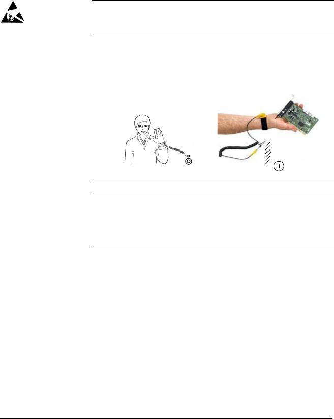
Printed circuit boards and fiber optic cables
These instructions are intended for all who handle the circuit boards and fiber optic cables. Ignoring the following instructions can cause damage to the equipment.
WARNING! The printed circuit boards contain components sensitive to electrostatic discharge. Wear a grounding wrist band when handling the boards. Do not touch the boards unnecessarily.
Use grounding strip:
ABB order no.: 3ADV050035P0001
WARNING! Handle the fiber optic cables with care. When unplugging optic cables, always grab the connector, not the cable itself. Do not touch the ends of the fibers with bare hands as the fiber is extremely sensitive to dirt. The minimum allowed bend radius is 35 mm (1.38 in.).
Safety instructions
3ADW000195R0501 DCS800 Service Manual e e

9
Mechanical installation
These notes are intended for all who install the drive. Handle the unit carefully to avoid damage and injury.
WARNING!
•DCS800 sizes D4 … D7: The drive is heavy. Do not lift it alone. Do not lift the unit by the front cover. Place units D4 and D5 only on its back.
DCS800 sizes D5 … D7: The drive is heavy. Lift the drive by the lifting lugs only. Do not tilt the unit. The unit will overturn from a tilt of about 6 degrees.
•Make sure that dust from drilling does not enter the drive when installing. Electrically conductive dust inside the unit may cause damage or lead to malfunction.
•Ensure sufficient cooling.
•Do not fasten the drive by riveting or welding.
Safety instructions
3ADW000195R0501 DCS800 Service Manual e e 3ADW000195R0101 DCS800 Service Manual e a

10
Operation
These warnings are intended for all who plan the operation of the drive or operate the drive. Ignoring the instructions can cause physical injury or death and/or damage to the equipment.
WARNING!
•Before adjusting the drive and putting it into service, make sure that the motor and all driven equipment are suitable for operation throughout the speed range provided by the drive. The drive can be adjusted to operate the motor at speeds above and below the base speed.
•Do not control the motor with the disconnecting device
(disconnecting mains); instead, use the control panel keys  and
and  , or commands via the I/O board of the drive.
•Mains connection
You can use a disconnect switch (with fuses) to disconnect the electrical components of the drive from the mains for installation and maintenance work. The type of disconnect switch used must be as per EN 60947-3, Class B, so as to comply with EU regulations, or a circuit-breaker type which switches off the load circuit by means of an auxiliary contact causing the breaker’s main contacts to open. The mains disconnect must be locked in its «OPEN» position during any installation and maintenance work.
•EMERGENCY STOP buttons must be installed at each control desk and at all other control panels requiring an emergency stop function. Pressing the STOP button on the control panel of the drive will neither cause an emergency stop of the motor, nor will the drive be disconnected from any dangerous potential.
To avoid unintentional operating states, or to shut the unit down in case of any imminent danger according to the standards in the safety instructions it is not sufficient to merely shut down the drive via signals «RUN», «drive OFF» or «Emergency Stop» respectively «control panel» or «PC tool».
•Intended use
The operating instructions cannot take into consideration every possible case of configuration, operation or maintenance. Thus, they mainly give such advice only, which is required by qualified personnel for normal operation of the machines and devices in industrial installations.
If in special cases the electrical machines and devices are intended for use in non-industrial installations — which may require stricter safety regulations (e.g. protection against contact by children or similar) — these additional safety measures for the installation must be provided by the customer during assembly.
Safety instructions
3ADW000195R0501 DCS800 Service Manual e e
![]()
11
Note:
•When the control location is not set to Local (L not shown in the status row of the display), the stop key on the control panel will not
stop the drive. To stop the drive using the control panel, press the LOC/REM key and then the stop key  .
.
Safety instructions
3ADW000195R0501 DCS800 Service Manual e e 3ADW000195R0101 DCS800 Service Manual e a

3ADW000195R0501 DCS800 Service Manual e e

|
13 |
|
Table of contents |
|
|
Safety instructions |
5 |
|
What this chapter contains……………………………………………………………………………………………. |
5 |
|
To which products this chapter applies…………………………………………………………………………… |
5 |
|
Usage of warnings and notes ……………………………………………………………………………………….. |
5 |
|
Installation and maintenance work…………………………………………………………………………………. |
6 |
|
Grounding………………………………………………………………………………………………………… |
7 |
|
Mechanical installation…………………………………………………………………………………………………. |
9 |
|
Operation …………………………………………………………………………………………………………………. |
10 |
|
Table of contents |
13 |
|
Introduction |
16 |
|
How to use this manual………………………………………………………………………………………………. |
16 |
|
Contents of this manual ……………………………………………………………………………………………… |
16 |
|
Target group …………………………………………………………………………………………………………….. |
16 |
|
Associated publications ……………………………………………………………………………………………… |
16 |
|
Storage and transport ………………………………………………………………………………………………… |
17 |
|
Name plate and type code ………………………………………………………………………………………….. |
17 |
|
Type code ………………………………………………………………………………………………………………… |
18 |
|
Current and voltage ratings…………………………………………………………………………………………. |
19 |
|
Fault Tracing Thyristors |
21 |
|
Tools ……………………………………………………………………………………………………………………….. |
21 |
|
For commissioning and fault tracing…………………………………………………………………… |
21 |
|
Additionally for service and preventive maintenance ……………………………………………. |
22 |
|
How to detect a faulty thyristor…………………………………………………………………………………….. |
22 |
|
A fuse is blown ……………………………………………………………………………………………….. |
22 |
|
DC-current pulses measured by an oscilloscope …………………………………………………. |
23 |
|
Thyristor diagnosis ………………………………………………………………………………………….. |
23 |
|
Ripple monitor ………………………………………………………………………………………………… |
23 |
|
How to find a faulty thyristor………………………………………………………………………………………… |
24 |
|
Converters size D1 to D4 (20…1000 A)………………………………………………………………. |
24 |
|
Blown fuses ……………………………………………………………………………………………………. |
24 |
|
Converters size D5, D6, and D7 (900…5200 A) …………………………………………………… |
25 |
|
Blown fuses ……………………………………………………………………………………………………. |
25 |
|
Ripple monitor ………………………………………………………………………………………………… |
25 |
|
Handling the Semiconductors |
27 |
|
General Instruction how to handle the Semiconductors ………………………………………………….. |
27 |
|
Exchange of Thyristors for Size D1 to D4 |
29 |
|
Installation of OnBoard bridge and thyristor modules in converters size D1 to D4 |
|
|
(20…1000 A) …………………………………………………………………………………………………………….. |
29 |
|
Required Tools ……………………………………………………………………………………………….. |
29 |
|
Find faulty thyristor modules …………………………………………………………………………….. |
29 |
|
Remove faulty thyristor modules ……………………………………………………………………….. |
30 |
|
Install new thyristor modules …………………………………………………………………………….. |
34 |
|
Table of contents |
3ADW000195R0501 DCS800 Service Manual e e

|
14 |
||
|
Remove faulty OnBoard bridge (V1) …………………………………………………………………. |
36 |
|
|
Install new OnBoard bridge (V1) ………………………………………………………………………. |
36 |
|
|
OnBoard bridge (V1) and thyristor module location in DCS800-S01 (2-Q) units |
………. 37 |
|
|
OnBoard bridge (V1) and thyristor module location in DCS800-S02 (4-Q) units………. |
38 |
|
|
OnBoard bridge and thyristor module terminals ………………………………………………….. |
39 |
|
|
Exchange of Thyristors for Size D5 |
41 |
|
|
Installation of «Disc Type» thyristor in converters size D5 (900… |
2000 A) ………………………….. |
41 |
|
Required Tools ………………………………………………………………………………………………. |
41 |
|
|
Disk type thyristors …………………………………………………………………………………………. |
42 |
|
|
Find faulty thyristor …………………………………………………………………………………………. |
45 |
|
|
Remove faulty thyristor……………………………………………………………………………………. |
46 |
|
|
Install new thyristor…………………………………………………………………………………………. |
47 |
|
|
Exchange of Thyristors for Size D6 |
51 |
|
|
Installation of «Disc Type» thyristor in converters size D6 (1900… |
3000 A) ………………………… |
51 |
|
Required Tools ………………………………………………………………………………………………. |
51 |
|
|
Disk type thyristors …………………………………………………………………………………………. |
52 |
|
|
BCT thyristors………………………………………………………………………………………………… |
53 |
|
|
Find faulty thyristor …………………………………………………………………………………………. |
54 |
|
|
Remove faulty thyristor……………………………………………………………………………………. |
55 |
|
|
Install new thyristor…………………………………………………………………………………………. |
58 |
|
|
Exchange of Thyristors for Size D7 |
65 |
|
|
Installation of «Disc Type» thyristor in converters size D7 (2050… |
5200 A) ………………………… |
65 |
|
Required Tools ………………………………………………………………………………………………. |
65 |
|
|
Find faulty thyristor …………………………………………………………………………………………. |
66 |
|
|
Install new thyristor…………………………………………………………………………………………. |
69 |
|
|
Exchange of SDCS-CON-4 |
75 |
|
|
General …………………………………………………………………………………………………………………… |
75 |
|
|
Required Tools ………………………………………………………………………………………………. |
75 |
|
|
Overview SDCS-CON-4 exchange……………………………………………………………………. |
75 |
|
|
Service |
83 |
|
|
How to remove the converter fans in frames D1 to D3 (two fans) ……………………………………. |
83 |
|
|
How to remove the converter fans in a frame D3 (four fans) …………………………………………… |
87 |
|
|
How to remove the converter fan in a frame D6 ……………………………………………………………. |
92 |
|
|
How to remove the converter fan in a frame D7 ……………………………………………………………. |
93 |
|
|
DCS800 firmware download ………………………………………………………………………………………. |
94 |
|
|
General…………………………………………………………………………………………………………. |
94 |
|
|
Download SDCS-CON-4 firmware…………………………………………………………………….. |
94 |
|
|
Add firmware or text files ……………………………………………………………………………….. |
107 |
|
|
Create a workspace………………………………………………………………………………………. |
114 |
|
|
Download SDCS-COM-8 firmware ………………………………………………………………….. |
129 |
|
|
Set type code …………………………………………………………………………………………………………. |
131 |
|
|
Type code table ……………………………………………………………………………………………. |
133 |
|
|
DC-Motor neutral zone adjustment ……………………………………………………………………………. |
134 |
|
|
Types concerned ………………………………………………………………………………………….. |
134 |
|
|
Summary …………………………………………………………………………………………………….. |
134 |
|
|
General……………………………………………………………………………………………………….. |
134 |
Table of contents
3ADW000195R0501 DCS800 Service Manual e e

|
15 |
|
|
Preventive Maintenance |
135 |
|
Recommended regular maintenance |
…………………………………………………………………………..136 |
|
Maintenance schedule ……………………………………………………………………………………………… |
136 |
|
Annual preventive maintenance…………………………………………………………………………………. |
137 |
|
3 years preventive maintenance ………………………………………………………………………………… |
140 |
|
6 years preventive maintenance ………………………………………………………………………………… |
141 |
|
9 years preventive maintenance ………………………………………………………………………………… |
143 |
|
Appendix A — Spare Parts List |
145 |
Table of contents
3ADW000195R0501 DCS800 Service Manual e e

16
Introduction
How to use this manual
The purpose of this service manual is to provide detailed information on how to service power converters from the DCS800 series.
Contents of this manual
Safety instructions
This chapter is located at the beginning of this manual.
Introduction
This chapter informs about the contents and the use of this manual as well as the boundary conditions applying and the thyristor power converter rating plate.
Fault Tracing Thyristors
This chapter describes how to detect and select a faulty thyristor.
Handling the Semiconductors
This chapter describes the handling of thyristors and thyristor modules.
Exchange of Thyristors of Sizes D1 to D4
This chapter describes the exchange of thyristors in converters sizes D1 to D4.
Exchange of Thyristors of Size D5
This chapter describes the exchange of thyristors in converters size D5.
Exchange of Thyristors of Size D6
This chapter describes the exchange of thyristors in converters size D6.
Exchange of Thyristors of Size D7
This chapter describes the exchange of thyristors in converters size D7
Exchange of SDCS-CON-4
This chapter describes the exchange of a SDCS-CON-4
Service
This chapter contains hardware information and technical hints.
Preventive Maintenance
This chapter describes the measures for preventive maintenance of the thyristor converters.
Appendix A Spare Parts list
The Appendix A contains the spare parts list of the converters.
Target group
This manual is designed to help those responsible for planning, installing, starting up and servicing the thyristor power converter.
These people should possess:
basic knowledge of physics and electrical engineering, electrical wiring principles, components and symbols used in electrical engineering, and
basic experience with DC drives and products.
Associated publications
A list of associated publications is published on the inner page of this manual’s cover, see DCS800 Drive Manuals. Here is a list of the most important ones:
The DCS800 Hardware Manual (3ADW000194) describes all hardware
Introduction
3ADW000195R0501 DCS800 Service Manual e e

17
components of the DCS800, their connections and settings (e.g. jumpers)
The DCS800 Firmware Description (3ADW000193) gives an overview of the
DCS800 firmware, describes all parameters, describes the function of the DCS Control Panel, gives support in case of faults and alarms and gives information about communication.
The above listed documentation can be found on the CD-ROM being attached to the DCS800 Quick Guide (3ADW000191).
Storage and transport
If the unit has been in storage prior to installation or is transported to another location, care must be taken to ensure that the environmental conditions are complied with (see Hardware Manual).
Name plate and type code
For purposes of identification, each thyristor power converter is fitted with name plates, stating the type code and the serial number, which serve for each unit’s individual identification.
The type code contains information about the characteristics and the configuration of the unit.
|
ABB Automation Products |
U1 |
3 525 V |
U2 |
610 V |
|||||||
|
20 A |
Made in Germany |
||||||||||
|
Type: DCS800-S02-0025-05 |
I1 |
I2 |
25 A |
||||||||
|
+K454 |
|||||||||||
|
Ser No: 0025421A06294264 |
f1 |
50/60 Hz |
If |
6 A |
+J409 |
||||||
|
SCCR |
65 kA |
Fan |
—- |
||||||||
|
Production year |
Rated input voltage |
Rated output current |
|
|
2006 and week 29 |
Rated input current |
Rated internal field |
exciter current Rated fan voltage
Plus code
Example of a name plate
Introduction
3ADW000195R0501 DCS800 Service Manual e e

18
Type code
The type code contains information on the specifications and configuration of the drive. The first digits from left express the basic configuration (e.g. DCS800-S01- 2005). The optional selections are given thereafter, on the name plate by plus code. The main selections are described below. Not all selections are available for all types.
|
Type code |
D C S 8 0 |
0 — A A X — Y Y |
Y Y — Z Z |
— plus code |
||||||||||
|
Position |
A X |
Y |
Z |
B |
||||||||||
|
Position |
Plus code |
|||||||||||||
|
Product series |
DCS800 |
|||||||||||||
|
A |
Type |
S0 = Standard converter module IP00 |
||||||||||||
|
R0 = Rebuild system |
||||||||||||||
|
E0 = Panel solution |
||||||||||||||
|
A0 = Enclosed converter |
||||||||||||||
|
X |
Bridge type |
1 = Single bridge (2-Q) |
||||||||||||
|
2 = 2 anti parallel bridges (4-Q) |
||||||||||||||
|
Y |
Rated DC current |
YYYY = Rated current (e.g. 0025 = 25 ADC) |
||||||||||||
|
ZZ |
Rated AC voltage |
04 = 400 VAC |
||||||||||||
|
05 = 525 VAC |
||||||||||||||
|
06 = 600 VAC |
||||||||||||||
|
07 = 690 VAC |
||||||||||||||
|
08 = 800 VAC |
||||||||||||||
|
10 = 990 VAC |
||||||||||||||
|
12 = 1200 VAC |
||||||||||||||
|
B |
Power connection |
— = Standard D1 … D6 |
||||||||||||
|
L = Left side D7 |
||||||||||||||
|
R = Right side D7 |
||||||||||||||
|
a = Second thyristor type D5, D6 |
||||||||||||||
|
Internal field exciter |
+S164 |
With internal field exciter, external supply (only D5:25 A, Rebuild kit: 25 A/16 A) |
||||||||||||
|
configuration |
+0S163 |
Without internal field exciter (only D1 … D4) |
||||||||||||
|
Fan voltage |
Size D4 |
|||||||||||||
|
Standard fan voltage: |
230 V / 1-ph |
|||||||||||||
|
+S171 |
Additional fan voltage: |
115 V / 1-ph |
||||||||||||
|
Size D6 |
||||||||||||||
|
Standard fan voltage for 400 V / 500 V / 800 V units: |
400-500 V / 3-ph |
|||||||||||||
|
Standard fan voltage for 600 V / 690 V units: |
525-690 V / 3-ph |
|||||||||||||
|
+S172 |
Additional fan voltage for 600-690 V units: |
400-500 V / 3-ph |
||||||||||||
|
Current measurement |
+S175 |
SDCS-CMA-2 for sizes D5 to D7 |
||||||||||||
|
Voltage measurement |
+S186 |
120 V SDCS-SUB-4 for sizes D1 … D4 |
||||||||||||
|
+S180 |
600 V for sizes D6 and D7 |
|||||||||||||
|
+S181 |
690 V for sizes D6 and D7 |
|||||||||||||
|
+S182 |
800 V for sizes D6 and D7. |
|||||||||||||
|
+S183 |
990 V for sizes D6 and D7. |
|||||||||||||
|
+S189 |
Galvanic isolation for sizes D6 and D7 |
|||||||||||||
|
SDCS-DSL-4 |
+S199 |
With SDCS-DSL-4 |
||||||||||||
|
+0S199 |
Without SDCS-DSL-4 |
|||||||||||||
|
+ plug-in options |
||||||||||||||
|
DCS Control Panel |
0J400 |
Without DCS Control Panel |
||||||||||||
|
J409 |
Door mounting Kit (cable length 3 m) |
|||||||||||||
|
Fieldbus |
K454 |
Profibus RPBA |
||||||||||||
|
K451 |
DeviceNet RDNA |
|||||||||||||
|
K466 |
Ethernet IP + Modbus TCP RETA |
|||||||||||||
|
K458 |
Modbus RMBA |
|||||||||||||
|
I/O and DDCS |
L500 |
Analogue Extension RAIO |
||||||||||||
|
L501 |
Digital Extension RDIO |
|||||||||||||
|
L508 |
DDCS Communication board (10 Mbaud CH0) SDCS-COM-81 |
|||||||||||||
|
L509 |
DDCS Communication board (5 Mbaud CH0) SDCS-COM-82 |
Introduction
3ADW000195R0501 DCS800 Service Manual e e

19
The technical data and specifications are valid as of going to press. ABB reserves the right to make subsequent alterations.
If you have any questions concerning your drive system, please contact your local ABB agent.
Current and voltage ratings
|
Unit size |
2-Q rated current |
4-Q rated current |
Supply voltage [VAC] |
||||||
|
DCS800-01 [ADC] |
DCS800-02 [ADC] |
||||||||
|
400 |
525 |
600 |
690 |
800 |
990 |
1200 |
|||
|
D1 |
20 |
25 |
X |
X |
|||||
|
45 |
50 |
X |
X |
||||||
|
65 |
75 |
X |
X |
||||||
|
90 |
100 |
X |
X |
||||||
|
125 |
140 |
X |
X |
||||||
|
D2 |
180 |
200 |
X |
X |
|||||
|
230 |
260 |
X |
X |
||||||
|
D3 |
315 |
350 |
X |
X |
X |
||||
|
405 |
450 |
X |
X |
||||||
|
470 |
520 |
X |
X |
||||||
|
D4 |
610 |
680 |
X |
X |
X |
||||
|
740 |
820 |
X |
X |
||||||
|
900 |
1000 |
X |
X |
||||||
|
D5 |
900 |
900 |
X |
X |
|||||
|
1200 |
1200 |
X |
X |
||||||
|
1500 |
1500 |
X |
X |
X |
X |
||||
|
2000 |
2000 |
X |
X |
X1 |
X1 |
||||
|
D6 |
1900 |
1900 |
X |
||||||
|
2050 |
2050 |
X |
X |
X |
|||||
|
2500 |
2500 |
X |
X |
X |
X |
X |
|||
|
3000 |
3000 |
X |
X |
X |
X |
X |
|||
|
D7 |
2050 |
2050 |
X |
||||||
|
2600 |
2600 |
X |
X |
||||||
|
3300 |
3300 |
X |
X |
X |
X |
X |
X |
X |
|
|
4000 |
4000 |
X |
X |
X |
X |
X |
X |
X |
|
|
4800 |
4800 |
X |
X |
X |
|||||
|
5200 |
5200 |
X |
X |
1 only available as 2-Q drive
Introduction
3ADW000195R0501 DCS800 Service Manual e e

3ADW000195R0501 DCS800 Service Manual e e
![]()
21
Fault Tracing Thyristors
Tools
For commissioning and fault tracing
Following software tools are mandatory:
DriveWindow Light including commissioning wizard and DWL AP for Adaptive Program and
DriveWindow for fast drive monitoring using SDCS-COM-8.
Following tools are mandatory in addition to standard tools:
An oscilloscope including memory function with either galvanically isolating transformer or isolating amplifier (probe) for safe measurements. It can also be a hand held (portable) oscilloscope.
A clamp on current probe. In case the scaling of the DC load current needs to be checked it must be a DC clamp on current probe.
A voltmeter (at least CAT III 1000 V):
1000 V probes and test leads:
An ESD-field service kit (ABB Service Finland code 0001ESD / MS-Antistatic):
Make sure that all equipment in use is suitable for the voltage level applied to the power part!
Fault Tracing Thyristors
3ADW0000195R0501DCS8000ServiceManualeeee

22
Additionally for service and preventive maintenance
Following additional tools are mandatory for cleaning:
An ESD safe blower / ESD vacuum cleaner (ABB Service Finland code 0006ESD / MUNTZ 555-ESD-S-E):
How to detect a faulty thyristor
Thyristor problems can be noticed differently:
A fuse is blown
This is an indication, that a strong overcurrent has happened due to one of the following reasons:
An internal short circuit between the phases (line side) because of a defective thyristor (short circuit inside a thyristor from anode to cathode).
An internal short circuit between the phases (line side) because of circulating current in a 4-Q converter (malfunction of the control electronics, no thyristor defective).
An external short circuit at the DC terminals of the converter without sufficient impedance.
A commutation fault during generating (active braking with high current, high EMF and with low AC voltage) of a 4-Q converter.
Note:
In case of parallel fuses: If one of the parallel fuses is blown, all parallel fuses have to be changed. The ‘undamaged’ fuses might be ‘half-blown’ and will blow with the next high current.
Fault Tracing Thyristors
3ADW000195R0501 DCS800 Service Manual e e

23
DC-current pulses measured by an oscilloscope
Connect an oscilloscope to the fixed AO I-act (X4:9/10 on the SDCS-CON-4 or X4:5/6 on the SDCS-IOB-3) and check for the proper amount of current pulses:
Six current pulses in positive direction
There should be six current pulses in positive direction.
In case of a 4-Q converter also the six current pulses for the negative direction have to be checked.
Thyristor diagnosis
Also the thyristor diagnosis provided by the firmware can be used:
Switch the drive to local mode (DriveWindow, DriveWindow Light, DCS Control Panel or local I/O).
Start the thyristor diagnosis by means of ServiceMode (99.06) = ThyDiagnosis and set On and Run within 20 s.
During the thyristor diagnosis the main contactor will be closed and the thyristors are checked. The field current is not released while the thyristor diagnosis is active and thus the motor should not turn.
When the thyristor diagnosis is finished check Diagnosis (9.11) for details.
Ripple monitor
The ripple monitor indicates that the ripple of the DC current is much higher than normal. In such a case, most often one thyristor does not work. It’s missing current contribution causes a deep dip in the direct current.
The structure of the current loop (current controller) will force the other thyristors to compensate the dip by a certain overcurrent in order to keep the average current constant. Such a compensation results in a ripple monitoring fault during motoring mode operation with 90°.
The reason for a current less thyristor may be:
Fault Tracing Thyristors

24
A fuse has disconnected one of the six thyristors. This is possible only for converters with 900 … 5200 A (six internal branch fuses). A converter with three external fuses stops working completely at once when one of the three AC input fuses interrupts a phase input of the converter.
A thyristor does not get firing pulses or does not react to firing pulses.
The current controller may be totally mismatched to the DC load.
The AC mains network is causing that fault message. In this case, asymmetrical phase shift, uneven phase voltage or critical designed power factor correction equipment or harmonic reduction equipment can be the reason.
How to find a faulty thyristor
If a blown fuse is suspected in the converter, the problem is caused most often by a faulty thyristor. To make sure, that a thyristor is the reason and needs to be exchanged fault tracing must be done in two different ways, depending on the size of the converter.
In general, make sure, that all safety instructions, given within this manual or within the safety instructions, related to the machine or the application itself, are obeyed.
Converters size D1 to D4 (20…1000 A)
These converters require semiconductor fuses in the 3 AC lines.
The converter must be disconnected from the mains.
One motor armature cable should be disconnected from the converter.
Blown fuses
Using the OHM function of a normal multimeter, measurements must be made from each AC terminal to each DC terminal (U1 to C1, V1 to C1, W1 to C1, U1 to D1, V1 to D1 and W1 to D1; see picture Anti-parallel B6-bridges with
branching fuses on page 45). Normally, every measurement should show high resistance (> 1 k ).
Target: find a short circuit, indicated by low resistance ( <1 ) (destroyed thyristor).
If the converter is designed with half-bridge thyristor modules, then a module consists of two anti-parallel thyristors. In this case it is sufficient to know which thyristor pair or module has a defective thyristor because the complete module must be replaced.
After a thyristor module is replaced, the above mentioned measurement should be done another time to make sure that all faulty thyristors have been detected!
Note:
The RC circuit could also cause 0 result for a short time.
The measurement, showing less resistance than 1 should be made a second time with test leads applied to the terminals with opposite polarity; if this measurement shows the same result, one or two thyristors located in that path are faulty; they need to be replaced.
Fault Tracing Thyristors
3ADW000195R0501 DCS800 Service Manual e e

25
Converters size D5, D6, and D7 (900…5200 A)
These converters are equipped with fuses in the branches of the power part.
The converter must be disconnected from the mains.
Blown fuses
In case of a blown fuse, the faulty thyristor or the faulty pair of thyristors are already isolated at one side from the others and therefore the faulty branch is known (see picture Anti-parallel B6-bridges with branching fuses on page 45).
The OHM test should be performed, when the thyristor is still clamped. Outside the converter a special thyristor clamping device is needed.
For 4-Q converters with anti-parallel thyristors or BCT’s:
The selection of a forward or reverse thyristor or BCT (Bidirectional-Controlled-Thyristor) is done during the disassembly. Continue with related part Exchange of Thyristors for Size D5, D6 or D7 section Find faulty thyristor.
After a thyristor was replaced, the OHM test should be done another time to make sure that all faulty thyristors have been detected! If the motor is still connected to the converter the result of the measurement may be wrong.
Ripple monitor
If the ripple monitor fault occurred, a fault tracing as described above must be carried out:
Check the fuses and the thyristors, according to the statements before.
If the power section seems to be ok, but still one or more thyristors don’t take current, something went wrong in between the firing pulse generation and the thyristor’s gate; in this case check:
Is a firing pulse present on the primary side of the firing pulse transformer?
Is a firing pulse present on the secondary side of the firing pulse transformer?
Is the firing pulse transferred to the gate of the thyristor? Are there all electrical connections still healthy?
Can the thyristor be fired with the applied firing pulse? Is the pulse form of the firing pulse identical at all measuring positions?
Check the settings of the current controller.
Check the AC mains network by taking recordings of the line voltage and current at all 3 phases at the same time.
Fault Tracing Thyristors

26
Fault Tracing Thyristors
3ADW000195R0501 DCS800 Service Manual e e

27
Handling the Semiconductors
General Instruction how to handle the Semiconductors
Thyristor modules, busbars and fuses have to be mounted with the correct torque using a torque screw driver or torque wrench.
In converters sizes D5 (900 … 2000 A), D6 (1900 … 3000 A) and D7 (2050 … 5200 A) the mounting force is indicated by an indicating spring welded to the mounting clamp, which is inside the unit.
Always mark suspected damaged components clearly after removing them from the circuit, to avoid confusion with «good» components.
When removing a damaged semiconductor, write down how and where it was installed (direction, location, connected gate leads and with BCT’s the position of the gate connectors).
Check that the new and old components have the same type designation or that the new component can replace the old one. A semiconductor can be replaced by different compatible semiconductor according to the codes in the manufacturers’ table.
Semiconductor components are high-precision products. All unnecessary used tools and objects might damage the easily dented and scratched surfaces of the semiconductors.
1.Keep new semiconductors as long as possible in their original packages.
2.Use protective gloves if possible.
3.Clean work area and hands frequently.
4.Use good illumination.
Handling the Semiconductors
3ADW000195R0501 DCS800 Service Manual e e

28
Handling the Semiconductors
3ADW000195R0501 DCS800 Service Manual e e

29
Exchange of Thyristors for Size D1 to D4
Installation of OnBoard bridge and thyristor modules in converters size
D1 to D4 (20…1000 A)
All DCS800 size D1 to D4 are equipped with an OnBoard bridge (excitation) and thyristor modules. In order to keep the operating temperature of the semiconductor module low, the joint between the heat sink and the module should have a good heat conducting ability. The electrical conductivity of the connectors must also be good. For this reason the following instructions must be observed with particular care.
Required Tools
Special tools or material needed in addition to standard tools for the exchange of thyristor modules:
|
Torx screwdrivers: |
TX10, TX20, TX25 |
|
|
Torque spanner: |
mounting torques for the OnBoard bridge and the |
|
|
thyristor modules to heat sink and electrical |
||
|
connections see table Nominal mounting torque for |
||
|
OnBoard bridge and thyristor modules on page 35 |
Screws are metric type; use appropriate nuts
Tissue paper
Solvent (e.g. ethanol)
Thermal joint compound: type Berulub FZ1 E3
|
(grease) |
|
|
Manufacturer: |
Carl Bechem GmbH, 58089 Hagen |
|
ABB Service: |
GHSN 390 011 P 0051 |
|
or |
|
|
thermal joint compound: |
type WLPF 20 (10 ml) |
|
ABB Service: |
GHSN 390 011 P 10 |
Before the work is started, disconnect the converter from the power supply completely, then check the voltage free condition and make sure, everything is located in an electrical and mechanical safe condition!
Find faulty thyristor modules
See Fault Tracing Thyristors of this publication.
Exchange of Thyristors for Size D1 to D4
3ADW000195R0501 DCS800 Service Manual e e

30
Remove faulty thyristor modules
1. Remove the DCS Control Panel and design cover:
 Remove DCS Control Panel
Depress the locks by means of a screwdriver to remove the design cover
Remove design cover
2.Remove all plug in options on the intermediate cover e.g.:
serial communication modules (R-type),
extension I/O modules (RAIO, RDIO),
extension modules for second encoder (RTAC) or resolver (RRIA),
communication board (SDCS-COM-8),
isolated I/O (SDCS-IOB-2x, SDCS-IOB-3) and
SDCS-MEM-8 (Memory Card).
3.Remove the intermediate cover by depressing the two locks on the upper right and left hand side of the cover:
Depress the locks to remove the design cover
Remove all options, so that the intermediate cover is empty
Remove plug in options
Exchange of Thyristors for Size D1 to D4
3ADW000195R0501 DCS800 Service Manual e e
![]()
31
4.Disconnect all I/O plugs (X3 to X7) at the SDCS-CON-4 and the plugs at the SDCS-DSL-4 board, if used (X51 to X54):
Disconnect all plugs from SDCS-
CON-4 and SDCS-DSL-4 boards
Disconnect all plugs
5. Remove the grounding plug and the holding screw at the electronic tray:
Remove the grounding plug and the holding screw
Remove grounding and screws
Exchange of Thyristors for Size D1 to D4
3ADW000195R0501 DCS800 Service Manual e e

32
6.To unhinge the electronic tray including the SDCS-CON-4 pull it up and then out. Before remove tray completely unplug the flat cables (X12, X13, X37):
Electronic tray with SDCS-CON-4
Remove flat cables
Unhinge electronic tray
7. Remove all cables and plugs at the SDCS-PIN-4:
Keep winding direction and amount of windings for T100 in mind.
T100
Remove all cables and plugs
How to handle X8:
X8
use screw driver
Remove cables at the SDCS-PIN-4
Attention:
Write down the winding direction of the cable through T100!
D1: thread the wire 4 times through the hole in T100 (that equals 3 loops)
D2 — D4: thread the wire 1 time through the hole in T100 (that equals no loops)
Exchange of Thyristors for Size D1 to D4
3ADW000195R0501 DCS800 Service Manual e e

33
8. Remove the SDCS-PIN-4 board:
|
OnBoard field exciter |
Snubber resistor |
||||||
|
bridge module |
|||||||
|
Thyristor modules |
|||||||
|
Current transformer |
Temperature sensor |
|
Remove SDCS-PIN-4
9.Remove the gate leads from the faulty thyristor module and mark the connectors clearly.
10.Remove the busbars necessary to get full access to the faulty thyristor module.
11.If a current transformer must be removed, mark its position and the connections clearly.
Note:
Remove only as many parts as needed around the faulty thyristor module.
12.Remove the faulty thyristor module and mark it clearly as defective.
Exchange of Thyristors for Size D1 to D4
3ADW000195R0501 DCS800 Service Manual e e

34
Install new thyristor modules
1.Ensure that the new thyristor module is of the correct type (see appendix A of this manual).
2.Remove old heat conducting compound (grease) from the heat sink. Clean the mounting surfaces (heat sink and thyristor module) with an appropriate solvent (e.g. ethanol) by means of tissue paper. When the heat sink is clean, spread out the heat conducting compound with a rubber spatula or by hand.
3.Apply a thin layer of heat conducting compound to the new thyristor module:
Application of heat conducting compound
4.Spread the heat conducting compound evenly by moving the thyristor module forward and backward on the heat sink.
5.Tighten all clamping screws by hand until the screw heads touch the bottom of the thyristor module. Then tighten the screws to 2.0 Nm torque.
Note:
If the thyristor module is mounted by means of four screws, tighten the screws crosswise.
6.Tighten the screws to nominal torque according to table Nominal mounting torque for OnBoard bridge and thyristor modules page 35.
Exchange of Thyristors for Size D1 to D4
3ADW000195R0501 DCS800 Service Manual e e

35
|
OnBoard bridge and thyristor modules |
Nominal mounting torque |
|||
|
Size |
Type |
Electrical |
Thyristor module |
|
|
connections |
to heat sink |
|||
|
29 mm bridge block |
VVZF 70-16 |
— |
5 Nm |
|
|
20 mm block |
SKKT 27, 42, 57, 106 |
3 Nm |
5 Nm |
|
|
20 mm block |
MCC 26, 44, 56, 95 |
2.5 … 4 Nm |
2.5 … 4 Nm |
|
|
34 mm block |
MCC 162 |
4.45 … 5.5 Nm |
2.25 … 2.75 Nm |
|
|
34 mm block |
SKKT 162 |
5 Nm |
5 Nm |
|
|
34 mm block |
TT 162 |
6 Nm |
6 Nm |
|
|
50 mm block |
MCC 255 |
11 … 13 Nm |
4.5 … 7 Nm |
|
|
50 mm block |
TT 250, 330 |
12 Nm |
6 Nm |
|
|
60 mm block |
TT 425, 570 |
12 Nm |
6 Nm |
|
Nominal mounting torque for OnBoard bridge and thyristor modules
7.Reinstall the current transformer, make sure, its position is correct.
8.Reinstall the busbars, make sure, the correct torque is applied according to table Nominal mounting torque for OnBoard bridge and thyristor modules on page 35.
9.Reconnect all gate leads to the thyristor module.
10.Reinstall the SDCS-PIN-4 board.
11.Reconnect all cables and plugs at the SDCS-PIN-4:
snubber resistor (X30, X31),
temperature sensor (X22),
current transformers (X3, X4, X5),
OnBoard excitation (X8, X9, X11), use proper winding direction and amount of windings for T100
gate leads (first X16, X18 then X15, X17),
OnBoard excitation line voltage (X1, X2, X7),
all plugs (X10, X96, X99) and
all flat cables (X12, X13, X37), use the lock connectors at the SDCS-PIN-4
12.Reconnect the flat cables at the SDCS-CON-4 (X12, X13, X37) and re-hinge the electronic tray.
13.Reconnect the grounding plug and the holding screw at the electronic tray.
14.Reconnect all I/O plugs at the SDCS-CON-4 (X3 to X7) and the plugs at the SDCS-DSL-4 (X51 to X54).
15.Reinstall the intermediate cover, all plug in options and the design cover.
Exchange of Thyristors for Size D1 to D4
3ADW000195R0501 DCS800 Service Manual e e

36
Remove faulty OnBoard bridge (V1)
1.Follow the instructions Remove faulty thyristor modules until step 8 is done.
2.Remove all connectors from the faulty OnBoard bridge and mark the connectors clearly.
3.Remove the faulty OnBoard bridge and mark it clearly as defective.
Install new OnBoard bridge (V1)
1.Ensure that the new OnBoard bridge is of the correct type (see appendix A of this manual).
2.Remove old heat conducting compound (grease) from the heat sink. Clean the mounting surfaces (heat sink and OnBoard bridge) with an appropriate solvent (e.g. ethanol) by means of tissue paper. When the heat sink is clean, spread out the heat conducting compound with a rubber spatula or by hand.
3.Apply a thin layer of heat conducting compound to the new OnBoard bridge.
4.Spread the heat conducting compound evenly by moving the OnBoard bridge forward and backward on the heat sink.
5.Tighten all clamping screws by hand until the screw heads touch the bottom of the thyristor module. Then tighten the screws to 2.0 Nm torque.
6.Tighten the screws to nominal torque according to table Nominal mounting torque for OnBoard bridge and thyristor modules on page 35.
7.Reconnect all connectors to the OnBoard bridge.
8.Follow the instructions Install new thyristor modules beginning with step 10.
Exchange of Thyristors for Size D1 to D4
3ADW000195R0501 DCS800 Service Manual e e

37
OnBoard bridge (V1) and thyristor module location in DCS800-S01 (2-Q) units
DCS800-S01-0020 … 0180
V1
|
V14/V11 |
|
| <![if ! IE]>
<![endif]>K2 G2 |
<![if ! IE]>
<![endif]>K1 G1 |
|
V16/V13 |
|
| <![if ! IE]>
<![endif]>K2 G2 |
<![if ! IE]>
<![endif]>K1 G1 |
|
V12/V15 |
|
| <![if ! IE]>
<![endif]>K2 G2 |
<![if ! IE]>
<![endif]>K1 G1 |
|
V1 |
|
V14/V11 |
| <![if ! IE]>
<![endif]>K2 G2 G1 K1 |
| <![if ! IE]>
<![endif]>A |
| <![if ! IE]>
<![endif]>K |
| <![if ! IE]>
<![endif]>AK |
DCS800-S01-0315 … 0470
|
V16/V13 |
| <![if ! IE]>
<![endif]>K2 G2 G1 K1 |
| <![if ! IE]>
<![endif]>A |
| <![if ! IE]>
<![endif]>K |
| <![if ! IE]>
<![endif]>AK |
|
V12/V15 |
| <![if ! IE]>
<![endif]>K2 G2 G1 K1 |
| <![if ! IE]>
<![endif]>A |
| <![if ! IE]>
<![endif]>K |
| <![if ! IE]>
<![endif]>AK |
|
V1 |
|
V14/V11 |
| <![if ! IE]>
<![endif]>A |
| <![if ! IE]>
<![endif]>K |
| <![if ! IE]>
<![endif]>AK |
DCS800-S01-0610 … 0900
|
V16/V13 |
| <![if ! IE]>
<![endif]>A |
| <![if ! IE]>
<![endif]>K |
| <![if ! IE]>
<![endif]>AK |
|
V12/V15 |
| <![if ! IE]>
<![endif]>A |
| <![if ! IE]>
<![endif]>K |
| <![if ! IE]>
<![endif]>AK |
DCS800 loc of mod 1Q.dsf
Location of the OnBoard bridge and thyristor modules in DCS800-S01 (2-Q) units
Note:
This drawing is only showing the location of the OnBoard bridge and thyristor modules, the actual converter module size is different!
Exchange of Thyristors for Size D1 to D4
3ADW000195R0501 DCS800 Service Manual e e

38
OnBoard bridge (V1) and thyristor module location in DCS800-S02 (4-Q) units
DCS800-S02-0025 … 0200
V1
|
V11/V24 |
V13/V26 |
V15/V22 |
|||||||
|
DCS800-S02-0350 … 0520 |
|||||||||
|
V1 |
|||||||||
|
V11 |
K1 |
K2 |
V14 |
||||||
|
G1 |
A |
K |
AK |
AK |
K |
A |
G2 |
||
|
G2 |
G1 |
||||||||
|
V24 |
K2 |
K1 |
V21 |
||||||
|
V15 |
K1 |
K2 |
V12 |
||||||
|
G1 |
A |
K |
AK |
AK |
K |
A |
G2 |
||
|
V22 |
G2 |
G1 |
V25 |
||||||
|
K2 |
K1 |
||||||||
|
V13 |
K1 |
K2 |
V16 |
||||||
|
G1 |
A |
K |
AK |
AK |
K |
A |
G2 |
||
|
V26 |
G2 |
G1 |
V23 |
||||||
|
K2 |
K1 |
||||||||
DCS800-S02-0260
V1
| <![if ! IE]>
<![endif]>G1 K1 |
<![if ! IE]>
<![endif]>G2 K2 |
|
V11/V24 |
|
V14/V21 |
|
| <![if ! IE]>
<![endif]>K2 G2 |
<![if ! IE]>
<![endif]>K1 G1 |
| <![if ! IE]>
<![endif]>G1 K1 |
<![if ! IE]>
<![endif]>G2 K2 |
|
V13/V26 |
|
V16/V23 |
|
| <![if ! IE]>
<![endif]>K2 G2 |
<![if ! IE]>
<![endif]>K1 G1 |
| <![if ! IE]>
<![endif]>G1 K1 |
<![if ! IE]>
<![endif]>G2 K2 |
|
V15/V22 |
|
V12/V25 |
|
| <![if ! IE]>
<![endif]>K2 G2 |
<![if ! IE]>
<![endif]>K1 G1 |
DCS800-S01-0680 … 1000
|
V1 |
V26/V13 |
V22/V15 |
|
V24/V11 |
||
| <![if ! IE]>
<![endif]>A |
<![if ! IE]>
<![endif]>A |
<![if ! IE]>
<![endif]>A |
| <![if ! IE]>
<![endif]>K |
<![if ! IE]>
<![endif]>K |
<![if ! IE]>
<![endif]>K |
| <![if ! IE]>
<![endif]>AK |
<![if ! IE]>
<![endif]>AK |
<![if ! IE]>
<![endif]>AK |
| <![if ! IE]>
<![endif]>AK |
<![if ! IE]>
<![endif]>AK |
<![if ! IE]>
<![endif]>AK |
| <![if ! IE]>
<![endif]>K |
<![if ! IE]>
<![endif]>K |
<![if ! IE]>
<![endif]>K |
| <![if ! IE]>
<![endif]>A |
<![if ! IE]>
<![endif]>A |
<![if ! IE]>
<![endif]>A |
|
V21/V14 |
V23/V16 |
V25/V12 |
DCS800 loc of mod 4Q.dsf
Location of the OnBoard bridge and thyristor modules in DCS800-S02 (4-Q) units
Note:
This drawing is only showing the location of the OnBoard bridge and thyristor modules, the actual converter module size is different!
Exchange of Thyristors for Size D1 to D4
3ADW000195R0501 DCS800 Service Manual e e

39
OnBoard bridge and thyristor module terminals
The next figures show the terminals of the OnBoard bridge and all used thyristor modules. The terminal description is also stamped or marked by a sticker on the OnBoard bridge and all thyristor modules.
For all firing pulse cables is valid: Yellow is gate lead.
Red is cathode lead.
VVZF 70-16
|
(AK)(K) |
(A |
(AK)(K) |
(A |
||||
|
1 |
2 5 4 |
6 7 |
3 |
1 |
2 4 5 |
7 6 |
3 |
|
1 |
2 |
3 |
1 |
2 |
3 |
|
7 G |
6 G |
||||
|
6 K |
7 K |
||||
|
5 K |
4 K |
||||
|
4 G |
5 G |
||||
|
SKKT 27, 42, 57, 106 |
MCC26, 44, 56, 95 |
|
(AK) (K) |
(A) |
|||||
|
1 |
2 5 4 |
7 |
6 |
3 |
||
|
6 |
7 |
|||||
|
1 |
2 |
3 |
||||
|
6 |
7 |
|||||
|
5 |
4 |
4 |
5 |
|||
|
SKTT 162 |
||||||
|
MCC162 |
Exchange of Thyristors for Size D1 to D4
3ADW000195R0501 DCS800 Service Manual e e

40
|
AK |
K |
A |
||
|
K2 G2 |
||||
|
K1 G1 |
||||
|
TT 162 |
MCC255 |
|||
|
(A) |
(K) (AK) |
|||
|
AK K |
A 3 |
6G 7K |
5G 4K2 1 |
|
|
K1 G1 |
K2 |
G2 |
|
5G4K |
||||||
|
K2 |
3 |
1 |
||||
|
AK |
K |
A |
G2 |
2 |
||
|
G1 |
||||||
|
K1 |
||||||
|
6G7K |
Terminals of the OnBoard bridge and all thyristor modules
Exchange of Thyristors for Size D1 to D4
3ADW000195R0501 DCS800 Service Manual e e
![]()
TX10, TX20, TX25 13 Nm (M8)
25 Nm (M10)
50 Nm (M12)
41
Exchange of Thyristors for Size D5
Installation of «Disc Type» thyristor in converters size D5 (900…2000 A)
All DCS800 converters sizes D5/D6/D7 are equipped with disk type thyristors. The structure of the «Disc type» semiconductor component is such that it requires a certain compression force to operate. The prevention of overheating of the component essentially depends on a good heat dissipation between the semiconductor and the conducted heat sink. It is thus important that all joints have good thermal and electrical conduction.
Required Tools
Special tools or material needed in addition to standard tools for the exchange of thyristor modules:
Torx screwdrivers:
Torque spanner for electrical connections:
Screws are metric type; use appropriate nuts.
17 mm ring spanner for fuse and busbar connections.
17 mm ring spanner for press clamp.
Tissue paper / solvent (e.g. ethanol).
Thermal joint compound: type BECHEM-RHUS SU 2 (grease)
|
Manufacturer: |
Carl Bechem GmbH, 58089 Hagen |
|
ABB Service: |
GHSN 390 001 P 0001 |
|
Disassembly tool |
3ADT 621 023 P1 |
|
Note: |
For more detailed information about the wiring of the power part, see Hardware Manual.
Therefore strict observance of the build in instructions given below is of utmost importance. Make sure that the new component can replace the old one in accordance with the spare part list (see Appendix A).
Semiconductors and heat sinks are to be handled carefully to avoid scratches and other damage. Avoid touching the contact surfaces. Do not lift the semiconductor with the gate wire. Do not lift the semiconductor by touching the current contact surfaces. Do not damage the welding flange or the contact surface.
Before you start work, disconnect the converter completely from the power supply then check the voltage free condition and make sure, everything is located in an electrically and mechanically safe condition!
Exchange of Thyristors for Size D5
3ADW000195R0501 DCS800 Service Manual e e

42
Disk type thyristors
Some converter modules size D5 are equipped with different disc type thyristors. For easy identification the name plate of the converter module is marked with “a” after the voltage identification:
|
Converter with original |
U1 |
Converter with second |
|
thyristor type T459Nxxx |
thyristor type T460Nxxx |
|
|
Id code: DCA0012007P0001 |
Id code: 3ADC340105P0001 |
|
|
DCS800-S01-0900-06 |
3 ~ 600 VAC |
DCS800-S01-0900-06a |
|
DCS800-S02-0900-06 |
3 ~ 600 VAC |
DCS800-S02-0900-06a |
|
DCS800-S01-0900-07 |
3 ~ 690 VAC |
DCS800-S01-0900-07a |
|
DCS800-S02-0900-07 |
3 ~ 690 VAC |
DCS800-S02-0900-07a |
|
Converter with original |
U1 |
Converter with second |
|
thyristor type T589Nxxx |
thyristor type T590Nxxx |
|
|
Id code: DCA0012015P0001 |
Id code: 3ADC340106P0001 |
|
|
DCS800-S01-1200-04 |
3 ~ 400 VAC |
DCS800-S01-1200-04a |
|
DCS800-S02-1200-04 |
3 ~ 400 VAC |
DCS800-S02-1200-04a |
|
DCS800-S01-1200-05 |
3 ~ 525 VAC |
DCS800-S01-1200-05a |
|
DCS800-S02-1200-05 |
3 ~ 525 VAC |
DCS800-S02-1200-05a |
|
Parts list |
The current and voltage ratings of original and second thyristor type are the same, but the sizes of gate and cathode terminals are different. Thus it is not possible to interchange both thyristor types as spares.
Attention: Use always the correct spare thyristor!
Original thyristor type (900 A)
Converter with original thyristor type T459Nxxx Id code: DCA0012007P0001
Original thyristor type
Exchange of Thyristors for Size D5
3ADW000195R0501 DCS800 Service Manual e e

43
|
Gate (G): |
Faston 2.8 x 0.8 mm |
|
Cathode (HK): |
Faston 4.8 x 0.8 mm |
|
Conductive plate: |
Diameter 36 mm |
Second thyristor type (900 A)
Converter with second thyristor type T460Nxxx Id code: 3ADC340105P0001
|
Second thyristor type |
|
|
Gate (4): |
Round terminal D = 1.5 mm |
|
Cathode (5): |
Faston 4.8 x 0.5 mm |
|
Conductive plate: |
Diameter 36 mm |
Original thyristor type (1200 A)
Converter with original thyristor type T589Nxxx Id code: DCA0012015P0001
Original thyristor type
Exchange of Thyristors for Size D5
3ADW000195R0501 DCS800 Service Manual e e

44
|
Gate (G): |
Faston 2.8 x 0.8 mm |
|
Cathode (HK): |
Faston 4.8 x 0.8 mm |
|
Conductive plate: |
Diameter 36 mm |
Second thyristor type (1200 A)
Converter with second thyristor type T590Nxxx Id code: 3ADC340106P0001
|
Second thyristor type |
|
|
Gate (4): |
Round terminal D = 1.5 mm |
|
Cathode (5): |
Faston 4.8 x 0.5 mm |
|
Conductive plate: |
Diameter 36 mm |
Exchange of Thyristors for Size D5
3ADW000195R0501 DCS800 Service Manual e e

45
Find faulty thyristor
1.Find the defective branches by performing an OHM test (both polarities) between U1, V1, W1 and C1, D1 (see fig. Anti-parallel B6-bridges with branching fuses on page 45)
|
C1 (+) |
|||||
|
V11 |
V24 |
V13 |
V26 |
V15 |
V22 |
|
F11 |
F13 |
F15 |
branching fuse |
||
U1 
V1
W1
 branch
V14


 V21 V16


 V23
V23  V12
V12


 V25
V25
 D1 (-)
principle_B6_a.dsf
Anti-parallel B6-bridges with branching fuses
2.Disconnect the branching fuses of the defective branches.
3.Find the defective thyristors by performing an OHM test (both polarities) over their heat sinks.
4.In a 4—quadrant converter change both thyristors clamped between the same heatsinks at once.
Note:
Because “Disc Type” semiconductors need a certain compression force to operate properly, a measurement outside the clamped heat sinks might be wrong. To be sure which thyristor is broken change only one thyristor, clamp the heat sinks again and repeat step three.
Exchange of Thyristors for Size D5
3ADW000195R0501 DCS800 Service Manual e e

46
Remove faulty thyristor
1.Remove the screws of the DC – busbars and branch fuses preventing the stack to be prized open.
Note:
It depends on the location of the defective thyristor which DC – busbar and fuses have to be disconnected.
2.Write down the direction and location of the thyristors to be removed and mark their gate leads.
3.Remove the gate leads if possible.
4.Loosen the mounting clamp (see fig. Aluminum spring with welded indicating spring on page 47) at the top of the thyristor stack.
Attention: While loosen the mounting clamp the indicating spring must be pulled out a little, otherwise the spring will be damaged!
5.Attach the disassembly tool at the faulty thyristor and prize open the upper and lower heat sinks (see fig. How to use the disassembly tool page 46).
6.Remove the thyristors.
Attention: To centre the thyristors spring pins are used. The pins are inlayed into all lower heat sinks. Open the gap wide enough that the thyristor and the pins are not damaged while removing the thyristor!
Mounting clamp
|
View from |
|||||||||||||||||||||
|
View from |
|||||||||||||||||||||
|
the right |
|||||||||||||||||||||
|
the left |
Disassembly tool |
||||||||||||||||||||
mountcl_b.dsf
Front view
How to use the disassembly tool
Exchange of Thyristors for Size D5
3ADW000195R0501 DCS800 Service Manual e e

47
Install new thyristor
1.Ensure that the new thyristor is of the correct type (see Appendix A). Keep the semiconductor and its surroundings clean. If necessary clean them with a piece of tissue paper moistened with solvent.
Note:
Do not touch the polished surfaces of the thyristor.
2.Clean the polished surfaces of the semiconductor with a piece of tissue paper moistened with solvent. Dry all surfaces. Spread a thin layer of heat conducting paste on both sides of the thyristor, if necessary use a rubber spatula.
3.Connect the gate leads if possible.
4.Clean all parts with tissue paper moistened with solvent, which have had or will have contact with the thyristor or each other (lower / upper heat sink). Do not clean the surfaces of grease too thoroughly, because the aluminum surfaces will oxidize in a few seconds. Dry all surfaces.
5.Centre the thyristors by means of the spring pins.
Note:
Be sure that the thyristor is installed in the right direction. Do not pinch or cut the gate leads or any other cable.
6.Turn the thyristor so that the gate leads point in the right direction.
<![if ! IE]>
<![endif]> sulating tube
Loose condition
TORQUE INDICATING SPRING
Insulating plate
<![if ! IE]>
<![endif]> In-
In-
Heatsink
Correct torque
Aluminum spring with welded indicating spring
Exchange of Thyristors for Size D5
3ADW000195R0501 DCS800 Service Manual e e

48
7.Tighten the nuts of the mounting clamp by hand so that the clamp is in parallel with the contact surface of the heat sinks.
Note:
The indicating spring is a very sensitive instrument and must be handled with care.
8.Tighten each nut in turn, half a turn at a time with the help of a ring spanner until the indicating spring clicks into position “correct torque” (see fig. Aluminum spring with welded indicating spring on page 47). Do not tighten the screws any further.
Note:
The correct torque is indicated by means of the welded indicating spring.
9.Perform an OHM test to make sure the thyristor is ok.
10.Reconnect the DC – busbars, branch fuses and all other dismantled parts.
11.Perform an OHM test between U1, V1, W1 and C1, D1 to make sure the power part is ok.
|
U1 |
V1 |
W1 |
|||
|
View from the left |
Front view |
View from the right |
Location of thyristors in frame D5 (4-Q bridge)
Exchange of Thyristors for Size D5
3ADW000195R0501 DCS800 Service Manual e e
 Loading…
![]()
DCS800
Service manual
DCS800 Drives (20 to 5200 A)
DCS800 Drive Manuals
|
Language |
||||||||||
|
Public. number |
E |
D |
I |
ES |
F |
CN |
RU |
PL |
||
|
DCS800 Quick Guide |
3ADW000191 |
x |
x |
x |
x |
x |
||||
|
DCS800 Tools & Documentation CD |
3ADW000211 |
x |
||||||||
|
DCS800 Converter module |
||||||||||
|
Flyer DCS800 |
3ADW000190 |
x |
x |
x |
x |
|||||
|
Technical Catalogue DCS800 |
3ADW000192 |
x |
x |
x |
x |
x |
x |
x |
||
|
Hardware Manual DCS800 |
3ADW000194 |
x |
x |
x |
x |
x |
x |
x |
x |
|
|
Hardware Manual DCS800 update DCF503B/DCF504B |
3ADW000194Z0301 |
x |
||||||||
|
Firmware Manual DCS800 |
3ADW000193 |
x |
x |
p |
x |
x |
x |
x |
x |
|
|
Installation according to EMC |
3ADW000032 |
x |
||||||||
|
Technical Guide |
3ADW000163 |
x |
||||||||
|
Service Manual DCS800 |
3ADW000195 |
x |
x |
|||||||
|
12-Pulse Manual |
3ADW000196 |
x |
||||||||
|
CMA-2 Board |
3ADW000136 |
p |
||||||||
|
Flyer Hard — Parallel |
3ADW000213 |
x |
||||||||
|
Drive Tools |
||||||||||
|
DriveWindow 2.x — User’s Manual |
3BFE64560981 |
x |
||||||||
|
DriveOPC 2.x — User’s Manual |
3BFE00073846 |
x |
||||||||
|
Optical DDCS Communication Link |
3AFE63988235 |
x |
||||||||
|
DDCS Branching Units — User’s Manual |
3BFE64285513 |
x |
||||||||
|
DCS800 Applications |
||||||||||
|
PLC Programming with CoDeSys |
CoDeSys_V23 |
x |
x |
x |
||||||
|
61131 DCS800 target +tool description — Application Program |
3ADW000199 |
x |
||||||||
|
DCS800 Crane Drive |
||||||||||
|
DCS800 Crane Drive Manual suppl. |
3AST004143 |
x |
||||||||
|
DCS800 Crane Drive Product note |
PDC5 EN REVA |
p |
||||||||
|
DCS800 Winder ITC |
||||||||||
|
DCS800 Winder Product note |
PDC2 EN |
x |
||||||||
|
DCS800 Winder description ITC |
3ADW000308 |
x |
||||||||
|
Winder Questionnaire |
3ADW000253z |
x |
||||||||
|
DCS800-E Panel Solution |
||||||||||
|
Flyer DCS800-E Panel solution |
3ADW000210 |
x |
||||||||
|
Hardware Manual DCS800-E |
3ADW000224 |
x |
||||||||
|
DCS800-A Enclosed Converters |
||||||||||
|
Flyer DCS800-A |
3ADW000213 |
x |
||||||||
|
Technical Catalogue DCS800-A |
3ADW000198 |
x |
||||||||
|
Installation of DCS800-A |
3ADW000091 |
x |
x |
|||||||
|
DCS800-R Rebuild System |
||||||||||
|
Flyer DCS800-R |
3ADW000007 |
x |
x |
|||||||
|
DCS800-R Manual |
3ADW000197 |
x |
||||||||
|
DCS500/DCS600 Size A5…A7, C2b, C3 and C4 Upgrade Kits |
3ADW000256 |
x |
||||||||
|
Extension Modules |
||||||||||
|
RAIO-01 Analogue IO Extension |
3AFE64484567 |
x |
||||||||
|
RDIO-01 Digital IO Extension |
3AFE64485733 |
x |
||||||||
|
RRIA-01 Resolver Interface Module |
3AFE68570760 |
x |
||||||||
|
RTAC-01 Pulse Encoder Interface |
3AFE64486853 |
x |
||||||||
|
RTAC-03 TTL Pulse Encoder Interface |
3AFE68650500 |
x |
||||||||
|
AIMA R-slot extension |
3AFE64661442 |
x |
||||||||
|
Serial Communication |
||||||||||
|
Drive specific serial communication |
||||||||||
|
NETA Remote diagnostic interface |
3AFE64605062 |
x |
||||||||
|
Fieldbus Adapter with DC Drives RPBA- (PROFIBUS) |
3AFE64504215 |
x |
||||||||
|
Fieldbus Adapter with DC Drives RCAN-02 (CANopen) |
||||||||||
|
Fieldbus Adapter with DC Drives RCNA-01 (ControlNet) |
3AFE64506005 |
x |
||||||||
|
Fieldbus Adapter with DC Drives RDNA- (DeviceNet) |
3AFE64504223 |
x |
||||||||
|
Fieldbus Adapter with DC Drives RMBA (MODBUS) |
3AFE64498851 |
x |
||||||||
|
Fieldbus Adapter with DC Drives RETA (Ethernet) |
3AFE64539736 |
x |
||||||||
|
x -> existing |
p -> planned |
|||||||||
|
Status 04.2010 |
DCS800 Drive Manuals-List_j.doc
DCS800 Drives
20 to 5200 A
Service Manual
Code: 3ADW000195R0501 Rev E
DCS800 Service Manual e e.doc
|
EFFECTIVE: |
03.2011 |
|
SUPERSEDES: |
Rev D 09.2009 |
2011 ABB Automation Products GmbH. All rights reserved.
3ADW000195R0501 DCS800 Service Manual e e 3ADW000195R0101 DCS800 Service Manual e a
5
Safety instructions
What this chapter contains
This chapter contains the safety instructions you must follow when installing, operating and servicing the drive. If ignored, physical injury or death may follow, or damage may occur to the drive, the motor or driven equipment. Read the safety instructions before you work on the unit.
To which products this chapter applies
The information is valid for the whole range of the product DCS800, the converter modules DCS800-S0x size D1 to D7, field exciter units DCF80x, etc. like the Rebuild Kit DCS800-R00-9xxx.
Usage of warnings and notes
There are two types of safety instructions throughout this manual: warnings and notes. Warnings caution you about conditions which can result in serious injury or death and/or damage to the equipment, and advise on how to avoid the danger. Notes draw attention to a particular condition or fact, or give information on a subject. The warning symbols are used as follows:
Dangerous voltage warning warns of high voltage which can cause physical injury or death and/or damage to the equipment.
General danger warning warns about conditions, other than those caused by electricity, which can result in physical injury or death and/or damage to the equipment.
Electrostatic sensitive devices warning warns of electrostatic discharge which can damage the equipment.
Safety instructions
3ADW000195R0501 DCS800 Service Manual e e
6
Installation and maintenance work
These warnings are intended for all who work on the drive, motor cable or motor. Ignoring the instructions can cause physical injury or death and/or damage to the equipment.
WARNING!
•Only qualified electricians are allowed to install and maintain the drive!
•Never work on the drive, motor cable or motor when main power is applied.
Always ensure by measuring with a multimeter (impedance at least
1Mohm) that:
1.Voltage between drive input phases U1, V1 and W1 and the frame is close to 0 V.
2.Voltage between terminals C+ and D- and the frame is close to 0 V.
•Do not work on the control cables when power is applied to the drive or to the external control circuits. Externally supplied control circuits may cause dangerous voltages inside the drive even when the main power on the drive is switched off.
•Do not make any insulation resistance or voltage withstand tests on the drive or drive modules.
•Isolate the motor cables from the drive when testing the insulation resistance or voltage withstand of the cables or the motor.
•When reconnecting the motor cable, always check that the C+ and D- cables are connected with the proper terminal.
Note:
•The motor cable terminals on the drive are at a dangerously high voltage when the main power is on, regardless of whether the motor is running or not.
•Depending on the external wiring, dangerous voltages (115 V, 220 V or 230 V) may be present on the relay outputs of the drive system (e.g. SDCS-IOB-2 and RDIO).
•DCS800 with enclosure extension: Before working on the drive, isolate the whole drive system from the supply.
Safety instructions
3ADW000195R0501 DCS800 Service Manual e e
7
Grounding
These instructions are intended for all who are responsible for the grounding of the drive. Incorrect grounding can cause physical injury, death and/or equipment malfunction and increase electromagnetic interference.
WARNING!
•Ground the drive, motor and adjoining equipment to ensure personnel safety in all circumstances, and to reduce electromagnetic emission and pick-up.
•Make sure that grounding conductors are adequately sized and marked as required by safety regulations.
•In a multiple-drive installation, connect each drive separately to protective earth (PE ).
•Minimize EMC emission and make a 360° high frequency grounding (e.g. conductive sleeves) of screened cable entries at the cabinet lead-through plate.
•Do not install a drive equipped with an EMC filter to an ungrounded power system or a high resistance-grounded (over 30 ohms) power system.
Note:
•Power cable shields are suitable as equipment grounding conductors only when adequately sized to meet safety regulations.
•As the normal leakage current of the drive is higher than 3.5 mA AC or 10 mA DC (stated by EN 50178, 5.2.11.1), a fixed protective earth connection is required.
Safety instructions
3ADW000195R0501 DCS800 Service Manual e e 3ADW000195R0101 DCS800 Service Manual e a
8
Printed circuit boards and fiber optic cables
These instructions are intended for all who handle the circuit boards and fiber optic cables. Ignoring the following instructions can cause damage to the equipment.
WARNING! The printed circuit boards contain components sensitive to electrostatic discharge. Wear a grounding wrist band when handling the boards. Do not touch the boards unnecessarily.
Use grounding strip:
ABB order no.: 3ADV050035P0001
WARNING! Handle the fiber optic cables with care. When unplugging optic cables, always grab the connector, not the cable itself. Do not touch the ends of the fibers with bare hands as the fiber is extremely sensitive to dirt. The minimum allowed bend radius is 35 mm (1.38 in.).
Safety instructions
3ADW000195R0501 DCS800 Service Manual e e
9
Mechanical installation
These notes are intended for all who install the drive. Handle the unit carefully to avoid damage and injury.
WARNING!
•DCS800 sizes D4 … D7: The drive is heavy. Do not lift it alone. Do not lift the unit by the front cover. Place units D4 and D5 only on its back.
DCS800 sizes D5 … D7: The drive is heavy. Lift the drive by the lifting lugs only. Do not tilt the unit. The unit will overturn from a tilt of about 6 degrees.
•Make sure that dust from drilling does not enter the drive when installing. Electrically conductive dust inside the unit may cause damage or lead to malfunction.
•Ensure sufficient cooling.
•Do not fasten the drive by riveting or welding.
Safety instructions
3ADW000195R0501 DCS800 Service Manual e e 3ADW000195R0101 DCS800 Service Manual e a
10
Operation
These warnings are intended for all who plan the operation of the drive or operate the drive. Ignoring the instructions can cause physical injury or death and/or damage to the equipment.
WARNING!
•Before adjusting the drive and putting it into service, make sure that the motor and all driven equipment are suitable for operation throughout the speed range provided by the drive. The drive can be adjusted to operate the motor at speeds above and below the base speed.
•Do not control the motor with the disconnecting device
(disconnecting mains); instead, use the control panel keys and , or commands via the I/O board of the drive.
•Mains connection
You can use a disconnect switch (with fuses) to disconnect the electrical components of the drive from the mains for installation and maintenance work. The type of disconnect switch used must be as per EN 60947-3, Class B, so as to comply with EU regulations, or a circuit-breaker type which switches off the load circuit by means of an auxiliary contact causing the breaker’s main contacts to open. The mains disconnect must be locked in its «OPEN» position during any installation and maintenance work.
•EMERGENCY STOP buttons must be installed at each control desk and at all other control panels requiring an emergency stop function. Pressing the STOP button on the control panel of the drive will neither cause an emergency stop of the motor, nor will the drive be disconnected from any dangerous potential.
To avoid unintentional operating states, or to shut the unit down in case of any imminent danger according to the standards in the safety instructions it is not sufficient to merely shut down the drive via signals «RUN», «drive OFF» or «Emergency Stop» respectively «control panel» or «PC tool».
•Intended use
The operating instructions cannot take into consideration every possible case of configuration, operation or maintenance. Thus, they mainly give such advice only, which is required by qualified personnel for normal operation of the machines and devices in industrial installations.
If in special cases the electrical machines and devices are intended for use in non-industrial installations — which may require stricter safety regulations (e.g. protection against contact by children or similar) — these additional safety measures for the installation must be provided by the customer during assembly.
Safety instructions
3ADW000195R0501 DCS800 Service Manual e e
![]()
11
Note:
•When the control location is not set to Local (L not shown in the status row of the display), the stop key on the control panel will not
stop the drive. To stop the drive using the control panel, press the LOC/REM key and then the stop key .
Safety instructions
3ADW000195R0501 DCS800 Service Manual e e 3ADW000195R0101 DCS800 Service Manual e a
3ADW000195R0501 DCS800 Service Manual e e
|
13 |
|
Table of contents |
|
|
Safety instructions |
5 |
|
What this chapter contains……………………………………………………………………………………………. |
5 |
|
To which products this chapter applies…………………………………………………………………………… |
5 |
|
Usage of warnings and notes ……………………………………………………………………………………….. |
5 |
|
Installation and maintenance work…………………………………………………………………………………. |
6 |
|
Grounding………………………………………………………………………………………………………… |
7 |
|
Mechanical installation…………………………………………………………………………………………………. |
9 |
|
Operation …………………………………………………………………………………………………………………. |
10 |
|
Table of contents |
13 |
|
Introduction |
16 |
|
How to use this manual………………………………………………………………………………………………. |
16 |
|
Contents of this manual ……………………………………………………………………………………………… |
16 |
|
Target group …………………………………………………………………………………………………………….. |
16 |
|
Associated publications ……………………………………………………………………………………………… |
16 |
|
Storage and transport ………………………………………………………………………………………………… |
17 |
|
Name plate and type code ………………………………………………………………………………………….. |
17 |
|
Type code ………………………………………………………………………………………………………………… |
18 |
|
Current and voltage ratings…………………………………………………………………………………………. |
19 |
|
Fault Tracing Thyristors |
21 |
|
Tools ……………………………………………………………………………………………………………………….. |
21 |
|
For commissioning and fault tracing…………………………………………………………………… |
21 |
|
Additionally for service and preventive maintenance ……………………………………………. |
22 |
|
How to detect a faulty thyristor…………………………………………………………………………………….. |
22 |
|
A fuse is blown ……………………………………………………………………………………………….. |
22 |
|
DC-current pulses measured by an oscilloscope …………………………………………………. |
23 |
|
Thyristor diagnosis ………………………………………………………………………………………….. |
23 |
|
Ripple monitor ………………………………………………………………………………………………… |
23 |
|
How to find a faulty thyristor………………………………………………………………………………………… |
24 |
|
Converters size D1 to D4 (20…1000 A)………………………………………………………………. |
24 |
|
Blown fuses ……………………………………………………………………………………………………. |
24 |
|
Converters size D5, D6, and D7 (900…5200 A) …………………………………………………… |
25 |
|
Blown fuses ……………………………………………………………………………………………………. |
25 |
|
Ripple monitor ………………………………………………………………………………………………… |
25 |
|
Handling the Semiconductors |
27 |
|
General Instruction how to handle the Semiconductors ………………………………………………….. |
27 |
|
Exchange of Thyristors for Size D1 to D4 |
29 |
|
Installation of OnBoard bridge and thyristor modules in converters size D1 to D4 |
|
|
(20…1000 A) …………………………………………………………………………………………………………….. |
29 |
|
Required Tools ……………………………………………………………………………………………….. |
29 |
|
Find faulty thyristor modules …………………………………………………………………………….. |
29 |
|
Remove faulty thyristor modules ……………………………………………………………………….. |
30 |
|
Install new thyristor modules …………………………………………………………………………….. |
34 |
|
Table of contents |
3ADW000195R0501 DCS800 Service Manual e e
|
14 |
||
|
Remove faulty OnBoard bridge (V1) …………………………………………………………………. |
36 |
|
|
Install new OnBoard bridge (V1) ………………………………………………………………………. |
36 |
|
|
OnBoard bridge (V1) and thyristor module location in DCS800-S01 (2-Q) units |
………. 37 |
|
|
OnBoard bridge (V1) and thyristor module location in DCS800-S02 (4-Q) units………. |
38 |
|
|
OnBoard bridge and thyristor module terminals ………………………………………………….. |
39 |
|
|
Exchange of Thyristors for Size D5 |
41 |
|
|
Installation of «Disc Type» thyristor in converters size D5 (900… |
2000 A) ………………………….. |
41 |
|
Required Tools ………………………………………………………………………………………………. |
41 |
|
|
Disk type thyristors …………………………………………………………………………………………. |
42 |
|
|
Find faulty thyristor …………………………………………………………………………………………. |
45 |
|
|
Remove faulty thyristor……………………………………………………………………………………. |
46 |
|
|
Install new thyristor…………………………………………………………………………………………. |
47 |
|
|
Exchange of Thyristors for Size D6 |
51 |
|
|
Installation of «Disc Type» thyristor in converters size D6 (1900… |
3000 A) ………………………… |
51 |
|
Required Tools ………………………………………………………………………………………………. |
51 |
|
|
Disk type thyristors …………………………………………………………………………………………. |
52 |
|
|
BCT thyristors………………………………………………………………………………………………… |
53 |
|
|
Find faulty thyristor …………………………………………………………………………………………. |
54 |
|
|
Remove faulty thyristor……………………………………………………………………………………. |
55 |
|
|
Install new thyristor…………………………………………………………………………………………. |
58 |
|
|
Exchange of Thyristors for Size D7 |
65 |
|
|
Installation of «Disc Type» thyristor in converters size D7 (2050… |
5200 A) ………………………… |
65 |
|
Required Tools ………………………………………………………………………………………………. |
65 |
|
|
Find faulty thyristor …………………………………………………………………………………………. |
66 |
|
|
Install new thyristor…………………………………………………………………………………………. |
69 |
|
|
Exchange of SDCS-CON-4 |
75 |
|
|
General …………………………………………………………………………………………………………………… |
75 |
|
|
Required Tools ………………………………………………………………………………………………. |
75 |
|
|
Overview SDCS-CON-4 exchange……………………………………………………………………. |
75 |
|
|
Service |
83 |
|
|
How to remove the converter fans in frames D1 to D3 (two fans) ……………………………………. |
83 |
|
|
How to remove the converter fans in a frame D3 (four fans) …………………………………………… |
87 |
|
|
How to remove the converter fan in a frame D6 ……………………………………………………………. |
92 |
|
|
How to remove the converter fan in a frame D7 ……………………………………………………………. |
93 |
|
|
DCS800 firmware download ………………………………………………………………………………………. |
94 |
|
|
General…………………………………………………………………………………………………………. |
94 |
|
|
Download SDCS-CON-4 firmware…………………………………………………………………….. |
94 |
|
|
Add firmware or text files ……………………………………………………………………………….. |
107 |
|
|
Create a workspace………………………………………………………………………………………. |
114 |
|
|
Download SDCS-COM-8 firmware ………………………………………………………………….. |
129 |
|
|
Set type code …………………………………………………………………………………………………………. |
131 |
|
|
Type code table ……………………………………………………………………………………………. |
133 |
|
|
DC-Motor neutral zone adjustment ……………………………………………………………………………. |
134 |
|
|
Types concerned ………………………………………………………………………………………….. |
134 |
|
|
Summary …………………………………………………………………………………………………….. |
134 |
|
|
General……………………………………………………………………………………………………….. |
134 |
Table of contents
3ADW000195R0501 DCS800 Service Manual e e
|
15 |
|
|
Preventive Maintenance |
135 |
|
Recommended regular maintenance |
…………………………………………………………………………..136 |
|
Maintenance schedule ……………………………………………………………………………………………… |
136 |
|
Annual preventive maintenance…………………………………………………………………………………. |
137 |
|
3 years preventive maintenance ………………………………………………………………………………… |
140 |
|
6 years preventive maintenance ………………………………………………………………………………… |
141 |
|
9 years preventive maintenance ………………………………………………………………………………… |
143 |
|
Appendix A — Spare Parts List |
145 |
Table of contents
3ADW000195R0501 DCS800 Service Manual e e
16
Introduction
How to use this manual
The purpose of this service manual is to provide detailed information on how to service power converters from the DCS800 series.
Contents of this manual
Safety instructions
This chapter is located at the beginning of this manual.
Introduction
This chapter informs about the contents and the use of this manual as well as the boundary conditions applying and the thyristor power converter rating plate.
Fault Tracing Thyristors
This chapter describes how to detect and select a faulty thyristor.
Handling the Semiconductors
This chapter describes the handling of thyristors and thyristor modules.
Exchange of Thyristors of Sizes D1 to D4
This chapter describes the exchange of thyristors in converters sizes D1 to D4.
Exchange of Thyristors of Size D5
This chapter describes the exchange of thyristors in converters size D5.
Exchange of Thyristors of Size D6
This chapter describes the exchange of thyristors in converters size D6.
Exchange of Thyristors of Size D7
This chapter describes the exchange of thyristors in converters size D7
Exchange of SDCS-CON-4
This chapter describes the exchange of a SDCS-CON-4
Service
This chapter contains hardware information and technical hints.
Preventive Maintenance
This chapter describes the measures for preventive maintenance of the thyristor converters.
Appendix A Spare Parts list
The Appendix A contains the spare parts list of the converters.
Target group
This manual is designed to help those responsible for planning, installing, starting up and servicing the thyristor power converter.
These people should possess:
basic knowledge of physics and electrical engineering, electrical wiring principles, components and symbols used in electrical engineering, and
basic experience with DC drives and products.
Associated publications
A list of associated publications is published on the inner page of this manual’s cover, see DCS800 Drive Manuals. Here is a list of the most important ones:
The DCS800 Hardware Manual (3ADW000194) describes all hardware
Introduction
3ADW000195R0501 DCS800 Service Manual e e
17
components of the DCS800, their connections and settings (e.g. jumpers)
The DCS800 Firmware Description (3ADW000193) gives an overview of the
DCS800 firmware, describes all parameters, describes the function of the DCS Control Panel, gives support in case of faults and alarms and gives information about communication.
The above listed documentation can be found on the CD-ROM being attached to the DCS800 Quick Guide (3ADW000191).
Storage and transport
If the unit has been in storage prior to installation or is transported to another location, care must be taken to ensure that the environmental conditions are complied with (see Hardware Manual).
Name plate and type code
For purposes of identification, each thyristor power converter is fitted with name plates, stating the type code and the serial number, which serve for each unit’s individual identification.
The type code contains information about the characteristics and the configuration of the unit.
|
ABB Automation Products |
U1 |
3 525 V |
U2 |
610 V |
|||||||
|
20 A |
Made in Germany |
||||||||||
|
Type: DCS800-S02-0025-05 |
I1 |
I2 |
25 A |
||||||||
|
+K454 |
|||||||||||
|
Ser No: 0025421A06294264 |
f1 |
50/60 Hz |
If |
6 A |
+J409 |
||||||
|
SCCR |
65 kA |
Fan |
—- |
||||||||
|
Production year |
Rated input voltage |
Rated output current |
|
|
2006 and week 29 |
Rated input current |
Rated internal field |
exciter current Rated fan voltage
Plus code
Example of a name plate
Introduction
3ADW000195R0501 DCS800 Service Manual e e
18
Type code
The type code contains information on the specifications and configuration of the drive. The first digits from left express the basic configuration (e.g. DCS800-S01- 2005). The optional selections are given thereafter, on the name plate by plus code. The main selections are described below. Not all selections are available for all types.
|
Type code |
D C S 8 0 |
0 — A A X — Y Y |
Y Y — Z Z |
— plus code |
||||||||||
|
Position |
A X |
Y |
Z |
B |
||||||||||
|
Position |
Plus code |
|||||||||||||
|
Product series |
DCS800 |
|||||||||||||
|
A |
Type |
S0 = Standard converter module IP00 |
||||||||||||
|
R0 = Rebuild system |
||||||||||||||
|
E0 = Panel solution |
||||||||||||||
|
A0 = Enclosed converter |
||||||||||||||
|
X |
Bridge type |
1 = Single bridge (2-Q) |
||||||||||||
|
2 = 2 anti parallel bridges (4-Q) |
||||||||||||||
|
Y |
Rated DC current |
YYYY = Rated current (e.g. 0025 = 25 ADC) |
||||||||||||
|
ZZ |
Rated AC voltage |
04 = 400 VAC |
||||||||||||
|
05 = 525 VAC |
||||||||||||||
|
06 = 600 VAC |
||||||||||||||
|
07 = 690 VAC |
||||||||||||||
|
08 = 800 VAC |
||||||||||||||
|
10 = 990 VAC |
||||||||||||||
|
12 = 1200 VAC |
||||||||||||||
|
B |
Power connection |
— = Standard D1 … D6 |
||||||||||||
|
L = Left side D7 |
||||||||||||||
|
R = Right side D7 |
||||||||||||||
|
a = Second thyristor type D5, D6 |
||||||||||||||
|
Internal field exciter |
+S164 |
With internal field exciter, external supply (only D5:25 A, Rebuild kit: 25 A/16 A) |
||||||||||||
|
configuration |
+0S163 |
Without internal field exciter (only D1 … D4) |
||||||||||||
|
Fan voltage |
Size D4 |
|||||||||||||
|
Standard fan voltage: |
230 V / 1-ph |
|||||||||||||
|
+S171 |
Additional fan voltage: |
115 V / 1-ph |
||||||||||||
|
Size D6 |
||||||||||||||
|
Standard fan voltage for 400 V / 500 V / 800 V units: |
400-500 V / 3-ph |
|||||||||||||
|
Standard fan voltage for 600 V / 690 V units: |
525-690 V / 3-ph |
|||||||||||||
|
+S172 |
Additional fan voltage for 600-690 V units: |
400-500 V / 3-ph |
||||||||||||
|
Current measurement |
+S175 |
SDCS-CMA-2 for sizes D5 to D7 |
||||||||||||
|
Voltage measurement |
+S186 |
120 V SDCS-SUB-4 for sizes D1 … D4 |
||||||||||||
|
+S180 |
600 V for sizes D6 and D7 |
|||||||||||||
|
+S181 |
690 V for sizes D6 and D7 |
|||||||||||||
|
+S182 |
800 V for sizes D6 and D7. |
|||||||||||||
|
+S183 |
990 V for sizes D6 and D7. |
|||||||||||||
|
+S189 |
Galvanic isolation for sizes D6 and D7 |
|||||||||||||
|
SDCS-DSL-4 |
+S199 |
With SDCS-DSL-4 |
||||||||||||
|
+0S199 |
Without SDCS-DSL-4 |
|||||||||||||
|
+ plug-in options |
||||||||||||||
|
DCS Control Panel |
0J400 |
Without DCS Control Panel |
||||||||||||
|
J409 |
Door mounting Kit (cable length 3 m) |
|||||||||||||
|
Fieldbus |
K454 |
Profibus RPBA |
||||||||||||
|
K451 |
DeviceNet RDNA |
|||||||||||||
|
K466 |
Ethernet IP + Modbus TCP RETA |
|||||||||||||
|
K458 |
Modbus RMBA |
|||||||||||||
|
I/O and DDCS |
L500 |
Analogue Extension RAIO |
||||||||||||
|
L501 |
Digital Extension RDIO |
|||||||||||||
|
L508 |
DDCS Communication board (10 Mbaud CH0) SDCS-COM-81 |
|||||||||||||
|
L509 |
DDCS Communication board (5 Mbaud CH0) SDCS-COM-82 |
Introduction
3ADW000195R0501 DCS800 Service Manual e e
19
The technical data and specifications are valid as of going to press. ABB reserves the right to make subsequent alterations.
If you have any questions concerning your drive system, please contact your local ABB agent.
Current and voltage ratings
|
Unit size |
2-Q rated current |
4-Q rated current |
Supply voltage [VAC] |
||||||
|
DCS800-01 [ADC] |
DCS800-02 [ADC] |
||||||||
|
400 |
525 |
600 |
690 |
800 |
990 |
1200 |
|||
|
D1 |
20 |
25 |
X |
X |
|||||
|
45 |
50 |
X |
X |
||||||
|
65 |
75 |
X |
X |
||||||
|
90 |
100 |
X |
X |
||||||
|
125 |
140 |
X |
X |
||||||
|
D2 |
180 |
200 |
X |
X |
|||||
|
230 |
260 |
X |
X |
||||||
|
D3 |
315 |
350 |
X |
X |
X |
||||
|
405 |
450 |
X |
X |
||||||
|
470 |
520 |
X |
X |
||||||
|
D4 |
610 |
680 |
X |
X |
X |
||||
|
740 |
820 |
X |
X |
||||||
|
900 |
1000 |
X |
X |
||||||
|
D5 |
900 |
900 |
X |
X |
|||||
|
1200 |
1200 |
X |
X |
||||||
|
1500 |
1500 |
X |
X |
X |
X |
||||
|
2000 |
2000 |
X |
X |
X1 |
X1 |
||||
|
D6 |
1900 |
1900 |
X |
||||||
|
2050 |
2050 |
X |
X |
X |
|||||
|
2500 |
2500 |
X |
X |
X |
X |
X |
|||
|
3000 |
3000 |
X |
X |
X |
X |
X |
|||
|
D7 |
2050 |
2050 |
X |
||||||
|
2600 |
2600 |
X |
X |
||||||
|
3300 |
3300 |
X |
X |
X |
X |
X |
X |
X |
|
|
4000 |
4000 |
X |
X |
X |
X |
X |
X |
X |
|
|
4800 |
4800 |
X |
X |
X |
|||||
|
5200 |
5200 |
X |
X |
1 only available as 2-Q drive
Introduction
3ADW000195R0501 DCS800 Service Manual e e
3ADW000195R0501 DCS800 Service Manual e e
![]()
21
Fault Tracing Thyristors
Tools
For commissioning and fault tracing
Following software tools are mandatory:
DriveWindow Light including commissioning wizard and DWL AP for Adaptive Program and
DriveWindow for fast drive monitoring using SDCS-COM-8.
Following tools are mandatory in addition to standard tools:
An oscilloscope including memory function with either galvanically isolating transformer or isolating amplifier (probe) for safe measurements. It can also be a hand held (portable) oscilloscope.
A clamp on current probe. In case the scaling of the DC load current needs to be checked it must be a DC clamp on current probe.
A voltmeter (at least CAT III 1000 V):
1000 V probes and test leads:
An ESD-field service kit (ABB Service Finland code 0001ESD / MS-Antistatic):
Make sure that all equipment in use is suitable for the voltage level applied to the power part!
Fault Tracing Thyristors
3ADW0000195R0501DCS8000ServiceManualeeee
22
Additionally for service and preventive maintenance
Following additional tools are mandatory for cleaning:
An ESD safe blower / ESD vacuum cleaner (ABB Service Finland code 0006ESD / MUNTZ 555-ESD-S-E):
How to detect a faulty thyristor
Thyristor problems can be noticed differently:
A fuse is blown
This is an indication, that a strong overcurrent has happened due to one of the following reasons:
An internal short circuit between the phases (line side) because of a defective thyristor (short circuit inside a thyristor from anode to cathode).
An internal short circuit between the phases (line side) because of circulating current in a 4-Q converter (malfunction of the control electronics, no thyristor defective).
An external short circuit at the DC terminals of the converter without sufficient impedance.
A commutation fault during generating (active braking with high current, high EMF and with low AC voltage) of a 4-Q converter.
Note:
In case of parallel fuses: If one of the parallel fuses is blown, all parallel fuses have to be changed. The ‘undamaged’ fuses might be ‘half-blown’ and will blow with the next high current.
Fault Tracing Thyristors
3ADW000195R0501 DCS800 Service Manual e e
23
DC-current pulses measured by an oscilloscope
Connect an oscilloscope to the fixed AO I-act (X4:9/10 on the SDCS-CON-4 or X4:5/6 on the SDCS-IOB-3) and check for the proper amount of current pulses:
Six current pulses in positive direction
There should be six current pulses in positive direction.
In case of a 4-Q converter also the six current pulses for the negative direction have to be checked.
Thyristor diagnosis
Also the thyristor diagnosis provided by the firmware can be used:
Switch the drive to local mode (DriveWindow, DriveWindow Light, DCS Control Panel or local I/O).
Start the thyristor diagnosis by means of ServiceMode (99.06) = ThyDiagnosis and set On and Run within 20 s.
During the thyristor diagnosis the main contactor will be closed and the thyristors are checked. The field current is not released while the thyristor diagnosis is active and thus the motor should not turn.
When the thyristor diagnosis is finished check Diagnosis (9.11) for details.
Ripple monitor
The ripple monitor indicates that the ripple of the DC current is much higher than normal. In such a case, most often one thyristor does not work. It’s missing current contribution causes a deep dip in the direct current.
The structure of the current loop (current controller) will force the other thyristors to compensate the dip by a certain overcurrent in order to keep the average current constant. Such a compensation results in a ripple monitoring fault during motoring mode operation with 90°.
The reason for a current less thyristor may be:
Fault Tracing Thyristors
24
A fuse has disconnected one of the six thyristors. This is possible only for converters with 900 … 5200 A (six internal branch fuses). A converter with three external fuses stops working completely at once when one of the three AC input fuses interrupts a phase input of the converter.
A thyristor does not get firing pulses or does not react to firing pulses.
The current controller may be totally mismatched to the DC load.
The AC mains network is causing that fault message. In this case, asymmetrical phase shift, uneven phase voltage or critical designed power factor correction equipment or harmonic reduction equipment can be the reason.
How to find a faulty thyristor
If a blown fuse is suspected in the converter, the problem is caused most often by a faulty thyristor. To make sure, that a thyristor is the reason and needs to be exchanged fault tracing must be done in two different ways, depending on the size of the converter.
In general, make sure, that all safety instructions, given within this manual or within the safety instructions, related to the machine or the application itself, are obeyed.
Converters size D1 to D4 (20…1000 A)
These converters require semiconductor fuses in the 3 AC lines.
The converter must be disconnected from the mains.
One motor armature cable should be disconnected from the converter.
Blown fuses
Using the OHM function of a normal multimeter, measurements must be made from each AC terminal to each DC terminal (U1 to C1, V1 to C1, W1 to C1, U1 to D1, V1 to D1 and W1 to D1; see picture Anti-parallel B6-bridges with
branching fuses on page 45). Normally, every measurement should show high resistance (> 1 k ).
Target: find a short circuit, indicated by low resistance ( <1 ) (destroyed thyristor).
If the converter is designed with half-bridge thyristor modules, then a module consists of two anti-parallel thyristors. In this case it is sufficient to know which thyristor pair or module has a defective thyristor because the complete module must be replaced.
After a thyristor module is replaced, the above mentioned measurement should be done another time to make sure that all faulty thyristors have been detected!
Note:
The RC circuit could also cause 0 result for a short time.
The measurement, showing less resistance than 1 should be made a second time with test leads applied to the terminals with opposite polarity; if this measurement shows the same result, one or two thyristors located in that path are faulty; they need to be replaced.
Fault Tracing Thyristors
3ADW000195R0501 DCS800 Service Manual e e
25
Converters size D5, D6, and D7 (900…5200 A)
These converters are equipped with fuses in the branches of the power part.
The converter must be disconnected from the mains.
Blown fuses
In case of a blown fuse, the faulty thyristor or the faulty pair of thyristors are already isolated at one side from the others and therefore the faulty branch is known (see picture Anti-parallel B6-bridges with branching fuses on page 45).
The OHM test should be performed, when the thyristor is still clamped. Outside the converter a special thyristor clamping device is needed.
For 4-Q converters with anti-parallel thyristors or BCT’s:
The selection of a forward or reverse thyristor or BCT (Bidirectional-Controlled-Thyristor) is done during the disassembly. Continue with related part Exchange of Thyristors for Size D5, D6 or D7 section Find faulty thyristor.
After a thyristor was replaced, the OHM test should be done another time to make sure that all faulty thyristors have been detected! If the motor is still connected to the converter the result of the measurement may be wrong.
Ripple monitor
If the ripple monitor fault occurred, a fault tracing as described above must be carried out:
Check the fuses and the thyristors, according to the statements before.
If the power section seems to be ok, but still one or more thyristors don’t take current, something went wrong in between the firing pulse generation and the thyristor’s gate; in this case check:
Is a firing pulse present on the primary side of the firing pulse transformer?
Is a firing pulse present on the secondary side of the firing pulse transformer?
Is the firing pulse transferred to the gate of the thyristor? Are there all electrical connections still healthy?
Can the thyristor be fired with the applied firing pulse? Is the pulse form of the firing pulse identical at all measuring positions?
Check the settings of the current controller.
Check the AC mains network by taking recordings of the line voltage and current at all 3 phases at the same time.
Fault Tracing Thyristors
26
Fault Tracing Thyristors
3ADW000195R0501 DCS800 Service Manual e e
27
Handling the Semiconductors
General Instruction how to handle the Semiconductors
Thyristor modules, busbars and fuses have to be mounted with the correct torque using a torque screw driver or torque wrench.
In converters sizes D5 (900 … 2000 A), D6 (1900 … 3000 A) and D7 (2050 … 5200 A) the mounting force is indicated by an indicating spring welded to the mounting clamp, which is inside the unit.
Always mark suspected damaged components clearly after removing them from the circuit, to avoid confusion with «good» components.
When removing a damaged semiconductor, write down how and where it was installed (direction, location, connected gate leads and with BCT’s the position of the gate connectors).
Check that the new and old components have the same type designation or that the new component can replace the old one. A semiconductor can be replaced by different compatible semiconductor according to the codes in the manufacturers’ table.
Semiconductor components are high-precision products. All unnecessary used tools and objects might damage the easily dented and scratched surfaces of the semiconductors.
1.Keep new semiconductors as long as possible in their original packages.
2.Use protective gloves if possible.
3.Clean work area and hands frequently.
4.Use good illumination.
Handling the Semiconductors
3ADW000195R0501 DCS800 Service Manual e e
28
Handling the Semiconductors
3ADW000195R0501 DCS800 Service Manual e e
29
Exchange of Thyristors for Size D1 to D4
Installation of OnBoard bridge and thyristor modules in converters size
D1 to D4 (20…1000 A)
All DCS800 size D1 to D4 are equipped with an OnBoard bridge (excitation) and thyristor modules. In order to keep the operating temperature of the semiconductor module low, the joint between the heat sink and the module should have a good heat conducting ability. The electrical conductivity of the connectors must also be good. For this reason the following instructions must be observed with particular care.
Required Tools
Special tools or material needed in addition to standard tools for the exchange of thyristor modules:
|
Torx screwdrivers: |
TX10, TX20, TX25 |
|
|
Torque spanner: |
mounting torques for the OnBoard bridge and the |
|
|
thyristor modules to heat sink and electrical |
||
|
connections see table Nominal mounting torque for |
||
|
OnBoard bridge and thyristor modules on page 35 |
Screws are metric type; use appropriate nuts
Tissue paper
Solvent (e.g. ethanol)
Thermal joint compound: type Berulub FZ1 E3
|
(grease) |
|
|
Manufacturer: |
Carl Bechem GmbH, 58089 Hagen |
|
ABB Service: |
GHSN 390 011 P 0051 |
|
or |
|
|
thermal joint compound: |
type WLPF 20 (10 ml) |
|
ABB Service: |
GHSN 390 011 P 10 |
Before the work is started, disconnect the converter from the power supply completely, then check the voltage free condition and make sure, everything is located in an electrical and mechanical safe condition!
Find faulty thyristor modules
See Fault Tracing Thyristors of this publication.
Exchange of Thyristors for Size D1 to D4
3ADW000195R0501 DCS800 Service Manual e e
30
Remove faulty thyristor modules
1. Remove the DCS Control Panel and design cover:
Remove DCS Control Panel
Depress the locks by means of a screwdriver to remove the design cover
Remove design cover
2.Remove all plug in options on the intermediate cover e.g.:
serial communication modules (R-type),
extension I/O modules (RAIO, RDIO),
extension modules for second encoder (RTAC) or resolver (RRIA),
communication board (SDCS-COM-8),
isolated I/O (SDCS-IOB-2x, SDCS-IOB-3) and
SDCS-MEM-8 (Memory Card).
3.Remove the intermediate cover by depressing the two locks on the upper right and left hand side of the cover:
Depress the locks to remove the design cover
Remove all options, so that the intermediate cover is empty
Remove plug in options
Exchange of Thyristors for Size D1 to D4
3ADW000195R0501 DCS800 Service Manual e e
![]()
31
4.Disconnect all I/O plugs (X3 to X7) at the SDCS-CON-4 and the plugs at the SDCS-DSL-4 board, if used (X51 to X54):
Disconnect all plugs from SDCS-
CON-4 and SDCS-DSL-4 boards
Disconnect all plugs
5. Remove the grounding plug and the holding screw at the electronic tray:
Remove the grounding plug and the holding screw
Remove grounding and screws
Exchange of Thyristors for Size D1 to D4
3ADW000195R0501 DCS800 Service Manual e e
32
6.To unhinge the electronic tray including the SDCS-CON-4 pull it up and then out. Before remove tray completely unplug the flat cables (X12, X13, X37):
Electronic tray with SDCS-CON-4
Remove flat cables
Unhinge electronic tray
7. Remove all cables and plugs at the SDCS-PIN-4:
Keep winding direction and amount of windings for T100 in mind.
T100
Remove all cables and plugs
How to handle X8:
X8
use screw driver
Remove cables at the SDCS-PIN-4
Attention:
Write down the winding direction of the cable through T100!
D1: thread the wire 4 times through the hole in T100 (that equals 3 loops)
D2 — D4: thread the wire 1 time through the hole in T100 (that equals no loops)
Exchange of Thyristors for Size D1 to D4
3ADW000195R0501 DCS800 Service Manual e e
33
8. Remove the SDCS-PIN-4 board:
|
OnBoard field exciter |
Snubber resistor |
||||||
|
bridge module |
|||||||
|
Thyristor modules |
|||||||
|
Current transformer |
Temperature sensor |
|
Remove SDCS-PIN-4
9.Remove the gate leads from the faulty thyristor module and mark the connectors clearly.
10.Remove the busbars necessary to get full access to the faulty thyristor module.
11.If a current transformer must be removed, mark its position and the connections clearly.
Note:
Remove only as many parts as needed around the faulty thyristor module.
12.Remove the faulty thyristor module and mark it clearly as defective.
Exchange of Thyristors for Size D1 to D4
3ADW000195R0501 DCS800 Service Manual e e
34
Install new thyristor modules
1.Ensure that the new thyristor module is of the correct type (see appendix A of this manual).
2.Remove old heat conducting compound (grease) from the heat sink. Clean the mounting surfaces (heat sink and thyristor module) with an appropriate solvent (e.g. ethanol) by means of tissue paper. When the heat sink is clean, spread out the heat conducting compound with a rubber spatula or by hand.
3.Apply a thin layer of heat conducting compound to the new thyristor module:
Application of heat conducting compound
4.Spread the heat conducting compound evenly by moving the thyristor module forward and backward on the heat sink.
5.Tighten all clamping screws by hand until the screw heads touch the bottom of the thyristor module. Then tighten the screws to 2.0 Nm torque.
Note:
If the thyristor module is mounted by means of four screws, tighten the screws crosswise.
6.Tighten the screws to nominal torque according to table Nominal mounting torque for OnBoard bridge and thyristor modules page 35.
Exchange of Thyristors for Size D1 to D4
3ADW000195R0501 DCS800 Service Manual e e
35
|
OnBoard bridge and thyristor modules |
Nominal mounting torque |
|||
|
Size |
Type |
Electrical |
Thyristor module |
|
|
connections |
to heat sink |
|||
|
29 mm bridge block |
VVZF 70-16 |
— |
5 Nm |
|
|
20 mm block |
SKKT 27, 42, 57, 106 |
3 Nm |
5 Nm |
|
|
20 mm block |
MCC 26, 44, 56, 95 |
2.5 … 4 Nm |
2.5 … 4 Nm |
|
|
34 mm block |
MCC 162 |
4.45 … 5.5 Nm |
2.25 … 2.75 Nm |
|
|
34 mm block |
SKKT 162 |
5 Nm |
5 Nm |
|
|
34 mm block |
TT 162 |
6 Nm |
6 Nm |
|
|
50 mm block |
MCC 255 |
11 … 13 Nm |
4.5 … 7 Nm |
|
|
50 mm block |
TT 250, 330 |
12 Nm |
6 Nm |
|
|
60 mm block |
TT 425, 570 |
12 Nm |
6 Nm |
|
Nominal mounting torque for OnBoard bridge and thyristor modules
7.Reinstall the current transformer, make sure, its position is correct.
8.Reinstall the busbars, make sure, the correct torque is applied according to table Nominal mounting torque for OnBoard bridge and thyristor modules on page 35.
9.Reconnect all gate leads to the thyristor module.
10.Reinstall the SDCS-PIN-4 board.
11.Reconnect all cables and plugs at the SDCS-PIN-4:
snubber resistor (X30, X31),
temperature sensor (X22),
current transformers (X3, X4, X5),
OnBoard excitation (X8, X9, X11), use proper winding direction and amount of windings for T100
gate leads (first X16, X18 then X15, X17),
OnBoard excitation line voltage (X1, X2, X7),
all plugs (X10, X96, X99) and
all flat cables (X12, X13, X37), use the lock connectors at the SDCS-PIN-4
12.Reconnect the flat cables at the SDCS-CON-4 (X12, X13, X37) and re-hinge the electronic tray.
13.Reconnect the grounding plug and the holding screw at the electronic tray.
14.Reconnect all I/O plugs at the SDCS-CON-4 (X3 to X7) and the plugs at the SDCS-DSL-4 (X51 to X54).
15.Reinstall the intermediate cover, all plug in options and the design cover.
Exchange of Thyristors for Size D1 to D4
3ADW000195R0501 DCS800 Service Manual e e
36
Remove faulty OnBoard bridge (V1)
1.Follow the instructions Remove faulty thyristor modules until step 8 is done.
2.Remove all connectors from the faulty OnBoard bridge and mark the connectors clearly.
3.Remove the faulty OnBoard bridge and mark it clearly as defective.
Install new OnBoard bridge (V1)
1.Ensure that the new OnBoard bridge is of the correct type (see appendix A of this manual).
2.Remove old heat conducting compound (grease) from the heat sink. Clean the mounting surfaces (heat sink and OnBoard bridge) with an appropriate solvent (e.g. ethanol) by means of tissue paper. When the heat sink is clean, spread out the heat conducting compound with a rubber spatula or by hand.
3.Apply a thin layer of heat conducting compound to the new OnBoard bridge.
4.Spread the heat conducting compound evenly by moving the OnBoard bridge forward and backward on the heat sink.
5.Tighten all clamping screws by hand until the screw heads touch the bottom of the thyristor module. Then tighten the screws to 2.0 Nm torque.
6.Tighten the screws to nominal torque according to table Nominal mounting torque for OnBoard bridge and thyristor modules on page 35.
7.Reconnect all connectors to the OnBoard bridge.
8.Follow the instructions Install new thyristor modules beginning with step 10.
Exchange of Thyristors for Size D1 to D4
3ADW000195R0501 DCS800 Service Manual e e
37
OnBoard bridge (V1) and thyristor module location in DCS800-S01 (2-Q) units
DCS800-S01-0020 … 0180
V1
|
V14/V11 |
|
| <![if ! IE]>
<![endif]>K2 G2 |
<![if ! IE]>
<![endif]>K1 G1 |
|
V16/V13 |
|
| <![if ! IE]>
<![endif]>K2 G2 |
<![if ! IE]>
<![endif]>K1 G1 |
|
V12/V15 |
|
| <![if ! IE]>
<![endif]>K2 G2 |
<![if ! IE]>
<![endif]>K1 G1 |
|
V1 |
|
V14/V11 |
| <![if ! IE]>
<![endif]>K2 G2 G1 K1 |
| <![if ! IE]>
<![endif]>A |
| <![if ! IE]>
<![endif]>K |
| <![if ! IE]>
<![endif]>AK |
DCS800-S01-0315 … 0470
|
V16/V13 |
| <![if ! IE]>
<![endif]>K2 G2 G1 K1 |
| <![if ! IE]>
<![endif]>A |
| <![if ! IE]>
<![endif]>K |
| <![if ! IE]>
<![endif]>AK |
|
V12/V15 |
| <![if ! IE]>
<![endif]>K2 G2 G1 K1 |
| <![if ! IE]>
<![endif]>A |
| <![if ! IE]>
<![endif]>K |
| <![if ! IE]>
<![endif]>AK |
|
V1 |
|
V14/V11 |
| <![if ! IE]>
<![endif]>A |
| <![if ! IE]>
<![endif]>K |
| <![if ! IE]>
<![endif]>AK |
DCS800-S01-0610 … 0900
|
V16/V13 |
| <![if ! IE]>
<![endif]>A |
| <![if ! IE]>
<![endif]>K |
| <![if ! IE]>
<![endif]>AK |
|
V12/V15 |
| <![if ! IE]>
<![endif]>A |
| <![if ! IE]>
<![endif]>K |
| <![if ! IE]>
<![endif]>AK |
DCS800 loc of mod 1Q.dsf
Location of the OnBoard bridge and thyristor modules in DCS800-S01 (2-Q) units
Note:
This drawing is only showing the location of the OnBoard bridge and thyristor modules, the actual converter module size is different!
Exchange of Thyristors for Size D1 to D4
3ADW000195R0501 DCS800 Service Manual e e
38
OnBoard bridge (V1) and thyristor module location in DCS800-S02 (4-Q) units
DCS800-S02-0025 … 0200
V1
|
V11/V24 |
V13/V26 |
V15/V22 |
|||||||
|
DCS800-S02-0350 … 0520 |
|||||||||
|
V1 |
|||||||||
|
V11 |
K1 |
K2 |
V14 |
||||||
|
G1 |
A |
K |
AK |
AK |
K |
A |
G2 |
||
|
G2 |
G1 |
||||||||
|
V24 |
K2 |
K1 |
V21 |
||||||
|
V15 |
K1 |
K2 |
V12 |
||||||
|
G1 |
A |
K |
AK |
AK |
K |
A |
G2 |
||
|
V22 |
G2 |
G1 |
V25 |
||||||
|
K2 |
K1 |
||||||||
|
V13 |
K1 |
K2 |
V16 |
||||||
|
G1 |
A |
K |
AK |
AK |
K |
A |
G2 |
||
|
V26 |
G2 |
G1 |
V23 |
||||||
|
K2 |
K1 |
||||||||
DCS800-S02-0260
V1
| <![if ! IE]>
<![endif]>G1 K1 |
<![if ! IE]>
<![endif]>G2 K2 |
|
V11/V24 |
|
V14/V21 |
|
| <![if ! IE]>
<![endif]>K2 G2 |
<![if ! IE]>
<![endif]>K1 G1 |
| <![if ! IE]>
<![endif]>G1 K1 |
<![if ! IE]>
<![endif]>G2 K2 |
|
V13/V26 |
|
V16/V23 |
|
| <![if ! IE]>
<![endif]>K2 G2 |
<![if ! IE]>
<![endif]>K1 G1 |
| <![if ! IE]>
<![endif]>G1 K1 |
<![if ! IE]>
<![endif]>G2 K2 |
|
V15/V22 |
|
V12/V25 |
|
| <![if ! IE]>
<![endif]>K2 G2 |
<![if ! IE]>
<![endif]>K1 G1 |
DCS800-S01-0680 … 1000
|
V1 |
V26/V13 |
V22/V15 |
|
V24/V11 |
||
| <![if ! IE]>
<![endif]>A |
<![if ! IE]>
<![endif]>A |
<![if ! IE]>
<![endif]>A |
| <![if ! IE]>
<![endif]>K |
<![if ! IE]>
<![endif]>K |
<![if ! IE]>
<![endif]>K |
| <![if ! IE]>
<![endif]>AK |
<![if ! IE]>
<![endif]>AK |
<![if ! IE]>
<![endif]>AK |
| <![if ! IE]>
<![endif]>AK |
<![if ! IE]>
<![endif]>AK |
<![if ! IE]>
<![endif]>AK |
| <![if ! IE]>
<![endif]>K |
<![if ! IE]>
<![endif]>K |
<![if ! IE]>
<![endif]>K |
| <![if ! IE]>
<![endif]>A |
<![if ! IE]>
<![endif]>A |
<![if ! IE]>
<![endif]>A |
|
V21/V14 |
V23/V16 |
V25/V12 |
DCS800 loc of mod 4Q.dsf
Location of the OnBoard bridge and thyristor modules in DCS800-S02 (4-Q) units
Note:
This drawing is only showing the location of the OnBoard bridge and thyristor modules, the actual converter module size is different!
Exchange of Thyristors for Size D1 to D4
3ADW000195R0501 DCS800 Service Manual e e
39
OnBoard bridge and thyristor module terminals
The next figures show the terminals of the OnBoard bridge and all used thyristor modules. The terminal description is also stamped or marked by a sticker on the OnBoard bridge and all thyristor modules.
For all firing pulse cables is valid: Yellow is gate lead.
Red is cathode lead.
VVZF 70-16
|
(AK)(K) |
(A |
(AK)(K) |
(A |
||||
|
1 |
2 5 4 |
6 7 |
3 |
1 |
2 4 5 |
7 6 |
3 |
|
1 |
2 |
3 |
1 |
2 |
3 |
|
7 G |
6 G |
||||
|
6 K |
7 K |
||||
|
5 K |
4 K |
||||
|
4 G |
5 G |
||||
|
SKKT 27, 42, 57, 106 |
MCC26, 44, 56, 95 |
|
(AK) (K) |
(A) |
|||||
|
1 |
2 5 4 |
7 |
6 |
3 |
||
|
6 |
7 |
|||||
|
1 |
2 |
3 |
||||
|
6 |
7 |
|||||
|
5 |
4 |
4 |
5 |
|||
|
SKTT 162 |
||||||
|
MCC162 |
Exchange of Thyristors for Size D1 to D4
3ADW000195R0501 DCS800 Service Manual e e
40
|
AK |
K |
A |
||
|
K2 G2 |
||||
|
K1 G1 |
||||
|
TT 162 |
MCC255 |
|||
|
(A) |
(K) (AK) |
|||
|
AK K |
A 3 |
6G 7K |
5G 4K2 1 |
|
|
K1 G1 |
K2 |
G2 |
|
5G4K |
||||||
|
K2 |
3 |
1 |
||||
|
AK |
K |
A |
G2 |
2 |
||
|
G1 |
||||||
|
K1 |
||||||
|
6G7K |
Terminals of the OnBoard bridge and all thyristor modules
Exchange of Thyristors for Size D1 to D4
3ADW000195R0501 DCS800 Service Manual e e
![]()
TX10, TX20, TX25 13 Nm (M8)
25 Nm (M10)
50 Nm (M12)
41
Exchange of Thyristors for Size D5
Installation of «Disc Type» thyristor in converters size D5 (900…2000 A)
All DCS800 converters sizes D5/D6/D7 are equipped with disk type thyristors. The structure of the «Disc type» semiconductor component is such that it requires a certain compression force to operate. The prevention of overheating of the component essentially depends on a good heat dissipation between the semiconductor and the conducted heat sink. It is thus important that all joints have good thermal and electrical conduction.
Required Tools
Special tools or material needed in addition to standard tools for the exchange of thyristor modules:
Torx screwdrivers:
Torque spanner for electrical connections:
Screws are metric type; use appropriate nuts.
17 mm ring spanner for fuse and busbar connections.
17 mm ring spanner for press clamp.
Tissue paper / solvent (e.g. ethanol).
Thermal joint compound: type BECHEM-RHUS SU 2 (grease)
|
Manufacturer: |
Carl Bechem GmbH, 58089 Hagen |
|
ABB Service: |
GHSN 390 001 P 0001 |
|
Disassembly tool |
3ADT 621 023 P1 |
|
Note: |
For more detailed information about the wiring of the power part, see Hardware Manual.
Therefore strict observance of the build in instructions given below is of utmost importance. Make sure that the new component can replace the old one in accordance with the spare part list (see Appendix A).
Semiconductors and heat sinks are to be handled carefully to avoid scratches and other damage. Avoid touching the contact surfaces. Do not lift the semiconductor with the gate wire. Do not lift the semiconductor by touching the current contact surfaces. Do not damage the welding flange or the contact surface.
Before you start work, disconnect the converter completely from the power supply then check the voltage free condition and make sure, everything is located in an electrically and mechanically safe condition!
Exchange of Thyristors for Size D5
3ADW000195R0501 DCS800 Service Manual e e
42
Disk type thyristors
Some converter modules size D5 are equipped with different disc type thyristors. For easy identification the name plate of the converter module is marked with “a” after the voltage identification:
|
Converter with original |
U1 |
Converter with second |
|
thyristor type T459Nxxx |
thyristor type T460Nxxx |
|
|
Id code: DCA0012007P0001 |
Id code: 3ADC340105P0001 |
|
|
DCS800-S01-0900-06 |
3 ~ 600 VAC |
DCS800-S01-0900-06a |
|
DCS800-S02-0900-06 |
3 ~ 600 VAC |
DCS800-S02-0900-06a |
|
DCS800-S01-0900-07 |
3 ~ 690 VAC |
DCS800-S01-0900-07a |
|
DCS800-S02-0900-07 |
3 ~ 690 VAC |
DCS800-S02-0900-07a |
|
Converter with original |
U1 |
Converter with second |
|
thyristor type T589Nxxx |
thyristor type T590Nxxx |
|
|
Id code: DCA0012015P0001 |
Id code: 3ADC340106P0001 |
|
|
DCS800-S01-1200-04 |
3 ~ 400 VAC |
DCS800-S01-1200-04a |
|
DCS800-S02-1200-04 |
3 ~ 400 VAC |
DCS800-S02-1200-04a |
|
DCS800-S01-1200-05 |
3 ~ 525 VAC |
DCS800-S01-1200-05a |
|
DCS800-S02-1200-05 |
3 ~ 525 VAC |
DCS800-S02-1200-05a |
|
Parts list |
The current and voltage ratings of original and second thyristor type are the same, but the sizes of gate and cathode terminals are different. Thus it is not possible to interchange both thyristor types as spares.
Attention: Use always the correct spare thyristor!
Original thyristor type (900 A)
Converter with original thyristor type T459Nxxx Id code: DCA0012007P0001
Original thyristor type
Exchange of Thyristors for Size D5
3ADW000195R0501 DCS800 Service Manual e e
43
|
Gate (G): |
Faston 2.8 x 0.8 mm |
|
Cathode (HK): |
Faston 4.8 x 0.8 mm |
|
Conductive plate: |
Diameter 36 mm |
Second thyristor type (900 A)
Converter with second thyristor type T460Nxxx Id code: 3ADC340105P0001
|
Second thyristor type |
|
|
Gate (4): |
Round terminal D = 1.5 mm |
|
Cathode (5): |
Faston 4.8 x 0.5 mm |
|
Conductive plate: |
Diameter 36 mm |
Original thyristor type (1200 A)
Converter with original thyristor type T589Nxxx Id code: DCA0012015P0001
Original thyristor type
Exchange of Thyristors for Size D5
3ADW000195R0501 DCS800 Service Manual e e
44
|
Gate (G): |
Faston 2.8 x 0.8 mm |
|
Cathode (HK): |
Faston 4.8 x 0.8 mm |
|
Conductive plate: |
Diameter 36 mm |
Second thyristor type (1200 A)
Converter with second thyristor type T590Nxxx Id code: 3ADC340106P0001
|
Second thyristor type |
|
|
Gate (4): |
Round terminal D = 1.5 mm |
|
Cathode (5): |
Faston 4.8 x 0.5 mm |
|
Conductive plate: |
Diameter 36 mm |
Exchange of Thyristors for Size D5
3ADW000195R0501 DCS800 Service Manual e e
45
Find faulty thyristor
1.Find the defective branches by performing an OHM test (both polarities) between U1, V1, W1 and C1, D1 (see fig. Anti-parallel B6-bridges with branching fuses on page 45)
|
C1 (+) |
|||||
|
V11 |
V24 |
V13 |
V26 |
V15 |
V22 |
|
F11 |
F13 |
F15 |
branching fuse |
||
U1
V1
W1
branch
V14 V21 V16V23 V12 V25
D1 (-)
principle_B6_a.dsf
Anti-parallel B6-bridges with branching fuses
2.Disconnect the branching fuses of the defective branches.
3.Find the defective thyristors by performing an OHM test (both polarities) over their heat sinks.
4.In a 4—quadrant converter change both thyristors clamped between the same heatsinks at once.
Note:
Because “Disc Type” semiconductors need a certain compression force to operate properly, a measurement outside the clamped heat sinks might be wrong. To be sure which thyristor is broken change only one thyristor, clamp the heat sinks again and repeat step three.
Exchange of Thyristors for Size D5
3ADW000195R0501 DCS800 Service Manual e e
46
Remove faulty thyristor
1.Remove the screws of the DC – busbars and branch fuses preventing the stack to be prized open.
Note:
It depends on the location of the defective thyristor which DC – busbar and fuses have to be disconnected.
2.Write down the direction and location of the thyristors to be removed and mark their gate leads.
3.Remove the gate leads if possible.
4.Loosen the mounting clamp (see fig. Aluminum spring with welded indicating spring on page 47) at the top of the thyristor stack.
Attention: While loosen the mounting clamp the indicating spring must be pulled out a little, otherwise the spring will be damaged!
5.Attach the disassembly tool at the faulty thyristor and prize open the upper and lower heat sinks (see fig. How to use the disassembly tool page 46).
6.Remove the thyristors.
Attention: To centre the thyristors spring pins are used. The pins are inlayed into all lower heat sinks. Open the gap wide enough that the thyristor and the pins are not damaged while removing the thyristor!
Mounting clamp
|
View from |
|||||||||||||||||||||
|
View from |
|||||||||||||||||||||
|
the right |
|||||||||||||||||||||
|
the left |
Disassembly tool |
||||||||||||||||||||
mountcl_b.dsf
Front view
How to use the disassembly tool
Exchange of Thyristors for Size D5
3ADW000195R0501 DCS800 Service Manual e e
47
Install new thyristor
1.Ensure that the new thyristor is of the correct type (see Appendix A). Keep the semiconductor and its surroundings clean. If necessary clean them with a piece of tissue paper moistened with solvent.
Note:
Do not touch the polished surfaces of the thyristor.
2.Clean the polished surfaces of the semiconductor with a piece of tissue paper moistened with solvent. Dry all surfaces. Spread a thin layer of heat conducting paste on both sides of the thyristor, if necessary use a rubber spatula.
3.Connect the gate leads if possible.
4.Clean all parts with tissue paper moistened with solvent, which have had or will have contact with the thyristor or each other (lower / upper heat sink). Do not clean the surfaces of grease too thoroughly, because the aluminum surfaces will oxidize in a few seconds. Dry all surfaces.
5.Centre the thyristors by means of the spring pins.
Note:
Be sure that the thyristor is installed in the right direction. Do not pinch or cut the gate leads or any other cable.
6.Turn the thyristor so that the gate leads point in the right direction.
<![if ! IE]>
<![endif]>sulating tube
Loose condition
TORQUE INDICATING SPRING
Insulating plate
<![if ! IE]>
<![endif]>In-
Heatsink
Correct torque
Aluminum spring with welded indicating spring
Exchange of Thyristors for Size D5
3ADW000195R0501 DCS800 Service Manual e e
48
7.Tighten the nuts of the mounting clamp by hand so that the clamp is in parallel with the contact surface of the heat sinks.
Note:
The indicating spring is a very sensitive instrument and must be handled with care.
8.Tighten each nut in turn, half a turn at a time with the help of a ring spanner until the indicating spring clicks into position “correct torque” (see fig. Aluminum spring with welded indicating spring on page 47). Do not tighten the screws any further.
Note:
The correct torque is indicated by means of the welded indicating spring.
9.Perform an OHM test to make sure the thyristor is ok.
10.Reconnect the DC – busbars, branch fuses and all other dismantled parts.
11.Perform an OHM test between U1, V1, W1 and C1, D1 to make sure the power part is ok.
|
U1 |
V1 |
W1 |
|||
|
View from the left |
Front view |
View from the right |
Location of thyristors in frame D5 (4-Q bridge)
Exchange of Thyristors for Size D5
3ADW000195R0501 DCS800 Service Manual e e
ABB DCS800 DC Drives PDF User Guides and Manuals for Free Download: Found (5) Manuals for ABB DCS800 Device Model (Service Manual, Hardware Manual)
More Servo Drives Device Models:
-
Danfoss
vlt series
Contents1. How to Read this Design Guide5How to Read this Design Guide 5Approvals 5Symbols 6Abbreviations 6Definitions 72. Introduction to VLT HVAC Drive13Disposal Instruction 13Software Version 13CE labelling 14Air humidity 15Aggressive Environments 15Vibration and shock 16VLT HVAC Controls 28PID 30General aspects of …
vlt series DC Drives, 165
-
Overview
Artemis Servotorq II
Reference Information: The Artemis I²C control interface uses 12V signalling levels. Please see the Technical Manual for further details and a reference interface circuit. When initially powered up, the motor will perform an initialisation routine as detailed in the Technical Manual. During initialisation, the …
Artemis Servotorq II Servo Drives, 2
-
Kollmorgen
S300
DeviceNet-ErweiterungskarteDeviceNet Expansion CardCarte d’Expansion DeviceNetSERVOSTAR®S300 & S600 & S700DEUTSCH Technische BeschreibungENGLISH Technical descriptionFRANÇAIS Description TechniqueAusgabe/Edition/Édition 04/2012Datei/File/Fichier devicenet_def.*** …
S300 Computer Hardware, 12
-
Ormec
XD-Indexer Kit
XD-Indexer Kit Quick Installation Guide Page1ORMECSystemsCorp.|19LindenPark|Rochester,NY14625|phone(585)385‐3520|www.ormec.com Congratulations on your purchase of an ORMEC XD-Indexer …
XD-Indexer Kit Servo Drives, 2
Recommended Documentation:
Types of Manuals:
The main types of ABB DCS800 instructions:
- User guide — rules of useing and characteristics
- Service manual — repair, diagnostics, maintenance
- Operation manual — description of the main functions of equipment
DC Drives, Industrial Electrical, Servo Drives Instructions by ABB:
-
Allen-Bradley PowerFlex 4M
Publication 20P-IN050A-EN-PPowerFlex® DC DriveFrame D Pulse Transformer Circuit BoardInstallation InstructionsWhat This Kit Includes• Pulse transformer circuit board• Six screws and washers• 6 gate lead cables with connectors (for non-regenerative drives only)• 12 gate lead cables with connectors (for regenera …
PowerFlex 4M DC Drives, 8
-
Eaton Crouse-hinds series
1/8Luminarias de suspensión con LED Serie: LPLExplosion protected LED Pendant LightingSeries: LPLNOR000111511928CHBA000075Instrucciones de usoOperating instructionCROUSE-HINDSSERIES å åHWH åiGD PD …
Crouse-hinds series Lighting Equipment, 8
-
Parker 650V series
650V seriesFrame C, D, E & F HA467652U002 Issue 10Technical Manual05/03/09aerospaceaerospaceclimate controlclimate controlelectromechanicalfi ltrationfi ltrationfl uid & gas handlingfl uid & gas handlinghydraulicshydraulicspneumaticspneumaticsprocess controlprocess controlsealing & shieldingsealing …
650V series Controller, 139
-
YASKAWA GA800 Series
GA800 DriveIP55/UL Type 12 Heatsink External MountingInstallation ManualCatalog Code: GA80UxxxxxWxxThree-Phase 240 V class: 1 to 150 HPThree-Phase 480 V class: 1 to 600 HPThree-Phase 600 V class: 300 to 500 HP6-Phase/12-Pulse 400 V class: 75 to 600 HPPDF …
GA800 Series DC Drives, 78
-
HAUTAU SKA 30
InhaltsverzeichnisWichtige Sicherheitsanweisungen ……………………………… 2Gewährleistung, Entsorgung …………………………………….. 5Übersicht ………………………………………………………………. 6Montage am Kipp- und Drehfenster einwärts ………………. 7Mont …
SKA 30 DC Drives, 18
-
YASKAWA MOTOMAN-MH5
MANUAL NO. 2HW0485750Part Number: 171469-1CDRevision: 1MOTOMAN-MH5INSTRUCTIONSTYPE:YR-MH00005-C00 (STANDARD SPECIFICATION DX100) YR-MH0005N-C00 (STANDARD SPECIFICATION NXC100)Upon receipt of the product and prior to initial operation, read these instructions thoroughly, and retain for future reference.MOTOMAN INSTRUCTI …
MOTOMAN-MH5 Robotics, 74
-
Eaton Crouse-hinds series
GHG 730 7001 P0001 D/GB/F (o)CROUSE-HIN DSSERIESExplosionsgeschützte Klemmenkästen GHG 731Explosion protected terminal boxes GHG 731Boites de jonction GHG 731 pour atmosphères explosivesBetriebsanleitungOperating instructionsMode d’emploi …
Crouse-hinds series Cable Box, 20