-
Contents
-
Table of Contents
-
Bookmarks
Quick Links
Related Manuals for Asus P5Q — Motherboard — ATX
Summary of Contents for Asus P5Q — Motherboard — ATX
-
Page 2
Product warranty or service will not be extended if: (1) the product is repaired, modified or altered, unless such repair, modification of alteration is authorized in writing by ASUS; or (2) the serial number of the product is defaced or missing. -
Page 3: Table Of Contents
Special features …………….1-2 1.3.1 Product highlights …………1-2 1.3.2 ASUS special features ………… 1-3 1.3.3 ASUS Exclusive Overclocking Features ……1-7 Chapter 2: Hardware information Before you proceed …………..2-1 Motherboard overview …………..2-2 Motherboard layout …………2-2 2.2.1 2.2.2…
-
Page 4: Contents
3.1.1 ASUS Update utility …………3-1 3.1.2 Creating a bootable floppy disk ……..3-4 3.1.3 ASUS EZ Flash 2 utility ……….. 3-5 3.1.4 AFUDOS utility …………..3-6 3.1.5 ASUS CrashFree BIOS 3 utility ……..3-8 BIOS setup program …………..3-9 3.2.1…
-
Page 5
Contents 3.3.7 AHCI Configuration …………3-15 3.3.8 System Information …………3-16 Ai Tweaker menu ……………. 3-17 3.4.1 Ai Overclock Tuner [Auto] ……….3-17 3.4.2 CPU Ratio Setting [Auto] ……….3-18 3.4.3 FSB Strap to North Bridge [Auto] ……..3-18 3.4.4 DRAM Frequency [Auto] ………. -
Page 6
3.7.2 Boot Settings Configuration ………. 3-36 3.7.3 Security …………….. 3-37 Tools menu …………….. 3-39 3.8.1 ASUS EZ Flash 2 …………3-39 3.8.2 Drive Xpert Control [Auto] ……….3-40 3.8.3 Drive Xpert Mode Update [Last Setting] ……. 3-40 3.8.4 Express Gate …………..3-41 3.8.5… -
Page 7
Contents 4.3.9 ASUS AI Direct Link …………4-28 4.3.10 Audio configurations …………. 4-30 4.3.11 ASUS Drive Xpert …………4-34 4.3.12 ASUS Express Gate …………. 4-45 RAID configurations …………..4-55 4.4.1 RAID definitions …………4-55 4.4.2 Installing Serial ATA hard disks ……..4-56 4.4.3… -
Page 8: Notices
Notices Federal Communications Commission Statement This device complies with Part 15 of the FCC Rules. Operation is subject to the following two conditions: • This device may not cause harmful interference, and • This device must accept any interference received including interference that may cause undesired operation.
-
Page 9: Safety Information
Safety information Electrical safety • To prevent electrical shock hazard, disconnect the power cable from the electrical outlet before relocating the system. • When adding or removing devices to or from the system, ensure that the power cables for the devices are unplugged before the signal cables are connected. If possible, disconnect all power cables from the existing system before you add a device.
-
Page 10: About This Guide
Refer to the following sources for additional information and for product and software updates. ASUS websites The ASUS website provides updated information on ASUS hardware and software products. Refer to the ASUS contact information. Optional documentation Your product package may include optional documentation, such as warranty flyers, that may have been added by your dealer.
-
Page 11: Conventions Used In This Guide
Conventions used in this guide To make sure that you perform certain tasks properly, take note of the following symbols used throughout this manual. DANGER/WARNING: Information to prevent injury to yourself when trying to complete a task. CAUTION: Information to prevent damage to the components when trying to complete a task.
-
Page 12: P5Q Specifications Summary
4 x DIMM, max. 16GB, DDR2 1200 / 1066 / 800 / 667 MHz, non-ECC, un-buffered memory Dual channel memory architecture * Refer to www.asus.com or this user manual for the Memory QVL (Qualified Vendors Lists). ** When installing total memory of 4 GB capacity or more,…
-
Page 13
— AI Nap ASUS Unique Features: — ASUS Express Gate — ASUS AI Direct Llink ASUS Quiet Thermal Solution: — ASUS Fanless Design: unique stylish heatsink — ASUS Fan Xpert ASUS Crystal Sound: — AI Noise Filtering ASUS EZ DIY:… -
Page 14
Manageability WOL by PME, WOR by PME, WOR by Ring, Chassis Intrusion, PXE Support DVD contents Drivers Express Gate ASUS PC Probe II ASUS Update ASUS AI Suite Image-Editing Suite Anti-virus software (OEM version) Form Factor ATX Form Factor, 12” x 8.8” (30.5 cm x 22.4 cm) -
Page 15: Chapter 1: Product Introduction
This chapter describes the motherboard features and the new technologies it supports. Chapter 1: Product introduction…
-
Page 16
Chapter summary Welcome! ………………1-1 Package contents …………….. 1-1 Special features …………….1-2 ASUS P5Q… -
Page 17: Welcome
® The motherboard delivers a host of new features and latest technologies, making it another standout in the long line of ASUS quality motherboards! Before you start installing the motherboard, and hardware devices on it, check the items in your package with the list below.
-
Page 18: Special Features
Special features 1.3.1 Product highlights Intel Core™2 Extreme / Core™ 2 Quad / ® Core™2 Duo Processor Support This motherboard supports the latest Intel Core™ 2 Extreme / Core™ 2 Quad / ® Core™ 2 Duo processors in the LGA775 package. It is excellent for multi-tasking, multi-media and enthusiastic gamers with 1600 / 1333 / 1066 / 800 MHz FSB.
-
Page 19: Asus Special Features
Green ASUS This motherboard and its packaging comply with the European Union’s Restriction on the use of Hazardous Substances (RoHS). This is in line with the ASUS vision of creating environment-friendly and recyclable products/packagings to safeguard consumers’ health while minimizing the impact on the environment.
-
Page 20: Asus Ai Direct Link
ASUS EPU-6 Engine The new ASUS EPU—the world’s first power saving engine, has been upgraded to a new six-engine version, which provides total system power savings by detecting current PC loadings and intelligently moderating power in real-time.
-
Page 21: Asus Crystal Sound
Fan Xpert ASUS Fan Xpert intelligently allows you to adjust both the CPU and chassis fan speeds according to different ambient temperatures caused by different climate conditions in different geographic regions and your PC’s loading. The built-in variety of useful profiles offer flexible controls of fan speed to achieve a quiet and cool environment.
-
Page 22: Asus Mylogo2
ASUS CrashFree BIOS 3 The ASUS CrashFree BIOS 3 allows users to restore corrupted BIOS data from a USB flash disk containing the BIOS file. See page 3-8 for details. ASUS Q-Shield The specially designed ASUS Q-Shield does without the usual “fingers”…
-
Page 23: Asus Exclusive Overclocking Features
1.3.3 ASUS Exclusive Overclocking Features AI Booster The ASUS AI Booster allows you to overclock the CPU speed in Windows environment without the hassle of booting the BIOS. See page 4-23 for details. Precision Tweaker 2 Allows the user to adjust the NB Voltage, FSB termination Voltage, CPU PLL Voltage and the DRAM Voltage in 0.02v steps to finetune voltages to achieve the…
-
Page 24
Chapter 1: Product Introduction… -
Page 25: Chapter 2: Hardware Information
This chapter lists the hardware setup procedures that you have to perform when installing system components. It includes description of the jumpers and connectors on the motherboard. Chapter 2: Hardware information…
-
Page 26
Motherboard overview …………..2-2 Central Processing Unit (CPU) ……….. 2-5 System memory …………….. 2-11 Expansion slots …………….2-17 Jumper ………………2-20 Connectors …………….. 2-23 Starting up for the first time …………2-37 Turning off the computer …………2-38 ASUS P5Q… -
Page 27: Before You Proceed
ON, in sleep mode, or in soft-off mode. This is a reminder that you should shut down the system and unplug the power cable before removing or plugging in any motherboard component. The illustration below shows the location of the onboard LED. ASUS P5Q…
-
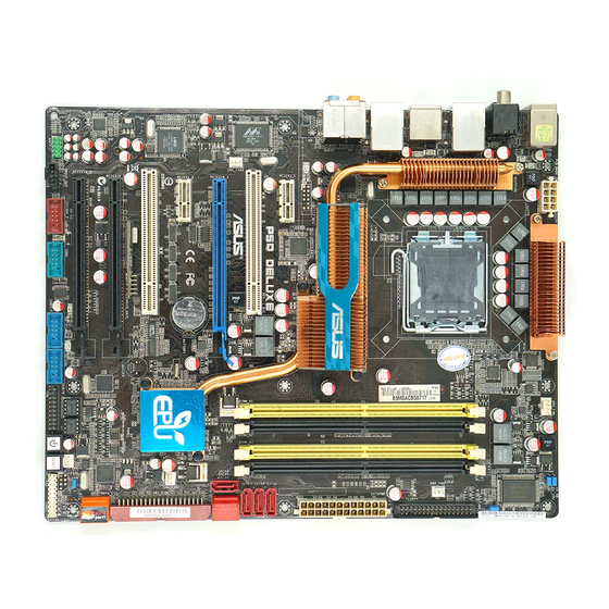
Page 28: Motherboard Overview
Motherboard overview 2.2.1 Motherboard layout Refer to 2.7 Connectors for more information about rear panel connectors and internal connectors. Chapter 2: Hardware information…
-
Page 29: Layout Contents
Chassis intrusion connector (4-1 pin CHASSIS) 2-25 Floppy disk drive connector (34-1 pin FLOPPY) 2-31 Optical drive audio connector (4-pin CD) 2-33 Front panel audio connector (10-1 pin AAFP) 2-32 Digital audio connector (4-1 pin SPDIF_OUT) Serial port connector (10-1 pin COM1) 2-33 ASUS P5Q…
-
Page 30: Placement Direction
2.2.3 Placement direction When installing the motherboard, make sure that you place it into the chassis in the correct orientation. The edge with external ports goes to the rear part of the chassis as indicated in the image below. 2.2.4 Screw holes Place six (6) screws into the holes indicated by circles to secure the motherboard to the chassis.
-
Page 31: Central Processing Unit (Cpu)
ASUS will shoulder the cost of repair only if the damage is shipment/transit-related. • Keep the cap after installing the motherboard. ASUS will process Return Merchandise Authorization (RMA) requests only if the motherboard comes with the cap on the LGA775 socket.
-
Page 32: Installing The Cpu
2.3.1 Installing the CPU To install a CPU: Locate the CPU socket on the motherboard. Before installing the CPU, make sure that the cam box is facing towards you and the load lever is on your left. Press the load lever with your thumb Retention tab (A), then move it to the left (B) until it is released from the retention tab.
-
Page 33
The Thermal Interface Material is toxic and inedible. If it gets into your eyes or touches your skin, ensure to wash it off immediately, and seek professional medical help. To prevent contaminating the paste, DO NOT spread the paste with your finger directly. ASUS P5Q… -
Page 34
Close the load plate (A), then push the load lever (B) until it snaps into the retention tab. The motherboard supports Intel ® LGA775 processors with the Intel ® Enhanced Memory 64 Technology (EM64T), Enhanced Intel SpeedStep Technology ® (EIST), and Hyper-Threading Technology. Refer to the Appendix for more information on these CPU features. -
Page 35: Installing The Cpu Heatsink And Fan
Push down two fasteners at a time in a diagonal sequence to secure the heatsink and fan assembly in place. Orient the heatsink and fan assembly such that the CPU fan cable is closest to the CPU fan connector. ASUS P5Q…
-
Page 36: Uninstalling The Cpu Heatsink And Fan
Connect the CPU fan cable to the connector on the motherboard labeled CPU_FAN. DO NOT forget to connect the CPU fan connector! Hardware monitoring errors can occur if you fail to plug this connector. 2.3.3 Uninstalling the CPU heatsink and fan To uninstall the CPU heatsink and fan: Disconnect the CPU fan cable from the connector on the motherboard.
-
Page 37: System Memory
The motherboard comes with four Double Data Rate 2 (DDR2) Dual Inline Memory Modules (DIMM) sockets. The figure illustrates the location of the DDR2 DIMM sockets: Channel Sockets Channel A DIMM_A1 and DIMM_A2 Channel B DIMM_B1 and DIMM_B2 ASUS P5Q 2-11…
-
Page 38: Memory Configurations
2.4.2 Memory configurations You may install 512 MB, 1 GB, 2 GB and 4 GB unbuffered and non-ECC DDR2 DIMMs into the DIMM sockets. • You may install varying memory sizes in Channel A and Channel B. The system maps the total size of the lower-sized channel for the dual-channel configuration.
-
Page 39
512MB Hynix HY5PS12821CFP-S5 5-5-5 Hynix HYMP564U64CP8-S5 1024MB Hynix HY5PS12821CFP-S5 5-5-5 Hynix HYMP512U64CP8-S5 512MB KINGMAX KKA8FEIBF-HJK-25A KINGMAX KLDC28F-A8KI5 1024MB KINGMAX KKA8FEIBF-HJK-25A KINGMAX KLDD48F-ABKI5 2048MB KINGMAX KKB8FFBXF-CFA-25A KINGMAX KLDE88F-B8KB5 512MB KINGSTON E5108AJBG-8E-E ELPIDA KVR800D2N5/512 512MB KINGSTON E5108AJBG-8E-E ELPIDA KVR800D2N6/512 ASUS P5Q 2-13… -
Page 40
P5Q Motherboard Qualified Vendors Lists (QVL) DDR2-800 MHz capability (cont.) DIMM socket support (Optional) Size Vendor Chip No. Chip Brand SS/DS Part No. 1024MB KINGSTON Heat-Sink Package 4-4-4-12 N/A KHX6400D2LLK2/1GN (EPP) V 1024MB KINGSTON Heat-Sink Package KHX6400D2ULK2/1G 1024MB KINGSTON Heat-Sink Package 4-4-4-12 N/A KHX6400D2LL/1G 1024MB… -
Page 41: Memory Configuration
• C*: Supports four modules inserted into both the yellow and black slots as two pairs of dual-channel memory configuration. Visit the ASUS website for the latest QVL. ASUS P5Q 2-15…
-
Page 42: Installing A Dimm
2.4.3 Installing a DIMM Make sure to unplug the power supply before adding or removing DIMMs or other system components. Failure to do so may cause severe damage to both the motherboard and the components. Unlock a DDR2 DIMM socket DDR2 DIMM notch by pressing the retaining clips outward.
-
Page 43: Expansion Slots
IRQ” or that the cards do not need IRQ assignments. Otherwise, conflicts will arise between the two PCI groups, making the system unstable and the card inoperable. Refer to the table on the next page for details. ASUS P5Q 2-17…
-
Page 44: Interrupt Assignments
2.5.3 Interrupt assignments Priority Standard function System timer Keyboard controller – Re-direct to IRQ#9 IRQ holder for PCI steering* Communications port (COM1)* IRQ holder for PCI steering* Floppy disk controller Printer port (LPT1)* System CMOS/Real Time Clock IRQ holder for PCI steering* IRQ holder for PCI steering* IRQ holder for PCI steering* PS/2 compatible mouse port*…
-
Page 45: Pci Slots
PCI Express specifications. Refer to the figure below for the location of the slot. PCI Express 2.0 x16 slot (blue) PCI slot 3 PCI Express x1 slot 1 PCI slot 2 PCI Express x1 slot 2 PCI slot 1 ASUS P5Q 2-19…
-
Page 46: Jumper
Jumper Clear RTC RAM (3-pin CLRTC) This jumper allows you to clear the Real Time Clock (RTC) RAM in CMOS. You can clear the CMOS memory of date, time, and system setup parameters by erasing the CMOS RTC RAM data. The onboard button cell battery powers the RAM data in CMOS, which include system setup information such as system passwords.
-
Page 47
For system failure due to the wrong setting of the OV_CPU jumper, shut down the computer and move the cap back to pins 2-3. • The system may need a better cooling system (for example, a water-cooling system) to work stably under high voltage settings. ASUS P5Q 2-21… -
Page 48
Keyboard/mouse power (3-pin PS2_USBPW56) This jumper allows you to enable or disable the keyboard/mouse and USB port 5-6 wake-up feature. When you set this jumper to pins 2-3 (+5VSB), you can wake up the computer by pressing a key on the keyboard (the default is the Space Bar), clicking the mouse or using a USB device. -
Page 49: Connectors
Line Out port (lime). This port connects a headphone or a speaker. In 4-channel, 6-channel, and 8-channel configuration, the function of this port becomes Front Speaker Out. Microphone port (pink). This port connects a microphone. ASUS P5Q 2-23…
-
Page 50
Side Speaker Out port (gray). This port connects the side speakers in an 8-channel audio configuration. Refer to the audio configuration table below for the function of the audio ports in 2, 4, 6, or 8-channel configuration. Audio 2, 4, 6, or 8-channel configuration Headset Port 4-channel… -
Page 51: Internal Connectors
This connector supports a Trusted Platform Module (TPM) system, which can securely store keys, digital certificates, passwords, and data. A TPM system also helps enhance network security, protects digital identities, and ensures platform integrity. The TPM module is purchased separately. ASUS P5Q 2-25…
-
Page 52
IDE connector (40-1 pin PRI_EIDE) The onboard IDE connector is for the Ultra DMA 133/100/66 signal cable. There are three connectors on each Ultra DMA 133/100/66 signal cable: blue, black, and gray. Connect the blue connector to the motherboard’s IDE connector, then select one of the following modes to configure your device. -
Page 53
Connect the right-angle side of SATA signal cable to SATA device. Or you may connect the right-angle side of SATA cable to the onboard SATA port to avoid mechanical conflict with huge graphics cards. ASUS P5Q 2-27… -
Page 54
Super Speed erases all original data in both hard disks. Before using the Drive Xpert technology, make sure that you have connected the SATA signal cables and installed SATA hard disk drives. Refer to 4.3.11 ASUS Drive Xpert for detailed application instructions. 2-28 Chapter 2: Hardware information… -
Page 55
If your chassis suppots front panel USB ports, you can attach a front panel USB cable to these connectors. Connect the USB cable to ASUS Q-Connector (USB, blue) first, and then install the Q-Connector (USB) to the USB connector onboard. -
Page 56
You can attach a FireWire/1394 cable to this connector if your chassis suppots the front panel IEEE1394 port. Connect the 1394 cable to ASUS Q-Connector (1394, red) first, and then install the Q-Connector (1394) to the 1394 connector onboard. -
Page 57
These are not jumpers! DO NOT place jumper caps on the fan connectors! Only the CPU_FAN and CHA_FAN1-2 connectors support the ASUS Fan Xpert feature. Optical drive audio connector (4-pin CD) This connector allows you to receive stereo audio input from sound sources such as a CD-ROM, TV tuner, or MPEG card. -
Page 58
10. Chassis intrusion connector (4-1 pin CHASSIS) This connector is for a chassis-mounted intrusion detection sensor or switch. Connect one end of the chassis intrusion sensor or switch cable to this connector. The chassis intrusion sensor or switch sends a high-level signal to this connector when a chassis component is removed or replaced. -
Page 59
Front Panel Type item in the BIOS is set to [HD Audio]. If you want to connect an AC’ 97 front panel audio module to this connector, set the item to [AC97]. Refer to page 3-28 for details. ASUS P5Q 2-33… -
Page 60
• If you are uncertain about the minimum power supply requirement for your system, refer to the Recommended Power Supply Wattage Calculator at http://support.asus.com/PowerSupplyCalculator/PSCalculator. aspx?SLanguage=en-us for details. 2-34 Chapter 2: Hardware information… -
Page 61: System Panel Connector
BIOS settings. Pressing the power switch for more than four seconds while the system is ON turns the system OFF. • Reset button (2-pin RESET) This 2-pin connector is for the chassis-mounted reset button for system reboot without turning off the system power. ASUS P5Q 2-35…
-
Page 62: Asus Q-Connector
16. ASUS Q-Connector (system panel) You can use the ASUS Q-Connector to connect/disconnect chassis front panel cables in a few steps. Refer to the instructions below to install the ASUS Q-Connector. Connect the front panel cables to the ASUS Q-Connector.
-
Page 63: Starting Up For The First Time
One continuous beep followed by three No VGA detected short beeps One continuous beep followed by four Hardware component failure short beeps At power on, hold down the <Delete> key to enter the BIOS Setup. Follow the instructions in Chapter 3. ASUS P5Q 2-37…
-
Page 64: Turning Off The Computer
Turning off the computer 2.9.1 Using the OS shut down function If you are using Windows Vista™: ® Click the Start button then select ShutDown. The power supply should turn off after Windows shuts down. ® If you are using Windows ®…
-
Page 65: Chapter 3: Bios Setup
This chapter tells how to change the system settings through the BIOS Setup menus. Detailed descriptions of the BIOS parameters are also provided. Chapter 3: BIOS setup…
-
Page 66
Managing and updating your BIOS ……….3-1 BIOS setup program …………..3-9 Main menu ……………… 3-12 Ai Tweaker menu ……………. 3-17 Advanced menu …………….. 3-24 Power menu …………….3-31 Boot menu ……………… 3-35 Tools menu …………….. 3-39 Exit menu ………………3-44 ASUS P5Q… -
Page 67: Managing And Updating Your Bios
® ASUS EZ Flash 2 (Updates the BIOS using a floppy disk or USB flash disk.) AFUDOS (Updates the BIOS using a bootable floppy disk) ASUS CrashFree BIOS 3 (Updates the BIOS using a USB flash disk or the motherboard support CD when the BIOS file fails or gets corrupted.)
-
Page 68
To update the BIOS through the Internet: desktop by clicking Start Launch the ASUS Update utility from the Windows ® > Programs > ASUS > ASUSUpdate > ASUSUpdate. The ASUS Update main window appears. Select Update BIOS from the Select the ASUS FTP site nearest… -
Page 69
To update the BIOS through a BIOS file: desktop by clicking Start Launch the ASUS Update utility from the Windows ® > Programs > ASUS > ASUSUpdate > ASUSUpdate. The ASUS Update main window appears. Select Update BIOS from a file option from the drop-down menu, then click Next. -
Page 70: Creating A Bootable Floppy Disk
3.1.2 Creating a bootable floppy disk Do either one of the following to create a bootable floppy disk. DOS environment a. Insert a 1.44MB floppy disk into the drive. b. At the DOS prompt, type format A:/S then press <Enter>. Windows XP environment ®…
-
Page 71: Asus Ez Flash 2 Utility
3.1.3 ASUS EZ Flash 2 utility The ASUS EZ Flash 2 feature allows you to update the BIOS without having to go through the long process of booting from a floppy disk and using a DOS-based utility. The EZ Flash 2 utility is built-in the BIOS chip so it is accessible by pressing <Alt>…
-
Page 72: Afudos Utility
Updating the BIOS file To update the BIOS file using the AFUDOS utility: Visit the ASUS website (www.asus.com) and download the latest BIOS file for the motherboard. Save the BIOS file to a bootable floppy disk. Chapter 3: BIOS setup…
-
Page 73
A:\>afudos /iP5Q.ROM The utility verifies the file and starts updating the BIOS. A:\>afudos /iP5Q.ROM AMI Firmware Update Utility — Version 1.19(ASUS V2.07(03.11.24BB)) Copyright (C) 2002 American Megatrends, Inc. All rights reserved. WARNING!! Do not turn off power during flash BIOS Reading file ..done Reading flash .. -
Page 74: Asus Crashfree Bios 3 Utility
3.1.5 ASUS CrashFree BIOS 3 utility The ASUS CrashFree BIOS 3 is an auto recovery tool that allows you to restore the BIOS file when it fails or gets corrupted during the updating process. You can update a corrupted BIOS file using the motherboard support CD or the USB flash disk that contains the updated BIOS file.
-
Page 75: Bios Setup Program
The BIOS setup screens shown in this section are for reference purposes only, and may not exactly match what you see on your screen. • Visit the ASUS website (www.asus.com) to download the latest BIOS file for this motherboard. ASUS P5Q…
-
Page 76: Bios Menu Screen
3.2.1 BIOS menu screen Menu items Menu bar Configuration fields General help BIOS SETUP UTILITY Main Ai Tweaker Advanced Power Boot Tools Exit Use [ENTER], [TAB] System Time [10:55:25] or [SHIFT-TAB] to System Date [Mon 05/12/2008] select a field. Legacy Diskette A [1.44M, 3.5 in.] Language [English]…
-
Page 77: Menu Items
Up/Down arrow keys or <Page Up> /<Page Down> keys to display the other items on the screen. 3.2.9 General help Pop-up window At the top right corner of the menu screen Scroll bar is a brief description of the selected item. ASUS P5Q 3-11…
-
Page 78: Main Menu
Main menu When you enter the BIOS Setup program, the Main menu screen appears, giving you an overview of the basic system information. Refer to section 3.2.1 BIOS menu screen for information on the menu screen items and how to navigate through them. BIOS SETUP UTILITY Main Ai Tweaker…
-
Page 79: Sata 1-6
When set to [Disabled], the data transfer from and to the device occurs one sector at a time. Configuration options: [Disabled] [Auto] PIO Mode [Auto] Allows you to select the data transfer mode. Configuration options: [Auto] [0] [1] [2] [3] [4] ASUS P5Q 3-13…
-
Page 80: Storage Configuration
DMA Mode [Auto] Selects the DMA mode. Configuration options: [Auto] [SWDMA0] [SWDMA1] [SWDMA2] [MWDMA0] [MWDMA1] [MWDMA2] [UDMA0] [UDMA1] [UDMA2] [UDMA3] [UDMA4] [UDMA5] SMART Monitoring [Auto] Sets the Smart Monitoring, Analysis, and Reporting Technology. Configuration options: [Auto] [Disabled] [Enabled] 32Bit Data Transfer [Enabled] Enables or disables 32-bit data transfer.
-
Page 81: Ahci Configuration
SATA Port1 [Auto] Allows you to select the type of device connected to the system. Configuration options: [Auto] [Not Installed] SMART Monitoring [Enabled] Allows you to set the Self-Monitoring, Analysis and Reporting Technology. Configration options: [Disabled] [Enabled] ASUS P5Q 3-15…
-
Page 82: System Information
3.3.8 System Information This menu gives you an overview of the general system specifications. The BIOS automatically detects the items in this menu. BIOS SETUP UTILITY Main BIOS Information Version : 0204 Build Date: 05/06/08 Processor Type : Intel(R) CPU 3.60GHz Speed : 3600MHz Count…
-
Page 83: Ai Tweaker Menu
Allows selection of CPU overclocking options to achieve desired CPU internal frequency. Select either one of the preset overclocking configuration options: Manual Allows you to individually set overclocking parameters. Auto Loads the optimal settings for the system. ASUS P5Q 3-17…
-
Page 84: Cpu Ratio Setting [Auto]
3.4.2 CPU Ratio Setting [Auto] Allows you to adjust the ratio between CPU Core Clock and FSB Frequency. Use the <+> and <-> keys to adjust the ratio. If an invalid ratio is set in CMOS, then actual and setpoint values may differ. The following two items appear only when you set the Ai Overclock Tuner item to [Manual].
-
Page 85: Dram Timing Control [Auto]
Configuration options: [Auto] [1 DRAM Clocks] – [15 DRAM Clocks] WRITE to READ Delay(S) [Auto] Configuration options: [Auto] [1 DRAM Clocks] – [15 DRAM Clocks] WRITE to READ Delay(D) [Auto] Configuration options: [Auto] [1 DRAM Clocks] – [15 DRAM Clocks] ASUS P5Q 3-19…
-
Page 86: Dram Static Read Control [Auto]
READ To READ Delay(S) [Auto] Configuration options: [Auto] [1 DRAM Clocks] – [15 DRAM Clocks] READ To READ Delay(D) [Auto] Configuration options: [Auto] [1 DRAM Clocks] – [15 DRAM Clocks] WRITE To WRITE Delay(S) [Auto] Configuration options: [Auto] [1 DRAM Clocks] – [15 DRAM Clocks] WRITE To WRITE Delay(D) [Auto] Configuration options: [Auto] [1 DRAM Clocks] –…
-
Page 87: Ai Transaction Booster [Auto]
FSB Termination Voltage [Auto] Allows you to set the front side bus termination voltage. The values range from 1.20V* to 1.90V with a 0.02V interval. The minimum value of this item becomes 1.10V when a 45nm CPU is installed. ASUS P5Q 3-21…
-
Page 88: Dram Voltage [Auto]
3.4.14 DRAM Voltage [Auto] Allows you to set the DRAM voltage. The values range from 1.80V to 3.08V with a 0.02V interval. 3.4.15 NB Voltage [Auto] Allows you to set the North Bridge voltage. The values range from 1.10V to 2.20V* with a 0.02V interval.
-
Page 89: Load-Line Calibration [Auto]
Set to [Disabled] to enhance FSB overclocking ability or [Auto] for EMI control. Configuration options: [Auto] [Disabled] 3.4.20 PCIE Spread Spectrum [Auto] Set to [Disabled] to enhance PCIE overclocking ability or [Auto] for EMI control. Configuration options: [Auto] [Disabled] ASUS P5Q 3-23…
-
Page 90: Advanced Menu
Advanced menu The Advanced menu items allow you to change the settings for the CPU and other system devices. Take caution when changing the settings of the Advanced menu items. Incorrect field values can cause the system to malfunction. BIOS SETUP UTILITY Main Ai Tweaker Advanced…
-
Page 91: Cpu Configuration
C1E Support [Enabled] Change Option Max CPUID Value Limit [Disabled] General Help Intel(R) Virtualization Tech [Enabled] Save and Exit CPU TM Function [Enabled] Exit Execute Disable Bit [Enabled] Intel(R) SpeedStep(TM) Tech [Enabled] v02.61 (C)Copyright 1985-2008, American Megatrends, Inc. ASUS P5Q 3-25…
-
Page 92
CPU Ratio Setting [Auto] Allows you to adjust the ratio between CPU Core Clock and FSB Frequency. Use the <+> and <-> keys to adjust the value. Configuration options: [Auto] [12.0] [13.0] [14.0] [15.0] [16.0] [17.0] [18.0] C1E Support [Enabled] Allows you to enable or disable Enhanced Halt State support. -
Page 93: Chipset
Memory Hole [Disabled] Allows you to set the memory hole mode. Configuration options: [Disabled] [15MB-16MB] Initiate Graphic Adapter [PEG/PCI] Allows you to decide which graphics controller to use as the primary boot device. Configuration options: [PCI/PEG] [PEG/PCI] ASUS P5Q 3-27…
-
Page 94: Onboard Devices Configuration
3.5.4 Onboard Devices Configuration BIOS SETUP UTILITY Advanced Onboard Devices Configuration Enable or Disable High Definition Audio High Definition Audio [Enabled] Controller Front Panel Type [HD Audio] SPDIF_OUT Mode Setting [SPDIF Output] Marvell IDE [Enabled] Marvell IDE Boot ROM [Enabled] Atheros GigaBit LAN [Enabled] LAN Boot ROM…
-
Page 95: Usb Configuration
Allows you to enable or disable the USB Host Controllers. Configuration options: [Disabled] [Enabled] The following items appear only when you set USB Functions to [Enabled]. USB 2.0 Controller [Enabled] Allows you to enable or disable the USB 2.0 controller. Configuration options: [Enabled] [Disabled] ASUS P5Q 3-29…
-
Page 96: Pcipnp
USB 2.0 Controller Mode [HiSpeed] Allows you to set the USB 2.0 controller mode to HiSpeed (480 Mbps) or FullSpeed (12 Mbps). Configuration options: [FullSpeed] [HiSpeed] The USB 2.0 Controller Mode item appears only when you enable the USB 2.0 Controller. BIOS EHCI Hand-off [Enabled] Allows you to enable the support for operating systems without an EHCI hand-off feature.
-
Page 97: Power Menu
Allows you to enable or disable the Advanced Configuration and Power Interface (ACPI) support in the Advanced Programmable Interrupt Controller (APIC). When set to [Enabled], the ACPI APIC table pointer is included in the RSDT pointer list. Configuration options: [Disabled] [Enabled] ASUS P5Q 3-31…
-
Page 98: Apm Configuration
3.6.5 APM Configuration BIOS SETUP UTILITY Power APM Configuration <Enter> to select whether or not to Restore on AC Power Loss [Power Off] restart the system after AC power loss. Power On By RTC Alarm [Disabled] Power On By External Modems [Disabled] Power On By PCI Devices [Disabled]…
-
Page 99: Hardware Monitor
(RPM). If the fan is not connected to the motherboard, the field shows [N/A]. CPU Q-Fan Control [Disabled] Allows you to enable or disable the CPU Q-fan control feature. Configuration options: [Disabled] [Enabled] ASUS P5Q 3-33…
-
Page 100
The following item appears only when you enable the CPU Q-Fan Control item. CPU Fan Profile [Silent] Allows you to set the appropriate performance level of the CPU fan. When set to [Standard], the CPU fan automatically adjusts depending on the CPU temperature. -
Page 101: Boot Menu
These items specify the boot device priority sequence from the available devices. The number of device items that appears on the screen depends on the number of devices installed in the system. Configuration options: [1st FLOPPY DRIVE] [Hard Drive] [ATAPI CD-ROM] [Disabled] ASUS P5Q 3-35…
-
Page 102: Boot Settings Configuration
This allows you to enable or disable the full screen logo display feature. Configuration options: [Disabled] [Enabled] Set this item to [Enabled] to use the ASUS MyLogo2™ feature. AddOn ROM Display Mode [Force BIOS] Sets the display mode for option ROM.
-
Page 103: Security
If you forget your BIOS password, you can clear it by erasing the CMOS Real Time Clock (RTC) RAM. See section 2.6 Jumper for information on how to erase the RTC RAM. After you have set a supervisor password, the other items appear to allow you to change other security settings. ASUS P5Q 3-37…
-
Page 104: Change User Password
BIOS SETUP UTILITY Boot Security Settings <Enter> to change password. Supervisor Password : Installed <Enter> again to User Password : Installed disabled password. Change Supervisor Password User Access Level [Full Access] Change User Password Clear User Password Password Check [Setup] Select Screen Select Item…
-
Page 105: Tools Menu
3.8.1 ASUS EZ Flash 2 Allows you to run ASUS EZ Flash 2. When you press <Enter>, a confirmation message appears. Use the left/right arrow key to select between [Yes] or [No], then press <Enter> to confirm your choice. Please see page 3-5, section 3.1.3 for details.
-
Page 106: Drive Xpert Control [Auto]
3.8.2 Drive Xpert Control [Auto] Allows you to enable or disable the Drive Xpert feature. Configuration options: [Auto] [Enabled] [Disabled] 3.8.3 Drive Xpert Mode Update [Last Setting] This item appears only when you set Drive Xpert Control to [Auto] or [Enabled]. Set this item to [Mode Change] to show further settings of the Drive Xpert function.
-
Page 107: Express Gate
3.8.4 Express Gate Allows you to enable or disable the ASUS Express Gate feature. The ASUS Express Gate feature is a unique instant-on environment that provides quick access to the Internet browser and Skype. Refer to section 4.3.12 for details.
-
Page 108: Asus O.c. Profile
3.8.5 ASUS O.C. Profile This item allows you to store or load multiple BIOS settings. BIOS SETUP UTILITY Tools O.C. PROFILE Configuration Save to Profile 1 O.C. Profile 1 Status : Not Installed O.C. Profile 2 Status : Not Installed…
-
Page 109: Ai Net 2
Select Item Change Option General Help Save and Exit Exit v02.58 (C)Copyright 1985-2008, American Megatrends, Inc. Check Atheros LAN cable [Disabled] Enables or disables checking of the LAN cable during the Power-On Self-Test (POST). Configuration options: [Disabled] [Enabled] ASUS P5Q 3-43…
-
Page 110: Exit Menu
Exit menu The Exit menu items allow you to load the optimal or failsafe default values for the BIOS items, and save or discard your changes to the BIOS items. BIOS SETUP UTILITY Main Ai Tweaker Advanced Power Boot Tools Exit Exit system setup Exit &…
-
Page 111: Chapter 4: Software Support
This chapter describes the contents of the support DVD that comes with the motherboard package and the software. Software support…
-
Page 112
Chapter summary Installing an operating system ……….. 4-1 Support DVD information …………4-1 Software information …………..4-9 RAID configurations …………..4-55 Creating a RAID driver disk …………4-64 ASUS P5Q… -
Page 113: Installing An Operating System
The support DVD that came with the motherboard package contains the drivers, software applications, and utilities that you can install to avail all motherboard features. The contents of the support DVD are subject to change at any time without notice. Visit the ASUS website(www.asus.com) for updates. 4.2.1 Running the support DVD Place the support DVD to the optical drive.
-
Page 114: Drivers Menu
Installs the Atheros L1e Gigabit Ethernet driver. Marvell 61xx SATA Driver Installs the Marvell 61xx SATA driver. ® ASUS EPU-Six Engine Installs the ASUS EPU-6 Engine driver and utility. USB 2.0 Driver Installs the USB 2.0 driver. Chapter 4: Software support…
-
Page 115: Utilities Menu
ASUS InstAll — Installation Wizard for Utilities Installs all of the utilities through the Installation Wizard. ASUS Update The ASUS Update utility allows you to update the motherboard BIOS in Windows ® environment. This utility requires an Internet connection either through a network or an Internet Service Provider (ISP).
-
Page 116
This utility helps you keep your computer in healthy operating condition. ASUS AI Suite The ASUS AI Suite is an innovative application to do overclocking, fan control, power saving and quiet thermal control. ASUS AI Direct Link The ASUS AI Direct Link provides up to 70% transferring speed improvement when compared to traditional USB 2.0 and is the easiest and fastest way for users to… -
Page 117: Make Disk Menu
Drive Xpert Installs the ASUS Drive Xpert utility. Anti-Virus Utility The anti-virus application detects and protects your computer from viruses that destroys data. Anti-Virus Utility Download Downloads and installs the latest anti-virus application. 4.2.4 Make disk menu The Make disk menu contains items to create the Intel ICH10R or Marvell 61xx ®…
-
Page 118: Manual Menu
Reader from the Utilities menu before opening a user manual ® ® file. 4.2.6 ASUS Contact information Click the Contact tab to display the ASUS contact information. You can also find this information on the inside front cover of this user guide. Chapter 4: Software support…
-
Page 119: Other Information
The icons on the top right corner of the screen give additional information on the motherboard and the contents of the support DVD. Click an icon to display the specified information. Motherboard Info Displays the general specifications of the motherboard. Browse this DVD Displays the support DVD contents in graphical format. ASUS P5Q…
-
Page 120: Technical Support Form
Technical support Form Displays the ASUS Technical Support Request Form that you have to fill out when requesting technical support. Filelist Displays the contents of the support DVD in text format. Chapter 4: Software support…
-
Page 121: Software Information
4.3.1 ASUS MyLogo2™ The ASUS MyLogo2™ utility lets you customize the boot logo. The boot logo is the image that appears on screen during the Power-On-Self-Tests (POST). The ASUS MyLogo2™ is automatically installed when you install the ASUS Update utility from the support DVD.
-
Page 122
Ratio box. When the screen returns to the ASUS Update utility, flash the original BIOS to load the new boot logo. 10. After flashing the BIOS, restart the computer to display the new boot logo during POST. -
Page 123: Ai Net2
LAN cable(s) connected to the LAN port(s). • If you want the system to check the status of the LAN cable before entering the OS, enable the item Post Check LAN Cable in the BIOS Setup. ASUS P5Q 4-11…
-
Page 124: Asus Pc Probe Ii
To launch the PC Probe II from the Windows ® > ASUS > PC Probe II > PC Probe II v1.xx.xx. The PC Probe II main window appears. After launching the application, the PC Probe II icon appears in the Windows ®…
-
Page 125
When displayed, the monitor panel for that sensor also turns red. Refer to the Monitor panels section for details. Preference You can customize the application using the Preference section in the main window. Click the box before each preference to activate or deactivate. ASUS P5Q 4-13… -
Page 126
Hardware monitor panels The hardware monitor panels display the current value of a system sensor such as fan rotation, CPU temperature, and voltages. The hardware monitor panels come in two display modes: hexagonal (large) and rectangular (small). When you check the Enable Monitoring Panel option from the Preference section, the monitor panels appear on your computer’s desktop. -
Page 127
You can enlarge or reduce the browser size by dragging the bottom right corner of the browser. DMI browser Click to display the DMI (Desktop Management Interface) browser. This browser displays various desktop and system information. Click the plus sign (+) before DMI Information to display the available information. ASUS P5Q 4-15… -
Page 128
PCI browser Click to display the PCI (Peripheral Component Interconnect) browser. This browser provides information on the PCI devices installed on your system. Click the plus sign (+) before the PCI Information item to display available information. Usage The Usage browser displays real-time information on the CPU, hard disk drive space, and memory usage. -
Page 129
The Preference tab allows you to customize sensor alerts, or change the temperature scale. Loads the default Loads your saved threshold values for Cancels or configuration each sensor ignores your changes Applies your Saves your changes configuration ASUS P5Q 4-17… -
Page 130: Asus Ai Suite
4.3.4 ASUS AI Suite ASUS AI Suite allows you to launch EPU-6 Engine, AI Booster, AI Nap, and Fan Xpert utilities easily. Installing AI Suite To install AI Suite on your computer: Place the support DVD to the optical drive. The Drivers installation tab appears if your computer has an enabled Autorun feature.
-
Page 131
Displays the CPU/ system temperature, CPU/memory/PCIE voltage, and CPU/ chassis fan speed Displays the FSB/CPU frequency Click on right corner of the expanded window to switch the temperature from degrees Centigrade to degrees Fahrenheit. ASUS P5Q 4-19… -
Page 132: Asus Ai Nap
4.3.5 ASUS AI Nap This feature allows you to minimize the power consumption of your computer whenever you are away. Enable this feature for minimum power consumption and a more quiet system operation. After installing AI Suite from the bundled support DVD, you can launch the utility by double-clicking the AI Suite icon on the Windows OS taskbar and click the AI Nap button on the AI Suite main window.
-
Page 133: Asus Fan Xpert
4.3.6 ASUS Fan Xpert Asus Fan Xpert intelligently allows you to adjust both the CPU and chassis fan speeds according to different ambient temperatures caused by different climate conditions in different geographic regions and your PC’s system loading. The built-in variety of useful profiles offer flexible controls of fan speed to achieve a quiet and cool environment.
-
Page 134: Fan Profile Modes
Fan profile modes Disable: Select this mode to disable the Fan Xpert function. • Standard: This mode makes the fan adjust speed in moderate pattern. • Silent: This mode minimizes fan speed for quiet fan operation. • Turbo: This mode boosts the fan to achieve maximal fan speed for the best •…
-
Page 135: Asus Ai Booster
4.3.7 ASUS AI Booster The ASUS AI Booster application allows you to overclock the CPU speed in WIndows environment without the hassle of booting the BIOS. ® After installing AI Suite from the bundled support DVD, you can launch the utility…
-
Page 136: Asus Epu-6 Engine
4.3.8 ASUS EPU-6 Engine ASUS EPU-6 Engine is an energy-efficient tool that satisfies different computing needs. This utility provides four modes that you can select to enhance system performance or save power. Selecting Auto mode will have the system shift modes automatically according to current system status.
-
Page 137: Engine Main Menu
Advanced settings for each mode (refer to the next page for further information) Click Current *• to show the CO2 that has been reduced since you click the Renew button *• Click Total to show the total CO2 that has been reduced since you launched 6 Engine. ASUS P5Q 4-25…
-
Page 138: Advanced Settings Menu
Advanced settings menu Click Advance ( ) from the 6 Engine main menu to display configuration options in each mode. Some options in certain modes are dimmed, meaning that they are not available. Click to select a mode Move the slider to adjust Click the arrow to see more…
-
Page 139
CPU Loadline Light/Medium/ Light/Medium/ Heavy Heavy Fan Control Keep Bios Keep Bios Setting/Slow Setting/Quiet AI Nap Never/After 3 Never/After 3 Never/After 3 Never/After 3 Idle Time mins–After 5 mins–After 5 mins–After 5 mins–After 5 hours hours hours hours ASUS P5Q 4-27… -
Page 140: Asus Ai Direct Link
You must first connect two computers (at least one of them is ASUS product) using a network cable, and then install the utility to both computers to avail the AI Direct Link feature.
-
Page 141
The default path of the AIDirectLinkIncoming folder is C:\Program Files\ASUS\AI Direct Link. To change its location, disable the incoming folder first. Then, select Incoming folder > Change incoming folder to open the system directories, and move the AIDirectLinkIncoming folder under another directory. -
Page 142: Audio Configurations
4.3.10 Audio configurations The Realtek ® ALC1200 audio CODEC provides 8-channel audio capability to deliver the ultimate audio experience on your computer. The software provides Jack-Sensing function, S/PDIF Out support, and interrupt capability. The ALC1200 also includes the Realtek ® proprietary UAJ ®…
-
Page 143: Configuration Options
Manager, click the Sound Effect tab. Click the shortcut buttons or the drop-down menus for options on changing the acoustic environment, adjust the equalizer, or set the karaoke to your desired settings. Click to effect the Sound Effect settings and exit. ASUS P5Q 4-31…
-
Page 144
Mixer The Mixer option allows you to configure audio output (playback) volume and audio input (record) volume. To set the mixer options: From the Realtek HD Audio Manager, click the Mixer tab. Turn the volume buttons to adjust the Playback and/or Record volume. -
Page 145
From the Realtek HD Audio Manager, click the 3D Audio Demo tab. Click the option buttons to change the sound, moving path, or environment settings. Click to test your settings. Click to effect the 3D Audio Demo settings and exit. ASUS P5Q 4-33… -
Page 146: Asus Drive Xpert
4.3.11 ASUS Drive Xpert Drive Xpert, an ASUS exclusive technology, secures the data on your hard disk and enhances hard drive performance without the hassles of complicated configurations. With its user-friendly graphical user interface, you can easily arrange hard drive backups or enhance the hard drive’s transfer rate.
-
Page 147
The setup is completed. Click Ok to restart your computer at once. After restarting your computer, the Drive Xpert icon on the Windows notification area ® turns green to indicate that EZ Backup is set up successfully. ASUS P5Q 4-35… -
Page 148
Configuring Super Speed This mode allows two hard disks to access data simultaneously. The dual channel design can largely enhance hard disk transfer rate. • We recommend that you use two new hard disks for this setup. • This setup erases all original data in both hard disks. Ensure to back up all data in the hard disks before using this setup. -
Page 149
The setup is completed. Click Ok to restart your computer at once. After restarting your computer, the Drive Xpert icon on the Windows notification area turns ® gray to indicate that the Drive Xpert function is disabled. ASUS P5Q 4-37… -
Page 150: Partitioning Volumes
Partitioning volumes You have to partition volumes for the hard disk after Super Speed configuration. To partition volumes: Right-click My Computer on the Windows desktop, ® and then select Manage from the pop-up window. Select Disk Management. Right-click the unallocated space of the disk, and then select New Partition.
-
Page 151
New Schedule Allows you to set specific date and time for the schedule. Physical Drive Allows you to set schedule for the selected hard disk. Scheduled Displays the date and time for the setup schedule. ASUS P5Q 4-39… -
Page 152
Event Log Displays event log list that might be helpful for troubleshooting and locating a system malfunction. Click Refresh to update the event log list; and click Ok to close the window. Setup Password Allows you to set the password for configuration access. -
Page 153
Restart the system, and launch the Express Gate. Launching Drive Xpert To open the ASUS Utility panel, click . Launch Drive Xpert from the ASUS Utility panel. The main screen as shown below appears. Select EZ Backup or Super Speed according to your need. -
Page 154
EZ Backup To start EZ Backup configuration: Click EZ Backup from the main screen. Check if the SATA cables and power cords are installed properly. Click Next to continue. Click Next to continue the configuration. Before proceeding, ensure that you have back up all original data in the hard disk connected to the SATA_E2 (white, port 1) connector on the motherboard. -
Page 155
Before proceeding, ensure to back up all original data in the two hard disks. Otherwise, the system erases all data in both hard disks. Click Next to continue. The setup is completed. Click OK to close the configuration window. ASUS P5Q 4-43… -
Page 156
• BIOS SETUP UTILITY Main Ai Tweaker Advanced Power Boot Tools Exit ASUS EZ Flash 2 Press ENTER to run the utility to select Drive Xpert Control [Auto] and update BIOS. Drive Xpert Mode Update [Mode Change] This utility doesn’t… -
Page 157: Asus Express Gate
4.3.12 ASUS Express Gate ASUS Express Gate is an instant-on environment that gives you quick access to the Internet. Within a few seconds of powering on your computer, you will be at the Express Gate menu where you can start the web browser, Skype, or other Express Gate softwares.
-
Page 158
Select the target disk volume for you to install Express Gate. If you have multiple volumes and OS installed in your hard drive, it is recommended to install Express Gate in Volume C. Click Next to continue. Follow the screen instructions to complete installation. -
Page 159
Enter Boot selection pop-up In the Express Gate Environment: Function <Alt> + <Tab> Switch between softwares <Ctrl> + <Alt> + <Del> Bring up Power-Off dialog box <Ctrl> + <Alt> + <Print Screen> Save screen snapshot as picture to file ASUS P5Q 4-47… -
Page 160: Using The Configuration Panel
Using the Configuration Panel Use the configuration panel to change various Express Gate settings. Click on an icon to open a particular configuration tool. The following tools are available: Date and Time: set current date and time as well as time zone. •…
-
Page 161: Using The Launchbar
USB drive. If a USB device is detected, the icon contains a green arrow. ASUS Express Gate supports file uploading from SATA HDDs, ODDs and USB drive and downloading to USB drives only. Shows network status; click to configure network.
-
Page 162
Click to choose input language and method as well as keyboard shortcuts (Ctrl-Space by default). Click to change LaunchBar options (auto-hide, docking position, etc). Click to show the “ASUS Utility” panel. Click to show “About Express Gate ”. Click to open Express Gate Help. -
Page 163
The most common scenario is for your computer to automatically obtain network settings (i.e. DHCP). If this is the case, you don’t need to click Setup for any LAN port. If this is not the case, click Setup to configure the static IP settings manually. ASUS P5Q 4-51… -
Page 164
Shows user- created image album(s) Image control bar ASUS Express Gate supports HDDs connected to motherboard chipset- controlled onboard SATA ports only. All onboard extended SATA ports and external SATA ports are NOT supported. 4-52 Chapter 4: Software support… -
Page 165
Using ASUS Drive Xpert Without drivers or BIOS setups, the ASUS exclusive Drive Xpert is ideal for anyone who needs to secure data on their hard drives or enhance hard drive performances without the hassles of complicated configurations. To start ASUS Drive Xpert application Open the ASUS Utility panel. -
Page 166: Updating Express Gate
Express Gate software will be released regularly, adding refinements or new applications. You can find original version of the software on the support DVD or download new versions from the ASUS support website. To update Express Gate Double-click the Express Gate setup file to start software update.
-
Page 167: Raid Configurations
RAID driver from the support DVD to a floppy disk before you install an operating system to the selected hard disk drive. Refer to section 4.5 Creating a RAID driver disk for details. ASUS P5Q 4-55…
-
Page 168: Installing Serial Ata Hard Disks
4.4.2 Installing Serial ATA hard disks The motherboard supports Serial ATA hard disk drives. For optimal performance, install identical drives of the same model and capacity when creating a disk array. To install the SATA hard disks for a RAID configuration: Install the SATA hard disks into the drive bays.
-
Page 169: Intel Matrix Storage Manager Option Rom Utility
The navigation keys at the bottom of the screen allow you to move through the menus and select the menu options. The RAID BIOS setup screens shown in this section are for reference only and may not exactly match the items on your screen. ASUS P5Q 4-57…
-
Page 170: Creating A Raid 0 Set (Striped)
Creating a RAID 0 set (striped) To create a RAID 0 set: From the utility main menu, select 1. Create RAID Volume and press <Enter>. The following screen appears. Intel(R) Matrix Storage Manager option ROM v8.0.0.1027 ICH10R wRAID5 Copyright(C) 2003-08 Intel Corporation. All Rights Reserved. [ CREATE VOLUME MENU ] Name:…
-
Page 171
WARNING: ALL DATA ON SELECTED DISKS WILL BE LOST. Are you sure you want to create this volume? (Y/N): Press <Y> to create the RAID volume and return to the main menu, or <N> to go back to the Create Volume menu. ASUS P5Q 4-59… -
Page 172: Creating A Raid 1 Set (Mirrored)
Creating a RAID 1 set (mirrored) To create a RAID 1 set: From the utility main menu, select 1. Create RAID Volume and press <Enter>. The following screen appears. Intel(R) Matrix Storage Manager option ROM v8.0.0.1027 ICH10R wRAID5 Copyright(C) 2003-08 Intel Corporation. All Rights Reserved. [ CREATE VOLUME MENU ] Name:…
-
Page 173
We recommend a lower stripe size for server systems, and a higher stripe size for multimedia computer systems used mainly for audio and video editing. Enter the RAID volume capacity that you want and press <Enter>. The default value indicates the maximum capacity allowed. ASUS P5Q 4-61… -
Page 174
Press <Enter> when the Create Volume item is highlighted. The following warning message appears. WARNING: ALL DATA ON SELECTED DISKS WILL BE LOST. Are you sure you want to create this volume? (Y/N): Press <Y> to create the RAID volume and return to the main menu or <N> to go back to the Create Volume menu. -
Page 175
WARNING: ALL DATA ON SELECTED DISKS WILL BE LOST. Are you sure you want to create this volume? (Y/N): Press <Y> to create the RAID volume and return to the main menu or <N> to go back to the Create Volume menu. ASUS P5Q 4-63… -
Page 176: Creating A Raid Driver Disk
Creating a RAID driver disk A floppy disk with the RAID driver is required when installing Windows ® XP/Vista and later operating system on a hard disk drive that is included in a RAID set. For Windows Vista user, you can create a RAID driver disk with a floppy disk drive or a USB flash disk drive.
-
Page 177
To install the RAID driver in Windows Vista: ® Insert the floppy disk/USB device with RAID driver into the floppy disk drive/USB port. During the OS installation, select Intel(R) SATA RAID Controller (Desktop ICH10R). Follow the succeeding screen instructions to complete the installation. ASUS P5Q 4-65… -
Page 178
4-66 Chapter 4: Software support… -
Page 179: Appendix: Cpu Features
The Appendix describes the CPU features and technologies that the motherboard supports. CPU features…
-
Page 180: A.1 Intel ® Em64T
Chapter summary Intel ® EM64T ………………A-1 Enhanced Intel SpeedStep Technology (EIST) ……A-1 ® Intel Hyper-Threading Technology ………..A-3 ® ASUS P5Q…
-
Page 181: Intel ® Em64T
32-bit operating systems. • The motherboard comes with a BIOS file that supports EM64T. You can download the latest BIOS file from the ASUS website (www.asus.com/ support/download/) if you need to update the BIOS file. See Chapter 3 for details.
-
Page 182: Using The Eist
A.2.2 Using the EIST To use the EIST feature: Turn on the computer, then enter the BIOS Setup. Go to the Advanced Menu, highlight CPU Configuration, then press <Enter>. Set the Intel(R) SpeedStep Technology item to [Automatic], then press <Enter>. Press <F10>…
-
Page 183: Intel ® Hyper-Threading Technology
Power up the system and enter the BIOS Setup. Under the Advanced Menu, make sure that the item Hyper-Threading Technology is set to [Enabled]. The BIOS item appears only if you installed a CPU that supports Hyper- -Threading Technology. Restart the computer. ASUS P5Q…
-
Page 184
Appendix: CPU features…
-
Contents
-
Table of Contents
-
Troubleshooting
-
Bookmarks
Quick Links
GA-EP35-DS3L/
GA-EP35-S3L
LGA775 socket motherboard for Intel
Core
processor family/
®
TM
Intel
Pentium
processor family/Intel
Celeron
processor family
®
®
®
®
User’s Manual
Rev. 1002
12ME-EP35DS3L-1002R
Related Manuals for Gigabyte GA-EP35-DS3L
Summary of Contents for Gigabyte GA-EP35-DS3L
-
Page 1
GA-EP35-DS3L/ GA-EP35-S3L LGA775 socket motherboard for Intel Core processor family/ ® Intel Pentium processor family/Intel Celeron processor family ® ® ® ® User’s Manual Rev. 1002 12ME-EP35DS3L-1002R… -
Page 3: Identifying Your Motherboard Revision
GIGABYTE’s prior written permission. Documentation Classifications In order to assist in the use of this product, GIGABYTE provides the following types of documentations: For quick set-up of the product, read the Quick Installation Guide included with the product.
-
Page 4: Table Of Contents
Box Contents … 6 Optional Items… 6 GA-EP35-DS3L/S3L Motherboard Layout … 7 Block Diagram… 8 Chapter 1 Hardware Installation … 9 Installation Precautions … 9 Product Specifications … 10 Installing the CPU and CPU Cooler … 13 1-3-1 Installing the CPU … 13 1-3-2 Installing the CPU Cooler …
-
Page 5
Chapter 3 Drivers Installation … 53 Installing Chipset Drivers … 53 Software Applications … 54 Driver CD Information … 54 Hardware Information … 55 Contact Us … 55 Chapter 4 Unique Features … 57 Xpress Recovery2 … 57 BIOS Update Utilities … 62 4-2-1 Updating the BIOS with the Q-Flash Utility … -
Page 6: Box Contents
Box Contents GA-EP35-DS3L or GA-EP35-S3L motherboard Motherboard driver disk User’s Manual Quick Installation Guide Intel LGA775 CPU Installation Guide ® One IDE cable and one floppy disk drive cable Two SATA 3Gb/s cables I/O Shield • The box contents above are for reference only and the actual items shall depend on product package you obtain.
-
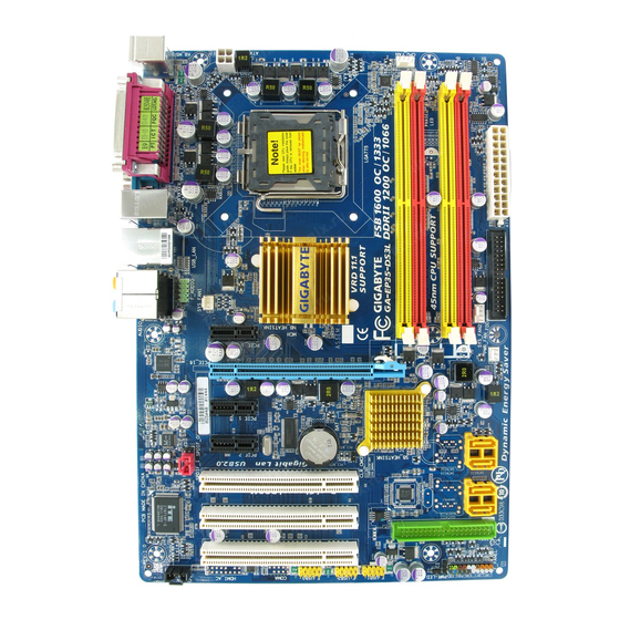
Page 7: Ga-Ep35-Ds3L/S3L Motherboard Layout
OPTICAL R_USB AUDIO SYS_FAN1 PCIE_3 PCIE_16 RTL8111B PCIE_1 CODEC PCIE_2 SPDIF_I PCI1 PCI2 PCI3 CD_IN «*» Only the GA-EP35-DS3L adopts All-Solid Capacitor design. CPU_FAN ATX_12V LGA775 Intel ® CLR_CMOS F_USB3 F_USB2 F_USB1 — 7 — PWR_FAN Intel ICH9 ® SATAII0…
-
Page 8: Block Diagram
Block Diagram PCIe CLK (100 MHz) PCI Express x16 ATA-133/100/66/33 IDE Channel JMicron PCI Express Bus 3 PCI Express x1 PCIe CLK (100 MHz) PCI Bus 3 PCI PCI CLK (33 MHz) LGA775 Processor Host Interface Intel ® RJ45 8111B Intel ICH9 ®…
-
Page 9: Chapter 1 Hardware Installation
Chapter 1 Hardware Installation Installation Precautions The motherboard contains numerous delicate electronic circuits and components which can become damaged as a result of electrostatic discharge (ESD). Prior to installation, carefully read the user’s manual and follow these procedures: Prior to installation, do not remove or break motherboard S/N (Serial Number) sticker or •…
-
Page 10: Product Specifications
Product Specifications Support for an Intel Intel Intel Intel Intel (Go to GIGABYTE’s website for the latest CPU support list.) L2 cache varies with CPU Front Side Bus 1333/1066/800 MHz FSB Chipset North Bridge: Intel South Bridge: Intel Memory 4 x 1.8V DDR2 DIMM sockets supporting up to 8 GB of system memory…
-
Page 11
Internal Connectors 1 x 24-pin ATX main power connector 1 x 4-pin ATX 12V power connector 1 x floppy disk drive connector 1 x IDE connector 4 x SATA 3Gb/s connectors 1 x CPU fan header 2 x system fan headers 1 x power fan header 1 x front panel header 1 x front panel audio header… -
Page 12
(Note 4) Available functions in Easytune may differ by motherboard model. (Note 5) Due to the hardware limitation, you must install the Intel Core 2 Duo/ Pentium Dual-Core/ Celeron Dual-Core/ Celeron 400 Series CPU to enable support for Dynamic Energy Saver. GA-EP35-DS3L/S3L Motherboard (Note 4) (Note 5) Windows Vista/XP/2000 ®… -
Page 13: Installing The Cpu And Cpu Cooler
Read the following guidelines before you begin to install the CPU: • Make sure that the motherboard supports the CPU. (Go to GIGABYTE’s website for the latest CPU support list.) • Always turn off the computer and unplug the power cord from the power outlet before installing the CPU to prevent hardware damage.
-
Page 14
Step 5: Once the CPU is properly inserted, replace the load plate and push the CPU socket lever back into its locked position. GA-EP35-DS3L/S3L Motherboard Step 2: Remove the protective socket cover. Step 4: Hold the CPU with your thumb and index fingers. -
Page 15: Installing The Cpu Cooler
1-3-2 Installing the CPU Cooler Follow the steps below to correctly install the CPU cooler on the motherboard. (The following procedure uses Intel boxed cooler as the example cooler.) ® Step 1: Apply an even and thin layer of thermal grease on the surface of the installed CPU.
-
Page 16: Installing The Memory
• Make sure that the motherboard supports the memory. It is recommended that memory of the same capacity, brand, speed, and chips be used. (Go to GIGABYTE’s website for the latest memory support list.) • Always turn off the computer and unplug the power cord from the power outlet before installing the memory to prevent hardware damage.
-
Page 17: Installing A Memory
1-4-2 Installing a Memory Before installing a memory module , make sure to turn off the computer and unplug the power cord from the power outlet to prevent damage to the memory module. DDR2 DIMMs are not compatible to DDR DIMMs. Be sure to install DDR2 DIMMs on this motherboard.
-
Page 18: Installing An Expansion Card
Example: Installing and Removing a PCI Express x16 Graphics Card: • Removing the Card: Gently push back on the lever on the slot and then lift the card straight out from the slot. GA-EP35-DS3L/S3L Motherboard PCI Express x16 Slot PCI Slot PCI Express x1 Slot •…
-
Page 19: Back Panel Connectors
Back Panel Connectors PS/2 Keyboard and PS/2 Mouse Port Use the upper port (green) to connect a PS/2 mouse and the lower port (purple) to connect a PS/2 keyboard. Parallel Port Use the parallel port to connect devices such as a printer, scanner and etc. The parallel port is also called a printer port.
-
Page 20
Only microphones still MUST be connected to the default Mic in jack ( ). Refer to the instructions on setting up a 2/4/5.1/ 7.1-channel audio configuration in Chapter 5, «Configuring 2/4/5.1/7.1-Channel Audio.» GA-EP35-DS3L/S3L Motherboard audio jacks can be reconfigured to — 20 -… -
Page 21: Internal Connectors
Internal Connectors ATX_12V CPU_FAN SYS_FAN1 SYS_FAN2 PWR_FAN IDE1 SATAII0/1/4/5 F_PANEL Read the following guidelines before connecting external devices: • First make sure your devices are compliant with the connectors you wish to connect. • Before installing the devices, be sure to turn off the devices and your computer. Unplug the power cord from the power outlet to prevent damage to the devices.
-
Page 22
When using a 2×12 power supply, remove the protective cover from the main power connector on the motherboard. Do not insert the power supply cable into pins under the protective cover when using a 2×10 power supply. GA-EP35-DS3L/S3L Motherboard ATX_12V ATX: Pin No. -
Page 23
3/4/5/6) CPU_FAN/SYS_FAN1/SYS_FAN2/PWR_FAN (Fan Headers) The motherboard has a 4-pin CPU fan header (CPU_FAN), a 3-pin system fan header (SYS_FAN1), a 4-pin system fan header (SYS_FAN2) and a 3-pin power fan header (PWR_FAN). Each fan header supplies a +12V power voltage and possesses a foolproof insertion design. When connect- ing a fan cable, be sure to connect it in the correct orientation. -
Page 24
9) SATAII0/1/4/5 (SATA 3Gb/s Connectors, Controlled by ICH9) The SATA connectors conform to SATA 3Gb/s standard and are compatible with SATA 1.5Gb/s standard. Each SATA connector supports a single SATA device. GA-EP35-DS3L/S3L Motherboard Pin No. SATAII0 SATAII1… -
Page 25: Front Panel Header
10) F_PANEL (Front Panel Header) Connect the power switch, reset switch, speaker and system status indicator on the chassis front panel to this header according to the pin assignments below. Note the positive and negative pins before connecting the cables. •…
-
Page 26: Front Panel Audio Header
• Some chassis provide a front panel audio module that has separated connectors on each wire instead of a single plug. For information about connecting the front panel audio module that has different wire assignments, please contact the chassis manufacturer. GA-EP35-DS3L/S3L Motherboard For HD Front Panel Audio: Pin No.
-
Page 27
13) CD_IN (CD In Connector, Black) You may connect the audio cable that came with your optical drive to the header. 14) SPDIF_I (S/PDIF In Header, Red) This header supports digital S/PDIF in and can connect to an audio device that supports digital audio out via an optional S/PDIF in cable. -
Page 28
• Do not plug the IEEE 1394 bracket (2×5-pin) cable into the USB header. • Prior to installing the USB bracket, be sure to turn off your computer and unplug the power cord from the power outlet to prevent damage to the USB bracket. GA-EP35-DS3L/S3L Motherboard Pin No. Pin No. -
Page 29: Clearing Cmos Jumper
17) CI (Chassis Intrusion Header) This motherboard provides a chassis detection feature that detects if the chassis cover has been removed. This function requires a chassis with chassis intrusion detection design. 18) CLR_CMOS (Clearing CMOS Jumper) Use this jumper to clear the CMOS values (e.g. date information and BIOS configurations) and reset the CMOS values to factory defaults.
-
Page 30
The number of lighted LEDs indicates the CPU loading. The higher the CPU loading, the more the number of lighted LEDs. GA-EP35-DS3L/S3L Motherboard You may clear the CMOS values by removing the battery: 1. Turn off your computer and unplug the power cord. -
Page 31: Chapter 2 Bios Setup
To see more advanced BIOS Setup menu options, you can press <Ctrl> + <F1> in the main menu of the BIOS Setup program. To upgrade the BIOS, use either the GIGABYTE Q-Flash or @BIOS utility. Q-Flash allows the user to quickly and easily upgrade or back up BIOS without entering the •…
-
Page 32: Startup Screen
BIOS Setup settings. You can access Boot Menu again to change the first boot device setting as needed. <End>: Q-Flash Press the <End> key to access the Q-Flash utility directly without having to enter BIOS Setup first. GA-EP35-DS3L/S3L Motherboard — 32 — Function Keys Function Keys…
-
Page 33: The Main Menu
Once you enter the BIOS Setup program, the Main Menu (as shown below) appears on the screen. Use arrow keys to move among the items and press <Enter> to accept or enter a sub-menu. (Sample BIOS Version: GA-EP35-DS3L E12a) CMOS Setup Utility-Copyright (C) 1984-2007 Award Software…
-
Page 34
(Pressing <F10> can also carry out this task.) Exit Without Saving Abandon all changes and the previous settings remain in effect. Pressing <Y> to the confirmation message will exit BIOS Setup. (Pressing <Esc> can also carry out this task.) GA-EP35-DS3L/S3L Motherboard — 34 -… -
Page 35: Standard Cmos Features
Standard CMOS Features CMOS Setup Utility-Copyright (C) 1984-2007 Award Software Date (mm:dd:yy) Time (hh:mm:ss) IDE Channel 0 Master IDE Channel 1 Master IDE Channel 2 Master IDE Channel 3 Master IDE Channel 4 Master IDE Channel 4 Slave Drive A Floppy 3 Mode Support Halt On Base Memory…
-
Page 36
Base Memory Also called conventional memory. Typically, 640 KB will be reserved for the MS-DOS operating system. Extended Memory The amount of extended memory. Total Memory The total amount of memory installed on the system. GA-EP35-DS3L/S3L Motherboard — 36 -… -
Page 37: Advanced Bios Features
Advanced BIOS Features CMOS Setup Utility-Copyright (C) 1984-2007 Award Software Hard Disk Boot Priority First Boot Device Second Boot Device Third Boot Device Password Check HDD S.M.A.R.T. Capability Limit CPUID Max. to 3 (Note) No-Execute Memory Protect CPU Enhanced Halt (C1E) CPU Thermal Monitor 2(TM2) CPU EIST Function (Note)
-
Page 38
With virtualization, one computer system can function as multiple virtual systems. (Default: Enabled) Full Screen LOGO Show Allows you to determine whether to display the GIGABYTE Logo at system startup. Disabled displays normal POST message. (Default: Enabled) Init Display First Specifies the first initiation of the monitor display from the installed PCI graphics card or the PCI Express graphics card. -
Page 39: Integrated Peripherals
Integrated Peripherals CMOS Setup Utility-Copyright (C) 1984-2007 Award Software SATA AHCI Mode SATA Port0-1 Native Mode USB Controller USB 2.0 Controller USB Keyboard Support USB Mouse Support Legacy USB storage detect Azalia Codec Onboard H/W LAN SMART LAN Onboard LAN Boot ROM Onboard IDE Controller Onboard Serial Port 1 Onboard Parallel Port…
-
Page 40
Start detecting at Port… Link Detected —> 100Mbps Cable Length= 30m Link Detected Displays transmission speed Cable Length Displays the approximate length of the attached LAN cable. GA-EP35-DS3L/S3L Motherboard SMART LAN / Length / Length / Length / Length +/-/PU/PD: Value… -
Page 41
Note: The Gigabit hub will only operate at a speed of 10/100Mbps in MS-DOS mode; it will operate at a normal speed of 10/100/1000 Mbps in Windows mode or when the LAN Boot ROM is activated. When a Cable Problem Occurs… If a cable problem occurs on a specified pair of wires, the Status field will show Short and thenlength shown will be the approximate distance to the fault or short. -
Page 42: Power Management Setup
Power On by Ring Allows the system to be awakened from an ACPI sleep state by a wake-up signal from a modem that supports wake-up function. (Default: Enabled) (Note) Supported on Windows GA-EP35-DS3L/S3L Motherboard Power Management Setup [S3(STR)] [Instant-Off] [Enabled]…
-
Page 43
Resume by Alarm Determines whether to power on the system at a desired time. (Default: Disabled) If enabled, set the date and time as following: Date (of Month) Alarm : Turn on the system at a specific time on each day or on a specific day in a month. -
Page 44: Pnp/Pci Configurations
PCI1 IRQ Assignment Auto 3,4,5,7,9,10,11,12,14,15 PCI2 IRQ Assignment Auto 3,4,5,7,9,10,11,12,14,15 PCI3 IRQ Assignment Auto 3,4,5,7,9,10,11,12,14,15 GA-EP35-DS3L/S3L Motherboard PnP/PCI Configurations [Auto] [Auto] [Auto] +/-/PU/PD: Value F10: Save F6: Fail-Safe Defaults BIOS auto-assigns IRQ to the first PCI slot. (Default) Assigns IRQ 3,4,5,7,9,10,11,12,14,15 to the first PCI slot.
-
Page 45: Pc Health Status
PC Health Status CMOS Setup Utility-Copyright (C) 1984-2007 Award Software Reset Case Open Status Case Opened Vcore DDR18V +3.3V +12V Current System Temperature Current CPU Temperature Current CPU FAN Speed Current SYSTEM FAN1 Speed Current SYSTEM FAN2 Speed Current POWER FAN Speed CPU Warning Temperature CPU FAN Fail Warning SYSTEM FAN2 Fail Warning…
-
Page 46: Mb Intelligent Tweaker(M.i.t.)
• When the System Voltage Optimized item blinks in red, it is recommended that you set the System Voltage Control item to Auto to optimize the system voltage settings. (Note) This item appears only if you install a CPU that supports this feature. GA-EP35-DS3L/S3L Motherboard MB Intelligent Tweaker(M.I.T.) [Auto] [25X] [+0.5]…
-
Page 47
Robust Graphics Booster Robust Graphics Booster (R.G.B.) helps to enhance the performance of the graphics chip and memory. Auto allows the BIOS to automatically set the R.G.B. mode based on system configurations. Options are: Auto (default), Fast, Turbo. CPU Clock Ratio (Note) Allows you to alter the clock ratio for the installed CPU. -
Page 48
Refresh to ACT Delay Options are: Auto (default), 0~255. Read to Precharge Delay Options are: Auto (default), 1~15. Static tRead Value Options are: Auto (default), 1~31. Static tRead Phase Adjust Options are: Auto (default), 1~31. GA-EP35-DS3L/S3L Motherboard ******** ******** — 48 -… -
Page 49
System Voltage Optimized ******** System Voltage Control Determines whether to manually set the system voltages. Auto lets BIOS automatically set the system voltages as required. Manual allows all voltage control items below to be configurable. (Default: Manual) DDR2 OverVoltage Control Allows you to set memory voltage. -
Page 50: Load Fail-Safe Defaults
Press <Enter> on this item and then press the <Y> key to load the optimal BIOS default settings. The BIOS defaults settings helps the system to operate in optimum state. Always load the Optimized defaults after updating the BIOS or after clearing the CMOS values. GA-EP35-DS3L/S3L Motherboard Load Fail-Safe Defaults Load Optimized Defaults…
-
Page 51: Set Supervisor/User Password
2-12 Set Supervisor/User Password CMOS Setup Utility-Copyright (C) 1984-2007 Award Software Standard CMOS Features Advanced BIOS Features Integrated Peripherals Power Management Setup PnP/PCI Configurations PC Health Status MB Intelligent Tweaker(M.I.T.) ESC: Quit F8: Q-Flash Press <Enter> on this item and type the password with up to 8 characters and then press <Enter>. You will be requested to confirm the password.
-
Page 52: Save & Exit Setup
Press <Enter> on this item and press the <Y> key. This exits the BIOS Setup without saving the changes made in BIOS Setup to the CMOS. Press <N> or <Esc> to return to the BIOS Setup Main Menu. GA-EP35-DS3L/S3L Motherboard Load Fail-Safe Defaults…
-
Page 53: Chapter 3 Drivers Installation
Chapter 3 Drivers Installation • Before installing the drivers, first install the operating system. (The following instructions use Windows XP as the example operating system.) • After installing the operating system, insert the motherboard driver disk into your optional drive. The driver Autorun screen is automatically displayed which looks like that shown in the screen shot below.
-
Page 54: Software Applications
Software Applications This page displays all the tools and applications that GIGABYTE develops and some free software. You may press the Install button following an item to install it. Driver CD Information This page provides information about the drivers, applications and tools in this driver disk.
-
Page 55: Hardware Information
Hardware Information This page provides information about the hardware devices on this motherboard. Contact Us Check the contacts information of the GIGABYTE headquarter in Taiwan and the overseas branch offices on the last page of this manual. — 55 -…
-
Page 56
GA-EP35-DS3L/S3L Motherboard — 56 -… -
Page 57: Chapter 4 Unique Features
Chapter 4 Unique Features Xpress Recovery2 Before You Begin: • Xpress Recovery2 will check the first physical hard drive* for the operating system. Xpress Recovery2 can only back up/restore the first physical hard drive that has the operating system installed. •…
-
Page 58
Recovery2 (10 GB or more is recommended; actual size requirements vary, depending on the amount of data) (Figure 2). Figure 1 3. Select a file system (for example, NTFS) and begin the installation of the operating system (Figure 3). Figure 3 GA-EP35-DS3L/S3L Motherboard Figure 2 — 58 -… -
Page 59
4. After the operating system is installed, right-click the My Computer icon on your desktop and select Manage (Figure 4). Go to Computer Management to check disk allocation. Xpress Recovery2 will save the backup file to the unallocated space (black stripe along the top)(Figure 5). Please note that if there is no enough unallocated space, Xpress Recovery2 cannot save the backup file. -
Page 60
Xpress Recovery2 will begin the backup process (Figure 11). Figure 10 3. When finished, go to Disk Management to check disk allocation. Figure 12 GA-EP35-DS3L/S3L Motherboard Figure 8 Figure 9 Figure 11 Xpress Recovery2 will automatically create a new partition to store the backup image file. -
Page 61
D. Using the Restore Function in Xpress Recovery2 Select RESTORE to restore the backup to your hard drive in case the system breaks down. The RESTORE option will not be present if no backup is created before (Figure 13, 14). Figure 13 E. -
Page 62: Bios Update Utilities
4-2-1 Updating the BIOS with the Q-Flash Utility A. Before You Begin: 1. From GIGABYTE’s website, download the latest compressed BIOS update file that matches your motherboard model. 2. Extract the file and save the new BIOS file (e.g. ep35ds3l.f1) to your floppy disk, USB flash drive, or hard drive.
-
Page 63
B. Updating the BIOS When updating the BIOS, choose the location where the BIOS file is saved. The follow procedure assumes that you save the BIOS file to a floppy disk. Step 1: 1. Insert the floppy disk containing the BIOS file into the floppy disk drive. In the main menu of Q- Flash, use the up or down arrow key to select Update BIOS from Drive and press <Enter>. -
Page 64
F8: Q-Flash Step 6: Select Save & Exit Setup and then press <Y> to save settings to CMOS and exit BIOS Setup. The procedure is complete after the system restarts. GA-EP35-DS3L/S3L Motherboard Load Fail-Safe Defaults Load Optimized Defaults Set Supervisor Password… -
Page 65: Updating The Bios With The @Bios Utility
BIOS or a system that is unable to start. 3. Do not use the C.O.M. (Corporate Online Management) function when using @BIOS. 4. GIGABYTE product warranty does not cover any BIOS damage or system failure resulting from an inadequate BIOS flashing.
-
Page 66
• If the BIOS update file for your motherboard is not present on the @BIOS server site, please manually download the BIOS update file from GIGABYTE’s website and follow the instructions in «Update the BIOS without Using the Internet Update Function» below. -
Page 67: Easytune 5 Pro
Toggles among Easy Mode, Advanced Mode, and Graphics Mode Displays the CPU frequency Shows the supported function(s) Go to GIGABYTE website to update EasyTune 5 Pro Opens EasyTune 5 Pro help file Quits or minimizes the EasyTune 5 Pro interface Performance Enhancement…
-
Page 68: Dynamic Energy Saver
70% and up to 20% improved power efficiency without sacrificing computing performance. The Dynamic Energy Saver Interface A. Meter Mode In Meter Mode, GIGABYTE’s Dynamic Energy Saver shows how much power they have saved in a set period of time. Meter Mode — Button Information Table…
-
Page 69
B. Total Mode In Total Mode, users are able to see how much total power savings they have accumulated in a set period of time since activating Dynamic Power Saver for the first time Total Mode — Button Information Table Button Description Dynamic Energy Saver On/Off Switch (Default: Off) Motherboard Phase LED On/Off Switch (Default: On) -
Page 70: Windows Vista Readyboost
• The recommended amount of memory to use for ReadyBoost acceleration is one to three times the amount of RAM installed in your computer. GA-EP35-DS3L/S3L Motherboard Step 1: Go to Computer. Right-click on the USB flash drive icon and choose Properties.
-
Page 71: Chapter 5 Appendix
Chapter 5 Appendix Configuring Audio Input and Output 5-1-1 Configuring 2/4/5.1/7.1-Channel Audio The motherboard provides six audio jacks on the back panel which support 2/4/5.1/7.1-channel audio. The picture to the right shows the default audio jack assignments. The integrated HD (High Definition) audio provides jack retasking capability that allows the user to change the function for each jack through the audio driver.
-
Page 72
Click OK to activiate the AC’97 functionality. When using an AC’97 front panel audio module, you can only have audio signals present on either the front or the back panel audio connections, but not both at the same time. GA-EP35-DS3L/S3L Motherboard — 72 -… -
Page 73: Installing The S/Pdif In Cable (Optional)
5-1-2 Installing the S/PDIF In Cable (Optional) The S/PDIF in cable provides S/PDIF in functionality. Coaxial Optical S/PDIF In S/PDIF In S/PDIF In: The S/PDIF in jacks allow you to input digital audio signals to the computer for audio processing. A.
-
Page 74
In/Out Settings dialog box, select an output sampling rate and select (or disable) the output source. Click OK to complete the configuration. GA-EP35-DS3L/S3L Motherboard Connect a S/PDIF coaxial cable or a S/PDIF optical cable (either one) to an external decoder for transmitting the S/PDIF digital audio signals. -
Page 75: Configuring Microphone Recording
5-1-3 Configuring Microphone Recording Step 1: After installing the audio driver, the Audio Manager icon will appear in your system tray. Double- click the icon to access the Audio Control Panel. Step 2: Connect your microphone to the Mic in jack (pink) on the back panel or the Line in jack on the front panel.
-
Page 76
Do NOT mute the recording sound, or you will not hear any sound when playing back the recording you just made. GA-EP35-DS3L/S3L Motherboard Select Realtek HD Audio Input in the Mixer device list Recording Control — 76 -… -
Page 77: Using The Sound Recorder
Step 6: To raise the recording and playing sound for the microphone, go to Options in Master Volume and select Advanced Controls. Click the Advanced button under a volume control option (e.g. Front Green In, Front Pink In). In the Other Controls field, select the 1 Microphone Boost check box.
-
Page 78: Troubleshooting
1 long, 2 short: Monitor or graphics card error 1 long, 3 short: Keyboard error 1 long, 9 short: BIOS ROM error Continuous long beeps: Graphics card not inserted properly Continuous short beeps: Power error GA-EP35-DS3L/S3L Motherboard — 78 -…
-
Page 79: Troubleshooting Procedure
5-2-2 Troubleshooting Procedure If you encounter any troubles during system startup, follow the troubleshooting procedure below to solve the problem. Turn off the power. Remove all peripherals, connecting cables, and power cord etc. Make sure the motherboard does not short-circuit with the chassis or other metal objects.
-
Page 80
If the procedure above is unable to solve your problem, contact the place of purchase or local dealer for help. Or go to the Support\Technical Service Zone page to submit your question. Our customer service staff will reply you as soon as possible. GA-EP35-DS3L/S3L Motherboard — 80 — The power supply, CPU or CPU socket might fail. -
Page 81: Regulatory Statements
«end of life» product. Restriction of Hazardous Substances (RoHS) Directive Statement GIGABYTE products have not intended to add and safe from hazardous substances (Cd, Pb, Hg, Cr+6, PBDE and PBB). The parts and components have been carefully selected to meet RoHS requirement.
-
Page 82
«end of life» products, and generally improve our quality of life by ensuring that potentially hazardous substances are not released into the environment and are disposed of properly. China Restriction of Hazardous Substances Table The following table is supplied in compliance with China’s Restriction of Hazardous Substances (China RoHS) requirements: GA-EP35-DS3L/S3L Motherboard — 82 -… -
Page 83
— 83 — Appendix… -
Page 84
GA-EP35-DS3L/S3L Motherboard — 84 -… -
Page 85
— 85 — Appendix… -
Page 86
GA-EP35-DS3L/S3L Motherboard — 86 -… -
Page 87
GIGA-BYTE TECHNOLOGY CO., LTD. Address: No.6, Bau Chiang Road, Hsin-Tien, Taipei 231, Taiwan TEL: +886-2-8912-4888 FAX: +886-2-8912-4003 Tech. and Non-Tech. Support (Sales/Marketing) : http://ggts.gigabyte.com.tw WEB address (English): http://www.gigabyte.com.tw WEB address (Chinese): http://www.gigabyte.tw U.S.A. G.B.T. INC. TEL: +1-626-854-9338 FAX: +1-626-854-9339 Tech. Support: http://rma.gigabyte-usa.com… -
Page 88
Representative Office Of GIGA-BYTE Technology Co., Ltd. in SERBIA & MONTENEGRO WEB address : http://www.gigabyte.co.yu You may go to the GIGABYTE website, select your language in the language list on the top right corner of the website. To submit a technical or non-technical (Sales/ Marketing) question, please link to : http://ggts.gigabyte.com.tw…
Руководство пользователя материнской платы MSI содержит подробные инструкции по сборке материнских плат B560M PLUS, B560M PRO-E и H510M PRO. Руководство содержит важную информацию по технике безопасности для обеспечения успешной сборки компьютера, например рекомендации по электростатическому разряду (ЭСР) и правильному обращению с компонентами материнской платы. В руководстве также приведены характеристики поддерживаемых процессоров, памяти, слотов расширения, встроенной графики, аудио, локальной сети, хранилища, USB, а также разъемов на внутренней и задней панелях. Кроме того, в руководстве освещаются различные программные и аппаратные функции материнской платы, включая MSI Center, Frozr AI Cooling, Mystic Light и EZ Debug LED. В руководстве также содержится болееview таких компонентов, как сокет ЦП, слоты DIMM, слоты M.2, слоты расширения PCIe, разъемы SATA и передний аудиоразъем. Важно тщательно следовать инструкциям в руководстве, чтобы обеспечить правильную установку и избежать повреждения компонентов. Если во время установки возникают какие-либо проблемы, рекомендуется обратиться за помощью к сертифицированному специалисту по компьютерам.
Материнская плата MSI

Материнская плата MSI
Информация по технике безопасности
- Компоненты, входящие в этот комплект, подвержены повреждению электростатическим разрядом (ESD). Пожалуйста, придерживайтесь следующих инструкций, чтобы обеспечить успешную сборку компьютера.
- Убедитесь, что все компоненты надежно подключены. Плохое соединение может привести к тому, что компьютер не распознает компонент или не запустится.
- Держите материнскую плату за края, чтобы не прикасаться к чувствительным компонентам.
- При обращении с материнской платой рекомендуется носить браслет с защитой от электростатического разряда (ESD), чтобы предотвратить электростатическое повреждение. Если браслет для защиты от электростатического разряда недоступен, снимите с себя статическое электричество, прикоснувшись к другому металлическому предмету, прежде чем брать в руки материнскую плату.
- Храните материнскую плату в контейнере для защиты от статического электричества или на антистатической прокладке, если материнская плата не установлена.
- Перед включением компьютера убедитесь, что на материнской плате или где-либо в корпусе компьютера нет незакрепленных винтов или металлических компонентов.
- Не загружайте компьютер до завершения установки. Это может привести к необратимому повреждению компонентов, а также к травмам пользователя.
- Если вам потребуется помощь на любом этапе установки, обратитесь к сертифицированному специалисту по компьютерам.
- Всегда выключайте источник питания и отсоединяйте шнур питания от розетки перед установкой или извлечением каких-либо компонентов компьютера.
- Сохраните это руководство для использования в будущем.
- Берегите материнскую плату от влаги.
- Убедитесь, что ваша электрическая розетка обеспечивает такую же мощность.tage, как указано на блоке питания, перед подключением блока питания к электрической розетке.
- Разместите шнур питания таким образом, чтобы на него нельзя было наступить. Не кладите ничего на шнур питания.
- Следует отметить все предостережения и предупреждения на материнской плате.
- При возникновении любой из следующих ситуаций обратитесь к обслуживающему персоналу для проверки материнской платы:
- В компьютер попала жидкость.
- Материнская плата подверглась воздействию влаги.
- Материнская плата работает неправильно или вы не можете заставить ее работать в соответствии с руководством пользователя.
- Материнская плата упала и была повреждена.
- Материнская плата имеет явные признаки поломки.
- Не оставляйте материнскую плату при температуре выше 60 ° C (140 ° F), это может повредить материнскую плату.
Характеристики
| ЦП |
* Для получения информации о совместимости перейдите на сайт intel.com. |
| Набор микросхем | Набор микросхем Intel® H510 / B560 |
| Память |
* Пожалуйста, обратитесь к www.msi.com для получения дополнительной информации о совместимой памяти. |
| Слоты расширения |
|
| На борту Graphics |
* Доступно только для процессоров со встроенной графикой. |
| Аудио | Кодек Realtek® ALC897
|
| ЛВС | 1x сетевой контроллер Intel® I219V 1 Гбит / с |
| Хранилище |
* SATA4 будет недоступен при установке M.2 SATA SSD в слот M2_1. |
| USB |
|
| Внутренние разъемы |
|
| Разъемы задней панели |
|
| Светодиодная особенность |
|
| Контроллер ввода / вывода | Микросхема контроллера NUVOTON NCT6687D-M |
| Монитор оборудования |
|
| Форм-фактор |
|
| Возможности BIOS |
|
| Software |
|
| Возможности MSI Center |
|
| Особые возможности |
|
Задняя панель ввода-вывода

Таблица состояния индикатора порта LAN

Аудио 7.1-канальная конфигурация
Для настройки 7.1-канального звука необходимо подключить передний аудиомодуль ввода / вывода к разъему JAUD1 и выполнить следующие шаги.
- Щелкните Realtek HD Audio Manager> Расширенные настройки, чтобы открыть диалоговое окно ниже.

- Выберите «Отключить звук на заднем устройстве вывода», когда к нему подключены передние наушники.
- Подключите динамики к аудиоразъемам на задней и передней панели ввода / вывода. Когда вы подключаете устройство к аудиоразъему, появляется диалоговое окно с вопросом, какое устройство подключено в данный момент.

Болееview компонентов

* Расстояние от центра ЦП до ближайшего слота DIMM.
Процессорное гнездо
Пожалуйста, установите ЦП в гнездо ЦП, как показано ниже.

Важнo
- Всегда отключайте шнур питания от розетки перед установкой или снятием ЦП.
- Сохраните защитный колпачок процессора после установки процессора. MSI будет обрабатывать запросы на возврат товара (RMA), если только на материнской плате есть защитная крышка на разъеме ЦП.
- При установке ЦП всегда не забывайте устанавливать радиатор ЦП. Радиатор процессора необходим для предотвращения перегрева и поддержания стабильности системы.
- Перед загрузкой системы убедитесь, что радиатор ЦП плотно прилегает к ЦП.
- Перегрев может серьезно повредить процессор и материнскую плату. Всегда проверяйте, правильно ли работают охлаждающие вентиляторы, чтобы защитить ЦП от перегрева. Обязательно нанесите ровный слой термопасты (или термоленты) между процессором и радиатором, чтобы улучшить отвод тепла.
- Если ЦП не установлен, всегда защищайте контакты разъема ЦП, накрыв разъем пластиковым колпачком.
- Если вы приобрели отдельный ЦП и радиатор / кулер, пожалуйста, обратитесь к документации в комплекте радиатора / кулера для получения более подробной информации об установке.
Слоты DIMM
Установите модуль памяти в слот DIMM, как показано ниже.

Важнo
- Для обеспечения стабильности системы в двухканальном режиме модули памяти должны быть одного типа, количества и плотности.
- Некоторые модули памяти могут работать на более низкой частоте, чем отмеченное значение, при разгоне из-за того, что частота памяти зависит от ее Serial Presence Detect (SPD). Зайдите в BIOS и найдите DRAM Frequency, чтобы установить частоту памяти, если вы хотите работать с памятью на отмеченной или более высокой частоте.
- Рекомендуется использовать более эффективную систему охлаждения памяти для полной установки или разгона модулей DIMM.
- Стабильность и совместимость установленного модуля памяти зависит от установленного процессора и устройств при разгоне.
- Пожалуйста, посетите www.msi.com для получения дополнительной информации о совместимой памяти.
M2_1: слот M.2 (клавиша M)
Установите устройство M.2 в слот M.2_1, как показано ниже.

M2_2: слот M.2 (клавиша E)
Установите модуль Wi-Fi в слот M.2_2, как показано ниже.

PCI_E1 ~ 2: Слоты расширения PCIe

Важнo
- При добавлении или удалении карт расширения всегда выключайте источник питания и отсоединяйте кабель питания от розетки. Прочтите документацию карты расширения, чтобы проверить наличие необходимых дополнительных изменений оборудования или программного обеспечения.
- Если вы устанавливаете большую и тяжелую видеокарту, вам необходимо использовать такой инструмент, как крепление графической карты MSI Gaming Series, чтобы выдержать ее вес и предотвратить деформацию слота.
SATA1 ~ 4: Разъемы SATA 6 Гбит / с
Эти разъемы представляют собой интерфейсные порты SATA 6 Гбит / с. Каждый разъем может подключаться к одному устройству SATA.

Важнo
- Не складывайте кабель SATA под углом 90 градусов. В противном случае во время передачи может произойти потеря данных.
- Кабели SATA имеют одинаковые разъемы с обеих сторон кабеля. Однако рекомендуется подключать плоский разъем к материнской плате в целях экономии места.
- SATA1 будет недоступен при установке M.2 SATA SSD в слот M2_1.
JAUD1: Передний аудиоразъем
Этот разъем позволяет подключать аудиоразъемы на передней панели.

JFP1, JFP2: разъемы передней панели
Эти разъемы подключаются к переключателям и светодиодам на передней панели.

ATX_PWR1, CPU_PWR1: разъемы питания
Эти разъемы позволяют подключать блок питания ATX.

Важнo
Убедитесь, что все кабели питания надежно подключены к соответствующему блоку питания ATX, чтобы обеспечить стабильную работу материнской платы.
JUSB1: разъем USB 2.0
Этот разъем позволяет подключать порты USB 2.0 на передней панели.

Важнo
- Обратите внимание, что контакты VCC и заземления должны быть подключены правильно, чтобы избежать возможных повреждений.
- Чтобы зарядить iPad, iPhone и iPod через порты USB, установите утилиту MSI® Center.
JUSB2: разъем USB 3.2 Gen 1 5 Гбит / с
Этот разъем позволяет подключать порты USB 3.2 Gen 1 5 Гбит / с на передней панели.

Важнo
Обратите внимание, что контакты питания и заземления должны быть подключены правильно, чтобы избежать возможных повреждений.
CPU_FAN1, SYS_FAN1: разъемы вентилятора
Разъемы вентилятора в режиме ШИМ обеспечивают постоянное выходное напряжение 12 В и регулируют скорость вентилятора с помощью сигнала управления скоростью. Когда вы подключаете 3-контактный вентилятор (без ШИМ) к разъему вентилятора в режиме ШИМ, скорость вентилятора всегда будет поддерживаться на уровне 100%, что может создавать много шума.
|
соединитель |
Режим вентилятора по умолчанию |
Максимум. текущий |
Максимум. мощность |
|
ЦП_FAN1 |
Режим ШИМ |
2A |
24W |
|
SYS_FAN1 |
Режим постоянного тока |
1A |
12W |

Важнo
Вы можете настроить скорость вращения вентилятора в BIOS> Hardware Monitor.
JTPM1: Разъем модуля TPM
Этот разъем предназначен для TPM (доверенного платформенного модуля). Дополнительные сведения и способы использования см. В руководстве по платформе безопасности TPM.

JCI1: Разъем обнаружения вторжения в корпус
Этот разъем позволяет подключать кабель переключателя вскрытия корпуса.

Использование детектора вторжения в корпус
- Подключите разъем JCI1 к переключателю / датчику вскрытия корпуса на корпусе.
- Закройте крышку корпуса.
- Перейдите в BIOS> Безопасность> Конфигурация вскрытия корпуса.
- Установите для параметра Chassis Intrusion значение Enabled.
- Нажмите F10, чтобы сохранить и выйти, а затем нажмите клавишу Enter, чтобы выбрать Да.
- После того, как крышка корпуса снова откроется, при включении компьютера на экране отобразится предупреждающее сообщение.
Сброс предупреждения о вторжении в корпус
- Перейдите в BIOS> Безопасность> Конфигурация вскрытия корпуса.
- Установите для параметра Chassis Intrusion значение Reset.
- Нажмите F10, чтобы сохранить и выйти, а затем нажмите клавишу Enter, чтобы выбрать Да.
JCOM1: Разъем последовательного порта
Этот разъем позволяет подключать дополнительный последовательный порт с помощью планки.

JBAT1: перемычка очистки CMOS (сброса BIOS)
На плате имеется память CMOS, которая питается от батареи, расположенной на материнской плате, для сохранения данных конфигурации системы. Если вы хотите очистить конфигурацию системы, установите перемычки для очистки памяти CMOS.

Сброс BIOS до значений по умолчанию
- Выключите компьютер и отсоедините шнур питания.
- Используйте перемычку, чтобы замкнуть JBAT1 примерно на 5-10 секунд.
- Снимите перемычку с JBAT1.
- Подключите шнур питания и включите компьютер.
Индикатор отладки EZ
Эти светодиоды показывают состояние материнской платы.
- ЦП — указывает на то, что ЦП не обнаружен или неисправен.
- Динамическое ОЗУ — указывает, что DRAM не обнаружен или неисправен.
- VGA — указывает на то, что графический процессор не обнаружен или неисправен.
- BOAT — указывает, что загрузочное устройство не обнаружено или не работает.
Установка ОС, драйверов и MSI Center
Загрузите и обновите последние утилиты и драйверы с сайта www.msi.com.
Установка Windows® 10
- Включите компьютер.
- Вставьте установочный диск Windows ® 10 / USB в свой компьютер.
- Нажмите кнопку перезагрузки на корпусе компьютера.
- Нажмите клавишу F11 во время POST (самотестирования при включении) компьютера, чтобы войти в меню загрузки.
- Выберите установочный диск Windows ® 10 / USB в меню загрузки.
- Нажмите любую клавишу, когда на экране отображается сообщение «Нажмите любую клавишу для загрузки с компакт-диска или DVD…».
- Следуйте инструкциям на экране, чтобы установить Windows ® 10.
Установка драйверов
- Загрузите компьютер в Windows® 10.
- Вставьте диск MSI® Drive в оптический привод.
- Нажмите «Выбрать», чтобы выбрать, что будет происходить с всплывающим уведомлением об этом диске, затем выберите «Запустить DVDSetup.exe», чтобы открыть программу установки. Если вы отключите функцию автозапуска на панели управления Windows, вы все равно можете вручную запустить DVDSetup.exe из корневого пути диска MSI Drive.
- Установщик найдет и перечислит все необходимые драйверы на вкладке «Драйверы / Программное обеспечение».
- Нажмите кнопку «Установить» в правом нижнем углу окна.
- После этого установка драйверов будет продолжена, после ее завершения вам будет предложено перезагрузить компьютер.
- Нажмите кнопку ОК, чтобы закончить.
- Перезагрузите компьютер.
Центр MSI
MSI Center — это приложение, которое помогает легко оптимизировать настройки игры и беспрепятственно использовать программное обеспечение для создания контента. Он также позволяет вам управлять и синхронизировать световые эффекты светодиодов на ПК и других продуктах MSI. С MSI Center вы можете настраивать идеальные режимы, контролировать производительность системы и регулировать скорость вращения вентилятора.
Руководство пользователя MSI Center
Если вы хотите узнать больше о MSI Center, обратитесь к http://download.msi.com/manual/mb/MSICENTER.pdf или отсканируйте QR-код, чтобы получить доступ.

Важнo
Функции могут отличаться в зависимости от вашего продукта.
UEFI BIOS
MSI UEFI BIOS совместим с архитектурой UEFI (Unified Extensible Firmware Interface). UEFI имеет много новых функций и расширенных возможностей.tagЭтого не может достичь традиционный BIOS, и в будущем он полностью заменит BIOS. BIOS MSI UEFI использует UEFI в качестве режима загрузки по умолчанию, чтобы полностью продвинуться вперед.tage возможностей нового чипсета.
Важнo
Термин BIOS в этом руководстве пользователя относится к UEFI BIOS, если не указано иное.
UEFI Адванtages
- Быстрая загрузка — UEFI может напрямую загружать операционную систему и сохранять процесс самотестирования BIOS. А также исключает время переключения в режим CSM во время POST.
- Поддерживает разделы жесткого диска размером более 2 ТБ.
- Поддерживает более 4 основных разделов с таблицей разделов GUID (GPT).
- Поддерживает неограниченное количество разделов.
- Поддерживает все возможности новых устройств — новые устройства могут не обеспечивать обратную совместимость.
- Поддерживает безопасный запуск — UEFI может проверить действительность операционной системы, чтобы убедиться в отсутствии вредоносных программ.ampers с процессом запуска.
Несовместимые случаи UEFI
- 32-битная операционная система Windows — данная материнская плата поддерживает только 64-битную операционную систему Windows 10.
- Старая видеокарта — система обнаружит вашу видеокарту. При отображении предупреждающего сообщения В этой видеокарте не обнаружена поддержка GOP (протокол вывода графики)..
Важнo
Мы рекомендуем вам заменить видеокарту на совместимую с GOP / UEFI или использовать встроенную графику от ЦП для нормальной работы.
Как проверить режим BIOS?
- Включите ваш компьютер.
- Нажмите клавишу Delete, когда нажмите клавишу DEL для входа в меню настройки, F11 для входа в меню загрузки сообщение появляется на экране во время процесса загрузки.
- После входа в BIOS вы можете проверить режим BIOS в верхней части экрана.
Настройка биоса
Настройки по умолчанию обеспечивают оптимальную производительность для стабильности системы в нормальных условиях. Вы всегда должны сохранять настройки по умолчанию, чтобы избежать возможного повреждения системы или сбоя загрузки, если вы не знакомы с BIOS.
Важнo
- Элементы BIOS постоянно обновляются для повышения производительности системы. Поэтому описание может немного отличаться от последней версии BIOS и предназначено только для справки. Вы также можете обратиться к информационной панели HELP для описания элемента BIOS.
- Экраны, параметры и настройки BIOS зависят от вашей системы.
Вход в программу настройки BIOS
Нажмите Удалить ключ, когда Нажмите клавишу DEL, чтобы войти в меню настройки, F11, чтобы войти в меню загрузки. сообщение появляется на экране во время процесса загрузки.
Функциональная клавиша
- F1: Общая помощь
- F2: Добавить / удалить избранный элемент
- F3: Вход в меню избранного
- F4: Войти в меню характеристик процессора
- F5: Войти в меню Memory-Z
- F6: Загрузите оптимальные настройки по умолчанию
- F7: Переключение между расширенным режимом и режимом EZ
- F8: Загрузить Overclocking Profile
- F9: Сохранить Overclocking Profile
- F10: Сохранить изменения и сбросить *
- F12: Сделайте снимок экрана и сохраните его на USB-накопитель (только в формате FAT / FAT32).
- Ctrl + F: Войти на страницу поиска
* Когда вы нажимаете F10, появляется окно подтверждения с информацией об изменении. Выберите «Да» или «Нет», чтобы подтвердить свой выбор.
Руководство пользователя BIOS
Если вы хотите узнать больше инструкций по настройке BIOS, обратитесь к http://download.msi.com/manual/mb/Intel500BIOS.pdf или отсканируйте QR-код, чтобы получить доступ.

Сброс BIOS
Для решения определенных проблем может потребоваться восстановить настройки BIOS по умолчанию. Сбросить BIOS можно несколькими способами:
- Перейдите в BIOS и нажмите F6, чтобы загрузить оптимизированные настройки по умолчанию.
- Замкните перемычку Clear CMOS на материнской плате.
Важнo
Перед очисткой данных CMOS убедитесь, что компьютер выключен. См. Раздел «Перемычка / кнопка очистки CMOS» для сброса BIOS.
Обновление BIOS
Обновление BIOS с помощью M-FLASH
Перед обновлением:
Загрузите последнюю версию BIOS file соответствует модели вашей материнской платы от MSI webсайт. А затем сохраните BIOS file на USB-накопитель.
Обновление BIOS:
- Вставьте USB-накопитель с обновлением. file в порт USB.
- Воспользуйтесь следующими способами, чтобы войти в режим вспышки.
- Перезагрузитесь и нажмите Ctrl + F5 во время POST и нажмите Да перезагрузить систему.
- Перезагрузитесь и нажмите Del во время POST для входа в BIOS. Щелкните значок М-ВСПЫШКА и нажмите Да, чтобы перезагрузить систему.
- Выберите BIOS file для выполнения процесса обновления BIOS.
- При появлении запроса нажмите Да чтобы начать восстановление BIOS.
- После того, как процесс прошивки будет на 100% завершен, система автоматически перезагрузится.
Обновление BIOS с помощью MSI Center
Перед обновлением:
- Убедитесь, что драйвер LAN уже установлен и подключение к Интернету установлено правильно.
- Перед обновлением BIOS закройте все остальные приложения.
Чтобы обновить BIOS:
- Установите и запустите MSI Center и перейдите на страницу поддержки.
- Выберите Live Update и нажмите кнопку Advance.
- Выберите BIOS file и нажмите кнопку «Установить».
- Появится напоминание об установке, затем нажмите на нем кнопку «Установить».
- Система автоматически перезагрузится для обновления BIOS.
- После того, как процесс прошивки будет завершен на 100%, система автоматически перезагрузится.
FAQ’S
Совместима ли эта материнская плата с моим процессором?
Пожалуйста, обратитесь к странице спецификации материнской платы, чтобы проверить, поддерживается ли ваш процессор.
Поддерживает ли эта материнская плата процессоры AMD AM3+ FX/AM3 Phenom™ II/Athlon™ II/Sempron™?
Да, это так.
Как установить процессор на эту материнскую плату?
Инструкции по установке см. в руководстве пользователя для вашего процессора.
Сколько портов SATA на этой материнской плате?
На этой материнской плате 4 порта SATA.
Сколько портов USB 2.0 на этой материнской плате?
На этой материнской плате 6 портов USB 2.0.
Сколько портов USB 3.0 на этой материнской плате?
На этой материнской плате 2 портов USB 3.0.
Какая самая мощная материнская плата для игр?
Лучшие игровые материнские платы AMD: X570(S), B550, TRX40, X470 и B450. Текущий флагманский чипсет AMD X570/X570S обеспечивает полную поддержку PCIe 4.0, включая устройства, подключенные как к интегрированным в ЦП, так и к чипсетным контроллерам PCIe, а скорость передачи между ЦП и чипсетом также удвоена.
Важны ли материнские платы для игр?
Материнские платы никак не влияют на вашу игровую производительность. Тип вашей материнской платы позволит вашей видеокарте и процессору работать лучше (или хуже). Это похоже на влияние твердотельного накопителя на FPS.
Какая самая мощная материнская плата для игр?
Лучшие игровые материнские платы AMD: X570(S), B550, TRX40, X470 и B450. Текущий флагманский чипсет AMD X570/X570S обеспечивает полную поддержку PCIe 4.0, включая устройства, подключенные как к интегрированным в ЦП, так и к чипсетным контроллерам PCIe, а скорость передачи между ЦП и чипсетом также удвоена.
Что делает компьютер быстрым?
Наличие процессора с большим количеством ядер и более высокой тактовой частотой означает, что вы можете быстрее взаимодействовать с большим количеством приложений. Хорошие оценки в этих областях делают ваш компьютер быстрее. Для самых ресурсоемких задач, будь то игры или редактирование видео, частота процессора 4.0 ГГц является хорошим базовым показателем.
Какая оперативная память совместима с материнской платой MSI?
Минимальная конфигурация памяти обычно составляет 8 ГБ для большинства MSI Desktop (DT). Объем памяти 8 ГБ хорош для обычного использования.
Как настроить игровой компьютер Msi?
Вы можете физически убедиться, что они установлены правильно, вставив вилку силового кабеля в заднюю часть блока питания. В некоторых системах есть выключатель питания, который необходимо повернуть.
Какие программные функции доступны на материнских платах MSI B560M PLUS, B560M PRO-E и H510M PRO?
Материнские платы MSI B560M PLUS, B560M PRO-E и H510M PRO имеют различные программные функции, такие как MSI Center, Intel Extreme Tuning Utility, CPU-Z MSI GAMING, Google Chrome, Google Toolbar, Google Drive, Norton Internet Security Solution, LAN Manager. , Mystic Light (для H510M PRO), User Scenario, Hardware Monitor, Frozr AI Cooling, True Color, Live Update, Speed Up, Super Charger, Audio Boost, Smart Fan Control, Mystic Light Extension (RGB) (для H510M PRO), Mystic Light Extension (RAINBOW) (для H510M PRO), Mystic light SYNC (для H510M PRO), EZ LED Control (для H510M PRO), слот Lightning Gen 4 PCI-E, DDR4 Boost, Core Boost, печатная плата с медным утолщением на 2 унции и Стальная броня PCI-E.
какие варианты хранения доступны на материнских платах MSI B560M PLUS, B560M PRO-E и H510M PRO?
Материнские платы MSI B560M PLUS, B560M PRO-E и H510M PRO имеют 4 порта USB 3.2 Gen 1 5 Гбит/с (2 порта типа A на задней панели, 2 порта доступны через внутренний разъем USB) и 6 портов USB 2.0 (4 порта типа -A порты на задней панели (хаб- GL850G), 2 порта доступны через внутренний разъем USB 2.0).
Какие порты USB доступны на материнских платах MSI B560M PLUS, B560M PRO-E и H510M PRO?
Материнские платы MSI B560M PLUS, B560M PRO-E и H510M PRO имеют 4 порта USB 3.2 Gen 1 5 Гбит/с (2 порта типа A на задней панели, 2 порта доступны через внутренний разъем USB) и 6 портов USB 2.0 (4 порта типа -A порты на задней панели (хаб- GL850G), 2 порта доступны через внутренний разъем USB 2.0).
Какой контроллер локальной сети доступен на материнских платах MSI B560M PLUS, B560M PRO-E и H510M PRO?
Материнские платы MSI B560M PLUS, B560M PRO-E и H510M PRO оснащены 1 контроллером локальной сети Intel I219V 1 Гбит/с.
Какие звуковые функции доступны на материнских платах MSI B560M PLUS, B560M PRO-E и H510M PRO?
Материнские платы MSI B560M PLUS, B560M PRO-E и H510M PRO оснащены кодеком Realtek ALC897 и поддерживают 7.1-канальный звук высокой четкости.
Какая встроенная графика доступна на материнских платах MSI B560M PLUS, B560M PRO-E и H510M PRO?
Материнские платы MSI B560M PLUS, B560M PRO-E и H510M PRO имеют 1 порт HDMI 2.0b с портом HDR, который поддерживает максимальное разрешение 4K 60 Гц, 1 порт VGA, который поддерживает максимальное разрешение 2048×1536 60 Гц или 1920×1200 60 Гц ( для H510M PRO/ H510M-A PRO/ H510M BOMBER/ B560M PRO-E/ B560M-X) и 1 порт DisplayPort 1.4 с максимальным разрешением 4K 60 Гц (для H510M PRO).
Какие слоты расширения доступны на материнских платах MSI B560M PLUS, B560M PRO-E и H510M PRO?
Материнские платы MSI B560M PLUS, B560M PRO-E и H510M PRO имеют 1 слот PCIe x16 (от ЦП), который поддерживает до PCIe 4.0 для ЦП Intel 11-го поколения и до PCIe 3.0 для ЦП Intel 10-го поколения. Они также имеют 1 слот PCIe 3.0 x1 (от PCH) и 1 слот M.2 с ключом E только для модуля WiFi (M2_2) (для H510M PRO/ H510M-A PRO/ H510M BOMBER).
Какой максимальный объем памяти поддерживают материнские платы MSI B560M PLUS, B560M PRO-E и H510M PRO?
Материнские платы MSI B560M PLUS, B560M PRO-E и H510M PRO поддерживают до 64 ГБ памяти DDR4.
Какие процессоры совместимы с материнскими платами MSI B560M PLUS, B560M PRO-E и H510M PRO?
Материнские платы MSI B560M PLUS, B560M PRO-E и H510M PRO поддерживают процессоры Intel Core 10-го поколения, процессоры Intel Core 11-го поколения, процессоры Pentium Gold и Celeron. Пожалуйста, обратитесь к intel.com для получения информации о совместимости.
Документы / Ресурсы
 |
Материнская плата MSI MSI [pdf] Руководство пользователя MSI, H510M PRO, H510M-A PRO, H510M BOMBER, B560M PRO-E, B560M PLUS, B560M-X, материнская плата |
Рекомендации
![]()
Быстрое начало
Благодарим вас за покупку материнской платы MSI® MPG Z590 GAMING CARBON WIFI/ MPG Z590 GAMING FORCE. В этом разделе «Быстрый старт» представлены демонстрационные схемы установки компьютера. Некоторые из инсталляций также обеспечивают видеодемонстрации. Пожалуйста, дайте ссылку на URL смотреть это с web браузер на телефоне или планшете. Возможно, вы даже связались с URL путем сканирования QR-кода.
Установка процессора


Установка памяти DDR4

http://youtu.be/T03aDrJPyQs


Установка материнской платы


Подключение разъемов питания


Установка дисков SATA


Установка графической карты


Подключение периферийных устройств

Включение

Информация по технике безопасности
- Компоненты, входящие в этот комплект, подвержены повреждению электростатическим разрядом (ESD). Пожалуйста, придерживайтесь следующих инструкций, чтобы обеспечить успешную сборку компьютера.
- Убедитесь, что все компоненты надежно подключены. Плохое соединение может привести к тому, что компьютер не распознает компонент или не запустится.
- Держите материнскую плату за края, чтобы не прикасаться к чувствительным компонентам.
- При обращении с материнской платой рекомендуется носить браслет с защитой от электростатического разряда (ESD), чтобы предотвратить электростатическое повреждение. Если браслет для защиты от электростатического разряда недоступен, снимите с себя статическое электричество, прикоснувшись к другому металлическому предмету, прежде чем брать в руки материнскую плату.
- Храните материнскую плату в контейнере для защиты от статического электричества или на антистатической прокладке, если материнская плата не установлена.
- Перед включением компьютера убедитесь, что на материнской плате или где-либо в корпусе компьютера нет незакрепленных винтов или металлических компонентов.
- Не загружайте компьютер до завершения установки. Это может привести к необратимому повреждению компонентов, а также к травмам пользователя.
- Если вам потребуется помощь на любом этапе установки, обратитесь к сертифицированному специалисту по компьютерам.
- Всегда выключайте источник питания и отсоединяйте шнур питания от розетки перед установкой или извлечением каких-либо компонентов компьютера.
- Сохраните это руководство для использования в будущем.
- Берегите материнскую плату от влаги.
- Убедитесь, что ваша электрическая розетка обеспечивает такую же мощность.tage, как указано на блоке питания, перед подключением блока питания к электрической розетке.
- Располагайте шнур питания таким образом, чтобы люди не могли наступить на него. Не кладите ничего на шнур питания.
- Следует отметить все предостережения и предупреждения на материнской плате.
- При возникновении любой из следующих ситуаций обратитесь к обслуживающему персоналу для проверки материнской платы:
- В компьютер попала жидкость.
- Материнская плата подверглась воздействию влаги.
- Материнская плата не работает должным образом или вы не можете заставить ее работать в соответствии с руководством пользователя.
- Материнская плата упала и была повреждена.
- Материнская плата имеет явные признаки поломки.
- Не оставляйте материнскую плату при температуре выше 60 ° C (140 ° F), это может повредить материнскую плату.
Уведомление об остановке дела
Перед установкой материнской платы в корпус сначала установите необходимую монтажную стойку для материнской платы на монтажную пластину в корпусе.
Во избежание повреждения материнской платы любые ненужные монтажные зазоры между цепями материнской платы и корпусом компьютера запрещены. Знаки защитной зоны корпуса будут отмечены на задней стороне материнской платы (как показано ниже), чтобы служить предупреждением для пользователя.

Характеристики
| ЦП | ∙ Поддерживает процессоры Intel® Core™ 10-го поколения, процессоры Intel® Core™ 11-го поколения, процессоры Pentium® Gold и Celeron®* ∙ Разъем процессора LGA1200* Информацию о совместимости см. на сайте intel.com. |
| Набор микросхем | Набор микросхем Intel® Z590 |
| Память | ∙ 4 слота памяти DDR4, поддержка до 128 ГБ* ∙ Поддерживает 1R 2133/2666/2933 МГц для ЦП Intel® 10-го поколения (от JEDEC и POR) ∙ Поддерживает 1R 2133/2666/2933/3200 МГц для ЦП Intel® 11-го поколения (от JEDEC и POR) ∙ Максимальная частота разгона: ▪ 1DPC 1R Макс. скорость до 5200 МГц ▪ 1DPC 2R Макс. скорость до 4700+ МГц ▪ 2DPC 1R Макс. скорость до 4400+ МГц ▪ 2DPC 2R Макс. скорость до 4000+ МГц ∙ Поддерживает двухканальный режим ∙ Поддерживает не-ECC, небуферизованную память ∙ Поддерживает Intel® Extreme Memory Profile (ХМР) *Пожалуйста, обратитесь к www.msi.com для получения дополнительной информации о совместимой памяти. |
| Разъем расширения | ∙ 3 слота PCIe x16 ▪ Support x16/x0/x4, x8/x8/x4, x8/x4+x4/x4 ▪ Слоты PCI_E1 и PCI_E3 (от ЦП) ▫ Поддержка до PCIe 4.0 для процессоров Intel® 11-го поколения ▫ Поддержка до PCIe 3.0 для процессоров Intel® 10-го поколения ▪ Слот PCI_E5 (от чипсета Z590) ▫ Поддерживает до PCIe 3.0 ∙ 2 слота PCIe 3.0 x1 (от чипсета Z590) |
| Multi-GPU | ∙ Поддерживает трехстороннюю технологию AMD® CrossFire™ |
| На борту Graphics | ∙ 1x HDMI 2.0b с портом HDR, поддерживает максимальное разрешение 4K 60 Гц*/** ∙ 1 порт DisplayPort 1.4, поддерживает максимальное разрешение 4K 60 Гц*/** * Доступно только для процессоров со встроенной графикой. ** Технические характеристики графики могут отличаться в зависимости от установленного процессора. |
| Хранилище | ∙ 6 портов SATA 6 Гбит/с (от чипсета Z590) ∙ 3 слота M.2 (ключ M) ▪ Слот M2_1 (от ЦП) ▫ Доступно только на процессорах Intel® 11-го поколения. ▫ Поддерживает до PCIe 4.0 x4 ▫ Поддерживает 2242/2260/2280/22110 запоминающих устройств ▪ Слот M2_2* и M2_3** (начиная с чипсета Z590) ▫ Поддерживает до PCIe 3.0 x4 ▫ Поддерживает SATA до 6 Гбит/с ▫ Поддерживает устройства хранения 2242/2260/2280 ▫ Поддержка памяти Intel® Optane™*** ∙ Поддерживает технологию Intel® Smart Response для процессоров Intel Core™. * SATA2 будет недоступен при установке M.2 SATA SSD в слот M2_2. ** SATA5 и SATA6 будут недоступны при установке M.2 SSD в слот M2_3. *** Перед использованием модулей памяти Intel® Optane™ убедитесь, что вы обновили драйверы и BIOS до последней версии от MSI. webсайт. |
| RAID | ∙ Поддерживает RAID 0, RAID 1 и RAID 10 для устройств хранения данных SATA. ∙ Поддерживает RAID 0 и RAID 1 для устройств хранения M.2 NVMe. |
| USB | ∙ Набор микросхем Intel® Z590 ▪ 1 порт USB3.2 Gen2x2 20 Гбит/с (порт Type-C на задней панели) ▪ 4 порта USB 3.2 Gen 2 10 Гбит/с (3 порта типа A на задней панели, 1 порт типа C доступен через внутренний разъем) ▪ 4 порта USB 3.2 Gen 1 5 Гбит/с (2 порта типа A на задней панели, 2 порта типа A доступны через внутренний разъем) ∙ Концентратор-GL850G ▪ 8 портов USB 2.0 (4 порта типа A на задней панели, 4 порта типа A доступны через внутренние разъемы) |
| Аудио | Кодек Realtek® ALC4080 ∙ 7.1-канальный звук высокой четкости |
| ЛВС | 1x сетевой контроллер Intel® I225V 2.5 Гбит / с |
| Беспроводная локальная сеть и Bluetooth® (только для MPG Z590 GAMING CARBON WIFI) | ∙ Intel® Wi-Fi 6E AX210
∙ Беспроводной модуль предварительно установлен в разъем M.2 (Key-E). ∙ Поддерживает MU-MIMO TX/RX, 2.4 ГГц/6 ГГц (160 МГц) до 2.4 Гбит/с
∙ Поддерживает 802.11 a/b/g/n/ac/ax ∙ Поддерживает Bluetooth® 5.2, FIPS, FISMA |
| Внутренние разъемы | ∙ 1x 24-контактный основной разъем питания ATX
∙ 2x 8-контактных разъема питания ATX 12 В ∙ 1x 6-контактный разъем питания PCI-E ∙ 6 разъемов SATA 6 Гбит/с
∙ 3 слота M.2 (M-Key) ∙ 1 порт USB 3.2 Gen 2 10 Гбит/с Type-C ∙ 1 разъем USB 3.2 Gen 1 5 Гбит/с (поддерживает 2 дополнительных порта USB 3.2 Gen 1 5 Гбит/с) ∙ 2 разъема USB 2.0 Type-A (поддерживает 4 дополнительных порта USB 2.0) ∙ 1x 4-контактный разъем вентилятора процессора ∙ 1x 4-контактный разъем вентилятора водяного насоса
∙ 6x 4-контактных разъема системного вентилятора ∙ 1 аудиоразъем на передней панели ∙ 2 разъема системной панели ∙ 1 разъем для защиты корпуса от проникновения ∙ 1 перемычка Clear CMOS ∙ 1 разъем модуля TPM ∙ 1 разъем TBT (поддерживает RTD3) ∙ 1x разъем контроллера настройки |
| LED Особенности | ∙ 1x переключатель управления светодиодом EZ
∙ 4 светодиода отладки EZ ∙ 1x 2-значный светодиод кода отладки
∙ 1x 4-контактный разъем RGB LED ∙ 2x 3-контактных разъема RAINBOW LED ∙ 1x 3-контактный разъем CORSAIR LED |
| Задняя Панель Соединители | ∙ 1 кнопка прошивки BIOS
∙ 4 порта USB 2.0 Type-A ∙ 1 порт DisplayPort ∙ 1 порт HDMI ∙ 2 порта USB 3.2 Gen 1 5 Гбит/с, тип A
∙ 3 порта USB 3.2 Gen 2 10 Гбит/с, тип A ∙ 1 порт USB 3.2 Gen 2×2 20 Гбит/с Type-C ∙ 1 порт LAN 2.5G (RJ45) ∙ 2 разъема антенны Wi-Fi (только для MPG Z590 GAMING CARBON WIFI) ∙ 5 аудиоразъемов ∙ 1x оптический разъем S/PDIF OUT |
| Контроллер ввода / вывода | Микросхема контроллера NUVOTON NCT6687 |
| Монитор оборудования | ∙ Определение температуры процессора/системы/чипсета
∙ Определение скорости вращения вентилятора процессора/системы/насоса ∙ Управление скоростью вращения вентилятора процессора/системы/насоса |
| Форм-фактор | ∙ Форм-фактор ATX
∙ 12 дюймов x 9.6 дюйма (30.5 см x 24.4 см) |
| Возможности BIOS | ∙ 1x 256 Мб flash
∙ UEFI AMI BIOS ∙ ACPI 6.2, SMBIOS 3.0 ∙ Многоязычный |
| Software | ∙ Центр MSI
∙ Звуковая мелодия MSI ∙ Утилита Intel Extreme Tuning Utility ∙ Проигрыватель приложений MSI (BlueStacks) ∙ Программное обеспечение Open Broadcaster (OBS)
∙ ЦП-Z MSI GAMING ∙ Google Chrome™, панель инструментов Google, Google Диск ∙ Решение Norton™ для обеспечения безопасности в Интернете |
| ∙ Игровой режим | |
| ∙ Режим создателя | |
| ∙ Таинственный свет | |
| ∙ Ambient Link (только для MPG Z590 GAMING CARBON WIFI) | |
| ∙ Менеджер локальной сети | |
| Центр MSI Особенности | ∙ Пользовательский сценарий
∙ Монитор |
| ∙ Охлаждение ИИ Frozr | |
| ∙ Истинный цвет | |
| ∙ Живое обновление | |
| ∙ Ускорение | |
| ∙ Супер зарядное устройство | |
| Особые возможности | ∙ Аудио
▪ Усиление звука 5 ▪ Звуковая мелодия ∙ Сеть ▪ 2.5 Гбит / с LAN ▪ Менеджер LAN ▪ Intel Wi-Fi (только для MPG Z590 GAMING CARBON WIFI) ∙ Охлаждение ▪ Щит M.2 Мороз ▪ термопрокладка K7 ▪ Дроссельная заслонка ▪ Насос-вентилятор ▪ Интеллектуальное управление вентиляторами |
| Особые возможности | ∙ светодиод
▪ Мистический свет ▪ Расширение Mystic Light (RAINBOW/RGB/CORSAIR) ▪ Мистический свет SYNC ▪ Ambient Link (только для MPG Z590 GAMING CARBON WIFI)
▪ Управление светодиодами EZ ▪ Светодиод EZ DEBUG ∙ Производительность ▪ Слот Lightning Gen 4 PCI-E ▪ Молния 4-го поколения M.2 ▪ Технология Multi GPU-CrossFire ▪ Ускорение DDR4 ▪ Усиление ядра ▪ Усиление игры ▪ Молния USB 20G ▪ USB 3.2 2-го поколения, 10 Гбит/с ▪ USB с типом A + C ▪ Передний порт USB Type-C ▪ Двойное питание ЦП: 8+8 контактов ▪ ДОПОЛНИТЕЛЬНЫЙ РАЗЪЕМ ПИТАНИЯ PCIE ▪ Серверная плата ▪ Печатная плата с утолщенной медью на 2 унции
∙ Защита ▪ Стальная броня PCI-E ▪ Предустановленное экранирование ввода/вывода ∙ Опыт ▪ Центр MSI ▪ Охлаждение Frozr AI ▪ Щелкните BIOS 5. ▪ Кнопка Flash BIOS |
Содержимое пакета
Пожалуйста, проверьте содержимое упаковки материнской платы. Он должен содержать:
| Материнская плата | MPG Z590 GAMING CARBON WIFI / MPG Z590 GAMING FORCE | |
| Документация | Руководство пользователя | 1 |
| Руководство по быстрой установке | 1 | |
| Заявление | USB-накопитель с драйверами и утилитами | 1 |
| Кабели | Кабели SATA 6 Гбит/с | 1 |
| Светодиодный Y-кабель JRGB | 1 | |
| Светодиодный кабель JCORSAIR | 1 | |
| Светодиодный кабель JRAINBOW | 1 | |
| Аксессуары | Антенна Wi-Fi (только для MPG Z590 GAMING CARBON WIFI) | 1 |
| Значок корпуса | 1 | |
| Винт M.2 + стойка (2 комплекта в упаковке) | 1 | |
| Винт M.2 + стойка (1 комплект/упаковка) | 1 | |
| наклейка на милю на галлон | 1 | |
| Наклейки на кабель SATA | 1 | |
| Карточка регистрации продукта | 1 | |
| Подарки | Маленький набор отверток | 1 |
| Маленькая кисть | 1 |
⚠ Важнo
Если что-либо из вышеперечисленного повреждено или отсутствует, обратитесь к продавцу.
Задняя панель ввода-вывода

∙ Порт/кнопка Flash BIOS — см. стр. 44 для получения информации об обновлении BIOS с помощью кнопки Flash BIOS.
Таблица состояния индикатора порта LAN

Конфигурация аудиопортов

Аудиоконсоль Realtek
После установки Realtek Audio Console. Вы можете использовать его для изменения настроек звука, чтобы улучшить качество звука. ∙ Выбор устройства – позволяет выбрать источник аудиовыхода для изменения соответствующих параметров. Знак галочки указывает на устройства по умолчанию.
∙ Улучшение приложений – множество опций предоставит вам полное руководство по ожидаемым звуковым эффектам как для устройств вывода, так и для устройств ввода.∙
Основной объем – регулирует громкость или балансирует правую/левую сторону динамиков, подключенных к передней или задней панели, регулируя планку.
∙ Статус Джека – отображает все устройства рендеринга и захвата, в настоящее время подключенные к вашему компьютеру.
∙ Настройки соединителя – настраивает параметры подключения.
Автоматическое всплывающее диалоговое окно
Когда вы подключаете устройство к аудиоразъему, появляется диалоговое окно с вопросом, какое устройство подключено в данный момент. Каждый разъем соответствует своей настройке по умолчанию, как показано на следующей странице.
⚠ Важно
Изображения выше приведены только для справки и могут отличаться от приобретенного вами продукта.
Аудиоразъемы для наушников и микрофона схема

Схема аудиоразъемов на стереодинамики
Схема аудиоразъемов на 7.1-канальные динамики
 Установка антенн
- Совместите антенну с базой.
- Прикрутите два антенных кабеля к разъемам антенны WiFi, как показано на рисунке.

- Установите антенну как можно выше.


Болееview компонентов

Процессорное гнездо
Введение в процессор LGA1200
Поверхность процессора LGA1200 имеет две выемки и еще один Золотой треугольник для помощи в правильном выравнивании процессора для размещения материнской платы. Золотой треугольник — это индикатор Pin 1.
⚠ Важнo
- Всегда отключайте шнур питания от розетки перед установкой или снятием ЦП.
- Сохраните защитный колпачок процессора после установки процессора. MSI будет обрабатывать запросы на возврат товара (RMA), если только на материнской плате есть защитная крышка на разъеме ЦП.
- При установке ЦП всегда не забывайте устанавливать радиатор ЦП. Радиатор процессора необходим для предотвращения перегрева и поддержания стабильности системы.
- Перед загрузкой системы убедитесь, что радиатор ЦП плотно прилегает к ЦП.
- Перегрев может серьезно повредить процессор и материнскую плату. Всегда проверяйте, правильно ли работают охлаждающие вентиляторы, чтобы защитить ЦП от перегрева. Обязательно нанесите ровный слой термопасты (или термоленты) между процессором и радиатором, чтобы улучшить отвод тепла.
- Если ЦП не установлен, всегда защищайте контакты разъема ЦП, накрыв разъем пластиковым колпачком.
- Если вы приобрели отдельный ЦП и радиатор / кулер, пожалуйста, обратитесь к документации в комплекте радиатора / кулера для получения более подробной информации об установке.
- Эта материнская плата предназначена для разгона. Перед попыткой разгона убедитесь, что все остальные системные компоненты допускают разгон. Любая попытка работать за пределами технических характеристик продукта не рекомендуется. MSI® не гарантирует ущерб или риски, вызванные неправильной эксплуатацией, не соответствующей спецификациям продукта.
Слоты DIMM

Рекомендации по установке модуля памяти

⚠ Важно
- Всегда сначала вставляйте модули памяти в слот DIMMA2.
- Для обеспечения стабильности системы в двухканальном режиме модули памяти должны быть одного типа, количества и плотности.
- Некоторые модули памяти могут работать на более низкой частоте, чем отмеченное значение, при разгоне из-за того, что частота работы памяти зависит от ее Serial Presence Detect (SPD). Перейдите в BIOS и найдите частоту DRAM, чтобы установить частоту памяти, если вы хотите, чтобы память работала на отмеченной или на более высокой частоте.
- Рекомендуется использовать более эффективную систему охлаждения памяти для полной установки или разгона модулей DIMM.
- Стабильность и совместимость установленного модуля памяти зависят от установленного процессора и устройств при разгоне.
- Пожалуйста, обратитесь к www.msi.com для получения дополнительной информации о совместимой памяти.
PCI_E1 ~ 5: Слоты расширения PCIe
 ⚠ Важно
- Если вы устанавливаете большую и тяжелую видеокарту, вам необходимо использовать такой инструмент, как MSI Graphics Card Bolster, чтобы выдержать ее вес и предотвратить деформацию слота.
- Для установки одной карты расширения PCIe x16 с оптимальной производительностью рекомендуется использовать слот PCI_E1.
- При добавлении или удалении плат расширения всегда выключайте питание и отсоединяйте кабель питания блока питания от сетевой розетки. Читать дополнение
документацию карты для проверки любых необходимых дополнительных аппаратных или программных изменений.
JFP1, JFP2: разъемы передней панели
Эти разъемы подключаются к переключателям и светодиодам на передней панели.

M2_1 ~ 3: Слоты M.2 (клавиша M)
 https://youtu.be/2UeWMgjwogU
⚽ Демонстрация видео
Посмотрите видео, чтобы узнать, как установить
Твердотельный накопитель M.2.
https://youtu.be/2UeWMgjwogU
⚠ Важно
- Intel® RST поддерживает только твердотельные накопители PCIe M.2 с ПЗУ UEFI.
- Память Intel® Optane™ готова для слотов M2_2 и M2_3.
Установка модуля M.2
- Ослабьте винты радиатора M.2 SHIELD FROZR.
- Снимите M.2 SHIELD FROZR и снимите защитные пленки с термопрокладок.

- При необходимости закрепите прилагаемую заглушку M.2 в соответствии с длиной твердотельного накопителя M.2.
- Вставьте твердотельный накопитель M.2 в слот M.2 под углом 30 градусов.
- Закрепите M.2 SSD на месте с помощью прилагаемого винта M.2 8.5H.
⚠ Важно
Пропустите шаг 3 и шаг 5, если вы устанавливаете 22110 M.2 в слот M2_1 или 2280 M.2 в слоты M2_2 и M2_3.
- Установите радиатор M.2 SHIELD FROZR на место и закрепите его.


SATA1 ~ 6: Разъемы SATA 6 Гбит / с
Эти разъемы представляют собой интерфейсные порты SATA 6 Гбит / с. Каждый разъем может подключаться к одному устройству SATA.
 ⚠ Важно
- Не складывайте кабель SATA под углом 90 градусов. В противном случае во время передачи может произойти потеря данных.
- Кабели SATA имеют одинаковые разъемы с обеих сторон кабеля. Однако рекомендуется подключать плоский разъем к материнской плате в целях экономии места.
- SATA2 будет недоступен при установке M.2 SATA SSD в слот M2_2.
- SATA5 и SATA6 будут недоступны при установке твердотельного накопителя M.2 SATA/PCIe в слот M2_3.
Таблица комбинаций M.2 и SATA
| Слоты | Доступные разъемы SATA | |||||
| M2_1 | PCIe (слот M2_1 доступен только на процессорах Intel® 11-го поколения) | |||||
| M2_2 | PCIe | SATA | PCIe | SATA | PCIe | SATA |
| M2_3 | PCIe | PCIe | SATA | SATA | ─ | ─ |
| SATA1 | ✓ | ✓ | ✓ | ✓ | ✓ | ✓ |
| SATA2 | ✓ | ─ | ✓ | ─ | ✓ | ─ |
| SATA3 | ✓ | ✓ | ✓ | ✓ | ✓ | ✓ |
| SATA4 | ✓ | ✓ | ✓ | ✓ | ✓ | ✓ |
| SATA5 | ─ | ─ | ─ | ─ | ✓ | ✓ |
| SATA6 | ─ | ─ | ─ | ─ | ✓ | ✓ |
(SATA: M.2 SATA SSD, PCIe: M.2 PCIe SSD, ✓: доступно, ─: недоступно)
JAUD1: Передний аудиоразъем
Этот разъем позволяет подключать аудиоразъемы на передней панели.
 JTBT1: Разъем для дополнительной карты Thunderbolt
Этот разъем позволяет подключать дополнительную карту ввода-вывода Thunderbolt.

CPU_PWR1~2, ATX_PWR1, PCIE_PWR1: разъемы питания
Эти разъемы позволяют подключать блок питания ATX.

⚠ Важно
Убедитесь, что все кабели питания надежно подключены к соответствующему блоку питания ATX, чтобы обеспечить стабильную работу материнской платы.
JDASH1: разъем контроллера настройки
Этот разъем используется для подключения дополнительного модуля контроллера настройки.
 JCI1: Разъем обнаружения вторжения в корпус
Этот разъем позволяет подключать кабель переключателя вскрытия корпуса.
Использование детектора вскрытия корпуса
- Подключите разъем JCI1 к переключателю / датчику вскрытия корпуса на корпусе.
- Закройте крышку корпуса.
- Перейдите в BIOS> НАСТРОЙКИ> Безопасность> Конфигурация вскрытия корпуса.
- Установите для параметра Chassis Intrusion значение Enabled.
- Нажмите F10, чтобы сохранить и выйти, а затем нажмите клавишу Enter, чтобы выбрать Да.
- После того, как крышка корпуса снова откроется, при включении компьютера на экране отобразится предупреждающее сообщение.
Сброс предупреждения о вторжении в корпус
- Перейдите на BIOS > НАСТРОЙКИ > Безопасность > Конфигурация защиты корпуса от проникновения.
- Поставьте Шасси Вторжение в Сброс.
- Нажмите F10 для сохранения и выхода, а затем нажмите Enter ключ для выбора Да.
JUSB4: Разъем USB 3.2 Gen 2 Type-C
Этот разъем позволяет подключить разъем USB 3.2 Gen 2 Type-C на передней панели. Разъем имеет надежную конструкцию. При подключении кабеля убедитесь, что он подключен с соответствующей ориентацией.
 JUSB3: разъем USB 3.2 Gen 1
Этот разъем позволяет подключать порты USB 3.2 Gen 1 5 Гбит / с на передней панели.

⚠ Важно
Внимание что контакты питания и заземления должны быть правильно подключены, чтобы избежать возможных повреждений.
JUSB1 ~ 2: Разъемы USB 2.0
Эти разъемы позволяют подключать порты USB 2.0 на передней панели.
 ⚠ Важно
- Обратите внимание, что контакты VCC и заземления должны быть подключены правильно, чтобы избежать возможных повреждений.
- Чтобы зарядить iPad, iPhone и iPod через порты USB, установите утилиту MSI® Center.
JTPM1: Разъем модуля TPM
Этот разъем предназначен для TPM (доверенного платформенного модуля). Дополнительные сведения и способы использования см. В руководстве по платформе безопасности TPM.

CPU_FAN1, PUMP_FAN1, SYS_FAN1 ~ 6: Разъемы вентилятора
Разъемы вентилятора можно классифицировать как режим ШИМ (широтно-импульсная модуляция) или режим постоянного тока. Разъемы вентилятора в режиме ШИМ обеспечивают постоянный выход 12 В и регулируют скорость вентилятора с помощью
сигнал управления скоростью. Разъемы вентилятора в режиме постоянного тока контролируют скорость вращения вентилятора, изменяя громкость.tagе. Разъемы для вентиляторов с автоматическим режимом могут автоматически определять режимы ШИМ и постоянного тока. Тем не менее, вы можете следовать приведенным ниже инструкциям, чтобы вручную настроить разъем вентилятора на режим PWM или DC.

Переключение режима вентилятора и регулировка скорости вентилятора
Вы можете переключаться между режимом ШИМ и режимом постоянного тока и регулировать скорость вращения вентилятора в BIOS> АППАРАТНЫЙ МОНИТОР.

⚠ Важно
Убедитесь, что вентиляторы работают правильно после переключения режима PWM / DC.
Определение контактов разъемов вентилятора

JBAT1: перемычка очистки CMOS (сброса BIOS)
На борту имеется память CMOS, которая питается от батареи, расположенной на материнской плате, для сохранения данных конфигурации системы. Если вы хотите очистить системную конфигурацию, установите перемычки для очистки памяти CMOS.

Сброс BIOS до значений по умолчанию
- Выключите компьютер и отсоедините шнур питания.
- Используйте перемычку, чтобы замкнуть JBAT1 примерно на 5-10 секунд.
- Снимите перемычку с JBAT1.
- Подключите шнур питания и включите компьютер.
JRGB1: разъем для светодиода RGB
Разъем JRGB позволяет подключать светодиодные ленты 5050 RGB 12В.

Подключение светодиодной ленты RGB

⚠ Важно
- Разъем JRGB поддерживает до 2 метров непрерывных светодиодных лент 5050 RGB.
(12V/G/R/B) с максимальной номинальной мощностью 3A (12V). - Всегда выключайте питание и вынимайте шнур питания из розетки.
- перед установкой или снятием светодиодной ленты RGB.
- Пожалуйста, используйте программное обеспечение MSI для управления расширенной светодиодной лентой.
JRAINBOW1 ~ 2: Адресные разъемы для светодиодов RGB
Разъемы RAINBOW позволяют подключать светодиодные ленты RGB с индивидуальной адресацией WS2812B 5 В.

⚠ ВНИМАНИЕ
Не подключайте неправильный тип светодиодных лент. Разъем JRGB и разъем RAINBOW обеспечивают разную громкость.tages, а подключение светодиодной ленты 5V к разъему JRGB приведет к повреждению светодиодной ленты.
⚠ Важно
- Разъем RAINBOW поддерживает до 75 светодиодов WS2812B Светодиодные ленты RGB с индивидуальной адресацией (5 В/данные/земля) с максимальной номинальной мощностью 3 А (5 В). В случае яркости 20% разъем поддерживает до 200 светодиодов.
- Всегда выключайте источник питания и отсоединяйте шнур питания от розетки перед установкой или снятием светодиодной ленты RGB.
- Пожалуйста, используйте программное обеспечение MSI для управления расширенной светодиодной лентой.
JCORSAIR1: разъем CORSAIR
Разъем JCORSAIR1 позволяет подключать светодиодные ленты CORSAIR с индивидуальным адресом освещения PRO RGB 5 В или вентиляторы CORSAIR RGB с системой CORSAIR.
фан-хаб. После правильного подключения всех элементов вы сможете управлять светодиодными лентами CORSAIR RGB и вентиляторами с помощью программного обеспечения MSI.

⚠ Важно
Разъем JCORSAIR1
- Поклонники должны начинать с 1 и продолжать серию. 1> 2> 3> 4> 5> 6. Любой вентилятор, не подключенный последовательно, нарушит связь, и функция светодиодного освещения RGB не будет работать.
- Количество поддерживаемых вентиляторов RGB LED или полос RGB LED Lighting PRO может различаться в зависимости от модели. Пожалуйста, обратитесь к спецификации материнской платы.
- CORSAIR RGB LED Fan и CORSAIR Lighting Node PRO нельзя использовать одновременно.
Встроенные светодиоды
Индикатор отладки EZ
Эти светодиоды показывают состояние отладки материнской платы.
 JPWRLED1: потребляемая мощность светодиода
Этот разъем используется розничными торговцами для демонстрации встроенных светодиодных индикаторов.
 Индикатор кода отладки
Светодиодный индикатор кода отладки отображает ход выполнения и коды ошибок во время и после POST. Дополнительные сведения см. в таблице индикаторов кода отладки.

Таблица светодиодных индикаторов кода отладки
Коды прогресса SEC
| 01 | Включить. Определение типа сброса (мягкий/жесткий) |
| 02 | Инициализация AP перед загрузкой микрокода |
| 03 | Инициализация системного агента перед загрузкой микрокода |
| 04 | Инициализация PCH перед загрузкой микрокода |
| 06 | Загрузка микрокода |
| 07 | Инициализация AP после загрузки микрокода |
| 08 | Инициализация системного агента после загрузки микрокода |
| 09 | Инициализация PCH после загрузки микрокода |
| 0B | Инициализация кэша |
Коды ошибок SEC
| 0С – 0D | Зарезервировано для будущих кодов ошибок AMI SEC. |
| 0E | Микрокод не найден |
| 0F | Микрокод не загружен |
Коды прогресса PEI
| 10 | Ядро PEI запущено |
| 11 | Инициализация ЦП предпамяти запущена |
| 12 – 14 | Инициализация ЦП предварительной памяти (зависит от модуля ЦП) |
| 15 | Инициализация системного агента перед памятью запущена |
| 16 – 18 | Инициализация системного агента перед памятью (зависит от модуля системного агента) |
| 19 | Инициализация pre-memory PCH запущена |
| 1А – 1С | Инициализация предпамяти PCH (зависит от модуля PCH) |
| 2B | Инициализация памяти. Чтение данных Serial Presence Detect (SPD) |
| 2C | Инициализация памяти. Обнаружение наличия памяти |
| 2D | Инициализация памяти. Информация о времени программирования памяти |
| 2E | Инициализация памяти. Настройка памяти |
| 2F | Инициализация памяти (другое) |
| 31 | Установленная память |
| 32 | Инициализация пост-памяти ЦП запущена |
| 33 | Процессор пост-инициализация памяти. Инициализация кэша |
| 34 | Процессор пост-инициализация памяти. Инициализация процессора(ов) приложений (AP) |
| 35 | Процессор пост-инициализация памяти. Выбор процессора BootStrap (BSP) |
| 36 | Процессор пост-инициализация памяти. Инициализация режима управления системой (SMM) |
| 37 | Инициализация Post-Memory System Agent запущена |
| 38 — 3 А | Инициализация системного агента после памяти (зависит от модуля системного агента) |
| 3B | Инициализация Post-Memory PCH запущена |
| 3С – 3Э | Инициализация Post-Memory PCH (зависит от модуля PCH) |
| 4F | DXE IPL запущен |
Коды выполнения DXE
| 50 | Ошибка инициализации памяти. Недопустимый тип памяти или несовместимая скорость памяти |
| 51 | Ошибка инициализации памяти. Ошибка чтения SPD |
| 52 | Ошибка инициализации памяти. Неверный объем памяти или модули памяти не совпадают |
| 53 | Ошибка инициализации памяти. Не обнаружено полезной памяти |
| 54 | Неизвестная ошибка инициализации памяти |
| 55 | Память не установлена |
| 56 | Неверный тип процессора или скорость |
| 57 | Несоответствие ЦП |
| 58 | Сбой самотестирования ЦП или возможная ошибка кэш-памяти ЦП |
| 59 | Микрокод процессора не найден или обновление микрокода не выполнено |
| 5A | Внутренняя ошибка ЦП |
| 5B | Сброс PPI недоступен |
| 5С – 5Э | Зарезервировано для будущих кодов ошибок AMI. |
Коды выполнения DXE
| 60 | Ядро DXE запущено |
| 61 | Инициализация энергонезависимой памяти |
| 62 | Установка служб выполнения PCH |
| 63 | Инициализация CPU DXE запущена |
| 64 – 67 | Инициализация CPU DXE (зависит от модуля CPU) |
| 68 | Инициализация хост-моста PCI |
| 69 | Инициализация системного агента DXE запущена |
| 6A | Инициализация системного агента DXE SMM запущена |
| 6Б – 6Ф | Инициализация системного агента DXE (зависит от модуля системного агента) |
| 70 | Инициализация PCH DXE запущена |
| 71 | Инициализация PCH DXE SMM запущена |
| 72 | Инициализация устройств PCH |
| 73 – 77 | Инициализация PCH DXE (зависит от модуля PCH) |
| 78 | Инициализация модуля ACPI |
| 79 | Инициализация CSM |
| 7А – 7Ф | Зарезервировано для будущих кодов AMI DXE |
| 90 | Фаза выбора загрузочного устройства (BDS) запущена |
| 91 | Начато подключение драйвера |
| 92 | Инициализация шины PCI запущена |
| 93 | Инициализация контроллера горячей замены шины PCI |
| 94 | Перечисление шины PCI 32 |
| 95 | Ресурсы запроса шины PCI |
| 96 | Ресурсы назначения шины PCI |
| 97 | Устройства вывода консоли подключаются |
| 98 | Консольные устройства ввода подключаются |
| 99 | Инициализация супер ввода-вывода |
| 9A | Инициализация USB запущена |
| 9B | Сброс USB |
| 9C | USB обнаружение |
| 9D | Включить USB |
| 9Э-9Ф | Зарезервировано для будущих кодов AMI |
| A0 | Инициализация IDE запущена |
| A1 | Сброс IDE |
| A2 | IDE Обнаружение |
| A3 | Включить IDE |
| A4 | Инициализация SCSI запущена |
| A5 | Сброс SCSI |
| A6 | Обнаружение SCSI |
| A7 | Включить SCSI |
| A8 | Настройка подтверждения пароля |
| A9 | Начало установки |
| AB | Настройка ввода Подождите |
| AD | Событие «Готово к загрузке» |
| AE | Событие устаревшей загрузки |
| AF | Выход из службы загрузки |
| B0 | Начало работы Установить виртуальный адрес MAP |
| B1 | Конец карты виртуального адреса во время выполнения |
| B2 | Инициализация устаревшего дополнительного ПЗУ |
| B3 | Сброс системы |
| B4 | Горячее подключение USB |
| B5 | Горячее подключение шины PCI |
| B6 | Очистка NVRAM |
| B7 | Configuration Reset (сброс настроек NVRAM) |
| Б8 – БФ |
Коды ошибок DXE
| D0 | Ошибка инициализации ЦП |
| D1 | Ошибка инициализации системного агента |
| D2 | Ошибка инициализации PCH |
| D3 | Некоторые архитектурные протоколы недоступны |
| D4 | Ошибка выделения ресурсов PCI. Нет ресурсов |
| D5 | Нет места для устаревшего дополнительного ПЗУ |
| D6 | Устройства вывода консоли не найдены |
| D7 | Консольные устройства ввода не найдены |
| D8 | Неверный пароль |
| D9 | Ошибка при загрузке параметра загрузки (LoadImage вернул ошибку) |
| DA | Вариант загрузки не выполнен (StartImage вернул ошибку) |
| DB | Обновление флэш-памяти не удалось |
| DC | Протокол сброса недоступен |
Коды прогресса возобновления S3
| E0 | Просматривается S3 Resume (S3 Resume PPI вызывается DXE IPL) |
| E1 | Выполнение сценария загрузки S3 |
| E2 | Репост видео |
| E3 | Вызов вектора пробуждения OS S3 |
| E4 — E7 | Зарезервировано для будущих кодов выполнения AMI. |
Коды ошибок возобновления S3
| E8 | Ошибка возобновления S3 |
| E9 | S3 Резюме PPI не найдено |
| EA | Ошибка сценария загрузки возобновления S3 |
| EB | Ошибка пробуждения ОС S3 |
| ЭК – ЭФ | Зарезервировано для будущих кодов ошибок AMI. |
Коды прогресса восстановления
| F0 | Состояние восстановления, вызванное прошивкой (автоматическое восстановление) |
| F1 | Условия восстановления, инициированные пользователем (Принудительное восстановление) |
| F2 | Процесс восстановления запущен |
| F3 | Образ прошивки для восстановления найден |
| F4 | Образ прошивки для восстановления загружен |
| F5 — F7 | Зарезервировано для будущих кодов выполнения AMI. |
Коды ошибок восстановления
| F8 | Восстановление PPI недоступно |
| F9 | Капсула восстановления не найдена |
| FA | Недействительная капсула восстановления |
| ФБ – ФФ | Зарезервировано для будущих кодов ошибок AMI. |
Коды состояний ACPI
Следующие коды появляются после загрузки и перевода операционной системы в режимы ACPI.
| 01 | Система переходит в спящий режим S1 |
| 02 | Система переходит в спящий режим S2 |
| 03 | Система переходит в спящий режим S3 |
| 04 | Система переходит в спящий режим S4 |
| 05 | Система переходит в спящий режим S5 |
| 10 | Система выходит из спящего режима S1 |
| 20 | Система выходит из спящего режима S2 |
| 30 | Система выходит из спящего режима S3 |
| 40 | Система выходит из спящего режима S4 |
| AC | Система перешла в режим ACPI. Контроллер прерываний находится в режиме PIC. |
| AA | Система перешла в режим ACPI. Контроллер прерываний находится в режиме APIC. |
Температуры процессора
| 00 – 99 | Отображает текущую температуру процессора после полной загрузки системы в ОС. |
Установка ОС, драйверов и MSI Center
Загрузите и обновите последние версии утилит и драйверов по адресу www.msi.com
Установка Windows® 10
- Включите компьютер.
- Вставьте установочный диск Windows® 10 / USB в свой компьютер.
- Нажмите кнопку перезагрузки на корпусе компьютера.
- Нажмите клавишу F11 во время POST компьютера (самотестирование при включении), чтобы войти в меню загрузки.
- Выберите установочный диск Windows® 10 / USB в меню загрузки.
- Нажмите любую клавишу, когда на экране появится сообщение «Нажмите любую клавишу для загрузки с компакт-диска или DVD…».
- Следуйте инструкциям на экране, чтобы установить Windows® 10.
Установка драйверов
- Загрузите компьютер в Windows® 10.
- Вставьте USB-накопитель MSI® в USB-порт.
- Нажмите «Выбрать», чтобы выбрать, что произойдет с всплывающим уведомлением об этом диске, затем выберите «Запустить DVDSetup.exe», чтобы открыть программу установки. Если вы отключите функцию автозапуска на панели управления Windows, вы все равно сможете вручную запустить DVDSetup.exe из корневого пути USB-накопителя MSI.
- Установщик найдет и перечислит все необходимые драйверы на вкладке «Драйверы / Программное обеспечение».
- Нажмите кнопку «Установить» в правом нижнем углу окна.
- После этого будет запущена установка драйвера, после завершения которой вам будет предложено перезагрузить компьютер.
- Нажмите кнопку ОК, чтобы закончить.
- Перезагрузите компьютер.
Центр MSI
MSI Center — это приложение, которое поможет вам легко оптимизировать игровые настройки и беспрепятственно использовать программное обеспечение для создания контента. Он также позволяет вам управлять и синхронизировать световые эффекты светодиодов на ПК и других продуктах MSI. С помощью MSI Center вы можете настроить идеальные режимы, отслеживать производительность системы и регулировать скорость вращения вентилятора.
Руководство пользователя MSI Center
 Если вы хотите узнать больше о MSI Center, обратитесь к http://download.msi.com/manual/mb/MSICENTER.pdf или отсканируйте QR-код, чтобы получить к нему доступ.
⚠ Важнo
Функции могут отличаться в зависимости от вашего продукта.
UEFI BIOS
MSI UEFI BIOS совместим с архитектурой UEFI (Unified Extensible Firmware Interface). Инфраструктура прошивки UEFI BIOS имеет много новых функций и улучшений.tag, чего традиционный BIOS не может достичь. Он будет полностью поддерживать будущие ПК и устройства, соответствующие архитектуре прошивки UEFI.
⚠ Важнo
Термин BIOS в этом руководстве пользователя относится к UEFI BIOS, если не указано иное.
UEFI Advantages
- Быстрая загрузка — UEFI может напрямую загружать операционную систему и сохранять процесс самопроверки BIOS. А также исключает время на переход в режим CSM во время POST
- Поддерживает разделы жесткого диска размером более 2 ТБ.
- Поддерживает более 4 основных разделов с таблицей разделов GUID (GPT).
- Поддерживает неограниченное количество разделов
- Поддерживает все возможности новых устройств — новые устройства могут не обеспечивать обратную совместимость.
- Поддерживает безопасный запуск — UEFI может проверить действительность операционной системы, чтобы убедиться в отсутствии вредоносных программ.ampers с процессом запуска.
Несовместимые случаи UEFI
- 32-битная операционная система Windows — эта материнская плата поддерживает только 64-битную операционную систему Windows 10.
- Старая видеокарта — система обнаружит вашу видеокарту. При отображении предупреждающего сообщения В этой видеокарте не обнаружена поддержка GOP (Graphics Output Protocol).
⚠ Важнo
Мы рекомендуем вам заменить ее графической картой, совместимой с GOP/UEFI, или использовать встроенную графику из ЦП для нормальной работы.
Как проверить режим BIOS?
- Включите ваш компьютер.
- Нажмите клавишу Delete, когда нажмите клавишу DEL для входа в меню настройки, F11 для входа в меню загрузки сообщение появляется на экране во время процесса загрузки.
- После входа в BIOS вы можете проверить режим BIOS в верхней части экрана.
Настройка биоса
Настройки по умолчанию обеспечивают оптимальную производительность для стабильности системы в нормальных условиях. Вы всегда должны сохранять настройки по умолчанию, чтобы избежать возможного повреждения системы или сбоя загрузки, если вы не знакомы с BIOS.
⚠ Важнo
∙ Элементы BIOS постоянно обновляются для повышения производительности системы. Поэтому описание может немного отличаться от последней версии BIOS и должно быть только для справки. Вы также можете обратиться к информационной панели HELP для описания элемента BIOS.
∙ Экраны, параметры и настройки BIOS зависят от вашей системы.
Вход в программу настройки BIOS
Нажмите клавишу Delete, когда нажмите клавишу DEL, чтобы войти в меню настройки, F11, чтобы войти в меню загрузки.
Во время загрузки на экране появляется сообщение меню.
Функциональная клавиша
F1: Общий список справки
F2: добавить/удалить избранный элемент
F3: войти в меню избранного
F4: войти в меню характеристик ЦП
F5: войти в меню Память-Z
F6: загрузить оптимизированные значения по умолчанию.
F7: переключение между расширенным режимом и режимом EZ.
F8: Загрузить Overclocking Profile
F9: Сохранить Overclocking Profile
F10: сохранить изменения и сбросить настройки*
F12: сделать снимок экрана и сохранить его на флэш-накопитель USB (только в формате FAT/FAT32).
Ctrl+F: войти на страницу поиска
* Когда вы нажимаете F10, появляется окно подтверждения с информацией об изменении. Выберите «Да» или «Нет», чтобы подтвердить свой выбор.
Руководство пользователя BIOS
 Если вы хотите узнать больше инструкций по настройке BIOS, обратитесь к http://download.msi.com/manual/mb/Intel500BIOS.pdf или отсканируйте QR-код, чтобы получить доступ.
Сброс BIOS
Для решения определенных проблем может потребоваться восстановить настройки BIOS по умолчанию. Сбросить BIOS можно несколькими способами:
- Перейдите в BIOS и нажмите F6, чтобы загрузить оптимизированные настройки по умолчанию.
- Замкните перемычку Clear CMOS на материнской плате.
- Нажмите кнопку Clear CMOS на задней панели ввода-вывода.
⚠ Важнo
Перед очисткой данных CMOS убедитесь, что компьютер выключен. Пожалуйста, обратитесь к Очистить
Секция перемычек/кнопок CMOS для сброса BIOS.
Обновление BIOS
Обновление BIOS с помощью M-FLASH
Перед обновлением:
Загрузите последнюю версию BIOS file который соответствует модели вашей материнской платы от MSI webсайт. А затем сохраните BIOS file на USB-накопитель.
Чтобы обновить BIOS:
1. Вставьте флэш-накопитель USB с обновлением file в порт USB.
2. Используйте следующие методы для входа в режим вспышки.
▪ Перезагрузитесь, нажмите Ctrl + F5 во время POST и нажмите Да, чтобы перезагрузить систему.
Нажимать для активации M-Flash для обновления BIOS.
▪ Перезагрузитесь и нажмите клавишу Del во время POST, чтобы войти в BIOS. Нажмите кнопку M-FLASH и нажмите «Да», чтобы перезагрузить систему.

3. Выберите BIOS. file для выполнения процесса обновления BIOS.
4. При появлении запроса нажмите Да, чтобы начать восстановление BIOS.
5. После того, как процесс прошивки завершится на 100%, система автоматически перезагрузится.
Обновление BIOS с помощью MSI Center
Перед обновлением:
∙ Убедитесь, что драйвер локальной сети уже установлен, а подключение к Интернету настроено правильно.
∙ Перед обновлением BIOS закройте все остальные прикладные программы.
Чтобы обновить BIOS:
- Установите и запустите MSI CENTER и перейдите на страницу поддержки.
- Выберите Live Update и нажмите кнопку Advanced.
- Выберите BIOS file и нажмите на кнопку Установить.
- Появится напоминание об установке, затем нажмите на нем кнопку «Установить».
- Система автоматически перезагрузится для обновления BIOS.
- После того, как процесс прошивки BIOS завершится на 100%, система автоматически перезагрузится.
Обновление BIOS с помощью кнопки Flash BIOS
- Загрузите последнюю версию BIOS file соответствует модели вашей материнской платы от MSI® webсайт.
- Переименуйте BIOS file в MSI.ROM и сохраните его в корень USB-накопителя.
- Подключите блок питания к CPU_PWR1 и ATX_PWR1. (Нет необходимости устанавливать процессор и память.)
- Подключите USB-накопитель, содержащий MSI.ROM. file в порт Flash BIOS на задней панели ввода-вывода.
- Нажмите кнопку Flash BIOS, чтобы обновить BIOS, и светодиод начнет мигать.
- По завершении процесса светодиод погаснет.
Нормативные уведомления
Заявление о соответствии FCC
Примечание: Это оборудование было протестировано и признано соответствующим ограничениям для цифровых устройств класса B в соответствии с частью 15 правил FCC. Эти ограничения разработаны для обеспечения разумной защиты от вредных помех при установке в жилых помещениях. Это оборудование генерирует, использует и может излучать радиочастотную энергию и, если оно установлено и используется не в соответствии с инструкциями, может создавать вредные помехи для радиосвязи. Однако нет гарантии, что помехи не возникнут при конкретной установке. Если это оборудование действительно создает недопустимые помехи для приема радио или телевидения, что можно определить путем включения и выключения оборудования, пользователю рекомендуется попытаться устранить помехи одним или несколькими из следующих способов:
- Изменить ориентацию или местоположение приемной антенны.
- Увеличьте расстояние между оборудованием и приемником.
- Подключить оборудование к розетке в цепи, отличной от той, к которой подключен приемник.
- Обратитесь за помощью к дилеру или опытному радио / телевизионному технику.
Внимание: Изменения или модификации, прямо не одобренные стороной, ответственной за соответствие, могут лишить пользователя права на эксплуатацию оборудования.
Протестировано на соответствие стандартам FCC ДЛЯ ДОМАШНЕГО ИЛИ ОФИСНОГО ИСПОЛЬЗОВАНИЯ
Это устройство соответствует части 15 правил FCC.
Эксплуатация возможна при соблюдении следующих двух условий:
(1) Это устройство не должно создавать вредных помех, и (2) это устройство должно принимать любые принимаемые помехи, включая помехи, которые могут вызвать сбои в работе.
Соответствие CE
Изделия с маркировкой CE соответствуют одному или нескольким из следующих
Директивы, которые могут быть применимы:
КРАСНЫЙ 2014/53 / ЕС; Низкая громкостьtage Директива 2014/35/ЕС;
Директива по электромагнитной совместимости 2014/30/ЕС; Директива RoHS 2011/65/ЕС.
Соответствие этим директивам оценивается с использованием применимых Европейских гармонизированных стандартов.
Контактным лицом по нормативным вопросам является MSI,
MSI-NL Эйндховен 5706 5692 ER Сын.
Соответствие C-Tick
информация о батарее
Европейский Союз:
Батареи, батарейные блоки и аккумуляторы не следует выбрасывать вместе с несортированными бытовыми отходами. Воспользуйтесь общественной системой сбора, чтобы вернуть, утилизировать или обработать их в соответствии с местными правилами.
Тайвань:
Для лучшей защиты окружающей среды отработанные батареи следует собирать отдельно для вторичной переработки или специальной утилизации.
Калифорния, США:
Батарея таблеточного типа может содержать перхлорат и требует особого обращения при переработке или утилизации в Калифорнии.
Для получения дополнительной информации посетите: http://www.dtsc.ca.gov/hazardouswaste/perchlorate/
ВНИМАНИЕ: При неправильной замене батареи существует опасность взрыва.
Заменяйте только батареей того же или эквивалентного типа, рекомендованного производителем.
Информация о химических веществах
В соответствии с нормативами по химическим веществам, такими как Регламент REACH ЕС (Регламент ЕС
№ 1907/2006 Европейского парламента и
Совета), MSI предоставляет информацию о химических веществах в продуктах по адресу: https://storage-asset.msi.com/html/popup/csr/evmtprtt_pcm.html
Экологическая политика
- Изделие разработано с учетом возможности повторного использования деталей и переработки, и его нельзя выбрасывать по окончании срока службы.
- Пользователи должны обратиться в местный уполномоченный пункт сбора для переработки и утилизации отслуживших свой срок продуктов.
- Посетите MSI webи найдите ближайшего дистрибьютора для получения дополнительной информации об утилизации.
- Пользователи также могут связаться с нами по адресу gpcontdev@msi.com для получения информации о правильной утилизации, возврате, переработке и разборке продуктов MSI.
Заявление об отходах электрического и электронного оборудования (WEEE)
Чтобы защитить глобальную окружающую среду и как защитник окружающей среды, MSI должна напомнить вам, что…
В соответствии с Директивой Европейского союза («ЕС») об отходах электрического и электронного оборудования, Директива 2002/96/EC, которая вступает в силу 13 августа 2005 г., продукты «электрического и электронного оборудования» больше не могут выбрасываться как бытовые отходы, и производители защищенного электронного оборудования будут обязаны забрать такие продукты по истечении срока их службы. MSI обязуется соблюдать требования о возврате продукции по истечении срока службы продукции под брендом MSI, продаваемой в ЕС. Вы можете вернуть эти продукты в местные пункты сбора.
Продукты с функцией радио (EMF)
Этот продукт включает в себя радиопередающее и приемное устройство. Для обычных компьютеров расстояние в 20 см гарантирует, что уровни радиочастотного воздействия соответствуют требованиям ЕС. Продукты, предназначенные для работы на более близком расстоянии, например планшетные компьютеры, соответствуют применимым требованиям ЕС в типичных рабочих положениях. Продукты можно эксплуатировать без соблюдения разделительного расстояния, если иное не указано в инструкциях, относящихся к продукту.
Ограничения для продуктов с функцией радио
ВНИМАНИЕ: Беспроводная локальная сеть IEEE 802.11x с полосой частот 5.15–5.35 ГГц разрешена для использования только внутри помещений во всех странах-членах Европейского Союза, ЕАСТ (Исландия, Норвегия,
Лихтенштейн) и большинство других европейских стран (например, Швейцария, Турция, Республика Сербия). Использование этого приложения WLAN на открытом воздухе может привести к помехам в существующих службах радиосвязи.
Диапазоны радиочастот и максимальные уровни мощности
Особенности: 802.11 a/b/g/n/ac/ax, BT
Диапазон частот: 2.4 ГГц, модуляция 5 ГГц
:FHSS, DSSS, OFDM Выходная мощность: 10, 20, 23
Ширина полосы канала: 1, 5, 20, 40, 80, 160 МГц
Авторские права
Micro-Star Int’l Co., Ltd.
Copyright © 2020 Все права защищены.
Используемый логотип MSI является зарегистрированным товарным знаком
Micro-Star Int’l Co., Ltd. Все остальные упомянутые марки и названия могут быть товарными знаками соответствующих владельцев. Никакие гарантии относительно точности или полноты не выражены или не подразумеваются. MSI оставляет за собой право вносить изменения в этот документ без предварительного уведомления.
лист регистраций изменений
Версия 1.0, 2020, Первый выпуск.
Техподдержка
Если в вашей системе возникает проблема, и из руководства пользователя невозможно найти решение, обратитесь по месту покупки или к местному дистрибьютору.
В качестве альтернативы, пожалуйста, попробуйте следующие справочные ресурсы для получения дополнительных указаний.
- Посетите MSI webсайт для технического руководства, обновлений BIOS, обновлений драйверов и другой информации: http://www.msi.com
- Зарегистрируйте свой продукт по адресу: http://register.msi.com