Some RENAULT Premium Truck Service Manual & Wiring Diagrams PDF above the page.
The Renault Premium truck was produced from 1996 to 2013. The machine was used both as a main tractor, and a city van, and
as a chassis for special equipment.
Specialists share Premium on dCi (first generation) and dXi (new gamut).
The dCi designation is due to a common rail engine with electronic V-MAC control. This system analyzes various truck operating parameters and calculates the
optimum injection timing.
This improves fuel combustion, improves engine performance and reduces fuel consumption.
By the way, according to this criterion, Premium is one of the best representatives of heavy-duty commercial vehicles. In addition, the V-MAC monitors and
regulates the braking process, controls the engine brake and retarder in the transmission.
The truck’s system also includes cruise control, which ensures optimal driving in the selected mode.
Renault Premium owner’s, operators, service and maintenance manuals, error codes list, DTC, spare parts manuals & catalogues, wiring diagrams, schematics free download PDF
See also:
| Title | File Size | Download Links |
| Renault Premium 320 / 370 / 420 dCi Service Manual rus [PDF] | 21.1Mb | Download |
| Renault Premium 330 DXi 11 Service Manual [PDF] | 17.1Mb | Download |
| Renault Premium 380 DXi 11 Service Manual [PDF] | 17.1Mb | Download |
| Renault Premium 440 DXi 11 Service Manual [PDF] | 17.1Mb | Download |
| Renault Premium Bodywork manual [PDF] | 4.2Mb | Download |
| Renault Premium Braking system devices [PDF] | 4.3Mb | Download |
| Renault Premium DXi 11 Service Manual [PDF] | 17.1Mb | Download |
| Renault Premium DXI450 fuse box diagrams [PDF] | 71.2kb | Download |
| Renault Premium DXI450 Wirings Diagrams [PDF] | 6.2Mb | Download |
| Renault Premium EDC BOSH Wiring Diagrams [PDF] | 144.4kb | Download |
| Renault Premium Route 460 4×2 Specifications [PDF] | 367.8kb | Download |
| Renault Trucks – Premium DXi Engine Control Error Codes MID128 [PDF] | 36.6kb | Download |
Comfortable Renault Premium trucks guarantee the driver a pleasant driving experience on any route and flawless work in the transportation of various goods (by the way, the body can be installed under the needs of the enterprise). Reliable and practical design, ergonomic dashboards, and a high level of safety have provided these French trucks with well-deserved popularity. With this technique, you can rely on a difficult situation and be sure that the cargo will be transported on time, even under adverse external conditions. Since the number of owners and drivers of Renault trucks is increasing every year, there was a need for a professional source of information where everything related to the repair, electrical features, use, and maintenance of these machines would be collected and visually presented. Moreover, such a competent Renault Premium repair manual is available on this page, and the manuals will interest readers, regardless of the level of initial knowledge and skills in the field of auto mechanics, from drivers to car service specialists.
Clear illustrations distinguish this Renault Premium workshop manual PDF – there is not a single spread without drawings and diagrams. There are also tables and drawings. In a word, everything that is needed in addition to the main text so that the reader can easily understand any, even not the easiest, topics for him. However, at the same time, the content is well thought out, and you can quickly find exactly what you need on the pages of the manual.
Renault Premium service manuals were informative and convenient, and maximum attention was paid to these trucks’ repair and electrical equipment. At the beginning of the manual, the technical characteristics of the truck, the features of its design, and all its constituent elements are given. For example, everything about the engine, clutch, gearbox, shafts, axles, wheels and other important units, assemblies and systems. At the same time, the instruction manual for Renault Premium is not given in a separate form, but this is not necessary, given the high information content of the guide. The reader who has mastered this manual is unlikely to have questions on this topic because as you study the manual, it becomes clear how to use the equipment in various conditions with maximum working efficiency. The manuals also consider the rules for maintaining a Renault Premium truck by the regulations and prescribed test procedures – settings, inspections, and so on.
In general, headlights, lighting, and electrical equipment are separate topics in the proposed manuals. All Renault Premium wiring diagrams must be available here. The rules for its repair, competent troubleshooting and possible defects are given for each element of the car considered in the manual. Each stage of solving the repair problem is presented clearly and clearly, so even a novice master can competently and effectively repair one or another Renault Premium element. And, as you know, a practical and expedient repair always saves time and money for the car owner.

Renault Premium

Andrew Burrows Diagram / Diagram 02/02/16
List of «equipment» codes
Key to appliances
|
Code |
Function name |
Location |
|
A001 |
Cab electrical distribution box |
|
|
A004 |
Batteries |
|
|
A006 |
Electrically controlled master switch |
|
|
A007 |
Manually controlled master switch |
|
|
A009 |
Alternator |
|
|
A011 |
Voltage converter (24V / 12V) for information technology pack |
|
|
A012 |
Voltage converter (24V / 12V — 10A) for audio communication system |
|
|
A013 |
Voltage converter (24V / 12V — 15A) for audio communication system |
|
|
A014 |
Power fuse box unit (FM1 to FM4) |
|
|
A020 |
Voltage converter (24V / 12V) — 12 and 24 Volts integrated sockets |
|
|
A200 |
Available power supply (insulated cut wires) |
|
|
A201 |
Available power supply (vehicle earth) |
|
|
A204 |
Available power supply (after master switch) |
|
|
A205 |
Available power supply (after ignition) |
|
|
A212 |
Available power supply (engine speed) |
|
|
A213 |
Available power supply (PTO N°1) |
|
|
A219 |
Available power supply (radio-telephone +) |
|
|
A220 |
Available power supply (radio-telephone -) |
|
|
A226 |
Available power supply (CB -) |
|
|
A227 |
Available power supply (CB +) |
|
|
A229 |
Available power supply (bodybuilder equipment control) |
|
|
A230 |
Available power supply (equipment in |
|
|
«road» position warning pictogram) |
||
|
A231 |
Available power supply (equipment in |
|
|
«working» position warning pictogram) |
||
|
A240 |
Available power supply (lighting) |
|
|
A246 |
Available power supply (PTO N°1 control) |
|
|
A247 |
Available power supply (alternator information, engine running) |
|
|
A248 |
Available power supply (alternator information, engine speed) |
|
|
A249 |
Available power supply (tachograph corrected speed information) |
|
|
A250 |
Available power supply (PTO 2 control) |
1 / 14

Andrew Burrows Diagram / Diagram 02/02/16
|
A251 |
Available power supply (PTO 2 warning light) |
|
A252 |
Available power supply (PTO 2 solenoid valve piloting) |
|
A253 |
Available power supply (reversing information) |
|
A254 |
Available power supply (parking brake information) |
|
A255 |
Available power supply (gearbox neutral information) |
|
A256 |
Available power supply (chassis-mounted |
|
engine speed control actuation demand) |
|
|
A257 |
Available power supply (selection of engine speed N°1) |
|
A258 |
Available power supply (selection of engine speed N°2) |
|
A259 |
Available power supply (engine speed acceleration demand) |
|
A260 |
Available power supply (engine speed deceleration demand) |
|
A261 |
Available power supply (reversing forbidden inhibition) |
|
A270 |
Available power supply (main engine speed automatic return) |
|
A280 |
Available power supply (low speed) |
|
A281 |
Available power supply (engine stop control) |
|
A282 |
Available power supply (engine start control) |
|
A283 |
Available power supply (engine starting information) |
|
A284 |
Available power supply (engine alert) |
|
A285 |
Available power supply (parameter definable frequency-related output) |
|
A286 |
Available power supply (PLC 2 min. output) |
|
A287 |
Available power supply (PLC 1 min. output) |
|
A288 |
Available power supply (PLC 1 min. input) |
|
A289 |
Available power supply (PLC 2 min. input) |
|
A290 |
Available power supply (high level CAN bus J1939) |
|
A291 |
Available power supply (low level CAN bus J1939) |
|
A294 |
Available power supply (LH rear marker light(s) |
|
A295 |
Available power supply (RH rear marker light(s) |
|
A297 |
Available power supply (night lighting) |
|
A311 |
Available power supply (PTO 1 engaged information) |
|
A312 |
Available power supply (equipment in dangerous position) |
|
A313 |
Available power supply (CAN bus disabling) |
|
A314 |
Available power supply (engine speed set-point validation) |
|
A315 |
Available power supply (PTO 3 solenoid valve piloting) |
|
A317 |
Available power supply (PTO 3 control) |
|
A318 |
Available power supply (PTO 3 warning light) |
2 / 14

Andrew Burrows Diagram / Diagram 02/02/16
|
A319 |
Available power supply (suspension level control) |
|
A320 |
Available power supply (suspension level actuation control) |
|
A321 |
Available power supply (6 km/h limitation) |
|
A322 |
Available power supply (30 km/h limitation) |
|
A323 |
Available power supply (alarm stop) |
|
A324 |
Available power supply (rigid perimetric protection module) |
|
A325 |
Available power supply (independent heating cut-off) |
|
B001 |
Air suspension remote control |
|
B002 |
Air suspension ‘up’ position remote control |
|
B003 |
Air suspension ‘down’ position remote control |
|
B004 |
Air suspension memorized position remote control |
|
B026 |
Automatic transmission gear selector |
|
B103 |
Key switch unit |
|
B105 |
Engine stop control |
|
B106 |
Hazard lights control |
|
B108 |
Revolving beacons control |
|
B111 |
Horn control |
|
B113 |
Side/parking lights control |
|
B116 |
Doors locking control |
|
B117 |
Sun-roof opening / closing control (on dashboard) |
|
B118 |
Swivelling rearview mirrors and alarm siren adjustment control |
|
B119 |
Rearview mirrors and windscreen defrosting control |
|
B125 |
Radio set control |
|
B126 |
Driver’s window winder motor control (driver side) |
|
B127 |
Front passenger window winder motor control (front passenger side) |
|
B130 |
Front passenger window winder motor control (driver side) |
|
B133 |
Add-on heater timer control |
|
B134 |
Pull-down display menu control |
|
B137 |
Windscreen wash control |
|
B138 |
Windscreen wipers control |
|
B139 |
Windscreen / headlamps wash/wipe control |
|
B140 |
Dipped beam headlights control |
|
B141 |
Main beam headlights control |
|
B142 |
Headlamps ride corrector control |
|
B143 |
Steering wheel fingertip controls N° 1 |
3 / 14

Andrew Burrows Diagram / Diagram 02/02/16
|
B144 |
Long range driving lights control |
|
B145 |
Fog driving lights control |
|
B146 |
Fog lights control |
|
B148 |
Working lights control |
|
B151 |
Reversing buzzer inhibition control |
|
B155 |
Electric or hydraulic retarder control |
|
B159 |
Engine speed set-point control for difficult terrain |
|
B162 |
Cab tilting control |
|
B163 |
Alarm anti-panic control |
|
B164 |
Rear wheels diff lock control |
|
B165 |
Second rear axle lift-up control |
|
B167 |
Cab add-on heater control |
|
B168 |
Traction control enabling control |
|
B169 |
Trailer brake holding enabling control |
|
B170 |
Cab emergency stop control |
|
B171 |
Chassis emergency stop control |
|
B172 |
Alarm siren sound level reduction control |
|
B175 |
Pre-arrangement for bodybuilder N° 1 control |
|
B176 |
Pre-arrangement for bodybuilder N° 2 control |
|
B177 |
PTO 1 engagement request control (in cab) |
|
B181 |
Direction indicator control |
|
B182 |
Auto/manual selection control |
|
B183 |
Fuel water bleed control |
|
B184 |
Axle load-shedding activation control |
|
B185 |
PTO 2 engagement request control (in cab) |
|
B186 |
Brake holding enabling control |
|
B187 |
Inter-axle diff lock control |
|
B190 |
PTO 2 engagement request control (en cab) |
|
B194 |
Overhead lighting control (ambience) |
|
B197 |
Coolant circuit solenoid valve control |
|
B198 |
Fast idling actuation control |
|
B199 |
Fast idling adjustment control |
|
C001 |
LH front wheel brake linings wear sensor |
|
C002 |
RH front wheel brake linings wear sensor |
|
C005 |
Lift-up axle or second rear axle LH wheel brake linings wear sensor |
4 / 14

Andrew Burrows Diagram / Diagram 02/02/16
|
C006 |
Lift-up axle or second rear axle RH wheel brake linings wear sensor |
|
C007 |
LH front wheel speed sensor |
|
C008 |
RH front wheel speed sensor |
|
C009 |
LH rear wheel speed sensor |
|
C010 |
RH rear wheel speed sensor |
|
C011 |
Lift-up axle or second rear axle LH wheel speed sensor |
|
C012 |
Lift-up axle or second rear axle RH wheel speed sensor |
|
C013 |
Driver’s door open position information sensor |
|
C014 |
Passenger’s front door open position information sensor |
|
C019 |
Boost air pressure and temperature sensor |
|
C020 |
Boost air temperature sensor |
|
C021 |
Boost air pressure sensor |
|
C022 |
Engine oil level sensor |
|
C023 |
Engine oil pressure sensor |
|
C024 |
Engine oil level and temperature sensor unit |
|
C025 |
3-level air conditioning pressure sensor |
|
C027 |
Low level air conditioning pressure sensor |
|
C028 |
High level air conditioning pressure sensor |
|
C029 |
Intermediate level air conditioning pressure sensor |
|
C030 |
Rear inter-axle diff lock engaged sensor |
|
C031 |
Front inter-axle diff lock engaged sensor |
|
C035 |
PTO 1 engaged position information sensor |
|
C036 |
PTO 2 engaged position information sensor |
|
C038 |
Drive axle suspension RH position sensor |
|
C039 |
Drive axle suspension LH position sensor |
|
C045 |
Internal temperature sensor |
|
C046 |
External temperature sensor |
|
C048 |
Engine cooling circuit temperature sensor |
|
C051 |
Fuel level sensor |
|
C053 |
Stop lights switch |
|
C054 |
Air filter clogging sensor |
|
C056 |
Tachograph speed sensor |
|
C057 |
Neutral position sensor |
|
C058 |
Reverse gear engaged position sensor |
|
C059 |
Retarder oil temperature sensor |
5 / 14

Andrew Burrows Diagram / Diagram 02/02/16
|
C060 |
Retarder coolant temperature sensor |
|
C061 |
Front axle suspension position sensor |
|
C062 |
Clutch position sensor |
|
C064 |
Retarder air pressure sensor |
|
C066 |
Retarder coolant temperature sensor |
|
C067 |
Flywheel speed sensor |
|
C068 |
Camshaft engine speed sensor |
|
C070 |
PTO 3 engaged position information sensor |
|
C071 |
Alarm ultra-sonic transmitter sensor |
|
C072 |
Alarm ultra-sonic receiver sensor |
|
C075 |
AdBlue tank temperature and level sensors |
|
C076 |
Exhaust gases temperature sensor |
|
C077 |
Nitrogen oxides gases concentration sensor |
|
C079 |
Trailer braking assistance pressure system sensor |
|
C084 |
Engine oil temperature sensor |
|
C086 |
Steering lockover angle sensor |
|
C087 |
Chassis lateral acceleration sensor |
|
C088 |
Engine coolant level sensor |
|
C096 |
Range change selector pressure sensor |
|
C109 |
Water in fuel sensor |
|
C110 |
Parking brake indicator pressure sensor |
|
C111 |
Accelerator pedal position sensor |
|
C112 |
Accelerator pedal «rest» position sensor N° 2 |
|
C113 |
Accelerator pedal rest position sensor |
|
C114 |
Accelerator pedal sensor unit |
|
C115 |
Lift-up air spring pressure sensor |
|
C116 |
Middle axle suspension air pressure sensor |
|
C117 |
Front air spring pressure sensor |
|
C118 |
Drive axle suspension LH pressure sensor |
|
C119 |
Drive axle suspension RH pressure sensor |
|
C120 |
Piloted axle oil level sensor |
|
C121 |
Piloted axle lockover angle sensor |
|
C122 |
Piloted axle lockover angle sensor |
|
C123 |
LH rear wheel brake linings wear sensor (drive axle N° 1) |
|
C124 |
RH rear wheel brake linings wear sensor (drive axle N° 1) |
6 / 14

Andrew Burrows Diagram / Diagram 02/02/16
|
C125 |
LH rear wheel brake linings wear sensor (drive axle N° 2) |
|
C126 |
RH rear wheel brake linings wear sensor (drive axle N° 2) |
|
C130 |
Clutch pedal position sensor |
|
C132 |
Engine boost pressure sensor |
|
C133 |
Engine cooling fan speed sensor |
|
C134 |
Brake pedal sensor unit |
|
C135 |
Brake pedal position copying sensor |
|
C140 |
LH front wheel brake linings wear sensor (drive axle or axle N° 2) |
|
C141 |
RH front wheel brake linings wear sensor (drive axle or axle N° 2) |
|
C142 |
LH front wheel brake linings wear sensor (drive axle or axle N° 1) |
|
C143 |
RH front wheel brake linings wear sensor (drive axle or axle N° 1) |
|
C144 |
LH front wheel speed sensor (drive axle or axle N° 1) |
|
C145 |
RH front wheel speed sensor (drive axle or axle N° 1) |
|
C146 |
LH front wheel speed sensor (drive axle or axle N° 2) |
|
C147 |
RH front wheel speed sensor (drive axle or axle N° 2) |
|
C148 |
High fuel pressure sensor |
|
C149 |
Driver’s seatbelt not buckled sensor |
|
C150 |
Engine block inside pressure sensor |
|
C172 |
Fifth wheel position sensors |
|
C173 |
N° 1 rear drive axle inter-wheel diff. lock engaged position sensor |
|
C174 |
N° 2 rear drive axle inter-wheel diff lock engaged position sensor |
|
D001 |
Principal information display |
|
D004 |
Tachograph |
|
D006 |
Vehicle hour-meter |
|
D018 |
Battery charge warning light |
|
D021 |
Fuel preheating warning light |
|
D026 |
Fog lights warning light |
|
D039 |
Main beam headlights warning light |
|
D041 |
Fog driving lights warning light |
|
D044 |
Working spotlight warning light |
|
D047 |
Fuel level warning light |
|
D059 |
Brake pads wear warning light |
|
D065 |
Air filter clogging warning light |
|
D067 |
Inter-wheel diff. lock warning light |
|
D077 |
Equipment in unlocked position warning light |
7 / 14

Andrew Burrows Diagram / Diagram 02/02/16
|
D081 |
Trailer brake pads wear warning light |
|
D082 |
Equipment in service information tell-tale light |
|
D083 |
Equipment in dangerous position information tell-tale light |
|
D084 |
Equipment lighting information tell-tale light |
|
E008 |
Driver’s side single overhead light |
|
E010 |
Front passenger’s side single overhead light |
|
E012 |
RH upper overhead lighting (door) |
|
E025 |
Driver’s reading spotlight |
|
E026 |
Front passenger’s reading spotlight |
|
E028 |
Driver’s overhead light / reading spotlight unit |
|
E029 |
Passenger’s overhead light / reading spotlight unit |
|
E030 |
Tool compartment light |
|
E031 |
Front grille lighting |
|
E032 |
Bottom bunk overhead lighting |
|
E033 |
LH upper overhead lighting (door) |
|
E034 |
LH overhead lighting (ambience) |
|
E035 |
RH overhead lighting (ambience) |
|
E036 |
Top bunk overhead lighting |
|
E100 |
RH front direction change indicator lights |
|
E101 |
LH front direction change indicator lights |
|
E102 |
Driver’s side stepwell lighting |
|
E103 |
Front passenger’s side stepwell lighting |
|
E104 |
Roof RH front direction change indicator lights |
|
E105 |
Roof LH front direction change indicator lights |
|
E109 |
RH rear direction change indicator lights |
|
E110 |
LH rear direction change indicator lights |
|
E114 |
Revolving beacon N° 1 |
|
E115 |
Revolving beacon N° 2 |
|
E116 |
RH rear fog light |
|
E117 |
LH rear fog light |
|
E119 |
LH stop lights |
|
E120 |
RH stop lights |
|
E122 |
RH clearance light N° 1 |
|
E123 |
RH clearance light N° 2 |
|
E124 |
LH front side/parking lights |
8 / 14

Andrew Burrows Diagram / Diagram 02/02/16
|
E125 |
RH front side/parking lights |
|
E128 |
LH clearance lights N° 3 |
|
E129 |
LH clearance lights N° 4 |
|
E131 |
RH clearance lights N° 3 |
|
E132 |
RH clearance lights N° 4 |
|
E133 |
LH clearance lights N° 1 |
|
E134 |
LH clearance lights N° 2 |
|
E135 |
LH tail lights unit |
|
E136 |
RH tail lights unit |
|
E137 |
RH rear side/parking lights |
|
E138 |
LH rear side/parking lights |
|
E141 |
LH reversing lights |
|
E142 |
RH reversing lights |
|
E144 |
Roof LH side/parking lights |
|
E145 |
Roof LH side/parking lights |
|
E149 |
Anti-glare strip-mounted LH marker lights |
|
E150 |
Anti-glare strip-mounted RH marker lights |
|
E500 |
RH dipped beam headlight |
|
E501 |
LH dipped beam headlight |
|
E502 |
RH main beam headlight |
|
E503 |
LH dipped beam headlight |
|
E504 |
RH headlamp insert |
|
E505 |
LH headlamp insert |
|
E506 |
LH fog driving light |
|
E507 |
RH fog driving light |
|
E508 |
RH long range driving light |
|
E509 |
LH long range driving light |
|
E510 |
Working spotlight |
|
G001 |
Vehicle management ECU |
|
G002 |
Engine management ECU |
|
G003 |
Bodybuilder pre-arrangement management ECU |
|
G004 |
Air suspension ECU |
|
G005 |
EBS braking management ECU |
|
G006 |
Vehicle power supply management ECU (ADR) |
|
G007 |
Front axle braking assistance modulator unit |
9 / 14
![]()
Andrew Burrows Diagram / Diagram 02/02/16
|
G008 |
Drive axle braking assistance modulator unit |
|
G012 |
Lighting and signalling management ECU |
|
G016 |
Second rear axle braking assistance modulator unit |
|
G017 |
Cab temperature regulation ECU |
|
G018 |
Onboard management interface ECU |
|
G019 |
Gear selector ECU |
|
G020 |
Automatic transmission ECU |
|
G021 |
Hydraulic retarder ECU |
|
G022 |
Electric retarder ECU |
|
G025 |
Engine immobilizer ECU |
|
G026 |
Alarm ECU |
|
G027 |
Piloted axle ECU |
|
G028 |
Doors central locking ECU |
|
G029 |
Automatic transmission sensors / actuators unit |
|
G030 |
AdBlue supply management pump module |
|
G051 |
Air production management ECU |
|
G102 |
Onboard management ECU |
|
G104 |
Tyre pressures monitoring ECU |
|
H001 |
Engine immobilizer antenna |
|
H002 |
Radio set antenna |
|
H011 |
LH front loudspeaker |
|
H012 |
RH front loudspeaker |
|
H014 |
Radio set |
|
H016 |
CD player |
|
J001 |
Cigar lighter |
|
J002 |
RH heated seat unit |
|
J003 |
LH heated seat unit |
|
J006 |
Refrigerated compartment |
|
J007 |
Refrigerator |
|
K001 |
Air/water add-on heater |
|
K002 |
Air/air add-on heater |
|
K003 |
Air conditioning ECU |
|
L004 |
External horn |
|
L006 |
Horn — Alarm siren |
|
L008 |
Electric horn |
10 / 14
Andrew Burrows Diagram / Diagram 02/02/16
|
M002 |
Starter |
||
|
M020 |
Windscreen wipers drive motor |
||
|
M021 |
Windscreen wash pump motor |
||
|
M022 |
Headlamps wash pump motor |
||
|
M023 |
LH headlamp ride correction motor |
||
|
M024 |
RH headlamp ride correction motor |
||
|
M056 |
Driver’s door window winder motor |
||
|
M057 |
Front passenger’s door window winder motor |
||
|
M060 |
Electric roof air vent motor |
||
|
M080 |
RH rearview mirror horizontal swivelling motor |
||
|
M081 |
RH rearview mirror vertical swivelling motor |
||
|
M082 |
LH rearview mirror horizontal swivelling motor |
||
|
M083 |
LH rearview mirror vertical swivelling motor |
||
|
M102 |
Cab tilting motor |
||
|
M200 |
Air conditioning compressor electric clutch |
||
|
M203 |
Add-on heater fuel pump motor |
||
|
N001 |
Fuel heater resistor N° 2 |
||
|
N004 |
Air preheating resistor |
||
|
N008 |
LH defrosting rearview mirror resistor |
||
|
N009 |
RH defrosting rearview mirror resistor |
||
|
N010 |
Windscreen defrosting resistor |
||
|
N015 |
AdBlue heating resistor (in tank to pump module circuit) |
||
|
N016 |
AdBlue heating resistor (in pump module to tank circuit) |
||
|
N017 |
AdBlue heating resistor (in pump module |
||
|
to metering solenoid valve circuit) |
|||
|
N018 |
AdBlue heating resistor (in metering |
||
|
solenoid valve to pump module circuit) |
|||
|
N019 |
AdBlue heating resistor (in filter on pump) |
||
|
S001 |
After ignition power supply relay N°1 |
||
|
S002 |
After ignition power supply relay N°2 |
||
|
S003 |
After ignition power supply relay N° 3 |
||
|
S004 |
Accessories power supply relay N° 1 |
||
|
S005 |
Accessories power supply relay N° 2 |
||
|
S020 |
Starting relay |
||
|
S021 |
Alternator circuit earthing relay (ADR) |
||
|
S022 |
Alternator controlled power supply relay (engine running) |
11 / 14 |
|

Andrew Burrows Diagram / Diagram 02/02/16
|
S100 |
Stop lights power supply relay |
|
S101 |
Rear fog lights power supply relay |
|
S102 |
Main beam headlights power supply relay |
|
S103 |
Fog driving lights power supply relay |
|
S104 |
Reversing lights power supply relay |
|
S105 |
RH and LH side/parking and marker lights power supply relay |
|
S106 |
Switches night lighting power supply relay |
|
S107 |
RH and LH side/parking and marker lights |
|
power supply relay (trailer and bodybuilder) |
|
|
S108 |
Revolving beacons power supply relay |
|
S109 |
Long range driving lights power supply relay |
|
S110 |
Fog lights cut-off relay if main beam headlights on |
|
S200 |
Automatic transmission management ECU power supply relay |
|
S201 |
Vehicle and engine ECUs power supply relay |
|
S202 |
Air suspension power supply relay |
|
S300 |
Cab tilting safety and authorization relay |
|
S400 |
Windscreen wipers motor time-delay relay |
|
S401 |
Headlamps wash pump motor power supply relay |
|
S402 |
Electric retarder relay box |
|
S403 |
Electric retarder |
|
S452 |
Air conditioning fan piloting relay |
|
S453 |
Add-on heater power supply relay |
|
S500 |
Heated and swivelling rearview mirror power supply relay |
|
S501 |
Air preheating relay |
|
S502 |
Windscreen defrosting control relay |
|
S600 |
Cab tilting motor power supply relay |
|
V001 |
Air/water add-on heater solenoid valve |
|
V002 |
Rear wheels diff lock electrovalve |
|
V003 |
LH roadwheel ABS electrovalve |
|
V004 |
Front RH wheel ABS solenoid valve |
|
V005 |
Axle piloting solenoid valve unit |
|
V006 |
Locking solenoid valve |
|
V007 |
LH steer control solenoid valve |
|
V008 |
RH steer control solenoid valve |
|
V009 |
60-tonne vehicle safety solenoid valve |
12 / 14

Andrew Burrows Diagram / Diagram 02/02/16
|
V010 |
PTO engagement electrovalve N° 1 |
|
V011 |
High speed disengagement solenoid valve |
|
V012 |
High speed engagement solenoid valve |
|
V013 |
Low speed engagement solenoid valve |
|
V014 |
Low speed disengagement solenoid valve |
|
V015 |
Retarder proportional electrovalve |
|
V016 |
Retarder accumulation electrovalve |
|
V018 |
PTO engagement electrovalve N° 2 |
|
V021 |
Engine brake N° 1 solenoid valve |
|
V022 |
Engine brake N° 2 solenoid valve |
|
V023 |
Exhaust brake solenoid valve |
|
V030 |
Drive axle suspension control solenoid valve unit |
|
V031 |
Drive axle rear suspension main electrovalve |
|
V032 |
Drive axle rear suspension (RH side) electrovalve |
|
V033 |
Drive axle rear suspension (LH side) electrovalve |
|
V034 |
Rear axle suspension control solenoid valve unit |
|
V035 |
Rear axle suspension main electrovalve |
|
V036 |
Rear axle suspension electrovalve |
|
V037 |
Lift-up air spring control electrovalve |
|
V038 |
Front suspension electrovalve |
|
V040 |
PTO N° 3 engagement electrovalve |
|
V050 |
Braking auxiliary electrovalve |
|
V051 |
Trailer braking inlet/exhaust electrovalve |
|
V052 |
Range change electrovalve |
|
V053 |
Splitter control electrovalve |
|
V054 |
Splitter and range change control unit |
|
V055 |
Engine water circuit by-pass solenoid valve |
|
V056 |
AdBlue supply metering solenoid valve |
|
V060 |
High pressure pump solenoid valve |
|
V101 |
Cylinder injector solenoid valve N° 1 |
|
V102 |
Cylinder injector solenoid valve N° 2 |
|
V103 |
Cylinder injector solenoid valve N° 3 |
|
V104 |
Cylinder injector solenoid valve N° 4 |
|
V105 |
Cylinder injector solenoid valve N° 5 |
|
V106 |
Cylinder injector solenoid valve N° 6 |
13 / 14
Andrew Burrows Diagram / Diagram 02/02/16
|
V107 |
Air horn |
|
|
V108 |
Air dryer bleeding solenoid valve |
|
|
V109 |
Engine cooling fan speed regulation solenoid valve |
|
|
V110 |
Inter-axle diff. lock electrovalve |
|
|
W100 |
Alternator circuit draw resistor |
|
|
W500 |
Diode(s) |
|
|
W501 |
Diodes set |
|
|
W502 |
Diode on after ignition information circuit for vehicle management box |
|
|
W503 |
Diode on engine running information relay power supply circuit |
|
|
W504 |
Diode on alternator earthing relay power supply circuit |
|
|
W505 |
Diode on alternator earthing relay power supply circuit |
|
|
W506 |
Doors central locking diode |
|
|
W507 |
Vehicle alarm sounding diode |
|
|
X200 |
Available power supplies connector |
|
|
X203 |
CAN bus grouping connector |
|
|
X900 |
15-pin trailer socket |
|
|
X902 |
24 Volts power supply socket |
|
|
X906 |
ABS/EBS trailer socket |
|
|
X907 |
Ground receptacle |
|
|
X908 |
12 Volts power supply socket |
|
|
X909 |
Extra 24 Volts power supply socket |
|
|
X913 |
Vehicle diagnostic socket |
|
|
X914 |
Vehicle data extraction socket |
|
|
X915 |
Automatic gearbox diagnostic socket |
|
|
Z001 |
Fuel heating unit |
|
|
Z003 |
Fan speed regulator unit |
|
|
Z004 |
Retarder unit |
|
|
Z005 |
Automatic transmission unit |
|
|
Z008 |
Driver’s swivelling defrosting rearview mirror |
|
|
Z009 |
Passenger’s swivelling defrosting rearview mirror |
|
|
Z010 |
Front passenger’s door locking striker unit |
|
|
Z011 |
Driver’s door locking striker unit |
|
|
Z014 |
Trailer brake control EBS modulator unit |
14 / 14
Andrew Burrows Key / Diagram 02/02/16
Summary of diagrams
CAN BUS transfer zone J1587-1
Diagram plate: 006
CAN BUS transfer zone J1939-1
Diagram plate: 007
CAN BUS transfer zone J1939-2
Diagram plate: 008
CAN BUS transfer zone J1939-ENG
Diagram plate: 009
Energy production (except ADR)
Diagram plate: 010
Energy production «ADR»
Diagram plate: 012
Control ECU ADR
Diagram plate: 015
Electrical distribution 1/7
Diagram plate: 020
Electrical distribution 2/7
Diagram plate: 022
Electrical distribution 3/7
Diagram plate: 024
Electrical distribution 4/7
Diagram plate: 026
Electrical distribution 5/7
Diagram plate: 028
Electrical distribution 6/7
Diagram plate: 030
Electrical distribution 7/7
Diagram plate: 032
1 / 5
Andrew Burrows Key / Diagram 02/02/16
Air production management
Diagram plate: 040
Lighting and signalling management
Diagram plate: 050
Windscreen wiper(s) and headlamps wash
Diagram plate: 052
Side, marker, identification and parking lights
Diagram plate: 053
Rear lights
Diagram plate: 055
Headlights and front lights
Diagram plate: 057
Specific trade lights and horn
Diagram plate: 059
Electric window raiser / Sun-roof
Diagram plate: 060
Swivelling defrosting rearview mirrors
Diagram plate: 064
Comfort lighting 1/2
Diagram plate: 069
Comfort lighting 2/2
Diagram plate: 070
Comfort accessories
Diagram plate: 074
Radio, CB radio and telephone
Diagram plate: 075
Air conditioning
Diagram plate: 079
Independent (add-on) heating AT2000ST
Diagram plate: 090
2 / 5
Andrew Burrows Key / Diagram 02/02/16
Independent (add-on) heating THERME90S
Diagram plate: 092
Independent (add-on) heating AT2000ST — ADR
Diagram plate: 094
Diff lock
Diagram plate: 100
EBS braking system 1/7
Diagram plate: 102
EBS braking system 2/7
Diagram plate: 103
EBS braking system 3/7
Diagram plate: 104
EBS braking system 4/7
Diagram plate: 105
EBS braking system 5/7
EBS table 4×2/4×4
EBS braking system 6/7
EBS table 6×2/6×4
EBS braking system 7/7
EBS table 8×2/8×4
Steered axle
Diagram plate: 110
Automatic gearbox
Diagram plate: 120
Gearbox «ALLISON 3000V»
Diagram plate: 122
Electronic air suspension — «4×2» tractors
Diagram plate: 150
Electronic air suspension — Except «4×2» tractors
Diagram plate: 152
3 / 5
Andrew Burrows Key / Diagram 02/02/16
Electronic air suspension «6×2»
Diagram plate: 154
Electric retarder
Diagram plate: 202
Hydraulic retarder
Diagram plate: 204
Vehicle electronic management 1/2
Diagram plate: 602
Vehicle electronic management 2/2
Diagram plate: 604
Bodybuilder pre-arrangement management
Diagram plate: 605
Engine electronic management DXI11 (1/2)
Diagram plate: 610
Engine electronic management DXI11 (2/2)
Diagram plate: 612
Engine electronic management DXI7 (1/2)
Diagram plate: 614
Engine electronic management DXI7 (2/2)
Diagram plate: 616
Urea inflow management
Diagram plate: 620
Alarm
Diagram plate: 702
Door control/Immobiliser
Diagram plate: 750
Tachograph
Diagram plate: 800
Diagnostic socket
Diagram plate: 805
4 / 5
Andrew Burrows Key / Diagram 02/02/16
Principal information display 1/2
Diagram plate: 850
Principal information display 2/2
Diagram plate: 851
Trailer sockets
Diagram plate: 890
Available power supplies 1/3
Diagram plate: 900
Available power supplies 2/3
Diagram plate: 901
Available power supplies 3/3
Diagram plate: 902
Onboard management «FMS + TMC»
Diagram plate: 940
Onboard management «FMS + RAL»
Diagram plate: 941
5 / 5
![]()
|
Andrew Burrows |
02/02/2016, 9:04:03 AM (CET) |
|
+ |
XJH50:1 |
— |
||||||||||||||||
|
147 |
||||||||||||||||||
|
W506 |
||||||||||||||||||
|
XJH50:2 |
147 |
750-C |
||||||||||||||||
|
147 |
2 |
1 |
169 |
169 |
1 |
4 |
1 |
169 |
702-C |
|||||||||
|
1A |
||||||||||||||||||
|
XJB15:9 |
XJC01-16:9 |
1 |
1 |
|||||||||||||||
|
F52 |
10A |
XJC01-17:1 |
||||||||||||||||
|
2 |
1 |
2 |
2227 |
2227 |
6 |
0 |
B103 |
|||||||||||
|
P11 |
||||||||||||||||||
|
XJC01-03:15 |
5 |
214 |
028-B |
|||||||||||||||
|
1 |
||||||||||||||||||
|
A006 |
||||||||||||||||||
|
3 |
22 |
|||||||||||||||||
|
022-B |
||||||||||||||||||
|
2 |
||||||||||||||||||
|
147 |
3 |
1 |
XJC01-03:22 |
2 |
205 |
|||||||||||||
|
3 |
||||||||||||||||||
|
602-C |
||||||||||||||||||
|
1 |
||||||||||||||||||
|
2227 |
||||||||||||||||||
|
4 |
2 |
750-E |
||||||||||||||||
|
2227 |
||||||||||||||||||
|
122-D |
||||||||||||||||||
|
1 |
2222 |
88a |
88 |
201 |
1 |
F01 |
25A |
201 |
800-B |
|||||||||
|
201 |
2 |
1 |
2223 |
030-D |
||||||||||||||
|
A007 |
||||||||||||||||||
|
A004 |
A004 |
|||||||||||||||||
|
1 |
2 |
201 |
+ |
+ — |
— |
268 |
+ |
+ — |
— |
1 |
||||||||
|
2 |
2222 |
201 |
2 |
|||||||||||||||
|
2226 |
3 |
4 |
F109 |
25A |
||||||||||||||
|
1 |
||||||||||||||||||
|
201 |
2 |
1 |
2328 |
620-E |
||||||||||||||
|
2226 |
2226 |
|||||||||||||||||
|
A009 |
2226 |
XJC01-03:12 |
2226 |
2226 |
||||||||||||||
|
022-B |
||||||||||||||||||
|
2222 |
||||||||||||||||||
|
+15 |
XJE21:7 |
|||||||||||||||||
|
B+ |
7 |
7 |
||||||||||||||||
|
900-C |
||||||||||||||||||
|
G |
||||||||||||||||||
|
W |
25 |
M002 |
25 |
|||||||||||||||
|
026-A |
||||||||||||||||||
|
B- |
||||||||||||||||||
|
L |
||||||||||||||||||
|
2222 |
2222 |
2222 |
||||||||||||||||
|
202-E |
||||||||||||||||||
|
1 |
BS |
|||||||||||||||||
|
2222 |
B+ |
E |
1 |
|||||||||||||||
|
1077 |
612-D |
|||||||||||||||||
|
5101 |
SW1 |
E1 |
1077 |
|||||||||||||||
|
616-D |
||||||||||||||||||
|
A014 |
||||||||||||||||||
|
FM04 |
40A |
5101 |
028-E |
|||||||||||||||
|
2222 |
1 |
2 |
238 |
238 |
064-B |
|||||||||||||
|
FM01 |
125A |
2224 |
||||||||||||||||
|
612-E |
||||||||||||||||||
|
1 |
2 |
2224 |
2224 |
|||||||||||||||
|
616-E |
||||||||||||||||||
|
FM02 |
200A |
X907 |
||||||||||||||||
|
2 |
2 |
1 |
2 |
2221 |
2221 |
1 |
||||||||||||
|
XJB17:1 |
FM03 |
125A |
||||||||||||||||
|
+ |
— |
|||||||||||||||||
|
1 |
2 |
2 |
||||||||||||||||
|
70 7595 |
A |
|||||||||||||||||
|
010 |
Andrew Burrows Energy production / Diagram 02/02/16
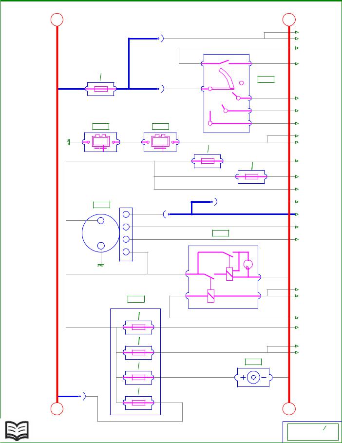
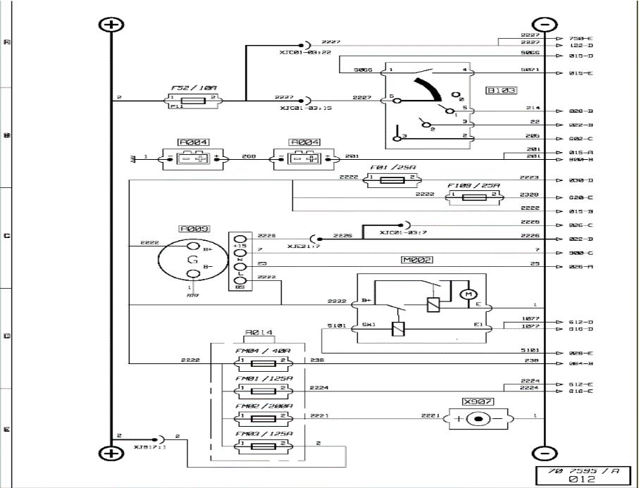
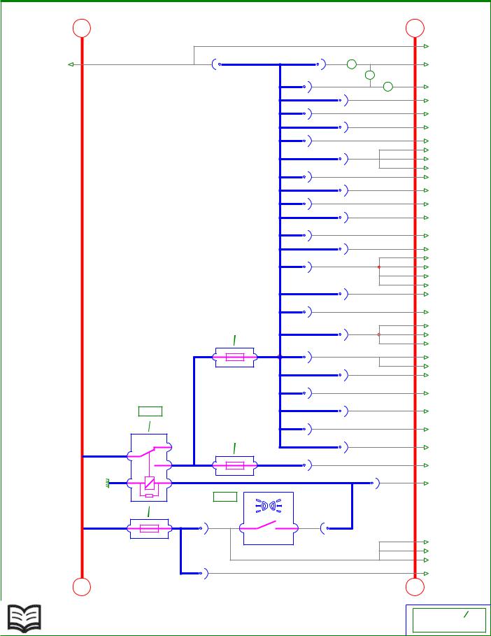
Energy production (except ADR)
Key to appliances
|
Code |
Function |
Location |
|
A004 |
Batteries |
C4d |
|
A006 |
Electrically controlled master switch |
C4d |
|
A007 |
Manually controlled master switch |
C4d |
|
A009 |
Alternator |
B3c |
|
A014 |
Power fuse box unit (FM1 to FM4) |
C4d |
|
B103 |
Key switch unit |
C2c |
|
M002 |
Starter |
B3c |
|
W506 |
Doors central locking diode |
A2c |
|
X907 |
Ground receptacle |
C5d |
1: with electrical master switch
2: with mechanical master switch
Energy production (except ADR)
1 / 2

Andrew Burrows Energy production / Diagram 02/02/16
2 / 2
|
Andrew Burrows |
02/02/2016, 9:05:20 AM (CET) |
|
+ |
— |
||||||||||||
|
2227 |
|||||||||||||
|
2227 |
750-E |
||||||||||||
|
2227 |
|||||||||||||
|
122-D |
|||||||||||||
|
XJC01-03:22 |
5066 |
||||||||||||
|
015-D |
|||||||||||||
|
5066 |
1 |
4 |
5071 |
||||||||||
|
015-E |
|||||||||||||
|
F52 |
10A |
B103 |
|||||||||||
|
6 |
|||||||||||||
|
2 |
1 |
2 |
2227 |
2227 |
0 |
||||||||
|
P11 |
XJC01-03:15 |
5 |
214 |
||||||||||
|
1 |
028-B |
||||||||||||
|
3 |
22 |
||||||||||||
|
2 |
022-B |
||||||||||||
|
3 |
2 |
205 |
|||||||||||
|
A004 |
A004 |
602-C |
|||||||||||
|
201 |
|||||||||||||
|
1 |
— |
+ |
268 |
— |
+ |
201 |
015-A |
||||||
|
201 |
|||||||||||||
|
800-B |
|||||||||||||
|
F01 |
25A |
||||||||||||
|
2222 |
1 |
2 |
2223 |
||||||||||
|
F109 |
25A |
030-D |
|||||||||||
|
2222 |
1 |
2 |
2328 |
||||||||||
|
620-E |
|||||||||||||
|
2222 |
|||||||||||||
|
015-B |
|||||||||||||
|
2226 |
|||||||||||||
|
A009 |
026-C |
||||||||||||
|
XJC01-03:7 |
|||||||||||||
|
2226 |
2226 |
2226 |
|||||||||||
|
2222 |
022-B |
||||||||||||
|
+15 |
XJE21:7 |
||||||||||||
|
B+ |
7 |
||||||||||||
|
7 |
|||||||||||||
|
G |
900-C |
||||||||||||
|
W |
M002 |
||||||||||||
|
25 |
25 |
||||||||||||
|
B- |
026-A |
||||||||||||
|
L |
|||||||||||||
|
2222 |
|||||||||||||
|
1 |
BS |
||||||||||||
|
2222 |
B+ |
E |
1 |
||||||||||
|
1077 |
|||||||||||||
|
5101 |
SW1 |
E1 |
612-D |
||||||||||
|
1077 |
|||||||||||||
|
A014 |
616-D |
||||||||||||
|
FM04 |
40A |
5101 |
|||||||||||
|
028-E |
|||||||||||||
|
2222 |
1 |
2 |
238 |
238 |
|||||||||
|
064-B |
|||||||||||||
|
FM01 |
125A |
2224 |
|||||||||||
|
1 |
2 |
2224 |
612-E |
||||||||||
|
2224 |
|||||||||||||
|
616-E |
|||||||||||||
|
FM02 |
200A |
X907 |
|||||||||||
|
1 |
2 |
2221 |
2221 |
1 |
|||||||||
|
2 |
2 |
FM03 |
125A |
||||||||||
|
+ XJB17:1 |
1 |
2 |
2 |
— |
|||||||||
|
70 7595 |
A |
||||||||||||
|
012 |
Andrew Burrows Energy production / Diagram 02/02/16
Energy production «ADR»
Key to appliances
|
Code |
Function |
Location |
|
A004 |
Batteries |
C4d |
|
A009 |
Alternator |
B3c |
|
A014 |
Power fuse box unit (FM1 to FM4) |
C4d |
|
B103 |
Key switch unit |
C2c |
|
M002 |
Starter |
B3c |
|
X907 |
Ground receptacle |
C5d |
Energy production «ADR»
1 / 2
Andrew Burrows Energy production / Diagram 02/02/16
2 / 2
|
Andrew Burrows |
02/02/2016, 9:06:35 AM (CET) |
|
+ |
— |
|||||||||||
|
201 |
||||||||||||
|
012-B |
||||||||||||
|
G006 |
||||||||||||
|
2222 |
88A |
88 |
201 |
|||||||||
|
012-C |
||||||||||||
|
OFF |
W501 |
|||||||||||
|
ON |
||||||||||||
|
4462 |
4462 |
|||||||||||
|
094-B |
||||||||||||
|
6 |
XJR62:2 |
|||||||||||
|
X1 |
260 |
260 |
||||||||||
|
2119 |
2119 |
7 |
030-B |
|||||||||
|
2 |
5 |
|||||||||||
|
XJC01-11:4 |
31 |
31 |
||||||||||
|
050-C |
||||||||||||
|
8 |
XJC01-11:10 |
|||||||||||
|
305 |
305 |
/ 10 A |
||||||||||
|
9 |
030-B |
F91 |
||||||||||
|
1 |
1 |
|||||||||||
|
3 |
||||||||||||
|
1 |
1 |
|||||||||||
|
6 |
||||||||||||
|
1150 |
1150 |
|||||||||||
|
5 |
026-C |
|||||||||||
|
1 |
1 |
|||||||||||
|
1149 |
XJR32:1 |
|||||||||||
|
7 |
B170 |
|||||||||||
|
XJB15:6 |
||||||||||||
|
1 |
2 |
1 |
64 |
/ 03 A |
||||||||
|
020-B |
F96 |
|||||||||||
|
1149 |
10 |
9 |
2117 |
/ 03 A |
||||||||
|
026-C |
F58 |
|||||||||||
|
5066 |
XJR32:8 |
5066 |
5 |
7 |
5070 |
|||||||
|
012-B |
||||||||||||
|
XJC01-15:3 |
||||||||||||
|
X2 |
5066 |
6 |
8 |
5067 |
||||||||
|
5066 |
I |
|||||||||||
|
1 |
||||||||||||
|
0 |
||||||||||||
|
XJC01-15:8 |
XJC01-32:6 |
|||||||||||
|
B171 |
||||||||||||
|
XJR11:6 |
XJR32:5 |
|||||||||||
|
5069 |
2 |
5067 |
5067 |
5067 |
||||||||
|
4 |
1 |
|||||||||||
|
5071 |
2 |
5068 |
4 |
5070 |
5070 |
5070 |
||||||
|
012-B |
3 |
3 |
||||||||||
|
XJR11:3 |
XJR32:3 |
|||||||||||
|
+ |
— |
|||||||||||
|
70 7595 |
A |
|||||||||||
|
015 |
Andrew Burrows Energy production / Diagram 02/02/16
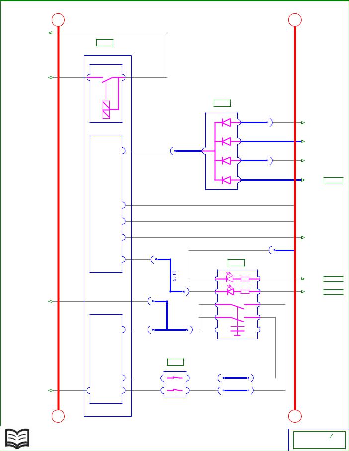
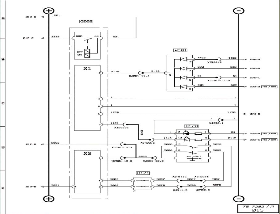
Control ECU ADR
Key to appliances
|
Code |
Function |
Location |
|
B170 |
Cab emergency stop control |
C2d |
|
B171 |
Chassis emergency stop control |
A3c |
|
G006 |
Vehicle power supply management ECU (ADR) |
C4d |
|
W501 |
Diodes set |
A2c |
Control ECU ADR
1 / 2
Andrew Burrows Energy production / Diagram 02/02/16
2 / 2
|
Andrew Burrows |
02/02/2016, 9:07:43 AM (CET) |
|
+ |
— |
|||||||||||||
|
64 |
105-B |
|||||||||||||
|
015-D |
64 |
64 |
2 |
64 |
057-D |
|||||||||
|
1 |
||||||||||||||
|
XJR32:10 |
XJC01-13:5 |
|||||||||||||
|
64 |
||||||||||||||
|
3 |
059-C |
|||||||||||||
|
XJH51:19 |
64 |
|||||||||||||
|
154-A |
||||||||||||||
|
XJC01-09:4 |
64 |
150-B |
||||||||||||
|
XJC01-09:5 |
64 |
901-A |
||||||||||||
|
XJC01-02:1 |
64 |
057-C |
||||||||||||
|
64 |
||||||||||||||
|
XJC01-02:3 |
092-D |
|||||||||||||
|
64 |
||||||||||||||
|
094-C |
||||||||||||||
|
64 |
||||||||||||||
|
XJR61:7 |
090-C |
|||||||||||||
|
64 |
||||||||||||||
|
604-C |
||||||||||||||
|
XJC01-13:10 |
64 |
602-E |
||||||||||||
|
XJC01-02:2 |
64 |
604-B |
||||||||||||
|
XJC01-13:2 |
64 |
605-C |
||||||||||||
|
XJC01-02:9 |
64 |
|||||||||||||
|
055-B |
||||||||||||||
|
XJH52:1 |
64 |
059-B |
||||||||||||
|
64 |
||||||||||||||
|
XJC01-09:2 |
050-B |
|||||||||||||
|
64 |
||||||||||||||
|
602-D |
||||||||||||||
|
64 |
||||||||||||||
|
XJC01-02:6 |
079-C |
|||||||||||||
|
64 |
||||||||||||||
|
604-A |
||||||||||||||
|
64 |
||||||||||||||
|
074-E |
||||||||||||||
|
XJC01-08:6 |
64 |
|||||||||||||
|
104-D |
||||||||||||||
|
XJC01-17:4 |
64 |
064-B |
||||||||||||
|
64 |
||||||||||||||
|
060-B |
||||||||||||||
|
F96 |
03A |
64 |
||||||||||||
|
XJC01-02:10 |
060-C |
|||||||||||||
|
1 |
2 |
64 |
060-D |
|||||||||||
|
P09 |
64 |
|||||||||||||
|
XJR33:9 |
750-B |
|||||||||||||
|
64 |
||||||||||||||
|
100-D |
||||||||||||||
|
XJC01-07:9 |
64 |
|||||||||||||
|
100-B |
||||||||||||||
|
S106 |
XJC01-13:7 |
64 |
||||||||||||
|
122-C |
||||||||||||||
|
XJC01-13:11 |
||||||||||||||
|
R07 |
10A |
64 |
||||||||||||
|
702-D |
||||||||||||||
|
XJH50:9 |
64 |
|||||||||||||
|
F97 |
05A |
070-B |
||||||||||||
|
2 |
XJH50:10 |
|||||||||||||
|
1 |
2 |
2128 |
2128 |
|||||||||||
|
901-B |
||||||||||||||
|
P07 |
||||||||||||||
|
1 |
313 |
XJH52:3 |
313 |
313 |
||||||||||
|
050-C |
||||||||||||||
|
B143 |
XJC01-03:10 |
|||||||||||||
|
F90 |
03A |
|||||||||||||
|
2 |
1 |
2 |
373 |
373 |
A3 |
A2 |
313 |
313 |
||||||
|
P12 |
XJC01-03:19 |
B113 |
XJC01-03:13 |
373 |
032-D |
|||||||||
|
373 |
||||||||||||||
|
050-D |
||||||||||||||
|
373 |
||||||||||||||
|
032-B |
||||||||||||||
|
+ |
373 |
373 |
— |
050-B |
||||||||||
|
XJC01-03:23 |
||||||||||||||
|
70 7595 |
A |
|||||||||||||
|
020 |
Andrew Burrows Electrical distribution / Diagram 02/02/16
Electrical distribution (1/7)
Key to appliances
|
Code |
Function |
Location |
|
B113 |
Side/parking lights control |
C2b |
|
B143 |
Steering wheel fingertip controls N° 1 |
C2b |
|
S106 |
Switches night lighting power supply relay |
A2c |
1: with dashboard-mounted long range driving lights control 2: with top ledge-mounted long range driving lights control 3: with revolving beacon(s)
Electrical distribution (1/7)
1 / 2

Andrew Burrows Electrical distribution / Diagram 02/02/16
2 / 2

|
Andrew Burrows |
02/02/2016, 9:09:39 AM (CET) |
|
+ |
— |
||||||
|
2226 |
W100 |
||||||
|
010-C |
|||||||
|
2226 |
2226 |
1 |
2 |
22 |
|||
|
012-C |
|||||||
|
22 |
|||||||
|
805-C |
|||||||
|
22 |
22 |
22 |
|||||
|
010-B |
024-A |
||||||
|
22 |
XJC01-04:21 |
||||||
|
012-B |
|||||||
|
S001 |
|||||||
|
R01 |
50A |
||||||
|
1 |
22 |
||||||
|
F10 |
30A |
||||||
|
2 |
1 |
2 |
2014 |
2014 |
|||
|
079-B |
|||||||
|
P76 |
XJC01-09:1 |
||||||
|
F19 |
05A |
||||||
|
1 |
2 |
463 |
463 |
||||
|
079-D |
|||||||
|
P51 |
XJC01-04:22 |
||||||
|
F48 |
03A |
||||||
|
1 |
2 |
2025 |
2025 |
||||
|
102-D |
|||||||
|
P50 |
2025 |
||||||
|
XJC01-16:7 |
104-E |
||||||
|
243 |
|||||||
|
850-E |
|||||||
|
XJR11:10 |
|||||||
|
243 |
|||||||
|
604-E |
|||||||
|
F03 |
7,5A |
XJC01-18:7 |
|||||
|
1 |
2 |
243 |
243 |
||||
|
604-D |
|||||||
|
P74 |
|||||||
|
2310 |
|||||||
|
122-D |
|||||||
|
XJC01-18:6 |
|||||||
|
F29 |
10A |
2310 |
|||||
|
1 |
2 |
2310 |
2310 |
941-D |
|||
|
2310 |
|||||||
|
940-D |
|||||||
|
P75 |
XJC01-04:13 |
||||||
|
+ |
— |
||||||
|
70 7595 |
A |
||||||
|
022 |
Andrew Burrows Electrical distribution / Diagram 02/02/16
Electrical distribution (2/7)
Key to appliances
|
Code |
Function |
Location |
|
|
S001 |
After ignition power supply relay N°1 |
A2c |
|
|
W100 |
Alternator circuit draw resistor |
A2c |
Electrical distribution (2/7)
1 / 2

Andrew Burrows Electrical distribution / Diagram 02/02/16
2 / 2

|
Andrew Burrows |
02/02/2016, 9:10:39 AM (CET) |
|
+ |
— |
||||||||
|
22 |
22 |
026-C |
|||||||
|
022-B |
|||||||||
|
S002 |
501 |
052-C |
|||||||
|
R02 |
50A |
S400 |
XJC01-02:20 |
||||||
|
R15 |
20A |
501 |
052-E |
||||||
|
1 |
22 |
XJC01-02:24 |
|||||||
|
F13 |
20A |
501 |
503 |
050-C |
|||||
|
2 |
1 |
2 |
501 |
501 |
XJC01-02:22 |
||||
|
P38 |
509 |
507 |
052-D |
||||||
|
XJC01-02:23 |
|||||||||
|
509 |
050-D |
||||||||
|
XJC01-02:18 |
509 |
||||||||
|
F70 |
10A |
052-E |
|||||||
|
1 |
2 |
211 |
XJC01-02:19 |
211 |
|||||
|
105-D |
|||||||||
|
P81 |
XJR13:3 |
||||||||
|
F11 |
10A |
||||||||
|
1 |
2 |
273 |
273 |
204-B |
|||||
|
P04 |
|||||||||
|
F08 |
05A |
24 |
750-E |
||||||
|
1 |
2 |
24 |
XJC01-01:14 |
24 |
|||||
|
851-C |
|||||||||
|
P79 |
XJC01-01:19 |
||||||||
|
S500 |
24 |
||||||||
|
040-D |
|||||||||
|
24 |
|||||||||
|
R04 |
10A |
XJB15:4 |
702-C |
||||||
|
24 |
|||||||||
|
F39 |
15A |
750-C |
|||||||
|
XJH150:8 |
|||||||||
|
1 |
2 |
215 |
4060 |
||||||
|
604-B |
|||||||||
|
P03 |
XJC01-16:4 |
||||||||
|
4 |
|||||||||
|
602-C |
|||||||||
|
215 |
4 |
||||||||
|
XJC01-17:8 |
064-C |
||||||||
|
4 |
4 |
||||||||
|
064-D |
|||||||||
|
XJC01-17:11 |
4 |
||||||||
|
064-B |
|||||||||
|
XJC01-19:1 |
215 |
||||||||
|
F71 |
15A |
064-B |
|||||||
|
1 |
2 |
2234 |
XJC01-16:5 |
2234 |
|||||
|
900-D |
|||||||||
|
F26 |
15A |
||||||||
|
P39 |
XJC01-09:7 |
||||||||
|
1 |
2 |
275 |
275 |
900-E |
|||||
|
F59 |
10A |
P80 |
XJB15:7 |
||||||
|
1 |
2 |
2317 |
2317 |
941-B |
|||||
|
S104 |
2317 |
||||||||
|
P05 |
XJC01-07:11 |
940-B |
|||||||
|
R08 |
10A |
||||||||
|
2317 |
1018 |
604-D |
|||||||
|
F103 |
10A |
XJC01-03:9 |
608 |
||||||
|
055-C |
|||||||||
|
2 |
1 |
2 |
608 |
||||||
|
XJR11:5 |
890-C |
||||||||
|
608 |
|||||||||
|
P33 |
900-C |
||||||||
|
XJC01-03:17 |
608 |
||||||||
|
890-C |
|||||||||
|
XJR13:9 |
608 |
||||||||
|
055-B |
|||||||||
|
+ |
— |
||||||||
|
XJH51:12 |
|||||||||
|
70 7595 |
A |
||||||||
|
024 |
Andrew Burrows Electrical distribution / Diagram 02/02/16
Electrical distribution (3/7)
Key to appliances
|
Code |
Function |
Location |
|
S002 |
After ignition power supply relay N°2 |
A2c |
|
S104 |
Reversing lights power supply relay |
A2c |
|
S400 |
Windscreen wipers motor time-delay relay |
A2c |
|
S500 |
Heated and swivelling rearview mirror power supply relay |
A2c |
Electrical distribution (3/7)
1 / 2

Andrew Burrows Electrical distribution / Diagram 02/02/16
2 / 2

|
Andrew Burrows |
02/02/2016, 9:11:44 AM (CET) |
|
+ |
XJE21:4 |
W503 |
— |
||||||||||
|
25 |
25 |
2 |
1 |
2307 |
2307 |
||||||||
|
010-D |
1A |
851-B |
|||||||||||
|
25 |
XJC01-01:1 |
||||||||||||
|
012-C |
4306 |
||||||||||||
|
F75 |
15A |
||||||||||||
|
XJR65:2 |
074-A |
||||||||||||
|
1 |
2 |
4306 |
4306 |
||||||||||
|
S022 |
074-B |
||||||||||||
|
P32 |
XJR65:3 |
||||||||||||
|
R05 |
20A |
4306 |
|||||||||||
|
D006 |
|||||||||||||
|
900-B |
|||||||||||||
|
XJR73:3 |
XJC01-04:9 |
||||||||||||
|
1 |
25 |
1 |
|||||||||||
|
1 |
2 |
||||||||||||
|
2 |
F76 |
10A |
XJR73:2 |
||||||||||
|
1 |
2 |
2229 |
2229 |
||||||||||
|
1 |
092-E |
||||||||||||
|
P08 |
XJC01-07:10 |
||||||||||||
|
2229 |
|||||||||||||
|
1 |
094-B |
||||||||||||
|
S021 |
XJR62:1 |
||||||||||||
|
R10 |
10A |
2 |
W505 |
||||||||||
|
1150 |
1150 |
2126 |
2126 |
D04 |
|||||||||
|
1 |
1 |
||||||||||||
|
015-C |
|||||||||||||
|
XJC01-01:20 |
XJC01-01:12 |
XJC01-11:6 |
|||||||||||
|
2226 |
1 |
2226 |
1 |
||||||||||
|
012-C |
1 |
1 |
|||||||||||
|
XJC01-06:2 |
|||||||||||||
|
W504 |
|||||||||||||
|
XJC01-06:4 |
XJC01-02:4 |
2 |
|||||||||||
|
D03 |
|||||||||||||
|
2117 |
2117 |
||||||||||||
|
1 |
|||||||||||||
|
015-D |
F58 |
03A |
|||||||||||
|
XJR32:2 |
|||||||||||||
|
22 |
22 |
1 |
2 |
2117 |
|||||||||
|
024-A |
|||||||||||||
|
P06 |
|||||||||||||
|
S003 |
|||||||||||||
|
R03 |
50A |
||||||||||||
|
W502 |
|||||||||||||
|
1 |
22 |
22 |
2 |
1 |
2122 |
2122 |
|||||||
|
1A |
602-C |
||||||||||||
|
F64 |
10A |
XJC01-03:1 |
|||||||||||
|
2 |
1 |
2 |
606 |
606 |
606 |
||||||||
|
890-C |
|||||||||||||
|
P28 |
F24 |
20A |
XJR13:8 |
||||||||||
|
808 |
|||||||||||||
|
1 |
2 |
808 |
612-B |
||||||||||
|
808 |
|||||||||||||
|
616-C |
|||||||||||||
|
P26 |
XJE21:8 |
||||||||||||
|
274 |
274 |
||||||||||||
|
F23 |
05A |
110-D |
|||||||||||
|
XJC01-05:9 |
274 |
||||||||||||
|
1 |
2 |
274 |
274 |
150-A |
|||||||||
|
274 |
|||||||||||||
|
152-A |
|||||||||||||
|
P02 |
274 |
||||||||||||
|
F67 |
10A |
XJC01-10:9 |
154-B |
||||||||||
|
1 |
2 |
2325 |
2325 |
||||||||||
|
120-A |
|||||||||||||
|
P25 |
XJC01-15:10 |
2325 |
|||||||||||
|
F16 |
10A |
||||||||||||
|
122-B |
|||||||||||||
|
1 |
2 |
2121 |
2121 |
2121 |
|||||||||
|
100-C |
|||||||||||||
|
P01 |
XJC01-15:1 |
||||||||||||
|
2121 |
2121 |
||||||||||||
|
604-C |
|||||||||||||
|
2121 |
XJC01-03:2 |
2121 |
|||||||||||
|
605-D |
|||||||||||||
|
2121 |
XJC01-03:6 |
2121 |
|||||||||||
|
100-D |
|||||||||||||
|
+ |
XJC01-14:8 |
— |
|||||||||||
|
70 7595 |
A |
||||||||||||
|
026 |
Andrew Burrows Electrical distribution / Diagram 02/02/16
Electrical distribution (4/7)
Key to appliances
|
Code |
Function |
Location |
|
D006 |
Vehicle hour-meter |
C3c |
|
S003 |
After ignition power supply relay N° 3 |
A2c |
|
S021 |
Alternator circuit earthing relay (ADR) |
A2c |
|
S022 |
Alternator controlled power supply relay (engine running) |
A2c |
|
W502 |
Diode on after ignition information circuit for vehicle management box |
A2c |
|
W503 |
Diode on engine running information relay power supply circuit |
A2c |
|
W504 |
Diode on alternator earthing relay power supply circuit |
A2c |
|
W505 |
Diode on alternator earthing relay power supply circuit |
A2c |
1: with ADR equipment
Electrical distribution (4/7)
1 / 2
![]()
Andrew Burrows Electrical distribution / Diagram 02/02/16
2 / 2

|
Andrew Burrows |
02/02/2016, 9:12:45 AM (CET) |
|
+ |
F14 |
15A |
— |
||||||||||
|
S004 |
1 |
2 |
4308 |
4308 |
074-E |
||||||||
|
P45 |
XJC01-08:10 |
||||||||||||
|
R21 |
50A |
F27 |
20A |
||||||||||
|
2 |
1 |
2 |
2232 |
2232 |
060-B |
||||||||
|
P66 |
XJC01-16:3 |
||||||||||||
|
214 |
1 |
F37 |
10A |
||||||||||
|
1 |
2 |
4309 |
4309 |
075-B |
|||||||||
|
P63 |
XJC01-03:16 |
||||||||||||
|
4309 |
075-C |
||||||||||||
|
F61 |
15A |
||||||||||||
|
S005 |
XJH51:17 |
||||||||||||
|
214 |
|||||||||||||
|
1 |
2 |
47 |
47 |
||||||||||
|
010-B |
074-B |
||||||||||||
|
214 |
R22 |
50A |
|||||||||||
|
012-B |
P40 |
XJC01-01:7 |
|||||||||||
|
XJC01-01:15 |
|||||||||||||
|
1 |
|||||||||||||
|
F63 |
15A |
||||||||||||
|
2 |
214 |
1 |
2 |
2315 |
2315 |
074-E |
|||||||
|
P65 |
XJH52:4 |
||||||||||||
|
2231 |
060-E |
||||||||||||
|
F66 |
10A |
||||||||||||
|
XJR33:8 |
|||||||||||||
|
1 |
2 |
2231 |
2231 |
070-E |
|||||||||
|
S201 |
P64 |
XJR80:2 |
|||||||||||
|
R20 |
50A |
2231 |
070-E |
||||||||||
|
XJC01-08:14 |
|||||||||||||
|
2 |
0023 |
F07 |
05A |
0023 |
|||||||||
|
604-D |
|||||||||||||
|
1 |
2 |
229 |
XJC01-01:24 |
229 |
|||||||||
|
602-C |
|||||||||||||
|
2 |
— |
||||||||||||
|
P18 |
XJC01-01:22 |
||||||||||||
|
229 |
800-B |
||||||||||||
|
F09 |
05A |
XJH51:24 |
|||||||||||
|
1 |
2 |
2125 |
2125 |
605-A |
|||||||||
|
P19 |
XJC01-01:18 |
||||||||||||
|
2323 |
610-C |
||||||||||||
|
F40 |
30A |
F42 |
10A |
||||||||||
|
XJE21:12 |
|||||||||||||
|
1 |
2 |
291 |
1 |
2 |
2323 |
612-E |
|||||||
|
2323 |
|||||||||||||
|
P44 |
P46 |
XJB15:3 |
616-E |
||||||||||
|
S020 |
F107 |
10A |
|||||||||||
|
R17 |
10A |
1 |
2 |
2329 |
620-C |
||||||||
|
F41 |
15A |
P59 |
XJE21:9 |
||||||||||
|
XJE21:2 |
292 |
1 |
2 |
291 |
291 |
612-E |
|||||||
|
5101 |
|||||||||||||
|
P43 |
|||||||||||||
|
010-D |
291 |
||||||||||||
|
616-D |
|||||||||||||
|
012-D |
|||||||||||||
|
292 |
292 |
||||||||||||
|
5102 |
612-C |
||||||||||||
|
292 |
|||||||||||||
|
XJE21:10 |
616-C |
||||||||||||
|
5102 |
5102 |
602-C |
|||||||||||
|
+ |
XJC01-06:5 |
— |
|||||||||||
|
70 7595 |
A |
||||||||||||
|
028 |
Andrew Burrows Electrical distribution / Diagram 02/02/16
Electrical distribution (5/7)
Key to appliances
|
Code |
Function |
Location |
|
S004 |
Accessories power supply relay N° 1 |
A2c |
|
S005 |
Accessories power supply relay N° 2 |
A2c |
|
S020 |
Starting relay |
A2c |
|
S201 |
Vehicle and engine ECUs power supply relay |
A2c |
Electrical distribution (5/7)
1 / 2

Andrew Burrows Electrical distribution / Diagram 02/02/16
2 / 2

|
Andrew Burrows |
02/02/2016, 9:13:44 AM (CET) |
|
+ |
S202 |
— |
||||||||||||
|
R19 |
10A |
1155 |
||||||||||||
|
150-B |
||||||||||||||
|
1155 |
||||||||||||||
|
152-B |
||||||||||||||
|
1 |
1155 |
1155 |
||||||||||||
|
154-C |
||||||||||||||
|
F49 |
05A |
XJC01-10:15 |
260 |
|||||||||||
|
260 |
150-B |
|||||||||||||
|
2 |
1 |
2 |
260 |
|||||||||||
|
XJC01-09:9 |
152-B |
|||||||||||||
|
260 |
||||||||||||||
|
P16 |
154-C |
|||||||||||||
|
260 |
||||||||||||||
|
150-B |
||||||||||||||
|
260 |
||||||||||||||
|
XJC01-09:10 |
152-B |
|||||||||||||
|
260 |
||||||||||||||
|
154-C |
||||||||||||||
|
260 |
260 |
|||||||||||||
|
154-B |
||||||||||||||
|
015-B |
||||||||||||||
|
XJC01-09:8 |
||||||||||||||
|
305 |
305 |
305 |
055-E |
|||||||||||
|
015-C |
305 |
|||||||||||||
|
XJR11:2 |
053-D |
|||||||||||||
|
305 |
305 |
053-E |
||||||||||||
|
F91 |
10A |
|||||||||||||
|
XJH50:21 |
||||||||||||||
|
1 |
2 |
305 |
305 |
305 |
057-B |
|||||||||
|
P56 |
XJF01:5 |
|||||||||||||
|
S107 |
304 |
055-C |
||||||||||||
|
304 |
||||||||||||||
|
R12 |
10A |
XJR11:12 |
053-A |
|||||||||||
|
304 |
057-D |
|||||||||||||
|
F92 |
10A |
|||||||||||||
|
2 |
XJF01:6 |
|||||||||||||
|
1 |
2 |
304 |
304 |
053-E |
||||||||||
|
1 |
303 |
P55 |
XJH50:22 |
303 |
||||||||||
|
303 |
050-C |
|||||||||||||
|
XJC01-03:14 |
||||||||||||||
|
F93 |
10A |
634 |
890-B |
|||||||||||
|
S105 |
XJR13:4 |
|||||||||||||
|
1 |
2 |
634 |
||||||||||||
|
634 |
900-E |
|||||||||||||
|
R06 |
20A |
|||||||||||||
|
P52 |
XJB15:11 |
|||||||||||||
|
1 |
303 |
F94 |
10A |
632 |
900-E |
|||||||||
|
XJB15:10 |
||||||||||||||
|
1 |
2 |
632 |
632 |
890-B |
||||||||||
|
2 |
||||||||||||||
|
P53 |
XJR13:2 |
|||||||||||||
|
F06 |
05A |
|||||||||||||
|
/ 25A |
2223 |
2223 |
2223 |
1 |
2 |
2306 |
2306 |
851-B |
||||||
|
F01 |
010-C |
|||||||||||||
|
/ 25A |
2223 |
XJB15:12 |
P29 |
XJC01-04:23 |
||||||||||
|
F01 |
012-C |
|||||||||||||
|
263 |
750-D |
|||||||||||||
|
F20 |
10A |
263 |
||||||||||||
|
XJH50:24 |
702-D |
|||||||||||||
|
2223 |
1 |
2 |
263 |
263 |
075-B |
|||||||||
|
P54 |
XJC01-04:1 |
|||||||||||||
|
F36 |
10A |
202 |
050-B |
|||||||||||
|
2223 |
1 |
2 |
202 |
XJC01-04:16 |
202 |
|||||||||
|
050-B |
||||||||||||||
|
P30 |
XJC01-04:20 |
|||||||||||||
|
F108 |
20A |
2132 |
090-B |
|||||||||||
|
XJR61:4 |
||||||||||||||
|
2223 |
1 |
2 |
2132 |
2132 |
||||||||||
|
092-C |
||||||||||||||
|
+ |
P30 |
XJC01-17:12 |
— |
|||||||||||
|
70 7595 |
A |
|||||||||||||
|
030 |
Andrew Burrows Electrical distribution / Diagram 02/02/16
Electrical distribution (6/7)
Key to appliances
|
Code |
Function |
Location |
|
S105 |
RH and LH side/parking and marker lights power supply relay |
A2c |
|
S107 |
RH and LH side/parking and marker lights |
A2c |
|
power supply relay (trailer and bodybuilder) |
||
|
S202 |
Air suspension power supply relay |
A2c |
Electrical distribution (6/7)
1 / 2

Andrew Burrows Electrical distribution / Diagram 02/02/16
2 / 2

|
Andrew Burrows |
02/02/2016, 9:14:40 AM (CET) |
|
+ |
B143 |
— |
|||||||||||||||
|
/ 03 A |
373 |
373 |
B3 |
B4 |
62 |
||||||||||||
|
F90 |
020-E |
B141 |
|||||||||||||||
|
62 |
62 |
||||||||||||||||
|
XJC01-03:24 |
|||||||||||||||||
|
S102 |
62 |
62 |
057-D |
||||||||||||||
|
R09 |
10A |
||||||||||||||||
|
F17 |
10A |
||||||||||||||||
|
1 |
62 |
1 |
2 |
602 |
602 |
057-D |
|||||||||||
|
P37 |
XJF01:2 |
||||||||||||||||
|
662 |
F72 |
10A |
|||||||||||||||
|
1 |
2 |
603 |
603 |
057-A |
|||||||||||||
|
P36 |
XJF01:8 |
||||||||||||||||
|
XJC01-03:20 |
603 |
603 |
851-C |
||||||||||||||
|
662 |
XJC01-02:5 |
||||||||||||||||
|
S103 |
XJC01-13:1 |
||||||||||||||||
|
R23 |
10A |
60 |
60 |
057-B |
|||||||||||||
|
F100 |
15A |
XJF01:4 |
|||||||||||||||
|
60 |
60 |
60 |
|||||||||||||||
|
851-C |
|||||||||||||||||
|
2 |
1 |
2 |
663 |
||||||||||||||
|
XJC01-10:14 |
|||||||||||||||||
|
662 |
|||||||||||||||||
|
P21 |
|||||||||||||||||
|
1 |
68 |
68 |
|||||||||||||||
|
XJC01-10:12 |
S110 |
||||||||||||||||
|
B143 |
RE08 |
10A |
|||||||||||||||
|
62 |
|||||||||||||||||
|
XJC01-13:9 |
|||||||||||||||||
|
373 |
B143 |
373 |
A3 |
B1 |
69 |
||||||||||||
|
/ 03 A |
|||||||||||||||||
|
F90 |
020-E |
B145 |
68 |
||||||||||||||
|
S101 |
373 |
A3 |
B2 |
370 |
307 |
890-C |
|||||||||||
|
B146 |
|||||||||||||||||
|
R18 |
10A |
XJR13:5 |
|||||||||||||||
|
307 |
055-C |
||||||||||||||||
|
1 |
370 |
370 |
307 |
||||||||||||||
|
F101 |
10A |
XJR11:7 |
890-C |
||||||||||||||
|
XJC01-02:15 |
1 |
2 |
307 |
307 |
|||||||||||||
|
850-C |
|||||||||||||||||
|
2 |
|||||||||||||||||
|
P37 |
XJC01-02:17 |
||||||||||||||||
|
S100 |
|||||||||||||||||
|
R13 |
10A |
3 |
055-C |
||||||||||||||
|
F104 |
10A |
3 |
|||||||||||||||
|
890-C |
|||||||||||||||||
|
2 |
1 |
2 |
XJR11-4 |
||||||||||||||
|
P13 |
3 |
3 |
890-C |
||||||||||||||
|
1 |
5028 |
XJR13:7 |
5028 |
||||||||||||||
|
604-B |
|||||||||||||||||
|
+ |
XJC01-01:4 |
— |
|||||||||||||||
|
70 7595 |
A |
||||||||||||||||
|
032 |
Andrew Burrows Electrical distribution / Diagram 02/02/16
Electrical distribution (7/7)
Key to appliances
|
Code |
Function |
Location |
|
B141 |
Main beam headlights control |
C2b |
|
B143 |
Steering wheel fingertip controls N° 1 |
C2b |
|
B145 |
Fog driving lights control |
C2b |
|
B146 |
Fog lights control |
C2b |
|
S100 |
Stop lights power supply relay |
A2c |
|
S101 |
Rear fog lights power supply relay |
A2c |
|
S102 |
Main beam headlights power supply relay |
A2c |
|
S103 |
Fog driving lights power supply relay |
A2c |
|
S110 |
Fog lights cut-off relay if main beam headlights on |
A2c |
Electrical distribution (7/7)
1 / 2

Andrew Burrows Electrical distribution / Diagram 02/02/16
2 / 2
 Loading…

This webpage contains Renault Premium 450 Dxi 2008 Service Repair Manual PDF used by Renault garages, auto repair shops, Renault dealerships and home mechanics.
With this Renault Premium 450 Dxi Workshop manual, you can perform every job that could be done by Renault garages and mechanics from:
- changing spark plugs,
- brake fluids,
- oil changes,
- engine rebuilds,
- electrical faults
- and much more
The Renault Premium 450 Dxi 2008 Service Repair Manual PDF includes:
- detailed illustrations,
- drawings,
- diagrams,
- step by step guides,
- explanations of Renault Premium 450 Dxi:
- service
- repair
- maintenance
PDF Document Details
: Renault Premium 450 Dxi 2008 Service Repair Manual PDF
Andrew Burrows Diagram / Diagram 02/02/16
List of «equipment» codes
Key to appliances
|
Code |
Function name |
Location |
|
A001 |
Cab electrical distribution box |
|
|
A004 |
Batteries |
|
|
A006 |
Electrically controlled master switch |
|
|
A007 |
Manually controlled master switch |
|
|
A009 |
Alternator |
|
|
A011 |
Voltage converter (24V / 12V) for information technology pack |
|
|
A012 |
Voltage converter (24V / 12V — 10A) for audio communication system |
|
|
A013 |
Voltage converter (24V / 12V — 15A) for audio communication system |
|
|
A014 |
Power fuse box unit (FM1 to FM4) |
|
|
A020 |
Voltage converter (24V / 12V) — 12 and 24 Volts integrated sockets |
|
|
A200 |
Available power supply (insulated cut wires) |
|
|
A201 |
Available power supply (vehicle earth) |
|
|
A204 |
Available power supply (after master switch) |
|
|
A205 |
Available power supply (after ignition) |
|
|
A212 |
Available power supply (engine speed) |
|
|
A213 |
Available power supply (PTO N°1) |
|
|
A219 |
Available power supply (radio-telephone +) |
|
|
A220 |
Available power supply (radio-telephone -) |
|
|
A226 |
Available power supply (CB -) |
|
|
A227 |
Available power supply (CB +) |
|
|
A229 |
Available power supply (bodybuilder equipment control) |
|
|
A230 |
Available power supply (equipment in |
|
|
«road» position warning pictogram) |
||
|
A231 |
Available power supply (equipment in |
|
|
«working» position warning pictogram) |
||
|
A240 |
Available power supply (lighting) |
|
|
A246 |
Available power supply (PTO N°1 control) |
|
|
A247 |
Available power supply (alternator information, engine running) |
|
|
A248 |
Available power supply (alternator information, engine speed) |
|
|
A249 |
Available power supply (tachograph corrected speed information) |
|
|
A250 |
Available power supply (PTO 2 control) |
1 / 14
Andrew Burrows Diagram / Diagram 02/02/16
|
A251 |
Available power supply (PTO 2 warning light) |
|
A252 |
Available power supply (PTO 2 solenoid valve piloting) |
|
A253 |
Available power supply (reversing information) |
|
A254 |
Available power supply (parking brake information) |
|
A255 |
Available power supply (gearbox neutral information) |
|
A256 |
Available power supply (chassis-mounted |
|
engine speed control actuation demand) |
|
|
A257 |
Available power supply (selection of engine speed N°1) |
|
A258 |
Available power supply (selection of engine speed N°2) |
|
A259 |
Available power supply (engine speed acceleration demand) |
|
A260 |
Available power supply (engine speed deceleration demand) |
|
A261 |
Available power supply (reversing forbidden inhibition) |
|
A270 |
Available power supply (main engine speed automatic return) |
|
A280 |
Available power supply (low speed) |
|
A281 |
Available power supply (engine stop control) |
|
A282 |
Available power supply (engine start control) |
|
A283 |
Available power supply (engine starting information) |
|
A284 |
Available power supply (engine alert) |
|
A285 |
Available power supply (parameter definable frequency-related output) |
|
A286 |
Available power supply (PLC 2 min. output) |
|
A287 |
Available power supply (PLC 1 min. output) |
|
A288 |
Available power supply (PLC 1 min. input) |
|
A289 |
Available power supply (PLC 2 min. input) |
|
A290 |
Available power supply (high level CAN bus J1939) |
|
A291 |
Available power supply (low level CAN bus J1939) |
|
A294 |
Available power supply (LH rear marker light(s) |
|
A295 |
Available power supply (RH rear marker light(s) |
|
A297 |
Available power supply (night lighting) |
|
A311 |
Available power supply (PTO 1 engaged information) |
|
A312 |
Available power supply (equipment in dangerous position) |
|
A313 |
Available power supply (CAN bus disabling) |
|
A314 |
Available power supply (engine speed set-point validation) |
|
A315 |
Available power supply (PTO 3 solenoid valve piloting) |
|
A317 |
Available power supply (PTO 3 control) |
|
A318 |
Available power supply (PTO 3 warning light) |
2 / 14
Andrew Burrows Diagram / Diagram 02/02/16
|
A319 |
Available power supply (suspension level control) |
|
A320 |
Available power supply (suspension level actuation control) |
|
A321 |
Available power supply (6 km/h limitation) |
|
A322 |
Available power supply (30 km/h limitation) |
|
A323 |
Available power supply (alarm stop) |
|
A324 |
Available power supply (rigid perimetric protection module) |
|
A325 |
Available power supply (independent heating cut-off) |
|
B001 |
Air suspension remote control |
|
B002 |
Air suspension ‘up’ position remote control |
|
B003 |
Air suspension ‘down’ position remote control |
|
B004 |
Air suspension memorized position remote control |
|
B026 |
Automatic transmission gear selector |
|
B103 |
Key switch unit |
|
B105 |
Engine stop control |
|
B106 |
Hazard lights control |
|
B108 |
Revolving beacons control |
|
B111 |
Horn control |
|
B113 |
Side/parking lights control |
|
B116 |
Doors locking control |
|
B117 |
Sun-roof opening / closing control (on dashboard) |
|
B118 |
Swivelling rearview mirrors and alarm siren adjustment control |
|
B119 |
Rearview mirrors and windscreen defrosting control |
|
B125 |
Radio set control |
|
B126 |
Driver’s window winder motor control (driver side) |
|
B127 |
Front passenger window winder motor control (front passenger side) |
|
B130 |
Front passenger window winder motor control (driver side) |
|
B133 |
Add-on heater timer control |
|
B134 |
Pull-down display menu control |
|
B137 |
Windscreen wash control |
|
B138 |
Windscreen wipers control |
|
B139 |
Windscreen / headlamps wash/wipe control |
|
B140 |
Dipped beam headlights control |
|
B141 |
Main beam headlights control |
|
B142 |
Headlamps ride corrector control |
|
B143 |
Steering wheel fingertip controls N° 1 |
3 / 14
Andrew Burrows Diagram / Diagram 02/02/16
|
B144 |
Long range driving lights control |
|
B145 |
Fog driving lights control |
|
B146 |
Fog lights control |
|
B148 |
Working lights control |
|
B151 |
Reversing buzzer inhibition control |
|
B155 |
Electric or hydraulic retarder control |
|
B159 |
Engine speed set-point control for difficult terrain |
|
B162 |
Cab tilting control |
|
B163 |
Alarm anti-panic control |
|
B164 |
Rear wheels diff lock control |
|
B165 |
Second rear axle lift-up control |
|
B167 |
Cab add-on heater control |
|
B168 |
Traction control enabling control |
|
B169 |
Trailer brake holding enabling control |
|
B170 |
Cab emergency stop control |
|
B171 |
Chassis emergency stop control |
|
B172 |
Alarm siren sound level reduction control |
|
B175 |
Pre-arrangement for bodybuilder N° 1 control |
|
B176 |
Pre-arrangement for bodybuilder N° 2 control |
|
B177 |
PTO 1 engagement request control (in cab) |
|
B181 |
Direction indicator control |
|
B182 |
Auto/manual selection control |
|
B183 |
Fuel water bleed control |
|
B184 |
Axle load-shedding activation control |
|
B185 |
PTO 2 engagement request control (in cab) |
|
B186 |
Brake holding enabling control |
|
B187 |
Inter-axle diff lock control |
|
B190 |
PTO 2 engagement request control (en cab) |
|
B194 |
Overhead lighting control (ambience) |
|
B197 |
Coolant circuit solenoid valve control |
|
B198 |
Fast idling actuation control |
|
B199 |
Fast idling adjustment control |
|
C001 |
LH front wheel brake linings wear sensor |
|
C002 |
RH front wheel brake linings wear sensor |
|
C005 |
Lift-up axle or second rear axle LH wheel brake linings wear sensor |
4 / 14
Andrew Burrows Diagram / Diagram 02/02/16
|
C006 |
Lift-up axle or second rear axle RH wheel brake linings wear sensor |
|
C007 |
LH front wheel speed sensor |
|
C008 |
RH front wheel speed sensor |
|
C009 |
LH rear wheel speed sensor |
|
C010 |
RH rear wheel speed sensor |
|
C011 |
Lift-up axle or second rear axle LH wheel speed sensor |
|
C012 |
Lift-up axle or second rear axle RH wheel speed sensor |
|
C013 |
Driver’s door open position information sensor |
|
C014 |
Passenger’s front door open position information sensor |
|
C019 |
Boost air pressure and temperature sensor |
|
C020 |
Boost air temperature sensor |
|
C021 |
Boost air pressure sensor |
|
C022 |
Engine oil level sensor |
|
C023 |
Engine oil pressure sensor |
|
C024 |
Engine oil level and temperature sensor unit |
|
C025 |
3-level air conditioning pressure sensor |
|
C027 |
Low level air conditioning pressure sensor |
|
C028 |
High level air conditioning pressure sensor |
|
C029 |
Intermediate level air conditioning pressure sensor |
|
C030 |
Rear inter-axle diff lock engaged sensor |
|
C031 |
Front inter-axle diff lock engaged sensor |
|
C035 |
PTO 1 engaged position information sensor |
|
C036 |
PTO 2 engaged position information sensor |
|
C038 |
Drive axle suspension RH position sensor |
|
C039 |
Drive axle suspension LH position sensor |
|
C045 |
Internal temperature sensor |
|
C046 |
External temperature sensor |
|
C048 |
Engine cooling circuit temperature sensor |
|
C051 |
Fuel level sensor |
|
C053 |
Stop lights switch |
|
C054 |
Air filter clogging sensor |
|
C056 |
Tachograph speed sensor |
|
C057 |
Neutral position sensor |
|
C058 |
Reverse gear engaged position sensor |
|
C059 |
Retarder oil temperature sensor |
5 / 14
Andrew Burrows Diagram / Diagram 02/02/16
|
C060 |
Retarder coolant temperature sensor |
|
C061 |
Front axle suspension position sensor |
|
C062 |
Clutch position sensor |
|
C064 |
Retarder air pressure sensor |
|
C066 |
Retarder coolant temperature sensor |
|
C067 |
Flywheel speed sensor |
|
C068 |
Camshaft engine speed sensor |
|
C070 |
PTO 3 engaged position information sensor |
|
C071 |
Alarm ultra-sonic transmitter sensor |
|
C072 |
Alarm ultra-sonic receiver sensor |
|
C075 |
AdBlue tank temperature and level sensors |
|
C076 |
Exhaust gases temperature sensor |
|
C077 |
Nitrogen oxides gases concentration sensor |
|
C079 |
Trailer braking assistance pressure system sensor |
|
C084 |
Engine oil temperature sensor |
|
C086 |
Steering lockover angle sensor |
|
C087 |
Chassis lateral acceleration sensor |
|
C088 |
Engine coolant level sensor |
|
C096 |
Range change selector pressure sensor |
|
C109 |
Water in fuel sensor |
|
C110 |
Parking brake indicator pressure sensor |
|
C111 |
Accelerator pedal position sensor |
|
C112 |
Accelerator pedal «rest» position sensor N° 2 |
|
C113 |
Accelerator pedal rest position sensor |
|
C114 |
Accelerator pedal sensor unit |
|
C115 |
Lift-up air spring pressure sensor |
|
C116 |
Middle axle suspension air pressure sensor |
|
C117 |
Front air spring pressure sensor |
|
C118 |
Drive axle suspension LH pressure sensor |
|
C119 |
Drive axle suspension RH pressure sensor |
|
C120 |
Piloted axle oil level sensor |
|
C121 |
Piloted axle lockover angle sensor |
|
C122 |
Piloted axle lockover angle sensor |
|
C123 |
LH rear wheel brake linings wear sensor (drive axle N° 1) |
|
C124 |
RH rear wheel brake linings wear sensor (drive axle N° 1) |
6 / 14
Andrew Burrows Diagram / Diagram 02/02/16
|
C125 |
LH rear wheel brake linings wear sensor (drive axle N° 2) |
|
C126 |
RH rear wheel brake linings wear sensor (drive axle N° 2) |
|
C130 |
Clutch pedal position sensor |
|
C132 |
Engine boost pressure sensor |
|
C133 |
Engine cooling fan speed sensor |
|
C134 |
Brake pedal sensor unit |
|
C135 |
Brake pedal position copying sensor |
|
C140 |
LH front wheel brake linings wear sensor (drive axle or axle N° 2) |
|
C141 |
RH front wheel brake linings wear sensor (drive axle or axle N° 2) |
|
C142 |
LH front wheel brake linings wear sensor (drive axle or axle N° 1) |
|
C143 |
RH front wheel brake linings wear sensor (drive axle or axle N° 1) |
|
C144 |
LH front wheel speed sensor (drive axle or axle N° 1) |
|
C145 |
RH front wheel speed sensor (drive axle or axle N° 1) |
|
C146 |
LH front wheel speed sensor (drive axle or axle N° 2) |
|
C147 |
RH front wheel speed sensor (drive axle or axle N° 2) |
|
C148 |
High fuel pressure sensor |
|
C149 |
Driver’s seatbelt not buckled sensor |
|
C150 |
Engine block inside pressure sensor |
|
C172 |
Fifth wheel position sensors |
|
C173 |
N° 1 rear drive axle inter-wheel diff. lock engaged position sensor |
|
C174 |
N° 2 rear drive axle inter-wheel diff lock engaged position sensor |
|
D001 |
Principal information display |
|
D004 |
Tachograph |
|
D006 |
Vehicle hour-meter |
|
D018 |
Battery charge warning light |
|
D021 |
Fuel preheating warning light |
|
D026 |
Fog lights warning light |
|
D039 |
Main beam headlights warning light |
|
D041 |
Fog driving lights warning light |
|
D044 |
Working spotlight warning light |
|
D047 |
Fuel level warning light |
|
D059 |
Brake pads wear warning light |
|
D065 |
Air filter clogging warning light |
|
D067 |
Inter-wheel diff. lock warning light |
|
D077 |
Equipment in unlocked position warning light |
7 / 14
Andrew Burrows Diagram / Diagram 02/02/16
|
D081 |
Trailer brake pads wear warning light |
|
D082 |
Equipment in service information tell-tale light |
|
D083 |
Equipment in dangerous position information tell-tale light |
|
D084 |
Equipment lighting information tell-tale light |
|
E008 |
Driver’s side single overhead light |
|
E010 |
Front passenger’s side single overhead light |
|
E012 |
RH upper overhead lighting (door) |
|
E025 |
Driver’s reading spotlight |
|
E026 |
Front passenger’s reading spotlight |
|
E028 |
Driver’s overhead light / reading spotlight unit |
|
E029 |
Passenger’s overhead light / reading spotlight unit |
|
E030 |
Tool compartment light |
|
E031 |
Front grille lighting |
|
E032 |
Bottom bunk overhead lighting |
|
E033 |
LH upper overhead lighting (door) |
|
E034 |
LH overhead lighting (ambience) |
|
E035 |
RH overhead lighting (ambience) |
|
E036 |
Top bunk overhead lighting |
|
E100 |
RH front direction change indicator lights |
|
E101 |
LH front direction change indicator lights |
|
E102 |
Driver’s side stepwell lighting |
|
E103 |
Front passenger’s side stepwell lighting |
|
E104 |
Roof RH front direction change indicator lights |
|
E105 |
Roof LH front direction change indicator lights |
|
E109 |
RH rear direction change indicator lights |
|
E110 |
LH rear direction change indicator lights |
|
E114 |
Revolving beacon N° 1 |
|
E115 |
Revolving beacon N° 2 |
|
E116 |
RH rear fog light |
|
E117 |
LH rear fog light |
|
E119 |
LH stop lights |
|
E120 |
RH stop lights |
|
E122 |
RH clearance light N° 1 |
|
E123 |
RH clearance light N° 2 |
|
E124 |
LH front side/parking lights |
8 / 14
Andrew Burrows Diagram / Diagram 02/02/16
|
E125 |
RH front side/parking lights |
|
E128 |
LH clearance lights N° 3 |
|
E129 |
LH clearance lights N° 4 |
|
E131 |
RH clearance lights N° 3 |
|
E132 |
RH clearance lights N° 4 |
|
E133 |
LH clearance lights N° 1 |
|
E134 |
LH clearance lights N° 2 |
|
E135 |
LH tail lights unit |
|
E136 |
RH tail lights unit |
|
E137 |
RH rear side/parking lights |
|
E138 |
LH rear side/parking lights |
|
E141 |
LH reversing lights |
|
E142 |
RH reversing lights |
|
E144 |
Roof LH side/parking lights |
|
E145 |
Roof LH side/parking lights |
|
E149 |
Anti-glare strip-mounted LH marker lights |
|
E150 |
Anti-glare strip-mounted RH marker lights |
|
E500 |
RH dipped beam headlight |
|
E501 |
LH dipped beam headlight |
|
E502 |
RH main beam headlight |
|
E503 |
LH dipped beam headlight |
|
E504 |
RH headlamp insert |
|
E505 |
LH headlamp insert |
|
E506 |
LH fog driving light |
|
E507 |
RH fog driving light |
|
E508 |
RH long range driving light |
|
E509 |
LH long range driving light |
|
E510 |
Working spotlight |
|
G001 |
Vehicle management ECU |
|
G002 |
Engine management ECU |
|
G003 |
Bodybuilder pre-arrangement management ECU |
|
G004 |
Air suspension ECU |
|
G005 |
EBS braking management ECU |
|
G006 |
Vehicle power supply management ECU (ADR) |
|
G007 |
Front axle braking assistance modulator unit |
9 / 14
![]()
Andrew Burrows Diagram / Diagram 02/02/16
|
G008 |
Drive axle braking assistance modulator unit |
|
G012 |
Lighting and signalling management ECU |
|
G016 |
Second rear axle braking assistance modulator unit |
|
G017 |
Cab temperature regulation ECU |
|
G018 |
Onboard management interface ECU |
|
G019 |
Gear selector ECU |
|
G020 |
Automatic transmission ECU |
|
G021 |
Hydraulic retarder ECU |
|
G022 |
Electric retarder ECU |
|
G025 |
Engine immobilizer ECU |
|
G026 |
Alarm ECU |
|
G027 |
Piloted axle ECU |
|
G028 |
Doors central locking ECU |
|
G029 |
Automatic transmission sensors / actuators unit |
|
G030 |
AdBlue supply management pump module |
|
G051 |
Air production management ECU |
|
G102 |
Onboard management ECU |
|
G104 |
Tyre pressures monitoring ECU |
|
H001 |
Engine immobilizer antenna |
|
H002 |
Radio set antenna |
|
H011 |
LH front loudspeaker |
|
H012 |
RH front loudspeaker |
|
H014 |
Radio set |
|
H016 |
CD player |
|
J001 |
Cigar lighter |
|
J002 |
RH heated seat unit |
|
J003 |
LH heated seat unit |
|
J006 |
Refrigerated compartment |
|
J007 |
Refrigerator |
|
K001 |
Air/water add-on heater |
|
K002 |
Air/air add-on heater |
|
K003 |
Air conditioning ECU |
|
L004 |
External horn |
|
L006 |
Horn — Alarm siren |
|
L008 |
Electric horn |
10 / 14
Andrew Burrows Diagram / Diagram 02/02/16
|
M002 |
Starter |
||
|
M020 |
Windscreen wipers drive motor |
||
|
M021 |
Windscreen wash pump motor |
||
|
M022 |
Headlamps wash pump motor |
||
|
M023 |
LH headlamp ride correction motor |
||
|
M024 |
RH headlamp ride correction motor |
||
|
M056 |
Driver’s door window winder motor |
||
|
M057 |
Front passenger’s door window winder motor |
||
|
M060 |
Electric roof air vent motor |
||
|
M080 |
RH rearview mirror horizontal swivelling motor |
||
|
M081 |
RH rearview mirror vertical swivelling motor |
||
|
M082 |
LH rearview mirror horizontal swivelling motor |
||
|
M083 |
LH rearview mirror vertical swivelling motor |
||
|
M102 |
Cab tilting motor |
||
|
M200 |
Air conditioning compressor electric clutch |
||
|
M203 |
Add-on heater fuel pump motor |
||
|
N001 |
Fuel heater resistor N° 2 |
||
|
N004 |
Air preheating resistor |
||
|
N008 |
LH defrosting rearview mirror resistor |
||
|
N009 |
RH defrosting rearview mirror resistor |
||
|
N010 |
Windscreen defrosting resistor |
||
|
N015 |
AdBlue heating resistor (in tank to pump module circuit) |
||
|
N016 |
AdBlue heating resistor (in pump module to tank circuit) |
||
|
N017 |
AdBlue heating resistor (in pump module |
||
|
to metering solenoid valve circuit) |
|||
|
N018 |
AdBlue heating resistor (in metering |
||
|
solenoid valve to pump module circuit) |
|||
|
N019 |
AdBlue heating resistor (in filter on pump) |
||
|
S001 |
After ignition power supply relay N°1 |
||
|
S002 |
After ignition power supply relay N°2 |
||
|
S003 |
After ignition power supply relay N° 3 |
||
|
S004 |
Accessories power supply relay N° 1 |
||
|
S005 |
Accessories power supply relay N° 2 |
||
|
S020 |
Starting relay |
||
|
S021 |
Alternator circuit earthing relay (ADR) |
||
|
S022 |
Alternator controlled power supply relay (engine running) |
11 / 14 |
|
Andrew Burrows Diagram / Diagram 02/02/16
|
S100 |
Stop lights power supply relay |
|
S101 |
Rear fog lights power supply relay |
|
S102 |
Main beam headlights power supply relay |
|
S103 |
Fog driving lights power supply relay |
|
S104 |
Reversing lights power supply relay |
|
S105 |
RH and LH side/parking and marker lights power supply relay |
|
S106 |
Switches night lighting power supply relay |
|
S107 |
RH and LH side/parking and marker lights |
|
power supply relay (trailer and bodybuilder) |
|
|
S108 |
Revolving beacons power supply relay |
|
S109 |
Long range driving lights power supply relay |
|
S110 |
Fog lights cut-off relay if main beam headlights on |
|
S200 |
Automatic transmission management ECU power supply relay |
|
S201 |
Vehicle and engine ECUs power supply relay |
|
S202 |
Air suspension power supply relay |
|
S300 |
Cab tilting safety and authorization relay |
|
S400 |
Windscreen wipers motor time-delay relay |
|
S401 |
Headlamps wash pump motor power supply relay |
|
S402 |
Electric retarder relay box |
|
S403 |
Electric retarder |
|
S452 |
Air conditioning fan piloting relay |
|
S453 |
Add-on heater power supply relay |
|
S500 |
Heated and swivelling rearview mirror power supply relay |
|
S501 |
Air preheating relay |
|
S502 |
Windscreen defrosting control relay |
|
S600 |
Cab tilting motor power supply relay |
|
V001 |
Air/water add-on heater solenoid valve |
|
V002 |
Rear wheels diff lock electrovalve |
|
V003 |
LH roadwheel ABS electrovalve |
|
V004 |
Front RH wheel ABS solenoid valve |
|
V005 |
Axle piloting solenoid valve unit |
|
V006 |
Locking solenoid valve |
|
V007 |
LH steer control solenoid valve |
|
V008 |
RH steer control solenoid valve |
|
V009 |
60-tonne vehicle safety solenoid valve |
12 / 14
Andrew Burrows Diagram / Diagram 02/02/16
|
V010 |
PTO engagement electrovalve N° 1 |
|
V011 |
High speed disengagement solenoid valve |
|
V012 |
High speed engagement solenoid valve |
|
V013 |
Low speed engagement solenoid valve |
|
V014 |
Low speed disengagement solenoid valve |
|
V015 |
Retarder proportional electrovalve |
|
V016 |
Retarder accumulation electrovalve |
|
V018 |
PTO engagement electrovalve N° 2 |
|
V021 |
Engine brake N° 1 solenoid valve |
|
V022 |
Engine brake N° 2 solenoid valve |
|
V023 |
Exhaust brake solenoid valve |
|
V030 |
Drive axle suspension control solenoid valve unit |
|
V031 |
Drive axle rear suspension main electrovalve |
|
V032 |
Drive axle rear suspension (RH side) electrovalve |
|
V033 |
Drive axle rear suspension (LH side) electrovalve |
|
V034 |
Rear axle suspension control solenoid valve unit |
|
V035 |
Rear axle suspension main electrovalve |
|
V036 |
Rear axle suspension electrovalve |
|
V037 |
Lift-up air spring control electrovalve |
|
V038 |
Front suspension electrovalve |
|
V040 |
PTO N° 3 engagement electrovalve |
|
V050 |
Braking auxiliary electrovalve |
|
V051 |
Trailer braking inlet/exhaust electrovalve |
|
V052 |
Range change electrovalve |
|
V053 |
Splitter control electrovalve |
|
V054 |
Splitter and range change control unit |
|
V055 |
Engine water circuit by-pass solenoid valve |
|
V056 |
AdBlue supply metering solenoid valve |
|
V060 |
High pressure pump solenoid valve |
|
V101 |
Cylinder injector solenoid valve N° 1 |
|
V102 |
Cylinder injector solenoid valve N° 2 |
|
V103 |
Cylinder injector solenoid valve N° 3 |
|
V104 |
Cylinder injector solenoid valve N° 4 |
|
V105 |
Cylinder injector solenoid valve N° 5 |
|
V106 |
Cylinder injector solenoid valve N° 6 |
13 / 14
Andrew Burrows Diagram / Diagram 02/02/16
|
V107 |
Air horn |
|
|
V108 |
Air dryer bleeding solenoid valve |
|
|
V109 |
Engine cooling fan speed regulation solenoid valve |
|
|
V110 |
Inter-axle diff. lock electrovalve |
|
|
W100 |
Alternator circuit draw resistor |
|
|
W500 |
Diode(s) |
|
|
W501 |
Diodes set |
|
|
W502 |
Diode on after ignition information circuit for vehicle management box |
|
|
W503 |
Diode on engine running information relay power supply circuit |
|
|
W504 |
Diode on alternator earthing relay power supply circuit |
|
|
W505 |
Diode on alternator earthing relay power supply circuit |
|
|
W506 |
Doors central locking diode |
|
|
W507 |
Vehicle alarm sounding diode |
|
|
X200 |
Available power supplies connector |
|
|
X203 |
CAN bus grouping connector |
|
|
X900 |
15-pin trailer socket |
|
|
X902 |
24 Volts power supply socket |
|
|
X906 |
ABS/EBS trailer socket |
|
|
X907 |
Ground receptacle |
|
|
X908 |
12 Volts power supply socket |
|
|
X909 |
Extra 24 Volts power supply socket |
|
|
X913 |
Vehicle diagnostic socket |
|
|
X914 |
Vehicle data extraction socket |
|
|
X915 |
Automatic gearbox diagnostic socket |
|
|
Z001 |
Fuel heating unit |
|
|
Z003 |
Fan speed regulator unit |
|
|
Z004 |
Retarder unit |
|
|
Z005 |
Automatic transmission unit |
|
|
Z008 |
Driver’s swivelling defrosting rearview mirror |
|
|
Z009 |
Passenger’s swivelling defrosting rearview mirror |
|
|
Z010 |
Front passenger’s door locking striker unit |
|
|
Z011 |
Driver’s door locking striker unit |
|
|
Z014 |
Trailer brake control EBS modulator unit |
14 / 14
Andrew Burrows Key / Diagram 02/02/16
Summary of diagrams
CAN BUS transfer zone J1587-1
Diagram plate: 006
CAN BUS transfer zone J1939-1
Diagram plate: 007
CAN BUS transfer zone J1939-2
Diagram plate: 008
CAN BUS transfer zone J1939-ENG
Diagram plate: 009
Energy production (except ADR)
Diagram plate: 010
Energy production «ADR»
Diagram plate: 012
Control ECU ADR
Diagram plate: 015
Electrical distribution 1/7
Diagram plate: 020
Electrical distribution 2/7
Diagram plate: 022
Electrical distribution 3/7
Diagram plate: 024
Electrical distribution 4/7
Diagram plate: 026
Electrical distribution 5/7
Diagram plate: 028
Electrical distribution 6/7
Diagram plate: 030
Electrical distribution 7/7
Diagram plate: 032
1 / 5
Andrew Burrows Key / Diagram 02/02/16
Air production management
Diagram plate: 040
Lighting and signalling management
Diagram plate: 050
Windscreen wiper(s) and headlamps wash
Diagram plate: 052
Side, marker, identification and parking lights
Diagram plate: 053
Rear lights
Diagram plate: 055
Headlights and front lights
Diagram plate: 057
Specific trade lights and horn
Diagram plate: 059
Electric window raiser / Sun-roof
Diagram plate: 060
Swivelling defrosting rearview mirrors
Diagram plate: 064
Comfort lighting 1/2
Diagram plate: 069
Comfort lighting 2/2
Diagram plate: 070
Comfort accessories
Diagram plate: 074
Radio, CB radio and telephone
Diagram plate: 075
Air conditioning
Diagram plate: 079
Independent (add-on) heating AT2000ST
Diagram plate: 090
2 / 5
Andrew Burrows Key / Diagram 02/02/16
Independent (add-on) heating THERME90S
Diagram plate: 092
Independent (add-on) heating AT2000ST — ADR
Diagram plate: 094
Diff lock
Diagram plate: 100
EBS braking system 1/7
Diagram plate: 102
EBS braking system 2/7
Diagram plate: 103
EBS braking system 3/7
Diagram plate: 104
EBS braking system 4/7
Diagram plate: 105
EBS braking system 5/7
EBS table 4×2/4×4
EBS braking system 6/7
EBS table 6×2/6×4
EBS braking system 7/7
EBS table 8×2/8×4
Steered axle
Diagram plate: 110
Automatic gearbox
Diagram plate: 120
Gearbox «ALLISON 3000V»
Diagram plate: 122
Electronic air suspension — «4×2» tractors
Diagram plate: 150
Electronic air suspension — Except «4×2» tractors
Diagram plate: 152
3 / 5
Andrew Burrows Key / Diagram 02/02/16
Electronic air suspension «6×2»
Diagram plate: 154
Electric retarder
Diagram plate: 202
Hydraulic retarder
Diagram plate: 204
Vehicle electronic management 1/2
Diagram plate: 602
Vehicle electronic management 2/2
Diagram plate: 604
Bodybuilder pre-arrangement management
Diagram plate: 605
Engine electronic management DXI11 (1/2)
Diagram plate: 610
Engine electronic management DXI11 (2/2)
Diagram plate: 612
Engine electronic management DXI7 (1/2)
Diagram plate: 614
Engine electronic management DXI7 (2/2)
Diagram plate: 616
Urea inflow management
Diagram plate: 620
Alarm
Diagram plate: 702
Door control/Immobiliser
Diagram plate: 750
Tachograph
Diagram plate: 800
Diagnostic socket
Diagram plate: 805
4 / 5
Andrew Burrows Key / Diagram 02/02/16
Principal information display 1/2
Diagram plate: 850
Principal information display 2/2
Diagram plate: 851
Trailer sockets
Diagram plate: 890
Available power supplies 1/3
Diagram plate: 900
Available power supplies 2/3
Diagram plate: 901
Available power supplies 3/3
Diagram plate: 902
Onboard management «FMS + TMC»
Diagram plate: 940
Onboard management «FMS + RAL»
Diagram plate: 941
5 / 5
![]()
|
Andrew Burrows |
02/02/2016, 9:04:03 AM (CET) |
|
+ |
XJH50:1 |
— |
||||||||||||||||
|
147 |
||||||||||||||||||
|
W506 |
||||||||||||||||||
|
XJH50:2 |
147 |
750-C |
||||||||||||||||
|
147 |
2 |
1 |
169 |
169 |
1 |
4 |
1 |
169 |
702-C |
|||||||||
|
1A |
||||||||||||||||||
|
XJB15:9 |
XJC01-16:9 |
1 |
1 |
|||||||||||||||
|
F52 |
10A |
XJC01-17:1 |
||||||||||||||||
|
2 |
1 |
2 |
2227 |
2227 |
6 |
0 |
B103 |
|||||||||||
|
P11 |
||||||||||||||||||
|
XJC01-03:15 |
5 |
214 |
028-B |
|||||||||||||||
|
1 |
||||||||||||||||||
|
A006 |
||||||||||||||||||
|
3 |
22 |
|||||||||||||||||
|
022-B |
||||||||||||||||||
|
2 |
||||||||||||||||||
|
147 |
3 |
1 |
XJC01-03:22 |
2 |
205 |
|||||||||||||
|
3 |
||||||||||||||||||
|
602-C |
||||||||||||||||||
|
1 |
||||||||||||||||||
|
2227 |
||||||||||||||||||
|
4 |
2 |
750-E |
||||||||||||||||
|
2227 |
||||||||||||||||||
|
122-D |
||||||||||||||||||
|
1 |
2222 |
88a |
88 |
201 |
1 |
F01 |
25A |
201 |
800-B |
|||||||||
|
201 |
2 |
1 |
2223 |
030-D |
||||||||||||||
|
A007 |
||||||||||||||||||
|
A004 |
A004 |
|||||||||||||||||
|
1 |
2 |
201 |
+ |
+ — |
— |
268 |
+ |
+ — |
— |
1 |
||||||||
|
2 |
2222 |
201 |
2 |
|||||||||||||||
|
2226 |
3 |
4 |
F109 |
25A |
||||||||||||||
|
1 |
||||||||||||||||||
|
201 |
2 |
1 |
2328 |
620-E |
||||||||||||||
|
2226 |
2226 |
|||||||||||||||||
|
A009 |
2226 |
XJC01-03:12 |
2226 |
2226 |
||||||||||||||
|
022-B |
||||||||||||||||||
|
2222 |
||||||||||||||||||
|
+15 |
XJE21:7 |
|||||||||||||||||
|
B+ |
7 |
7 |
||||||||||||||||
|
900-C |
||||||||||||||||||
|
G |
||||||||||||||||||
|
W |
25 |
M002 |
25 |
|||||||||||||||
|
026-A |
||||||||||||||||||
|
B- |
||||||||||||||||||
|
L |
||||||||||||||||||
|
2222 |
2222 |
2222 |
||||||||||||||||
|
202-E |
||||||||||||||||||
|
1 |
BS |
|||||||||||||||||
|
2222 |
B+ |
E |
1 |
|||||||||||||||
|
1077 |
612-D |
|||||||||||||||||
|
5101 |
SW1 |
E1 |
1077 |
|||||||||||||||
|
616-D |
||||||||||||||||||
|
A014 |
||||||||||||||||||
|
FM04 |
40A |
5101 |
028-E |
|||||||||||||||
|
2222 |
1 |
2 |
238 |
238 |
064-B |
|||||||||||||
|
FM01 |
125A |
2224 |
||||||||||||||||
|
612-E |
||||||||||||||||||
|
1 |
2 |
2224 |
2224 |
|||||||||||||||
|
616-E |
||||||||||||||||||
|
FM02 |
200A |
X907 |
||||||||||||||||
|
2 |
2 |
1 |
2 |
2221 |
2221 |
1 |
||||||||||||
|
XJB17:1 |
FM03 |
125A |
||||||||||||||||
|
+ |
— |
|||||||||||||||||
|
1 |
2 |
2 |
||||||||||||||||
|
70 7595 |
A |
|||||||||||||||||
|
010 |
Andrew Burrows Energy production / Diagram 02/02/16
Energy production (except ADR)
Key to appliances
|
Code |
Function |
Location |
|
A004 |
Batteries |
C4d |
|
A006 |
Electrically controlled master switch |
C4d |
|
A007 |
Manually controlled master switch |
C4d |
|
A009 |
Alternator |
B3c |
|
A014 |
Power fuse box unit (FM1 to FM4) |
C4d |
|
B103 |
Key switch unit |
C2c |
|
M002 |
Starter |
B3c |
|
W506 |
Doors central locking diode |
A2c |
|
X907 |
Ground receptacle |
C5d |
1: with electrical master switch
2: with mechanical master switch
Energy production (except ADR)
1 / 2
Andrew Burrows Energy production / Diagram 02/02/16
2 / 2
|
Andrew Burrows |
02/02/2016, 9:05:20 AM (CET) |
|
+ |
— |
||||||||||||
|
2227 |
|||||||||||||
|
2227 |
750-E |
||||||||||||
|
2227 |
|||||||||||||
|
122-D |
|||||||||||||
|
XJC01-03:22 |
5066 |
||||||||||||
|
015-D |
|||||||||||||
|
5066 |
1 |
4 |
5071 |
||||||||||
|
015-E |
|||||||||||||
|
F52 |
10A |
B103 |
|||||||||||
|
6 |
|||||||||||||
|
2 |
1 |
2 |
2227 |
2227 |
0 |
||||||||
|
P11 |
XJC01-03:15 |
5 |
214 |
||||||||||
|
1 |
028-B |
||||||||||||
|
3 |
22 |
||||||||||||
|
2 |
022-B |
||||||||||||
|
3 |
2 |
205 |
|||||||||||
|
A004 |
A004 |
602-C |
|||||||||||
|
201 |
|||||||||||||
|
1 |
— |
+ |
268 |
— |
+ |
201 |
015-A |
||||||
|
201 |
|||||||||||||
|
800-B |
|||||||||||||
|
F01 |
25A |
||||||||||||
|
2222 |
1 |
2 |
2223 |
||||||||||
|
F109 |
25A |
030-D |
|||||||||||
|
2222 |
1 |
2 |
2328 |
||||||||||
|
620-E |
|||||||||||||
|
2222 |
|||||||||||||
|
015-B |
|||||||||||||
|
2226 |
|||||||||||||
|
A009 |
026-C |
||||||||||||
|
XJC01-03:7 |
|||||||||||||
|
2226 |
2226 |
2226 |
|||||||||||
|
2222 |
022-B |
||||||||||||
|
+15 |
XJE21:7 |
||||||||||||
|
B+ |
7 |
||||||||||||
|
7 |
|||||||||||||
|
G |
900-C |
||||||||||||
|
W |
M002 |
||||||||||||
|
25 |
25 |
||||||||||||
|
B- |
026-A |
||||||||||||
|
L |
|||||||||||||
|
2222 |
|||||||||||||
|
1 |
BS |
||||||||||||
|
2222 |
B+ |
E |
1 |
||||||||||
|
1077 |
|||||||||||||
|
5101 |
SW1 |
E1 |
612-D |
||||||||||
|
1077 |
|||||||||||||
|
A014 |
616-D |
||||||||||||
|
FM04 |
40A |
5101 |
|||||||||||
|
028-E |
|||||||||||||
|
2222 |
1 |
2 |
238 |
238 |
|||||||||
|
064-B |
|||||||||||||
|
FM01 |
125A |
2224 |
|||||||||||
|
1 |
2 |
2224 |
612-E |
||||||||||
|
2224 |
|||||||||||||
|
616-E |
|||||||||||||
|
FM02 |
200A |
X907 |
|||||||||||
|
1 |
2 |
2221 |
2221 |
1 |
|||||||||
|
2 |
2 |
FM03 |
125A |
||||||||||
|
+ XJB17:1 |
1 |
2 |
2 |
— |
|||||||||
|
70 7595 |
A |
||||||||||||
|
012 |
Andrew Burrows Energy production / Diagram 02/02/16
Energy production «ADR»
Key to appliances
|
Code |
Function |
Location |
|
A004 |
Batteries |
C4d |
|
A009 |
Alternator |
B3c |
|
A014 |
Power fuse box unit (FM1 to FM4) |
C4d |
|
B103 |
Key switch unit |
C2c |
|
M002 |
Starter |
B3c |
|
X907 |
Ground receptacle |
C5d |
Energy production «ADR»
1 / 2
Andrew Burrows Energy production / Diagram 02/02/16
2 / 2
|
Andrew Burrows |
02/02/2016, 9:06:35 AM (CET) |
|
+ |
— |
|||||||||||
|
201 |
||||||||||||
|
012-B |
||||||||||||
|
G006 |
||||||||||||
|
2222 |
88A |
88 |
201 |
|||||||||
|
012-C |
||||||||||||
|
OFF |
W501 |
|||||||||||
|
ON |
||||||||||||
|
4462 |
4462 |
|||||||||||
|
094-B |
||||||||||||
|
6 |
XJR62:2 |
|||||||||||
|
X1 |
260 |
260 |
||||||||||
|
2119 |
2119 |
7 |
030-B |
|||||||||
|
2 |
5 |
|||||||||||
|
XJC01-11:4 |
31 |
31 |
||||||||||
|
050-C |
||||||||||||
|
8 |
XJC01-11:10 |
|||||||||||
|
305 |
305 |
/ 10 A |
||||||||||
|
9 |
030-B |
F91 |
||||||||||
|
1 |
1 |
|||||||||||
|
3 |
||||||||||||
|
1 |
1 |
|||||||||||
|
6 |
||||||||||||
|
1150 |
1150 |
|||||||||||
|
5 |
026-C |
|||||||||||
|
1 |
1 |
|||||||||||
|
1149 |
XJR32:1 |
|||||||||||
|
7 |
B170 |
|||||||||||
|
XJB15:6 |
||||||||||||
|
1 |
2 |
1 |
64 |
/ 03 A |
||||||||
|
020-B |
F96 |
|||||||||||
|
1149 |
10 |
9 |
2117 |
/ 03 A |
||||||||
|
026-C |
F58 |
|||||||||||
|
5066 |
XJR32:8 |
5066 |
5 |
7 |
5070 |
|||||||
|
012-B |
||||||||||||
|
XJC01-15:3 |
||||||||||||
|
X2 |
5066 |
6 |
8 |
5067 |
||||||||
|
5066 |
I |
|||||||||||
|
1 |
||||||||||||
|
0 |
||||||||||||
|
XJC01-15:8 |
XJC01-32:6 |
|||||||||||
|
B171 |
||||||||||||
|
XJR11:6 |
XJR32:5 |
|||||||||||
|
5069 |
2 |
5067 |
5067 |
5067 |
||||||||
|
4 |
1 |
|||||||||||
|
5071 |
2 |
5068 |
4 |
5070 |
5070 |
5070 |
||||||
|
012-B |
3 |
3 |
||||||||||
|
XJR11:3 |
XJR32:3 |
|||||||||||
|
+ |
— |
|||||||||||
|
70 7595 |
A |
|||||||||||
|
015 |
Andrew Burrows Energy production / Diagram 02/02/16
Control ECU ADR
Key to appliances
|
Code |
Function |
Location |
|
B170 |
Cab emergency stop control |
C2d |
|
B171 |
Chassis emergency stop control |
A3c |
|
G006 |
Vehicle power supply management ECU (ADR) |
C4d |
|
W501 |
Diodes set |
A2c |
Control ECU ADR
1 / 2
Andrew Burrows Energy production / Diagram 02/02/16
2 / 2
|
Andrew Burrows |
02/02/2016, 9:07:43 AM (CET) |
|
+ |
— |
|||||||||||||
|
64 |
105-B |
|||||||||||||
|
015-D |
64 |
64 |
2 |
64 |
057-D |
|||||||||
|
1 |
||||||||||||||
|
XJR32:10 |
XJC01-13:5 |
|||||||||||||
|
64 |
||||||||||||||
|
3 |
059-C |
|||||||||||||
|
XJH51:19 |
64 |
|||||||||||||
|
154-A |
||||||||||||||
|
XJC01-09:4 |
64 |
150-B |
||||||||||||
|
XJC01-09:5 |
64 |
901-A |
||||||||||||
|
XJC01-02:1 |
64 |
057-C |
||||||||||||
|
64 |
||||||||||||||
|
XJC01-02:3 |
092-D |
|||||||||||||
|
64 |
||||||||||||||
|
094-C |
||||||||||||||
|
64 |
||||||||||||||
|
XJR61:7 |
090-C |
|||||||||||||
|
64 |
||||||||||||||
|
604-C |
||||||||||||||
|
XJC01-13:10 |
64 |
602-E |
||||||||||||
|
XJC01-02:2 |
64 |
604-B |
||||||||||||
|
XJC01-13:2 |
64 |
605-C |
||||||||||||
|
XJC01-02:9 |
64 |
|||||||||||||
|
055-B |
||||||||||||||
|
XJH52:1 |
64 |
059-B |
||||||||||||
|
64 |
||||||||||||||
|
XJC01-09:2 |
050-B |
|||||||||||||
|
64 |
||||||||||||||
|
602-D |
||||||||||||||
|
64 |
||||||||||||||
|
XJC01-02:6 |
079-C |
|||||||||||||
|
64 |
||||||||||||||
|
604-A |
||||||||||||||
|
64 |
||||||||||||||
|
074-E |
||||||||||||||
|
XJC01-08:6 |
64 |
|||||||||||||
|
104-D |
||||||||||||||
|
XJC01-17:4 |
64 |
064-B |
||||||||||||
|
64 |
||||||||||||||
|
060-B |
||||||||||||||
|
F96 |
03A |
64 |
||||||||||||
|
XJC01-02:10 |
060-C |
|||||||||||||
|
1 |
2 |
64 |
060-D |
|||||||||||
|
P09 |
64 |
|||||||||||||
|
XJR33:9 |
750-B |
|||||||||||||
|
64 |
||||||||||||||
|
100-D |
||||||||||||||
|
XJC01-07:9 |
64 |
|||||||||||||
|
100-B |
||||||||||||||
|
S106 |
XJC01-13:7 |
64 |
||||||||||||
|
122-C |
||||||||||||||
|
XJC01-13:11 |
||||||||||||||
|
R07 |
10A |
64 |
||||||||||||
|
702-D |
||||||||||||||
|
XJH50:9 |
64 |
|||||||||||||
|
F97 |
05A |
070-B |
||||||||||||
|
2 |
XJH50:10 |
|||||||||||||
|
1 |
2 |
2128 |
2128 |
|||||||||||
|
901-B |
||||||||||||||
|
P07 |
||||||||||||||
|
1 |
313 |
XJH52:3 |
313 |
313 |
||||||||||
|
050-C |
||||||||||||||
|
B143 |
XJC01-03:10 |
|||||||||||||
|
F90 |
03A |
|||||||||||||
|
2 |
1 |
2 |
373 |
373 |
A3 |
A2 |
313 |
313 |
||||||
|
P12 |
XJC01-03:19 |
B113 |
XJC01-03:13 |
373 |
032-D |
|||||||||
|
373 |
||||||||||||||
|
050-D |
||||||||||||||
|
373 |
||||||||||||||
|
032-B |
||||||||||||||
|
+ |
373 |
373 |
— |
050-B |
||||||||||
|
XJC01-03:23 |
||||||||||||||
|
70 7595 |
A |
|||||||||||||
|
020 |
Andrew Burrows Electrical distribution / Diagram 02/02/16
Electrical distribution (1/7)
Key to appliances
|
Code |
Function |
Location |
|
B113 |
Side/parking lights control |
C2b |
|
B143 |
Steering wheel fingertip controls N° 1 |
C2b |
|
S106 |
Switches night lighting power supply relay |
A2c |
1: with dashboard-mounted long range driving lights control 2: with top ledge-mounted long range driving lights control 3: with revolving beacon(s)
Electrical distribution (1/7)
1 / 2
Andrew Burrows Electrical distribution / Diagram 02/02/16
2 / 2
|
Andrew Burrows |
02/02/2016, 9:09:39 AM (CET) |
|
+ |
— |
||||||
|
2226 |
W100 |
||||||
|
010-C |
|||||||
|
2226 |
2226 |
1 |
2 |
22 |
|||
|
012-C |
|||||||
|
22 |
|||||||
|
805-C |
|||||||
|
22 |
22 |
22 |
|||||
|
010-B |
024-A |
||||||
|
22 |
XJC01-04:21 |
||||||
|
012-B |
|||||||
|
S001 |
|||||||
|
R01 |
50A |
||||||
|
1 |
22 |
||||||
|
F10 |
30A |
||||||
|
2 |
1 |
2 |
2014 |
2014 |
|||
|
079-B |
|||||||
|
P76 |
XJC01-09:1 |
||||||
|
F19 |
05A |
||||||
|
1 |
2 |
463 |
463 |
||||
|
079-D |
|||||||
|
P51 |
XJC01-04:22 |
||||||
|
F48 |
03A |
||||||
|
1 |
2 |
2025 |
2025 |
||||
|
102-D |
|||||||
|
P50 |
2025 |
||||||
|
XJC01-16:7 |
104-E |
||||||
|
243 |
|||||||
|
850-E |
|||||||
|
XJR11:10 |
|||||||
|
243 |
|||||||
|
604-E |
|||||||
|
F03 |
7,5A |
XJC01-18:7 |
|||||
|
1 |
2 |
243 |
243 |
||||
|
604-D |
|||||||
|
P74 |
|||||||
|
2310 |
|||||||
|
122-D |
|||||||
|
XJC01-18:6 |
|||||||
|
F29 |
10A |
2310 |
|||||
|
1 |
2 |
2310 |
2310 |
941-D |
|||
|
2310 |
|||||||
|
940-D |
|||||||
|
P75 |
XJC01-04:13 |
||||||
|
+ |
— |
||||||
|
70 7595 |
A |
||||||
|
022 |
Andrew Burrows Electrical distribution / Diagram 02/02/16
Electrical distribution (2/7)
Key to appliances
|
Code |
Function |
Location |
|
|
S001 |
After ignition power supply relay N°1 |
A2c |
|
|
W100 |
Alternator circuit draw resistor |
A2c |
Electrical distribution (2/7)
1 / 2
Andrew Burrows Electrical distribution / Diagram 02/02/16
2 / 2
|
Andrew Burrows |
02/02/2016, 9:10:39 AM (CET) |
|
+ |
— |
||||||||
|
22 |
22 |
026-C |
|||||||
|
022-B |
|||||||||
|
S002 |
501 |
052-C |
|||||||
|
R02 |
50A |
S400 |
XJC01-02:20 |
||||||
|
R15 |
20A |
501 |
052-E |
||||||
|
1 |
22 |
XJC01-02:24 |
|||||||
|
F13 |
20A |
501 |
503 |
050-C |
|||||
|
2 |
1 |
2 |
501 |
501 |
XJC01-02:22 |
||||
|
P38 |
509 |
507 |
052-D |
||||||
|
XJC01-02:23 |
|||||||||
|
509 |
050-D |
||||||||
|
XJC01-02:18 |
509 |
||||||||
|
F70 |
10A |
052-E |
|||||||
|
1 |
2 |
211 |
XJC01-02:19 |
211 |
|||||
|
105-D |
|||||||||
|
P81 |
XJR13:3 |
||||||||
|
F11 |
10A |
||||||||
|
1 |
2 |
273 |
273 |
204-B |
|||||
|
P04 |
|||||||||
|
F08 |
05A |
24 |
750-E |
||||||
|
1 |
2 |
24 |
XJC01-01:14 |
24 |
|||||
|
851-C |
|||||||||
|
P79 |
XJC01-01:19 |
||||||||
|
S500 |
24 |
||||||||
|
040-D |
|||||||||
|
24 |
|||||||||
|
R04 |
10A |
XJB15:4 |
702-C |
||||||
|
24 |
|||||||||
|
F39 |
15A |
750-C |
|||||||
|
XJH150:8 |
|||||||||
|
1 |
2 |
215 |
4060 |
||||||
|
604-B |
|||||||||
|
P03 |
XJC01-16:4 |
||||||||
|
4 |
|||||||||
|
602-C |
|||||||||
|
215 |
4 |
||||||||
|
XJC01-17:8 |
064-C |
||||||||
|
4 |
4 |
||||||||
|
064-D |
|||||||||
|
XJC01-17:11 |
4 |
||||||||
|
064-B |
|||||||||
|
XJC01-19:1 |
215 |
||||||||
|
F71 |
15A |
064-B |
|||||||
|
1 |
2 |
2234 |
XJC01-16:5 |
2234 |
|||||
|
900-D |
|||||||||
|
F26 |
15A |
||||||||
|
P39 |
XJC01-09:7 |
||||||||
|
1 |
2 |
275 |
275 |
900-E |
|||||
|
F59 |
10A |
P80 |
XJB15:7 |
||||||
|
1 |
2 |
2317 |
2317 |
941-B |
|||||
|
S104 |
2317 |
||||||||
|
P05 |
XJC01-07:11 |
940-B |
|||||||
|
R08 |
10A |
||||||||
|
2317 |
1018 |
604-D |
|||||||
|
F103 |
10A |
XJC01-03:9 |
608 |
||||||
|
055-C |
|||||||||
|
2 |
1 |
2 |
608 |
||||||
|
XJR11:5 |
890-C |
||||||||
|
608 |
|||||||||
|
P33 |
900-C |
||||||||
|
XJC01-03:17 |
608 |
||||||||
|
890-C |
|||||||||
|
XJR13:9 |
608 |
||||||||
|
055-B |
|||||||||
|
+ |
— |
||||||||
|
XJH51:12 |
|||||||||
|
70 7595 |
A |
||||||||
|
024 |
Andrew Burrows Electrical distribution / Diagram 02/02/16
Electrical distribution (3/7)
Key to appliances
|
Code |
Function |
Location |
|
S002 |
After ignition power supply relay N°2 |
A2c |
|
S104 |
Reversing lights power supply relay |
A2c |
|
S400 |
Windscreen wipers motor time-delay relay |
A2c |
|
S500 |
Heated and swivelling rearview mirror power supply relay |
A2c |
Electrical distribution (3/7)
1 / 2
Andrew Burrows Electrical distribution / Diagram 02/02/16
2 / 2
|
Andrew Burrows |
02/02/2016, 9:11:44 AM (CET) |
|
+ |
XJE21:4 |
W503 |
— |
||||||||||
|
25 |
25 |
2 |
1 |
2307 |
2307 |
||||||||
|
010-D |
1A |
851-B |
|||||||||||
|
25 |
XJC01-01:1 |
||||||||||||
|
012-C |
4306 |
||||||||||||
|
F75 |
15A |
||||||||||||
|
XJR65:2 |
074-A |
||||||||||||
|
1 |
2 |
4306 |
4306 |
||||||||||
|
S022 |
074-B |
||||||||||||
|
P32 |
XJR65:3 |
||||||||||||
|
R05 |
20A |
4306 |
|||||||||||
|
D006 |
|||||||||||||
|
900-B |
|||||||||||||
|
XJR73:3 |
XJC01-04:9 |
||||||||||||
|
1 |
25 |
1 |
|||||||||||
|
1 |
2 |
||||||||||||
|
2 |
F76 |
10A |
XJR73:2 |
||||||||||
|
1 |
2 |
2229 |
2229 |
||||||||||
|
1 |
092-E |
||||||||||||
|
P08 |
XJC01-07:10 |
||||||||||||
|
2229 |
|||||||||||||
|
1 |
094-B |
||||||||||||
|
S021 |
XJR62:1 |
||||||||||||
|
R10 |
10A |
2 |
W505 |
||||||||||
|
1150 |
1150 |
2126 |
2126 |
D04 |
|||||||||
|
1 |
1 |
||||||||||||
|
015-C |
|||||||||||||
|
XJC01-01:20 |
XJC01-01:12 |
XJC01-11:6 |
|||||||||||
|
2226 |
1 |
2226 |
1 |
||||||||||
|
012-C |
1 |
1 |
|||||||||||
|
XJC01-06:2 |
|||||||||||||
|
W504 |
|||||||||||||
|
XJC01-06:4 |
XJC01-02:4 |
2 |
|||||||||||
|
D03 |
|||||||||||||
|
2117 |
2117 |
||||||||||||
|
1 |
|||||||||||||
|
015-D |
F58 |
03A |
|||||||||||
|
XJR32:2 |
|||||||||||||
|
22 |
22 |
1 |
2 |
2117 |
|||||||||
|
024-A |
|||||||||||||
|
P06 |
|||||||||||||
|
S003 |
|||||||||||||
|
R03 |
50A |
||||||||||||
|
W502 |
|||||||||||||
|
1 |
22 |
22 |
2 |
1 |
2122 |
2122 |
|||||||
|
1A |
602-C |
||||||||||||
|
F64 |
10A |
XJC01-03:1 |
|||||||||||
|
2 |
1 |
2 |
606 |
606 |
606 |
||||||||
|
890-C |
|||||||||||||
|
P28 |
F24 |
20A |
XJR13:8 |
||||||||||
|
808 |
|||||||||||||
|
1 |
2 |
808 |
612-B |
||||||||||
|
808 |
|||||||||||||
|
616-C |
|||||||||||||
|
P26 |
XJE21:8 |
||||||||||||
|
274 |
274 |
||||||||||||
|
F23 |
05A |
110-D |
|||||||||||
|
XJC01-05:9 |
274 |
||||||||||||
|
1 |
2 |
274 |
274 |
150-A |
|||||||||
|
274 |
|||||||||||||
|
152-A |
|||||||||||||
|
P02 |
274 |
||||||||||||
|
F67 |
10A |
XJC01-10:9 |
154-B |
||||||||||
|
1 |
2 |
2325 |
2325 |
||||||||||
|
120-A |
|||||||||||||
|
P25 |
XJC01-15:10 |
2325 |
|||||||||||
|
F16 |
10A |
||||||||||||
|
122-B |
|||||||||||||
|
1 |
2 |
2121 |
2121 |
2121 |
|||||||||
|
100-C |
|||||||||||||
|
P01 |
XJC01-15:1 |
||||||||||||
|
2121 |
2121 |
||||||||||||
|
604-C |
|||||||||||||
|
2121 |
XJC01-03:2 |
2121 |
|||||||||||
|
605-D |
|||||||||||||
|
2121 |
XJC01-03:6 |
2121 |
|||||||||||
|
100-D |
|||||||||||||
|
+ |
XJC01-14:8 |
— |
|||||||||||
|
70 7595 |
A |
||||||||||||
|
026 |
Andrew Burrows Electrical distribution / Diagram 02/02/16
Electrical distribution (4/7)
Key to appliances
|
Code |
Function |
Location |
|
D006 |
Vehicle hour-meter |
C3c |
|
S003 |
After ignition power supply relay N° 3 |
A2c |
|
S021 |
Alternator circuit earthing relay (ADR) |
A2c |
|
S022 |
Alternator controlled power supply relay (engine running) |
A2c |
|
W502 |
Diode on after ignition information circuit for vehicle management box |
A2c |
|
W503 |
Diode on engine running information relay power supply circuit |
A2c |
|
W504 |
Diode on alternator earthing relay power supply circuit |
A2c |
|
W505 |
Diode on alternator earthing relay power supply circuit |
A2c |
1: with ADR equipment
Electrical distribution (4/7)
1 / 2
![]()
Andrew Burrows Electrical distribution / Diagram 02/02/16
2 / 2
|
Andrew Burrows |
02/02/2016, 9:12:45 AM (CET) |
|
+ |
F14 |
15A |
— |
||||||||||
|
S004 |
1 |
2 |
4308 |
4308 |
074-E |
||||||||
|
P45 |
XJC01-08:10 |
||||||||||||
|
R21 |
50A |
F27 |
20A |
||||||||||
|
2 |
1 |
2 |
2232 |
2232 |
060-B |
||||||||
|
P66 |
XJC01-16:3 |
||||||||||||
|
214 |
1 |
F37 |
10A |
||||||||||
|
1 |
2 |
4309 |
4309 |
075-B |
|||||||||
|
P63 |
XJC01-03:16 |
||||||||||||
|
4309 |
075-C |
||||||||||||
|
F61 |
15A |
||||||||||||
|
S005 |
XJH51:17 |
||||||||||||
|
214 |
|||||||||||||
|
1 |
2 |
47 |
47 |
||||||||||
|
010-B |
074-B |
||||||||||||
|
214 |
R22 |
50A |
|||||||||||
|
012-B |
P40 |
XJC01-01:7 |
|||||||||||
|
XJC01-01:15 |
|||||||||||||
|
1 |
|||||||||||||
|
F63 |
15A |
||||||||||||
|
2 |
214 |
1 |
2 |
2315 |
2315 |
074-E |
|||||||
|
P65 |
XJH52:4 |
||||||||||||
|
2231 |
060-E |
||||||||||||
|
F66 |
10A |
||||||||||||
|
XJR33:8 |
|||||||||||||
|
1 |
2 |
2231 |
2231 |
070-E |
|||||||||
|
S201 |
P64 |
XJR80:2 |
|||||||||||
|
R20 |
50A |
2231 |
070-E |
||||||||||
|
XJC01-08:14 |
|||||||||||||
|
2 |
0023 |
F07 |
05A |
0023 |
|||||||||
|
604-D |
|||||||||||||
|
1 |
2 |
229 |
XJC01-01:24 |
229 |
|||||||||
|
602-C |
|||||||||||||
|
2 |
— |
||||||||||||
|
P18 |
XJC01-01:22 |
||||||||||||
|
229 |
800-B |
||||||||||||
|
F09 |
05A |
XJH51:24 |
|||||||||||
|
1 |
2 |
2125 |
2125 |
605-A |
|||||||||
|
P19 |
XJC01-01:18 |
||||||||||||
|
2323 |
610-C |
||||||||||||
|
F40 |
30A |
F42 |
10A |
||||||||||
|
XJE21:12 |
|||||||||||||
|
1 |
2 |
291 |
1 |
2 |
2323 |
612-E |
|||||||
|
2323 |
|||||||||||||
|
P44 |
P46 |
XJB15:3 |
616-E |
||||||||||
|
S020 |
F107 |
10A |
|||||||||||
|
R17 |
10A |
1 |
2 |
2329 |
620-C |
||||||||
|
F41 |
15A |
P59 |
XJE21:9 |
||||||||||
|
XJE21:2 |
292 |
1 |
2 |
291 |
291 |
612-E |
|||||||
|
5101 |
|||||||||||||
|
P43 |
|||||||||||||
|
010-D |
291 |
||||||||||||
|
616-D |
|||||||||||||
|
012-D |
|||||||||||||
|
292 |
292 |
||||||||||||
|
5102 |
612-C |
||||||||||||
|
292 |
|||||||||||||
|
XJE21:10 |
616-C |
||||||||||||
|
5102 |
5102 |
602-C |
|||||||||||
|
+ |
XJC01-06:5 |
— |
|||||||||||
|
70 7595 |
A |
||||||||||||
|
028 |
Andrew Burrows Electrical distribution / Diagram 02/02/16
Electrical distribution (5/7)
Key to appliances
|
Code |
Function |
Location |
|
S004 |
Accessories power supply relay N° 1 |
A2c |
|
S005 |
Accessories power supply relay N° 2 |
A2c |
|
S020 |
Starting relay |
A2c |
|
S201 |
Vehicle and engine ECUs power supply relay |
A2c |
Electrical distribution (5/7)
1 / 2
Andrew Burrows Electrical distribution / Diagram 02/02/16
2 / 2
|
Andrew Burrows |
02/02/2016, 9:13:44 AM (CET) |
|
+ |
S202 |
— |
||||||||||||
|
R19 |
10A |
1155 |
||||||||||||
|
150-B |
||||||||||||||
|
1155 |
||||||||||||||
|
152-B |
||||||||||||||
|
1 |
1155 |
1155 |
||||||||||||
|
154-C |
||||||||||||||
|
F49 |
05A |
XJC01-10:15 |
260 |
|||||||||||
|
260 |
150-B |
|||||||||||||
|
2 |
1 |
2 |
260 |
|||||||||||
|
XJC01-09:9 |
152-B |
|||||||||||||
|
260 |
||||||||||||||
|
P16 |
154-C |
|||||||||||||
|
260 |
||||||||||||||
|
150-B |
||||||||||||||
|
260 |
||||||||||||||
|
XJC01-09:10 |
152-B |
|||||||||||||
|
260 |
||||||||||||||
|
154-C |
||||||||||||||
|
260 |
260 |
|||||||||||||
|
154-B |
||||||||||||||
|
015-B |
||||||||||||||
|
XJC01-09:8 |
||||||||||||||
|
305 |
305 |
305 |
055-E |
|||||||||||
|
015-C |
305 |
|||||||||||||
|
XJR11:2 |
053-D |
|||||||||||||
|
305 |
305 |
053-E |
||||||||||||
|
F91 |
10A |
|||||||||||||
|
XJH50:21 |
||||||||||||||
|
1 |
2 |
305 |
305 |
305 |
057-B |
|||||||||
|
P56 |
XJF01:5 |
|||||||||||||
|
S107 |
304 |
055-C |
||||||||||||
|
304 |
||||||||||||||
|
R12 |
10A |
XJR11:12 |
053-A |
|||||||||||
|
304 |
057-D |
|||||||||||||
|
F92 |
10A |
|||||||||||||
|
2 |
XJF01:6 |
|||||||||||||
|
1 |
2 |
304 |
304 |
053-E |
||||||||||
|
1 |
303 |
P55 |
XJH50:22 |
303 |
||||||||||
|
303 |
050-C |
|||||||||||||
|
XJC01-03:14 |
||||||||||||||
|
F93 |
10A |
634 |
890-B |
|||||||||||
|
S105 |
XJR13:4 |
|||||||||||||
|
1 |
2 |
634 |
||||||||||||
|
634 |
900-E |
|||||||||||||
|
R06 |
20A |
|||||||||||||
|
P52 |
XJB15:11 |
|||||||||||||
|
1 |
303 |
F94 |
10A |
632 |
900-E |
|||||||||
|
XJB15:10 |
||||||||||||||
|
1 |
2 |
632 |
632 |
890-B |
||||||||||
|
2 |
||||||||||||||
|
P53 |
XJR13:2 |
|||||||||||||
|
F06 |
05A |
|||||||||||||
|
/ 25A |
2223 |
2223 |
2223 |
1 |
2 |
2306 |
2306 |
851-B |
||||||
|
F01 |
010-C |
|||||||||||||
|
/ 25A |
2223 |
XJB15:12 |
P29 |
XJC01-04:23 |
||||||||||
|
F01 |
012-C |
|||||||||||||
|
263 |
750-D |
|||||||||||||
|
F20 |
10A |
263 |
||||||||||||
|
XJH50:24 |
702-D |
|||||||||||||
|
2223 |
1 |
2 |
263 |
263 |
075-B |
|||||||||
|
P54 |
XJC01-04:1 |
|||||||||||||
|
F36 |
10A |
202 |
050-B |
|||||||||||
|
2223 |
1 |
2 |
202 |
XJC01-04:16 |
202 |
|||||||||
|
050-B |
||||||||||||||
|
P30 |
XJC01-04:20 |
|||||||||||||
|
F108 |
20A |
2132 |
090-B |
|||||||||||
|
XJR61:4 |
||||||||||||||
|
2223 |
1 |
2 |
2132 |
2132 |
||||||||||
|
092-C |
||||||||||||||
|
+ |
P30 |
XJC01-17:12 |
— |
|||||||||||
|
70 7595 |
A |
|||||||||||||
|
030 |
Andrew Burrows Electrical distribution / Diagram 02/02/16
Electrical distribution (6/7)
Key to appliances
|
Code |
Function |
Location |
|
S105 |
RH and LH side/parking and marker lights power supply relay |
A2c |
|
S107 |
RH and LH side/parking and marker lights |
A2c |
|
power supply relay (trailer and bodybuilder) |
||
|
S202 |
Air suspension power supply relay |
A2c |
Electrical distribution (6/7)
1 / 2
Andrew Burrows Electrical distribution / Diagram 02/02/16
2 / 2
|
Andrew Burrows |
02/02/2016, 9:14:40 AM (CET) |
|
+ |
B143 |
— |
|||||||||||||||
|
/ 03 A |
373 |
373 |
B3 |
B4 |
62 |
||||||||||||
|
F90 |
020-E |
B141 |
|||||||||||||||
|
62 |
62 |
||||||||||||||||
|
XJC01-03:24 |
|||||||||||||||||
|
S102 |
62 |
62 |
057-D |
||||||||||||||
|
R09 |
10A |
||||||||||||||||
|
F17 |
10A |
||||||||||||||||
|
1 |
62 |
1 |
2 |
602 |
602 |
057-D |
|||||||||||
|
P37 |
XJF01:2 |
||||||||||||||||
|
662 |
F72 |
10A |
|||||||||||||||
|
1 |
2 |
603 |
603 |
057-A |
|||||||||||||
|
P36 |
XJF01:8 |
||||||||||||||||
|
XJC01-03:20 |
603 |
603 |
851-C |
||||||||||||||
|
662 |
XJC01-02:5 |
||||||||||||||||
|
S103 |
XJC01-13:1 |
||||||||||||||||
|
R23 |
10A |
60 |
60 |
057-B |
|||||||||||||
|
F100 |
15A |
XJF01:4 |
|||||||||||||||
|
60 |
60 |
60 |
|||||||||||||||
|
851-C |
|||||||||||||||||
|
2 |
1 |
2 |
663 |
||||||||||||||
|
XJC01-10:14 |
|||||||||||||||||
|
662 |
|||||||||||||||||
|
P21 |
|||||||||||||||||
|
1 |
68 |
68 |
|||||||||||||||
|
XJC01-10:12 |
S110 |
||||||||||||||||
|
B143 |
RE08 |
10A |
|||||||||||||||
|
62 |
|||||||||||||||||
|
XJC01-13:9 |
|||||||||||||||||
|
373 |
B143 |
373 |
A3 |
B1 |
69 |
||||||||||||
|
/ 03 A |
|||||||||||||||||
|
F90 |
020-E |
B145 |
68 |
||||||||||||||
|
S101 |
373 |
A3 |
B2 |
370 |
307 |
890-C |
|||||||||||
|
B146 |
|||||||||||||||||
|
R18 |
10A |
XJR13:5 |
|||||||||||||||
|
307 |
055-C |
||||||||||||||||
|
1 |
370 |
370 |
307 |
||||||||||||||
|
F101 |
10A |
XJR11:7 |
890-C |
||||||||||||||
|
XJC01-02:15 |
1 |
2 |
307 |
307 |
|||||||||||||
|
850-C |
|||||||||||||||||
|
2 |
|||||||||||||||||
|
P37 |
XJC01-02:17 |
||||||||||||||||
|
S100 |
|||||||||||||||||
|
R13 |
10A |
3 |
055-C |
||||||||||||||
|
F104 |
10A |
3 |
|||||||||||||||
|
890-C |
|||||||||||||||||
|
2 |
1 |
2 |
XJR11-4 |
||||||||||||||
|
P13 |
3 |
3 |
890-C |
||||||||||||||
|
1 |
5028 |
XJR13:7 |
5028 |
||||||||||||||
|
604-B |
|||||||||||||||||
|
+ |
XJC01-01:4 |
— |
|||||||||||||||
|
70 7595 |
A |
||||||||||||||||
|
032 |
Andrew Burrows Electrical distribution / Diagram 02/02/16
Electrical distribution (7/7)
Key to appliances
|
Code |
Function |
Location |
|
B141 |
Main beam headlights control |
C2b |
|
B143 |
Steering wheel fingertip controls N° 1 |
C2b |
|
B145 |
Fog driving lights control |
C2b |
|
B146 |
Fog lights control |
C2b |
|
S100 |
Stop lights power supply relay |
A2c |
|
S101 |
Rear fog lights power supply relay |
A2c |
|
S102 |
Main beam headlights power supply relay |
A2c |
|
S103 |
Fog driving lights power supply relay |
A2c |
|
S110 |
Fog lights cut-off relay if main beam headlights on |
A2c |
Electrical distribution (7/7)
1 / 2
Andrew Burrows Electrical distribution / Diagram 02/02/16
2 / 2