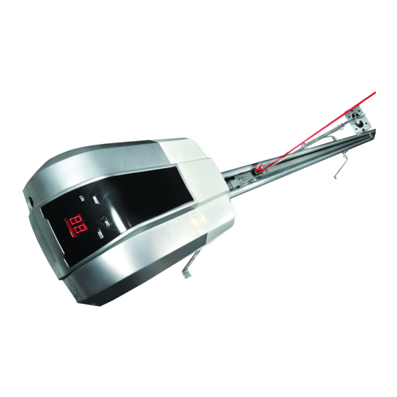
Электромеханический привод AN-Motors ASG600 используется для ворот площадью до 8.4 м2.
Электромеханический привод AN-Motors ASG600 используется для ворот площадью до 8.4 м2.
Поставляется в комплекте ASG600/3KIT-L
- Привод ASG600 со встроенным блоком управления и радиоприемником
- Направляющая металическая цепная рейка
- Пульты дистанционного управления AT-4 — 2шт
- Монтажный набор
- Руководство по монтажу и эксплуатации
Артикул: ASG600/3KIT-L

ПОДРОБНЕЕ
Полная инструкция по монтажу, подключению и настройке привода AN-Motors ASG600 во вкладке ИНСТРУКЦИИ.
В комплекте с приводом поставляются два пульта AT-4 (An-Motors), в память радиоприемника встроенного в плату управления приводом возможно записать до 20 пультов. Для записи дополнительных пультов используются кнопка CODE на корпусе привода.
Запись дополгительного пульта в память блока управления:
1. Нажмите кнопку «CODE» на 1-2 секунды индикация на экране — (режим ожидания)
2. После появления на индикаторе надписи Su нажмите на 1-2 секунды выбранную Вами кнопку на пульте радиоуправления AT-4
3. Повторно нажмите на 1-2 секунды ту же кнопку на пульте радиоуправления. На индикаторе кратковременно замигает надпись Su, после чего блок управления перейдет в режим ожидания —
4. При запоминании блоком управления 20 пультов на индикаторе появляется надпись Fu — память заполнена.
ВНИМАНИЕ
Если пульт утерян, во избежание несанкционированного проникновения в помещение, необходимо стереть все коды из памяти радиоприемника блока управления и заново запрограммировать все оставщиеся пульты.
Удаление пультов из памяти блока управления
1. Нажмите и удерживайте кнопку «CODE» в течение 8 секунд, до появления на индикаторе надписи dL, которая подтверждает удаление из памяти блока управления всех внесенных в него пультов (кодов)
2. Отпустите кнопку «CODE», после чего привод перейдет в режим ожидания —
ИНСТРУКЦИИ
- Инструкция ASG600
Полная инструкция по монтажу, подключению и настройке привода AN-Motors ASG600
Полная инструкция по монтажу, подключению и настройке привода AN-Motors ASG600 во вкладке ИНСТРУКЦИИ.
В комплекте с приводом поставляются два пульта AT-4 (An-Motors), в память радиоприемника встроенного в плату управления приводом возможно записать до 20 пультов. Для записи дополнительных пультов используются кнопка CODE на корпусе привода.
Запись дополгительного пульта в память блока управления:
1. Нажмите кнопку «CODE» на 1-2 секунды индикация на экране — (режим ожидания)
2. После появления на индикаторе надписи Su нажмите на 1-2 секунды выбранную Вами кнопку на пульте радиоуправления AT-4
3. Повторно нажмите на 1-2 секунды ту же кнопку на пульте радиоуправления. На индикаторе кратковременно замигает надпись Su, после чего блок управления перейдет в режим ожидания —
4. При запоминании блоком управления 20 пультов на индикаторе появляется надпись Fu — память заполнена.
ВНИМАНИЕ
Если пульт утерян, во избежание несанкционированного проникновения в помещение, необходимо стереть все коды из памяти радиоприемника блока управления и заново запрограммировать все оставщиеся пульты.
Удаление пультов из памяти блока управления
1. Нажмите и удерживайте кнопку «CODE» в течение 8 секунд, до появления на индикаторе надписи dL, которая подтверждает удаление из памяти блока управления всех внесенных в него пультов (кодов)
2. Отпустите кнопку «CODE», после чего привод перейдет в режим ожидания —
Купить пульты для привода An-Motors ASG600 ворот Алютех (Alutech)
-
Contents
-
Table of Contents
-
Bookmarks
Quick Links
РУКОВОДСТВО
Installation and operation manual
ПО МОНТАЖУ И ЭКСПЛУАТАЦИИ
Sets series ASG/KIT for automation of garage doors
ASG600/3KIT
ASG1000/3KIT
ASG1000/4KIT
Related Manuals for AN-Motors ASG600/3KIT

Summary of Contents for AN-Motors ASG600/3KIT
-
Page 1
РУКОВОДСТВО Installation and operation manual ПО МОНТАЖУ И ЭКСПЛУАТАЦИИ Sets series ASG/KIT for automation of garage doors ASG600/3KIT ASG1000/3KIT ASG1000/4KIT… -
Page 2: Table Of Contents
CONTENTS General information and safety measures………… …………………..PRODUCT DESCRIPTION……………………………………………………………. 2.1. Scope of supply ………………………………………………………………..…… 2.2. Technical characteristics ………………………………………………………….. Installation preparation ………………………………………………………… 3.1. Preliminary inspection ………………………………………………………. 3.2. Tools and materials for installation…….. …………………………………. 3.3. Preliminary works …………………………………………………………………… Installation ………………………………………………………………………………….. 4.1. Assembling of the drive rail…. ………………………………………………… 4.2.
-
Page 3: General Information And Safety Measures
1. GENERAL INFORMATION AND SAFETY MEASURES This manual contains important information about safety measures. Before the mount- ing it is necessary to make a careful study of the mentioned information. Keep this manual for further application! Installation, connection, final testing of the equipment, commissioning and technical support must be performed by qualified and trained specialists.
-
Page 4: Product Description
The set for garage doors automation (further — Set) includes the electric drive (further — Drive) with the drive rail and serves for automation of the balance system of garage doors. Set ASG600/3KIT and set ASG1000/3KIT contain the rail ASGR3. Set ASG1000/4KIT contains the rail ASGR4.
-
Page 5: Technical Characteristics
2.2. Technical characteristics The mentioned characteristics are stated for the environment with 20 ºС (±5 ºС). Table 2. Technical characteristics of the drive Value Parameter ASG600/3KIT ASG1000/3KIT ASG1000/4KIT Supply voltage, В 230 (±10%) Supply frequency, Hz Maximal driving force, Н…
-
Page 6: Installation Preparation
3. INSTALLATION PREPARATION 3.1. Preliminary inspection Before the installation of the set it is necessary to: Check all the elements and materials on the possibility of their application and correspondence to the current regulations. Make sure that door construction is suitable for automation. The set cannot be applied in doors with a wicket or pedestrian zone.
-
Page 7: Preliminary Works
3.3. Preliminary works Before the installation: Define the approximate position of every component in the drive system; Define the plan according to which the connection of all electrical devices in the drive system will be performed; Make sure there are all required tools and materials; Define the extremes of the wire and lay cables in the places for components installation;…
-
Page 8
35º… 55º 15º… 30º Pic. 2. Set installation… -
Page 9: Installation Of The Drive On The Rail
а б Pic. 3. Manual unblocking of the carriage In the process of unblocking there can be uncontrolled movement of doors: — if the door spring are loose or broken; — if the doors are not balanced; — if the doors are opened manually the carriage can collide with the drive (during build- ing works limit the doors run in the opening direction);…
-
Page 10: Connection Of Carriage And Door Curtain
Position the fixing bracket of the rail 12 (view F, Pic. 2) and the bent fixing strip 22 (de- scribed above) on the rail at a place ensuring the highest rigidity of the rail (for example, at a distance 1/3 of the rail length from the door passage). Connect the fixing bracket of the rail and the fixing strip using two bolts 14 and two nuts 18.
-
Page 11: Photo Cells Installation
+24V PE GND PB фотоэлементы Photo cells кнопка Control button управления аккумулятор Accumulator Pic. 4. Electric supply system 5.1. Photo cells installation To ensure the security the drive may have photo cells. Output circuit of the receiver (RX) must be connected with the terminals «PE» and «GND». Power circuit of the receiver (RX) and transmitter (TX) of photo cells are connected with the terminals «+24V»…
-
Page 12: Drive Connection To The Electric Network
5.5. Drive connection to the electric network During the first connection of the drive to the electric network: Make sure that the rail carriage is blocked. Connect the plug of the drive feeding cable with the outlet of supply network. Immediately after connection of the plug and the outlet there will be a short light from the lamp (lightening), the indicator on the drive control panel (Pic.
-
Page 13: Adjustment Of Working Modes
Table 5. Adjustment of final positions of door opening/closing Action Indicator Press and hold button «SET» for 5 seconds When you see the indicator «Р1» release the button and press once again «SET» without holding it When you see the indicator «ОР» using buttons «UP» and «DOWN» move the door leaf to the final opening position.
-
Page 14: Programming Of Control Boards
Press and hold button «SET» for 5 seconds When you see the indicator «Р1» release button «SET» Using buttons «UP» and «DOWN» choose the mode «РЗ», after than press button «SET» Using buttons «UP» and «DOWN» choose «HI» (photo elements are ac- tive), or «НО»…
-
Page 15: Testing And Commissioning
А — Control buttons В – electronic blocking buttons С – LED Pic. 6. Radio control board Таблица 7. Запоминание и стирание пультов радиоуправления Action Indicator A) Board entering in the memory of the control unit Press button «CODE» When you see the indicator «Su» press 1…2с chosen button on the con- sole (one of the buttons А, pic.
-
Page 16: Commissioning
Repeat the cycle “opening-closing”. Make sure that the doors move in the required direc- tion, door curtain must move evenly without any changes of speed. The movement must slow down at approximately 200mm height from the final position. Make sure that the illuminating lamp is “lit” when the drive works and “goes out” after 3 minutes after final shut-off.
-
Page 17: Defects And Recommendations On Their Elimination
The drive is designed for operation in dry premises and cannot be applied in acid, salty and highly explosive environment. The drive system must be examined by service maintenance specialists regularly to ensure ef- fective and safe operation. Planned maintenance must be carried out in accordance with the current regulations stated in the present manual observing safety measures.
-
Page 18: Storage, Transporting And Utilization
Table 8. Defects and recommendations on their elimination Defect Possible reason Recommendations Drive does not work (indica- Electric supply is cut off Check the voltage in the net. tor on the control board does or safety device is fused Check and replace if necessary not show anything) the safety device (safety device parameters must correspond to…
-
Page 19
Certificate data Manufacturer _____________________________________ Product class _____________________________________ Factory number _____________________________________ Information about the client (customer) ___________________________________________ ___________________________________________________________________________ ___________________________________________________________________________ name, address and telephone of the client (customer) Information about the supplier (mounting company) ________________________________ ___________________________________________________________________________ ___________________________________________________________________________ name, address and telephone of the supplier (mounting company) Mounting questionnaire Customer (address) _________________________________________________________ ___________________________________________________________________________… -
Page 20
Registration of technical maintenance Date Works completed Customer Supplier Certificate on mounting and adjustment The set is installed and adjusted according to the stated regulations and is ready for commis- sioning. _______________________________ Date of mounting date, month, year Signature of person responsible for mounting _______________________________ signature _______________________________… -
Page 21
Guarantee 1. The seller guarantees functionality of the product in case all the instructions and regula- tions on its usage and installation by the Organization authorized by the Seller are observed. 2. Warranty period is ___________________ and is calculated from ___________________________________________________________________________. -
Page 22
Notes… -
Page 23
Notes…
- Home
- Инструкции
- Автоматика для ворот
- AN MOTORS
- ASG600/3KIT

| AN MOTORS ASG600/3KIT инструкция | |
|---|---|
| Тип инструкции: | Руководство по установке и использованию |
| Категория: | Автоматика для ворот AN MOTORS |
| Язык: | Русский |
| Размер: | 1.2 Mb |
| Формат файла: | |
| Дата добавления: | 26.05.2013 |
Похожие записи
AN MOTORS AH90 — Инструкция по монтажу
Автоматика для ворот
AN MOTORS APHOTO — Инструкция по эксплуатации и монтажу
Автоматика для ворот
AN MOTORS AR-1 — Инструкция по эксплуатации и монтажу
Автоматика для ворот
AN MOTORS ASG1000/3KIT — Инструкция по эксплуатации и монтажу
Автоматика для ворот
AN MOTORS ASI40 — Инструкция по эксплуатации и монтажу
Автоматика для ворот
AN MOTORS ASI50 — Инструкция по эксплуатации и монтажу
Автоматика для ворот
AN MOTORS ASL2000 — Инструкция по эксплуатации и монтажу
Автоматика для ворот
AN MOTORS ASW2500/KIT — Инструкция по эксплуатации и монтажу
Автоматика для ворот
AN MOTORS AT-4 — Инструкция по эксплуатации и монтажу
Автоматика для ворот
Отзывы по оборудованию и комментарии к материалу
Кто вы? человек робот
File Specifications:1037/1037249-asg6003kit.pdf file (07 Aug 2023) |
Accompanying Data:
AN-Motors ASG600/3KIT Garage Door Opener PDF Installation And Operation Manual (Updated: Monday 7th of August 2023 01:42:58 AM)
Rating: 4.6 (rated by 17 users)
Compatible devices: 139.53785, 1265, Deimos, twist AM, jet, MT60, ASG/KIT Series, 53479.
Recommended Documentation:
Installation And Operation Manual (Text Version):
(Ocr-Read Summary of Contents of some pages of the AN-Motors ASG600/3KIT Document (Main Content), UPD: 07 August 2023)
-
5, 5 2.2. Technical characteristics The mentioned characteristics are stated for the environment with 20 ºС (±5 ºС). Table 2. Technical characteristics of the drive Parameter Value ASG600/3KIT ASG1000/3KIT ASG1000/4KIT Supply voltage, В 230 (±10%) Supply frequency, Hz 50 Maximal driving force, Н 600 1000 Force exerted rating, Н 300 400 Speed at force exerted rating, m/c 0,08 0,06 Speed of idle movement (less than), m/c 0,14 0,15 Power co…
-
18, 18 Table 8. Defects and recommendations on their elimination Defect Possible reason Recommendations Drive does not work (indica- tor on the control board does not show anything) Electric supply is cut off or safety device is fused Check the voltage in the net. Check and replace if necessary the safety device (safety device parameters must correspond to …
-
8, A B C D F G F D G C A B 4 15 5 21 4 1 9 17 8 13 18 22 10 14 15º… 30º 22 12 16 11 20 19 6 7 35º… 55º 17 Pic. 2. Set installation
… -
15, 15 A B C А — Control buttons В – electronic blocking buttons С – LED Pic. 6. Radio control board Таблица 7. Запоминание и стирание пультов радиоуправления Action Indicator A) Board entering in the memory of the control unit — 1 Press button «CODE» 2 When you see the indicator «Su» press 1…2с chosen button on the con- sole (one of the buttons А, pic. 6) 3 Pres once again 1…2с…
-
3, AN-Motors ASG600/3KIT 3 1. GENERAL INFORMATION AND SAFETY MEASURES ! This manual contains important information about safety measures. Before the mount- ing it is necessary to make a careful study of the mentioned information. Keep this manual for further application! ! Installation, connection, final testing of the equipment, commissioning and technical support must be performed by qualified and trained specialists. ! Observe safety measures regulate…
-
7, 7 3.3. Preliminary works Before the installation: Define the approximate position of every component in the drive system; Define the plan according to which the connection of all electrical devices in the drive system will be performed; Make sure there are all required tools and materials; Define the extremes of the wire and lay cables in the places for components installation; Remove all unnecessar…
-
20, 20 Registration of technical maintenance Date Works completed Customer Supplier Certificate on mounting and adjustment The set is installed and…
-
13, 13 Table 5. Adjustment of final positions of door opening/closing Action Indicator 1 Press and hold button «SET» for 5 seconds 2 When you see the indicator «Р1» release the button and press once again «SET» without holding it 3 When you see the indicator «ОР» using buttons «UP» and «DOWN» move the door leaf to the final opening position. Then press the button «SET» 4 When you see the indicator «C…
-
4, 4 2. PRODUCT DESCRIPTION The set for garage doors automation (further — Set) includes the electric drive (further — Drive) with the drive rail and serves for automation of the balance system of garage doors. Set ASG600/3KIT and set ASG1000/3KIT contain the rail ASGR3. Set ASG1000/4KIT contains the rail ASGR4. The drive has an electric motor with a self-blocking reduction gear, electric control unit with the inbuilt radio receiver and lighting (ill…
-
17, 17 ! The drive is designed for operation in dry premises and cannot be applied in acid, salty and highly explosive environment. The drive system must be examined by service maintenance specialists regularly to ensure ef- fective and safe operation. Planned maintenance must be carried out in accordance with the current regulations stated in the present manual observing safety measures. Planned mainte- nance must be c…
-
10, AN-Motors ASG600/3KIT 10 Position the fixing bracket of the rail 12 (view F, Pic. 2) and the bent fixing strip 22 (de- scribed above) on the rail at a place ensuring the highest rigidity of the rail (for example, at a distance 1/3 of the rail length from the door passage). Connect the fixing bracket of the rail and the fixing strip using two bolts 14 and two nuts 18. Using the ladder lift the rail with the drive so that the bent strips are pressed to the c…
-
9, AN-Motors ASG600/3KIT а б Pic. 3. Manual unblocking of the carriage ! In the process of unblocking there can be uncontrolled movement of doors: — if the door spring are loose or broken; — if the doors are not balanced; — if the doors are opened manually the carriage can collide with the drive (during build- ing works limit the doors run in the opening direction); — in the unblocked position doors can be moved only with medium speed! 4.2. Installation of the drive on the rail To install t…
-
12, 12 5.5. Drive connection to the electric network During the first connection of the drive to the electric network: Make sure that the rail carriage is blocked. Connect the plug of the drive feeding cable with the outlet of supply network. Immediately after connection of the plug and the outlet there will be a short light from the lamp (lightening), the indicator on the drive control panel (Pic. 5) will show the numbers from «99» to «11». Then the drive …
-
16, 16 Repeat the cycle “opening-closing”. Make sure that the doors move in the required direc- tion, door curtain must move evenly without any changes of speed. The movement must slow down at approximately 200mm height from the final position. Make sure that the illuminating lamp is “lit” when the drive works and “goes out” after 3 minutes after final shut-off. Check the photo cells (if there a…
-
AN-Motors ASG600/3KIT User Manual
-
AN-Motors ASG600/3KIT User Guide
-
AN-Motors ASG600/3KIT PDF Manual
-
AN-Motors ASG600/3KIT Owner’s Manuals
Recommended: JES1133, DM400c series, MLB-25P, TASKalfa 181
Links & Tools
Product Types by AN-Motors:
- Garage Door Opener
Operating Impressions, Questions and Answers: