In today’s digital age, efficient document management is essential for individuals and organizations. PDF, or Portable Document Format, has become popular for splitting and storing digital documents across platforms. PDFs have many advantages, but they can be challenging to manage effectively.
PDF is an open standard backed by the International Organization for Standardization (ISO), an international group that establishes standards in various fields such as technology, manufacturing, security, and healthcare.
The PDF format can contain links, buttons, audio files, video files, form fields, and other interactive features. This article explains the concept of PDF Smart and explains the overall features of the same.
Contents
PDF Smart: PDF Language
PDF Language is revolutionizing how we interact with digital documents by breaking down language barriers. With its innovative features, PDF Language enables real-time translation of PDF files, making information accessible to a global audience. Say goodbye to language limitations and embrace a new era of inclusive document communication.
PDF uses a page description language called PostScript to interpret text and images. The type of object PostScript used to stock text and images allows PDF to be rendered effectively in any browser, software, or operating system.
Smart PDF Tools make creating PDF excerpts from other file formats easy. With smart PDF tools, you can easily split an original PDF into distinct page ranges, split each record page into a new PDF file, split odd or even pages, etc.
Understanding PDFSmart

PDFSmart is a powerful software tool designed to simplify and enhance the way we work with PDF documents. PDF Smart refers to feature-rich technology combining PDF flexibility and intelligent automation to make document management more efficient and user-friendly. Leverage advanced features such as OCR technology, optimized document creation, and cloud storage integration to improve how you create, share, and access PDF documents.
With its intuitive interface and extensive features, PDFSmart allows users to manage, edit, and convert PDF files efficiently. Whether you need to merge multiple PDFs into one, extract specific pages, or convert PDFs to editable formats like Word or Excel, PDFSmart has got you covered. With PDFSmart, understanding and manipulating PDFs has never been easier, making it an indispensable tool for professionals and individuals.
OCR Technology
Optical Character Recognition, or OCR, is a computer vision technology that admits characters in image format and converts them to text files. OCR is a pattern of process automation technology, where the automatic rendition of scanned images replaces manual tasks such as transcription and data entry.
Early uses of OCR included data entry for clippings such as passports, bills, and bank statements. Recent versions incorporate AI, machine learning, and advanced pattern recognition. This feature saves time and reduces the risk of human error when processing large amounts of data.
Controlling PDF Documents
Controlling PDF documents with PDFSmart provides users with comprehensive tools to manage and edit PDF files efficiently. This powerful software offers various features that give users control over PDF documents.
One of PDFSmart’s main features is its ability to combine multiple PDFs into one file. This is especially useful when dealing with scattered or fragmented information.
Users can easily connect documents, rearrange pages, and create consistent PDFs that meet their needs. PDFSmart also allows accurate page extraction, allowing users to select specific pages from a PDF file and save them as separate files. This feature is useful when sharing or working with only certain document parts.
Moreover, PDFSmart offers efficient PDF conversion options. Users can convert PDF to various formats like Word, Excel, PowerPoint, etc. This makes it easy to edit the content of PDF files, extract data for analysis, or create dynamic presentations.
Insertion Stamps Within Document

PDFSmart is a versatile software tool that goes beyond essential PDF management and offers a variety of advanced features. One of those features is the ability to add stamps to documents, which gives users additional functionality and customization options.
Stamps can be used for many purposes. Add watermarks, view document status, or label documents with specific labels. With PDFSmart, users can easily add stamps to PDF files with just a few clicks.
The software offers a variety of ready-made stamps, from simple symbols to more elaborate designs. Additionally, users can create custom stamps and incorporate company logos, signatures, and other personalized elements.
PDFSmart’s stamping process is seamless and intuitive. Users can select the stamp they need, adjust its size and position, and place it precisely on the document. This feature allows important information to be displayed prominently and easily recognized. PDFSmart improves PDF files’ visual presentation and composition by adding stamps to documents.
Addition of Attachments
PDFSmart is revolutionizing the way you work with documents by providing a comprehensive solution for seamless attachment integration. With its user-friendly interface and advanced features, PDFSmart makes adding attachments to PDF files easy for better document management and collaboration.
Eliminate the tedious process of combining multiple files into one document. PDFSmart lets you add attachments directly to PDFs, eliminating the need for separate folders and email attachments, simplifying the task.
Whether it’s images, spreadsheets, or other supporting documents, PDFSmart seamlessly integrates them into your PDF, creating a unified file that’s easy to navigate. Combining PDFSmart attachments has many advantages. This improves organization and accessibility and makes it easy to save all related files to PDF.
PDFSmart sets a new standard in document management by providing a powerful and intuitive platform for adding attachments to PDFs. Say goodbye to disjointed files and adopt a streamlined approach with PDFSmart.
PDF Tool: Bottom Line
PDF smart has transformed document management by linking the convenience of PDF with intelligent automation. The tool facilitates document creation, cloud storage integration, etc. PDF Smart is an intelligent choice for anyone looking for a more adept and effective way to conduct their digital documents.
PDFSmart is a game-changer in document management, offering seamless attachment integration for PDF files. Its user-friendly interface and advanced features simplify adding attachments, enhancing organization, accessibility, and collaboration. With PDFSmart, document management becomes efficient and hassle-free.
Содержание
- Using the Smart PDF Wizard
- Wizard Navigation
- Choose Export Target
- Choose Project Files
- Export Bill of Materials
- PCB Printout Settings
- Printouts & Layers Grid
- Right-click Menu
- Designator Print Settings
- Area to Print
- Additional Controls
- Printouts & Layers Grid
- Additional PDF Settings
- Configure Structure Settings
- Final Steps
- Additional Information
- The OutputJob Editor
- Paper Sizes for Generated PDF
- System Printer Settings
- INDICATION OF UNSUPPORTED PAPER SIZE IN TARGET
- Browsing the Generated PDF
- Component Parameters in PDF Output
- Tips
Полное содержание
The Smart PDF Wizard generates a single PDF for either a selected document(s) or the entire project, including schematics, PCB, and Bill Of Materials. PDF bookmarks are created for each net and component in the design. You can save the Smart
PDF settings to an OutJob file so your PDF can be regenerated with a single click.
Using the Smart PDF Wizard
The Smart PDF Wizard is launched by selecting File » Smart PDF from the main menus.

Follow the pages of the Smart PDF Wizard to output the design in PDF format.
Wizard Navigation
- Click Cancel to close the Smart PDF Wizard.
- Click Back to navigate to the previous screen.
- Click Next to navigate to the next screen.
- Click Finish anywhere in the wizard to create a PDF with your previously entered settings.
All settings are remembered except for Output File Name.
Choose Export Target

The Choose Export Target page allows you to specify what is to be exported and where it will be saved. Choose to export either the Current Project or Current Document. Both selections list the name
of the current project and current document.
If you choose to export the current project, you will be presented with further options for selecting documents on the next page of the wizard.
Use the Output File Name text box to specify the name of the PDF and where it will be saved. Click the browse button to open a dialog in which you can choose the desired path.
Choose Project Files

If you chose Current Document on the previous page (Choose Export Target), this page is not displayed.
If you chose Current Project on the previous page (Choose Export Target), the Choose Project Files page will appear and allows you to further define which documents are to be included in your PDF.
Select the files required using standard multi-select features (Ctrl+click, Shift+click). You also can use the selection options available from the right-click menu: Select All to
select all listed documents, Select All PCB to select all listed PCB documents, and Select All Schematic to select all schematic documents.
Export Bill of Materials

On the Export Bill of Materials page, enable the Export a Bill of Materials option to export a BOM with the PDF.
Use the Variant drop-down menu to select an assembly variant and template, if required.
Use the Template drop-down menu to select the desired template or click ![]() to open a standard dialog
to open a standard dialog
in which you can choose the desired template. Enable the Relative Path to Template File checkbox to show the relative path of the selected template.
PCB Printout Settings
If no PCB documents were selected for export on the Choose Export Target page, this page is not displayed.

If you chose to export PCB documents on the Choose Project Files page, the PCB Printout Settings page will appear in which you can configure the printout.
This page consists of three main regions (described in detail below):
- Printouts & Layers Grid — configure the printout for each layer.
- Designator Print Settings — configure the component designator data to print.
- Area to Print — specify the area to print.
Printouts & Layers Grid
Enable the desired Include Components and Printout Options checkboxes for the Multilayer Composite Print.
Right-click Menu
Use the right-click menu to further configure the printout for each layer. Right-click menu options include:
- Create Final — use to create a complete final artwork set. A dialog will appear asking for confirmation before proceeding.
Selecting this option will remove all the current print settings.
- Create Composite — use to create a multi-layer composite print set. A dialog will appear asking for confirmation before proceeding.
Selecting this option will remove all the current print settings.
- Create Power-Plane Set — use to create a power-plane drawing set. A dialog will appear asking for confirmation before proceeding.
Selecting this option will remove all the current print settings.
- Create Mask Set — use to create paste/solder mask drawings. A dialog will appear asking for confirmation before proceeding.
Selecting this option will remove all the current print settings.
- Create Drill Drawings — use to create a set of drill drawings and guides. A dialog will appear asking for confirmation before proceeding.
Selecting this option will remove all the current print settings.
- Create Assembly Drawings — use to create assembly drawings. A dialog will appear asking for confirmation before proceeding.
Selecting this option will remove all the current print settings.
- Create Composite Drill Guide — use to create a composite drill drawing. A dialog will appear asking for confirmation before proceeding.
Selecting this option will remove all the current print settings.
- Insert Printout — use to insert a new printout at the top of the list. The name of new printouts are numbered sequentially in the form New Printout x, where x equals 1, 2, 3, etc. To rename new printouts, click in the Name field and enter the desired new name.
- Insert Printout Set — use to insert a new Printout Set for Class All Layers.
- Insert Drill Printout Set — use to insert a new Drill Guide Printout Set.
- Insert Layer — use to insert a new layer. The Layer Properties dialog opens in which you can configure the new layer.
- Insert Layer Class — use to insert a new layer class. The Layer Class Properties dialog opens in which you can configure the new layer.
- Move Up — move the selected layer one position up in the list.
- Move Down — move the selected layer one position down in the list.
- Delete — delete the selected layer.
- Properties — use to open the Layer Properties dialog in which you can edit the layer properties of the selected layer .
- Preferences — use to open the PCB Print Preferences dialog in which you can edit print preferences.
Designator Print Settings
Use the drop-down to select which component designator data to print. Choices include:
- Print Physical Designators
- Print Logical Designators
Area to Print
- Entire Sheet — select to print the entire sheet.
- Specific Area — select to print specific areas. Use the available controls to configure the area then use Define to set the print area.
Additional Controls
- Preferences — click to open the PCB Print Preferences dialog in which you can configure print preferences.
Additional PDF Settings

The Additional PDF Settings page provides several additional export options:
- Zoom — use the slider bar to control the zoom level used in the PDF when browsing components and nets.
- Additional Information — allows you to control whether or not net information is generated in the PDF. If this option is enabled, you can select whether or not to generate additional bookmarks in the PDF for nets for Pins,
Net Labels, and Ports. - Include Component Parameters — enable to include parameters for components. Refer to the Component Parameters in PDF Output section below for more information regarding the use of this option.
- Exclusions — click to open the Exclude Parameters dialog in which you can choose specific parameters to be excluded from the generated PDF.
- Global Bookmarks for Components and Nets — enable to use global bookmarks for components and nets. The resulting global bookmarks can be found beneath the list of schematic sheets included in the generated PDF.
Global Bookmarks for nets will only be generated if the Generate nets information option is also enabled.
- Schematics include — use the checkboxes to include (checked) or not include (unchecked) the following in the PDF:
- No ERC Markers — controls whether No ERC directive markers get included when exporting schematic sheets. When checked, the following options are available:
- Thin Cross
- Thick Cross
- Small Cross
- Checkbox
- Triangle
- Parameter Sets — controls whether parameter set objects are included when exporting schematic sheets.
- Probes — controls whether probe objects are included when exporting schematic sheets.
- Blankets — controls whether blankets are included when exporting schematic sheets.
- Notes — controls whether notes are included when exporting schematic sheets.
- Collapsed notes — controls whether notes are included when exporting schematic sheets.
- No ERC Markers — controls whether No ERC directive markers get included when exporting schematic sheets. When checked, the following options are available:
- Schematics Color Mode — allows you to specify the coloring used when exporting schematic sheets. Choose from either Color, Greyscale, or Monochrome. This option
is only accessible when exporting schematic documents. - PCB Color Mode — allows you to specify the coloring used when exporting PCB printouts. Choose from Color, Greyscale, or Monochrome. This option is only accessible when exporting
PCB documents. - Quality — use the drop-down to select the desired quality of the PDF printout. Choices include:
- High (600 dpi)
- Medium (300 dpi)
- Low (150 dpi)
- Draft (75 dpi)
This option also is available in the applicable Print Properties dialog with a PDF Output Container being the target medium.
Configure Structure Settings

The Structure Settings page is used to configure the structure of the PDF.
If Use Physical Structure is checked, the exported schematic sheets will be expanded to physical sheets rather than logical sheets. If the option is not checked, further options are not available.
Use the Variant drop-down to select which variant to use, if desired.
Enable the following checkboxes if you want to display the expanded physical names of:
- Designators
- Net Labels
- Ports and Sheet Entries
- Sheet Number Parameter
- Document Number Parameter
Final Steps

The Final Steps page presents some additional configuration options before generating the PDF.
- Open PDF file after export — enable to open the generated PDF after the export is complete.
- Save Settings to Output Job document — enable to save your settings to an output job document. By enabling this option, you can publish the same job with the same settings repeatedly without using the Smart PDF
Wizard. - File Name of Output Job Document — specify the file name of the output job document including the file path. You can choose to overwrite an existing Output Job document or create a new one.
- Open Output Job file after export — enable to open the output Job file after the PDF has exported.
Additional Information
The OutputJob Editor
Your Smart PDF settings can be saved to an Output Job document. Modify this document in the OutputJob Editor, which becomes active when the active document is an *.OutJob file.

Paper Sizes for Generated PDF
The paper sizes used by the PDF Generator are not ‘acquired’ from your computer’s current Windows Default Printer. The sizes available for PDF generation are fixed and independent of those offered by the default printer, and remain independent regardless
of the type of printer chosen as the default. In other words, selecting an A3 paper size when generating a PDF through an Output Job file will remain at that size, even if you switch your default printer to the small A4 Inkjet down the hall. The following
fixed set of paper sizes are available for use by the PDF Printer:
- A0
- A1
- A2
- A3
- A4
- A5
- A6
- A
- B
- C
- D
- E
- Legal
- Letter
- Tabloid
System Printer Settings
You can also define custom page sizing with respect to output generated in PDF format. Custom page sizing is defined on the System — Printer Settings page of the Preferences dialog. The drop-down menu
associated with the Add button on the Preferences dialog presents a variety of predefined custom sizes:
- ARCH A
- ARCH B
- ARCH C
- ARCH D
- ARCH E
- ARCH E1
- C5 Envelope (162 x 229 mm)
- DL Envelope (110 x 220 mm)
- Folio (8.5 x 13 in)
- JIS B1
- JIS B2
- JIS B3
- JIS B4
- JIS B5
- Ledger (17 x 11 in)
- Monarch Envelope (3.87 x 7.5 in)
- No.10 Envelope (4.125 x 9.5 in)
- Note (7.5 x 10 in)
- Statement (5.5 x 8.5 in)
Choose an entry to have that size added to the list. If you need a different sizing, simply add a predefined sizing, select its entry in the list then click the Edit Page button. A dialog will appear from where you
can specify:
- A Title for the custom page sizing — something meaningful, perhaps containing the width and height (and units!) for easy reference.
- The page Width and Height.
- Units of measurement (mm or in).
The defined custom page sizes will be presented on the Size field menu when configuring page properties prior to exporting to PDF.
INDICATION OF UNSUPPORTED PAPER SIZE IN TARGET
When the target for an applicable output generator is changed from a PDF Output Container to a physical printer (Hard Copy), it is quite possible that the paper size defined for the generator — through the relevant properties dialog (right-click,
Page Setup) — may not be supported by the target medium. In this case, the connecting line from generator to medium is colored red.
You will be prevented from generating content (PDF Output Container) or previewing/printing (Hard Copy) in this state. You can either change the paper size for the output generator (and thus return the connecting line to a green state) before
the applicable output can be successfully generated, or simply change the target medium to one that does support your chosen paper size.
When a paper size mismatch exists and you opt to change the paper size for the configured output generator, using the Page Setup command for the generator will bring up an information dialog. This alerts you to the issue and
notifies you that the paper sizing has been restored to its default. What this means is that the paper size drop-down in the configuration dialog is refreshed with the standard set of supported paper sizes (PDF Output Container) or the set of
paper sizes supported by the target printer (Hard Copy).
Browsing the Generated PDF
The generated PDF groups documents according to their type: Schematic, PCB and BOM. For each schematic, bookmarks are provided based on your settings, which enables you to browse documents as well as individual components and nets residing on that document.
If the source schematics are hierarchical, the hierarchy will be reflected in the PDF bookmarks with the top-level sheet appearing at one level and all sub-sheets appearing as sub-bookmarks. If you have enabled the option to Use Physical Structure as part of the export process, the resulting PDF document will contain separate sheets for each channel in a multi-channel design.
For a PCB document, bookmarks are provided for each of the exported printouts.
For the Bill of Materials, bookmarks are provided so you can browse to each component.
If you enabled additional bookmarks on the Additional PDF Settings page of the Wizard to generate net information for Pins, Net Labels, and Ports, you will see these when browsing a schematic or a PCB (pins only).
Clicking on a bookmark will zoom to the area of the document where that object resides. The level of zoom applied is determined by the zoom control slider bar setting on the Additional PDF Settings page. Where possible, the object will
be centered within the main display window of the PDF Viewer. Highlighting will be applied when browsing by Components, Pins, Ports, or Net Labels for ease of reference.
If you did not enable the option to generate net information, only component information will be available in the generated PDF.
Component Parameters in PDF Output
Altium NEXUS includes component parameters in generated PDF output. Once generated, you can click on a component on a sheet in your PDF and peruse its parameters in a convenient pop-up. If you do not want to allow component parameters to be viewed
in this way, disable (uncheck) the Include Component Parameters option in the Additional Information region of the Additional PDF Settings page.
This feature works regardless if generating a PDF of a single schematic sheet or of the entire project.
If a component contains a parameter whose value is a URL to a web page in the format http://<siteaddress>, that entry will be a live link in the parameter pop-up. You can click it to follow the link and access the URL in your external
Web browser.
Inclusion of the «http://" prefix is required. Shortened forms of URL are not supported, such as www.altium.com, or live.altium.com.
Tips
- Only schematic, PCB, and BOM documents may be exported in PDF format using the Smart PDF Wizard.
- The settings for the outputs can be re-configured from the generated OutJob document. For example, the BOM can be re-configured to use a different template and re-published with the Publish to PDF command.
- Export options defined within the Smart PDF Wizard are stored with the design project.

Введение к руководству на английском языке по устройству, техническому обслуживанию и ремонту автомобилей Smart Fortwo Coupe и Smart Forfour 453-й серии.
- Автор: —
- Издательство: Daimler AG
- Год издания: 2014
- Страниц: 122
- Формат: PDF
- Размер: 7,2 Mb
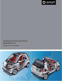
Введение к руководству на английском языке по устройству, техническому обслуживанию и ремонту автомобиля Smart Fortwo 451-й серии.
- Автор: —
- Издательство: Smart USA
- Год издания: 2007
- Страниц: 122
- Формат: PDF
- Размер: 11,6 Mb

Руководство по эксплуатации и ремонту автомобилей Smart ForTwo и Smart City-Coupe с 1998 года выпуска с бензиновыми и дизельными двигателями.
- Автор: —
- Издательство: Гуси-Лебеди
- Год издания: —
- Страниц: 252
- Формат: —
- Размер: —
Содержание статьи
- 1 Лучшая программа конвертирования PDF в текст — Smart PDF Converter Pro (pdf doc converter)
- 2 Возможности smart pdf converter pro (pdf doc converter)
- 3 Загрузить бесплатно smart pdf converter (pdf doc converter)
Всем привет! Продолжаем тему офисных программ и работу с файлами PDF. Наверняка Вы сталкивались с тем, что необходимо получить текст из файла PDF… Сегодня мы рассмотрим и загрузим программку, которая великолепно справляется с этой задачей, конвертирует русский текст в txt, html, doc с картинками и без.
Лучшая программа конвертирования PDF в текст — Smart PDF Converter Pro (pdf doc converter)

Smart PDF Converter Pro – это простая в использовании и очень полезная программа. Данная программа позволит вам преобразовывать ваши PDF файлы в несколько форматов: HTML, DOC, RTF, XLS, JPEG, TIFF, и TXT. Вы можете конвертировать ваши PDF в отдельные веб страницы или добавлять кнопки к вашим HTML, так что вы можете прокручивать страницы с одной на другую, одним щелчком мыши. Вы можете конвертировать с легкостью редактируемый .doc файл или использовать точный метод, если вам требуется точный слой файла. Вы можете конвертировать отдельный файл или различные таблицы Excel файла.
Smart PDF Converter Pro может конвертировать в JPEG и TIFF, для которых вы можете установить различное разрешение и качество. Smart PDF Converter Pro представлен уникальным, но простым интерфейсом, все, что вам нужно сделать – это добавить ваш PDF файл в программу, установить выводной формат, выводную папку и нажать на кнопку конвертирования.
Возможности smart pdf converter pro (pdf doc converter)
• Конвертировать PDF в DOC (редактируемые документы Word).
• Конвертировать PDF в HTML, TXT, XLS, JPEG, RTF, TIFF и другие форматы файлов.
• Сохранить первоначальный макет, формат, и гиперссылки
• Преобразовывать отредактированные документы обратно в формат PDF.
• Возможность разделять многостраничные PDF или склеивать несколько документов в один.
• Возможность зашифровать и защитить паролем.
Загрузить бесплатно smart pdf converter (pdf doc converter)
Простая инструкция если у кото-то что-то не заработает в smart pdf converter pro:
- Закиньте вашу PDF-ку, скажем в корень диска C:
- Переименуйте вашу PDF-ку, скажем, в «example.pdf» (без кавычек)
- Создайте на том же диске C: папку «DONE».
- Теперь конвертите ваш C:\example.pdf в конечную папку C:\DONE
The Smart PDF Wizard generates a single PDF for either a selected document(s) or the entire project, including schematics, PCB, and Bill Of Materials. PDF bookmarks are created for each net and component in the design. You can save the Smart PDF settings to an OutJob file so your PDF can be regenerated with a single click.
Using the Smart PDF Wizard
The Smart PDF Wizard is launched by selecting File » Smart PDF from the main menus.

Follow the pages of the Smart PDF Wizard to output the design in PDF format.
Wizard Navigation
- Click Cancel to close the Smart PDF Wizard.
- Click Back to navigate to the previous screen.
- Click Next to navigate to the next screen.
- Click Finish anywhere in the wizard to create a PDF with your previously entered settings.
All settings are remembered except for Output File Name.
Choose Export Target

The Choose Export Target page allows you to specify what is to be exported and where it will be saved. Choose to export either the Current Project or Current Document. Both selections list the name of the current project and current document.
If you choose to export the current project, you will be presented with further options for selecting documents on the next page of the wizard.
Use the Output File Name text box to specify the name of the PDF and where it will be saved. Click the browse button to open a dialog in which you can choose the desired path.
Choose Project Files

If you chose Current Document on the previous page (Choose Export Target), this page is not displayed.
If you chose Current Project on the previous page (Choose Export Target), the Choose Project Files page will appear and allows you to further define which documents are to be included in your PDF. Select the files required using standard multi-select features (Ctrl+click, Shift+click). You also can use the selection options available from the right-click menu: Select All to select all listed documents, Select All PCB to select all listed PCB documents, and Select All Schematic to select all schematic documents.
Export Bill of Materials

On the Export Bill of Materials page, enable the Export a Bill of Materials option to export a BOM with the PDF.
Use the Variant drop-down menu to select an assembly variant and template, if required.
Use the Template drop-down menu to select the desired template or click ![]() to open a standard dialog in which you can choose the desired template. Enable the Relative Path to Template File checkbox to show the relative path of the selected template.
to open a standard dialog in which you can choose the desired template. Enable the Relative Path to Template File checkbox to show the relative path of the selected template.
PCB Printout Settings
If no PCB documents were selected for export on the Choose Export Target page, this page is not displayed.

If you chose to export PCB documents on the Choose Project Files page, the PCB Printout Settings page will appear in which you can configure the printout.
This page consists of three main regions (described in detail below):
- Printouts & Layers Grid — configure the printout for each layer.
- Designator Print Settings — configure the component designator data to print.
- Area to Print — specify the area to print.
Printouts & Layers Grid
Enable the desired Include Components and Printout Options checkboxes for the Multilayer Composite Print.
Right-click Menu
Use the right-click menu to further configure the printout for each layer. Right-click menu options include:
- Create Final — use to create a complete final artwork set. A dialog will appear asking for confirmation before proceeding.
Selecting this option will remove all the current print settings.
- Create Composite — use to create a multi-layer composite print set. A dialog will appear asking for confirmation before proceeding.
Selecting this option will remove all the current print settings.
- Create Power-Plane Set — use to create a power-plane drawing set. A dialog will appear asking for confirmation before proceeding.
Selecting this option will remove all the current print settings.
- Create Mask Set — use to create paste/solder mask drawings. A dialog will appear asking for confirmation before proceeding.
Selecting this option will remove all the current print settings.
- Create Drill Drawings — use to create a set of drill drawings and guides. A dialog will appear asking for confirmation before proceeding.
Selecting this option will remove all the current print settings.
- Create Assembly Drawings — use to create assembly drawings. A dialog will appear asking for confirmation before proceeding.
Selecting this option will remove all the current print settings.
- Create Composite Drill Guide — use to create a composite drill drawing. A dialog will appear asking for confirmation before proceeding.
Selecting this option will remove all the current print settings.
- Insert Printout — use to insert a new printout at the top of the list. The name of new printouts are numbered sequentially in the form New Printout x, where x equals 1, 2, 3, etc. To rename new printouts, click in the Name field and enter the desired new name.
- Insert Printout Set — use to insert a new Printout Set for Class All Layers.
- Insert Drill Printout Set — use to insert a new Drill Guide Printout Set.
- Insert Layer — use to insert a new layer. The Layer Properties dialog opens in which you can configure the new layer.
- Insert Layer Class — use to insert a new layer class. The Layer Class Properties dialog opens in which you can configure the new layer.
- Move Up — move the selected layer one position up in the list.
- Move Down — move the selected layer one position down in the list.
- Delete — delete the selected layer.
- Properties — use to open the Layer Properties dialog in which you can edit the layer properties of the selected layer .
- Preferences — use to open the PCB Print Preferences dialog in which you can edit print preferences.
Designator Print Settings
Use the drop-down to select which component designator data to print. Choices include:
- Print Physical Designators
- Print Logical Designators
Area to Print
- Entire Sheet — select to print the entire sheet.
- Specific Area — select to print specific areas. Use the available controls to configure the area then use Define to set the print area.
Additional Controls
- Preferences — click to open the PCB Print Preferences dialog in which you can configure print preferences.
Additional PDF Settings

The Additional PDF Settings page provides several additional export options:
- Zoom — use the slider bar to control the zoom level used in the PDF when browsing components and nets.
- Additional Information — allows you to control whether or not net information is generated in the PDF. If this option is enabled, you can select whether or not to generate additional bookmarks in the PDF for nets for Pins, Net Labels, and Ports.
- Include Component Parameters — enable to include parameters for components. Refer to the Component Parameters in PDF Output section below for more information regarding the use of this option.
- Global Bookmarks for Components and Nets — enable to use global bookmarks for components and nets. The resulting global bookmarks can be found beneath the list of schematic sheets included in the generated PDF.
Global Bookmarks for nets will only be generated if the Generate nets information option is also enabled.
- Schematics include — use the checkboxes to include (checked) or not include (unchecked) the following in the PDF:
- No ERC Markers — controls whether No ERC directive markers get included when exporting schematic sheets. When checked, the following options are available:
- Thin Cross
- Thick Cross
- Small Cross
- Checkbox
- Triangle
- Parameter Sets — controls whether parameter set objects are included when exporting schematic sheets.
- Probes — controls whether probe objects are included when exporting schematic sheets.
- Blankets — controls whether blankets are included when exporting schematic sheets.
- Notes — controls whether notes are included when exporting schematic sheets.
- Collapsed notes — controls whether notes are included when exporting schematic sheets.
- No ERC Markers — controls whether No ERC directive markers get included when exporting schematic sheets. When checked, the following options are available:
- Schematics Color Mode — allows you to specify the coloring used when exporting schematic sheets. Choose from either Color, Greyscale, or Monochrome. This option is only accessible when exporting schematic documents.
- PCB Color Mode — allows you to specify the coloring used when exporting PCB printouts. Choose from Color, Greyscale, or Monochrome. This option is only accessible when exporting PCB documents.
- Quality — use the drop-down to select the desired quality of the PDF printout. Choices include:
- High (600 dpi)
- Medium (300 dpi)
- Low (150 dpi)
- Draft (75 dpi)
This option also is available in the applicable Print Properties dialog with a PDF Output Container being the target medium.
Configure Structure Settings

The Structure Settings page is used to configure the structure of the PDF.
If Use Physical Structure is checked, the exported schematic sheets will be expanded to physical sheets rather than logical sheets. If the option is not checked, further options are not available.
Use the Variant drop-down to select which variant to use, if desired.
Enable the following checkboxes if you want to display the expanded physical names of:
- Designators
- Net Labels
- Ports and Sheet Entries
- Sheet Number Parameter
- Document Number Parameter
Final Steps

The Final Steps page presents some additional configuration options before generating the PDF.
- Open PDF file after export — enable to open the generated PDF after the export is complete.
- Save Settings to Output Job document — enable to save your settings to an output job document. By enabling this option, you can publish the same job with the same settings repeatedly without using the Smart PDF Wizard.
- File Name of Output Job Document — specify the file name of the output job document including the file path. You can choose to overwrite an existing Output Job document or create a new one.
- Open Output Job file after export — enable to open the output Job file after the PDF has exported.
Additional Information
The OutputJob Editor
Your Smart PDF settings can be saved to an Output Job document. Modify this document in the OutputJob Editor, which becomes active when the active document is an *.OutJob file.

Paper Sizes for Generated PDF
The paper sizes used by the PDF Generator are not ‘acquired’ from your computer’s current Windows Default Printer. The sizes available for PDF generation are fixed and independent of those offered by the default printer, and remain independent regardless of the type of printer chosen as the default. In other words, selecting an A3 paper size when generating a PDF through an Output Job file will remain at that size, even if you switch your default printer to the small A4 Inkjet down the hall. The following fixed set of paper sizes are available for use by the PDF Printer:
- A0
- A1
- A2
- A3
- A4
- A5
- A6
- A
- B
- C
- D
- E
- Legal
- Letter
- Tabloid
System Printer Settings
You can also define custom page sizing with respect to output generated in PDF format. Custom page sizing is defined on the System — Printer Settings page of the Preferences dialog. The drop-down menu associated with the Add button on the Preferences dialog presents a variety of predefined custom sizes:
- ARCH A
- ARCH B
- ARCH C
- ARCH D
- ARCH E
- ARCH E1
- C5 Envelope (162 x 229 mm)
- DL Envelope (110 x 220 mm)
- Folio (8.5 x 13 in)
- JIS B1
- JIS B2
- JIS B3
- JIS B4
- JIS B5
- Ledger (17 x 11 in)
- Monarch Envelope (3.87 x 7.5 in)
- No.10 Envelope (4.125 x 9.5 in)
- Note (7.5 x 10 in)
- Statement (5.5 x 8.5 in)
Choose an entry to have that size added to the list. If you need a different sizing, simply add a predefined sizing, select its entry in the list then click the Edit Page button. A dialog will appear from where you can specify:
- A Title for the custom page sizing — something meaningful, perhaps containing the width and height (and units!) for easy reference.
- The page Width and Height.
- Units of measurement (mm or in).
The defined custom page sizes will be presented on the Size field menu when configuring page properties prior to exporting to PDF.
INDICATION OF UNSUPPORTED PAPER SIZE IN TARGET
When the target for an applicable output generator is changed from a PDF Output Container to a physical printer (Hard Copy), it is quite possible that the paper size defined for the generator — through the relevant properties dialog (right-click, Page Setup) — may not be supported by the target medium. In this case, the connecting line from generator to medium is colored red.
You will be prevented from generating content (PDF Output Container) or previewing/printing (Hard Copy) in this state. You can either change the paper size for the output generator (and thus return the connecting line to a green state) before the applicable output can be successfully generated, or simply change the target medium to one that does support your chosen paper size.
When a paper size mismatch exists and you opt to change the paper size for the configured output generator, using the Page Setup command for the generator will bring up an information dialog. This alerts you to the issue and notifies you that the paper sizing has been restored to its default. What this means is that the paper size drop-down in the configuration dialog is refreshed with the standard set of supported paper sizes (PDF Output Container) or the set of paper sizes supported by the target printer (Hard Copy).
Browsing the Generated PDF
The generated PDF groups documents according to their type: Schematic, PCB and BOM. For each schematic, bookmarks are provided based on your settings, which enables you to browse documents as well as individual components and nets residing on that document.
If the source schematics are hierarchical, the hierarchy will be reflected in the PDF bookmarks with the top-level sheet appearing at one level and all sub-sheets appearing as sub-bookmarks. If you have enabled the option to Use Physical Structure as part of the export process, the resulting PDF document will contain separate sheets for each channel in a multi-channel design.
For a PCB document, bookmarks are provided for each of the exported printouts.
For the Bill of Materials, bookmarks are provided so you can browse to each component.
If you enabled additional bookmarks on the Additional PDF Settings page of the Wizard to generate net information for Pins, Net Labels, and Ports, you will see these when browsing a schematic or a PCB (pins only).
Clicking on a bookmark will zoom to the area of the document where that object resides. The level of zoom applied is determined by the zoom control slider bar setting on the Additional PDF Settings page. Where possible, the object will be centered within the main display window of the PDF Viewer. Highlighting will be applied when browsing by Components, Pins, Ports, or Net Labels for ease of reference.
If you did not enable the option to generate net information, only component information will be available in the generated PDF.
Component Parameters in PDF Output
Altium Designer includes component parameters in generated PDF output. Once generated, you can click on a component on a sheet in your PDF and peruse its parameters in a convenient pop-up. If you do not want to allow component parameters to be viewed in this way, disable (uncheck) the Include Component Parameters option in the Additional Information region of the Additional PDF Settings page.
This feature works regardless if generating a PDF of a single schematic sheet or of the entire project.
If a component contains a parameter whose value is a URL to a web page in the format http://<siteaddress>, that entry will be a live link in the parameter pop-up. You can click it to follow the link and access the URL in your external Web browser.
Inclusion of the «http://" prefix is required. Shortened forms of URL are not supported, such as www.altium.com, or live.altium.com.
Tips
- Only schematic, PCB, and BOM documents may be exported in PDF format using the Smart PDF Wizard.
- The settings for the outputs can be re-configured from the generated OutJob document. For example, the BOM can be re-configured to use a different template and re-published with the Publish to PDF command.
- Export options defined within the Smart PDF Wizard are stored with the design project.
![]()
Смарт-приложение ПФ
Оригинальные инструкции
Наш адрес
Prevent, Adremit Limited, блок 5а, торговый двор,
Сетл, Северный Йоркшир, BD24 9RH
Смарт-приложение ПФ


Настенный монтаж


Установка стола

Mini-USB 5 В, 1 A (только для мобильных устройств) / Mini USB 5 В, 1 A (не входит в комплект) / Mini USB 5 В, 1 A (не входит в комплект) / Mini USB 5 В, 1 A (не входит в комплект) / Mini USB 5 В , 1 A (не вкл.) / Mini USB 5V, 1 A (нет встроенных
1: Подключите концентратор PFSRH к WIFI


Конфигурацию WIFI можно задать вручную или сканировать активные сети. Время автоматического сопряжения с WiFi-роутером с ключом WEP: 3–4 мин, с ключом WPA2: 1 мин.
2: Создание дома

I. Назовите комнату.
II. Подтверждать.
Создайте больше комнат (до 50)

Повторяйте шаги D и E, пока ваш дом не будет готов.
Законченный.
3: Сопряжение PFS и концентратора PFSRH
Обогрев.
Выбрать номер
Вентиляторный конвектор для измерения температуры должен быть сопряжен в первую очередь в каждой комнате/зоне.
Смарт-приложение ПФ


I. Выберите, с каким шагом вы хотите установить мощность +1/+10/+100/+1000/+10000.
II. Установите мощность, которую имеет ваш PFS, согласно паспортной табличке – 400/1000/1750 Вт.
III. Подтверждать.
I. Назовите вентиляторный конвектор.
II. Подтверждать.
В каждом помещении/зоне может быть установлено до 50 вентиляторных конвекторов.
4: Сопряжение концентратора PFSH с приложением

Загрузите приложение Frico PFS (Android, iOS) или посетите webсайт fricopfsmart.frico.se -> Создать аккаунт.

Добавьте концентратор PFSH.

I. Введите код сопряжения.
II. Подтверждать.

Состояние 2/2 = ОК!
5: Управление с помощью приложения
Загрузите приложение Frico PFS (Android, iOS) или посетите webсайт fricopfsmart.frico.se.
Главный экран

- Главный экран
- Настройки см. отдельное отопление.
- Добавьте больше единиц/концентраторов.
- Настройки хаба: Персонализировать / Удалить
Настройки

- Выйти
- Моя учетная запись: ID, пароль, язык, формат времени
- Тема: Внешний вид
- Список моих центральных блоков
- История моего потребления
- Управление всей установкой (Используется для установки всех устройств в один и тот же режим.)
- Режим отпуска: установите время отправления, время возвращения и желаемый режим.
- Начать обучение
- Запустить демонстрационный режим
- Скачать руководство пользователя
- Webсайт Фриско
- Terms of use
КОНТАКТЫ
КОНТАКТЫ
Настройки, которые также можно сделать здесь:
- Управление всей установкой (Используется для установки всех устройств в один и тот же режим.)
- Режим отпуска: установите время отправления, время возвращения и желаемый режим.

Измените настройки комнаты.
Режим вентилятора
Авто/Низкий/Высокий/Выкл.
Температурный режим
Можно выбрать один из трех режимов: комфортный, пониженный режим (ночной режим) или защита от замерзания. Настройки режима «Комфорт» и «Пониженный режим» также применяются в недельной программе при их использовании.

I Установите желаемую температуру (Заданная температура).
Я Применить.
Настройки по умолчанию
| Температурный режим | Заданная | Режим вентилятора |
| Комфортный режим | 21 ° C | |
| Уменьшенный (ночной режим) | 15,5 ° C | |
| Защита от замерзания | 7 ° C | Высокий (заблокирован) |
Если выбрано OFF, активируется защита от замерзания.
Таймер
Заданную температуру можно изменить на ограниченное время с помощью таймера (от 0 мин до 44 дней). Вентилятор работает на установленном значении.

I Установите временную желаемую температуру (Заданная температура).
II Установите время.
III Подать заявку.
Недельная программа
Пять предустановленных недельных программ (Модели 1-5) и возможность добавления одной индивидуальной для каждой комнаты/зоны.
Функция ITCS (по умолчанию) заставляет систему управления запоминать, когда она должна запускаться для достижения определенной желаемой температуры в определенное время в окружающей среде, в которой она используется. Его можно отключить на концентраторе или на PFS.
I Установить недельную программу, см. отдельный заголовок.
Я Применить.
Установить недельную программу

- Добавьте комфортный период.
- Добавить эко-период (сокращенный режим).
- Копировать из существующей программы: из ранее созданной или из предустановленной (модель 1-5).
- Удалить программу
6: Управление с помощью концентратора PFSH
Главный экран

- Красный: обогрев включен, черный: обогрев выключен
- Отображение времени или температуры в выбранной комнате. Сделайте свой выбор, нажав на центральную часть экрана.
- Блокировка экрана. Длительное нажатие переключает блокировку и разблокировку.
- Главное меню
- Шоу рум. (Активен, даже если хаб заблокирован, только viewвозможно.)
Главное меню

- История моего потребления
- Язык (отображается флаг текущего языка).
- Контролируйте всю установку. Используется для установки всех устройств в один и тот же режим.
- Пользовательские настройки: Часы, Дата, Лето-Зима (Ручной/Авто), Единица измерения температуры, Цвет (фон), Цвет кнопок, Подсветка, Заставка, Очиститель экрана, Заводской пользователь по умолчанию
- Настройки WIFI
- Режим отпуска: установите время отправления, время возвращения и желаемый режим.
- Меню установки (нажмите и удерживайте в течение 5 секунд): создание дома, сопряжение радио, удаление устройства, удаление всех устройств, идентификация устройства, уставка защиты от замерзания, настройки отопления, &C, настройки WIFI, общие заводские настройки по умолчанию, обновление прошивки, параметры)
- Главный экран
Общие символы
![]() Вернуться в предыдущее меню.
Вернуться в предыдущее меню. Вернитесь на главный экран.
КОНТАКТЫ

- Показывает температуру окружающей среды или желаемую температуру (заданную температуру).
- +/- Установите текущую уставку (деактивируется, если экран заблокирован).
- Общие настройки отопительных приборов, установленных в помещении. Когда кнопка настройки (шестерня), которая может быть здесь, удерживается (5 с), можно изменить следующее: имя устройства, мощность, ITCS (Да / Нет)
- Режим вентилятора, см. отдельный заголовок.
- Режимы, см. отдельные рубрики – Температурный режим, Таймер, Недельная программа.
- Главный экран
- Выберите номер.
Режим вентилятора Авто/Низкий/Высокий/Выкл.

Температурный режим
Можно выбрать один из трех режимов: комфортный, пониженный режим (ночной режим) или защита от замерзания. Настройки режима «Комфорт» и «Пониженный режим» также применяются в недельной программе при их использовании.

Настройки по умолчанию
| Температурный режим | Заданная | Режим вентилятора |
| Комфортный режим | 21 ° C | |
| Уменьшенный (ночной режим) | 15,5 ° C | |
| Защита от замерзания | 7 ° C | Высокий (заблокирован) |
Если выбрано OFF, активируется защита от замерзания.
Таймер
Заданную температуру можно изменить на ограниченное время с помощью таймера (от 3 мин до 44 дней). Вентилятор работает на установленном значении.
![]() Активировать.
Активировать.![]() Измените установленное время.
Измените установленное время.![]() Подтвердить.
Подтвердить.
Недельная программа
Пять предустановленных недельных программ (Программа 1-5) и возможность добавления одной индивидуальной для каждой комнаты/зоны.
Функция ITCS (по умолчанию) заставляет систему управления запоминать, когда она должна запускаться для достижения определенной желаемой температуры в определенное время в окружающей среде, в которой она используется. Его можно отключить, см. раздел 6, раздел Showroom, 3.
Недельные программы проще всего выполнять в приложении.

Главный офис
Для получения последней обновленной информации и информации о вашем местном контактном лице: www.frico.se
СВЯЗАТЬСЯ С НАМИ![]() Звоните по телефону: 0845 6880112
Звоните по телефону: 0845 6880112![]() Эл. почта: info@adremit.co.uk
Эл. почта: info@adremit.co.uk
Наш адрес
Prevent, Adremit Limited, блок 5а, торговый двор,
Сетл, Северный Йоркшир, BD24 9RH