-
Contents
-
Table of Contents
-
Bookmarks
Quick Links
Flow
AquaTrans™ AT868
Liquid Flow Ultrasonic Transmitter
User’s Manual
910-218 E
panametrics.com
August 2021
Related Manuals for Panametrics AquaTrans AT868
Summary of Contents for Panametrics AquaTrans AT868
-
Page 1
Flow AquaTrans™ AT868 Liquid Flow Ultrasonic Transmitter User’s Manual 910-218 E panametrics.com August 2021… -
Page 3
User’s Manual 910-218 E August 2021 panametrics.com Copyright 2021 Baker Hughes company. This material contains one or more registered trademarks of Baker Hughes Company and its subsidiaries in one or more countries. All third-party product and company names are trademarks of their respective… -
Page 4
[no content intended for this page]… -
Page 5
Preface Information Paragraphs Note: These paragraphs provide information that provides a deeper understanding of the situation, but is not essential to the proper completion of the instructions. IMPORTANT: These paragraphs provide information that emphasizes instructions that are essential to proper setup of the equipment. -
Page 6
Environmental Compliance Waste Electrical and Electronic Equipment (WEEE) Directive Panametrics Solutions is an active participant in Europe’s Waste Electrical and Electronic Equipment (WEEE) take-back initiative, directive 2012/19/EU. The equipment that you bought has required the extraction and use of natural resources for its production. It may contain hazardous substances that could impact health and the environment. -
Page 7: Table Of Contents
Contents Chapter 1. Installation Introduction ………………… .1 Unpacking .
-
Page 8
Contents Chapter 3. Displaying Data Introduction ………………..45 Adjusting LCD Contrast and Brightness . -
Page 9
Contents Transducer Problems ………………. 63 6.6.1 Wetted Transducer Problems . -
Page 10
Contents Adding an IDM-Compatible Meter …………….104 Editing Meter the Properties. -
Page 11: Chapter 1. Installation
Introduction To ensure safe and reliable operation of the Model AT868 Flowmeter, the system must be installed and programmed in accordance with the guidelines established by Panametrics engineers. Those guidelines, explained in detail in this chapter, include the following topics: •…
-
Page 12: Unpacking
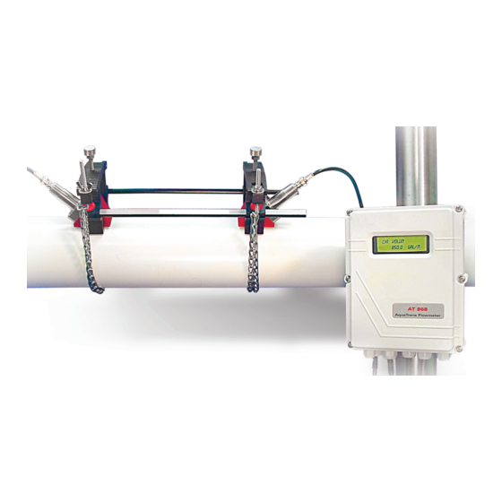
The discarding of an important item along with the packing materials is all too common. If anything is missing or damaged, contact Panametrics immediately for assistance. Site Considerations Because the relative location of the flowcell and the electronics enclosure is important, use the guidelines in this section to plan the AT868 installation.
-
Page 13: Cable Lengths
Locate the electronics enclosure as close as possible to the flowcell/transducers, preferably directly on the flowcell. However, Panametrics can supply transducer cables up to 1000 ft (300 m) in length for remote location of the electronics enclosure. If longer cables are required, consult Panametrics for assistance.
-
Page 14: Preparing The Unit
Chapter 1. Installation 1.6.1 Preparing the Unit Prepare the unit as described below before making any electrical connections. Disconnect any previously wired power line from the unit. Remove the screws on the front cover. Remove the plastic shield that protects the electrical connections by loosening the two screws and lifting the plastic shield.
-
Page 15: Wiring Transducers
Chapter 1. Installation Either proceed to the next section to continue wiring the AT868 or reinstall the plastic shield, replace the front cover on the enclosure and tighten the screws. 1.6.3 Wiring Transducers WARNING! Before connecting the transducers, discharge any static buildup by shorting the center conductor of the transducer cables to the metal shield on the cable connector.
-
Page 16: Wiring Std 0/4-20 Ma Analog Outputs
Chapter 1. Installation 1.6.4 Wiring Std 0/4-20 mA Analog Outputs The Model AT868 flow transmitter has a pair of isolated 0/4-20 mA analog output per channel (designated as Output A and Output C). These outputs can be configured independently. Typically, Output A is used for Channel 1 and Output C is used for Channel 2.
-
Page 17: Wiring The Totalizer/Frequency Output
Chapter 1. Installation 1.6.5 Wiring the Totalizer/Frequency Output The Model AT868 also provides a second pair of outputs per channel (designated as Output B and Output D) that can be configured as a totalizer or frequency output. Like the analog outputs, these outputs can also be configured independently. Typically, Output B is used for Channel 1 and Output D is used for Channel 2.
-
Page 18: Wiring The Serial Port
Signal names that imply direction (e.g., transmit and receive) are named from the point of view of the DTE device, which is usually the Panametrics meter. When the RS232 standard is strictly followed, these signals are labeled with the same name and pin # on the DCE device side as well. Unfortunately, that convention is not followed because the DTE and DCE side get confused.
-
Page 19
Chapter 1. Installation • Using a Factory-Configured Serial Interface (see page 10). 1.6.6.3 Using an INMAC Converter To wire the RS485 serial port, refer to Figure 4 on page 12 and complete the following steps: See “Preparing the Unit” on page 4 before you connect the power. Feed one end of the cable through the conduit hole and wire the leads to the COMMUNICATION terminal block as shown in Figure 4 on page 12 . -
Page 20: Wiring An External Totalizer Reset Switch
Chapter 1. Installation 1.6.6.4 Using a Factory-Configured Serial Interface Use the following steps to link the AT868 to the control system using a factory-configured RS485 interface: See “Preparing the Unit” on page 4 before you connect the power. Feed the wires through the conduit hole and wire lead TMT+ to pin 2 (RX) on the COMMUNICATION terminal block (refer to Figure 4 on page 12 for the terminal block location).
-
Page 21
Chapter 1 Installation Note: 1. All dimensions are in inches (millimeters). 10.00 9.00 (254.0) (228.6) 2.86 (72.6) Ø .41 (10.40) 4.11 (104.4) 4 Holes 5.88 (149.3) AquaTrans™ AT868 User’s Manual… -
Page 22
Chapter 1 Installation Contrast Adjustment Backlight Adjustment TB3: 0/4-20 mA Analog Outputs TB3: RS232/RS485 Serial Port NOTE: For compliance with the European Pin No. Description Pin No. Color* Description Union’s Low Voltage Directive, this unit 7 OUT1- Output 1 RTN (-) 5 DTR White Data Terminal Ready… -
Page 23: Chapter 2. Programming Site Data
The AT868 flow transmitter has a user program that provides access to the various programmable features of the unit. To program the AT868 you can use either the internal keypad or Panaview ™, a PC-based, non-resident Panametrics software program that communicates with the AT868 through its serial port. Note: If you are using Panaview , the AT868 is configured with the Meter Address as 1 and the baud rate as 9600.
-
Page 24: Activating A Channel/Path — Chx-Activ
Chapter 2. Programming Site Data Activating a Channel/Path — CHx-ACTIV The ACTIV submenu is used to activate/deactivate the channel/path. The channel/path should be activated when you receive your unit; however, you should verify that the channel/path is active before you begin programming. While following the programming instructions, refer to Figure 9 on page 85 .
-
Page 25: Entering System Data For A Channel/Path — Chx-Systm
Chapter 2. Programming Site Data Entering System Data for a Channel/Path — CHx-SYSTM The CHx-SYSTM submenu is used to enter system parameters for the individual channels/paths. When channels/paths operate separately, the AT868 uses the system parameters in this menu. When channels/paths are averaged together, the AT868 uses parameters selected in the GLOBL-SYSTM submenu.
-
Page 26: Selecting The Totalizer Units
Chapter 2. Programming Site Data 2.3.3 Selecting the Totalizer Units Use the arrow keys to select the desired units for the totalized flow rate display and press [ENTER]. Use the arrow keys to select the desired number of digits to the right of the decimal point in the totalized flow rate display and press [ENTER].
-
Page 27: Entering Transducer And Pipe Parameters — Chx-Pipe
Chapter 2. Programming Site Data Entering Transducer and Pipe Parameters — CHx-PIPE Enter the transducer and pipe parameters via the PIPE submenu. While following the programming instructions, refer to Figure 9 on page 85 . Remember to record all programmed data in Appendix C, Data Records . 2.4.1 Accessing the PIPE Submenu Press [ESC], [ENTER], [ESC] to enter the user program.
-
Page 28: Special Transducers
to increase or decrease the number and press [ENTER]. Enter the wedge sound speed (supplied by Panametrics) of the transducer by using the arrow keys. Press [ …
-
Page 29: Pipe Material
Chapter 2. Programming Site Data 2.4.4 Pipe Material If a standard clamp-on transducer is being used, the programming sequence should be rejoined here. Press [ and [ ] to select one of the pipe materials listed in Table 2 below and press [ENTER]. Note: Some of the pipe materials require additional selections.
-
Page 30: Pipe Outside Diameter
Obtain the required information by measuring either the pipe outside diameter (OD) or circumference at the transducer installation site. The data may also be obtained from standard pipe size tables found in the Panametrics Sound Speeds and Pipe Size Data reference (914-004). …
-
Page 31: Lining
Chapter 2. Programming Site Data 2.4.7 Lining Press [ and [ ] to select whether the pipe has a lining and press [ENTER]. Do one of the following: If you selected No, proceed to “Setting Up a Tracking Window” on page 21 and “Fluid Type” on page 22. •…
-
Page 32: Fluid Type
Chapter 2. Programming Site Data 2.4.9 Fluid Type The selections for fluid type vary depending on whether the Tracking Window is enabled or disabled. Press [ ] to select the desired fluid and press [ENTER]. Refer to Table 3 below for a list of available fluids. and [ Table 3: Fluid Types Tracking Windows =…
-
Page 33: Kv Input Selection
Chapter 2. Programming Site Data 2.4.11 KV Input Selection Press [ and [ ] to enter a static kinematic viscosity or a table of values and press [ENTER]. Do one of the following: • If you selected Table, enter the Calibration Factor by using the arrow keys. Press [ and [ ] to move the and…
-
Page 34: Entering The Zero Cutoff Value — Chx-I/O
Chapter 2. Programming Site Data Entering the Zero Cutoff Value — CHx-I/O Near a zero flow rate, the Model AT868 readings may fluctuate due to small offsets caused by thermal drift or similar factors. To force a zero display reading when there is minimal flow, enter a zero cutoff value as described below. While programming these parameters, refer to Figure 9 on page 85 .
-
Page 35: Set Transducer Signal Settings — Signl
Chapter 2. Programming Site Data 2.6.1 Set Transducer Signal Settings — SIGNL Use this option to set the limits for the incoming signal and other parameters affecting the transducer signal. For example, the programmed signal strength low limit may be used to determine the trigger point for an alarm. CAUTION! The SIGNL default settings are suitable for most applications.
-
Page 36: Setting Response Time — Avrg
Chapter 2. Programming Site Data Table 4: Transducer Signal Parameters (cont.) Transducer Signal Parameters Range Default Value Description Amplitude 0 to 100 The amplitude measures the transducer signal received by the Discriminator Model AT868. The E5: AMPLITUDE error message appears when the amplitude discriminator falls below the programmed AMP.
-
Page 37: Initializing Setup Parameters — Init
Chapter 2. Programming Site Data Procedure Options After completing the above step, the user program returns to the SET UP window. Do one of the following: • To continue regular programming, refer to Appendix A, Menu Maps , to navigate to the desired menu. •…
-
Page 38
Chapter 2. Programming Site Data 2.6.4.1 Entering KV/SS Table — KV/SS Use this option to calculate the kinematic viscosity (KV) based on signal strength (SS). Complete the following steps to enter KV and SS values: Press [ESC], [ENTER], [ESC] to enter the user program. … -
Page 39
Complete the following steps to enter multiple K factors for velocity or reynolds values: Note: The K-factors are supplied by Panametrics. The K-factor table cannot be edited without them. Press [ESC], [ENTER], [ESC] to enter the user program. … -
Page 40
Chapter 2. Programming Site Data 2.6.4.3 Activating Mass Flow — MASS Use this option to calculate mass flow from a static fluid density. Complete the following steps to enter the static density of the fluid: Press [ESC], [ENTER], [ESC] to enter the user program. … -
Page 41
Chapter 2. Programming Site Data 2.6.4.4 Selecting Transmitter Code Length — CODEL Use this option to select the size of the transducer transmission signal. This option is helpful when measuring flow on small pipes. Complete the following steps to select the code length. Press [ESC], [ENTER], [ESC] to enter the user program. -
Page 42: Entering Global System Data — Globl-Systm
Chapter 2. Programming Site Data Entering Global System Data — GLOBL-SYSTM While completing these instructions, refer to Figure 10 on page 86. Remember to record all programmed data in Appendix C, Data Records . Proceed to the following sections to enter system information in the GLOBL menu. 2.7.1 Selecting the GLOBL-SYSTM Units Press [ESC], [ENTER], [ESC] to enter the user program.
-
Page 43: Setting Up The External Totalizer Reset Switch
To connect an external reset switch, refer to “Wiring an External Totalizer Reset Switch” on page 10 . IMPORTANT: The hardware for the switch is user-supplied. Panametrics provides only the software needed to configure the switch and the terminals used to connect the switch.
-
Page 44: Selecting Mass Flow Units
Chapter 2. Programming Site Data 2.7.4 Selecting Mass Flow Units Press [ and [ ] to select the desired mass flow units for the flow rate display and press [ENTER]. The available units for this prompt are determined by the selection made at SYSTEM UNITS on the previous page. …
-
Page 45: Setting Up The Inputs And Outputs — Globl-I/O
Chapter 2. Programming Site Data Setting Up the Inputs and Outputs — GLOBL-I/O Set up the AT868 inputs and outputs via the Input/Output menu. While following the programming instructions, refer to Figure 10 on page 86 . Remember to record all programmed data in Appendix C, Data Records . The GLOBL-I/O submenu consists of the following options: •…
-
Page 46
Chapter 2. Programming Site Data The ERROR-HANDLING D display appears. This allows the user to set a time delay before the instrument reports that an error has occurred. Enter the desired time delay in seconds by using the arrow keys. Press [ and [ ] to and… -
Page 47: Setting Up Analog And Totalizer/Frequency Outputs — Optn
Chapter 2. Programming Site Data 2.8.2 Setting Up Analog and Totalizer/Frequency Outputs — OPTN The AT868 has one built-in analog output and one totalizer/frequency output for each channel which must be set up. To accomplish this, refer to one of the following sections: •…
-
Page 48
Chapter 2. Programming Site Data At BASE, enter a flow rate value for the low end of the analog output range by using the arrow keys. Press [ and and [ ] to move the cursor to desired location and press to increase or decrease the number. -
Page 49
2.8.2.3 Accessing a Totalizer/Frequency Output These outputs can be configured for frequency or totalizer output using Panametrics’s PanaView ™ software. The totalizer output issues one pulse per each selected volume of flow. The meter produces a pulse each time the programmed amount of flow passes through the pipe. -
Page 50
Chapter 2. Programming Site Data 2.8.2.4 Setting Up a Frequency Output At Output B or D, select OFF or FREQ and press [ENTER]. Do one of the following: • If you selected OFF, the meter returns to the Global I/O window. Go to “Procedure Options” on page 41 . •… -
Page 51
Chapter 2. Programming Site Data 2.8.2.5 Setting Up a Totalizer Output At Output B or D, select OFF or TTLZR and press [ENTER]. Do one of the following: If you selected OFF, the meter returns to the Global I/O window. Go to “Procedure Options” on page 41 . •… -
Page 52: Configuring The Communications Port — Globl-Comm
Chapter 2. Programming Site Data Configuring the Communications Port — GLOBL-COMM The AT868 flow transmitter is equipped with a built-in serial communications port. The standard port is an RS232 interface. However, an RS485 interface is available upon request. The AT868 can receive and execute remote commands with PanaView , by connecting the meter’s serial interface to the serial port of a PC.
-
Page 53: Configuring An Output As A Totalizer Or Frequency Output
Chapter 2. Programming Site Data 2.10 Configuring an Output as a Totalizer or Frequency Output Outputs B and D can be configured as totalizer or frequency outputs using PanaView software. Before an output can be configured, the AT868 must be connected to a PC via its serial port (see “Wiring the Serial Port” on page 8 ). Complete the following steps to configure the output: Open the SITE EDIT MENU from the CALIBRATION/TEST menu.
-
Page 54
Chapter 2. Programming Site Data [no content intended for this page] AquaTrans™ AT868 User’s Manual… -
Page 55: Chapter 3. Displaying Data
Chapter 3. Displaying Data Chapter 3. Displaying Data Introduction The AT868 flow transmitter is equipped with a Liquid Crystal Display (LCD), which may be programmed to display up to four variables in sequence. To ease viewing, both the brightness and the contrast of the LCD are adjustable. In addition, this chapter discusses resetting the totalizers and pausing the measurements.
-
Page 56: Setting Up The Display
Chapter 3. Displaying Data Setting Up the Display Complete the following instructions to display the desired data on the display screen (see Figure 10 on page 86). 3.3.1 Accessing the Display Submenu Press [ESC], [ENTER], [ESC] to enter the user program. …
-
Page 57: Resetting Totals
Chapter 3. Displaying Data Resetting Totals To reset the totals, you can use either the internal keypad, PanaView ™ software or an external switch. When resetting totals, the totals for both channels will be reset. Use the appropriate section below to reset the totalizers. 3.4.1 Resetting Totalizers Using the Internal Keypad Refer to Figure A-4 on page A-4 in Appendix A.,<Title Font>…
-
Page 58: Taking Measurements
Chapter 3. Displaying Data Taking Measurements PanaView ™ offers a unique command that enables you to pause and restart the measurements. When you pause the measurement, the AT868 suspends taking measurements. Therefore, all outputs are also affected. This option is only accessible using PanaView ™…
-
Page 59: Chapter 4. Calibration
Chapter 4. Calibration Chapter 4. Calibration Introduction Use this menu to calibrate and test the analog and totalizer/frequency outputs. Refer to Figure 12 on page 88 , while following the calibration instructions. Calibrating and Testing the Analog Outputs The AT868 flowmeter includes one built-in analog output per channel with a resolution of 5.0 A (0.03% full scale). Although one analog output is provided for each channel, the outputs are channel independent.
-
Page 60: Calibrating The Low End Of The Analog Output
] to select UP or DOWN to adjust the 4 mA reading and press [ENTER]. When the desired reading is achieved, select STORE. If the ammeter reading cannot be adjusted to within ±5.0 A of the 4 mA setting, select ABORT to end the calibration and contact Panametrics for assistance. 4.2.4 Calibrating the High End of the Analog Output …
-
Page 61: Testing The Output Linearity
Then, repeat the low and high end calibrations. If the analog output still does not pass the linearity test, contact Panametrics for assistance. Repeat Step 2 with a different output setting (0-100%). Check the ammeter reading at this setting and press [ENTER] when done.
-
Page 62: Testing The Totalizer/Frequency Outputs
Chapter 4. Calibration Testing the Totalizer/Frequency Outputs Prepare for the testing procedure by connecting a frequency counter to the appropriate terminal blocks, as shown in Figure 4 on page 12 . Note: Analog outputs 1 and 2 in the wiring diagram correspond to analog outputs B and D in the AT868 software. 4.3.1 Calibrating the Frequency Output Press [ESC], [ENTER], [ESC] to enter the user program.
-
Page 63: Chapter 5. Error Codes
Chapter 5. Error Codes Chapter 5. Error Codes Introduction The AT868 ultrasonic flow transmitter is a reliable, easy to maintain instrument. When properly installed and operated, as described in Chapter 1, Installation , the meter provides accurate flow rate measurements with minimal user intervention.
-
Page 64: E2: Sound Speed Error
Chapter 5. Error Codes E2: Sound Speed Error submenu of the User The sound speed exceeds the limits programmed in the Problem: SETUP-SIGNL Program . The error may be caused by incorrect programming, poor flow conditions or poor transducer Cause: orientation.
-
Page 65: E6: Cycle Skip, Accel
Chapter 5. Error Codes E6: Cycle Skip, Accel. submenu of the User The acceleration exceeds the limits programmed in the Problem: SETUP-SIGNL Program . This condition is usually caused by poor flow conditions or improper transducer alignment. Cause: Refer to Chapter 6, Diagnostics, , to correct any flowcell and/or transducer problems. Action: E7: Analog Out Error The current in the analog output circuit exceeds the limits for the analog output port.
-
Page 66
Chapter 5. Error Codes [no content intended for this page] AquaTrans™ AT868 User’s Manual… -
Page 67: Chapter 6. Diagnostics
Chapter 6. Diagnostics Chapter 6. Diagnostics Introduction This chapter explains how to troubleshoot the AT868 if problems arise with the electronics enclosure, the flowcell, or the transducers. Indications of a possible problem include: • Display of an error message on the LCD screen •…
-
Page 68: Configuring The Display
Chapter 6. Diagnostics 6.2.2 Configuring the Display At # of LCD PARAMS, press [ ] to select the desired number of parameters to be sequentially displayed and then press [ENTER]. For a 1-channel/path AT868, proceed to Step 3. For a 2-channel/path meter, proceed to Step 2. Note: If you select OFF , the meter returns to the Global I/O window.
-
Page 69: Using The Tracking Window
Chapter 6. Diagnostics Table 9: Available Diagnostic Parameters Option Bar Description Good NFup Displays the normalization factor for the upstream transducer. 0.85-1.0 <0.85 NFdn Displays the normalization factor for the downstream 0.85-1.0 <0.85 transducer. Cxdcr Displays the speed of sound in the transducer (clamp-on only). N.A.
-
Page 70: Configuring The Display
If the sound speed is not constant, leave the Tracking Window ON and reconfigure the display to show the desired measurements. Note: If you are unsure if the sound speed is fairly constant, consult Panametrics. 6.3.3 Deactivating the Tracking Window Press [ESC], [ENTER], [ESC] to enter the user program.
-
Page 71: Diagnostic Record
• Fluid problems • Pipe problems. Read the following sections carefully to determine if the problem is indeed related to the flowcell. If the instructions in this section fail to resolve the problem, contact Panametrics for assistance. 6.5.1 Fluid Problems Most fluid-related problems result from a failure to observe the flowmeter system installation instructions.
-
Page 72: Pipe Problems
The accuracy of the flow rate measurements is no better than the accuracy of the programmed pipe dimensions. For a flowcell supplied by Panametrics, the correct data ise included in the documentation. For other flowcells, measure the pipe wall thickness and diameter with the same accuracy desired in the flow rate readings.
-
Page 73: Transducer Problems
Because transducer problems are largely dependent on the type of transducers used, wetted or clamp-on, the following list of potential problems is grouped according to transducer type. Contact Panametrics if you cannot solve a transducer-related problem.
-
Page 74: Clamp-On Transducer Problems
To resolve a cycle skip, recouple both transducers with proper couplant. Check your couplant for temperature ranges. In addition, make sure the pipe wall is free of paint and rust. If the instructions in this section fail to resolve the problem, contact Panametrics for assistance. AquaTrans™ AT868 User’s Manual…
-
Page 75: Chapter 7. Parts Replacement
This service history may prove very helpful in diagnosing any future problems. Purchasing Parts To purchase the parts mentioned in this chapter or any items not specifically discussed, contact Panametrics for assistance. To make sure the proper components are obtained, be sure to specify the serial number of your AT868 at the time of purchase.
-
Page 76: Replacing The Lcd Display/Keypad
Chapter 7. Parts Replacement Replacing the LCD Display/Keypad The LCD display/keypad assembly normally provides years of dependable service, but it is easily field-replaceable when necessary. To replace the LCD display/keypad, see Figure 7 on page 71 and Figure 8 on page 72 for the component locations, and complete the following steps.
-
Page 77: Replacing The Fuse
Chapter 7. Parts Replacement Replacing the Fuse Complete the steps below to replace the AT868 fuse (refer to Figure 7 on page 71 ): Disconnect the power from the AT868 and move the electronics enclosure to a clean, flat work surface. WARNING! The main power to the Model AT868 must be disconnected before proceeding.
-
Page 78: Replacing The User Program
Chapter 7. Parts Replacement Replacing the User Program The AT868 User Program is stored on an erasable programmable read-only memory (EPROM) chip. The EPROM, which is designated as component U4, is mounted in a socket on the rear of the Channel 1 board. EPROM replacement may be required to replace a defective chip or to upgrade to a newer software version.
-
Page 79: Locating The Eprom
Chapter 7. Parts Replacement 7.5.2 Locating the EPROM Flip the Channel 1 board over and locate the U4 EPROM socket. It is the only socketed chip on this board and it has a white identification label. Using a chip puller, remove the EPROM from its socket. If a chip puller is unavailable, a straightened paper clip may be used in the notches at the upper right and lower left corners of the socket.
-
Page 80
Chapter 7. Parts Replacement [no content intended for this page] AquaTrans™ AT868 User’s Manual… -
Page 81
Chapter 7. Parts Replacement Mounting Plate Screw (4 Places) Set Screw (6 Places) ENTER FREQ2 AOUT2 85 — 265 VAC 50/60HZ 1/4A AquaTrans™ AT868 User’s Manual… -
Page 82
Chapter 7. Parts Replacement PCB Standoff (Typical) Mounting Screw, 4 Places (LCD/Keypad Assy.) LCD/Keypad Assy. EPROM Channel 1 PCB ENTER Fuse Mounting Screw, 2 Places (Plastic Shroud/CH1 PCB) FREQ2 AOUT2 85 — 265 VAC 50/60HZ 1/4A Channel 2 PCB AquaTrans™ AT868 User’s Manual… -
Page 83
Chapter 7. Parts Replacement Note: 1. All dimensions are in inches (millimeters). 10.00 9.00 (254.0) (228.6) 2.86 (72.6) Ø .41 (10.40) 4.11 (104.4) 4 Holes 5.88 (149.3) AquaTrans™ AT868 User’s Manual… -
Page 84
Chapter 7. Parts Replacement AquaTrans™ AT868 User’s Manual… -
Page 85: Chapter 9. Specifications
Chapter 9. Specifications Chapter 9. Specifications General Specifications The general specifications for the AT868 flow transmitter are divided into the following categories: 9.1.1 Hardware Configuration Channel Options Standard : 1-Channel Optional: 2-Channel/Path (2 paths per pipe) Package Options: General purpose Type 4X powder-coated aluminum wall mount Dimensions: 2.2 lb (1 kg);…
-
Page 86: Rangeability
Chapter 9. Specifications 9.1.5 Rangeability 400:1 9.1.6 Repeatability Wetted Transducers : 0.2% of full scale Clamp-on Transducers : 0.2 to 0.5% of full scale Note: Specifications assume a fully developed flow profile, with a straight run of pipe 10 diameters upstream and 5 diameters downstream from the measurement point.
-
Page 87: Input/Output Specifications
Chapter 9. Specifications Input/Output Specifications Digital Display: 2-line x 16-character LCD display, LED backlight, configurable to display up to 4 measurement parameters in sequence Digital Communications: Standard: RS232 serial port for PC, terminal or printer Optional: RS485 serial port for PC, terminal or printer Analog Outputs: 1 isolated 0/4-20 mA, 600 …
-
Page 88
Chapter 9. Specifications Output Units: Velocity: Feet per second (ft/s) Meters per second (m/s) Volumetric Flow: Cubic feet (ft ) per second, minute, hour Million cubic feet (ft ) per day Gallons (gal) per second, minute, hour Millions of gallons per day Barrels per second, minute, hour Millions of barrels per day Acre inches per second, minute, hour, da… -
Page 89: Transducer Specifications
Optional: Explosion-proof, Div. 1, Class 1, Group C&D, INIEX-Certified EEx d IIC T6 or weatherproof (Type 4, IP65) Other Options: Transducers for special applications; fixtures; no organic bonds or insulators; cooling jackets for high temperatures. Please consult Panametrics for details. AquaTrans™ AT868 User’s Manual…
-
Page 90: Clamp-On Transducers
Inside Diameter: 0.04 to 200 in. (1 mm to 5 m) and larger 9.5.2 Clamp-on Transducers Materials: 316 SS and most plastics (Consult Panametrics for concrete, composite materials and highly corroded or lined pipes.) Pipe Sizes: Outside Diameter: 0.5 to 200 in. (12.7 mm to 5 m) and larger Pipe Wall Thickness: Up to 3 in.
-
Page 91: Tilted Diameter Spoolpiece Specifications
Chapter 9. Specifications Tilted Diameter Spoolpiece Specifications Pipe Sizes: Standard: 2 to 200 in. (50 mm to 5 m), 100% interrogation Optional: > 200 in. Materials: Standard: SS, carbon steel, plastic or fiberglass Optional: Other metals, plastics, etc. Process Connections: Standard: Straight (welding), 150-lb flanged, 300-lb flanged and higher Optional: MJ, Victaulic, RTJ flanged or cold-tap Wetted Transducer Connections:…
-
Page 92
Chapter 9. Specifications [no content intended for this page] AquaTrans™ AT868 User’s Manual… -
Page 93: Appendix A. Menu Maps
Appendix A. Menu Maps Appendix A. Menu Maps This appendix includes the following AT868 menu maps: • Figure 9, “The CHx>ACTIV, SYSTM, PIPE, and I/O Menu Map,” on page 85 • Figure 10, “The GLOBL Menu Map,” on page 86 •…
-
Page 94
Appendix A. Menu Maps [no content intended for this page] AquaTrans™ AT868 User’s Manual… -
Page 95
Appendix A. Menu Maps To nt r th U r Pro ram pr E TER PROG RESET CALIB (*for 2-Chann l m t r onl ) CH2* GLOBL ACTIV SYSTEM PIPE SETUP SYSTM COMM ZERO CUTOFF EL LABEL Fi ur A-3) Fi ur A-2 TRA SDUCER UMBER SITE/CHA… -
Page 96
Appendix A. Menu Maps To nt r th U r Pro ram pr K pad Pro ram E TER PROG RESET CALIB (*for 2-Chann l m t r onl ) CH2* GLOBL Fi ur A-1) SYSTEM COMM METER MESSAGE M t r Addr SYSTEM U ITS BAUD RATE METRIC… -
Page 97
Appendix A. Menu Maps To enter the User Program press ENTER PROG RESET CALIB (*for 2-Channel meters only) CH2* GLOBL ACTIV SYSTEM PIPE SETUP SYSTM COMM (See Figure A-1) (See Figure A-1) (See Figure A-1) (See Figure A-1) See Figure A-2 SIGNL AVRG INIT… -
Page 98
Appendix A. Menu Maps To enter the User Program press ENTER PROG RESET CALIB RESET TOTALS? SLOT0 Slot 0 Outputs Totals are NOT Reset Totals are Reset A or C B or D TIME (usec) ANALOG OUTPUT PULSES 4 mA 20 mA TEST EXIT… -
Page 99: Appendix B. Ce Mark Compliance
Appendix B. CE Mark Compliance Appendix B. CE Mark Compliance Introduction For CE Mark compliance, the AT868 flow transmitter must comply with both the EMC and LVD directives. IMPORTANT: CE Mark compliance is required for all units intended for use in EU countries. EMC Compliance For EMC compliance, the electrical connections must be shielded and grounded as in Table 11 below.
-
Page 100: Lvd Compliance
Appendix B. CE Mark Compliance LVD Compliance For compliance with the European Union’s Low Voltage Directive, the AT868 requires an external power disconnect device such as a switch or circuit breaker. The disconnect device must be marked as such, clearly visible, directly accessible, and located within 1.8 m (6 ft) of the unit.
-
Page 101: Appendix C. Data Records
Appendix C. Data Records Appendix C. Data Records Site Data After the AT868 flow transmitter has been installed, specific site data must be entered via the User Program prior to operation. Record that information in Table 12 below. Table 12: Site Data General Information Model # Serial #…
-
Page 102
Appendix C. Data Records Table 12: Site Data Special Transducers Special Transducers Wedge Type Rayl Shear Wettd Wedge Type Rayl Shear Wettd Frequency Hz Frequency Hz Trans. Tw Trans. Tw Wedge Angle Wedge Angle Wedge Sndspd Wedge Sndspd Pipe Material Pipe Material All Clamp-On and Wetted Transducers All Clamp-On and Wetted Transducers… -
Page 103
Appendix C. Data Records Table 12: Site Data Channelx-SETUP-Signal Channel 1 Channel 2 (if applicable) Signal Low Lim. Signal Low Lim. Corr. Peak Lim. Corr. Peak Lim. SS +/- Limit SS +/- Limit Vel. Low Limit Vel. Low Limit Vel. High Limit Vel. -
Page 104
Appendix C. Data Records Table 12: Site Data Channelx-SETUP-Advanced Features-Multiple K Factors Custom Type CstV CstR Custom Type CstV CstR K-Factor Table K-Factor Table K-Factor # Vel./Reyn. K Factor K-Factor # Vel./Reyn. K Factor Channelx-SETUP-Advanced Features-Mass Flow from Static Mass Flow Mass Flow Fluid Density Fluid Density… -
Page 105: Appendix D. Measuring P And L Dimensions
To determine L, physically measure the distance between the center of the transducer ports at the inside wall as shown in Figure 15 below, if possible. If this is not possible in your installation, contact Panametrics for help. Pipe Thickness θ…
-
Page 106
Appendix D. Measuring P and L Dimensions Figure 16: Determining the Coupling Length Use the following formula to determine the P dimension: [ID + 2 x (WT)]/(cos MA) + 2 x (CL — FD) = P Dimension For example, given the following typical values: •… -
Page 107: Appendix E. Service Record
Appendix E. Service Record Appendix E. Service Record Introduction Whenever any service procedure is performed on the AT868, the details of the service should be recorded in this appendix. An accurate service history can prove very helpful in troubleshooting any future problems. Data Entry Record complete and detailed service information for your AT868 in Table 13 below.
-
Page 108
Appendix E. Service Record Table 13: Service Record Date Description of Service Performed By AquaTrans™ AT868 User’s Manual… -
Page 109: Diagnostic Parameters
Appendix E. Service Record Diagnostic Parameters After a successful initial installation of the AT868 and whenever any system malfunction is noticed, the values for the diagnostic parameters should be entered in Table 14 below. Table 14: Diagnostics Parameters Parameter Initial Current Parameter Initial…
-
Page 110
Appendix E. Service Record [no content intended for this page] AquaTrans™ AT868 User’s Manual… -
Page 111: Appendix F. Programming With Panaview
For detailed installation and setup instructions, refer to the PanaView ™ User’s Manual (910-211). Wiring the RS232 Interface For details on wiring your RS232 interface, refer to “Wiring the Serial Port” on page 8 and to the Panametrics document EIA-RS Serial Communications (916-054).
-
Page 112: Setting Up The Communications Port
Appendix F. Programming with PanaView™ F.3.1 Setting Up the Communications Port Complete the steps below to establish communications with your AT868: Open the “New Meter Browser” window and expand the network tree. Then, highlight the My Computer(Name) branch by clicking on it. Drop down the “Edit”…
-
Page 113
Appendix F. Programming with PanaView™ Click on the “Communications Port” option to select it. The Setup Communications screen appears similar to Figure 19 below. Figure 19: Setup Communications Screen Open the Protocol menu and click on IDM . Select any suitable available baud rate. A baud rate of 19,200 is appropriate for almost all applications. However, if you experience periodic communication unreliability problems, you may wish to consider lowering the baud rate on your instrument and in PanaView . -
Page 114: Adding An Idm-Compatible Meter
Appendix F. Programming with PanaView™ Adding an IDM-Compatible Meter To add a meter on the IDM-configured communications port, complete the following steps: Highlight the communication port to which the meter will be added by clicking on it, and then open the “Edit” menu on the menu bar Note: if the communication port is not highlighted first, the “New Meter”…
-
Page 115
Appendix F. Programming with PanaView™ IMPORTANT: The Network ID number must match the Network ID programmed in the meter Communications menu. If the initialization is successful, the Meter Browser shows a listing similar to Figure 22 below. Figure 22: Updated Network Tree However, if the settings do not match or there is some other difficulty, a screen similar to Figure 23 below. -
Page 116: Editing Meter The Properties
Appendix F. Programming with PanaView™ Editing Meter the Properties With PanaView , you can edit the properties of your flow transmitter, such as: • Set the meter clock, or synchronize it with the PC clock • Read, plot and save transducer signals •…
-
Page 117
Appendix F. Programming with PanaView™ The next window appears similar to Figure 25 below. To perform a specific task, refer to the following sections: • “Setting the Meter Clock” on page 108 • “Reading the Transducer Signals” on page 109 •… -
Page 118: Setting The Meter Clock
Appendix F. Programming with PanaView™ F.5.1 Setting the Meter Clock The meter Time may be reset in three different ways: • Manually enter the time and date in the text box Click on the [Sync to PC] option button to have PanaView set the time and date to the current PC setting •…
-
Page 119: Reading The Transducer Signals
Appendix F. Programming with PanaView™ F.5.2 Reading the Transducer Signals To read a transducer Signal from the meter, proceed as follows: Click on the Read Signals button. For a 2-channel meter, open the Channel drop-down menu and click on the desired channel.
-
Page 120: Plotting The Transducer Signals
Appendix F. Programming with PanaView™ F.5.3 Plotting the Transducer Signals To plot the selected signal, click on Plot to open a graphical screen similar to Figure 28 below. Figure 28: Signal Graph Screen F.5.4 Saving the Transducer Signals To save the raw signal, click Save to open a screen similar to Figure 29 below. Enter the desired name, and click Save to save the signal as a text file.
-
Page 121: Clearing The Totalizers
Appendix F. Programming with PanaView™ F.5.5 Clearing the Totalizers To clear the meter totalizers, click on the Clear Totalizers button in the Properties screen. The meter totalizers are immediately reset to 0. F.5.6 Handling Site Files To access your site files, click on the Site Files button in the Properties Screen to open the Site File Operations screen shown in Figure 30 below.
-
Page 122
Appendix F. Programming with PanaView™ F.5.6a Saving an Existing Site to the Meter To save an existing site file to the meter, proceed as follows: Select the radio button for Selected and highlight an existing site file in the left pane. Click on the Save Site to Meter button to open a screen similar to Figure 31 below. -
Page 123
Appendix F. Programming with PanaView™ F.5.6c Saving a Site File to the PC To save a site file to the PC, Proceed as follows: Highlight the desired site file in the left pane (see Figure 30 on page 111 ). Click Save Site to PC to open a screen similar to Figure 29 on page 110 . -
Page 124
Appendix F. Programming with PanaView™ F.5.6e Saving a Site File in Text Form To store the data from a site file as a text file for display or printout, proceed as follows: Highlight the site file in the left pane (see Figure 30 on page 111 ). Click Save Site Print to PC . -
Page 125: Changing Meter Settings
Appendix F. Programming with PanaView™ Changing Meter Settings With PanaView , the following remote programming tasks can be completed: • Program and change the meter operating parameters • Set up, start, and stop logs • Calibrate and test inputs and outputs •…
-
Page 126
Appendix F. Programming with PanaView™ From the meter tree, expand the Edit Functions option. A screen similar to Figure 35 below opens, with a list of available menus. The menus listed are those available on the meter. Note: For illustration purposes only, the specific menus shown are those for a one-channel GN868 flowmeter. Figure 35: Meter Tree — Edit Functions Option To open a particular menu, double-click on that menu on the tree. -
Page 127
Appendix F. Programming with PanaView™ To program a particular option, proceed as follows: Highlight and double-click on the desired option in the left pane. Figure 37 below shows the first entry ( Transducer Number ) in the Pipe Parameters option. The title above the center pane lists the current entry, while the center pane displays the available selections for that entry. -
Page 128
Appendix F. Programming with PanaView™ As you step through the menus, the bottom panel lists the current settings you have modified or left unchanged (see Figure 38 below). If you modify or step through the menus more than five items, a scroll bar at the right of the panel lets you review the earlier settings. -
Page 129
Index ACTIV …………14 Edit ADVAN . -
Page 130
Index PIPE …………17 IDM-Compatible Meters. -
Page 131
Index Specifications Voltage, Input ……….4 Clamp-On Transducers . -
Page 132
Index AquaTrans™ AT868 User’s Manual… -
Page 133
Notify Panametrics Sensing, giving full details of the problem, and provide the model number and serial number of the instrument. If the nature of the problem indicates the need for factory service, Panametrics will issue a RETURN AUTHORIZATION NUMBER (RAN), and shipping instructions for the return of the instrument to a service center will be provided. -
Page 134
Warranty [no content intended for this page] AquaTrans™ AT868 User’s Manual… -
Page 136
Customer Support Centers U.S.A. The Boston Center 1100 Technology Park Drive Billerica, MA 01821 U.S.A. Tel: 800 833 9438 (toll-free) 978 437 1000 E-mail: mstechsupport@bakerhughes.com Ireland Sensing House Shannon Free Zone East Shannon, County Clare Ireland Tel: +353 (0)61 470200 E-mail: mstechsupport@bakerhughes.com Copyright 2021 Baker Hughes company.
Table of Contents for Panametrics AquaTrans AT868:
-
AquaTrans™ AT868 User’s Manual 117 Appendix F. Programming with PanaView™ 6. To program a particular option, proceed as follows: a. Highlight and double-click on the desired option in the left pane. Figure 37 below shows the first entry ( Transducer Number ) in the Pipe Parameters option. The title above the center pane lists the current entry, while the center pane displays the available selections for that entry. b. Click on the desired choice. If the entry requires a numeric value,
-
AquaTrans™ AT868 User’s Manual 39 Chapter 2. Programming Site Data 2.8.2.3 Accessing a Totalizer/Frequency Output These outputs can be configured for frequency or totalizer output using Panametrics’s PanaView ™ software. The totalizer output issues one pulse per each selected volume of flow. The meter produces a pulse each time the programmed amount of flow passes through the pipe. The frequency output issues a frequency that
-
AquaTrans™ AT868 User’s Manual 67 Chapter 7. Parts Replacement 7.4 Replacing the Fuse Complete the steps below to replace the AT868 fuse (refer to Figure 7 on page 71 ): 1. Disconnect the power from the AT868 and move the electronics enclosure to a clean, flat work surface. 2. Loosen the six set screws on the front cover, and remove the front cover. 3. Remove the four screws from the bottom mounting plate. 4. Loosen cable glands if necessary, and remove the mounting plate from the chassis. 5. From the cutout on the back of the mountin
-
Chapter 7. Parts Replacement AquaTrans™ AT868 User’s Manual 73 Figure 1: 712-2167 Outline & installation, Z3, 2 – 24-inch flow meter system, remote mount Note: 1. All dimensions are in inches (millimeters). 4.11 (104.4) 5.88 (149.3) 2.86 (72.6) 9.00 (228.6) 10.00 (254.0) Ø .41 (10.40) 4 Holes
-
AquaTrans™ AT868 User’s Manual 107 Appendix F. Programming with PanaView™ The next window appears similar to Figure 25 below. To perform a specific task, refer to the following sections: • “Setting the Meter Clock” on page 108 • “Reading the Transducer Signals” on page 109 • “Plotting the Transducer Signals” on page 110 • “Saving the Transducer Signals” on page 110 • “Clearing the Totalizers” on page 111 • “Handling Site Files” on page 111 Figure 25: Prop
-
AquaTrans™ AT868 User’s Manual 121 Index Specifications Clamp-On Transducers. . . . . . . . . . . . . . . . . . . . . . . . . . . . . . . . 80 Electrical . . . . . . . . . . . . . . . . . . . . . . . . . . . . . . . . . . . . . . . . . . . . . . . 76 General . . . . . . . . . . . . . . . . . . . . . . . . . . . . . . . . . . . . . . . . . . . . . . . . 75 Materials . . .
-
AquaTrans™ AT868 User’s Manual 15 Chapter 2. Programming Site Data 2.3 Entering System Data for a Channel/Path — CHx-SYSTM The CHx-SYSTM submenu is used to enter system parameters for the individual channels/paths. When channels/paths operate separately, the AT868 uses the system parameters in this menu. When channels/paths are averaged together, the AT868 uses parameters selected in the GLOBL-SYSTM submenu. While following the progra
-
AquaTrans™ AT868 User’s Manual 33 Chapter 2. Programming Site Data 2.7.3 Setting Up the External Totalizer Reset Switch The GATE OPTION enables you to configure an external reset switch that can reset totals by activating a switch that is located remotely from the electronics. To connect an external reset switch, refer to “Wiring an External Totalizer Reset Switch” on page 10 . IMPORTANT: The hardware for the switch is user-supplied. Panametrics provides only the software needed to configure the
-
Appendix D. Measuring P and L Dimensions 96 AquaTrans™ AT868 User’s Manual Figure 16: Determining the Coupling Length Use the following formula to determine the P dimension: [ID + 2 x (WT)]/(cos MA) + 2 x (CL — FD) = P Dimension For example, given the following typical values: • Pipe inside diameter (ID) = 48” • Wall thickness (WT) = 3/8” • Installed coupling length (CL) = 2.0” • Transducer face depth (FD) =
-
Chapter 9. Specifications 80 AquaTrans™ AT868 User’s Manual 9.4.2 Clamp-on Transducers Type: Shear wave or longitudinal wave Temperature Range Standard: -40 o to 212 o F (-40 o to 100 o C) Optional (overall range): -328 o to 500 o F (-200 o to 260 o C) Frequency: Standard: 1 MHz Optional: 500 MHz, 2 MHz, or 4 MHz Mounting: SS chain or strap, welded or magnetic slide-track mounting fixtures Housing: Standard: None (spl
-
Appendix F. Programming with PanaView™ 104 AquaTrans™ AT868 User’s Manual F.4 Adding an IDM-Compatible Meter To add a meter on the IDM-configured communications port, complete the following steps: 1. Highlight the communication port to which the meter will be added by clicking on it, and then open the “Edit” menu on the menu bar Note: if the communication port is not highlighted first, the “New Meter” option is not active in the “Edit” menu). 2. Click on t
-
Chapter 2. Programming Site Data 18 AquaTrans™ AT868 User’s Manual 2.4.2 Special Transducers 1. For a special transducer, press [] to move the cursor to STD and press until SPEC appears and press [ENTER]. 2. Assign a number between 90 and 99 to the special transducer. Enter the number by using the arrow keys. Press [ and [] to move the cursor to desired location and press andto increase or
-
AquaTrans™ AT868 User’s Manual 61 Chapter 6. Diagnostics 6.4 Diagnostic Record The values for the diagnostic parameters immediately after initial installation of the meter and verification of proper operation should be entered in Table 14 on page 99 . These initial values can then be compared to current values to help diagnose any future malfunction of the system. 6.5 Flowcell Problems If preliminary troubleshooting with the Error Code Messages and the Diagnostic Parameters indicates a possible
-
AquaTrans™ AT868 User’s Manual 89 Appendix B. CE Mark Compliance Appendix B. CE Mark Compliance B.1 Introduction For CE Mark compliance, the AT868 flow transmitter must comply with both the EMC and LVD directives. IMPORTANT: CE Mark compliance is required for all units intended for use in EU countries. B.2 EMC Compliance For EMC compliance, the electrical connections must be shielded and grounded as in Table 11 below. Also refer to Figure 13 and Figure 14 on page 90 for wiring illustrations. After all the ne
-
AquaTrans™ AT868 User’s Manual 111 Appendix F. Programming with PanaView™ F.5.5 Clearing the Totalizers To clear the meter totalizers, click on the Clear Totalizers button in the Properties screen. The meter totalizers are immediately reset to 0. F.5.6 Handling Site Files To access your site files, click on the Site Files button in the Properties Screen to open the Site File Operations screen shown in Figure 30 below. Figure 30: Site File Operations Screen
-
Chapter 4. Calibration 52 AquaTrans™ AT868 User’s Manual 4.3 Testing the Totalizer/Frequency Outputs Prepare for the testing procedure by connecting a frequency counter to the appropriate terminal blocks, as shown in Figure 4 on page 12 . Note: Analog outputs 1 and 2 in the wiring diagram correspond to analog outputs B and D in the AT868 software. 4.3.1 Calibrating the Frequency Output 1. Press [ESC], [ENTER], [ESC] to enter the user program. 2. Press [ ] until CALIB appears and press
Questions, Opinions and Exploitation Impressions:
You can ask a question, express your opinion or share our experience of Panametrics AquaTrans AT868 device using right now.
3.0
Rated 3 out of 5
3 out of 5 stars (based on 1 review)
Your overall rating
PANAMETRICS AT868 (01) PDF MANUAL
Click here to download PANAMETRICS AT868 (01) PDF MANUAL
PANAMETRICS AT868 (01) PDF MANUAL
FREE ENGLISH PDF
OPERATING INSTRUCTIONS
USER GUIDE – USER MANUAL
OWNER GUIDE – OWNER MANUAL
REFERENCE GUIDE – REFERENCE MANUAL
INSTRUCTION GUIDE – INSTRUCTION MANUAL
Your overall rating
- YouTube
PANAMETRICS AT868 (01) PDF MANUAL
PANAMETRICS AT868 (01) PDF MANUAL
-
Page 1
Flow AquaTrans™ AT868 Liquid Flow Ultrasonic Transmitter User’s Manual 910-218 E panametrics.com August 2021… -
Page 3
User’s Manual 910-218 E August 2021 panametrics.com Copyright 2021 Baker Hughes company. This material contains one or more registered trademarks of Baker Hughes Company and its subsidiaries in one or more countries. All third-party product and company names are trademarks of their respective… -
Page 4
[no content intended for this page]… -
Page 5
Preface Information Paragraphs Note: These paragraphs provide information that provides a deeper understanding of the situation, but is not essential to the proper completion of the instructions. IMPORTANT: These paragraphs provide information that emphasizes instructions that are essential to proper setup of the equipment. -
Page 6
Environmental Compliance Waste Electrical and Electronic Equipment (WEEE) Directive Panametrics Solutions is an active participant in Europe’s Waste Electrical and Electronic Equipment (WEEE) take-back initiative, directive 2012/19/EU. The equipment that you bought has required the extraction and use of natural resources for its production. It may contain hazardous substances that could impact health and the environment. -
Page 7: Table Of Contents
Contents Chapter 1. Installation Introduction ………………… .1 Unpacking .
-
Page 8
Contents Chapter 3. Displaying Data Introduction ………………..45 Adjusting LCD Contrast and Brightness . -
Page 9
Contents Transducer Problems ………………. 63 6.6.1 Wetted Transducer Problems . -
Page 10
Contents Adding an IDM-Compatible Meter …………….104 Editing Meter the Properties. -
Page 11: Chapter 1. Installation
Introduction To ensure safe and reliable operation of the Model AT868 Flowmeter, the system must be installed and programmed in accordance with the guidelines established by Panametrics engineers. Those guidelines, explained in detail in this chapter, include the following topics: •…
-
Page 12: Unpacking
The discarding of an important item along with the packing materials is all too common. If anything is missing or damaged, contact Panametrics immediately for assistance. Site Considerations Because the relative location of the flowcell and the electronics enclosure is important, use the guidelines in this section to plan the AT868 installation.
-
Page 13: Cable Lengths
Locate the electronics enclosure as close as possible to the flowcell/transducers, preferably directly on the flowcell. However, Panametrics can supply transducer cables up to 1000 ft (300 m) in length for remote location of the electronics enclosure. If longer cables are required, consult Panametrics for assistance.
-
Page 14: Preparing The Unit
Chapter 1. Installation 1.6.1 Preparing the Unit Prepare the unit as described below before making any electrical connections. Disconnect any previously wired power line from the unit. Remove the screws on the front cover. Remove the plastic shield that protects the electrical connections by loosening the two screws and lifting the plastic shield.
-
Page 15: Wiring Transducers
Chapter 1. Installation Either proceed to the next section to continue wiring the AT868 or reinstall the plastic shield, replace the front cover on the enclosure and tighten the screws. 1.6.3 Wiring Transducers WARNING! Before connecting the transducers, discharge any static buildup by shorting the center conductor of the transducer cables to the metal shield on the cable connector.
-
Page 16: Wiring Std 0/4-20 Ma Analog Outputs
Chapter 1. Installation 1.6.4 Wiring Std 0/4-20 mA Analog Outputs The Model AT868 flow transmitter has a pair of isolated 0/4-20 mA analog output per channel (designated as Output A and Output C). These outputs can be configured independently. Typically, Output A is used for Channel 1 and Output C is used for Channel 2.
-
Page 17: Wiring The Totalizer/Frequency Output
Chapter 1. Installation 1.6.5 Wiring the Totalizer/Frequency Output The Model AT868 also provides a second pair of outputs per channel (designated as Output B and Output D) that can be configured as a totalizer or frequency output. Like the analog outputs, these outputs can also be configured independently. Typically, Output B is used for Channel 1 and Output D is used for Channel 2.
-
Page 18: Wiring The Serial Port
Signal names that imply direction (e.g., transmit and receive) are named from the point of view of the DTE device, which is usually the Panametrics meter. When the RS232 standard is strictly followed, these signals are labeled with the same name and pin # on the DCE device side as well. Unfortunately, that convention is not followed because the DTE and DCE side get confused.
-
Page 19
Chapter 1. Installation • Using a Factory-Configured Serial Interface (see page 10). 1.6.6.3 Using an INMAC Converter To wire the RS485 serial port, refer to Figure 4 on page 12 and complete the following steps: See “Preparing the Unit” on page 4 before you connect the power. Feed one end of the cable through the conduit hole and wire the leads to the COMMUNICATION terminal block as shown in Figure 4 on page 12 . -
Page 20: Wiring An External Totalizer Reset Switch
Chapter 1. Installation 1.6.6.4 Using a Factory-Configured Serial Interface Use the following steps to link the AT868 to the control system using a factory-configured RS485 interface: See “Preparing the Unit” on page 4 before you connect the power. Feed the wires through the conduit hole and wire lead TMT+ to pin 2 (RX) on the COMMUNICATION terminal block (refer to Figure 4 on page 12 for the terminal block location).
-
Page 21
Chapter 1 Installation Note: 1. All dimensions are in inches (millimeters). 10.00 9.00 (254.0) (228.6) 2.86 (72.6) Ø .41 (10.40) 4.11 (104.4) 4 Holes 5.88 (149.3) AquaTrans™ AT868 User’s Manual… -
Page 22
Chapter 1 Installation Contrast Adjustment Backlight Adjustment TB3: 0/4-20 mA Analog Outputs TB3: RS232/RS485 Serial Port NOTE: For compliance with the European Pin No. Description Pin No. Color* Description Union’s Low Voltage Directive, this unit 7 OUT1- Output 1 RTN (-) 5 DTR White Data Terminal Ready… -
Page 23: Chapter 2. Programming Site Data
The AT868 flow transmitter has a user program that provides access to the various programmable features of the unit. To program the AT868 you can use either the internal keypad or Panaview ™, a PC-based, non-resident Panametrics software program that communicates with the AT868 through its serial port. Note: If you are using Panaview , the AT868 is configured with the Meter Address as 1 and the baud rate as 9600.
-
Page 24: Activating A Channel/Path — Chx-Activ
Chapter 2. Programming Site Data Activating a Channel/Path — CHx-ACTIV The ACTIV submenu is used to activate/deactivate the channel/path. The channel/path should be activated when you receive your unit; however, you should verify that the channel/path is active before you begin programming. While following the programming instructions, refer to Figure 9 on page 85 .
-
Page 25: Entering System Data For A Channel/Path — Chx-Systm
Chapter 2. Programming Site Data Entering System Data for a Channel/Path — CHx-SYSTM The CHx-SYSTM submenu is used to enter system parameters for the individual channels/paths. When channels/paths operate separately, the AT868 uses the system parameters in this menu. When channels/paths are averaged together, the AT868 uses parameters selected in the GLOBL-SYSTM submenu.
-
Page 26: Selecting The Totalizer Units
Chapter 2. Programming Site Data 2.3.3 Selecting the Totalizer Units Use the arrow keys to select the desired units for the totalized flow rate display and press [ENTER]. Use the arrow keys to select the desired number of digits to the right of the decimal point in the totalized flow rate display and press [ENTER].
-
Page 27: Entering Transducer And Pipe Parameters — Chx-Pipe
Chapter 2. Programming Site Data Entering Transducer and Pipe Parameters — CHx-PIPE Enter the transducer and pipe parameters via the PIPE submenu. While following the programming instructions, refer to Figure 9 on page 85 . Remember to record all programmed data in Appendix C, Data Records . 2.4.1 Accessing the PIPE Submenu Press [ESC], [ENTER], [ESC] to enter the user program.
-
Page 28: Special Transducers
to increase or decrease the number and press [ENTER]. Enter the wedge sound speed (supplied by Panametrics) of the transducer by using the arrow keys. Press [ …
-
Page 29: Pipe Material
Chapter 2. Programming Site Data 2.4.4 Pipe Material If a standard clamp-on transducer is being used, the programming sequence should be rejoined here. Press [ and [ ] to select one of the pipe materials listed in Table 2 below and press [ENTER]. Note: Some of the pipe materials require additional selections.
-
Page 30: Pipe Outside Diameter
Obtain the required information by measuring either the pipe outside diameter (OD) or circumference at the transducer installation site. The data may also be obtained from standard pipe size tables found in the Panametrics Sound Speeds and Pipe Size Data reference (914-004). …
-
Page 31: Lining
Chapter 2. Programming Site Data 2.4.7 Lining Press [ and [ ] to select whether the pipe has a lining and press [ENTER]. Do one of the following: If you selected No, proceed to “Setting Up a Tracking Window” on page 21 and “Fluid Type” on page 22. •…
-
Page 32: Fluid Type
Chapter 2. Programming Site Data 2.4.9 Fluid Type The selections for fluid type vary depending on whether the Tracking Window is enabled or disabled. Press [ ] to select the desired fluid and press [ENTER]. Refer to Table 3 below for a list of available fluids. and [ Table 3: Fluid Types Tracking Windows =…
-
Page 33: Kv Input Selection
Chapter 2. Programming Site Data 2.4.11 KV Input Selection Press [ and [ ] to enter a static kinematic viscosity or a table of values and press [ENTER]. Do one of the following: • If you selected Table, enter the Calibration Factor by using the arrow keys. Press [ and [ ] to move the and…
-
Page 34: Entering The Zero Cutoff Value — Chx-I/O
Chapter 2. Programming Site Data Entering the Zero Cutoff Value — CHx-I/O Near a zero flow rate, the Model AT868 readings may fluctuate due to small offsets caused by thermal drift or similar factors. To force a zero display reading when there is minimal flow, enter a zero cutoff value as described below. While programming these parameters, refer to Figure 9 on page 85 .
-
Page 35: Set Transducer Signal Settings — Signl
Chapter 2. Programming Site Data 2.6.1 Set Transducer Signal Settings — SIGNL Use this option to set the limits for the incoming signal and other parameters affecting the transducer signal. For example, the programmed signal strength low limit may be used to determine the trigger point for an alarm. CAUTION! The SIGNL default settings are suitable for most applications.
-
Page 36: Setting Response Time — Avrg
Chapter 2. Programming Site Data Table 4: Transducer Signal Parameters (cont.) Transducer Signal Parameters Range Default Value Description Amplitude 0 to 100 The amplitude measures the transducer signal received by the Discriminator Model AT868. The E5: AMPLITUDE error message appears when the amplitude discriminator falls below the programmed AMP.
-
Page 37: Initializing Setup Parameters — Init
Chapter 2. Programming Site Data Procedure Options After completing the above step, the user program returns to the SET UP window. Do one of the following: • To continue regular programming, refer to Appendix A, Menu Maps , to navigate to the desired menu. •…
-
Page 38
Chapter 2. Programming Site Data 2.6.4.1 Entering KV/SS Table — KV/SS Use this option to calculate the kinematic viscosity (KV) based on signal strength (SS). Complete the following steps to enter KV and SS values: Press [ESC], [ENTER], [ESC] to enter the user program. … -
Page 39
Complete the following steps to enter multiple K factors for velocity or reynolds values: Note: The K-factors are supplied by Panametrics. The K-factor table cannot be edited without them. Press [ESC], [ENTER], [ESC] to enter the user program. … -
Page 40
Chapter 2. Programming Site Data 2.6.4.3 Activating Mass Flow — MASS Use this option to calculate mass flow from a static fluid density. Complete the following steps to enter the static density of the fluid: Press [ESC], [ENTER], [ESC] to enter the user program. … -
Page 41
Chapter 2. Programming Site Data 2.6.4.4 Selecting Transmitter Code Length — CODEL Use this option to select the size of the transducer transmission signal. This option is helpful when measuring flow on small pipes. Complete the following steps to select the code length. Press [ESC], [ENTER], [ESC] to enter the user program. -
Page 42: Entering Global System Data — Globl-Systm
Chapter 2. Programming Site Data Entering Global System Data — GLOBL-SYSTM While completing these instructions, refer to Figure 10 on page 86. Remember to record all programmed data in Appendix C, Data Records . Proceed to the following sections to enter system information in the GLOBL menu. 2.7.1 Selecting the GLOBL-SYSTM Units Press [ESC], [ENTER], [ESC] to enter the user program.
-
Page 43: Setting Up The External Totalizer Reset Switch
To connect an external reset switch, refer to “Wiring an External Totalizer Reset Switch” on page 10 . IMPORTANT: The hardware for the switch is user-supplied. Panametrics provides only the software needed to configure the switch and the terminals used to connect the switch.
-
Page 44: Selecting Mass Flow Units
Chapter 2. Programming Site Data 2.7.4 Selecting Mass Flow Units Press [ and [ ] to select the desired mass flow units for the flow rate display and press [ENTER]. The available units for this prompt are determined by the selection made at SYSTEM UNITS on the previous page. …
-
Page 45: Setting Up The Inputs And Outputs — Globl-I/O
Chapter 2. Programming Site Data Setting Up the Inputs and Outputs — GLOBL-I/O Set up the AT868 inputs and outputs via the Input/Output menu. While following the programming instructions, refer to Figure 10 on page 86 . Remember to record all programmed data in Appendix C, Data Records . The GLOBL-I/O submenu consists of the following options: •…
-
Page 46
Chapter 2. Programming Site Data The ERROR-HANDLING D display appears. This allows the user to set a time delay before the instrument reports that an error has occurred. Enter the desired time delay in seconds by using the arrow keys. Press [ and [ ] to and… -
Page 47: Setting Up Analog And Totalizer/Frequency Outputs — Optn
Chapter 2. Programming Site Data 2.8.2 Setting Up Analog and Totalizer/Frequency Outputs — OPTN The AT868 has one built-in analog output and one totalizer/frequency output for each channel which must be set up. To accomplish this, refer to one of the following sections: •…
-
Page 48
Chapter 2. Programming Site Data At BASE, enter a flow rate value for the low end of the analog output range by using the arrow keys. Press [ and and [ ] to move the cursor to desired location and press to increase or decrease the number. -
Page 49
2.8.2.3 Accessing a Totalizer/Frequency Output These outputs can be configured for frequency or totalizer output using Panametrics’s PanaView ™ software. The totalizer output issues one pulse per each selected volume of flow. The meter produces a pulse each time the programmed amount of flow passes through the pipe. -
Page 50
Chapter 2. Programming Site Data 2.8.2.4 Setting Up a Frequency Output At Output B or D, select OFF or FREQ and press [ENTER]. Do one of the following: • If you selected OFF, the meter returns to the Global I/O window. Go to “Procedure Options” on page 41 . •… -
Page 51
Chapter 2. Programming Site Data 2.8.2.5 Setting Up a Totalizer Output At Output B or D, select OFF or TTLZR and press [ENTER]. Do one of the following: If you selected OFF, the meter returns to the Global I/O window. Go to “Procedure Options” on page 41 . •… -
Page 52: Configuring The Communications Port — Globl-Comm
Chapter 2. Programming Site Data Configuring the Communications Port — GLOBL-COMM The AT868 flow transmitter is equipped with a built-in serial communications port. The standard port is an RS232 interface. However, an RS485 interface is available upon request. The AT868 can receive and execute remote commands with PanaView , by connecting the meter’s serial interface to the serial port of a PC.
-
Page 53: Configuring An Output As A Totalizer Or Frequency Output
Chapter 2. Programming Site Data 2.10 Configuring an Output as a Totalizer or Frequency Output Outputs B and D can be configured as totalizer or frequency outputs using PanaView software. Before an output can be configured, the AT868 must be connected to a PC via its serial port (see “Wiring the Serial Port” on page 8 ). Complete the following steps to configure the output: Open the SITE EDIT MENU from the CALIBRATION/TEST menu.
-
Page 54
Chapter 2. Programming Site Data [no content intended for this page] AquaTrans™ AT868 User’s Manual… -
Page 55: Chapter 3. Displaying Data
Chapter 3. Displaying Data Chapter 3. Displaying Data Introduction The AT868 flow transmitter is equipped with a Liquid Crystal Display (LCD), which may be programmed to display up to four variables in sequence. To ease viewing, both the brightness and the contrast of the LCD are adjustable. In addition, this chapter discusses resetting the totalizers and pausing the measurements.
-
Page 56: Setting Up The Display
Chapter 3. Displaying Data Setting Up the Display Complete the following instructions to display the desired data on the display screen (see Figure 10 on page 86). 3.3.1 Accessing the Display Submenu Press [ESC], [ENTER], [ESC] to enter the user program. …
-
Page 57: Resetting Totals
Chapter 3. Displaying Data Resetting Totals To reset the totals, you can use either the internal keypad, PanaView ™ software or an external switch. When resetting totals, the totals for both channels will be reset. Use the appropriate section below to reset the totalizers. 3.4.1 Resetting Totalizers Using the Internal Keypad Refer to Figure A-4 on page A-4 in Appendix A.,<Title Font>…
-
Page 58: Taking Measurements
Chapter 3. Displaying Data Taking Measurements PanaView ™ offers a unique command that enables you to pause and restart the measurements. When you pause the measurement, the AT868 suspends taking measurements. Therefore, all outputs are also affected. This option is only accessible using PanaView ™…
-
Page 59: Chapter 4. Calibration
Chapter 4. Calibration Chapter 4. Calibration Introduction Use this menu to calibrate and test the analog and totalizer/frequency outputs. Refer to Figure 12 on page 88 , while following the calibration instructions. Calibrating and Testing the Analog Outputs The AT868 flowmeter includes one built-in analog output per channel with a resolution of 5.0 A (0.03% full scale). Although one analog output is provided for each channel, the outputs are channel independent.
-
Page 60: Calibrating The Low End Of The Analog Output
] to select UP or DOWN to adjust the 4 mA reading and press [ENTER]. When the desired reading is achieved, select STORE. If the ammeter reading cannot be adjusted to within ±5.0 A of the 4 mA setting, select ABORT to end the calibration and contact Panametrics for assistance. 4.2.4 Calibrating the High End of the Analog Output …
-
Page 61: Testing The Output Linearity
Then, repeat the low and high end calibrations. If the analog output still does not pass the linearity test, contact Panametrics for assistance. Repeat Step 2 with a different output setting (0-100%). Check the ammeter reading at this setting and press [ENTER] when done.
-
Page 62: Testing The Totalizer/Frequency Outputs
Chapter 4. Calibration Testing the Totalizer/Frequency Outputs Prepare for the testing procedure by connecting a frequency counter to the appropriate terminal blocks, as shown in Figure 4 on page 12 . Note: Analog outputs 1 and 2 in the wiring diagram correspond to analog outputs B and D in the AT868 software. 4.3.1 Calibrating the Frequency Output Press [ESC], [ENTER], [ESC] to enter the user program.
-
Page 63: Chapter 5. Error Codes
Chapter 5. Error Codes Chapter 5. Error Codes Introduction The AT868 ultrasonic flow transmitter is a reliable, easy to maintain instrument. When properly installed and operated, as described in Chapter 1, Installation , the meter provides accurate flow rate measurements with minimal user intervention.
-
Page 64: E2: Sound Speed Error
Chapter 5. Error Codes E2: Sound Speed Error submenu of the User The sound speed exceeds the limits programmed in the Problem: SETUP-SIGNL Program . The error may be caused by incorrect programming, poor flow conditions or poor transducer Cause: orientation.
-
Page 65: E6: Cycle Skip, Accel
Chapter 5. Error Codes E6: Cycle Skip, Accel. submenu of the User The acceleration exceeds the limits programmed in the Problem: SETUP-SIGNL Program . This condition is usually caused by poor flow conditions or improper transducer alignment. Cause: Refer to Chapter 6, Diagnostics, , to correct any flowcell and/or transducer problems. Action: E7: Analog Out Error The current in the analog output circuit exceeds the limits for the analog output port.
-
Page 66
Chapter 5. Error Codes [no content intended for this page] AquaTrans™ AT868 User’s Manual… -
Page 67: Chapter 6. Diagnostics
Chapter 6. Diagnostics Chapter 6. Diagnostics Introduction This chapter explains how to troubleshoot the AT868 if problems arise with the electronics enclosure, the flowcell, or the transducers. Indications of a possible problem include: • Display of an error message on the LCD screen •…
-
Page 68: Configuring The Display
Chapter 6. Diagnostics 6.2.2 Configuring the Display At # of LCD PARAMS, press [ ] to select the desired number of parameters to be sequentially displayed and then press [ENTER]. For a 1-channel/path AT868, proceed to Step 3. For a 2-channel/path meter, proceed to Step 2. Note: If you select OFF , the meter returns to the Global I/O window.
-
Page 69: Using The Tracking Window
Chapter 6. Diagnostics Table 9: Available Diagnostic Parameters Option Bar Description Good NFup Displays the normalization factor for the upstream transducer. 0.85-1.0 <0.85 NFdn Displays the normalization factor for the downstream 0.85-1.0 <0.85 transducer. Cxdcr Displays the speed of sound in the transducer (clamp-on only). N.A.
-
Page 70: Configuring The Display
If the sound speed is not constant, leave the Tracking Window ON and reconfigure the display to show the desired measurements. Note: If you are unsure if the sound speed is fairly constant, consult Panametrics. 6.3.3 Deactivating the Tracking Window Press [ESC], [ENTER], [ESC] to enter the user program.
-
Page 71: Diagnostic Record
• Fluid problems • Pipe problems. Read the following sections carefully to determine if the problem is indeed related to the flowcell. If the instructions in this section fail to resolve the problem, contact Panametrics for assistance. 6.5.1 Fluid Problems Most fluid-related problems result from a failure to observe the flowmeter system installation instructions.
-
Page 72: Pipe Problems
The accuracy of the flow rate measurements is no better than the accuracy of the programmed pipe dimensions. For a flowcell supplied by Panametrics, the correct data ise included in the documentation. For other flowcells, measure the pipe wall thickness and diameter with the same accuracy desired in the flow rate readings.
-
Page 73: Transducer Problems
Because transducer problems are largely dependent on the type of transducers used, wetted or clamp-on, the following list of potential problems is grouped according to transducer type. Contact Panametrics if you cannot solve a transducer-related problem.
-
Page 74: Clamp-On Transducer Problems
To resolve a cycle skip, recouple both transducers with proper couplant. Check your couplant for temperature ranges. In addition, make sure the pipe wall is free of paint and rust. If the instructions in this section fail to resolve the problem, contact Panametrics for assistance. AquaTrans™ AT868 User’s Manual…
-
Page 75: Chapter 7. Parts Replacement
This service history may prove very helpful in diagnosing any future problems. Purchasing Parts To purchase the parts mentioned in this chapter or any items not specifically discussed, contact Panametrics for assistance. To make sure the proper components are obtained, be sure to specify the serial number of your AT868 at the time of purchase.
-
Page 76: Replacing The Lcd Display/Keypad
Chapter 7. Parts Replacement Replacing the LCD Display/Keypad The LCD display/keypad assembly normally provides years of dependable service, but it is easily field-replaceable when necessary. To replace the LCD display/keypad, see Figure 7 on page 71 and Figure 8 on page 72 for the component locations, and complete the following steps.
-
Page 77: Replacing The Fuse
Chapter 7. Parts Replacement Replacing the Fuse Complete the steps below to replace the AT868 fuse (refer to Figure 7 on page 71 ): Disconnect the power from the AT868 and move the electronics enclosure to a clean, flat work surface. WARNING! The main power to the Model AT868 must be disconnected before proceeding.
-
Page 78: Replacing The User Program
Chapter 7. Parts Replacement Replacing the User Program The AT868 User Program is stored on an erasable programmable read-only memory (EPROM) chip. The EPROM, which is designated as component U4, is mounted in a socket on the rear of the Channel 1 board. EPROM replacement may be required to replace a defective chip or to upgrade to a newer software version.
-
Page 79: Locating The Eprom
Chapter 7. Parts Replacement 7.5.2 Locating the EPROM Flip the Channel 1 board over and locate the U4 EPROM socket. It is the only socketed chip on this board and it has a white identification label. Using a chip puller, remove the EPROM from its socket. If a chip puller is unavailable, a straightened paper clip may be used in the notches at the upper right and lower left corners of the socket.
-
Page 80
Chapter 7. Parts Replacement [no content intended for this page] AquaTrans™ AT868 User’s Manual… -
Page 81
Chapter 7. Parts Replacement Mounting Plate Screw (4 Places) Set Screw (6 Places) ENTER FREQ2 AOUT2 85 — 265 VAC 50/60HZ 1/4A AquaTrans™ AT868 User’s Manual… -
Page 82
Chapter 7. Parts Replacement PCB Standoff (Typical) Mounting Screw, 4 Places (LCD/Keypad Assy.) LCD/Keypad Assy. EPROM Channel 1 PCB ENTER Fuse Mounting Screw, 2 Places (Plastic Shroud/CH1 PCB) FREQ2 AOUT2 85 — 265 VAC 50/60HZ 1/4A Channel 2 PCB AquaTrans™ AT868 User’s Manual… -
Page 83
Chapter 7. Parts Replacement Note: 1. All dimensions are in inches (millimeters). 10.00 9.00 (254.0) (228.6) 2.86 (72.6) Ø .41 (10.40) 4.11 (104.4) 4 Holes 5.88 (149.3) AquaTrans™ AT868 User’s Manual… -
Page 84
Chapter 7. Parts Replacement AquaTrans™ AT868 User’s Manual… -
Page 85: Chapter 9. Specifications
Chapter 9. Specifications Chapter 9. Specifications General Specifications The general specifications for the AT868 flow transmitter are divided into the following categories: 9.1.1 Hardware Configuration Channel Options Standard : 1-Channel Optional: 2-Channel/Path (2 paths per pipe) Package Options: General purpose Type 4X powder-coated aluminum wall mount Dimensions: 2.2 lb (1 kg);…
-
Page 86: Rangeability
Chapter 9. Specifications 9.1.5 Rangeability 400:1 9.1.6 Repeatability Wetted Transducers : 0.2% of full scale Clamp-on Transducers : 0.2 to 0.5% of full scale Note: Specifications assume a fully developed flow profile, with a straight run of pipe 10 diameters upstream and 5 diameters downstream from the measurement point.
-
Page 87: Input/Output Specifications
Chapter 9. Specifications Input/Output Specifications Digital Display: 2-line x 16-character LCD display, LED backlight, configurable to display up to 4 measurement parameters in sequence Digital Communications: Standard: RS232 serial port for PC, terminal or printer Optional: RS485 serial port for PC, terminal or printer Analog Outputs: 1 isolated 0/4-20 mA, 600 …
-
Page 88
Chapter 9. Specifications Output Units: Velocity: Feet per second (ft/s) Meters per second (m/s) Volumetric Flow: Cubic feet (ft ) per second, minute, hour Million cubic feet (ft ) per day Gallons (gal) per second, minute, hour Millions of gallons per day Barrels per second, minute, hour Millions of barrels per day Acre inches per second, minute, hour, da… -
Page 89: Transducer Specifications
Optional: Explosion-proof, Div. 1, Class 1, Group C&D, INIEX-Certified EEx d IIC T6 or weatherproof (Type 4, IP65) Other Options: Transducers for special applications; fixtures; no organic bonds or insulators; cooling jackets for high temperatures. Please consult Panametrics for details. AquaTrans™ AT868 User’s Manual…
-
Page 90: Clamp-On Transducers
Inside Diameter: 0.04 to 200 in. (1 mm to 5 m) and larger 9.5.2 Clamp-on Transducers Materials: 316 SS and most plastics (Consult Panametrics for concrete, composite materials and highly corroded or lined pipes.) Pipe Sizes: Outside Diameter: 0.5 to 200 in. (12.7 mm to 5 m) and larger Pipe Wall Thickness: Up to 3 in.
-
Page 91: Tilted Diameter Spoolpiece Specifications
Chapter 9. Specifications Tilted Diameter Spoolpiece Specifications Pipe Sizes: Standard: 2 to 200 in. (50 mm to 5 m), 100% interrogation Optional: > 200 in. Materials: Standard: SS, carbon steel, plastic or fiberglass Optional: Other metals, plastics, etc. Process Connections: Standard: Straight (welding), 150-lb flanged, 300-lb flanged and higher Optional: MJ, Victaulic, RTJ flanged or cold-tap Wetted Transducer Connections:…
-
Page 92
Chapter 9. Specifications [no content intended for this page] AquaTrans™ AT868 User’s Manual… -
Page 93: Appendix A. Menu Maps
Appendix A. Menu Maps Appendix A. Menu Maps This appendix includes the following AT868 menu maps: • Figure 9, “The CHx>ACTIV, SYSTM, PIPE, and I/O Menu Map,” on page 85 • Figure 10, “The GLOBL Menu Map,” on page 86 •…
-
Page 94
Appendix A. Menu Maps [no content intended for this page] AquaTrans™ AT868 User’s Manual… -
Page 95
Appendix A. Menu Maps To nt r th U r Pro ram pr E TER PROG RESET CALIB (*for 2-Chann l m t r onl ) CH2* GLOBL ACTIV SYSTEM PIPE SETUP SYSTM COMM ZERO CUTOFF EL LABEL Fi ur A-3) Fi ur A-2 TRA SDUCER UMBER SITE/CHA… -
Page 96
Appendix A. Menu Maps To nt r th U r Pro ram pr K pad Pro ram E TER PROG RESET CALIB (*for 2-Chann l m t r onl ) CH2* GLOBL Fi ur A-1) SYSTEM COMM METER MESSAGE M t r Addr SYSTEM U ITS BAUD RATE METRIC… -
Page 97
Appendix A. Menu Maps To enter the User Program press ENTER PROG RESET CALIB (*for 2-Channel meters only) CH2* GLOBL ACTIV SYSTEM PIPE SETUP SYSTM COMM (See Figure A-1) (See Figure A-1) (See Figure A-1) (See Figure A-1) See Figure A-2 SIGNL AVRG INIT… -
Page 98
Appendix A. Menu Maps To enter the User Program press ENTER PROG RESET CALIB RESET TOTALS? SLOT0 Slot 0 Outputs Totals are NOT Reset Totals are Reset A or C B or D TIME (usec) ANALOG OUTPUT PULSES 4 mA 20 mA TEST EXIT… -
Page 99: Appendix B. Ce Mark Compliance
Appendix B. CE Mark Compliance Appendix B. CE Mark Compliance Introduction For CE Mark compliance, the AT868 flow transmitter must comply with both the EMC and LVD directives. IMPORTANT: CE Mark compliance is required for all units intended for use in EU countries. EMC Compliance For EMC compliance, the electrical connections must be shielded and grounded as in Table 11 below.
-
Page 100: Lvd Compliance
Appendix B. CE Mark Compliance LVD Compliance For compliance with the European Union’s Low Voltage Directive, the AT868 requires an external power disconnect device such as a switch or circuit breaker. The disconnect device must be marked as such, clearly visible, directly accessible, and located within 1.8 m (6 ft) of the unit.
-
Page 101: Appendix C. Data Records
Appendix C. Data Records Appendix C. Data Records Site Data After the AT868 flow transmitter has been installed, specific site data must be entered via the User Program prior to operation. Record that information in Table 12 below. Table 12: Site Data General Information Model # Serial #…
-
Page 102
Appendix C. Data Records Table 12: Site Data Special Transducers Special Transducers Wedge Type Rayl Shear Wettd Wedge Type Rayl Shear Wettd Frequency Hz Frequency Hz Trans. Tw Trans. Tw Wedge Angle Wedge Angle Wedge Sndspd Wedge Sndspd Pipe Material Pipe Material All Clamp-On and Wetted Transducers All Clamp-On and Wetted Transducers… -
Page 103
Appendix C. Data Records Table 12: Site Data Channelx-SETUP-Signal Channel 1 Channel 2 (if applicable) Signal Low Lim. Signal Low Lim. Corr. Peak Lim. Corr. Peak Lim. SS +/- Limit SS +/- Limit Vel. Low Limit Vel. Low Limit Vel. High Limit Vel. -
Page 104
Appendix C. Data Records Table 12: Site Data Channelx-SETUP-Advanced Features-Multiple K Factors Custom Type CstV CstR Custom Type CstV CstR K-Factor Table K-Factor Table K-Factor # Vel./Reyn. K Factor K-Factor # Vel./Reyn. K Factor Channelx-SETUP-Advanced Features-Mass Flow from Static Mass Flow Mass Flow Fluid Density Fluid Density… -
Page 105: Appendix D. Measuring P And L Dimensions
To determine L, physically measure the distance between the center of the transducer ports at the inside wall as shown in Figure 15 below, if possible. If this is not possible in your installation, contact Panametrics for help. Pipe Thickness θ…
-
Page 106
Appendix D. Measuring P and L Dimensions Figure 16: Determining the Coupling Length Use the following formula to determine the P dimension: [ID + 2 x (WT)]/(cos MA) + 2 x (CL — FD) = P Dimension For example, given the following typical values: •… -
Page 107: Appendix E. Service Record
Appendix E. Service Record Appendix E. Service Record Introduction Whenever any service procedure is performed on the AT868, the details of the service should be recorded in this appendix. An accurate service history can prove very helpful in troubleshooting any future problems. Data Entry Record complete and detailed service information for your AT868 in Table 13 below.
-
Page 108
Appendix E. Service Record Table 13: Service Record Date Description of Service Performed By AquaTrans™ AT868 User’s Manual… -
Page 109: Diagnostic Parameters
Appendix E. Service Record Diagnostic Parameters After a successful initial installation of the AT868 and whenever any system malfunction is noticed, the values for the diagnostic parameters should be entered in Table 14 below. Table 14: Diagnostics Parameters Parameter Initial Current Parameter Initial…
-
Page 110
Appendix E. Service Record [no content intended for this page] AquaTrans™ AT868 User’s Manual… -
Page 111: Appendix F. Programming With Panaview
For detailed installation and setup instructions, refer to the PanaView ™ User’s Manual (910-211). Wiring the RS232 Interface For details on wiring your RS232 interface, refer to “Wiring the Serial Port” on page 8 and to the Panametrics document EIA-RS Serial Communications (916-054).
-
Page 112: Setting Up The Communications Port
Appendix F. Programming with PanaView™ F.3.1 Setting Up the Communications Port Complete the steps below to establish communications with your AT868: Open the “New Meter Browser” window and expand the network tree. Then, highlight the My Computer(Name) branch by clicking on it. Drop down the “Edit”…
-
Page 113
Appendix F. Programming with PanaView™ Click on the “Communications Port” option to select it. The Setup Communications screen appears similar to Figure 19 below. Figure 19: Setup Communications Screen Open the Protocol menu and click on IDM . Select any suitable available baud rate. A baud rate of 19,200 is appropriate for almost all applications. However, if you experience periodic communication unreliability problems, you may wish to consider lowering the baud rate on your instrument and in PanaView . -
Page 114: Adding An Idm-Compatible Meter
Appendix F. Programming with PanaView™ Adding an IDM-Compatible Meter To add a meter on the IDM-configured communications port, complete the following steps: Highlight the communication port to which the meter will be added by clicking on it, and then open the “Edit” menu on the menu bar Note: if the communication port is not highlighted first, the “New Meter”…
-
Page 115
Appendix F. Programming with PanaView™ IMPORTANT: The Network ID number must match the Network ID programmed in the meter Communications menu. If the initialization is successful, the Meter Browser shows a listing similar to Figure 22 below. Figure 22: Updated Network Tree However, if the settings do not match or there is some other difficulty, a screen similar to Figure 23 below. -
Page 116: Editing Meter The Properties
Appendix F. Programming with PanaView™ Editing Meter the Properties With PanaView , you can edit the properties of your flow transmitter, such as: • Set the meter clock, or synchronize it with the PC clock • Read, plot and save transducer signals •…
-
Page 117
Appendix F. Programming with PanaView™ The next window appears similar to Figure 25 below. To perform a specific task, refer to the following sections: • “Setting the Meter Clock” on page 108 • “Reading the Transducer Signals” on page 109 •… -
Page 118: Setting The Meter Clock
Appendix F. Programming with PanaView™ F.5.1 Setting the Meter Clock The meter Time may be reset in three different ways: • Manually enter the time and date in the text box Click on the [Sync to PC] option button to have PanaView set the time and date to the current PC setting •…
-
Page 119: Reading The Transducer Signals
Appendix F. Programming with PanaView™ F.5.2 Reading the Transducer Signals To read a transducer Signal from the meter, proceed as follows: Click on the Read Signals button. For a 2-channel meter, open the Channel drop-down menu and click on the desired channel.
-
Page 120: Plotting The Transducer Signals
Appendix F. Programming with PanaView™ F.5.3 Plotting the Transducer Signals To plot the selected signal, click on Plot to open a graphical screen similar to Figure 28 below. Figure 28: Signal Graph Screen F.5.4 Saving the Transducer Signals To save the raw signal, click Save to open a screen similar to Figure 29 below. Enter the desired name, and click Save to save the signal as a text file.
-
Page 121: Clearing The Totalizers
Appendix F. Programming with PanaView™ F.5.5 Clearing the Totalizers To clear the meter totalizers, click on the Clear Totalizers button in the Properties screen. The meter totalizers are immediately reset to 0. F.5.6 Handling Site Files To access your site files, click on the Site Files button in the Properties Screen to open the Site File Operations screen shown in Figure 30 below.
-
Page 122
Appendix F. Programming with PanaView™ F.5.6a Saving an Existing Site to the Meter To save an existing site file to the meter, proceed as follows: Select the radio button for Selected and highlight an existing site file in the left pane. Click on the Save Site to Meter button to open a screen similar to Figure 31 below. -
Page 123
Appendix F. Programming with PanaView™ F.5.6c Saving a Site File to the PC To save a site file to the PC, Proceed as follows: Highlight the desired site file in the left pane (see Figure 30 on page 111 ). Click Save Site to PC to open a screen similar to Figure 29 on page 110 . -
Page 124
Appendix F. Programming with PanaView™ F.5.6e Saving a Site File in Text Form To store the data from a site file as a text file for display or printout, proceed as follows: Highlight the site file in the left pane (see Figure 30 on page 111 ). Click Save Site Print to PC . -
Page 125: Changing Meter Settings
Appendix F. Programming with PanaView™ Changing Meter Settings With PanaView , the following remote programming tasks can be completed: • Program and change the meter operating parameters • Set up, start, and stop logs • Calibrate and test inputs and outputs •…
-
Page 126
Appendix F. Programming with PanaView™ From the meter tree, expand the Edit Functions option. A screen similar to Figure 35 below opens, with a list of available menus. The menus listed are those available on the meter. Note: For illustration purposes only, the specific menus shown are those for a one-channel GN868 flowmeter. Figure 35: Meter Tree — Edit Functions Option To open a particular menu, double-click on that menu on the tree. -
Page 127
Appendix F. Programming with PanaView™ To program a particular option, proceed as follows: Highlight and double-click on the desired option in the left pane. Figure 37 below shows the first entry ( Transducer Number ) in the Pipe Parameters option. The title above the center pane lists the current entry, while the center pane displays the available selections for that entry. -
Page 128
Appendix F. Programming with PanaView™ As you step through the menus, the bottom panel lists the current settings you have modified or left unchanged (see Figure 38 below). If you modify or step through the menus more than five items, a scroll bar at the right of the panel lets you review the earlier settings. -
Page 129
Index ACTIV …………14 Edit ADVAN . -
Page 130
Index PIPE …………17 IDM-Compatible Meters. -
Page 131
Index Specifications Voltage, Input ……….4 Clamp-On Transducers . -
Page 132
Index AquaTrans™ AT868 User’s Manual… -
Page 133
Notify Panametrics Sensing, giving full details of the problem, and provide the model number and serial number of the instrument. If the nature of the problem indicates the need for factory service, Panametrics will issue a RETURN AUTHORIZATION NUMBER (RAN), and shipping instructions for the return of the instrument to a service center will be provided. -
Page 134
Warranty [no content intended for this page] AquaTrans™ AT868 User’s Manual… -
Page 136
Customer Support Centers U.S.A. The Boston Center 1100 Technology Park Drive Billerica, MA 01821 U.S.A. Tel: 800 833 9438 (toll-free) 978 437 1000 E-mail: mstechsupport@bakerhughes.com Ireland Sensing House Shannon Free Zone East Shannon, County Clare Ireland Tel: +353 (0)61 470200 E-mail: mstechsupport@bakerhughes.com Copyright 2021 Baker Hughes company.
- Home
- Brands
- Panametrics Manuals
- Transmitter
- Panametrics AquaTrans AT868
1 docs – User Manuals, Help Guides and Specs – for the Panametrics AquaTrans AT868 product are present in our data base.
|
|
Product Types:
|
")
Tips for Finding Manuals:
This web-page provides a list of 1 accessible operating manuals and information books describing Panametrics AquaTrans AT868.
All manuals and instructions for Panametrics AquaTrans AT868 are introduced in an easy-to-use PDF format and may be gratuitously downloaded or looked through directly from the site.
The page offers the following types of manuals: Transmitter.
Helpful hints: While selecting a necessary guide for Panametrics AquaTrans AT868 one should pay special attention to the type of the document.
We try to supply you with the fullest possible set of papers we or our users are able to find. These may be overviews and specifications of the device, mounting and installing instructions, the unit operating rules and maintenance regulations and much more.
Haven’t found a required manual for your Panametrics AquaTrans AT868?
Check in a while. We update our guides collection and add new documents on a daily basis for you to be always able to find the very paper you need on our web-site. In case you own a directory or an instruction for Panametrics AquaTrans AT868, which is absent on our site, and you’d like to share it with the public, please send it to us as a scanned copy or a PDF file, and we’ll definitely place it on our page while providing your name as a supplier of the doc. Lots of our users will be grateful for your assistance!