Руководства пользователя
Версия E7971
6.08 MB
P8Z77-V LX2 User’s Manual (English)
Версия IE7842
65.15 KB
UASP_Support_insert_page_low
Версия J7665
6.31 MB
P8Z77-V LX2 User’s Manual (Japanese)
Версия E7821
10.65 MB
P8Z77-V LX2 User’s Manual (English)
Версия T7665
5.92 MB
P8Z77-V LX2 User’s Manual(Traditional Chinese)
Версия C7665
5.97 MB
P8Z77-V LX2 User’s Manual (Simplified Chinese)
Версия U7665
924.81 KB
P8Z77-V LX2 European Quick Start Guide for Multiple Languages
Версия A7665
1.36 MB
P8Z77-V LX2 Asian Quick Start Guide for Multiple Languages
Версия E7665
10.94 MB
P8Z77-V LX2 User’s Manual (English)
Посмотреть инструкция для Asus P8Z77-V LX2 бесплатно. Руководство относится к категории материнские платы, 1 человек(а) дали ему среднюю оценку 9.2. Руководство доступно на следующих языках: английский. У вас есть вопрос о Asus P8Z77-V LX2 или вам нужна помощь? Задайте свой вопрос здесь
Не можете найти ответ на свой вопрос в руководстве? Вы можете найти ответ на свой вопрос ниже, в разделе часто задаваемых вопросов о Asus P8Z77-V LX2.
Какая ширина Asus P8Z77-V LX2?
Asus P8Z77-V LX2 имеет ширину 305 mm.
Какая толщина Asus P8Z77-V LX2?
Asus P8Z77-V LX2 имеет толщину 213 mm.
Инструкция Asus P8Z77-V LX2 доступно в русский?
К сожалению, у нас нет руководства для Asus P8Z77-V LX2, доступного в русский. Это руководство доступно в английский.
Не нашли свой вопрос? Задайте свой вопрос здесь
![]()

E7821
First Edition V2
October 2012
Copyright © 2012 ASUSTeK COMPUTER INC. All Rights Reserved.
No part of this manual, including the products and software described in it, may be reproduced, transmitted, transcribed, stored in a retrieval system, or translated into any language in any form or by any means, except documentation kept by the purchaser for backup purposes, without the express written permission of ASUSTeK COMPUTER INC. (“ASUS”).
Product warranty or service will not be extended if: (1) the product is repaired, modified or altered, unless such repair, modification of alteration is authorized in writing byASUS; or (2) the serial number of the product is defaced or missing.
ASUS PROVIDES THIS MANUAL “AS IS” WITHOUT WARRANTY OF ANY KIND, EITHER EXPRESS OR IMPLIED, INCLUDING BUT NOT LIMITED TO THE IMPLIED WARRANTIES OR CONDITIONS OF MERCHANTABILITY OR FITNESS FOR A PARTICULAR PURPOSE. IN NO EVENT SHALL ASUS, ITS DIRECTORS, OFFICERS, EMPLOYEES OR AGENTS BE LIABLE FOR ANY INDIRECT, SPECIAL, INCIDENTAL, OR CONSEQUENTIAL DAMAGES (INCLUDING DAMAGES FOR LOSS OF PROFITS, LOSS OF BUSINESS, LOSS OF USE OR DATA, INTERRUPTION OF BUSINESS AND THE LIKE), EVEN IF ASUS HAS BEEN ADVISED OF THE POSSIBILITY OF SUCH DAMAGES ARISING FROM ANY DEFECT OR ERROR IN THIS MANUAL OR PRODUCT.
SPECIFICATIONS AND INFORMATION CONTAINED IN THIS MANUAL ARE FURNISHED FOR INFORMATIONAL USE ONLY, AND ARE SUBJECT TO CHANGE AT ANY TIME WITHOUT NOTICE, AND SHOULD NOT BE CONSTRUED AS A COMMITMENT BY ASUS. ASUS ASSUMES NO RESPONSIBILITY OR LIABILITY FOR ANY ERRORS OR INACCURACIES THAT MAY APPEAR IN THIS MANUAL, INCLUDING THE PRODUCTS AND SOFTWARE DESCRIBED IN IT.
Products and corporate names appearing in this manual may or may not be registered trademarks or copyrights of their respective companies, and are used only for identification or explanation and to the owners’ benefit, without intent to infringe.
Offer to Provide Source Code of Certain Software
This product contains copyrighted software that is licensed under the General Public License (“GPL”), under the Lesser General Public License Version (“LGPL”) and/or other Free Open Source Software Licenses. Such software in this product is distributed without any warranty to the extent permitted by the applicable law. Copies of these licenses are included in this product.
Where the applicable license entitles you to the source code of such software and/or other additional data, you may obtain it for a period of three years after our last shipment of the product, either
(1)for free by downloading it from http://support.asus.com/download
or
(2)for the cost of reproduction and shipment, which is dependent on the preferred carrier and the location where you want to have it shipped to, by sending a request to:
ASUSTeK Computer Inc.
Legal Compliance Dept.
15 Li Te Rd.,
Beitou, Taipei 112
Taiwan
In your request please provide the name, model number and version, as stated in the About Box of the product for which you wish to obtain the corresponding source code and your contact details so that we can coordinate the terms and cost of shipment with you.
The source code will be distributed WITHOUT ANY WARRANTY and licensed under the same license as the corresponding binary/object code.
This offer is valid to anyone in receipt of this information.
ASUSTeK is eager to duly provide complete source code as required under various Free Open Source Software licenses. If however you encounter any problems in obtaining the full corresponding source code we would be much obliged if you give us a notification to the email address gpl@asus.com, stating the product and describing the problem (please DO NOT send large attachments such as source code archives, etc. to this email address).
ii

Contents
|
Safety information………………………………………………………………………………………… |
vi |
|
About this guide…………………………………………………………………………………………… |
vii |
|
P8Z77-V LX2 specifications summary……………………………………………………………. |
ix |
|
Package contents………………………………………………………………………………………… |
xii |
|
Installation tools and components……………………………………………………………….. |
xiii |
Product introduction
|
1.1 |
Special features……………………………………………………………………………… |
1-1 |
|
|
1.1.1 |
Product highlights……………………………………………………………… |
1-1 |
|
|
1.2 |
Motherboard overview……………………………………………………………………. |
1-4 |
|
|
1.2.1 |
Before you proceed.………………………………………………………….. |
1-4 |
|
|
1.2.2 |
Motherboard layout……………………………………………………………. |
1-5 |
|
|
1.2.3 |
System memory………………………………………………………………… |
1-7 |
|
|
1.2.4 |
Expansion slots……………………………………………………………….. |
1-16 |
|
|
1.2.5 |
Jumpers…………………………………………………………………………. |
1-18 |
|
|
1.2.6 |
Onboard LED………………………………………………………………….. |
1-19 |
|
|
1.2.7 |
Internal connectors………………………………………………………….. |
1-19 |
Basic Installation
|
2.1 |
Building your PC system………………………………………………………………… |
2-1 |
|
|
2.1.1 |
Motherboard installation.……………………………………………………. |
2-1 |
|
|
2.1.2 |
CPU installation………………………………………………………………… |
2-4 |
|
|
2.1.3 |
CPU heatsink and fan assembly installation………………………….. |
2-6 |
|
|
2.1.5 |
ATX Power connection.……………………………………………………… |
2-9 |
|
|
2.1.6 |
SATA device connection.………………………………………………….. |
2-10 |
|
|
2.1.7 |
Expansion Card installation………………………………………………. |
2-11 |
|
|
2.2 |
Motherboard rear and audio connections………………………………………. |
2-12 |
|
|
2.2.1 |
Rear I/O connection…………………………………………………………. |
2-12 |
|
|
2.2.2 |
Audio I/O connections………………………………………………………. |
2-14 |
|
|
2.3 |
Starting up for the first time………………………………………………………….. |
2-16 |
|
|
2.4 |
Turning off the computer………………………………………………………………. |
2-16 |
BIOS setup
|
3.1 |
Knowing BIOS………………………………………………………………………………… |
3-1 |
|
|
3.2 |
BIOS setup program……………………………………………………………………….. |
3-2 |
|
|
3.2.1 |
EZ Mode………………………………………………………………………….. |
3-3 |
|
|
3.2.2 |
Advanced Mode………………………………………………………………… |
3-4 |
|
|
3.3 |
Main menu……………………………………………………………………………………… |
3-6 |
iii

|
3.4 |
Ai Tweaker menu……………………………………………………………………………. |
3-8 |
|
|
3.5 |
Advanced menu……………………………………………………………………………. |
3-16 |
|
|
3.5.1 |
CPU Configuration…………………………………………………………… |
3-16 |
|
|
3.5.2 |
PCH Configuration…………………………………………………………… |
3-19 |
|
|
3.5.3 |
SATAConfiguration………………………………………………………….. |
3-20 |
|
|
3.5.4 |
SystemAgent Configuration……………………………………………… |
3-21 |
|
|
3.5.5 |
USB Configuration…………………………………………………………… |
3-22 |
|
|
3.5.6 |
Onboard Devices Configuration…………………………………………. |
3-23 |
|
|
3.5.7 |
APM………………………………………………………………………………. |
3-24 |
|
|
3.5.8 |
Network Stack…………………………………………………………………. |
3-25 |
|
|
3.6 |
Monitor menu……………………………………………………………………………….. |
3-25 |
|
|
3.7 |
Boot menu……………………………………………………………………………………. |
3-28 |
|
|
3.8 |
Tools menu…………………………………………………………………………………… |
3-31 |
|
|
3.9 |
Exit menu……………………………………………………………………………………… |
3-32 |
|
|
3.10 |
Updating BIOS……………………………………………………………………………… |
3-33 |
|
|
3.10.1 |
ASUS Update utility…………………………………………………………. |
3-33 |
|
|
3.10.2 |
ASUS EZ Flash 2 utility.…………………………………………………… |
3-36 |
|
|
3.10.3 |
ASUS CrashFree BIOS 3 utility…………………………………………. |
3-37 |
|
|
3.10.4 |
ASUS BIOS Updater………………………………………………………… |
3-38 |
Software support
|
4.1 |
Installing an operating system………………………………………………………… |
4-1 |
|
|
4.2 |
Support DVD information………………………………………………………………… |
4-1 |
|
|
4.2.1 |
Running the support DVD…………………………………………………… |
4-1 |
|
|
4.2.2 |
Obtaining the software manuals………………………………………….. |
4-2 |
|
|
4.3 |
Software information………………………………………………………………………. |
4-3 |
|
|
4.3.1 |
AI Suite II…………………………………………………………………………. |
4-3 |
|
|
4.3.2 |
TurboV EVO…………………………………………………………………….. |
4-4 |
|
|
4.3.3 |
DIGI+ VRM.……………………………………………………………………… |
4-9 |
|
|
4.3.4 |
EPU.……………………………………………………………………………… |
4-11 |
|
|
4.3.5 |
FAN Xpert+…………………………………………………………………….. |
4-12 |
|
|
4.3.6 |
Probe II………………………………………………………………………….. |
4-13 |
|
|
4.3.7 |
Sensor Recorder……………………………………………………………… |
4-14 |
|
|
4.3.8 |
USB 3.0 Boost………………………………………………………………… |
4-16 |
|
|
4.3.9 |
Ai Charger………………………………………………………………………. |
4-17 |
|
|
4.3.10 |
Network iControl……………………………………………………………… |
4-18 |
iv

|
4.3.11 |
ASUS Update.………………………………………………………………… |
4-21 |
|
|
4.3.12 |
MyLogo2………………………………………………………………………… |
4-22 |
|
|
4.3.13 |
Audio configurations………………………………………………………… |
4-23 |
|
|
RAID support |
|||
|
5.1 |
RAID configurations……………………………………………………………………….. |
5-1 |
|
|
5.1.1 |
RAID definitions………………………………………………………………… |
5-1 |
|
|
5.1.2 |
Installing Serial ATA hard disks……………………………………………. |
5-2 |
|
|
5.1.3 |
Setting the RAID item in BIOS…………………………………………….. |
5-2 |
|
|
5.1.4 |
Intel® Rapid Storage Technology Option ROM utility………………. |
5-3 |
|
|
5.2 |
Creating a RAID driver disk…………………………………………………………….. |
5-8 |
|
|
5.2.1 |
Creating a RAID driver disk without entering the OS………………. |
5-8 |
|
|
5.2.2 |
Creating a RAID driver disk in Windows®.…………………………….. |
5-8 |
|
|
5.2.3 |
Installing the RAID driver during Windows® OS installation……… |
5-9 |
|
|
5.2.4 |
Using a USB floppy disk drive.………………………………………….. |
5-10 |
|
|
Intel® technologies |
6-1 |
||
|
6.1 |
Introduction to Intel® 2012 Desktop responsiveness technologies……. |
6-1 |
|
|
6.1.1 |
System Requirements .……………………………………………………… |
6-1 |
|
|
6.1.2 |
Intel® Smart Response Technology……………………………………… |
6-3 |
|
|
6.1.3 |
Intel® Rapid Start Technology.…………………………………………….. |
6-4 |
|
|
6.1.4 |
Intel® Smart Connect Technology.……………………………………… |
6-10 |
|
|
Multiple GPU support |
7-1 |
||
|
7.1 |
AMD® CrossFireX™ technology………………………………………………………. |
7-1 |
|
|
7.1.1 |
Requirements.………………………………………………………………….. |
7-1 |
|
|
7.1.2 |
Before you begin……………………………………………………………….. |
7-1 |
|
|
7.1.3 |
Installing two CrossFireX™ graphics cards…………………………… |
7-2 |
|
|
7.1.4 |
Installing the device drivers.……………………………………………….. |
7-3 |
|
|
7.1.5 |
Enabling the AMD® CrossFireX™ technology.………………………. |
7-3 |
|
|
Appendices |
|||
|
Notices |
……………………………………………………………………………………………………… |
A-1 |
|
|
ASUS contact information………………………………………………………………………….. |
A-4 |

Safety information
Electrical safety
•To prevent electrical shock hazard, disconnect the power cable from the electrical outlet before relocating the system.
•When adding or removing devices to or from the system, ensure that the power cables for the devices are unplugged before the signal cables are connected. If possible, disconnect all power cables from the existing system before you add a device.
•Before connecting or removing signal cables from the motherboard, ensure that all power cables are unplugged.
•Seek professional assistance before using an adapter or extension cord. These devices could interrupt the grounding circuit.
•Ensure that your power supply is set to the correct voltage in your area. If you are not sure about the voltage of the electrical outlet you are using, contact your local power company.
•If the power supply is broken, do not try to fix it by yourself. Contact a qualified service technician or your retailer.
Operation safety
•Before installing the motherboard and adding devices on it, carefully read all the manuals that came with the package.
•Before using the product, ensure all cables are correctly connected and the power cables are not damaged. If you detect any damage, contact your dealer immediately.
•To avoid short circuits, keep paper clips, screws, and staples away from connectors, slots, sockets and circuitry.
•Avoid dust, humidity, and temperature extremes. Do not place the product in any area where it may become wet.
•Place the product on a stable surface.
•If you encounter technical problems with the product, contact a qualified service technician or your retailer.
vi

About this guide
This user guide contains the information you need when installing and configuring the motherboard.
How this guide is organized
This guide contains the following parts:
•Chapter 1: Product introduction
This chapter describes the features of the motherboard and the new technology it supports. It includes description of the switches, jumpers, and connectors on the motherboard.
•Chapter 2: Basic Installation
This chapter lists the hardware setup procedures that you have to perform when installing system components.
•Chapter 3: BIOS setup
This chapter tells how to change system settings through the BIOS Setup menus. Detailed descriptions of the BIOS parameters are also provided.
•Chapter 4: Software support
This chapter describes the contents of the support DVD that comes with the motherboard package and the software.
•Chapter 5: RAID support
This chapter describes the RAID configurations.
•Chapter 6: Intel® Technologies
This chapter is an introduction to the Intel® 2012 desktop responsiveness technologies included with the motherboard.
•Chapter 7: Multiple GPU technology support
This chapter describes how to install and configure multipleATI® CrossFireX™ graphics cards.
Where to find more information
Refer to the following sources for additional information and for product and software updates.
1.ASUS websites
The ASUS website provides updated information on ASUS hardware and software products. Refer to the ASUS contact information.
2.Optional documentation
Your product package may include optional documentation, such as warranty flyers, that may have been added by your dealer. These documents are not part of the standard package.
vii

Conventions used in this guide
To ensure that you perform certain tasks properly, take note of the following symbols used throughout this manual.
DANGER/WARNING: Information to prevent injury to yourself when trying to complete a task.
CAUTION: Information to prevent damage to the components when trying to complete a task
IMPORTANT: Instructions that you MUST follow to complete a task.
NOTE: Tips and additional information to help you complete a task.
Typography
|
Bold text |
Indicates a menu or an item to select. |
|
Italics |
Used to emphasize a word or a phrase. |
|
<Key> |
Keys enclosed in the less-than and greater-than sign |
|
means that you must press the enclosed key. |
|
|
Example: <Enter> means that you must press the Enter or |
|
|
Return key. |
|
|
<Key1> + <Key2> + <Key3> |
If you must press two or more keys simultaneously, the key |
|
names are linked with a plus sign (+). |
viii
P8Z77-V LX2 specifications summary
|
CPU |
LGA1155 socket for Intel® 3rd / 2nd Generation Core™ i7 / Core™ i5 / Core™ i3, |
|||
|
Pentium®, and Celeron® processors |
||||
|
Supports 32nm and 22nm CPU |
||||
|
Supports Intel® Turbo Boost technology 2.0* |
||||
|
• The Intel® Turbo Boost technology 2.0 support depends on the CPU types. |
||||
|
Chipset |
• Refer to www.asus.com for Intel® CPU support list. |
|||
|
Intel® Z77 Express Chipset |
||||
|
Memory |
4 x DIMMs, max. 32GB, DDR3 2400(O.C.) / 2200(O.C.) / 2133(OC.)/1866(O.C.) |
|||
|
/1600/1333/1066 MHz, non-ECC, un-buffered memory* |
||||
|
Dual-channel memory architecture |
||||
|
Supports Intel® Extreme Memory Profile (XMP) |
||||
|
• Hyper DIMM support is subject to the physical characteristics of individual CPUs. Please |
||||
|
Graphics |
refer to Memory QVL (Qualified Vendors List) for details. |
|||
|
Integrated Graphics Processor — Intel® HD Graphics Support |
||||
|
Multi-VGA output support: HDMI, RGB port |
||||
|
— |
Supports HDMI with max.resolution up to 1920 x 1200 @60Hz |
|||
|
— |
Supports RGB with max. resolution up to 2048 x 1536 @75Hz |
|||
|
Multi-GPU |
— |
Maximum shared memory of 1696MB |
||
|
Supports ATI® Quad-GPU CrossFireXTM Technology |
||||
|
support |
||||
|
Expansion |
1 x PCI Express 3.0* / 2.0 x16 slot (blue at x16 mode) |
|||
|
slots |
1 x PCI Express 2.0 x16 slot [black] (max. at x4 mode, compatible with PCIe x1 and |
|||
|
x4 devices) |
||||
|
2 x PCI Express 2.0 x1 slots |
||||
|
2 x PCI slots |
||||
|
Storage |
• Intel® 3rd generation CoreTM processors support PCIe 3.0. |
|||
|
Intel® Z77 Express Chipset: |
||||
|
— 2 x Serial ATA 6.0 Gb/s ports (gray) with RAID 0,1,5,10 support |
||||
|
— 4 x Serial ATA 3.0 Gb/s ports (blue) with RAID 0,1,5,10 support |
||||
|
— Supports Intel® Smart Response Technology, Intel® Rapid Start Technology, |
||||
|
Intel® Smart Connect Technology* |
||||
|
LAN |
• Intel® Core® processors are supported on Windows 7 operating system. |
|||
|
Realtek® 8111F Gigabit LAN controller |
||||
|
Audio |
Realtek® ALC887 8-channel* High Definition Audio CODEC |
—Supports Jack-Detection, Multi-streaming and Front Panel Jack-Retasking
•Use a chassis with HD audio module in the front panel to support an 8-channel audio output
(continued on the next page)
ix

P8Z77-V LX2 specifications summary
USB
ASUS unique features
ASUS exclusive overclocking features
Intel® Z77 Express Chipset
—Supports ASUS USB 3.0 Boost UASP Mode.
—4 x USB 3.0 /2.0 ports (2 ports at the mid-board and 2 ports at the back panel)
—8 x USB 2.0 ports (4 ports at mid-board, 4 ports at back panel)
•The USB 3.0 ports only support Windows® 7 or later versions. UASP standard only supports Windows® 8.
ASUS DIGI+ VRM
—Digital Power Control: Digital power Design for the CPU and iGPU
—ASUS 4+1 Phase Power Design
ASUS EPU
— EPU
ASUS Exclusive Features
—Network iControl
—USB 3.0 Boost
—TurboV
—GPU Boost
—AI Charger
—Disk Unlocker
—AI Suite II
—Anti Surge
—Low EMI Solution
—100% Solid Capacitors
ASUS Quiet Thermal Solution
—ASUS Fanless Design: Stylish Heatsink solution
—ASUS Fan Xpert+
ASUS EZ DIY
—ASUS UEFI BIOS
—ASUS CrashFree BIOS 3
—ASUS EZ Flash 2
—ASUS My Logo 2
Precision Tweaker 2
—vCore: Adjustable CPU voltage at 0.005V increment
—vCCSA: 190-step system agent voltage control
—vDRAM Bus: 190-step Memory voltage control
—vPCH: 190-step Chipset voltage control
—iGPU: 127-step iGPU voltage control
SFS (Stepless Frequency Selection)
—BCLK/PCIE frequency tuning from 80MHz up to 300MHz at 0.1MHz increment
Overclocking Protection
— ASUS C.P.R.(CPU Parameter Recall)
(continued on the next page)
![]()
P8Z77-V LX2 specifications summary
|
Rear panel I/O |
1 x PS/2 keyboard port |
|
ports |
1 x PS/2 mouse port |
|
1 x HDMI port |
|
|
1 x RGB port |
|
|
1 x LAN (RJ-45) port |
|
|
2 x USB 3.0/2.0 ports |
|
|
4 x USB 2.0/1.1 ports |
|
|
3-jack 8-channel audio I/O ports |
|
|
Internal I/O |
1 x USB 3.0/2.0 connector supports additional 2 USB ports (19-pin) |
|
connectors |
2 x USB 2.0/1.1 connectors support additional 4 USB ports |
|
2 x SATA 6.0Gb/s connectors (gray) |
|
|
4 x SATA 3.0Gb/s connectors (blue) |
|
|
1 x COM port connector |
|
|
1 x CPU Fan connector (4-pin) |
|
|
2 x Chassis Fan connectors (4-pin) |
|
|
1 x Power Fan connector (3-pin) |
|
|
1 x Front panel audio connector |
|
|
1 x S/PDIF Out Header |
|
|
1 x 24-pin ATX Power connector |
|
|
1 x 4-pin ATX 12V Power connector |
|
|
1 x System Panel |
|
|
1 x Clear CMOS jumper |
|
|
BIOS features |
64 Mb Flash ROM, UEFI AMI BIOS, PnP, DMI2.0, WfM2.0, SM BIOS 2.7, |
|
ACPI 4.0a, Multi-language BIOS, ASUS EZ Flash 2, ASUS CrashFree BIOS |
|
|
3, F12 PrintScreen, F3 Shotcut Function and ASUS DRAM SPD (Serial |
|
|
Presence Detect) memory information |
|
|
Manageability |
WfM 2.0, DMI 2.0, WOL by PME, WOR by PME, PXE |
|
Accessories |
2 x Serial ATA 6.0Gb/s cables |
|
1 x User Manual |
|
|
1 x I/O Shield |
|
|
1 x Support DVD |
|
|
Storage |
Drivers |
|
ASUS Utilities |
|
|
ASUS Update |
|
|
Anti-virus software (OEM version) |
|
|
Form Factor |
ATX Form Factor, 12.0”x 8.4” (30.5 cm x 21.3 cm) |
Specifications are subject to change without notice.
xi
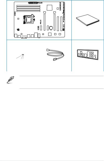
Package contents
Check your motherboard package for the following items.
ASUS P8Z77-V LX2 motherboard
|
Support DVD |
2 x Serial ATA 6.0 Gb/s cables |
1 x I/O shield |
||
•If any of the above items is damaged or missing, contact your retailer.
•The illustrated items above are for reference only.Actual product specifications may vary with different models.
xii
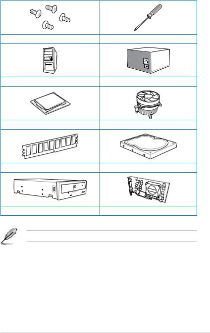
Installation tools and components
|
1 bag of screws |
Philips (cross) screwdriver |
|
PC chassis |
Power supply unit |
|
Intel LGA1155 CPU |
Intel LGA1155 CPU Fan |
|
DIMM |
SATA hard disk drive |
|
SATA optical disc drive (optional) |
Graphics card (optional) |
The tools and components in the table above are not included in the motherboard package.
xiii

xiv
Product introduction |
1 |
1.1Special features
1.1.1Product highlights
LGA1155 socket for Intel® 2nd/3rd Generation Core™ i7 / Core™ i5 / Core™ i3, Pentium®, and Celeron® Processors
This motherboard supports Intel 2nd/3rd generation Core™ i7/i5/i3, Pentium, and Celeron processors in the LGA1155 package. It provides great graphics and system performance with its GPU, dual-channel DDR3 memory slots, and PCI Express 2.0/3.0 expansion slots.
Intel® Z77 Express Chipset
Intel® Z77 Express Chipset is a single-chipset that supports the 1155 socket Intel® 2nd/3rd generation Core™ i7/i5/ i3, Pentium®, and Celeron® processors. It utilizes the serial point-to- point links, which increases bandwidth and enhances the system’s performance. It natively supports four USB 3.0 ports for up to ten times faster transfer rate than USB 2.0, and enables the iGPU function for Intel® integrated graphics performance.
Dual-ChannelDDR32400(O.C.)*/2200(O.C.)*/2133(O.C)/1866(O.C.)/1600/1333/
1066 Support
The motherboard supports DDR3 memory that features data transfer rates of 2400(O.C.)* /
2200(O.C.)* / 2133(O.C.) / 1866(O.C.)/ 1600 / 1333 / 1066 MHz to meet the higher bandwidth requirements of the latest 3D graphics, multimedia, and Internet applications. The dualchannel DDR3 architecture enlarges the bandwidth of your system memory to boost system performance.
*Due to the behavior of Intel® 2nd Generation processors, DDR3 2200 (and above)/2000/1800 MHz memory modules will run at DDR3 2133/1866/1600 MHz frequency as default.
Complete USB 3.0 Integration
ASUS facilitates strategic USB 3.0 accessibility for both the front and rear panel — 4 USB 3.0 ports in total. Experience the latest plug & play connectivity at speeds up to 10 times faster than USB 2.0. The P8Z77-V LX2 affords greater convenience to high speed connectivity.
Quad-GPU CrossFireX™ Support
The motherboard’s powerful Intel® Z77 platform optimizes PCIe allocation in multiple-GPU configurations of CrossFireX. This allows you to enjoy a never before-experienced brand new gaming style.

Intel® Smart Response Technology
Intel® Smart Response Technology, an important part of Green ASUS eco-friendly computing, reduces load and wait time, eliminates unecessary hard drive spin thus lowering power usage, and uses an installed SSD (requires 18.6 GB available space) as a cache for frequently accessed data or applications. It combines SSD performance and hard drive capacity, operating up to six times faster than a hard-drive-only system, to boost the system’s overall performance.
*Intel® 2nd/3rd generation Core™ processors on Windows® 7™ operating systems support Intel® Smart Response Technology.
**An operating system must be installed on the HDD to launch Intel® Smart Response Technology.
***The SSD is reserved for caching function.
Intel® Smart Connect Technology
Your computer can receive fresh updates for selected applications, even when the system is in sleep mode. This means less time waiting for applications to update and sync with the cloud, leading to a more efficient computing experience.
Intel® Rapid Start Technology
Intel® Rapid Start Technology allows your system to receive updates for your web applications in real-time even when your system is in sleep mode, saving wait time and power usage.
PCIe 3.0 Ready
PCI Express® 3.0 (PCIe 3.0) is the latest PCI Express bus standard with improved encoding schemes that provide twice the performance of current PCIe 2.0. Total bandwidth for a x16 link reaches a maximum of 32GB/s, double the 16GB/s of PCIe 2.0 (in x16 mode). As such, PCIe 3.0 provides users unprecedented data speeds, combined with the convenience and seamless transition offered by complete backward compatibility with PCIe 1.0 and PCIe
2.0 devices. PCIe 3.0 will become a must-have feature for users who wish to improve and optimize graphic performance, as well as have the latest technology available to them.
PCIe 3.0 speed is supported by Intel® 3rd generation processors.
Gigabit LAN solution
The onboard LAN controller is a highly integrated Gb LAN controller. It is enhanced with an
ACPI management function to provide efficient power management for advanced operating systems.
1 Chapter
|
1-2 |
Chapter 1: Product introduction |

8-channel high definition audio
The onboard 8-channel HD audio (High DefinitionAudio, previously codenamedAzalia) CODEC enables high-quality 192KHz/24-bit audio output and jack-detect feature that automatically detects and identifies what types of peripherals are plugged into the audio I/O jacks and notifies users of inappropriate connection, which means there will be no more confusion of Line-in, Line-out, and Mic jacks.
100% All High-quality Conductive Polymer Capacitors
This motherboard uses all high-quality conductive polymer capacitors for durability, improved lifespan, and enhanced thermal capacity.
ErP ready
The motherboard is European Union´s Energy-related Products (ErP) ready, and ErP requires products to meet certain energy efficiency requirements in regards to energy
Chapter 1

1.2Motherboard overview
1.2.1Before you proceed
Take note of the following precautions before you install motherboard components or change any motherboard settings.
• Unplug the power cord from the wall socket before touching any component.
• Before handling components, use a grounded wrist strap or touch a safely grounded object or a metal object, such as the power supply case, to avoid damaging them due to static electricity.
•Hold components by the edges to avoid touching the ICs on them.
•Whenever you uninstall any component, place it on a grounded antistatic pad or in the bag that came with the component.
•Before you install or remove any component, switch off the ATX power supply and detach its power cord. Failure to do so may cause severe damage to the motherboard, peripherals, or components.
1 Chapter
|
1-4 |
Chapter 1: Product introduction |
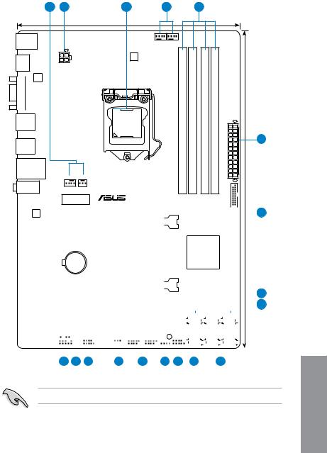
1.2.2Motherboard layout
|
1 |
2 |
3 |
1 |
4 |
||||
|
21.3cm(8.4in) |
||||||||
|
KBMS |
CPU_FAN |
|||||||
|
CHA_FAN2 |
||||||||
|
DIGI |
||||||||
|
+VRM |
||||||||
|
HDMI |
ATX12V |
|||||||
|
ASM |
||||||||
|
1442 |
||||||||
|
VGA |
module) |
module) |
module) |
module) |
||||
|
LGA1155 |
240-pin |
240-pin |
240-pin |
240-pin |
||||
|
USB34 |
(64bit,A1 |
(64bit,A2 |
(64bit,B1 |
(64bit,B2 |
||||
|
_ |
_ |
_ |
_ |
2 |
||||
|
LAN3 |
DIMM |
DIMM |
DIMM |
DIMM |
||||
|
_USB12 |
DDR3 |
DDR3 |
DDR3 |
DDR3 |
30.5cm(12.0in) |
|||
|
LAN_USB12 |
EATXPWR |
|||||||
|
CHA_FAN1 PWR_FAN |
||||||||
|
AUDIO |
||||||||
|
PCIEX1_1 |
||||||||
|
USB3_34 |
|
P8Z77-V LX2 |
|||||||||||||||||||||||||||||||||||||||||||||
|
RTL |
|||||||||||||||||||||||||||||||||||||||||||||
|
8111F |
5 |
||||||||||||||||||||||||||||||||||||||||||||
|
PCIEX16_1 |
|||||||||||||||||||||||||||||||||||||||||||||
|
PCIEX1_2 |
|||||||||||||||||||||||||||||||||||||||||||||
|
asmedia |
Intel® |
||||||||||||||||||||||||||||||||||||||||||||
|
Z77 |
|||||||||||||||||||||||||||||||||||||||||||||
|
ASM1083 |
|||||||||||||||||||||||||||||||||||||||||||||
|
Lithium Cell |
|||||||||||||||||||||||||||||||||||||||||||||
|
CMOS Power |
|||||||||||||||||||||||||||||||||||||||||||||
|
Super |
PCIEX16_2 |
6 |
|||||||||||||||||||||||||||||||||||||||||||
|
I/O |
|||||||||||||||||||||||||||||||||||||||||||||
|
7 |
|||||||||||||||||||||||||||||||||||||||||||||
|
PCI1 |
8Mb |
||||||||||||||||||||||||||||||||||||||||||||
|
BIOS |
|||||||||||||||||||||||||||||||||||||||||||||
|
ALC887 |
SATA3G_3 |
SATA3G_2 |
SATA3G_1 |
||||||||||||||||||||||||||||||||||||||||||
|
-VD2 |
|||||||||||||||||||||||||||||||||||||||||||||
|
PCI2 |
|||||||||||||||||||||||||||||||||||||||||||||
|
SB_PWR |
|||||||||||||||||||||||||||||||||||||||||||||
|
SPDIF_OUT |
COM1 |
CLRTC |
USB78 USB56 |
SATA3G_4 |
SATA6G_2 |
SATA6G_1 |
|||||||||||||||||||||||||||||||||||||||
|
AAFP |
|||||||||||||||||||||||||||||||||||||||||||||
|
SPEAKER |
F |
_ |
PANEL |
||||||||||||||||||||||||||||||||||||||||||
|
15 |
14 |
13 |
12 |
11 |
10 |
9 |
7 |
8 |
Refer to 2.2.1 Rear I/O connection for more information about rear panel connectors.
Chapter 1

Layout contents
|
Connectors/Jumpers/Slots/LED |
Page |
|||
|
1. |
CPU, Chassis and power fan connectors |
1-23 |
||
|
(4-pin CPU_FAN, 4-pin CHA_FAN1/2, 3-pin PWR_FAN) |
||||
|
2. |
EATX power connectors (24-pin EATXPWR, 4-pin EATX12V) |
1-26 |
3.Intel® CPU socket
|
4. |
DDR3 DIMM sockets |
1-7 |
|
5. |
USB 3.0 connector (20-1 pin USB3_34) |
1-24 |
|
6. |
Onboard LED (SB_PWR) |
1-19 |
|
7. |
Intel® Z77 Serial ATA 3.0 Gb/s connectors (7-pin SATA3G_1–4 [blue]) |
1-25 |
|
8. |
Intel® Z77 Serial ATA 6.0 Gb/s connectors (7-pin SATA6G_1/2 [gray]) |
1-20 |
|
9. |
System panel connector (10-1 pin F_PANEL) |
1-27 |
|
10. |
Speaker connector (4-pin SPEAKER) |
1-28 |
|
11. |
USB 2.0 connectors (10-1 pin USB56, USB78) |
1-21 |
|
12. |
Clear RTC RAM (3-pin CLRTC) |
1-18 |
|
13. |
Serial port connectors (10-1 pin COM1) |
1-19 |
|
14. |
Digital audio connector (4-1 pin SPDIF_OUT) |
1-22 |
|
15. |
Front panel audio connector (10-1 pin AAFP) |
1-22 |
1 Chapter
|
1-6 |
Chapter 1: Product introduction |
![]()
1.2.3System memory
This motherboard comes with four Double Data Rate 3 (DDR3) Dual Inline Memory Modules (DIMM) sockets. A DDR3 module has the same physical dimensions as a DDR2 DIMM but is notched differently to prevent installation on a DDR2 DIMM socket. DDR3 modules are developed for better performance with less power consumption. The figure illustrates the location of the DDR3 DIMM sockets:
|
DIMM A1 |
DIMM A2 |
DIMM B1 |
DIMM B2 |
|
P8Z77-V LX2 |
P8Z77-V LX2 240-pin DDR3 DIMM sockets
Recommended memory configurations
We recommend that you install the memory modules from the blue slots for better overclocking ability.
Chapter 1
Memory configurations
You may install 1GB, 2GB, 4GB and 8GB unbuffered non ECC DDR3 DIMMs into the DIMM sockets.
•You may install varying memory sizes in ChannelAand Channel B. The system maps the total size of the lower-sized channel for the dual-channel configuration.Any excess memory from the higher-sized channel is then mapped for single-channel operation.
•Due to the behavior of Intel® 2nd Generation processor, DDR3 2200 (and above)/2000/1800 MHz memory module will run at DDR3 2133/1866/1600 MHz frequency as default.
•According to Intel® CPU spec, DIMM voltage below 1.65V is recommended to protect the CPU.
•Always install DIMMs with the same CAS latency. For optimum compatibility, we recommend that you obtain memory modules from the same vendor.
•Due to the memory address limitation on 32-bit Windows OS, when you install 4GB or more memory on the motherboard, the actual usable memory for the OS can be about 3GB or less. For effective use of memory, we recommend that you do any of the following:
—Use a maximum of 3GB system memory if you are using a 32-bit Windows OS.
—Install a 64-bit Windows OS when you want to install 4GB or more on the motherboard.
For more details, refer to the Microsoft® support site at http://support.microsoft.com/kb/929605/en-us.
•This motherboard does not support DIMMs made up of 512Mb (64MB) chips or less (Memory chip capacity counts in Megabit, 8 Megabit/Mb = 1 Megabyte/MB).
•The default memory operation frequency is dependent on its Serial Presence Detect (SPD), which is the standard way of accessing information from a memory module. Under the default state, some memory modules for overclocking may operate at a lower frequency than the vendor-marked value. To operate at the vendor-marked
or at a higher frequency, refer to section 3.4 Ai Tweaker menu for manual memory frequency adjustment.
• For system stability, use a more efficient memory cooling system to support a full memory load (4 DIMMs) or overclocking condition.
Visit the ASUS website for the latest QVL.
1 Chapter
|
1-8 |
Chapter 1: Product introduction |

P8Z77-V LX2 Motherboard Qualified Vendors Lists (QVL) DDR3 2400MHz capability
|
Vendors |
Part No. |
Size |
SS/DS |
Chip |
Chip |
Timing |
Voltage |
DIMM socket support |
|
|
(Optional) |
|||||||||
|
Brand |
NO. |
1 DIMM |
2 DIMMs 4 DIMMs |
||||||
|
Transcend |
TX2400KLU-4GK (381850)(XMP) |
4GB(2x 2GB) |
SS |
— |
— |
9 |
1.65V |
• |
• |
*The 2400MHz memory modules above are supported on Intel® 3rd generation processors by this motherboard; however, the actual frequency support varied depending on the O.C. margin of the installed CPU.
**Due to Intel 2nd generation processors’ behavior, DDR3 2200 and above/2000/1800 MHz memory module runs at DDR3 2133/1866/1600 MHz frequency as default.
P8Z77-V LX2 Motherboard Qualified Vendors Lists (QVL) DDR3 2250MHz capability
|
Vendors |
Part No. |
Size |
SS/ |
Chip |
Chip |
Timing |
Voltage |
DIMM socket support (Optional) |
||
|
DS |
Brand |
NO. |
1 DIMM |
2 DIMMs |
4 DIMMs |
|||||
|
Kingston |
KHX2250C9D3T1K2/4GX(XMP) |
4GB(2x 2GB) |
DS |
— |
— |
— |
1.65V |
• |
• |
• |
*The 2250MHz memory modules above are supported on Intel® 3rd generation processors by this motherboard; however, the actual frequency support varied depending on the O.C. margin of the installed CPU.
**Due to Intel 2nd generation processors’ behavior, DDR3 2200 and above/2000/1800 MHz memory module runs at DDR3 2133/1866/1600 MHz frequency as default.
P8Z77-V LX2 Motherboard Qualified Vendors Lists (QVL) DDR3 2200MHz capability
|
Vendors |
Part No. |
Size |
SS/ |
Chip |
Chip |
Timing |
Voltage |
DIMM socket support (Optional) |
|
DS |
Brand |
NO. |
1 DIMM 2 DIMMs 4 DIMMs |
|||||
|
G.SKILL |
F3-17600CL8D-4GBPS(XMP) |
4GB(2x 2GB) |
DS |
— |
— |
8-8-8-24 |
1.65V |
• |
|
KINGMAX |
FLKE85F-B8KJAFEIH(XMP) |
4GB(2x 2GB) |
DS |
— |
— |
— |
1.5V-1.7V |
• |
*The 2200MHz memory modules above are supported on Intel® 3rd generation processors by this motherboard; however, the actual frequency support varied depending on the O.C. margin of the installed CPU.
**Due to Intel 2nd generation processors’ behavior, DDR3 2200 and above/2000/1800 MHz memory module runs at DDR3 2133/1866/1600 MHz frequency as default.
P8Z77-V LX2 Motherboard Qualified Vendors Lists (QVL) DDR3 2133MHz capability
|
Vendors |
Part No. |
Size |
SS/ |
Chip |
Chip |
Timing |
Voltage |
DIMM socket support (Optional) |
||
|
DS |
Brand |
NO. |
1 DIMM |
2 DIMMs |
4 DIMMs |
|||||
|
A-DATA |
AX3U2133GC2G9B-DG2(XMP) |
2GB |
SS |
— |
— |
9-11-9-27 |
1.55~1.75V |
• |
||
|
CORSAIR |
CMT4GX3M2A2133C9(XMP) |
4GB(2x 2GB) |
DS |
— |
— |
9-10-9-24 |
1.65V |
• |
||
|
CORSAIR |
CMT4GX3M2B2133C9(XMP) |
4GB(2x 2GB) |
DS |
— |
— |
9-10-9-27 |
1.50V |
• |
• |
|
|
GEIL |
GE34GB2133C9DC(XMP) |
2GB |
DS |
— |
— |
9-9-9-28 |
1.65V |
• |
• |
|
|
GEIL |
GU34GB2133C9DC(XMP) |
4GB(2 x 2GB) |
DS |
— |
— |
9-9-9-28 |
1.65V |
• |
• |
• |
|
KINGSTON |
KHX2133C9AD3T1K2/4GX(XMP) |
4GB(2x 2GB ) |
DS |
— |
— |
— |
1.65V |
• |
• |
• |
|
KINGSTON |
KHX2133C9AD3X2K2/4GX(XMP) |
4GB(2 x 2GB) |
DS |
— |
— |
9-11-9-27 |
1.65V |
• |
• |
• |
|
KINGSTON |
KHX2133C9AD3T1K4/8GX(XMP) |
8GB(4 x 2GB) |
DS |
— |
— |
9-11-9-27 |
1.65V |
• |
• |
• |
|
KINGSTON |
KHX2133C9AD3T1FK4/8GX(XMP) |
8GB(4x 2GB) |
DS |
— |
— |
— |
1.65V |
• |
• |
• |
Chapter 1

P8Z77-V LX2 Motherboard Qualified Vendors Lists (QVL) DDR3 2000MHz capability
|
Vendors |
Part No. |
Size |
SS/ |
Chip |
Chip |
Timing |
Voltage |
DIMM socket support (Optional) |
||
|
DS |
Brand |
NO. |
1 DIMM |
2 DIMMs |
4 DIMMs |
|||||
|
Apacer |
78.AAGD5.9KD(XMP) |
6GB(3 x 2GB) |
DS |
— |
— |
9-9-9-27 |
1.65V |
• |
• |
• |
|
CORSAIR |
CMZ4GX3M2A2000C10(XMP) |
4GB(2 x 2GB) |
SS |
— |
— |
10-10-10-27 |
1.50V |
• |
• |
• |
|
CORSAIR |
CMT6GX3M3A2000C8(XMP) |
6GB(3 x 2GB) |
DS |
— |
— |
8-9-8-24 |
1.65V |
• |
• |
|
|
G.SKILL |
F3-16000CL9D-4GBFLS(XMP) |
4GB(2 x 2GB) |
DS |
— |
— |
9-9-9-24 |
1.65V |
• |
• |
• |
|
G.SKILL |
F3-16000CL9D-4GBTD(XMP) |
4GB(2 x 2GB) |
DS |
— |
— |
9-9-9-27 |
1.65V |
• |
• |
• |
|
G.SKILL |
F3-16000CL6T-6GBPIS(XMP) |
6GB(3x 2GB ) |
DS |
— |
— |
6-9-6-24 |
1.65V |
• |
• |
|
|
GEIL |
GUP34GB2000C9DC(XMP) |
4GB(2 x 2GB) |
DS |
— |
— |
9-9-9-28 |
1.65V |
|||
|
KINGSTON |
KHX2000C9AD3T1K2/ |
4GB(2x 2GB ) |
DS |
— |
— |
— |
1.65V |
• |
• |
• |
|
4GX(XMP) |
||||||||||
|
KINGSTON |
KHX2000C9AD3W1K2/ |
4GB(2x 2GB ) |
DS |
— |
— |
— |
1.65V |
• |
• |
|
|
4GX(XMP) |
||||||||||
|
KINGSTON |
KHX2000C9AD3T1K2/ |
4GB(2 x 2GB) |
DS |
— |
— |
9 |
1.65V |
• |
• |
• |
|
4GX(XMP) |
||||||||||
|
KINGSTON |
KHX2000C9AD3W1K3/ |
6GB(3x 2GB ) |
DS |
— |
— |
— |
1.65V |
• |
• |
|
|
6GX(XMP) |
||||||||||
|
KINGSTON |
KHX2000C9AD3T1K3/ |
6GB(3x 2GB ) |
DS |
— |
— |
— |
1.65V |
• |
• |
|
|
6GX(XMP) |
||||||||||
|
Transcend |
TX2000KLN-8GK(XMP) |
8GB(2 x 4GB) |
DS |
— |
— |
— |
1.6V |
• |
• |
• |
P8Z77-V LX2 Motherboard Qualified Vendors Lists (QVL) DDR3 1866MHz capability
|
Vendors |
Part No. |
Size |
SS/ |
Chip |
Chip |
Timing |
Voltage |
DIMM socket support (Optional) |
|||
|
DS |
Brand |
NO. |
1 DIMM |
2 DIMMs |
4 DIMMs |
||||||
|
CORSAIR |
CMT4GX3M2A1866C9(XMP) |
4GB(2 x 2GB) |
DS |
— |
— |
9-9-9-24 |
1.65V |
• |
• |
• |
|
|
CORSAIR |
CMT6GX3MA1866C9(XMP) |
6GB(3 x 2GB) |
DS |
— |
— |
9-9-9-24 |
1.65V |
• |
• |
||
|
CORSAIR |
CMZ8GX3M2A1866C9(XMP) |
8GB(2 x 4GB) |
DS |
— |
— |
9-10-9-27 |
1.50V |
• |
• |
• |
|
|
G.SKILL |
F3-14900CL9D- |
8GB(2 x 4GB) |
DS |
— |
— |
9-10-9-28 |
1.5V |
• |
• |
• |
|
|
8GBXL(XMP) |
|||||||||||
|
G.SKILL |
F3-14900CL9Q- |
8GB(2GB x 4) |
DS |
— |
— |
9-9-9-24 |
1.6V |
• |
• |
• |
|
|
8GBXL(XMP) |
|||||||||||
|
KINGSTON |
KHX1866C9D3T1K3/ |
3GB(3 x 1GB) |
SS |
— |
— |
— |
1.65V |
• |
• |
• |
|
|
3GX(XMP) |
|||||||||||
|
KINGSTON |
KHX1866C9D3T1K3/ |
6GB(3 x 2GB) |
DS |
— |
— |
— |
1.65V |
• |
• |
• |
|
|
6GX(XMP) |
|||||||||||
1 Chapter
|
1-10 |
Chapter 1: Product introduction |

ASUS P8Z77-V LX2
P8Z77-V LX2 Motherboard Qualified Vendors Lists (QVL) DDR3 1600MHz capability
|
Vendors |
Part No. |
Size |
SS/ |
Chip |
Chip NO. |
Timing |
Voltage |
DIMM socket support |
|||
|
(Optional) |
|||||||||||
|
DS |
Brand |
1 DIMM |
2 DIMMs |
4 DIMMs |
|||||||
|
A-DATA |
AM2U16BC2P1 |
2GB |
SS |
A-DATA |
3CCD-150 |
— |
— |
• |
• |
• |
|
|
9A EL1126T |
|||||||||||
|
A-DATA |
AD31600E001GM(O)U3K |
3GB(3 x 1GB) |
SS |
— |
— |
8-8-8-24 |
1.65V- |
• |
• |
||
|
1.85V |
|||||||||||
|
A-DATA |
AM2U16BC4P2 |
4GB |
DS |
A-DATA |
3CCD-150 |
— |
— |
• |
• |
• |
|
|
9A EL1126T |
|||||||||||
|
A-DATA |
AX3U1600GC4G9-2G(XMP) |
8GB(2 x 4GB) |
DS |
— |
— |
9-9-9-24 |
1.55V- |
• |
• |
• |
|
|
1.75V |
|||||||||||
|
A-DATA |
AX3U1600XC4G79-2X(XMP) |
8GB(2 x 4GB) |
DS |
— |
— |
7-9-7-21 |
1.55V- |
• |
• |
• |
|
|
1.75V |
|||||||||||
|
CORSAIR |
TR3X3G1600C8D(XMP) |
3GB(3 x 1GB) |
SS |
— |
— |
8-8-8-24 |
1.65V |
• |
• |
||
|
CORSAIR |
CMD12GX3M6A1600C8(XMP) |
12GB(6x2GB) |
DS |
— |
— |
8-8-8-24 |
1.65V |
• |
• |
• |
|
|
CORSAIR |
CMP4GX3M2A1600C8(XMP) |
4GB(2 x 2GB) |
DS |
— |
— |
8-8-8-24 |
1.65V |
• |
• |
• |
|
|
CORSAIR |
CMP4GX3M2A1600C9(XMP) |
4GB(2 x 2GB) |
DS |
— |
— |
9-9-9-24 |
1.65V |
• |
• |
• |
|
|
CORSAIR |
CMP4GX3M2C1600C7(XMP) |
4GB(2 x 2GB) |
DS |
— |
— |
7-8-7-20 |
1.65V |
• |
• |
• |
|
|
CORSAIR |
CMX4GX3M2A1600C9(XMP) |
4GB(2 x 2GB) |
DS |
— |
— |
9-9-9-24 |
1.65V |
• |
• |
||
|
CORSAIR |
CMX4GX3M2A1600C9(XMP) |
4GB(2 x 2GB) |
DS |
— |
— |
9-9-9-24 |
1.65V |
• |
• |
• |
|
|
CORSAIR |
TR3X6G1600C8 G(XMP) |
6GB(3 x 2GB) |
DS |
— |
— |
8-8-8-24 |
1.65V |
• |
• |
• |
|
|
CORSAIR |
TR3X6G1600C8D G(XMP) |
6GB(3 x 2GB) |
DS |
— |
— |
8-8-8-24 |
1.65V |
• |
• |
• |
|
|
CORSAIR |
TR3X6G1600C9 G(XMP) |
6GB(3 x 2GB) |
DS |
— |
— |
9-9-9-24 |
1.65V |
• |
• |
• |
|
|
CORSAIR |
CMP8GX3M2A1600C9(XMP) |
8GB(2 x 4GB) |
DS |
— |
— |
9-9-9-24 |
1.65V |
• |
• |
• |
|
|
CORSAIR |
CMZ8GX3M2A1600C7R(XMP) |
8GB(2 x 4GB) |
DS |
— |
— |
7-8-7-20 |
1.50V |
• |
• |
• |
|
|
CORSAIR |
CMX8GX3M4A1600C9(XMP) |
8GB(4 x 2GB) |
DS |
— |
— |
9-9-9-24 |
1.65V |
• |
• |
• |
|
|
Crucial |
BL25664BN1608.16FF(XMP) |
6GB(3 x 2GB) |
DS |
— |
— |
— |
— |
• |
• |
• |
|
|
G.SKILL |
F3-12800CL9D-2GBNQ(XMP) |
2GB(2 x 1GB) |
SS |
— |
— |
9-9-9-24 |
1.5V |
• |
• |
• |
|
|
G.SKILL |
F3-12800CL7D-4GBRH(XMP) |
4GB(2 x 2GB) |
SS |
— |
— |
7-7-7-24 |
1.6V |
• |
• |
• |
|
|
G.SKILL |
F3-12800CL7D-4GBRM(XMP) |
4GB(2 x 2GB) |
DS |
— |
— |
7-8-7-24 |
1.6V |
• |
• |
• |
|
|
G.SKILL |
F3-12800CL8D-4GBRM(XMP) |
4GB(2 x 2GB) |
DS |
— |
— |
8-8-8-24 |
1.60V |
• |
• |
• |
|
|
G.SKILL |
F3-12800CL9D-4GBECO(XMP) |
4GB(2 x 2GB) |
DS |
— |
— |
9-9-9-24 |
XMP 1.35V |
• |
• |
• |
|
|
G.SKILL |
F3-12800CL9D-4GBRL(XMP) |
4GB(2 x 2GB) |
DS |
— |
— |
9-9-9-24 |
1.5V |
• |
• |
• |
|
|
G.SKILL |
F3-12800CL9T-6GBNQ(XMP) |
6GB(3 x 2GB) |
DS |
— |
— |
9-9-9-24 |
1.5V~1.6V |
• |
• |
• |
|
|
G.SKILL |
F3-12800CL7D-8GBRH(XMP) |
8GB(2 x 4GB) |
DS |
— |
— |
7-8-7-24 |
1.6V |
• |
• |
• |
|
|
G.SKILL |
F3-12800CL8D-8GBECO(XMP) |
8GB(2 x 4GB) |
DS |
— |
— |
8-8-8-24 |
XMP 1.35V |
• |
• |
• |
|
|
G.SKILL |
F3-12800CL9D-8GBRL(XMP) |
8GB(2 x 4GB) |
DS |
— |
— |
9-9-9-24 |
1.5V |
• |
• |
• |
|
|
GEIL |
GET316GB1600C9QC(XMP) |
16GB(4x |
DS |
— |
— |
9-9-9-28 |
1.6V |
• |
• |
• |
|
|
4GB) |
|||||||||||
|
GEIL |
GV34GB1600C8DC(XMP) |
2GB |
DS |
— |
— |
8-8-8-28 |
1.6V |
• |
• |
• |
|
|
KINGMAX |
FLGD45F-B8MF7 MAEH(XMP) |
1GB |
SS |
— |
— |
7 |
— |
• |
• |
||
|
KINGMAX |
FLGE85F-B8KJ9A FEIS(XMP) |
2GB |
DS |
— |
— |
— |
— |
• |
• |
• |
|
|
KINGMAX |
FLGE85F-B8MF7 MEEH(XMP) |
2GB |
DS |
— |
— |
7 |
— |
• |
|||
|
KINGSTON |
KHX1600C9D3P1K2/4G |
4GB(2 x 2GB) |
SS |
— |
— |
— |
1.5V |
• |
• |
• |
|
|
KINGSTON |
KHX1600C9D3K3/12GX(XMP) |
12GB(3x4GB) |
DS |
— |
— |
9-9-9-27 |
1.65V |
• |
• |
• |
Chapter 1
1-11

P8Z77-V LX2 Motherboard Qualified Vendors Lists (QVL) DDR3 1600MHz capability
|
Vendors |
Part No. |
Size |
SS/ |
Chip |
Chip NO. |
Timing |
Voltage |
DIMM socket support |
|||
|
(Optional) |
|||||||||||
|
DS |
Brand |
1 DIMM |
2 DIMMs |
4 DIMMs |
|||||||
|
KINGSTON |
KHX1600C9D3T1BK3/ |
12GB(3x4GB) |
DS |
— |
— |
9-9-9-27 |
1.65V |
• |
• |
• |
|
|
12GX(XMP) |
|||||||||||
|
KINGSTON |
KHX1600C9AD3/2G |
2GB |
DS |
— |
— |
— |
1.65V |
• |
• |
• |
|
|
KINGSTON |
KVR1600D3N11/2G-ES |
2GB |
DS |
KTC |
D1288JPN |
11-11- |
1.35V-1.5V |
• |
• |
• |
|
|
DPLD9U |
11-28 |
||||||||||
|
KINGSTON |
KHX1600C7D3K2/4GX(XMP) |
4GB(2x 2GB ) |
DS |
— |
— |
— |
1.65V |
• |
• |
• |
|
|
KINGSTON |
KHX1600C8D3K2/4GX(XMP) |
4GB(2 x 2GB) |
DS |
— |
— |
8 |
1.65V |
• |
• |
• |
|
|
KINGSTON |
KHX1600C8D3T1K2/4GX(XMP) |
4GB(2 x 2GB) |
DS |
— |
— |
8 |
1.65V |
• |
• |
• |
|
|
KINGSTON |
KHX1600C9D3K2/4GX(XMP) |
4GB(2 x 2GB) |
DS |
— |
— |
9 |
1.65V |
• |
• |
• |
|
|
KINGSTON |
KHX1600C9D3LK2/4GX(XMP) |
4GB(2 x 2GB) |
DS |
— |
— |
9 |
XMP 1.35V |
• |
• |
• |
|
|
KINGSTON |
KHX1600C9D3X2K2/4GX(XMP) |
4GB(2 x 2GB) |
DS |
— |
— |
9-9-9-27 |
1.65V |
• |
• |
• |
|
|
KINGSTON |
KHX1600C9D3T1K3/6GX(XMP) |
6GB(3x 2GB ) |
DS |
— |
— |
— |
1.65V |
• |
• |
• |
|
|
KINGSTON |
KHX1600C9D3K3/6GX(XMP) |
6GB(3 x 2GB) |
DS |
— |
— |
9 |
1.65V |
• |
• |
• |
|
|
KINGSTON |
KHX1600C9D3T1BK3/6GX |
6GB(3 x 2GB) |
DS |
— |
— |
9-9-9-27 |
1.65V |
• |
• |
• |
|
|
(XMP) |
|||||||||||
|
KINGSTON |
KHX1600C9D3K2/8GX(XMP) |
8GB(2 x 4GB) |
DS |
— |
— |
9-9-9-27 |
1.65V |
• |
• |
• |
|
|
KINGSTON |
KHX1600C9D3P1K2/8G |
8GB(2 x 4GB) |
DS |
— |
— |
— |
1.5V |
• |
• |
• |
|
|
Super Talent |
WA160UX6G9 |
6GB(3 x 2GB) |
DS |
— |
— |
9 |
— |
• |
• |
||
|
Transcend |
JM1600KLN-8GK |
8GB(4GBx2) |
DS |
Transcend |
TK483 |
— |
— |
• |
• |
• |
|
|
PCW3 |
|||||||||||
|
Asint |
SLZ3128M8-EGJ1D(XMP) |
2GB |
DS |
Asint |
3128M8 |
9-9-9-24 |
1.6V |
• |
• |
• |
|
|
-GJ1D |
|||||||||||
|
Elixir |
M2P2G64CB8HC9N-DG(XMP) |
2GB |
DS |
— |
— |
— |
— |
• |
• |
• |
|
|
Mushkin |
998659(XMP) |
6GB(3 x 2GB) |
DS |
— |
— |
9-9-9-24 |
1.5~1.6V |
• |
• |
• |
1 Chapter
P8Z77-V LX2 Motherboard Qualified Vendors Lists (QVL) DDR3 1333MHz capability
|
Vendors |
Part No. |
Size |
SS/ |
Chip Brand |
Chip NO. |
Timing |
Voltage |
DIMM socket support |
|||
|
(Optional) |
|||||||||||
|
DS |
1 DIMM |
2 DIMMs |
4 DIMMs |
||||||||
|
A-DATA |
AD31333001GOU |
1GB |
SS |
A-Data |
AD30908C8D-151C |
— |
— |
• |
• |
• |
|
|
E0906 |
|||||||||||
|
A-DATA |
AD3U1333C2G9 |
2GB |
SS |
A-DATA |
3CCD-1509HNA1126L |
— |
— |
• |
• |
• |
|
|
A-DATA |
AD63I1B0823EV |
2GB |
SS |
A-Data |
3CCA-1509A |
— |
— |
• |
• |
• |
|
|
A-DATA |
AM2U139C2P1 |
2GB |
SS |
ADATA |
3CCD-1509A EL1127T |
— |
— |
• |
• |
• |
|
|
A-DATA |
AX3U1333C2G9-BP |
2GB |
SS |
— |
— |
— |
— |
• |
• |
• |
|
|
A-DATA |
AD31333G001GOU |
3GB |
SS |
— |
— |
8-8-8-24 |
1.65- |
• |
• |
• |
|
|
(3 x 1GB) |
1.85V |
||||||||||
|
AXDU1333GC2 |
4GB |
1.25V- |
|||||||||
|
A-DATA |
SS |
— |
— |
9-9-9-24 |
1.35V(low |
• |
• |
• |
|||
|
G9-2G(XMP) |
(2 x 2GB) |
||||||||||
|
voltage) |
|||||||||||
|
A-DATA |
AD31333G002GMU |
2GB |
DS |
— |
— |
8-8-8-24 |
1.65- |
• |
• |
||
|
1.85V |
|||||||||||
|
A-DATA |
AD63I1C1624EV |
4GB |
DS |
A-Data |
3CCA-1509A |
— |
— |
• |
• |
• |
|
|
A-DATA |
AM2U139C4P2 |
4GB |
DS |
ADATA |
3CCD-1509A EL1127T |
— |
— |
• |
• |
• |
|
|
A-DATA |
SU3U1333W8G9-B |
8GB |
DS |
ELPIDA |
J4208BASE-DJ-F |
— |
— |
• |
|||
|
Apacer |
78.A1GC6.9L1 |
2GB |
DS |
Apacer |
AM5D5808DEWSBG |
— |
— |
• |
• |
• |
|
|
Apacer |
78.A1GC6.9L1 |
2GB |
DS |
Apacer |
AM5D5808FEQSBG |
9 |
— |
• |
• |
• |
|
|
Apacer |
AU02GFA33C9NBGC |
2GB |
DS |
Apacer |
AM5D5808APQSBG |
— |
— |
• |
• |
• |
|
|
Apacer |
78.B1GDE.9L10C |
4GB |
DS |
Apacer |
AM5D5908CEHSBG |
— |
— |
• |
• |
• |
|
|
CORSAIR |
CM3X1024-1333C9 |
1GB |
SS |
— |
— |
9-9-9-24 |
1.60V |
• |
• |
• |
|
|
CORSAIR |
TR3X3G1333C9 G |
3GB |
SS |
— |
— |
9-9-9-24 |
1.50V |
• |
• |
• |
|
|
(3 x 1GB) |
|||||||||||
|
CORSAIR |
TR3X6G1333C9 G |
6GB |
SS |
— |
— |
9-9-9-24 |
1.50V |
• |
• |
||
|
(3x 2GB) |
|||||||||||
|
CORSAIR |
CMD24GX3M6A |
24GB |
DS |
— |
— |
9-9-9-24 |
1.60V |
• |
• |
• |
|
|
1333C9(XMP) |
(6 x 4GB) |
||||||||||
|
CORSAIR |
TW3X4G1333C9D G |
4GB |
DS |
— |
— |
9-9-9-24 |
1.50V |
• |
• |
• |
|
|
(2 x 2GB) |
|||||||||||
|
CORSAIR |
CM3X4GA1333C9N2 |
4GB |
DS |
CORSAIR |
256MBDCJ |
9-9-9-24 |
— |
• |
• |
• |
|
|
GELC0401136 |
|||||||||||
|
CORSAIR |
CMX4GX3M1A1333C9 |
4GB |
DS |
— |
— |
9-9-9-24 |
1.50V |
• |
• |
• |
|
|
CORSAIR |
CMD8GX3M4A1333C7 |
8GB |
DS |
— |
— |
7-7-7-20 |
1.60V |
• |
• |
• |
|
|
(4 x 2GB) |
|||||||||||
(continued on the next page)
|
1-12 |
Chapter 1: Product introduction |

|
Vendors |
Part No. |
Size |
SS/ |
Chip Brand |
Chip NO. |
Timing |
Voltage |
DIMM socket support |
|||||
|
(Optional) |
|||||||||||||
|
DS |
1 DIMM |
2 DIMMs |
4 DIMMs |
||||||||||
|
Crucial |
CT12864BA1339.8FF |
1GB |
SS |
Micron |
9FF22D9KPT |
9 |
— |
• |
• |
• |
|||
|
Crucial |
CT25664BA1339.16FF |
2GB |
DS |
Micron |
9KF27D9KPT |
9 |
— |
• |
• |
• |
|||
|
Crucial |
BL25664BN13 |
6GB |
DS |
— |
— |
7-7-7-24 |
1.65V |
• |
• |
• |
|||
|
37.16FF (XMP) |
(3 x 2GB) |
||||||||||||
|
ELPIDA |
EBJ10UE8EDF0-DJ-F |
1GB |
SS |
ELPIDA |
J1108EDSE-DJ-F |
— |
1.35V(low |
• |
• |
• |
|||
|
voltage) |
|||||||||||||
|
ELPIDA |
EBJ21UE8EDF0-DJ-F |
2GB |
DS |
ELPIDA |
J1108EDSE-DJ-F |
— |
1.35V(low |
• |
• |
||||
|
voltage) |
|||||||||||||
|
G.SKILL |
F3-10600CL8 |
1GB |
SS |
G.SKILL |
— |
— |
— |
• |
• |
• |
|||
|
D-2GBHK(XMP) |
|||||||||||||
|
G.SKILL |
F3-10600CL |
2GB |
SS |
— |
— |
9-9-9-24 |
1.5V |
• |
• |
• |
|||
|
9D-2GBNQ |
(2 x 1GB) |
||||||||||||
|
G.SKILL |
F3-10666CL7 |
3GB |
SS |
— |
— |
7-7-7-18 |
1.5~1.6V |
• |
• |
• |
|||
|
T-3GBPK(XMP) |
(3 x 1GB) |
||||||||||||
|
G.SKILL |
F3-10666CL8D- |
4GB |
DS |
— |
— |
8-8-8- |
XMP |
• |
• |
• |
|||
|
4GBECO(XMP) |
(2 x 2GB) |
8-24 |
1.35V |
||||||||||
|
G.SKILL |
F3-10666CL |
6GB |
DS |
— |
— |
7-7-7-18 |
1.5~1.6V |
• |
• |
||||
|
7T-6GBPK(XMP) |
(3 x 2GB) |
||||||||||||
|
G.SKILL |
F3-10666C |
8GB |
DS |
— |
— |
7-7-7-21 |
1.5V |
• |
• |
• |
|||
|
L7D-8GBRH(XMP) |
(2 x 4GB) |
||||||||||||
|
GEIL |
GET316GB1333C9QC |
16GB |
DS |
— |
— |
9-9-9-24 |
1.5V |
• |
|||||
|
(4 x 4GB) |
|||||||||||||
|
GEIL |
GV32GB1333C9DC |
2GB |
DS |
— |
— |
9-9-9-24 |
1.5V |
• |
• |
• |
|||
|
(2 x 1GB) |
|||||||||||||
|
GEIL |
GG34GB1333C9DC |
4GB |
DS |
GEIL |
GL1L128M88BA12N |
9-9-9-24 |
1.3V(low |
• |
• |
• |
|||
|
(2 x 2GB) |
voltage) |
||||||||||||
|
GEIL |
GV34GB1333C9DC |
4GB |
DS |
— |
— |
9-9-9-24 |
1.5V |
• |
• |
• |
|||
|
(2 x 2GB) |
|||||||||||||
|
GEIL |
GVP34GB1333C7DC |
4GB |
DS |
— |
— |
7-7-7-24 |
1.5V |
• |
• |
• |
|||
|
(2 x 2GB) |
|||||||||||||
|
Hynix |
HMT112U6TFR8A-H9 |
1GB |
SS |
Hynix |
H5TC1G83TFRH9A |
— |
1.35V(low |
• |
• |
• |
|||
|
voltage) |
|||||||||||||
|
Hynix |
HMT325U6BFR8C-H9 |
2GB |
SS |
Hynix |
H5TQ2G83BFRH9C |
— |
— |
• |
• |
• |
|||
|
Hynix |
HMT125U6TFR8A-H9 |
2GB |
DS |
Hynix |
H5TC1G83TFRH9A |
— |
1.35V(low |
• |
• |
• |
|||
|
voltage) |
|||||||||||||
|
Hynix |
HMT351U6BFR8C-H9 |
4GB |
DS |
Hynix |
H5TQ2G83BFRH9C |
— |
— |
• |
• |
• |
|||
|
KINGMAX |
FLFD45F-B8KL9 NAES |
1GB |
SS |
KINGMAX |
KKB8FNWBFGNX-27A |
— |
— |
• |
• |
• |
|||
|
KINGMAX |
FLFE85F-C8KF9 CAES |
2GB |
SS |
KINGMAX |
KFC8FMFXF-DXX-15A |
— |
— |
• |
• |
• |
|||
|
KINGMAX |
FLFE85F-C8KL9 NAES |
2GB |
SS |
KINGMAX |
KFC8FNLXF-DXX-15A |
— |
— |
• |
• |
• |
|||
|
KINGMAX |
FLFE85F-C8KM9 NAES |
2GB |
SS |
KINGMAX |
KFC8FNMXF-BXX-15A |
— |
— |
• |
• |
• |
|||
|
KINGMAX |
FLFE85F-B8KL9 NEES |
2GB |
DS |
KINGMAX |
KKB8FNWBFGNX-26A |
— |
— |
• |
• |
• |
|||
|
KINGMAX |
FLFF65F-C8KL9 NEES |
4GB |
DS |
KINGMAX |
KFC8FNLXF-DXX-15A |
— |
— |
• |
• |
• |
|||
|
KINGMAX |
FLFF65F-C8KM9 NEES |
4GB |
DS |
KINGMAX |
KFC8FNMXF-BXX-15A |
— |
— |
• |
• |
• |
|||
|
KINGSTON |
KVR1333D3 |
1GB |
SS |
ELPIDA |
J1108BDBG-DJ-F |
9 |
1.5V |
• |
• |
• |
|||
|
N9/1G(low profile) |
|||||||||||||
|
KINGSTON |
KVR1333D3 |
2GB |
SS |
Hynix |
H5TQ2G83AFRH9C |
9 |
— |
• |
• |
• |
|||
|
N9/2G(low profile) |
|||||||||||||
|
KINGSTON |
KVR1333D3S8N9/2G |
2GB |
SS |
Micron |
IID77 D9LGK |
— |
1.5V |
• |
• |
• |
|||
|
KINGSTON |
KVR1333D3S |
2GB |
SS |
ELPIDA |
J2108BCSE-DJ-F |
— |
1.5V |
• |
• |
• |
|||
|
8N9/2G-SP(low profile) |
|||||||||||||
|
KINGSTON |
KVR1333D3 |
2GB |
DS |
ELPIDA |
J1108BFBG-DJ-F |
9 |
1.5V |
• |
• |
• |
|||
|
N9/2G(low profile) |
|||||||||||||
|
KINGSTON |
KVR1333D3N9/2G |
2GB |
DS |
KTC |
D1288JPNDPLD9U |
9 |
1.5V |
• |
• |
• |
|||
|
KINGSTON |
KVR1333D3N9/2G |
2GB |
DS |
ELPIDA |
J1108BDSE-DJ-F |
9 |
1.5V |
• |
• |
• |
|||
|
KINGSTON |
KVR1333D3 |
2GB |
DS |
KTC |
D1288JEMFNGD9U |
— |
1.5V |
• |
• |
• |
|||
|
N9/2G-SP(low profile) |
|||||||||||||
|
KINGSTON |
KVR1333D3N9/2G- |
2GB |
DS |
KINGSTON |
D1288JPSFPGD9U |
— |
1.5V |
• |
• |
• |
|||
|
SP(low profile) |
|||||||||||||
|
KINGSTON |
KHX1333C7 |
4GB |
DS |
— |
— |
7 |
1.65V |
• |
• |
• |
|||
|
D3K2/4GX(XMP) |
(2 x 2GB) |
||||||||||||
|
KINGSTON |
KHX1333C9D3UK2/ |
4GB |
DS |
— |
— |
9 |
XMP |
• |
|||||
|
4GX(XMP) |
(2 x 2GB) |
1.25V |
|||||||||||
|
KINGSTON |
KVR1333D |
4GB |
DS |
ELPIDA |
J2108BCSE-DJ-F |
9 |
1.5V |
• |
• |
• |
|||
|
3N9/4G(low profile) |
|||||||||||||
|
KINGSTON |
KVR1333D |
4GB |
DS |
ELPIDA |
J2108BCSE-DJ-F |
— |
1.5V |
• |
• |
• |
|||
|
3N9/4G(low profile) |
|||||||||||||
|
KINGSTON |
KVR1333D3N9/4G |
4GB |
DS |
KTC |
D2568JENCNGD9U |
— |
1.5V |
• |
• |
• |
|||
|
KINGSTON |
KVR1333D3N9/4G |
4GB |
DS |
Hynix |
H5TQ2G83AFR |
— |
— |
• |
• |
• |
|||
|
KINGSTON |
KVR1333D3N9/4G- |
4GB |
DS |
KINGSTON |
D2568JENCPGD9U |
— |
1.5V |
• |
• |
• |
|||
|
SP(low profile) |
|||||||||||||
|
Micron |
MT4JTF12864AZ- |
1GB |
SS |
Micron |
OJD12D9LGQ |
— |
— |
• |
• |
• |
|||
|
1G4D1 |
|||||||||||||
|
Micron |
MT8JTF12864AZ- |
1GB |
SS |
Micron |
9FF22D9KPT |
9 |
— |
• |
• |
• |
|||
|
1G4F1 |
|||||||||||||
|
(continued on the next page) |
|||||||||||||
|
ASUS P8Z77-V LX2 |
1-13 |
Chapter 1

1 Chapter
|
Vendors |
Part No. |
Size |
SS/ |
Chip Brand |
Chip NO. |
Timing |
Voltage |
DIMM socket support |
|||
|
(Optional) |
|||||||||||
|
DS |
1 DIMM |
2 DIMMs |
4 DIMMs |
||||||||
|
Micron |
MT8JTF25664AZ- |
2GB |
SS |
Micron |
OJD12D9LGK |
— |
— |
• |
• |
• |
|
|
1G4D1 |
|||||||||||
|
Micron |
MT8JTF25664AZ- |
2GB |
SS |
MICRON |
IJM22 D9PFJ |
— |
— |
• |
• |
• |
|
|
1G4M1 |
|||||||||||
|
Micron |
MT16JTF25664AZ- |
2GB |
DS |
Micron |
9KF27D9KPT |
9 |
— |
• |
• |
• |
|
|
1G4F1 |
|||||||||||
|
Micron |
MT16JTF51264AZ- |
4GB |
DS |
Micron |
OLD22D9LGK |
— |
— |
• |
• |
• |
|
|
1G4D1 |
|||||||||||
|
NANYA |
NT4GC64B8HG0NF- |
4GB |
DS |
NANYA |
NT5CB256M8GN-CG |
— |
— |
• |
• |
• |
|
|
CG |
|||||||||||
|
PSC |
AL7F8G73F-DJ2 |
1GB |
SS |
PSC |
A3P1GF3FGF |
— |
— |
• |
• |
• |
|
|
PSC |
AL8F8G73F-DJ2 |
2GB |
DS |
PSC |
A3P1GF3FGF |
— |
— |
• |
• |
• |
|
|
SAMSUNG |
M378B2873FHS-CH9 |
1GB |
SS |
SAMSUNG |
K4B1G0846F |
— |
— |
• |
• |
• |
|
|
SAMSUNG |
M378B5773DH0-CH9 |
2GB |
SS |
SAMSUNG |
K4B2G0846D |
— |
— |
• |
• |
• |
|
|
SAMSUNG |
M378B5673FH0-CH9 |
2GB |
DS |
SAMSUNG |
K4B1G0846F |
— |
— |
• |
• |
• |
|
|
SAMSUNG |
M378B5273CH0-CH9 |
4GB |
DS |
SAMSUNG |
K4B2G0846C |
— |
— |
• |
• |
• |
|
|
SAMSUNG |
M378B1G73AH0-CH9 |
8GB |
DS |
SAMSUNG |
K4B4G0846A-HCH9 |
— |
— |
• |
• |
||
|
Super Talent |
W1333UA1GH |
1GB |
SS |
Hynix |
H5TQ1G83TFR |
9 |
— |
• |
• |
• |
|
|
Super Talent |
W1333UX2G8(XMP) |
2GB |
SS |
— |
— |
8 |
— |
• |
• |
||
|
(2x 1GB) |
|||||||||||
|
Super Talent |
W1333UB2GS |
2GB |
DS |
SAMSUNG |
K4B1G0846F |
9 |
— |
• |
• |
• |
|
|
Super Talent |
W1333UB4GS |
4GB |
DS |
SAMSUNG |
K4B2G0846C |
— |
— |
• |
• |
• |
|
|
Super Talent |
W1333UX6GM |
6GB |
DS |
Micron |
0BF27D9KPT |
9-9-9-24 |
1.5V |
• |
• |
• |
|
|
(3x 2GB) |
|||||||||||
|
Transcend |
JM1333KLN-2G |
2GB |
SS |
Micron |
0YD77D9LGK |
— |
— |
• |
• |
• |
|
|
Transcend |
JM1333KLN-2G |
2GB |
SS |
Hynix |
H5TQ2G83BZRH9C |
— |
— |
• |
• |
• |
|
|
Transcend |
JM1333KLU-2G |
2GB |
DS |
Transcend |
TK243PDF3 |
— |
— |
• |
• |
• |
|
|
Transcend |
TS256MLK64V3U |
2GB |
DS |
Micron |
9GF27D9KPT |
— |
— |
• |
• |
||
|
Century |
PC3-10600 DDR3 |
1GB |
SS |
NANYA |
NT5CB128M8DN-CF |
— |
— |
• |
• |
• |
|
|
-1333 9-9-9 |
|||||||||||
|
Elixir |
M2F2G64CB88D7N-CG |
2GB |
SS |
Elixir |
N2CB2G80DN-CG |
— |
— |
• |
• |
||
|
Elixir |
M2F2G64CB88G7N-CG |
2GB |
SS |
Elixir |
N2CB2G80GN-CG |
— |
— |
• |
• |
||
|
Elixir |
M2F4G64CB8HB5N- |
4GB |
DS |
Elixir |
N2CB2G80BN-CG |
— |
— |
• |
• |
• |
|
|
CG |
|||||||||||
|
Elixir |
M2F4G64CB8HD5N- |
4GB |
DS |
Elixir |
N2CB2G80DN-CG |
— |
— |
• |
• |
||
|
CG |
|||||||||||
|
KINGSHARE |
KSRPCD313332G |
2GB |
DS |
PATRIOT |
PM128M8D385-15 |
— |
— |
• |
• |
• |
|
|
KINGSTEK |
KSTD3PC-10600 |
2GB |
SS |
MICRON |
PE911-125E |
— |
— |
• |
• |
||
|
Kingtiger |
2GB DIMM PC3-10666 |
2GB |
DS |
SAMSUNG |
SEC 904 HCH9 |
— |
— |
• |
• |
• |
|
|
K4B1G0846D |
|||||||||||
|
MARKVI |
BMD32048M |
2GB |
DS |
MARKVI |
M3D1288P-13 |
— |
— |
• |
• |
• |
|
|
SION |
1333C9-1123 |
SION |
|||||||||
|
MARKVI |
BMD34096M |
4GB |
DS |
MARKVI |
M3D2568E-13 |
— |
— |
• |
• |
• |
|
|
SION |
1333C9-1124 |
SION |
|||||||||
|
PATRIOT |
PSD31G13332H |
1GB |
DS |
— |
— |
9 |
— |
• |
|||
|
PATRIOT |
PSD31G13332 |
1GB |
DS |
PATRIOT |
PM64M8D38U-15 |
— |
— |
• |
• |
||
|
PATRIOT |
PSD32G13332H |
2GB |
DS |
— |
— |
— |
— |
• |
• |
• |
|
|
RAMAXEL |
RMR1870ED48 |
2GB |
DS |
ELPIDA |
J1108BDBG-DJ-F |
— |
— |
• |
• |
• |
|
|
E8F-1333 |
|||||||||||
|
RAMAXEL |
RMR1870EC58 |
4GB |
DS |
ELPIDA |
J2108BCSE-DJ-F |
— |
— |
• |
• |
• |
|
|
E9F-1333 |
|||||||||||
|
RiDATA |
C304627CB1AG22Fe |
2GB |
DS |
RiDATA |
N/A |
9 |
— |
• |
• |
• |
|
|
RiDATA |
E304459CB1AG32Cf |
4GB |
DS |
RiDATA |
N/A |
9 |
— |
• |
• |
• |
|
|
SILICON |
SP001GBLTU133S01 |
1GB |
SS |
NANYA |
NT5CB128M8AN-CG |
9 |
— |
• |
• |
• |
|
|
POWER |
|||||||||||
|
SILICON |
SP001GBLTU133S02 |
1GB |
SS |
Elixir |
N2CB1680AN-C6 |
9 |
— |
• |
• |
• |
|
|
POWER |
|||||||||||
|
SILICON |
SP002GBLTU133S02 |
2GB |
DS |
Elixir |
N2CB1680AN-C6 |
9 |
— |
• |
• |
• |
|
|
POWER |
|||||||||||
|
TAKEMS |
TMS1GB364D081- |
1GB |
SS |
— |
— |
7-7-7-20 |
1.5V |
• |
• |
||
|
107EY |
|||||||||||
|
TAKEMS |
TMS1GB364D081- |
1GB |
SS |
— |
— |
8-8-8-24 |
1.5V |
• |
• |
||
|
138EY |
|||||||||||
|
TAKEMS |
TMS2GB364D081- |
2GB |
DS |
— |
— |
7-7-7-20 |
1.5V |
• |
• |
||
|
107EY |
|||||||||||
|
TAKEMS |
TMS2GB364D081- |
2GB |
DS |
— |
— |
8-8-8-24 |
1.5V |
• |
• |
||
|
138EY |
|||||||||||
|
TAKEMS |
TMS2GB364D082- |
2GB |
DS |
— |
— |
8-8-8-24 |
1.5V |
• |
• |
||
|
138EW |
|||||||||||
|
UMAX |
E41302GP0-73BDB |
2GB |
DS |
UMAX |
U2S24D30TP-13 |
— |
— |
• |
• |
• |
|
|
WINTEC |
3WVS31333-2G-CNR |
2GB |
DS |
AMPO |
AM3420803-13H |
— |
— |
• |
• |
• |
|
1-14 |
Chapter 1: Product introduction |
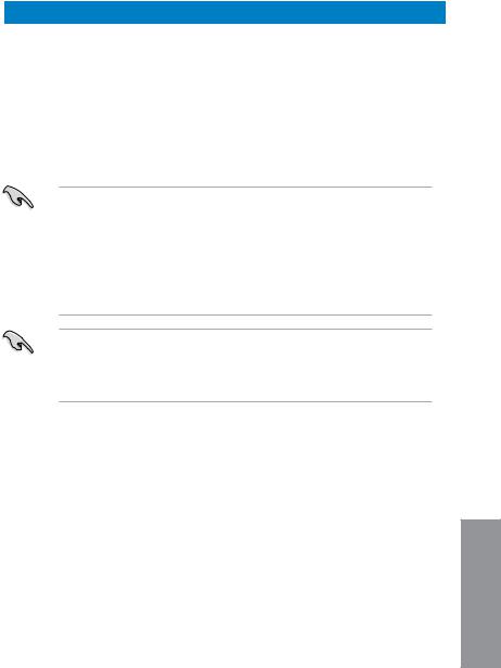
P8Z77-V LX2 Motherboard Qualified Vendors Lists (QVL) DDR3 1066MHz capability
|
Vendors |
Part No. |
Size |
SS/ |
Chip |
Chip NO. |
Timing |
Voltage |
DIMM socket support (Optional) |
|||
|
DS |
Brand |
1 DIMM |
2 DIMMs |
4 DIMMs |
|||||||
|
Crucial |
CT12864BA1067.8FF |
1GB |
SS |
Micron |
9GF22D9KPT |
7 |
— |
• |
• |
• |
|
|
Crucial |
CT25664BA1067.16FF |
2GB |
DS |
Micron |
9HF22D9KPT |
7 |
— |
• |
• |
• |
|
|
ELPIDA |
EBJ10UE8EDF0-AE-F |
1GB |
SS |
ELPIDA |
J1108EDSE-DJ-F |
— |
1.35V(low voltage) |
• |
• |
• |
|
|
ELPIDA |
EBJ21UE8EDF0-AE-F |
2GB |
DS |
ELPIDA |
J1108EDSE-DJ-F |
— |
1.35V(low voltage) |
• |
• |
• |
|
|
KINGSTON |
KVR1066D3N7/1G (low |
1GB |
SS |
ELPIDA |
J1108BFSE-DJ-F |
7 |
1.5V |
• |
• |
• |
|
|
profile) |
|||||||||||
|
KINGSTON |
KVR1066D3N7/2G |
2GB |
DS |
ELPIDA |
J1108BDSE-DJ-F |
7 |
1.5V |
• |
• |
• |
|
|
KINGSTON |
KVR1066D3N7/4G |
4GB |
DS |
Hynix |
H5TQ2G83AFR |
7 |
1.5V |
• |
• |
• |
|
|
Micron |
MT8JTF12864AZ- |
1GB |
SS |
Micron |
9GF22D9KPT |
7 |
— |
• |
• |
• |
|
|
1G1F1 |
|||||||||||
|
Micron |
MT16JTF25664AZ- |
2GB |
DS |
Micron |
9HF22D9KPT |
7 |
— |
• |
• |
• |
|
|
1G1F1 |
|||||||||||
|
Kingtiger |
2GB DIMM PC3-8500 |
2GB |
DS |
Hynix |
H5TQ1G83AFP |
— |
— |
• |
• |
• |
|
|
G7C |
Side(s): SS — Single-sided DS — Double-sided DIMM support:
•1 DIMM: Supports one (1) module inserted into any slot as Single-channel memory configuration. We suggest that you install the module intoA2 slot.
•2 DIMMs: Supports two (2) modules inserted into either the blue slots or the black slots as one pair of Dual-channel memory configuration. We suggest that you install the modules into slots A2 and B2 for better compatibility.
•4 DIMMs: Supports four (4) modules inserted into both the blue and black slots as two pairs of Dual-channel memory configuration.
•ASUS exclusively provides hyper DIMM support function.
•Hyper DIMM support is subject to the physical characteristics of individual CPUs. Load the X.M.P. or D.O.C.P. settings in the BIOS for the hyper DIMM support.
•Visit the ASUS website for the latest QVL.
Chapter 1
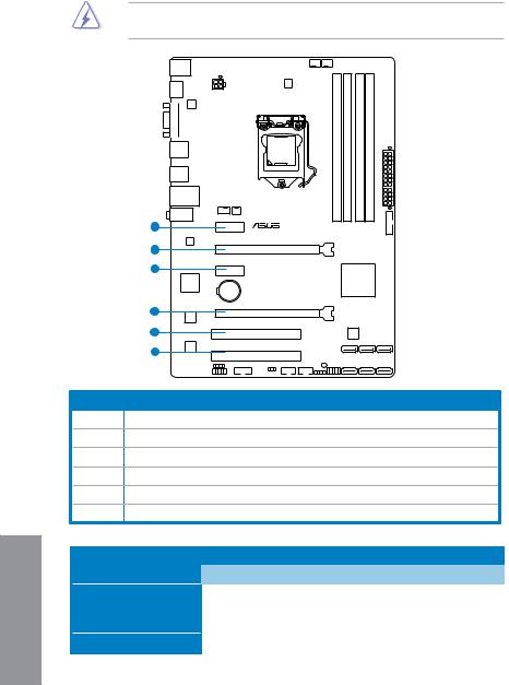
1.2.4Expansion slots
Unplug the power cord before adding or removing expansion cards. Failure to do so may cause you physical injury and damage motherboard components.
1 Chapter
1
P8Z77-V LX2
2
3
4
5
6
Slot No. Slot Description
1PCIe 2.0 x1_1 slot
2PCIe 3.0/2.0 x16_1 slot [blue] (at 16x mode)
3PCIe 2.0 x1_2 slot
4PCIe 2.0 x16_2 slot [black] (at 4x mode)
5PCI slot_1
6PCI slot_2
|
VGA configuration |
PCI Express operating mode |
||
|
PCIe 2.0 x16_1 |
PCIe 2.0 x16_2 |
||
|
Single VGA/PCIe card |
x16 |
N/A |
|
|
(Recommend for single VGA) |
|||
|
Dual VGA/PCIe card |
x16 |
x4 |
|
1-16 |
Chapter 1: Product introduction |
![]()
•In single VGA card mode, use the PCIe 3.0/2.0 x16_1 slot (blue) for a PCI Express x16 graphics card to get better performance.
•In CrossFireX™ mode, use the PCIe 3.0/2.0 x16_1 and PCIe 2.0 x16_2 slots for PCI Express x16 graphics cards to get better performance.
•We recommend that you provide sufficient power when running CrossFireX™ mode.
•Connect a chassis fan to the motherboard connector labeled CHA_FAN1/2 when using multiple graphics cards for better thermal environment.
IRQ assignments for this motherboard
|
IGD |
A |
B |
C |
D |
E |
F |
– |
G |
H |
|
shared |
– |
– |
– |
– |
– |
– |
|||
|
Audio Controller |
– |
– |
– |
– |
– |
– |
shared |
shared |
|
|
EHCI Controller |
– |
– |
– |
– |
– |
– |
– |
||
|
XHCI Controller |
shared |
– |
– |
– |
– |
– |
– |
||
|
SATA Controller |
– |
– |
– |
shared |
– |
– |
|||
|
PCIEX16_1 |
shared |
– |
– |
– |
– |
– |
– |
– |
|
|
PCIEX16_2 |
shared |
– |
– |
– |
– |
– |
– |
– |
|
|
PCIEX1_1 |
– |
– |
shared |
– |
– |
– |
– |
– |
|
|
PCIEX1_2 |
– |
– |
– |
shared |
– |
– |
– |
– |
|
|
RTL8111F |
shared |
– |
– |
– |
– |
– |
– |
– |
|
|
PCI Slot 1 |
– |
shared |
– |
– |
– |
– |
– |
– |
|
|
PCI Slot 2 |
– |
– |
shared |
– |
– |
– |
– |
– |
Chapter 1

1.2.5Jumpers
Clear RTC RAM (CLRTC)
This jumper allows you to clear the Real Time Clock (RTC) RAM in CMOS. You can clear the CMOS memory of date, time, and system setup parameters by erasing the CMOS RTC RAM data. The onboard button cell battery powers the RAM data in CMOS, which include system setup information such as system passwords.
P8Z77-V LX2
CLRTC
|
1 |
2 |
2 |
3 |
|
Normal |
Clear RTC |
||
|
(Default) |
P8Z77-V LX2 Clear RTC RAM
To erase the RTC RAM:
1.Turn OFF the computer and unplug the power cord.
2.Move the jumper cap from pins 1-2 (default) to pins 2-3. Keep the cap on pins 2-3 for about 5~10 seconds, then move the cap back to pins 1-2.
3.Plug the power cord and turn ON the computer.
4.Hold down the <Del> key during the boot process and enter BIOS setup to reenter data.
Except when clearing the RTC RAM, never remove the cap on CLRTC jumper default position. Removing the cap will cause system boot failure!
• If the steps above do not help, remove the onboard battery and move the jumper again to clear the CMOS RTC RAM data. After clearing the CMOS, reinstall the battery.
•You do not need to clear the RTC when the system hangs due to overclocking. For system failure due to overclocking, use the CPU Parameter Recall (C.P.R) feature. Shut down and reboot the system so the BIOS can automatically reset parameter settings to default values.
1 Chapter
|
1-18 |
Chapter 1: Product introduction |

1.2.6Onboard LED
1.Standby Power LED
The motherboard comes with a standby power LED that lights up to indicate that the system is ON, in sleep mode, or in soft-off mode. This is a reminder that you should shut down the system and unplug the power cable before removing or plugging in any motherboard component. The illustration below shows the location of the onboard LED.
|
P8Z77-V LX2 |
SB_PWR |
|
|
ON |
OFF |
|
|
Standby Power |
Powered Off |
P8Z77-V LX2 Onboard LED
1.2.7Internal connectors
1.Serial port connector (10-1 pin COM1)
This connector is for a serial (COM) port. Connect the serial port module cable to this connector, then install the module to a slot opening at the back of the system chassis.
COM1
|
RXD |
DTR |
DSR |
CTS |
|
DCD |
TXD |
GND |
RTS RI |
P8Z77-V LX2 Serial port (COM1) connector
The COM module is purchased separately.
Chapter 1

2.Intel® Z77 Serial ATA 6.0 Gb/s connectors (7-pin SATA6G_1/2 [gray])
These connectors connect to Serial ATA 6.0 Gb/s hard disk drives via Serial ATA 6.0 Gb/s signal cables.
If you installed Serial ATA hard disk drives, you can create a RAID 0, 1, 5, and 10 configuration with the Intel® Rapid Storage Technology through the onboard Intel® Z77 chipset.
P8Z77-V LX2
|
SATA6G_2 |
SATA6G_1 |
|||||||||||||||||||
|
GND RSATA RXP2 RSATA RXN2 GND RSATA TXN2 RSATA TXP2 GND |
GND RSATA RXP1 RSATA RXN1 GND RSATA TXN1 RSATA TXP1 GND |
|||||||||||||||||||
P8Z77-V LX2 SATA 6.0Gb/s connectors
•These connectors are set to [AHCI Mode] by default. If you intend to create a Serial ATA RAID set using these connectors, set the SATA Mode item in the BIOS to [RAID
Mode]. Refer to section 3.5.3 SATAConfiguration for details.
•Before creating a RAID set, refer to Chapter 5 RAID Support or the manual bundled in the motherboard support DVD.
•When using NCQ, set the SATA Mode in the BIOS to [AHCI Mode]. Refer to section
3.5.3 SATAConfiguration for details.
•You must install Windows® XP Service Pack 3 or later versions before using Serial ATA hard disk drives. The Serial ATA RAID feature is available only if you are using Windows® XP SP3 or later versions.
1 Chapter
|
1-20 |
Chapter 1: Product introduction |

3.USB 2.0 connectors (10-1 pin USB56, USB78)
These connectors are for USB 2.0 ports. Connect the USB module cable to any of these connectors, then install the module to a slot opening at the back of the system chassis. These USB connectors comply with USB 2.0 specification that supports up to
480 Mbps connection speed.
USB78 USB56
|
P8Z77-V LX2 |
USB+5V USBP8- |
USBP8+ |
GND NC |
||
|
PIN 1 |
USB+5V USB P7- |
USB P7+ |
GND |
PIN 1 |
|
P8Z77-V LX2 USB2.0 connectors
|
USB+5V |
USB P6- |
USB P6+ |
GND NC |
||||
|
USB+5V |
USB P5- |
USB P5+ |
GND |
Never connect a 1394 cable to the USB connectors. Doing so will damage the motherboard!
The USB module cable is purchased separately.
Chapter 1

4.Front panel audio connector (10-1 pin AAFP)
This connector is for a chassis-mounted front panel audio I/O module that supports either HD Audio or legacy AC`97 audio standard. Connect one end of the front panel audio I/O module cable to this connector.
P8Z77-V LX2
|
AGND NC SENSE1 RETUR |
SENSE2 RETUR |
|||
AAFP
PIN 1
LPORT1 RPORT1 RPORT2 SEND LPORT2 _SENSE HD-audio-compliant
pin definition
PIN 1
Line out_L
NC
Line out_R
MICPWR
MIC2
Legacy AC’97 compliant definition
P8Z77-V LX2 Front panel audio connector
•We recommend that you connect a high-definition front panel audio module to this connector to avail of the motherboard’s high-definition audio capability.
•If you want to connect a high-definition front panel audio module to this connector, set the Front Panel Select item in the BIOS setup to [HDAudio]; if you want to connect an
AC’97 front panel audio module to this connector, set the item to [AC 97]. By default, this connector is set to [HD]. Refer to 3.5.6 Onboard Devices Configuration for details.
5.Digital audio connector (4-1 pin SPDIF_OUT)
This connector is for an additional Sony/Philips Digital Interface (S/PDIF) port. Connect the S/PDIF Out module cable to this connector, then install the module to a slot opening at the back of the system chassis.
1 Chapter
|
+5V |
SPDIFOUT GND |
|
P8Z77-V LX2 |
 SPDIF_OUT
P8Z77-V LX2 Digital audio connector
The S/PDIF module is purchased separately.
|
1-22 |
Chapter 1: Product introduction |

6.CPU, chassis, and power fan connectors
(4-pin CPU_FAN, 4-pin CHA_FAN1/2; 3-pin PWR_FAN)
Connect the fan cables to the fan connectors on the motherboard, ensuring that the black wire of each cable matches the ground pin of the connector.
CPU_FAN CHA_FAN2
|
GND CPU FAN PWR CPU FAN IN CPU FAN PWM |
GND CHA FAN PWR CHA FAN IN CHA FAN PWM |
|||||||||
 CHA_FAN1 PWR_FAN
|
CHA FAN PWM CHA FAN IN CHA FAN PWR GND |
|||||||||||||||||||||||||||||||
|
Rotation +12V GND |
|||||||||||||||||||||||||||||||
P8Z77-V LX2 Fan connectors
Do not forget to connect the fan cables to the fan connectors. Insufficient air flow inside the system may damage the motherboard components. These are not jumpers! Do not place jumper caps on the fan connectors!
The CPU_FAN connector supports the CPU fan of maximum 1A (12 W) fan power.
Chapter 1

7.USB 3.0 connector (20-1 pin USB3_34)
These connectors are for the additional USB 3.0 ports, and complies with the USB 3.0 specificaton that supports up to 480 MBps connection speed. If the USB 3.0 front panel cable is available from your system chassis, with this USB 3.0 connector, you can have a front panel USB 3.0 solution.
USB3_34
P8Z77-V LX2
P8Z77-V LX2 USB3.0 Front panel connector
You can connect the ASUS front panel USB 3.0 bracket to this connector to obtain the front panel USB 3.0 solution.
1 Chapter
|
1-24 |
Chapter 1: Product introduction |

8.Intel® Z77 Serial ATA 3.0 Gb/s connectors (7-pin SATA3G_1–4 [blue])
These connectors connect to Serial ATA 3.0 Gb/s hard disk drives and optical disc drives via Serial ATA 3.0 Gb/s signal cables.
If you installed Serial ATA hard disk drives, you can create a RAID 0, 1, 5, and 10 configuration with the Intel® Rapid Storage Technology through the onboard Intel® Z77 chipset.
|
SATA3G_3 |
SATA3G_2 |
SATA3G_1 |
|||
|
GND RSATA TXP3 |
RSATA TXN3 GND RSATA RXN3 |
RSATA RXP3 |
GND |
GND RSATA TXP2 RSATA TXN2 GND RSATA RXN2 RSATA RXP2 GND |
GND RSATA TXP1 RSATA TXN1 GND RSATA RXN1 RSATA RXP1 GND |
|
P8Z77-V LX2 |
|||||
|
SATA3G_4 |
|||||
|
GND RSATA RXP4 |
RSATA RXN4 GND RSATA TXN4 |
RSATA TXP4 |
GND |
P8Z77-V LX2 SATA 3.0Gb/s connectors
•These connectors are set to [AHCI Mode] by default. If you intend to create a Serial ATA RAID set using these connectors, set the SATA Mode item in the BIOS to [RAID
Mode]. Refer to section 3.5.3 SATAConfiguration for details.
•When using NCQ, please check the SATA Mode in the BIOS is [AHCI Mode]. Refer to
3.5.3 SATAConfiguration for details.
•You must install Windows® XP Service Pack 3 or later versions before using Serial ATA hard disk drives. The Serial ATA RAID feature is available only if you are using Windows® XP SP3 or later versions.
•Before creating a RAID set, refer to Chapter 5 RAID Support or the manual bundled in the motherboard support DVD.
Chapter 1

9.ATX power connectors (24-pin EATXPWR; 4-pin EATX12V)
These connectors are for ATX power supply plugs. The power supply plugs are designed to fit these connectors in only one orientation. Find the proper orientation and push down firmly until the connectors completely fit.
|
ATX12V |
EATXPWR |
|||
|
GND |
+12V DC |
+3 Volts |
GND |
|
|
GND |
+12V DC |
+12 |
Volts |
+5 Volts |
|
PIN 1 |
+12 |
Volts |
+5 Volts |
|
|
+5V Standby |
+5 Volts |
|||
|
Power OK |
-5 Volts |
|||
|
GND |
GND |
|||
|
+5 Volts |
GND |
|||
|
P8Z77-V LX2 |
GND |
GND |
||
|
+5 Volts |
PSON# |
|||
|
GND |
GND |
|||
|
+3 |
Volts |
-12 Volts |
||
|
+3 |
Volts |
+3 Volts |
||
|
PIN 1 |
P8Z77-V LX2 ATX power connectors
• For a fully configured system, we recommend that you use a power supply unit (PSU) that complies withATX 12 V Specification 2.0 (or later version) and provides a minimum power of 450 W.
•Do not forget to connect the 4-pin EATX12 V power plug; otherwise, the system will not boot.
•We recommend that you use a PSU with higher power output when configuring a system with more power-consuming devices. The system may become unstable or may not boot up if the power is inadequate.
•If you are uncertain about the minimum power supply requirement for your system, refer to the Recommended Power Supply Wattage Calculator at http://support.asus. com/PowerSupplyCalculator/PSCalculator.aspx?SLanguage=en-us for details.
1 Chapter
|
1-26 |
Chapter 1: Product introduction |
![]()
11.System panel connector (10-1 pin PANEL)
This connector supports several chassis-mounted functions.
F_PANEL
|
PWR LED PWR BTN |
|
|
PWRLED+ PLEDPWR GND |
|
|
P8Z77-V LX2 |
PIN 1 |
|
HD_LED+ HD_LEDGround HWRST# (NC) |


 +HD_LED
 RESET
RESET
P8Z77-V LX2 System panel connector
•System power LED (2-pin PLED)
This 2-pin connector is for the system power LED. Connect the chassis power LED cable to this connector. The system power LED lights up when you turn on the system power, and blinks when the system is in sleep mode.
•Hard disk drive activity LED (2-pin +HDLED)
This 2-pin connector is for the HDD Activity LED. Connect the HDD Activity LED cable to this connector. The LED lights up or flashes when data is read from or written to the
HDD.
•Power/Soft-off button (2-pin PWRBTN)
This 2-pin connector is for the system power button.
•Reset button (2-pin RESET)
This 2-pin connector is for the chassis-mounted reset button for system reboot without turning off the system power.
Chapter 1

12.Speaker connector (4- pin SPEAKER)
This 4-pin connector is for the chassis-mounted system warning speaker. The speaker allows you to hear system beeps and warnings.
P8Z77-V LX2
SPEAKER
+5V GND GND Speaker Out
PIN 1 


P8Z77-V LX2 Speaker Out connector
1 Chapter
|
1-28 |
Chapter 1: Product introduction |

Basic Installation |
2 |
2.1Building your PC system
2.1.1Motherboard installation
The diagrams in this section are for reference only. The motherboard layout may vary with models, but the installation steps are the same for all models.
1. Install the I/O Shield to the chassis rear I/O panel.
1
Chapter 2

2.Place the motherboard into the chassis, ensuring that its rear I/O ports are aligned to the chassis’ rear I/O panel.
2 Chapter
|
2-2 |
Chapter 2: Basic installation |

3.Place six screws into the holes indicated by circles to secure the motherboard to the chassis.
P8Z77-V LX2
Chapter 2
DO NOT overtighten the screws! Doing so can damage the motherboard.

2.1.2CPU installation
The LGA1156 CPU is incompatible with the LGA1155 socket. DO NOT install a LGA1156 CPU on the LGA1155 socket.
1
A
B
2
2 Chapter
|
2-4 |
Chapter 2: Basic installation |

 Loading…
Краткое содержание страницы № 1
P8Z77-V LX2
Motherboard
Краткое содержание страницы № 2
E7821 First Edition V2 October 2012 Copyright © 2012 ASUSTeK COMPUTER INC. All Rights Reserved. No part of this manual, including the products and software described in it, may be reproduced, transmitted, transcribed, stored in a retrieval system, or translated into any language in any form or by any means, except documentation kept by the purchaser for backup purposes, without the express written permission of ASUSTeK COMPUTER INC. (“ASUS”). Product warranty or service will not be extended i
Краткое содержание страницы № 3
Contents Safety information ………………………………………………………………………………………… vi About this guide ………………………………………………………………………………………….. vii P8Z77-V LX2 specifications summary …………………………………………………………… ix Package contents ………………………………………………………………………………………… xii Installa
Краткое содержание страницы № 4
3.4 Ai Tweaker menu …………………………………………………………………………….3-8 3.5 Advanced menu ……………………………………………………………………………3-16 3.5.1 CPU Configuration …………………………………………………………..3-16 3.5.2 PCH Configuration …………………………………………………………..3-19 3.5.3 SATA Configuration …………………………………………………..
Краткое содержание страницы № 5
4.3.11 ASUS Update ………………………………………………………………….4-21 4.3.12 MyLogo2 ………………………………………………………………………..4-22 4.3.13 Audio configurations…………………………………………………………4-23 RAID support 5.1 RAID configurations ……………………………………………………………………….5-1 5.1.1 RAID definitions ……………………………………………..
Краткое содержание страницы № 6
Safety information Electrical safety • To prevent electrical shock hazard, disconnect the power cable from the electrical outlet before relocating the system. • When adding or removing devices to or from the system, ensure that the power cables for the devices are unplugged before the signal cables are connected. If possible, disconnect all power cables from the existing system before you add a device. • Before connecting or removing signal cables from the motherboard, ensure that all power
Краткое содержание страницы № 7
About this guide This user guide contains the information you need when installing and configuring the motherboard. How this guide is organized This guide contains the following parts: • Chapter 1: Product introduction This chapter describes the features of the motherboard and the new technology it supports. It includes description of the switches, jumpers, and connectors on the motherboard. • Chapter 2: Basic Installation This chapter lists the hardware setup procedures that you have to perf
Краткое содержание страницы № 8
Conventions used in this guide To ensure that you perform certain tasks properly, take note of the following symbols used throughout this manual. DANGER/WARNING: Information to prevent injury to yourself when trying to complete a task. CAUTION: Information to prevent damage to the components when trying to complete a task IMPORTANT: Instructions that you MUST follow to complete a task. NOTE: Tips and additional information to help you complete a task. Typography Bold text Indicates a menu or
Краткое содержание страницы № 9
P8Z77-V LX2 specifications summary ® CPU LGA1155 socket for Intel 3rd / 2nd Generation Core™ i7 / Core™ i5 / Core™ i3, ® ® Pentium , and Celeron processors Supports 32nm and 22nm CPU ® Supports Intel Turbo Boost technology 2.0* ® • The Intel Turbo Boost technology 2.0 support depends on the CPU types. • Refer to www.asus.com for Intel® CPU support list. ® Chipset Intel Z77 Express Chipset Memory 4 x DIMMs, max. 32GB, DDR3 2400(O.C.) / 2200(O.C.) / 2133(OC.)/1866(O.C.) /1600/1333/1066 MHz, non
Краткое содержание страницы № 10
P8Z77-V LX2 specifications summary ® USB Intel Z77 Express Chipset — Supports ASUS USB 3.0 Boost UASP Mode. — 4 x USB 3.0 /2.0 ports (2 ports at the mid-board and 2 ports at the back panel) — 8 x USB 2.0 ports (4 ports at mid-board, 4 ports at back panel) ® • The USB 3.0 ports only support Windows 7 or later versions. UASP standard only ® supports Windows 8. ASUS unique ASUS DIGI+ VRM features — Digital Power Control: Digital power Design for the CPU and iGPU — ASUS 4+1 Phase Power Design A
Краткое содержание страницы № 11
P8Z77-V LX2 specifications summary Rear panel I/O 1 x PS/2 keyboard port ports 1 x PS/2 mouse port 1 x HDMI port 1 x RGB port 1 x LAN (RJ-45) port 2 x USB 3.0/2.0 ports 4 x USB 2.0/1.1 ports 3-jack 8-channel audio I/O ports Internal I/O 1 x USB 3.0/2.0 connector supports additional 2 USB ports (19-pin) connectors 2 x USB 2.0/1.1 connectors support additional 4 USB ports 2 x SATA 6.0Gb/s connectors (gray) 4 x SATA 3.0Gb/s connectors (blue) 1 x COM port connector 1 x CPU Fan connector (4-pin) 2 x
Краткое содержание страницы № 12
Package contents Check your motherboard package for the following items. LGA1155 ASUS P8Z77-V LX2 motherboard User Guide Support DVD 2 x Serial ATA 6.0 Gb/s cables 1 x I/O shield • If any of the above items is damaged or missing, contact your retailer. • The illustrated items above are for reference only. Actual product specifications may vary with different models. xii User Manual P8Z77-V LX2
Краткое содержание страницы № 13
Installation tools and components 1 bag of screws Philips (cross) screwdriver PC chassis Power supply unit Intel LGA1155 CPU Intel LGA1155 CPU Fan DIMM SATA hard disk drive SATA optical disc drive (optional) Graphics card (optional) The tools and components in the table above are not included in the motherboard package. xiii
Краткое содержание страницы № 14
xiv
Краткое содержание страницы № 15
Product introduction 1 1.1 Special features 1.1.1 Product highlights ® LGA1155 socket for Intel 2nd/3rd Generation Core™ i7 / Core™ i5 / Core™ ® ® i3, Pentium , and Celeron Processors This motherboard supports Intel 2nd/3rd generation Core™ i7/i5/i3, Pentium, and Celeron processors in the LGA1155 package. It provides great graphics and system performance with its GPU, dual-channel DDR3 memory slots, and PCI Express 2.0/3.0 expansion slots. ® Intel Z77 Express Chipset ® ® Intel Z77 Express Chi
Краткое содержание страницы № 16
Chapter 1 Chapter 1 ® Intel Smart Response Technology ® Intel Smart Response Technology, an important part of Green ASUS eco-friendly computing, reduces load and wait time, eliminates unecessary hard drive spin thus lowering power usage, and uses an installed SSD (requires 18.6 GB available space) as a cache for frequently accessed data or applications. It combines SSD performance and hard drive capacity, operating up to six times faster than a hard-drive-only system, to boost the system’s
Краткое содержание страницы № 17
Chapter 1 Chapter 1 8-channel high definition audio The onboard 8-channel HD audio (High Definition Audio, previously codenamed Azalia) CODEC enables high-quality 192KHz/24-bit audio output and jack-detect feature that automatically detects and identifies what types of peripherals are plugged into the audio I/O jacks and notifies users of inappropriate connection, which means there will be no more confusion of Line-in, Line-out, and Mic jacks. 100% All High-quality Conductive Polymer Capacit
Краткое содержание страницы № 18
Chapter 1 Chapter 1 1.2 Motherboard overview 1.2.1 Before you proceed Take note of the following precautions before you install motherboard components or change any motherboard settings. • Unplug the power cord from the wall socket before touching any component. • Before handling components, use a grounded wrist strap or touch a safely grounded object or a metal object, such as the power supply case, to avoid damaging them due to static electricity. • Hold components by the edges to avoid tou
Краткое содержание страницы № 19
LGA1155 Chapter 1 Chapter 1 1.2.2 Motherboard layout 1 2 3 1 4 21.3cm(8.4in) CPU_FAN KBMS CHA_FAN2 DIGI +VRM HDMI ATX12V ASM 1442 USB34 2 LAN3 _USB12 LAN_USB12 CHA_FAN1 PWR_FAN AUDIO PCIEX1_1 USB3_34 P8Z77-V LX2 RTL 8111F 5 PCIEX16_1 PCIEX1_2 ® Intel asmedia ASM1083 Z77 Lithium Cell CMOS Power PCIEX16_2 Super I/O 6 8Mb PCI1 7 BIOS SATA3G_3 SATA3G_2 SATA3G_1 ALC887 -VD2 PCI2 SB_PWR USB78 USB56 SATA3G_4 SATA6G_2 SATA6G_1 COM1 CLRTC SPDIF_OUT AAFP SPEAKER F_PANEL 10 15 14 13 12 11 9 7 8 Refer to 2.
Краткое содержание страницы № 20
Chapter 1 Chapter 1 Layout contents Connectors/Jumpers/Slots/LED Page 1. CPU, Chassis and power fan connectors 1-23 (4-pin CPU_FAN, 4-pin CHA_FAN1/2, 3-pin PWR_FAN) 2. EATX power connectors (24-pin EATXPWR, 4-pin EATX12V) 1-26 ® 3. Intel CPU socket 4. DDR3 DIMM sockets 1-7 5. USB 3.0 connector (20-1 pin USB3_34) 1-24 6. Onboard LED (SB_PWR) 1-19 ® 7. Intel Z77 Serial ATA 3.0 Gb/s connectors (7-pin SATA3G_1–4 [blue]) 1-25 ® 8. Intel Z77 Serial ATA 6.0 Gb/s connectors (7-pin SATA6G_1/2 [gray]) 1-2