-
Contents
-
Table of Contents
-
Bookmarks
Quick Links
Hantek 1008
DIGITAL OSCILLOSCOPE
USER’s MANUAL
V1.0.5
Related Manuals for Hantek 1008
Summary of Contents for Hantek 1008
-
Page 1
Hantek 1008 DIGITAL OSCILLOSCOPE USER’s MANUAL V1.0.5… -
Page 2: Table Of Contents
Content General Safety Summary ………………1 Chapter 1 Getting Start ……………….. 2 1.1 System Requirement ………………3 1.2 Install and Run Software …………….3 1.4 General Features ………………. 4 1.5 General Check ………………..4 1.6 Probe Compensation ………………5 1.7 Self Calibration ………………..6 1.8 The User’s Interface ………………
-
Page 3: General Safety Summary
General Safety Summary General Safety Summary Review the following safety precautions carefully before operate the device to avoid any personal injuries or damages to the device and any products connected to it. To avoid potential hazards use the device as specified by this user’s guide only. ■…
-
Page 4: Chapter 1 Getting Start
Getting Start Chapter 1 Getting Start The oscilloscope is small, lightweight, no external power required, portable oscillo- scope. The oscilloscopes is ideal for production test, research and design and all of the applications involving analog circuits test and troubleshooting, as well as education and training.
-
Page 5: System Requirement
1.2 Install and Run Software Download Firstly, please scan the two-dimension code on scope or click the following link to download the software and user guide. https://e.hantek.com/Products/hantek1008c Install Software Double click Setup.exe. According to the information, install the software step by step.
-
Page 6: General Features
Getting Start Run the software Double click icon on desktop to run the software. 1.4 General Features Product features: 8 Channels Maximum real-time sample rate: 2.4MSa/s Memory depth: 4K points Built-in Fast Fourier Transform function(FFT); 20 Automatic measurements; …
-
Page 7: Probe Compensation
Getting Start 1.6 Probe Compensation Perform this function to match the characteristics of the probe and the channel input. This should be performed whenever attaching a probe to any input channel at the first time. From the “Probe” menu, select attenuation to 1:10. Set the switch to “X10” on the probe and connect it to CH1 of the oscilloscope.
-
Page 8: Self Calibration
Getting Start If necessary, use a non-metallic tool to adjust the trimmer capacitor of the probe for the flattest square wave being displayed on the oscilloscope. Repeat if it is necessary. 1.7 Self Calibration The self calibration routine lets you optimize the oscilloscope signal path for maximum measurement accuracy.
-
Page 9: The User’s Interface
Getting Start 1.8 The User’s Interface Click the software icon on the desk after you finished the software setting and equipment connecting. Then a user interface will be showed as follows: In addition to displaying waveforms, the display area is filled with many details about the waveform and the oscilloscope control settings.
-
Page 10
Getting Start 5. Acquisition mode 6. Horizontal Setting Panel The user can select horizontal Time/Div. 7. Vertical Setting The user can turn on/off the CH1-CH8. Also the user can change the CH1-CH8 Volt/Div and probe attenuation. 8. Marker of trigger level. 9. -
Page 11: Input Connectors
Getting Start 1.9 Input Connectors Signal Input Channel CH1-CH6: Probe compensation output and Used to connect with the probe. ground; Used to calibrate probe. USB port: Used to connect Digital output Channel: Signal Input Channel CH7-CH8: the scope with PC. Used to output digital Used to connect with the probe.
-
Page 12: Chapter3 Understanding Oscilloscope Functions
Understanding Oscilloscope Chapter3 Understanding Oscilloscope Functions Set Oscilloscope Set Vertical System Set Horizontal System Set Trigger System Save/Load Utility Function Measure Signal Display System Waveform Generator Zoom In/Out Waveforms Acquisition …
-
Page 13: Setup The Oscilloscope
Understanding Oscilloscope 3.1 Setup the Oscilloscope Save Setup The oscilloscope software saves the current setup before you close the oscilloscope software. The oscilloscope recalls this setup the next time you run the software. You can use the “Save Setup” menu to permanently save up to several different setups. Load Setup The oscilloscope can recall the last setup before the oscilloscope software was running, any saved setups, or the factory setup.
-
Page 14: Set Vertical System
Understanding Oscilloscope 3.2 Set Vertical System Click “More->Setup->Vertical” Menu. Select Channel: CH1-CH8 Channel Setting: ON/OFF: Turn on/off the channel Volt/DIV: Select the channel voltage/div Coupling: DC coupling Probe: Select the channel probe attenuation Change Volt/DIV You can click “Volt/Div” to select the voltage range. Probe Attenuation Setting Select the attenuation factor for the probe.
-
Page 15: Setup Horizontal System
Understanding Oscilloscope 3.3 Setup Horizontal System Click “More->Setup->Horizontal” Menu. Change Time/DIV Select the horizontal Time/DIV (scale factor). Also user can select left and right arrows or Combox to change Time/Div in sidebar. If the waveform acquisition is stopped, Time/Div control expands or compresses the waveform.
-
Page 16: Set Trigger System
Understanding Oscilloscope Y -T : Show the relative relation between vertical voltage and horizontal time X -Y: Show CH1 value at X axis; CH2 value at Y axis. The XY format is used to analyzer phase difference, such as those represented by Lissajous patterns. Please refer to Section.
-
Page 17
Understanding Oscilloscope Edge Trigger The trigger determines when the oscilloscope starts to acquire data and display a wave- form. When a trigger is set up properly, it can convert unstable displays or blank screens into meaningful waveforms. If the oscilloscope wants to acquire a waveform, it collects enough data so that it can draw the waveform to the left of the trigger point. -
Page 18: Set Math
Understanding Oscilloscope 3.5 Set MATH Click “More->Setup->Math” Menu. The MATH Setup window: ON/OFF: Turn On/Off the MATH Channel. Source A/B: Set the sources of the math channel. Operate: Set operates type of the math channel. Volt/DIV: Set the resolution of the math channel. Invert: Turn on/off the invert function The mathematic functions include addition, subtract, multiply and FFT.
-
Page 19
Understanding Oscilloscope The Math Function Display Fast Fourier Transform Function To use the FFT mode, you need to click in Toolbar to open the FFT setup window. The FFT setup window: You can select the Source channel, Window algorithm, FFT number, and FFT Zoom factor. -
Page 20: Set Reference
Understanding Oscilloscope Window: Selects the FFT window type Scale: Selects the vertical scale units Vert Scale: Selects the vertical scale HORI Scale: Selects the FFT zoom factor Set horizontal scale, If the information is more than the quantity displayed to the display window, more information is displayed by using scroll bar.
-
Page 21
Understanding Oscilloscope Save Click “Save ” to save the waveform to *.rfc file. The saved source window appears. The save file window will appear after you selected the saved source. The Reference Waveform Display Window: Note: If you turn on the “Reference” channel, the load file window will appear. Hantek1008 Manual… -
Page 22: Save And Load
Understanding Oscilloscope 3.7 Save and Load Click “More->File” menu to save waveform, setups and image. 1. Save Data Save waveform data as a type file 2. Save Setup Save the current oscilloscope setup to file 3. Save Image Save the software display window as a .bmp or .jpg file Load Menu Click “File”…
-
Page 23: Utility Menu
Understanding Oscilloscope This function can record input waveform from CH1 to CH4. “Storage” button: Record waveform and save it as “.dfr” file. “Start” button: Start to record waveforms. “Stop” button: Stop recording waveforms. Click “More->Setup->Record” menu again to close the window. “Play Back”…
-
Page 24: Measure Signal
Understanding Oscilloscope 3.9 Measure Signal 3.9.1 Cursor Menu Click “More->Cursor” menu. This method allows you to take measurements by moving the cursors Source The user can set the source to CH1-CH8 and MATH. When you use cursors, be sure to set the Source to the waveform on the display that you want to measure.
-
Page 25
Understanding Oscilloscope The Trace cursor display window: The Trace cursor measure result display on status bar 3) Vertical The Vertical cursors appear as vertical lines on the display and measure the vertical parameters. The Vertical cursor display window: Hantek1008 Manual… -
Page 26: Measure Menu
Understanding Oscilloscope The Vertical cursor measure result display on status bar 4) Horizontal The Horizontal cursors appear as horizontal lines on the display and measure the horizontal parameters. The Horizontal cursor display window: The Horizontal cursor measure result display on status bar: 3.9.2 Measure Menu Click “More->Measure”…
-
Page 27
Understanding Oscilloscope Peak To Peak : Peak-to-peak = Max –Min, Measured over the entire waveform Top: Voltage of the statistical maximum level, Measured over the entire waveform Base: Voltage of the statistical minimum level, Measured over the entire waveform Middle: Voltage of the 50% level from base to top RMS: The Root Mean Square voltage over the entire waveform Amplitude: Amp = Base — Top, Measured over the entire waveform Mean: The arithmetic mean over the entire waveform… -
Page 28
Understanding Oscilloscope The Measure Display Window: Note: The results of the automatic measurements will be displayed on the bottom of the screen. Maximum 8 results could be displayed at the same time. When there is no room, the next new measurement result will make the previous results moving left, out of screen. -
Page 29: Display System
Understanding Oscilloscope 3.10 Display System Display Type Click “More->Display->Type” menu. The following figure shows the type parameters setting. If the Vectors type mode is selected, the waveform will be displayed as following figure. If the Dots type mode is selected, the waveform will be displayed as following figure. Hantek1008 Manual…
-
Page 30
Understanding Oscilloscope Display Grid Click “More->Display->Grid” in main menu The grid shows: Without grid not shows: Hantek1008 Manual… -
Page 31: Zoom In/Out
Understanding Oscilloscope Intensity Click “Display->Intensity” in main menu. The following figure shows the intensity dialog. It shows the display parameters setting. You can change the grid and waveform intensity in this dialog. 3.11 Zoom In/Out The software will stop updating waveform after the user clicked “Stop” button. The user can change the waveform display by adjusting the scale and position.
-
Page 32: Print And Print Preview
Understanding Oscilloscope 3.12 Print and Print Preview Click “File” in main menu. 1. Click “More->File->Print” menu to set the printer to print the current waveform. 2. Click the “More->File->PrintPreview” menu to get into the Preview window. In “PrintPreview” window, use the “Zoom In” button and the “Zoom Out” button to change the size of the waveform graph.
-
Page 33: Generate Square Waveform
Understanding Oscilloscope 3.13 Generate Square Waveform Click “ -> Generator” to Generator setting. The following dialog will display: 1. Edit Setting Click “Edit->Edit On” to open edit setting. Hantek1008 Manual…
-
Page 34
Understanding Oscilloscope Click “Edit->Set Parameters” to set waveform parameters. Wave Num: The number of waveform channels, you can set it as 3, 5 or 8. Pluse: Setting pluse number. StartLevel: Setting the start level (High or Low) of channels. To change the pulse width, please click «File->Edit->Edit On». Then click left mouse to change the pulse width. -
Page 35
Understanding Oscilloscope 2. Output Waveform 1. Click “Operate->Output->ON”. 2. Click “File->Download”. 3. Connect D0~D7 digital channels to output waveform. Hantek1008 Manual… -
Page 36: Chapter 4 Application Example
Application Example Chapter 4 Application Example Simple Measurement Capturing a Single-Shot Signal The Application of the X-Y Taking Cursor Measurement Hantek1008 Manual…
-
Page 37: Simple Measurement
Application Example 4.1 Simple Measurement To acquire and display a signal, please do the steps as follows: 1. Connect signal to CH1 by using probe. 2. Adjust the vertical and horizontal controls to meet your measurement to optimize the waveform display. To measure the Frequency and “Vpp”, you can do these steps as follows: 1.
-
Page 38: Capturing A Single-Shot Signal
Application Example 4.2 Capturing a Single-Shot Signal To capture a single event, it needs to gather some pre-test knowledge of the signal in order to set up the trigger level and slope correctly. For example, if the event is derived from 3.3V COMS logic, a trigger level of 1.2 or higher Volts should work on a rising edge.
-
Page 39
Application Example 4. Select X-Y format at Horizontal window. The oscilloscope will displays a Lissajous pattern representing the input and the output characteristics of the circuit. 5. Adjust the scale and offset of the horizontal and vertical to a desirable waveform display. -
Page 40: Taking Cursor Measurements
Application Example between I and III quadrant, . If the main axis is at II and IV quadrant, θ must be in the range of (π/2~π) or (π~3π/2). 4.4 Taking Cursor Measurements Use cursors to make time and amplitude measurements on a waveform quickly. Measure the Peak Frequency or Time of the First Sine Waveform Do these steps: 1.
-
Page 41
Application Example Do these steps: 1. Click “More->Cursor->Source”, select CH1 (select other CH if you want measure other CH). 2. Click “More->Cursor->Type”, select Horizontal. 3. Push left mouse button, and the Horizontal lines appear. 4. Drag the mouse button to the point you want to measure. 5. -
Page 42
Application Example Trace the Amplitude: Read the details showing in the status bar. Note: Click “More->Cursor->Type”, select “Cross”, you can measure time and amplitude at one time. Hantek1008 Manual… -
Page 43: Appendix
Appendix Appendix Appendix A: Specifications Appendix B: General Maintenance Hantek1008 Manual…
-
Page 44: Appendix A: Specifications
Appendix Appendix A: Specifications Specifications Table: Acquisition Acquisition Mode Real-Time Sample Acquisition Rate 2.4MSa/s(Single Channel) Input Bandwidth 100K(Single Channel) Input Coupling Resistance: 1MΩ Input Impedance Supported Voltage 1X, 10X, 100X, 1000X, 10000X, 20:1 Attenuation Factors Maximum Input Voltage 400Vpk (DC + peak) Horizontal Scanning Speed 1ns/div ~ 20000s/div(1-2-5 sequences)
-
Page 45
Appendix Measurement Amplitude difference between cursors (ΔV) Cursor Time difference between cursors (Δt) Reciprocal of Δt in Hertz (1/ Δt) (Cross, Trace, Horizontal, Vertical) Voltage Vp-p, Vmax, Vmin, Vmean, Vamp, Vtop, Vbase, Vmid, Auto Measurement Vrms, Vcrms,Preshoot, Overshoot Measure Time Frequency, Period, Rise Time(10%~90%), Fall Measurement Time(10%~90%), Positive Width, Negative Width,… -
Page 46: Appendix B: General Maintenance
Appendix Appendix B: General Maintenance General Care Do not store or leave the oscilloscope where the device will be exposed to direct sunlight for long periods of time. Caution To avoid damages to the device or probes, do not expose them to sprays, liquids or solvents.
-
Page 1
Hantek 1008 DIGITAL OSCILLOSCOPE MANUAL Hantek1008… -
Page 2
Hantek 1008 DIGITAL OSCILLOSCOPE USER’S MANUAL Hantek1008 (Version 1. 0.0) -
Page 3: Table Of Contents
Hantek1008 Content General Safety Summary ……..………………………….……3 CHAPTER 1: Getting Started………………………………..4 System Requirement..………………………………..5 Install Software..…………………….…………..…6 Install Driver….………………………..………..11 General Features..……………………..………..16 General Check….…………………..…………..17 Probe Compensation….………..…………..17 Functional Check…………19 Seft Calibration…………21 Accessaries……………22 CHAPTER 2: Operating Basics………………………………23 The User’s Interface………………………….24 The Vertical System…………………………..30 The Horizontal System……………………..…..32 The Trigger System…………………..33 Input Connectors..……………….…………………..35 CHAPTER 3: Understanding Function..…………………..36…
-
Page 4: General Safety Summary
Hantek 1008 DIGITAL OSCILLOSCOPE General Safety Summary Review the following safety precautions carefully before operating the device to avoid any personal injuries or damages to the device including any products connected to it. To avoid any potential hazards use the device as specified by this user’s guide only.
-
Page 5: Chapter 1 Getting Started
Hantek1008 Chapter 1 Getting Started The oscilloscope is small, compact, portable oscillo-scopes! The oscilloscope is ideal for production test, research and design and all of the applications involving analog circuits test and troubleshooting, as well as education and training. In addition to the list of general features on the next page, this chapter describes how to do the following tasks: ■…
-
Page 6: System Requirement
Hantek 1008 DIGITAL OSCILLOSCOPE System Requirement To run oscilloscope software, the needs of computer configuration are as follows: Minimum System Requirement Operating System Window NT/2000/XP/VISTA/Win7 Processor Upwards of 1.00G processor Memory 256M byte Disk Space 500M disk free space Screen Resolution 800 x 600 pixel Recommended Configuration…
-
Page 7: Install Software
Hantek1008 Install Software Note: Do not connect the USB connection until the software installation is complete. 1. While in Windows, insert the installation CD into the CD-ROM drive. 2. The installation should start up automatically. Otherwise in Windows Explorer, switch to the CD-ROM drive and run Setup.exe.
-
Page 8
Hantek 1008 DIGITAL OSCILLOSCOPE 4. Choose a destination directory. Click ‘Next’ to continue. -
Page 9
Hantek1008 5. Check the setup information. Click Next to start copying files. -
Page 10
Hantek 1008 DIGITAL OSCILLOSCOPE 6. This Status dialog is displayed during files copying. 7. Updating Your System Configuration. -
Page 11
Hantek1008 8. The installation is completed. -
Page 12: Install Driver
Hantek 1008 DIGITAL OSCILLOSCOPE Install Driver 1. Connect the A-Type Plug of USB cable to your PC’s USB port. 2. Connect the B-Type Plug of USB cable to the device’s USB port. 3. New hardware is found.
-
Page 13
Hantek1008 4. New hardware search wizard starts. -
Page 14
Hantek 1008 DIGITAL OSCILLOSCOPE 5. Select the specific location. -
Page 15
Hantek1008 6. New hardware search wizard starts to search the driver. -
Page 16
Hantek 1008 DIGITAL OSCILLOSCOPE 7. New hardware wizard installs “DRIVER ”. 8. The wizard has finished installation of “DRIVER”. -
Page 17: General Features
Hantek1008 General Feature Product features: ■ 8 channel ■ Maximum real-time sample rate 2.4MSa/s ■ Max m emory depth 4K points ■ Built-in fast fourier transform function(FFT) ■ 20 Automatic measurements; ■ Automatic cursor tracking measurements; ■ Waveform storage, record and replay dynamic waveforms; ■…
-
Page 18: General Check
Hantek 1008 DIGITAL OSCILLOSCOPE General Check Please check the instrument as following steps after receiving the oscilloscope: Check the shipping container for damage: Keep the damaged shipping container or cushioning material until the contents of the shipment have been checked for completeness. Ensure and the instrument has been checked mechanically and electrically.
-
Page 19
Hantek1008 Correct Compensated Over compensated… -
Page 20: Function Check
Hantek 1008 DIGITAL OSCILLOSCOPE Under Compensated ■ If necessary, use the supplied non-metallic tool to adjust the trimmer capacitor of the probe for the flattest square wave being displayed on the oscilloscope. ■ Repeat if necessary. WARNNING: To avoid electric shock while using the probe, be sure the perfection of the insulated cable, and do not touch the metallic portions of the probe head while it is con- nected with a voltage source.
-
Page 21
Hantek1008 ■ Input a signal to a channel of the oscilloscope The oscilloscope is equipped with eight channels. Please input signal in the following steps: 1. Set the attenuation switch on the probe as 10X and connect the probe on the osci- lloscope with CH1. -
Page 22: Seft Calibration
Hantek 1008 DIGITAL OSCILLOSCOPE 3. Attach the tip of probe and ground tab to the Connector of Probe compensator. Click the button. A square wave will be displayed in several seconds. (Approximately 1 kHz, 2V, peak- to- peak). 4. Inspect CH2-CH8 with the same method. Repeat step 2 and 3.
-
Page 23: Accessaries
Hantek1008 Accessories All the accessories list below are standard accessories for the oscilloscope: ■ Four Test Cables ■ An Auto lgnition Probes ■ A USB Cable ■ A PC software of the oscilloscope…
-
Page 24: Chapter 2 Operating Basics
Hantek 1008 DIGITAL OSCILLOSCOPE Chapter 2 Operating Basics ■ The User’s Interface ■ The Menu System ■ The Vertical System ■ The Horizontal System ■ The Trigger System ■ Input Connectors…
-
Page 25: The User’s Interface
Hantek1008 The User’s Interface Click the software icon on the desk after you finished the software installation and equip- ment connecting. Then a user interface will be showed as follows: In addition to displaying waveforms, the display area is filled with many details about the waveform and the oscilloscope control settings.
-
Page 26
Hantek 1008 DIGITAL OSCILLOSCOPE 4. It shows the main time base setting. The Horizontal Panel The user can change Time/DIV, format in the panel. 6. The Vertical Panel The user can turn on/off the CH1/…/CH8. Also the user can change the CH1/ …/CH8 volt/div, coupling and probe attenuation. -
Page 27
Hantek1008 The Menu System The Main Menu 1. File: load or save data, setup 2. View: Change the user interface… -
Page 28
Hantek 1008 DIGITAL OSCILLOSCOPE 3. Setup: Setup setting 4. Display: Change wave display type 5. Cursor: Set Cursor measure type 6. Measure: Set measurement parameters… -
Page 29
Hantek1008 7.Acquire: Run, stop or other operation setting 8. Utility: Utility setting 9. Window: Window setting… -
Page 30
Hantek 1008 DIGITAL OSCILLOSCOPE 10. Vehicle: Vehicle setting 11. Help: Turn on help file… -
Page 31: The Vertical System
Hantek1008 The Vertical System Click “Setup”->” Vertical” The following figure shows the vertical parameters setting in the vertical Setup window. 1. Select channel : User can select the channel by clicking the Combo Box.
-
Page 32
Hantek 1008 DIGITAL OSCILLOSCOPE 2. ON/OFF: Turn on or off the selected channel. 3. VOLTS/DIV: Set the selected channel voltage range. 4. Coupling: DC 5. Probe: Set the Select one according to the probe attenuation factor to ensure correct vertical scale reading… -
Page 33: The Horizontal System
Hantek1008 The Horizontal System Click ”Setup”->“Horizontal” The following figure shows the horizontal parameters settings in the Horizontal System window. 1. Time/DIV: lead the setting of the time base parameters 2. Format: lead the setting of the horizontal format parameters…
-
Page 34: The Trigger System
Hantek 1008 DIGITAL OSCILLOSCOPE The Trigger System Click “Setup”-> “Trigger” The following figure shows the trigger system control. 1. Trigger Mode: Sets the trigger mode…
-
Page 35
Hantek1008 2. Trigger Sweep: Select the trigger sweep mode to AUTO, NORMAL or SINGLE 3. Tirgger Source : Select the trigger source to CH1-CH8. 4. Trigger Slope: Select the edge trigger slope to Positive or Negative slope… -
Page 36: Input Connectors
Hantek 1008 DIGITAL OSCILLOSCOPE Input Connector CH1/…/CH8: Input connectors for waveform display. CAL: Probe compensation output. Other Connector: USB Port: Connect the B-Type Plug of USB cable to this port. Power Supply : Built in waveform generator. GND.: A ground terminal- not installed in this version.
-
Page 37: Chapter 3: Understanding Function
Hantek1008 Chapter 3 Understanding Oscilloscope Functions ■ Set Oscilloscope ■ Set Vertical System ■ Set Horizontal System ■ Set Trigger System ■ Save/Load ■ Utility Function ■ Measure Signal ■ Print…
-
Page 38
Hantek 1008 DIGITAL OSCILLOSCOPE Setup the Oscilloscope Save Setup The oscilloscope software saves the current setup before you close the oscilloscope software. The oscilloscope recalls this setup the next time you run the software. You can use the “Save Setup” menu to permanently save several different setups. -
Page 39: Set Vertical System
Hantek1008 Set Vertical System Set Channel Click “Vertical” in “Setup” Menu. The Channel Selection The Channel Control Panel in sidebar. The Vertical function: Turn ON/Off : Turn on/off the channel. Volt/DIV: Select the channel voltage/div. Coupling : DC Probe: Select the channel probe attenuation Invert: Turn on/off the invert function.
-
Page 40
Hantek 1008 DIGITAL OSCILLOSCOPE You can also change the selected channel voltage in sidebar. You can left click and drag the mouse on the knob to change the voltage. Probe Attenuation Setting Select the attenuation factor for the probe. To check the probe attenuation setting, toggle the probe menu to match the attenuation factor of the probe. -
Page 41
Hantek1008 Invert The invert function turns the displayed waveform 180 degrees, with respect to the ground level. When the oscilloscope is triggered on the inverted signal, the trigger is also inverted. Click “Invert” in Vertical window The following picture shows the waveform before inversion:… -
Page 42
Hantek 1008 DIGITAL OSCILLOSCOPE The following picture shows the waveform of inversion:… -
Page 43
Hantek1008 Set Math Click “MATH” in Channel menu to set MATH channel. The MATH Setup window ON/OFF: Turn On/Off the MATH Channel. Source A/B: Set the source of the math channel. Operate: Set operation type of the math channel. Volt/DIV: Set the resolution of the math channel. Probe: Set the math channel probe attenuation. -
Page 44
Hantek 1008 DIGITAL OSCILLOSCOPE Operate Four Types: A + B Add source A and source B A — B Subtract source B from source A A × B Multiply source A by source B Divided source A by source B Convert a time-domain signal into its frequency components (spectrum). -
Page 45
Hantek1008 Set Reference Click “REF” in “Setup” menu to set REF channel. The Reference Channel Function: On/Off: Turn on/off the reference channel. Volt/DIV: Change the resolution of the reference channel. Load: Load the reference waveform from the “.rfc” file from your computer. Save: Save the current reference waveform to your computer as “.rfc”… -
Page 46
Hantek 1008 DIGITAL OSCILLOSCOPE Click “Save ” to save the waveform to *.rfc file. Then a saved source window appears. The save file window will appear after you select the saved source. The Reference Waveform Display Window: Note: If you turn on the “Reference” channel, the load file window will appear. -
Page 47: Set Horizontal System
Hantek1008 Setup Horizontal System Change Time/DIV The “Time/DIV” Select the horizontal Time/DIV (scale factor) for the main time base or for the window time base. The Horizontal Panel Click the blue knob can change Time/DIV. If the waveform acquisition is stopped, Time/DIV control expands or compresses the waveform.
-
Page 48
Hantek 1008 DIGITAL OSCILLOSCOPE Change Horizontal Position Double click the channel button to set the trigger point to the horizontal center of the screen. Horizontal position changes the displayed waveform position, relative to the trigger point. The user can drag… -
Page 49: Set Trigger System
Hantek1008 Set Trigger System Set Edge Trigger The trigger determines when the oscilloscope starts to acquire data and display a wave- form. When a trigger is set up properly, it can convert unstable displays or blank screens into meaningful waveforms. If the oscilloscope wants to acquire a waveform, it collects enough data so that it can draw the waveform to the left of the trigger point.
-
Page 50
Hantek 1008 DIGITAL OSCILLOSCOPE CH1: Select CH1 as trigger signal CH2: Select CH2 as trigger signal CH3: Select CH3 as trigger signal CH4: Select CH4 as trigger signal : Select CH5 as trigger signal : Select CH6 as trigger signal… -
Page 51: Save/Load
Hantek1008 Save/Load Save Click “File” in main menu to save data, setup and image. 1. Save Data Save waveform data as one of type file under Save Data. 2. Save Setup Save the current oscilloscope setup to file. 3. Save Image Save the software display window in a .bmp or .jpg format file.
-
Page 52
Hantek 1008 DIGITAL OSCILLOSCOPE Load Click “File” in main menu to recall saved waveform and setup. 1. Load Data Load the waveform that had saved. 2. Load Setup Load the instrument that had saved. -
Page 53: Utility Function
Hantek1008 Utility/Function Click «Untility» in main menu. Calibration The self calibration routine lets you optimize the oscilloscope signal path for maximum measurement accuracy. You can run the routine at any time but you should always run the routine if the ambient temperature changes by 5 deg or more. For accurate calibra- tion, power on the oscilloscope and wait twenty minutes to ensure it is warmed up.
-
Page 54
Hantek 1008 DIGITAL OSCILLOSCOPE Factory Setup Click “Factory Setup” in “Utility” menu to load default setups. When you click the Factory Setup in Utility menu, the oscilloscope displays the CH1 -CH8 waveforms and removes all waveforms. The oscilloscope set up for normal operation when it is shipped from the factory and can be recalled at anytime by user. -
Page 55
Hantek1008 Language Click “Language” in “Utility” menu. There are two languages in “ Language” menu. The default language is English. -
Page 56: Measure Signal
Hantek 1008 DIGITAL OSCILLOSCOPE Measure Signal Cursor Menu Click “Cursor” in main menu. This method allows you to take measurements by moving the cursors. 1. Source The user can set the source to CH1, CH2, CH3,CH4 , CH5, CH6,CH7 CH8 8 MATH.
-
Page 57
Hantek1008 1) Cross The Cross cursors appear as cross lines on the display and measure the vertical and horizontal parameters. The Cross cursor display window The Cross measure result displays on status bar. 2) Trace The Trace cursors appear as vertical lines on the display and measure the waveform amplitude at the point the waveform crosses the cursor. -
Page 58
Hantek 1008 DIGITAL OSCILLOSCOPE The Trace cursor display window The Trace cursor measure result display on status bar. 3) Vertical The Vertical cursors appear as vertical lines on the display and measure the vertical parameters. -
Page 59
Hantek1008 The Vertical cursor display window The Vertical cursor measure result display on status bar. 4) Horizontal The Horizontal cursors appear as horizontal lines on the display and measure the hori- zontal parameters. -
Page 60
Hantek 1008 DIGITAL OSCILLOSCOPE The Horizontal cursor display window The Horizontal cursor measure result display on status bar. Measure Menu Click “Measure” in main menu. The oscilloscope provides 20 parametric auto measurements (12 voltage and 8 time measurements). -
Page 61
Hantek1008 1. Source The user can use the “Source” menu to select a measure source. 2. Vertical Maximum: Voltage of the absolute maximum level, measured over the entire waveform. Minimum: Voltage of the absolute minimum level, measured over the entire waveform. Peak To Peak: Peak-to-peak = Max –… -
Page 62
Hantek 1008 DIGITAL OSCILLOSCOPE RMS: The Root Mean Square voltage over the entire waveform. Amplitude: Amp = Base – Top, measured over the entire waveform. Mean: The arithmetic mean over the entire waveform. Cycle Mean: The arithmetic mean over the first cycle in the waveform. -
Page 63
Hantek1008 +Pulse Width: Measured of the first positive pulse in the waveform. The time between the 50% amplitude points. -Pulse Width: Measured of the first negative pulse in the waveform. The time between the 50% amplitude points. 4. Clear Measure Clear all measure items on display screen. -
Page 64: The Display System
Hantek 1008 DIGITAL OSCILLOSCOPE The Display System Display Type Click “Type” in “Display” menu. The following figure shows the type parameters setting. If the Vectors type mode is selected, the waveform will be displayed as following figure.
-
Page 65
Hantek1008 If the Dots type mode is selected, the waveform will be displayed as following figure. Display Grid Click “Display” in main menu. -
Page 66
Hantek 1008 DIGITAL OSCILLOSCOPE The grid shows:… -
Page 67
Hantek1008 The grid not shows: Intensity Click “Display->Intensity” in main menu. -
Page 68
Hantek 1008 DIGITAL OSCILLOSCOPE The following figure shows the intensity dialog, which shows the display parameters setting. You can change the grid and waveform color intensity in this dialog. -
Page 69
Hantek1008 Grid Background Color Click Grid Banckground Color in Display. You can change the banckground color. Click the black box, , , and you can set the background color. -
Page 70: Print
Hantek 1008 DIGITAL OSCILLOSCOPE Print And Print Preview 1. Click “Print” in “File” menu to set the printer to print the current waveform. 2. Click the “PrintPreview” in “File” menu to get into the Preview window. In “PrintPreview ” window, use the “Zoom In” button and the “Zoom Out” button to change the size of the waveform graph.
-
Page 71
Hantek1008 The Print report… -
Page 72: Chapter 4 Application Example
Hantek 1008 DIGITAL OSCILLOSCOPE Chapter 4 Application Example ■ Simple Measurement ■ Capturing a Single-Shot Signal ■ The Application of the X-Y ■ Taking Cursor Measurement…
-
Page 73: Simple Measurement
Hantek1008 Simple Measurement User can adjust the controls to meet your measurement to optimize the waveform display. To measure the frequency and “Vpp”, you can do these steps as follows: 1. Click the “Measure->Horizontal->Frequency” button, the frequency of the signal display on the bottom of the waveform interface.
-
Page 74: Capturing A Single Shot Signal
Hantek 1008 DIGITAL OSCILLOSCOPE Capturing a Single-Shot Signal To capture a single event, it needs to gather some pre-test knowledge of the signal in order to set up the trigger level and slope correctly. For example, if the event is derived from 3.3V COMS logic, a trigger level of 1.2 or higher Volts should work on a rising edge.
-
Page 75: The Application Of The X-Y
Hantek1008 The Application of the X-Y Operation X-Y Plot acts to analyze correlation of data of two channels. Lissajous diagram is displayed in the screen when you use X-Y Plot, which enables to compare frequencies, amplitudes and phases of counterpart waveform against the reference waveform. This makes it possible to compare and analyze frequency, amplitude and phase between input and output.
-
Page 76
Hantek 1008 DIGITAL OSCILLOSCOPE Signal in X-Y Format:… -
Page 77
Hantek1008 Instruction of the Ellipse Method Sinθ = A/B or C/D, where θ = phase shift (in degrees) between the two signals. From the formula above: θ = ±arcsine (A/B) or ±arcsine (C/D) If the main axis of the ellipse is between I and III quadrant, θ must be in the range of (0~π/2) or (3π/2~2π). -
Page 78: Taking Cursor Measurements
Hantek 1008 DIGITAL OSCILLOSCOPE Taking Cursor Measurements Use cursors to make time and amplitude measurements on a waveform quickly. Measure the Peak Frequency or Time of the First Sine Waveform Do these steps: 1. Click “Cursor->Source ”, select CH1(select CH2-CH8 if you want measure CH2-CH8).
-
Page 79
Hantek1008 Read the details showing in the status bar. Measure the Amplitude of the First Waveform Peak of the Waveform Do these steps: 1. Click “Cursor->Source”, select CH1 (select CH2 if you want measure CH2). 2. Click “Cursor->Type”, select Horizontal. 3. -
Page 80
Hantek 1008 DIGITAL OSCILLOSCOPE Read the details showing in the status bar. Trace the Amplitude of a fixed position on X-axis in a Waveform Do these steps: 1. Click “Cursor->Source”, select CH1 (select CH2 if you want trace CH2). 2. Click “Cursor->Type”, select Trace. -
Page 81
Hantek1008 Read the details showing in the status bar. Note: Click “Cursor->Type”, select “Cross”, you can measure time and amplitude at the same time. -
Page 82: Chapter 5 Appendix
Hantek 1008 DIGITAL OSCILLOSCOPE Chapter 5 Appendix ■ Appendix A: Specifications ■ Appendix B: General Maintenance…
-
Page 83: Appendix A
Hantek1008 Appendix A: Specifications Specifications Table: Acquisition Sample Mode Real-Time Sample Sample Rate 2.4MSa/s(Single channel) Input Input Coupling Input Impedance Resistance: 1M Ω Supported Voltage 1X, 10X, 100X, 1000X, 10000X, 20:1 Attenuation Factors 400Vpk(DC + AC peak) Input Protection Horizontal Scanning Speed Range(Sec/Div) 1ns/div ~ 20000s/div(1-2-5 sequences) Time Base Accuracy…
-
Page 84
Hantek 1008 DIGITAL OSCILLOSCOPE Trigger Trigger Source CH1, CH2, CH3, CH4, CH5, CH6, CH7 and CH8 Trigger Mode Auto, Normal and Signal Edge Trigger Type Trigger Sensitivity 0.02 div increments Trigger Level Accuracy ±4 division Measurement Amplitude difference between cursors( Δ… -
Page 85: Appendix B
Hantek1008 Appendix B: General Maintenance General Care Do not store or leave the oscilloscope where the device will be exposed to direct sunlight for long periods of time. Caution To avoid damages to the device or probes, do not expose them to spray, liquids or solvents.
Тогда понятно, а то уже весь извелся где же на авто при диагностике такая частота нужна)))
Содержание статьи
- Китайский осциллограф
- Внешний вид модели Hantek 1008 С
- Установка и инструкция пользователя
- Особенности работы с Hantek 1008С
- Где и как купить Hantek 1008 С?
- Остались вопросы?
- Быстрый заказ
- Обратный звонок
На счет собрать себе осцил, то у меня есть МтПро поэтому и не могу понять как такой чудо прибор можно поменять на карманный осцил:biggrin:
Тогда понятно, а то уже весь извелся где же на авто при диагностике такая частота нужна)))
На счет собрать себе осцил, то у меня есть МтПро поэтому и не могу понять как такой чудо прибор можно поменять на карманный осцил:biggrin:
Так а че его разворачивать он всегда в режиме полной готовности на передвижной стойке с подключенными всеми входами (а их то там 8). Надо взял датчик давлен, или датчик разряжен или щупы для зажигания все уже подключено раз два и усе готово.
Ну а на выезде дааа . надо подсуетиться. Конечно карманный осцил самое то, но как же я без теста ускорения колен вала (ЭРЦ), и анализа сигнала датчика давления ну там потери воздуха, работа впуска выпуска . неее это уже как зависимость без них не могу:biggrin1::help:
| uncle_sem | 02.11.2015 00:12 |
Так а че его разворачивать он всегда в режиме полной готовности на передвижной стойке с подключенными всеми входами (а их то там 8). Надо взял датчик давлен, или датчик разряжен или щупы для зажигания все уже подключено раз два и усе готово.
Ну а на выезде дааа . надо подсуетиться. Конечно карманный осцил самое то, но как же я без теста ускорения колен вала (ЭРЦ), и анализа сигнала датчика давления ну там потери воздуха, работа впуска выпуска . неее это уже как зависимость без них не могу:biggrin1::help:
смотря как работать и что искать. в моей например практике большинство проблем ищутся дсо — потому что это высоковольтная часть и сигналы датчиков.
но некоторые, купив мотортестер — пихают его в каждую дырку. если же подбирать оборудование к проблеме, а не выпендриваться — то и мотортестер использовать РЕАЛЬНАЯ необходимость появляется достаточно редко.
Hantek 1008C USB 8CH автомобильный диагностический осциллограф DAQ программа генератор + » 2 шт. 60 MHz зонд «
Hantek 1008C USB 8CH автомобильный диагностический осциллограф DAQ программа генератор + » 2 шт. 60 MHz зонд «
| uncle_sem | 02.11.2015 18:49 |
Хантек кстате одним каналом запросто берет 40мГц. К нему есть пару программ и одна из них применима к мотортестерам. А недавно выпустили гораздо интересней осциллограф бюджетный приставку к компьютеру Mdso ISDS205A-его за глаза хватит для автодел и не только.:thumbup:
| [Ссылки могут видеть только зарегистрированные пользователи. Зарегистрироваться. ] |
| [Ссылки могут видеть только зарегистрированные пользователи. Зарегистрироваться. ] |
Ну и немного инфы теории современных осцил.
| [Ссылки могут видеть только зарегистрированные пользователи. Зарегистрироваться. ] |
дсо нано
| [Ссылки могут видеть только зарегистрированные пользователи. Зарегистрироваться. ] |
Более того-карманные малыши постоянно развиваются и куча прошивок уже имеется под эти осциллографы. Ну хотя бы прикольная на дсо203- вроде малыш-но мозги сломать можно от его возможностей
| [Ссылки могут видеть только зарегистрированные пользователи. Зарегистрироваться. ] |
А теперь подумайте- можно их в авто применить?
Это пишу про бюджетные варианты от 40-120 евро. Ну и чем они хуже мотортестеров конструкторов?
| uncle_sem | 02.11.2015 23:50 |
8 каналов. а нужны они? я тоже думал — много каналов это хорошо. в реальности нужно максимум наверно 4, да и то под вопросом — просто потому что одновременный съем и анализ многих сигналов обычно не нужен. бывает и так что без этого не обойтись, но типично — нафиг не упало. насчет использования на современных движках — см ниже.
Хантек кстате одним каналом запросто берет 40мГц. К нему есть пару программ и одна из них применима к мотортестерам. А недавно выпустили гораздо интересней осциллограф бюджетный приставку к компьютеру Mdso ISDS205A-его за глаза хватит для автодел и не только.:thumbup:
Более того-карманные малыши постоянно развиваются и куча прошивок уже имеется под эти осциллографы. Ну хотя бы прикольная на дсо203- вроде малыш-но мозги сломать можно от его возможностей
А теперь подумайте- можно их в авто применить?
Это пишу про бюджетные варианты от 40-120 евро. Ну и чем они хуже мотортестеров конструкторов?
на машинах 40МГц обычно ен нужно. самое быстрое — это кан-шина, и если не записывать и не анализировать сигналы на ней — то и дсо нано с его чахлыми килогерцами — более чем.
но! мотортестеры (не импортные «фирменные»), а отечественные — мт-про, диамаг, автоскоп и т.д. — они тоже развиваются. и для них появляется куча датчиков и приложений, позволяющих анализировать и равномерность вращения и давление в цилиндрах — а это уже достаточно серьезный анализ и впуска, и выпуска, и механики двигателя — если уметь этим пользоваться и понимать что тебе хочет сказать этот автоматический анализатор.
в последнее время я как раз наблюдаю печальную тенденцию, смахивающую на ситуацию в диагностике, когда сканеры только начали появляться, и начинающие диагносты просто не понимали что им хочет сказать сканер. как пример — замена датчиков коленвала и датчиков холла. просто потому что «компьютер сказал». а то что это было на заглушенном двигателе — на это как-то начхать. или другой пример, когда человек по любой проблеме начинает снимать скрипты и делать анализ мотортестером. хотя там нужно было начинать со сканера, а то и с дымогенератора.
насчет необходимости осцилла для диагностики «вообще» на современных двигателях — не соглашусь, он нужен ДАЖЕ для простых работ, типа той же высоковольтной части или проверки датчиков коленвала/распредвала, или там расходомеров воздуха. он позволяет на 100% убедиться в неисправности детали. иногда это важно.
| uncle_sem | 04.11.2015 23:49 |
| [Ссылки могут видеть только зарегистрированные пользователи. Зарегистрироваться. ] |
Казанский товарищ молодец.
| uncle_sem | 30.11.2015 12:50 |
| K-Pragmatic | 02.12.2015 20:44 |
| seishinkan | 06.02.2016 13:33 |
| Старатель | 07.02.2016 02:53 |
| Старатель | 07.02.2016 16:46 |
| uncle_sem | 07.02.2016 22:02 |
| Старатель | 08.02.2016 01:10 |
| uncle_sem | 14.02.2016 16:48 |
что он? где он? кто здесь?
| seishinkan | 17.02.2016 14:48 |
| uncle_sem | 18.02.2016 12:37 |
| Старатель | 18.02.2016 13:43 |
В «Мотор-мастер» ( Тула ) заводской шнурок USB с фильтром хорошего качества стоит 300 руб. Высылают почтой и даже наложенным платежом.
Уже 410 руб., но два фильтра — [Ссылки могут видеть только зарегистрированные пользователи. Зарегистрироваться. ]
| Medvejonok | 22.03.2016 10:54 |
Medvejonok, извините за нескромный вопрос.
А почему именно Fluke 98?
Чем вам не нравятся приборы российского производства?
Тетрисы мне никогда не нравились.
В моторке положить некуда, то и дело старается упасть.
Экран мелкий, 1-2 канала.
Нет вкусностей.
Цены непомерные.
| Medvejonok | 26.03.2016 07:37 |
Medvejonok, извините за нескромный вопрос.
А почему именно Fluke 98?
Чем вам не нравятся приборы российского производства?
Тетрисы мне никогда не нравились.
В моторке положить некуда, то и дело старается упасть.
Экран мелкий, 1-2 канала.
Нет вкусностей.
Цены непомерные.
| uncle_sem | 26.03.2016 10:33 |
ИМХО то что флюк (да и другие импортные осцилы) умеет в плане автодиагностики — это просто детский уровень в сравнении с теми же постоловским, мтпро и диамагом. то есть ради этого его брать не стоит вообще. вот насчет дсо203 — поддерживаю, у самого такой, вполне помогает решать простые задачи типа проверки системы зажигания и синхры ДПКВ-ДПРВ. разъемы там не разбалтываются совршенно, но вот «папы» обязательно нужно взять сразу же, чтобы иметь возможность свои провода к нему делать.
общался с человеком который работал на бошевском fsa — пишет что они особо не парятся, и обеспечивают «базовый уровень», то бишь проверка системы зажигания и основных датчиков. никаких скриптов, анализов — ничерта. у портативных — и подавно ничего не будет. впрочем, я б не отказался от спец-режима в dso203 для проверки системы зажигания 
насчет надежности флюка. ну как-бы да, надёжный. но он стоит под штуку баксов, а дсо203 — 150 или меньше. у меня за пару лет тьфу-тьфу-тьфу ничерта с ним не стало. допустим он издохнет лет через 6-8-10. к тому времени появится что-то более интересное. а флюк — и не выкинешь и не продашь. будет стоять на полочке, красивый такой весь из себя.
Текущее время: 08:22 . Часовой пояс GMT +3.
| Страница 4 из 10 | « Первая | 4 | 5 | 6 | > | Последняя » |
Powered by vBulletin® Version 3.8.7
Copyright ©2000 — 2019, vBulletin Solutions, Inc. Перевод:
zCarot Автодиагностика и автосканеры.

Осциллограф 1008C Hantek — это очень важный измерительный прибор, без которого сложно обойтись и профессиональным мастерам, и радиолюбителям. Поэтому многие стараются приобрести подобное устройство для своей лаборатории, но такая покупка будет стоить дорого.
Китайский осциллограф
 В российских магазинах осциллограф может стоить несколько десятков тысяч рублей.
Несмотря на всю значимость и необходимость подобных аппаратов для работы, не у каждого есть возможность сделать такую покупку.
Поэтому радиолюбители стараются сэкономить.
Лучшим способом приобретения относительно недорогого осциллографа будет его покупка в Китае.
Здесь местные компании выпускают неплохие варианты, которые обходятся в два, а иногда и в три раза дешевле, чем те, что продаются в российских магазинах.
Одним из таких устройств является осциллограф Hantek 1008С. Подобная модель обходится недорого, но работает прекрасно. Более того, данный осциллограф оснащен не только основными функциями, но и массой дополнительных настроек, которые существенно упрощают работу радиолюбителя.
Внешний вид модели Hantek 1008 С
 Покупая Hantek 1008С, нужно быть готовым к тому, что данный аппарат не идеален.
Однако он прекрасно справляется со своими основными функциями.
Поэтому, если осциллограф приобретается для радиолюбителя, то это будет хорошая покупка.
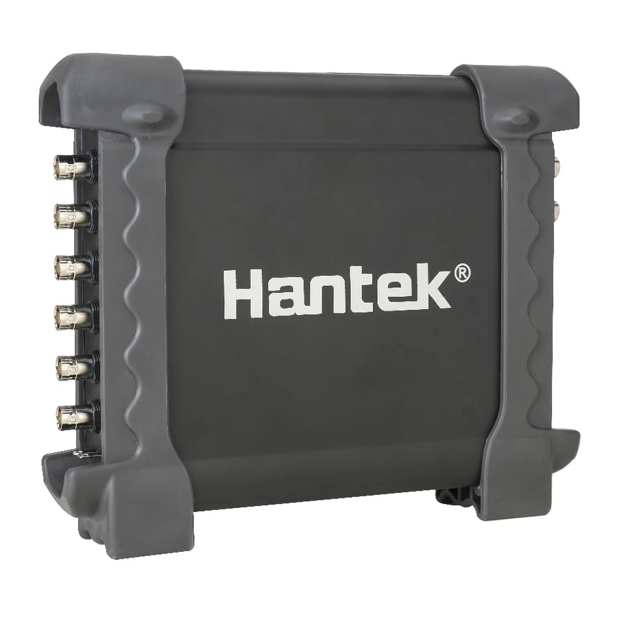
К внутреннему содержимому у некоторых пользователей есть претензии, к внешнему виду — нет.
Аппарат полностью соответствует своему описанию. Его корпус выполнен качественно, а все нужные элементы и разъемы расположены достаточно удобно.
 Сам корпус устройства выполнен в черном цвете. На боковых панелях расположены различные разъемы для подключения приборов.
Среди них имеется и USB-выход. В комплекте идет несколько наборов кабелей, поэтому дополнительно ничего приобретать не нужно.
Кроме того, в комплект входит USB-кабель, поэтому осциллограф Hantek 1008C можно подсоединить к компьютеру.
 Для правильной настройки потребуется сразу скачать нужные драйвера.
В комплекте идут установочные диски, но некоторые пользователи жалуются на то, что они работают некорректно.
Несмотря на то, что осциллограф Hantek 1008C стоит достаточно дешево, он компактен и удобен.
При габаритах в 15 на 10 см и высоте в 2 см весит устройство всего 300 г.
Такой аппарат удобно брать с собой и использовать для различных измерений вне дома.
Главное — иметь при себе планшет с USB-разъемом или ноутбук, чтобы получать обзор на экран через USB-кабель, поскольку на самом осциллографе экрана нет.
Установка и инструкция пользователя
 Для того чтобы привести осциллограф Hantek 1008С в действие, необходимо для начала подключить устройство к сети и подсоединить к компьютеру.
Самым удобным вариантом будет использование компьютера либо ноутбука с системой Windows 7. Покупатели, которые уже успели протестировать Hantek 1008С, жалуются на то, что с десятой версией Windows очень часто возникают проблемы.
Те драйвера, которые уже идут в комплекте, не подходят, а найти на «десятку» подходящие утилиты в сети бывает достаточно сложно. После того, как весь необходимый софт будет установлен на компьютер, можно приступать к работе с Hantek 1008С.
 В инструкции говорится о том, что перед тем, как использовать осциллограф Hantek 1008C, его необходимо обязательно откалибровать. Внутри прибора находится встроенный калибровочный генератор.
Все работы по подстройке устройства и нормализации его работы проводятся за счет поворота регулятора, расположенного на щупе.
После того, как все необходимые настройки будут произведены в соответствии с требованиями инструкции по эксплуатации, можно приступать к измерительным работам.
Модель Hantek 1008С можно назвать максимально простым осциллографом. Если же у мастера возникнут какие-либо вопросы, всю необходимую информацию можно получить из инструкции либо на российском официальном сайте.
Особенности работы с Hantek 1008С
 Это устройство подойдет для любителей техники, которым приходится периодически делать замеры сигналов. Более того, в комплектации к модели Hantek 1008С идет много дополнений, которые связаны с автомобилями.
Поэтому даже сами продавцы позиционируют свой товар как автомобильный осциллограф.
Однако это не говорит о том, что данный аппарат можно использовать исключительно для диагностики транспортных средств.
Стоит заметить, что комплектация Hantek 1008ch считается расширенной.
Поэтому данная модель обходится дороже аналогов. Но у покупателя есть возможность сэкономить и приобрести более дешевые комплектации, которые получили название 1008А и 1008В.
 В расширенной версии присутствуют функции для работы с автомобилем, поэтому она будет оптимальным вариантом для автолюбителей.
Что касается технических характеристик, то тут стоит заметить, что данная модель является 8-канальной. Осциллограф Hantek 1008С работает на процессоре STM 32 F103. Внутренняя начинка подобрана не слишком удачно, поэтому при измерении сигналов создается шум.
Все необходимые настройки, которые устанавливаются мастером, запоминаются устройством. Иногда возникают проблемы с расширением файлов. Оно по умолчанию идет в формате .drc. Это не всем удобно. Однако при необходимости можно установить на компьютер программу, которая позволит избавиться от этого незначительного дефекта.
Где и как купить Hantek 1008 С?
Если приобретать обычную модель в одном из российских магазинов, придется выложить более 20000 р. Осциллограф Hantek 1008C на китайском рынке будет стоить не более 5000 р. Это цена с доставкой и полной комплектацией.
Разница в стоимости очень большая. Но, покупая прибор в Китае, следует максимально внимательно отнестись к выбору продавца. Вторым важным моментом при приобретении осциллографа является курьерская доставка. Если продавец решит сэкономить на упаковке и доставке, то в целости и сохранности получить свой осциллограф вряд ли получится.
Гарантией того, что осциллограф приедет к адресату быстро и без повреждений, будет заказ модели Хантек 1008С в российских магазинах. Но в данном случае придется переплатить. Некоторые перекупщики устанавливают цену вдвое выше заводской.
При желании можно купить осциллограф у официального дистрибьютора в России. Это будет несколько дороже, но за потраченные деньги покупатель получит не только качественный и полностью рабочий товар, но и гарантию на 3 года, возможность вернуть товар на протяжении четырнадцати дней, а также полную консультацию у представителей компании.
Официальный дистрибьютор занимается и негарантийным ремонтом подобного оборудования. Но эта услуга будет платной.
В целом, если принимать во внимание отзывы пользователей, которые уже успели приобрести и протестировать осциллограф Hantek 1008C, можно сделать выводы, что это действительно хороший аппарат за свои деньги, отличная портативная модель на разные случаи жизни.
Вы можете оплатить:
- наличными при получении товара
- банковской картой Visa, MasterCard
- через другие платежные системы


Доставка товара
Самовывоз
Примерная стоимость доставки
Остались вопросы?
Оставьте свой телефон и мы сами позвоним вам 
- согласно списку совместимостей

- Описание
- Сопутствующие товары

предназначен для отключения Ad-Blue системы / SCR (мочевины) используемой на грузовых авто, автобусах и др.
эмулятор электронного контролера и датчика NOx каталитической системы грузовиков Volvo
включает 68 программ для сотен моделей автомобилей и типов ECU
выполняет функцию подмены реального пробега на тот что указан в щитке приборов

позволяет включить приборную панель вне автомобиля
- +375 29 8888-713
- +375 44 713-8888
- iDiag.by
- +375 29 8888-713
- +375 17 248-6666
- idiag.by@gmail.com
- Приём заказов с 09:00 до 20:00, без выходных
- Беларусь, 220020, г. Минск, пр. Победителей 127, офис 321
- На картеВсе контакты
Быстрый заказ
Оставьте контактный телефон и мы свяжемся с Вами для оформления заказа в рабочее время с 09:00 до 19:00
Обратный звонок
Оставьте контактный телефон и мы свяжемся с вами для оформления заказа в рабочее время с 09:00 до 19:00