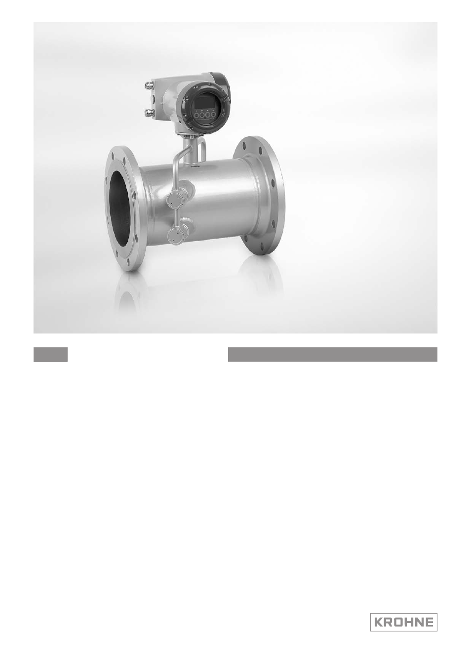
Ультразвуковой расходомер для измерения расхода
газа
OPTISONIC 7300
Руководство по эксплуатации
© KROHNE 06/2013 — 4001690602 — MA OPTISONIC 7300 R03 ru
![]()

 OPTISONIC 7300 Handbook
Ultrasonic gas flowmeter
© KROHNE 09/2012 — 4001102303 — MA OPTISONIC 7300 R03 en
:IMPRINT :::::::::::::::::::::::::::::::::::::::
All rights reserved. It is prohibited to reproduce this documentation, or any part thereof, without the prior written authorisation of KROHNE Messtechnik GmbH.
Subject to change without notice.
Copyright 2012 by
KROHNE Messtechnik GmbH — Ludwig-Krohne-Str. 5 — 47058 Duisburg (Germany)
|
2 |
www.krohne.com |
09/2012 — 4001102303 — MA OPTISONIC 7300 R03 en |

|
CONTENTS |
||||||
|
OPTISONIC 7300 |
||||||
|
1 |
Safety instructions |
6 |
||||
|
1.1 |
Intended use ……………………………………………………………………………………………………… |
6 |
||||
|
1.2 |
Certification ………………………………………………………………………………………………………. |
6 |
||||
|
1.3 |
Safety instructions from the manufacturer …………………………………………………………… |
7 |
||||
|
1.3.1 Copyright and data protection …………………………………………………………………………………… |
7 |
|||||
|
1.3.2 Disclaimer ………………………………………………………………………………………………………………. |
7 |
|||||
|
1.3.3 Product liability and warranty …………………………………………………………………………………… |
8 |
|||||
|
1.3.4 Information concerning the documentation………………………………………………………………… |
8 |
|||||
|
1.3.5 Warnings and symbols used……………………………………………………………………………………… |
9 |
|||||
|
1.4 |
Safety instructions for the operator……………………………………………………………………… |
9 |
||||
|
2 Device description |
10 |
|||||
|
2.1 |
Scope of delivery………………………………………………………………………………………………. |
10 |
||||
|
2.2 |
Device description ……………………………………………………………………………………………. |
11 |
||||
|
2.2.1 Field housing…………………………………………………………………………………………………………. |
12 |
|||||
|
2.3 |
Nameplates …………………………………………………………………………………………………….. |
13 |
||||
|
2.3.1 Example of nameplate for the compact version ………………………………………………………… |
13 |
|||||
|
2.3.2 Example of nameplate for the measuring sensor (field version) …………………………………. |
14 |
|||||
|
2.3.3 Examples of nameplates on the signal converter (field version) …………………………………. |
14 |
|||||
|
3 |
Installation |
16 |
||||
|
3.1 |
Notes on installation ………………………………………………………………………………………… |
16 |
||||
|
3.2 |
Storage …………………………………………………………………………………………………………… |
16 |
||||
|
3.3 |
Transport ………………………………………………………………………………………………………… |
17 |
||||
|
3.4 |
Installation requirements signal converter…………………………………………………………. |
17 |
||||
|
3.5 |
Installation requirements sensor ………………………………………………………………………. |
17 |
||||
|
3.5.1 Inlet and outlet ………………………………………………………………………………………………………. |
18 |
|||||
|
3.5.2 Mounting position…………………………………………………………………………………………………… |
18 |
|||||
|
3.5.3 Flange deviation …………………………………………………………………………………………………….. |
19 |
|||||
|
3.5.4 T-section ………………………………………………………………………………………………………………. |
19 |
|||||
|
3.5.5 Vibration ……………………………………………………………………………………………………………….. |
20 |
|||||
|
3.5.6 Control valve …………………………………………………………………………………………………………. |
20 |
|||||
|
3.5.7 Insulation………………………………………………………………………………………………………………. |
20 |
|||||
|
3.6 |
Mounting the field housing, remote version ………………………………………………………… |
21 |
||||
|
3.6.1 Pipe mounting ……………………………………………………………………………………………………….. |
21 |
|||||
|
3.6.2 Turning the display of the field housing version ………………………………………………………… |
22 |
|||||
|
4 Electrical connections |
23 |
|||||
|
4.1 |
Safety instructions……………………………………………………………………………………………. |
23 |
||||
|
4.2 |
Signal cable (remote versions only)……………………………………………………………………. |
23 |
||||
|
4.3 |
Power supply …………………………………………………………………………………………………… |
25 |
||||
|
4.4 |
Laying electrical cables correctly ………………………………………………………………………. |
26 |
||||
|
4.5 |
Inputs and outputs, overview …………………………………………………………………………….. |
27 |
||||
|
4.5.1 Combinations of the inputs/outputs (I/Os) ………………………………………………………………… |
27 |
|||||
|
4.5.2 Description of the CG number …………………………………………………………………………………. |
28 |
|||||
|
4.5.3 Fixed, non-alterable input/output versions……………………………………………………………….. |
29 |
|
09/2012 — 4001102303 — MA OPTISONIC 7300 R03 en |
www.krohne.com |
3 |

|
4.5.4 Alterable input/output versions……………………………………………………………………………….. |
30 |
|
|
4.6 |
Description of the inputs and outputs…………………………………………………………………. |
31 |
|
4.6.1 Control input …………………………………………………………………………………………………………. |
31 |
|
|
4.6.2 Current output ………………………………………………………………………………………………………. |
32 |
|
|
4.6.3 Pulse and frequency output…………………………………………………………………………………….. |
33 |
|
|
4.6.4 Status output and limit switch …………………………………………………………………………………. |
34 |
|
|
4.6.5 Control input …………………………………………………………………………………………………………. |
35 |
|
|
4.7 |
Connection diagrams of inputs and outputs ………………………………………………………… |
36 |
|
4.7.1 Important notes……………………………………………………………………………………………………… |
36 |
|
|
4.7.2 Description of the electrical symbols……………………………………………………………………….. |
37 |
|
|
4.7.3 Basic inputs/outputs ………………………………………………………………………………………………. |
38 |
|
|
4.7.4 Modular inputs/outputs and bus systems…………………………………………………………………. |
41 |
|
|
4.7.5 Ex i inputs/outputs …………………………………………………………………………………………………. |
49 |
|
|
4.7.6 HART® connection …………………………………………………………………………………………………. |
54 |
|
|
5 Start-up |
56 |
|
|
5.1 |
Switching on the power …………………………………………………………………………………….. |
56 |
|
5.2 |
Starting the signal converter …………………………………………………………………………….. |
56 |
|
6 Operation |
57 |
|
|
6.1 |
Display and operating elements ………………………………………………………………………… |
57 |
|
6.1.1 Display in measuring mode with 2 or 3 measured values …………………………………………… |
59 |
|
|
6.1.2 Display for selection of sub-menu and functions, 3 lines……………………………………………. |
59 |
|
|
6.1.3 Display when setting parameters, 4 lines …………………………………………………………………. |
60 |
|
|
6.1.4 Display when changing parameters, 4 lines ……………………………………………………………… |
60 |
|
|
6.1.5 Using an IR interface (option) ………………………………………………………………………………….. |
61 |
|
|
6.2 |
Menu overview…………………………………………………………………………………………………. |
62 |
|
6.3 |
Function tables ………………………………………………………………………………………………… |
65 |
|
6.3.1 Menu A, quick setup……………………………………………………………………………………………….. |
65 |
|
|
6.3.2 Menu B, test ………………………………………………………………………………………………………….. |
66 |
|
|
6.3.3 Menu C, setup ……………………………………………………………………………………………………….. |
68 |
|
|
6.3.4 Set free units…………………………………………………………………………………………………………. |
83 |
|
|
6.4 |
Description of functions ……………………………………………………………………………………. |
84 |
|
6.4.1 Reset counter in the menu «quick setup» …………………………………………………………………. |
84 |
|
|
6.4.2 Deleting error messages in the menu «quick setup»………………………………………………….. |
84 |
|
|
6.5 |
Error messages……………………………………………………………………………………………….. |
85 |
|
7 Service |
88 |
|
|
7.1 |
Spare parts availability……………………………………………………………………………………… |
88 |
|
7.2 |
Availability of services ………………………………………………………………………………………. |
88 |
|
7.3 |
Returning the device to the manufacturer…………………………………………………………… |
88 |
|
7.3.1 General information……………………………………………………………………………………………….. |
88 |
|
|
7.3.2 Form (for copying) to accompany a returned device…………………………………………………… |
89 |
|
|
7.4 |
Disposal ………………………………………………………………………………………………………….. |
89 |
|
4 |
www.krohne.com |
09/2012 — 4001102303 — MA OPTISONIC 7300 R03 en |

|
OPTISONIC 7300 |
CONTENTS |
|
|
8 Technical data |
90 |
|
|
8.1 |
Measuring principle………………………………………………………………………………………….. |
90 |
|
8.2 |
Technical data………………………………………………………………………………………………….. |
91 |
|
8.3 |
Dimensions and weights …………………………………………………………………………………. |
102 |
|
8.3.1 Gas flow sensor, carbon steel ……………………………………………………………………………….. |
103 |
|
|
8.3.2 Converter housing………………………………………………………………………………………………… |
106 |
|
|
8.3.3 Mounting plate, field housing ………………………………………………………………………………… |
107 |
|
|
9 Description of HART interface |
108 |
|
|
9.1 |
General description ………………………………………………………………………………………… |
108 |
|
9.2 |
Software history …………………………………………………………………………………………….. |
108 |
|
9.3 |
Connection variants………………………………………………………………………………………… |
109 |
|
9.3.1 Point-to-Point connection — analogue / digital mode………………………………………………… |
110 |
|
|
9.3.2 Multi-Drop connection (2-wire connection) …………………………………………………………….. |
111 |
|
|
9.3.3 Multi-Drop connection (3-wire connection) …………………………………………………………….. |
112 |
|
|
9.4 |
Inputs/outputs and HART® dynamic variables and device variables |
…………………….. 113 |
|
9.5 |
Remote operation …………………………………………………………………………………………… |
114 |
|
9.5.1 Online/offline operation ………………………………………………………………………………………… |
114 |
|
|
9.5.2 Parameters for the basic configuration ………………………………………………………………….. |
115 |
|
|
9.5.3 Units …………………………………………………………………………………………………………………… |
115 |
|
|
9.6 |
Field Communicator 375/475 (FC 375/475) ……………………………………………………….. |
115 |
|
9.6.1 Installation ………………………………………………………………………………………………………….. |
115 |
|
|
9.6.2 Operation…………………………………………………………………………………………………………….. |
116 |
|
|
9.7 |
Asset Management Solutions (AMS)…………………………………………………………………. |
117 |
|
9.7.1 Installation ………………………………………………………………………………………………………….. |
117 |
|
|
9.7.2 Operation…………………………………………………………………………………………………………….. |
117 |
|
|
9.8 |
Process Device Manager (PDM)……………………………………………………………………….. |
118 |
|
9.8.1 Installation ………………………………………………………………………………………………………….. |
118 |
|
|
9.8.2 Operation…………………………………………………………………………………………………………….. |
118 |
|
|
9.9 |
Field Device Manager (FDM) ……………………………………………………………………………. |
119 |
|
9.9.1 Installation ………………………………………………………………………………………………………….. |
119 |
|
|
9.9.2 Operation…………………………………………………………………………………………………………….. |
119 |
|
|
9.10 Field Device Tool Device Type Manager (FDT DTM) ………………………………………….. |
119 |
|
|
9.10.1 Installation ………………………………………………………………………………………………………… |
119 |
|
|
9.10.2 Operation…………………………………………………………………………………………………………… |
119 |
|
|
9.11 HART Menu Tree…………………………………………………………………………………………… |
120 |
|
|
9.11.1 HART Menu Tree — Field Communicator HART Application……………………………………… |
120 |
|
|
9.11.2 HART Menu Tree AMS — Device’s context menu …………………………………………………….. |
121 |
|
|
9.11.3 HART Menu Tree PDM — Menu Bar and Working Window ……………………………………….. |
122 |
|
|
9.11.4 HART Menu Tree FDM — Device Configuration ……………………………………………………….. |
123 |
|
|
9.11.5 Description of used abbreviations ………………………………………………………………………… |
123 |
|
|
9.11.6 Process Variables Root Menu………………………………………………………………………………. |
124 |
|
|
9.11.7 Diagnostic Root Menu …………………………………………………………………………………………. |
125 |
|
|
9.11.8 Device Root Menu……………………………………………………………………………………………….. |
127 |
|
|
9.11.9 Offline Root Menu……………………………………………………………………………………………….. |
130 |
|
|
10 Notes |
133 |
|
09/2012 — 4001102303 — MA OPTISONIC 7300 R03 en |
www.krohne.com |
5 |

|
1 SAFETY INSTRUCTIONS |
||
|
OPTISONIC 7300 |
||
1.1 Intended use
CAUTION!
Responsibility for the use of the measuring devices with regard to suitability, intended use and corrosion resistance of the used materials against the measured fluid lies solely with the operator.
INFORMATION!
The manufacturer is not liable for any damage resulting from improper use or use for other than the intended purpose.
The overall functionality of the OPTISONIC 7300 gas flowmeter is the continuous measurement of actual volume flow, mass flow, molar mass, flow speed, velocity of sound, gain, SNR and diagnosis value.
1.2 Certification
CE marking
The device fulfils the statutory requirements of the following EC directives:
•EMC Directive 2004/108/EC in conjunction with EN 61326-1: 2006
•Low Voltage Directive 2006/95/EC in conjunction with EN 61010-1: 2001
•NAMUR NE 21/04
The manufacturer certifies successful testing of the product by applying the CE marking.
DANGER!
For devices used in hazardous areas, additional safety notes apply; please refer to the Ex documentation.
|
6 |
www.krohne.com |
09/2012 — 4001102303 — MA OPTISONIC 7300 R03 en |

|
SAFETY INSTRUCTIONS 1 |
||
|
OPTISONIC 7300 |
||
1.3 Safety instructions from the manufacturer
1.3.1 Copyright and data protection
The contents of this document have been created with great care. Nevertheless, we provide no guarantee that the contents are correct, complete or up-to-date.
The contents and works in this document are subject to copyright. Contributions from third parties are identified as such. Reproduction, processing, dissemination and any type of use beyond what is permitted under copyright requires written authorisation from the respective author and/or the manufacturer.
The manufacturer tries always to observe the copyrights of others, and to draw on works created in-house or works in the public domain.
The collection of personal data (such as names, street addresses or e-mail addresses) in the manufacturer’s documents is always on a voluntary basis whenever possible. Whenever feasible, it is always possible to make use of the offerings and services without providing any personal data.
We draw your attention to the fact that data transmission over the Internet (e.g. when communicating by e-mail) may involve gaps in security. It is not possible to protect such data completely against access by third parties.
We hereby expressly prohibit the use of the contact data published as part of our duty to publish an imprint for the purpose of sending us any advertising or informational materials that we have not expressly requested.
1.3.2 Disclaimer
The manufacturer will not be liable for any damage of any kind by using its product, including, but not limited to direct, indirect or incidental and consequential damages.
This disclaimer does not apply in case the manufacturer has acted on purpose or with gross negligence. In the event any applicable law does not allow such limitations on implied warranties or the exclusion of limitation of certain damages, you may, if such law applies to you, not be subject to some or all of the above disclaimer, exclusions or limitations.
Any product purchased from the manufacturer is warranted in accordance with the relevant product documentation and our Terms and Conditions of Sale.
The manufacturer reserves the right to alter the content of its documents, including this disclaimer in any way, at any time, for any reason, without prior notification, and will not be liable in any way for possible consequences of such changes.
|
09/2012 — 4001102303 — MA OPTISONIC 7300 R03 en |
www.krohne.com |
7 |

|
1 SAFETY INSTRUCTIONS |
||
|
OPTISONIC 7300 |
||
1.3.3 Product liability and warranty
The operator shall bear responsibility for the suitability of the device for the specific purpose. The manufacturer accepts no liability for the consequences of misuse by the operator. Improper installation and operation of the devices (systems) will cause the warranty to be void. The respective «Standard Terms and Conditions» which form the basis for the sales contract shall also apply.
1.3.4 Information concerning the documentation
To prevent any injury to the user or damage to the device it is essential that you read the information in this document and observe applicable national standards, safety requirements and accident prevention regulations.
If this document is not in your native language and if you have any problems understanding the text, we advise you to contact your local office for assistance. The manufacturer can not accept responsibility for any damage or injury caused by misunderstanding of the information in this document.
This document is provided to help you establish operating conditions, which will permit safe and efficient use of this device. Special considerations and precautions are also described in the document, which appear in the form of underneath icons.
|
8 |
www.krohne.com |
09/2012 — 4001102303 — MA OPTISONIC 7300 R03 en |

|
SAFETY INSTRUCTIONS 1 |
||
|
OPTISONIC 7300 |
||
1.3.5 Warnings and symbols used
Safety warnings are indicated by the following symbols.
DANGER!
This information refers to the immediate danger when working with electricity.
DANGER!
This warning refers to the immediate danger of burns caused by heat or hot surfaces.
DANGER!
This warning refers to the immediate danger when using this device in a hazardous atmosphere.
DANGER!
These warnings must be observed without fail. Even partial disregard of this warning can lead to serious health problems and even death. There is also the risk of seriously damaging the device or parts of the operator’s plant.
WARNING!
Disregarding this safety warning, even if only in part, poses the risk of serious health problems. There is also the risk of damaging the device or parts of the operator’s plant.
CAUTION!
Disregarding these instructions can result in damage to the device or to parts of the operator’s plant.
INFORMATION!
These instructions contain important information for the handling of the device.
LEGAL NOTICE!
This note contains information on statutory directives and standards.
• HANDLING
This symbol designates all instructions for actions to be carried out by the operator in the specified sequence.
iRESULT
This symbol refers to all important consequences of the previous actions.
1.4Safety instructions for the operator
WARNING!
In general, devices from the manufacturer may only be installed, commissioned, operated and maintained by properly trained and authorized personnel.
This document is provided to help you establish operating conditions, which will permit safe and efficient use of this device.
|
09/2012 — 4001102303 — MA OPTISONIC 7300 R03 en |
www.krohne.com |
9 |

|
2 DEVICE DESCRIPTION |
OPTISONIC 7300 |
2.1 Scope of delivery
INFORMATION!
Do a check of the packing list to make sure that you have all the elements given in the order.
INFORMATION!
Inspect the cartons carefully for damages or signs of rough handling. Report damage to the carrier and to the local office of the manufacturer.
INFORMATION!
The device will arrive in two cartons. One carton contains the converter and one carton contains the sensor.
Figure 2-1: Scope of delivery
1Ordered flowmeter
2Product documentation
3Factory calibration report
4CD-ROM with product documentation in available languages
5Signal cable (remote versions only)
INFORMATION!
Assembly materials and tools are not part of the delivery. Use the assembly materials and tools in compliance with the applicable occupational health and safety directives.
|
10 |
www.krohne.com |
09/2012 — 4001102303 — MA OPTISONIC 7300 R03 en |
![]()
|
DEVICE DESCRIPTION 2 |
||
|
OPTISONIC 7300 |
||
2.2 Device description
The ultrasonic flowmeters are designed exclusively for the continuous measurement of actual volume flow, mass flow, molar mass, flow speed, velocity of sound, gain, SNR and diagnosis value.
Your measuring device is supplied ready for operation. The factory settings for the operating data have been made in accordance with your order specifications.
The following versions are available:
•Compact version (the signal converter is mounted directly on the measuring sensor)
•Remote version (electrical connection to the measuring sensor via signal cable)
1Compact version
2Remote version
|
09/2012 — 4001102303 — MA OPTISONIC 7300 R03 en |
www.krohne.com |
11 |

|
2 DEVICE DESCRIPTION |
OPTISONIC 7300 |
|||||||||||||||||||||||||||||||
|
2.2.1 Field housing |
||||||||||||||||||||||||||||||||
Figure 2-2: Construction of the field housing
1Cover for electronics and display
2Cover for power supply and inputs/outputs terminal compartment
3Cover for for measuring sensor terminal compartment with locking screw
4Cable entry for measuring sensor signal cable
5Cable entry for measuring sensor signal cable
6Cable entry for power supply
7Cable entry for inputs and outputs
8Mounting plate for pipe and wall mounting
INFORMATION!
Each time a housing cover is opened, the thread should be cleaned and greased.
Use only resin-free and acid-free grease.
Ensure that the housing gasket is properly fitted, clean and undamaged.
|
12 |
www.krohne.com |
09/2012 — 4001102303 — MA OPTISONIC 7300 R03 en |

|
DEVICE DESCRIPTION 2 |
||
|
OPTISONIC 7300 |
||
2.3 Nameplates
INFORMATION!
Look at the device nameplate to ensure that the device is delivered according to your order. Check for the correct supply voltage printed on the nameplate.
2.3.1 Example of nameplate for the compact version
|
OPTISONIC 7300 C |
|
Mfd: 20xx in The Netherlands |
1Name and address of the manufacturer
2Ambient temperature
3Protection class
4Tag no.
5Main supply data
6Electronics revision number
7Calibration data
8Type designation of the flowmeter and CE sign with number(s) of notified body / bodies
|
09/2012 — 4001102303 — MA OPTISONIC 7300 R03 en |
www.krohne.com |
13 |

|
2 DEVICE DESCRIPTION |
OPTISONIC 7300 |
2.3.2 Example of nameplate for the measuring sensor (field version)
1Name and address of the manufacturer
2Ambient temperature
3Protection class
4Tag no.
5PED data
6Calibration data
7Type designation of the flowmeter and CE sign with number(s) of notified body / bodies
2.3.3Examples of nameplates on the signal converter (field version)
1Name and address of the manufacturer
2Ambient temperature
3Protection class
4Tag no.
5Main supply data
6Electronics revision number
7Calibration data
8Type designation of the flowmeter and CE sign with number(s) of notified body / bodies
|
14 |
www.krohne.com |
09/2012 — 4001102303 — MA OPTISONIC 7300 R03 en |

|
DEVICE DESCRIPTION 2 |
||
|
OPTISONIC 7300 |
||
Electrical connection data of inputs/outputs (example of basic version)
Figure 2-3: Example of a nameplate for electrical connection data of inputs and outputs
1Power supply (AC: L and N; DC: L+ and L-; PE for ≥ 24 VAC; FE for ≤ 24 VAC and DC)
2Connection data of connection terminal D/D-
3Connection data of connection terminal C/C-
4Connection data of connection terminal B/B-
5Connection data of connection terminal A/A-; A+ only operable in the basic version
•A = active mode; the signal converter supplies the power for connection of the subsequent devices
•P = passive mode; external power supply required for operation of the subsequent devices
•N/C = connection terminals not connected
|
09/2012 — 4001102303 — MA OPTISONIC 7300 R03 en |
www.krohne.com |
15 |

|
3 INSTALLATION |
OPTISONIC 7300 |
3.1 Notes on installation
INFORMATION!
Inspect the cartons carefully for damages or signs of rough handling. Report damage to the carrier and to the local office of the manufacturer.
INFORMATION!
Do a check of the packing list to make sure that you have all the elements given in the order.
INFORMATION!
Look at the device nameplate to ensure that the device is delivered according to your order. Check for the correct supply voltage printed on the nameplate.
3.2Storage
•Store the device in a dry, dust-free location.
•Avoid continuous direct sunlight.
•Store the device in its original packaging.
•Storage temperature: -50…+70°C / -58…+158°F
|
16 |
www.krohne.com |
09/2012 — 4001102303 — MA OPTISONIC 7300 R03 en |

|
INSTALLATION 3 |
||
|
OPTISONIC 7300 |
||
3.3 Transport
Signal converter
• Do not lift the signal converter by the cable glands.
Measuring sensor
•Do not lift the measuring sensor by the connection box.
•Use hoisting belts only.
•To transport flange devices, use lifting straps. Wrap these around both process connections.
Figure 3-1: Transport
3.4Installation requirements signal converter
•Allow 10…20 cm / 3.9…7.9″ of space at the sides and rear of the signal converter to permit free air circulation.
•Protect signal converter against direct solar radiation, install a sunshield if necessary.
•Signal converters installed in switchgear cabinets require adequate cooling, e.g. by fan or heat exchanger.
•Do not expose the signal converter to intense vibration.
3.5Installation requirements sensor
To secure the optimum functioning of the flowmeter, please note the following observations.
The OPTISONIC 7300 is designed for the measurement dry gasflow. Excess of liquids may disturb the acoustic signals and should thus be avoided.
The following guidelines should be observed in case occasional small amounts of liquids are to be expected:
•Install the flow sensor in a horizontal position in a slightly descending line.
•Orientate the flow sensor such that the path of the acoustic signal is in the horizontal plane.
For exchanging the transducers, please keep a free space of 1 m / 39″ around the transducer.
|
09/2012 — 4001102303 — MA OPTISONIC 7300 R03 en |
www.krohne.com |
17 |

|
3 INSTALLATION |
OPTISONIC 7300 |
3.5.1 Inlet and outlet
1 path flowmeter
Figure 3-2: Recommended inlet and oulet for ≤ DN80/3″
1≥ 20 DN
2≥ 3 DN
2 path flowmeter
Figure 3-3: Recommended inlet and oulet for ≥ DN100/4″
1≥ 10 DN
2≥ 3 DN
3.5.2Mounting position
•Horizontally with the acoustic path in horizontal plane
•Vertically
Figure 3-4: Mounting position
+15° < α < -15°
|
18 |
www.krohne.com |
09/2012 — 4001102303 — MA OPTISONIC 7300 R03 en |

|
INSTALLATION 3 |
||||||||||||||||||||||||||||||
|
OPTISONIC 7300 |
||||||||||||||||||||||||||||||
Figure 3-5: Horizontal and vertical mounting
3.5.3 Flange deviation
CAUTION!
Max. permissible deviation of pipe flange faces: Lmax — Lmin ≤ 0.5 mm / 0.02″
Figure 3-6: Flange deviation
1Lmax
2Lmin
3.5.4T-section
Figure 3-7: Distance behind a T-section
1 ≥ 10 DN
|
09/2012 — 4001102303 — MA OPTISONIC 7300 R03 en |
www.krohne.com |
19 |

|
3 INSTALLATION |
OPTISONIC 7300 |
3.5.5 Vibration
Figure 3-8: Avoid vibrations
3.5.6 Control valve
To avoid distorted flow profiles and interference caused by valve noise in the sensor, control valves or pressure reducers should not be installed in the same pipeline as the flowmeter. In case this is required, please contact the manufacturer.
Figure 3-9: Control valve
3.5.7 Insulation
Figure 3-10: Leave vent holes free
1 Vent holes
WARNING!
Always leave vent holes free!
|
20 |
www.krohne.com |
09/2012 — 4001102303 — MA OPTISONIC 7300 R03 en |
![]()
|
INSTALLATION 3 |
||
|
OPTISONIC 7300 |
||
3.6 Mounting the field housing, remote version
INFORMATION!
Assembly materials and tools are not part of the delivery. Use the assembly materials and tools in compliance with the applicable occupational health and safety directives.
3.6.1 Pipe mounting
Figure 3-11: Pipe mounting of the field housing
1 Fix the signal converter to the pipe.
2Fasten the signal converter using standard U-bolts and washers.
3Tighten the nuts.
|
09/2012 — 4001102303 — MA OPTISONIC 7300 R03 en |
www.krohne.com |
21 |

|
3 INSTALLATION |
OPTISONIC 7300 |
3.6.2 Turning the display of the field housing version
Figure 3-12: Turning the display of the field housing version
The display of the field housing version can be turned in 90° increments.
1Unscrew the cover from the display and operation control unit.
2Using a suitable tool, pull out the two metal puller devices to the left and right of the display.
3Pull out the display between the two metal puller devices and rotate it to the required position.
4Slide the display and then the metal puller devices back into the housing.
5Re-fit the cover and tighten it by hand.
CAUTION!
The ribbon cable of the display must not be folded or twisted repeatedly.
INFORMATION!
Each time a housing cover is opened, the thread should be cleaned and greased. Use only resinfree and acid-free grease.
Ensure that the housing gasket is properly fitted, clean and undamaged.
|
22 |
www.krohne.com |
09/2012 — 4001102303 — MA OPTISONIC 7300 R03 en |

|
ELECTRICAL CONNECTIONS 4 |
||
|
OPTISONIC 7300 |
||
4.1 Safety instructions
DANGER!
All work on the electrical connections may only be carried out with the power disconnected. Take note of the voltage data on the nameplate!
DANGER!
Observe the national regulations for electrical installations!
DANGER!
For devices used in hazardous areas, additional safety notes apply; please refer to the Ex documentation.
WARNING!
Observe without fail the local occupational health and safety regulations. Any work done on the electrical components of the measuring device may only be carried out by properly trained specialists.
INFORMATION!
Look at the device nameplate to ensure that the device is delivered according to your order. Check for the correct supply voltage printed on the nameplate.
4.2 Signal cable (remote versions only)
The flow sensor is connected to the signal converter via the signal cable(s). A flow sensor with one acoustic path, 1 cable is required. A flow sensor with two acoustic paths, 2 cables are required.
Figure 4-1: Construction field version
1GFC 300 F converter
2Open connection box
3Tool for releasing connectors
4Marking on cable
5Insert cable(s) into connection box
|
09/2012 — 4001102303 — MA OPTISONIC 7300 R03 en |
www.krohne.com |
23 |

|
4 ELECTRICAL CONNECTIONS |
||
|
OPTISONIC 7300 |
||
CAUTION!
To ensure smooth functioning, always use the signal cable(s) included in the delivery.
Figure 4-2: Clamp the cables on the shielding bush
1Cables
2Cable glands
3Grounding clamps
4Cable with metal shielding bush
Figure 4-3: Connect the cables on the signal converter
INFORMATION!
Connect the cable on connector with similar numeral marking
|
24 |
www.krohne.com |
09/2012 — 4001102303 — MA OPTISONIC 7300 R03 en |

|
ELECTRICAL CONNECTIONS 4 |
||
|
OPTISONIC 7300 |
||
4.3 Power supply
WARNING!
When this device is intended for permanent connection to the mains.
It is required (for example for service) to mount an external switch or circuit breaker near the device for disconnection from the mains. It shall be easily reachable by the operator and marked as the disconnecting the device for this equipment.
The switch or circuit breaker and wiring has to be suitable for the application and shall also be in accordance with the local (safety) requirements of the (building) installation
(e.g. IEC 60947-1 / -3)
INFORMATION!
The power terminals in the terminal compartments are equipped with additional hinged lids to prevent accidental contact.
1100…230 VAC (-15% / +10%), 22 VA
224 VAC/DC (AC: -15% / +10%; DC: -25% / +30%), 22 VA or 12 W
DANGER!
The device must be grounded in accordance with regulations in order to protect personnel against electric shocks.
100…230 VAC
•Connect the protective ground conductor PE of the mains power supply to the separate terminal in the terminal compartment of the signal converter.
•Connect the live conductor to the L terminal and the neutral conductor to the N terminal.
24 VAC/DC
•Connect a functional ground FE to the separate U-clamp terminal in the terminal compartment of the signal converter.
•When connecting to functional extra-low voltages, provide a facility for protective separation (PELV) (VDE 0100 / VDE 0106 and/or IEC 364 / IEC 536 or relevant national regulations).
|
09/2012 — 4001102303 — MA OPTISONIC 7300 R03 en |
www.krohne.com |
25 |

|
4 ELECTRICAL CONNECTIONS |
||||||||||||||||||||||||
|
OPTISONIC 7300 |
||||||||||||||||||||||||
|
4.4 Laying electrical cables correctly |
||||||||||||||||||||||||
Figure 4-4: Protect housing from dust and water
1 Lay the cable in a loop just before the housing.
2Tighten the screw connection of the cable entry securely.
3Never mount the housing with the cable entries facing upwards.
4Seal cable entries that are not needed with a plug.
|
26 |
www.krohne.com |
09/2012 — 4001102303 — MA OPTISONIC 7300 R03 en |

|
ELECTRICAL CONNECTIONS 4 |
||
|
OPTISONIC 7300 |
||
4.5 Inputs and outputs, overview
4.5.1 Combinations of the inputs/outputs (I/Os)
This signal converter is available with various input/output combinations.
Basic version
•Has 1 current output, 1 pulse output and 2 status outputs / limit switches.
•The pulse output can be set as status output/limit switch and one of the status outputs as a control input.
Ex i version
•Depending on the task, the device can be configured with various output modules.
•Current outputs can be active or passive.
•Optionally available also with Foundation Fieldbus and Profibus PA
Modular version
• Depending on the task, the device can be configured with various output modules.
Bus systems
•The device allows intrinsically safe and non intrinsically safe bus interfaces in combination with additional modules.
•For connection and operation of bus systems, please note the separate documentation.
Ex option
•For hazardous areas, all of the input/output variants for the housing designs with terminal compartment in the Ex d (pressure-resistant casing) or Ex e (increased safety) versions can be delivered.
•Please refer to the separate instructions for connection and operation of the Ex-devices.
|
09/2012 — 4001102303 — MA OPTISONIC 7300 R03 en |
www.krohne.com |
27 |

|
4 ELECTRICAL CONNECTIONS |
||||||||||||||||||
|
OPTISONIC 7300 |
||||||||||||||||||
|
4.5.2 Description of the CG number |
||||||||||||||||||
Figure 4-5: Marking (CG number) of the electronics module and input/output variants
1ID number: 6
2ID number: 0 = standard
3Power supply option
4Display (language versions)
5Input/output version (I/O)
61st optional module for connection terminal A
72nd optional module for connection terminal B
The last 3 digits of the CG number (5, 6 and 7) indicate the assignment of the terminal connections. Please see the following examples.
Examples for CG number
|
CG 360 11 |
100 |
100…230 VAC & standard display; basic I/O: Ia or Ip & Sp/Cp & Sp & Pp/Sp |
|
CG 360 11 |
7FK |
100…230 VAC & standard display; modular I/O: Ia & PN/SN and optional module PN/SN & CN |
|
CG 360 81 |
4EB |
24 VDC & standard display; modular I/O: Ia & Pa/Sa and optional module Pp/Sp & Ip |
Description of abbreviations and CG identifier for possible optional modules on terminals A and B
|
Abbreviation |
Identifier for CG No. |
Description |
|
Ia |
A |
Active current output |
|
Ip |
B |
Passive current output |
|
Pa / Sa |
C |
Active pulse output, frequency output, status output or limit switch |
|
(changeable) |
||
|
Pp / Sp |
E |
Passive pulse output, frequency output, status output or limit switch |
|
(changeable) |
||
|
PN / SN |
F |
Passive pulse output, frequency output, status output or limit switch acc. |
|
to NAMUR (changeable) |
||
|
Ca |
G |
Active control input |
|
Cp |
K |
Passive control input |
|
CN |
H |
Active control input to NAMUR |
|
Signal converter monitors cable breaks and short circuits acc. to |
||
|
EN 60947-5-6. Errors indicated on LC display. Error messages possible |
||
|
via status output. |
||
|
IIna |
P |
Active current input |
|
IInp |
R |
Passive current input |
|
— |
8 |
No additional module installed |
|
— |
0 |
No further module possible |
|
28 |
www.krohne.com |
09/2012 — 4001102303 — MA OPTISONIC 7300 R03 en |

|
ELECTRICAL CONNECTIONS 4 |
||
|
OPTISONIC 7300 |
||
4.5.3 Fixed, non-alterable input/output versions
This signal converter is available with various input/output combinations.
•The grey boxes in the tables denote unassigned or unused connection terminals.
•In the table, only the final digits of the CG no. are depicted.
•Connection terminal A+ is only operable in the basic input/output version.
|
CG-No. Connection terminals |
||||||||
|
A+ |
A |
A- |
B |
B- |
C |
C- |
D |
D- |
Basic in-/output (I/O) (Standard)
|
1 0 0 |
I + HART® passive 1 |
Sp / Cp passive 2 |
Sp passive |
Pp / Sp passive 2 |
||||
|
p |
||||||||
|
I |
a |
+ HART® active 1 |
||||||
Ex-i in-/outputs (Option)
|
2 0 0 |
Ia + HART® active |
PN / SN NAMUR 2 |
||||
|
3 0 0 |
Ip + HART® passive |
PN / SN NAMUR 2 |
||||
|
2 1 0 |
Ia active |
PN / SN NAMUR |
Ia + HART® active |
PN / SN NAMUR 2 |
||
|
Cp passive |
2 |
|||||
|
3 1 0 |
Ia active |
PN / SN NAMUR |
Ip + HART® passive |
PN / SN NAMUR 2 |
||
|
Cp passive |
2 |
|||||
|
2 2 0 |
Ip passive |
PN / SN NAMUR |
Ia + HART® active |
PN / SN NAMUR 2 |
||
|
Cp passive |
2 |
|||||
|
3 2 0 |
Ip passive |
PN / SN NAMUR |
Ip + HART® passive |
PN / SN NAMUR 2 |
||
|
Cp passive |
2 |
1Function changed by reconnecting
2Changeable
|
09/2012 — 4001102303 — MA OPTISONIC 7300 R03 en |
www.krohne.com |
29 |

4 ELECTRICAL CONNECTIONS
4.5.4 Alterable input/output versions
OPTISONIC 7300 
This signal converter is available with various input/output combinations.
•The grey boxes in the tables denote unassigned or unused connection terminals.
•In the table, only the final digits of the CG no. are depicted.
•Term. = (connection) terminal
|
CG |
Connection terminals |
|||||||||
|
no. |
||||||||||
|
A+ |
A |
A- |
B |
B- |
C |
C- |
D |
D- |
||
Modular IOs (option)
|
4 _ _ |
max. 2 optional modules for term. A + B |
Ia + HART® active |
Pa / Sa active 1 |
|
|
8 _ _ |
max. 2 optional modules for term. A + B |
Ip + HART® passive |
Pa / Sa active 1 |
|
|
6 _ _ |
max. 2 optional modules for term. A + B |
Ia + HART® active |
Pp / Sp passive 1 |
|
|
B _ _ |
max. 2 optional modules for term. A + B |
Ip + HART® passive |
Pp / Sp passive 1 |
|
|
7 _ _ |
max. 2 optional modules for term. A + B |
Ia + HART® active |
PN / SN NAMUR 1 |
|
|
C _ _ |
max. 2 optional modules for term. A + B |
Ip + HART® passive |
PN / SN NAMUR 1 |
Modbus (Option)
|
G _ _ 2 |
max. 2 optional modules for term. A + B |
Common |
Sign. B |
Sign. A |
||
|
(D1) |
(D0) |
|||||
|
H _ _ 3 |
max. 2 optional modules for term. A + B |
Common |
Sign. B |
Sign. A |
||
|
(D1) |
(D0) |
|||||
1Changeable
2Not activated bus terminator
3Activated bus terminator
|
30 |
www.krohne.com |
09/2012 — 4001102303 — MA OPTISONIC 7300 R03 en |
![]()
|
ELECTRICAL CONNECTIONS 4 |
||
|
OPTISONIC 7300 |
||
4.6 Description of the inputs and outputs
4.6.1 Control input
INFORMATION!
Depending on the version, the control inputs must be connected passively or actively or according to NAMUR EN 60947-5-6! Which I/O version and inputs/outputs are installed in your signal converter are indicated on the sticker in the cover of the terminal compartment.
•All control inputs are electrically isolated from each other and from all other circuits.
•All operating data and functions can be adjusted.
•Passive mode: external power supply required: Uext ≤ 32 VDC
•Active mode: use of the internal power supply: Unom = 24 VDC
•NAMUR mode: in accordance with EN 60947-5-6
(Active control input to NAMUR EN 60947-5-6: signal converter monitors cable breaks and short circuits acc. to EN 60947-5-6. Errors indicated on LC display. Error messages possible via status output.
•For information on the adjustable operating states refer to Function tables on page 65.
INFORMATION!
For further information refer to Connection diagrams of inputs and outputs on page 36.
DANGER!
For devices used in hazardous areas, additional safety notes apply; please refer to the Ex documentation.
|
09/2012 — 4001102303 — MA OPTISONIC 7300 R03 en |
www.krohne.com |
31 |

|
4 ELECTRICAL CONNECTIONS |
||
|
OPTISONIC 7300 |
||
4.6.2 Current output
INFORMATION!
The current outputs must be connected depending on the version! Which I/O versions and inputs/outputs are installed in your signal converter are indicated on the sticker in the cover of the terminal compartment.
•All outputs are electrically isolated from each other and from all other circuits.
•All operating data and functions can be adjusted.
•Passive mode: external power Uext ≤ 32 VDC at I ≤ 22 mA
•Active mode: load impedance RL ≤ 1 kΩ at I ≤ 22 mA; RL ≤ 450 Ω at I ≤ 22 mA for Ex i outputs
•Self-monitoring: interruption or load impedance too high in the current output loop
•Error message possible via status output, error indication on LC display.
•Current value error detection can be adjusted.
•Automatic range conversion via threshold or control input. The setting range for the threshold is between 5 and 80% of Q100%, ± 0…5% hysteresis (corresponding ratio from smaller to larger range of 1:20 to 1:1.25).
Signaling of the active range possible via a status output (adjustable).
•Forward / reverse flow measurement (F/R mode) is possible.
INFORMATION!
For further information refer to Connection diagrams of inputs and outputs on page 36.
DANGER!
For devices used in hazardous areas, additional safety notes apply; please refer to the Ex documentation.
|
32 |
www.krohne.com |
09/2012 — 4001102303 — MA OPTISONIC 7300 R03 en |

|
ELECTRICAL CONNECTIONS 4 |
||
|
OPTISONIC 7300 |
||
4.6.3 Pulse and frequency output
INFORMATION!
Depending on the version, the pulse and frequency outputs must be connected passively or actively or according to NAMUR EN 60947-5-6! Which I/O version and inputs/outputs are installed in your signal converter are indicated on the sticker in the cover of the terminal compartment.
•All outputs are electrically isolated from each other and from all other circuits.
•All operating data and functions can be adjusted.
•Passive mode:
External power supply required: Uext ≤ 32 VDC
I ≤ 20 mA at f ≤ 10 kHz (override up to fmax ≤ 12 kHz) I ≤ 100 mA at f ≤ 100 Hz
•Active mode:
Use of the internal power supply: Unom = 24 VDC
I ≤ 20 mA at f ≤ 10 kHz (over range up to fmax ≤ 12 kHz) I ≤ 20 mA at f ≤ 100 Hz
•NAMUR mode: passive in accordance with EN 60947-5-6, f ≤ 10 kHz, over range up to fmax ≤ 12 kHz
•Scaling:
Frequency output: in pulses per time unit (e.g. 1000 pulses/s at Q100%); Pulse output: quantity per pulse.
•Pulse width:
symmetric (pulse duty factor 1:1, independent of output frequency) automatic (with fixed pulse width, duty factor approx. 1:1 at Q100%) or fixed (pulse width adjustable as required from 0.05 ms…2 s)
•Forward / reverse flow measurement (F/R mode) is possible.
•All pulse and frequency outputs can also be used as a status output / limit switch.
CAUTION!
At frequencies above 100 Hz, shielded cables must be used to prevent radio interference.
INFORMATION!
For further information refer to Connection diagrams of inputs and outputs on page 36.
DANGER!
For devices used in hazardous areas, additional safety notes apply; please refer to the Ex documentation.
|
09/2012 — 4001102303 — MA OPTISONIC 7300 R03 en |
www.krohne.com |
33 |

|
4 ELECTRICAL CONNECTIONS |
||
|
OPTISONIC 7300 |
||
4.6.4 Status output and limit switch
INFORMATION!
Depending on the version, the status outputs and limit switches must be connected passively or actively or according to NAMUR EN 60947-5-6! Which I/O version and inputs/outputs are installed in your signal converter are indicated on the sticker in the cover of the terminal compartment.
•The status outputs / limit switches are electrically isolated from each other and from all other circuits.
•The output stages of the status outputs/limit switches during simple active or passive operation behave like relay contacts and can be connected with any polarity.
•All operating data and functions can be adjusted.
•Passive mode: external power supply required: Uext ≤ 32 VDC; I ≤ 100 mA
•Active mode: use of the internal power supply: Unom = 24 VDC; I ≤ 20 mA
•NAMUR mode: passive in accordance with EN 60947-5-6
•For information on the adjustable operating states refer to Function tables on page 65.
INFORMATION!
For further information refer to Connection diagrams of inputs and outputs on page 36.
DANGER!
For devices used in hazardous areas, additional safety notes apply; please refer to the Ex documentation.
|
34 |
www.krohne.com |
09/2012 — 4001102303 — MA OPTISONIC 7300 R03 en |

|
ELECTRICAL CONNECTIONS 4 |
||
|
OPTISONIC 7300 |
||
4.6.5 Control input
INFORMATION!
Depending on the version, the control inputs must be connected passively or actively or according to NAMUR EN 60947-5-6! Which I/O version and inputs/outputs are installed in your signal converter are indicated on the sticker in the cover of the terminal compartment.
•All control inputs are electrically isolated from each other and from all other circuits.
•All operating data and functions can be adjusted.
•Passive mode: external power supply required: Uext ≤ 32 VDC
•Active mode: use of the internal power supply: Unom = 24 VDC
•NAMUR mode: in accordance with EN 60947-5-6
(Active control input to NAMUR EN 60947-5-6: signal converter monitors cable breaks and short circuits acc. to EN 60947-5-6. Errors indicated on LC display. Error messages possible via status output.
•For information on the adjustable operating states refer to Function tables on page 65.
INFORMATION!
For further information refer to Connection diagrams of inputs and outputs on page 36.
DANGER!
For devices used in hazardous areas, additional safety notes apply; please refer to the Ex documentation.
|
09/2012 — 4001102303 — MA OPTISONIC 7300 R03 en |
www.krohne.com |
35 |

|
4 ELECTRICAL CONNECTIONS |
||
|
OPTISONIC 7300 |
||
4.7 Connection diagrams of inputs and outputs
4.7.1 Important notes
INFORMATION!
Depending on the version, the inputs/outputs must be connected passively or actively or acc. to NAMUR EN 60947-5-6! Which I/O version and inputs/outputs are installed in your signal converter are indicated on the sticker in the cover of the terminal compartment.
•All groups are electrically isolated from each other and from all other input and output circuits.
•Passive mode: An external power supply is necessary to operate (activation) the subsequent devices (Uext).
•Active mode: The signal converter supplies the power for operation (activation) of the subsequent devices, observe max. operating data.
•Terminals that are not used should not have any conductive connection to other electrically conductive parts.
DANGER!
For devices used in hazardous areas, additional safety notes apply; please refer to the Ex documentation.
Description of the used abbreviations
|
Ia |
Ip |
Current output active or passive |
|
Pa |
Pp |
Pulse/frequency output active or passive |
|
PN |
Pulse/frequency output passive acc. to NAMUR EN 60947-5-6 |
|
|
Sa |
Sp |
Status output/limit switch active or passive |
|
SN |
Status output/limit switch passive acc. to NAMUR EN 60947-5-6 |
|
|
Ca |
Cp |
Control input active or passive |
|
CN |
Control input active acc. to NAMUR EN 60947-5-6: |
|
|
Signal converter monitors cable breaks and short circuits acc. to EN 60947-5-6. Errors |
||
|
indicated on LC display. Error messages possible via status output. |
||
|
IIna |
IInp |
Current input active or passive |
|
36 |
www.krohne.com |
09/2012 — 4001102303 — MA OPTISONIC 7300 R03 en |

|
ELECTRICAL CONNECTIONS 4 |
||
|
OPTISONIC 7300 |
||
4.7.2 Description of the electrical symbols
mA meter
0…20 mA or 4…20 mA and other
RL is the internal resistance of the measuring point including the cable resistance
DC voltage source (Uext), external power supply, any connection polarity
DC voltage source (Uext), observe connection polarity according to connection diagrams
Internal DC voltage source
Controlled internal power source in the device
Electronic or electromagnetic counter
At frequencies above 100 Hz, shielded cables must be used to connect the counters.
Ri Internal resistance of the counter
Button, NO contact or similar
Table 4-1: Description of symbols
|
09/2012 — 4001102303 — MA OPTISONIC 7300 R03 en |
www.krohne.com |
37 |

|
4 ELECTRICAL CONNECTIONS |
||
|
OPTISONIC 7300 |
||
4.7.3 Basic inputs/outputs
CAUTION!
Observe connection polarity.
Current output active (HART®), basic I/Os
•Uint, nom = 24 VDC nominal
•I ≤ 22 mA
•RL ≤ 1 kΩ
Figure 4-6: Current output active Ia
Current output passive (HART®), basic I/Os
•Uint, nom = 24 VDC nominal
•Uext ≤ 32 VDC
•I ≤ 22 mA
•U0 ≥ 1.8 V
•RL ≤ (Uext — U0) / Imax
Figure 4-7: Current output passive Ip
|
38 |
www.krohne.com |
09/2012 — 4001102303 — MA OPTISONIC 7300 R03 en |

|
ELECTRICAL CONNECTIONS 4 |
||
|
OPTISONIC 7300 |
||
INFORMATION!
•For frequencies above 100 Hz, shielded cables are to be used in order to reduce effects from electrical interferences (EMC).
•Compact and field housing versions: Shield connected via the cable terminals in the terminal compartment.
Wall-mounted version: Shield connected using 6.3 mm / 0.25″ push-on connectors (insulation to DIN 46245) in the terminal compartment.
•Any connection polarity.
Pulse/frequency output passive, basic I/Os
•Uext ≤ 32 VDC
•fmax in operating menu set to fmax ≤ 100 Hz: I ≤ 100 mA
open:
I ≤ 0.05 mA at Uext = 32 VDC closed:
U0, max = 0.2 V at I ≤ 10 mA U0, max = 2 V at I ≤ 100 mA
•fmax in the operating menu set to 100 Hz < fmax ≤ 10 kHz: I ≤ 20 mA
open:
I ≤ 0.05 mA at Uext = 32 VDC closed:
U0, max = 1.5 V at I ≤ 1 mA U0, max = 2.5 V at I ≤ 10 mA U0, max = 5.0 V at I ≤ 20 mA
•If the following maximum load resistance RL, max is exceeded, the load resistance RL must be reduced accordingly by parallel connection of R:
f ≤ 100 Hz: RL, max = 47 kΩ f ≤ 1 kHz: RL, max = 10 kΩ f ≤ 10 kHz: RL, max = 1 kΩ
•The minimum load resistance RL, min is calculated as follows: RL, min = (Uext — U0) / Imax
•Can also be set as status output; for the electrical connection refer to status output connection diagram.
Figure 4-8: Pulse/frequency output passive Pp
|
09/2012 — 4001102303 — MA OPTISONIC 7300 R03 en |
www.krohne.com |
39 |

|
4 ELECTRICAL CONNECTIONS |
||
|
OPTISONIC 7300 |
||
INFORMATION!
• Any connection polarity.
Status output / limit switch passive, basic I/Os
•Uext ≤ 32 VDC
•I ≤ 100 mA
•RL, max = 47 kΩ
RL, min = (Uext — U0) / Imax
•open:
I ≤ 0.05 mA at Uext = 32 VDC closed:
U0, max = 0.2 V at I ≤ 10 mA U0, max = 2 V at I ≤ 100 mA
•The output is open when the device is de-energized.
•X stands for the terminals B, C or D. The functions of the connection terminals depend on the settings refer to Function tables on page 65.
Figure 4-9: Status output / limit switch passive Sp
Control input passive, basic I/Os
•8 V ≤ Uext ≤ 32 VDC
•Imax = 6.5 mA at Uext ≤ 24 VDC Imax = 8.2 mA at Uext ≤ 32 VDC
•Switching point for identifying «contact open or closed»: Contact open (off): U0 ≤ 2.5 V with Inom = 0.4 mA Contact closed (on): U0 ≥ 8 V with Inom = 2.8 mA
•Can also be set as a status output; for the electrical connection refer to status output connection diagram.
Figure 4-10: Control input passive Cp
1 Signal
|
40 |
www.krohne.com |
09/2012 — 4001102303 — MA OPTISONIC 7300 R03 en |
![]()
|
ELECTRICAL CONNECTIONS 4 |
||
|
OPTISONIC 7300 |
||
4.7.4 Modular inputs/outputs and bus systems
CAUTION!
Observe connection polarity.
INFORMATION!
•For further information on electrical connection refer to Description of the inputs and outputs on page 31.
•For the electrical connection of bus systems, please refer to the separate documentation for the respective bus systems.
Current output active (only current output terminals C/C- have HART® capability), modular I/Os
•Uint, nom = 24 VDC
•I ≤ 22 mA
•RL ≤ 1 kΩ
•X designates the connection terminals A, B or C, depending on the version of the signal converter.
Figure 4-11: Current output active Ia
Current output passive (only current output terminals C/C- have HART® capability), modular I/Os
•Uext ≤ 32 VDC
•I ≤ 22 mA
•U0 ≥ 1.8 V
•RL, max= (Uext — U0) / Imax
•X designates the connection terminals A, B or C, depending on the version of the signal converter.
Figure 4-12: Current output passive Ip
|
09/2012 — 4001102303 — MA OPTISONIC 7300 R03 en |
www.krohne.com |
41 |
 Loading…
-
HP E1563A
Contents 1Table of ContentsHP E1563A and HP E1564A DigitizerHEWLETT-PACKARD WARRANTY STATEMENT ………………………………………. 3Safety Symbols …………………………………………………………………………………………….. 4WARNINGS…………………………………. …
E1563A Measuring Instruments, 166
-
Omega DPG1000L Series
DescriptionThe DPG1000L is a 2-wire pressure transmitter withdigital display. It is powered by the 4-20 mA current loopand produces a true analog output signal. The output isfiltered to improve noise immunity. The temperaturecompensated piezoresistive transducer features 316stainless steel wetted parts.Installation Pre …
DPG1000L Series Measuring Instruments, 2
-
BEKA BA358C
Issue: 41st October 2010BA358CIntrinsically safe4/20mA loop poweredpanel mountingrate totaliserIssue 4CertificationinformationlabelRatedisplayAnnunciators foroptional alarmsRotating flowindicatorTotaldisplay …
BA358C Measuring Instruments, 30
-
Fluke MDA-550
September 2018©2018 Fluke Corporation. All rights reserved.All product names are trademarks of their respective companies.Specifications are subject to change without notice.MDA-550/MDA-510Motor Drive AnalyzerUsers Manual …
MDA-550 Measuring Instruments, 36
-
Next Century GW-301
! [email protected]!www.nextcenturymeters.com!V.!!101717!In#the#Field#Set-up#and#Installation##This!document!outlines!the!procedures!for!set-up/installation!of!the!NextCentury!Data!Gathering!System!while!in!the!field.##1#|#GW-301#Gateway#Installation#1. Locate!a!suitable!location!to!house!th e!G a te w a …
GW-301 Measuring Instruments, 2
-
DeWalt N096898
DEWALT Industrial Tool Co., 701 Joppa Road, Baltimore, MD 21286(DEC10) Part No. N096898 DW089 Copyright © 2010 DEWALTThe following are trademarks for one or more DEWALT power tools: the yellow and black color scheme, the “D” shaped air intake grill, the array of pyramids on the handgrip, the kit box confi …
N096898 Measuring Instruments, 7
-
Kaman KD-2306
Copyright © 2014 Kaman Precision Products PART NO: 860512-001 A Division of Kaman Aerospace Corporation Last Revised: 11/26/2014 217 Smith Street Middletown, CT 06457 www.kamansensors.com KD-2306 Non-contact Displacement Measuring System User’s Manual This apparatus, when installed and operated per the manuf …
KD-2306 Measuring Instruments, 20