
-
Contents
-
Table of Contents
-
Troubleshooting
-
Bookmarks
Quick Links
Related Manuals for Omicron CMC 356
Summary of Contents for Omicron CMC 356
-
Page 1
CMC 356 Reference Manual… -
Page 2
The user is responsible for every application that makes use of an OMICRON product. OMICRON electronics translates this manual from the source language English into a number of other languages. Any translation of this manual is done for local requirements, and in the event of a dispute… -
Page 3: Table Of Contents
Information for Disposal and Recycling …………….. 12 1 Designated Use ………………….13 2 Introduction ……………………14 Options Available for the CMC 356 Test Set…………. 14 3 Operating the CMC 356 ………………..15 System Components………………..15 Safe Use of the Connecting Cables …………….16 3.2.1…
-
Page 4
CMC 356 Reference Manual Signal Generation………………….28 4.2.1 Accuracy and Signal Quality………………. 28 5 Connections and Interfaces ………………29 Front Panel Connections ……………….. 29 5.1.1 Generator Combination Socket for VOLTAGE OUTPUT and CURRENT OUTPUT..32 Connections on the Back Panel…………….. 34 5.2.1… -
Page 5
Table of Contents Inputs……………………..60 6.4.1 Binary Inputs……………………60 6.4.2 Counter Inputs 100 kHz (Low Level) …………….63 Technical Data of the Communication Ports …………. 65 6.5.1 The NET-1C Board………………….65 6.5.2 The NET-1B Board ………………….66 6.5.3 The NET-1 Board ………………….66 Environmental Conditions………………. -
Page 6
Option LLO-2 (Low Level Outputs) …………….94 7 Increasing the Output Power, Operating Modes …………95 Safety Instructions for High Current Output…………. 95 Single-Phase Operation of the CMC 356 …………..96 7.2.1 1 x 32 A High Burden Mode (L-L-L-L) …………….96 7.2.2… -
Page 7: Preface
REFACE The purpose of this reference manual is to familiarize users with the CMC 356 test set and to show how to use it properly in various application areas. The manual contains important tips on how to use the CMC 356 safely, properly, and efficiently.
-
Page 8: Safety Instructions
Before operating the CMC 356 test set, carefully read the following safety instructions. Only operate (or even turn on) the CMC 356 after you have read this reference manual and fully understood the instructions herein. The CMC 356 may only be operated by trained personnel. Any maloperation can result in damage to property or persons.
-
Page 9
Follow the instructions in sections 3.2 and 3.4 that describe the safe use of the connecting cables and how to set the CMC 356 into operation. • The CMC 356 must only be used from a power outlet that has a protective earth. •… -
Page 10
For applications drawing DC current: The load may not exceed 3 mH because of dangerous feedback current. • When setting up the CMC 356, make sure that the air slots on the back, top, and bottom of the test set remain unobstructed. •… -
Page 11
Safety Instructions Changing the Power Fuse • Unplug the power cord between the test set and the power source. • The fuse is located at the back of the test set. • Fuse type: T12.5 AH 250 V (wire fuse 5 × 20 mm). For safety reasons please use only fuse types recommended by the manufacturer. -
Page 12: Information For Disposal And Recycling
CMC 356 Reference Manual NFORMATION FOR ISPOSAL AND ECYCLING Regulations for the EU and other European countries with corresponding laws The test set must not be disposed of in the household garbage. At the end of its service life, bring the test set to a collecting point for electrical recycling in accordance with the local legal regulations.
-
Page 13: Designated Use
[0 Hz (DC) … 10 kHz] for ten analog inputs are available. The CMC 356 is part of the OMICRON Test Universe which, in addition to the physical test set, consists of a test software for a computer with…
-
Page 14: Introduction
CMC 356 Reference Manual NTRODUCTION The CMC 356 is a part of the OMICRON Test Universe which, in addition to the physical test set, consists of a test software for a computer with Microsoft Windows operating system, and, when needed, external voltage and/or current amplifiers, GPS or IRIG-B synchronization units or other accessories.
-
Page 15: Operating The Cmc 356
System Components Before operating the CMC 356 for the first time, use the packing list to verify that all components of the test system are available. To set the CMC 356 into operation you need the following components: •…
-
Page 16: Safe Use Of The Connecting Cables
↔ Safety socket of, for example, the CMC 356 test set. Plug only the regular test leads of 2.0 m/6 ft. length into the CMC 356 output safety sockets. Regular test lead Test lead adapter ↔…
-
Page 17: Regular Test Leads For Safety Sockets
Operating the CMC 356 Regular Test Leads for Safety Sockets Use the regular test leads of 2.0 m/6 ft. length to connect the CMC 356 output to other safety sockets of, for example, amplifiers, test objects or to banana adapters in control cabinets.
-
Page 18: M4 (0.15″) Cable Lug Adapters
CMC 356 Reference Manual 3.3.2 M4 (0.15″) Cable Lug Adapters The optional CMC Wiring Accessory Package includes M4 (0.15″) cable lug adapters to connect regular test leads to screw-clamp terminals of SEL/ABB/GE relays (and others). Regular test lead ↔ M4 (0.15″) cable lug adapter The cable lugs have blank ends.
-
Page 19: Starting The Test System
Click Test Universe Software Manuals. In this topic you find a direct link at «Getting Started». To view the manual, click the link. This description refers both to the computer and to the CMC 356. It does not take into consideration any external devices. If the system is driven by external amplifiers, follow the instructions in section 7.5, «Operation with…
-
Page 20
“Technical Data of the Communication Ports” on page 76. For instructions how to incorporate network-capable CMC test sets like the CMC 356 into a computer network, refer to the Getting Started with Test Universe manual. To view the manual, start the Test Universe Help from the Start Page or any test module and navigate to the table of contents entry User Manuals (at the beginning of the table of contents). -
Page 21: Setup And Function
Setup and Function ETUP AND UNCTION The computer-controlled OMICRON test system employs the concept of a functional division between the software running on the computer and the CMC 356 hardware connected to the test object. OMICRON Test Universe test software running on the computer •…
-
Page 22: Block Diagram
1* Note regarding the hardware option ELT-1: The hardware option ELT-1 enables the measurement of analog signals using the CMC 356. In the standard configuration (CMC 356 without option ELT-1), the inputs BINARY/ANALOG INPUT 1 — 10 can only be used as…
-
Page 23: Voltage Output (Voltage Amplifier)
(voltage outputs) The four voltage outputs have a common neutral N and are galvanically separated from all other outputs of the CMC 356. The two black sockets labeled «N» are galvanically connected with one another. The voltage amplifier and the current amplifiers are linear amplifiers with DC coupling.
-
Page 24: Current Output (Current Amplifier)
The output sockets are internally protected against currents > 45A peak (32A ; the CMC 356 switches off with the error message «current on neutral too high»). In non-operative state, relay contacts (as illustrated in figure 5-3) protect the current amplifier from external power by shortening the outputs to N.
-
Page 25: Binary / Analog Input (Binary Inputs 1 — 10)
CPU. The binary inputs are configured from the Hardware Configuration module of the OMICRON Test Universe software. When doing so, it can be specified whether the contacts are potential-sensitive or not. When the contacts are potential-sensitive, the expected nominal voltage and pick-up threshold can be set for each binary input.
-
Page 26: Aux Dc (Dc Power For Test Objects)
«This unit outputs an AuxDC voltage of ___V immediately after powering-up». If the voltage on the «AUX DC» output exceeds 42 V, the associated signal light lights up. More information about the configuration of the AUX DC supply can be found in the OMICRON Test Universe AuxDC Help.
-
Page 27: Cpu
Setup and Function 4.1.6 The CMC 356 CPU (Central Processing Unit) carries out the following tasks: • Communication with the computer or a network via USB or Ethernet. • Digital signal generation for all outputs of the test set (including control signals for external amplifiers).
-
Page 28: Signal Generation
4.2.1 Accuracy and Signal Quality The CMC 356 is a very precise test set with excellent long-term and temperature drift behavior. To achieve this accuracy, the philosophy was not only to solve signal generation digitally, but also to implement the distribution of signals to the various modules using digital methods.
-
Page 29: Connections And Interfaces
ONNECTIONS AND NTERFACES Front Panel Connections Figure 5-1: AUX DC Front view of the CMC 356 Output voltage in 3 ranges from 0 — 264 V; used to supply power to test objects. VOLTAGE OUTPUT BINARY OUTPUT ANALOG DC INPUT…
-
Page 30
Circuit diagram of a binary input with potential-free operation (dry) programmable threshold voltage (wet operation) Note: For simplified circuit diagrams of the inputs BINARY/ANALOG INPUTS and ANALOG DC INPUT of the CMC 356 with hardware option ELT-1 installed, please refer to Figure 6-19 on page 76. -
Page 31
Connections and Interfaces Figure 5-3: VOLTAGE OUTPUT Simplified diagrams of 4 x 300 V current and voltage outputs CURRENT OUTPUT A CURRENT OUTPUT B 3 x 32 A 3 x 32 A In non-operative state, relay contacts (as illustrated in figure 5-3) protect the current amplifier from external power by shortening the outputs to N. -
Page 32: Generator Combination Socket For Voltage Output And Current Output
CURRENT OUTPUT The combination socket CURRENT OUTPUT / VOLTAGE OUTPUT simplifies the connection of test objects to the CMC 356. The three voltage outputs (VOLTAGE OUTPUT 1-3) as well as the CURRENT OUTPUT A are wired to the combination socket (refer to table 5-1 on page 33).
-
Page 33
VOLTAGE 2 and VOLTAGE 3 as well as CURRENT 2 and CURRENT 3. Table 5-2: Manufacturer ordering Description of the generator combination socket information Description SPEAKON LINE 8-pole Article Number NL8FC Manufacturer Neutrik (www.neutrik.com) You can order the plug for generator combination socket directly from OMICRON. -
Page 34: Connections On The Back Panel
USB Port The test set’s standard interface NET-1C board holds a USB port to connect the CMC 356 to your computer. To ensure the required EMC compatibility, we strongly recommend to use the OMICRON-supplied cable, only. Note that a Test Universe software of version 3.0 (or later) plus the matching CMC firmware is required for the USB port to work.
-
Page 35: Ethernet Ports Eth1 And Eth2
Connections and Interfaces 5.2.2 Ethernet Ports ETH1 and ETH2 The NET-1C board’s two PoE (Power over Ethernet) ports ETH1 and ETH2 are standard 10/100Base-TX (twisted pair) Ethernet ports. They support auto crossing (auto MDI/MDIX). This means you can use a standard cable or a cross-over Ethernet patch cable.
-
Page 36: Status Led A, B
The test set will issue voltages and currents only when it is associated to the client requesting this. The association process can be initiated by the Test Set Association and Configuration tool or by the OMICRON Device Browser. For more details about this process, refer to the Help of the according tool.
-
Page 37: Ethernet / Network Settings
OMICRON Test Universe. For instructions how to incorporate network-capable CMC test sets like the CMC 356 into a computer network, refer to the The First Steps to Get Started chapter of the Getting Started with Test Universe manual.
-
Page 38: Selv Interfaces
For energy meter test applications, the «ext. Interf.» grants easy connectivity. Synchronization Via the «ext. Interf.», the CMC 356 time base can be GPS- and IRIG-B- synchronized. Depending on the synchronization method of your choice, use either the CMGPS synchronization unit or the CMIRIG-B interface box.
-
Page 39: Ll Out 1-6 (Low Level Outputs 1-6)
The low level outputs are short-circuit-proof and continually monitored for overload. Connect the external amplifier to the CMC 356 low level outputs. Use the connecting cable that was supplied with the amplifier. For more detailed information please refer to the technical data section 6.3.5, «Low Level Outputs «LL out»…
-
Page 40
CMC 356 Reference Manual… -
Page 41: Technical Data
Technical Data ECHNICAL Guaranteed Values: • General: The values are valid for the period of one year after factory calibration, within 23 °C ± 5 °C at nominal value and after a warm-up time greater than 25 min. • Guaranteed values from the generator outputs: The values are valid in the frequency range from 10 to 100 Hz unless specified otherwise.
-
Page 42: Insulation Coordination
Measurement category CAT III / 300 V (BINARY / ANALOG CAT IV / 150 V INPUTS) Functional groups on CMC 356 front panel: VOLTAGE OUTPUT, CURRENT OUTPUT (A, B), AUX DC, BINARY OUTPUT, BINARY / ANALOG INPUT, ANALOG DC INPUT…
-
Page 43: Outputs
Technical Data Outputs For block diagrams of the available generator outputs, please refer to section 4.1, «Block Diagram» on page 22. Table 6-3: Analog current, voltage, General Generator Outputs Data and LL outputs. (analog current and voltage outputs, outputs «LL out») Frequency ranges sinusoidal signals 10 ……
-
Page 44: Extended Frequency Range
Extended Frequency Range In selected Test Universe modules (e.g., Harmonics and PQ Signal Generator) the CMC 356 supports a mode for generating stationary signals up to 3 kHz on the voltage outputs and the low-level outputs. This mode corrects the phase and gain errors of the output filter. The 3 dB bandwidth of this filter limits the amplitude at 3 kHz to about 70 % of the maximum range value.
-
Page 45: Current Outputs
Technical Data 6.3.2 Current Outputs Table 6-5: Outputs of current groups Current Outputs (Groups A and B) A and B Output currents 6-phase AC (L-N) 6 x 0 … 32 A (Group A and B) Footnotes: 3-phase AC (L-N) 3 x 0 … 64 A (Group A + B parallel) 1.Data for three-phase 2, 3 2-phase AC (L-L)
-
Page 46
S: 64A (L-L) [VA] 1400 P: 64A (L-L) [W] S: 128A (LL-LN) [VA] 1200 P: 128A (LL-LN) [W] 1000 Output Current [Arms] Output current in A For additional information refer to section 7.2, «Single-Phase Operation of the CMC 356» on page 96. -
Page 47
Technical Data Figure 6-3: Typical compliance 160.0 voltage (50/60 Hz) 140.0 low sensitive 32 A (L-L-L-L) 1~ low sensitive 32A (L-L-L-L) 120.0 high sensitive 32 A (L-L-L-L) 1~ high sensitive 32A (L-L-L-L) low sensitive 64 A (L-L//L-L) 1~ low sensitive 64A (L-L // L-L) high sensitive 64 A (L-L//L-L) 1~ high sensitive 64A (L-L // L-L) 100.0… -
Page 48
CMC 356 Reference Manual Figure 6-5: Typical continuous output current and output power at 23 °C; single-phase mode Current in A Figure 6-6: Typical continuous output current and output power at 23 °C; three- and six-phase mode Current in A The continuous operating range is given by the area below the curves in the figure 6-5 and 6-6 above. -
Page 49
Technical Data Table 6-6: Typical duty cycles for 6 x 32 A (L-N) 3 x 64 A (L-N) operation at ambient duty toff duty toff temperature of 23 °C cycle [min] cycle [min] 0 … 25 0 … 1200 100% >… -
Page 50: Voltage Outputs
CMC 356 Reference Manual 6.3.3 Voltage Outputs Table 6-7: CMC 356 voltage outputs 4 Voltage Outputs Footnotes: Output voltages 1.a) V (t) automatically 3-phase AC (L-N) 3 x 0 … 300 V calculated: 4-phase AC (L-N) 4 x 0 … 300 V…
-
Page 51: Power Diagram For Three-Phase Operation
Technical Data 6.3.3.1 Power Diagram for Three-Phase Operation Figure 6-7: typical Power diagram for three-phase operation guaranteed Output voltage in V…
-
Page 52: Power Diagram For Single-Phase Operation
CMC 356 Reference Manual 6.3.3.2 Power Diagram for Single-Phase Operation Also refer to section 7.2.4, «Single-Phase Voltage» on page 99. Figure 6-8: typical Single-phase operation guaranteed Output voltage L-N in V Figure 6-9: Single-phase operation typical guaranteed Output voltage L-L in V…
-
Page 53: Operational Limits In Conjunction With Mains Supply
Technical Data 6.3.4 Operational Limits in Conjunction with Mains Supply Principally, the maximum output power of the CMC 356 is limited by the mains input supply voltage. For mains voltages of 115 V or smaller, it is also possible to supply the CMC 356 with two phases (L-L) instead of the normal phase-neutral (L-N) operation in order to increase the supply voltage (115 V * sqrt(3) = 200 V).
-
Page 54: Low Level Outputs «Ll Out» For External Amplifiers
In addition, each SELV interface connector provides a serial digital interface (pins 8-16; see below) that transmits control and monitor functions between the CMC 356 and the external amplifiers. Supported devices are the CMA 156, CMA 56 , CMS 156, CMS 251…
-
Page 55
GND is connected to protective earth (PE). Input OMICRON amplifier nominal: 0 … 5 V If you purchased the option FL-6, the maximum output frequency is constrained to 599 Hz. Values at nominal voltage (10 V ), 50/60 Hz, and 20 kHz measurement bandwidth. -
Page 56: Low-Level Binary Outputs («Ext. Interf.»)
< 3 µs (V = 5 V, R = 4.7 k extern pullup Connection Connector «ext. Interf.» (CMC 356 rear side) Insulation Reinforced insulation to all other potential groups of the test equipment. GND is connected to protective earth (PE).
-
Page 57
Figure 6-11: Circuit diagram of Rear side «ext. Interf.» binary of CMC 356 transistor outputs 11 = 5 … 15 V extern Inside of CMC 356 pullup Ω 22 k 16 V Binary outputs 11 … 14 «ext. Interf.» Ω… -
Page 58: Binary Output Relays
CMC 356 Reference Manual 6.3.7 Binary Output Relays Table 6-14: Data of binary output 4 Binary Output Relays (Binary Outputs 1-4) relays Type Potential-free contacts; software-controlled AC loading 300 VAC; I 8 A; P 2000 VA DC loading 300 VDC; I 8 A;…
-
Page 59: Dc Supply (Aux Dc)
Technical Data 6.3.8 DC Supply (AUX DC) Table 6-15: DC Voltage supply DC Supply (AUX DC) AUX DC Voltage ranges 0 … 66 V (max. 0.8 A) 0 … 132 V (max 0.4 A) 0 … 264 V (max. 0.2 A) Power Max.
-
Page 60: Inputs
CMC 356 Reference Manual Inputs 6.4.1 Binary Inputs Note: If option ELT-1 is installed, only the general binary input data given in the following Table 6-16 are valid. For detailed information about the option ELT-1, please refer to section 6.11, «Option ELT-1» on page 71.
-
Page 61
Applies to positive voltage signal edge; value shown in % of reading (rd.) + % of upper range value (rg.) Refer to figure 5-2, «Simplified circuit diagrams of binary inputs and outputs (CMC 356 standard, without option ELT-1 installed)» on page 30. -
Page 62
The debounce function is placed after the deglitch function described above and both are realized by the firmware of the CMC 356 and are calculated in real time. The figure below illustrates the debounce function. On the right-hand side of the figure, the debounce time is too short. -
Page 63: Counter Inputs 100 Khz (Low Level)
2 V Rise & fall times < 1 ms Max. input voltage ± 30 V Connection Socket «ext. Interf.» (rear CMC 356) Insulation Reinforced insulation to all other potential groups of the test equipment. GND is connected to protective earth (PE).
-
Page 64
CMC 356 Reference Manual Figure 6-16: Rear side Circuit diagram of of CMC 356 +15 V «ext. Interf.» counter inputs Inside of 1 and 2 CMC 356 Ω 22 k Counter inputs 1 & 2 «ext. Interf.» Ω 100 k… -
Page 65: Technical Data Of The Communication Ports
Technical Data Technical Data of the Communication Ports The first versions of the CMC 356 test sets were delivered with a NET-1 board that contained two different Ethernet ports: ETH1, a10/100Base-TX Ethernet port and ETH2, a 100Base-FX (optical fiber) Ethernet port.
-
Page 66: The Net-1B Board
CMC 356 Reference Manual 6.5.2 The NET-1B Board Table 6-22: NET-1B: Ethernet ports ETH1/ETH2 Technical data of the NET-1B communication Type 10/100Base-TX (10/100Mbit, ports ETH1 and ETH2 twisted pair, auto-MDI/MDIX or auto-crossover) Connector RJ45 Cable type LAN cable of category 5 (CAT5)
-
Page 67
Technical Data Table 6-24: Technical data of the NET-1: Ethernet port ETH2 NET-1 communication port Type 100Base-FX (100Mbit, fiber, duplex) ETH2 Connector MT-RJ Cable type 50/125 µm or 62.5/125 µm (duplex patch cable) Cable length > 1 km (0.62 miles) possible Status idication Green LED: physical link present Yellow LED: traffic on interface… -
Page 68: Environmental Conditions
(17.7 x 5.7 x 15.4 «) Housing IP20 according to EN 60529 Cleaning To clean the CMC 356, use a cloth dampened with isopropanol alcohol or water. Prior to cleaning, always switch off the power switch and unplug the power cord from the mains.
-
Page 69: Safety Standards, Electromagnetic Compatibility (Emc) And Certificates
Technical Data Safety Standards, Electromagnetic Compatibility (EMC) and Certificates Table 6-28: CE conformity, certified Safety Standards and Emission EMC compatibility Europe EN 61326-1; EN 61000-6-4; EN 61000-3-2/3 International IEC 61326-1; IEC 61000-6-4; IEC 61000-3-2/3 FCC Subpart B of Part 15 Class A Immunity Europe EN 61326-1;…
-
Page 70: Compliance Statements
CMC 356 Reference Manual 6.10 Compliance Statements 6.10.1 Declaration of Conformity (EU) The product adheres to the specifications of the guidelines of the council of the European Community for meeting the requirements of the member states regarding the electromagnetic compatibility (EMC) Directive 2004/108/EC, the low voltage Directive 2006/95/EC and the RoHS Directive 2011/65/EU.
-
Page 71: Option Elt-1
Binary/analog inputs and inputs for analog DC measurement Binary/analog inputs The ELT-1 option enables the CMC 356 to measure analog signals: • Analog DC inputs (+/-10V and either +/-1mA or +/-20mA) for basic transducer testing with the test module QuickCMC.
-
Page 72: General Data
CMC 356 Reference Manual Using the CMC 356 test set in combination with the Test Universe module Transducer enables advanced testing of multifunctional single-phase and three-phase electrical transducers with symmetrical or non-symmetrical operating characteristics. The hardware option ELT-1 can either be ordered with the new test set or later as a factory upgrade (the CMC 356 needs to be returned to OMICRON).
-
Page 73: Analog Dc Input (Vdc, Idc)
Technical Data Four different operating modes are possible: • Multimeter Mode (section 6.11.6) • Harmonic Analysis (section 6.11.7) • Transient Recording (section 6.11.8) • Trend Recording (section 6.11.9) 6.11.2 Analog DC Input (V Figure 6-18: DC measurement unit (analog inputs V The measurement of analog DC signals has been implemented to enable the testing of transducers.
-
Page 74: Accuracy Of The Analog Dc Input
CMC 356 Reference Manual 6.11.3 Accuracy of the Analog DC Input Note: Exceeding the specified input values can damage the measurement inputs! Table 6-29: DC measurement input DC Measurement Input IDC Measurement ranges 0 … ±1 mA 0 … ±20 mA Max.
-
Page 75: Measuring Currents
Technical Data 6.11.4 Measuring Currents Since the analog inputs of the CMC 356 are voltage inputs, current measurement has to be performed using suitable active current clamps with voltage outputs or shunt resistors. OMICRON offers the C-PROBE1 as a suitable current clamp. The C-PROBE1 is not included in the scope of delivery of option ELT-1 and thus has to be ordered separately.
-
Page 76: Accuracy Of Binary/Analog Inputs With Option Elt-1
CMC 356 Reference Manual 6.11.5 Accuracy of Binary/Analog Inputs with Option ELT-1 The technical data for the binary inputs change with the installation of option ELT-1. Figure 6-19: ANALOG DC INPUT Simplified diagrams of analog and binary inputs Only available with option ELT-1.
-
Page 77: Multimeter Mode
Ω Input impedance 162 k (|| 50 pF) Refer to figure 5-2, «Simplified circuit diagrams of binary inputs and outputs (CMC 356 standard, without option ELT-1 installed)» on page 30. 6.11.6 Multimeter Mode This operating mode is designed for measuring steady-state signals (e.g., also non-sinusoidal shaped signals).
-
Page 78: Accuracy Of Ac Measurements
CMC 356 Reference Manual 6.11.6.1 Accuracy of AC Measurements Conditions: integration time 1 s, measurement signal sinusoidal, excitation 10 — 100 %, accuracy references the measurement full scale values. Table 6-33: Sampling rate 28.44 kHz; Frequency range Accuracy measurement range…
-
Page 79
Technical Data The accuracy data contains linearity, temperature, long-term drift, and frequency. Figure 6-20: Typical frequency Frequency response in the 100 V range Frequency Response in the 100 V Range response with a sampling (SR = 28.44 kHz) (SR = 28.44 kHz) rate of 28.44 kHz and an Maximum+3Sigmamax input voltage of 70 V… -
Page 80: Channel Cross-Talk
CMC 356 Reference Manual Figure 6-22: Typical AC linear AC linearity in the 100 V range AC Linearity in the 100 V Range progression at 50 Hz and a Maximum+3Sigmamax sampling rate of 0.04 Minimum-3Sigmamin 28.44 kHz 0.03 0.02 0.01 -0.01…
-
Page 81: Accuracy Of Phase Measurement
Technical Data 6.11.6.3 Accuracy of Phase Measurement Figure 6-23: Phase error as function of Phase error as function of the input voltage Phase Error as a Function of the input voltage input voltage Phase CH1-CH2; range: 100 V; f = 50 Hz (Phase CH1-CH2, Range:100 V, f = 50 Hz) CH1:10V CH1:70V…
-
Page 82: Sampling Rate
CMC 356 Reference Manual Figure 6-25: Typical phase error as Phase error as function of input frequency Phase Error as a Function of Frequency function of the input (fs = 28.44 kHz, range = 100 V, Uin = 20 Vrms) (SR = 28.44 kHz, R: 100 V, Uin = 20 Vrm s)
-
Page 83: Accuracy Of Frequency Measurement
Technical Data 6.11.6.4 Accuracy of Frequency Measurement Figure 6-26: Error in the frequency Error in frequency measurement as a function of the input voltage Error in Frequency Measurem ent as a Function of the input voltage measurement as a (measured over 50 periods) (Measured over 50 Periods) function of the input voltage…
-
Page 84: Accuracy Of Power Measurement
CMC 356 Reference Manual 6.11.6.5 Accuracy of Power Measurement General The power is calculated from one current channel and one voltage channel: Active power: * u t ( )*i t ( ) t d — — Apparent power: S = V…
-
Page 85
Technical Data Table 6-43: Sampling rate Frequency range Power Accuracy 9.48 kHz Typical Guaranteed 10 Hz … 750 Hz + 0.3 % / — 0.7 % ± 1.8 % 10 Hz … 750 Hz + 0.3 % / — 0.7 % ±… -
Page 86
CMC 356 Reference Manual Typical relative error as function of the excitation Figure 6-27: Typical error of the Typical error of apparent power S as function of the excitation Typ. Error apparent pow er S as a function of the excitation apparent power S as (fs = 28.44 kHz, f = 50 Hz) -
Page 87
Technical Data Figure 6-29: Typical error of the Typical error of reactive power Q as function of the excitation Typ. Error reactive pow er Q as a function of the excitation reactive power Q as a (fs = 28.44 kHz, f = 50 Hz) (fs = 28.44kHz, f=50Hz) function of the excitation, fs = 28.44 kHz, fin = 50 Hz… -
Page 88: Harmonic Analysis
CMC 356 Reference Manual Note: • For very small phase shifts (< 0,3 °) and small excitation (< 10 %), too small integration time (< 1 s) or sampling rate 3.16 kHz, the sign of the reactive power cannot definitely be determined.
-
Page 89: Accuracy Of Frequency Measurement
Technical Data 6.11.7.1 Accuracy of Frequency Measurement The permitted input frequency range depends on the specified sampling rate: Table 6-46: Sampling rate and input Sampling rate Input frequency range frequency range 28.44 kHz 49 Hz … 3400 Hz 9.48 kHz 17 Hz …
-
Page 90: Accuracy Of Amplitude Measurement
CMC 356 Reference Manual 6.11.7.2 Accuracy of Amplitude Measurement The measurement values are given as effective values (rms). The permitted input frequency range for the fundamental wave depends on the specified sampling rate: Table 6-47: Sampling rate and input Sampling rate…
-
Page 91: Accuracy Of Phase Measurement
Technical Data Table 6-51: Sampling rate Frequency range Accuracy 9.48 kHz Typical Guaranteed 3.16 kHz measurement range fmin … 100 Hz ± 0.15 % ± 0.4 % 100 mV fmin … 1 kHz ± 0.2 % / — 0.5 % ±…
-
Page 92: Transient Recording
Trigger delay (negative) Recording of input signals Note: More details about triggering methods can be found in the OMICRON Test Universe Help and in the practical examples of the ELT-1 option. The maximum length of the recording depends on the settings for the…
-
Page 93: Trend Recording
Technical Data Table 6-53: The maximum recording Number of Maximum Maximum Maximum time depends on the active recording time [s] recording time [s] recording time [s] number of active channels channels at fs = 28.4 kHz at fs = 9.48 kHz at fs = 3.16 kHz and the sampling frequency…
-
Page 94: Option Llo-2 (Low Level Outputs)
CMC 356 Reference Manual 6.12 Option LLO-2 (Low Level Outputs) The LLO-2 option («LL out 7 — 12») represents an additional SELV (SELV = Safety Extra Low Voltage) interface connector holding two independent generator triples. These six high accuracy analog signal sources can serve to either control an external amplifier or to directly provide small signal outputs.
-
Page 95: Increasing The Output Power, Operating Modes
The CMC 356 has a very large application diversity. The current outputs offer enough output power to test all electromechanical relays. In particular, the CMC 356 offers a variety of types of single-phase operation using its two galvanically separated three-phase current outputs with which the output power from the units can be significantly increased.
-
Page 96: Single-Phase Operation Of The Cmc 356
CMC 356 Reference Manual Single-Phase Operation of the CMC 356 7.2.1 1 x 32 A High Burden Mode (L-L-L-L) 1 x 0 … 32 A (±45 A ), max. 140 V , 1 x 1740 VA at 25 A peak Both amplifier groups CURRENT OUTPUT A and CURRENT OUTPUT B are connected in series.
-
Page 97: X 64 A High Burden And High Current Mode (L-L)
Increasing the Output Power, Operating Modes 7.2.2 1 x 64 A High Burden and High Current Mode (L-L) 1 x 0 … 64 A (±90 A ), max. 70 V , 1 x 1740 VA at 50 A peak The currents 1 and 2 of each group are phase-opposite. In addition, the groups A and B are connected in parallel.
-
Page 98: X 128 A High Current Mode (Ll-Ln)
CMC 356 Reference Manual 7.2.3 1 x 128 A High Current Mode (LL-LN) 1 x 0 … 128 A (±180 A ), max. 35 V , 1 x 1000 VA at 80 A peak Since the current over the N socket is limited to 32 A…
-
Page 99: Single-Phase Voltage
Increasing the Output Power, Operating Modes 7.2.4 Single-Phase Voltage 1 x 0 … 300 V, 1 x 200 VA [100 … 300 V] typical Figure 7-4: Single-phase operation of Load the voltage system (L-N) 1’ N’ 1 x 0 … 600 V, 1 x 275 VA [200 … 600 V] typical Figure 7-5: Single-phase operation of Load…
-
Page 100: Two-Phase Operation
CMC 356 Reference Manual Two-Phase Operation For some applications it is beneficial to have two independent currents, each higher than 32 A , or a higher compliance voltage available. 7.3.1 2 x 64 A High Current Mode (LL-LN) 2 x 0 … 64 A (±90 A ), max.
-
Page 101: X 32 A High Burden Mode (L-L)
Increasing the Output Power, Operating Modes 7.3.2 2 x 32 A High Burden Mode (L-L) 2 x 0 … 32 A (±45 A ), max. 70 V , 2 x 870 VA at 25 A peak The currents 1 and 2 of each group are phase-opposite. Observe the safety instructions given in Section 7.1 on page 95 when using this operating mode.
-
Page 102: Three-Phase Current Mode With High Burden
CMC 356 Reference Manual Three-Phase Current Mode with High Burden 3 x 0 … 32 A (±45 A ), max. 70 V , 3 x 860 VA at 25 A peak For loads with three separate phases it is possible to double the available compliance voltage.
-
Page 103: Operation With External Amplifiers
6 × 250 V / 75 VA for the synchronization in two galvanically separated voltage triples with CMC 356 + CMS 156. For a complete overview of the supported configurations of the CMC 356 and CMA/S amplifiers see the OMICRON Test Universe Help, topic…
-
Page 104
CMC 356 Reference Manual… -
Page 105: Troubleshooting
Troubleshooting ROUBLESHOOTING Troubleshooting Guide In case of operational problems with the CMC 356 proceed as follows: 1. Consult the reference manual or the Test Universe Help. 2. Check whether the malfunction is reproducible and document it. 3. Try to isolate the malfunction by using another computer, test set or connecting cable, if available.
-
Page 106: Potential Errors, Possible Causes, Remedies
CMC 356 Reference Manual Potential Errors, Possible Causes, Remedies Some potential disruptions that may occur while operating the CMC 356 are listed below. Try to eliminate them by applying the remedies proposed here. Table 8-1: Troubleshooting the Error Possible causes…
-
Page 107: Open Source License Information
OURCE ICENSE NFORMATION Parts of the CMC test set software are under OMICRON license, other parts are under open source software licenses. Both the open source license texts and the necessary source code are provided in the OMICRON Open Source Download Area at www.omicron.at/opensource/.
-
Page 108
Open Source License Information… -
Page 109: Support
OMICRON Academy – Learn More www.omicron.at/academy www.omicronusa.com/academy Learn more about your product in one of the training courses offered by the OMICRON Academy. OMICRON electronics GmbH, Oberes Ried 1, 6833 Klaus, Austria, +43 59495…
-
Page 110
Support… -
Page 111: Index
DC current measurement input ……… 74 max. altitude for operation ……..68 DC measurement (ANALOG DC INPUT) ….74 amplifier current amplifier (output) of CMC 356 ….24 DC voltage measurement input ……… 74 voltage amplifier (output) of CMC 356 ….23 debouncing input signals ……….. 62 apparent power calculation ………84…
-
Page 112
…………43 output drift …………43 output range settings ………..43 output resolution ……….43 front panel components of CMC 356 ……29 LL out (SELV low level outputs) ……… 54 fuse changing the fuse ……….11 LLO-2 option ………….. 94 type …………..41… -
Page 113
GPS ……….. 38 output error ……….45 synchronized operation ……….43 output range …………43 output resolution ……….43 system components of CMC 356 ……15 PoE (Power over Ethernet, technical data) ….65 power active power calculation ……..84 apparent power calculation ……..84 reactive power calculation ……..84… -
Page 114
……..69 USA/Canada Federal regulations ……….70 USB on NET-1C board (technical data) ……65 vibration …………..68 voltage max. input voltage INPUT VDC ……74 voltage outputs (technical data) ……..50 weak mains supply and output power (relation) ..53 weight of CMC 356 ………….68…
-
Page 1
CMC 356 User Manual… -
Page 2
The user is responsible for every application that makes use of an OMICRON product. OMICRON electronics translates this manual from the source language English into a number of other languages. Any translation of this manual is done for local requirements, and in the event of a dispute between… -
Page 3: Table Of Contents
Preface……………………7 Safety Instructions ………………..8 Designated Use ……………….. 11 Introduction ………………..12 Options Available for the CMC 356 Test Set…………..12 Operating the CMC 356 …………….13 System Components ………………… 13 Safe Use of the Connecting Cables …………….14 3.2.1…
-
Page 4
CMC 356 Reference Manual Connections on the Back Panel ………………32 5.2.1 Ethernet Ports ETH1 and ETH2 ……………. 32 5.2.2 ! Button ………………….33 5.2.3 Associate Button………………..33 5.2.4 Status LED A, B………………..34 5.2.5 Ethernet / Network Settings …………….34 5.2.6… -
Page 5
6.11 Option LLO-2 (Low Level Outputs)…………….. 90 Increasing the Output Power, Operating Modes ……..91 Safety Instructions for High Current Output…………..91 Single-Phase Operation of the CMC 356 …………..92 7.2.1 1 x 32 A High Burden Mode (L-L-L-L)…………..92 7.2.2… -
Page 6
CMC 356 Reference Manual CMC 356-Related Products and Accessories ……… 105 CMA Current Amplifiers & CMS Voltage Amplifiers ………… 105 CMControl-6 ……………………. 106 Time Synchronization Accessories…………….107 9.3.1 CMGPS………………….107 9.3.2 CMIRIG-B ………………….109 100TX to 100FX-SC Converter ………………111 Current Clamp C-PROBE1………………. -
Page 7: Preface
REFACE The purpose of this reference manual is to familiarize users with the CMC 356 test set and to show how to properly use it in various application areas. The manual contains important tips on how to use the CMC 356 safely, properly, and efficiently.
-
Page 8: Safety Instructions
Before operating the CMC 356 test set, carefully read the following safety instructions. Only operate (or even turn on) the CMC 356 after you have read this reference manual and fully understood the instructions herein. The CMC 356 may only be operated by trained personnel. Any maloperation can result in damage to property or persons.
-
Page 9
Follow the instructions in sections 3.2 and 3.4 that describe the safe use of the connecting cables and how to set the CMC 356 into operation. • The CMC 356 must only be used from a power outlet that has a protective earth. •… -
Page 10
For applications drawing DC current: The load may not exceed 3 mH because of dangerous feedback current. • When setting up the CMC 356, make sure that the air slots on the back, top, and bottom of the test set remain unobstructed. •… -
Page 11: Designated Use
[0 Hz (DC) … 10 kHz] for ten analog inputs are available. The CMC 356 is part of the OMICRON Test Universe which, in addition to the physical test set, consists of a test software for a computer with…
-
Page 12: Introduction
CMC 356 Reference Manual NTRODUCTION The CMC 356 is a part of the OMICRON Test Universe which, in addition to the physical test set, consists of a test software for a computer with Microsoft Windows operating system, and, when needed, external voltage and/or current amplifiers, GPS or IRIG-B synchronization units or other accessories (refer to section 9, «CMC 356-Related Products and…
-
Page 13: Operating The Cmc 356
System Components Before operating the CMC 356 for the first time, use the packing list to verify that all components of the test system are available. To set the CMC 356 into operation you need the following components: •…
-
Page 14: Safe Use Of The Connecting Cables
↔ Safety socket of, for example, the CMC 356 test set. Plug only the regular test leads of 2.0 m/6 ft. length into the CMC 356 output safety sockets. Regular test lead Test lead adapter ↔…
-
Page 15: Regular Test Leads For Safety Sockets
Operating the CMC 356 Regular Test Leads for Safety Sockets Use the regular test leads of 2.0 m/6 ft. length to connect the CMC 356 output to other safety sockets of, for example, amplifiers, test objects or to banana adapters in control cabinets.
-
Page 16: M4 (0.15″) Cable Lug Adapters
CMC 356 Reference Manual 3.3.2 M4 (0.15″) Cable Lug Adapters The optional CMC Wiring Accessory Package includes M4 (0.15″) cable lug adapters to connect regular test leads to screw-clamp terminals of SEL/ABB/GE relays (and others). Regular test lead ↔ M4 (0.15″) cable lug adapter The cable lugs have blank ends.
-
Page 17: Starting The Test System
Detailed instructions for installing the software for the OMICRON Test Universe can be found in the software manual «The Concept». This description refers both to the computer and to the CMC 356. It does not take into consideration any external devices. If the system is driven by external amplifiers, follow the instructions in section 7.5, «Operation with…
-
Page 18
3. Turn on both devices. 4. Start the OMICRON Test Universe software. A comprehensive hardware test is carried out on the CMC 356. In the process, switching sounds from relays in the CMC test set can be heard. If any irregularities are determined during the course of this self-test, the software displays a corresponding error message on the PC monitor (refer to section 8, «Troubleshooting»… -
Page 19: Setup And Function
Setup and Function ETUP AND UNCTION The computer-controlled OMICRON test system employs the concept of a functional division between the software running on the computer and the CMC 356 hardware connected to the test object. OMICRON Test Universe test software running on the computer •…
-
Page 20: Block Diagram
1* Note regarding the hardware option ELT-1: The hardware option ELT-1 enables the measurement of analog signals using the CMC 356. In the standard configuration (CMC 356 without option ELT-1), the inputs BINARY/ANALOG INPUT 1 — 10 can only be used as…
-
Page 21: Voltage Output (Voltage Amplifier)
(voltage outputs) The four voltage outputs have a common neutral N and are galvanically separated from all other outputs of the CMC 356. The two black sockets labeled «N» are galvanically connected with one another. The voltage amplifier and the current amplifiers are linear amplifiers with DC coupling.
-
Page 22: Current Output (Current Amplifier)
The output sockets are internally protected against currents > 45A peak (32A ; the CMC 356 switches off with the error message «current on neutral too high»). In non-operative state, relay contacts (as illustrated in figure 5-3) protect the current amplifier from external power by shortening the outputs to N.
-
Page 23: Binary / Analog Input (Binary Inputs 1 — 10)
CPU. The binary inputs are configured from the Hardware Configuration module of the OMICRON Test Universe software. When doing so, it can be specified whether the contacts are potential-sensitive or not. When the contacts are potential-sensitive, the expected nominal voltage and pick-up threshold can be set for each binary input.
-
Page 24: Aux Dc (Dc Power For Test Objects)
«This unit outputs an AuxDC voltage of ___V immediately after powering-up». If the voltage on the «AUX DC» output exceeds 42 V, the associated signal light lights up. More information about the configuration of the AUX DC supply can be found in the OMICRON Test Universe AuxDC Help.
-
Page 25: Cpu
Setup and Function 4.1.6 The CMC 356 CPU (Central Processing Unit) carries out the following tasks: • Communication with the computer or a network via the Ethernet ports “ETH1” and “ETH2”. • Digital signal generation for all outputs of the test set (including control signals for external amplifiers).
-
Page 26: Accuracy And Signal Quality
CMC 356 Reference Manual 4.2.1 Accuracy and Signal Quality The CMC 356 is a very precise test set with excellent long-term and temperature drift behavior. To achieve this accuracy, the philosophy was not only to solve signal generation digitally, but also to implement the distribution of signals to the various modules using digital methods.
-
Page 27: Connections And Interfaces
ONNECTIONS AND NTERFACES Front Panel Connections Figure 5-1: AUX DC Front view of the CMC 356 Output voltage in 3 ranges from 0 — 264 V; used to supply power to test objects. VOLTAGE OUTPUT BINARY OUTPUT ANALOG DC INPUT…
-
Page 28
Circuit diagram of a binary input with potential-free operation (dry) programmable threshold voltage (wet operation) Note: For simplified circuit diagrams of the inputs BINARY/ANALOG INPUTS and ANALOG DC INPUT of the CMC 356 with hardware option ELT-1 installed, please refer to Figure 6-20 on page 72. -
Page 29
Connections and Interfaces Figure 5-3: VOLTAGE OUTPUT Simplified diagrams of 4 x 300 V current and voltage outputs CURRENT OUTPUT A CURRENT OUTPUT B 3 x 32 A 3 x 32 A In non-operative state, relay contacts (as illustrated in figure 5-3) protect the current amplifier from external power by shortening the outputs to N. -
Page 30: Generator Combination Socket For Voltage Output And Current Output
CURRENT OUTPUT The combination socket CURRENT OUTPUT / VOLTAGE OUTPUT simplifies the connection of test objects to the CMC 356. The three voltage outputs (VOLTAGE OUTPUT 1-3) as well as the CURRENT OUTPUT A are wired to the combination socket (refer to table 5-1 on page 31).
-
Page 31
Description of the generator combination socket information Description SPEAKON LINE 8-pole Article Number NL8FC Manufacturer Neutrik (www.neutrik.com) You can order the plug for generator combination socket directly from OMICRON. For the part number refer to section 9.8, «Ordering Information» on page 127. -
Page 32: Connections On The Back Panel
CMC 356 Reference Manual Connections on the Back Panel Figure 5-5: Rear view of CMC 356 Power supply Fans Interface Status LEDs A & B Fuse T12.5 AH power supply «ext. Interf.» «Associate» button Fan voltage outputs 4 mm/0.16 » socket…
-
Page 33: Button
The test set will issue voltages and currents only when it is associated to the client requesting this. The association process can be initiated by the Test Set Association and Configuration tool or by the OMICRON Device Browser. For more details about this process, refer to the Help of the according tool.
-
Page 34: Status Led A, B
IP Configuration For the CMC test set to communicate with the controlling computer and the OMICRON Test Universe software, TCP/IP is used. The IP parameters are set by either the Test Set Association and Configuration tool or the OMICRON Device Browser.
-
Page 35
Additionally, there is a special DHCP server integrated in the CMC test set to serve IP addresses only for that computer the OMICRON Test Universe software is running on. Note that this will only take place when there is no DHCP server in the network. -
Page 36: Selv Interfaces
117 and 9.6.6, «CMLIB B» on page 118. Synchronization Via the «ext. Interf.», the CMC 356 time base can be GPS- and IRIG-B- synchronized. Depending on the synchronization method of your choice, use either the CMGPS synchronization unit or the CMIRIG-B interface box.
-
Page 37: Ll Out 1-6 (Low Level Outputs 1-6)
The low level outputs are short-circuit-proof and continually monitored for overload. Connect the external amplifier to the CMC 356 low level outputs. Use the connecting cable that was supplied with the amplifier. For more detailed information please refer to the technical data section 6.3.5, «Low Level Outputs «LL out»…
-
Page 38
CMC 356 Reference Manual… -
Page 39: Technical Data
Technical Data ECHNICAL Guaranteed Values: • General: The values are valid for the period of one year after factory calibration, within 23 °C ± 5 °C at nominal value and after a warm-up time greater than 25 min. • Guaranteed values from the generator outputs: The values are valid in the frequency range from 10 to 100 Hz unless specified otherwise.
-
Page 40: Insulation Coordination
Measurement category CAT III / 300 V (BINARY / ANALOG CAT IV / 150 V INPUTS) Functional groups on CMC 356 front panel: VOLTAGE OUTPUT, CURRENT OUTPUT (A, B), AUX DC, BINARY OUTPUT, BINARY / ANALOG INPUT, ANALOG DC INPUT…
-
Page 41: Outputs
Technical Data Outputs For block diagrams of the available generator outputs, please refer to section 4.1, «Block Diagram» on page 20. Table 6-3: Analog current, voltage, General Generator Outputs Data and LL outputs. (analog current and voltage outputs, outputs «LL out») Frequency ranges sinusoidal signals 10 ……
-
Page 42: Extended Frequency Range
Extended Frequency Range In selected Test Universe modules (e.g., Harmonics and PQ Signal Generator) the CMC 356 supports a mode for generating stationary signals up to 3 kHz on the voltage outputs and the low-level outputs. This mode corrects the phase and gain errors of the output filter. The 3 dB bandwidth of this filter limits the amplitude at 3 kHz to about 70 % of the maximum range value.
-
Page 43: Current Outputs
Technical Data 6.3.2 Current Outputs Table 6-5: Outputs of current groups Current Outputs (Groups A and B) A and B Output currents 6-phase AC (L-N) 6 x 0 … 32 A (Group A and B) Footnotes: 3-phase AC (L-N) 3 x 0 … 64 A (Group A + B parallel) 1.Data for three-phase 2, 3 2-phase AC (L-L)
-
Page 44
S: 64A (L-L) [VA] 1400 P: 64A (L-L) [W] S: 128A (LL-LN) [VA] 1200 P: 128A (LL-LN) [W] 1000 Output Current [Arms] Output current in A For additional information refer to section 7.2, «Single-Phase Operation of the CMC 356» on page 92. -
Page 45
Technical Data Figure 6-3: Typical compliance 160.0 voltage (50/60 Hz) 140.0 low sensitive 32 A (L-L-L-L) 1~ low sensitive 32A (L-L-L-L) 120.0 high sensitive 32 A (L-L-L-L) 1~ high sensitive 32A (L-L-L-L) low sensitive 64 A (L-L//L-L) 1~ low sensitive 64A (L-L // L-L) high sensitive 64 A (L-L//L-L) 1~ high sensitive 64A (L-L // L-L) 100.0… -
Page 46
CMC 356 Reference Manual Figure 6-5: Typical continuous output current and output power at 23 °C; single-phase mode Current in A Figure 6-6: Typical continuous output current and output power at 23 °C; three- and six-phase mode Current in A The continuous operating range is given by the area below the curves in the figure 6-5 and 6-6 above. -
Page 47
Technical Data Table 6-6: Typical duty cycles for 6 x 32 A (L-N) 3 x 64 A (L-N) operation at ambient duty toff duty toff temperature of 23 °C cycle [min] cycle [min] 0 … 25 0 … 1200 100% >… -
Page 48: Voltage Outputs
CMC 356 Reference Manual 6.3.3 Voltage Outputs Table 6-7: CMC 356 voltage outputs 4 Voltage Outputs Output voltages Footnotes: 3-phase AC (L-N) 3 x 0 … 300 V 1.a) V (t) automatically 4-phase AC (L-N) 4 x 0 … 300 V…
-
Page 49: Power Diagram For Three-Phase Operation
Technical Data 6.3.3.1 Power Diagram for Three-Phase Operation Figure 6-7: typical Power diagram for three-phase operation guaranteed Output voltage in V…
-
Page 50: Power Diagram For Single-Phase Operation
CMC 356 Reference Manual 6.3.3.2 Power Diagram for Single-Phase Operation Also refer to section 7.2.4, «Single-Phase Voltage» on page 95. Figure 6-8: typical Single-phase operation guaranteed Output voltage L-N in V Figure 6-9: Single-phase operation typical guaranteed Output voltage L-L in V…
-
Page 51: Operational Limits In Conjunction With Mains Supply
Technical Data 6.3.4 Operational Limits in Conjunction with Mains Supply Principally, the maximum output power of the CMC 356 is limited by the mains input supply voltage. For mains voltages of 115 V or smaller, it is also possible to supply the CMC 356 with two phases (L-L) instead of the normal phase-neutral (L-N) operation in order to increase the supply voltage (115 V * sqrt(3) = 200 V).
-
Page 52: Low Level Outputs «Ll Out» For External Amplifiers
In addition, each SELV interface connector provides a serial digital interface (pins 8-16; see below) that transmits control and monitor functions between the CMC 356 and the external amplifiers. Supported devices are the CMA 156, CMA 56, CMS 156, CMS 251 and CMS 252 (see also 9.6.7, «CMLIB A»…
-
Page 53
GND is connected to protective earth (PE). Input OMICRON amplifier nominal: 0 … 5 V If you purchased the option FL-6, the maximum output frequency is constrained to 599 Hz. Values at nominal voltage (10 V ), 50/60 Hz, and 20 kHz measurement bandwidth. -
Page 54: Low-Level Binary Outputs («Ext. Interf.»)
< 3 µs (V = 5 V, R = 4.7 k extern pullup Connection Connector «ext. Interf.» (CMC 356 rear side) Insulation Reinforced insulation to all other potential groups of the test equipment. GND is connected to protective earth (PE).
-
Page 55
Figure 6-12: Circuit diagram of Rear side «ext. Interf.» binary of CMC 356 transistor outputs 11 = 5 … 15 V extern Inside of CMC 356 pullup Ω 22 k 16 V Binary outputs 11 … 14 «ext. Interf.» Ω… -
Page 56: Binary Output Relays
CMC 356 Reference Manual 6.3.7 Binary Output Relays Table 6-13: Data of binary output 4 Binary Output Relays (Binary Outputs 1-4) relays Type Potential-free contacts; software-controlled AC loading 300 VAC; I 8 A; P 2000 VA DC loading 300 VDC; I 8 A;…
-
Page 57: Dc Supply (Aux Dc)
Technical Data 6.3.8 DC Supply (AUX DC) Table 6-14: DC Voltage supply DC Supply (AUX DC) AUX DC Voltage ranges 0 … 66 V (max. 0.8 A) 0 … 132 V (max 0.4 A) 0 … 264 V (max. 0.2 A) Power Max.
-
Page 58: Inputs
CMC 356 Reference Manual Inputs 6.4.1 Binary Inputs Note: If option ELT-1 is installed, only the general binary input data given in the following Table 6-15 are valid. For detailed information about the option ELT-1, please refer to section 6.10, «Option ELT-1» on page 67.
-
Page 59
Applies to positive voltage signal edge; value shown in % of reading (rd.) + % of upper range value (rg.) Refer to figure 5-2, «Simplified circuit diagrams of binary inputs and outputs (CMC 356 standard, without option ELT-1 installed)» on page 28. -
Page 60
The debounce function is placed after the deglitch function described above and both are realized by the firmware of the CMC 356 and are calculated in real time. The figure below illustrates the deglitch function. On the right-hand side of the figure, the debounce time is too short. -
Page 61: Counter Inputs 100 Khz (Low Level)
2 V Rise & fall times < 1 ms Max. input voltage ± 30 V Connection Socket «ext. Interf.» (rear CMC 356) Insulation Reinforced insulation to all other potential groups of the test equipment. GND is connected to protective earth (PE).
-
Page 62
CMC 356 Reference Manual Figure 6-17: Rear side Circuit diagram of of CMC 356 +15 V «ext. Interf.» counter inputs Inside of 1 and 2 CMC 356 Ω 22 k Counter inputs 1 & 2 «ext. Interf.» Ω 100 k… -
Page 63: Technical Data Of The Ethernet Ports
ETH2: a 100Base-FX (optical fiber) Ethernet port. With the introduction of the front panel control device CMControl, the CMC 356 test sets are now equipped with a NET-1B board that holds two identical PoE (Power over Ethernet) ports ETH1 and ETH2.
-
Page 64: The Net-1 Board
CMC 356 Reference Manual 6.5.2 The NET-1 Board Table 6-20: Ethernet port ETH1 Technical data of the NET-1 Ethernet port ETH1 Type 10/100Base-TX (10/100Mbit, twisted pair, auto-MDI/MDIX or auto-crossover) Connector RJ45 Cable type LAN cable of category 5 (CAT5) or better…
-
Page 65: Environmental Conditions
(17.7 x 5.7 x 15.4 «) Housing IP20 according to EN 60529 Cleaning To clean the CMC 356, use a cloth dampened with isopropanol alcohol or water. Prior to cleaning, always switch off the power switch and unplug the power cord from the mains.
-
Page 66: Safety Standards, Electromagnetic Compatibility (Emc) And Certificates
CMC 356 Reference Manual Safety Standards, Electromagnetic Compatibility (EMC) and Certificates Table 6-25: CE conformity, certified CE Conformity, Requirements Safety Standards and The product adheres to the specifications of the guidelines of the council of EMC-compatibility the European Community for meeting the requirements of the member states regarding the electromagnetic compatibility (EMC) Directive 89/336/EEC and the low voltage Directive 73/23/EEC.
-
Page 67: Option Elt-1
Binary/analog inputs and inputs for analog DC measurement Binary/analog inputs The ELT-1 option enables the CMC 356 to measure analog signals: • Analog DC inputs (+/-10V and either +/-1mA or +/-20mA) for basic transducer testing with the test module QuickCMC.
-
Page 68: General Data
CMC 356 Reference Manual Using the CMC 356 test set in combination with the Test Universe module Transducer enables advanced testing of multifunctional single-phase and three-phase electrical transducers with symmetrical or non-symmetrical operating characteristics. The hardware option ELT-1 can either be ordered with the new test set or later as a factory upgrade (the CMC 356 needs to be returned to OMICRON).
-
Page 69: Analog Dc Input (Vdc, Idc)
Technical Data Four different operating modes are possible: • Multimeter Mode (section 6.10.6) • Harmonic Analysis (section 6.10.7) • Transient Recording (section 6.10.8) • Trend Recording (section 6.10.9) 6.10.2 Analog DC Input (V Figure 6-19: DC measurement unit (analog inputs V The measurement of analog DC signals has been implemented to enable the testing of transducers.
-
Page 70: Accuracy Of The Analog Dc Input
CMC 356 Reference Manual 6.10.3 Accuracy of the Analog DC Input Note: Exceeding the specified input values can damage the measurement inputs! Table 6-26: DC measurement input DC Measurement Input IDC Measurement ranges 0 … ±1 mA 0 … ±20 mA Max.
-
Page 71: Measuring Currents
Technical Data 6.10.4 Measuring Currents Since the analog inputs of the CMC 356 are voltage inputs, current measurement has to be performed using suitable active current clamps with voltage outputs or shunt resistors. OMICRON offers the C-PROBE1 as a suitable current clamp (refer to section 9.5, «Current Clamp C-PROBE1″…
-
Page 72: Accuracy Of Binary/Analog Inputs With Option Elt-1
CMC 356 Reference Manual 6.10.5 Accuracy of Binary/Analog Inputs with Option ELT-1 The technical data for the binary inputs change with the installation of option ELT-1. Figure 6-20: ANALOG DC INPUT Simplified diagrams of analog and binary inputs Only available with option ELT-1.
-
Page 73: Multimeter Mode
Ω Input impedance 162 k (|| 50 pF) Refer to figure 5-2, «Simplified circuit diagrams of binary inputs and outputs (CMC 356 standard, without option ELT-1 installed)» on page 28. 6.10.6 Multimeter Mode This operating mode is designed for measuring steady-state signals (e.g., also non-sinusoidal shaped signals).
-
Page 74: Accuracy Of Ac Measurements
CMC 356 Reference Manual 6.10.6.1 Accuracy of AC Measurements Conditions: integration time 1 s, measurement signal sinusoidal, excitation 10 — 100 %, accuracy references the measurement full scale values. Table 6-30: Sampling rate 28.44 kHz; Frequency range Accuracy measurement range…
-
Page 75
Technical Data The accuracy data contains linearity, temperature, long-term drift, and frequency. Figure 6-21: Typical frequency Frequency response in the 100 V range Frequency Response in the 100 V Range response with a sampling (SR = 28.44 kHz) (SR = 28.44 kHz) rate of 28.44 kHz and an Maximum+3Sigmamax input voltage of 70 V… -
Page 76: Channel Cross-Talk
CMC 356 Reference Manual Figure 6-23: Typical AC linear AC linearity in the 100 V range AC Linearity in the 100 V Range progression at 50 Hz and a Maximum+3Sigmamax sampling rate of 0.04 Minimum-3Sigmamin 28.44 kHz 0.03 0.02 0.01 -0.01…
-
Page 77: Accuracy Of Phase Measurement
Technical Data 6.10.6.3 Accuracy of Phase Measurement Figure 6-24: Phase error as function of Phase error as function of the input voltage Phase Error as a Function of the input voltage input voltage Phase CH1-CH2; range: 100 V; f = 50 Hz (Phase CH1-CH2, Range:100 V, f = 50 Hz) CH1:10V CH1:70V…
-
Page 78
CMC 356 Reference Manual Figure 6-26: Typical phase error as Phase error as function of input frequency Phase Error as a Function of Frequency function of the input (fs = 28.44 kHz, range = 100 V, Uin = 20 Vrms) (SR = 28.44 kHz, R: 100 V, Uin = 20 Vrm s) -
Page 79: Accuracy Of Frequency Measurement
Technical Data 6.10.6.4 Accuracy of Frequency Measurement Figure 6-27: Error in the frequency Error in frequency measurement as a function of the input voltage Error in Frequency Measurem ent as a Function of the input voltage measurement as a (measured over 50 periods) (Measured over 50 Periods) function of the input voltage…
-
Page 80: Accuracy Of Power Measurement
CMC 356 Reference Manual 6.10.6.5 Accuracy of Power Measurement General The power is calculated from one current channel and one voltage channel: Active power: * u t ( )*i t ( ) t d — — Apparent power: S = V…
-
Page 81
Technical Data Table 6-40: Sampling rate Frequency range Power Accuracy 9.48 kHz Typical Guaranteed 10 Hz … 750 Hz + 0.3 % / — 0.7 % ± 1.8 % 10 Hz … 750 Hz + 0.3 % / — 0.7 % ±… -
Page 82
CMC 356 Reference Manual Typical relative error as function of the excitation Figure 6-28: Typical error of the Typical error of apparent power S as function of the excitation Typ. Error apparent pow er S as a function of the excitation apparent power S as (fs = 28.44 kHz, f = 50 Hz) -
Page 83
Technical Data Figure 6-30: Typical error of the Typical error of reactive power Q as function of the excitation Typ. Error reactive pow er Q as a function of the excitation reactive power Q as a (fs = 28.44 kHz, f = 50 Hz) (fs = 28.44kHz, f=50Hz) function of the excitation, fs = 28.44 kHz, fin = 50 Hz… -
Page 84: Harmonic Analysis
CMC 356 Reference Manual Note: • For very small phase shifts (< 0,3 °) and small excitation (< 10 %), too small integration time (< 1 s) or sampling rate 3.16 kHz, the sign of the reactive power cannot definitely be determined.
-
Page 85: Accuracy Of Frequency Measurement
Technical Data 6.10.7.1 Accuracy of Frequency Measurement The permitted input frequency range depends on the specified sampling rate: Table 6-43: Sampling rate and input Sampling rate Input frequency range frequency range 28.44 kHz 49 Hz … 3400 Hz 9.48 kHz 17 Hz …
-
Page 86: Accuracy Of Amplitude Measurement
CMC 356 Reference Manual 6.10.7.2 Accuracy of Amplitude Measurement The measurement values are given as effective values (rms). The permitted input frequency range for the fundamental wave depends on the specified sampling rate: Table 6-44: Sampling rate and input Sampling rate…
-
Page 87: Accuracy Of Phase Measurement
Technical Data Table 6-48: Sampling rate Frequency range Accuracy 9.48 kHz Typical Guaranteed 3.16 kHz measurement range fmin … 100 Hz ± 0.15 % ± 0.4 % 100 mV fmin … 1 kHz ± 0.2 % / — 0.5 % ±…
-
Page 88: Transient Recording
Trigger delay (negative) Recording of input signals Note: More details about triggering methods can be found in the OMICRON Test Universe Help and in the practical examples of the ELT-1 option. The maximum length of the recording depends on the settings for the…
-
Page 89: Trend Recording
Technical Data Table 6-51: The maximum recording Number of Maximum Maximum Maximum time depends on the active recording time [s] recording time [s] recording time [s] number of active channels channels at fs = 28.4 kHz at fs = 9.48 kHz at fs = 3.16 kHz and the sampling frequency…
-
Page 90: Option Llo-2 (Low Level Outputs)
CMC 356 Reference Manual 6.11 Option LLO-2 (Low Level Outputs) The LLO-2 option («LL out 7 — 12») represents an additional SELV (SELV = Safety Extra Low Voltage) interface connector holding two independent generator triples. These six high accuracy analog signal sources can serve to either control an external amplifier or to directly provide small signal outputs.
-
Page 91: Increasing The Output Power, Operating Modes
The CMC 356 has a very large application diversity. The current outputs offer enough output power to test all electromechanical relays. In particular, the CMC 356 offers a variety of types of single-phase operation using its two galvanically separated three-phase current outputs with which the output power from the units can be significantly increased.
-
Page 92: Single-Phase Operation Of The Cmc 356
CMC 356 Reference Manual Single-Phase Operation of the CMC 356 7.2.1 1 x 32 A High Burden Mode (L-L-L-L) 1 x 0 … 32 A (±45 A ), max. 140 V , 1 x 1740 VA at 25 A peak Both amplifier groups CURRENT OUTPUT A and CURRENT OUTPUT B are connected in series.
-
Page 93: X 64 A High Burden And High Current Mode (L-L)
Increasing the Output Power, Operating Modes 7.2.2 1 x 64 A High Burden and High Current Mode (L-L) 1 x 0 … 64 A (±90 A ), max. 70 V , 1 x 1740 VA at 50 A peak The currents 1 and 2 of each group are phase-opposite. In addition, the groups A and B are connected in parallel.
-
Page 94: X 128 A High Current Mode (Ll-Ln)
CMC 356 Reference Manual 7.2.3 1 x 128 A High Current Mode (LL-LN) 1 x 0 … 128 A (±180 A ), max. 35 V , 1 x 1000 VA at 80 A peak Since the current over the N socket is limited to 32 A…
-
Page 95: Single-Phase Voltage
Increasing the Output Power, Operating Modes 7.2.4 Single-Phase Voltage 1 x 0 … 300 V, 1 x 200 VA [100 … 300 V] typical Figure 7-4: Single-phase operation of Load the voltage system (L-N) 1’ N’ 1 x 0 … 600 V, 1 x 275 VA [200 … 600 V] typical Figure 7-5: Single-phase operation of Load…
-
Page 96: Two-Phase Operation
CMC 356 Reference Manual Two-Phase Operation For some applications it is beneficial to have two independent currents, each higher than 32 A , or a higher compliance voltage available. 7.3.1 2 x 64 A High Current Mode (LL-LN) 2 x 0 … 64 A (±90 A ), max.
-
Page 97: X 32 A High Burden Mode (L-L)
Increasing the Output Power, Operating Modes 7.3.2 2 x 32 A High Burden Mode (L-L) 2 x 0 … 32 A (±45 A ), max. 70 V , 2 x 870 VA at 25 A peak The currents 1 and 2 of each group are phase-opposite. Observe the safety instructions given in Section 7.1 on page 91 when using this operating mode.
-
Page 98: Three-Phase Current Mode With High Burden
CMC 356 Reference Manual Three-Phase Current Mode with High Burden 3 x 0 … 32 A (±45 A ), max. 70 V , 3 x 860 VA at 25 A peak For loads with three separate phases it is possible to double the available compliance voltage.
-
Page 99: Operation With External Amplifiers
6 × 250 V / 75 VA for the synchronization in two galvanically separated voltage triples with CMC 356 + CMS 156. For a complete overview of the supported configurations of the CMC 356 and CMA/S amplifiers see the OMICRON Test Universe Help, topic…
-
Page 100
CMC 356 Reference Manual… -
Page 101: Troubleshooting
• screenshots or the exact wording of possible error messages. 6. If you call the OMICRON hotline, please have your computer and test set available and be prepared to repeat the steps that caused the problem. To speed up the support, please attach the following diagnostic log files: •…
-
Page 102: Potential Errors, Possible Causes, Remedies
CMC 356 Reference Manual Potential Errors, Possible Causes, Remedies Some potential disruptions that may occur while operating the CMC 356 are listed below. Try to eliminate them by applying the remedies proposed here. Table 8-1: Troubleshooting the Error Possible causes…
-
Page 103: Overheating
Troubleshooting Overheating If a thermal shutdown occurs because of loading the voltage or current outputs a long time by high burden, the Test Universe displays the following messages respectively in the Status History window: • “Voltage overtemperature:” followed by a list of the affected outputs “CMC switched off.”…
-
Page 104
CMC 356 Reference Manual… -
Page 105: Cmc 356-Related Products And Accessories
RODUCTS AND CCESSORIES This chapter describes the optional equipment for the CMC 356 test set. In the following the amplifiers CMA 56, CMA 156, CMS 156, CMS 251 and CMS 252 are jointly named CMA/S. Please visit the OMICRON Web site www.omicron.at for up-to-date information.
-
Page 106: Cmcontrol-6
The CMControl is available in two variations: CMControl-6 for CMC 356, CMC 256plus and CMC 256-6, and CMControl-3 for CMC 353. The rugged Ethernet connector ensures reliable communication with the CMC test set.
-
Page 107: Time Synchronization Accessories
Interf. For detailed information about the CMGPS, please refer to the CMGPS reference manual, the product catalog, or the OMICRON Web site www.omicron.at. For ordering information about the CMGPS, refer to table 9-5, «Order numbers overview» on page 128.
-
Page 108
Antenna For cases that may require an extension of the antenna cable, an optional set of 2 × 20 m cables is available from OMICRON. For ordering information, refer to table 9-5, «Order numbers overview» on page 128. Figure 9-5:… -
Page 109: Cmirig-B
9.3.2 CMIRIG-B Via the CMIRIG-B interface box you can connect devices to the CMC 356 test set that either transmit or receive the IRIG-B time reference signal (DC level shift protocol B00x). That way, two or more CMC test sets are synchronized.
-
Page 110
± 5µs typ., ± 20µs guar. — Voltage outputs ± 1µs typ., ± 5µs guar. Valid for CMC 356 output frequencies < 100Hz and re-synchronized analog output signals. For ordering information about the CMIRIG-B, refer to table 9-5, «Order numbers overview» on page 128. -
Page 111: 100Tx To 100Fx-Sc Converter
Converter Order number: VEHZ0021 This converter connects the CMC 356 to a network via fiber optics. The 100TX to 100FX-SC Converter transfers data from a 10/100Base-TX copper to a fiber interface. It is designed to receive both data and power…
-
Page 112: Current Clamp C-Probe1
«-» = black For detailed information about the C-PROBE1 current clamp and the option ELT-1, please refer to the respective reference manuals, the product catalog, or visit the OMICRON Web site www.omicron.at. Table 9-4: Max. voltage of the leads 600 V…
-
Page 113: Accessories For Meter Testing
CMC 356-Related Products and Accessories Accessories for Meter Testing 9.6.1 Scanning Head OSH256 The passive optical scanning head OSH256 detects the status of an LED, that is either an optical pulse output from an energy meter or the binary status of a protective relay or other similar optical source.
-
Page 114: Interface Box Ifb256
CMC 356 Reference Manual The OSH256 connects to the EXIF socket of a CMC 356 by means of the adapter cable VEHK0010 (refer to section 9.6.5, «Adapter Cable for Scanning Heads» on page 117) or a CMLIB B (refer to section 9.6.6, «CMLIB B»…
-
Page 115: Scanning Head Tk 326
TK 326 Order number: VEHZ2008 The TK 326 connects to the EXIF socket of a CMC 356 by means of the adapter cable VEHK0010 (refer to section 9.6.5, «Adapter Cable for Scanning Heads» on page 117) or a CMLIB B (refer to section 9.6.6,…
-
Page 116: Scanning Head Tvs 6.15/1
The magnetic scanning head TVS 6.15/1 Order number: VEHZ2004 The TVS 6.15/1 connects to the EXIF socket of a CMC 356 by means of the adapter cable VEHK0010 (section 9.6.5 on page 117) or a CMLIB B (section 9.6.6 on page 118).
-
Page 117: Adapter Cable For Scanning Heads
Adapter Cable for Scanning Heads The adapter cable VEHK0010 connects the scanning heads OSH256, TK 326 and TVS 6.15/1 directly to a CMC 356 test set. The scanning heads connection cable is simply extended by the adapter cable plugging the 5-pole LEMO connectors into each other.
-
Page 118: Cmlib B
• if a reference meter is used and therefore two pulse inputs are required • if the binary transistor outputs of a CMC 356 test set need to be accessed. For these applications, the CMLIB B is used as interface.
-
Page 119: Cmlib A
CMA 156 and CMS 156. Applications for CMLIB A: • Connection of amplifiers that do not have an OMICRON connection socket to the CMC analog low level signal outputs. • Connection of OMICRON amplifiers to controlling sources that do not have an OMICRON connection socket.
-
Page 120: Cpol Polarity Tester
The CMC 356 injects a special continuous voltage or current test signal at one point. Then CPOL checks the polarity at all terminals and provides a clear indication as to whether the polarity is OK (green LED) or not (red LED).
-
Page 121: Connection Cable For Ref 54X Relays (Abb) With Low Level Signal Inputs
CMC 356-Related Products and Accessories 9.6.9 Connection Cable for REF 54x Relays (ABB) with Low Level Signal Inputs This connection cable with twin-BNC clamp plugs type AMPHENOL 31-224 is tailored to connect ABB relays of the REF 54x series (with AMPHENOL twin-BNC bulkhead receptacles type 31-223) to the low level outputs of the CMC 356 (16-pole LEMO connector).
-
Page 122: C-Shunt
C-Shunt C-Shunt 1 and C-Shunt 10 are precision shunts for current measurements. They can be directly inserted into the binary/analog inputs of a CMC 356 with ELT-1 option. The ELT-1 option enables the CMC 356 to measure analog signals; see 6.10 ”Option ELT-1” on page 67.
-
Page 123: Wiring Accessories
CMC 356 test set. They can, however, also be ordered separately. 1. Flexible test lead Order number: VEHK0112 2 m (6 ft.) test lead to connect the CMC 356 output to other safety sockets of, for example, amplifiers, test objects or to banana adapters in control cabinets.
-
Page 124: Optional Cmc Wiring Accessory Package
CMC 356 Reference Manual 3. Flexible terminal adapter Order number: VEHS0009 Flexible terminal adapter to connect to screw-clamp terminals. Specification: 1000 V/32 A Amount supplied: 12 pieces 9.7.2 Optional CMC Wiring Accessory Package Figure 9-22: The CMC Wiring Accessory Package…
-
Page 125
1. Flexible test lead adapter 5 cm 5 cm (2″) test lead adapter with retractable sleeve to connect the CMC 356 output to non-safety sockets in combination with a regular flexible 2 m (6 ft.) test lead as shown at section 9.7.1. -
Page 126
CMC 356 Reference Manual 4. Flexible terminal adapter Flexible terminal adapter to connect to screw-clamp terminals. Identical to article of standard delivery scope listed under 9.7.1. Specification: 1000 V/32 A Amount: 12 pieces 5. M4 (0.15″) Cable Lug Adapters Cable lug adapters for M4 (0.15″) screws to connect regular test leads to screw-clamp terminals of SEL/ABB/GE relays (and others). -
Page 127: Ordering Information
CMC 356-Related Products and Accessories Ordering Information This section lists the order numbers for optional equipment of the CMC 356 test set. Figure 9-23: Plug for generator Connection cables I CMC 356 test set combination socket VEHS0103 Generator combination cable VEHK0103 Test object (relay, meter…)
-
Page 128
VEHV1010 CMS 156 Voltage/current amplifier (3×250 V, 3×25 A) VEHV1030 → CMControl-6 ( section 9.2) CMControl-6; upgrade for an existing CMC 356 (includes soft VEHO2806 bag VEHP0014) CMControl-6; add-on for a new CMC 356 VEHO2805 → CMIRIG-B Interface box ( section 9.3.2) -
Page 129
CMC 356-Related Products and Accessories Article Order no. Meter testing accessories OSH256 Passive scanning head, suction and adhesive VEHZ2006 → fixation ( section 9.6.1) IFB256 Interface Box for scanning head OSH256; used for relay testing when binary information → section 9.6.2) VEHZ1152 originates from a relay’s LED. -
Page 130
12 pieces 5. M4 (0.15″) Cable Lug Adapters, 1000 V/20 A, 20 pieces 6. M5 (0.2″) Cable Lug Adapters, 1000 V/20 A, 10 pieces 7. Cable Tie (Velcro fastener), length 150 mm (6″), 10 pieces 8. OMICRON Accessory Bag, 1 piece… -
Page 131
Article Order no. Heavy-duty transport case with wheels and extendable VEHP0021 handle for the CMC 356 test set with or without CMControl-6, for CMB IO-7, and for CMA or CMS amplifiers. Soft bag for CMC 356 test set VEHP0012 Soft bag for CMC 356 test set with attached CMControl-6… -
Page 132
CMC 356 Reference Manual… -
Page 133: Appendix
Appendix PPENDIX The OMICRON Bootloader software The OMICRON Bootloader software includes software parts developed by: • Intel Corporation (IXP400 SW Release version 2.3) • Intrinsyc Software (Intrinsyc Bootloader) • Swedish Institute of Computer Science, Adam Dunkels (lwIP TCP/IP stack) •…
-
Page 134
The OMICRON Bootloader Software — Copyright Notices 3. All advertising materials mentioning features or use of this software must display the following acknowledgement: This product includes software developed by Intrinsyc Software. 4. The name of Intrinsyc may not be used to endorse or promote products derived from this software without specific prior written permission. -
Page 135
Appendix zlib (Jean-loup Gailly and Mark Adler) Copyright (C) 1995-2002 Jean-loup Gailly and Mark Adler. This software is provided ‘as-is’, without any express or implied warranty. In no event will the authors be held liable for any damages arising from the use of this software. Permission is granted to anyone to use this software for any purpose, including commercial applications, and to alter it and redistribute it freely, subject to the following restrictions: 1. -
Page 136
The OMICRON Bootloader Software — Copyright Notices… -
Page 137: Contact Information / Technical Support
6833 Klaus, Austria Phone: +43 5523 507-333 E-Mail: support@omicron.at Web: http://www.omicron.at For addresses of OMICRON offices with customer service centers, regional sales offices or offices for training, consulting and commissioning, please see the Contact section of our Web site http://www.omicron.at.
-
Page 138
Contact Information / Technical Support… -
Page 139: Index
NDEX amplifier Numerics CMA current amplifier ……..105 CMS voltage amplifier ……..105 current amplifier (output) of CMC 356 ….22 599 Hz restriction ……13 voltage amplifier (output) of CMC 356 ….21 amplifiers ordering information ………. 128 apparent power calculation ……..80 accessories adapter cable for scanning heads ……117…
-
Page 140
……….. 41 ordering information ………..128 output resolution ……….41 C-Shunt (accessory) ……….122 front panel components of CMC 356 ……27 current max. input current INPUT IDC ……70 front panel control CMControl ……..106 max. input current INPUT VDC ……70 fuse changing the ………… -
Page 141
……..66 for CMC 356 (overview) ……..12 option ELT-1 …………67 option LLO-2 …………90 ordering information for CMC 356 accessories ..127 OSH256 scanning head …………113 LL out (SELV low level outputs) ……..52 output power per phase when group A || group B ….. -
Page 142
CMC 356 Reference Manual reactive power calculation ……….80 Technical Support ………… 137 temperature relative humidity …………65 operating temperature of CMC 356 ….. 65 resolution storage temperature ……….65 current outputs ………….43 LL out 1-6 ………….53 temperature drift of output signals ……41 phase output …………41…
Система маммографическая рентгеновская цифровая ОМИКРОН по ТУ 9442-005-91526802-2015 с принадлежностямиварианты исполнения:
I. Исполнение 1, в составе:
1.1. Штатив С-образный маммографический МAMMO-GRAPH — 1 шт., «ITALRAY S.r.l»., Италия, в составе:
1.1.1. Штатив С-образный маммографический MAMMO-GRAPH — 1 шт., «ITALRAY S.r.l»., Италия.
1.1.2 Педаль управления компрессией — 1 шт., производства фирмы «ITALRAY S.r.l»., Италия.
1.1.3. Рентгеновский излучатель С 339V с рентгеновской трубкой ХМ 12 — 1 шт., производства фирмы «I.А.Е. SpA», Италия.
1.1.4. Приемник рентгеновский цифровой: Плоскопанельный цифровой детектор MAMMO1012F 24×30 см — 1 шт., производства фирмы «iRay Technology (Shanghai) Ltd», Китай.
1.2. Автоматизированное рабочее место рентгенлаборанта: Аппаратно-программный комплекс АРМ лаборант, варианты исполнения:
1.2.1 Автоматизированное рабочее место рентгенлаборанта: Аппаратно-программный комплекс АРМ лаборант -1 шт., производства ООО «РЕНМЕДПРОМ», Россия, в составе:
1.2.1.1 Основной блок AWS, варианты исполнения:
1.2.1.1.1 Основной блок AWS — 1 шт., производства ООО «РЕНМЕДПРОМ», Россия.
1.2.1.1.2 Основной блок AWS — 1 шт., производства фирмы «Медрей» ООД (MEDRAY LTD), Болгария.
1.2.1.2. ЖК монитор, варианты исполнения:
1.2.1.2.1 ЖК монитор TD2421, производства фирмы «ViewSonic Corporation», США, не более 2 шт.
1.2.1.2.2 ЖК монитор монохромный G22S+ или G23S+ или G32S+ или G52S+, производства фирмы «Shenzhen Beacon Display Technology Со., Ltd.», Китай, не
более 2 шт.
1.2.2 Автоматизированное рабочее место рентгенлаборанта: Аппаратно-программный комплекс АРМ лаборант -1 шт., производства фирмы «Медрей» ООД (MEDRAY LTD), Болгария, в составе:
1.2.2.1 Основной блок AWS, варианты исполнения:
1.2.2.1.1 Основной блок AWS — 1 шт., производства ООО «РЕНМЕДПРОМ», Россия.
1.2.2.1.2 Основной блок AWS — 1 шт. производства фирмы «Медрей» ООД (MEDRAY LTD), Болгария.
1.2.2.2. ЖК монитор, варианты исполнения:
1.2.2.2.1 ЖК монитор TD2421, производства фирмы ViewSonic Corporation, США, не более 2 шт.
1.2.2.2.2 ЖК монитор монохромный G22S+ или G23S+ или G32S+ или G52S+, производства фирмы Shenzhen Beacon Display Technology Со., Ltd., Китай, не более 2 шт.
1.3. Ширма рентгенозашитная — 1 шт., варианты исполнения (при необходимости):
1.3.1 Ширмы рентгенозащитные по ТУ 9452-010-46782692-2001, производства ООО «СПЕЦМЕДПРИБОР», Россия, РУ № ФСР 2010/08184, в следующих исполнениях:
— резиносвинцовые передвижные большие ШРЗпб-«Р-К» (фронтальная ШРЗпб-Ф-«Р-К»;
— с центральной и боковой панелью правой ШРЗпб-П-«Р-К»;
— с центральной и боковой панелью левой ШРЗпб-Л-«Р-К»;
— с центральной и двумя боковыми панелями ШРЗпб-ПЛ-«Р-К)».
1.3.2 Ширмы рентгенозашитные цельнометаллические свинцовые по ТУ 9452-009-17459079-2002, производства ЗАО «ПОНИ», Россия, РУ № ФСР 2011/11811, в следующих исполнениях:
— ширмы для медицинского персонала: ШРБ1-«ПОНИ»; ШРБ2п-«ПОНИ»;
ШРБ2л-«ПОНИ»; ШРБЗ-«ПОНИ».
1.3.3 Защитное устройство для оператора -1 шт., производства фирмы «ITALRAY S.r.l.», Италия.
1.4 Автоматизированное рабочее место врача рентгенолога: Аппаратно-программный комплекс АРМ Врач — 1 шт., производства ООО «РЕНМЕДПРОМ», Россия (при необходимости), в составе:
1.4.1 Системный компьютерный блок NL — 1 шт., производства ООО «Сетевая лаборатория», Россия.
1.4.2 ЖК монитор, варианты исполнения:
1.4.2.1 ЖК монитор монохромный G22S+ или G23S+ или G32S+ или G52S+, производства фирмы Shenzhen Beacon Display Technology Со., Ltd., Китай, не более 2 шт.
1.4.2.2 ЖК монитор АОС 22В1, производства фирмы «TPV Electronics (Fujian) Со., Ltd.», Китай, не более 2 шт.
1.4.3 Источник бесперебойного питания RPT-1025AP — 1 шт., производства фирмы «Powercom Со., Ltd.», Тайвань (Китай).
1.5 Эксплуатационная документация:
1.5.1 Ведомость эксплуатационных документов на Систему маммографическую рентгеновскую цифровую ОМИКРОН по ТУ 9442-005-91526802-2015 с принадлежностями. Исполнение 1.
1.5.2 Формуляр на Систему маммографическую рентгеновскую цифровую ОМИКРОН по ТУ 9442-005-91526802-2015 с принадлежностями. Исполнение 1.
1.5.3 Руководство по эксплуатации на Систему маммографическую рентгеновскую цифровую ОМИКРОН по ТУ 9442-005-91526802-2015 с принадлежностями.
Исполнение 1.
2. Принадлежности:
2.1 Автоматизированное рабочее место файл сервер: Аппаратно-программный комплекс АРМ файл сервер, производства ООО «РЕНМЕДПРОМ», Россия, в составе:
2.1.1 Системный компьютерный блок NL — 1 шт., производства ООО «Сетевая лаборатория», Россия.
2.1.2 Источник бесперебойного питания RPT-1025AP — 1 шт., производства фирмы «Powercom Со., Ltd.», Тайвань (Китай) — 1 шт.,
II. Исполнение 2, в составе:
1.1 Штатив С-образный маммографический MAMMO-GRAPH — 1 шт., производства фирмы «ITALRAY S.r.l»., Италия, в составе:
1.1.1. Штатив С-образный маммографический MAMMO-GRAPH — 1 шт., производства фирмы «ITALRAY S.r.l»., Италия.
1.1.2 Педаль управления компрессией — 1 шт., производства фирмы «ITALRAY S.r.l»., Италия.
1.1.3. Рентгеновский излучатель С 339V с рентгеновской трубкой ХМ 12 — 1 шт., производства фирмы «1.А.Е. SpA», Италия.
1.1.4. Приемник рентгеновский цифровой: Плоскопанельный цифровой детектор FLAT DR 24×30 см — 1 шт., производства фирмы «Медрей» ООД (MEDRAY LTD), Болгария.
1.2. Автоматизированное рабочее место рентгенлаборанта: Аппаратно-программный комплекс АРМ лаборант, варианты исполнения:
1.2.1 Автоматизированное рабочее место рентгенлаборанта: Аппаратно-программный комплекс АРМ лаборант -1 шт., производства ООО «РЕНМЕДПРОМ», Россия, в составе:
1.2.1.1 Основной блок AWS, варианты исполнения:
1.2.1.1.1 Основной блок AWS — 1 шт., производства ООО «РЕНМЕДПРОМ», Россия.
1.2.1.1.2 Основной блок AWS — 1 шт., производства фирмы «Медрей» ООД (MEDRAY LTD), Болгария.
1.2.1.2. ЖК монитор, варианты исполнения:
1.2.1.2.1 ЖК монитор TD2421, производства фирмы «ViewSonic Corporation», США, не более 2 шт.
1.2.1.2.2 ЖК монитор монохромный G22S+ или G23S+ или G32S+ или G52S+, производства фирмы «Shenzhen Beacon Display Technology Со., Ltd.», Китай, не
более 2 шт.
1.2.2 Автоматизированное рабочее место рентгенлаборанта: Аппаратно-программный комплекс АРМ лаборант — 1 шт., производства фирмы «Медрей» ООД (MEDRAY LTD), Болгария, в составе:
1.2.2.1 Основной блок AWS, варианты исполнения:
1.2.2.1.1 Основной блок AWS — 1 шт., производства ООО «РЕНМЕДПРОМ», Россия;
1.2.2.1.2 Основной блок AWS — 1 шт, производства фирмы «Медрей» ООД (MEDRAY LTD), Болгария.
1.2.2.2. ЖК монитор, варианты исполнения:
1.2.2.2.1 ЖК монитор TD242I, производства фирмы ViewSonic Corporation, США, не более 2 шт.
1.2.2.2.2 ЖК монитор монохромный G22S+ или G23S+ или G32S+ или G52S+, производства фирмы Shenzhen Beacon Display Technology Со., Ltd., Китай, не более 2 шт.
1.3. Ширма рентгенозащитная — 1 шт., варианты исполнения (при необходимости):
1.3.1 Ширмы рентгенозащитные по ТУ 9452-010-46782692-2001, производства ООО «СПЕЦМЕДПРИБОР», Россия, РУ № ФСР 2010/08184, в следующих исполнениях:
— резиносвинцовые передвижные большие ШРЗпб-«Р-К» (фронтальная ШРЗпб-Ф-«Р-К»;
— с центральной и боковой панелью правой ШРЗпб-П-«Р-К»;
— с центральной и боковой панелью левой ШРЗпб-Л-«Р-К»;
— с центральной и двумя боковыми панелями ШРЗпб-ПЛ-«Р-К»).
1.3.2 Ширмы рентгенозащитные цельнометаллические свинцовые по
ТУ 9452-009-17459079-2002, производства ЗАО «ПОНИ», Россия, РУ № ФСР 2011/11811, в следующих исполнениях:
— ширмы для медицинского персонала: ШРБ1-«ПОНИ»; ШРБ2п-«ПОНИ»;
ШРБ2л-«ПОНИ»; ШРБЗ-«ПОНИ».
1.3.3 Защитное устройство для оператора — 1 шт., производства фирмы «ITALRAY S.r.l.», Италия.
1.4 Автоматизированное рабочее место врача рентгенолога: Аппаратно-программный комплекс АРМ Врач — 1 шт., производства ООО «РЕНМЕДПРОМ», Россия (при необходимости), в составе:
1.4.1 Системный компьютерный блок NL — 1 шт., производства ООО «Сетевая лаборатория», Россия.
1.4.2 ЖК монитор, варианты исполнения:
1.4.2.1 ЖК монитор монохромный G22S+ или G23S+ или G32S+ или G52S+, производства фирмы Shenzhen Beacon Display Technology Со., Ltd., Китай, не более 2 шт.
1.4.2.2 ЖК монитор АОС 22В1, производства фирмы «TPV Electronics (Fujian) Со., Ltd.», Китай, не более 2 шт.
1.4.3 Источник бесперебойного питания RPT-1025AP — 1 шт., производства фирмы «Powercom Со., Ltd.», Тайвань (Китай).
1.5 Эксплуатационная документация:
1.5.1 Ведомость эксплуатационных документов на Систему маммографическую рентгеновскую цифровую ОМИКРОН по ТУ 9442-005-91526802-2015 с принадлежностями. Исполнение 2.
1.5.2 Формуляр на Систему маммографическую рентгеновскую цифровую ОМИКРОН по ТУ 9442-005-91526802-2015 с принадлежностями. Исполнение 2.
1.5.3 Руководство по эксплуатации на Систему маммографическую рентгеновскую цифровую ОМИКРОН по ТУ 9442-005-91526802-2015 с принадлежностями.
Исполнение 2.
2. Принадлежности:
2.1 Автоматизированное рабочее место файл сервер: Аппаратно-программный комплекс АРМ файл сервер, производства ООО «РЕНМЕДПРОМ», Россия, в составе:
2.1.1 Системный компьютерный блок NL — 1 шт., производства ООО «Сетевая лаборатория», Россия.
2.1.2 Источник бесперебойного питания RPT-1025AP — 1 шт., производства фирмы «Powercom Со., Ltd.», Тайвань (Китай).
III. Исполнение 3, в составе:
1.1. Штатив кольцеобразный маммографический MAMMO-R DR, производства фирмы «Медрей» ООД (MEDRAY LTD), Болгария, в составе:
1.1.1 Штатив кольцеобразный маммографический MAMMO-R DR, производства фирмы «Медрей» ООД (MEDRAY LTD), Болгария.
1.1.2 Пульт управления рентгеновского питающего устройства штатива кольцеобразного маммографического MAMMO-R DR — 1 шт., производства фирмы «Медрей» ООД (MEDRAY LTD), Болгария.
1.1.3. Педаль управления компрессией — 1 шт., производства фирмы LINAK (Линак), Дания или Китай.
1.1.4. Педаль управления штативом — 1 шт., производства фирмы LINAK (Линак), Дания или Китай.
1.1.5. Рентгеновский излучатель С 339V с рентгеновской трубкой ХМ 12-1 шт., производства фирмы «I.А.Е. SpA», Италия.
1.1.6. Приемник рентгеновский цифровой: Плоскопанельный цифровой детектор MAMMO1012F 24×30 см — 1шт., производства фирмы «iRay Technology (Shanghai) Ltd», Китай.
1.2. Автоматизированное рабочее место рентгенлаборанта: Аппаратно-программный комплекс АРМ лаборант, варианты исполнения:
1.2.1 Автоматизированное рабочее место рентгенлаборанта: Аппаратно-программный комплекс АРМ лаборант — 1 шт., производства ООО «РЕНМЕДПРОМ», Россия, в составе:
1.2.1.1 Основной блок AWS, варианты исполнения:
1.2.1.1.1 Основной блок AWS — 1 шт., производства ООО «РЕНМЕДПРОМ», Россия.
1.2.1.1.2 Основной блок AWS — 1 шт., производства фирмы «Медрей» ООД (MEDRAY LTD), Болгария.
1.2.1.2. ЖК монитор, варианты исполнения:
1.2.1.2.1 ЖК монитор TD2421, производства фирмы «ViewSonic Corporation», США, не более 2 шт.
1.2.1.2.2 ЖК монитор монохромный G22S+ или G23S+ или G32S+ или G52S+, производства фирмы «Shenzhen Beacon Display Technology Со., Ltd.», Китай, не
более 2 шт.
1.2.2 Автоматизированное рабочее место рентгенлаборанта: Аппаратно-программный комплекс АРМ лаборант — 1 шт., производства фирмы «Медрей» ООД (MEDRAY LTD), Болгария, в составе:
1.2.2.1 Основной блок AWS, варианты исполнения:
1.2.2.1.1 Основной блок AWS — 1 шт., производства ООО «РЕНМЕДПРОМ», Россия.
1.2.2.1.2 Основной блок AWS — 1 шт., производства фирмы «Медрей» ООД (MEDRAY LTD), Болгария.
1.2.2.2. ЖК монитор, варианты исполнения:
1.2.2.2.1 ЖК монитор TD2421, производства фирмы «ViewSonic Corporation», США, не более 2 шт.
1.2.2.2.2 ЖК монитор монохромный G22S+ или G23S+ или G32S+ или G52S+, производства фирмы «Shenzhen Beacon Display Technology Со., Ltd.», Китай, не
более 2 шт.
1.3. Ширма рентгенозащитная — 1 шт., варианты исполнения (при необходимости):
1.3.1 Ширмы рентгенозащитные по ТУ 9452-010-46782692-2001, производства ООО «СПЕЦМЕДПРИБОР», Россия, РУ № ФСР 2010/08184, в следующих исполнениях:
— резиносвинцовые передвижные большие ШРЗпб-«Р-К» (фронтальная ШРЗпб-Ф-«Р-К»;
— с центральной и боковой панелью правой ШРЗпб-П-«Р-К»;
— с центральной и боковой панелью левой ШРЗпб-Л-«Р-К»;
— с центральной и двумя боковыми панелями ШРЗпб-ПЛ-«Р-К»).
1.3.2 Ширмы рентгенозащитные цельнометаллические свинцовые
по ТУ 9452-009-17459079-2002, производства ЗАО «ПОНИ», Россия,
РУ № ФСР 2011/11811, в следующих исполнениях:
— ширмы для медицинского персонала: ШРБ1-«ПОНИ»; ШРБ2п-«ПОНИ»:
ШРБ2л-«ПОНИ»; ШРБЗ-«ПОНИ».
1.3.3 Защитное устройство для оператора — 1 шт., производства фирмы «Медрей» ООД (MEDRAY LTD) Болгария.
1.4 Автоматизированное рабочее место врача рентгенолога: Аппаратно-программный комплекс АРМ Врач -1 шт., производства ООО «РЕНМЕДПРОМ», Россия (при необходимости), в составе:
1.4.1 Системный компьютерный блок NL — 1 шт., производства ООО «Сетевая лаборатория», Россия.
1.4.2 ЖК монитор, варианты исполнения:
1.4.2.1 ЖК монитор монохромный G22S+ или G23S+ или G32S+ или G52S+, производства фирмы «Shenzhen Beacon Display Technology Со., Ltd.», Китай, не
более 2 шт.
1.4.2.2 ЖК монитор АОС 22В1, производства фирмы «TPV Electronics (Fujian) Со., Ltd.», Китай, не более 2 шт.
1.4.3 Источник бесперебойного питания RPT-1025AP — 1 шт., производства фирмы «Powercom Со., Ltd.», Тайвань (Китай).
1.5 Эксплуатационная документация:
1.5.1 Ведомость эксплуатационных документов на Систему маммографическую рентгеновскую цифровую ОМИКРОН по ТУ 9442-005-91526802-2015 с принадлежностями. Исполнение 3.
1.5.2 Формуляр на Систему маммографическую рентгеновскую цифровую ОМИКРОН по ТУ 9442-005-91526802-2015 с принадлежностями. Исполнение 3.
1.5.3 Руководство по эксплуатации на Систему маммографическую рентгеновскую цифровую ОМИКРОН по ТУ 9442-005-91526802-2015 с принадлежностями.
Исполнение 3.
2. Принадлежности:
2.1 Автоматизированное рабочее место файл сервер: Аппаратно-программный комплекс АРМ файл сервер, производства ООО «РЕНМЕДПРОМ», Россия, в составе:
2.1.1 Системный компьютерный блок NL — 1 шт., производства ООО «Сетевая лаборатория», Россия.
2.1.2 Источник бесперебойного питания RPT-1025AP — 1 шт., производства фирмы «Powercom Со., Ltd.», Тайвань (Китай).
2.2 Пластина для геометрического увеличения, производства ООО «РЕНМЕДПРОМ», Россия.
2.3 Компрессионная пластина для геометрического увеличения, производства
ООО «РЕНМЕДПРОМ», Россия.
2.4 Компрессионная пластина для прицельных снимков, производства
ООО «РЕНМЕДПРОМ», Россия.
IV. Исполнение 4, в составе:
1.1. Штатив кольцеобразный маммографический MAMMO-R DR, производства фирмы «Медрей» ООД (MEDRAY LTD), Болгария, в составе:
1.1.1 Штатив кольцеобразный маммографический MAMMO-R DR. производства фирмы «Медрей» ООД (MEDRAY LTD), Болгария.
1.1.2 Пульт управления рентгеновского питающего устройства штатива кольцеобразного маммографического MAMMO-R DR — 1 шт., производства фирмы «Медрей» ООД (MEDRAY LTD). Болгария.
1.1.3. Педаль управления компрессией — 1 шт., производства фирмы LINAK (Линак), Дания или Китай.
1.1.4. Педаль управления штативом — 1 шт., производства фирмы LINAK (Линак), Дания или Китай.
1.1.5. Рентгеновский излучатель С 339V с рентгеновской трубкой ХМ 12 — 1 шт., производства фирмы «I.А.Е. SpA», Италия.
1.1.6. Приемник рентгеновский цифровой: Плоскопанельный цифровой детектор FLAT DR 24×30 см — 1 шт., производства фирмы «Медрей» ООД (MEDRAY LTD), Болгария.
1.2. Автоматизированное рабочее место рентгенлаборанта: Аппаратно-программный комплекс АРМ лаборант, варианты исполнения:
1.2.1 Автоматизированное рабочее место рентгенлаборанта: Аппаратно-программный комплекс АРМ лаборант — 1 шт., производства ООО «РЕНМЕДПРОМ», Россия, в составе:
1.2.1.1 Основной блок AWS, варианты исполнения:
1.2.1.1.1 Основной блок AWS — 1 шт., производства ООО «РЕНМЕДПРОМ», Россия.
1.2.1.1.2 Основной блок AWS — 1 шт., производства фирмы «Медрей» ООД (MEDRAY LTD), Болгария.
1.2.1.2. ЖК монитор, варианты исполнения:
1.2Л.2.1 ЖК монитор TD2421, производства фирмы «ViewSonic Corporation», США, не более 2 шт.;
1.2.1.2.2 ЖК монитор монохромный G22S+ или G23S+ или G32S+ или G52S+, производства фирмы «Shenzhen Beacon Display Technology Со., Ltd.», Китай, не
более 2 шт.
1.2.2 Автоматизированное рабочее место рентгенлаборанта: Аппаратно-программный комплекс АРМ лаборант — 1 шт., производства фирмы «Медрей» ООД (MEDRAY LTD), Болгария, в составе:
1.2.2.1 Основной блок AWS, варианты исполнения:
1.2.2.1.1 Основной блок AWS — 1 шт., производства ООО «РЕНМЕДПРОМ», Россия.
1.2.2.1.2 Основной блок AWS — 1 шт, производства фирмы «Медрей» ООД (MEDRAY LTD), Болгария.
1.2.2.2. ЖК монитор, варианты исполнения:
1.2.2.2.1 ЖК монитор TD2421, производства фирмы «ViewSonic Corporation», США, не более 2 шт.
1.2.2.2.2 ЖК монитор монохромный G22S+ или G23S+ или G32S+ или G52S+, производства фирмы «Shenzhen Beacon Display Technology Со., Ltd.», Китай, не
более 2 шт.
1.3. Ширма рентгенозащитная — 1 шт., варианты исполнения (при необходимости):
1.3.1 Ширмы рентгенозащитные по ТУ 9452-010-46782692-2001, производства ООО «СПЕЦМЕДПРИБОР», Россия, РУ № ФСР 2010/08184, в следующих исполнениях:
— резиносвинцовые передвижные большие ШРЗпб-«Р-К» (фронтальная ШРЗпб-Ф-«Р-К»;
— с центральной и боковой панелью правой ШРЗпб-П-«Р-К»;
— с центральной и боковой панелью левой ШРЗпб-Л-«Р-К»;
— с центральной и двумя боковыми панелями ШРЗпб-ПЛ-«Р-К»).
1.3.2 Ширмы рентгенозащитные цельнометаллические свинцовые
по ТУ 9452-009-17459079-2002, производства ЗАО «ПОНИ», Россия,
РУ № ФСР 2011/11811, в следующих исполнениях:
— ширмы для медицинского персонала: ШРБ1-«ПОНИ»; ШРБ2п-«ПОНИ»;
ШРБ2л-«ПОНИ»; ШРБЗ-«ПОНИ».
1.3.3 Защитное устройство для оператора — 1 шт., производства фирмы «Медрей» ООД (MEDRAY LTD) Болгария.
1.4 Автоматизированное рабочее место врача рентгенолога: Аппаратно-программный комплекс АРМ Врач -1 шт., производства ООО «РЕНМЕДПРОМ», Россия (при необходимости), в составе:
1.4.1 Системный компьютерный блок NL — 1 шт., производства ООО «Сетевая лаборатория», Россия.
1.4.2 ЖК монитор, варианты исполнения:
1.4.2.1 ЖК монитор монохромный G22S+ или G23S+ или G32S+ или G52S+, производства фирмы «Shenzhen Beacon Display Technology Со., Ltd.», Китай, не
более 2 шт.
1.4.2.2 ЖК монитор АОС 22В1, производства фирмы «TPV Electronics (Fujian) Со., Ltd.», Китай, не более 2 шт.
1.4.3 Источник бесперебойного питания RPT-1025AP — 1 шт., производства фирмы «Powercom Со., Ltd.», Тайвань (Китай).
1.5 Эксплуатационная документация:
1.5.1 Ведомость эксплуатационных документов на Систему маммографическую рентгеновскую цифровую ОМИКРОН по ТУ 9442-005-91526802-2015 с принадлежностями. Исполнение 4.
1.5.2 Формуляр на Систему маммографическую рентгеновскую цифровую ОМИКРОН по ТУ 9442-005-91526802-2015 с принадлежностями. Исполнение 4.
1.5.3 Руководство по эксплуатации на Систему маммографическую рентгеновскую цифровую ОМИКРОН по ТУ 9442-005-91526802-2015 с принадлежностями.
Исполнение 4.
2. Принадлежности:
2.1 Автоматизированное рабочее место файл сервер: Аппаратно-программный комплекс АРМ файл сервер, производства ООО «РЕНМЕДПРОМ», Россия, в составе:
2.1.1 Системный компьютерный блок NL — 1 шт., производства ООО «Сетевая лаборатория», Россия.
2.1.2 Источник бесперебойного питания RPT-1025AP — 1 шт., производства фирмы «Powercom Со., Ltd.», Тайвань (Китай).
2.2 Пластина для геометрического увеличения, производства ООО «РЕНМЕДПРОМ», Россия.
2.3 Компрессионная пластина для геометрического увеличения, производства
ООО «РЕНМЕДПРОМ», Россия.
2.4 Компрессионная пластина для прицельных снимков, производства
ООО «РЕНМЕДПРОМ», Россия.
Полуавтоматический универсальный шлифовальный станок, программируемый в автоматическом режиме обучения
OMICRON TEACH-IN 3606
Руководство по эксплуатации и обслуживанию
�?зготовитель: фирма ROBBI s.a.s. di ROBBI ROBERTO & С. (�?талия)
Формат: PDF
Руководство содержит важную информацию по эксплуатации, обеспечению безопасности и техническому обслуживанию станка, необходимую для правильного обслуживания и эксплуатации.
Содержание данного руководства основано на последней информации о продукции на момент публикации.
Содержание:
1.1 ТЕХН�?ЧЕСК�?Е ХАРАКТЕР�?СТ�?К�?
1.2 ПРЕДВАР�?ТЕЛЬНЫЕ ОПЕРАЦ�?�?
1.3 �?НСТРУКЦ�?�? ПО ЭКСПЛУАТАЦ�?�?
1.4 ТЕКУЩЕЕ ТЕХН�?ЧЕСКОЕ ОБСЛУЖ�?ВАН�?Е
1.5 ПЕР�?ОД�?ЧЕСКОЕ ТЕХН�?ЧЕСКОЕ ОБСЛУЖ�?ВАН�?Е
2.1 ВЕДОМОСТЬ КОМПОНЕНТОВ — Г�?ДРАВЛ�?ЧЕСКАЯ С�?СТЕМА — С�?СТЕМА СМАЗК�? —
ПНЕВМАТ�?ЧЕСКАЯ С�?СТЕМА
3.1 ПАНЕЛЬ ЭЛЕКТР�?ЧЕСКОГО КНОПОЧНОГО УПРАВЛЕН�?Я: ОРГАНЫ УПРАВЛЕН�?Я
4.1 ОРГАНЫ УПРАВЛЕН�?Я СТАНКА
5.1 ВЕДОМОСТЬ ЗАПЧАСТЕЙ
5.1.1 ПЕРЕДНЯЯ БАБКА
5.1.2 ЗАДНЯЯ БАБКА
5.1.2.1 ЗАДНЯЯ БАБКА
5.1.2 2 ЗАДНЯЯ БАБКА
5.1.3 ОСЬ ШЛ�?ФОВАЛЬНОГО ШП�?НДЕЛЯ
5.1.4 ПЕРЕМЕЩЕН�?Е СТОЛА
5.1.4.2 УГЛОВОЕ ПЕРЕМЕЩЕН�?Е СТОЛА
5.1.4.5 ПР�?ВОДНОЙ МЕХАН�?ЗМ ПЕРЕМЕЩЕН�?Я СТОЛА
5.1.4.6 МЕХАН�?ЗМ ПЕРЕМЕЩЕН�?Я СТОЛА
5.1.5 ПЕРЕМЕЩЕН�?Е ШЛ�?ФОВАЛЬНОГО КРУГА
5.1.5.5 РЕДУКТОР МЕХАН�?ЗМА ПЕРЕМЕЩЕН�?Я ШЛ�?ФОВАЛЬНОЙ ГОЛОВК�?
5.1.5.6 ОПОРНОЕ УСТРОЙСТВО МЕХАН�?ЗМА ПЕРЕМЕЩЕН�?Я ШЛ�?ФОВАЛЬНОГО КРУГА
5.1.6 ПР�?СПОСОБЛЕН�?Е ДЛЯ ПРАВК�? ШЛ�?ФОВАЛЬНОГО КРУГА
5.1.6.1 АЛМАЗОДЕРЖАТЕЛЬ ДЛЯ НАРУЖНОГО ШЛ�?ФОВАН�?Я
5.1.6.2 АЛМАЗОДЕРЖАТЕЛЬ ДЛЯ ВНУТРЕННЕГО ШЛ�?ФОВАН�?Я
5.1.6.3 ПР�?СПОСОБЛЕН�?Е ДЛЯ УГЛОВОЙ ПРАВК�? ШЛ�?ФОВАЛЬНОГО КРУГА
5.1.7 НЕПОДВ�?ЖНЫЙ ЛЮНЕТ ДЛЯ НАРУЖНОГО ШЛ�?ФОВАН�?Я (ПО ЗАПРОСУ)
5.1.7.1 НЕПОДВ�?ЖНЫЙ ЛЮНЕТ 10-60
5.1.7.2 НЕПОДВ�?ЖНЫЙ ЛЮНЕТ 60-120
5.1.8 НЕПОДВ�?ЖНЫЙ ЛЮНЕТ ДЛЯ ВНУТРЕННЕГО ШЛ�?ФОВАН�?Я (ПО ЗАПРОСУ)
5.1.8.1 НЕПОДВ�?ЖНЫЙ ЛЮНЕТ 10-100
5.1.8.2 НЕПОДВ�?ЖНЫЙ ЛЮНЕТ 100-170
5.1.9 ОБОРУДОВАН�?Е
ВН�?МАН�?Е!
Вся информация, которая размещается на сайте носит ознакомительный характер. Мы стремимся к тому, чтобы Вы получали только достоверную, максимально полную и точную информацию. Но мы не исключаем, что некоторая информация может со временем утратить свою актуальность, допускаем возможность ошибок в содержании.
�?нформация на сайте размещается в исходном виде. Мы не даем гарантии на полноту и актуальность информации. �?нформация предоставляется также без каких-либо других явно или неявно выраженных или предполагаемых гарантий.
Администрация сайта не несет ответственности за информацию, предоставленную пользователями. Администрация сайта оставляет за собой право, не уведомляя пользователей и посетителей ресурса, вносить изменения в контент.
На сайте есть ссылки на сторонние ресурсы (сайты), на которые мы не имеем никакого влияния. Ссылки на другие ресурсы предназначены для того, чтобы пользователю было удобнее искать информацию по схожей тематике. Мы не несем ответственности за содержание других сайтов (контент), за их доступность пользователям.
Нет и не может быть таких обстоятельств, при которых владелец (администрация) сайта будет нести какую-либо ответственность перед какой-либо стороной за прямой, непрямой или косвенно причиненный ущерб из-за использования информации, находящейся на страницах этого сайта, или информации на том сайте, на который имеется гиперссылка с этого ресурса. Ни при каких обстоятельствах мы не будем нести ответственность за возможную, но упущенную выгоду, потерю программ или данных, приостановку вашей хозяйственной деятельности и в аналогичных случаях, даже если будем явно проинформированы о большой вероятности подобного ущерба.
�?нтернет не обеспечивает надежной защиты данных и информации, поэтому не несет и не может нести ответственность за информацию, которую получают пользователи из �?нтернета.
Посещая данный сайт и используя его контент в своих целях, Вы прямо выражаете свое согласие с данным «Отказом от ответственности» и принимаете всю ответственность на себя.
Администрация сайта в любое время может и имеет право вносить изменения в эти правила. Они вступают в силу безотлагательно с этого момента. Если Вы продолжаете пользоваться сайтом после того, как в «Отказ от ответственности» внесены изменения, значит — Вы автоматически согласились на соблюдение обновленных правил.
Владельцы и создатели данного ресурса не несут ответственности за содержание ссылок, за их использование и за информацию, размещенную на данном сайте, как не несут ответственность за игнорирование пользователями коммерческого статуса того программного обеспечения, на которое ведут ссылки с этого сайта.
Авторское право и право на товарный знак
Мы стремимся соблюдать авторские права других собственников и использовать собственные или не требующие лицензирования материалы. Загрузка и копирование текстовых материалов, изображений, фотографий или иных файлов с нашего сайта допускается только для личного, некоммерческого использования. Поскольку содержимое этого раздела сайта создается из открытых общедоступных и бесплатных источников. Если вам стало известно об авторском праве на какой-либо материал на сайте, пожалуйста, сообщите нам. После уведомления о нарушениях, мы удалим такое содержимое немедленно.
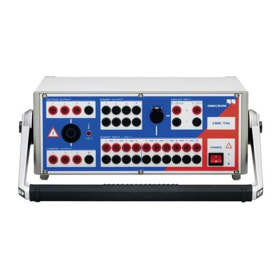
- Manuals
- Brands
- Omicron Manuals
- Measuring Instruments
- CMC 156
- Reference manual
-
Contents
-
Table of Contents
-
Bookmarks
Quick Links
27
Reference Manual
CMC 156
Related Manuals for Omicron CMC 156
Summary of Contents for Omicron CMC 156
-
Page 1
Reference Manual CMC 156… -
Page 2
The user is responsible for every application that makes use of an OMICRON product. OMICRON electronics translates this manual from the source language English into a number of other languages. Any translation of this manual is done for local requirements, and in the event of a dispute… -
Page 3: Safety Instructions
ATTENTION: Before starting up the CMC 156, carefully read the following safety instructions. The system must not be put into operation without full knowledge of this information! The CMC 156 may only be operated by trained personnel on the company premises!
-
Page 4
• External devices may only be connected to the SELV interfaces of the CMC 156 (host-interface, Gen. out 7-12, ext. Interface) if they comply to the SELV requirements according to EN60950. Do not open the CMC 156 or remove any of its housing components Voltages of up to 400 V will occur inside the unit! If the unit is opened, warranty claims will become void. -
Page 5: Table Of Contents
Table of Contents Table of Contents Safety Instructions ………………..3 Table of Contents ………………… 5 Introduction ………………….. 7 Start-Up ………………….9 System components ………………….9 System Start ……………………. 9 Design and Operation ………………11 Modules ……………………..12 3.1.1 Host Interface …………………..13 3.1.2 Processor ………………….13 3.1.3…
-
Page 6
Test Set CMC 156 Inputs ……………………..39 5.3.1 Binary Inputs ………………….39 5.3.2 Counter Inputs 100 kHz ………………41 5.3.3 Measuring Inputs ………………..42 Computer Interface ………………….43 Ambient Conditions ………………….43 5.5.1 Climate ……………………. 43 5.5.2 Shock and Vibration ……………….. 44 5.5.3… -
Page 7: Introduction
Introduction 1 Introduction The CMC 156 test system consists of the components CMC 156 test set, a computer and the CMC user software. External amplifiers and optional devices can also be controlled optionally. Due to its wide range of optional settings, the CMC 156 test set completely eliminates the need for operating elements on the front panel — every function is controlled by the software on the COMPUTER.
-
Page 8
Test Set CMC 156… -
Page 9: Start-Up
Figure 1 Connection CMC 156 and computer These instructions refer to a system including a computer and basic device CMC 156, i.e. without additional amplifiers. If the system is to be operated with external amplifiers, please refer to the instructions in your CMC SW user’s manual, section «Configuring an external amplifier».
-
Page 10
CMUSB-P converter (ordering number VEHZ2007) instead of the VEHK0002 to connect the CMC 156 to the computer. 2. Connect the CMC 156 and the computer to the power supply. (Power supply cable is supplied.) 3. Power both units up. CMC 156: ON/OFF switch on the front panel. -
Page 11: Design And Operation
Our computer-controlled design concept allows the following segregation of functions: Computer • Application software • Control and display • Measuring data processing • Reporting and archiving CMC 156 test set • Signal generation • Voltage and current amplifier • Input signal measurement • Time-critical processes…
-
Page 12: Modules
Test Set CMC 156 Modules Figure 2 Basic block diagram of the CMC 156…
-
Page 13: Host Interface
If the computer is equipped with a parallel printer port, too, use the 25-pole cable (VEHK0002) that was supplied with the test set to connect the CMC 156 to the computer. If the computer is equipped with a USB port, use an OMICRON CMUSB-P converter (ordering number VEHZ2007) instead of the VEHK0002 to connect the CMC 156 to the computer.
-
Page 14: Measuring Module
Test Set CMC 156 3.1.4 Measuring Module The measuring module for analog signals primarily consists of a laser trimmed high-precision voltage reference, a 16-bit A/D converter with series-connected multiplexer and the appropriate input circuits (precision voltage divider, filter). The input signals V and I , the output voltages, amplifier temperatures, etc.
-
Page 15: Internal Current And Voltage Amplifiers
Design and Operation 3.1.5 Internal Current and Voltage Amplifiers The output amplifiers are designed as linear amplifiers and direct voltage coupling with MOSFET output stages. Using this technology, excellent harmonic distortion and frequency response specifications can be realized in a very compact design. The direct voltage coupling allows accurate representation of any transient function.
-
Page 16: Power Supply
For more information, please refer to the CMC software manual, chapter ‘System configuration’. 3.1.6 Power Supply The following power supplies are used in the CMC 156: a. The mains-sided power supply with power factor correction creates an intermediate circuit voltage for the supply of the connected isolated power supplies.
-
Page 17: Signal Generation
The requirement for 6 fixed-phase coupled signals suggests a digital implementation. In the CMC 156 the quality of the signals is achieved due to the use of a modern and powerful signal processor. The implemented algorithm linearly interpolates between the basic values of…
-
Page 18
Figure 3 Block diagram of the generator outputs of the CMC 156 The CMC 156 test system supplies four generator triples of three signals each. The generator triples 1 and 2 are output via the internal amplifiers to the outputs of the front panel. -
Page 19: Accuracy
Design and Operation Accuracy The data sheet values for the CMC 156 are not typical values but guaranteed values over one year from the time of factory calibration at 23 °C ± 5 % (73 °F ± 10 °F). Some factors had to be taken into account during development in order to achieve the desired accuracy.
-
Page 20: Connectors And Interfaces
Test Set CMC 156 4 Connectors and Interfaces Connectors on the Front Panel BINARY OUTPUT Combination jack for BINARY INPUT 4 internal floating binary outputs ANALOG INPUT routed out individually. 20-pole combination jack for the following connections: — current measuring input…
-
Page 21
Connectors and Interfaces Figure 6 Outputs and inputs of the front panel… -
Page 22: Generator Combination Socket For Voltage Output, Current Output
VOLTAGE OUTPUT, CURRENT OUTPUT The combination socket CURRENT OUTPUT / VOLTAGE OUTPUT serves for easy connection of the test object to the CMC 156. All signals of the connection sections CURRENT OUTPUT and VOLTAGE OUTPUT are brought out at this connector.
-
Page 23
Felix -Wankel-Str. 1, 85221 Dachau, Tel.: +49 (0)8131 2808-0 or NCV GmbH, Erzbischof Buchberger Allee 14, 93051 Regensburg, Tel.: +49 (0)941 98041, FAX: +49 (0)941 999772 Table 3 Suppliers If you want to order from OMICRON, refer to section 7.2 «Ordering Notes “. -
Page 24: Measurement Combination Socket For Binary Input And Analog Input
BINARY INPUT and ANALOG INPUT The combination socket BINARY INPUT / ANALOG INPUT serves for easy connection of the test object to the CMC 156. All signals of the connection sections BINARY INPUT and ANALOG INPUT are brought out at this connector.
-
Page 25
Binary input 1 gy/bn Binary input 4 GND_A wh/pk Analog GND UDC_IN pk/bn DC voltage input The shield is not connected within the CMC 156 and has therefore to be connected within the signal source. Table 4 Assignment Measurement Combination Socket… -
Page 26
Tel.: +1 (0)707 5788811, Fax: +1 (0)7075780869 LEMOSA GmbH , Stahlgruberring 7, 81829 München 82 Tel. +49 (0)89 423085, Fax +49 (0)89 427192 Table 6 Manufacturer / Supplier If you want to order from OMICRON, refer to section 7.2, «Ordering Notes “. -
Page 27: Connections On The Back Panel
For connection to this socket use the cable which is included in the scope of delivery of the external amplifier (connection cable CMC 156 — amplifier). The outputs are isolated from mains and the power outputs by reinforced isolation (SELV interface) and supply calibrated signals in the range 0 to 5V (7.07V…
-
Page 28
Test Set CMC 156 Figure 10 Plug for Interface «Gen. out 7-12» (lower 16-pole Lemo jack); (view onto cable connection side) Function Pin 1 Gen. Out 7 Pin 2 Gen. Out 8 Pin 3 Gen. Out 9 Pin 4 GND_A (electrically connected to ground) Pin 5 Gen. -
Page 29: Ext. Interface
Connectors and Interfaces 4.2.2 ext. Interface On the connection socket ‘ext. Interf.’ two counter inputs are supplied for meter testing with input frequencies of up to 100kHz. In addition, there are four additional transistor binary outputs 11-14. Compared to the relay binary outputs these have the advantage that they do not bounce and that only minimal response times occur.
-
Page 30
Plug with 2 guide cams and pull relief For ext. Interface: FGG.2B.316.CLAD 72Z Plug with 1 guide cam and pull relief Bend protection spout black GMA.2B.070 DN Table 9 Manufacturer designation If you want to order from OMICRON, refer to section 7.2″Ordering Notes “. -
Page 31: Technical Data
Technical Data 5 Technical Data The following data refer to a CMC 156 test set with standard design, without external amplifiers. For test sets with the EP option (Extended Precision), technical data regarding the power amplifiers are different from the corresponding data of standard devices: therefore, these data can be found separately in chapter 6, «Technical Data EP Option».
-
Page 32: Outputs
Test Set CMC 156 Outputs The data given in the following table are valid for all generator outputs, regardless of the amplifiers used (internal or external ones); the following tables are valid only for equipment with internal amplifiers. For the block diagram of the generator outputs available please refer to Figure 3 on page 18.
-
Page 33: Current Outputs Current Output 1-3
Technical Data 5.2.1 Current Outputs CURRENT OUTPUT 1-3 3 current outputs for standard design Output currents 3 × 0 to 12.5 A 3-phase AC (L-N) 1 × 0 to 12.5 A 1-phase AC (L-N) 1 × 0 to 21 A in parallel 1-phase DC (L-N) 1 ×…
-
Page 34
Test Set CMC 156 Ptyp in [VA] Pgar in [VA] 9 10 10 11 11 12 12 13 I in A Figure 12 Typical (Ptyp.) and guaranteed (Pguar.) output power of the internal current amplifiers with standard design For a parallel connection of two current outputs a maximum output power of Pout >… -
Page 35: Voltage Outputs Voltage Output 1-3
Technical Data 5.2.2 Voltage Outputs VOLTAGE OUTPUT 1-3 3 voltage outputs for standard design Output voltages 3 × 0 to 125 V 3-phase AC (L-N) 1 × 0 to 250 V 1-phase AC (L-L) 3-phase DC (L-N) 3 × 0 to ±125 V Resolution 6 mV Power…
-
Page 36: Interface For An External Amplifier ‘Gen. Out 7-12
Test Set CMC 156 3 x sym. guar. 3 x sym. typ. L2 only guar. L2 only typ. DC L2 only typ 0,00 25,00 50,00 75,00 100,00 125,00 V (L-N) in Vrms Figure 14 Typical (Ptyp) and guaranteed (Pmin) output power of the voltage amplifiers1 with standard design 5.2.3…
-
Page 37: Binary Outputs Relays
Technical Data 5.2.4 Binary Outputs Relays 4 Binary outputs relays (Binary outputs 1-4) Type potential free contacts, software controlled AC break capacity 250 V 8 A; P 2000 VA DC break capacity 300 V 8 A; P 50 W (see the following limit curve) Inrush current 15 A (max.
-
Page 38: Binary Outputs Transistor
< 3 µs (V = 5 V, R =4k7) external pullup Connector Socket «ext. Interf.» (Back panel CMC 156) Isolation SELV to all other potential groups of the test set. Electrically connected to Gen. Out 7-12 and ground. Table 16 Binary outputs transistor…
-
Page 39: Inputs
Technical Data Inputs 5.3.1 Binary Inputs 10 Binary inputs Response time typ. 220 µs (debounced) Sampling rate < 100 µs Measurement accuracy See Table 18 and Table 19 Counter function Counting frequency 3 kHz (per input) Pulse width > 150 µs (for high and low signal) Operating threshold for — Guaranteed 0: input open or load against N >…
-
Page 40
Test Set CMC 156 Time measurement on binary inputs Due to the sampling rate and to the features of the input filters, a signal present on binary inputs can only be sampled with a certain time tolerance. All input binary signals are filtered on a period of 100 µs to remove possible noise and therefore this time represents a delay in all measurements. -
Page 41: Counter Inputs 100 Khz
< 1 ms ± 30 V max. input voltage Connector Socket «ext. Interf.» (rear panel CMC 156 ) Isolation SELV to all other potential groups of the test set. Electrically connected to Gen. Out 7-12 and ground.
-
Page 42: Measuring Inputs
Test Set CMC 156 5.3.3 Measuring Inputs 1 Direct current measuring input Measuring range 0 to ± 20 mA max. input current 600 mA Accuracy typ. error 0.01 % guaranteed error < 0.05 % Connection 4 mm banana sockets or measuring comb. socket.
-
Page 43: Computer Interface
Designation Host Interface The Host Interface (parallel interface) serves as connection from the CMC 156 test set to the computer (LPT or USB). If the computer is equipped with a parallel printer port, too, use the 25-pole cable (VEHK0002) that was supplied with the test set to connect the CMC 156 to the computer.
-
Page 44: Shock And Vibration
Test Set CMC 156 5.5.2 Shock and Vibration Dynamics Vibration Tested according to IEC68-2-6 (operating mode) frequency range 10 to 150 Hz; acceleration 2 g continuous (20 m/s ); 10 sweeps, each axis. Shock Tested according to IEC68-2-27 (operating mode) 15 g/11 ms, half-sine, each axis.
-
Page 45: Safety
Technical Data Safety Safety standards and certificates complied with European standards EN 61010-1:1993 EN 60950 +A1:1993-05 International standards IEC 1010-1 CAN/CSA-C22.2 No 1010.1-92 Certificates UL/CSA certified up to test set serial number Pxnnnx . (Example: a test set with serial number N D224C is UL/SCA-certified, a test set with the serial number Q B111D not).
-
Page 46
Test Set CMC 156… -
Page 47: Technical Data Ep Option
• higher output power • two current ranges (from 0 to 12.5 A and from 0 to 1.25 A) Technical data valid for a CMC 156 test set with standard design can be found in chapter 5, «Technical Data».
-
Page 48: Outputs (Ep Option)
Test Set CMC 156 Outputs (EP option) The power output specifications of test sets with EP option (Extended Precision) may differ in substantial extent from the standard design. For the standard design specifications, please refer to Paragraph 5.2 “Outputs”. …
-
Page 49: Current Outputs Current Output 1-3
Technical Data EP Option 6.1.1 Current Outputs CURRENT OUTPUT 1-3 3 current outputs range 12.5A Output currents 3 × 0 to 12,5 A 3-phase AC (L-N) 1 × 0 to 12, 5A 1-phase AC (L-N) 1 × 0 to 27 A at >45 Hz in parallel 1 ×…
-
Page 50
Test Set CMC 156 3 current outputs range 1.25A Output currents 3-phase AC (L-N) 3 × 0 to 1.25 A 1 × 0 to 1.25 A 1-phase AC (L-N) 1 × 0 to 3.75 A in parallel 1 × 0 to ± 1.25 A… -
Page 51
Technical Data EP Option 50.0 P typ in [VA] 45.0 P gar in [VA] 40.0 35.0 30.0 25.0 20.0 15.0 10.0 I in A Figure 18 Typical (Ptyp.) and guaranteed (Pguar.) output power of the internal current amplifiers in the 12.5 A range for EP option. For a parallel connection of three current outputs a maximum output power of Pout >… -
Page 52
Test Set CMC 156 Ptyp in [VA] Pguar in [VA] I in A Figure 20 Typical (Ptyp.) and guaranteed (Pguar.) output power of the internal current amplifiers in the 1.25 A range for option EP. -
Page 53: Voltage Outputs Voltage Output 1-3
Technical Data EP Option 6.1.2 Voltage Outputs VOLTAGE OUTPUT 1-3 3 voltage outputs Output voltages 3 × 0 to 127.5V 3-phase AC (L-N) 1-phase AC (L-L) 1 × 0 to 255 V (240 V + 6 % or 230 V + 10 %) 3 ×…
-
Page 54
Test Set CMC 156 160.0 3 x symm. typ. 3 x symm. typical 140.0 nur L2 belastet garantiert burden on L2 only, guarant. nur L2 belastet typ. burden on L2 only, typical 120.0 DC nur L2 belastet typ DC, burden on L2 only, typ. -
Page 55: Output Power With Ep Option
Technical Data EP Option 6.1.3 Output Power with EP option The output power accuracy is defined only for the system CMC 156 with EP option. Output power accuracy Accuracy (VA) 0.05 % typical; 0.1 % guaranteed Temperature drift 0.005 % / ° C max.
-
Page 56
Test Set CMC 156… -
Page 57: Appendix
7.1.1 Current Amplifier CMA 56 The CMA 56 is controlled via the CMC 156 . The current amplifier is located in the same compact housing as the CMC 56 test set and supplies 3 × 50 A (max. 135 VA per phase).
-
Page 58: Current Amplifier Cma 156
The six current phases are arranged in two isolated groups and can be used independently from the phases of the CMC 156 (e.g. for differential protection testing). By connecting the current phases in series, a power of up to 280 VA can be output, which allows the testing of a wide range of electromechanical relays.
-
Page 59
Appendix Most important specifications of the CMA 156: Output currents 6-phase AC 6 x 0 to 25 A 3-phase AC 3 x 0 to 50 A 1 x 0 to ± 25 A Power 6-phase AC 6 x 70 VA at 7.5 A 3-phase AC 3 x 140 VA at 15 A 1-phase AC (L-L) -
Page 60: Voltage And Current Amplifier Cms 156
The three voltage phases and the three current phases of the amplifier are isolated from each other and can be used independently from the phases of the CMC 156 . This allows testing of differential relays with six independent current phases, or synchronizing devices with six independent voltage phases.
-
Page 61
Appendix Most important specifications of the CMS 156: Output voltages 3-phase AC (L-N) 3 x 0 to 250 V 1-phase AC (L-L) 1 x 0 to 500 V 3 x 0 to ± 250 V DC (L-N) Voltage outputs power 3-phase AC (L-N) 3 x 75 VA at 75 to 250 V 1-phase AC (L-N) -
Page 62: Cmlib B — Optional Connection For Meter Testing
Test Set CMC 156 7.1.4 CMLIB B — Optional connection for meter testing With the option CMLIB B it is easily possible to connect auxiliary equipment needed for meter testing to a CMC test set. The devices involved are: •…
-
Page 63
Appendix Principle setup: VEHK0003 Power supply CMLIB B Optical head e.g.: SH2003 Wattmeter BNC to banana connection cable VEHK0005… -
Page 64: Ordering Notes
Test Set CMC 156 Ordering Notes In this section ordering notes for additional devices and accessories to the CMC 156 are found. For easier identification of cables and plugs these items are represented graphically below. Plug for Plug for (CMC…
-
Page 65
Appendix Connecting cable CMC 156 – amplifier VEHK0003 Ampl. in Amplifier (CMA, CMS) Notebook (USB) Ampl. in Ampl.out Connection to computer via CMUSB-P converter VEHZ2007 ext. Interf. CMC 156 Gen. out 7 — 12 Connecting cable CMC 156 – CMLIB B… -
Page 66
VEHS0103 Plug for Measuring Combination socket VEHS0104 Accessories CMUSB-P VEHZ2007 Converter for controlling a CMC 156 by a computer with USB port (replaces VEHK0002; see below). Option FL-6 In a number of countries (e.g., Japan), the VEHO0599 export of multiphase generators able to output steady signals with a frequency between 600 Hz and 2000 Hz is not permitted. -
Page 67
VEHZ0005 Carrying bag for CMC 156 (mini) VEHP0100 for CMA/CMS VEHP0010 Transport case Case for CMA/CMS VEHP0011 Case for CMC 156 / 151 (mini) VEHP0101 Additional user manuals CMC 156 VESD1002 (specify language when ordering) Table 36 Ordering notes (continued) -
Page 68
Test Set CMC 156… -
Page 69: Contact Information/Technical Support
OMICRON electronics GmbH Oberes Ried 1 6833 Klaus, Austria Phone: +43 5523 507-333 E-Mail: support@omicron.at Web: www.omicron.at For addresses of OMICRON offices with customer service centers. regional sales offices or offices for training. consulting and commissioning please see our website.
-
Page 70
Test Set CMC 156… -
Page 71: Index
Index Index output power of the internal current amplifiers ……..34, 36 output power of the internal current amplifiers (EP) ……51, 52, 54 ϕ …………32, 48 parallel connection of the outputs …. 34 parallel connection of the outputs (EP) ..51 protection of the current and voltage outputs ……….
-
Page 72
Test Set CMC 156 Direct voltage measuring input ….42 Disconnection temperature ……15 Display …………11 Cables DSP ………….. 13 ordering notes on ……..64 CAN/CSA-C22.2 No 1010.1-92 ….45 Changing the mains fuse …….. 4 Clicking when starting up ……10 EN 61010-1/1993 ……… -
Page 73
Index Inputs binary ……….14, 39 counter inputs ……….. 41 Gen. out 7-12 front panel ……….21 Installing the CMC 56 ……..10 assignment ……….28 Instructions for your safety ……3 Assignment ……….30 Internal amplifer Generator Combination connector protection of the current and voltage Assignment ………. -
Page 74
Test Set CMC 156 National standards……..45 traceability ……….19 communication with ……..13 Phase angle ϕ ……..32, 48 Nominal frequency ……..31 Nominal voltage ……….31 Phase error ……….32, 48 binary inputs ……….14 Phase resolution ……..32, 48 Plugs ordering notes on …….. -
Page 75
Index Suppliers for plugs ……..26 Suppliers of plugs ……..23 Supply …………31 Range Switching OFF due to an overtemperature ……. 16 voltage outputs (EP) ……… 53 System components ……..9 Rated (= nominal) voltage ……31 connecting the ……….9 Rated voltage System start ……….. -
Page 76
Test Set CMC 156 measuring input ……..42 Warranty …………4 Ventilation slots ……….10 Weight …………45 Vibration and Shock ……..44 Wiring the system components ….. 9 View front panel ……….20 rear view ……….. 27 VNom …………31 Voltage amplifer CMS 156 ………..
Система маммографическая рентгеновская цифровая ОМИКРОН по ТУ 9442-005-91526802-2015 с принадлежностями
Состав:
1. Маммограф рентгеновский, варианты исполнения:
1.1 Маммограф рентгеновский ОМИКРОН, производства ООО «РЕНМЕДПРОМ», Россия, в составе:
— Штатив:
— С дуга;
1.2 Установка рентгенографическая MAMMO-GRAPH, производства «ITALRAY S.r.l»., Италия, РУ №ФСЗ 2007/00154;
1.3 Маммограф рентгеновский МАММО DR, производства «Медрей» ООД (MEDRAY LTD), Болгария;
1.4 Маммограф рентгеновский с кольцеобразным штативом MAMMO-R DR, производства «Медрей» ООД (MEDRAY LTD), Болгария;
2. Рентгеновский излучатель с рентгеновской трубкой, варианты исполнения:
2.1 Рентгеновская трубка ХМ 12 или ХМ 15, производства «1TALRAY S.r.l.», Италия;
2.2 Рентгеновская трубка М 113Т, производства «Varian Medical Systems, Inc.», Канада;
2.3 Рентгеновская трубка ХМ 12 или ХМ 15 или ХМ 1016 или ХМ 1016 Т, производства
«I.А.Е. SpA», Италия;
3. Приемник рентгеновский цифровой, варианты исполнения:
3.1 ПРЦ ОМИКРОН плоскопанельный цифровой детектор 24×30 см, производства
ООО «РЕНМЕДПРОМ», Россия;
3.2 MAMMO1012F Плоскопанельный цифровой детектор 24×30 см, производства
«iRay Technology (Shanghai) Ltd», Китай;
3.3 FLAT DR Плоскопанельный цифровой детектор 24×30 см, производства «Медрей»
ООД (MEDRAY LTD) Болгария.
4. Автоматизированное рабочее место рентгенлаборанта, варианты исполнения:
4.1 Аппаратно-программный комплекс АРМ лаборант, производства ООО «РЕНМЕДПРОМ», Россия, в составе:
— блок электроники синхронизации с устройством рентгеновским питающим и приемником рентгеновским цифровым;
— системный компьютерный блок;
— монитор, не более 2 шт.;
— источник бесперебойного питания;
4.2 Аппаратно-программный комплекс АРМ лаборант, производства «Медрей»
ООД (MEDRAY LTD) Болгария, в составе:
— блок электроники синхронизации с устройством рентгеновским питающим и приемником рентгеновским цифровым;
— системный компьютерный блок;
— монитор, не более 2 шт.;
— источник бесперебойного питания;
5. Ширма рентгенозащитная, варианты исполнения (при необходимости):
5.1 Ширмы рентгенозащитные по ТУ 9452-010-46782692-2001, производства
ООО «СПЕЦМЕДПРИБОР», Россия, РУ № ФСР 2010/08184, в следующих исполнениях:
— резиносвинцовые передвижные большие ШРЗпб-«Р-К» (фронтальная ШРЗпб-Ф-«Р-К»;
— с центральной и боковой панелью правой ШРЗпб-П-«Р-К»;
— с центральной и боковой панелью левой ШРЗпб-Л-«Р-К»;
— с центральной и двумя боковыми панелями ШРЗпб-ПЛ-«Р-К»).
5.2 Ширмы рентгенозащитные цельнометаллические свинцовые по ТУ 9452-009-17459079-2002, производства ЗАО «ПОНИ», Россия, РУ № ФСР 2011/11811, в следующих исполнениях:
— ширмы для медицинского персонала: ШРБ1-«ПОНИ»; ШРБ2п-«ПОНИ»; ШРБ2л-«ПОНИ»; ШРБ3-«ПОНИ».
5.3 Защитное устройство для оператора, производства «ITALRAY S.r.l.», Италия или производства «Медрей» ООД (MEDRAY LTD) Болгария.
6. Эксплуатационная документация:
6.1. Ведомость эксплуатационных документов на Систему маммографическую рентгеновскую цифровую ОМИКРОН по ТУ 9442-005-91526802-2015 с принадлежностями;
6.2. Формуляр на Систему маммографическую рентгеновскую цифровую ОМИКРОН
по ТУ 9442-005-91526802-2015 с принадлежностями;
6.3. Руководство по эксплуатации на Систему маммографическую рентгеновскую цифровую ОМИКРОН по ТУ 9442-005-91526802-2015 с принадлежностями.
Принадлежности:
1. Автоматизированное рабочее место врача рентгенолога: Аппаратно-программный комплекс АРМ Врач, производства ООО «РЕНМЕДПРОМ», Россия, в составе:
— системный компьютерный блок;
— монитор специальный монохромный, не более 2 шт.;
— монитор, не более 2 шт.;
— источник бесперебойного питания;
2. Автоматизированное рабочее место файл сервер: Аппаратно-программный комплекс
АРМ файл сервер, производства ООО «РЕНМЕДПРОМ», Россия, в составе:
— системный компьютерный блок;
— монитор, не более 2 шт.;
— источник бесперебойного питания;
3. Устройство автоматической смены фильтров Rh/Mo (радий-молибден), производства
«ITALRAY S.r.l.», Италия.
4. Педаль управления, варианты исполнения:
4.1 Педаль управления, производства ООО «РЕНМЕДПРОМ», Россия, не более 2 шт.;
4.2 Дополнительная пара компрессионных педалей, производства «ITALRAY S.r.l.», Италия.
5. Пластина для геометрического увеличения, производства ООО «РЕНМЕДПРОМ», Россия.
6. Компрессионная пластина для геометрического увеличения, производства
ООО «РЕНМЕДПРОМ», Россия.
7. Компрессионная пластина для прицельных снимков, производства ООО «РЕНМЕДПРОМ», Россия.
8. Кресло пациента с регулируемой высотой, производства «ITALRAY S.r.l.», Италия.
9. Рукоятки вращения С-дуги, производства ООО «РЕНМЕДПРОМ», Россия, не более 2 шт.
10. Устройство включения рентгеновского излучения, производства ООО «РЕНМЕДПРОМ»,Россия.
11. Устройство отключения тормоза вращения С-дуги, производства ООО «РЕНМЕДПРОМ», Россия, не более 2 шт.
12. Устройство управления перемещением С-дуги вверх/вниз, производства
ООО «РЕНМЕДПРОМ», Россия.
13. Устройство управлением аварийного отключения, производства ООО «РЕНМЕДПРОМ»
Россия.
Купить Система маммографическая рентгеновская цифровая ОМИКРОН по ТУ 9442-005-91526802-2015 с принадлежностями, лучшая цена, доставка по России. Для заказа у нас на сайте вы можете заполнить заявку в свободной форме на почту Адрес электронной почты защищен от спам-ботов. Для просмотра адреса в вашем браузере должен быть включен Javascript. или же воспользоваться формой заказа на сайте.