Introduction
This manual is a guide for using the MITSUBISHI CNC M700V/M70V Series.
Programming is described in this manual, so read this manual thoroughly before starting programming. Thoroughly study
the «Precautions for Safety» on the following page to ensure safe use of this NC unit.
Details described in this manual
CAUTION For items described as «Restrictions» or «Usable State» in this manual, the instruction manual issued by
the machine tool builder takes precedence over this manual.
Items not described in this manual must be interpreted as «not possible».
This manual is written on the assumption that all option functions are added.
Refer to the specifications issued by the machine tool builder before starting use.
Refer to the Instruction Manual issued by each machine tool builder for details on each machine tool.
Some screens and functions may differ depending on the NC system (or its version), and some functions
may not be possible. Please confirm the specifications before use.
General precautions
(1) Refer to the following documents for details on handling
MITSUBISHI CNC M700V/M70V Series Instruction Manual ………… IB-1500922
Precautions for Safety
Always read the specifications issued by the machine tool builder, this manual, related manuals and attached documents
before installation, operation, programming, maintenance or inspection to ensure correct use.
Understand this numerical controller, safety items and cautions before using the unit.
This manual ranks the safety precautions into «DANGER», «WARNING» and «CAUTION».
Note that even items ranked as » CAUTION», may lead to major results depending on the situation. In any case,
important information that must always be observed is described.
The following sings indicate prohibition and compulsory.
The meaning of each pictorial sing is as follows.
DANGER
When the user may be subject to imminent fatalities or major injuries if handling is mistaken.
WARNING
When the user may be subject to fatalities or major injuries if handling is mistaken.
CAUTION
When the user may be subject to injuries or when physical damage may occur if handling is mistaken.
This sign indicates prohibited behavior (must not do).
For example, indicates «Keep fire away».
This sign indicated a thing that is pompously (must do).
For example, indicates «it must be grounded».
CAUTION
CAUTION
rotated object
CAUTION HOT
Danger
Electric shock risk
Danger
explosive
Prohibited
Disassembly is
prohibited
KEEP FIRE AWAY
General instruction
Earth ground
Mitsubishi CNC is designed and manufactured solely for applications to machine tools to be used for industrial
purposes.
Do not use this product in any applications other than those specified above, especially those which are
substantially influential on the public interest or which are expected to have significant influence on human lives or
properties.
Not applicable in this manual.
1. Items related to operation
If the operation start position is set in a block which is in the middle of the program and the program is
started, the program before the set block is not executed. Please confirm that G and F modal and
coordinate values are appropriate. If there are coordinate system shift commands or M, S, T and B
commands before the block set as the start position, carry out the required commands using the MDI, etc.
If the program is run from the set block without carrying out these operations, there is a danger of
interference with the machine or of machine operation at an unexpected speed, which may result in
breakage of tools or machine tool or may cause damage to the operators.
Under the constant surface speed control (during G96 modal), if the axis targeted for the constant surface
speed control moves toward the spindle center, the spindle rotation speed will increase and may exceed
the allowable speed of the workpiece or chuck, etc. In this case, the workpiece, etc. may jump out during
machining, which may result in breakage of tools or machine tool or may cause damage to the operators.
For Safe Use
DANGER
WARNING
1. Items related to product and manual
For items described as «Restrictions» or «Usable State» in this manual, the instruction manual issued by
the machine tool builder takes precedence over this manual.
Items not described in this manual must be interpreted as «not possible».
This manual is written on the assumption that all option functions are added. Refer to the specifications
issued by the machine tool builder before starting use.
Refer to the Instruction Manual issued by each machine tool builder for details on each machine tool.
Some screens and functions may differ depending on the NC system (or its version), and some functions
may not be possible. Please confirm the specifications before use.
2. Items related to operation
Before starting actual machining, always carry out graphic check, dry run operation and single block
operation to check the machining program, tool compensation amount, workpiece compensation amount
and etc.
If the workpiece coordinate system offset amount is changed during single block stop, the new setting will
be valid from the next block.
Turn the mirror image ON and OFF at the mirror image center.
If the tool compensation amount is changed during automatic operation (including during single block
stop), it will be validated from the next block or blocks onwards.
3. Items related to programming
The commands with «no value after G» will be handled as «G00».
«;» «EOB» and «%» «EOR» are expressions used for explanation. The actual codes are: For ISO: «CR, LF», or
«LF» and «%».
Programs created on the Edit screen are stored in the NC memory in a «CR, LF» format, but programs
created with external devices such as the FLD or RS-232C may be stored in an «LF» format.
The actual codes for EIA are: «EOB (End of Block)» and «EOR (End of Record)».
When creating the machining program, select the appropriate machining conditions, and make sure that
the performance, capacity and limits of the machine and NC are not exceeded. The examples do not
consider the machining conditions.
Do not change fixed cycle programs without the prior approval of the machine tool builder.
When programming the multi-part system, take special care to the movements of the programs for other
part systems.
CAUTION
Disposal
(Note) This symbol mark is for EU countries only.
This symbol mark is according to the directive 2006/66/EC Article 20 Information for end-
users and Annex II.
Your MITSUBISHI ELECTRIC product is designed and manufactured with high quality materials and
components which can be recycled and/or reused.
This symbol means that batteries and accumulators, at their end-of-life, should be disposed of
separately from your household waste.
If a chemical symbol is printed beneath the symbol shown above, this chemical symbol means that the
battery or accumulator contains a heavy metal at a certain concentration. This will be indicated as
follows:
Hg: mercury (0,0005%), Cd: cadmium (0,002%), Pb: lead (0,004%)
In the European Union there are separate collection systems for used batteries and accumulators.
Please, dispose of batteries and accumulators correctly at your local community waste collection/
recycling centre.
Please, help us to conserve the environment we live in!
Trademarks
MELDAS, MELSEC, EZSocket, EZMotion, iQ Platform, MELSOFT, GOT, CC-Link, CC-Link/LT and CC-Link
IE are either trademarks or registered trademarks of Mitsubishi Electric Corporation in Japan and/or other
countries.
Ethernet is a registered trademark of Xerox Corporation in the United States and/or other countries.
Microsoft and Windows are either trademarks or registered trademarks of Microsoft Corporation in the
United States and/or other countries.
CompactFlash and CF are either trademarks or registered trademarks of SanDisk Corporation in the United
States and/or other countries.
UNIX is a registered trademark of The Open Group in the United States and/or other countries.
Intel and Pentium are either trademarks or registered trademarks of Intel Corporation in the United States
and/or other countries.
Other company and product names that appear in this manual are trademarks or registered trademarks of the
respective companies.
( /Japanese)
( A)
Handling of our product
(English)
This is a class A product. In a domestic environment this product may cause radio interference in which case the
user may be required to take adequate measures.
( /Korean)
(A )
.
CONTENTS
1 Control Axes ……………………………………………………………………………………………………………………………… 1
1.1 Coordinate Words and Control Axes ……………………………………………………………………………………….. 2 1.2 Coordinate Systems and Coordinate Zero Point Symbols ………………………………………………………….. 3
2 Least Command Increments ………………………………………………………………………………………………………. 5
2.1 Input Setting Unit …………………………………………………………………………………………………………………. 6 2.2 Input Command Increment Tenfold …………………………………………………………………………………………. 7 2.3 Indexing Increment ………………………………………………………………………………………………………………. 8
3 Program Formats ………………………………………………………………………………………………………………………. 9
3.1 Program Format …………………………………………………………………………………………………………………. 10 3.2 File Format ………………………………………………………………………………………………………………………… 14 3.3 Optional Block Skip …………………………………………………………………………………………………………….. 16
3.3.1 Optional Block Skip; / ………………………………………………………………………………………………….. 16 3.3.2 Optional Block Skip Addition ; /n ……………………………………………………………………………………. 18
3.4 G code ……………………………………………………………………………………………………………………………… 20 3.4.1 Modal, unmodal ………………………………………………………………………………………………………….. 20 3.4.2 G Code Lists ……………………………………………………………………………………………………………….. 20
3.5 Precautions Before Starting Machining ………………………………………………………………………………….. 24
4 Pre-read Buffers ………………………………………………………………………………………………………………………. 25
4.1 Pre-read Buffers …………………………………………………………………………………………………………………. 26
5 Position Commands ………………………………………………………………………………………………………………… 27
5.1 Position Command Methods ; G90,G91 …………………………………………………………………………………. 28 5.2 Inch/Metric Conversion ; G20,G21…………………………………………………………………………………………. 30 5.3 Decimal Point Input …………………………………………………………………………………………………………….. 32
6 Interpolation Functions ……………………………………………………………………………………………………………. 37
6.1 Positioning (Rapid Traverse) ; G00……………………………………………………………………………………….. 38 6.2 Linear Interpolation ; G01 …………………………………………………………………………………………………….. 45 6.3 Circular Interpolation ; G02,G03 …………………………………………………………………………………………… 47 6.4 R Specification Circular Interpolation ; G02,G03 ……………………………………………………………………… 52 6.5 Plane Selection ; G17,G18,G19…………………………………………………………………………………………….. 54 6.6 Thread Cutting ……………………………………………………………………………………………………………………. 56
6.6.1 Constant Lead Thread Cutting ; G33………………………………………………………………………………. 56 6.6.2 Inch Thread Cutting ; G33…………………………………………………………………………………………….. 61
6.7 Helical Interpolation ; G17 to G19, G02, G03 ………………………………………………………………………….. 63 6.8 Unidirectional Positioning ; G60…………………………………………………………………………………………….. 70 6.9 Cylindrical Interpolation ; G07.1…………………………………………………………………………………………….. 72 6.10 Polar Coordinate Interpolation ; G12.1,G13.1/G112,G113 …………………………………………………….. 79 6.11 Exponential Interpolation ; G02.3,G03.3……………………………………………………………………………….. 86 6.12 Polar Coordinate Command ; G16/G15………………………………………………………………………………… 92 6.13 Spiral/Conical Interpolation ; G02.0/G03.1(Type1), G02/G03(Type2) ……………………………………….. 99 6.14 3-dimensional Circular Interpolation ; G02.4,G03.4………………………………………………………………. 104 6.15 NURBS Interpolation ; G06.2…………………………………………………………………………………………….. 109 6.16 Hypothetical Axis Interpolation ; G07………………………………………………………………………………….. 114
7 Feed Functions ………………………………………………………………………………………………………………………. 117
7.1 Rapid Traverse Rate………………………………………………………………………………………………………….. 118 7.2 Cutting Feedrate ………………………………………………………………………………………………………………. 119 7.3 F1-digit Feed…………………………………………………………………………………………………………………….. 120 7.4 Feed Per Minute/Feed Per Revolution (Asynchronous Feed/Synchronous Feed) ; G94,G95 ………. 123 7.5 Inverse Time Feed ; G93 ……………………………………………………………………………………………………. 127 7.6 Feedrate Designation and Effects on Control Axes ………………………………………………………………… 132 7.7 Rapid Traverse Constant Inclination Acceleration/Deceleration ………………………………………………. 137
7.8 Rapid Traverse Constant Inclination Multi-step Acceleration/Deceleration ………………………………… 142 7.9 Cutting Feed Constant Inclination Acceleration/Deceleration …………………………………………………… 151 7.10 Exact Stop Check ; G09……………………………………………………………………………………………………. 158 7.11 Exact Stop Check Mode ; G61…………………………………………………………………………………………… 162 7.12 Deceleration Check………………………………………………………………………………………………………….. 163
7.12.1 G1 -> G0 Deceleration Check…………………………………………………………………………………….. 165 7.12.2 G1 -> G1 Deceleration Check…………………………………………………………………………………….. 166
7.13 Automatic Corner Override ……………………………………………………………………………………………….. 167 7.14 Tapping Mode ; G63 ………………………………………………………………………………………………………… 172 7.15 Cutting Mode ; G64…………………………………………………………………………………………………………. 173
8 Dwell………………………………………………………………………………………………………………………………………. 175
8.1 Dwell (Time Designation) ; G04 …………………………………………………………………………………………… 176
9 Miscellaneous Functions ……………………………………………………………………………………………………….. 179
9.1 Miscellaneous Functions (M8-digits) ……………………………………………………………………………………. 180 9.2 Secondary Miscellaneous Functions (A8-digits, B8-digits or C8-digits) …………………………………….. 182 9.3 Index Table Indexing …………………………………………………………………………………………………………. 183
10 Spindle Functions …………………………………………………………………………………………………………………. 185
10.1 Spindle Functions…………………………………………………………………………………………………………….. 186 10.2 Constant Surface Speed Control ; G96,G97………………………………………………………………………… 187 10.3 Spindle Clamp Speed Setting ; G92 …………………………………………………………………………………… 189 10.4 Spindle/C Axis Control ……………………………………………………………………………………………………… 191 10.5 Multiple-spindle Control…………………………………………………………………………………………………….. 194
10.5.1 Multiple-spindle Control II ………………………………………………………………………………………….. 195
11 Tool Functions (T command) ………………………………………………………………………………………………… 197
11.1 Tool Functions (T8-digit BCD) …………………………………………………………………………………………… 198
12 Tool Compensation Functions ……………………………………………………………………………………………… 199
12.1 Tool Compensation………………………………………………………………………………………………………….. 200 12.2 Tool Length Compensation/Cancel ; G43/G44 …………………………………………………………………….. 204 12.3 Tool Length Compensation in the Tool Axis Direction ; G43.1/G44…………………………………………. 207 12.4 Tool Radius Compensation ; G38,G39/G40/G41,G42…………………………………………………………… 214
12.4.1 Tool Radius Compensation Operation…………………………………………………………………………. 215 12.4.2 Other Commands and Operations during Tool Radius Compensation……………………………… 224 12.4.3 G41/G42 Commands and I, J, K Designation ………………………………………………………………. 234 12.4.4 Interrupts during Tool Radius Compensation ………………………………………………………………. 240 12.4.5 General Precautions for Tool Radius Compensation……………………………………………………… 243 12.4.6 Changing of Compensation No. during Compensation Mode………………………………………….. 244 12.4.7 Start of Tool Radius Compensation and Z Axis Cut in Operation…………………………………….. 247 12.4.8 Interference Check …………………………………………………………………………………………………… 249 12.4.9 Diameter Designation of Compensation Amount…………………………………………………………… 258 12.4.10 Workpiece Coordinate Changing during Radius Compensation…………………………………….. 260
12.5 3-dimensional Tool Radius Compensation ; G40/G41,G42……………………………………………………. 262 12.6 Tool Radius Compensation for 5-axis Machining ; G40/G41.2,G42.2 ……………………………………… 273 12.7 Tool Position Offset ; G45 to G48 ………………………………………………………………………………………. 283 12.8 Compensation Data Input by Program ; G10……………………………………………………………………….. 291 12.9 Compensation Data Input to Variable by Program ; G11……………………………………………………….. 296 12.10 Inputting the Tool Life Management Data ; G10,G11 ………………………………………………………….. 297
12.10.1 Inputting the Tool Life Management Data by G10 L3 Command ; G10 L3,G11 ……………….. 297 12.10.2 Inputting the Tool Life Management Data by G10 L30 Command ; G10 L30,G11 ……………. 299 12.10.3 Precautions for Inputting the Tool Life Management Data…………………………………………….. 302
13 Program Support Functions …………………………………………………………………………………………………. 303
13.1 Fixed Cycles……………………………………………………………………………………………………………………. 304 13.1.1 Drilling, Spot Drilling ; G81…………………………………………………………………………………………. 308 13.1.2 Drilling, Counter Boring ; G82 …………………………………………………………………………………….. 309 13.1.3 Deep Hole Drilling Cycle ; G83 …………………………………………………………………………………… 310
13.1.3.1 Deep Hole Drilling Cycle…………………………………………………………………………………….. 310 13.1.3.2 Small Diameter Deep Hole Drilling Cycle ……………………………………………………………… 311
13.1.4 Tapping Cycle ; G84 …………………………………………………………………………………………………. 313 13.1.5 Boring ; G85…………………………………………………………………………………………………………….. 324 13.1.6 Boring ; G86…………………………………………………………………………………………………………….. 325 13.1.7 Back Boring ; G87…………………………………………………………………………………………………….. 326 13.1.8 Boring ; G88…………………………………………………………………………………………………………….. 328 13.1.9 Boring ; G89…………………………………………………………………………………………………………….. 329 13.1.10 Stepping Cycle ; G73………………………………………………………………………………………………. 330 13.1.11 Reverse Tapping Cycle ; G74…………………………………………………………………………………… 331 13.1.12 Circular Cutting ; G75 ……………………………………………………………………………………………… 333 13.1.13 Fine Boring ; G76……………………………………………………………………………………………………. 335 13.1.14 Precautions for Using a Fixed Cycle………………………………………………………………………….. 337 13.1.15 Initial Point and R Point Level Return ; G98,G99…………………………………………………………. 340 13.1.16 Setting of Workpiece Coordinates in Fixed Cycle Mode ………………………………………………. 341 13.1.17 Drilling Cycle with High-Speed Retract ………………………………………………………………………. 342 13.1.18 Acceleration/Deceleration Mode Change in Hole Drilling Cycle …………………………………….. 346
13.2 Special Fixed Cycle; G34, G35, G36, G37 ………………………………………………………………………….. 348 13.2.1 Bolt Hole Cycle ; G34………………………………………………………………………………………………… 349 13.2.2 Line at Angle ; G35 …………………………………………………………………………………………………… 350 13.2.3 Arc ; G36…………………………………………………………………………………………………………………. 351 13.2.4 Grid ; G37 ……………………………………………………………………………………………………………….. 352
13.3 Subprogram Control; G22, G23 …………………………………………………………………………………………. 353 13.3.1 Subprogram Call ; G22,G23 ……………………………………………………………………………………… 353 13.3.2 Figure rotation ; G22 I_J_K_………………………………………………………………………………………. 358
13.4 Variable Commands ……………………………………………………………………………………………………….. 361 13.5 User Macro …………………………………………………………………………………………………………………….. 366
13.5.1 User Macro Commands; G65, G66, G66.1, G67, G68(G23)…………………………………………… 366 13.5.2 Macro Call Instruction ………………………………………………………………………………………………. 367
13.5.2.1 Simple Macro Calls ; G65 ………………………………………………………………………………….. 367 13.5.2.2 Modal Call A (Movement Command Call) ; G66……………………………………………………. 370 13.5.2.3 Modal Call B (for Each Block) ; G66.1 …………………………………………………………………. 372 13.5.2.4 G Code Macro Call …………………………………………………………………………………………… 373 13.5.2.5 Miscellaneous Command Macro Call (for M, S, T, B Code Macro Call) ……………………. 374 13.5.2.6 Detailed Description for Macro Call Instruction …………………………………………………….. 375
13.5.3 ASCII Code Macro …………………………………………………………………………………………………… 377 13.5.4 Variable…………………………………………………………………………………………………………………… 381 13.5.5 Types of Variables …………………………………………………………………………………………………… 383
13.5.5.1 Common Variables …………………………………………………………………………………………… 383 13.5.5.2 Local Variables (#1 to #33) ………………………………………………………………………………… 384 13.5.5.3 Macro Interface Inputs/Outputs (#1000 to #1035, #1100 to #1135, #1200 to #1295, #1300 to #1395) ……………………… 388 13.5.5.4 Tool Compensation …………………………………………………………………………………………… 395 13.5.5.5 Workpiece Coordinate System Compensation (#5201 — #532n) ………………………………. 396 13.5.5.6 NC Alarm (#3000) …………………………………………………………………………………………….. 397 13.5.5.7 Integrating Time (#3001, #3002) ………………………………………………………………………… 398 13.5.5.8 Suppression of Single Block Stop and Miscellaneous Function Finish Signal Waiting (#3003) ………………………………………….. 398 13.5.5.9 Feed Hold, Feedrate Override, G09 Valid/Invalid (#3004) ……………………………………… 399 13.5.5.10 Message Display and Stop (#3006) …………………………………………………………………… 399 13.5.5.11 Mirror Image (#3007) ………………………………………………………………………………………. 400 13.5.5.12 G Command Modals (#4001-#4021, #4201-#4221) …………………………………………….. 401 13.5.5.13 Other Modals (#4101 — #4120, #4301 — #4320) …………………………………………………… 402 13.5.5.14 Position Information (#5001 — #5160 + n) …………………………………………………………… 403 13.5.5.15 Number of Workpiece Machining Times (#3901, #3902) ……………………………………… 406 13.5.5.16 Coordinate Rotation Parameter …………………………………………………………………………. 406 13.5.5.17 Rotary Axis Configuration Parameters ……………………………………………………………….. 407 13.5.5.18 Reverse Run Information………………………………………………………………………………….. 407 13.5.5.19 Tool Life Management (#60000 — #64700) …………………………………………………………. 408 13.5.5.20 Reading The Parameters (#100000-#100002, #100010) ……………………………………… 413 13.5.5.21 Reading PLC data (#100100-#100103,#100110) ………………………………………………… 416
13.5.5.22 Time Reading Variables (#3001, #3002, #3011, #3012) ………………………………………. 419 13.5.5.23 R Device Access Variables (#50000 — #50749, #51000 — #51749, #52000 — #52749) ………………………………………. 421 13.5.5.24 Read/write of the Workpiece Installation Error Compensation Amounts ………………….. 427
13.5.6 Operation Commands ………………………………………………………………………………………………. 428 13.5.7 Control Commands ………………………………………………………………………………………………….. 433 13.5.8 External Output Commands ; POPEN, PCLOS, DPRNT ………………………………………………. 436 13.5.9 Precautions …………………………………………………………………………………………………………….. 440 13.5.10 Actual Examples of Using User Macros……………………………………………………………………… 442
13.6 G Command Mirror Image ; G50.1,G51.1,G62…………………………………………………………………….. 446 13.7 Corner Chamfering I / Corner Rounding I …………………………………………………………………………… 450
13.7.1 Corner Chamfering I ; G01 X_ Y_ ,C_ ………………………………………………………………………… 450 13.7.2 Corner Rounding I ; G01 X_ Y_ ,R_ …………………………………………………………………………… 452 13.7.3 Corner Chamfering Expansion/Corner Rounding Expansion ………………………………………….. 454 13.7.4 Interrupt during Corner Chamfering/Interrupt during Corner Rounding …………………………….. 456
13.8 Corner Chamfering II / Corner Rounding II …………………………………………………………………………. 457 13.8.1 Corner Chamfering II ; G01/G02/G03 X_ Y_ ,C_…………………………………………………………… 458 13.8.2 Corner Rounding II ; G01/G02/G03 X_ Y_ ,R_……………………………………………………………… 460 13.8.3 Corner Chamfering Expansion/Corner Rounding Expansion …………………………………………. 462 13.8.4 Interrupt during Corner Chamfering/Interrupt during Corner Rounding ……………………………. 462
13.9 Linear Angle Command ; G01 X_/Y_ A_/,A_……………………………………………………………………….. 463 13.10 Geometric …………………………………………………………………………………………………………………….. 464
13.10.1 Geometric I ; G01 A_ ………………………………………………………………………………………………. 464 13.10.2 Geometric IB …………………………………………………………………………………………………………. 466
13.10.2.1 Geometric IB (Automatic calculation of two-arc contact) ; G02/G03 P_Q_ /R_………… 467 13.10.2.2 Geometric IB (Automatic calculation of linear — arc intersection) ; G01 A_ , G02/G03 P_Q_H_ ……………………………………………………………………………… 469 13.10.2.3 Geometric IB (Automatic calculation of linear — arc intersection) ; G01 A_ , G02/G03 R_H_………………………………………………………………………………….. 472
13.11 Circular Cutting ; G12,G13………………………………………………………………………………………………. 475 13.12 Parameter Input by Program ; G10 L70, G11.1 ………………………………………………………………….. 477 13.13 Macro Interruption ; ION,IOF……………………………………………………………………………………………. 480 13.14 Tool Change Position Return ; G30.1 — G30.6 ……………………………………………………………………. 488 13.15 Normal Line Control ; G40.1/G41.1/G42.1 (G150/G151/G152) …………………………………………….. 491 13.16 High-accuracy Control ; G61.1,G08………………………………………………………………………………….. 510 13.17 High-speed Machining Mode …………………………………………………………………………………………… 525
13.17.1 High-speed Machining Mode I, II ; G05 P1, G05 P2…………………………………………………….. 525 13.18 High-speed High-accuracy Control ; G05, G05.1………………………………………………………………… 527
13.18.1 High-speed High-accuracy Control I, II ………………………………………………………………………. 527 13.18.2 SSS Control …………………………………………………………………………………………………………… 533
13.19 Spline ; G05.1 Q2/Q0……………………………………………………………………………………………………… 539 13.20 High-accuracy Spline Interpolation ; G61.2………………………………………………………………………… 548 13.21 Scaling ; G50/G51………………………………………………………………………………………………………….. 550 13.22 Coordinate Rotation by Program ; G68.1/G69.1 …………………………………………………………………. 554 13.23 Coordinate Rotation Input by Parameter ; G10 I_ J_/K_………………………………………………………. 562 13.24 3-dimensional Coordinate Conversion ; G68.1/G69.1 …………………………………………………………. 575 13.25 Tool Center Point Control ; G43.4/G43.5 …………………………………………………………………………… 590 13.26 Timing Synchronization Operation ……………………………………………………………………………………. 618
13.26.1 Timing Synchronization Operation (! code) ; !L……………………………………………………………. 618 13.26.2 Timing Synchronization Operation with Start Point Designated (Type 1) ; G115 ……………… 621 13.26.3 Timing Synchronization Operation with Start Point Designated (Type 2) ; G116 …………….. 623 13.26.4 Timing Synchronization Operation Function Using M codes ; M*** ……………………………….. 625
13.27 Inclined Surface Machining ; G68.2, G68.3 ……………………………………………………………………….. 629 13.27.1 How to Define Feature Coordinate System Using Euler Angles…………………………………….. 630 13.27.2 How to Define Feature Coordinate System Using Roll-Pitch-Yaw angles ……………………….. 632 13.27.3 How to Define Feature Coordinate System Using Three Points in a Plane……………………… 634 13.27.4 How to Define Feature Coordinate System Using Two Vectors …………………………………….. 636 13.27.5 How to Define Feature Coordinate System Using Projection Angles ……………………………… 638 13.27.6 How to Define Feature Coordinate System Using Tool Axis Direction ……………………………. 640 13.27.7 Tool Axis Direction Control ………………………………………………………………………………………. 642 13.27.8 Details of Operation ………………………………………………………………………………………………… 648
13.27.9 Rotary Axis Basic Position Selection …………………………………………………………………………. 652 13.27.10 Relation with Other Functions…………………………………………………………………………………. 658 13.27.11 Precautions………………………………………………………………………………………………………….. 661
13.28 Machining Condition Selection I ; G120.1,G121 …………………………………………………………………. 665 13.29 End Point Error Check Cancellation ; G69…………………………………………………………………………. 670 13.30 Coordinate Read Function ; G14 ……………………………………………………………………………………… 672
14 Coordinate System Setting Functions……………………………………………………………………………………. 675
14.1 Coordinate Words and Control Axes ………………………………………………………………………………….. 676 14.2 Basic Machine, Workpiece and Local Coordinate Systems……………………………………………………. 677 14.3 Machine Zero Point and 2nd, 3rd, 4th Reference Position (Zero point) …………………………………… 678 14.4 Automatic Coordinate System Setting ………………………………………………………………………………… 679 14.5 Basic Machine Coordinate System Selection ; G53 ……………………………………………………………… 681 14.6 Coordinate System Setting ; G92 ………………………………………………………………………………………. 682 14.7 Reference Position (Zero point) Return ; G28,G29……………………………………………………………….. 684 14.8 2nd, 3rd, and 4th Reference Position (Zero point) Return ; G30 …………………………………………….. 688 14.9 Reference Position Check ; G27………………………………………………………………………………………… 691 14.10 Workpiece Coordinate System Setting and Offset ; G54 to G59 (G54.1)……………………………….. 692 14.11 Local Coordinate System Setting ; G52……………………………………………………………………………. 703 14.12 Workpiece Coordinate System Preset ; G92.1 ………………………………………………………………….. 707 14.13 Coordinate System for Rotary Axis…………………………………………………………………………………… 712 14.14 Workpiece Installation Error Compensation ; G54.4……………………………………………………………. 715
15 Protection Function ………………………………………………………………………………………………………………. 729
15.1 Stroke Check Before Travel ; G22.1/G23.1 …………………………………………………………………………. 730
16 Measurement Support Functions ………………………………………………………………………………………….. 733
16.1 Automatic Tool Length Measurement ; G37.1 ……………………………………………………………………… 734 16.2 Skip Function ; G31 ………………………………………………………………………………………………………… 738 16.3 Multi-step Skip Function 1 ; G31.n ,G04 …………………………………………………………………………….. 743 16.4 Multi-step Skip Function 2 ; G31 P ……………………………………………………………………………………. 745 16.5 Speed Change Skip ; G31 Fn ………………………………………………………………………………………….. 747 16.6 Programmable Current Limitation ; G10 L14 ; ……………………………………………………………………… 751
Appendix 1 Program Errors ……………………………………………………………………………………………………….. 753
Appendix 2 Order of G Function Command Priority ……………………………………………………………………. 787
1 Control Axes
MITSUBISHI CNC
2
1.1 Coordinate Words and Control Axes
Function and purpose
X-Y table
X-Y and rotating table
(a) Direction of table movement
(a) Direction of table movement
(b) Direction of table rotation
+Z
+Z +Y
+X
+X +Y
(a)(a)
+Z +Y
+C
+C +Y
+X +X
(a) (b) (a)
M700V/M70V Series Programming Manual (M2/M0 Format)
1.2 Coordinate Systems and Coordinate Zero Point Symbols
3
1.2 Coordinate Systems and Coordinate Zero Point Symbols
The basic machine coordinate system is the coordinate system that expresses the position (tool change
position, stroke end position, etc.) that is specific to the machine.
Workpiece coordinate systems are used for workpiece machining.
Upon completion of the dog-type reference position return, the parameters are referred and the basic machine
coordinate system and workpiece coordinate systems (G54 to G59) are automatically set.
The offset of the basic machine coordinate zero point and reference position is set by a parameter. (Normally,
set by machine manufacturers)
Workpiece coordinate systems can be set with coordinate systems setting functions, workpiece coordinate
offset measurement (additional specification), and etc.
Reference position: A specific position to establish coordinate systems and change tools
Basic machine coordinate zero point: A position specific to machine
Workpiece coordinate zero points (G54 to G59) A coordinate zero point used for workpiece machining
1 Control Axes
MITSUBISHI CNC
4
The local coordinate systems (G52) are valid on the coordinate systems designated by workpiece coordinate
systems 1 to 6.
Using the G92 command, the basic machine coordinate system can be shifted and made into a hypothetical
machine coordinate system. At the same time, workpiece coordinate systems 1 to 6 are also shifted.
Reference position
Basic machine coordinate zero point
Workpiece coordinate zero points
Local coordinate zero point
Offset set by a parameter
Offset set by a program («0» is set when turning the power ON)
G52 Local coordinate system offset (*1)
G54 Workpiece coordinate (G54) system offset (*1)
G55 Workpiece coordinate (G55) system offset
G92 G92 Coordinate system shift
EXT External workpiece coordinate offset
(*1) G52 offset is independently possessed by G 54 to G59 respectively.
G52
G92
G55G54
EXT
G52
5
2
Least Command Increments
2 Least Command Increments
MITSUBISHI CNC
6
2.1 Input Setting Unit
Function and purpose
The input setting units are the units of setting data including tool compensation amounts and workpiece
coordinates compensation.
The program command units are the units of movement amounts in programs.
These are expressed with mm, inch or degree ().
Detailed description
Program command units for each axis and input setting units, common for all axes, are determined by the
setting of parameters as follows.
Precautions
(1) Inch/metric changeover can be handled by either a parameter screen (#1041 I_inch: valid only when the
power is turned ON) or G commands (G20 or G21).
However, the changeover by a G command applies only to the program command units, and not to the
input setting units. Consequently, the tool compensation amounts and other compensation amounts as
well as the variable data should be preset in order to correspond to input setting units.
(2) The millimeter and inch systems cannot be used together.
(3) When performing a circular interpolation between the axes whose program command units are different,
the center command (I, J, K) and the radius command (R) are designated by the input setting units. (Use
a decimal point to avoid confusion.)
Parameter Linear axis Rotary axis
()Millimeter Inch
Input setting unit
#1003 iunit = B 0.001 0.0001 0.001
= C 0.0001 0.00001 0.0001
= D 0.00001 0.000001 0.00001
= E 0.000001 0.0000001 0.000001
Program command unit
#1015 cunit = 0 Follow #1003 iunit
= 1 0.0001 0.00001 0.0001
= 10 0.001 0.0001 0.001
= 100 0.01 0.001 0.01
= 1000 0.1 0.01 0.1
= 10000 1.0 0.1 1.0
M700V/M70V Series Programming Manual (M2/M0 Format)
2.2 Input Command Increment Tenfold
7
2.2 Input Command Increment Tenfold
Function and purpose
The program’s command increment can be multiplied by an arbitrary scale with the parameter designation.
This function is valid when a decimal point is not used for the command increment.
The scale is set with the parameter «#8044 UNIT*10».
Detailed description
(1) When running a machining program already created with a 10m input command increment with a CNC
unit for which the command increment is set to 1m and this function’s parameter value is set to «10»,
this function enables the same machining as the original program.
(2) When running a machining program already created with a 1m input command increment with a CNC
unit for which the command increment is set to 0.1m and this function’s parameter value is set to «10»,
this function enables the same machining as the original program.
(3) This function cannot be used for the dwell function G04_X_(P_);.
(4) This function cannot be used for the compensation amount of the tool compensation input.
(5) This function can be used when decimal point type I is valid, but cannot be used when decimal point type
II is valid.
(6) This function cannot be used for a tool shape setting command (in G10L100 format).
Program example (Machining program : programmed with 1=10m)
(CNC unit is 1=1m system)
«UNIT*10» parameter
10 1
X Y X Y
N1 G90 G00 X0 Y0; 0 0 0 0
N2 G91 X-10000 Y-15000; -100.000 -150.000 -10.000 -15.000
N3 G01 X-10000 Y-5000 F500; -200.000 -200.000 -20.000 -20.000
N4 G03 X-10000 Y-10000 J-10000; -300.000 -300.000 -30.000 -30.000
N5 X10000 Y-10000 R10000; -200.000 -400.000 -20.000 -40.000
N6 G01 X20.000 Y20.000 -180.000 -380.000 0.000 -20.000
UNIT*10 ON UNIT*10 OFF
N1
N2
N3
N4
N5
R
-400
-300
-200
-100
W
-100-200-300
N6
N1
N2
N3
N4
N5
R
-40
-30
-20
-10
W
-10-20-30
N6
2 Least Command Increments
MITSUBISHI CNC
8
2.3 Indexing Increment
Function and purpose
This function limits the command value for the rotary axis.
This can be used for indexing the rotary table, etc. It is possible to cause a program error with a program
command other than an indexing increment (parameter setting value).
Detailed description
When the indexing increment (parameter) which limits the command value is set, the rotary axis can only be
positioned with that indexing increment. If a program other than the indexing increment setting value is
commanded, a program error (P20) will occur.
The indexing position will not be checked when the parameter is set to 0.
(Example)When the indexing increment setting value is 2 degrees, the machine coordinate position at the end
point can only be commanded with the 2-degree increment.
G90 G01 C102.000 ; … Moves to the 102 degree angle.
G90 G01 C101.000 ; … Program error
G90 G01 C102 ; … Moves to the 102 degree angle. (Decimal point type II)
The following axis specification parameter is used.
Precautions
(1) When the indexing increment is set, positioning will be conducted in degree unit.
(2) The indexing position is checked with the rotary axis, and is not checked with other axes.
(3) When the indexing increment is set to 2 degrees, the rotary axis is set to the B axis, and the B axis is
moved with JOG to the 1.234 position, an indexing error will occur if «G90B5.» or «G91B2.» is
commanded.
# Item Details Setting range (unit)
2106 Index unit Indexing increment
Set the indexing increment with which the rotary axis can be positioned.
0 to 360()
3 Program Formats
MITSUBISHI CNC
10
3.1 Program Format
A collection of commands assigned to an NC to move a machine is called «program».
A program is a collection of units called «block» which specifies a sequence of machine tool operations.
Blocks are written in the order of the actual movement of a tool.
A block is a collection of units called «word» which constitutes a command to an operation.
A word is a collection of characters (alphabets, numerals, signs) arranged in a specific sequence.
% Block Block Block Block Block Block Block Block Block
%
M700V/M70V Series Programming Manual (M2/M0 Format)
3.1 Program Format
11
Detailed description
Program
A program format looks as follows.
(1) Program start
Input an End Of Record (EOR, %) at the head of a program.
It is automatically added when writing a program on an NC. When using an external device, do not forget
to input it at the head of a program. For details, refer to the description of the file format.
(2) Program No.
Program Nos. are used to classify programs by main program unit or subprogram unit. They are
designated by the address «L» followed by numbers of up to 8 digits. Program Nos. must be written at the
head of programs. A setting is available to prohibit L8000s and L9000s from editing (edit lock). Refer to
the instruction manual for the edit lock.
(Note) The addresses of the program No. and subprogram call No. differ according to the parameter.
The system must be formatted when this parameter is changed.
This manual describes on the assumption that the parameter is set to «0».
(3) Comment
Data between control out «(» and control in «)» is ignored.
Information including program names and comments can be written in.
(4) Program section
A program is a collection of several blocks.
(5) Program end
Input an end of record (EOR, %) at the end of a program.
It is automatically added when writing a program on an NC.
Setting of «#11009 M2 labelO» Address of the program No. Address to call the subprogram
0 L L
1 O A
% L (COMMENT) Block Block Block Block Block Block Block Block
%
(1)
(5)
(2)
(4)
(3)
3 Program Formats
MITSUBISHI CNC
12
Block and word
[Block]
A block is a least command increment, consisting of words.
It contains the information which is required for a tool machine to execute a specific operation. One block unit
constitutes a complete command.
The end of each block is marked with an End of Block (EOB, expressed as «;» for the sake of convenience).
[Word]
A word consists of a set of an alphabet, which is called an address, and numerals (numerical information).
Meanings of the numerical information and the number of significant digits of words differ according to an
address.
The major contents of a word are described below.
(1) Sequence No.
A «sequence No.» consists of the address «N» followed by numbers of up to 6 digits (Normally 3 or 4
digits). It is used as an index when searching a necessary block in a program (as branch destination and
etc.).
It does not affect the operation of a tool machine.
(2) Preparatory functions (G code, G function)
«Preparatory function (G code, G function)» consists of the address G followed by numbers of 2 or 3
digits (it may include 1 digit after the decimal point). G codes are mainly used to designate functions,
such as axis movements and setting of coordinate systems. For example, G00 executes a positioning
and G01 executes a linear interpolation.
(3) Coordinate words
«Coordinate words» specify the coordinate position and movement amounts of tool machine axes. They
consist of an address which indicates each axis of a tool machine followed by numerical information (+ or
— signs and numerals).
X, Y, Z, U, V, W, A, B and C are used as address. Coordinate positions and movement amounts are
specified by either «incremental value commands» or «absolute value commands».
(4) Feed Functions (F functions)
«Feed Functions (F functions)» designate the speed of a tool relative to a workpiece. They consist of the
address F followed by numbers.
(a) Alphabet (address) (n) Numerals
EOB
Word Word Word… ;Word
(a) (n)
N___ G__ X__ Z__ F__ ;
( 1) ( 2) ( 3) ( 4) EOB
M700V/M70V Series Programming Manual (M2/M0 Format)
3.1 Program Format
13
Main program and subprograms
Fixed sequences or repeatedly used parameters can be stored in the memory as subprograms which can
then be called from the main program when required.
If a command is issued to call a subprogram while a main program is being executed, the subprogram will be
executed. And when the subprogram is completed, the main program will be resumed.
Refer to the description of subprogram control for the details of the execution of subprograms.
(MP) Main program (S1) Subprogram 1 (S2) Subprogram 2
L0010;
G22L1000;
G22L2000;
M02;
L1000;
G23;
(MP) (S1)
L2000;
G23;
(S2)
3 Program Formats
MITSUBISHI CNC
14
3.2 File Format
Function and purpose
Program file can be created using NC edit screen and PC.
It can be input/output between NC memory and an external I/O device. Hard discs stored in NC unit are
regarded as an external I/O device. For the details of input/output method, refer to the instruction manual.
Program file format differs depending on the device which creates the program.
Detailed description
Devices available for input/output
Devices which can input/output program files are as follows.
Program file format
The file format for each external I/O device is as follows.
(1) NC memory (Creates program on NC)
External I/O device M700VW M700VS M70V
NC memory
HD (internal hard disc) — —
Serial
Memory card (front IC card)
DS (NC control unit side compact flash) — —
FD — —
USB memory — —
Ethernet
End of record (EOR, %) The end of record (EOR, %) is automatically added. It does not need to be input purposely.
Program No. (L No.) Not necessary.
File transfer
When multiple programs within the NC memory are transferred to an external device as serial, they will be integrated into one file in the external device. When a file containing multiple programs in an external device is transferred to NC memory as serial, it will be divided into one file per one program.
(COMMENT) ; G28XYZ ;
M02 ; %
M700V/M70V Series Programming Manual (M2/M0 Format)
3.2 File Format
15
(2) External device (except for serials, such as memory card, DS, FD, USB memory)
(3) External device (serial)
[Single program] [Multiple programs]
End of record (EOR, %)
The first line (from % to LF, or CR LF) will be skipped. Also, the content after the second % will not be transferred. «%» must be included in the first line because if not, the necessary information when transferring a file to an NC memory cannot be transferred.
Program No. (L No.) L No. before (COMMENT) will be ignored and the file name will be given the priority.
File transfer
Transfer and check of multiple programs between external devices, except for serial <_> serial, are not available. When a file containing multiple programs in an external device is transferred to NC memory as serial, it will be divided into one file per one program. When transferring divided programs one by one from an external device, which is not serial, (multiple programs) to an NC memory, the head program name can be omitted like «(COMMENT)» only when the transferring destination file name is designated to the file name field of device B.
Program name Program name should be designated with up to 32 alphanumeric characters (29 characters for a multi-part system program).
End of block (EOB, When the I/O parameter «CR output» is set to «1», EOB becomes CRLF.
End of record (EOR, %)
The first line (from % to LF, or CR LF) will be skipped. Also, the content after the second % will not be transferred. «%» must be included in the first line because if not, the necessary information when transferring a file to an NC memory cannot be transferred.
File transfer
Transfer and check of multiple programs between external devices, except for serial <_> serial, are not available. When transferring a file as serial, the head program name can be omitted like «(COMMENT)» only when the transferring destination file name is designated to the file name field of device B.
Program name Program name should be designated with up to 32 alphanumeric characters (29 characters for a multi-part system program).
End of block (EOB, When the I/O parameter «CR output» is set to «1», EOB becomes CRLF.
CRLF
(COMMENT) CRLF
G28 XYZ CRLF
: : M02 CRLF
% ^Z
CRLF
CRLF
G28 XYZ CRLF
: : M02 CRLF
L101(COMMENT1) CRLF
: M02 CRLF
% ^Z
L100(COMMENT)
LF
L100(COMMENT) LF
G28 XYZ LF
: : M02 LF
%
%
3 Program Formats
MITSUBISHI CNC
16
3.3 Optional Block Skip
3.3.1 Optional Block Skip; /
Function and purpose
This function selectively ignores a section of a machining program from a «/» (slash code) to the end of the
block.
Detailed description
Provided that the optional block skip switch is ON, a section of a machining program from a «/» to the end of
the block are ignored. They are executed if the switch is OFF.
Parity check is valid regardless of whether the optional block skip switch is ON or OFF.
When, for instance, all blocks are to be executed for one workpiece but specific blocks are not to be executed
for another workpiece, one machining program can be used to machine different parts by inserting the «/» into
those specific blocks.
Program example
(1) When the parameter «#1274 ext10/bit4» is set to «0» and the parameter «#1226 aux10/bit1» is set to «0»:
A «/» placed in the middle of a block is always interpreted as a division instruction regardless of the
optional block skip signal state being ON or OFF.
(2) When the parameter «#1274 ext10/bit4» is set to «0» and the parameter «#1226 aux10/bit1» is set to «1»:
A «/» placed in a bracketed («[ ]») expression is interpreted as a division instruction.
As for a «/» that appears in any other contexts, the section of the block following the «/» will be skipped if
the optional skip signal is ON, and the «/» itself will be ignored if the optional skip signal is OFF.
— Operation example of a case when optional block skip signal is ON:
— Operation example of a case when optional block skip signal is OFF:
G00 X0. Z0.;
#101 = [ 100. / 4 ] ; Sets «25.» to #101. (As the result of execution of a division instruction)
G00 Z[ 100. / 4 ] ; Moves Z axis to «25.». (As the result of execution of a division instruction)
#102 = 100. / #101 ; Sets «4.» to #102. (As the result of execution of a division instruction)
M30 ;
G00 X0. Z0.;
#101 = [ 100. / 4 ] ; Sets «25.» to #101. (As the result of execution of a division instruction)
G00 X100. / Z200. ; Moves X axis to «100. «. No Z axis movements made. (As the result of skipping the section of the block after «/»)
G00 Z[ 100. / 4 ] ; Moves Z axis to «25.». (As the result of execution of a division instruction)
#102 = 100. / #101 ; Sets «100.» to #102. (As the result of skipping the section of the block after «/»)
M30 ;
G00 X0. Z0.;
#101 = [ 100. / 4 ] ; Sets «25.» to #101. (As the result of execution of a division instruction)
G00 X100. / Z200. ; Moves X axis to «100.» and Z axis to «200.». (As the result of ignoring «/»)
G00 Z[ 100. / 4 ] ; Moves Z axis to «25.». (As the result of execution of a division instruction)
#102 = 100. / #101 ; Program error «P242 = not defined at vrble set» occurs. (As the result of ignoring «/»)
M30 ;
M700V/M70V Series Programming Manual (M2/M0 Format)
3.3 Optional Block Skip
17
(3) When the parameter «#1274 ext10/bit4» is set to «1»:
When a «/» is placed in a bracketed expression or when an expression that includes a «/» is on the right
side of an equation, the «/» is interpreted as a division instruction.
As for a «/» that appears in any other contexts, the section of the block following the «/» will be skipped if
the optional skip signal is ON, and the «/» itself will be ignored if the optional skip signal is OFF.
— Operation example of a case when optional block skip signal is ON:
— Operation example of a case when optional block skip signal is OFF:
Precautions
(1) When the parameter «#1274 ext10/bit4» is set to «0» and parameter «#1226 aux10/bit1» is set to «0»», put
the «/» code for optional block skip at the beginning of a block. If it is placed inside the block, it is
assumed as a user macro, a division instruction.
(Example)
N20 G1 X25. /Z25. ; ……….NG (User macro, a division instruction; a program error results.)
/N20 G1 X25. Z25. ; ……….OK
When parameter «#1274 ext10/bit4» = «0» and parameter «#1226 aux10/bit1» = «1», a «/» placed in the
middle of a block functions as a starting point of the optional skip. To use a «/» as a division instruction,
bracket (enclose in square brackets) the formula containing a slash code.
(2) A space immediately followed by a «/» at the very beginning of a block is always regarded as equal to a «/
» at the head of a block regardless of the value set in parameter «#1226 aux10/bit1».
(3) The optional block skip is processed immediately before the pre-read buffer.
Consequently, it is not possible to skip up to the block which has been read into the pre-read buffer.
(4) This function is valid even during a sequence No. search.
(5) All blocks with the «/» code are also input and output during tape storing and tape output, regardless of
the position of the optional block skip switch.
G00 X0. Z0.;
#101 = [ 100. / 4 ] ; Sets «25.» to #101. (As the result of execution of a division instruction)
G00 X100. / Z200. ; Moves X axis to «100.». No Z axis movements made. (As the result of skipping the section of the block after «/»)
G00 Z[ 100. / 4 ] ; Moves Z axis to «25.». (As the result of execution of a division instruction)
#102 = 100. / #101 ; Sets «4.» to #102. (As the result of execution of a division instruction)
M30 ;
G00 X0. Z0.;
#101 = [ 100. / 4 ] ; Sets «25.» to #101. (As the result of execution of a division instruction)
G00 X100. / Z200. ; Moves X axis to «100.» and Z axis to «200.». (As the result of ignoring «/»)
G00 Z[ 100. / 4 ] ; Moves Z axis to «25.». (As the result of execution of a division instruction)
#102 = 100. / #101 ; Sets «4.» to #102. (As the result of execution of a division instruction)
M30 ;
3 Program Formats
MITSUBISHI CNC
18
3.3.2 Optional Block Skip Addition ; /n
Function and purpose
Whether the block with «/n (n:1 to 9)» (slash) is executed during automatic operation and searching is
selected.
By using the machining program with «/n» code, different parts can be machined by the same program.
Detailed description
The block with «/n» (slash) code is skipped when the «/n» is programmed to the head of the block and the
optional block skip n signal is turned ON. For a block with the «/n» code inside the block (not at the head of the
block), the program is operated according to the value of the parameter «#1226 aux10/bit1» setting.
When the optional block skip n signal is OFF, the block with «/n» is executed.
Program example
(1) When the 2 parts like the figure below are machined, the following program is used. When the optional
block skip 5 signal is ON, the part 1 is created. When the optional block skip 5 signal is OFF, the part 2 is
created.
N1 G54 ;
N2 G90 G81 X50. Z-20. R3. F100 ;
/5 N3 X30. ;
N4 X10. ;
N5 G80 ;
M02 ;
Part 1 Optional block skip 5 signal ON
Part 2 Optional block skip 5 signal OFF
N4 N2 N2N3N4
M700V/M70V Series Programming Manual (M2/M0 Format)
3.3 Optional Block Skip
19
(2) When two or more «/n» codes are commanded at the head of the same block, the block will be ignored if
either of the optional block skip n signals corresponding to the command is ON.
(3) When the parameter «#1226 aux10/bit1» is «1»and two or more «/n» are commanded inside the same
block, the commands following «/n» in the block are ignored if either of the optional block skip n signals
corresponding to the command is ON.
N01 G90 Z3. M03 S1000 ; (a) Optional block skip 1 signal ON (Optional block skip 2.3 signal OFF) N01 -> N08 -> N09 -> N10 -> N11 -> N12
/1/2 N02 G00 X50. ;
/1/2 N03 G01 Z-20. F100 ;
/1/2 N04 G00 Z3. ;
/1 /3 N05 G00 X30. ; (b) Optional block skip 2 signal ON (Optional block skip 1.3 signal OFF) N01 -> N05 -> N06 -> N07 -> N11 -> N12
/1 /3 N06 G01 Z-20. F100 ;
/1 /3 N07 G00 Z3. ;
/2/3 N08 G00 X10. ; (c) Optional block skip 3 signal ON (Optional block skip 1.2 signal OFF) N01 -> N02 -> N03 -> N04 -> N11 -> N12
/2/3 N09 G01 Z-20. F100 ;
/2/3 N10 G00 Z3. ;
N11 G28 X0 M05 ;
N12 M02 ;
N01 G91 G28 X0.Y0.Z0.; N03 block will operate as follows. (a) Optional block skip 1 signal ON Optional block skip 2 signal OFF «Y1. Z1.» is ignored. (b) Optional block skip 1 signal OFF Optional block skip 2 signal ON «Z1.» is ignored.
N02 G01 F1000;
N03 X1. /1 Y1. /2 Z1.;
N04 M30;
3 Program Formats
MITSUBISHI CNC
20
3.4 G code 3.4.1 Modal, unmodal
G codes define the operation modes of each block in programs.
G codes can be modal or unmodal command.
Modal commands always designate one of the G codes in the group as the NC operation mode. The
operation mode is maintained until a cancel command is issued or other G code among the same group is
commanded.
An unmodal command designates the NC operation mode only when it is issued. It is invalid for the next
block.
3.4.2 G Code Lists
G code Group Function Section
00 01 Positioning 6.1
01 01 Linear interpolation 6.2
02 01
Circular interpolation CW (clockwise) R-specified circular interpolation CW Helical interpolation CW Spiral/Conical interpolation CW (type 2)
6.3 6.4 6.7 6.13
03 01
Circular interpolation CCW (counterclockwise) R-specified circular interpolation CCW Helical interpolation CCW Spiral/Conical interpolation CCW (type 2)
6.3 6.4 6.7 6.13
02.1 01 Spiral/Conical interpolation CW (type1) 6.13
03.1 01 Spiral/Conical interpolation CCW (type1) 6.13
02.3 01 Exponential function interpolation positive rotation 6.11
03.3 01 Exponential function interpolation negative rotation 6.11
02.4 01 3-dimensional circular interpolation 6.14
03.4 01 3-dimensional circular interpolation 6.14
04 00 Dwell 8.1
05 00 High-speed machining mode High-speed high-accuracy control II
13.17 13.18
05.1 00 High-speed high-accuracy control I Spline
13.18 13.19
06.2 01 NURBS interpolation 6.15
07 00 Hypothetical axis interpolation 6.16
07.1 107
21 Cylindrical interpolation 6.9
08 00 High-accuracy control 13.16
09 00 Exact stop check 7.10
10 00 Compensation data input by program Parameter input by program Parameter coordinate rotation input
12.8 13.12 13.23
11.1 00 Cancel (Compensation data input by program, Parameter input by program)
13.12
11.1 00 Program compensation data input to variable 12.9
12 00 Circular cut CW (clockwise) 13.11
13 00 Circular cut CCW (counterclockwise) 13.11
12.1 112
21 Polar coordinate interpolation ON 6.10
* 13.1 113
21 Polar coordinate interpolation cancel 6.10
14 00 Coordinate data read 13.30
* 15 18 Polar coordinate command OFF 6.12
16 18 Polar coordinate command ON 6.12
17 02 Plane selection X-Y 6.5
18 02 Plane selection Z-X 6.5
M700V/M70V Series Programming Manual (M2/M0 Format)
3.4 G code
21
19 02 Plane selection Y-Z 6.5
20 06 Inch command 5.2
21 06 Metric command 5.2
22 00 Subprogram call / figure rotation ON 13.3
23 00 Subprogram return / figure rotation cancel 13.3
22.1 04 Stroke check before travel ON 15.1
23.1 04 Stroke check before travel cancel 15.1
24
25
26
27 00 Reference position check 14.9
28 00 Reference position return 14.7
29 00 Start position return 14.7
30 00 2nd to 4th reference position return 14.8
30.1 00 Tool change position return 1 13.14
30.2 00 Tool change position return 2 13.14
30.3 00 Tool change position return 3 13.14
30.4 00 Tool change position return 4 13.14
30.5 00 Tool change position return 5 13.14
30.6 00 Tool change position return 6 13.14
31 00 Skip Multi-step skip function 2
16.2 16.4
31.1 00 Multi-step skip function 1-1 16.3
31.2 00 Multi-step skip function 1-2 16.3
31.3 00 Multi-step skip function 1-3 16.3
32
33 01 Thread cutting 6.6
34 00 Special fixed cycle (bolt hole circle) 13.2
35 00 Special fixed cycle (line at angle) 13.2
36 00 Special fixed cycle (arc) 13.2
37 00 Special fixed cycle (grid) 13.2
37.1 00 Automatic tool length measurement 16.1
38 00 Tool radius compensation vector designation 12.4
39 00 Tool radius compensation corner arc 12.4
* 40 07 Tool radius compensation cancel 3-dimentional tool radius compensation cancel Tool radius compensation for 5-axis machining cancel
12.4 12.5 12.6
41 07 Tool radius compensation left 3-dimentional tool radius compensation left
12.4 12.5
42 07 Tool radius compensation right 3-dimentional tool radius compensation right
12.4 12.5
* 40.1 150
15 Normal line control cancel 13.15
41.1 151
15 Normal line control left ON 13.15
42.1 152
15 Normal line control right ON 13.15
41.2 07 Tool radius compensation for 5-axis machining (left) 12.6
42.2 07 Tool radius compensation for 5-axis machining (right) 12.6
43 08 Tool length compensation 12.2
*44 08 Tool length compensation cancel Tool length compensation in the tool axis direction Tool center point control cancel
12.2 12.3 13.25
43.1 08 Tool length compensation along the tool axis ON 12.3
43.4 08 Tool center point control type 1 13.25
43.5 08 Tool center point control type 2 13.25
G code Group Function Section
3 Program Formats
MITSUBISHI CNC
22
45 00 Tool position offset (extension) 12.7
46 00 Tool position offset (reduction) 12.7
47 00 Tool position offset (double elongation) 12.7
48 00 Tool position offset (double contraction) 12.7
* 50 11 Scaling cancel 13.21
51 11 Scaling ON 13.21
* 50.1 19 G command mirror image cancel 13.6
51.1 19 G command mirror image ON 13.6
52 00 Local coordinate system setting 14.11
53 00 Basic machine coordinate system selection 14.5
53.1 00 Tool axis direction control (type 1) 13.27
53.6 00 Tool axis direction control (type 2) 13.27
* 54 12 Workpiece coordinate system 1 selection 14.10
55 12 Workpiece coordinate system 2 selection 14.10
56 12 Workpiece coordinate system 3 selection 14.10
57 12 Workpiece coordinate system 4 selection 14.10
58 12 Workpiece coordinate system 5 selection 14.10
59 12 Workpiece coordinate system 6 selection 14.10
54.1 12 Workpiece coordinate system selection 48 / 96 sets extended 14.10
54.4 27 Workpiece installation error compensation 14.14
60 00 Unidirectional positioning 6.8
61 13 Exact stop check mode 7.11
61.1 13 High-accuracy control 1 ON 13.16
61.2 13 High-accuracy spline interpolation 13.20
62 19 G command mirror image 13.6
63 13 Tapping mode 7.14
* 64 13 Cutting mode 7.15
65 00 User macro call 13.5.1
66 14 User macro modal call A 13.5.1
66.1 14 User macro modal call B 13.5.1
* 67 14 User macro modal call cancel 13.5.1
68 00 Subprogram return 13.5.1
69 00 End point error check cancellation 13.29
68.1 16 Coordinate rotation by program ON / 3-dimensional coordinate conversion mode ON
13.22 13.24
68.2 16 Inclined surface machining command 13.27
68.3 16 Inclined surface machining command (Define using tool axis direction)
13.27
* 69.1 16 Coordinate rotation by program cancel / 3-dimensional coordinate conversion mode OFF / Inclined surface machining command cancel
13.22 13.24 13.27
70 09 User fixed cycle
71 09 User fixed cycle
72 09 User fixed cycle
73 09 Fixed cycle (step) 13.1.10
74 09 Fixed cycle (reverse tap) 13.1.11
75 09 Fixed cycle (circle cutting cycle) 13.1.12
76 09 Fixed cycle (fine boring) 13.1.13
77 09 User fixed cycle
78 09 User fixed cycle
79 09 User fixed cycle
* 80 09 Fixed cycle cancel 13.1
81 09 Fixed cycle (drill/spot drill) 13.1.1
82 09 Fixed cycle (drill/counter boring) 13.1.2
83 09 Fixed cycle (deep drilling/small-diameter deep-hole drilling) 13.1.3
G code Group Function Section
M700V/M70V Series Programming Manual (M2/M0 Format)
3.4 G code
23
Precautions
(1) Codes marked with * are codes that must be or are selected in the initial state.
The codes marked with are codes that should be or are selected in the initial state by the
parameters.
(2) If two or more G codes from the same code are commanded, the latter G code will be valid.
(3) This G code list is a list of conventional G codes. Depending on the machine, movements that differ
from the conventional G commands may be included when called by the G code macro. Refer to
the Instruction Manual issued by the tool builder.
(4) Whether the modal is initialized or not depends on each reset input.
(a) «Reset 1»
The modal is initialized when the reset initial parameter «#1151 rstinit» turns ON.
(b) «Reset 2» and «Reset & rewind»
The modal is initialized when the signal is input.
(c) Resetting when emergency stop is canceled
Follows «Reset 1».
(d) When modal is automatically reset at the start of individual functions such as reference position
return.
Follows «Reset & rewind».
84 09 Fixed cycle (tapping) 13.1.4
85 09 Fixed cycle (boring) 13.1.5
86 09 Fixed cycle (boring) 13.1.6
87 09 Fixed cycle (back boring) 13.1.7
88 09 Fixed cycle (boring) 13.1.8
89 09 Fixed cycle (boring) 13.1.9
90 03 Absolute value command 5.1
91 03 Incremental command value 5.1
92 00 Coordinate system setting / Spindle clamp speed setting 14.6
92.1 00 Workpiece coordinate system pre-setting 14.12
93 05 Inverse time feed 7.5
94 05 Feed per minute (Asynchronous feed) 7.4
95 05 Feed per revolution (Synchronous feed) 7.4
96 17 Constant surface speed control ON 10.2
97 17 Constant surface speed control OFF 10.2
* 98 10 Fixed cycle Initial level return 13.1.15
99 10 Fixed cycle R point level return 13.1.15
100 — 225 00 User macro (G code call) Max. 10 13.5.2
120.1 00 Machining condition selection I 13.28
121 00 Machining condition selection I cancel 13.28
CAUTION
1. The commands with «no value after G» will be handled as «G00».
G code Group Function Section
3 Program Formats
MITSUBISHI CNC
24
3.5 Precautions Before Starting Machining
CAUTION
1. When creating the machining program, select the appropriate machining conditions, and make sure that the
performance, capacity and limits of the machine and NC are not exceeded. The examples do not consider the
machining conditions.
2. Before starting actual machining, always carry out graphic check, dry run operation and single block operation
to check the machining program, tool compensation amount, workpiece offset amount and etc.
4 Pre-read Buffers
MITSUBISHI CNC
26
4.1 Pre-read Buffers
Function and purpose
During automatic processing, the contents of one block ahead are normally pre-read so that program analysis
processing is conducted smoothly. However, during tool radius compensation, a maximum of 5 blocks are
pre-read for the intersection point calculation including interference check.
Detailed description
The specifications of pre-read buffers in 1 block are as follows:
(1) The data of 1 block is stored in this buffer.
(2) When comments and the optional block skip function is ON, the data extending from the «/» (slash) code
up to the EOB code are not read into the pre-read buffer.
(3) The pre-read buffer contents are cleared with resetting.
(4) When the single block function is ON during continuous operation, the pre-read buffer stores the next
block’s data and then stops operation.
(5) The way to prohibit the M command which operates the external controls from pre-reading, and to make
it to recalculate, is as follows:
Identify the M command which operates the external controls by a PLC, and turn on the «recalculation
request» on PLC output signal. (When the «recalculation request» is turned ON, the program that has
been pre-read is recalculated.)
Precautions
(1) Depending on whether the program is executed continuously or by single blocks, the timing of the
validation/invalidation of the external control signals including optional block skip, differ.
(2) If the external control signal such as optional block skip is turned ON/OFF with the M command, the
external control operation will not be effective for the program pre-read with the buffer register.
5 Position Commands
MITSUBISHI CNC
28
5.1 Position Command Methods ; G90,G91
Function and purpose
By using the G90 and G91 commands, it is possible to execute the next coordinate commands using absolute
values or incremental values.
The R-designated circle radius and the center of the circle determined by I, J, K are always incremental value
commands.
Command format
G90/G91 X__ Y__ Z__ __ ;
G90 Absolute command
G91 Incremental command
X,Y,Z, Coordinate values ( is the additional axis.)
M700V/M70V Series Programming Manual (M2/M0 Format)
5.1 Position Command Methods ; G90,G91
29
Detailed description
(1) Regardless of the current position, in the absolute value mode, it is possible to move to the position of
the workpiece coordinate system that was designated in the program.
(2) For the next block, the last G90/G91 command that was given becomes the modal.
(3) Since multiple commands can be issued in the same block, it is possible to command specific addresses
as either absolute values or incremental values.
(4) When the power is turned ON, it is possible to select whether you want absolute value commands or
incremental value commands with the #1073 I_Absm parameter.
(5) Even when commanding with the manual data input (MDI), it will be treated as a modal from that block.
N1 G90 G00 X0 Y0 ; In the incremental value mode, the current position is the start point (0), and the movement is made only the value determined by the program, and is expressed as an incremental value. N2 G90 G01 X200. Y50. F100 ; N2 G91 G01 X200. Y50. F100 ; Using the command from the 0 point in the workpiece coordinate system, it becomes the same coordinate command value in either the absolute value mode or the incremental value mode.
Tool
(G90) N3 X100. Y100. ;
The axis moves to the workpiece coordinate system X = 100.mm and Y = 100.mm position.
(G91) N3 X-100. Y50. ;
The X axis moves to -100.mm and the Y axis to +50.0mm as an incremental value, and as a result X moves to 100.mm and Y to 100.mm.
N4 G90 X300. G91 Y100. ; The X axis is treated in the absolute value mode, and with G90 is moved to the workpiece coordinate system 300.mm position. The Y axis is moved +100.mm with G91. As a result, Y moves to the 200.mm position. In terms of the next block, G91 remains as the modal and becomes the incremental value mode.
300.200.
200.
100 N1
100. N2
W X
Y
300.200.
200.
100.
N3
W X
Y
100.
300.200.100.
N4
W X
Y
100.
200.
5 Position Commands
MITSUBISHI CNC
30
5.2 Inch/Metric Conversion ; G20,G21
Function and purpose
The commands can be changed between inch and metric with the G20/G21 command.
Command format
Detailed description
The G20 and G21 commands merely select the command units. They do not select the Input units.
G20 and G21 selection is meaningful only for linear axes. It is invalid for rotation axes.
Output unit, command unit and setting unit
The counter, parameter setting and display unit are determined by parameter «#1041 I_inch». The movement/
speed command will be displayed as metric units when «#1041 I_inch» is ON during the G21 command mode.
The internal unit metric data of the movement/speed command will be converted into an inch unit and
displayed when «#1041 I_inch» is OFF during the G20 command mode. The command unit for when the
power is turned ON and reset is decided by combining the parameters «#1041 I_inch», «#1151 rstint» and
«#1210 RstGmd/bit5».
NC axis
PLC axis
G20; … Inch command
G21; … Metric command
Item
Initial inch OFF (metric internal unit)
#1041 I_inch=0
Initial inch ON (inch internal unit)
#1041 I_inch=1
G21 G20 G21 G20
Movement/speed command Metric Inch Metric Inch
Counter display Metric Metric Inch Inch
Speed display Metric Metric Inch Inch
User parameter setting/display Metric Metric Inch Inch
Workpiece/tool offset setting/display Metric Metric Inch Inch
Handle feed command Metric Metric Inch Inch
Item #1042 pcinch=0 (metric) #1042 pcinch=1 (inch)
Movement/speed command Metric Inch
Counter display Metric Inch
User parameter setting/display Metric Inch
M700V/M70V Series Programming Manual (M2/M0 Format)
5.2 Inch/Metric Conversion ; G20,G21
31
Precautions
(1) The parameter and tool data will be input/output with the unit set by «#1041 I_inch».
If «#1041 I_inch» is not found in the parameter input data, the unit will follow the unit currently set to NC.
(2) The unit of read/write used in PLC window is fixed to metric unit regardless of a parameter and G20/G21
command modal.
(3) A program error (P33) will occur if G20/G21 command is issued in the same block as following G codes.
Command in a separate block.
— G05 (High-speed machining mode)
— G7.1 (Cylindrical Interpolation)
— G12.1 (Polar coordinate interpolation)
5 Position Commands
MITSUBISHI CNC
32
5.3 Decimal Point Input
Function and purpose
This function enables to input decimal points. It assigns the decimal point in millimeter or inch units for the
machining program input information that defines the tool paths, distances and speeds.
Use the parameter «#1078 Decpt2» to select whether minimum input command increment (type I) or zero point
(type II) to apply to the least significant digit of data without a decimal point.
Detailed description
(1) The decimal point command is valid for the distances, angles, times, speeds and scaling rate, in
machining programs. (Note, only after G51)
(2) In decimal point input type I and type II, the values of the data commands without the decimal points are
shown in the table below.
(3) The valid addresses for the decimal points are X, Y, Z, U, V, W, A, B, C, I, J, K, E, F, P, Q, and R.
However, P is valid only during scaling. For details, refer to the list.
(4) In decimal point command, the valid range of command value is as shown below. (Input command unit
cunit = 10)
(5) The decimal point command is valid even for commands defining the variable data used in subprograms.
(6) While the smallest decimal point command is validated, the smallest unit for a command without a
decimal point designation is the smallest command input unit set in the specifications (1m, 10m,
etc.) or mm can be selected. This selection can be made with parameter «#1078 Decpt2».
(7) Decimal point commands for decimal point invalid addresses are processed as integer data only and
everything below the decimal point is ignored. Addresses which are invalid for the decimal point are D, H,
L, M, N, O, S and T. All variable commands, however, are treated as data with decimal points.
(8) «Input command increment tenfold» is applied in the decimal point type I mode, but not in the decimal
point type II mode.
Command Command unit Type I Type II
X1;
cunit=10000 1000
(m, 10-4inch,10-3)
1 (mm, inch, )
cunit= 1000 100 1
cunit= 100 10 1
cunit= 10 1 1
Movement command (linear)
Movement command (rotary)
Feedrate Dwell
Input unit [mm]
-99999.999 to 99999.999 -99999.999 to
99999.999
0.001 to 10000000.000
0 to 99999.999 Input unit
[inch] -9999.9999 to 9999.9999
0.0001 to 1000000.0000
M700V/M70V Series Programming Manual (M2/M0 Format)
5.3 Decimal Point Input
33
Decimal point input I, II and decimal point command validity
Decimal point input I and II will result as follows when decimal points are not used in an address which a
decimal point command is valid. Whether an address is valid or invalid for the decimal point command is
shown in the table below.
Both decimal point input I and II will produce the same result when a command uses a decimal point.
(1) Decimal point input I
The least significant digit of command data matches the command unit.
(Example) When «X1» is commanded in 1m system, the same result occurs as for an «X0.001»
command.
(2) Decimal point input II
The least significant digit of command data matches the command unit.
(Example) When «X1» is commanded in 1m system, the same result occurs as for an «X1.» command.
-Addresses used, validity of decimal point commands-
Address Decimal Point
Command Application Remarks
A
Valid Coordinate position data
Invalid Revolving table
Invalid Miscellaneous function code
Valid Angle data
Invalid Data settings, axis numbers (G10)
Invalid Subprogram call : program No. (label O)
B
Valid Coordinate position data
Invalid Revolving table
Invalid Miscellaneous function code
C
Valid Coordinate position data
Invalid Revolving table
Invalid Miscellaneous function code
Valid Corner chamfering amount ,C
D
Invalid Compensation numbers (tool position, tool radius)
Valid Automatic tool length measurement: deceleration distance d
Invalid Data setting: byte type data
Invalid Subprogram storing device number ,D
E Valid
Inch thread: number of ridges, precision thread: lead
Valid Dwell time at hole bottom of fixed cycle (label L, O)
F
Valid Feedrate, automatic tool length measurement speed
Valid Thread lead
Valid Number of Z axis pitch in synchronous tap
G Valid Preparatory function code
H
Invalid Tool length compensation number
Invalid Sequence numbers in subprograms (label L, O)
Invalid Subprogram return destination sequence No. (label L, O)
Invalid Parameter input by program: bit type data
Invalid Basic spindle selection
I
Valid Arc center coordinates, center of figure rotation (incremental)
Valid Tool radius compensation vector components
Valid Hole pitch in the special fixed cycle
Valid Circle radius of cut circle (increase amount)
Valid G0/G1 imposition width, drilling cycle G0 imposition width ,I
Valid Stroke check before travel: lower limit coordinates
5 Position Commands
MITSUBISHI CNC
34
J
Valid Coordinates for arc center and center of figure rotation (incremental)
Valid Tool radius compensation vector components
Valid Special fixed cycle’s hole pitch or angle
Valid G0/G1 imposition width, drilling cycle G1 imposition width
Valid Stroke check before travel: lower limit coordinates
K
Valid Coordinates for arc center and center of figure rotation (incremental)
Valid Tool radius compensation vector components
Invalid Number of holes of the special fixed cycle
Invalid Number of drilling cycle repetitions
Valid Stroke check before travel: lower limit coordinates
L
Invalid Subprogram call program No. (label L)
Invalid Tool compensation data input by program/workpiece offset input: type selection
L2, L20, L10, L11 L12, L13,
Invalid Parameter input by program: data setting selection L70
Invalid Parameter input by program: 2-word type data 4 bytes
Invalid Program No. (label L)
Invalid Tool life data
M Invalid Miscellaneous function codes
N Invalid Sequence numbers
Invalid Parameter input by program: data numbers
O Invalid Program numbers
P
Invalid/Valid Dwell time Parameter
Invalid Subprogram program call: program No.
Invalid/Valid Dwell at tap cycle hole base Parameter
Invalid Number of holes of the special fixed cycle
Invalid Amount of helical pitch
Invalid Offset number (G10)
Invalid Constant surface speed control axis number
Invalid Parameter input by program: broad classification number
Invalid Multi-step skip function 2 signal command
Invalid Subprogram return destination sequence No.
Invalid 2nd, 3rd, 4th reference position return number
Valid Scaling magnification
Invalid High-speed mode type
Invalid Type of the coordinate to be read
Invalid Transmission source compensation No. of program compensation data input to variable
Invalid Extended workpiece coordinate system No.
Invalid Tool life data group No.
Invalid Machining purpose
Q
Valid Cut amount of deep hole drill cycle
Valid Shift amount of back boring
Valid Shift amount of fine boring
Invalid Minimum spindle clamp speed
Valid Starting shift angle for screw cutting
Invalid Tool life data management method
Invalid Machining condition
Address Decimal Point
Command Application Remarks
M700V/M70V Series Programming Manual (M2/M0 Format)
5.3 Decimal Point Input
35
(Note 1) Decimal points are all valid in user macro arguments.
Program example
(1) Program example of decimal point valid address
Precautions
(1) If an arithmetic operator is inserted, the data will be handled as data with a decimal point.
(Example1) G00 X123+0 ;
This is the X axis 123mm command. It will not be 123m.
R
Valid R-point in the fixed cycle
Valid R-specified arc radius
Valid Corner R arc radius ,R
Valid Offset amount (G10)
Invalid Synchronous tap/asynchronous tap changeover
Valid Automatic tool length measurement: deceleration distance r
Valid Rotation angle
Invalid Skip acceleration/deceleration time constant
S
Invalid Spindle function codes
Invalid Maximum spindle clamp speed
Invalid Constant surface speed control: surface speed
Invalid Parameter input by program: word type data 2 bytes
T Invalid Tool function codes
U Valid Coordinate position data
V Valid Coordinate position data
W Valid Coordinate position data
X Valid Coordinate position data
Valid Dwell time
Y Valid Coordinate position data
Z Valid Coordinate position data
Program example Decimal point command 1 Decimal point
command 2 When 1 = 1mm When 1 = 1m When 1 = 10m
G0 X123.45 (decimal points are all mm points)
X123.450 mm X123.450 mm X123.450 mm
G0 X12345 X12.345 mm (last digit is 1m unit)
X123.450 mm X12345.000 mm
#111=123 #112=5.55 X#111 Y#112
X123.000 mm Y5.550 mm
X123.000 mm Y5.550 mm
X123.000 mm Y5.550 mm
#113=#111+#112 (addition)
#113=128.550 #113=128.550 #113=128.550
#114=#111-#112 (subtraction)
#114=117.450 #114=117.450 #114=117.450
#115=#111*#112 (multiplication)
#115=682.650 #115=682.650 #115=682.650
#116=#111/#112 #117=#112/#111 (division)
#116=22.162 #117=0.045
#116=22.162 #117=0.045
#116=22.162 #117=0.045
Address Decimal Point
Command Application Remarks
5 Position Commands
MITSUBISHI CNC
36
37
6
Interpolation Functions
6 Interpolation Functions
MITSUBISHI CNC
38
6.1 Positioning (Rapid Traverse) ; G00
Function and purpose
This command is accompanied by coordinate words and performs high-speed positioning of a tool, from the
present point (start point) to the end point specified by the coordinate words.
Command format
The command addresses are valid for all additional axes.
Detailed description
(1) Positioning will be performed at the rapid traverse rate set in the parameter «#2001 rapid».
(2) G00 command belongs to the 01 group and is modal. When G00 command is successively issued, the
following blocks can be specified only by the coordinate words.
(3) In the G00 mode, acceleration and deceleration are always carried out at the start point and end point of
the block. Before advancing to the next block, a commanded deceleration or an in-position check is
conducted at the end point to confirm that the movement is completed for all the moving axes in each
part system.
(4) G functions (G72 to G89) in the 09 group are cancelled (G80) by the G00 command.
G00 X__ Y__ Z____,I__ ; … Positioning (Rapid Traverse)
X, Y, Z, Coordinate values ( is the additional axis.) An absolute position or incremental position is indicated based on the state of G90/G91 at that time.
,I In-position width. This is valid only in the commanded block. A block that does not contain this address will follow the parameter «#1193 inpos» settings. 1 to 999999
CAUTION
1. The commands with «no value after G» will be handled as «G00».
M700V/M70V Series Programming Manual (M2/M0 Format)
6.1 Positioning (Rapid Traverse) ; G00
39
Tool path
Whether the tool moves along a linear or non-linear path can be selected by the parameter «#1086 G0Intp».
The positioning time does not change according to the path.
(1) Linear path: When the parameter «#1086 G0Intp» is set to «0»
In positioning, a tool follows the shortest path which connects the start point and the end point. The
positioning speed is automatically calculated so that the shortest distribution time is obtained in order
that the commanded speeds for each axis do not exceed the rapid traverse rate.
When, for instance, the X-axis and Y-axis rapid traverse rates are both 9600mm/min;
G91 G00 X-300000 Y200000 ; (With an input setting unit of 0.001mm)
The tool will follow the path shown in the figure below.
(2) Non-linear path: When the parameter «#1086 G0Intp» is set to «1»
In positioning, the tool will move along the path from the start point to the end point at the rapid traverse
rate of each axis.
When, for instance, the X-axis and Y-axis rapid traverse rates are both 9600mm/min;
G91 G00 X-300000 Y200000 ; (With an input setting unit of 0.001mm)
The tool will follow the path shown in the figure below.
(S) Start point (E) End point (fx) Actual X axis rate (fy) Actual Y axis rate
(S) Start point (E) End point (fx) Actual X axis rate (fy) Actual Y axis rate
300
(mm)
(E)
(S)
fy=6400mm/min
Y
X 20
0
fx=9600mm/min
300
(mm)
(E)
(S)
fy=9600mm/min
Y
X
20 0
fx=9600mm/min
6 Interpolation Functions
MITSUBISHI CNC
40
Program example
Precautions for deceleration check
There are two methods for the deceleration check; commanded deceleration method and in-position check
method. Select a method with the parameter «#1193 inpos».
A block with an in-position width command performs an in-position check with a temporarily changed in-
position width. (Programmable in-position width command)
The deceleration check method set in basic specification parameter «#1193 inpos» is used for blocks that do
not have the in-position width command.
During cutting feed and when the error detection is ON, the in-position check is forcibly carried out.
* Following descriptions are for the case of rapid traverse. For G01, interpret the parameters into suitable
ones.
(S) Start point (E) End point
G91 G00 X-270. Y300. Z150. ;
Rapid traverse (G00)
#1193 inpos
0 1
,I command No
Commanded deceleration method (Commanded deceleration check which varies according to the type of acceleration/deceleration, set in «#2003 smgst» bit3-0)
In-position check method (In-position check by «#2077 G0inps», «#2224 SV024»)
Yes In-position check method (In-position check by «,I», «#2077 G0inps», «#2224 SV024»)
Cutting feedrate (G01)
#1193 inpos
0 1
,I command No
Commanded deceleration method (Commanded deceleration check which varies according to the type of acceleration/deceleration, set in «#2003 smgst» bit7-4)
In-position check method (In-position check by «#2078 G1inps», «#2224 SV024»)
Yes In-position check method (In-position check by «,I», «#2078 G1inps», «#2224 SV024»)
mm
( — 120,+200,+300)
(+150, — 100,+150)
X
Z
Y
+300
+150
+200+150
-100 — 120
(S)
(E)
M700V/M70V Series Programming Manual (M2/M0 Format)
6.1 Positioning (Rapid Traverse) ; G00
41
Commanded deceleration method when «inpos» = «0»
Upon completion of the rapid traverse (G00), the next block will be executed after the deceleration check time
(Td) has elapsed.
The deceleration check time (Td) is as follows, depending on the acceleration/deceleration type set in the
parameter «#2003 smgst».
(1) Linear acceleration/linear deceleration
(2) Exponential acceleration/linear deceleration
(3) Exponential acceleration/exponential deceleration (Primary delay)
The time required for the deceleration check is the longest among the deceleration check times of each axis
determined by the acceleration/deceleration mode and time constants of the axes commanded
simultaneously.
(Ts) Acceleration/deceleration time constant
(Td) Deceleration check time: Td = Ts + (0 to 7ms)
(Ts) Acceleration/deceleration time constant
(Td) Deceleration check time: Td = 2 Ts + (0 to 7ms)
(Ts) Acceleration/deceleration time constant
(Td) Deceleration check time: Td = 2 Ts + (0 to 7ms)
Ts
Td
G00 Xx1; G00 Xx2;
Td Ts
G00 Xx1; G00 Xx2;
2Ts
Ts
Td
G00 Xx1; G00 Xx2;
6 Interpolation Functions
MITSUBISHI CNC
42
In-position check method when «inpos» = 1
Upon completion of the rapid traverse (G00), the next block will be executed after confirming that the
remaining distances for each axis are below the fixed amounts.
The confirmation of the remaining distance should be done with the imposition width.
The bigger one of the servo parameter «#2224 SV024» or G0 in-position width «#2077 G0inps» (For G01, in-
position width «#2078 G1inps»), will be adapted as the in-position width.
G0 deceleration pattern
The in-position width LR indicates the remaining distance from the previous block at the start of the next block
(shaded area of the figure above).
(TR) Rapid traverse acceleration and deceleration time constant
(LR) In-position width
G00 Xx1 ; G00 Xx2 ;
LR
2TR
TR
M700V/M70V Series Programming Manual (M2/M0 Format)
6.1 Positioning (Rapid Traverse) ; G00
43
The purpose of the rapid traverse deceleration check is to minimize the positioning time. The bigger the
setting value for the in-position width, the shorter the time is, but the remaining distance of the previous block
at the start of the next block also becomes larger, and this could become an obstacle in the actual processing
work.
The check for the remaining distance is done at set intervals. Accordingly, it may not be possible to get the
effect of time reduction for positioning as in-position width setting value.
(1) In-position check by the G0inps: When SV024 < G0inps (Stop is judged at A in the figure)
(2) In-position check using SV024: When G0inps < SV024 (Stop is judged at A in the figure)
(a) Command to motor (b) Outline of motor movement
(a) Command to motor (b) Outline of motor movement
SV024
(a)
(b)
G0inps
A
G0inps
(a)
(b)
SV024
A
6 Interpolation Functions
MITSUBISHI CNC
44
Programmable in-position width command
This command commands the in-position width for the positioning command from the machining program.
Execution of the next block starts after confirming that the position error amount of the positioning (rapid
traverse: G00) command block is less than the in-position width issued in this command.
The bigger one of in-position width (SV024, G0inps (For G01, G1inps)) with parameter or in-position width
specified by program will be adapted as the in-position width.
When there are several movement axes, the system confirms that the position error amount of each
movement axis in each part system is less than the in-position width issued in this command before executing
the next block.
The differences of In-position check
The differences between the in-position check with parameter and with programmable command are as
follows:
(1) In-position check with parameter
After completing deceleration of the command system (A), the servo system’s position error amount and
the parameter setting value (in-position width) are compared.
(2) In-position check with programmable command («,I» address command)
After starting deceleration of the command system (A), the position error amount and commanded in-
position width are compared.
G00 X_ Y_ Z_ ,I_ ;
X,Y,Z Positioning coordinate value of each axis
,I In-position width
(a) Servo machine position (b) Command (c) In-position width (Servo system position error amount) (Ts) Acceleration/deceleration time constant (Td) Deceleration check time: Td = Ts + (0 to 7ms)
(a) Servo machine position (b) Command (c) In-position width (Error amount between command end point and machine position) (Ts) Acceleration/deceleration time constant (Td) Deceleration check time: Td = Ts + (0 to 7ms)
Ts
Td
(a) (b)
(c)
A
G00 Xx1;
Ts
Td
(a) (b)
(c)
A
G00 Xx1;
M700V/M70V Series Programming Manual (M2/M0 Format)
6.2 Linear Interpolation ; G01
45
6.2 Linear Interpolation ; G01
Function and purpose
This command is accompanied by coordinate words and a feedrate command. It makes the tool move
(interpolate) linearly from its current position to the end point specified by the coordinate words at the speed
specified by address F. In this case, the feedrate specified by address F always acts as a linear speed in the
tool nose center advance direction.
Command format
Detailed description
(1) G01 command is a modal command in the 01 group. When G01 command is issued in succession, it can
only be issued with coordinate words in subsequent blocks.
(2) The feedrate for a rotary axis is commanded by /min (decimal point position unit). (F300=300/min)
(3) The G functions (G72 to G89) in the 09 group are cancelled (G80) by the G01 command.
Programmable in-position width command for linear interpolation
This command commands the in-position width for the linear interpolation command from the machining
program.
The commanded in-position width is valid in the linear interpolation command only when carrying out
deceleration check.
— When the error detection switch is ON.
— When G09 (exact stop check) is commanded in the same block.
— When G61 (exact stop check mode) is selected.
(Note 1) Refer to section «Positioning (Rapid Traverse); G00» for details on the in-position check operation.
G01 X__ Y__ Z__ __ F__ ,I__ ; … Linear interpolation
X,Y,Z, Coordinate values ( is the additional axis.) An absolute position or incremental position is indicated based on the state of G90/G91 at that time.
F Feedrate (mm/min or /min)
,I In-position width. This is valid only in the commanded block. A block that does not contain this address will follow the parameter «#1193 inpos» settings. 1 to 999999
G01 X_ Y_ Z_ F_ ,I_ ;
X,Y,Z Linear interpolation coordinate value of each axis
F Feedrate
,I In-position width
6 Interpolation Functions
MITSUBISHI CNC
46
Program example
(Example) Cutting in the sequence of P1 -> P2 -> P3 -> P4 -> P1 at 300mm/min feedrate.
However, P0 -> P1 is for tool positioning.
G91 G00 X20. Y20. ; P0 -> P1
G01 X20. Y30. F300 ; P1 -> P2
X30. ; P2 -> P3
X-20. Y-30. ; P3 -> P4
X-30. ; P4 -> P1
P4 P1
P0
P3P2
20
30
20 20 30
Y
X
(mm)
M700V/M70V Series Programming Manual (M2/M0 Format)
6.3 Circular Interpolation ; G02,G03
47
6.3 Circular Interpolation ; G02,G03
Function and purpose
Command format
G02 X__ Y__ I__ J__ F__ ; … Circular interpolation : Clockwise (CW)
G03 X__ Y__ I__ J__ F__ ; … Circular interpolation : Counterclockwise (CCW)
X,Y End point
I,J Arc center
F Feedrate
6 Interpolation Functions
MITSUBISHI CNC
48
Detailed description
(1) For the arc command, the arc end point coordinates are assigned with addresses X, Y (or Z, or parallel
axis X, Y, Z), and the arc center coordinate value is assigned with addresses I, J (or K).
Either an absolute value or incremental value can be used for the arc end point coordinate value
command, but the arc center coordinate value must always be commanded with an incremental value
from the start point.
The arc center coordinate value is commanded with a program command unit. Caution is required for
the circular command of an axis for which the program command unit (#1015 cunit) differs. Command
with a decimal point to avoid confusion.
(2) G02 (G03) is a modal command of the 01 group. When G02 (G03) command is issued continuously, the
next block and after can be commanded with only coordinate words.
The circular rotation direction is distinguished by G02 and G03.
G02 Clockwise (CW)
G03 Counterclockwise (CCW)
(3) An arc which extends for more than one quadrant can be executed with a single block command.
(4) The following information is needed for circular interpolation.
(a) Plane selection : Is there an arc parallel to one of the XY, ZX or YZ planes?
(b) Rotation direction : Clockwise (G02) or counterclockwise (G03)
(c) Circular end point coordinates : Given by addresses X, Y, Z
(d) Circular center coordinates : Given by addresses I, J, K (incremental value commands)
(e) Feedrate : Given by address F
G17(X-Y) plane G18(Z-X) plane G19(Y-Z) plane
X
Z
Y G3
G3 G3
G2 G2
G2
Y
X
G02
G03
G02
G03
X
Z
G02
G03
Y
Z
M700V/M70V Series Programming Manual (M2/M0 Format)
6.3 Circular Interpolation ; G02,G03
49
Plane selection
The arc exists in the following three planes (refer to the figure in the Detailed description), and are selected
by the following method.
XY plane
G17; Command with a (plane selection G code)
ZX plane
G18; Command with a (plane selection G code)
YZ plane
G19; Command with a (plane selection G code)
Change into linear interpolation command
Program error (P33) will occur when the center and radius are not designated at circular command.
When the parameter «#11029 Arc to G1 no Cent (Change command from arc to linear when no arc center
designation)» is set, the linear interpolation can be operated up to the end point coordinate value only for that
block. However, a modal is the circular modal.
This function is not applied to a circular command by a geometric function.
(Example) The parameter «#11029 Arc to G1 no Cent (Change command from arc to linear when no arc
center designation)» = «1»
G90 X0 Y0 ; N1 G02 X20. I10. F500 ; … (a) N2 G00 X0 ; N3 G02 X20. F500 ; … (b) M02 ;
(a) The circular interpolation (G02) is executed because there is a center command.
(b) The linear interpolation (G01) is executed because there is no center and radius command.
N1
N3
200
6 Interpolation Functions
MITSUBISHI CNC
50
Program example
(Example 1)
(Example 2)
(S) Start point (E) End point (J) Circle center
G02 J50. F500; Circle command
(S) Start point (E) End point (J) Arc center
G91 G02 X50.Y50. J50. F500; 3/4 command
F = 500mm/min
+Y
+X
J = 50mm
Y
X
(S) / (E)
(J)
F = 500mm/min
+Y
+X
J = 50mm X50Y50mm
(J)
Y
X
(E)
(S)
M700V/M70V Series Programming Manual (M2/M0 Format)
6.3 Circular Interpolation ; G02,G03
51
Precautions
(1) The terms «clockwise» (G02) and «counterclockwise» (G03) used for circular operations are defined as a
case where, in a right-hand coordinate system, the negative direction is viewed from the positive
direction of the coordinate axis which is at right angles to the plane in question.
(2) If all the end point coordinates are omitted or the end point is at the same position as the start point,
commanding the center using I, J and K is the same as commanding a 360arc (perfect circle).
(3) The following occurs when the start and end point radius do not match in a circular command :
(a) Program error (P70) occurs at the circular start point when error R is greater than parameter «#1084 RadErr».
#1084 RadErr Parameter value 0.100 Start point radius=5.000 End point radius=4.899 ErrorR=0.101 (S) Start point (CP) Center (E) End point (SR) Start point radius (ER) End point radius (AL) Alarm stop
(b) Spiral interpolation in the direction of the commanded end point will be conducted when error R is less than the parameter value.
#1084 RadErr Parameter value 0.100 Start point radius=5.000 End point radius=4.900 ErrorR=0.100 (S) Start point (CP) Center (E) End point (SR) Start point radius (ER) End point radius (SI) Spiral interpolation
(G91) G02 X9.899 I5. ;
R (S)
(AL)
(SR) (ER)
(CP) (E)
(G91) G02 X9.9 I5. ;
R
(SI)
(E)(CP) (S)
(SR) (ER)
6 Interpolation Functions
MITSUBISHI CNC
52
6.4 R Specification Circular Interpolation ; G02,G03
Function and purpose
Along with the conventional circular interpolation commands based on the circular center coordinate (I, J, K)
designation, these commands can also be issued by directly designating the circular radius R.
Command format
The arc radius is commanded with a program command unit. Caution is required for the arc command of an
axis for which the program command unit (#1015 cunit) differs. Command with a decimal point to avoid
confusion.
Detailed description
The circular center is on the bisector line which is perpendicular to the line connecting the start and end points
of the circular. The point, where the circular with the specified radius whose start point is the center intersects
the perpendicular bisector line, serves as the center coordinates of the circular command.
If the R sign of the commanded program is plus, the circular is smaller than a semicircular; if it is minus, the
circular is larger than a semicircular.
The following condition must be met with an R-specified arc interpolation command:
Where L is the line from the start point to the end point. If an R specification and I, J, (K) specification are
given at the same time in the same block, the circular command with the R specification takes precedence. In
the case of a full-circle command (where the start and end points coincide), an R specification circular
command will be completed immediately even if it is issued and no operation will be executed. An I, J, (K)
specification circular command should therefore be used in such a case.
G02 X__ Y__ R__ F__ ; … R specification circular interpolation Clockwise (CW)
G03 X__ Y__ R__ F__ ; … R specification circular interpolation Counterclockwise (CCW)
X X axis end point coordinate
Y Y axis end point coordinate
R Arc radius
F Feedrate
(S) Start point (E) End point
When L/2 — r > parameter (#1084 RadErr), an alarm will occur.
L
r
R < 0
(S)
R > 0
(E)
L 12 r
M700V/M70V Series Programming Manual (M2/M0 Format)
6.4 R Specification Circular Interpolation ; G02,G03
53
Circular center coordinate compensation
When the error margin between the segment connecting the start and end points» and «the commanded
radius 2″ is less than the setting value, «the midpoint of segment connecting the start and end points» is
compensated as the circular center, because the required semicircle is not obtained by calculation error in R
specification circular interpolation.
Set the setting value to the parameter «#11028 Tolerance Arc Cent (Tolerable correction value of arc center
error)».
(Example) «#11028 Tolerance Arc Cent» = «0.000 (mm)»
Calculation error margin compensation allowance value: 0.002 mm
Segment connecting the start and end points: 10.000
N3: Radius 2 = 10.002 «Error 0.002 -> Compensate»
N5: Radius 2 = 10.004 «Error 0.004 -> Do not compensate»
Therefore, this example is shown in the above figure.
Program example
(Example 1)
(Example 2)
(Example 3)
(Example 4)
Setting value Tolerance value
Setting value < 0 0(Center error will not be interpolated)
Setting value = 0 2 minimum setting increment
Setting value > 0 Setting value
G90 X0 Y0 ; N1 G02 X10. R5.000; N2 G0 X0; …(a) N3 G02 X10. R5.001; N4 G0 X0; …(b) N5 G02 X10. R5.002; N6 G0 X0; M02 ;
(a) Compensate the center coordinate: Same as N1 path
(b) Do not compensate the center coordinate: Slightly inside N1 path
G02 Xx1 Yy1 Rr1 Ff1 ; XY plane R-specified arc
G03 Zz1 Xx1 Rr1 Ff1 ; ZX plane R-specified arc
G02 Xx1 Yy1 Ii1 Jj1 Rr1 Ff1 ; XY plane R-specified arc (When the R specification and I, J, (K) specification are contained in the same block, the circular command with the R specification takes precedence.)
G17 G02 Ii1 Jj1 Rr1 Ff1 ; XY plane This is an R-specified arc, but as this is a circle command, it will be completed immediately.
0 10
N1, N3
N5
6 Interpolation Functions
MITSUBISHI CNC
54
6.5 Plane Selection ; G17,G18,G19
Function and purpose
The plane to which the movement of the tool during the circle interpolation (including helical cutting) and tool
radius compensation command belongs is selected.
If the 3 basic axes and the parallel axes corresponding to these basic axes are entered as parameters, the
commands can select the plane composed of any 2 axes which are not parallel axes. If a rotary axis is
registered as a parallel axis, the commands can select the plane containing the rotary axis.
The plane selection is as follows:
— Plane that executes circular interpolation (including helical cutting)
— Plane that executes tool radius compensation
— Plane that executes fixed cycle positioning
Command format
X, Y and Z indicate each coordinate axis or the parallel axis.
Detailed description
Parameter entry
Table 1 Examples of plane selection parameter entry
As shown in the above example, the basic axis and its parallel axis can be registered.
The basic axis can be an axis other than X, Y and Z.
Axes that are not registered are irrelevant to the plane selection.
G17 ; … Plane selection X-Y
G18 ; … Plane selection Z-X
G19 ; … Plane selection Y-Z
#1026-1028base_I,J,K #1029-1031aux_I,J,K
I X U
J Y
K Z V
M700V/M70V Series Programming Manual (M2/M0 Format)
6.5 Plane Selection ; G17,G18,G19
55
Plane selection system
In Table 1,
I is the horizontal axis for the G17 plane or the vertical axis for the G18 plane
J is the vertical axis for the G17 plane or the horizontal axis for the G19 plane
K is the horizontal axis for the G18 plane or the vertical axis for the G19 plane
In other words,
G17 ….. IJ plane
G18 ….. KI plane
G19 ….. JK plane
(1) Axis addresses assigned in the same block as the plane selection (G17, G18, G19) command determine
which of the basic axes or parallel axes are to be in the actual plane selected.
For the parameter entry example in Table 1.
G17 X__Y__ ; XY plane
G18 X__V__ ; VX plane
G18 U__V__ ; VU plane
G19 Y__Z__ ; YZ plane
G19 Y__V__ ; YV plane
(2) The plane will not changeover at a block where a plane selection G code (G17, G18, G19) is not
commanded.
G17 X__Y__ ; XY plane
Y__Z__ ; XY plane (plane does not change)
(3) If the axis address is omitted in the block where the plane selection G code (G17, G18, G19) is
commanded, it is assumed that the axis addresses of the 3 basic axes have been omitted.
For the parameter entry example in Table 1.
G17 ; XY plane
G17 U__ ; UY plane
G18 U__ ; ZU plane
G18 V__ ; VX plane
G19 Y__ ; YZ plane
G19 V__ ; YV plane
(4) When the axis address is commanded to the same block as the plane selection G code (G17, G18, G19),
the commanded axes will travel.
(5) The axis command that does not exist in the plane determined by the plane selection G code (G17, G18,
G19) is irrelevant to the plane selection.
For the parameter entry example in Table 1.
G17 U__Z__ ;
If the above is commanded, the UY plane will be selected, and Z will move regardless of the plane.
(6) When the basic axes or their parallel axes are duplicated and assigned in the same block as the plane
selection G code (G17, G18, G19), the plane is determined in the order of basic axes, and then parallel
axes.
For the parameter entry example in Table 1.
G17 U__Y__W__ ;
If the above is commanded, the UY plane will be selected, and W will move regardless of the plane.
(Note 1) When the power is turned ON or when the system is reset, the plane set by the parameter «#1025
I_plane» is selected.
6 Interpolation Functions
MITSUBISHI CNC
56
6.6 Thread Cutting
6.6.1 Constant Lead Thread Cutting ; G33
Function and purpose
The G33 command exercises feed control over the tool which is synchronized with the spindle rotation and so
this makes it possible to conduct constant-lead straight thread-cutting, and tapered thread-cutting. Multiple
thread screws, etc., can also be machined by designating the thread cutting angle.
Command format
Normal lead thread cutting
Precision lead thread cutting
G33 Z__(X__ Y____ ) F__ Q__ ;
Z (X Y ) Thread end point
F Lead of long axis (axis which moves the most) direction
Q Thread cutting start shift angle (0.001 — 360.000)
G33 Z__(X__ Y____ ) E__ Q__ ;
Z (X Y ) Thread end point
E Lead of long axis (axis which moves most) direction
Q Thread cutting start shift angle (0.001 — 360.000)
M700V/M70V Series Programming Manual (M2/M0 Format)
6.6 Thread Cutting
57
Detailed description
(1) The E command is also used for the number of ridges in inch thread cutting, and whether the number of
ridges or precision lead is to be designated can be selected by parameter setting.(Parameter «#8156
Fine thread cut E» is set to «1» for precision lead designation.)
(2) The lead in the long axis direction is commanded for the taper thread lead.
Thread cutting metric input
(t) Tapered thread section When a < 45, lead is in Z-axis direction. When a < 45, lead is in X-axis direction. When a = 45, lead can be in either Z or X-axis direction.
Input setting unit B (0.001mm)
Command address F (mm/rev) E (mm/rev) E (ridges/inch)
Least Command Increments 1(=0.001) (1.=1.000)
1(=0.0001) (1.=1.0000)
1(=1.00) (1.=1.00)
Command range 0.001 — 999.999
0.0001 — 999.9999
0.03 — 999.99
Input setting unit C (0.0001mm)
Command address F (mm/rev) E (mm/rev) E (ridges/inch)
Least Command Increments 1(=0.0001) (1.=1.0000)
1(=0.00001) (1.=1.00000)
1(=1.000) (1.=1.000)
Command range 0.0001 — 999.9999
0.00001 — 999.99999
0.026 — 222807.017
Input setting unit D (0.00001mm)
Command address F (mm/rev) E (mm/rev) E (ridges/inch)
Least Command Increments 1(=0.00001) (1.=1.00000)
1(=0.000001) (1.=1.000000)
1(=1.0000) (1.=1.0000)
Command range 0.00001 — 999.99999
0.000001 — 999.999999
0.0255 — 224580.0000
Input setting unit E (0.000001mm)
Command address F (mm/rev) E (mm/rev) E (ridges/inch)
Least Command Increments 1(=0.000001) (1.=1.000000)
1(=0.0000001) (1.=1.0000000)
1(=1.00000) (1.=1.00000)
Command range 0.000001 — 999.999999
0.0000001 — 999.9999999
0.02541 — 224719.00000
LZ
Z
XLX
a
(t)
6 Interpolation Functions
MITSUBISHI CNC
58
Thread cutting inch input
(Note 1) It is not possible to assign a lead where the feedrate as converted into feed per minute exceeds the
maximum cutting feedrate.
(3) The constant surface speed control function should not be used for taper thread cutting commands or
scrolled thread cutting commands.
(4) The spindle rotation speed should be kept constant throughout from the rough cutting until the finishing.
(5) If the feed hold function is employed during thread cutting to stop the feed, the thread ridges will lose
their shape. For this reason, feed hold does not function during thread cutting. Note that this is valid from
the time the thread cutting command is executed to the time the axis moves.
If the feed hold switch is pressed during thread cutting, block stop will occur at the end point of the block
following the block in which thread cutting is completed (no longer G33 mode).
(6) The converted cutting feedrate is compared with the cutting feed clamp rate when thread cutting starts,
and if it is found to exceed the clamp rate, an operation error will occur.
(7) In order to protect the lead during thread cutting, a cutting feedrate which has been converted may
sometimes exceed the cutting feed clamp rate.
(8) An illegal lead is normally produced at the start of the thread and at the end of the cutting because of
servo system delay and other such factors.
Therefore, it is necessary to command a thread length which is determined by adding the illegal lead
lengths to the required thread length.
(9) The spindle rotation speed is subject to the following restriction :
1 <= R <= Maximum feedrate/Thread lead
Where R <= Tolerable speed of encoder (r/min)
R: Spindle rotation speed (r/min)
Thread lead = mm or inches
Maximum feedrate= mm/min or inch/mm (this is subject to the restrictions imposed by the machine
specifications.)
(10) A program error (P97) may occur when the result of the expression (9) is R<1 because the thread lead is
very large to the highest cutting feedrate.
Input setting unit B (0.0001inch)
Command address F (inch/rev) E (inch/rev) E (ridges/inch)
Least Command Increments 1(=0.0001) (1.=1.0000)
1(=0.00001) (1.=1.00000)
1(=1.000) (1.=1.000)
Command range 0.0001 — 39.3700
0.00001 — 39.37007
0.025 — 9999.999
Input setting unit C (0.00001inch)
Command address F (inch/rev) E (inch/rev) E (ridges/inch)
Least Command Increments 1(=0.00001) (1.=1.00000)
1(=0.000001) (1.=1.000000)
1(=1.0000) (1.=1.0000)
Command range 0.00001 — 39.37007
0.000001 — 39.370078
0.0255 — 9999.9999
Input setting unit D (0.000001inch)
Command address F (inch/rev) E (inch/rev) E (ridges/inch)
Least Command Increments 1(=0.000001) (1.=1.000000)
1(=0.0000001) (1.=1.0000000)
1(=1.00000) (1.=1.00000)
Command range 0.000001 — 39.370078
0.0000001 — 39.3700787
0.02541 — 9999.99999
Input setting unit E (0.0000001inch)
Command address F (inch/rev) E (inch/rev) E (ridges/inch)
Least Command Increments 1(=0.0000001) (1.=1.0000000)
1(=0.00000001) (1.=1.00000000)
1(=1.000000) (1.=1.000000)
Command range 0.0000001 — 39.3700787
0.00000001 — 39.37007873
0.025401 — 9999.999999
M700V/M70V Series Programming Manual (M2/M0 Format)
6.6 Thread Cutting
59
(11) Dry run is valid for thread cutting but the feedrate based on dry run is not synchronized with the spindle
rotation.
The dry run signal is checked at the start of thread cutting and any switching during thread cutting is
ignored.
(12) Synchronous feed applies for the thread cutting commands even with an asynchronous feed command
(G94).
(13) Spindle override and cutting feed override are invalid and the speeds are fixed to 100% during thread
cutting.
(14) When a thread cutting is commanded during tool radius compensation, the compensation is temporarily
canceled and the thread cutting is executed.
(15) When the mode is switched to another automatic mode while G33 is executed, the following block which
does not contain a thread cutting command is first executed and then the automatic operation stops.
(16) When the mode is switched to the manual mode while G33 is executed, the following block which does
not contain a thread cutting command is first executed and then the automatic operation stops. In the
case of a single block, the following block which does not contain a thread cutting command (G33 mode
is cancelled) is first executed and then the automatic operation stops. Note that automatic operation is
stopped until the G33 command axis starts moving.
(17) The thread cutting command waits for the single rotation synchronization signal of the rotary encoder
and starts movement.
Make sure to carry out timing synchronization operation between part systems before issuing a thread
cutting command with multiple part systems. For example, when using the 1-spindle specifications with
two part systems, if one part system issues a thread cutting command during ongoing thread cutting by
another part system, the movement will start without waiting for the rotary encoder single rotation
synchronization signal causing an illegal operation.
(18) The thread cutting start shift angle is not modal. If there is no Q command with G33, this will be handled
as «Q0».
(19) The automatic handle interrupt/interruption is valid during thread cutting.
(20) If a value exceeding 360.000 is command in G33 Q, a program error (P35) will occur.
(21) G33 cuts one row with one cycle. To cut two rows, change the Q value, and issue the same command.
6 Interpolation Functions
MITSUBISHI CNC
60
Program example
N110 G90 G0 X-200. Y-200. S50 M3 ; The spindle center is positioned to the workpiece center, and the spindle rotates in the forward direction.N111 Z110. ;
N112 G33 Z40. F6.0 ; The first thread cutting is executed. Thread lead = 6.0mm
N113 M19 ; Spindle orientation is executed with the M19 command.
N114 G0 X-210. ; The tool is evaded in the X axis direction.
N115 Z110. M0 ; The tool rises to the top of the workpiece, and the program stops with M00. Adjust the tool if required.
N116 X-200. ; M3 ;
Preparation for second thread cutting is done.
N117 G04 X5.0 ; Command dwell to stabilize the spindle rotation if necessary.
N118 G33 Z40. ; The second thread cutting is executed.
Z
X Y
X
10 50 10
M700V/M70V Series Programming Manual (M2/M0 Format)
6.6 Thread Cutting
61
6.6.2 Inch Thread Cutting ; G33
Function and purpose
If the number of ridges per inch in the long axis direction is assigned in the G33 command, the feed of the tool
synchronized with the spindle rotation will be controlled, which means that constant-lead straight thread-
cutting and tapered thread-cutting can be performed.
Command format
Detailed description
(1) The number of ridges in the long axis direction is assigned as the number of ridges per inch.
(2) The E code is also used to assign the precision lead length, and whether the number of ridges or
precision lead length is to be designated can be selected by parameter setting. (The number of ridges is
designated by setting the parameter «#8156 Fine thread cut E» to «0».)
(3) The E command value should be set within the lead value range when converted to lead.
(4) See Section «Constant lead thread cutting» for other details.
G33 Z__ (X_ Y_ _) E__ Q__ ; … Inch thread cutting
Z (X Y ) End point of thread cutting
E Number of ridges per inch in direction of long axis (axis which moves most) (decimal point command can also be assigned)
Q Thread cutting start shift angle, 0 to 360
6 Interpolation Functions
MITSUBISHI CNC
62
Program example
Thread lead ….. 3 threads/inch (= 8.46666 …)
When programmed with 1= 10 mm, 2=10 mm using metric input
N210 G90 G0 X-200. Y-200. S50 M3 ;
N211 Z110. ;
N212 G91 G33 Z-70. E3.0 ; (First thread cutting)
N213 M19 ;
N214 G90 G0 X-210. ;
N215 Z110. M0 ;
N216 X-200. ; M3 ;
N217 G04 X2.0 ;
N218 G91 G33 Z-70. ; (Second thread cutting)
Z
XY
X
1 50.0mm
2
M700V/M70V Series Programming Manual (M2/M0 Format)
6.7 Helical Interpolation ; G17 to G19, G02, G03
63
6.7 Helical Interpolation ; G17 to G19, G02, G03
Function and purpose
This function is for circularly interpolating 2 axes on the selected plane and simultaneously interpolating the
other axis linearly in synchronization with the circular motion.
When this interpolation is performed with 3 orthogonal axes, the tool will travel helically.
3-dimentional path XY plane path (projection path)
(a) Program command path
(b) XY plane projection path in command program
(S) Start point
(E) End point
X
Y
Z
(a)
(b)
(S)
(E) j
Y
X
i
(E)
(S)
6 Interpolation Functions
MITSUBISHI CNC
64
Command format
Either an absolute value or incremental value can be used for the arc end point coordinate value command
and the linear axis end point coordinate value command, but the arc center coordinate value must always be
commanded with an incremental value from the start point.
The arc center coordinate value and arc radius value are commanded with a program command unit. Caution
is required for the helical interpolation command of an axis for which the program command unit (#1015 cunit)
differs.
Command with a decimal point to avoid confusion.
G17/G18/G19 G02/G03 X__ Y__ Z__ I__ J__ P__ F__ ; … Helical interpolation command (Specify arc center)
G17/G18/G19 G02/G03 X__ Y__ Z__ R__ F__ ; … Helical interpolation command (Specify radius (R))
G17/G18/G19 Arc plane (G17: X-Y plane, G18: Z-X plane, G19: Y-Z plane)
G02/G03 Arc rotation direction (G02: clockwise, G03: counterclockwise)
X, Y Arc end point coordinates
Z Linear axis end point coordinates
I, J Arc center coordinates
P Number of pitches
R Arc radius
F Feedrate
M700V/M70V Series Programming Manual (M2/M0 Format)
6.7 Helical Interpolation ; G17 to G19, G02, G03
65
Detailed description
Speed designation during the helical interpolation
Normally, the helical interpolation speed is designated with the tangent speed F’ including the 3rd axis
interpolation element as shown in the lower drawing. However, when designating the arc plane element
speed, the tangent speed F on the arc plane is commanded as shown in the upper drawing.
The NC automatically calculates the helical interpolation tangent speed F’ so that the tangent speed on the
arc plane is F.
The arc plane element speed designation and normal speed designation can be selected with the parameter.
(S) Start point
(E) End point
#1235 set07/bit0 Meaning
1 Arc plane element speed designation is selected.
0 Normal speed designation is selected.
Y
Z
X
F’
F
Y
X (S)
(E)
(S)
(E)
6 Interpolation Functions
MITSUBISHI CNC
66
Normal speed designation
(1) This command should be issued with a linear axis (multiple axes can be commanded) that does not
contain a circular axis in the circular interpolation command combined.
(2) For feedrate F, command the X, Y and Z axis composite element directions speed.
(3) Pitch L is obtained with the following expression.
xs, ys are the start point coordinates from the arc center
xe, ye are the end point coordinates from the arc center
(4) If pitch No. is 0, address P can be omitted.
(Note) The pitch No. P command range is 0 to 9999.
The pitch No. designation (P command) cannot be made with the R-specified arc.
(S) Start point (E) End point
Y
X
e
s
P
2
1
Z
L
Z
Y
X
(E)
(S)
L =
= e — s = tan — 1 — tan — 1 ( )0 < 2 ysye
xsxe
(2 P + )/2 Z
M700V/M70V Series Programming Manual (M2/M0 Format)
6.7 Helical Interpolation ; G17 to G19, G02, G03
67
(5) Plane selection
The helical interpolation arc plane selection is determined with the plane selection mode and axis
address as for the circular interpolation. For the helical interpolation command, the plane where circular
interpolation is executed is commanded with the plane selection G code (G17, G18, G19), and the 2
circular interpolation axes and linear interpolation axis (axis that intersects with circular plane) 3 axis
addresses are commanded.
XY plane circular, Z axis linear
Command the X, Y and Z axis addresses in the G02 (G03) and G17 (plane selection G code) mode.
ZX plane circular, Y axis linear
Command the X, Y and Z axis addresses in the G02 (G03) and G18 (plane selection G code) mode.
YZ plane circular, X axis linear
Command the X, Y and Z axis addresses in the G02 (G03) and G19 (plane selection G code) mode.
The plane for an additional axis can be selected as with circular interpolation.
UY plane circular, Z axis linear
Command the U, Y and Z axis addresses in the G02 (G03) and G17 (plane selection G code) mode.
In addition to the basic command methods above, the command methods described in the following
program example can be used. Refer to the section «Plane Selection; G17,G18,G19» for the arc planes
selected with these command methods.
Arc plane element speed designation
If arc plane element speed designation is selected, the F command will be handled as modal data in the same
manner as the normal F command. This will also apply to the following G01, G02 and G03 commands.
(Example)
When the arc plane element speed designation is selected, only the helical interpolation speed command is
converted to the speed commanded with the arc plane element. The other linear and arc commands operate
as normal speed commands.
(1) The actual feedrate display (Fc) indicates the tangent element of the helical interpolation.
(2) The modal value speed display (FA) indicates the command speed.
(3) The speed data acquired with API functions follows the Fc and FA display.
(4) This function is valid only when feed per minute (asynchronous feed:G94) is selected. If feed per
revolution (synchronous feed: G95) is selected, the arc plane element speed will not be designated.
(5) The helical interpolation option is required to use this function.
G17 G91 G02 X10. Y10. Z-4. I10. F100 ; Helical interpolation at speed at which arc plane element is F100
G01 X20. ; Linear interpolation at F100
G02 X10. Y-10. Z4. J10. ; Helical interpolation at speed at which arc plane element is F100
G01 Y-40. F120; Linear interpolation at F120
G02 X-10. Y-10. Z-4. I-10. ; Helical interpolation at speed at which arc plane element is F120
G01 X-20. ; Linear interpolation at F120
6 Interpolation Functions
MITSUBISHI CNC
68
Program example
(Example 1)
(Note) If pitch No. is 0, address P can be omitted.
(Example 2)
(Example 3)
G17 ; XY plane
G03 Xx1 Yy1 Zz1 Ii1 Jj1 P0 Ff1; XY plane arc, Z axis linear
G17 ; XY plane
G02 Xx1 Yy1 Zz1 Rr1 Ff1; XY plane arc, Z axis linear
G17 G03 Uu1 Yy1 Zz1 Ii1 Jj1 P2 Ff1; UY plane arc, Z axis linear
z1
Z
Y
X
z1 r1
Z
Y
X
z1
Z
Y
U
M700V/M70V Series Programming Manual (M2/M0 Format)
6.7 Helical Interpolation ; G17 to G19, G02, G03
69
(Example 4)
(Note) If the same system is used, the standard axis will perform circular interpolation and the additional
axis will perform linear interpolation.
(Example 5)
(Note) Two or more axes can be designated for the linear interpolation axis.
G18 G03 Xx1 Uu1 Zz1 Ii1 Kk1 Ff1; ZX plane arc, U axis linear
G18 G02 Xx1 Uu1 Yy1 Zz1 Ii1 Jj1 Kk1 Ff1; ZX plane arc, U axis, Y axis linear (The J command is ignored)
u1
z1
x1
Z
XU
6 Interpolation Functions
MITSUBISHI CNC
70
6.8 Unidirectional Positioning ; G60
Function and purpose
The G60 command can position the tool at a high degree of precision without backlash error by locating the
final tool position from a constant direction.
Command format
Detailed description
(1) The creep distance for the final positioning as well as the final positioning direction is set by parameter.
(2) After the tool has moved at the rapid traverse rate to the position separated from the final position by an
amount equivalent to the creep distance, it moves to the final position in accordance with the rapid
traverse setting where its positioning is completed.
G60 X__ Y__ Z__ __; … Unidirectional positioning
Additional axis
(S) Start point
(E) End point
(ST) Stop once
(PP) Positioning position
(FD) Final advance direction
(CD) G60 creep distance
G60a
G60 — a
+-
(PP)
(S)
(E)
(ST)
(S)
(FD)
(CD)
M700V/M70V Series Programming Manual (M2/M0 Format)
6.8 Unidirectional Positioning ; G60
71
(3) The above positioning operation is performed even when Z axis commands have been assigned for Z
axis cancel and machine lock. (Display only)
(4) When the mirror image function is ON, the tool will move in the opposite direction as far as the
intermediate position due to the mirror image function but the operation within the creep distance during
its final advance will not be affected by mirror image.
(5) The tool moves to the end point at the dry run speed during dry run when the G0 dry run function is valid.
(6) Feed during creep distance movement with final positioning can be stopped by resetting, emergency
stop, interlock, feed hold and rapid traverse override zero.
The tool moves over the creep distance at the rapid traverse setting. Rapid traverse override is valid.
(7) Unidirectional positioning is not performed for the drilling axis during drilling fixed cycles.
(8) Unidirectional positioning is not performed for shift amount movements during the fine boring or back
boring fixed cycle.
(9) Normal positioning is performed for axes whose creep distance has not been set by parameter.
(10) Unidirectional positioning is always a non-interpolation type of positioning.
(11) When the same position (movement amount of zero) has been commanded, the tool moves back and
forth over the creep distance and is positioned at its original position from the final advance direction.
(12) Program error (P61) will occur when the G60 command is assigned with an NC system which has not
been provided with this particular specification.
6 Interpolation Functions
MITSUBISHI CNC
72
6.9 Cylindrical Interpolation ; G07.1
Function and purpose
This function develops a shape on the side of a cylinder (shape in a cylindrical coordinate system) into a
plane. When the developed shape is programmed as the plane coordinates, it will be converted into a linear
axis movement and rotary axis movement in the cylindrical coordinates to conduct a contour control when
machining.
As programming can be carried out to the developed shape of the side of the cylinder, this is effective for
machining cylindrical cams, etc. When programmed with the rotary axis and its orthogonal axis, grooves and
other shapes can be machined on the side of the cylinder.
Command format
G07.1 C__ ; … Cylindrical interpolation mode start/cancel
C Cylinder radius value (When rotary axis name is «C») — Radius value 0: Cylindrical interpolation mode start — Radius value = 0: Cylindrical interpolation mode cancel
r
B
Z
X Y
0
360
2 r
M700V/M70V Series Programming Manual (M2/M0 Format)
6.9 Cylindrical Interpolation ; G07.1
73
Detailed description
(1) The coordinate commands in the interval from the start to cancellation of the cylindrical interpolation
mode will be the cylindrical coordinate system.
(2) G107 can be used instead of G07.1.
(3) Command G07.1 is an independent block. A program error (P33) will occur if this command is issued in
the same block as other G codes.
(4) Program the rotary axis with an angle degree.
(5) Linear interpolation or circular interpolation can be commanded during the cylindrical interpolation mode.
Note that the plane selection command must be issued just before the G07.1 block.
(6) The coordinate commands can be both an absolute command or incremental command.
(7) Tool radius compensation can be applied on the program command. Cylindrical interpolation will be
executed to the path after it has gone through a tool radius compensation.
(8) Command the tangent speed on the developed cylinder by F. F is in mm/min or inch/min unit.
Cylindrical interpolation accuracy
In the cylindrical interpolation mode, the movement amount of the rotary axis commanded with an angle is
converted into distance on a circle periphery, and after calculating the linear and circular interpolation
between the other axes, the amount is converted into an angle again.
Thus, the actual movement amount may differ from the commanded value such as when the cylinder radius is
small. Note that the gap generated by this will not be cumulated.
Related parameters
#1516 mill_ax (Milling axis name)
#8111 Milling Radius
#1267 ext03/bit0 (G code type)
#1270 ext06/bit7 (Handling of C axis coordinate during cylindrical interpolation)
G07.1 C Cylinder radius value; Cylindrical interpolation mode start (Cylindrical interpolation will start)
: : :
(The coordinate commands in this interval will be the cylindrical coordinate system)
G07.1 C0 ; Cylindrical interpolation mode cancel (Cylindrical interpolation will be canceled)
6 Interpolation Functions
MITSUBISHI CNC
74
Plane selection
The axis used for cylindrical interpolation must be set with the plane selection command. (Note)
Use parameters (#1029, #1030 and #1031) to set which parallel axis corresponds to the rotary axis.
The circular interpolation and tool radius compensation, etc., can be designated on that plane.
The plane selection command is set immediately before or after the G07.1 command. If a movement
command is issued without this command, a program error (P485) will occur.
When the axis address is commanded while selecting the plane, the axis will travel. To prevent the axis from
traveling, command the address with the incremental value.
(Note) Depending on the model or version, the Z-C plane (Y-Z cylindrical plane) will be automatically
selected with G07.1 and G19.
The circular interpolation and tool radius compensation, etc., can be designated on that plane.
(Example)
G19 Z0. C0. ; …………….. Plane selection command for cylindrical interpolation, and 2-axis command of Z axis and C axis for interpolation
G07.1 C100. ; …………….. Cylindrical interpolation start
:
G07.1 C0 ; …………….. Cylindrical interpolation cancel
Basic coordinate system X,Y,Z
Cylindrical coordinate system C , Y , Z (Rotary axis is X axis’ parallel axis) #1029
Cylindrical coordinate system X , C , Z (Rotary axis is Y axis’ parallel axis) #1030
Cylindrical coordinate system X , Y , C (Rotary axis is Z axis’ parallel axis) #1031
Basic coordinate system X,Y,Z
Cylindrical coordinate system
G17
Y
X
G18
Z
X
G19
Y
Z
G18
Z
C
G17
C
Y
G19
C
Z
G17
X
C
G18
C
X
G19
Y
C
G17
Y
X
G18
Z
X
G19
Y
Z
Z
C
G19
M700V/M70V Series Programming Manual (M2/M0 Format)
6.9 Cylindrical Interpolation ; G07.1
75
Program example
#1029 aux_I
#1030 aux_J C
#1031 aux_K
N01 G28 XZC ;
N02 T020 ;
N03 G97 S100 M23 ;
N04 G00 X50. Z0. ;
N05 G94 G01 X40. F100. ;
N06 G19 C0 Z0 ; …………. Plane selection command for cylindrical interpolation and two axes command for interpolation
N07 G07.1 C20. ; …………. Cylindrical interpolation start
N08 G41 ;
N09 G01 Z-10. C80. F150 ;
N10 Z-25. C90. ;
N11 Z-80. C225 ;
N12 G03 Z-75.C270. R55. ;
N13 G01 Z-25 ;
N14 G02 Z-20.C280. R80. ;
N15 G01 C360. ;
N16 G40 ;
N17 G07.1 C0 ; …………. Cylindrical interpolation cancel
N18 G01 X50. ;
N19 G0 X100. Z100. ;
N20 M25 ;
N21 M30 ;
50
100
150
200
250
300
350
-20-40-60-80
C
Z
N09N10
N11
N12 N13
N14
N15
(mm)
6 Interpolation Functions
MITSUBISHI CNC
76
Relation with other functions
Circular interpolation
(1) Circular interpolation between the rotary axis and linear axis is possible during the cylindrical
interpolation mode.
(2) An R specification command can be issued with circular interpolation. (I, J and K cannot be designated.)
Tool radius compensation
The tool radius can be compensated during the cylindrical interpolation mode.
(1) Command the plane selection in the same manner as circular interpolation.
When using tool radius compensation, start up/cancel the compensation in the cylindrical interpolation
mode.
(2) A program error (P485) will occur if G07.1 is commanded during tool radius compensation.
(3) If the G07.1 command is issued with no movement command after the tool radius compensation is
canceled, the position of the axis in the G07.1 command block is interpreted as the position applied after
the tool radius compensation is canceled and the following operations are performed.
Cutting feed per minute (asynchronous feed)
(1) The feed per minute (asynchronous) mode is forcibly set when the cylindrical interpolation mode is
started.
(2) When the cylindrical interpolation mode is canceled, the feed per revolution (synchronous) will return to
the state before the cylindrical interpolation mode was started.
Constant surface speed control
(1) A program error (P485) will occur if G07.1 is commanded in the constant surface speed control mode
(G96).
Miscellaneous functions
(1) The miscellaneous function (M) and 2nd miscellaneous function can be issued in the cylindrical
interpolation mode.
(2) The S command in the cylindrical interpolation mode specifies the rotary tool’s rotation speed instead of
the spindle rotation speed.
M700V/M70V Series Programming Manual (M2/M0 Format)
6.9 Cylindrical Interpolation ; G07.1
77
Tool length compensation
(1) Program error (P481) will occur if tool length compensation is performed in the cylindrical interpolation
mode.
(2) Complete the tool compensation operation (movement of tool length and wear compensation amount)
before executing the cylindrical interpolation.
If the tool compensation operation is not completed when the cylindrical interpolation start command is
issued, the followings will occur:
— The machine coordinate will not change even if G12.1 is executed.
— The workpiece coordinate will change to that of the post tool length compensation when G07.1 is
executed.
(Even if the cylindrical interpolation is canceled, this workpiece coordinate will not be canceled. )
F command during cylindrical interpolation
As for the F command during cylindrical interpolation mode, whether to use the previous F command depends
on the previous mode of the feed per minute command (G94/G98) or feed per rotation command (G95/G99).
(1) When G94 (G98) is commanded just before G07.1
If there is no F command in the cylindrical interpolation, the previous F command feedrate will be used.
After the cylindrical interpolation mode is canceled, the F command feedrate set at the start of the
cylindrical interpolation mode or the last F command feedrate set during cylindrical interpolation will
continue to be the feedrate.
(2) When G95 (G99) is commanded just before G07.1
The previous F command feedrate cannot be used during cylindrical interpolation, thus a new F
command must be issued.
After the cylindrical interpolation mode is canceled, the feedrate will return to the state before the
cylindrical interpolation mode was started.
When there is no F command in G07.1
When F is commanded in G07.1
:
:
G43 H12 ; … Tool length compensation before cylindrical interpolation -> Valid
G0 X100. Z0. ;
G19 Z C ;
G07.1 C100. ;
:
G43 H11 ; … Tool length compensation in cylindrical interpolation mode -> Program error
:
G07.1 C0 ;
Previous mode No F command After G07.1 is canceled
G94 (G98) Previous F is used <-
G95 (G99) Program error (P62) F just before G07.1 is used
Previous mode With F command After G07.1 is canceled
G94 (G98) Commanded F is used <-
G95 (G99) Commanded F is used *1 F just before G07.1 is used
*1) Moves with the feed per minute command during G07.1.
6 Interpolation Functions
MITSUBISHI CNC
78
Restrictions and precautions
(1) The following G code commands can be used during the cylindrical interpolation mode.
A program error will occur if a G code other than those listed above is commanded during cylindrical
interpolation.
(2) The cylindrical interpolation mode is canceled when the power is turned ON or reset.
(3) A program error (P484) will occur if any axis commanded during cylindrical interpolation has not
completed the reference position return.
(4) Tool radius compensation must be canceled before canceling the cylindrical interpolation mode.
(5) When the cylindrical interpolation mode is canceled and switched to the cutting mode, the plane selected
before the cylindrical interpolation will be restored.
(6) Program cannot be restarted (program restart) when the block is in the cylindrical interpolation.
(7) A program error (P486) will occur if the cylindrical interpolation command is issued during the mirror
image.
(8) When the cylindrical interpolation mode is started or canceled, the deceleration check is performed.
(9) A program error (P481) will occur if the cylindrical interpolation or the polar coordinate interpolation is
commanded during the cylindrical interpolation mode.
G code Details
G00 Positioning
G01 Linear interpolation
G02 Circular interpolation (CW)
G03 Circular interpolation (CWW)
G04 Dwell
G09 Exact stop check
G40-42 Tool radius compensation
G61 Exact stop mode
G64 Cutting mode
G65 Macro call (simple call)
G66 Macro modal call (modal call)
G66.1 Macro modal call (block call per macro)
G67 Macro modal call cancel (modal call cancel)
G80-89 Fixed cycle for drilling
G90/91 Absolute/incremental value command
G94 Asynchronous feed
G98 Hole drilling cycle initial return
G99 Hole drilling cycle R point return
M700V/M70V Series Programming Manual (M2/M0 Format)
6.10 Polar Coordinate Interpolation ; G12.1,G13.1/G112,G113
79
6.10 Polar Coordinate Interpolation ; G12.1,G13.1/G112,G113
Function and purpose
This function converts the commands programmed with the orthogonal coordinate axis into linear axis
movement (tool movement) and rotary axis movement (workpiece rotation), and controls the contour.
The plane that uses the linear axis as the plane’s 1st orthogonal axis, and the intersecting hypothetical axis as
the plane’s 2nd axis (hereafter «polar coordinate interpolation plane») is selected. Polar coordinate
interpolation is carried out on this plane. The workpiece coordinate system zero point is used as the
coordinate system zero point during polar coordinate interpolation.
This is effective for cutting a notch in a linear line to the external diameter of the workpiece, for cutting cam
shafts and etc.
Command format
(a) Linear axis
(b) Rotation axis (hypothetical axis)
(c) Polar coordinate interpolation plane (G17 plane)
G12.1; … Polar coordinate interpolation mode start
G13.1; … Polar coordinate interpolation mode cancel
X
C
Z
(c)
(a)
(b)
6 Interpolation Functions
MITSUBISHI CNC
80
Detailed description
(1) The coordinate commands in the interval from the start to cancellation of the polar coordinate
interpolation mode will be the polar coordinate interpolation.
(2) G112 and G113 can be used instead of G12.1 and G13.1.
(3) Command G12.1 and G13.1 in an independent block. A program error (P33) will occur if this command
is issued in the same block as other G codes.
(4) Linear interpolation or circular interpolation can be commanded during the polar coordinate interpolation
mode.
(5) The coordinate commands can be both an absolute command or incremental command.
(6) Tool radius compensation can be applied on the program command. Polar coordinate interpolation will
be executed to the path after it has gone through a tool radius compensation.
(7) Command the tangent speed in the polar coordinate interpolation plane (orthogonal coordinate system)
by F. F is in mm/min or inch/min unit.
(8) When the G12.1/G13.1 command is issued, the deceleration check is executed.
Plane selection
The linear axis and rotary axis used for polar coordinate interpolation must be set beforehand with
parameters.
(1) Determine the deemed plane for carrying out polar coordinate interpolation with the parameter (#1533) of
the linear axis used for polar coordinate interpolation.
(2) A program error (P485) will occur if the plane selection command (G17 to G19) is issued during the polar
coordinate interpolation mode.
(Note) Depending on the model or version, parameter (#1533) may not be provided. In this case, the
operation will be the same as when the parameter (#1533) is blank (no setting).
Related parameters
#1516 mill_ax (Milling axis name)
#1517 mill_c (Milling interpolation hypothetical axis name)
#8111 Milling Radius
#1533 millPax (Pole coordinate linear axis name)
G12.1; Polar coordinate interpolation mode start (Polar coordinate interpolation will start)
: : :
(The coordinate commands in this interval will be the polar coordinate interpolation)
G13.1; Polar coordinate interpolation mode cancel (Polar coordinate interpolation is canceled)
#1533 setting value Deemed plane
X G17 (XY plane)
Y G19 (YZ plane)
Z G18 (ZX plane)
Blank (no setting) G17 (XY plane)
M700V/M70V Series Programming Manual (M2/M0 Format)
6.10 Polar Coordinate Interpolation ; G12.1,G13.1/G112,G113
81
Program example
Hypothetical C axis
Hypothetical C axis
Tool
Path after tool radius compensation
Program path
: :
N01 G17 G90 G0 X40.0 C0 Z0; Setting of start position
N02 G12.1; Polar coordinate interpolation mode: Start
N03 G1 G42 X20.0 F2000; Actual machining start
N04 C10.0; N05 G3 X10.0 C20.0 R10.0;
N06 G1 X-20.0; Shape program
N07 C-10.0;
N08 G3 X-10.0 C-20.0 I10.0 J0; (Follows orthogonal coordinate values on X-C hypothetical axis plane.)
N09 G1 X20.0; N10 C0; N11 G40 X40.0;
N12 G13.1; Polar coordinate interpolation mode: Cancel
: : M30 ;
X
Z
C
N04
N05N06
N07
N08 N09
N10
N01 N02 N11
N03
C
X
6 Interpolation Functions
MITSUBISHI CNC
82
Relation with other functions
Program commands during polar coordinate interpolation
(1) The program commands in the polar coordinate interpolation mode are issued by the orthogonal
coordinate value of the linear axis and rotary axis (hypothetical axis) on the polar coordinate interpolation
plane.
The axis address of the rotary axis (C) is specified as the axis address for the plane’s 2nd axis
(hypothetical axis) command.
The command unit is not deg (degree). The same unit (mm or inch) as used for the command by the axis
address of the plane’s 1st axis (linear axis) will be used.
(2) The hypothetical axis coordinate value will be set to «0» when G12.1 is commanded. In other words, the
position where G12.1 is commanded will be interpreted as angle = 0, and the polar coordinate
interpolation will start.
Circular interpolation on polar coordinate plane
The arc radius address for carrying out circular interpolation during the polar coordinate interpolation mode is
determined with the linear axis parameter (#1533).
The arc radius can also be designated with the R command.
(Note) Depending on the model or version, parameter (#1533) may not be provided. In this case, the
operation will be the same as when the parameter (#1533) is blank (no setting).
Tool radius compensation
The tool radius can be compensated during the cylindrical interpolation mode.
(1) Command the plane selection in the same manner as polar coordinate interpolation.
When conducting tool radius compensation, it must be started up and canceled during the polar
coordinate interpolation mode.
(2) A program error (P485) will occur if polar coordinate interpolation is executed during tool radius
compensation.
(3) If the G12.1 and G13.1 commands are issued with no movement command after the tool radius
compensation is canceled, the position of the axis in the G12.1 and G13.1 commands block is
interpreted as the position applied after the tool radius compensation is canceled and the following
operations are performed.
Cutting asynchronous feed
(1) The asynchronous mode is forcibly set when the polar coordinate interpolation mode is started.
(2) When the polar coordinate interpolation mode is canceled, the synchronous mode will return to the state
before the polar coordinate interpolation mode was started.
(3) A program error (P485) will occur if G12.1 is commanded in the constant surface speed control mode
(G96).
#1533 setting value Center designation command
X I, J (polar coordinate plane is interpreted as XY plane)
Y J, K (polar coordinate plane is interpreted as YZ plane)
Z K, I (polar coordinate plane is interpreted as ZX plane)
Blank (no setting) I, J (polar coordinate plane is interpreted as XY plane)
M700V/M70V Series Programming Manual (M2/M0 Format)
6.10 Polar Coordinate Interpolation ; G12.1,G13.1/G112,G113
83
Miscellaneous functions
(1) The miscellaneous function (M) and 2nd miscellaneous function can be issued in the polar coordinate
interpolation mode.
(2) The S command in the polar coordinate interpolation mode specifies the rotary tool’s rotation speed
instead of the spindle rotation speed.
Tool length compensation
(1) Program error (P481) will occur if tool length compensation is performed in the polar coordinate
interpolation mode.
(2) Complete the tool compensation operation (movement of tool length and wear compensation amount)
before executing the polar coordinate interpolation.
If the tool compensation operation is not completed when the polar coordinate interpolation start
command has been issued, the followings will occur:
— Machine coordinate will not change even if G12.1 is executed.
— When G12.1 is executed, the workpiece coordinate will change to that of the post tool length
compensation.
(Even if the polar coordinate interpolation is canceled, this workpiece coordinate will not be canceled. )
:
G43 H12 ; … Tool length compensation before polar coordinate interpolation -> Valid
G0 X100. Z0. ; G12.1; :
G43 H11 ; … Tool length compensation in polar coordinate interpolation mode -> Program error
: G13.1;
6 Interpolation Functions
MITSUBISHI CNC
84
F command during polar coordinate interpolation
As for the F command during polar coordinate interpolation mode, whether to use the previous F command
depends on the previous mode of the feed per minute command (G94/G98) or feed per rotation command
(G95/G99).
(1) When G94 (G98) is commanded just before G12.1
If there is no F command in the polar coordinate interpolation, the previous F command feedrate will be
used.
After the polar coordinate interpolation mode is canceled, the F command feedrate set at the start of the
polar coordinate interpolation mode or the last F command feedrate set during polar coordinate
interpolation will continue to be the feedrate.
(2) When G95 (G99) is commanded just before G12.1
The previous F command feedrate cannot be used during polar coordinate interpolation. A new F
command must be issued.
The feedrate after the polar coordinate interpolation mode is canceled will return to the state before the
polar coordinate interpolation mode was started.
[When there is no F command in G12.1]
[When F is commanded in G12.1]
Hole drilling axis in the fixed cycle for drilling command
Hole drilling axis in the fixed cycle for drilling command during the polar coordinate interpolation is determined
with the linear axis parameter (# 1533).
Shift amount in the G76 (fine boring) or G87 (back boring) command
Shift amount in the G76 (fine boring) or G87 (back boring) command during the polar coordinate interpolation
is determined with the linear axis parameter (#1533).
Previous mode No F command After G13.1
G94 (G98) Previous F is used <-
G95 (G99) Program error (P62) F just before G12.1 is used
Previous mode With F command After G13.1
G94 (G98) Commanded F is used <-
G95 (G99) Commanded F is used *1 F just before G12.1 is used
*1) Moves with the feed per minute command during G12.1.
#1533 setting value Hole drilling axis
X Z (polar coordinate plane is interpreted as XY plane)
Y X (polar coordinate plane is interpreted as YZ plane)
Z Y (polar coordinate plane is interpreted as ZX plane)
Blank (no setting) Z (polar coordinate plane is interpreted as XY plane)
#1533 setting value Center designation command
X I, J (polar coordinate plane is interpreted as XY plane)
Y J, K (polar coordinate plane is interpreted as YZ plane)
Z K, I (polar coordinate plane is interpreted as ZX plane)
Blank (no setting) I, J (polar coordinate plane is interpreted as XY plane)
M700V/M70V Series Programming Manual (M2/M0 Format)
6.10 Polar Coordinate Interpolation ; G12.1,G13.1/G112,G113
85
Restrictions and precautions
(1) The following G code commands can be used during the polar coordinate interpolation mode.
A program error (P481) may occur if a G code other than those listed above is commanded during polar
coordinate interpolation.
(2) Program cannot be restarted (program restart) when the block is in the cylindrical interpolation.
(3) Before commanding polar coordinate interpolation, set the workpiece coordinate system so that the
center of the rotary axis is at the coordinate system zero point. Do not change the coordinate system
during the polar coordinate interpolation mode. (G50, G52, G53, relative coordinate reset, G54 to G59,
etc.)
(4) The feedrate during polar coordinate interpolation will be the interpolation speed on the polar coordinate
interpolation plane (orthogonal coordinate system).
(The relative speed with the tool will vary according to the polar coordinate conversion.)
When passing near the center of the rotary axis on the polar coordinate interpolation plane (orthogonal
coordinate system), the rotary axis side feedrate after polar coordinate interpolation will be very high.
(5) The axis movement command outside of the plane during polar coordinate interpolation will move
unrelated to the polar coordinate interpolation.
(6) The current position displays during polar coordinate interpolation will all indicate the actual coordinate
value. However, the «remaining movement amount» indicates the movement amount on the polar
coordinate input plane.
(7) The polar coordinate interpolation mode is canceled when the power is turned ON or reset.
(8) A program error (P484) will occur if any axis commanded during polar coordinate interpolation has not
completed the reference position return.
(9) Tool radius compensation must be canceled before canceling the polar coordinate interpolation mode.
(10) When the polar coordinate interpolation mode is canceled and switched to the cutting mode, the plane
selected before the polar coordinate interpolation will be restored.
(11) A program error (P486) will occur if the polar coordinate interpolation command is issued during the
mirror image.
(12) A program error (P481) will occur if the cylindrical interpolation or the polar coordinate interpolation is
commanded during the polar coordinate interpolation mode.
(13) During polar coordinate interpolation, if X axis moveable range is controlled in the plus side, X axis has to
be moved to the plus area that includes «0» and above before issuing the polar coordinate interpolation
command. If X axis moveable range is controlled in the minus side, X axis has to be moved to the minus
area that does not include «0» before issuing the polar coordinate interpolation command.
G code Details
G00 Positioning
G01 Linear interpolation
G02 Circular interpolation (CW)
G03 Circular interpolation (CWW)
G04 Dwell
G09 Exact stop check
G40-42 Tool radius compensation
G61 Exact stop mode
G64 Cutting mode
G65 Macro call (simple call)
G66 Macro modal call (modal call)
G66.1 Macro modal call (block call per macro)
G67 Macro modal call cancel (modal call cancel)
G80-89 Fixed cycle for drilling
G90/91 Absolute/incremental value command
G94 Asynchronous feed
G98 Hole drilling cycle initial return
G99 Hole drilling cycle R point return
6 Interpolation Functions
MITSUBISHI CNC
86
6.11 Exponential Interpolation ; G02.3,G03.3
Function and purpose
Exponential function interpolation changes the rotary axis into an exponential function shape in respect to the
linear axis movement.
At this time, the other axes carry out linear interpolation between the linear axis.
This allows a machining of a taper groove with constant torsion angle (helix angle) (uniform helix machining of
taper shape).
This function can be used for slotting or grinding a tool for use in an end mill, etc.
— Uniform helix machining of taper shape
— Relation of linear axis and rotary axis
Torsion angle : J1 = J2 = J3
A : A axis (rotary axis)
X : X axis (linear axis)
A : A axis (rotary axis)
X : X axis (linear axis)
* : {B, C… constant}
J1 J2 J3
(G02.3/G03.3)
(G00)
(G01) (G01)
A
Z
X
X=B(eCA-1)
A
X *
M700V/M70V Series Programming Manual (M2/M0 Format)
6.11 Exponential Interpolation ; G02.3,G03.3
87
Command format
(Note 1) Designate the end point of the linear axis specified by parameter «#1514 expLinax» and the axis that
carries out linear interpolation between that axis.
If the end point on of the rotary axis designated with parameter «#1515 expRotax» is specified,
linear interpolation without exponential function interpolation will take place.
(Note 2) The command unit is as follows.
The command range is -89 to +89.
A program error (P33) will occur if there is no address I or J command.
A program error (P35) will occur if the address I or J command value is 0.
(Note 3) The command unit is as follows.
The command range is a positive value that does not include 0.
A program error (P33) will occur if there is no address R command.
A program error (P35) will occur if the address R command value is 0.
(Note 4) The command unit and command range is the same as the normal F code. (Command as per
minute feed. )
Command the composite feedrate that includes the rotary axis.
The normal F modal value will not change by the address F command.
A program error (P33) will occur if there is no address F command.
A program error (P35) will occur if the address F command value is 0.
(Note 5) The command unit is as follows.
The command unit and command range is the same as the normal F code.
Command the composite feedrate that includes the rotary axis.
The normal F modal value will not change by the address Q command.
The axis will interpolate between the initial speed (F) and end speed (Q) in the CNC according to
the linear axis.
If there is no address Q command, interpolation will take place with the same value as the initial
feedrate (address F command). (The start point and end point feedrates will be the same.)
A program error (P35) will occur if the address Q command value is 0.
G02.3 Xx1 Yy1 Zz1 Ii1 Jj1 Rr1 Ff1 Qq1 Kk1 ; … Forward rotation interpolation (modal)
G03.3 Xx1 Yy1 Zz1 Ii1 Jj1 Rr1 Ff1 Qq1 Kk1 ; … Negative rotation interpolation (modal)
X X axis end point (Note 1)
Y Y axis end point (Note 1)
Z Z axis end point (Note 1)
I Angle i1 (Note 2)
J Angle j1 (Note 2)
R Constant value r1 (Note 3)
F Initial feedrate (Note 4)
Q Feedrate at end point (Note 5)
K Command will be ignored.
Setting unit #1003 = B #1003 = C #1003 = D #1003 = E
(Unit = ) 0.001 0.0001 0.00001 0.000001
Setting unit #1003 = B #1003 = C #1003 = D #1003 = E Unit
Metric system 0.001 0.0001 0.00001 0.000001 mm
Inch system 0.0001 0.00001 0.000001 0.0000001 inch
Setting unit #1003 = B #1003 = C #1003 = D #1003 = E Unit
Metric system 0.001 0.0001 0.00001 0.000001 mm
Inch system 0.0001 0.00001 0.000001 0.0000001 inch
6 Interpolation Functions
MITSUBISHI CNC
88
— Example of uniform helix machining of taper shape
Detailed description
Relational expression of exponential function
The exponential function relational expression of the linear axis (X) and rotary axis (A) in the G02.3/G03.3
command is defined in the following manner.
X() = r1 * (e/D — 1) / tan(i1) …(linear axis (X) movement (1))
A() = (-1) * 360 * / (2) …(rotary axis (A) movement)
However,
D = tan (j1) / tan (i1)
= 0 during forward rotation (G02.3), and = 1 during reverse rotation (G03.3).
is the rotation angle (radian) from the rotary axis’ start point
The rotary axis’ rotation angle () is as follows according to expression (1).
= D * 1n(X * tan(i1) / r1) + 1
A : A axis (rotary axis)
X : X axis (linear axis)
x0 : linear axis start point
i1
j1 x1x0
r1
ZZ
A X
M700V/M70V Series Programming Manual (M2/M0 Format)
6.11 Exponential Interpolation ; G02.3,G03.3
89
Machining example
— Uniform helix machining of taper shape
Z() = r1 *(e/D-1)* tan(p1) / tan(i1) + z0 …(1)
X() = r1 *(e/D-1)/ tan(i1) …(2)
A() = (-1) * 360 * / (2)
D = tan (j1) / tan (i1)
Z() : Absolute value from zero point of Z axis (axis that linearly interpolates with linear axis (X axis))
X() : Absolute value from X axis (linear axis) start point
A() : Absolute value from A axis (rotary axis) start point
r1 : Exponential function interpolation constant value (address R command)
r2 : Workpiece left edge radius
x2 : X axis (linear axis) position at workpiece left edge
x1 : X axis (linear axis) end point (address X command)
x0 : X axis (linear axis) start point (Set as «x0 <= x1» so that workpiece does not interfere with tool)
z1 : End point of Z axis (axis that linearly interpolates between interval with linear axis (X axis)) (address Z
command)
z0 : Start point of Z axis (axis that linearly interpolates between interval with linear axis (X axis))
i1 : Taper gradient angle (address I command)
p1 : Slot base gradient angle
j1 : Torsion angle (helix angle) (address J command)
: Torsion direction (0: forward rotation, 1: reverse direction)
: Workpiece rotation angle (radian)
f1 : Initial feedrate (address F command)
q1 : Feedrate at end point (address Q command)
k1 : Insignificant data (address K command)
According to expressions (1) and (2):
Z() = X() * tan(p1) + z0 …(3)
According to expression (3), the slot base gradient angle (p1) is determined from the X axis and Z axis end
point positions (x1, z1).
The Z axis movement amount is determined by the slot base gradient angle (p1) and X axis position.
In the above diagram, the exponential function interpolation’s constant value (r1) is determined with the
following expression using the workpiece left edge radius (r2), X axis start point (x0), X axis position at
workpiece left edge (x2) and taper gradient angle (i1).
r1 = r2 -(x2 — x0) * tan(i1)
The taper gradient angle (i1) and torsion angle (j1) are set by the command address I and J, respectively.
Note that if the shape is a reverse taper shape, the taper gradient angle (i1) is issued as a negative value.
The torsion direction () is changed by the G code. (Forward rotation when G02.3 is commanded, negative
rotation when G03.3 is commanded)
The above settings allow uniform helix machining of a taper shape (or reverse taper shape).
i1
j1 x1x0 x2
p1
r1r2
z1
z2 z0 A
X
Z
6 Interpolation Functions
MITSUBISHI CNC
90
Command and operation
(E) End point
(S) Start point
G2.3(Equivalent to G3.3 if j1<0)
X movement direction > 0 X movement direction < 0
i1 > 0 i1 < 0 i1 > 0 i1 < 0
C o
m m
an d
O p
er at
io n
M ac
h in
in g
p ro
g ra
m ex
am p
le
N10 G28XYZC; N20 G91G0 X100. Z100.; N30 G2.3 X100. Z100. I50. J80. R105. F500.; N40 M30;
N10 G28XYZC; N20 G91G0 X100. Z200.; N30 G2.3 X100. Z-100. I-50. J80. R105. F500.; N40 M30;
N10 G28XYZC; N20 G91G0 X-100. Z100.; N30 G2.3 X-100. Z100. I50. J80. R105. F500.; N40 M30;
N10 G28XYZC; N20 G91G0 X-100. Z200.; N30 G2.3 X-100. Z-100. I-50. J80. R105. F500.; N40 M30;
G3.3(Equivalent to G2.3 if j1<0)
X movement direction > 0 X movement direction < 0
i1 > 0 i1 < 0 i1 > 0 i1 < 0
C o
m m
a n
d O
p er
at io
n M
ac h
in in
g p
ro g
ra m
e xa
m p
le
N10 G28XYZC; N20 G91G0 X100. Z100.; N30 G3.3 X100. Z100. I50. J80. R105. F500.; N40 M30;
N10 G28XYZC; N20 G91G0 X100. Z200.; N30 G3.3 X100. Z-100. I-50. J80. R105. F500.; N40 M30;
N10 G28XYZC; N20 G91G0 X-100. Z100.; N30 G3.3 X-100. Z100. I50. J80. R105. F500.; N40 M30;
N10 G28XYZC; N20 G91G0 X-100. Z200.; N30 G3.3 X-100. Z-100. I-50. J80. R105. F500.; N40 M30;
i1
X
Z
j1
r1
(S)
(E) —
X
Z +
j1
i1
r1
(S) (E)
X
Z
j1
i1
r1
(S)
(E)
X
Z+ —
j1
i1
r1
(S) (E)
X
A
X
A
X
A
X
A
X
Z
j1
i1
r1
(S)
(E) —
X
Z +
j1
i1
r1
(S) (E)
X
Z
j1
i1
r1
(S)
(E)
X
Z+ —
j1
i1
r1
(S)
(E)
X
A
X
A
X
A
X
A
M700V/M70V Series Programming Manual (M2/M0 Format)
6.11 Exponential Interpolation ; G02.3,G03.3
91
Precautions
(1) When G02.3/G03.3 is commanded, interpolation takes place with the exponential function relational
expression using the start position of the linear axis and rotary axis as 0.
(2) Linear interpolation will take place in the following cases, even if in the G02.3/G03.3 mode.
The feedrate for linear interpolation will be the F command in that block. (Note that the normal F modal is
not updated.)
— The linear axis designated with the parameter (#1514 expLinax) is not commanded, or the movement
amount for that axis is 0.
— The rotary axis designated with the parameter (#1515 expRotax) is commanded.
(3) A program error will occur if the following commands are issued during the G02.3/G03.3 mode. A
program error will also occur if G02.3 or G03.3 command is issued in the following modes.
— Tool length compensation (A program error will occur only when the compensation starts at the same
time as the movement by exponential function interpolation. The tool length compensation will operate
normally if it has started before the G02.3/G03.3 mode starts.
— Tool radius compensation
— High-speed high-accuracy control
— High-speed machining
— Scaling
— Tool length compensation along tool axis
— Figure rotation
— Coordinate rotation by program
— Coordinate rotation by parameter
— 3-dimentional coordinate conversion
(4) A program error (P481) will occur if commands are issued during the polar coordinate interpolation,
cylindrical interpolation or milling interpolation modes.
(5) Program error (P612) will occur if commands are issued during the scaling or mirror image.
(6) Program error (P34) will occur if commands are issued during the high-speed high-accuracy control II.
(7) G02.3/G03.3 will function with asynchronous feed even during the synchronous feed mode, and the
synchronous feed mode will be canceled.
(8) If the parameter «#1515 expRota» setting is the same axis name as the initial C axis, the axis selected
with the C axis selection signal will be interpolated as the rotary axis.
6 Interpolation Functions
MITSUBISHI CNC
92
6.12 Polar Coordinate Command ; G16/G15
Function and purpose
With this function, the end point coordinate value is commanded with the polar coordinate of the radius and
angle.
Command format
G16 ; … Polar coordinate command mode ON
G15 ; … Polar coordinate command mode OFF
M700V/M70V Series Programming Manual (M2/M0 Format)
6.12 Polar Coordinate Command ; G16/G15
93
Detailed description
(1) The polar coordinate command is applied in the interval from turning ON to OFF of the polar coordinate
command mode.
(2) The plane selection during the polar coordinate command mode is carried out with G17, G18 and G19.
(3) The polar coordinate command is a modal. The polar coordinate command mode when the power is
turned ON is off (G15). Whether to initialize the modal at reset or not can be selected with the parameter
(#1210 RstGmd/bit 11) setting.
(4) During polar coordinate command mode, command the radius with the 1st axis for the selected plane,
and the angle with the 2nd axis. For example, when the X-Y plane is selected, command the radius with
the address «X», and the angle with the address «Y».
(5) For the angle, the counterclockwise direction of the selected plane is positive and the clockwise direction
is negative.
(6) The radius and angle can be commanded with both the absolute value (G90) and incremental value
(G91).
(7) When the radius is commanded with the absolute value, command the distance from the zero point in the
workpiece coordinate system (note that when the local coordinate system is set, command the distance
in the local coordinate system).
(8) When the radius is commanded with the incremental value command, considering the end point of the
previous block as the polar coordinate center, command the incremental value from that end point. The
angle is commanded with the incremental value of the angle from the previous block.
(9) When the radius is commanded with the negative value, the same operation as the command that the
radius command value is changed to the absolute value and 180 is added to the angle command value.
G1x ; Plane selection for polar coordinate command (G17/G18/G19)
G16 ; Polar coordinate command mode ON
G9x G01 Xx1 Yy1 F2000 ; :
Polar coordinate command G9x : Center selection for polar coordinate command (G90/G91) G90 : The workpiece coordinate system zero point is the polar coordinate center. G91 : The present position is the polar coordinate center. x1 : 1st axis for the plane : The radius of the polar coordinate commanded y1 : 2nd axis for the plane : The angle of the polar coordinate commanded
G15 ; Polar coordinate command mode OFF
(CP) Current position (IP) Commanded position
For G90/G17 (X-Y plane)
y1
x1
X
Y
(IP)
(CP)
+
—
6 Interpolation Functions
MITSUBISHI CNC
94
Command position
(1) When the zero point in the workpiece coordinate system is applied to the polar coordinate center
The zero point in the workpiece coordinate system is applied to the polar coordinate center by
commanding the radius value with the absolute value.
Note that the zero point in the local coordinate system is applied to the polar coordinate center if the local
coordinate system (G52) is used.
(2) When the present position is applied to the polar coordinate center
The present position is applied to the polar coordinate center by commanding the radius value with the
incremental value.
When the angle is the absolute value command When the angle is the incremental value command
When the angle is the absolute value command When the angle is the incremental value command
(CP) Current position (IP) Command position (a) Angle (r) Radius
(IP)
(CP)
(r)
(a)
(IP)
(CP)
(r)
(a)
(IP)
(CP)
(r)
(a)
(IP)
(CP)
(r) (a)
M700V/M70V Series Programming Manual (M2/M0 Format)
6.12 Polar Coordinate Command ; G16/G15
95
(3) When the radius value command is omitted
When the radius value command is omitted, the zero point in the workpiece coordinate system is applied
to the polar coordinate center, and the distance between the polar coordinate center and current position
is regarded as the radius. Note that the zero point in the local coordinate system is applied to the polar
coordinate center if the local coordinate system (G52) is used.
(4) When the angle command is omitted
When the angle command is omitted, the angle of the present position in the workpiece coordinate
system is applied to the angle command.
The zero point in the workpiece coordinate system is applied to the polar coordinate center by
commanding the radius value with the absolute value. Note that the zero point in the local coordinate
system is applied to the polar coordinate center if the local coordinate system (G52) is used.
If the radius value is commanded with the incremental value, the current position is applied to the polar
coordinate center.
When the angle is the absolute value command When the angle is the incremental value command
When the angle is the absolute value command When the angle is the incremental value command
(CP) Current position (IP) Command position (a) Angle (r) Radius
(IP)
(CP)
(r)
(a)
(IP)
(CP)
(r) (a)
(IP)
(CP)
(r)
(a)
(IP)
(CP)
(r)
(a)
6 Interpolation Functions
MITSUBISHI CNC
96
Axis command not interpreted as polar coordinate command
The axis command with the following command is not interpreted as the polar coordinate command during the
polar coordinate command mode. The movement command that has no axes commands for the 1st axis and
2nd axis in the selected plane mode is also not interpreted as polar coordinate command during the polar
coordinate command mode.
Function G code
Dwell G04
Programmable parameter/Compensation data input G10
Local Coordinate System Setting G52
Machine coordinate system setting G92
Machine coordinate system selection G53
Coordinate rotation by program G68.1
Scaling G51
G command mirror image G62
Reference position check G27
Reference position return G28
Start position return G29
2nd, 3rd, 4th reference position return G30
Tool change position return 1 G30.1
Tool change position return 2 G30.2
Tool change position return 3 G30.3
Tool change position return 4 G30.4
Tool change position return 5 G30.5
Tool change position return 6 G30.6
Automatic Tool Length Measurement G37.1
Skip G31
Multi-step skip function 1-1 G31.1
Multi-step skip function 1-2 G31.2
Multi-step skip function 1-3 G31.2
Linear angle command G01 Aa1
M700V/M70V Series Programming Manual (M2/M0 Format)
6.12 Polar Coordinate Command ; G16/G15
97
Program example
When the zero point in the workpiece coordinate system is the polar coordinate zero point
— The polar coordinate zero point is the zero point in the workpiece coordinate system.
— The plane is the X-Y plane.
(1) When the radius and angle are the absolute value command
(2) When the radius is the absolute value command and the angle is the incremental value command
N1 G17 G90 G16 ; Polar coordinate command, X-Y plane selection The polar coordinate zero point is the zero point in the workpiece coordinate system.
N2 G85 X200. Y30. Z-20. F200. ; Radius 200mm, angle 30
N3 Y120. ; Radius 200mm, angle 120
N4 Y270. ; Radius 200mm, angle 270
N5 G15 G80 ; Polar coordinate command cancel
N1 G17 G90 G16 ; Polar coordinate command, X-Y plane selection The polar coordinate zero point is the zero point in the workpiece coordinate system.
N2 G85 X200. Y30. Z-20. F200. ; Radius 200mm, angle 30
N3 G91 Y90. ; Radius 200mm, angle +90
N4 Y150. ; Radius 200mm, angle +150
N5 G15 G80 ; Polar coordinate command cancel
200mm
X
Y
30
120
270
N4
N2
N3
6 Interpolation Functions
MITSUBISHI CNC
98
Precautions
(1) If the following commands are carried out during the polar coordinate command mode, or if the polar
coordinate command is carried out during the following command mode, a program error (P34) will
occur.
(2) When the mirror image (G code/parameter/external signal) is canceled anywhere except at the mirror
image center during the polar coordinate command mode, the absolute value and machine position will
deviate. The mirror center is set with an absolute value, if the mirror center is commanded again in this
state, the center may be set to an unpredictable position. Cancel the mirror image above the mirror
center or, after cancellation, assign a positioning command using absolute value command that the
radius and angle of the polar coordinate command are designated.
Function G code
High-speed high-accuracy control I G05.1 Q1
High speed high accuracy control II G05 P10000
Spline G05.1 Q1
M700V/M70V Series Programming Manual (M2/M0 Format)
6.13 Spiral/Conical Interpolation ; G02.0/G03.1(Type1), G02/G03(Type2)
99
6.13 Spiral/Conical Interpolation ; G02.0/G03.1(Type1), G02/G03(Type2)
Function and purpose
This function carries out interpolation that smoothly joins the start and end points in a spiral. This interpolation
is carried out for arc commands in which the start point and end point are not on the same circumference.
There are two types of command formats, and they can be switched with the parameters.
Command format
Circular interpolation operations are carried out at the f1 speed by the commands above.
The path is toward the end point, following a spiral arc path centered at the position designated by distance i
(X axis direction) and distance j (Y axis direction) in respect to the start point.
(1) The arc plane is designated by G17, G18 and G19. (Common for type 1 and 2)
(2) The arc rotation direction is designated by G02.1(G02) or G03.1(G03). (Common for type 1 and 2)
(3) The end point coordinates are designated with XYZ. (Common for type 1 and 2)
(Decimal point command is possible. Use mm (or inch) as the unit.)
When designation of arc plane axes is omitted, the coordinates of the start point are inherited.
If the axis other than arc plane axes is designated, conical interpolation is applied.
G17 G02.1/G03.1 X__ Y__ I__ J__ P__ F__; … Spiral/conical interpolation (Type 1: #1272 ex08/bit2=0)
G17 G02/G03 X__ Y__ I__ J__ Q__/L__/K__ F__; … Spiral/conical interpolation (Type 2: #1272 ex08/ bit2=1)
G17 Arc plane
G02.0/G03.1(Type1) Arc rotation direction (Type 1)
G02/G03(Type2) Arc rotation direction (Type 2)
X Y End point coordinates (Conical Interpolation when the axis other than arc plane axes is included.)
I J Arc center
P (Type 1) Number of pitches (number of spirals) (Type 1)
Q/L/K (Type 2) Incremental-decremental amount of radius /Number of pitches(Number of spirals)/ Increment-decrement amount of height (Type 2)
F Feedrate (tool path direction speed)
G17 XY plane
G18 ZX plane
G19 YZ plane
G02.1/G02 Clockwise (CW)
G03.1/G03 Counterclockwise (CCW)
6 Interpolation Functions
MITSUBISHI CNC
100
(4) The arc center is designated with IJK. (Decimal point command is possible. Use mm (or inch) as the
unit.)
I : Incremental designation in the X axis direction from the start point
J : Incremental designation in the Y axis direction from the start point
K : Incremental designation in the Z axis direction from the start point
When either 1 axis of arc plane is omitted, the coordinates of the start point are inherited.
(5) P designates the number of pitches (number of spirals). (Type 1)
The number of pitches and rotations are as shown below.
(6) Q designates the increment/decrement amount of radius per spiral rotation. (Type 2)
The number of spiral rotations when the radius increment/decrement amount is specified can be
calculated with the following expression.
Number of rotations= | (arc end point radius — arc start point radius) | / | increment or decrement amount
of radius |
(7) L designates the number of pitches (number of spirals). (Type 2) (range: 0 to 99)
When omitted, L1 is designated.
The number of pitches and rotations are as shown below.
Q takes precedence over L if both Q and L have been designated at the same time.
(8) K designates the increment or decrement amount of height per spiral rotation in conical interpolation.
(Type 2)
The increment or decrement amount of height is designated with I/J/K for the axis other than arc plane.
The relation between increment or decrement amount of height and the rotation plane is as shown
below.
The number of rotations when the designation of increment or decrement amount of height is specified
can be calculated with the following expression.
Number of rotations = Height / | Increment/decrement amount of height |
If Q, K and L have been designated at the same time, the order of precedence is Q>K>L.
Decimal point command is possible in the range of the increment or decrement amount of radius and
height. Use mm (or inch) as the unit.
Number of pitches (0 to 99) Number of rotations
P0 Less than 1 rotation (Can be omitted.)
P1 1 or more rotation and less than 2 rotations
Pn n or more rotation and less than (n+1) rotations
Number of pitches (0 to 99) Number of rotations
L1 Less than 1 rotation
L2 1 or more rotation and less than 2 rotations
Ln (n-1) or more rotations and less than n rotations
Rotation plane Increment or decrement amount of height
G18 J command
G19 I command
Other than G18/G19 K command
M700V/M70V Series Programming Manual (M2/M0 Format)
6.13 Spiral/Conical Interpolation ; G02.0/G03.1(Type1), G02/G03(Type2)
101
Detailed description
(1) The arc rotation direction G02.1 is the same as G02, and G03.1 is the same as G03.
(2) There are no R-designated arcs in spiral interpolation.
(3) Conical cutting, tapered thread-cutting and other such machining operations can be conducted by
changing the start point and end point radius and commanding the linear axis simultaneously.
(4) Normally the spiral interpolation is automatically enabled with the arc commands (G02, G03) when the
difference between the start point radius and the end point radius is less than the parameter setting
value.
(5) The axis combination that can be simultaneously commanded depends on the specifications. The
combination within that range is arbitrary.
(6) The feedrate is the constant tangent speed.
(7) Simultaneous control by combining with tool radius compensation (G41, G42) is not possible.
(8) The arc plane always follows G17, G18 and G19. The plane arc control is carried out by G17, G18 and
G19, even if designated by two addresses that do not match the plane.
(9) Conical interpolation
When an axis designation other than the spiral interpolation plane is simultaneously designated, other
axes are also interpolated in synchronization with the spiral interpolation.
(10) The command such as «G69 G02» or «G69 G03» can be also used for the spiral interpolation.
For details, refer to the section «End point error check cancel; G69».
(11) In the following cases, a program error will occur.
6 Interpolation Functions
MITSUBISHI CNC
102
(a) Items common for type 1 and 2
(b) Items for type 2 only
Setting Items Command range (unit) Error
End point coordinates
Range of coordinate command (mm/inch) (Decimal point command is possible.)
— If a value exceeding the command range is issued, a program error (P35) will occur. — If an axis other than one which can be controlled with the command system is commanded, a program error (P33) will occur.
Arc center
Range of coordinate command (mm/inch) (Decimal point command is possible.)
— If a value exceeding the command range is issued, a program error (P35) will occur. — If an axis other than one which can be controlled with the command system is commanded, a program error (P33) will occur. — If rotation plane axis is not designated completely, a program error (P33) will occur.
Number of pitches
0 to 99 — If a value exceeding the command range is issued, a program error (P35) will occur.
Feedrate
Range of speed command (mm/min,inch/min) (Decimal point command is possible.)
— If a value exceeding the command range is issued, a program error (P35) will occur.
Setting Items Command range (unit) Error
Increment or decrement amount of radius
Range of coordinate command (mm/inch) (Decimal point command is possible.)
— If the sign of designated increment or decrement amount is opposite from that of the difference between the start point radius and the end point radius, a program error (P33) will occur. — If the end point position obtained from the speed and increment or decrement amount is larger than «SpiralEndErr (#8075)», a program error (P70) will occur.
Increment or decrement amount of height
Range of coordinate command (mm/inch) (Decimal point command is possible.)
— If the sign of designated increment or decrement amount is opposite from that of the movement direction of height, a program error (P33) will occur. — If the end point position obtained from the speed and increment or decrement amount is larger than «SpiralEndErr (#8075)», a program error (P70) will occur.
G02.1/0G3.1 — Program error (P34) will occur if G02.1/G03.1 are used during type 2.
M700V/M70V Series Programming Manual (M2/M0 Format)
6.13 Spiral/Conical Interpolation ; G02.0/G03.1(Type1), G02/G03(Type2)
103
Program example
(Example 1)
(Example 2)
(Example 3) In this example, the interpolation is truncated cone interpolation.
Relation with other functions
(1) Items common for type 1 and 2
— As the start point and end point are not on the same arc, a normal line control will not be applied
correctly.
— If there is no center command when geometric is valid, a program error (P33) will occur.
(2) Items for type 2 only
— If the spiral interpolation command is issued during the mirror image, a program error (P34) will occur.
— If the spiral interpolation command is issued during the scaling, a program error (P34) will occur.
— If the spiral interpolation command is issued during the corner chamfering/corner rounding command, a
program error (P33) will occur.
G91 G17 G01 X60. F500 ; Y140. ; G2.1 X60. Y0 I100. P1 F300 ; G01 X-120. ; G90 G17 G01 X60. F500 ; Y140. ; G2.1 X120. Y140. I100. P1 F300 ; G01 X0 ;
(S) Start point (E) End point (C) Center
G91 G17 G01 X60. F500 ;
Y140. ;
G02.1X60.0 Z100.0 I100. P1 F300 ; -> Because this is the G17 plane, arc control is not carried out by X-Z.
G01X-120 ; Arc control is carried out by X-Y.
G17 G91 G02.1 X100.Z150. I150.P3 F500;
XY plane
XZ plane
XW
Y
140.
60. 140.120.
X60.
110.
(S)
(E) (C)
W
Z
Y
X
X
W
Z
X
6 Interpolation Functions
MITSUBISHI CNC
104
6.14 3-dimensional Circular Interpolation ; G02.4,G03.4
Function and purpose
To issue a circular command over a 3-dimensional space, an arbitrary point (intermediate point) must be
designated on the arc in addition to the start point (current position) and end point. By using the 3-dimensional
circular interpolation command, an arc shape determined by the three points (start point, intermediate point,
end point) designated on the 3-dimensional space can be machined.
To use this function, its dedicated option is required. If the option is not provided and the 3-dimensional
circular interpolation command is issued, a program error (P39) will occur.
Command format
(1) The G02.4 and G03.4. operations are the same. (Cannot designate the rotation direction)
(2) The axes used as the reference in 3-dimensional circular interpolation are the three basic axes set with
the parameters.
(3) The X, Y, Z address in the block may be omitted. The intermediate point coordinates omitted in the 1st
block become the start point coordinates, and the end point coordinates omitted in the 2nd block become
the intermediate point coordinates.
(4) When using the 3-dimensional circular interpolation command, an arbitrary axis can be commanded in
addition to the orthogonal coordinate system (X, Y, Z) used as the reference. The arbitrary axis
designated in the intermediate point designating block (1st block) will interpolate to the command point
when moving from the start point to intermediate point. The arbitrary axis designated in the end point
command block (2nd block) will interpolate to the command point when moving from the intermediate
point to the end point. The number of arbitrary axes that can be commanded differs according to the
number of simultaneous contour control axes. The total of the basic three axes used as the reference of
the 3-dimensional circular interpolation and the arbitrary axes commanded simultaneously must be less
than the number of simultaneous contour control axes.
(S) Start point (Current position) (E) End point (C) Intermediate point
G02.4(G03.4) Xx1 Yy1 Zz1 1 ; Intermediate point designation (1st block) Xx2 Yy2 Zz2 2 ; End point designation (2nd block)
G02.4(G03.4) 3-dimensional circular interpolation command (Cannot designate the rotation direction)
x1, y1, z1 Intermediate point coordinates
x2, y2, z2 End point coordinates
Arbitrary axis other than axis used as the reference (X,Y,Z) in 3-dimensional circular interpolation (Cannot be omitted.)
Z
X
Y
(S)
(C)
(E)
M700V/M70V Series Programming Manual (M2/M0 Format)
6.14 3-dimensional Circular Interpolation ; G02.4,G03.4
105
Detailed description
Designating intermediate point and end point
When using the 3-dimensional circular interpolation command, an arc that exists over the 3-dimensional
space can be determined by designating the intermediate point and end point in addition to the start point
(current position). (Refer to following figure) So according to the command format, it is necessary to designate
an intermediate point in the 1st block and an end point in the 2nd block. If only one block is designated, a
program error (P74) will occur.
Liner interpolation is applied when the end point match the start point in the 3-dimensional circular
interpolation command. (Refer to «When liner interpolation is applied») Thus, a true circle (360-degree
rotation) cannot be designated in the 3-dimensional circular interpolation.
In addition, designate the intermediate point in the middle of a start point and an end point. If the intermediate
point is near the start point or the end point, arc accuracy may fall.
— Designation of arc in 3-dimensional space
As shown in the above figure, when three points (start point, intermediate point, end point) are specified on 3-
dimensional space, arc center coordinates can be obtained. An arc center cannot be obtained if only two
points are specified, and a liner interpolation is applied.
If the intermediate point is near the start point or the end point, an error may occur when calculating arc
center.
(P) Plane including start point, intermediate point and end point (S) Start point (Current position) (E) End point (CP) Intermediate point (C) Center
(E)
(CP)
(S) (C)
(P)
6 Interpolation Functions
MITSUBISHI CNC
106
When liner interpolation is applied
In the following case, liner interpolation is applied without executing 3-dimensional circular interpolation.
(1) When the start point, intermediate point, and end point are on the same line (refer to the following figure)
(If the end point exists between the start point and intermediate point, axes move in the order of start
point, intermediate point, and end point.)
(2) When two of the start point, intermediate point and end point match
(Liner interpolation is applied even if the end point matches the start point to command true circle. When
the start point matches the end point, axes move in order of the start point, an intermediate point, and an
end point.)
— When liner interpolation is applied
Modal command
The 3-dimensional circular interpolation command G02.4 (G03.4) is a modal command belonging to 01 group.
Therefore, the command will remain valid until the other G command in the 01 group is issued. When the 3-
dimensional circular interpolation command is carried out continuously, the end point of present command is
the start point of next command.
Start point (Current position)
Intermediate point (Block1)
End point (Block2)
When the three points are on the same line, liner interpolation is applied.
Start point (Current position)
End point (Block2)
Intermediate point (Block1)
Even if the end point exists between the start point and intermediate point, move in the order of start point, intermediate point, and end point.
M700V/M70V Series Programming Manual (M2/M0 Format)
6.14 3-dimensional Circular Interpolation ; G02.4,G03.4
107
Relation with other functions
Commands that cannot be used
G code command which leads to a program error during 3-dimensional circular interpolation modal
G code command which leads to a program error when 3-dimensional circular interpolation is commanded
G code Function name Program error
G05 Pn High speed machining mode P34
G05 P10000 High speed high accuracy control II P34
G05.1 Q0/G05.1 Q1 High-speed high-accuracy control I P34
G07.1 Cylindrical interpolation P485
G12/G13 Circular cutting CW/CCW P75
G12.1 Polar coordinate interpolation P485
G16 Polar coordinate command P75
G41/G42 Tool radius compensation P75
G41/G42 3-dimensional tool radius compensation P75
G41.1/G42.1 Normal line control P75
G43 Tool length compensation P75
G51 Scaling P75
G51.1, G62 Mirror image on P75
G66/G66.1 User macro P75
G67 User macro P276
G68.1 Coordinate rotation by program P75
G68.1 3-dimensional coordinate conversion P921
G73/G74/G76/G81/G82 G83/G84/G85/G86/G87 G88/G89
Fixed cycle P75
G code modal Function name Program error
G05 Pn High speed machining mode P34
G05 P10000 High speed high accuracy control II P34
G05.1 Q1 High-speed high-accuracy control I P34
G07.1 Cylindrical interpolation P481
G12.1 Polar coordinate interpolation P481
G16 Polar coordinate command P75
G41/G42 Tool radius compensation P75
G41/G42 3-dimensional tool radius compensation P75
G41.1/G42.1 Normal line control P75
G43 Tool length compensation P75
G51 Scaling P75
G51.1, G62 Mirror image on P75
G66/G66.1 User macro P75
G68.1 Coordinate rotation by program P75
G68.1 3-dimensional coordinate conversion P922
6 Interpolation Functions
MITSUBISHI CNC
108
Functions that cannot be used
If following functions are used in 3-dimensional circular interpolation, alarm will occur.
— Chopping
— Macro interruption
— Mirror image by parameter setting
— Mirror image by external input
— Corner chamfering / corner R
Restrictions may be added for other functions. Refer to explanation of each function.
Precautions
(1) If single block is valid and this command is operated, a block stop is carried out at an intermediate point
and the end point.
(2) The speed command during 3-dimensional circular interpolation is the tangent speed on arc.
(3) When 3-dimensional circular interpolation is commanded while incremental command is valid, the
relative position of the intermediate point in respect to the start point is designated in the intermediate
point designation block, and the relative position of the end point in respect to the intermediate point is
designated in the intermediate point designation block.
(4) The path of 3-dimentional circular interpolation during graphic check is drawn as linear at each range
from start point to intermediate point and from intermediate point to end point.
M700V/M70V Series Programming Manual (M2/M0 Format)
6.15 NURBS Interpolation ; G06.2
109
6.15 NURBS Interpolation ; G06.2
Function and purpose
This function realizes NURBS (Non-Uniform Rational B-Spline) curve machining by simply commanding
NURBS curve parameters (stage, weight, knot, control point), which is used for the curved surface/line
machining, without replacing the path with minute line segments.
As this function operates only in the high-speed high-accuracy control II mode, the high-speed high-accuracy
control II option is required.
During NURBS interpolation, interpolation takes place at the commanded speed. However, if the curvature is
large, the speed is clamped so that the machine’s tolerable acceleration rate is not exceeded.
Command format
G05 P10000 ; … High-speed high-accuracy control II mode ON
G06.2 Pp Kk1 Xx1 Yy1 Zz1 Rr1 Ff;NURBS interpolation ON Kk2 Xx2 Yy2 Zz2 Rr2; Kk3 Xx3 Yy3 Zz3 Rr3; Kk4 Xx4 Yy4 Zz4 Rr4; : Kkn Xxn Yyn Zzn Rrn; Kkn+1; Kkn+2; Kkn+3; Kkn+4;NURBS interpolation OFF
Pp
Set the stage of the NURBS curve. Designate in the same block as G06.2 command. The NURBS curve of the stage p will be (p-1)th curve. When omitted, Pp means the same as P4. (Example) P2: Primary curve (liner)
Kkn
Knot Set the knot for each NURBS interpolation block. Set the same value for the knot in the 1st block to the stage p block. NURBS interpolation is terminated if there is a block exclusively with knot.
Xxn Yyn Zzn Control point coordinate value. Designate the same coordinate value for the 1st block control point as that designated right before NURBS interpolation.
Rrn Control point weight. Set the weight of each NURBS interpolation control point.
Ff Interpolation speed (Can be omitted)
G05 P0 ; … High-speed high-accuracy control II mode OFF
6 Interpolation Functions
MITSUBISHI CNC
110
Detailed description
(1) Designate the stage P for the 1st block of NURBS interpolation.
(2) Designate the same coordinate value for the 1st block control point of NURBS interpolation as that
designated right before NURBS interpolation.
(3) Designate all axes to be used in the subsequent NURBS interpolation blocks for 1st block of NURBS
interpolation.
(4) Set the same value for knot K from the 1st block of NURBS interpolation to setting value block of the
stage P.
(5) Command knot K exclusive block of the same number as the setting value of the stage P for terminating
NURBS interpolation.
At this time, set the same value for knot K setting.
(Note) If an exclusive knot is commanded immediately after NURBS interpolation, NURBS interpolation
mode is active again.
An exclusive knot that is commanded immediately after NURBS interpolation is the same meaning
as following command.
G06.2 Pp Km Xxn Yyn Zzn R1.0
Passes through control point
NURBS interpolation ON
(x3,y3,z3) (x4,y4,z4)
(xn,yn,zn)
(x1,y1,z1)
(x2,y2,z2)
M700V/M70V Series Programming Manual (M2/M0 Format)
6.15 NURBS Interpolation ; G06.2
111
Program example
The example of program that has 4 stages (cubic curve) and 11 control points is shown below.
Control point P0 P1 P2 P3 P4 P5 P6 P7 P8 P9 P 10
Knot 0.0 0.0 0.0 0.0 1.0 2.0 3.0 4.0 5.0 6.0 7.0 8.0 8.0 8.0 8.0
:
:
G05 P10000; High-speed high-accuracy control II mode ON
G90 G01 X0. Y0. Z0. F300 ;
G06.2 P4 X0. Y0. R1. K0 ; P0 NURBS interpolation ON
X1.0 Y2.0 R1. K0 ; P1
X2.5 Y3.5 R1. K0 ; P2
X4.4 Y4.0 R1. K0 ; P3
X6.0 Y0.5 R1. K1 ; P4
X8.0 Y0.0 R1. K2 ; P5
X9.5 Y0.5 R1. K3 ; P6
X11.0 Y2.0 R1. K4 ; P7
X10.5 Y4.5 R1. K5 ; P8
X8.0 Y6.5 R1. K6 ; P9
X9.5 Y8.0 R1. K7 ; P10
K8;
K8;
K8;
K8; NURBS interpolation OFF
G05 P0; High-speed high-accuracy control II mode OFF
:
:
Passes through control point
NURBS interpolation ON
0
1
2
3
4
5
6
7
8
9
0 2 4 6 8 10 12 P0(0.0,0.0)
P1(1.0,2.0)
P2(2.5,3.5) P3(4.4,4.0)
P4(6.0,0.5) P5(8.0,0.0)
P6(9.5,0.5)
P9(8.0,6.5)
P10(9.5,8.0)
X
Y
P7(11.0,2.0)
P8(10.5,4.5)
6 Interpolation Functions
MITSUBISHI CNC
112
Relation with other functions
G code/Feed/Miscellaneous functions
All the G code, feedrate and MSTB code cannot be set during NURBS interpolation.
However, when the fixed cycle G code is commanded in the same block where G06.2 is commanded, the
fixed cycle G code is ignored.
If a command other than the axis address designated in the 1st block of NURBS interpolation, R and K is
commanded, a program error will occur.
Data format
(1) Optional block skip «/»
Cannot be set in the NURBS interpolation 2nd block or after.
(2) Control IN «(«and Control OUT «)»
Cannot be set in the NURBS interpolation 2nd block or after.
(3) Local variables and common variables
Can be referred but cannot be set in the NURBS interpolation. Setting the variables causes a program
error (P29).
(4) System variables
Cannot be referred nor set in the NURBS interpolation; a program error (P29) will occur.
Interruption/restart
The validity of program interruption/restart is shown below.
(Note 1) A single block stop is carried out at the last control points only.
The single block stop is not applied during NURBS interpolation.
(Note 2) NURBS interpolation mode is canceled with Reset (Reset1/Reset2/Reset&Rewind).
(Note 3) The operation differs according to the manual absolute signal status.
— When the manual absolute signal OFF
NURBS interpolation is carried out in the state where axis-coordinate system is shifted by the
manual absolute movement amount.
— When the manual absolute signal ON
At automatic start after manual interruption, a program error (P554) will occur after moving by the
remaining distance.
Note that the operation can run continually by returning the axis to the original position after manual
interruption.
(Note 4) «Macro interrupt» signal (UIT) is ignored.
(Note 5) «PLC interrupt» signal (PIT) is ignored.
Type During NURBS interpolation
Single block Valid (Note 1)
Feed hold Valid
Reset Valid (Note 2)
Program stop Invalid
Optional stop Invalid
Manual interruption Invalid (Note 3)
MDI interruption Invalid
Restart search Invalid
Macro interruption Invalid (Note 4)
PLC interruption Invalid (Note 5)
M700V/M70V Series Programming Manual (M2/M0 Format)
6.15 NURBS Interpolation ; G06.2
113
Graphic check
NURBS interpolation cannot be applied during graphic check (continuous/step check).
Linear interpolation that connects the control points is applied during graphic check.
Precautions
(1) Target axes for NURBS interpolation are 3 basic axes.
(2) Command the control point for all the axes for which NURBS interpolation is carried out in the 1st block
(G06.2 block). A program error (P32) will occur if an axis which was not commanded in the 1st block is
commanded in the 2nd block or after.
(3) The first control point (G06.2 block coordinate value) should be commanded as the start point of the
NURBS curve. Thus, the start point of the NURBS curve should be commanded to match the end point
of the previous block. A program error will occur if the points do not match.
(4) The command range of the weight is 0.0001 to 99.9999. Even if the decimal point is omitted, the value
will be handled as the one with a decimal point. If «1» is commanded, the result will be the same as «1.0».
If more than 5 digits are commanded after the decimal point, a program error (P33) will occur.
(5) The knot command cannot be omitted, and must be commanded in each block. A program error (P33)
will occur if omitted.
(6) As with knot, in the same manner as weight, up to 4 digits can be commanded after the decimal point.
Even if the decimal point is omitted, the value will be handled as the one with a decimal point. If «1» is
commanded, the result will be the same as «1.0».
If more than 5 digits are commanded after the decimal point, a program error (P33) will occur.
(7) As with knot, command the same or greater value than the previous block. If a smaller value than
previous block is set, a program error (P551) will occur.
(8) NURBS interpolation cannot be applied during graphic check (continuous/step check).
Linear interpolation that connects the control points is applied during graphic check.
(9) NURBS interpolation mode is canceled with Reset (Reset1/Reset2/Reset&Rewind).
(10) NURBS interpolation can be commanded in only the following modes. If NURBS interpolation is
commanded in other than the following modes, the program error (P29) will occur.
Type Mode in which NURBS interpolation can be commanded
G group 5 Asynchronous feed (G94)
G group 7 Tool radius compensation cancel (G40)
G group 8 Tool length compensation (G43) Tool length compensation cancel (G44)
G group 9 Fixed cycle cancel (G80)
G group 11 Scaling cancel (G50)
G group 13 High-accuracy control ON (G61.1) Cutting mode (G64)
G group 14 User macro modal call cancel (G67)
G group 15 Normal line control cancel (G40.1)
G group 16 Programmable coordinate rotation mode OFF /3-dimensional coordinate conversion mode OFF (G69.1)
G group 17 Constant surface speed control OFF (G97)
G group 18 Polar coordinate command OFF (G15)
G group 19 G command mirror image cancel (G50.1)
G group 21 Polar coordinate interpolation cancel (G13.1)
— Not during the coordinate rotation by parameter
— Not during the mirror image by parameter setting
— Not during the mirror image by external input
6 Interpolation Functions
MITSUBISHI CNC
114
6.16 Hypothetical Axis Interpolation ; G07
Function and purpose
Take one of the axes of the helical interpolation or spiral interpolation, including a linear axis, as a hypothetical
axis (axis with no actual movement) and perform pulse distribution. With this procedure, an interpolation
equivalent to the helical interpolation or spiral interpolation looked from the side (hypothetical axis), or SIN or
COS interpolation, will be possible.
Normal helical interpolation
Helical interpolation in the hypothetical axis interpolation mode
To perform the SIN interpolation on Z-X plane, execute the helical interpolation (Y-X plane: G17 G02) with Y
axis which is designated as the hypothetical axis. The hypothetical axis does not make any actual movement.
0.
5.
10.
-5.
-10.
20. 40. -10.0.
X X
YZ
0.
5.
10.
-5.
-10.
20. 40. -10.0.
X X
YZ
M700V/M70V Series Programming Manual (M2/M0 Format)
6.16 Hypothetical Axis Interpolation ; G07
115
Command format
Detailed description
(1) During G07 0 ; to G07 1 ;, axis will be the hypothetical axis.
(2) Any axis among the NC axes can be designated as the hypothetical axis.
(3) Multiple axes can be designated as the hypothetical axis.
(4) The number other than 0 (hypothetical axis interpolation mode ON) or 1 (cancel) is commanded, it will
be handled as 1 (cancel). However, when only the axis name is designated with no number, it will be
handled as 0 (mode ON).
G07 0 ; … Hypothetical axis interpolation mode ON
G07 1 ; … Hypothetical axis interpolation mode cancel
Axis name for which hypothetical axis interpolation is performed.
6 Interpolation Functions
MITSUBISHI CNC
116
Program example
Precautions
(1) Interpolation functions that are used for hypothetical axis interpolation are helical interpolation and spiral
interpolation.
(2) Cancel the hypothetical axis interpolation before the high-speed high-accuracy control II (G05P10000) is
commanded.
(3) The hypothetical axis interpolation is valid only in the automatic operation. It is invalid in the manual
operation mode. Handle interruption is valid even for the hypothetical axis, that is, axis will move by the
interrupted amount.
(4) Movement command for the hypothetical axis will be ignored. The feedrate will be distributed in the
same manner as actual axis.
(5) The protection functions such as interlock or stored stroke limit are valid for the hypothetical axis.
(6) Even when the hypothetical axis is applied for the hypothetical axis again, no error will occur and the
hypothetical mode will be continued.
(7) When the hypothetical axis cancel is commanded to the actual axis, no error will occur and the axis is
actual as it is.
(8) The hypothetical axis will be canceled by carrying out the reset 2 or reset & rewind.
N01 G07 Y0 ; Y axis is handled as hypothetical axis.
N02 G17 G02 X0. Y0. Z40. I0. J-10. P2 F50; SIN interpolation is executed on X-Z plane.
N03 G07 Y1 ; Y axis is returned to the actual axis.
0.
5.
10.
-5.
-10.
20. 40.
X
Z
7 Feed Functions
MITSUBISHI CNC
118
7.1 Rapid Traverse Rate
Function and purpose
The rapid traverse rate can be set with parameters independently for each axis. The available speed ranges
are from 1 mm/min to 10000000 mm/min. The upper limit is subject to the restrictions limited by the machine
specifications.
Refer to the specifications manual of the machine for the rapid traverse rate settings.
The feedrate is valid for the G00, G27, G28, G29, G30 and G60 commands.
Two paths are available for positioning: the interpolation type where the area from the start point to the end
point is linearly interpolated or the non-interpolation type where movement proceeds at the maximum speed
of each axis. The type is selected with parameter «#1086 G0Intp». The positioning time is the same for each
type.
If the high-accuracy control mode’s rapid traverse rate is set, the axis will move at that feedrate during high-
accuracy control, high-speed high-accuracy control I/II, high-accuracy spline control or SSS control.
— If the value set for the high-accuracy control mode rapid traverse rate is 0, the axis will move at the rapid
traverse rate.
— The high-accuracy control mode rapid traverse rate can be set independently for each axis.
— The high-accuracy control mode rapid traverse rate is effective for the G00, G27, G28, G29, G30 and G60
commands.
— Override can be applied on the high-accuracy control mode rapid traverse rate using the external signal
supplied.
M700V/M70V Series Programming Manual (M2/M0 Format)
7.2 Cutting Feedrate
119
7.2 Cutting Feedrate
Function and purpose
The cutting feedrate is assigned with address F and numerals.
The cutting feedrate is valid for the G01, G02, G03, G02.1 and G03.1 commands.
If the high-accuracy control mode’s cutting clamp speed is set, the cutting feedrate will be clamped at that
feedrate during high-accuracy control, high-speed high-accuracy control, high-accuracy spline control or SSS
control.
— If the value set for the high-accuracy control mode cutting clamp speed is 0, the axis will be clamped at the
cutting feed clamp speed.
— The cutting feedrate is clamped with high-accuracy control mode cutting clamp speed in the parameter.
Examples Feed per minute (asynchronous feed)
Speed range that can be commanded (when input setting unit is 1m)
(Note 1) A program error (P62) will occur when there is no F command in the first cutting command (G01,
G02, G03) after the power has been turned ON.
Feedrate
G1 X100. Y100. F200 ; 200.0mm/min F200 or F200.000 gives the same rate.
G1 X100. Y100. F123.4 ; 123.4mm/min
G1 X100. Y100. F56.789 ; 56.789mm/min
Command mode
Feedrate command range Remarks
mm/min 0.001 to 10000000
inch/min 0.0001 to 1000000
/min 0.001 to 10000000
7 Feed Functions
MITSUBISHI CNC
120
7.3 F1-digit Feed
Function and purpose
By setting the F1-digit feed parameter, the feedrate which has been set to correspond to the 1-digit number
following the F address serves as the command value.
When F0 is assigned, the rapid traverse rate is established and the speed is the same as for G00. (G modal
does not change, but the acceleration/deceleration method follows the rapid traverse setting.)
When F1 to F5 is assigned, the feedrate set to correspond to the command serves as the command value.
Detailed description
(1) To validate the F1-digit feed, set the parameter «#1079 F1digit» to «1».
(2) The override function of the feedrate which is set in accordance to the F1-digit is performed by using the
1st manual handle. (Feedrate cannot be changed with the 2nd or 3rd handle.)
The amount by which the feedrate can be increased or reduced is determined by the following formula.
Here, «+» means increase, and «-» means reduction.
Set the corresponding speed of F1 to F5 with the base specification parameters «#1185 spd_F1» to
«#1189 spd_F5» respectively.
The increase/reduction range is from «0» to the set value of the parameter «#1506 F1_FM».
The error «M01 operation error 0104» will occur when the feedrate is 0.
(3) Use of both the F1-digit command and normal cutting feedrate command is possible when the F1-digit is
valid.
(Example 1)
F0 Rapid traverse rate
F1 to F5 F1-digit
F6 or more Normal cutting feedrate command
(4) The F1-digit command is valid in a G01, G02, G03, G02.1 or G03.1 modal.
(5) The F1-digit command can also be used for fixed cycle.
(6) The number of manual handle pulses is 1 pulse per scale unit regardless of the scaling factor.
(7) During a F1-digit command, the F1-digit number and F1-digit command signal are output as the PLC
signals.
K : Operation constant (This is the number of FM divisions, and is the calculated constant of the increment/decrement speed per scale of the manual handle pulse generator.) This is set with the base specification parameter «#1507 F1_K».
FM : This is the clamp speed of F1 to F5 This is set with the base specification parameter «#1506 F1_FM».
P : The number of manual handle pulses
F = (FM K
P)
M700V/M70V Series Programming Manual (M2/M0 Format)
7.3 F1-digit Feed
121
F1-digit and G commands
(1) 01 group G command in same block as F1-digit commands
(2) F1-digit and unmodal commands may be assigned in the same block. In this case, the unmodal
command is executed and at the same time the F1-digit modal command is updated.
Example of arithmetic constant K setting
When the handle scale unit is to be made 10mm/min.
FM is made 15000 mm/min:
Therefore, K is 1500.
The feedrate is made F (1 to 5) 10 (mm/min) by rotating the handle by one scale unit.
The conditions for validation of the speed change with the handle
When all the following conditions are established, the speed change is valid with the handle.
(1) The operation must be automatic (program run, MDI).
(2) The operation must be in automatic start.
(3) The operation must be in cutting feed, and F1-digit feedrate command must be issued.
(4) The F1-digit feed parameter must be ON.
(5) The F1-digit feed switch must be ON.
(6) The operation must not be in machine lock.
(7) The operation must not be in dry run. .
(8) Upper limit of F1-digit feedrate (#1506) and F1-digit feedrate change constant (#1507) are not zero.
Conversion of the F1-digit feedrate changing with handle operation
Once the F1-digit feedrate is changed with manual handle, the changed feedrate is valid until parameter is
changed or the power is turned OFF. Changed feedrate can be checked only during operation. Note that if the
parameter «#1246 set18/bit16″(switchover of the F1-digit feedrate changing method) is set to «1», even after
the power is turned OFF, operation is kept at the changed feedrate by changing to the feedrate after changing
the parameter of F1-digit feedrate. In this case, if the screen is not switched, the changed parameter values
are not reflected to display.
Executed feedrate Modal display rate G modal
G0F0 F0G0
Rapid traverse rate 0 G0
G0F1 F1G0
Rapid traverse rate 1 G0
G1F0 F0G1
Rapid traverse rate 0 G1
G1F1 F1G1
F1 contents 1 G1
F = 10 = 15000 K
7 Feed Functions
MITSUBISHI CNC
122
Precautions
(1) If F1-digit feedrate changing valid signal is turned ON when F1-digit feed is commanded and changing
feedrate with the manual handle is valid and applied to the following conditions, it is clamped at the upper
limit of F1-digit feedrate.
F1-digit feedrate > Upper limit of F1-digit feedrate
(2) When the F1-digit feedrate is 0 with the handle operation during the F1-digit feedrate command, the
alarm «0104 F1-digit feed rate zero» will occur. This alarm can be eliminated when the F1-digit feedrate is
set in larger value than 0 with the handle operation.
(3) When K is 0, the speed is not changed.
(4) F1 to F5 are invalid in the G00 mode and the rapid traverse rate is established instead.
(5) If F0 is used in the G02, G03, G02.1 or G03.1 mode, the program error (P121) will occur. The error will
be eliminated if the F0 command is rewritten.
(6) When F1. to F5. (with decimal point) are assigned, the 1mm/min to 5mm/min (direct numerical value
command) are established instead of the F1-digit feed command.
(7) When the commands are used with inch units, one-tenth of the feedrate set correspond to F1 to F5
serves at the assigned speed inch/min.
(8) When the commands are used with the millimeter or degree units, the feedrate set to correspond to F1 to
F5 serves as the assigned speed mm ()/mm.
(9) Even if the F1-digit feed is commanded during feed per revolution (G95), it is executed as a normal F
command (direct numerical value command).
(10) When both the F1-digit feed command and inverse time feed command are present, the inverse time
feed command will have the priority.
(11) When both the F1-digit feedrate changing and the manual speed command are present, the manual
speed command will have the priority.
(12) In the synchronous tapping command, the speed cannot be changed with the handle.
M700V/M70V Series Programming Manual (M2/M0 Format)
7.4 Feed Per Minute/Feed Per Revolution (Asynchronous Feed/Synchronous Feed) ; G94,G95
123
7.4 Feed Per Minute/Feed Per Revolution (Asynchronous Feed/
Synchronous Feed) ; G94,G95
Function and purpose
Feed per minute (asynchronous feed)
By issuing the G94 command, the commands from that block are issued directly by the numerical value
following F as the feedrate per minute (mm/min, inch/min).
Feed per revolution (synchronous feed)
By issuing the G95 command, the commands from that block are issued directly by the numerical value
following F as the feedrate per spindle revolution (mm/rev, inch/rev).
When this command is used, the rotary encoder must be attached to the spindle.
Command format
G94; … Feed per minute (mm/min) (asynchronous feed)
G95; … Feed per revolution (mm/rev) (synchronous feed)
7 Feed Functions
MITSUBISHI CNC
124
Detailed description
G94/G95 commands are modal commands.
(Ex.) After the G95 command is assigned, the G95 command is valid until the G94 command or G93
command (inverse time feed) is next assigned.
(1) The F code command range is as follows.
Metric input
Input Setting unit B(0.001mm)
Command Mode Feed per minute Feed per revolution
Command Address F(mm/min) F(mm/rev)
Minimum command unit 1 (=1.000) (1.=1.000)
1 (=0.001) (1.=1.000)
Command range 0.001 —
1000000.000 0.001 — 999.999
Input Setting unit C(0.0001mm)
Command Mode Feed per minute Feed per revolution
Command Address F(mm/min) F(mm/rev)
Minimum command unit 1 (=1.0000) (1.=1.0000)
1 (=0.0001) (1.=1.0000)
Command range 0.0001 —
1000000.0000 0.0001 — 999.9999
Input Setting unit D(0.00001mm)
Command Mode Feed per minute Feed per revolution
Command Address F(mm/min) F(mm/rev)
Minimum command unit 1 (=1.00000) (1.=1.00000)
1 (=0.00001) (1.=1.00000)
Command range 0.00001 —
1000000.00000 0.00001 — 999.99999
Input Setting unit E(0.000001mm)
Command Mode Feed per minute Feed per revolution
Command Address F(mm/min) F(mm/rev)
Minimum command unit 1 (=1.000000) (1.=1.000000)
1 (=0.000001) (1.=1.000000)
Command range 0.000001 —
1000000.000000 0.000001 — 999.999999
M700V/M70V Series Programming Manual (M2/M0 Format)
7.4 Feed Per Minute/Feed Per Revolution (Asynchronous Feed/Synchronous Feed) ; G94,G95
125
Inch input
(2) The effective rate (actual movement speed of machine) under per-revolution feed conditions is given in
the following formula (Formula 1).
FC = F N OVR …… (Formula 1)
FC : Effective rate (mm/min, inch/min)
F : Commanded feedrate (mm/rev, inch/rev)
N : Spindle rotation speed (r/min)
OVR: Cutting feed override
When a multiple number of axes have been commanded at the same time, the effective rate FC in
formula 1 applies in the vector direction of the command.
Input Setting unit B(0.0001inch)
Command Mode Feed per minute Feed per revolution
Command Address F(inch/min) F(inch/rev)
Minimum command unit 1 (=1.0000) (1.=1.0000)
1 (=0.0001) (1.=1.0000)
Command range 0.0001 —
100000.0000 0.0001 — 999.9999
Input Setting unit C(0.00001inch)
Command Mode Feed per minute Feed per revolution
Command Address F(inch/min) F(inch/rev)
Minimum command unit 1 (=1.00000) (1.=1.00000)
1 (=0.00001) (1.=1.00000)
Command range 0.00001 —
100000.00000 0.00001 — 999.99999
Input Setting unit D(0.000001inch)
Command Mode Feed per minute Feed per revolution
Command Address F(inch/min) F(inch/rev)
Minimum command unit 1 (=1.000000) (1.=1.000000)
1 (=0.000001) (1.=1.000000)
Command range 0.000001 —
100000.000000 0.000001 — 999.999999
Input Setting unit E(0.0000001inch)
Command Mode Feed per minute Feed per revolution
Command Address F(inch/min) F(inch/rev)
Minimum command unit 1 (=1.0000000) (1.=1.0000000)
1 (=0.0000001) (1.=1.0000000)
Command range 0.0000001 —
100000.0000000 0.0000001 — 999.9999999
7 Feed Functions
MITSUBISHI CNC
126
Precautions
(1) The effective rate (mm/min or inch/min), which is produced by converting the commanded speed, the
spindle rotation speed and the cutting feed override into the per-minute speed, appears as the FC on the
monitor 1. Screen of the setting and display unit.
(2) When the above effective rate exceeds the cutting feed clamp rate, it is clamped at that clamp rate.
(3) If the spindle rotation speed is zero when feed per revolution is executed, the error «M01 operation erro
0105″ occurs.
(4) Feedrate in the machine lock status is the command speed.
(5) Under dry run conditions, feed per minute applies and movement results at the manual feedrate (mm/min
or inch/min).
(6) The fixed cycle G84 (tapping cycle) and G74 (reverse tapping cycle) are executed according to the feed
mode that is already designated.
(7) Whether feed per minute (G94) or feed per revolution (G95) is to be established when the power is
turned ON or when M02 or M30 is executed can be selected by setting parameter «#1074 I_Sync».
M700V/M70V Series Programming Manual (M2/M0 Format)
7.5 Inverse Time Feed ; G93
127
7.5 Inverse Time Feed ; G93
Function and purpose
During inside cutting when machining curved shapes with radius compensation applied, the machining speed
on the cutting surface becomes faster than the tool center feedrate. Therefore, problems such as reduced
accuracy may occur.
This reduced accuracy can be prevented with inverse time feed. This function can, in place of normal feed
commands, issue one block of machining time (inverse) in F commands. The machining speed on the cutting
surface is constantly controlled, even if radius compensation is applied to the machining program that
expresses the free curve surface with fine segment lines.
Note that when the calculated machining time exceeds the cutting feed clamp speed, the F command value in
the inverse time feed follows the cutting feed clamp speed.
Regular F command
The speed of tool center is commanded, thus the actual speed at the cutting surface may become larger or smaller.
Inverse time feed
The actual speed at the cutting surface is commanded, thus, the speed will be constant and machining speed can be kept as that was commanded regardless of the tool radius.
(F) F command
(F)
(F)
7 Feed Functions
MITSUBISHI CNC
128
Command format
Inverse time feed (G93) is a modal command. Once commanded, it will be valid until feed per minute or feed
per revolution is commanded.
In movement blocks, since processing time is commanded to a line segment, command the feedrate «F» each
time.
Detailed description
(1) Inverse time feed (G93) is a modal command. Once commanded, it is valid until feed per minute (G94) or
feed per revolution (G95) is commanded, or until a reset (M02, M30, etc.) is executed.
(2) Command method of F command values in inverse time feed
(3) The initial modal after a restart is G94 (feed per minute) or G95 (feed per revolution).
(4) The feedrate of the block inserted in tool radius compensation and corner R/C is the same speed as the
feedrate of the block immediately before it.
(5) The feedrate of the block inserted in C axis normal line control (normal line control type II) is the same
speed as the feedrate of the movement block after turning.
G93 ; … Inverse time feed
G00 Xx1 Yy1 ;
G93 ; -> Inverse time feed mode ON
G01 Xx2 Yy2 Ff2; -> In inverse time feed mode
G02 Xx3 Yy3 Ii3 Jj3 Ff3; :
G94(G95); -> Inverse time feed mode OFF
Metric command (G21) Inch command (G20)
During linear mode (G01)
Cutting point feedrate (mm/min)
Line segment length (mm)
Cutting point feedrate (inch/min)
Line segment length (inch)
During arc mode (G02, G03)
(G02.1, G03.1)
Cutting point feedrate (mm/min)
Start point arc radius (mm)
Cutting point feedrate (inch/min)
Start point arc radius (inch)
Command range
B 0.001 to 999999.999 (1/min)
C 0.0001 to 999999.9999 (1/min)
D 0.00001 to 999999.99999 (1/min)
E 0.000001 to 999999.999999 (1/min)
M700V/M70V Series Programming Manual (M2/M0 Format)
7.5 Inverse Time Feed ; G93
129
Program example
When using inverse time feed during tool radius compensation
Comparison between feed per minute and inverse time feed (Assuming that tool radius is 10. [mm])
(Unit: mm/min)
Feed per minute
N01 G90 G00 X80. Y-80. ;
N02 G01 G41 X80 Y-80. D11 F500 ;
N03 X180. ;
N04 G02 Y-280. R100. ;
N05 G03 Y-480. R100. ;
N06 G02 Y-680. R100. ;
N07 G01 X80. F500 ;
N08 Y-80. ;
N09 G04 X80. Y-80. ;
N10 M02 ;
Inverse time feed
N01 G90 G00 X80. Y-80. ;
N02 G01 G41 X80 Y-80. D11 F500 ;
N03 X180. ;
N04 G93 G02 Y-280. R100. F5 ;
N05 G03 Y-480. R100. F5 ;
N06 G02 Y-680. R100. F5 ;
N07 G94 G01 X80. F500 ;
N08 Y-80. ;
N09 G04 X80. Y-80. ;
N10 M02 ;
Sequence No. Feed per minute Inverse time feed
Feedrate of tool center Feedrate of cutting point Feedrate of tool center Feedrate of cutting point
N04 F500 F450 F550 F500
N05 F500 F550 F450 F500
N06 F500 F450 F550 F500
The block seam protrudes due to the cutting speed change at the block seam.
The feedrate follows the command regardless of the tool radius.
N4
N6
N5
7 Feed Functions
MITSUBISHI CNC
130
Relation with other functions
(1) Scaling (G51)
When using a scaling function, issue a F command for the shape after scaling. For example, if a double-
size scaling is carried out, the machining distance will be twice.
Thus, if executing a cutting at the same speed as that of before scaling, command the value (F)
calculated by dividing F value by the multiples of scaling.
(2) High-speed machining mode II (G05P2)
With the inverse time feed (G93) modal, high-speed machining mode II (G05P2) is operated in the
inverse time feed mode, instead of high-speed machining mode. High-speed machining mode will be
valid when the inverse time feed mode is canceled.
(3) If the speed calculated in the G93 mode exceeds the speed range at the feed per minute, clamping is
performed at the clamp speed set with parameters.
(4) The program error (P125) will occur when the commands below are issued in the inverse time feed
(G93) mode.
(5) The program error (P125) will occur if inverse time feed (G93) is commanded in the following modes.
F = Feedrate (mm/min) / Distance (mm)
Shape after scaling (Double size)
G code Function
G02.3, G03.3 Exponential interpolation
G06.2 NURBS interpolation
G12 Circular cutting CW
G13 Circular cutting CCW
G31 to G31.3 Skip
G33 Thread cutting
G34 to G36, G37 Special Fixed Cycle
G37.1 Automatic Tool Length Measurement
G73 to G89 Fixed cycle
G96 Constant surface speed control ON
G code Function
G02.3, G03.3 Exponential interpolation
G33 Thread cutting
G73 to G89 Fixed cycle
G96 Constant surface speed control ON
F F’ =
2
F
M700V/M70V Series Programming Manual (M2/M0 Format)
7.5 Inverse Time Feed ; G93
131
Precautions
(1) The initial modal after a restart is G94 (feed per minute) or G95 (feed per revolution).
(2) The F command in G93 modal is unmodal. Issue an F command for each block. The program error (P62)
will occur in blocks with no F command.
(3) The program error (P62) will occur when F0 is commanded.
(4) An F command is necessary when changing from G93 to G94 or G95. The program error (P62) will occur
if there is no F command.
(5) The feed function is clamped at the maximum cutting speed. Consequently, the feed may be slower than
the commanded speed.
(6) If an extremely slow speed such as F0.001 is designated, an error will occur in the machining time.
7 Feed Functions
MITSUBISHI CNC
132
7.6 Feedrate Designation and Effects on Control Axes
Function and purpose
It has already been mentioned that a machine has a number of control axes. These control axes can be
divided into linear axes which control linear movement and rotary axes which control rotary movement. The
feedrate is designed to assign the displacement speed of these axes, and the effect exerted on the tool
movement speed which poses problems during cutting differs according to when control is exercised over the
linear axes or when it is exercised over the rotary axes.
The displacement amount for each axis is assigned separately for each axis by a value corresponding to the
respective axis. The feedrate is not assigned for each axis but assigned as a single value. Therefore, when
two or more axes are to be controlled simultaneously, it is necessary to understand how this will work for each
of the axes involved.
The assignment of the feedrate is described with the following related items.
M700V/M70V Series Programming Manual (M2/M0 Format)
7.6 Feedrate Designation and Effects on Control Axes
133
Detailed description
When controlling linear axes
Both when only one machine axis is to be controlled and when there are two or more axes to be controlled
simultaneously, the feedrate which is assigned by the F code functions as a linear speed in the tool advance
direction.
(Example)When the feedrate is designated as «f» and linear axes (X and Y) are to be controlled:
When only linear axes are to be controlled, it is sufficient to designate the cutting feed in the program.
The feedrate for each axis is such that the designated rate is broken down into the components corresponding
to the movement amounts.
(Example) When the feedrate is designated as «f» and the linear axes (X and Y) are to be controlled using the
circular interpolation function:
The rate in the tool advance direction, or in other words the tangential direction, will be the feedrate
designated in the program.
In this case, the feedrate of the X and Y axes will change along with the tool movement. However,
the combined speed will always be maintained at the constant value «f».
(S) Tool start point
(E) Tool end point
(F) Speed in this direction is «f».
fx: Feedrate for X axis
fy: Feedrate for Y axis
(S) Tool start point (E) Tool end point (F) Speed in this direction is «f».
Y
Xx
y = f
x
= f y
x2 + y2
x2 + y2 (E)
(F)
(S)
fx
fy
y
x
Y
Xi
(E)
(F)
(S)
7 Feed Functions
MITSUBISHI CNC
134
When controlling rotary axes
When rotary axes are to be controlled, the designated feedrate functions as the rotary speed of the rotary
axes or, in other words, as an angular speed.
Consequently, the cutting feed in the tool advance direction, or in other words the linear speed, varies
according to the distance between the center of rotation and the tool.
This distance must be borne in mind when designating the feedrate in the program.
(Example) When the feedrate is designated as «f» and rotary axis (C) is to be controlled
(«f» units = /min)
In this case, in order to make the cutting feed (linear feed) in the tool advance direction «fc» :
Therefore, the feedrate to be designated in the program must be :
(S) Tool start point (E) Tool end point (CP) Center of rotation (F) Angular speed is «f».
(S) c
(E)
r (CP)
(F)
fc
fc = f r 180
f = fc 180 r
M700V/M70V Series Programming Manual (M2/M0 Format)
7.6 Feedrate Designation and Effects on Control Axes
135
When linear and rotary axes are to be controlled at the same time
The controller proceeds in exactly the same way whether linear or rotary axes are to be controlled.
When a rotary axis is to be controlled, the numerical value assigned by the coordinate word (A,B,C) is the
angle and the numerical values assigned by the feedrate (F) are all handled as linear speeds. In other words,
1of the rotary axis is treated as being equivalent to 1mm of the linear axis.
Consequently, when both linear and rotary axes are to be controlled simultaneously, in the components for
each axis of the numerical values assigned by F will be the same as previously described in «When controlling
linear axes». However, although in this case both the size and direction of the speed components based on
linear axis control do not vary, the direction of the speed components based on rotary axis control will change
along with the tool movement (their size will not change). This means, as a result, that the combined tool
advance direction feedrate will vary along with the tool movement.
(Example) When the feedrate is designated as «f» and linear (X) and rotary (C) axes are to be controlled
simultaneously
In the X-axis incremental command value is «x» and the C-axis incremental command values is «c»:
X-axis feedrate (linear speed) «fx» and C-axis feedrate (angular speed) «» are expressed as:
Linear speed «fc» based on C-axis control is expressed as:
(S) Tool start point (E) Tool end point (CP) Center of rotation Size and direction are fixed for fx. Size is fixed for fc but direction varies. Both size and direction vary for ft.
…… (1) …… (2)
…… (3)
(S)
x
fc
c
fc ft
fx
fx
ft r
(E)
(CP)
fx = f x2 + c 2
x = f x2 + c 2
c
fc = 180
r
7 Feed Functions
MITSUBISHI CNC
136
If the speed in the tool advance direction at start point (S) is «ft» and the component speeds in the X-axis and
Y-axis directions are «ftx» and «fty», respectively, then these can be expressed as:
r is the distance between center of rotation and tool (in mm units)
is the angle between the (S) point and the X axis at the center of rotation (in units )
The combined speed «ft» according to (1), (2), (3), (4) and (5) is:
Consequently, feedrate «f» designated by the program must be as follows:
«ft» in formula (6) is the speed at the (S) point and the value of changes as the C axis rotates, which means
that the value of «ft» will also change. Consequently, in order to keep the cutting feed «ft» as constant as
possible the angle of rotation which is designated in one block must be reduced to as low as possible and the
extent of the change in the value must be minimized.
…… (4)
…… (5)
…… (6)
…… (7)
ftx = — rsin ( ) + fx 180
180
fty = — rcos ( )
180 180
ftx 2 + fty 2 ft =
x2 — x c rsin ( ) + ( ) 2
x2 + c2 = f
90 r c
180
180
x2 — x c rsin( ) + ( ) 2
x2 + c2 f = ft
90 r c
180
180
M700V/M70V Series Programming Manual (M2/M0 Format)
7.7 Rapid Traverse Constant Inclination Acceleration/Deceleration
137
7.7 Rapid Traverse Constant Inclination Acceleration/Deceleration
Function and purpose
This function performs acceleration and deceleration at a constant inclination during linear acceleration/
deceleration in the rapid traverse mode. Compared to the method of acceleration /deceleration after
interpolation, the constant inclination acceleration/deceleration method makes for improved cycle time.
Detailed description
(1) Rapid traverse constant inclination acceleration/deceleration are valid only for a rapid traverse
command. Also, this function is effective only when the rapid traverse command acceleration/
deceleration mode is linear acceleration and linear deceleration.
(2) The acceleration/deceleration patterns in the case where rapid traverse constant inclination acceleration/
deceleration are performed are as follows.
[When the interpolation distance is long enough for the rapid traverse rate to be achieved]
rapid : Rapid traverse rate
Ts : Acceleration/deceleration time constant
Td : Command deceleration check time
: Acceleration/deceleration inclination
T : Interpolation time
L : Interpolation distance
L
T
rapid
TsTs Td
T = rapid L
+Ts
Td = Ts + (0 14ms)
= tan — 1 rapid
Ts ( )
G00 Xx1 ;
7 Feed Functions
MITSUBISHI CNC
138
[When the interpolation distance is so short that the rapid traverse rate is not achieved]
rapid : Rapid traverse rate (Axis specification parameter #2001 rapid)
Ts1 : Acceleration/deceleration time (Axis specification parameter #2004 G0tL)
Ts2 : Acceleration/deceleration time to reach the maximum speed
Td : Command deceleration check time
: Acceleration/deceleration inclination
T1 : Interpolation time (time-constant acceleration/deceleration)
T2 : Interpolation time (inclination-constant acceleration/deceleration)
L : Interpolation distance
Ts2Ts1
0 to 14 ms)(2 T2Td +=
rapid LTs12T2 =
+=
) Ts1
rapid(tan 1
=
T1
Td
L
Ts1
rapid
T2 Ts2
Td
L
Ts1
T1
Ts2
rapid
Time
Next block
In case of inclination-constant acceleration/deceleration:
Speed
In case of time-constant acceleration/deceleration:
Speed
Time
Next block
M700V/M70V Series Programming Manual (M2/M0 Format)
7.7 Rapid Traverse Constant Inclination Acceleration/Deceleration
139
(3) When 2-axis simultaneous interpolation (linear interpolations) is performed during rapid traverse
constant inclination acceleration and deceleration, the acceleration (deceleration) time is the longest
value of the acceleration (deceleration) times determined for each axis by the rapid traverse rate of
commands executed simultaneously, the rapid traverse acceleration and deceleration time constant, and
the interpolation distance, respectively. Consequently, linear interpolation is performed even when the
axes have different acceleration and deceleration time constants.
[2-axis simultaneous interpolation (When linear interpolation is used, Tsx < Tsz, Lx Lz)]
Tsx : X axis acceleration/deceleration time
Tsz : Z axis acceleration/deceleration time
Tdx : X axis commanded deceleration check time
Tdz : Z axis commanded deceleration check time
Lx : X axis interpolation distance
Lz : Z axis interpolation distance
Lx
Tdz
Tdx Tsx Tsx
Tsz Tsz
rapid X
rapid Z
Lz
When Tsz is greater than Tsx,
Tdz is also greater than Tdx, and
Td = Tdz in this block.
Time
Next block
Time
Next block
Z axis
X axis
Speed
7 Feed Functions
MITSUBISHI CNC
140
(4) If a minimum time constant for inclination-constant acceleration/deceleration has been set by the
parameter, acceleration/deceleration speed is adjusted to prevent the acceleration/deceleration time
calculated by interpolation distance from going below the minimum time constant.
[When the interpolation distance is so short that the acceleration/deceleration time is shorter than the
minimum time constant for constant inclination acceleration/deceleration]
(5) The program format of G0 (rapid traverse command) when rapid traverse constant inclination
acceleration/deceleration are executed is the same as when this function is invalid (time constant
acceleration/deceleration).
(6) This function is valid only for G0 (rapid traverse).
rapid : Rapid traverse speed (Axis specification parameter #2001 rapid)
Ts1 : Acceleration/deceleration time (Axis specification parameter #2004 G0tL)
Ts2 : Acceleration/deceleration time to reach the maximum speed
Ts3 : Minimum time for inclination-constant acceleration/deceleration (Axis specification parameter #2198 G0tMin)
Td : Command deceleration check time
T1 : Interpolation time
L : Interpolation distance
Td
L
Ts1
rapid
T
Ts22T =
Td = (0 to 14 ms)2 T +
Ts3
Ts2 Time
Next block
Speed
M700V/M70V Series Programming Manual (M2/M0 Format)
7.7 Rapid Traverse Constant Inclination Acceleration/Deceleration
141
Precautions
(1) When «#2003 smgst Acceleration and deceleration modes» is set to the soft acceleration/deceleration,
and «#1219 aux03 bit7: Time constant setting changeover for soft acceleration/deceleration» is set to «1:
Accelerating time is obtained by G0tL+G0t1 (G1tL+G1t1)», acceleration/deceleration speed is adjusted
to prevent the sum of the 1st step and 2nd step acceleration/deceleration times from going below the
minimum time constant for constant-inclination acceleration/deceleration.
(2) When «#2003 smgst Acceleration and deceleration modes» is set to the soft acceleration/deceleration, if
the acceleration/deceleration time is shorter than G0tL (or G1tL), the 2nd step time constant will be
reduced by the same rate as the 1st step time constant.
(3) If a commanded travel distance in a block is small, acceleration/deceleration time becomes quite short
when the constant-inclination acceleration/deceleration method is enabled. Although this does contribute
to reducing the cycle time, this can also be a cause of machine vibrations. In such case set the minimum
time constant for constant-inclination acceleration/deceleration in parameter «#2198 G0tMin». By this
setting, the acceleration/deceleration speed is controlled so that the acceleration/deceleration time
should not fall below the preset value.
7 Feed Functions
MITSUBISHI CNC
142
7.8 Rapid Traverse Constant Inclination Multi-step Acceleration/
Deceleration
Function and purpose
This function carries out the acceleration/deceleration according to the torque characteristic of the motor in
the rapid traverse mode during automatic operation. (This function is not available in manual operation.) The
rapid traverse constant inclination multi-step acceleration/deceleration method makes for improved cycle time
because the positioning time is shortened by using the motor ability to its maximum.
In general, the servomotor has the characteristic that the torque falls in the high-speed rotation range.
(Note) This characteristic is data at input voltage 380VAC.
In the rapid traverse constant inclination acceleration/deceleration method, the acceleration is treated as
constant because this torque characteristic is not considered. So, It is necessary to use a minimum
acceleration within the used speed range. Therefore, the margin of acceleration must be had in a low-speed
range. Or if the acceleration is used to its maximum, the upper limit of the rotation speed must be slowed.
Then, to use the servomotor ability to its maximum, acceleration/deceleration to which the torque
characteristic is considered is carried out by the rapid traverse constant inclination multi-step acceleration/
deceleration method.
T o
rq ue
[N -m
]
Rotation speed (r/min)
0 1000 3500 0
25
100
125
75
50
2000 3000
M700V/M70V Series Programming Manual (M2/M0 Format)
7.8 Rapid Traverse Constant Inclination Multi-step Acceleration/Deceleration
143
The acceleration/deceleration patterns in the case where rapid traverse constant inclination multi-step
acceleration/deceleration are performed are as follows.
[Rapid traverse constant inclination multi-step acceleration/deceleration]
[Rapid traverse constant inclination acceleration/deceleration]
Number of steps is automatically adjusted by parameter setting.
It was necessary to slow down the acceleration for high speed rotation.
(f) Speed (t) Time (a) Acceleration
t bt a
(f)
(t)
(f)
(t)
(t)
(t)
(a) (a)
7 Feed Functions
MITSUBISHI CNC
144
Detailed description
Use conditions
(1) It is necessary to enable this function by setting «2» to the parameter «#1205 G0bdcc».
However, note the following conditions.
(2) To use this function, the following parameters must be set for each axis.
Acceleration rate in proportion to the maximum acceleration rate = Acceleration at rapid traverse rate /
Max. acceleration
(3) When either of the following conditions applies, this function is invalid and operates as «rapid traverse
constant inclination acceleration/deceleration». For the axis which the rapid traverse constant inclination
multi-step acceleration/deceleration is not necessary, set «0» to «#2151 rated_spd», «#2152 acc_rate»
and «#2153 G0t_rated».
(a) «2» cannot be set to parameter «#1205 G0bdcc» except the 1st part system. When «2» is set to other than 1st part system, «Y51 parameter error 17» will occur.
(b) When there is no specification for the rapid traverse constant inclination acceleration/deceleration, «2» cannot be set to parameter «#1205 G0bdcc». Even if the parameter is set to «2», this function is invalid. A normal time constant acceleration/deceleration (acceleration/deceleration after interpolation) is applied.
(c) Even if «2» is set to «#1205 G0bdcc» when G00 non-interpolation type («#1086 G00Intp» = «1»), this function is invalid. In this case, a normal time constant acceleration/deceleration (acceleration/deceleration after interpolation) is applied.
#2001 rapid Rapid traverse [mm/min]
#2151 rated_spd Rated speed [mm/min]
#2153 G0t_rated Acceleration time to rated speed [ms]
#2152 acc_rate Acceleration at rapid traverse in ratio to the maximum acceleration [%]
Feedrate
rapid
rated_spd
Time
Acceleration
Max. acceleration
Acceleration at rapid traverse rate
Time
(a) When «#2151 rated_spd» (rated speed) is «0» or larger than «#2001 rapid» (rapid traverse)
(b) When «#2152 acc_rate» (Acceleration rate in proportion to the maximum acceleration rate) is «0» or «100»
(c) Even if «2» is set to «#1205 G0bdcc» when G00 non-interpolation type («#1086 G00Intp» = «1»), this function is invalid. In this case, a normal time constant acceleration/deceleration (acceleration/deceleration after interpolation) is applied.
(G0t_rated)
M700V/M70V Series Programming Manual (M2/M0 Format)
7.8 Rapid Traverse Constant Inclination Multi-step Acceleration/Deceleration
145
(4) The comparison of the acceleration/deceleration patterns by the parameter setting is in the table below.
Mode
Rapid traverse constant inclination
multi-step acceleration/ deceleration
#1086 G00Intp
#1205 G0bdcc
Operation
G00 command
ON
0
0 Time constant acceleration/deceleration (interpolation type)
1 Constant inclination acceleration/deceleration (acceleration/deceleration before interpolation)
2 Constant inclination multi-step acceleration/ deceleration
1 Arbitrary Time constant acceleration/deceleration (non- interpolation type)
OFF
0
0 Time constant acceleration/deceleration (interpolation type)
1 Constant inclination acceleration/deceleration (acceleration/deceleration before interpolation)
2 Time constant acceleration/deceleration (interpolation type)
1 Arbitrary Time constant acceleration/deceleration (non- interpolation type)
Manual rapid traverse
Arbitrary Arbitrary Arbitrary Time constant acceleration/deceleration (non- interpolation type)
7 Feed Functions
MITSUBISHI CNC
146
Decision method of steps
For rapid traverse constant inclination multi-step acceleration/deceleration, the number of steps is
automatically adjusted by set parameter.
The acceleration per step is assumed to be a decrease by 10% of the maximum acceleration per step.
Therefore, the number of steps is decided as follows.
The acceleration/deceleration pattern when the parameter setting value is shown below.
«Step» = (100 — «#2152 acc_rate») / 10 + 1 (Discard fractions less than 1)
No. Item Setting value
2001 rapid Rapid traverse rate 36000 [mm/min]
2151 rated_spd Rated speed 16800 [mm/min]
2152 acc_rate Acceleration rate in proportion to the maximum acceleration rate
58 [%]
Acceleration
Feedrate
rapid =36000
rated_spd =16800
amax
0.58amax
0.9amax
0.8amax
0.7amax
10
M700V/M70V Series Programming Manual (M2/M0 Format)
7.8 Rapid Traverse Constant Inclination Multi-step Acceleration/Deceleration
147
Acceleration pattern at two or more axis interpolation
When there are two or more rapid traverse axes with a different acceleration pattern, there are the following
two operation methods.
— Interpolation type (#1086 G0Intp = 0) : Moves from the start point to the end point by straight line
— Non-interpolation type (#1086 G0Intp = 1) : Each axis moves separately at the speed of the parameter
Rapid traverse constant inclination multi-step acceleration/deceleration are valid only for an interpolation type.
For the interpolation type, the acceleration pattern operates to the maximum acceleration within the range
where tolerable acceleration of each axis is not exceeded.
[Acceleration pattern of Y axis independently] [Acceleration pattern of X axis independently]
[Acceleration pattern of synthesis direction]
(a) Acceleration (f) Speed
(S) Start point (E) End point
(ac1) Acceleration pattern when the axis moved to synthesis direction at Y axis rapid traverse rate
(ac2) Acceleration pattern when the axis moved to synthesis direction at X axis rapid traverse rate
(ac3) Acceleration pattern of synthesis direction
Y
a y
v y (f)
(a)
4
3 5
(S)
(E)
X
a x
v x (f)
(a)
a x / 0.8
a y / 0.6
vy / 0.6 vx / 0.8
(ac2)
(a)
(f)
(ac3)
(ac1)
7 Feed Functions
MITSUBISHI CNC
148
S-pattern filter control
With S-pattern filter control, this enables the rapid traverse inclination multi-step acceleration/deceleration
fluctuation to further smoothen.
This can be set in the range of 0 to 200 (ms) with the basic specification parameter «#1569 SfiltG0» (G00 soft
acceleration/deceleration filter). With «#1570 Sfilt2» (Soft acceleration/deceleration filter 2), this also enables
the acceleration/deceleration fluctuation to further smoothen.
(f) Speed
(t) Time
(p) Parameter setting value = SfiltG0 + Sfilt2
(sf1) No S-pattern filter control
(sf2) S-pattern filter control
(f)
(sf2)
(t)
(sf1)
(p)
M700V/M70V Series Programming Manual (M2/M0 Format)
7.8 Rapid Traverse Constant Inclination Multi-step Acceleration/Deceleration
149
The high-accuracy control mode rapid traverse rate
During high-accuracy control, high-speed high-accuracy control I/II or high-accuracy spline control, the high-
accuracy control mode’s rapid traverse rate («#2109 Rapid (H-precision)») can be set besides rapid traverse
rate («#2001 rapid»).
Operation when the value is set at the high-accuracy control mode’s rapid traverse rate is as follows.
(1) When «The high-accuracy control mode rapid traverse rate» > «rapid traverse rate»
This function is invalid and operates as «rapid traverse constant inclination acceleration/deceleration».
(2) When «The high-accuracy control mode rapid traverse rate» < «rapid traverse rate»
«The high-accuracy control mode rapid traverse rate» is applied according to acceleration pattern
calculated from acceleration rate to «rapid traverse», «rated speed», «G0 time constant to rated speed»
and «maximum acceleration».
(f) Speed (t) Time (r) Rapid traverse rate (ac) Acceleration
Larger than the rated speed Smaller than the rated speed
(f) Speed
(f1) Rated speed
(f2) The high-accuracy control mode rapid traverse rate
(t) Time
(t1) Acceleration time to rated speed
(ac) Acceleration
(ac1) Max. Acceleration
(ac2) Acceleration at rapid traverse rate
(r) Rapid traverse rate
#2004 G0tL
(f)
(ac)
(r)
(t)
(t)
(f) (r)
(t)
(f2) (f1)
(t)
(ac) (ac1)
(ac2)
(t1)
(f)
(ac)
(f2) (f1)
(r)
(t)
(t)
(ac1)
(ac2)
(t1)
7 Feed Functions
MITSUBISHI CNC
150
Precautions
(1) Rapid traverse constant inclination multi-step acceleration/deceleration are valid only for a rapid traverse
command. Note that when the manual rapid traverse, rapid traverse constant inclination multi-step
acceleration/deceleration cannot be used.
In this case, a time constant acceleration/deceleration (acceleration/deceleration after interpolation) is
applied. So, acceleration/deceleration is decided by the following parameters.
— #2001 rapid : Rapid traverse rate
— #2003 smgst : Acceleration/deceleration mode
— #2004 G0tL : G0 time constant (linear)
— #2005 G0t1 : G0 time constant (primary delay)
The acceleration time (time constant) is different bewteen the rapid traverse constant inclination multi-
step acceleration/deceleration and the manual rapid traverse as shown in figure.
(2) Rapid traverse constant inclination multi-step acceleration/deceleration cannot be used in part system
excluding 1st part system. However, even if two or more part systems are used, it is possible to use this
function in case of the 1st part system.
(3) When there is no specification for the rapid traverse constant inclination acceleration/deceleration, this
function is invalid even if «2» is set to the parameter «#1205 G0bdcc». In this case, a normal time constant
acceleration/deceleration (acceleration/deceleration after interpolation) is applied.
(4) When G00 non-interpolation type («#1086 G0Intp» = «1»), rapid traverse constant inclination multi-step
acceleration/deceleration cannot be used. It is valid at interpolation mode only.
(5) When the rapid traverse constant inclination multi-step acceleration/deceleration is applied, rapid
traverse acceleration/deceleration types («#2003 smgst» bit0 to bit3) are ignored.
(6) When the rapid traverse constant inclination multi-step acceleration/deceleration is valid, G0 constant
inclination («#1200 G0_acc») cannot be used. Even if G0 constant inclination is valid («#1200 G0_acc» =
«1»), the setting is ignored.
(7) When the rapid traverse constant inclination multi-step acceleration/deceleration is valid, programmable
in-position check cannot be used. The in-position width will be ignored even if commanded.
(8) This function cannot be used during the tool center point control.
(9) For rapid traverse constant inclination multi-step acceleration/deceleration, feed forward control is
invalid.
(f) Speed
(t) Time
(ac) Acceleration
(rm) Rapid traverse constant inclination multi-step acceleration/deceleration
(mr) Manual rapid traverse (linear)
(sf) S-pattern filter control
(sac) Soft acceleration/deceleration
(f) (rm)
(t)
(mr)
(sf)
(ac)
(sac)
(f)
(rm)
(mr)
M700V/M70V Series Programming Manual (M2/M0 Format)
7.9 Cutting Feed Constant Inclination Acceleration/Deceleration
151
7.9 Cutting Feed Constant Inclination Acceleration/Deceleration
Function and purpose
This function performs linear acceleration/deceleration at a constant inclination in the cutting feed mode. The
inclination-constant acceleration/deceleration method can be more beneficial in reducing cycle time in
comparison to the time-constant acceleration/deceleration method.
Detailed description
(1) Cutting feed constant inclination acceleration/deceleration function is effective only when the
commanded cutting feed acceleration/deceleration mode is linear method or soft method in a linear
interpolation command.
(2) The program format of linear interpolation when cutting feed constant inclination acceleration/
deceleration is executed is the same as when this function is invalid (time constant acceleration/
deceleration).
7 Feed Functions
MITSUBISHI CNC
152
(3) The acceleration/deceleration patterns in the case where cutting feed constant inclination acceleration/
deceleration is performed are as follows.
[When the interpolation distance is long enough for the rapid traverse rate to be achieved]
In case of time-constant acceleration/deceleration:
In case of inclination-constant acceleration/deceleration:
In the case of time-constant acceleration/deceleration, the acceleration/deceleration inclination is determined
by the cutting feed rate. In the case of inclination-constant acceleration/deceleration, it’s determined by the
maximum cutting feed rate; therefore, the cycle time will be shorter than in the former case.
clamp : Maximum cutting feed rate (Axis specification parameter «#2002 clamp»)
F : Cutting feed rate
Ts1 : Acceleration/deceleration time (Axis specification parameter «#2007 G1tL»)
1 : Acceleration/deceleration inclination (time-constant acceleration/deceleration)
2 : Acceleration/deceleration inclination (inclination-constant acceleration/deceleration)
T1 : Interpolation time (time-constant acceleration/deceleration)
T2 : Interpolation time (inclination-constant acceleration/deceleration)
L : Interpolation distance
Ts1
L
Ts1
clamp
T1
F
1
21Ts F L
T1 +=
) Ts1 F
(tan-1=1
Ts1
L
Ts1
2
clamp
T2
F clamp FTs1
F L
T2
+=
) Ts1
clamp (tan2 -1=
M700V/M70V Series Programming Manual (M2/M0 Format)
7.9 Cutting Feed Constant Inclination Acceleration/Deceleration
153
[When the interpolation distance is so short that the cutting feed rate is not achieved]
[When the interpolation distance is so short that the maximum cutting feed rate is not achieved and
the override for cutting feed inclination-constant acceleration/deceleration is activated]
clamp : Maximum cutting feed rate (Axis specification parameter «#2002 clamp»)
F : Cutting feed rate
Ts1 : Acceleration/deceleration time (Axis specification parameter «#2007 G1tL»)
Ts2 : Acceleration/deceleration time to reach the cutting feed rate
: Acceleration/deceleration inclination
T : Interpolation time
L : Interpolation distance
clamp : Maximum cutting feed rate (Axis specification parameter «#2002 clamp»)
F : Cutting feed rate
OVR : Maximum override value for cutting feed inclination-constant acceleration/deceleration (Base Specifications Parameter «#1367 G1AccOVRMax»)
Ts1 : Acceleration/deceleration time (Axis specification parameter «#2007 G1tL»)
Ts2 : Acceleration/deceleration time to reach the cutting feed rate
: Acceleration/deceleration inclination
) Ts1
clamp (tan -1=
L
Ts1
clamp
T
F
Ts2
clamp LTs22T =
L
Ts1
clamp
T
F OVR
Ts2
) Ts1
clamp (tan -1=
2T = clamp
OVRLTs2
7 Feed Functions
MITSUBISHI CNC
154
[2-axis simultaneous interpolation (When Tsx < Tsz, Lx Lz)]
When 2-axis simultaneous interpolation is performed during linear interpolation inclination-constant
acceleration/deceleration, the acceleration/deceleration time of each axis will be set to the longest one among
the acceleration/decoration times determined by maximum cutting feed rates (axis specification parameter
«#2002 clamp»), cutting feed acceleration/deceleration time constant (axis specification parameter «#2007
G1tL»), cutting feed rates (F) and interpolation distances (L) of the simultaneously commanded axes.
Should the acceleration/deceleration time constant of an axis be greater than the cutting feed acceleration/
deceleration time constant (axis specification parameter «#2007 G1tL»), that axis accelerates/decelerates in
accordance with the cutting feed acceleration/deceleration time constant (axis specification parameter «#2007
G1tL»).
When Tsx < Tsz, the acceleration/deceleration time of the block (Ts) will be equal to the acceleration/
deceleration time Tsz (Z axis acceleration/deceleration time).
Tsx : X axis acceleration/deceleration time
Tsz : Z axis acceleration/deceleration time
Lx : X axis interpolation distance
Lz : Z axis interpolation distance
Fx : X axis feed rate
Fz : Z axis feed rate
Lx
TsxTsx
clampX
X
Z
TszTsz
Lz
clampZ
Fx
Fz
M700V/M70V Series Programming Manual (M2/M0 Format)
7.9 Cutting Feed Constant Inclination Acceleration/Deceleration
155
[When the feed rate is so low that the acceleration/deceleration time is shorter than the minimum time
constant for inclination-constant acceleration/deceleration]
Acceleration/deceleration speed is adjusted to prevent the acceleration/deceleration time calculated by the
cutting feed rate from going below the minimum time constant.
clamp : Maximum cutting feed rate (Axis specification parameter «#2002 clamp»)
F : Cutting feed rate
Ts1 : Acceleration/deceleration time (Axis specification parameter «#2007 G1tL»)
Ts2 : Acceleration/deceleration time to reach the cutting feed rate
Ts3 : Minimum time for inclination-constant acceleration/deceleration (Axis specification parameter «#2199 G1tMin»)
T : Interpolation time
L : Interpolation distance
L
Ts1
clamp
T
Ts3
F
Ts2
Ts32 F
L T +=
7 Feed Functions
MITSUBISHI CNC
156
[When the interpolation distance is so short that the acceleration/deceleration time is shorter than the
minimum time constant for inclination-constant acceleration/deceleration]
Acceleration/deceleration speed is adjusted to prevent the acceleration/deceleration time calculated by
interpolation distance from going below the minimum time constant.
clamp : Maximum cutting feed rate (Axis specification parameter «#2002 clamp»)
F : Cutting feed rate
Ts1 : Acceleration/deceleration time (Axis specification parameter «#2007 G1tL»)
Ts2 : Acceleration/deceleration time to reach the cutting feed rate
Ts3 : Minimum time for inclination-constant acceleration/deceleration (Axis specification parameter «#2199 G1tMin»)
T : Interpolation time
L : Interpolation distance
L
Ts1
clamp
T
Ts3
F
Ts2
Ts32T =
M700V/M70V Series Programming Manual (M2/M0 Format)
7.9 Cutting Feed Constant Inclination Acceleration/Deceleration
157
Precautions
(1) If a value greater than 100 (%) is designated for cutting feed override under cutting feed inclination-
constant acceleration/deceleration control, the acceleration/deceleration inclination becomes steeper as
the feedrate increases. To use the cutting feed override function at a rate higher than 100%, set the
parameter «#1367 G1AccOVRMax» accordingly. When the setting of this parameter is between 0 and 99,
the override value is handled as 100% even if the specified cutting feed override is over 100%.
(2) If there are one or more NC control axes that are set to soft acceleration/deceleration for G1, the
parameter «#1367 G1AccOVRMax» setting will be ignored and the cutting feed override value is handled
as 100%.
(3) When «#2003 smgst Acceleration and deceleration modes» is set to the soft acceleration/deceleration,
and «#1219 aux03 bit7: Time constant setting changeover for soft acceleration/deceleration» is set to «1:
Accelerating time is obtained by G0tL+G0t1 (G1tL+G1t1)», acceleration/deceleration speed is adjusted
to prevent the sum of the 1st step and 2nd step acceleration/deceleration times from going below the
minimum time constant for inclination-constant acceleration/deceleration.
(4) When «#2003 smgst Acceleration and deceleration modes» is set to the soft acceleration/deceleration, if
the acceleration/deceleration is shorter than G0tL (or G1tL), the 2nd step time constant will be reduced
by the same rate as the 1st step time constant.
(5) If the commanded travel distance in the block is small or the commanded linear interpolation (G1) feed
rate is low, acceleration/deceleration time becomes quite short when the inclination-constant
acceleration/deceleration method is enabled. Although this does contribute to reduce the cycle time, this
can also be a cause of machine vibrations. Such vibrations can be prevented by setting the minimum
time constant for inclination-constant acceleration/deceleration in parameter «#2198 G0tMin». By this
setting, the acceleration/deceleration speed is controlled so that the acceleration/deceleration time
should not fall below the preset value.
7 Feed Functions
MITSUBISHI CNC
158
7.10 Exact Stop Check ; G09
Function and purpose
In order to prevent roundness during corner cutting and machine shock when the tool feedrate changes
suddenly, there are times when it is desirable to start the commands in the following block once the in-position
state after the machine has decelerated and stopped has been checked. The exact stop check function is
designed to accomplish this purpose.
A deceleration check is performed when the G09 (exact stop check) command has been designated in the
same block. The G09 command is unmodal.
Either the deceleration check time or in-position state is selected with the parameter «#1193 inpos».
The in-position width is set into parameter the servo parameter «#2224 sv024».
Command format
The exact stop check command G09 has an effect only with the cutting command (G01 — G03) in its particular
block.
G09 ; … Exact stop check
M700V/M70V Series Programming Manual (M2/M0 Format)
7.10 Exact Stop Check ; G09
159
Detailed description
[With continuous cutting feed]
[With cutting feed in-position check]
As shown in the figure above, the remaining distance (shaded area in the above figure) of the previous block
when the next block is started can be set into the servo parameter «#2224 sv024» as the in-position width «Lc».
The in-position width is designed to reduce the roundness at the workpiece corners to below the constant
value.
To eliminate corner roundness, set the value as small as possible to servo parameter «#2224 sv024» and
perform an in-position check or assign the dwell command (G04) between blocks.
Ts : Cutting feed acceleration/deceleration time constant
Lc : In-position width
Ts
G00 Xx2;G00 Xx1;
Ts Ts
G00 Xx1; G00 Xx2;
Lc
Lc
7 Feed Functions
MITSUBISHI CNC
160
With deceleration check
(1) With linear acceleration/deceleration
(2) With exponential acceleration/deceleration
(3) With exponential acceleration/linear deceleration
The time required for the deceleration check during cutting feed is the longest among the cutting feed
deceleration check times of each axis determined by the cutting feed acceleration/deceleration time constants
and by the cutting feed acceleration/ deceleration mode of the axes commanded simultaneously.
(Note 1) To execute exact stop check in a fixed cycle cutting block, insert command G09 into the fixed cycle
subprogram.
TS: Acceleration/deceleration time constant
Td: Deceleration check time Td = Ts + (0 to 14ms)
TS: Acceleration/deceleration time constant
Td: Deceleration check time Td = 2 Ts + (0 to 14ms)
TS: Acceleration/deceleration time constant
Td: Deceleration check time Td = 2 Ts + (0 to 14ms)
Ts
Td
G00 Xx1; G00 Xx2;
Ts
Td
G00 Xx1; G00 Xx2;
Td Ts
G00 Xx1; G00 Xx2;
2Ts
M700V/M70V Series Programming Manual (M2/M0 Format)
7.10 Exact Stop Check ; G09
161
Program example
[Exact stop check result]
N001 G09 G01 X100.000 F150 ; The commands in the following block are started once the deceleration check time or in-position state has been checked after the machine has decelerated and stopped.
N002 Y100.000 ;
(a) Tool
(b) With G09
(c) Without G09
f: Commanded speed
t: Time
Solid line indicates speed pattern with G09 command
Broken line indicates speed pattern without G09 command
N002
N001
N001
N002
f
X
Y t
(a)
(b)
(c)
7 Feed Functions
MITSUBISHI CNC
162
7.11 Exact Stop Check Mode ; G61
Function and purpose
Whereas the G09 exact stop check command checks the in-position status only for the block in which the
command has been assigned, the G61 command functions as a modal. This means that deceleration will
apply at the end points of each block to all the cutting commands (G01 to G03) subsequent to G61 and that
the in-position status will be checked.
The modal command is released by the following commands.
G61.1……….High-accuracy control
G63 ………. Tapping mode
G64 ………. Cutting mode
Command format
In-position check is executed when the G61 command has been selected, and thereafter, the in-position
check is executed at the end of the cutting command block until the check mode is canceled.
G61 ; … Exact stop check mode
M700V/M70V Series Programming Manual (M2/M0 Format)
7.12 Deceleration Check
163
7.12 Deceleration Check
Function and purpose
The deceleration check is a function that determines the method of the check at the completion of the axis
movement block’s movement.
The deceleration check includes the in-position check and commanded speed check method.
The G0 and G1 deceleration check method combination can be selected. (Refer to section «Deceleration
check combination».)
With this function, the deceleration check in the reverse direction of G1 -> G0 or G1 -> G1 can be changed by
changing the parameter setting.
Detailed description
Types of deceleration check
(1) Command speed check
With the commanded speed check, the completion of deceleration is judged when the command to the
motor is completed.
(2) In-position check
With the in-position check, the completion of deceleration is judged when the motor moves to the in-
position width designated with the parameter.
Command to motor
Movement of motor
Deceleration start point (Judges the stop here)
Command to motor
Movement of motor
G0/G1 in-position width
Deceleration start point (Judges the stop here)
7 Feed Functions
MITSUBISHI CNC
164
Designating deceleration check
The deceleration check by designating a parameter includes «deceleration check specification type 1» and
«deceleration check specification type 2». The setting is selected with the parameter «#1306 InpsTyp».
(1) Deceleration check specification type 1 («#1306 InpsTyp» = 0)
The G0 and G1 deceleration check method can be selected with the base specification parameter
deceleration check method 1 (#1193 inpos) and deceleration check method 2 (#1223 AUX07/BIT-1).
(Note 1) XX expresses all commands.
(Note 2) «#1223 aux07» is the part system common parameter.
(2) Deceleration check specification type 2 («#1306 InpsTyp» = 1)
Rapid traverse and cutting feed in-position are designated with the «#1193 inpos» parameter.
(Note 1) «#1193 inpos» is the parameter per part system.
(Note 2) «G0» means the rapid traverse, and «G1» means the cutting feed.
Parameter Rapid traverse command Parameter Other than rapid traverse command
(G1: other than G0 command)
inpos (#1193)
G0 -> XX (G0+G9 -> XX)
AUX07/BIT-1 (#1223/BIT-1)
G1+G9 -> XX G1 -> XX
0 Command deceleration check 0 Command deceleration check No deceleration check
1 In-position check 1 In-position check
Parameter Command block
#1193 inpos G0 G1+G9 G1
0 Command deceleration check Command deceleration check No deceleration check
1 In-position check In-position check No deceleration check
M700V/M70V Series Programming Manual (M2/M0 Format)
7.12 Deceleration Check
165
7.12.1 G1 -> G0 Deceleration Check
Detailed description
In G1 -> G0 continuous blocks, the parameter «#1502 G0Ipfg» can be changed to change the deceleration
check in the reverse direction.
Program example
When there is a deceleration check in the movement of several axes:
(1)
(2)
(3)
(4)
(5)
Same direction Reverse direction
G0Ipfg:0
(a) The acceleration rate is excessive due to the
composite speed of G1 and G0.
G0Ipfg:1
Command deceleration
G91 G1 X100. Y100. F4000 ; G0 X-100. Y120. ;
A deceleration check is carried out, because the X axis moves in the reverse direction in the program.
G91 G1 X100. Y-100. F4000 ; G0 X80. Y100. ;
A deceleration check is carried out, because the Y axis moves in the reverse direction in the program.
G90 G1 X100. Y100. F4000 ; G0 X80. Y100. ;
A deceleration check is carried out, because the X axis moves in the reverse direction in the program. (When the program start position is X0 Y0)
G91 G1 X100. Y100. F4000 ; G0 X100. Y100. ;
A deceleration check is not carried out, because both the X axis and the Y axis move in the same direction in the program.
G91 G1 X100. Y80. F4000 ; G0 X80. ;
A deceleration check is not carried out, because the X axis moves in the same direction, and there is no Y axis movement command in the program.
G0 G1
G0 G1
(a)
G0 G1
G1 G0
7 Feed Functions
MITSUBISHI CNC
166
7.12.2 G1 -> G1 Deceleration Check
Detailed description
In G1 -> G1 continuous blocks, the parameter «#1503 G1Ipfg» can be changed to change the deceleration
check of the reverse direction.
Program example
When there is a deceleration check in the movement of several axes:
(1)
(2)
(3)
(4)
(5)
Same direction Reverse direction
G1Ipfg:0
G1Ipfg:1
Command deceleration
G91 G1 X100. Y100. F4000 ; G1 X-100. Y120. ;
A deceleration check is carried out, because the X axis moves in the reverse direction in the program.
G91 G1 X100. Y-100. F4000 ; G1 X80. Y100. ;
A deceleration check is carried out, because the Y axis moves in the reverse direction in the program.
G90 G1 X100. Y100. F4000 ; G1 X80. Y120. ;
A deceleration check is carried out, because the X axis moves in the reverse direction in the program. (When the program start position is X0 Y0)
G91 G1 X100. Y100. F4000 ; G1 X100. Y100. ;
A deceleration check is not carried out, because both the X axis and the Y axis move in the same direction in the program.
G91 G1 X100. Y80. F4000 ; G1 X80. ;
A deceleration check is not carried out, because the X axis moves in the same direction, and there is no Y axis movement command in the program.
G1 G1
G1 G1
G1 G1
G1 G1
M700V/M70V Series Programming Manual (M2/M0 Format)
7.13 Automatic Corner Override
167
7.13 Automatic Corner Override
Function and purpose
With tool radius compensation, this function reduces the load during inside cutting of automatic corner R, or
during inside corner cutting, by automatically applying override to the feedrate.
This function is always valid in the tool radius compensation (G41/G42).
Detailed description
Machining inside corners
When cutting an inside corner, as shown in the figure below, the machining allowance amount increases and
a greater load is applied to the tool. To remedy this, override is applied automatically within the corner set
range, the feedrate is reduced, the increase in the load is reduced and cutting is performed effectively.
However, this function is valid only when finished shapes are programmed.
[Operation]
(1) When automatic corner override is not to be applied :
When the tool moves in the order of P1 -> P2 -> P3 in the above figure, the machining allowance at P3
increase by an amount equivalent to the area of shaded section S and so that tool load increases.
(2) When automatic corner override is to be applied :
When the inside corner angle in the above figure is less than the angle set in the parameter, the
override set into the parameter is automatically applied in the deceleration range Ci.
(a) Workpiece (b) Machining allowance (c) Tool
(d) Programmed path (finished shape) (e) Workpiece surface shape
(f) Tool center path
: Max. angle at inside corner
Ci : Deceleration range (IN)
Ci
S
P1
P3
(b)
(b)
(c)
(a) (d)
(e)
(f)
P2
7 Feed Functions
MITSUBISHI CNC
168
[Parameter setting]
The following parameters are set into the machining parameters. Refer to the Instruction Manual for details on
the setting method.:
Automatic corner R
(1) The override set in the parameter is automatically applied at the deceleration range Ci and corner R
section for inside offset with automatic corner R. (There is no angle check.)
# Parameter Setting range
#8007 OVERRIDE 0 to 100 [%]
#8008 Max. angle at inside corner 0 to 180 []
#8009 DSC. ZONE 0 to 99999.999 [mm] or 0 to 3937.000 [inch]
(a) Workpiece (b) Machining allowance (c) Corner R center
(d) Corner R section (e) Programmed path (f) Workpiece surface shape
(g) Tool center path
Ci
(a)
(b)
(b)
(c)
(d)
(e) (f) (g)
M700V/M70V Series Programming Manual (M2/M0 Format)
7.13 Automatic Corner Override
169
Application example
(1) Linear — linear corner
The override set in the parameter is applied at Ci.
(2) Linear — arc (outside offset) corner
The override set in the parameter is applied at Ci.
(3) Arc (inside offset) — linear corner
The override set in the parameter is applied at Ci.
(Note) The deceleration range Ci where the override is applied is the length of the arc with an arc
command.
(4) Arc (inside offset) — arc (outside offset) corner
The override set in the parameter is applied at Ci.
(a) Tool (b) Program (c) Tool center
(a) Tool (b) Program (c) Tool center
(a) Tool (b) Program (c) Tool center
(a) Tool (b) Program (c) Tool center
Ci
(b)
(a)
(c)
Ci
(b) (c)
(a)
Ci
(b)
(a) (a)
(c)
N1
Ci
N2 (b)
(c)
7 Feed Functions
MITSUBISHI CNC
170
Relation with other functions
Function Override at corner
Cutting feed override
Automatic corner override is applied after cutting feed override has been applied.
Override cancel
Automatic corner override is not canceled by override cancel.
Speed clamp Valid after automatic corner override
Dry run Automatic corner override is invalid.
Synchronous feed Automatic corner override is applied to the synchronous feedrate.
Thread cutting Automatic corner override is invalid.
G31 skip Program error occurs with G31 command during tool radius compensation.
Machine lock Valid
Machine lock high speed
Automatic corner override is invalid.
G00 Invalid
G01 Valid
G02,G03 Valid
M700V/M70V Series Programming Manual (M2/M0 Format)
7.13 Automatic Corner Override
171
Precautions
(1) Automatic corner override is valid only in the G01, G02, and G03 modes; it is not effective in the G00
mode. When switching from the G00 mode to the G01 (or G02 or G03) mode at a corner (or vice versa),
automatic corner override will not be applied at that corner in the G00 block.
(2) The automatic corner override will not be applied until the tool radius compensation mode is entered.
(3) Automatic corner override will not be applied on a corner where the tool radius compensation is started
or canceled.
(4) Automatic corner override will not be applied on a corner where the tool radius compensation I, K vector
command is issued.
(5) Automatic corner override will not be applied when intersection calculation cannot be executed.
Intersection calculation cannot be executed in the following case.
-When the movement command block does not continue for four or more times.
(6) The deceleration range with an arc command is the length of the arc.
(7) The inside corner angle, as set by parameter, is the angle on the programmed path.
(8) Automatic corner override will not be applied when the maximum angle in the parameter is set to 0 or
180.
(9) Automatic corner override will not be applied when the override in the parameter is set to 0 or 100.
(a) Start-up block (b) Program
(c)Tool center (d) Cancel block
(e) Automatic corner override will not be applied.
(b) Program (c) Tool center
(e) Automatic corner override will not be applied.
(c) (d)
(e)
(a) (b)
(G41 X_Z_I_K_;)
(c)
(e)
(b)
7 Feed Functions
MITSUBISHI CNC
172
7.14 Tapping Mode ; G63
Function and purpose
The G63 command allows the control mode best suited for tapping to be entered, as indicated below:
(1) Cutting override is fixed at 100%.
(2) Deceleration commands at joints between blocks are invalid.
(3) Feed hold is invalid.
(4) Single block is invalid.
(5) In-tapping mode signal is output.
G63 is released by the exact stop check mode (G61), high-accuracy control mode (G61.1), or cutting mode
(G64) command.
The machine is in the cutting mode status when its power is turned ON.
Command format
G63; … Tapping mode
M700V/M70V Series Programming Manual (M2/M0 Format)
7.15 Cutting Mode ; G64
173
7.15 Cutting Mode ; G64
Function and purpose
The G64 command allows the cutting mode in which smooth cutting surfaces are obtained to be established.
Unlike the exact stop check mode (G61), the next block is executed continuously with the machine not
decelerating and stopping between cutting feed blocks in this mode.
G64 is released by the exact stop check mode (G61), high-accuracy control mode (G61.1), or tapping mode
(G63).
The machine is in the cutting mode status when its power is turned ON.
Command format
G64; … Cutting mode
7 Feed Functions
MITSUBISHI CNC
174
8 Dwell
MITSUBISHI CNC
176
8.1 Dwell (Time Designation) ; G04
Function and purpose
The machine movement is temporarily stopped by the program command to make the waiting time state.
Therefore, the start of the next block can be delayed. The waiting time state can be canceled by inputting the
skip signal.
Command format
The input command unit for the dwell time depends on the parameter.
Detailed description
(1) When designating the dwell time with X, the decimal point command is valid.
(2) When designating the dwell time with P, the availability of the decimal point command can be selected
with the parameter (#8112). When the decimal point command is invalid in the parameter setting, the
command below the decimal point issued with P is ignored.
(3) When the decimal point command is valid or invalid, the dwell time command range is as follows.
(4) The dwell time setting unit applied when there is no decimal point can be made 1s by setting 1 in the
parameter «#1078 Decpt2». This is effective only for X and P for which the decimal command is valid.
(5) When a cutting command is in the previous block, the dwell command starts calculating the dwell time
after the machine has decelerated and stopped. When it is commanded in the same block as an M, S, T
or B command, the calculation starts simultaneously.
(6) The dwell is valid during the interlock.
(7) The dwell is valid even for the machine lock.
(8) The dwell can be canceled by setting the parameter «#1173 dwlskp» beforehand. If the set skip signal is
input during the dwell time, the remaining time is discarded, and the following block will be executed.
G04 X__ /P__ ; … Dwell (Time designation)
X/P Dwell time
Command range when the decimal point command is valid
Command range when the decimal point command is invalid
0 to 99999.999(s) 0 to 99999999 (ms)
(a) Previous block cutting command (b) Dwell command (c) Dwell time (d) Next block
(a)
(c)
(b)
(d)
M700V/M70V Series Programming Manual (M2/M0 Format)
8.1 Dwell (Time Designation) ; G04
177
Program example
(Note 1) The above examples are the results under the following conditions.
— Input setting unit 0.001mm or 0.0001inch
— #100 = 1000 ;
(Note 2) «G04P DECIMAL PNT-P» is a control parameter (#8112).
(Note 3) If the input setting unit is 0.0001inch, the X before G04 will be multiplied by 10. For example for
«X5. G04 ;», the dwell time will be 50 seconds.
Precautions and restrictions
(1) When using this function, command X after G04 in order to make sure that the dwell is based on X.
Command
Dwell time [s]
#1078 Decpt2 = 0 #1078 Decpt2 = 1
G04P DECIMAL PNT-N G04P DECIMAL PNT-P G04P DECIMAL PNT-N G04P DECIMAL PNT-P
G04 X500 ; 0.5 500
G04 X5000 ; 5 5000
G04 X5. ; 5 5
G04 X#100 ; 1000 1000
G04 P5000 ; 5 5 5000
G04 P12.345 ; 0.012 12.345 0.012 12.345
G04 P#100 ; 1 1000 1 1000
8 Dwell
MITSUBISHI CNC
178
179
9
Miscellaneous Functions
9 Miscellaneous Functions
MITSUBISHI CNC
180
9.1 Miscellaneous Functions (M8-digits)
Function and purpose
The miscellaneous functions are also known as M functions, and they command auxiliary functions, such as
spindle forward and reverse rotation, operation stop and coolant ON/OFF.
Detailed description
These functions are designated by an 8-digit number (0 to 99999999) following the address M with this
controller, and up to 4 groups can be commanded in a single block.
The number of M commands that can be issued within the same block is determined by the parameter setting
(#12005 Mfig).
(Example) G00 Xx Mm1 Mm2 Mm3 Mm4 ;
When five or more commands are issued in a block, only the last four will be valid.
Whether to BCD output or binary output the second miscellaneous function can be selected by a parameter.
The four commands of M00, M01, M02, and M30 are used as auxiliary commands for specific objectives and
so they cannot be used as general auxiliary commands. Therefore, 92 miscellaneous functions are available.
Reference should be made to the instructions issued by the machine manufacturer for the actual
correspondence between the functions and numerical values.
When the M00, M01, M02, and M30 functions are used, the next block is not read into the pre-read buffer due
to pre-read inhibiting.
If the M function is designated in the same block as a movement command, the commands may be executed
in either of the following two orders. The machine specifications determine which sequence applies.
(1) The M function is executed after the movement command.
(2) The M function is executed at the same time as the movement command.
Processing and completion sequences are required in each case for all M commands. The four M functions
used for specific purposes will now be described.
Program stop : M00
When the NC has read this function, it stops reading the next block. As far as the NC system’s functions are
concerned, it only stops reading the next block. Whether such machine functions as the spindle rotation and
coolant supply are stopped or not differs according to the machine in question.
Re-start is enabled by pressing the automatic start button on the machine operation board.
Whether resetting can be initiated by M00 depends on the machine specifications.
Optional stop : M01
If the M01 command is read when the optional stop switch on the machine operation board is ON, it will stop
reading the next block and perform the same operation as the M00.
If the optional stop switch is OFF, the M01 command is ignored.
(Example) The status and operation of optional stop switch
N10 G00 X1000 ; Stops at N11 when switch is ON
N11 M01 ; Next command (N12) is executed without stopping at N11 when switch is OFF
N12 G01 X2000 Z3000 F600 ;
:
M700V/M70V Series Programming Manual (M2/M0 Format)
9.1 Miscellaneous Functions (M8-digits)
181
Program end : M02 or M30
This command is normally used in the final block for completing the machining, and so it is primarily used for
cueing up the machining program. Whether the program is actually cued up or not depends on the machine
specifications.
Depending on the machine specifications, the system is reset by the M02 or M30 command upon completion
of cueing up the program and any other commands issued in the same block.
(Although the contents of the command position display counter are not cleared by this reset action, the modal
commands and compensation amounts are canceled.)
The next operation stops when the cueing up operation is completed (the in-automatic operation lamp goes
off). To restart the unit, the automatic start button must be pressed or similar steps must be taken.
When the program is restarted after M02 and M30 are completed, if the first movement command is
designated only with a coordinate word, the interpolation mode will function when the program ends. It is
recommended that a G function always be designated for the movement command designated first.
(Note 1) Independent signals are also output respectively for the M00, M01, M02 and M30 commands and
these outputs are each reset by pressing the reset key.
(Note 2) M02 or M30 can be assigned by manual data input (MDI).
At this time, commands can be issued simultaneously with other commands.
Internal processing with M00/M01/M02/M30 commands
Internal processing suspends pre-reading when the M00, M01, M02 or M30 command has been read. Other
machining programs cueing up operations and the initialization of modals by resetting differ according the
machine specifications.
9 Miscellaneous Functions
MITSUBISHI CNC
182
9.2 Secondary Miscellaneous Functions (A8-digits, B8-digits or C8-digits)
Function and purpose
These serve to assign the indexing table positioning and etc. In this controller, they are assigned by an 8-digit
number from 0 to 99999999 following address A, B or C. The machine maker determines which codes
correspond to which positions.
Detailed description
Select the address A, B or C that is used for the secondary miscellaneous function by a parameter «#1170
M2name». (Except the address that is used for the axis name.)
The secondary miscellaneous function can be issued up to 4 sets in a block. The number of M commands to
be issued within a same block is determined by the parameter setting (#12011 Bfig).
Whether to BCD output or binary output the secondary miscellaneous function can be selected by a
parameter.
If the A, B or C function is designated in the same block as a movement command, the commands may be
executed in either of the following two orders. The machine specifications determine which sequence applies.
(1) The A, B or C function is executed after the movement command.
(2) The A, B or C function is executed simultaneously with the movement command.
Processing and completion sequences are required for all secondary miscellaneous functions.
The table below gives address combinations. It is not possible to use an address which is the same for the
axis name of an additional axis and secondary miscellaneous function.
Precautions
When A has been assigned as the secondary miscellaneous function address, the following commands
cannot be used.
— Linear angle commands (,A can be used.)
— Geometric command
Additional axis name
A B C
Secondary miscellaneous function
A —
B —
C —
M700V/M70V Series Programming Manual (M2/M0 Format)
9.3 Index Table Indexing
183
9.3 Index Table Indexing
Function and purpose
Index table indexing can be carried out by setting the index axis.
The indexing command only requires specifying the indexing angle to the axis set for indexing. It is not
necessary to command special M codes for table clamping and unclamping, thus simplifying the program.
Detailed description
The index table index function carries out following operations.
Command format example
(Example) G00 B90 ;
B: The axis that was designated by the index axis with parameter «#2076 index x».
(1) Set «1» to the «index_x» parameter (#2076) of the axis in which index table indexing will be carried out.
(2) The movement command (either absolute or incremental) for the selected axis is executed with the
program command.
(3) An unclamp operation is carried out before the axis movement.
(4) The commanded axis movement starts after the unclamp operation completes.
(5) The clamp operation is carried out after the movement is completed.
(6) The next block is processed after the clamp operation completes.
[Operation time chart]
Program command
Unclamp command
Unclamp completed
B axis movement
T10 FIN WAIT 0800 T10 FIN WAIT 0800
G0 B90.;
9 Miscellaneous Functions
MITSUBISHI CNC
184
Precautions
(1) Several axes can be set as index table indexing axes.
(2) The movement speed of index table indexing axes follows the feedrate of the modal (G0/G1) at that time.
(3) The unclamp command for the indexing axes is also issued when the index table indexing axes are
commanded in the same block as other axes. Thus, the movement of other axes commanded in the
same block is not carried out until the unclamp operation completes.
Note that the movement of other axes commanded in the same block is carried out during a non-
interpolation commands.
(4) Index table indexing axes are used as normal rotation axes, but this function performs an unclamp
operation even for linear axes.
(5) If some error that makes unclamp command OFF occurs during indexing axis movement in automatic
operation, the unclamp state will remain, and the indexing axis will execute a deceleration stop.
Other axes commanded in the same block will also execute a deceleration stop, except during non-
interpolation commands.
(6) If the axis movement is interrupted by an interlock, etc., during indexing axis movement, the unclamp
state will remain.
(7) The clamp and unclamp operations are not executed when the movement commands of the index table
indexing axis are successively issued.
Note that the clamp and unclamp operations are executed even when the movement commands are
continued during single block operation.
(8) Make sure that the command position is at a position where clamping is possible.
10 Spindle Functions
MITSUBISHI CNC
186
10.1 Spindle Functions
Function and purpose
These functions are assigned with an 8-digit (0 to 99999999) number following the address S, and one group
can be assigned in one block.
The output signal is a 32-bit binary data with sign and start signal.
Processing and completion sequences are required for all S commands.
M700V/M70V Series Programming Manual (M2/M0 Format)
10.2 Constant Surface Speed Control ; G96,G97
187
10.2 Constant Surface Speed Control ; G96,G97
Function and purpose
These commands automatically control the spindle rotation speed in line with the changes in the radius
coordinate values as cutting proceeds in the diametrical direction, and they serve to keep the cutting point
speed constant during the cutting.
Command format
Detailed description
(1) The constant surface speed control axis is set by parameter «#1181 G96_ax».
0: Fixed at 1st axis (P command invalid)
1: 1st axis
2: 2nd axis
3: 3rd axis
(2) When the above-mentioned parameter is not zero, the constant surface speed control axis can be
assigned by address P.
(Example) G96_ax = 1
(3) Example of selection program and operation
G96 S__ P__ ; … Constant surface speed ON
S Surface speed
P Constant surface speed control axis
G97 ; … Constant surface speed cancel
Program Constant surface speed control axis
G96 S100 ; 1st axis
G96 S100 P3 ; 3rd axis
F300;
:
G90 G96 G01 X50. Z100. S200 ; The spindle rotation speed is controlled so that the surface speed is 200m/min.
:
G97 G01 X50. Z100. F300 S500 ; The spindle rotation speed is controlled to 500r/min.
:
M02 ; The modal returns to the initial value.
10 Spindle Functions
MITSUBISHI CNC
188
Precautions
Under the constant surface speed control (during G96 modal), if the axis targeted for the constant surface
speed control moves toward the spindle center, the spindle rotation speed will increase and may exceed the
allowable speed of the workpiece or chuck, etc. In this case, the workpiece, etc. may jump out during
machining, which may result in breakage of tools or machine or may cause damage to the operators. Thus
make sure to use this control while the «spindle speed clamp» is enabled.
When the constant surface speed control is commanded, keep enough distance from the program zero point.
Program example
(1) When the parameter «1146 Sclamp» is set to «0».
(2) When the parameter «1146 Sclamp» is set to «1».
(Note) For safety, issue the rotation command to the spindle after G92.
G96 S200 ; … The spindle rotation speed is controlled so that the surface speed is 200m/min.
G92 S4000 Q200 ; … The spindle rotation speed is clamped up to 4000r/min and down to 200r/min.
M3 ; … The rotation command to the spindle
G92 S4000 Q200 ; … The spindle rotation speed is clamped up to 4000r/min and down to 200r/min.
G96 S200 ; … The spindle rotation speed is controlled so that the surface speed is 200m/min.
M3 ; … The rotation command to the spindle
WARNING
1. Under the constant surface speed control (during G96 modal), if the axis targeted for the constant surface
speed control moves toward the spindle center, the spindle rotation speed will increase and may exceed the
allowable speed of the workpiece or chuck, etc. In this case, the workpiece, etc. may jump out during machining,
which may result in breakage of tools or machine or may cause damage to the operators.
M700V/M70V Series Programming Manual (M2/M0 Format)
10.3 Spindle Clamp Speed Setting ; G92
189
10.3 Spindle Clamp Speed Setting ; G92
Function and purpose
The maximum clamp rotation speed of the spindle can be assigned by address S following G92 and the
minimum clamp rotation speed by address Q.
Use this command when the spindle speed needs to be limited depending on the workpiece to be machined,
the chuck to be mounted on the spindle and the tool specifications, etc.
Command format
Detailed description
(1) Besides this command, parameters can be used to set the rotation speed range up to 4 stages in 1 r/min
units to accommodate gear selection between the spindle and spindle motor. The lowest upper limit and
highest lower limit are valid among the rotation speed ranges based on the parameters and based on
«G92 S_ Q_ ;».
(2) Set in the parameters «#1146 Sclamp» and «#1227 aux11/bit5» whether to carry out rotation speed clamp
only in the constant surface speed mode or even when the constant surface speed is canceled.
(Note 1) G92S command and rotation speed clamp operation
(Note2) The address Q following the G92 command is handled as the spindle speed clamp command
regardless of the constant surface mode.
(3) The command value of the spindle clamp speed will be cleared by modal reset (reset 2 or reset &
rewind).
Note that the modal is retained if the parameter «#1210 RstGmd / bit19» is ON.
When the power is turned ON, the setting will be cleared to 0.
G92 S__ Q__ ; … Spindle Clamp Speed Setting
S Maximum clamp rotation speed
Q Minimum clamp rotation speed
Sclamp=0 Sclamp=1
aux11/bit5=0 aux11/bit5=1 aux11/bit5=0 aux11/bit5=1
Command In G96 ROTATION SPEED CLAMP COMMAND ROTATION SPEED CLAMP COMMAND
In G97 SPINDLE ROTATION SPEED COMMAND ROTATION SPEED CLAMP COMMAND
Operation
In G96 ROTATION SPEED CLAMP EXECUTION ROTATION SPEED CLAMP EXECUTION
In G97 NO ROTATION SPEED CLAMP ROTATION SPEED
CLAMP EXECUTION NO ROTATION SPEED
CLAMP
10 Spindle Functions
MITSUBISHI CNC
190
Precautions
(1) Once the maximum clamp speed and the minimum clamp speed are set using the spindle clamp speed
setting (G92 S_ Q _), the maximum speed clamp will not be cancelled even if the command «G92 S0» is
issued. Even when G92 S0 is commanded, the value of Q_ is kept enabled and Q_ is greater than S0.
(2) Note that if the spindle clamp speed setting (G92 S_ Q_) is not commanded, the speed may increase to
the machine’s maximum specified speed that is set by the parameter.
Especially when the constant surface speed control (G96 S_) is commanded, command the spindle
clamp speed setting as well as the spindle maximum rotation speed. As the tool moves closer to the
spindle center, the spindle rotation speed will increase and may exceed the allowable speed of the
workpiece or chuck, etc.
WARNING
1. The spindle clamp speed setting command is a modal command, but make sure to confirm that the G and F
modal and coordinate values are appropriate if the operation is started from a block in the middle of the
program. If there are coordinate system shift commands or M, S, T and B commands before the block set as the
start position, carry out the required commands using the MDI, etc. If the program is run from the set block
without carrying out these operations, the machine interference may occur or the machine may operate at an
unexpected speed.
M700V/M70V Series Programming Manual (M2/M0 Format)
10.4 Spindle/C Axis Control
191
10.4 Spindle/C Axis Control
Function and purpose
This function enables a spindle (MDS-D or later) to also be used as a C axis (rotary axis) by an external
signal.
Detailed description
Spindle/C axis changeover
Changeover between the spindle and C axis is done by the C axis Servo ON signal.
At servo OFF …… Spindle (C axis control not possible)
At servo ON …… C axis (spindle control not possible)
The C axis is in a reference position return incomplete state.
(1) Reference position return state
Reference position return is incomplete when the Z phase has not been passed.
Reference position return is complete when the Z phase has been passed.
(2) C axis position data
The NC’s internal C axis position data is updated even for the spindle rotation during spindle control.
The C axis coordinate value counter is held during spindle control, and is updated according to the
amount moved during spindle control when the C axis servo READY is turned ON. (The C axis position
at servo ON may differ from the position just before the previous servo OFF.)
C axis SpindleSpindle Servo ON
10 Spindle Functions
MITSUBISHI CNC
192
Changeover timing chart example
(Note 1) For axis commands, the reference position return complete is checked at calculation. Thus, when
the C axis servo ON command and C axis command are continuous, the program error (P430) will
occur as shown above in *2.
In response to this kind of situation, the following two processes must be carried out on user PLC,
as shown above in *1.
— Input the recalculation request signal with a servo ON command.
— Wait for the completion of the servo ON command until the C axis enters a servo READY state.
C axis gain
The C axis gain is changed over (the optimum gain is selected) by the C axis cutting condition. During C axis
cutting feed, cutting gain is applied. During other axis’ cutting feed (C axis face turning), non-cutting stop gain
is applied. Non-cutting gain is applied in all other cases.
(Note 1) The cutting feed of other part systems does not affect the C axis gain selection.
(Note 2) There are 1st to 3rd cutting gains, which are selected with the ladder.
*2
Blocks being calculated
Recalculation request
Blocks being executed
Reference position return complete status
C axis command (automatic operation)
Spindle forward run/ reverse run start
Servo ON
Servo READY
Motor speed C axis movement
Program error (P430 AXIS NOT RET.)
Reference position return complete
Reference position return complete
Orientation Orientation
Spindle reverse run
Reverse run
*2*1
*1
Forward run
Spindle forward run
C axis command
Servo ON C axis command
C axis command recalculation
Servo OFF
Spindle reverse run
C axis command
Spindle forward run Servo ON Servo OFF Spindle reverse run Servo ON
Servo ON
Program error because the reference position return is incomplete at this calculation.
Reference position return complete at recalculation
G1
G1
G1G0
G0
G1
G0
G0
Z axis command (other part system)
X axis command (C axis part system)
Selected gain
C axis command
Non-cutting gain
Non-cutting gainNon-cutting gain Cutting stop gainCutting gain
M700V/M70V Series Programming Manual (M2/M0 Format)
10.4 Spindle/C Axis Control
193
Deceleration check in movement including spindle/C-axis
The deceleration check in a movement command including the spindle/C-axis is as the table described below
when the following condition is fulfilled. When the different values are set for the position loop gain in non-
cutting mode (spindle parameter #3203 PGCO) and the position loop gain in cutting mode (spindle parameter
#3330 PGC1 to #3333 PGC4). That is because a vibration and so on occurs in the machine when the gain is
changed during the axis movement.
(Note 1) When G1 command is issued, the in-position check is performed regardless of the deceleration
check parameter.
(Note 2) XX expresses all commands.
Precautions and restrictions
(1) A reference position return cannot be executed by the orientation when there is no Z phase in the
detector (PLG, ENC, other).
Replace the detector with one having a Z phase, or if using the detector as it is, set the position control
changeover to «After deceleration stop» in the parameters (Spindle parameters, SP129 bitE:1), and set
the axis to «Axis without zero point» (Zero point return parameters, noref:1).
(2) The program error (P430) will occur if a C axis command is issued during servo OFF or during
orientation.
(3) Do not execute a servo OFF during a C axis command.
The remaining C axis commands will be cleared at servo ON.
(If servo OFF is executed during C axis control, the feed will stop and spindle control will occur.)
(4) If servo ON is executed during spindle rotation, the rotation will stop and C axis control will occur.
(5) Dog-type reference position return is not possible for the C axis.
Set the reference position return to the orientation method in the parameters (Spindle parameters,
SP129 bitE: 0), or set the axis to «Axis without reference position (zero point)» (Zero point return
parameters «#2031 noref: 1»).
Parameter Rapid traverse command Parameter Other than rapid traverse command
(G1: other than G0 command)
Inpos (#1193)
G0 -> XX (G0+G9 -> XX)
AUX07/bit1 (#1223/bit1)
G1 -> G0 (G0+G9 -> XX)
G1 -> G1
0 Command deceleration check
0 In-position check (Applicable only to SV024)
No deceleration check
1 In-position check 1
10 Spindle Functions
MITSUBISHI CNC
194
10.5 Multiple-spindle Control
Function and purpose
Multiple spindle control is a function used to control the sub-spindle in a machine tool that has a main spindle
(1st spindle) and a sub-spindle (2nd spindle to 4th spindle).
Multiple-spindle control II (ext36/bit0 = 1) :
Control following the external signal (spindle command selection signal, spindle selection signal) and
spindle control command ([S***** ;] only), etc.
The spindle selection command [S =*****;] cannot be used.
M700V/M70V Series Programming Manual (M2/M0 Format)
10.5 Multiple-spindle Control
195
10.5.1 Multiple-spindle Control II
Function and purpose
Multiple-spindle control II is a function that designates which spindle to select with the signals from PLC. The
command is issued to the spindle with one S command.
Detailed description
(1) Spindle command selection, spindle selection
The S command to the spindle is output as the rotation speed command to the selected spindle when the
spindle selection signal (SWS) from the PLC turns ON. The selected spindle rotates at the output
rotation speed. The spindle whose selection is canceled when the spindle selection signal (SWS) turns
OFF maintains the speed at which it was rotating at before being canceled. This allows each axis to be
simultaneously rotated at differing rotation speeds.
The spindle command selection signal is used to determine which part system each spindle receives the
S command from.
(Note) Refer to the PLC Interface Manual for details on each signal.
$2 $1
Y18A8 Y1894
Y1908
Y1968
Y19C8
R6500/6501
R6550/6551 Y18F4
Y1954 R6600/6601
R6650/6651 Y19B4
X18A0
X1900
X1960
X19C0
R7002
R7052
R7102
R7152
$2
$1
R2567
R2767
R7000/7001
R7050/7051
R7100/7101
R7150/7151
SWS
SWS
SWS
SWS
S command S command
1st spindle
2nd spindle
3rd spindle
4th spindle
Encoder input
Encoder input
PLC side
Spindle rotation speed output
Spindle stop
Encoder selection
Spindle command selection
Spindle selection
Spindle enable
Spindle rotation speed input
PLC side
PLC side
PLC side
10 Spindle Functions
MITSUBISHI CNC
196
Relation with other functions
(1) Spindle clamp speed setting (G92)
This is valid only on the spindle selected with the spindle selection signal (SWS).
The spindle not selected with the spindle selection signal (SWS) maintains the speed at which it was
rotating before being canceled.
(The spindle clamp speed is maintained with the G92 command.)
(2) Constant surface speed control
Constant surface speed control can be applied on all spindles.
The spindle rotation speed is automatically controlled during constant surface speed control, so when
machining with constant surface speed, the spindle selection signal (SWS) for that spindle must be left
ON.
The spindle not selected with the spindle selection signal (SWS) maintains the speed at which it was
rotating before being canceled.
(3) Thread cutting/synchronous feed
The threads are cut with the spindle selected with the spindle selection signal (SWS). The encoder
feedback selected with the encoder selection signal is used.
(4) Synchronous tapping
The synchronous tapping spindle is selected with the spindle selection signal (SWS).
Select the synchronous tapping spindle before issuing the synchronous tapping command. Do not
change the synchronous tapping spindle selection signal during the synchronous tapping mode.
If a C axis mode command is issued to the synchronous tapping spindle, the «M01 operation error 1026»
will occur. When the C axis command is canceled, the error will be canceled and machining will resume.
If a polygon machining command is issued to the synchronous tapping spindle, the «M01 operation error
1026″ will occur. When the polygon machining command is canceled, the error will be canceled and
machining will resume.
(5) Asynchronous tapping
The asynchronous tapping spindle is selected with the spindle selection signal (SWS).
Select the asynchronous tapping spindle before issuing the tapping command. Input a calculation
request to change the asynchronous tapping spindle selection. Do not change the asynchronous
tapping spindle selection signal during the asynchronous tapping mode.
(6) Tapping retract
The tapping retract spindle is selected with the spindle selection signal (SWS).
Select the spindle for which the tapping cycle execution is stopped before turning the tapping retract
signal ON. If tapping retract is executed when a different spindle is selected, the «M01 operation error
1032″ will occur. Do not change the spindle selection signal during tapping retract.
Restrictions
(1) The S manual numerical value command is invalid when multiple-spindle control II is valid.
(2) Setup parameter «#1199 Sselect» is invalid when multiple-spindle control II is valid.
(3) The spindle control mode changeover G code cannot be used when multiple-spindle control II is valid. A
program error (P34) will occur.
(4) The «S1=***» and «S2=***» commands are invalid when multiple-spindle control II is valid. The program
error (P33) will occur.
(5) The spindle gear shift command output signal (GR1/GR2) is not output when multiple-spindle control II is
valid.
197
11
Tool Functions (T command)
11 Tool Functions (T command)
MITSUBISHI CNC
198
11.1 Tool Functions (T8-digit BCD)
Function and purpose
The tool functions are also known as T functions and they assign the tool numbers. They are designated with
an 8-digit number following the address T, and one set can be commanded in one block. The output signal is
an 8-digit BCD signal and start signal.
If the T function is designated in the same block as a movement command, the commands may be executed
in either of the following two orders. The machine specifications determine which sequence applies.
(1) The T function is executed after completion of the movement.
(2) The T function is executed simultaneously with the movement command.
Processing and completion sequences are required for all T commands.
199
12
Tool Compensation Functions
12 Tool Compensation Functions
MITSUBISHI CNC
200
12.1 Tool Compensation
Function and purpose
The basic tool compensation function includes the tool length compensation and tool radius compensation.
Each compensation amount is designated with the tool compensation No. Each compensation amount is input
from the setting and display unit or the program.
Tool length compensation
(Side view)
Tool radius compensation
(Plane view)
(a) Reference position
(b) Tool length
(c) Right compensation
(d) Left compensation
(a)
(b)
(c)
(d)
M700V/M70V Series Programming Manual (M2/M0 Format)
12.1 Tool Compensation
201
Tool compensation memory
There are two types of tool compensation memories for I and II, setting and selecting the tool compensation
amount. (The type used is determined by the machine maker specifications.)
The compensation amount settings are preset with the setting and display unit.
Type I is selected when parameter «#1037 cmdtyp» is set to «1», and type II is selected when set to «2».
Type of tool compensation memory Classification of length compensation, radius compensation
Classification of shape compensation, wear compensation
Type I Not applied Not applied
Type II Applied Applied
(a) Reference position
(b) Reference tool
(c) Shape
(d) Tool length compensation
(e) Wear amount
(f) Tool radius compensation
(a)
(b)
(c)
(d)(c)
(f)
(e) (e)
12 Tool Compensation Functions
MITSUBISHI CNC
202
Type I
One compensation amount corresponds to one compensation No. as shown on the right. Thus, these
can be used commonly regardless of the tool length compensation amount, tool radius compensation
amount, shape compensation amount and wear compensation amount.
(D1) = a1, (H1) = a1
(D2) = a2 , (H2) = a2
: :
(Dn) = an, (Hn) = an
Type II
The shape compensation amount related to the tool length, wear compensation amount, shape
compensation related to the tool radius and the wear compensation amount can be set independently for
one compensation No. as shown below.
The tool length compensation amount is set with H, and the tool radius compensation amount with D.
(H1) = b1 + c1, (D1) = d1 + e1
(H2) = b2 + c2, (D2) = d2 + e2
: :
(Hn) = bn + cn, (Dn) = dn + en
Compensation No. Compensation amount
1 a1
2 a2
3 a3
: :
: :
n an
Compensation No. Tool length (H) Tool radius (D)/(Position compensation)
Shape compensation amount
Wear compensation amount
Shape compensation amount
Wear compensation amount
1 b1 c1 d1 e1
2 b2 c2 d2 e2
3 b3 c3 d3 e3
: : : : :
: : : : :
n bn cn dn en
CAUTION
1. If the tool compensation amount is changed during automatic operation (including during single block stop), it
will be validated from the next block or multiple blocks onwards.
M700V/M70V Series Programming Manual (M2/M0 Format)
12.1 Tool Compensation
203
Tool compensation No. (H/D)
This address designates the tool compensation No.
(1) H is used for the tool length compensation, and D is used for the tool position compensation and tool
radius compensation.
(2) The tool compensation No. that is designated once does not change until a new H or D is designated.
(3) The compensation No. can be commanded once in each block. (If two or more Nos. are commanded, the
latter one will be valid.)
(4) The No. of compensation sets that can be used will differ according to the machine.
For 40 sets: Designate with the H01 to H40 (D01 to D40) numbers.
(5) If a value larger than this is set, the program error (P170) will occur.
(6) The setting value ranges are as follows for each No.
The compensation amount for each compensation No. is preset with the setting and display unit.
Setting Shape compensation amount Wear compensation amount
Metric system Inch system Metric system Inch system
#1003 = B 999.999 (mm) 99.9999 (inch) 999.999 (mm) 99.9999 (inch)
#1003 = C 999.9999 (mm) 99.99999 (inch) 999.9999 (mm) 99.99999 (inch)
#1003 = D 999.99999 (mm) 99.999999 (inch) 999.99999 (mm) 99.999999 (inch)
#1003 = E 999.999999 (mm) 99.9999999 (inch) 999.999999 (mm) 99.9999999 (inch)
12 Tool Compensation Functions
MITSUBISHI CNC
204
12.2 Tool Length Compensation/Cancel ; G43/G44
Function and purpose
The end position of the movement command for each axis can be compensated by the preset amount when
this command is used. A continuity can be applied to the program by setting the actual deviation from the tool
length value decided during programming as the compensation amount using this function.
Command format
Detailed description
Tool length compensation movement amount
The movement amount is calculated with the following expressions when the G43 tool length compensation
command or G44 tool length compensation cancel command is issued.
lh1; Compensation amount for compensation No. h1
lh2; Compensation amount for compensation No. h2 (Negative value)
Regardless of the absolute value command or incremental value command, the actual end point will be the
point compensated by the compensation amount designated for the programmed movement command end
point coordinate value.
The G44 (tool length compensation cancel) mode is entered when the power is turned ON or when M02 has
been executed.
G43 Zz Hh ; … Tool length compensation + start
G44 Zz ; … Tool length compensation cancel
Z axis movement amount
G43 Zz Hh1 ; z +(lh1) Compensation in + direction by tool compensation amount
G43 Zz Hh2 ; z +(lh2) Compensation in — direction by tool compensation amount
G44 Zz ; ; z -(lh1 or lh2) Compensation amount cancel
(Example 1) For absolute value command H01=-100000
N1 G28 Z0 T01 M06 ; N2 G90 G92 Z0 ; N3 G43 Z5000 H01 ; N4 G01 Z-50000 F500 ;
(Example 2) For incremental value command H01=-100000
N1 G28 Z0 T01 M06 ; N2 G91 G92 Z0 ; N3 G43 Z5000 H01 ; N4 G01 Z-55000 F500 ;
Tool length compensation
H01=-100.
R
5.000
0 W
50.000
M700V/M70V Series Programming Manual (M2/M0 Format)
12.2 Tool Length Compensation/Cancel ; G43/G44
205
Compensation No.
(1) The compensation amount differs according to the compensation type.
(2) The valid range of the compensation No. will differ according to the specifications (No. of compensation
sets).
(3) If the commanded compensation No. exceeds the specification range, the program error (P170) will
occur.
(4) Tool length cancel will be applied when H0 is designated.
(5) The compensation No. commanded in the same block as G43 will be valid for the following modals.
(Example 3)
G43 Zz1 Hh1 ;Tool length compensation is executed with h1.
:
G45 Xx1 Yy1 Hh6 ;
:
G44 Zz2 ; …………………… The tool length compensation is canceled.
:
G43 Zz2 ; …………………… Tool length compensation is executed again with h1.
:
(6) If G43 is commanded in the G43 modal, a compensation of the difference between the compensation
No. data will be executed.
(Example 4)
G43 Zz1 Hh1 ; ………… Becomes the z1 + (lh1) movement.
:
G43 Zz2 Hh2 ; ………… Becomes the z2+(lh2-lh1) movement.
:
Type I
G43 Hh1; When the above is commanded, the compensation amount lh1 commanded with compensation No. h1 will be applied commonly regardless of the tool length compensation amount, tool radius compensation amount, shape compensation amount or wear compensation amount.
Type II
G43 Hh1; When the above is commanded, the compensation amount lh1 commanded with compensation No. h1 will be as follows. lh1: Shape compensation (b) + wear compensation amount (a)
l h1
R
l h1
R
(a)
(b)
12 Tool Compensation Functions
MITSUBISHI CNC
206
Axis valid for tool length compensation
(1) When parameter «#1080 Dril_Z» is set to «1», the tool length compensation is always applied on the Z
axis.
(2) When parameter «#1080 Dril_Z» is set to «0», the axis will depend on the axis address commanded in the
same block as G43. The order of priority is shown below.
Zp > Yp > Xp
(Example 5)
G43 Xx1 Hh1 ; ………… + compensation to X axis
:
G44 Xx2 ;
:
G43 Yy1 H-h2 ; ………… -compensation to Y axis
:
G44 Yy2 ;
:
G43 1 Hh3 ;………… + compensation to additional axis
:
G44 1 ;
:
G43 Xx3 Yy3 Zz3 ;………… Compensation is applied on Z axis
:
G44 ;
The handling of the additional axis will follow the parameters «#1029 to 1031 aux_I, J and K» settings.
If the tool length compensation is commanded for the rotary axis, set the rotary axis name for one of the
parallel axes.
(3) If H (compensation No.) is not designated in the same block as G43, the Z axis will be valid.
(Example 6)
G43 Hh1 ;………… Compensation and cancel to X axis
:
G44 ;
Movement during other commands in tool length compensation modal
(1) If reference point return is executed with G28 and manual operation, the tool length compensation will be
canceled when the reference point return is completed.
(Example 7)
G43 Zz1 Hh1 ;
:
G28 Zz2 ; ………………. Canceled when reference point is reached. (Same as G44)
:
G43 Zz2 Hh2 ;
:
G44 G28 Zz2 ; ………… The tool length compensation will be included
when positioning the intermediate point.
Canceled when reference point is reached.
(2) The movement is commanded to the G53 machine coordinate system, the axis will move to the machine
position when the tool compensation amount is canceled.
When the G54 to G59 workpiece coordinate system is returned to, the position returned to will be the
coordinates shifted by the tool compensation amount.
M700V/M70V Series Programming Manual (M2/M0 Format)
12.3 Tool Length Compensation in the Tool Axis Direction ; G43.1/G44
207
12.3 Tool Length Compensation in the Tool Axis Direction ; G43.1/G44
Function and purpose
(1) Changes in the tool length compensation in the tool axis direction and compensation amount
The tool length can be compensated in the tool axis direction even when the rotation axis rotates and the
tool axis direction becomes other than the Z axis direction. By using this function, and setting the
deviation between the tool length amount set in the program and the actual tool length as the
compensation amount, a more flexible program can be created. This is especially valid for programs in
which many rotation axis movement commands are present.
The tool length compensation amount in the tool axis direction can be changed by rotating the manual
pulse generator when the tool length compensation amount in the tool axis direction is being changed
during the tool length compensation in the tool axis direction mode.
(2) Machine configuration
The compensation using the tool length compensation in the tool axis direction function is applied to the
direction of the tool tip axis (rotary axis).
As for the axes that determine the compensation direction, a combination of the C axis (spindle) for Z
axis rotation and the A axis for X axis rotation or B axis for Y axis rotation is designated using a
parameter.
Axis A or B Axis B or C Axis A or B
(d) Rotation center (e) Tool (f) Axis direction (compensation direction) (g) Workpiece
Y
Z
X
A B
C
A
B
C (d)
(e)
(f)
A/B
(g)
(d)
(e)
(f)
(g)
12 Tool Compensation Functions
MITSUBISHI CNC
208
Command format
Detailed description
(1) G43 and G43.1 are in the same G code group. Therefore, it is not possible to designate more than one of
these commands simultaneously for compensation. G44 is used to cancel the G43 and G43.1
commands.
(2) If the G43.1 command is designated when the option for the tool length compensation in the tool axis
direction is not provided, the program error (P930) will occur.
(3) If reference position has not been completed for any of the X, Y, Z, A or B and C axes in the G43.1 block,
the program error (P430) will occur. However, the error does not apply to the following cases.
— When mechanical axes have been selected:
The error does not apply to the A, B and C axes.
— When «1» has been set for the «#2031 noref» zero point return parameter:
The error does not apply to the axis for which «noref» is set to «1» because it is considered that the
reference position return of the axis has already completed.
G43.1 X__ Y__ Z__ H__ ; … Tool length compensation in the tool axis direction ON
G44 X__ Y__ Z__ ; … Tool length compensation cancel
X, Y, Z Movement data
H Tool length compensation No. (If the compensation No. exceeds the specification range, a program error (P170) will occur.)
M700V/M70V Series Programming Manual (M2/M0 Format)
12.3 Tool Length Compensation in the Tool Axis Direction ; G43.1/G44
209
Changing the amount of tool length compensation in the tool axis direction
(1) When the following conditions have been met, the handle movement amount is added to the tool length
compensation amount in the tool axis direction by rotating the manual pulse generator.
— When the operation mode is MDI, memory or tape operation mode and the state is «during single block
stop», «during feed hold» or «during cutting feed movement». Note that compensation amount cannot be
changed during error or warning.
— During tool length compensation in the tool axis direction (G43.1).
— In the tool length compensation amount in the tool axis direction changing mode (YC92/1).
— In the tool handle feed & interruption mode (YC5E/1).
— The 3rd axis (tool axis) is selected for the handle selection axis.
(2) The change amount is canceled when the compensation No. is changed.
(Note 1) The coordinate value in the tool length compensation amount in the tool axis direction change mode
operates in the same manner as that when the manual ABS is ON, regardless of manual ABS
switch (YC28) or base axis specification parameter «#1061 intabs».
(Note 2) If compensation amount is changed during continuous operation, single block stop, or feed hold,
the compensation amount will be effective immediately in the next block.
(Note 3) When changing compensation amount, the compensation amount corresponding to the actual
compensation No. will be changed. However, when executing the NC reset or tool length
compensation in the direction of tool axis cancel (G44), the compensation amount will be returned
to the original.
(Example) When changing compensation amount during continuous operation.
(Example) When changing compensation amount during single block stop.
(a) Compensation amount before change
(b) Changed compensation amount (c) Path after compensation
(d) Programmed path (e) Single block stop
(a)
(b)
(c)
(d)
(a)
(b) (c)
(d)
(b)
(e)
12 Tool Compensation Functions
MITSUBISHI CNC
210
Tool length compensation in the tool axis direction vector
The vectors representing the tool length compensation in the tool axis direction are as follows.
(1) When the A and C axes are set as the rotary axes:
Vx = L * sin(A) * sin(C)
Vy = -L * sin(A) * cos(C)
Vz = L * cos(A)
(2) When the B and C axes are set as the rotary axes:
Vx = L * sin(B) * cos(C)
Vy = L * sin(B) * sin(C)
Vz = L * cos(B)
Vx, Vy, Vz : Tool length compensation in the tool axis direction vectors for X, Y and Z axes
L : Tool length compensation amount (1h)
A, B, C : Rotation angle (machine coordinate position) of A, B and C axes
(3) Rotary axis angle command
The value used for the angle of the rotary axis (tool tip axis) differs according to the type of rotary axis
involved.
When servo axes are used:
The machine coordinate position is used for the rotation angles of the A, B and C axes.
When mechanical axes are used:
Instead of the machine coordinate position of the axes, the values read out from the R registers (R2628
to R2631) are used for the rotation angles of the A, B and C axes.
Compensation amount resetting
Tool length compensation in the tool axis direction is cleared in the following cases.
(1) When manual reference position return is completed.
(2) When reset 1, reset 2 or reset & rewind has been executed.
(3) When the G44 command has been designated.
(4) When the offset No. 0 command has been executed.
(5) When NC reset has been executed with «1» set for the basic system parameter «#1151 rstint».
(6) When the G53 command is designated while the compensation status is still established, the
compensation is temporarily canceled, and the tool moves to the machine position designated by G53.
(a) Path after tool length compensation in the tool axis direction
(b) G43.1 command (c) Program path (d) G44 command
(c)
(d)
(a)
(b)
M700V/M70V Series Programming Manual (M2/M0 Format)
12.3 Tool Length Compensation in the Tool Axis Direction ; G43.1/G44
211
Program example
Example of arc machining
Shown below is an example of a program for linear -> arc -> arc -> linear machining using the B and C rotary
axes on the ZX plane.
Machining program
N01 G91 G28 X0 Y0 Z0 ; Compensation amount H01 = 50 mm
N02 G28 B0 C0 ;
N03 G90 G54 G00 X400. Y0 ;
N04 Z-150. ;
N05 B90. ; B axis: 90
N06 G18 ;
N07 G43.1 X250. H01 ; Tool length compensation in the tool axis direction ON
N08 G01 Z0 F200 ;
N09 G02 X0 Z250. I-250. K0 B0 ; Top right arc, B axis: 0
N10 G02 X-250. Z0 I0 K-250. B-90. ; Bottom right arc, B axis: -90
N11 G01 Z-150. ;
N12 G00 G44 X-400. ; Tool length compensation in the tool axis direction OFF
N13 G91 G28 B0 C0 ;
N14 G28 X0 Y0 Z0 ;
N15 M02 ;
(a) Tool with no compensation (b) Programmed path (c) Tool length compensation amount (d) Path after compensation
X
Z N10
N08 N09
N11
N12
N07
X
Z N10
N08 N09
N11
N12
N07
(c)
(d)
(a) (b)
(c) (d)
(b)
12 Tool Compensation Functions
MITSUBISHI CNC
212
Relation with other functions
Relation with 3-dimensional coordinate conversion
(1) A program error (P931) will occur if 3-dimensional coordinate conversion is carried out during tool length
compensation in the tool axis direction.
(2) A program error (P921) will occur if the tool length is compensated in the tool axis direction during 3-
dimensional coordinate conversion.
(3) A program error (P923) will occur if the tool length compensation in the tool axis direction is commanded
in the same block as the 3-dimensional coordinate conversion.
Relation with automatic reference position return
(1) A program error (P931) will occur if a command from G27 to G30 is issued during tool length
compensation in the tool axis direction.
Relation with manual reference position return
(1) Reference position return for the orthogonal axis
Tool length compensation in the tool axis direction will be canceled, as well as the dog-type reference
position return and the high-speed reference position return.
N1 G90 G00 G54 X0 Y0 Z0 ;
Positioning to the workpiece origin
N2 G00 A45. ;
Rotating the rotary axis by 45
N3 G43.1 H1 ;
Tool length compensation in the tool axis direction ON
N4 G19 G03 Y-5.858 Z-14.142 J14.142 K-14.142 A90. ;
Circular cutting
Manual dog-type reference position return (a)
N5 G00 Y0. ;
N6 Z0. ;
: :
N5 G00 Y0. ; -> Positioning to the position where tool length compensation in the tool axis direction was canceled.
N6 Z0. -> Positioning to the position where tool length compensation in the tool axis direction was canceled.
: :
Z
Y M
N2
N1
N4
N3 W
45
(a)
Z
Y M
W
N6
N5
M700V/M70V Series Programming Manual (M2/M0 Format)
12.3 Tool Length Compensation in the Tool Axis Direction ; G43.1/G44
213
(2) Reference position return for the rotary axis
Tool length compensation in the tool axis direction will be canceled, as well as the dog-type reference
position return and the high-speed reference position return.
Relation with graphic check
(1) Graphic check draws a path after compensation.
N1 G90 G00 G54 X0 Y0 Z0 ;
Positioning to the workpiece origin
N2 G00 A45. ;
Rotating the rotary axis by 45
N3 G43.1 H1 ;
Tool length compensation in the tool axis direction ON
N4 G19 G03 Y-5.858 Z-14.142 J14.142 K-14.142 A90. ;
Circular cutting
Manual dog-type reference position return (a)
N5 G00 Y0. ;
N6 Z0. ;
: :
N5 G00 Y0. ;
Positioning to the position where tool length compensation in the tool axis direction was canceled.
N6 Z0. ;
Positioning to the position where tool length compensation in the tool axis direction was canceled.
: :
Z
Y M
N2 45
N3 W
N3
N4
90
(a)
N5
N6
Z
M Y
W
12 Tool Compensation Functions
MITSUBISHI CNC
214
12.4 Tool Radius Compensation ; G38,G39/G40/G41,G42
Function and purpose
This function compensates the radius of the tool. The compensation can be done in the random vector
direction by the radius amount of the tool selected with the G command (G38 to G42) and the D command.
Command format
Detailed description
The number of sets for the compensation differ according to machine specification. (The No. of sets is the
total of the tool length offset, tool position offset and tool radius compensation sets.)
The H command is ignored during the tool radius compensation, and only the D command is valid.
The compensation will be executed within the plane designated with the plane selection G code or axis
address 2 axis, and axes other than those included in the designated plane and the axes parallel to the
designated plane will not be affected. Refer to the section on plane selection for details on selecting the plane
with the G code.
G40 X__Y__; … Tool radius compensation cancel
G41 X__Y__D__; … Tool radius compensation (left)
G42 X__Y__D__; … Tool radius compensation (right)
G38 I__J__; … Change or hold of compensation vector (Can be commanded only during the radius compensation mode.)
G39 X__Y__; … Corner changeover (Can be commanded only during the radius compensation mode.)
M700V/M70V Series Programming Manual (M2/M0 Format)
12.4 Tool Radius Compensation ; G38,G39/G40/G41,G42
215
12.4.1 Tool Radius Compensation Operation
Detailed description
Tool radius compensation cancel mode
The tool radius compensation cancel mode is established by any of the following conditions.
(1) After the power has been switched on
(2) After the reset button on the setting and display unit has been pressed
(3) After the M02 or M30 command with reset function has been executed
(4) After a compensation cancel command (G40) is issued
The compensation vectors are zero in the compensation cancel mode, and the tool nose point path coincides
with the programmed path.
Programs including tool radius compensation must be terminated in the compensation cancel mode.
Tool radius compensation start (startup)
Tool radius compensation starts when all the following conditions are met in the compensation cancel mode.
(1) The movement command is issued after G41 or G42.
(2) The tool radius compensation offset No. is 0 < D <= max. offset No.
(3) The movement command of positioning (G00) or linear interpolation (G01) is issued.
Whether in continuous or single block operation, compensation always starts after reading three blocks, or if
the three blocks do not contain any movement command, up to five continuous blocks wil be pre-read.
In compensation mode, too, up to 5 blocks are pre-read and the compensation is arithmetically processed.
There are two ways of starting the compensation operation: type A and type B.
The type can be selected with bit 2 of parameter «#8157 Radius comp type B».
This type is used in common with the compensation cancel type.
[Control state diagram]
After pre-reading G41, start pre-reading Max. 5 blocks
Execution block Pre-read buffer
N16 G02_; N15 G01_; N14 G41_; N13 G00_; N12 S_; N11 T_;
N16 G02_; N15 G01_; N14 G41_; N13 G00_; N12 S_; N11 T_;
N16 G02_; N15 G01_;
N16 G02_; N15 G01_; N14 G41_; N13 G00_; N12 S_; N11 T_;
12 Tool Compensation Functions
MITSUBISHI CNC
216
Start operation for tool radius compensation
(1) Machining an inside corner
(2) Machining an outside corner (obtuse angle) [90 <= < 180]
Linear -> Linear Linear -> Circular
(S) Start point
(CP) Center of circular
r: Compensation amount
s: Stop point with single block
Program path Tool center path
Linear -> Linear (Type A) Linear -> Circular (Type A)
Linear -> Linear (Type B) Linear -> Circular (Type B)
(S) Start point
(CP) Center of circular
r: Compensation amount
s: Stop point with single block
Program path Tool center path
G42
s
(S)
r
s
G42
r
(S) (CP)
G41 r
s
(S)
G41
r
s
(S) (CP)
G41
r r
s
(S)
G41
r r
s
(S) (CP)
M700V/M70V Series Programming Manual (M2/M0 Format)
12.4 Tool Radius Compensation ; G38,G39/G40/G41,G42
217
(3) Machining an outside corner (acute angle) [ < 90]
(Note 1) If there is no axis movement command in the same block as G41 or G42, compensation is
performed perpendicularly to the next block’s direction.
Operation in compensation mode
Calculate the tool center path from the linear line/circular arc to perform compensation to the program path
(G00, G01, G02, G03).
Even if the same compensation command (G41, G42) is issued in the compensation mode, the command will
be ignored.
When 4 or more blocks without movement command are continuously specified in the compensation mode,
overcutting or undercutting will occur.
When the M00 command has been issued during tool radius compensation, pre-reading is prohibited.
Linear -> Linear (Type A) Linear -> Circular (Type A)
Linear -> Linear (Type B) Linear -> Circular (Type B)
(S) Start point
(CP) Center of circular
r: Compensation amount
s: Stop point with single block
Program path Tool center path
G41
r
s
(S)
G41
r
s
(S)
(CP)
G41
r
r
s
(S) G41
r
r
s
(S)
(CP)
12 Tool Compensation Functions
MITSUBISHI CNC
218
(1) Machining an outside corner
Linear -> Linear (90<= < 180) Linear -> Linear (0 < < 90)
Linear -> Circular (90 <= < 180) Linear -> Circular (0 < < 90)
Circular -> Linear (90 <= < 180) Circular -> Linear (0 < < 90)
Circular -> Circular (90 <= < 180) Circular -> Circular (0 < < 90)
(CP) Center of circular
r: Compensation amount
s: Stop point with single block
Program path Tool center path
s
r
r
s
s
r r
(CP)
r
r
s
(CP)
r r
s
(CP)
r
r
s
(CP)
r r
s
(CP)
(CP)
r r
s (CP) (CP)
M700V/M70V Series Programming Manual (M2/M0 Format)
12.4 Tool Radius Compensation ; G38,G39/G40/G41,G42
219
(2) Machining an inside corner
Linear -> Linear (Obtuse angle) Linear -> Linear (Acute angle)
Linear -> Circular (Obtuse angle) Linear -> Circular (Acute angle)
Circular -> Linear (Obtuse angle) Circular -> Linear (Acute angle)
Circular -> Circular (Obtuse angle) Circular -> Circular (Acute angle)
(CP) Center of circular
r: Compensation amount
s: Stop point with single block
Program path Tool center path
r
s r
r s
r
s
(CP)
r
r
s
(CP)
r s
(CP)
r
s
(CP)
r
s
(CP)(CP) r
s
(CP)
(CP)
12 Tool Compensation Functions
MITSUBISHI CNC
220
(3) When the arc end point is not on the arc
For spiral arc
A spiral arc will be interpolated from the start to end point of the arc.
Normal circular command
If the error after compensation is within the parameter value («#1084 RadErr»), it is interpolated as a
spiral arc.
(4) When the inner intersection point does not exist
In cases like the figure below, the intersection point of circulars A and B may not exist depending on the
compensation amount.
In such cases, program error (P152) appears and the tool stops at the end point of the previous block.
In the pattern 1 and 2 in this figure, machining is possible because compensation amount r is small.
In pattern 3, compensation r is so large that an intersection does not exist and program error (P152) will
occur.
(E) End point of circular (CP) Center of circular r: Compensation amount
(CP) Center of circular r: Compensation amount
Program path Tool center path
r
r s
R
(E)
(CP)
r
r
A B
P152 (CP)
3
2 1
M700V/M70V Series Programming Manual (M2/M0 Format)
12.4 Tool Radius Compensation ; G38,G39/G40/G41,G42
221
Tool radius compensation cancel
If either of the following conditions is met in the tool radius compensation mode, the compensation will be
canceled.
However, this must be any movement command except a circular command.
If the compensation is canceled by a circular command, program error (P151) will occur.
(1) The G40 command has been executed.
(2) Executed the compensation No.D00.
The cancel mode is established once the compensation cancel command has been read, 5-block pre-reading
is suspended and 1-block pre-reading will be operated.
Tool radius compensation cancel operation
(1) Machining an inside corner
Linear -> Linear Circular -> Linear
(E) End point
(CP) Center of circular
r: Compensation amount
s: Stop point with single block
Program path Tool center path
r
s
G40
(E)
G40
r
s
(CP) (E)
12 Tool Compensation Functions
MITSUBISHI CNC
222
(2) Machining an outside corner (obtuse angle) [90 <= < 180]
Linear -> Linear (Type A) Circular -> Linear (Type A)
Linear -> Linear (Type B) Circular -> Linear (Type B)
(E) End point
(CP) Center of circular
r: Compensation amount
s: Stop point with single block
Program path Tool center path
r
s
G40
(E)
G40
r
s
(CP) (E)
r
s
G40
r
(E)
G40
r
s
r
(CP) (E)
M700V/M70V Series Programming Manual (M2/M0 Format)
12.4 Tool Radius Compensation ; G38,G39/G40/G41,G42
223
(3) Machining an outside corner (acute angle) [ < 90]
Linear -> Linear (Type A) Circular -> Linear (Type A)
Linear -> Linear (Type B) Circular -> Linear (Type B)
(E) End point
(CP) Center of circular
r: Compensation amount
s: Stop point with single block
Program path Tool center path
r
s
G40
(E)
s
G40
r
(CP)
(E)
r
s
G40
r
(E)
r
s
G40
r
(E)
(CP)
12 Tool Compensation Functions
MITSUBISHI CNC
224
12.4.2 Other Commands and Operations during Tool Radius Compensation
Detailed description
Insertion of corner arc
An arc that uses the compensation amount as the radius is inserted without calculating the point of
intersection at the workpiece corner when G39 (corner arc) is commanded.
(With G39 command) (No G39 command) (With G39 command) (No G39 command)
[For outer side compensation] [For inner side compensation]
(a) Inserted circular
(b) Point of intersection
r: Compensation amount
s: Stop point with single block
N1 G28 X0 Y0 ; N2 G91 G01 G42 X20. Y20. D1 F100 ; N3 G39 X40. ; N4 G39 Y40. ; N5 G39 X-40. ; N6 Y-40. ; N7 G40 X-20. Y-20. ; N8 M02 ;
Program path
Tool center path
s(a) (b)
r s
(a)
(b)
r
N2
N1
D1=5.000
N3
N4
N5
N6
N7
Y
X
M700V/M70V Series Programming Manual (M2/M0 Format)
12.4 Tool Radius Compensation ; G38,G39/G40/G41,G42
225
Changing and holding of compensation vector
The compensation vector can be changed or held during tool radius compensation by using the G38
command.
(1) Holding of vector
When G38 is commanded in a block having a movement command, the point of intersection will not be
calculated at the program end point, and instead the vector of the previous block will be held.
G38 Xx Yy;
This can be used for pick feed, etc.
[Holding the inside compensation vector]
N11 G1 Xx11 ; N12 G38 Xx12 Yy12 ; N13 G40 Xx13 ; r1:N11-N12 Vector at N11-N12 block intersection calculation
[Holding the outside compensation acute angle]
N11 G1 Xx11 Yy11 ; N12 G38 Xx12 Yy12 ; N13 G40 Xx13 ; r1: Vector at N11-N12 block intersection calculation
[Holding the outside compensation obtuse angle]
N11 G1 Xx11 Yy11 ; N12 G38 Xx12 Yy12 ; N13 G40 Xx13 ; r1: Vector at N11-N12 block intersection calculation
Program path
Tool center path
N11
N12
N13
r1
r1
N11 N12
N13
r1
r1
N11 N12
N13
r1
r1
12 Tool Compensation Functions
MITSUBISHI CNC
226
(2) Changing of vector
A new compensation vector direction can be commanded with I, J and K, and a new compensation
amount with D.
(These can be commanded in the same block as the movement command.)
G38 Ii Jj Dd ; (I, J and K will differ according to the selected plane.)
The compensation amount d vector is created in the commanded i and j vector direction.
(Note) If G38 is commanded in the same block as the circular block (G02/G03) I and J commands, I and J
will be handled as the G38 vector, and an error will occur.
N11 G1 Xx11 ; N12 Yy12 ; N13 G38 Xx13 Ii Jj Dd ; N14 G40 Xx14 Yy14 ;
Program path
Tool center path
N13
N12
N11
i
j
N14
d d
M700V/M70V Series Programming Manual (M2/M0 Format)
12.4 Tool Radius Compensation ; G38,G39/G40/G41,G42
227
Changing the compensation direction during tool radius compensation
The compensation direction is determined by the tool radius compensation commands (G41, G42) and
compensation amount sign.
The compensation direction can be changed by changing the compensation command during the
compensation mode without canceling the mode.
However, it is impossible to change the direction in the compensation start block and the next block.
(1) Linear -> Linear
(a) When there is a point of intersection (A) when the compensation direction is changed.
(b) When there is no point of intersection when the compensation direction is changed.
(2) Linear <-> Circular
(a) When there is a point of intersection (A) when the compensation direction is changed.
(b) When there is no point of intersection when the compensation direction is changed.
G code Compensation amount sign + Compensation amount sign —
G41 Left-side compensation Right-side compensation
G42 Right-side compensation Left-side compensation
Program path Tool center path
r
G41
r
G41 G42
r
r
(a)
(b)
A
r
G41
r
G41 G42G41G42
r
r
r
r
A
(b)
(a)
12 Tool Compensation Functions
MITSUBISHI CNC
228
(3) Circular -> Circular
(a) When there is a point of intersection when the compensation direction is changed.
(b) When there is no point of intersection when the compensation direction is changed.
(4) Linear return
(5) Arc exceeding 360 due to compensation
In the case below, it is possible that the arc may exceed 360
a. Changing the compensation direction by switching between G41/G42.
If the arc exceeds 360, compensation will be performed as shown in the figure and uncut section will be
left.
(CP) Center of circular
: G42 G01 X_ Y_; G41 G02 X_ Y_ I_ J_; G42 G01 X_ Y_; :
Program path Tool center path
Section left uncut
G42G41G41
G41
G41
G42
(CP)
(CP)
(a)
(b) r
r
r
G41
G42 r
G41
G42
G42
M700V/M70V Series Programming Manual (M2/M0 Format)
12.4 Tool Radius Compensation ; G38,G39/G40/G41,G42
229
Command for eliminating compensation vectors temporarily
When the following command is issued in the compensation mode, the compensation vectors are temporarily
eliminated and then, compensation mode will automatically return.
In this case, the compensation is not canceled, and the tool goes directly from the intersection point vector to
the point without vectors, in other words, to the programmed command point. When returning to the
compensation mode, it goes directly to the intersection point.
(1) Reference position return command
Temporarily no compensation vectors at intermediate point. (Reference position when there is no
intermediate point)
(2) The compensation vector will be eliminated temporarily with the G53 command (Basic machine
coordinate system selection).
(Note 1) The compensation vectors do not change with the coordinate system setting (G92) command.
(3) G33 thread cutting command
Tool radius compensation does not apply to the G33 block.
(CP) Intermediate Point
(G41) :
N5 G91 G01 X60. Y30. ;
N6 G28 X50. Y-40. ; <- Temporarily no compensation vectors at intermediate point. (Reference position when there is no intermediate point)
N7 X30. Y-60. ;
N8 X70. Y40. ;
:
(CP)
N6N5
S
S
S
N8 N7
r
G33
12 Tool Compensation Functions
MITSUBISHI CNC
230
Blocks without movement
The following blocks are known as blocks without movement.
M00, M01, M02 and M30 are handled as pre-read inhibit M codes.
(1) When command is assigned at start of the compensation
Compensation vector cannot be created when there are four or more successive blocks without
movement, or when pre-reading prohibiting M command is issued.
M03 ; M command
S12 ; S command
T45 ; T command
G04 X500 ; Dwell
G22 X200. Y150. Z100 ; Machining prohibited region setting
G10 L10 P01 R50 ; Compensation amount setting
G92 X600. Y400. Z500. ; Coordinate system setting
(G17) Z40. ; Movement outside the compensation plane
G90 ; G code only
G91 X0 ; Movement amount 0
N1 X30.Y60. :
N2 G41 D10 ;
Block without movement
N3 G4 X1000 ;
N4 F100 ;
N5 S500 ;
N6 M3 ;
N7 X20.Y-50. ;
N8 X50.Y-20. ;
N1
N2, 3, 4, 5, 6
N7
N8
M700V/M70V Series Programming Manual (M2/M0 Format)
12.4 Tool Radius Compensation ; G38,G39/G40/G41,G42
231
(2) When command is assigned in the compensation mode
Compensation vector will be created as normal when there are not four or more successive blocks
without movement, or when pre-read prohibiting M command is not issued.
Block N7 is executed at N7 in the figure.
Compensation vector will be created perpendicularly to the end point of the previous block when there
are four or more successive blocks without movement, or when pre-read prohibiting M command is
issued.
In this case, a cut may occur.
(3) When commanded together with compensation cancel
Only the compensation vectors are canceled when a block without movement is commanded together
with the G40 command.
N6 G91 X100. Y200. ;
N7 G04 X P1000 ; … Block without movement
N8 X200. ;
N6 X100. Y200. ;
N7 G4 X1000 ;
Block without movement
N8 F100 ;
N9 S500 ;
N10 M4 ;
N11 X100 ;
N6 X100. Y200. ;
N7 G40 M5 ;
N8 X100. Y50. ;
N8N7
N6
N7 N10
N6
N11
N6
N7
N8
12 Tool Compensation Functions
MITSUBISHI CNC
232
When I, J, K are commanded in G40
(1) If the final movement command block in the four blocks before the G40 block is the G41 or G42 mode, it
will be assumed that the movement is commanded in the vector I, J or K direction from the end point of
the final movement command. After interpolating between the hypothetical tool center path and point of
intersection, it will be canceled. The compensation direction will not change.
In this case, the point of intersection will always be obtained, regardless of the compensation direction,
even when the commanded vector is incorrect as shown below.
[When the I and j symbols in the above program example are incorrect]
If the compensation vector obtained with point of intersection calculation is extremely large, a
perpendicular vector will be created in the block before G40.
N1 (G41) G1 X_ ; N2 G40 Xa Yb Ii Jj ;
Program path
Tool center path
Hypothetical tool center path
r N1
(i,j) N2 A
(a,b)
rG41
rN1
(i,j)
N2
A
(a,b)
r
G41
r
G40
(i,j)
A
(a,b)
r
G41
M700V/M70V Series Programming Manual (M2/M0 Format)
12.4 Tool Radius Compensation ; G38,G39/G40/G41,G42
233
(2) If the arc is 360 or more due to the details of I, J and K at G40 after the arc command, an uncut section
will occur.
Corner movement
When a multiple number of compensation vectors are created at the joints between movement command
blocks, the tool will move in a straight line between these vectors. This action is called corner movement.
When the vectors do not coincide, the tool moves in order to machine the corner although this movement is
part and parcel of the joint block.
Consequently, operation in the single block mode will execute the previous block + corner movement as a
single block and the remaining joining movement + following block will be executed as a single block in the
following operation.
N1 (G42,G91) G01 X200. ; N2 G02 J150. ; N3 G40 G1 X150. Y-150. I-100. J100. ;
Program path
Tool center path
Section left uncut
(CP) Center of circular r: Compensation amount s: Stop point with single block
Program path Tool center path
r
N1
(i,j)
N2
r
G42
r
G40 N3
r
N1
N2
r
s
(CP)
12 Tool Compensation Functions
MITSUBISHI CNC
234
12.4.3 G41/G42 Commands and I, J, K Designation
Function and purpose
The compensation direction can be intentionally changed by issuing the G41/G42 command and I, J, K in the
same block.
Command format
Assign a linear command (G00, G01) in a movement mode.
Detailed description
I, J type vectors (G17 X-Y plane selection)
This section describes the new I,J type vectors (G17 plane) created by this command. (Similar descriptions
apply to vector K,I for the G18 plane and to J, K for the G19 plane.)
As shown in the following figures, I, J type vectors create compensation vectors which are perpendicular to
the direction designated by I, J and equivalent to the compensation amount, without the intersection point
calculation of the programmed path. The I, J vectors can be commanded even in the mode (G41/G42 mode
in the block before) and even at the compensation start (G40 mode in the block before).
(1) When I, J is commanded at compensation start
G17 (X-Y plane) G41/G42 X__ Y__ I__ J__ ;
G18 (Z-X plane) G41/G42 X__ Z__ I__ K__ ;
G19 (Y-Z plane) G41/G42 Y__ Z__ J__ K__ ;
Program path
Tool center path
(G40)
N100 G91 G41 X100. Y100. I150. D1 ;
N110 G04 X1000 ;
N120 G01 F1000 ;
N130 S500 ;
N140 M03 ;
N150 X150. ;
N150
N100
Y
X
N110 N120 N130 N140
D1
M700V/M70V Series Programming Manual (M2/M0 Format)
12.4 Tool Radius Compensation ; G38,G39/G40/G41,G42
235
(2) When there are no movement commands at the compensation start.
(3) When I, J has been commanded in the mode (G17 plane)
Program path
Tool center path
(a) I, J type vector (b) Intersection point calculation type vector
Program path
Tool center path
Path after intersection point calculation
(G40)
N1 G41 I150. D1 ;
N2 G91 X100. Y100. ;
N3 X150. ;
N3
N2
Y
X
D1 N1
(G17 G41 G91)
N100 G41 G00 X150. J50. ;
N110 G02 I150. ;
N120 G00 X- 150. ;(N120)
N100
Y
X
N120
( I ,J)N110
D1
(a) (b)
(b)
12 Tool Compensation Functions
MITSUBISHI CNC
236
(Reference)
(a) G18 plane
(b) G19 plane
(4) When I, J has been commanded in a block without movement
(G18 G41 G91)
N100 G41 G00 Z150. I50. ;
N110 G02 K50. ;
N120 G00 Z — 150. ;(N120)
N100
Z
X
N120
(K,I) N110
(G19 G41 G91)
N100 G41 G00 Y150. K50. ;
N110 G02 J50. ;
N120 G00 Y — 150. ; (N120)
N100
Z
Y
N120
(J,K) N110
N1 G41 D1 G01 F1000 ;
N2 G91 X100. Y100. ;
N3 G41 I50. ;
N4 X150. ;
N5 G40 ;
N3
N2
D1
N1
N4
(I,J) N5
M700V/M70V Series Programming Manual (M2/M0 Format)
12.4 Tool Radius Compensation ; G38,G39/G40/G41,G42
237
Compensation vector direction
(1) In G41 mode
Direction produced by rotating the direction commanded by I,J by 90 to the left when looking at the zero
point from the forward direction of the Z axis (3rd axis).
(2) In G42 mode
Direction produced by rotating the direction commanded by IJ by 90 to the right when looking at the
zero point from the forward direction of the Z axis (3rd axis).
Selection of compensation modal
G41 and G42 modals can be switched over at any time.
(Example 1) With I100. (Example 2) With I-100.
(100, 0) IJ direction (-100, 0) IJ direction
Compensation vector direction Compensation vector direction
(Example 1) With I100. (Example 2) With I-100.
(100, 0) IJ direction (-100, 0) IJ direction
Compensation vector direction Compensation vector direction
N1 G28 X0 Y0 ;
N2 G41 D1 F1000 ;
N3 G01 G91 X100. Y100. ;
N4 G42 X100. I100. J — 100.
D2 ;
N5 X100. Y- 100. ;
N6 G40 ;
N7 M02 ;
%
N3
x
D1 N2
N6
(I,J)
N5
y
N4 D2
12 Tool Compensation Functions
MITSUBISHI CNC
238
Compensation amount for compensation vectors
The compensation amount is determined by the offset No. (modal) in a block with the IJ designation.
Vector A is the compensation amount registered in offset No. modal D1 of the N100 block.
Vector B is the compensation amount registered in offset No. modal D2 of the N200 block.
Precautions
(1) Issue the I,J type vector in a linear mode (G0, G1). If it is in an arc mode at the start of compensation,
program error (P151) will occur.
When it is in the compensation mode as well as in the arc mode, I,J will be designated at the center of
the circular.
(2) When the I,J type vector is designated, it will not be deleted (Interference avoidance) even if there is
interference. Consequently, overcutting may occur.
In the figure below, cutting will occur in the shaded section.
(G41 D1 G91)
N100 G41 X150. I50. ;
N110 X100. Y- 100. ; X
N110
(I,J)
A
Y N100
D1 D1
(G41 D1 G91)
N200 G41 X150. I50. D2 ;
N210 X100. Y- 100. ;
X N210
(I,J)
B
Y N200
D2
D1
N1 G28 X0 Y0 ;
N2 G42 D1 F1000 ;
N3 G91 X100. ;
N4 G42 X100. Y100. I10. ;
N5 X100. Y — 100. ;
N6 G40 ;
N7 M02 ;
Y
X
N5
(I,J)
N4
N3
N2 N6
M700V/M70V Series Programming Manual (M2/M0 Format)
12.4 Tool Radius Compensation ; G38,G39/G40/G41,G42
239
(3) The vectors differ for the G38 I _J_ (K_) command and the G41/G42 I_J_(K_) command.
(4) Refer to the following table for the compensation methods depend on the presence or absence of G41/
G42 command and I, K, (J) command.
During the I, J type vector compensation, the A insertion block will not exist.
G38 G41/G42
E xa
m pl
e
: (G41)
: G38 G91 X100. I50. J50. ;
:
: (G41)
: G41 G91 X100. I50. J50. ;
:
Vector in IJ direction having a compensation amount (a) size
Vector perpendicular in IJ direction and having a compensation amount (b) size
G41/G42 I, J (K) Compensation methods
No No Intersection point calculation type vector
No Yes Intersection point calculation type vector
Yes No Intersection point calculation type vector
Yes Yes I, J, type vector
No insertion block
(I J)
(a)
(I J)
(b)
Y
X N5
(I,J)
N4
N3
N2
N1
N1 G91 G01 G41 X200. D1 F1000 ; N2 X-150. Y150. ; N3 G41 X300. I50. ; N4 X-150. Y-150. ; N5 G40 X-200. ;
(A)
12 Tool Compensation Functions
MITSUBISHI CNC
240
12.4.4 Interrupts during Tool Radius Compensation
Detailed description
MDI interruption
Tool radius compensation is valid in any automatic operation mode — whether tape, memory or MDI mode.
The figure below shows what happens by MDI interruption after stopping the block during tape or memory
mode.
S in the figure indicates the stop position with single block.
(1) Interrupt without movement (tool path does not change)
(2) Interrupt with movement
The compensation vectors are automatically re-calculated in the movement block after interrupt.
With linear interrupt
With circular interruption
Automatic operation MDI interruption
N1 G41 D1;
N2 X20. Y50. ;
<— S1000 M3;
N3 G3 X40. Y-40. R70. ;
Automatic operation MDI interruption
N1 G41 D1;
N2 X20. Y50. ;
<— X50. Y-30. ;
X30. Y50. ;
N3 G3 X40.Y-40. R70. ;
Automatic operation MDI interruption
N1 G41 D1;
N2 X20. Y50. ;
<— G2 X40. Y-40. R70. ;
G1 X40. ;
N3 G3 X40. Y-40. R70. ;
N2
S
N3
S
S
N2
N3
S
S
N2 N3
M700V/M70V Series Programming Manual (M2/M0 Format)
12.4 Tool Radius Compensation ; G38,G39/G40/G41,G42
241
Manual interruption
(1) Interrupt with manual absolute OFF.
The tool path will deviate from the compensated path by the interrupt amount.
Program path
Tool path after compensation
Interrupt (A)
Tool path after interrupt
A
12 Tool Compensation Functions
MITSUBISHI CNC
242
(2) Interrupt with manual absolute ON.
In the incremental value mode, the same operation will be performed as the manual absolute OFF.
In the absolute value mode, however, the tool returns to its original path at the end point of the block
following the interrupted block, as shown in the figure.
Program path
Tool path after compensation
Interrupt (A)
Tool path after interrupt
A
A
M700V/M70V Series Programming Manual (M2/M0 Format)
12.4 Tool Radius Compensation ; G38,G39/G40/G41,G42
243
12.4.5 General Precautions for Tool Radius Compensation
Precautions
Assigning the compensation amounts
(1) The offset amounts can be designated with the D code by designating an offset amount No. Once
designated, the D code is valid until another D code is commanded. If an H code is designated, the
program error (P170) No COMP No will occur.
Besides being used to designate the compensation amounts for tool radius compensation, the D codes
are also used to designate the compensation amounts for tool position compensation.
(2) Compensation amounts are normally changed when a different tool has been selected in the
compensation cancel mode. However, when an amount is changed during the compensation mode, the
vectors at the end point of the block are calculated using the compensation amount designated in that
block.
Compensation amount symbols and tool center path
If the compensation amount is negative (-), the figure will be the same as if G41 and G42 are interchanged.
Thus, the axis that was rotating around the outer side of the workpiece will rotate around the inner side, and
vice versa.
An example is shown below. Normally, the compensation amount is programmed as positive (+). However, if
the tool path center is programmed as shown in (a) and the compensation amount is set to be negative (-), the
movement will be as shown in (b). On the other hand, if the program is created as shown in (b) and the offset
amount is set to be negative (-), the movement will be as shown in (a). Thus, only one program is required to
execute machining of both male and female shapes. The tolerance for each shape can be randomly
determined by adequately selecting the offset amount.
(Note that a circle will be divided with type A when compensation is started or canceled.)
G41 offset amount (+) or G42 offset amount (-) (a)
G41 offset amount (-) or G42 offset amount (+) (b)
Tool center path
12 Tool Compensation Functions
MITSUBISHI CNC
244
12.4.6 Changing of Compensation No. during Compensation Mode
Function and purpose
As a principle, the compensation No. must not be changed during the compensation mode. If changed, the
movement will be as shown below.
When compensation No. (compensation amount) is changed:
G41 G01 …….. Dr1 ;
( = 0,1,2,3)
N101 G0 Xx1 Yy1 ;
N102 G0 Xx2 Yy2 Dr2 ; …….. Compensation No. changed
N103 Xx3 Yy3 ;
During linear -> linear
The compensation amount designated with N101 will be applied.
The compensation amount designated with N102 will be applied.
Program path
Tool center path
N101 r2
r2r1
r1 N102
N103
r1
r1
r1 r1
r2
r2
M700V/M70V Series Programming Manual (M2/M0 Format)
12.4 Tool Radius Compensation ; G38,G39/G40/G41,G42
245
Linear ->circular
(CP) Arc center
Program path
Tool center path
N101
N102 r1
r2
G02r1
N102
N101
G03
r1
r1
r1 r1
r2
(CP)
(CP)
12 Tool Compensation Functions
MITSUBISHI CNC
246
Circular -> circular
(CP) Arc center
Program path
Tool center path
r1 N101
r1 r2
N102
r1 r1
r1 r1
r2
(CP)
(CP)
(CP)
(CP)
M700V/M70V Series Programming Manual (M2/M0 Format)
12.4 Tool Radius Compensation ; G38,G39/G40/G41,G42
247
12.4.7 Start of Tool Radius Compensation and Z Axis Cut in Operation
Function and purpose
Often when starting cutting, a method of applying a radius compensation (normally the XY plane) beforehand
at a position separated for the workpiece, and then cutting in with the Z axis is often used. When using this
method, create the program so that the Z axis movement is divided into the two steps of rapid traverse and
cutting feed after nearing the workpiece.
Program example
When the following type of program is created:
With this program, at the start of the N1 compensation the program will be read to the N6 block. The relation
of N1 and N6 can be judged, and correct compensation can be executed as shown above.
If the above program’s N4 block is divided into two
In this case, the four blocks N2 to N5 do not have a command in the XY plane, so when the N1 compensation
is started, the program cannot be read to the N6 block.
As a result, the compensation is done based only on the information in the N1 block, and the compensation
vector is not created at the start of compensation. Thus, an excessive cut in occurs as shown above.
N1 G91 G00 G41 X500. Y500. D1 ; N2 S1000 ; N3 M3 ; N4 G01 Z-300. F1 ; N6 Y100. F2 ; : :
N4 Z axis lowers (1 block)
Tool center path
N1 G91 G00 G41 X500. Y500. D1 ; N2 S1000 ; N3 M3 ; N4 Z-250. ; N5 G01 Z-50. F1 ; N6 Y100. F2 ;
(c) Cut in
N1 Y
X
N1 Y
Z
N4 N6 N6
N4
N1
N1
N4
N5N6
XX
Y Z
N6
(c)
12 Tool Compensation Functions
MITSUBISHI CNC
248
In this case, consider the calculation of the inner side, and before the Z axis cutting, issue a command in the
same direction as the direction that the Z axis advances in after lowering, to prevent excessive cutting.
The movement is correctly compensated as the same direction as the N6 advance direction is commanded in
N2.
N1 G91 G00 G41 X500. Y400. D1 ; N2 Y100. S1000 ; N3 M3 ; N4 Z-250. ; N5 G01 Z-50. F1 ; N6 Y100. F2 ;
N1 Y
Z
N5
N6
N2
N1
N2
Y
X
N6 N6
N4
M700V/M70V Series Programming Manual (M2/M0 Format)
12.4 Tool Radius Compensation ; G38,G39/G40/G41,G42
249
12.4.8 Interference Check
Function and purpose
When tool radius is larger than the program path, a tool, compensated by the tool radius compensation
function, may sometimes cut into the workpiece. This is known as interference, and interference check is the
function which prevents this from occurring.
The table below shows the three functions of interference check and each can be selected for use by
parameter.
Detailed description
Conditions viewed as interference
When there is a movement command in three of the five pre-read blocks, and if the compensation calculation
vectors which are created at the contacts of movement commands intersect each other, it will be viewed as
interference.
Function Parameter
Operation#8102 COLL. ALM OFF
#8103 COLL. CHK OFF
(1) Interference check alarm function
0 0 Operation stops with a program error (P153) before executing a block which will cause cutting.
(2) Interference check avoidance function
1 0
The tool path is changed to prevent cutting from occurring. If the path cannot be changed, a program error (P153) occurs and the program will be stopped.
(3) Interference check invalid function
0/1 1 Cutting continues as is, even if the workpiece is cut into. Use in the fine segment program.
r : Compensation amount
(a) Vectors intersect
Program path
Tool center path
N1 N3
N2
r
(a)
12 Tool Compensation Functions
MITSUBISHI CNC
250
(Example 1)When operating a program including a short segment with a tool with a large radius
Cutting will occur in the shaded section.
(1) With alarm function
An alarm is given before N1 is executed. The buffer correction function can thus be used to change N1 to
the following, enabling machining to continue: N1 G1 X20. Y-40.;
(2) With avoidance function
The intersection of N1 and N3 is calculated to create interference avoidance vectors.
Tool center path is (a) -> (e).
(3) With interference check invalid function
The tool passes while cutting the N1 and N3 line.
Tool center path is (a)->(b)->(c)->(d)->(e) .
(G41) N1 G91 G1 X50. Y-100. ; N2 X70. Y-100. ; N3 X120. Y0 ;
N1 N3
N2
(a)
(b)
(c)
(d)
(e)
M700V/M70V Series Programming Manual (M2/M0 Format)
12.4 Tool Radius Compensation ; G38,G39/G40/G41,G42
251
(Example 2) When operating a program including a small circular with a tool with a large radius
Cutting occurs near the start point/end point of the circular in the following figure.
Interference check processing
(1) With alarm function
The alarm occurs before N1 is executed.
(2) With avoidance function
With the above process, the vectors (1), (2), (3)’ and (4)’ will remain as the valid vectors. The tool center
path will follow the path which connects these vectors, as the interference avoidance path.
(3) With interference check invalid function
The tool center path will follow the path which connects (1), (2), (3), (4), (1)’, (2)’, (3)’, (4)’, as the
interference avoidance path while cutting.
Vectors (1) (4)’ check -> No interference
Vectors (2) (3)’ check -> No interference
Vectors (3) (2)’ check -> Interference -> Erase vectors (3) (2)’
Erase vectors (4) (1)’
(Thick broken line path)
(Thin broken line path)
(4)(2)
(1)
N1
N3
N2
(2)
(4) (1)
(3)
(3)
12 Tool Compensation Functions
MITSUBISHI CNC
252
When interference check cannot be executed
(1) When three of the movement command blocks cannot be pre-read
(When there are three or more blocks in the five pre-read blocks that do not have movement)
(2) When there is an interference following the fourth movement block
(a) Interference check is not possible
Program path
Tool center path
N1
N3
N2
N4
N5
N6
(a)
M700V/M70V Series Programming Manual (M2/M0 Format)
12.4 Tool Radius Compensation ; G38,G39/G40/G41,G42
253
Operation when interference avoidance function is valid
The movement will be as shown below when the interference avoidance check is valid.
(a) Program path
(b) Tool center path
Program path
Tool center path without interference check
Tool center path when interference is avoided (*: Linear movement)
Valid vector
Invalid vector
N1 N3
N2
(b) (a)
N1
N3N2
N1
N3N2
r
r (CP)
*
12 Tool Compensation Functions
MITSUBISHI CNC
254
If all of the line vectors for the interference avoidance are deleted, create a new avoidance vector as shown in
below to avoid the interference.
In the case of the figure below, the groove will be left uncut.
Tool center path when interference is avoided
Program path
Tool center path when interference is avoided 2
Tool center path when interference is avoided 1
Program path
(a) Avoidance vector
Program path
Tool center path without interference check
Tool center path when interference is avoided
N1
N3
N2
N1
N3
N2
r1
N4
r2
r1 r2
(a)2
(a)1
(a)
(a)
M700V/M70V Series Programming Manual (M2/M0 Format)
12.4 Tool Radius Compensation ; G38,G39/G40/G41,G42
255
Interference check alarm operation
The interference check alarm occurs under the following conditions.
(1) When the interference check alarm function has been selected
When all the vectors at the end of its own block have been deleted.
When, as shown in the figure below, vectors 1 through 4 at the end point of the N1 block have all been
deleted, program error (P153) will occur prior to N1 execution.
(2) When the interference check avoidance function has been selected
(Example 1) When there are valid vectors at the end point of the following blocks even when all the vectors at
the end point of its own block have been deleted.
When, in the figure below, the N2 interference check is conducted, the N2 end point vectors are all
deleted but the N3 end point vectors are regarded as valid.
Program error (P153) now occurs at the N1 end point and the operation stops.
In the case shown in the figure below, the tool will move in the reverse direction at N2.
Program error (P153) now occurs before executing N1 and the operation stops.
N1
P153
2 3
N2 1
N3 4
N1
2 N21
N3 43
N4
P153
N1
P153
N2 N3
N4
1 2 3 4
12 Tool Compensation Functions
MITSUBISHI CNC
256
(Example 2) When avoidance vectors cannot be created
Even when, as in the figure below, the conditions for creating the avoidance vectors are satisfied, it
may still be impossible to create avoidance vectors, or the interference vectors may interfere with
N3.
Program error (P153) will occur at the N1 end point when the vector intersecting angle is more than
90 and the operation will stop.
N1
N2
N3
N4
P153
N1
N2
N3
N4
P153
M700V/M70V Series Programming Manual (M2/M0 Format)
12.4 Tool Radius Compensation ; G38,G39/G40/G41,G42
257
(Example 3) When the program advance direction and the advance direction after compensation are reversed
When grooves, narrower than the tool radius with parallel or widening bottom, are programmed, it
will still be regarded as interference even if there is actually no interference.
(Example 4) Command for eliminating compensation vectors temporarily
Interference check will be executed even at the end point of the block right before the command to
eliminate compensation vectors temporarily, as well as when the command is not issued. It may be
regarded as an interference even if there is actually no interference. If regarded as an interference,
program error (P153) will occur.
In the figure below, only vector 1 is left as an end point vector in N2 because of the N3 G53
command to temporarily eliminate compensation vectors. However, the interference check will still
be conducted to vector 1 to 4 and an interference will be detected.
Program error (P153) now occurs at the end point of the previous block and the operation stops.
Program path
Tool center path
Tool center path when the interference check is invalid
Tool center path when the interference check is invalid in N3 due to a command (G01 etc.) not to eliminate compensation vectors.
Valid vector
Invalid vector (Invalid, however, subject to interference check)
P153
N1(G01)
N2(G03)
N3(G53)
1
2
3 4
P153
12 Tool Compensation Functions
MITSUBISHI CNC
258
12.4.9 Diameter Designation of Compensation Amount
Function and purpose
With this function, the tool radius compensation amount can be designated by tool diameter. When the control
parameter #8117 OFS Diam DESIGN is ON, the compensation amount specified to the commanded tool
No. will be recognized as the diameter compensation amount, and the amount will be converted to the radius
compensation amount when executing the compensation.
Operation example
Operations when designating the compensation amount with diameter
When the tool radius compensation amount D=10.0 is commanded, tool radius compensation amount «d» is
5.0 if the parameter «#8117» is ON (set to «1»).
(Tool radius compensation amount «r» is 10.0 if the parameter «#8117» is OFF (set to «0»).)
(1) Linear -> linear corner (acute angle)
Outside of the corner Inside of the corner
Program path
Tool center path (When #8117 is ON)
Tool center path (When #8117 is OFF)
rd
20 20
d s
r
d
r
d r
d
r
s
M700V/M70V Series Programming Manual (M2/M0 Format)
12.4 Tool Radius Compensation ; G38,G39/G40/G41,G42
259
(2) Linear -> arc (obtuse angle)
(3) Arc -> linear (obtuse angle)
Restrictions
(1) If tool radius compensation amount has already been set, the compensation amount is not be changed
even if the parameter «8117» is changed.
(2) Make sure not to change the parameter #8117 during the compensation. When the parameter is
changed using parameter input by program function, the program error (P421) will occur.
(3) If the parameter #8117 is set to ON with the parameter «#1037 cmdtyp» set to 2, the tool radius wear
data is also regarded as the diameter compensation amount, thus, it will be converted to the radius value
and compensation will be performed.
(4) Diameter designation of tool radius compensation amount can be used for the tool life management
data.
(5) There is no effect by #8117 on the tool radius measurement function.
Outside of the corner Inside of the corner
Outside of the corner Inside of the corner
Program path
Tool center path (When #8117 is ON)
Tool center path (When #8117 is OFF)
(CP) Arc center
s
d
r
(CP)
r
s
d
(CP)
d
sr
(CP)
d s
r
d
r
(CP)
12 Tool Compensation Functions
MITSUBISHI CNC
260
12.4.10 Workpiece Coordinate Changing during Radius Compensation
Function and purpose
When the tool radius compensation is executed, the tool center path is calculated based on the position on the
coordinate system. The based coordinate system is different depending on setting of the parameter «#1246/
bit2 Switch coordinate systems for radius compensation».
Detailed description
When the parameter is «0», the tool radius compensation is calculated based on the position on the workpiece
coordinate system.
When the parameter is «1», the tool radius compensation is calculated based on the position on the program
coordinate system.
The program coordinate systems are defined as shown in the figure below.
(R1) 1st reference position
(a) 1st reference position offset
(b) Interrupt amount offset
(c) Extended workpiece coordinate system offset
(d) G92 offset
(e) Workpiece coordinate system offset
(f) Local coordinate system offset
(g) G53 Basic machine coordinate system
(h) Program coordinate system
(i) G54 to G59/G54.1Pn Workpiece coordinate system/Extended workpiece coordinate system
(j) G52 Local coordinate system
(b)
(c)
(e)
(f)
(a)
(h)
(R1)
(i)
(j)
(g)
(d)
M700V/M70V Series Programming Manual (M2/M0 Format)
12.4 Tool Radius Compensation ; G38,G39/G40/G41,G42
261
The coordinate system changed by parameter is as follows.
D3 = 5.000
G54 offset
X15.000
Y15.000
G90 G54 G00 X15. Y20.;
N1 G41 D3 X5. Y10. ;
N2 G01 Y-20. F1000 ;
N3 G40 X30. ;
M30 ;
(1) Parameter = 0
(2) Parameter = 1
Program path (a) Compensation vector
Tool center path (b) Program coordinate system
G54
10.0
5.0
— 20.0
20.0
G53
N2
N3
N1
(a)
(b)
G54
N2
N3
N1
25.0
— 5.0
20.0 35.0
G53
(a)
(b)
12 Tool Compensation Functions
MITSUBISHI CNC
262
12.5 3-dimensional Tool Radius Compensation ; G40/G41,G42
Function and purpose
The three-dimensional tool radius compensation compensates the tool in a three-dimensional space following
the commanded three-dimensional vectors.
As shown above, the tool is moved in the tool center coordinate position (x’, y’, z’) (d) which is compensated
by the tool radius «r» (c) in respect to the program coordinate position (x, y, z) (b) following the plane normal
line vector (I, J, K) (a).
Though two-dimensional tool radius compensation creates the vectors at a right angle to the (I, J, K) direction,
three-dimensional tool radius compensation creates the vector in the (I, J, K) direction. (The vector is created
at the end point of the block.)
The three-dimensional compensation vector (compensation) (e) axis elements are as below.
Thus, the tool center coordinate position (x’, y’, z’) (d) is each expressed as below. Note that (x, y, z) are the
program coordinate position.
(Note 1) Three-dimensional compensation vector (Hx, Hy, Hz) refers to the plane normal line vector whose
direction is same as the plane normal line vector (I, J, K ) and the size equals to the tool radius «r».
(Note 2) When the machining parameter «#8071 3-D CMP» is set to a value other than «0», the value of
«#8071 3-D CMP» will be used as the value. (Refer to the Setup Manual for
details.)
(Note 3) This function is an option. If commanded when the function is not provided, an error will occur.
(x’, y’, z’)
Y (J) X (I)
Z (K)
(x, y, z)
(I, J, K)
(b)
(c)
(a) (d)
(e)
I Hx = r
( I2 + J 2 + K 2 )
J H Y = r
( I2 + J 2 + K 2 )
K HZ = r
( I2 + J 2 + K 2 )
x = x + Hx
y = y + Hy
z = z + Hz
( I2 + J 2 + K 2 )
M700V/M70V Series Programming Manual (M2/M0 Format)
12.5 3-dimensional Tool Radius Compensation ; G40/G41,G42
263
Command format
Command the compensation No. D and plane normal line vector (I, J, K) in the same block as the three-
dimensional tool radius compensation command G41 (G42).
If only one or two axes are commanded, the normal tool radius compensation mode will be applied. (When
setting «0» to the axes, this command is valid.)
Detailed description
G41(G42) X__ Y__ Z__ I__ J__ K__ D__ ; … Three-dimensional tool radius compensation starts.
X__ Y__ Z__ I__ J__ K__; … New plane normal line vector is commanded in the compensation mode.
G40; (or D00;) … Three-dimensional tool radius compensation is canceled.
G40 X__ Y__ Z__; (or X__ Y__ Z__ D00;) … Three-dimensional tool radius compensation is canceled.
G41 Three-dimensional tool radius compensation command (+ direction)
G42 Three-dimensional tool radius compensation command (- direction)
G40 Three-dimensional tool radius compensation cancel command
X, Y, Z Movement axis command compensation space
I, J, K Plane normal line vector
D Compensation No. (Note that when «D00» is issued, three dimensional tool radius compensation will be canceled even if G40 is not commanded.)
G code Compensation amount:
D00 + —
G40 Cancel Cancel Cancel
G41 I, J, K direction Reverse direction of
I, J, K Cancel
G42 Reverse direction
of I, J, K I, J, K direction Cancel
The compensation space is determined by the axis address commands (X, Y, Z, U, V, W) of the block where the three-dimensional tool radius compensation starts.
(Example) G17 ; G41 Xx Yy Zz Ii Jj Kk ;
X Y Z space
G17 ; G41 Yy Ii Jj Kk ;
X Y Z space
Here, U, V and W are each the additional axes for the X, Y and Z axis. If the X axis and U axis (Y and V, Z and W) are commanded simultaneously in the three-dimensional tool radius compensation start block, the currently commanded plane selection axis will have the priority. If the axis address is not commanded, it will be interpreted that the X, Y and Z axes are commanded for the coordinate axes.
G17 V ; G41 Xx Vv Zz Ii Jj Kk ;
X V Z space
G17 W ; G41 Ww Ii Jj Kk ;
X Y W space
G17 ; G41 Xx Yy Zz Ww Ii Jj Kk ;
X Y Z space
G17 ; G41 Xx Yy Zz Ww Ii Jj Kk ;
X Y W space
G17 ; G41 Ii Jj Kk ;
X Y Z space
G17 U ; G41 Ii Jj Kk ;
U Y Z space
12 Tool Compensation Functions
MITSUBISHI CNC
264
Operation example
Compensation start
(1) When there is a movement command
(2) When there is no movement command
Movement during the compensation
(3) When there is a movement command and a plane normal line vector command
(4) When there is no plane normal line vector command
(S) Start point
Tool center path
Program path
Three-dimensional compensation vector
(S) Start point
Tool center path
Three-dimensional compensation vector
(S) Start point
(a) Old vector
(b) New vector
Tool center path
Program path
(S) Start point
(a) Old vector
(b) New vector
Tool center path
Program path
G41 Xx Yy Zz Ii Jj Kk Dd ;
(S)
G41 Ii Jj Kk Dd ;
(S)
Xx Yy Zz Ii Jj Kk ;
(a)
(b)
(S)
Xx Yy Zz Ii Jj Kk ;
(a)
(S)
(b)
M700V/M70V Series Programming Manual (M2/M0 Format)
12.5 3-dimensional Tool Radius Compensation ; G40/G41,G42
265
(5) For arc or helical cutting
The I, J, K commands for a circular or helical cutting are regarded as the circular center commands, thus, the
new vector is equivalent to the old vector.
Even for the R-designation method, commanded I, J, K addresses will be ignored, then the new vector will be
equivalent to the old vector.
G02 Xx Yy (Zz) Ii Jj ; I, J(K) means the circular center
or
G02 Xx Yy (Zz) Rr ; R-designated circular
(Note) The center coordinate will not shift during the circular or helical cutting. Thus, when I, J, K are
commanded with the vector as below, the program error (P70) will occur.
G02 Xx Yy (Zz) Ii Jj ; I, J(K) means the circular center
or
G02 Xx Yy (Zz) Rr ; R-designated circular
Movement during the tool radius compensation
(6) When compensation amount is to be changed
(Note) If I, J, K are not commanded in a block where the compensation amount is to be changed, the
vector will be equivalent to the old vector. In this case, the modal will change, however, the
compensation amount will change when I, J, K are commanded.
(S) Start point
(a) Old vector
(b) New vector
Tool center path
Program path
(S) Start point
(a) Old vector
(b) New vector
(CP) Arc center
Tool center path
Program path
(S) Start point
(a) Old vector
(b) New vector
Tool center path
Program path
(a) (b)
(S)
(b)(a)
r
(CP)
r
(S)
G41 Xx Yy Zz Ii Jj Kk Dd1 ;
G41 Xx Yy Zz Ii Jj Kk Dd2 ;
(b)
(S)
(a)
12 Tool Compensation Functions
MITSUBISHI CNC
266
(7) When compensation direction is to be changed
(Note 1) If I, J and K are not commanded in a block where the compensation direction is to be changed, the
vector will be equivalent to the old vector and the compensation direction will not be changed. In
this case, the modal will change, however, the compensation direction will change when I, J and K
are commanded.
(Note 2) If the compensation direction is changed in an arc (G02/G03) block, I, J will be the center of arc,
thus, the compensation direction will not change.
Even for the R-designation method, commanded I, J and K will be ignored, and the compensation
direction cannot be changed.
(8)When there is a movement command
G40 Xx Yy Zz ; (or Xx Yy Zz D00
Tool radius compensation cancel
(9) When there is no movement command
G40; (or D00;)
(S) Start point
(a) Old vector
(b) New vector
Tool center path
Program path
(S) Start point
(E) End point
(a) Old vector
Tool center path
Program path
(a) Old vector
Tool center path
Program path
G41 Xx Yy Zz Ii Jj Kk Dd1 ;
G42 Xx Yy Zz Ii Jj Kk ; (b)
(a)
(S)
(S)
(a)
(E)
(a)
M700V/M70V Series Programming Manual (M2/M0 Format)
12.5 3-dimensional Tool Radius Compensation ; G40/G41,G42
267
Relation with other functions
Normal tool radius compensation
If the plane normal line vector (I, J, K) is not commanded for all three axes in the three-dimensional tool radius
compensation start block, the normal tool radius compensation mode will take place.
If G41 (G42) is commanded without commanding the plane normal line vector during three-dimensional tool
radius compensation, the modal will change, however, the old vector will be used.
If G41 (G42) with the plane normal line vector is commanded during tool radius compensation, this command
will be ignored and the normal tool radius compensation will take place.
Tool length compensation
Tool length compensation is applied on the coordinate after three-dimensional tool radius compensation.
Tool position offset
Tool position offset is applied on the coordinate after three-dimensional tool radius compensation.
Fixed cycle
The program error (P155) will occur.
Scaling
Scaling is applied on the coordinate before three-dimensional tool radius compensation.
Scaling is not applied on the plane normal line vector (I, J, K).
D1=10. G90 ; G51 X0 Y0 P0.5 ; N1 G41 D1 X-10. Y-20. Z-10. I-5. J-5. K-5. ; N2 X-30. Y-30. Z-20. ; N3 X-50. Y-20. Z-10. ; N4 Y0. ; N1( -5.000, -10.000, -10.000 ) N1( -10.773, -15.773, -15.773 ) N2( -15.000, -15.000, -20.000 ) N2( -20.773, -20.773, -25.773 ) N3( -25.000, -10.000, -10.000 ) N3( -30.773, -15.773, -15.773 ) N4( -25.000, 0.000, -10.000 ) N4( -30.773, -5.773, -15.773 ) *Upper: Program position after scaling Lower: Position after scaling and compensation
(a) Programmed path (b) Path after compensation (c) Plane normal line vector
(d) Program path after scaling (e) Path after scaling and compensation
X
X
Y
Z
— 50. — 30. — 20. — 10.
— 30.
— 20.
— 10.
— 20.
(b)
(c)
(a) (d)
(b)
(c)
(a)
(d)
(e)
(e)
12 Tool Compensation Functions
MITSUBISHI CNC
268
Coordinate rotation by program
Program coordinate rotation is applied on the coordinate before three-dimensional tool radius compensation.
The plane normal line vector (I, J, K) will not rotate.
Coordinate rotation by parameter
Parameter coordinate rotation is applied on the coordinates after three-dimensional tool radius compensation.
The plane normal line vector (I, J, K) rotates.
Mirror image
Mirror image is applied on the coordinates after three-dimensional tool radius compensation.
Mirror image is applied on the plane normal line vector (I, J, K).
Skip
The program error (P608) will occur.
Reference position check
The compensation amount will not be canceled. Thus, if this is commanded during three-dimensional tool
radius compensation, the path will be deviated by the compensation amount, thus the program error (P434)
will occur.
D1=10. G90 ; G68.1 X0 Y0 R45. ; N1 G41 D1 X-10. Y-20. Z-10. I-5. J-5. K-5. ; N2 X-30. Y-30. Z-20. ; N3 X-50. Y-20. Z-10. ; N4 Y0. ; N1( 7.071, -21.213, -10.000 ) N1( 1.298, -26.986, -15.773 ) N2( 0.000, -42.426, -20.000 ) N2( -5.773, -48.199, -25.773 ) N3( -21.213, -49.497, -10.000 ) N3( -26.986, -55.270, -15.773 ) N4( -35.355, -35.355, -10.000 ) N4( -41.128, -41.128, -15.773 ) *Upper: Program position after coordinate rotation Lower: Position after coordinate rotation and compensation
(a) Programmed path (b) Path after compensation (c) Plane normal line vector
(d) Program path after coordinate rotation (e) Path after coordinate rotation and compensation
X
Z
— 20.
— 10.
X
Y
— 50. — 30. — 20. — 10.
— 30.
— 20.
(b)
(c)
(a) (d)
(b)
(c)
(a)
(d)
(e)
(e)
M700V/M70V Series Programming Manual (M2/M0 Format)
12.5 3-dimensional Tool Radius Compensation ; G40/G41,G42
269
Automatic Corner Override
Automatic corner override is invalid during three-dimensional tool radius compensation.
Machine coordinate system selection
(1) For the absolute command, all axes will be temporarily canceled at the commanded coordinate position.
(2) For the incremental command, the axis will move by the amount obtained by subtracting each axis vector
from the incremental movement amount.
(The compensation amount is temporarily canceled.)
D1=10. G90 ; N1 G41 D1 X-10. Y-20. Z-10. I-5. J-5. K-5. ; N2 X-30. Y-30. Z-20. ; N3 X-50. Y-20. Z-10. ; N4 G53 Y0 ; N1( -10.000, -20.000, -10.000 ) N1( -15.773, -25.773, -15.773 ) N2( -30.000, -30.000, -20.000 ) N2( -35.773, -35.773, -25.773 ) N3( -50.000, -20.000, -10.000 ) N3( -55.773, -25.773, -15.773 ) N4( -50.000, 0.000, -10.000 ) N4( -50.000, 0.000, -10.000 ) *Upper: Program position Lower: Position after compensation
(a) Programmed path (b) Path after compensation
D1=10. G91 ; N1 G41 D1 X-10. Y-20. Z-10. I-5. J-5. K-5. ; N2 X-20. Y-10. Z-10. ; N3 X-20. Y10. Z10. ; N4 G53 Y20. ; N1( -10.000, -20.000, -10.000 ) N1( -15.773, -25.773, -15.773 ) N2( -30.000, -30.000, -20.000 ) N2( -35.773, -35.773, -25.773 ) N3( -50.000, -20.000, -10.000 ) N3( -55.773, -25.773, -15.773 ) N4( -50.000, 0.000, -10.000 ) N4( -50.000, 0.000, -10.000 ) *Upper: Program position Lower: Position after compensation
(a) Programmed path (b) Path after compensation
X
X
Y
Z
— 50. — 30. — 20. — 10.
— 30.
— 20.
— 10.
— 20.
(b)
(a)
(a)
(b)
X
X
Y
Z
— 50. — 30. — 20. — 10.
— 30.
— 20.
— 10.
— 20.
(b)
(a)
(a)
(b)
12 Tool Compensation Functions
MITSUBISHI CNC
270
Coordinate system setting
When commanded in the same block as the coordinate system setting, the coordinate system will be set, and
operation will start up independently with the plane normal line vector (I, J, K).
D1=10. G91 ; N1 G92 G41 D1 X-10. Y-20. Z-10. I-5. J-5. K-5. ; N2 X-20. Y-10. Z-10. ; N3 X-30. Y-10. Z10. ; N4 Y20. ; N1( -10.000, -20.000, -10.000 ) N1( -15.773, -25.773, -15.773 ) N2( -30.000, -30.000, -20.000 ) N2( -35.773, -35.773, -25.773 ) N3( -50.000, -20.000, -10.000 ) N3( -55.773, -25.773, -15.773 ) N4( -50.000, 0.000, -10.000 ) N4( -55.773, -5.773, -15.773 ) *Upper: Program position Lower: Position after compensation
(a) Programmed path (b) Path after compensation
X
X
Y
Z
— 50. — 30. — 20. — 10.
— 30.
— 20.
— 10.
— 20.
W(0,0)
W(0,0)
G92
G92
(b)
(a)
(a)
(b)
M700V/M70V Series Programming Manual (M2/M0 Format)
12.5 3-dimensional Tool Radius Compensation ; G40/G41,G42
271
Reference position return
All the axes will be temporarily canceled at the intermediate point.
NC reset
Three-dimensional tool radius compensation will be canceled if NC reset is executed during three-
dimensional tool radius compensation.
Emergency stop
Three-dimensional tool radius compensation will be canceled by the emergency stop or emergency stop
cancel during three-dimensional tool radius compensation.
D1=10. G91 ; N1 G41 D1 X-10. Y-20. Z-10. I-5. J-5. K-5. ; N2 X-20. Y-10. Z-10. ; N3 X-20. Y10. Z10. ; N4 G28 X0 Y0 Z0 ; N1( -10.000, -20.000, -10.000 ) N1( -15.773, -25.773, -15.773 ) N2( -30.000, -30.000, -20.000 ) N2( -35.773, -35.773, -25.773 ) N3( -50.000, -20.000, -10.000 ) N3( -55.773, -25.773, -15.773 ) N4( 0.000, 0.000, 0.000 ) N4( 0.000, 0.000, 0.000 ) N4( 20.000, 10.000, 10.000 ) N4( 20.000, 10.000, 10.000 ) *Upper: Workpiece coordinate position Lower: Position after compensation
(a) Programmed path (b) Path after compensation
X
X
Z
— 30. — 20. — 10.
— 40.
— 20.
— 10.
— 30.
W(0,0)
M(0,0)
— 10.
Y
— 30.
— 20.
M(0,0)
W(0,0)
— 20.
— 10.
— 50.
— 30. — 20.- 70. — 50.
(b)
(a)
(a)
(b)
12 Tool Compensation Functions
MITSUBISHI CNC
272
Restrictions
(1) The compensation No. is selected with the D address, however, the D address is valid only when G41 or
G42 is commanded. If D is not commanded, the number of the previous D address will be valid.
(2) Switch the mode to the compensation mode in the G00 or G01 mode. When changed during the arc
mode, the program error (P150) will occur.
The compensation direction and compensation amount after the mode change will become valid from the
block where I, J and K are commanded in the G00 or G01 mode. If three-dimensional tool radius
compensation is commanded in a block not containing the plane normal line vector (I, J, K) during the arc
mode, only the modal information will be changed.
The plane normal line vector will be validated from the block where I, J and K are commanded next.
(3) During the three-dimensional tool radius compensation mode in a certain space, it is not possible to
switch the space to another one and to execute three-dimensional tool radius compensation. To switch
the compensation space, always cancel the compensation mode with G40 or D00 first.
(Example)
(4) If the compensation No. D is other than the range of 1 to 40 with the standard specifications or 1 to 800
(max.) with the additional specifications, the program error (P170) will occur.
(5) Only the G40 and D00 commands can be used to cancel three-dimensional tool radius compensation.
(6) If the size (I2+J2+K2) of the vector commanded with I, J and K overflows, the program error (P35) will
occur.
G41 Xx Yy Zz Ii Jj Kk ; Compensation starts in X, Y, Z space.
: :
: :
G41 Uu Yy Zz Ii Jj Kk ; Compensation is carried out in X, Y, Z space, and U axis moves by commanded value.
M700V/M70V Series Programming Manual (M2/M0 Format)
12.6 Tool Radius Compensation for 5-axis Machining ; G40/G41.2,G42.2
273
12.6 Tool Radius Compensation for 5-axis Machining ; G40/G41.2,G42.2
Function and purpose
This function realizes the tool radius compensation for 5-axis machine with 2 rotary axes by calculating the
change in the direction of a workpiece and the inclination of the tool caused by the move of the rotary axes.
Tool radius compensation is carried out by calculating the tool path on the surface of a workpiece from the
program command, and obtaining the compensation vector on a plane perpendicular to the tool direction
(offset plane).
This function is available only for the 5-axis machining and also, requires the option.
If the option is not provided, a program error (P161) will occur.
Command format
(Note) All the G codes in the above command format belong to modal group 7.
r : Compensation amount
: Tool center path
: Program path
(a) Tool direction
(b) Offset plane
G41.2 X_ Y_ Z_ A_ B_ C_ D_; … Tool radius compensation for 5-axis machining left
G42.2 X_ Y_ Z_ A_ B_ C_ D_; … Tool radius compensation for 5-axis machining right
G40 X_ Y_ Z_ A_ B_ C_; (or X_ Y_ Z_ A_ B_ C_D00;) … Tool radius compensation for 5-axis machining cancel
X,Y,Z Orthogonal coordinate axis movement command (can be omitted)
A,B,C Rotary axis movement command (can be omitted)
D Compensation No.
r
r
(a) (b)
X
Y
Z
12 Tool Compensation Functions
MITSUBISHI CNC
274
Detailed description
This function calculates the change in the direction of a workpiece and the inclination of the tool caused by the
move of the rotary axes, and converts the programmed tool path onto the offset plane (perpendicular to the
tool direction at the compensation point) to conduct the tool radius compensation for 5-axis machining. (Refer
to «How to calculate the compensation vector» for the details of offset plane.)
The operations at the start/cancel and in compensation mode on the offset plane conform to the normal tool
radius compensation. Refer to the «Tool Radius Compensation» section for the operations which are not
explained in this section.
Tool radius compensation start (startup)
The type of compensation start can be selected from type A and type B by the parameter «#8157 Radius
comp type B», like the conventional tool radius compensation. Refer to «Tool Radius Compensation» for the
descriptions of type A/type B.
The startup must be carried out in the G code modal listed in «Available modes» in «Relation with other
functions». If commanded in an unlisted modal, the program error (P163) will occur.
Tool radius compensation operation
For usable functions during the compensation, refer to «Available commands» in «Relation with other
functions». If an unavailable function is commanded, the program error (P162) will occur. Interference check
is not available for tool radius compensation for 5-axis machining.
Tool radius compensation cancel
When any of the following condition is met, the tool radius compensation for 5-axis machining will be
canceled.
(1) After the compensation cancel command (G40) is issued
(2) A command of offset number D00 is issued
(3) NC reset 1 is commanded (Note 1)
(4) Reset 2 and Reset &Rewind is commanded
The type of compensation cancel can be selected from type A and type B by the parameter «#8157 Radius
comp type B», as well as the startup.
(Note 1) The compensation is canceled when «#1151 rstint» is ON.
M700V/M70V Series Programming Manual (M2/M0 Format)
12.6 Tool Radius Compensation for 5-axis Machining ; G40/G41.2,G42.2
275
How to calculate the compensation vector
The compensation vectors for tool radius compensation for 5-axis machining is obtained as shown below.
(1) Convert the program command into the path on the surface of the table coordinate system. Table
coordinate system rotates with the workpiece (Fig. 1) as the table rotates. The command path on this
coordinate system is the relative command path of the tool against the workpiece.
(2) Reflect the obtained path on the table coordinate system onto the offset plane (vertical to the tool axis
direction at the compensation point) and calculate the points (A’ and C’ in Fig. 2) on the offset plane.
(3) Perform the conventional tool radius compensation on the offset plane and calculate the compensation
vector on the offset plane.
Fig. 1 Table coordinate system
(a) Tool direction at point A
(b) Tool direction at point B
Offset plane at point A Offset plane at point B Path on the table coordinate system
Fig. 2 Conversion into the points on the offset plane
Path on the table coordinate system on the offset plane
Compensation vector on the offset plane
Fig. 3 Compensation on the offset plane
X X
Y Z Z
Y
A
B(a)
(b)
C
C
B
A
A
X
Z Y
A
C X
C
B
AY Z
12 Tool Compensation Functions
MITSUBISHI CNC
276
When a block is inserted
When a block is inserted when cutting a corner, the direction of the tool at the single block stop is equal to that
of the previous block. (Like a feedrate and other modal data, the rotation angle of the previous block is kept.)
If the program moves from A, B to C as shown in Fig. 4, the offset plane at point B is Fig. 5.
Point B2-B3 is the inserted block.The tool direction between B2-B3 is same as at point B2 and the tool moves
on the offset plane which is created at point B.
(b) Tool direction at point B
Path on the table coordinate system
Offset plane at point B
Fig. 4 When a block is inserted
Path on the table coordinate system on the offset plane
(S) Single block stop point
Fig. 5 Offset plane at point B
B
X
Y Z
A
A
C
C
B
(b)
C
B
B1
B3 B2
B4
(S)
A
M700V/M70V Series Programming Manual (M2/M0 Format)
12.6 Tool Radius Compensation for 5-axis Machining ; G40/G41.2,G42.2
277
Program example
(D1 =5.0H1=50.0)
N1 G28 Z
N2 G28 BC
N3 G28 XY
N4 G90 G54 G00 X-60. Y0.
N5 G00 B30.
N6 G43.4 H1 Z-50.
N7 G42.2 G01 X-50. D1
N8 G01 X-49.990 Y-1.000 C 1.15
N9 G01 X-49.960 Y-1.999 C 2.29
N10 G01 X-49.910 Y-2.998 C 3.44
:
:
N200 G01 X50. Y0. C180.
N201 G01 Z0.
N202 G40
N203 G44
N204 G28 Z
N205 G28 BC
N206 G28 X
M30
(a) Compensation amount (P) Program path (C) Tool center path
X
Y
-50.0
50.0
(P)
(a)
G54
(C)
Z
-50.0
12 Tool Compensation Functions
MITSUBISHI CNC
278
Relation with other functions
Commands which can be issued in a same block
If unlisted commands are issued in a same block with tool radius compensation for 5-axis machining, the
program error (P163) will occur.
Available commands
(Note) If the inch/metric command switches during tool radius compensation for 5-axis machining, the
program error (P162) occurs.
Function
G00 Positioning
G01 Linear interpolation
G90 Absolute value command
G91 Incremental value command
F Feedrate command
N : Sequence No.
Function
G00 Positioning
G01 Linear interpolation
G04 Dwell
G05 P0, G05 P1, G05 P2 High speed machining mode
G05 P0, G05 P10000 High speed high accuracy control II
G08 P0, G08 P1 High-accuracy control
G09 Exact stop
G20, G21 Inch/metric command (Note)
G22, G23 Stroke check before travel ON/OFF
G40 Tool radius compensation cancel
G40 Tool radius compensation for 5-axis machining left/right
G61 Exact stop check mode
G61.1 High-accuracy control I ON
G64 Cutting mode
G65 User macro Simple call
G66 User macro Modal call A
G66.1 User macro Modal call B
G67 User macro Modal call cancel
G90, G91 Absolute value command/incremental value command
G93 Inverse time feed
G94 Feed per minute
G95 Feed per revolution
G96, G97 Constant surface speed control ON/OFF
M98, M99 Subprogram call, main program return
F Feedrate command
M, S, T, B M, S, T, B command
Macro command
Local variable, Common variable, Arithmetic Commands (such as four basic arithmetic rule, trigonometric functions, square root) Control Commands (IF-GOTO- and WHILE-DO-)
N Sequence No.
M700V/M70V Series Programming Manual (M2/M0 Format)
12.6 Tool Radius Compensation for 5-axis Machining ; G40/G41.2,G42.2
279
Available modes
Function
G00, G01 Positioning, Linear Interpolation
G17, G18, G19 Plane selection
G20, G21 Inch/Metric command
G22, G23 Stroke check before travel ON/OFF
G40 Tool radius compensation cancel
G40.1, G150 Normal line control cancel
G40 Tool radius compensation for 5-axis machining left/right
G43 Tool length compensation (+/-)
G43.1 Tool length compensation in the tool axis direction
G43.4, G43.5 Tool center point control type I/II
G44 Tool length compensation cancel
G50 Scaling cancel
G50.1 G command mirror image cancel
G54, G55, G56,G57, G58, G59, G54.1
Work coordinate system selection, extended workpiece coordinate system selection
G54.4Pn Workpiece installation error compensation
G61 Exact stop check mode
G61.1 High-accuracy control I ON
G64 Cutting mode
G67 User macro Modal call cancel
G68.2 Inclined surface machining
G68.3 Inclined surface machining command (Define using tool axis direction)
G69 3-dimensional coordinate conversion cancel
G80 Fixed cycle cancel
G90,G91 Absolute value command, incremental value command
G93 Inverse time feed
G94 Feed per minute
G95 Feed per revolution
G96, G97 Constant surface speed control ON/OFF
G98, G99 Fixed cycle initial level return, R point level return
G15, G13.1, G113 Polar coordinate command cancel
12 Tool Compensation Functions
MITSUBISHI CNC
280
Precautions
(1) Interference check is not available for tool radius compensation for 5-axis machining. The parameter
«#8103 COLL. CHK OFF» to turn ON/OFF the interference check, available for conventional tool radius
compensation, is invalid in tool radius compensation for 5-axis machining.
(2) Tool radius compensation vector designation (G38), Tool radius compensation corner arc (G39) are not
available. If commanded, the program error (P162) occurs.
(3) Corner Chamfering/Corner Rounding, Linear Angle Command, Geometric Command are not available. If
commanded, the program error (P162) occurs.
(4) Manual interruption, automatic operation handle interruption, manual / automatic simultaneous, manual
speed command, manual reference position return, tool handle feed & interruption, and manual arbitrary
feed mode will cause the alarm «M01 Illegal op in 5 ax tool R comp 0232» when manual mode is ON.
(5) Macro interruption cannot be used. If the tool radius compensation for 5-axis machining is commanded
when macro interruption is valid, the program error (P163) will occur. If macro interruption valid (ION) is
commanded in tool radius compensation for 5-axis machining, the program error (P162) occurs.
(6) Tool escape and return is not available. Turning ON the tool escape and return transit point designation
signal and the manual mode will cause the alarm «M01 Illegal op in 5 ax tool R comp 0232».
(7) Switching from a mode to MDI mode or from MDI mode to another mode in tool radius compensation for
5-axis machining, will cause the alarm «M01 Illegal op in 5 ax tool R comp 0232».
(8) Turning ON on the PLC interruption signal in tool radius compensation for 5-axis machining, will cause
the alarm «M01 Illegal op in 5 ax tool R comp 0232».
(9) The external input mirror image cannot be used to axes for 5-axis machining (Note). If commanded in the
tool radius compensation for 5-axis machining is commanded, a program error (P162) will occur. Also, if
the tool radius compensation for 5-axis machining is commanded during the external input mirror image,
the program error (P163) will occur.
(10) If the tool radius compensation for 5-axis machining is in the reverse run control mode, or if the reverse
run control mode signal is turned ON in the tool radius compensation for 5-axis machining, the program
error (P163) will occur.
(11) The ON/OFF of the tool radius compensation for 5-axis machining must be nested in the ON/OFF of the
tool center point control and it must be commanded in the tool center point control. If the tool center point
control is commanded in tool radius compensation for 5-axis machining, the program error (P162)
occurs.
(12) When used with the tool center point control, compensation is applied to the tool center point path.
(13) The restart search from the block in the tool radius compensation for 5-axis machining is possible while
the restart search from the block concurrently using the tool center point control is impossible.
(Note) Axes for 5-axis machining are the axes designated with parameters «#7900 RCDAX_I», «#7901
RCDAX_J», «#7902 RCDAX_K», «#7922 ROTAXT1», «#7932 ROTAXT2», «#7942 ROTAXW1», and
«#7952 ROTAXW2».
(a) During tool center point control
(b) In tool radius compensation for 5-axis machining
(a) (b)
G44
G40
G41.2 D1
G43.4 H1
M700V/M70V Series Programming Manual (M2/M0 Format)
12.6 Tool Radius Compensation for 5-axis Machining ; G40/G41.2,G42.2
281
(14) The ON/OFF of the tool radius compensation for 5-axis machining must be nested in the ON/OFF of the
the tool length compensation in the tool axis direction and it must be commanded in the tool length
compensation in the tool axis direction. If the tool length compensation in the tool axis direction is
commanded in tool radius compensation for 5-axis machining, the program error (P162) occurs.
(15) Fairing in high-speed machining mode/high-speed high-accuracy control is not available. The parameter
«#8033 Fairing ON» to turn ON/OFF the fairing function in high-speed machining mode/high-speed high-
accuracy control is invalid in 3-dimensional tool radius compensation for 5-axis machining.
(16) As shown in the below figure, we recommend that the tool approach to the surface of the workpiece at an
angle. Tool radius compensation amount may not be correctly reflected on the cutting when the direction
of the approach is opposite to the cutting direction. So the tool must shift to the surface of the workpiece
at the start of the cutting at an angle to the tool axis direction.
(17) The buffer correction is not available in tool radius compensation for 5-axis machining. Pressing the
menu [Prg correct] will display an error message.
(18) Also, if the tool radius compensation for 5-axis machining is commanded during the mirror image by
parameter setting / external mirror image input, the program error (P163) will occur. If the parameter is
turned on in tool radius compensation for 5-axis machining, the program error (P162) occurs.
(a) Tool length compensation in the tool axis direction
(b) In 3-dimensional tool radius compensation for 5-axis machining
:
Tool radius compensation amount may not be correctly reflected because there is no movement on the offset plane and the tool radius compensation amount is not re- calculated.
: Tool radius compensation amount is correctly reflected.
Offset plane (perpendicular to the tool axis direction)
Movement on the offset plane.
(a) (b)
G43.1 H1
G41.2 D1
G40
G44
12 Tool Compensation Functions
MITSUBISHI CNC
282
(19) Axis configuration of applicable machines is as follows.
(a)This function is applicable to the following three machine configurations.
(b)This function is not applicable to machines as below.
Type Tool tilt type Table tilt type Combined type
Description A machine whose tool head
has two rotary axes A machine whose table has two rotary axes
A machine whose tool head and table has a rotary axis for each
Example of machines
(A) Tool side rotary axis 2 Table side rotary axis 1 Tool-side rotary axis
(B) Tool side rotary axis 1 Table-side 2nd rotary axis Table-side rotary axis
Description Example of machines
A machine whose rotary axiss rotation center axis is not parallel to any orthogonal coordinate axis.
A machine whose direction from the tool tip to the tool base is not parallel to Z axis (Z axis positive direction) when machine positions of
the rotary axes are all 0.
(a) Tool axis direction
A machine in which three linear axes do not form a right-handed orthogonal coordinate system.
(B)
(A) (A)
(B)
(A)
(B)
0
(a)
M700V/M70V Series Programming Manual (M2/M0 Format)
12.7 Tool Position Offset ; G45 to G48
283
12.7 Tool Position Offset ; G45 to G48
Function and purpose
Using the G45 to G46 commands, the movement distance of the axes specified in the same block can be
extended or reduced by a preset compensation length.
Furthermore, the compensation amount can be similarly doubled (x 2 expansion) or halved (x 2 reduction)
with commands G47 and G48.
The number of sets for the compensation differ according to machine specification. Refer to Specifications
Manual.
D01 to Dn
(The numbers given are the total number of sets for tool length compensation, tool position
compensation and tool radius compensation.)
G45 command
(S) Start point (E) End point (a) Internal arithmetic processing (b) Movement amount
Expansion by compensation amount only
G46 command
Reduction by compensation amount only
G47 command
2 expansion by compensation amount
G48 command
2 reduction by compensation amount
(Program command value)
(compensation amount)
(Movement amount after compensation)
(b)
(S)
(a)
(E)
(b) (S)
(a)
(E)
(b)
(S)
(a)
(E)
(b)
(S)
(a)
(E)
12 Tool Compensation Functions
MITSUBISHI CNC
284
Command format
Detailed description
Details for incremental values are given below.
G45 X__ Y__ Z__ H__ (D__) ; … Expansion of movement amount by compensation amount set in compensation memory
G46 X__ Y__ Z__ H__ (D__) ; … Reduction of movement amount by compensation amount set in compensation memory
G47 X__ Y__ Z__ H__ (D__) ; … Expansion of movement amount by double the compensation amount set in compensation memory
G48 X__ Y__ Z__ H__ (D__) ; … Reduction of movement amount by double the compensation amount set in compensation memory
X, Y, Z Movement amount of each axis
H (D)
Tool compensation No.: Tool compensation type I Tool length compensation and tool radius compensation is not distinguished. Thus, the same compensation amount will be obtained whichever H or D is used. Tool compensation type II: The compensation amount will be obtained as follows. H: Compensation amount designated with tool length compensation No. D: Compensation amount designated with tool radius compensation No.
Command Movement amount of equivalent command
(assigned compensation amount = l) Example
(when X = 1000)
G45 Xx Dd X(x+l) l= 10 X= 1010 l= -10 X= 990
G45 X-x Dd X-(x+l) l= 10 X= -1010 l= -10 X= -990
G46 Xx Dd X(x-l) l= 10 X= 990 l= -10 X= 1010
G46 X-x Dd X-(x-l) l= 10 X= -990 l= -10 X= -1010
G47 Xx Dd X(x+2*l) l= 10 X= 1020 l= -10 X= 980
G47 X-x Dd X-(x+2*l) l= 10 X= -1020 l= -10 X= -980
G48 Xx Dd X(x-2*l) l= 10 X= 980 l= -10 X= 1020
G48 X-x Dd X-(x-2*l) l= 10 X= -980 l= -10 X= -1020
M700V/M70V Series Programming Manual (M2/M0 Format)
12.7 Tool Position Offset ; G45 to G48
285
Program example
(Example 1)
Tool position compensation with 1/4 arc command
It is assumed that compensation has already been provided in the + X direction by D01 = 200.
Even if the compensation numbers are not assigned in the same block as the G45 to G48 commands,
compensation is provided with the tool position compensation number previously stored in the memory.
If the commanded compensation No. exceeds the specification range, the program error (P170) will occur.
These G codes are unmodal and are effective only in the command block.
Even with an absolute value command, the amount of the movement is extended or reduced for each axis
with respect to the direction of movement from the end point of the preceding block to the position assigned by
the G45 to G48 block.
In other words, even for an absolute value command, compensation can be applied to movement amounts
(incremental values) in the same block.
When a command for «n» number of simultaneous axes is given, the same compensation will be applied to all
axes. It is valid even for the additional axes. (but it must be within the range of the number of axes which can
be controlled simultaneously.)
(S) Start point
(E) End point
(CP) Programmed arc center
(a) Program path
(b) Tool center path
(c) Tool
G91 G45 G03 X -1000 Y1000 I -1000 F1000 D01 ;
(S) Start point (e) End point after compensation (f) Programmed end point
1000 200
X
1000
Y
(b)
(S)
(a)
(E)
(CP)
(c)
110. 50.
220.
50.
270. X
G01 G45 X220. Y60. D20 ; (D20) = +50. 000
60.
Y
(f)(S)
(e)
12 Tool Compensation Functions
MITSUBISHI CNC
286
(Note 1) If compensation is applied to two axes, over-cutting or under-cutting will result, as shown in the
figures below. In cases like this, use the cutter compensation commands (G40 to G42).
(a) Programmed path (b) Tool center path (c) Machined shape
(d) Workpiece (e) Desired shape (f) Under-cutting
(g) Tool l = Compensation amount setting
X
G01 G45 Xx 1 Dd1 ; Xx2 Yy 2 ;
G45 Yy3 ;
Y
l
(b)
(c)
(a)
(d)
(f)
(g)
(e)
G01 Xx1 ; G45 Xx 2 Yy2 Dd 2 ;
Yy3 ;
X
Y
l
(b)
(e)
(a)
(d)
(f)
(g)
(c)
M700V/M70V Series Programming Manual (M2/M0 Format)
12.7 Tool Position Offset ; G45 to G48
287
(Example 2)
(a) Programmed path (b) Tool center path
N1 G46 G00 Xx1 Yy1 Dd1 ; N2 G45 G01 Yy2 Ff2 ; N3 G45 G03 Xx3 Yy3 Ii3 ; N4 G01 Xx4 ;
N3
X
Y
N4
N1
N2
(b)
(a)
12 Tool Compensation Functions
MITSUBISHI CNC
288
(Example 3)
When the G45 to G48 command is assigned, the compensation amount for each pass is the amount assigned
by the compensation number, and the tool does not move for the difference from the previous compensation
as it would do with the tool length compensation command (G43).
Compensation amount D01 = 10.000mm (Compensation amount of tool radius)
(S) Start point (a) Programmed path (b) Tool center path
N100 G91 G46 G00 X40.0 Y40.0 D01 ;
N101 G45 G01 X100.0 F200 ;
N102 G45 G03 X10.0 Y10.0 J10.0 ;
N103 G45 G01 Y40.0 ;
N104 G46 X0 ;
N105 G46 G02 X-20.0 Y20.0 J20.0 ;
N106 G45 G01 Y0 ;
N107 G47 X-30.0 ;
N108 Y-30.0 ;
N109 G48 X-30.0 ;
N110 Y 30.0 ;
N111 G45 X-30.0 ;
N112 G45 G03 X-10.0 Y-10.0 J-10.0 ;
N113 G45 G01 Y-20.0 ;
N114 X10.0 ;
N115 Y-40.0 ;
N116 G46 X-40.0 Y-40.0 ;
N117 M02 :
%
4030
N101
10
N102
30
30
30
40
40
10
N100
N105N108N110
N103
N115
N114
N116
N113 N109
N112
N104
N106
N107
20R
10R
10R
N111
(b)(a)
(S)
M700V/M70V Series Programming Manual (M2/M0 Format)
12.7 Tool Position Offset ; G45 to G48
289
Precautions
(1) These commands should be used when operation is not in a canned cycle mode.
(They are ignored even if they are assigned during a canned cycle.)
(2) As a result of the internal arithmetic processing based on the expansion or reduction, the tool will
proceed to move in the opposite direction when the command direction is reversed.
(3) When a zero movement amount has been specified in the incremental value command (G91) mode, the
result is as follows.
When a zero movement amount has been specified with an absolute value command, the operation is
completed immediately and the tool does not move for the compensation amount.
Program command G48 X20.000 D01 ;
Compensation Compensation amount = +15.000
Tool movement Actual movement = X — 10.000
(S) Start point
(E) End point
Compensation No. : D01
Compensation amount corresponding to D01
: 1234
NC command G45 X0 D01 ; G45 X-0 D01 ; G46 X0 D01 ; G46 X-0 D01;
Equivalent command X1234 ; X -1234 ; X -1234 ; X1234 ;
(S)
(E)
12 Tool Compensation Functions
MITSUBISHI CNC
290
(4) In the case of circular interpolation, tool radius compensation is possible by the G45 to G48 commands
only for one quadrant, two quadrants (semi sphere) or three quadrants when the start and end points are
on the axis.
The commands are assigned as follows depending on whether the compensation is applied for outside
or inside the arc programmed path.
However, in this case, compensation must already be provided in the desired direction at the arc start
point. (If a compensation command is assigned for the arc independently, the arc start point and end
point radius will shift by an amount equivalent to the compensation amount.)
1/4 circle
G45 for compensation outside the circle G46 for compensation inside the circle (a) Programed path
1/2 circle
G47 for compensation outside the circle G48 for compensation inside the circle (a) Programed path
3/4 circle
G45 for compensation outside the circle G46 for compensation inside the circle (a) Programed path
G45
G46
(a)
G47
G48
(a)
G45
G46
(a)
M700V/M70V Series Programming Manual (M2/M0 Format)
12.8 Compensation Data Input by Program ; G10
291
12.8 Compensation Data Input by Program ; G10
Function and purpose
The tool compensation and workpiece offset can be set or changed by the program using the G10 command.
The commanded values will be set regardless of the absolute value (G90) or incremental value (G91) mode.
Command format
Workpiece offset input
(Note) The compensation amount in the G91 will be an incremental amount and will be cumulated each
time the program is executed. Command G90 or G91 before the G10 as a cautionary means to
prevent this type of error.
Tool compensation input
Type I
Type II
(Note) Type I is selected when the parameter «#1037 cmdtyp» is set to «9», or Type II is selected when set
to «10».
G90 (G91) G10 L2 P__ X__ Y__ Z__ ;
P
0 : External workpiece 1 : G54 2 : G55 3 : G56 4 : G57 5 : G58 6 : G59
G10 L10 P__ R__ ; … For tool compensation memory
P Compensation No.
R Compensation amount
G10 L10 P__ R__ ; … For tool compensation memory Tool length compensation shape compensation
G10 L11 P__ R__ ; … For tool compensation memory Tool length compensation wear compensation
G10 L12 P__ R__ ; … For tool compensation memory Tool radius shape compensation
G10 L13 P__ R__ ; … For tool compensation memory Tool radius wear compensation
12 Tool Compensation Functions
MITSUBISHI CNC
292
Detailed description
(1) Program error (P171) will occur if this command is input when the specifications are not available.
(2) G10 is an unmodal command and is valid only in the commanded block.
(3) The G10 command does not contain movement, but must not be used with G commands other than G54
to G59, G90 or G91.
(4) Do not command G10 in the same block as the fixed cycle and sub-program call command. This will
cause malfunctioning and program errors.
(5) The workpiece offset input command (L2 or L20) should not be issued in the same block as the tool
compensation input command (L10).
(6) If an illegal L No. or compensation No. is commanded, the program errors (P172 and P170) will occur
respectively.
If the offset amount exceeds the maximum command value, the program error (P35) will occur.
(7) Decimal point inputs can be used for the offset amount.
(8) The offset amounts for the external workpiece coordinate system and the workpiece coordinate system
are commanded as distances from the basic machine coordinate system zero point.
(9) The workpiece coordinate system updated by inputting the workpiece coordinate system will follow the
previous modal (G54 to G59) or the modal (G54 to G59) in the same block.
(10) L2 can be omitted when the workpiece offset is input.
(11) When the P command is omitted, it will be handled as the currently selected workpiece compensation
input.
(12) When the «P» to designate the compensation No. is commanded in the same block as G22.1 or G23.1,
the tool compensation data will not be input. «P» will be regarded as the number of repetition of
subprogram call, that will cause an illegal operation.
Program example
(1) Input the compensation amount
H10=-12.345 H05=9.8765 H30=2.468
; G10 L10 P10 R-12.345 ; G10 L10 P05 R9.8765 ; G10 L10 P30 R2.468 ;
M700V/M70V Series Programming Manual (M2/M0 Format)
12.8 Compensation Data Input by Program ; G10
293
(2) Updating of compensation amount
(Example 1) Assume that H10 = -1000 is already set.
(Example 2) Assume that H10 = -1000 is already set.
Main program
Subprogram L1111
(Note)Final offset amount will be H10= -5000.
(Example 3) The program for Example 2 can also be written as follows.
Main program
Subprogram L1111
N1 G01 G90 G43 Z-100000 H10 F100 ; (Z=-101000)
N2 G28 Z0 ;
N3 G91 G10 L10 P10 R-500 ; (The mode is the G91 mode, so -500 is added.)
N4 G01 G90 G43 Z-100000 H10 ; (Z=-101500)
N1 G00 X100000 ; a
N2 #1=-1000 ;
N3 G22 L1111 P4 ; b1, b2, b3, b4
N1 G01 G91 G43 Z0 H10 F100 ; c1, c2, c3, c4
G01 X1000; d1, d2, d3, d4
#1=#1-1000 ;
G90 G10 L10 P10 R#1 ;
G23 ;
N1 G00 X100000 ;
N2 G22 L1111 P4 ;
N1 G01 G91 G43 Z0 H10 F100 ;
N2 G01 X1000 ;
N3 G10 L10 P10 R-1000 ;
N4 G23 ;
(a) (b1) (b2) (b3) (b4)
1000 1000 1000 1000
10 00
10 00
10 00
10 00c1
d1
c3 d3
c2 d2
c4 d4
12 Tool Compensation Functions
MITSUBISHI CNC
294
(3) When updating the workpiece coordinate system offset amount
Assume that the previous workpiece coordinate system offset amount is as follows.
X=-10.000 Y=-10.000
(Note 1) Changes of workpiece position display at N101
At N101, the G54 workpiece position display data will change before and after the workpiece
coordinate system is changed with G10.
When workpiece coordinate system offset amount is set in G54 to G59
N100 G00 G90 G54 X0 Y0 ;
N101 G90 G10 L2 P1 X-15.000 Y-15.000 ;
N102 X0 Y0 ;
M02 ;
Basic machine coordinate system zero point (a) G54 coordinate before change (b) G54 coordinate after change
X=0 Y=0
-> X=+5.000 Y=+5.000
G90 G10 L2 P1 X-10.000 Y-10.000 ;
G90 G10 L2 P2 X-20.000 Y-20.000 ;
G90 G10 L2 P3 X-30.000 Y-30.000 ;
G90 G10 L2 P4 X-40.000 Y-40.000 ;
G90 G10 L2 P5 X-50.000 Y-50.000 ;
G90 G10 L2 P6 X-60.000 Y-60.000 ;
— X — 20. — 10.
— 10.
M
— 20.
— Y
— Y
— Y
— X
— X
N100
N101
N102
(W1)
W1
(a)
(b)
M700V/M70V Series Programming Manual (M2/M0 Format)
12.8 Compensation Data Input by Program ; G10
295
(4) When using one workpiece coordinate system as multiple workpiece coordinate systems
Precautions
(1) Even if this command is displayed on the screen, the offset No. and variable details will not be updated
until actually executed.
N1 G90 G10 L10 P10 R-100 ;
N2 G43 Z-10000 H10 ;
N3 G0 X-10000 Y-10000 ;
N4 G90 G10 L10 P10 R-200 ; …….. The H10 offset amount is updated when the N4 block is executed.
Main program
:
#1=-50. #2=10. ;
G22 L200 P5 ;
M02 ;
%
Subprogram L200
N1 G90 G54 G10 L2 P1 X#1 Y#1 ;
N2 G00 X0 Y0 ;
N3 X-5. F100 ;
N4 X0 Y-5. ;
N5 Y0 ;
N6 #1=#1+#2 ;
N7 G23 ;
%
Basic machine coordinate system zero point
— X — 10.
— 10.
M
— 20.
— Y — 50.
— 30.
— 60.
— 40.
G54» »
W
W
W
W
W
G54» ‘
G54»
G54′
G54
— 50. — 40. — 30. — 20.
1
2
3
5
4
12 Tool Compensation Functions
MITSUBISHI CNC
296
12.9 Compensation Data Input to Variable by Program ; G11
Function and purpose
Using G11, the compensation amount of the No. commanded as the transmission source can be set into the
arbitrary variable.
Command format
Detailed description
(1) G11 command is unmodal, thus, it is valid only in the block where it is commanded.
(2) G11 must not be used with G codes other than G54 to G59, G90 or G91. If G11 is used with unsuitable
G codes, an illegal operation will result.
(3) When G11 is commanded in the same block as G22 or G23, the tool compensation data will not be input.
(«P» will be regarded as the number of repetition of subprogram call.)
G11 P__ Q__ ; … Compensation data input to variable by program
P Compensation No. of transmission source
Q Variable No. of transmission destination
Tool compensation memory type
Function
Type I Tool compensation amount substituted
Type II
Tool length shape compensation amount Substituted
Tool length wear compensation amount —
Tool radius shape compensation amount —
Tool radius wear compensation amount —
M700V/M70V Series Programming Manual (M2/M0 Format)
12.10 Inputting the Tool Life Management Data ; G10,G11
297
12.10 Inputting the Tool Life Management Data ; G10,G11
12.10.1 Inputting the Tool Life Management Data by G10 L3 Command ; G10 L3,G11
Function and purpose
Using the G10 command (unmodal command), the tool life management data can be registered, changed and
added to, and preregistered groups can be deleted.
Command format
Start of life management data registration
Start of life management data change or addition
Start of life management data deletion
End of life management data registration, change, addition or deletion
G10 L3 ; P_ L_ Q_ ; (First group) T_ H_ D_ ; T_ H_ D_ ; P_ L_ Q_ ; (Next group ) T_ H_ D_;
P Group No.
L Life
Q Control method
T Tool No. The spare tools are selected in the order of the tool Nos. registered here.
H Length compensation No.
D Radius compensation No.
G10 L3 P1; P_ L_ Q_ ; (First group) T_ H_ D_ ; T_ H_ D_ ; P_ L_ Q_ ; (Next group) T_ H_ D_;
P Group No.
L Life
Q Control method
T Tool No.
H Length compensation No.
D Radius compensation No.
G10 L3 P2; P_ ; (First group) P_ ; (Second group)
P Group No.
G11 ;
12 Tool Compensation Functions
MITSUBISHI CNC
298
Detailed description
Command range
Operation example
Item Command range
Group No. (Pn) 1 to 99999999 (Only group No. 1 can be used for the tool life management III)
Life (Ln) 0 to 65000 times (No. of times control method) 0 to 4000 minutes (time control method)
Control method (Qn)
1 to 3 1: Number of mounts control 2: Time control 3: Number of cutting times control
Tool No. (Tn) 1 to 99999999
Length compensation No. (Hn) 0 to 999
Radius compensation No. (Dn) 0 to 999
Program example Operation
Data registration
G10 L3 ; P10 L10 Q1 ; T10 H10 D10 ; G11 ; M02 ;
1. After deleting all group data, the registration starts. 2. Group No. 10 is registered. 3. Tool No. 10 is registered in group No. 10. 4. The registration ends. 5. The program ends.
Group change, addition
G10 L3 P1 ; P10 L10 Q1 ; T10 H10 D10 ; G11; M02 ;
1. Changing and addition of the group and tool starts. 2. The change and addition operation takes place in the following manner. (1) When group No. 10 has not been registered. — Group No. 10 is additionally registered. — Tool No. 10 is registered in group No. 10. (2) When group No. 10 has been registered, but tool No. 10 has not been registered. — Tool No. 10 is additionally registered in group No. 10 (3) When group No. 10 and tool No. 10 have been both registered. — The tool No. 10 data is changed. 3. The group and tool change and addition ends. 4. The program ends.
Group deletion
G10 L3 P2 ; P10 ; G11 ; M02 ;
1. The group deletion starts. 2. The group No. 10 data is deleted. 3. The group deletion ends. 4. The program ends.
M700V/M70V Series Programming Manual (M2/M0 Format)
12.10 Inputting the Tool Life Management Data ; G10,G11
299
12.10.2 Inputting the Tool Life Management Data by G10 L30 Command ; G10 L30,G11
Function and purpose
Using the G10 command (unmodal command), the tool life management data can be registered, changed and
added to, and preregistered groups can be deleted.
To specify additional compensation amount or direct compensation amount by control method, the length
compensation and diameter compensation can be registered/changed with the tool compensation amount
format.
Command format
Start of life management data registration
Start of life management data change or addition
Start of life management data deletion
End of life management data registration, change, addition or deletion
G10 L30 ; P_ L_ Q_ ; (First group) T_ H_ R_ ; T_ H_ R_ ; P_ L_ Q_ ; (Next group ) T_ H_ R_;
P Group No.
L Life
Q Control method
T Tool No. The spare tools are selected in the order of the tool Nos. registered here.
H Length compensation No. or length compensation amount
R Radius compensation No. or Radius compensation amount
G10 L30 P1; P_ L_ Q_ ; (First group) T_ H_ R_ ; T_ H_ R_ ; P_ L_ Q_ ; (Next group) T_ H_ R_;
P Group No.
L Life
Q Length compensation data format, radius compensation data format, control method
T Tool No.
H Length compensation No. or length compensation amount
D Radius compensation No. or radius compensation amount
G10 L30 P2; P_ ; (First group) P_ ; (Second group)
P Group No.
G11 ;
12 Tool Compensation Functions
MITSUBISHI CNC
300
Detailed description
Command range
Item Command range
Group No. (Pn) 1 to 99999999 (Only group No. 1 can be used for the tool life management III)
Tool No. (Tn) 1 to 99999999
Control method (Qabc)
abc:Three integer digits a.Tool length compensation data format 0: Compensation No. 1: Incremental value compensation amount 2: Absolute value compensation amount b.Tool radius compensation data format 0: Compensation No. 1: Incremental value compensation amount 2: Absolute value compensation amount c.Tool management method 0: Usage time 1: Number of mounts 2: Number of usages
Life (Ln) 0 to 4000 minutes (usage time) 0 to 65000 times (number of mounts) 0 to 65000 times (number of usages)
Length compensation (No./amount)
(Hn) 0 to 999 (compensation No.) 99999.999 (incremental value compensation amount) 99999.999 (absolute value compensation amount)
Radius compensation (No./amount)
(Rn) 0 to 999 (compensation No.) 99999.999 (incremental value compensation amount) 99999.999 (absolute value compensation amount)
M700V/M70V Series Programming Manual (M2/M0 Format)
12.10 Inputting the Tool Life Management Data ; G10,G11
301
Operation example
Program example Operation
Data registration
G10 L30 ; P10 L10 Q001 ; T10 H10 R10 ; G11 ; M02 ;
1. After deleting all group data, the registration starts. 2. Group No. 10 is registered. Tool management method is number of mounts Compensation No. method is applied to tool length compensation and tool radius compensation. 3. Tool No. 10 is registered in group No. 10. 4. The registration ends. 5. The program ends.
Group change, addition
G10 L30 P1 ; P10 L10 Q122 ; T10 H10 R0.25 ; G11; M02 ;
1. Changing and addition of the group and tool starts. 2. The change and addition operation takes place in the following manner. (1) When group No. 10 has not been registered. [Group No. 10 is additionally registered. ] About the change and addition tool Tool management method is number of usages Tool length compensation is incremental value compensation amount method Tool radius compensation is absolute value compensation amount method [Tool No. 10 is registered in group No. 10. ] The absolute value compensation amount «0.25» is set to tool radius compensation. (2) When group No. 10 has been registered, but tool No. 10 has not been registered. — Tool No. 10 is additionally registered in group No. 10 (3) When group No. 10 and tool No. 10 have been both registered. — The tool No. 10 data is changed. 3. The group and tool change and addition ends. 4. The program ends.
Group deletion
G10 L30 P2 ; P10 ; G11 ; M02 ;
1. The group deletion starts. 2. The group No. 10 data is deleted. 3. The group deletion ends. 4. The program ends.
12 Tool Compensation Functions
MITSUBISHI CNC
302
12.10.3 Precautions for Inputting the Tool Life Management Data
Relation with other functions
(1) During the following operations, the tool usage data will not be counted.
— Machine lock
— Miscellaneous function lock
— Dry run
— Single block
— Skip
Precautions
(1) The tool life data is registered, changed, added to or deleted by executing the program in the memory or
MDI mode.
(2) The group No. and tool No. cannot be commanded in duplicate. The program error (P179) will occur.
(3) When two or more addresses are commanded in one block, the latter address will be valid.
(4) If the life data (L_) is omitted, the life data for that group will be «0».
(5) If the control method (Q_) is omitted, the control method for that group will follow the base specification
parameter «#1106 Tcount».
Note that when carrying out the No. of cutting times control method, command the method from the
program.
(6) If the control method (Q_) is not designated with 3-digit by G10 L30 command, the omitted high-order are
equivalent to «0».
Therefore, «Q1» is equivalent to «Q001», and «Q12» is equivalent to «Q012».
(7) If the length compensation No. (H_) is omitted, the length compensation No. for that group will be «0».
(8) If the radius compensation No. (D_) is omitted, the radius compensation No. for that group will be «0».
(9) Programming with a sequence No. is not possible between G10 L3 or G10 L30 and G11. The program
error (P33) will occur.
(10) If the usage data count valid signal (YC8A) is ON, G10 L3 or G10 L30 cannot be commanded. The
program error (P177) will occur.
(11) The registered data is held even if the power is turned OFF.
(12) When G10 L3 or G10 L30 is commanded, the commanded group and tool will be registered after all of
the registered data is erased.
(13) The change and addition conditions in the G10L3P1 or G10 L30 P1 command are as follows.
(a) Change conditions
Both the commanded group No. and tool No. are registered.
-> Change the commanded tool No. data.
(b) Additional conditions
Neither the commanded group No. nor tool No. is registered.
-> Additionally register the commanded group No. and tool No. data.
The commanded group No. is registered, but the commanded tool No. is not registered.
-> Additionally register the commanded tool No. data to the commanded group No.
(14) The setting range of the tool compensation No. will differ according to options as in the table below.
(15) Only group No. 1 can be used to register, change and add for the tool life management III.
No. of tool offset sets option Setting range
200 sets 1-200
400 sets 1-400
999 sets 1-999
303
13
Program Support Functions
13 Program Support Functions
MITSUBISHI CNC
304
13.1 Fixed Cycles
Function and purpose
These fixed cycles are used to perform prepared sequences of machining programs, such as positioning, hole
drilling, boring and tapping in a block. The machining sequences available are listed in the table below.
By editing the standard fixed cycle subprograms, the fixed cycle sequences can be changed by the user. The
user can also register and edit an original fixed cycle program. For the standard fixed cycle subprograms,
refer to the list of the fixed cycle subprograms in the appendix of the operation manual. The list of fixed cycle
functions for this control unit is shown below.
A fixed cycle mode can be canceled by G80 command and other hole machining modes or G command in the
01 group. At the same time, various other data will also be cleared to zero.
G code
Hole machining start
Operation at hole bottom
Return operation Retract at
high speed Application
(-Z direction) Dwell Spindle (+Z
direction)
G80 — — — — — Cancel
G81 Cutting feed — — Rapid traverse
Yes Drill, spot drilling cycle
G82 Cutting feed Yes — Rapid traverse
— Drill, counter boring cycle
G83 Intermittent feed — — Rapid traverse
Yes Deep hole drilling cycle
G84 Cutting feed Yes Reverse rotation
Cutting feed — Tapping cycle
G85 Cutting feed — — Cutting feed — Boring cycle
G86 Cutting feed Yes Stop Rapid traverse
— Boring cycle
G87 Rapid traverse — Forward rotation
Cutting feed — Back boring cycle
G88 Cutting feed Yes Stop Rapid traverse
— Boring cycle
G89 Cutting feed Yes — Cutting feed — Boring cycle
G73 Intermittent feed Yes — Rapid traverse
Yes Stepping cycle
G74 Cutting feed Yes Forward rotation
Cutting feed — Reverse tapping cycle
G75 Cutting feed — — Rapid traverse
— Circular cutting cycle
G76 Cutting feed — Oriented spindle
stop
Rapid traverse
— Fine boring cycle
M700V/M70V Series Programming Manual (M2/M0 Format)
13.1 Fixed Cycles
305
Detailed description
Basic operations of fixed cycle for drilling
There are 7 actual operations which are each described below.
(1) This indicates the X and Y axes positioning, and executes positioning with G00.
(2) This is an operation done after positioning is completed (at the initial point), and when G87 is
commanded, the M19 command is output from the control unit to the machine. When this M command is
executed and the finish signal (FIN) is received by the control unit, the next operation will start. If the
single block stop switch is ON, the block will stop after positioning.
(3) The tool is positioned to the R point by rapid traverse.
(4) Hole machining is conducted by cutting feed.
(5) This operation takes place at the hole bottom position, and depending on the fixed cycle mode, the
operation can be the spindle stop (M05), the rotary tool reverse rotation (M04), rotary tool forward
rotation (M03), dwell or tool shift.
(6) The tool is retracted to the R point at the cutting feed or the rapid traverse rate, depending on the fixed
cycle mode.
(7) The tool is returned to the initial point at rapid traverse rate.
(Note) Whether the fixed cycle is to be completed at operation 6 or 7 can be selected by G98/G99 G
commands. (Refer to «Initial point and R point level return; G98, G99»)
Difference between absolute value command and incremental value command
(I) Initial point (R) R point return
For absolute value For incremental value
(R) R point
(2)
(4)
(3)
(5)
(6)
(7) (R)
(I)(1)
+r
— z
(R)
-r
— z
(R)
13 Program Support Functions
MITSUBISHI CNC
306
Positioning plane and hole drilling axis
The fixed cycle has basic control elements for the positioning plane and hole drilling axis. The positioning
plane is determined by the G17, G18 and G19 plane selection commands, and the hole drilling axis is the axis
perpendicular (X, Y, Z or their parallel axis) to the above plane.
Xp, Yp and Zp indicate the basic axes X, Y and Z or an axis parallel to the basic axis.
An arbitrary axis other than the hole drilling axis can be commanded for positioning.
The hole drilling axis is determined by the axis address of the hole drilling axis commanded in the same block
as G81 to G89, G73, G74 or G76. The basic axis will be the hole drilling axis if there is no designation.
(Example 1) When G17 (X-Y plane) is selected, and the axis parallel to the Z axis is set as the W axis.
G81 …….Z_ ; The Z axis is used as the hole drilling axis.
G81 ……W_ ; The W axis is used as the hole drilling axis.
G81 …… ; (No Z or W) The Z axis is used as the hole drilling axis.
(Note 1) The hole drilling axis can be fixed to the Z axis with parameter #1080 Dril_Z.
(Note 2) Change over of the hole drilling axis must be carried out with the fixed cycle canceled.
In the following explanations on the movement in each fixed cycle mode, the XY plane is used for the
positioning plane and the Z axis for the hole drilling axis. Note that all command values will be incremental
values, the positioning plane will be the XY plane and the hole drilling axis will be the Z axis.
Programmable in-position width command in fixed cycle
This commands the in-position width for commanding the fixed cycle from the machining program. The
commanded in-position width is valid only in the eight fixed cycles; G81 (drill, spot drill), G82 (drill, counter
boring), G83 (deep drill cycle), G84 (tap cycle), G85 (boring), G89 (boring), G73 (step cycle) and G74 (reverse
tap cycle). The «, I» address is commanded in respect to the positioning axis, and the «,J» address is
commanded in respect to the drilling axis.
Plane selection Positioning plane Hole drilling axis
G17 (X-Y) Xp-Yp Zp
G18 (Z-X) Zp-Xp Yp
G19 (Y-Z) Yp-Zp Xp
Address Meaning of address Command range (unit) Remarks
,I In-position width for positioning axis (position error amount) 0.001 to 999.999 (mm)
If a value exceeding the command range is commanded, a program error (P35) will occur.
,J In-position width for drilling axis (position error amount)
M700V/M70V Series Programming Manual (M2/M0 Format)
13.1 Fixed Cycles
307
In-position check in fixed cycle
When L (number of repetitions) is designated twice or more times in the fixed cycle, the commanded in-
position width will be valid in the repetition block (5) to (8) below.
:
G91 G81 X-50. Z-50. R-50. L2 F2000 ,I0.2 ,J0.3;
:
In the following machining program, the commanded in-position width is valid for the Fig. 2 block. In the (B)
block, the in-position width (, I) commanded regarding to positioning in the previous block (A) is invalid (5).
However, when returning from the hole bottom, the in-position width (, J) commanded in the previous block
(A) is valid (8).
To validate the in-position width for positioning, command again as shown in block (C) (9).
:
G91 G81 X-50. Z-50. R-50. F2000 ,I0.2 ,J0.3 ; ….. (A)
X-10. ; ……………………………………………………. (B)
X-10.,I0.2 ; ……………………………………………… (C)
Operation pattern ,I ,J
(1) Valid —
(2) — Invalid
(3) — Invalid
(4) — Valid
(5) Valid —
(6) — Invalid
(7) — Invalid
Fig. 1 Operation when number of repetitions L is designated (8) — Valid
Operation pattern ,I ,J
(1) Valid —
(2) — Invalid
(3) — Invalid
(4) — Valid
(5) Invalid —
(6) — Invalid
(7) — Invalid
(8) — Valid
(9) Valid —
(10) — Invalid
(11) — Invalid
Fig. 2 Operation in fixed cycle modal (12) — Valid
(6)
(5)(1)
(8) (7)
(4)
(3)
(2)
— 10.
— 10. — 50.
(6)
(5)(1)
(8)
(7)
(4)
(3)
(2)
(9)
(11)
(10)
(12)
13 Program Support Functions
MITSUBISHI CNC
308
13.1.1 Drilling, Spot Drilling ; G81
Command format
Detailed description
The operation stops at after the (1), (2) and (4) commands during single block operation.
G81 Xx1 Yy1 Zz1 Rr1 Ff1 Ll1,Ii1,Jj1;
Xx1 Designation of hole drilling position (absolute value or incremental value)
Yy1 Designation of hole drilling position (absolute value or incremental value)
Zz1 Designation of hole bottom position (absolute value or incremental value) (modal)
Rr1 Designation of R point position (absolute value or incremental value) (modal)
Ff1 Designation of feedrate for cutting feed (modal)
Ll1 Designation of number of repetitions. (0 to 9999) When 0 is set, no execution
,Ii1 Positioning axis in-position width
,Jj1 Drilling axis in-position width
Operation pattern i1 j1 Program
(1) Valid — G0 Xx1 Yy1
(2) — Invalid G0 Zr1
(3) — Invalid G1 Zz1 Ff1
(4) — Valid G98 mode G0Z — (z1+r1) G99 mode G0Z — z1
G98 G99
(1)
(2)
(3) (4)
x1 , y1
z1 (4)
r 1
M700V/M70V Series Programming Manual (M2/M0 Format)
13.1 Fixed Cycles
309
13.1.2 Drilling, Counter Boring ; G82
Command format
Detailed description
The operation stops at after the (1), (2) and (5) commands during single block operation.
G82 Xx1 Yy1 Zz1 Rr1 Ff1 Pp1 Ll1 ,Ii1 ,Jj1;
Xx1 Designation of hole drilling position (absolute value or incremental value)
Yy1 Designation of hole drilling position (absolute value or incremental value)
Zz1 Designation of hole bottom position (absolute value or incremental value) (modal)
Rr1 Designation of R point position (absolute value or incremental value) (modal)
Ff1 Designation of feedrate for cutting feed (modal)
Pp1 Designation of dwell time at hole bottom position (decimal points will be ignored)
Ll1 Designation of number of repetitions. (0 to 9999) When 0 is set, no execution
,Ii1 Positioning axis in-position width
,Jj1 Drilling axis in-position width
Operation pattern i1 j1 Program
(1) Valid — G0 Xx1 Yy1
(2) — Invalid G0 Zr1
(3) — Invalid G1 Zz1 Ff1
(4) — — G4Pp1(Dwell)
(5) — Valid G98 mode G0Z — (z1+r1) G99 mode G0Z — z1
G98 G99
(1)
(2)
(3)
(4)
x1 , y1
z1 (5)
r 1
(5)
13 Program Support Functions
MITSUBISHI CNC
310
13.1.3 Deep Hole Drilling Cycle ; G83
13.1.3.1 Deep Hole Drilling Cycle
Command format
Detailed description
When executing a second and following cuttings in the G83 as shown above, the movement will change from
rapid traverse to cutting feed «m» mm before the position machined last. After reaching the hole bottom, the
axis will return according to the G98 or G99 mode.
«m» will differ according to the parameter «#8013 G83 return». Program so that q1 > m.
The operation stops at after the (1), (2) and (n) commands during single block operation.
G83 Xx1 Yy1 Zz1 Rr1 Qq1 Ff1 Ll1 ,Ii1 ,Jj1;
Xx1 Designation of hole drilling position (absolute value or incremental value)
Yy1 Designation of hole drilling position (absolute value or incremental value)
Zz1 Designation of hole bottom position (absolute value or incremental value) (modal)
Rr1 Designation of R point position (absolute value or incremental value) (modal)
Qq1 Cut amount for each cutting pass (incremental value) (modal)
Ff1 Designation of feedrate for cutting feed (modal)
Ll1 Designation of number of repetitions. (0 to 9999) When 0 is set, no execution
,Ii1 Positioning axis in-position width
,Jj1 Drilling axis in-position width
Operation pattern i1 j1 Program
(1) Valid — G0 Xx1 Yy1
(2) — Invalid G0 Zr1
(3) — Invalid G1 Zq1 Ff1
(4) — Invalid G0 Z-q1
(5) — Invalid G0 Z(q1-m)
(6) — Invalid G1 Z(q1+m) Ff1
(7) — Invalid G0 Z -2*q1
(8) — Invalid G0 Z (2*q1-m)
(9) — Invalid G1 Z(q1+m) Ff1
(10) — Invalid G0 Z-3*q1
:
(n)-1 — Invalid
(n) — Valid G98 mode G0 Z — (z1+r1) G99 mode G0 Z — z1
(1)
(2)
(3) (4) (5)
(6)
(7) (8)
(9)
(10)
(n) (n)
G98 G99
(n) -1
x1,y1
q1
q1
q1
r 1
z1
m
m
M700V/M70V Series Programming Manual (M2/M0 Format)
13.1 Fixed Cycles
311
13.1.3.2 Small Diameter Deep Hole Drilling Cycle
Command format
Detailed description
«i1» follows the parameter «#8085 G83S Forward F» when there is no I command.
«i2» follows the parameter «#8086 G83S Back F» when there is no I command.
G83 Xx1 Yy1 Zz1 Rr1 Qq1 Ff1 Ii1 Pp1;
Xx1 Designation of hole drilling position (absolute value or incremental value)
Yy1 Designation of hole drilling position (absolute value or incremental value)
Zz1 Designation of hole bottom position (absolute value or incremental value) (modal)
Rr1 Designation of R point position (absolute value or incremental value) (modal)
Qq1 Cut amount for each cutting pass (incremental value) (modal)
Ff1 Designation of feedrate for cutting feed (modal)
Ii1
Feedrate from R point to the cutting start position, the speed for returning from hole bottom It stores only in the same block as G83, and it is valid until the small diameter deep hole drilling cycle is canceled. (It follows the setting of «#8086 G83S Back F» when omitted.)
Pp1 Dwell time at hole bottom position
c: Parameter «#8084 G83S Clearance»
qs: Small diameter deep hole drilling cycle signal (YCCA)
skip: Small diameter deep hole drilling cycle signal (YCCA) input
Operation pattern Program
(1) G0 Xx1 Yy1,Ii1
(2) G0 Zr1
(3) G1 Zq1 Ff1
(4) G1 Z-q1 Fi2
(5) G1 Z(q1-c) Fi1
(6) G1 Z(q1+c) Ff1
(7) G1 Z-2q1 Fi2
(8) G1 Z(2q1-c) Fi1
(9) G1 Z(q1+c) Ff1
(10) G1 Z-(2q1+qs) Fi2
(11) G1 Z(2q1+qs-c) Fi1
(12) G1 Z(z1-q1*n-qs) Ff1
(13) G98 mode G1 Z-(z1+r1) Fi2 G99 mode G1 Z-z1 Fi2
q1
c
x1,y1
r 1
z1
G98
(1)
(2)
(3) (4) (5)
(6) (7)
(8)
(9)
skip
(10)
(11)
q1 qS
G99
q1 c
c
(12)
(13) (13)
13 Program Support Functions
MITSUBISHI CNC
312
In deep hole drilling, cutting and retract are repeated and the workpiece is machined multiple times. In
addition, when PLC signals are input during cutting, the cutting for the time concerned is skipped. In this way,
this cycle reduces the load applied to the tool.
The small-diameter deep-hole drilling cycle mode is established by designating the M code command which
was set in the parameter.
If the G83 command is designated in this mode, the small-diameter deep-hole drilling cycle is executed.
The mode is canceled by the following conditions.
— Designation of a fixed cycle cancel command (G80, G commands in Group 1)
— Resetting
It is not immediately switched to the small diameter deep hole drilling cycle mode even the small diameter
deep hole drilling cycle switch M command is issued during G83 deep hole drilling cycle modal. Then, when
G83 is commanded, the small diameter deep hole drilling cycle mode is applied.
When the small diameter deep hole drilling cycle signal (YCCA) is input during the cutting operation (9), the
remaining cutting command is skipped and the axis returns to the R point at the cutting speed i2.
«In small diameter deep hole cycle signal (XCC1)» is output between the positioning to the R point of drilling
axis (2) and the R point/initial point return after finishing the drilling (13).
«c» depends on the parameter «#8084 G83S Clearance».
Program the small diameter deep hole drilling cycle to make it «q1 > c».
The stop position of the single block operation is when the command, (1), (2) or (13), is completed.
If there is no «I» command, or either the parameter «#8085 G83S Forward F» or «#8086 G83S Back F» is set to
«0», a program error (P62) will occur.
Confirm the following related parameters before using the small hole diameter drilling cycle.
— #8083 G83S modeM
— #8084 G83S Clearance
— #8085 G83S Forward F
— #8086 G83S Back F
M700V/M70V Series Programming Manual (M2/M0 Format)
13.1 Fixed Cycles
313
13.1.4 Tapping Cycle ; G84
Command format
(Note) ,S command is held as a modal information.
When the value is smaller than the spindle rotation speed (S command), the value of spindle
rotation speed is valid even at the return.
If the spindle rotation speed is not «0» at the return, the tapping return override value («#1172
tapovr») is invalid.
G84 Xx1 Yy1 Zz1 Rr1 Qq1 Ff1 Pp1,Rr2 Ss1, Ss2, Ii1 ,Jj1 Ll1 (Kk1);
Xx1 Designation of hole drilling position (absolute value or incremental value)
Yy1 Designation of hole drilling position (absolute value or incremental value)
Zz1 Designation of hole bottom position (absolute value or incremental value) (modal)
Rr1 Designation of R point position (absolute value or incremental value) (modal)
Qq1 Cut amount for each cutting pass (incremental value)
Ff1 During synchronous tapping: Designation of drilling axis feed amount (tapping pitch) per spindle revolution (modal) During asynchronous tapping: Designation of the feedrate for cutting feed (modal)
Pp1 Designation of dwell time at hole bottom position (decimal points will be ignored) (modal)
,Rr2 Synchronization method selection (r2=1 synchronous, r2=0 asynchronous) (When omitted, the mode will follow the setting of parameter «#8159 Synchronous tap»)
Ss1
Spindle rotation speed command (Note 1) At a synchronous tapping mode, «Sn = *****» type S command will be ignored. (n:spindle number, *****: rotation speed) (Note 2) If an S command is issued during synchronous tapping modal, a program error (P186) will occur.
,Ss2 Spindle rotation speed during return
,Ii1 Positioning axis in-position width
,Jj1 Drilling axis in-position width
Ll1 Designation of number of repetitions (0 to 9999). When 0 is set, no execution
Kk1 Number of repetitions (It can be commanded when the parameter «#1271 ext07/bit1» is «1» )
13 Program Support Functions
MITSUBISHI CNC
314
Detailed description
Normal tapping cycle (When Q is not designated)
When r2 = 1, the synchronous tapping mode will be applied, and when r2 = 0, the asynchronous tapping
mode will be applied. If there is no r2 command, the mode will follow the parameter setting.
When G84 is being executed, the override will be canceled and the override will automatically be set to 100%.
Dry run is valid for the positioning command when the control parameter «G00 DRY RUN» is on. If the feed
hold button is pressed during G84 execution, the movement will not stop immediately, and instead, will stop
after (6) during sequences (3) to (6). During the rapid traverse in sequence (1), (2) and (9), the movement will
stop immediately.
The operation stops at after the (1), (2) and (9) commands during single block operation.
During the G84 modal, the «Tapping» NC output signal will be output.
During the G84 synchronous tapping modal, the M3, M4, M5 and S code will not be output.
When it is interrupted by such as the emergency stop during the tapping cycle, a tool can be taken out from
the workpiece by enabling the «Tap retract» signal (TRV) .
Operation pattern i1 j1 Program
(1) Valid — G0 Xx1 Yy1
(2) — Invalid G0 Zr1
(3) — Invalid G1 Zz1 Ff1
(4) — — G4 Pp1
(5) — — M4 (Spindle reverse rotation)
(6) — Invalid G1 Z-z1 Ff1
(7) — — G4 Pp1
(8) — — M3 (Spindle forward rotation)
(9) — Valid G98 mode G0 Z-r1 G99 mode No movement
(4)(5)
r 1
z1
G98 G99
(1)
(2)
(3) (6) (6)
(9)
x1 , y1
(8) (7)(8) (7)
M700V/M70V Series Programming Manual (M2/M0 Format)
13.1 Fixed Cycles
315
Pecking tapping cycle (there is Q command, #1272 ext08/bit4=0)
m : parameter (#8018 G74 RETRACT)
(Note)This program is for the G84 command.
The spindle forward rotation (M3) and reverse rotation (M4) are reversed with the G74 command.
Operation pattern Program
(1) G0 Xx1 Yy1 ,Ii1
(2) G0 Zr1
(3) G1 Zq1 Ff1
(4) M4 (Spindle reverse rotation)
(5) G1 Z-m Ff1
(6) M3 (Spindle forward rotation)
(7) G1 Z(q1+m) Ff1
(8) M4 (Spindle reverse rotation)
(9) G1 Z-m Ff1
(10) M3 (Spindle forward rotation)
(11) G1 Z(q1+m) Ff1
: :
(n1) G1 Z(z1-q1*n) Ff1
(n2) G4 Pp1
(n3) M4 (Spindle reverse rotation)
(n4) G1 Z-z1 Ff1 Ss2
(n5) G4 Pp1
(n6) M3 (Spindle forward rotation)
(n7) G98 mode G0 Z — r1 ,Jj1 G99 mode No movement
(1)
(2)
(3)
(4) (5)
(6)
(7)
(8)
(9)
(10)
(11)
(n1)
(n2)(n3)
(n4) (n4)
(n5)(n6) (n5)(n6)
(n7) r 1
z1
G98 G99
q1
q1
q1
x1,y 1
m
m
13 Program Support Functions
MITSUBISHI CNC
316
The load applied to the tool can be reduced by designating the depth of cut per pass (Q) and cutting the
workpiece to the hole bottom for a multiple number of passes.
The amount retracted from the hole bottom is set to the parameter «#8018 G84/G74 return». Select either the
pecking tapping cycle or the deep-hole tapping cycle by parameter «#1272 ext08/bit4». When «depth of cut
per pass Q» is designated in the block containing the G84 or G74 command with the pecking tapping cycle
selected, the pecking tapping cycle will be executed.
In the following cases, the normal tapping cycle will be carried out.
— When Q is not designated.
— When the command value of Q is zero.
Deep-hole tapping cycle (there is Q command, #1272 ext08/bit4=1)
(R) R point
(Note)This program is for the G84 command.
The spindle forward rotation (M3) and reverse rotation (M4) are reversed with the G74 command.
(1)
r 1
z1
G98 G99
q1
x1,y 1
(R)
q1
q1
(2)
(3)
(4)
(5)
(6)(7)
(8)
(10)
(13)
(11)(12)
(9)
(n7)
(n5)(n6)
(n1) (n4) (n4)
(n2)(n3)
(n5)(n6)
M700V/M70V Series Programming Manual (M2/M0 Format)
13.1 Fixed Cycles
317
(a) In the deep-hole tapping, the load applied to the tool can be reduced by designating the depth of cut per
pass
and cutting the workpiece to the hole bottom for a multiple number of passes.
Under the deep-hole tapping cycle, the tool is retracted to the R-point every time.
(b) Select either the pecking tapping cycle or the deep-hole tapping cycle by parameter «#1272 ext08/bit4».
When «depth of cut per pass Q» is designated in the block containing the G84 or G74 command in the
state where the deep-hole tapping cycle is selected by parameter, the deep-hole tapping cycle is
executed.
In the following cases, the normal tapping cycle will be carried out.
— When Q is not designated
— When the command value of Q is zero
(c) When G84 is executed, the override will be canceled and the override will automatically be set to 100%
in cutting operation. And the override set by the parameter «#1172 tapovr» will be also disabled. (When
«#1272 ext08/bit5» = «1», the setting of «#1172 tapovr» will be enabled only during a pulling operation)
(d) Dry run is valid for a positioning command when the parameter «#1085 G00 DRY RUN» is 1 and is valid
for the positioning command. If the feed hold button is pressed during G84 execution, the tool does not
stop immediately during cutting or returning, and it stops after completing an R point return.
(e) During single block operation, the tool does not stop during cutting or returning, but stops after
completing an R point/initial point return.
(f) During the G84 mode, the NC signal «Tapping» will be output.
(g) During the G84 synchronous tapping mode, the M3, M4, M5 or S code will not be output.
(h) If the command value of F becomes extremely small such as around F < 0.01mm/rev during
synchronous tapping, the spindle rotation rotates unsmoothly. So make sure to command a value larger
than «0.01mm/rev». The unit of F can be selected between mm/rev and mm/min.
(i) If the external deceleration signal is turned ON during synchronous or asynchronous tapping, the feed
rate does not change even when deceleration conditions are satisfied.
(j) If the operation is interrupted by a cause such as an emergency stop or reset during the deep-hole
tapping cycle, a tap retract is executed when the tap retract signal is input.
(k) When the reference position return signal is input during the deep-hole tapping cycle, a tap retract is
carried out, and a reference position return will be executed from the end point of the tap retract.
Operation pattern Program
(1) G0 Xx1 Yy1
(2) G0 Zr1
(3) G9 G1 Zq1 Ff1
(4) M4 (Spindle reverse rotation)
(5) G9 G1 Z-q1 Ff1
(6) G4 Pp1
(7) M3 (Spindle forward rotation)
(8) G9 G1 Z(2*q1) Ff1
(9) M4 (Spindle reverse rotation)
(10) G9 G1 Z-(2*q1) Ff1
(11) G4 Pp1
(12) M3 (Spindle forward rotation)
(13) G9 G1 Z(3*q1) Ff1
: :
(n1) G9 G1 Zz1 Ff1
(n2) G4 Pp1
(n3) M4 (Spindle reverse rotation)
(n4) G9 G1 Z-z1 Ff1
(n5) G4 Pp1
(n6) M3 (Spindle forward rotation)
(n7) G98 mode G0 Z-r1 G99 mode No movement
13 Program Support Functions
MITSUBISHI CNC
318
Spindle acceleration/deceleration pattern during synchronous tapping
This function enables to make spindle acceleration/deceleration pattern closer to that of the speed loop by
dividing the spindle and drilling axis acceleration/deceleration pattern into up to three stages during
synchronous tapping.
The acceleration/deceleration pattern can be set up to three stages for each gear.
When returning from the hole bottom, rapid return is possible at the spindle rotation speed during return. The
spindle rotation speed during return is held as modal information.
(1) When tap rotation speed < spindle rotation speed during return <= synchronous tapping changeover
spindle rotation speed 2
S Command spindle rotation speed
S’ Spindle rotation speed during return
S1 Tapping rotation speed (spindle basic specification parameters #3013 to #3016)
S2 Synchronous tapping changeover spindle rotation speed 2 (spindle basic specification parameters #3037 to #3040)
Smax Maximum rotation speed (spindle basic specification parameters #3005 to #3008)
T1 Tapping time constant (spindle basic specification parameters #3017 to #3020)
T2 Synchronous tapping changeover time constant 2 (spindle basic specification parameters #3041 to #3044)
Smax S2
S(S1)
S1 S’ S2
Smax
T1
T1T1
T1
T2
T2
M700V/M70V Series Programming Manual (M2/M0 Format)
13.1 Fixed Cycles
319
(2) When synchronous tapping changeover spindle rotation speed 2 < spindle rotation speed during return
S Command spindle rotation speed
S’ Spindle rotation speed during return
S1 Tapping rotation speed (spindle basic specification parameters #3013 to #3016)
S2 Synchronous tapping changeover spindle rotation speed 2 (spindle basic specification parameters #3037 to #3040)
Smax Maximum rotation speed (spindle basic specification parameters #3005 to #3008)
T1 Tapping time constant (spindle basic specification parameters #3017 to #3020)
T2 Synchronous tapping changeover time constant 2 (spindle basic specification parameters #3041 to #3044)
T3 Synchronous tapping changeover time constant 3 (spindle basic specification parameters #3045 to #3048)
Smax S2
S(S1)
S1 S2
S (Smax)
T1
T2 T1T1
T1
T2
T3
T3
13 Program Support Functions
MITSUBISHI CNC
320
Feedrate for tapping cycle and tapping return
The feedrates for the tapping cycle and tapping return are as shown below.
(1) Selection of synchronous tapping cycle/asynchronous tapping cycle
— is irrelevant to the setting
(2) Selection of asynchronous tapping cycle feedrate
— is irrelevant to the setting
(3) Spindle rotation speed during return of synchronous tapping cycle
M code for forward/reverse rotation command
The M code set with the parameter #3028 sprcmn is output as the M code for spindle forward/reverse
rotation that is output at hole bottom or at R point during asynchronous tapping cycle.
Note that the M code for forward rotation is output as M3 and that for reverse rotation is as M4 if the
parameter «#3028 sprcmm» is set to 0.
Feed per minute command of the synchronous tapping
Enable the feed per minute command of the synchronous tapping by the setting of parameter «#1268 ext04/
bit2″. When this parameter is valid, G94 and G95 modal will be applied.
G84, Rxx
Control parameter Synchronous tapping
Synchronous/asynchronous
,R00 — Asynchronous
,Rxx No designation
OFF
ON Synchronous
,R01 —
G94/G95 Control parameter
F1-digit valid F command value Feed designation
G94
OFF F designation Feed per minute
ON Other than F0 to F8
F0 to F8 (no decimal point) F1-digit feed
G95 — F designation Feed per revolution
Address Meaning of address Command range (unit) Remarks
,S Spindle rotation speed
during return 0 to 99999 (r/min)
The data is held as modal information. If the value is smaller than the spindle rotation speed, the spindle rotation speed value will be valid even during return. If the spindle rotation speed is not 0 during return, the tapping retract override value will be invalid.
During G94 modal (feed per minute) During G95 modal (feed per revolution)
#1268/bit2 = ON Feed per minute Feed per revolution
#1268/bit2 = OFF Feed per revolution Feed per revolution
M700V/M70V Series Programming Manual (M2/M0 Format)
13.1 Fixed Cycles
321
Parameter setting values and tapping axis
(1) Synchronous tapping in-position check settings
(Note1) The I point refers to the initial point.
#1223 aux07
«P» designation of G84/G74 command
In-position check during synchronous tapping
bit3 bit4 bit5 bit2
In-position check during synchronous
tapping
Hole bottom
R point I point -> R
point
0 — — — — Carry out in-position check at I point -> R point/R point/hole bottom.
1 — — — No «P» designation Example : G84 F1. Z-5. S1000 R-5.
Hole bottom: Do not carry out in-position check. R point: Do not carry out in-position check. I point -> R point: Do not carry out in-position check.
1 1 1 1 «P» designation Example: G84 F1. Z-5. S1000 P0 R-5.
Hole bottom: Carry out in-position check by tap in-position width. R point: Carry out in-position check. I point -> R point: Carry out in-position check.
1 1 0 1 «P» designation Example: G84 F1. Z-5. S1000 P0 R-5.
Hole bottom: Carry out in-position check by tapping in-position width. R point: Do not carry out in-position check. I point -> R point: Carry out in-position check.
1 0 1 1 «P» designation Example: G84 F1. Z-5. S1000 P0 R-5.
Hole bottom: Do not carry out in-position check. R point: Carry out in-position check. I point -> R point: Carry out in-position check.
1 0 0 1 «P» designation Example: G84 F1. Z-5. S1000 P0 R-5.
Hole bottom: Do not carry out in-position check. R point: Do not carry out in-position check. I point -> R point: Carry out in-position check.
1 1 1 0 «P» designation Example: G84 F1. Z-5. S1000 P0 R-5.
Hole bottom: Carry out in-position check by tapping in-position width. R point: Carry out in-position check. I point -> R point: Do not carry out in-position check.
1 1 0 0 «P» designation Example: G84 F1. Z-5. S1000 P0 R-5.
Hole bottom: Carry out in-position check by tapping in-position width. R point: Do not carry out in-position check. I point -> R point: Do not carry out in-position check.
1 0 1 0 «P» designation Example: G84 F1. Z-5. S1000 P0 R-5.
Hole bottom: Do not carry out in-position check. R point: Carry out in-position check. I point -> R point: Do not carry out in-position check.
1 0 0 0 «P» designation Example: G84 F1. Z-5. S1000 P0 R-5.
Hole bottom : Do not carry out in-position check. R point: Do not carry out in-position check. I point R point: Do not carry out in-position check.
13 Program Support Functions
MITSUBISHI CNC
322
(2) In-position width and tapping axis movement for a synchronous tapping in-position check
(a) In-position completion of the G0 feed from the R point
(b) G1 deceleration start at tapping cut-in
(c) G1 deceleration start at tapping return
(d) Start of G0 feed to the R point
(1) Section in which the in-position check is carried out by G0inps.
(2) Section in which the in-position check is carried out by TapInp.
(3) Section in which the in-position check is carried out by G1inps.
(4) Section in which the in-position check is carried out by sv024.
R point: In-position check by the G1inps
I point: In-position check by the G0inps
Hole bottom: In-position check by the Tapinps
(Z) Hole bottom (R) R point
FIN
(1) (2) (3) (4)
(Z) (R) (d) (c)(b)(a)(F)
(T)
M700V/M70V Series Programming Manual (M2/M0 Format)
13.1 Fixed Cycles
323
(3) Relation between the parameter setting values and tapping axis movement for a synchronous tapping in-
position check
(Note1) The I point refers to the initial point.
Remarks: The processing time of several 10ms is needed when an in-position check is not carried out at the
hole bottom.
Also, the processing time of between 0 to 14.2ms is required at the R point.
And the spindle gain changeover time at I point -> R point, too.
#1223 aux07
Hole bottom wait time Operation at hole bottom Operation at R point Operation at I point —
> R point
bit3 bit4 bit5 bit2
Synchronous tapping
in-position check
Hole bottom
R point I point -> R
point
0 — — — Time designated by «P». Several 10ms as processing time when no «P».
Operation determined by setting of inpos (#1193) and aux 07 (#1223): bit 1 parameters.
Operation determined by setting of inpos (#1193) and aux 07 (#1223): bit 1 parameters.
Operation determined by setting of inpos (#1193) and aux 07 (#1223): bit 1 parameters.
1 0 0 1
Larger value of «P» and TapDwl (#1313) is valid. No dwell executed if both values are 0.
Wait until time in the left column elapses.
Wait until completion of in- position check by G0inps.
1 0 1 1
Larger value of «P» and TapDwl (#1313) is valid. No dwell executed if both values are 0.
Wait until time in the left column elapses.
Wait until completion of in- position check by G1inps.
Wait until completion of in- position check by G0inps.
1 1 0 1
Larger value of «P» and TapDwl (#1313) is valid. No dwell executed if both values are 0.
Wait until dwell time in the left column elapses after completion of in-position check.
Wait until completion of in- position check by G0inps.
1 1 1 1
Larger value of «P» and TapDwl (#1313) is valid. Several 10ms as processing time when both of them are «0».
Wait until dwell time in the left column elapses after completion of in-position check.
Wait until completion of in- position check by G1inps.
Wait until completion of in- position check by G0inps.
1 0 0 0
Larger value of «P» and TapDwl (#1313) is valid. No dwell executed if both values are 0.
Wait until time in the left column elapses.
1 0 1 0
Larger value of «P» and TapDwl (#1313) is valid. No dwell executed if both values are 0.
Wait until time in the left column elapses.
Wait until completion of in- position check by G1inps.
1 1 0 0
Larger value of «P» and TapDwl (#1313) is valid. No dwell executed if both values are 0.
Wait until dwell time in the left column elapses after completion of in-position check.
1 1 1 0
Larger value of «P» and TapDwl (#1313) is valid. Several 10ms as processing time when both of them are «0».
Wait until dwell time in the left column elapses after completion of in-position check.
Wait until completion of in- position check by G1inps.
13 Program Support Functions
MITSUBISHI CNC
324
13.1.5 Boring ; G85
Command format
Detailed description
The operation stops at after the (1), (2) and (4) or (5) commands during single block operation.
G85 Xx1 Yy1 Zz1 Rr1 Ff1 Ll1 ,Ii1 ,Jj1;
Xx1 Designation of hole drilling position (absolute value or incremental value)
Yy1 Designation of hole drilling position (absolute value or incremental value)
Zz1 Designation of hole bottom position (absolute value or incremental value) (modal)
Rr1 Designation of R point position (absolute value or incremental value) (modal)
Ff1 Designation of feedrate for cutting feed (modal)
Ll1 Designation of number of repetitions. (0 to 9999) When «0» is set, no execution
,Ii1 Positioning axis in-position width
,Jj1 Drilling axis in-position width
Operation pattern i1 j1 Program
(1) Valid — G0 Xx1 Yy1
(2) — Invalid G0 Zr1
(3) — Invalid G1 Zz1 Ff1
(4) — Invalid G1 Z-z1 Ff1
(5) — Invalid G98 mode G0Z-r1 G99 mode No movement
r1
z1
G98 G99
(1)
(2)
(3) (4) (4)
(5)
x1 , y1
M700V/M70V Series Programming Manual (M2/M0 Format)
13.1 Fixed Cycles
325
13.1.6 Boring ; G86
Command format
Detailed description
The operation stops at after the (1), (2) and (7) commands during single block operation.
G86 Xx1 Yy1 Zz1 Rr1 Ff1 Pp1 Ll1 ;
Xx1 Designation of hole drilling position (absolute value or incremental value)
Yy1 Designation of hole drilling position (absolute value or incremental value)
Zz1 Designation of hole bottom position (absolute value or incremental value) (modal)
Rr1 Designation of R point position (absolute value or incremental value) (modal)
Ff1 Designation of feedrate for cutting feed (modal)
Pp1 Designation of dwell time at hole bottom position (decimal points will be ignored) (modal)
Ll1 Designation of number of repetitions. (0 to 9999) When 0 is set, no execution
Operation pattern Program
(1) G0 Xx1 Yy1
(2) G0 Zr1
(3) G1 Zz1 Ff1
(4) G4 Pp1
(5) M5 (spindle stop)
(6) G98 mode G0 Z — (z1+r1) G99 mode G0 Z — z1
(7) M3 (Spindle forward rotation)
(4)(5) G98 G99
(1)
(2)
(3) (6)
(7)
x1 , y 1
z1 (6)
r 1
(7)
13 Program Support Functions
MITSUBISHI CNC
326
13.1.7 Back Boring ; G87
Command format
Detailed description
The operation stops at after the (1), (4), (6) and (11) commands during single block operation.
G87 Xx1 Yy1 Zz1 Rr1 Iq1 Jq2 Kq3 Ff1 Ll1;
Xx1 Designation of hole drilling position (absolute value or incremental value)
Yy1 Designation of hole drilling position (absolute value or incremental value)
Zz1 Designation of hole bottom position (absolute value or incremental value) (modal)
Rr1 Designation of R point position (absolute value or incremental value) (modal)
Iq1 Jq2 Kq3
Designation of shift amount (incremental value) (modal) The command addresses for each plane selection are as follow; G17 plane: IJ G18 plane: KI G19 plane: JK Depending on the parameter setting, the shift amount can be designated by Q address. Refer to «Designation of shift amount (I,J,K)».
Ff1 Designation of feedrate for cutting feed (modal)
Ll1 Designation of number of repetitions. (0 to 9999) When 0 is set, no execution
Operation pattern Program
(1) G0 Xx1 Yy1
(2) M19 (Spindle orientation)
(3) G0 Xq1 (Yq2) (shift)
(4) G0 Zr1
(5) G1 X-q1(Y-q2)Ff1 (shift)
(6) M3 (Spindle forward rotation)
(7) G1 Zz1 Ff1
(8) M19 (Spindle orientation)
(9) G0 Xq1 (Yq2) (shift)
(10) G98 mode G0 Z — (z1+r1) G99 mode G0 Z — (r1+z1)
(11) G0 X-q1(Y-q2) (shift)
(12) M3 (Spindle forward rotation)
(1)
r 1
Xq1(Yq2)(3)
(2) (12)(11)
(8) (9) (10)
(4)
(7)
(6) (5)
z1
x1 , y1
M700V/M70V Series Programming Manual (M2/M0 Format)
13.1 Fixed Cycles
327
Designation of shift amount (I,J,K)
When this command is used, high precision drilling machining that does not scratch the machining surface
can be done. Positioning to the hole bottom and the escape (return) after cutting is executed in the state
shifted to the direction opposite of the cutter.
The command addresses to designate the shift amount for each plane selection are as follow;
G17 plane: IJ
G18 plane: KI
G19 plane: JK
The shift amount is executed with linear interpolation, and the feedrate follows the F command.
Command I, J, and K with incremental values in the same block as the hole position data.
I, J and K will be handled as modal during the fixed cycle.
(Note) If the parameter «#1080 Dril_Z» which fixes the hole drilling axis to the Z axis is set, the shift amount
can be designated with address Q instead of I and j. In this case, whether to shift or not and the shift
direction are set with parameter «#8207 G76/87 No shift» and «#8208 G76/87 Shift (-)». The sign for
the Q value is ignored and the value is handled as a positive value. The Q value is a modal during
the fixed cycle, and will also be used as the G83, G73 and G76 cutting amount.
A: Tool position during cutting
B: Tool position when positioning to the hole bottom and,also,when escaping after cutting
A B
13 Program Support Functions
MITSUBISHI CNC
328
13.1.8 Boring ; G88
Command format
Detailed description
The operation stops at after the (1), (2), (6) and (9) commands during single block operation.
G88 Xx1 Yy1 Zz1 Rr1 Ff1 Pp1 Ll1;
Xx1 Designation of hole drilling position (absolute value or incremental value)
Yy1 Designation of hole drilling position (absolute value or incremental value)
Zz1 Designation of hole bottom position (absolute value or incremental value) (modal)
Rr1 Designation of R point position (absolute value or incremental value) (modal)
Ff1 Designation of feedrate for cutting feed (modal)
Pp1 Designation of dwell time at hole bottom position (decimal points will be ignored) (modal)
Ll1 Designation of number of repetitions. (0 to 9999) When 0 is set, no execution
Operation pattern Program
(1) G0 Xx1 Yy1
(2) G0 Zr1
(3) G1 Zz1 Ff1
(4) G4 Pp1
(5) M5 (Spindle stop)
(6) Stop when single block stop switch is ON
(7) Automatic start switch ON
(8) G98 mode G0 Z — (z1+r1) G99 mode G0 Z — z1
(9) M3 (Spindle forward rotation)
(4)(5)(6)(7) G98 G99
(1)
(2)
(3) (8)
(9)
x1 , y1
z1 (8)
r 1
(9)
M700V/M70V Series Programming Manual (M2/M0 Format)
13.1 Fixed Cycles
329
13.1.9 Boring ; G89
Command format
Detailed description
The operation stops at after the (1), (2) and (5) or (6) commands during single block operation.
G89 Xx1 Yy1 Zz1 Rr1 Ff1 Pp1 Ll1 ,Ii1,Jj1;
Xx1 Designation of hole drilling position (absolute value or incremental value)
Yy1 Designation of hole drilling position (absolute value or incremental value)
Zz1 Designation of hole bottom position (absolute value or incremental value) (modal)
Rr1 Designation of R point position (absolute value or incremental value) (modal)
Ff1 Designation of feedrate for cutting feed (modal)
Pp1 Designation of dwell time at hole bottom position (decimal points will be ignored) (modal)
Ll1 Designation of number of repetitions. (0 to 9999) When 0 is set, no execution
,Ii1 Positioning axis in-position width
,Jj1 Drilling axis in-position width
Operation pattern i1 j1 Program
(1) Valid — G0 Xx1 Yy1
(2) — Invalid G0 Zr1
(3) — Invalid G1 Zz1 Ff1
(4) — — G4 Pp1
(5) — Invalid G1 Z-z1 Ff1
(6) — Valid G98 mode G0 Z — r1 G99 mode No movement
(4)
r 1
z1
G98 G99
(1)
(2)
(3) (5) (5)
(6)
x1 , y1
13 Program Support Functions
MITSUBISHI CNC
330
13.1.10 Stepping Cycle ; G73
Command format
Detailed description
When executing a second and following cutting in the G73 as shown above, the movement will return several
«m» mm with rapid traverse and then will change to cutting feed. The return amount «m» will differ according to
the parameter «#8012 G73 return».
The operation stops at after the (1), (2) and (n) commands during single block operation.
G73 Xx1 Yy1 Zz1 Qq1 Rr1 Ff1 Pp1 Ll1 ,Ii1 ,Jj1;
Xx1 Designation of hole drilling position (absolute value or incremental value)
Yy1 Designation of hole drilling position (absolute value or incremental value)
Zz1 Designation of hole bottom position (absolute value or incremental value) (modal)
Qq1 Cut amount for each cutting pass (incremental value) (modal)
Rr1 Designation of R point position (absolute value or incremental value) (modal)
Ff1 Designation of feedrate for cutting feed (modal)
Pp1 Designation of dwell time at hole bottom position (decimal points will be ignored) (modal)
Ll1 Designation of number of repetitions. (0 to 9999) When «0» is set, no execution
,Ii1 Positioning axis in-position width
,Jj1 Drilling axis in-position width
Operation pattern i1 j1 Program
(1) Valid — G0 Xx1 Yy1
(2) — Invalid G0 Zr1
(3) — Invalid G1 Zq1 Ff1
(4) — — G4 Pp1
(5) — Invalid G0 Z-m
(6) — Invalid G1 Z(q1+m) Ff1
:
(n)-1 — Invalid
(n) — Valid G98 mode G0 Z — (z1+r1) G99 mode G0 Z — z1
(1)
(2)
(3)
(4)
x1 , y1
z1
r 1
(5) (6)
q1
q1
q1
(n)
m
(n) — 1
(n)
G98 G99
M700V/M70V Series Programming Manual (M2/M0 Format)
13.1 Fixed Cycles
331
13.1.11 Reverse Tapping Cycle ; G74
Command format
(Note) When asynchronous tapping mode is applied, F address becomes the cutting feed speed.
G74 Xx1 Yy1 Zz1 Rr1 Ff1 Pp1 ,Rr2 Ss1 ,Ss2 Ll1 ,Ii1,Jj1;
Xx1 Designation of hole drilling position (absolute value or incremental value)
Yy1 Designation of hole drilling position (absolute value or incremental value)
Zz1 Designation of hole bottom position (absolute value or incremental value) (modal)
Rr1 Designation of R point position (absolute value or incremental value) (modal)
Ff1 Z-axis feed amount (tapping pitch) per spindle rotation (modal)
Pp1 Designation of dwell time at hole bottom position (decimal points will be ignored) (modal)
,Rr2 Synchronization method selection (r2=1 synchronous, r2=0 asynchronous) (modal) (When omitted, the mode will follow the setting of parameter «#8159 Synchronous tap»)
Ss1
Spindle rotation speed (Note) At a synchronous tapping mode, «Sn = *****» type S command will be ignored. (n:spindle number, *****: rotation speed) (Note) If an S command is issued during synchronous tapping modal, a program error (P186) will occur.
,Ss2 Spindle rotation speed during return
Ll1 Designation of number of repetitions. (0 to 9999) When 0 is set, no execution
,Ii1 Positioning axis in-position width
,Jj1 Drilling axis in-position width
13 Program Support Functions
MITSUBISHI CNC
332
Detailed description
When r2 = 1, the synchronous tapping mode will be applied, and when r2 = 0, the asynchronous tapping
mode will be applied. If there is no r2 command, mode will follow the parameter setting.
When G74 is executed, the override will be canceled and the override will automatically be set to 100%.
Dry run is valid for the positioning command when the parameter «#1085 G00 Drn» is set to «1».
If the feed hold button is pressed during G74 execution, and the sequence is at (3) to (6), the movement will
not stop immediately, and instead will stop after (6). During the rapid traverse in sequence (1), (2) and (9), the
movement will stop immediately.
The operation stops at after the (1), (2) and (9) commands during single block operation.
During the G74 and G84 modal, the «Tapping» NC output signal will be output.
During the G74 synchronous tapping modal, the M3, M4, M5 and S code will not be output.
Spindle acceleration/deceleration pattern during synchronous tapping
Refer to «Tapping cycle; G84».
Feedrate for tapping cycle and tapping return
Refer to «Tapping cycle; G84».
M code for forward/reverse rotation command
Refer to «Tapping cycle; G84».
Parameter setting values and tapping axis
Refer to «Tapping cycle; G84».
Operation pattern i1 j1 Program
(1) Valid — G0 Xx1 Yy1
(2) — Invalid G0 Zr1
(3) — Invalid G1 Zz1 Ff1
(4) — — G4 Pp1
(5) — — M3 (Spindle forward rotation)
(6) — Invalid G1 Z-z1 Ff1
(7) — — G4 Pp1
(8) — — M4 (Spindle reverse rotation)
(9) — Valid G98 mode G0 Z-r1 G99 mode No movement
(4)(5)
r 1
z1
G98 G99
(1)
(2)
(3) (6) (6)
(9)
x1 ,y1
(8) (7)(8)
(7)
M700V/M70V Series Programming Manual (M2/M0 Format)
13.1 Fixed Cycles
333
13.1.12 Circular Cutting ; G75
Function and purpose
Circle cutting starts with the X and Y axes positioned at the center of the circle, and the Z axis cuts into the
commanded position. Then, the tool cuts the inner circumference of the circle drawing a true circle and returns
to the center position.
Command format
G75 Xx1 Yy1 Zz1 Rr1 Qq1 Pp1 Ff1 Ll1 ;
Xx1 Designation of hole drilling position (absolute value or incremental value)
Yy1 Designation of hole drilling position (absolute value or incremental value)
Zz1 Designation of hole bottom position (absolute value or incremental value) (modal)
Rr1 Designation of R point position (absolute value or incremental value) (modal)
Qq1 Radius of outer circumference (modal)
Pp1 Tool radius compensation No. (modal)
Ff1 Designation of feedrate for cutting feed (modal)
Ll1 Designation of number of repetitions. (0 to 9999) When 0 is set, no execution
13 Program Support Functions
MITSUBISHI CNC
334
Detailed description
The operation stops at after the (1), (2) and (6) commands during single block operation.
Operation pattern Program
(1) G0 Xx1 Yy1
(2) G0 Zr1
(3) G1 Zz1 Ff1
(4) Gn X-(q1-r) I-(q1/2) Inner circumference half circle n:q1 >= 0 -> G02 q1 < 0 -> G03 r:Tool radius compensation amount of the No. commanded with p1.
(5) Iq1
(6) X(q1-r) I(q1/2) Inner circumference half circle
(7) G98 mode G0 Z — (z1+r1) G99 mode G0 Z — z1
(4)
G98 G99
(1)
(2)
(3)
(6)
(7)
x1 , y1
z1
r 1
(5)
(7)
r
q1
Y
X
Z
X
M700V/M70V Series Programming Manual (M2/M0 Format)
13.1 Fixed Cycles
335
13.1.13 Fine Boring ; G76
Command format
Detailed description
The operation stops at after the (1), (2) and (7) commands during single block operation.
G76 Xx1 Yy1 Zz1 Rr1 Iq1 Jq2 Kq3 Ff1 Ll1;
Xx1 Designation of hole drilling position (absolute value or incremental value)
Yy1 Designation of hole drilling position (absolute value or incremental value)
Zz1 Designation of hole bottom position (absolute value or incremental value) (modal)
Rr1 Designation of R point position (absolute value or incremental value) (modal)
Iq1 Jq2 Kq3
Designation of shift amount (incremental value) (modal) The command addresses for each plane selection are as follow; G17 plane: IJ G18 plane: KI G19 plane: JK Depending on the parameter setting, the shift amount can be designated by Q address. Refer to «Designation of shift amount (I,J,K)».
Ff1 Designation of feedrate for cutting feed (modal)
Ll1 Designation of number of repetitions. (0 to 9999) When «0» is set, no execution
Operation pattern Program
(1) G0 Xx1 Yy1
(2) G0 Zr1
(3) G1 Zz1 Ff1
(4) M19 (Spindle orientation)
(5) G1 Xq1 (Yq2)Ff1 (shift)
(6) G98 mode G0 Z — (z1+r1) G99 mode G0 Z — z1
(7) G0 X-q1 (Y-q2) (shift)
(8) M3 (Spindle forward rotation)
(4)(5) G98 G99
(1)
(2)
(3) (6)
(7)
x1 , y1
z1(6)
r 1
(7)
(8)
(8)
13 Program Support Functions
MITSUBISHI CNC
336
Designation of shift amount (I,J,K)
When this command is used, high precision drilling machining that does not scratch the machining surface
can be done.
Positioning to the hole bottom and the escape (return) after cutting is executed in the state shifted to the
direction opposite of the cutter.
The command addresses to designate the shift amount for each plane selection are as follow;
G17 plane: IJ
G18 plane: KI
G19 plane: JK
The shift amount is executed with linear interpolation, and the feedrate follows the F command.
Command I, J, and K with incremental values in the same block as the hole position data.
I, J and K will be handled as modal during the fixed cycle.
(Note) If the parameter «#1080 Dril_Z» which fixes the hole drilling axis to the Z axis is set, the shift amount
can be designated with address Q instead of I and j. In this case, whether to shift or not and the shift
direction are set with parameter «#8207 G76/87 IGNR» and «#8208 G76/87 (-)». The sign for the Q
value is ignored and the value is handled as a positive value.
The Q value is a modal during the fixed cycle, and will also be used as the G83, G87 and G73
cutting amount.
A: Tool position during cutting
B: Tool position when escaping after cutting
A B
M700V/M70V Series Programming Manual (M2/M0 Format)
13.1 Fixed Cycles
337
13.1.14 Precautions for Using a Fixed Cycle
Precautions
(1) Before the fixed cycle is commanded, the spindle must be rotating in a specific direction with an M
command (M3 ; or M4 ;).
Note that for the G87 (back boring) command, the spindle rotation command is included in the fixed cycle
so only the rotation speed command needs to be commanded beforehand.
(2) If there is a basic axis, additional axis or R data in the block during the fixed cycle mode, the hole drilling
operation will be executed. If there is no data, the hole will not be drilled.
Note that even when the X axis data exists, the hole will not be drilled if the data is a dwell (G04) time
command.
(3) Command the hole machining data (Q, P, I, J, K) in a block where hole drilling is executed (Block
containing a basic axis, additional axis or R data).
(4) The fixed cycle can be canceled by the G00 to G03 or G33 command besides the G80 command. If
these are designated in the same block as the fixed cycle, the following will occur.
Note that for the G02 and G03 commands, R will be handled as the arc radius.
(5) If M00 or M01 is commanded in a same block with a fixed cycle or during a fixed cycle mode, the fixed
cycle will be ignored. Instead, M00 and M01 will be output after positioning. The fixed cycle is executed if
X, Y, Z or R is commanded.
(6) If an M function is commanded in the same block as the fixed cycle command, the M code and MF will be
output during the initial positioning. The next operation will be moved to with FIN (finish signal).
If there is a designation of No. of times, the above control will be executed only for the first drilling.
(7) If another control axis (ex. rotary axis, additional axis) is commanded in the same block as the fixed cycle
control axis, the fixed cycle will be executed after the other control axis is moved.
(8) If the No. of repetitions L is not designated, L1 will be set. If L0 is designated in the same block as the
fixed cycle G code command, the hole machining data will be recorded, but the hole machining will not
be executed.
(Example) G73 X Y Z R Q P F L0 ;
Memorize only the codes with an execution address
(9) When the fixed cycle is executed, the modal command commanded in the fixed cycle program will be
valid only in the fixed cycle subprogram. The modal of the program that called out the fixed cycle will not
be affected.
m = 00 to 03, 33 n = Fixed cycles
Gm Gn X_Y_Z_R_Q_P_L_F_;
Gm : Execution Gn : Ignore X_Y_Z : Execution R_Q_P_L : Ignore F : Record
13 Program Support Functions
MITSUBISHI CNC
338
(10) Other subprograms cannot be called from the fixed cycle subprogram.
(11) Decimal points in the movement command will be ignored during the fixed cycle subprogram.
(12) If the No. of repetitions L is 2 or more during the incremental value mode, the positioning will also be
incremental each time.
(Example) G91 G81 X10. Z-50. R-20. F100. L3;
(13) If the spindle rotation speed value during return is smaller than the spindle rotation speed, the spindle
rotation speed value is valid even during return.
(14) If the 2nd and 3rd acceleration/deceleration stage inclinations following the spindle rotation speed and
time constants set in the parameters are each steeper than the previous stage’s inclination, the previous
stage’s inclination will be valid.
(15) If the values set in the spindle base specification parameter «tap rotation speed» and «the synchronous
tap changeover spindle rotation speed 2″ exceed the maximum rotation speed, the spindle rotation
speed will be clamped at the maximum rotation speed.
(16) If the spindle rotation speed during return is not 0, the tap return override value will be invalid.
(17) In a block where the movement direction of any axis reverses as shown below, the servo system load will
greatly increase, so do not command the in-position width in the machining program.
G0 X100. ,I10.0;
X-200.;
(18) If the in-position width commanded with the programmable in-position width command is increased, the
positioning time and linear interpolation time can be reduced. However, the positioning error amount of
the previous block will also increase when the next block starts, so the actual machining could be
obstructed.
(19) The in-position width and the positioning error amount are compared at a set time, so the positioning
error amount at the in-position point will be smaller than the commanded in-position width.
(20) If the in-position width commanded with the programmable in-position command is small, the
commanded deceleration check or in-position check following the parameters may be carried out first.
X Y 10. 10. 10.
M700V/M70V Series Programming Manual (M2/M0 Format)
13.1 Fixed Cycles
339
(21) Synchronous or asynchronous tapping can be selected with the M function.
Basic specification parameters
Synchronous tapping cannot be selected with the M function when this parameter is OFF.
Basic specification parameters
The synchronous tapping mode is selected with the miscellaneous function code set with this parameter.
The M function can be commanded just before or in the same block as the tapping command.
When using this parameter, validate «#1272 ext08/bit1 M function synchronous tap cycle».
The selection of synchronous or asynchronous tapping will follow the combination shown below.
(Note1) Do not use M00, 01, 02, 30, 98 or 99.
(22) Even when the parameter #1151 rstinit is OFF, the fixed cycle will be canceled if NC reset 1 is carried
out while executing the fixed cycle.
# Item Details Setting range
1272 (PR)
ext08 bit 1 M-function synchronous tapping cycle valid.
0: Invalid 1: Valid
# Item Details Setting range
1513 stapM M code for synchronous tapping selection 0 to 99999999
Combination
Program command (,R0/1) 0 0 0 0 1 1 1 1 No command
#8159 Synchronous tap 0 0 1 1 0 0 1 1 0 0 1 1
M function code (M**)
Synchronous/asynchronous selection
A A A A S S S S A S S S
: Does not command A : Asynchronous tap
: Commands S : Synchronous tap
13 Program Support Functions
MITSUBISHI CNC
340
13.1.15 Initial Point and R Point Level Return ; G98,G99
Function and purpose
Whether to use R point or initial level as the return level in the final sequence of the fixed cycle can be
selected.
Command format
Detailed description
The relation of the G98/G99 mode and the number of repetition designation is as shown below.
(Note) The final return position will be different between label O and L when drilling is executed more than
twice with G99 command.
Label O… R point return
Label L… Initial point return
With label L, R point return can be selected by setting «#1246 set18/bit3 Change final return
position at M2L»
G98 ; … Initial level return
G99 ; … R point level return
No. of hole drilling times
Program example G98
(At power ON, at cancel with M02, M30, and reset button)
G99
Only one execution
G81 X100. Y100. Z-50. R25. F1000 ;
Initial level return is executed. R point level return is executed.
Two or more executions
G81 X100. Y100. Z-50. R25. L5 F1000 ;
Initial level return is always executed.
(a) First time (b) Second time (c) Last time
(I)
(R)
(I)
(R)
(a) (b) (c) (a) (b) (c) (Note)
M700V/M70V Series Programming Manual (M2/M0 Format)
13.1 Fixed Cycles
341
13.1.16 Setting of Workpiece Coordinates in Fixed Cycle Mode
Function and purpose
The designated axis moves in the workpiece coordinate system set for the axis.
The Z axis becomes valid from the R point positioning after positioning is completed or from Z axis movement.
(Note) When the workpiece coordinates change, re-program the addresses Z and R, even if the values are
the same.
(Example)G54 Xx1 Yy1 Zz1;
G81 Xx1 Yy2 Zz2 Rr2;
G55 Xx3 Yy3 Zz2 Rr2; … Re-command even if Z and R are the same as the previous value.
Xx4 Yy4;
Xx5 Yy5;
13 Program Support Functions
MITSUBISHI CNC
342
13.1.17 Drilling Cycle with High-Speed Retract
Function and purpose
This function retracts the drill from the hole bottom at high speed in drilling machining. This helps extending
the drill life by reducing the time of drilling in vain at hole bottom.
The drill moves up at high-speed (1) and returns to the initial point or R point in rapid traverse (2).
Command format
The command format is the same as fixed cycle.
(1) (2)
M700V/M70V Series Programming Manual (M2/M0 Format)
13.1 Fixed Cycles
343
Detailed description
(1) This function is available only when #8123 H-spd retract ON is enabled in the following fixed cycles.
— G81 (Drill spot drilling cycle)
— G83 (Deep whole drilling cycle)
— G73 (Step cycle)
(2) When #8123 H-spd retract ON is ON, the axis is retracted from the hole bottom at high speed with lost
motion compensation.
(a) Set the lost motion compensation type 2 or 3 to the servo parameter. Then set the following
parameters to adjust the retract amount.
— #2170 Lmc1QR (Lost motion compensation gain 1 for high-speed retract)
(correspond to «#2216 SV016 LMC1 Lost motion compensation 1»)
— #2171 Lmc2QR (lost motion compensation gain 2 for high-speed retract)
(correspond to «#2241 SV041 LMC2 Lost motion compensation 2»)
(b) Set the following parameters for lost motion compensation timing or lost motion compensation 3
spring constant/ viscous coefficient in addition to the ordinary lost motion compensations.
— #2172 LmcdQR (Lost motion compensation timing for high-speed retract)
(correspond to «#2239 SV039 LMCD Lost motion compensation timing)
— #2173 LmckQR (Lost motion compensation 3 spring constant for high-speed retract)
(correspond to «#2285 SV085 LMCk Lost motion compensation 3 spring constant»)
— #2174 LmccQR (Lost motion compensation 3 viscous coefficient for high-speed retract)
(correspond to «#2286 SV086 LMCc Lost motion compensation 3 viscous coefficient»)
(c) If the drilling axis is synchronously controlled, set the same value in both parameters for primary and
secondary axes.
(3) While G80 (Fixed cycle cancel) command is issued, this function is canceled by issuing any other fixed
cycle of the same group (Group 9) or any Group 1 command.
(4) This function is invalid during the following command modal .
In this case, the drill moves in the ordinary rapid traverse even if «#8123» is enabled.
— G43.1 (Tool length compensation in the tool axis direction)
— G43.4, G43.5 (Tool center point control)
— G68 (3-dimensional coordinate conversion)
13 Program Support Functions
MITSUBISHI CNC
344
Details of Operation
Operation at G81 command
During single block operation, the axis stops after (1), (2) and (5) only.
Operation at G83 command
During single block operation, the axis stops after (1), (2) and (10) only.
(1) Moves from start point to initial point
(2) Moves from initial point to R point
(3) Cutting feed
(4) Retracted at high-speed
(5) Returns to R point or initial point
(I) Initial point
(S) Start point
(R) R point
(1) Moves from start point to initial point
(2) Moves from initial point to R point
(3) Cutting feed
(4) Retracted at high-speed
(5) Returns to R point
(6) Moves to the previous cutting feed position + G83 return amount position
(7) Cutting feed
(8) Repeats (4) to (7)
(9) Retracted at high-speed
(10) Returns to R point or initial point
(I) Initial point
(S) Start point
(R) R point
(m) G83 Return amount
(1) (2)
(3) (4)
(5)
G98
G99
(S)
(R)
(I)
(10)
(1) (2)
(3)
(4)
(7)
(5) (6)
(9)
(8)
(I)
(R)
(S)
(m)
M700V/M70V Series Programming Manual (M2/M0 Format)
13.1 Fixed Cycles
345
Operation at G73 command
During single block operation, the axis stops after (1), (2) and (8) only.
If a dwell command is issued, the high-speed retract will be executed after the command.
(1) Moves from start point to initial point
(2) Moves from initial point to R point
(3) Cutting feed
(4) Retracted at high-speed
(5) Moves to the position set with G73 return amount
(6) Repeats (3) to (5)
(7) Retracted at high-speed
(8) Returns to R point or initial point
(I) Initial point
(S) Start point
(R) R point
(n) G73 Return amount
(8)
(7)
(6)
(5) (4)
(3)
(1)
(2)
G98
G99
(I)
(R)
(S)
(n)
13 Program Support Functions
MITSUBISHI CNC
346
13.1.18 Acceleration/Deceleration Mode Change in Hole Drilling Cycle
Function and purpose
This function switches the acceleration/deceleration mode for hole drilling cycle between the inclination-
constant method and the acceleration/deceleration after interpolation.
Command format
The command formats are the same as those of the fixed cycles G81,G82,G83 and G73.
Detailed description
With parameter «#1253 set25/bit2 Acceleration/deceleration mode change in hole drilling cycle»
enabled,operation will be as follows.
(1) Acceleration/deceleration mode will be either linear or soft method. (Unless soft acceleration/
deceleration is applied, the linear method will always be applied.)
(2) The operation follows the parameter settings that determine whether the inclination-constant or post-
interpolation acceleration/deceleration is applied. «#2001 rapid (rapid traverse rate)» and «#2004 G0tL
(G0 time constant (linear))» provide G0 (rapid traverse) acceleration/deceleration inclination, and «#2002
clamp (cutting feedrate for clamp)» and «#2007 G1tL (G1 time constant (linear))» provide G1 (cutting
feed) acceleration/deceleration inclination. Refer to «Rapid Traverse Constant Inclination Acceleration/
Deceleration» for details of constant inclination acceleration/deceleration.
M700V/M70V Series Programming Manual (M2/M0 Format)
13.1 Fixed Cycles
347
Operation example
Operation example of acceleration/deceleration mode change in hole drilling cycle» being enabled
The below illustrates the processes of hole-bottom deceleration check of a drilling axis following the
parameter «#19417 Hole dec check 2» settings.
(a) cut point
(b) hole bottom
#19417 G81 G82 G83 G73
0 (a)Cut point Perform deceleration check. Perform no deceleration check.
(b)Hole bottom Perform no deceleration check.
1 (a)Cut point Perform no command deceleration check. Perform command deceleration check.
(b)Hole bottom Perform command deceleration check.
2 (a)Cut point Perform command deceleration check.
erform in-position check (sv024).
(b)Hole bottom Perform in-position check (sv024).
(1)
(2)
(3)
(4)
(5) (6)
(7)
(a)
(b)
(9)
(8)
(10)
(11) (12)
(a)
13 Program Support Functions
MITSUBISHI CNC
348
13.2 Special Fixed Cycle; G34, G35, G36, G37
Function and purpose
The special fixed cycle is used with the standard fixed cycle.
Before using the special fixed cycle, record the hole machining data except for the positioning data (except for
X, Y plane) by the standard fixed cycle.
The tool is positioned to the hole drilling position when the special fixed cycle is executed. The drilling
operation is executed with the fixed cycle for drilling.
Even after the special fixed cycle is executed, the recorded standard fixed cycle will be kept until canceled.
If the special fixed cycle is designated when not in the fixed cycle mode, only positioning will be executed, and
the hole drilling operation will not be carried out.
If the special fixed cycle is commanded without commanding the fixed cycle for drilling, positioning will be
executed following the current 01 group modal G code.
M700V/M70V Series Programming Manual (M2/M0 Format)
13.2 Special Fixed Cycle; G34, G35, G36, G37
349
13.2.1 Bolt Hole Cycle ; G34
Function and purpose
This function is to drill «n» holes, dividing the circumference by «n», on the circumference with a radius R
centering the coordinates designated with X and Y. The drilling starts at the point which makes the angle
with X axis. The hole drilling operation at each hole will follow the standard fixed cycle.
The movement between hole positions will all be done in the G00 mode. G34 will not hold the data after the
command is completed.
Command format
Program example
As shown in the example, the tool position after the G34 command is completed is above the final hole. When
moving to the next position, the coordinate value must be calculated to issue the command with an
incremental value. Thus, use of the absolute value mode is handy.
(Note 1) If an address other than the selected plane’s vertical axis, horizontal axis, G, N, I, J, K, H, O, P, F,
M, S or 2nd miscellaneous function is issued in the same block as the G34 command, a program
error (P32) will occur.
G34 Xx1 Yy1 Ir J Kn ;
Xx1,Yy1 Positioning of bolt hole cycle center. This will be affected by G90/G91.
Ir Radius r of the circle. The unit follows the input setting unit, and is given with a positive No.
J Angle of the point to be drilled first. The CCW direction is positive. (The decimal point position will be the degree class. If there is no decimal point, the unit will be 0.001.
Kn No. of holes n to be drilled. 1 to 9999 can be designated, but 0 cannot be designated. When the value is positive, positioning will take place in the CCW direction, and when negative, will take place in the CW direction. If «0» is designated, a program error (P221) occurs.
N001 G91;
N002 G81 Z-10.000 R5.000 L0 F200 ;
N003 G90 G34 X200.000 Y100.000 I100.000 J20.000 K6;
N004 G80 ; ————— (G81 cancel)
N005 G90 G0 X500.000 Y100.000 ;
(a) Position before G34 is executed
(500mm, 100mm)
20
x1=200mm n=6
I=100mmy1=100mm
(a) N005 G0
13 Program Support Functions
MITSUBISHI CNC
350
13.2.2 Line at Angle ; G35
Function and purpose
Using the position designated by X and Y as the start point, the n holes will be drilled with interval d in the
direction which makes an angle with X axis. The hole drilling operation at each hole will follow the standard
fixed cycle.
The movement between hole positions will all be done in the G00 mode. G35 will not hold the data after the
command is completed.
Command format
Program example
(Note 1) If the K command is K0 or if there is no K command, the program error (P221) will occur.
(Note 2) If the K value is more than four digits, the last four digits will be valid.
(Note 3) If an address other than the selected plane’s vertical axis, horizontal axis, G, N, I, J, K, H, O, P, F,
M, S or 2nd miscellaneous function is issued in the same block as the G35 command, a program
error (P32) will occur.
(Note 4) If G command of group 0 is issued in the same block as the G35 command, the command issued
later has the priority.
(Example)G35 G28 Xx1 Yy1 Ii1 Jj1 Kk1 ; G35 is ignored G 28 is executed as Xx1 Yy1
(Note 5) If there is G72 to G89 command in the same block as the G35 command, the fixed cycle will be
ignored, and the G35 command will be executed.
G35 Xx1 Yy1 Id J Kn ;
Xx1,Yy1 Designation of start point coordinates. This will be affected by G90/G91.
Id Interval d. The unit follows the input setting unit. If d is negative, the drilling will take place in the direction symmetrical to the center of the start point.
J Angle . The CCW direction is positive. (The decimal point position will be the degree class. If there is no decimal point, the unit will be 0.001.)
Kn No. of holes n to be drilled. 1 to 9999 can be designated, and the start point is included.
G91 ;
G81 Z-10.000 R5.000 L0 F100 ;
G35 X200.000 Y100.000
I100.000 J30.000 K5 ;
(a) Position before G35 is executed
y1=100mm
=30
n=5
d=100mm
x1=200mm (a)
M700V/M70V Series Programming Manual (M2/M0 Format)
13.2 Special Fixed Cycle; G34, G35, G36, G37
351
13.2.3 Arc ; G36
Function and purpose
The «n» holes aligned with the angle interval will be drilled starting at the point which makes the angle
with the X axis on the circumference with a radius R centering the coordinates designated with X and Y. The
hole drilling operation at each hole will follow the standard fixed cycle.
The movement between hole positions will all be done in the G00 mode. G36 will not hold the data after the
command is completed.
Command format
Program example
(Note 1) If an address other than the selected plane’s vertical axis, horizontal axis, G, N, I, J, K, H, O, P, F,
M, S or 2nd miscellaneous function is issued in the same block as the G36 command, a program
error (P32) will occur.
G36 Xx1 Yy1 Ir J P Kn ;
Xx1,Yy1 Center coordinates of arc. This will be affected by G90/G91.
Ir Radius r of arc. The unit follows the input setting unit, and is given with a positive No.
J Angle of the point to be drilled first. The CCW direction is positive. (The decimal point position will be the degree class. If there is no decimal point, the unit will be 0.001.
P
Angle interval . When the value is positive, the drilling will take place in the CCW direction, and in the CW direction when negative. (The decimal point position will be the degree class. If there is no decimal point, the unit will be 0.001.)
Kn No. of holes n to be drilled. The setting range is 1 to 9999.
N001 G91 ;
N002 G81 Z-10.000 R5.000 F100 ;
N003 G36 X300.000 Y100.000 I300.000
J10.000 P15000 K 6 ;
(a) Position before G36 is executed
n=6
x1=300mm
=10
= 15
y1=100mm
(a)
13 Program Support Functions
MITSUBISHI CNC
352
13.2.4 Grid ; G37
Function and purpose
The nx points on a grid are drilled with an interval x parallel to the X axis, starting at the position designated
with X, Y. The hole drilling operation at each hole will follow the standard fixed cycle.
The movement between hole positions will all be done in the G00 mode. G37 will not hold the data after the
command is completed.
Command format
Program example
(Note 1) If the P and K commands are P0 or K0, or if there is no P or K command, the program error (P221)
will occur. If the P or K value is more than four digits, the last four digits will be valid.
(Note 2) If an address other than the selected plane’s vertical axis, horizontal axis, G, N, I, J, K, H, O, P, F,
M, S or 2nd miscellaneous function is issued in the same block as the G37 command, a program
error (P32) will occur.
(Note 3) If G command of group 0 is issued in the same block as the G37 command, the command issued
later has the priority.
(Note 4) If there is G72 to G89 command in the same block as the G37 command, the fixed cycle will be
ignored, and the G37 command will be executed.
(Note 5) If the G22.1/G23.1 command is programmed in the same block as the G37 command, the G22.1/
G23.1 command will be ignored, and the G37 command will be executed.
G37 Xx1 Yy1 Ix Pnx Jy Kny ;
Xx1,Yy1 Designation of start point coordinates. This will be affected by G90/G91.
I x Interval x of the X axis. The unit will follow the input setting unit. If x is positive, the interval will be in the forward direction looking from the start point, and when negative, will be in the reverse direction looking from the start point.
Pnx No. of holes nx in the X axis direction. The setting range is 1 to 9999.
J y Interval y of the Y axis. The unit will follow the input setting unit. If y is positive, the interval will be in the forward direction looking from the start point, and when negative, will be in the reverse direction looking from the start point.
Kny No. of holes ny in the Y axis direction. The setting range is 1 to 9999.
G91 ;
G81 Z-10.000 R5.000 F20 ;
G37 X300.000 Y-100.000 I50.000 P10
J100.000 K8 ;
(a) Position before G37 is executed
ny=8
nx=10×1=300mm
y= 100mmy1=100mm
x=50mm
(a)
M700V/M70V Series Programming Manual (M2/M0 Format)
13.3 Subprogram Control; G22, G23
353
13.3 Subprogram Control; G22, G23
13.3.1 Subprogram Call ; G22,G23
Function and purpose
Fixed sequences or repeatedly used parameters can be stored in the memory as subprograms which can
then be called from the main program when required. G22 serves to call subprograms and G23 serves to
return operation from the subprogram to the main program. Furthermore, it is possible to call other
subprograms from particular subprograms and the nesting depth can include as many as 8 levels.
The table below shows the functions which can be executed by adding and combining the tape memory/
editing functions, subprogram control functions and fixed cycle functions.
(Note 1) denotes available functions and denotes unavailable functions.
(Note 2) Variables cannot be transferred with the G22 command but variable commands in subprograms
can be used provided that the variable command option is available.
(Note 3) A maximum of 8 nesting levels form the nesting depth.
Case 1 Case 2 Case 3 Case 4
1. Tape memory and editing Yes Yes Yes Yes
2. Subprogram control No Yes Yes No
3. Fixed cycles No No Yes Yes
Function
1. Memory mode
2. Tape editing (main memory)
3. Subprogram call
4. Subprogram variable designation (Note 2)
5. Subprogram nesting level call (Note 3)
6. Fixed cycles
7. Editing subprogram for fixed cycle
G22 L1 ;
L1000 L1 L2 L8
G23 ;
G23 ; G23 ;
M02 ;
G22 L2 ;
G22 L3 ;
Main program: Level 0 (L1000)
Subprogram: Level 1 (L1)
Subprogram: Level 2 (L2)
Subprogram: Level 8 (L8)
8- le
ve l n
es tin
g
13 Program Support Functions
MITSUBISHI CNC
354
Command format
Subprogram call
Return to main program from subprogram
G22 L__ H__ P__ ,D__ ;
G22 H__ P__ ,D__ ;
L A(label O)
Program No. of subprogram to be called (own program if omitted) Note that L(A) can be omitted only during memory mode and MDI mode. (Max. 8 digits)
File name A file name can be specified instead of a program No. In this case, enclose the file name with brackets <>. (The file name can have up to 32 characters including the extension.) (Example) G22 ;
H Sequence No. in subprogram to be called (head block if omitted) (Max. 5 digits)
P
Number of subprogram repetitions (When omitted, this is interpreted as P1, and is not executed when P0.) (1 to 9999 times depending on the 4-digit value) For instance, For instance, G22 L1 P3 ; is equivalent to the following: G22 L1 ; G22 L1 ; G22 L1 ;
,D
Subprogram device No. (0 to 4). The subprogram is searched according to the setting of parameter «#8890 Subpro srch odr D0» to «#8894 Subpro srch odr D4» when ,D is omitted. The device No. is set to the parameter, such as «#8880 Subpro stor D0: dev».
G23 H__ ;
H Sequence No. of return destination (returned to block that follows the calling block)
M700V/M70V Series Programming Manual (M2/M0 Format)
13.3 Subprogram Control; G22, G23
355
Detailed description
Creating and registering subprograms
Subprograms have the same format as machining programs for normal memory mode, except that the
subprogram completion instruction G23 (H_ ) ; must be registered as an independent block in the last block.
(1) The above program is registered by editing operations at the setting and display unit. For further details,
refer to the section on «program editing» in the Instruction Manual.
(2) Only those subprogram Nos. ranging from 1 to 99999999 designated by the optional specifications can
be used. When there are no program Nos. on the tape, they are registered as the setting No. for
«program input.»
(3) Up to 8 nesting levels can be used for calling programs from subprograms and program error (P230) will
occur if this number is exceeded.
(4) Main programs and subprograms are registered in the order they were read without distinction.
Therefore, main programs and subprograms should not be given the same Nos. (If they are, error «E11»
will be displayed at registration.)
(5) Besides the G22 command, subprogram nesting is subject to the following commands:
— G65 : Macro call
— G66 : Modal call
— G66.1 : Modal call
— G code call
— Miscellaneous function call
— MDI interruption
— Automatic tool length measurement
— Macro interruption
— Multiple-step skip function
(6) Subprogram nesting is not subject to the following commands which can be called even beyond the 8th
nesting level.
— Fixed cycles
— Pattern cycles
(7) To repeatedly use the subprogram, it can be repeated p1 times by programming G22 Ll1 Pp1;.
(8) When using the multi-part system, if the subprogram attributed to the part system with the call command
is empty, the subprogram call operation will change according to the parameters.
L******** ; Program No. as subprogram No.
……………………………. ; : ……………………………. ;
Main body of subprogram
G23 ; Subprogram return command
%(EOR) Registration completion code
#1050 MemPrg
#1285 ext21/bit1
Details
0,2,4,6 — The subprogram registered in the common memory of the part systems is called out.
1,3,5,7
OFF The subprogram registered in the memory for the selected part system is called out.
ON The subprogram registered in the memory for the selected part system is called out. If the subprogram in the selected part system is empty, the subprogram with the same No. in the 1st part system is called out.
13 Program Support Functions
MITSUBISHI CNC
356
Program example
Program example 1
When there are 3 subprogram calls (known as 3 nesting levels)
Sequence of execution : (a)-(b)-(c)-(c’)-(b’)-(a’)
(1) For nesting, the G22 and G23 commands should always be paired off on a 1:1 basis; (a)’ for (a), (b)’ for
(b), etc.
(2) Modal information is rewritten in the order of execution sequence without distinction between main
programs and subprograms. Therefore, after calling a subprogram, attention must be paid to the modal
data status when programming.
Program example 2
The G22 H_ ; G23 H_ ; commands designate the sequence Nos. in a program with a call instruction.
(M) Main program (S1) Subprogram 1
(S2) Subprogram 2
(S3) Subprogram 3
G22L1;
M02;
L1;
G22L10;
G23;
L10;
G22L20;
G23;
L20;
G23;
(a’) (b’) (c’)
(a) (b) (c)
(MP) (S1) (S3)(S2)
G22H3;
N3___;
G23;
G22H__ ;
N100___; G22L123; N200_; N300___; N400___;
L123;
G23H200;
G23H__ ;
M700V/M70V Series Programming Manual (M2/M0 Format)
13.3 Subprogram Control; G22, G23
357
Precautions
(1) Program error (P232) will occur when the designated L (program No.) cannot be found.
(2) The G22 L_ ; G23 ; block does not perform a single block stop. If any address except L(O), N, P, L or H
is used, single block stop can be executed. (With «X100. G22 L100 ;, the operation branches to L100
after X100. is executed. )
(3) When G23 is commanded by the main program, operation returns to the head. (This is same for MDI.)
(4) Branching from tape and BTR mode to the subprogram with G22 L_; is possible, but the return
destination sequence No. cannot be designated with G23 H_ ;. (H_ is ignored.)
(5) Note that it takes time to search when the sequence No. is designated by G23 H_ ;.
(6) When using a file name for the subprogram, specify the file name with 32 characters or less, including
the extension. If a file name exceeding 32 characters is specified, a program error (P232) will occur.
(7) All the programs are registered as files. For example, when calling a file «0100» as a subprogram, «0100»
cannot be searched with G22L100 or G22L0100. When numerical values are specified after L, 0 is
ignored. In this case, it is regarded that the program No. (file) «100» is specified. To call a program like
«0100» , specify the file name using the G22<0100> format.
13 Program Support Functions
MITSUBISHI CNC
358
13.3.2 Figure rotation ; G22 I_J_K_
Function and purpose
If the same pattern is used repeatedly on a concentric circle, one of the rotating machining patterns can be
registered as a subprogram. When the subprogram is called from the main program, if the rotation center is
designated, a path similar to the rotary phase can be easily created on the concentric circle. This simplifies
creation of the program.
Command format
G22 I__ J__ K__ L__ H__ P__ ,D__ ; … Subprogram call command
G22 I__ J__ K__ H__ P__ ,D__ ; … Subprogram call command
I, J, K Rotation center coordinates
L
Program No. of subprogram to be called (own program if omitted) Note that L can be omitted only during memory mode and MDI mode. (Max. 8 digits)
A file name can be specified instead of a program No. In this case, enclose the file name with brackets < >. (The file name can have up to 32 characters including the extension.) (Example) G22 ;
H
Sequence No. in subprogram to be called (head block if omitted)} (Max. 5-digit value)
P
Number of subprogram repetitions (When omitted, this is interpreted as P1, and is not executed when P0.) (1 to 9999 times depending on the 4-digit value)
,D
Subprogram device No. (0 to 4). The subprogram in the memory can be used when ,D is omitted. The device No. is set with the machining parameters.
M700V/M70V Series Programming Manual (M2/M0 Format)
13.3 Subprogram Control; G22, G23
359
Detailed description
(1) The first subprogram called out with subprogram call is executed at 0 rotation angle. The path is created
as commanded.
(2) If the number of repetitions is set to twice or more, the rotation angle is obtained from the called
subprogram’s start point, end point and rotation center coordinate. The path of the first subprogram is
used as the basic figure and is rotated and arranged for the designated number of call repetitions, using
the rotation center coordinates as a reference.
(3) All blocks in the subprogram are rotated.
(4) If the subprogram start point and end point are not on the same circle having the commanded figure
rotation center coordinates as the center, the axis will interpolate using the subprogram’s end point as
the start point, and the end point in the first movement command block in the rotated subprogram as the
end point.
(5) Both absolute values and incremental values can be used in the figure rotation subprogram. Even if
commanded with an absolute value command, the rotation will be the same as when commanded with
an incremental value.
(6) I, J and K are commanded with the incremental amount from the start point.
(7) A subprogram of which figure is rotating cannot be branched to the other subprogram.
(8) The figure is rotated on the workpiece coordinate system, and can be shifted with the G92, G52, G54 to
G59 (workpiece coordinate system shift) command.
(9) Functions (reference position return, uni-direction positioning, etc.) on the machine coordinate system for
the rotary plane axis cannot be used while the figure is rotated. However, the machine coordinate system
functions can be used for axes other than the rotation plane.
(10) Refer to «Calling subprogram; G22,G23» for .
(a) Basic figure (b) Rotation center
J
I
(a)
(b)
P
13 Program Support Functions
MITSUBISHI CNC
360
Program example
Precautions
(1) A program error will occur if figure rotation is commanded during figure rotation.
(2) Figure rotation and program coordinate rotation cannot be commanded simultaneously. The program
error will occur.
Main program (L1000)
N01 G90 G54 G00 X0 Y0 ; N02 G01 G41 X200. Y150. D01 F500 ; N03 G01 Z-50. F300 ; N04 G22 L2200 P5 J-100. ; N05 G90 G01 Z50. F500 ; N06 G40 ; N07 G00 X0 Y0 ;
Subprogram (L2200)
N01 G91 G01 X29.389 Y-59.549 ; N02 X65.717 Y-9.549 ; N03 G23 ;
(a) Basic figure
200.
100. 300.
Y
X
(a)
M700V/M70V Series Programming Manual (M2/M0 Format)
13.4 Variable Commands
361
13.4 Variable Commands
Function and purpose
Programming can be endowed with flexibility and general-purpose capabilities by designating variables,
instead of giving direct numerical values to particular addresses in a program, and by assigning the variable
values depending on the condition of executing the program.
Command format
Detailed description
Variable expressions
(Note 1) The 4 standard operators are +, -, * and /.
(Note 2) Functions cannot be used unless the user macro specifications are available.
(Note 3) Error (P241) will occur when a variable No. is negative.
(Note 4) Examples of incorrect variable expressions are given below.
#*** = ;
#*** = [formula] ;
Example
#m m = value consisting of 0 to 9 #100
# [f]
f = one of the followings in the formula # [-#120]
Numerical value m 123
Variable #543
Formula Operator Formula #110+#119
— (minus) formula -#120
[Formula] [#119]
Function [formula] SIN [#110]
Incorrect Correct
#6/2 # [6/2] (#6/2 is regarded as [#6] /2 )
#—5 # [-[-5]]
#- [#1] # [-#1]
13 Program Support Functions
MITSUBISHI CNC
362
Types of variables
The following table gives the types of variables.
(Note 1) All common variables are retained even when the power is turned OFF.
(Note 2) When the power is turned OFF or reset, the common variables can be set to by setting the
parameter (#1128 RstVC1, #1129 PwrVC1).
(Note 3) The common variables are divided into the following two types.
Common variables 1 : Used in common through all part systems
Common variables 2 : Used in common in the programs of the part system
(Note 4) #400s of the address common variables can be used only when there are 700 sets or more of
common variables and the parameter «#1336 #400_Valtype» is «1». If address #400s common
variable is used when the set of common variable is less than 700 sets or the parameter «#1336
#400_Valtype» is «0», a program error (P241) will occur.
When common variable address #400s can be used, these can be displayed and set on the
common variable screen.
It also becomes possible to input/output data of common variable address #400s.
Type No. Function
Common variables Common variables 1 Common variables 2
— Can be used in common throughout main, sub and macro programs. — When using common variables in the multi-part system, the number of common variable shared among the part systems can be specified by the parameter «#1052 MemVal». (Note 5)
1 part system
100 sets 500 to 549 100 to 149
200 sets 500 to 599 100 to 199
300 sets 500 to 699 100 to 199
600 sets 500 to 999 100100 to 800199 (Note 7)
100 to 199
700 sets 400 to 999 (Note 4) 100100 to 800199 (Note 7)
100 to 199
8000 sets 400 to 999(Note 4) 100100 to 800199(Note 7) 900000 to 907399
100 to 199
Multi-part system (n = number of part systems)
50 + 50 * n sets 500 to 549 100 to 149 * n
100 + 100 * n sets 500 to 599 100 to 199 * n
200 + 100 * n sets 500 to 699 100 to 199 * n
500 + 100 * n sets 500 to 999 100100 to 800199 (Note 7)
100 to 199 * n
600 + 100 * n sets 400 to 999 (Note 4) 100100 to 800199 (Note 7)
100 to 199 * n
7900+100 sets 400 to 999(Note 4) 100100 to 800199(Note 7) 900000 to 907399
100 to 199 *n
Local variables 1 to 33 Can be used as local variables in macro programs.
System variable From 1000 Application is fixed by system.
Fixed cycle variables 1 to 32 Local variables in fixed cycle programs.
M700V/M70V Series Programming Manual (M2/M0 Format)
13.4 Variable Commands
363
(Note 5) When the parameter «#1052 MemVal» is set to «1» in multi-part system, a part or all of common
variables «#100 to #199» and «#500 to #999» can be shared and used between part systems. Set
the number of common variables by the parameter «#1303 V1comN» (#100 to set value) and
«#1304 V0comN» (#500 to set value).
When the parameter «#1052 MemVal» is set to «0», the common variables #100 to #199 are used for
each part system, and variables #500 to #999 are common for the part systems. Address #400s
and #900000 to #908399 which can be used with the 8000 sets of variable, which can be used as
common variable with 700 sets or more of variable, is common for the part systems regardless of
the setting of parameter «#1052 MemVal».
(Note 6) When inputting the common variable data, if the following illegal variable No. data exist in the input
file, the illegal variable No. data is ignored and only the correct common variable data will be input.
— Variable data which is not common variables such as local variables (#1 to #33) and system
variables (from #1000), etc.
— Variable data with which conditions of number of common variable sets do not match.
(Example)
If the #100 to #199, #500 to #599 exist in the input file when the common variable 100 sets (#100 to
#149, #500 to #549), the #150 to #199, #550 to #599 are ignored, and #100 to #149, #500 to #549
will be input.
(EX) Set «10» to «#1303 V1comN» Set «5» to «#1304 V0comN»
#100 to #109 : Common for the part systems #500 to #504 : Common for the part systems
#110 to #199 : Each part system #505 to #999 : Each part system
13 Program Support Functions
MITSUBISHI CNC
364
(Note 7) When the parameter «#1316 CrossCom» is set to «1», the common variables #100100 to #800199
can be used as common for the part systems. The part system common variable which can be
used is shown in the table below.
(Example)
<1-part system>
#100100=200 ; Equivalent to #100 = 200 ;
#200105=#100 ; «200» is set to #200105
#300110=#100100 ; «200» is set to #300110
#800199=#500120 ; The variable value of #500120 is set to #800199
Common variables for each part system #100 to #199″ in other part system can be used.
$1
#200100=-100; «-100» is set to #100 of 2nd part system.
#101=#200102 ; The variable value of #102 of 2nd part system is set to #101
#300105=#200103 ; The variable value of #103 of 2nd part system is set to #105 of 3rd part
system
#110=#500107 ; The variable value of #500107 is set to #110
— The PLC data reading function cannot be used, which uses system variables #100100 to #100110, and
variables #100100 to #100110 are used as common variables.
— The setting of number of common variables shared between the part systems (The parameter #1052
MemVal» is set to «1») becomes invalid, thus the movement is the same as «0» is set.
— When the parameters (#1128 RstVC1, #1129 PwrVC1) are set to «1», the operation is as follows.
«#1128 RstVC1» (When reset, variables is empty)
Common variables shared between the part systems equivalent to #100 to #199 of reset part
system are cleared.
(Example) When resetting in 1st part system, #100100 to #100199 are cleared.
When resetting in 2nd part system, #200100 to #200199 are cleared.
«#1129 PwrVC1» (When power-ON, variable is empty)
Common variables shared between the part systems equivalent to #100 to #199 of valid part
system are cleared.
(Example) In 1st part system, #100100 to #100199 are cleared.
In 2nd part system, #100100 to #100199 and #200100 to #200199 are cleared.
— Common variables shared between the part systems #100100 to #800199 can be displayed and set on
the common variable screen.
— If common variables #100100 to #800199 are used when the number of sets of common variables is
less than 600 sets or the parameter «#1316 CrossCom» is «0», a program error (P241) will occur.
Variable sets Common variables 1 (When «#1316 CrossCom» = «1»)
Variable sets specification
600 sets (500 + 100)
#100100 to #100199 (Equivalent to # 100 to #199 in 1st part system) #200100 to #200199 (Equivalent to # 100 to #199 in 2nd part system) #300100 to #300199 (Equivalent to # 100 to #199 in 3rd part system) #400100 to #400199 (Equivalent to # 100 to #199 in 4th part system) #500100 to #500199 #600100 to #600199 #700100 to #700199 #800100 to #800199
700 sets (600 + 100)
8000 sets (7900 + 100)
M700V/M70V Series Programming Manual (M2/M0 Format)
13.4 Variable Commands
365
Variable quotations
Variables can be used for all addresses except L(O), N and / (slash).
(1) When the variable value is used directly:
X#1 ………………………….. Value of #1 is used as the X value.
(2) When the complement of the variable value is used:
X-#2 ………………………….. Value with the #2 sign changed is used as the X value.
(3) When defining variables:
#3 = #5 ………………………. Variable #3 uses the equivalent value of variable #5.
#1 = 1000 …………………… Variable #1 uses the equivalent value 1000 (which is treated as 1000.).
(4) When defining the variable arithmetic formula:
#1 = #3 + #2 — 100 ……….. Value of the operation result of #3 + #2 — 100. is used as the #1 value.
X#1 + #3 + 1000 …….. Value of the operation result of #1 + #3 + 1000 is used as the X value.
(Note 1) A variable cannot be defined in the same block as an address. It must be defined in a separate
block.
(Note 2) Up to five sets of square parentheses [ ] may be used.
#543 = -[[[[[#120]/2+15.]*3-#100]/#520+#125+#128]*#130+#132]
(Note 3) There are no restrictions on the number of characters and number of variables for variable
definition.
(Note 4) The variable values should be within the range of 0 to 99999999.
If this range is exceeded, the arithmetic operations may not be conducted properly.
(Note 5) The variable definitions become valid from the next command.
#1 = 100 ; ……………………….. #1 = 100
#1 = 200 #2 = #1 + 200 ; ….. #1 = 200, #2 = 400
#3 = #1 + 300 ; ………………… #3 = 500
(Note 6) Variable quotations are always regarded as having a decimal point at the end.
When #100 = 10
X#100 ; is treated as X10.
Incorrect Correct
X#1 = #3 + 100 ; #1 = #3 + 100 ; X#1 ;
13 Program Support Functions
MITSUBISHI CNC
366
13.5 User Macro
13.5.1 User Macro Commands; G65, G66, G66.1, G67, G68(G23)
Function and purpose
A group of control and arithmetic instructions can be registered and used as a macro program to make it one
integrated function.
Macro programs use variables, control and arithmetic instructions to create subprograms which function to
provide special-purpose controls.
By combining the user macros with variable commands, it is possible to use the macro program call,
arithmetic operations, data input/output with PLC, control, decision, branch and many other instructions for
measurement and other such applications.
These special-purpose control functions (macro programs) are called by the macro call instructions from the
main program when needed.
Detailed description
(1) When the G66 or G66.1 command is entered, the specified user macro program will be called every time
a block is executed or after a movement command in blocks with a movement command is executed,
until the G67 (cancel) command is entered.
(2) The G66 (G66.1) and G67 commands must be paired in a same program.
(MP) Main program (S1) Macro program (subprogram)
G code Function
G65 User macro Simple call
G66 User macro Modal call A (Movement command call)
G66.1 User macro Modal call B (Per-block call)
G67 User macro Modal call (G66, G66.1) cancel
G68 User macro program termination (same as G23)
;
G68(G23);
;
M30;
(MP) (S1)
G65/G66/G66.1
M700V/M70V Series Programming Manual (M2/M0 Format)
13.5 User Macro
367
13.5.2 Macro Call Instruction
Function and purpose
Macro call commands include the simple calls which call only the instructed block and the modal calls (types
A and B) which call a block in the call modal.
13.5.2.1 Simple Macro Calls ; G65
Function and purpose
Command format
G68 or G23 is used to terminate the user macro subprogram.
(MP) Main program (S1) Subprogram
G65 L__(A__) P__ argument ; … Simple macro calls
G65 P__ argument ; … Simple macro calls
L A(label O)
Program No.
File name A file name can be specified instead of a program No. In this case, enclose the file name with brackets <>. (The file name can have up to 32 characters including the extension.)
P Number of repetitions:
Argument Specify variable data
G65 Ll1 Pp1 ;
Ll1
G68(G23) ;
(MP)
(MP)
(S1)(Ll1)
(S1)
13 Program Support Functions
MITSUBISHI CNC
368
Detailed description
When the argument must be transferred as a local variable to a user macro subprogram, the actual value
should be designated after the address.
In this case, regardless of the address, a sign and decimal point can be used in the argument. There are 2
ways in which arguments are designated.
Argument designation I
Format : A_ B_ C_ … X_ Y_ Z_
(1) Arguments can be designated using any address except G, L(A), N, O and P.
(2) I, J and K must be designated in alphabetical order.
I_ J_ K_ …… Correct
J_ I_ K_ …… Incorrect
(3) Except for I, J and K, there is no need for designation in alphabetical order.
(4) Addresses which do not need to be designated can be omitted.
(5) The following table shows the correspondence between the addresses which can be designated by
argument designation I and the variable numbers in the user macro main body.
: Can be used
: Cannot be used
* : Can be used while G66.1 command is modal
(Note) With the label O type, the address «A» is used as the address for subprogram No., thus, «A» can not
be used as the local variable No.
Address and variable No. correspondence Addresses available for call instructions
Argument designation I address
Variable in macro G65,G66 G66.1
A #1
B #2
C #3
D #7
E #8
F #9
G #10 *
H #11
I #4
J #5
K #6
L #12 *
M #13
N #14 *
O #15
P #16 *
Q #17
R #18
S #19
T #20
U #21
V #22
W #23
X #24
Y #25
Z #26
M700V/M70V Series Programming Manual (M2/M0 Format)
13.5 User Macro
369
Argument designation II
Format : A__ B__ C__ I__ J__ K__ I__ J__ K__ …
(1) In addition to address A, B and C, up to 10 groups of arguments with I, J, K serving as 1 group can be
designated.
(2) When the same address is duplicated, designate the addresses in the specified order.
(3) Addresses which do not need to be designated can be omitted.
(4) The following table shows the correspondence between the addresses which can be designated by
argument designation II and the variable numbers in the user macro main body.
(Note 1) Subscripts 1 to 10 for I, J, and K indicate the order of the specified command sets. They are not
required to specify instructions.
(Note 2) With the label O type, the address «A» is used as the address for subprogram No., thus, «A» can not
be used as the local variable No.
Using arguments designations I and II together
If addresses corresponding to the same variable are commanded when both types I and II are used to
designate arguments, the latter address will become valid.
(Example 1)
In the above example, I7.7 argument is valid when both arguments D3.3 and I7.7 are commanded for the #7
variable.
Argument specification II address
Variable in macro Argument specification
II address Variable in macro
A #1 J5 #17
B #2 K5 #18
C #3 I6 #19
I1 #4 J6 #20
J1 #5 K6 #21
K1 #6 I7 #22
I2 #7 J7 #23
J2 #8 K7 #24
K2 #9 I8 #25
I3 #10 J8 #26
J3 #11 K8 #27
K3 #12 I9 #28
I4 #13 J9 #29
J4 #14 K9 #30
K4 #15 I10 #31
I5 #16 J10 #32
K10 #33
Call instruction
Variable
G65 A1.1 B-2.2 D3.3 I4.4 I7.7;
#1: 1.1
#2:-2.2
#3:
#4: 4.4
#5:
#6: #7: 3.3 7.7
13 Program Support Functions
MITSUBISHI CNC
370
13.5.2.2 Modal Call A (Movement Command Call) ; G66
Function and purpose
When the block with a movement command is commanded between G66 and G67, the movement command
is first executed and then the designated user macro subprogram is executed. A number of user macro
subprograms are designated with «P».
The argument is the same as for a simple call.
Command format
Modal call A
Modal call end
Detailed description
(1) When the G66 command is entered, the specified user macro program will be called after the movement
command in a block with the movement commands has been executed, until the G67 (cancel) command
is entered.
(2) The G66 and G67 commands must be paired in a same program.
A program error will occur when G67 is issued without G66.
(MP) Main program (S1) Subprogram
G66 L__(A__) P__ argument ;
G66 P__ argument ;
L A(label O)
Program No.
File name A file name can be specified instead of a program No. In this case, enclose the file name with brackets < >. (The file name can have up to 32 characters including the extension.)
P Number of repetitions:
Argument Specify variable data
G67 ;
G66 Ll1 Pp1 ;
G67 ;
Ll1
G68(G23) ;
(MP)
(MP)
(S1)
(S1)
(S1)
M700V/M70V Series Programming Manual (M2/M0 Format)
13.5 User Macro
371
(Example) Drill cycle
(Note 1) After the axis command is executed in the main program, the subprogram is executed.
(Note 2) The subprogram is not executed in the blocks following G67.
(F) Argument F (R) Argument R (Z) Argument Z
N1 G90 G54 G0 X0 Y0 Z0;
N2 G91 G00 X- 50.Y- 50.Z- 200.;
N3 G66 L9010 R — 10.Z- 30.F100;
N4 X- 50.Y- 50.;
N5 X- 50.;
N6 G67;
X
L 9010
N10 G00 Z #18 M0;
N20 G09 G01 Z #26 F#9;
N30 G00 Z- #18+#26 ;
G68(G23);
W
Y
— 150. — 100. — 50. N1
— 100.
— 50.
N2 N3
N4 N5
N10
N20 N30
(R)
(Z)
(F)
To subprogram after axis command execution
To main program
Main program
Subprogram
To subprogram after axis command execution
SubprogramSubprogram
13 Program Support Functions
MITSUBISHI CNC
372
13.5.2.3 Modal Call B (for Each Block) ; G66.1
Function and purpose
The specified user macro subprogram is called unconditionally for each command block which is assigned
between G66.1 and G67 and the subprogram will be repeated for the number of times specified in P.
The argument is the same as for a simple call.
Command format
Modal call B
Modal call end
Detailed description
(1) In the G66.1 mode, everything except the L(O), N and G codes in the various command blocks which are
read are handled as the argument without being executed. Any G code designated last or any N code
commanded after anything except L(O) and N will function as the argument.
(2) All significant blocks in the G66.1 mode are handled as when G65L__ is assigned at the head of a block.
(Example 1)
In «G66.1 L1000 ; » mode,
N100 G01 G90 X100. Y200. F400 R1000 ; is same as
N100 G65 L1000 G01 G90 X100. Y200. F400 R1000 ;.
(Note 1) The call is performed even in the G66.1 command block in the G66.1 mode and the
correspondence between the argument address and the variable number is the same as for G65
(simple call).
(3) The range of the G and N command values which can be used anew as variables in the G66.1 mode is
subject to the restrictions as normal NC command values.
(4) Program number L(O), sequence numbers N and modal G codes are updated as modal information.
G66.1 L__(A__) P__ argument ;
G66.1 P__ argument ;
L A(label O)
Program No.
File name A file name can be specified instead of a program No. In this case, enclose the file name with brackets < >. (The file name can have up to 32 characters including the extension.)
P Number of repetitions
Argument Specify variable data
G67 ;
M700V/M70V Series Programming Manual (M2/M0 Format)
13.5 User Macro
373
13.5.2.4 G Code Macro Call
Function and purpose
User macro subprogram with prescribed program numbers can be called merely by issuing the G code
command.
Command format
Detailed description
(1) The above instruction functions in the same way as the instructions below, however, the correspondence
between M codes and instructions can be set by parameters.
a : G22 L ;
b : G65 L Argument ;
c : G66 L Argument ;
d : G66.1 L Argument ;
When the parameters corresponding to c and d above are set, issue the cancel command (G67) either in
the user macro or after the call code has been commanded so as to cancel the modal call.
(2) The correspondence between the «**» which conducts the macro call and the macro program number L
to be called is set by parameters.
(3) Up to 10 G codes from G100 to G999 can be used with this instruction. (G codes from G01 to G99 used
in the system can also be used with parameter «#1081 Gmac_P»).
(Note 1) G101 to G110 and G200 to G202 are user macro I codes, but if the parameters are set as the G
code call codes, the G code call will be the priority, and these codes cannot be used for user macro
I.
(4) These commands cannot be issued in a program which has been called by a G code macro.
If issued in such a program, they will be handled as ordinary G commands.
G** argument ; … G code macro call
G** G code for macro call
13 Program Support Functions
MITSUBISHI CNC
374
13.5.2.5 Miscellaneous Command Macro Call (for M, S, T, B Code Macro Call)
Function and purpose
The user macro subprogram of the specified program number can be called merely by issuing an M (or S, T,
B) code. (Registered M code and all S, T and B codes.)
Command format
Detailed description
(1) The above instruction functions in the same way as the instructions below, however, the correspondence
between M codes and instructions can be set by parameters. (Same for S, T and B codes)
When the parameters corresponding to c and d above are set, issue the cancel command (G67) either in
the user macro or after the call code has been commanded so as to cancel the modal call.
(2) The correspondence between the «M**» which conducts the macro call and the macro program number
L**** to be called is set by parameters. Up to 10 M codes from M00 to M9999 can be registered.
Note that the codes to be registered should exclude those basically required for the machine and M0,
M1, M2, M30 and M96 to M99 and M198.
(3) As with G22, it is displayed on the screen display of the setting and display unit but the M codes and MF
are not output.
(4) Even if the registered miscellaneous commands above are issued in a user macro subprogram which
are called by an M code, it will not be regarded as a macro call and will be handled as a normal
miscellaneous command. (Same for S, T and B codes)
(5) All S, T and B codes call the subprograms in the prescribed program numbers of the corresponding S, T
and B functions.
(6) Up to 10 M codes can be set.
(Note) When «1 to 3» is set to «#7002 M[01] type», the macro call will be equivalent call to G65/G66/G66.1.
In this case, the alphabet before the M,S,T,B code macro is not handled as an argument.
For example, commanding the M code and T code in the same block changes the operation
depending on the order of the address.
(Preparation)
Register M06 to M code macro
(Command)
M06 T02 … The value of T is handled as the variable #20 in the macro. The value is entered in the
T code at the same time.
T02 M06 … The value is not entered in the variable#20 in macro. The value is entered in the T
code.
M** ; (or S** ;, T** ;, B** … Miscellaneous command macro call
M** M code for macro call (or S, T, B code)
a:G22 L**** ; b:G65 L**** M** ;
M** is not output.
c:G66 L**** M** ;
d:G66.1 L**** M** ;
M700V/M70V Series Programming Manual (M2/M0 Format)
13.5 User Macro
375
13.5.2.6 Detailed Description for Macro Call Instruction
Detailed description
Differences between G22 and G65 commands
(1) The argument can be designated for G65 but not for G22.
(2) The sequence number can be designated for G22 but not for G65, G66 and G66.1.
(3) G22 executes subprograms after all the commands except M, P, H and L(A) in the G22 block are
executed, but G65 branches directly to the subprogram without any further operation.
(4) When any address except L(A), N, P, H or L is included in the G22 block, the single block stop will be
conducted, but not for the G65.
(5) The level of the G22 local variables is fixed but it varies in accordance with the nesting depth for G65.
(«#1» before and after G22, for instance, has the same significance, but they have different significance in
G65.)
(6) The G22 nesting depth extends up to 8 levels in combination with G65, G66 and G66.1. The G65 nesting
depth extends up to only 4 levels in combination with G66 and G66.1.
Macro call command nesting depth
Up to 4 nesting levels are available for macro subprogram calls by simple call or modal call.
The argument for a macro call instruction is valid only within the called macro level. Since the nesting depth
for macro calls extends up to 4 levels, the argument can be used as a local variable for the programs of each
macro call of each level.
(Note 1) When a G65, G66, G66.1 G code macro call or miscellaneous command macro call is conducted,
this is regarded as a nesting level and the level of the local variables is also incremented by one.
(Note 2) With modal call A, the designated user macro subprogram is called every time a movement
command is executed. However, when the G66 command is duplicated, the next user macro
subprogram is called to movement commands in the macro every time an axis is moved.
User macro subprograms are called from the one commanded last.
(Example 1)
Main program User macro operation
(a) l1 call
(b) After Z1 execution
(c) l2 call
(d) After Z2 execution
(e) l2 cancel
(f) After Z3 execution
(g) l1 cancel
G66Ll 1 ; Zz1 ;
x1 y1 x2 G68
x1 y1 x2 G68
x1 y1 x2 G68
G66Ll 2 ; Zz2 ;
G67 ;
Zz3 ;
G67 ;
Zz4 ; Zz5 ;
l 1
l 2
l 1
l 1 l 1 l 1
(a)
(c)
(e)
(g)
(d)
(b)
(f)
13 Program Support Functions
MITSUBISHI CNC
376
(Note 3) When G22 command is executed in G66(G66.1) modal, the program designated by G66(G66.1) will
be executed after completing the movement command in the subprogram called by G22 (in case of
G66.1, after completing each block).
(Example 2)
(MP) Main program
(S1),(S2) Subprogram
When the program numbers of l1 and l2 are same, the program numbers of (S1) and (S2) will be same.
G66 Ll1;
G01 Xx1;
G22 Ll2;
G67; G0 Xx3;
G23;
(MP)
(S2)
G0 Xx2;
G23;
(S1)
G0 Xx2;
G23;
(S1)
M700V/M70V Series Programming Manual (M2/M0 Format)
13.5 User Macro
377
13.5.3 ASCII Code Macro
Function and purpose
A macro program can be called out by setting the correspondence of a subprogram (macro program)
preregistered with the parameters to codes, and then commanding the ASCII code in the machining program.
This function can be used in addition to the G, M, S, T and B miscellaneous command macro call function.
(Execution example 1)G22 type
After outputting 2000 to common variable #146, the program No. 200 subprogram is called with the G22
subprogram call type.
Parameter
(Execution example 2)G65 type
After outputting 500 to local variable #1, the program No. 3000 subprogram is called out with the G65 macro
call type.
Parameter
(MP) Main program (S1) Subprogram
#7401 (ASCII [01] Valid/Invalid) 1 (Valid)
#7402 (ASCII [01] Code) D
#7403 (ASCII [01] Type) 0 (G22 type)
#7404 (ASCII [01] Program No.) 200
#7405 (ASCII [01] Variable) 146
(MP) Main program (S1) Subprogram
#7411 (ASCII [02] Valid/Invalid) 1 (Valid)
#7412 (ASCII [02] Code) A
#7413 (ASCII [02] Type) 1 (G65 type)
#7414 (ASCII [02] Program No.) 3000
#7415 (ASCII [02] Variable) 100 (Not used)
L0002;
D2000;
M30;
L200
G23;
(MP) (S1)
L0003;
A500;
M30;
L3000
G23;
(MP) (S1)
13 Program Support Functions
MITSUBISHI CNC
378
Command format
Detailed description
(1) The command above performs same operations as commands listed below. The correspondence of
commands is set for each ASCII code with the parameters.
0 : G22 L****;
1 : G65 L**** ;
2 : G66 L**** ;
3 : G66.1 L**** ;
When parameters corresponding to 2 and 3 above are set, the modal call will be canceled. Thus,
command the cancel command (G67) after commanding the call code or during the user macro.
(2) The ASCII code for calling the macro and the program No. L**** to be called are set with the parameters.
Up to two ASCII codes can be registered.
(3) The code section is output to the variables, but the output destination differs according to the call type
and address.
(a) For G22 type
The code section is output to a common variable and the variable No. is set with a parameter.
When corresponding to the first address (parameter #7401), the section is output to the common variable
which is indicated by the first variable No. (parameter #7404).
(b) For G65/G66/G66.1 type
The code section is output to a local variable. The variable No. differs according to the address, and
corresponds to the following table.
(Note) The following addresses can be used.
A, B, D, F, H, I, J, K, M, Q, R, S, T
**** ; … Designates the address and code
ASCII code for calling out a macro (one character)
**** Value or expression output to variable (Setting range: 999999.9999)
Address # Address # Address #
A 1 K 6 U 21
B 2 L 12 V 22
C 3 M 13 W 23
D 7 N 14 X 24
E 8 O 15 Y 25
F 9 P 16 Z 26
G 10 Q 17
H 11 R 18
I 4 S 19
J 5 T 20
M700V/M70V Series Programming Manual (M2/M0 Format)
13.5 User Macro
379
Precautions
Calling a macro with an ASCII code from a macro-called program
A macro cannot be called with an ASCII code from a macro-called program with an ASCII code.
The other patterns are shown below.
If it is judged that a macro cannot be called, the command will be handled as a normal command.
Nest level of macro call command
Up to 4 nesting levels are available for macro subprogram calls using simple call (G65) and modal call (G66/
G66.1).
The macro call command’s argument is valid only in the called macro level.
Since the macro call nest level is four, the argument can be used in the program as a local variable for each
macro call.
Nest level of macro call command
Counting the main program as 0, up to eight levels of subprograms can be called (G22) from a subprogram.
The following commands are used for subprogram nesting.
(1) G22
(2) G65 G66 G66.1
(3) G code call Miscellaneous function call (M/S/T/B)
(4) MDI interruption
(5) Automatic Tool Length Measurement
(6) Multiple-step skip function
The following commands can be issued regardless of nesting.
(7) Fixed cycle
(8) Macro interruption
Called side
ASCII GMSTB macro G65/66/66.1 G22
Calling side
ASCII
GMSTB macro
G65/66/66.1
G22
13 Program Support Functions
MITSUBISHI CNC
380
Order of command priority
If «M» is designated for the ASCII code address, it may overlap with the codes basically necessary for that
machine. In this case, commands will be identified with the following priority using code values.
(1) M00 (program stop command), M01 (optional stop command)
M02,M30 (end command)
(2) When corresponding to miscellaneous code (M) call macro command
(3) When corresponding to ASCII code macro command
(4) Used as normal command
If «S», «T» and «B» are designated for the ASCII code address, commands will be identified with the
following priority using code values.
(a) When corresponding to miscellaneous code (S, T, B) call macro command
(b) When corresponding to ASCII code macro command
(c) Used as normal command
If the other addresses do not correspond to the ASCII code macro command, they will be identified as
normal commands. If the command to be used, overlaps with an ASCII code macro command, it must
be commanded in the macro-called program with the ASCII code.
Note that there are cases where the command will be unconditionally handled as a normal command, as
explained in below.
Conditions where the address set is handled as a normal command
(1) When there is a data setting command (G10) in the same block.
(2) When ASCII code macro call is executed after the G code macro call command in the same block (also
applies for M, S, T, B and ASCII)
(Example) When address «D» (G65 type) is set in the ASCII code macro, and M50 is set in the macro call
(G65 type).
(3) When inputting parameters
(4) When there is a comma (,) before the address. Example) ,D ,R, etc.
(5) When commanded in fixed cycle
(6) When commanded in macro subprogram called with G code macro call
(Also applies when macro is called with M, S, T, B or ASCII)
M50 D200 ; Execute M code macro with argument (200 set in #7)
M700V/M70V Series Programming Manual (M2/M0 Format)
13.5 User Macro
381
13.5.4 Variable
Function and purpose
Both the variable specifications and user macro specifications are required for the variables which are used
with the user macros.
The compensation amounts of the local, common and system variables among the variables for this NC
system except #33 are retained even when the unit’s power is switched off. (Common variables can also be
cleared by parameter «#1129 PwrVC1».)
Detailed description
Use of multiple variable
When the user macro specifications are applied, variable Nos. can be turned into variables (multiple uses of
variables) or replaced by .
Only one of the four basic arithmetic rule (+, -, * , / ) operations can be conducted with .
(Example 1) Multiple uses of variables
(Example 2) Example of multiple designations of variables
(Example 3) Replacing variable Nos. with
#1=10 #10=20 #20=30 ;
#5=# [#[#1]] ; # [# [#1] ] = # [#10] from #1 = 10. # [#10] = #20 from #10 = 20. Therefore, #5 = #20 or #5 = 30.
#1=10 #10 =20 #20=30 #5=1000;
#[#[#1]]=#5; # [# [#1] ] = # [#10] from #1 = 10. # [#10] = #20 from #10 = 20. Therefore, #20 = #5 or #20 = 1000.
#10=5; ##10 = 100; is handled in the same manner as # [#10] = 100.
##10=100 ; In which case, #5 = 100.
#10=5 ;
#[#10 + 1] = 1000 ; In which case, #6 = 1000.
#[#10 — 1] = -1000 ; In which case, #4 = -1000.
#[#10 * 3] = 100 ; In which case, #15 = 100.
#[#10/2] = -100 ; In which case, #2 = -100.
13 Program Support Functions
MITSUBISHI CNC
382
Undefined variables
When applying the user macro specifications, variables which have not been used even once after the power
was switched on or local variables which were not specified by the G65, G66 or G66.1 commands, can be
used as . Also, variables can forcibly be set to .
Variable #0 is always used as the and cannot be defined in the left-side member.
(1) Arithmetic expressions
#1 = #0 ; ………………..#1 =
#2 = #0 + 1; ………. #2 = 1
#3 = 1 + #0; ………. #3 = 1
#4 = #0 * 10; ………. #4 = 0
#5 = #0 + #0; ………. #5 = 0
Note that in an arithmetic expression is handled in the same way as 0.
+ = 0
+ = Constant
+ = Constant
(2) Variable quotations
When only the undefined variables are quoted, they are ignored including the address itself.
When #1 =
G0 X#1 Y1000 ; …………………….Equivalent to G0 Y1000 ;
G0 X#1 + 10 Y1000 ;……………… Equivalent to G0 X10 Y1000 ;
(3) Conditional expressions
differs from «0», only for EQ and NE. (#0 is .)
(Note 1) EQ and NE should be used only for integers. For comparison of numeric values with decimals, GE,
GT, LE, and LT should be used.
When #101 = When #101 = 0
#101EQ#0 = established
#101EQ#0 0 = not established
#101NE0 0 established
#101NE0 0 0 not established
#101GE#0 >= 0 established
#101GE#0 0 >= established
#101GT0 > 0 not established
#101GT0 0 > 0 not established
#101LE#0 <= established
#101LE#0 0 <= established
#101LT0 < 0 not established
#101LT0 0 < 0 not established
M700V/M70V Series Programming Manual (M2/M0 Format)
13.5 User Macro
383
13.5.5 Types of Variables
13.5.5.1 Common Variables
Detailed description
Common variables can be used commonly from any position. Number of the common variables sets depends
on the specifications.
Refer to the explanation about Variable Commands for details.
Variable name setting and quotation
Any name (variable name) can be given to common variables #500 to #519. It must be composed of not more
than 7 alphanumerics and it must begin with a letter. Do not use «#» in variable names. It causes an alarm
when the program is executed.
Variable names are separated by a comma (,).
(1) Once variable names have been set, they will not be cleared even when the power is turned off.
(2) Variables in programs can be quoted by their variable names. In this case, the variables should be
enclosed in square parentheses [ ].
(Example 1) G01X [#POINT1] ;
[#NUMBER] =25 ;
(3) The variable Nos., data and variable names are displayed on the screen of the setting and display unit.
(Example 2)
Program… SETVN500 [A234567, DIST, TOOL25] ;
(Note) Do not use characters (SIN, COS, etc.) predetermined by the NC and used for operation
commands at the head of a variable name.
SETVNn [ NAME1,NAME2, …..] ;
n Head No. of variable to be named
NAME1 #n name (variable name)
NAME2 #n + 1 name (variable name)
13 Program Support Functions
MITSUBISHI CNC
384
13.5.5.2 Local Variables (#1 to #33)
Detailed description
Local variables can be defined as an when a macro subprogram is called, and also used locally
within main programs and subprograms. They can be duplicated because there is no relationship between
macros. (up to 4 levels)
The is assumed to be Aa1 Bb1 Cc1…… Zz1.
The following table shows the correspondences between the addresses designated by and the
local variable numbers used in the user macro main bodies.
[Argument designation I]
«» in the above table denotes argument addresses which cannot be used. However, provided that the G66.1
mode has been established, an argument address denoted by the asterisk can be added for use.
The hyphen (-) mark indicates that there is no corresponding address.
(Note) With the label O type, the address «A» is used as the address for subprogram No., thus, «A» can not
be used as the argument address.
G65 L__P __ ;
L Program No.
P Number of repetitions
Call command Argument address
Local variable No.
Call command Argument address
Local variable No. G65
G66 G66.1
G65 G66
G66.1
A #1 Q #17
B #2 R #18
C #3 S #19
D #7 T #20
E #8 U #21
F #9 V #22
* G #10 W #23
H #11 X #24
I #4 Y #25
J #5 Z #26
K #6 — #27
* L #12 — #28
M #13 — #29
* N #14 — #30
O #15 — #31
* P #16 — #32
— #33
M700V/M70V Series Programming Manual (M2/M0 Format)
13.5 User Macro
385
[Argument designation II]
(Note 1) The numbers 1 to 10 accompanying I, J and K indicate the sequence of the commanded sets, and
are not required in the actual command.
(1) Local variables in subprograms can be defined by means of the designation during macro
call. (Local variables can be used freely in those subprograms.)
Argument designation II address
Variable in macro Argument designation II
address Variable in macro
A #1 J5 #17
B #2 K5 #18
C #3 I6 #19
I1 #4 J6 #20
J1 #5 K6 #21
K1 #6 I7 #22
I2 #7 J7 #23
J2 #8 K7 #24
K2 #9 I8 #25
I3 #10 J8 #26
J3 #11 K8 #27
K3 #12 I9 #28
I4 #13 J9 #29
J4 #14 K9 #30
K4 #15 I10 #31
I5 #16 J10 #32
K10 #33
(MP) Main program (S1) Subprogram
(a) Local variables set by argument (b) Refer to the local variables and control the movement, etc.
(c) Local variable data table
G65 L9900 A60. S100. F800;
M02;
G91 G01 X #19*COS #1 Y #19*SIN #1 F#9;
G68;
A(#1)= 60.000
F(#9)= 800
S(#19)= 100.000
(MP)
(S1)
(a)
(b)
(S1) L9900
(c)
13 Program Support Functions
MITSUBISHI CNC
386
(2) The local variables can be used freely in that subprogram.
In the front surface milling example, argument J is programmed as the milling pitch 10.mm. However, this
is changed to 8.333mm to create an equal interval pitch.
The results of the No. of reciprocation data calculation is set in local variable #30.
(MP) Main program (S1) Subprogram
(a)Local variables set by argument (b) The local variables can be changed in the subprogram.
(c) Local variable data table (d) Example of front surface milling
G65 L1 A100. B50. J10. F500; #30=FUP #2/#5/2 ;
#5=#2/#30/2 ;
G22 H100 P#30 ;
X#1 ;
G23 ;
N100 G1 X#1 F#9 ;
Y#5 ;
X- #1 ;
Y#5 ;
G23 ;
A(#1) 100.000
B(#2) 50.000
F(#9) 500
J(#5) 10.000 8.333
(#30) 3
J
A
B
(S1)
(MP)
(a)
(S1)
(d)
(c)
(b)
M700V/M70V Series Programming Manual (M2/M0 Format)
13.5 User Macro
387
(3) Local variables can be used independently on each of the macro call levels (4 levels).
Local variables are also provided independently for the main program (macro level 0).
Arguments cannot be used for the level 0 local variables.
The status of the local variables is displayed on the setting and display unit.
Refer to the Instruction Manual for details.
(MP) Main program (L) Local variables
(LV0 — 3) Macro level 0 — 3
#1=0.1 #2=0.2 #3=0.3;
G65 L1A1. B2. C3.;
M02;
G65 L10A10. B20. C30.;
G68;
G65 L100A100. B200.;
G68; G68;
#1 0.100 #2 0.200 #3 0.300
#32
A (#1) 1.000 B (#2) 2.000 C (#3) 3.000 D (#7)
Z(#26)
#32
A (#1) 10.000 B (#2) 20.000 C (#3) 30.000 D (#7)
Z(#26)
#32
A (#1) 100.000 B (#2) 200.000 C (#3)
Z(#26)
#32
(MP) (LV0) L1 (LV1) L10 (LV2) L100 (LV3)
(L) (0) (L) (1) (L) (2) (L) (3)
13 Program Support Functions
MITSUBISHI CNC
388
13.5.5.3 Macro Interface Inputs/Outputs (#1000 to #1035, #1100 to #1135, #1200 to #1295, #1300
to #1395)
Function and purpose
The status of the interface input signals can be ascertained by reading out the values of variable numbers
#1000 to #1035, #1200 to #1295.
The interface output signals can be sent by substituting values in variable Nos. #1100 to #1135, #1300 to
#1395.
Example of 1st part system
(a) Input signal (b) Output signal (c) Macro instructions
#1000
#1031
#1032 (R6436, R6437)
#1200
#1231
#1033 (R6438, R6439)
#1232
#1263
#1034 (R6440, R6441)
#1264
#1295
#1035 (R6442, R6443)
#1132 (R6372, R6373)
#1133 (R6374, R6375)
#1134 (R6376, R6377)
#1135 (R6378, R6379)
#1300
#1331
#1332
#1363
#1364
#1395
#1100
#1131
(c)
(a) (b)
M700V/M70V Series Programming Manual (M2/M0 Format)
13.5 User Macro
389
Detailed description
Macro interface inputs (#1000 to #1035, #1200 to #1295) : PLC -> NC
A variable value which has been read out can be only 1 or 0 (1:contact closed, 0:contact open). All the input
signals from #1000 to #1031 can be read at once by reading out the value of variable No. #1032. Similarly, the
input signals #1200 to #1231, #1232 to #1263, and #1264 to #1295 can be read by reading the values of the
variable Nos. #1033 to #1035.
Variable Nos. #1000 to #1035, #1200 to #1295 are for readout only, and nothing can be placed in the left side
member of their operation formula.
Input here refers to input to the control unit.
Whether it is per part system or common among part systems depends on the setting of the base specification
parameter «#1230 set02/bit7».
Following correspondence tables are example of the 1st part system.
$1 $2 $3 $4
R6436,7 R6444,5 R6452,3 R6460,1
System variable No. of points
Interface input signal
System variable No. of points
Interface input signal
#1000 1 Register R6436 bit 0 #1016 1 Register R6437 bit 0
#1001 1 Register R6436 bit 1 #1017 1 Register R6437 bit 1
#1002 1 Register R6436 bit 2 #1018 1 Register R6437 bit 2
#1003 1 Register R6436 bit 3 #1019 1 Register R6437 bit 3
#1004 1 Register R6436 bit 4 #1020 1 Register R6437 bit 4
#1005 1 Register R6436 bit 5 #1021 1 Register R6437 bit 5
#1006 1 Register R6436 bit 6 #1022 1 Register R6437 bit 6
#1007 1 Register R6436 bit 7 #1023 1 Register R6437 bit 7
#1008 1 Register R6436 bit 8 #1024 1 Register R6437 bit 8
#1009 1 Register R6436 bit 9 #1025 1 Register R6437 bit 9
#1010 1 Register R6436 bit 10 #1026 1 Register R6437 bit 10
#1011 1 Register R6436 bit 11 #1027 1 Register R6437 bit 11
#1012 1 Register R6436 bit 12 #1028 1 Register R6437 bit 12
#1013 1 Register R6436 bit 13 #1029 1 Register R6437 bit 13
#1014 1 Register R6436 bit 14 #1030 1 Register R6437 bit 14
#1015 1 Register R6436 bit 15 #1031 1 Register R6437 bit 15
System variable No. of points
Interface input signal
#1032 32 Register R6436, R6437
#1033 32 Register R6438, R6439
#1034 32 Register R6440, R6441
#1035 32 Register R6442, R6443
13 Program Support Functions
MITSUBISHI CNC
390
System variable No. of points
Interface input signal System variable No. of points
Interface input signal
#1200 1 Register R6438 bit 0 #1216 1 Register R6439 bit 0
#1201 1 Register R6438 bit 1 #1217 1 Register R6439 bit 1
#1202 1 Register R6438 bit 2 #1218 1 Register R6439 bit 2
#1203 1 Register R6438 bit 3 #1219 1 Register R6439 bit 3
#1204 1 Register R6438 bit 4 #1220 1 Register R6439 bit 4
#1205 1 Register R6438 bit 5 #1221 1 Register R6439 bit 5
#1206 1 Register R6438 bit 6 #1222 1 Register R6439 bit 6
#1207 1 Register R6438 bit 7 #1223 1 Register R6439 bit 7
#1208 1 Register R6438 bit 8 #1224 1 Register R6439 bit 8
#1209 1 Register R6438 bit 9 #1225 1 Register R6439 bit 9
#1210 1 Register R6438 bit 10 #1226 1 Register R6439 bit 10
#1211 1 Register R6438 bit 11 #1227 1 Register R6439 bit 11
#1212 1 Register R6438 bit 12 #1228 1 Register R6439 bit 12
#1213 1 Register R6438 bit 13 #1229 1 Register R6439 bit 13
#1214 1 Register R6438 bit 14 #1230 1 Register R6439 bit 14
#1215 1 Register R6438 bit 15 #1231 1 Register R6439 bit 15
System variable No. of points
Interface input signal System variable No. of points
Interface input signal
#1232 1 Register R6440 bit 0 #1248 1 Register R6441 bit 0
#1233 1 Register R6440 bit 1 #1249 1 Register R6441 bit 1
#1234 1 Register R6440 bit 2 #1250 1 Register R6441 bit 2
#1235 1 Register R6440 bit 3 #1251 1 Register R6441 bit 3
#1236 1 Register R6440 bit 4 #1252 1 Register R6441 bit 4
#1237 1 Register R6440 bit 5 #1253 1 Register R6441 bit 5
#1238 1 Register R6440 bit 6 #1254 1 Register R6441 bit 6
#1239 1 Register R6440 bit 7 #1255 1 Register R6441 bit 7
#1240 1 Register R6440 bit 8 #1256 1 Register R6441 bit 8
#1241 1 Register R6440 bit 9 #1257 1 Register R6441 bit 9
#1242 1 Register R6440 bit 10 #1258 1 Register R6441 bit 10
#1243 1 Register R6440 bit 11 #1259 1 Register R6441 bit 11
#1244 1 Register R6440 bit 12 #1260 1 Register R6441 bit 12
#1245 1 Register R6440 bit 13 #1261 1 Register R6441 bit 13
#1246 1 Register R6440 bit 14 #1262 1 Register R6441 bit 14
#1247 1 Register R6440 bit 15 #1263 1 Register R6441 bit 15
M700V/M70V Series Programming Manual (M2/M0 Format)
13.5 User Macro
391
System variable No. of points
Interface input signal System variable No. of points
Interface input signal
#1264 1 Register R6442 bit 0 #1280 1 Register R6443 bit 0
#1265 1 Register R6442 bit 1 #1281 1 Register R6443 bit 1
#1266 1 Register R6442 bit 2 #1282 1 Register R6443 bit 2
#1267 1 Register R6442 bit 3 #1283 1 Register R6443 bit 3
#1268 1 Register R6442 bit 4 #1284 1 Register R6443 bit 4
#1269 1 Register R6442 bit 5 #1285 1 Register R6443 bit 5
#1270 1 Register R6442 bit 6 #1286 1 Register R6443 bit 6
#1271 1 Register R6442 bit 7 #1287 1 Register R6443 bit 7
#1272 1 Register R6442 bit 8 #1288 1 Register R6442 bit 8
#1273 1 Register R6442 bit 9 #1289 1 Register R6443 bit 9
#1274 1 Register R6442 bit 10 #1290 1 Register R6443 bit 10
#1275 1 Register R6442 bit 11 #1291 1 Register R6443 bit 11
#1276 1 Register R6442 bit 12 #1292 1 Register R6443 bit 12
#1277 1 Register R6442 bit 13 #1293 1 Register R6443 bit 13
#1278 1 Register R6442 bit 14 #1294 1 Register R6443 bit 14
#1279 1 Register R6442 bit 15 #1295 1 Register R6443 bit 15
13 Program Support Functions
MITSUBISHI CNC
392
Macro interface outputs (#1100 to #1135, #1300 to #1395) : NC -> PLC
Output signals can only be 0 or 1.
All the output Nos. from #1100 to #1131 can be sent at once by substituting a value in variable No. #1132.
Similarly, the output signals #1300 to #1311, #1332 to #1363, and #1364 to #1395 can be sent by substituting
values to the variable Nos. #1133 to #1135. (20 to 231)
The status of the writing and output signals can be read in order to compensate the #1100 to #1135, #1300 to
#1395 output signals.
Output here refers to the output from the NC side.
Whether it is per part system or common among part systems depends on the setting of the base specification
parameter «#1230 set02/bit7».
The following correspondence tables are examples of the 1st part system.
$1 $2 $3 $4
R6372,3 R6380,1 R6388,9 R6396,7
System variable
No. of points
Interface output signal System variable
No. of points
Interface output signal
#1100 1 Register R6372 bit 0 #1116 1 Register R6373 bit 0
#1101 1 Register R6372 bit 1 #1117 1 Register R6373 bit 1
#1102 1 Register R6372 bit 2 #1118 1 Register R6373 bit 2
#1103 1 Register R6372 bit 3 #1119 1 Register R6373 bit 3
#1104 1 Register R6372 bit 4 #1120 1 Register R6373 bit 4
#1105 1 Register R6372 bit 5 #1121 1 Register R6373 bit 5
#1106 1 Register R6372 bit 6 #1122 1 Register R6373 bit 6
#1107 1 Register R6372 bit 7 #1123 1 Register R6373 bit 7
#1108 1 Register R6372 bit 8 #1124 1 Register R6373 bit 8
#1109 1 Register R6372 bit 9 #1125 1 Register R6373 bit 9
#1110 1 Register R6372 bit 10 #1126 1 Register R6373 bit 10
#1111 1 Register R6372 bit 11 #1127 1 Register R6373 bit 11
#1112 1 Register R6372 bit 12 #1128 1 Register R6373 bit 12
#1113 1 Register R6372 bit 13 #1129 1 Register R6373 bit 13
#1114 1 Register R6372 bit 14 #1130 1 Register R6373 bit 14
#1115 1 Register R6372 bit 15 #1131 1 Register R6373 bit 15
System variable
No. of points
Interface output signal
#1132 32 Register R6372, R6373
#1133 32 Register R6374, R6375
#1134 32 Register R6376, R6377
#1135 32 Register R6378, R6379
M700V/M70V Series Programming Manual (M2/M0 Format)
13.5 User Macro
393
System variable
No. of points
Interface output signal System variable
No. of points
Interface output signal
#1300 1 Register R6374 bit 0 #1316 1 Register R6375 bit 0
#1301 1 Register R6374 bit 1 #1317 1 Register R6375 bit1
#1302 1 Register R6374 bit 2 #1318 1 Register R6375 bit 2
#1303 1 Register R6374 bit 3 #1319 1 Register R6375 bit 3
#1304 1 Register R6374 bit 4 #1320 1 Register R6375 bit 4
#1305 1 Register R6374 bit 5 #1321 1 Register R6375 bit 5
#1306 1 Register R6374 bit 6 #1322 1 Register R6375 bit 6
#1307 1 Register R6374 bit 7 #1323 1 Register R6375 bit 7
#1308 1 Register R6374 bit 8 #1324 1 Register R6375 bit 8
#1309 1 Register R6374 bit 9 #1325 1 Register R6375 bit 9
#1310 1 Register R6374 bit 10 #1326 1 Register R6375 bit 10
#1311 1 Register R6374 bit 11 #1327 1 Register R6375 bit 11
#1312 1 Register R6374 bit 12 #1328 1 Register R6375 bit 12
#1313 1 Register R6374 bit 13 #1329 1 Register R6375 bit 13
#1314 1 Register R6374 bit 14 #1330 1 Register R6375 bit 14
#1315 1 Register R6374 bit 15 #1331 1 Register R6375 bit 15
System variable
No. of points
Interface output signal System variable
No. of points
Interface output signal
#1332 1 Register R6376 bit 0 #1348 1 Register R6377 bit 0
#1333 1 Register R6376 bit 1 #1349 1 Register R6377 bit 1
#1334 1 Register R6376 bit 2 #1350 1 Register R6377 bit 2
#1335 1 Register R6376 bit 3 #1351 1 Register R6377 bit 3
#1336 1 Register R6376 bit 4 #1352 1 Register R6377 bit 4
#1337 1 Register R6376 bit 5 #1353 1 Register R6377 bit 5
#1338 1 Register R6376 bit 6 #1354 1 Register R6377 bit 6
#1339 1 Register R6376 bit 7 #1355 1 Register R6377 bit 7
#1340 1 Register R6376 bit 8 #1356 1 Register R6377 bit 8
#1341 1 Register R6376 bit 9 #1357 1 Register R6377 bit 9
#1342 1 Register R6376 bit 10 #1358 1 Register R6377 bit 10
#1343 1 Register R6376 bit 11 #1359 1 Register R6377 bit 11
#1344 1 Register R6376 bit 12 #1360 1 Register R6377 bit 12
#1345 1 Register R6376 bit 13 #1361 1 Register R6377 bit 13
#1346 1 Register R6376 bit 14 #1362 1 Register R6377 bit 14
#1347 1 Register R6376 bit 15 #1363 1 Register R6377 bit 15
13 Program Support Functions
MITSUBISHI CNC
394
(Note 1) The last values of the system variables #1100 to #1135, #1300 to #1395 sent are retained as 1 or 0.
(They are not cleared even with resetting.)
(Note 2) The following applies when any number except 1 or 0 is substituted into #1100 to #1131, #1300 to
#1395.
is treated as 0.
Any number except 0 and is treated as 1.
Any value less than 0.00000001 is indefinite.
System variable
No. of points
Interface output signal System variable
No. of points
Interface output signal
#1364 1 Register R6378 bit 0 #1380 1 Register R6379 bit 0
#1365 1 Register R6378 bit 1 #1381 1 Register R6379 bit 1
#1366 1 Register R6378 bit 2 #1382 1 Register R6379 bit 2
#1367 1 Register R6378 bit 3 #1383 1 Register R6379 bit 3
#1368 1 Register R6378 bit 4 #1384 1 Register R6379 bit 4
#1369 1 Register R6378 bit 5 #1385 1 Register R6379 bit 5
#1370 1 Register R6378 bit 6 #1386 1 Register R6379 bit 6
#1371 1 Register R6378 bit 7 #1387 1 Register R6379 bit 7
#1372 1 Register R6378 bit 8 #1388 1 Register R6379 bit 8
#1373 1 Register R6378 bit 9 #1389 1 Register R6379 bit 9
#1374 1 Register R6378 bit 10 #1390 1 Register R6379 bit 10
#1375 1 Register R6378 bit 11 #1391 1 Register R6379 bit 11
#1376 1 Register R6378 bit 12 #1392 1 Register R6379 bit 12
#1377 1 Register R6378 bit 13 #1393 1 Register R6379 bit 13
#1378 1 Register R6378 bit 14 #1394 1 Register R6379 bit 14
#1379 1 Register R6378 bit 15 #1395 1 Register R6379 bit 15
M700V/M70V Series Programming Manual (M2/M0 Format)
13.5 User Macro
395
13.5.5.4 Tool Compensation
Detailed description
Tool compensation data can be read and set using the variable numbers.
«n» in the table corresponds to the tool No. Maximum «n» value is the number of tool compensation sets.
The #10000s and #2000s are equivalent functions, however, the maximum value of «n» for #2000 order is
«200».
When the number of tool offset sets is larger than «200», use the variables of #10000s.
The tool compensation data is configured as data with a decimal point in the same way as other variables.
When «# 10001=1000;» is programmed, 1000.000 is set in tool compensation data.
(Example 1) Calculation and tool offset data setting
(Note 1) In (Example 1), no consideration is given to the delay in the skip sensor signal.
#5003 is the Z axis start point position and #5063 indicates the position at which the skip signal is
input while G31 is being executed in the Z axis skip coordinates.
Variable number range Type 1 Type 2
#10001 to #10000+n #2001 to #2000+n (Length dimension)
#11001 to #11000+n #2201 to #2200+n (Length wear)
#16001 to #16000+n #2401 to #2400+n (Radius dimension)
#17001 to #17000+n #2601 to #2600+n (Radius wear)
Programming example Common variables Tool compensation data
G28 Z0 T01 ; Reference position return
M06; Tool change (T0101)
#1=#5003 ; Start point memory
G00 Z-500. ; Rapid traverse to safe position
G31 Z-100. F100; Skip measurement
#10001=#5063-#1 ; Measurement distance calculation and tool compensation data setting
Sensor
#101=1000; #10001=#101; #102=#10001;
#101=1000.0
#102=1000.0 H1=1000.000
# 1
H 1
#5063 G31
G00
13 Program Support Functions
MITSUBISHI CNC
396
13.5.5.5 Workpiece Coordinate System Compensation (#5201 — #532n)
Detailed description
By using variable Nos #5201 to #532n, it is possible to read out the workpiece coordinate system
compensation data or to substitute values.
(Note) The number of axes which can be controlled differs according to the specifications.
The last digit of the variable No. corresponds to the control axis No.
This is an example where the external workpiece compensation values are added to the workpiece coordinate
(G54, G55) system compensation values without changing the position of the workpiece coordinate systems.
Coordinate name 1st axis 2nd axis 3rd axis 4th axis ….. nth axis Remarks
External workpiece offset
#5201 #5202 #5203 #5204 ….. #520n External workpiece offset specifications are required.
G54 #5221 #5222 #5223 #5224 ….. #522n
G55 #5241 #5242 #5243 #5244 ….. #524n
G56 #5261 #5262 #5263 #5264 ….. #526n Workpiece coordinate system offset specifications are required. G57 #5281 #5282 #5283 #5284 ….. #528n
G58 #5301 #5302 #5303 #5304 ….. #530n
G59 #5321 #5322 #5323 #5324 ….. #532n
N1 G28 X0 Y0 Z0 ; N2 #5221=-20. #5222=-20. ; N3 G90 G00 G54 X0 Y0 ;
N10 #5221=-90. #5222=-10. ; N11 G90 G00 G54 X0Y0 ;
M02 ;
N100 #5221=#5221+#5201 ; #5222=#5222+#5202 ; #5241=#5241+#5201 ;
#5242=#5242+#5202 ; #5201=0 #5202=0;
— 90. — 20.
— 20.
— 10.
N1
N3
W1 W1 N11
W1 (G54) W2 (G55)
G55 G54
W2 (G55) W1 (G54)
M
G54 G55
Y
X
G54 workpiece coordinate system defined by N10
Coordinate system after change
Coordinate system before change
(Example 1)
(Example 2)
G54 workpiece coordinate system defined by N2
Basic machine coordinate External workpiece offset
Basic machine coordinate system
M700V/M70V Series Programming Manual (M2/M0 Format)
13.5 User Macro
397
13.5.5.6 NC Alarm (#3000)
Detailed description
The NC unit can be forcibly set to the alarm state by using variable No. #3000.
Any alarm number from 1 to 9999 can be specified.
The alarm message must be written in 31 or less characters.
NC alarm 3 signal (program error) is output.
The «P277: MACRO ALM MESG» appears in the column on «DIAG 1.» screen and the alarm
message «(CALL #PROGRAMMER #TEL #530)» and alarm No. (70) will appear in the .
(Note 1) If the numerical value «0» or larger than «9999» is commanded as an alarm No., the alarm No. will be
invalid and cannot be displayed. However, it will be set as the alarm state and the commanded
alarm message will be displayed.
(Note 2) An alarm message can be commanded by enclosing the message that exists right after the alarm
No. with round parentheses. If other character strings are commanded between the alarm No. and
the alarm message enclosed by the parentheses, the alarm message will be invalid and not
displayed. However, it turns to the alarm state and the commanded alarm No. is displayed.
(Note 3) If a character string with 32 or more is commanded, the character string of 32th or after is not
displayed.
(Note 4) The space in character strings of the alarm message is ignored and not displayed on the screen. To
separate character strings, insert a character such as «.» (period) instead.
#3000= 70 (CALL #PROGRAMMER #TEL #530) ;
70 Alarm No.
CALL #PROGRAMMER #TEL #530 Alarm message
Example of program (alarm when #1 = 0)
P277:
CALL #PROGRAMMER #TEL #530 70
IF[#1 NE 0]GOTO 100 ; #3000=70 ( CALL #PROGRAMMER #TEL #530 );
N100
DIAG 1.
MACRO ALM MESG
Stops with NC alarm
13 Program Support Functions
MITSUBISHI CNC
398
13.5.5.7 Integrating Time (#3001, #3002)
Detailed description
The integrating time during the power is turned ON or the automatic start is running, can be read or values can
be substituted by using variable Nos. #3001 and #3002.
The integrating time returns to zero in about 2.44 1011 ms (approximately 7.7 years).
13.5.5.8 Suppression of Single Block Stop and Miscellaneous Function Finish Signal Waiting
(#3003)
Detailed description
By substituting the values below in variable No. #3003, it is possible to suppress single block stop in the
subsequent blocks or to advance to the next block without waiting for the miscellaneous function (M, S, T, B)
finish (FIN) signal.
(Note 1) Variable No. #3003 is set to zero by NC reset.
Type Variable No. Unit Contents when power
is switched on Initialization of
contents Count condition
Power ON 3001 1ms
Same as when power is switched off
Substitute values to variables
At all times while power is ON
Automatic start 3002 In-automatic start
#3003 Single block stop Miscellaneous function finish signal
0 Not suppressed Wait
1 Suppressed Wait
2 Not suppressed Not wait
3 Suppressed Not wait
G65P9010T( ) ms ;
T#20
#3001=0 ; WHILE #3001LE#20 DO1 ;
END1 :
M99 ;
O9010
allowable time
Allowable time portion: DO1 to END1 is repeated and when allowable time is reached, operations jumps to M99.
Local variable
Entered in local variable #20
To sub-program
M700V/M70V Series Programming Manual (M2/M0 Format)
13.5 User Macro
399
13.5.5.9 Feed Hold, Feedrate Override, G09 Valid/Invalid (#3004)
Detailed description
By substituting the values below in variable No. #3004, it is possible to make the feed hold, feedrate override
and G09 functions either valid or invalid in the subsequent blocks.
(Note 1) Variable No. #3004 is set to zero by NC reset.
(Note 2) The functions are valid when the above bits are 0, and invalid when they are 1.
(Note 3) When the feed hold is set to invalid with #3004, the following will occur when the feed hold switch is
pressed.
— During thread cutting, block stop will be carried out at the end of the next block of the block where
thread cutting is completed.
— During tapping with tap cycle, block stop will be carried out after the operation of R point return.
— In the case other than above, block stop will be carried out after the termination of the currently
executing block.
13.5.5.10 Message Display and Stop (#3006)
Detailed description
By using variable No. #3006, the operation stops after the previous block is executed and, if message display
data is commanded, the corresponding message and the stop No. will be indicated on the operator message
area.
The message should be written in 31 or less characters and should be enclosed by round parentheses.
Contents (value)
#3004
bit 0 bit 1 bit 2
Feed hold Feedrate override G09 check
0 Valid Valid Valid
1 Invalid Valid Valid
2 Valid Invalid Valid
3 Invalid Invalid Valid
4 Valid Valid Invalid
5 Invalid Valid Invalid
6 Valid Invalid Invalid
7 Invalid Invalid Invalid
#3006 = 1( TAKE FIVE );
1 to 9999 Stop No. (When Nos. other than 1 — 9999 are set, the command will be invalidated.)
TAKE FIVE Message (Nothing will be displayed if no message is designated.)
13 Program Support Functions
MITSUBISHI CNC
400
13.5.5.11 Mirror Image (#3007)
Detailed description
By reading variable No. #3007, it is possible to ascertain the status of mirror image of the each axis at the
point.
Each axis corresponds to a bit of #3007.
When the bits are 0, the mirror image function is invalid.
When the bits are 1, the mirror image function is valid.
#3007
Bit 15 14 13 12 11 10 9 8 7 6 5 4 3 2 1 0
nth axis 6 5 4 3 2 1
M700V/M70V Series Programming Manual (M2/M0 Format)
13.5 User Macro
401
13.5.5.12 G Command Modals (#4001-#4021, #4201-#4221)
Detailed description
Using variable Nos. #4001 to #4021, it is possible to read the modal commands which have been issued in
previous blocks.
Similarly, it is possible to read the modals in the block being executed with variable Nos. #4201 to #4221.
(Example)
G28 X0 Y0 Z0;
G90 G1 X100. F1000 ;
G91 G65 L300 X100. Y100. ;
M02 ;
L300
#1 = #4003 ; = -> Group 03 G modal (pre-read) #1 = 91.0
#2 = #4203 ; = -> Group 03 G modal (now being executed) #2 = 90.0
G#1 X#24 Y#25 ;
G68 ;
%
Variable No. Function Pre-read
block Execution
block
#4001 #4201 Interpolation mode G00 : 0, G01 : 1,G 02 : 2, G03 : 3, G33 : 33
#4002 #4202 Plane selection G17 : 17, G18 : 18, G19 : 19
#4003 #4203 Absolute/incremental G90 : 90, G91 : 91
#4004 #4204 No variable No.
#4005 #4205 Feed designation G94 : 94, G95 : 95
#4006 #4206 Inch/metric G20 : 20, G21 : 21
#4007 #4207 Tool radius compensation G40 : 40, G41 : 41, G42 : 42
#4008 #4208 Tool length compensation G43:43, G44:44
#4009 #4209 Fixed cycle G80 : 80, G73-74 : 73-74, G76 : 76, G81-89 : 81-89
#4010 #4210 Return level G98 : 98, G99 : 99
#4011 #4211
#4012 #4212 Workpiece coordinate system G54-G59 : 54-59
#4013 #4213 Acceleration/deceleration G61-G64 : 61-64, G61.1 : 61.1
#4014 #4214 Macro modal call G66 : 66, G66.1 : 66.1, G67 : 67
#4015 #4215
#4016 #4216
#4017 #4217 Constant surface speed control G96 : 96, G97 : 97
#4018 #4218 No variable No.
#4019 #4219 Mirror image G50.1:50.1, G51.1:51.1
#4020 #4220
#4021 #4221 No variable No.
13 Program Support Functions
MITSUBISHI CNC
402
13.5.5.13 Other Modals (#4101 — #4120, #4301 — #4320)
Detailed description
Using variable Nos. #4101 to #4120, it is possible to read the modal commands which have been issued in
previous blocks.
Similarly, it is possible to read the modals in the block being executed with variable Nos. #4301 to #4320.
(Note 1) The programs are registered as files. When the program No. (file name) is read with #4115, #4315,
the character string will be converted to a value.
(Example 1) The file name «123» is the character string 031, 032, 033, so the value will be
(031-030)*100 + (032-030)*10 + (033-030) = 123.0. Note that if the file name contains
characters other than numbers, it will be «blank».
(Example 2) If the file name is «123ABC», it contains characters other than numbers; so, the result
will be «blank».
Variable No. Modal information
Variable No. Modal information
Pre-read Execution Pre-read Execution
#4101 #4301 #4111 #4311 Tool length compensation No. H
#4102 #4302 #4112 #4312
#4103 #4303 #4113 #4313 Miscellaneous function M
#4104 #4304 #4114 #4314 Sequence number N
#4105 #4305 #4115 #4315 Program number L(O) (Note 1)
#4106 #4306 #4116 #4316
#4107 #4307 Tool radius compensation No. D
#4117 #4317
#4108 #4308 #4118 #4318
#4109 #4309 Feedrate F #4119 #4319 Spindle function S
#4110 #4310 #4120 #4320 Tool function T
M700V/M70V Series Programming Manual (M2/M0 Format)
13.5 User Macro
403
13.5.5.14 Position Information (#5001 — #5160 + n)
Detailed description
Using variable Nos. #5001 to #5160, it is possible to read the end point coordinates, machine coordinates,
workpiece coordinates, skip coordinates, tool position compensation amount and servo deviation amounts in
the last block.
(Note) The number of axes which can be controlled differs according to the specifications.
The last digit of the variable No. corresponds to the control axis No.
Position information Axis No. Reading during
movement 1 2 3 … n
End point coordinate of the last block #5001 #5002 #5003 … #5000+n Yes
Machine coordinate #5021 #5022 #5023 … #5020+n No
Workpiece coordinate #5041 #5042 #5043 … #5040+n No
Skip coordinate
Parameter #8713
0 Workpiece coordinate
system
#5061 #5062 #5063 … #5060+n
Yes 1 Feature coordinate/
Workpiece installation coordinate
Feature coordinate/ Workpiece installation coordinate
#5161 #5162 #5163 … #5161+n
Tool position compensation amount
#5081 #5082 #5083 … #5080+n No
Servo deviation amount #5101 #5102 #5103 … #5100+n Yes
Macro interruption stop Start point coordinates #5121 #5122 #5123 … #5120+n Yes
Macro interruption stop End point coordinates #5141 #5142 #5143 … #5140+n Yes
W
M
M
W
G01
G00
Read command
Basic machine coordinate system
[Workpiece coordinates]
[End point coordinates]
Workpiece coordinate system
Workpiece coordinate system
Machine coordinate system[Machine
coordinates]
13 Program Support Functions
MITSUBISHI CNC
404
(1) The position of the end point coordinates is position in the workpiece coordinate system.
(2) The end point coordinates, skip coordinates and servo deviation amounts can be read even during
movement. However, it must first be checked that movement has stopped before reading the machine
coordinates and the workpiece coordinates.
(3) The skip coordinates indicates the position where the skip signal is turned ON in the G31 block. If the
skip signal does not turn ON. they will be the end point position.
(For further details, refer to the section on Automatic Tool Length Measurement.)
(4) The end point coordinates indicate the tool nose position regardless of the tool compensation and other
such factors. On the other hand, the machine coordinates, workpiece coordinates and skip coordinates
indicate the tool reference point position with consideration given to tool compensation.
For » «, check stop and then proceed to read.
For » «, reading is possible during movement.
Skip coordinate value is the position on the workpiece coordinate system, feature coordinate system, or
workpiece installation coordinate system.
For #5061 to #5060+n, when the parameter «#8713 Skip coord. Switch» is set to «0», it is the position on
the workpiece coordinate system, and when set to «1», it is the position on the feature coordinate system
or workpiece installation coordinate system.
For #5161 to #5160+n, it is the position on the workpiece coordinate system while the inclined surface
machining command or workpiece installation compensation is OFF.
For feature coordinate system, the skip coordinate value is on «the actual position where the tool length
compensation is included» regardless of the setting of the parameter «#1287 ext23/bit1, bit2 (inclined
surface coordinate display).
The coordinate value in variable Nos. #5061 to #5060+n or #5161 to #5160+n memorize the moments
when the skip input signal during movement was input and so they can be read at any subsequent time.
For further details, refer to the section on «Skip Function».
Read Command
Skip coordinates value
Gauge, etc.
F G31
W
M
(feedrate)
Skip signal
Machine coordinate system
[Workpiece coordinates]
[Machine coordinates]
[Input coordinates of skip signal]
Workpiece coordinate system
M700V/M70V Series Programming Manual (M2/M0 Format)
13.5 User Macro
405
(Example 1) Example of workpiece position measurement
An example to measure the distance from the measured reference position to the workpiece edge is
shown below.
(Example 2) Reading of skip input coordinates
is the error caused by response delay. (Refer to the section on the skip function for details.)
#122 is the N4 skip signal input coordinates as there is no Y command at N7.
#101 X axis measurement amount N1 G90/G91 modal recording
#102 Y axis measurement amount N2 X, Y start point recording
#103 Measurement linear segment amount
N3 Z axis entry amount
N4 X, Y measurement (Stop at skip input)
#5001 X axis measurement start point
N5 Return to X, Y start point
#5002 Y axis measurement start point
N6 X, Y measurement incremental value calculation
N7 Measurement linear segment calculation
#5061 X axis skip input point N8 Z axis escape
#5062 Y axis skip input point N9,N10 G90/G91 modal return
N11 Main program return
(a) Skip signal
#111=-75.+ #112=-75.+
#121=-25.+ #122=-75.+
G65 L9031 X100. Y100. Z-10. F200;
F(#9) 200 X(#24)100.000 Y(#25)100.000 Z(#26) — 10.000
#101 87.245 #102 87.245 #103 123.383
N1 #180=#4003; N2 #30=#5001 #31=#5002; N3 G91 G01 Z#26 F#9; N4 G31 X#24 Y#25 F#9; N5 G90 G00 X#30 Y#31; N6 #101=#30- #5061 #102=#31- #5062; N7 #103=SQR #101*#101+#102*#102 ; N8 G91 G01Z- #26; N9 IF #180 EQ 91 GOTO 11; N10 G90; N11 G23;
L9031
N3 N4
N5N8 #103 #102
#101 X
Z
Y
To subprogram
Main program
Argument
Start point
Skip input
N1 G91 G28 X0 Y0; N2 G90 G00 X0 Y0; N3 X0 Y- 100.; N4 G31 X- 150. Y- 50. F80; N5 #111=#5061#112=#5062; N6 G00 Y0; N7 G31 X0; N8 #121=#5061#122=#5062; N9 M02;
— Y
— 150
— 50
— 75
— 100
— 75 — 25 Y X- X
(a)
13 Program Support Functions
MITSUBISHI CNC
406
13.5.5.15 Number of Workpiece Machining Times (#3901, #3902)
Detailed description
The number of workpiece machining times can be read using variables #3901 and #3902.
By substituting a value in these variable Nos., the number of workpiece machining times can be changed.
(Note) The number of workpiece machining times must be a positive value.
13.5.5.16 Coordinate Rotation Parameter
Detailed description
The following variables can be read by the system variables of the variable command.
Note that writing is not possible onto these variables.
Type Variable No. Data setting range
Number of workpiece machining times
#3901
0 to 999999 Maximum workpiece
value #3902
Variable No. Description
#30060 Control axis No. on the coordinate rotation plane (horizontal axis)
#30061 Control axis No. on the coordinate rotation plane (vertical axis)
#30062 Coordinate rotation center (horizontal axis)
#30063 Coordinate rotation center (vertical axis)
#30064 Coordinate rotation angle
#30065 SIN data for the coordinate rotation angle [SIN(Coordinate rotation angle)]
#30066 COS data for the coordinate rotation angle [COS(Coordinate rotation angle)]
#30067 Coordinate rotation vector (horizontal axis)
#30068 Coordinate rotation vector (vertical axis)
M700V/M70V Series Programming Manual (M2/M0 Format)
13.5 User Macro
407
13.5.5.17 Rotary Axis Configuration Parameters
Detailed description
The following rotary axis configuration parameters can be read by the system variables of the variable
command.
By substituting a value in these variables, the setting value of rotary axis configuration parameter can be
changed.
13.5.5.18 Reverse Run Information
Detailed description
Variable number Parameter
#31001 #7903 G92_CRD Origin zero set coordinate selection
#31002 #7904 NO_TIP Tool handle feed function selection
#31003 #7920 SLCT_T1 Rotary axis selection (Tool rotating type base-side rotary axis)
#31004 #7923 DIR_T1 Rotation direction (The tool rotating type base-side rotary axis)
#31005 #7924 COFST1H Horizontal axis rotation center offset (The tool rotating type base-side rotary axis)
#31006 #7925 COFST1V Vertical axis rotation center offset (The tool rotating type base-side rotary axis)
#31007 #7926 COFST1T Height axis rotation center offset (The tool rotating type base-side rotary axis)
#31008 #7930 SLCT_T2 Rotary axis selection (The tool rotating type tool-side rotary axis)
#31009 #7933 DIR_T2 Rotation direction (The tool rotating type tool-side rotary axis)
#31010 #7934 COFST2H Horizontal axis rotation center offset(The tool rotating type tool-side rotary axis)
#31011 #7935 COFST2V Vertical axis rotation center offset (The tool rotating type tool-side rotary axis)
#31012 #7936 COFST2T Height axis rotation center offset (The tool rotating type tool-side rotary axis)
#31013 #7940 SLCT_W1 Rotary axis selection (The table rotating type base-side rotary axis)
#31014 #7943 DIR_ W1 Rotation direction (The table rotating type base-side rotary axis)
#31015 #7944 COFSW1H Horizontal axis rotation center offset (The table rotating type base-side rotary axis)
#31016 #7945 COFSW1V Vertical axis rotation center offset (The table rotating type base-side rotary axis)
#31017 #7946 COFSW1T Height axis rotation center offset (The table rotating type base-side rotary axis)
#31018 #7950 SLCT_W2 Rotary axis selection (The table rotating type workpiece-side rotary axis)
#31019 #7953 DIR_W2 Rotation direction (The table rotating type workpiece-side rotary axis)
#31020 #7954 COFSW2H Horizontal axis rotation center offset (The table rotating type workpiece-side rotary axis)
#31021 #7955 COFSW2V Vertical axis rotation center offset (The table rotating type workpiece-side rotary axis)
#31022 #7956 COFSW2T Height axis rotation center offset (The table rotating type workpiece-side rotary axis)
#31023 #7912 NO_MANUAL Selection of manual feed for 5-axis machining
Variable number
Usage Description Range
#31100 Number of available blocks for reverse run
+1 added number of the blocks that retained the reverse run information while the «Reverse run control mode» signal was ON
0 to 201
#31101 Counter of available blocks for reverse run
Number of available blocks for reverse run (value of #31100) when the «Reverse run» signal turned ON to start. Turns «0» when the forward run has been executed for all the blocks. Shows «0» in the normal operation.
0 to 201
13 Program Support Functions
MITSUBISHI CNC
408
13.5.5.19 Tool Life Management (#60000 — #64700)
Detailed description
Definition of variable Nos.
(1) Designation of group No.
#60000
The tool life management data group No. to be read with #60001 to #64700 is designated by substituting
a value in this variable No. If a group No. is not designated, the data of the group registered first is read.
This is valid until reset. When the tool life management III are provided, the group No. other than 1
cannot be used.
(2) Tool life management system variable No. (Read)
#60001 to #64700
# | a | b | c | d | e |
| a | : «6» Fix (Tool life management)
| b | c | : Details of data classification
The group No. and life data are common for the group.
| d | e | : Registration No. or data type
Registration No.
Data type
Data class Details Remarks
00 For control Refer by data types
05 Group No. Refer by registration No.
10 Tool No. Refer by registration No.
15 Tool data flag Refer by registration No.
20 Tool status Refer by registration No.
25 Life data Refer by registration No.
30 Usage data Refer by registration No.
35 Tool length compensation data Refer by registration No.
40 Tool radius compensation data Refer by registration No.
45 Auxiliary data Refer by registration No.
M 1 to 200
Type Details
1 Number of registered tools
2 Life current value
3 Tool selected No.
4 Number of remaining registered tools
5 Signal being executed
6 Cutting time cumulative value (minute)
7 Life end signal
8 Life prediction signal
M700V/M70V Series Programming Manual (M2/M0 Format)
13.5 User Macro
409
List of variables
Variable No.
Item Type Details Data range
60001 Number of registered tools
Common to system Total number of tools registered in each group. 0 to 200
60002 Life current value
For each group (Designate Group No. #60000)
Usage time/No. of uses of tool being used. Spindle tool usage data or usage data for tool in use (#60003).
0 to 4000 min 0 to 65000 times
60003 Tool selection No.
Registration No. of tool being used. Designated group’s selected tool registration No. (If a tool is not selected, the first tool of ST:1, or if ST:1 is not used, the first tool of ST:0. When all tools have reached their lives, the last tool).
0 to 200
60004 Number of remaining registered tools
No. of first registered tool that has not reached its life.
0 to 200
60005 Execution signal
«1» when this group is used in program being executed. «1» when spindle tool data group No. and designated group No. match.
0/1
60006 Cutting time cumulative value (min)
Indicates the time that this group is used in the program being executed.
(Not used)
60007 Life end signal
«1» when lives of all tools in this group have expired. «1» when all registered tools in the designated group reach lives.
0/1
60008 Life prediction signal
«1» when selecting a new tool with the next command in this group. «1» when there are no tools in use (ST: 1) while there is an unused tool (ST: 0) in the specified group.
0/1
13 Program Support Functions
MITSUBISHI CNC
410
Variable No.
Item Type Details Data range
60500 +***
Group No.
Each group/ registration No. (Group No. #60000/ registration No. *** is designated.) Note that the group No./ method and life are common for the groups.
This group’s No. 1 to 99999999
61000 +***
Tool No. Tool No. 1 to 99999999
61500 +***
Tool data flag
Parameters such as usage data count method, length compensation method, and radius compensation method. bit 0, 1 Tool length compensation data format bit 2, 3 Tool radius compensation data format 0: Compensation No. method 1: Incremental value compensation amount method 2: Absolute value compensation amount method bit 4, 5 Tool life management method 0: Usage time 1: No. of mounts 2: No. of usages
0 to FF (H)
62000 +***
Tool status
Tool usage state 0 : Tool not used 1 : Tool in use 2 : Normal life tool 3 : Tool error 1 4 : Tool error 2
0 to 4
62500 +***
Life data Life time or No. of lives for each tool 0 to 4000 minutes 0 to 65000 times
63000 +***
Usage data Usage time or No. of uses for each tool 0 to 4000 minutes 0 to 65000 times
63500 +***
Tool length compensation data
Length compensation data set as compensation No., absolute value compensation amount or increment value compensation amount method.
Compensation No.: 0 to No. of tool compensation sets Absolute value compensation amount 99999.999 Increment value compensation amount 99999.999
64000 +***
Tool radius compensation data
Radius compensation data set as compensation No., absolute value compensation amount or increment value compensation amount method.
Compensation No.: 0 to No. of tool compensation sets Absolute value compensation amount 99999.999 Increment value compensation amount 99999.999
64500 +***
Auxiliary data Spare data 0 to 65535
M700V/M70V Series Programming Manual (M2/M0 Format)
13.5 User Macro
411
Program example
(1) Normal commands
(2) When group No. is not designated.
#104 = #60004 ; …… Reads the remaining number of registered tools in the group registered first.
#111 = #61001 ; …… Reads the #1 tool No. in the group registered first.
%
(3) When non-registered group No. is designated. (Group 9999 does not exist.)
#60000 = 9999 ; …… Designates the group No.
#104 = #60004 ; …… #104 =-1
(4) When registration No. not used is designated. (Group 10 has 15 tools)
#60000 = 10 ; …… Designates the group No.
#111 = #61016 ; …… #111 =-1
(5) When registration No. out of the specifications is designated.
#60000 = 10 ;
#111 = #61017 ; …… Program error (P241)
(6) When tool life management data is registered with G10 command after group No. is designated.
#101 = #60001 ; …… Reads the number of registered tools.
#102 = #60002 ; …… Reads the life current value.
#103 = #60003 ; …… Reads the tool selection No.
#60000 = 10 ; …… Designates the group No. of the life data to be read.
Designated program No. is valid until reset.
#104 = #60004 ; …… Reads the remaining number of registered tools in group 10.
#105 = #60005 ; …… Reads the signal being executed in group 10.
#111 = #61001 ; …… Reads the group 10, #1 tool No.
#112 = #62001 ; …… Reads the group 10, #1 status.
#113 = #61002 ; …… Reads the group 10, #2 tool No.
%
#60000 = 10 ; ….. Designates the group No.
G10 L3 ; ….. Starts the life management data registration.
The group 10 life data is registered through the commands from G10 to G11.1.
P10 LLn NNn ; ….. 10 is the group No., Ln is the life per tool, Nn is the method.
TTn ; ….. Tn is the tool No.
:
G11.1 ; ….. Registers the life data with the G10 command.
#111 = #61001 ; ….. Reads the group 10, #1 tool No.
G10 L3 ; ….. Starts the life management data registration.
The group 10 life data is registered through the commands from G10 to G11.1.
P1 LLn NNn ; ….. .
1 is the group No., Ln is the life per tool, Nn is the method.
TTn ; ….. Tn is the tool No.
:
G11.1 ; ….. Registers the life data with the G10 command.
(The registered data is deleted.)
#111 = #61001 ; ….. Group 10 does not exist. #111 = -1.
13 Program Support Functions
MITSUBISHI CNC
412
Precautions
(1) If the tool life management system variable is commanded without designating a group No., the data of
the group registered at the head of the registered data will be read.
(2) If a non-registered group No. is designated and the tool life management system variable is commanded,
«-1» will be read as the data.
(3) If an unused registration No. tool life management system variable is commanded, «-1» will be read as
the data.
(4) Once commanded, the group No. is valid until NC reset.
(5) When the tool life management III are provided, the group No. other than 1 cannot be used.
M700V/M70V Series Programming Manual (M2/M0 Format)
13.5 User Macro
413
13.5.5.20 Reading The Parameters (#100000-#100002, #100010)
Function and purpose
Parameter data can be read in with the system variables.
Detailed description
The parameter values are read in with the following four blocks using these four system variables.
Parameter No. designation (#100000)
The parameter to be read in is designated by substituting the parameter No. in this system variable.
If the parameters are read without designating this No., the parameters will be read in the same manner as if
the minimum parameter No. (#1) is designated. Once designated, the setting is held until the parameter No.
is designated again or until it is reset.
A program error (P39) will occur if a nonexistent parameter No. is set.
Part system No. designation (#100001)
(1) System variable for part system No. designation
The part system No. of the parameter to be read in is designated by substituting an index value in this
system variable. This designation will be ignored when reading in parameters that are not in a specific
part system.
If the parameters are read without designating this No., the parameters will be read in the same manner
as if the index value 0 (system in running program) is designated. Once designated, the setting is held
until the parameter No. is designated again or until it is reset.
A program error (P39) will occur if a nonexistent part system No. is set.
(2) Index values
Variable No. Application
#100000 Parameter No. designation
#100001 Part system No. designation
#100002 Axis No./spindle No. designation
#100010 Parameter value read
#100000 = 1001; ……….. Designates the parameter No.
#100001 = 0; ……….. Designates the part system No. (Always set 0)
#100002 = 1; ……….. Designates the axis No./spindle No.
#100 = #100010; ……….. Reads the parameter value.
Index values Parameters per part system
0 Running part system
1 1st part system
2 2nd part system
3 —
: —
9 —
10 PLC axis
13 Program Support Functions
MITSUBISHI CNC
414
Axis No./spindle No. designation (#100002)
(1) System variable for axis No./spindle No. designation
The axis No./spindle No. of the parameter to be read in is designated by substituting an index value in
this system variable. This designation will be ignored when reading in parameters that are neither for a
specific axis nor spindle.
If the parameters are read without designating this number, the parameters will be read in the same
manner as when the index value 1 (1st axis/1st spindle) is designated. Once designated, the setting is
held until the index value is designated again or until it is reset.
A program error (P39) will occur if a nonexistent axis/spindle No. is set.
(2) Index values
Reading the parameters (#100010)
The designated parameter data is read with this system variable.
Data to be read as follows, depending on the parameter type.
Index values Axis parameter Spindle parameter
1 1st axis 1st spindle
2 2nd axis 2nd spindle
3 3rd axis 3rd spindle
4 4th axis 4th spindle
5 5th axis —
6 6th axis —
Type Read in data
Value The values displayed on the Parameter screen are output.
Text ASCII codes are converted into decimal values.
M700V/M70V Series Programming Manual (M2/M0 Format)
13.5 User Macro
415
Program example
(1) To read the parameter per part system [#1002 axisno (Number of axes)]
(2) To read the axis parameter [#2037 G53ofs (#1 reference point)]
[Conditions]
<1st axis> <2nd axis>
#2037 G53ofs 100.000 200.000
[1st part system program]
(3) To read each parameter for each part system, axis and spindle
Precautions
(1) The number of axes and spindles is set at the maximum number specified by the model.
(2) The inch/metric changeover function for the setting and display is valid for the readout data.
#100000 = 1002; ……….. Designates [#1002].
#100001 = 0; ………..
#101 = #100010; ……….. Reads the number of axes
#100001 = 5; ……….. Designates [5th part system]. (Program error (P39) occurs.)
#100001 = 10; ……….. Designates [PLC axis].
#110 = #100010; ……….. Reads the number of PLC axes.
#100002 = 1; ……….. Designates [1st axis].
#100000 = 2037; ……….. Designates [#2037].
#101 = #100010; ……….. Reads the [#1 reference point] for the 1st axis. (#101=100.000)
#100002 = 2; ……….. Designates [2nd axis].
#102 = #100010; ……….. Reads the [#1 reference point] for the 2nd axis. (#102=200.000)
#100002 = 1; ……….. Designates [1st spindle].
#100000 = 3001; ……….. Designates [#3001].
#101 = #100010; ……….. Reads the [#3001 slimt1 (Limit rotation speed (Gear: 00))] for 1st spindle.
#100000 = 3002; ……….. Designates [#3002].
#102 = #100010; ……….. Reads the [#3002 slimt2 (Number of limit rotation (Gear: 01))] for 1st spindle.
#100002 = 2; ……….. Designates [2nd spindle].
#100000 = 3001; ……….. Designates [#3001].
#201 = #100010 ; ……….. Reads the [#3001 slimt1 (Number of limit rotation (Gear: 00))] for 2nd spindle.
#100000 = 3002; ……….. Designates [#3002].
#202 = #100010; ……….. Reads the [#3002 slimt2 (Number of limit rotation (Gear: 00))] for 2nd spindle.
13 Program Support Functions
MITSUBISHI CNC
416
13.5.5.21 Reading PLC data (#100100-#100103,#100110)
Function and purpose
PLC data can be read in with the system variables.
(Note 1) These can be used only with some models.
(Note 2) The readable devices are limited.
Detailed description
The PLC data is read in with the following five blocks using these five system variables.
Device designation (#100100)
(1) System variable for device designation
The type of device to be read in can be designated by substituting the device designation value in this
system variable.
If the data is read without designating this number, the data will be read in the same manner as when the
minimum device designation value (0: M device) is designated. Once designated, the setting is held
until the device is designated again or until it is reset.
A program error (P39) will occur if a nonexistent device is set.
(2) Device designation value
The unit indicates the amount of data per device No. «Word» is 16 bits, and «Bit» is one bit.
* is a device that expresses the device No. as a hexadecimal.
Variable No. Application
#100100 Device type designation
#100101 Device No. designation
#100102 Number of read bytes designation
#100103 Read bit designation
#100110 Reading PLC data
#100100 = 1; ……….. Designates the device type.
#100101 = 0; ……….. Designates the device No.
#100102 = 1; ……….. Designates the number of bytes.
#100103 = 2; ……….. Designates the bit. (Valid only when reading word device bits.)
#100=#100110; ……….. Reads in the PLC data.
Device designation
value Device Unit Device No.
Device designation
value Device Unit Device No.
0 M Bit M0 to M10239 10 F Bit F0 to F1023
1 D Word D0 to D2047 13 L Bit L0 to L511
2 C Bit C0 to C255 18 V Bit V0 to V255
4 X * Bit X0 to X1FFF 19 ST Bit ST0 to ST63
5 Y * Bit Y0 to Y1FFF 20 SD Word SD0 to SD127
6 R Word R0 to R32767 21 SB * Bit SB0 to SB1FF
7 T Bit T0 to T703 22 SW * Word SW0 to SW1FF
9 SM Bit SM0 to SM127 23 B * Bit B0 to B1FFF
24 W * Word W0 to W1FFF
M700V/M70V Series Programming Manual (M2/M0 Format)
13.5 User Macro
417
Device No. designation (#100101)
The device to be read in is designated by substituting the device No. in this system variable.
Convert a device expressed as a hexadecimal into a decimal when designating.
If the data is read without designating this number, the data will be read in the same manner as when the
minimum device No. (0) is designated. Once designated, the setting is held until the device No. is designated
again or until it is reset.
A program error (P39) will occur if a nonexistent device No. is set.
Number of bytes designation (#100102)
(1) System variable for number of bytes designation
The reading size is designated by substituting the number of bytes designation value in this system
variable.
If the data is read without designating this number, the data will be read in the same manner as when the
minimum device designation value (0: M device) is designated. Once designated, the setting is held
until the number of bytes is designated again or until it is reset.
A program error (P39) will occur if a number of bytes that does not exist in the specifications is set.
(2) Number of bytes designation value
0 to 4 are designated without a sign, and 101 to 104 are designated with a sign.
Bit designation (#100103)
(1) System variable for bit designation
The bit to be read in is designated by substituting the bit designation value in this system variable.
This designation is valid only when reading the bits for a 16-bit device, and is invalid for the others.
If the data is read without designating this number, the data will be read in the same manner as if the
minimum bit designation value (0: bit 0) is designated. Once designated, the setting is held until the bit is
designated again or until it is reset.
A program error (P39) will occur if a nonexistent bit is set.
(2) Bit designation value
Number of bytes
designation value
Read in data Operation
Size Sign Range Word device Bit device
0 1 bit — 0 to 1 The number of bits designated is read in.
The bits for the designated device No. are read in.
1 1 byte No 0 to 255 The low-order byte is read in.
8 bits are read in from the designated device No. 101 Yes -128 to 127
2 2 byte No 0 to 65535 Two bytes are read in.
16 bits are read in from the designated device No. 102 Yes -32768 to 32767
4 4 byte No 0 to 4294967295 The designated device (L) and next device (H) are read in.
32 bits are read in from the designated device No. 104 Yes
-2147483648 to 2147483647
Bit designation value Read in bit
0 Bit 0
1 Bit 1
: :
15 Bit 15
13 Program Support Functions
MITSUBISHI CNC
418
Reading PLC data (#100110)
The data for the designated device is read in with this system variable.
Refer to the table for number of bytes designation for details on the range of data read in.
Program example
(1) To read a bit device
(2) To read a word device
Precautions
(1) As the PLC data is read asynchronously from the ladder execution, the data is not necessarily the one
which was gained when the program was executed. Be careful when reading devices which are
changing.
(2) If reading of a nonexistent device is attempted by designating the device No. and number of bytes, the 0
value will be read in only for the nonexistent section.
#100100 = 0; ……….. Designates [M device].
#100101 = 0; ……….. Designates [Device No. 0].
#100102 = 0; ……….. Designates [Bit].
#100 = #100110; ……….. Reads M0 (one bit).
#100102 = 1; ……….. Designates [1 bytes].
#101 = #100110; ……….. Reads M0 to M7 (8 bits). (If M7 to M0 is 0001 0010, this will be #102 = 18 (0x12).)
#100102 = 102; ……….. Designates [Signed two bytes].
#102 = #100110; ……….. Reads M0 to M15 (16 bits). (If M15 to M0 is 1111 1110 1101 1100, this will be #102 = -292 (0xFEDC).)
#100102 = 4; ……….. Designates [4 bytes].
#104 = #100110; ……….. Reads M0 to M31 (32 bits). (If M31 to M0 is 0001 0010 0011 0100 0101 0110 0111 1000, #104 = 305419896 (0x12345678).)
#100100 = 1; ……….. Designates [D device].
#100101 = 0; ……….. Designates [Device No. 0].
#100102 = 0; ……….. Designates [Bit].
#100103 = 1; ……….. Designates [Bit 1].
#100 = #100110; ……….. Reads the D0 bit 1. (If D0 = 0x0102, #101 =1.)
#100102 = 1; ……….. Designates [1 bytes].
#101 = #100110; ……….. Reads the low-order byte of D0. (If D0 = 0x0102, #101 =2.)
#100102 = 2; ……….. Designates [2 bytes].
#102 = #100110; ……….. Reads D0. (If D0 = 0x0102, #102 =258.)
#100102 = 104; ……….. Designates [Signed four bytes].
#104 = #100110; ……….. Reads D0 and D1. (If D0 = 0xFFFE and D1 = 0xFFFF, #104 =-2.)
M700V/M70V Series Programming Manual (M2/M0 Format)
13.5 User Macro
419
13.5.5.22 Time Reading Variables (#3001, #3002, #3011, #3012)
Detailed description
The following operations can be carried out using the system variable extension for the user macro time.
(1) By adding time information system variable #3011 and #3012, the current date (#3011) and current time
(#3012) can be read and written.
(2) By adding parameter #1273/bit1, the unit (millisecond unit/hour unit) of the cumulative time during
system variable #3002 automatic start, can be changed.
(3) The cumulative time returns to 0 at approx. 2.44 1011 milliseconds (approx. 7.7 years).
(4) If a negative value or a value exceeding 244335917226 milliseconds (67871.08811851 hours for #3002
time designation) is set for the cumulative time, a program error (P35) will occur.
(5) If a value exceeding the command range is set for the date or time, a program error (P35) will occur.
(6) Always set the month/date/hour/minute/second as a two-digit value when setting the date and time.
If the value only has one digit, always add 0. (February 14, 2001 => #3001= 20010214 ;, etc.)
Variable No. Details
#3001 The cumulative time during power ON can be read and the value can be substituted. The unit is millisecond.
#3002 The cumulative time during automatic start can be read and the value can be substituted. The unit can be changed between millisecond and hour with parameter #1273/bit1.
#3011
The current date can be read and written. YYYY/MM/DD is read as a YYYYMMDD value. Command range for year/month/date setting Year (YYYY) : 2000 to 2099 Month (MM) : 1 to 12 Date (DD) : 1 to maximum number of days in month
#3012
The current time can be read and written. HH/MM/SS is read as a value «HHMMSS». When a value «HHMMSS» is written in, it will be set as HH/MM/DD. Command range for hour/minute/second setting Hour (HH) : 0 to 23 (24-hour system) Minute (MM) : 0 to 59 Second (SS) : 0 to 59
13 Program Support Functions
MITSUBISHI CNC
420
Program example
Example of use (#3011, #3012)
(Example 1) To read the current date (February 14, 2001) in common variable #100
#100 = #3011 ; (20010214 is inserted in #100)
(Example 2) To write current time (18 hours, 13 minutes, 6 seconds) into system variable #3012
#3012 = 181306 ; (The command value cumulative time #2: time is set to 18:13:06.)
(Example 3) By setting the following program example, the machining start/end time (year/month/date/hour/
minute/second) can be viewed.
Precautions
Limits and precautions for using time reading variable
(1) #3011 reads the date as an eight-digit value, so the difference between the two dates read in will not be
the difference of days.
(2) #3012 reads the time as a six-digit value, so the difference between the two times read in will not be the
difference of hours.
#100=#3011 ; => Machining start year/month/date #101=#3012 ; => Machining start hour/minute/second G28 X0 Y0 Z0 ; G92 ; G0 X50. ; : : : #102=#3011 ; …. Machining end year/month/date #103=#3012 ; …. Machining end hour/minute/second M30 ;
M700V/M70V Series Programming Manual (M2/M0 Format)
13.5 User Macro
421
13.5.5.23 R Device Access Variables (#50000 — #50749, #51000 — #51749, #52000 — #52749)
Function and purpose
By using variable Nos. #50000 to #50749, #51000 to #51749, #52000 to #52749, it is possible to read data
(R8300 to R9799, R18300 to R19799, R28300 to R29799) and substitute value in the R device user backup
area.
Detailed description
These variables read and write the two words of R device.
Data range of these variables is -2147483648 to 2147483647.
Depending on the setting of the PLC bit selection parameter «#6455/ bit0 to 2», these variables can be
changed between decimal point valid or invalid for each user backup area.
The position of the decimal point when decimal point valid is selected, varies according to the parameters
«#1003 iunit»(inupt setting unit) and «#1041 I_inch»(initial inch).
These variables are retained even when the power is off.
These are common among part systems.
Variable No. R device
#50000 R8300,R8301
User backup area (1500 points) #50001 R8302,R8303
:
#50749 R9798,R9799
Variable No. R device
#51000 R18300,R18301
User backup area (1500 points) #51001 R18302,R18303
:
#51749 R19798,R19799
Variable No. R device
#52000 R28300,R28301
User backup area (1500 points) #52001 R28302,R28303
:
#52749 R29798,R29799
#1041 I_inch #1003 iunit
B C D E
0 : Metric Three digits after the
decimal point Four digits after
the decimal point Five digits after
the decimal point Six digits after
the decimal point
1 : Inch Four digits after
the decimal point Five digits after
the decimal point Six digits after
the decimal point Seven digits after the decimal point
13 Program Support Functions
MITSUBISHI CNC
422
Access from a machining program to R device
[Reading variables]
When the variable #50000 is used in a machining program as shown below, the data set in device R8300 and
R8301 will be referred.
(1) When decimal point invalid is selected
Regardless of the setting of the parameter «#1003 iunit»(inupt setting unit) and «#1041 I_inch»(initial
inch), the data set in the R device will be the command value.
In case of the above example, the command value will be «X123456.».
(2) When decimal point valid is selected
The data set in the R device will be read as a data with a decimal point.
The position of the decimal point will be as follows, according to the settings of the parameters «#1003
iunit»(inupt setting unit) and «#1041 I_inch»(initial inch).
[Substitution into variables]
When substituting a value to the variable #50000 in a machining program as shown below, data will be set in
the device R8302 and R8303.
(1) When decimal point invalid is selected
Regardless of the setting of the parameter «#1003 iunit»(inupt setting unit) and «#1041 I_inch»(initial
inch), substituted value will be set in the R device.
When a value with a decimal point is substituted to a variable like «#50001 = 123.456 ;», the numbers
after the decimal point will be truncated and «123» will be set.
Device Value #50000
R8301 0x0001 0x1e240 (hexadecimal)
= 123456 (decimal) R8300 0xe240
#1041 I_inch #1003 iunit
B C D E
0: Metric X123.456 X12.3456 X1.23456 X0.123456
1: Inch X12.3456 X1.23456 X0.123456 X0.0123456
#50001 Device Value
123 (decimal) = 0x7b (hexadecimal)
R8303 0x0000
R8302 0x007b
G0 X#50000 ;
R8300,R8301
#50001 = 123 ;
R8302,R8303
M700V/M70V Series Programming Manual (M2/M0 Format)
13.5 User Macro
423
(2) When decimal point valid is selected
According to the settings of the parameter «#1003 iunit»(inupt setting unit) and «#1041 I_inch»(initial inch),
values which are shifted for the number of decimals will be set in the R device, as shown below.
When a value with a decimal point is substituted to a variable like «#50001 = 123.456 ;», the value will
directly be set.
If the number of decimals of the substituted data exceeds the number of significant figures, the value will
be rounded off to the number of significant figures and will be set.
When «#50001 = 123.4567899 ;».
#1041 I_inch 0 : Metric
#1003 iunit B C D E
#50001 123000 (decimal) = 0x1e078 (hexadecimal)
1230000 (decimal) = 0x12c4b0 (hexadecimal)
12300000 (decimal) = 0xbbaee0 (hexadecimal)
123000000 (decimal) = 0x754d4c0 (hexadecimal)
Device R8303 0x0001 0x0012 0x00bb 0x0754
R8302 0xe078 0xc4b0 0xaee0 0xd4c0
#1041 I_inch 1 : Inch
#1003 iunit B C D E
#50001 1230000 (decimal) = 0x12c4b0 (hexadecimal)
12300000 (decimal) = 0xbbaee0 (hexadecimal)
123000000 (decimal) = 0x754d4c0 (hexadecimal)
1230000000 (decimal) = 0x49504f80 (hexadecimal)
Device R8303 0x0012 0x00bb 0x0754 0x4950
R8302 0xc4b0 0xaee0 0xd4c0 0x4f80
#1041 I_inch 0 : Metric
#1003 iunit B C D E
#50001 123456 (decimal) = 0x1e240 (hexadecimal)
1234560 (decimal) = 0x12d680 (hexadecimal)
12345600 (decimal) = 0xbc6100 (hexadecimal)
123456000 (decimal) = 0x75bca00 (hexadecimal)
Device R8303 0x0001 0x0012 0x00bc 0x075b
R8302 0xe240 0xd680 0x6100 0xca00
#1041 I_inch 1 : Inch
#1003 iunit B C D E
#50001 1234560 (decimal) = 0x12d680 (hexadecimal)
12345600 (decimal) = 0xbc6100 (hexadecimal)
123456000 (decimal) = 0x75bca00 (hexadecimal)
1234560000 (decimal) = 0x4995e400 (hexadecimal)
Device R8303 0x0012 0x00bc 0x075b 0x4998
R8302 0xd680 0x6100 0xca00 0xe400
#1041 I_inch 0 : Metric
#1003 iunit B C D E
#50001 123457 (decimal) = 0x1e241 (hexadecimal)
1234568 (decimal) = 0x12d688 (hexadecimal)
12345679 (decimal) = 0xbc614f (hexadecimal)
123456790 (decimal) = 0x75bcd16 (hexadecimal)
Device R8303 0x0001 0x0012 0x00bc 0x075b
R8302 0xe241 0xd688 0x614f 0xcd16
#1041 I_inch 1 : Inch
#1003 iunit B C D E
#50001 1234568 (decimal) = 0x12d688 (hexadecimal)
12345679 (decimal) = 0xbc614f (hexadecimal)
123456790 (decimal) = 0x75bcd16 (hexadecimal)
1234567899 (decimal) = 0x499602db (hexadecimal)
Device R8303 0x0012 0x00bc 0x075b 0x4996
R8302 0xd688 0x614f 0xcd16 0x02db
13 Program Support Functions
MITSUBISHI CNC
424
Use of R device access variables in control command
These variables can be used in control command.
However, note that the variable value and the condition of true/false differ between decimal point valid
variables and invalid variables.
(1) When decimal point invalid is selected
Regardless of the setting of the parameter «#1003 iunit»(inupt setting unit) and «#1041 I_inch»(initial
inch), R device value of #50003 whose condition is true, will be «1».
(2) When decimal point valid is selected
The condition is true when #50003 is «1». So the R device value of #50003 will be as follows depending
on the setting of the parameter «#1003 iunit»(inupt setting unit) and «#1041 I_inch»(initial inch).
IF [#50003 EQ 1] GOTO 30 ; G00 X100 ; N30
#50003 Device Value
1 (decimal) = 0x01 (hexadecimal)
R8307 0x0000
R8306 0x0001
#1041 I_inch 0 : Metric
#1003 iunit B C D E
#50003 1000 (decimal) = 0x3e8 (hexadecimal)
10000 (decimal) = 0x2710 (hexadecimal)
100000 (decimal) = 0x186a0 (hexadecimal)
1000000 (decimal) = 0xf4240 (hexadecimal)
Device R8307 0x0000 0x0000 0x0001 0x000f
R8306 0x03e8 0x2710 0x86a0 0x4240
#1041 I_inch 1 : Inch
#1003 iunit B C D E
#50003 10000 (decimal) = 0x2710 (hexadecimal)
100000 (decimal) = 0x186a0 (hexadecimal)
1000000 (decimal) = 0xf4240 (hexadecimal)
10000000 (decimal) = 0x989680 (hexadecimal)
Device R8307 0x0000 0x0001 0x000f 0x0098
R8306 0x2710 0x86a0 0x4240 0x9680
M700V/M70V Series Programming Manual (M2/M0 Format)
13.5 User Macro
425
Substitution between R device access variable and other variables.
[Substitution into R device access variables]
Common variables and coordinates variables can be substituted to the R device access variables.
(Example 1) Common variables
(Example 2) #5063 : Skip coordinates #5063
(1) When decimal point invalid is selected
Regardless of the settings of the parameter «#1003 iunit»(inupt setting unit) and «#1041 I_inch»(initial
inch), the value which is rounded off will be set.
— When the common variable and coordinate variable in the above example are «-123.456»
(2) When decimal point valid is selected
Substitution will be as follows according to the settings of the parameter «#1003 iunit»(inupt setting unit)
and «#1041 I_inch»(initial inch).
#101 = -123.456 ; #50004 = #101 ;
#50004 = #5063 ;
#50004 Device Value
-123 (decimal) = 0xffffff85 (hexadecimal)
R8309 0xffff
R8308 0x0085
#1041 I_inch 0 : Metric
#1003 iunit B C D E
#50004 -123456 (decimal) = 0xfffe1dc0 (hexadecimal)
-1234560 (decimal) = 0xffed2980 (hexadecimal)
-12345600 (decimal) = 0xff439f00 (hexadecimal)
-123456000 (decimal) = 0xf8a43600 (hexadecimal)
Device R8309 0xfffe 0xffed 0xff43 0xf8a4
R8308 0x1dc0 0x2980 0x9f00 0x3600
#1041 I_inch 1 : Inch
#1003 iunit B C D E
#50004 -1234560 (decimal) = 0xffed2980 (hexadecimal)
-12345600 (decimal) = 0xff439f00 (hexadecimal)
-123456000 (decimal) = 0xf8a43600 (hexadecimal)
-1234560000 (decimal) = 0xb66a1c00 (hexadecimal)
Device R8309 0xffed 0xff43 0xf8a4 0xb66a
R8308 0x2980 0x9f00 0x3600 0x1c00
13 Program Support Functions
MITSUBISHI CNC
426
[Substitution of R device access variables]
(1) When decimal point invalid is selected
Regardless of the settings of the parameter «#1003 iunit»(inupt setting unit) and «#1041 I_inch»(initial
inch), #102 will be «123».
(2) When decimal point valid is selected
Substitution will be as follows according to the settings of the parameter «#1003 iunit»(inupt setting unit)
and «#1041 I_inch»(initial inch).
Precautions
(1) The position of a decimal point changes depending on the settings of the parameter «#1003 iunit»(inupt
setting unit) and «#1041 I_inch»(initial inch). Fix the decimal point position while considering these
parameter settings when setting a number to an R device.
(2) These variables do not handle . If #0 is substituted, it will be converted into «0».
Therefore, when comparing this variable after substituting #0 #0 and #0 #0 with a
conditional expression (EQ), it will not be formed.
(3) A program error (P35) will occur when a value exceeding an effective range is substituted into these
variables.
(4) When these values are used as decimal point invalid, the settings of «#1078 Decpt2» (Decimal point type
2) and «#8044 UNIT*10» will not be applied.
(5) When a graphic is being checked, writing into R device will not be executed even if a value is substituted
into these variables.
The reading of these variables (reference to the R device value) during a graphic check will be as follows
depending on the model.
M700VW : «0» is always read.
M700VS/M70V : The currently set R device value is read.
#50005 = 123.456789 ; #102 = #50005
#1041 I_inch 0: Metric
#1003 iunit B C D E
#102 123.4570 123.4568 123.4568 123.4568
#1041 I_inch 1 : Inch
#1003 iunit B C D E
#102 123.4568 123.4568 123.4568 123.4568
M700V/M70V Series Programming Manual (M2/M0 Format)
13.5 User Macro
427
13.5.5.24 Read/write of the Workpiece Installation Error Compensation Amounts
Detailed description
Using the system variables below, read/write of the workpiece installation error compensation amounts is
enabled.
(Note 1) The primary rotary axis position corresponds with the axis set by the parameter #7942, and the
secondary rotary axis position corresponds with the axis set by the parameter #7952.
(Note 2) If the primary and secondary rotary axis positions are not of the table side rotary axes, the set
values are ignored.
(Note 3) The setting ranges are the same as those set in the workpiece installation error setting screen.
(Note 4) If the system variables #26000 to #26077 are written during workpiece installation error
compensation, the program erro (P545) will occur.
Common No.01 No.02 No.03 No.04 No.05 No.06 No.07
Workpiece installation error compensation amount x
#26000 #26010 #26020 #26030 #26040 #26050 #26060 #26070
Workpiece installation error compensation amount y
#26001 #26011 #26021 #26031 #26041 #26051 #26061 #26071
Workpiece installation error compensation amount z
#26002 #26012 #26022 #26032 #26042 #26052 #26062 #26072
Workpiece installation error compensation amount a
— #26013 #26023 #26033 #26043 #26053 #26063 #26073
Workpiece installation error compensation amount b
— #26014 #26024 #26034 #26044 #26054 #26064 #26074
Workpiece installation error compensation amount c
— #26015 #26025 #26035 #26045 #26055 #26065 #26075
Primary rotary axis position #26006 #26016 #26026 #26036 #26046 #26056 #26066 #26076
Secondary rotary axis position
#26007 #26017 #26027 #26037 #26047 #26057 #26067 #26077
13 Program Support Functions
MITSUBISHI CNC
428
13.5.6 Operation Commands
Function and purpose
A variety of operations can be performed between variables.
Command format
is a combination of constants, variables, functions and operators.
Constants can be used instead of #j and #k below.
(Note 1) A value without a decimal point is basically treated as a value with a decimal point at the end (1 =
1.000).
(Note 2) Compensation amounts from #10001 and workpiece coordinate system compensation values from
#5201 are handled as data with a decimal point. Consequently, data with a decimal point will be
produced even when data without a decimal point have been defined in the variable numbers.
(Example)
(Note 3) The after a function must be enclosed in the square parentheses [ ].
#i = ;
(1) Definition and substitution of variables
#i = #j Definition, substitution
(2) Addition operation
#i = #j + #k Addition
#i = #j — #k Subtraction
#i = #j OR #k Logical sum (at every bit of 32 bits)
#i = #j XOR #k Exclusive OR (at every bit of 32 bits)
(3) Multiplication operation
#i = #j * #k Multiplication
#i = #j / #k Division
#i = #j MOD #k Remainder
#i = #j AND #k Logical product (at every bit of 32 bits)
(4) Functions
#i = SIN [#k] Sine
#i = COS [#k] Cosine
#i = TAN [#k] Tangent tan uses sin/cos.
#i = ASIN [#k] Arcsine
#i = ATAN [#k] Arctangent (ATAN or ATN may be used)
#i = ACOS [#k] Arccosine
#i = SQRT [#k] Square root (SQRT or SQR may be used)
#i = ABS [#k] Absolute value
#i = BIN [#k] Conversion from BCD to BIN
#i = BCD [#k] Conversion from BIN to BCD
#i = ROUND[#k] Rounding off (ROUND or RND may be used)
#i = FIX [#k] Discard fractions less than 1
#i = FUP [#k] Add for fractions less than 1
#i = LN [#k] Natural logarithm
#i = EXP [#k] Exponent with e (=2.718 …..) as bottom
Operation Commands Common variables after execution
#101 =1000 ; #10001 =#101 ; #102 =#10001 ;
#101 1000.000 #102 1000.000
M700V/M70V Series Programming Manual (M2/M0 Format)
13.5 User Macro
429
Detailed description
Sequence of operations
(1) The sequence of the operations (a) to (c) is performed in the following order; the function, the
multiplication operation and the addition operation.
(2) The part to be given priority in the operation sequence should be enclosed in square parentheses [ ]. Up
to 5 pairs of such parentheses, including those for the functions, may be used.
(a) Function
(b) Multiplication operation
(c) Addition operation
#101=#111+#112*SIN #113
#101=SQRT #111- #112 *SIN #113 +#114 *#115 ; First pair of brackets
Second pair of brackets
Third pair of brackets
13 Program Support Functions
MITSUBISHI CNC
430
Examples of operation commands
(1) Main program and argument designation
G65 P100 A10 B20. ; #101 = 100.000 #102 = 200.000 ;
#1 10.000 #2 20.000 #101 100.000 #102 200.000
(2) Definition and substitution =
#1 = 1000 #2 = 1000.
#1 1000.000 #2 1000.000
#3 = #101 #4 = #102
#3 100.000 #4 200.000
From common variables
#5 = #10001 (#10001 = -10.) #5 -10.000 From compensation amount
(3) Addition and subtraction + —
#11 = #1 + 1000 #12 = #2 — 50. #13 = #101 + #1 #14 = #10001 — 3. (#10001 = -10.) #15 = #10001 + #102
#11 2000.000 #12 950.000 #13 1100.000 #14 -13.000 #15 190.000
(4) Multiplication and division * /
#21 = 100 * 100 #22 = 100. * 100 #23 = 100 * 100. #24 = 100. * 100. #25 = 100 / 100 #26 = 100. / 100 #27 = 100 / 100. #28 = 100. / 100. #29 = #10001 * #101 (#10001 = -10.) #30 = #10001 / #102
#21 10000.000 #22 10000.000 #23 10000.000 #24 10000.000 #25 1.000 #26 1.000 #27 1.000 #28 1.000 #29 -1000.000 #30 -0.050
(5) Remainder MOD
#19 = 48 #20 = 9 #31 = #19 MOD #20
#19/#20 = 48/9 = 5 with 3 over #31 = 3
(6) Logical sum OR
#3 = 100 #4 = #3 OR 14
#3 = 01100100 (binary) 14 = 00001110 (binary)
#4 = 01101110 = 110
(7) Exclusive OR XOR
#3 = 100 #4 = #3 XOR 14
#3 = 01100100 (binary) 14 = 00001110 (binary)
#4 = 01101010 = 106
(8) Logical product AND
#9 = 100 #10 = #9 AND 15
#9 = 01100100 (binary) 15 = 00001111 (binary)
#10 = 00000100 = 4
(9) Sin SIN
#501 = SIN [60] #502 = SIN [60.] #503 = 1000 * SIN [60] #504 = 1000 * SIN [60.] #505 = 1000. * SIN [60] #506 = 1000. * SIN [60.] (Note) SIN [60] is equivalent to SIN [60.]
#501 #502 #503 #504 #505 #506
0.866 0.866 866.025 866.025 866.025 866.025
(10) Cosine COS
#541 = COS [45] #542 = COS [45.] #543 = 1000 * COS [45] #544 = 1000 * COS [45.] #545 = 1000. * COS [45] #546 = 1000. * COS [45.] (Note) COS [45] is equivalent to COS [45.]
#541 #542 #543 #544 #545 #546
0.707 0.707 707.107 707.107 707.107 707.107
(11) Tangent TAN
#551 = TAN [60] #552 = TAN [60.] #553 = 1000 * TAN [60] #554 = 1000 * TAN [60.] #555 = 1000. * TAN [60] #556 = 1000. * TAN [60.] (Note) TAN [60] is equivalent to TAN [60.]
#551 #552 #553 #554 #555 #556
1.732 1.732 1732.051 1732.051 1732.051 1732.051
M700V/M70V Series Programming Manual (M2/M0 Format)
13.5 User Macro
431
(12) Arcsine ASIN
#531 = ASIN [100.500 / 201.] #532 = ASIN [100.500 / 201] #533 = ASIN [0.500] #534 = ASIN [-0.500]
#531 #532 #533 #534
30.000 30.000 30.000 -30.000
(Note) When #1273/bit 0 is set to 1, #534 will be 330 .
(13) Arctangent ATN or ATAN
#561 = ATAN [173205 / 100000] #562 = ATAN [173205 / 100000.] #563 = ATAN [173.205 / 100] #564 = ATAN [173.205 / 100.] #565 = ATAN [1.73205]
#561 #562 #563 #564 #565
60.000 60.000 60.000 60.000 60.000
(14) Arccosine ACOS
#521 = ACOS [100 / 141.421] #522 = ACOS [100. / 141.421]
#521 #522
45.000 45.000
(15) Square root SQR or SQRT
#571 = SQRT [1000] #572 = SQRT [1000.] #573 = SQRT [10. * 10. + 20. * 20] (Note) In order to increase the accuracy, proceed with the operation inside parentheses as much as possible.
#571 #572 #573
31.623 31.623 22.360
(16) Absolute value ABS
#576 = -1000 #577 = ABS [#576] #3 = 70. #4 = -50. #580 = ABS [#4 — #3]
#576 #577 #580
-1000.000 1000.000 120.000
(17) BIN, BCD
#1 = 100 #11 = BIN [#1] #12 = BCD [#1]
#11 #12
64 256
(18) Rounding off RND or ROUND
#21 = ROUND [14 / 3] #22 = ROUND [14. / 3] #23 = ROUND [14 / 3.] #24 = ROUND [14. / 3.] #25 = ROUND [-14 / 3] #26 = ROUND [-14. / 3] #27 = ROUND [-14 / 3.] #28 = ROUND [-14. / 3.]
#21 #22 #23 #24 #25 #26 #27 #28
5 5 5 5 -5 -5 -5 -5
(19) Discarding fractions below decimal point FIX
#21 = FIX [14 / 3] #22 = FIX [14. / 3] #23 = FIX [14 / 3.] #24 = FIX [14. / 3.] #25 = FIX [-14 / 3] #26 = FIX [-14. / 3] #27 = FIX [-14 / 3.] #28 = FIX [-14. / 3.]
#21 #22 #23 #24 #25 #26 #27 #28
4.000 4.000 4.000 4.000 -4.000 -4.000 -4.000 -4.000
(20) Adding fractions less than 1 FUP
#21 = FUP [14 / 3] #22 = FUP [14. / 3] #23 = FUP [14 / 3.] #24 = FUP [14. / 3.] #25 = FUP [-14 / 3] #26 = FUP [-14. / 3] #27 = FUP [-14 / 3.] #28 = FUP [-14. / 3.]
#21 #22 #23 #24 #25 #26 #27 #28
5.000 5.000 5.000 5.000 -5.000 -5.000 -5.000 -5.000
(21) Natural logarithms LN
#10 = LN [5] #102 = LN [0.5] #103 = LN [-5]
#101 #102 Error
1.609 -0.693 «P282»
(22) Exponents EXP
#104 = EXP [2] #105 = EXP [1] #106 = EXP [-2]
#104 #105 #106
7.389 2.718 0.135
13 Program Support Functions
MITSUBISHI CNC
432
Precautions
(1) Notes on logical relation
EQ, NE, GT, LT, GE and LE conduct the same calculation as addition and subtraction. Pay careful
attention to errors. For example, to determine whether or not #10 and #20 are equal in the following
example, it is not always possible to judge correctly because of the error.
IF [#10 EQ #20]
Therefore when the difference between #10 and #20 falls within the designated error range, both values
should be considered equal.
IF [ABS [#10 — #20] LT 200000]
M700V/M70V Series Programming Manual (M2/M0 Format)
13.5 User Macro
433
13.5.7 Control Commands
Function and purpose
The flow of programs can be controlled by IF-GOTO- and WHILE-DO-END.
Detailed description
Branching
When the condition is satisfied, control branches to «n» and when it is not satisfied, the next block is executed.
IF [conditional expression] can be omitted and, when it is, control branches to «n» unconditionally.
The following types of [conditional expressions] are available.
«n» of «GOTO n» must always be in the same program. If not, program error (P231) will occur. A formula or
variable can be used instead of #i, #j and «n».
In the block with sequence number «n» which will be executed after a «GOTO n» command, the sequence
number «Nn» must always be at the head of the block. Otherwise, program error (P231) will occur.
If «/» is at the head of the block and «Nn» follows, control can be branched to the sequence number.
(Note 1) When searching the sequence number of the branch destination, the search is conducted up to the
end of the program (% code) from the block following IF…………; and if it is not found, it is then
conducted from the top of the program to the block before IF…………;. Therefore, branch searches
in the opposite direction to the program flow will take longer time compared with branch searches in
the forward direction.
(Note 2) EQ and NE should be compared only for integers. For comparison of numeric values with
decimals, GE, GT, LE, and LT should be used.
IF [conditional expression] GOTO n; (n = sequence number in the program)
#i EQ #j = When #i and #j are equal
#i NE #j When #i and #j are not equal
#i GT #j > When #i is greater than #j
#i LT #j < When #i is less than #j
#i GE #j >= When #i is #j or more
#i LE #j <= When #i is #j or less
N100
N10 #22=#20 ; IF #2 EQ1 GOTO100 ; #22=#20 — #3 ;
N100 X#22 ; #1=#1+1 ;
With N10
Branch search
Branch search
To head
Branching to N100 when content of #2 is 1
13 Program Support Functions
MITSUBISHI CNC
434
Repetitions
While the conditional expression is established, the blocks from the following block to ENDm are repeatedly
executed; when it is not established, execution moves to the block following ENDm. DOm may come before
WHILE.
«WHILE [conditional expression] DOm» and «ENDm» must be used as a pair. If «WHILE [conditional
expression]» is omitted, these blocks will be repeatedly ad infinitum. The repeating identification Nos. range
from 1 to 127. (DO1, DO2, DO3, ….. DO127) Up to 27 nesting levels can be used.
WHILE [conditional expression] DOm ; (m =1, 2, 3 ….. 127) : END m ;
(1) Same identification No. can be used any number of times.
(2) Any number may be used as the WHILE-DOm identification No.
(3) Up to 27 nesting levels can be used for WHILE-DOm. «m» is any number from 1 to 127 for the nesting depth.
(Note) For nesting, «m» which has been used once cannot be used.
(4) The number of WHILE-DOm nesting levels cannot exceed 27.
(5) WHILE — DOm must be designated first and ENDm last.
(6) WHILE — DOm and ENDm must correspond on a 1:1 (pairing) basis in a same program.
END1;
WHILE DO1;
END1;
WHILE DO1;
END1;
WHILE DO1;
END3;
WHILE DO3;
END2;
WHILE DO2;
END1;
WHILE DO1;
END1;
WHILE DO1;
END2;
WHILE DO2;
END27;
WHILE DO27;
DO1
DO2
DO27
END1;
WHILE DO1;
END2;
WHILE DO2;
END3;
WHILE DO3;
END28;
WHILE DO28; Not possible
WHILE DO1;
END 1;
Not possible
END1;
WHILE DO1;
WHILE DO1;Not possible
M700V/M70V Series Programming Manual (M2/M0 Format)
13.5 User Macro
435
(Note) As the canned cycles G73 and G83 and the special canned cycle G34 use WHILE, these will be
added multiple times.
(7) Two WHILE — DOm’s must not overlap.
(8) Branching externally out of the WHILE — DOm range, is possible.
(9) No branching into WHILE — DOm, is possible.
(10) Subprograms can be called by G22, G65 or G66 between WHILE — DOm’s.
(11) Calls can be initiated by G65 or G66 between WHILE — DOm’s and commands can be issued again from 1. Up to 27 nesting levels are possible for the main program and subprograms.
(12) A program error will occur in G23 if WHILE and END are not paired in the subprogram (including macro subprogram).
(MP) Main program (SP) Subprogram
END1;
END2;
WHILE DO1;
WHILE DO2;Not possible
WHILE DO1;
END1;
IF GOTOn;
Nn;
END1;
IF GOTOn;
END1;
IF GOTOn;
Nn;
END1;
WHILE DO1;
WHILE DO1;
Nn;
WHILE DO1; Not possible
Not possible
G65 L100;
END1;
WHILE DO1; WHILE DO02;
END2;
G23;M02;
(MP) (SP)
G65 L100;
END1;
WHILE DO1; WHILE DO1;
END1;
G23;M02;
(MP) (SP)(100)
WHILE DO1;
G23;
G22 L100;
M02;
(MP) (SP)
DOn ENDn illegal usage.
13 Program Support Functions
MITSUBISHI CNC
436
13.5.8 External Output Commands ; POPEN, PCLOS, DPRNT
Function and purpose
Besides the standard user macro commands, the following macro instructions are also available as external
output commands. They are designed to output the variable values or characters to external devices. The
data output port can be chosen from RS-232C interface or memory card.
Command format
Command sequence
Detailed description
Open command : POPEN
(1) The command is issued before the series of data output commands.
(2) The DC2 control code and % code are output from the NC system to the external output device.
(3) Once POPEN; is issued, it will remain valid until PCLOS; is issued.
POPEN … Open command
PCLOS … Closed command
DPRNT … Data output command
POPEN For preparing the data outputs
PCLOS For terminating the data outputs
DPRNT For character output and digit-by-digit variable numerical output
… Open command … Data output command … Closed command
POPEN
PCLOS
DPRNT
M700V/M70V Series Programming Manual (M2/M0 Format)
13.5 User Macro
437
Close command : PCLOS
(1) This command is issued when all the data outputs are completed.
(2) The DC4 control code and % code are output from the NC system to the external output device.
(3) This command is used together with the open command and it should not be issued unless the open
mode has been established.
(4) Issue the close command at the end of the program even when the operation is suspended by resetting
or some other operation during data output.
Data output command : DPRNT
(1) The character output and decimal output of the variable values are done with ISO codes.
(2) The commanded character string is output as it is by the ISO code.
Alphanumerics (A to Z, 0 to 9) and special characters (+, -, *, /) can be used.
Note that asterisk (*) is output as a space code.
(3) The required significant digits above and below the decimal point of the variable values are each
commanded within square parentheses. As a result, the commanded number of digits of variable values
are output in ISO code in decimal notation from the high-order digits including the decimal point. In this
case, trailing zeroes are not omitted.
(4) Leading zeroes are omitted.
The omitted leading zero can be replaced by a space by the setting of a parameter.
This can justify the last digit of the data output to the printer.
(5) Linefeed (LF) code will be output to the end of the output data.
And by setting the parameter «#9112 to #9512 DEV0 — 4 CR OUTPUT» to «1», (CR) code will be written in
just before EOB (LF) code.
(Note) A data output command can be issued even in two-part system mode. In this case, however, note
that the output channel is shared by both part systems. So, be careful not to execute data output by
both part systems simultaneously.
Data output port
(1) The output port can be selected by the parameter «#9007 MACRO PRINT PORT».
(2) When the port is a memory card, the file name of the port can be designated by the parameter «#9054
MACRO PRINT FILE».
(3) When the port is a memory card, the port directory is fixed to root directory.
DPRNT [l1#v1 [d1 c1] l2#v2 [d2 c2] …… ] ;
l1 Character string
v1 Variable No.
d1 Significant digits above decimal point c + d <= 8
c1 Significant digits after decimal point
13 Program Support Functions
MITSUBISHI CNC
438
Example of use
(Note) Designate a blank line when opening an output file on an edit screen. If not, it will be regarded that
no information is provided in the head line of the file on the NC edit screen.
#1127 DPRINT (DPRINT alignment)
= 1 (Align the minimum digit and output)
#9007 MACRO PRINT PORT = 9 (Output to a memory card by an external output command)
#9008 MACRO PRINT DEV. = 0 (Device 0 is selected for an external output command)
#9054 MACRO PRINT FILE = DPRNT_OUT (File name to store output data of an external output command)
#9112 DEV0 CR OUTPUT = 1 (Insert the CR code just before the LF code)
#1=12.34;
#2=#0
#100=-123456789.;
#500=-0.123456789;
POPEN;
DPRNT[]; (Note)
DPRNT[VAL-CHECK];
DPRNT[1234567890];
DPRNT[#1[44]];
DPRNT[#2[44]];
DPRNT[#100[80]];
DPRNT[#500[80]];
DPRNT[#100[08]];
DPRNT[#500[08]];
PCLOS;
M30;
%
Blank Linefeed code
Values above the number of significant figures are rounded down
Values below the number of significant figures are rounded off
(CR) (LF)
V A L — C H E C K (CR) (LF)
1 2 3 4 5 6 7 8 9 0 (CR) (LF)
1 2 . 3 4 0 0 (CR) (LF)
0 . 0 0 0 0 (CR) (LF)
— 2 3 4 5 6 7 8 9 (CR) (LF)
— 0 (CR) (LF)
— . 0 0 0 0 0 0 0 0 (CR) (LF)
— . 1 2 3 4 5 6 7 9 (CR) (LF)
M700V/M70V Series Programming Manual (M2/M0 Format)
13.5 User Macro
439
Precautions
(1) An external output command during restart-searching is ignored.
After using the restart-search type 2 to restart-search between a POPEN command and a PCLOS
command, execute a POPEN command by such as an MDI interruption before restarting the program.
(2) An external output command during graphic check is ignored.
(3) A program error (P460) will occur if an external output command is issued when the output device is
unable to output due to a lack of connection, a low free space etc.
(4) The NC automatically conducts a closing processing when it is reset between a POPEN command and a
PCLOS command. So, execute a POPEN command by such as an MDI interruption before executing the
rest of the machining program.
(5) If a program error occurs between a POPEN command and a PCLOS command, NC will not
automatically conduct a closing processing. So, there is no need to execute a POPEN command by such
as an MDI interruption before executing the rest of the machining program.
(6) If a program error occurs to the output port due to the setting of the memory card, execute an NC reset
and close the output file before demounting the card.
(7) When the output port is a memory card, the output file may be destroyed if the card is dismounted or the
power is turned off without issuing a PCLOS command or NC reset after a POPEN command is issued.
(8) As for M700VW series, output data of an external output command can be output to a memory card only
when the drive name of the card is «E:» or «F:». Drive name «E» is given the priority. A program error
(P460) will occur if the output port executes the external output command of the memory card when the
drive name is neither «E:» nor «F:».
(9) When the data is output to a memory card, the maximum number of files that can be created is
determined by the FAT16 format.
13 Program Support Functions
MITSUBISHI CNC
440
13.5.9 Precautions
Precautions
When the user macro commands are employed, it is possible to use the M, S, T and other NC control
commands together with the arithmetic, decision, branching and other macro commands for preparing the
machining programs. When the former commands are made into executable statements and the latter
commands into macro statements, the macro statement processing should be accomplished as quickly as
possible in order to minimize the machining time, because such processing is not directly related to machine
control.
By setting the parameter «#8101 macro single», the macro statements can be processed concurrently with the
execution of the executable statement.
(During normal machining, set the parameter OFF to process all the macro statements together, and during a
program check, set it ON to execute the macro statements block by block. Setting can be chosen depending
on the purpose. )
Program example
Macro statements are:
(a) Arithmetic commands (block including =)
(b) Control commands (block including GOTO, DO-END, etc.)
(c) Macro call commands (including macro calls based on G codes and cancel commands (G65, G66,
G66.1, G67))
Execution statements refer to statements other than macro statements.
N1 G91 G28 X0 Y0 ; ……(1)
N2 G92 X0 Y0 ; ……(2)
N3 G00 X-100. Y-100. ; ……(3)
N4 #101 = 100. * COS[210.] ; ……(4) (4),(5) Macro statements
N5 #103 = 100. * SIN[210.] ; ……(5)
N6 G01 X#101 Y#103 F800 ; ……(6)
M700V/M70V Series Programming Manual (M2/M0 Format)
13.5 User Macro
441
Flow of processing by the Program Example in the previous page
N4, N5 and N6 are processed in parallel with the control of the executable statement of N3. If the N4, N5 and
N6 analysis is in time during N3 control, the machine movement will be continuously controlled.
N4 is processed in parallel with the control of the executable statement of N3. After N3 is finished, N5 and N6
are analyzed, and then N6 is executed. So the machine control is held on standby during the N5 and N6
analysis time.
Program analysis
Block executing
Program analysis
Block executing
(1) (2) (4)(5)(6)(3)
(1) (2) (4)(5)(6)(3)
(1) (2) (3)
(1) (2) (3)
(4) (5) (6)
(4) (5) (6)
13 Program Support Functions
MITSUBISHI CNC
442
13.5.10 Actual Examples of Using User Macros
Program example
The following three examples will be described.
(Example 1) SIN curve
(Example 2) Bolt hole circle
(Example 3) Grid
(Example 1) SIN curve
G65 Ll1 Aa1 Bb1 Cc1 Ff1; a1; Initial value 0 b1; Final value 360 c1; R of R*SIN
f1; Feedrate
(SIN ) Y
X
100.
— 100.
0 90. 270. 360.180.
G65 L9910 A0 B360.C100.F100;
#1=0
#2=360.000
#3=100.000 #9=100.000
WHILE #1LE#2 DO1;
#101=#3*SIN #1 ;
G90 G01 X#1 Y#10 F#9;
#1=#1+10.;
END1; G23;
L9910
To subprogram
Main Program (Subprogram)
Commanding with one block is possbiel when G90G01X#1Y[#3*SIN[#1]] F#9; is issued.
Local variables set by argument
( 1)
(Note 1)
M700V/M70V Series Programming Manual (M2/M0 Format)
13.5 User Macro
443
(Example 2) Bolt hole circle
After defining the hole data with fixed cycle (G72 to G89), the macro command is issued as the hole position
command.
— Y
y1
W x1- X
a1; b1; r1; x1; y1;
a1
L9920
0 #101 G90,G91
#102
X #103 Y #104
#111
*COS [#111] + #120
*SIN #111 + #121 #120 #122 #121 #123
#120- #103 #122 #121- #104 #123 #120 #103 #121 #104
#101+1 #101 360 *#101/
+#1 #111
N100 X#122 Y#123
END#101
#102=90
N
Y
N
Y
#101=
#102=
#103= #104= #111=
#120=
#121=
#122= #123=
#122= #123=
#111=
G81 Z- 100.R50.F300L0 G65 L9920 Aa1 Bb1 Rr1 Xx1 Yy1;
L9920
#101=0; #102=#4003; #103=#5001; #104=#5002; #111=#1;
WHILE #101LT#2 DO1;
#120=#24+#18*COS #111 ; #121=#25+#18*SIN #111 ;
#122=#120 #123=#121; IF #102EQ90 GOTO100;
#122=#120- #103; #123=#121- #104;
#103=#120; #104=#121;
N100 X#122 Y#123; #101=#101+1; #111=#1+360.*#101/#2;
END1; G23;
Start angle No. of holes Radius X axis center position Y axis center position
To subprogram
Main program
(Subprogram)
(Note 1) The processing time can be shortened by programming in one block.
Hole position angle
Drilling command
No.of holes counter up
X axis current position update Y axis current position update
X axis incremental value Y axis incremental value
Judgment of G90, G91 mode
X axis absolute value Y axis absolute value
Hole position X coordinates
Hole position Y coordinates
(Note 1)
(Note 1) No. of holes
mode Read in
Read previous coordinates
Start angle
X axis current position Y axis current position Start angle
No. of hole count
G90 or G91(Note 1)
Radius Center coordinates X
Radius Center coordinates Y
(Note 1)
No. of holes
(Note 1)
13 Program Support Functions
MITSUBISHI CNC
444
(Example 3) Grid
After defining the hole data with the fixed cycle (G72 to G89), macro call is commanded as a hole position
command.
— Y
— 500.
W- 500.- X
300R
100R
200R
G28 X0 Y0 Z0; T1 M06; G90 G43 Z100.H01; G54 G00 X0 Y0; G81 Z- 100.R3.F100 L0 M03; G65 L9920 X — 500.Y- 500.A0 B8 R100.; G65 L9920 X — 500.Y- 500.A0 B8 R200.; G65 L9920 X — 500.Y- 500.A0 B8 R300.;
To subprogram
To subprogram
To subprogram
— Y
y1
W
x1- X
i1
G81 Zz1 Rr1 Ff1; G65 Pp1 Xx1 Yy1 Ii1 Jj1 Aa1 Bb1;
x1; y1; i1; j1; a1; b1;
j1
Subprogram is on next page
X axis hole position Y axis hole position X axis interval Y axis interval No. of holes in X direction
No. of holes in Y direction
— Y
W
— X
— X
— Z
G28 X0 Y0 Z0; T1 M06; G90 G43 Z100.H01; G54 G00 X0 Y0; G81 Z- 100.R3.F100 L0 M03; G65 L9930 X0 Y0 I — 100. J- 75. A5B3;
G84 Z- 90. R3. F250 M03; G65 L9930 X0 I — 100. J-75. A5B3;
— 75.
— 75.
— 100.
100. 100.100.
To subprogram
To subprogram
M700V/M70V Series Programming Manual (M2/M0 Format)
13.5 User Macro
445
#101=#24;
#102=#25;
#103=#4;
#104=#5;
#106=#2;
WHILE #106GT0 DO1;
#105=#1;
WHILE #105GT0 DO2;
G90 X#101 Y#102;
#101=#101+#103;
#105=#105- 1;
END2;
#101=#101- #103;
#102=#102+#104;
#103=- #103;
#106=#106- 1;
END1;
G23;
L9930 L9930
1 #101 :y 1 #102 :i 1 #103 :j 1 #104 :b 1 #106
END
#106>0
#105>0
X#101 Y#102
#101+#103 #101
#105- 1 #105
#101- #103 #101 #102+#104 #102
— #103 #103
#106-1 #106
N Y
1
Y direction drilling completion check
#101=X axis start point #102=Y axis start point #103=X direction interval #104=Y direction interval #106=No. of holes in Y direction
(Subprogram)
(Note 1)
Start point X coordinates
Start point Y coordinates
X axis interval
No. of holes in Y direction
No. of holes in X direction: a #105 No. of holes in X direction set
No. of holes in Y direction check
Positioning, drilling
X coordinates update
No. of holes in X direction 1
X coordinates revision Y coordinates update
X axis drilling direction reversal
No. of holes in Y direction 1
(Note 1)
(Note 1)
Y axis interval
(Note 1) The processing time can be shortened by programming in one block.
13 Program Support Functions
MITSUBISHI CNC
446
13.6 G Command Mirror Image ; G50.1,G51.1,G62
Function and purpose
When cutting a shape that is symmetrical on the left and right, programming time can be shortened by
machining the one side and then using the same program to machine the other side. The mirror image
function is effective for this.
For example, when using a program as shown below to machine the shape on the left side (A), a symmetrical
shape (B) can be machined on the right side by applying mirror image and executing the program.
Command format
Mirror image ON
Mirror image OFF
Mirror image ON
Mirror image OFF
Mirror axis
G51.1 Xx1 Yy1 Zz1
x1, y1, z1 Mirror image center coordinates (Mirror image will be applied regarding this position as a center)
G50.1 Xx2 Yy2 Zz2
x2, y2, z2 Mirror image cancel axis (The values of x2, y2, z2 will be ignored.)
G62 X1 Y1 Z1
X1, Y1, Z1 Mirror image applied with the position where the command is issued as a center.
G62 X0 Y0 Z0
X0, Y0, Z0 Set «0» to the axis that mirror image is to be canceled.
Y
X
(A) (B)
M700V/M70V Series Programming Manual (M2/M0 Format)
13.6 G Command Mirror Image ; G50.1,G51.1,G62
447
Detailed description
(1) At G51.1, command the mirror image axis and the coordinate to be a center of mirror image with the
absolute command or incremental command.
(2) At G50.1, command the axis for which mirror image is to be turned OFF.
The values of x2, y2, and z2 will be ignored.
(3) If mirror image is applied on only one axis of the designated plane, the rotation direction and
compensation direction will be reversed for the arc or tool radius compensation and coordinate rotation,
etc.
(4) This function is processed on the local coordinate system, so the center of the mirror image will change
when the counter is preset or when the workpiece coordinates are changed.
(5) Reference point return during mirror image
If the reference point return command (G28, G30) is executed during the mirror image, the mirror image
will be valid during the movement to the intermediate point, but will not be applied on the movement to
the reference point after the intermediate point.
(6) Return from zero point during mirror image
If the return command (G29) from the zero point is commanded during the mirror image, the mirror will be
applied on the intermediate point.
(7) The mirror image will not be applied on the G53 command.
(8) For G62, mirror image ON/OFF will be applied on all the axes commanded in the same block.
The position where G62 is executed is regarded as the center of the mirror image.
(9) For G62, command «0» or «1» following to the axis name basically.
The value other than «0» will be regarded as «1»
In addition, mirror image axis ON/OFF can be commanded together.
(a) Intermediate point when mirror is applied (b) Path on which mirror is applied (c) Mirror center
(d) Intermediate point (e) Programmed path
(a)
(e)
(c)
(d)
(b)
13 Program Support Functions
MITSUBISHI CNC
448
Relation with other functions
(1) Combination with radius compensation
The mirror image (G51.1) will be processed after the radius compensation (G41, G42) is applied, so the
following type of cutting will take place.
(a) Programmed path (b) When only radius compensation is applied
(c) When only mirror image is applied (d) When both mirror image and radius compensation are applied
(e) Mirror center
(a)(b) (d)
(c)
(e)
M700V/M70V Series Programming Manual (M2/M0 Format)
13.6 G Command Mirror Image ; G50.1,G51.1,G62
449
Precautions
If mirror image is not canceled at the mirror center, the absolute value and machine position will deviate as
shown below. (This state will last until an absolute value command (positioning with G90 mode) is issued, or a
reference point return with G28 or G30 is executed.) The mirror center is set with an absolute value, so if the
mirror center is commanded again in this state, the center may be set to an unpredictable position.
Cancel the mirror at the mirror center or position with the absolute value command after canceling.
CAUTION
1. Turn the mirror image ON and OFF at the mirror image center.
(a) Absolute value (position commanded in program) (b) Machine position
(c) When moved with the incremental command after mirror cancel (d) Mirror cancel command
(e) Mirror axis command (f) Mirror center
(a) (b)
(d) (c)
(f)
(e)
13 Program Support Functions
MITSUBISHI CNC
450
13.7 Corner Chamfering I / Corner Rounding I
Function and purpose
Chamfering at any angle or corner rounding is performed automatically by adding «,C_» or «,R_» to the end of
the block to be commanded first among those command blocks which shape the corner with lines only.
13.7.1 Corner Chamfering I ; G01 X_ Y_ ,C_
Function and purpose
This chamfers a corner by connecting the both side of the hypothetical corner which would appear as if
chamfering is not performed, by the amount commanded by «,C_».
Command format
Chamfering is performed at the point where N100 and N200 intersect.
Detailed description
(1) The start point of the block following the corner chamfering is the hypothetical corner intersection point.
(2) If there are multiple or duplicate corner chamfering commands in a same block, the last command will be
valid.
(3) When both the corner chamfer and corner rounding commands exist in the same block, the latter
command is valid.
(4) Tool compensation is calculated for the shape which has already been subjected to corner chamfering.
(5) When the block following a command with corner chamfering does not contain a linear command, a
corner chamfering/corner rounding II command will be executed.
(6) Program error (P383) will occur when the movement amount in the corner chamfering block is less than
the chamfering amount.
(7) Program error (P384) will occur when the movement amount in the block following the corner chamfering
block is less than the chamfering amount.
(8) Program error (P382) will occur when a movement command is not issued in the block following the
corner chamfering I command.
N100 G01 X__ Y__ ,C__ ; N200 G01 X__ Y__ ;
,C Length up to chamfering starting point or end point from imaginary corner
M700V/M70V Series Programming Manual (M2/M0 Format)
13.7 Corner Chamfering I / Corner Rounding I
451
Program example
(1) G91 G01 X100. ,C10.;
(2) X100. Y100.;
(a) Chamfering start point
(b) Hypothetical corner intersection point
(c) Chamfering end point
X100.0 X100.0
10.0
10.0
X
Y
Y100.0
(1)
(2)
(a) (b)
(c)
13 Program Support Functions
MITSUBISHI CNC
452
13.7.2 Corner Rounding I ; G01 X_ Y_ ,R_
Function and purpose
The hypothetical corner, which would exist if the corner were not to be rounded, is rounded with the arc having
the radius which is commanded by «,R_» only when configured of linear lines.
Command format
Corner rounding is performed at the point where N100 and N200 intersect.
Detailed description
(1) The start point of the block following the corner rounding is the hypothetical corner intersection point.
(2) When both the corner chamfer and corner rounding commands exist in the same block, the latter
command is valid.
(3) Tool compensation is calculated for the shape which has already been subjected to corner rounding.
(4) When the block following a command with corner rounding does not contain a linear command, a corner
chamfering/corner rounding II command will be executed.
(5) Program error (P383) will occur when the movement amount in the corner rounding block is less than the
R value.
(6) Program error (P384) will occur when the movement amount in the block following the corner rounding
block is less than the R value.
(7) Program error (P382) will occur if a movement command is not issued in the block following the corner
rounding.
N100 G01 X__ Y__ ,R__ ; N200 G01 X__ Y__ ;
,R Circular radius of corner rounding
M700V/M70V Series Programming Manual (M2/M0 Format)
13.7 Corner Chamfering I / Corner Rounding I
453
Program example
(1) G91 G01 X100. ,R10.;
(2) X100. Y100.;
(a) Corner rounding start point
(b) Corner rounding end point
(c) Hypothetical corner intersection point
X100.0 X100.0
X
Y
Y100.0
(1)
(2)
R10.0(a)
(b)
(c)
13 Program Support Functions
MITSUBISHI CNC
454
13.7.3 Corner Chamfering Expansion/Corner Rounding Expansion
Function and purpose
Using an E command, the feedrate can be designated for the corner chamfering and corner rounding
section.In this way, the corner section can be cut into a correct shape.
Example
F200.
E100.
F200.
F200.
Y F200.
(G94) G01Y70.,C30. F200.E100.; X-110.;
(G94) G01Y70.,R30. F200.E100.; X-110.;
X
E100.
M700V/M70V Series Programming Manual (M2/M0 Format)
13.7 Corner Chamfering I / Corner Rounding I
455
Detailed description
(1) The E command is modal. It is also valid for the feed in the next corner chamfering/corner rounding
section.
Example
(2) E command modal has separate asynchronous feedrate modal and synchronous feedrate modal
functions.
Which one is validated depends on the asynchronous/synchronous mode (G94/G95).
(3) When the E command is 0, or when there has not been an E command up to now, the corner
chamfering/corner rounding section feedrate will be the same as the F command feedrate.
Example
(4) E command modal is not cleared even if the reset button is pressed.
It is cleared when the power is turned OFF. (In the same manner as F commands.)
(5) All E commands except those shown below are at the corner chamfering/corner rounding section
feedrate.
— E commands during thread cutting modal
— E commands during thread cutting cycle modal
(G94) G01Y30.,C10. F100.E50.; X-50.,C10.; Y50.,C10.; X-50.;
F100.
F100.
F100.
E50.
E50.
E50.
F100.
Y
X
F100. F100.
F100.
F100.
F100.
F100.
F100.
F100. F100. F100.
F100.
E50.
E50. E50.
Y
X
(G94) G01Y30.,C10. F100.E50.; X-50.,C10.; Y50.,C10. E0; X-50.;
(G94) G01Y30.,C10. F100.; X-50.,C10.; Y50.,C10. E50; X-50.;
13 Program Support Functions
MITSUBISHI CNC
456
13.7.4 Interrupt during Corner Chamfering/Interrupt during Corner Rounding
Detailed description
(1) Shown below are the operations of manual interruption during corner chamfering or corner rounding.
(2) With a single block during corner chamfering or corner rounding, the tool stops after these operations are
executed.
With an absolute value command and manual absolute switch ON.
N1 G28 XY; N2 G00 X120.Y20. ; N3 G03 X70. Y70.I-50. ,R20. F100 ; N4 G01 X20. Y20. ; :
With an incremental value command and manual absolute switch OFF
N1 G28 XY; N2 G00 X120. Y20. ; N3 G03 X-50. Y50. I-50. ,R20. F100 ; N4 G01 X-50. Y-50.; :
(a) When interrupt is not applied
(b) When interrupt is applied
(c) X-axis interrupt (d) Z-axis interrupt
20.
Y
20.
70.
X
N4 N3
70. 120. (mm)
(d)
(c)
(b)
(a)
20.
Y
20.
70.
X 70. 120.
N4 N3
(mm)
(d)
(c)
(b)
(a)
M700V/M70V Series Programming Manual (M2/M0 Format)
13.8 Corner Chamfering II / Corner Rounding II
457
13.8 Corner Chamfering II / Corner Rounding II
Function and purpose
Corner chamfering and corner rounding can be performed by adding «,C» or «,R» to the end of the block which
is commanded first among the block that forms a corner with continuous arbitrary angle lines or arcs.
13 Program Support Functions
MITSUBISHI CNC
458
13.8.1 Corner Chamfering II ; G01/G02/G03 X_ Y_ ,C_
Function and purpose
The corner is chamfered by commanding «,C» in the 1st block of the two continuous blocks containing an arc.
For an arc, this will be the chord length.
Command format
Corner chamfering is performed at the point where N100 and N200 intersect.
Detailed description
(1) The corner chamfering and corner rounding options are required to use this function. A program error
(P381) will occur if the function is commanded without the option.
(2) The start point of the block following the corner chamfering is the hypothetical corner intersection point.
(3) If there are multiple or duplicate corner chamfering commands in a same block, the last command will be
valid.
(4) When both corner chamfering and corner rounding are commanded in the same block, the latter
command will be valid.
(5) Tool compensation is calculated for the shape which has already been subjected to corner chamfering.
(6) Program error (P385) will occur when positioning or thread cutting is commanded in the corner
chamfering command block or in the next block.
(7) Program error (P382) will occur when the block following corner chamfering contains a G command
other than group 01 or another command.
(8) Program error (P383) will occur when the movement amount in the block, commanding corner
chamfering, is less than the chamfering amount.
(9) Program error (P384) will occur when the movement amount is less than the chamfering amount in the
block following the block commanding corner chamfering.
(10) Even if a diameter is commanded, it will be handled as a radial command value during corner
chamfering.
(11) Program error (P382) will occur when a movement command is not issued in the block following the
corner chamfering II command.
N100 G03 X__ Y__ I__ J__ ,C__ ; N200 G01 X__ Y__ ;
,C Length up to chamfering starting point or end point from hypothetical corner
M700V/M70V Series Programming Manual (M2/M0 Format)
13.8 Corner Chamfering II / Corner Rounding II
459
Program example
(1) Linear — arc
(2) Arc — arc
Absolute value command N1 G28 XY; N2 G90 G00 X100. Y100.; N3 G01 X50.Y150.,C20. F100; N4 G02 X0 Y100. I-50. J0; : Relative value command N1 G28 XY; N2 G91 G00 X100. Y100.; N3 G01 X-50.Y50.,C20. F100; N4 G02 X-50. Y-50. I-50. J0; :
(a) Hypothetical corner intersection point
Absolute value command N1 G28 XY; N2 G91 G00 X140. Y10.; N3 G02 X60.Y50.I0 J100. ,C20. F100; N4 X0 Y30.I-60.J80.; : Relative value command N1 G28 XY; N2 G91 G00 X140. Y10.; N3 G02 X-80.Y40. R100. ,C20. F100; N4 X-60. Y-20. I-60. J80.; :
(a) Hypothetical corner intersection point
Y
150.
100.
X 100.50.
N4
C20. C20.
N3
(a)
(mm)
Y
130.
110.
50.
30.
10. X
140.60.
N4 C20.
C20.
N3
(a)
(mm)
13 Program Support Functions
MITSUBISHI CNC
460
13.8.2 Corner Rounding II ; G01/G02/G03 X_ Y_ ,R_
Function and purpose
The corner is rounded by commanding «,R_» in the 1st block of the two continuous blocks containing an arc.
Command format
Corner rounding is performed at the point where N100 and N200 intersect.
Detailed description
(1) The corner chamfering and corner rounding options are required to use this function. Program error
(P381) will occur if the function is commanded without the option.
(2) The start point of the block following the corner rounding is the hypothetical corner intersection point.
(3) When both corner chamfering and corner rounding are commanded in a same block, the latter command
will be valid.
(4) Tool compensation is calculated for the shape which has already been subjected to corner rounding.
(5) Program error (P385) will occur when positioning or thread cutting is commanded in the corner rounding
command block or in the next block.
(6) Program error (P382) will occur when the block following corner rounding contains a G command other
than group 01 or another command.
(7) Program error (P383) will occur when the movement amount in the corner rounding block is less than the
R value.
(8) Program error (P384) will occur when the movement amount is less than the R value in the block
following the corner rounding.
(9) Even if a diameter is commanded, it will be handled as a radial command value during corner rounding.
(10) A program error (P382) will occur if a movement command is not issued in the block following corner
rounding.
N100 G03 X__ Y__ I__ J__ ,R__ ; N200 G01 X__ Y__ ;
,R Arc radius of corner rounding
M700V/M70V Series Programming Manual (M2/M0 Format)
13.8 Corner Chamfering II / Corner Rounding II
461
Program example
(1) Linear — arc
(2) Arc — arc
Absolute value command N1 G28 XY; N2 G90 G00 X100. Y30.; N3 G01 X50.Y80.,R10. F100; N4 G02 X0 Y30. I-50.J0; : Relative value command N1 G28 XY; N2 G91 G00 X100. Y30.; N3 G01 X-50.Y50.,R10. F100; N4 G02 X-50. Y-50. I-50.J0; :
(a) Hypothetical corner intersection point
Absolute value command N1 G28 XY; N2 G90 G00 X100. Y30.; N3 G02 X50.Y80. R50.,R10.F100; N4 X0 Y30. R50.; : Relative value command N1 G28 XY; N2 G91 G00 X100. Y30.; N3 G02 X-50.Y50. I0 J50.,R10.F100; N4 X-50. Y-50. I-50. J0; :
(a) Hypothetical corner intersection point
Y
80.
30.
X 100.50.
N4 N3
(a)
(mm)
R10.
Y
80.
30.
X 100.50.
N4 N3
(a)
(mm)
R10.
13 Program Support Functions
MITSUBISHI CNC
462
13.8.3 Corner Chamfering Expansion/Corner Rounding Expansion
For details, refer to «Corner Chamfering I / Corner Rounding I: Corner Chamfering Expansion / Corner
Rounding Expansion».
13.8.4 Interrupt during Corner Chamfering/Interrupt during Corner Rounding
For details, refer to «Corner Chamfering I / Corner Rounding I: Interrupt during Corner Chamfering Interrupt
during / Corner Rounding».
M700V/M70V Series Programming Manual (M2/M0 Format)
13.9 Linear Angle Command ; G01 X_/Y_ A_/,A_
463
13.9 Linear Angle Command ; G01 X_/Y_ A_/,A_
Function and purpose
The end point coordinates are automatically calculated by commanding the linear angle and one of the end
point coordinate axes.
Command format
This designates the angle and the X or Y axis coordinates.
Select the command plane with G17 to G19.
Detailed description
(1) As seen from the + direction of the horizontal axis of the selected plane, the counterclockwise (CCW)
direction is considered to be + and the clockwise direction (CW) -.
(2) Either of the axes on the selected plane is commanded for the end point.
(3) The angle is ignored when the angle and the coordinates of both axes are commanded.
(4) When only the angle has been commanded, this is treated as a geometric command.
(5) The angle of either the start point (a1) or end point (a2) may be used.
(6) This function is valid only for the G01 command; it is not valid for other interpolation or positioning
commands.
(7) The range of slope «a» is between -360.000 and 360.000.
When a value outside this range is commanded, it will be divided by 360 (degrees) and the remainder will
be commanded.
(Example) If 400 is commanded, 40 (remainder of 400/360) will become the command angle.
(8) If an address A is used for the axis name or the 2nd miscellaneous function, use «,A» as the angle.
(9) If «A» and «,A» are commanded in a same block, «,A» will be interpreted as the angle.
(Note) A program error (P33) will occur if this function is commanded during the high-speed machining
mode or high-speed high-accuracy mode.
N1 G01 Xx1(Yy1) Aa1; N2 G01 Xx2(Yy2) A-a2; (A-a2 can also be set as Aa 3. )
N1 G01 Xx1(Yy1) ,Aa1; N2 G01 Xx2(Yy2) ,A-a2;
Y
y2
y1 ( x1,y1)
N1
X
N2
a1
a2
a3
( x2,y2)
13 Program Support Functions
MITSUBISHI CNC
464
13.10 Geometric
13.10.1 Geometric I ; G01 A_
Function and purpose
When it is difficult to calculate the intersection point of two straight lines in a continuous linear interpolation
command, the end point of the first straight line will be automatically calculated inside the CNC and the
movement command will be controlled, provided that the slope of the first straight line as well as the end point
coordinates and slope of the second straight line are commanded.
(Note) If the parameter (#1082 Geomet) is set to 0, geometric I will not function.
Command format
Detailed description
(1) Program error (P396) will occur when the geometric command is not on the selected plane.
(2) As seen from the + direction of the horizontal axis of the selected plane, the counterclockwise (CCW)
direction is considered to be + and the clockwise direction (CW) -.
(3) The range of slope «a» is -360.000 a 360.000.
When a value outside this range is commanded, it will be divided by 360 (degrees) and the remainder will
be commanded.
(Example) If 400. is commanded, 40(remainder of 400/360) will become the command angle.
(4) The slope of the line can be commanded on either the start or end point side. Whether the commanded
slope is on the start or end point side is identified automatically inside the NC unit.
(5) The end point coordinates of the second block should be commanded with absolute values. If
incremental values are used, program error (P393) will occur.
(6) The feedrate can be commanded for each block.
(7) When the angle where the two straight lines intersect is less than 1, program error (P392) will occur.
(8) Program error (P396) will occur when the plane is changed in the 1st block and 2nd block.
(9) This function is ignored when address A is used for the axis name or as the 2nd miscellaneous function.
(10) Single block stop is possible at the end point of the 1st block.
(11) Program error (P394) will occur when the 1st and 2nd blocks do not contain the G01 or G33 command.
N1 G01 Aa1 (A-a2) Ff1; N2 Xx2 Yy2 A-a4 (A-a3) Ff2;
Aa1, A-a2, A-a3, Aa4 Angle
Ff1, Ff2 Feedrate
Xx2, Yy2 Next block end point coordinates
(C) Current position
a1
Y
X N1 N2a2
a3
a4
(x2,y2)
?
(C)
M700V/M70V Series Programming Manual (M2/M0 Format)
13.10 Geometric
465
Relation with other functions
(1) Corner chamfering and corner rounding can be commanded after the angle command in the 1st block.
(2) The geometric command I can be issued after the corner chamfering or corner rounding command.
(3) The geometric command I can be issued after the linear angle command.
(Example 1) N1 Aa1 ,Cc1 ; N2 Xx2 Yy2 Aa2 ;
(Example 2) N1 Aa1 ,Rr1 ; N2 Xx2 Yy2 Aa2 ;
(Example 3) N1 Xx2 Yy2 ,Cc1 ; N2 Aa1 ; N3 Xx3 Yy3 Aa2 ;
(Example 4) N1 Xx2 Aa1 ; N2 Aa2 ; N3 Xx3 Yy3 Aa3 ;
?
N2
N1
(x2,y2)
a2
a1
c1
c1
(x1,y1)
N2
N1
(x2,y2)
a1
a2
r1
?
(x1,y1)
N2
N1(x2,y2)
(x3,y3) a2
a1
c1
c1
(x1,y1)
N3
?
N2
N1(x2,y2)
(x3,y3) a3
a2
(x1,y1)
N3
a1
?
13 Program Support Functions
MITSUBISHI CNC
466
13.10.2 Geometric IB
Function and purpose
With the geometric IB function, the contact and intersection are calculated by commanding a arc center point
or linear angle in the movement commands of two continuous blocks (only blocks with arc commands),
instead of commanding the first block end point.
(Note) If the parameter (#1082 Geomet) is not set to 2, geometric IB will not function.
Two-arc contact
Linear — arc (arc — linear) intersection
Linear — arc (arc — linear) contact
N2
N1
r2
r1 (??)
Y
X
N2
N2 N1
N1
(??)
(??) Y
X
r1
r1
N2
N2
N1 N1
r1 r1
(??)
Y
X
(??)
M700V/M70V Series Programming Manual (M2/M0 Format)
13.10 Geometric
467
13.10.2.1 Geometric IB (Automatic calculation of two-arc contact) ; G02/G03 P_Q_ /R_
Function and purpose
When the contact of two continuous contacting arcs is not indicated in the drawing, it can be automatically
calculated by commanding the 1st circular center coordinate value or radius, and the 2nd arc end point
absolute value and center coordinate value or radius.
Command format
* I and J (X and Y axes arc center coordinate incremental value) commands can be issued instead of P and Q.
1st block arc : Incremental amount from the start point to the center
2nd block arc : Incremental amount from the end point to the center
N1 G02(G03) Pp1 Qq1 Ff1; N2 G03(G02) Xx2 Yy2 Pp2 Qq2 Ff2;
N1 G02(G03) Pp1 Qq1 Ff1; N2 G03(G02) Xx2 Yy2 Rr2 Ff2;
N1 G02(G03) Rr1 Ff1; N2 G03(G02) Xx2 Yy2 Pp2 Qq2 Ff2;
P,Q X and Y axes circular center coordinate absolute value (diameter/radius value command) The center address for the 3rd axis is commanded with A.
R Arc radius (when a (-) sign is attached, the arc is judged to be 180 or more)
r2
r1
(x2,y2)
Y
X
(p2,q2)
(p1,q1)
13 Program Support Functions
MITSUBISHI CNC
468
Detailed description
(1) Program error (P393) will occur before the 1st block if the 2nd block is not a coordinate absolute value
command.
(2) Program error (P398) will occur before the 1st block if there is no geometric IB specification.
(3) Program error (P395) will occur before the 1st block if there is no R (here, the 1st block is designated
with P, Q (I, J)) or P, Q (I, J) designation in the 2nd block.
(4) Program error (P396) will occur before the 1st block if another plane selection command (G17 to G19) is
issued in the 2nd block.
(5) Program error (P397) will occur before the 1st block if two arcs that do not contact are commanded.
(6) The contact calculation accuracy is 1m (fractions rounded up).
(7) Single block operation stops at the 1st block.
(8) When I or J is omitted, the values are regarded as I0 and J0. P and Q cannot be omitted.
(9) The error range in which the contact is obtained is set in parameter «#1084 RadErr».
(10) For an arc block perfect circle command (arc block start point = arc block end point), the R designation
arc command finishes immediately, and there is no operation. Thus, use a PQ (IJ) designation arc
command.
(11) G codes of the G modal group 1 in the 1st/2nd block can be omitted.
(12) Addresses being used as axis names cannot be used as command addresses for arc center coordinates
or arc radius.
(13) When the 2nd block arc inscribes the 1st block arc and the 2nd block is an R designation arc, the R+ sign
becomes the inward turning arc command, and the R- sign becomes the outward turning arc command.
Tool path
«Arc error»
R-
R+
N2
N1
M700V/M70V Series Programming Manual (M2/M0 Format)
13.10 Geometric
469
13.10.2.2 Geometric IB (Automatic calculation of linear — arc intersection) ; G01 A_ , G02/G03
P_Q_H_
Function and purpose
When the contact point of a shape in which a line and arc contact is not indicated in the drawing, it can be
automatically calculated by commanding the following program.
Command format
* I and J (X and Y axes arc center coordinate incremental value) commands can be issued instead of P and Q.
1st block arc : Incremental amount from the start point to the center
2nd block arc : Incremental amount from the end point to the center
N1 G01 Aa1(A-a2) Ff1 ; N2 G02(G03) Xx2 Yy2 Pp2 Qq2 Hh2 Ff2 ;
N1 G02(G03) Pp1 Qq1 Hh1 (,Hh1) Ff1 ; N2 G1 Xx2 Yy2 Aa3 (A-a4) Ff2 ;
A Linear angle (-360.000 to 360.000)
P,Q X and Y axes circular center coordinate absolute value (diameter/radius value command) The center address for the 3rd axis is commanded with A.
H (,H) Selection of linear — arc intersection 0: Intersection of the shorter line 1: Intersection of the longer line
H=1 H=1
H=0
N2 N1
H=0
N1 a1
N2 a3
— a4 — a2
(??)
(??)
(??) (??) (p2,q2)
(x2,y2) (p1,q1)
(x2,y2) Y
X
13 Program Support Functions
MITSUBISHI CNC
470
Detailed description
(1) When the 2nd miscellaneous function address is A, the 2nd miscellaneous function is validated and this
function is invalidated.
(2) Program error (P393) will occur before the 1st block if the 2nd block is not a coordinate absolute value
command.
(3) Program error (P398) will occur before the 1st block if there is no geometric IB specification.
(4) In case of the 2nd block arc, a program error (P395) will occur before the 1st block if there is no P, Q (I,
J) designation. A program error (P395) will also occur if there is no A designation for the line.
(5) Program error (P396) will occur before the 1st block if another plane selection command (G17 to G19) is
issued in the 2nd block.
(6) Program error (P397) will occur before the 1st block if a straight line and arc that do not contact or
intersect are commanded.
(7) Single block operation stops at the 1st block.
(8) When I or J is omitted, the values are regarded as I0 and J0. P and Q cannot be omitted.
(9) When H is omitted, the value is regarded as H0.
(10) The linear — arc contact is automatically calculated by designating R instead of P, Q (I, J).
(11) The error range in which the intersect is obtained is set in parameter «#1084 RadErr».
(12) As seen from the + direction of the horizontal axis of the selected plane, the counterclockwise (CCW)
direction is considered to be + and the clockwise direction (CW) -.
(13) The slope of the line can be commanded on either the start or end point side. Whether designated slope
is the starting point or the end point will be automatically identified.
(14) When the distance to the intersection from the line and arc is same (as in the figure below), the control by
address H (short/long distance selection) is invalidated. In this case, the judgment is carried out based
on the angle of the line.
(15) The intersect calculation accuracy is 1m (fractions rounded up).
(16) In linear — arc intersections, the arc command can only be PQ (IJ) command. When the arc block start
point and arc block end point are the same point, the arc is a perfect circle.
(17) G codes of the G modal group in the 1st/2nd block can be omitted.
(18) Addresses being used as axis names cannot be used as command addresses for angles, arc center
coordinates or intersection selections.
(19) When geometric IB is commanded, two blocks are pre-read.
Tool path
Arc error
N2 G2 Xx2 Yy2 Pp2 Qq2 Ff2 ; N1 G1 A a1 Ff1;
N1 G1 A a2 Ff1; N2 G2 Xx2 Yy2 Pp2 Qq2 Ff2 ;
(p2,q2)
-a2
a1
M700V/M70V Series Programming Manual (M2/M0 Format)
13.10 Geometric
471
Relation with other functions
Command Tool path
Geometric IB + corner chamfering N1 G02 P_ Q_ H_ ; N2 G01 X_ Y_ A_ ,C_ ; G01 X_ Y_ ;
N2
N1 X
Y
13 Program Support Functions
MITSUBISHI CNC
472
13.10.2.3 Geometric IB (Automatic calculation of linear — arc intersection) ; G01 A_ , G02/G03
R_H_
Function and purpose
When the intersection of a shape in which a line and arc intersect is not indicated in the drawing, it can be
automatically calculated by commanding the following program.
Command format (For G18 plane)
N1 G01 Aa1(A-a2) Ff1; N2 G03(G02) Xx2 Yy2 Rr2 Ff2;
N1 G03(G02) Rr1 Ff1; N2 G01 Xx2 Yy2 Aa3(A-a4) Ff2;
A Linear angle (-360.000 to 360.000)
R Arc radius
Y
X
N1
(x2,y2)
(??) N1N2
N2
(x2,y2)
(??)
a3
— a4
— a2 r2 r1
a1
M700V/M70V Series Programming Manual (M2/M0 Format)
13.10 Geometric
473
Detailed description
(1) When the 2nd miscellaneous function address is A, the 2nd miscellaneous function is validated and this
function is invalidated.
(2) Program error (P393) will occur before the 1st block if the 2nd block is not a coordinate absolute value
command.
(3) Program error (P398) will occur before the 1st block if there is no geometric IB specification.
(4) Program error (P396) will occur before the 1st block if another plane selection command (G17 to G19) is
issued in the 2nd block.
(5) A program error (P397) will occur before the 1st block if a straight line and arc that do not contact are
commanded.
(6) In case of the 2nd block arc, a program error (P395) will occur before the 1st block if there is no R
designation. A program error (P395) will also occur if there is no A designation for the line.
(7) Single block operation stops at the 1st block.
(8) The linear — arc contact is automatically calculated by designating R instead of P, Q (I, J).
(9) The error range in which the contact is obtained is set in parameter «#1084 RadErr».
(10) The line slope is the angle to the positive (+) direction of its horizontal axis. Counterclockwise (CCW) is
positive (+). Clockwise (CW) is negative (-).
(11) The slope of the line can be commanded on either the start or end point side. Whether the commanded
slope is on the start or end point side is identified automatically inside the NC unit.
(12) The intersect calculation accuracy is 1m (fractions rounded up).
(13) In linear — arc contact, the arc command can only be an R command. Thus, when the arc block start point
= arc block end point, the arc command finishes immediately, and there will be no operation.(Perfect
circle command is impossible. )
(14) G codes of the G modal group 1 in the 1st block can be omitted.
(15) Addresses being used as axis names cannot be used as command addresses for angles or arc radius.
(16) When geometric IB is commanded, two blocks are pre-read.
Tool path
Arc error
13 Program Support Functions
MITSUBISHI CNC
474
Relation with other functions
Command Tool path
Geometric IB + corner chamfering N1 G03 R_ ; N2 G01 X_ Y_ A_ ,C_ ; G01 X_ Y_ ;
Geometric IB + corner rounding II N1 G03 R_ ; N2 G01 X_ Y_ A_ ,R_ ; G01 X_ Y_ ;
X
Y
N1
N2
X
Y
N1
N2
M700V/M70V Series Programming Manual (M2/M0 Format)
13.11 Circular Cutting ; G12,G13
475
13.11 Circular Cutting ; G12,G13
Function and purpose
Circle cutting starts the tool from the center of the circle, and cuts the inner circumference of the circle. The
tool continues cutting while drawing a circle and returns to the center position.
Command format
Detailed description
(1) The sign + for the offset amount indicates reduction, and — indicates enlargement.
(2) The circle cutting is executed on the plane G17, G18 or G19 currently selected.
For G12 (tool center path) 0->1->2->3->4->5->6->7->0
For G13 (tool center path) 0->7->6->5->4->3->2->1->0
G12 I__ D__ F__ ; … Circular cutting Clockwise (CW)
G13 I__ D__ F__ ; … Circular cutting Counterclockwise (CCW)
I Radius of circle (incremental value), the sign is ignored
D Offset No. (The offset No. and offset data are not displayed on the setting and display unit.)
F Feedrate
Compensation amount sign +
Compensation amount sign —
(a) Circle radius (b) d1 offset amount +
(c) d1 offset amount —
5
2
1
7
64
3
i 1
X
Y
0
(a)
(c)
(b)
13 Program Support Functions
MITSUBISHI CNC
476
Program example
(Example 1) G12 I50.000 D01 F100 ;
When compensation amount is +10.000mm
Precautions
(1) If the offset No. «D» is not issued or if the offset No. is illegal, the program error (P170) will occur.
(2) If [Radius (I) — offset amount] is 0 or negative, the program error (P233) will occur.
(3) If G12 or G13 is commanded during radius compensation (G41, G42), the radius compensation will be
validated on the path after compensated with the D, commanded with G12 or G13.
(4) If an address not included in the format is commanded in the same block as G12 and G13, the program
error (P32) will occur.
But when the parameter «#11034» is set to «1», it operates as follows;
(a)Program error will not occur except for an «H» command.
(b)Only «D»,»F»,»I» and «M»,»S»,»T»,»B» will be valid.
Tool
Compensation amount
Radius 50.000
10.000
X
Y
M700V/M70V Series Programming Manual (M2/M0 Format)
13.12 Parameter Input by Program ; G10 L70, G11.1
477
13.12 Parameter Input by Program ; G10 L70, G11.1
Function and purpose
The parameters set from the setting and display unit can be changed in the machining programs.
The function has three command formats.
G10 L70 … For commanding data with decimal point, and character string data.
The data’s command range conforms to the parameter setting range described in Setup
Manual.
G10 L100 … For setting/changing the tool shape for 3D solid program check.
Command format
(Note 1) The sequence of addresses in a block must be as shown above.
When an address is commanded two or more times, the last command will be valid.
(Note 2) The part system No. is set in the following manner. «1» for the 1st part system, «2» for 2nd part
system, and so forth.
If the address S is omitted, the part system of the executing program will be applied.
As for the parameters common to part systems, the command of part system No. will be ignored.
(Note 3) The axis No. is set in the following manner. «1» for 1st axis, «2» for 2nd axis, and so forth.
If the address A is omitted, the 1st axis will be applied.
As for the parameters common to axes, the command of axis No. will be ignored.
(Note 4) Address H is commanded with the combination of setting data (0 or 1) and the bit designation (0
to 7).
(Note 5) Only the decimal number can be commanded with the address D.
The value that is smaller than the input setting increment (#1003 iunit) will be round off to the
nearest increment.
(Note 6) The character string must be put in angled brackets «<» and «>».
If these brackets are not provided, the program error (P33) will occur.
Up to 63 characters can be set.
(Note 7) Command G10 L70, G11.1 in independent blocks. A program error (P33, P421) will occur if not
commanded in independent blocks.
(Note The following data cannot be changed with the G10 L70 command.
Tool compensation data, workpierce coordinate data, PLC switch, and PLC axis parameter.
(Note 9) The settings of the parameters with (PR) in the parameter list will be enabled after the power is
turned OFF and ON. Refer to the parameter list in your manual.
G10 L70 ;…Data setting start command P__ S__ A__ H __ ; ………. Bit parameter P__ S__ A__ D__ ; …………… Numerical value parameter P__ S__ A__ ; …… Character string parameter …
P Parameter No.
S Part system No.
A Axis No.
H Data
D Data
character string Data
G11.1 ; … Data setting end command
13 Program Support Functions
MITSUBISHI CNC
478
(Note 1) Line No. corresponds with a line No.in the tool shape set area (tool shape set screen).
(Note 2) The setting of #8117 OFS Diam DESIGN determines tool diameter or tool radius.
(Note 3) The available integer range can be changed by the parameter «#11050 T-ofs digit type».
(Note 4) For details of the data, refer to the explanation of M700V/M70V Series Instruction Manual (IB-
1500922) «Program Check (3D)».
(Note 5) Omitted addresses cannot be set or changed.
(Note 6) When address T is set to 0, the designated line is deleted.
(Note 7) In the following cases, Program Errors (P421) occurs and the parameter in the block is not
changed.
When a block contains an address whose data are out of range
When there is an illegal address
When P or T is omitted
(Note Command G10L100, G11.1 in independent blocks. The program error Program Errors (P421) will
occur if not commanded in independent blocks.
(Note 9) The parameter #1078 Decimal point type 2 is enabled.
(Note 10) The parameter #8044 Unit*10 is disabled.
(Note 11) For M70V Series, the tool shape data will be rewritten during graphic check.
(Note 12) For M700VW Series, this change is reflected on the graphic check drawing. The tool shape data is
not rewritten.
(Note 13) For M700VS Series, graphic check operation varies depending on the display unit type:
For the 10.4-type this change is reflected on the graphic check drawing alone. The tool shape data
is not rewritten.
For the 15-type the tool shape data is rewritten.
G10 L100 ;…Data setting start command P__ T__ K__ D__ H__ I__ J__ C__ ; …
P Line No. of the tool set area 1 to 80 (Required to command) (Note 1)
T Tool No. 0 to 99999999 (Required to command)
K
Command the tool type using a numerical value. 0: Default tool (3: Drill is set) 1: Ball end mill 2: Flat end mill 3: Drill 4: Bull nose end mill 5: Chamfer 6: Tap 7: Face mill
D Tool diameter/radius (Decimal point input available) (Note 2)(Note 3)
H Tool length (Decimal point input available) (Note 3)
I Tool shape data 1 (Decimal point input available)
J Tool shape data 2 (Decimal point input available)
C
Command the tool color using a numerical value. 0: Default color (2: Red is set) 1: Grey 2: Red 3: Yellow 4: Blue 5: Green 6: Light blue 7: Purple 8: Pink
G11.1 ; … Data setting mode cancel
M700V/M70V Series Programming Manual (M2/M0 Format)
13.12 Parameter Input by Program ; G10 L70, G11.1
479
Program example
(1) When G40 L70 command
(2) When G10 L100 command
G10 L70;
P6401 H71 ; Sets «1» to «#6401 bit7».
P8204 S1 A2 D1.234 ; Sets «1.234» to «#8204 of the 1st part system 2nd axis».
P8621 ; Sets «X» to «#8621».
G11.1 ;
G10 L100;
P1 T1 K3 D5. H20. I0 J0 C2 ; Set the data of Line 1
P2 T10 D10. ; Set 10. for the tool diameter/radius of Line 2
P8 T0 ; Clear the data of Line 8
G11.1 ;
13 Program Support Functions
MITSUBISHI CNC
480
13.13 Macro Interruption ; ION,IOF
Function and purpose
A user macro interrupt signal (UIT) is input from the machine to interrupt the program being currently executed
and instead call another program and execute it. This is called the user macro interrupt function.
Use of this function allows the program to operate flexibly enough to meet varying conditions.
Command format
User macro interruption enable
User macro interruption disable
Detailed description
The user macro interrupt function is enabled and disabled by the ION and IOF commands programmed to
make the user macro interrupt signal (UIT) valid or invalid. That is, if an interrupt signal (UIT) is input from the
machine side in a user macro interrupt enable period from when ION is issued to when IOF is issued or the
NC is reset, a user macro interrupt is caused to execute the program specified following to IOF instead of the
one being executed currently.
Another interrupt signal (UIT) is ignored while one user macro interrupt is being in service. It is also ignored in
a user macro interrupt disable state such as after an IOF command is issued or the system is reset.
ION and IOF are processed internally as user macro interrupt control M codes.
ION P__ H__ ;
ION H__ ;
P Interrupt program No.
File name A file name can be specified instead of a program No. In this case, enclose the file name with brackets <>. (The file name can have up to 32 characters including the extension.)
H Interrupt sequence No.
IOF ;
M700V/M70V Series Programming Manual (M2/M0 Format)
13.13 Macro Interruption ; ION,IOF
481
Interrupt enable conditions
A user macro interruption is enabled only during execution of a program.
The requirements for the user macro interrupt are as follows:
(1) An automatic operation mode or MDI has been selected.
(2) The system is running in automatic mode.
(3) No user macro interruption is being processed.
(Note 1) A macro interruption is disabled in manual operation mode (JOG, STEP, HANDLE, etc.)
Outline of operation
(1) When a user macro interrupt signal (UIT) is input after an ION a1 ; command is issued by the current
program, interrupt program La1 is executed. When an G23; command is issued by the interrupt program,
control returns to the main program.
(2) If G23 Hh1 ; is specified, the blocks from the one next to the interrupted block to the last one are
searched for the block with sequence number Nh1;. Control thus returns to the block with sequence
number Nh1 that is found first in the above search.
ION a1;
Nh1 ;
IOF ;
Nh1 ;
La1 ;
G23(Hh1) ;
M30 ;
(If Hh1 is specified)
User macro interrupt signal (UIT)
Current program
Interrupt program
Interrupt signal (UIT) not acceptable within a user macro program
«User macro interruption» signal is acceptable.
«User macro interruption» signal is not acceptable.
13 Program Support Functions
MITSUBISHI CNC
482
Interrupt type
Interrupt types 1 and 2 can be selected by the parameter «#1113 INT_2».
[Type 1]
(1) When an interrupt signal (UIT) is input, the system immediately stops moving the tool and interrupts
dwell, then permits the interrupt program to run.
(2) If the interrupt program contains a move or miscellaneous function (MSTB) command, the commands in
the interrupted block are lost. After the interrupt program completes, the main program resumes
operation from the block next to the interrupted one.
(3) If the interrupted program contains no move and miscellaneous (MSTB) commands, it resumes
operation, after completion of the interrupt program, from the point in the block where the interrupt was
caused.
If an interrupt signal (UIT) is input during execution of a miscellaneous function (MSTB) command, the NC
system waits for a completion signal (FIN). The system thus executes a move or miscellaneous function
command (MSTB) in the interrupt program only after input of FIN.
[Type 2]
(1) When an interrupt signal (UIT) is input, the interrupt program will be executed without interrupting
execution of the current block in parallel with the executing block.
(2) If the interrupt program contains a move or miscellaneous function (MSTB) command, the commands in
the interrupted block are completed, then, these commands will be executed.
(3) If the interrupt program contains no move and miscellaneous function (MSTB) commands, the interrupt
program is executed without interrupting execution of the current block.
However, if the interrupt program has not ended even after the execution of the original block is completed,
the system may stop machining temporarily.
M700V/M70V Series Programming Manual (M2/M0 Format)
13.13 Macro Interruption ; ION,IOF
483
block
block block
block block block
block block
block block
block block block
block
block
block
block
block
block
User macro interruption signal
Main program
Interrupt program
Executing
Interrupt program
If the interrupt program contains a move or miscellaneous function command, the reset of block (2) is lost.
If the interrupted program contains no move and miscellaneous commands, it resumes operation from where it left in block (2), that is, all the reset commands.
[Type 1]
Main program
The move or miscellaneous command in the interrupt program is executed after completion of the current block.
If the interrupted program contains no move and miscellaneous commands, the interrupted program is kept executed in parallel to execution of the current program.
[Type 2] User macro interruption signal
Interrupt program
Interrupt program
User macro interruption signal
User macro interruption signal
13 Program Support Functions
MITSUBISHI CNC
484
Calling method
User macro interruption is classified into the following two types depending on the way an interrupt program is
called. These two types of interrupt are selected by parameter «#8155 Sub-pro interrupt».
Both types of interrupt are added to the calculation of the nest level. The subprograms and user macros
called in the interrupt program are also added to the calculation of the nest level.
Acceptance of user macro interruption signal (UIT)
A user macro interruption signal (UIT) is accepted in the following two modes: These two modes are selected
by a parameter «#1112 S_TRG».
Returning from user macro interruption
G23 (H__) ;
An G23 command is issued in the interrupt program to return to the main program.
Address H is used to specify the sequence number of the return destination in the main program.
The blocks from the one next to the interrupted block to the last one in the main program are first searched for
the block with designated sequence No. If it is not found, all the blocks before the interrupted one are then
searched. Control thus returns to the block with sequence No. that is found first in the above search.
(This is equivalent to G23H__ used after G22 calling.)
Subprogram type interrupt
The user macro interruption program is called as a subprogram. As with calling by G22, the local variable level remains unchanged before and after an interrupt.
Macro type interruption The user macro interpretation program is called as a user macro. As with calling by G65, the local variable level changes before and after an interrupt. No arguments in the main program can be passed to the interrupt program.
Status trigger mode
The user macro interruption signal (UIT) is accepted as valid when it is ON. If the interrupt signal (UIT) is ON when the user macro interrupt function is enabled by ION, the interrupt program is activated. By keeping the interrupt signal (UIT) ON, the interrupt program can be executed repeatedly.
Edge trigger mode The user macro interrupt signal (UIT) is accepted as valid at its rising edge, that is, at the instance it turns ON. This mode is useful to execute an interrupt program once.
ON
OFF
(Status trigger mode)
User macro interruption
(Edge trigger mode)
User macro interruption signal (UIT)
User macro interruption signal (UIT)
M700V/M70V Series Programming Manual (M2/M0 Format)
13.13 Macro Interruption ; ION,IOF
485
Modal information affected by user macro interruption
If modal information is changed by the interrupt program, it is handled as follows after control returns from the
interrupt program to the main program.
Returning with G23;
The change of modal information by the interrupt program is invalidated and the original modal information is restored. With interrupt type 1, however, if the interrupt program contains a move or miscellaneous function (MSTB) command, the original modal information is not restored.
Returning with G23Hh1 ; The original modal information is updated by the change in the interrupt program even after returning to the main program. This is the same as in returning with G23Hh1; from a program called by G22, etc.
ION a1 ; La1 ;
G23(Hh1) ;
Nh1 ;
Modal modified by interrupt program remains effective.
User macro interruption signal (UIT)
Interrupt program
(Modal change)
Modal before interrupt is restored.
Main program being executed
(With Hh1 specified)
Modal information affected by user macro interruption
13 Program Support Functions
MITSUBISHI CNC
486
Modal information variables (#4401 to #4520)
Modal information when control passes to the user macro interruption program can be known by reading
system variables #4401 to #4520.
The unit specified with a command applies.
The above system variables are available only in the user macro interrupt program.
If they are used in other programs, program error (P241) will occur.
(Note 1) The programs are registered as files. When the program No. (file name) is read with #4515, the
character string will be converted to a value.
(Example 1)
The file name «123» is the character string 0x31, 0x32, 0x33, so the value will be (0x31-0x30)*100 +
(0x32-0x30)*10 + (0x33-0x30) = 123.0.
Note that if the file name contains characters other than numbers, it will be «blank».
(Example 2)
If the file name is «123ABC», it contains characters other than numbers, so the result will be «blank».
System variable Modal information
#4401 : #4421
G code (group01) : G code (group21)
Some groups are not used.
#4507 D code
#4509 F code
#4511 H code
#4513 M code
#4514 Sequence No.
#4515 Program No. (Note 1)
#4519 S code
#4520 T code
M700V/M70V Series Programming Manual (M2/M0 Format)
13.13 Macro Interruption ; ION,IOF
487
Parameters
(1) Subprogram call validity «#8155 Sub-pro interrupt»
1: Subprogram type user macro interruption
0: Macro type user macro interruption
(2) Status trigger mode validity «#1112 S_TRG»
1: Status trigger mode
0: Edge trigger mode
(3) Interrupt type 2 validity «#1113 INT_2»
1: The executable statements in the interrupt program are executed after completion of execution of the
current block. (Type 2)
0: The executable statements in the interrupt program are executed before completion of execution of
the current block. (Type 1)
(4) Validity of alternate M code for user macro interruption control «#1109 subs_M»
1: Valid
0: Invalid
Precautions
(1) If the user macro interruption program uses system variables #5001 and after (position information) to
read coordinates, the coordinates pre-read in the buffer are used.
(2) If an interrupt is caused during execution of the tool radius compensation, a sequence No. (G23H__;)
must be specified with a command to return from the user macro interrupt program. If no sequence No.
is specified, control cannot return to the main program normally.
13 Program Support Functions
MITSUBISHI CNC
488
13.14 Tool Change Position Return ; G30.1 — G30.6
Function and purpose
By specifying the tool change position in a parameter «#8206 tool change» and also specifying a tool change
position return command in a machining program, the tool can be changed at the most appropriate position.
The axes that are going to return to the tool change position and the order in which the axes begin to return
can be changed by commands.
Command format
Detailed description
Commands and return order are given below.
(Note 1) An arrow ( ->) indicates the order of axes that begin to return. A hyphen ( — ) indicates that the axes
begin to return simultaneously. (Example: «Z axis -> X axis — Y axis» indicates that the Z axis returns
to the tool change position, then the X axis and Y axis do at the same time.)
(1) The tool change position return on/off for the additional axis can be set with parameter «#1092 Tchg_A»
for the additional axis.
For the order for returning to the tool change position, the axes return after the standard axis completes
the return to the tool change position (refer to above table).
The additional axis alone cannot return to the tool change position.
(2) If the axis address is commanded in the same block as the tool change position return command, a
program error (P33) will occur.
G30.n ; … Tool change position return
n = 1 to 6: Specify the axes that return to the tool change position and the order in which they return.
Command Return order
G30.1 Z axis -> X axis — Y axis (-> additional axis)
G30.2 Z axis -> X axis -> Y axis (-> additional axis)
G30.3 Z axis -> Y axis -> X axis (-> additional axis)
G30.4 X axis -> Y axis — Z axis (-> additional axis)
G30.5 Y axis -> X axis — Z axis (-> additional axis)
G30.6 X axis — Y axis — Z axis (-> additional axis)
M700V/M70V Series Programming Manual (M2/M0 Format)
13.14 Tool Change Position Return ; G30.1 — G30.6
489
Operation example
The figure below shows an example of how the tool operates during the tool change position return command.
(Only operations of X and Y axes in G30.1 to G30.3 are figured.)
(1) G30.1 command: The Z axis returns to the tool changing position, then the X and Y axes simultaneously
do the same thing. (If tool changing position return is on for an added axis, the added axis also returns to
the tool changing position after the X, Y and Z axes reach the tool changing position.)
(2) G30.2 command: The Z axis returns to the tool changing position, then the X axis does the same thing.
After that, the Y axis returns to the tool changing position. (If tool changing position return is on for an
added axis, the added axis also returns to the tool changing position after the X, Y and Z axes reach the
tool changing position.)
(3) G30.3 command : The Z axis returns to the tool changing position, then the X axis does the same thing.
After that, the X axis returns to the tool changing position. (If tool changing position return is on for an
added axis, the added axis also returns to the tool changing position after the X and Z axes reach the tool
changing position.)
(4) G30.4 command : The X axis returns to the tool changing position, then the Y axis and Z axis
simultaneously do the same thing. (If tool changing position return is on for an added axis, the added axis
also return to the tool changing position after the X, Y and X axes reach the tool changing position.)
(5) G30.5 command : The Y axis returns to the tool changing position, then the X and Z axes return to the
tool changing position simultaneously. (If tool changing position return is on for an added axis, the added
axis also returns to the tool changing position after the X, Y and Z axes reach the tool changing position.)
(6) G30.6command :The X, Y and Z axes return to the tool changing position simultaneously. (If tool
changing position return is on for an added axis, the added axis also returns to the tool changing position
after the X, Y and Z axes reach the tool changing position.)
TCP : Tool change position
G30.3
G30.2
G30.1
Y
X
(TCP)
13 Program Support Functions
MITSUBISHI CNC
490
(7) After all necessary tool changing position return is completed by a G30.n command, tool changing
position return complete signal TCP (XC93) is turned ON. When an axis out of those having returned to
the tool changing position by a G30.n command leaves the tool changing position, the TCP signal is
turned OFF.
With a G30.1 command, for example, the TCP signal is turned on when the Z axis has reached the tool
changing position after the X and Y axes did (after the additional axis did if additional axis tool change
position return is valid). The TCP signal is then turned OFF when the X or Y axis leaves the position. If
tool changing position return for added axes is on with parameter «#1092 Tchg_A», the TCP signal is
turned ON when the added axis or axes have reached the tool changing position after the standard axes
did. It is then turned OFF when one of the X, Y, Z, and added axes leaves the position.
[TCP signal output timing chart] (G30.1 command with tool change position return for additional axes set
ON)
(8) When a tool changing position return command is issued, tool offset data such as for tool length offset
and tool radius compensation for the axis that moved is canceled.
(9) This command is executed by dividing blocks for every axis. If this command is issued during single-
block operation, therefore, a block stop occurs each time one axis returns to the tool change position. To
make the next axis tool change position return, therefore, a cycle start needs to be specified.
Machining program
Arrival of Z axis to tool change position
Arrival of X and Y axis to tool change position
Arrival of additional axis to tool change position
Tool change position return complete signal (TCP)
G30.1; G00X — 100.T02;
M700V/M70V Series Programming Manual (M2/M0 Format)
13.15 Normal Line Control ; G40.1/G41.1/G42.1 (G150/G151/G152)
491
13.15 Normal Line Control ; G40.1/G41.1/G42.1 (G150/G151/G152)
Function and purpose
The C axis (rotation axis) turning will be controlled so that the tool constantly faces the normal line direction in
respect to the movement of the axes in the selected plane during program operation.
At the block seams, the C axis turning is controlled so that the tool faces the normal line direction at the next
block’s start point.
During arc interpolation, the rotation axis turning is controlled in synchronization with the operation of arc
interpolation.
The normal line control I and II can be used according to the C axis turning direction during normal line
control. This is set by the parameters.
C axis center (rotation axis)
Tool end position
C axis turning
Rotation axis center (C axis)
Tool end position
Normal line control type
Turning direction Turning speed Turning speed in arc
interpolation
Type I (#1524 C_type=0)
Direction that is 180 or less (shortcut direction)
Parameter speed (#1523 C_feed)
Speed when the program path follows the F command
Type II (#1524 C_type=1)
As a principle, the commanded direction
Feedrate Speed when the tool nose follows the F command
13 Program Support Functions
MITSUBISHI CNC
492
Command format
The axis No. for the normal line control axis is designated with the parameter (#1522 C_axis).
Normal line control is carried out in respect to the movement direction of the axis which is selecting the plane.
G17 plane X-Y axes
G18 plane Z-X axes
G19 plane Y-Z axes
To cancel the normal line control by resetting or not can be selected by the parameter (#1210 RstGmd/ bitE).
0: Cancel 1: Keep this status
G40.1 (G150) X__ Y__ F__ ; … Normal line control cancel
G41.1 (G151) X__ Y__ F__ ; … Normal line control left ON
G42.1 (G152) X__ Y__ F__ ; … Normal line control right ON
X X axis end point coordinate
Y Y axis end point coordinate
F Feedrate
G41.1 Normal line control left side G42.1 Normal line control right side
(a) Center of rotation
(b) Tool end(b) Tool end
Programmed path
Tool end path
(a)
(b)
(a)
(b)
M700V/M70V Series Programming Manual (M2/M0 Format)
13.15 Normal Line Control ; G40.1/G41.1/G42.1 (G150/G151/G152)
493
Detailed description
Definition of the normal line control angle
The normal line control angle is 0 (degree) when the tool is facing the horizontal axis (+ direction) direction.
The counterclockwise direction turning is + (plus), and the clockwise direction turning is — (minus).
G17 plane (I — J axes) … The axis angle is 0(degree) when the tool is facing the +I direction.
G18 plane (K — I axes) …The axis angle is 0(degree) when the tool is facing the +K direction.
G19 plane (J — K axes) … The axis angle is 0(degree) when the tool is facing the +J direction.
0 I+
J+
90
180
270
0 K+
I+
90
180
270
0 J+
K+
90
180
270
13 Program Support Functions
MITSUBISHI CNC
494
Normal line control turning operation in respect to movement command
(1) Start up
After the normal line control axis turns to the right angle of the advance direction at the start point of the
normal line control command block, the axis which is selecting the plane is moves. Note that the normal
line control axis at the start up turns in the direction that is 180 or less (shortcut direction) in both the
normal line control type I and II.
(2) During normal line control mode
(a) Block seam
(b) During block movement
The normal line control axis angle is kept unchanged during the linear command, and the normal line
control axis does not turn.
During the arc command, the normal line control axis turns in synchronization with the operation of the
arc interpolation.
: N1 G01 Xx1 Yy1 Ff1 ;
N2 G41.1 ; … Independent block
N3 Xx2 Yy2 ; :
N2 is fixed
: N1 G01 Xx1 Yy1 Ff1 ;
N2 G41.1 Xx2 Yy2 ; … Same block
:
No tool radius compensation
After the normal line control axis is turned to be at the right angle of the plane selecting movement in the next block, the operation moves to the next block.
Liner — Liner Liner — Arc Arc — Arc
Programmed path
Tool end path
With tool radius compensation
If tool radius compensation is applied, normal line control is carried out along the path to which the tool radius compensation is applied.
Liner — Liner Liner — Arc Arc — Arc
Programmed path
Tool radius compensation path
Tool end path
(x2,y2)
(x1,y1) N3
N3
N1
G41.1
(x2,y2)
(x1,y1) N2
N2
N1
G41.1
M700V/M70V Series Programming Manual (M2/M0 Format)
13.15 Normal Line Control ; G40.1/G41.1/G42.1 (G150/G151/G152)
495
(3) Cancel
The normal line control axis will not turn, and the plane selecting axis will be moved by the program
command.
: N1 G01 Xx1 Yy1 Ff1 ;
N2 G40.1 ; … Independent block
N3 Xx2 Yy2 ; :
N2 is fixed
: N1 G01 Xx1 Yy1 Ff1 ;
N2 G40.1 Xx2 Yy2 ; … Same block
:
(x2,y2)
(x1,y1) N3
N1
G40.1
(x2,y2)
(x1,y1) N2
N1
G40.1
13 Program Support Functions
MITSUBISHI CNC
496
Normal line control temporary cancel
During normal line control, the turning operation for the normal line control axis is not carried out at the seam
between a block and the next block, in which the movement amount is smaller than that set with the
parameter (#1535 C_leng).
(1) For liner block;
When the movement amount of the N2 block is smaller than the parameter(#1535 C_leng), the normal
line control axis is not turned at the seam between the N1 block and N2 block. It stays the same direction
as the N1 block.
(2) For arc block;
When the diameter value of the N2 block is smaller than the parameter(#1535 C_leng), the normal line
control axis is not turned at the seam between the N1 block and N2 block. It stays the same direction as
the N1 block.
During arc interpolation of the N2 block, the normal line control axis does not turn in synchronization with
the operation of arc interpolation.
(Note) Since operation fractions are created by calculating the intersection point of two segments, the
turning operation may or may not be carried out when the parameter (#1535 C_leng) and the
segment length are equal.
N2 block movement amount < Parameter(#1535 C_leng)
N2 block diameter value < Parameter (#1535 C_leng)
(a) Diameter value
N3N1 N2
N3N1
N2
(a)
M700V/M70V Series Programming Manual (M2/M0 Format)
13.15 Normal Line Control ; G40.1/G41.1/G42.1 (G150/G151/G152)
497
Normal line control axis turning direction at block seam
The normal line control axis turning direction at block seam differs according to the normal line control type I
or II. The turning angle is limited by the angle set with the parameter (#1521 C_min).
Item Normal line control type I Normal line control type II
Normal line control axis turning direction at block seam
Direction that is 180 or less. (shortcut direction)
G41.1 : — direction (CW) G42.1 : + direction (CCW)
Normal line control axis turning angle at block seam
When — | | < , turning is not performed. : Turning angle : Parameter (#1521 C_min) — When the turning angle is 180, the turning direction is indefinite regardless of the command mode. [G41.1/G42.1 When the normal line control axis is at 0]
(a) Normal line control axis turning (CCW) (b) Normal line control axis turning (CW) (c) No turning
When — | | < , turning is not performed. : Turning angle : Parameter (#1521 C_min) In the following cases, an operation error (0118) will occur. <= < 180 — 180 + < <= 360 — [G41.1 When the normal line control axis is at 0]
[G42.1 When the normal line control axis is at 0]
(c) No turning (d) Normal line control axis turning (e) Operation error (0118)
—
0180
270
90 (a)
(b) (c)
—
0180
270
90
180 —
(c) (d)
(e)
—
0180
270
90
180 +
(c)
(d)
(e)
13 Program Support Functions
MITSUBISHI CNC
498
(1) Normal line control type I
Normal line control axis turning angle at block seam:
G41.1 G42.1
1. — < <
No turning
No turning
2. <= < 180
3. 180 <= <= 360-
Shortcut direction
Shortcut direction
—
0180
270 (-90 )
90
0180
270 (-90 )
90
360 —
0180
270 (-90 )
90
M700V/M70V Series Programming Manual (M2/M0 Format)
13.15 Normal Line Control ; G40.1/G41.1/G42.1 (G150/G151/G152)
499
(2) Normal line control type II
(Note) If the axis turns into the command direction, it turns inside the workpiece. Therefore, an operation
error will occur.
Normal line control axis turning angle at block seam:
G41.1 G42.1
1. — < <
No turning
No turning
2. <= < 180-
Operation error 0118 (Note)
3. 180 — <= <= 180 +
4. 180 + < <= 360 —
Operation error 0118 (Note)
—
0180
270 (-90 )
90
0180
270 (-90 )
90
180 —
180 —
0180
270 (-90 )
90
180 +
360 —
0180
270 (-90 )
90
180 +
13 Program Support Functions
MITSUBISHI CNC
500
Normal line control axis turning speed
Turning speed at block seam (select from type I or type II)
(1) Normal line control axis turning speed at block seam
(a) Rapid traverse
Normal line control type I Normal line control type II
— Dry run OFF The rapid traverse rate (#2001 rapid) is applied. Normal line control axis turning speed f = Rapid traverse rate * (Rapid traverse override) ( /min) — Dry run ON The manual feedrate is applied. Normal line control axis turning speed f = Manual feedrate * (Cutting feed override) ( /min) (Note 1) When the manual override valid is ON, the cutting feed override is valid. (Note 2) If the normal line control axis turning speed exceeds the cutting feed clamp speed (#2002 clamp), the cutting feed clamp speed will be applied. (Note 3) When the rapid traverse is ON, the dry run is invalid.
— Dry run OFF Normal line control axis turning speed f = F * 180 / ( * R) * (Rapid traverse override) ( /min) For R=0, the following expression is applied. Normal line control axis turning speed f = F * (Rapid traverse override) ( /min) F: Rapid traverse rate (#2001 rapid) (mm/min) R: Parameter (#8041 C-rot.R) (mm) (Length from normal line control axis center to tool nose) (Note 1) If the normal line control axis turning speed exceeds the rapid traverse rate (#2001 rapid), the rapid traverse rate will be applied. — Dry run ON Normal line control axis turning speed f = F * 180 / ( * R) * (Cutting feed override) ( /min) For R=0, the following expression is applied. Normal line control axis turning speed f = F * (Cutting feed override) ( /min) F: Manual feedrate (mm/min) R: Parameter (#8041 C-rot.R) (mm) (Length from normal line control axis center to tool nose) (Note 1) When the manual override valid is ON, the cutting feed override is valid. (Note 2) If the normal line control axis turning speed exceeds the rapid traverse rate (#2001 rapid), the rapid traverse rate will be applied. (Note 3) When the rapid traverse is ON, the dry run is invalid.
M700V/M70V Series Programming Manual (M2/M0 Format)
13.15 Normal Line Control ; G40.1/G41.1/G42.1 (G150/G151/G152)
501
(b) Cutting feed
Normal line control type I Normal line control type II
— Dry run OFF The normal line control axis turning speed set with the parameter (#1523 C_feed) is applied. Normal line control axis turning speed f = Parameter (#1523 C_feed) * (Cutting feed override) ( / min) — Dry run ON (Rapid traverse ON) The cutting feed clamp speed (#2002 clamp) is applied. Normal line control axis turning speed f = Cutting feed clamp speed (/min) — Dry run ON (Rapid traverse OFF) The manual feedrate is applied. Normal line control axis turning speed f = Manual feedrate * (Cutting feed override) ( /min) (Note 1) When the manual override valid is ON, the cutting feed override is valid. (Note 2) If the normal line control axis turning speed exceeds the cutting feed clamp speed (#2002 clamp), the cutting feed clamp speed will be applied.
F: Feedrate command f: Normal line control axis turning speed
The feedrate at the tool nose is the F command. The normal line control axis turning speed is the normal line control axis speed that follows this F command. Normal line control axis turning speed f = F * 180 / ( * R) * (Cutting feed override) ( /min) For R=0, the following expression is applied. Normal line control axis turning speed f = F ( /min) F: Feedrate command (mm/min) R: Parameter (#8041 C-rot.R) (mm) (Length from normal line control axis center to tool nose) (Note 1) If the normal line control axis turning speed exceeds the cutting feed clamp speed (#2002 clamp), the cutting feed clamp speed will be applied. (Note 2) When the dry run is ON, the normal line control axis turning speed is obtained by the same expression as the rapid traverse.
F: Feedrate command f: Normal line control axis turning speed R: Parameter (#8041 C-rot.R)
(F)
(f)
=F*180/( *R)
(F)
(f)
(R)
13 Program Support Functions
MITSUBISHI CNC
502
(2) Normal line control axis turning speed during circular interpolation
(Note 1) If the normal line control axis turning speed exceeds the cutting feed clamp speed (#2002 clamp),
the speed will be as follows;
— Normal line control axis turning speed = Cutting feed clamp speed.
— Moving speed during arc interpolation = The speed according to the normal line control axis
turning speed
Normal line control type I Normal line control type II
The normal line control axis turning speed is the rotation speed obtained by feedrate F. Normal line control axis turning speed f = F * 180 / ( * r) ( /min) F : Feed command speed (mm/min) r : Arc radius (mm)
The feedrate at the tool nose is the F command. The normal line control axis turning speed is the rotation speed that follows this F command. Normal line control axis turning speed f = F * 180 / ( * (R + r)) ( /min) F : Feed command speed (mm/min) R : Parameter (#8041 C-rot. R) (mm) Length from normal line control axis center to tool nose r : Arc radius (mm)
=F*180/( *r)
(F)
(r)
(f)
=F*180/( *(R+r))
(F)
(R) (r)
(f)
M700V/M70V Series Programming Manual (M2/M0 Format)
13.15 Normal Line Control ; G40.1/G41.1/G42.1 (G150/G151/G152)
503
Automatic corner arc insertion function
During normal line control, an arc is automatically inserted at the corner in the axis movement of the plane
selection. This function is for the normal line control type I.
The radius of the arc to be inserted is set with the parameter (#8042 C-ins.R).
This parameter can be read and written using the macro variable #1901.
Normal line control is performed also during the interpolation for the arc to be inserted.
— The corner arc is not inserted in the following cases:linear and arc, arc and arc, linear and moveless or
moveless and linear blocks or when a line is shorter than the radius of arc to insert.
— During the radius compensation, the radius compensation is applied to the path that the corner arc is
inserted.
Parameter (#8042 C-rot. R)
Corner R is not inserted.
Radius compensation path
Parameter (#8042 C-rot. R)
13 Program Support Functions
MITSUBISHI CNC
504
— The stop point of the single block and block start interlock is as follows.
The stop point of the cutting start interlock is as follows.
Stop point
Stop point
M700V/M70V Series Programming Manual (M2/M0 Format)
13.15 Normal Line Control ; G40.1/G41.1/G42.1 (G150/G151/G152)
505
Program example
Normal line control type I
Main program L500
Sub-program L501
G91X0Y0; G28C0; G90G92G53X0Y0; G00G54X25.Y-10.; G03G41.1X35.Y0.R10.F10.; #10=10; WHILE[#10NE0]DO1; G22L501; #10=#10-1; END1; G03X25.Y10.R10.; G40.1; G28X0Y0; M02;
G03X8.Y9.R15.; G02X-8.R10.; G03Y-9.R-15.; G02X8.R10.; G03X35.Y0.R15.; G23;
(0,0)
R10
R10R15
20.20.
13 Program Support Functions
MITSUBISHI CNC
506
Normal line control type II
(Example 1)
Main program L500
Sub-program L1001
G91X0Y0; G28Z0; G28C0; G90G92G53X0Y0Z0; G00G54G43X35.Y0.Z100.H1; G00Z3.; G01Z0.1F6000; G42.1; G22L1001P510; G22L1002P2; G91G01Y10.Z0.05; G40.1; G90G00Z100.; G28X0Y0Z0; M02;
G17G91G01Y20.,R10.Z-0.01; (Corner chamfering/Corner R specifications are required)
X-70.,R10.; Y-40.,R10.; X70.,R10.; Y20.; G23;
L1002
G17G91G01Y20.,R10.; (Corner chamfering/Corner R specifications are required)
X-70.,R10.; Y-40.,R10.; X70.,R10.; Y20.; G23;
(a) C-axis (b) Tool
5.
(b)
0.1
10.
(a)
20.
(0,0)
R10
20.
35. 35.
M700V/M70V Series Programming Manual (M2/M0 Format)
13.15 Normal Line Control ; G40.1/G41.1/G42.1 (G150/G151/G152)
507
(Example 2)
Main program L2000
Sub-program L2001
G91G28Z0; G28X0Y0; G28C0; G90G92G53X0Y0Z0; G00G54X30.Y0.; G00Z3.; G41.1G01Z0.1F5000; G22L2001P510; G22L2002P2; G91G01X-30.Z0.05; G40.1; G90G00Z100.; G28X0Y0Z0; M02;
G17G91G01X-60.Z-0.01; X60.; G23;
L2002
G17G91G01X-60.; X60.; G23;
(a) C-axis (b) Tool
5.
(b)
0.1
(a)
(0,0)
30. 30.
13 Program Support Functions
MITSUBISHI CNC
508
Relation with other functions
Function name Notes
Unidirectional positioning Normal line control is not applied.
Helical cutting Normal line control is applied normally.
Spiral interpolation The start point and end point are not on the same arc, so normal line control is not applied correctly.
Exact stop check The operation will not decelerate and stop for the turning movement of the normal line control axis.
Error detect Error detect is not applied on the turning movement of the normal line control axis.
Override Override is applied on the turning movement by normal line control axis.
Program coordinate rotation Normal line control is applied to the shape after coordinate rotation.
Scaling Normal line control is applied to the shape after scaling.
Mirror image Normal line control is applied to the shape after mirror image.
Thread cutting Normal line control is not applied.
Automatic reference point return Normal line control is not applied.
Start position return Normal line control is not applied on the movement to the intermediate point position. If the base specification parameter «#1086 G0Intp» is OFF, normal line control is applied to the movement from the intermediate point to a position designated in the program.
High-accuracy control This cannot be commanded during normal line control. A program error (P29) will occur. The normal line control command during high-accuracy control cannot be issued, either. A program error (P29) will occur.
Spline This cannot be commanded during normal line control. A program error (P29) will occur. The normal line control command during spline cannot be issued, either. A program error (P29) will occur.
High-speed High-accuracy control I/II
This cannot be commanded during normal line control. A program error (P29) will occur. The normal line control command during high-speed High-accuracy control I/II cannot be issued either. A program error (P29) will occur.
Cylindrical interpolation This cannot be commanded during normal line control. A program error (P486) will occur. The normal line control command during cylindrical interpolation cannot be issued, either. A program error (P481) will occur.
Workpiece coordinate system offset The workpiece coordinate system cannot be changed during normal line control. A program error (P29) will occur. The program parameter input (G10L2) cannot be commanded either. A program error (P29) will occur.
Local coordinate system offset The local coordinate system cannot be changed during normal line control. A program error (P29) will occur.
Program restart The program including the normal line control command cannot be restarted. «E98 CAN’T RESEARCH» will occur.
Dry run The feedrate is changed by the dry run signal even in respect to the turning movement of the normal line control axis.
Chopping The axis cannot be used as the normal line control axis during the chopping command.
Graphic check The section turned by normal line control is not drawn. The axes subject to prog0801013000_ check are drawn.
G00 non-interpolation Normal line control is not applied.
Polar coordinate interpolation This cannot be commanded during normal line control. A program error (P486) will occur. The normal line control command during pole coordinate interpolation cannot be issued either. A program error (P481) will occur.
Exponential Interpolation If the normal line control axis is the same as the rotation axis of exponential interpolation, a program error (P612) will occur. If they are different, an error will not occur, but normal line control is not applied.
Plane selection This cannot be commanded during normal line control. A program error (P903) will occur.
System variable The block end coordinate (#5001 — ) for the normal line control axis during normal line control cannot obtain a correct axis position.
M700V/M70V Series Programming Manual (M2/M0 Format)
13.15 Normal Line Control ; G40.1/G41.1/G42.1 (G150/G151/G152)
509
Precautions
(1) During normal line control, the program coordinates are updated following the normal line control axis
movement. Thus, program the normal line control on the program coordinate system.
(2) The normal line control axis will stop at the turning start position for the single block, cutting block start
interlock and block start interlock.
(3) The C axis movement command is ignored during normal line control.
(4) During C axis normal line control (during the G41.1 and G42.1 modal), the C axis workpiece offset
rewrite command (G92C_;) cannot be issued. The program error (P901) will occur if commanded.
(5) If mirror image is applied to either the 1-axis or 2-axis, the normal line control direction will be reversed.
(6) Designate the rotation axis as the normal line control axis (parameter (#1522 C_axis)). Designate so that
the axis is not duplicated with the axis on the plane where normal line control is to be carried out. If an
illegal axis is designated, the program error (P902) will occur when the program (G40.1, G41.1, G42.1) is
commanded.
The program error (P902) will also occur if the parameter (#1522 C_axis) is «0» when commanding a
program.
(7) This function may not be usable, depending on the model.
(8) The movement of the normal line control axis is counted as one axis of number of simultaneous
contouring control axes.
If the number of simultaneous contouring control axes exceeds the specification range by movement of
the normal line control axis, the program error (P10) will occur.
13 Program Support Functions
MITSUBISHI CNC
510
13.16 High-accuracy Control ; G61.1,G08
Function and purpose
This function aims to reduce the error caused by the accuracy of the control system during machining. The
parameter method and G code command method, which turn initial high-accuracy ON, are used to enter the
high-accuracy control mode.
The following troubles occurred when using normal control:
(1) Corner rounding occurred at linear and linear-connected corners because the next command movement
started before the previous command finished. (Fig. 1)
(2) When cutting circle commands, an error occurred further inside the commanded path, and the resulting
cutting path was smaller than the commanded path.
(Fig. 2)
This function uses the following six functions to minimize the increase in machining time while reducing the
shape error.
(1) Pre-interpolation acceleration/deceleration (linear acceleration/deceleration)
(2) Optimum speed control
(3) Vector accuracy interpolation
(4) Feed forward
(5) Arc entrance/exit speed control
(6) S-pattern filter control
Fig. 1 Rounding at linear corners
Fig. 2 Radius reduction error in circle commands
(a) Commanded path (b) Actual path
(a)
(b)
(a)
(b)
M700V/M70V Series Programming Manual (M2/M0 Format)
13.16 High-accuracy Control ; G61.1,G08
511
Command format
High-accuracy control mode ON (G61.1 command method)
The high-accuracy control mode is validated from the block containing the G61.1 command. This function is
valid only for the first part system.
The «G61.1» high-accuracy control mode is canceled with one of the functions of G code group 13.
— G61 (Exact stop check mode)
— G63 (Tapping mode)
— G64 (Cutting mode)
— G08 P1 (High-accuracy control mode)
High-accuracy control mode ON (G08 command method)
The «G08 P1» high-accuracy control mode is canceled with P0.
Command G08P_ in an independent block.
The decimal places below the decimal point are ignored for P address.
(Note ) G08 belongs to the code group «0», and given the priority over the functions of the G code group 13.
After «G08 P1» is commanded, G code group 13 is automatically changed to G64 (cutting) mode.
Other commands of G code group 13 result in error.
Even if high-accuracy control mode is canceled by «G08 P0» command, G64 (cutting) mode will not
be changed.
To return to the function of G code group 13 when «G08 P1» has been commanded, command it
again after canceling the high-accuracy control mode.
G61.1 F__ ; … High-accuracy control mode ON
F Feedrate command
G08 P1 ; … High-accuracy control mode start
G08 P0 ; … High-accuracy control mode cancel
13 Program Support Functions
MITSUBISHI CNC
512
Detailed description
(1) Feedrate command (F) is clamped with the «#2110 Clamp (H-precision)» (Cutting feed clamp speed for
high-accuracy control mode) set with parameter.
(2) Rapid traverse rate conforms to «#2109 Rapid(H-precision)» (Rapid traverse rate during high-accuracy
control mode) set by the parameter.
(3) When the #2109 Rapid(H-precision) is set to 0, the move will conform to 2001 rapid (rapid
traverse rate) set by the parameter. Also, when «#2110 Clamp (H-precision)» is set to «0», the speed will
be clamped with «#2002 clamp» (Cutting clamp speed) set with parameter.
(4) The modal holding state of the high-accuracy control mode differs according to the combination of the
base specification parameter «#1151 rstint» (reset initial) and «#1148 I_G611» (initial high-accuracy).
H (hold): Modal hold
ON: Switches to high-accuracy mode
As for G61.1, the mode is switched to the high-accuracy mode, even if the other modes (G61 to G64) are
valid.
OFF: The status of the high-accuracy mode is OFF.
Parameter Default state Resetting
Reset initial
(#1151)
Initial high accuracy
(#1148) Power ON Reset 1 Reset 2
Reset & rewind
OFF OFF OFF
Hold OFF
ON OFF
OFF ON ON
Hold ON
ON ON
Parameter Emergency stop Emergency stop cancel
Reset initial
(#1151)
Initial high accuracy
(#1148)
Emergency stop switch, External emergency stop
Emergency stop switch, External emergency stop
OFF OFF Hold
Hold
ON OFF
OFF ON Hold
Hold
ON ON
Parameter Block interruption Block stop NC alarm OT
Reset initial
(#1151)
Initial high accuracy
(#1148)
Mode changeover (automatic/manual), or
Feed hold Single block Servo alarm H/W OT
OFF OFF
Hold ON
OFF ON
ON
M700V/M70V Series Programming Manual (M2/M0 Format)
13.16 High-accuracy Control ; G61.1,G08
513
Pre-interpolation acceleration/deceleration
Acceleration/deceleration control is carried out for the movement commands to suppress the impact when the
machine starts or stops moving. However, with conventional post-interpolation acceleration/deceleration, the
corners at the block seams are rounded, and path errors occur regarding the command shape.
In the high-accuracy control function mode, acceleration/deceleration is carried out before interpolation to
solve the above problems. This pre-interpolation acceleration/deceleration enables machining on a machining
path that more closely follows the command.
The acceleration/deceleration time can be reduced because constant inclination acceleration/deceleration is
carried out.
(1) Basic patterns of acceleration/deceleration control in linear interpolation commands
Acceleration/deceleration waveform pattern
N o
rm al
m o
d e
(F) Speed of each axis (T) Time
(a) Because of the constant time constant acceleration/deceleration, the rising edge/falling edge of the waveform becomes more gentle as the command speed becomes slower. (b) The acceleration/deceleration time constant can be independently set for each axis. Linear type, exponential function type, or both can be selected. Note that if the time constant of each axis is not set to the same value, an error will occur in the path course. #2002 clamp : G01 clamp speed #2007 G1tL : Linear type acceleration/deceleration time constant #2008 G1t1 : Exponential type acceleration/ deceleration time constant
H ig
h -a
cc u
ra cy
c o
n tr
o l m
o d
e
(f) Combined speed (T) Time
(a) Because of the constant inclination type linear acceleration/deceleration, the acceleration/ deceleration time is reduced as the command speed becomes slower. (b) Only one acceleration/deceleration time constant (common for each axis) exists in a system. #2002 clamp : G01 clamp speed #1206 G1bF : Target speed #1207 G1btL : Acceleration/deceleration time to target speed (Note) G1bF and G1btL are values for specifying the inclination of the acceleration/deceleration time. The actual cutting feed maximum speed is clamped by the «#2002 clamp» value.
clamp
G1tLG1tL
clamp
G1t1G1t1
(F)
(T)
(F)
(T)
clamp
G1btLG1btL
G1btL/2 G1btL/2
G1bF
G1bF/2
(f)
(T)
13 Program Support Functions
MITSUBISHI CNC
514
(2) Path control in circular interpolation commands
When commanding circular interpolation with the conventional post-interpolation acceleration/
deceleration control method, the path itself that is output from the CNC to the servo runs further inside
the commanded path, and the circle radius becomes smaller than that of the commanded circle. This is
due to the influence of the smoothing course droop amount for CNC internal acceleration/deceleration.
With the pre-interpolation acceleration/deceleration control method, the path error is eliminated and a
circular path faithful to the command results, because interpolation is carried out after the acceleration/
deceleration control. Note that the tracking lag due to the position loop control in the servo system is not
the target here.
The following shows a comparison of the circle radius reduction error amounts for the conventional post-
interpolation acceleration/deceleration control and pre-interpolation acceleration/deceleration control in
the high-accuracy control mode.
The compensation amount of the circle radius reduction error (R) is theoretically calculated as shown
in the following table.
Ts : Acceleration/deceleration time constant in the CNC (s)
Tp : Servo system position loop time constant (s)
Kf : Feed forward coefficient
(Note) When a speed is set to #2110 Clamp (H-precision), which is the cutting clamp speed parameter
for the high-accuracy control mode, clamping will be carried out at that speed.
R : Commanded radius (mm) R : Radius error (mm) F : Cutting feedrate (mm/min)
Post-interpolation acceleration/deceleration control (normal mode)
Pre-interpolation acceleration/deceleration control(high-accuracy control mode)
Linear acceleration/deceleration
Exponential function acceleration/deceleration
Linear acceleration/deceleration
(a) Because the item Ts can be ignored by using the pre- interpolation acceleration/deceleration control method, the radius reduction error amount can be reduced. (b) Item Tp can be negated by making Kf = 1.
R
R
F
F
R = Ts 2 + Tp2 1 12
1 2R
F 60
2
R = Ts2 + Tp2 1 2R
F 60
2
R = Tp2 (1 — 1 2R
F 60
2 Fwd_g 100
2 ) + 1
12 Sfilt2 1000
2 (1 — Ks )
M700V/M70V Series Programming Manual (M2/M0 Format)
13.16 High-accuracy Control ; G61.1,G08
515
Optimum speed control
(1) Optimum corner deceleration
By calculating the angle of the seam between blocks, and carrying out acceleration/ deceleration control
in which the corner is passed at the optimum speed, highly accurate edge machining can be realized.
When entering in a corner, optimum speed for the corner (optimum corner speed) is calculated from the
angle with the next block. The machine decelerates to the speed in advance, and then accelerates back
to the command speed after passing the corner.
Corner deceleration is not carried out when blocks are smoothly connected. In this case, the criteria for
whether the connection is smooth or not can be designated by the machining parameter «#8020 DCC
ANGLE».
When the corner angle is larger than the parameter «DCC ANGLE» for a linear-linear connection, or for a
circle, etc., the acceleration V occurs due to the change in the direction of progress after passing the
corner at the speed V.
The corner speed V is controlled so that V becomes less than the pre-interpolation acceleration/
deceleration tolerable value set in the parameters («#1206 G1bF», «#1207 G1btL»).
In this case the speed pattern is as follows.
V : Speed before entering the corner V : Speed change at the corner V1 : Speed after passing the corner
The optimum corner speed is represented by V0. V0 is obtained from the pre- interpolation acceleration/deceleration tolerable value (V’) and the corner angle (outside angle) .
V’ = G1bF/G1btL
Combined speed pattern
To further reduce the corner speed V0 (to further improve the edge accuracy), the V0 value can be reduced in the machining parameter «#8019 R COMPEN».
V0′ = V0*(100 — Ks) / 100 (Ks : R COMPEN)
X axis speed pattern
(Note 1) In this case, the cycle time may increase due to the increase in the time required for acceleration/deceleration.
(Note 2) V0 can be increased by setting a negative value for the accuracy coefficient.
Y axis speed pattern
(F) Speed
(T) Time
V1
V
V
N01 G01X100.Y1.F500 ; N02 G01X100.Y- 1.F500 ;
V0
V0x
V0y
V0= V0x +V0y2 2
13 Program Support Functions
MITSUBISHI CNC
516
The accuracy coefficient differs according to parameter «#8201 COMP CHANGE».
The corner speed V0 can be maintained at more than a certain speed so that the corner speed does not
drop too far.
Set «#2096 crncsp (corner deceleration minimum speed)» for each axis, and make a combined speed so
that the moving axis does not exceed this setting.
Note that the speed is controlled with the optimum corner deceleration speed in the following cases.
— When the combined corner deceleration speed is less than the optimum corner deceleration speed.
— When the corner deceleration minimum speed parameter setting for the moving axes is set to «0» for
even one axis.
#8201 COMP CHANGE Accuracy coefficient used
0 #8019 R COMPEN
1 #8022 CORNER COMP
Speed is not clamped Speed is clamped
(a) Corner deceleration speed (b) Clamp value according to X axis
(c) Y axis setting value (d) X axis setting value
V
(a)
(b)
(c)
(a)
(d)
M700V/M70V Series Programming Manual (M2/M0 Format)
13.16 High-accuracy Control ; G61.1,G08
517
(2) Arc speed clamp
During circular interpolation, even when moving at a constant speed, acceleration is generated as the
advance direction constantly changes. When the arc radius is large enough in relation to the
commanded speed, control is carried out at the commanded speed. However, when the arc radius is
relatively small, the speed is clamped so that the generated acceleration does not exceed the tolerable
acceleration/deceleration speed before interpolation, calculated with the parameters.
This allows arc cutting to be carried out at an optimum speed for the arc radius.
When the above F’ expression is substituted in the expression for the maximum logical arc radius
reduction error amount R, explained in the section «Pre-interpolation acceleration/deceleration», the
commanded radius R is eliminated, and R does not rely on R.
In other words, with the arc command in the high-accuracy control mode, in logical terms regardless of
the commanded speed F or commanded radius R, machining can be carried out with a radius reduction
error amount within a constant value.
To further lower the arc clamp speed (to further improve the roundness), the arc clamp speed can be
lowered with the machining parameter «#8019 R COMPEN». In this case, speed control is carried out to
improve the maximum arc radius reduction error amount R by the set percentage.
After setting the «R COMPEN», the above R’ will appear on the parameter screen.
(Note 1) The maximum arc radius reduction error amount R can be increased by setting a negative value
for the «accuracy coefficient».
(Note 2) When the «R COMPEN» is set with positive value, the arc clamp speed will drop, so in a machining
program with many arc commands, the machining time will take longer.
(Note 3) The «R COMPEN» is valid only when the arc speed clamp is applied. To reduce the radius reduction
error when not using the arc speed clamp, the commanded speed F must be lowered.
(Note 4) If the «accuracy coefficient» is not set (0), arc speed clamping will not be applied.
(Note 5) The accuracy coefficient differs according to parameter.
F : Commanded speed (mm/min) R : Commanded arc radius (mm) : Angle change per interpolation unit V : Speed change per interpolation unit
The tool is fed with the arc clamp speed F so that V does not exceed the tolerable acceleration/deceleration speed before interpolation V.
R : Arc radius reduction error amount Tp : Position loop gain time constant of servo system Kf : Feed forward coefficient F : Cutting feedrate
R’ : Maximum arc radius reduction error amount Ks : R COMPEN (%)
#8201 COMP CHANGE Accuracy coefficient used
0 #8019 R COMPEN
1 #8023 CURVE COMP
F
F
F
F
V
F’ R * V’ * 60 * 1000(mm/min)
V’ = G1bF( mm/min)
G1btL(ms)
R Tp2 1 — Kf 2 1 2R
F 60
2
Tp2 1 — Kf 2 1 2
V’ * 1000 60
R’ = (mm) R * (100 — Ks)
100
#8019 R COMPEN (0.078) 50
Accuracy coefficient setting value
R
13 Program Support Functions
MITSUBISHI CNC
518
Vector accuracy interpolation
When a fine segment is commanded and the angle between the blocks is extremely small (when not using
optimum corner deceleration), interpolation can be carried out more smoothly using the vector accuracy
interpolation.
Feed forward control
With this function, the constant speed error caused by the position loop control of the servo system can be
greatly reduced. However, as machine vibration is induced by the feed forward control, there are cases when
the coefficient cannot be increased. In this case, use this function together with the smooth high gain (SHG)
control function and stably compensate the delay by the servo system’s position loop to realize a high
accuracy. As the response is smoother during acceleration/deceleration, the position loop gain can be
increased.
(1) Feed forward control
(a) Commanded path (b) Vector accuracy interpolation
Kp : Position loop gain Kv : Speed loop gain M : Motor S : Segment
(a) Command during pre-interpolation acceleration/deceleration
(b) Command during post-interpolation acceleration/deceleration
(c) Feed forward control
(d) Machine error compensation amount
(e) Detector
(a)
(b)
Kp
S
Kv M+ + —
+ —
(a)
(b)
(c)
(d)
(e)
M700V/M70V Series Programming Manual (M2/M0 Format)
13.16 High-accuracy Control ; G61.1,G08
519
(2) Reduction of arc radius reduction error amount using feed forward control
With the high-accuracy control, the arc radius reduction error amount can be greatly reduced by
combining the pre-interpolation acceleration/deceleration control method above-mentioned and the feed
forward control/SHG control.
The theoretical radius reduction error amount R in the high-accuracy control mode is obtained with the
following expression and it will be displayed under the parameters «#8019 R COMP» and «#8023 CURVE
COMP».
The method to calculate the feed forward gain is different between «Feed forward control» and «SHG
control + Feed forward control».
The feed forward gain can be set independently for G00 and G01.
The values used in the calculation of theoretical radius reduction error amount
(1) Feed forward (fwd_g) uses the axis specification parameter «#2010 fwd_g» set for the first axis of the
part system.
(2) Position loop gain for the position loop time constant uses the servo parameter «#2203 SV003(PGN)»
set for the first axis of the part system.
(3) Soft acceleration/deceleration 2 (sfilt2) uses the value of the basic system parameter «#1570 sfukt2».
(4) For calculating the equivalent feed forward gain under SHG control + Feed forward control, «SV003»
is used when all the servo parameters «#2203 SV003(PGN1)», «#2204 SV004(PGN2)», and «#2257
SV057″ are set for the 1st axis of the part system.
(Note 1) If the machine vibrates when Kf is set to 1, Kf must be lowered or the servo system must be
adjusted.
(Note 2) If the theoretical radius reduction error amount is unable to display due to the number of fraction,
the digit after the decimal point will be displayed as «…».
R : Arc radius (mm) F : Cutting feedrate (mm/min) Tp : Position loop time constant (sec) = Inverse number to position loop gain fwd_g Feed forward gain Sfilt2Soft acceleration/deceleration 2 (msec) KAccuracy coefficient (or curve accuracy coefficient)/100
Feed forward control SHG control + Feed forward control
Fwd_g = fwd_g
The equivalent feed forward gain can be obtained with the following expression.
Path for pre-interpolation acceleration/deceleration control method (Kf = 1)
Path for pre-interpolation acceleration/deceleration control method (Kf = 0)
Path for post-interpolation acceleration/deceleration control method
R = Tp2 (1 — 1 2R
F 60
2 Fwd_g 100
2 ) + 1
12 Sfilt2 1000
2 (1 — Ks )
100 1 — 1 — 50
2 2f wd_g 2 * PGN1 for SHG control
fwd_g’= PGN1 for conventional control
R
R
F
13 Program Support Functions
MITSUBISHI CNC
520
Arc entrance/exit speed control
There are cases when the speed fluctuates and the machine vibrates at the joint from the straight line to arc or
from the arc to straight line.
This function decelerates to the deceleration speed before entering the arc and after exiting the arc to reduce
the machine vibration. If this is overlapped with corner deceleration, the function with the slower deceleration
speed is valid.
The validity of this control can be changed with the base specification parameter «#1149 cireft». The
deceleration speed is designated with the base specification parameter «#1209 cirdcc».
(Example 1)When not using corner deceleration
G61.1 ; . . N1 G91 G01 X-10. F3000 ; N2 G03 X-5. Y-5. J-2.5 ; N3 G01 Y-10. ; . .
Commanded speed
Arc clamp speed
Arc deceleration speed
(F) Speed
(T) Time
N1 N2
N3
N1 N2 N3
(F)
(T)
M700V/M70V Series Programming Manual (M2/M0 Format)
13.16 High-accuracy Control ; G61.1,G08
521
(Example 2)When using corner deceleration
S-pattern filter control
This control interpolates the fluctuations in the segments further smoothly, when they are distributed to each
axis element with vector accuracy interpolation. With this, the fluctuation amplified by feed forward control is
reduced and the effect onto the machine is reduced.
This can be set in the range of 0 to 200(ms) with the base specification parameter #1568 SfiltG1 and #1569
SfiltG0. With #1570 Sfilt2, the acceleration/deceleration fluctuation can be further smoothened.
G61.1 ; . . N1 G91 G01 X-10. F3000 ; N2 G03 X5. Y-5. I2.5 ; N3 G01 X10. ; . .
Commanded speed
Arc clamp speed
Arc deceleration speed
Corner deceleration speed
(F) Speed
(T) Time
(R) Parameter setting value
Command to drive unit
N1
N2 N3
N1 N2 N3
(F)
(T)
F
T T
F
(R)
13 Program Support Functions
MITSUBISHI CNC
522
Circular error radius compensation control for each axis
When the roundness at the machine end is, compared to the reference circle, expanded at an axis creating an
ellipsis state, compensation is carried out for each axis to make a perfect circle.
The validity of this control can be changed with control parameter «#8108 R COMP Select». Note that «#8108
R COMP Select» is valid only when «#8107 R COMPENSATION» is set to «1».
The compensation coefficient for each axis is designated with the axis specification parameter «#2069
Rcoeff».
(1) Compensation in each axis direction of arc
(a) Machine end path (b) Commanded path
(b)
(a)
(a)
(b)
M700V/M70V Series Programming Manual (M2/M0 Format)
13.16 High-accuracy Control ; G61.1,G08
523
(2) Smooth compensation at entrance and exit
The compensation amount is gradually increased from the arc start point to the 90 position, and achieves
100% compensation at the 90 position. The compensation is gradually decreased from 90 before the end
point, and 0% compensation is reached at the end point.
Relation with other functions
(1) The modal must be set as shown below when commanding G08 P1.
(2) An alarm will occur if high-accuracy control is commanded in the following modes.
— During milling Program error (P481)
— During cylindrical interpolation Program error (P481)
— During polar coordinate interpolation Program error (P481)
— During normal line control Program error (P29)
(3) A program error (P29) will occur if the following commands are issued during the high-accuracy control
mode.
— Milling
— Cylindrical interpolation
— Polar coordinate interpolation
— Normal line control
(a) Machine end path (b) Commanded path
Function G code
High-speed high-accuracy control II, High-speed machining cancel
G05 P0
Cylindrical interpolation cancel G07.1
High-accuracy control cancel G08 P0
Polar coordinate interpolation cancel G15
Tool radius compensation mode cancel G40
Normal line control cancel G40.1
Tool length compensation cancel G44
Programmable mirror image OFF G50.1
Mirror image with settings cancel
Mirror image with signals cancel
No macro modal call G67
Feed per revolution cancel G94
Constant surface speed control mode cancel G97
Interruption type macro mode IOF
(b)
(a)
13 Program Support Functions
MITSUBISHI CNC
524
Precautions
(1) The «high-accuracy control» specifications are required to use this function
If G61.1 is commanded when there are no specifications, a program error (P123) will occur.
(2) Command G61.1 in an independent block.
(3) The command format is changed by the basic parameter «#1267 ext03/bit0».
If G8 is commanded when the parameter is set to «0», a program error (P34) will occur.
If G61.1 is commanded when the parameter is set to «1», a program error (P34) will occur.
(4) This function may not be usable, depending on the model.
(5) The #1205 G0bdcc (G0 pre-interpolation) can be used with only one part system.
If the 2nd or later part system is set to the G0 pre-interpolation acceleration/deceleration, a program error
will occur.
(6) «#1568 SfiltG1», «#1569 SfiltG0» and «#1570 Sfilt2» cannot be changed from the screen during program
mode.
If these parameters is changed by «parameter input by program», these parameters become valid after
the axes stop.
M700V/M70V Series Programming Manual (M2/M0 Format)
13.17 High-speed Machining Mode
525
13.17 High-speed Machining Mode
13.17.1 High-speed Machining Mode I, II ; G05 P1, G05 P2
Function and purpose
This function runs a machining program for which a freely curved surface has been approximated by fine
segments at high speed.
This is effective in increasing the speed of machining dies of a freely curved surface.
G1 block fine segment capacity for 1mm segment
The above performance is available under the following conditions.
— 6-axis system (including spindle) or less
— 1-part system
— 3 axes or less commanded simultaneously in G01
— Block containing only axis name and movement amount (Macro and variable command are not
included.)
— During G61.1 high-accuracy control mode, or during cutting mode (G64)
— During tool radius compensation cancel (G40) (Only in the high-speed machining mode II)
When the above conditions are not satisfied, the given feedrate may not be secured.
Command format
In addition to the G05 P0 command, the high-speed machining mode I is canceled when the high-speed
machining mode II (G05 P2) is commanded.
In reverse, the high-speed machining mode II is canceled when the high-speed machining mode I (G05 P1) is
commanded.
Mode Command
Maximum feedrate when 1mm segment G1 block is executed
M720V M750V/M730V M70V
TypeB TypeA
Standard mode G05 P0 16.8m/min 16.8m/min 8.4m/min 16.8m/min
High-speed machining mode I
G05 P1 16.8m/min 16.8m/min 8.4m/min 16.8m/min
High-speed machining mode II
G05 P2 67.5m/min 168.0m/min — 33.7m/min
G05 P1 ; … High-speed machining mode I ON
G05 P2 ; … High-speed machining mode II ON
G05 P0 ; … High-speed machining mode I/II OFF
13 Program Support Functions
MITSUBISHI CNC
526
Detailed description
(1) The override, maximum cutting speed clamp, single block operation, dry run, manual interruption and
graphic trace and high-accuracy control mode are valid even during the high-speed machining mode I/II.
(2) When using the high-speed machining mode II mode, set «bit1» of the parameter «#1572 Cirorp» to «1» to
eliminate the speed fluctuation at the seams between an arc and straight line or arc and arc.
Program example
High-speed machining mode I
Precautions
(1) If «G05 P1(P2)» is commanded when the option for high-speed machining mode I/(II) is not provided, a
program error (P39) will occur.
(2) The automatic operation process has the priority in the high-speed machining mode I/II , so the screen
display may be slowed down.
(3) The speed will decelerate once at the G05 command block, so turn ON and OFF when the tool separates
from the workpiece.
(4) When carrying out operation in the high-speed machining mode I/II by communication or tape mode, the
machining speed may be suppressed depending on the program transmission speed limit.
(5) Command the G05 command in an independent block.
(6) A decimal point is invalid for the P address in the G05 command block.
(7) The P addresses which are valid in the G05 command block are P0, P1 and P2 only.
If other P addresses are commanded in the G05 block, a program error (P35) will occur.
If there is no P command, a program error (P33) will occur.
(8) The machining speed may be suppressed depending on the number of characters in a designated block.
G28 X0. Y0. Z0. ;
G91 G00 X-100. Y-100. ;
G01 F10000 ;
G05 P1 ; ———- High-speed machining mode I ON
:
X0.1 Y0.01 ;
X0.1 Y0.02 ;
X0.1 Y0.03 ;
:
G05 P0 ; ———- High-speed machining mode I OFF
M30 ;
M700V/M70V Series Programming Manual (M2/M0 Format)
13.18 High-speed High-accuracy Control ; G05, G05.1
527
13.18 High-speed High-accuracy Control ; G05, G05.1
13.18.1 High-speed High-accuracy Control I, II
Function and purpose
This function runs a machining program that approximates a freely curved surface with fine segments at high
speed and high accuracy. This is effective in increasing the speed of machining dies of a freely curved
surface. High-speed high-accuracy control I is valid only for the first part system and High-speed high-
accuracy control II for one part system only.
Simultaneous 3-axis fine segment capacity for 1mm segment
(Note 1) When the fairing is valid (When the parameter «#8033» is set to «1»), and the fairing is executed
successively, depending on machining programs, the performance of fine segment execution may
decelerate more than the value described in the above table. In the network connection, the value
described in the above table may not be guaranteed depending on the state.
(Note 2) The above performance applies under the following conditions.
— 6-axis system (including spindle) or less
— 1-part system
— 3 axes or less commanded simultaneously in G01
— Block containing only axis name and movement amount (Macro and variable command are not
included.)
— Tool radius compensation cancel mode (G40)
When the above conditions are not satisfied, the given feedrate may not be secured.
(Note 3) The performance of the fine segment execution during the tool center point control (G43.4/G43.5) is
100m/min.
(Note 4) The performance of the fine segment execution during the Inclined surface machining command
(G68.2/G68.3) and the workpiece installation error compensation (G54.4 P1 to 7) is 100m/min.
Command format
(Note 1) The high-speed high-accuracy mode l and II can not be used at the same time.
(Note 2) G05.1 Q1 (high-speed high-accuracy mode I) and G05 P10000 (high-speed high-accuracy mode II)
are valid when the parameter «#1267 ext03/bit0» is ON.
Performance of the fine segment execution (1mm-long segment)
Restriction in the program M720V M750V/M730V
M70V
TypeB TypeA
Standard mode 16.8m/min 16.8m/min 8.4m/min 16.8m/min No
High-speed high-accuracy control I mode
16.8m/min 33.7m/min 16.8m/min 16.8m/min Yes
High-speed high-accuracy control II mode
67.5 m/min 168.0m/min
(Note 3) (Note 4)
— 33.7m/min Yes
G05.1 Q1 ; … High-speed high-accuracy control I ON
G05.1 Q0 ; … High-speed high-accuracy control I OFF
G05 P10000 ; … High-speed high-accuracy control II ON
G05 P0 ; … High-speed high-accuracy control II OFF
13 Program Support Functions
MITSUBISHI CNC
528
Detailed description
(1) The high-speed high-accuracy control I / II can be used during computer link, tape, MDI, IC card or
memory modes.
(2) The override, maximum cutting speed clamp, single block operation, dry run, handle interrupt and
graphic trace are valid even during the high-speed high-accuracy control I / II modal.
(3) The machining speed may drop depending on the number of characters in one block.
(4) The high-speed high-accuracy control I / II function automatically turns the high-accuracy control mode
ON.
For high-accuracy control function, refer to «High-accuracy control».
(5) Turn the tool radius compensation command ON and OFF during the high-speed high-accuracy control I
/ II mode.
If the high-speed high-accuracy control I / II mode is turned OFF without turning the tool radius
compensation OFF, program error (P34) will occur.
(6) Turn the high-speed high-accuracy control I / II mode OFF before commanding data other than those
which can be commanded.
(7) When using the high-speed high-accuracy control II mode, set parameter «#1572 Cirorp» to «1» to
eliminate the speed fluctuation at the seams between arc and straight line or arc and arc.
(8) Feedrate command F is clamped with the «#2110 Clamp (H-precision)» (Cutting feed clamp speed for
high-accuracy control mode) set with parameter.
(9) Rapid traverse rate enables «#2109 Rapid(H-precision)» (Rapid traverse rate during high-accuracy
control mode) set by the parameter.
(10) When the «#2109 Rapid(H-precision)» is set to «0», the movement follows «#2001 rapid» (rapid traverse
rate) set by the parameter. Also, when «#2110 Clamp (H-precision)» is set to «0», the speed will be
clamped with «#2002 clamp» (Cutting clamp speed) set with parameter.
Additional functions when high-speed high-accuracy control II mode is ON
(1) Fairing
If there is a protrusion in a path (zigzagging path) in a machining program generated with a CAM, etc., this
function can be used to eliminate the protruding path smaller than the setting value so that the protruding path
is smoothly connected with the previous and the next paths.
This function is valid only for continuous linear commands (G1).
If there is any protruding path after fairing, fairing is repeated.
Related parameters Details
#8033 Fairing ON 0 : Fairing invalid 1 : Execute fairing for the protruding block
#8029 Fairing L Execute fairing for the shorter block than this setting value
Before fairing After fairing
Path before/after fairing execution
Before fairing
After first fairing
After final fairing
Path in repetitive fairing executions
M700V/M70V Series Programming Manual (M2/M0 Format)
13.18 High-speed High-accuracy Control ; G05, G05.1
529
(2) Acceleration clamp speed
The cutting feed clamp speed during the high-speed high-accuracy control II mode, when the following
parameter is set to «1», is clamped so that the acceleration generated by each block movement does not
exceed the tolerable value. This function clamps the speed optimally even at a section where «angle change
at each block is small but entire curvature is large» such as shown below.
The tolerable acceleration value is calculated from the parameter «#1206 G1bF» and «#1207 G1btL» setting
values. (Tolerable acceleration = #1206/#1207)
(Note 1) When a speed is set in «#2109 Clamp(H-precision)», clamp is executed at that speed. When the
setting value is «0», clamp is executed with «#2002 clamp».
(3) Corner deceleration in high-speed mode
During high-accuracy control, if the angle between the adjacent blocks in the machining program is large, this
function, conventionally, automatically decelerates the machining so that the acceleration generated when
passing through the corner is maintained within the tolerable value.
If a fine block is inserted at the corner section in the machining program generated with the CAM, etc., the
corner passing speed will not match the periphery. This can affect the machining surface.
In the corner deceleration in the high-speed mode, even when this type of fine block is inserted, the corner will
be judged from a vantage point by setting the below parameter.
The fine block is excluded at the judgment of an angle, but is not excluded from the actual movement
command.
(a) When»#8036 CordecJudge» is set to «1», corner deceleration is realized without an influence of fine
blocks.
Related parameters Details
#8034 AccClampt ON
0 : Clamp the cutting speed with parameter «#2002 clamp» (Note 1) or the corner deceleration function. 1: Cutting speed clamp determined by acceleration reference is also executed.
Speed control by curvature
If the tool moves along the large curvature section without deceleration, a large acceleration is generated resulting in a path error by curving inward.
Related parameters Details
#8036 CordecJudge 0 : Judge the corner from the angle of the neighboring block. 1 : Judge the corner from the angle of the neighboring block, excluding the minute blocks.
#8027 CorJudgeL Exclude shorter block than this setting value.
High-speed mode corner deceleration
R
(a)
13 Program Support Functions
MITSUBISHI CNC
530
Relation with other functions
The modal state must be as shown below when commanding G05.1 Q1 and G05 P10000.
A program error (P34) will occur if these conditions are not satisfied.
When commanding the SSS control, refer to «SSS control» for details.
Although «G05.1 Q1» can be commanded in the modal listed below, correct movement may not be
guaranteed.
Function G code
Tool radius compensation cancel G40
Tool length compensation cancel G44 <- High-speed high-accuracy mode I only
G command mirror image cancel G50.1
Mirror image cancel with parameter settings cancel
Mirror image cancel with signals cancel
Cutting mode G64
User macro modal call cancel G67
Programmable coordinate rotation mode OFF G69.1
Fixed cycle cancel G80
Feed per minute G94
Constant surface speed control OFF G97
User macro interrupt cancel IOF
Function G code
Exact stop check mode G61
Automatic corner override —
Tapping mode G63
Feed per revolution G95
Constant surface speed G96
M700V/M70V Series Programming Manual (M2/M0 Format)
13.18 High-speed High-accuracy Control ; G05, G05.1
531
(2) The following data can be commanded while the high-speed high-accuracy control I/II mode is ON.
Program error will occur if other data is commanded.
(Note 1) Macro interruption cannot be used. (High-speed high-accuracy control II only)
Function
High-speed high-accuracy
mode G code
I II
Positioning G00
Cutting feed G01 G02 G03
Helical interpolation G02 G03
Plane selection G17 G18 G19
Tool radius compensation G40 G41 G42
Tool length compensation G43 G44
Programmable mirror image G50.1 G51.1 G62
Mirror image with parameter settings — — —
Mirror image with signals — — —
Absolute command G90
Incremental command G91
Workpiece coordinate system setting G92
Workpiece coordinate system selection G54 to G59
Machine coordinate system command G53
Subprogram call G22
Parameter input by program G10 L50
Programmable compensation amount input G10 L10
High-speed high-accuracy control I cancel — G05.1 Q0
High-speed high-accuracy control II cancel — G05 P0
Spline control — G05.1 Q2 G05.1 Q0
F code command Fxxx
Sequence No. command Nxxx
Comment command ( )
Optional Block Skip /
Miscellaneous function (Note 1) Mxxx Sxxx Txxx Bxxx
I, J, K, R command for circular interpolation I J K R
Axis movement data X Y Z etc.
13 Program Support Functions
MITSUBISHI CNC
532
Precautions
(1) High-speed high-accuracy control I and II are optional functions.
If «G05.1 Q1» or «G05 P10000» is commanded when the option is not provided, a program error (P39) will
occur.
(2) The automatic operation processing has the priority in the high-speed high-accuracy control I/II modal,
so the screen display, etc., may be delayed.
(3) The speed will decelerate once at the «G05.1 Q1», «G05.1 Q0» and the «G05 P10000″/»P05 P0»
command blocks, so turn ON and OFF when the tool separates from the workpiece.
(4) If an address other than G/Q or P/N is commanded in the «G05.1 Q1», «G05.1 Q0» and «G05 P10000»,
«G05 P0» command blocks, a program error (P33) will occur.
(5) Command the «G05.1 Q1», «G05.1 Q0» and the «G05 P10000», «G05 P0» command in an independent
block.
(6) When carrying out high-speed high-accuracy control I/II operation during tape mode, the machining
speed may be suppressed depending on the program transmission speed and the number of characters
in one block.
(7) If there is no Q or P command in the G05.1 or G05 command block, a program error (P33) will occur.
(8) A decimal point is invalid in the Q or P command.
(9) If the high-speed high-accuracy control I command is issued in the high-speed high-accuracy control II
modal, a program error (P34) will occur.
(10) If the high-speed high-accuracy control II command is issued in the high-speed high-accuracy control I
modal, a program error (P34) will occur.
(11) Variable commands and user macros cannot be used in the high-speed high-accuracy control II modal.
(12) Fairing function is valid for the continuous linear command (G1). Fairing is not possible in the case
below.
(13) In a single block mode, operation stops at the end point of each block.
(14) The G codes for this function are valid when the parameter «#1267 ext03/bit0» is set to «0».
If «G05.1 Q1» is commanded when this setting value is «0», a program error (P34) will occur.
(15) If the polar coordinate interpolation (G12.1) and the cylindrical interpolation (G07.1) are commanded
during the high-speed high-accuracy control II, a program error (P34) will occur.
(16) A program error (P481) will occur if the high-speed high-accuracy control II is commanded during the
polar coordinate interpolation (G12.1) and the cylindrical interpolation (G07.1).
(17) A program error (P33) will occur if the geometric command is issued during the high-speed high-
accuracy control II.
(18) GMSBT macro is not operated during the high-speed high-accuracy control II.
G02 G01G02
M700V/M70V Series Programming Manual (M2/M0 Format)
13.18 High-speed High-accuracy Control ; G05, G05.1
533
13.18.2 SSS Control
Function and purpose
With conventional high-accuracy control, the angle between two blocks is compared with the corner
deceleration angle to determine whether to execute corner deceleration between the blocks. This can cause
the speed to suddenly change between the blocks with an angle close to the corner deceleration angle,
resulting in scratches or streaks.
With SSS (Super Smooth Surface) control, the user can predict the optimum machining speed, using the large
area of path information. Comparing to the conventional high-accuracy control function, SSS control has more
advanced features listed below so that smoother workpiece cutting surface can be realized.
(1) Speed fluctuation caused by the machining-disturbing blocks (minute stepping or waviness) is
suppressed. Thus, scratches caused by these blocks are reduced.
(2) Even if corner deceleration is not required, the speed is clamped if the predicted acceleration is high.
Furthermore, the machining time can be reduced in machining a program with many corners.
The length of the path direction recognized with SSS control can be adjusted with the machining parameter
«#8091 reference length». The range is increased as the setting value increases, and the effect of the error is
reduced.
(Note) This function is an option. The high-speed high-accuracy control II option is required to use this
function.
Conventional optimum corner deceleration
SSS Control
When corner deceleration angle is or less
When corner deceleration angle is or more
(F) Feedrate (T) Time (a) Do not decelerate (b) Decelerate according to angle
(F)
(T)
(a)
(F)
(T)
(b)
(F)
(T)
(F)
(T)
13 Program Support Functions
MITSUBISHI CNC
534
Detailed description
(1) Following the below procedure to use SSS control.
(a) Turn the following parameters ON beforehand.
Base specification parameter «#1267 ext03/bit0»
Machining parameter «#8090 SSS ON»
(b) Command «G05 P10000 ;» (high-speed high-accuracy control II ON).
-> SSS control is valid until «G05 P0 ;» (high-speed high-accuracy control II OFF) is commanded.
(2) The SSS control can be used during computer link, tape, MDI, IC card or memory modes.
(3) The machining speed may drop depending on the number of characters in one block.
(4) To command data other than the valid command data, turn the SSS control mode OFF first.
(5) SSS control is valid only for the first part system.
M700V/M70V Series Programming Manual (M2/M0 Format)
13.18 High-speed High-accuracy Control ; G05, G05.1
535
Parameter standard values
The standard values of the parameters related to SSS control are shown below.
(1) Machining parameters
(Note) Reference items for adjusting the parameter
The relation of each parameter, the accuracy and the speed is shown below.
The accuracy and speed required for machining can be adjusted with these settings.
When setting the parameters, adjust the values within the range in which the machine does not
vibrate.
(2) Base specification parameters
(3) Axis specification parameters
# Item Standard value
8019 R COMP 0
8020 DCC ANGLE 10
8021 COMP CHANGE 1
8022 CORNER COMP 0
8023 R COMPEN -20
8029 Fairing L 0
8033 Fairing ON 0
8034 AccClampt ON 0
8036 CordecJudge 0
8037 CorJudgeL 0
Parameter Adjustment target Effect
#8022 CORNER COMP Accuracy at corner section
Large setting = Accuracy increases, speed drops
#8023 R COMPEN Accuracy at curve section
Large setting = Accuracy increases, speed drops
#8092 ClampCoeff Accuracy at curve section
Large setting = Accuracy drops, speed increases (Note) Usually use the standard value and adjust with «#8023».
# Item Standard value
1148 I_G611 Initial high accuracy 0
1205 G0bdcc G0 before interpolation 0
1206 G1bf Acceleration/deceleration before interpolation Maximum speed
—
1207 G1btL Acceleration/deceleration before interpolation Time constant
—
1209 Cirdcc Arc deceleration speed —
1267 ext03/bit0 G code type 1
1572 Cirorp Arc command overlap 0
1568 SfiltG1 G1 soft acceleration/deceleration filter 0
1569 SfiltG0 G0 soft acceleration/deceleration filter 0
1570 Sfilt2 Soft acceleration/deceleration filter 2 0
# Item Standard value
2010 fwd_g Feed forward gain 70
2068 G0fwdg G00 feed forward gain 70
2096 crncsp Minimum corner deceleration speed 0
13 Program Support Functions
MITSUBISHI CNC
536
Relation with other functions
(1) The modal must be set as shown below when SSS control starts.
A program error (P34) will occur if these conditions are not satisfied.
Modal state
Status other than modal
Function Mode
Tool radius compensation mode G40
Programmable mirror image G50.1
Cutting mode G64
Macro modal call mode G67
Program coordinate rotation ON G69.1
Fixed cycle mode G80
Feed per revolution G94
Constant surface speed control mode G97
Interrupt type macro mode IOF
Function Status
Mirror image by parameter setting OFF
Mirror image by external input OFF
M700V/M70V Series Programming Manual (M2/M0 Format)
13.18 High-speed High-accuracy Control ; G05, G05.1
537
(2) The following functions can be commanded during the SSS control mode.
A program error will occur if any other function is commanded.
— During G code command: Program error (P34)
— Other cases: Program error (P33)
(3) The F1-digit command function cannot be used.
(4) Macro interruption cannot be used.
(5) The override, maximum cutting speed clamp, signal block operation and graphic trace are valid even
during the SSS control mode.
(6) The tool radius compensation command should not be used during the SSS control mode.
(7) Turn the tool radius compensation command ON and OFF during the SSS control mode.
If the SSS control mode is turned OFF before the tool radius compensation is turned OFF, a program
error (P34) will occur.
(8) The geometric IB command is invalid during SSS control, and will be handled as a normal arc command.
Function Command
Positioning G00
Cutting feed G01 G02 G03
Helical interpolation G02 G03
Spiral interpolation G02.1 G03.1
Plane selection G17 G18 G19
Tool radius compensation G40 G41 G42
Programmable mirror image G50.1 G51.1 G62
Absolute command G90
Incremental command G91
Subprogram call G22
High-speed high-accuracy control II cancel G05 P0
Spline control G05.1 Q2 G05.1 Q0
F code command Fxxx
Sequence No. command Nxxx
Comment command ( )
Optional Block Skip /
Miscellaneous function (Note 1) Mxxx Sxxx Txxx Bxxx
I, J, K, R command for circular interpolation I J K R
Axis movement data X Y Z etc.
13 Program Support Functions
MITSUBISHI CNC
538
Precautions
(1) Pre-reading is executed during SSS control, so a program error could occur before the block containing
the error is executed.
(2) Buffer correction is not guaranteed during SSS control.
(3) If automatic/manual simultaneous or automatic handle interrupt are used during SSS control, the
machining accuracy will not be guaranteed.
(4) During SSS control, if override is set to «0» in the single block stop state, the «M01 operation error 0102
override zero» will occur.
(5) If a fine arc command is issued during SSS control, it may take longer to machine.
(6) A program error (P33) will occur if the external input mirror image is applied during SSS control.
(7) The same path as single block operation will be used during graphic check.
(8) The line under the cutting feedrate and arc command block are subjected to the speed control in the SSS
control. The command blocks that are not subjected to speed control, decelerate first and automatically
switch the SSS control ON and OFF.
(9) SSS control is temporally disabled in the following modal:
— NURBS interpolation
— Polar coordinate interpolation
— Cylindrical interpolation
— User macro interruption enable (ION)
— Feed per revolution (synchronous feed)
— Inverse time feed
— Constant surface speed control
— Fixed cycle
— 3-dimensional coordinate conversion
— Hypothetical axis interpolation
(10) There are some restrictions for each high-accuracy control. Refer to each section for restrictions.
— «High-accuracy control; G61.1, G08»
— «High-speed high-accuracy control ; G05, G05.1»
(11) Fairing is disabled during the SSS control.
M700V/M70V Series Programming Manual (M2/M0 Format)
13.19 Spline ; G05.1 Q2/Q0
539
13.19 Spline ; G05.1 Q2/Q0
Function and purpose
This function automatically generates a spline curve that passes through a sequence of points commanded by
the fine segment machining program, and interpolates the path along this curve. This allows highly accurate
machining at a high speed.
The spline function can be commanded when the machining parameter «#8025 SPLINE ON» is set to «1» in
the high-speed high-accuracy control function II mode (between G05 P10000 and G05 P0). The following
explanation is limited to the spline function in the high-speed high-accuracy control function II mode.
Command format
G05.1 Q2 X0 Y0 Z0 ; … Spline mode ON
G05.1 Q0; … Spline mode OFF
13 Program Support Functions
MITSUBISHI CNC
540
Detailed description
Temporary cancellation of spline interpolation
Normally, once the spline function is activated, one curve is generated by smoothly connecting all points until
it is canceled. However, if a corner edge should be created, or if the segment length is long and spline
interpolation should not to be carried out, the function can be canceled temporarily with the parameters.
(1) Cancel angle
If the angle of two consecutive blocks exceeds the value set in parameter «#8026 CANCEL ANG.», the
spline function will be temporarily canceled, and optimum corner deceleration will be applied. When this
parameter is not set (=0), the spline interpolation will be constantly applied. The parameter of the high-
accuracy control function «#8020 DCC ANGLE» is valid during the temporary cancellation, and the
optimum corner deceleration will be applied.
(Example 1) Cancel angle = 60
(Example 2) Cancel angle = 0
(Note 1) If the section to be a corner is smooth when actual machining is carried out, lower the «#8026
CANCEL ANG.». If a smooth section becomes a corner, increase the «#8026 CANCEL ANG.».
(Note 2) If «#8026 CANCEL ANG.» >= «#8020″ DCC ANGLE», the axis will decelerate at all corners where
the angle is larger than the «#8026 CANCEL ANG.» .
(Note 3) If the «#8026 CANCEL ANG.» < «#8020″ DCC ANGLE», corner deceleration will not be applied if the
corner angle is equal to or less than «#8020″ DCC ANGLE» even if the spline interpolation is
canceled.
Program command Spline interpolation path
Program command Spline interpolation path
M700V/M70V Series Programming Manual (M2/M0 Format)
13.19 Spline ; G05.1 Q2/Q0
541
(2) Fine segment length
If the movement amount in a block is longer than the parameter «#8030 MINUTE LENGTH», the spline
function will be temporarily canceled, and the linear interpolation will be executed. When this parameter
is not set (= 0), the fine segment length will be 1mm.
When the segment length in a block > fine segment length (#8030 MINUTE LENGTH), the linear
interpolation will be executed.
If #8030 is set to «-1», the spline interpolation will not be canceled according to the block length.
(3) When a block without movement exists
If a block without movement exists during the spline function is operating, the spline interpolation will be
canceled temporarily. Note that blocks containing only «;» will not be viewed as a block without
movement.
(a) Linear interpolation
(b) Block without movement
(a)
(b)
13 Program Support Functions
MITSUBISHI CNC
542
(4) When a block markedly longer than other blocks exists in spline function
Given that the i-th block length is Li in the spline interpolation mode and if the following condition is met,
«Li > Li — 1 8» or «Li > Li + 1 8»
the block will be interpreted as a linear section, and the spline mode will be temporarily canceled.
However, if the parameter «#8030 MINUTE LENGTH» is set to «-1», the mode will not be canceled.
Spline interpolation curve shape correction
Normally, once the spline function is enabled, one curve is generated by connecting all points smoothly until
the function is canceled. But if the spline curve shape should be corrected, the spline curve shape can be
corrected with the parameters.
(1) Chord error of block containing inflection point
When changing the CAD curve data into fine segments with the CAM, normally, the tolerance (chord
error) of the curve is approximated in segments that are approx. 10m. If there is an inflection point in
the curve, the length of the block containing the inflection point may lengthen. (Because the tolerance is
applied at both ends near the inflection
point.) If the block lengths with this block and the previous and subsequent blocks are unbalanced, the
spline curve in this block may have a large error in respect to the original curve.
At sections where the tolerance (chord error) of the fine segment block and spline curve in a block
containing this type of inflection point, if the chord error in the corresponding section is larger than the
value set in parameter (#8027 Toler-1), the spline curve shape is automatically corrected so that the
error is within the designated value. However, if the maximum chord error of the corresponding section is
more than five times larger than the parameter «Toler-1» setting value, the spline function will be
temporarily canceled.
The curve is corrected only in the corresponding block.
The corrections are carried out under the following conditions for each block in the spline interpolation
mode.
Li > Li-1 8 or Li > Li + 1 8
There is an inflection point in the spline curve, and the maximum error of the spline curve and linear block is larger than parameter «Toler-1». (Distance between P3-P4 in Fig. 1)
Li+1Li — 1
M700V/M70V Series Programming Manual (M2/M0 Format)
13.19 Spline ; G05.1 Q2/Q0
543
When the above conditions are satisfied, the spline curve will be corrected so that the error between
P3-P4 in Fig. 2 is within the designated value.
In parameter «Toler-1», set the tolerance when developed into fine segments with the CAM. Set a smaller
value if the expansion (indentation) is apparent due to the relation with the adjacent cutting paths.
(a) Tolerance (chord error) (b) Spline curve (c) Inflection point (d) Fine segment
Fig. 1 Spline curve before error correction
(e) Chord error designated in the parameter «Toler-1» (f) Spline curve before correction (g) Spline curve after correction
Fig. 2 Spline curve after error correction
P0
P1
P2 P3
P4
P5 P6
P7
(a) (b)
(d)
(c)
P3
P4
(e)
(f)
(g)
13 Program Support Functions
MITSUBISHI CNC
544
(2) Chord error of block not containing inflection point
Even in blocks that do not contain an inflection point, if the block lengths are not matched, the tolerance
of the spline curve may increase. The curve may also expand due to the effect of relatively short blocks.
At sections where the tolerance (chord error) between the fine segment block and spline curve in a block
without an inflection point becomes large, if the chord error in the corresponding section is larger than the
value set in parameter (#8028 Toler-2), the spline curve shape is automatically corrected so that the
error is within the designated value. However, if the maximum chord error of the corresponding section is
more than five times larger than the parameter «Toler-2» setting value, the spline function will be
temporarily canceled.
The curve is corrected only in the corresponding block.
The corrections are carried out under the following conditions for each block in the spline interpolation
mode.
When the above conditions are satisfied, the spline curve will be corrected so that the error between
P2-P3 in Fig. 4 is within the designated value.
In parameter «Toler-2», set the tolerance when developed into fine segments with the CAM.
There is no inflection point in the spline curve, and the maximum error of the spline curve and linear block is larger than parameter «Toler-2».(Distance between P2-P3 in Fig. 3)
(a) Tolerance (chord error) (b) Spline curve (d) Fine segment
Fig. 3 Spline curve before error correction
(e) Chord error designation parameter «Toler-2» (f) Spline curve before correction (g) Spline curve after correction
Fig. 4 Spline curve after error correction
P3P2
P4
P1
P5
(a)
(b)
(d)
P3P2
P4
P1
P5
(e) (f)
(g)
M700V/M70V Series Programming Manual (M2/M0 Format)
13.19 Spline ; G05.1 Q2/Q0
545
Curvature speed clamp
The commanded speed F for the spline function during a segment linear arc will be the speed commanded in
the previously set modal. However, if the axis is fed with the same speed, excessive acceleration may occur
at the sections where the curvature is large (where curvature radius is small) as shown below. Thus, the
speed clamp will be applied.
With the spline function, the high-accuracy control function is always valid. Thus, even if the curvature
changes such as in this curve, the speed will be clamped so that the tolerable value for pre-interpolation
acceleration/deceleration, which is calculated with the parameters, is not exceeded.
The clamp speed is set for each block, and the smaller of the curvature radius Rs at the curve block start point
and the curvature radius Re at the end point of the block will be used as the main curvature radius R. Using
this main curvature radius R, the clamp speed F’ will be calculated with expression (1).
The smaller of this clamp speed F’ and the commanded speed F will be incorporated for the actual feedrate.
This allows cutting with an adequate feedrate corresponding the curvature radius along the entire curve.
Acceleration and curvature
(a) Curvature small (b) Acceleration small (c) Acceleration large
(d) Curvature large F: Feed command speed (mm/min)
Rs : Block start point curvature radius (mm)
Re : Block end point curvature radius (mm)
R : Block main curvature radius (mm) (smaller one of Rs and Re)
V : Tolerable value of pre-interpolation acceleration/deceleration
F’ : Clamp speed (mm/min)
G1bF : Target pre-interpolation acceleration/deceleration
G1btL : Acceleration/deceleration time to reach the target speed
Ks : #8019 R COMP (Accuracy coefficient)
F
F(a)
(b)
(c)
(d)
Rs
Re
F’
V = G1bF(mm/min)
G1btL(ms)
F’ = R V 60 1000 (1) 100- Ks
100
13 Program Support Functions
MITSUBISHI CNC
546
Program example
(1) The spline function carries out spline interpolation when the following conditions are all satisfied. If the
following conditions are not satisfied, the spline function will be canceled once, and the judgment
whether to carry out new spline from the next block will be made.
— When the block length is shorter than the machining parameter «#8030 MINUTE LENGTH».
— When the movement amount is not 0.
— When one of the following modes is entered.
G01: Linear interpolation, G40: Tool compensation cancel, G64: Cutting mode,
G80: Fixed cycle cancel, G94: Per minute feed
— When only an axis commanded with G05.1Q2 is commanded.
— Graphic check is not being carried out.
— A single block is not being executed.
(2) During the spline function mode, the command to the axis must be issued after G05.1 Q2 in the same
block. For example, if the X axis and Y axis are to be commanded in the spline function mode, command
«G05.1 Q2 X0 Y0;». The command block containing an axis not designated with this command (G05.1
Q2 X0 Y0) in the spline function mode will carry out linear interpolation instead of spline interpolation.
(3) If G05.1 Q2 is commanded when not in the high-speed high-accuracy control function II mode (between
G05 P10000 and G05 P0), the program error (P34) will occur.
(4) If the machining parameter «#8025 SPLINE ON» is «0» in the high-speed high-accuracy control function II
mode (between G05 P10000 and G05 P0) and G05.1 Q2 is commanded, the program error (P34) will
occur.
(5) Up to three axes set as the basic axes I, J and K can be commanded for the spline function.
:
G91;
G05 P10000; ———- High-accuracy control mode ON
:
G05.1 Q2 X0 Y0 Z0; ———- Spline mode ON
G01 X1000 Z-300 F1000;
X1000 Z-200;
Y1000;
X-1000 Z-50;
X-1000 Z-300;
G05.1 Q0; ———- Spline mode OFF
:
G05 P0 ; ———- High-speed high-accuracy control I OFF
:
M700V/M70V Series Programming Manual (M2/M0 Format)
13.19 Spline ; G05.1 Q2/Q0
547
Precautions
(1) The spline function will be canceled during graphic check.
(2) This function is valid when the base specification parameters «#1267 ext03/bit0» is set to «1». If «G05.1
Q2″ is set to «0», the program error (P34) will occur.
(3) If this function are not provided and «G05.1 Q2» is commanded, the program error (P39) will occur.
(4) Even if «-1» is set for parameter «#8030 MINUTE LENGTH», the spline function will be temporarily
canceled by the cancel conditions (cancel angle, non-movement block, excessive chord error, etc.) other
than the block length.
(5) Command «G05.1 Q2» and «G05.1 Q0» commands in independent blocks.
The program error (P33) will occur if these are not commanded in independent blocks.
(6) The program error (P33) will occur if the G05.1 command block does not contain a Q command.
(7) The program error (P33) will occur if the number of axis in the part system does not exceed 3.
13 Program Support Functions
MITSUBISHI CNC
548
13.20 High-accuracy Spline Interpolation ; G61.2
Function and purpose
This function automatically generates a spline curve that passes through a sequence of points commanded by
the fine segment machining program, and interpolates the path along this curve. This allows highly accurate
machining at a high speed.
This function has two functions; fairing function to delete unnecessary fine blocks, and spline interpolation
function to connect smoothly a sequence of points commanded by the program.
The high-accuracy control function G61.1 is also valid.
The high-accuracy spline Interpolation is valid only for the first part system.
Command format
Detailed description
(1) Fairing
Refer to «Additional functions when high-speed high-accuracy control II mode is ON» in «High-speed
high-accuracy control».
(2) Spline interpolation
Refer to «Detailed description» of «Spline».
Function Details
Fairing Super-fine blocks often included in the data generated with CAM are deleted. Such a super-fine block may scratch the machining surface, and increase machining time because of acceleration/ deceleration. This function avoids these troubles.
Spline interpolation
The spline interpolation connects smoothly a sequence of points commanded by program. As a result, the glossy machining surface can be obtained, and the machining time can be reduced because the frequency of the corner deceleration decreases compared with conventional linear interpolation.
G61.2 X__ Y__ Z__ F__ ; or G61.2 ; … Spline mode ON
X X axis end point coordinate
Y Y axis end point coordinate
Z Z axis end point coordinate
F Feedrate
G64 ; … Spline mode OFF
M700V/M70V Series Programming Manual (M2/M0 Format)
13.20 High-accuracy Spline Interpolation ; G61.2
549
Program example
(1) The spline interpolation is available when the following conditions are all satisfied. If the following
conditions are not satisfied, the spline function will be canceled once, and the judgment whether to carry
out new spline from the next block will be made.
— It is the movement only of three axes set to the basic axes I, J and K.
— When the block length is shorter than the machining parameter «#8030 MINUTE LENGTH».
— When the movement amount is not 0.
— The group 1 command is G01 (linear interpolation).
— Operation in fixed cycle modal
— It is not during hypothetical axis interpolation mode.
— It is not during 3-dimensional coordinate conversion modal.
— It is not in a single block mode.
(2) The spline function is a modal command of group 13. This function is valid from G61.2 command block.
(3) The spline function is canceled by group 13 commands (G61 to G64).
(4) The spline function is canceled by NC reset 2, reset & rewind, NC reset 1 (the setting which does not
hold modal when NC is reset) or power ON/OFF.
Precautions
(1) This function is valid when the base specification parameters «#1267 ext03/bit0» is set to «0». If «G61.2» is
commanded when «1» is set, program error (P34) will occur.
(2) If this function are not provided and G61.2 is commanded, the program error (P39) will occur.
(3) Even if «-1» is set for parameter «#8030 MINUTE LENGTH», the spline function will be temporarily
canceled by the cancel conditions (cancel angle, non-movement block, excessive chord error, etc.) other
than the block length.
(4) Graphic check will draw the shape of when the spline interpolation OFF.
(5) A program error (P34) will occur if the number of axis in part system does not exceed 3.
: G91 ; G61.2 ; …………………. High-accuracy spline interpolation mode ON G01 X0.1 Z0.1 F1000 ; X0.1 Z-0.2 ; Y0.1 ; X-0.1 Z-0.05 ; X-0.1 Z-0.3 ; G64 ; ……………………. High-accuracy spline interpolation mode OFF :
13 Program Support Functions
MITSUBISHI CNC
550
13.21 Scaling ; G50/G51
Function and purpose
By multiplying the moving axis command values within the range specified under this command by the factor,
the shape commanded by the program can be enlarged or reduced to the desired size.
Command format
Scaling ON (set the common scaling factor to the three basic axes)
Scaling ON (When setting the scaling factor to each of the three basic axes)
Scaling cancel
G51 X__ Y__ Z__ P__ ;
X,Y,Z Scaling center coordinates
P Scaling factor
sc : Scaling center
p1,p2,p3: Program shape s1,s2,s3: Shape after scaling
G51 X__ Y__ Z__ I__ J__ K__ ;
X,Y,Z Scaling center coordinates
I Scaling factor of basic 1st axis
J Scaling factor of basic 2nd axis
K Scaling factor of basic 3rd axis
G50 ;
sc s1
s3s2
p2
p1
p3
Y
Xx1
y1
M700V/M70V Series Programming Manual (M2/M0 Format)
13.21 Scaling ; G50/G51
551
Detailed description
Specifying the scaling axis, scaling center and its factor
Commanding G51 selects the scaling mode. The G51 command only specifies the scaling axis, its center and
factor, and does not move the axis.
Though the scaling mode is selected by the G51 command, the axis actually valid for scaling is the axis where
the scaling center has been specified.
(1) Scaling center
— Specify the scaling center in accordance with the then absolute/incremental mode (G90/G91).
— The scaling center must be specified also when the current position is defined as a center.
— As described above, the axis valid for scaling is only the axis whose center has been specified.
(2) Scaling factor
— Use the address P or I, J, K to specify the scaling factor.
— Minimum command unit : 0.000001
— Command range: Both -99999999 to 99999999 (-99.999999 to 99.999999 times) and -99.999999 to
99.999999 is valid, but the decimal point command is valid only after the G51 command.
— When the factor is not specified in the same block as G51, the factor set with the parameter «#8072
SCALING P» is used.
— When the address P and the address I, J, K are commanded in a same block, a factor specified by the
address I, J, K is applied for the basic three axes. And a factor specified by the address P is applied for
other axes.
— If changed during the scaling mode, the value of this parameter will not become valid. Scaling is
performed with the setting value that was used when G51 was commanded.
— When the factor is not specified in either the program nor parameter, it is calculated as 1.
(3) A program error will occur in the following cases.
— Scaling was commanded though there was no scaling specification. (P350)
— The upper limit of the factor command range was exceeded in the same block as G51. (P35)
(When using the machining parameter scaling factor, the factor is calculated as 1,
when -0.000001 < factor < 0.000001, or the factor is more than 99.999999 or less than -99.999999. )
Scaling cancel
When G50 is commanded, scaling is canceled.
13 Program Support Functions
MITSUBISHI CNC
552
Program example
(Example 1)
(a) Scaling center
(b) Program path after 1/2 scaling (c) Tool path after 1/2 scaling
(d) Program path when scaling is not applied (e) Tool path when scaling is not applied
N01 G92 X0 Y0 Z0; N02 G90 G51 X-100. Y-100. P0.5; N03 G00 G43 Z-200. H02; N04 G41 X-50. Y-50. D01; N05 G01 Z-250. F1000; N06 Y-150. F200; N07 X-150.; N08 G02 Y-50. J50.; N09 G01 X-50.; N10 G00 G44 Z0; N11 G40 G50 X0 Y0; N12 M02;
— 50.- 100.- 150.- 200.
— 50.
— 100.
— 150.
N06
N07
N08
N09 N03 N11
D01=25.000
Y
X
(a)
(b) (c)
(e) (d)
M700V/M70V Series Programming Manual (M2/M0 Format)
13.21 Scaling ; G50/G51
553
Relation with other functions
(1) G27 reference position check command
When G27 is commanded during scaling, scaling is canceled at completion of the command.
(2) Reference position return command (G28, G29, G30)
When the G28, G30 or reference position return command is issued during scaling, scaling is canceled
at the midpoint and the axis returns to the reference position. When the midpoint is to be ignored, the
axis returns to the reference point directly.
When G29 is commanded during scaling, scaling is applied to the movement after the midpoint.
(3) G60 (unidirectional positioning) command
If the G60 (unidirectional positioning) command is given during scaling, scaling is applied to the final
positioning point and is not applied to the creep amount. Namely, the creep amount is uniform
regardless of scaling.
(4) Workpiece coordinate system switching
When the workpiece coordinate system is switched during scaling, the scaling center is shifted by the
difference between the offset amounts of the new and old workpiece coordinate systems.
(5) During figure rotation
When figure rotation is commanded during scaling, scaling is applied to the center of the figure rotation
and the rotation radius.
(6) Scaling command in figure rotation subprogram
By commanding the scaling in the subprogram of the figure rotation, scaling can be applied only to the
shape designated by the subprogram, not to the rotation radius of the figure rotation.
(7) During coordinate rotation
When scaling is commanded during coordinate rotation, the scaling center rotates. Scaling is executed at
that rotated scaling center.
(8) G51 command
When the G51 command is issued during the scaling mode, the axis whose center was newly specified
is also made valid for scaling. Also, the factor under the latest G51 command is made valid.
Precautions
(1) Scaling is not applied to the compensation amounts of tool radius compensation, tool position
compensation, tool length compensation and the like. (Compensation is calculated for the shape after
scaling.)
(2) Scaling is valid for only the movement command in automatic operation. It is invalid for manual
movement.
(3) For X, Y and Z, scaling is valid for only the specified axes and is not applied to unspecified axes.
(4) When an arc is commanded and scaling is valid for one of the two axes configuring the arc plane, a
program error (P70) will occur.
(5) When M02 or M30 is commanded, or when NC reset is carried out during the scaling mode, the mode
switches to a cancel mode.
(6) When the coordinate system is shifted (G92, G52 command) during scaling, the scaling center is also
shifted by the difference amount.
(7) If manual interruption is made during scaling, manual ABS selection is ignored for the movement
followed by an incremental value command and operation performed is the same as in manual ABS
OFF.
13 Program Support Functions
MITSUBISHI CNC
554
13.22 Coordinate Rotation by Program ; G68.1/G69.1
Function and purpose
When machining a complicated shape located in a rotated position in respect to the coordinate system, this
function enables to machine the rotated shape with the program for the shape before rotation on the local
coordinate system and with the rotation angle designated by the program coordinate rotation command.
Command format
Select the command plane with G17 to G19.
G68.1 X__ Y__ R__; … Coordinate rotation ON
X,Y Rotation center coordinates Two axes (X,Y or Z) corresponding to the selected plane are designated with absolute positions.
R Rotation angle The counterclockwise direction is +.
G69.1 ; … Coordinate rotation cancel
W : Original local coordinate W’ : Rotated local coordinate system r1 : Rotation angle (x1, y1) Rotation center
r1 (x1,y1)
W
W’
x1
X’
X
Y’
Y
y1
M700V/M70V Series Programming Manual (M2/M0 Format)
13.22 Coordinate Rotation by Program ; G68.1/G69.1
555
Detailed description
(1) Always command the rotation center coordinate (x1, y1) with an absolute value. Even if commanded with
an incremental address, it will not be handled as an incremental value. The rotation angle «r1» depends
on the G90/G91 modal.
(2) If the rotation center coordinates (x1, y1) are omitted, the position where the G68.1 command was
executed will be the rotation center.
(3) The rotation takes place in the counterclockwise direction by the angle designated in rotation angle r1.
(4) The rotation angle r1 setting range is -360.000 to 360.000. If a command exceeding 360 degrees is
issued, the remainder divided by 360 degrees will be the command.
(5) Since the rotation angle «r1» is modal data, if once commanded, it will not be changed until the new angle
is commanded. Thus, the command of rotation angle «r1″can be omitted.
If the rotation angle is omitted in spite that G68.1 is commanded for the first time, «r1» will be regarded as
0.
(6) The program coordinate rotation is a function used on the local coordinate system. The relation of the
rotated coordinate system, workpiece coordinate system and basic machine coordinate system is shown
below.
(7) The coordinate rotation command during coordinate rotation is processed as the changes of center
coordinates and rotation angle.
(8) If M02 or M30 is commanded or the reset signal is input during the coordinate rotation mode, the
coordinate rotation mode will be canceled.
(9) G68.1 is displayed on the modal information screen during the coordinate rotation mode. When the
mode is canceled, the display changes to G69.1. (The modal value is not displayed for the rotation angle
command R.)
(10) The program coordinate rotation function is valid only in the automatic operation mode.
(R) Rotation angle
(L) Local coordinate system
(W) Workpiece coordinate system
(M) Basic machine coordinate system
(x1,y1)=(0,0)
(R)
(L)
(W)
(M)
13 Program Support Functions
MITSUBISHI CNC
556
Program example
Program coordinate rotation by absolute command
N01 G28 X0. Y0.;
N02 G54 G52 X200. Y100. ; Local coordinate designation
N03 T10 ;
N04 G68.1 X-100. Y0. R60. ; Coordinate rotation ON
N05 G22 H101 ; Subprogram execution
N06 G69.1 ; Coordinate rotation cancel
N07 G54 G52 X0 Y0 ; Local coordinate system cancel
N08 M02 ; End
Subprogram (Shape programmed with original coordinate system) N101 G00 X-100. Y-40.; N102 G83 X-150. R-20. Q-10. F100 ; N103 G00 Y40. ; N104 G83 X-150. R-20. Q-10. F100 ; N105 G23
(a) Actual machining shape (b) Program coordinate (W) Local coordinates (before rotation)
— 100.
— 100.
100.
Y
X
100. 200.- 100. N101
N102
N103
N104
Y’ X’
60(a)
(b)
(W)
M700V/M70V Series Programming Manual (M2/M0 Format)
13.22 Coordinate Rotation by Program ; G68.1/G69.1
557
Operation when only one axis was commanded by the first movement command
Command basically two axes in the rotation plane by an absolute value immediately after the coordinate
rotation command.
When commanding one axis only, the following two kinds of operations can be selected by the parameter
«#19003 PRG coord rot type».
(1) When «#19003 PRG coord rot type» is «1», the operation is the same as when «N04» is «X50.Y0.». The
end point is calculated on the assumption that the start point rotates along with the coordinates’ rotation.
(2) When «#19003 PRG coord rot type» is «0», only axis commanded in N04 (X’ Axis) is moved. The start
point does not rotate along with the coordinate rotation; therefore the end position is calculated based on
the current position on local coordinate system before rotation.
N01 G17 G28 X0. Y0.;
N02 G90 G92 G53 X0. Y0.;
N03 G68.1 X40. Y0. R90.; Coordinate rotation ON
N04 X50.;G04 X5. ;
N05 Y50.;
N06 G69.1 ; Coordinate rotation cancel
N07 M02 ; End
Machine movement path (S) Start point
(a) Rotation center (b) The start point is rotated virtually
(W) Local coordinate system before rotation (W’) Local coordinate system after rotation
N01 G17 G28 X0. Y0.;
N02 G90 G92 G53 X0. Y0.;
N03 G68.1 X40. Y0. R90.; Coordinate rotation ON
N04 X50.;G04 X5. ;
N05 Y50.;
N06 G69.1 ; Coordinate rotation cancel
N07 M02 ; End
Machine movement path (S) Start point
(a) Rotation center
(W) Local coordinate system before rotation (W’) Local coordinate system after rotation
N04
Y
X
X
Y
N05
X=-10
Y=10(X,Y)=(50,50)
(X ,Y)=(0,0)
X=50
Y=50
(X,Y)=(40,40)
(a)
(S)
(b)
(W)
(W1)
N04
Y
X
X’
Y’
N05
X=-10
Y=10 X’ =50
Y’=50
(X ,Y )=(40,40)
(X’,Y’)=(0,0)
(X,Y)=(50,50) (a)
(S)
(W)
(W1)
13 Program Support Functions
MITSUBISHI CNC
558
Local coordinate designation during program coordinate rotation
(1) When «#19003 PRG coord rot type» is «0», the position commanded on the rotated coordinate system is
set as the local coordinate zero point.
(2) When «#19003 PRG coord rot type» is «1», the position commanded on the coordinate system before it is
rotated, is set as the local coordinate zero point and the local coordinate will be rotated.
N01 G17 G28 X0. Y0.;
N02 G90 G92 G53 X0. Y0.;
N03 G68.1 X20. Y0. R90.; Coordinate rotation ON
N04 G52 X10. Y10.; Local coordinate designation
N05 X20.;
N06 Y10.;
N07 G69.1 ; Coordinate rotation cancel W : Workpiece coordinate system
N08 M02 ; End L : Local coordinate system
(1) Operation of #19003 = 0 (2) Operation of #19003 = 1
N03
Workpiece coordinate system is rotated virtually. Workpiece coordinate system is not rotated.
N04
The workpiece coordinate zero point after rotation is considered as (X,Y)=(0,0). The position after shifted by 10 each in the X and Y direction is set as the local coordinate zero point. * The direction of the shift is not the direction of X’ and Y’.
Designate the local coordinate system on the workpiece coordinate system.
N05
The commanded axis moves on the rotation coordinate system. * Axis without movement command does not move.
The commanded axis moves on the rotation coordinate system. * Axis without movement command moves to the position on rotation coordinate system.
N06
Y
X
Y’ Y=- 20
X=20
W
X’
W ‘
(Rotation center)
(Workpiece coordinate systm after rotation)
(Workpiece coordinate system is rotated virtually.)
Y,Y’
X,X’W,W ‘
Y
X
Y’
Y»
X=30
Y=- 10
X’ X»
W
L
(X,Y)=(10,10) (X,Y)=(0,0) (Local coordinate
designation)
Y,Y’
X,X’
X»
Y»
X=30
Y=- 10
W,W’
L (Rotation center) (Local coordinate designation)
Y
X
X»
Y»
(X» ,Y» )=(10,30)
(X» ,Y» )=(20,30)
Y=10
L
W
Start point: Y
X
X»
Y»
(X» ,Y» )=( — 10, — 10)
(X» ,Y» )=(20, — 10)(X» ,Y» )=(10,30) Y=10
X=40
L
W
(Rotation center)
(The start point is rotated virtually.) Start point:
Y
X
X»
Y»
(X» ,Y» )=(20,30) (X» ,Y» )=(20,10)Y=10
X=30
L
W
(Local coordinate system)
Y
X
X»
Y»
(X» ,Y» )=(20, — 10)
(X» ,Y» )=(20,10) Y=10
X=40X=20
L
W
M700V/M70V Series Programming Manual (M2/M0 Format)
13.22 Coordinate Rotation by Program ; G68.1/G69.1
559
Coordinate system designation during program coordinate rotation
When the coordinate system setting (G92) is executed during program coordinate rotation (G68.1), this
program operates same as «Local coordinate designation during program coordinate rotation».
(1) When «#19003 PRG coord rot type» is «0», the position is preset to the current position commanded on
the rotated coordinate system.
(Ex.) Designation on the coordinate system (X’-Y’) after rotation
(2) When «#19003 PRG coord rot type» is «1», the position is preset to the current position commanded on
the coordinate system before rotation. The coordinate system is rotated after the position is
commanded.
(Ex.) Setting on the coordinate system (X-Y) after rotation
(Note 1) When «#19003 PRG coord rot type» is «1»and the coordinate system setting (G92) is executed
during coordinate rotation mode, the rotation center of program coordinate rotation is not shifted.
(The same position in respect to the basic machine coordinate system)
(a) Position after rotation (b) Commanded position (c) G92 shift amount
(a) Position after rotation (b) Commanded position (c) G92 shift amount
G54(0, 0) X
Y
X’
Y’
10.
10.
G68.1 X0 Y0 R30. G0 X10. Y10. G92 X0. Y0.
G54(0, 0) X
Y
X’
Y’
10. 10.
(a)
(b)
(c)
G54(0, 0) X
Y
X’
Y’
10.
10.
G68.1 X0 Y0 R30. G0 X10. Y10. G92 X0. Y0.
G54(0, 0) X
Y
X’
Y’
10.
10.
(a)
(b)
(c)
13 Program Support Functions
MITSUBISHI CNC
560
Relation with other functions
(1) Program error (P111) will occur if the plane selection code is commanded during the coordinate rotation
mode.
(2) Program error (P485) will occur if pole coordinate interpolation is commanded during the coordinate
rotation mode.
(3) Program error (P481) will occur if coordinate rotation is commanded during the pole coordinate
interpolation mode.
(4) Program error (P485) will occur if cylindrical interpolation is commanded during the coordinate rotation
mode.
(5) Program error (P481) will occur if coordinate rotation is commanded during the cylindrical interpolation
mode.
(6) Program error (P34) will occur if the workpiece coordinate system preset (G92.1) is commanded during
the coordinate rotation mode.
(7) Program error (P34) will occur if high-accuracy control mode, high-speed machining mode, high-speed
high-accuracy I or II is commanded during the coordinate rotation mode.
(8) Program coordinate rotation and figure rotation cannot be carried out simultaneously. If the coordinate
rotation is commanded during the figure rotation and vice versa, a program error (P252) will occur.
(9) If the tool position offset is commanded during the coordinate rotation mode, a program error (P141) will
occur.
M700V/M70V Series Programming Manual (M2/M0 Format)
13.22 Coordinate Rotation by Program ; G68.1/G69.1
561
Precautions
(1) Always command an absolute value for the movement command immediately after G68.1 and G69.1.
(2) If the manual absolute is ON and interrupted the coordinate rotation axis, then, do not use automatic
operation for the following absolute value command.
(3) The intermediate point during reference point return is the position after the coordinates are rotated.
(4) If the workpiece coordinate system offset amount is changed during the coordinate rotation mode, the
rotation center for the program coordinate rotation will be shifted. (The center will follow the coordinate
system.)
(5) If the workpiece coordinates are changed during the coordinate rotation mode (ex. from G54 to G55), the
rotation center of the program coordinate rotation will be the position on the coordinate system which the
command was issured. (The same position in respect to the basic machine coordinate system)
(6) If coordinate rotation is executed to the G00 command for only one axis, two axes will move. If G00 non-
interpolation (parameter «#1086 G0Intp» = 1) is set, each axis will move independently at the respective
rapid traverse rates. If the axis must be moved linearly (interpolated) from the start point to the end point
(such as during the hole machining cycle), always turn G00 non-interpolation OFF (parameter «#1086
GOIntp» = 0). The feedrate in this case is the composite speed of each axis’ rapid traverse rate, so the
movement speed will be faster than when moving only one axis (before coordinate rotation).
(7) If the coordinate rotation specifications are not provided, a program error (P260) will occur when
coordinate rotation is commanded.
(8) The compensation during the coordinate rotation mode is carried out to the local coordinate system after
coordinate rotation. The compensation direction is the coordinate system before rotation.
(9) Mirror image during the coordinate rotation mode is applied on the local coordinate system after
coordinate rotation.
(10) On the display, the positions after rotation is always displayed on the local coordinate system before
rotation.
(11) When the coordinate value variables are read, the positions are all on the coordinate system before
rotation.
(12) The coordinates can also be rotated for the parallel axis. Select the plane that contains the parallel axis
before issuing the G68.1 command. The plane cannot be selected in the same block as the G68.1
command.
(13) The coordinates can be rotated for the rotation axis. The angle will be interpreted as the length when
rotating.
13 Program Support Functions
MITSUBISHI CNC
562
13.23 Coordinate Rotation Input by Parameter ; G10 I_ J_/K_
Function and purpose
If a deviation occurs between the workpiece alignment line and machine coordinate system’s coordinate axis
when the workpiece is mounted, the machine can be controlled by rotating the machining program
coordinates according to the workpiece alignment line deviation. The coordinate rotation amount is set with
the parameters. The parameter can be set on the parameter setting screen or with the G10 command.
Note that when the G10 command is used, the optional specification «parameter input by program» is
required.
(a) Center of rotation (b) Rotation angle
Ym
Xm
G56
G54
G55
G57
W1′
W2′
W3′
W4′
M
W1
W2
(a) (b)
M700V/M70V Series Programming Manual (M2/M0 Format)
13.23 Coordinate Rotation Input by Parameter ; G10 I_ J_/K_
563
Command format
Parameters specified in the parameter setting screen can be changed from the machining program.
Refer to «M700V/M70V Series Instruction Manual(IB-1500922)» for setting and contents of the parameter.
Detailed description
(1) As for the rotation center coordinate position, designate the position on the machine coordinate system.
(2) All workpiece coordinate systems from G54 to G59, G54.1 rotate with the rotation command.
While the machine coordinate system does not rotate, it can be understood that there is a hypothetical
machine coordinate system in the coordinate system after rotation.
(3) The coordinate value counter does not rotate. The position in the original workpiece coordinate system
(non-rotated) is displayed.
(4) If the setting is made on the parameter setting screen, the setting is validated with the cycle start after the
parameter is set. If set with the G10 command, settings are immediately validated.
G10 I__ J__ ;
G10 K__ ;
I
Horizontal vector. Command a value corresponding to Coord rot vctr (H) which is set in the parameter input screen. Command range: -999999.999 to 999999.999 Coordinate rotation angle is automatically calculated when commanding vector contents.
J
Vertical vector. Command a value corresponding to Coord rot vctr (V) which is set in the parameter input screen. Command range: -999999.999 to 999999.999 Coordinate rotation angle is automatically calculated when commanding vector contents.
K
Rotation angle Command a value corresponding to Coord rot angle which is set in the parameter input screen. Command range: -360.000 to 360.000 Set the vector contents to 0 when commanding coordinate rotation angle.
13 Program Support Functions
MITSUBISHI CNC
564
Coordinate rotation start
The coordinate rotation starts when the following parameters are changed. (When the same value is reset to
the parameter, it is not considered as change)
When the parameter «#8116 coordinate rotation parameter invalid» is «1» or the parameter «#8627 coordinate
rotation angle» is «0», coordinate rotation will not start.
#8621 Coord rot plane(H)
#8622 Coord rot plane(V)
#8623 Coord rot centr(H)
#8624 Coord rot centr(V)
#8625 Coord rot vctr(H)
#8626 Coord rot vctr(V)
#8627 Coord rot angle
#8116 CoordRotPara invd
First movement command after coordinate rotation
When programming the fist movement command after the coordinate rotation, use the two axes of the rotated
plane by absolute value in G00 or G01 mode.
When the following commands are executed, the motion differs by setting of the parameter «#19008 PRM
coord rot type».
— Command to an axis the configuring rotation plane by the absolute value
— Command by incremental value
— Command by circular interpolation
The operation will be the same when the first movement command after reset is executed.
Coordinate rotation temporary cancel
The coordinate rotation by parameter is temporarily canceled when in (1) or (2) as follows.
(1) Reference position return command (G28, G30)
If reference position return is performed on any of the axes in the rotated coordinate system (horizontal
axis or vertical axis), both of the two axes will temporarily cancel the coordinate rotation.
However moving to the intermediate point will not be temporarily canceled, but it will keep operating.
(2) Basic machine coordinate system selection (G53)
Only the commanded axis of basic machine coordinate system selection (G53) will be temporarily cancel
the coordinate rotation.
When programming the first movement command after the temporary cancel , use the two axes of the rotated
plane by absolute value in G00 or G01 mode.
The operation of the first movement command after the temporary cancel is the same as when the parameter
«#19008 PRM coord rot type» is set to «0» in «First movement command after coordinate rotation»
M700V/M70V Series Programming Manual (M2/M0 Format)
13.23 Coordinate Rotation Input by Parameter ; G10 I_ J_/K_
565
First movement command after coordinate rotation cancel
When rotation angle «0» is commanded during coordinate rotation, it will be canceled by next movement
command regardless of G90 and G91.
The calculation of the end point will be different by setting of the parameter «#19008 PRM coord rot type».
(1) When the parameter «#19008 PRM coord rot type» is «0».
The end point is calculated on the assumption that the start point rotates along with the coordinate
rotation cancel.
Program the first movement command after coordinate rotation cancel either G00 or G01 mode.
[Parameter] [Machining program]
#8621 Coord rot plane(H) = X N01 G54 G90 X50.Y50.;
#8622 Coord rot plane(V) = Y N02 G54 G90 X0. Y0.;
#8623 Coord rot centr(H) = 30.0 N03 G10 K0.; (Coordinate rotation cancel)
#8624 Coord rot centr(V) = 60.0 N04 G91 G00 X20. Y10.;(Incremental value command to two axes)
#8627 Coord rot angle = 0.0 :
[G54 workpiece coordinate system offset]
X = 10.0
Y = 10.0
(W): Workpiece coordinate system before rotation
(W1): Workpiece coordinate system after rotation
(a): Rotation center
(b): Actual axis position
(c): Start point rotated virtually along with the coordinate rotation cancel
(d): N04 Commanded path
(e): N04 Actual movement path
(f): N04 End point
13 Program Support Functions
MITSUBISHI CNC
566
(2) When the parameter «#19008 PRM coord rot type» is «1».
The start point does not rotate along with the coordinate rotation cancel; therefore the end point position
is calculated based on the current position on local coordinate system before rotation.
[Parameter] [Machining program]
#8621 Coord rot plane(H) = X N01 G54 G90 X50.Y50.;
#8622 Coord rot plane(V) = Y N02 G54 G90 X0. Y0.;
#8623 Coord rot centr(H) = 30.0 N03 G10 K0.; (Coordinate rotation cancel)
#8624 Coord rot centr(V) = 60.0 N04 G91 G00 X20. Y10.;(Incremental value command to two axes)
#8627 Coord rot angle = 0.0 :
[G54 workpiece coordinate system offset]
X = 10.0
Y = 10.0
(W): Workpiece coordinate system before rotation
(W1): Workpiece coordinate system after rotation
(a): Rotation center
(b): The actual axis position and start point position are the same
(d): N04 Commanded path
(e): N04 Actual movement path
(f): N04 End point
M700V/M70V Series Programming Manual (M2/M0 Format)
13.23 Coordinate Rotation Input by Parameter ; G10 I_ J_/K_
567
Operation example
Operation when two axes configuring the rotation plane are commanded by absolute value
[Parameter] [Machining program]
#8621 Coord rot plane(H) = X N01 G17 G28 X0. Y0.;
#8622 Coord rot plane(V) = Y N02 G54 G90 X0. Y0.;
#8623 Coord rot centr(H) = 30.0 N03 G10 K90.; (Coordinate rotation cancel)
#8624 Coord rot centr(V) = 60.0 N04 G54 G90 G00 X20. Y10.;(Absolute value command to two axes)
#8627 Coord rot angle = 0.0 :
[G54 workpiece coordinate system offset]
X = 10.0
Y = 10.0
(W): Workpiece coordinate system before rotation
(W1): Workpiece coordinate system after rotation
(a): Rotation center
(b): Actual axis position
(c): Workpiece coordinate zero point after rotation
(d): N04 Commanded path
(e): N04 Actual movement path
(f): N04 End point
13 Program Support Functions
MITSUBISHI CNC
568
Operation when an axis configuring the rotation plane is commanded by the absolute value
The operation can be selected from following 2 types by setting of the parameter «#19008 PRM coord rot
type».
(1) When the parameter «#19008 PRM coord rot type» is «0».
The end point is calculated on the assumption that the start point rotates along with the coordinates’
rotation. For that reason, the operation is the same as when «N04» is «G00 X20. Y0.» in the following
example.
[Parameter] [Machining program]
#8621 Coord rot plane(H) = X N01 G17 G28 X0. Y0.;
#8622 Coord rot plane(V) = Y N02 G54 G90 X0. Y0.;
#8623 Coord rot centr(H) = 30.0 N03 G10 K90.; (Coordinate rotation cancel)
#8624 Coord rot centr(V) = 60.0 N04 G54 G90 G00 X20.;(Absolute value command to an axis)
#8627 Coord rot angle = 0.0 :
[G54 workpiece coordinate system offset]
X = 10.0
Y = 10.0
(W): Workpiece coordinate system before rotation
(W1): Workpiece coordinate system after rotation
(a): Rotation center
(b): Actual axis position
(c): Start point rotated virtually along with the coordinate rotation.
(d): N04 Commanded path
(e): N04 Actual movement path
(f): N04 End point
M700V/M70V Series Programming Manual (M2/M0 Format)
13.23 Coordinate Rotation Input by Parameter ; G10 I_ J_/K_
569
(2) When the parameter «#19008 PRM coord rot type» is «1».
The start point does not rotate along with the coordinate rotation; therefore the end position is calculated
based on the current position on local coordinate system before rotation.
For that reason, only the axis commanded in N04 (X’ axis) is moved.
[Parameter] [Machining program]
#8621 Coord rot plane(H) = X N01 G17 G28 X0. Y0.;
#8622 Coord rot plane(V) = Y N02 G54 G90 X0. Y0.;
#8623 Coord rot centr(H) = 30.0 N03 G10 K90.; (Coordinate rotation start)
#8624 Coord rot centr(V) = 60.0 N04 G54 G90 G00 X20.;(Absolute value command to an axis)
#8627 Coord rot angle = 0.0 :
[G54 workpiece coordinate system offset]
X = 10.0
Y = 10.0
(W): Workpiece coordinate system before rotation
(W1): Workpiece coordinate system after rotation
(a): Rotation center
(b): The actual axis position and start point position are the same
(d): N04 Actual movement path
(e): N04 Commanded path
(f): N04 End point
13 Program Support Functions
MITSUBISHI CNC
570
Operation when incremental value commands are given
The operation can be selected from the following 2 types by setting of the parameter «#19008 PRM coord rot
type».
(1) When the parameter «#19008 PRM coord rot type» is «0».
The end point is calculated on the assumption that the start point rotates along with the coordinates’
rotation. For that reason, the commanded path and actual movement path differs in N04.
[Parameter] [Machining program]
#8621 Coord rot plane(H) = X N01 G17 G28 X0. Y0.;
#8622 Coord rot plane(V) = Y N02 G54 G90 X0. Y0.;
#8623 Coord rot centr(H) = 30.0 N03 G10 K90.; (Coordinate rotation start)
#8624 Coord rot centr(V) = 60.0 N04 G54 G91 G00 X20. Y10.;(Absolute value command to two axes )
#8627 Coord rot angle = 0.0 :
[G54 workpiece coordinate system offset]
X = 10.0
Y = 10.0
(W): Workpiece coordinate system before rotation
(W1): Workpiece coordinate system after rotation
(a): Rotation center
(b): Actual axis position
(c): Start point rotated virtually along with the coordinate rotation
(d): N04 Commanded path
(e): N04 Actual movement path
(f): N04 End point
M700V/M70V Series Programming Manual (M2/M0 Format)
13.23 Coordinate Rotation Input by Parameter ; G10 I_ J_/K_
571
(2) When the parameter «#19008 PRM coord rot type» is «1».
The start point does not rotate along with the coordinate rotation; therefore the end point position is
calculated based on the current position on local coordinate system before rotation.
For that reason, the commanded path and actual movement path are the same in N04.
[Parameter] [Machining program]
#8621 Coord rot plane(H) = X N01 G17 G28 X0. Y0.;
#8622 Coord rot plane(V) = Y N02 G54 G90 X0. Y0.;
#8623 Coord rot centr(H) = 30.0 N03 G10 K90.; (Coordinate rotation start)
#8624 Coord rot centr(V) = 60.0 N04 G54 G91 G00 X20. Y10.;(Absolute value command to two axes )
#8627 Coord rot angle = 0.0 :
[G54 workpiece coordinate system offset]
X = 10.0
Y = 10.0
(W): Workpiece coordinate system before rotation
(W1): Workpiece coordinate system after rotation
(a): Rotation center
(b): The actual axis position and start point position are the same
(d): N04 Actual movement path
(e): N04 Commanded path
(f): N04 End point
13 Program Support Functions
MITSUBISHI CNC
572
Operation when circular interpolation is commanded
The operation can be selected from the following 2 types by setting of the parameter «#19008 PRM coord rot
type».
(1) When the parameter «#19008 PRM coord rot type» is «0».
The end point of an arc is calculated on the assumption that the start point virtually rotates along with the
coordinates’ rotation.
In this case, the start point of an arc is not rotating but the end point of an arc is rotating, so it may cause
«P70: Arc end point deviation large» due to the difference in radius between the start and end points.
[Parameter] [Machining program]
#1084 Arc error = 0.1 N01 G17 G28 X0. Y0.;
#8621 Coord rot plane(H) = X N02 G54 G90 X0. Y0.;
#8622 Coord rot plane(V) = Y N03 G10 K90.; (Coordinate rotation start)
#8623 Coord rot centr(H) = 30.0 N04 G54 G91 G03 X20. R10. F500;(Circular interpolation command)
#8624 Coord rot centr(V) = 60.0 :
#8627 Coord rot angle = 0.0
[G54 workpiece coordinate system offset]
X = 10.0
Y = 10.0
(W): Workpiece coordinate system before rotation
(W1): Workpiece coordinate system after rotation
(a): Rotation center
(b): Actual axis position
(c): Start point rotated virtually along with the coordinate rotation
(d): N04 Commanded path
(f): End point calculated from the virtually rotated start point
(g): Start point radius
(h): End point radius
As the difference in radius between the start and end points is bigger than «#1084 Rad Err», it causes «P70: Arc end point deviation large».
M700V/M70V Series Programming Manual (M2/M0 Format)
13.23 Coordinate Rotation Input by Parameter ; G10 I_ J_/K_
573
(2) When the parameter «#19008 PRM coord rot type» is «1».
The start point and end point of an arc are calculated from the current position on the workpiece
coordinate system before the coordinate rotation and the circular interpolation is performed from the
current position to the end point.
[Parameter] [Machining program]
#1084 Arc error = 0.1 N01 G17 G28 X0. Y0.;
#8621 Coord rot plane(H) = X N02 G54 G90 X0. Y0.;
#8622 Coord rot plane(V) = Y N03 G10 K90.; (Coordinate rotation start)
#8623 Coord rot centr(H) = 30.0 N04 G54 G91 G03 X20. R10. F500;(Circular interpolation command)
#8624 Coord rot centr(V) = 60.0 :
#8627 Coord rot angle = 0.0
[G54 workpiece coordinate system offset]
X = 10.0
Y = 10.0
(W): Workpiece coordinate system before rotation
(W1): Workpiece coordinate system after rotation
(a): Rotation center
(b): The actual axis position and start point position are the same.
(d): N04 Actual movement path
(e): N04 Commanded path
(f): N04 End point
13 Program Support Functions
MITSUBISHI CNC
574
Program example
(1) When used for compensating positional deviation of pallet changer
Precautions
(1) If rotation angle zero is commanded while carrying out coordinate rotation, it will be canceled at the next
movement command regardless of the G90 or G91.
(2) Command the first movement after this command with the G00 or G01 mode. If an arc command is
issued, the arc start point will not be rotated. However, only the arc end point will rotate. This will cause
the start point radius and end point radius to differ, and the program error (P70) will occur.
(3) When data is input with the data input/output function, coordinate rotation angle is considered to exist,
and automatic calculation from the vector component will not be executed.
(4) Do not use this command with G54 to G59 and G90, G91. If used, the command will not be reflected
correctly.
(5) If both vertical / horizontal vectors (I,J) and rotation angle are commanded, the rotation angle will be
given the priority
(6) To use any of the following functions together with the coordinate rotation by parameter, start the
coordinate rotation by parameter first and command the following function later.
— Tool radius compensation
— Mirror image
(7) The coordinate rotation by parameter and the 3-dimensional coordinate conversion cannot be used at
the same time. If they are used at the same time the coordinate position will not be calculated right.
(a) Rotation movement (15 degree)
N01 G28 X0 Y0 Z0 ; N02 G22 L9000 ; Pallet deviation measurement N03 G90 G53 X0 Y0 ; Parallel movement amount shift N04 G92 X0 Y0 ; Parallel movement amount definition N05 G10 K15. ; Rotation amount definition N06 G90 G54 G00 X0 Y0 ; G54 workpiece machining N07 G22 H101 ; N08 G90 G55 G00 X0 Y0 ; G55 workpiece machining N09 G22 H101 ; N10 G90 G56 G00 X0 Y0 ; G56 workpiece machining N11 G22 H101 ;
N12 G90 G57 G00 X0 Y0 ; G57 workpiece machining N13 G22 H101 ; N14 G27 X0 Y0 Z0 ; N15 M02 ; Machining shape program N101 G91 G01 G42 D01 F300 ; N102 X100 ; N103 G03 Y50. R25. ; N104 G01 X-100. ; N105 G03 Y-50. R25. ; N106 G01 G40 ; N107 G23 ;
Y
X M
+
+
+
+
G56
G57
G54
G55 (a)
M700V/M70V Series Programming Manual (M2/M0 Format)
13.24 3-dimensional Coordinate Conversion ; G68.1/G69.1
575
13.24 3-dimensional Coordinate Conversion ; G68.1/G69.1
Function and purpose
With the 3-dimensional coordinate conversion function, a new coordinate system can be defined by shifting
the zero point and rotating in respect to the X, Y and Z axes of the currently set workpiece coordinate system.
By using this function, an arbitrary spatial plane can be defined, and machining on that plane can be carried
out with normal program commands.
To use this function, the optional specification is required. If the 3-dimensional coordinate conversion is
commanded when the option is not available, a program error will occur.
When the G68.1 command is issued, the zero point is shifted by the command value (x, y, z) in respect to the
current local coordinate system. A new G68.1 program coordinate system rotated by the designated rotation
angle «r» in respect to the commanded rotation center direction (i, j, k) is created.
The local coordinate system is the same as the workpiece coordinate system when the local coordinate
system offset is not ON.
Command format
(M) Machine coordinate system (P) G68.1 Program coordinate system (W) Workpiece coordinate system
G68.1 X__ Y__ Z__ I__ J__ K__ R__ ; … 3-dimensional coordinate conversion mode command
X,Y,Z Rotation center coordinates Designate with the absolute position of the local coordinate system.
I,J,K Rotation center axis direction (1: Designated 0: Not designated) Note that «1» is designated for only one of the three axes. «0» is designated for the other two axes.
R
Rotation angle The counterclockwise direction looking at the rotation center from the rotation center axis direction is positive (+). The setting range is -360 to 360, and the unit follows the minimum command unit.
G69.1 ; … 3-dimensional coordinate conversion mode cancel command
Y’
X’
X
Y
Z’
Z (M)
(P)
(W)
13 Program Support Functions
MITSUBISHI CNC
576
Detailed description
(1) Command the rotation center coordinates with absolute values.
(2) If the rotation center coordinates are omitted, the zero point of the currently set coordinate system will be
the rotation center coordinates.
(3) Designate values for all of I, J and K.
If any of the I, J, K is not designated, program coordinate rotation command will be valid.
(4) Set «1» in only one of I, J and K, and set «0» for the other two.
The program error (P33) will occur if «1» is set in two or more.
(5) The program error (P33) will also occur if «0» is set for all I, J and K.
(6) When addresses I, J and K are not designated, this will be handled as the program coordinate rotation.
(7) If a number other than «0» (including numbers of two or more digits) is designated for addresses I, J and
K, this will be handled as «1».
If a blank is designated, this will be handled as «0».
(8) If a G code that cannot be commanded in the 3-dimensional coordinate conversion modal is issued, the
program error (P921) will occur.
When the 3-dimensional coordinate conversion is commanded during the modal where 3-dimensional
coordinate conversion cannot be carried out, the program error (P922) will also occur.
Furthermore, the G codes that cannot be commanded together with G68.1 are commanded in the same
block as G68.1, the program error (P923) will occur.
(9) The 3-dimensional coordinate conversion command for the rotary axis will result in the program error
(P32).
(10) If a 3-dimensional coordinate conversion command is issued when there is no specifications for 3-
dimensional coordinate conversion, the program error (P920) will occur.
Coordinate system
(1) By issuing the 3-dimensional coordinate conversion command, a new coordinate system (G68.1
program coordinate system) will be created on the local coordinate system.
(2) The coordinate system for the 3-dimensional coordinate conversion rotation center coordinates is the
local coordinate system.
Thus, these coordinate systems are affected by the following coordinate system offset and coordinate
system shift amount.
— Local coordinate system offset by G52 command
— G92 shift amount by G92 command
— Coordinate system offset corresponding to workpiece coordinate system selected by the command
— External workpiece coordinate offset
— Manual interruption amount or manual feed amount when manual ABS is OFF
(3) If 3-dimensional coordinate conversion is commanded again during the 3-dimensional coordinate
conversion modal, a G68.1 program coordinate system is created on the current G68.1 program
coordinate system, and is used as a new G68.1 program coordinate system.
(4) The local coordinate system cannot be created (G52) on the G68.1 program coordinate system.
(If G52 is issued, the program error (P921) will occur.)
(5) G68.1 program coordinate system can be reset either by G69.1 command or reset inputting. (Exclude
reset 1 when «0» is set to the parameter «#1151 rsint»)
M700V/M70V Series Programming Manual (M2/M0 Format)
13.24 3-dimensional Coordinate Conversion ; G68.1/G69.1
577
Rotation angle
(1) For the rotation angle, the counterclockwise direction looking at the rotation center from the plus direction
of the rotation center axis is the plus (+) direction.
(2) The rotation angle command unit with no decimal point depends on the parameter «#1078 Decpt»
(Decimal point type 2).
(3) If the rotation angle is omitted, the rotation angle will be handled as 0.
Rotation center coordinates
(1) The G68.1 rotation center coordinate system is commanded with the local coordinate system (G68.1
program coordinate system during the 3-dimensional coordinate conversion modal).
(2) The rotation center coordinate designation is handled as an absolute value command whether or not an
absolute/incremental modal (G90/G91) is currently being executed.
(3) If the rotation center coordinate is omitted, it will be handled as if the zero point of the current local
coordinate (G68.1 program coordinate system during the 3-dimensional coordinate conversion modal) is
designated for the omitted address’s axis. (The same as when «0» is just set.)
G68.1 multiple commands
By commanding 3-dimensional coordinate conversion during the 3-dimensional coordinate conversion modal,
two or more multiple commands can be issued.
(1) The 3-dimensional coordinate conversion command in the 3-dimensional coordinate conversion modal is
combined with the conversion in the modal.
(2) If the 3-dimensional coordinate conversion is overlapped during the 3-dimensional coordinate conversion
modal, the overlapped 3-dimensional coordinate conversion will be created on the coordinate system
(G68.1 program coordinate system) created with the 3-dimensional coordinate conversion in the modal.
Thus, the rotary axis and coordinates must be designated with this G68.1 program coordinate system.
If creating a 90 rotated coordinate system for X axis and Y axis each, commands must be issued as in
Example 2, not Example 1.
G68.1 X0.Y0.Z0.I1J0K0 R90.; X axis rotation 90 G68.1 X0.Y0.Z0.I0J1K0 R90.; Y axis rotation 90 (The Y axis designated here is the same as the Z axis in the original coordinate system.)
G68.1 X0.Y0.Z0.I1J0K0 R90.; X axis rotation 90 G68.1 X0.Y0.Z0.I0J0K1 R-90.; Z axis rotation -90 (The Z axis -90 rotation designated here is the same as the Y axis +90 rotation in the original coordinate system.)
13 Program Support Functions
MITSUBISHI CNC
578
Conversion method for 3-dimensional coordinate conversion
The coordinate values (Xp, Yp, Zp) in the newly set G68.1 program coordinate system and the coordinate
values (Xm, Ym, Zm) in the reference workpiece coordinate system are converted as shown below.
R1, R2 : Rotation row calculated from first and second G68.1 parameter
T1, T2 : Movement row calculated from first and second G68.1 parameter
The conversion rows Rn and Tn (n = 1, 2) are as follow.
Rn conversion row
Tn conversion row
First G68.1 command
[Xm, Ym, Zm, 1] = [Xp, Yp, Zp, 1] R1 T1 …………………. (Forward row)
[Xp, Yp, Zp, 1] = [Xm, Ym, Zm, 1] (T1-1) (R1-1) …………. (Reverse row)
Second G68.1 command
[Xm, Ym, Zm, 1]=[Xp, Yp, Zp, 1]R2 T2 R1 T1
[Xp, Yp, Zp, 1]=[Xm, Ym, Zm, 1](T1-1)(R1-1)(T2-1)(R2-1)
I designation (rotation around X axis)
J designation (rotation around Y axis)
K designation (rotation around Z axis)
x, y, z : Rotation center coordinates (parallel movement amount) I, J, K : Rotation axis selection R : Rotation angle
1 0 0 0
0 cosR sinR 0
0 — sinR cosR 0
0 0 0 1
cosR 0 — sinR 0
0 1 0 0
sinR 0 cosR 0
0 0 0 1
cosR sinR 0 0
— sinR cosR 0 0
0 0 1 0
0 0 0 1
1 0 0 0
0 1 0 0
0 0 1 0
x y z 1
M700V/M70V Series Programming Manual (M2/M0 Format)
13.24 3-dimensional Coordinate Conversion ; G68.1/G69.1
579
Program example
Program example 1
(1) With N1, the zero point is shifted by (x, y, z) = (10., 0, 0) in respect to the currently set local coordinate
system. The new G68.1 program coordinate system (A) rotated -30 in the counterclockwise direction
using the Y axis as the center, is set.
(2) With N2, the zero point is shifted by (x, y, z) = (0, 10., 0) in respect to the newly set G68.1 program
coordinate system (A). The new G68.1 program coordinate system (B) rotated +45 in the
counterclockwise direction using the X axis as the center, is set.
(3) With N3, the G68.1 program coordinate systems that have been set are all canceled, and the state prior
to where the first G68.1 has been commanded is resumed.
N1 G68.1 X10.Y0. Z0. I0 J1 K0 R-30.;
N2 G68.1 X0. Y10. Z0. I1 J0 K0 R45.;
:
N3 G69.1;
P'(10,0,0)
+Z +Y
+X
+X’
+Z»
+Y»
+Y’
+X»
45
P(0,0,0)
— 30
P»(0,10,0)
(L)
(A)
(B)
13 Program Support Functions
MITSUBISHI CNC
580
Program example 2
This is only a sample program to explain about the operations. (To actually proceed with the machining by
using this program, the dedicated tools and the tool change functions are required.)
(1) Example of machining program using arc cutting
In the following program example, the arc cutting (N3 block) carried out on the top of the workpiece is
also carried out on the side of the workpiece. By using 3-dimensional coordinate conversion, the side can
be cut with the same process (N8 block).
N01 G17 G90 G00 X0 Y0 Z0; Position to the workpiece zero point P.
N02 G00 X100. Y200. Z200.; Move to (100, 200, 200) with rapid traverse.
N03 G02 X100. Y400. J100. F1000; Carry out arc cutting on workpiece top.
N04 G00 Z300.; Escape +100 in +Z direction at rapid traverse rate.
N05 G68.1 X0 Y0 Z200. I0 J1 K0 R90.; Set the G68.1 program coordinate system (XYZ) which has been rotated +90in the Y axis direction around the (0,0,200).
N06 G17 G90 G00 X0 Y0 Z0; Position to the new program zero point P’.
N07 G00 X100. Y200. Z200.; Move to G68.1 program coordinate system (100, 200, 200) and workpiece coordinate system (200, 200, 100) at rapid traverse rate.
N08 G02 X100. Y400. J100. F1000; Carry out arc cutting on workpiece side.
N09 G00 Z300.; Move +100 in + Z’ direction of G68.1 program coordinate system at rapid traverse rate.
N10 G69.1;
N11 M02;
+X’
+X
N1
P (0,0,0)
N2
N3
N4
N6
P (0,0,200)
+Z
+Z’
N7 N9
+Y’
+Y
N8
M700V/M70V Series Programming Manual (M2/M0 Format)
13.24 3-dimensional Coordinate Conversion ; G68.1/G69.1
581
(2) Example of machining program using fixed cycle
In the following program, the bolt hole circle (N08 block) executed on the top of the workpiece is also
carried out on the side of the workpiece. By using 3-dimensional coordinate conversion, the side can be
cut with the same process (N18 block).
N01 G90 G00 X0 Y0 Z0; Position to the workpiece coordinate system’s 1st workpiece zero point.
N02 F2000;
N03 G00 X100. Y100. Z-600.; Move to (100, 100, -600) at rapid traverse rate.
N04 G52 X100. Y100. Z-600.; Set the local coordinate system (X’Y’Z’) to the (100, 100, -600).
N05 G00 X100. Y10. Z 200.; Move to (100, 10, 200) position in G68 program coordinate system at rapid traverse rate.
N06 G91; Incremental value command
N07 G81 Z-10. R5. L0 F2000; Drilling
N08 G34 X100. Y200. I90. J270. K10.; Bolt hole circle
N09 G80; Drilling cancel
N10 G91 G00 X-200.; Move -200 from machining end point in X axis direction at rapid traverse rate.
N11 G90 G52 X0 Y0 Z0; Cancel local coordinate system.
N12 G90 G00 X0 Y0 Z0; Position to workpiece zero point.
N13 G00 X100. Y100. Z-400.; Move to (100, 100, -400) with rapid traverse.
N14 G68.1 X100. Y100. Z-400. I0 J1 K0 R90.; Set G68.1 program coordinate system (X»,Y»,Z») rotated +90 in Y axis direction using (100, 100, -400) position as center.
N15 G00 X100.Y10. Z200.; Move to (100, 10, 200) position in G68.1 program coordinate system at rapid traverse rate.
N16 G91; Incremental value command
N17 G81 Z-10. R5. L0 F200; Drilling
N18 G34 X100.Y200. I90. J270. K10.; Bolt hole circle
N19 G80; Drilling cancel
N20 G91 G00 X-200.; Move -200 from machining end point in X axis direction at rapid traverse rate.
N21 G69.1; Cancel 3-dimensional coordinate conversion modal.
N22 M02; End program.
-Z
(0,0,0)
N1
+Y
+X
N3
+Z
(100,100, — 600)
+X
N5
N10
N12
N13
(100,100, — 400)
N15
N20
N7 N9
N17 N19
+Y
+X
+Z
+Y
13 Program Support Functions
MITSUBISHI CNC
582
Relation with other functions
(1) Circular interpolation in the 3-dimensional coordinate conversion modal operates according to the
coordinate value resulted by the 3-dimensional coordinate conversion. With G17, G18 and G19
commands, circular interpolation functions normally for all the planes in which 3-dimensional coordinate
conversion has been executed.
(2) Fine spline
Designation of a spline axis should be done to the movement axis after the 3-dimensional coordinate
conversion. When a movement occurs to the axis in which spline cannot be designated, spline will be in
the pause status.
(3) Reference position check
The 3-dimensional coordinate conversion is applied for the positioning commanded by G27 in the 3-
dimensional coordinate conversion modal.
(4) The 3-dimensional coordinate conversion is applied for the mid-point commanded by G28 and G30 in the
3-dimensional coordinate conversion modal. However, reference position return will be carried out
without the 3-dimensional coordinate conversion.
(5) Tool position return
3-dimensional coordinate conversion is not carried out for the tool change position even if a command
from G30.1 to G30.6 is issued in the 3-dimensional coordinate conversion modal. The returning order
and position will be on the machine coordinate system.
(6) Tool compensation
When executing the tool length/radius/position compensation in the 3-dimensional coordinate conversion
modal, the 3-dimensional coordinate conversion is carried out after the compensation value has been
applied.
(7) Machine coordinate system selection
Coordinate conversion will not be carried out for the machine coordinate system even if G53 command is
issued in the 3-dimensional coordinate conversion modal.
(8) Mirror image
When issuing the mirror image command in the 3-dimensional coordinate conversion modal, as well as
when executing the 3-dimensional coordinate conversion in the mirror image modal, 3-dimensional
coordinate conversion will be executed for the coordinate value, which is calculated by the mirror image.
(9) User macro
When a user macro call command is issued in the 3-dimensional coordinate conversion modal, the 3-
dimensional coordinate conversion will be valid after the macro execution.
(10) Fixed cycle for drilling
The fixed cycle in the 3-dimensional coordinate conversion can be executed in an oblique direction for
the orthogonal coordinate system. In the same manner, synchronous tapping cycle can also be
executed.
However, the mode for the fixed cycle for hole drilling will be changed from the rapid traverse to the
cutting feed at the speed set with the parameter «#1564 3Dspd». (Excluding during the synchronous
tapping cycle.)
[Operation]
(1) Position to the initial position at the rapid traverse rate.
(2) Position to the R point at the rapid traverse rate.
(3) Hole machining is conducted by cutting feed.
(4) Escape to the R point. Cutting feed or rapid traverse depending on the fixed cycle mode.
(5) The tool is returned to the initial point at the rapid traverse rate.
(I) Initial point
(R) R point
(R)
(I) (1)
(2)
(3) (4)
(5)
M700V/M70V Series Programming Manual (M2/M0 Format)
13.24 3-dimensional Coordinate Conversion ; G68.1/G69.1
583
(11) The Synchronous tapping cycle in the 3-dimensional coordinate conversion modal will not function even
if «#1223 BIT3 (synchronous tapping in-position check expansion valid)» is valid. Set the synchronous
tapping cycle to invalid.
(12) Geometric command
Geometric command can be issued in the 3-dimensional coordinate conversion modal. However, if the
geometric command is issued in the same block as in the 3-dimensional coordinate conversion
command (G68.1, G69.1), «the program error (P32) will occur.
(13) Initial constant surface speed
When the 3-dimensional coordinate conversion command is issued while the parameter initial constant
surface speed is valid, the program error (P922) will occur.
This is the same consequence as in the case where the 3-dimensional coordinate conversion command
is issued in the constant surface speed (G96) modal.
(14) Machine lock
The machine lock in the 3-dimensional coordinate conversion modal will be valid for the movement axis
for the coordinate value after executing the 3-dimensional coordinate conversion.
(15) Interlock
The interlock in the 3-dimensional coordinate conversion modal will be valid for the movement axis for
the coordinate value after executing the 3-dimensional coordinate conversion.
(16) When reading the workpiece coordinate system/skip coordinate system during the 3-dimensional
coordinate system conversion modal, local coordinate system and G68.1 program coordinate system
can be switched with the parameter «#1563 3Dcdrc».
(17) Manual operation
Manual operation in the 3-dimensional coordinate conversion modal will not execute the 3-dimensional
conversion. Manual operation will be executed in the machine coordinate system.
Also, when the manual ABS is OFF, G68.1 program coordinate system will move as much as the manual
interruption or manual feed amount.
(18) Workpiece coordinate display
Whether to display the workpiece coordinate system position in the 3-dimensional coordinate conversion
modal, in the workpiece coordinate system or in the G68.1 program coordinate system can be switched
with the parameter «#1561 3Dcdc». In the same manner, absolute value can be displayed on the special
display.
(Note) 1um of display deviation may occur during the 3-dimensional coordinate conversion; however,
this is normal.
(19) Remaining command display
Whether to display the remaining commands in the 3-dimensional coordinate conversion modal, in the
workpiece coordinate system or in the G68.1 program coordinate system can be switched with the
parameter «#1562 3Dremc».
(Note) 1um of display deviation may occur during the 3-dimensional coordinate conversion; however,
this is normal.
(20) G41, G42, and the fixed cycle commands G73 to G89 have to be nested inside the G68.1/G69.1
commands.
For the block next to G68.1, a movement command in the G90 (Absolute value command) mode has to
be issued.
— G00 command during 3-dimensional coordinate conversion modal is the interpolation type
regardless of settings of the basic parameter «#1086 G0Intp (G00 non-interpolation)»
— Origin zero cannot be executed during the 3-dimensional coordinate conversion modal.
(Example)
G68.1 X50. Y100. Z150. I1 J0 K0 R60. ; G90 G00 X0 Y0 Z0 ; G41 D01 ;
G40 ; G69.1 ;
Issuance of G90 mode movement commands
13 Program Support Functions
MITSUBISHI CNC
584
Relation with other G codes
Pxxx in the list indicates the program error Nos.
Format Function
When this command is designated during
3-dimensional coordinate
conversions
When 3-dimensional coordinate conversion is designated in this modal
status
When 3-dimensional coordinate
conversion is designated in the
same block
G00 Positioning P923
G01 Linear interpolation P923
G02 Circular interpolation CW P923
Helical interpolation CW P921 P922 P923
G03 Circular interpolation CCW P923
Helical interpolation CCW P921 P922 P923
G02.3 Exponential interpolation CW
P921 P922 P923
G02.4 3-dimensional circular interpolation CW
P921 P922 P923
G03.3 Exponential interpolation CCW
P921 P922 P923
G03.4 3-dimensional circular interpolation CCW
P921 P922 P923
G04 Dwell — G04 valid, G68.1 ignored
G05 P0 High-speed machining mode cancel — P923
G05 P1,2 High-speed machining mode I, II
P34 Illegal G code P34 Illegal G code P923
G05 P10000 High speed high accuracy control II
P34 Illegal G code P34 Illegal G code P923
G05.1 Q0 High-speed machining mode/High-speed high- accuracy control cancel
P923
G05.1 Q1 High-speed high-accuracy control I P923
G05.1 Q2 Fine spline P34 Illegal G code P34 Illegal G code P923
G07.1/G107 Cylindrical interpolation P921 P481 Illegal G code (mill) P923
G09 Exact stop check — P923
G10
Parameter input by program P421 Parameter input error P923
Program tool compensation input —
G10 valid, G68.1 ignored
G11.1 Parameter input by program cancel — P923
G12 Circular cutting CW — P923
G12.1 Polar coordinate interpolation
P921 P481 Illegal G code (mill) P923
G13 Circular cutting CCW — P923
G13.1 Polar coordinate interpolation cancel — P923
G15 Polar coordinate command cancel — P923
G16 Polar coordinate command P923
G17 Plane selection X-Y
G18 Plane selection Z-X
G19 Plane selection Y-Z
G20 Inch command
G21 Metric command
M700V/M70V Series Programming Manual (M2/M0 Format)
13.24 3-dimensional Coordinate Conversion ; G68.1/G69.1
585
Format Function
When this command is designated during
3-dimensional coordinate
conversions
When 3-dimensional coordinate conversion is
designated in the left modal status
When 3-dimensional coordinate
conversion is designated in the
same block
G27 Reference position check — G27 valid, G68.1 ignored
G28 Reference position return — G28 valid, G68.1 ignored
G29 Start position return — G29 valid, G68.1 ignored
G30 2nd to 4th reference position return —
G30 valid, G68.1 ignored
G30.1 Tool change position return 1 —
G30.1 valid, G68.1 ignored
G30.2 Tool change position return 2 —
G30.2 valid, G68.1 ignored
G30.3 Tool change position return 3 —
G30.3 valid, G68.1 ignored
G30.4 Tool change position return 4 —
G30.4 valid, G68.1 ignored
G30.5 Tool change position return 5 —
G30.5 valid, G68.1 ignored
G30.6 Tool change position return 6 —
G30.6 valid, G68.1 ignored
G31 Skip — P923
G31.1 Multi-step skip 1 — P923
G31.2 Multi-step skip 2 — P923
G31.3 Multi-step skip 3 — P923
G33 Thread cutting P921 P922 P923
G34 Special fixed cycle (bolt hole circle) — P923
G35 Special fixed cycle (line at angle) — P923
G36 Special fixed cycle (arc) — P923
G37 Special fixed cycle (grid) — P923
G37.1 Automatic Tool Length Measurement
P921 — G37 valid, G68.1 ignored
G38 Tool radius compensation (vector designation) — P923
G39 Tool radius compensation (corner arc) — P923
G40 Tool radius compensation cancel —
G41
Tool radius compensation P922 P923
3-dimensional tool radius compensation P922 P923
G42
Tool radius compensation P922 P923
3-dimensional tool radius compensation P922 P923
G40.1/G150 Normal line control cancel P921 — P923
G41.1/G151 Normal line control (left) P921 P922 P923
G42.1/G152 Normal line control (right) P921 P922 P923
G43 Tool length compensation P923
G44 Tool length compensation cancel — P923
13 Program Support Functions
MITSUBISHI CNC
586
Format Function
When this command is designated during
3-dimensional coordinate
conversions
When 3-dimensional coordinate conversion is
designated in the left modal status
When 3-dimensional coordinate
conversion is designated in the
same block
G45 Tool position compensation increase — P923
G46 Tool position compensation decrease — P923
G47 Tool position compensation 2-fold increase — P923
G48 Tool position compensation 2-fold decrease — P923
G43.1 Tool length compensation along the tool axis
P927 P931 P923
G43.4 Tool center point control type1 ON
P941 P922 P923
G43.5 Tool center point control type2 ON
P941 P922 P923
G50 Scaling cancel P921 — P923
G51 Scaling ON P921 P923
G51.1 Mirror image ON P923
G52 Local Coordinate System Setting
P921 — G52 valid, G68.1 ignored
G53 Machine coordinate system setting —
G53 valid, G68.1 ignored
G54 Workpiece coordinate system 1 selection
P921 P923
G55 Workpiece coordinate system 2 selection
P921 P923
G56 Workpiece coordinate system 3 selection
P921 P923
G57 Workpiece coordinate system 4 selection
P921 P923
G58 Workpiece coordinate system 5 selection
P921 P923
G59 Workpiece coordinate system 6 selection
P921 P923
G54.1 Extended workpiece coordinate system selection
P921 P923
G60
Unidirectional positioning P921 — G60 valid, G68.1 ignored
Unidirectional positioning (Modal designation)
P921 P922 P923
G61 Exact stop check mode P923
G61.1 High-accuracy control P923
G62 Mirror image cancel — P923
G63 Tapping mode P921 P922 P923
G64 Cutting mode
M700V/M70V Series Programming Manual (M2/M0 Format)
13.24 3-dimensional Coordinate Conversion ; G68.1/G69.1
587
(Note) All the G codes not listed above cannot be used.
Format Function
When this command is designated during
3-dimensional coordinate
conversions
When 3-dimensional coordinate conversion is
designated in the left modal status
When 3-dimensional coordinate
conversion is designated in the
same block
G65 User macro Simple call —
Update modal only (Coordinate rotation by program)
G66 User macro Modal call A
Update modal only (Coordinate rotation by program)
G66.1 User macro Modal call B
Update modal only (Coordinate rotation by program)
Update modal only (Coordinate rotation by program)
G67 User macro Modal call cancel
Update modal only after macro (Coordinate rotation by program)
G68.1
Coordinate rotation by program ON
P921 P922 —
3-dimensional coordinate conversion ON —
G69.1
Coordinate rotation by program cancel
(3-dimensional coordinate conversion cancel)
— —
3-dimensional coordinate conversion cancel — —
G73 Fixed cycle (step) P922 P923
G74 Fixed cycle (reverse tapping) *incl: Synchronous tapping
P922 P923
G76 Fixed cycle (Fine boring) P922 P923
G80 Fixed cycle cancel — P923
G81 Fixed cycle (drill/spot drill) P922 P923
G82 Fixed cycle (drill/counter boring) P922 P923
G83 Fixed cycle (deep drilling) P922 P923
G84 Fixed cycle (tapping) *incl: Synchronous tapping P922 P923
G85 Fixed cycle (boring) P922 P923
G86 Fixed cycle (boring) P922 P923
G87 Fixed cycle (back boring) P922 P923
G88 Fixed cycle (boring) P922 P923
G89 Fixed cycle (boring) P922 P923
G90 Absolute value command
G91 Incremental value command
G92 Coordinate system setting P921 — P923
G94 Asynchronous feed (feed per minute )
G95 Synchronous feed (feed per revolution)
G96 Constant surface speed control ON
P921 P922 P923
G97 Constant surface speed control OFF
P921 — P923
G98 Fixed cycle (Initial level return)
G99 Fixed cycle (R point level return)
13 Program Support Functions
MITSUBISHI CNC
588
Precautions
Precautions related to arc command
If the first command after the 3-dimensional coordinate conversion command is an arc shape, and the center
of the arc did not change before and after the 3-dimensional coordinate conversion, an arc is drawn. However,
an error will occur in the following cases:
(1) For the arc in which the arc center is specified with I and J, if the center coordinate has been deviated
followed by the 3-dimensional coordinate conversion, a program error (P70 Major arc end position
deviation) will occur.
Example in which program error (P70) occurs
G90 G28 X0 Y0 Z0 ;
F3000 G17 ;
G68.1 X100. Y0. Z0. I0 J0 K1 R0. ;
G02 X100. I50. ;
No 3-dimensional coordinate conversion In 3-dimensional coordinate conversion
(a) Arc center (C) Current position (E) End point (Err.) Program error
Y
X
(X100, Y0) (X50, Y0)
(a)
(C) (E)
Y Y’
(X100, Y0)
(X’50, Y’0)
(X’100, Y’0) X’ X
(C)
(Err.)
(E)
(a)
M700V/M70V Series Programming Manual (M2/M0 Format)
13.24 3-dimensional Coordinate Conversion ; G68.1/G69.1
589
(2) For the arc in which the arc radius is specified with R, If the center coordinate has been deviated by the
3-dimensional coordinate conversion, a program error (P71 Arc center calculation disabled) will occur.
Example in which program error (P71) occurs
G90 G28 X0 Y0 Z0 ;
F3000 G17 ;
G68.1 X100. Y0. Z0. I0 J0 K1 R0. ;
G02 X100. R50. ;
No 3-dimensional coordinate conversion In 3-dimensional coordinate conversion
(a) Arc center (C) Current position (E) End point (r) Radius (Err.) Program error
Y
X (X100, Y0)
= 50(r)
(C) (E)
Y Y’
(X100, Y0) (X’100, Y’0)
X
50
X’ (C)
(Err.)
(E)
(r)
13 Program Support Functions
MITSUBISHI CNC
590
13.25 Tool Center Point Control ; G43.4/G43.5
Function and purpose
The tool center point control function controls a commanded position described in the machining program to
be the tool center point in the coordinate system that rotates together with a workpiece (table coordinate
system). This function can be applied for 5-axis machining, including a tool tilt type (Fig. 1 (a)) with two rotary
axes set on the head, table tilt type (Fig. 1 (b)) with two rotary axes set on the table, or combined type (Fig. 1
(c)) with a rotary axis set on each tool and table.
With this function, in the case of using tool tilt type, the tool center point is controlled so that it moves on the
programmed path specified on the workpiece coordinate system. In the case of using the table tilt type, the
tool center point is controlled so that it moves on the programmed path specified on the table coordinate
system (a coordinate system which rotates together with a workpiece).
Tool center point control OFF and tool length compensation along the tool axis ON
Tool Center Point Control ON
Rotation center Program path Rotation center
Path of the tool center point
Controls so that the path of the tool holder center point draws a straight line.
Fig.1(a) Controls so that the tool center point draws a straight line.
M700V/M70V Series Programming Manual (M2/M0 Format)
13.25 Tool Center Point Control ; G43.4/G43.5
591
To use this function, the optional specification is required. Without the option, a program error (P940) occurs
upon executing the tool center point control command.
And, 3 orthogonal axes must be commanded first and 2 rotary axes alter.
Tool center point control OFF and tool length compensation along the tool axis ON
Tool Center Point Control ON
Path of the tool center point
Rotation center
Rotation center
Controls so that the tool holder center point positions on the workpiece coordinate system.
Fig.1(b) Controls so that the tool center point positions on the table coordinate system.
Tool center point control OFF and tool length compensation along the tool axis ON
Tool Center Point Control ON
Path of the tool center point
Rotation center Rotation center
Controls so that the tool holder center point positions on the workpiece coordinate system.
Fig.1(c) Controls so that the tool center point positions on the table coordinate system.
Z(+)
X(+)
B(- ) B(- )
Z(+)
X(+)
X'(+) Z»(+)
X»(+)
Z(+)
X(+)
B(- ) B(- )
Z(+)
X(+)
X'(+) Z»(+)
X»(+)
Z'(+)
13 Program Support Functions
MITSUBISHI CNC
592
Command format
Tool center point control ON
(Note 1) When orthogonal coordinate axis movement command or rotary axis movement command is not
issued in the same block, start-up wil be without axis movement (No movement for the offset
amount).
(Note 2) Commands to I, J, and K will be ignored during the tool center point control type1.
(Note 3) Rotary axis movement command cannot be issued during the tool center point control type2. If
issued, a program error (P33) occurs.
(Note 4) If I, J, or K is omitted when issuing the tool center point control type2 command, the omitted
address will be considered as «0».
Tool center point control cancel
There are two command formats: , where tool angle is commanded by the rotary axis; and ,
where tool angle is commanded by the vectors of the workpiece surface, I, J, and K.
(Note 1) Instead of using G44, the following G codes in the G group 8 can be used for canceling.
G43(tool length compensation in the forward direction) / G43.1 (tool length compensation along the
tool axis)
(Note 2) If orthogonal coordinate axis command and rotary axis command are issued in the same block as
G44, the tool center point control modal will be canceled on the spot. Then, commanded axis
movement will be performed. If G44 is issued alone, the tool center point control modal will be
canceled on the spot, and yet no axis movement (movement for the compensation amount) will be
performed.
G43.4 (X__ Y__ Z__ A__ C__) H__ ; … Type1 ON
G43.5 (X__ Y__ Z__) I__ J__ K__ H__ ; … Type2 ON
X,Y,Z Orthogonal coordinate axis movement command
A,C Rotary axis movement command
I,J,K Workpiece surface angle vector
H Tool length offset number
G44 (X__ Y__ Z__ A__ C__)
M700V/M70V Series Programming Manual (M2/M0 Format)
13.25 Tool Center Point Control ; G43.4/G43.5
593
Detailed description
Programming coordinate system
The end position of each block looking from the programming coordinate system is specified in the tool center
point control mode. In the program, specify the position of the tool center point.
The programming coordinate system is a coordinate system used for the tool center point control, and either
the table coordinate system or the workpiece coordinate system will be specified by the parameter.
(1) Table coordinate system
When 0 is set to the programming coordinate system selection parameter, the table coordinate system,
which is the valid workpiece coordinate system at that time fixed to the table, is specified as the
programming coordinate system. Table coordinate system rotates along the table rotation. And it does
not rotate along the tool axis rotation. The X,Y,Z addresses are considered to have been issued on the
table coordinate system.
When a rotary axis movement is commanded in a block prior to G43.4/G43.5 command, the angle
generated by rotary axis movement is regarded as an initial setting at G43.4/G43.5
command.
(2) Workpiece coordinate system
When 1 is set to the programming coordinate system selection parameter, the programming coordinate
system will be the valid workpiece coordinate system at that time. The coordinate system in this case
does not rotate along the table rotation. A linear movement is carried out for the table (workpiece) when
the X,Y,Z addresses are issued. The end position looking from the workpiece coordinate system after
table rotation is specified to the X, Y and Z.
13 Program Support Functions
MITSUBISHI CNC
594
Rotary axis standard position selection
When the table coordinate system (the workpiece coordinate system fixed to the table) is to be defined as the
programming coordinate system, use the parameter to decide at what angle the workpiece coordinate system
is to be fixed to the table.
Rotary axis standard selection
Start position standard (#7911=1) 0 position standard (#7911=0)
The timing to be fixed to the table
The position of rotary axis holding the workpiece at the start of tool center point control
When the position of rotary axis holding the workpiece is at 0 degree on the workpiece coordinate system
Operation example 1 (Workpiece
coordinate offset 0)
Machine coordinate
system
: G90G54G0C0 C-15. ; G43.4 Hh ; : C90. ; :
Workpiece coordinate 0
: G90G54C0 C-15. ; G43.4 Hh ; : C90. ; :
Workpiece coordinate 0
Machine coordinate position fixed at -15
Machine coordinate position 75 by C90. command
Machine coordinate position -15 by C-15. command
Machine coordinate position 90 by C90. command
Operation example 2 (Workpiece
coordinate offset 45 )
Machine coordinate system
: G90G54G0C0 C-15. ; G43.4 Hh ; : C90. ; :
Workpiece coordinate 0
: G90G54C0 C-15. ; G43.4 Hh ; : C90. ; :
Workpiece coordinate 0
Machine coordinate position fixed at 30
Machine coordinate position 120 by C90. command
Machine coordinate position 30 by C-15. command
Machine coordinate position 135 by C90. command
Y
X
0
Y
X
Y
X 0
Y
X
-15
Y
X -75
X
Y
-15
X 90
Y
Y
X
X
Y
45
X
Y
45
X
Y
30 X 120
Y X
Y
30 X 135
Y
M700V/M70V Series Programming Manual (M2/M0 Format)
13.25 Tool Center Point Control ; G43.4/G43.5
595
Start up
(1) Start-up without movement command
(a) Tool center point control type1, type2
When the tool center point control is ON, no axis movement is performed (including movement for the
compensation amount).
(b) Tool center point control type2
«G43.5 Ii Jj Kk Hh ; » performs the same movement as the tool center point control type1 in (2).
(2) Start-up with movement command (When orthogonal coordinate axis command is issued in the same
block)
(a) Tool center point control type1, type2
When the tool center point control is ON, the tool center point moves only as much as it is ordered under
the incremental value command.
: G43.4 Hh ;
: or :
G43.5 Hh ;
: G43.4 Hh ;
: or :
G43.5 Hh ;
: G91 ;
(Incremental value)
G43.4 Yy Zz Hh; :
or :
G43.5 Yy Zz Hh ; :
: G91 ;
(Incremental value)
G43.4 Yy Zz Hh; :
or :
G43.5 Yy Zz Hh ; :
Y
Z
A (+)
Y
Z
A (+)
Y
Z
A (+)
Y
Z
Y
Z
A (+)
Y
Z
13 Program Support Functions
MITSUBISHI CNC
596
Under the absolute value command, the tool center point moves to y1, z1.
(b) Tool center point control type2
The rotary axis moves toward the commanded workpiece surface vector (I,J,K) direction along the
movement command issued.
(3) Start-up with movement command (When rotary axis command is issued in the same block)
(a) Tool center point control type1
In the case of using the tool tilt type, the orthogonal axis moves according to the rotary axis angle while
fixing the tool center point to the center. In the case of using the table tilt type, the orthogonal axis moves
so that the tool center point locates on the rotated table workpiece coordinate system.
(b) Tool center point control type2
A program error (P33) will occur.
: G91 ;
(Incremental value)
G43.4 Yy Zz Hh; :
or :
G43.5 Yy Zz Hh ; :
: G90 ; (Absolute
value) G00 Yy0 Zz0;
G43.4 Yy Zz Hh; :
or :
G43.5 Yy Zz Hh ; :
: G91 ;
(Incremental value)
G43.5 Yy Zz Ii Jj Kk Hh;
:
: G91 ;
(Incremental value)
G43.5 Yy Zz Ii Jj Kk Hh;
:
: G43.4 Aa Hh;
:
: G43.4 Aa Hh;
:
Y
Z
A (+)
y1- y0
(y1,z1) h
(y0,z0)
z1- z0
Y
Z
A (+)
(y1,z1) h
y1- y0 z1- z0
(y0,z0)
z y
(i,j,k)
Y
Z
A (+)
z
y
Y
Z
A (+)
(i,j,k)
z
a
Y
Z
A (+)
a Y
Z A (+)
M700V/M70V Series Programming Manual (M2/M0 Format)
13.25 Tool Center Point Control ; G43.4/G43.5
597
Cancel
(1) Cancellation without movement command
— Tool center point control type1, type2
Cancellation movement for the compensation amount is not performed regardless of absolute/
incremental value command.
On the other hand, the tool center point control modal will be canceled.
The tool will not move.
(2) Cancellation with movement command (When orthogonal coordinate axis command is issued in the
same block)
— Tool center point control type1, type2
Cancellation movement for the compensation amount is not performed regardless of absolute/
incremental value command.
Orthogonal coordinate axis movement command is executed upon cancellation of the tool center point
control modal.
: G44;
:
: G44;
:
: G91;
(Incremental value)
G44 Yy Zz ; :
: G91;
(Incremental value)
G44 Yy Zz ; :
Y
Z
A (+)
Y
Z A (+)
z
y
Y
Z
A (+)
z y
Y
Z
A (+)
13 Program Support Functions
MITSUBISHI CNC
598
(3) Cancellation with movement command (When rotary axis command is issued in the same block)
— Tool center point control type1, type2
Cancellation movement for the compensation amount is not performed regardless of absolute/
incremental value command.
Rotary axis movement command is executed upon cancellation of the tool center point control modal
: G44 Aa
Hh; :
: G44 Aa
Hh; :
aY
Z
A (+)
a
Y
Z
A (+)
M700V/M70V Series Programming Manual (M2/M0 Format)
13.25 Tool Center Point Control ; G43.4/G43.5
599
During tool center point control
(1) Tool center point control type1
(a) When executing movement command to the orthogonal coordinate axis and rotary axis.
(b) When executing movement command to the rotary axis only.
(2) Tool center point control type2
(a) When executing movement command to the orthogonal coordinate axis and workpiece surface angle
vector command.
(b) When executing workpiece surface angle vector command only.
: G90 ; G43.4 Yy1 Zz1 Aa1 Hh ; Yy2 Aa2 ; Yy3 Aa3 ; :
Tool center point moves along the program path.
: G90 ; G43.4 Yy1 Zz1 Aa1 Hh ; Yy2 ; Aa2 ; Yy3 Aa3 ; :
When executing movement command to the rotary axis only, the orthogonal axis moves without moving the tool center point.
: G43.5 Yy1 Zz1 Ii1 Jj1 Kk1 Hh ; Yy2 Ii2 Jj2 Kk2 ; Yy3 Ii3 Jj3 Kk3 ; :
Tool center point moves along the program path.
: G43.5 Yy1 Zz1 Ii1 Jj1 Kk1 Hh ; Yy2 ; Ii2 Jj2 Kk2 ; Yy3 Ii3 Jj3 Kk3 ; :
When executing workpiece surface angle vector command only, the orthogonal axis moves without moving the tool center point.
Z A (+)
a1
z1
y1 y2 y3
a2=0 a3
Y
z1
a1
A (+)
a2 a3
y1 y3y2
Z A (+)
z1
y1 y2 y3
(i1,j1,k1)
Y
(i2,j2,k2)
(i3,j3,k3)
z1
(i1, j1, k1)
A (+)
a3
y1 y3y2
(i3, j3, k3)
13 Program Support Functions
MITSUBISHI CNC
600
Feedrate during tool center point control
Feedrate during the tool center point control is controlled so that the tool center point moves according to the
commanded speed.
Interpolation mode
There are two modes of interpolation: single axis rotation interpolation and joint interpolation. You can select
one of them by parameter.
(1) Single axis rotation interpolation
When transforming from a start-point angle vector «r1» into an end-point angle vector «r2», interpolate so
that the angular rate of the rotary around the vector k axis, which is vertical to r1-r2 plane, will be
constant.
(a) Features
Tool angle vector always exists on the plane consisting of O, r1 and r2.
— The angular rates of each rotary axis will not be constant.
(b) Operations
(Example) Current position Aa C0
When commanding G90 Yy A-a. C45. ; or G90 Yy Ii Jj Kk ;
(r1) Start-point command vector «r1» (r2) End-point command vector «r2» (k) Unit vector vertical to r1-r2 plane
Z( — ) Z( — )
Y(- )
Y( — ) O (r1)
(k)
(r2)
Y(- )
Z(- )
Y(+)
Z(+)
Z(+)
Z(+) Z(+)
Y(+)
Y(+)
Y(+)
Y(+)
Z(+)
Y(+)
Z(+) Z(+)
Z(+)
Y (+)
M700V/M70V Series Programming Manual (M2/M0 Format)
13.25 Tool Center Point Control ; G43.4/G43.5
601
(2) Joint interpolation
A movement from a start-point angle vector «r1» to an end-point angle vector «r2» is interpolated to keep
the angular rates of each axis constant.
(a) Features
— The angular rates of each rotary axis become constant.
— As this control aims to keep the angular rates of each rotary axis constant, a tool angle vector may not
exist on the plane consisting of O, r1 and r2.
Passing singular point
When passing the singular point (singular position*1), there are two kinds of movements to be followed from
the singular point.
When using an A-C axis tilt type machinery, there are two different movements (Fig. b, c) to be followed. In
those movements, the rotation angles of the A axis are the same absolute value but different in signs (+/-).
The rotation angles of the C axis corresponding the two movements are differed by 180 degrees one another.
Determine which one of the two movements are to be selected with parameter.
The figures below are the example of movements seen during tool center point control type 2. When the tool
center-point-side rotary axis moves in the sign (+) direction from the starting position (Fig. a), (Fig. b) is
representing «passing singular point type1». When the tool center-point-side rotary axis moves in the sign (-)
direction from the starting position (Fig. a), (Fig. c) is representing «passing singular point type2».
*1 The position in which the tool-center-point side rotary axis or the table base-side rotary axis is 0.
(r1) Start-point command vector «r1» (r2) End-point command vector «r2»
Movement in sign(+)
Movement in sign(-
)
Y(- ) C(+)
A(+)
Z(- )
O
(r1)
(r2)
Y(- )
Z(- )
C0
(a)
Y(- )
Z(- )
C0
(b)
Y(- )
Z(- ) —
C0
(c)
13 Program Support Functions
MITSUBISHI CNC
602
(1) Passing singular point type1
Select the same direction as the start point of the tool base-side rotary axis or table workpiece-side rotary
axis in the block where a singular point passing is carried out. When the rotation angle of the start point is
0, select the wider stroke limit. When the stroke limits are the same, select the one with a minus-coded
rotation angle.
(a) Singular point
(b) When passing the neighborhood of the singular point, C axis rotates 180 within the parameter «#7907 CHK_ANG» (Judging angle for the singular point neighborhood.).
(c) C axis rotates 180
X(- ) Y(- )
Z(- )
(a)
(b)
(c)
Z(+) Z'(+)
Y(+) Y'( — )
Z»(+)
Y»( — )
(a)
(b)
(c)
Z(+)
Y(- ) Y(+)
Z(+) Z(+)
Y(- )
(a)
(b)
(c)
M700V/M70V Series Programming Manual (M2/M0 Format)
13.25 Tool Center Point Control ; G43.4/G43.5
603
(2) Passing singular point type 2
Select the one with the smaller rotary movement amount of the tool base-side rotary axis or the table
workpiece-side rotary axis on the singular point. When the tool base-side rotary axis and the table
workpiece have the same rotary movement amount, select the one with the tool base-side rotary axis or
the table workpiece-side rotary axis that are to be rotated in the minus-coded direction.
(a) C axis does not rotate 180 when passing the neighborhood of the singular point.
X(- ) Y(- )
Z(- )
(a)
Z(+) Z'(+)
Y(+) Y'(+) Y»(+)
Z»(+)
(a)
Z(+)
Y(+)Y(+)
Z(+)
Y(+)
Z(+)
(a)
13 Program Support Functions
MITSUBISHI CNC
604
(3) Movement in the singular point neighborhood in each interpolation mode
Interpolat ion mode
Command Type of passing
singular point
Command from a singular point to a non-singular point
Command to pass a singular point
Single axis rotation interpolati on
G43.4 (Rotation axis commands)
Type 1 Value as commanded. However, in the case where the signs at the start point and end point of either tool center-point-side rotary axis or table base-side rotary axis differ, if tool base-side rotary axis or table workpiece-side rotary axis rotates in the same block, the tool will not pass the singular point, resulting in a program error (P943).
Type 2
G43.5 (I,J,K command)
Type 1
Select the one with the wider stroke range. When the stroke range is the same, select a minus direction of the tool center-point-side rotary axis or the table base-side rotary axis.
Select the one whose end point has the same sign as the start point of the tool center-point-side rotary axis or the table base-side rotary axis.
Type 2 Select the one with the smaller movement amount of the tool base-side rotary axis or the table workpiece-side rotary axis.
Joint interpolati on
G43.4 (Rotation axis commands)
Type 1 Value as commanded.
Type 2
G43.5 (I,J,K command)
Type 1
Select the one with the wider stroke range. When the stroke range is the same, select a minus direction of the tool center-point-side rotary axis or the table base-side rotary axis.
Select the one with the same-coded end point as the start point of the tool center-point-side rotary axis or the table base-side rotary axis.
Type 2 Select the one with the smaller movement amount of the tool base-side rotary axis or the table workpiece-side rotary axis.
M700V/M70V Series Programming Manual (M2/M0 Format)
13.25 Tool Center Point Control ; G43.4/G43.5
605
Machine Speed Fluctuation Suppression During High-Accuracy Control
In tool center point control during high-accuracy control, if there is no change in a center point speed
command (F command), and also if a rotary axis moves with each blocks segment length short, the machine
end speed (speed of a motor that drives the tool/table) may fluctuate sharply. By enabling the parameter
#7913 MCHN_SPEED_CTRL Machine speed fluctuation suppression, the fluctuation can be suppressed.
(1) When #7913 = 0, the machine end speed is awaited to decelerate down to the machine end speed
command (Note).
Select this setting when a machining is desired to closely follow movement commands.
(2) When #7913 = 1, the next block movement command is output to the machine immediately after a
movement command output of the currently processed block is completed.
Select this setting in such a case as an execution of a machining program with noncontinuous rotary axis
movement commands, where a smooth movement is desired preventing a sudden deceleration of the
machine end speed between blocks.
Nevertheless, if any of the conditions below is satisfied, deceleration is awaited regardless of the
parameter setting.
— When judged to be a corner
— When the machining programs F command is changed
— When the speed is clamped
— When the override is changed
(Note) A machine end speed command value means a speed command value that is output to the
machine end so that the center point speed becomes the F command value.
Nevertheless, depending on the machining program, enabling the parameter #7913 MCHN_SPEED_CTRL
Machine speed fluctuation suppression may generate a machine vibration without deceleration.
13 Program Support Functions
MITSUBISHI CNC
606
Discontinuous rotary axis movement commands (a block is skipped between the movement commands)
(1) Speed when #7913 = 0
Awaited to decelerate down to the machine end speed of the next block. Thus, the speed changes sharply.
(2) Speed when #7913 = 1
Not awaited to decelerate down to the machine end command speed of the next block. Thus, the speed does
not change sharply, and the movement is smooth.
In (2), because the speed is not awaited to decelerate down to the machine end command speed of the next
block, the actual center point speed exceeds the command speed. In such a case, by adjusting (increasing)
the setting value of #1570 Sfilt2 Soft acceleration/deceleration filter 2, a range of the excess of the center
point speed can be suppressed even when it exceeds the command speed.
:
G61.1;
G43.4 Hh;
G1 Ff;
:
N10 Xx1 Yy1 Zz1 Aa1; (Note 1) Center point block lengths are even.
N20 Xx2 Yy2 Zz2; (Note 2) A machine end block length is longer when it has a rotary axis movement command. (In this case, the machine end speed is faster in a block with rotary axis movement than in a block without rotary axis movement.)
N30 Xx3 Yy3 Zz3 Aa3;
N40 Xx4 Yy4 Zz4;
: (Note 3) When SSS control is enabled, a machine speed fluctuation suppression is disabled.
Tool center point speed
Machine end speed
Center point command speed
Machine end command speed
(F) Actual speed
(T) Time
Tool center point speed
Machine end speed
Center point command speed
Machine end command speed
(F) Actual speed
(T) Time
N10
N10 N20 N30 N40
N20 N30 N40
(F)
(T)
(T)
(F)
N10
N10 N20 N30 N40
N20 N30 N40
(F)
(T)
(T)
(F)
M700V/M70V Series Programming Manual (M2/M0 Format)
13.25 Tool Center Point Control ; G43.4/G43.5
607
Rotary Axis Prefiltering
Rotary axis prefiltering means smoothing (prefiltering) the rotary axis command (tool angle shift) process,
which moves the rotary axis smoothly and produces smoother cutting surface. Tool center point moves on the
tracks as programmed by the rotary axis command while the command process is smoothed with this
function.
This function is available for the programs which have intermittent rotary axis commands (tool angle shifts) or
the programs with inconstant shift amount of rotary axis angle (or tool angle) per unit time.
Set the filter time constant for this function with parameters.
When the rotary axis prefiltering is disabled, the tool center point shift speed may be sharply fluctuated due to
the intermitted rotary axis command. See the following image.
As shown below, the rotary axis prefiltering reduces speed fluctuation of tool center point by smoothing the
rotary axis command process.
(Note 1) This function is available only when SSS control is enabled. (Not available together with a machine
speed fluctuation suppression.)
(Note 2) This function is disabled at G00 command.
(Note 3) The actual angle of the tool may be deviated from the commanded one in the program.
(Note 4) Even if a rotary axis prefiltering is enabled for a program without an angle shift, it does not affect the
machining quality. However, it may extend cycle time, so when executing such a machining, it is
recommended that the rotary axis prefiltering is disabled.
(a) Without tool angle shift (b) With tool angle shift (c) Machine position (rotation center)
(d) Tool center point needs to be shifted at constant speed in spite of the tool angle shift.
(e) Tool center point
(a) Tool angle before smoothing (b) Tool angle after smoothing (c) With tool angle shift
(d) Machine position (rotation center) (e) Without tool angle shift
(f) Tool center point needs to be shifted at constant speed (g) Tool center point
(a)
(c)
(b)
(e)(d)
P0 P1 P2 P3 P4 P5 P6 P7 P8 P9 P10 P11
Q1 Q2 Q3 Q4 Q5 Q6 Q7 Q8
Q9 Q10
(a) (c) (b)
(e)
(d)
(f) (g)
13 Program Support Functions
MITSUBISHI CNC
608
Arc command in tool center point control (G43.4/G43.5)
When the following conditions are met, arc command will be executed on the selected plane in tool center
point control.
(Note) A program error (P942) will occur in the following cases.
— During tool center point control type2 (G43.5)
— Rotary axis command is issued in the same block
— During the inclined surface machining and the workpiece installation error compensation
Programming coordinate system
Rotary axis standard position selection
Start position standard (#7911=1)
0 position standard (#7911=0)
Table coordinate system (#7908=0)
Rotary axis machine coordinate position in arc command is at 0. (1)(2) Workpiece coordinate system
(#7908=1)
Programming coordinate system
Rotary axis standard position selection
Start position standard (#7911=1)
0 position standard (#7911=0)
Table coordinate system (#7908=0)
Rotary axis workpiece coordinate position at the start of tool center point control coincides with that of the arc command. (4)
Rotary axis workpiece coordinate position in arc command is at 0. (3)
Workpiece coordinate system (#7908=1)
Rotary axis about the I/J/K axis workpiece coordinate position in arc command is at 0 . (5)
Programming coordinate system
Rotary axis standard position selection
Start position standard (#7911=1)
0 position standard (#7911=0)
Table coordinate system (#7908=0)
Table side rotary axis workpiece coordinate position at the start of tool center point control coincides with that of the arc command, and also, tool side rotary axis machine coordinate position in arc command is at 0.
Table side rotary axis workpiece coordinate position in arc command is at 0 and tool side rotary axis machine coordinate position is at 0.
Workpiece coordinate system (#7908=1)
Tool side rotary axis machine coordinate position in arc command is at 0 and table side rotary axis workpiece coordinate position is at 0.
M700V/M70V Series Programming Manual (M2/M0 Format)
13.25 Tool Center Point Control ; G43.4/G43.5
609
(1) Tool tilt type (Rotary axis machine coordinate 0)
(2) Tool tilt type (Rotary axis machine coordinate -30)
(3) Table tilt type (0 position standard)
: G18 G43.4 H1 : G02 Xx Zz Ii Kk :
: G18 G43.4 H1 A-30. : G02 Xx Zz Ii Kk :
: G18 G43.4 H1 : G02 Xx Zz Ii Kk :
(a) Arc operations (P) Program error
X(+)
Y(+)
Z(+)
X(+)
Y(+)
Z(+) (a)
X(+)
Y(+) X(+)
Y(+)
Z(+)
A(-)
A0
Z(+)
A-30
(P)
X(+)
Y(+)
Z(+)
X(+)
Y(+)
Z(+)
A(+)
(a)
13 Program Support Functions
MITSUBISHI CNC
610
(4) Table tilt type (Start position standard)
(5) Table tilt type (Programming coordinate system = workpiece coordinate system)
: G19 A-45. G43.4 H1 : G02 Xx Yy Ii Jj :
: G18 G43.4 H1 : G02 Xx Zz Ii Kk :
(a) Arc operations (s) Start position (I) About I axis
X(+)
Y(+)
Z(+)
Z(+)
Y(+)
X(+) A(+)
A0
(a) A-45:(s)
Y(+)
Z(+)
X(+)
Y(+)
Z(+)
:(s)A0
(I)
X(+)
(a)
M700V/M70V Series Programming Manual (M2/M0 Format)
13.25 Tool Center Point Control ; G43.4/G43.5
611
Relation with other functions
(1) F1-digit Feed
Controls so that the tool center point moves at the commanded speed. Note that speed cannot be
changed with the manual handle.
(2) Buffer correction
Buffer correction cannot be performed during tool center point control.
(3) Miscellaneous function (MSTB)
Miscellaneous function (MSTB) command can be executed during tool center point control.
(When passing the singular point, strobe signal is output at the block start and the completion wait at the
block end.)
(4) Spindle/C axis control
Axes unrelated to the tool tilt or table tilt can be controlled.
(5) Manual reference position return
Do not perform manual reference position return during tool center point control. If performed, the tool
moves off the programmed track.
(6) Machining time calculation
Machining time calculation is not performed accurately on the machining program in which the tool
center point control mode is commanded.
(7) Graphic trace
Graphic trace during the tool center point control is always traced with the tool center point.
(8) Graphic check
Graphic check during the tool center point control is always check the graphic with the tool center point.
(9) Program restart
Restart search cannot be performed during the tool center point control. If attempted, a program error
(P49) occurs.
(10) Rest modal retention
Canceled during the tool center point control.
(11) Collation stop
Position in the tool center point control can be collated and stopped.
(12) Automatic operation handle interruption
Do not perform the automatic operation handle interruption during the tool center point control. If
performed, the tool moves off the programmed track.
(13) Manual / Automatic simultaneous
Manual / Automatic simultaneous cannot be executed to the axes related to the tool center point control
during the tool center point control.
(Example) : G90 Aa1 ; G43.4 Yy1 Aa2 Mm Hh ; :
(a) M strobe output (b) Passing singular point (c) M completion wait
Y
Z (+)
a
y1
(+)
a2
A
C
(a) (c) (b)
13 Program Support Functions
MITSUBISHI CNC
612
(14) Tool handle feed & interruption
Do not perform the tool handle feed & interruption during the tool center point control. If performed, the
tool moves off the programmed track.
(15) Corner chamfering/Corner R
When the corner chamfering/corner R is performed during the tool center point control, the tool center
point control becomes valid to the track after the corner chamfering/corner R.
(16) Mirror image by parameter setting / external mirror image input
When the tool center point control command is issued during the mirror image by parameter/external
Input, a program error (P941) occurs. Also, do not turn the mirror image by parameter/external input ON
during the tool center point control.
(17) Linear angle command
When A axis is used as a rotary axis, the linear angle command cannot be executed. When A axis is not
used as a rotary axis, tool center point control becomes valid to the shape after the linear angle
command.
(18) Geometric command
When A axis is used as a rotary axis, the geometric command cannot be executed. When A axis is not
used as a rotary axis, tool center point control becomes valid to the shape after the geometric command.
(19) Figure rotation
The tool center point control becomes valid to the shape after the figure rotation.
(20) Coordinate rotation by parameter
When the tool center point control command is issued during the coordinate rotation by parameter, a
program error (P941) occurs. Also, do not turn the coordinate rotation by parameter ON during the tool
center point control.
(21) Chopping
Chopping operation for the 3 orthogonal axes and 2 rotary axes cannot be performed during the tool
center point control.
(22) Macro interruption
If the macro interruption command is executed during the tool center point control, a program error
(P942) occurs.
(23) Tool life management
The compensation amount of the tool center point control during the tool life management is equal to the
compensation amount of the tool subjected to the tool life management.
(24) G00 non-interpolation
Functions as «G00 interpolation».
(25) Actual feedrate display
The final combined feedrate is displayed here.
(26) Manual interruption
When the manual interruption is executed during the feed hold or single block stop, the movement will be
the one to be observed when the manual ABS is OFF when rebooting regardless of whether an absolute/
incremental value command is selected.
(27) Machine lock
The each axis Machine Lock becomes valid to the motor axis.
(28) Remaining distance counter
Remaining distance at the tool center point on the programming coordinate system is displayed.
(29) Interlock
Interlock is applied for the motor axis.
M700V/M70V Series Programming Manual (M2/M0 Format)
13.25 Tool Center Point Control ; G43.4/G43.5
613
(30) Cutting feed / Rapid traverse override
Override is applied to the feedrate at the tool center point. When the federate is clamped, the override is
applied to the clamp speed.
(31) Manual reference position return
If the manual reference position return is performed during the tool center point control, the tool moves
off the programmed track after that.
(32) Dry run
Dry run is applied to the speed at the tool center point.
(33) NC reset
Immediately decelerates to stop when the NC reset is executed during the tool center point control. The
tool center point control will be canceled even if NC reset 1 and the modal retention.
(34) Emergency stop
Immediately stops if the emergency stop is applied during the tool center point control.
(35) Stored stroke limit
Stored stroke limit will be valid at the motor axis for all IB, IIB and IC.
(36) MDI interruption
When the MDI interruption is performed during the tool center point control, an operation error (O170)
occurs.
(37) High-accuracy Control function
The acceleration at rapid traverse (G00) during the high-accuracy control is same as that at cutting
feedrate (G01).
13 Program Support Functions
MITSUBISHI CNC
614
Relation with other G codes
Pxxx in the list indicates the program error Nos.
(Note) All the G codes not listed cannot be used.
(Note 1) It is valid when the parameter «#1267 ext03/bit0» is OFF. If it is commanded when this parameter is
ON, the program error (P34) will occur.
(Note 2) It is valid when the parameter «#1267 ext03/bit0» is ON. If it is commanded when the parameter is
OFF, the program error (P34) will occur.
Format Function When the function on the left is commanded in the
modal of this function
When this function is commanded in the modal
on the left
When this function is commanded in the same
block
G00 Positioning Switched to a rapid traverse feedrate, and then perform tool center point control.
Perform tool center point control at a rapid traverse feedrate.
Perform tool center point control at a rapid traverse feedrate.
G01 Linear interpolation Switched to a cutting feedrate, and then perform tool center point control.
Perform tool center point control at a cutting feedrate.
Perform tool center point control at a cutting feedrate.
G02/G03
Circular interpolation
Available when some conditions are met. Refer to «Tool Center Point Control; G43.4/G43.5».
P941 P941
Helical interpolation
P942 P941 P941
G02.1/G03.1 Spiral Interpolation P942 P941 P941
G02.3/G03.3 Exponential Interpolation
P942 P941 P941
G04 Dwell Dwelling is performed. —
Tool center point control is ignored as dwell function takes precedence over the tool center point control function.
G05
P1 (Note 1)
High speed machining mode
Max. feedrate is 16.8m/min when 1mm segment G1 block is commanded with 5 axes simultaneously
Max. feedrate is 16.8m/min when 1mm segment G1 block is commanded with 5 axes simultaneously
P 33
P2 (Note 1)
Max. feedrate is 100m/min when 1mm segment G1 block is commanded with 5 axes simultaneously
Max. feedrate is 100m/min when 1mm segment G1 block is commanded with 5 axes simultaneously
P 33
P10000 (Note 2)
High speed high accuracy control II
Max. feedrate is 100m/min when 1mm segment G1 block is commanded with 5 axes simultaneously
Max. feedrate is 100m/min when 1mm segment G1 block is commanded with 5 axes simultaneously
P 33
G05.1 (Note 2) High-speed high- accuracy control I
Max. feedrate is 33.7m/min when 1mm segment G1 block is commanded with 5 axes simultaneously
Max. feedrate is 33.7m/min when 1mm segment G1 block is commanded with 5 axes simultaneously
P 33
G06.2 NURBS interpolation
P942 P*** NURBS general error P941
G07 Hypothetical axis interpolation (Not implemented)
P942 — P941
G07.1 G107
Cylindrical interpolation
P942 P941 P941
M700V/M70V Series Programming Manual (M2/M0 Format)
13.25 Tool Center Point Control ; G43.4/G43.5
615
(Note) It is valid when the parameter «#1267 ext03/bit0» is ON. If it is commanded when the parameter is
OFF, the program error (P34) will occur.
Format Function When the function on the left is commanded in the
modal of this function
When this function is commanded in the modal
on the left
When this function is commanded in the same
block
G08 (Note)
P0
High-accuracy control
Tool center point control is performed in the cutting mode.
Tool center point control is performed in the cutting mode.
P 33
P1 Tool center point control is performed in the high accuracy control mode.
Tool center point control is performed in the high accuracy control mode.
P 33
G09 Exact stop check Deceleration check is performed at the block end.
— Deceleration check is performed at the block end.
G10/G11.1 Parameter input by program
P942 — P941
G10 Compensation Data Input by Program
P942 — P941
G12/G13 Circular cutting P942 —
Tool center point control is ignored as the circular cutting takes precedence over the tool center point control function.
G12.1/G13.1 G112/G113
Polar coordinate interpolation
P942 P941 P941
G15/G16 Polar coordinate command
P942 P941 P941
G17 to G19 Plane selection The modal is switched to the specified plane.
— The modal is switched to the specified plane.
G20/G21 Inch/metric P942 Tool center point control is performed according to the inch / metric modal.
P941
G22.1/G23.1 Stroke check before travel
P942 P941 P941
G27 Reference position check
P942 —
The tool center point control is ignored as the reference position check becomes valid.
G28 Reference position return
P942 —
The tool center point control is ignored as the reference position return becomes valid.
G29 Start position return
P942 —
The tool center point control is ignored as the start position return becomes valid.
G30 2nd, 3rd, 4th reference position return
P942 —
The tool center point control is ignored as the 2nd, 3rd, 4th reference position return becomes valid.
G30.1 to G30.6 Tool change position return 1 to 6
P942 — P941
G31 Skip P942 — P941
G31.1 to G31.3 Multi-step skip function
P942 — P941
G33 Thread cutting P942 P941 P941
G34 to G36/ G37.1
Special fixed cycle P942 — P941
13 Program Support Functions
MITSUBISHI CNC
616
Format Function When the function on the left is commanded in the
modal of this function
When this function is commanded in the modal
on the left
When this function is commanded in the same
block
G37 Automatic tool length measurement
P942 — P941
G38 Tool radius compensation vector specification
P942 — P941
G39
Tool radius compensation corner circular command
P942 — P941
G40/G41/G42 Tool radius compensation
P942 P941 P941
G40.1/G41.1/ G41.2 G150/G151/ G152
Normal line control P942 P941 P941
G43/G44 Tool length compensation
Tool length compensation can be performed upon tool center point control cancellation.
Tool center point control can be performed upon tool length compensation cancellation.
The subsequently commanded modal takes precedence.
G43.1/G44 Tool length compensation along the tool axis
Tool length compensation along the tool axis can be performed upon tool center point control cancellation.
Tool center point control can be performed upon tool length compensation along the tool axis cancellation.
The subsequently commanded modal takes precedence.
G45/G46/ G47/G48
Tool position offset P942 — P941
G50/G51 Scaling P942 P941 P942
G52 Local Coordinate System Setting
P942 —
The tool center point control is ignored as the local coordinate system setting becomes valid.
G53 Machine coordinate system selection
P942 —
The tool center point control is ignored as the machine coordinate system selection becomes valid.
G54 to G59/ G54.1
Workpiece coordinate system selection
P942
Tool center point control is performed in the currently selected workpiece coordinate system.
P941
G60 Unidirectional positioning
P942 —
The tool center point control is ignored as the unidirectional positioning becomes valid.
G61 Exact stop check mode
Deceleration check is performed at the block end.
Deceleration check is performed at the block end.
Deceleration check is performed at the block end.
G61.1 High-accuracy control
Tool center point control is performed in the high accuracy control mode.
Tool center point control is performed in the high accuracy control mode.
Tool center point control is performed in the high accuracy control mode.
G61.2 High-accuracy spline interpolation 1
P942 P941 P941
G62 Mirror image P942 P941 P941
G63 Tapping mode P942 P941 P941
G64 Cutting mode Tool center point control is performed in the cutting mode.
Tool center point control is performed in the cutting mode.
Tool center point control is performed in the cutting mode.
M700V/M70V Series Programming Manual (M2/M0 Format)
13.25 Tool Center Point Control ; G43.4/G43.5
617
Format Function When the function on the left is commanded in the
modal of this function
When this function is commanded in the modal
on the left
When this function is commanded in the same
block
G65 to G67/ G66.1
User macro Tool center point control becomes valid even in the user macro program.
Tool center point control becomes valid even in the user macro program.
Tool center point control is ignored as the user macro takes precedence over the tool center point control function.
G68 User macro subprogram termination
User macro subprogram is terminated.
— Tool center point control will be ignored.
G69 End position error check cancellation
The end position error check cancellation becomes valid.
— The end position error check cancellation, too, becomes valid.
G68.1/G69.1 Coordinate rotation P942 P941 P941
G68.1 IiJjKk/ G69.1
3-dimensional coordinate conversion
P922 P941 P923
G70 to G89 Fixed cycle P942 The tool center point control is ignored as the start fixed cycle becomes valid.
The tool center point control is ignored as the start fixed cycle becomes valid.
G90/G91 Absolute/ Incremental value command
The modal is switched to the specified absolute / incremental value command, and then tool center point control is performed.
Tool center point control is performed following the absolute / incremental modal.
Tool center point control is performed under the specified absolute / incremental value command.
G92 Machine coordinate system setting
P942 — P941
G94 Feed per minute Tool center point control is performed in the feed-per- minute mode.
Tool center point control is performed in the feed-per- minute mode.
Tool center point control is performed in the feed-per- minute mode.
G95 Feed per revolution P942 P941 P941
G96/G97 Constant surface speed control
P942 P941 P941
G98 Fixed cycle initial level return
The modal is switched to G98 and tool center point control is performed.
The modal is switched to G98 and tool center point control is performed.
The modal is switched to G98 and tool center point control is performed.
G99 Fixed cycle R point level return
The modal is switched to G99 and tool center point control becomes valid.
The modal is switched to G99 and tool center point control becomes valid.
The modal is switched to G99 and tool center point control becomes valid.
G114.1 Spindle synchronization
P942 P941 P941
13 Program Support Functions
MITSUBISHI CNC
618
13.26 Timing Synchronization Operation
13.26.1 Timing Synchronization Operation (! code) ; !L
Function and purpose
The multi-part system control NC system can simultaneously run multiple machining programs independently.
The synchronization-between-part systems function is used in cases when, at some particular point during
operation, the operations of 1st and 2nd part systems are to be synchronized or in cases when the operation
of only one part system is required.
Command format
CAUTION
1. When programming a multi-part system, carefully observe the movements caused by other part systems’
programs.
(a) Simultaneous and independent operation (b) Timing synchronization operation (c) 2nd part system operation only; 1st part system waiting
!L__ ;
L Timing Synchronization Operation No. 1 to 9999
$1 $2
(a)
(a)
(c)
(b)
(b)
(b)
(a)
M700V/M70V Series Programming Manual (M2/M0 Format)
13.26 Timing Synchronization Operation
619
Detailed description
(1) If !L1__ is commanded from one part system, operation of the first part system’s program will wait until
!L1__ is commanded from the other part system’s program.
When !L__ is commanded, the programs for the two part systems will start simultaneously.
(2) The timing synchronization command is normally issued in a single block. However, if a movement
command or M, S or T command is issued in the same block, whether to synchronize after the
movement command or M, S or T command or to execute the movement command or M, S or T
command after synchronization will depend on the parameter (#1093 Wmvfin).
#1093 Wmvfin
0 : Wait before executing movement command.
1 : Wait after executing movement command.
(3) If there is no movement command in the same block as the timing synchronization operation, when the
next block movement starts, synchronization may not be secured between the part systems. To
synchronize the part systems when movement starts after waiting, issue the movement command in the
same block as the timing synchronization operation.
(4) Timing synchronization operation is done only while the part system to be waited is operating
automatically. If this is not possible, the timing synchronization operation will be ignored and operation
will advance to the next block.
(5) The L command is the timing synchronization identification No. The same Nos. are waited but when they
are omitted, the Nos. are handled as L0.
(6) «SYN» will appear in the operation status section during timing synchronization operation. The timing
synchronization operation signal will be output to the PLC I/F.
(a) Timing synchronization operation (b) Waiting (c) Simultaneous start
!L __ ;
!L __ ;
Pi2 Pn 2
Pi1 Pn 1
Pi Pi21
Pn1 Pn2
$1
(a)
$2
$1
$2
(c)
(b)
13 Program Support Functions
MITSUBISHI CNC
620
Operation example
Example of timing synchronization operation between part systems
The above programs are executed as follows:
$1 $2
!L1;
!L1;
P11 P21
P13
P12 P22
P23
!L2;
P24
!L2;
$1
$2 P23 P24P22
L1 L2
P21
P11 P12 P13
M700V/M70V Series Programming Manual (M2/M0 Format)
13.26 Timing Synchronization Operation
621
13.26.2 Timing Synchronization Operation with Start Point Designated (Type 1) ; G115
Function and purpose
The part system can wait for the other part system to reach the start point before starting itself.
The start point can be set in the middle of a block.
Command format
Detailed description
(1) Designate the start point using the workpiece coordinates of the other part system (ex. $2).
(2) The start point check is executed only for the axis designated by G115.
(Example) !L2 G115 X100. ;
Once the other part system reaches X100., the own part system will start. The other axes are not
checked.
(3) The other part system starts first when timing synchronization operation is executed.
(4) The own part system waits for the other part system to move and reach the designated start point, and
then starts.
!L__ G115 X__ Y__ Z__ ;
!L Timing synchronization operation
G115 G command
X Y Z Start point (Command by axis and workpiece coordinate value.)
Timing synchronization operation Designated start point
$1 ! G115
$2 !
!
! G115$1
$2
13 Program Support Functions
MITSUBISHI CNC
622
(5) When the start point designated by G115 is not on the next block movement path of the other part
system, the own part system starts once all the designated axis of the other part system has reach the
designated start point.
(6) The timing synchronization status continues when the G115 command has been duplicated between
part systems.
(7) The single block stop function does not apply for the G115 block.
(8) A program error (P32) will occur if an address other than an axis is designated in G115 command block.
Movement Designated start point Actual start point
Timing synchronizing
!L1 G115
!L1 G115
$1
$2
M700V/M70V Series Programming Manual (M2/M0 Format)
13.26 Timing Synchronization Operation
623
13.26.3 Timing Synchronization Operation with Start Point Designated (Type 2) ; G116
Function and purpose
The own part system can make the other part system to wait until it reaches the start point.
The start point can be set in the middle of a block.
Command format
Detailed description
(1) Designate the start point using the workpiece coordinates of the own part system (ex. $1).
(2) The start point check is executed only for the axis designated by G116.
(Example) !L1 G116 X100. ;
Once the own part system reaches X100., the other part system (ex. $2) will start. The other axes are not
checked.
(3) The own part system starts first when timing synchronization operation is executed.
(4) The other part system waits for the own part system to move and reach the designated start point, and
then starts.
!L__ G116 X__ Y__ Z__ ;
!L Timing synchronization operation
G116 G command
X Y Z Start point (Command by axis and workpiece coordinate value.)
Timing synchronization operation Designated start point
$1
$2
$1
$2
! G116
!
!
! G116
13 Program Support Functions
MITSUBISHI CNC
624
(5) When the start point designated by G116 is not on the next block movement path of own part system, the
other part system starts once all the designated axes of the own part system has reach the designated
start point.
(6) The timing synchronization status continues when the G116 command has been duplicated between
part systems.
(7) The single block stop function does not apply for the G116 block.
(8) A program error (P32) will occur if an address other than an axis is designated in G116 command block.
Movement Designated start point Actual start point
Timing synchronizing
!L1 G116
!L1 G116
$1
$2
M700V/M70V Series Programming Manual (M2/M0 Format)
13.26 Timing Synchronization Operation
625
13.26.4 Timing Synchronization Operation Function Using M codes ; M***
Function and purpose
The timing synchronization operation function between part systems is conventionally commanded with the «!»
code, but by using this function, the part systems can be waited with the M code commanded in the machining
program.
If the timing synchronization operation M code is commanded in either part system during automatic
operation, the system will wait for the same M code to be commanded in the other part system before
executing the next block.
The timing synchronization operation M code is used to control the timing synchronization operation between
the 1st part system and 2nd part system. Whether the timing synchronization operation M code can be used is
determined with the parameter settings.
Command format
Set the timing synchronization operation M code within the setting range of the parameter.
The minimum value is set in the parameter «#1310 WtMmin», and the maximum value is set in the parameter
«#1311 WtMmax».
M*** ;
*** Timing synchronization operation M code
13 Program Support Functions
MITSUBISHI CNC
626
Detailed description
(1) When the timing synchronization operation M code is commanded in the machining program, the two
part systems will be waited and operation will start in the commanded block. If the timing synchronization
operation M code is commanded in either part system during automatic operation, the system will wait for
the same M code to be commanded in the other part system before executing the next block.
(2) When the timing synchronization operation M code has been commanded in one part system, and the
part system is standing by for waiting, an alarm will occur if a different M code is commanded in the other
part system.
(a) Simultaneous and independent operation (b) Timing synchronization operation (c) 2nd part system operation only; 1st part system waiting (d) M102 Waiting (e) M101 Waiting
(a) M100 Waiting (b) Simultaneous and independent operation
(c) Alarm (Operation stops)
P11 P21
M100 ; M100 ;
P12 P22
M101 ;
M101 ; M102 ;
P23
M102 ;
P14 P24
M30 ; M30 ;
(e)
(d)
$2
(a)
(a)
(c)
(a)
(b)
(b)
(b)
$1
P11 P12 P14
P21 P22 P24P23
(d)
(e)
$1
$2
P11 P21
M100 ;
M101 ;
P12 P22
(a)
$1 $2
(b)
(c)
M700V/M70V Series Programming Manual (M2/M0 Format)
13.26 Timing Synchronization Operation
627
(3) The part systems are waited with the M code following the parameters below.
(a) M code range designation parameter (M code minimum value <= M code <= M code maximum value)
Timing synchronization operation between part systems using the M code is valid when both of the
above parameters are set to a value other than «0». (This function is invalid if either parameter is set to
«0».)
The timing synchronization operation M code cannot be used if the M code maximum value is smaller
than the minimum value.
When the timing synchronization operation M code is valid, both the M code and ! code can be used for
timing synchronization operation.
(b) Timing synchronization operation method parameters
Depending on the timing synchronization operation method selection parameter and timing
synchronization operation ignore signal combination, the timing synchronization operation will be
determined by the parameters, regardless of the command format («!» code and M code).
This parameter requires the CNC to be turned OFF after the settings. Turn the power OFF and ON to
enable the parameter settings.
# Item Details Setting range
1310 WtMmin
Minimum value for timing synchronization operation M code
The minimum value of the M code is set. If the setting value is «0», the the timing synchronization operation M code will be ignored.
0, 100 to 99999999
1311 WtMmax
Maximum value for timing synchronization operation M code
The maximum value of the M code is set. If the setting value is «0», the the timing synchronization operation M code will be ignored.
0, 100 to 99999999
# Item Details Setting range
1279 (PR)
ext15 (bit0)
Method for timing synchronization operation between part systems
Select an operation for timing synchronization operation between part systems. 0: If one of the part systems is not in automatic operation, ignore the timing synchronization operation and execute the next block. 1: Operate according to the timing synchronization operation ignore signal. If the timing synchronization operation ignore signal is «1», the timing synchronization operation will be ignored. If «0», the part systems will be waited.
0 / 1
# Item Details Setting range
1093 Wmvfin
Method for timing synchronization operation between part systems
Designate the timing synchronization operation between part systems method when using multi-part systems. When there is a movement command in the timing synchronization operation (!, M) block: 0: Waiting before executing movement command 1: Waiting after executing movement command
0 / 1
13 Program Support Functions
MITSUBISHI CNC
628
Precautions
(1) When timing synchronization operation with the M code, always command the M code in an independent
block.
(2) When standing by after commanding the timing synchronization operation M code in one part system, an
alarm will occur if a different M code is commanded in the other part system. Operation will stop in both
part systems.
(3) The M code in the machining program can be ignored with the timing synchronization operation ignore
signal. Operation with a single part system is possible without deleting the M code in the machining
program.
(4) When the M code can be used, both the M code and ! code can be used.
(5) While the timing synchronization operation M code is valid, if one part system is standing by with an M
code, an alarm will occur if there is a ! code timing synchronization operation command in the other part
system.
(6) While the timing synchronization operation M code is valid, if one part system is standing by with a !
code, an alarm will occur if there is an M code timing synchronization operation command in the other
part system.
(7) The G115 and G116 commands cannot be used when waiting with the M code.
(8) If the M code command Nos. are overlapped, the order of priority will be M code macro, M command
synchronous tapping, timing synchronization operation M code and normal M code.
M700V/M70V Series Programming Manual (M2/M0 Format)
13.27 Inclined Surface Machining ; G68.2, G68.3
629
13.27 Inclined Surface Machining ; G68.2, G68.3
Function and purpose
Inclined surface machining function enables defining a new coordinate system (called «Feature coordinate
system») which is obtained by rotating and parallel translating the origin of the present coordinate system (X,
Y, Z) (a coordinate system before inclined surface machining command). With this function, you can define an
arbitrary plane in a space and issue normal program commands to this plane in machining.
It’s possible to automatically control the tool axis to be in the + Z direction of the newly defined feature
coordinate system. The feature coordinate system is redefined in accordance with the tool axis direction, thus
there is no need to mind the feature coordinate system’s direction and tool axis’ rotation direction in making
machining programs.
This function is available only for the 5-axis machining and also, the option is required.
If the option is not provided and the inclined surface machining command is issued, a program error (P950)
will occur.
The feature coordinate system is defined in the following method.
Original coordinate system
Feature coordinate system
G code Command method
G68.2 P0 Define using Euler angles
G68.2 P1 Define using roll-pitch-yaw angles
G68.2 P2 Define using three points in a plane
G68.2 P3 Define using two vectors
G68.2 P4 Define using projection angles
G68.3 Define using tool axis direction
G69.1 Cancel inclined surface machining command
Z
Y
X
ZY
X
13 Program Support Functions
MITSUBISHI CNC
630
13.27.1 How to Define Feature Coordinate System Using Euler Angles
Command format
(Note 1) If the address X, Y or Z is omitted, the address will be regarded as zero.
When x, y and z are all 0, the feature coordinate system’s origin will be the same as of the
coordinate system before inclined surface machining command.
(Note 2) If the address I, J or K is omitted, the address will be regarded as zero.
(Note 3) If any address other than P, X, Y, Z, I, J and K is included, a program error (P954) will occur.
G68.2 P0 Xx Yy Zz Ia Jb Kc; … Inclined surface machining mode ON (define using Euler angles) (P0 can be omitted.)
x, y, z Feature coordinate system’s zero point Command the zero point by the absolute values with respect to the coordinate system before inclined surface machining command.
a, b, c Euler angles (-360.0 to 360.0)
M700V/M70V Series Programming Manual (M2/M0 Format)
13.27 Inclined Surface Machining ; G68.2, G68.3
631
Detailed description
By commanding G68.2 P0 (define using Euler angles), the feature coordinate system (a coordinate system
made by rotating and shifting the origin of the coordinate system before inclined surface machining) is
defined.
Coordinate system rotation is commanded using the Euler angles.
When G68.2 Xx Yy Zz Ia Jb Kc is commanded, the feature coordinate system is established as below.
(a) Define a point (x, y, z) in the coordinate system before inclined surface machining command, as the
feature coordinate system’s origin.
(b) Rotate the coordinate system, which was defined by shifting the origin in (a), by angle a about its Z axis.
(c) Rotate the coordinate system, which was defined by rotation in (b), by angle b about its X axis.
(d) Rotate the coordinate system, which was defined by rotation in (c), by angle c about its Z axis.
(e) The coordinate system made in the above steps is feature coordinate system.
If coordinate system’s rotation is counter clockwise when viewing from the positive ends of the rotation center
axis, this rotation will be considered as forward rotation. Relationship between the coordinate system before
inclined surface machining command and the feature coordinate system is as shown below.
WZ
WX
WY
WZ
WX
WY
FZ
FX
FYa
c
b
(b)
x
y
z
(a) (c)
Z
X
Y Z
X
Y
(d)
Z X
Y
x y
z
(e)
13 Program Support Functions
MITSUBISHI CNC
632
13.27.2 How to Define Feature Coordinate System Using Roll-Pitch-Yaw angles
Command format
(Note 1) If the address X, Y or Z is omitted, the address will be regarded as zero.
When x, y and z are all 0, the feature coordinate system’s origin will be the same as of the
coordinate system before inclined surface machining command.
(Note 2) If the address I, J or K is omitted, the address will be regarded as zero.
(Note 3) If any address other than P, Q, X, Y, Z, I, J and K is included, a program error (P954) will occur.
(Note 4) A program error (P954) will occur if «q» is a value other than those listed above.
G68.2 P1 Qq Xx Yy Zz Ia Jb Kc; … Inclined surface machining mode ON (define using roll-pitch-yaw angles)
x, y, z Feature coordinate system’s zero point Command the zero point by the absolute values with respect to the coordinate system before inclined surface machining command.
q Rotation order q First Second Third 123 X Y Z 132 X Z Y 213 Y X Z 231 Y Z X 312 Z X Y 321 Z Y X If the address Q is omitted, «q» will be handled as «123».
a Rotation angle about X axis (roll angle) (the setting range is from -360.0 to 360.0)
b Rotation angle about Y axis (pitch angle) (the setting range is from -360.0 to 360.0)
c Rotation angle about Z axis (yaw angle) (the setting range is from -360.0 to 360.0)
M700V/M70V Series Programming Manual (M2/M0 Format)
13.27 Inclined Surface Machining ; G68.2, G68.3
633
Detailed description
(a) Designate the feature coordinate system’s origin by x, y and z (coordinates before inclined surface
machining command).
(b) Rotate the shifted coordinate system by a angle about the X axis of the coordinate system before
inclined surface machining command. (Roll angle)
(c) Rotate the coordinate system, which was defined after rotation in (b), by b angle about the Y axis of the
coordinate system before inclined surface machining command. (Pitch angle)
(d) Rotate the coordinate system, which was defined after rotation in (c), by c angle about the Y axis of the
coordinate system before inclined surface machining command. (Yaw angle)
(e) The coordinate system made in the above steps is feature coordinate system.
(Example) G68.2 P1 Q123 Xx Yy Zz Ia Jb Kc;(When q=123 [rotations in the order of WX, WY and WZ])
(a) (b)
(c) (d) (e)
FX
FZ
FY
WX
WZ
WY
a FY FX
FZ
FX b
FY
FZ
c FY FX
FZ
(x, y, z)
13 Program Support Functions
MITSUBISHI CNC
634
13.27.3 How to Define Feature Coordinate System Using Three Points in a Plane
Command format
(Note 1) If the address Q is omitted, the address will be regarded as zero.
(Note 2) If the address X, Y or Z in Q0 to Q3 is omitted, the address will be handled as zero.
(Note 3) If the address R is omitted, the address will be regarded as zero.
(Note 4) If any address other than P, Q, X, Y, Z and R is included, a program error (P954) will occur.
(Note 5) A program error (P954) will occur in the following cases.
— When any other command is included among G68.2 P2 Q0 to Q3.
— When any of G68.2 P2 Q1 to Q3 is lacked.
— When G68.2 P2 Q0 to Q3 are overlapped.
— When a value other than 0 to 3 is commanded in the address Q.
— When R is commanded in more than one block.
(Note 6) A program error (P955) will occur in the following cases.
— When the same point was designated for two or more points among the 1st to the 3rd points.
— When the three points exist on a straight line.
— The distance between one of the three points and the straight line connecting the other two points
is shorter than 0.1[mm].
G68.2 P2 Q0 Xx0 Yy0 Zz0 Ra; G68.2 P2 Q1 Xx1 Yy1 Zz1 ; G68.2 P2 Q2 Xx2 Yy2 Zz2 ; G68.2 P2 Q3 Xx3 Yy3 Zz3 ; … Inclined surface machining mode ON (define using three points in a plane)
Q
Designate the points Designate from the 1st to the 3rd points, or specify by the shift distance. 0: Shift distance 1: The 1st point 2: The 2nd point 3: The 3rd point
x0, y0, z0 Shift distance between the 1st point and the feature coordinate system’s origin Command by the incremental value with respect to the feature coordinate system before parallel shift.
a The angle to rotate the feature coordinate system about Z axis (the setting range is from — 360.0 to 360.0)
x1, y1, z1 The 1st point Designate the feature coordinate system’s origin with the workpiece coordinate system’s position.
x2, y2, z2 The 2nd point Designate a point on the feature coordinate system’s X axis (+ direction) with the workpiece coordinate system’s position.
x3, y3, z3 The 3rd point Designate a point on the feature coordinate system’s Y axis with the workpiece coordinate system’s position.
M700V/M70V Series Programming Manual (M2/M0 Format)
13.27 Inclined Surface Machining ; G68.2, G68.3
635
Detailed description
(1) Designate the points Q1, Q2 and Q3 with respect to the coordinate system before inclined surface
machining command. The point Q1 will be the origin of the feature coordinate system.
(2) An axis in the direction from Q1 to Q2 is X axis.
Normally, designate a point on Y axis (+ direction) as Q3. (If the commanded X axis and Y axis are not at
perfect right angles, Y axis will be automatically compensated to be at a right angle to X axis.)
(Note 1) Feature coordinate system’s Z axis is in the direction of the cross product of (Q2-Q1)(Q3-Q1).
(Note 2) Feature coordinate system’s Y axis is determined with respect to the right-handed system.
(3) When shift distance (x0, y0, z0) of the feature coordinate system’s origin is commanded, the feature
coordinate system’s origin is further parallel translated by (x0, y0, z0). Command the parallel translation
distance with respect to the feature coordinate system before parallel translation. Always specify x0, y0
and z0 by incremental value.
(4) When the rotation angle a is commanded in the address R, the feature coordinate system is rotated by
the angle a about the Z axis of the feature coordinate system.
(Example) G68.2 P2 Q0 Xx0 Yy0 Zz0 Ra ;
G68.2 P2 Q1 Xx1 Yy1 Zz1 ;
G68.2 P2 Q2 Xx2 Yy2 Zz2 ;
G68.2 P2 Q3 Xx3 Yy3 Zz3 ;
(x0,y0,z0) Q1
Q3
Q2
a
WZ
FZ (=FZ1)
WY
WX
FX
FY FZ1
FX1
FY1
a
(x1,y1,z1)
13 Program Support Functions
MITSUBISHI CNC
636
13.27.4 How to Define Feature Coordinate System Using Two Vectors
Command format
(Note 1) If the address X, Y or Z is omitted, the address will be regarded as zero.
When x, y and z are all 0, the feature coordinate system’s origin will be the same as of the
coordinate system before inclined surface machining command.
(Note 2) If the address I, J or K in G68.2 P3 Q1 and Q2 is omitted, the omitted value will be handled as zero.
(Note 3) If any address other than P, Q, I, J and K is included, a program error (P954) will occur. (X, Y and Z
are possible to command in G68.2 P3 Q1)
(Note 4) A program error (P954) will occur in the following cases.
— When any other command is included between G68.2P3 Q1 and Q2.
— When either G68.2 P3 Q1 or Q2 is lacked.
— When G68.2 P3 Q1 and Q2 are overlapped.
— When a value other than 1 to 2 is commanded in the address Q.
— When the address Q is omitted
(Note 5) A program error (P955) will occur in the following cases.
— When the values ix, jx and kx are all zero.
— When the values iz, jz and kz are all zero.
— When the angle formed by the feature coordinate system’s X and Z vectors is not a right angle,
and the deviation is 5 degrees or bigger.
G68.2 P3 Q1 Xx Yy Zz Iix Jjx Kkx ; G68.2 P3 Q2 Iiz Jjz Kkz ; … Inclined surface machining mode ON (define using two vectors)
Q
Designate vectors Select X axis direction vector or Z axis direction vector. 1: X axis direction vector 2: Z axis direction vector
x, y, z Feature coordinate system’s origin Command by the absolute values with respect to the coordinate system before inclined surface machining command.
ix, jx, kx
Feature coordinate system’s X axis direction vector Command the direction with respect to the ordinate system before inclined surface machining command. The setting range is the same as the axis setting range, and the unit is dimensionless.
iz, jz, kz
Feature coordinate system’s Z axis direction vector Command the direction with respect to the coordinate system before inclined surface machining command. The setting range is the same as the axis setting range, and the unit is dimensionless.
M700V/M70V Series Programming Manual (M2/M0 Format)
13.27 Inclined Surface Machining ; G68.2, G68.3
637
Detailed description
(1) Designate the feature coordinate system’s origin by x, y and z (coordinates before inclined surface
machining command).
(2) Define the X, Y and Z axes’ directions of the feature coordinate system in the following procedure.
— Feature coordinate system’s X axis positive direction is rx = (ix, jx, kx).
— Feature coordinate system’s Y axis positive direction is that of the cross product of (iz, jz, kz)(ix, jx,
kx).
— Feature coordinate system’s Z axis is determined with respect to the right-handed system.
The direction of rx=(ix, jx, kx) is the X axis of the feature coordinate system.
Normally, the direction of rz=(iz, jz, kz) is the Z axis (positive direction) of the feature coordinate system.
(If the commanded X axis and Y axis are not at perfect right angles, it will be automatically compensated
to be at a right angle to X axis.)
Example G68.2 P3 Q1 Xx Yy Zz Iix Jjx Kkx ;
G68.2 P3 Q2 Iiz Jjz Kkz ;
FZ
FY FX
rz=(iz,jz,kz) rx=(ix,jx,kx)
(x,y,z) XY
Z WX
WZ
WY
13 Program Support Functions
MITSUBISHI CNC
638
13.27.5 How to Define Feature Coordinate System Using Projection Angles
Command format
(Note 1) If the address X, Y or Z is omitted, the address will be regarded as zero.
When x, y and z are all 0, the feature coordinate system’s origin will be the same as of the
coordinate system before inclined surface machining command.
(Note 2) If the address I, J or K is omitted, the omitted value will be handled as zero.
(Note 3) If any address other than P, X, Y, Z, I, J and K is included, a program error (P954) will occur.
(Note 4) Program error (P954) will occur when the angle formed by the X axis after rotating by angle a about
Y axis, and the Y axis after rotating by angle b about X axis is 1 degree or less.
G68.2 P4 Xx Yy Zz Ia Jb Kc ; … Inclined surface machining mode ON (define using projection angles)
x, y, z Feature coordinate system’s origin Command by the absolute values with respect to the coordinate system before inclined surface machining command.
a The angle to rotate the X axis about the Y axis of the coordinate system before inclined surface machining command (the setting range is from -360.0 to 360.0)
b The angle to rotate the X axis about the Y axis of the coordinate system before inclined surface machining command (the setting range is from -360.0 to 360.0)
c The rotation angle about the Z axis of the feature coordinate system (the setting range is from -360.0 to 360.0)
M700V/M70V Series Programming Manual (M2/M0 Format)
13.27 Inclined Surface Machining ; G68.2, G68.3
639
Detailed description
(1) Designate the feature coordinate system’s origin by x, y and z (coordinates before inclined surface
machining command).
(2) Define the X, Y and Z axes’ directions of the feature coordinate system in the following procedure.
— The direction in which the X axis of the coordinate system before inclined surface machining command
is rotated by the angle a about Y axis is defined as «ra».
— The direction in which the Y axis of the coordinate system before inclined surface machining command
is rotated by the angle b about X axis is defined as «rb».
— Feature coordinate system’s Z axis is in the direction of the cross product of (ra rb).
— Feature coordinate system’s X axis is in the direction determined by rotating «ra» by the angle c about
the feature coordinate system’s Z axis.
— Feature coordinate system’s Z axis is determined with respect to the right-handed system.
(Note 1) If «ra» and «rb» are considered to be parallel (or if the angle formed by the two vectors is 1 degree or
less), a program error (P955) will occur.
(Note 2) Except XZ and YZ plane, it is not possible to designate a plane that is in parallel with Z axis.
Example G68.2 P4 Xx Yy Zy Ia Jb Kc ;
FZ
FY FX a
b
XY
Z
ra
rb
WXWZ
WY
FY FX
c
FZ
(x, y, z)
13 Program Support Functions
MITSUBISHI CNC
640
13.27.6 How to Define Feature Coordinate System Using Tool Axis Direction
Command format
(Note 1) If the address X, Y or Z is omitted, the address will be regarded as zero.
When x, y and z are all 0, the feature coordinate system’s origin will be the same as of the
coordinate system before inclined surface machining command.
(Note 2) If the address R is omitted, the omitted value will be handled as zero.
(Note 3) If any address other than X, Y, Z and R is included, a program error (P954) will occur.
G68.3 Xx Yy Zz Ra; … Inclined surface machining mode ON (define using tool axis direction)
x, y, z Feature coordinate system’s origin Command by the absolute values with respect to the coordinate system before inclined surface machining command.
a The angle to rotate the feature coordinate system about Z axis (the setting range is from -360.0 to 360.0)
M700V/M70V Series Programming Manual (M2/M0 Format)
13.27 Inclined Surface Machining ; G68.2, G68.3
641
Detailed description
(1) Designate the feature coordinate system’s origin by x, y and z (coordinates before inclined surface
machining command).
(2) Define the X, Y and Z axes’ directions of the feature coordinate system in the following procedure.
— Feature coordinate system’s Z axis is in the tool axis direction.
— Feature coordinate system’s X axis is in the direction of the X axis of the coordinate system before
inclined surface machining command after rotating with the tool. (When all the tool side rotary axes are at
0 degree (machine value), the feature coordinate system’s X axis will be in the same direction as the X
axis of the coordinate system before inclined surface machining.)
— Feature coordinate system’s Y axis is in the direction of the Y axis of the coordinate system before
inclined surface machining command after rotating with the tool. (When all the tool side rotary axes are at
0 degree (machine value), the feature coordinate system’s Y axis will be in the same direction as the Y
axis in the coordinate system before inclined surface machining.)
— Feature coordinate system is finally established by rotating by the angle a about the Z axis.
Example G68.3 Xx Yy Zy Ra;
WY
WZ
WX
FY
FXa
aFZ
13 Program Support Functions
MITSUBISHI CNC
642
13.27.7 Tool Axis Direction Control
Function and purpose
When G53.1 is commanded, a rotary axis is automatically moved so that the tool axis direction (direction from
the tool’s tip to the bottom) will be the feature coordinate system’s +Z direction.
For table tilt type and composite type machines, feature coordinate system may change in accordance with
the rotation of the table rotation axis. There are two types of tool axis direction control: G53.1 command (type
I) which moves only the rotation axis, and G53.6 command (type II) which moves the rotation axis and the
orthogonal axis by fixing the tool center point position in the view from workpiece.
Below is an example of composite type machine configuration to explain the operation when G53.1 is
commanded.
Tool-side rotary axis is regarded as B axis and table-side rotary axis as C axis in this case. For composite type
machines, when G53.1 is commanded, C axis rotates so that the feature coordinate system’s Z axis (1st
feature coordinate system) lies on the X-Z plane of the workpiece coordinate system. And also B axis rotates
so that the tool axis direction will be the + Z direction of the 2nd feature coordinate system, which is defined
after C axis’ rotation. (X, Y and Z axes will not move.)
The current position counter shows the coordinates of the 2nd feature coordinate system. The travel speed of
the rotary axes at G53.1 is determined based on the current modal (G00/G01).
Z
X
Y Z
X
Y
G53.1
M700V/M70V Series Programming Manual (M2/M0 Format)
13.27 Inclined Surface Machining ; G68.2, G68.3
643
Command format
G53.1/G53.6 are group 00.
(Note 1) Command G53.1/G53.6 during inclined surface machining mode. If commanded in any other mode,
a program error (P953) will occur.
(Note 2) Make sure to command G53.1/G53.6 sorely in a block. If this command is issued in the same block
as of other G codes or travel command etc., a program error (P953) will occur.
(Note 3) The travel speed when G53.1 is commanded follows the G group 1 modal (such as G00/G01) during
the tool axis direction control command.
(Note 4) The travel speed on the feature coordinate system when G53.6 is commanded follows G group 1
modal (such as G00/G01). The travel speed of each axis may exceed the command speed as the
tool tip position is fixed in the view from workpiece. However, rapid traverse (G00) is clamped by the
parameter «#2001 rapid», and the cutting feed (G01) is clamped by the parameter «#2002 clamp».
(Note 5) If the address P is omitted, the omitted value will be handled as zero. If any other value than 0, 1,
and 2 is command, a program error (P35) will occur.
(Note 6) If any address other than P/N is commanded while commanding G53.1, a program error (P953) will
occur.
(Note 7) If any address other than P/H/N is commanded while commanding G53.6, a program error (P953)
will occur.
(Note When the address H is omitted, H modal commanded before G53.6 command will be applied. If H
modal is not commanded, a program error (P953) will occur.
(Note 9) If the tool length offset No. is changed by address H command, a program error (P953) will occur.
G53.1 Pp ; … Tool axis direction control (type 1): only the rotation axis moves
G53.6 Pp Hh … Tool axis direction control (type 2); move the rotation axis and the orthogonal axis by fixing the tool center point position in the view from workpiece
p Select a solution for each machine type 0: Select a default solution for each machine type. 1: Select a solution so that the primary rotary axis rotation is positive. 2: Select a solution so that the primary rotary axis rotation is negative.
H Tool length offset No.
(Example 1) (Example 2)
: G43 H1 : G53.6 <- Use H1 :
: G53.6 <-Error (P953) :
(Example 1)
:
G43 H1 <- Command the tool offset No.1
:
G53.6 H2 <- If tool length offset No.2 is commanded, a program error (P953) will occur.
:
13 Program Support Functions
MITSUBISHI CNC
644
(Note 10) If the offset amount for the tool No. that the address H is commanded is «0», a program error (P957)
will occur.
(Example 1) When «H1 = 0»
:
G43 H1
:
G53.6 <- Error (P957)
:
(Example 2) When «H1 0»
:
G43 H1
:
H0 <- Tool length offset is «0» while it remains G43 modal.
:
G53.6 <- Error (P957)
:
(Example 3) When «0» is commaned to address H
:
G53.6 <- Error (P957)
:
M700V/M70V Series Programming Manual (M2/M0 Format)
13.27 Inclined Surface Machining ; G68.2, G68.3
645
Detailed description
The operation of type 1 (G53.1)
(1) Composite type B-C axes
As for the composite type machine, B axis/C axis rotates to make the tool axis direction to +Z direction on
the feature coordinate system by G53.1 command. In this case, X axis, Y axis, and Z axis do not travel.
(2) Table tilt type A-C axes
As for the table tilt type machine, A axis/C axis rotates to make the tool axis direction to +Z direction on
the feature coordinate system by G53.1 command. In this case, X axis, Y axis, and Z axis do not travel.
(3) Tool tilt type B-C axes
As for the tool tilt type machine, B axis/C axis rotates to make the tool axis direction to +Z direction on the
feature coordinate system by G53.1 command. In this case, X axis, Y axis, and Z axis do not travel.
wZ
fy G53.1
wY wX
fx
fz
wZ wY wX
fz fy
fx
G53.1
wZ
G53.1
wY wX
fxfz
fy
13 Program Support Functions
MITSUBISHI CNC
646
Type 2 (G53.6) command
(1) Composite type B-C axes
As for the composite type machine, the tool tip position is fixed in the view from the workpiece, and X
axis/Y axis/Z axis/B axis/C axis travel to make the tool axis direction +Z on the feature coordinate system
by G53.6 command.
(2) Table tilt type A-C axes
As for the table tilt type machine, the tool tip position is fixed in the view from the workpiece, and X axis/
Y axis/Z axis/A axis/C axis travel to make the tool axis direction +Z on the feature coordinate system by
G53.6 command.
(3) Tool tilt type B-C axes
As for the tool tilt type machine, the tool tip position is fixed in the view from the workpiece, and X axis/Y
axis/Z axis/B axis/C axis travel to make the tool axis direction +Z on the feature coordinate system by
G53.6 command.
wZ
fy G53.6
wY wX
fx
fz
fz fy
fx
wZ wY wX
G53.6
wZ
G53.1
wY wX
fxfz
fy
M700V/M70V Series Programming Manual (M2/M0 Format)
13.27 Inclined Surface Machining ; G68.2, G68.3
647
Select rotary axis’ solution
When G53.1 is commanded, there are normally two types of solutions for the rotary axis’ calculated angle;
one is to rotate the primary rotary axis positively, and the other negatively. Use the address P (P=0, 1 or 2) in
G53.1 to select either one of the solutions.
These are the default solutions for each machine type.
When P is «0»: Select a default solution for each machine type
When P is «1»: Select a solution so that the primary rotary axis rotation is positive
When P is «2»: Select a solution so that the primary rotary axis rotation is negative
When the address P is omitted, P will be regarded as zero, so the default solution for each machine type is
selected. If any other value than 0,1, and 2 is command, a program error (P35) will occur.
These are the default solutions for each machine type.
Primary rotary axis is the rotary axis which serves as the criteria for selecting the solution in G53.1 command.
Machine type Primary rotary axis Solution selected by default
Tool tilt Tool-side 2nd rotary axis Select a solution so that the primary rotary axis rotation is positive (same as when P is «1»)
Table tilt Table-side 2nd rotary axis Select a solution so that the primary rotary axis rotation is negative (same as when P is «2»)
Composite Tool-side rotary axis Select a solution so that the primary rotary axis rotation is positive (same as when P is «1»)
B > 0
C
G53.1 P2
C
B < 0
G53.1 P0 G53.1 P1
wY
wZ
wX
fY fZ
fX
fY fZ
fX
fY fZ
fX
13 Program Support Functions
MITSUBISHI CNC
648
13.27.8 Details of Operation
Detailed description
(1) Operation during inclined surface machining mode
When inclined surface machining is commanded, the above-mentioned feature coordinate system is
defined. By setting the parameters #8901 to #8906 to «23», you can display the coordinates of the feature
coordinate system on the counter (no machine motion). The travel commands during inclined surface
machining mode are handled with respect to the feature coordinate system.
In the counter display of the feature coordinate system, the machining position on the program command
which does not include the tool length compensation/tool radius compensation can be selected by setting
of the parameter «#1287 ext23/bit1, bit2 (inclined surface coordinate display)».
(2) Tool Axis Direction Control
When G53.1 is commanded, the rotary axis moves so that the tool axis direction will be + Z direction of
the feature coordinate system. At this time, the rotary axis moves, but X, Y and Z axes won’t move. The
rotary axis’ travel speed is determined based on the modal when G53.1 is commanded.
(3) Cancel inclined surface machining mode
The command G69.1 cancels the inclined surface machining. When this mode is canceled, the feature
coordinate system setting will be canceled, the coordinate system will change back to the workpiece
coordinate system when inclined surface machining was commanded, and workpiece coordinate
position counter will change back to the previous workpiece coordinate system’s coordinates (no
machine motion). By inputting Reset, the inclined surface machining is also canceled.
(If the parameter «#1151 rstint» is set to «0», however, the inclined surface machining mode is kept even
when Reset 1 is input.)
CAUTION
1. Depending on the feature coordinate system setting, rotary axis may move greatly in response to G53.1
command. Thus, before commanding G53.1, move the tool far enough from the table.
M700V/M70V Series Programming Manual (M2/M0 Format)
13.27 Inclined Surface Machining ; G68.2, G68.3
649
Program example
Program example 1
The machining program #10 is for machining an identical shape on each face of the hexagonal column using
a composite type machine. Feature coordinate systems on each face are defined in the blocks N1 to N6, and
then same machining is performed using the subprogram (Machining program #100). The workpiece origin is
deemed to be at the center of the hexagonal column’s end-face.
Machining program #10
Machining program #100
G53.1
G90 G0 X0. Y0. Z5.;
G1 Z-5. F500;
G1 Y20. F1000;
G2 X20. Y0. R20. F1000;
G1 X0. F1000;
G23 ;
G: Feature coordinate system’s origin
N1 G68.2 X86.6025 Y50. Z0. I-90. J-45. K0. G22L100; G69.1; G0 Z200.;
Machining on the face (1)
N2 G68.2 X86.6025 Y-50. Z0. I-150. J-45. K0.; G22L100; G69.1; G0 Z200.;
Machining on the face (2)
N3 G68.2 X0. Y-100. Z0. I-210. J-45. K0.; G22L100; G69.1; G0 Z200.;
Machining on the face (3)
N4 G68.2 X-86.6025 Y-50. I-270. J-45. K0.; G22L100; G69.1; G0Z200. ;
Machining on the face (4)
N5 G68.2 X-86.6025 Y50. I-330. J-45. K0; G22L100; G69.1; G0Z200.;
Machining on the face (5)
N6 G68.2 X0. Y100. I-30. J-45. K0.; G22L100; G69.1; G0 Z200.;
Machining on the face (6)
M30
(1)
(2)
(3)
(4)
(6)
(5)
50. 86.6025
G WY
FY
WX
FY FZ FX
13 Program Support Functions
MITSUBISHI CNC
650
Program example 2
The machining program #10 to #15 are for machining a shape on an inclined surface of the cube as shown in
the figure next page. The feature coordinate system is defined by designating the inclined surface in each
main program, and then same machining is done using the subprogram (Machining program #100).
Machining program #10 Euler angles
N1 G28XYZBC;
G54X0Y0Z0;
M200;
G68.2 X33.3333 Y 33.3333 Z66.6666 I-45 J54.7356 K0;
G22L100;
G69.1;
Machining program #11 Roll-pitch-yaw angles
N2 G28XYZBC;
M200;
G68.2 P1 Q321 X33.3333 Y 33.3333 Z66.6666 I45 J-35.2644 K-30;
G22L100;
G69.1;
M30;
Machining program #12 Three points in a plane
N3 G28XYZBC;
G54X0Y0Z;
M200;
G68.2 P2 Q0 X0 Y-18.7503 Z0 R0;
G68.2 P2 Q1 X50 Y50 Z100
G68.2 P2 Q2 X50 Y0 Z50;
G68.2 P2 Q3 X50 Y50 Z100;
G22L100;
G69.1;
M30;
Machining program #13 Two vectors
N4 G28XYZBC;
G54X0Y0Z0;
M200;
G68.2 P3 Q1 X33.3333 Y 33.3333 Z66.6666 J-100 K0;
G68.2 P3 Q2 I-100 J-100 K100;
G22L100;
G69.1;
M30;
M700V/M70V Series Programming Manual (M2/M0 Format)
13.27 Inclined Surface Machining ; G68.2, G68.3
651
G: Feature coordinate system’s origin
Machining program #14 Projection angles
N5 G28XYZBC;
G54X0Y0Z0;
M200;
G68.2 P4 X33.3333 Y 33.3333 Z66.6666 I-45 J45 K-60;
G22L100;
G69.1;
M30;
Machining program #15 Tool axis direction basis
N6 G28XYZBC;
G54X0Y0Z0;
M200;
B-45. C45.;
G68.3 X33.3333 Y33.3333 Z66.6667 R0.;
G22L100;
G69.1;
M30;
Machining program #100
G53.1
G90G0.X0.Y0.Z0.B0.C0.;
G0X0Y0Z0;
G1 Y50. F1000;
G2 X50. Y0. R50. F1000;
G1 X0. F1000;
G23;
A
B C
A
B C
(X0, Y0, Z0) = (33.3333, 33.3333, 66.6667)
G
100 100
100
WY
WZ
WX
FY
FZ
FX
FY
FX
13 Program Support Functions
MITSUBISHI CNC
652
13.27.9 Rotary Axis Basic Position Selection
Detailed description
When inclined surface machining is commanded, the basic position for establishing the feature coordinate
system’s origin can be set with the parameter (#7915 Rotary axis basic position in inclined surface
machining). There are two types of basic position selection. One is to set the feature coordinate system in
view from the workpiece coordinate system independently of the rotary axis’ position when inclined surface
machining is commanded (Start position basis), and the other is to set the feature coordinate system in view
from a workpiece coordinate system which is determined regardless of the rotary axis position when inclined
surface machining is commanded (Zero degree position basis).
Rotary axis basic position in inclined surface machining
Start position basis (#7915=1)
Rotary axis basic position in inclined surface machining
Zero degree position basis (#7915=0)
When workpiece is placed in the workpiece coordinate system direction: Workpiece coordinate offset A0. C0.
When G68.2 is commanded Feature coordinate system is defined at a position in view from a coordinate system which is determined based on the workpiece coordinate system.
When G53.1 is commanded The tool axis direction matches the Z axis direction of the feature coordinate system, which has been defined with G68.2.
When G68.2 is commanded Feature coordinate system is defined at a position in view from a workpiece coordinate system regardless of rotary axis position.
When G53.1 is commanded The tool axis direction matches the Z axis direction of the feature coordinate system, which has been defined with G68.2.
WZ
WY
WX C0
G90 G54 A0. C0. G68.2XxYyZz G53.1
FX
FY
FZ
WZ
WY
WX C0
FX
FY
FZ WZ
WY
WX
C0
G90 G54 A0. C0. G68.2XxYyZz G53.1
FX
FY
FZ
WZ
WY
WX C0
FX
FY
FZ WZ
WY
WX
C0
M700V/M70V Series Programming Manual (M2/M0 Format)
13.27 Inclined Surface Machining ; G68.2, G68.3
653
Rotary axis basic position in inclined surface machining
Start position basis (#7915=1)
Rotary axis basic position in inclined surface machining
Zero degree position basis (#7915=0)
When workpiece is placed deviated from the workpiece coordinate system: Workpiece coordinate offset A0. C30.
When G68.2 is commanded Feature coordinate system is defined at a position in view from a workpiece coordinate system.
When G53.1 is commanded The tool axis direction does not match the Z axis direction of the feature coordinate system, which has been defined with G68.2 command.
When G68.2 is commanded Feature coordinate system is defined at a position in view from a workpiece coordinate system regardless of rotary axis position.
When G53.1 is commanded The tool axis direction matches the Z axis direction of the feature coordinate system, which has been defined with G68.2.
Example) Polygon machining: Machining an identical shape on each of the six surfaces.
(Subprogram) : G68.2 Xx Yy Zz Ii Jj Kk G53.1 G01 Xx Ff : G69.1 G23 Create a machining shape in the subprogram using inclined surface machining and tool axis direction control. Need to consider the rotary axis’ angle before calling the subprogram.
(Main program) : G68.2 Xx Yy Zz Ii Jj Kk G53.1 G22Ll G69.1 : (Subprogram) G01 Xx Ff : G23 Carry out inclined surface machining and tool axis direction control in the main program and create a machining shape in the subprogram. No need to consider the rotary axis’ angle before calling the subprogram.
WZ
30
WY
WX C0
G90 G54 A0. C30. G68.2XxYyZz G53.1
30
FX
FY
FZ
WZ
WY
WX C0
FX
FZ
FY WZ
WY
WX
C0
G90 G54 A0. C30. G68.2XxYyZz G53.1
30 FX
FY FZ
WZ
WY
WX C0
FX
FZ
FY WZ
WY
WX
C0
WZ
WY
WX (1)
(2)
(3) (4)
(5)
(6)
13 Program Support Functions
MITSUBISHI CNC
654
Combination with tool center point (TCP) control
When inclined surface machining control is commanded together with the TCP control, define the table-
interlocked feature coordinate system by setting the parameter (#7911 Rotary axis basic position selection)
for TCP control. When zero degree position basis (#7911=0) is selected, it is possible to define the table-
interlocked feature coordinate system at an arbitrary rotary axis angle. For the start position basis (#7911=1),
the table-interlocked feature coordinate system can be defined on an inclined surface only when the TCP
control is commanded at the same rotary axis angle as of the inclined surface machining command (G68.2) or
tool axis direction control command (G53.1).
When workpiece is placed in the workpiece coordinate system direction:
Rotary axis basic position selection Workpiece coordinate zero point for a basis
(#7911 = 0)
Rotary axis basic position selection The position when the tool center point is
commanded for a basis (#7911 = 1)
Inclined surface machining Zero degree position basis (#7915 =0) Workpiece coordinate offset A 0. C0.
When G68.2 is commanded Feature coordinate system is defined at a position in view from a workpiece coordinate system regardless of rotary axis position.
When G53.1 is commanded The tool axis direction matches the Z axis direction of the feature coordinate system, which has been defined with G68.2.
When G43.4 is commanded Feature coordinate system is fixed to the table at 0 degree of the coordinate system.
When G43.4 is commanded Feature coordinate system is fixed to the table at a position in view from a workpiece coordinate system regardless of rotary axis position.
WZ
WY
WX C0
G90 G54 A0. C0. G68.2XxYyZz G53.1 G43.4
FX
FY
FZ
WZ
WY
WX C0
FX
FY
FZ WZ
WY
WX
C0
*FX
*FY
*FZ WZ
WY
WX
C0
*FX
*FY
*FZ WZ
WY
WX
C0
M700V/M70V Series Programming Manual (M2/M0 Format)
13.27 Inclined Surface Machining ; G68.2, G68.3
655
When workpiece is placed deviated from workpiece coordinate system
(1) When TCPcontrol (G43.4) is commanded at the same angle as of tool axis direction control (G53.1)
Rotary axis basic position selection Workpiece coordinate zero point for a basis
(#7911 = 0)
Rotary axis basic position selection The position when the tool center point is
commanded for a basis (#7911 = 1)
Inclined surface machining Zero degree position basis (#7915 =0) Workpiece coordinate offset A 0. C30.
When G68.2 is commanded Feature coordinate system is defined at a position in view from a workpiece coordinate system regardless of rotary axis position.
When G53.1 is commanded The tool axis direction matches the Z axis direction of the feature coordinate system, which has been defined with G68.2.
When G43.4 is commanded Feature coordinate system is fixed to the table at a position in view from a workpiece coordinate system regardless of rotary axis angle.
When G43.4 is commanded Feature coordinate system is fixed to the table at the position of the present feature coordinate system.
WZ
30
WY
WX C0
G90 G54 A0. C0. G68.2XxYyZz G53.1 G43.4
FX
FY
FZ
WZ
WY
WX C-30
FX
FY
FZ WZ
WY
WX
C-30
*FX
*FY
*FZ WZ
WY
WX
C-30
*FX
*FY
*FZ WZ
WY
WX
C-30
13 Program Support Functions
MITSUBISHI CNC
656
When TCP control (G43.4) is commanded at a different angle from tool axis direction control (G53.1).
Rotary axis basic position selection Workpiece coordinate zero point for a basis
(#7911 = 0)
Rotary axis basic position selection The position when the tool center point is
commanded for a basis (#7911 = 1)
Inclined surface machining Zero degree position basis (#7915 =0) Workpiece coordinate offset A 0. C30. Rotary axis is rotated before tool center point control command
When G68.2 is commanded Feature coordinate system is defined at a position in view from a workpiece coordinate system regardless of rotary axis position.
When G53.1 is commanded The tool axis direction matches the Z axis direction of the feature coordinate system, which has been defined with G68.2.
When G53.1 is commanded The tool axis direction does not match the Z axis direction of the feature coordinate system, which has been defined with G68.2 command.
When G43.4 is commanded Feature coordinate system is fixed to the table at 0 degree of the coordinate system that is determined based on the rotary axis position.
When G43.4 is commanded Feature coordinate system is fixed to the table at the position of the present feature coordinate system.
WZ
30
WY
WX C0
G90 G54 A0. C0. G68.2XxYyZz G53.1 G0 A30. G43.4
FX
FY
FZ
WZ
WY
WX C-30
FX
FY
FZ WZ
WY
WX
C-30
FX
WZ
WY
WX
FY
FZ
C-30
*FX
WZ
WY
WX
*FY
*FZ C-30
FX
WZ
WY
WX
FY
FZ
C-30
M700V/M70V Series Programming Manual (M2/M0 Format)
13.27 Inclined Surface Machining ; G68.2, G68.3
657
Start position based inclined surface machining command (#7915=1)
If the Z axis of the feature coordinate system defined on an inclined surface matches the tool axis direction,
the table-interlocked feature coordinate system can be defined by commanding the tool center point (TCP)
control.
However, if the TCP control start position basis is selected (#7911=1), the table-interlocked feature coordinate
system can be defined on an inclined surface only when TCP control is commanded at the same angle as of
the inclined surface machining command (G68.2) or tool axis direction control command (G53.1).
13 Program Support Functions
MITSUBISHI CNC
658
13.27.10 Relation with Other Functions
Relation with other functions
Commands Available in Inclined Surface Machining Mode
If commanded in any other mode, a program error (P951) will occur.
Command Function
G00, G01 G02, G03
G02.1, G03.1
Positioning, Linear interpolation Circular interpolation, Helical interpolation Spiral interpolation
G04 Dwell
G05 P0, P1, P2, P10000 High-speed machining mode, High-speed high- accuracy control II
G05.1 Q0, Q1 High-speed high-accuracy control I
G08 P1 High-accuracy control
G09 Exact stop check
G10, G11 Program data input/cancel, compensation data input
G12, G13 Circular cut
G17, G18, G19 Plane selection
G22/G23 Stroke check before travel ON/cancel
G28 Automatic 1st reference position return
G29 Start position return
G30 2nd to 4th reference position return
G30.1 to G30.6 Tool exchange position return
G34, G35, G36, G37.1 Special fixed cycle
G40, G41, G42 Tool radius compensation cancel/left/right
G43, G44 G43.1
G43.4, G43.5
Tool length compensation plus/minus/cancel Tool length compensation along the tool axis Tool center point control I/II
G45,G46,G47,G48 Tool position offset
G50,G51 Scaling cancel/ON
G50.1, G51.1, G62 G command mirror image cancel/ON
G53 Machine coordinate system selection
G53.1 Tool axis direction control
G61 G61.1 G64
Exact stop check mode High-accuracy control mode I ON Cutting mode
G65 User macro simple call
G66, G66.1, G67 User macro modal call A/B/cancel
G69.1 Coordinate rotation cancel, Inclined surface machining cancel
G70 to G76, G80 to G89 Fixed cycle for hole drilling * Including synchronous tapping
G90, G91 Absolute command, Incremental command
G93 G94 G95
Inverse time feed Feed per minute Feed per revolution
G98, G99 Fixed cycle initial level return, R point level return
M98, M99 Subprogram call, main program return
F Feedrate command
M,S,T,B M, S, T, B command
Macro command
Local variable, Common variable, Arithmetic Commands (Four basic arithmetic rule, Trigonometric functions, Square root, etc.) Control Commands (IF-GOTO- and WHILE-DO-)
M700V/M70V Series Programming Manual (M2/M0 Format)
13.27 Inclined Surface Machining ; G68.2, G68.3
659
Modes where inclined surface machining (including cancel command) is available
If inclined surface machining (G68.2 or G68.3) is commanded in a mode other than those listed below, a
program error (P952) will occur.
Mode Function
G00, G01 Positioning, Linear Interpolation
G05 P0, P1, P2 High speed machining mode
G05.1 Q0, Q1 High-speed high-accuracy control I
G08 P1 High-accuracy control
G13.1 Polar coordinate interpolation cancel
G15 Polar coordinate command cancel
G17, G18, G19 Plane selection
G20, G21 Inch command, Metric command
G22/G23 Stroke check before travel ON/cancel
G40 Tool radius compensation cancel
G40.1 Normal line control cancel
G43 G44
Tool length compensation Tool length compensation cancel
G50 Scaling cancel
G50.1 G command mirror image OFF
G54 to G59, G54.1 Workpiece coordinate system selection, Extended workpiece coordinate system selection
G54.4 Pn Workpiece installation error compensation
G61 G61.1 G64
Exact stop check mode High-accuracy control mode I ON Cutting mode
G67 User macro modal call OFF
G69.1 Coordinate rotation cancel, 3-dimensional coordinate conversion cancel
G80 Fixed cycle cancel
G90, G91 Absolute command, Incremental command
G93 G94 G95
Inverse time feed Feed per minute Feed per revolution
G97 Constant surface speed control OFF
G98, G99 Fixed cycle initial level return, R point level return
13 Program Support Functions
MITSUBISHI CNC
660
Modes where tool axis direction control (G53.1) is available
If tool axis direction control is commanded in a mode other than those listed below, a program error (P953) will
occur.
Mode Function
G00, G01 Positioning, Linear Interpolation
G05 P0, P1, P2 High speed machining mode
G05.1 Q0, Q1 High-speed high-accuracy control I
G08 High-accuracy control
G13.1 Polar coordinate interpolation cancel
G15 Polar coordinate command cancel
G17, G18, G19 Plane selection
G20, G21 Inch command, Metric command
G23 Stroke check before travel OFF
G40 Tool radius compensation cancel
G40.1 Normal line control cancel
G43 G44
Tool length compensation Tool length compensation cancel
G50 Scaling cancel
G50.1 G command mirror image OFF
G50.2 Polygon machining mode OFF
G54 to G59, G54.1 Workpiece coordinate system selection, Extended workpiece coordinate system selection
G54.4 Pp Workpiece installation error compensation
G61 G61.1/G08P1
G64
Exact stop check mode High-accuracy control mode I ON Cutting mode
G67 User macro modal call OFF
G68.2 to G68.3 Inclined surface machining
G80 Fixed cycle cancel
G90, G91 Absolute command, Incremental command
G93 G94 G95
Inverse time feed Feed per minute Feed per revolution
G97 Constant surface speed control OFF
G98, G99 Fixed cycle initial level return, R point level return
M700V/M70V Series Programming Manual (M2/M0 Format)
13.27 Inclined Surface Machining ; G68.2, G68.3
661
13.27.11 Precautions
Precautions
(1) A rotary axis moves at G53.1 command. Thus, move the tool far enough from the table before
commanding G53.1.
(2) When inclined surface machining is commanded, the coordinates of the feature coordinate system are
set in the system variables #5001 to #5100+n (excluding #5021 to #5021+n), which are used for reading
the position information. But, the coordinates of the machine coordinate system are set in the variables
#5021 to #5021+n (machine coordinate values) even when inclined surface machining is commanded.
n: varies depending on the number of control axes.
(3) When Reset signal is input during inclined surface machining, the inclined surface machining mode will
be canceled, and the modal G code will be G69.1 (or G69.5 for lathe). (But when the parameter #1151
rsint is «0», the inclined surface machining mode will be kept even if Reset 1 is input.)
(4) When external deceleration signal is input, the signal is not input to the axes of the feature coordinate
system, but to the axes of actually operating machine coordinate system.
(5) If G28 or G30 is commanded during inclined surface machining, the control is done with respect to the
inclined surface coordinate system until the interim point.
(6) Tool radius compensation, G command mirror image, fixed cycle command, tool center point control,
scaling and tool length compensation along tool axis should be nested in inclined surface machining
command. Thus, these commands need to be commanded between the inclined surface machining
command (G68.2, etc) and G69.
(a) In inclined surface machining
(b) In tool radius compensation
G68.2 X_Y_Z_I_J_K_
G41 D1
G40
G69
(a) (b)
:
:
:
13 Program Support Functions
MITSUBISHI CNC
662
(7) If inclined surface machining (G68.2) is commanded while tool length compensation is active, the actual
tool tip position does not match with the current position. In such case, command G53.1 to align the tool
axis direction with the Z axis of the feature coordinate system, which will make the tool tip position the
same as the current position.
(8) Coordinate conversion is not carried out at manual interruption, so a travel by the manual interruption
amount is made with respect to the machine coordinate system. When manual interruption with ABS ON,
or tool center point control has been performed during inclined surface machining, return to the position
before interruption, and then restart automatic operation. If you restart automatic operation in a position
different from the one before interruption, an error » M01 Illegal OP in tilted face cut 0185″ will occur. An
interruption to a rotary axis during inclined surface machining will also cause an error «M01 Illegal OP in
tilted face cut 0185″. If automatic handle interruption is attempted during inclined surface machining, an
error «M01 Illegal OP in tilted face cut 0185» will occur.
(9) MDI interruption, PLC interruption and macro interruption are disabled during inclined surface machining.
If MDI interruption or PLC interruption is attempted during inclined surface machining, «M01 Illegal OP in
tilted face cut 0185″ will occur. If macro interruption is enabled during inclined surface machining, a
program error (P951) will occur. Also when inclined surface machining is commanded while macro
interruption is active, a program error (P952) will occur.
(10) When inclined surface machining is commanded during MDI interruption, PLC interruption, or macro
interruption, a program error (P952) will occur.
(11) When a circular command is graphically traced under the inclined surface machining control, circular
tracing is performed if the feature coordinate system matches the machine coordinate system. If the
systems are unmatched, a linear tracing is performed instead.
(12) Tracing is done using the machine coordinate values.
(13) When this function is used together with tool center point control or workpiece installation error
compensation function, inclined surface machining is subject to the restraints of each function. Refer to
each chapter.
Before commanding G68.2, the current position and actual tool tip are the same.
When feature coordinate system is defined in G68.2, a point obtained by compensating the tool length direction to be in the feature coordinate axis’ Z direction is deemed as the current position. Thus, the current position doesn’t match with the actual tool tip position.
The actual tool tip point becomes the same as the current position by commanding G53.1 to align the tool axis direction with the feature coordinate system’s Z direction.
X
Z
X
Z
Z
X
M700V/M70V Series Programming Manual (M2/M0 Format)
13.27 Inclined Surface Machining ; G68.2, G68.3
663
(14) Program restart from the block after inclined surface machining command is not possible. If commanded,
a program error (P49) occurs.
(15) If you want to display the coordinates on the position screen during inclined surface machining, enter
«23» in the parameters #8901 to #8906. Then, the corresponding counter is shown with respect to the
feature coordinate system.
The inclined surface coordinate counter can select the machining position on the program command
which includes the tool length compensation/tool radius compensation by setting the parameter «#1287
ext23/bit1, bit2 (inclined surface coordinate display)».
When tool tip coordinate display is enabled, inclined surface coordinates’ counter can be displayed on
the window by selecting the inclined surface for the counter selections 1, 2 and 3.
(16) A movement in response to G0 command is always interpolation type. (Non-interpolation type is not
available.)
(17) In the case of table rotation type machines, tool axis direction is not changed in G68.3. Thus, a feature
coordinate system is defined with respect to the Z axis of the coordinate system before inclined surface
machining command. But, designation of feature coordinate system’s origin, and the rotation R about Z
axis are enabled.
(18) When inclined surface machining is commanded during inclined surface machining, a program error
(P951) will occur.
(19) In the parameters #7900 to #7902, #7922, #7932, #7942, and #7952, designate the axes of the first part
system. If you command inclined surface machining in a part system where any of the designated axes is
not ready, a program error (P932) will occur.
(20) Feature coordinate system is defined with respect to the coordinate system (workpiece coordinate
system), which is independent of the table rotation axis’ rotation angle, so it is dependent on the table
rotation axis’ angle before inclined surface machining command.
(21) A linear axis command during inclined surface machining is done using the coordinates of the feature
coordinate system. And a rotary axis command is done using the coordinates (machine values) of the
workpiece coordinate system.
(22) If the address R, I, J or K has exceeded the setting range, a program error (P35) will occur.
(23) Buffer correction is not possible during inclined surface machining command. If you attempt buffer
correction, a message notifying that buffer correction is disabled will appear.
(24) If the operation mode is switched to «reference position return» during inclined surface machining
command, an error «M01 Illegal OP in tilted face cut 0185» will occur.
(25) If a linear angle command, geometric command or figure rotation command is issued during inclined
surface machining command, a program error (P951) will occur.
Program example
Restart from the block N10 or N11 is possible. N10 G00 X_Y_Z_;
N11 G00 X_Y_Z_B_C;
:
Restart from the block N20 or later is not possible. N20 G68.2 X_Y_Z_I_J_K;
Attempting to do so will cause an alarm. N21 G01 X_Y_Z_F_;
N22 G01 X_Y_Z_F_;
N23 G69.1
N30 G90 G00 X_Y_;
N31 G90 G00 Z_;
13 Program Support Functions
MITSUBISHI CNC
664
(26) Axis configuration of applicable machines is as follows.
(a) This function applies to three types of machine configuration as below.
In this manual, the following axes are called as primary rotary axis: the ttool-side 2nd rotary axis (tool tile
type), the table-side 1st rotary axis (table tile type), and the tool side rotary axis (combined type).
(b) This function is not applicable to machines as below.
Type Tool tilt Table tilt Composite
Description Two rotary axes on tool head side
Two rotary axes on table side One rotary axis each on tool head side and table side
Machine example
Primary rotary axis (A)
Tool-side 2nd rotary axis Table-side rotary axis 1st Tool-side rotary axis
(B) Tool-side 1st rotary axis Table-side 2nd rotary axis Table-side 2nd rotary axis
Description Machine example
A machine whose rotary axiss rotation center axis is not parallel to any orthogonal coordinate axis.
A machine whose direction from the tool tip to the tool base is not parallel to Z axis (Z axis positive direction) when machine positions of the rotary axes are all 0.
(a) Tool axis direction
A machine in which three linear axes do not form a right- handed orthogonal coordinate system.
(B)
(A) (A)
(B)
(A)
(B)
0
(a)
M700V/M70V Series Programming Manual (M2/M0 Format)
13.28 Machining Condition Selection I ; G120.1,G121
665
13.28 Machining Condition Selection I ; G120.1,G121
Function and purpose
After initializing the machining condition parameter groups with the machining condition selection I function,
the machining condition parameter groups can be switched by G code command.
Command format
G120.1 Pp Qq ; … Machining condition selection I
P
Machining usage 0: Reference parameter 1: Usage 1 2: Usage 2 3: Usage 3
Q
Condition 1: Condition 1 2: Condition 2 3: Condition 3 When omitted, Q1 is applied.
G121; … Machining condition selection I cancel
13 Program Support Functions
MITSUBISHI CNC
666
Detailed description
(1) G120.1 and G121 commands are unmodal commands of G code group 0.
(2) G120.1 and G121 can be commanded to 1st part system only. If they are commanded to other part
system, a program error (P34) will occur.
(3) Command G120.1 and G121 in an independent block. If not, a program error (P33) will occur.
(4) Address P in G120.1 command cannot be omitted. If omitted, a program error (P33) will occur.
(5) Address Q in G120.1 command can be omitted. If omitted, it will be handled as «Q1 (condition 1)» is
commanded.
(6) When address P and Q in G120.1 command is commanded with a decimal point, the digit after the
decimal point is ignored.
(7) If other than «0 to 3» is set to address P in G120.1 command or other than «1 to 3» is set to address Q, a
program error (P35) will occur.
(8) When address P is set to «0» and address Q is omitted or set between «1» and «3» in G120.1 command, it
will be switched to the reference parameter.
(9) It will be switched to the machining condition parameter group selected in «Machining cond» screen by
G121 command.
(10) When the emergency stop and reset (reset 1, reset 2, and reset & rewind) are performed while running
the machining program whose machining condition parameter group is switched by G120.1 command, it
will be switched to the selected condition parameter group machining in «Machining cond».
(11) Because the parameters are switched after being decelerated by G120.1 and G121 commands, the
workpiece may be damaged. Make sure to keep the tool away from the workpiece when commanding
G120.1 and G121.
(12) When the machining condition parameter group is switched by G120.1 command more than once, the
parameter group commanded last becomes valid.
(13) It is switched to the selected machining condition parameter group in the «Machining cond» screen by
program end (M02 and M30).
(14) If G120.1 and G121 are commanded without initializing the machining condition parameter group, a
program error (P128) will occur.
M700V/M70V Series Programming Manual (M2/M0 Format)
13.28 Machining Condition Selection I ; G120.1,G121
667
(15) G code modals which cause the program error when commanding G120.1 and G121.1 are listed below.
G code Function Program error when G120.1 and G121 are commanded
G2.3, G3.3 Exponential function interpolation P128
G06.2 NURBS interpolation P32
G07.1 Cylindrical interpolation P128
G12.1 Polar coordinate interpolation P128
G10 Parameter input by program
P421 Tool compensation input by program
G33 Thread cutting P128
G38 Tool radius compensation (vector designation) P128
G39 Tool radius compensation (corner arc) P128
G41, G42 Tool radius compensation
P128 3-dimentional tool radius compensation
G41.1/G151 Normal line control Left P128
G42.1/G152 Normal line control Right P128
G43 Tool length compensation (+) P128
G44 Tool length compensation (-) P128
G43.1 Tool length compensation in the tool axis direction P128
G43.4, G43.5 Tool center point control P942
G66, G66.1 User macro (modal call A, B) P128
G68.2, G68.3 Inclined surface machining P951
G73/G74/G76/G81/G82/G83/ G84/G85/G86/G87/G88/G89
Fixed cycle
P33 (When G120.1 command is issued)
P128 (When G121 command is issued)
13 Program Support Functions
MITSUBISHI CNC
668
Program example
«Machining cond» screen
(1) When «machin usage 1» and «condition 1» from the machining condition parameter group are selected in
«Machining cond» screen before running the program.
N1 G91 G28 Z0; Operate with the machining condition parameter group (machining usage 1/condition 1)N2 G28 X0 Y0;
N3 G90 G54 G0 X2. Y2.;
N4 G43 H1 Z50.;
N5 G90 G1 Z-5. F3000;
N6 M3 S10000;
N7 F2000;
N8 G05 P10000;
N9 G01 X2.099 Y1.99;
N10 X2.199 Y1.990;
:
N1499 G05 P0;
N1500 G91 G28 Z0;
N1501 G28 X0 Y0;
N1502 M5;
N1503 G120.1 P1 Q3; The machining condition parameter groups are switched. Operate with the machining condition parameter group (machining usage 1/condition 3)
N1504 G90 G54 G0 X2. Y2.;
N1505 G43 H1 Z50.;
N1506 G90 G1 Z-8. F3000;
N1507 M3 S10000;
N1508 F1200;
N1509 G05 P10000;
N1510 G01 X2.099 Y1.997;
N1511 X2.199 Y1.990;
:
N2999 G05 P0;
N3000 G91 G28 Z0;
N3001 G28 X0 Y0;
N3002 M5;
N3003 M30; Return to the selected machining condition parameter group in «Machining cond» screen at the program end.
High-speed setting (for rough cutting machining)
Standard setting (for medium nishing machining)
High-accuracy setting (for nishing machining)
M700V/M70V Series Programming Manual (M2/M0 Format)
13.28 Machining Condition Selection I ; G120.1,G121
669
Precautions
(1) SSS control mode will not turn OFF by switching to the machining condition parameter group whose
parameter corresponding to «#8090 SSS ON» is set to «0» (disable) during SSS control mode. SSS
control mode will not turn ON by switching to the machining condition parameter group whose parameter
corresponding to «#8090 SSS ON» is set to «1» (enable) during high-speed high-accuracy control II.
(2) During automatic operation, the machining condition parameter group can neither be switched nor be set
from «Machining cond» screen.
(3) It is switched to the reference parameter by turning the power ON again.
(4) While displaying «machining cond» screen, the selected machining condition parameter group in the
screen cannot be switched by G120.1 command in the machining program. Change to the other screen
to switch it.
(5) When G120.1 and G121 are commanded in 1st part system while running the program in 2nd part
system, parameters are switched when smoothing for all NC axes in 1st part system and 2nd part
system become «0».
(6) The machining condition parameter group neither set the parameter setting from the program by G10
command nor read the parameters by system variables (from #100000).
(7) When the machining condition parameter group is switched, the same values are used for all NC axes
which belong to 1st part system to the parameter «#2010 Feed forward gain».
13 Program Support Functions
MITSUBISHI CNC
670
13.29 End Point Error Check Cancellation ; G69
Function and purpose
If an illegal program is given to NC, a program error will occur.
However, the error point check cancellation command G69 can be used to escape a program error only in the
following conditions.
(1) The end point does not exist on the circumference of a circle in circular interpolation
(containing helical cutting).
(2) With tool radius compensation, the compensation amount is changed during circular interpolation modal.
Command format
Detailed description
(1) Circular cutting (including helical interpolation)
If the end point does not exist on the circumference of a circle and G69 command is given in circular
interpolation, the circular radius changes linearly together with the angle after movement as shown
below:
Although the speed of the outer circumference is slightly faster than the commanded speed, the angular
speed is constant.
G69(G03) X__ Y__ Z__ ; … End point error check cancellation
G69 End point error check cancellation (G69 command is unmodal.)
G03 Commands such as circular command
X,Y,Z End point of the circular commands
Though this point is illegal at usual, it will not be regarded as the error point by using G69.
s e
Rs
Re
e
Rs
Re
s 0
R
R
End point
Outer circumference
Radius
Start point
Start point
Angle
M700V/M70V Series Programming Manual (M2/M0 Format)
13.29 End Point Error Check Cancellation ; G69
671
(Ex.1) Heart cum cutting
Displacement is the radius difference at the start and end points ((b — a) in the illustration below).
The example program is separated into two blocks of the right and left sides.
(Ex.2) Conical cutting
Conical cutting is taper thread cutting application, and its start or end point exists on the center line.
Taper can be carried out by incrementing or decrementing the circular radius. The pitch is
determined by z1/p1.
(2) Tool radius compensation
When some changes such as the compensation amount occur in the circular interpolation modal, use
this command (G69).
(Ex.1) Tool radius compensation during circular mode
G69 G03 Ya+b Jb Ff1 ; (right side) G69 G03 Y-a-b J-a ; (left side)
G69 G02 X-x1 Y0 Zz1 I-x1 Pp1 Ff1 ; x1 : Bottom radius z1 : Height p1 : Number of pitches f1 : Feedrate
G69 G41 G02 Xx1 Yy1 Ii1 Jj1 Ff1 Hh1 Tool radius compensation amount change
G69 G40 G02 Xx2 Yy2 Ii2 Jj2 Tool radius compensation cancel
Y
X0 a b
Y
X0
Z
x1
p1
z1
13 Program Support Functions
MITSUBISHI CNC
672
13.30 Coordinate Read Function ; G14
Function and purpose
The G14 command is used to read the end point coordinates of the immediately preceding block, the machine
coordinates, the workpiece coordinates, the TLM coordinates, or the skip coordinates.
Command format
Detailed description
(1) The type of coordinates to be read is specified in p. The coordinates that can be read are listed below:
(2) The end point position will be read instead of the skip coordinates when the skip signal is not turned ON
in a G31 block.
(3) G14 command is unmodal, thus, it is valid only in the block where it is commanded.
(4) The end point and skip coordinates can be read even while moving. Always confirm that the movement
has stopped before reading the machine, workpiece, and TLM coordinates.
(Note) To stop the movement, stop the axis movement with the dwell command and so forth.
(5) The program error (P241) will occur if an illegal variable No. is commanded.
G14 X__ Y__ Z__A__P__ ; … Coordinate read command
X,Y,Z,A Each axis and the variable No. where the axiss coordinates data will be stored. (Aa means the additional axis.)
P Type of the coordinates to be read
«P» command value
Contents Compensation
amount
Read during moving
No p command is given or
a value other than 1 to 4 is specified
End point position of the immediately preceding block (The absolute coordinate system set by G92)
Not contained Enabled
1 Machine coordinates (Basic machine coordinate system)
Contained Disabled
2 Zero point of the current workpiece coordinate system (Workpiece coordinate system)
Contained Disabled
3
TLM coordinates (The point where TLM switch is turned OFF to ON at machine stop is used as the zero point of the TLM coordinate system.)
Contained Disabled
4 Skip singnal input coordinates (Workpiece coordinate system)
Contained Enabled
M700V/M70V Series Programming Manual (M2/M0 Format)
13.30 Coordinate Read Function ; G14
673
Example of program
(1) An example of p1 command value and reading coordinates are given.
N1 G28 X0 Y0 Z0 ;
N2 G90 G00 X-200. Y-100. G53 ;
N3 M60 ; (TLM switch is turned from OFF to ON.)
N4 G00 G54 X-100. Y-100. ;
N5 G92 X0 Y0 Y-50. ;
N6 G00 G43 X-100. H10 ;
N7 G14 X100 Y101 Pp1 ;
( G54 : X-50. H10 : 50.)
( Y-75. )
Coordinates «P» command value Read coordinates Compensation
amount
End point position of the immediately preceding block
No p command is given or a value other than 1 to 4 is specified
#100 = -100. #101 = -50.
Not contained
Machine coordinates
1 #100 = -200. #101 = -175.
Contained
Workpiece coordinates
2 #100 = -50. #101 = -50.
Contained
TLM coordinates 3 #100 = -0
#101 = -75. Contained
-50-150
-50
-100 G92
N2
N4
N3
Y
X
-150
-200
N5N10
-100-200-250
Basic machine coordinate system
Coordinate system after execution of N4.
Workpiece coordinate system after execution of N5.
TLM coordinate system (TLM switch ON)
Position after execution of N5.
13 Program Support Functions
MITSUBISHI CNC
674
(2) An example of reading skip coordinates are given.
The coordinates read by the above program is as follows.
(Note1) «» is an error caused by response delay. (For details, see the section of skip function.)
(Note2) The skip signal input coordinates of N4 block will be read to #111 because there is no Y command
in the N7 block
Precautions and Restrictions
(1) The program error (P241) will occur if an illegal variable No. is commanded.
N1 G91 G28 X0 Y0 Z0 ; N2 G90 G00 X0 Y0 ; N3 X0 Y-100. ; N4 G31 X-150. Y-50. F80 ; N5 G14 X100 Y101 P4 ; N6 G00 Y0 ; N7 G31 X0 ; N8 G14 X110 Y111 P4 ; N9 M02 ;
#100 = 75. + #101 = 75. +
#110 = 25. + #111 = 75. +
Y
X-X
-75 -25-150
-50
-75
-100 N3
N7
N4
N6
Skip signal input
675
14
Coordinate System Setting Functions
14 Coordinate System Setting Functions
MITSUBISHI CNC
676
14.1 Coordinate Words and Control Axes
Function and purpose
X-Y table
X-Y and rotating table
(a) Direction of table movement
(a) Direction of table movement
(b) Direction of table rotation
+Z
+Z +Y
+X
+X +Y
(a)(a)
+Z +Y
+C
+C +Y
+X +X
(a) (b) (a)
M700V/M70V Series Programming Manual (M2/M0 Format)
14.2 Basic Machine, Workpiece and Local Coordinate Systems
677
14.2 Basic Machine, Workpiece and Local Coordinate Systems
Function and purpose
The basic machine coordinate system is fixed in the machine and it denotes that position which is determined
inherently by the machine.
The workpiece coordinate systems are used for programming and in these systems the basic point on the
workpiece is set as the coordinate zero point.
The local coordinate systems are created on the workpiece coordinate systems and they are designed to
facilitate the programs for parts machining.
Upon completion of the reference position return, the basic machine coordinate system and workpiece
coordinate systems (G54 to G59) are automatically set with reference to the parameters.
The basic machine coordinate system is set so that the first reference position is brought to the position
specified by the parameter from the basic machine coordinate zero point (machine zero point).
The local coordinate systems (G52) are valid on the coordinate systems designated by workpiece coordinate
systems 1 to 6.
The hypothetical machine coordinate system can be set on the basic machine coordinate system using a G92
command. At this time, the workpiece coordinate system 1 to 6 is also simultaneously shifted.
Also refer to «Coordinate Systems and Coordinate Zero Point symbols».
M: Basic machine coordinate system
W: Workpiece coordinate system
L: Local coordinate system
W1 W2
W4
R#1
Y
X
Y1
X1
W3
W2 W1 L
Z
X
M
R#1
Z1
X1 M
14 Coordinate System Setting Functions
MITSUBISHI CNC
678
14.3 Machine Zero Point and 2nd, 3rd, 4th Reference Position (Zero point)
Function and purpose
The machine zero point serves as the reference for the basic machine coordinate system. It is inherent to the
machine and is determined by the reference (zero) point return.
2nd, 3rd and 4th reference positions relate to the position of the coordinates which have been set beforehand
by parameter from the zero point of the basic machine coordinate system.
(M) Basic machine coordinate system
(G52) Local coordinate system
(R1) 1st reference position
(R2) 2nd reference position
(R3) 3rd reference position
(R4) 4th reference position
(W) Workpiece coordinate systems (G54 to G59)
(W)
(X1,Y1)
G52
x
y
x
y
x
y (X2,Y2)
(M)
(R1)
(R4)
(R3)
(R2)
M700V/M70V Series Programming Manual (M2/M0 Format)
14.4 Automatic Coordinate System Setting
679
14.4 Automatic Coordinate System Setting
Function and purpose
This function creates each coordinate system according to the parameter values input beforehand from the
setting and display unit when the first manual reference position return or the reference position is reached
with the dog-type reference position return when the NC power is turned ON.
The actual machining program is programmed over the coordinate systems which have been set above.
(M) Basic machine coordinate system
(R1) 1st reference position
(G54) Workpiece coordinate system 1
(G55) Workpiece coordinate system 2
(G56) Workpiece coordinate system 3
(G57) Workpiece coordinate system 4
(G58) Workpiece coordinate system 5
(G59) Workpiece coordinate system 6
(G54)
y1
x1
(G55)(G56)
(G57)(G58)(G59)
y2
x2
y3
x3
y4
x4
(R1)
(M)
14 Coordinate System Setting Functions
MITSUBISHI CNC
680
Detailed description
(1) The coordinate systems created by this function are as follow:
(a) Basic machine coordinate system
(b) Workpiece coordinate systems (G54 to G59)
(2) The parameters related to the coordinate system all provide the distance from the zero point of the basic
machine coordinate system. Therefore, after deciding at which position the first reference position
should be set in the basic machine coordinate system and then set the zero point positions of the
workpiece coordinate systems.
(3) When the automatic coordinate system setting function is executed, shifting of the workpiece coordinate
system with G92, setting of the local coordinate system with G52, shifting of the workpiece coordinate
system with origin set, and shifting of the workpiece coordinate system with manual interrupt will be
canceled.
(4) The dog-type reference position return will be executed when the first time manual reference position
return or the first time automatic reference position return is executed after the power has been turned
ON. It will be also executed when the dog-type is selected by the parameter for the manual reference
position return or the automatic reference position return for the second time onwards.
CAUTION
1. If the workpiece coordinate offset amount is changed during automatic operation (including during single block
operation), it will be validated from the next block or after multiple blocks of the command.
M700V/M70V Series Programming Manual (M2/M0 Format)
14.5 Basic Machine Coordinate System Selection ; G53
681
14.5 Basic Machine Coordinate System Selection ; G53
Function and purpose
The basic machine coordinate system is the coordinate system that expresses the position (tool change
position, stroke end position, etc.) that is characteristic to the machine.
The tool is moved to the position commanded on the basic machine coordinate system with the G53
command and the coordinate command that follows.
Command format
Detailed description
(1) When the power is switched on, the basic machine coordinate system is automatically set as referenced
to the reference (zero) position return position, which is determined by the automatic or manual
reference (zero) position return.
(2) The basic machine coordinate system is not changed by the G92 command.
(3) The G53 command is valid only in the block in which it has been designated.
(4) In the incremental value command mode (G91), the G53 command provides movement with the
incremental value in the coordinate system being selected.
(5) Even if G53 is commanded, the tool radius compensation amount for the commanded axis will not be
canceled.
(6) The 1st reference position coordinate value indicates the distance from the basic machine coordinate
system 0 point to the reference position (zero point) return position.
(7) The G53 command will move with cutting feedrate or rapid traverse following command modal.
(8) If the G53 command and G28 command (reference position return) are issued in the same block, the
command issued last will be valid.
1st reference position coordinate value: X=+500 and Y=+500
(G90)G53 X__ Y__ Z__ __ ;
Additional axis
(M) Basic machine coordinate system (R1) 1st reference position
(500,500)
-Y
— X R1(M)
14 Coordinate System Setting Functions
MITSUBISHI CNC
682
14.6 Coordinate System Setting ; G92
Function and purpose
By commanding G92, the absolute value (workpiece) coordinate system and current position display value
can be preset in the command value without moving the machine.
Command format
Detailed description
After the power is turned on, the first reference position return will be done with dog-type, and when
completed, the coordinate system will be set automatically. (Automatic coordinate system setting)
(2)By commanding G92, the absolute value (workpiece) coordinate system and current position display value
can be preset in the command value without moving the machine.
(Note) If the workpiece coordinate system deviated because the axis is moved manually when the manual
absolute position switch is OFF, etc., the workpiece coordinate system can be corrected with the
following steps.
(1) Execute reference position return while the coordinate system is deviated.
(2) After that, command G92G53X0Y0Z0;. With this command, the workpiece coordinate position
and current position will be displayed, and the workpiece coordinate system will be preset to the
offset value.
G92 X__ Y__ Z__ __ ;
Additional axis
Reference position return completed
The basic machine coordinate system and workpiece coordinate system are created at the preset position. (a) Power ON position (b) Basic machine coordinate system (c) Workpiece coordinate system
[Position] X 0.000 Y 0.000
[Workpiece] X 300.000 Y 200.000
Coordinate system setting
For example, if G92X 0 Y 0; is commanded, the workpiece coordinate system will be newly created. (d) Tool position
[Position] X -200.000 Y -150.000
[Workpiece] X 100.000 Y 50.000
[Position] X 0.000 Y 0.000
[Workpiece] X 0.000 Y 0.000
R
(a)
WG54 100. 200.
100.
R,M
(a)
(b)
(c)
WG54 100. 200. 300.
200.
100.
50.
R,M
(d)
WG54′ 100. 200.
100.
-100.
— 50. WG54
R,M
(d)
M700V/M70V Series Programming Manual (M2/M0 Format)
14.6 Coordinate System Setting ; G92
683
Precautions
(1) When the parameter «#1279 ext15/bit5» is set to «1», the shift amount set with the coordinate system
setting (G92) will be cleared when the axis reaches to the manual reference position.
14 Coordinate System Setting Functions
MITSUBISHI CNC
684
14.7 Reference Position (Zero point) Return ; G28,G29
Function and purpose
After the commanded axes have been positioned by G0, they are returned respectively at rapid traverse to the
first reference position when G28 is commanded.
By commanding G29, the axes are first positioned independently at high speed to the G28 or G30
intermediate point and then positioned by G0 to the commanded position.
Command format
(CP) Intermediate point
(S) Start point
(R1) 1st reference position
(R2) 2nd reference position
(R3) 3rd reference position
(R4) 4th reference position
G28 Xx1 Yy1 Zz1 1; … Automatic reference position return
X, Y, Z, Coordinate value of the intermediate point ( is an additional axis)
G29 Xx2 Yy2 Zz2 2; … Start point return
X, Y, Z, Coordinate value of the end point ( is an additional axis)
(0,0,0,0)
G28 G28
G29
G29
G30
G30P3 G30P4
G30P2
(x1,y 1,z 1, 1)
(x2,y 2,z 2, 2)
(x3,y 3,z 3, 3)
(R1)
(R3)
(R2)
(S)
(R4)
(CP)
M700V/M70V Series Programming Manual (M2/M0 Format)
14.7 Reference Position (Zero point) Return ; G28,G29
685
Detailed description
(1) The G28 command is equivalent to the following:
G00 Xx1 Yy1 Zz1 1;
G00 Xx3 Yy3 Zz3 3;
In this case, Xx3, Yy3, Zz3 and 3 are the reference position coordinates and they are set by parameter
«#2037 G53ofs» as the distance from the basic machine coordinate system zero point.
(2) After the power has been switched on, the axes which have not been subject to manual reference
position return are returned by the dog type of return just as with the manual type. In this case, the return
direction is regarded as the command sign direction. If the return type is straight-type return, the return
direction will not be checked.For the second and subsequence returns, the return is made at high speed
to the reference (zero) position which was stored at the first time and the direction is not checked.
(3) When reference position return is completed, the zero point arrival output signal is output and also #1
appears at the axis name line on the setting and display unit screen.
(4) The G29 command is equivalent to the following:
G00 Xx1 Yy1 Zz1 1;
G00 Xx2 Yy2 Zz2 2
Rapid traverse (non-interpolation type) applies independently for each axis for the positioning from the
reference position to the intermediate point.
In this case, x1 y1 z1 and 1 are the coordinate value of the G28 or G30 intermediate point.
(5) Program error (P430) occurs when G29 is executed without executing automatic reference position (zero
point) return (G28) after the power has been turned ON.
(6) When the Z axis is canceled, the movement of the Z axis to the intermediate point will be ignored, and
only the position display for the following positioning will be executed. (The machine itself will not move.)
(7) The intermediate point coordinates (x1, y1, z1, 1) of the positioning point are assigned by the position
command modal. (G90, G91).
(8) G29 is valid for either G28 or G30 but the commanded axes are positioned after a return has been made
to the latest intermediate point.
(9) The tool compensation will be canceled during reference position return unless it is already canceled,
and the compensation amount will be cleared.
(10) The intermediate point can be ignored by parameter «#1091 Ignore intermediate point» setting.
(11) Control from the intermediate point to the reference position is ignored for reference position return in the
machine lock status. The next block is executed when the commanded axis reaches as far as the
intermediate point.
(12) Mirror image is valid from the start point to the intermediate point during reference position return in the
mirror image mode and the tool will move in the opposite direction to that of the command. However,
mirror image is ignored from the intermediate point to the reference position and the tool will move to the
reference position.
(13) When G28/G29/G30 is commanded in single block mode, if «#1279 ext15/bit6 Enable single block stop
at middle point» is set to «1», single block stop at middle point will be performed; single block stop at
middle point will not be performed if set to «0».
(14) If the mode is switched to MDI mode or reference point return mode while in a single block stop at
middle point, «M01 Operation Error 0013» occurs.
(15) If the NC is reset while in a single block stop at middle point, the interim position for G29 start position
return will not be updated.
(16) If a miscellaneous function is commanded in the same block as G28/G29, the miscellaneous function
completion waiting point will be the end of commanded movement, instead of the interim position.
(17) When PLC interruption is operated while in a single block stop at intermediate point, «M01 Operation
Error 0129″ occurs.
14 Coordinate System Setting Functions
MITSUBISHI CNC
686
Program example
(Example 1) G28 Xx1 Zz1 ;
(a) 1st operation after power has been turned ON
(b) 2nd and subsequent operations
(d) Return start position
(e) Near-point dog
(F) Rapid traverse rate
(CP) Intermediate point
(R1) Reference position (#1)
(x1,z1)
(R1)
G0Xx3 Zz3;
G0Xx1 Zz1;
(F)
(e) (R1)
(a)
(b)
(CP)
(a)
(b)
(d)
M700V/M70V Series Programming Manual (M2/M0 Format)
14.7 Reference Position (Zero point) Return ; G28,G29
687
(Example 2) G29 Xx2, Zz2 ;
(Example 3) G28 Xx1 Zz1 ;
: (From point A to 1st reference position)
:
G30 Xx2 Zz2 ;
: (From point B to 2nd reference position)
:
G29 Xx3 Zz3 ;
(From point C to point D)
(C) Current position (CP) G28, G30 Intermediate point
(CP1) Old intermediate point
(CP2) New intermediate point
(R1) Reference position (#1)
(R2) 2nd reference position (#2)
R
(G0)Xx1 Zz1;
(x1,z1)
(G0)Xx2 Zz2;
(x2,z2)
(C)
(CP)
(x1,z1)
C
G29 B
G28
A
D
G30 (x2,z2)
(x3,z3)
(R1)
(R2)(CP1)
(CP2)
14 Coordinate System Setting Functions
MITSUBISHI CNC
688
14.8 2nd, 3rd, and 4th Reference Position (Zero point) Return ; G30
Function and purpose
The tool can return to the second, third, or fourth reference position by specifying G30 P2 (P3 or P4).
Command format
(S) Start point
(CP) Intermediate point
(R2) 2nd reference position
(R3) 3rd reference position
(R4) 4th reference position
G30 P2(P3,P4)Xx1 Yy1 Zz1 1;
X, Y, Z, Coordinate value of the intermediate point ( is an additional axis)
P
Reference position No. P2: 2nd reference position return P3: 3rd reference position return P4: 4th reference position return
G28
G29
G29
G30
G30P3 G30P4
G30P2
(x1,y1,z1, 1)
G28
(R2)
(R4) (R3)
(CP) (S)
M700V/M70V Series Programming Manual (M2/M0 Format)
14.8 2nd, 3rd, and 4th Reference Position (Zero point) Return ; G30
689
Detailed description
(1) The 2nd, 3rd, or 4th reference position return is specified by P2, P3, or P4.
A command without P or with other designation method will return the tool to the 2nd reference position.
(2) In the 2nd, 3rd, or 4th reference position return mode, as in the 1st reference position return mode, the
tool returns to the 2nd, 3rd, or 4th reference position via the intermediate point specified by G30.
(3) The 2nd, 3rd, and 4th reference position coordinates refer to the positions specific to the machine, and
these can be checked with the setting and display unit.
(4) If G29 is commanded after completion of returning to the 2nd, 3rd, and 4th reference position, the
intermediate position used last is used as the intermediate position for returning by G29.
(5) With reference position return on a plane during compensation, the tool moves without tool radius
compensation from the intermediate point as far as the reference position. With a subsequent G29
command, the tool move without tool radius compensation from the reference position to the
intermediate point and it moves with such compensation until the G29 command from the intermediate
point.
(CP) Intermediate point
(R1) 1st reference position (R2) 2nd reference position
(CP) Intermediate point
(a) Tool nose center path (b) Program path
(R1) 1st reference position (R2) 2nd reference position
(R2) (x2,y2)
G29 Xx2 Yy2;
(R1)
G30 Xx1 Yy1;
— X
-Y
(CP) (x1,y1)
(R2)
(x2,y2)
G29 Xx2Yy2;
(x1,y1)
-Y
— X
G30 Xx1Yy1;
(CP)
(b)
(a)
14 Coordinate System Setting Functions
MITSUBISHI CNC
690
(6) The tool length compensation amount for the axis involved is canceled after the 2nd, 3rd and 4th
reference position return.
(7) With second, third and fourth reference point returns in the machine lock status, control from the
intermediate point to the reference point will be ignored. When the designated axis reaches as far as the
intermediate point, the next block will be executed.
(8) With second, third and fourth reference position returns in the mirror image mode, mirror image will be
valid from the start point to the intermediate point and the tool will move in the opposite direction to that of
the command. However, mirror image is ignored from the intermediate point to the reference position
and the tool moves to the reference position.
(9) If the 2nd, 3rd or 4th reference position is changed while G30 zero point return operation is in pause due
to an interlock, «M01 Operation Error» occurs.
(10) When G28/G29/G30 is commanded in single block mode, if «#1279 ext15/bit6 Enable single block stop
at middle point» is set to «1», single block stop at middle point will be performed; single block stop at
middle point will not be performed if set to «0».
(11) If the mode is switched to MDI mode or reference point return mode while in a single block stop at middle
point, «M01 Operation Error 0013» occurs.
(12) If the NC is reset while in a single block stop at middle point, the interim position for G29 start position
return will not be updated.
(13) If a miscellaneous function is commanded in the same block as G30, the miscellaneous function
completion waiting point will be the end of commanded movement, instead of the interim position.
(14) When PLC interruption is operated while while in a single block stop at intermediate point, «M01
Operation Error 0129″ occurs.
(a) X-axis mirror image (b) No mirror image
(R2) 2nd reference position
(R2)
-Y
— X
G30 P2 Xx1Yy1; (b)
(a)
M700V/M70V Series Programming Manual (M2/M0 Format)
14.9 Reference Position Check ; G27
691
14.9 Reference Position Check ; G27
Function and purpose
This command first positions the tool at the position assigned by the program and then, if that positioning point
is the 1st reference position, it outputs the reference position arrival signal to the machine in the same way as
with the G28 command. Therefore, when a machining program is prepared so that the tool will depart from the
1st reference position and return to the 1st reference position, it is possible to check whether the tool has
returned to the reference position after the program has been run.
Command format
Detailed description
(1) If the P command has been omitted, the 1st reference position will be checked.
(2) The number of axes whose reference positions can be checked simultaneously depends on the number
of axes which can be controlled simultaneously.
Note that the display shows one axis at a time from the final axis.
(3) An alarm will occur if the reference position is not reached after the command is completed.
X__ Y__ Z__ P__ ; … Check command
X Y Z Return control axis
P
Check No. P1: 1st reference position check P2: 2nd reference position check P3: 3rd reference position check P4: 4th reference position check
14 Coordinate System Setting Functions
MITSUBISHI CNC
692
14.10 Workpiece Coordinate System Setting and Offset ; G54 to G59
(G54.1)
Function and purpose
(1) The workpiece coordinate systems facilitate the programming on the workpiece, serving the reference
position of the machining workpiece as the zero point.
(2) These commands enable the tool to move to the positions in the workpiece coordinate system. There are
48 or 96 sets of added workpiece coordinate systems, as well as 6 workpiece coordinate systems, which
are used by the programmer for programming (G54 to G59). (The 48 sets and 96 sets are options.)
(3) Among the workpiece coordinate systems currently selected by these commands, any workpiece
coordinate system with coordinates which have been commanded by the current position of the tool is
reset. (The «present position of the tool» includes the compensation amounts for tool radius, tool length
and tool position.)
(4) A hypothetical machine coordinate system with coordinates which have been commanded by the current
position of the tool is set by this command.
(The «present position of the tool» includes the compensation amounts for tool radius, tool length and tool
position compensation.) (G54,G92)
Command format
When the designated extended workpiece coordinate system offset amount is rewritten
When the extended workpiece coordinate system is selected, and the offset amount is rewritten
(G90) G54 to G59 … Workpiece coordinate system selection
(G54 to G59) G92 X__ Y__ Z__ __ ; … Workpiece coordinate system setting
Additional axis
G54.1 Pn ; … Workpiece coordinate system selection (P1 to P48, P1 to P96)
G54.1 Pn ; G92 X__ Y__ Z__ ; … Workpiece coordinate system setting (P1 to P48, P1 to P96)
G10 L20 Pn X__ Y__ Z__ ; … Workpiece coordinate system offset amount setting (P1 to P48, P1 to P96)
G10 G54.1 Pn X__ Y__ Z__ ; … Workpiece coordinate system offset amount setting (P1 to P48, P1 to P96)
M700V/M70V Series Programming Manual (M2/M0 Format)
14.10 Workpiece Coordinate System Setting and Offset ; G54 to G59 (G54.1)
693
Detailed description
(1) With any of the G54 through G59 commands or G54.1P1 through G54.1P96 commands, the tool radius
compensation amounts for the commanded axes will not be canceled even if workpiece coordinate
system selection is commanded.
(2) The G54 workpiece coordinate system is selected when the power is turned ON.
(3) Commands G54 through G59 and G54.1P1 through G54.1P96 are modal commands (group 12).
(4) The coordinate system will move with G92 in a workpiece coordinate system.
(5) The offset setting amount in a workpiece coordinate system denotes the distance from the basic
machine coordinate system zero point.
(6) The offset settings of workpiece coordinate systems can be changed any number of times. (They can
also be changed by G10 L2 Pp1 Xx1 Yy1 Zz1.)
[Handling when L or P is omitted]
(#1)Reference position (zero point) return position
Basic machine coordinate system zero point
G54 reference position (zero point)
G55 reference position (zero point)
G54 X = -500 Y = -500 G55 X = -2000 Y = -1000
G10 L2 Pn Xx Yy Zz ; n=0 : Set the offset amount in the external workpiece coordinate system. n=1 to 6: Set the offset amount in the designated workpiece coordinate system. Others : The program error (P35) will occur.
G10 L2 Xx Yy Zz ; Set the offset amount in the currently selected workpiece coordinate system. When in G54.1 modal, the program error (P33) will occur.
G10 L20 Pn Xx Yy Zz ; n=1 to 96 : Set the offset amount in the designated workpiece coordinate system. Others : The program error (P35) will occur.
G10 L20 Xx Yy Zz ; Set the offset amount in the currently selected workpiece coordinate system. When in G54 to G59 modal, the program error (P33) will occur.
G10 Pn Xx Yy Zz ;
Set the offset amount in the designated coordinate system No. by P code. When the currently selected coordinate system is G54 to G59, P1 to P6 corresponds to G54 to G59 respectively. When the external coordinate system is selected, P No. corresponds to G54.1 P1 to P96. If other values are set, the program error (P35) will occur.
G10 Xx Yy Zz ; Set the offset amount in the currently selected coordinate system.
G10 G54.1 Xx Yy Zz ; When there is no P code in the same block as G54.1, the program error (P33) will occur.
R#1
— X
— Y
— X(G54)(- 500, — 500)
— X(G55)(- 2000, — 1000)
W2
— Y(G55)
W1 — Y (G54)
M
14 Coordinate System Setting Functions
MITSUBISHI CNC
694
(7) A new workpiece coordinate system 1 is set by issuing the G92 command in the G54 (workpiece
coordinate system 1) mode. At the same time, the other workpiece coordinate systems 2 to 6 (G55 to
G59) will move in parallel and new workpiece coordinate systems 2 to 6 will be set.
(8) A hypothetical machine coordinate system is formed at the position which deviates from the new
workpiece reference position (zero point) by an amount equivalent to the workpiece coordinate system
offset amount.
After the power has been switched on, the hypothetical machine coordinate system is matched with the
basic machine coordinate system by the first automatic (G28) or manual reference position (zero point)
return.
(9) By setting the hypothetical machine coordinate system, the new workpiece coordinate system will be set
at a position which deviates from that hypothetical machine coordinate system by an amount equivalent
to the workpiece coordinate system offset amount.
(10) When the first automatic (G28) or manual reference position (zero point) return is completed after the
power has been turned ON, the basic machine coordinate system and workpiece coordinate systems are
set automatically in accordance with the parameter settings.
(11) If G54 X- Y-; is commanded after the reference position return (both automatic or manual) executed after
the power is turned ON, the program error (P62) will occur. (A speed command is required as the
movement will be controlled with the G01 speed.)
(12) Do not command a G code for which a P code is used in the same block as G54.1. The P code will be
used in the prioritized G command.
(13) When number of workpiece offset sets additional specifications is not added, the program error (P39) will
occur when the G54.1 command is executed. This error will also occur when one of P49 to P96 is
commanded although the specifications allow up to the 48 sets.
(14) When number of workpiece offset sets additional specifications is not added, the program error (P172)
will occur when the G10 L20 command is executed.
(15) The local coordinate system cannot be used during G54.1 modal. The program error (P438) will occur
when the G52 command is executed during G54.1 modal.
(R1) Reference position 1 (a) Hypothetical machine coordinate system based on G92
(b) Old workpiece 1 (G54) coordinate system (c) Old workpiece 2 (G55) coordinate system
(d) New workpiece 1 (G54) coordinate system (e) New workpiece 2 (G55) coordinate system
(R1)
— X
— X(G54)
— X
— X(G54′ )
— X(G55)
— X(G55′ ) — Y(G54)
— Y
— Y(G55)
— Y
— Y(G54 ‘ )
— Y(G55 ‘ )
W2
W1
W2
W1
M
M (a)
(b)
(c)
(d)
(e)
M700V/M70V Series Programming Manual (M2/M0 Format)
14.10 Workpiece Coordinate System Setting and Offset ; G54 to G59 (G54.1)
695
(16) A new workpiece coordinate system P1 can be set by commanding G92 in the G54.1 P1 mode.
However, the workpiece coordinate system of the other workpiece coordinate systems G54 to G59,
G54.1, and P2 to P96 will move in parallel with it, and a new workpiece coordinate system will be set.
(17) The offset amount of the extended workpiece coordinate system is assigned to the variable number as
shown in Table 1.
[Variable Nos. of the extended workpiece coordinate offset system]
(18) When the parameter «#1151 Reset ini» is OFF, the modal of G54.1 command will be retained even if the
reset 1 is carried out.
(19) P address (coordinate system selection) of G54.1 cannot be commanded alone even in G54.1 modal.
Even if commanded, the designated extended workpiece coordinate system cannot be selected.
(Ex)
P54.1 P5 ; Changed to P5 workpiece coordinate system.
P3 ; Ignored.
G92 X0 Y0 Z0 ; The current position becomes the zero point of P5 workpiece coordinate system.
(20) When G92 is commanded in the extended workpiece coordinate system, the coordinate system will be
sifted.
1st axis to nth axis
1st axis to nth axis
1st axis to nth axis
1st axis to nth axis
P1 #7001 to #700n P25 #7481 to #748n P49 #7961 to #796n P73 #8441 to #844n
P2 #7021 to #702n P26 #7501 to #750n P50 #7981 to #798n P74 #8461 to #846n
P3 #7041 to #704n P27 #7521 to #752n P51 #8001 to #800n P75 #8481 to #848n
P4 #7061 to #706n P28 #7541 to #754n P52 #8021 to #802n P76 #8501 to #850n
P5 #7081 to #708n P29 #7561 to #756n P53 #8041 to #804n P77 #8521 to #852n
P6 #7101 to #710n P30 #7581 to #758n P54 #8061 to #806n P78 #8541 to #854n
P7 #7121 to #712n P31 #7601 to #760n P55 #8081 to #808n P79 #8561 to #856n
P8 #7141 to #714n P32 #7621 to #762n P56 #8101 to #810n P80 #8581 to #858n
P9 #7161 to #716n P33 #7641 to #764n P57 #8121 to #812n P81 #8601 to #860n
P10 #7181 to #718n P34 #7661 to #766n P58 #8141 to #814n P82 #8621 to #862n
P11 #7201 to #720n P35 #7681 to #768n P59 #8161 to #816n P83 #8641 to #864n
P12 #7221 to #722n P36 #7701 to #770n P60 #8181 to #818n P84 #8661 to #866n
P13 #7241 to #724n P37 #7721 to #772n P61 #8201 to #820n P85 #8681 to #868n
P14 #7261 to #726n P38 #7741 to #774n P62 #8221 to #822n P86 #8701 to #870n
P15 #7281 to #728n P39 #7761 to #776n P63 #8241 to #824n P87 #8721 to #872n
P16 #7301 to #730n P40 #7781 to #778n P64 #8261 to #826n P88 #8741 to #874n
P17 #7321 to #732n P41 #7801 to #780n P65 #8281 to #828n P89 #8761 to #876n
P18 #7341 to #734n P42 #7821 to #782n P66 #8301 to #830n P90 #8781 to #878n
P19 #7361 to #736n P43 #7841 to #784n P67 #8321 to #832n P91 #8801 to #880n
P20 #7381 to #738n P44 #7861 to #786n P68 #8341 to #834n P92 #8821 to #882n
P21 #7401 to #740n P45 #7881 to #788n P69 #8361 to #836n P93 #8841 to #884n
P22 #7421 to #742n P46 #7901 to #790n P70 #8381 to #838n P94 #8861 to #886n
P23 #7441 to #744n P47 #7921 to #792n P71 #8401 to #840n P95 #8881 to #888n
P24 #7461 to #746n P48 #7941 to #794n P72 #8421 to #842n P96 #8901 to #890n
CAUTION
1. If the workpiece coordinate system offset amount is changed during single block stop, the new setting will be
valid from the next block.
14 Coordinate System Setting Functions
MITSUBISHI CNC
696
Program example
(Example 1)
When the 1st reference position coordinate position is zero, the basic machine coordinate system
zero point and reference position (zero point) return position (#1) will coincide.
(Example 2)
(1) G28 X0 Y0 ;
(2) G53 X-1000 Y-500 ;
(3) G53 X0 Y0 ;
(1) G28 X0 Y0 ;
(2) G90 G00 G53 X0 Y0 ;
(3) G54 X-500 Y-500 ;
(4) G01 G91 X-500 F100 ;
(5) Y-500 ;
(6) X+500 ;
(7) Y+500 ;
(8) G90 G00 G55 X0 Y0 ;
(9) G01 X-500 F200 ;
(10) X0 Y-500 ;
(11) G90 G28 X0 Y0 ;
(R1)
(1)
M(2) (3)
M
(G55)
(G54) — 1000 — 500
(G54)(G55)
W2 W1 -500
(11) (6)
(5) (4)
(3)
(2)
(1)
(10) (7)
(8)(9)
(R1)
-1000
-500
-1000
-1500
-X
-X
-Y -Y
M700V/M70V Series Programming Manual (M2/M0 Format)
14.10 Workpiece Coordinate System Setting and Offset ; G54 to G59 (G54.1)
697
(Example 3) When workpiece coordinate system G54 (-500, -500) has deviated in Example 2. (It is assumed
that (3) to (10) in Example 2 have been entered in subprogram 1111.)
(Note) The workpiece coordinate system will deviate each time when steps (3) to (5) are repeated. The
reference position return (G28) command should therefore be issued upon completion of the
program.
(1) G28 X0 Y0 ;
(2) G90 G00 G53 X0 Y0 ; (This is not required when there is no G53 offset.)
(3) G54 X-500 Y-500 ; Amount by which workpiece coordinate system deviates
(4) G92 X0 Y0 ; New workpiece coordinate system is set.
(5) G22 L1111 ;
(a) Old G54 coordinate system (b) New G54 coordinate system
(c) Old G55 coordinate system (d) New G55 coordinate system
(R1) Reference position return position
M
— X(G55) — X (G54′)
— Y (G54)
— Y (G55)
— X(G55′)
— Y (G54′)
— Y(G55′)
— Y
— X
— X(G54)
W2
W1 (4)
(3)
(2) (1)
(R1)
(a)
(b)
(c)
(d)
14 Coordinate System Setting Functions
MITSUBISHI CNC
698
(Example 4)When six workpieces are placed on the same coordinate system of G54 to G59, and each is to be
machined with the same machining.
(1) Setting of workpiece offset data
(2) Machining program (subprogram)
(3) Positioning program (main)
Workpiece 1 X=-100.000 Y=-100.000…..G54 Workpiece 2 X=-100.000 Y=-500.000…..G55 Workpiece 3 X=-500.000 Y=-100.000…..G56 Workpiece 4 X=-500.000 Y=-500.000…..G57 Workpiece 5 X=-900.000 Y=-100.000…..G58 Workpiece 6 X=-900.000 Y=-500.000…..G59
L100;
N1 G90 G0 G43 X-50. Y-50. Z-100. H10 ; …..Positioning
N2 G01 X-200. F50 ; …..Surface cutting
Y-200. ; …..Surface cutting
X-50. ; …..Surface cutting
Y-50. ; …..Surface cutting
N3 G28 X0 Y0 Z0 ;
: : :
N4 G98 G81 X-125. Y-75. Z-150. R-100. F40 ; ….. Drilling 1
X-175. Y-125. ; ….. Drilling 2
X-125. Y-175. ; ….. Drilling 3
X- 75. Y-125. ; ….. Drilling 4
G80 ;
N5 G28 X0 Y0 Z0 ;
:
N6 G98 G84 X-125. Y-75. Z-150. R-100. F40 ; ….. Tapping 1
X-175. Y-125. ; ….. Tapping 2
X-125. Y-175. ; ….. Tapping 3
X- 75. Y-125. ; ….. Tapping 4
G80 ;
G23 ;
G28 X0 Y0 Z0 ; ….. When power is turned ON
N1 G90 G54 G22L100 ; N2 G55 G22L100 ; N3 G57 G22L100 ; N4 G56 G22L100 ; N5 G58 G22L100 ; N6 G59 G22L100 ; N7 G28 X0 Y0 Z0 ; N8 M02 ; %
M700V/M70V Series Programming Manual (M2/M0 Format)
14.10 Workpiece Coordinate System Setting and Offset ; G54 to G59 (G54.1)
699
75
W 2
-X
-Y
G 55
W 4
-X
-Y
G 57
W 6
-X
-Y
G 59
W 3
-X
-Y
G 56
W 5
-X
-Y
G 58
W 1
-X
-Y
G 54
12 5
20 0m
m
17 5
50 m
m 12
5 17
5
50 0m
m
10 0m
m
10 0m
m 50
0m m
90 0m
m
-X
-Y0 M
4 3
2 1
20 0m
m
50 75
14 Coordinate System Setting Functions
MITSUBISHI CNC
700
(Example 5)Program example when continuously using 48 sets of added workpiece coordinate system
offsets.
In this example, the offsets for each workpiece are set beforehand in P1 to P48 when 48
workpieces are fixed on a table, as shown in the drawing below.
L1000 L1001
G28 XYZ ; Reference position return G43 X-10.Y-10.Z-100.H10.; Contour
#100=1 ; Initialize added workpiece coordinate system subprogram No.
G01 X-30.;
G90 ; Absolute value mode Y-30.;
WHILE [#100LE48]D01 ; Repeat subprogram No. to 48 X-10.;
G54.1 P#100 ; Set workpiece coordinate system Y-10.;
G22 L1001 ; Call sub-program G00 G40 Z10.;
#100=#100+1 ; Subprogram No. +1 G98 G81 X-20.Y-15.Z-150.R5.F40; Drilling
END1 ; X-25.Y-20.;
G28 Z ; Return to reference position X-20.Y-25.;
G28 XY ; X-15.Y-20.;
M02 ; G80 ;
G23 ;
P8 P7 P1
P2 P3
P4 P5
P6
P9 P10 P16
P15 P14
P13 P12
P11
P24 P23 P17
P18 P19
P20 P21
P22
P25 P26 P32
P31 P30
P29 P28
P27
P40 P39 P33
P34 P35
P36 P37
P38
P41 P42 P48
P47 P46
P45 P44
P43
M700V/M70V Series Programming Manual (M2/M0 Format)
14.10 Workpiece Coordinate System Setting and Offset ; G54 to G59 (G54.1)
701
(Example 6)Program example when the added workpiece coordinate system offsets are transferred to the
standard workpiece coordinate system offsets and used.
In this example, the workpiece coordinate system offsets for each workpiece are set beforehand in
P1 to P24 when the workpiece is fixed on a rotating table, as shown in the drawing below.
L20000 (Main)
G28 XYZB ; Reference position return
G90 ; Absolute value mode
G00 B0 ; Position table to face 1
G65 L2001 A1 ; Load workpiece offsets
G22 L2002 ; Drilling
G00 B90. ; Position table to face 2
G65 L2001 A7 ;
G22 L2002 ;
G00 B180. ; Position table to face 3
G65 L2001 A13 ;
G22 L2002 ;
G00 B270. ; Position table to face 4
G65 L2001 A19 ;
G22 L2002 ;
G28 XYB ; Return to reference position
M02 ;
%
B
X
P19 Z
YP20
P21 P22 P23
P24
P1 P2
P3
P4 P5 P6
14 Coordinate System Setting Functions
MITSUBISHI CNC
702
L2001 (Transmission of workpiece offsets)
#2=5221 ; Leading No. of workpiece coordinate system variables
#3=[#1-1]*20+7001 ; Leading No. of added workpiece coordinate system variables
#5=0 ; No. of sets counter clear
WHILE [#5 LT 6] DO1 ; Check No. of sets
#6=#6+1 ; Set transmission source 1st axis variable No.
#7=#7+1 ; Set transmission destination 1st axis variable No.
#4=#4+1 ; Clear No. of axes counter
WHILE [#4 LT 6] DO2 ; Check No. of axes
#[#6]=#[#7] ; Transmit variable data
#6=#6+1 ; Set transmission source next axis
#7=#7+1 ; Set transmission destination next axis
#4=#4+1 ; No. of axes counter +1
END2 ;
#2=#2+20 ; Transmission source Set lead of next variable set.
#3=#3+20 ; Transmission destination Set lead of next variable set.
#5=#5+1 ; No. of sets counter +1
END1 ;
G23 ;
%
L2002 (Drilling)
G54 G22 H100 ; Drilling in G54 coordinate system
G55 G22 H100 ; In G55
G56 G22 H100 ; In G56
G57 G22 H100 ; In G57
G58 G22 H100 ; In G58
G59 G22 H100 ; In G59
G28 Z0 ;
G23 ;
N100 G98 G81 X-20. Y-15. Z-150. R5. F40 ; Fixed cycle for drilling call
X-25. Y-20. ;
X-20. Y-25. ;
X-15. Y-20. ;
G80 ;
G28 Z ;
G23 ;
%
M700V/M70V Series Programming Manual (M2/M0 Format)
14.11 Local Coordinate System Setting ; G52
703
14.11 Local Coordinate System Setting ; G52
Function and purpose
The local coordinate systems can be set on the G54 through G59 workpiece coordinate systems using the
G52 command so that the commanded position serves as the programmed zero point.
The G52 command can also be used instead of the G92 command to change the deviation between the zero
point in the machining program and the machining workpiece zero point.
Command format
Detailed description
(1) The G52 command is valid until a new G52 command is issued, and the tool does not move. This
command comes in handy for employing another coordinate system without changing the zero point
positions of the workpiece coordinate systems (G54 to G59).
(2) The local coordinate system offset will be cleared by the dog-type manual reference (zero) point return or
reference (zero) point return performed after the power has been switched ON.
(3) The local coordinate system is canceled by (G54 to G59) G52 X0 Y0 Z0 0;.
(4) Coordinate commands in the absolute value (G90) cause the tool to move to the local coordinate system
position.
(Note) If the program is executed repeatedly, the workpiece coordinate system will deviate each time.
Thus, when the program is completed, the reference position return operation must be
commanded.
G54(G54 to G59) G52 X__ Y__ Z__ __ ;
Additional axis
Ln
Ln
Ln G52X_Z_;
R
M
G52U_W_;
Wn(n=1 6)
Reference position Workpiece coordinate system offset (Screen setting, G10 G54 X__ Z__ ; )
External workpiece coordinate system offset (Screen setting, G10 P0 X__ Z__ ; ) Machine coordinate
system
Local coordinate system
Workpiece coordinate system
Absolute value
Absolute value
Incremental value
14 Coordinate System Setting Functions
MITSUBISHI CNC
704
(Example 1) Local coordinates for absolute value mode (The local coordinate system offset is not cumulated)
The local coordinate system is created by (5), canceled (9) and matched with the coordinate system for
(3).
(Note) If the program is executed repeatedly, the workpiece coordinate system will deviate each time.
Thus, when the program is completed, the reference position return operation must be
commanded.
(Example 2) Local coordinates for incremental value mode (The local coordinate system offset is cumulated.)
The local coordinate system X’Y’ is created at the XY coordinate system (500,500) position by (3).
The local coordinate system X»Y» is created at the X’Y’ coordinate system (1000,1000) position by (5).
The local coordinate system is created at the X»Y» coordinate system (-1500, -1500) position by (7). In
other words, the same occurs as when the local coordinate system and XY coordinate system are
matched and the local coordinate system is canceled.
(1) G28 X0 Y0 ;
(2) G00 G90 X1. Y1. ;
(3) G92 X0 Y0 ;
(4) G00 X500 Y500 ;
(5) G52 X1. Y1. ;
(6) G00 X0 Y0 ;
(7) G01 X500 F100 ;
(8) Y500 ;
(9) G52 X0 Y0 ;
(10) G00 X0 Y0 ;
(1) G28 X0 Y0 ;
(2) G92 X0 Y0 ;
(3) G91 G52 X500 Y500 ;
(4) G22 L100 ;
(5) G52 X1. Y1. ;
(6) G22 L100 ;
(7) G52 X-1.5 Y-1.5 ;
(8) G00 G90 X0 Y0 ;
M02 ;
(A) L100 ;
(B) G90 G00 X0 Y0 ;
(C) G01 X500 ;
(D) Y500 ;
(E) G91 ;
(F) G23 ;
(3) (2)
(6)
R#1 W1
W1 (10)
X
(5) (4)
(8) (9)
(7)
500 1000 1500 2000 2500 3000
W1 L1
2500
2000
1500
1000
500
(1)
(New coordinate system created by (3) Matched with local coordinate system by (9).
Current position
Local coordinate system created by (5).
(4)
(C)
(D)
R#1 W1
W1 L2
X
500 1000 1500 2000 2500 3000
W1 L1
2500
2000
1500
1000
500 X’
X»
Y»Y’ Y
(1) (2) (3)
(6)
(B)
(8)
(B)
(C)
(D)
Current position (Matched with local coordinate system by (7).
Local coordinate system created by (5).
Local coordinate system created by (3).
M700V/M70V Series Programming Manual (M2/M0 Format)
14.11 Local Coordinate System Setting ; G52
705
(Example 3) When used together with workpiece coordinate system
The local coordinate system is created at the G54 coordinate system (500,500) position by (3), but the
local coordinate system is not created for the G55 coordinate system.
During the movement for (7), the axis moves to the G54 local coordinate system’s reference position
(zero point).
The local coordinate system is canceled by G90G54G52X0Y0;.
(1) G28 X0 Y0 ; G54 G55
(2) G00 G90 G54 X0 Y0 ; X 1000 1000 Workpiece coordinate system (parameter setting value)(3) G52 X500 Y500 ; Y 500 2000
(4) G22 L200 ;
(5) G00 G90 G55 X0 Y0 ;
(6) G22 L200 ;
(7) G00 G90 G54 X0 Y0 ;
:
M02 ;
(A) L200 ;
(B) G00 X0 Y0 ;
(C) G01 X500 F100 ;
(D) Y500 ;
(E) G23 ; %
500 1000 1500 2000 2500 3000
3000
2500
2000
1500
1000
500
R#1
W1
W1 L1 G54
X
Y
G55
(B)
(2)
(5) W2
(7)
(1)
(3)
(B)
(D)
(D)
(C)
(C)
Local coordinate system created by (3)
Current position
14 Coordinate System Setting Functions
MITSUBISHI CNC
706
(Example 4) Combination of workpiece coordinate system G54 and multiple local coordinate systems
The local coordinate system is created at the G54 coordinate system (1000,1000) position by (4).
The local coordinate system is created at the G54 coordinate system (2000,2000) by (6).
The G54 coordinate system and local coordinate system are matched by (8).
(1) G28 X 0 Y0 ; G54
(2) G00 G90 G54 X0 Y0 ; X 500 Workpiece coordinate offset (parameter setting value)(3) G22 L300; Y 500
(4) G52 X1. Y1. ;
(5) G22 L300 ;
(6) G52 X2. Y2. ;
(7) G22 L300 ;
(8) G52 X0 Y0 ;
:
M02 ;
(A) L300 ;
(B) G00 X0 Y0 ;
(C) G01 X500 F100 ;
(D) Y500 ;
(E) X0 Y0 ;
(F) G23 ;
%
(3)
W1 L2
500 1000 1500 2000 2500 3000
3000
2500
2000
1500
1000
500
(D)
(C)(E)
(B)
W1 L1
(8) (2)
R#1
G54
W1
(5)
(7)
Local coordinate system created by (4)
Local coordinate system created by (6)
Current position
M700V/M70V Series Programming Manual (M2/M0 Format)
14.12 Workpiece Coordinate System Preset ; G92.1
707
14.12 Workpiece Coordinate System Preset ; G92.1
Function and purpose
This function presets the workpiece coordinate system shifted with the program command during manual
operation to the workpiece coordinate system offset from the machine zero point by the workpiece coordinate
offset amount by the program command (G92.1).
The workpiece coordinate system, which is set when the following type of operation or program command is
executed, will be shifted from the machine coordinate system.
— When manual interrupt is executed while manual absolute is OFF
— When movement command is issued in machine lock state
— When axis is moved with handle interrupt
— When operation is carried out with mirror image
— When local coordinate system is set with G52
— Shifting the workpiece coordinate system with G92
This function presets the shifted workpiece coordinate system to the workpiece coordinate system offset from
the machine zero point by the workpiece coordinate offset amount. This takes place in the same manner as
manual reference position return. Whether to preset the relative coordinates or not can be selected with the
parameters.
Command format
G92.1 X0 Y0 Z0 0 ;
0 Additional axis
14 Coordinate System Setting Functions
MITSUBISHI CNC
708
Detailed description
(1) Command the address of the axis to be preset. The axis will not be preset unless commanded.
(2) A program error (P35) will occur if a value other than «0» is commanded.
(3) When manual operation is carried out when manual absolute is set to OFF, or if the axis is moved with
handle interrupt.
If manual operation is carried out when manual absolute is set to OFF, or if the axis is moved with handle
interrupt, the workpiece coordinate system will be shifted by the manual movement amount.
This function returns the shifted workpiece coordinate zero point W1′ to the original workpiece coordinate
zero point W1, and sets the distance from W1 to the current position as the workpiece coordinate
system’s current position.
(a) Manual movement amount
(C) Current position
(Wx) Workpiece coordinate x after preset
(Wy) Workpiece coordinate y after preset
X
Y
X
Y
W1
W1
W1
M
(a)
(C) (Wx)
(C)
(Wy)
M700V/M70V Series Programming Manual (M2/M0 Format)
14.12 Workpiece Coordinate System Preset ; G92.1
709
(4) When movement command is issued in machine lock state
If the movement command is issued in the machine lock state, the current position will not move, and
only the workpiece coordinates will move.
This function returns the moved workpiece coordinates to the original current position, and sets the
distance from W1 to the current position as the workpiece coordinate system’s current position.
(5) When operation is carried out with mirror image
If operation is carried out with mirror image, only the NC internal coordinates are used as the program
command coordinates. The other coordinates are the current position coordinates.
This function sets the NC internal coordinates as the current position coordinates.
(a) Movement amount during machine lock
(b) Workpiece coordinate system coordinate value
(C) Current position
(d) Workpiece coordinate x after preset
(e) Workpiece coordinate y after preset
(W1) Workpiece coordinate zero point
(a) Actual operation
(b) Program command
(C) Current position
(d) Mirror image center
(e) Workpiece coordinate x after preset
(g) Workpiece coordinate y after preset
(W1) Workpiece coordinate zero point
X
Y
X
Y
(W1) (W1)
(a)
(C)
(d)
(C)
(e)
(b)
X
Y
X
Y
(W1) (W1)
(e)
(b) (g)
(d)
(a)
(C) (C)
14 Coordinate System Setting Functions
MITSUBISHI CNC
710
(6) Setting local coordinate system with G52
The local coordinate system is set with the G52 command, and the program commands, etc., are issued
with the local coordinate system.
With this function, the set local coordinate system is canceled, and the program commands, etc., use the
workpiece coordinate system which has W1 as the zero point. The canceled local coordinate system is
only the selected workpiece coordinate system.
(7) Shifting the workpiece coordinate system with G92
The workpiece coordinate system shifts with the G92 command, and the distance between W1′ and the
current position is set as the current position of the workpiece coordinate system.
This function returns the shifted workpiece coordinate zero point to W1, and sets the distance from W1 to
the current position as the workpiece coordinate system’s present position. This is valid for all workpiece
coordinate systems.
(a) Local coordinates x
(b) Local coordinates y
(C) Current position
(d) Workpiece coordinate x after preset
(e) Workpiece coordinate y after preset
(L1) Local coordinate zero point
(W1) Workpiece coordinate zero point
(a) Local coordinates x
(b) Local coordinates y
(C) Current position
(d) Workpiece coordinate x after preset
(e) Workpiece coordinate y after preset
(W1) Workpiece coordinate zero point
(W1′) Workpiece zero point after G92 command
X
Y
X
Y
(W1)
(L1)
(W1)
(C) (d) (C)
(e)
(a)
(b)
X
Y
X
Y
(W1)
(W1′)
(W1)
(C) (d) (C)
(e)
(a)
(b)
M700V/M70V Series Programming Manual (M2/M0 Format)
14.12 Workpiece Coordinate System Preset ; G92.1
711
Program example
The workpiece coordinate system shifted with G92 is preset with G92.1.
(W1) Workpiece coordinate zero point
(W1′) Workpiece zero point after G92 command
(Example)
G28 X0 Y0 ; … (1)
G00 G90 X1. Y1. ; … (2)
G92 X0 Y0 … (3)
G00 X500 Y500 ; … (4)
G92.1 X0 Y0 ; … (5)
Precautions
(1) Cancel tool radius compensation, tool length compensation and tool position offset before using this
function. If this function is executed without canceling them, the workpiece coordinates will be at a
position obtained by subtracting the workpiece coordinate offset amount from the machine value. Thus,
the compensation vector will be temporarily canceled.
(2) This function cannot be executed while the program is being resumed.
(3) Do not command this function during the scaling, coordinate rotation or program mirror image modes.
A program error (P34) will occur if commanded.
X
Y
X
Y
(W1)
(1)
(W1)
(2) (3)
(4) (5)
500
1000
1500
500 1000 1500
500
1000
1500
500 1000 1500 (mm) (mm)
(W1′)
14 Coordinate System Setting Functions
MITSUBISHI CNC
712
14.13 Coordinate System for Rotary Axis
Function and purpose
The axis designated as the rotary axis with the parameters is controlled with the rotary axis’ coordinate
system.
The rotary axis includes the rotating type (short-cut valid/invalid) and linear type (workpiece coordinate
position linear type and all coordinate position linear type).
The workpiece coordinate position range is 0 to 359.999 for the rotating type, and 0 to 99999.999 for the
linear type.
The machine coordinate value and relative position differ according to the parameters.
The rotary axis is commanded with a degree () unit regardless of the inch or metric designation.
The rotary axis type can be set with the parameter «#8213 rotation axis type» for each axis.
Rotary axis
Linear axis Rotating type rotary axis Linear type rotary axis
Short-cut invalid Short-cut valid Workpiece
coordinate position linear type
All-coordinate position
linear type
#8213 setting value 0 1 2 3 —
Workpiece coordinate
position Displayed in the range of 0 to 359.999. Displayed in the range of 0 to 99999.999.
Machine coordinate position/relative
position Displayed in the range of 0 to 359.999.
Displayed in the range of 0 to 99999.999.
ABS command
The incremental amount from the end point to the current position is divided by 360 degrees, and the axis moves by the remainder amount according to the sign.
Moves with a short- cut to the end point.
In the same manner as the normal linear axis, it moves according to the sign by the amount obtained by subtracting the current position from the end point (without rounding up to 360 degrees).
INC command Moves in the direction of the commanded sign by the commanded incremental amount starting at the current position.
Reference position return
Depends on the absolute command or the incremental command during the movement to the intermediate point.
Returns with movement within 360 degrees. Moves and returns in the R point direction for the difference from the current position to the R point.
M700V/M70V Series Programming Manual (M2/M0 Format)
14.13 Coordinate System for Rotary Axis
713
Operation example
Examples of differences in the operation and counter displays according to the type of rotation coordinate are
given below.
(The workpiece offset is set as 0.)
Rotary type (short-cut invalid)
(1) The machine coordinate position, workpiece coordinate position and relative position are displayed in the
range of 0 to 359.999.
(2) For the absolute position command, the axis moves according to the sign by the remainder amount
obtained by dividing by 360.
Rotary type (short-cut valid)
(1) The machine coordinate position, workpiece coordinate position and relative position are displayed in the
range of 0 to 359.999.
(2) For the absolute position command, the axis rotates to the direction having less amount of movement to
the end point.
Program Workpiece Machine
G28 C0.
N1 G90 C-270. 90.000 90.000
N2 C405. 45.000 45.000
N3 G91 C180. 225.000 225.000
Program Workpiece Machine
G28 C0.
N1 G90 C-270. 90.000 90.000
N2 C405. 45.000 45.000
N3 G91 C180. 225.000 225.000
90
45
0
N3
N2
N1
90
45
0
N3 N2
N1
14 Coordinate System Setting Functions
MITSUBISHI CNC
714
Linear type (workpiece coordinate position linear type)
(1) The coordinate position counter other than the workpiece coordinate position is displayed in the range of
0 to 359.999.
The workpiece coordinate position is displayed in the range of 0 to 99999.999.
(2) The movement is the same as the linear axis.
(3) During reference position return, the axis moves in the same manner as the linear axis until the
intermediate point is reached. The axis returns with a rotation within 360 from the intermediate point to
the reference position.
(4) During absolute position detection, even if the workpiece coordinate position is not within the range of 0
to 359.999, the system will start up in the range of 0 to 359.999 when the power is turned ON again.
Linear type (all coordinate position linear type)
(1) The workpiece coordinate position counter is displayed in the range of 0 to 99999.999.
(2) The movement is the same as the linear axis.
(3) During reference position return, the axis moves in the same manner as the linear axis until the
intermediate point is reached.
The axis rotates by the difference from the intermediate point to the reference position and returns to
the reference position.
(4) During absolute position detection, the system starts up at the position where the power was turned OFF
when the power is turned ON again.
Program Workpiece Machine Relative position
G28 C0.
N1 G90 C-270. -270.000 90.000 90.000
N2 C405. 405.000 45.000 45.000
N3 G91 C180. 585.000 225.000 225.000
After the power is turned ON again
Workpiece Machine
225.000 225.000
Program Workpiece Machine Relative position
G28 C0.
N1 G90 C-270. -270.000 -270.000 -270.000
N2 C405. 405.000 405.000 405.000
N3 G91 C180. 585.000 585.000 585.000
After the power is turned ON again
Workpiece Machine
585.000 585.000
90
45
0
N3
N2
N1
90
45
0
N3
N2
N1
M700V/M70V Series Programming Manual (M2/M0 Format)
14.14 Workpiece Installation Error Compensation ; G54.4
715
14.14 Workpiece Installation Error Compensation ; G54.4
Function and purpose
This function is for the 5-axis machine. This compensates the error when a workpiece is placed off the
workpiece coordinate system to enable machining according to the program. In this function, a new
coordinate system with the workpiece as its reference position will be defined (called «workpiece installation
coordinate system») and the program will be executed in this new coordinate system.
(a) Error at the workpiece installation
According to the workpiece installation error, the coordinate system is automatially shifted.
This function is available only for the 5-axis machining and also, the option is required.
If the option is not provided and the workpiece installation error compensation command is issued, a program
error (P544) will occur.
Command format
(1) Make sure to command G54.4 independently. If it is commanded together with another G code, travel
command, or miscellaneous command in the same block, a program error (P546) will occur.
(2) If any address P is not commanded, a program error (P33) will occur. If any other value than 0 to 7 is
command, a program error (P35) will occur.
G54.4 Pn ; … Workpiece installation error compensation
P
Workpiece installation error compensation number (n = 0 to 7) 0: Workpiece installation error compensation is canceled 1 to 7: A compensation is carried out using a corresponding workpiece installation error compensation amount
(a)
14 Coordinate System Setting Functions
MITSUBISHI CNC
716
Detailed description
Definition of workpiece installation coordinate system
A workpiece installation coordinate system is defined based on the following three workpiece installation error
data.
(1) Errors in the XYZ directions (x, y, z)
Set the origin of the workpiece installation coordinate system seen from the original workpiece
coordinate system.
(2) Error in the rotation direction of each axis (a, b, c)
Set a, b, and c to determine the XYZ directions of the workpiece installation coordinate system.
Compared to the original workpiece coordinate system, the workpiece installation coordinate systems X
axis is rotated by the angle a, Y axis is rotated by the angle b, and Z axis is rotated by the angle c.
The positive direction of the rotational angle is the right-handed rotation.
(3) Table rotary axis position when measuring the errors
Set the machine coordinate values of the table rotary axis when x, y, z, a, b, and c are
measured.
— In the case of tool tilt type, this setting is not required.
— In the case of table tilt type, set the both two axes.
— In the case of composit type, set only the table side rotary axis.
Workpiece which is installed off the original position
Original workpiece installation position
(W) Workpiece coordinate system (w1) Workpiece installation coordinate system
x
y
c
X
Y
X
Y
(W) (X Y Z) (W1) (X Y Z )
M700V/M70V Series Programming Manual (M2/M0 Format)
14.14 Workpiece Installation Error Compensation ; G54.4
717
Setting a workpiece installation error
For workpiece installation errors, it is possible to set seven sets of error compensation amounts (workpiece
installation error compensation amount No.01 to No.07) corresponding to compensation numbers
commanded by address P.
The common workpiece installation error compensation amounts are added commonly to seven workpiece
installation error compensation amount sets.
It is possible to set errors in XYZ directions (x, y, z) and the table side rotary axis position when these
errors were measured, however, it is not possible to set an error in rotation direction of each axis (a, b,
c).
Carry out these settings in the workpiece installation error setting screen, or using system variables.
System variable
Using the system variables, read/write of the workpiece installation error compensation amounts is enabled.
Refer to «Types of Variables» for details.
14 Coordinate System Setting Functions
MITSUBISHI CNC
718
Addition of error compensation amounts
If the rotary axis positions are different between the common workpiece installation error compensation
amount and the workpiece installation error compensation amount from No.01 to No.07, the total error
compensation amounts are converted to those of a position of 0, then they are added.
(Note) Even if C axis rotates, errors in the rotation directions (a, b, c) do not change.
Example) In the case of a composit type machine with a table side rotary axis (C axis), if error compensation amounts are set in Common (A) and No.01 as right, the error amounts to be compensated are as below.
Error at C=45 of common Error at C=0 of common
Error amounts to be actually compensated (C=0)
Error at C=-90 of No.01 Error at C=0 of No.01
(a) Convert to the error at C = 0 (b) The errors of Common (A) and No.01 are added
(c) Convert to the error at C = 0
B 45.0 C
c b a 0.0 z 0.0 y
10.0 x
B — 90.0 C
45.0 c 0.0 b 0.0 a 0.0 z 5.0 y 0.0 x
(A) No.01
45
x0 X
Y
c0 b0 a0
0.0 z0 0.0 y0 10.0 x0
(a)
X
Y
x0
y0
c0 b0 a0
0.0 z0 7.071 y0 7.071 x0
(b)
X Y
x
y
45.0 c 0.0 b 0.0 a
0.0 z 7.071 y
12.071 x
c
— 90
XY
y1 c1
45.0 c1 0.0 b1 0.0 a1
0.0 z1 5.0 y1
0.0 x1 (c)
X Y
x1
c1
45.0 c1 0.0 b1 0.0 a1
0.0 z1 0.0 y1
5.0 x1
M700V/M70V Series Programming Manual (M2/M0 Format)
14.14 Workpiece Installation Error Compensation ; G54.4
719
Explanation of operation
(1) Operations in the mode
— Workpiece installation error compensation start
With a command G54.4 Pn (n = 1 to 7), the workpiece installation error compensation mode is started.
The workpiece installation coordinate system is set according to the workpiece installation error
compensation No. (between No.01 and No.07) selected by n and the rotary axis position at the
command, and the workpiece installation error counter changes to indicate the coordinate values of the
workpiece installation coordinate system. (The machine does not make any movement.) Travel
commands during the workpiece installation error compensation mode are dealt as those on the
workpiece installation coordinate system.
— Workpiece installation error compensation cancel
With a command G54.4 P0, the workpiece installation error compensation mode is canceled. The setting
of the workpiece installation coordinate system is canceled, the original workpiece coordinate system is
validated, and the workpiece installation error counter changes to indicate the coordinate values of the
original workpiece coordinate system. (The machine does not make any movement.) The workpiece
installation error compensation is canceled also at resetting.
When attempting to execute the program (A), the workpiece is placed 3mm off the original position in the X
direction, 5mm off in the Y direction, and -10 off the Z axis angle. In this case, set the compensation amounts
below as the workpiece installation error compensation amounts, and command a workpiece installation error
compensation. The machining is carried out as intended by the original program.
(W1) Workpiece installation coordinate system
Program (A) G90 G0 X5. Y5. G1 X15. Y5. F500 G3 X5. Y15. R10. F500 G1 X5. Y5. F500
Workpiece installation error compensation No.01 x = 3. y = 5. z = 0. a = 0. b = 0. c = -10. Rotary axis position 1 = 0 Rotary axis position 2 = 0
G54.4P1 G90 G0 X5. Y5. G1 X15.Y5. F500 G3 X5. Y15. R10. F500 G1 X5. Y5. F500 G54.4P0
X
Y
5 15
15
5
X’
Y’
X
Y
x=3
c = -10
(W1)
y=5
14 Coordinate System Setting Functions
MITSUBISHI CNC
720
[Precautions in commanding and canceling G54.4]
In the first travel command immediately after commanding G54.4, make sure to issue an absolute value
command. In the G54.4 command block, the machine does not make any movement. Therefore, if an
incremental value command is issued immediately after having commanded G54.4, the operation may result
in what is not intended by the program. (Once an absolute value command is issued, the operations of blocks
thereafter will be as intended by the program even with incremental value commands.)
This precaution also applies to a cancel operation, so make sure to issue an absolute value command
immediately after commanding G54.4P0.
Operation with no installation error
If an incremental value command is issued immediately after having commanded G54.4
G54.4 P1 N1 G91 G0 X5. Y5. N2 G91 G1 Y15. F500
If an incremental value is commanded in the next block of G54.4, an incremental travel is made from the current machine position. The operation does not result in what is intended by the program.
(Incremental value command) N1 G91 G0 X5. Y5. N2 G91 G1 Y15. (Absolute value command) N1 G90 G0 X5. Y5. N2 G90 G1 Y20.
If an absolute value command is issued immediately after having commanded G54.4
G54.4 P1 N1 G90 G0 X5. Y5. N2 G90 G1 Y20. F500
If an absolute value is commanded in the next block of G54.4, the operation results in what is intended by the program.
X
Y
N1
N2
20
5
X’
Y’
X
Y
N1
N2
M700V/M70V Series Programming Manual (M2/M0 Format)
14.14 Workpiece Installation Error Compensation ; G54.4
721
(2) Compensation of the tool direction
In a workpiece installation error compensation, in addition to position compensations of XYZ, the tool
angle against the workpiece is also compensated compared to the rotary axis position so that it is as
intended by the program.
Generally there are two types of combinations of rotary axis angles after compensation.
(Example) Composit type (The tool side rotary axis is B, the table side rotary axis is C)
Workpiece installation error compensation ON
In addition to XYZ, the rotary axis position is also compensated.
Position after tool direction compensation
Sign of B=Positive Sign of B=Negative
(Program command) (Program command) (Program command)
B = 0 B = 30 B = -30
C = 0 C = 0 C = 180
(A) Original workpiece installation position
(Current position) (Machine position)
(Current position) (Machine position)
(B) Ideal position B 0. B 30. B 0. B -30.
(D) Error of Y axis angle b = 30 C 0. C 0. C 0. C 180.
(Note) The workpiece installation error counter indicates the program command position, and the machine position counter indicates the actual machine position.
X
Z
Y
(B)(A)
(D)
14 Coordinate System Setting Functions
MITSUBISHI CNC
722
Select one of these above according to the rules below.
— In a G54.4 command block
Select the combination whose travel distance of the secondary rotary axis is shorter than in the other
combination.
When selecting this, the machine does not move, and the workpiece installation error counter is updated.
— Not in a G54.4 command block
Select the combination according to the parameter «#7906 PASSTYP».
(This parameter is the same parameter as Singular point passage type of tool center point control.)
Type Type 1 Type 2
Parameter #7906 = 0 #7906 = 1
Operation Select the combination whose primary rotary axis sign is the same as of the block start point.
Select the combination whose travel distance of the secondary rotary axis is shorter.
M700V/M70V Series Programming Manual (M2/M0 Format)
14.14 Workpiece Installation Error Compensation ; G54.4
723
Relation with other functions
Commands Issuable during workpiece installation error compensation
If a command other than those listed below is issued, a program error (P545) will occur.
(Note 1) If inch and metric are changed over during workpiece installation error compensation, an alarm will
occur.
(Note 2) If the workpiece coordinate system is changed during workpiece installation error compensation, an
alarm will occur.
Command Function
G00, G01 G02, G03
Positioning, Linear interpolation Circular interpolation, Helical interpolation
G04 Dwell
G05 P0, P1, P2, P10000 High-speed machining mode, High-speed high-accuracy control II
G05.1 Q0, Q1 High-speed high-accuracy control I
G08 P0 P1 High-accuracy control
G09 Exact stop check
G10, G11 Parameter input by program cancel, Compensation data input by program
G12, G13 Circular cut
G17, G18, G19 Plane selection
G20, G21 Inch command, Metric command (Note 1)
G28 Automatic 1st reference position return
G29 Start position return
G30 2nd to 4th reference position return
G30.1 to G30.6 Tool exchange position return
G34, G35, G36, G37.1 Special fixed cycle
G40, G41, G42 Tool radius compensation cancel/left/right
G41.2, G42.2 3-dimensional tool radius compensation for 5-axis machining left/right
G43, G44 G43.1, G43.5
Tool length compensatio, Tool length compensation along the tool axis +/cancel/- Tool center point control type I/II
G45,G46,G47,G48 Tool position offset
G50,G51 Scaling cancel/ON
G50.1, G51.1, G62 G command mirror image cancel/ON
G53 Machine coordinate system selection
G53.1 Tool axis direction control
G54 to G59, G54.1 Pn Workpiece coordinate system selection (Note 2), Extended workpiece coordinate system selection
G54.4 P0 Workpiece installation error compensation cancel
G61 G61.1 G64
Exact stop check mode High-accuracy control mode I ON Cutting mode
G65 User macro Simple call
G66, G66.1, G67 User macro modal call A/B/cancel
G68.2, G68.3, G69 Inclined surface machining, Coordinate rotation/Inclined surface machining cancel
G73 to G76, G80 to G89 Fixed cycle for hole drilling * Including synchronous tapping
G90, G91 Absolute value command/incremental value command
G93 G94 G95
Inverse time feed Feed per minute Feed per revolution
G98, G99 Fixed cycle initial level return, R point level return
M98, M99 Subprogram call, main program return
M,S,T,B M, S, T, B command
Macro command Local variable, Common variable, Arithmetic Commands (Four basic arithmetic rule, Trigonometric functions, Square root, etc.) Control Commands (IF-GOTO- and WHILE-DO-)
14 Coordinate System Setting Functions
MITSUBISHI CNC
724
Modes in which workpiece installation error compensation is commandable
If workpiece installation error compensation (including the cancel command) is commanded in a mode other
than those listed below, a program error (P546) will occur.
Workpiece installation error compensation is not commandable
When the following functions are enabled, workpiece installation error compensation cannot be commanded.
If it is commanded, a program error (P546) will occur.
Mode Function
G00, G01 Positioning, Linear Interpolation
G05 P0, P1, P2, P10000 High speed machining mode
G05.1 Q0, Q1 High-speed high-accuracy control I
G08 P0 P1 High-accuracy control
G13.1 Polar coordinate interpolation cancel
G15 Polar coordinate command cancel
G17, G18, G19 Plane selection
G20, G21 Inch command, Metric command
G23 Stroke check before travel OFF
G40 Tool radius compensation cancel
G40.1 Normal line control cancel
G44 Tool length compensation cancel
G50 Scaling cancel
G50.1 Mirror image by G code OFF
G54 to G59, G54.1 Workpiece coordinate system selection, Extended workpiece coordinate system selection
G54.4 P0 Workpiece installation error compensation cancel
G61 G61.1 G64
Exact stop check mode High-accuracy control mode I ON Cutting mode
G67 User macro modal call OFF
G69 Coordinate rotation cancel, 3-dimensional coordinate conversion cancel
G80 Fixed cycle cancel
G90, G91 Absolute value command/incremental value command
G93 G94 G95
Inverse time feed Feed per minute Feed per revolution
G97 Constant surface speed control OFF
G98, G99 Fixed cycle initial level return, R point level return
Function name Related parameter Related PLC signal
Coordinate rotation by parameter
#8621 to #8627 —
Mirror image by parameter setting
#8211 —
Mirror image by external input
— Y7C0 to Y7DF
M700V/M70V Series Programming Manual (M2/M0 Format)
14.14 Workpiece Installation Error Compensation ; G54.4
725
Precautions
(1) In the system variables to read the position information (#5001 to #5116, excluding #5021 to #5036 and
#5101 to #5116), the coordinate values of the workpiece installation coordinate system are set during
workpiece installation error compensation. In the variables #5021 to #5036 and #5101 to #5116, the
coordinate values of the machine coordinate system are set even during workpiece installation error
compensation.
(2) Workpiece installation error compensation will be canceled if reset is executed during workpiece
installation error compensation.
(3) In order to enable machine lock, interlock, and external deceleration, input their signals not to the axes of
the workpiece installation coordinate system but to the axes of the machine coordinate system which are
in actual operation.
(4) Tool radius compensation, 3-dimensional tool radius compensation for 5-axis machining, tool length
compensation, tool center point control, mirror image by G code, scaling, inclined surface machining, and
fixed cycle command must be nested in workpiece installation error compensation. When commanding
them, they must be commanded during workpiece installation error compensation mode.
(a) In workpiece installation error compensation (b) In tool radius compensation
(5) A coordinate conversion is not applied to a manual interruption, it is operated on the machine coordinate
system. During workpiece installation error compensation, if a manual interruption or tool center point
control is executed with the manual absolute switch ON, make sure to return to the position before the
interruption to restart an automatic operation. If you restart automatic operation in a position different
from the one before interruption, an error » M01 Illegal op in wk instl err cmp 0070″ will occur. An
interruption to a rotary axis during workpiece installation error compensation will also cause an error
«M01 Illegal op in wk instl err cmp 0070». In addition, if an automatic operation handle interruption is
executed during workpiece installation error compensation, the alarm M01 Illegal op in wk instl err cmp
0070 will occur.
(6) It is not possible to execute an MDI interruption, PLC interruption, or macro interruption during workpiece
installation error compensation. If any of these is executed during workpiece installation error
compensation, an error M01 Illegal op in wk instl err cmp 0070 will occur. If macro interruption is
enabled during workpiece installation error compensation, a program error (P545) will occur. Also when
workpiece installation error compensation is commanded while macro interruption is active, a program
error (P546) will occur.
(7) When workpiece installation error compensation is commanded during MDI interruption, PLC
interruption, or macro interruption, a program error (P546) will occur.
(8) In graphic check, the path of the original workpiece coordinate system is displayed.
(9) Tracing is done using the machine coordinate values.
(10) A program restart cannot be applied to a block after workpiece installation error compensation has been
enabled. If commanded, a program error (P49) occurs.
(11) G0 commands during workpiece installation error compensation are always interpolation type. (Non-
interpolation type is not available.)
(12) During workpiece installation error compensation, a buffer correction is not possible. If you attempt buffer
correction, a message notifying that buffer correction is disabled will appear.
G54.4P1
G41 D1
G40
G54.4P0
(a) (b)
14 Coordinate System Setting Functions
MITSUBISHI CNC
726
(13) In the parameters #7900 to #7902, #7922, #7932, #7942, and #7952, designate the axes of the 1st part
system. If you command workpiece installation error compensation in a part system where any of the
designated axes is not ready, a program error (P932) will occur.
(14) If an arbitrary feed in manual mode is executed during workpiece installation error compensation, an
error M01 Illegal op in wk instl err cmp 0070 will occur.
(15) If a manual speed command is executed during workpiece installation error compensation, an error M01
Illegal op in wk instl err cmp 0070 will occur.
(16) If a figure rotation is executed during workpiece installation error compensation, a program error (P545)
will occur. In addition, if workpiece installation error compensation is commanded during figure rotation, a
program error (P546) will occur.
(17) If a coordinate rotation by parameter is executed during workpiece installation error compensation, a
program error (P545) will occur. In addition, if workpiece installation error compensation is commanded
during coordinate rotation by parameter, a program error (P546) will occur.
(18) If a linear angle command is executed during workpiece installation error compensation, a program error
(P545) will occur.
(19) If a geometric command is executed during workpiece installation error compensation, a program error
(P545) will occur.
(20) Chopping is not possible while an axis in workpiece installation error compensation is moving. In
addition, if a movement command of workpiece installation error compensation is issued during
chopping, an error M01 Command axis chopping axis 0151 will occur.
(21) If a command to rotate a rotary axis by over 180 in a block is issued, a program error (P547) will occur.
In such a case, divide the block into multiple blocks so that a movement less than 180 is commanded in
each block.
(22) If workpiece installation error compensation is commanded during user macro modal call B (G66.1), a
program error (P33) will occur.
(23) Do not change the workpiece offset amounts during workpiece installation error compensation.
(24) Even if the workpiece installation error compensation amounts are changed during workpiece installation
error compensation, the offset at startup will be enabled.
(25) Axis configuration of applicable machines is as follows.
(a) This function applies to three types of machine configuration as below.
In this manual, the following axes are called as primary rotary axis: the tool-side 2nd rotary axis (tool tile type),
the table-side 1st rotary axis (table tile type), and the tool side rotary axis (combined type). The other rotary
axes are called secondary rotary axis.
Type Tool tilt Table tilt Composite
Description Two rotary axes on tool head side
Two rotary axes on table side One rotary axis each on tool head side and table side
Machine example
Primary rotary axis (A)
Tool-side 2nd rotary axis Table-side 1st rotary axis Tool-side rotary axis
Secondary rotary axis position (B)
Tool-side 1st rotary axis Table-side 2nd rotary axis Table-side rotary axis
(B)
(A) (A)
(B)
(A)
(B)
M700V/M70V Series Programming Manual (M2/M0 Format)
14.14 Workpiece Installation Error Compensation ; G54.4
727
(b) This function is not applicable to machines as below.
Description Machine example
A machine whose rotary axis rotation center axis is not parallel to any orthogonal coordinate axis.
A machine whose direction from the tool tip to the tool base is not parallel to Z axis (Z axis positive direction) when machine positions of the rotary axes are all 0.
(a) Tool axis direction
A machine in which three linear axes do not form a right- handed orthogonal coordinate system.
0
(a)
14 Coordinate System Setting Functions
MITSUBISHI CNC
728
729
15
Protection Function
15 Protection Function
MITSUBISHI CNC
730
15.1 Stroke Check Before Travel ; G22.1/G23.1
Function and purpose
By commanding the boundaries from the program with coordinate values on the machine coordinate system,
machine entry into that boundary can be prohibited. This can be set only for the three basic axes.
While the normal stored stroke limit stops entry before the prohibited area, this function causes a program
error before movement to the block if a command exceeding the valid movement area is issued.
Command format
(Note) In the following command format, the basic axes are X, Y and Z. If the basic axis name differs,
issue the command address of upper position coordinates with the basic axis name.
Detailed description
(1) The inner side of the boundary commanded with the upper position coordinate and the lower position
coordinate is the prohibited area.
(2) If the command is omitted, «0» will be set for the address.
(3) The area designated with this function is different from the area designated with the stored stroke limit.
However, the area enabled by both functions will be the actual valid movement range.
(Note) The upper point and lower point are commanded with coordinate on the machine coordinate
system.
G22.1 X__ Y__ Z__ I__ J__ K__ ; … Stroke check before travel ON
G23.1 ; … Stroke check before travel cancel
X Y Z Coordinates of upper point (basic axis name and its coordinate position)
I J K Coordinates of lower point (I,J,K address and its coordinate position)
(x, y, z): Upper point designated coordinate (i, j, k): Lower point designated coordinate
Shaded area: Prohibited area
X
Z Y
(x, y, z)
(i, j, k)
M700V/M70V Series Programming Manual (M2/M0 Format)
15.1 Stroke Check Before Travel ; G22.1/G23.1
731
Precautions
(1) This function is valid only when starting the automatic operation. When interrupted with manual absolute
OFF, the prohibited area will also be shifted by the interrupted amount.
(2) An error will occur if the start point or end point is in the prohibited area.
(3) Stroke check will not be carried out for the axes having the same coordinates set for the upper point and
the lower point.
(4) The stroke check is carried out with the tool center coordinate values.
(5) If G23.1 X_Y_Z_; etc., is commanded, the command will be interpreted as G23.1;X_Y_Z;(2 blocks) .
Thus, the stroke check before travel will be canceled, then movement will take place with the previous
movement modal.
(6) During automatic reference position return, the check will not be carried out from the intermediate point
to the reference position. With G29, when moving from the start point to intermediate point, the check will
not be carried out.
(7) If there is an address not used in one block, a program error will occur.
(8) When the rotary-type rotary axis is set as a basic axis, the prohibited area will be converted to the range
of from 0 to 360 in the same manner as the movement command.
If the setting extends over «0», the side containing «0» will be the check area.
(Example)
(a) G22.1 Z45. K315. Stroke check area 45. <= Z <= 315.
(b) G22.1 Z-115. K-45. Stroke check area 225. <= Z <= 315.
(c) G22.1 Z45. K-45. Stroke check area 0. <= Z <=45., 315. <= Z <= 360.
Shaded area: check area
0 360
— 45 315
— 115 225
0 360
— 45 315
315
4545 (a) (b) (C)
15 Protection Function
MITSUBISHI CNC
732
733
16
Measurement Support Functions
16 Measurement Support Functions
MITSUBISHI CNC
734
16.1 Automatic Tool Length Measurement ; G37.1
Function and purpose
These functions issue the command values from the measuring start position as far as the measurement
position, move the tool in the direction of the measurement position, stop the machine once the tool has
arrived at the sensor, cause the NC system to calculate automatically the difference between the coordinate
values at that time and the coordinate values of the commanded measurement position and provide this
difference as the tool offset amount.
When offset is already being applied to a tool, it moves the tool toward the measurement position with the
offset still applied, and if a further offset amount is generated as a result of the measurement and calculation,
it provides further compensation of the present compensation amount.
If there is one type of offset amount at this time, and the offset amount is distinguished between tool length
offset amount and wear offset amount, the wear amount will be automatically compensated.
Command format
G37.1 Z__ R__ D__ F__ ; … Automatic tool length measurement command
Z Measuring axis address and coordinates of measurement position ——X,Y,Z, ( is the additional axis)
R This commands the distance between the measurement position and point where the movement is to start at the measuring speed.
D This commands the range within which the tool is to stop.
F
This commands the measuring feedrate. When R_, D_ or F_ is omitted, the value set in the parameter is used instead. («AUTO TLM» on machining parameter screen) — #8004 SPEED (measuring feedrate): 0 to 1000000 [mm/min] — #8005 ZONE r: 0 to 99999.999 [mm] — #8006 ZONE d: 0 to 99999.999 [mm]
M700V/M70V Series Programming Manual (M2/M0 Format)
16.1 Automatic Tool Length Measurement ; G37.1
735
Detailed description
(1) Operation with G37.1 command
(2) The sensor signal (measuring position arrival signal) is used in common with the skip signal.
(3) The feedrate will be 1mm/min if the F command and parameter measurement speed are 0.
(4) An updated offset amount is valid unless it is assigned from the following Z axis (measurement axis)
command of the G37.1 command.
(5) Excluding the delay at the PLC side, the delay and fluctuations in the sensor signal processing range
from 0 to 0.2ms.
As a result, the measuring error shown below is caused.
Maximum measuring error [mm] = Measuring speed [mm/min] * 1/60 * 0.2 [ms]/1000
(6) The machine position coordinates at that point in time are read by sensor signal detection, and the
machine will overtravel and stop at a position equivalent to the servo droop.
Maximum overtravel [mm] = Measuring speed [mm/min] * 1/60 * 1/Position loop gain [1/s]
The standard position loop gain is 33 (1/s).
Op1 : Normal completion as it is measurement within the allowable range.
Op2 : Alarm stop (P607) as it is outside of the measurement allowable range.
Op3 : Alarm stop (P607) as the sensor is not detected.
Op4 : Alarm stop (P607) as it is outside of the measurement allowable range. However if there is no (c) area, normal completion will occur.
(a) Measurement allowable range (b) Compensation amount (d1) Distance
(F1) Speed (f2) Feedrate (d) Measurement range
(r) Deceleration range
Measuring position Stop point Sensor output
(a)
(b)
(f2)(F1)
(d1)
D (d) D (d)
R (r) F (fp)
(c)
16 Measurement Support Functions
MITSUBISHI CNC
736
Operation example
For new measurement
[mm]
(Note) A new measurement is applied when the current tool length compensation amount is zero. Thus,
length will be compensated whether or not length dimension by tool compensation memory type
and length wear are differentiated.
When tool compensation is applied
[mm]
(Note) A measurement for the wear amount is applied when the current tool length compensation amount
is other than zero. Thus, length wear will be compensated if length dimension by tool compensation
memory type and length wear are differentiated. If not differentiated, length dimension will be
compensated.
G28 Z0; T01; M06 T02; G90 G00 G43 Z0 H01; G37.1 Z-400. R200. D150. F1; Coordinate value when reached at the measurement position = -300. -300.-(-400.)=100. 0+100.=100. H01=100. (a) Tool length (b) Movement amount by tool length measurement (c) Measuring device
G28 Z0; T01; M06 T02; G43 G00 Z0 H01; G37.1 Z-400. R200. D50. F10; Coordinate value when reached measurement position = -305. -305.-(400.)=95. Thus, H01=95. (c) Measuring device (d) Wear amount
0
— 100
— 200
— 300
— 400
F
R D
D
(a)
(b)
(c)
(Z0)
0
— 100
— 200
— 300
— 400
F
R
D
D
(Z0)
(d)
(c)
M700V/M70V Series Programming Manual (M2/M0 Format)
16.1 Automatic Tool Length Measurement ; G37.1
737
Precautions
(1) Program error (P600) occurs if G37.1 is commanded when the automatic tool length measurement
function is not provided.
(2) Program error (P604) will occur when no axis has been commanded in the G37.1 block or when two or
more axes have been commanded.
(3) Program error (P605) will occur when the H code is commanded in the G37.1 block.
(4) Program error (P606) will occur when G43_H code is not commanded prior to the G37.1 block.
(5) Program error (P607) will occur when the sensor signal is input outside the allowable measuring range or
when the sensor signal is not detected even upon arrival at the end point.
(6) When a manual interrupt is applied while the tool is moving at the measuring speed, a return must be
made to the position prior to the interrupt and then operation must be resumed.
(7) The data commanded in G37.1 or the parameter setting data must meet the following conditions:
| Measurement point start point | > R command or parameter r > D command or parameter d
(8) When the D address and parameter d in (7) above are zero, the operation will be completed normally
only when the commanded measurement point and sensor signal detection point coincide. Otherwise,
program error (P607) will occur.
(9) When the R and D addresses as well as parameters r and d in (7) above are all zero, program error
(P607) will occur regardless of whether the sensor signal is present or not after the tool has been
positioned at the commanded measurement point.
(10) When the measurement allowable range is larger than the measurement command distance, it becomes
the measurement allowable range for all axes.
(11) When the measurement speed movement distance is larger than the measurement command distance,
all axes move at the measurement speed.
(12) When the measurement allowable range is larger than the measurement speed movement distance, the
axis moves in the measurement allowable range at the measurement speed.
(13) The automatic tool length measurement command (G37.1) must be commanded together with the
G43H_ command that designates the offset No.
G43 H_;
G37.1 Z_ R_ D_ F_;
(14) If an axis other than Z is specified for the measuring axis in G37.1 while the parameter «#1080 Dril_Z» is
set to «1», the program error (P606) occurs.
16 Measurement Support Functions
MITSUBISHI CNC
738
16.2 Skip Function ; G31
Function and purpose
When the skip signal is input externally during linear interpolation based on the G31 command, the machine
feed is stopped immediately, the coordinate value is read, the remaining distance is discarded and the
command in the following block is executed.
Command format
Detailed description
(1) If Ff is commanded as the feedrate in the same block as the G31 command block, command feed f will
apply; if not commanded, the value set in the parameter «#1174 Skip_F» will serve as the feedrate. In
either case, the F modal will not be updated.
(2) The G31 maximum speed will depend on the machine specifications.
(3) When R0 is commanded or the R command is omitted, the step acceleration/deceleration will be applied
to G31 block after the interpolation without performing the automatic acceleration/deceleration.
When R1 is commanded, the automatic acceleration/deceleration will be performed according to the
cutting feed acceleration/deceleration mode set by the parameter «#2003 smgst» with the time constant
set by the parameter «#2102 skip_tL» and «#2103 skip_t1».
Even if G1 constant inclination acceleration/deceleration (the parameter «#1201 G1_acc» is set to «1») is
valid, the time constant acceleration and deceleration will be performed.
G31 X__ Y__ Z__ __ R__ F__ ;
X,Y,Z, Axis coordinate value; they are commanded as absolute or incremental values according to the G90/G91 modal when commanded. is the additional axis.
R
Acceleration/deceleration command R0: Acceleration/deceleration time constant=0 (No automatic acceleration/deceleration after interpolation.) R1: Acceleration/deceleration time constant valid. Accelerate/decelerate with the time constant set with the parameters «#2102 skip_tL» and «#2103 skip_t1». R0 is applied when it is omitted.
F Feedrate (mm/min)
M700V/M70V Series Programming Manual (M2/M0 Format)
16.2 Skip Function ; G31
739
(4) When the R1 is commanded with the acceleration and deceleration command, the automatic
acceleration and deceleration will be performed after the interpolation even if the skip single is input.
Note that if the value of the parameter «#2102 skip_tL» and #2103 skip_t1″ are big, it will not stop
immediately.
Acceleration/deceleration when R0 is commanded or R is omitted
Acceleration/deceleration when R1 is commanded
(5) Command the acceleration/deceleration command (R0/R01) per G31 command. If not, «the acceleration/
deceleration time constant=0 (R0)» will be applied and no automatic acceleration/deceleration will be
performed after the interpolation.
(6) Override is invalid with the G31 command and it is fixed at 100%. Dry run is also invalid. The stop
conditions (feed hold, interlock, override zero and stroke end) are valid. External deceleration is also
valid.
(7) The G31 command is unmodal and it needs to be commanded each time.
(8) If the skip command is input at the start of the G31 command, the G31 command will be completed
immediately.
When a skip signal has not been input until the completion of the G31 block, the G31 command will also
be completed upon completion of the movement commands.
(9) When the G31 command is issued during tool radius compensation, the program error (P608) will occur.
(10) When there is no F command in the G31 command and the parameter speed is also zero, the program
error (P603) will occur.
(11) With machine lock or with the Z axis cancel switch ON when only the Z axis is commanded, the skip
signal will be ignored and execution will continue as far as the end of the block.
Readout of skip coordinates
The coordinate positions for which the skip signal is input are stored in the system variables #5061 (1st axis)
to #506n (n-th axis), so these can be used in the user macros.
(Note) When the parameter «#1366 skipExTyp» is set to «1», the skip coordinate value will be «0», even if
G31 command is issued in the first part system or G31 command is issued in only one of the
multiple part system.
(sk1) Skip signal (tL) Skip time constant
:
G90 G00 X-100. ;
G31 X-200. F60 ; (Skip command)
#101=#5061 ; Skip signal input coordinate position (workpiece coordinate system) is readout to #101.
:
t
sk1 f
f
sk1
(tL)(tL) t
16 Measurement Support Functions
MITSUBISHI CNC
740
G31 coasting
The amount of coasting from when the skip signal is input during the G31 command until the machine stops
differs according to the parameter «#1174 skip_F» or F command in G31.
The time between deceleration start and stop after responding to the skip signal is short, so the machine can
be stopped precisely with a small coasting amount. The coasting amount can be calculated from the following
formula.
Stop pattern with skip signal input is shown below.
The relationship between the coasting amount and speed when Tp is 30ms and t1 is 5ms is shown in the
following figure.
0 : Coasting amount (mm)
F : G31 skip speed (mm/min)
Tp : Position loop time constant (s) = (position loop gain)-1
t1 : Response delay time (s) = (time taken from the detection to the arrival of the skip signal at the controller via PC)
t2 : Response error time 0.001 (s)
When G31 is used for calculation, the value calculated from the section indicated by 1 in the above equation can be compensated, however, 2 results in calculation error.
(a) Skip signal input (T) Time
(a) Maximum value (b) Average value (c) Minimum value F: Feedrate : coasting amount
0 = Tp+ (t1 t2)60 F
60 F
60 F
60 F= (Tp+t1) t2
1 2
Tp t1 t2 (T)
F (a)
0
Tp=0.03 t1=0.0050.050
F (mm/min)
0.040
0.030
0.020
0.010
(mm)
0 10 20 30 40 50 60 70
(a) (b)
(c)
M700V/M70V Series Programming Manual (M2/M0 Format)
16.2 Skip Function ; G31
741
Readout error of skip coordinates mm
(1) Skip signal input coordinate readout
The coasting amount based on the position loop time constant Tp and cutting feed time constant Ts is
not included in the skip signal input coordinate values.
Therefore, the workpiece coordinate values applying when the skip signal is input can be readout within
the error range in the following formula as the skip signal input coordinate values. However, coasting
based on response delay time t1 results in a measurement error and so compensation must be provided.
Readout error of skip signal input coordinates
Readout error with a 60mm/min feedrate is as shown below and the measurement value is within
readout error range of 1m:
= (60/60) * 0.001 = 0.001 (mm)
(2) Readout of other coordinates
The readout coordinate values include the coasting amount. Therefore, when coordinate values at the
time of skip signal input is required, reference should be made to the section on the G31 coasting
amount to compensate the coordinate value. As in the case of (1), the coasting amount based on the
delay error time t2 cannot be calculated, and this generates a measuring error.
= (F/60) * t 2
: Readout error F : Feedrate t2 : Response error time 0.001 (s) (a) Measurement value
F (mm/min)
+1
0
— 1 60
( m) (a)
16 Measurement Support Functions
MITSUBISHI CNC
742
Examples of compensating for coasting
(1) Compensating for skip signal input coordinates
#110 = Skip feedrate;
#111 = Response delay time t1;
(2) Compensating for workpiece coordinates
#110 = Skiop feedrate;
#111 = Response delay time t1;
#112 = Position loop time constant Tp;
Operation example
:
G31 X100.F100 ; Skip command
G04; Machine stop check
#101=#5061 ; Skip signal input coordinate readout
#102=#110*#111/60 ; Coasting based on response delay time
#105=#101-#102 ; Skip signal input coordinates
:
:
G31 X100.F100 ; Skip command
G04; Machine stop check
#101=#5061 ; Skip signal input coordinate readout
#102=#110*#111/60 ; Coasting based on response delay time
#103=#110*#112/60 ; Coasting based on position loop time constant
#105=#101-#102-#103 ; Skip signal input coordinates
:
G90 G00 X-100000 Y0; G31 X-500000 F100; G01 Y-100000; G31 X-0 F100; Y-200000; G31 X-50000 F100; Y-300000; X0;
— 500000 0
— 100000
— 200000
— 300000
— 100000
G01
G31
G31
G31
G01 G01
G01 X
W
Y
M700V/M70V Series Programming Manual (M2/M0 Format)
16.3 Multi-step Skip Function 1 ; G31.n ,G04
743
16.3 Multi-step Skip Function 1 ; G31.n ,G04
Function and purpose
The setting of combinations of skip signals to be input enables skipping under various conditions. The actual
skip operation is the same as G31.
The G commands which can specify skipping are G31.1, G31.2, G31.3, and G04, and the correspondence
between the G commands and skip signals can be set by parameters.
Command format
Same with G31.2 and G31.3; Ff is not required with G04.
As with the G31 command, this command executes linear interpolation and when the preset skip signal
conditions have been met, the machine is stopped, the remaining commands are canceled, and the next block
is executed.
Detailed description
(1) Command the skip speed by the program command or the parameter. Feedrate G31.1 set with the
parameter corresponds to «#1176 skip1f», G31.2 corresponds to «#1178 skip2f», G31.3 corresponds to
«#1180 skip3f», and G04 corresponds to «#1173 dwlskp». However, F modal will not be updated in each
case.
(2) A command is skipped if it meets the specified skip signal condition.
(3) The feedrates corresponding to the G31.1, G31.2, and G31.3 commands can be set by parameters.
(4) The skip conditions (logical sum of skip signals which have been set) corresponding to the G31.1, G31.2,
G31.3 and G04 commands can be set by parameters.
(5) Other commands work the same as the G31 (skip function) command.
G31.1 X__ Y__ Z__ __ R__ F__ ;
X,Y,Z, Target coordinates
R
Acceleration/deceleration command R0: Acceleration/deceleration time constant=0 (No automatic acceleration/deceleration after interpolation.) R1: Acceleration/deceleration time constant valid. Accelerate/decelerate with the time constant set with the parameters «#2102 skip_tL» and «#2103 skip_t1». R0 is applied when it is omitted.
F Feedrate (mm/min)
Parameter setting Valid skip signal
1 2 3
1
2
3
4
5
6
7
16 Measurement Support Functions
MITSUBISHI CNC
744
Operation example
(1) The multi-step skip function enables the following control, thereby improving measurement accuracy and
shortening the time required for measurement.
[Parameter settings]
[Program example]
N10 G31.1 X200.0 ;
N20 G31.2 X40.0 ;
N30 G31.3 X1.0 ;
(Note 1) If skip signal 1 is input before skip signal 2 in the above operation, N20 is skipped at that point and
N30 is also ignored.
(2) If a skip signal with the condition set during G04 (dwell) is input, the remaining dwell time is canceled and
the following block is executed.
Skip condition Skip speed
G31.1 : 7 20.0mm/min (f1)
G31.2 : 3 5.0mm/min (f2)
G31.3 : 1 1.0mm/min (f3)
(a) Measurement distance (F) Skip speed (sk1) Input of skip signal 1 (sk2) Input of skip signal 2 (sk3) Input of skip signal 3
(sk1) Skip signal (tL) Skip time constant
N10
f
N20
N30
(f1)
(f2)
(f3)
t
(a)
(F)
(sk3) (sk2) (sk1)
(tL) (tL) (tL) (tL) t
(f1)
(f2) (f3)
(sk3)
(sk2)
(sk1) N10
N20 N30
f
M700V/M70V Series Programming Manual (M2/M0 Format)
16.4 Multi-step Skip Function 2 ; G31 P
745
16.4 Multi-step Skip Function 2 ; G31 P
Function and purpose
During linear interpolation by the skip command (G31), operation can be skipped according to the conditions
of the skip signal parameter Pp.
If multi-step skip commands are issued simultaneously in different part systems as shown in the left figure,
both part systems perform skip operation simultaneously if the input skip signals are the same, or they
perform skip operation separately if the input skip signals are different as shown in the right figure. The skip
operation is the same as a normal skip command (G31 without P command).
If the skip condition specified by the parameter «#1173 dwlskp» (indicating external skip signals 1 to 4) is
metduring execution of a dwell command (G04), the remaining dwell time is canceled and the following block
isexecuted.
Command format
[Same skip signals input in both 1st and 2nd part systems]
[Different skip signals input in 1st and 2nd part systems]
($1) 1st part system ($2) 2nd part system
(sk1) Skip signal 1 (sk2) Skip signal 2
G31 X__ Y__ Z__ __ P__ R__ F__ ;
X Y Z Target coordinates
P Skip signal command
R
Acceleration/deceleration command R0: Acceleration/deceleration time constant=0 (No automatic acceleration/deceleration after interpolation.) R1: Acceleration/deceleration time constant valid. Accelerate/decelerate with the time constant set with the parameters «#2102 skip_tL» and «#2103 skip_t1». R0 is applied when it is omitted.
F Feedrate (mm/min)
Y1 (sk1)
($1)
Y1
X1 X1
(sk1)
($1)
Y2 (sk1)
($2)
Y2
X2 X2
(sk2)
($2)
16 Measurement Support Functions
MITSUBISHI CNC
746
Detailed description
(1) The skip speed is specified by program command or parameter. The feedrate by the parameter is set by
«#1174 skip_F». Note that the F modal is not updated in each case.
(2) The skip signal is specified by skip signal command p. The command range of «p» is from 1 to 255. If
outside the range is commanded, program error (P35) will occur.
(3) The specified skip signal command is a logical sum of the skip signals.
(Example) G31 X100. P5 F100 ;
Operation is skipped if skip signal 1 or 3 is input.
(4) If skip signal parameter Pp is not specified, it works as a skip function (G31), not as a multi-step skip
function. If speed parameter Ff is not specified, the skip speed set by the parameter «#1174 skip_F» will
apply.
[Relations between skip and multi-step skip]
(5) If skip specification is effective and P is specified as an axis address, skip signal parameter P will be
given a priority. The axis address «P» will be ignored.
(Example) G31 X100. P500 F100 ;
This is regarded as a skip signal. (The program error (P35) will occur.)
(6) Other than above, the same detailed description as «Skip function; G31» applies.
Skip signal command P Valid skip signal
8 7 6 5 4 3 2 1
1
2
3
4
5
6
7
8
: : :
253
254
255
Skip specifications
Condition Speed Condition Speed
G31 X100 ; (Without P and F)
Program error (P601) Skip 1 #1174 skip_F
G31 X100 P5 ; (Without F)
Program error (P602) Command value #1174 skip_F
G31 X100 F100 ; (Without P)
Program error (P601) Skip 1 Command value
G31 X100 P5 F100 ; Program error (P602) Command value Command value
M700V/M70V Series Programming Manual (M2/M0 Format)
16.5 Speed Change Skip ; G31 Fn
747
16.5 Speed Change Skip ; G31 Fn
Function and purpose
When the skip signal is detected during linear interpolation by the skip command (G31), the feedrate is
changed.
Command format
G31 X__ Y__ Z__ __ R__ F__ F1 = __ … Fn = __ ; («n» is the skip signal 1 to … Skip command
X,Y,Z, Target coordinates
F Feedrate when starting the cutting feed (mm/min)
R
Acceleration/deceleration command R0: Acceleration/deceleration time constant=0 When the movement is stopped by the skip signal detection, the step stop will occur. R1: Acceleration/deceleration time constant valid. When the movement is stopped by the skip signal detection, it will decelerate with the time constant set with the parameter «#2102 skip_tL» and «#2103 skip_t1». When omitted, R0 will be applied.
Fn=
Feedrate after detecting the skip signal (mm/min) Fn = 0 : Movement stop Fn 0 : Changing the feedrate to fn F1 = Feedrate after inputting the skip signal 1 : F8 = Feedrate after inputting the skip signal 8
16 Measurement Support Functions
MITSUBISHI CNC
748
Detailed description
(1) When the skip signal for which the feedrate fn0 is commanded, the speed is changed to the command
speed corresponding to the skip signal.
(2) When the skip signal for which the feedrate fn=0 is commanded, the movement is stopped. If R0 is
commanded or R command is omitted, the step stop will occur without performing the automatic
acceleration/deceleration after the interpolation when the movement is stopped by the skip signal
detection.
When R1 is commanded, the automatic acceleration/deceleration will be performed with the skip time
constant after the interpolation even if the movement is stopped by the skip signal detection.
Note that if the value of the parameter «#2102 skip_tL» and #2103 skip_t1″ are large, it will not stop
immediately.
After the movement is stopped, the remaining movement commands are canceled and the following
block will be executed.
(3) When a skip signal has not been input until the completion of the G31 block, the G31 command will also
be completed upon completion of the movement commands.
(4) When the skip return is valid, the return operation by the skip signal detection is executed after the
movement is stopped.
(5) Even if G1 constant inclination acceleration/deceleration (#1201 G1_acc) is valid, the speed change skip
will be the operation of the time constant acceleration and deceleration.
(6) When the feedrate command (Fn=fn) is not specified after detecting the skip signal, the normal G31 skip
operation will be applied.
(7) If the skip signal is input during the deceleration by the movement command completion, the speed
change will be ignored.
(a) Deceleration section by the movement command completion
(F) Speed (T) Time
(sk1) Skip signal 1 (Movement stop): Valid
(sk2) Skip signal 2 (Speed change) : Invalid
(sk3) Skip signal 3
(sk4) Skip signal 4
f4
f
f3
f2
0
f1
(a)
(F)
(T)
(sk4)
(sk3)
(sk2) (sk1)
M700V/M70V Series Programming Manual (M2/M0 Format)
16.5 Speed Change Skip ; G31 Fn
749
(8) The skip signal without commanding the feedrate in the program will be ignored.
(9) The speed change or the movement stop is performed when detecting the rising edge of the skip signal.
Note that if several rising edges are input at 3.5ms intervals or less, they may be judged as the
simultaneous input. When they are judged as the simultaneous input, the smaller value will be valid.
(10) If the G31 block is started with the skip signal input, that signal is considered to rise at the same time as
the block starts.
(11) If the skip signals for changing the speed and for stopping the movement are simultaneously input, the
skip signal for stopping the movement will be valid regardless of the size of the number.
(12) If the skip time constant «#2102 skip_tL» is illegal, the «Y51 PARAMETER ERROR 15» will occur, and if
the «#2103 skip_t1» is illegal, the «Y51 PARAMETER ERROR 16» will occur.
(13) Other than above, the same detailed description as «Skip function; G31» applies.
(F) Speed (T) Time
(sk1) Skip signal 1
(sk2) Skip signal 2
(sk3) Skip signal 3
(sk4) Skip signal 4
(sk3+sk4) Skip signal 3+Skip signal 4
f4
f
f3
f2
0
f1
(F)
(T)
(sk3+sk4)
(sk1)
(sk2)
(sk4)
(sk3)
(sk2)
(sk1)
(T)
16 Measurement Support Functions
MITSUBISHI CNC
750
Operation example
(1) Example of when R command is not commanded
(2) Example of when R1 is commanded
G31 X100. Ff F1=0 F2=f2 F3=f3 F4=f4 ;
(a) Skip signal constant (b) Position loop time constant
(F) Speed (T) Time
(sk1) Skip signal 1 (sk2) Skip signal 2
(sk3) Skip signal 3 (sk4) Skip signal 4
G31 X100. R1 Ff F1=0 F2=f2 F3=f3 F4=f4;
(F) Speed (T) Time
(sk1) Skip signal 1 (sk2) Skip signal 2
(sk3) Skip signal 3 (sk4) Skip signal 4
(tL) Skip time constant
f4
f
f3
f2
0 f1
(F)
(T) (a) (a)
(sk4)
(sk3)
(sk2)
(sk1)
(b)
f4
f
(F)
(T)
f3
f2
0 (tL) (tL) (tL)
(sk4)
(sk3)
(sk2)
(sk1)
f1
M700V/M70V Series Programming Manual (M2/M0 Format)
16.6 Programmable Current Limitation ; G10 L14 ;
751
16.6 Programmable Current Limitation ; G10 L14 ;
Function and purpose
This function allows the current limit value of the NC axis to be changed to a desired value in the program, and
is used for the workpiece stopper, etc.
The commanded current limit value is designated with a ratio of the limit current to the rated current.
Command format
Precautions
(1) If the current limit value is reached when the current limit is valid, the current limit reached signal is
output.
(2) The following two modes can be used with external signals as the operation after the current limit is
reached. The external signal determines which mode applies.
[Normal mode]
The movement command is executed in the current state.
During automatic operation, the movement command is executed until the end, and then move to the
next block with the droops still accumulated.
[Interlock mode]
During the occurrence of the droops, it enters to the internal interlock state and the next movement will
not be carried out.
During automatic operation, the operation stops at the corresponding block, and the next block is not
moved to.
During manual operation, the following same direction commands are ignored.
(3) The position droop generated by the current limit can be canceled when the current limit changeover
signal of external signals is canceled. (Note that the axis must not be moving.)
(4) The setting range of the current limit value is 1% to 999%. Commands that exceed this range will cause
a program error (P35).
(5) If a decimal point is designated with the G10 command, only the integer will be valid.
Example) G10 L14 X10.123 ; The current limit value will be set to 10%.
(6) For the axis name «C», the current limit value cannot be set from the program (G10 command).
To set from the program, set the axis address with an incremental axis name, or set the axis name to one
other than «C».
G10 L14 Xn ;
L14 Current limit value setting (+ side/- side)
X Axis address
n Current limit value (%) Setting range: 1 to 999
16 Measurement Support Functions
MITSUBISHI CNC
752
753
Appendix 1
Program Errors
Appendix 1 Program Errors
MITSUBISHI CNC
754
These alarms occur during automatic operation and the causes of these alarms are mainly program errors which
occur for instance when mistakes have been made in the preparation of the machining programs or when
programs which conform to the specification have not been prepared.
P10 No. of simultaneous axes over Details
The number of axis addresses commanded in a block is exceeds the specifications. Remedy
— Divide the alarm block command into two. — Check the specifications.
P11 Illegal axis address Details
The axis address commanded by the program does not match any of the ones set by the parameter. Remedy
— Correct the axis names in the program.
P20 Division error Details
The issued axis command cannot be divided by the command unit. Remedy
— Correct the program.
P29 Not accept command Details
The command has been issued when it is impossible.
— The normal line control command (G40.1, G41.1, G42.1) has been issued during the modal in which the normal line control is not acceptable.
— The command has been issued during the modal in which the 2-part system synchronous thread cutting is not acceptable.
Remedy
— Correct the program.
P30 Parity H error Details
The number of holes per character on the paper tape is even for EIA code and odd for ISO code. Remedy
— Check the paper tape. — Check the tape puncher and tape reader.
P31 Parity V error Details
The number of characters per block on the paper tape is odd. Remedy
— Make the number of characters per block on the paper tape even. — Set the parameter parity V selection OFF.
P32 Illegal address Details
An address not listed in the specifications has been used. Remedy
— Correct the program address. — Correct the parameter settings. — Check the specifications.
M700V/M70V Series Programming Manual (M2/M0 Format)
755
P33 Format error Details
The command format in the program is not correct. Remedy
— Correct the program.
P34 Illegal G code Details
The commanded G code is not in the specifications. An illegal G code was commanded during the coordinate rotation command.
Remedy
— Correct the G code address in the program. Details
G51.2 or G50.2 was commanded when «#1501 polyax (Rotational tool axis number)» was set to «0». G51.2 or G50.2 was commanded when the tool axis was set to the linear axis («#1017 rot (Rotational axis)» is set to»0″).
Remedy
— Correct the parameter settings.
P35 Setting value range over Details
The setting range for the addresses has been exceeded. Remedy
— Correct the program.
P36 Program end error Details
«EOR» has been read during tape and memory mode. Remedy
— Enter the M02 and M30 command at the end of the program. — Enter the M99 command at the end of the subprogram.
P37 O, N number zero Details
«0» has been specified for program or sequence No. Remedy
— Designate program Nos. within a range from 1 to 99999999. — Designate sequence Nos. within a range from 1 to 99999.
P38 No spec: Add. Op block skip Details
«/n» has been issued while the optional block skip addition is not in the specifications. Remedy
— Check the specifications.
P39 No specifications Details
— A non-specified G code was commanded.
— The selected operation mode is out of specifications. Remedy
— Check the specifications.
Appendix 1 Program Errors
MITSUBISHI CNC
756
P45 G-CODE COMB. Details
The combination of G codes in a block is inappropriate. A part of unmodal G codes and modal G codes cannot be commanded in a same block.
Remedy
Correct the combination of G codes. Separate the incompatible G codes into different blocks.
P48 Restart pos return incomplete Details
A travel command was issued before the execution of the block that had been restart-searched. Remedy
— Carry out program restart again. Travel command cannot be executed before the execution of the block that has been restart- searched.
P49 Invalid restart search Details
— Restart search was attempted for the 3-dimensional circular interpolation.
— Restart search was attempted for the mixed control (cross axis control) command (G110).
— Restart search was attempted during the cylindrical interpolation, polar coordinate interpolation, or tool tip center control.
— Restart search was attempted from a block (G68.2) during the inclined surface machining mode or from the inclined surface machining mode cancel command block (G69).
— Restart search was attempted to the program after direct command mode. Remedy
— Correct the program. — Correct the restart search position.
P50 No spec: Inch/Metric change Details
Inch/Metric changeover (G20/G21) command was issued while the function is out of specifications. Remedy
— Check the specifications.
P60 Compensation length over Details
The commanded movement distance is excessive (over 231). Remedy
— Correct the command range for the axis address.
P61 No spec: Unidirectional posit. Details
Unidirectional positioning (G60) was commanded while the function is out of specifications. Remedy
— Check the specifications.
P62 No F command Details
— No feed rate command has been issued.
— There is no F command in the cylindrical interpolation or polar coordinate interpolation immediately after the G95 mode is commanded.
Remedy
— The default movement modal command at power ON is G01. This causes the machine to move without a G01 command if a movement command is issued in the program, and an alarm results. Use an F command to specify the feed rate.
— Specify F with a thread lead command.
M700V/M70V Series Programming Manual (M2/M0 Format)
757
P63 No spec: High-speed machining Details
High-speed machining cancel (G5P0) was commanded while the high-speed machining is out of specifications.
Remedy
— Check the specifications.
P65 No spec: High speed mode 3 Details
Remedy
— Check whether the specifications are provided for the high-speed mode III.
P70 Arc end point deviation large Details
— There is an error in the arc start and end points as well as in the arc center.
— The difference of the involute curve through the start point and the end point is large.
— When arc was commanded, one of the two axes configuring the arc plane was a scaling valid axis. Remedy
— Correct the numerical values of the addresses that specify the start and end points, arc center as well as the radius in the program.
— Correct the «+» and «-» directions of the address numerical values. — Check for the scaling valid axis.
P71 Arc center error Details
— An arc center cannot be obtained in R-specified circular interpolation.
— A curvature center of the involute curve cannot be obtained. Remedy
— Correct the numerical values of the addresses in the program. — Correct the start and end points if they are inside of the base circle for involute interpolation. When
carrying out tool radius compensation, make sure that the start and end points after compensation will not be inside of the base circle for involute interpolation.
— Correct the start and end points if they are at an even distance from the center of the base circle for involute interpolation.
P72 No spec: Herical cutting Details
A helical command has been issued though it is out of specifications. Remedy
— Check whether the specifications are provided for the helical cutting. — An Axis 3 command has been issued by the circular interpolation command. If there is no helical
specification, move the linear axis to the next block.
P73 No spec: Spiral cutting Details
A spiral command was issued though it is out of specifications. Remedy
— Issue the G02.1 and G03.1 commands for circular interpolation. — Check whether the specifications are provided for the spiral cutting.
P74 Can’t calculate 3DIM arc Details
The 3-dimension circular cannot be obtained because the end block was not specified during 3- dimension circular interpolation supplementary modal. The 3-dimension circular cannot be obtained due to an interruption during 3-dimension circular interpolation supplementary modal.
Remedy
— Correct the program.
Appendix 1 Program Errors
MITSUBISHI CNC
758
P75 3DIM arc illegal Details
An illegal G code was issued during 3-dimension circular interpolation modal. Otherwise, 3-dimension circular interpolation command was issued during a modal for which a 3- dimension circular interpolation command cannot be issued.
Remedy
— Correct the program.
P76 No spec: 3DIM arc interpolat Details
G02.4/G03.4 was commanded though there is no 3-dimension circular interpolation specification. Remedy
— Check the specifications.
P80 No spec: Hypoth ax interpolat Details
Hypothetical axis interpolation (G07) was commanded though it is out of specifications. Remedy
— Check the specifications.
P90 No spec: Thread cutting Details
A thread cutting command was issued though it is out of specifications. Remedy
— Check the specifications.
P91 No spec: Var lead threading Details
Variable lead thread cutting (G34) was commanded though it is out of specifications. Remedy
— Check the specifications.
P93 Illegal pitch vaule Details
An illegal thread lead (thread pitch) was specified at the thread cutting command. Remedy
— Correct the thread lead for the thread cutting command.
P100 No spec: Cylindric interpolat Details
A cylindrical interpolation command was issued though it is out of specifications. Remedy
— Check the specifications.
P110 Plane select during figure rot Details
Plane selection (G17/G18/G19) was commanded during figure rotation. Remedy
— Correct the machining program.
P111 Plane selected while coord rot Details
Plane selection commands (G17, G18, G19) were issued during a coordinate rotation was being commanded.
Remedy
— Always command coordinate rotation cancel after the coordinate rotation command, and then issue a plane selection command.
M700V/M70V Series Programming Manual (M2/M0 Format)
759
P112 Plane selected while R compen Details
— Plane selection commands (G17, G18, G19) were issued while tool radius compensation (G41, G42) and nose R compensation (G41, G42, G46) commands were being issued.
— Plane selection commands were issued after completing nose R compensation commands when there were no further axis movement commands after G40, and compensation has not been cancelled.
Remedy
— Issue plane selection commands after completing (axis movement commands issued after G40 cancel command) tool radius compensation and nose R compensation commands.
P113 Illegal plane select Details
The circular command axis does not correspond to the selected plane. Remedy
— Select a correct plane before issuing a circular command.
P120 No spec: Feed per rotation Details
Feed per rotation (G95) was commanded though it is out of specifications. Remedy
— Check the specifications.
P121 F0 command during arc modal Details
F0 (F 1-digit feed) was commanded during the arc modal (G02/G03). Remedy
— Correct the machining program.
P122 No spec: Auto corner override Details
An auto corner override command (G62) was issued though it is out of specifications. Remedy
— Check the specifications. — Delete the G62 command from the program.
P123 No spec: High-accuracy control Details
High-accuracy control command was issued though it is out of specifications. Remedy
— Check the specifications.
P124 No spec: Inverse time feed Details
— The inverse time option is not provided. Remedy
— Check the specifications.
P125 G93 mode error Details
— The issued G code command is illegal during G93 mode.
— G93 command was issued during a modal for which inverse time feed cannot be performed. Remedy
— Correct the program.
Appendix 1 Program Errors
MITSUBISHI CNC
760
P126 Invalid cmnd in high-accuracy Details
An illegal command was issued during the high-accuracy control mode.
— A G code group 13 command was issued during the high-accuracy control mode.
— Milling, cylindrical interpolation or pole coordinate interpolation was commanded during the high- accuracy control mode.
Remedy
— Correct the program.
P127 No spec: SSS Control Details
The SSS control valid parameter has been set although there is no SSS control specification. Remedy
— Check the specifications. Set «#8090 SSS ON» to «0» when there is no SSS control specification.
P128 Machin condtn select I disable Details
Machining condition selection I was commanded during the mode where the selection command is unavailable.
Remedy
— Check the program and see whether any unavailable mode is included during machining condition selection I. If any, cancel that mode.
P130 2nd M function code illegal Details
The 2nd miscellaneous function address, commanded in the program, differs from the address set in the parameters.
Remedy
— Correct the 2nd miscellaneous function address in the program.
P131 No spec: Cnst surface ctrl G96 Details
A constant surface speed control command (G96) was issued though it is out of specifications. Remedy
— Check the specifications. — Issue a rotation speed command (G97) instead of the constant surface speed control command
(G96).
P132 Spindle rotation speed S=0 Details
No spindle rotation speed command has been issued. Remedy
— Correct the program.
P133 Illegal P-No. G96 Details
The illegal No. was specified for the constant surface speed control axis. Remedy
— Correct the parameter settings and program that specify the constant surface speed control axis.
P134 G96 Clamp Err. Details
The constant surface speed control command (G96) was issued without commanding the spindle speed clamp (G92/G50).
Remedy
Press the reset key and carry out the remedy below. — Check the program. — Issue the G92/G50 command before the G96 command. — Command the constant surface speed cancel (G97) to switch to the rotation speed command.
M700V/M70V Series Programming Manual (M2/M0 Format)
761
P140 No spec: Pos compen cmd Details
The position compensation command (G45 to G48) is out of specifications. Remedy
— Check the specifications.
P141 Pos compen during rotation Details
Position compensation was commanded during the figure rotation or coordinate rotation command. Remedy
— Correct the program.
P142 Pos compen invalid arc Details
Position compensation cannot be executed with the issued arc command. Remedy
— Correct the program.
P150 No spec: Nose R compensation Details
— Tool radius compensation commands (G41 and G42) were issued though they are out of specifications.
— Nose R compensation commands (G41, G42, and G46) were issued though they are out of specifications.
Remedy
— Check the specifications.
P151 Radius compen during arc mode Details
A compensation command (G40, G41, G42, G43, G44, or G46) has been issued in the arc modal (G02 or G03).
Remedy
— Issue the linear command (G01) or rapid traverse command (G00) in the compensation command block or cancel block. (Set the modal to linear interpolation.)
P152 No intersection Details
— In interference block processing during execution of a tool radius compensation (G41 or G42) or nose R compensation (G41, G42, or G46) command, the intersection point after one block is skipped cannot be determined.
— The compensation amount cannot be calculated during the tool radius compensation for 5-axis machining (G41.2,G42.2).
Remedy
— Correct the program.
P153 Compensation interference Details
An interference error has occurred while the tool radius compensation command (G41 or G42) or nose R compensation command (G41, G42 or G46) was being executed.
Remedy
— Correct the program.
P154 No spec: 3D compensation Details
A three-dimensional compensation command was issued though it is out of specifications. Remedy
— Check the specifications.
Appendix 1 Program Errors
MITSUBISHI CNC
762
P155 Fixed cyc exec during compen Details
A fixed cycle command has been issued in the radius compensation mode. Remedy
— Issue a radius compensation cancel command (G40) to cancel the radius compensation mode that has been applied since the fixed cycle command was issued.
P156 R compen direction not defined Details
A shift vector with undefined compensation direction was found at the start of G46 nose R compensation.
Remedy
— Change the vector to that which has the defined compensation direction. — Change the tool to that which has a different tip point No.
P157 R compen direction changed Details
During G46 nose R compensation, the compensation direction is reversed. Remedy
— Change the G command to that which allows the reversed compensation direction (G00, G28, G30, G33, or G53).
— Change the tool to that which has a different tip point No. — Enable «#8106 G46 NO REV-ERR».
P158 Illegal tip point Details
An illegal tip point No. (other than 1 to was found during G46 nose R compensation. Remedy
— Correct the tip point No.
P159 C-CMP REMAINS Details
One of the followings was commanded while the compensation has not been canceled (the compensation amount remained).
(1) Automatic tool nose R compensation (G143)
(2) Radius compensation (G145)
(3) Plane selection (G17 to G19)
(4) Skip (G31 or G31.1/G31.2/G31.3)
(5) Fixed cycle for drilling (G81 to G89)
(6) Compound type fixed cycle II (G74 to G76) Remedy
— Cancel the compensation (with compensation amount «0») before commanding. — Command the G00 move block before the block with a command among (1) to (6).
P160 G53 CMP. ERR Details
— G53 was commanded during nose R compensation (by G41/G42/G46).
— G53 was commanded to the block where the nose R compensation mode is changed (with G40/ G41/G42/G46).
— G53 was commanded while nose R compensation amount has not been cleared. Remedy
— Correct the program. — When issuing G53 after G40 command, move the compensation plane axis by G00/G01/G02/G03
command before issuing G53.
M700V/M70V Series Programming Manual (M2/M0 Format)
763
P161 No spec: 5ax tool R compensate Details
Tool radius compensation for 5-axis machining is not included in the specifications. Remedy
— Check the specifications.
P162 Disable Cmd in 5ax tool R comp Details
A command (G or T command, etc) was issued during tool radius compensation for 5-axis machining, although it is disabled during the compensation.
Remedy
— Cancel the tool radius compensation for 5-axis machining.
P163 5 ax tool R comp is disable Details
Tool radius compensation for 5-axis machining was commanded in a mode where the command is disabled.
Remedy
— Cancel the mode that disables the command.
P170 No offset number Details
— No compensation No. (DOO, TOO or HOO) command was given when the radius compensation (G41, G42, G43 or G46) command was issued. Otherwise, the compensation No. is larger than the number of sets in the specifications.
— When setting the L system tool life management II, the tool group management program was executed with the tool life management disabled.
Remedy
— Add the compensation No. command to the compensation command block. — Check the number of sets for the tool compensation Nos. and correct the compensation No.
command to be within the number of sets. — When setting the L system tool life management II («#1096 T_Ltyp»=»2»), enable the tool life
management («#1103 T_Life»=»1») to execute a tool group management program.
P171 No spec:Comp input by prog G10 Details
Compensation data input by program (G10) was commanded though it is out of specifications. Remedy
— Check the specifications.
P172 G10 L number error Details
An address of G10 command is not correct. Remedy
— Correct the address L No. of the G10 command.
P173 G10 P number error Details
The compensation No. at the G10 command is not within the permitted number of sets in the specifications.
Remedy
— Check the number of sets for the tool compensation Nos. and correct the address P designation to be within the number of sets.
Appendix 1 Program Errors
MITSUBISHI CNC
764
P174 No spec:Comp input by prog G11 Details
Compensation data input by program cancel (G11) was commanded though there is no specification of compensation data input by program.
Remedy
— Check the specifications.
P177 Tool life count active Details
Registration of tool life management data with G10 was attempted when the «usage data count valid» signal was ON.
Remedy
— The tool life management data cannot be registered during the usage data count. Turn the «usage data count valid» signal OFF.
P178 Tool life data entry over Details
The number of registration groups, total number of registered tools or the number of registrations per group exceeded the range in the specifications.
Remedy
— Correct the number of registrations.
P179 Illegal group No. Details
— A duplicate group No. was found at the registration of the tool life management data with G10.
— A group No. that was not registered was designated during the T****99 command.
— An M code command, which must be issued as a single command, coexists in the same block as that of another M code command.
— The M code commands set in the same group exist in the same block. Remedy
— Register the tool life data once for one group: commanding with a duplicate group No. is not allowed. — Correct to the group No.
P180 No spec: Drilling cycle Details
A fixed cycle command (G72 — G89) was issued though it is out of specifications. Remedy
— Check the specifications. — Correct the program.
P181 No spindle command (Tap cycle) Details
Spindle rotation speed (S) has not been commanded in synchronous tapping. Remedy
— Command the spindle rotation speed (S) in synchronous tapping. — When «#8125 Check Scode in G84» is set to «1», enter the S command in the same block where the
synchronous tapping command is issued.
P182 Synchronous tap error Details
— Connection to the main spindle unit was not established.
— The synchronous tapping was attempted with the spindle not serially connected under the multiple- spindle control I.
Remedy
— Check connection to the main spindle. — Check that the main spindle encoder exists. — Set 1 to the parameter #3024 (sout).
M700V/M70V Series Programming Manual (M2/M0 Format)
765
P183 No pitch/thread number Details
The pitch or number of threads has not been commanded in the tap cycle of a fixed cycle for drilling command.
Remedy
— Specify the pitch data and the number of threads by F or E command.
P184 Pitch/thread number error Details
— The pitch or the number of threads per inch is illegal in the tap cycle of the fixed cycle for drilling command.
— The pitch is too small for the spindle rotation speed.
— The thread number is too large for the spindle rotation speed. Remedy
— Correct the pitch or the number of threads per inch.
P185 No spec: Sync tapping cycle Details
Synchronous tapping cycle (G84/G74) was commanded though it is out of specifications. Remedy
— Check the specifications.
P186 Illegal S cmnd in synchro tap Details
S command was issued during synchronous tapping modal. Remedy
— Cancel the synchronous tapping before issuing the S command.
P190 No spec: Turning cycle Details
A lathe cutting cycle command was issued though it is out of specifications. Remedy
— Check the specification. — Delete the lathe cutting cycle command.
P191 Taper length error Details
In the lathe cutting cycle, the specified length of taper section is illegal. Remedy
— Set the smaller radius value than the axis travel amount in the lathe cycle command.
P192 Chamfering error Details
Chamfering in the thread cutting cycle is illegal. Remedy
— Set a chamfering amount not exceeding the cycle.
P200 No spec: MRC cycle Details
The compound type fixed cycle for turning machining I (G70 to G73) was commanded though it is out of specifications.
Remedy
— Check the specifications.
Appendix 1 Program Errors
MITSUBISHI CNC
766
P201 Program error (MRC) Details
— The subprogram, called with a compound type fixed cycle for turning machining I command, has at least one of the following commands: reference position return command (G27, G28, G29, G30); thread cutting (G33, G34); fixed cycle skip-function (G31, G31.n).
— An arc command was found in the first movement block of the finished shape program in compound type fixed cycle for turning machining I.
Remedy
— Delete G27, G28, G29, G30, G31, G33, G34, and fixed cycle G codes from the subprogram called with the compound type fixed cycle for turning machining I commands (G70 to G73).
— Delete G02 and G03 from the first movement block of the finished shape program in compound type fixed cycle for turning machining I.
P202 Block over (MRC) Details
The number of blocks in the shape program of the compound type fixed cycle for turning machining I is over 50 or 200 (the maximum number differs according to the model).
Remedy
— Set a 50/200 or less value for the number of blocks in the shape program called by the compound type fixed cycle for turning machining I commands (G70 to G73). (The maximum number differs according to the model).
P203 D cmnd figure error (MRC) Details
A proper shape will not obtained by executing the shape program for the compound type fixed cycle for turning machining I (G70 to G73).
Remedy
— Correct the shape program for the compound type fixed cycle for turning machining I (G70 to G73).
P204 E cmnd fixed cycle error Details
A command value of the compound type fixed cycle for turning machining (G70 to G76) is illegal. Remedy
— Correct the command value of the compound type fixed cycle for turning machining (G70 to G76).
P210 No spec: Pattern cycle Details
A compound type fixed cycle for turning machining II (G74 to G76) command was commanded though it is out of specifications.
Remedy
— Check the specifications.
P220 No spec: Special fixed cycle Details
There are no special fixed cycle specifications. Remedy
— Check the specifications.
P221 No. of special fixed holes = 0 Details
«0» has been specified for the number of holes in special fixed cycle mode. Remedy
— Correct the program.
P222 G36 angle error Details
A G36 command specifies «0» for angle intervals. Remedy
— Correct the program.
M700V/M70V Series Programming Manual (M2/M0 Format)
767
P223 G12/G13 radius error Details
The radius value specified with a G12 or G13 command is below the compensation amount. Remedy
— Correct the program.
P224 No spec: Circular (G12/G13) Details
There are no circular cutting specifications. Remedy
— Check the specifications.
P230 Subprogram nesting over Details
Over 8 times of subprogram calls have been done in succession from a subprogram.
— A M198 command was found in the program in the data server.
— The program in the IC card has been called more than once (the program in the IC card can be called only once during nested).
Remedy
— Correct the program so that the number of subprogram calls does not exceed 8 times.
P231 No sequence No. Details
The sequence No., commanded at the return from the subprogram or by GOTO in the subprogram call, was not set.
Remedy
— Specify the sequence Nos. in the call block of the subprogram.
P232 No program No. Details
— The machining program has not been found when the machining program is called.
— The file name of the program registered in IC card is not corresponding to O No. Remedy
— Enter the machining program. — Check the subprogram storage destination parameters. — Ensure that the external device (including IC card) that contains the file is mounted.
P235 Program editing Details
Operation was attempted for the file under program editing. Remedy
— Execute the program again after completion of program editing.
P240 No spec: Variable commands Details
A variable command (with #) was issued though it is out of specifications. Remedy
— Check the specifications.
P241 No variable No. Details
The variable No. commanded is out of the range specified in the specifications. Remedy
— Check the specifications. — Correct the program variable No.
Appendix 1 Program Errors
MITSUBISHI CNC
768
P242 = not defined at vrble set Details
The «=» sign has not been commanded when a variable is defined. Remedy
— Designate the «=» sign in the variable definition of the program.
P243 Can’t use variables Details
An invalid variable has been specified in the left or right side of an operation expression. Remedy
— Correct the program.
P244 Invalid set date or time Details
Date or time was set earlier than current date or time in the system variables (#3011, #3012) when the system lock was valid.
Remedy
— Date or time cannot be changed. — Correct the program.
P250 No spec: Figure rotation Details
Figure rotation (M98 I_J_P_H_L_) was commanded though it is out of specifications. Remedy
— Check the specifications.
P251 Figure rotation overlapped Details
Figure rotation command was issued during figure rotation. Remedy
— Correct the program.
P252 Coord rotate in fig. rotation Details
A coordinate rotation related command (G68, G69) was issued during figure rotation. Remedy
— Correct the program.
P260 No spec: Coordinates rotation Details
A coordinate rotation command was issued though it is out of specifications. Remedy
— Check the specifications.
P261 G code illegal (Coord rot) Details
Another G code or a T command has been issued in the block of coordinate rotation command. Remedy
— Correct the program.
P262 Illegal modal (Coord rot) Details
A coordinate rotation command has been issued during modal in which coordinate rotation is not allowed.
Remedy
— Correct the program.
M700V/M70V Series Programming Manual (M2/M0 Format)
769
P270 No spec: User macro Details
A macro specification was commanded though it is out of specifications. Remedy
— Check the specifications.
P271 No spec: Macro interrupt Details
A macro interruption command has been issued though it is out of specifications. Remedy
— Check the specifications.
P272 NC and macro texts in a block Details
An executable statement and a macro statement exist together in the same block. Remedy
— Place the executable statement and macro statement in separate blocks in the program.
P273 Macro call nesting over Details
The number of macro call nests exceeded the limit imposed by the specifications. Remedy
— Correct the program so that the macro calls do not exceed the limit imposed by the specifications.
P275 Macro argument over Details
The number of argument sets in the macro call argument type II has exceeded the limit. Remedy
— Correct the program.
P276 Illegal G67 command Details
A G67 command was issued though it was not during the G66 command modal. Remedy
— Correct the program. — Issue G66 command before G67 command, which is a call cancel command.
P277 Macro alarm message Details
An alarm command has been issued in #3000. Remedy
— Refer to the operator messages on the diagnosis screen. — Refer to the instruction manual issued by the machine tool builder.
P280 Brackets [ ] nesting over Details
Over five times have the parentheses «[» or «]» been used in a single block. Remedy
— Correct the program so that the number of «[» or «]» is five or less.
P281 Brackets [ ] not paired Details
A single block does not have the same number of commanded parentheses «[» as that of «]». Remedy
— Correct the program so that «[» and «]» parentheses are paired up properly.
Appendix 1 Program Errors
MITSUBISHI CNC
770
P282 Calculation impossible Details
The arithmetic formula is incorrect. Remedy
— Correct the formula in the program.
P283 Divided by zero Details
The denominator of the division is zero. Remedy
— Correct the program so that the denominator for division in the formula is not zero.
P288 IF EXCESS Details
Over ten times of IF statement nesting have been done. Remedy
Correct the program so that the number of IF statement nesting does not exceed ten.
P289 IF-ENDIF MMC. Details
An IF statement is not ended with ENDIF. THEN/ELSE has been commanded while there is no IF command.
Remedy
— Correct the program so that IF statements are ended with ENDIFs. — Put IF[condition] before THEN/ELSE command.
P290 IF sentence error Details
There is an error in the «IF[ ]GOTO(» statement. Remedy
— Correct the program.
P291 WHILE sentence error Details
There is an error in the «WHILE[ ]DO(-END(» statement. Remedy
— Correct the program.
P292 SETVN sentence error Details
There is an error in the «SETVN(» statement when the variable name setting was made. Remedy
— Correct the program. — The number of characters in the variable name of the SETVN statement must be 7 or less.
P293 DO-END nesting over Details
The number of DO-END nesting levels in the «WHILE[ ]DO(-END(» statement has exceeded 27.
Remedy
— Correct the program so that the nesting levels of the DO-END statement does not exceed 27.
P294 DO and END not paired Details
The DOs and ENDs are not paired off properly. Remedy
— Correct the program so that the DOs and ENDs are paired off properly.
M700V/M70V Series Programming Manual (M2/M0 Format)
771
P295 WHILE/GOTO in tape Details
There is a WHILE or GOTO statement on the tape during tape operation. Remedy
— Apply memory mode operation instead of tape mode that does not allow the execution of the program with a WHILE or GOTO statement.
P296 No address (macro) Details
A required address has not been specified in the user macro. Remedy
— Correct the program.
P297 Address-A error Details
The user macro does not use address A as a variable. Remedy
— Correct the program.
P298 G200-G202 cmnd in tape Details
User macro G200, G201, or G202 was specified during tape or MDI mode. Remedy
— Correct the program.
P300 Variable name illegal Details
The variable names have not been commanded properly. Remedy
— Correct the variable names in the program.
P301 Variable name duplicated Details
A duplicate variable name was found. Remedy
— Correct the program so that no duplicate name exists.
P310 Not use GMSTB macro code Details
G, M, S, T, or B macro code was called during fixed cycle. Remedy
— Correct the program. — Correct the parameter settings.
P350 No spec: Scaling command Details
The scaling command (G50, G51) was issued though it is out of specifications. Remedy
— Check the specifications.
P360 No spec: Program mirror Details
A mirror image (G50.1 or G51.1) command has been issued though the programmable mirror image specifications are not provided.
Remedy
— Check the specifications.
Appendix 1 Program Errors
MITSUBISHI CNC
772
P370 No spec: Facing t-post MR Details
The facing turret mirror image specifications are not provided. Remedy
— Check the specifications.
P371 Facing t-post MR illegal Details
— Mirror image for facing tool posts was commanded to an axis in external mirror image or parameter mirror image.
— The commanded mirror image for facing tool posts enables the mirror image for a rotary axis. Remedy
— Correct the program. — Correct the parameter settings.
P380 No spec: Corner R/C Details
The corner R/C was issued though it is out of specifications. Remedy
— Check the specifications. — Delete the corner chamfering/corner rounding command in the program.
P381 No spec: Arc R/C Details
Corner chamfering II or corner rounding II was commanded in the arc interpolation block though it is out of specifications.
Remedy
— Check the specifications.
P382 No corner movement Details
The block next to corner chamfering/ corner rounding is not a travel command. Remedy
— Replace the block succeeding the corner chamfering/ corner rounding command by G01 command.
P383 Corner movement short Details
The travel distance in the corner chamfering/corner rounding command was shorter than the value in the corner chamfering/corner rounding command.
Remedy
— Set the smaller value for the corner chamfering/corner rounding than the travel distance.
P384 Corner next movement short Details
The travel distance in the following block in the corner chamfering/corner rounding command was shorter than the value in the corner chamfering/corner rounding command.
Remedy
— Set the smaller value for the corner chamfering/corner rounding than the travel distance in the following block.
P385 Corner during G00/G33 Details
A block with corner chamfering/corner rounding was given during G00 or G33 modal. Remedy
— Correct the program.
M700V/M70V Series Programming Manual (M2/M0 Format)
773
P390 No spec: Geometric Details
A geometric command was issued though it is out of specifications. Remedy
— Check the specifications.
P391 No spec: Geometric arc Details
There are no geometric IB specifications. Remedy
— Check the specifications.
P392 Angle < 1 degree (GEOMT) Details
The angular difference between the geometric line and line is 1 or less. Remedy
— Correct the geometric angle.
P393 Inc value in 2nd block (GEOMT) Details
The second geometric block has a command with an incremental value. Remedy
— Issue a command with an absolute value in the second geometric block.
P394 No linear move command (GEOMT) Details
The second geometric block contains no linear command. Remedy
— Issue the G01 command.
P395 Illegal address (GEOMT) Details
The geometric format is invalid. Remedy
— Correct the program.
P396 Plane selected in GEOMT ctrl Details
A plane switching command was issued during geometric command processing. Remedy
— Complete the plane switching command before geometric command processing.
P397 Arc error (GEOMT) Details
In geometric IB, the circular arc end point does not contact or cross the next block start point. Remedy
— Correct the geometric circular arc command and the preceding and following commands.
P398 No spec: Geometric1B Details
A geometric command was issued though the geometric IB specifications are not provided. Remedy
— Check the specifications.
Appendix 1 Program Errors
MITSUBISHI CNC
774
P411 Illegal modal G111 Details
— G111 was issued during milling mode.
— G111 was issued during nose R compensation mode.
— G111 was issued during constant surface speed.
— G111 was issued during mixed control (cross axis control).
— G111 was issued during fixed cycle.
— G111 was issued during polar coordinate interpolation.
— G111 was issued during cylindrical interpolation mode. Remedy
— Before commanding G111, cancel the following commands. — Milling mode — Nose R compensation — Constant surface speed — Mixed control (cross axis control) — Fixed cycle — Polar coordinate interpolation — Cylindrical interpolation
P412 No spec: Axis name switch Details
Axis name switch (G111) was issued though it is out of specifications. Remedy
— Check the specifications.
P420 No spec: Para input by program Details
Parameter input by program (G10) was commanded though it is out of specifications. Remedy
— Check the specifications.
P421 Parameter input error Details
— The specified parameter No. or set data is illegal.
— An illegal G command address was input in parameter input mode.
— A parameter input command was issued during fixed cycle modal or nose R compensation.
— G10L70, G11 were not commanded in independent blocks. Remedy
— Correct the program.
P430 R-pnt return incomplete Details
— A command was issued to move an axis, which has not returned to the reference position, away from that reference position.
— A command was issued to an axis removal axis. Remedy
— Execute reference position return manually. — Disable the axis removal on the axis for which the command was issued.
P431 No spec: 2,3,4th R-point ret Details
A command for second, third or fourth reference position return was issued though there are no such command specifications.
Remedy
— Check the specifications.
M700V/M70V Series Programming Manual (M2/M0 Format)
775
P432 No spec: Start position return Details
Start position return (G29) was commanded though it is out of specifications. Remedy
— Check the specifications.
P433 No spec: R-position check Details
Reference position check (G27) was commanded though it is out of specifications. Remedy
— Check the specifications.
P434 Compare error Details
One of the axes did not return to the reference position when the reference position check command (G27) was executed.
Remedy
— Correct the program.
P435 G27 and M commands in a block Details
An M command was issued simultaneously in the G27 command block. Remedy
— Place the M code command, which cannot be issued in a G27 command block, in separate block from G27 command block.
P436 G29 and M commands in a block Details
An M command was issued simultaneously in the G29 command block. Remedy
— Place the M code command, which cannot be issued in a G29 command block, in separate block from G29 command block.
P438 G52 invalid during G54.1 Details
A local coordinate system command was issued during execution of the G54.1 command. Remedy
— Correct the program.
P450 No spec: Chuck barrier Details
The chuck barrier on command (G22) was specified although the chuck barrier is out of specifications. Remedy
— Check the specifications.
P451 No spec: Stroke chk bef travel Details
Stroke check before travel (G22/G23) was commanded though it is out of specifications. Remedy
— Check the specifications.
P452 Limit before travel exists Details
An illegal command, which places the axis travel start/end point in the prohibited area or moves the axis through the prohibited area, was detected when Stroke check before travel (G22) was commanded.
Remedy
— Correct the coordinate values of the axis address commanded in the program.
Appendix 1 Program Errors
MITSUBISHI CNC
776
P460 Tape I/O error Details
An error has occurred in the tape reader. Otherwise an error has occurred in the printer during macro printing.
Remedy
— Check the power and cable of the connected devices. — Correct the I/O device parameters.
P461 File I/O error Details
— A file of the machining program cannot be read.
— IC card has not been inserted. Remedy
— In memory mode, the programs stored in memory may have been destroyed. Output all of the programs and tool data and then format the system.
— Ensure that the external device (including an IC card, etc) that contains the file is mounted. — Correct the parameter settings for HD operation or IC card operation.
P462 Computer link commu error Details
A communication error occurred during the BTR operation. Remedy
— «L01 Computer link error» is displayed simultaneously. Take the remedy corresponding to the error No.
P480 No spec: Milling Details
— Milling was commanded though it is out of specifications.
— Polar coordinate interpolation was commanded though it is out of specifications. Remedy
— Check the specifications.
P481 Illegal G code (mill) Details
— An illegal G code was used during the milling mode.
— An illegal G code was used during cylindrical interpolation or polar coordinate interpolation.
— The G07.1 command was issued during the tool radius compensation. Remedy
— Correct the program.
P482 Illegal axis (mill) Details
— A rotary axis was commanded during the milling mode.
— Milling was executed though an illegal value was set for the milling axis No.
— Cylindrical interpolation or polar coordinate interpolation was commanded during mirror image.
— Cylindrical interpolation or polar coordinate interpolation was commanded before the tool compensation was completed after the T command.
— G07.1 was commanded when cylindrical interpolation was not possible (there is no rotary axis, or external mirror image is ON).
— An axis other than a cylindrical coordinate system axis was commanded during cylindrical interpolation.
Remedy
— Correct the machining program, parameters and PLC interface signals.
M700V/M70V Series Programming Manual (M2/M0 Format)
777
P484 R-pnt ret incomplete (mill) Details
— Movement was commanded to an axis that had not completed reference position return during the milling mode.
— Movement was commanded to an axis that had not completed reference position return during cylindrical interpolation or polar coordinate interpolation.
Remedy
— Carry out manual reference position return.
P485 Illegal modal (mill) Details
— The milling mode was turned ON during nose R compensation or constant surface speed control.
— A T command was issued during the milling mode.
— The mode was switched from milling to cutting during tool compensation.
— Cylindrical interpolation or polar coordinate interpolation was commanded during the constant surface speed control mode (G96).
— The command unacceptable in the cylindrical interpolation was issued.
— A T command was issued during the cylindrical interpolation or polar coordinate interpolation mode.
— A movement command was issued when the plane was not selected just before or after the G07.1 command.
— A plane selection command was issued during the polar coordinate interpolation mode.
— Cylindrical interpolation or polar coordinate interpolation was commanded during tool radius compensation.
— The G16 plane in which the radius value of a cylinder is «0» was specified.
— A cylindrical interpolation or polar coordinate interpolation command was issued during coordinate rotation by program.
Remedy
— Correct the program. — Issue G40 or G97 before issuing G12.1. — Issue a T command before issuing G12.1. — Issue G40 before issuing G13.1. — Specify the radius value of a cylinder other than «0», or specify the X axis’s current value other than
«0» before issuing G12.1/G16.
P486 Milling error Details
— The milling command was issued during the mirror image (when parameter or external input is turned ON).
— Polar coordinate interpolation, cylindrical interpolation or milling interpolation was commanded during mirror image for facing tool posts.
— The start command of the cylindrical interpolation or polar coordinate interpolation was issued during the normal line control.
Remedy
— Correct the program.
P501 Cross (G110) impossible Details
Mixed control (cross axis control) command (G110) was issued in the following modes.
— During nose R compensation mode
— During pole coordinate interpolation mode
— During cylindrical interpolation mode
— During balance cut mode
— During fixed cycle machining mode
— During facing turret mirror image
— During constant surface speed control mode
— During hobbing mode
— During axis name switch Remedy
— Correct the program.
Appendix 1 Program Errors
MITSUBISHI CNC
778
P503 Illegal G110 axis Details
— The commanded axis does not exist.
— The mixed control (cross axis control) (G110) was commanded to the axis for which the mixed control (cross axis control) is disabled.
— The number of axes included in the mixed control (cross axis control) (G110) command is exceeding the maximum number of axes per part system.
Remedy
— Correct the program.
P511 Synchronization M code error Details
— Two or more synchronization M codes were commanded in the same block.
— The synchronization M code and «!» code were commanded in the same block.
— Synchronization with the M code was commanded in 3rd part system or more. (Synchronization with the M code is valid only in 1st part system or 2nd part system.)
Remedy
— Correct the program.
P520 Control axis superimposition/Designated axis illegal Details
An axis which was impossible to superimpose was designated as a master axis or superimposing axis.
Remedy
Correct the program.
P521 Illegal synchronization axis Details
The axis specified as a basic or synchronous axis of synchronization across part systems cannot be synchronized.
Remedy
— Correct the program.
P530 DEC. POINT ERR Details
A decimal point was added to the address where the decimal point command is not allowed. («#1274 ext10/bit0 (Type of address enabling/disabling decimal point command)»)
Remedy
Do not add any decimal point to the addresses where the decimal point is not allowed.
P544 No spec: Wk instl err cmp Details
The workpiece installation error compensation function is out of the specifications. Remedy
— Check the specifications.
P545 Invld cmd in wk instl err cmp Details
During workpiece installation error compensation, a command impossible to issue (such as G command) was issued.
Remedy
— Check the program. If you wish to issue a command impossible to issue (such as G command) during workpiece installation error compensation, cancel workpiece installation error compensation once.
M700V/M70V Series Programming Manual (M2/M0 Format)
779
P546 Wk instl err cmp cmd invalid Details
— Workpiece installation error compensation was commanded in a G modal in which commanding it is not allowed.
— An illegal G command was issued in the block that has a workpiece installation error compensation command.
Remedy
— Check the program. Also check the G modals which were issued at commanding the workpiece installation error compensation, and cancel illegal ones.
— Issue the G command in a separate block.
P547 Illegal wk instl err cmp cmd Details
A command in which the rotary axis’s travel distance exceeds 180 degrees was issued. Remedy
— Divide the travel command so that the rotary axis’s travel distance per block is less than 180 degrees.
P550 No spec: G06.2(NURBS) Details
There is no NURBS interpolation option. Remedy
— Check the specifications.
P551 G06.2 knot error Details
The knot (k) command value is smaller than the value for the previous block. Remedy
— Correct the program. — Specify the knot by monotone increment.
P552 Start point of 1st G06.2 err Details
The block end point immediately before the G06.2 command and the G06.2 first block command value do not match.
Remedy
— Match the G06.2 first block coordinate command value with the previous block end point.
P554 Invld manual interrupt in G6.2 Details
Manual interruption was executed in a block that applies the G06.2 mode. Remedy
— Execute the manual interruption in the block that does not apply the G06.2 mode.
P555 Invalid restart during G06.2 Details
Restart was attempted from the block that applies G06.2 mode. Remedy
— Restart from the block that does not apply the G06.2 mode.
P600 No spec: Auto TLM Details
An automatic tool length measurement command (G37) was issued though it is out of specifications. Remedy
— Check the specifications.
Appendix 1 Program Errors
MITSUBISHI CNC
780
P601 No spec: Skip Details
A skip command (G31) was issued though it is out of specifications. Remedy
— Check the specifications.
P602 No spec: Multi skip Details
A multiple skip command (G31.1, G31.2, G31.3 or G31 Pn) was issued though it is out of specifications.
Remedy
— Check the specifications.
P603 Skip speed 0 Details
The skip speed is «0». Remedy
— Specify the skip speed.
P604 TLM illegal axis Details
No axis was specified in the automatic tool length measurement block. Otherwise, two or more axes were specified.
Remedy
— Specify only one axis.
P605 T & TLM command in a block Details
The T code is in the same block as the automatic tool length measurement block. Remedy
— Specify the T code before the automatic tool length measurement block.
P606 T cmnd not found before TLM Details
The T code was not yet specified in automatic tool length measurement. Remedy
— Specify the T code before the automatic tool length measurement block.
P607 TLM illegal signal Details
The measurement position arrival signal turned ON before the area specified by the D command or «#8006 ZONE d». Otherwise, the signal remained OFF to the end.
Remedy
— Correct the program.
P608 Skip during radius compen Details
A skip command was issued during radius compensation processing. Remedy
— Issue a radius compensation cancel (G40) command or remove the skip command.
M700V/M70V Series Programming Manual (M2/M0 Format)
781
P610 Illegal parameter Details
— The parameter setting is not correct.
— G114.1 was commanded while the spindle synchronization was selected with the PLC interface signal.
— G110 was commanded while the mixed control (cross axis control) was selected with the PLC interface signal.
— G125 was commanded while the control axis synchronization across part systems was selected with the PLC interface signal.
Remedy
— Correct the settings of «#1514 expLinax (Exponential function interpolation linear axis)» and «#1515 expRotax (Exponential function interpolation rotary axis)».
— Correct the program. — Correct the parameter settings.
P611 No spec: Exponential function Details
There is no specification for the exponential interpolation. Remedy
— Check the specifications.
P612 Exponential function error Details
A travel command for exponential interpolation was issued during mirror image for facing tool posts. Remedy
— Correct the program.
P700 Illegal command value Details
Spindle synchronization was commanded to a spindle that is not connected serially. Remedy
— Correct the program. — Correct the parameter settings.
P900 No spec: Normal line control Details
A normal line control command (G40.1, G41.1, or G42.1) was issued though it is out of specifications. Remedy
— Check the specifications.
P901 Normal line control axis G92 Details
A coordinate system preset command (G92) was issued to a normal line control axis during normal line control.
Remedy
— Correct the program.
P902 Normal line control axis error Details
— The normal line control axis was set to a linear axis.
— The normal line control axis was set to the linear type rotary axis II axis.
— The normal line control axis has not been set.
— The normal line control axis is the same as the plane selection axis. Remedy
— Correct the normal line control axis setting.
Appendix 1 Program Errors
MITSUBISHI CNC
782
P903 Plane chg in Normal line ctrl Details
The plane selection command (G17, G18, or G19) was issued during normal line control. Remedy
— Delete the plane selection command (G17, G18, or G19) from the program of the normal line control.
P920 No spec: 3D coord conv Details
There is no specification for 3-dimensional coordinate conversion. Remedy
— Check the specifications.
P921 Illegal G code at 3D coord Details
The commanded G code cannot be performed during 3-dimensional coordinate conversion modal. Remedy
— Refer to «MITSUBISHI CNC 700/70 Series Programming Manual (Machining Center System)» for usable G commands.
— When the parameter «#8158 Init const sur spd» is enabled, disable the parameter or issue the constant surface speed control cancel (G97) command.
P922 Illegal mode at 3D coord Details
A 3-dimensional coordinate conversion command was issued during a modal for which 3-dimensional coordinate conversion cannot be performed.
Remedy
— Refer to «MITSUBISHI CNC 700/70 Series Programming Manual (Machining Center System)» for usable G commands.
P923 Illegal addr in 3D coord blk Details
A G code and G68 was commanded in a block though the G code cannot be commanded with G68. Remedy
— Refer to «MITSUBISHI CNC 700/70 Series Programming Manual (Machining Center System)» for usable G commands.
P930 No spec: Tool axis compen Details
A tool length compensation along the tool axis command was issued though it is out of specifications. Remedy
— Check the specifications.
P931 Executing tool axis compen Details
There is a G code that cannot be commanded during tool length compensation along the tool axis. Remedy
— Correct the program.
P932 Rot axis parameter error Details
There is an illegal linear axis name or rotary axis name set in the rotary axis configuration parameters. There is an illegal setting in the parameter concerning the configuration of the inclined surface machining axis.
Remedy
— Set the correct value and turn the power ON again.
M700V/M70V Series Programming Manual (M2/M0 Format)
783
P940 No spec: Tool tip control Details
There is no specification for tool tip center control. Remedy
— Check the specifications.
P941 Invalid T tip control command Details
A tool tip center control command was issued during a modal for which a tool tip center control command cannot be issued.
Remedy
— Correct the program.
P942 Invalid cmnd during T tip ctrl Details
A G code that cannot be commanded was issued during tool tip center control. Remedy
— Correct the program.
P943 Tool posture command illegal Details
In tool tip center control type 1, if the signs at the tool-side rotary axis or table base-side rotary axis start and finish points differ, a tool base-side rotary axis or table workpiece-side rotary axis rotation exists for the same block, and does not pass a singular point. In tool tip center control type 2, the posture vector command is incorrect.
Remedy
— Correct the program.
P950 No spec: Tilt face machining Details
Inclined surface machining option is not supported. Remedy
— Check the specifications.
P951 Ill cmd in tilt face machining Details
A forbidden command (G command, etc) was issued during inclined surface machining. Remedy
— Check the program. If you want to execute a command (G command, etc) that is unavailable during inclined surface machining, cancel the inclined surface machining.
P952 Inclined face cut prohibited Details
Inclined surface machining was commanded during the mode where the machining is unavailable. Inclined surface machining was commanded during interruption.
Remedy
— Check the program and see whether any unavailable mode is included during inclined surface machining command. If any, cancel that mode.
P953 Tool axis dir cntrl prohibited Details
Tool axis direction control was commanded during the mode where the control is unavailable. Remedy
— Check the program and see whether any unavailable mode is included during tool axis direction control. If any, cancel that mode.
Appendix 1 Program Errors
MITSUBISHI CNC
784
P954 Inclined face command error Details
The address to issue the inclined surface machining command is incorrect. Remedy
— Check the program.
P955 Inclined face coord illegal Details
Impossible to define an inclined surface with the values you specified. Remedy
— Check the program.
P956 G68.2P10 surface not defined Details
The coordinate system for the machining surface selected with G68.2P10 has not been defined. Remedy
— Set the machining surface so that the coordinate system can be defined.
P957 Tool axis dir ctrl cmp amt 0 Details
When the tool axis direction control type 2 (G53.6) was commanded, a tool length compensation No. whose compensation amount is 0 was commanded.
Remedy
— Correct the program. Set the tool length compensation amount, or command a tool length compensation No. whose compensation amount is not 0.
P960 No spec: Direct command mode Details
G05 P4 was commanded while direct command mode option is OFF. Remedy
— Check the specifications.
P961 Invalid during dir cmnd mode Details
— A G code other than G05 P0 was commanded in direct command mode.
— A sequence No. command, F code command, MSTB command or variable command was issued.
— A corner chamfering command or corner R command was issued.
— A travel command was issued to an axis that had not been command in the G05 P4 block. Remedy
— Check the program.
P962 Dir cmnd mode cmnd invalid Details
G05 P4 was commanded in a modal where direct command mode is not available. Remedy
— Check the program.
P963 Illegal direct cmnd mode cmnd Details
The commanded coordinate value was beyond the maximum travel distance in direct command mode. Remedy
— Correct the coordinate value in direct command mode.
M700V/M70V Series Programming Manual (M2/M0 Format)
785
P990 PREPRO error Details
Combining commands that required pre-reading (nose R offset, corner chamfering/corner rounding, geometric I, geometric IB, and compound type fixed cycle for turning machining) resulted in eight or more pre-read blocks.
Remedy
— Delete some or all of the combinations of commands that require pre-reading.
Appendix 1 Program Errors
MITSUBISHI CNC
786
787
Appendix 2
Order of G Function Command Priority
Appendix 2 Order of G Function Command Priority
MITSUBISHI CNC
788
Upper level: When commanded in the same block indicates that both commands are executed simultaneously
Lower level: When commanded during modal
Command in a separate block when possible
(Note) A program error (P45) will occur if they are commanded in the same block. This error can be
avoided by setting the parameter «#1241 bit0 (No G-CODE COMB. Error)» to «1», but be aware that
one of the G commands is ignored.
(*1) G02.4 or G03.4 programmed together with the «parameter input by program» command will cause
the error P421.
G02.4 or G03.4 with G11 will cause the error P33.
(*2) G02.4 or G03.4 programmed together with G41 or G42 will cause the error P75.
(*3) G02.4 or G03.4 programmed together with G43 or G44 will cause the error P75.
Commanded G code
G Group
01 G00-G03.4 G33, G06.2
02 G17-G19
03 G90, G91
05 G94, G95
06 G20, G21
07 G40-G42.2
08 G43,G44
G43.1,G43.4 G43.5
G00-G03.4 Positioning/ interpolation
G command commanded last is valid. Group 1 modal is updated.
Also possible during arc modal.
Arc and G41 to G42.2 cause error P151. (*2)
(*2) Tool radius is compensated, and then axes move.
Arc and G43 to G48 cause error P70. (*3)
The G44 movement in the arc modal moves with G01. (*3)
G04 Dwell
Group 1 modal is updated. G04 is executed.
G04 is executed G40 to G42.2 are ignored. (Note)
G04 is executed G43 to G48 are ignored. (Note)
G09 Exact stop check
G10, G11.1 Programmable data setting
(*1) G10 is priority for axis. No movement I, J, K rotation input.
G10 is used for axis, so the selected plan axis will be the basic axis.
G10 to G11 are executed. G40 to G42.2 are ignored.
G10 to G11 are executed. G43 to G48 are ignored.
G17 to G19 Plane Selection
G command commanded last is valid.
Plane axis changeover during radius compensation causes error P112.
G20, G21 Inch/metric changeover
Possible in same block
G27 to G30 Reference position compare/ return
G00 to G03.4 modals are updated. G27 to G30 are executed.
G27 to G30 are executed. G40 to G42.2 are ignored. (Note
G27 to G30 are executed. G43 to G48 are ignored. (Note)
M700V/M70V Series Programming Manual (M2/M0 Format)
789
(*4) G02.4 or G03.4 programmed together with G66 or G66.1 will cause the error P75.
(*5) G02.4 or G03.4 programmed together with G51.1 or G62 (Mirror image ON) will cause the error
P75.
Commanded G code
G Group
09 G70 to G89
10 G98, G99
12 G54 to G59
13 G61 to
G64
14 G66 to G67
17 G96, G97
19 G50.1
G51.1, G62
G00 to G03.4 Positioning/ interpolation
Group 1 command is executed. Group 9 is canceled.
G66 to G67 are executed. (*4) G00 to G03.1 modals are updated.
(*4)
(*5) During the arc command, all axis names become mirror center data.
(*5) Movement with mirror shape.
G04 Dwell
G04 is executed. G70 to G89 except G80 are ignored.(Note)
G04 is executed Group 12 is changed.
G04 is executed G50.1, G51.1 and G62 are ignore.d (Note)
G09 Exact stop check
G10, G11.1 Program data setting
G10 to G11 are executed. G70 to G89 except G80 are ignored.
G10 is executed G54 to G59 modals are updated.
G66 to G67 are executed. G10 is ignored.
G10 to G11 are executed. G50.1, G51.1 and G62 are ignored.
G17 to G19 Plane Selection
G20, G21 Inch/metric changeover
G27 to G30 Reference position compare/ return
G66 to G67 are executed. G27 to G30 are ignored. (Note)
G27 to G30 are executed. G50.1, G51.1 and G62 are ignored.(Note)
Appendix 2 Order of G Function Command Priority
MITSUBISHI CNC
790
Upper level: When commanded in the same block indicates that both commands are executed simultaneously
Lower level: When commanded during modal
Command in a separate block when possible
(Note) A program error (P45) will occur if they are commanded in the same block. This error can be
avoided by setting the parameter «#1241 bit0 (No G-CODE COMB. Error)» to «1»,but be aware that
one of the G commands is ignored.
(*1) G02.4 orG03.4 programmed together with G41 or G42 will cause the error P75.
(*2) G02.4 or G03.4 programmed together with G43 or G44 will cause the error P75.
(*3) G02.4 or G03.4 programmed together with G51.1 or G62 (Mirror image ON)will cause the error
P75.
Commanded G code
G Group
01 G00-G03.4 G33, G06.2
02 G17-G19
03 G90, G91
05 G94, G95
06 G20, G21
07 G40-G42.2
08 G43,G44
G43.1,G43.4 G43.5
G31 to G31.3 Skip
Error:P608 Error:P608
G33 Thread cutting
G command commanded last is valid.
G37.1 Automatic tool length measurement
G37.1 is executed. G00 to G33 are ignored. (Note)
G37.1 is executed. G40 to G42.2 are ignored.(Note)
G37.1 is executed. G43 to G48 are ignored.(Note)
G40 to G42.2 Tool radius compensation
Arc and G41 to G42.2 cause error P151. (*1) G41 to G42.2 in arc modal cause error P151. (*1)
Plane axis changeover during tool radius compensation causes error P112.
G command commanded last is valid.
G43, G44, G43.1,G43.4,G43.5 Tool length compensation/tool center point control
Arc and G43, G44 cause error P70. (*2)
G command commanded last is valid.
G50.1 G51.1 , G62 Program mirror image
(*3)
(*3)
G52 Local coordinate system
G52 is executed G40 to G42.2 are ignored. (Note)
G52 is executed. G43 to G48 are ignored. (Note)
G53 Machine coordinate system
G53 is executed G40 to G42.2 are ignored.(Note)
G53 is executed G43 to G48 are ignored.(Note)
M700V/M70V Series Programming Manual (M2/M0 Format)
791
Commanded G code
G Group
09 G70 to G89
10 G98, G99
12 G54 to G59
13 G61 to G64
14 G66 to G67
17 G96, G97
19 G50.1
G51.1, G62
G31 to G31.3 Skip
G33 Thread cutting
Group 1 command is executed. Group 9 is canceled.
G66 to G67 are executed. G33 modal is updated.
G37.1 Automatic tool length measurement
G37.1 is executed. G70 to G89 except G80 are ignored. (Note)
G66 to G67 are executed. G37.1 is ignored.(Note)
G37.1 is executed. G50.1, G51.1 and G62 are ignored.(Note)
G40 to G42.2 Tool radius compensation
Error:P155 Error:P155
G43, G44, G43.1,G43.4,G43.5 Tool length compensation/tool center point control
G66 to G67 are executed. G43 to G48 modals are updated..
G50.1 G51.1, G62 Program mirror image
G66 to G67 are executed. G50.1, G51.1 and G62 are ignored.
G command commanded last is valid.
G52 Local coordinate system
G52 is executed. G70 to G89 except G80 are ignored.(Note)
G52 is executed G50.1, G51.1 and G62 are ignored.(Note)
G53 Machine coordinate system
G53 is executed. G70 to G89 except G80 are ignored. (Note)
G53 is executed. G50.1, G51.1 and G62 are ignored.(Note)
Appendix 2 Order of G Function Command Priority
MITSUBISHI CNC
792
Upper level: When commanded in the same block indicates that both commands are executed simultaneously
Lower level: When commanded during modal
Command in a separate block when possible
(Note) A program error (P45) will occur if they are commanded in the same block. This error can be
avoided by setting the parameter «#1241 bit0 (No G-CODE COMB. Error)» to «1»,but be aware that
one of the G commands is ignored.
(*1) G02.4 or G03.4 programmed together with G66 or G66.1 will cause the error P75.
G02.4 or G03.4 programmed together with G67 will cause the error P75.
(*2) G02.4 or G03.4 programmed together with fixed cycle will cause the error P75.
Commanded G code
G Group
01 G00-G03.4 G33, G06.2
02 G17-G19
03 G90, G91
05 G94, G95
06 G20, G21
07 G40-G42.2
08 G43,G44
G43.1,G43.4 G43.5
G54 to G59 Workpiece coordinate system
G61 to G64 Mode selection
G65 Macro call
G65 is executed G00 to G03.1 modals are updated.
G65 is executed G43 to G48 modals are updated.
G66 to G67 Macro call
G66 to G67 are executed. G00 to G03.1 modals are updated. (*1)
(*1)
G66 to G67 are executed. G43 to G48 modals are updated.
G73 to G89 Fixed cycles
G73 to G89 are canceled. G01 to G33 modals are updated.
(*2)
Error:P155 Fixed cycle during compensation Error:P155
G90, G91 Absolute value/ incremental value
Use in same block
G92 Coordinate system setting
G94, G95 Synchronous/ asynchronous
G command commanded last is valid.
M700V/M70V Series Programming Manual (M2/M0 Format)
793
Commanded G code
G Group
09 G70 to G89
10 G98, G99
12 G54 to G59
13 G61 to G64
14 G66 to G67
17 G96, G97
19 G50.1
G51.1, G62
G54 to G59 Workpiece coordinate system
G command commanded last is valid.
G66 to G67 are executed. G54 and G59 modals are updated.
G61 to G64 Mode selection
G command commanded last is valid.
G65 Macro call
G65 is executed. G70 to G89 except G80 are ignored.
Error
G65 is executed. G50.1, G51.1 and G62 are ignored.
G66 to G67 Macro call
G66 to G67 are executed. G70 to G89 except G80 are ignored.
G66 to G67 are executed. G54 and G59 modals are updated.
G command commanded last is valid.
G66 to G67 are executed. G50.1, G51.1 and G62 are ignored.
G73 to G89 Fixed cycles
G command commanded last is valid.
G66 to G67 are executed. G73 to G89 are ignored.
All axes become mirror center.
G90, G91 Absolute value/ incremental value
G92 Coordinate system setting
G92 is executed. G70 to G89 except G80 are ignored.(Note)
Note that G92 is priority for axis.
G94, G95 Synchronous/ asynchronous
Appendix 2 Order of G Function Command Priority
MITSUBISHI CNC
794
Upper level: When commanded in the same block indicates that both commands are executed simultaneously
Lower level: When commanded during modal
Command in a separate block when possible
Commanded G code
G Group
01 G00-G03.4 G33, G06.2
02 G17-G19
03 G90, G91
05 G94, G95
06 G20, G21
07 G40-G42.2
08 G43,G44
G43.1,G43.4 G43.5
G96, G97 Constant surface speed control
G98, G99 Fixed cycle Initial point/ R point return
M700V/M70V Series Programming Manual (M2/M0 Format)
795
Commanded G code
G Group
09 G70 to G89
10 G98, G99
12 G54 to G59
13 G61 to G64
14 G66 to G67
17 G96, G97
19 G50.1
G51.1, G62
G96, G97 Constant surface speed control
G command commanded last is valid.
G98, G99 Fixed cycle Initial point/ R point return
G command commanded last is valid.
Appendix 2 Order of G Function Command Priority
MITSUBISHI CNC
796
Index
Numbers
2nd, 3rd, and 4th Reference Position (Zero point) Return ; G30…………………………………………….688
3-dimensional Circular Interpolation ; G02.4,G03.4…………………………………………….104
3-dimensional Coordinate Conversion ; G68.1/G69.1…………………………………………….575
3-dimensional Tool Radius Compensation ; G40/ G41,G42………………………………………………….262
A
Acceleration/Deceleration Mode Change in Hole Drilling Cycle ……………………………………. 346
Actual Examples of Using User Macros…………….442 Arc ; G36……………………………………………………… 351 ASCII Code Macro ………………………………………..377 Automatic Coordinate System Setting ……………… 679 Automatic Corner Override …………………………….. 167 Automatic Tool Length Measurement ; G37.1 …… 734
B
Back Boring ; G87…………………………………………. 326 Basic Machine Coordinate System Selection ;
G53…………………………………………………………681 Basic Machine, Workpiece and
Local Coordinate Systems …………………………677 Bolt Hole Cycle ; G34……………………………………..349 Boring ; G85………………………………………………….324 Boring ; G86………………………………………………….325 Boring ; G88………………………………………………….328 Boring ; G89………………………………………………….329
C
Changing of Compensation No. during Compensation Mode ………………………………… 244
Circular Cutting ; G12,G13………………………………475 Circular Cutting ; G75……………………………………..333 Circular Interpolation ; G02,G03 ………………………. 47 Common Variables ………………………………………..383 Compensation Data Input by Program ; G10 ……..291 Compensation Data Input to Variable by Program ;
G11…………………………………………………………296 Constant Lead Thread Cutting ; G33 …………………. 56 Constant Surface Speed Control ; G96,G97……… 187 Control Commands ………………………………………. 433 Coordinate Read Function ; G14 …………………….. 672 Coordinate Rotation by Program ;
G68.1/G69.1…………………………………………….554 Coordinate Rotation Input by Parameter ;
G10 I_ J_/K_ …………………………………………… 562 Coordinate Rotation Parameter ………………………. 406 Coordinate System for Rotary Axis ………………….. 712 Coordinate System Setting ; G92…………………….. 682 Coordinate Systems and
Coordinate Zero Point Symbols …………………….3 Coordinate Words and Control Axes…………………….2 Coordinate Words and Control Axes…………………676
Corner Chamfering Expansion/ Corner Rounding Expansion …………………….. 462
Corner Chamfering Expansion/ Corner Rounding Expansion……………………… 454
Corner Chamfering I ; G01 X_ Y_ ,C_…………….. 450 Corner Chamfering I / Corner Rounding I ………… 450 Corner Chamfering II ;
G01/G02/G03 X_ Y_ ,C_ ………………………….. 458 Corner Chamfering II / Corner Rounding II ………. 457 Corner Rounding I ; G01 X_ Y_ ,R_ ……………….. 452 Corner Rounding II ; G01/G02/G03 X_ Y_ ,R_….. 460 Cutting Feed Constant Inclination Acceleration/
Deceleration……………………………………………. 151 Cutting Feedrate ………………………………………….. 119 Cutting Mode ; G64………………………………………. 173 Cylindrical Interpolation ; G07.1………………………… 72
D
Deceleration Check ………………………………………. 163 Decimal Point Input ………………………………………… 32 Deep Hole Drilling Cycle ; G83……………………….. 310 Deep Hole Drilling Cycle………………………………… 310 Detailed Description for
Macro Call Instruction …………………………….. 375 Details of Operation ………………………………………. 648 Diameter Designation of
Compensation Amount …………………………….. 258 Drilling Cycle with High-Speed Retract…………….. 342 Drilling, Counter Boring ; G82…………………………. 309 Drilling, Spot Drilling ; G81……………………………… 308 Dwell (Time Designation) ; G04………………………. 176
E
End Point Error Check Cancellation ; G69 ……….. 670 Exact Stop Check ; G09 ………………………………… 158 Exact Stop Check Mode ; G61 ……………………….. 162 Exponential Interpolation ; G02.3,G03.3…………….. 86 External Output Commands ; POPEN, PCLOS,
DPRNT…………………………………………………… 436
F
F1-digit Feed………………………………………………… 120 Feed Hold, Feedrate Override, G09 Valid/Invalid
(#3004) ………………………………………………….. 399 Feed Per Minute/Feed Per Revolution
(Asynchronous Feed/Synchronous Feed) ; G94,G95 ………………………………………………… 123
Feedrate Designation and Effects on Control Axes …………………………………………… 132
Figure rotation ; G22 I_J_K_…………………………… 358 File Format ……………………………………………………. 14 Fine Boring ; G76………………………………………….. 335 Fixed Cycles ………………………………………………… 304
G
G code …………………………………………………………. 20 G Code Lists ………………………………………………….. 20 G Code Macro Call ………………………………………. 373 G Command Mirror Image ; G50.1,G51.1,G62….. 446
G Command Modals (#4001-#4021, #4201-#4221) …………………… 401
G1 -> G0 Deceleration Check…………………………. 165 G1 -> G1 Deceleration Check…………………………. 166 G41/G42 Commands and I, J, K Designation …… 234 General Precautions for
Tool Radius Compensation……………………….. 243 Geometric …………………………………………………… 464 Geometric I ; G01 A_ …………………………………….. 464 Geometric IB ……………………………………………….. 466 Geometric IB (Automatic calculation of
linear — arc intersection) ; G01 A_ , G02/G03 R_H_ ………………………….. 472
Geometric IB (Automatic calculation of linear — arc intersection) ; G01 A_ , G02/G03 P_Q_H_………………………. 469
Geometric IB (Automatic calculation of two-arc contact) ; G02/G03 P_Q_ /R_ ……….. 467
Grid ; G37 ……………………………………………………. 352
H
Helical Interpolation ; G17 to G19, G02, G03 ……… 63 High-accuracy Control ; G61.1,G08…………………. 510 High-accuracy Spline Interpolation ; G61.2 ………. 548 High-speed High-accuracy Control ;
G05, G05.1……………………………………………… 527 High-speed High-accuracy Control I, II …………….. 527 High-speed Machining Mode I, II ;
G05 P1, G05 P2………………………………………. 525 High-speed Machining Mode ………………………….. 525 How to Define Feature Coordinate System Using
Euler Angles……………………………………………. 630 How to Define Feature Coordinate System Using
Projection Angles …………………………………….. 638 How to Define Feature Coordinate System Using
Roll-Pitch-Yaw angles ………………………………. 632 How to Define Feature Coordinate System Using
Three Points in a Plane…………………………….. 634 How to Define Feature Coordinate System Using
Tool Axis Direction …………………………………… 640 How to Define Feature Coordinate System Using
Two Vectors ……………………………………………. 636 Hypothetical Axis Interpolation ; G07……………….. 114
I
Inch Thread Cutting ; G33 ………………………………. 61 Inch/Metric Conversion ; G20,G21 ……………………. 30 Inclined Surface Machining ; G68.2, G68.3 ………. 629 Index Table Indexing ……………………………………. 183 Indexing Increment ………………………………………….. 8 Initial Point and R Point Level Return ;
G98,G99…………………………………………………. 340 Input Command Increment Tenfold …………………….. 7 Input Setting Unit …………………………………………….. 6 Inputting the Tool Life Management Data ;
G10,G11…………………………………………………. 297 Inputting the Tool Life Management Data by
G10 L3 Command ; G10 L3,G11 ……………….. 297 Inputting the Tool Life Management Data by
G10 L30 Command ; G10 L30,G11 ……………. 299 Integrating Time (#3001, #3002) ……………………. 398 Interference Check ………………………………………. 249
Interrupt during Corner Chamfering/Interrupt during Corner Rounding ……………………………………..462
Interrupt during Corner Chamfering/Interrupt during Corner Rounding ………………………………………456
Interrupts during Tool Radius Compensation …….240 Inverse Time Feed ; G93…………………………………127
L
Line at Angle ; G35…………………………………………350 Linear Angle Command ; G01 X_/Y_ A_/,A_ ……..463 Linear Interpolation ; G01………………………………….45 Local Coordinate System Setting ; G52 ……………703 Local Variables (#1 to #33) …………………………….384
M
Machine Zero Point and 2nd, 3rd, 4th Reference Position (Zero point) ………………….678
Machining Condition Selection I ; G120.1,G121 ……………………………………………665
Macro Call Instruction …………………………………….367 Macro Interface Inputs/Outputs
(#1000 to #1035, #1100 to #1135, #1200 to #1295, #1300 to #1395) ……………………………………….388
Macro Interruption ; ION,IOF……………………………480 Message Display and Stop (#3006) …………………399 Mirror Image (#3007) ……………………………………..400 Miscellaneous Command Macro Call
(for M, S, T, B Code Macro Call) ………………..374 Miscellaneous Functions (M8-digits) ………………..180 Modal Call A (Movement Command Call) ;
G66………………………………………………………..370 Modal Call B (for Each Block) ;
G66.1 ………………………………………………………372 Modal, unmodal ………………………………………………20 Multiple-spindle Control II ………………………………..195 Multiple-spindle Control…………………………………..194 Multi-step Skip Function 1 ; G31.n ,G04 …………..743 Multi-step Skip Function 2 ; G31 P…………………..745
N
NC Alarm (#3000) …………………………………………397 Normal Line Control ; G40.1/G41.1/G42.1 (G150/
G151/G152) ……………………………………………..491 Number of Workpiece Machining Times (#3901,
#3902) …………………………………………………….406 NURBS Interpolation ; G06.2 …………………………..109
O
Operation Commands ……………………………………428 Optional Block Skip …………………………………………16 Optional Block Skip Addition ; /n ……………………….18 Optional Block Skip; / ……………………………………..16 Other Commands and Operations during
Tool Radius Compensation ………………………..224 Other Modals (#4101 — #4120, #4301 — #4320) ….402
P
Parameter Input by Program ; G10 L70, G11.1 ….477
Plane Selection ; G17,G18,G19………………………… 54 Polar Coordinate Command ; G16/G15 ………………92 Polar Coordinate Interpolation ; G12.1,G13.1/
G112,G113 ………………………………………………79 Position Command Methods ; G90,G91 …………….. 28 Position Information (#5001 — #5160 + n) ………….403 Positioning (Rapid Traverse) ; G00……………………38 Precautions ………………………………………………….440 Precautions Before Starting Machining ………………24 Precautions for Inputting the
Tool Life Management Data ………………………. 302 Precautions for Using a Fixed Cycle …………………337 Precautions ………………………………………………….. 661 Pre-read Buffers …………………………………………….. 26 Program Format …………………………………………….. 10 Programmable Current Limitation ; G10 L14 ; …… 751
R
R Device Access Variables (#50000 — #50749, #51000 — #51749, #52000 — #52749) ………….421
R Specification Circular Interpolation ; G02,G03……………………………………………………52
Rapid Traverse Constant Inclination Acceleration/ Deceleration …………………………………………… 137
Rapid Traverse Constant Inclination Multi-step Acceleration/Deceleration …………………………142
Rapid Traverse Rate ……………………………………… 118 Read/write of the Workpiece Installation Error
Compensation Amounts ……………………………. 427 Reading PLC data
(#100100-#100103,#100110) ……………………. 416 Reading The Parameters (#100000-#100002,
#100010) ……………………………………………….. 413 Reference Position (Zero point) Return ;
G28,G29………………………………………………….684 Reference Position Check ; G27………………………691 Relation with Other Functions …………………………. 658 Reverse Run Information ………………………………..407 Reverse Tapping Cycle ; G74 …………………………. 331 Rotary Axis Basic Position Selection ……………….. 652 Rotary Axis Configuration Parameters……………… 407
S
Scaling ; G50/G51…………………………………………. 550 Secondary Miscellaneous Functions
(A8-digits, B8-digits or C8-digits) ……………….. 182 Setting of Workpiece Coordinates in
Fixed Cycle Mode ……………………………………. 341 Simple Macro Calls ; G65 ………………………………367 Skip Function ; G31………………………………………. 738 Small Diameter Deep Hole Drilling Cycle………….. 311 Special Fixed Cycle; G34, G35, G36, G37 ……….. 348 Speed Change Skip ; G31 Fn ……………………….. 747 Spindle Clamp Speed Setting ; G92 …………………189 Spindle Functions…………………………………………..186 Spindle/C Axis Control …………………………………… 191 Spiral/Conical Interpolation ; G02.0/G03.1(Type1),
G02/G03(Type2) ……………………………………….. 99 Spline ; G05.1 Q2/Q0……………………………………..539 SSS Control ………………………………………………….533 Start of Tool Radius Compensation and Z Axis Cut
in Operation……………………………………………..247
Stepping Cycle ; G73…………………………………….. 330 Stroke Check Before Travel ; G22.1/G23.1 ………. 730 Subprogram Call ; G22,G23 ………………………….. 353 Subprogram Control; G22, G23………………………. 353 Suppression of Single Block Stop and Miscellaneous
Function Finish Signal Waiting (#3003) ……… 398
T
Tapping Cycle ; G84……………………………………… 313 Tapping Mode ; G63……………………………………… 172 Thread Cutting ……………………………………………….. 56 Time Reading Variables
(#3001, #3002, #3011, #3012) ………………….. 419 Timing Synchronization Operation (! code) ; !L …. 618 Timing Synchronization Operation Function Using M
codes ; M*** …………………………………………… 625 Timing Synchronization Operation with
Start Point Designated (Type 1) ; G115………. 621 Timing Synchronization Operation with
Start Point Designated (Type 2) ; G116……… 623 Timing Synchronization Operation…………………… 618 Tool Axis Direction Control …………………………….. 642 Tool Center Point Control ; G43.4/G43.5………….. 590 Tool Change Position Return ; G30.1 — G30.6…… 488 Tool Compensation ………………………………………. 395 Tool Compensation……………………………………….. 200 Tool Functions (T8-digit BCD) ……………………….. 198 Tool Length Compensation in the
Tool Axis Direction ; G43.1/G44 ………………… 207 Tool Length Compensation/Cancel ; G43/G44….. 204 Tool Life Management (#60000 — #64700) ………. 408 Tool Position Offset ; G45 to G48……………………. 283 Tool Radius Compensation ;
G38,G39/G40/G41,G42 ……………………………. 214 Tool Radius Compensation for 5-axis Machining ;
G40/G41.2,G42.2…………………………………….. 273 Tool Radius Compensation Operation……………… 215 Types of Variables ……………………………………….. 383
U
Unidirectional Positioning ; G60………………………… 70 User Macro Commands; G65, G66, G66.1, G67,
G68(G23) ……………………………………………….. 366 User Macro ………………………………………………….. 366
V
Variable Commands …………………………………….. 361 Variable……………………………………………………….. 381
W
Workpiece Coordinate Changing during Radius Compensation………………………………. 260
Workpiece Coordinate System Compensation (#5201 — #532n) ………………………………………. 396
Workpiece Coordinate System Preset ; G92.1 …. 707 Workpiece Coordinate System Setting and Offset ;
G54 to G59 (G54.1) …………………………………. 692 Workpiece Installation Error Compensation ;
G54.4 …………………………………………………….. 715
Revision History
Date of revision Manual No. Revision details
Nov. 2008 IB(NA)1500930-A First edition created.
Jan. 2010 IB(NA)1500930-B
— Reviewed «Precautions for Safety». — Corrected the items below. 10.3 Constant Surface Speed Control; G96, G97 10.4 Spindle Clamp Speed Setting; G92 — Corrected the mistakes.
Nov. 2011 IB(NA)1500930-C
— Conducted a thorough review. Modified the structures of the following chapters. 3. Program Formats Changed the chapter title. (Previously «Data Formats») Removed 3.1 — 3.3, 3.5, 3.6 in the previous version. Newly created 3.1 and 3.2. Changed the title of 3.4 and divided it into 2 chapters. (Newly created 3.4.1) 4. Pre-read Buffers Changed the chapter title. (Previously «Buffer Register») Removed 4.1 in the previous version. 6. Interpolation Functions The chapter order of 6.3 — 6.7 has been changed 6.1 Positioning (Rapid Traverse); G00 Made a major change to the structure. 10. Spindle Functions Removed 10.1 in the previous version. 12.7 — 12.9 (previously it was 12.6 — 12.8) The chapter numbers have been change due to new chapter «12.6 Tool radius compensation for 5-axis machining» 13.1 Standard Fixed Cycles, 13.2 Special Fixed Cycle The chapter has been divided into each fixed cycle. 13.5.2 Macro Call Command Divided the contents of 13.5.2 into 13.5.2.1 — 13.5.2.6. 13.5.5 Types of Variables Divided the contents of 13.5.5 into 13.5.5.1 — 13.5.5.24. 14. Coordinates System Setting Functions The chapter order of 14.4 — 14.6 has been changed. — Added/Changed the following chapters in order to support the system software H0 version [Added] Handling of our product 12.6 Tool Radius Compensation for 5-axis Machining; G40/G41.2,G42.2 13.5.5.17 Rotary Axis Configuration Parameters 13.5.5.23 R Device Access Variables (#50000 — #50749, #51000 — #51749, #52000 — #52749) 13.5.5.24 Read/write of the workpiece installation error compensation amounts 13.9.2 Geometric IB 13.25.2 Waiting-and-simultaneous Operation with Start Point Designated (Type 1) ;G115 13.25.3 Waiting-and-simultaneous Operation with Start Point Designated (Type 2) ;G116 13.25.4 Waiting-and-simultaneous Operation Function Using M codes ; M*** 13.26 Inclined Surface Machining; G68.2, G68.3 14.14 Workpiece Installation Error Compensation; G54.4 [Changed] Precaution for Safety 3.4.2 G Code Lists 5.3 Decimal Point Input 6.9 Cylindrical Interpolation ; G07.1 7.3 F1-digit Feed 12.10 Inputting the Tool Life Management Data ; G10,G11 13.1.3 Deep Hole Drilling Cycle ; G83 13.1.4 Tapping Cycle ; G84 13.4 Variable Commands (Continue to the next page)
Date of revision Manual No. Revision details
(Continued from the previous page) 13.5.5.14 Position Information (#5001 — #5160 + n) 13.5.5.19 Tool Life Management (#60000 — #64700) 13.5.8 External Output Commands ; POPEN,PCLOS,DPRNT 13.10 Circular cutting ; G12,G13 13.15 High-accuracy control ; G61.1,G08 13.16 High speed machining mode 13.17 High-speed High-accuracy control ; G05, G05.1 13.19 High-accuracy Spline Interpolation ; G61.2 13.24 Tool center point control ; G43.4/G43.5 13.26 Inclined Surface Machining ; G68.2, G68.3 15.2 Skip Function ; G31 15.3 Multi-step Skip Function 1 ; G31.n ,G04 15.4 Multi-step Skip Function 2 ; G31 P 15.5 Speed Change Skip ; G31 Fn Appendix 2 Order of G Function Command Priority — Corrected the mistakes.
Sep. 2013 IB(NA)1500930-D
— Modified the structures of the following chapters. Changed 15. Measurement Support Functions to 16. Measurement Support Functions (Changed the chapter No.) Added 15. Protection Functions and changed 15.7 Stroke Check Before Travel to 15.1 — Added/Changed the following chapters in order to support the system software J2 ver- sion. [Added] 7.8 Rapid Traverse Constant Inclination Multi-step Acceleration/Deceleration 13.1.18 Acceleration/Deceleration Mode Change in Hole Drilling Cycle 13.7.3 Corner Chamfering Expansion/Corner Rounding Expansion 13.7.4 Interrupt during Corner Chamfering/Interrupt during Corner Rounding 13.8 Corner Chamfering II/Corner Rounding II [Changed] 7.7 Rapid Traverse Constant Inclination Acceleration/Deceleration 13.1.4 Tapping Cycle ; G84 13.7 Corner Chamfering I/Corner Rounding I 13.12 Parameter Input by Program 13.15 Normal Line Control 13.16 High-accuracy Control 13.23 Parameter Coordinate Rotation 13.28 Machining Condition Selection — Corrected the mistakes.
Global Service Network
AMERICA EUROPE
MITSUBISHI ELECTRIC AUTOMATION INC. (AMERICA FA CENTER) MITSUBISHI ELECTRIC EUROPE B.V. Central Region Service Center GOTHAER STRASSE 10, 40880 RATINGEN, GERMANY 500 CORPORATE WOODS PARKWAY, VERNON HILLS, ILLINOIS 60061, U.S.A. TEL: +49-2102-486-0 / FAX: +49-2102-486-5910 TEL: +1-847-478-2500 / FAX: +1-847-478-2650
Germany Service Center Michigan Service Satellite KURZE STRASSE. 40, 70794 FILDERSTADT-BONLANDEN, GERMANY ALLEGAN, MICHIGAN 49010, U.S.A. TEL: + 49-711-770598-121 / FAX: +49-711-770598-141 TEL: +1-847-478-2500 / FAX: +1-847-478-2650
France Service Center DEPARTEMENT CONTROLE NUMERIQUE Ohio Service Satellite 25, BOULEVARD DES BOUVETS, 92741 NANTERRE CEDEX FRANCE LIMA, OHIO 45801, U.S.A. TEL: +33-1-41-02-83-13 / FAX: +33-1-49-01-07-25 TEL: +1-847-478-2500 / FAX: +1-847-478-2650 CINCINATTI, OHIO 45201, U.S.A. France (Lyon) Service Satellite DEPARTEMENT CONTROLE NUMERIQUE TEL: +1-847-478-2500 / FAX: +1-847-478-2650 120, ALLEE JACQUES MONOD 69800 SAINT PRIEST FRANCE
TEL: +33-1-41-02-83-13 / FAX: +33-1-49-01-07-25 Minnesota Service Satellite ROGERS, MINNESOTA 55374, U.S.A. Italy Service Center TEL: +1-847-478-2500 / FAX: +1-847-478-2650 VIALE COLLEONI, 7 — CENTRO DIREZIONALE COLLEONI PALAZZO SIRIO INGRESSO 1
20864 AGRATE BRIANZA (MB), ITALY West Region Service Center TEL: +39-039-6053-342 / FAX: +39-039-6053-206 16900 VALLEY VIEW AVE., LAMIRADA, CALIFORNIA 90638, U.S.A. TEL: +1-714-699-2625 / FAX: +1-847-478-2650 Italy (Padova) Service Satellite
VIA G. SAVELLI, 24 — 35129 PADOVA, ITALY Northern CA Satellite TEL: +39-039-6053-342 / FAX: +39-039-6053-206 SARATOGA, CALIFORNIA 95070, U.S.A. TEL: +1-714-699-2625 / FAX: +1-847-478-2650 U.K. Branch
TRAVELLERS LANE, HATFIELD, HERTFORDSHIRE, AL10 8XB, U.K. East Region Service Center TEL: +49-2102-486-0 / FAX: +49-2102-486-5910 200 COTTONTAIL LANE SOMERSET, NEW JERSEY 08873, U.S.A. TEL: +1-732-560-4500 / FAX: +1-732-560-4531 Spain Service Center
CTRA. DE RUBI, 76-80-APDO. 420 Pennsylvania Service Satellite 08173 SAINT CUGAT DEL VALLES, BARCELONA SPAIN PITTSBURG, PENNSYLVANIA 15644, U.S.A. TEL: +34-935-65-2236 / FAX: +34-935-89-1579 TEL: +1-732-560-4500 / FAX: +1-732-560-4531
Poland Service Center Connecticut Service Satellite UL.KRAKOWSKA 50, 32-083 BALICE, POLAND TORRINGTON, CONNECTICUT 06790, U.S.A. TEL: +48-12-630-4700 / FAX: +48-12-630-4701 TEL: +1-732-560-4500 / FAX: +1-732-560-4531
Mitsubishi Electric Turkey A. mraniye ubesi Turkey Service Center
South Region Service Center ERIFALI MAH. NUTUK SOK. NO.5 34775 1845 SATTELITE BOULEVARD STE. 450, DULUTH, GEORGIA 30097, U.S.A. MRANIYE / ISTANBUL, TURKEY TEL +1-678-258-4529 / FAX +1-678-258-4519 TEL: +90-216-526-3990 / FAX: +90-216-526-3995
Texas Service Satellites Czech Republic Service Center GRAPEVINE, TEXAS 76051, U.S.A. KAFKOVA 1853/3, 702 00 OSTRAVA 2, CZECH REPUBLIC TEL: +1-678-258-4529 / FAX: +1-678-258-4519 TEL: +420-59-5691-185 / FAX: +420-59-5691-199 HOUSTON, TEXAS 77001, U.S.A. TEL: +1-678-258-4529 / FAX: +1-678-258-4519 Russia Service Center
213, B.NOVODMITROVSKAYA STR., 14/2, 127015 MOSCOW, RUSSIA Tennessee Service Satellite TEL: +7-495-748-0191 / FAX: +7-495-748-0192 Nashville, Tennessee, 37201, U.S.A. TEL: +1-678-258-4529 / FAX: +1-678-258-4519 Sweden Service Center
STRANDKULLEN, 718 91 FRVI , SWEDEN Florida Service Satellite TEL: +46-581-700-20 / FAX: +46-581-700-75 WEST MELBOURNE, FLORIDA 32904, U.S.A. TEL: +1-678-258-4529 / FAX: +1-678-258-4519 Bulgaria Service Center
4 ANDREJ LJAPCHEV BLVD. POB 21, BG-1756 SOFIA, BULGARIA Canada Region Service Center TEL: +359-2-8176009 / FAX: +359-2-9744061 4299 14TH AVENUE MARKHAM, ONTARIO L3R OJ2, CANADA TEL: +1-905-475-7728 / FAX: +1-905-475-7935 Ukraine (Kharkov) Service Center
APTEKARSKIY LANE 9-A, OFFICE 3, 61001 KHARKOV, UKRAINE Canada Service Satellite TEL: +380-57-732-7774 / FAX: +380-57-731-8721 EDMONTON, ALBERTA T5A 0A1, CANADA TEL: +1-905-475-7728 FAX: +1-905-475-7935 Ukraine (Kiev) Service Center
4-B, M. RASKOVOYI STR., 02660 KIEV, UKRAINE Mexico Region Service Center TEL: +380-44-494-3355 / FAX: +380-44-494-3366 MARIANO ESCOBEDO 69 TLALNEPANTLA, 54030 EDO. DE MEXICO TEL: +52-55-3067-7500 / FAX: +52-55-9171-7649 Belarus Service Center
OFFICE 9, NEZAVISIMOSTI PR.177, 220125 MINSK, BELARUS Monterrey Service Satellite TEL: +375-17-393-1177 / FAX: +375-17-393-0081 MONTERREY, N.L., 64720, MEXICO TEL: +52-81-8365-4171 South Africa Service Center
P.O. BOX 9234, EDLEEN, KEMPTON PARK GAUTENG, 1625 SOUTH AFRICA TEL: +27-11-394-8512 / FAX: +27-11-394-8513
BRAZIL
MELCO CNC do Brasil Comrcio e Servios S.A Brazil Region Service Center ACESSO JOSE SARTORELLI, KM 2.1 CEP 18550-000, BOITUVA-SP, BRAZIL TEL: +55-15-3363-9900 / FAX: +55-15-3363-9911
ASEAN CHINA
MITSUBISHI ELECTRIC ASIA PTE. LTD. (ASEAN FA CENTER) MITSUBISHI ELECTRIC AUTOMATION (CHINA) LTD. (CHINA FA CENTER) Singapore Service Center China (Shanghai) Service Center 307 ALEXANDRA ROAD #05-01/02 MITSUBISHI ELECTRIC BUILDING SINGAPORE 159943 1-3,5-10,18-23/F, NO.1386 HONG QIAO ROAD, CHANG NING QU, TEL: +65-6473-2308 / FAX: +65-6476-7439 SHANGHAI 200336, CHINA
TEL: +86-21-2322-3030 / FAX: +86-21-2308-2830 Malaysia (KL) Service Center China (Ningbo) Service Dealer 60, JALAN USJ 10 /1B 47620 UEP SUBANG JAYA SELANGOR DARUL EHSAN, MALAYSIA China (Wuxi) Service Dealer TEL: +60-3-5631-7605 / FAX: +60-3-5631-7636 China (Jinan) Service Dealer
China (Hangzhou) Service Dealer Malaysia (Johor Baru) Service Center China (Wuhan) Service Satellite NO. 16, JALAN SHAH BANDAR 1, TAMAN UNGKU TUN AMINAH, 81300 SKUDAI, JOHOR MALAYSIA TEL: +60-7-557-8218 / FAX: +60-7-557-3404 China (Beijing) Service Center
9/F, OFFICE TOWER 1, HENDERSON CENTER, 18 JIANGUOMENNEI DAJIE, Philippines Service Center DONGCHENG DISTRICT, BEIJING 100005, CHINA UNIT NO.411, ALABAMG CORPORATE CENTER KM 25. WEST SERVICE ROAD TEL: +86-10-6518-8830 / FAX: +86-10-6518-3907 SOUTH SUPERHIGHWAY, ALABAMG MUNTINLUPA METRO MANILA, PHILIPPINES 1771 China (Beijing) Service Dealer TEL: +63-2-807-2416 / FAX: +63-2-807-2417
VIETNAM China (Tianjin) Service Center UNIT 2003, TIANJIN CITY TOWER, NO 35 YOUYI ROAD, HEXI DISTRICT,
MITSUBISHI ELECTRIC VIETNAM CO.,LTD TIANJIN 300061, CHINA Vietnam (Ho Chi Minh) Service Center TEL: +86-22-2813-1015 / FAX: +86-22-2813-1017 UNIT 01-04, 10TH FLOOR, VINCOM CENTER 72 LE THANH TON STREET, DISTRICT 1, China (Shenyang) Service Satellite HO CHI MINH CITY, VIETNAM China (Changchun) Service Satellite TEL: +84-8-3910 5945 / FAX: +84-8-3910 5947
China (Chengdu) Service Center Vietnam (Hanoi) Service Satellite ROOM 407-408, OFFICE TOWER AT SHANGRI-LA CENTER, NO. 9 BINJIANG DONG ROAD, SUITE 9-05, 9TH FLOOR, HANOI CENTRAL OFFICE BUILDING, 44B LY THUONG KIET STREET, JINJIANG DISTRICT, CHENGDU, SICHUAN 610021, CHINA HOAN KIEM DISTRICT, HANOI CITY, VIETNAM TEL: +86-28-8446-8030 / FAX: +86-28-8446-8630 TEL: +84-4-3937-8075 / FAX: +84-4-3937-8076
China (Shenzhen) Service Center INDONESIA ROOM 2512-2516, 25/F., GREAT CHINA INTERNATIONAL EXCHANGE SQUARE, JINTIAN RD.S.,
FUTIAN DISTRICT, SHENZHEN 518034, CHINA PT. MITSUBISHI ELECTRIC INDONESIA TEL: +86-755-2399-8272 / FAX: +86-755-8218-4776 Indonesia Service Center China (Xiamen) Service Dealer GEDUNG JAYA 11TH FLOOR, JL. MH. THAMRIN NO.12, JAKARTA PUSAT 10340, INDONESIA China (Dongguan) Service Dealer TEL: +62-21-3192-6461 / FAX: +62-21-3192-3942
THAILAND KOREA
MITSUBISHI ELECTRIC AUTOMATION (THAILAND) CO., LTD. (THAILAND FA CENTER) MITSUBISHI ELECTRIC AUTOMATION KOREA CO., LTD. (KOREA FA CENTER) Thailand Service Center Korea Service Center BANG-CHAN INDUSTRIAL ESTATE NO.111 SOI SERITHAI 54 1480-6, GAYANG-DONG, GANGSEO-GU, SEOUL 157-200, KOREA T.KANNAYAO, A.KANNAYAO, BANGKOK 10230, THAILAND TEL: +82-2-3660-9602 / FAX: +82-2-3664-8668 TEL: +66-2906-8255 / FAX: +66-2906-3239
Thailand Service Center Korea Taegu Service Satellite 898/19,20,21,22 S.V. CITY BUILDING OFFICE TOWER 1, FLOOR 7 4F KT BUILDING, 1630 SANGYEOK-DONG, BUK-KU, DAEGU 702-835, KOREA RAMA III RD., BANGPONGPANG, YANNAWA, BANGKOK 10120, THAILAND TEL: +82-53-382-7400 / FAX: +82-53-382-7411 TEL: +66-2-682-6522 / FAX: +66-2-682-9750
INDIA TAIWAN
MITSUBISHI ELECTRIC INDIA PVT. LTD. MITSUBISHI ELECTRIC TAIWAN CO., LTD. (TAIWAN FA CENTER) India Service Center Taiwan (Taichung) Service Center (Central Area) 2nd FLOOR, TOWER A & B, DLF CYBER GREENS, DLF CYBER CITY, NO.8-1, INDUSTRIAL 16TH RD., TAICHUNG INDUSTRIAL PARK, SITUN DIST., DLF PHASE-III, GURGAON 122 002, HARYANA, INDIA TAICHUNG CITY 40768, TAIWAN R.O.C. TEL: +91-124-4630 300 / FAX: +91-124-4630 399 TEL: +886-4-2359-0688 / FAX: +886-4-2359-0689 Ludhiana satellite office Jamshedpur satellite office Taiwan (Taipei) Service Center (North Area)
10F, NO.88, SEC.6, CHUNG-SHAN N. RD., SHI LIN DIST., TAIPEI CITY 11155, TAIWAN R.O.C. India (Pune) Service Center TEL: +886-2-2833-5430 / FAX: +886-2-2833-5433 EMERALD HOUSE, EL-3, J-BLOCK, MIDC BHOSARI. PUNE 411 026, MAHARASHTRA, INDIA TEL: +91-20-2710 2000 / FAX: +91-20-2710 2100 Taiwan (Tainan) Service Center (South Area) Baroda satellite office 11F-1., NO.30, ZHONGZHENG S. ROAD, YONGKANG DISTRICT, TAINAN CITY 71067, TAIWAN, R.O.C Mumbai satellite office TEL: +886-6-252-5030 / FAX: +886-6-252-5031
India (Bangalore) Service Center PRESTIGE EMERALD, 6TH FLOOR, MUNICIPAL NO. 2, LAVELLE ROAD, BANGALORE — 560 043, KAMATAKA, INDIA TEL: +91-80-4020-1600 / FAX: +91-80-4020-1699 Chennai satellite office Coimbatore satellite office
OCEANIA
MITSUBISHI ELECTRIC AUSTRALIA LTD. Australia Service Center 348 VICTORIA ROAD, RYDALMERE, N.S.W. 2116 AUSTRALIA TEL: +61-2-9684-7269 / FAX: +61-2-9684-7245
Notice
Every effort has been made to keep up with software and hardware revisions in the contents described in this manual. However, please understand that in some unavoidable cases simultaneous revision is not possible. Please contact your Mitsubishi Electric dealer with any questions or comments regarding the use of this prod- uct.
Duplication Prohibited
This manual may not be reproduced in any form, in part or in whole, without written permission from Mitsub- ishi Electric Corporation.
COPYRIGHT
- Manuals
- Brands
- Mitsubishi Electric Manuals
- Control Systems
- M70V Series
- Connection manual
-
Contents
-
Table of Contents
-
Bookmarks
Quick Links
Related Manuals for Mitsubishi Electric M70V Series
Summary of Contents for Mitsubishi Electric M70V Series
-
Page 2
Introduction This manual covers the items required for installing and connecting the MITSUBISHI CNC M70V Series. Read this manual thoroughly and understand the product’s functions and performance before starting to use. This manual is written on the assumption that all optional functions are added, but the actually delivered device may not have all functions. -
Page 3
Refer to the following documents. M700V/M70V/E70 Series PLC Interface Manual ..IB-1500920 MDS-D2/DH2 Series Specifications Manual ..IB-1501124 MDS-D2/DH2 Series Instruction Manual ..IB-1501127 MDS-DM2 Series Specifications Manual ..IB-1501136 MDS-DM2 Series Instruction Manual ..IB-1501139 MDS-DJ Series Specifications Manual ..IB-1501130 MDS-DJ Series Instruction Manual .. -
Page 4
Precautions for Safety Always read this manual and enclosed documents before installation, operation, maintenance and inspection to ensure correct usage. Thoroughly understand the basics, safety information and precautions of the devices before using. This manual classifies the safety precautions into «DANGER», «WARNING» and «CAUTION». DANGER When the user could be subject to imminent fatalities or serious injuries if handling is mistaken. -
Page 5
For Safe Use Mitsubishi CNC is designed and manufactured solely for applications to machine tools. Do not use this product in any applications other than those specified as above, especially those which are substantially influential on the public interest or which are expected to have significant influence on human lives or properties. -
Page 6
3. Items related to prevention of bodily injury or property damage DANGER When transporting or installing a built-in IPM spindle or linear servomotor, be careful so that your hand or property will not be trapped in the motors or other metal objects. Also keep the devices with low magnetic tolerance away from the product. -
Page 7
4. General precautions Always follow the precautions below. Incorrect handling could result in faults, injuries or electric shocks, etc. (1) Transportation and installation CAUTION Correctly transport the products according to the mass. Use motor’s suspension bolts to transport the motor itself. Do not use it to transport the motor after installation onto the machine. -
Page 8
CAUTION Always install the motor with reduction gear in the designated direction. Failure to observe this could result in oil leaks. Always install a cover, etc., over the shaft so that the rotary section of the motor cannot be touched during motor rotation. -
Page 9
(2) Items related to wiring CAUTION Correctly wire this product. Failure to observe this could result in motor runaway, etc. Do not install a phase advancing capacitor, surge absorber or radio noise filter on the output side of the drive unit. Correctly connect the output side (terminal U, V, W). -
Page 10
(3) Adjustments CAUTION Check and adjust programs and each parameter before starting operation. Failure to observe this could result in unpredictable operations depending on the machine. Do not make drastic adjustments or changes as the operation could become unstable. (4) Usage CAUTION Install an external emergency stop circuit so that the operation can be stopped and the power turns OFF immediately when unforeseen situation occurs. -
Page 11
(5) Troubleshooting CAUTION Use a motor with electromagnetic brakes or establish an external brake mechanism for Shut off with motor Shut off with CNC brake the purpose of holding; this serves as brake control output control PLC output countermeasures for possible hazardous situation caused by power failure or product fault. -
Page 12
(6) Maintenance, inspection and part replacement CAUTION Periodically back up the programs, tool data and parameters to avoid potential data loss. Also, back up those data before maintenance and inspections. When replacing the battery on the controller side, the machining programs, tool data and parameters should be backed up with the input/output device beforehand. -
Page 14
Treatment of waste The following two laws will apply when disposing of this product. Considerations must be made to each law. The following laws are in effect in Japan. Thus, when using this product overseas, the local laws will have a priority. -
Page 16
This symbol mark is according to the directive 2006/66/EC Article 20 Information for end- users and Annex II. Your MITSUBISHI ELECTRIC product is designed and manufactured with high quality materials and components which can be recycled and/or reused. This symbol means that batteries and accumulators, at their end-of-life, should be disposed of separately from your household waste. -
Page 18
Trademarks MELDAS, MELSEC, EZSocket, EZMotion, iQ Platform, MELSOFT, GOT, CC-Link, CC-Link/LT and CC-Link IE are either trademarks or registered trademarks of Mitsubishi Electric Corporation in Japan and/or other countries. Ethernet is a registered trademark of Xerox Corporation in the United States and/or other countries. -
Page 20
本製品の取扱いについて ( 日本語 /Japanese) 本製品は工業用 ( クラス A) 電磁環境適合機器です。販売者あるいは使用者はこの点に注意し、住商業環境以外で の使用をお願いいたします。 Handling of our product (English) This is a class A product. In a domestic environment this product may cause radio interference in which case the user may be required to take adequate measures. 본… -
Page 22: Table Of Contents
Contents 1 System Configuration……………………..1 1.1 System Basic Configuration Drawing………………… 2 1.2 General Connection Diagram …………………… 3 1.2.1 Without Touch Panel……………………3 1.2.2 With Touch Panel……………………… 4 1.3 List of Configuration ……………………..5 1.3.1 List of Units ………………………. 5 1.3.2 Durable Parts ……………………..8 1.3.3 Replacements ……………………..
-
Page 23
4.2.5.3 Connecting with MDS-DJ Series………………110 4.2.6 Connecting with Optical Communication Repeater Unit …………111 4.2.7 Connecting with I/O Devices via CC-Link ……………… 113 4.2.8 Connecting with RS-232C Device………………..115 4.2.9 Connecting with Skip Signal (Sensor)………………117 4.2.10 Connecting with Synchronous Feed Encoder/ Manual Pulse Generator……… 119 4.2.10.1 Handle Numbers …………………. -
Page 24
Appendix 1.30 G071 Cable……………………182 Appendix 1.31 G300 Cable……………………183 Appendix 1.32 G301 Cable……………………184 Appendix 1.33 G380 Cable……………………185 Appendix 1.34 G395 Cable……………………186 Appendix 1.35 G396 Cable……………………187 Appendix 1.36 G460 Cable……………………188 Appendix 1.37 MR-BKS1CBL-A1-H / MR-BKS1CBL-A2-H Cable…………189 Appendix 1.38 MR-PWS1CBL-A1-H / MR-PWS1CBL-A2-H Cable………… -
Page 26: System Configuration
System Configuration…
-
Page 27: System Basic Configuration Drawing
MITSUBISHI CNC 1 System Configuration 1.1 System Basic Configuration Drawing Keyboard unit Display unit Remote I/O unit Control unit Manual pulse generator Operation panel I/O unit Remote I/O unit Manual pulse generator Synchronous feed encoder Servo/Spindle drive units Motors (Note 1) Control unit is mounted on the back side of the display unit. (Note 2) Operation panel I/O unit is mounted on the back side of the keyboard unit.
-
Page 28: General Connection Diagram
M70V Series Connection Manual 1.2 General Connection Diagram 1.2 General Connection Diagram 1.2.1 Without Touch Panel Dotted lines indicate the sections prepared by the machine tool builder. <> Angle brackets indicates attached cable of unit. L1 L2 L3 CNC control unit…
-
Page 29: With Touch Panel
MITSUBISHI CNC 1 System Configuration 1.2.2 With Touch Panel Dotted lines indicate the sections prepared by the machine tool builder. <> Angle brackets indicates attached cable of unit. L1 L2 L3 CNC control unit No-fuse breaker (NFB) FCU7-MU55x <G098/G492/G499> F120 Main card HN76x <F480>…
-
Page 30: List Of Configuration
M70V Series Connection Manual 1.3 List of Configuration 1.3 List of Configuration 1.3.1 List of Units Classification Type Components Remarks [Control unit] NC functions Main control card Export Tarde Control Order and Foreign and display controller FCU7-MU556 Memory card Exchange Order noncompliant unit…
-
Page 31
MITSUBISHI CNC 1 System Configuration Classification Type Components Remarks [Operation panel I/O unit] DI: 64-points 24V/0V common type DO: 64-points sink type DI 24V/0V common input Base card FCU7-DX710 MPG:2ch DO Sink output Terminator (R-TM) Occupied stations (fixed): 1, 2, 7, 8 RIO3 extensible stations: 3, 4, 5, 6 DI: 96-points 24V/0V common type DO: 80-points sink type… -
Page 32
M70V Series Connection Manual 1.3 List of Configuration Classification Type Components Remarks [External power supply unit] External power supply with power supply Power supply card Input 200VAC PD25 ON/OFF function Case set Output 24VDC (3A) [Manual pulse generator] UFO-01-2Z9 Input 5VDC… -
Page 33: Durable Parts
MITSUBISHI CNC 1 System Configuration 1.3.2 Durable Parts Durable parts Part type Control unit battery Q6BAT 84LHS06(for MADE IN JAPAN and unit version «*» to «C») Backlight for FCU7-DU120-12(*) 84LHS16(for MADE IN JAPAN and unit version «D» and later) 84LHS16(for MADE IN CHINA) 104LHS39 (for unit version «*») Backlight for FCU7-DU140-12/32(*) 104LHS52 (for unit version «A»…
-
Page 34: List Of Cables
M70V Series Connection Manual 1.3 List of Configuration 1.3.4 List of Cables Length (m) of cables provided Max. cable Type Application by Mitsubishi length Motor side PLG cable CNP2E-1-xM Spindle side accuracy detector 2, 3, 4, 5, 7, 10, 15, 20, 25, 30…
-
Page 35
MITSUBISHI CNC 1 System Configuration Length (m) of cables provided Max. cable Type Application by Mitsubishi length Remote I/O (with terminal block) between remote I/O, FCUA-R211-xM remote I/O — CNC control unit, 0.3, 1, 2, 3, 5, 8, 10, 15, 20 30m (*) remote I/O — Operation panel I/O unit, remote I/O — MITSUBISHI CNC machine operation panel A… -
Page 36: General Specifications
General Specifications…
-
Page 37: Environment Conditions
MITSUBISHI CNC 2 General Specifications 2.1 Environment Conditions Operation panel Machine operation Unit name Control unit Display unit Keyboard unit I/O unit panel Item FCU7-MU556/557/ FCU7-DU120-12/ FCU7-KB024/025/026/ Type FCU7-DX71x/72x/73x FCU7-KB921/926 551/552 140-x2 029/044/046/047/048 During 0 to 55C° operation Ambient temperature During -20 to 60C°…
-
Page 38
(Note 5) Differs according to the number of machine input operation points and the load and number of points connected to the machine output. The maximum value applies when all points are ON. (Note 6) MITSUBISHI CNC M70V Series, which is an open equipment, must be installed within a sealed metal control panel. -
Page 39: Control Unit
MITSUBISHI CNC 2 General Specifications 2.2 Control Unit Dimension and names of parts [FCU7-MU556/ FCU7-MU557] (16) (20) (10) (11) (12) (13) (14) (15) (17) (18) (19)
-
Page 40
M70V Series Connection Manual 2.2 Control Unit [FCU7-MU551 / FCU7-MU552] (16) (20) (10) (11) (12) (13) (14) (15) (17) (18) (19) Connector Connector Function Function name name Front USB memory I/F (11) RIO1 Remote I/O unit I/F Front CF card I/F… -
Page 41
MITSUBISHI CNC 2 General Specifications (3) Display unit backlight inverter I/F or driver I/F (INV) (4) 24VDC input (DCIN) +24V <Cable side connector type> Connector: 2-178288-3 Contact: 1-175218-5 x3 Recommended manufacturer: Tyco Electronics (a) Specifications of power supply Consider the following characteristics when selecting the stabilized power supply (prepared by machine tool builder). -
Page 42
M70V Series Connection Manual 2.2 Control Unit (5) External emergency stop input (EMG) EMG IN +24V * Be sure to connect EMG terminal cable (G123) to the connector when not used. <Cable side connector type> Connector: 005057-9403 Contact: 0016020103 x3… -
Page 43
MITSUBISHI CNC 2 General Specifications (9) Ethernet I/F (LAN) * Connect connector case with FG pattern. * Use cross cable (G300) when directly connecting a device such as a personal computer to the unit. <Cable side connector type> Connector: 5-569550-3 Recommended manufacturer: Tyco Electronics (10) Operation panel I/O unit I/F (CG71) 3.3V… -
Page 44
M70V Series Connection Manual 2.2 Control Unit (11) Remote I/O unit I/F (RIO1) Up to eight remote I/O stations can be connected. TXRX1 TXRX1* <Cable side connector type> Connector: 1-178288-3 Contact: 1-175218-2 x3 Recommended manufacturer: Tyco Electronics (12) Menu key I/F (MENUKEY) (13) Encoder input 1ch/ 5V manual pulse generator input 2ch (ENC) Synchronous feed encoder or 5V manual pulse generator can be connected to this connector. -
Page 45
MITSUBISHI CNC 2 General Specifications (a) Input for synchronous feed encoder <Specification of input part> Three phases (A phase, B phase, a phase difference 90 degrees, Number of pulse phases Z phase) (Refer to the waveform below.) Signal output of the encoder Line driver output Input voltage range 0V to 5.25V… -
Page 46
M70V Series Connection Manual 2.2 Control Unit (c) 5V manual pulse generator input/output circuit Connector pin No. HA1A HA2A Signal input HA1B HA2B Control circuit Power output When using the synchronous feed encoder and the manual pulse generator at the same time, connect the manual pulse generator to the operation panel I/O unit or use a distribution cable made by the machine tool builder. -
Page 47
MITSUBISHI CNC 2 General Specifications (a) Skip signal input conditions Use the input signal within the following condition ranges. 24V common 0V common Input voltage at external contact ON 6V or less 18V or more, 25.2V or less Input current at external contact ON 6mA or more Input voltage at external contact OFF 20V or more, 25.2V or less… -
Page 48
M70V Series Connection Manual 2.2 Control Unit (15) Serial communication (RS-232C) I/F 2ch (SIO) RD1(RXD1) SD1(TXD1) CS1(CTS1) RS1(RTS1) DR1(DSR1) ER1(DTR1) RD2(RXD2) SD2(TXD2) CS2(CTS2) RS2(RTS2) DR2(DSR2) ER2(DTR2) * Connect connector case with FG pattern. <Cable side connector type> Plug: 10120-3000VE Shell: 10320-52F0-008… -
Page 49
MITSUBISHI CNC 2 General Specifications (19) LED Name Name Function At fault Conditions (1) Failure of DC24V input 24VDCIN DC24V input check Not lit (2) Fuse is disconnected near DCIN connector (1) Failure of internal voltage output in control unit DCOUT Internal output voltage check Not lit (2) Short circuit of DC5V output on CG71 or ENC or FAN connector… -
Page 50: Display Unit
M70V Series Connection Manual 2.3 Display Unit 2.3 Display Unit Outline dimension [FCU7-DU120-12 (8.4-type)] 110( Space required for wiring) (Note 1) The above side view shows the state with the control unit mounted. (Note 2) Consider the minimum radius value of optical communication cable for the bottom space. (Refer to «Connection : Precautions for Using Optical Communication Cable».)
-
Page 51
MITSUBISHI CNC 2 General Specifications [FCU7-DU140-12 (10.4-type)] 110( Space required for wiring) (Note 1) The above side view shows the state with the control unit mounted. (Note 2) Consider the minimum radius value of optical communication cable for the bottom space. (Refer to «Connection : Precautions for Using Optical Communication Cable».) <Panel cut dimension drawing>… -
Page 52
M70V Series Connection Manual 2.3 Display Unit [FCU7-DU140-32 (10.4-type with touch panel)] 110( Space required for wiring) (Note 1) The above side view shows the state with the control unit mounted. (Note 2) Consider the minimum radius value of optical communication cable for the bottom space. (Refer to «Connection : Precautions for Using Optical Communication Cable».) -
Page 53: Keyboard Unit
MITSUBISHI CNC 2 General Specifications 2.4 Keyboard Unit Outline dimension [FCU7-KB024 (8.4-type)] 110 ( Space required for wiring (Note) The above side view shows the state with the operation panel I/O unit FCU7-DX720/DX721 mounted. <Panel cut dimension drawing> (Unit outline) 13 0 (Square hole) 4-M3 Screw…
-
Page 54
M70V Series Connection Manual 2.4 Keyboard Unit [FCU7-KB025 (8.4-type)] 110 (Space required for wiring) (Note) The above side view shows the state with the operation panel I/O unit FCU7-DX721 mounted. <Panel cut dimension drawing> (Unit outline) 13 0 (Square hole) -
Page 55
MITSUBISHI CNC 2 General Specifications [FCU7-KB026 (Clear keys for 8.4-type)] 110 ( Space required for wiring (Note) The above side view shows the state with the operation panel I/O unit FCU7-DX720/DX721 mounted. <Panel cut dimension drawing> (Unit outline) 13 0 (Square hole) 4-M3 Screw… -
Page 56
M70V Series Connection Manual 2.4 Keyboard Unit [FCU7-KB029 (In tandem for 8.4-type)] 110 ( Space required for wiring (Note) The above side view shows the state with the operation panel I/O unit FCU7-DX720/DX721 mounted. <Panel cut dimension drawing> (Unit outline) -
Page 57
MITSUBISHI CNC 2 General Specifications [FCU7-KB044 (10.4-type)] 110 ( Space required for wiring (Note) The above side view shows the state with the operation panel I/O unit FCU7-DX720/DX721 mounted. <Panel cut dimension drawing> (Unit outline) 13 0 (Square hole) 4-M3 Screw… -
Page 58
M70V Series Connection Manual 2.4 Keyboard Unit [FCU7-KB046 (Clear keys for 10.4-type)] 110 ( Space required for wiring (Note) The above side view shows the state with the operation panel I/O unit FCU7-DX720/DX721 mounted. <Panel cut dimension drawing> (Unit outline) -
Page 59
MITSUBISHI CNC 2 General Specifications [FCU7-KB047 (Clear keys for 10.4-type/ QWERTY assignment)] 110 ( Space required for wiring (Note) The above side view shows the state with the operation panel I/O unit FCU7-DX720/DX721 mounted. <Panel cut dimension drawing> (Unit outline) (Square hole) 4-M3 Screw… -
Page 60
M70V Series Connection Manual 2.4 Keyboard Unit [FCU7-KB048 (Clear keys for 10.4-type)] 110 ( Space required for wiring (Note) The above side view shows the state with the operation panel I/O unit FCU7-DX720/DX721 mounted. <Panel cut dimension drawing> (Unit outline) -
Page 61: Operation Panel I/O Unit
MITSUBISHI CNC 2 General Specifications 2.5 Operation Panel I/O Unit Characteristics of operation panel I/O unit are as follows. (1) Number of DI/DO points that can be mounted on the machine operation panel is 64/64 as standard and 96/96 at the maximum.
-
Page 62
M70V Series Connection Manual 2.5 Operation Panel I/O Unit Dimension and names of parts [FCU7-DX710/ FCU7-DX711] 110 ( Space required for wiring) (10) (11) (12) (4) (5) (13) <Dimension drawing for installing on the panel> <Installation on the back side of the keyboard>… -
Page 63
MITSUBISHI CNC 2 General Specifications [FCU7-DX720/ FCU7-DX721/ FCU7-DX730/ FCU7-DX731] 110 ( Space required for wiring) (10) (11) (12) (4) (5) (13) (Note) (9) is not available for FCU7-DX731. <Dimension drawing for installing on the panel> <Installation on the back side of the keyboard> 116 ( Unit outline Operation panel I/O unit can be installed on the back side… -
Page 64
M70V Series Connection Manual 2.5 Operation Panel I/O Unit (1) Machine input (CG31) Digital input 32 points (1st station) (2) Machine input (CG33) Digital input 32 points (2nd station) (3) Machine input (CG35) Digital input 32 points (3rd station) (Note) This is not available for FCU7-DX710/FCU7-DX711. -
Page 65
MITSUBISHI CNC 2 General Specifications (a) Outline of digital signal input circuit Both 24V common and 0V common connections are allowed in the digital signal input circuit. Follow the wiring diagram below for each type. Input circuit 0V common 24V common CG31/CG33/CG35 CG31/CG33/CG35 (Machine side) -
Page 66
M70V Series Connection Manual 2.5 Operation Panel I/O Unit (4) Machine output (CG32) Digital output 32 points (1st station) (5) Machine output (CG34) Digital output 32 points (2nd station) (6) Machine output (CG36) FCU7-DX730/DX731: Digital output 32 points (3rd station) -
Page 67
MITSUBISHI CNC 2 General Specifications (a) Outline of digital signal output circuit The digital signal output circuit uses a sink type (DX7x0) or source type (DX7x1). Use within the specification ranges shown below. Output circuit CG32/CG34/CG36 (Macine side) 24VDC(+) Control Circuit Sink type (DX7x0) -
Page 68
M70V Series Connection Manual 2.5 Operation Panel I/O Unit (7) Keyboard I/F (NCKB) (8) FG terminal (FG) (9) Analog output 1ch (AO) (Note) This is not available for FCU7-DX731. * Connect connector case with FG pattern. <Cable side connector type>… -
Page 69
MITSUBISHI CNC 2 General Specifications (10) Manual pulse generator input 2ch (5V and 12V) (MPG) 5V manual pulse generator and 12V manual pulse generator can be connected to this connector. Connect the synchronous feed encoder to the ENC connector of the control unit. reserve reserve HA2A… -
Page 70
M70V Series Connection Manual 2.5 Operation Panel I/O Unit <Input/output circuit> Connector pin No. HA1A HA2A Signal input HA1B HA2B Control unit +12V +12V Power output Power output (11) Remote I/O unit I/F (RIO3) TXRX3 TXRX3* 0V(GND) <Cable side connector type>… -
Page 71
MITSUBISHI CNC 2 General Specifications (13) LED Name Function At fault Conditions 3VON DC3V input check Not lit (1) Disconnection between control unit and operation panel I/O unit (1) Disconnection between control unit and operation panel I/O unit 5VON DC5V input check Not lit (2) Short circuit of manual pulse generator cable RIO communication… -
Page 72: Remote I/O Unit
M70V Series Connection Manual 2.6 Remote I/O Unit 2.6 Remote I/O Unit The following eight types of signals can be input/output from the remote I/O unit (FCUA-DX1xx) according to the type and No. of contacts. Use serial link connections to connect the unit with the control unit or the operation panel I/O unit.
-
Page 73
MITSUBISHI CNC 2 General Specifications Dimension and names of parts [Front view] (11) (11) (11) (DX10x) (DX11x/DX12x) (DX14x) [Bottom view] [Side view] (Front) (10) (Rear) <Installation dimension drawing> Mounting hole 2-M5 screw Bottom… -
Page 74
M70V Series Connection Manual 2.6 Remote I/O Unit (1) Machine input (DI-L) (2) Machine input (DI-R) Both 24V common and 0V common connections are allowed in the digital signal input circuit. Follow the wiring diagram below for each type. Input circuit… -
Page 75
MITSUBISHI CNC 2 General Specifications (3) Machine output (DO-L) (4) Machine output (DO-R) The digital signal output circuit uses a sink type (DX1x0) or source type (DX1x1). Use within the specification ranges shown below. Output circuit (Machine side) DO-L/DO-R 24VDC(+) Control circuit Sink type (DX1x0) -
Page 76
M70V Series Connection Manual 2.6 Remote I/O Unit [Analog signal input/output (AIO)] The analog signal output circuit can be used only for FCUA-DX120/DX121. Output circuit 0V(RG) Output conditions Output voltage 0V to ± 10V ( ± 5%) Resolution 12bit ( ± 10V × n/4096) (Note) Load conditions 10kΩ… -
Page 77
MITSUBISHI CNC 2 General Specifications (5) Analog signal input/output (AIO) (a) Outline of analog signal output circuit The analog signal output circuit can be used only for FCUA-DX140/DX141. Output circuit 0V(RG) Output conditions Output voltage 0V to ± 10V ( ± 5%) Resolution 12bit ( ±… -
Page 78
M70V Series Connection Manual 2.6 Remote I/O Unit (6) Transfer speed changeover switch (DS) Not used Not used (7) Station No. changeover switch (CS) Selection of station No. (8) Remote I/O unit I/F #1 (RIO1) (9) Remote I/O unit I/F #2 (RIO2) -
Page 79: Scan I/O Unit
MITSUBISHI CNC 2 General Specifications 2.7 Scan I/O Unit The HR347/357 card is the machine operation panel input/output card. It has a digital input/output and scan input/output, and is connected to the machine operation panel and other devices. Item HR347 HR357 Number of points 64 points…
-
Page 80
M70V Series Connection Manual 2.7 Scan I/O Unit Dimension and names of parts [HR347/ HR357] SCAN2 SCAN1 (Scan DI/DO : 64/64) CF35 RIO3 DCIN CF33 CF31 (DO : 32) (DO : 32) 4-C2… -
Page 81
MITSUBISHI CNC 2 General Specifications (1) Scan type input/output (CF35) CF35 LC3B LC3A LC2B LC2A LC1B LC1A LC0B LC0A LD7B* LD7A* LD6B* LD6A* LD5B* LD5A* LD4B* LD4A* LD3B* LD3A* LD2B* LD2A* LD1B* LD1A* LD0B* LD0A* KYC7* KYC6* KYC5* KYC4* KYC3* KYC2* KYC1* KYC0*… -
Page 82
M70V Series Connection Manual 2.7 Scan I/O Unit (a) Scan input An example is shown of a scan input circuit manufactured by the machine manufacturer. CF35 KYCO* KYC1* KYC2* KYC3* KYC4* KYC5* KYC6* KYC7* KYD7* KYD6* KYD5* KYD4* KYD3* KYD2*… -
Page 83
MITSUBISHI CNC 2 General Specifications (b) Scan output An example is shown of a scan output circuit manufactured by the machine manufacturer. CF35 CF35 LC3A LC3B LC2A LC2B LC1A LC1B LC0A LC0B LD0B* LD0A* LD1B* LD1A* LD2B* LD2A* LD3B* LD3A* LD4B* LD4A* LD5B*… -
Page 84
M70V Series Connection Manual 2.7 Scan I/O Unit (2) LED Status Function Color Remedy Normal At fault 24IN 24VDC input check Green Not lit 24VDC voltage check 5OUT Internal output voltage check Green Not lit Contact the MITSUBISHI service dept. -
Page 85
MITSUBISHI CNC 2 General Specifications (4) Machine input (CF31) Digital input CF31 24VDC 0V(RG) 24VDC 0V(RG) <Cable side connector type> Connector: 7940-6500SC Strain relief: 3448-7940 Recommended manufacturer: 3M * This is an example when SCAN1 is set to «0», SCAN2 to «1», and DIO to «2». Refer to «PLC Interface Manual»… -
Page 86
M70V Series Connection Manual 2.7 Scan I/O Unit Input conditions The input signals must be used within the following condition ranges. 24V common 0V common Input voltage at external contact ON 6V or less 18V or more, 25.2V or less… -
Page 87
MITSUBISHI CNC 2 General Specifications (5) Machine output (CF33) Digital output CF33 24VDC 0V(RG) 24VDC 0V(RG) <Cable side connector type> Connector: 7940-6500SC Strain relief: 3448-7940 Recommended manufacturer: 3M * This is an example when SCAN1 is set to «0», SCAN2 to «1», and DIO to «2». Refer to «PLC Interface Manual»… -
Page 88
M70V Series Connection Manual 2.7 Scan I/O Unit The HR357 output circuit is a source type (source output). Source type FCU6-HR3x7 CF33 24VDC (Machine side) Control circuit 0V(RG) CAUTION 1. Do not apply any voltage to the connector other than that specified in this manual. Failure to observe this could cause bursting, damage, etc. -
Page 89
MITSUBISHI CNC 2 General Specifications (6) 24VDC input (DCIN) +24V <Cable side connector type> Connector: 2-178288-3 Contact: 1-175218-5 x3 Recommended manufacturer: Tyco Electronics (7) Remote I/O unit I/F (RIO3A) (8) Remote I/O unit I/F (RIO3B) TXRX1 TXRX1* <Cable side connector type> Connector: 1-178288-3 Contact: 1-175218-2 x3 Recommended manufacturer: Tyco Electronics… -
Page 90: External Power Supply Unit
M70V Series Connection Manual 2.8 External Power Supply Unit 2.8 External Power Supply Unit Item PD25 200 to 230VAC Input power voltage +10%-15% 50/60Hz ± 1Hz Output current Dimension 130mm × 65mm × 230mm Mass 1.5kg Output holding time 300ms (Note 1) PD25 will not be turned ON by the ON/OFF switch immediately after the power OFF.
-
Page 91
MITSUBISHI CNC 2 General Specifications (1) AC power input (ACIN) ACIN N ACIN H <Cable side connector type> Connector: 2-178128-3 Contact: 1-175218-5 × 3 Recommended manufacturer: Tyco Electronics (2) ON/OFF switch (ON/OFF SW) Switch ON (upward): 24VDC output Switch OFF (downward): 24VDC output OFF (3) ON/OFF input (ON/OFF) P-OFF P-ON… -
Page 92: Manual Pulse Generator
M70V Series Connection Manual 2.9 Manual Pulse Generator 2.9 Manual Pulse Generator [UFO-01-2Z9] 5V Manual Pulse Generator (100 pulse/rev) <Outline dimension drawing> Gasket 3- M4 stud Index Panel cut diameter 72 at equal pitch Above size only <Panel cut drawing>…
-
Page 93
MITSUBISHI CNC 2 General Specifications [HD60C] 12V Manual Pulse Generator (25 pulse/rev) Packing t 2.0 3-M4 stud bolt L10 Installation of screws other than M3 x 6 8.89 7.60 not possible 24 27 0.5 <Panel cut dimension drawing> 4. 8 (Divide equally by three) 120°… -
Page 94: Synchronous Feed Encoder
M70V Series Connection Manual 2.10 Synchronous Feed Encoder 2.10 Synchronous Feed Encoder Dimension and names of parts [OSE-1024-3-15-68] Caution plate 5. 4 hole 19. 5 14. 3 — 0. 11 — 0. 006 — 0. 012 — 0. 017 — 0. 042 +0.
-
Page 95: Optical Communication Repeater Unit (Fcu7-Ex022)
MITSUBISHI CNC 2 General Specifications 2.11 Optical Communication Repeater Unit (FCU7-EX022) When the distance of the optical communication cable between NC control unit and drive unit is over 30m, the communication can be performed by relaying the optical signal. Using up to two units, relay of the total length of up to 90m can be performed. <Product features>…
-
Page 96
M70V Series Connection Manual 2.11 Optical Communication Repeater Unit (FCU7-EX022) (1) Optical communication I/F (OPT1IN, OPT1OUT, OPT2IN, OPT2OUT) <Cable side connector type> (PCF type) Connector : CF-2D101-S Recommended manufacturer: Japan Aviation Electronics (POF type) Connector :PF-2D101 Recommended manufacturer: Japan Aviation Electronics… -
Page 97
MITSUBISHI CNC 2 General Specifications (4) Power OFF input (CF01) ACFAIL <PCB side connector type> Connector: 53103-0230 Recommended manufacturer: MOLEX <Cable side connector type> connector: 005057-9402 Contact: 0016020103 Recommended manufacturer: MOLEX (5) FG terminal (FG) <Cable side faston terminal type name> Type name : 175022-1(For AWG20-14 250 series) Recommended manufacturer: Tyco Electronics Terminal protection tube: 174817-2 (Yellow) -
Page 98: Mitsubishi Cnc Machine Operation Panel
M70V Series Connection Manual 2.12 MITSUBISHI CNC Machine Operation Panel 2.12 MITSUBISHI CNC Machine Operation Panel 2.12.1 MITSUBISHI CNC Machine Operation Panel A Outline dimension [FCU7-KB921 (MITSUBISHI CNC machine operation panel A)] (Space required for wiring) <Panel cut dimension drawing>…
-
Page 99
MITSUBISHI CNC 2 General Specifications Connector No. Connector name Function No. Connector name Function DCIN 24VDC input FG terminal DCOUT 24VDC output Relay wiring Mahine operation panel B RIOIN Remote I/O SUBP switch (1)(2) 24VDC input/output (DCIN/DCOUT) I/O +24V <Cable side connector type> Connector: 2-178288-3 Contact: 1-175218-5 x3 Recommended manufacturer: Tyco Electronics… -
Page 100
M70V Series Connection Manual 2.12 MITSUBISHI CNC Machine Operation Panel (3) Remote I/O connected connector (RIOIN) I/O TXRX I/O TXRX* <Cable side connector type> Connector: 1-178288-3 Contact: 1-175218-2 x3 Recommended manufacturer: Tyco Electronics (4) FG terminal (FG) (5) Relay wiring (EXT) -
Page 101
MITSUBISHI CNC 2 General Specifications Machine operation panel B switch (SUBP) Relay EMGCOM Relay EMG Relay 6 Relay 5 Relay 4 Relay 3 Relay 2 Relay 1 Spare SW(X75) Spare SW(X74) Spare SW(X73) Selector SW(X72) G(X71) F(X6D) E(X6F) D(0V) C(X70) B(X6E) A(X6C) G(X6B) -
Page 102
M70V Series Connection Manual 2.12 MITSUBISHI CNC Machine Operation Panel Wiring of machine operation panel B <Wiring of rotary switch (SUBP)> Machine Operation Panel I/F PCB HN232 Machine operation panel B 1kΩ [SUBP] (FCU7-KB926) Rotary Switch (RSW1) (For cutting override) -
Page 103
MITSUBISHI CNC 2 General Specifications <Wiring of other switches (SUBP)> Machine Operation Panel I/F PCB HN232 [SUBP] Machine operation panel B 1kΩ (FCU7-KB926) Selector Switch (For memory protection) 2 notch Key shape 2c Manual return type Switch input spare (3 points) [EXT] Spare for signal relay Push down switch… -
Page 104
M70V Series Connection Manual 2.12 MITSUBISHI CNC Machine Operation Panel <Connection when the selector SW has 3 notches> [SUBP] Selector SW 3 notch 2a2b Manual return type <Connection when relaying wiring to control panel> [EXT] P-ON PONCOM Connection with (0V) -
Page 105: Mitsubishi Cnc Machine Operation Panel B
MITSUBISHI CNC 2 General Specifications 2.12.2 MITSUBISHI CNC Machine Operation Panel B Outline dimension [FCU7-KB926 (MITSUBISHI CNC machine operation panel B)] (Space required for wiring) <Panel cut drawing> (Unit outline) (Square hole) 4-M3 Screw…
-
Page 106
M70V Series Connection Manual 2.12 MITSUBISHI CNC Machine Operation Panel Connector Switch Switch (1) Memory protection switch (3) Spindle override (RSW2) (2) Emergency stop button (4) Cutting override (RSW1) (1) Memory protection switch <Contact configuration> Contact 2 Contact 1 Contact 1(Common) -
Page 107
MITSUBISHI CNC 2 General Specifications (2) Emergency stop button Contact 1(A contact) Contact 1(A contact) Contact 2(B contact) Contact 2(B contact) Contact 3(A contact) Contact 3(A contact) Contact 4(B contact) Contact 4(B contact) <Switch type> Switch: XA1E-BV422MR Recommended manufacturer: IDEC Connection: Thread terminal (M3) (3) Spindle override (RSW2) Output signal 1… -
Page 108
M70V Series Connection Manual 2.12 MITSUBISHI CNC Machine Operation Panel (4) Cutting override (RSW1) Output signal 1 Output signal 3 Output signal 5 Common terminal Output signal 4 Output signal 2 Output signal 6 <Switch type> Switch: AC09-GY0/20L3B02 Recommended manufacturer: Fuji Electric Connection: Connector <Switch side connector type>… -
Page 109: Exclusive Cf Cards For Mitsubishi Cnc
MITSUBISHI CNC 2 General Specifications 2.13 Exclusive CF Cards for MITSUBISHI CNC Item FCU7-CF256M FCU7-CF002G Capacity 256MB Operation-guaranteed -40 ℃ to +85 ℃ temperature NAND Flash SLC (Note) (Note) SLC stands for Single Level Cell, and it stores one bit data in each memory cell. This provides longer life span and high product reliability in comparison with MLC (Multi Level Cell), which is commonly applied to CF cards.
-
Page 110: Installation
Installation…
-
Page 111: Heat Radiation Countermeasures
MITSUBISHI CNC 3 Installation 3.1 Heat Radiation Countermeasures Please refer to the following method for heat radiation countermeasures. Example of heat radiation countermeasures <Hypothetical conditions> (1) Average internal temperature of operation panel: T ≤ 55°C (2) Peripheral temperature of operation panel : Ta ≤ 0°C to 45°C (3) Internal temperature rise value : ΔT = T — Ta (max) = 10°C Procedures for heat design and verification Calculate total heat radiation of each…
-
Page 112
M70V Series Connection Manual 3.1 Heat Radiation Countermeasures The following shows an example of calculation applied to heat radiation countermeasures for the operation panel when 8.4-type display unit is used. Because heat will accumulate in the upper portions of the unit, install an agitating fan as required. -
Page 113
MITSUBISHI CNC 3 Installation Calculation example of panel internal heating value (1) Calculation of unit heating value Heating value (W) Total heating value of units (W): 28W (= control unit + display unit + keyboard unit + operation panel I/O unit) Total heating value (W) by machine input (D1): 5.6W (=24V (total heating value when the 32 points are simultaneously turned ON) ×… -
Page 114: Noise Countermeasures
M70V Series Connection Manual 3.2 Noise Countermeasures 3.2 Noise Countermeasures 3.2.1 Connection of FG (Frame Ground) The frame should basically be grounded at one ground point. Connect the control unit and operation panel I/O unit’s 0V (RG) to the FG on the +24V stabilized power supply.
-
Page 115: Shield Clamping Of Cables
MITSUBISHI CNC 3 Installation 3.2.2 Shield Clamping of Cables The shield cables connected to the units must be properly connected to the ground with clamp fittings and the like in order to stabilize the system’s operation while preventing malfunctioning due to exogenous noise. (Refer to «EMC Installation Guidelines: EMC Countermeasure Parts: Shield Clamp Fitting».) 3.2.3 Connecting Spark Killers Connect a spark killer on the coil or the contact in parallel for noise countermeasures.
-
Page 116: Unit Installation
M70V Series Connection Manual 3.3 Unit Installation 3.3 Unit Installation 3.3.1 Display Unit Mount the display unit with four fixing screws. (Note) Refer to «General Specifications: Display Unit» for the panel cut dimension drawing and the screw hole position. Fixing screws (4)
-
Page 117: Keyboard Unit
MITSUBISHI CNC 3 Installation 3.3.2 Keyboard Unit Mount the keyboard unit with four fixing screws. (Note 1) Refer to «General Specifications: Keyboard Unit» for the panel cut dimension drawing and the screw hole position. (Note 2) A clear protective film covers the sheet keys of the keyboard at the time of shipment. Make sure to remove the sheet before use.
-
Page 118: Control Unit Battery
M70V Series Connection Manual 3.3 Unit Installation 3.3.4 Control Unit Battery A lithium battery in the control unit battery holder retains parameter settings, machining programs and the like, which requires to be backed up at the power OFF. Battery Q6BAT Battery cumulative data holding time 45,000 hours (At 0 to 45°C.
-
Page 119: Optional Unit (Memory Expansion Unit / Function Expansion Unit)
MITSUBISHI CNC 3 Installation 3.3.5 Optional Unit (Memory Expansion Unit / Function Expansion Unit) (Note) For details on how to install the optional unit, refer to the installation procedure sheet attached to the optional unit. This chapter explains how to install optional unit alone as an example. If installing memory expansion unit as a second optional unit, refer to the installation procedure sheet.
-
Page 120: Connection
Connection…
-
Page 121: Precautions For Wiring
MITSUBISHI CNC 4 Connection 4.1 Precautions for Wiring 4.1.1 Precautions when Connecting/Disconnecting Cables If the cable is connected/disconnected without turning the power OFF, the normal unit or peripheral devices could be damaged, and risks could be imposed. Disconnect each cable with the following procedures. (a) For the following type of connector, press the tabs with a thumb and forefinger in the direction of the arrow, and pull the connector off.
-
Page 122
M70V Series Connection Manual 4.1 Precautions for Wiring (b) For a flat cable type connector with latches, open the latches in the directions of the arrows, and pull the connector off. Open Pull For a flat cable type connector without latches, hold the connector with a thumb and forefinger, and pull the connector off. -
Page 123
MITSUBISHI CNC 4 Connection (e) For the optical cable connector, pull off while holding down the lock button. Press Pull For the Ethernet connector, pull off while holding down the locked latch. (1) Press Pull CAUTION 1. Do not connect or disconnect the cables between units while the power is ON. 2. -
Page 124: Precautions For Using Optical Communication Cable
M70V Series Connection Manual 4.1 Precautions for Wiring 4.1.2 Precautions for Using Optical Communication Cable An optical communication cable is used for communication between the control unit and the drive unit. Special precautions, differing from the conventional cable, are required when laying and handling the optical communication cable.
-
Page 125: Precautions For Laying Optical Communication Cable
MITSUBISHI CNC 4 Connection 4.1.2.3 Precautions for Laying Optical Communication Cable (1) Do not apply a force exceeding the cable’s tolerable tension. Binding the cables too tight with tie-wraps could result in an increased loss or a disconnection. Use a cushioning material such as a sponge or rubber when bundling the cables and fix so that the cables do not move.
-
Page 126: Connection Of Control Unit
M70V Series Connection Manual 4.2 Connection of Control Unit 4.2 Connection of Control Unit The method for connecting to each unit and device from the control unit is explained in this section. 4.2.1 Control Unit Connection System Drawing Control unit…
-
Page 127: Connecting With Power Supply
F170 cable FAN ALARM POWER DCOUT ON/OFF switch (Note) MITSUBISHI CNC M70V series does not employ ACFAIL function. (CF01 is not connected.) <Related items> Cable drawing: «Cable: F110 Cable», «Cable: F170 Cable» Connector pin assignment: «General Specifications: Control Unit» (DCIN connector)
-
Page 128: Connecting With Emergency Stop Signal
M70V Series Connection Manual 4.2 Connection of Control Unit 4.2.3 Connecting with Emergency Stop Signal Connect the emergency stop switch to EMG connector by F120 cable. Emergency stop switch F120 NC control unit Emergency stop switch NC control unit +24V…
-
Page 129
MITSUBISHI CNC 4 Connection <Drive unit (MDS-DJ-V1) external emergency stop: Example> NC control unit Stabilized power supply +24V 0V(LG) Emergency MDS-DJ stop switch NC control unit F120 +24V EMGIN MDS-DJ-V1 Emergency stop input circuit <Caution> (1) External emergency stop cannot substitute the emergency stop signal which is input to NC. It is a function which helps the NC emergency stop. -
Page 130: Connecting With Operation Panel I/O Unit
M70V Series Connection Manual 4.2 Connection of Control Unit 4.2.4 Connecting with Operation Panel I/O Unit Connect the operation panel I/O unit to the connector CG71. Operation panel Control unit I/O unit CG71 G011 cable CG71 <Related items> Cable drawing: «Cable G011 Cable»…
-
Page 131: Connecting With Drive Unit
MITSUBISHI CNC 4 Connection 4.2.5 Connecting with Drive Unit Connect the optical communication cables from the NC to the each drive unit so that they run in a straight line from the NC to the drive unit that is a final axis. Up to 11 axes can be connected per system. Note that the number of connected axes is limited by the NC.
-
Page 132: Connecting With Mds-D2/Dh2 Series
M70V Series Connection Manual 4.2 Connection of Control Unit 4.2.5.1 Connecting with MDS-D2/DH2 Series CAUTION 1. Connect the NC and the drive units by the optical communication cables. The distance between the NC and the final drive unit must be within 30m and the bending radius within 80mm.
-
Page 133
MITSUBISHI CNC 4 Connection (2) When using two or more power supply units within a single NC communication bus system Two or more power supply units may be required within a single NC communication bus system if the spindle drive unit capacity is large. -
Page 134: Connecting With Mds-Dm2 Series
M70V Series Connection Manual 4.2 Connection of Control Unit 4.2.5.2 Connecting with MDS-DM2 Series CAUTION 1.Connect the NC and the drive units by the optical communication cables. The distance between the NC and the final drive unit must be within 30m and the bending radius within 80mm.
-
Page 135: Connecting With Mds-Dj Series
MITSUBISHI CNC 4 Connection 4.2.5.3 Connecting with MDS-DJ Series CAUTION 1. Connect the NC and the drive units by the optical communication cables. The distance between the NC and the final drive unit must be within 30m and the bending radius within 80mm. 2.
-
Page 136: Connecting With Optical Communication Repeater Unit
M70V Series Connection Manual 4.2 Connection of Control Unit 4.2.6 Connecting with Optical Communication Repeater Unit CAUTION Optical Communication Repeater Unit cannot be used to connect between two Servo Drive Units. (1) Connection example Connect the control unit to OPT1IN and the drive unit to OPT1OUT.
-
Page 137
MITSUBISHI CNC 4 Connection (2) Power Supply Sequence The diagram below shows the timing of power ON/OFF of the drive unit 200VAC (400VAC), the optical communication repeater unit, and the control unit. [Power ON] Turn the power ON in the following order; drive unit -> optical communication repeater unit -> control unit If the control unit is powered ON before the optical communication repeater unit, the initial communication with the drive unit may fail and cause an alarm. -
Page 138: Connecting With I/O Devices Via Cc-Link
M70V Series Connection Manual 4.2 Connection of Control Unit 4.2.7 Connecting with I/O Devices via CC-Link CC-Link unit (FCU7-HN746) works as master station or local station of CC-Link (Ver.2 mode). Mount the CC-Link unit on the control unit’s expansion card slot.
-
Page 139
MITSUBISHI CNC 4 Connection Wiring the cables to the CC-Link terminal block (1) Remove the sheath of the cable and isolate each internal wire from the shield mesh. (2) Remove the shield mesh and the coat of each internal wire. Twist the core wires. Shield mesh Approx. -
Page 140: Connecting With Rs-232C Device
M70V Series Connection Manual 4.2 Connection of Control Unit 4.2.8 Connecting with RS-232C Device (1) Connect the RS-232C device to the connector SIO. Control unit F035 cable RS-232C device Cable name F034 cable General-purpose cable F035 cable See (2) SD1(TXD1)
-
Page 141
MITSUBISHI CNC 4 Connection (2) Example of wiring connections to the RS-232C device When connecting to the RS-232C device, refer to the following diagrams and cross the wiring for the transmission signals. Hand shaking No hand shaking upon RS/CS, ER/DR signals upon RS/CS, ER/DR signals SD(TXD) SD(TXD) -
Page 142: Connecting With Skip Signal (Sensor)
M70V Series Connection Manual 4.2 Connection of Control Unit 4.2.9 Connecting with Skip Signal (Sensor) Connect skip signals to the connector SKIP. Skip signals are used for processing high-speed signals. Always shield the cable. Control unit FCUA-R030 SKIP (Note) Connecting the skip signal cable to a wrong connector causes a damage on the control unit when turning ON the skip signal power supply.
-
Page 143
MITSUBISHI CNC 4 Connection <24V connection at COM terminal> Control unit SKIP R030 cable Stabilized power supply 24VDC(+) 1,5,11,15 24V connection at COM terminal (Note 1) NC recognizes input signals of 2ms or more as the valid skip signals. If machine contacts (relay, etc.) are used, malfunctions will occur due to chattering. -
Page 144: Connecting With Synchronous Feed Encoder/ Manual Pulse Generator
M70V Series Connection Manual 4.2 Connection of Control Unit 4.2.10 Connecting with Synchronous Feed Encoder/ Manual Pulse Generator Synchronous feed encoder (1ch) or 5V power supply type manual pulse generator (2ch) can be connected. Synchronous feed encoder OSE1024-3-15-68 R054 cable <Right angle>…
-
Page 145: Connecting With Safety Observing I/O Device
MITSUBISHI CNC 4 Connection 4.2.11 Connecting with Safety Observing I/O Device Safety observing functions follow «IEC61800-5-2/EN61800-5-2», and safety of the functions complies with «EN ISO13849-1:2008 (PL d, Category 3)». However, make sure to check the safety of the machine by using «risk assessment».
-
Page 146: Connection Diagram Using The Sto-Compatible Drive System
M70V Series Connection Manual 4.2 Connection of Control Unit 4.2.11.2 Connection diagram using the STO-compatible drive system STO (Safe Torque Off) is a function to execute the gate shutdown by drive unit’s internal circuit. This function can be substituted for one of the two contactors that were used for the redundant power shutdown.
-
Page 147: Connection Of Operation Panel I/O Unit
MITSUBISHI CNC 4 Connection 4.3 Connection of Operation Panel I/O Unit 4.3.1 Operation Panel I/O Unit Connection System Drawing Operation panel I/O unit Control unit CG71 G011 cable CG71 R211 cable Remote I/O unit, scan I/O unit card RIO3 MITSUBISHI CNC Machine operation panel F351 cable Machine control panel, switchboard, etc.
-
Page 148: Connecting With Keyboard Unit
M70V Series Connection Manual 4.3 Connection of Operation Panel I/O Unit 4.3.2 Connecting with Keyboard Unit Connect the keyboard unit to the connector NCKB. The cable comes with the keyboard unit. Operation panel Keyboard unit I/O unit (Rear view) NCKB (Note) Firmly insert the connection cable until it is locked.
-
Page 149: Connecting With Manual Pulse Generator (Mpg)
MITSUBISHI CNC 4 Connection 4.3.3 Connecting with Manual Pulse Generator (MPG) Both 5V power supply type (UFO-01-2Z9) and 12V power supply type (HD60C) manual pulse generator can be used. Take the maximum cable length, etc. into consideration when selecting. (Note) Set one of the following parameters which is suitable for your manual pulse generator.
-
Page 150: Handle Numbers
M70V Series Connection Manual 4.3 Connection of Operation Panel I/O Unit 4.3.3.1 Handle Numbers Unit configuration decides handle Nos. «ENC»: Connector on control unit «MPG»: Connector on operation panel I/O unit Operation panel I/O unit (FCU7-DX71x/ DX72x/ DX73x/DX621) 1st handle…
-
Page 151: Wiring For 24V Common Input
MITSUBISHI CNC 4 Connection 4.3.4.1 Wiring for 24V Common Input (Machine side) CG31/CG33/CG35 3.3kΩ 0V(RG) 3.3kΩ 0V(RG) 3.3kΩ 0V(RG) 3.3kΩ 0V(RG) 3.3kΩ 0V(RG) Control unit 24VDC(+) A3,B3 Sink type For connection details, refer to the descriptions on machine input connector pin assignment in «(1) Machine input (CG31)», «(2) Machine input (CG33)», and «(3) Machine input (CG35)»…
-
Page 152: Wiring For 0V Common Input
M70V Series Connection Manual 4.3 Connection of Operation Panel I/O Unit 4.3.4.2 Wiring for 0V Common Input (Machine side) CG31/CG33/CG35 24VDC(+) 3.3kΩ 24VDC(+) 3.3kΩ 24VDC(+) 3.3kΩ 24VDC(+) 3.3kΩ 24VDC(+) 3.3kΩ Control unit A3,B3 0V(RG) Source type For connection details, refer to the descriptions on machine input connector pin assignment in «(1) Machine input (CG31)», «(2) Machine input (CG33)», and «(3) Machine input (CG35)»…
-
Page 153: Wiring For Sink Type Output (Fcu7-Dx710/Dx720/Dx730)
MITSUBISHI CNC 4 Connection 4.3.4.3 Wiring for Sink Type Output (FCU7-DX710/DX720/DX730) Operation panel I/O unit Machine side (Card name : HN341/HN361/HN362) CG32 (CG34,CG36) *1 additional wiring 24VDC 24VDC 24VDC Y200 Y201 Y202 Y203 Y204 Y205 Y206 Y207 Y208 Y209 Y20A Y20B Y20C Y20D…
-
Page 154: Wiring For Source Type Output (Fcu7-Dx711/Dx721/Dx731)
M70V Series Connection Manual 4.3 Connection of Operation Panel I/O Unit 4.3.4.4 Wiring for Source Type Output (FCU7-DX711/DX721/DX731) Operation panel I/O unit (Card name : HN351/HN371/HN372) Machine side CG32 (CG34,CG36) *1 Additional wiring 24VDC 24VDC 24VDC 24VDC 24VDC 24VDC 24VDC…
-
Page 155: Outline Of Analog Signal Output Circuit
MITSUBISHI CNC 4 Connection 4.3.4.5 Outline of Analog Signal Output Circuit Operation Panel I/O unit The analog signal output circuit can be used only for the FCU7-DX720/DX721.
-
Page 156: Connection Of Remote I/O Unit
M70V Series Connection Manual 4.4 Connection of Remote I/O Unit 4.4 Connection of Remote I/O Unit This chapter describes the connection of the remote I/O unit and machine control signals. 4.4.1 Connection and Station No. Setting on Remote I/O Unit…
-
Page 157
MITSUBISHI CNC 4 Connection When connecting to the operation panel I/O unit Control unit Remote I/O unit Operation panel I/O unit FCUA-DX1xx FCU7-DX710/711 Occupies Station No.3 — 6 the station No. 1, 2, 7, 8 CG71 Remote I/O 3ch FCUA-R211 RIO3 G011 Max. -
Page 158: Station No. Setting When Using Multiple Remote I/O Units
M70V Series Connection Manual 4.4 Connection of Remote I/O Unit 4.4.2 Station No. Setting when Using Multiple Remote I/O Units Multiple remote I/O units can be used, as long as the total No. of occupied stations connected with serial links is eight or less.
-
Page 159
MITSUBISHI CNC 4 Connection Setting example 3 FCUA-DX110/111 or FCUA-DX120/121 + + + + Number of occupied stations: 2 Total number of occupied stations: 8 (Maximum configuration) -
Page 160
M70V Series Connection Manual 4.4 Connection of Remote I/O Unit When connecting to the operation panel I/O unit Station No. 1, 2, 7, 8 (or 1, 2, 3, 7, are occupied by the operation panel I/O unit. (Station No. 7 and 8 are reserved for manual pulse generator.)
 -
Page 161
MITSUBISHI CNC 4 Connection Setting example 3 FCU7-DX720/721 FCUA-DX110/111 /730/731 or FCUA-DX100/101 FCUA-DX120/121 + + Number of occupied stations: 1 Total number of occupied stations: 3 (Maximum configuration) -
Page 162: Connecting Fcua-Dx10X/14X Unit With Machine Control Signal
M70V Series Connection Manual 4.4 Connection of Remote I/O Unit 4.4.3 Connecting FCUA-DX10x/14x Unit with Machine Control Signal Input Output Type of machine input/output signal and number of points 32 points 32 points FCUA-R300 / FCUA-DX10x FCUA-R301 DI-L FCUA-DX14x Machine…
-
Page 163
MITSUBISHI CNC 4 Connection <Signal assignment> FCUA-DX10x /14x <CAUTION> Machine side DI-L When using two or more remote I/O units or control panel, etc. when connecting to the operation panel I/O unit, the signal assignment will differ. Refer to the «PLC Interface Manual» for details. The I/O assignment shows an example when the units are connected to the control unit and the station No. -
Page 164: Connecting Fcua-Dx14X Unit With Analog Input/Output Signal
M70V Series Connection Manual 4.4 Connection of Remote I/O Unit 4.4.4 Connecting FCUA-DX14x Unit with Analog Input/Output Signal For the analog input/output signal, connect the FCUA-R031 cable to «AIO». Up to four input points and one output point can be connected for the analog input/output signal. When manufacturing the FCUA-R031 cable, use the FCUA-CS000 connector set (optional, with both ends).
-
Page 165: Connecting Fcua-Dx11X Unit With Machine Control Signal
MITSUBISHI CNC 4 Connection 4.4.5 Connecting FCUA-DX11x Unit with Machine Control Signal Input Output Type of machine input/output signal and number of points 64 points 48 points FCUA-DX11x FCUA-R300 / FCUA-R301 DI-L Machine signal DI-R FCUA-R300 / FCUA-R301 DC IN DO-L Machine signal R IO2 …
-
Page 166
M70V Series Connection Manual 4.4 Connection of Remote I/O Unit <Signal assignment> <CAUTION> When using two or more remote I/O units or when FCUA-DX11x connecting to the operation panel I/O unit, the DI-L DI-R signal assignment will differ. Refer to the «PLC Interface Manual»… -
Page 167: Connecting Fcua-Dx12X Unit With Machine Control Signal
MITSUBISHI CNC 4 Connection 4.4.6 Connecting FCUA-DX12x Unit with Machine Control Signal Analog Input Output Type of machine input/output signal and output number of points 64 points 48 points 1 point FCUA-DX12x FCUA-R300 / FCUA-R301 DI-L Machine signal DI-R FCUA-R300 / FCUA-R301 DC IN …
-
Page 168
M70V Series Connection Manual 4.4 Connection of Remote I/O Unit <Signal assignment> <CAUTION> When using two or more remote I/O units or when FCUA-DX12x connecting to the operation panel I/O unit, the signal assignment will differ. Refer to the «PLC Interface… -
Page 169: Connection Of Mitsubishi Cnc Machine Operation Panel
MITSUBISHI CNC 4 Connection 4.5 Connection of MITSUBISHI CNC Machine Operation Panel (Note) In this chapter «MITSUBISHI CNC Machine operation panel» is shorten to Machine operation panel. Connect Machine operation panel A to the remote I/O unit I/F of control unit or operation panel I/O unit. — Machine operation panel A (RIOIN) — cable (FCUA-R211 or SH41) — control unit (RIO1) — Machine operation panel A (RIOIN) — cable (FCUA-R211 or SH41) — operation panel I/O unit (RIO3) When supplying power to control unit from Machine operation panel A, the following connection is necessary.
-
Page 170
M70V Series Connection Manual 4.5 Connection of MITSUBISHI CNC Machine Operation Panel <Software Interface> Machine operation panel occupies RIO station No. 4 to 6. The device numbers for switch and LED on operation panel are fixed as listed below. The following lists the devices for using the RIO 1st channel. -
Page 171
MITSUBISHI CNC 4 Connection (b) Spindle override (6bit) 8 position code list Device No. Setting value X66 X67 X68 X69 X6A Not used (c) Memory protection switch (1bit) Memory protection switch X6C Spare X6D — X6F (2) Machine operation panel A (Key switch/LED) Machine operation panel A is equipped with 55 switches and 55 LEDs. -
Page 172: Connection Of Scan I/O Card
M70V Series Connection Manual 4.6 Connection of Scan I/O card 4.6 Connection of Scan I/O card (1) External power supply (DCIN) 24VDC is required for the HR347/HR357 card operation. Prepare a stabilized power supply that satisfies the following specifications. Output: 24VDC±5% Ripple: ±5%(P-P)
-
Page 173
MITSUBISHI CNC 4 Connection… -
Page 174: Appendix 1 Cable
Appendix 1 章 付録 Cable…
-
Page 175
MITSUBISHI CNC Appendix 1 Cable (Note) Symbols for writing cable drawings indicates twisted pair. indicates the shield sheath. indicates shield clamping to the grounding plate. (4) In the cable drawings, the partner of the twisted pair cable is given a priority, so the pin No. of the connectors at both ends are not necessary in number of order. -
Page 176: Appendix 1.1 Cable Wire And Assembly
M70V Series Connection Manual Appendix 1.1 Cable Wire and Assembly Appendix 1.1 Cable Wire and Assembly (1) Cable wire The specifications of the wire used for each cable, and the machining methods are shown in this section. When manufacturing the detector cable and battery connection cable, use the recommended wires shown below or equivalent products.
-
Page 177
MITSUBISHI CNC Appendix 1 Cable (2) Cable assembly Assemble the cable with the cable shield wire securely connected to the ground plate of the connector. Core wire Connect with a ground plate of connector. Shield Sheath (external conductor) -
Page 178: Appendix 1.2 Cnp2E-1 Cable
M70V Series Connection Manual Appendix 1.2 CNP2E-1 Cable Appendix 1.2 CNP2E-1 Cable Max. cable length: 30m Application: Motor side PLG cable Spindle side accuracy detector TS5690 cable Spindle drive unit side connector (3M) Spindle motor side connector Receptacle: 36210-0100PL…
-
Page 179: Appendix 1.3 Cnp3Ez-2P/Cnp3Ez-3P Cable
MITSUBISHI CNC Appendix 1 Cable Appendix 1.3 CNP3EZ-2P/CNP3EZ-3P Cable Max. cable length: 30m Application: Spindle side detector cable OSE-1024 cable CNP3EZ-2P (Straight) CNP3EZ-3P (Angle) Spindle drive unit side connector Spindle motor side connector (3M) (DDK) Receptacle: 36210-0100PL Connector: MS3106A20-29S (D190) Shell kit: 36310-3200-008 Back shell: CE02-20BS-S (straight) (MOLEX)
-
Page 180: Appendix 1.4 Cnv22J-K1P / Cnv22J-K2P Cable
M70V Series Connection Manual Appendix 1.4 CNV22J-K1P / CNV22J-K2P Cable Appendix 1.4 CNV22J-K1P / CNV22J-K2P Cable Max. cable length: 0.3m Application: For HF-KP (Servo) Motor side detector relay cable (motor side) Compatible with only IP65 CNV22J-K1P (load side angle) CNV22J-K2P (reverse load side angle)
-
Page 181: Appendix 1.5 Cnv2E-6P/Cnv2E-7P Cable
MITSUBISHI CNC Appendix 1 Cable Appendix 1.5 CNV2E-6P/CNV2E-7P Cable Max. cable length: 30m Application: Motor side detector cable (for A51/A74N(/A74))/ Ball screw side detector cable CNV2E-6P (Straight) CNV2E-7P (Angle) Motor detector/ Drive unit side connector (3M) Ball screw side detector side connector Receptacle: 36210-0100PL (DDK) Shell kit: 36310-3200-008…
-
Page 182: Appendix 1.6 Cnv2E-8P/Cnv2E-9P Cable
M70V Series Connection Manual Appendix 1.6 CNV2E-8P/CNV2E-9P Cable Appendix 1.6 CNV2E-8P/CNV2E-9P Cable Max. cable length: 30m Application: For HF/HF-H, HF-KP (Tool spindle) Motor side detector cable (for A48/A51/A74N(/A74)) / For HF-KP (Servo) Motor side detector relay cable (Drive unit side) (CNV2E-8P)
-
Page 183: Appendix 1.7 Cnv2E-D Cable
MITSUBISHI CNC Appendix 1 Cable Appendix 1.7 CNV2E-D Cable Max. cable length: 30m Application: MDS-B-SD unit cable Drive unit side connector (3M) Receptacle: 36210-0100PL MDS-B-SD unit side connector Shell kit: 36310-3200-008 (3M) (MOLEX) Connector: 10120-3000VE Connector set: 54599-1019 Shell kit: 10320-52F0-008 0.5mm P5(+5V) 0.5mm…
-
Page 184: Appendix 1.8 Cnv2E-Hp Cable
M70V Series Connection Manual Appendix 1.8 CNV2E-HP Cable Appendix 1.8 CNV2E-HP Cable Max. cable length: 30m Application: MDS-B-HR unit cable Drive unit side connector (3M) MDS-B-HR unit side connector Receptacle: 36210-0100PL (Hirose Electric) Shell kit: 36310-3200-008 (MOLEX) Plug: RM15WTP-8S Connector set: 54599-1019 Clamp: RM15WTP-CP (10) 0.5mm…
-
Page 185: Appendix 1.9 Cnv2E-K1P / Cnv2E-K2P Cable
MITSUBISHI CNC Appendix 1 Cable Appendix 1.9 CNV2E-K1P / CNV2E-K2P Cable Max. cable length: 10m Application: For HF-KP (Servo) Motor side detector cable Compatible with only IP65 CNV2E-K1P (load side angle) CNV2E-K2P (reverse load side angle) Servo drive unit side connector Servo motor detector connector (3M) (Tyco Electronics AMP)
-
Page 186: Appendix 1.10 Dg21 Cable
M70V Series Connection Manual Appendix 1.10 DG21 Cable Appendix 1.10 DG21 Cable Max. cable length: 5m Application: Battery cable (For drive unit — battery unit) Drive unit side connector Battery unit side connector (Hirose Electric) (3M) Connector: DF1B-2S-2.5R Connector: 10120-3000VE…
-
Page 187: Appendix 1.11 Dg22 Cable
MITSUBISHI CNC Appendix 1 Cable Appendix 1.11 DG22 Cable Max. cable length: 10m Application: Battery cable (For drive unit — drive unit) (Note) This cable is required to supply the power from the battery unit to multiple drive units. Drive unit side connector Drive unit side connector (Hirose Electric) (Hirose Electric)
-
Page 188: Appendix 1.12 Dg23 Cable
M70V Series Connection Manual Appendix 1.12 DG23 Cable Appendix 1.12 DG23 Cable Max. cable length: 10m Application: Battery cable (For drive unit — battery box) (Note) The battery box side is connected using a bare conductor or a terminal bar.
-
Page 189: Appendix 1.13 Dg24 Cable
MITSUBISHI CNC Appendix 1 Cable Appendix 1.13 DG24 Cable Max. cable length: 10m Application: 5V spply/DO output cable (For drive unit — battery box) (Note) The battery box side is connected using a bare conductor or a terminal bar. Drive unit side connector Battery box side Connector :10120-3000VE…
-
Page 190: Appendix 1.14 F023/F024 Cable
M70V Series Connection Manual Appendix 1.14 F023/F024 Cable Appendix 1.14 F023/F024 Cable Max. cable length: 20m Application: Manual Pulse Generator (5V spec) HANDLE HANDLE HA1A HA1B HA2A HA2B [HANDLE] Wire material: UL1061-2464 [1ch][2ch] AWG22 × 6P Connector: 10120-3000VE Crimp terminal: V1.25-3…
-
Page 191: Appendix 1.15 F034/F035 Cable
MITSUBISHI CNC Appendix 1 Cable Appendix 1.15 F034/F035 Cable Max. cable length: 15m (the maximum length of the cable when connected to the control unit via other units) Application: RS232C I/F cable (for control unit) SD1(TXD1) RD1(RXD1) RS1(RTS1) CS1(CTS1) ER1(DTR1) DR1(DSR1) Reserved Reserved…
-
Page 192: Appendix 1.16 F070 Cable
M70V Series Connection Manual Appendix 1.16 F070 Cable Appendix 1.16 F070 Cable Max. cable length: 30m Application: 24VDC power cable DCIN DCIN +24V +24V [DCIN] Wire material: B-18(19)U × 2SJ-1 × 9 Connector: 2-178288-3 Crimp terminal: V1.25-3 or V1.25-4 × 2 Contact: 1-175218-5 ×…
-
Page 193: Appendix 1.17 F110 Cable
MITSUBISHI CNC Appendix 1 Cable Appendix 1.17 F110 Cable Max. cable length: 15m Application: 24VDC power cable for PD25/PD27 DCIN DCOUT CF01 DCOUT DCIN AWG16 +24V +24V CF01 AWG22 ACFAIL ACFAIL [DCIN] Connector: 2-178288-3 [DCOUT] Contact: 1-175218-5 × 3 Connector: 3-178127-6 Recommended manufacturer: Contact: Wire material:…
-
Page 194: Appendix 1.18 F120 Cable
M70V Series Connection Manual Appendix 1.18 F120 Cable Appendix 1.18 F120 Cable Max. cable length: 30m Application: Emergency stop cable B22-9 EMG IN EMG IN [EMG] Wire material: B-22(19)U × 2SJ-1 × 9 Crimp terminal: V1.25-3 × 2 Connector: 005057-9403 Recommended manufacturer: Contact: 0016020103 ×…
-
Page 195: Appendix 1.19 F170 Cable
MITSUBISHI CNC Appendix 1 Cable Appendix 1.19 F170 Cable Max. cable length: 15m Application: ON/OFF switch cable for PD25/PD27 ON/OFF PD25 ON/OFF OFF-1 P-OFF OFF-2 ON-1 ON-2 P-ON [ON/OFF] Connector: 1-178288-5 Wire material: DPVVSB 3P × 0.3mm Crimp terminal: V1.25-3 or V1.25-4 Contact: 1-175218-5 Recommended manufacturer: Recommended manufacturer: JST…
-
Page 196: Appendix 1.20 F221 Cable
M70V Series Connection Manual Appendix 1.20 F221 Cable Appendix 1.20 F221 Cable Max. cable length: 30m Application: Analog output [AO] Wire material: B-22(19) × 2SJ-1 × 9 Connector: 10120-3000VE Crimp terminal: V1.25-3 Recommended manufacturer: Contact: 10320-52F0-008 Recommended manufacturer: JST Sumitomo Electric Industries Recommended manufacturer: 3M (Note 1) Follow the instruction of the machine side in connecting the shield.
-
Page 197: Appendix 1.21 F320/F321 Cable
MITSUBISHI CNC Appendix 1 Cable Appendix 1.21 F320/F321 Cable Max. cable length: 50m Application: Manual Pulse Generator (12V spec) HANDLE HANDLE HA1A HA1B HA2A HA2B [HANDLE] Wire material: UL1061-2464 [1ch][2ch] AWG22 × 6P Connector: 10120-3000VE Crimp terminal: V1.25-3 Case: 10320-52F0-008 Recommended manufacturer: Recommended manufacturer: JST Recommended manufacturer: 3M…
-
Page 198: Appendix 1.22 F351 Cable
M70V Series Connection Manual Appendix 1.22 F351 Cable Appendix 1.22 F351 Cable Max. cable length: 50m Application: DI/DO CG31,CG32,CG33,CG34,CG35,CG36 [CG31, CG32, CG33, CG34, CG35, CG36] Wire material: B40-S Connector: 7940-6500SC Recommended manufacturer: Strain relief: 3448-7940 Oki Electric Cable Recommended manufacturer: 3M (Note) This cable is used to connect the operation panel I/O unit.
-
Page 199: Appendix 1.23 Fcua-R030 Cable
MITSUBISHI CNC Appendix 1 Cable Appendix 1.23 FCUA-R030 Cable Max. cable length: 20m Application: SKIP input cable SKIP SKIP SKIP0 SKIP0 SKIP1 SKIP1 SKIP2 SKIP2 SKIP3 SKIP3 SKIP4 SKIP4 SKIP5 SKIP5 SKIP6 SKIP6 SKIP7 SKIP7 [SKIP] Wire material: UL1061-2464 AWG22 × 6P Crimp terminal: V1.25-4 ×…
-
Page 200: Appendix 1.24 Fcua-R031 Cable
M70V Series Connection Manual Appendix 1.24 FCUA-R031 Cable Appendix 1.24 FCUA-R031 Cable Max. cable length: 30m Application: Analog input/output (for remote I/O unit) [AIO] Wire material: UL1061-2464 AWG24 × 6P Crimp terminal: V1.25-3 × 10 Connector: 10120-3000VE Case: 10320-52F0-008 Recommended manufacturer:…
-
Page 201: Appendix 1.25 Fcua-R050/R054 Cable
MITSUBISHI CNC Appendix 1 Cable Appendix 1.25 FCUA-R050/R054 Cable Max. cable length: 30m Application: Synchronous encoder — control unit FCUA-R050 FCUA-R054 ENC1 ENC1A (ENC2A) ENC1A*(ENC2A*) ENC1B (ENC2B) ENC1B*(ENC2B*) ENC1Z (ENC2Z) ENC1Z*(ENC2Z*) [FCUA-R050 cable] Connector: MS3106B20-29S Cable clamp: MS3057-12A [ENC1] Wire material: UL1061-2464 Recommended manufacturer: AWG24 ×…
-
Page 202: Appendix 1.26 Fcua-R211 Cable
M70V Series Connection Manual Appendix 1.26 FCUA-R211 Cable Appendix 1.26 FCUA-R211 Cable Max. cable length: 30m (the maximum length of the cable when connected to the control unit via other units) Application: Remote I/O (with terminal block) between remote I/O,…
-
Page 203: Appendix 1.27 Fcua-R300/Fcua-R301 Cable
MITSUBISHI CNC Appendix 1 Cable Appendix 1.27 FCUA-R300/FCUA-R301 Cable Type: FCUA-R300 Max. cable length: 50m Application: DI/DO cable (one side connector) (for remote I/O unit) DI-L/DO-L, DI-R/DO-R [DI-L/DO-L,DI-R/DO-R] Wire material: B40-S Connector: 7940-6500SC Recommended manufacturer: Recommended manufacturer: 3M Oki Electric Cable Type: FCUA-R301 Max.
-
Page 204
M70V Series Connection Manual Appendix 1.27 FCUA-R300/FCUA-R301 Cable Machine control panel, electric cabinet, etc. FCUA-R300 FCUA-R301 RA : Relay PL : Pilot lamp Connector pin correspondence Terminal FCUA- Terminal FCUA- block BX1F DX1xx block BX1F DX1xx… -
Page 205: Appendix 1.28 G011 Cable
MITSUBISHI CNC Appendix 1 Cable Appendix 1.28 G011 Cable Max. cable length: 0.5m Application: Connection between NC unit and operation panel I/O unit G011 3.3V KBCS0* KBCS1* KBCS2* KBAD0 KBAD1 KBAD2 KBD0 KBD1 KBD2 KBD3 KBRES* RDYOUT* BUZOUT* 3.3V TXRX3 TXRX3* SCAN36 SCAN36…
-
Page 206: Appendix 1.29 G023/G024 Cable
M70V Series Connection Manual Appendix 1.29 G023/G024 Cable Appendix 1.29 G023/G024 Cable Max. cable length: 20m (the maximum length of the cable when connected to the control unit via other units) Application: Manual Pulse Generator cable (5V) (for connection to control unit)
-
Page 207: Appendix 1.30 G071 Cable
MITSUBISHI CNC Appendix 1 Cable Appendix 1.30 G071 Cable Max. cable length: 0.5m Application: 24VDC relay cable for MITSUBISHI CNC machine operation panel DCOUT DCIN R : Red W : White G : Green [DCOUT] [DCIN] Connector: 2-178288-3 Connector: 2-178288-3 Wire material: UL1264 AWG16 Contact: 1-175218-5 x 3 Contact: 1-175218-5 x 3…
-
Page 208: Appendix 1.31 G300 Cable
M70V Series Connection Manual Appendix 1.31 G300 Cable Appendix 1.31 G300 Cable Max. cable length: 10m Application: LAN cross cable (Shielded cable is recommended when the length will be 1m or more) G300 White White Green Green Green Green White…
-
Page 209: Appendix 1.32 G301 Cable
MITSUBISHI CNC Appendix 1 Cable Appendix 1.32 G301 Cable Max. cable length: 1m Application: LAN straight cable (Shielded cable is recommended when the length will be 1m or more) G301 White White Green Green Green Green White White Orange Orange Orange Orange Blue…
-
Page 210: Appendix 1.33 G380 Cable
M70V Series Connection Manual Appendix 1.33 G380 Cable Appendix 1.33 G380 Cable Max. cable length: 30m Application: Optical communication cable for wiring between drive units (outside panel) for optical communication repeater unit Use when the cable length is 10m or more to 30m or less.
-
Page 211: Appendix 1.34 G395 Cable
MITSUBISHI CNC Appendix 1 Cable Appendix 1.34 G395 Cable Max. cable length: 10m Application: Optical communication cable for wiring between drive units (outside panel) for wiring between NC-drive units Use when wiring outside of the panel with a cable of 10m or less. Section with reinforced sheath Section without reinforced sheath…
-
Page 212: Appendix 1.35 G396 Cable
M70V Series Connection Manual Appendix 1.35 G396 Cable Appendix 1.35 G396 Cable Max. cable length: 10m Application: Optical communication cable for wiring between drive units (inside panel) Use when wiring in the panel with a cable of 10m or less.
-
Page 213: Appendix 1.36 G460 Cable
MITSUBISHI CNC Appendix 1 Cable Appendix 1.36 G460 Cable Max. cable length: 0.5m Application: Cable between MITSUBISHI CNC machine operation panel A and MITSUBISHI CNC machine operation panel B RSW1 SUBP RSW2 SW-NO SW-NO SW-C SW-C [RSW1][RSW2] 1 : Purple 2 : Blue 3 : Green 4 : Yellow…
-
Page 214: Appendix 1.37 Mr-Bks1Cbl-A1-H / Mr-Bks1Cbl-A2-H Cable
M70V Series Connection Manual Appendix 1.37 MR-BKS1CBL-A1-H / MR-BKS1CBL-A2-H Cable Appendix 1.37 MR-BKS1CBL-A1-H / MR-BKS1CBL-A2-H Cable Max. cable length: 10m Application: <200V Series> Brake cable for HF-KP MR-BKS1CBL-A1-H (load side angle) MR-BKS1CBL-A2-H (reverse load side angle) Servo motor brake connector…
-
Page 215: Appendix 1.38 Mr-Pws1Cbl-A1-H / Mr-Pws1Cbl-A2-H Cable
MITSUBISHI CNC Appendix 1 Cable Appendix 1.38 MR-PWS1CBL-A1-H / MR-PWS1CBL-A2-H Cable Max. cable length: 10m Application: <200V Series> Power cable for HF-KP MR-PWS1CBL-A1-H (load side angle) MR-PWS1CBL-A2-H (reverse load side angle) Servo motor power supply connector (Japan Aviation Electronics) Connector: JN4FT04SJ1 Hood, Socket insulator, Bushing and Grand nut Contact:…
-
Page 216: Appendix 1.39 R-Tm Terminator Connector
M70V Series Connection Manual Appendix 1.39 R-TM Terminator Connector Appendix 1.39 R-TM Terminator Connector Application: Terminator for OPI interface R-TM R-TM TXRX* TXRX [R-TM] Connector: 1-178288-3 (X type) Contact: 1-175216-2 × 2 Recommended manufacturer: Tyco Electronics Resistor: 100Ω 1/4W (Note 1) The parts used shall be Mitsubishi recommended parts. Equivalent parts may be used providing they are compatible with the specifications.
-
Page 217: Appendix 1.40 Sh21 Cable
MITSUBISHI CNC Appendix 1 Cable Appendix 1.40 SH21 Cable Max. cable length: 30m Application: Power supply communication cable Power backup unit communication cable Cable for Auxiliary axis/Servo drive units SV1, SV2 SVTXD SVTXD SVTXD* SVTXD* SVALM SVALM SVALM* SVALM* SVRXD SVRXD SVRXD4 SVRXD4…
-
Page 218: Appendix 1.41 Sh41 Cable
M70V Series Connection Manual Appendix 1.41 SH41 Cable Appendix 1.41 SH41 Cable Max. cable length: 1m (the maximum length of the cable when connected to the control unit via other units) Application: Remote I/O cable between remote I/O, remote I/O-CNC control unit,…
-
Page 219: Appendix 1.42 List Of Cable Connector Sets
MITSUBISHI CNC Appendix 1 Cable Appendix 1.42 List of Cable Connector Sets Type Application Package contents Connector (3M) Shell kit (3M) 10120-3000VE x 2pcs. 10320-52F0-008 x 2pcs. FCUA-CS000 Control unit — General I/O units Strain relief (3M) Connector (3M) 3448-7940 x 2pcs. 7940-6500SC x 4pcs.
-
Page 220: Appendix 2 Emc Installation Guidelines
Appendix 2 章 付録 EMC Installation Guidelines…
-
Page 221: Appendix 2.1 Introduction
MITSUBISHI CNC Appendix 2 EMC Installation Guidelines For details of the drive section (servo/spindle drive unit), refer to the «EMC Installation Guidelines» of instruction manuals for each drive unit. Appendix 2.1 Introduction EMC Directives became mandatory as of January 1, 1996. The subject products must have a CE mark attached indicating that the product complies with the Directives.
-
Page 222: Appendix 2.3 Emc Measures
M70V Series Connection Manual Appendix 2.3 EMC Measures Appendix 2.3 EMC Measures The main items relating to EMC measures include the following. (1) Store the device in a sealed metal panel. (2) Ground all conductors that are floating electrically. Decrease the impedance.
-
Page 223: Appendix 2.4.2 Measures For Door
MITSUBISHI CNC Appendix 2 EMC Installation Guidelines Appendix 2.4.2 Measures for Door (1) Use metal for all members configuring the panel. (2) When joining the door, use a gasket to lower the impedance of the contacting sections, or use a structure with a large contact area as shown below.
-
Page 224: Appendix 2.5 Measures For Wiring In Panel
M70V Series Connection Manual Appendix 2.5 Measures for Wiring in Panel Appendix 2.5 Measures for Wiring in Panel Cables act as antennas to propagate unnecessary noise, and thus must be appropriately shielded and treated. The following measures must be sufficiently considered for the cables (SH21/G018/F012/FCUA-R211) that carry out high-speed communication.
-
Page 225: Appendix 2.5.2 Shield Treatment Of Cables
MITSUBISHI CNC Appendix 2 EMC Installation Guidelines Appendix 2.5.2 Shield Treatment of Cables Use shielded cables for the cables wired outside the panel. Use a shield clamp within 10cm of the lead-out port from the panel. (Refer to «EMC Countermeasure Parts: Shield Clamp Fitting».) (1) DC power supply cable [F110/F070 cable] Shield clamp…
-
Page 226
M70V Series Connection Manual Appendix 2.5 Measures for Wiring in Panel (3) Servo communication cable [SH21 cable] Shield clamp Control panel Control panel Control unit Drive section unit SH21B cable Ferrite core Use a shield clamp within 10cm from the panel’s inlet/outlet. -
Page 227: Appendix 2.6 Emc Countermeasure Parts
MITSUBISHI CNC Appendix 2 EMC Installation Guidelines Appendix 2.6 EMC Countermeasure Parts Appendix 2.6.1 Shield Clamp Fitting The effect can be improved by directly connecting the cable’s shield sheath to the grounding plate as shown below. Install the grounding plate near the outlet (within 10cm) of each panel, and press against the grounding plate with the clamp fitting.
-
Page 228: Appendix 2.6.2 Ferrite Core
M70V Series Connection Manual Appendix 2.6 EMC Countermeasure Parts Appendix 2.6.2 Ferrite Core The ferrite core is mounted integrally with the plastic case. This can be installed with one touch without cutting the interface cable or power supply cable. This ferrite core is effective against common mode noise, allowing measures against noise without affecting the quality of the signal.
-
Page 229: Appendix 2.6.3 Surge Absorber
MITSUBISHI CNC Appendix 2 EMC Installation Guidelines Appendix 2.6.3 Surge Absorber Make sure that the surge does not directly enter the AC line of the general-purpose stabilized power supply (user- prepared) supplying power to the control unit and DIO. Select the following product or equivalent for the surge absorber. Refer to the manufacturer catalog for detailed characteristics, outline and connection methods of the surge absorber.
-
Page 230
M70V Series Connection Manual Appendix 2.6 EMC Countermeasure Parts (3) Example of surge absorber installation An example of installing the surge absorber in the machine control panel is shown below. A short-circuit fault will occur in the surge absorber if a surge exceeding the tolerance is applied. Thus, install a circuit protection breaker in the stage before the surge absorber. -
Page 231: Appendix 2.6.4 Selection Of Stabilized Power Supply
MITSUBISHI CNC Appendix 2 EMC Installation Guidelines Appendix 2.6.4 Selection of Stabilized Power Supply Consider the following characteristics when selecting the stabilized power supply (prepared by machine manufacturer). Use a power supply that complies with CE Marking or that follows the safety standards given below. Stabilized power supply selection items Item Standard setting…
-
Page 232: Appendix 3 Restrictions For Lithium Batteries
Appendix 3 章 付録 Restrictions for Lithium Batteries…
-
Page 233: Appendix 3.1 Restriction For Packing
MITSUBISHI CNC Appendix 3 Restrictions for Lithium Batteries Appendix 3.1 Restriction for Packing The United Nations Dangerous Goods Regulations «Article 12» became effective from 2003. When transporting lithium batteries with means subject to the UN Regulations, such as by air transport, measures corresponding to the Regulations must be taken.
-
Page 234: Appendix 3.1.1 Target Products
M70V Series Connection Manual Appendix 3.1 Restriction for Packing Appendix 3.1.1 Target Products The following Mitsubishi NC products use lithium batteries. If the lithium metal content exceeds 1g for battery cell and 2g for battery, the battery is classified as dangerous good (Class9).
-
Page 235: Appendix 3.1.2 Handling By User
MITSUBISHI CNC Appendix 3 Restrictions for Lithium Batteries Appendix 3.1.2 Handling by User The following technical opinion is solely Mitsubishi’s opinion. The shipper must confirm the latest IATA Dangerous Goods Regulations, IMDG Codes and laws and orders of the corresponding export country. These should be checked by the company commissioned for the actual transportation.
-
Page 236: Appendix 3.1.3 Reference
M70V Series Connection Manual Appendix 3.1 Restriction for Packing (2) When packaged by user The user must follow UN Regulations when packing, preparing for shipping and preparing the indications, etc. (a) Packing a lithium battery falling under Class 9 Consult with The Ship Equipment Inspection Society of Japan for details on packaging.
-
Page 237: Appendix 3.2 Products Information Data Sheet (Er Battery)
MITSUBISHI CNC Appendix 3 Restrictions for Lithium Batteries Appendix 3.2 Products information data sheet (ER battery) MSDS system does not cover the product used in enclosed state. The ER battery described in this section applies to that product. This description is applied to the normal use, and is provided as reference but not as guarantee. This description is based on the lithium battery’s (ER battery) hazardous goods data sheet (Products information data sheet) which MITSUBISHI has researched, and will be applied only to the ER batteries described in the previous section «Restriction for Packing».
-
Page 238
M70V Series Connection Manual Appendix 3.2 Products information data sheet (ER battery) (7) Stability and reactivity Stability Stable under normal handling condition. Do not mix multiple batteries with their terminals uninsulated. This may cause a short- Condition to avoid circuit, resulting in heating, bursting or ignition. -
Page 239: Appendix 3.3 Issuing Domestic Law Of The United States For Primary Lithium Battery Transportation
MITSUBISHI CNC Appendix 3 Restrictions for Lithium Batteries Appendix 3.3 Issuing Domestic Law of the United States for Primary Lithium Battery Transportation Federal Aviation Administration (FAA) and Research and Special Programs Administration (RSPA) announced an additional regulation (interim final rule) for the primary lithium batteries transportation restrictions item in «Federal Register» on Dec.15 2004.
-
Page 240: Appendix 3.4 Restriction Related To Eu Battery Directive
This symbol mark is according to the directive 2006/66/EC Article 20 Information for end-users and Annex II. Your MITSUBISHI ELECTRIC product is designed and manufactured with high quality materials and components which can be recycled and/or reused. This symbol means that batteries and accumulators, at their end-of-life, should be disposed of separately from your household waste.
-
Page 241
MITSUBISHI CNC Appendix 3 Restrictions for Lithium Batteries… -
Page 242: Appendix 4 Precautions For Compliance To Ul/C-Ul Standards
Appendix 4 章 付録 Precautions for Compliance to UL/c-UL Standards…
-
Page 243
MITSUBISHI CNC Appendix 4 Precautions for Compliance to UL/c-UL Standards Observe the following matters to comply with UL/c-UL Standards. Refer to «Instruction Manual for Compliance with UL/c-UL Standard»(BNP-B2429-003) for details. (1) Selection of external 24VDC power supply unit (The unit shall be prepared by the machine tool builder.) This NC system complies with the UL Standards on the condition that the stabilized power supply unit supplying 24VDC to each unit is a UL-approved part. -
Page 244
Revision History Date of revi- Manual No. Revision details sion Mar. 2010 IB(NA)1500956-A First edition created. «Handling of our product» was added. Following units are added. — FCU7-MU556/MU557 (Control unit) — FCU7-EX022 (Optical repeater unit) — FCU7-HN721/HN722 (Function expansion unit) Following cables are added. -
Page 245
Date of revi- Manual No. Revision details sion The construction of chapters and sections were revised. — «5 EMC Installation Guidelines» to Appendix 2. — «6 Restrictions for Lithium Batteries» to Appendix 3. Dec. 2013 IB(NA)1500956-D — «7 Precautions for Compliance to UL/c-UL Standards» to Appendix 4. — «8 Cable»… -
Page 247
Global Service Network AMERICA EUROPE MITSUBISHI ELECTRIC AUTOMATION INC. (AMERICA FA CENTER) MITSUBISHI ELECTRIC EUROPE B.V. Central Region Service Center GOTHAER STRASSE 10, 40880 RATINGEN, GERMANY 500 CORPORATE WOODS PARKWAY, VERNON HILLS, ILLINOIS 60061, U.S.A. TEL: +49-2102-486-0 / FAX: +49-2102-486-5910… -
Page 248
MITSUBISHI ELECTRIC AUTOMATION (CHINA) LTD. (CHINA FA CENTER) Singapore Service Center China (Shanghai) Service Center 307 ALEXANDRA ROAD #05-01/02 MITSUBISHI ELECTRIC BUILDING SINGAPORE 159943 1-3,5-10,18-23/F, NO.1386 HONG QIAO ROAD, CHANG NING QU, TEL: +65-6473-2308 / FAX: +65-6476-7439 SHANGHAI 200336, CHINA… -
Page 249
Every effort has been made to keep up with software and hardware revisions in the contents described in this manual. However, please understand that in some unavoidable cases simultaneous revision is not possible. Please contact your Mitsubishi Electric dealer with any questions or comments regarding the use of this prod- uct.
 are occupied by the operation panel I/O unit. (Station No. 7 and 8 are reserved for manual pulse generator.)
- Инструкции и руководства
- Бренды
- Mitsubishi Electronics
- M70V
- Справочник Пользователя
![]()
MELDAS is a registered trademark of Mitsubishi Electric Corporation.
Other company and product names that appear in this manual are trademarks or registered trademarks of the respective companies.

Introduction
This manual is an instruction manual for NAVI MILL for 700/70 (hereafter NAVI MILL).
This manual explains how to operate NAVI MILL, so read this manual thoroughly before use. Be sure to study «Precautions for Safety» on the next page and use the system safely.
Details described in this manual
 CAUTION
For items described as «Restrictions» or «Usable State» in this manual, the instruction manual issued by the machine tool builder takes precedence over this manual.
Items not described in this manual must be interpreted as «not possible».
This manual is written on the assumption that all option functions are added. Confirm with the specifications issued by the machine tool builder before starting to use.
Refer to the Instruction Manual issued by each machine tool builder for details on each machine tool.
Some screens and functions may differ depending on the NC system (or its version), and some functions may not be possible. Please confirm the specifications before use.
Refer to the following documents. MITSUBISHI CNC 700/70 Series MITSUBISHI CNC 700/70 Series MITSUBISHI CNC 700/70 Series
|
Instruction Manual ……………………………… |
IB-1500042 |
|
Setup Manual ……………………………………. |
IB-1500124 |
|
Programming Manual (M system) ………… |
IB-1500072 |
Precautions for Safety
Always read the specifications issued by the machine tool builder, this manual, related manuals and attached documents before operation or programming to ensure correct use.
Understand the NAVI MILL, safety items and cautions before using the system.
This manual ranks the safety precautions into «DANGER», «WARNING» and «CAUTION».
|
DANGER |
When the user may be subject to imminent fatalities or major |
|
|
injuries if handling is mistaken. |
||
|
When the user may be subject to fatalities or major injuries if |
||
|
WARNING |
||
|
handling is mistaken. |
||
|
When the user may be subject to bodily injury or when property |
||
|
CAUTION |
||
|
damage may occur if handling is mistaken. |
Note that even items ranked as « CAUTION«, may lead to serious consequences depending on the situation. In any case, important information that must always be observed is described.
 DANGER
Not applicable in this manual.
 WARNING
1. Items related to operation
If the operation start position is set in a block which is in the middle of the program and the program is started, the program before the set block is not executed. Please confirm that G and F modal and coordinate values are appropriate. If there are coordinate system shift commands or M, S, T and B commands before the block set as the start position, carry out the required commands using the MDI, etc. If the program is run from the set block without carrying out these operations, there is a danger of interference with the machine or of machine operation at an unexpected speed, which may result in breakage of tools or machine tool or may cause damage to the operators.
Under the constant surface speed control (during G96 modal), if the axis targeted for the constant surface speed control moves toward the spindle center, the spindle rotation speed will increase and may exceed the allowable speed of the workpiece or chuck, etc. In this case, the workpiece, etc. may jump out during machining, which may result in breakage of tools or machine tool or may cause damage to the operators.
 CAUTION
1. Items related to product and manual
For items described as «Restrictions» or «Usable State» in this manual, the instruction manual issued by the machine tool builder takes precedence over this manual.
Items not described in this manual must be interpreted as «not possible».
This manual is written on the assumption that all option functions are added. Confirm with the specifications issued by the machine tool builder before starting use.
Refer to the Instruction Manual issued by each machine tool builder for details on each machine tool.
Some screens and functions may differ depending on the NC system (or its version), and some functions may not be possible. Please confirm the specifications before use.
(Continued on next page)

 CAUTION
2. Items related to installation and assembly
Ground the signal cables to ensure stable system operation. Also ground the NC unit main frame, power distribution panel and machine to one point, so they all have the same potential.
3. Items related to preparation before use
Always set the stored stroke limit. Failure to set this could result in collision with the machine end.
Always turn the power OFF before connecting/disconnecting the I/O device cable. Failure to do so could damage the I/O device and NC unit.
4. Items related to screen operation
NAVI MILL uses the following variables in order to operate the NC program.
|
NC program mode |
Variables used by NAVI MILL |
|
User macro mode |
#150 to #179 |
|
MTB macro mode |
#450 to #479 |
When NC program mode is user macro mode, do not use common variables. If those variables are written over, malfunction will be resulted. If mistakenly written them over, turn the NC power OFF after securing your safety. When the power is turned ON again, the system recovers the data.
NC program mode is specified on the Preferences screen.
When either «TOOL REG No.» or «HOLE CYCLE» is input in the hole drilling screen, the feedrate and spindle speed are automatically determined using the data in the tool file screen and the cutting condition file screen. In the same way, when «TOOL REG No.» is input in the face cutting screen, the contour cutting screen and the pocket screen, the feedrate and spindle speed are automatically determined. Note that the feedrate and spindle speed of each process determined once will not be changed by changing the data in the tool file screen and the cutting condition file screen.
5. Items related to operation
Stay out of the moveable range of the machine during automatic operation. During rotation, keep hands, feet and face away from the spindle.
Carry out dry operation before actually machining, and confirm the machining program, tool offset and workpiece coordinate system offset.
If the operation start position is set from a block in the program and the program is started, the program before the set block is not executed. If there are coordinate system shift commands or M, S, T, and B commands before the block set as the starting position, carry out the required commands using the MDI, etc. There is a danger of interference with the machine if the operation is started from the set starting position block without carrying out these operations.
Program so the mirror image function is turned ON/OFF at the mirror image center. The mirror image center will deviate if the function is turned ON/OFF at a position other than the mirror image center.
(Continued on next page)
 CAUTION
6. Items related to faults and abnormalities
If the battery low warning is issued, save the machining programs, tool data and parameters in an input/output device, and then replace the battery. When the battery alarm is issued, the machining programs, tool data and parameters may be destroyed. Reload the data after replacing the battery.
If the axis overruns or emits an abnormal noise, immediately press the emergency stop button and stop the axis movement.
7. Items related to maintenance
Incorrect connections may damage the devices, so connect the cables to the specified connectors.
Do not apply voltages other than those indicated according to specification on the connector. Doing so may lead to destruction or damage.
Do not connect or disconnect the connection cables between each unit while the power is ON.
Do not connect or disconnect the PCBs while the power is ON.
Do not connect the cable by pulling on the cable wire.
Do not short circuit, charge, overheat, incinerate or disassemble the battery.
Dispose the spent battery according to local laws.
Dispose the spent cooling fan according to local laws.
Do not replace the control unit while the power is ON.
Do not replace the operation panel I/O unit while the power is ON.
Do not replace the control section power supply PCB while the power is ON.
Do not replace the expansion PCB while the power is ON.
Do not replace the memory cassette while the power is ON.
Do not replace the cooling fan while the power is ON.
Do not replace the battery while the power is ON.
Be careful that metal cutting chips, etc., do not come into contact with the connector contacts of the memory cassette.
Do not replace the high-speed program server unit while the power is ON.
![]()
Disposal
(Note) This symbol mark is for EU countries only.
This symbol mark is according to the directive 2006/66/EC Article 20 Information for endusers and Annex II.
Your MITSUBISHI ELECTRIC product is designed and manufactured with high quality materials and components which can be recycled and/or reused.
This symbol means that batteries and accumulators, at their end-of-life, should be disposed of separately from your household waste.
If a chemical symbol is printed beneath the symbol shown above, this chemical symbol means that the battery or accumulator contains a heavy metal at a certain concentration. This will be indicated as follows:
Hg: mercury (0,0005%), Cd: cadmium (0,002%), Pb: lead (0,004%)
In the European Union there are separate collection systems for used batteries and accumulators. Please, dispose of batteries and accumulators correctly at your local community waste collection/ recycling centre.
Please, help us to conserve the environment we live in!
Contents |
||
|
1. OUTLINE ……………………………………………………………………………………………………… |
1 |
|
|
1.1 |
System Outline ……………………………………………………………………………………………… |
1 |
|
1.2 |
Input Procedures …………………………………………………………………………………………… |
2 |
|
1.3 |
Screen Configuration……………………………………………………………………………………… |
3 |
|
1.4 |
Starting NAVI MILL………………………………………………………………………………………… |
4 |
|
1.5 |
Setting up NAVI MILL …………………………………………………………………………………….. |
5 |
|
2. FUNCTIONS OF DISPLAY AREA ……………………………………………………………………. |
7 |
|
|
2.1 |
LIST VIEW Area ……………………………………………………………………………………………. |
8 |
|
2.2 OPERATION VIEW Area………………………………………………………………………………. |
10 |
|
|
2.3 |
Setting Area………………………………………………………………………………………………… |
11 |
|
2.4 |
Message Area …………………………………………………………………………………………….. |
11 |
|
2.5 |
Menu Display Area ………………………………………………………………………………………. |
11 |
|
3. BASIC OPERATIONS…………………………………………………………………………………… |
12 |
|
|
3.1 |
Changing Active View…………………………………………………………………………………… |
12 |
|
3.2 |
Changing Screen…………………………………………………………………………………………. |
12 |
|
3.3 |
Setting Data………………………………………………………………………………………………… |
14 |
|
3.4 |
Switching Windows………………………………………………………………………………………. |
17 |
|
3.5 |
Switching Selection Tags ……………………………………………………………………………… |
17 |
|
3.6 |
Inputting Operations …………………………………………………………………………………….. |
18 |
|
4. SCREEN SPECIFICATIONS …………………………………………………………………………. |
19 |
|
|
4.1 |
Starting NAVI MILL………………………………………………………………………………………. |
19 |
|
4.2 |
Screen Related to the Program ……………………………………………………………………… |
20 |
|
4.2.1 Program Edit Screen ………………………………………………………………………. |
20 |
|
|
4.3 |
Screens Related to the Process Edit Functions ……………………………………………….. |
24 |
|
4.3.1 Process List Screen………………………………………………………………………… |
24 |
|
|
4.3.2 Multiple Parts Screen………………………………………………………………………. |
26 |
|
|
4.3.3 Operating Process ………………………………………………………………………….. |
30 |
|
|
4.3.4 Process Mode Selection Screen……………………………………………………….. |
36 |
|
|
4.3.5 Initial Condition Setting ……………………………………………………………………. |
39 |
|
|
4.3.6 Hole Drilling …………………………………………………………………………………… |
43 |
|
|
4.3.7 Face Cutting ………………………………………………………………………………….. |
55 |
|
|
4.3.8 Contour Cutting………………………………………………………………………………. |
59 |
|
|
4.3.9 Pocket…………………………………………………………………………………………… |
69 |
|
|
4.3.10 EIA Screen…………………………………………………………………………………… |
78 |
|
|
4.4 |
Screens Related to File Editing ……………………………………………………………………… |
79 |
|
4.4.1 Tool File Screen……………………………………………………………………………… |
79 |
|
|
4.4.2 Cutting Condition File Screen …………………………………………………………… |
81 |
|
|
4.5 |
Screen Related to the Parameters …………………………………………………………………. |
83 |
|
4.5.1 Parameter Screen…………………………………………………………………………… |
83 |
|
|
4.5.2 PREFERENCE Screen……………………………………………………………………. |
86 |
|
|
4.6 |
Screen Related to the Version……………………………………………………………………….. |
88 |
|
4.6.1 Version Screen ………………………………………………………………………………. |
88 |
|
|
4.7 |
Program Checker Screen ……………………………………………………………………………… |
89 |
|
4.8 |
Guidance Function ………………………………………………………………………………………. |
94 |
|
4.8.1 Tool Guidance Screen …………………………………………………………………….. |
95 |
|
5. PROGRAM SPECIFICATIONS………………………………………………………………………. |
96 |
||
|
5.1 |
NC Program………………………………………………………………………………………………… |
97 |
|
|
5.1.1 Output Method for NC Program………………………………………………………… |
97 |
||
|
5.1.2 Restrictions ………………………………………………………………………………….. |
100 |
||
|
5.2 |
File Program ……………………………………………………………………………………………… |
101 |
|
|
5.3 |
Parameter Program ……………………………………………………………………………………. |
101 |
|
|
5.4 |
Macro Program………………………………………………………………………………………….. |
101 |
|
|
6. TOOL FUNCTIONS ……………………………………………………………………………………. |
102 |
||
|
6.1 Tool Change Command (M6) and T-Command ……………………………………………… |
102 |
||
|
6.2 |
Editing Tool Number and Next Tool Number………………………………………………….. |
103 |
|
|
7. RESTRICTIONS FOR CNC FUNCTION SPECIFICATIONS…………………………….. |
104 |
||
|
8. ALARM MESSAGE…………………………………………………………………………………….. |
105 |
||
|
8.1 |
Error Message …………………………………………………………………………………………… |
105 |
|
|
8.2 |
Warning Message………………………………………………………………………………………. |
108 |
|
|
8.3 |
Operation Message ……………………………………………………………………………………. |
109 |
|
|
APPENDIX 1. VARIABLES USED IN NAVI MILL ……………………………………………….. |
110 |
||
|
APPENDIX 2. PROGRAMMING EXAMPLE ………………………………………………………. |
112 |
||
|
Appendix 2.1 |
Machining Drawing ……………………………………………………………………. |
112 |
|
|
Appendix 2.2 |
Process Table …………………………………………………………………………… |
113 |
|
|
Appendix 2.3 |
Condition Setting……………………………………………………………………….. |
113 |
|
|
Appendix 2.4 |
Creating Program………………………………………………………………………. |
114 |

1. OUTLINE
1.1 System Outline
1. OUTLINE
1.1 System Outline
This manual is an instruction manual for NAVI MILL for 700/70 (hereafter NAVI MILL).
The part program for the vertical machining center (three axes of X, Y and Z) is created with the NAVI MILL.
(1)The following machining processes can be edited.
•Hole drilling (Drilling, pecking, step, boring, tapping, helical boring)
•Face cutting (Circle, square)
•Contour cutting (Circle, square, free)
•Pocket machining (Circle, square, L pattern, U pattern, track)
•EIA
(2)The tool file and the cutting condition file are provided and the cutting conditions are determined automatically.
(3)The operation screen consists of the LIST VIEW area and the OPERATION VIEW area. In the LIST VIEW area, the whole part program can be always viewed. In the OPERATION VIEW area, there are the guide drawings related to the input items, and the data can be easily input by using these guide drawings.
[LIST VIEW area]
The object of the NAVI MILL is selected.
[OPERATION VIEW area] The screen is displayed
corresponding to the object selected in the LIST VIEW.
[Cutting conditions automatically determined]
Upon tool registration No. entry, the cutting conditions for each process are automatically determined based on the tool file and cutting condition file.
[Help]
[Guide drawing]
 [Menu keys]
(Note) The operation screen size is fixed to 800(width) x 600(length).
(4)Program Checker enables the tool paths of a part program to be graphically traced. With this function, errors in input data can be detected at an earlier stage.
(5)Guidance function provides an operator with error recovery information.
(6)Part program is a macro-program-based NC program. Commands can be added between processes from the edit screen of the standard MELDAS 700/70 Series.
(7)The macro program mentioned above can be customized by the machine tool builder.
—1 —
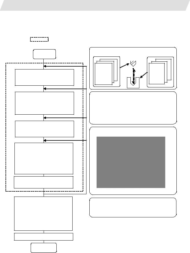
1. OUTLINE
1.2 Input Procedures
1.2 Input Procedures
The input procedure for the NAVI MILL is shown below.
The part is operated on the NAVI MILL’s screen.
Start
File edition
Tool file
Cutting condition file
Parameter setting
Parameter file
(The parameter setting is valid even if the parameter is set after editing the NC program)
NC program selection
Newly create
Read out
Process editing:
Initial conditions Process mode selection Process data input
Hole drilling / Face cutting / Contour cutting / Pocket machining / EIA, etc.
Program check (Note) Set the tool
compensation amount and workpiece coordinate system offset to perform Program Check. This function is realized by using the 700/70 Series graphic check function.
NC program operation
Supplements
|
Tool file |
Cut condition file |
|
|
(Tool registration No. 1 to 99) |
(Work registration No.1 to |
|
|
99 |
8 |
|
|
Tool leng. offset |
Material |
|
|
1 |
1 |
|
|
Tool leng. offset No. |
Tool applicable |
|
|
Tool leng. offset |
Material |
|
|
No. |
: rotation rate |
|
|
Tool diam. ffset |
||
|
No. |
No. |
Tool applicable |
|
Tool diam. offset |
: |
|
|
rotation rate |
||
|
Spindle rotation |
: |
|
|
No. |
||
|
direction |
||
|
Spindle rotation |
||
|
direction |
||
|
: |
Parameter setting
•M0 output • M6 output • M19 output •Next tool preparation, etc.
•Common parameters for hole drilling process (Z clearance, tap selection)
•Common parameters for face cutting process (XYZ clearance, Z approach G code)
•Common parameters for contour cutting / pocket machining process
Process editing
The NC program, tool file, cutting condition file and parameter file transferred to the CNC can be edited on Magicpro-NAVI MILL for 60S.
END
— 2 —

1. OUTLINE
1.3 Screen Configuration
1.3 Screen Configuration
The screen configuration for the MILL NAVI is shown below.
|
Program |
||||
|
Program |
edit |
|||
|
screen |
||||
|
Process list |
Multiple |
|||
|
parts |
||||
|
screen |
||||
|
screen |
||||
|
Initial |
Hole |
Machining |
||
|
condition |
drilling |
pattem |
||
|
setting screen |
screen |
screen |
||
|
Face |
||||
|
Process |
cutting |
Cutting |
||
|
screen |
||||
|
Process |
mode select |
condition |
||
|
Contour |
||||
|
screen |
screen |
|||
|
cutting |
||||
|
(For a new process, |
screen |
|||
|
select the process |
|
|||
|
form the process |
screen |
|||
|
mode.) |
||||
|
EIA |
||||
|
Program |
screen |
|||
|
checker |
||||
|
Tool file |
||||
|
File |
screen |
|||
|
Cutting |
||||
|
condition |
||||
|
file screen |
||||
|
Parameter |
Parameter |
Preference |
||
|
screen |
screen |
|||
|
Version |
Version |
|||
|
screen |
||||
— 3 —

1. OUTLINE
|
1.3 Screen Configuration |
||
|
Screen name |
Details |
|
|
Title screen |
This screen is displayed when the power is turned ON. |
|
|
Program edit screen |
The process program is read out and saved, etc. |
|
|
Process list screen |
Tool information and cutting conditions for each |
|
|
process of a machining program are listed. |
||
|
Multiple parts screen |
A NC program for the multiple parts machining is |
|
|
generated. |
||
|
Process mode select |
The process mode (hole drilling, etc.) is selected. |
|
|
screen |
||
|
Initial conditions setting |
The initial conditions for the process program are set. |
|
|
screen |
||
|
Hole drilling screen |
The parameters for the hole drilling process are input. |
|
|
Hole drilling machining |
The parameters related to the machining pattern of the |
|
|
pattern screen |
hole drilling process are input. |
|
|
Cutting condition screen |
The cutting conditions by the process are input. |
|
|
Face cutting screen |
The parameters for the face cutting process are input. |
|
|
Contour cutting screen |
The parameters for the contour cutting process are |
|
|
input. |
||
|
Contour cutting pattern |
The parameters related to the machining pattern of the |
|
|
screen |
contour cutting process are input. |
|
|
Pocket screen |
The parameters of the pocket process are input. |
|
|
Pocket pattern screen |
The parameters related to the machining pattern of the |
|
|
pocket process are input. |
||
|
EIA screen |
The EIA process is input. |
|
|
Tool file screen |
The tool data by each tool is registered. |
|
|
Cutting condition file |
The cutting conditions (speed rate) by each process are |
|
|
screen |
input. |
|
|
Parameter screen |
The tool code and miscellaneous parameter are set. |
|
|
Preference screen |
The system is set up. |
|
|
Version screen |
The version data of the NAVI MILL is displayed. |
|
|
Program checker |
The tool paths of a NC program is graphically traced. |
1.4 Starting NAVI MILL
Select 
 EDIT
EDIT 
 function, then [NAVI] menu to display NAVI MILL screen.
Program edit screen is displayed once when the power is turned ON. Then, whatever the screen previously selected with NAVI MILL is displayed thereafter.
— 4 —

1. OUTLINE
1.5 Setting up NAVI MILL
1.5 Setting up NAVI MILL
Part program output from NAVI MILL is a macro-program-based NC program. Thus, macro programs have to be registered in the NC system in advance. Also, the destinations where NC programs or NAVI MILL’s reference files are saved, as well as the unit for data input, have to be specified prior to NAVI MILL operations.
NAVI MILL setup items
|
Item |
Details |
Standard value |
|
PATH |
Path to the folder in which NC program is saved. |
MEM:/ |
|
PROGRAM |
||
|
PATH |
Path to the folder in which tool file, cutting condition file |
In 700 Series: |
|
PARAMETER |
and parameter file are saved. |
D:/NCFILE/NAVI |
|
In 70 Series: |
||
|
MEM:/ |
||
|
MACRO |
Macro program mode |
1 (User Macro) |
|
1: User macro mode |
||
|
2: MTB macro mode |
||
|
UNIT |
Unit for data input |
2 (mm) |
|
1: inch |
||
|
2: mm |
NAVI MILL setup procedures
(1)Open PARAMETER screen.
|
(2) |
Set «999 MAINTE» to 1. |
[PREFERENCE] menu is displayed. |
|
(3) |
Press [PREFERENCE] menu. |
PREFERENCE screen is displayed. |
(4)Select the macro type. (1:Uer macro 2:MTB macro)
— 5 —

1.OUTLINE
(5)Press [MACRO ENTRY] menu.
(6)Press [Y] key.
(7)Enter the program path.
(8)Enter the parameter path.
(9)Select the unit. (1:inch, 2:mm)
1.5 Setting up NAVI MILL
«OK?(Y/N)» message is displayed.
Macro program is registered in NC system.
When the unit is changed, turn the power OFF and ON again.
(Addendum)
•Always carry out a macro program registration when setting up NAVI MILL or switching «MACRO» types.
•Change «PROGRAM PATH» and «PARAMETER PATH» when necessary.
•When «UNIT» is changed, turn the power OFF and ON again.
•If the tool file, cutting condition file and parameter file do not exist in «PARAMETER PATH» folder when the power is turned ON, those files are created by the system.
— 6 —

2.FUNCTIONS OF DISPLAY AREA
2.FUNCTIONS OF DISPLAY AREA
The screen of the NAVI MILL is divided into the following five areas.
(1)LIST VIEW area (Refer to «2.1 LIST VIEW Area»)
(2)OPERATION VIEW area (Refer to «2.2 OPERATION VIEW Area»)
(3)Setting area (Refer to «2.3 Setting Area»)
(4)Message area (Refer to «2.4 Message Area»)
(5)Menu display area (Refer to «2.5 Menu Display Area»)
|
(1) LIST VIEW area |
(2) OPERATION VIEW area |
(4) Message area
|
(3) Setting area |
||||
|
(5) Menu display area |
<Screen example>
— 7 —
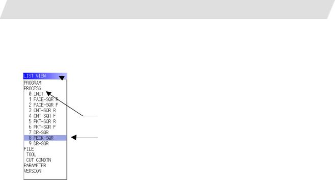
2. FUNCTIONS OF DISPLAY AREA
2.1 LIST VIEW Area
2.1 LIST VIEW Area
The object of the NAVI MILL is selected in this area.
 (1) Area bar
(2) Object
(3) Cursor
(1)Area bar
When the LIST VIEW area is active, the area bar is highlighted.
(2)Objects
The list of objects that can be selected are displayed. The object is composed of the main object and the sub object that the main object is detailed. The details of each object are as follows.
|
Main object |
Sub object |
Details |
|
PROGRAM |
— |
Newly creates, reads out, and deletes, etc. the NC program. |
|
PROCESS |
0 INIT |
Displays the currently edited process list. |
|
1 DR-LINE |
The settings of the selected process can be displayed and |
|
|
: |
changed. |
|
|
FILE |
TOOL |
Displays and changes the tool file. |
|
CUT CONDTN |
Displays and changes the cutting conditions for each process |
|
|
per workpiece material. |
||
|
PARAMETER |
— |
Displays the tool option and the miscellaneous parameter to |
|
be used in each process. Those can be changed. |
||
|
VERSION |
— |
Displays the version data of the NAVI MILL. |
(Note) If too many processes are registered and all the objects cannot be displayed, a scroll bar will be displayed. In this case, change display of the list by pressing cursor key or page key down, or by clicking on the scroll bar.
— 8 —

2. FUNCTIONS OF DISPLAY AREA
2.1 LIST VIEW Area
(3) Cursors
When the LIST VIEW area is active and the object is selected with the cursor, the display in the OPERATION VIEW area and the menu display area will be changed.
<Cursor Movement>
The cursor is moved using the cursor keys or a pointing device.
|
Key type |
Operation of cursor |
|
[↑] Cursor key |
Moves the cursor one field up regardless of the main object or sub object. |
|
Note that if the ↑ cursor is pressed when the cursor is at the top, the cursor |
|
|
does not move. |
|
|
[↓] Cursor key |
Moves the cursor one field down regardless of the main object or sub object. |
|
Note that if the ↓ cursor is pressed when the cursor is at the bottom, the cursor |
|
|
does not move. |
|
|
[←] Cursor key |
When the cursor is at the sub object, moves the cursor to the previous main |
|
object. |
|
|
[→] Cursor key |
When the cursor is at the sub object, moves the cursor to the next main object. |
|
[Page Up] key |
Moves the displayed data toward the top. |
|
[Page Down] |
Moves the displayed data toward the bottom. |
|
key |
|
|
Pointing device |
Cursor jumps to the spot where clicked with a pointing device. If an object not |
|
selectable is clicked, cursor does not jump. |
— 9 —

2. FUNCTIONS OF DISPLAY AREA
2.2 OPERATION VIEW Area
2.2 OPERATION VIEW Area
The various data are displayed in this area. Selecting the object in the LIST VIEW area changes the contents displayed in the OPERATION VIEW area.
 (1) Area bar
 (2) Help
 (3) Guide drawing
(4) Sub cursor
(1)Area bar
When the OPERATION VIEW area is active, the area bar is highlighted. The name of the currently edited program is displayed.
(2)Help
Quick reference on the setting items is displayed.
(3)Guide drawing
When the process is edited, a guide drawing according to the currently edited machining mode is displayed.
(4)Sub cursor
|
Key type |
Operation of cursor |
|
[↑] Cursor key |
Moves the cursor one field up. |
|
Note that if the ↑ cursor is pressed when the cursor is at the top, the cursor |
|
|
does not move. |
|
|
[↓] Cursor key |
Moves the cursor one field down. |
|
Note that if the ↓ cursor is pressed when the cursor is at the bottom, the cursor |
|
|
does not move. |
|
|
[Page Up] key |
Moves the displayed data toward the top. |
|
[Page Down] |
Moves the displayed data toward the bottom. |
|
key |
— 10 —

2. FUNCTIONS OF DISPLAY AREA
2.3 Setting Area
2.3 Setting Area
The value to be set to data is input.
2.4 Message Area
An error message or operation message, etc. during operation is displayed.
2.5 Menu Display Area
The screen operation is selected, and the screen is changed.
The different menus are displayed in each screen. (Refer to the chapter 4.)
— 11 —

3. BASIC OPERATIONS
3.1 Changing Active View
3. BASIC OPERATIONS
3.1 Changing Active View
To operate NAVI MILL, activate either LIST VIEW area or OPERATION VIEW area. When the VIEW is active, the area bar is highlighted and data can be input. Use menu keys [←] and [→] or a pointing device to change one of the VIEWs to be activated.
3.2 Changing Screen
When the object is selected in the LIST VIEW area, the screen (contents in the OPERATION VIEW area) changes. (Refer to the section 2.1 LIST VIEW Area.)
Note that the screen cannot be changed while the OPERATION VIEW area is active.
In such a case, press the [←] menu key or click «LIST VIEW» with a pointing device to turn the LIST VIEW area active.
Operation example
(1) Open the program edit screen.
The OPERATION VIEW area is active.
(2) Press the [←] menu key.
The LIST VIEW area will turn active.
— 12 —
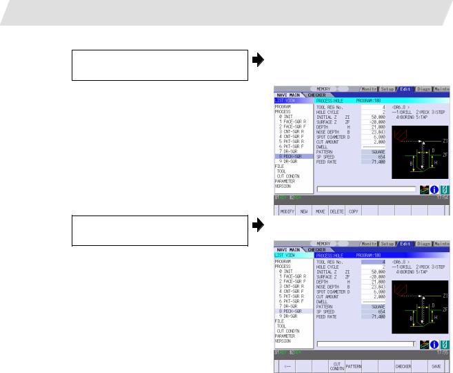
3.BASIC OPERATIONS
(3)Select the object with the cursor key.
(4) Press the [MODIFY] menu key.
3.2 Changing Screen
The OPERATION VIEW area will change into the screen corresponding to the selected object.
The OPERATION VIEW area will turn active.
— 13 —

3. BASIC OPERATIONS
3.3 Setting Data
3.3 Setting Data
After moving the sub cursor, input the data into the setting area and then press the [INPUT] key, and the data will be set. (The sub cursor is displayed only when the OPERATION VIEW area is active.)
Sub-cursor
 Setting area
— 14 —

3. BASIC OPERATIONS
3.3 Setting Data
Operation method
An example for setting the data on the hole drilling screen is shown below.
(1) Screen selection
Select the object to be changed from the LIST VIEW and press [MODIFY] menu key.
(2) Setting item selection
Move the sub cursor with cursor keys.
The OPERATION VIEW area will turn active.
(Refer to the section 3.2 «Changing screen».)
This is an example of the sub cursor movement on the hole drilling screen.
|
(3) Data key input |
||||
|
Set data with the numeral keys or |
The data is set in the data setting area. |
|||
|
alphabet keys, etc. |
18 000 |
[1][2] [3] [.] [4] [5] [6]
(4)[Input] key input
|
Press the [input] key. |
Data for the selected setting item is set. |
The sub cursor moves to the next position.
(Note 1) The contents in the data setting area are only displayed when [INPUT] key is not pressed and will be invalidated if the screen is changed at this time. Data for the currently selected setting item will be set when [INPUT] key is pressed.
(Note 2) If illegal data is set, an error occurs when [Input] is pressed. Set the correct data again.
— 15 —

3. BASIC OPERATIONS
3.3 Setting Data
Operations in the data setting area
The key is input at the position where the cursor is displayed. If a cursor is not displayed, the key input is invalid.
When a key is input, the data appears at the cursor position, and the cursor moves one character space to the right.

 [→] / [←] keys: Moves the cursor one character to the left or right.
|
(1) The cursor is at the position shown on |
|
|
the right. |
1 2 3 7 7 7 | 4 5 6 |
(2) Press the [→] key.
The cursor moves one character space to the right.
1 2 3 7 7 7 4 | 5 6

 [DETETE] key: Deletes the character in front of the cursor.
|
(1) |
Move the cursor to the |
position where |
The cursor moves in the data setting area. |
|||
|
the data is to be deleted. |
1 2 3 4 |
| 5 6 |
||||
|
(2) |
The character in front of the cursor is |
|||||
|
Press the [DETETE] key. |
||||||
|
deleted. |
||||||
|
1 2 3 |
| 5 6 |
|||||
— 16 —
![]()
3. BASIC OPERATIONS
3.4 Switching Windows
3.4 Switching Windows
When a shortcut button on the keyboard is pressed, its corresponding window is displayed.
|
Button |
Application |
|||||
|
Displays the tool guidance window. |
||||||
|
LIST |
?Displays the message guidance window.
Displays the checker window.
3.5 Switching Selection Tags
Menu tag
When a tag button on the keyboard is pressed, the main window and checker window can be switched over.
|
Button |
Application |
||||
|
Selects the tag on the left. |
|||||
|
Selects the tag on the right. |
|||||
(Note 1) Depending on the keyboard specifications, tag button may not be available.
— 17 —

3. BASIC OPERATIONS
3.6 Inputting Operations
3.6 Inputting Operations
In addition to the method of directly inputting numeric data for specific data settings, a method to input the operation results using four rules operators and function symbols can be used.
Input method
Numeric values, function symbols, operators and parentheses ( ) are combined and set in the data setting area.
The operation results appear when the [INPUT] key is pressed. Data for the currently selected setting item will be set when [INPUT] key is pressed again.
The contents in the data setting area are erased.
Examples of operator settings, and results
|
Operation |
Setting |
Operation |
|
|
example |
results |
||
|
Addition |
=100+50 |
150.000 |
|
|
Subtraction |
=100−50 |
50.000 |
|
|
Multiplication |
=12.3 4 |
49.200 |
|
|
Division |
=100/3 |
33.333 |
|
|
Function |
=1.2 |
5.4 |
|
|
(2.5+SQRT(4)) |
|||
Function symbols, setting examples and results
|
Function |
Function |
Setting |
Operation |
||
|
symbol |
example |
results |
|||
|
Absolute |
ABS |
=ABS (50−60) |
10 |
||
|
value |
|||||
|
Square root |
SQRT |
=SQRT (3) |
1.732 |
||
|
Sine |
SIN |
=SIN |
(30) |
0.5 |
|
|
Cosine |
COS |
=COS |
(15) |
0.966 |
|
|
Tangent |
TAN |
=TAN |
(45) |
1 |
|
|
Arc tangent |
ATAN |
=ATAN (1.3) |
52.431 |
||
|
Circle ratio |
PAI |
=PAI*10 |
31.415 |
||
|
Inch |
INCH |
=INCH/10 |
2.54 |
Operation examples
(1)Set as shown below, and press the [Input] key.
=12 20 [Input]
(2) Press the [Input] key again.
Notes for using operators and functions
The operation results appear in the data setting area.
240 |
Data for the selected setting item is set. The cursor moves to the next position.
|
Division |
: |
Zero division causes an error. |
|
Square root |
: |
If the value in the parentheses is negative, an error occurs. |
|
Triangle function |
: |
The unit of angle θ is degree (°). |
|
Arc tangent |
: |
−90 < operation results < 90. |
Restrictions
•Always use «=» for the first character.
•Do not use the following characters as the second character or last character. Invalid as second character: , /, )
Invalid as last character: , /, (, +, —
•Make sure that the left parentheses and right parentheses are balanced.
•The 360° limit does not apply on the angle. SIN (500) is interpreted as SIN (140).
— 18 —

4. SCREEN SPECIFICATIONS
4.1 Starting NAVI MILL
4. SCREEN SPECIFICATIONS
4.1 Starting NAVI MILL
When NAVI MILL is started, the program edit screen will be displayed.
Screen layout
At the initial start up of NAVI MILL, the cursor is displayed at the position of [PROGRAM] in the LIST VIEW area, and the program edit screen is displayed in the OPERATION VIEW area.
The LIST VIEW area is active.
The process program is not selected.
— 19 —

4. SCREEN SPECIFICATIONS
4.2 Screen Related to the Program
4.2 Screen Related to the Program
4.2.1 Program Edit Screen
The NC program is newly created and read out, etc. on this screen. When [PROGRAM] is selected in the LIST VIEW area, this screen is displayed.
Screen layout
The process list of the currently selected program is displayed in the LIST VIEW area.
— 20 —

4. SCREEN SPECIFICATIONS
|
4.2 Screen Related to the Program |
|||||
|
< Process displays > |
|||||
|
Process name |
Display |
Remarks |
|||
|
character |
|||||
|
Hole drilling |
Drilling |
DR-**** |
The symbol (abbrev.) which indicates the |
||
|
machining pattern is applied to the «****» part. |
|||||
|
Pecking |
PECK-**** |
||||
|
● Random : RNDM |
|||||
|
● Linear |
: LINE |
||||
|
Step |
STEP-**** |
||||
|
● Arc |
: ARC |
||||
|
Boring |
BORE-**** |
● Circle |
: CIR |
||
|
● Square |
: SQR |
||||
|
Tapping |
(TAP-****) |
||||
|
● Grid |
: GRID |
||||
|
Helical boring |
HLX-BORE ? |
The symbol which indicates the machining |
|||
|
type (rough / finishing) is applied to the «?» |
|||||
|
part. |
|||||
|
● Rough |
: R |
||||
|
● Finishing : F |
|||||
|
Face cutting |
Square |
FACE-SQR ? |
The symbol which indicates the machining |
||
|
Circle |
FACE-CIR ? |
type (rough / finishing) is applied to the «?» |
|||
|
Contour |
Square |
CNT-SQR ? |
part. |
||
|
cutting |
Circle |
CNT-CIR ? |
● Rough |
: R |
|
|
Free |
CNT-FREE ? |
● Finishing : F |
|||
|
|
Square |
PKT-SQR ? |
|||
|
Circle |
PKT-CIR ? |
||||
|
L pattern |
PKT-LPT ? |
||||
|
U pattern |
PKT-UPT ? |
||||
|
Track |
PKT-TRK ? |
||||
|
EIA |
EIA (EIA) |
Screen display item
|
No. |
Display item |
Details |
Setting range |
|
1 |
PROGRAM LIST |
Displays the program number and comment of the |
— |
|
NC program that can be currently read out. |
— 21 —

4. SCREEN SPECIFICATIONS
4.2 Screen Related to the Program
Menus
|
No. |
Menu |
Details |
||
|
1 |
← |
Turns the LIST VIEW area active. |
||
|
2 |
NEW |
Newly creates the NC program. (Note 1) |
||
|
< Display in the setting area when pressing the menu > |
||||
|
O( |
) COMMENT( |
) |
||
|
3 |
OPEN |
Reads out the existing NC program. (Note 1) (Note 2) |
||
|
< Display in the setting area when pressing the menu > |
||||
|
O( |
) |
When this menu is pressed, the cursor appears at the program list’s name section. When the setting area is empty, select a program with the cursor and press the [INPUT] key to read the program.
|
Cursor |
||||
|
4 |
COPY |
Copies the existing NC program to another program. (Note 1) |
||
|
< Display in the setting area when pressing the menu > |
||||
|
O( |
) → O( |
) |
||
|
5 |
COMMENT |
Edits the comment in the NC program. (Note 1) |
||
|
< Display in the setting area when pressing the menu > |
||||
|
O( |
) COMMENT( |
) |
||
|
6 |
RENAME |
Renames the existing NC program. (Note 1) |
||
|
< Display in the setting area when pressing the menu > |
||||
|
O( |
) → O( |
) |
||
|
7 |
DELETE |
Deletes the NC program. |
||
|
< Display in the setting area when pressing the menu > |
||||
|
O( |
) to O( |
) |
||
|
8 |
LIST UPDATE |
Updates the list display. |
(Note 1) 1 to 7999 or 10000 to 99999999 can be set for the O No, and up to 18 alphanumeric characters can be set for the comment.
(Note 2) NC program mode includes user macro mode and MTB mode. (This is specified in the preferences screen.) When user macro mode is active and an NC program created with MTB mode is opened, the NC program is converted into user macro mode. When MTB mode is active and an NC program created with user macro mode is opened, the NC program is converted into MTB mode.
— 22 —

4. SCREEN SPECIFICATIONS
Operation example (Opening the existing NC program)
(1)Select the [PROGRAM] in the LIST VIEW area.
(2)Press the [OPEN] menu key, and input the NC program No. to be read out.
(3) Press the [INPUT] key.
4.2 Screen Related to the Program
The program edit screen will be displayed. The list of the NC program that can be read out will be displayed.
The [OPEN] menu will be highlighted, and the setting area will be displayed.
The highlight of the [OPEN] menu will turn OFF, and the setting area will disappear. The process of the NC program read out will be displayed in the LIST VIEW area. The NC program No. read out will be displayed on the area bar of the OPERATION VIEW area.
— 23 —

4. SCREEN SPECIFICATIONS
4.3 Screens Related to the Process Edit Functions
4.3 Screens Related to the Process Edit Functions
4.3.1 Process List Screen
The tool information and cutting conditions for each process are displayed on this screen. When [PROCESS] is selected in the LIST VIEW area, this screen is displayed.
When the NC program is not selected, this screen is not displayed. Screen layout
— 24 —

4. SCREEN SPECIFICATIONS
4.3 Screens Related to the Process Edit Functions
Screen display items
|
No. |
Display item |
Details |
Setting range |
||
|
1 |
PCS |
The process name is displayed. |
— |
||
|
(Note) This name is same as the name displayed |
|||||
|
in the LIST VIEW area. |
|||||
|
2 |
T NAME |
The name of tool to be used is displayed. |
— |
||
|
3 |
T |
Specify the No. of tool to be used. |
0 to 9999 |
||
|
4 |
NT |
Specify the No. of tool to be used in the next |
0 to 9999 |
||
|
process. According to the specified tool No., the |
|||||
|
tool is determined after the tool change. |
|||||
|
(Note) When «1» is set in the parameter «103 |
|||||
|
NEXT TOOL PREP», this data is valid. |
|||||
|
5 |
H |
Specify the tool length offset No. |
1 to number of tool |
||
|
The maximum value for the H is changed |
sets |
||||
|
according to the specifications. |
|||||
|
6 |
D |
Specify tool diameter offset No. |
1 to number of tool |
||
|
The maximum value for the D is changed |
sets |
||||
|
according to the specifications. |
|||||
|
7 |
S |
Input the spindle rotation speed. |
1 to 99999 rev/min |
||
|
8 |
F |
Input the feedrate. |
0.001 to |
||
|
When the hole cycle type is «TAP», input the pitch |
60000.000 mm/min |
||||
|
(mm/rev). |
0.001 to |
||||
|
999.999 mm/rev |
|||||
|
Menus |
|||||
|
No. |
Menu |
Details |
|||
|
1 |
← |
Turns the LIST VIEW area active. |
|||
|
2 |
NEXT T PRESET |
Sets the next tool No. automatically. For the next tool No., the tool No. |
|||
|
of the next process is set. |
|||||
|
3 |
MULTI PT |
Multiple Parts screen is displayed. |
|||
|
When using the Multiple Parts function, press “MULTI PT”. |
|||||
|
4 |
SAVE |
Saves changes in the process list. |
— 25 —

4. SCREEN SPECIFICATIONS
4.3 Screens Related to the Process Edit Functions
4.3.2 Multiple Parts Screen
Multiple Parts function enables you to generate a NC program that allows one designated machining process to be completed at once for multiple workpieces. This NC program can be generated based on the NC programs generated for a single part machining with the appropriate arrangement of the multiple workpieces.
When working on multiple workpieces, there are two options available to specify their positions:
•by identifying the values of the work-coordinate system per each workpiece.
•by determining each offset amount from one specific work coordinate.
As for machining pattern, there are two options available:
•to have one machining process completed for all workpieces on the table before moving on to the next machining process (the number of times to execute tool-changes can be reduced by choosing this option).
•to have entire machining processes completed per each workpiece.
(Note 1) The NC program generated with the Multiple Parts function is differed from its original NC program. (Note 2) The NC program generated with the Multiple Parts function cannot be edited with NAVI MILL. If
editing is attempted, the operation message “No init process, Create OK? (Y/N)” appears.
|
<Drawing> |
||||||
|
90 |
200 |
90 |
||||
|
160 |
||||||
|
70 |
70 |
|||||
|
35 |
35 |
|||||
|
50 |
50 |
|||||
|
50 |
||||||
|
35 |
||||||
|
0 |
90 |
130 |
||||
|
3 |
50 |
|||||
|
10 |
35 |
|||||
|
-R |
50 |
|||||
|
8 |
||||||
|
9-M8 P=1.25 Depth8 |
6-Φ6.8 Hole Depth17 |
4-Φ6.8 Penetration |
||||
|
Prepared hole Φ6.8 Depth12 |
||||||
|
5 |
||||||
|
10 |
15 |
|||||
|
20 |
<NAVI MILL base function>
Program for single part
<Layout of workpieces>
|
Program generater |
||||||||||||||
|
Program for multiple parts |
for multiple parts |
|||||||||||||
— 26 —
![]()
4. SCREEN SPECIFICATIONS
4.3 Screens Related to the Process Edit Functions
To view the “Multiple Parts Screen”, go to the “Process List Screen” and press [MULTI PT] menu.
Screen Layout
— 27 —

4. SCREEN SPECIFICATIONS
4.3 Screens Related to the Process Edit Functions
Screen Details
|
No. |
Display item |
Details |
Setting range |
||||||
|
1 |
PROGRAM O |
Program No. and comments are input. |
|||||||
|
Avoid using the same program No. for the Multiple |
|||||||||
|
Parts NC program and the currently editing program. If |
|||||||||
|
a duplicated program No. is used for both programs, an |
|||||||||
|
error message occurs. |
|||||||||
|
2 |
NUM OF PARTS |
Number of parts is input. |
2 to 8 |
||||||
|
3 |
MACHINING |
Machining pattern is selected. |
1 to 2 |
||||||
|
1: A pattern that has one machining process |
|||||||||
|
completed for all workpieces before moving on |
|||||||||
|
to the next machining process |
|||||||||
2:A pattern that has entire machining processes completed per one workpiece before moving on to the next workpiece
— 28 —

4. SCREEN SPECIFICATIONS
4.3 Screens Related to the Process Edit Functions
|
No. |
Display item |
Details |
Setting range |
||||||||
|
4 |
COORDINATE |
The method to specify the position of multiple |
1 to 2 |
||||||||
|
workpieces is selected. |
|||||||||||
|
1: A method that identifies the values of the |
|||||||||||
|
work-coordinate system per each workpiece |
|||||||||||
2:A method that determines each offset amount from
one specific work coordinate
|
5 X |
The value of each workpiece position is input |
-99999.999 to |
||||
|
Y |
depending on the offset amount from one specific work |
99999.999mm |
||||
|
coordinate. |
||||||
|
This is valid when selecting «2» in the COORDINATE |
||||||
|
screen. |
||||||
|
WC |
The value of the work-coordinate system per each |
54 to 59 |
||||
|
workpiece is input. |
P1 to P48 |
|||||
|
This is valid when selecting «1» in the COORDINATE |
||||||
|
screen. |
(Note) Program No. can be selected from 1 to 7999 or 10000 to 99999999. Comment section allows up to 18 characters/numbers.
Menu
|
No. |
Menu |
Details |
|
1 |
GEN PRGM |
Generate a NC program for the Multiple Parts machining. |
|
2 |
RETURN |
Return to the Process List Screen. |
— 29 —

4. SCREEN SPECIFICATIONS
4.3 Screens Related to the Process Edit Functions
4.3.3 Operating Process
When the cursor is moved to the sub-object of PROCESS in the LIST VIEW area, a menu for editing the process is displayed, and the process can be operated.
Screen layout
Menus
|
No. |
Menu |
Details |
|
1 |
MODIFY |
The OPERATION VIEW area turns active, and the process parameters |
|
can be changed. |
||
|
2 |
NEW |
Adds a new process. |
|
The process will be inserted into the cursor position. |
||
|
3 |
MOVE |
Changes the process position. |
|
4 |
DELETE |
Deletes the process at the cursor position. |
|
When performing the deletion, the process under the deleted process |
||
|
will be moved up. |
||
|
5 |
COPY |
Copies the process at the cursor position. |
|
The copied process will be inserted under the cursor position. |
— 30 —
 Loading…
MELDAS is a registered trademark of Mitsubishi Electric Corporation. Other company and product names that appear in this manual are trademarks or registered trademarks of the respective companies.
Introduction
This manual is a guide for using the MITSUBISHI CNC 700/70 Series. Programming is described in this manual, so read this manual thoroughly before starting programming. Thoroughly study the «Precautions for Safety» on the following page to ensure safe use of this NC unit. Details described in this manual
CAUTION
For items described in «Restrictions» or «Usable State», the instruction manual issued by the machine tool builder takes precedence over this manual.
An effort has been made to note as many special handling methods in this user’s manual. Items not described in this manual must be interpreted as «not possible».
This manual has been written on the assumption that all option functions are added. Refer to the specifications issued by the machine tool builder before starting use.
Refer to the Instruction Manual issued by each machine tool builder for details on each machine tool. Some screens and functions may differ depending on the NC system or its version, and some
functions may not be possible. Please confirm the specifications before use.
General precautions
(1) Refer to the following documents for details on handling MITSUBISHI CNC 700/70 Series Instruction Manual …………………………… IB-1500042
Precautions for Safety Always read the specifications issued by the machine maker, this manual, related manuals and attached documents before installation, operation, programming, maintenance or inspection to ensure correct use. Understand this numerical controller, safety items and cautions before using the unit. This manual ranks the safety precautions into «DANGER», «WARNING» and «CAUTION».
When the user may be subject to imminent fatalities or major injuries if handling is mistaken. When the user may be subject to fatalities or major injuries if handling is mistaken. When the user may be subject to injuries or when physical damage may occur if handling is mistaken.
Note that even items ranked as » CAUTION«, may lead to major results depending on the situation. In any case, important information that must always be observed is described.
DANGER
Not applicable in this manual.
WARNING
Not applicable in this manual.
CAUTION
1. Items related to product and manual
For items described as «Restrictions» or «Usable State» in this manual, the instruction manual issued by the machine tool builder takes precedence over this manual.
An effort has been made to describe special handling of this machine, but items that are not described must be interpreted as «not possible».
This manual is written on the assumption that all option functions are added. Refer to the specifications issued by the machine tool builder before starting use.
Refer to the Instruction Manual issued by each machine tool builder for details on each machine tool.
Some screens and functions may differ depending on the NC system or its version, and some functions may not be possible. Please confirm the specifications before use.
(Continued on next page)
DANGER
WARNING
CAUTION
CAUTION
2. Items related to operation
Before starting actual machining, always carry out dry operation to confirm the machining program, tool compensation amount and workpiece offset amount, etc.
If the workpiece coordinate system offset amount is changed during single block stop, the new setting will be valid from the next block.
Turn the mirror image ON and OFF at the mirror image center.
Refer to the Instruction Manual issued by each machine tool builder for details on each machine tool.
If the tool compensation amount is changed during automatic operation (including during single block stop), it will be validated from the next block or blocks onwards.
3. Items related to programming
The commands with «no value after G» will be handled as «G00».
EOB», «%», and EOR are symbols used for explanation. The actual codes for ISO are «CR, LF» («LF») and «%». The programs created on the Edit screen are stored in the NC memory in a «CR, LF» format, however, the programs created with external devices such as the FLD or RS-232C may be stored in an «LF» format.
The actual codes for EIA are «EOB (End of Block)» and «EOR (End of Record)».
When creating the machining program, select the appropriate machining conditions, and make sure that the performance, capacity and limits of the machine and NC are not exceeded. The examples do not consider the machining conditions.
Do not change fixed cycle programs without the prior approval of the machine tool builder.
When programming a program of the multi-part system, carefully observe the movements caused by other part systems’ programs.
Contents
1. Control Axes………………………………………………………………………………………………………………….1 1.1 Coordinate Words and Control Axis…………………………………………………………………………….1 1.2 Coordinate Systems and Coordinate Zero Point Symbols………………………………………………2
2. Least Command Increments…………………………………………………………………………………………..3 2.1 Input Setting Units…………………………………………………………………………………………………….3 2.2 Input Command Increment Tenfold……………………………………………………………………………..5 2.3 Indexing Increment……………………………………………………………………………………………………6
3. Data Formats …………………………………………………………………………………………………………………7 3.1 Tape Codes……………………………………………………………………………………………………………..7 3.2 Program Formats ……………………………………………………………………………………………………10 3.3 Tape Memory Format………………………………………………………………………………………………13 3.4 Optional Block Skip …………………………………………………………………………………………………13
3.4.1 Optional Block Skip; /…………………………………………………………………………………………13 3.4.2 Optional Block Skip Addition ; /n………………………………………………………………………….14
3.5 Program/Sequence/Block Numbers ; O, N …………………………………………………………………16 3.6 Parity H/V ………………………………………………………………………………………………………………17 3.7 G Code Lists ………………………………………………………………………………………………………….18 3.8 Precautions Before Starting Machining………………………………………………………………………21
4. Buffer Register …………………………………………………………………………………………………………….22 4.1 Input Buffer…………………………………………………………………………………………………………….22 4.2 Pre-read Buffers……………………………………………………………………………………………………..23
5. Position Commands …………………………………………………………………………………………………….24 5.1 Position Command Methods ; G90, G91 ……………………………………………………………………24 5.2 Inch/Metric Command Change; G20, G21………………………………………………………………….26 5.3 Decimal Point Input …………………………………………………………………………………………………28
6. Interpolation Functions ………………………………………………………………………………………………..33 6.1 Positioning (Rapid Traverse); G00…………………………………………………………………………….33 6.2 Linear Interpolation; G01………………………………………………………………………………………….40 6.3 Plane Selection; G17, G18, G19……………………………………………………………………………….42 6.4 Circular Interpolation; G02, G03 ……………………………………………………………………………….44 6.5 R-specified Circular Interpolation; G02, G03 ………………………………………………………………49 6.6 Helical Interpolation ; G17 to G19, G02, G03 ……………………………………………………………..52 6.7 Thread Cutting ……………………………………………………………………………………………………….56
6.7.1 Constant Lead Thread Cutting ; G33……………………………………………………………………56 6.7.2 Inch Thread Cutting; G33……………………………………………………………………………………60
6.8 Unidirectional Positioning; G60…………………………………………………………………………………61 6.9 Cylindrical Interpolation; G07.1 …………………………………………………………………………………63 6.10 Polar Coordinate Interpolation; G12.1, G13.1/G112,G113 ………………………………………….71 6.11 Exponential Function Interpolation; G02.3, G03.3 ……………………………………………………..78 6.12 Polar Coordinate Command ; G16/G15 ……………………………………………………………………84 6.13 Spiral/Conical Interpolation; G02.0/G03.1(Type1), G02/G03(Type2) ……………………………90 6.14 3-dimensional Circular Interpolation; G02.4, G03.4 ……………………………………………………95 6.15 NURBS Interpolation……………………………………………………………………………………………100 6.16 Hypothetical Axis Interpolation; G07 ………………………………………………………………………105
7. Feed Functions ………………………………………………………………………………………………………….107 7.1 Rapid Traverse Rate ……………………………………………………………………………………………..107 7.2 Cutting Feedrate …………………………………………………………………………………………………..107 7.3 F1-digit Feed………………………………………………………………………………………………………..108 7.4 Feed Per Minute/Feed Per Revolution
(Asynchronous Feed/Synchronous Feed); G94, G95 …………………………………………………110
7.5 Inverse Time Feed; G93 ………………………………………………………………………………………..112 7.6 Feedrate Designation and Effects on Control Axes ……………………………………………………116 7.7 Rapid Traverse Constant Inclination Acceleration/Deceleration …………………………………..120 7.8 Rapid Traverse Constant Inclination Multi-step Acceleration/Deceleration ……………………122 7.9 Exact Stop Check; G09………………………………………………………………………………………….131 7.10 Exact Stop Check Mode; G61……………………………………………………………………………….134 7.11 Deceleration Check……………………………………………………………………………………………..134
7.11.1 G1 -> G0 Deceleration Check………………………………………………………………………….136 7.11.2 G1 -> G1 Deceleration Check………………………………………………………………………….137
7.12 Automatic Corner Override; G62……………………………………………………………………………138 7.13 Tapping Mode; G63 …………………………………………………………………………………………….143 7.14 Cutting Mode ; G64 ……………………………………………………………………………………………..143
8. Dwell………………………………………………………………………………………………………………………….144 8.1 Per-second Dwell ; G04 …………………………………………………………………………………………144
9. Miscellaneous Functions ……………………………………………………………………………………………146 9.1 Miscellaneous Functions (M8-digits BCD) ………………………………………………………………..146 9.2 Secondary Miscellaneous Functions (B8-digits, A8 or C8-digits) …………………………………148 9.3 Index Table Indexing……………………………………………………………………………………………..149
10. Spindle Functions…………………………………………………………………………………………………….151 10.1 Spindle Functions (S6-digits Analog) ……………………………………………………………………..151 10.2 Spindle Functions (S8-digits) ………………………………………………………………………………..151 10.3 Constant Surface Speed Control; G96, G97……………………………………………………………152
10.3.1 Constant Surface Speed Control ……………………………………………………………………..152 10.4 Spindle Clamp Speed Setting; G92 ……………………………………………………………………….153 10.5 Spindle/C Axis Control …………………………………………………………………………………………154 10.6 Multiple Spindle Control ……………………………………………………………………………………….157
10.6.1 Multiple Spindle Control II ……………………………………………………………………………….158
11. Tool Functions (T command)…………………………………………………………………………………….160 11.1 Tool Functions (T8-digit BCD)……………………………………………………………………………….160
12. Tool Compensation Functions ………………………………………………………………………………….161 12.1 Tool Compensation ……………………………………………………………………………………………..161 12.2 Tool Length Compensation/Cancel; G43, G44/G49 …………………………………………………165 12.3 Tool Length Compensation in the Tool Axis Direction ; G43.1/G49…………………………….168 12.4 Tool Radius Compensation; G38, G39/G40/G41,G42………………………………………………175
12.4.1 Tool radius Compensation Operation ……………………………………………………………….176 12.4.2 Other Commands and Operations during Tool Radius Compensation…………………..185 12.4.3 G41/G42 Commands and I, J, K Designation…………………………………………………….194 12.4.4 Interrupts during Tool Radius Compensation …………………………………………………….200 12.4.5 General Precautions for Tool Radius Compensation…………………………………………..202 12.4.6 Changing of Compensation No. during Compensation Mode……………………………….203 12.4.7 Start of Tool Radius Compensation and Z Axis Cut in Operation………………………….205 12.4.8 Interference Check ………………………………………………………………………………………..207 12.4.9 Diameter Designation of Compensation Amount………………………………………………..214 12.4.10 Workpiece Coordinate Changing during Radius Compensation………………………….216
12.5 Three-dimensional Tool Radius Compensation ; G40/G41,G42…………………………………218 12.6 Tool Position Offset; G45 to G48 …………………………………………………………………………..229 12.7 Programmed Compensation Input ; G10, G11…………………………………………………………236 12.8 Inputting the Tool Life Management Data; G10, G11 ……………………………………………….241
12.8.1 Inputting the Tool Life Management Data by G10 L3 Command…………………………..241 12.8.2 Inputting the Tool Life Management Data by G10 L30 Command…………………………243 12.8.3 Precautions for Inputting the Tool Life Management Data……………………………………246
13. Program Support Functions ……………………………………………………………………………………..247 13.1 Fixed Cycles……………………………………………………………………………………………………….247
13.1.1 Standard Fixed Cycles; G80 to G89, G73, G74, G75, G76 ………………………………….247 13.1.2 Drilling Cycle with High-Speed Retract ……………………………………………………………..274 13.1.3 Initial Point and R Point Level Return; G98, G99………………………………………………..277 13.1.4 Setting of Workpiece Coordinates in Fixed Cycle Mode………………………………………278
13.2 Special Fixed Cycle; G34, G35, G36, G37.1 …………………………………………………………..279 13.3 Subprogram Control; M98, M99, M198…………………………………………………………………..284
13.3.1 Calling Subprogram with M98 and M99 Commands …………………………………………..284 13.3.2 Calling Subprogram with M198 Commands ………………………………………………………289 13.3.3 Figure Rotation; M98 I_ J_ K_ …………………………………………………………………………289
13.4 Variable Commands…………………………………………………………………………………………….292 13.5 User Macro Specifications ……………………………………………………………………………………297
13.5.1 User Macro Commands; G65, G66, G66.1, G67………………………………………………..297 13.5.2 Macro Call Command …………………………………………………………………………………….298 13.5.3 ASCII Code Macro …………………………………………………………………………………………307 13.5.4 Variables………………………………………………………………………………………………………311 13.5.5 Types of Variables …………………………………………………………………………………………313 13.5.6 Arithmetic Commands…………………………………………………………………………………….351 13.5.7 Control Commands ………………………………………………………………………………………..356 13.5.8 External Output Commands…………………………………………………………………………….359 13.5.9 Precautions…………………………………………………………………………………………………..361 13.5.10 Actual Examples of Using User Macros…………………………………………………………..363
13.6 G Command Mirror Image; G50.1, G51.1……………………………………………………………….367 13.7 Corner Chamfering/Corner Rounding I …………………………………………………………………..370
13.7.1 Corner Chamfering » ,C_ » ………………………………………………………………………………370 13.7.2 Corner Rounding » ,R_ » …………………………………………………………………………………372
13.8 Linear Angle Command ……………………………………………………………………………………….373 13.9 Geometric Command …………………………………………………………………………………………..374 13.10 Circle Cutting; G12, G13 …………………………………………………………………………………….378 13.11 Parameter Input by Program; G10, G11 ……………………………………………………………….380 13.12 Macro Interrupt; M96, M97………………………………………………………………………………….381 13.13 Tool Change Position Return; G30.1 to G30.6 ………………………………………………………389 13.14 Normal Line Control ; G40.1/G41.1/G42.1…………………………………………………………….392 13.15 High-accuracy Control ; G61.1, G08 …………………………………………………………………….403 13.16 High-speed Machining Mode ; G05, G05.1……………………………………………………………417
13.16.1 High-speed Machining Mode I,II ; G05 P1, G05 P2…………………………………………..417 13.17 High-speed High-accuracy Control ; G05, G05.1……………………………………………………420
13.17.1 High-speed High-accuracy Control I, II ……………………………………………………………420 13.17.2 SSS Control ………………………………………………………………………………………………..427
13.18 Spline; G05.1 ……………………………………………………………………………………………………432 13.19 High-accuracy Spline Interpolation ; G61.2……………………………………………………………439 13.20 Scaling ; G50/G51……………………………………………………………………………………………..441 13.21 Coordinate Rotation by Program; G68/G69 …………………………………………………………..446 13.22 Coordinate Rotation Input by Parameter; G10……………………………………………………….453 13.23 3-dimensional Coordinate Conversion ; G68/69 …………………………………………………….456 13.24 Tool Center Point Control; G43.4/G43.5 ……………………………………………………………….473 13.25 Timing-synchronization between Part Systems ……………………………………………………..495
14. Coordinates System Setting Functions ……………………………………………………………………..498 14.1 Coordinate Words and Control Axes………………………………………………………………………498 14.2 Basic Machine, Workpiece and Local Coordinate Systems……………………………………….499 14.3 Machine Zero Point and 2nd, 3rd, 4th Reference Positions……………………………………….500 14.4 Basic Machine Coordinate System Selection; G53…………………………………………………..501 14.5 Coordinate System Setting ;G92……………………………………………………………………………502 14.6 Automatic Coordinate System Setting ……………………………………………………………………503 14.7 Reference (Zero) Position Return; G28, G29…………………………………………………………..504 14.8 2nd, 3rd and 4th Reference (Zero) Position Return; G30 ………………………………………….508
14.9 Reference Position Check; G27…………………………………………………………………………….511 14.10 Workpiece Coordinate System Setting and Offset ; G54 to G59 (G54.1) …………………..512 14.11 Local Coordinate System Setting; G52 …………………………………………………………………524 14.12 Workpiece Coordinate System Preset; G92.1 ……………………………………………………….528 14.13 Coordinate System for Rotary Axis ………………………………………………………………………533
15. Measurement Support Functions………………………………………………………………………………536 15.1 Automatic Tool Length Measurement; G37 …………………………………………………………….536 15.2 Skip Function; G31………………………………………………………………………………………………540 15.3 Multi-step Skip Function; G31.n, G04 …………………………………………………………………….545 15.4 Multi-step Skip Function 2; G31 …………………………………………………………………………….547 15.5 Speed Change Skip; G31 …………………………………………………………………………………….549 15.6 Programmable Current Limitation ………………………………………………………………………….552 15.7 Stroke Check before Travel; G22/G23……………………………………………………………………553
Appendix 1. Program Error ………………………………………………………………………………………….555 Appendix 2. Order of G Function Command Priority……………………………………………………..575 INDEX …………………………………………………………………………………………………………………………… X-1
1. Control Axes 1.1 Coordinate Words And Control Axis
1
1. Control Axes 1.1 Coordinate Words and Control Axis
Function and purpose
In the standard specifications, there are 3 control axes, but, by adding an additional axis, up to 4 axes can be controlled. The designation of the processing direction responds to those axes and uses a coordinate word made up of alphabet characters that have been decided beforehand.
Program coordinates
Direction of table movement
Direction of table movement
Bed
X-Y table
+Z
+Z +Y
+X
+X +Y
Workpiece
X-Y table
Program coordinates Direction of table movement Direction of table
revolution
+Z +C
+X +X
+Y
+Y
+C
Workpiece
X-Y and revolving table
1. Control Axes 1.2 Coordinate Systems And Coordinate Zero Point Symbols
2
1.2 Coordinate Systems and Coordinate Zero Point Symbols Function and purpose
: Reference position
: Machine coordinate zero point
: Workpiece coordinate zero points (G54 — G59)
Basic machine coordinate system
Machine zero point
1st reference position Workpiece
coordinate system 3 (G56)
Workpiece coordinate system 2 (G55)
Workpiece coordinate system 1 (G54)
Workpiece coordinate system 6 (G59)
Workpiece coordinate system 5 (G58)
Workpiece coordinate system 4 (G57)
Local coordinate system (G52)
-Y
y3
-X
y2
y
y1
y5
x1
x3 x2
x
x5
2. Least Command Increments 2.1 Input Setting Units
3
2. Least Command Increments 2.1 Input Setting Units
Function and purpose
The input setting units are, as with the compensation amounts, the units of setting data used in common for all axes. The command units are the movement amounts in the program which are commanded with MDI inputs or command tape. These are expressed with mm, inch or degree () units. With the parameters, the command units are decided for each axis, and the input setting units are decided commonly for all axes.
Linear axis Parameters
Millimeter Inch Rotation axis
()
#1003 iunit = B 0.001 0.0001 0.001 = C 0.0001 0.00001 0.0001 = D 0.00001 0.000001 0.00001
Input setting unit
= E 0.000001 0.0000001 0.000001 #1015 cunit = 0 Follow #1003 iunit = 1 0.0001 0.00001 0.0001 = 10 0.001 0.0001 0.001 = 100 0.01 0.001 0.01 = 1000 0.1 0.01 0.1
Command unit
= 10000 1.0 0.1 1.0
(Note 1) Inch/metric changeover is performed in either of 2 ways: conversion from the parameter
screen (#1041 I_inch: valid only when the power is turned ON) and conversion using the G command (G20 or G21).
However, when a G command is used for the conversion, the conversion applies only to the input command increments and not to the input setting units.
Consequently, the tool offset amounts and other compensation amounts as well as the variable data should be preset to correspond to inches or millimeters.
(Note 2) The millimeter and inch systems cannot be used together. (Note 3) During circular interpolation on an axis where the input command increments are
different, the center command (I, J, K) and the radius command (R) can be designated by the input setting units. (Use a decimal point to avoid confusion.)
2. Least Command Increments 2.1 Input Setting Units
4
Detailed description
(1) Units of various data
These input setting units determine the parameter setting unit, program command unit and the external interface unit for the PLC axis and handle pulse, etc. The following rules show how the unit of each data changes when the input setting unit is changed. This table applies to the NC axis and PLC axis.
Input setting unit Data Unit
system Setting value 1m (B) 0.1m (C) 10nm (D) 1nm (E)
20000 (mm/min) 20000 20000 20000 20000Milli- metre Setting range 1 to 999999 1 to 999999 1 to 999999 1 to 999999
2000 (inch/min) 2000 2000 2000 2000
Speed data Example: rapid Inch
Setting range 1 to 999999 1 to 999999 1 to 999999 1 to 999999 123.123 (mm) 123.123 123.1230 123.12300 123.123000Milli-
metre Setting range 99999.999 99999.9999 99999.99999 99999.999999 12.1234 (inch) 12.1234 12.12340 12.123400 12.1234000
Position data Example: SoftLimit+ Inch
Setting range 9999.9999 9999.99999 9999.999999 9999.9999999 1 (m) 2 20 200 2000Milli-
metre Setting range 9999 9999 9999 9999 0.001 (inch) 2 20 200 2000
Interpolation unit data Inch
Setting range 9999 9999 9999 9999 (2) Program command
The program command unit follows the above table. If the data has a decimal point, the number of digits in the integer section will remain and the number of digits in the decimal point section will increase as the input setting unit becomes smaller. When setting data with no decimal point, and which is a position command, the data will be affected by the input setting increment and input command increment. For the feed rate, as the input setting unit becomes smaller, the number of digits in the integer section will remain the same, but the number of digits in the decimal point section will increase.
2. Least Command Increments 2.2 Input Command Increment Tenfold
5
2.2 Input Command Increment Tenfold Function and purpose
The program’s command increment can be multiplied by an arbitrary scale with the parameter designation. This function is valid when a decimal point is not used for the command increment. The scale is set with the parameters.
Detailed description
(1) When running a machining program already created with a 10m input command increment
with a CNC unit for which the command increment is set to 1m and this function’s parameter value is set to «10», machining similar to before this function is possible.
(2) When running a machining program already created with a 1m input command increment
with a CNC unit for which the command increment is set to 0.1m and this function’s parameter value is set to «10», machining similar to before this function is possible.
(3) This function cannot be used for the dwell function G04_X_(P_);. (4) This function cannot be used for the compensation amount of the tool compensation input. (5) This function can be used when decimal point type I is valid, but cannot be used when decimal
point type II is valid.
«UNIT*10» parameter Program example (Machining program:
programmed with 1=10m) (CNC unit is 1=1m system) 10 1
X Y X Y N1 G90 G00 X0 Y0; 0 0 0 0 N2 G91 X-10000 Y-15000; -100.000 -150.000 -10.000 -15.000 N3 G01 X-10000 Y-5000 F500; -200.000 -200.000 -20.000 -20.000 N4 G03 X-10000 Y-10000 J-10000; -300.000 -300.000 -30.000 -30.000 N5 X10000 Y-10000 R5000; -200.000 -400.000 -20.000 -40.000 N6 G01 X20.000 Y.20.000 -180.000 -380.000 0.000 -20.000
N1
N2
N3
N4
N5
R
-400
-300
-200
-100
W
-100 -200 -300
N6
UNIT*10 ON
N1
N2
N3
N4
N5
R
-40
-30
-20
-10
W
-10 -20 -30
N6
UNIT*10 OFF
2. Least Command Increments 2.3 Indexing Increment
6
2.3 Indexing Increment
Function and purpose
This function limits the command value for the rotary axis. This can be used for indexing the rotary table, etc. It is possible to cause a program error with a program command other than an indexing increment (parameter setting value).
Detailed description
When the indexing increment (parameter) for limiting the command value is set, the rotary axis can be positioned with that indexing increment. If a program other than the indexing increment setting value is commanded, a program error (P20) will occur. The indexing position will not be checked when the parameter is set to 0. (Example) When the indexing increment setting value is 2 degrees, only command with the
2-degree increment are possible.
G90 G01 C102. 000 ; Moves to the 102 degree angle. G90 G01 C101. 000 : Program error G90 G01 C102 ; Moves to the 102 degree angle. (Decimal point type II)
The following axis specification parameter is used.
# Item Contents Setting range (unit)
2106 Index unit Indexing increment
Set the indexing increment to which the rotary axis can be positioned.
0 to 360 ( )
Precautions
When the indexing increment is set, degree increment positioning takes place. The indexing position is checked with the rotary axis, and is not checked with other axes. When the indexing increment is set to 2 degrees, the rotary axis is set to the B axis, and the B
axis is moved with JOG to the 1.234 position, an indexing error will occur if «G90B5.» or «G91B5.» is commanded.
3. Data Formats 3.1 Tape Codes
7
3. Data Formats 3.1 Tape Codes
Function and purpose
The tape command codes used for this controller are combinations of alphabet letters (A, B, C, … Z), numbers (0, 1, 2 … 9) and signs (+, -, / …). These alphabet letters, numbers and signs are referred to as characters. Each character is represented by a combination of 8 holes which may, or may not, be present. These combinations make up what is called codes. This controller uses, the ISO code (R-840).
(Note 1) If a code not given in the tape code table in Fig. 1 is assigned during operation, program
error (P32) will result. (Note 2) For the sake of convenience, a semicolon » ; » has been used in the CNC display to
indicate the end of a block (EOB/IF) which separates one block from another. Do not use the semicolon key, however, in actual programming but use the keys in the following table instead.
CAUTION EOB», «%», and EOR are symbols used for explanation. The actual codes for ISO are «CR, LF» («LF») and «%». The programs created on the Edit screen are stored in the NC memory in a «CR, LF» format, however, the programs created with external devices such as the FLD or RS-232C may be stored in an «LF» format. The actual codes for EIA are «EOB (End of Block)» and «EOR (End of Record)».
Detailed description
EOB/EOR keys and displays Code used
Key used ISO Screen display
End of block LF or NL ; End of record % %
(1) Significant data section (label skip function) All data up to the first EOB ( ; ), after the power has been turned on or after operation has been reset, are ignored during automatic operation based on tape, memory loading operation or during a search operation. In other words, the significant data section of a tape extends from the character or number code after the initial EOB ( ; ) code after resetting to the point where the reset command is issued.
3. Data Formats 3.1 Tape Codes
8
(2) Control out, control in
When the ISO code is used, all data between control out «(» and control in «)» or «;» are ignored, although these data appear on the setting and display unit. Consequently, the command tape name, No. and other such data not directly related to control can be inserted in this section. This information (except (B) in the tape codes) will also be loaded, however, during tape loading. The system is set to the «control in» mode when the power is witched on.
L C S L F RG0 0 X — 8 5 0 0 0 Y — 6 4 0 0 0 ( CUT T ERPRE T URN ) F
Operator information print-out example
Information in this section is ignored and nothing is executed.
Example of ISO code
(3) EOR (%) code
Generally, the end-or-record code is punched at both ends of the tape. It has the following functions: (a) Rewind stop when rewinding tape (with tape handler) (b) Rewind start during tape search (with tape handler) (c) Completion of loading during tape loading into memory
(4) Tape preparation for tape operation (with tape handler)
Initial block Last block2m
10cm %
2m
10cm %
(EOR) (EOR)(EOB) (EOB) (EOB)(EOB)
; ;;;
If a tape handler is not used, there is no need for the 2-meter dummy at both ends of the tape and for the head EOR (%) code.
3. Data Formats 3.1 Tape Codes
9
8 7 6 5 4 3 2 1 Channel No.
1 2
3 4
5 6
7 8
9 0
A B
C D
E F
G H
I J
K L
M N
O P
Q R
S T
U V
W X
Y Z
+ — .
, / %
LF(Line Feed) or NL ( (Control Out)
) (Control In) :
# * = [ ] SP(Space) CR(Carriage Return) BS(Back Space)
HT(Horizontal Tab) &
! $ ‘ (Apostrophe)
; <
> ?
@ «
DEL(Delete) NULL
DEL(Delete)
Under the ISO code, IF or NL is EOB and % is EOR. Under the ISO code, CR is meaningless, and EOB will not occur.
A
B
ISO code (R-840) Feed holes
Code A are stored on tape but an error results (except when they are used in the comment section) during operation. The B codes are non-working codes and are always ignored. Parity V check is not executed.
Table of tape codes
3. Data Formats 3.2 Program Formats
10
3.2 Program Formats
Function and purpose
The prescribed arrangement used when assigning control information to the controller is known as the program format, and the format used with this controller is called the «word address format».
Detailed description
(1) Word and address
A word is a collection of characters arranged in a specific sequence. This entity is used as the unit for processing data and for causing the machine to execute specific operations. Each word used for this controller consists of an alphabet letter and a number of several digits (sometimes with a «-» sign placed at the head of the number.).
*
Alphabet (address)
Word
Numerals
Word configuration
The alphabet letter at the head of the word is the address. It defines the meaning of the numerical information which follows it. For details of the types of words and the number of significant digits of words used for this controller, refer to the «format details».
(2) Blocks
A block is a collection of words. It includes the information which is required for the machine to execute specific operations. One block unit constitutes a complete command. The end of each block is marked with an EOB (end-of-block) code.
(Example 1)
G0X — 1000 ; G1X — 2000F500 ; 2 blocks
(Example 2)
(G0X — 1000 ; ) G1X — 2000F500 ;
Since the semicolon in the parentheses will not result in an EOB, it is 1 block.
(3) Programs
A program is a collection of several blocks.
3. Data Formats 3.2 Program Formats
11
Metric command Inch command Rotary axis
(Metric command) Rotary axis
(Inch command) Program No. 08 Sequence No. N6 Preparatory function G3/G21
0.001() mm/ 0.001 inch X+53 Y+53 Z+53 +53 X+44 Y+44 Z+44 +44 X+53 Y+53 Z+53 +53 X+53 Y+53 Z+53 +53
0.0001() mm/ 0.0001 inch X+54 Y+54 Z+54 +54 X+45 Y+45 Z+45 +45 X+54 Y+54 Z+54 +54 X+54 Y+54 Z+54 +54
0.00001() mm/ 0.00001 inch X+55 Y+55 Z+55 +55 X+46 Y+46 Z+46 +46 X+55 Y+55 Z+55 +55 X+55 Y+55 Z+55 +55
Movement axis
0.000001() mm/ 0.000001 inch X+56 Y+56 Z+56 +56 X+47 Y+47 Z+47 +47 X+56 Y+56 Z+56 +56 X+56 Y+56 Z+56 +56
0.001() mm/ 0.001 inch I+53 J+53 K+53 I+44 J+44 K+44 I+53 J+53 K+53 I+53 J+53 K+53
(Note 5) 0.0001() mm/ 0.0001 inch I+54 J+54 K+54 I+45 J+45 K+45 I+54 J+54 K+54 I+54 J+54 K+54
(Note 5) 0.00001() mm/ 0.00001 inch I+55 J+55 K+55 I+46 J+46 K+46 I+55 J+55 K+55 I+55 J+55 K+55
(Note 5)
Arc and cutter radius
0.000001() mm/ 0.000001 inch I+56 J+56 K+56 I+47 J+47 K+47 I+56 J+56 K+56 I+56 J+56 K+56
(Note 5) Dwell 0.001(rev)/(s) X53/P8
0.001() mm/ 0.001 inch F63 F54 F63 F54 (Note 6)
0.0001 () mm/ 0.0001 inch F64 F55 F64 F55 (Note 6)
0.00001 () mm/ 0.00001 inch F65 F56 F65 F56 (Note 6)
Feed function (Feed per minute)
0.000001 () mm/ 0.000001 inch F66 F57 F66 F57 (Note 6)
0.0001() mm/ 0.0001 inch F33 F34 F33 F34 (Note 6)
0.00001 () mm/ 0.00001 inch F34 F35 F34 F35 (Note 6)
0.000001 () mm/ 0.000001 inch F35 F36 F35 F36 (Note 6)
Feed function (Feed per revolution)
0.0000001 () mm/ 0.0000001 inch F36 F37 F36 F37 (Note 6)
Tool compensation H3 D3 Miscellaneous function (M) M8 Spindle function (S) S8 Tool function (T) T8 2nd miscellaneous function A8/B8/C8 Subprogram P8 H5 L4
0.001() mm/ 0.001 inch R+53 Q53 P8 L4 R+44 Q44 P8 L4 R+53 Q53 P8 L4 R+53 Q53 P8 L4
0.0001() mm/ 0.0001 inch R+54 Q54 P8 L4 R+45 Q45 P8 L4 R+54 Q54 P8 L4 R+54 Q54 P8 L4
0.00001() mm/ 0.00001 inch R+55 Q55 P8 L4 R+46 Q46 P8 L4 R+55 Q55 P8 L4 R+55 Q55 P8 L4
Fixed cycle
0.000001() mm/ 0.000001 inch R+56 Q56 P8 L4 R+47 Q47 P8 L4 R+56 Q56 P8 L4 R+56 Q56 P8 L4
(Note 1) indicates the additional axis address, such as A, B or C.
(Note 2) The number of digits check for a word is carried out with the maximum number of digits of that address.
(Note 3) Numerals can be used without the leading zeros.
3. Data Formats 3.2 Program Formats
12
(Note 4) The description of the brief summary is explained below: Example 1 : 08 :8-digit program No. Example 2 : G21 :Dimension G is 2 digits to the left of the decimal point, and 1 digit to the right. Example 3 : X+53 :Dimension X uses + or — sign and represents 5 digits to the left of the decimal
point and 3 digits to the right. For example, the case for when the X axis is positioned (G00) to the 45.123 mm position in the absolute value (G90) mode is as follows:
G00 X45.123 ;
3 digits below the decimal point
5 digits above the decimal point, so it’s +00045, but the leading zeros and the mark (+) have been omitted. G0 is possible, too.
(Note 5) If an arc is commanded using a rotary axis and linear axis while inch commands are being used, the
degrees will be converted into 0.1 inches for interpolation.
(Note 6) While inch commands are being used, the rotary axis speed will be in increments of 10 degrees. Example: With the F1. (per-minute-feed) command, this will become the 10 degrees/minute command.
(Note 7) The decimal places below the decimal point are ignored when a command, such as an S command, with an invalid decimal point has been assigned with a decimal point.
(Note This format is the same for the value input from the memory, MDI or setting and display unit.
(Note 9) Command the program No. in an independent block. Command the program No. in the head block of the program.
3. Data Formats 3.3 Tape Memory Format
13
3.3 Tape Memory Format
Function and purpose
(1) Storage tape and significant sections
The others are about from the current tape position to the EOB. Accordingly, under normal conditions, operate the tape memory after resetting. The significant codes listed in «Table of tape codes» in «3.1 Tape Codes» in the above significant section are actually stored into the memory. All other codes are ignored and are not stored. The data between control out «(» and control in «)» are stored into the memory.
3.4 Optional Block Skip 3.4.1 Optional Block Skip; /
Function and purpose
This function selectively ignores specific blocks in a machining program which starts with the «/» (slash) code.
Detailed description
(1) Provided that the optional block skip switch is ON, blocks starting with the «/» code are ignored.
They are executed if the switch is OFF. Parity check is valid regardless of whether the optional block skip switch is ON or OFF. When, for instance, all blocks are to be executed for one workpiece but specific block are not to be executed for another workpiece, the same command tape can be used to machine different parts by inserting the «/» code at the head of those specific blocks.
Precautions for using optional block skip
(1) Put the «/» code for optional block skip at the beginning of a block. If it is placed inside the block,
it is assumed as a user macro, a division instruction.
Example : N20 G1 X25./Y25. ; ….NG (User macro, a division instruction; a program error results.)
/N20 G1 X25. Y25. ;…..OK (2) Parity checks (H and V) are conducted regardless of the optional block skip switch position. (3) The optional block skip is processed immediately before the pre-read buffer. Consequently, it is not possible to skip up to the block which has been read into the pre-read
buffer. (4) This function is valid even during a sequence number search. (5) All blocks with the «/» code are also input and output during tape storing and tape output,
regardless of the position of the optional block skip switch.
3. Data Formats 3.4 Optional Block Skip
14
3.4.2 Optional Block Skip Addition ; /n Function and purpose
Whether the block with «/n (n:1 to 9)» (slash) is executed during automatic operation and searching is selected. By using the machining program with «/n» code, different parts can be machined by the same program.
Detailed description
The block with «/n» (slash) code is skipped when the «/n» is programmed to the head of the block and the optional block skip signal is turned ON. For the block with the «/n» code inside the block (not the head of block), the program is operated according to the value of the parameter «#1226 aux10/bit1» setting. When the optional block skip signal is OFF, the block with «/n» is executed.
Example of program
(1) When the 2 parts like the figure below are machined, the following program is used. When the
optional block skip 5 signal is ON, the part 1 is created. When the optional block skip 5 signal is OFF, the part 2 is created. N1 G54; N2 G90G81X50. Z-20. R3. F100; /5 N3 X30.; N4 X10.; N5 G80; M02;
Part 1 the optional block skip 5 signal ON
Part 2 the optional block skip 5 signal OFF
N4 N2 N2 N3 N4
3. Data Formats 3.4 Optional Block Skip
15
(2) When two or more «/n» codes are commanded to the head of the same block, the block is
ignored if either of the optional block skip signal corresponding to the command is ON.
N01 G90 Z3. M03 S1000; /1/2 N02 G00 X50.; /1/2 N03 G01 Z-20. F100; /1/2 N04 G00 Z3.; /1 /3 N05 G00 X30.; /1 /3 N06 G01 Z-20. F100; /1 /3 N07 G00 Z3.; /2/3 N08 G00 X10.; /2/3 N09 G01 Z-20. F100; /2/3 N10 G00 Z3.; N11 G28 X0 M05; N12 M02;
(a) Optional block skip 1 signal ON (Optional block skip 2, 3 signals OFF)
N01 -> N08 -> N09 -> N10 -> N11 -> N12 (b) Optional block skip 2 signal ON
(Optional block skip 1, 3 signals OFF) N01 -> N05 -> N06 -> N07 -> N11 -> N12 (c) Optional block skip 3 signal ON
(Optional block skip 1, 2 signals OFF) N01 -> N02 -> N03 -> N04 -> N11 -> N12
(3) When the parameter «#1226 aux10/bit1» is «1», when two or more «/n» are commanded inside
the same block, the commands following «/n» in the block are ignored if either of the optional block skip signal corresponding to the command is ON.
N01 G91 G28 X0.Y0.Z0.;
N02 G01 F1000;
N03 X1. /1 Y1. /2 Z1.;
N04 M30;
(a) When the optional block skip 1 signal is ON and the optional block skip 2 signal is OFF, «Y1. Z1.» is ignored
(b) When the optional block skip 1 signal is
OFF and the optional block skip 2 signal is ON, «Z1.» is ignored.
3. Data Formats 3.5 Program/Sequence/Block Numbers ; O, N
16
3.5 Program/Sequence/Block Numbers ; O, N
Function and purpose
These numbers are used for monitoring the execution of the machining programs and for calling both machining programs and specific stages in machining programs. (1) Program numbers are classified by workpiece correspondence or by subprogram units, and
they are designated by the address «0» followed by a number with up to 8 digits. (2) Sequence numbers are attached where appropriate to command blocks which configure
machining programs, and they are designated by the address «N» followed by a number with up to 6 digits.
(3) Block numbers are automatically provided internally. They are preset to zero every time a program number or sequence number is read, and they are counted up one at a time unless program numbers or sequence numbers are commanded in blocks which are subsequently read.
Consequently, all the blocks of the machining programs given in the table below can be determined without further consideration by combinations of program numbers, sequence numbers and block numbers.
Monitor display Machining program Program No. Sequence No. Block No.
O12345678 (DEMO, PROG) ; 12345678 0 0 G92 X0 Y0 ; 12345678 0 1 G90 G51 X-150. P0.75 ; 12345678 0 2 N100 G00 X-50. Y-25. ; 12345678 100 0 N110 G01 X250. F300 ; 12345678 110 0 Y-225. ; 12345678 110 1 X-50. ; 12345678 110 2 Y-25.; 12345678 110 3 N120 G51 Y-125. P0.5 ; 12345678 120 0 N130 G00 X-100. Y-75. ; 12345678 130 0 N140 G01 X-200. ; 12345678 140 0 Y-175. ; 12345678 140 1 X-100. ; 12345678 140 2 Y-75. ; 12345678 140 3 N150 G00 G50 X0 Y0 ; 12345678 150 0 N160 M02 ; 12345678 160 0 %
3. Data Formats 3.6 Parity H/V
17
3.6 Parity H/V
Function and purpose
Parity check provides a mean of checking whether the tape has been correctly perforated or not. This involves checking for perforated code errors or, in other words, for perforation errors. There are two types of parity check: Parity H and Parity V.
(1) Parity H
Parity H checks the number of holes configuring a character and it is done during tape operation, tape input and sequence number search. A parity H error is caused in the following cases. (a) ISO code
When a code with an odd number of holes in a significant data section has been detected. (b) EIA code
When a code with an even number of holes in a significant data section has been detected.
Parity H error example
This character causes a parity H error. When a parity H error occurs, the tape stops following the alarm code.
(2) Parity V
A parity V check is done during tape operation, tape input and sequence number search when the I/O PARA #9n15 (n is the unit No.1 to 5) parity V check function is set to «1». It is not done during memory operation. A parity V error occurs in the following case: when the number of codes from the first significant code to the EOB (;) in the significant data section in the vertical direction of the tape is an odd number, that is, when the number of characters in one block is odd. When a parity V error is detected, the tape stops at the code following the EOB (;).
(Note 1) Among the tape codes, there are codes which are counted as characters for parity
and codes which are not counted as such. For details, refer to the «Table of tape codes» in «3.1 Tape Codes».
(Note 2) Any space codes which may appear within the section from the initial EOB code to the address code or «/» code are counted for parity V check.
3. Data Formats 3.7 G Code Lists
18
3.7 G Code Lists
Function and purpose
G code Group Function Section 00 01 Positioning 6.1 01 01 Linear interpolation 6.2
02 01 Circular interpolation CW (clockwise) R-specified circular interpolation CW Helical interpolation CW Spiral/Conical interpolation CW (type 2)
6.4 6.5 6.6 6.13
03 01 Circular interpolation CCW (counterclockwise) R-specified circular interpolation CCW Helical interpolation CCW Spiral/Conical interpolation CCW (type 2)
6.4 6.5 6.6 6.13
02.1 01 Spiral/Conical interpolation CW (type1) 6.13 03.1 01 Spiral/Conical interpolation CCW (type1) 6.13 02.3 01 Exponential function interpolation positive rotation 6.11 03.3 01 Exponential function interpolation negative rotation 6.11 02.4 01 3-dimensional circular interpolation 6.14 03.4 01 3-dimensional circular interpolation 6.14 04 00 Dwell 8.1 05 00 High-speed machining mode
High-speed high-accuracy control II 13.16 13.17
05.1 00 High-speed high-accuracy control I Spline
13.17 13.18
06.2 01 NURBS interpolation 6.15 07 00 Hypothetical axis interpolation 6.16 07.1 107 21 Cylindrical interpolation 6.9
08 00 High-accuracy control 13.15 09 00 Exact stop check 7.9 10 00 Program data input (parameter /compensation data/parameter
coordinate rotation data) 12.7
13.11 13.22
11 00 Program data input cancel 12.7 13.11
12 00 Circular cut CW (clockwise) 13.10 13 00 Circular cut CCW (counterclockwise) 13.10 12.1 112 21 Polar coordinate interpolation ON 6.10
* 13.1 113 21 Polar coordinate interpolation cancel 6.10
14 * 15 18 Polar coordinate command OFF 6.12
16 18 Polar coordinate command ON 6.12 17 02 Plane selection X-Y 6.3 18 02 Plane selection Z-X 6.3 19 02 Plane selection Y-Z 6.3 20 06 Inch command 5.2 21 06 Metric command 5.2
3. Data Formats 3.7 G Code Lists
19
G code Group Function Section
22 04 Stroke check before travel ON 15.7 23 04 Stroke check before travel cancel 15.7 24 25 26 27 00 Reference position check 14.9 28 00 Reference position return 14.7 29 00 Start position return 14.7 30 00 2nd to 4th reference position return 14.8 30.1 00 Tool change position return 1 13.13 30.2 00 Tool change position return 2 13.13 30.3 00 Tool change position return 3 13.13 30.4 00 Tool change position return 4 13.13 30.5 00 Tool change position return 5 13.13 30.6 00 Tool change position return 6 13.13 31 00 Skip
Multi-step skip function 2 15.2 15.4
31.1 00 Multi-step skip function 1-1 15.3 31.2 00 Multi-step skip function 1-2 15.3 31.3 00 Multi-step skip function 1-3 15.3 32 33 01 Thread cutting 6.7 34 00 Special fixed cycle (bolt hole circle) 13.2 35 00 Special fixed cycle (line at angle) 13.2 36 00 Special fixed cycle (arc) 13.2 37 00 Automatic tool length measurement 15.1 37.1 00 Special fixed cycle (grid) 13.2 38 00 Tool radius compensation vector designation 12.4 39 00 Tool radius compensation corner arc 12.4
* 40 07 Tool radius compensation cancel 3-dimentional tool radius compensation cancel
12.4 12.5
41 07 Tool radius compensation left 3-dimentional tool radius compensation left
12.4 12.5
42 07 Tool radius compensation right 3-dimentional tool radius compensation right
12.4 12.5
* 40.1 15 Normal line control cancel 13.14 41.1 15 Normal line control left ON 13.14 42.1 15 Normal line control right ON 13.14 43 08 Tool length compensation (+) 12.2 44 08 Tool length compensation (-) 12.2 43.1 08 Tool length compensation along the tool axis 12.3 43.4 08 Tool center point control type 1 13.24 43.5 08 Tool center point control type 2 13.24 45 00 Tool position offset (extension) 12.6 46 00 Tool position offset (reduction) 12.6 47 00 Tool position offset (doubled) 12.6 48 00 Tool position offset (halved) 12.6
* 49 08 Tool length compensation cancel Tool center point control cancel
12.2 13.24
* 50 11 Scaling cancel 13.20 51 11 Scaling ON 13.20
3. Data Formats 3.7 G Code Lists
20
G code Group Function Section * 50.1 19 G command mirror image cancel 13.6
51.1 19 G command mirror image ON 13.6 52 00 Local coordinate system setting 14.11 53 00 Basic machine coordinate system selection 14.4
* 54 12 Workpiece coordinate system 1 selection 14.10 55 12 Workpiece coordinate system 2 selection 14.10 56 12 Workpiece coordinate system 3 selection 14.10 57 12 Workpiece coordinate system 4 selection 14.10 58 12 Workpiece coordinate system 5 selection 14.10 59 12 Workpiece coordinate system 6 selection 14.10 54.1 12 Workpiece coordinate system selection 48 / 96 sets extended 14.10 60 00 Unidirectional positioning 6.8 61 13 Exact stop check mode 7.10 61.1 13 High-accuracy control 1 ON 13.15 61.2 13 High-accuracy spline interpolation 13.19 62 13 Automatic corner override 7.12 63 13 Tapping mode 7.13 63.1 13 Synchronous tapping mode (normal tapping) 63.2 13 Synchronous tapping mode (reverse tapping)
* 64 13 Cutting mode 7.14 65 00 User macro call 13.5.1 66 14 User macro modal call A 13.5.1 66.1 14 User macro modal call B 13.5.1
* 67 14 User macro modal call cancel 13.5.1 68 16 Programmable coordinate rotation mode ON/3-dimensional
coordinate conversion mode ON 13.21 13.23
* 69 16 Programmable coordinate rotation mode OFF/3-dimensional coordinate conversion mode OFF
13.21 13.23
70 09 User fixed cycle 71 09 User fixed cycle 72 09 User fixed cycle 73 09 Fixed cycle (step) 13.1.1 74 09 Fixed cycle (reverse tap) 13.1.1 75 09 Fixed cycle (circle cutting cycle) 13.1.1 76 09 Fixed cycle (fine boring) 13.1.1 77 09 User fixed cycle 78 09 User fixed cycle 79 09 User fixed cycle
* 80 09 Fixed cycle cancel 13.1.1 81 09 Fixed cycle (drill/spot drill) 13.1.1 82 09 Fixed cycle (drill/counter boring) 13.1.1 83 09 Fixed cycle (deep drilling) 13.1.1 84 09 Fixed cycle (tapping) 13.1.1 85 09 Fixed cycle (boring) 13.1.1 86 09 Fixed cycle (boring) 13.1.1 87 09 Fixed cycle (back boring) 13.1.1 88 09 Fixed cycle (boring) 13.1.1 89 09 Fixed cycle (boring) 13.1.1
90 03 Absolute value command 5.1 91 03 Incremental command value 5.1
3. Data Formats 3.8 Precautions Before Starting Machining
21
G code Group Function Section
92 00 Coordinate system setting / Spindle clamp speed setting 14.5 92.1 00 Workpiece coordinate system pre-setting 14.12 93 05 Inverse time feed 7.5
94 05 Feed per minute (Asynchronous feed) 7.4 95 05 Feed per revolution (Synchronous feed) 7.4 96 17 Constant surface speed control ON 10.3 97 17 Constant surface speed control OFF 10.3 * 98 10 Fixed cycle Initial level return 13.1.2
99 10 Fixed cycle R point level return 13.1.2 100 to 255
00 User macro (G code call) Max. 10 13.5.2
(Note 1) Codes marked with * are codes that must be or are selected in the initial state. The codes marked with are codes that should be or are selected in the initial state by
the parameters. (Note 2) If two or more G codes from the same code are commanded, the latter G code will be
valid. (Note 3) This G code list is a list of conventional G codes. Depending on the machine, movements
that differ from the conventional G commands may be included when called by the G code macro. Refer to the Instruction Manual issued by the tool builder.
(Note 4) Whether the modal is initialized or not depends on each reset input. (1) «Reset 1»
The modal is initialized when the reset initial parameter «#1151 rstinit» turns ON. (2) «Reset 2» and «Reset & rewind»
The modal is initialized when the signal is input. (3) Resetting when emergency stop is canceled
Follows «Reset 1». (4) When modal is automatically reset at the start of individual functions such as
reference position return. Follows «Reset & rewind».
CAUTION The commands with «no value after G» will be handled as «G00».
3.8 Precautions Before Starting Machining Precautions before starting machining
CAUTION When creating the machining program, select the appropriate machining conditions so that the machine, NC performance, capacity and limits are not exceeded. The examples do not allow for the machining conditions.
Before starting actual machining, always carry out dry operation to confirm the machining program, tool compensation amount and workpiece offset amount, etc.
4. Buffer Register 4.1 Input Buffer
22
4. Buffer Register 4.1 Input Buffer
Function and purpose
When the pre-read buffer is empty during a tape operation or RS232C operation, the contents of the input buffer are immediately transferred to the pre-read buffers and, provided that the data stored in the input buffer do not exceed 250 x 4 characters, the following data (Max. 250 characters) are read and loaded into the input buffer. This buffer is designed to eliminate the operational delay originating in the readout time of the tape reader and to smooth out the block joints. The pre-reading effects are lost, however, when the block execution time is shorter than the tape readout time of the following block.
(Buffer size : 250 x 5 characters)
Tape Input buffer
Memory
Keyboard
MDI data
Mode switching
Analysis processing
Max. 5 execution blocks
Buffer 4
Arithmetic processing
Note : Data equivalent to 1 block are stored in 1 pre-read buffer.
Buffer 3
Buffer 2
Buffer 1
Pre-read buffer 5
The input buffer has a memory capacity of 250 x 5 characters (including the EOB code).
(1) The contents of the input buffer register are updated in 250-character units. (2) Only the significant codes in the significant data section are read into the input buffer. (3) When codes (including «(» and «)») are sandwiched in the control in or control out mode and the
optional block skip function is ON, the data extending from the «/» (slash) code up to the EOB code are read into the input buffer.
(4) The input buffer contents are cleared with resetting. (Note 1) The input buffer size (250 characters) differs according to the model.
4. Buffer Register 4.2 Pre-read Buffers
23
4.2 Pre-read Buffers
Function and purpose
During automatic processing, the contents of 1 block are normally pre-read so that program analysis processing is conducted smoothly. However, during tool radius compensation, a maximum of 5 blocks are pre-read for the intersection point calculation including interference check. The specifications of the data in 1 block are as follows:
(1) The data of 1 block are stored in this buffer. (2) Only the significant codes in the significant data section are read into the pre-read buffer. (3) When codes are sandwiched in the control in and control out, and the optional block skip
function is ON, the data extending from the «/» (slash) code up to the EOB code are not read into the pre-read buffer.
(4) The pre-read buffer contents are cleared with resetting. (5) When the single block function is ON during continuous operation, the pre-read buffer stores
the following block data and then stops operation.
Other precautions
(1) Depending on whether the program is executed continuously or by single blocks, the timing of
the valid/invalid for the external control signals for the block skip and others will differ. (2) If the external control signal such as optional block skip is turned ON/OFF with the M
command, the external control operation will not be effective on the program pre-read with the buffer register.
(3) According to the M command that operates the external controls, it prohibits pre-reading, and the recalculation is as follows:
The M command that commands the external controls is distinguished at the PLC, and the «recalculation request» for PLC -> NC interface table is turned ON.
(When the «recalculation request» is ON, the program that has been pre-read is reprocessed.)
5. Position Commands 5.1 Position Command Methods; G90, G91
24
5. Position Commands 5.1 Position Command Methods ; G90, G91
Function and purpose
By using the G90 and G91 commands, it is possible to execute the next coordinate commands using absolute values or incremental values. The R-designated circle radius and the center of the circle determined by I, J, K are always incremental value commands.
Command format
G9D X__ Y__ Z__ __; G90 :Absolute command G91 :Incremental command :Additional axis
Detailed description
(1) Regardless of the current position, in the absolute
value mode, it is possible to move to the position of the workpiece coordinate system that was designated in the program.
N 1 G90 G00 X0 Y0 ;
In the incremental value mode, the current position is the start point (0), and the movement is made only the value determined by the program, and is expressed as an incremental value.
N 2 G90 G01 X200. Y50. F100;
N 2 G91 G01 X200. Y50. F100;
Using the command from the 0 point in the workpiece coordinate system, it becomes the same coordinate command value in either the absolute value mode or the incremental value mode.
(2) For the next block, the last G90/G91 command that was given becomes the modal.
(G90) N 3 X100. Y100.;
The axis moves to the workpiece coordinate system X = 100mm and Y = 100mm position.
(G91) N 3 X-100. Y50.;
The X axis moves to -100.mm and the Y axis to +50.0mm as an incremental value, and as a result X moves to 100.mm and Y to 100.mm.
Tool
300.200.
200.
100. N1
100. N2
W X
Y
300.200.
200.
100.
N3
W X
Y
100.
5. Position Commands 5.1 Position Command Methods; G90, G91
25
(3) Since multiple commands can be issued in the same block, it is possible to command specific
addresses as either absolute values or incremental values.
N 4 G90 X300. G91 Y100.;
The X axis is treated in the absolute value mode, and with G90 is moved to the workpiece coordinate system 300.mm position. The Y axis is moved +100.mm with G91. As a result, Y moves to the 200.mm position. In terms of the next block, G91 remains as the modal and becomes the incremental value mode.
(4) When the power is turned ON, it is possible to select whether you want absolute value
commands or incremental value commands with the #1073 I_Absm parameter. (5) Even when commanding with the manual data input (MDI), it will be treated as a modal from
that block.
300.200. 100.
N4
W X
Y
100.
200.
5. Position Commands 5.2 Inch/Metric Command Change; G20, G21
26
5.2 Inch/Metric Command Change; G20, G21
Function and purpose
These G commands are used to change between the inch and millimeter (metric) systems.
Command format
G20/G21; G20 : Inch command G21 : Metric command
Detailed description
The G20 and G21 commands merely select the command units. They do not select the Input units. G20 and G21 selection is meaningful only for linear axes and it is meaningless for rotation axes.
Output unit, command unit and setting unit
The counter or parameter setting and display unit is determined by parameter «#1041 I_inch». For the movement/speed command, the followings will be resulted: The movement/speed command will be displayed as metric units when «#1041 I_inch» is ON during the G21 command mode. The internal unit metric data of the movement/speed command will be converted into an inch unit and displayed when «#1041 I_inch» is OFF during the G20 command mode. The command unit for when the power is turned ON and reset is decided by combining the parameters «#1041 I_inch», «#1151 rstint» and «#1210 RstGmd/bit5». NC axis
Initial inch OFF (metric internal unit)
#1041 I_inch=0
Initial inch ON (inch internal unit)
#1041 I_inch=1 Item
G21 G20 G21 G20 Movement/ speed command Metric Inch Metric Inch
Counter display Metric Metric Inch Inch Speed display Metric Metric Inch Inch User parameter setting/display Metric Metric Inch Inch
Workpiece/ tool offset setting/display
Metric Metric Inch Inch
Handle feed command Metric Metric Inch Inch
PLC axis
Item #1042 pcinch=0 (metric)
#1042 pcinch=1 (inch)
Movement/ speed command Metric Inch
Counter display Metric Inch User parameter setting/display Metric Inch
5. Position Commands 5.2 Inch/Metric Command Change; G20, G21
27
Precautions
(1) The parameter and tool data will be input/output with the «#1041 I_inch» setting unit.
If «#1041 I_inch» is not found in the parameter input data, the unit will follow the unit currently set to NC.
(2) The unit of read/write used in PLC window is fixed to metric unit regardless of a parameter and G20/G21 command modal.
(3) A program error (P33) will occur if G20/G21 command is issued in the same block as following G code. Command in a separate block. G05 (High-speed machining mode) G7.1 (Cylindrical Interpolation) G12.1 (Polar coordinate interpolation)
5. Position Commands 5.3 Decimal Point Input
28
5.3 Decimal Point Input
Function and purpose
This function enables the decimal point command to be input. It assigns the decimal point in millimeter or inch units for the machining program input information that defines the tool paths, distances and speeds. The parameter «#1078 Decpt2» selects whether type I (minimum input command unit) or type II (zero point) is to apply for the least significant digit of data without a decimal point.
Detailed description
(1) The decimal point command is valid for the distances, angles, times, speeds and scaling rate,
in machining programs. (Note, only after G51) (2) In decimal point input type 1 and type 2, the values of the data commands without the decimal
points are shown in the table below. Command Command unit Type 1 Type 2
cunit = 10000 1000 (m, 10-4 inch, 10-3 ) 1 (mm, inch, ) cunit = 1000 100 1 cunit = 100 10 1
X1 ;
cunit = 10 1 1 (3) The valid addresses for the decimal points are X, Y, Z, U, V, W, A, B, C, I, J, K, E, F, P, Q, and
R. However, P is valid only during scaling. For details, refer to the list. (4) In decimal point command, the valid range of command value is as shown below. (Input
command unit cunit = 10)
Movement command (linear)
Movement command (rotary) Feedrate Dwell
Input unit [mm]
-99999.999 to 99999.999
0. 001 to 10000000.000
Input unit [inch]
-9999.9999 to 9999.9999
-99999.999 to 99999.999 0. 0001 to
1000000.0000
0 to 99999.999
(5) The decimal point command is valid even for commands defining the variable data used in
subprograms. (6) While the smallest decimal point command is validated, the smallest unit for a command
without a decimal point designation is the smallest command input unit set in the specifications (1m, 10m, etc.) or mm can be selected. This selection can be made with parameter «#1078 Decpt2».
(7) Decimal point commands for decimal point invalid addresses are processed as integer data
only and everything below the decimal point is ignored. Addresses which are invalid for the decimal point are D, H, L, M, N, O, S and T. All variable commands, however, are treated as data with decimal points.
(8) «Input command increment tenfold» is applied in the decimal point type I mode, but not in the
decimal point type II mode.
5. Position Commands 5.3 Decimal Point Input
29
Example of program
(1) Example of program for decimal point valid address
Decimal point command 1 Specification division
Program example When 1 = 1m When 1 = 10m
Decimal point command 2
1 = 1mm G0X123.45 (decimal points are all mm points)
X123.450mm X123.450mm X123.450mm
G0X12345 X12.345mm (last digit is 1m unit)
X123.450mm X12345.000mm
#111 = 123, #112 = 5.55 X#111 Y#112
X123.000mm, Y5.550mm
X123.000mm, Y5.550mm
X123.000mm, Y5.550mm
#113 = #111+#112 (addition) #113 = 128.550 #113 = 128.550 #113 = 128.550
#114 = #111-#112 (subtraction) #114 = 117.450 #114 = 117.450 #114 = 117.450
#115 = #111#112 (multiplication) #115 = 682.650 #115 = 682.650 #115 = 682.650
#116 = #111/#112 #117 = #112/#111 (division)
#116 = 22.162 #117 = 0.045
#116 = 22.162 #117 = 0.045
#116 = 22.162 #117 = 0.045
Decimal point input I/II and decimal point command valid/invalid
If a command does not use a decimal point at an address where a decimal point command is valid in the table on the following page, it is handled differently between decimal point input I and II modes as explained below. A command using a decimal point is handled the same way in either the decimal point input I or II mode.
(1) Decimal point input I
The least significant digit place of command data corresponds to the command unit. (Example) Command «X1» in the 1m system is equivalent to command «X0.001».
(2) Decimal point input II
The least significant digit place of command data corresponds to the decimal point. (Example) Command «X1» in the 1m system is equivalent to command «X1.».
(Note) When a four rules operator is contained, the data will be handled as that with a decimal
point.
(Example) When the min. input command unit is 1m : G0 x 123 + 0 ; … X axis 123mm command. It will not be 123m.
5. Position Commands 5.3 Decimal Point Input
30
Addresses used and validity/invalidity of decimal point commands are shown below.
Address Decimal point command Application Remarks
A Valid Coordinate position data Invalid Revolving table Invalid Miscellaneous function code Valid Angle data Invalid Data settings, axis numbers (G10)
B Valid Coordinate position data Invalid Revolving table Invalid Miscellaneous function code
C Valid Coordinate position data Invalid Revolving table Invalid Miscellaneous function code
Valid Corner chamfering amount ,c D Invalid Compensation numbers (tool position, tool radius)
Valid Automatic tool length measurement: deceleration distance d
Invalid Data setting: byte type data Invalid Subprogram storing device number ,D
E Valid Inch thread: number of ridges, precision thread: lead
F Valid Feedrate, automatic tool length measurement speed Valid Thread lead Valid Number of Z axis pitch in synchronous tap
G Valid Preparatory function code H Invalid Tool length compensation number
Invalid Sequence numbers in subprograms Invalid Program parameter input: bit type data Invalid Basic spindle selection
I Valid Arc center coordinates, center of figure rotation Valid Tool radius compensation vector components Valid Hole pitch in the special fixed cycle Valid Circle radius of cut circle (increase amount) Valid G0/G1 imposition width, drilling cycle G0 imposition width ,I Valid Stroke check before travel: lower limit coordinates
J Valid Arc center coordinates, center of figure rotation Valid Tool radius compensation vector components Valid Special fixed cycle’s hole pitch or angle Valid G0/G1 imposition width, drilling cycle G1 imposition width Valid Stroke check before travel: lower limit coordinates
5. Position Commands 5.3 Decimal Point Input
31
Address Decimal point command Application Remarks
K Valid Arc center coordinates, center of figure rotation Valid Tool radius compensation vector components Invalid Number of holes of the special fixed cycle Invalid Number of drilling cycle repetitions Valid Stroke check before travel: lower limit coordinates
L Invalid Number of fixed cycle and subprogram repetitions Invalid Program tool compensation input/workpiece offset input:
type selection L2, L20, L12, L10, L13, L11
Invalid Program parameter input: data setting selection L70 Invalid Program parameter input: 2-word type data 4
bytes Invalid Tool life data
M Invalid Miscellaneous function codes N Invalid Sequence numbers
Invalid Program parameter input: data numbers O Invalid Program numbers P Invalid/Valid Dwell time Param
eter Invalid Subprogram program call: program No. Invalid/Valid Dwell at tap cycle hole base Param
eter Invalid Number of holes of the special fixed cycle Invalid Amount of helical pitch Invalid Offset number (G10) Invalid Constant surface speed control axis number Invalid Program parameter input: broad classification number Invalid Multi-step skip function 2 signal command Invalid Subprogram return destination sequence No. Invalid 2nd, 3rd, 4th reference position return number Valid Scaling magnification Invalid High-speed mode type Invalid Extended workpiece coordinate system No. Invalid Tool life data group No.
Q Valid Cut amount of deep hole drill cycle Valid Shift amount of back boring Valid Shift amount of fine boring Invalid Minimum spindle clamp speed Valid Starting shift angle for screw cutting Invalid Tool life data management method
5. Position Commands 5.3 Decimal Point Input
32
Address Decimal point command Application Remarks
R Valid R-point in the fixed cycle Valid R-specified arc radius Valid Corner R arc radius ,R Valid Offset amount (G10) Invalid Synchronous tap/asynchronous tap changeover Valid Automatic tool length measurement: deceleration
distance r
Valid Rotation angle S Invalid Spindle function codes
Invalid Maximum spindle clamp speed Invalid Constant surface speed control: surface speed Invalid Program parameter input: word type data 2
bytes T Invalid Tool function codes U Valid Coordinate position data V Valid Coordinate position data W Valid Coordinate position data X Valid Coordinate position data
Valid Dwell time Y Valid Coordinate position data Z Valid Coordinate position data
(Note 1) All decimal points are valid for the user macro arguments.
6. Interpolation Functions 6.1 Positioning (Rapid Traverse)
33
6. Interpolation Functions 6.1 Positioning (Rapid Traverse); G00
Function and purpose
This command is accompanied by coordinate words. It positions the tool along a linear or non-linear path from the present point as the start point to the end point which is specified by the coordinate words.
Command format
G00 X__ Y__ Z__ __ ; ( represents additional axis) X, Y, Z, : Represent coordinates, and could be either absolute values or
incremental values, depending on the setting of G90/G91.
Detailed description
(1) Once this command has been issued, the G00 mode is retained until it is changed by another
G function or until the G01, G02, G03 or G33 command in the 01 group is issued. If the next command is G00, all that is required is simply that the coordinate words be specified.
(2) In the G00 mode, the tool is always accelerated at the start point of the block and decelerated
at the end point. Having no more command pulse in the current block and the following error status of the acceleration/deceleration paths are confirmed before advancing to the next block. The in-position width is set with the parameters.
(3) Any G command (G72 to G89) in the 09 group is cancelled (G80) by the G00 command. (4) The tool path can be selected from linear or non-linear.
The positioning time is the same for the linear and non-linear paths. (a) Linear path……… : This is the same as linear interpolation (G01), and the speed is limited
by the rapid traverse rate of each axis. (b) Non-linear path .. : The tool is positioned at the rapid traverse rate independently for each
axis.
CAUTION The commands with «no value after G» will be handled as «G00».
6. Interpolation Functions 6.1 Positioning (Rapid Traverse)
34
Example of program
Unit : mm
Tool
Z
End point (-120,+200,+300)
Start point (+150,-100,+150)
X Y
+300
+150
+200+150
-120 -100
G91 G00 X-270000 Y300000 Z150000 ; (For input setting unit: 0.001mm)
(Note 1) When parameter «#1086 G0Intp» is set to «0», the path along which the tool is positioned is the shortest path connecting the start and end points. The positioning speed is automatically calculated so that the shortest distribution time is obtained in order that the commanded speeds for each axis do not exceed the rapid traverse rate.
When for instance, the Y axis and Z axis rapid traverse rates are both 9600mm/min, the tool will follow the path in the figure below if the following is programmed:
G91 G00 X-300000 Y200000 ; (With an input setting unit of 0.001mm)
End point Actual Y axis rate : 6400mm/min
Actual X axis rate : 9600mm/min
Start point (Unit : mm)
fx
fy
Y
X
300
20 0
6. Interpolation Functions 6.1 Positioning (Rapid Traverse)
35
(Note 2) When parameter «#1086 G0Intp» is set to 1, the tool will move along the path from the start point to
the end point at the rapid traverse rate of each axis. When, for instance, the Y axis and Z axis rapid traverse rates are both 9600mm/min, the tool will
follow the path in the figure below if the following is programmed: G91 G00 X-300000 Y200000 ; (With an input setting unit of 0.001mm)
End point Actual Y axis rate : 9600mm/min
Actual X axis rate : 9600mm/min
Start point (Unit : mm)
fx
fy
Y
X
300
20 0
(Note 3) The rapid traverse rate for each axis with the G00 command differs according to the individual machine and so reference should be made to the machine specifications.
6. Interpolation Functions 6.1 Positioning (Rapid Traverse)
36
(Note 4) Rapid traverse (G00) deceleration check There are two methods for the deceleration check at rapid traverse; commanded deceleration
method and in-position check method. Select a method with the parameter «#1193 inpos».
When «inpos» = «1» Upon completion of the rapid traverse (G00), the next block will be executed after confirming that
the remaining distances for each axis are below the fixed amounts. (Refer to following drawing.) The confirmation of the remaining distance should be done with the imposition width, LR . L R is the
setting value for the servo parameter «#2224 SV 024». The purpose of checking the rapid feedrate is to minimize the time it takes for positioning. The
bigger the setting value for the servo parameter «#2224 SV024», the longer the reduced time is, but the remaining distance of the previous block at the starting time of the next block also becomes larger, and this could become an obstacle in the actual processing work. The check for the remaining distance is done at set intervals. Accordingly, it may not be possible to get the actual amount of time reduction for positioning with the setting value SV 024.
When «inpos» = «0»
Upon completion of the rapid traverse (G00), the next block will be executed after the deceleration check time (Td) has elapsed. The deceleration check time (Td) is as follows, depending on the acceleration/deceleration type.
(1) Linear acceleration/linear deceleration…………………………………. Td = Ts +
Ts
Td
Previous block Next block
Ts : Acceleration/deceleration time constant
Td : Deceleration check time Td = Ts + (0 ~ 14ms)
(2) Exponential acceleration/linear deceleration…………………………. Td = 2 Ts +
2 Ts
Td Ts
Previous block Next block
Ts : Acceleration/deceleration time constant
Td : Deceleration check time Td = 2 Ts + (0 ~ 14ms)
6. Interpolation Functions 6.1 Positioning (Rapid Traverse)
37
(3) Exponential acceleration/exponential deceleration ………………… Td = 2 Ts +
Ts
Td
Previous block Next block
Ts : Acceleration/deceleration time constant
Td : Deceleration check time Td = 2 Ts + (0 ~ 14ms)
Where Ts is the acceleration time constant, = 0 to 14ms The time required for the deceleration check during rapid traverse is the longest among the rapid
traverse deceleration check times of each axis determined by the rapid traverse acceleration/deceleration time constants and by the rapid traverse acceleration/deceleration mode of the axes commanded simultaneously.
6. Interpolation Functions 6.1 Positioning (Rapid Traverse)
38
Programmable in-position width command for positioning
This command commands the in-position width for the positioning command from the machining program.
G00 X__ Y__ Z__ , I__ ;
In-position width
Positioning coordinate value of each axis
Operation during in-position check
Execution of the next block starts after confirming that the position error amount of the positioning (rapid traverse: G00) command block and the block that carries out deceleration check with the linear interpolation (G01) command is less than the in-position width issued in this command. The in-position width in this command is valid only in the command block, so the deceleration check method set in base specification parameter «#1193 inpos» is used for blocks that do not have the in-position width command. When there are several movement axes, the system confirms that the position error amount of each movement axis in each part system is less than the in-position width issued in this command before executing the next block. The differences of when the in-position check is validated with the parameter (base specification parameter «#1193 inpos» set to 1; refer to next page for in-position width) and when validated with this command are shown in the following drawing.
Differences between in-position check with this command and in-position check with parameter
In-position check with «,I» address command In-position check with parameter After starting deceleration of the command system, the position error amount and commanded in-position width are compared.
After starting deceleration of the command system, the servo system’s position error amount and the parameter setting value (in-position width) are compared.
Servo Command
In-position width (Error amount of command end point and machine position)
Start of in-position check with «,I» address command
Block being executed
Ts
Td
In-position width (Servo system position error amount)
Start of in-position check with parameter
Servo Command
Block being executed
Ts
Td
Ts : Acceleration/deceleration time constant Td : Deceleration check time Td = Ts + (0 to 14ms)
6. Interpolation Functions 6.1 Positioning (Rapid Traverse)
39
In-position width setting
When the servo parameter «#2224 SV024» setting value is smaller than the setting value of the G0 in-position width «#2077 G0inps» and the G1 in-position width «#2078 G1inps», the in-position check is carried out with the G0 in-position width and the G1 in-position width. In-position check using the «G0inps» value Command to motor
Outline of motor movement
G0 in-position
SV024
A stop is judged here. In-position check using the «G1inps» value Command to motor
Outline of motor movement
G1 in-position
SV024
A stop is judged here.
When the SV024 value is larger, the in-position check is completed when the error amount is smaller than the SV024 setting value. The in-position check method depends on the method set in the deceleration check parameter.
(Note 1) When the in-position width (programmable in-position check width) is set in the machining program, either the in-position width set with the parameter (SV024, G0inps, G1inps) or that set in the program, whichever larger, is applied when performing an in-position check.
(Note 2) When the SV024 setting value is larger than the G0 in-position width/G1 in-position width, the in-position check is carried out with the SV024 value.
(Note 3) When the error detect is ON, the in-position check is forcibly carried out.
6. Interpolation Functions 6.2 Linear Interpolation
40
6.2 Linear Interpolation; G01
Function and purpose
This command is accompanied by coordinate words and a feedrate command. It makes the tool move (interpolate) linearly from its present position to the end point specified by the coordinate words at the speed specified by address F. In this case, the feedrate specified by address F always acts as a linear speed in the tool nose center advance direction.
Command format
G01 X__ Y__ Z__ __ F__ ,I__ ; ( represents additional axis) X, Y, Z, :Represents the coordinate value. An absolute position or
incremental position is indicated based on the state of G90/G91 at that time.
F :Feedrate (mm/min or /min) I :In-position width. This is valid only in the commanded block. A
block that does not contain this address will follow the parameter «#1193 inpos» settings.
Detailed description
(1) Once this command is issued, the mode is maintained until another G function (G00, G02, G03,
G33) in the 01 group which changes the G01 mode is issued. Therefore, if the next command is also G01 and if the feedrate is the same, all that is required to be done is to specify the coordinate words. If no F command is given in the first G01 command block, program error (P62) results.
(2) The feedrate for a rotary axis is commanded by /min (decimal point position unit). (F300 = 300/min)
(3) The G functions (G70 — G89) in the 09 group are cancelled (G80) by the G01 command.
6. Interpolation Functions 6.2 Linear Interpolation
41
Example of program
(Example 1) Cutting in the sequence of P1 P2 P3 P4 P1 at 300 mm/min feedrate P0 P1 is for tool positioning
Unit: mm Input setting unit: 0.001mmP4
P1
P0
P3 P2
20
30
20 20
30
Y
X
G90 G00 X20000 Y20000 ; P0 P1 G01 X20000 Y30000 F300 P1 P2 X30000 ; P2 P3 X-20000 Y-30000 ; P3 P4 X-30000 ; P4 P1
Programmable in-position width command for linear interpolation
This command commands the in-position width for the linear interpolation command from the machining program. The commanded in-position width is valid in the linear interpolation command only when carrying out deceleration check. When the error detect switch is ON. When G09 (exact stop check) is commanded in the same block. When G61 (exact stop check mode) is selected.
G01 X__ Y__ Z__ F__ , I__ ; In-position width
Feedrate Linear interpolation coordinate value of each axis
(Note 1) Refer to section «6.1 Positioning (rapid traverse); G00» for details on the in-position check operation.
6. Interpolation Functions 6.3 Plane Selection
42
6.3 Plane Selection; G17, G18, G19
Function and purpose
The plane to which the movement of the tool during the circle interpolation (including helical cutting) and tool radius compensation command belongs is selected. By registering the basic three axes and the corresponding parallel axis as parameters, a plane can be selected by two axes that are not the parallel axis. If the rotary axis is registered as a parallel axis, a plane that contains the rotary axis can be selected.
The plane selection is as follows: Plane that executes circular interpolation (including helical cutting) Plane that executes tool radius compensation Plane that executes fixed cycle positioning.
Command format
G17 ; G18 ; G19 ;
(ZX plane selection) (YZ plane selection) (XY plane selection)
X, Y and Z indicate each coordinate axis or the parallel axis.
Parameter entry
Table 1 Example of plane selection parameter entry #1026 to 1028
base_I,J,K #1029 to 1039
aux_I,J,K
I X U
J Y
K Z V
As shown in the above example, the basic axis and its parallel axis can be registered. The basic axis can be an axis other than X, Y and Z. Axes that are not registered are irrelevant to the plane selection.
6. Interpolation Functions 6.3 Plane Selection
43
Plane selection system
In Table 1, I is the horizontal axis for the G17 plane or the vertical axis for the G18 plane J is the vertical axis for the G17 plane or the horizontal axis for the G19 plane K is the horizontal axis for the G18 plane or the vertical axis for the G19 plane In other words, G17 ….. IJ plane G18 ….. KI plane G19 ….. JK plane (1) The axis address commanded in the same block as the plane selection (G17, G18, G19)
determines which basic axis or parallel axis is used for the plane selection. For the parameter registration example in Table 1.
G17X__Y__ ; XY plane G18X__V__ ; VX plane G18U__V__ ; VU plane G19Y__Z__ ; YZ plane G19Y__V__ ; YV plane
(2) The plane will not changeover at a block where a plane selection G code (G17, G18, G19) is
not commanded. G17X__Y__ ; XY plane
Y__Z__ ; XY plane (plane does not change)
(3) If the axis address is omitted in the block where the plane selection G code (G17, G18, G19) is commanded, it will be viewed as though the basic three axes address has been omitted. For the parameter registration example in Table 1.
G17 ; XY plane G17U__ ; UY plane G18U__ ; ZU plane G18V__ ; VX plane G19Y__ ; YZ plane G19V__ ; YV plane
(4) The axis command that does not exist in the plane determined by the plane selection G code
(G17, G18, G19) is irrelevant to the plane selection. For the parameter registration example in Table 1.
G17U__Z__ ; (5) If the above is commanded, the UY plane will be selected, and Z will move regardless of the
plane. If the basic axis and parallel axis are commanded in duplicate in the same block as the plane selection G code (G17, G18, G19), the plane will be determined in the priority order of basic axis and parallel axis. For the parameter registration example in Table 1.
G17U__Y__W__-; If the above is commanded, the UY plane will be selected, and W will move regardless of the plane. (Note 1) The plane set with parameter «#1025 I_plane» will be selected when the power is turned
ON or reset.
6. Interpolation Functions 6.4 Circular Interpolation; G02, G03
44
6.4 Circular Interpolation; G02, G03
Function and purpose
These commands serve to move the tool along an arc.
Command format
G02 (G03) X__ Y__ I__ J__ K__ F__;
G02 : Clockwise (CW) G03 : Counterclockwise (CCW) X, Y : End point I, J : Arc center F : Feedrate
For the arc command, the arc end point coordinates are assigned with addresses X, Y (or Z, or parallel axis X, Y, Z), and the arc center coordinate value is assigned with addresses I, J (or K). Either an absolute value or incremental value can be used for the arc end point coordinate value command, but the arc center coordinate value must always be commanded with an incremental value from the start point. The arc center coordinate value is commanded with an input setting unit. Caution is required for the arc command of an axis for which the input command value differs. Command with a decimal point to avoid confusion.
6. Interpolation Functions 6.4 Circular Interpolation; G02, G03
45
Detailed description
(1) G02 (or G03) is retained until another G command (G00, G01 or G33) in the 01 group that
changes its mode is issued. The arc rotation direction is distinguished by G02 and G03. G02 Clockwise (CW) G03 Counterclockwise (CCW)
Y
X
G02
G03
G02
G03
G02
G03
Y
X
Z
Z X
Z
Y G3
G3 G3
G2 G2
G2
G17(X-Y)plane G18(Z-X)plane G19(Y-Z)plane
(2) An arc which extends for more than one quadrant can be executed with a single block
command. (3) The following information is needed for circular interpolation.
(a) Plane selection ………………. : Is there an arc parallel to one of the XY, ZX or YZ planes? (b) Rotation direction …………… : Clockwise (G02) or counterclockwise (G03)? (c) Arc end point coordinates… : Given by addresses X, Y, Z (d) Arc center coordinates ……. : Given by addresses I, J, K (incremental commands) (e) Feed rate ………………………. : Given by address F
6. Interpolation Functions 6.4 Circular Interpolation; G02, G03
46
Example of program
(Example 1)
Y axis
Feedrate F = 500mm/min
Circle center J = 50mm
Start point/end point X axis
+Y
+X
G02 J50000 F500 ; Circle command
(Example 2)
Y axis
Feedrate F = 500mm/min
Start point
X axis
+Y
+X
Arc center J = 50mm
End point X50 Y50mm
G91 G02 X50000 Y50000 J50000 F500 ; 3/4 command
6. Interpolation Functions 6.4 Circular Interpolation; G02, G03
47
Plane selection
The planes in which the arc exists are the following three planes (refer to the detailed drawings), and are selected with the following method. XY plane G17; Command with a (plane selection G code) ZX plane G18; Command with a (plane selection G code) YZ plane G19; Command with a (plane selection G code)
Change into linear interpolation command
Program error (P33) will occur when the center and radius are not designated at circular command. When the parameter «#11029 Arc to G1 no Cent (Change command from arc to linear when no arc center designation)» is set, the linear interpolation can be applied to terminal coordinates value for only the block. However, a modal is the circular modal. This function is not applied to a circular command by a geometric function. (Example) The parameter «#11029 Arc to G1 no Cent (Change command from arc to linear when no arc center designation)» = «1»
N1
N3
20 0
G90 X0 Y0 ; N1 G02 X20. I10. F500 ; N2 G00 X0 N3 G02 X20. F500 ; M02 ;
(a) (b)
(a) The circular interpolation (G02) is executed because there is a center command. (b) The linear interpolation (G01) is executed because there is no center and radius command.
6. Interpolation Functions 6.4 Circular Interpolation; G02, G03
48
Precautions for circular interpolation
(1) The terms «clockwise» (G02) and «counterclockwise» (G03) used for arc operations are
defined as a case where in a right-hand coordinate system, the negative direction is viewed from the position direction of the coordinate axis which is at right angles to the plane in question.
(2) When all the end point coordinates are omitted or when the end point is the same position as the start point, a 360 arc (full circle) is commanded when the center is commanded using I, J and K.
(3) The following occurs when the start and end point radius do not match in an arc command : (a) Program error (P70) results at the arc start point when error R is greater than parameter
«#1084 RadErr».
Start point
Alarm stop
Start point radius End point radius
End point
#1084 RadErr parameter value 0.100 Start point radius = 5.000
End point radius = 4.899 Error R = 0.101
Center
(G91) G02X9.899I 5. ;
R
(b) Spiral interpolation in the direction of the commanded end point results when error R is
less than the parameter value.
Start point Start point radius End point radius
End point
#1084 RadErr parameter value 0.100 Start point radius = 5.000
End point radius = 4.900 Error R = 0.100
Spiral interpolation
Center
(G91) G02X9.9I 5. ;
R
The parameter setting range is from 0.001mm to 1.000mm.
6. Interpolation Functions 6.5 R-specified Circular Interpolation; G02, G03
49
6.5 R-specified Circular Interpolation; G02, G03
Function and purpose
Along with the conventional circular interpolation commands based on the arc center coordinate (I, J, K) designation, these commands can also be issued by directly designating the arc radius R.
Command format
G02 (G03) X__ Y__ R__ F__ ;
X : X axis end point coordinate Y : Y axis end point coordinate R : Arc radius F : Feedrate
The arc radius is commanded with an input setting unit. Caution is required for the arc command of an axis for which the input command value differs. Command with a decimal point to avoid confusion.
Detailed description
The arc center is on the bisector line which is perpendicular to the line connecting the start and end points of the arc. The point, where the arc with the specified radius whose start point is the center intersects the perpendicular bisector line, serves as the center coordinates of the arc command. If the R sign of the commanded program is plus, the arc is smaller than a semisphere; if it is minus, the arc is larger than a semisphere.
Center point
Arc path when R sign is minus
L r
Arc path when R sign is plus
End point
Center point 01
Start point
02 Center point
The following condition must be met with an R-specified arc interpolation command:
L/(2xr) 1 An error will occur when L/2 — r > (parameter : #1084 RadErr) Where L is the line from the start point to end point. When the R specification and I, J, K specification are contained in the same block, the R specification has priority in processing. When the R specification and I, J, K specification are contained in the same block, the R specification has priority in processing. The plane selection is the same as for the I, J, K-specified arc command.
6. Interpolation Functions 6.5 R-specified Circular Interpolation; G02, G03
50
Example of program
(Example 1)
G02 Xx1 Yy1 Rr1 Ff1 ; XY plane R-specified arc (Example 2)
G03 Zz1 Xx1 Rr1 Ff1 ; ZX plane R-specified arc (Example 3)
G02 Xx1 Yy1 Ii1 Jj1 Rr1 Ff1 ; XY plane R-specified arc (When the R specification and I, J, (K) specification are contained in the same block, the R specification has priority in processing.)
(Example 4)
G17 G02 Ii1 Jj1 Rr1 Ff1 ; XY plane This is an R-specified arc, but as this is a circle command, it is already completed.
6. Interpolation Functions 6.5 R-specified Circular Interpolation; G02, G03
51
Circular center coordinate compensation
When «the error margin between the segment connecting the start and end points» and «the commanded radius 2» is less than the setting value because the required semicircle is not obtained by calculation error in R specification circular interpolation, «the midpoint of segment connecting the start and end points» is compensated as the circular center. Set the setting value to the parameter «#11028 Tolerance Arc Cent (Tolerable correction value of arc center error)». (Ex.) «#11028 Tolerance Arc Cent» = «0.000 (mm)»
Setting value Tolerance value Setting value< 0 0(Center error will not be interpolated) Setting value= 0 2minimum setting increment
Setting value> 0 Setting value
0 10
N1, N3
N
G90 X0 Y0 ;
N1 G02 X10. R5.000;
N2 G0 X0;
N3 G02 X10. R5.001;
N4 G0 X0;
N5 G02 X10. R5.002;
N6 G0 X0;
M02 ;
(a)
(b)
(a) Compensate the center coordinate: Same as N1 path (b) Do not compensate the center coordinate: Inside path a little than N1 Calculation error margin compensation allowance value: 0.002 mm Segment connecting the start and end paints: 10.000 N3: Radius 2 = 10.002 «Error 0.002 -> Compensate» N5: Radius 2 = 10.004 «Error 0.004 -> Do not compensate» Therefore, this example is shown in the above figure.
6. Interpolation Functions 6.6 Helical Interpolation ; G17 to G19, G02, G03
52
6.6 Helical Interpolation ; G17 to G19, G02, G03
Function and purpose
While circular interpolating with G02/G03 within the plane selected with the plane selection G code (G17, G18, G19), the 3rd axis can be linearly interpolated. Normally, the helical interpolation speed is designated with the tangent speed F’ including the 3rd axis interpolation element as shown in the lower drawing of Fig. 1. However, when designating the arc plane element speed, the tangent speed F on the arc plane is commanded as shown in the upper drawing of Fig. 1. The NC automatically calculates the helical interpolation tangent speed F’ so that the tangent speed on the arc plane is F.
Y
Z
X
F
F
Y
X
Start point
Start point
End point
End point
Fig. 1 Designation of helical interpolation speed
Command format
G17 G02 (G03) Xx1 Yy1 Zz1 Ii1 Jj1 Pp1 Ff1 ; Helical interpolation command (Specify arc center) G17 G02 (G03) Xx2 Yy2 Zz2 Rr2 Ff2 ; Helical interpolation command (Specify radius (R)) G17(G18, G19) : Plane selection (G17: XY plane, G18: ZX plane, G19: YZ plane) G02(G03) : Arc rotation direction Xx1 Yy1 Xx2 Yy2 : Arc end point coordinate Zz1 Zz2 : Linear axis end point coordinate Ii1 Jj1 : Arc center coordinate Pp1 : Pitch No. Ff1 Ff2 : Feedrate Rr2 : Arc radius
The arc center coordinate and arc radius are commanded with an input setting input. Caution is required for the helical interpolation command of an axis for which the input command value differs. Command with a decimal point to avoid confusion. Absolute or incremental values can be assigned for the arc end point coordinates and the end point coordinates of the linear axis, but incremental values must be assigned for the arc center coordinates.
6. Interpolation Functions 6.6 Helical Interpolation ; G17 to G19, G02, G03
53
The arc plane element speed designation and normal speed designation can be selected with the parameter.
#1235 set07/bit0 Meaning 1 Arc plane element speed designation is selected. 0 Normal speed designation is selected.
Normal speed designation
Z axis
P1 time
First time
End point
Y axis
X axis
Start point
Y
X
e
s Z1
l
Second time
(1) This command should be issued with a linear axis (multiple axes can be commanded) that does not contain a circular axis in the circular interpolation command combined.
(2) For feedrate F, command the X, Y Z axis composite element directions speed. (3) Pitch l is obtained with the following expression.
l= Z1 (2 P1 + ) / 2
= E — s = tan-1 ye xe — tan-1 ys
xs (0 < 2)
Where xs, ys are the start point coordinates from the arc center xe, ye are the end point coordinates from the arc center
(4) If pitch No. is 0, address P can be omitted.
(Note) The pitch No. P command range is 0 to 9999. The pitch No. designation (P command) cannot be made with the R-specified arc.
(5) Plane selection
The helical interpolation arc plane selection is determined with the plane selection mode and axis address as for the circular interpolation. For the helical interpolation command, the plane where circular interpolation is executed is commanded with the plane selection G code (G17, G18, G19), and the 2 circular interpolation axes and linear interpolation axis (axis that intersects with circular plane) 3 axis addresses are commanded.
XY plane circular, Z axis linear Command the X, Y and Z axis addresses in the G02 (G03) and G17 (plane selection G code) mode.
ZX plane circular, Y axis linear Command the X, Y and Z axis addresses in the G02 (G03) and G18 (plane selection G code) mode.
YZ plane circular, X axis linear Command the X, Y and Z axis addresses in the G02 (G03) and G19 (plane selection G code) mode.
6. Interpolation Functions 6.6 Helical Interpolation ; G17 to G19, G02, G03
54
The plane for an additional axis can be selected as with circular interpolation.
UY plane circular, Z axis linear
Command the U, Y and Z axis addresses in the G02 (G03) and G19 (plane selection G code) mode.
In addition to the basic command methods above, the command methods following the program example can be used. Refer to the section «6.3 plane selection» for the arc planes selected with these command methods.
Example of program
(Example 1)
Z axis
Y axis
X axis
z1
G17 ; XY plane G03 Xx1 Yy1 Zz1 Ii1 Jj1 P0 Ff1 ; XY plane arc, Z axis linear
(Note) If pitch No. is 0, address P can be omitted.
Z axis
Y axis
X axis
z1 r1
(Example 2) G17 ; XY plane G02 Xx1 Yy1 Zz1 Rr1 Ff1 ; XY plane arc, Z axis linear
(Example 3)
Z axis
Y axis
U axis z1
G17 G03 Uu1 Yy1 Zz1 Ii1 Jj1 P2 Ff1 ; UY plane arc, Z axis linear
6. Interpolation Functions 6.6 Helical Interpolation ; G17 to G19, G02, G03
55
(Example 4)
U axis X axis
Z axis
u1
z1
x1
G18 G03 Xx1 Uu1 Zz1 Ii1 Kk1 Ff1 ; ZX plane arc, U axis linear (Note) If the same system is used, the standard axis will perform circular interpolation
and the additional axis will perform linear interpolation.
(Example 5) G18 G02 Xx1 Uu1 Yy1 Zz1 Ii1 Jj1 Kk1 Ff1 ;
ZX plane arc, U axis, Y axis linear (The J command is ignored)
(Note) Two or more axes can be designated for the linear interpolation axis.
Arc plane element speed designation
If arc plane element speed designation is selected, the F command will be handled as modal data in the same manner as the normal F command. This will also apply to the following G01, G02 and G03 commands. For example, the program will be as follows. (Example) G17 G91 G02 X10. Y10. Z-4. I10, F100 ; Helical interpolation at speed at which arc plane
element is F100 G01 X20. ; Linear interpolation at F100 G02 X10. Y-10. Z4. J10. ; Helical interpolation at speed at which arc plane
element is F100 G01 Y-40. F120 ; Linear interpolation at F120 G02 X-10. Y-10. Z-4. I10. ; Helical interpolation at speed at which arc plane
element is F120 G01 X-20. ; Linear interpolation at F120
When the arc plane element speed designation is selected, only the helical interpolation speed command is converted to the speed commanded with the arc plane element. The other linear and arc commands operate as normal speed commands. (1) The actual feedrate display (Fc) indicates the tangent element of the helical interpolation. (2) The modal value speed display (FA) indicates the command speed. (3) The speed data acquired with API functions follows the Fc and FA display. (4) This function is valid only when feed per minute (asynchronous feed: G94) is selected. If feed
per revolution (synchronous feed: G95) is selected, the arc plane element speed will not be designated.
(5) The helical interpolation option is required to use this function.
6. Interpolation Functions 6.7 Thread Cutting
56
6.7 Thread Cutting 6.7.1 Constant Lead Thread Cutting ; G33
Function and purpose
The G33 command exercises feed control over the tool which is synchronized with the spindle rotation and so this makes it possible to conduct constant-lead straight thread-cutting and tapered thread-cutting. Multiple thread screws, etc., can also be machined by designating the thread cutting angle.
Command format
G33 Z__(X__ Y__ __) F__ Q__ ; (Normal lead thread cutting commands) Z (X Y ) : Thread end point F : Lead of long axis (axis which moves most) direction Q : Thread cutting start shift angle, (0.000 to 360.000)
G33 Z__(X__ Y__ __) E__ Q__ ; (Precision lead thread cutting commands) Z (X Y ) : Thread end point E : Lead of long axis (axis which moves most) direction Q : Thread cutting start shift angle, (0.000 to 360.000)
Detailed description
(1) The E command is also used for the number of ridges in inch thread cutting, and whether the
ridge number or precision lead is to be designated can be selected by parameter setting. (Precision lead is designated by setting the parameter «#1229 set 01/bit 1» to 1.)
(2) The lead in the long axis direction is commanded for the taper thread lead.
Tapered thread section
When a<45, the lead is LZ. When a>45, the lead is LX. When a=45, the lead can be in either LX or LZ.
LZ
Z
X LX
a
6. Interpolation Functions 6.7 Thread Cutting
57
Thread cutting metric input
Input unit system B (0.001mm) C (0.0001mm)
Command address F (mm/rev) E (mm/rev) E (ridges/inch) F (mm/rev) E (mm/rev) E (ridges/inch)
Minimum command
unit
1(=1.000) (1.=1.000)
1(=1.00000) (1.=1.00000)
1(=1.00) (1.=1.00)
1(=1.0000) (1.=1.0000)
1(=1.000000) (1.=1.000000)
1(=1.000) (1.=1.000)
Command range
0.001~ 999.999
0.00001~ 999.99999
0.03~999.99 0.0001~ 999.9999
0.000001~ 999.999999
0.026~ 999.999
Input unit
system D (0.00001mm) E (0.000001mm)
Command address F (mm/rev) E (mm/rev) E (ridges/inch) F (mm/rev) E (mm/rev) E (ridges/inch)
Minimum command
unit
1(=1.00000) (1.=1.00000)
1(=1.0000000) (1.=1.0000000)
1(=1.0000) (1.=1.0000)
1(=1.000000) (1.=1.000000)
1(=1.00000000) (1.=1.00000000)
1(=1.00000) (1.=1.00000)
Command range
0.00001~ 999.99999
0.0000001~ 999.9999999
0.0255~ 999.9999
0.000001~ 999.999999
0.00000001~ 999.99999999
0.02541~ 999.99999
Thread cutting inch input
Input unit system B (0.0001inch) C (0.00001inch)
Command address F (inch/rev) E (inch/rev) E (ridges/inch) F (inch/rev) E (inch/rev) E (ridges/inch)
Minimum command
unit
1(=1.0000) (1.=1.0000)
1(=1.000000) (1.=1.000000)
1(=1.0000) (1.=1.0000)
1(=1.00000) (1.=1.00000)
1(=1.0000000) (1.=1.0000000)
1(=1.00000) (1.=1.00000)
Command range 0.0001~99.9999 0.000001~
39.370078 0.0101~
9999.9999 0.00001~ 99.99999
0.0000001~ 39.3700787
0.01001~ 9999.99999
Input unit
system D (0.000001inch) E (0.0000001inch)
Command address F (inch/rev) E (inch/rev) E (ridges/inch) F (inch/rev) E (inch/rev) E (ridges/inch)
Minimum command
unit
1(=1.000000) (1.=1.000000)
1(=1.00000000) (1.=1.00000000)
1(=1.000000) (1.=1.000000)
1(=1.0000000) (1.=1.0000000)
1(=1.000000000) (1.=1.000000000)
1(=1.0000000) (1.=1.0000000)
Command range
0.000001~ 99.999999
0.00000001~ 39.37007874
0.010001~ 9999.999999
0.0000001~ 99.9999999
0.000000001~ 39.370078740
0.0100001~ 9999.9999999
(Note 1) It is not possible to assign a lead where the feed rate as converted into per-minute
feed exceeds the maximum cutting feed rate.
(3) The constant surface speed control function should not be used for taper thread cutting commands or scrolled thread cutting commands.
(4) The thread cutting command waits for the single rotation sync signal of the rotary encoder and starts movement. Make sure to carry out timing-synchronization between part systems before issuing a thread cutting command with multiple part systems. For example, with the 1-spindle specifications with two part systems, if one part system issues a thread cutting command during ongoing thread cutting by another part system, the movement will start without waiting for the rotary encoder single rotation sync signal causing an illegal operation.
(5) The spindle speed should be kept constant throughout from the rough cutting until the finishing.
6. Interpolation Functions 6.7 Thread Cutting
58
(6) If the feed hold function is employed during thread cutting to stop the feed, the thread ridges
will lose their shape. For this reason, feed hold does not function during thread cutting. Note that this is valid from the time the thread cutting command is executed to the time the axis moves. If the feed hold switch is pressed during thread cutting, block stop will result at the end point of the block following the block in which thread cutting is completed (no longer G33 mode).
(7) The converted cutting feedrate is compared with the cutting feed clamp rate when thread cutting starts, and if it is found to exceed the clamp rate, an operation error will result.
(8) In order to protect the lead during thread cutting, a cutting feed rate which has been converted may sometimes exceed the cutting feed clamp rate.
(9) An illegal lead is normally produced at the start of the thread and at the end of the cutting because of servo system delay and other such factors. Therefore, it is necessary to command a thread length which is determined by adding the illegal lead lengths to the required thread length.
(10) The spindle speed is subject to the following restriction :
1 R Maximum feedrate Thread lead
Where R Permissible speed of encoder (r/min) R : Spindle speed (r/min) Thread lead : mm or inches Maximum feedrate : mm/min or inch/mm (This is subject to the restrictions imposed
by the machine specifications). (11) When the thread lead is extremely large to the maximum cutting feedrate enough to satisfy
«R<1» in the formula of (10) above, the program error (P93) may occur. (12) Though dry run is valid for thread cutting, the feed rate based on dry run is not synchronized
with the spindle rotation. The dry run signal is checked at the start of thread cutting and any switching during thread cutting is ignored.
(13) Synchronous feed applies for the thread cutting commands even with an asynchronous feed command (G94).
(14) Spindle override and cutting feed override are invalid and the speeds are fixed to 100% during thread cutting.
(15) When a thread cutting is commanded during tool radius compensation, the compensation is temporarily canceled and the thread cutting is executed.
(16) When the mode is switched to another automatic mode while G33 is executed, the following block which does not contain a thread cutting command is first executed and then the automatic operation stops.
(17) When the mode is switched to the manual mode while G33 is executed, the following block which does not contain a thread cutting command is first executed and then the automatic operation stops. In the case of a single block, the following block which does not contain a thread cutting command (when G33 mode is cancelled) is first executed and then the automatic operation stops. Note that automatic operation will stop immediately if the mode is switched before the G33-commanded axis starts moving.
(18) The handle interruption for automatic operation is valid while thread cutting. (19) The thread cutting start shift angle is not a modal. If there is no Q command with G33, this will
be handled as «Q0». (20) If a value more than 360.000 is commanded with G33 Q, the program error (P35) will occur. (21) G33 cuts one row with one cycle. To cut two rows, change the Q value, and issue the same
command.
6. Interpolation Functions 6.7 Thread Cutting
59
Example of program
Z
X Y
X
10 50 10
N110 G90 G0 X-200. Y-200. S50 M3 ; N111 Z110. ;
The spindle center is positioned to the workpiece center, and the spindle rotates in the forward direction.
N112 G33 Z40. F6.0 ; The first thread cutting is executed. Thread lead = 6.0mm
N113 M19 ; Spindle orientation is executed with the M19 command.
N114 G0X-210. ; The tool is evaded in the X axis direction. N115 Z110. M0 ; The tool rises to the top of the workpiece, and the
program stops with M00. Adjust the tool if required.
N116 X-200. ; M3 ;
Preparation for second thread cutting is done.
N117 G04 X5.0 ; Command dwell to stabilize the spindle rotation if necessary.
N11 G33 Z40. ; The second thread cutting is executed.
6. Interpolation Functions 6.7 Thread Cutting
60
6.7.2 Inch Thread Cutting; G33
Function and purpose
If the number of ridges per inch in the long axis direction is assigned in the G33 command, the feed of the tool synchronized with the spindle rotation will be controlled, which means that constant-lead straight thread-cutting and tapered thread-cutting can be performed.
Command format
G33 Z__ E__ Q__ ;
Z : Thread cutting direction axis address (X, Y, Z, ) and thread length E : Number of ridges per inch in direction of long axis (axis which moves
most) (decimal point command can also be assigned) Q : Thread cutting start shift angle, 0 to 360.
Detailed description
(1) The number of ridges in the long axis direction is assigned as the number of ridges per inch. (2) The E code is also used to assign the precision lead length, and whether the ridge number of
precision lead length is to be designated can be selected by parameter setting. (The number of ridges is designated by setting the parameter «#1229 set01/bit1» to 0.)
(3) The E command value should be set within the lead value range when the lead is converted. (4) The other matters are the same as uniform lead thread cutting.
6. Interpolation Functions 6.8 Unidirectional Positioning
61
Example of program
Thread lead ….. 3 threads/inch (= 8.46666 …) When programmed with 1= 10mm, 2 = 10mm using metric input
Z
X Y
X
1 50.0mm
2
N210 G90 G0X-200. Y-200. S50M3; N211 Z110.; N212 G91 G33 Z-70.E3.0; (First thread cutting) N213 M19; N214 G90 G0X-210.; N215 Z110.M0;
N216 X-200.; M3; N217 G04 X2.0; N218 G91 G33 Z-70.; (Second thread cutting)
6.8 Unidirectional Positioning; G60
Function and purpose
The G60 command can position the tool at a high degree of precision without backlash error by locating the final tool position from a single determined direction.
6. Interpolation Functions 6.8 Unidirectional Positioning
62
Command format
G60 X__ Y__ Z__ __ ; : Optional axis
Detailed description
(1) The creep distance for the final positioning as well as the final positioning direction is set by
parameter. (2) After the tool has moved at the rapid traverse rate to the position separated from the final
position by an amount equivalent to the creep distance, it move to the final position in accordance with the rapid traverse setting where its positioning is completed.
Start point
Start point End point
G60a
Stop once
Positioning position
[Final advance direction]
G60-a [G60creep distance]
+ —
(3) The above positioning operation is performed even when Z axis commands have been
assigned for Z axis cancel and machine lock. (Display only) (4) When the mirror image function is ON, the tool will move in the opposite direction as far as the
intermediate position due to the mirror image function but the operation within the creep distance during its final advance will not be affected by mirror image.
(5) The tool moves to the end point at the dry run speed during dry run when the G0 dry run function is valid.
(6) Feed during creep distance movement with final positioning can be stopped by resetting, emergency stop, interlock, feed hold and rapid traverse override zero. The tool moves over the creep distance at the rapid traverse setting. Rapid traverse override is valid.
(7) Uni-directional positioning is not performed for the drilling axis during drilling fixed cycles. (8) Uni-directional positioning is not performed for shift amount movements during the fine boring
or back boring fixed cycle. (9) Normal positioning is performed for axes whose creep distance has not been set by
parameter. (10) Uni-directional positioning is always a non-interpolation type of positioning. (11) When the same position (movement amount of zero) has been commanded, the tool moves
back and forth over the creep distance and is positioned at its original position from the final advance direction.
(12) Program error (P61) results when the G60 command is assigned with an NC system which has not been provided with this particular specification.
6. Interpolation Functions 6.9 Cylindrical Interpolation; G07.1
63
6.9 Cylindrical Interpolation; G07.1
Function and purpose
This function develops a shape with a cylindrical side (shape in cylindrical coordinate system) into a plane. When the developed shape is programmed as the plane coordinates, that is converted into the linear axis and rotation axis movement in the cylindrical coordinates and the contour is controlled during machining.
r
B
Z
X Y
As programming can be carried out with a shape with which the side on the cylinder is developed, this is effective for machining cylindrical cams, etc. When programmed with the rotation axis and its orthogonal axis, slits, etc., can be machined on the cylinder side.
Develop- ment
0
360
2r
6. Interpolation Functions 6.9 Cylindrical Interpolation; G07.1
64
Command format
G07.1 C__ ; (Cylindrical interpolation mode start/cancel) C :Cylinder radius value
Radius value 0: Cylindrical interpolation mode start Radius value = 0: Cylindrical interpolation mode cancel
(Note) The above format applies when the name of the rotation axis is «C». If the name is not «C»,
command the name of the rotation axis being used instead of «C». (1) The coordinates commanded in the interval from the start to cancellation of the cylindrical
interpolation mode will be the cylindrical coordinate system. G07.1 C Cylinder radius value; : : :
Cylindrical interpolation mode start (Cylindrical interpolation will start) (The coordinate commands in this interval will be the cylindrical coordinate system)
G07.1 C0 ; Cylindrical interpolation mode cancel (Cylindrical interpolation will be canceled)
(2) G107 can be used instead of G07.1.
6. Interpolation Functions 6.9 Cylindrical Interpolation; G07.1
65
Detailed description
(1) Command G07.1 in an independent block. A program error (P33) will occur if this command is
issued in the same block as another G code.
(2) Program the rotation axis with an angle degree.
(3) Linear interpolation or circular interpolation can be commanded during the cylindrical interpolation mode. Note that the plane selection command must be issued just before the G07.1 block.
(4) The coordinates can be commanded with either an absolute command or incremental command.
(5) Tool radius compensation can be applied on the program command. Cylindrical interpolation will be executed on the path after tool radius compensation.
(6) Command the segment feed in the cylinder development with F. The F unit is mm/min or inch/min.
(7) Cylindrical interpolation accuracy In the cylindrical interpolation mode, the movement amount of the rotation axis commanded
with an angle is converted on the circle periphery, and after operating the linear and circular interpolation between the other axes, the amount is converted into an angle again.
Thus, the actual movement amount may differ from the commanded value such as when the cylinder radius is small.
Note that the error generated at this time is not cumulated.
(8) F command during cylindrical interpolation As for the F command in the cylindrical interpolation mode, whether the previous F command
is used or not depends on that the mode just before G07.1 is the feed per minute command (G94/G98) or feed per rotation command (G95/G99).
(a) When G94 is commanded just before G07.1 If there is no F command in the cylindrical interpolation, the previous F command feedrate
will be used. The feedrate after the cylindrical interpolation mode is canceled will remain the F
command feedrate issued when the cylindrical interpolation mode was started or the final F command feedrate set during cylindrical interpolation.
(b) When G95 is commanded just before G07.1 The previous F command feedrate cannot be used during cylindrical interpolation, thus a
new F command must be issued. The feedrate after the cylindrical interpolation mode is canceled will return to that applied
before the cylindrical interpolation mode was started.
When there is no F command in G07.1 Previous mode No F command After G07.1 is canceled G94 (G98) Previous F is used G95 (G99) Program error (P62) F just before G07.1 is used
When F is commanded in G07.1
Previous mode No F command After G07.1 is canceled G94 (G98) Commanded F is used G95 (G99) Commanded F is used *1 F just before G07.1 is used
*1) Moves with the feed per minute command during G07.1.
6. Interpolation Functions 6.9 Cylindrical Interpolation; G07.1
66
(9) Plane selection The axis used for cylindrical interpolation must be set with the plane selection command.(Note) The correspondence of the rotation axis to an axis’ parallel axis is set with the parameters (#1029, #1030, #1031). The circular interpolation and tool radius compensation, etc., can be designated on that plane. The plane selection command is set immediately before or after the G07.1 command. If not set and a movement command is issued, a program error (P485) will occur.
(Example)
Basic coordinate system X, Y, Z
Cylindrical coordinate system C, Y, Z (Rotation axis is X axis’ parallel axis) #1029
Cylindrical coordinate system X, C, Z (Rotation axis is Y axis’ parallel axis) #1030
Cylindrical coordinate system X, Y, C (Rotation axis is Z axis’ parallel axis) #1031
G17
Y
X
G18
Z
X
G19
Y
Z
G18
Z
C
G18
C
X
G19
C
Z
G19
Y
C
G17
X
C
G17
C
Y
G19 Z0. C0. ;
G07.1 C100. ;
:
G07.1 C0 ;
(Note) Depending on the model or version, the Z-C plane (Y-Z cylinder plane) will be automatically
selected with G07.1 and G19. The circular interpolation and tool radius compensation, etc., can be designated on that
plane.
Basic coordinate system X, Y, Z
Cylindrical coordinate system
G17
Y
X
G18
Z
X
G19
Y
Z
G19
Z
C
6. Interpolation Functions 6.9 Cylindrical Interpolation; G07.1
67
(10) Related parameters
# Item Details Setting range
1516 mill_ax Milling axis name
Set the name of the rotation axis for milling interpolation (pole coordinate interpolation, cylindrical interpolation). Only one of the rotation axes can be set.
A to Z
8111 Milling Radius Select the diameter and radius of the linear axis for milling interpolation (pole coordinate interpolation, cylindrical interpolation). 0: Radius command for all axes 1: Each axis setting (follows #1019 dia diameter
designation axis)
0 / 1
1267 (PR)
ext03 (bit0)
G code type The type of G code is changed. 0: Conventional format 1: Mitsubishi special format
0 / 1
1270 (PR)
ext06 (bit7)
Handle C axis coordinate during cylindrical interpolation
Specify whether the rotary axis coordinate before the cylindrical interpolation start command is issued is kept during the cylindrical interpolation or not. 0: Do not keep 1: keep
0 / 1
Relation with other functions
(1) The following G code commands can be used during the cylindrical interpolation
mode. G code Details
G00 G01 G02 G03 G04 G09 G40-42 G61 G64 G65 G66 G66.1 G67 G80-89 G90/91 G94 G98 G99
Positioning Linear interpolation Circular interpolation (CW) Circular interpolation (CWW) Dwell Exact stop check Tool nose R compensation Exact stop check mode Cutting mode Macro call (simple call) Macro modal call A (modal call) Macro modal call B (block call per macro) Macro modal call cancel (modal call cancel) Hole drilling fixed cycle Absolute/incremental value command Asynchronous feed Hole drilling cycle initial return Hole drilling cycle R point return
A program error (P481) may occur if a G code other than those listed above is commanded during cylindrical interpolation.
(2) Circular interpolation
(a) Circular interpolation between the rotation axis and linear axis is possible during the cylindrical interpolation mode.
(b) An R specification command can be issued with circular interpolation. (I, J and K cannot be designated.)
6. Interpolation Functions 6.9 Cylindrical Interpolation; G07.1
68
(3) Tool radius compensation The tool radius can be compensated during the cylindrical interpolation mode.
(a) Command the plane selection in the same manner as circular interpolation. When using tool radius compensation, start up and cancel the compensation within the
cylindrical interpolation mode.
(b) A program error (P485) will occur if G07.1 is commanded during tool radius compensation.
(c) If the G07.1 command is issued with no movement command given after the tool radius compensation is canceled, the position of the axis in the G07.1 command block is interpreted as the position applied after the tool radius compensation is canceled and the following operations are performed.
(4) Tool length compensation
(a) A program error (P481) will occur if the tool length compensation is carried out in the cylindrical interpolation mode. : : G43H12 ; … Tool length compensation before cylindrical interpolation Valid G0 X100. Z0 ; G19 Z C ; G07.1 C100. ; : G43H11 ; … Tool length compensation in cylindrical interpolation mode Program error : G07.1 C0 ;
(b) Complete the tool compensation movement (movement of tool length and wear compensation amount) before executing the cylindrical interpolation. If the tool compensation movement is not completed when the cylindrical interpolation start command has been issued, the followings will be resulted: Machine coordinate is not changed even if G07.1 is executed.
The workpiece coordinate is changed to that of the post tool length compensation when G07.1 is executed. (Even if canceling the cylindrical interpolation, this workpiece coordinate will not be canceled.)
(5) Cutting asynchronous feed
(a) The asynchronous mode is forcibly set when the cylindrical interpolation mode is started.
(b) When the cylindrical interpolation mode is canceled, the synchronization mode will return to the state before the cylindrical interpolation mode was started.
(c) A program error (P485) will occur if G07.1 is commanded in the constant surface speed control mode (G96).
(6) Miscellaneous functions
(a) The miscellaneous function (M) and 2nd miscellaneous function can be issued even in the cylindrical interpolation mode.
(b) The S command in the cylindrical interpolation mode issues the rotary tool’s rotation speed instead of the spindle rotation speed.
6. Interpolation Functions 6.9 Cylindrical Interpolation; G07.1
69
Restrictions and precautions
(1) The cylindrical interpolation mode is canceled when the power is turned ON or reset.
(2) A program error (P484) will occur if any axis commanded for cylindrical interpolation has not completed reference position return.
(3) Tool radius compensation must be canceled before the cylindrical interpolation mode can be canceled.
(4) When the cylindrical interpolation mode is canceled, the mode will change to the cutting mode, and the plane will return to that selected before cylindrical interpolation.
(5) The program of the block during the cylindrical interpolation cannot be restarted (program restart).
(6) A program error (P486) will occur if the cylindrical interpolation command is issued during the mirror image.
(7) When the cylindrical interpolation mode is started or canceled, the deceleration check is performed.
(8) A program error (P481) will occur if the cylindrical interpolation or the pole coordinate interpolation is commanded during the cylindrical interpolation mode.
6. Interpolation Functions 6.9 Cylindrical Interpolation; G07.1
70
Example of program
#1029 aux_I #1030 aux_J C #1031 aux_K
Command of plane selection for cylindrical interpolation and command of two interpolation axes Cylindrical interpolation start Cylindrical interpolation cancel
N01 G28XZC; N02 G97S100M23; N03 G00X50.Z0.; N04 G94G01X40.F100.; N05 G19C0Z0; N06 G07.1C20.; N07 G41; N08 G01Z-10.C80.F150; N09 Z-25.C90.; N10 Z-80.C225; N11 G03Z-75.C270.R55.; N12 G01Z-25; N13 G02Z-20.C280.R80.; N14 G01C360. N15 G40; N16 G07.1C0; N17 G01X50.; N18 G0X100.Z100.; N19 M25; N20 M30;
(Unit: mm)
50
100
150
200
250
300
350
-20-40-60-80
C
Z
N09 N10
N11
N12 N13
N14
N15
N11
10
09 N08
N13
N14
N12
6. Interpolation Functions 6.10 Polar Coordinate Interpolation; G12.1, G13.1/G112,G113
71
6.10 Polar Coordinate Interpolation; G12.1, G13.1/G112,G113
Function and purpose
This function converts the commands programmed with the orthogonal coordinate axis into linear axis movement (tool movement) and rotation axis movement (workpiece rotation), and controls the contour. The plane that uses the linear axis as the plane’s 1st orthogonal axis, and the intersecting hypothetical axis as the plane’s 2nd axis (hereafter «pole coordinate interpolation plane») is selected. Pole coordinate interpolation is carried out on this plane. The workpiece coordinate system zero point is used as the coordinate system zero point during pole coordinate interpolation.
Linear axis
X axis
C axis
Z axis
Rotation axis (hypothetical axis)
Polar coordinate interpolation plane (G17 plane)
This is effective for cutting a notch section on a linear section of the workpiece diameter, and for cutting cam shafts, etc.
Command format
G12.1 ; Pole coordinate interpolation mode start G13.1 ; Pole coordinate interpolation mode cancel
(1) The coordinates commanded in the interval from the start to cancellation of the pole
coordinate interpolation mode will be the pole coordinate interpolation. G12.1 ; Pole coordinate interpolation mode start : (Pole coordinate interpolation will start) : (The coordinate commands in this interval will be the pole coordinate : interpolation) G13.1 ; Pole coordinate interpolation mode cancel (Pole coordinate interpolation is canceled)
(2) G112 and G113 can be used instead of G12.1 and G13.1.
6. Interpolation Functions 6.10 Polar Coordinate Interpolation; G12.1, G13.1/G112,G113
72
Detailed description
(1) Command G12.1 and G13.1 in an independent block. A program error (P33) will occur if this
command is issued in the same block as another G code.
(2) Linear interpolation or circular interpolation can be commanded during the pole coordinate interpolation mode.
(3) The coordinates can be commanded with either an absolute command or incremental command.
(4) Tool radius compensation can be applied on the program command. Pole coordinate interpolation will be executed on the path after tool radius compensation.
(5) Command the segment feed in the pole coordinate interpolation plane (orthogonal coordinate system) with F. The F unit is mm/min or inch/min.
(6) When the G12.1 command is issued, the deceleration check is executed.
(7) Plane selection The linear axis and rotation axis used for pole coordinate interpolation must be set beforehand
with the parameters.
(a) Determine the deemed plane for carrying out pole coordinate interpolation with the parameter (#1533) for the linear axis used for pole coordinate interpolation.
#1533 setting value Deemed plane X G17 (XY plane) Y G19 (YZ plane) Z G18 (ZX plane)
Blank (no setting) G17 (XY plane)
(b) A program error (P485) will occur if the plane selection command (G16 to G19) is issued during the pole coordinate interpolation mode.
(Note) Depending on the model or version, parameter (#1533) may not be provided. In this case, the operation will be the same as if the parameter (#1533) is blank (no setting).
6. Interpolation Functions 6.10 Polar Coordinate Interpolation; G12.1, G13.1/G112,G113
73
(8) F command during pole coordinate interpolation As for the F command in the pole coordinate interpolation mode, whether the previous F command is used or not depends on that the mode just before G12.1 is the feed per minute command (G94/G98) or feed per rotation command (G95/G99).
(a) When G94(G98) is commanded just before G12.1 If there is no F command in the pole coordinate interpolation, the previous F command feedrate will be used. The feedrate after the pole coordinate interpolation mode is canceled will remain the F command feedrate issued when the pole coordinate interpolation mode was started or the final F command feedrate set during pole coordinate interpolation. The previous F command feedrate cannot be used during pole coordinate interpolation.
(b) When G95(G99) is commanded just before G12.1 The previous F command feedrate cannot be used during pole coordinate interpolation. A new F command must be issued. The feedrate after the pole coordinate interpolation mode is canceled will return to that applied before the pole coordinate interpolation mode was started.
When there is no F command in G12.1
Previous mode No F command After G13.1 is canceled G94(G98) Previous F is used G95(G99) Program error (P62) F just before G12.1 is used
When F is commanded in G12.1
Previous mode No F command After G07.1 is canceled G94(G98) Commanded F is used G95(G99) Commanded F is used *1 F just before G12.1 is used
*1) Moves with the feed per minute command during G12.1.
(9) Related parameters
# Item Details Setting range
1516 mill_ax Milling axis name
Set the name of the rotation axis for milling interpolation (pole coordinate interpolation, cylindrical interpolation). Only one of the rotation axes can be set.
A to Z
1517 mill_c Milling interpolation hypothetical axis name
Select the hypothetical axis command name for milling interpolation (pole coordinate interpolation, cylindrical interpolation). 0: Y axis command 1: Command rotation axis name
0 / 1
8111 Milling Radius Select the diameter and radius of the linear axis for milling interpolation. 0: Radius command for all axes 1: Each axis setting (follows #1019 dia diameter
designation axis)
0 / 1
1533 mill_Pax Polar coordinate linear axis name
Set the linear axis for polar coordinate interpolation. Axis name
6. Interpolation Functions 6.10 Polar Coordinate Interpolation; G12.1, G13.1/G112,G113
74
Relation with other functions
(1) The following G code commands can be used during the pole coordinate interpolation mode.
G code Details G00 G01 G02 G03 G04 G09 G40-42 G61 G64 G65 G66 G66.1 G67 G80-89 G90/91 G94 G98 G99
Positioning Linear interpolation Circular interpolation (CW) Circular interpolation (CWW) Dwell Exact stop check Tool radius compensation Exact stop check mode Cutting mode Macro call (simple call) Macro modal call A (modal call) Macro modal call B (block call per macro) Macro modal call cancel (modal call cancel) Hole drilling fixed cycle Absolute/incremental value command Asynchronous feed Hole drilling cycle initial return Hole drilling cycle R point return
A program error (P481) may occur if a G code other than those listed above is commanded during pole coordinate interpolation.
(2) Program commands during pole coordinate interpolation
(a) The program commands in the pole coordinate interpolation mode are commanded with the orthogonal coordinate value of the linear axis and rotation axis (hypothetical axis) on the pole coordinate interpolation plane.
The axis address of the rotation axis (C) is commanded as the axis address for the plane’s 2nd axis (hypothetical axis) command.
The command unit is not degree, and instead is the same unit (mm or inch) as the command issued with the axis address for the plane’s 1st axis (linear axis).
(b) The hypothetical axis coordinate value will be set to «0» when G12.1 is commanded. In other words, the position where G12.1 is commanded will be interpreted as angle = 0, and the pole coordinate interpolation will start.
(3) Circular interpolation on pole coordinate plane The arc radius address for carrying out circular interpolation during the pole coordinate
interpolation mode is determined with the linear axis parameter (#1533). #1533 setting value Center designation command
X I, J (pole coordinate plane is interpreted as XY plane) Y J, K (pole coordinate plane is interpreted as YZ plane) Z K, I (pole coordinate plane is interpreted as ZX plane)
Blank (no setting) I, J (pole coordinate plane is interpreted as XY plane)
The arc radius can also be designated with the R command.
(Note) Depending on the model or version, parameter (#1533) may not be provided. In this case, the operation will be the same as if the parameter (#1533) is blank (no setting).
6. Interpolation Functions 6.10 Polar Coordinate Interpolation; G12.1, G13.1/G112,G113
75
(4) Tool radius compensation The tool radius can be compensated during the pole coordinate interpolation mode.
(a) Command the plane selection in the same manner as pole coordinate interpolation. When using tool radius compensation, it must be started up and canceled within the pole
coordinate interpolation mode.
(b) A program error (P485) will occur if polar coordinate interpolation is executed during tool radius compensation.
(c) If the G12.1 and G13.1 commands are issued with no movement command given after the tool radius compensation is canceled, the position of the axis in the G12.1 and G13.1 commands block is interpreted as the position applied after the tool radius compensation is canceled and the following operations are performed.
(5) Tool length compensation
(a) A program error (P481) will occur if the tool length compensation is carried out in the polar coordinate interpolation mode.
: : G43 H12 ; …Tool length compensation before polar coordinate interpolation Valid G0 X100. Z0 ; G12.1 ; : G43 H11 ; …Tool length compensation in polar coordinate interpolation mode
Program error : G13.1 ;
(b) Complete the tool compensation operation (movement of tool length and wear compensation amount) before executing the polar coordinate interpolation. If the tool compensation operation is not completed when the polar coordinate interpolation start command has been issued, the followings will be resulted:
Machine coordinate is not changed even if G12.1 is executed..
The workpiece coordinate is changed to that of the post tool length compensation when G12.1 is executed. (Even if canceling the polar coordinate interpolation, this workpiece coordinate will not be canceled.)
(6) Cutting asynchronous feed
(a) The asynchronous mode is forcibly set when the pole coordinate interpolation mode is started.
(b) When the pole coordinate interpolation mode is canceled, the synchronization mode will return to the state before the pole coordinate interpolation mode was started.
(c) A program error (P485) will occur if G12.1 is commanded in the constant surface speed control mode (G96).
(7) Miscellaneous functions
(a) The miscellaneous function (M) and 2nd miscellaneous function can be issued even in the pole coordinate interpolation mode.
(b) The S command in the pole coordinate interpolation mode issues the rotary tool’s rotation speed instead of the spindle rotation speed.
6. Interpolation Functions 6.10 Polar Coordinate Interpolation; G12.1, G13.1/G112,G113
76
(8) Hole drilling axis in the hole drilling fixed cycle command during the pole coordinate
interpolation Hole drilling axis in the hole drilling fixed cycle command during the pole coordinate interpolation is determined with the linear axis parameter (#1533).
#1533 setting value Hole drilling axis X Z (pole coordinate plane is interpreted as XY plane) Y X (pole coordinate plane is interpreted as YZ plane) Z Y (pole coordinate plane is interpreted as ZX plane)
Blank (no setting) Z (pole coordinate plane is interpreted as XY plane)
(9) Shift amount in the G76 (fine boring) or G87 (back boring) command during the pole coordinate interpolation
Shift amount in the G76 (fine boring) or G87 (back boring) command during the pole coordinate interpolation is determined with the linear axis parameter (#1533).
#1533 setting value Center designation command X I, J (pole coordinate plane is interpreted as XY plane) Y J, K (pole coordinate plane is interpreted as YZ plane) Z K, I (pole coordinate plane is interpreted as ZX plane)
Blank (no setting) I, J (pole coordinate plane is interpreted as XY plane)
Restrictions and precautions
(1) The program cannot be restarted (resumed) for a block in pole coordinate interpolation.
(2) Before commanding pole coordinate interpolation, set the workpiece coordinate system so that the center of the rotation axis is at the coordinate system zero point. Do not change the coordinate system during the pole coordinate interpolation mode. (G50, G52, G53, relative coordinate reset, G54 to G59, etc.)
(3) The feedrate during pole coordinate interpolation will be the interpolation speed on the pole coordinate interpolation plane (orthogonal coordinate system). (The relative speed with the tool will be converted with pole coordinate conversion.) When passing near the center of the rotation axis on the pole coordinate interpolation plane (orthogonal coordinate system), the rotation axis side feedrate after pole coordinate interpolation will be very high.
(4) The axis movement command outside of the plane during pole coordinate interpolation will move unrelated to the pole coordinate interpolation.
(5) The current position displays during pole coordinate interpolation will all indicate the actual coordinate value. However, the «remaining movement amount» will be the movement amount on the pole coordinate input plane.
(6) The pole coordinate interpolation mode will be canceled when the power is turned ON or reset.
(7) A program error (P484) will occur if any axis commanded for pole coordinate interpolation has not completed zero point return.
(8) Tool radius compensation must be canceled before the pole coordinate interpolation mode can be canceled.
(9) When the pole coordinate interpolation mode is canceled, the mode will change to the cutting mode, and the plane will return to that selected before pole coordinate interpolation.
(10) A program error (P486) will occur if the pole coordinate interpolation command is issued during the mirror image.
6. Interpolation Functions 6.10 Polar Coordinate Interpolation; G12.1, G13.1/G112,G113
77
(11) A program error (P486) will occur if the cylindrical interpolation or the pole coordinate interpolation is commanded during the pole coordinate interpolation mode.
(12) During pole coordinate interpolation, if X axis moveable range is controlled in the plus side, X axis has to be moved to the plus area that includes «0» and above before issuing the polar coordinate interpolation command. If X axis moveable range is controlled in the minus side, X axis has to be moved to the area that does not include «0» before issuing the polar coordinate interpolation command.
Example of program
Hypothetical C axis
X axis
Z axis
C axis
Hypothetical C axis
C axis
Tool
X axis
N01 N02
N11
N05
N04
N03
N10
N09 N08
N07
N06
Path after tool radius compensation Program path
: N01 G17 G90 G0 X40.0 C0 Z0; N02 G12.1; N03 G1 G42 X20.0 F2000; N04 C10.0; N05 G3 X10.0 C20.0 R10.0; N06 G1 X-20.0; N07 C-10.0; N08 G3 X-10.0 C-20.0 I10.0 J0; N09 G1 X20.0; N10 C0; N11 G40 X40.0; N12 G13.1; : : M30 ;
Setting of start position Polar coordinate interpolation mode: Start Actual machining start Shape program (Command the position with the orthogonal coordinate on X-C hypothetical axis plane.) Polar coordinate interpolation mode: Cancel
6. Interpolation Functions 6.11 Exponential Function Interpolation; G02.3, G03.3
78
6.11 Exponential Function Interpolation; G02.3, G03.3
Function and purpose
Exponential function interpolation changes the rotation axis into an exponential function shape in respect to the linear axis movement. At this time, the other axes carry out linear interpolation between the linear axis. This allows a machining of a taper groove with constant torsion angle (helix angle) (uniform helix machining of taper shape). This function can be used for slotting or grinding a tool for use in an end mill, etc. Uniform helix machining of taper shape
(Linear axis)
Torsion angle: J1=J2=J3
A axis (Rotation axis)
Z axis
X axis
J1
J2
J3
(G02.3/G03.3)
(G00)
(G01) (G01)
Relation of linear axis and rotation axis
A axis (Rotation axis)
«Relation of linear axis and rotation axis»
X=B (eCA-1) {B, C … constant}
X axis (Linear axis)
6. Interpolation Functions 6.11 Exponential Function Interpolation; G02.3, G03.3
79
Command format
G02.3/G03.3 Xx1 Yy1 Zz1 Ii1 Jj1 Rr1 Ff1 Qq1 Kk1 ; G02.3 : Forward rotation interpolation (modal) G03.3 : Negative rotation interpolation (modal) X : X axis end point (Note 1) Y : Y axis end point (Note 1) Z : Z axis end point (Note 1) I : Angle i1 (Note 2) J : Angle j1 (Note 2) R : Constant value r1 (Note 3) F : Initial feedrate (Note 4) Q : Feedrate at end point (Note 5) K : Command will be ignored.
(Note 1) Designate the end point of the linear axis designated with parameter «#1514 expLinax» and the axis that carries out linear interpolation between that axis.
If the end point on of the rotation axis designated with parameter «#1515 expRotax» is designated, linear interpolation without exponential function interpolation will take place.
(Note 2) The command unit is as follows.
Setting unit #1003 = B #1003 = C #1003 = D #1003 = E (Unit = ) 0.001 0.0001 0.00001 0.000001
The command range is -89 to +89. A program error (P33) will occur if there is no address I or J command. A program error (P35) will occur if the address I or J command value is 0. (Note 3) The command unit is as follows.
Setting unit #1003 = B #1003 = C #1003 = D #1003 = E Unit Metric system 0.001 0.0001 0.00001 0.000001 mm Inch system 0.0001 0.00001 0.000001 0.0000001 inch
The command range is a positive value that does not include 0. A program error (P33) will occur if there is no address R command. A program error (P35) will occur if the address R command value is 0. (Note 4) The command unit and command range is the same as the normal F code. (Command
as a per minute feed.) Command the composite feedrate that includes the rotation axis. The normal F modal value will not change by the address F command. A program error (P33) will occur if there is no address F command. A program error (P35) will occur if the address F command value is 0.
6. Interpolation Functions 6.11 Exponential Function Interpolation; G02.3, G03.3
80
(Note 5) The command unit is as follows.
Setting unit #1003 = B #1003 = C #1003 = D #1003 = E Unit Metric system 0.001 0.0001 0.00001 0.000001 mm Inch system 0.0001 0.00001 0.000001 0.0000001 inch
The command unit and command range is the same as the normal F code. Command the composite feedrate that includes the rotation axis. The normal F modal value will not change by the address Q command. The axis will interpolate between the initial speed (F) and end speed (Q) in the CNC
according to the linear axis. If there is no address Q command, interpolation will take place with the same value as
the initial feedrate (address F command). (The start point and end point feedrates will be the same.)
A program error (P35) will occur if the address Q command value is 0.
Example of uniform helix machining of taper shape
i1
j1 x1 x0
r1
Z axis Z axis
A axis
Linear axis … X axis, rotation axis … A axis, linear axis (X axis) start point … x0
X axis
Relational expression of exponential function
The exponential function relational expression of the linear axis (X) and rotation axis (A) in the G02.3/G03.3 command is defined in the following manner. X () = r1 (e/D- 1) / tan (i1) (linear axis (X) movement (1)) A () = (-1) 360 / (2) (rotation axis (A) movement) D = tan (j1) / tan (i1) = 0 during forward rotation (G02.3), and = 1 during reverse rotation (G03.3) is the rotation angle (radian) from the rotation axis’ start point The rotation axis’ rotation angle () is as follows according to expression (1). = D 1n { (X tan (i1) / r1) + 1 }
6. Interpolation Functions 6.11 Exponential Function Interpolation; G02.3, G03.3
81
Machining example
Example of uniform helix machining of taper shape
i1
j1 x1 x0 x2
p1
A axis
r1 r2
z1 z2 z0
X axis
Z axis
Z () = r1 (e/D-1) tan (p1) / tan (i1) + z0 … (1) X () = r1 (e/D-1) / tan (i1) … (2) A () = (-1) 360 / (2) D = tan (j1) / tan (i1) Z () Absolute value from zero point of Z axis (axis that linearly interpolates between interval
with linear axis (X axis)) X () Absolute value from X axis (linear axis) start point A () Absolute value from A axis (rotation axis) start point r1 Exponential function interpolation constant value (address R command) r2 Workpiece left edge radius x2 X axis (linear axis) position at workpiece left edge x1 X axis (linear axis) end point (address X command) x0 X axis (linear axis) start point (Set as «x0 x1» so that workpiece does not interfere with
tool) z1 End point of Z axis (axis that linearly interpolates between interval with linear axis (X
axis)) (address Z command) z0 Start point of Z axis (axis that linearly interpolates between interval with linear axis (X
axis)) i1 Taper gradient angle (address I command) p1 Slot base gradient angle j1 Torsion angle (helix angle) (address J command) Torsion direction (0: Forward rotation, 1: reverse direction) Workpiece rotation angle (radian) f1 Initial feedrate (address F command) q1 Feedrate at end point (address Q command) k1 Insignificant data (address K command) According to expressions (1) and (2): Z () = X () tan (p1) + z0 … (3) According to expression (3), the slot base gradient angle (p1) is determined from the X axis and Z axis end point positions (x1, z1). The Z axis movement amount is determined by the slot base gradient angle (p1) and X axis position. In the above diagram, the exponential function interpolation’s constant value (r1) is determined with the following expression using the workpiece left edge radius (r2), X axis start point (x0), X axis position at workpiece left edge (x2) and taper gradient angle (i1). r1 = r2 — { (x2 — x0) tan (i1) } … (4)
6. Interpolation Functions 6.11 Exponential Function Interpolation; G02.3, G03.3
82
The taper gradient angle (i1) and torsion angle (j1) are each issued with the command address I and J. Note that if the shape is a reverse taper shape, the taper gradient angle (i1) is issued as a negative value. The torsion direction () is changed with the G code. (Forward rotation when G02.3 is commanded, negative rotation when G03.3 is commanded) The above settings allow uniform helix machining of a taper shape (or reverse taper shape).
Command and operation
G2.3(Equivalent to G3.3 if j1<0)
X movement direction > 0 X movement direction < 0
i1>0 i1<0 i1>0 i1<0
C om
m an
d
i1
X
Z End point
j1
r1
Start point
—
X
Z +
j1
i1
r1
End point
Start point
X
Z
j1
i1
r1
Start point
End point
End point
Start point
X
Z+ —
j1
i1
r1
O pe
ra tio
n
X
A
X
A
X
A
X
A
M ac
hi ni
ng
pr og
ra m
e xa
m pl
e N10 G28XYZC;
N20 G91G0 X100. Z100.;
N30 G2.3 X100. Z100.
I50. J80. R105. F500.;
N40 M30;
N10 G28XYZC;
N20 G91G0 X100. Z200.;
N30 G2.3 X100. Z-100.
I-50. J80. R105. F500.;
N40 M30;
N10 G28XYZC;
N20 G91G0 X-100. Z100.;
N30 G2.3 X-100. Z100.
I50. J80. R105. F500.;
N40 M30;
N10 G28XYZC;
N20 G91G0 X-100. Z200.;
N30 G2.3 X-100. Z-100.
I-50. J80. R105. F500.;
N40 M30;
G3.3(Equivalent to G2.3 if j1<0)
X movement direction > 0 X movement direction < 0
i1>0 i1<0 i1>0 i1<0
C om
m an
d
End point Start
point
X
Z
j1
i1
r1
End point
Start point
—
X
Z +
j1
r1
Start point
End point
X
Z
j1
i1
r1
End point
Start point
X
Z+ —
j1
i1
r1
O pe
ra tio
n
X A
X
A
X A
X
A
M ac
hi ni
ng
pr og
ra m
e xa
m pl
e N10 G28XYZC;
N20 G91G0 X100. Z100.;
N30 G3.3 X100. Z100.
I50. J80. R105. F500.;
N40 M30;
N10 G28XYZC;
N20 G91G0 X100. Z200.;
N30 G3.3 X100. Z-100.
I-50. J80. R105. F500.;
N40 M30;
N10 G28XYZC;
N20 G91G0 X-100. Z100.;
N30 G3.3 X-100. Z100.
I50. J80. R105. F500.;
N40 M30;
N10 G28XYZC;
N20 G91G0 X-100. Z200.;
N30 G3.3 X-100. Z-100.
I-50. J80. R105. F500.;
N40 M30;
6. Interpolation Functions 6.11 Exponential Function Interpolation; G02.3, G03.3
83
Precautions for programming
(1) When G02.3/G03.3 is commanded, interpolation takes place with the exponential function
relational expression using the start position of the linear axis and rotation axis as 0.
(2) Linear interpolation will take place in the following cases, even if in the G02.3/G03.3 mode. The feedrate for linear interpolation will be the F command in that block. (Note that the normal
F modal is not updated.) The linear axis designated with the parameter (#1514 expLinax) is not commanded, or the
movement amount for that axis is 0. The rotation axis designated with the parameter (#1515 expRotax) is commanded.
(3) A program error will occur if the following commands are issued in G02.3 or G03.3 mode. A program error will also occur if G02.3 or G03.3 command is issued in the following modes.: Tool length compensation
(A program error will occur only when the compensation starts at the same time as the movement by exponential function interpolation. The tool length compensation will operate normally if it has started before the G02.3/G03.3 mode starts.
Tool radius compensation High-speed high-accuracy control High-speed machining Scaling Tool length compensation along tool axis Figure rotation Coordinate rotation by program Coordinate rotation by parameter 3-dimentional coordinate conversion
(4) A program error (P481) will occur if commands are issued during the pole coordinate interpolation, cylindrical interpolation or milling interpolation modes.
(5) Program error (P612) will occur if commands are issued during the scaling or mirror image.
(6) Program error (P34) will occur if commands are issued during the high-speed high-accuracy control II.
(7) G02.3/G03.3 will function with asynchronous feed even during the synchronous feed mode.
(8) If the parameter «#1515 expRota» setting is the same axis name as the initial C axis, the axis selected with the C axis selection signal will interpolate as the rotation axis.
6. Interpolation Functions 6.12 Polar Coordinate Command ; G16/G15
84
6.12 Polar Coordinate Command ; G16/G15
Function and purpose
With this function, the end point coordinate value is commanded with the polar coordinate of the radius and angle.
Command format
G16 ; Polar coordinate command mode ON G15 ; Polar coordinate command mode OFF
Detailed description
(1) The polar coordinate command is applied in the interval from turning ON to OFF of the polar
coordinate command mode. G1x ; G16 ;
Plane selection for polar coordinate command (G17/G18/G19) Polar coordinate command mode ON
G9x G01 Xx1 Yy1 F2000 ; :
Polar coordinate command G9x : Center selection for polar coordinate command (G90/G91)
G90 The workpiece coordinate system zero point is the polar coordinate center.
G91 The present position is the polar coordinate center. x1 : 1st axis for the plane The radius commanded y1 : 2nd axis for the plane The angle commanded
For G90/G17(X-Y plane)
Commanded position
Present position y1
x1
X
Y
Plus
Minus
G15 ;
Polar coordinate command mode OFF
(2) The plane selection during the polar coordinate command mode is carried out with G17, G18 and G19.
(3) The polar coordinate command is a modal. The polar coordinate command mode when the power is turned ON is OFF (G15). Whether to initialize the modal at reset or not can be selected with the parameter (#1210 RstGmd/bit 11) setting.
(4) During polar coordinate command mode, command the radius with the 1st axis for the selected plane, and the angle with the 2nd axis. For example, when the X-Y plane is selected, command the radius with the address «X», and the angle with the address «Y».
(5) For the angle, the counterclockwise direction of the selected plane is positive and the clockwise direction is negative.
(6) The radius and angle can be commanded with both the absolute value and incremental value (G90, G91).
6. Interpolation Functions 6.12 Polar Coordinate Command ; G16/G15
85
(7) When the radius is commanded with the absolute value, command the distance from the zero
point in the workpiece coordinate system (note that the local coordinate system is applied when the local coordinate system is set).
(8) When the radius is commanded with the incremental value command, considering the end point of the previous block as the polar coordinate center, command the incremental value from that end point. The angle is commanded with the incremental value of the angle from the previous block.
(9) When the radius is commanded with the negative value, the same operation as the command that the radius command value is changed to the absolute value and 180 is added to the angle command value.
Command position
(1) When the zero point in the workpiece coordinate system is applied to the polar
coordinate center The zero point in the workpiece coordinate system is applied to the polar coordinate center by
commanding the radius with the absolute value. Note that the zero point in the local coordinate system is applied to the polar coordinate center if the local coordinate system (G52) is used.
When the angle is the absolute value command
When the angle is the incremental value command
Command position
Present position
Angle
Radius
Command position
Present position Angle
Radius
Command position when the zero point in the workpiece coordinate system is applied to the polar coordinate center
(2) When the present position is applied to the polar coordinate center The present position is applied to the polar coordinate center by commanding the radius with
the incremental value.
When the angle is the absolute value command
When the angle is the incremental value command
Command position
Present position
Angle
Radius
Command position
Present position
Angle Radius
Command position when the present position is applied to the polar coordinate center
6. Interpolation Functions 6.12 Polar Coordinate Command ; G16/G15
86
(3) When the radius command is omitted When the radius command is omitted, the zero point in the workpiece coordinate system is
applied to the polar coordinate center, and the distance between the polar coordinate center and current position is regarded as the radius. Note that the zero point in the local coordinate system is applied to the polar coordinate center if the local coordinate system (G52) is used.
When the angle is the absolute value command
When the angle is the incremental value command
Command position
Present position Angle
Present position Angle
Radius
Command position
Radius
Command position when the radius command is omitted
(4) When the angle command is omitted When the angle command is omitted, the angle of the present position in the workpiece
coordinate system is applied to the angle command. The zero point in the workpiece coordinate system is applied to the polar coordinate center by commanding the radius with the absolute value. Note that the zero point in the local coordinate system is applied to the polar coordinate center if the local coordinate system (G52) is used. If the radius is commanded with the incremental value, the present position is applied to the polar coordinate center.
When the radius is the absolute value command
When the radius is the incremental value command
Command position
Present position
Radius
Angle
Command position
Present position
Radius
Angle
Command position when the angle command is omitted
6. Interpolation Functions 6.12 Polar Coordinate Command ; G16/G15
87
Axis command not interpreted as polar coordinate command
The axis command with the following command is not interpreted as the polar coordinate command during the polar coordinate command mode. The movement command that has no axes commands for the 1st axis and 2nd axis in the selected plane mode is also not interpreted as polar coordinate command during the polar coordinate command mode.
Function G code Dwell G04 Program parameter input/compensation input
G10
Local coordinate system setting G52 Machine coordinate system setting G92 Machine coordinate system selection G53 Coordinate rotation by program G68 Scaling G51 G command mirror image G51.1 Reference position check G27 Reference position return G28 Start position return G29 2nd to 4th reference position return G30 Tool change position return 1 G30.1 Tool change position return 2 G30.2 Tool change position return 3 G30.3 Tool change position return 4 G30.4 Tool change position return 5 G30.5 Tool change position return 6 G30.6 Automatic tool length measurement G37 Skip G31 Multi-step skip function 1-1 G31.1 Multi-step skip function 1-2 G31.2 Multi-step skip function 1-3 G31.2 Linear angle command G01 Aa1
6. Interpolation Functions 6.12 Polar Coordinate Command ; G16/G15
88
Example of program
When the zero point in the workpiece coordinate system is the polar coordinate zero point
The polar coordinate zero point is the zero point in the workpiece coordinate system.
The plane is the X-Y plane.
200mm
X
Y
30
120
270
N4
N2
N3
(1) When the radius and angle are the absolute value command
N1 G17 G90 G16 ; Polar coordinate command, X-Y plane selection The polar coordinate zero point is the zero point
in the workpiece coordinate system. N2 G85 X200. Y30. Z-20. F200. ; Radius 200mm, angle 30 N3 Y120. ; Radius 200mm, angle 120 N4 Y270. ; Radius 200mm, angle 270 N5 G15 G80 ; Polar coordinate command cancel
(2) When the radius is the absolute value command and the angle is the incremental value
command N1 G17 G90 G16 ;
Polar coordinate command, X-Y plane selection The polar coordinate zero point is the zero point in the workpiece coordinate system.
N2 G85 X200. Y30. Z-20. F200. ; Radius 200mm, angle 30 N3 G91 Y90. ; Radius 200mm, angle + 90 N4 Y150. ; Radius 200mm, angle +150 N5 G15 G80 ; Polar coordinate command cancel
6. Interpolation Functions 6.12 Polar Coordinate Command ; G16/G15
89
Precautions
(1) If the following commands are carried out during the polar coordinate command mode, or if the
polar coordinate command is carried out during the following command mode, a program error (P34) will occur.
Function G code High-speed high-accuracy control I
G05.1 Q1
High-speed high-accuracy control II
G05 P10000
Spline G05.1 Q2
(2) When the mirror image (G code/parameter/external signal) is canceled anywhere except at the mirror image center during the polar coordinate command mode, the absolute value and machine position will deviate. The mirror center is set with an absolute value and so if another mirror center is assigned in this state, the center may be set at an unforeseen position. Cancel the mirror image above the mirror center or, after cancellation, assign a positioning command using absolute value command that the radius and angle of the polar coordinate command are designated.
6. Interpolation Functions 6.13 Spiral/Conical Interpolation
90
6.13 Spiral/Conical Interpolation; G02.0/G03.1(Type1), G02/G03(Type2)
Function and purpose
This function carries out interpolation that smoothly joins the start and end points in a spiral. This interpolation is carried out for arc commands in which the start point and end point are not on the same circumference. There are two types of command formats, and they can be switched with the parameters.
Command format
G17 G02.1/G03.1 X__ Y__ I__ J__ P__ F__ ; (Type 1: #1272 ex08/bit2=0) G17 G02/G03 X__ Y__ I__ J__ Q__/L__/K__ F__ ; (Type 2: #1272 ex08/bit2=1) G17 : Rotation plane G02.1/G03.1 (Type 1) : Arc rotation direction (Type 1) G02/G03 (Type 2) : Arc rotation direction (Type 2) X Y : End point coordinates (Conical Interpolation when the axis other
than rotation plane axes is included.) I J : Arc center P : Number of pitches (number of rotations) (Type 1) Q/L/K (Type 2) : Incremental/decremental amount of radius /Number of
pitches(Number of spirals)/ Increment/decrement amount of height (Type 2)
F : Feedrate (tool path direction speed) Circular interpolation operations are carried out at the f1 speed by the commands above. The path is toward the end point, following a spiral arc path centered at the position designated by distance i (X axis direction) and distance j (Y axis direction) in respect to the start point. (1) The arc plane is designated by G17, G18 and G19. (Common for type 1 and 2) G17 XY plane G18 ZX plane G19 YZ plane (2) The arc rotation direction is designated by G02.1(G02) or G03.1(G03). (Common for type 1
and 2) G02.1(G02) Clockwise (CW) G03.1(G03) Counterclockwise (CCW) (3) The end point coordinates are designated with XYZ. (Common for type 1 and 2)
(Decimal point command is possible. Use mm (or inch) as the unit). When designation of arc plane axes is omitted, the coordinates of the start point are inherited. If the axis other than arc plane axes is designated, conical interpolation is applied.
(4) The arc center is designated with IJK. (Common for type 1 and 2)
(Decimal point command is possible. Use mm (or inch) as the unit.) I : Incremental designation in the X axis direction from the start point J : Incremental designation in the Y axis direction from the start point K : Incremental designation in the Z axis direction from the start point When either 1 axis of arc plane is omitted, the coordinates of the start point are inherited.
6. Interpolation Functions 6.13 Spiral/Conical Interpolation
91
(5) P designates the number of pitches (number of spirals). (Type 1)
The number of pitches and rotations is as shown below. Number of pitches
(0 to 99) Number of rotations
P0 Less than 1 rotation (Can be omitted.)
P1 1 or more rotation, less than 2 rotations
Pn n or more rotation, less than (n+1) rotations
(6) Q designates the increment/decrement amount of radius per spiral rotation. (Type 2)
The number of spiral rotations when the radius increment/decrement amount is specified can be calculated with the following expression. Number of rotations= | (arc end point radius — arc start point radius)) | / | increment/decrement amount of radius |
(7) L designates the number of pitches (number of spirals). (Type 2) (range: 0 to 99)
When omitted, L1 is designated. The number of pitches and rotations is as shown below.
Number of pitches (0 to 99) Number of rotations
L1 Less than 1 rotation L2 1 or more rotation,
less than 2 rotations Ln (n-1) or more rotations,
less than n rotations Q takes precedence over L if both Q and L have been designated at the same time. (8) K designates the increment/decrement amount of height per spiral rotation in conical
interpolation. (Type 2) The increment/decrement amount of height is designated with I/J/K for the axis other than arc plane. The relation between increment/decrement amount of height and the rotation plane is as shown below.
Rotation plane Increment/decrement amount of height
G18 J command G19 I command Other than G18/G19 K command
The number of rotations when the designation of increment/decrement amount of height is specified can be calculated with the following expression. Number of rotations = Height / | Increment/decrement amount of height | If Q, K and L have been designated at the same time, the order of precedence is Q>K>L. Decimal point command is possible in the range of the increment/decrement amount of radius and height. Use mm (or inch) as the unit.
6. Interpolation Functions 6.13 Spiral/Conical Interpolation
92
(9) In the following cases, a program error will occur.
(a) Items common for type 1 and 2
Settings Command range (Unit) Error
End point coordinate
Range of coordinate command (mm/inch) (Decimal point command is possible.)
If a value exceeding the command range is issued, program error (P35) will occur.
If an axis other than one which can be controlled with the command system is commanded, a program error (P33) will occur.
Arc center Range of coordinate command (mm/inch) (Decimal point command is possible.)
If a value exceeding the command range is issued, a program error (P35) will occur.
If an axis other than one which can be controlled with the command system is commanded, a program error (P33) will occur.
If rotation plane axis is not designated completely, a program error (P33) will occur.
Number of pitches
0 to 99 If a value exceeding the command range is issued, a program error (P35) will occur.
Feedrate Range of speed command (mm/min,inch/mi n) (Decimal point command is possible.)
If a value exceeding the command range is issued, a program error (P35) will occur.
(b) Items for type 2 only
Settings Command range (Unit) Error
Increment/ decrement amount of radius
Range of coordinate command (mm/inch) (Decimal point command is possible.)
If the sign of designated increment/decrement amount is opposite from that of the difference between the start point radius and the end point radius, a program error (P33) will occur.
If the end point position obtained from the speed and increment/decrement amount is larger than «SpiralEndErr (#8075)», a program error (P70) will occur.
Increment/ decrement amount of height
Range of coordinate command (mm/inch) (Decimal point command is possible.)
If the sign of designated increment/decrement amount is opposite from that of the movement direction of height, a program error (P33) will occur.
If the end point position obtained from the speed and increment/decrement amount is larger than «SpiralEndErr (#8075)», a program error (P70) will occur.
G02.1/0G3.1 Program error (P34) will occur if G02.1/G03.1 are used during type 2.
6. Interpolation Functions 6.13 Spiral/Conical Interpolation
93
Detailed description
(1) The arc rotation direction G02.1 is the same as G02, and G03.1 is the same as G03. (2) There are no R-designated arcs in spiral interpolation. (3) Conical cutting, tapered thread-cutting and other such machining operations can be
conducted by changing the start point and end point radius and commanding the linear axis simultaneously.
(4) Normally the spiral interpolation is automatically enabled with the arc commands (G02, G03) when the difference between the start point radius and the end point radius is less than the parameter setting value.
(5) The axis combination that can be simultaneously commanded depends on the specifications. The combination within that range is random.
(6) The feedrate is the constant tangential speed. (7) Simultaneous control by combining with tool radius compensation (G41, G42) is not possible. (8) The arc plane always follows G17, G18 and G19. The plane arc control is carried out by G17,
G18 and G19, even if designated by two addresses that do not match the plane. (9) Conical interpolation
When an axis designation other than the spiral interpolation plane is simultaneously designated, other axes are also interpolated in synchronization with the spiral interpolation.
6. Interpolation Functions 6.13 Spiral/Conical Interpolation
94
Example of program
(Example 1)
G91 G17 G01 X60. F500 ; Y140. ; G02.1 X60. Y0 I100. P1 F300 ; G01 X120 ; G90 G17 G01 X60. F500 ; Y140. ; G02.1 X120. Y140. I100. P1 F300 ; G01 X0 ;
Start point
End point
140.
60. 120. 160.
Y
W X
X60.
I100.
Center
(Example 2)
G91 G17 G01 X60. F500 ; Y140. ; G02.1 X60.0 Z100.0 I100. P1 F300 ; G01 X120 ;
Because this is the G17 plane, arc control is not carried out by X-Z.
Arc control is carried out by X-Y. (Example 3) In this example, the interpolation is truncated cone interpolation.
G17 G91 G02.1 X100. Z150. I150. P3 F500 ;
XY plane
XZ plane
X
X
X
Z Z
Y
W
W
Relation with other functions
(1) Items common for type 1 and 2
The start point and end point are not on the same arc, so normal line control is not applied correctly.
If there is no center command when geometric is valid, a program error (P33) will occur. (2) Items for type 2 only
If the spiral interpolation command is issued during the mirror image, a program error (P34) will occur.
If the spiral interpolation command is issued during the scaling, a program error (P34) will occur.
If the spiral interpolation command is issued during the corner chamfering/corner rounding command, a program error (P33) will occur.
6. Interpolation Functions 6.14 3-dimensional Circular Interpolation; G02.4, G03.4
95
6.14 3-dimensional Circular Interpolation; G02.4, G03.4
Function and purpose
To issue a circular command over a 3-dimensional space, an arbitrary point (intermediate point) must be designated on the arc in addition to the start point (current position) and end point. By using the 3-dimensional circular interpolation command, an arc shape determined by the three points (start point, intermediate point, end point) designated on the 3-dimensional space can be machined. An option is required to validate this function. If the option is not provided and the 3-dimensional circular interpolation command is issued, a program error (P39) will occur. 3-dimensional circular interpolation command
Start point (Current position)
End point
Intermediate point Z
X
Y
6. Interpolation Functions 6.14 3-dimensional Circular Interpolation; G02.4, G03.4
96
Command format
G02.4(G03.4) Xx1 Yy1 Zz1 1 ; Intermediate point designation (1st block)
Xx2 Yy2 Zz2 2 ; End point designation (2nd block) G02.4(G03.4) x1, y1, z1 x2, y2, z2
: 3-dimensional circular interpolation command (Cannot designate the rotation direction) : Intermediate point coordinates : End point coordinates : Arbitrary axis other than axis used as the reference in 3-dimensional circular interpolation (May be omitted)
The G02.4 and G03.4. operations are the same. (The rotation direction cannot be designated.) The axes used as the reference in 3-dimensional circular interpolation are the three basic axes
set with the parameters. The X, Y, Z address in the block may be omitted. The intermediate point coordinates omitted in
the 1st block become the start point coordinates, and the end point coordinates omitted in the 2nd block become the intermediate point coordinates.
When using the 3-dimensional circular interpolation command, an arbitrary axis can be commanded in addition to the orthogonal coordinate system (X, Y, Z) used as the reference. The arbitrary axis designated in the intermediate point designating block (1st block) will interpolate to the command point when moving from the start point to intermediate point. The arbitrary axis designated in the end point command block (2nd block) will interpolate to the command point when moving from the intermediate point to the end point. The number of arbitrary axes that can be commanded differs according to the number of simultaneous contour control axes. The total of the basic three axes used as the reference of the 3-dimensional circular interpolation and the arbitrary axes commanded simultaneously must be less than the number of simultaneous contour control axes.
6. Interpolation Functions 6.14 3-dimensional Circular Interpolation; G02.4, G03.4
97
Designating intermediate point and end point
When using the 3-dimensional circular interpolation command, an arc that exists over the 3-dimensional space can be determined by designating the intermediate point and end point in addition to the start point (current position). (Refer to following figure) So according to the command format, it is necessary to designate an intermediate point in the 1st block and an end point in the 2nd block. If only one block is designated, a program error (P74) will occur. Liner interpolation is applied when the end point match the start point in the 3-dimensional circular interpolation command. (Refer to «When liner interpolation is applied») Thus, a true circle (360-degree rotation) cannot be designated in the 3-dimensional circular interpolation. In addition, designate that an intermediate point is located in the middle of a start point and an end point. If the intermediate point is near the start point or the end point, arc accuracy may fall.
Designation of arc in 3-dimensional space
Start point (Current position)
End point
Intermediate point Plane including start point, intermediate point and end point
Center
As shown in the above figure, when three points (start point, intermediate point, end point) are specified on 3-dimensional space, arc center coordinates can be obtained. An arc center cannot be obtained if only two points are specified, and a liner interpolation is applied. If the intermediate point is near the start point or the end point, an error may occur when calculating arc center.
6. Interpolation Functions 6.14 3-dimensional Circular Interpolation; G02.4, G03.4
98
When liner interpolation is applied
In the following case, liner interpolation but 3-dimensional circular interpolation is applied. (1) When the start point, intermediate point, and end point are on the same line (refer to the
following figure) (If the end point exists between the start point and intermediate point, axes move in the order of start point, intermediate point, and end point.)
(2) When two points match in start point, a intermediate point, end point (Liner interpolation is applied even if the end point matches the start point to command true circle. When the start point matches the end point, axes move in order of the start point, an intermediate point, and an end point.)
When liner interpolation is applied
Start point (Current position)
Intermediate point (Block1)
End point (Block2)
When the three points are on the same line, liner interpolation is applied.
Start point (Current position)
End point (Block2)
Intermediate point (Block1)
Even if the end point exists between the start point and intermediate point, move in the order of start point, intermediate point, and end point.
Modal command
The 3-dimensional circular interpolation command G02.4 (G03.4) is a modal command belonging to 01 group. The command will remain valid until the other G command in the 01 group is issued. When the 3-dimensional circular interpolation command is carried out continuously, the end point of present command is the start point of next command.
Precautions
(1) If single block is valid and this command is operated, a block stop is carried out at an
intermediate point and the end point. (2) The speed command during 3-dimensional circular interpolation is the tangential speed on
arc. (3) When 3-dimensional circular interpolation is commanded while incremental command is valid,
the relative position of the intermediate point in respect to the start point is designated in the intermediate point designation block, and the relative position of the end point in respect to the intermediate point is designated in the intermediate point designation block.
(4) The path of 3-dimentional circular interpolation during graphic check is drawn as linear at each range from start point to intermediate point and from intermediate point to end point.
6. Interpolation Functions 6.14 3-dimensional Circular Interpolation; G02.4, G03.4
99
Relation with other functions
(1) Commands that cannot be used
(a) G code command which leads to a program error during 3-dimensional circular interpolation modal
G code Function name Program error G05 Pn High-speed machining mode P34 G05 P10000 High-speed high-accuracy control II P34 G05.1 Q0/G05.1 Q1 High-speed high-accuracy control I P34 G07.1 Cylindrical interpolation P485 G12/G13 Circular cutting CW/CCW P75 G12.1 Polar coordinate interpolation P485 G16 Polar coordinate command P75 G41/G42 Tool radius compensation P75 G41/G42 3-dimentional tool radius compensation P75 G41.1/G42.1 Normal line control P75 G43/G44 Tool length compensation P75 G51 Scaling P75 G51.1 Mirror image P75 G66/G66.1 User macro P75 G67 User macro P276 G68 Programmable coordinate rotation P75 G68 3-dimensional coordinate conversion P921 G73/G74/G76/G81/G82/G83 / G84/G85/G86/G87/G88/G89
Fixed cycle P75
(b) G code command which leads to a program error when 3-dimensional circular interpolation
is commanded G code modal Function name Program error
G05 Pn High-speed machining mode P34 G05 P10000 High-speed high-accuracy control II P34 G05.1 Q1 High-speed high-accuracy control I P34 G07.1 Cylindrical interpolation P481 G12.1 Polar coordinate interpolation P481 G16 Polar coordinate command P75 G41/G42 Tool radius compensation P75 G41/G42 3-dimentional tool radius compensation P75 G41.1/G42.1 Normal line control P75 G43/G44 Tool length compensation P75 G51 Scaling P75 G51.1 Mirror image P75 G66/G66.1 User macro P75 G68 Programmable coordinate rotation P75 G68 3-dimensional coordinate conversion P922
(2) Functions that cannot be used If following functions are used in 3-dimensional circular interpolation, alarm will occur.
Chopping Mirror image by parameter setting Macro interruption Mirror image by external input Corner chamfering / corner R
Restrictions may be added for other functions. Refer to explanation of each function.
6. Interpolation Functions 6.15 NURBS Interpolation
100
6.15 NURBS Interpolation
Function and purpose
This function realizes NURBS (Non-Uniform Rational B-Spline) curve machining by simply commanding NURBS curve parameters (stage, weight, knot, control point), which is used for the curved surface/line machining, without replacing the path with minute line segments. This function operates only in the high-speed high-accuracy control II mode, so the high-speed high-accuracy control II option is required. During NURBS interpolation, interpolation takes place at the commanded speed. However, if the curvature is large, the speed is clamped so that the machine’s tolerable acceleration rate is not exceeded.
Command format
G05 P10000 ; G06.2 Pp Kk1 Xx1 Yy1 Zz1 Rr1 Ff;
High-speed high-accuracy control II mode ON NURBS interpolation ON
Kk2 Xx2 Yy2 Zz2 Rr2; Kk3 Xx3 Yy3 Zz3 Rr3; Kk4 Xx4 Yy4 Zz4 Rr4; — — — — — — — — — — — — — — — — — — — — Kkn Xxn Yyn Zzn Rrn; Kkn+1; Kkn+2; Kkn+3;
Kkn+4; NURBS interpolation OFF
G05 P0; High-speed high-accuracy control II mode OFF
G05 P10000 G06.2 Qq Pp
: High-speed high-accuracy control II mode : NURBS interpolation : Set the stage of the NURBS curve. Designate in the same block as G06.2 command. The NURBS curve of the stage p will be (p-1)th curve. When omitted, Pp means the same as P4. (Example) P2: Primary curve (liner)
Kkn : Knot Set the knot for each NURBS interpolation block. Set the same value for the knot in the 1st block to the stage p block. NURBS interpolation is terminated if there is a block exclusively with knot.
Xxn Yyn Zzn : Control point coordinate value Designate the same coordinate value for the 1st block control point as that designated right before NURBS interpolation.
Rrn : Control point weight Set the weight of each NURBS interpolation control point.
Ff : Interpolation speed (May be omitted)
6. Interpolation Functions 6.15 NURBS Interpolation
101
Detailed description
(1) Designate the stage P for the 1st block of NURBS interpolation. (2) Designate the same coordinate value for the 1st block control point of NURBS interpolation as
that designated right before NURBS interpolation. (3) Designate all axes to be used in the subsequent NURBS interpolation blocks for 1st block of
NURBS interpolation (4) Set the same value for knot K from the 1st block of NURBS interpolation to setting value block
of the stage P. (5) Command knot K exclusive block of the same number as the setting value of the stage P for
terminating NURBS interpolation. At this time, set the same value for knot K setting.
(x3,y3,z3) (x4,y4,z4)
(xn,yn,zn)
Passes through control point
NURBS interpolation curve
(x1,y1,z1)
(x2,y2,z2)
(Note) If an exclusive knot is commanded after NURBS interpolation immediately, NURBS
interpolation mode is active again. An exclusive knot that is commanded after NURBS interpolation immediately is the same meaning as following command. G06.2 Pp Km Xxn Yyn Zzn R1.0
6. Interpolation Functions 6.15 NURBS Interpolation
102
Example of program
The example of program that has 4 stages (cubic curve) and 11 control points is shown below.
Control point P0 P1 P2 P3 P4 P5 P6 P7 P8 P9 P10
Knot 0.0 0.0 0.0 0.0 1.0 2.0 3.0 4.0 5.0 6.0 7.0 8.0 8.0 8.0 8.0
: : G05 P10000; G90 G01 X0. Y0. Z0. F300; G06.2 P4 X0. Y0. R1. K0; P0 X1.0 Y2.0 R1. K0; P1 X2.5 Y3.5 R1. K0; P2 X4.4 Y4.0 R1. K0; P3 X6.0 Y0.5 R1. K1; P4 X8.0 Y0.0 R1. K2; P5 X9.5 Y0.5 R1. K3; P6 X11.0 Y2.0 R1. K4; P7 X10.5 Y4.5 R1. K5; P8 X8.0 Y6.5 R1. K6; P9 X9.5 Y8.0 R1. K7; P10 K8; K8; K8; K8; G05 P0; : :
0
1
2
3
4
5
6
7
8
9
0 2 4 6 8 10 12 P0(0.0,0.0)
P1(1.0,2.0)
P2(2.5,3.5) P3(4.4,4.0)
P4(6.0,0.5) P5(8.0,0.0)
P6(9.5,0.5)
P9(8.0,6.5)
P10(9.5,8.0)
X
Y
P7(11.0,2.0)
P8(10.5,4.5)
Passes through control point
NURBS interpolation curve
6. Interpolation Functions 6.15 NURBS Interpolation
103
Relation with other functions
(1) G code/Feed/Miscellaneous functions
All the G code, feedrate and MSTB code cannot be set during NURBS interpolation. However, when the fixed cycle G code is commanded in the same block where G06.2 is commanded, the fixed cycle G code is ignored. If a command other than the axis address designated in the 1st block of NURBS interpolation, R and K is commanded, a program error will occur.
(2) Data format
(a) Optional block skip «/» Cannot be set in the NURBS interpolation 2nd block or after.
(b) Control IN «(«and Control OUT «)» Cannot be set in the NURBS interpolation 2nd block or after.
(c) Local variables and common variables Can be referred but cannot be set in the NURBS interpolation. Setting the variables causes a program error (P29).
(d) System variables Cannot be referred nor set in the NURBS interpolation; a program error (P29) will occur.
(3) Interruption/restart
The validity of program interruption/restart is shown below.
Type During NURBS interpolation
Single block Valid (Note 1) Feed hold Valid Reset Valid (Note 2) Program stop Invalid Optional stop Invalid Manual interruption Invalid (Note 3) MDI interruption Invalid Restart search Invalid Macro interruption Invalid (Note 4) PLC interruption Invalid (Note 5)
(Note 1) A single block stop is carried out at only the last control points. The single block stop is not applied during NURBS interpolation.
(Note 2) NURBS interpolation mode is canceled with Reset (Reset1/Reset2/Reset&Rewind). (Note 3) The operation differs according to the manual absolute signal status. When the manual absolute signal OFF
NURBS interpolation is carried out in the state where axis-coordinate system is shifted by the manual absolute movement amount.
When the manual absolute signal ON At automatic start after manual interruption, a program error (P554) will occur after moving the by the remaining distance. Note that the operation can run continually if returning the axis to the original position after manual interruption.
(Note 4) «Macro interrupt» signal (UIT) is ignored. (Note 5) «PLC interrupt» signal (PIT) is ignored.
(4) Graphic check NURBS interpolation cannot be applied during graphic check (continuous/step check). Linear interpolation that connects the control points is applied during graphic check.
6. Interpolation Functions 6.15 NURBS Interpolation
104
Precautions
(1) Target axes for NURBS interpolation are 3 basic axes. (2) Command the control point for all the axes for which NURBS interpolation is carried out in the
1st block (G06.2 block). A program error (P32) will occur if an axis which was not commanded in the 1st block is commanded in the 2nd block or after.
(3) The first control point (G06.2 block coordinate value) should be commanded as the start point
of the NURBS curve. Thus, command so that it matches the end point of the previous block. A program error will occur if the points do not match.
(4) The command range of the weight is 0.0001 to 99.9999. Even if the decimal point is omitted,
the value will be handled as the one with a decimal point. If «1» is commanded, the result will be the same as «1.0». If more than 5 digits are commanded
after the decimal point, a program error (P33) will occur. (5) The knot command cannot be omitted, and must be commanded in each block. A program
error (P33) will occur if omitted. (6) As with knot, in the same manner as weight, up to 4 digits can be commanded after the
decimal point. Even if the decimal point is omitted, the value will be handled as the one with a decimal point.
If «1» is commanded, the result will be the same as «1.0». If more than 5 digits are commanded after the decimal point, a program error (P33) will occur.
(7) As with knot, command the same or greater value than the previous block. If a smaller value
than previous block is set, a program error (P551) will occur. (8) NURBS interpolation cannot be applied during graphic check (continuous/step check). Linear interpolation that connects the control points is applied during graphic check. (9) NURBS interpolation mode is canceled with Reset(Reset1/Reset2/Reset&Rewind). (10) NURBS interpolation can be commanded in only the following modes. If NURBS interpolation
is commanded in other than the following modes, the program error (P29) will occur.
Type Mode in which NURBS interpolation can be commanded
G group 5 Asynchronous feed (G94) G group 7 Tool radius compensation cancel (G40) G group 8 Tool length compensation +/-(G43/G44)
Tool length compensation cancel (G49) G group 9 Fixed cycle cancel (G80) G group 11 Scaling cancel (G50) G group 13 High-accuracy control 1 ON (G61.1)
Cutting mode (G64) G group 14 User macro modal call cancel (G67) G group 15 Normal line control cancel (G40.1) G group 16 Programmable coordinate rotation mode OFF
/3-dimensional coordinate conversion mode OFF (G69)
G group 17 Constant surface speed control OFF (G97) G group 18 Polar coordinate command OFF (G15) G group 19 G command mirror image cancel (G50.1) G group 21 Polar coordinate interpolation cancel (G13.1)
— Not during the parameter coordinate rotation — Not during the mirror image by parameter setting — Not during the mirror image by external input
6. Interpolation Functions 6.16 Hypothetical Axis Interpolation; G07
105
6.16 Hypothetical Axis Interpolation; G07
Function and purpose
Take one of the axes of the helical interpolation or spiral interpolation, including a linear axis, as a hypothetical axis (axis with no actual movement) and perform pulse distribution. With this procedure, an interpolation equivalent to the helical interpolation or spiral interpolation looked from the side (hypothetical axis), or SIN or COS interpolation, will be possible. Normal helical interpolation
0.
5.
10.
-5.
-10.
20. 40. -10.0.
X axis
Y axisZ axis
X axis
Helical interpolation in the hypothetical axis interpolation mode
0.
5.
10.
-5.
-10.
20. 40. -10.0.
X axis Hypothetical axis
(Y axis in this example) does not move actually.
X axis
Y axisZ axis
To perform the SIN interpolation on Z-X plane, execute the helical interpolation (Y-X plane: G17 G02) with Y axis which is designated as the hypothetical axis.
Command format
G07 0 ; Hypothetical axis interpolation mode ON
G07 1 ; Hypothetical axis interpolation mode cancel
: Designate the axis for which hypothetical axis interpolation is performed.
6. Interpolation Functions 6.16 Hypothetical Axis Interpolation; G07
106
Detailed description
(1) During G070 to G071, axis will be the hypothetical axis. (2) Any axis among the NC axes can be designated as the hypothetical axis. (3) Multiple axes can be designated as the hypothetical axis. (4) The number other than 0 (hypothetical axis interpolation mode ON) or 1 (cancel) is
commanded, it will be handled as 1 (cancel). However, when only the axis name is designated with no number, it will be handled as 0 (mode ON).
Example of program
N01 G07 Y0 ; Y axis is handled as hypothetical axis. N02 G17 G02 X0. Y0. Z40. I0. J-10. P2 F50; SIN interpolation is executed on X-Z plane. N03 G07 Y1 ; Y axis is returned to the actual axis.
0.
5.
10.
-5.
-10.
20. 40.
X axis
Z axis
Precautions
(1) Interpolation functions that are used for hypothetical axis interpolation are helical interpolation
and spiral interpolation. (2) Cancel the hypothetical axis interpolation before the high-speed high-accuracy control 2
(G05P10000) is commanded. (3) The hypothetical axis interpolation is valid only in the automatic operation. It is invalid in the
manual operation mode. Handle interruption is valid even for the hypothetical axis, that is, axis will move by the interrupted amount.
(4) Movement command for the hypothetical axis will be ignored. The feedrate will be distributed in the same manner as actual axis.
(5) The protection functions such as interlock or stored stroke limit are valid for the hypothetical axis.
(6) Even when the hypothetical axis is applied for the hypothetical axis again, no error will occur and the hypothetical mode will be continued.
(7) When the hypothetical axis cancel is commanded to the actual axis, no error will occur and the axis is actual as it is.
(8) The hypothetical axis will be canceled by carrying out the reset 2 or reset & rewind.
7. Feed Functions 7.1 Rapid Traverse Rate
107
7. Feed Functions 7.1 Rapid Traverse Rate
Function and purpose
The rapid traverse rate can be set independently with parameters for each axis. The available speed ranges are from 1 mm/min to 10000000 mm/min. The upper limit is subject to the restrictions imposed by the machine specifications. Refer to the specifications manual of the machine for the rapid traverse rate settings. The feedrate is valid for the G00, G27, G28, G29, G30 and G60 commands. Two paths are available for positioning: the interpolation type where the area from the start point to the end point is linearly interpolated or the non-interpolation type where movement proceeds at the maximum speed of each axis. The type is selected with parameter «#1086 G0Intp». The positioning time is the same for each type. If the high-accuracy control mode’s rapid traverse rate is set, the axis will move at that feed rate during high-accuracy control, high-speed high-accuracy control I/II, high-accuracy spline control or SSS control. If the value set for the high-accuracy control mode rapid traverse rate is 0, the axis will move at
the rapid traverse rate. The high-accuracy control mode rapid traverse rate can be set independently for each axis. The high-accuracy control mode rapid traverse rate is effective for the G00, G27, G28, G29, G30
and G60 commands. Override can be applied on the high-accuracy control mode rapid traverse rate using the external
signal supplied.
7.2 Cutting Feedrate
Function and purpose
The cutting feedrate is assigned with address F and 8 digits (F8-digit direct designation). The F8 digits are assigned with a decimal point for a 5-digit integer and a 3-digit fraction. The cutting feedrate is valid for the G01, G02, G03, G02.1 and G03.1 commands. If the high-accuracy control mode’s cutting clamp speed is set, the cutting feed rate will be clamped at that feedrate during high-accuracy control, high-speed high-accuracy control, high-accuracy spline control or SSS control. If the value set for the high-accuracy control mode cutting clamp speed is 0, the axis will be
clamped at the cutting feed clamp speed. The cutting feedrate is clamped with high-accuracy control mode cutting clamp speed in the
parameter. (Example)
Feedrate G1 X100. Y100. F200 ; G1 X100. Y100. F123.4 ; G1 X100. Y100. F56.789 ;
200.0mm/min 123.4mm/min 56.789mm/min
F200 or F200.000 gives the same rate.
Speed range that can be commanded (when input setting unit is 1m)
Command mode Feed rate command range Remarks
mm/min 0.001 to 10000000 mm/min
inch/min 0.0001 to 1000000 inch/min
/min 0.001 to 10000000 /min
(Note 1) A program error (P62) results when there is no F command in the first cutting command (G01, G02, G03) after the power has been switched on.
7. Feed Functions 7.3 F1-digit Feed
108
7.3 F1-digit Feed
Function and purpose
By setting the F1-digit feed parameter, the feedrate which has been set to correspond to the 1-digit number following the F address serves as the command value. When F0 is assigned, the rapid traverse rate is established and the speed is the same as for G00. (G modal does not change, but the acceleration/deceleration method is followed by the settings for the rapid traverse.) When F1 to F5 is assigned, the feedrate set to correspond to the command serves as the command value. The command greater than F6 is considered to be the normal cutting feedrate. The F1-digit command is valid in a G01, G02, G03, G02.1 or G03.1 modal. The F1-digit command can also be used for fixed cycle.
Detailed description
The override function of the feedrate which is set in accordance to the F1-digit is performed by using the 1st manual handle. (Feedrate cannot be changed with the 2nd or 3rd handle.) The amount by which the feedrate can be increased or reduced is determined by the following formula.
F = FM
K (number of manual handle pulse generator pulses)
Where «+» means increase, and «-» means reduction. K : Operation constant (This is the number of FM divisions, and is the calculated constant of
the increment/decrement speed per scale of the manual handle pulse generator.) This is set with the base specification parameter «#1507 F1_K».
FM : This is the clamp speed of F1 to F5 This is set with the base specification parameter «#1506 F1_FM».
Set the corresponding speed of F1 to F5 with the base specification parameters «#1185 spd_F1» to «#1189 spd_F5» respectively. The increase/reduction range is from «0» to the set value of the parameter «#1506 F1_FM». Operation alarm (104) will occur when the feedrate is 0. (1) Operation method
(a) Make the F1-digit command valid. (Set the base specification parameter «#1079 F1digt» to 1.)
(b) Set FM and K. Setting range K : 1 to 32767 (Base specification parameter «#1507 F1_K») FM : 0 to Fmax (mm/min) (Base specification parameter «#1506 F1_FM»)
(c) Set F1 to F5. (Base specification parameter «1185 spd_F1» to «#1189 spd_F5»)
(2) Special notes (a) Use of both the F1-digit command and normal cutting feedrate command is possible when
the F1-digit is valid. (Example 1)
F0 Rapid traverse rate F1 to F5 F1-digit F6 or more Normal cutting feedrate command
(b) F1 to F5 are invalid in the G00 mode and the rapid traverse rate is established instead.
(c) If F0 is used in the G02 or G03 mode, a program error (P121) will result.
7. Feed Functions 7.3 F1-digit Feed
109
(d) When F1. to F5. (with decimal point) are assigned, the 1mm/min to 5mm/min direct commands are established instead of the F1-digit command.
(e) When the commands are used with the millimeter or degree units, the feedrate set to correspond to F1 to F5 serves as the assigned speed mm ()/min.
(f) When the commands are used with inch units, one-tenth of the feedrate set correspond to F1 to F5 serves at the assigned speed inch/min.
(g) The number of manual handle pulses is 1 pulse per scale unit regardless of the scaling factor.
(h) During a F1-digit command, the F1-digit number and F1-digit command signal are output as the PLC signals.
(i) Even if the F1-digit feed commanded during the feed per rotation (G95) is considered as a regular F command (direct value command).
(3) F1-digit and G commands (a) 01 group G command in same block as F1-digit commands
Executed feedrate Modal display rate G modal G0F0 F0G0 Rapid traverse rate 0 G0
G0F1 F1G0 Rapid traverse rate 1 G0
G1F0 F0G1 Rapid traverse rate 0 G1
G1F1 F1G1 F1 contents 1 G1
(b) F1-digit and unmodal commands may be assigned in the same block. In this case, the unmodal command is executed and at the same time the F1-digit modal command is updated.
(4) Example of arithmetic constant K setting
When the handle scale unit is to be made 10mm/min. FM is made 15000 mm/min:
F = 10 = 15000 K
Therefore, K is 1500. The feed rate is made F (1 to 5) 10 (mm/min) by rotating the handle through one scale unit.
(5) Valid manual handle conditions The manual handle is valid during cutting feed (F1 to F5), automatic start, F1-digit valid and manual handle valid switch ON at the machine side as well as in the MDI mode, tape mode or memory mode provided that the machine lock (machine lock rapid traverse) or dry run status has not been established. The function cannot be used when the handle specifications have not been provided.
7. Feed Functions 7.4 Feed Per Minute/Feed Per Revolution (Asynchronous Feed/Synchronous Feed)
110
7.4 Feed Per Minute/Feed Per Revolution (Asynchronous Feed/Synchronous Feed); G94, G95
Function and purpose
Using the G95 command, it is possible to assign the feed amount per rotation with an F code. When this command is used, the rotary encoder must be attached to the spindle. When the G94 command is issued the per-minute feed rate will return to the designated per-minute feed (asynchronous feed) mode.
Command format
G94; G95;
G94 : Per-minute feed (mm/min) (asynchronous feed) G95 : Per-revolution feed (mm/rev) (synchronous feed)
The G95 command is a modal command and so it is valid until the G94 command (per-minute feed) or G93 command (inverse time feed) is next assigned.
(1) The F code command range is as follows.
The movement amount per spindle revolution with synchronous feed (per-revolution feed) is assigned by the F code and the command range is as shown in the table below. Metric input
Input command unit
system B (0.001mm) C (0.0001mm)
Command mode Feed per minute Feed per rotation Feed per minute Feed per rotation
Command address F (mm/min) E (mm/rev) F (mm/min) E (mm/rev)
Minimum command unit
1 (= 1.000), (1. = 1.000)
1 (= 0.001), (1. = 1.000)
1 (= 1.0000), (1. = 1.0000)
1 (= 0.0001), (1. = 1.0000)
Command range
0.001 ~1000000.000
0.001 ~999.999
0.0001 ~1000000.0000
0.0001 ~999.9999
Input
command unit system
D (0.00001mm) E (0.000001mm)
Command mode Feed per minute Feed per rotation Feed per minute Feed per rotation
Command address F (mm/min) E (mm/rev) F (mm/min) E (mm/rev)
Minimum command unit
1 (= 1.00000), (1. = 1.00000)
1 (= 0.00001), (1. = 1.00000)
1 (= 1.000000), (1. = 1.000000)
1 (= 0.000001), (1. = 1.000000)
Command range
0.00001 ~1000000.00000
0.00001 ~999.99999
0.000001 ~1000000.000000
0.000001 ~999.999999
7. Feed Functions 7.4 Feed Per Minute/Feed Per Revolution (Asynchronous Feed/Synchronous Feed)
111
Inch input
Input command unit
system B (0.0001inch) C (0.00001inch)
Command mode Feed per minute Feed per rotation Feed per minute Feed per rotation
Command address F (inch/min) E (inch/rev) F (inch/min) E (inch/rev)
Minimum command unit
1 (= 1.0000), (1. = 1.0000)
1 (= 0.0001), (1. = 1.0000)
1 (= 1.00000), (1. = 1.00000)
1 (= 0.00001), (1. = 1.00000)
Command range
0.0001 ~ 100000.0000
0.0001 ~ 999.9999
0.00001 ~ 100000.00000
0.00001 ~ 999.99999
Input
command unit system
D (0.000001inch) E (0.0000001inch)
Command mode Feed per minute Feed per rotation Feed per minute Feed per rotation
Command address F (inch/min) E (inch/rev) F (inch/min) E (inch/rev)
Minimum command unit
1 (= 1.000000), (1. = 1.000000)
1 (= 0.000001), (1. = 1.000000)
1 (= 1.0000000), (1. = 1.0000000)
1 (= 0.0000001), (1. = 1.0000000)
Command range
0.000001 ~100000.000000
0.000001 ~999.999999
0.0000001 ~100000.0000000
0.0000001 ~999.9999999
(2) The effective speed (actual movement speed of machine) under per-revolution feed conditions
is given in the following formula (Formula 1). FC = F N OVR ….. (Formula 1)
Where FC = Effective rate (mm/min, inch/min) F = Commanded feedrate (mm/rev, inch/rev) N = Spindle speed (r/min) OVR = Cutting feed override
When a multiple number of axes have been commanded at the same time, the effective rate FC in formula 1 applies in the vector direction of the command.
(Note 1) The effective rate (mm/min or inch/min), which is produced by converting the
commanded speed, the spindle speed and the cutting feed override into the per-minute speed, appears as the FC on the monitor 1. Screen of the setting and display unit.
(Note 2) When the above effective rate exceeds the cutting feed clamp rate, it is clamped at
that clamp rate. (Note 3) If the spindle speed is zero when synchronous feed is executed, operation alarm
«105» results. (Note 4) Under dry run conditions, asynchronous speed applies and the axes move at the
manual feed rate (mm/min, inch/min, /min). (Note 5) The fixed cycle G84 (tapping cycle) and G74 (reverse tapping cycle) are executed to
the feed mode that is already designated. (Note 6) Whether asynchronous feed (G94) or synchronous feed (G95) is applied when the
power is switched on or when M02 or M30 is executed is set with the parameter «#1074 I_Sync».
7. Feed Functions 7.5 Inverse Time Feed; G93
112
7.5 Inverse Time Feed; G93
Function and purpose
During inside cutting when machining curved shapes with radius compensation applied, the machining speed on the cutting surface becomes faster than the tool center feedrate. Therefore, problems such as reduced accuracy may occur. This reduced accuracy can be prevented with inverse time feed. This function can, in place of normal feed commands, issue one block of machining time (inverse) in F commands. The machining speed on the cutting surface is constantly controlled, even if radius compensation is applied to the machining program that expresses the free curve surface with fine segment lines. Note that when the calculated machining time exceeds the cutting feed clamp speed, the F command value in the inverse time feed follows the cutting feed clamp speed.
Regular F command
Actual machining speed
Large Small
F command
The speed of tool center is commanded, thus the actual speed at the cutting surface may become larger or smaller.
Inverse time feed
Same
F command
The actual speed at the cutting surface is commanded, thus, the speed will be constant and machining speed can be kept as that was commanded regardless of the tool radius.
Command format
G93 ; Inverse time feed
Inverse time feed (G93) is a modal command. Once commanded, it is valid until feed per minute or feed per revolution is commanded.
G00 Xx1 Yy1 ; G93; Inverse time feed mode ON G01 Xx2 Yy2 Ff2; In inverse time feed mode G02 Xx3 Yy3 Ii3 Jj3 Ff3; : G94(G95); Inverse time feed mode OFF
In movement blocks, since processing time is commanded to a line segment, command the feedrate «F» each time.
7. Feed Functions 7.5 Inverse Time Feed; G93
113
Detailed description
(1) Inverse time feed (G93) is a modal command. Once commanded, it is valid until feed per
minute (G94) or feed per revolution (G95) is commanded, or until a reset (M02, M30, etc.) is executed.
(2) Command method of F command values in inverse time feed
Metric command (G21) Inch command (G20)
During linear mode (G01)
Cutting point feedrate (mm/min) Line segment length (mm)
Cutting point feedrate (inch/min) Line segment length (inch)
During arc mode (G02, G03) (G02.1, G03.1)
Cutting point feedrate (mm/min) Start point arc radius (mm)
Cutting point feedrate (inch/min) Start point arc radius (inch)
B 0.001 to 999999.999(1/min) C 0.0001 to 999999.9999(1/min) D 0.00001 to 999999.99999(1/min)
Command range
E 0.000001 to 999999.999999(1/min) (3) The initial modal after a restart is G94 (feed per minute) or G95 (feed per revolution). (4) The feedrate of the block inserted in tool radius compensation and corner R/C is the same
speed as the feedrate of the block immediately before it. (5) The feedrate of the block inserted in C axis normal line control (normal line control type II) is the
same speed as the feedrate of the movement block after turning.
Precautions
(1) The initial modal after a restart is G94 (feed per minute) or G95 (feed per revolution). (2) The F command in G93 modal is unmodal. Issue an F command for each block. The program
error (P62) will occur in blocks with no F command. (3) The program error (P62) will occur when F0 is commanded. (4) An F command is necessary when changing from G93 to G94/G95. The program error
(P62) will occur if there is no F command. (5) The feed function is clamped at the maximum cutting speed. Consequently, the feed may be
slower than the commanded speed. (6) If an extremely slow speed such as F0.001 is designated, an error will occur in the machining
time.
7. Feed Functions 7.5 Inverse Time Feed; G93
114
Example of program
When using inverse time feed during tool radius compensation
N01 G90 G00 X80. Y-80. ;
N02 G01 G41 X80 Y-80. D11 F500 ;
N03 X180. ;
N04 G02 Y-280. R100. ;
N05 G03 Y-480. R100. ;
N06 G02 Y-680. R100. ;
N07 G01 X80. F500 ;
N08 Y-80. ;
N09 G04 X80. Y-80. ;
N10 M02 ;
Feed per minute
N01 G90 G00 X80. Y-80. ;
N02 G01 G41 X80. Y-80. D11 F500 ;
N03 X180. ;
N04 G93 G02 Y-280. R100. F5 ;
N05 G03 Y-480. R100. F5 ;
N06 G02 Y-680. R100. F5 ;
N07 G94 G01 X80. F500 ;
N08 Y-80. ;
N09 G04 X80. Y-80. ;
N10 M02 ;
Inverse time feed
(Fig. 3)
N4
N6
N5
Comparison between feed per minute and inverse time feed
(Assuming that tool radius is 10. [mm]) (Unit: mm/min) Feed per minute Inverse time feed Location
Sequence No.
Feedrate of tool center
Feedrate of cutting point
Feedrate of tool center
Feedrate of cutting point
N04 F500 F450 F550 F500 N05 F500 F550 F450 F500 N06 F500 F450 F550 F500
The block seam protrudes due to the cutting speed change at the block seam.
The feedrate follows the command regardless of the tool radius.
7. Feed Functions 7.5 Inverse Time Feed; G93
115
Relation with other functions
(1) Scaling (G51)
When using a scaling function, issue a F command for the shape after scaling. For example, if a double-size scaling is carried out, the machining distance will be twice. Thus, if executing a cutting at the same speed as that of before scaling, command the value (F) calculated by dividing F value by the multiples of scaling.
Feedrate (mm/min) F =
Distance (mm)
F F’=
2
Shape after scaling (Double size)
F
(2) High-speed machining mode II (G05P2)
With the inverse time feed (G93) modal, high-speed machining mode II (G05P2) is operated in the inverse time feed mode, instead of high-speed machining mode. High-speed machining mode will be valid when the inverse time feed mode is canceled.
(3) If the speed calculated in the G93 mode exceeds the speed range at the feed per minute, clamping is performed at the clamp speed set with parameters.
(4) The program error (P125) will occur when the commands below are issued in the inverse time feed (G93) mode.
G code Function G02.3, G03.3 Exponential interpolation G06.2 NURBS interpolation G12 Circular cutting CW G13 Circular cutting CCW G31~G31.3 Skip G33 Thread cutting G34~G36, G37 Special fixed cycle G37.1 Automatic tool length measurement G73~G89 Fixed cycle G96 Constant surface speed control ON
(5) The program error (P125) will occur if inverse time feed (G93) is commanded in the following
modes. G code Function
G02.3, G03.3 Exponential interpolation G33 Thread cutting G73~G89 Fixed cycle G96 Constant surface speed control ON
7. Feed Functions 7.6 Feedrate Designation and Effects on Control Axes
116
7.6 Feedrate Designation and Effects on Control Axes
Function and purpose
It has already been mentioned that a machine has a number of control axes. These control axes can be divided into linear axes which control linear movement and rotary axes which control rotary movement. The feedrate is designed to assign the displacement speed of these axes, and the effect exerted on the tool movement speed which poses problems during cutting differs according to when control is exercised over the linear axes or when it is exercised over the rotary axes. The displacement amount for each axis is assigned separately for each axis by a value corresponding to the respective axis. The feedrate is not assigned for each axis but assigned as a single value. Therefore, when two or more axes are to be controlled simultaneously, it is necessary to understand how this will work for each of the axes involved. The assignment of the feedrate is described with the following related items.
When controlling linear axes
Even when only one machine axis is to be controlled or there are two or more axes to be controlled simultaneously, the feed rate which is assigned by the F code functions as a linear speed in the tool advance direction. (Example) When the feedrate is designated as «f» and linear axes (X and Y) are to be controlled:
P (Tool start point)
P2 (Tool end point)
Speed in this direction is «f»
Y
Xx
y
Feedrate for X axis = f x x x2 + y2
Feedrate for Y axis = f x y x2 + y2
When only linear axes are to be controlled, it is sufficient to designate the cutting feed in the program. The feedrate for each axis is such that the designated rate is broken down into the components corresponding to the movement amounts.
7. Feed Functions 7.6 Feedrate Designation and Effects on Control Axes
117
(Example) When the feedrate is designated as «f» and the linear axes (X and Y) are to be controlled using the circular interpolation function:
The rate in the tool advance direction, or in other words the tangential direction, will be the feedrate designated in the program.
Linear speed is «f» y
x
Y
Xi
P2
P1
In this case, the feed rate of the X and Z axes will change along with the tool movement. However, the combined speed will always be maintained at the constant value «f».
When controlling rotary axes
When rotary axes are to be controlled, the designated feedrate functions as the rotary speed of the rotary axes or, in other words, as an angular speed. Consequently, the cutting feed in the tool advance direction, or in other words the linear speed, varies according to the distance between the center of rotation and the tool. This distance must be borne in mind when designating the feedrate in the program. (Example) When the feedrate is designated as «f» and rotary axis (CA) is to be controlled («f» units
= /min)
Rotation center
P2(tool end point)
P1 (tool start point)
Angular speed is «f»
Linear speed is : c
rf 180
r
In this case, in order to make the cutting feed (linear feed) in the tool advance direction «fc» :
fc = f r 180
Therefore, the feedrate to be designated in the program must be :
f = fc 180 r
7. Feed Functions 7.6 Feedrate Designation and Effects on Control Axes
118
When linear and rotary axes are to be controlled at the same time
The controller proceeds in exactly the same way whether linear or rotary axes are to be controlled. When a rotary axis is to be controlled, the numerical value assigned by the coordinate word (A, B, C) is the angle and the numerical values assigned by the feedrate (F) are all handled as linear speeds. In other words, 1 of the rotary axis is treated as being equivalent to 1mm of the linear axis. Consequently, when both linear and rotary axes are to be controlled simultaneously, the components for each axis of the numerical values assigned by F will be the same as previously described «When controlling linear axes». However, although in this case both the size and direction of the speed components based on linear axis control do not vary, the direction of the speed components based on rotary axis control will change along with the tool movement (their size will not change). This means, as a result, that the combined tool advance direction feedrate will vary along with the tool movement.
(Example) When the feed rate is designated as «f» and Linear (X) and rotary (C) axes are to be
controlled simultaneously. In the X-axis incremental command value is «x» and the C-axis incremental command values is «c»:
Rotation center
Size and direction are fixed for fx. Size is fixed for fc but direction varies. Both size and direction vary for ft.
P1
x
fc
c
fc ft
fx
fx
ft r
P2
7. Feed Functions 7.6 Feedrate Designation and Effects on Control Axes
119
X-axis feedrate (linear speed) «fx» and C-axis feedrate (angular speed) «» are expressed as:
fx = f x x2 + c2
……………………………………………………………………………. (1)
= f c x2 + c2
…………………………………………………………………………….. (2)
Linear speed «fc» based on C-axis control is expressed as:
fc = r 180 …………………………………………………………………………………….. (3)
If the speed in the tool advance direction at start point P1 is «ft» and the component speeds in the X-axis and Y-axis directions are «ftx» and «fty», respectively, then these can be expressed as:
ftx = -rsin ( 180 )
180 + fx ……………………………………………………… (4)
fty = -rcos ( 180 )
180 ……………………………………………………………. (5)
Where r is the distance between center of rotation and tool (in mm units), and is the angle between the P1 point and the X axis at the center of rotation (in units ). The combined speed «ft» according to (1), (2), (3), (4) and (5) is:
ft = ftx2 + fty2
= f
x2 — x c rsin ( 180 )
90 + ( r c 180 )2
x2 + c2 ……………….. (6)
Consequently, feedrate «f» designated by the program must be as follows:
f = ft
x2 + c2
x2 — x c rsin ( 180 )
90 + ( r c 180 )2
……………….. (7)
«ft» in formula (6) is the speed at the P1 point and the value of changes as the C axis rotates, which means that the value of «ft» will also change. Consequently, in order to keep the cutting feed «ft» as constant as possible the angle of rotation which is designated in one block must be reduced to as low as possible and the extent of the change in the value must be minimized.
7. Feed Functions 7.7 Rapid Traverse Constant Inclination Acceleration/Deceleration
120
7.7 Rapid Traverse Constant Inclination Acceleration/Deceleration
Function and purpose
This function performs acceleration and deceleration at a constant inclination during linear acceleration/deceleration in the rapid traverse mode. Compared to the method of acceleration /deceleration after interpolation, the constant inclination acceleration/deceleration method makes for improved cycle time.
Detailed description
(1) Rapid traverse constant inclination acceleration/deceleration are valid only for a rapid traverse
command. Also, this function is effective only when the rapid traverse command acceleration/deceleration mode is linear acceleration and linear deceleration.
(2) The acceleration/deceleration patterns in the case where rapid traverse constant inclination acceleration/deceleration are performed are as follows.
L
T s T s T d
T
Next block
rapid
rapid : Rapid traverse rate
Ts : Acceleration/deceleration time constant
Td : Command deceleration check time : Acceleration/deceleration inclination T : Interpolation time L : Interpolation distance
T = rapid
L +Ts
Td = Ts + (0~1.7 ms)
= tan-1 rapid
Ts ( )
rapid: Rapid traverse rate Ts: Acceleration/deceleration time constant Td: Command deceleration check time : Acceleration/deceleration inclination T: Interpolation time L: Interpolation distance
L
Ts Td
T
rapid
Next block
= tan-1 rapid Ts
( )
Td = + (0 ~ 1.7 ms) T 2
T = 2 Ts X L / rapid
7. Feed Functions 7.7 Rapid Traverse Constant Inclination Acceleration/Deceleration
121
(3) When 2-axis simultaneous interpolation (linear interpolations) is performed during rapid
traverse constant inclination acceleration and deceleration, the acceleration (deceleration) time is the longest value of the acceleration (deceleration) times determined for each axis by the rapid traverse rate of commands executed simultaneously, the rapid traverse acceleration and deceleration time constant, and the interpolation distance, respectively. Consequently, linear interpolation is performed even when the axes have different acceleration and deceleration time constants.
<2-axis simultaneous interpolation (When linear interpolation is used, Tsx < Tsz, and Lx Lz)>
x Tsx Tsx
Tdx
Lx
Tx
Next block
X axis
Tsz
Lz
Tz
Z axis
rapid X
rapid Z
Z
Tsz Tdz
Next block
When Tsz is greater than Tsx, Tdz is also greater than Tdx, and Td = Tdz in this block.
(4) The program format of G0 (rapid traverse command) when rapid traverse constant inclination acceleration/deceleration are executed is the same as when this function is invalid (time constant acceleration/deceleration).
(5) This function is valid only for G0 (rapid traverse).
7. Feed Functions 7.8 Rapid Traverse Constant Inclination Multi-step Acceleration/Deceleration
122
7.8 Rapid Traverse Constant Inclination Multi-step Acceleration/Deceleration
Function and purpose
This function carries out the acceleration/deceleration according to the torque characteristic of the motor in the rapid traverse mode during automatic operation. (This function is not available in manual operation.) The rapid traverse constant inclination multi-step acceleration/deceleration method makes for improved cycle time because the positioning time is shortened by using the motor ability to its maximum. In general, the servomotor has the characteristic that the torque falls in the high-speed rotation range.
0 1000 3500
Rotation speed [r/min]
0
25
100
125
75
To rq
ue [N
m
]
50
2000 3000
(Note) This characteristic is data at input voltage 380VAC.
In the rapid traverse constant inclination acceleration/deceleration method, the acceleration has been treated constantly because this torque characteristic is not considered. So, It is necessary to use a minimum acceleration within the used speed range. Therefore, the margin of acceleration must be had in a low-speed range. Or if the acceleration is used to its maximum, the upper limit of the rotation speed must be slowed. Then, to use the servomotor ability to its maximum, acceleration/deceleration to which the torque characteristic is considered is carried out by the rapid traverse constant inclination multi-step acceleration/deceleration method. The acceleration/deceleration patterns in the case where rapid traverse constant inclination multi-step acceleration/deceleration are performed are as follows.
7. Feed Functions 7.8 Rapid Traverse Constant Inclination Multi-step Acceleration/Deceleration
123
Speed
Time
Acceler- ation
Time (b) Rapid traverse constant inclination
acceleration/deceleration
It was necessary to slow down the acceleration for high speed rotation.
tb
Speed
Time
Acceler- ation
Time
ta
(a) Rapid traverse constant inclination multi-step acceleration/deceleration
Number of steps is automatically adjusted by parameter setting.
Detailed description
(1) It is necessary to enable this function by set «2» to the parameter «#1205 G0bdcc».
However, note the following conditions. (a) «2» cannot be set to parameter «#1205 G0bdcc» besides the 1st part system. When «2» is
set for besides 1st part system, «Y51 parameter error 17» will occur. (b) When there is no specification for the rapid traverse constant inclination
acceleration/deceleration, «2» cannot be set to parameter «#1205 G0bdcc». Even if the parameter is set to «2», this function is invalid. A normal time constant acceleration/deceleration (acceleration/deceleration after interpolation) is applied.
(c) Even if «2» is set to «#1205 G0bdcc» when G00 non-interpolation type («#1086 G00Intp» = «1»), this function is invalid. In this case, a normal time constant acceleration/deceleration (acceleration/deceleration after interpolation) is applied.
(2) To use this function, the following parameters must be set for each axis.
#2001 rapid #2151 rated_spd #2153 G0t_rated #2152 acc_rate
Rapid traverse [mm/min] Rated speed [mm/min] Acceleration time to rated speed [ms] Acceleration at rapid traverse in ratio to the maximum acceleration [%]
7. Feed Functions 7.8 Rapid Traverse Constant Inclination Multi-step Acceleration/Deceleration
124
Max. acceleration
Acceleration at rapid traverse rate
Rapid traverse rate
Rated speed
Acceleration time to rated speed
Acceleration rate in proportion to the maximum acceleration rate Max. acceleration
Acceleration at rapid traverse rate =
Speed
Time
Acceleration
Time
(3) When either of the following conditions applies, this function is invalid and operates as «rapid
traverse constant inclination acceleration/deceleration». For the axis which the rapid traverse constant inclination multi-step acceleration/deceleration is not necessary for, set «0» to «#2151 rated_spd», «#2152 acc_rate» and «#2153 G0t_rated». (a) When «#2151 rated_spd» (rated speed) is «0» or larger than «#2001 rapid» (rapid traverse) (b) When «#2152 acc_rate» (Acceleration rate in proportion to the maximum acceleration rate)
is «0» or «100» (c) Even if «2» is set to «#1205 G0bdcc» when G00 non-interpolation type («#1086 G00Intp» =
«1»), this function is invalid. In this case, a normal time constant acceleration/deceleration (acceleration/deceleration after interpolation) is applied.
7. Feed Functions 7.8 Rapid Traverse Constant Inclination Multi-step Acceleration/Deceleration
125
(4) The comparison of the acceleration/deceleration patterns by the parameter setting is in the
table below.
Mode Rapid traverse constant
inclination multi-step acceleration/deceleration
#1086 G00Intp
#1205 G0bdcc Operation
0 Time constant acceleration/deceleration (interpolation type)
1 Constant inclination acceleration/deceleration (acceleration/deceleration before interpolation)
0
2 Constant inclination multi-step acceleration/deceleration
ON
1 Arbitrary Time constant acceleration/deceleration (non-interpolation type)
0 Time constant acceleration/deceleration (interpolation type)
1 Constant inclination acceleration/deceleration (acceleration/deceleration before interpolation)
0
2 Time constant acceleration/deceleration (interpolation type)
G00 command
OFF
1 Arbitrary Time constant acceleration/deceleration (non-interpolation type)
Manual rapid traverse
Arbitrary Arbitrary Arbitrary Time constant acceleration/deceleration (non-interpolation type)
7. Feed Functions 7.8 Rapid Traverse Constant Inclination Multi-step Acceleration/Deceleration
126
Detailed description (decision method of steps)
For rapid traverse constant inclination multi-step acceleration/deceleration, the number of steps is automatically adjusted by set parameter. The acceleration per step is assumed to be a decrease by 10% of the maximum acceleration per step. Therefore, the number of steps is decided as follows.
«Step» = (100 — «#2152 acc_rate») / 10 + 1 (Discard fractions less than 1) The acceleration/deceleration pattern when the parameter setting value is as follows is shown below.
No. Item Setting value 2001 rapid Rapid traverse rate 36000 [mm/min] 2151 rated_spd Rated speed 16800 [mm/min] 2152 acc_rate Acceleration rate in proportion to the
maximum acceleration rate 58 [%]
Acceleration
Speedrapid =36000
rated_spd =16800
amax
0.58amax
0.9amax 0.8amax
0.7amax
The acceleration decreases by 10% of the maximum acceleration amax.
7. Feed Functions 7.8 Rapid Traverse Constant Inclination Multi-step Acceleration/Deceleration
127
Detailed description (Acceleration pattern at two or more axis interpolation)
When there are two or more rapid traverse axes with a different acceleration pattern, there are the following two operation methods. Interpolation type (#1086 G0Intp = 0) : Moves from the start point to the end point by straight
line Non-interpolation type (#1086 G0Intp = 1) : Each axis moves severally at the speed of
the parameter Rapid traverse constant inclination multi-step acceleration/deceleration are valid only for an interpolation type. For the interpolation type, the acceleration pattern operates to the maximum acceleration within the range where tolerable acceleration of each axis is not exceeded.
(a) Acceleration pattern of X axis independently (b) Acceleration pattern of Y axis independently
Start point
End point
X
Y
4
3 5
Acceleration
Speed
ay
vy
Acceleration
Speed
ax
vx
Acceleration
Speed
Acceleration pattern when the axis moved to synthesis direction at X axis rapid traverse rate
Acceleration pattern of synthesis direction
(c) Acceleration pattern of synthesis direction
ax / 0.8 ay / 0.6
vy / 0.6 vx / 0.8
Acceleration pattern when the axis moved to synthesis direction at Y axis rapid traverse rate
7. Feed Functions 7.8 Rapid Traverse Constant Inclination Multi-step Acceleration/Deceleration
128
Detailed description (S-pattern filter control)
With S-pattern filter control, this enables the rapid traverse inclination multi-step acceleration/ deceleration fluctuation to further smoothen. This can be set in the range of 0 to 200 (ms) with the basic specification parameter «#1569 SfiltG0» (G00 soft acceleration/deceleration filter). With «#1570 Sfilt2» (Soft acceleration/deceleration filter 2), this also enables the acceleration/deceleration fluctuation to further smoothen.
Time
Speed
Parameter setting = SfiltG0 + Sfilt2
S-pattern filter
No S-pattern filter
Detailed description (Rapid traverse rate for the high-accuracy control mode)
The high-accuracy control mode’s rapid traverse rate («#2109 Rapid (H-precision)») can be set besides rapid traverse rate («#2001 rapid») during high-accuracy control, high-speed high-accuracy control I/II or high-accuracy spline control. Operation when the value is set at the high-accuracy control mode’s rapid traverse rate is as follows. (1) When «The high-accuracy control mode rapid traverse rate» > «rapid traverse rate»
This function is invalid and operates as «rapid traverse constant inclination acceleration/deceleration».
Rapid traverse
rate
Speed
Time Acceleration
Time
#2004 G0tL
(2) When «The high-accuracy control mode rapid traverse rate» < «rapid traverse rate»
«The high-accuracy control mode rapid traverse rate» is applied according to acceleration pattern calculated from acceleration rate to «rapid traverse», «rated speed», «G0 time constant to rated speed» and «maximum acceleration».
7. Feed Functions 7.8 Rapid Traverse Constant Inclination Multi-step Acceleration/Deceleration
129
Max. Acceleration
Acceleration at rapid traverse rate
Rapid traverse date
Rated speed
Acceleration time to rated speed
Speed
Time
Acceleration
Time
The high-accuracy control mode rapid traverse rate
Larger than the rated speed
Max. Acceleration
Acceleration at rapid traverse rate
Rapid traverse date
Rated speed
Acceleration time to rated speed
Speed
Time Acceleration
Time
The high-accuracy control mode rapid traverse rate
Smaller than the rated speed
Precautions
(1) Rapid traverse constant inclination multi-step acceleration/deceleration are valid only for a
rapid traverse command. Note that when the manual rapid traverse, rapid traverse constant inclination multi-step acceleration/deceleration cannot be used. In this case, a time constant acceleration/deceleration (acceleration/deceleration after interpolation) is applied. So, acceleration/deceleration is decided by the following parameters. #2001 rapid Rapid traverse rate #2003 smgst Acceleration/deceleration mode #2004 G0tL G0 time constant (linear) #2005 G0t1 G0 time constant (primary delay) The acceleration time (time constant) is different to the rapid traverse constant inclination multi-step acceleration/deceleration and the manual rapid traverse as shown in figure.
7. Feed Functions 7.8 Rapid Traverse Constant Inclination Multi-step Acceleration/Deceleration
130
Acceleration
Speed
Rapid traverse constant inclination multi-step acceleration/ deceleration
Manual rapid traverse (linear)
Time
Speed
Manual rapid traverse (linear)
Rapid traverse constant inclination multi-step acceleration/deceleration
S-pattern filter
Soft acceleration/deceleration
(2) Rapid traverse constant inclination multi-step acceleration/deceleration cannot be used in part
system excluding 1st part system. However, even if two or more part system is used, it is possible to use this function in case of the 1st part system.
(3) When there is no specification for the rapid traverse constant inclination acceleration/deceleration, this function is invalid even if «2» is set to parameter «#1205 G0bdcc». In this case, a normal time constant acceleration/deceleration (acceleration/deceleration after interpolation) is applied.
(4) When G00 non-interpolation type («#1086 G00Intp» = «1»), rapid traverse constant inclination multi-step acceleration/deceleration cannot be used. It is valid at interpolation mode only.
(5) When the rapid traverse constant inclination multi-step acceleration/deceleration is applied, rapid traverse acceleration/deceleration types («#2003 smgst» bit0 to bit3) are ignored.
(6) When the rapid traverse constant inclination multi-step acceleration/deceleration is valid, G0 constant inclination («#1200 G0_acc») cannot be used. Even if G0 constant inclination is valid («#1200 G0_acc» = 1), the setting is ignored.
(7) When the rapid traverse constant inclination multi-step acceleration/deceleration is valid, programmable in-position check cannot be used. The in-position width will be ignored even if commanded.
(8) This function cannot be used during the tool center point control. (9) For rapid traverse constant inclination multi-step acceleration/deceleration, feedforward
control is invalid.
7. Feed Functions 7.9 Exact Stop Check; G09
131
7.9 Exact Stop Check; G09 Function and purpose
In order to prevent roundness during corner cutting and machine shock when the tool feedrate changes suddenly, there are times when it is desirable to start the commands in the following block once the in-position state after the machine has decelerated and stopped or the elapsing of the deceleration check time has been checked. The exact stop check function is designed to accomplish this purpose. Either the deceleration check time or in-position state is selected with parameter «#1193 inpos». In-position check is valid when «#1193 inpos» is set to 1. The in-position width is set with parameter «#2224 SV024» on the servo parameter screen by the machine manufacturer.
Command format
G09 ;
The exact stop check command G09 has an effect only with the cutting command (G01 — G03) in its particular block.
Example of program
N001 G09 G01 X100.000 F150 ; The following block is started once the deceleration
check time or in-position state has been checked after the machine has decelerated and stopped.
N002 Y100.000 ;
X axis
f (Commanded speed)
Time
Solid line indicates speed pattern with G09 command. Broken line indicates speed pattern without G09 command.
Fig. 1 Exact stop check result
Y axis
N002
N001
Tool
With G09
Without G09
N001
N002
7. Feed Functions 7.9 Exact Stop Check; G09
132
Detailed description
(1) With continuous cutting feed
Ts
Fig. 2 Continuous cutting feed command
Previous block Next block
(2) With cutting feed in-position check
Fig. 3 Block joint with cutting feed in-position check
Ts Ts
Previous block Next block
Lc (in-position width)
In Figs. 2 and 3:
Ts = Cutting feed acceleration/deceleration time constant Lc = In-position width As shown in Fig. 3, the remaining distance (shaded area in Fig. 3) of the previous block when the next block is started can be set into the servo parameter «#2224 SV024» as the in-position width «Lc». The in-position width is designed to reduce the roundness at the workpiece corners to below the constant value.
Lc Next block
Previous block
To eliminate corner roundness, set the value as small as possible to servo parameter «#2224 SV024» and perform an in-position check or assign the dwell command (G04) between blocks.
7. Feed Functions 7.9 Exact Stop Check; G09
133
(3) With deceleration check
(a) With linear acceleration/deceleration
Ts
Td
Previous block Next block
Ts : Acceleration/deceleration time constant Td : Deceleration check time Td = Ts + ( 0 ~ 14ms)
(b) With exponential acceleration/deceleration
Ts
Td
Previous block Next block
Ts : Acceleration/deceleration time constant Td : Deceleration check time Td = 2 Ts + ( 0 ~ 14ms)
(c) With exponential acceleration/linear deceleration
2 x Ts
Td Ts
Previous block Next block
Ts : Acceleration/deceleration time constant Td : Deceleration check time Td = 2 Ts + ( 0 ~ 14ms)
The time required for the deceleration check during cutting feed is the longest among the cutting feed deceleration check times of each axis determined by the cutting feed acceleration/deceleration time constants and by the cutting feed acceleration/ deceleration mode of the axes commanded simultaneously. (Note 1) To execute exact stop check in a fixed cycle cutting block, insert command G09
into the fixed cycle subprogram.
7. Feed Functions 7.10 Exact Stop Check Mode; G61
134
7.10 Exact Stop Check Mode; G61
Function and purpose
Whereas the G09 exact stop check command checks the in-position status only for the block in which the command has been assigned, the G61 command functions as a modal. This means that deceleration will apply at the end points of each block to all the cutting commands (G01 to G03) subsequent to G61 and that the in-position status will be checked. G61 is released by high-accuracy control (G61.1), automatic corner override (G62), tapping mode (G63), or cutting mode (G64).
Command format
G61 ;
In-position check is executed in the G61 block, and thereafter, the in-position check is executed at the end of the cutting command block is executed until the check mode is canceled.
7.11 Deceleration Check Function and purpose
The deceleration check is a function that determines the method of the check at the completion of the axis movement block’s movement. The deceleration check includes the in-position check and commanded speed check method. The G0 and G1 deceleration check method combination can be selected. (Refer to section «Deceleration check combination».) With this function, the deceleration check in the reverse direction of G1 G0 or G1 G1 can be changed by changing the parameter setting. (1) Types of deceleration check
Commanded speed check
With the commanded speed check, the completion of deceleration is judged when the command to the motor is completed
Judges the stop here Deceleration start point
Command to motor
movement of motor
In-position check With the in-position check, the completion of deceleration is judged when the motor moves to the in-position width designated with the parameter.
Judges the stop here
G0/G1 in-position width
Deceleration start point
7. Feed Functions 7.11 Deceleration Check
135
(2) Designating deceleration check
The deceleration check by designating a parameter includes «deceleration check specification type 1» and «deceleration check specification type 2». The setting is selected with the parameter «#1306 InpsTyp».
(a) Deceleration check specification type 1 («#1306 InpsTyp» = 0) The G0 and G1 deceleration check method can be selected with the base specification
parameter deceleration check method 1 (#1193 inpos) and «deceleration check method 2» (#1223 aux07/bit1).
Parameter Rapid traverse command Parameter Other than rapid traverse command
(G1 : other than G0 command) inpos
(#1193) G0XX
(G0+G9XX) AUX07/BIT-1 (#1223/BIT-1) G1+G9XX G0XX
0 Command
deceleration check
0 Command
deceleration check
1 In-position check 1 In-position
check
No deceleration check
(Note 1) XX expresses all commands.
(Note 2) «#1223 aux07» is the part system common parameter.
(b) Deceleration check specification type 2 («#1306 InpsTyp» = 1) Rapid traverse and cutting in-position are designated with the «#1193 inpos» parameter.
Parameter Command block #1193 Inpos G0 G1+G9 G1
0 Command deceleration check
Command deceleration check
No deceleration check
1 In-position check
In-position check
No deceleration check
(Note 1) «#1193 inpos» is the parameter per part system.
(Note 2) «G0» means the rapid traverse, and «G1» means the cutting feed.
7. Feed Functions 7.11 Deceleration Check
136
7.11.1 G1 G0 Deceleration Check
Detailed operations
(1) In G1 G0 continuous blocks, the parameter «#1502 G0Ipfg» can be changed to change the
deceleration check in the reverse direction. Same direction Reverse direction
G0Ipfg: 0
G0Ipfg: 1
Command deceleration
Example of program
When there is a deceleration check in the movement of several axes: (1) G91 G1 X100. Y100. F4000 ;
G0 X-100. Y120. ; A deceleration check is carried out, because the X axis moves in the reverse direction in the program above.
(2) G91 G1 X100. Y-100. F4000 ;
G0 X80. Y100. ; A deceleration check is carried out, because the Y axis moves in the reverse direction in the program above.
(3) G90 G1 X100. Y100. F4000 ;
G0 X80. Y120. ; A deceleration check is carried out, because the X axis moves in the reverse direction in the program above. (When the program start position is X0 Y0)
(4) G91 G1 X100. Y100. F4000 ;
G0 X100. Y100. ; A deceleration check is not carried out, because both the X axis and the Y axis move in the same direction in the program above.
(5) G91 G1 X100. Y80. F4000 ;
G0 X80. ; A deceleration check is not carried out, because the X axis moves in the same direction, and there is no Y axis movement command in the program above.
G0 G1
G0 G1
G1 G0
G1 G0
7. Feed Functions 7.11 Deceleration Check
137
7.11.2 G1 G1 Deceleration Check Detailed operations
(1) In G1 G1 continuous blocks, the parameter «#1503 G1Ipfg» can be changed to change the
deceleration check of the reverse direction. Same direction Reverse direction
G1Ipfg: 0
G1Ipfg: 1
Command deceleration
Example of program
When there is a deceleration check in the movement of several axes: (1) G91 G1 X100. Y100. F4000 ;
G1 X-100. Y120. ; A deceleration check is carried out, because the X axis moves in the reverse direction in the program above.
(2) G91 G1 X100. Y-100. F4000 ;
G1 X80. Y100. ; A deceleration check is carried out, because the Y axis moves in the reverse direction in the program above.
(3) G90 G1 X100. Y100. F4000 ;
G1 X80. Y120. ; A deceleration check is carried out, because the X axis moves in the reverse direction in the program above. (When the program start position is X0 Y0)
(4) G91 G1 X100. Y100. F4000 ;
G1 X100. Y100. ; A deceleration check is not carried out, because both the X axis and the Y axis move in the same direction in the program above.
(5) G91 G1 X100. Y80. F4000 ;
G1 X80. ; A deceleration check is not carried out, because the X axis moves in the same direction, and there is no Y axis movement command in the program above.
G1 G1
G1 G1
G1 G1
G1 G1
7. Feed Functions 7.12 Automatic Corner Override; G62
138
7.12 Automatic Corner Override; G62
Function and purpose
With tool radius compensation, this function reduces the load during inside cutting of automatic corner R, or during inside corner cutting, by automatically applying override to the feed rate. Automatic corner override is valid until the tool radius compensation cancel (G40), exact stop check mode (G61), high-accuracy control mode (G61.1), tapping mode (G63), or cutting mode (G64) command is issued.
Command format
G62 ;
Machining inside corners
When cutting an inside corner as in Fig. 1, the machining allowance amount increases and a greater load is applied to the tool. To remedy this, override is applied automatically within the corner set range, the feedrate is reduced, the increase in the load is reduced and cutting is performed effectively. However, this function is valid only when finished shapes are programmed.
workpiece Machining allowance
Programmed path (finished shape)
Workpiece surface shape
Tool center path
Tool
: Max. angle at inside corner Ci : Deceleration range (IN)
Machining allowance
Ci
S
(1) (2) (3)
Deceleration
Fig.1
range
7. Feed Functions 7.12 Automatic Corner Override; G62
139
(1) Operation
(a) When automatic corner override is not to be applied : When the tool moves in the order of (1) (2) (3) in Fig. 1, the machining allowance at (3) increases by an amount equivalent to the area of shaded section S and so the tool load increases.
(b) When automatic corner override is to be applied : When the inside corner angle in Fig. 1 is less than the angle set in the parameter, the override set into the parameter is automatically applied in the deceleration range Ci.
(2) Parameter setting
The following parameters are set into the machining parameters : # Parameter Setting range
#8007 OVERRIDE 0 to 100% #8008 MAX ANGLE 0 to 180 #8009 DSC. ZONE 0 to 99999.999mm or 0 to 3937.000 inches
Refer to the Instruction Manual for details on the setting method.
Automatic corner R
Workpiece
P ro
gr am
m ed
pa
th
M ac
hi ni
ng
al lo
w an
ce
W or
k su
rfa ce
sh
ap e
To ol
c en
te r
pa th
Corner R section
Machining allowance
Corner R center
Ci
(1) The override set in the parameter is automatically applied at the deceleration range Ci and
corner R section for inside offset with automatic corner R. (There is no angle check.)
7. Feed Functions 7.12 Automatic Corner Override; G62
140
Example of operations
(1) Line — line corner
Tool
Program
Tool center
Ci
The override set in the parameter is applied at Ci.
(2) Line — arc (outside) corner
Tool
Program Tool center
Ci
The override set in the parameter is applied at Ci.
(3) Arc (inside compensation) — line corner
Tool
Program
Ci
Tool
Tool center
The override set in the parameter is applied at Ci. (Note) The deceleration range Ci where the override is applied is the length of the arc with an
arc command.
(4) Arc (inside compensation) — arc (outside compensation) corner
Program
Tool center
N1
Ci N2
The override set in the parameter is applied at Ci.
7. Feed Functions 7.12 Automatic Corner Override; G62
141
Relation with other functions
Function Override at corner
Cutting feed override Automatic corner override is applied after cutting feed override has been applied.
Override cancel Automatic corner override is not canceled by override cancel.
Speed clamp Valid after automatic corner override
Dry run Automatic corner override is invalid.
Synchronous feed Automatic corner override is applied to the synchronous feedrate.
Thread cutting Automatic corner override is invalid.
G31 skip Program error results with G31 command during tool radius compensation.
Machine lock Valid
Machine lock high speed Automatic corner override is invalid.
G00 Invalid
G01 Valid
G02, G03 Valid
7. Feed Functions 7.12 Automatic Corner Override; G62
142
Precautions
(1) Automatic corner override is valid only in the G01, G02, and G03 modes; it is not effective in
the G00 mode. When switching from the G00 mode to the G01 (or G02 or G03) mode at a corner (or vice versa), automatic corner override will not be applied at that corner in the G00 block.
(2) Even if the automatic corner override mode is entered, the automatic corner override will not be
applied until the tool radius compensation mode is entered. (3) Automatic corner override will not be applied on a corner where the tool radius compensation is
started or canceled. Start-up block Program
Cancel block
Automatic corner override will not be applied
Tool center
(4) Automatic corner override will not be applied on a corner where the tool radius compensation I,
K vector command is issued.
Block containing I, K vector command
Program
Tool center
Automatic corner override will not be applied (G41X_Z_I_K_;)
(5) Automatic corner override will not be applied when intersection calculation cannot be
executed. Intersection calculation cannot be executed in the following case.
(a) When the movement command block does not continue for four or more times.
(6) The deceleration range with an arc command is the length of the arc. (7) The inside corner angle, as set by parameter, is the angle on the programmed path. (8) Automatic corner override will not be applied when the maximum angle in the parameter is set
to 0 or 180. (9) Automatic corner override will not be applied when the override in the parameter is set to 0 or
100.
7. Feed Functions 7.13 Tapping Mode; G63
143
7.13 Tapping Mode; G63
Function and purpose
The G63 command allows the control mode best suited for tapping to be entered, as indicated below : (1) Cutting override is fixed at 100%. (2) Deceleration commands at joints between blocks are invalid. (3) Feed hold is invalid. (4) Single block is invalid. (5) In-tapping mode signal is output. G63 is released by the exact stop check mode (G61), high-accuracy control mode (G61.1), automatic corner override (G62), or cutting mode (G64).
Command format
G63 ;
7.14 Cutting Mode ; G64
Function and purpose
The G64 command allows the cutting mode in which smooth cutting surfaces are obtained to be established. Unlike the exact stop check mode (G61), the next block is executed continuously with the machine not decelerating and stopping between cutting feed blocks in this mode. G64 is released by the exact stop mode (G61), high-accuracy control mode (G61.1), automatic corner override (G62), or tapping mode (G63). This cutting mode is established in the initialized status.
Command format
G64 ;
8. Dwell 8.1 Per-second Dwell ; G04
144
8. Dwell
The G04 command can delay the start of the next block. 8.1 Per-second Dwell ; G04
Function and purpose
The machine movement is temporarily stopped by the program command to make the waiting time state. Therefore, the start of the next block can be delayed. The waiting time state can be canceled by inputting the skip signal.
Command format
G04 X__ ; or G04 P__ ; X, P Dwell time
The input command unit for the dwell time depends on the parameter.
Detailed description
(1) When designating the dwell time with X, the decimal point command is valid.
(2) When designating the dwell time with P, the availability of the decimal point command can be selected with the parameter (#8112). When the decimal point command is invalid in the parameter setting, the command below the decimal point issued with P is ignored.
(3) When the decimal point command is valid or invalid, the dwell time command range is as follows.
Command range when the decimal point command is valid
Command range when the decimal point command is invalid
0 ~ 99999.999 (s) 0 ~ 99999999 (ms)
(4) The dwell time setting unit applied when there is no decimal point can be made 1s by setting 1 in the parameter #1078 Decpt2. This is effect only for X and P for which the decimal command is valid.
(5) When a cutting command is in the previous block, the dwell command starts calculating the dwell time after the machine has decelerated and stopped. When it is commanded in the same block as an M, S, T or B command, the calculation starts simultaneously.
(6) The dwell is valid during the interlock.
(7) The dwell is valid even for the machine lock.
(8) The dwell can be canceled by setting the parameter #1173 dwlskp beforehand. If the set skip signal is input during the dwell time, the remaining time is discarded, and the following block will be executed.
Previous block cutting command
Next block
Dwell command
Dwell time
8. Dwell 8.1 Per-second Dwell ; G04
145
Example of program
Dwell time [sec]
#1078 Decpt2 = 0 #1078 Decpt2 = 1 Command DECIMAL
PNT-N DECIMAL
PNT-P DECIMAL
PNT-N DECIMAL
PNT-P G04 X500 ; 0.5 500 G04 X5000 ; 5 5000 G04 X5. ; 5 5 G04 X#100 ; 1000 1000 G04 P5000 ; 5 5 5000 G04 P12.345 ; 0.012 12.345 0.012 12.345 G04 P#100 ; 1 1000 1 1000
(Note 1) The above examples are the results under the following conditions. Input setting unit 0.001mm or 0.0001inch #100 = 1000 ; (Note 2) «DECIMAL PNT-P» is a control parameter (#8112). (Note 3) If the input setting unit is 0.0001inch, the X before G04 will be multiplied by 10. For
example for «X5. G04 ;», the dwell time will be 50 sec. Precautions and restrictions
(1) When using this function, command X after G04 in order to make sure that the dwell is based
on X.
9. Miscellaneous Functions 9.1 Miscellaneous Functions (M8-digits BCD)
146
9. Miscellaneous Functions 9.1 Miscellaneous Functions (M8-digits BCD)
Function and purpose
The miscellaneous (M) functions are also known as auxiliary functions, and they include such numerically controlled machine functions as spindle forward and reverse rotation, operation stop and coolant ON/OFF. These functions are designated by an 8-digit number (0 to 99999999) following the address M with this controller, and up to 4 groups can be commanded in a single block. (Example) G00 Xx Mm1 Mm2 Mm3 Mm4 ;
When five or more commands are issued, only the last four will be valid. The output signal is an 8-digit BCD code and start signal. The eight commands of M00, M01, M02, M30, M96, M97, M98 and M99 are used as auxiliary commands for specific objectives and so they cannot be used as general auxiliary commands. This therefore leaves 94 miscellaneous functions which are usable as such commands. Reference should be made to the instructions issued by the machine manufacturer for the actual correspondence between the functions and numerical values. When the M00, M01, M02, and M30 functions are used, the next block is not read into the pre-read buffer due to pre-read inhibiting. If the M function is designated in the same block as a movement command, the commands may be executed in either of the following two orders. Which of these sequences actually applies depends on the machine specifications.
(1) The M function is executed after the movement command.
(2) The M function is executed at the same time as the movement command.
Processing and completion sequences are required in each case for all M commands except M96, M97, M98 and M99. The 8M functions used for specific purposes will now be described.
Program stop : M00
When the tape reader has read this function, it stops reading the next block. As far as the NC system’s functions are concerned, only the tape reading is stopped. Whether such machine functions as the spindle rotation and coolant supply are stopped or not differs according to the machine in question. Re-start is enabled by pressing the automatic start button on the machine operation board. Whether resetting can be initiated by M00 depends on the machine specifications.
9. Miscellaneous Functions 9.1 Miscellaneous Functions (M8-digits BCD)
147
Optional stop ; M01
If the tape reader reads the M01 command when the optional stop switch on the machine operation board is ON, it will stop and the same effect as with the M00 function will apply. If the optional stop switch is OFF, the M01 command is ignored. (Example)
: N10 G00 X1000 ; N11 M01 ; N12 G01 X2000 Z3000 F600 ; :
Optional stop switch status and operation Stops at N11 when switch is ON Next command (N12) is executed
without stopping at N11 when switch is OFF
Program end ; M02 or M30
This command is normally used in the final block for completing the machining, and so it is primarily used for tape rewinding. Whether the tape is actually rewound or not depends on the machine specifications. Depending on the machine specifications, the system is reset by the M02 or M30 command upon completion of tape rewinding and any other commands issued in the same block. (Although the contents of the command position display counter are not cleared by this reset action, the modal commands and compensation amounts are canceled.) The next operation stops when the rewinding operation is completed (the in-automatic operation lamp goes off). To restart the unit, the automatic start button must be pressed or similar steps must be taken. When the program is restarted after M02 and M30 are completed, if the first movement command is designated only with a coordinate word, the interpolation mode will function when the program ends. It is recommended that a G function always be designated for the movement command designated first. (Note 1) Independent signals are also output respectively for the M00, M01, M02 and M30
commands and these outputs are each reset by pressing the reset key. (Note 2) M02 or M30 can be assigned by manual data input (MDI). At this time, commands can be
issued simultaneously with other commands just as with the tape.
Macro interrupt ; M96, M97
M96 and M97 are M codes for user macro interrupt control. The M code for user macro interrupt control is processed internally, and is not output externally. To use M96 and M97 as an auxiliary code, change the setting to another M code with the parameter (#1109 subs_M and #1110 M96_M, #1111 M97_M).
Subprogram call/completion ; M98, M99
These commands are used as the return instructions from branch destination subprograms and branches to subprograms. M98 and M99 are processed internally and so M code signals and strobe signals are not output.
Internal processing with M00/M01/M02/M30 commands
Internal processing suspends pre-reading when the M00, M01, M02 or M30 command has been read. Other tape rewinding operations and the initialization of modals by resetting differ according the machine specifications.
9. Miscellaneous Functions 9.2 Secondary Miscellaneous Functions (B8-digits, A8 or C8-digits)
148
9.2 Secondary Miscellaneous Functions (B8-digits, A8 or C8-digits)
Function and purpose
These serve to assign the indexing table positioning and other such functions. In this controller, they are assigned by an 8-digit number from 0 to 99999999 following address A, B or C. The machine maker determines which codes correspond to which positions. If the A, B or C function is designated in the same block as a movement command, the commands may be executed in either of the following two orders. The machine specifications determine which sequence applies.
(1) The A, B or C function is executed after the movement command.
(2) The A, B or C function is executed simultaneously with the movement command.
Processing and completion sequences are required for all secondary miscellaneous functions. The table below given the various address combinations. It is not possible to use an address which is the same for the axis name of an additional axis and secondary miscellaneous function.
Additional axis name 2nd miscellaneous function
A B C
A B C
(Note) When A has been assigned as the secondary miscellaneous function address, the following commands cannot be used.
(1) Linear angle commands (,A can be used.) (2) Geometric commands
9. Miscellaneous Functions 9.3 Index Table Indexing
149
9.3 Index Table Indexing Function and purpose
Index table indexing can be carried out by setting the index axis. The indexing command only issues the indexing angle to the axis set for indexing. It is not necessary to command special M codes for table clamping and unclamping, thus simplifying the program.
Detailed description
The index table index function carries out operations as follows.
(Example) G00 B90 ;
The axis that was designated as the index axis with parameter «#2076 index x».
(1) Set the «index_x» parameter (#2076) for the axis in which index table indexing will be carried out to «1».
(2) The movement command (either absolute or incremental) for the selected axis is executed with the program command.
(3) An unclamp process are carried out before the axis movement.
(4) The commanded axis movement starts after the unclamp process completes.
(5) The clamp process is carried out after the movement is completed.
(6) The next block is processed after the unclamp process completes.
T10 FIN WAIT 0800 T10 FIN WAIT 0800
B axis movement
Unclamp completed
Unclamp command
G0 B90. ;Program command
9. Miscellaneous Functions 9.3 Index Table Indexing
150
Precautions
(1) Several axes can be set as index table indexing axes.
(2) The movement speed of index table indexing axes follows the feedrate of the modal (G0/G1) at that time.
(3) The unclamp process for the indexing axes is also issued when the index table indexing axes are commanded in the same block as other axes. Thus, the movement of other axes commanded in the same block is not carried out until the unclamp process completes.
Note that the movement of other axes commanded in the same block is carried out for non-interpolation commands.
(4) Index table indexing axes are used as normal rotation axes, but this function performs an unclamp process even for linear axes.
(5) If some error that makes unclamp command OFF occurs during indexing axis movement in automatic operation, the unclamp state will be remained, and the indexing axis will execute a deceleration stop.
Other axes commanded in the same block will also execute a deceleration stop, except for non-interpolation commands.
(6) If the axis movement is interrupted by an interlock, etc., during indexing axis movement, the unclamp state will be remained.
(7) The clamp and unclamp process are not executed when the movement commands of the index table indexing axis are continuous.
Note that the clamp and unclamp process are executed even when the movement commands are continued during single block operation.
(8) Make sure that the command position is at a position where clamping is possible.
10. Spindle Functions 10.1 Spindle Functions (S6-digits Analog)
151
10. Spindle Functions 10.1 Spindle Functions (S6-digits Analog)
Function and purpose
When the S6-digits function is added, a 6-digit value (0 to 999999) can be designated after the S code. Always select S command binary output when using this function. If the S function is designated in the same block as a movement command, the commands may be executed in either of the following two orders. The machine specifications determine which one is applied. (1) The S function is executed after the movement command. (2) The S function is executed simultaneously with the movement command. By assigning a 6-digit number following the S code, these functions enable the appropriate gear signals, voltages corresponding to the commanded spindle speed (r/min) and start signals to be output. If the gear step is changed manually other than when the S command is being executed, the voltage will be obtained from the set speed at that gear step and the previously commanded speed, and then will be output. The analog signal specifications are given below.
(1) Output voltage …………… 0 to 10V
(2) Resolution…………………. 1/4096 (2-12)
(3) Load conditions …………. 10k
(4) Output impedance ……… 220 If the parameters for up to 4 gear stages are set in advance, the gear stage corresponding to the S command will be selected and the gear signal will be output. The analog voltage is calculated in accordance with the input gear signal. (1) Parameters corresponding to individual gears …….Limit rotation speed, maximum rotation
speed, shift rotation speed, tap rotation speed.
(2) Parameters corresponding to all gears……………….Minimum rotation speed, orientation rotation speed
10.2 Spindle Functions (S8-digits)
Function and purpose
These functions are assigned with an 8-digit (0 to 99999999) number following the address S, and one group can be assigned in one block. The output signal is a 32-bit binary data with sign and start signal. Processing and completion sequences are required for all S commands.
10. Spindle Functions 10.3 Constant Surface Speed Control; G96, G97
152
10.3 Constant Surface Speed Control; G96, G97 10.3.1 Constant Surface Speed Control
Function and purpose
These cinommands automatically control the spindle speed in line with the changes in the radius coordinate values as cutting proceeds in the diametrical direction, and they serve to keep the cutting pot speed constant during the cutting.
Command format
G96 S__ P__; Constant surface speed ON
S : Peripheral speed P : Constant surface speed control axis
G97 ; Constant surface speed cancel
Detailed description
(1) The constant surface speed control axis is set by parameter «#1181 G96_ax».
0 : Fixed at 1st axis (P command invalid) 1 : 1st axis 2 : 2nd axis 3 : 3rd axis
(2) When the above-mentioned parameter is not zero, the constant surface speed control axis can be assigned by address P. (Example) G96_ax : 1
Program Constant surface speed control axis G96 S100 ; 1st axis G96 S100 P3 ; 3rd axis
(3) Example of selection program and operation
G90 G96 G01 X50. Z100. S200 ;
~ G97 G01 X50. Z100. F300 S500 ;
~ M02 ;
The spindle speed is controlled so that the peripheral speed is 200m/min.
The spindle speed is controlled to 500r/min.
The modal returns to the initial setting.
10. Spindle Functions 10.4 Spindle Clamp Speed Setting; G92
153
10.4 Spindle Clamp Speed Setting; G92
Function and purpose
The maximum clamp speed of the spindle can be assigned by address S following G92 and the minimum clamp speed by address Q.
Command format
G92 S__ Q__;
S : Maximum clamp speed Q : Minimum clamp speed
Detailed description
(1) Besides this command, parameters can be used to set the rotational speed range up to 4
stages in 1 r/min units to accommodate gear selection between the spindle and spindle motor. The lowest upper limit and highest lower limit are valid among the rotational speed ranges based on the parameters and based on G92 Ss Qq ;
(2) Set in the parameter «#1146 Sclamp» or «#1227 aux11/bit5» whether to carry out rotation speed clamp only in the constant surface speed mode or even when the constant surface speed is canceled.
(Note1) G92S command and speed clamp operation
Sclamp = 0 Sclamp = 1 aux11/bit5 = 0 aux11/bit5 = 1 aux11/bit5 = 0 aux11/bit5 = 1
In G96 SPEED CLAMP COMMAND SPEED CLAMP COMMAND Command
In G97 SPINDLE SPEED COMMAND SPEED CLAMP COMMAND In G96 SPEED CLAMP EXECUTION SPEED CLAMP EXECUTION
Operation In G97 NO SPEED CLAMP SPEED CLAMP
EXECUTION NO SPEED CLAMP
(Note2) The address Q following the G92 command is handled as the spindle speed clamp speed regardless of the constant surface mode.
(3) The command value of spindle clamp speed will be cleared by modal reset (reset2 or reset & rewind). Note that the modal is retained if the parameter #1210 RstGmd / bit19 is ON.
Precautions
(1) Once the maximum clamp speed and the minimum clamp speed are set, the maximum clamp speed will
not be canceled even if the command such as G92 S0 is issued. Even when G92 S0 is commanded, the value of Qq is kept valid and S value (S0) falls below Q value (Qq). Thus, Qq will be handled as the maximum clamp speed and S0 as the minimum clamp speed.
10. Spindle Functions 10.5 Spindle/C Axis Control
154
10.5 Spindle/C Axis Control
Function and purpose
This function enables one spindle (MDS-A/B-SP and later) to also be used as a C axis (rotation axis) by an external signal.
Detailed description
(1) Spindle/C axis changeover
Changeover between the spindle and C axis is done by the C axis SERVO ON signal.
At servo OFF ……………..Spindle (C axis control not possible) At servo ON ……………….C axis (spindle control not possible)
The C axis is in a reference position return incomplete state.
C axis Spindle Spindle Servo ON
Reference position return state Reference position return is incomplete when the Z phase has not been passed. Reference position return is complete when the Z phase has been passed. C axis position data The NC’s internal C axis position data is updated even for the spindle rotation
during spindle control. The C axis coordinate position counter is held during spindle control, and is
updated for the amount moved during spindle control when the C axis servo READY is turned ON. (The C axis position at servo ON may differ from the position just before the previous servo OFF.)
(2) Changeover timing chart example
2
Reference position return complete status
Blocks being calculated
Recalculation request
Blocks being executed
C axis command (automatic operation)
Spindle forward run/ reverse run start
Servo ON
Servo READY
Motor speed C axis movement
Program error (P430)
Reference position return complete
Reference position return complete
Orientation Orientation
Spindle reverse run
Reverse run
2 1
1
Forward run
Spindle forward run
C axis command
Servo ON C axis command C axis command
recalculation
Servo OFF
Spindle reverse run
C axis command
Spindle forward Spindle reverse run Servo ON Servo OFF Servo ON
Servo ON
Program error because the reference position return is incomplete at this calculation.
Reference position return complete at recalculation
10. Spindle Functions 10.5 Spindle/C Axis Control
155
(Note) For axis commands, the reference position return complete is checked at calculation.
Thus, when the C axis servo ON command and C axis command are continuous, the program error (P430) occur as shown above in 2. In response to this kind of situation, the following two processes must be carried out on user PLC, as shown above in 1. Input the recalculation request signal with a servo ON command. Wait for the completion of the servo ON command until the C axis enters a servo
READY state. (3) C axis gain
The C axis gain is changed over (the optimum gain is selected) by the C axis cutting condition. During C axis cutting feed, cutting gain is applied. During other axis’ cutting feed (C axis face turning), non-cutting stop gain is applied. Non-cutting gain is applied in all other cases.
Z axis command (other part system)
X axis command (C axis part system)
Selected gain
C axis command
Non-cutting gain
Non-cutting gainNon-cutting gain Cutting stop gain Cutting gain
G1
G1
G1 G0
G0
G1
G0
G0
(Note 1) The cutting feed of other part systems does not affect the C axis gain selection. (Note 2) There are 1st to 3rd cutting gains, which are selected with the ladder.
(4) Deceleration check in movement including spindle/C-axis The deceleration check in a movement command including the spindle/C-axis is as the table described below when the following condition is fulfilled.
When the different values are set for the position loop gain in non-cutting mode (spindle parameter #3203 PGCO) and the position loop gain in cutting mode (spindle parameter #3330 PGC1 to #3333 PGC4).
That is because a vibration and so on occurs in the machine when the gain is changed during the axis movement.
Parameter Rapid traverse command Parameter Other than rapid traverse command
(G1 : other than G0 command) Inpos
(#1193) G0XX
(G0+G9XX) AUX07/BIT-1 (#1223/BIT-1)
G1+G9XX (G1+G9XX) G1 G1
0 Command
deceleration check
0
1 In-position check 1
In-position check
(Applicable only to SV024)
No deceleration check
(Note 1) When G1 command is issued, the in-position check is performed regardless of the deceleration check parameter.
(Note 2) XX expresses all commands.
10. Spindle Functions 10.5 Spindle/C Axis Control
156
Precautions and Restrictions
(1) A reference position return cannot be executed by the orientation when there is no Z phase in
the detector (PLG, ENC, other). Replace the detector with one having a Z phase, or if using the detector as it is, set the position control changeover to «After deceleration stop» in the parameters (Spindle parameters, SP129 bitE: 1), and set the axis to «Axis without zero point» (Zero point return parameters, noref: 1).
(2) The program error (P430) will occur if a C axis command is issued during servo OFF or during orientation.
(3) Do not execute a servo OFF during a C axis command. The remaining C axis commands will be cleared at servo ON. (If servo OFF is executed during C axis control, the feed will stop and spindle control will occur.)
(4) If servo ON is executed during spindle rotation, the rotation will stop and C axis control will occur.
(5) Dog-type reference position return are not possible for the C axis. Set the reference position return to the orientation method in the parameters (Spindle parameters, SP129 bitE: 0), or set the axis to «Axis without zero point» (Zero point return parameters, noref: 1).
10. Spindle Functions 10.6 Multiple Spindle Control
157
10.6 Multiple Spindle Control
Function and purpose
Multiple spindle control is a function used to control the sub-spindle in a machine tool that has a main spindle (1st spindle) and a sub-spindle (2nd spindle to 4th spindle).
Multiple spindle control II: (ext36/bit0 = 1)
Control following the external signal (spindle command selection signal, spindle selection signal) and spindle control command ([S ;] only), etc. The spindle selection command [S = ;] cannot be used.
10. Spindle Functions 10.6 Multiple Spindle Control
158
10.6.1 Multiple Spindle Control II
Function and purpose
Multiple spindle control II is a function that designates which spindle to select with the signals from PLC. The command is issued to the spindle with one S command.
Detailed description
(1) Spindle command selection, spindle selection
The S command to the spindle is output as the rotation speed command to the selected spindle when the spindle selection signal (SWS) from the PLC turns ON. The selected spindle rotates at the output rotation speed. The spindle whose selection is canceled when the spindle selection signal (SWS) turns OFF maintains the speed at which it was rotating at before being canceled. This allows each axis to be simultaneously rotated at differing rotation speeds. The spindle command selection signal is used to determine which part system each spindle receives the S command from.
S command $2 S command $1
Y18A8 Y1894
Y1908
Y1968
Y19C8
1st spindle
R6500/6501
R6550/6551 Y18F4
2nd spindle
Y1954 3rd spindle
R6600/6601
R6650/6651 Y19B4
4th spindle
X18A0
X1900
X1960
X19C0
R7002
R7052
R7102
R7152
Encoder input $2
Encoder input $1
R2567
R2767
R7000/7001
R7050/7051
R7100/7101
R7150/7151
PLC side
PLC side
PLC side
PLC side
Spindle rotation speed output
Spindle stop
Encoder selection
Spindle command selection Spindle
selection
Spindle enable
SWS
SWS
SWS
SWS
Spindle rotation speed input
(Note) Refer to the PLC Interface Manual for details on each signal.
10. Spindle Functions 10.6 Multiple Spindle Control
159
Relation with other functions
(1) Spindle clamp speed setting (G92)
This is valid only on the spindle selected with the spindle selection signal (SWS). The spindle not selected with the spindle selection signal (SWS) maintains the speed at which it was rotating at before being canceled. (The spindle clamp speed is maintained with the G92 command.)
(2) Constant surface speed control Constant surface speed control can be applied on all spindles. The spindle rotation speed is automatically controlled during constant surface speed control, so when machining with constant surface speed, the spindle selection signal (SWS) for that spindle must be left ON. The spindle not selected with the spindle selection signal (SWS) maintains the speed at which it was rotating at before being canceled.
(3) Thread cutting/synchronous feed The threads are cut with the spindle selected with the spindle selection signal (SWS). The encoder feedback selected with the encoder selection signal is used.
(4) Synchronous tap The synchronous tap spindle is selected with the spindle selection signal (SWS). Select the synchronous tap spindle before issuing the synchronous tap command. Do not change the synchronous tap spindle selection signal during the synchronous tapping mode. If a C axis mode command is issued to the synchronous tap spindle, the «M01 operation error 1026» will occur. When the C axis command is canceled, the error will be canceled and machining will resume. If a polygon machining command is issued to the synchronous tap spindle, the «M01 operation error 1026» will occur. When the polygon machining command is canceled, the error will be canceled and machining will resume.
(5) Asynchronous tap The asynchronous tap spindle is selected with the spindle selection signal (SWS). Select the asynchronous tap spindle before issuing the tap command. Input a calculation request to change the asynchronous tap spindle selection. Do not change the asynchronous tap spindle selection signal during the asynchronous tapping mode.
(6) Tap return The tap return spindle is selected with the spindle selection signal (SWS). Select the spindle for which the tap cycle execution is stopped before turning the tap return signal ON. If tap return is executed when a different spindle is selected, the «M01 operation error 1032» will occur. Do not change the spindle selection signal during tap return.
Restrictions
(1) The S manual value command is invalid when multiple spindle control II is valid.
(2) Setup parameter «#1199 Sselect» is invalid when multiple spindle control II is valid.
(3) The spindle control mode changeover G code cannot be used when multiple spindle control II is valid. A program error (P34) will occur.
(4) The «S1=» and «S2=» commands are invalid when multiple spindle control II is valid. A program error (P33) will occur.
(5) The spindle gear shift command output signal (GR1/GR2) is not output when multiple spindle control II is valid.
11. Tool Functions (T command) 11.1 Tool Functions (T8-digit BCD)
160
11. Tool Functions (T command) 11.1 Tool Functions (T8-digit BCD)
Function and purpose
The tool functions are also known simply as T functions and they assign the tool numbers and tool offset number. They are designated with a 8-digit number following the address T, and one set can be commanded in one block. The output signal is an 8-digit BCD signal and start signal. If the T function is designated in the same block as a movement command, the commands may be executed in either of the following two orders. The machine specifications determine which sequence applies.
(1) The T function is executed after the movement command.
(2) The T function is executed simultaneously with the movement command.
Processing and completion sequences are required for all T commands.
12. Tool Compensation Functions 12.1 Tool Compensation
161
12. Tool Compensation Functions 12.1 Tool Compensation
Function and purpose
The basic tool compensation function includes the tool length compensation and tool radius compensation. Each compensation amount is designated with the tool compensation No. Each compensation amount is input from the setting and display unit or the program.
(Side view)
Reference position
Tool length Tool length compensation
Right compensation
Left compensation
(Plane view)
Tool radius compensation
12. Tool Compensation Functions 12.1 Tool Compensation
162
Tool compensation memory
There are two types of tool compensation memories for setting and selecting the tool compensation amount. (The type used is determined by the machine maker specifications.) The compensation amount settings are preset with the setting and display unit. Type 1 is selected when parameter «#1037 cmdtyp» is set to «1», and type 2 is selected when set to «2».
Type of tool compensation
memory
Classification of length compensation, radius compensation
Classification of shape compensation, wear compensation
Type 1 Not applied Not applied Type 2 Applied Applied
Reference
Reference tool
Shape
Tool length compensation
Wear amount
Shape
Tool radius compensation
Wear amount
12. Tool Compensation Functions 12.1 Tool Compensation
163
Type 1
One compensation amount corresponds to one compensation No. as shown on the right. Thus, these can be used commonly regardless of the tool length compensation amount, tool radius compensation amount, shape compensation amount and wear compensation amount. (D1) = a1 , (H1) = a1 (D2) = a2 , (H2) = a2 : : (Dn) = an , (Hn) = an
Compensation No. Compensation amount
1 a1 2 a2 3 a3 n an
Type 2
The shape compensation amount related to the tool length, wear compensation amount, shape compensation related to the tool radius and the wear compensation amount can be set independently for one compensation No. as shown below. The tool length compensation amount is set with H, and the tool radius compensation amount with D. (H1) = b1 + c1, (D1) = d1 + e1 (H2) = b2 + c2, (D2) = d2 + e2 : : (Hn) = bn + cn, (Dn) = dn + en
Tool length (H) Tool radius (D)/ (Position compensation) Compe
nsation No.
Shape compensation
amount
Wear compensation
amount
Shape compensation
amount
Wear compensation
amount 1 b1 c1 d1 e1 2 b2 c2 d2 e2 3 b3 c3 d3 e3 n bn cn dn en
CAUTION
If the tool compensation amount is changed during automatic operation (including during single block stop), it will be validated from the next block or blocks onwards.
12. Tool Compensation Functions 12.1 Tool Compensation
164
Tool compensation No. (H/D)
This address designates the tool compensation No.
(1) H is used for the tool length compensation, and D is used for the tool position offset and tool
radius compensation. (2) The tool compensation No. that is designated once does not change until a new H or D is
designated. (3) The compensation No. can be commanded once in each block. (If two or more Nos. are
commanded, the latter one will be valid.) (4) The No. of compensation sets that can be used will differ according to the machine. For 40 sets: Designate with the H01 to H40 (D01 to D40) numbers. (5) If a value larger than this is set, the program error (P170) will occur. (6) The setting value ranges are as follows for each No. The compensation amount for each compensation No. is preset with the setting and display
unit. Shape compensation amount Wear compensation amount Setting Metric system Inch system Metric system Inch system
#1003=B 99999.999 (mm)
9999.9999 (inch)
99999.999 (mm)
9999.9999 (inch)
#1003=C 99999.9999 (mm)
9999.99999 (inch)
99999.9999 (mm)
9999.99999 (inch)
#1003=D 99999.99999 (mm)
9999.999999 (inch)
99999.99999 (mm)
9999.999999 (inch)
#1003=E 99999.999999 (mm)
9999.9999999 (inch)
99999.999999 (mm)
9999.9999999 (inch)
12. Tool Compensation Functions 12.2 Tool Length Compensation/Cancel; G43, G44/G49
165
12.2 Tool Length Compensation/Cancel; G43, G44/G49
Function and purpose
The end position of the movement command can be compensation by the preset amount when this command is used. A continuity can be applied to the program by setting the actual deviation from the tool length value decided during programming as the compensation amount using this function.
Command format
When tool length compensation is + When tool length compensation is G43 Zz Hh ; :
Tool length compensation (+) start
G44 Zz Hh ; :
Tool length compensation () start
G49 Zz ; Tool length compensation cancel
G49 Zz ; Tool length compensation cancel
Detailed description
(1) Tool length compensation movement amount
The movement amount is calculated with the following expressions when the G43 or G44 tool length compensation command or G49 tool length compensation cancel command is issued.
Z axis move-
ment amount
G43 Zz Hn1 ; z + (lh1) Compensation in + direction by tool compensation amount G44 Zz Hh1 ; z — (lh1) Compensation in — direction by tool compensation amount G49 Zz ; z — (+) (lh1) Compensation amount cancel (Note) lh1 : Compensation amount for compensation No. h1
Regardless of the absolute value command or incremental value command, the actual end point will be the point compensated by the compensation amount designated for the programmed movement command end point coordinate value. The G49 (tool length compensation cancel) mode is entered when the power is turned ON or when M02 has been executed. (Example 1) For absolute value command
H01 = -100000 N1 G28 Z0 T01 M06 ; N2 G90 G92 Z0 ; N3 G43 Z5000 H01 ; N4 G01 Z-50000 F500 ;
(Example 2) For incremental value command
H01 = -100000 N1 G28 Z0 T01 M06 ; N2 G91 G92 Z0 ; N3 G43 Z5000 H01 ;
N4 G01 Z-55000 F500 ;
Tool length compensation H01=-100.
W or
kp ie
ce
R
+5.00
0 W
-50.000
12. Tool Compensation Functions 12.2 Tool Length Compensation/Cancel; G43, G44/G49
166
(2) Compensation No.
(a) The compensation amount differs according to the compensation type. Type 1
G43 Hh1 ; When the above is commanded, the compensation amount lh1 commanded with compensation No. h1 will be applied commonly regardless of the tool length compensation amount, tool radius compensation amount, shape compensation amount or wear compensation amount.
Table
lh1
R
Workpiece
Type 2
G43 Hh1 ; When the above is commanded, the compensation amount lh1 commanded with compensation No. h1 will be as follows. lh1: Shape compensation + wear compensation amount
Table
R
Workpiece
Shape compensation amountlh1
Wear compensation amount
(b) The valid range of the compensation No. will differ according to the specifications (No. of compensation sets).
(c) If the commanded compensation No. exceeds the specification range, the program error (P170) will occur.
(d) Tool length cancel will be applied when H0 is designated. (e) The compensation No. commanded in the same block as G43 or G44 will be valid for the
following modals.
(Example 3) G43 Zz1 Hh1 ; ………..Tool length compensation is executed with h1. : G45 Xx1 Yy1 Hh6 ; : G49 Zz2 ; ……………….The tool length compensation is canceled. : G43 Zz2 ; ……………….Tool length compensation is executed again with h1. :
(f) If G43 is commanded in the G43 modal, a compensation of the difference between the
compensation No. data will be executed.
(Example 4) G43 Zz1 Hh1 ; ……….. Becomes the z1 + (lh1) movement. : G43 Zz2 Hh2 ; ……….. Becomes the z2 + (lh2 — lh1) movement. :
The same applies for the G44 command in the G44 modal.
12. Tool Compensation Functions 12.2 Tool Length Compensation/Cancel; G43, G44/G49
167
(3) Axis valid for tool length compensation
(a) When parameter «#1080 Dril_Z» is set to «1», the tool length compensation is always applied on the Z axis.
(b) When parameter «#1080 Dril_Z» is set to «0», the axis will depend on the axis address commanded in the same block as G43. The order of priority is shown below.
Zp > Yp > Xp
(Example 5) G43 Xx1 Hh1 ; …………….+ compensation to X axis : G49 Xx2 ; : G44 Yy1 Hh2 ; …………….-compensation to Y axis : G49 Yy2 ; : G43 1 Hh3 ;……………..+ compensation to additional axis : G49 1 ; : G43 Xx3 Yy3 Zz3 ; ………Compensation is applied on Z axis : G49 ;
The handling of the additional axis will follow the parameters «#1029 to 1031 aux_I, J and K» settings. If the tool length compensation is commanded for the rotary axis, set the rotary axis name for one of the parallel axes.
(c) If H (compensation No.) is not designated in the same block as G43, the Z axis will be
valid.
(Example 6) G43 Hh1 ; …………………….Compensation and cancel to X axis : 49 ;
(4) Movement during other commands in tool length compensation modal
(a) If reference position return is executed with G28 and manual operation, the tool length compensation will be canceled when the reference position return is completed.
(Example 7)
G43 Zz1 Hh1 ; : G28 Zz2 ; ……………………Canceled when reference position is reached. : G43 Zz2 Hh2 ; (Same as G49) : G49 G28 Zz2 ; …………….After the Z axis is canceled, reference position
return is executed. (b) The movement is commanded to the G53 machine coordinate system, the axis will move
to the machine position when the tool compensation amount is canceled. When the G54 to G59 workpiece coordinate system is returned to, the position returned to will be the coordinates shifted by the tool compensation amount.
12. Tool Compensation Functions 12.3 Tool Length Compensation in the Tool Axis Direction ; G43.1/G49
168
12.3 Tool Length Compensation in the Tool Axis Direction ; G43.1/G49
Function and purpose
(1) Changes in the tool length compensation in the tool axis direction and compensation amount
The tool length can be compensated in the tool axis direction even when the rotation axis rotates and the tool axis direction becomes other than the Z axis direction. By using this function, and setting the deviation between the tool length amount set in the program and the actual tool length as the compensation amount, a more flexible program can be created. This is especially valid for programs in which many rotation axis movement commands are present. The tool length compensation amount in the tool axis direction can be changed by rotating the manual pulse generator when the tool length compensation amount in the tool axis direction is being changed during the tool length compensation in the tool axis direction mode.
(2) Machine configuration
The compensation using the tool length compensation in the tool axis direction function is applied to the direction of the tool tip axis (rotary axis). As for the axes that determine the compensation direction, a combination of the C axis (spindle) for Z axis rotation and the A axis for X axis rotation or B axis for Y axis rotation is designated using a parameter.
Rotation center
Tool
Axis direction (compensation direction)
Workpiece
Axis C
Axis A or B
Y
Z
X
A B
C
Rotation center
Tool
Axis direction (compensation direction)
Axis A
Axis B
Workpiece
Axis A or B Axis B or C Axis A or B
Command format
G43.1 X__ Y__ Z__ H__ ; G49 X__ Y__ Z__ ;
Tool length compensation in the tool axis direction Tool length compensation cancel
X, Y, Z H
: Movement data : Tool length compensation No.
(If the compensation No. exceeds the specification range, a program error (P170) will occur.
12. Tool Compensation Functions 12.3 Tool Length Compensation in the Tool Axis Direction ; G43.1/G49
169
Detailed description
(1) G43, G44 and G43.1 are all G codes in the same group. Therefore, it is not possible to
designate more than one of these commands simultaneously for compensation. G49 is used to cancel the G43, G44 and G43.1 commands.
(2) If the G43.1 command is designated when the option for the tool length compensation in the
tool axis direction is not provided, the program error (P930) will occur. (3) If reference position has not been completed for any of the X, Y, Z, A or B and C axes in the
G43.1 block, the program error (P430) will occur. However, the error does not apply to the following cases. — When mechanical axes have been selected: The error does not apply to the A, B and C axes. — When «1» has been set for the «#2031 noref» zero point return parameter: The error does not apply to the axis for which «noref» is set to «1» because it is considered that the reference position return of the axis has already completed.
Changing the amount of tool length compensation in the tool axis direction
(1) When the following conditions have been met, the handle movement amount is added to the
tool length compensation amount in the tool axis direction by rotating the manual pulse generator. When the operation mode is MDI, memory or tape operation mode and the state is «during single block stop», «during feed hold» or «during cutting feed movement». Note that compensation amount cannot be changed during error or warning. During tool length compensation in the tool axis direction (G43.1). In the tool length compensation amount in the tool axis direction changing mode (YC92/1). In the tool handle feed & interruption mode (YC5E/1). The 3rd axis (tool axis) is selected for the handle selection axis.
(2) The change amount is canceled when the compensation No. is changed. (Note 1) The coordinate value in the tool length compensation amount in the tool axis direction
change mode operates in the same manner as that when the manual ABS is ON, regardless of manual ABS switch (YC28) or base axis specification parameter «#1061 intabs».
(Note 2) If compensation amount is changed during continuous operation, single block stop, or feed hold, the compensation amount will be effective immediately in the next block.
(Example) When changing compensation amount during continuous operation.
Changed compensation amount
Compensation amount before change
Path after compensation
Program path
Workpiece
12. Tool Compensation Functions 12.3 Tool Length Compensation in the Tool Axis Direction ; G43.1/G49
170
(Example) When changing compensation amount during single block stop.
Changed compensation amount
Compensation amount before change
Path after compensation
Program path
Workpiece
Single block stop
Changed compensation amount
(Note 3) When changing compensation amount, the compensation amount corresponding to the actual compensation No. will be changed. However, when executing the NC reset or tool length compensation in the direction of tool axis cancel (G49), the compensation amount will be returned to the original.
Tool length compensation in the tool axis direction vector
The vectors representing the tool length compensation in the tool axis direction are as follows. (1) When the A and C axes are set as the rotary axes:
Vx = L sin (A) sin (C) Vy = -L sin (A) cos (C) Vz = L cos (A)
(2) When the B and C axes are set as the rotary axes:
Vx = L sin (B) cos (C) Vy = L sin (B) sin (C) Vz = L cos (B)
Vx, Vy, Vz : Tool length compensation in the tool axis direction vectors for X, Y and Z axes L : Tool length compensation amount (1h) A, B, C : Rotation angle (machine coordinate position) of A, B and C axes
Path after tool length compensation in the tool axis direction
Program path G43.1 command
G44 command
12. Tool Compensation Functions 12.3 Tool Length Compensation in the Tool Axis Direction ; G43.1/G49
171
(3) Rotary axis angle command
The value used for the angle of the rotary axis (tool tip axis) differs according to the type of rotary axis involved.
When servo axes are used: The machine coordinate position is used for the rotation angles of the A, B and C axes.
When mechanical axes are used: Instead of the machine coordinate position of the axes, the values read out from the R registers (R2628 to R2631) are used for the rotation angles of the A, B and C axes.
Compensation amount resetting
Tool length compensation in the tool axis direction is cleared in the following cases. (1) When manual reference position return is completed. (2) When reset 1, reset 2 or reset & rewind has been executed. (3) When the G49 command has been designated. (4) When the compensation No. 0 command has been executed. (5) When NC reset has been executed with «1» set for the basic system parameter «#1151 rstint». (6) When the G53 command is designated while the compensation status is still established, the
compensation is temporarily canceled, and the tool moves to the machine position designated by G53.
12. Tool Compensation Functions 12.3 Tool Length Compensation in the Tool Axis Direction ; G43.1/G49
172
Example of program
(1) Example of arc machining
Shown below is an example of a program for linear arc arc linear machining using the B and C rotary axes on the ZX plane.
X axis
Tool length compensation amount
Example of program
Tool with no compensation
N09
N10
Path after compensation
Programmed path
N07
Z axis
N12
N11
N08
Machining program N01 G91 G28 X0 Y0 Z0 ; Compensation amount H01 = 50 mm N02 G28 B0 C0 ; N03 G90 G54 G00 X400. Y0 ; N04 Z-150. ; N05 B90. ; B axis: 90 degrees N06 G18 ; N07 G43.1 X250. H01 ; Tool length compensation in the tool axis
direction ON N08 G01 Z0 F200 ; N09 G02 X0 Z250. I-250. K0 B0 ; Top right arc, B axis: 0 degrees N10 G02 X-250. Z0 I0 K-250. B-90. ; Bottom right arc, B axis: -90 degrees N11 G01 Z-150. ; N12 G00 G44 X-400. ; Tool length compensation in the tool axis
direction OFF N13 G91 G28 B0 C0 ; N14 G28 X0 Y0 Z0 ; N15 M02 ;
X axis
Tool length compensation amount
(Reference) Example of tool length compensation (G43)
N09
N10
Path after compensation
Programmed path
N07
Z axis
N12
N11
N08
12. Tool Compensation Functions 12.3 Tool Length Compensation in the Tool Axis Direction ; G43.1/G49
173
Relation with other functions
(1) Relation with 3-dimensional coordinate conversion
(a) A program error (P931) will occur if 3-dimensional coordinate conversion is carried out during tool length compensation in the tool axis direction.
(b) A program error (P921) will occur if the tool length is compensated in the tool axis direction during 3-dimensional coordinate conversion.
(c) A program error (P923) will occur if the tool length compensation in the tool axis direction is commanded in the same block as the 3-dimensional coordinate conversion.
(2) Relation with automatic reference position return
(a) A program error (P931) will occur if a command from G27 to G30 is issued during tool length compensation in the tool axis direction.
(3) Relation with manual reference position return
(a) Reference position return for the orthogonal axis Tool length compensation in the tool axis direction will be canceled, as well as the dog-type reference position return and the high-speed reference position return.
N1G90G00G54X0Y0Z0 ; Positioning to the workpiece origin N2G00A45. ; Rotating the rotary axis by 45 N3G43.1H1 ; Tool length compensation in the tool axis
direction ON N4G19G03Y-5.858Z-14.142J14.142K-14.142A90.; Circular cutting *Manual dog-type reference position return N5G00Y0. ; N6Z0. :
:
Manual dog-type reference position return
Z
Y M
N2
N1
N4
N3 W
45
N5G00Y0. ; Positioning to the position where tool length
compensation in the tool axis direction was canceled.
N6Z0. Positioning to the position where tool length
compensation in the tool axis direction was canceled.
: :
Z
Y M
W
N6
N5
12. Tool Compensation Functions 12.3 Tool Length Compensation in the Tool Axis Direction ; G43.1/G49
174
(b) Reference position return for the rotary axis
Tool length compensation in the tool axis direction will be canceled, as well as the dog-type reference position return and the high-speed reference position return.
N1G90G00G54X0Y0Z0 ; Positioning to workpiece origin N2G00A45. ; Rotating the rotary axis by 45 N3G43.1H1 ; Tool length compensation in the tool
axis direction ON N4G19G03Y-5.858Z-14.142J14.142K-14.142A90.; Circular cutting *Manual dog-type reference position return N5G00Y0. ; N6Z0. : :
Z
Y M
N2 45
N3W
N3
N4
90
Manual dog-type reference position return
N5
N6
Z
M Y
W N5G00Y0. ; Positioning to the position where tool
length compensation in the tool axis direction was canceled.
N6Z0. ; Positioning to the position where tool
length compensation in the tool axis direction was canceled.
: :
(4) Relation with graphic check
(a) Graphic check draws a path after compensation.
12. Tool Compensation Functions 12.4 Tool Radius Compensation; G38, G39/G40/G41,G42
175
12.4 Tool Radius Compensation; G38, G39/G40/G41,G42
Function and purpose
This function compensates the radius of the tool. The compensation can be done in the random vector direction by the radius amount of the tool selected with the G command (G38 to G42) and the D command.
Command format
G40X__Y__ ; : Tool radius compensation cancel G41X__Y__ ; : Tool radius compensation (left) G42X__Y__ ; : Tool radius compensation (right) G38I__J__ ; : Change or hold of compensation vector G39X__Y__ ; : Corner changeover
Can be commanded only during the radius compensation mode.
Detailed description
The No. of compensation sets will differ according to the machine model. (The No. of sets is the total of the tool length offset, tool position offset and tool radius compensation sets.) The H command is ignored during the tool radius compensation, and only the D command is valid. The compensation will be executed within the plane designated with the plane selection G code or axis address 2 axis, and axes other than those included in the designated plane and the axes parallel to the designated plane will not be affected. Refer to the section on plane selection for details on selecting the plane with the G code.
12. Tool Compensation Functions 12.4 Tool Radius Compensation; G38, G39/G40/G41,G42
176
12.4.1 Tool radius Compensation Operation
Tool radius compensation cancel mode
The tool radius compensation cancel mode is established by any of the following conditions.
(1) After the power has been switched on (2) After the reset button on the setting and display unit has been pressed (3) After the M02 or M30 command with reset function has been executed (4) After the tool radius compensation cancel command (G40) has been executed
The offset vectors are zero in the compensation cancel mode, and the tool nose point path coincides with the programmed path. Programs including tool radius compensation must be terminated in the compensation cancel mode.
Tool radius compensation start (start-up)
Tool radius compensation starts when all the following conditions are met in the compensation cancel mode.
(1) The movement command is issued after G41 or G42. (2) The tool radius compensation offset No. is 0 < D max. offset No. (3) The movement command of positioning (G00) or linear interpolation (G01) is issued.
At the start of compensation, the operation is executed after at least three movement command blocks (if three movement command blocks are not available, after five movement command blocks) have been read regardless of the continuous operation or single block operation. During compensation, 5 blocks are pre-read and the compensation is arithmetically processed. Control mode transition diagram
Machining program Pre-read buffer Execution block
T__; S__;
T__; S__;
G00_;
G00_; G41_; G01_; G02_;
G02_; G01_; G41_;
T____; S____; G00____; G41____; G01____; G02____;
G01_; G02_;
Start of pre-reading 5 blocks
There are two ways of starting the compensation operation: type A and type B. The type can be selected with bit 2 of parameter «#1229 set 01». This type is used in common with the compensation cancel type. In the following explanatory figure, «S» denotes the single block stop point.
12. Tool Compensation Functions 12.4 Tool Radius Compensation; G38, G39/G40/G41,G42
177
Start of movement for tool radius compensation
(1) For inner side of corner
r = Compensation amount
Start point
G42
s s
G42
r
Program path
Tool center path
Program path
Tool center path
Center of circular
Linear Linear Linear Circular
Start point
(2) For outer side of corner (obtuse angle) [900<180]
r = Compensation amount
Tool center path
Program path
Start point Center of circular
Linear Linear(Type A)
G41
s
G41
r
s
G41
r r
s
r r
s
Start point
Tool center path
Program path
Tool center path
Center of circular Start point
Point of intersection
G41
Tool center path
Program path
Linear Circular(Type A)
Linear Linear(Type B)
Start point
Linear Circular(Type B)
Point of intersection
Program path
12. Tool Compensation Functions 12.4 Tool Radius Compensation; G38, G39/G40/G41,G42
178
(3) For outer side of corner (obtuse angle) [0<90]
G41
r
s
Start point
Tool center path
Program path
r
s
Start point
G41
Tool center path
Program path
Center of circular
Linear Circular(Type A)
r
r
s
Tool center path
Program path
Start point
G41
Linear Linear(Type B)
r
r
s
G41
Start point
Center of circular
Tool center path
Program path
Linear Circular(Type B)
Linear Linear(Type A)
(Note) If there is axis movement command in the same block as G41 or G42, compensation is
performed perpendicularly to the next block’s direction.
12. Tool Compensation Functions 12.4 Tool Radius Compensation; G38, G39/G40/G41,G42
179
Operation in compensation mode
Relative to the program path (G00, G01, G02, G03), the tool center path is found from the straight line/circular arc to make compensation. Even if the same compensation command (G41, G42) is issued in the compensation mode, the command will be ignored. When 4 or more blocks not accompanying movement are commanded continuously in the compensation mode, overcutting or undercutting will result. When the M00 command has been issued during tool radius compensation, pre-reading is prohibited.
(1) Machining an outer wall
Tool center path
Program path
Point of intersection
Linear Linear (90<180)
s
Linear Linear (0<<90)
r
r
s
Tool center path
Program path
Center of circular
r
r
s
Linear Circular (0<<90)
s
r
r
Linear Circular (90180)
Tool center path
Program path
Tool center path
Program path
Center of circular
12. Tool Compensation Functions 12.4 Tool Radius Compensation; G38, G39/G40/G41,G42
180
Tool center path
Point of intersection
Center of circular
Circular Linear (0<<90)
r
r
s
Circular Linear (90<180)
r r
s
Program path
Center of circular
Program path
Tool center path
Tool center path
Program path
Point of intersection
Center of circular
Circular Circular (90<180)
r r
s
Circular Circular (0<<90)
r r
s
Center of circular
Center of circular Center of circular
Tool center path
Program path
12. Tool Compensation Functions 12.4 Tool Radius Compensation; G38, G39/G40/G41,G42
181
(2) Machining an inner wall
Tool center path
Program path
Point of intersection
Linear Linear (Obtuse angle)
r s
Linear Linear (Acute angle)
r
r s
r
Linear Circular (Obtuse angle)
s
r
r
Linear Circular (Acute angle)
s
r
Circular Linear (Acute angle)
s
r
Circular Linear (Obtuse angle)
s
Tool center path
Program path
Tool center path
Program path
Point of intersection
Center of circular
Tool center path
Program path
Point of intersection
Center of circular
Tool center path
Program path
Center of circular
Point of intersection Tool center path
Program path
Center of circular
Point of intersection
Tool center path
Program path
Point of intersection
Center of circular
Circular Linear (Obtuse angle)
r
s
Center of circular
Circular Linear (Acute angle)
r
s
Center of circular
Center of
Tool center path Point of
intersection
Program path
12. Tool Compensation Functions 12.4 Tool Radius Compensation; G38, G39/G40/G41,G42
182
(3) When the arc end point is not on the arc
For spiral arc ……………………….. A spiral arc will be interpolated from the start to end point of the arc.
For normal arc command………. If the error after compensation is within parameter «#1084 RadErr», the area from the arc start point to the end point is interpolated as a spiral arc.
Center of circular
End point of circular
Program path
Hypothetical circle
r
r s
R
Tool center path
(4) When the inner intersection point does not exist In an instance such as that shown in the figure below, the intersection point of arcs A and B may cease to exist due to the offset amount. In such cases, program error (P152) appears and the tool stops at the end point of the previous block.
Program error stop
Line intersecting circulars A, B
Tool center path
Program path
Center of circular A
r
r
A B
Tool radius compensation cancel
If either of the following conditions is met in the tool radius compensation mode, the compensation will be canceled. However, the movement command must be a command which is not a circular command. If the compensation is canceled by a circular command, program error (P151) results.
(1) The G40 command has been executed. (2) The D00 tool number has been executed.
The cancel mode is established once the compensation cancel command has been read, 5-block pre-reading is suspended and 1-block pre-reading is made operational.
12. Tool Compensation Functions 12.4 Tool Radius Compensation; G38, G39/G40/G41,G42
183
Tool radius compensation cancel operation
(1) For inner side of corner
r = Compensation amount
Tool center path
Program path
End point
Linear Linear
s
G40
Circular Linear
r
s
G40
Center of circular End point
Tool center path
Program path
(2) For outer side of corner (obtuse angle)
r = Compensation amount
Tool center path
Program path
End point Center of circular
Linear Linear (Type A)
s
G40
Circular Linear (Type A)
r
s
Linear Linear (Type B)
r
s
r
Circular Linear (Type B)
r
s
r
G40
End point Program path
Tool center path
Point of intersection
Program path
Tool center path
Center of circular End point
G40
Tool center path
Program path
End point
G40
Point of intersection
12. Tool Compensation Functions 12.4 Tool Radius Compensation; G38, G39/G40/G41,G42
184
(3) For outer side of corner (acute angle)
Tool center path
End point
Program path
Linear Linear (Type A)
r
s
G40
Circular Linear (Type A)
s
G40
r
Tool center path
Program path
End point
Center of circular
Linear Linear (Type B)
r
s
G40
r
Tool center path
End point
Program path
Circular Linear (Type B)
r
s
G40
r
Tool center path
Program path
Center of circular
End point
12. Tool Compensation Functions 12.4 Tool Radius Compensation; G38, G39/G40/G41,G42
185
12.4.2 Other Commands and Operations during Tool Radius Compensation
Insertion of corner arc
An arc that uses the compensation amount as the radius is inserted without calculating the point of intersection at the workpiece corner when G39 (corner arc) is commanded.
Inserted circular Tool center path
r = Compensation amount
Program path
(With G39 command)
For outer side compensation
Point of intersection
(No G39 command)
s
s
For inner side compensation
Inserted circular
Tool center path
r = Compensation amount
Program path
(With G39 command)
Point of intersection
(No G39 command)
Tool center path
Program path
N1 G28X0Y0 ; N2 G91G01G42X20.Y20.D1F100 ; N3 G39X40. ; N4 G39Y40. ; N5 G39X-40. ; N6 Y-40. ; N7 G40X-20.Y-20. ; N8 M02 ;
N2
N1
D1=5.000
N3
N4
N5
N6
N7
Y
X
12. Tool Compensation Functions 12.4 Tool Radius Compensation; G38, G39/G40/G41,G42
186
Changing and holding of compensation vector
The compensation vector can be changed or held during tool radius compensation by using the G38 command.
(1) Holding of vector: When G38 is commanded in a block having a movement command, the
point of intersection will not be calculated at the program end point, and instead the vector of the previous block will be held.
G38 Xx Yy ; This can be used for pick feed, etc.
(1) Holding the inside compensation vector (2) Holding the outside compensation acute angle
Program path
N11G1Xx11; N12G38Xx12Yy12; N13G40Xx13;
Tool center path
r1: Vector at N11-N12 block intersection calculation
N11
N12
N13 r1
r1
Program path N11G1Xx11Yy11; N12G38Xx12Yy12; N13G40Xx13;
Tool center path
N11 N12
N13
r1
r1
r1: Vector at N11-N12 block intersection calculation
(3) Holding the outside compensation obtuse angle
r1: Vector at N11-N12 block intersection calculation
Program path N11G1Xx11Yy11; N12G38Xx12Yy12; N13G40Xx13;
Tool center path
N11 N12
N13
r1
r1
(2) Changing of vector: A new compensation vector direction can be commanded with I, J and K,
and a new offset amount with D. (These can be commanded in the same block as the movement
command.) G38 Ii Jj Dd ; (I, J and K will differ according to the selected plane.)
Program path
N11G1Xx11; N12Yy12; N13G38Xx13IiJjDd; N14G40Xx14Yy14;
Tool center path
The compensation amount d vector is created in the commanded i and j vector direction.
N13
N12
N11
i
j
N14
d d
(Note) If G38 is commanded in the same block as the circular block (G02/G03) I and J commands, I and J will be handled as the G38 vector, and an error will occur.
12. Tool Compensation Functions 12.4 Tool Radius Compensation; G38, G39/G40/G41,G42
187
Changing the compensation direction during tool radius compensation
The compensation direction is determined by the tool radius compensation commands (G41, G42) and compensation amount sign.
Compensation amount sign
G code + —
G41 Left-hand compensation Right-hand compensation
G42 Right-hand compensation Left-hand compensation The compensation direction can be changed by changing the compensation command in the compensation mode without the compensation having to be first canceled. However, no change is possible in the compensation start block and the following block. Refer to section «12.4.5 General precautions for tool radius compensation» for the movement when the symbol is changed.
Point of intersection
Tool center path
Program path
r
G41
r
Linear Linear
G41 G42
r
r
If there is no point of intersection when the compensation direction is changed.
Linear Circular
Tool center path
Program path
r
G41
r
G41 G42 G41G42
r
r
r
r
12. Tool Compensation Functions 12.4 Tool Radius Compensation; G38, G39/G40/G41,G42
188
Tool center path
Program path
Circular center
Circular center G42 G41 G41
G41
G41
G42
Circular Circular
Linear return
Tool center path Program path
G41
G42 r
Tool center path
Program path
Uncut section
Arc exceeding 360 due to compensation
G41
G42
G42
In the case below, it is possible that the arc may exceed 360 a. With offset direction selection based on
G41/G42 b. I, J, K was commanded in G40. In cases like this the tool center path will pass through a section where the arc is doubled due to the compensation and a section will be left uncut.
12. Tool Compensation Functions 12.4 Tool Radius Compensation; G38, G39/G40/G41,G42
189
Command for eliminating compensation vectors temporarily
When the following command is issued in the compensation mode, the offset vectors are temporarily eliminated and a return is then made automatically to the compensation mode. In this case, the compensation is not canceled, and the tool goes directly from the intersection point vector to the point without vectors or, in other words, to the programmed command point. When a return is made to the compensation mode, it goes directly to the intersection point.
(1) Reference position return command
Intermediate point
N6N5
S
S
S
N8 N7
(G41) ~ N5 G91 G01 X60. Y30. ; N6 G28 X50. Y-40. ; N7 X30. Y-60. ; N8 X70. Y40. ;
~
Temporarily no compensation vectors at intermediate point.
(Reference position when there is no intermediate point)
(2) G33 thread cutting command
Tool nose radius compensation does not apply to the G33 block.
Point of intersection Tool center path
Program path
r (G41)
G33
(3) The compensation vector will be eliminated temporarily with the G53 command (basic machine coordinate system selection).
(Note 1) The compensation vectors do not change with the coordinate system setting (G92)
command.
12. Tool Compensation Functions 12.4 Tool Radius Compensation; G38, G39/G40/G41,G42
190
Blocks without movement and pre-read inhibit M command
The following blocks are known as blocks without movement.
a. M03 ; ……………………………M command b. S12 ; …………………………….S command c. T45 ; …………………………….T command d. G04 X500 ; ……………………Dwell e. G22 X200. Y150. Z100 ; ….Machining inhibit region setting f. G10 L10 P01 R50 ; …………Offset amount setting g. G92 X600. Y400. Z500. ; …Coordinate system setting h. (G17) Z40. ; ………………..Movement but not on offset plane i. G90 ; …………………………….G code only j. G91 X0 ; ……………………….Zero movement amount ….. Movement amount is zero
No movement
M00, M01, M02 and M30 are handled as pre-read inhibit M codes. (1) When command is assigned at start of the compensation
Perpendicular compensation will be applied on the next movement block.
N1
N2
N3
N4
N1 X30. Y60. ;
N2 G41 D10 ;
N3 X20. Y-50. ;
N4 X50. Y-20. ;
Block without movement
If four or more blocks containing no move command continue or if there is a pre-read inhibit M code, no compensation vector is generated.
N1
N2, 3, 4, 5, 6
N7
N8
N1 X30. Y60. ; N2 G41 D10 ; N3 G4 X1000 ; N4 F100 ; N5 S500 ; N6 M3 ; N7 X20. Y-50. ; N8 X50. Y-20. ;
Block without movement
Point of intersection
Point of intersection N1
N2 N5
N6
N7
N1 G41 X30. Y60. D10 ; N2 G4 X1000 ; N3 F100 ; N4 S500 ; N5 M3 ; N6 X20. Y-50. ; N7 X50. Y-20. ;
Block without movement
12. Tool Compensation Functions 12.4 Tool Radius Compensation; G38, G39/G40/G41,G42
191
(2) When command is assigned in the compensation mode
When 4 or more blocks without movement follow in succession in the compensation mode or when there is no pre-read inhibit M code, the intersection point vectors will be created as usual.
N8 N6
N7
N6
N8 N6 G91 X100. Y200. ;
N7 G04 X P1000 ;
N8 X200. ; Block without movement
Block N7 is executed here.
When 4 or more blocks without movement follow in succession or if there is a pre-read inhibit M code, the offset vectors are created perpendicularly at the end point of the previous block.
N11
N6 N7 N10
N6
N11 N6 X100. Y200. ;
N7 G4 X1000 ;
N8 F100 ;
N9 S500 ;
N10 M4 ;
N11 W100. ;
In this case, a cut results.
Block without movement
(3) When commanded together with compensation cancel
N6 X100. Y200. ; N7 G40 M5 ; N8 X100. Y50. ;
N6
N7
N8
12. Tool Compensation Functions 12.4 Tool Radius Compensation; G38, G39/G40/G41,G42
192
When I, J, K are commanded in G40
(1) If the final movement command block in the four blocks before the G40 block is the G41 or
G42 mode, it will be assumed that the movement is commanded in the vector I, J or K direction from the end point of the final movement command. After interpolating between the hypothetical tool center path and point of intersection, it will be canceled. The compensation direction will not change.
Tool center path
Program path
Hypothetical tool center path
N1 (G41) G1X_ ; N2 G40XaYbIiJj;
r N1
(i,j) N2 A
(a,b)
r G41
In this case, the point of intersection will always be obtained, regardless of the compensation direction, even when the commanded vector is incorrect as shown below.
Tool center path
Program path
Hypothetical tool center path
r N1
(i,j)
N2
A
(a,b)
r
G41 When the I and j symbols in the above program example are incorrect
If the compensation vector obtained with point of intersection calculation is extremely large, a perpendicular vector will be created in the block before G40.
Tool center path
Program path
Hypothetical tool center path r
G40
(i,j)
A
(a,b)
r G41
12. Tool Compensation Functions 12.4 Tool Radius Compensation; G38, G39/G40/G41,G42
193
(2) If the arc is 360 or more due to the details of I, J and K at G40 after the arc command, an
uncut section will occur.
Tool center path Program path
Uncut section
N1 (G42,G91) G01X200. ; N2 G02 J150. ; N3 G40 G1X150. Y-150. I-100. J100. ;
r
N1
(i,j)
N2
r G42
r
G40 N3
Corner movement
When a multiple number of offset vectors are created at the joints between movement command blocks, the tool will move in a straight line between those vectors. This action is called corner movement. When the vectors do not coincide, the tool moves in order to machine the corner although this movement is part and parcel of the joint block. Consequently, operation in the single block mode will execute the previous block + corner movement as a single block and the remaining joining movement + following block will be executed as a single block in the following operation.
Tool center path
Program path
This movement and feedrate fall under block N2.
Stop point with single block
Center of circular r
N1
N2
r
12. Tool Compensation Functions 12.4 Tool Radius Compensation; G38, G39/G40/G41,G42
194
12.4.3 G41/G42 Commands and I, J, K Designation
Function and purpose
The compensation direction can be intentionally changed by issuing the G41/G42 command and I, J, K in the same block.
Command format
G17 (XY plane) G41/G42 X__ Y__ I__ J__ ; G18 (ZX plane) G41/G42 X__ Z__ I__ K__ ; G19 (YZ plane) G41/G42 Y__ Z__ J__ K__ ;
Assign an linear command (G00, G01) in a movement mode.
I, J type vectors (G17 XY plane selection)
The new I, J type vector (G17 plane) created by this command is now described. (Similar descriptions apply to vector I, K for the G18 plane and to J, K for the G19 plane.) As shown in the figures, the vectors with a size equivalent to the offset amount are made to serve as the I, J type compensation vector perpendicularly to the direction designated by I, J without the intersection point of the programmed path being calculated. the I, J vector can be commanded even in the mode (G41/G42 mode in the block before) and even at the compensation start (G40 mode in the block before).
(1) When I, J is commanded at compensation start
Tool center path
Program path
(G40) N100 G91 G41 X100. Y100. I150. D1 ; N110 G04 X1000 ; N120 G01 F1000 ; N130 S500 ; N140 M03 ; N150 X150. ;
N150
N100
Y
X
N110 N120 N130 N140
D1
(2) When there are no movement commands at the compensation start.
(G40) N1 G41 I150. D1 ; N2 G91 X100. Y100. ; N3 X150. ;
N3
N2
Y
X
D1 N1
12. Tool Compensation Functions 12.4 Tool Radius Compensation; G38, G39/G40/G41,G42
195
(3) When I, J has been commanded in the G41/G42 mode (G17 plane)
Tool path after interrupt
Program path Tool center path
(N120)
N100
Y
X
N120
(I,J)N110
D1
(2) (1)
(2)
(G17 G41 G91) N100 G41 G00X150. J50. ; N110 G02 I150. ; N120 G00 X150. ;
(1) I, J type vector (2) Intersection point calculation
type vector
(Reference) (a) G18 plane
(N120)
N100
Z
X
N120
(K,I) N110
(G18 G41 G91) N100 G41 G00 Z150. I50. ; N110 G02 K50. ; N120 G00 Z150. ;
(b) G19 plane
(N120)
N100
Z
Y
N120
(J,K) N110
(G19 G41 G91) N100 G41 G00 Y150. K50. ; N110 G02 J50. ; N120 G00 Y150. ;
12. Tool Compensation Functions 12.4 Tool Radius Compensation; G38, G39/G40/G41,G42
196
(4) When I, J has been commanded in a block without movement
N1 G41 D1 G01 F1000 ; N2 G91 X100. Y100. ; N3 G41 I50. ; N4 X150. ; N5 G40 ;
N3
N2
D1 N1
N4
(I,J) N5
Direction of compensation vectors
(1) In G41 mode
Direction produced by rotating the direction commanded by I, J through 90 to the left from the forward direction of the Z axis (axis 3) as seen from the zero point (Example 1) With I100. (Example 2) With I-100.
Compensation vector direction
(100, 0) IJ direction
Compensation vector direction
(-100, 0 IJ direction)
(2) In G42 mode Direction produced by rotating the direction commanded by I, J through 90 to the right from the forward direction of the Z axis (axis 3) as seen from the zero point (Example 1) With I100. (Example 2) With I-100.
Compensation vector direction
(0, 100 IJ direction)
Compensation vector direction
(-100, 0) IJ direction
12. Tool Compensation Functions 12.4 Tool Radius Compensation; G38, G39/G40/G41,G42
197
Selection of compensation modal
The G41 or G42 modal can be selected at any time.
N1 G28 X0 Y0 ; N2 G41 D1 F1000 ; N3 G01 G91 X100. Y100. ; N4 G42 X100. I100. J-100. D2 ; N5 X100. Y-100. ; N6 G40 ; N7 M02 ; %
N3
x
D1 N2
N6
(I,J)
N5
y
N4 D2
Compensation amount for compensation vectors
The offset amounts are determined by the offset number (modal) in the block with the I, J designation.
X N110
(I,J) A
Y N100
D1 D1
(G41 D1 G91) N100 G41 X150. I50. ; N110 X100. Y-100. ;
< Example 1>
Vector A is the offset amount entered in offset number modal D1 in the N200 block.
(G41 D1 G91) N200 G41 X150. I50. D2 ; N210 X100. Y-100. ;
X N210
(I,J)
B
Y N200
D2 D1
< Example 2>
Vector B is the offset amount entered in offset number modal D2 in the N200 block.
12. Tool Compensation Functions 12.4 Tool Radius Compensation; G38, G39/G40/G41,G42
198
Precautions
(1) Issue the I, J type vector in a linear mode (G0, G1). If it is issued in an arc mode at the start of
compensation, program error (P151) will occur. An IJ designation in an arc mode functions as an arc center designation in the compensation mode.
(2) When the I, J type vector has been designated, it is not deleted (avoidance of interference) even if there is interference. Consequently, overcutting may arise in such a case.
N1 G28 X0Y0 ; N2 G42 D1 F1000 ; N3 G91 X100. ; N4 G42 X100. Y100. I10. ; N5 X100. Y-100. ; N6 G40 ; N7 M02 ;
Cut section
Y
X
N5
(I,J)
N4
N3
N2 N6
(3) The vectors differ for the G38 I _J_ (K_) command and the G41/G42 I_J_(K_) command.
G38 G41/G42
~ (G41)
~ G38 G91 X100. I50. J50. ;
~
~ (G41)
~ G41 G91 X100. I50. J50. ;
~
E xa
m pl
e
(I J)
(Compensation amount)
(I J) (Compensation amount)
Vector in IJ direction having a compensation amount size
Vector perpendicular in IJ direction and having a compensation amount size
12. Tool Compensation Functions 12.4 Tool Radius Compensation; G38, G39/G40/G41,G42
199
(4) Refer to the following table for the offset methods based on the presence and/or absence of
the G41 and G42 commands and I, J, (K) command.
G41/G42 I, J (K) Offset method No No Intersection point calculation type vector No Yes Intersection point calculation type vector Yes No Intersection point calculation type vector
Yes Yes I, J, type vector No insertion block
N1 G91 G01 G41 X200. D1 F1000 ; N2 X-150. Y150. ; N3 G41 X300. I50. ; N4 X-150. Y-150. ; N5 G40 X-200. ; During the I, J type vector compensation, the A insertion block will not exist.
Y
X N5
(I,J)
N4
N3
N2
N1
A
12. Tool Compensation Functions 12.4 Tool Radius Compensation; G38, G39/G40/G41,G42
200
12.4.4 Interrupts during Tool Radius Compensation
MDI interrupt
Tool radius compensation is valid in any automatic operation mode-whether tape, memory or MDI operation. An interrupt based on MDI will give the result as in the figure below after block stop during tape or memory operation. (1) Interrupt without movement (tool path does not change)
N2
S
N3
N1 G41D1;
N2 X20. Y50. ;
N3 G3 X40. Y-40. R70. ; S1000 M3;
MDI interrupt
(Stopping position for single block)
(2) Interrupt with movement
The offset vectors are automatically re-calculated at the movement block after interrupt.
N1 G41D1;
N2 X20. Y50. ;
N3 G3 X40.Y-40. R70. ; X50. Y-30. ;
X30. Y50. ;
With linear interrupt
S
S
N2 N3
MDI interrupt
S
S
N2 N3
N1 G41 D1 ;
N2 X20. Y50. ;
N3 G3 X40. Y-40. R70.; G2 X40. Y-40. R70. ;
G1 X40. ;
MDI interrupt
With circular interrupt
12. Tool Compensation Functions 12.4 Tool Radius Compensation; G38, G39/G40/G41,G42
201
Manual interrupt
(1) Interrupt with manual absolute OFF.
The tool path is shifted by an amount equivalent to the interrupt amount.
Tool path after interrupt
Interrupt Tool path after compensation
Program path
(2) Interrupt with manual absolute ON.
In the incremental value mode, the same operation results as with manual absolute OFF. In the absolute value mode, however, the tool returns to its original path at the end point of the block following the interrupted block, as shown in the figure.
Interrupt
Interrupt
12. Tool Compensation Functions 12.4 Tool Radius Compensation; G38, G39/G40/G41,G42
202
12.4.5 General Precautions for Tool Radius Compensation Precautions
(1) Designating the offset amounts
The offset amounts can be designated with the D code by designating an offset amount No. Once designated, the D code is valid until another D code is commanded. If an H code is designated, the program error (P170) No COMP No will occur. Besides being used to designate the compensation amounts for tool radius compensation, the D codes are also used to designate the compensation amounts for tool position compensation.
(2) Changing the offset amounts
Offset amounts are normally changed when a different tool has been selected in the compensation cancel mode. However, when an amount is changed in the compensation mode, the vectors at the end point of the block are calculated using the offset amount designated in that block.
(3) Offset amount symbols and tool center path
If the offset amount is negative (), the figure will be the same as if G41 and G42 are interchanged. Thus, the axis that was rotating around the outer side of the workpiece will rotate around the inner side, and vice versa. An example is shown below. Normally, the offset amount is programmed as positive (+). However, if the tool path center is programmed as shown in (a) and the offset amount is set to be negative (), the movement will be as shown in (b). On the other hand, if the program is created as shown in (b) and the offset amount is set to be negative (), the movement will be as shown in (a). Thus, only one program is required to execute machining of both male and female shapes. The tolerance for each shape can be randomly determined by adequately selecting the offset amount. (Note that a circle will be divided with type A when compensation is started or canceled.)
Workpiece
Workpiece
G41 offset amount (+) or G42 offset amount () (a)
Tool center path
G41 offset amount () or G42 offset amount (+) (b)
Tool center path
12. Tool Compensation Functions 12.4 Tool Radius Compensation; G38, G39/G40/G41,G42
203
12.4.6 Changing of Compensation No. during Compensation Mode Function and purpose
As a principle, the compensation No. must not be changed during the compensation mode. If changed, the movement will be as shown below. When offset No. (compensation amount) is changed:
G41 G01 ……………………….. Dr1 ; ( = 0, 1, 2, 3) N101 G0 Xx1 Yy1 ; N102 G0 Xx2 Yy2 Dr2 ; …………………………….. Offset No. changed N103 Xx3 Yy3 ;
(1) During linear linear
Tool center path
Program path
The offset amount designated with N101 will be applied.
The offset amount designated with N102 will be applied.
Tool center path
Program path
N101 r2
r2r1
r1 N102
N103
r1
r1
r1 r1
r2
r2
12. Tool Compensation Functions 12.4 Tool Radius Compensation; G38, G39/G40/G41,G42
204
(2) Linear circular
r1
r2
r1
N102
r1
r1
r1 r1
r2
Tool center path
Program path
Center of circular Tool center path
Program path
N101
N102 G02
N101
G03
Center of circular
(3) Circular circular
Tool center path
Program path
Center of circular
r1 N101
r1 r2
N102
r1 r1
r1 r1
r2
Center of circular
Center of circular
Center of circular
Tool center path Program path
12. Tool Compensation Functions 12.4 Tool Radius Compensation; G38, G39/G40/G41,G42
205
12.4.7 Start of Tool Radius Compensation and Z Axis Cut in Operation Function and purpose
Often when starting cutting, a method of applying a radius compensation (normally the XY plane) beforehand at a position separated for the workpiece, and then cutting in with the Z axis is often used. When using this method, create the program so that the Z axis movement is divided into the two steps of rapid traverse and cutting feed after nearing the workpiece.
Example of program
When the following type of program is created:
Tool center path
N4: Z axis lowers (1 block)
N1 Y
X
N1 Y
Z
N4 N6 N6 N1 G91 G00 G41 X 500. Y 500. D1 ; N2 S1000 ; N3 M3 ; N4 G01 Z-300. F1 ; N6 Y 100. F2 ;
With this program, at the start of the N1 compensation the program will be read to the N6 block. The relation of N1 and N6 can be judged, and correct compensation can be executed as shown above. If the above program’s N4 block is divided into two
N1 G91 G00 G41 X 500. Y 500. D1; N2 S1000 ; N3 M3 ; N4 Z-250. ; N5 G01 Z-50. F1 ; N6 Y 100. F2 ; Cut in
N1
N1
N4
N5N6
X
Y Z
N6
X
In this case, the four blocks N2 to N5 do not have a command in the XY plane, so when the N1 compensation is started, the program cannot be read to the N6 block. As a result, the compensation is done based only on the information in the N1 block, and the compensation vector is not created at the start of compensation. Thus, an excessive cut in occurs as shown above.
12. Tool Compensation Functions 12.4 Tool Radius Compensation; G38, G39/G40/G41,G42
206
In this case, consider the calculation of the inner side, and before the Z axis cutting, issue a command in the same direction as the direction that the Z axis advances in after lowering, to prevent excessive cutting.
N1 G91 G00 G41 X 500. Y 400. D1 ;
N2 Y100. S1000 ;
N3 M3 ;
N4 Z-250. ;
N5 G01 Z-50. F1 ;
N6 Y 100. F2 ;
N1 Y
Z
N5
N6
N2
N1
N2
Y
X
N6
N4
N6
The movement is correctly compensated as the same direction as the N6 advance direction is commanded in N2.
12. Tool Compensation Functions 12.4 Tool Radius Compensation; G38, G39/G40/G41,G42
207
12.4.8 Interference Check Function and purpose
(1) Outline
A tool, whose radius has been compensated with the tool radius compensation function by the usual 2-block pre-read, may sometimes cut into the workpiece. This is known as interference, and interference check is the function which prevents this from occurring. There are three types of interference check, as indicated below, and each can be selected for use by parameter.
Function Parameter Operation Interference check alarm function
#8102 : OFF #8103 : OFF
A program error results before the execution of the block in which the cut arises, and operation stops.
Interference check avoidance function
#8102 : ON #8103 : OFF
The tool path is changed so that workpiece is not cut into.
Interference check invalid function
#8103 : ON Cutting proceeds unchanged even when it occurs. Use this for microscopic segment programs.
(Note) #8102 COLL. ALM OFF (interference check avoidance) #8103 COLL. CHK OFF (interference check invalid)
Detailed description
(Example)
Avoidance path
Outer diameter of tool
N1 N3
N2
(G41) N1 G90 G1 X50. Y-100.; N2 X70. Y-100.; N3 X120. Y0;
Cutting with N2 Cutting with N2
(1) With alarm function
The alarm occurs before N1 is executed and so, using the edit function, N1 can be changed as below and machining can be continued : N1 G90 G1 X20. Y40. ;
(2) With avoidance function
The intersection point of N1 and N3 is calculated and the interference avoidance vectors are created.
12. Tool Compensation Functions 12.4 Tool Radius Compensation; G38, G39/G40/G41,G42
208
(3) With interference check invalid function
The tool passes while cutting the N1 and N3 line.
(4)'(3)'(2)
(2)'(1)
N1
N3
N2
(1)’
(3)
(4)
Example of interference check
Vectors (1) (4)’ check No interference Vectors (2) (3)’ check No interference Vectors (3) (2)’ check Interference Erase vectors (3) (2)’ Erase vectors (4) (1)’
With the above process, the vectors (1), (2), (3)’ and (4)’ will remain as the valid vectors, and the path that connects these vectors will be executed as the interference avoidance path.
12. Tool Compensation Functions 12.4 Tool Radius Compensation; G38, G39/G40/G41,G42
209
Conditions viewed as interference
If there is a movement command in three of the five pre-read blocks, and if the compensation calculation vectors created at the contacts of each movement command intersect, it will be viewed as interference.
Tool center path Program path
Vectors intersect N1 N3
N2
r
When interference check cannot be executed
(1) When three of the movement command blocks cannot be pre-read (When there are three or more blocks in the five pre-read blocks that do not have movement) (2) When there is an interference following the fourth movement block
Tool center path
Program path
Interference check is not possible
N1
N3
N2
N4
N5
N6
12. Tool Compensation Functions 12.4 Tool Radius Compensation; G38, G39/G40/G41,G42
210
Operation during interference avoidance
The movement will be as shown below when the interference avoidance check is used.
Tool center path Program path
N1 N3
N2
Solid line vector : Valid Dotted line vector : Invalid
Linear movement
Center of circular
Program path
Tool center path when interference is avoided
Tool center path without interference check
N1
N3N2
N1
N3N2
r
r
Tool center path when interference is avoided
Tool center path without interference check
Program path
12. Tool Compensation Functions 12.4 Tool Radius Compensation; G38, G39/G40/G41,G42
211
If all of the line vectors for the interference avoidance are deleted, create a new avoidance vector as shown on the right to avoid the interference.
Avoidance vector 1 Avoidance vector 2
Tool center path 1
Tool center path 2
Avoidance vector
Tool center path
Program path
Program path
N1
N3
N2
N1
N3
N2
r1
N4
r2
r1 r2
Avoidance vector
In the case of the figure below, the groove will be left uncut.
Tool center path
Program path
Interference avoidance path
12. Tool Compensation Functions 12.4 Tool Radius Compensation; G38, G39/G40/G41,G42
212
Interference check alarm
The interference check alarm occurs under the following conditions.
(1) When the interference check alarm function has been selected
(a) When all the vectors at the end block of its own block have been deleted. When, as shown in the figure, vectors 1 through 4 at the end point of the N1 block have all been deleted, program error (P153) results prior to N1 execution.
N1
2 3
N2 1
N3 4
(2) When the interference check avoidance function has been selected
(a) When there are valid vectors at the end point of the following block even when all the vectors at the end point of its own block have been deleted. (i) When, in the figure, the
N2 interference check is conducted, the N2 end point vectors are all deleted but the N3 end point vectors are regarded as valid. Program error (P153) now occurs at the N1 end point.
Alarm stop
N1
2 N21
N3 4 3
N4
(ii) In a case such as that
shown in the figure, the tool will move in the reverse direction at N2. Program error (P153) occurs after N1 execution.
N1
N2 N3
N4
1 2 3 4
12. Tool Compensation Functions 12.4 Tool Radius Compensation; G38, G39/G40/G41,G42
213
(b) When avoidance vectors cannot be created
(i) Even when, as in the figure, the conditions for creating the avoidance vectors are met, it may still be impossible to create these vectors or the interference vectors may interfere with N3. Program error (P153) will occur at the N1 end point when the vector intersecting angle is more than 90.
Alarm stop
N1
N2
N3
N4
Alarm stop
Angle of intersection
N1
N2
N3
N4
(c) When the program advance direction and the advance direction after compensation are reversed In the following case, interference is still regarded as occurring even when there is actually no interference. When grooves which are narrower than the tool radius or which have parallel or widening walls are programmed
Tool center path
Program path
Stop
12. Tool Compensation Functions 12.4 Tool Radius Compensation; G38, G39/G40/G41,G42
214
12.4.9 Diameter Designation of Compensation Amount Function and purpose
With this function, the tool radius compensation amount can be designated by tool diameter. When the control parameter #8117 OFS Diam DESIGN is ON, the compensation amount specified to the commanded tool No. will be recognized as the diameter compensation amount, and the amount will be converted to the radius compensation amount when executing the compensation.
Operations when designating the compensation amount with diameter
(1) When the tool radius compensation amount D=10.0 is commanded, tool radius compensation
amount «d» is 5.0 if the parameter «#8117» is ON (set to «1»). (Tool radius compensation amount «r» is 10.0 if the parameter «#8117» is OFF (set to «0»).)
Program path r
Program path
Tool center path (When #8117 is ON)
20 tool
d
Tool center path (When #8117 is OFF)
20 tool
(a) Linear to linear (acute angle)
Tool center path (When #8117 is OFF)
Tool center path (When #8117 is ON)d
s
r
d
r
Outside of the corner
d r
d
r
s
Inside of the corner
Program path
Program path
Tool center path (When #8117 is ON)
Tool center path (When #8117 is OFF)
12. Tool Compensation Functions 12.4 Tool Radius Compensation; G38, G39/G40/G41,G42
215
(b) Linear to arc (obtuse angle)
Program path Program path
Tool center path (When #8117 is ON)
Tool center path (When #8117 is OFF)
s
Arc center
d
r
Inside of the corner
r
Arc center
s
d
Outside of the corner
(c) Arc to linear (obtuse angle)
d
s
r d s
r
d
Arc center
r
Program path
Program path
Tool center path (When #8117 is ON)
Tool center path (When #8117 is OFF)
Arc center
Inside of the corner Outside of the corner
Tool center path (When #8117 is ON)
Tool center path (When #8117 is OFF)
Restrictions
(1) If tool radius compensation amount has already been set, the compensation amount is not be
changed even if the parameter «8117» is changed.
(2) Make sure not to change the parameter #8117 during the compensation. When the parameter is changed using parameter input by program function, the program error (P241) will occur.
(3) If the parameter #8117 is set to ON with the parameter «#1037 cmdtyp» set to 2, the tool radius wear data is also regarded as the diameter compensation amount, thus, it will be converted to the radius value and compensation will be performed.
(4) Diameter designation of tool radius compensation amount can be used for the tool life management data.
(5) There is no effect by #8117 on the tool radius measurement function.
12. Tool Compensation Functions 12.4 Tool Radius Compensation; G38, G39/G40/G41,G42
216
12.4.10 Workpiece Coordinate Changing during Radius Compensation Function and purpose
When the tool radius compensation is executed, the tool center path is calculated based on the position on the coordinate system. The based coordinate system can be changed by the parameter.
Detailed description
When the parameter is «0», the tool radius compensation is calculated based on the position on the workpiece coordinate system. When the parameter is «1», the tool radius compensation is calculated based on the position on the program coordinate system. The program coordinate systems are defined as shown in the figure below.
G52 Local coordinate system
Local coordinate system offset G54 to G59/G54.1Pn Workpiece coordinate system /Extended workpiece coordinate system
Workpiece coordinate system offset
G92 offset
Extended workpiece coordinate system offset /G54.2Pn Extended workpiece coordinate system offset
G53 Basic machine coordinate system Interrupt amount offset
1st reference position offset
1st reference position
Program coordinate system
12. Tool Compensation Functions 12.4 Tool Radius Compensation; G38, G39/G40/G41,G42
217
The coordinate system changed by parameter is as follows. G90 G54 G00 X15. Y20. N1 G41 D3 X5. Y10.; N2 G01 Y-20. F1000; N3 G40 X30.; M30;
D3 = 5.000 G54 offset X15.000 Y15.000
Program coordinate system
G54
10.0
5.0
-20.0
20.0
(i) Parameter = 0
G53
N2
N3
N1
Compensation vector
Tool center path
Program path
Program path
G54
N2
N3
N1
25.0
-5.0
20.0 35.0
(ii) Parameter = 1
G53
Compensation vector
Tool center path
Program coordinate system
12. Tool Compensation Functions 12.5 Three-dimensional Tool Radius Compensation ; G40/G41,G42
218
12.5 Three-dimensional Tool Radius Compensation ; G40/G41,G42 Function and purpose
The three-dimensional tool radius compensation compensates the tool in a three-dimensional space following the commanded three-dimensional vectors.
Tool center coordinate position (x’, y’, z’)
Workpiece
Y (J) X (I)
Three-dimensional compensation vector
Z (K)
r: tool radius
Program coordinate position (x, y, z)
Plane normal line vector (I, J, K)
Tool
As shown above, the tool is moved to the tool center coordinate position (x’, y’, z’) which is offset by the tool radius «r» in respect to the program coordinate position (x, y, z) following the plane normal line vector (I, J, K). Though two-dimensional tool radius compensation creates the vectors at a right angle to the (I, J, K) direction, three-dimensional tool radius compensation creates the vector in the (I, J, K) direction. (The vector is created at the end point of the block.) The three-dimensional compensation vector (offset) axis elements are as the right.
I Hx = * r
(I2 + J2 + K2)
J HY = * r
(I2 + J2 + K2)
K HZ = * r
(I2 + J2 + K2)
Thus, the tool center coordinate position (x’, y’, z’) is each expressed as the right. Note that (x, y, z) are the program coordinate position.
x = x + Hx y = y + Hy z = z + Hz
(Note 1) Three-dimensional compensation vector (Hx, Hy, Hz) refers to the plane normal line
vector such as follows; The direction is same as the plane normal line vector (I, J, K ). The size equals to the tool radius «r».
(Note 2) When the machining parameter «#8071 3-D CMP» is set to a value other than «0», the value of «#8071 3-D CMP» will be used as the (I2 + J2 + K2) value. (Refer to the Setup Manual for details.)
(Note 3) This function is an additional specification. If commanded when the function is not provided, an error will occur.
12. Tool Compensation Functions 12.5 Three-dimensional Tool Radius Compensation ; G40/G41,G42
219
Command format
Command the compensation No. D and plane normal line vector (I, J, K) in the same block as the three-dimensional tool radius compensation command G41 (G42). If only one or two axes are commanded, the normal tool radius compensation mode will be applied. (When setting «0» to the axes, this command is valid.)
G41(G42) X__ Y__ Z__ I__ J__ K__ D__ ;
Three-dimensional tool radius compensation starts. — Refer to (Example 1) and (Example 2).
X__ Y__ Z__ I__ J__ K__; :
New plane normal line vector are commanded in the compensation mode. — Refer to (Example 3) to (Example 7).
G40; (or D00;) G40 X__ Y__ Z__; (or X__ Y__ Z__ D00;)
Three-dimensional tool radius compensation is canceled. — Refer to (Example and (Example 9).
G41 G42 G40 X, Y, Z I, J, K D
: Three-dimensional tool radius compensation command (+ direction) : Three-dimensional tool radius compensation command (- direction) : Three-dimensional tool radius compensation cancel command : Movement axis command compensation space : Plane normal line vector : Compensation No. (Note that when «D00» is issued, three dimensional tool radius compensation will be canceled even if G40 is not commanded.)
Compensation amount: Compensation
G code + D00
G40 Cancel Cancel Cancel G41 I, J, K direction Reverse direction of I, J, K Cancel G42 Reverse direction of I, J, K I, J, K direction Cancel
Detailed description
(Example)
G17 G41 Xx Yy Zz Ii Jj Kk ;
XYZ space
G17 ; G41 Yy Ii Jj Kk ;
XYZ space
G17 V ; G41 Xx Vv Zz Ii Jj Kk ;
XVZ space
G17 W ; G41 Ww Ii Jj Kk ;
XYW space
G17 ; G41 Xx Yy Zz Ww Ii Jj Kk ;
XYZ space
G17 W; G41 Xx Yy Zz Ww Ii Jj Kk ;
XYW space
G17 ; G41 Ii Jj Kk ;
XYZ space
The compensation space is determined by the axis address commands (X, Y, Z, U, V, W) of the block where the three-dimensional tool radius compensation starts. Here, U, V and W are each the additional axes for the X, Y and Z axis. If the X axis and U axis (Y and V, Z and W) are commanded simultaneously in the three-dimensional tool radius compensation start block, the currently commanded plane selection axis will have the priority. If the axis address is not commanded, it will be interpreted that the X, Y and Z axes are commanded for the coordinate axes.
G17 U ; G41 Ii Jj Kk ;
UYZ space
12. Tool Compensation Functions 12.5 Three-dimensional Tool Radius Compensation ; G40/G41,G42
220
Example of operation
(1) Compensation start: When there is a movement command
G41 xx Yy Zz Ii Jj Kk Dd ;
Program path
Three-dimensional compensation vector
Tool center path
Start point
(2) Compensation start: When there is no movement command
G41 Ii Jj Kk Dd ;
Three-dimensional compensation vector
Tool center path
Start point
(3) Movement during the compensation: When there is a movement command and a plane normal
line vector command
New vector
Old vector
Xx Yy Zz Ii Jj Kk ;
Program path
Tool center path
Start point
(4) Movement during the compensation: When there is no plane normal line vector command
Xx Yy Zz Ii Jj Kk ;
New vector Old vector
Program path
Tool center path
Start point
12. Tool Compensation Functions 12.5 Three-dimensional Tool Radius Compensation ; G40/G41,G42
221
(5) Movement during the compensation: For arc or helical cutting
The I, J, K commands for a circular or helical cutting are regarded as the circular center commands, thus, the new vector is equivalent to the old vector. Even for the R-designation method, commanded I, J, K addresses will be ignored, then the new vector will be equivalent to the old vector.
G02 Xx Yy (Zz) Ii Jj ; I, J(K) means the circular center or
G02 Xx Yy (Zz) Rr ; R-designated circular
New vector Old vector
Program path
Tool center path
Start point
(Note) The center coordinate will not shift during the circular or helical cutting.
Thus, when I, J, K are commanded with the vector as below, the program error (P70) will occur.
Circular radius
Circular center
G02 Xx Yy (Zz) Ii Jj ; I, J(K) means the circular center or
G02 Xx Yy (Zz) Rr ; R-designated circular
New vector Old vector
Program path
Tool center path
Start point
Circular radius
(6) Movement during the compensation: When compensation amount is to be changed
G41 Xx Yy Zz Ii Jj Kk Dd1 ; : G41 Xx Yy Zz Ii Jj Kk Dd2 ;
New vector
Program path
Old vector
Start point
Tool center path
(Note 1) If I, J, K are not commanded in a block where the compensation amount is to be changed,
the vector will be equivalent to the old vector. In this case, the modal will change, however, the compensation amount will change when I, J, K are commanded.
12. Tool Compensation Functions 12.5 Three-dimensional Tool Radius Compensation ; G40/G41,G42
222
(7) Movement during the compensation: When compensation direction is to be changed
G41 Xx Yy Zz Ii Jj Kk Dd1 ; : G42 Xx Yy Zz Ii Jj Kk ; New vector
Program path Old vector
Start point
Tool center path
(Note 1) If I, J and K are not commanded in a block where the compensation direction is to be
changed, the vector will be equivalent to the old vector and the compensation direction will not be changed. In this case, the modal will change, however, the compensation direction will change when I, J and K are commanded.
(Note 2) If the compensation direction is changed in an arc (G02/G03) block, I, J will be the center of arc, thus, the compensation direction will not change. Even for the R-designation method, commanded I, J and K will be ignored, and the compensation direction cannot be changed.
(8) Compensation cancel: When there is a movement command
G40 Xx Yy Zz ; (or Xx Yy Zz D00
Program path
Old vector
Start point
Tool center path
End point
(9) Compensation cancel: When there is no movement command
G40; ( or D00
Program path
Old vector Tool center path
12. Tool Compensation Functions 12.5 Three-dimensional Tool Radius Compensation ; G40/G41,G42
223
Relation with other functions
(1) Normal tool radius compensation
If the plane normal line vector (I, J, K) is not commanded for all three axes in the three-dimensional tool radius compensation start block, the normal tool radius compensation mode will take place. If G41 (G42) is commanded without commanding the plane normal line vector during three-dimensional tool radius compensation, the modal will change, however, the old vector will be used. If G41 (G42) with the plane normal line vector is commanded during tool radius compensation, this command will be ignored and the normal tool radius compensation will take place.
(2) Tool length offset
Tool length offset is applied on the coordinate after three-dimensional tool radius compensation.
(3) Tool position offset
Tool position offset is applied on the coordinate after three-dimensional tool radius compensation.
(4) Fixed cycle
The program error (P155) will occur.
(5) Scaling Scaling is applied on the coordinate before three-dimensional tool radius compensation. Scaling is not applied on the plane normal line vector (I, J, K).
D1=10.
G90 ; G51 X0 Y0 P0.5 ; N1 G41 D1 X-10. Y-20. Z-10. I-5. J-5. K-5. ; N2 X-30. Y-30. Z-20. ; N3 X-50. Y-20. Z-10. ; N4 Y0. ;
N1( -5.000, -10.000, -10.000 ) N1( -10.773, -15.773, -15.773 )
N2( -15.000, -15.000, -20.000 ) N2( -20.773, -20.773, -25.773 )
N3( -25.000, -10.000, -10.000 ) N3( -30.773, -15.773, -15.773 )
N4( -25.000, 0.000, -10.000 ) N4( -30.773, -5.773, -15.773 )
*Upper: Program position after scaling Lower: Position after scaling and compensation
Program path
Path after compensation
Plane normal line vector
Program path
Path after compensation
Plane normal line vector
Program path after scaling
Path after scaling and compensation
Program path after scaling
Path after scaling and compensation
X
X
Y
Z
-50. -30. -20. -10.
-30.
-20.
-10.
-20.
12. Tool Compensation Functions 12.5 Three-dimensional Tool Radius Compensation ; G40/G41,G42
224
(6) Program coordinate rotation
Program coordinate rotation is executed in respect to the coordinates before three-dimensional tool radius compensation. The plane normal line vector (I, J, K) dose not rotate.
D1=10.
G90 ; G68 X0 Y0 R45. ; N1 G41 D1 X-10. Y-20. Z-10. I-5. J-5. K-5. ; N2 X-30. Y-30. Z-20. ; N3 X-50. Y-20. Z-10. ; N4 Y0. ;
N1( 7.071, -21.213, -10.000 ) N1( 1.298, -26.986, -15.773 )
N2( 0.000, -42.426, -20.000 ) N2( -5.773, -48.199, -25.773 )
N3( -21.213, -49.497, -10.000 ) N3( -26.986, -55.270, -15.773 )
N4( -35.355, -35.355, -10.000 ) N4( -41.128, -41.128, -15.773 )
*Upper: Program position after coordinate rotation Lower: Position after coordinate rotation and compensation
Program path after coordinate rotation
Path after coordinate rotation and compensation
X
Z
-20.
-10.
X
Y
-50. -30. -20. -10.
-30.
-20.
Program path
Path after compensation Plane normal line vector
Program path
Path after compensation
Plane normal line vector
Program path after coordinate rotation
Path after coordinate rotation and compensation
(7) Parameter coordinate rotation
Parameter coordinate rotation is applied on the coordinates after three-dimensional tool radius compensation. The plane normal line vector (I, J, K) rotates.
(8) Mirror image
Mirror image is applied on the coordinates after three-dimensional tool radius compensation. Mirror image is applied on the plane normal line vector (I, J, K).
(9) Skip
The program error (P608) will occur.
(10) Reference position check The compensation amount will not be canceled. Thus, if this is commanded during three-dimensional tool radius compensation, the path will be deviated by the compensation amount, so the program error (P434) will occur.
(11) Automatic corner override
Automatic corner override is invalid during three-dimensional tool radius compensation.
12. Tool Compensation Functions 12.5 Three-dimensional Tool Radius Compensation ; G40/G41,G42
225
(12) Machine coordinate system selection
(a) For the absolute command, all axes will be temporarily canceled at the commanded
coordinate position. D1=10.
G90 ; N1 G41 D1 X-10. Y-20. Z-10. I-5. J-5. K-5. ; N2 X-30. Y-30. Z-20. ; N3 X-50. Y-20. Z-10. ; N4 G53 Y0 ;
N1( -10.000, -20.000, -10.000 ) N1( -15.773, -25.773, -15.773 )
N2( -30.000, -30.000, -20.000 ) N2( -35.773, -35.773, -25.773 )
N3( -50.000, -20.000, -10.000 ) N3( -55.773, -25.773, -15.773 )
N4( -50.000, 0.000, -10.000 ) N4( -50.000, 0.000, -10.000 )
*Upper: Program position Lower: Position after compensation
Program path
Path after compensation
Program path
Path after compensation
X
X
Y
Z
-50. -30. -20. -10.
-30.
-20.
-10.
-20.
(b) For the incremental command, the axis will move by the amount obtained by subtracting
each axis vector from the incremental movement amount. (The compensation amount is temporarily canceled.) D1=10.
G91 ; N1 G41 D1 X-10. Y-20. Z-10. I-5. J-5. K-5. ; N2 X-20. Y-10. Z-10. ; N3 X-20. Y10. Z10. ; N4 G53 Y20. ;
N1( -10.000, -20.000, -10.000 ) N1( -15.773, -25.773, -15.773 )
N2( -30.000, -30.000, -20.000 ) N2( -35.773, -35.773, -25.773 )
N3( -50.000, -20.000, -10.000 ) N3( -55.773, -25.773, -15.773 )
N4( -50.000, 0.000, -10.000 ) N4( -50.000, 0.000, -10.000 ) *Upper: Program position Lower: Position after compensation
X
X
Y
Z
-50. -30. -20. -10.
-30.
-20.
-10.
-20.
Program path
Path after compensation
Program path
Path after compensation
12. Tool Compensation Functions 12.5 Three-dimensional Tool Radius Compensation ; G40/G41,G42
226
(13) Coordinate system setting
When commanded in the same block as the coordinate system setting, the coordinate system will be set, and operation will start up independently with the plane normal line vector (I, J, K). D1=10. G91 ; N1 G92 G41 D1 X-10. Y-20. Z-10. I-5. J-5. K-5. ; N2 X-20. Y-10. Z-10. ; N3 X-30. Y-10. Z10. ; N4 Y20. ; N1( -10.000, -20.000, -10.000 ) N1( -15.773, -25.773, -15.773 ) N2( -30.000, -30.000, -20.000 ) N2( -35.773, -35.773, -25.773 ) N3( -50.000, -20.000, -10.000 ) N3( -55.773, -25.773, -15.773 ) N4( -50.000, 0.000, -10.000 ) N4( -55.773, -5.773, -15.773 ) *Upper:
Program position Lower:
Position after compensation
Program path
Path after compensation
Program path
Path after compensation
X
X
Y
Z
-50. -30. -20. -10.
-30.
-20.
-10.
-20.
W(0,0)
W(0,0)
G92
G92
12. Tool Compensation Functions 12.5 Three-dimensional Tool Radius Compensation ; G40/G41,G42
227
(14) Reference position return
All the axes will be temporarily canceled at the intermediate point. D1=10.
G91 ; N1 G41 D1 X-10. Y-20. Z-10. I-5. J-5. K-5. ; N2 X-20. Y-10. Z-10. ; N3 X-20. Y10. Z10. ; N4 G28 X0 Y0 Z0 ;
N1( -10.000, -20.000, -10.000 ) N1( -15.773, -25.773, -15.773 )
N2( -30.000, -30.000, -20.000 ) N2( -35.773, -35.773, -25.773 )
N3( -50.000, -20.000, -10.000 ) N3( -55.773, -25.773, -15.773 )
N4( 0.000, 0.000, 0.000 ) N4( 0.000, 0.000, 0.000 )
N4( 20.000, 10.000, 10.000 ) N4( 20.000, 10.000, 10.000 ) *Upper: Program position (workpiece coordinate) Lower: Position after compensation
X
X
Z
-30. -20. -10.
-40.
-20.
-10.
-30.
W(0,0)
M(0,0)
-10.
Y
-30.
-20.
M(0,0)
W(0,0)
-20.
-10.
-50.
-30. -20. -70. -50.
Program path
Path after compensation
Program path
Path after compensation
(15) NC reset
Three-dimensional tool radius compensation will be canceled if NC reset is executed during three-dimensional tool radius compensation.
(16) Emergency stop
Three-dimensional tool radius compensation will be canceled by the emergency stop or emergency stop cancel during three-dimensional tool radius compensation.
12. Tool Compensation Functions 12.5 Three-dimensional Tool Radius Compensation ; G40/G41,G42
228
Restrictions
(1) The compensation No. is selected with the D address, however, the D address is valid only
when G41 or G42 is commanded. If D is not commanded, the number of the previous D address will be valid.
(2) Switch the mode to the compensation mode in the G00 or G01 mode. When changed during
the arc mode, the program error (P150) will occur. The compensation direction and compensation amount after the mode change will become valid from the block where I, J and K are commanded in the G00 or G01 mode. If three-dimensional tool radius compensation is commanded in a block not containing the plane normal line vector (I, J, K) during the arc mode, only the modal information will be changed. The plane normal line vector will be validated from the block where I, J and K are commanded next.
(3) During the three-dimensional tool radius compensation mode in a certain space, it is not
possible to switch the space to another one and to execute three-dimensional tool radius compensation. To switch the compensation space, always cancel the compensation mode with G40 or D00 first.
(Example) G41 Xx Yy Zz Ii Jj Kk; : :
Compensation starts in X, Y, Z space.
G41 Uu Yy Zz Ii Jj Kk; Compensation is carried out in X, Y, Z space, and U axis moves by commanded value.
(4) If the compensation No. D is other than the range of 1 to 40 with the standard specifications or
1 to 800 (max.) with the additional specifications, the program error (P170) will occur.
(5) Only the G40 and D00 commands can be used to cancel three-dimensional tool radius compensation.
(6) If the size (I2+J2+K2) of the vector commanded with I, J and K overflows, the program error
(P35) will occur.
12. Tool Compensation Functions 12.6 Tool Position Offset; G45 to G48
229
12.6 Tool Position Offset; G45 to G48 Function and purpose
Using the G45 to G46 commands, the movement distance of the axes specified in the same block can be extended or reduced by a preset compensation length. Furthermore, the compensation amount can be similarly doubled (x 2 expansion) or halved (x 2 reduction) with commands G47 and G48. The number of sets for the compensation differ according to machine specification. Refer to Specifications Manual.
D01 to Dn (The numbers given are the total number of sets for tool length compensation, tool position offset and Tool radius compensation.)
G45 command G46 command G47 command G48 command Expansion by
compensation amount only
Reduction by compensation amount
only
2 expansion by compensation amount
2 reduction by compensation amount
Internal arithmetic processing
Movement amount
Start point End point
Internal arithmetic processing
Movement amount
Start point End point
Internal arithmetic processing
Movement amount
Start point End point
Internal arithmetic processing
Movement amount
Start point End point
(Program command value)
=
(compensation amount) (Movement amount after compensation)
Command format
G45 X__ Y__ Z__ D__ ;
Expansion of movement amount by compensation amount set in compensation memory
G46 X__ Y__ Z__ D__ ; Reduction of movement amount by compensation amount set in compensation memory
G47 X__ Y__ Z__ D__ ; Expansion of movement amount by double the compensation amount set in compensation memory
G48 X__ Y__ Z__ D__ ; Reduction of movement amount by double the compensation amount set in compensation memory
X, Y, Z : Movement amount of each axis
D : Tool compensation No.
12. Tool Compensation Functions 12.6 Tool Position Offset; G45 to G48
230
Detailed description
Details for incremental values are given below.
Command
Movement amount of equivalent command
(assigned compensation amount = l)
Example (when X = 1000)
G45Xx Dd X ( x + l ) l = 10 X = 1010 l = 10 X = 990
G45Xx Dd X ( x + l ) l = 10 X = 1010 l = 10 X = 990
G46Xx Dd X ( x l ) l = 10 X = 990 l = 10 X = 1010
G46Xx Dd X ( x l ) l = 10 X = 990 l = 10 X = 1010
G47Xx Dd X ( x + 2 l ) l = 10 X = 1020 l = 10 X = 980
G47Xx Dd X ( x + 2 l ) l = 10 X = 1020 l = 10 X = 980
G48Xx Dd X ( x 2 l ) l = 10 X = 980 l = 10 X = 1020
G48Xx Dd X ( x 2 l ) l = 10 X = 980 l = 10 X = 1020
Precautions
(1) These commands should be used when operation is not in a canned cycle mode. (They are ignored even if they are assigned during a canned cycle.) (2) As a result of the internal arithmetic processing based on the expansion or reduction, the tool
will proceed to move in the opposite direction when the command direction is reversed.
Start point
End point Programmed command Compensation Tool movement
G48X20.000D01; Compensation amount = +15.000 Actual movement = X 10.000
(3) When a zero movement amount has been specified in the incremental value command (G91) mode, the result is as follows.
Compensation number : D01 Compensation amount corresponding to D01: 1234
NC command G45X0 D01; G45X 0 D01; G46X0 D01; G46X 0 D01; Equivalent command X1234; X 1234; X 1234; X1234;
When a zero movement amount has been specified with an absolute value command, the operation is completed immediately and the tool does not move for the compensation amount.
12. Tool Compensation Functions 12.6 Tool Position Offset; G45 to G48
231
(4) In the case of circular interpolation, cutter compensation is possible using the G45 to G48 commands only for one quadrant, two quadrants (semi-sphere) or three quadrants when the start and end points are on the axis.
The commands are assigned as follows depending on whether the compensation is applied for outside or inside the arc programmed path. However, in this case, compensation must already be provided in the desired direction at the arc start point. (If a compensation command is assigned for the arc independently, the arc start point and end point radii will shift by an amount equivalent to the compensation amount.)
Programed path 1/4 circle
G45
G46
G45 for compensation outside the circle G46 for compensation inside the circle
1/2 circle
Programmed path
G47
G48
G47 for compensation outside the circle G48 for compensation inside the circle
Programmed path
3/4 circle G45
G46 G45 for compensation outside the circle G46 for compensation inside the circle
12. Tool Compensation Functions 12.6 Tool Position Offset; G45 to G48
232
Example of program
(Example 1)
Tool position offset with 1/4 arc command
Programmed path 1000
Tool nose center path
200
X Start point 1000Programmed arc
center
End point
Y
Tool
It is assumed that compensation has already been provided in the + X direction by
D01 = 200.
G91 G45 G03 X-1000 Y1000 I-1000 F1000 D01;
Even if the compensation numbers are not assigned in the same block as the G45 to G48 commands, compensation is provided with the tool position compensation number previously stored in the memory. Program error «P170» results when the specified compensation number has exceeded the specification range. These G codes are unmodal and are effective only in the command block. Even with an absolute value command, the amount of the movement is extended or reduced for each axis with respect to the direction of movement from the end point of the preceding block to the position assigned by the G45 to G48 block. In other words, even for an absolute value command, compensation can be applied to movement amounts (incremental values) in the same block.
12. Tool Compensation Functions 12.6 Tool Position Offset; G45 to G48
233
When a command for «n» number of simultaneous axes is given, the same compensation will be applied to all axes. It is valid even for the additional axes (but it must be within the range of the number of axes which can be controlled simultaneously.)
Programmed end point
110. 50.
220.
50.
270. X
End point after compensation
G01 G45X220. Y60. D20 ; (D20) = +50. 000
60.
Y
Start point
(Note 1) If compensation is applied to two axes, over-cutting or under-cutting will result, as shown in the figures below. In cases like this, use the cutter compensation commands (G40 to G42).
Tool nose center path
Tool
Desired shape
Under-cutting
Programmed path
X
l: compensation amount setting
G01 G45 Xx1 Dd1 ; Xx2 Yy2 ;
G45 Yy3 ;
Y
Workpiece
Machined shape
l
l: compensation amount setting
G01 Xx1 ; G45 Xx2 Yy2 Dd2 ;
Yy3 ;
Tool nose center path
Tool
Desired shape
Over-cutting
Programmed path
X
Y
Workpiece
Machined shape
l
12. Tool Compensation Functions 12.6 Tool Position Offset; G45 to G48
234
(Example 2)
N1 G46 G00 Xx1 Yy1 Dd1 ;
N2 G45 G01 Yy2 Ff2 ;
N3 G45 G03 Xx3 Yy3 Ii3 ;
N4 G01 Xx4 ;
Tool nose center path
N3
Programmed path
X
Y
N4
N1
N2
(Example 3)
When the G45 to G48 command is assigned, the compensation amount for each pass is the amount assigned by the compensation number, and the tool does not move for the difference from the previous compensation as it would do with the tool length compensation command (G43).
Tool nose center path
40
Programmed path
30
N101
10
N102
30
30
30
40
40
10
N100
N105 N108N110
N103
N115
N114
N116
N113 N109
N112
N104
N106
N107
20R
10R
Start point
10R
N111
12. Tool Compensation Functions 12.6 Tool Position Offset; G45 to G48
235
Compensation amount D01 = 10.000mm (Offset amount of tool radius)
N100 G91 G46 G00 X40.0 Y40.0 D01 ; N101 G45 G01 X100.0 F200 ; N102 G45 G03 X10.0 Y10.0 J10.0 ; N103 G45 G01 Y40.0 ; N104 G46 X0 ; N105 G46 G02 X20.0 Y20.0 J20.0 ; N106 G45 G01 Y0 ; N107 G47 X30.0 ; N108 Y30.0 ; N109 G48 X30.0 ; N110 Y 30.0 ; N111 G45 X30.0 ; N112 G45 G03 X10.0 Y10.0 J10.0 ; N113 G45 G01 Y20.0 ; N114 X10.0 ; N115 Y40.0 ; N116 G46 X40.0 Y40.0 ; N117 M02 ; %
12. Tool Compensation Functions 12.7 Programmed Compensation Input ; G10, G11
236
12.7 Programmed Compensation Input ; G10, G11
Function and purpose
The tool compensation and workpiece offset can be set or changed on the tape using the G10 command. During the absolute value (G90) mode, the commanded compensation amount will become the new compensation amount, and during the incremental value (G91) mode, the commanded compensation amount will be added to the currently set compensation amount to create the new compensation amount.
Command format
(1) Workpiece offset input
G90 G10 L2 P__X__Y__Z__; G91 P : 0 External workpiece 1 G54 2 G55 3 G56 4 G57 5 G58 6 G59
(Note) The offset amount in the G91 will be an incremental amount and will be cumulated each time the program is executed. Command G90 or G91 before the G10 as a cautionary means to prevent this type of error.
(2) Tool compensation input
(a) For tool compensation memory I
G10 L10 P__R__ ; P : Compensation No. R : Compensation amount
(b) For tool compensation memory II
G10 L10 P__R__ ; Tool length compensation shape compensation G10 L11 P__R__ ; Tool length compensation wear compensation G10 L12 P__R__ ; Tool radius shape compensation G10 L13 P__R__ ; Tool radius wear compensation
(3) Offset input cancel
G11 ;
12. Tool Compensation Functions 12.7 Programmed Compensation Input ; G10, G11
237
Detailed description
(1) Program error (P171) will occur if this command is input when the specifications are not
available. (2) G10 is an unmodal command and is valid only in the commanded block. (3) The G10 command does not contain movement, but must not be used with G commands other
than G54 to G59, G90 or G91. (4) Do not command G10 in the same block as the fixed cycle and sub-program call command.
This will cause malfunctioning and program errors. (5) The workpiece offset input command (L2 or L20) should not issued in the same block as the
tool compensation input command (L10). (6) If an illegal L No. or compensation No. is commanded, the program errors (P172 and P170)
will occur respectively. If the offset amount exceeds the maximum command value, the program error (P35) will occur. (7) Decimal point inputs can be used for the offset amount. (8) The offset amounts for the external workpiece coordinate system and the workpiece
coordinate system are commanded as distances from the basic machine coordinate system zero point.
(9) The workpiece coordinate system updated by inputting the workpiece coordinate system will follow the previous modal (G54 to G59) or the modal (G54 to G59) in the same block.
(10) L2 (or L20) can be omitted when the workpiece offset is input. (11) If the P command is omitted at the workpiece offset input, the currently selected workpiece
offset will be handled as the input.
Example of program
(1) Input the compensation amount
; G10L10P10R12345 ; G10L10P05R98765 ; G10L10P30R2468 ;
H10=-12345 H05=98765 H30=2468
(2) Updating of compensation amount
(Example 1) Assume that H10 = -1000 is already set. N1 G01 G90 G43 Z — 100000 H10; (Z = -101000) N2 G28 Z0;
N3 G91 G10 L10 P10R — 500 ; (The mode is the G91 mode, so -500 is added.)
N4 G01 G90 G43 Z — 100000 H10 ; (Z = -101500)
12. Tool Compensation Functions 12.7 Programmed Compensation Input ; G10, G11
238
(Example 2) Assume that H10 = -1000 is already set.
Main program N1 G00 X100000 ;a N2 #1 = -1000 ; N3 M98 P1111 L4 ;b1, b2, b3, b4
Subprogram O1111 N1 G01 G91 G43 Z0 H10 F100 ; c1, c2, c3, c4 G01 X1000 ; d1, d2, d3, d4 #1 = #1 1000 ; G90 G10 L10 P10 R#1 ; M99;
(Note) Final offset amount will be H10= -5000.
(a) (b1) (b2) (b3) (b4)
1000 1000 1000 1000
10 00
1 00
0 10
00 1
00 0 c1
d1
c3 d3
c2 d2
c4 d4
(Example 3) The program for Example 2 can also be written as follows. Main program N1 G00 X100000 ; N2 M98 P1111 L4 ;
Subprogram O1111 N1 G01 G91 G43 Z0 H10 F100 ; N2 G01 X1000 ; N3 G10 L10 P10 R1000 ; N4 M99 ;
12. Tool Compensation Functions 12.7 Programmed Compensation Input ; G10, G11
239
(3) When updating the workpiece coordinate system offset amount
Assume that the previous workpiece coordinate system offset amount is as follows. X = 10.000 Y = 10.000
N100 G00 G90 G54 X0 Y0 ; N101 G90 G10 L2 P1 X15.000 Y15.000 ; N102 X0 Y0 ; M02 ;
Basic machine coordinate system zero point
G54 coordinate before change
G54 coordinate after change
-X -20. -10.
-10.
M
-20.
-Y
-Y
-Y
-X
-X
N100
N101
N102
(W1)
W1
(Note 1) Changes of workpiece position display at N101
At N101, the G54 workpiece position display data will change before and after the workpiece coordinate system is changed with G10.
X = 0 X = +5.000 Y = 0 Y = +5.000
When workpiece coordinate system offset amount is set in G54 to G59
G90 G10 L2 P1 X10.000 Y10.000 ; G90 G10 L2 P2 X20.000 Y20.000 ; G90 G10 L2 P3 X30.000 Y30.000 ; G90 G10 L2 P4 X40.000 Y40.000 ; G90 G10 L2 P5 X50.000 Y50.000 ; G90 G10 L2 P6 X60.000 Y60.000 ;
12. Tool Compensation Functions 12.7 Programmed Compensation Input ; G10, G11
240
(4) When using one workpiece coordinate system as multiple workpiece coordinate
systems
#1 = 50. #2 = 10. ; M98 P200 L5 ; M02 ; % N1 G90 G54 G10 L2 P1 X#1 Y#1 ; N2 G00 X0 Y0 ; N3 X5. F100 ; N4 X0 Y5. ; N5 Y0 ; N6 #1 = #1 + #2 ; N7 M99 ; %
Main program
Subprogram O200
Basic machine coordinate system zero point
4th time
3rd time
2nd time
1st time
-X -10.
-10.
M
-20.
-Y -50.
-30.
-60.
-40.
G54″»
W
W
W
W
W
G54″‘
G54″
G54′
G54
-50. -40. -30. -20.
5th time
Precautions
(1) Even if this command is displayed on the screen, the offset No. and variable details will not be
updated until actually executed. N1 G90 G10 L10 P10R100 ; N2 G43 Z10000 H10 ; N3 G0 X-10000 Y10000 ; N4 G90 G10 L10 P10 R200 ;…The H10 offset amount is updated when the N4 block is
executed.
12. Tool Compensation Functions 12.8 Inputting the Tool Life Management Data; G10, G11
241
12.8 Inputting the Tool Life Management Data; G10, G11 12.8.1 Inputting the Tool Life Management Data by G10 L3 Command
Function and purpose
Using the G10 command (unmodal command), the tool life management data can be registered, changed and added to, and preregistered groups can be deleted.
Command format
(1) Registering data
G10 L3 ; Start of life management data registration P_L_Q_; Registration of the group No., the life, the control
method T_H_D_; Registration of the tool No., the length compensation
No., the radius compensation No. T_H_D_; P_L_Q_; Registration of next group No., the life, the control
method T_H_D_; Registration of the tool No., the length compensation
No., the radius compensation No. G11 ; End of life management data registration P :Group No. L :Life Q :Control method T :Tool No., The spare tools are selected in the order of the tool numbers
registered here. H :Length compensation No. D :Radius compensation No.
Next group
First group
(2) Changing and adding groups
G10 L3 P1; Start of life management data change or addition P_L_Q_; Change or addition of the group No., the life,
the control method T_H_D_; Change or addition of the tool No., the length
compensation No., the radius compensation No. T_H_D_; P_L_Q_; Change or addition of next group No., the life,
the control method T_H_D_; Change or addition of the tool No., the length
compensation No., the radius compensation No. G11 ; End of life management data change or addition P : Group No. L : Life Q : Control method T : Tool No. H : Length compensation No. D : Radius compensation No.
Next group
First group
(3) Deleting a group
G10 L3 P2; Start of life management data deletion P_; Delete the group No. P_; Delete next group No. G11 ; End life management data deletion P : Group No.
12. Tool Compensation Functions 12.8 Inputting the Tool Life Management Data; G10, G11
242
Example of operation
Program example Operation Data registration
G10 L3; P10 L10 Q1; T10 H10 D10; G11; M02 ;
1. After deleting all group data, the registration starts. 2. Group No. 10 is registered. 3. Tool No. 10 is registered in group No. 10. 4. The registration ends. 5. The program ends.
Group change, addition
G10 L3 P1; P10 L10 Q1; T10 H10 D10; G11; M02 ;
1. Changing and addition of the group and tool starts. 2. The change and addition operation takes place in the following manner.
(1) When group No. 10 has not been registered. Group No. 10 is additionally registered. Tool No. 10 is registered in group No. 10.
(2) When group No. 10 has been registered, but tool No. 10 has not been registered. Tool No. 10 is additionally registered in group
No. 10. (3) When group No. 10 and tool No. 10 have been
both registered. The tool No. 10 data is changed.
3. The group and tool change and addition ends. 4. The program ends.
Group deletion
G1 L3 P2; P10; G11; M02 ;
1. The group deletion starts. 2. The group No. 10 data is deleted. 3. The group deletion ends. 4. The program ends.
Command range
Item Command range Group No. (Pn) 1 to 99999999 Life (Ln) 0 to 9999 times (No. of times control method)
0 to 4000 minutes (time control method) Control method (Qn) 1 to 3
1: Number of mounts control 2: Time control 3: Number of cutting times control
Tool No. (Tn) 1 to 99999999 Length compensation No. (Hn) 0 to 999 Radius compensation No. (Dn) 0 to 999
12. Tool Compensation Functions 12.8 Inputting the Tool Life Management Data; G10, G11
243
12.8.2 Inputting the Tool Life Management Data by G10 L30 Command
Function and purpose
Using the G10 command (unmodal command), the tool life management data can be registered, changed and added to, and preregistered groups can be deleted. Registering data To specify absolute value compensation amount or increment value compensation amount by control method, the length compensation and diameter compensation can be registered/changed with the tool compensation amount format.
Command format
(1) Registering data
G10 L30 ; Start of life management data registration P_L_Q_; Registration of the group No., the life, the control
method T_H_R_; Registration of the tool No., the length compensation
(No./amount), the radius compensation (No./amount) T_H_R_; P_L_Q_; Registration of next the group No., the life, the control
method T_H_R_; Registration of the tool No., the length compensation
(No./amount), the radius compensation (No./amount) G11 ; End of data registration for life management P :Group No. L :Life Q :Control method T :Tool No., he spare tools are selected in the order of the tool Nos. registered
here. H :Length compensation No. or length compensation amount R :Length diameter compensation No. or diameter compensation amount
Next group
First group
(2) Changing and adding groups
G10 L30 P1; Start of life management data change or addition P_L_Q_; Change or addition of the group No., the life,
the control method T_H_R_; Change or addition of the tool No., the length
compensation (No./amount), the radius compensation (No./amount)
T_H_R_; P_L_Q_; Change or addition of the group No., the life,
the control method T_H_R_; Change or addition of the tool No., the length
compensation (No./amount), the radius compensation (No./amount)
G11 ; End of life management data change or addition P L Q T H R
: Group No. : Life : Length compensation data format, radius compensation data format, control method : Tool No. : Length compensation No. or length compensation amount : Length diameter compensation No. or diameter compensation amount
Next group
First group
12. Tool Compensation Functions 12.8 Inputting the Tool Life Management Data; G10, G11
244
(3) Deleting a group
G10 L30 P2; Start of life management data deletion P_; Delete the group No. P_; Delete next group No. G11 ; End life management data deletion P : Group No.
Example of operation
Program example Operation
Data registration
G10 L30 ; P10 L10 Q001 ; T10 H10 R10 ; G11 ; M02 ;
1. After deleting all group data, the registration starts. 2. Group No. 10 is registered.
Tool management method is number of mounts Compensation No. method is applied to tool length compensation and tool radius compensation.
3. Tool No. 10 is registered in group No. 10. 4. The registration ends. 5. The program ends.
Group change, addition
G10 L30 P1 ; P10 L10 Q122 ; T10 H10 R0.25 ; G11; M02 ;
1. Changing and addition of the group and tool starts. 2. The change and addition operation takes place in the
following manner. (1) When group No. 10 has not been registered.
(a) Group No. 10 is additionally registered. The change and addition tool Tool management method is number of usages Tool length compensation is incremental value
compensation amount method Tool radius compensation is absolute value
compensation amount method (b) Tool No. 10 is registered in group No. 10. The absolute value compensation amount «0.25» is set to tool radius compensation.
(2) When group No. 10 has been registered, but tool No. 10 has not been registered.
Tool No. 10 is additionally registered in group No. 10. (3) When group No. 10 and tool No. 10 have been both
registered. The tool No. 10 data is changed.
3. The group and tool change and addition ends. 4. The program ends.
Group deletion
G10 L30 P2 ; P10 ; G11 ; M02 ;
1. The group deletion starts. 2. The group No. 10 data is deleted. 3. The group deletion ends. 4. The program ends.
12. Tool Compensation Functions 12.8 Inputting the Tool Life Management Data; G10, G11
245
Command range
Item Command range Group No. (Pn) 1 to 99999999 Tool No. (Tn) 1 to 99999999 Control method (Qabc) abc : Three integer digits
a. Tool length compensation data format 0: Compensation No. 1: Incremental value compensation amount 2: Absolute value compensation amount
b. Tool radius compensation data format 0: Compensation No. 1: Incremental value compensation amount 2: Absolute value compensation amount
c. Tool management method 0: Usage time 1: Number of mounts 2: Number of usages
Life (Ln) 0 to 4000 minutes (usage time) 0 to 9999 times (number of mounts) 0 to 9999 times (number of usages)
Length compensation (No./amount)
(Hn) 0 to 999 (compensation No.) 9999.999 (incremental value compensation amount) 9999.999 (absolute value compensation amount)
Radius compensation (No./amount)
(Dn) 0 to 999 (compensation No.) 9999.999 (incremental value compensation amount) 9999.999 (absolute value compensation amount)
12. Tool Compensation Functions 12.8 Inputting the Tool Life Management Data; G10, G11
246
12.8.3 Precautions for Inputting the Tool Life Management Data
Precautions
(1) The tool life data is registered, changed, added to or deleted by executing the program in the
memory or MDI mode. (2) The group No. and tool No. cannot be commanded in duplicate. (3) When two or more addresses are commanded in one block, the latter address will be valid. (4) If the life data (L_) is omitted, the life data for that group will be «0». (5) If the control method (Q_) is omitted, the control method for that group will follow the base
specification parameter «#1106 Tcount». Note that when carrying out the No. of cutting times control method, command the method from the program.
(6) If the control method (Q_) is not designated with 3-digit by G10 L30 command, the omitted high-order are equivalent to «0». Therefore, «Q1» is equivalent to «Q001», and «Q12» is equivalent to «Q012».
(7) If the length compensation No. (H_) is omitted, the length compensation No. for that group will be «0».
(8) If the radius compensation No. (D_) is omitted, the radius compensation No. for that group will be «0».
(9) Programming with a sequence No. is not possible between G10 L3 or G10 L30 and G11. Program error (P33) will be occur.
(10) If the usage data count valid signal (YC8A) is ON, G10 L3 or G10 L30 cannot be commanded. (11) The registered data is held even if the power is turned OFF. (12) When G10 L3 or G10 L30 is commanded, the commanded group and tool will be registered
after all of the registered data is erased. (13) The change and addition conditions in the G10L3P1 or G10 L30 P1 command are as follows.
(a) Change conditions Both the commanded group No. and tool No. are registered. Change the commanded tool No. data.
(b) Additional conditions Neither the commanded group No. nor tool No. is registered. Additionally register the commanded group No. and tool No. data.
The commanded group No. is registered, but the commanded tool No. is not registered. Additionally register the commanded tool No. data to the commanded group No.
(14) The setting range of the tool compensation No. will differ according to the specifications (number of tool compensation sets).
Relation with other functions
(1) During the following operations, the tool usage data will not be counted.
Machine lock Miscellaneous function lock Dry run Single block Skip
13. Program Support Functions 13.1 Fixed Cycles
247
13. Program Support Functions 13.1 Fixed Cycles 13.1.1 Standard Fixed Cycles; G80 to G89, G73, G74, G75, G76
Function and purpose
These standard canned cycles are used for predetermined sequences of machining operations such as positioning, hole drilling, boring, tapping, etc. which are specified in a block. The various sequences in the table below are provided for the standard canned cycles. By editing the standard canned cycle subprogram, the canned cycle sequence can be changed by the user. The user can also register and edit an original canned cycle program. For the standard canned cycle subprogram, refer to the list of the canned cycle subprogram in the appendix of the operation manual. The list of canned cycle functions for this control unit is shown below.
Operation at hole bottom G code
Hole machining start
(-Z direction) Dwell Spindle
Return operation
(+Z direction)
Retract at high- speed
Application
G80 — — — — — Cancel
G81 Cutting feed — — Rapid feed Available Drill, spot drilling cycle
G82 Cutting feed Yes — Rapid feed — Drill, counter boring cycle
G83 Intermittent feed — — Rapid feed Available Deep hole drilling cycle
G84 Cutting feed Yes Reverse rotation Cutting feed — Tapping cycle
G85 Cutting feed — — Cutting feed — Boring cycle
G86 Cutting feed Yes Stop Rapid feed — Boring cycle
G87 Cutting feed — Forward rotation Cutting feed — Back boring
cycle
G88 Rapid traverse Yes Stop Rapid feed — Boring cycle
G89 Cutting feed Yes — Cutting feed — Boring cycle
G73 Cutting feed Yes — Rapid feed Available Stepping cycle
G74 Intermittent feed Yes Forward rotation Cutting feed — Reverse tapping
cycle
G75 Cutting feed — — Rapid feed — Circular cutting cycle
G76 Cutting feed — Oriented spindle stop Rapid feed — Fine boring
cycle
A canned cycle mode is canceled when the G80 or any G command in (G00, G01, G02, G03) is issued. The various data will also be cleared simultaneously to zero.
13. Program Support Functions 13.1 Fixed Cycles
248
Command format
G8 (G7) X__ Y__ Z__ R__ Q__ P__ F__ L__ S__ , S __ ,I__ ,J__; G8 (G7) X__ Y__ Z__ R__ Q__ P__ F__ L__ S__ , R __ ,I__ ,J__; G8 (G7): Hole machining mode X Y Z R Q P F L S , S
: Hole positioning data : Hole machining data : Number of repetitions (When «0» is set, drilling is not executed at a command block.)
: Spindle rotation speed : Spindle rotation speed during retraction
, R , I , J
: Synchronization changeover : Positioning axis in-position width : Drilling axis in-position width
As shown above, the format is divided into the hole machining mode, hole positioning data, hole machining data, No. of repetitions, spindle rotation speed, synchronization changeover (or spindle rotation speed during return), positioning axis in-position width and drilling axis in-position width.
Detailed description
(1) Outline of data and corresponding addresses
(a) Hole machining mode: Canned cycle modes such as drilling, counter boring, tapping and boring.
(b) Hole position data: Data used to position the X and Y axes. (Unmodal) (c) Hole machining data: Actual machining data used for machining. (Modal) (d) Number of repetitions: Number of times to carry out hole machining. (Unmodal) (e) Synchronization changeover: Synchronous/asynchronous tapping selection command is
issued during G84/G74 tapping. (Modal)
(2) If M00 or M01 is commanded in the same block as the canned cycle or during the canned cycle mode, the canned cycle will be ignored. Instead, M00 and M01 will be output after positioning. The canned cycle will be executed if X, Y, Z or R is commanded.
13. Program Support Functions 13.1 Fixed Cycles
249
(3) There are 7 actual operations which are each described in turn below.
Operation 1
R point
Initial point Operation 2
Operation 3
Operation 4
Operation 5
Operation 6
Operation 7
Operation 1 : This indicates the X and Y axes positioning, and executes positioning with G00. Operation 2 : This is an operation done after positioning is completed (at the initial hole), and
when G87 is commanded, the M10 command is output from the control unit to the machine. When this M command is executed and the finish signal (FIN) is received by the control unit, the next operation will start. If the single block stop switch is ON, the block will stop after positioning.
Operation 3 : The tool is positioned to the R point by rapid traverse. Operation 4 : Hole machining is conducted by cutting feed. Operation 5 : This operation takes place at the hole bottom position and it differs according to
the canned cycle mode. Possible actions include spindle stop (M05) spindle reverse rotation (M04), spindle forward rotation (M03), dwell and tool shift.
Operation 6 : The tool is retracted to the R point. Operation 7 : The tool is returned to the initial pint at the rapid traverse rate. Whether the canned cycle is to be completed at operation 6 or 7 can be selected by the following G commands. G98 ………… Initial level return G99 ………… R point level return These are modal commands, and for example, if G98 is commanded once, the G98 mode will be entered until G99 is designated. The initial state when the NC is ready is the G98 mode. The hole machining data will be ignored if X, Y, Z or R is not commanded. This function is mainly used with the special canned cycled.
(4) Canned cycle addresses and meanings
Address Significance G Selection of hole machining cycle sequence (G80 to G89, G73, G74, G76) X Designation of hole drilling position (absolute value or incremental value) Y Designation of hole drilling position (absolute value or incremental value) Z Designation of hole bottom position (absolute value or incremental value)
P Designation of dwell time at hole bottom position (decimal points will be ignored) or designation of tool radius compensation No. for G75
Q Designation of cut amount for each cutting pass for G73 or G83, designation of the shift amount for G76 or G87 (incremental value), or designation of the radius of outer circumference for G76 or G87
R Designation of R point position (absolute value or incremental value)
F Designation of feed rate for cutting feed (asynchronous tapping) or number of Z axis pitch (synchronous tapping)
L Designation of number of repetitions. (0 to 9999) When 0 is set, no execution
I, J, K Designation of shift amount for G76 or G87 (incremental value) (The shift amount is designated with Q address according to the parameter setting.)
13. Program Support Functions 13.1 Fixed Cycles
250
Address Significance
S
Spindle rotation speed command (Note1) S command that was issued with the form of Sn = ****** will be
ignored during the synchronous tapping. (n:spindle No., *****:rotation speed)
(Note2) If S command is issued in the synchronous tapping modal, the program error (P186) will occur.
,S Spindle rotation speed designation during retraction
,R Designation of synchronous tapping/asynchronous tapping (If «,R» setting is omitted, that depends on the parameter setting.)
M
Designation of miscellaneous command (Note) On the asynchronous tapping with normal tapping, spindle forward
rotation will be applied for Mm1 basically. Note that the spindle reverse rotation should be commanded with M(m1 + 1), that is, the M code of spindle forward rotation command +1, or that could lead an incorrect operation.
,I Designation of positioning axis in-position width ,J Designation of drilling axis in-position width
(5) Difference between absolute value command and incremental value command
For absolute value
R point +r
-r
-z
-z
For incremental value
Workpiece Workpiece
R point
(6) Feed rate for tapping cycle and tapping return The feed rates for the tapping cycle and tapping return are as shown below. (a) Selection of synchronous tapping cycle/asynchronous tapping cycle
Program G84, Rxx Control parameter Synchronous tapping
Synchronous/ asynchronous
, R00 OFF
Asynchronous , Rxx
No designation ON , R01
Synchronous
is irrelevant to the setting
13. Program Support Functions 13.1 Fixed Cycles
251
(b) Selection of asynchronous tapping cycle feed rate
G94/G95 Control parameter F1-digit value F command value Feed designation
OFF F designation Other than F0 to F8
Per-minute feed G94
ON F0 to F8 (no decimal point) F1-digit feed
G95 F designation Per-revolution feed is irrelevant to the setting
(c) Spindle rotation speed during return of synchronous tapping cycle
Address Meaning of address
Command range (unit) Remarks
,S Spindle rotation speed during return
0 to 99999 (r/min)
The data is held as modal information. If the value is smaller than the speed rotation speed, the speed rotation speed value will be valid even during return. If the spindle rotation speed is not 0 during return, the tap return override value will be invalid.
(7) M code for forward/reverse rotation command.
The M code set with the parameter #3028 sprcmn is output as the M code for spindle forward/reverse rotation that is output at hole bottom or at R point during asynchronous tapping cycle. Note that the M code for forward rotation is output as M3 and that for reverse rotation is as M4 if the parameter #3208) is set to 0.
Positioning plane and hole drilling axis
The canned cycle has basic control elements for the positioning plane and hole drilling axis. The positioning plane is determined by the G17, G18 and G19 plane selection command, and the hole drilling axis is the axis perpendicular (X, Y, Z or parallel axis) to the above plane.
Plane selection Positioning plane Hole drilling axis G17 (X Y) Xp Yp Zp G18 (Z X) Zp Xp Yp G19 (Y Z) Yp Zp Xp
Xp, Yp and Zp indicate the basic axes X, Y and Z or an axis parallel to the basic axis. A random axis other than the hole drilling axis can be commanded for positioning. The hole drilling axis is determined by the axis address of the hole drilling axis commanded in the same block as G81 to G89, G73, G74 or G76. The basic axis will be the hole drilling axis if there is no designation.
(Example1) When G17 (XY plane) is selected, and the axis parallel to the Z axis is set as the W
axis. G81 … W__; The W axis is used as the hole drilling axis. G81 … Z __; The Z axis is used as the hole drilling axis. G81 … ; (No Z or W) The Z axis is used as the hole drilling axis.
(Note 1) The hole drilling axis can be fixed to the Z axis with parameter #1080 Dril_Z. (Note 2) Change over the hole drilling axis in the canned cycle canceled state.
In the following explanations on the movement in each canned cycle mode, the XY plane is used for the positioning plane and the Z axis for the hole drilling axis. Note that all command values will be incremental values, the positioning plane will be the XY plane and the hole drilling axis will be the Z axis.
13. Program Support Functions 13.1 Fixed Cycles
252
Programmable in-position width command in fixed cycle
This command commands the in-position width for the fixed cycle from the machining program. The commanded in-position width is valid only in the G81 (drill, spot drill), G82 (drill, counter boring), G83 (deep drill cycle), G84 (tap cycle), G85 (boring), G89 (boring), G73 (step cycle) and G74 (reverse tap cycle) fixed cycles. The «, I» address is commanded in respect to the positioning axis, and the «,J» address is commanded in respect to the drilling axis.
Address Meaning of address Command range (unit) Remarks
,I In-position width (position error amount)
,J In-position width for drilling axis in fixed cycle (position error amount)
0.001 to 999.999 (mm)
When a value exceeding the command range is issued, a program error will occur. (P35)
In-position check in fixed cycle
When the number of repetitions L is designated as two or more times in the fixed cycle, the commanded in-position width will be valid in the repetition block (operation 5 to operation 8). : G81 X-50. Z-50. R-50. L2 F2000, I0.2, J0.3 ; :
Operation1 -50.
Operation5
Operation2
Operation3 Operation4
Operation7 Operation8
Operation6
-50.
Fig. 1 Operation when number of repetitions L is designated
In the following machining program, the commanded in-position width is valid for the Fig. 2 block. In the (B) block, the in-position width (, I) commanded for positioning in the previous block (A) is invalid (operation 5). However, when returning from the hole bottom, the in-position width (, J) commanded in the previous block (A) is valid (operation 8). To validate the in-position width for positioning, command again as shown in block (C) (Operation 9). : G81 X-50. Z-50. R-50. F2000, I0.2, J0.3 ;……..(A) X-10. ; …………………………………………………………..(B) X-10., I0.2 ; ……………………………………………………(C) :
Operation pattern ,I ,J
Operation 1 Valid Operation 2 Invalid Operation 3 Invalid Operation 4 Valid Operation 5 Valid Operation 6 Invalid Operation 7 Invalid Operation 8 Valid
13. Program Support Functions 13.1 Fixed Cycles
253
Operation1
Operation4
Opera- tion7
Opera- tion6
Operation5 -10.
Opera-
tion12 Operation8
Opera- tion11
Opera- tion10
Operation9 -10.
Operation2
Operation3
-50.
Operation pattern
,I ,J
Operation 1 Valid Operation 2 Invalid Operation 3 Invalid Operation 4 Valid Operation 5 Invalid Operation 6 Invalid Operation 7 Invalid Operation 8 Valid Operation 9 Valid Operation 10 Invalid Operation 11 Invalid Operation 12 Valid
Fig. 2 Operation in fixed cycle modal
Setting values of synchronous tap in-position check parameters and tap axis movement
(1) Synchronous tap in-position check settings
#1223 aux07 Bit3 Bit4 Bit5 Bit2
Synchronous tapping
in-position check
At hole bottom
At R point
I point R point
«P» designation of G84/G74 command
In-position check during synchronous tapping
0 Carry out in-position check at I point R point/R point/hole bottom.
1 No «P» designation
Example: G84 F1. Z-5. S1000 R-5.
Hole bottom: R point:
I point R point:
Do not carry out in-position check. Do not carry out in-position check. Do not carry out in-position check.
1 1 1 1 «P» designation
Example: G84 F1. Z-5. S1000 PO R-5.
Hole bottom:
R point: I point R point:
Carry out in-position check by tap in-position width. Carry out in-position check. Carry out in-position check.
1 1 0 1 «P» designation
Example: G84 F1. Z-5. S1000 PO R-5.
Hole bottom:
R point: I point R point:
Carry out in-position check by tap in-position width. Do not carry out in-position check. Carry out in-position check.
1 0 1 1 «P» designation
Example: G84 F1. Z-5. S1000 PO R-5.
Hole bottom: R point:
I point R point:
Do not carry out in-position check. Carry out in-position check. Carry out in-position check.
1 0 0 1 «P» designation
Example: G84 F1. Z-5. S1000 PO R-5.
Hole bottom: R point:
I point R point:
Do not carry out in-position check. Do not carry out in-position check. Carry out in-position check.
1 1 1 0 «P» designation
Example: G84 F1. Z-5. S1000 PO R-5.
Hole bottom:
R point: I point R point:
Carry out in-position check by tap in-position width. Carry out in-position check. Do not carry out in-position check.
1 1 0 0 «P» designation
Example: G84 F1. Z-5. S1000 PO R-5.
Hole bottom:
R point: I point R point:
Carry out in-position check by tap in-position width. Do not carry out in-position check. Do not carry out in-position check.
1 0 1 0 «P» designation
Example: G84 F1. Z-5. S1000 PO R-5.
Hole bottom: R point:
I point R point:
Do not carry out in-position check. Carry out in-position check. Do not carry out in-position check.
1 0 0 0 «P» designation
Example: G84 F1. Z-5. S1000 PO R-5.
Hole bottom: R point:
I point R point:
Do not carry out in-position check. Do not carry out in-position check. Do not carry out in-position check.
(Note 1) The I point refers to the initial point.
13. Program Support Functions 13.1 Fixed Cycles
254
(2) Relation between the in-position width and tap axis movement for a synchronous tap
in-position check
Time T
Speed
Hole bottom
FIN R point
(2)(4) (3) (1)
In-position completion of the G0 feed from the R point
G1 deceleration start at tap return
Start of G0 feed to the R point G1
deceleration start at tap cut-in
R point : In-position check by the G1inps value. I point : In-position check by the G0inps value. Hole bottom : In-position check by the Tapinps value.
(1) Section in which the in- position check is carried out by the sv024 value.
(2) Section in which the in- position check is carried out by the TapInp value.
(3) Section in which the in- position check is carried out by the G1inps value.
(4) Section in which the in- position check is carried out by the G0inps value.
13. Program Support Functions 13.1 Fixed Cycles
255
(3) Relation between the parameter setting values and tap axis movement for a synchronous tap in-position check
#1223 aux07 Bit3 Bit4 Bit5 Bit2
Synchronous tapping
in-position check
At hole bottom
At R point
At I point R point
Hole bottom wait time
Operation at hole bottom
Operation at R point
Operation at I point R point
0
Time designated by «P». Processing time is several 10ms when no «P».
Operation determined by setting of inpos (#1193) and aux 07 (#1223): bit 1 parameters.
Operation determined by setting of inpos (#1193) and aux 07 (#1223): bit 1 parameters.
Operation determined by setting of inpos (#1193) and aux 07 (#1223): bit 1 parameters.
1 0 0 1
Larger value of «P» and TapDwl (#1313) is valid. No dwell executed if both values are 0.
Wait until time in left column has elapsed.
Wait until completion of in-position check by G0inps value.
1 0 1 1
Larger value of «P» and TapDwl (#1313) is valid. No dwell executed if both values are 0.
Wait until time in left column has elapsed.
Wait until completion of in-position check by G1inps value.
Wait until completion of in-position check by G0inps value.
1 1 0 1
Larger value of «P» and TapDwl (#1313) is valid. No dwell executed if both values are 0.
Wait until dwell time in left column has elapsed after completion of in-position check.
Wait until completion of in-position check by G0inps value.
1 1 1 1
Larger value of «P» and TapDwl (#1313) is valid. Processing time is several 10ms if both values are 0.
Wait until dwell time in left column has elapsed after completion of in-position check.
Wait until completion of in-position check by G1inps value.
Wait until completion of in-position check by G0inps value.
1 0 0 0 Larger value of «P» and TapDwl (#1313) is valid. No dwell executed if both values are 0.
Wait until time in left column has elapsed.
1 0 1 0
Larger value of «P» and TapDwl (#1313) is valid. No dwell executed if both values are 0.
Wait until time in left column has elapsed.
Wait until completion of in-position check by G1inps value.
1 1 0 0
Larger value of «P» and TapDwl (#1313) is valid. No dwell executed if both values are 0.
Wait until dwell time in left column has elapsed after completion of in-position check.
1 1 1 0
Larger value of «P» and TapDwl (#1313) is valid. Processing time is several 10ms if both values are 0.
Wait until dwell time in left column has elapsed after completion of in-position check.
Wait until completion of in-position check by G1inps value.
(Note 1) The I point refers to the initial point. Remarks: The processing time is several 10ms when an in-position check is not carried out at the hole bottom.
The processing time is between 0 to 14.2ms when an in-position check is not carried out at the R point. The processing time is the spindle gain changeover time when an in-position check is not carried out at I point R point.
13. Program Support Functions 13.1 Fixed Cycles
256
Movement when executing each fixed cycles
(a) G81 (Drilling, spot drilling)
Program G81 Xx1 Yy1 Zz1 Rr1 Ff1 ,Ii1 ,Jj1;
(1) G0 Xx1 Yy1 (2) G0 Zr1 (3) G1 Zz1 Ff1 (4) G98 mode G0Z (z1+r1) G99 mode G0Z z1
G98 G99 mode mode
(1)
(2)
(3) (4)
x1 , y1
z1
r1
(4)
The operation stops at after the (1), (2) and (4) commands during single block operation.
Operation pattern i1 j1
(1) Valid — (2) — Invalid (3) — Invalid (4) — Valid
(b) G82 (Drilling, counter boring)
Program G82 Xx1 Yy1 Zz1 Rf1 Ff1 Pp1 ,Ii1 ,Jj1; P : Dwell designation
(1) G0 Xx1 Yy1 (2) G0 Zr1 (3) G1 Zz1 Ff1 (4) G4 Pp1 (Dwell) (5) G98 mode G0Z (z1+r1) G99 mode G0Z z1
G98 G99 mode mode
(1) x1 , y1
z1
r1(2)
(3)
(4)
(5) (5)
Operation pattern i1 j1
(1) Valid — (2) — Invalid (3) — Invalid (4) — — (5) — Valid
The operation stops at after the (1), (2) and (5) commands during single block operation.
13. Program Support Functions 13.1 Fixed Cycles
257
(c) G83 (Deep hole drilling cycle)
Program G83 Xx1 Yy1 Zz1 Rr1 Qq1 Ff1 ,Ii1 ,Jj1; Q : This designates the cutting amount per pass, and is always designated with an
incremental value.
(1) G0 Xx1 Yy1 (2) G0 Zr1 (3) G1 Zq1 Ff1 (4) G0 Z q1 (5) G0 Z (q1 m) (6) G1 Z (q1 + m) Ff1 (7) G0 Z 2 q1 (8) G0 Z (2 q1 m) (9) G1 Z (q1 + m) Ff1 (10) G0 Z 3 q1
: :
(n) G98 mode G0Z (z1+r1) G99 mode G0Z z1
G98 G99 mode mode
(1)
(n)
(n) — 1
x1,y1
q1
q1
q1
r1
z1
m
m
(3) (4) (5)
(6) (7) (8)
(9)
(10)
(2)
(n)
Operation
pattern i1 j1
(1) Valid — (2) — Invalid (3) — Invalid (4) — Invalid (5) — Invalid (6) — Invalid (7) — Invalid (8) — Invalid (9) — Invalid (10) — Invalid
: :
n-1 — Invalid n — Valid
When executing a second and following cutting in the G83 as shown above, the movement will change from rapid traverse to cutting feed several mm (m mm in the figure above) before the position machined last. When the hole bottom is reached, the axis will return according to the G98 or G99 mode. m will differ according to the parameter «#8013 G83 return». Program so that q1>m. The operation stops at after the (1), (2) and n commands during single block operation.
13. Program Support Functions 13.1 Fixed Cycles
258
(d) G84 (Tapping cycle)
Program G84 Xx1 Yy1 Zz1 Rr1 Ff1 Pp1 Rr2 (or S1, S2) ,Ii1 ,Jj1; P : Dwell designation
(1) G0 Xx1 Yy1 (2) G0 Zr1 (3) G1 Zz1 Ff1 (4) G4 Pp1 (5) M4 (Spindle reverse rotation) (6) G1 Z z1 Ff1 (7) G4 Pp1 (8) M3 (Spindle forward rotation) G98 mode G0Z r1 G99 mode No movement
G98 G99 mode mode
(4) (5)
r1
z1
(1) x1 ,y1
(2)
(3) (6)
(7) (8)
(9) (6)
(7) (8)
Operation
pattern i1 j1
(1) Valid — (2) — Invalid (3) — Invalid (4) — — (5) — — (6) — Invalid (7) — — (8) — — (9) — Valid
When r2 = 1, the synchronous tapping mode will be entered, and when r2 = 0, the
asynchronous tapping mode will be entered. When G84 is executed, the override will be canceled and the override will automatically
be set to 100%. Dry run is valid when the control parameter «G00 DRY RUN» is on and is valid for the
positioning command. If the feed hold button is pressed during G84 execution, and the sequence is at (3) to (6), the movement will not stop immediately, and instead will stop after (6). During the rapid traverse in sequence (1), (2) and (9), the movement will stop immediately.
The operation stops at after the (1), (2) and (9) commands during single block operation. During the G84 modal, the «Tapping» NC output signal will be output. During the G84 synchronous tapping modal, the M3, M4, M5 and S code will not be
output.
13. Program Support Functions 13.1 Fixed Cycles
259
This function allows spindle acceleration/deceleration pattern to be approached to the speed loop acceleration/deceleration pattern by dividing the spindle and drilling axis acceleration/deceleration pattern into up to three stages during synchronous tapping. The acceleration/deceleration pattern can be set up to three stages for each gear. When returning from the hole bottom, rapid return is possible depending on the spindle rotation speed during return. The spindle rotation speed during return is held as modal information. (i) When tap rotation speed < spindle rotation speed during return synchronous tap changeover spindle rotation speed 2
Smax S2
S(S1)
S1 S’ S2
Smax
T1
T1 T1
T1
T2
T2
S : Command spindle rotation speed S’ : Spindle rotation speed during return S1 : Tap rotation speed (spindle base specification parameters #3013 to #3016) S2 : Synchronous tap changeover spindle rotation speed 2
(spindle base specification parameters #3037 to #3040) Smax : Maximum rotation speed (spindle base specification parameters #3005 to
#3008) T1 : Tap time constant (spindle base specification parameters #3017 to #3020) T2 : Synchronous tap changeover time constant 2
(spindle base specification parameters #3041 to #3044)
13. Program Support Functions 13.1 Fixed Cycles
260
(ii) When synchronous tap changeover spindle rotation speed 2 < spindle rotation speed during return
Smax S2 S(S1)
S1 S2
S'(Smax)
T1
T2 T1T1
T1
T2
T3
T3
S : Command spindle rotation speed S’ : Spindle rotation speed during return S1 : Tap rotation speed (spindle base specification parameters #3013 to #3016) S2 : Synchronous tap changeover spindle rotation speed 2
(spindle base specification parameters #3037 to #3040) Smax : Maximum rotation speed (spindle base specification parameters #3005 to
#3008) T1 : Tap time constant (spindle base specification parameters #3017 to #3020) T2 : Synchronous tap changeover time constant 2
(spindle base specification parameters #3041 to #3044) T3 : Synchronous tap changeover time constant 3
(spindle base specification parameters #3045 to #3048)
13. Program Support Functions 13.1 Fixed Cycles
261
(iii) Pecking tapping cycle
The load applied to the tool can be reduced by designating the depth of cut per pass (Q) and cutting the workpiece to the hole bottom for a multiple number of passes. The amount retracted from the hole bottom is set to the parameter «#8018 G84/G74 return». Select either the pecking tapping cycle or the deep-hole tapping cycle by parameter. («#1272 ext08/bit4») When «depth of cut per pass Q» is designated in the block containing the G84 or G74 command in the state where the pecking tapping cycle is selected, the pecking tapping cycle is executed. In the following cases, the normal tapping cycle is established.
When Q is not designated When the command value of Q is zero
G84 Xx1 Yy1 Zz1 Rr1 Qq1 Ff1 Ee1 Pp1 Ss1 ,Ss2 ,Ii1 ,Jj1 ,Rr2 ;
X, Yy Z R Q F E P S , S , I , J , R
: Hole drilling position : Hole bottom position : Point R position : Depth of cut per pass (designated as an incremental position) : Z-axis feed amount (tapping pitch) per spindle rotation : Tap thread number per 1-inch feed of Z axis : Dwell time at hole bottom position : Rotation speed of spindle : Rotation speed of spindle during retract : In-position width of positioning axis : In-position width of hole drilling axis : Synchronization method selection (r2=1 synchronous, r2=0 asynchronous)
(Note) When «,R0» is commanded, F address is regarded as cutting federate. Refer to the section «Fixed cycle» for details.
q1
m
m q1
q1
r1
z1
x1, y1
(1)
(2)
(3) (6)
(4) (5) (7)
(10)
(9) (11)(8)
(n7)
(n5) (n6) (n5) (n6)
(n4) (n4)
(n1)
(n2) (n3) M98 mode
M99 mode
(1) G0 Xx1 Yy1 , Ii1 (2) G0 Zr1 (3) G1 Zq1 Ff1 (4) M4 (Spindle reverse rotation) (5) G1 Z-m Ff1 (6) M3 (Spindle forward rotation) (7) G1 Z(q1+m) Ff1 (8) M4 (Spindle reverse rotation) (9) G1 Z-m Ff1 (10) M3 (Spindle forward rotation) (11) G1 Z(q1+m) Ff1 : : (n1) G1 Z(z1-q1*n) Ff1 (n2) G4 Pp1 (n3) M4 (Spindle reverse rotation) (n4) G1 Z-z1 Ff1 Ss2 (n5) G4 Pp1 (n6) M3 (Spindle forward rotation) G98 mode G0 Z-r1 , Ij1 G99 mode No movement
(n7)
* 1. m: Parameter «#8018 G84/G74 return» 2. This program is for the G84 command. The spindle forward rotation (M3)
and reverse rotation (M4) are reversed with the G74 command.
13. Program Support Functions 13.1 Fixed Cycles
262
(iv) Deep-hole tapping cycle
In the deep-hole tapping, the load applied to the tool can be reduced by designating the depth of cut per pass and cutting the workpiece to the hole bottom for a multiple number of passes. Under the deep-hole tapping cycle, the tool is retracted to the R-point every time. Select either the pecking tapping cycle or the deep-hole tapping cycle by parameter. («#1272 ext08/bit4») When «depth of cut per pass Q» is designated in the block containing the G84 or G74 command in the state where the deep-hole tapping cycle is selected by parameter, the deep-hole tapping cycle is executed. In the following cases, the normal tapping cycle is established. When Q is not designated When the command value of Q is zero
G84 Xx1 Yy1 Zz1 Rr1 Qq1 Ff1 Ee1 Pp1 Ss1 ,Ss2 ,Ii ,Jj ,Rr2 ;
X,Y Z R Q F E P S ,S ,I ,J ,R
: Hole drilling position : Hole bottom position : Point R position : Depth of cut per pass (designated as an incremental position) : Z-axis feed amount (tapping pitch) per spindle rotation : Tap thread number per 1-inch feed of Z axis : Dwell time at hole bottom and point R return : Rotation speed of spindle : Rotation speed of spindle during retract : In-position width of positioning axis : In-position width of hole drilling axis : Synchronization method selection (r2=1 synchronous, r2=0 asynchronous)
(Note) When «,R0» is commanded, F address is regarded as cutting federate. Refer to the section «Fixed cycle» for details.
(1)
r1
z1
G98 mode
G99 mode
q1
x1,y1
R point
q1
q1
(2)
(3)
(4)
(5)
(6)(7)
(8)
(10)
(13)
(11)(12)
(9)
(n7)
(n5)(n6)
(n1) (n4) (n4)
(n2)(n3)
(n5)(n6)
(1) G0 Xx1 Yy1 (2) G0 Zr1 (3) G9 G1 Zq1 Ff1 (4) M4 (Spindle reverse rotation) (5) G9 G1 Z-q1 Ff1 (6) G4 Pp1 (7) M3 (Spindle forward rotation) (8) G9 G1 Z(2?q1) Ff1 (9) M4 (Spindle reverse rotation) (10) G9 G1 Z-(2?q1) Ff1 (11) G4 Pp1 (12) M3 (Spindle forward rotation) (13) G9 G1 Z(3?q1) Ff1
: (n1) G9 G1 Zz1 Ff1 (n2) G4 Pp1 (n3) M4 (Spindle reverse rotation) (n4) G9 G1 Z-z1 Ff1 (n5) G4 Pp1 (n6) M3 (Spindle forward rotation) (n7) G98 mode G0 Z-r1 G99 mode No movement
*1. This program is for the G84 command. The spindle forward rotation (M3) and reverse rotation (M4) are reversed with the G74 command.
13. Program Support Functions 13.1 Fixed Cycles
263
(e) G85 (Boring)
Program G85 Xx1 Yy1 Zz1 Rr1 Ff1 ,Ii1 ,Jj1;
(1) G0 Xx1 Yy1 (2) G0 Zr1 (3) G1 Zz1 Ff1 (4) G1 Z z1 Ff1 G98 mode G0Z r1 G99 mode No movement
G98 G99 mode mode
r1
z1
(1) x1 , y1
(2)
(3)
(5)
(4) (4)
(5)
Operation pattern i1 j1
(1) Valid — (2) — Invalid (3) — Invalid (4) — Invalid (5) — Valid
The operation stops at after the (1), (2), and (4) or (5) commands during single block operation.
(f) G86 (Boring)
Program G86 Xx1 Yy1 Zz1 Rr1 Ff1 Pp1 ;
G98 G99 mode mode
(4)(5)
(1) x1 , y1
z1
r1(2)
(3) (6) (6)
(7)
(1) G0 Xx1 Yy1 (2) G0 Zr1 (3) G1 Zz1 Ff1 (4) G4 Pp1 (5) M5 (Spindle stop) G98 mode G0Z (z1+r1) G99 mode G0Z z1 (7) M3 (Spindle forward rotation)
(7)
(6)
The operation stops at after the (1), (2) and (7) commands during single block operation.
13. Program Support Functions 13.1 Fixed Cycles
264
(g) G87 (Back boring)
Program G87 Xx1 Yy1 Zz1 Rr1 Iq1 Jq2 Ff1 ; (Note) Take care to the z1 and r1 designations. (The z1 and r1 symbols are reversed). There is no R point return.
(1)
r1
Xq1(Yq2)
(12)(11)
z1
x1 , y1
(2)
(8) (9)
(7)
(6) (5)
(4)
(10)
(3) (1) G0 Xx1 Yy1 (2) M19 (Spindle orient) (3) G0 Xq1 (Yq2) (Shift) (4) G0 Zr1 (5) G1 Xq1 (Yq2) Ff1 (Shift) (6) M3 (Spindle forward rotation) (7) G1 Zz1 Ff1 (8) M19 (Spindle orient) (9) G0 Xq1 (Yq2) (Shift) G98 mode G0Z (z1+r1) G99 mode G0Z (r1+z1) (11) G0 Xq1 (Yq2) (Shift) (12) M3 (Spindle forward rotation)
(10)
The operation stops at after the (1), (4), (6) and (11) commands during single block operation. When this command is used, high precision drilling machining that does not scratch the machining surface can be done. (Positioning to the hole bottom and the escape (return) after cutting is executed in the state shifted to the direction opposite of the cutter.) The shift amount is designated as shown below with addresses I, J and K.
Spindle orient position
Cutter
Tool during cutting Tool after cutting
Cancel
Shift
Machining hole
Cancel
Shift
Shift amount
The shift amount is executed with linear interpolation, and the feed rate follows the F command. Command I, J, and K with incremental values in the same block as the hole position data. I, J and K will be handled as modals during the canned cycle. (Note) If the parameter «#1080 Dril_Z» which fixes the hole drilling axis to the Z axis is
set, the shift amount can be designated with address Q instead of I and j. In this case, whether to shift or not and the shift direction are set with parameter «#8207 G76/87 No shift» and «#8208 G76/87 Shift ()». The symbol for the Q value is ignored and the value is handled as a positive value.
The Q value is a modal during the canned cycle, and will also be used as the G83, G73 and G76 cutting amount.
For G17 : I, J For G18 : K, I For G19 : J, K
13. Program Support Functions 13.1 Fixed Cycles
265
(h) G88 (Boring)
Program G88 Xx1 Yy1 Zz1 Rr1 Ff1 Pp1 ;
(1) G0 Xx1 Yy1 (2) G0 Zr1 (3) G1 Zz1 Ff1 (4) G4 Pp1 (5) M5 (Spindle stop) (6) Stop when single block stop
switch is ON. (7) Automatic start switch ON G98 mode G0Z (z1+r1) G99 mode G0Z z1 (9) M3 (Spindle forward rotation)G98 G99
mode mode (4)(5)(6)(7)
(1) x1 , y1
z1
r1 (2)
(3) (8) (8)
(9)
(9)
(8)
The operation stops at after the (1), (2), (6) and (9) commands during single block operation.
(i) G89 (Boring)
Program G89 Xx1 Yy1 Zz1 Rr1 Ff1 Pp1, Ii1, Jj1;
(1) G0 Xx1 Yy1 (2) G0 Zr1 (3) G1 Zz1 Ff1 (4) G4 Pp1 (5) G1 Z z1 Ff1 G98 mode G0Z r1 G99 mode No movement
G98 G99 mode mode
r1
z1
(1)
(6)
x1 , y1
(2)
(3)
(4)
(5) (5) (6)
Operation pattern i1 j1
(1) Valid — (2) — Invalid (3) — Invalid (4) — — (5) — Invalid (6) — Valid
The operation stops at after the (1), (2) and (5) or (6) commands during single block operation.
13. Program Support Functions 13.1 Fixed Cycles
266
(j) G73 (Step cycle)
Program G73 Xx1 Yy1 Zz1 Qq1 Rr1 Ff1 Pp1 ,Ii1 ,Jj1; P : Dwell designation
G98 G99 mode mode
(1) G0 Xx1 Yy1 (2) G0 Zr1 (3) G1 Zq1 Ff1 (4) G4 Pp1 (5) G0 Z m (6) G1 Z (q1 + m) Ff1 : (n) G98 mode G0Z (z1+r1) G99 mode G0Z z1
(1)
(3)
x1 , y1
z1
r1
q
q
q
(n) m
(n) -1
(2)
(4) (5) (6)
(n)
Operation
pattern i1 j1
(1) Valid — (2) — Invalid (3) — Invalid (4) — — (5) — Invalid (6) — Invalid
: :
(n) -1 — Invalid
(n) — Valid
When executing a second and following cutting in the G73 as shown above, the movement will return several mm (m mm in the figure above) with rapid traverse and then will change to cutting feed. The return amount m will differ according to the parameter «#8012 G73 return». The operation stops at after the (1), (2) and (n) commands during single block operation.
13. Program Support Functions 13.1 Fixed Cycles
267
(k) G74 (Reverse tapping cycle)
Program G74 Xx1 Yy1 Zz1 Rr1 Pp1 Rr2(or S1,S2) ,Ii1 ,Jj1; P : Dwell designation
(1) G0 Xx1 Yy1 (2) G0 Zr1 (3) G1 Zz1 Ff1 (4) G4 Pp1 (5) M3 (Spindle forward rotation) (6) G1 Z z1 Ff1 (7) G4 Pp1 (8) M4 (Spindle reverse rotation) G98 mode G0Z r1 G99 mode No movement
G98 G99 mode mode(4)(5)
r1
z1
(1) x1 ,y1
(7)(8) (2)
(3)
(7) (8) (9)
(6) (6)
(9)
Operation
pattern i1 j1
(1) Valid — (2) — Invalid (3) — Invalid (4) — — (5) — — (6) — Invalid (7) — — (8) — — (9) — Valid
When r2 = 1, the synchronous tapping mode will be entered, and when r2 = 0, the asynchronous tapping mode will be entered. When G74 is executed, the override will be canceled and the override will automatically be set to 100%. Dry run is valid when the control parameter «#1085 G00Drn» is set to «1» and is valid for the positioning command. If the feed hold button is pressed during G74 execution, and the sequence is at (3) to (6), the movement will not stop immediately, and instead will stop after (6). During the rapid traverse in sequence (1), (2) and (9), the movement will stop immediately. The operation stops at after the (1), (2) and (9) commands during single block operation. During the G74 and G84 modal, the «Tapping» NC output signal will be output. During the G74 synchronous tapping modal, the M3, M4, M5 and S code will not be output.
13. Program Support Functions 13.1 Fixed Cycles
268
This function allows spindle acceleration/deceleration pattern to be approached to the speed loop acceleration/deceleration pattern by dividing the spindle and drilling axis acceleration/deceleration pattern into up to three stages during synchronous tapping. The acceleration/deceleration pattern can be set up to three stages for each gear. When returning from the hole bottom, rapid return is possible depending on the spindle rotation speed during return. The spindle rotation speed during return is held as modal information. (i) When tap rotation speed < spindle rotation speed during return synchronous tap changeover spindle rotation speed 2
Smax S2
S(S1)
S1 S’ S2
Smax
T1
T1 T1
T1
T2
T2
S : Command spindle rotation speed S’ : Spindle rotation speed during return S1 : Tap rotation speed (spindle base specification parameters #3013 to #3016) S2 : Synchronous tap changeover spindle rotation speed 2
(spindle base specification parameters #3037 to #3040) Smax : Maximum rotation speed (spindle base specification parameters #3005 to
#3008) T1 : Tap time constant (spindle base specification parameters #3017 to #3020) T2 : Synchronous tap changeover time constant 2
(spindle base specification parameters #3041 to #3044)
13. Program Support Functions 13.1 Fixed Cycles
269
(ii) When synchronous tap changeover spindle rotation speed 2 < spindle rotation speed during return
Smax S2 S(S1)
S1 S2
S'(Smax)
T1
T2 T1T1
T1
T2
T3
T3
S : Command spindle rotation speed S’ : Spindle rotation speed during return S1 : Tap rotation speed (spindle base specification parameters #3013 to #3016) S2 : Synchronous tap changeover spindle rotation speed 2
(spindle base specification parameters #3037 to #3040) Smax : Maximum rotation speed (spindle base specification parameters #3005 to
#3008) T1 : Tap time constant (spindle base specification parameters #3017 to #3020) T2 : Synchronous tap changeover time constant 2
(spindle base specification parameters #3041 to #3044) T3 : Synchronous tap changeover time constant 3
(spindle base specification parameters #3045 to #3048)
13. Program Support Functions 13.1 Fixed Cycles
270
(l) G75 (Fine boring)
Circle cutting cycle performs a series of the cutting as follows: First: positioning of X and Y axes to the circle center. Next: cutting in with Z axis to the commanded position. Then: moving the perfect round cutting the inside of the circle. Until: returning to the circle center. Program G75 Xx1 Yy1 Zz1 Rr1 Qq1 Pp1 Ff1 ; The operation stops at after the (1), (2) and (6) commands during single block operation.
(4)
G98 d
G99 mode
(1)
(2)
(3)
(6)
(7)
x1 , y1
z1
r1
(5)
(7)
r
q1
Y
X
Z
X
(1) G0 Xx1 Yy1
(2) G0 Zr1
(3) G1 Zz1 Ff1
(4) Gn X-(q1-r) I-(q1/2)
Inner circumference half circle
(5) Iq1 Outer circumference
(6) X(q1-r) I(q1/2)
Inner circumference half circle (7) G98 mode G0 Z-(z1+r1) G99 mode G0 Z-z1 n:q1 0 : G02
q1 < 0 : G03
r: Tool radius compensation amount of the No.
commanded with p1″
13. Program Support Functions 13.1 Fixed Cycles
271
(m) G76 (Fine boring)
Program G76 Xx1 Yy1 Zz1 Rr1 Iq1 Jq2 Ff1 ;
(1) G0 Xx1 Yy1 (2) G0 Zr1 (3) G1 Zz1 Ff1 (4) M19 (Spindle orient) (5) G1 Xq1 (Yq2) Ff1 (Shift) G98 mode G0Z (z1+r1) G99 mode G0Z z1 (7) G0 X q1 (Y q2) Ff1 (Shift) (8) M3 (Spindle forward rotation)
G98 G99 mode mode
(4)(5)
(1)
x1 , y1
z1
r1(2)
(8)
(3)
(6)
(6)
(7)
(7)
(8)
(6)
The operation stops at after the (1), (2) and (7) commands during single block operation. When this command is used, high precision drilling machining that does not scratch the machining surface can be done. (Positioning to the hole bottom and the escape (return) after cutting is executed in the state shifted to the direction opposite of the cutter.)
Spindle orient position
Tool during cutting
Cancel
Tool after cutting
Machining hole
Cutter
Shift
Cancel
Shift
Shift amount
Command I, J, and K with incremental values in the same block as the hole position data. I, J and K will be handled as modals during the canned cycle.
(Note) If the parameter «#1080 Dril_z» which fixes the hole drilling axis to the Z axis is
set, the shift amount can be designated with address Q instead of I and J. In this case, whether to shift or not and the shift direction are set with parameter «#8207 G76/87 IGNR» and «#8208 G76/87 ()». The symbol for the Q value is ignored and the value is handled as a positive value.
The Q value is a modal during the canned cycle, and will also be used as the G83, G87 and G73 cutting amount.
The shift amount is designated as shown below with addresses I, J and K. For G17 : I, J For G18 : K, I For G19 : J, K The shift amount is executed with linear interpolation, and the feed rate follows the F command.
13. Program Support Functions 13.1 Fixed Cycles
272
Precautions for using canned cycle
(1) Before the canned cycle is commanded, the spindle must be rotating in a specific direction
with an M command (M3 ; or M4 ;). Note that for the G87 (back boring) command, the spindle rotation command is included in the canned cycle so only the rotation speed command needs to be commanded beforehand.
(2) If there is a basic axis, additional axis or R data in the block during the canned cycle mode, the hole drilling operation will be executed. If there is not data, the hole will not be drilled. Note that in the X axis data, if the data is a dwell (G04) time command, the hole will not be drilled.
(3) Command the hole machining data (Q, P, I, J, K) in a block where hole drilling is executed. (Block containing a basic axis, additional axis or R data.)
(4) The canned cycle can be canceled by the G00 to G03 or G33 command besides the G80 command. If these are designated in the same block as the canned cycle, the following will occur.
(Where, 00 to 03 and 33 are m, and the canned cycle code is n) Gm Gn X___Y___Z___R___Q___P___L___F___; Execute Ignore Execute Ignore Record Gm Gn X___Y___Z___R___Q___P___L___F___; Ignore Execute Ignore Record
Note that for the G02 and G03 commands, R will be handled as the arc radius. (5) If an M function is commanded in the same block as the canned cycle command, the M code
and MF will be output during the initial positioning. The next operation will be moved to with FIN (finish signal). If there is a No. of times designated, the above control will be executed only on the first time.
(6) If another control axis (ex., rotary axis, additional axis) is commanded in the same block as the canned cycle control axis, the canned cycle will be executed after the other control axis is moved first.
(7) If the No. of repetitions L is not designated, L1 will be set. If L0 is designated in the same block as the canned cycle G code command, the hole machining data will be recorded, but the hole machining will not be executed. (Example) G73X___Y___Z___R___Q___P___F___L0___;
Execute Record only code having an address (8) When the canned cycle is executed, only the modal command commanded in the canned
cycle program will be valid in the canned cycle subprogram. The modal of the program that called out the canned cycle will not be affected.
(9) Other subprograms cannot be called from the canned cycle subprogram. (10) Decimal points in the movement command will be ignored during the canned cycle
subprogram. (11) If the No. of repetitions L is 2 or more during the incremental value mode, the positioning will
also be incremented each time. (Example) G91G81X10. Z50.R20.F100.L3 ;
X
Z 10. 10. 10.
13. Program Support Functions 13.1 Fixed Cycles
273
(12) If the spindle rotation speed value during return is smaller than the spindle speed, the spindle
rotation speed value is valid even during return. (13) If the 2nd and 3rd acceleration/deceleration stage inclinations following the spindle rotation
speed and time constants set in the parameters are each steeper than the previous stage’s inclination, the previous stage’s inclination will be valid.
(14) If the values set in the spindle base specification parameter «stap1-4» (tap rotation speed) and «taps21-24» (synchronous tap changeover spindle rotation speed 2) exceed the maximum rotation speed, the spindle rotation speed will be clamped at the maximum rotation speed.
(15) If the spindle rotation speed during return is not 0, the tap return override value will be invalid. (16) In a block where the movement direction of any axis reverses as shown below, the servo
system load will greatly increase so do not command the in-position width in the machining program.
G0 X100., I10.0 ; X-200. ; (17) If the in-position width commanded with the programmable in-position width command is
increased, the positioning time and linear interpolation time can be reduced. However, the position error amount of the previous block will also increase before the next block starts, so the actual machining could be obstructed.
(18) The in-position width and the position error amount are compared at a set time, so the position error amount at the point to be judged as in-position will be smaller than the commanded in-position width.
(19) If the in-position width commanded with the programmable in-position command is small, the commanded deceleration check or in-position check following the parameters may be carried out first.
(20) Synchronous and asynchronous tap can be selected with the M function. Base specifications parameters
# Items Details Setting range
1272 (PR) ext08 bit1 M-function synchronous tap cycle valid. 0:Invalid
1:Valid Synchronous tap cannot be selected with the M function when this parameter is OFF. Base specifications parameters
# Items Details Setting range
1513 stapM M code for synchronous tap selection 0 to 99999999 The synchronous tap mode is selected with the miscellaneous function code set with this parameter. The M function can be commanded in the same block before the tap command.
The synchronous and asynchronous tap will follow the combination shown below. Combination Program command (,R0/1) 0 0 0 0 1 1 1 1 No command #1229 (bit4) (Synchronous tap valid) 0 0 1 1 0 0 1 1 0 0 1 1
M function code (M**) Synchronous/ asynchronous selection A A A A S S S S A S S S
: Does not command A : Asynchronous tap : Commands S : Synchronous tap
(Note1) Do not use M00, 01, 02, 30, 98 or 99. (Note2) Depending on the model, selection with the M function may not be possible.
(21) Even when the parameter #1151 rstinit is OFF, the fixed cycle will be canceled if NC reset 1
is carried out while executing the fixed cycle.
13. Program Support Functions 13.1 Fixed Cycles
274
13.1.2 Drilling Cycle with High-Speed Retract
Function And Purpose
This function retracts the drill from the hole bottom at high speed in drilling machining. This function helps extending the drill life by reducing the time of drilling in vain at hole bottom.
Hole bottom Moves up at high-speed
Returns in rapid traverse
The drill moves up at high-speed and returns to initial point or R point in rapid traverse
Command Format
Same as the fixed cycle command format.
Detailed Description
(1) This function is available only when #8123 H-spd retract ON is enabled in the following fixed
cycles. G81 (Drill spot drilling cycle) G83 (Deep whole drilling cycle) G73 (Step cycle)
(2) When #8123 H-spd retract ON is ON, the axis is retracted from the hole bottom at high speed
with lost motion compensation. (a) Set the lost motion compensation type 2 or 3 with servo parameter. Then set the following
parameters to adjust the retract amount. #2170 Lmc1QR (Lost motion compensation gain 1 for high-speed retract) (equivalent to «#2216 SV016 LMC1 Lost motion compensation 1») #2171 Lmc2QR (Lost motion compensation gain 2 for high-speed retract) (equivalent to «#2241 SV041 LMC2 Lost motion compensation 2»)
(b) Set the following parameters for lost motion compensation timing or lost motion
compensation 3 spring constant/ viscous coefficient in addition to the ordinary lost motion compensations. #2172 LmcdQR (Lost motion compensation timing for high-speed retract) (equivalent to «#2239 SV039 LMCD Lost motion compensation timing») #2173 LmckQR (Lost motion compensation 3 spring constant for high-speed retract) (equivalent to «#2285 SV085 LMCk Lost motion compensation 3 spring constant») #2174 LmccQR (Lost motion compensation 3 viscous coefficient for high-speed retract) (equivalent to «#2286 SV086 LMCc Lost motion compensation 3 viscous coefficient»)
13. Program Support Functions 13.1 Fixed Cycles
275
(c) If the drilling axis is synchronously controlled, set the same value in both parameters for
primary and secondary axes.
(3) While G80 (Fixed cycle cancel) command is issued, this function is canceled by issuing any other fixed cycle of the same group (Group 9) or any Group 1 command.
(4) This function is invalid during the following command modal.
In this case, the drill moves in the ordinary rapid traverse even if «#8123 H-spd retract ON» is enabled. G43.1 (Tool length compensation in the tool axis direction) G43.4, G43.5 (Tool center point control) G68 (3-dimensional coordinate conversion)
Detailed Description
(1) Operation at G81 command
Start point Initial point G98 mode
R point G99 mode
Retracted at high-speed
(1) (2)
(3)
(4)
(5)
(1) Moves from start point to initial point (2) Moves from initial point to R point (3) Cutting feed (4) Retracted at high-speed
During single block operation, the axis stops after (1), (2) and (5) only.
(2) Operation at G83 command
Initial point G98 mode
G99 mode R point
Retracted at high-speed
G83 Return amount
Retracted at high-speed
Retracted at high-speed
(1) Moves from startong point to initial point
(2) Moves from initial point to R point
(3) Cutting feed
(4) Retracted at high-speed
(5) Returns to R point
(6) Moves to the previous cutting feed position
+ G83 return amount position
(7) Cutting feed
(8) Repeat of (4),(5),(6),and(7)
(9) Retracted at high-speed
(10) Returns to R point or initail point
(1) (2)
(3)
(4)
(5) (6)
(7)
(8)
(9)
(10)
During single block operation, the axis stops after (1), (2) and (10) only.
13. Program Support Functions 13.1 Fixed Cycles
276
(3) Operation of G73 command
Start point Initial point
R point
G98 mode
G99 mode
Retracted
Retracted
at high-speed
at high-speed
G73 Return amount
(1)
(2)
(3)
(4)
(5)
(6)
(7)
(8)
(1) Moves from start point to initial point
(2) Moves from initial point to R point
(3) Cutting feed
(4) Retracted at high-speed
(5) Moves to the position set
with G73 return amount
(6) Repeat of (3),(4), and (5)
(7) Retracted at high-speed
(8) Returns to R point or initial point
During single block operation, the axis stops after (1), (2) and (8) only.
If a dwell command is issued, the high-speed retract will be executed after the command.
13. Program Support Functions 13.1 Fixed Cycles
277
13.1.3 Initial Point and R Point Level Return; G98, G99
Function and purpose
Whether to use R point or initial level for the return level in the final sequence of the canned cycle can be selected.
Command format
G98 ; G99 ; G98 ; Initial level return G99 ; R point level return
Detailed description
The relation of the G98/G99 mode and No. of repetition designation is as shown below.
No. of hole drilling
Program example
G98 At power ON, at cancel with M02, M30, and reset
button G99
Only one execution
G81X100. Y100. Z50. R25. F1000;
Initial point
R point
Initial level return is executed.
Initial point
R point
R point level return is executed.
Second and following executions
G81X100. Y100. Z50. R25. L5F1000;
Second time
Final time
First time
Initial level return is executed for all times.
Second time
Final time
First time
Example of program
(Example 1)
G82 Zz1 Rr1 Pp1 Ff1 L0 ; Record only the hold machining data (Do not execute)
Xx1 Yy1 ; Execute hole drilling operation with G82 mode The No. of canned cycle repetitions is designated with L. If L1 is designated or L not designated, the canned cycle will be executed once. The setting range is 1 to 9999. If L0 is commanded, only the hole machining data will be recorded. G8 (7) Xx1 Yy1 Zz1 Rr1 Pp1 Qq1 Ff1 Ll1 ;
13. Program Support Functions 13.1 Fixed Cycles
278
The ideology of the data differs between the absolute value mode (G90) and incremental value mode (G91) as shown below.
Z axis absolute value zero point
R point R
Z
R point R
Z
Absolute value mode (G90) Incremental value mode (G91)
Designate a command value with a symbol for X, Y and Z. R indicates the coordinate value from the zero point in the absolute value mode, so a symbol must always be added. However, in the incremental value the symbol will be ignored and will be viewed as the same symbol as for Z. Note that the symbols will be viewed in reverse for G87. The hole machining data is held as shown below in the canned cycle. The hole machining data is canceled when the G80 command or G commands (G00, G01, G02, G03, G2.1, G3.1, G33) in the 01 group are reached.
(Example 2) N001 G81 Xx1 Yy1 Zz1 Rr1 Ff1 ;
N002 G81 ;Only selection of canned cycle sequence N003 Xx2 Yy2 ;Change of positioning point, and execution of canned cycle N004 M22 ;Execution of only M22 N005 G04 Xx3 ;Execution of only dwell N006 G92 Xx4 Yy4 ;Execution of only coordinate system setting N007 G28 (G30) Z0 ;Execution of only reference position (zero point) return N008 ; No work N009 G99 Zz2 Rr2 Ff2 L0 ;Execution of only hole machining data recording N010 Xx5 Yy5 Ll5 ;Change of positioning point, and execution of R point return canned
cycle for I5 times N011 G98 Xx6 Yy6 Zz6 Rr6 ;Change of positioning point, and execution of canned cycle N012 Ww1 ;Execute W axis according to 01 group modal before N001, and then
execute canned cycle 13.1.4 Setting of Workpiece Coordinates in Fixed Cycle Mode
The designated axis moves with the workpiece coordinate system set for the axis. The Z axis is valid after the R point positioning after positioning or from Z axis movement.
(Note) When the workpiece coordinates are changed over for address Z and R, re-program
even if the values are the same. (Example) G54 Xx1 Yy1 Zz1 ; G81 Xx2 Yy2 Zz2 Rr2 ; G55 Xx3 Yy3 Zz2 Rr2 ;Re-command even if Z and R are the same as the previous value. Xx4 Yy4 ; Xx5 Yy5 ;
13. Program Support Functions 13.2 Special Fixed Cycle; G34, G35, G36, G37.1
279
13.2 Special Fixed Cycle; G34, G35, G36, G37.1
Function and purpose
The special fixed cycle is used with the standard fixed cycle. Before using the special fixed cycle, program the fixed cycle sequence selection G code and hole machining data to record the hole machining data. (If there is no positioning data, the fixed cycle will not be executed, and only the data will be recorded.) The axis is positioned to the hole machining position when the special fixed cycle is executed. The hole machining operation is executed with the canned cycle for hole machining. Even after the special fixed cycle is executed, the recorded standard fixed cycled will be held until canceled. If the special fixed cycle is designated when not in the fixed cycle mode, only positioning will be executed, and the hole drilling operation will not be done. If the special fixed cycle is commanded without commanding the fixed cycle for hole machining, positioning will be executed following the current 01 group modal G code.
13. Program Support Functions 13.2 Special Fixed Cycle; G34, G35, G36, G37.1
280
Bolt hole circle (G34)
G34 X x1 Y y1 I r J K n ;
X, Y :Positioning of bolt hole cycle center. This will be affected by G90/G91. I :Radius r of the circle. The unit follows the input setting unit, and is given with a
positive number. J :Angle of the point to be drilled first. The CCW direction is positive.
(The decimal point position will be the degree class. If there is no decimal point, the unit will be 0.001.)
K :No. of holes n to be drilled. 1 to 9999 can be designated, but 0 cannot be designated. When the value is positive, positioning will take place in the CCW direction, and when negative, will take place in the CW direction. If 0 is designated, the program error (P221) will occur.
Drilling of n obtained by dividing the circumference by n will start at point created by the Z axis and angle . The circumference is that of the radius R centering on the coordinates designated with XX and Y. The hole drilling operation at each hole will hold the drilling data for the standard canned cycle such as G81. The movement between hole positions will all be done in the G00 mode. G34 will not hold the data even when the command is completed. (Example)
With 0.001mm least command increment
Position prior to excution of G34 command
G0 command in N005
N001 G91 ; N002 G81 Z 10.000 R5.000 L0 F200 ; N003 G90 G34 X200.000 Y100.000 I100.000 J20.000 K6 ; N004 G80 ; …………………….(G81 cancel) N005 G90 G0 X500.000 Y100.000 ;
(500 mm, 100 mm)
20
n = 6 holes
I = 100 mm
X1 = 200 mm
Y1 = 100 mm
W
(Example)
As shown in the example, the tool position after the G34 command is completed is over the final hole. When moving to the next position, the coordinate value must be calculated to issue the command with an incremental value. Thus, use of the absolute value mode is handy. (Note 1) If an address other than the selected plane’s vertical axis, horizontal axis, G, N,
I, J, K, H, O, P, F, M, S or 2nd miscellaneous function is issued in the same block as the G34 command, a program error (P32) will occur.
13. Program Support Functions 13.2 Special Fixed Cycle; G34, G35, G36, G37.1
281
Line at angle (G35)
G35 X x1 Y y1 I d J K n ;
X, Y :Designation of start point coordinates. This will be affected by G90/G91. I :Interval d. The unit follows the input setting unit. If d is negative, the drilling will
take place in the direction symmetrical to the point that is the center of the start point.
J :Angle . The CCW direction is positive. (The decimal point position will be the degree class. If there is no decimal point, the unit will be 0.001.)
K :No. of holes n to be drilled. 1 to 9999 can be designated, and the start point is included.
Using the position designated by X and Y as the start point, the Zn holes will be drilled with interval d in the direction created by X axis and angle . The hole drilling operation at each hole position will be determined by the standard canned cycle, so the hole drilling data (hole machining mode and hole machining data) must be held beforehand. The movement between hole positions will all be done in the G00 mode. G35 will not hold the data even when the command is completed.
(Example)
n=5 holes
Position before G35 is executed
=30
d=100mm
x1=200mm
When input setting unit is 0.001mm
G91 ; G81 Z 10000 R5000 L0 F100 ; G35 X200000 Y100000 I100000 J30000 K5 ;
y1=100mm
(Note 1) If the K command is K0 or if there is no K command, the program error (P221)
will occur. (Note 2) If the K value is more than four digits, the last four digits will be valid. (Note 3) If an address other than the selected plane’s vertical axis, horizontal axis, G, N,
I, J, K, H, O, P, F, M, S or 2nd miscellaneous function is issued in the same block as the G35 command, a program error (P32) will occur.
(Note 4) If a group 0 G command is issued in the same block as the G35 command, the command issued later is the priority. (Example) G35 G28 Xx1 Yy1 Ii1 Jj1 Kk1 ;
G35 is ignored G 28 is executed as Xx1 Yy1 (Note 5) If there is a G72 to G89 command in the same block as the G35 command, the
canned cycle will be ignored, and the G35 command will be executed.
13. Program Support Functions 13.2 Special Fixed Cycle; G34, G35, G36, G37.1
282
Arc (G36)
G36 X x1 Y y1 I r J P K n ;
X, Y :Center coordinates of arc. This will be affected by G90/G91. I :Radius r of arc. The unit follows the input setting unit, and is given with a positive
No. J :Angle of the point to be drilled first. The CCW direction is positive. (The decimal
point position will be the degree class. If there is no decimal point, the unit will be 0.001.)
P :Angle interval . When the value is positive, the drilling will take place in the CCW direction, and in the CW direction when negative. (The decimal point position will be the degree class. If there is no decimal point, the unit will be 0.001.)
K :No. of holes n to be drilled. 1 to 9999 can be designated.
The n holes aligned at the angle interval will be drilled starting at point created by the X axis and angle . The circumference is that of the radius R centering on the coordinates designated with XX and Y. As with the bolt hole circle, the hole drilling operation at each hole will depend on the standard canned cycle. The movement between hole positions will all be done in the G00 mode. G36 will not hold the data even when the command is completed. (Example)
n=6 holes
x1=300mm
=10
= 15
y1=100mm
Position before G36 is executed
When input setting unit is 0.001mm
N001 G91 ; N002 G81 Z 10000 R5000 F100 ; N003 G36 X300000 Y100000 I300000 J10000 P15000 K6 ;
(Note 1) If an address other than the selected plane’s vertical axis, horizontal axis, G, N,
I, J, K, H, O, P, F, M, S or 2nd miscellaneous function is issued in the same block as the G36 command, a program error (P32) will occur.
13. Program Support Functions 13.2 Special Fixed Cycle; G34, G35, G36, G37.1
283
Grid (G37.1)
G37.1 X x1 Y y1 I Dx P nx J Dy K ny ;
X, Y :Designation of start point coordinates. This will be affected by G90/G91. I :Interval Dx of the X axis. The unit will follow the input setting unit. If Dx is positive,
the interval will be in the forward direction looking from the start point, and when negative, will be in the reverse direction looking from the start point.
P :No. of holes nx in the X axis direction. The setting range is 1 to 9999. J :Interval Dy of the Y axis. The unit will follow the input setting unit. If Dy is positive,
the interval will be in the forward direction looking from the start point, and when negative, will be in the reverse direction looking from the start point.
K :No. of holes ny in the Y axis direction. The setting range is 1 to 9999.
The nx points on a grid are drilled with an interval x parallel to the X axis, starting at the position designated with X, Y. The drilling operation at each hole position will depend on the standard canned cycle, so the hole drilling data (hole machining mode and hole machining data) must be held beforehand. The movement between hole positions will all be done in the G00 mode. G37.1 will not hold the data even when the command is completed.
(Example)
ny=8 holes Position before G37 is executed
nx=10 holes x1=300mm
y= 100mm
y1=100mm
x=50mm
When input setting unit is 0.01mm
G91 ; G81 Z 10000 R5000 F20 ; G37.1 X300000 Y100000 I50000 P10 J100000 K8 ;
(Note 1) If the P and K commands are P0 or K0, or if there is no P or K command, the
program error (P221) will occur. If the P or K value is more than four digits, the last four digits will be valid. (Note 2) If an address other than the selected plane’s vertical axis, horizontal axis, G, N,
I, J, K, H, O, P, F, M, S or 2nd miscellaneous function is issued in the same block as the G37.1 command, a program error (P32) will occur.
(Note 3) If a group 0 G command is issued in the same block as the G37.1 command, the command issued later is the priority.
(Note 4) If there is a G72 to G89 command in the same block as the G37.1 command, the canned cycle will be ignored, and the G37.1 command will be executed.
(Note 5) If the G22/G23 command is programmed in the same block as the G37.1 command, the G22/G23 command will be ignored, and the G37.1 command will be executed.
13. Program Support Functions 13.3 Subprogram Control; M98, M99, M198
284
13.3 Subprogram Control; M98, M99, M198 13.3.1 Calling Subprogram with M98 and M99 Commands
Function and purpose
Fixed sequences or repeatedly used parameters can be stored in the memory as subprograms which can then be called from the main program when required. M98 serves to call subprograms and M99 serves to return operation from the subprogram to the main program. Furthermore, it is possible to call other subprograms from particular subprograms and the nesting depth can include as many as 8 levels.
Main program O0010; M98 P1000; M02;
Subprogram O1000; M98 P1200
H20; M99;
(Level 1)
Subprogram O1200; N20; M98 P2000; N60; M99;
Subprogram O2000; M98 P2500; M99 P60;
Subprogram O3000; M99;
(Level 2) (Level 3) (Level
Nesting depth
The table below shows the functions which can be executed by adding and combining the tape storing and editing functions, subprogram control functions and fixed cycle functions.
Case 1 Case 2 Case 3 Case 4 1. Tape storing and editing Yes Yes Yes Yes 2. Subprogram control No Yes Yes No 3. Fixed cycles No No Yes Yes
Function 1. Memory mode 2. Tape editing (main memory) 3. Subprogram call 4. Subprogram variable designation (Note 2) 5. Subprogram nesting level call (Note 3) 6. Fixed cycles 7. Subprogram editing for fixed cycle
(Note 1) » » denotes a function which can be used and «» a function which cannot be used.
(Note 2) Variables cannot be transferred with the M98 command but variable commands in subprograms can be used provided that the variable command option is available.
(Note 3) A maximum of 8 nesting levels form the nesting depth.
13. Program Support Functions 13.3 Subprogram Control; M98, M99, M198
285
Command format
Subprogram call
M98 P__ H__ L__ ,D; or M98 <File name> H__ L__ ,D__ ; M98 Subprogram call command P Program No. of subprogram to be called (own program if omitted)
P can be omitted only during memory mode and MDI mode. (Max. 8 digits)
File name A file name can be specified instead of a program No. In this case, enclose the file name with brackets <>. (The file name can have up to 32 characters including the extension.) (Example) M98
H Sequence No. in subprogram to be called (head block if omitted) (Max. 5 digits)
L Number of subprogram repetitions (When omitted, this is interpreted at L1, and is not executed when L0.) (Between 1 and 9999 times according to 4-digit value.) For instance, M98 P1 L3 ; is equivalent to the following: M98 P1 ; M98 P1 ; M98 P1 ;
,D Subprogram device No. (0 to 4). The subprogram in the memory can be used when ,D is omitted. The device No. is set with the machining parameters.
Return to main program from subprogram
M99 P__ ; M99 Subprogram return command P Sequence No. of return destination (returned to block that follows the calling
block)
Creating and entering subprograms
Subprograms have the same format as machining programs for normal memory mode except that the subprogram completion instruction M99 (P_ L_ ) ; is entered as an independent block at the last block.
; Program No. as subprogram No. ………………………….. ; ………………………….. ; : Main body of subprogram : : ………………………….. ; M99 ; Subprogram return command % (EOR) Entry completion code
(1) The above program is entered by editing operations at the setting and display unit. For further details, refer to the section on program editing in the Instruction Manual.
13. Program Support Functions 13.3 Subprogram Control; M98, M99, M198
286
(2) Only those subprograms Nos. ranging from 1 to 99999999 designated by the optional specifications can be used. When there are no program Nos. on the tape, they are entered as the setting No. for «program input.»
(3) Up to 8 nesting levels can be used for calling programs from subprograms, and program error (P230) results if this number is exceeded.
(4) No distinction between main programs and subprograms is made since they are entered in the sequence in which they were read. This means that main programs and subprograms should not be given the same Nos. (If they are, error «E11» appears during entry.)
(5) Besides the M98 command, subprogram nesting is subject to the following commands:
G65 : Macro call G66 : Modal call G66.1 : Modal call G code call Miscellaneous function call MDI interruption Automatic tool length measurement Macro interruption Multiple-step skip function
(6) Subprogram nesting is not subject to the following commands which can be called even beyond the 8th nesting level.
Fixed cycles Pattern cycles
(7) To repeatedly use the subprogram, it can be repeated l1 times by programming M98 Pp1 Ll1;.
(8) When using the multi-part system, if the subprogram attributed to the part system with the call command is empty, the subprogram call operation will change according to the parameters.
#1050 MemPrg
#1285 ext21/bit1 Details
0, 2, 4, 6 — The subprogram registered in the memory common for the part systems is called out.
1, 3, 5, 7 OFF The subprogram registered in the memory for the selected part system is called out.
ON The subprogram registered in the memory for the selected part system is called out. If the subprogram in the selected part system is empty, the subprogram with the same No. in the 1st part system is called out.
13. Program Support Functions 13.3 Subprogram Control; M98, M99, M198
287
Example of program 1
When there are 3 subprogram calls (known as 3 nesting levels)
M98P1;
M02;
Main program Subprogram 1 Subprogram 2 Subprogram 3
Sequence of execution : (1) (2) (3) (3) (2) (1)
(1)
O1; M98P10;
M99;
O10; M98P20;
M99;
O20;
M99;
(1)
(2)
(2)
(3)
(3)
(1) For nesting, the M98 and M99 commands should always be paired off on a 1:1 basis (1) for (1), (2)’ for (2), etc.
(2) Modal information can be rewritten according to the execution sequence without distinction between main programs and subprograms. This means that after calling a subprogram, attention must be paid to the modal data status when programming.
13. Program Support Functions 13.3 Subprogram Control; M98, M99, M198
288
Example of program 2
The M98 H_ ; M99 P_ ; commands designate the sequence Nos. in a program with a call instruction.
M98H3;
N3___;
M99;
M98H__ ;
N100___;
M98P123; N200_; N300___; N400___;
O123; M99P200;
M99P__ ;
S ea
rc h
Precautions
(1) Program error (P232) results when the designated P (program No.) is not located.
(2) Single block stop does not occur with the M98 P_ ; M99 ; block. If any address except O, N, P, L or H is used, single block stop can be executed. (With X100. M98 P100 ;, operation branches to O100 after X100. is executed.)
(3) When M99 is commanded by the main program, operation returns to the head. (This is same for MDI.)
(4) Branching from tape and BTR operation to the subprogram with M98 P_ is possible, but the return destination sequence No. cannot be designated with M99 P_ ;. (P_ is ignored).
(5) Bear in mind that the search operation will take time when the sequence No. is designated by M99 P_ ;.
(6) When using a file name for the subprogram, specify the file name with 32 characters or less, including the extension. If a file name exceeding 32 characters is specified, a program error (P232) will occur.
(7) All the programs are registered as files. For example, when calling the file «0100» as a subprogram, «0100» cannot be searched with M98P100 or M98P0100. When a value is specified following P, reading 0 is omitted; therefore, it is assumed that the program No. (file) «100» was specified in this case. When wishing the program like «0100» to be called, specify the file name using the M98<0100> format.
13. Program Support Functions 13.3 Subprogram Control; M98, M99, M198
289
13.3.2 Calling Subprogram with M198 Commands
Function and purpose
Programs saved in the data server can be called as subprograms. To call a program in the data server as a subprogram, command in the main program as shown below.
Command format
Calling Subprogram
M198 P__ L__ ; or M198 <File name> L__ ; M198 Subprogram call command P Program No. in data server to be called as subprogram. (Max. 8 digits) File name
A file name can be specified instead of a program No. In this case, enclose the file name with brackets <>. (The file name can have up to 32 characters including the extension.)
L Number of subprogram repetitions. (Max. 4 digits) This can be omitted. (In this case, the subprogram will be called once.)
When «L0» is designated, the subprogram call will not be executed. (Note) Sequence No. call (M198 H***) cannot be commanded. Return to main program from subprogram
M99 ;
Detailed description
(1) The subprogram can be called with the M198 command once in the subprogram nest. The
subprogram can be called only from the memory or MDI program.
(2) The section from the head of the program to the first LF (carriage return code, 0x0A hexadecimal) is invalid, and is not run or displayed. Note that if the head starts with a 0 No., the program will be valid from the head.
(3) A program registered in an IC card can be executed from only one part system. A program error will occur if it is attempted to execute the programs in the IC card simultaneously by two or more part systems. When the reset is applied on all the part systems, the program of 2nd and following part systems may be displayed as only «%».
(4) Refer to «13.3.1 Calling subprogram with M98 and M99 commands» for .
13.3.3 Figure Rotation; M98 I_ J_ K_
Function and purpose
If the same pattern is used repeatedly on a concentric circle, one of the rotating machining patterns can be registered as a subprogram. When the subprogram is called from the main program, if the rotation center is designated, a path similar to the rotary phase can be easily created on the concentric circle. This simplifies creation of the program.
13. Program Support Functions 13.3 Subprogram Control; M98, M99, M198
290
Command format
M98 I__ J__ K__ P__ H__ L__ ,D__; or, M98 I__ J__ K__ H__ L__ ,D__ ;
M98 I, J, K P
: Subprogram call command : Rotation center : Program No. in subprogram to be called. (Own program if omitted.)
Note that P can be omitted only during memory operation and MDI operation. (Max. 8-digit value)
: A file name can be designated instead of the program No. In this case, enclosed the file name with brackets <>. (The file name can have up to 32 characters, including the extension.) (Example) M98 ;
H
: Sequence No. in subprogram to be called (Head block if omitted) (Max. 5-digit value)
L :
Number of subprogram repetitions (If omitted, this is handled as L1. When L0 is set, the subprogram is not called.) (1 to 9999 times set with 4-digit value.)
,D Subprogram device No. (0 to 4). The subprogram in the memory can be used when ,D is omitted. The device No. is set with the machining parameters.
Detailed description
P1 times Basic figure
j1
i1 Rotation center
(1) The first subprogram called out with subprogram call is executed at a 0 rotation angle. The path is created as commanded.
(2) If the number of repetitions is set to two or more, the rotation angle is obtained from the called subprogram’s start point, end point and rotation center coordinate. The path of the first subprogram is used as a basic figure and is rotated and arranged for the designated number of call repetitions, using the rotation center coordinates as a reference.
(3) All blocks in the subprogram are rotated. (4) If the subprogram start point and end point are not on the same circle having the commanded
figure rotation center coordinates as the center, the axis will interpolate using the subprogram’s end point as the start point, and the end point in the first movement command block in the rotated subprogram as the end point.
13. Program Support Functions 13.3 Subprogram Control; M98, M99, M198
291
(5) Both absolute values and incremental values can be used in the figure rotation subprogram.
Even if commanded with an absolute value command, the rotation will be the same as when commanded with an incremental value.
(6) I, J, and K are commanded with the incremental amount from the start point. (7) A subprogram of which figure is rotating cannot be branched to the other subprogram. (8) The figure is rotated on the workpiece coordinate system, and can be shifted with the G92,
G52, G54 to G59 (workpiece coordinate system shift) command. (9) Functions (reference position return, unidirectional positioning, etc.) on the machine
coordinate system for the rotary plane axis cannot be used while the figure is rotated. However, the machine coordinate system functions can be used for axes other than the rotation plane.
(10) Refer to «13.3.1 Calling subprogram with M98 and M99 commands» for .
Precautions
(1) A program error will occur if figure rotation is commanded during figure rotation. (2) Figure rotation and program coordinate rotation cannot be commanded simultaneously.
Example of program
200.
Main program (L1000) N01 G90 G54 G00 X0 Y0 ; N02 G01 G41 X200. Y150. D01 F500 ; N03 G01 Z-50. F300 ; N04 G22 L2200 P5 J-100. ; N05 G90 G01 Z50. F500 ; N06 G40 ; N07 G00 X0 Y0 ; Subprogram (L2200) N01 G91 G01 X29.389 Y-59.549 ; N02 X65.717 Y-9.549 ; N03 G23 ;
100. 300.
Y
X
Basic figure
13. Program Support Functions 13.4 Variable Commands
292
13.4 Variable Commands
Function and purpose
Programming can be endowed with flexibility and general-purpose capabilities by designating variables, instead of giving direct numerical values to particular addresses in a program, and by assigning the values of those variables as required when executing a program.
Command format
# = or # = [formula]
Detailed description
(1) Variable expressions Example
(a) #m (b) # [f]
m = value consisting of 0 to 9 f = one of the following in the formula
Numerical value m Variable Formula operator formula (minus) formula [Formula] function [formula]
#100 # [-#120] 123 #543 #110+#119 -#120
[#119] SIN [#110]
(Note 1) The 4 standard operators are +, , and /. (Note 2) Functions cannot be used unless the user macro specifications are available. (Note 3) Error «P241» results when a variable number is negative. (Note 4) Examples of incorrect variable expressions are given below.
Incorrect Correct #6/2 #[6/2] (Note that expression such as «#6/2» is regarded as
«[#6] /2») #- -5 #[- [-5]] #- [#1] #[-#1]
13. Program Support Functions 13.4 Variable Commands
293
(2) Type of variables
The following table gives the types of variables. Type of variable No. Function
Common variables Common variables 1
Common variables 2
100 sets 500 to 549 100 to 149 200 sets 500 to 599 100 to 199 300 sets 500 to 699 100 to 199
600 sets
500 to 999 100100 to 800199 (Note 7)
100 to 199
1st part system
700 sets
400 to 999 (Note 4) 100100 to 800199 (Note 7)
100 to 199
50 + 50 * n sets 500 to 549 100 to 149 * n 100 + 100 * n sets 500 to 599 100 to 199 * n 200 + 100 * n sets 500 to 699 100 to 199 * n
500 + 100 * n sets
500 to 999 100100 to 800199 (Note 7)
100 to 199 * n
Multi-part system (n = number of part systems)
600 + 100 * n sets
400 to 999 (Note 4) 100100 to 800199 (Note 7)
100 to 199 * n
Can be used in common throughout main, sub and macro programs.
When using common variables in the multi-part system, the number of common variable shared between the part systems can be specified by the parameter «#1052 MemVal». (Note 5)
Local variables 1 to 33 Can be used for local variables in macro programs.
System variables From 1000 Application is fixed by system.
Fixed cycle variables 1 to 32 Local variables in fixed cycle programs.
(Note 1) All common variables are retained even when the power is turned OFF.
(Note 2) When the power is turned OFF or reset, the common variables can be set to by setting the parameter (#1128 RstVC1, #1129 PwrVC1).
(Note 3) The common variables are divided into the following two types. Common variables 1 : Used in common through all part systems Common variables 2 : Used in common in the programs of the part system
(Note 4) Address #400s common variable can be used only when the sets of common variable is «700 sets» and the parameter «#1336 #400_Valtype» is «1». If address #400s common variable is used when the set of common variable is other than 700 sets or the parameter «#1336 #400_Valtype» is «0», a program error (P241) will occur. When common variable address #400s can be used, these can be displayed and set on the common variable screen. It is possible to input/output data of common variable address #400s.
13. Program Support Functions 13.4 Variable Commands
294
(Note 5) When the parameter «#1052 MemVal» is set to «1» in multi-part system, a part or all of common variable «#100 to #199» and «#500 to #999» can be shared and used between part systems. The number of the shared common variable is set by the parameter «#1303 V1comN» (#100 to set value) and «#1304 V0comN» (#500 to set value). (Example) «10» is set to «#1303 V1comN» «5» is set to «#1304 V0comN» #100 to #109 : Common for the
part systems #500 to #504 : Common for the part systems
#110 to #199 : Each part system #505 to #999 : Each part system When the parameter «#1052 MemVal» is set to «0», the common variables «#100 to #199» are used for each part system, and variables «#500 to #999» are common for the part systems. Address #400s, which can be used as common variable with 700 sets of variable, is common for the part systems regardless of the setting of parameter «#1052 MemVal».
(Note 6) In the common variable data input, when the following illegal variable No. data exist in input file, the illegal variable No. data is ignored and only the correct common variable data is input. Variable data which is not common variables of local variable (#1 to #33) and
system variable (#1000 to ), etc. Variable data to which conditions of number of common variable sets are not
corresponding
(Example) If the #100 to #199, #500 to #599 exist in the input file when the common variable 100 sets (#100 to #149, #500 to #549), the #150 to #199, #550 to #599 are ignored, and #100 to #149, #500 to #549 are input.
(Note 7) When the parameter «#1316 CrossCom» is set to «1», the common variables #100100 to #800199 can be used for common variable shared between the part systems. The common variable shared between part systems which can be used is shown in the table below.
Variable sets Common variables 1 (When «#1316 CrossCom» = «1» 600 sets (500 + 100)
Variable sets specification
700 sets (600 + 100)
#100100 to #100199 (Equivalent to # 100 to #199 in 1st part system) #200100 to #200199 (Equivalent to # 100 to #199 in 2nd part system) #300100 to #300199 (Equivalent to # 100 to #199 in 3rd part system) #400100 to #400199 (Equivalent to # 100 to #199 in 4th part system) #500100 to #500199 #600100 to #600199 #700100 to #700199 #800100 to #800199
When 1-part system
#100100=200
#200105=#100
#300110=#100100
#800199=#500120
Equivalent to #100 = 200 ;
«200» is set to #200105
«200» is set to #300110
The variable value of #500120 is set to #800199
13. Program Support Functions 13.4 Variable Commands
295
When multi-part system «Common variable for each part system #100 to #199» in other part system can be used.
$1
#200100=-100
#101=#200102
#300105=#200103
#110=#500107
«-100» is set to #100 of 2nd part system.
The variable value of #102 of 2nd part system is set to #101
The variable value of #103 of 3rd part system is set to #105
The variable value of #500107 is set to #110
The PLC data reading function cannot be used by using system variable #100100 to #100110, and variable #100100 to #100110 are used as common variable.
The setting of number of common variable shared between the part systems (The parameter #1052 MemVal» is set to «1») is invalid, thus the movement is the same as «0» setting.
When the parameters (#1128 RstVC1, #1129 PwrVC1) are set to «1», the operation is as follows according to expression.
«#1128 RstVC1» (Clear variables by resetting) Common variables shared between the part systems equivalent to #100 to #199 of reset part system are cleared. (Example)When resetting in 1st part system, #100100 to #100199 are cleared.
When resetting in 2nd part system, #200100 to #200199 are cleared.
«#1129 PwrVC1» (Clear variables by power-ON) Common variables shared between the part systems equivalent to #100 to #199 of valid part system are cleared. (Example) In 1st part system, #100100 to #100199 are cleared.
In 2nd part system, #100100 to #100199 and #200100 to #200199 are cleared.
Common variables shared between the part systems #100100 to #800199 can be displayed and set on the common variable screen.
If common variable #100100 to #800199 are used when the set of common variable is other than 600/700 sets or the parameter «#1316 CrossCom» is «0», a program error (P241) will occur.
(3) Variable quotations
Variables can be used for all addresses accept O, N and / (slash).
(a) When the variable value is used directly: X#1…………………………… Value of #1 is used as the X value.
(b) When the complement of the variable value is used: X#2…………………………. Value with the #2 sign changed is used as the X value.
(c) When defining variables: #3 = #5 ……………………… Variable #3 uses the equivalent value of variable #5. #1 = 1000 ………………….. Variable #1 uses the equivalent value 1000 (which is treated as
1000.).
(d) When defining the variable arithmetic formula: #1 = #3 + #2 100……… The value of the operation result of #3 + #2 100. is used as the
#1 value. X [#1 + #3 + 1000] ……… The value of the operation result of #1 + #3 + 1000 is used as the
X value.
13. Program Support Functions 13.4 Variable Commands
296
(Note 1) A variable cannot be defined in the same block as an address. It must be defined in a
separate block. Incorrect Correct
X#1 = #3 + 100; #1 = #3 + 100; X#1;
(Note 2) Up to five sets of square parentheses [ ] may be used. #543 = [[[[[#120]/2+15.]3 #100]/#520 + #125 + #128] #130 + #132] (Note 3) There are no restrictions on the number of characters and number of variables for
variable definition. (Note 4) The variable values should be within a range form 0 to 99999999.
If this range is exceeded, the arithmetic operations may not be conducted properly. (Note 5) The variable definitions are valid from the moment that the variables are actually
defined. #1 = 100 ;………………………… #1 = 100 (Valid from the next command) #1 = 200 #2 = #1 + 200 ; ….. #1 = 200, #2 = 400 (Valid from the next command) #3 = #1 + 300 ;…………………. #3 = 500 (Valid from the next command)
(Note 6) Variable quotations are always regarded as having a decimal point at the end. When #100 = 10, then X#100 ; is treated as X10.
13. Program Support Functions 13.5 User Macro Specifications
297
13.5 User Macro Specifications 13.5.1 User Macro Commands; G65, G66, G66.1, G67
Function and purpose
By combining the user macros with variable commands, it is possible to use macro program call, arithmetic operation, data input/output with PLC, control, decision, branch and many other instructions for measurement and other such applications.
Macro call instruction
O Main program O Macro program
……. ; ……. ;
M30 ; M99 ;
Macro programs use variables, arithmetic instructions and control instructions to create subprograms which function to provide special-purpose control. These special-purpose control functions (macro programs) are called by the macro call instructions exactly when required from the main program. The following G codes are available for the macro call commands.
G code Function G65 User macro Simple call G66 User macro Modal call A (Movement command call) G66.1 User macro Modal call B (Per-block call) G67 User macro Modal call cancel
Detailed description
(1) When the G66 (or 66.1) command is entered, the specified user macro subprogram will be
called after each block has been executed (or after the movement command in the block) with the movement commands has been executed until the G67 (cancel) command is entered.
(2) The G66 (or G66.1) and G67 commands must be paired in the same program.
13. Program Support Functions 13.5 User Macro Specifications
298
13.5.2 Macro Call Command
Function and purpose
Included among the macro call commands are the simple calls which apply only to the instructed block and also modal calls (types A and B) which apply to each block in the call modal.
Simple macro calls
To subprogram
To main program
Main program
G65Pp1Ll1 ;
Subprogram (Oo1)
Oo1 M99
M99 is used to conclude the user macro subprogram.
Format
G65 P__ L__ argument ; or G65 <File name> L__ argument ; G65 Call instruction P Program No. File name
A file name can be specified instead of a program No. In this case, enclose the file name with brackets <>. (The file name can have up to 32 characters including the extension.)
L Number of repetitions Argument Specify variable data
When the argument must be transferred as a local variable to a user macro subprogram, the actual value should be designated after the address. Regardless of the address, a sign and decimal point can be used in the argument. There are 2 ways in which arguments are designated. (1) Argument designation I Format : A_ B_ C_ … X_ Y_ Z_
Detailed description (a) Arguments can be designated using any address except G, L, N, O and P.
(b) Except for I, J and K, there is no need for designation in alphabetical order.
(c) I, J and K must be designated in alphabetical order.
I_ J_ K_ …… Correct J_ I_ K_ …… Incorrect
(d) Addresses which do not need to be designated can be omitted.
(e) The following table shows the correspondence between the addresses which can be designated by argument designation I and the variable Nos. in the user macro main body.
13. Program Support Functions 13.5 User Macro Specifications
299
Address and variable number
correspondence Call instructions and usable address
Argument designation I
address Variable in macro G65, G66 G66.1
A #1 B #2 C #3 D #7 E #8 F #9 G #10 H #11 I #4 J #5 K #6 L #12 M #13 N #14 O #15 P #16 Q #17 R #18 S #19 T #20 U #21 V #22 W #23 X #24 Y #25 Z #26
: Can be used. : Cannot be used.
: Can be used while G66.1 command is modal.
13. Program Support Functions 13.5 User Macro Specifications
300
(2) Argument designation II Format : A__ B__ C__ I__ J__ K__ I__ J__ K__
Detailed description
(a) In addition to address A, B and C, up to 10 groups of arguments with I, J, K serving as 1 group can be designated.
(b) When the same address is duplicated, designate the addresses in the specified order. (c) Addresses which do not need to be designated can be omitted. (d) The following table shows the correspondence between the addresses which can be
designated by argument designation II and the variable numbers in the user macro main body.
Argument
designation II address
Variable within macro
Argument designation II
address
Variable within macro
A # 1 J5 #17 B # 2 K5 #18 C # 3 I6 #19 I1 # 4 J6 #20 J1 # 5 K6 #21 K1 # 6 I7 #22 I2 # 7 J7 #23 J2 # 8 K7 #24 K2 # 9 I8 #25 I3 #10 J8 #26 J3 #11 K8 #27 K3 #12 I9 #28 I4 #13 J9 #29 J4 #14 K9 #30 K4 #15 I10 #31 I5 #16 J10 #32
K10 #33 (Note 1) The numbers 1 through 10 accompanying I, J and K denote the sequence of the
commanded groups and they are not required for the actual instructions.
(3) Using arguments designations I and II together If addresses corresponding to the same variable are commanded when both types I and II are used
to designate arguments, the latter address is valid.
(Example 1)
Call instruction G65 A1.1 B-2.2 D3.3 I4.4 I7.7 ;
Variable
#1 : 1.1 #2 : 2.2 #4 : 4.4 #5 : #6 : #7 : 3.3 7.7
In the above example, the last I7.7 argument is valid when both arguments D3.3 and I7.7 are
commanded for the #7 variable.
13. Program Support Functions 13.5 User Macro Specifications
301
Modal call A (movement command call)
G65Pp1Ll1 ; G67
To subprogram
To main program
Main program Subprogram
Oo1 M99
To subprogram
When the block with a movement command is commanded between G66 and G67, the movement command is first executed and then the designated user macro subprogram is executed. The number of times the subprogram is executed is l1 times with each call. The argument is the same as for a simple call.
Format
G66 P__ L__ argument ; or G66 <File name> L__ argument ; G66 Call instruction P Program No. File name
A file name can be specified instead of a program No. In this case, enclose the file name with brackets <>. (The file name can have up to 32 characters including the extension.)
L Number of repetitions Argument Specify variable data
Detailed description (1) When the G66 command is entered, the specified user macro subprogram will be called after
the movement command in the block with the movement commands has been executed until the G67 (cancel) command is entered.
(2) The G66 and G67 commands must be paired in the same program. A program error will result when G67 is issued without the G66 command.
13. Program Support Functions 13.5 User Macro Specifications
302
(Example) Drill cycle
N1 G90 G54 G0 X0Y0Z0;
N2 G91 G00 X-50.Y-50.Z-200.;
N3 G66 P9010 R-10.Z-30.F100;
N4 X-50.Y-50.;
N5 X-50.;
N6 G67;
To subprogram after axis command execution
To main program
S ub
pr og
ra m
X
O 9010 N10 G00 Z #18 M0; N20 G09 G01 Z #26 F#9; N30 G00 Z- [#18+#26]; M99; ~
S ub
pr og
ra m
W
Y
-150. -100. -50. N1
-100.
-50.
N2 N3
N4 N5
N10
N20 N30
Argument F
To subprogram after axis command execution
Argument R
Argument Z
(Note 1) After the axis command is executed in the main program, the subprogram is executed.
(Note 2) The subprogram is not executed in the blocks following G67.
13. Program Support Functions 13.5 User Macro Specifications
303
Modal call B (for each block)
The specified user macro subprogram is called unconditionally for each command block which is assigned between G66.1 and G67 and the subprogram is executed the specified number of times. Format
G66.1 P__ L__ argument ; or G66.1 <File name> L__ argument ; G66.1 Call instruction P Program No. File name
A file name can be specified instead of a program No. In this case, enclose the file name with brackets <>. (The file name can have up to 32 characters including the extension.)
L Number of repetitions Argument Specify variable data
Detailed description (1) In the G66.1 mode, everything except the O, N and G codes in the various command blocks
which are read are handled as the argument without being executed. Any G code designated last or any N code commanded after anything except O and N will function as the argument.
(2) The same applies as when G65P__ is assigned at the head of a block for all significant blocks in the G66.1 mode.
(Example 1)
N100 G01 G90 X100. Y200. F400 R1000; in the G66.1 L1000; mode is the same as: N100 G65 L1000 G01 G90 X100. Y200. F400 R1000;
(Note 1) The Call is performed even in the G66.1 command block in the G66.1 mode and the correspondence between the argument address and the variable number is the same as for G65 (simple call).
(3) The range of the G and N command values which can be used anew as variables in the G66.1
mode is subject to the restrictions applying to values as normal NC command values. (4) Program number L(O), sequence numbers N and modal G codes are updated as modal
information.
13. Program Support Functions 13.5 User Macro Specifications
304
G code macro call
User macro subprogram with prescribed program numbers can be called merely by issuing the G code command. Format G** argument ;
G** :G code for macro call
Detailed description (1) The above instruction functions in the same way as the instructions below, and parameters are
set for each G code to determine the correspondence with the instructions. a. M98P ; b. G65P argument ; c. G66P argument ; d. G66.1P argument ; When the parameters corresponding to c and d above are set, issue the cancel command
(G67) either in the user macro or after the call code has been commanded so as to cancel the modal call.
(2) The correspondence between the «**» which conducts the macro call and the macro program
number P to be called is set by parameter.
(3) Up to 10 G codes from G100 to G255 can be used with this instruction. (G codes used in the system can also be used with parameter «#1081 Gmac_P»). (Note 1) G101 to G110 and G200 to G202 are user macro I codes, but if the parameters
are set as the G code call codes, the G code call will be the priority, and these codes cannot be used for user macro I.
(4) These commands cannot be issued during a user macro subprogram which has been called
by a G code.
Program example
G16X100. Y100. Z100. F500 ;
O9016 M99 ;
13. Program Support Functions 13.5 User Macro Specifications
305
Miscellaneous command macro call (for M, S, T, B code macro call)
The user macro subprogram of the specified program number can be called merely by issuing an M (or S, T, B) code. (Only entered codes apply for M but all S, T and B codes apply.) Format M** ; (or S** ;, T** ;, B**
M** M code for macro call (or S, T, B code) Detailed description (1) The above instruction functions in the same way as the instructions below, and parameters are
set for each M code to determine the correspondence with the instructions. (Same for S, T and B codes)
a : M98 P ; b : G65 P M** ; c : G66 P M** ; d : G66. 1P M** ;
M98, M** are not output
When the parameters corresponding to c and d above are set, issue the cancel command
(G67) either in the user macro or after the call code has been commanded so as to cancel the modal call.
(2) The correspondence between the «M**» which conducts the macro call and the macro program number P to be called is set by parameter. Up to 10 M codes from M00 to M95 can be entered. Note that the codes to be registered are the codes basically required for the machine, and codes excluding M0, M1, M2, M30 and M96 to M99.
(3) As with M98, it is displayed on the screen display of the setting and display unit but the M codes and MF are not output.
(4) Even if the miscellaneous command entered above is issued during a user macro subprogram
called by the M code, macro call will not result and it will be handled as an ordinary miscellaneous command.
(5) All S, T and B codes call the subprograms in the prescribed program numbers of the
corresponding S, T and B functions. (6) A maximum of 10 M codes can be set. However when not setting all 10. Set the parameters as
shown below.
Setting to call O8000 with type 0 (M98 type) during M20 command Setting to call O8001 with type 0 (M98 type) during M21 command Set parameters not being used as shown on left.
[ MACRO ]
M [01] 20 0 8000 M [02] 21 0 8001 M [03] 9999 0 199999999 M [04] 9999 0 199999999 M [05] 9999 0 199999999 : : : : : : M [10] 9999 0 199999999
13. Program Support Functions 13.5 User Macro Specifications
306
Differences between M98 and G65 commands
(1) The argument can be designated for G65 but not for M98. (2) The sequence number can be designated for M98 but no for G65, G66 and G66.1. (3) M98 executes a subprogram after all the commands except M, P, H and L in the M98 block
have been executed, but G65 branches to the subprogram without any further operation. (4) When any address except O, N, P, H or L is included in the M98 block, single block stop results.
This is not the case with G65. (5) The level of the M98 local variables is fixed but it can be varied in accordance with the nesting
depth for G65. (#1, for instance, has the same significance either before or after M98 but a different significance in each case with G65.)
(6) The M98 nesting depth extends up to 8 levels in combination with G65, G66 and G66.1. The G65 nesting depth extends up to only 4 levels in combination with G66 and G66.1.
Macro call command nesting depth
Up to 4 nesting levels are available for macro subprogram calls based on simple call or modal call. The argument with a macro call instruction is valid only on the called macro level. Since the nesting depth for macro calls extends up to 4 levels, the argument can be used as a local variable for the program with each respective macro call. (Note 1) When a G65, G66, G66.1 G code macro call or miscellaneous command macro call
is conducted, this is regarded as nesting level 1 and the level of the local variables is also incremented by one.
(Note 2) The designated user macro subprogram is called every time the movement command is executed with modal call A. However, when the G66 command has been duplicated, the next user macro subprogram is called every time an axis is moved even with movement commands in the macro.
User macro subprograms are called in sequence from the subprogram commanded last.
(Example 1)
Main program
(p1 call) Macro p1 User macro operation
After Z1 execution
(p2 call)
Macro p1
(p1 cancel)
(p2 cancel) After Z2 execution
After Z3 execution
Macro p1 Macro p1 Macro p1
Macro p2
G66Pp1; Zz1 ; x1 y1 x2 M99
x1 y1 x2
x1 y1 x2
G66Pp2; Zz2 ;
G67 ;
Zz3 ;
G67 ;
Zz4 ; Zz5 ;
M99
M99
13. Program Support Functions 13.5 User Macro Specifications
307
13.5.3 ASCII Code Macro
Function and purpose
A macro program can be called out by setting the correspondence of a subprogram (macro program) pre-registered with the parameters to codes, and then commanding the ASCII code in the machining program. This function can be used in addition to the G, M, S, T and B miscellaneous command macro call function. (Execution example 1) M98 type
Main program Subprogram
O0002 ; : D2000 ; : M30 ;
O200 : : : M99 ;
After outputting 2000 to common variable #146, the program No. 200 subprogram is called with the M98 subprogram call type.
#7401 (ASCII [01] Valid/Invalid) 1 (Valid) #7402 (ASCII [01] Code) D #7403 (ASCII [01] Type) 0 (M98 type) #7404 (ASCII [01] Program No.) 200 #7405 (ASCII [01] Variable) 146
Parameter
(Execution example 2) G65 type
Main program Subprogram
O0003 ; : A500 ; : M30 ;
O3000 : : : M99 ;
After outputting 500 to local variable #1, the program No. 3000 subprogram is called out with the G65 macro call type.
#7411 (ASCII [02] Valid/Invalid) 1 (Valid) #7412 (ASCII [02] Code) A #7413 (ASCII [02] Type) 0 (G65 type) #7414 (ASCII [02] Program No.) 3000 #7415 (ASCII [02] Variable) 100 (Not used)
Parameter
13. Program Support Functions 13.5 User Macro Specifications
308
Command format
; Designates the address and code
: :
ASCII code for calling out macro (one character) Value or expression output to variable (Setting range: 999999.9999)
Detailed description
(1) The command above functions in the same way as that below. The correspondence of
commands is set for each ASCII code with the parameters. 0: M98 P ; 1: G65 P ; 2: G66 P ; 3: G66.1 P ; In order to cancel the modal call while parameters are set for 2 and 3 above, issue the cancel
command (G67) after commanding the call code or the during the user macro.
(2) The ASCII code for calling the macro and the program No. P to be called are set with the parameters.
Up to two ASCII codes can be registered.
(3) The code section is output to the variables, but the output destination differs according to the call type and address.
(a) For M98 type The code section is output to the common variable, and the variable No. is set with the
parameters. When corresponding to the first address (parameter #7401), the section is output to the
common variable where the first variable No. (parameter #7404) is indicating.
(b) For G65/G66/G66.1 type The code section is output to the local variable. The variable No. differs according to the
address, and corresponds to the following table.
Address # Address # Address # A 1 K 6 U 21 B 2 L 12 V 22 C 3 M 13 W 23 D 7 N 14 X 24 E 8 O 15 Y 25 F 9 P 16 Z 26 G 10 Q 17 H 11 R 18 I 4 S 19 J 5 T 20
(Note) The following addresses can be used.
A, B, D, F, H, I, J, K, M, Q, R, S, T
13. Program Support Functions 13.5 User Macro Specifications
309
Restrictions
(1) Calling a macro with an ASCII code from a program macro-called with an ASCII code A macro cannot be called with an ASCII code from a program macro-called with an ASCII
code. The other patterns are shown below. If it is determined that the macro cannot be called, the command will be handled as a normal
command.
Called side ASCII GMSTB
macro G65/66/66.1 M98
ASCII GMSTB macro G65/66/66.1
Calling side
M98
(2) Nest level of macro call command
The macro subprogram can be called in up to four levels using simple call (G65) and modal call (G66/G66.1).
The macro call command’s argument is valid only in the called macro level. Since the macro call nest level is four levels, the argument for each macro call can be used in
the program as a local variable.
(3) Nest level of subprogram call
Counting the main program as 0, up to eight levels of subprograms can be called (G22) from a subprogram.
The following commands are used for subprogram nesting.
(a) G22
(b) G65 G66 G66.1
(c) G code call Miscellaneous function call (M/S/T/B)
(d) MDI interruption
(e) Automatic tool length measurement
(f) Multiple-step skip function The following commands can be commanded regardless of nesting.
(g) Fixed cycle
(h) Macro interruption
13. Program Support Functions 13.5 User Macro Specifications
310
(4) Order of command priority
If «M» is designated for the ASCII code address, the codes basically necessary for that
machine will be overlapped. In this case, commands will be identified with the following priority using code values.
(a) M00 (program stop command), M01 (optional stop command) M02, M30 (end command)
(b) When corresponding to miscellaneous code (M) call macro command
(c) When corresponding to ASCII code macro command
(d) Used as normal command If «S», «T» and «B» are designated for the ASCII code address, commands will be identified with
the following priority using code values.
(a) When corresponding to miscellaneous code (S, T, B) call macro command
(b) When corresponding to ASCII code macro command
(c) Used as normal command If the other addresses do not correspond to the ASCII code macro command, they will be
identified as normal commands. If the command to be used overlaps with an ASCII code macro command, it must be commanded in the program macro-called with the ASCII code.
Note that there are cases where the command will be unconditionally handled as a normal command, as explained in (5) below.
(5) Conditions where the address set in ASCII code macro command is handled as a normal
command
(a) When there is a data setting command (G10) in the same block.
(b) When ASCII code macro call is executed after the G code macro call command in the same block (also applies for M, S, T, B and ASCII)
(Example) When address «D» (G65 type) is set in the ASCII code macro, and M50 is set in the macro call (G65 type).
M50 D200 ; Execute M code macro with argument (Set 200 in #7)
(c) When inputting parameters
(d) When there is a comma (,) before the address. (Example) «,D», «,R», etc.
(e) When commanded in fixed cycle
(f) When commanded in macro subprogram called with G code macro call (Also applies when macro is called with M, S, T, B or ASCII)
13. Program Support Functions 13.5 User Macro Specifications
311
13.5.4 Variables
Function and purpose
Both the variable specifications and user macro specifications are required for the variables which are used with the user macros. The offset amounts of the local, common and system variables among the variables for this MELDAS NC system except #33 are retained even when the unit’s power is switched off. (Common variables can also be cleared by parameter «#1129 PwrVC1».)
Variable multiplexing
When the user macro specifications applied, variable numbers can be turned into variables (multiple use of variables) or replaced by . Only one of the four basic arithmetic rule (+, -, , ) operations can be conducted with .
(Example 1) Multiple use of variables #1 = 10 #10 = 20 #20 = 30 ; #[#[#1]] = #[#10] from #1 = 10. #5 = #[#[#1]] ; #[#10] = #20 from #10 = 20. Therefore, #5 = #20 or #5 = 30.
#1 = 20 #10 = 20 #20 = 30 #5 = 1000 ; #[#[#1]] = #[#10] from #1 = 10. #[#[#1]] = #5 ; #[#10] = #20 from #10 = 20. Therefore, #20 = #5 or #20 = 1000.
(Example 2) Example of multiple designation of variables
#10 = 5 In which case ##10 = 100 ; #5 = 100
##10 = 100; is handled in the same manner as # [#10] = 100.
(Example 3) Replacing variable numbers with
#10 = 5 ; #[#10 + 1] = 1000 ; In which case, #6 = 1000. #[#10 — 1] = -1000 ; In which case, #4 = -1000. #[#103] = 100 ; In which case, #15 = 100. #[#10/2] = -100 ; In which case, #3 = -100. (Rounded off.)
13. Program Support Functions 13.5 User Macro Specifications
312
Undefined variables
Variables applying with the user macro specifications such as variables which have not been used even once after the power was switched on or local variables not quoted by the G65, G66 or G66.1 commands can be used as . Also, variables can forcibly be set to . Variable #0 is always used as the variable and cannot be defined in the left-side member.
(1) Arithmetic expressions #1 = #0 ; ……………….#1 = #2 = #0 + 1 ; …………. #2 = 1 #3 = 1 + #0 ; …………. #3 = 1 #4 = #010 ; …………. #4 = 0 #5 = #0 + #0 ; ……….. #5 = 0
It should be borne in mind that in an arithmetic expression is handled in the same way as 0.
+ = 0 + = Constant + = Constant
(2) Variable quotations When undefined variables only are quoted, they are ignored up to the address. When #1 = G0 X#1 Y1000 ;…………….Equivalent to G0 Y1000 ; G0 X#1 + 10 Y1000 ; …….Equivalent to G0 X10 Y1000 ;
(3) Conditional expressions and 0 are not equivalent for EQ and NE only. (#0 means .)
When #101 = When #101 = 0 #101 EQ #0
= established #101 EQ #0
0 = not established #101 NE 0
0 established #101 NE 0
0 0 not established #101 GE #0
established #101 GE #0
0 established #101 GT 0
> 0 not established #101 GT 0
0 > 0 not established #101 LE #0
established #101 LE #0
0 established #101 LT 0
< 0 not established #101 LT 0
0 < 0 not established (Note 1) EQ and NE should be used only for integers. For comparison of numeric values with
decimals, GE, GT, LE, and LT should be used.
13. Program Support Functions 13.5 User Macro Specifications
313
13.5.5 Types of Variables
Common variables
Common variables can be used commonly from any position. Number of the common variables sets depends on the specifications. Refer to «13.4 Variable commands» for details.
Local variables (#1 to #33)
These can be defined as an when a macro subprogram is called or used locally within main programs and subprograms. They can be duplicated regardless of the relationship existing between macros (up to 4 levels). G65 P__ L__ ; P : Program number
l : Number of repetitions The is assumed to be Aa1 Bb1 Cc1 ………….. Zz1.
The following table shows the correspondences between the addresses designated by and the local variable numbers used in the user macro main bodies.
[Argument specification I] Call command Call command
G65 G66 G66.1
Argument address
Local variable number
G65 G66 G66.1
Argument address
Local variable number
A #1 Q #17 B #2 R #18 C #3 S #19 D #7 T #20 E #8 U #21 F #9 V #22
G #10 W #23
H #11 X #24 I #4 Y #25 J #5 Z #26 K #6 — #27
L #12 — #28
M #13 — #29
N #14 — #30
O #15 — #31
P #16 — #32 — #33
» » in the above table denotes an argument address which cannot be used. However, provided that the G66.1 mode has been established, an argument address denoted by the asterisk can be added for use. «» denotes that a corresponding address is not available.
13. Program Support Functions 13.5 User Macro Specifications
314
[Argument specification II]
Argument specification II address
Variable in macro
Argument specification II address
Variable in macro
A # 1 I6 #19 B # 2 J6 #20 C # 3 K6 #21 I1 # 4 I7 #22 J1 # 5 J7 #23 K1 # 6 K7 #24 I2 # 7 I8 #25 J2 # 8 J8 #26 K2 # 9 K8 #27 I3 #10 I9 #28 J3 #11 J9 #29 K3 #12 K9 #30 I4 #13 I10 #31 J4 #14 J10 #32 K4 #15 K10 #33 I5 #16 J5 #17 K5 #18
(Note 1) Subscripts 1 to 10 for I, J, and K indicate the order of the specified command sets. They are not required to specify instructions.
(1) Local variables in subprograms can be defined by means of the designation
during macro call.
Main program
Refer to the local variables and control the movement, etc.
Subprogram (9900)
Local variables set by argument
Local variable data table
G65 P9900 A60. S100. F800; M02;
To subprogram
G91 G01 X [#19COS [#1] ] Y [#19SIN [#1] ] F#9;
M99;
A(#1)= 60.000 F(#9)= 800 S(#19)= 100.000
13. Program Support Functions 13.5 User Macro Specifications
315
(2) The local variables can be used freely in that subprogram.
Main program Subprogram (1)
Local variables set by argument
Local variable data table
The local variables can be changed in the subprogram.
G65 P1 A100. B50. J10. F500;
#30=FUP [#2/#5/2] ; #5=#2/#30/2 ; M98 H100 L#30 ; X#1 ; M99 ; N100 G1 X#1 F#9 ; Y#5 ; X-#1 ; Y#5 ; M99 ;
A (#1) 100.000 B (#2) 50.000 F (#9) 500 J (#5) 10.000 8.333 (#30) 3
Example of front surface milling
To subprogram
The local variables can be changed in the subprogram.
J
A
B
In the front surface milling example, argument J is programmed as the milling pitch 10.mm.
However, this is changed to 8.333mm to create an equal interval pitch. The results of the No. of reciprocation data calculation is set in local variable #30.
13. Program Support Functions 13.5 User Macro Specifications
316
(3) Local variables can be used independently on each of the macro call levels (4 levels). Local variables are also provided independently for the main program (macro level 0). Arguments cannot be used for the level 0 local variables.
Main (level 0) O1 (macro level 1) O10 (macro level 2) O100 (macro level 3) #1=0.1 #2=0.2 #3=0.3;
G65 P1A1. B2. C3.;
M02;
G65 P10A10. B20. C30.;
M99;
G65 P100A100. B200.;
M99;
M99;
Local variables (0) #1 0.100 #2 0.200 #3 0.300 #32
Local variables (1) A (#1) 1.000 B (#2) 2.000 C (#3) 3.000 D (#7) Z(#26) #32
Local variables (2) A (#1) 10.000 B (#2) 20.000 C (#3) 30.000 D (#7) Z(#26) #32
Local variables (3) A (#1) 100.000 B (#2) 200.000 C (#3) Z(#26) #32
The status of the local variables appear on the setting and display unit. Refer to the Operation Manual for details.
13. Program Support Functions 13.5 User Macro Specifications
317
Macro interface inputs (#1000 to #1035, #1200 to #1295) : PLC NC
The status of the interface input signals can be ascertained by reading out the values of variable numbers #1000 to #1035, #1200 to #1295. A variable value which has been read out can be only one of 2 values: 1 or 0 (1: contact closed, 0: contact open). All the input signals from #1000 to #1031 can be read at once by reading out the value of variable number #1032. Similarly, the input signals #1200 to #1231, #1232 to #1263, and #1264 to #1295 can be read by reading the values of the variable numbers #1033 to #1035. Variable numbers #1000 to #1035, #1200 to #1295 are for readout only, and cannot be placed in the left side member of their arithmetic formula. Input here refers to input to the control unit. System variable
No. of points
Interface input signal
System variable
No. of points
Interface input signal
#1000 #1001 #1002 #1003 #1004 #1005 #1006 #1007 #1008 #1009 #1010 #1011 #1012 #1013 #1014 #1015
1 1 1 1 1 1 1 1 1 1 1 1 1 1 1 1
Register R6436 bit 0 Register R6436 bit 1 Register R6436 bit 2 Register R6436 bit 3 Register R6436 bit 4 Register R6436 bit 5 Register R6436 bit 6 Register R6436 bit 7 Register R6436 bit 8 Register R6436 bit 9 Register R6436 bit 10 Register R6436 bit 11 Register R6436 bit 12 Register R6436 bit 13 Register R6436 bit 14 Register R6436 bit 15
#1016 #1017 #1018 #1019 #1020 #1021 #1022 #1023 #1024 #1025 #1026 #1027 #1028 #1029 #1030 #1031
1 1 1 1 1 1 1 1 1 1 1 1 1 1 1 1
Register R6437 bit 0 Register R6437 bit 1 Register R6437 bit 2 Register R6437 bit 3 Register R6437 bit 4 Register R6437 bit 5 Register R6437 bit 6 Register R6437 bit 7 Register R6437 bit 8 Register R6437 bit 9
Register R6437 bit 10 Register R6437 bit 11 Register R6437 bit 12 Register R6437 bit 13 Register R6437 bit 14 Register R6437 bit 15
System variable
No. of points
Interface input signal
#1032 #1033 #1034 #1035
32 32 32 32
Register R6436, R6437 Register R6438, R6439 Register R6440, R6441 Register R6442, R6443
13. Program Support Functions 13.5 User Macro Specifications
318
System variable
No. of points
Interface input signal
System variable
No. of points
Interface input signal
#1200 #1201 #1202 #1203 #1204 #1205 #1206 #1207 #1208 #1209 #1210 #1211 #1212 #1213 #1214 #1215
1 1 1 1 1 1 1 1 1 1 1 1 1 1 1 1
Register R6438 bit 0 Register R6438 bit 1 Register R6438 bit 2 Register R6438 bit 3 Register R6438 bit 4 Register R6438 bit 5 Register R6438 bit 6 Register R6438 bit 7 Register R6438 bit 8 Register R6438 bit 9
Register R6438 bit 10 Register R6438 bit 11 Register R6438 bit 12 Register R6438 bit 13 Register R6438 bit 14 Register R6438 bit 15
#1216 #1217 #1218 #1219 #1220 #1221 #1222 #1223 #1224 #1225 #1226 #1227 #1228 #1229 #1230 #1231
1 1 1 1 1 1 1 1 1 1 1 1 1 1 1 1
Register R6439 bit 0 Register R6439 bit 1 Register R6439 bit 2 Register R6439 bit 3 Register R6439 bit 4 Register R6439 bit 5 Register R6439 bit 6 Register R6439 bit 7 Register R6439 bit 8 Register R6439 bit 9
Register R6439 bit 10 Register R6439 bit 11 Register R6439 bit 12 Register R6439 bit 13 Register R6439 bit 14 Register R6439 bit 15
System variable
No. of points
Interface input signal
System variable
No. of points
Interface input signal
#1232 #1233 #1234 #1235 #1236 #1237 #1238 #1239 #1240 #1241 #1242 #1243 #1244 #1245 #1246 #1247
1 1 1 1 1 1 1 1 1 1 1 1 1 1 1 1
Register R6440 bit 0 Register R6440 bit 1 Register R6440 bit 2 Register R6440 bit 3 Register R6440 bit 4 Register R6440 bit 5 Register R6440 bit 6 Register R6440 bit 7 Register R6440 bit 8 Register R6440 bit 9
Register R6440 bit 10 Register R6440 bit 11 Register R6440 bit 12 Register R6440 bit 13 Register R6440 bit 14 Register R6440 bit 15
#1248 #1249 #1250 #1251 #1252 #1253 #1254 #1255 #1256 #1257 #1258 #1259 #1260 #1261 #1262 #1263
1 1 1 1 1 1 1 1 1 1 1 1 1 1 1 1
Register R6441 bit 0 Register R6441 bit 1 Register R6441 bit 2 Register R6441 bit 3 Register R6441 bit 4 Register R6441 bit 5 Register R6441 bit 6 Register R6441 bit 7 Register R6441 bit 8 Register R6441 bit 9
Register R6441 bit 10 Register R6441 bit 11 Register R6441 bit 12 Register R6441 bit 13 Register R6441 bit 14 Register R6441 bit 15
13. Program Support Functions 13.5 User Macro Specifications
319
System variable
No. of points
Interface input signal
System variable
No. of points
Interface input signal
#1264 #1265 #1266 #1267 #1268 #1269 #1270 #1271 #1272 #1273 #1274 #1275 #1276 #1277 #1278 #1279
1 1 1 1 1 1 1 1 1 1 1 1 1 1 1 1
Register R6442 bit 0 Register R6442 bit 1 Register R6442 bit 2 Register R6442 bit 3 Register R6442 bit 4 Register R6442 bit 5 Register R6442 bit 6 Register R6442 bit 7 Register R6442 bit 8 Register R6442 bit 9
Register R6442 bit 10 Register R6442 bit 11 Register R6442 bit 12 Register R6442 bit 13 Register R6442 bit 14 Register R6442 bit 15
#1280 #1281 #1282 #1283 #1284 #1285 #1286 #1287 #1288 #1289 #1290 #1291 #1292 #1293 #1294 #1295
1 1 1 1 1 1 1 1 1 1 1 1 1 1 1 1
Register R6443 bit 0 Register R6443 bit 1 Register R6443 bit 2 Register R6443 bit 3 Register R6443 bit 4 Register R6443 bit 5 Register R6443 bit 6 Register R6443 bit 7 Register R6443 bit 8 Register R6443 bit 9
Register R6443 bit 10 Register R6443 bit 11 Register R6443 bit 12 Register R6443 bit 13 Register R6443 bit 14 Register R6443 bit 15
Macro interface outputs (#1100 to #1135, #1300 to #1395) NC PLC
The interface output signals can be sent by substituting values in variable numbers #1100 to #1135, #1300 to #1395. An output signal can be only 0 or 1. All the output signals from #1100 to #1131 can be sent at once by substituting a value in variable number #1132. Similarly, the output signals #1300 to #1311, #1332 to #1363, and #1364 to #1395 can be sent by assigning values to the variable numbers #1133 to #1135. (20 to 231) The status of the writing and output signals can be read in order to offset the #1100 to #1135, #1300 to #1395 output signals. Output here refers to the output from the NC side.
System variable
No. of points
Interface output signal
System variable
No. of points
Interface output signal
#1100 #1101 #1102 #1103 #1104 #1105 #1106 #1107 #1108 #1109 #1110 #1111 #1112 #1113 #1114 #1115
1 1 1 1 1 1 1 1 1 1 1 1 1 1 1 1
Register R6372 bit 0 Register R6372 bit 1 Register R6372 bit 2 Register R6372 bit 3 Register R6372 bit 4 Register R6372 bit 5 Register R6372 bit 6 Register R6372 bit 7 Register R6372 bit 8 Register R6372 bit 9
Register R6372 bit 10 Register R6372 bit 11 Register R6372 bit 12 Register R6372 bit 13 Register R6372 bit 14 Register R6372 bit 15
#1116 #1117 #1118 #1119 #1120 #1121 #1122 #1123 #1124 #1125 #1126 #1127 #1128 #1129 #1130 #1131
1 1 1 1 1 1 1 1 1 1 1 1 1 1 1 1
Register R6373 bit 0 Register R6373 bit 1 Register R6373 bit 2 Register R6373 bit 3 Register R6373 bit 4 Register R6373 bit 5 Register R6373 bit 6 Register R6373 bit 7 Register R6373 bit 8 Register R6373 bit 9
Register R6373 bit 10 Register R6373 bit 11 Register R6373 bit 12 Register R6373 bit 13 Register R6373 bit 14 Register R6373 bit 15
13. Program Support Functions 13.5 User Macro Specifications
320
System variable
No. of points
Interface output signal
#1132 #1133 #1134 #1135
32 32 32 32
Register R6372, R6373 Register R6374, R6375 Register R6376, R6377 Register R6378, R6379
System variable
No. of points
Interface output signal
System variable
No. of points
Interface output signal
#1300 #1301 #1302 #1303 #1304 #1305 #1306 #1307 #1308 #1309 #1310 #1311 #1312 #1313 #1314 #1315
1 1 1 1 1 1 1 1 1 1 1 1 1 1 1 1
Register R6374 bit 0 Register R6374 bit 1 Register R6374 bit 2 Register R6374 bit 3 Register R6374 bit 4 Register R6374 bit 5 Register R6374 bit 6 Register R6374 bit 7 Register R6374 bit 8 Register R6374 bit 9
Register R6374 bit 10 Register R6374 bit 11 Register R6374 bit 12 Register R6374 bit 13 Register R6374 bit 14 Register R6374 bit 15
#1316 #1317 #1318 #1319 #1320 #1321 #1322 #1323 #1324 #1325 #1326 #1327 #1328 #1329 #1330 #1331
1 1 1 1 1 1 1 1 1 1 1 1 1 1 1 1
Register R6375 bit 0 Register R6375 bit 1 Register R6375 bit 2 Register R6375 bit 3 Register R6375 bit 4 Register R6375 bit 5 Register R6375 bit 6 Register R6375 bit 7 Register R6375 bit 8 Register R6375 bit 9
Register R6375 bit 10 Register R6375 bit 11 Register R6375 bit 12 Register R6375 bit 13 Register R6375 bit 14 Register R6375 bit 15
System variable
No. of points
Interface output signal
System variable
No. of points
Interface output signal
#1332 #1333 #1334 #1335 #1336 #1337 #1338 #1339 #1340 #1341 #1342 #1343 #1344 #1345 #1346 #1347
1 1 1 1 1 1 1 1 1 1 1 1 1 1 1 1
Register R6376 bit 0 Register R6376 bit 1 Register R6376 bit 2 Register R6376 bit 3 Register R6376 bit 4 Register R6376 bit 5 Register R6376 bit 6 Register R6376 bit 7 Register R6376 bit 8 Register R6376 bit 9
Register R6376 bit 10 Register R6376 bit 11 Register R6376 bit 12 Register R6376 bit 13 Register R6376 bit 14 Register R6376 bit 15
#1348 #1349 #1350 #1351 #1352 #1353 #1354 #1355 #1356 #1357 #1358 #1359 #1360 #1361 #1362 #1363
1 1 1 1 1 1 1 1 1 1 1 1 1 1 1 1
Register R6377 bit 0 Register R6377 bit 1 Register R6377 bit 2 Register R6377 bit 3 Register R6377 bit 4 Register R6377 bit 5 Register R6377 bit 6 Register R6377 bit 7 Register R6377 bit 8 Register R6377 bit 9
Register R6377 bit 10 Register R6377 bit 11 Register R6377 bit 12 Register R6377 bit 13 Register R6377 bit 14 Register R6377 bit 15
13. Program Support Functions 13.5 User Macro Specifications
321
System variable
No. of points
Interface output signal
System variable
No. of points
Interface output signal
#1364 #1365 #1366 #1367 #1368 #1369 #1370 #1371 #1372 #1373 #1374 #1375 #1376 #1377 #1378 #1379
1 1 1 1 1 1 1 1 1 1 1 1 1 1 1 1
Register R6378 bit 0 Register R6378 bit 1 Register R6378 bit 2 Register R6378 bit 3 Register R6378 bit 4 Register R6378 bit 5 Register R6378 bit 6 Register R6378 bit 7 Register R6378 bit 8 Register R6378 bit 9
Register R6378 bit 10 Register R6378 bit 11 Register R6378 bit 12 Register R6378 bit 13 Register R6378 bit 14 Register R6378 bit 15
#1380 #1381 #1382 #1383 #1384 #1385 #1386 #1387 #1388 #1389 #1390 #1391 #1392 #1393 #1394 #1395
1 1 1 1 1 1 1 1 1 1 1 1 1 1 1 1
Register R6379 bit 0 Register R6379 bit 1 Register R6379 bit 2 Register R6379 bit 3 Register R6379 bit 4 Register R6379 bit 5 Register R6379 bit 6 Register R6379 bit 7 Register R6379 bit 8 Register R6379 bit 9
Register R6379 bit 10 Register R6379 bit 11 Register R6379 bit 12 Register R6379 bit 13 Register R6379 bit 14 Register R6379 bit 15
(Note 1) The last values of the system variables #1100 to #1135, #1300 to #1395 sent are retained as 1 or 0. (They are not cleared even with resetting.)
(Note 2) The following applies when any number except 1 or 0 is substituted into #1100 to #1131, #1300 to #1395. is treated as 0. Any number except 0 and is treated as 1. Any value less than 0.00000001 is indefinite.
13. Program Support Functions 13.5 User Macro Specifications
322
Output signal
M ac
ro in
st ru
ct io
ns
#1000
#1031
Input signal #1032 (R6436, R6437)
#1200
#1231
#1033 (R6438, R6439)
#1232
#1263
#1034 (R6440, R6441)
#1264
#1295
#1035 (R6442, R6443)
#1100
#1131
#1132 (R6372, R6373)
#1300
#1331
#1133 (R6374, R6375)
#1332
#1363
#1134 (R6376, R6377)
#1364
#1395
#1135 (R6378, R6379)
13. Program Support Functions 13.5 User Macro Specifications
323
Tool compensation
Tool data can be read and set using the variable numbers.
Variable number range Type 1 Type 2 #10001 to #10000 + n #2001 to #2000 + n (Length dimension) #11001 to #11000 + n #2201 to #2200 + n (Length wear)
#16001 to #16000 + n #2401 to #2400 + n (Radius dimension) #17001 to #17000 + n #2601 to #2600 + n (Radius wear)
«n» in the table indicates the tool No. The maximum value of «n» matches the number of tool offset sets. Numbers in the #10000 order have the equivalent function to that in the #2000 order, however, the maximum value of «n» for #2000 order is «200». When the number of tool offset sets is larger than «200», use the variables of #10000 order. The tool compensation data are configured as data with a decimal point in the same way as for other variables. Consequently, programming as «#10001 = 1000;» results the setting «1000.000» in the tool compensation data.
#101=1000; #10001=#101; #102=#10001;
#101=1000.0 #102=1000.0
H1=1000.000After
execution
Programming example Common variables Tool compensation data
(Example 1) Calculation and tool offset data setting
# 1
H 1
#5063
Sensor
G31
G00
Reference position return Tool change (spindle T01) Start point memory Rapid traverse to safety position Skip measurement Measured distance calculation and tool compensation data setting
G28 Z0 T01 ;
M06 ;
#1=#5003 ;
G00 Z-500. ;
G31 Z-100. F100;
#10001=#5063-#1 ;
(Note) In this example, no consideration is given to the delay in the skip sensor signal. #5003 is the Z axis start point position and #5063 is the Z axis skip coordinates, and
indicated is the position at which the skip signal is input while G31 is being executed.
13. Program Support Functions 13.5 User Macro Specifications
324
Workpiece coordinate system offset
By using variable numbers #5201 to #532n, it is possible to read out the workpiece coordinate system offset data or to substitute values. (Note) The number of axes which can be controlled differs according to the specifications.
The last digit of the variable No. corresponds to the control axis No. Axis No.
Axis name Axis 1 Axis 2 Axis 3 Axis 4 . . Axis n Remarks
External workpiece offset #5201 #5202 #5203 #5204 . . #520n External workpiece offset
specifications are required. G54 #5221 #5222 #5223 #5224 . . #522n G55 #5241 #5242 #5243 #5244 . . #524n G56 #5261 #5262 #5263 #5264 . . #526n G57 #5281 #5282 #5283 #5284 . . #528n G58 #5301 #5302 #5303 #5304 . . #530n G59 #5321 #5322 #5323 #5324 . . #532n
N1 G28 X0 Y0 Z0 ; N2 #5221=-20. #5222=-20. ; N3 G90 G00 G54 X0 Y0 ; N10 #5221=-90. #5222=-10. ; N11 G90 G00 G54 X0Y0 ; M02 ;
N100 #5221=#5221+#5201 ; #5222=#5222+#5202 ; #5241=#5241+#5201 ; #5242=#5242+#5202 ; #5201=0 #5202=0;
(Example 1)
External workpiece offset (Example 2)
G54 workpiece coordinate system defined by N10 G54 workpiece
coordinate system defined by N2
Base machine coordinate system
Base machine coordinate system
-90. -20.
-20. -10.
N1
N3
W1 W1 N11
W1 (G54) W2 (G55)
M
W2 (G55) W1 (G54)
M
G55 G54
Coordinate system before change
Coordinate system after change
G54 G55
This is an example where the external workpiece offset values are added to the workpiece coordinate (G54, G55) system offset values without changing the position of the workpiece coordinate systems.
13. Program Support Functions 13.5 User Macro Specifications
325
Alarm (#3000)
The NC system can be forcibly set to the alarm state by using variable number #3000.
Format
#3000 = 70 (CALL#PROGRAMMER#TEL#530) :
Any alarm number from 1 to 9999 can be specified. The alarm message must be less than 31 characters long. «NC alarm 3 (program error)» signal will be output. The «P277» user macro alarm message appears in the column on diagnosis screen 1 while the alarm number and alarm message CALL #PROGRAMMER #TEL#530 is indicated in the .
Example of program (alarm when #1 = 0) IF [#1 NE 0] GOTO 100 ; #3000=70 (CALL#PROGRAMMER#TEL#530) ; N100
P277 : Macro alarm message
CALL#PROGRAMMER#TEL#530 70
Stops with NC alarm
(Note 1) Alarm number 0 is not displayed and any number exceeding 9999 cannot be indicated. (Note 2) The characters following the first alphabet letter in the right member is treated as the
alarm message. Therefore, a number cannot be designated as the first character of an alarm message. It is recommended that the alarm messages be enclosed in round parentheses.
70 : Alarm number CALL#PROGRAMMER#TEL#530 : Alarm message
13. Program Support Functions 13.5 User Macro Specifications
326
Integrating (run-out) time (#3001, #3002)
The integrating (run-out) time can be read during automatic operation or automatic start or values can be substituted by using variable numbers #3001 and #3002.
Type Variable number Unit
Contents when power is switched
on
Initialization of contents Count condition
Integrating (run-out) time 1 3001 At all times while
power is ON Integrating (run-out) time 2 3002
ms Same as when power is switched off
Value substituted for variable
In-automatic start
The integrating run time returns to zero in about 2.44 1011 ms (approximately 7.7 years).
G65P9010 T ms; (allowable
time) To subprogram
Local variableEntered in local variable #20
Allowable time portion : DO1-END is repeated and when allowable time is reached, operations jumps to M99.
T#20
#3001=0 ; WHILE [#3001LE#20] DO1 ; END1 : M99 ;
O9010
Suppression of single block stop and miscellaneous function finish signal waiting
By substituting the values below in variable number #3003, it is possible to suppress single block stop in the subsequent blocks or to advance to the next block without waiting for the miscellaneous function (M, S, T, B) finish (FIN) signal.
#3003 Single block stop Miscellaneous function finish signal 0 Not suppressed Awaited 1 Suppressed Awaited 2 Not suppressed Not awaited 3 Suppressed Not awaited
(Note 1) #3003 is cleared to zero by NC reset.
13. Program Support Functions 13.5 User Macro Specifications
327
Feed hold, feedrate override, G09 valid/invalid
By substituting the values below in variable number #3004, it is possible to make the feed hold, feedrate override and G09 functions either valid or invalid in the subsequent blocks.
Bit 0 Bit 1 Bit 2 #3004 Contents (value) Feed hold Feedrate override G09 check
0 Valid Valid Valid 1 Invalid Valid Valid 2 Valid Invalid Valid 3 Invalid Invalid Valid 4 Valid Valid Invalid 5 Invalid Valid Invalid 6 Valid Invalid Invalid 7 Invalid Invalid Invalid
(Note 1) Variable number #3004 is set to zero by NC reset. (Note 2) The functions are valid when the above bits are 0 and invalid when they are 1. (Note 3) When the feed hold is set to invalid with #3004, the following will occur when the feed hold
switch is pressed. During thread cutting, block stop will be carried out at the end of the next block of the
block where thread cutting is completed. During tapping with tap cycle, block stop will be carried out after the operation of R point
return. In the case other than above, block stop will be carried out after termination of the
currently executing block.
Message display and stop
By using variable number #3006, the execution is stopped after the previous block has been executed and, if message display data have been commanded, then the corresponding message will be indicated on the operator message area.
Format
#3006 = 1 ( TAKE FIVE ) :
1 Fixed value (Nothing is displayed if a value other than 1 is set.)
TAKE FIVE Message The message should not be longer than 31 characters and it should be enclosed within round ( ) parentheses.
Mirror image
By reading variable number #3007, it is possible to ascertain the status of mirror image at a particular point in time for each axis. The axes correspond to the bits of #3007. When the bits are 0, it means that the mirror image function is not valid; when they are 1, it means that it is valid.
#3007
Bit 15 14 13 12 11 10 9 8 7 6 5 4 3 2 1 0 nth axis 6 5 4 3 2 1
13. Program Support Functions 13.5 User Macro Specifications
328
G command modals
Using variable numbers #4001 to #4021, it is possible to read the G modal commands which have been issued up to the block immediately before. Similarly, it is possible to read the modals in the block being executed with variable numbers #4201 to #4221.
Variable number Pre-read
block Execution
block Function
#4001 #4201 Interpolation mode : G00:0, G01:1, G02:2, G03:3, G33:33
#4002 #4202 Plane selection : G17:17, G18:18, G19:19 #4003 #4203 Absolute/incremental : G90:90, G91:91 #4004 #4204 No variable No. #4005 #4205 Feed designation : G94:94, G95:95 #4006 #4206 Inch/metric : G20:20, G21/21 #4007 #4207 Tool nose R compensation : : G40:40, G41:41, G42:42 #4008 #4208 Tool length compensation : G43:43, G44:44, G49:49
#4009 #4209 Canned cycle : G80:80, G73 to 74, G76:76, G81 to G89:81 to 89
#4010 #4210 Return level : G98:98, G99:99 #4011 #4211 #4012 #4212 Workpiece coordinate system : G54 to G59:54 to 59
#4013 #4213 Acceleration/deceleration : G61 to G64:61 to 64, G61.1:61.1
#4014 #4214 Macro modal call : G66:66, G66.1:66.1, G67:67 #4015 #4215 #4016 #4216 #4017 #4217 Constant surface speed control : G96:96, G97:97 #4018 #4218 No variable No. #4019 #4219 Mirror image : G50.1:50.1, G51.1:51.1 #4020 #4220 #4021 #4221 No variable No.
(Example) G28 X0 Y0 Z0 ; G90 G1 X100. F1000; G91 G65 P300 X100. Y100.; M02; O300;
#1 = #4003; Group 3G modal (pre-read) #1 = 91.0 #2 = #4203; Group 3G modal (now being executed) #2 = 90.0 G#1 X#24 Y#25; M99; %
13. Program Support Functions 13.5 User Macro Specifications
329
Other modals
Using variable numbers #4101 to #4120, it is possible to read the model commands assigned up to the block immediately before. Similarly, it is possible to read the modals in the block being executed with variable numbers #4301 to #4320.
Variable number Variable number Pre-read Execution
Modal information Pre-read Execution
Modal information
#4101 #4301 #4111 #4311 Tool length compensation No. H
#4102 #4302 #4112 #4312 #4103 #4303 #4113 #4313 Miscellaneous function M #4104 #4304 #4114 #4314 Sequence number N
#4105 #4305 #4115 #4315 Program number O (Note 1)
#4106 #4306 #4116 #4316
#4107 #4307 Tool radius compensation No. D #4117 #4317
#4108 #4308 #4118 #4318 #4109 #4309 Feedrate F #4119 #4319 Spindle function S #4110 #4310 #4120 #4320 Tool function T
(Note 1) The programs are registered as files. When the program No. (file name) is read with #4115, #4315, the character string will be converted to a value.
(Example 1) The file name «123» is the character string 031, 032, 033, so the value will be
(031-030)*100 + (032-030)*10 + (033-030) = 123.0. Note that if the file name contains characters other than numbers, it will be «blank».
(Example 2) If the file name is «123ABC», it contains characters other than numbers; so, the
result will be «blank».
13. Program Support Functions 13.5 User Macro Specifications
330
Position information
Using variable numbers #5001 to #5104, it is possible to read the servo deviation amounts, tool position compensation amount, skip coordinates, workpiece coordinates, machine coordinates and end point coordinates in the block immediately before.
Axis No.
Position information
1 2 3 4 n
Remarks (reading during
movement)
End point coordinate of block immediately before #5001 #5002 #5003 #5004 #5000+n Yes
Machine coordinate #5021 #5022 #5023 #5024 #5020+n No Workpiece coordinate #5041 #5042 #5043 #5044 #5040+n No Skip coordinate #5061 #5062 #5063 #5064 #5060+n Yes Tool position compensation amount #5081 #5082 #5083 #5084 #5080+n No
Servo deviation amount #5101 #5102 #5103 #5104 #5100+n Yes Start point coordinate of block with a macro interrupt
#5121 #5122 #5123 #5124 #5120+n Yes
End point coordinate of block with a macro interrupt
#5141 #5142 #5143 #5144 #5140+n Yes
(Note 1) The number of axes which can be controlled differs according to the specifications. (Note 2) The last digit of the variable No. corresponds to the control axis No.
13. Program Support Functions 13.5 User Macro Specifications
331
Basic machine coordinate system
Workpiece coordinate system
[End point coordinates]
[Workpiece coordinates]
[Machine coordinates]
Workpiece coordinate system
Machine coordinate system
W
M
M
W
Read command
G01
G00
(1) The positions of the end point coordinates and skip coordinates are positions in the workpiece
coordinate system. (2) The end point coordinates, skip coordinates and servo deviation amounts can be read even
during movement. However, it must first be checked that movement has stopped before reading the machine coordinates and the workpiece coordinates.
(3) The position where the skip signal is turned ON in the G31 block is indicated for the skip coordinates. The end point position is indicated when the skip signal has not been turned ON. (For further details, refer to the section on tool length measurement.)
Skip coordinates
Gauge, etc. Read command
13. Program Support Functions 13.5 User Macro Specifications
332
(4) The tool nose position where the tool compensation and other such factors are not considered
is indicated as the end point position. The tool reference position with consideration given to tool compensation is indicated for the machine coordinates, workpiece coordinates and skip coordinates.
Skip signal
F (feedrate)
[Input coordinates of skip signal]
[Workpiece coordinates]
Workpiece coordinate system
Machine coordinate system
[Machine coordinates]
G31
W
M
For » «, check stop and then proceed to read. For » «, reading is possible during movement.
The position of the skip signal input coordinates is the position in the workpiece coordinate system. The coordinates in variable numbers #5061 to #5064 memorize the moments when the skip input signal during movement was input and so they can be read at any subsequent time. For further details, reference should be made to the section on the skip function.
13. Program Support Functions 13.5 User Macro Specifications
333
(Example 1) Example of workpiece position measurement
An example to measure the distance from the measured reference position to the workpiece edge is shown below.
G65 P9031 X100. Y100. Z-10. F200;
F(#9) 200 X(#24)100.000 Y(#25)100.000 Z(#26) -10.000
#101 87.245 #102 87.245 #103 123.383
N1 #180=#4003; N2 #30=#5001 #31=#5002; N3 G91 G01 Z#26 F#9; N4 G31 X#24 Y#25 F#9; N5 G90 G00 X#30 Y#31; N6 #101=#30-#5061 #102=#31-#5062; N7 #103=SQR [#101#101+#102*#102] ; N8 G91 G01Z-#26; N9 IF [#180 EQ 91] GOTO 11; N10 G90; N11 M99;
To subprogram
Main program
Argument O9031
Start point
Skip input
N3 N4
N5 N8 #103 #102
#101 X
Z
Y
#101 X axis measurement amount N1 G90/G91 modal recording #102 X axis measurement amount N2 X, Y start point recording #103 Measurement linear segment N3 Z axis entry amount amount N4 X, Y measurement (Stop at skip input) #5001 X axis measurement start point N5 Return to X, Y start point #5002 Y axis measurement start point N6 X, Y measurement incremental value calculation N7 Measurement linear segment calculation #5061 X axis skip input point N8 Z axis escape #5062 Y axis skip input point N9, N10 G90/G91 modal return N11 Subprogram return
(Example 2) Reading of skip input coordinates
-Y
-50
-75
-100
N1 G91 G28 X0 Y0; N2 G90 G00 X0 Y0; N3 X0Y-100.; N4 G31 X-150. Y-50. F80; N5 #111=#5061#112=#5062; N6 G00 Y0; N7 G31 X0; N8 #121=#5061#122=#5062; N9 M02;
-150 -75 -25 Y X-X
Skip signal
#111 = 75. + #112 = 75. + #121 = 25. + #122 = 75. + is the error caused by response delay. (Refer to the section on the skip function for details.) #122 is the N4 skip signal input coordinates as there is no Y command at N7.
13. Program Support Functions 13.5 User Macro Specifications
334
Variable name setting and quotation
Any name (variable name) can be given to common variables #500 to #519. It must be composed of not more than 7 alphanumerics and it must begin with a letter. Do not use «#» in variable names. It causes an alarm when the program is executed.
Format
SETVN n [ NAME1, NAME2, ] : n : Head number of variable to be named NAME1 : #n name (variable name) NAME2 : #n + 1 name (variable name)
Variable names are separated by a comma (,).
Detailed description (1) Once variable names have been set, they will not be cleared even when the power is switched
off. (2) Variables in programs can be quoted by their variable names. In cases like this, the variables
should be enclosed in square parentheses. (Example 1) G01X [#POINT1] ;
[#NUMBER] = 25 ;
(3) The variable numbers, data and variable names appear on the screen of the setting and display unit.
(Example 2) Program …… SETVN500 [A234567, DIST, TOOL25] ;
[Common variables] #500 -12345.678 A234567
#501 5670.000 DIST
#502 -156.500 TOOL25
#518 10.000 NUMBER
Common variable #(502) Data (-156.5) Name (TOOL25)
(Note) At the head of the variable name, do not use the characters determined by the NC for use in arithmetic commands, etc. (e.g. SIN, COS).
13. Program Support Functions 13.5 User Macro Specifications
335
Number of workpiece machining times
The number of workpiece machining times can be read using variables #3901 and #3902. By substituting a value in these variables, the number of workpiece machining times can be changed.
Type Variable No. Data setting range Number of workpiece machining times #3901
Maximum workpiece value #3902
0 to 999999
(Note) Always substitute a positive value for the number of workpiece machining times.
Coordinate rotation parameter
The following variables can be read by the system variables of the variable command. Note that writing is not possible onto these variables.
Variable No. Description
#30060 Control axis No. on the coordinate rotation plane (horizontal axis)
#30061 Control axis No. on the coordinate rotation plane (vertical axis)
#30062 Coordinate rotation center (horizontal axis) #30063 Coordinate rotation center (vertical axis) #30064 Coordinate rotation angle
#30065 SIN data for the coordinate rotation angle [SIN(Coordinate rotation angle)]
#30066 COS data for the coordinate rotation angle [COS(Coordinate rotation angle)]
#30067 Coordinate rotation vector (horizontal axis) #30068 Coordinate rotation vector (vertical axis)
Reverse run information
Variable number Usage Description Range
#31100 Number of available blocks for reverse run
+1 added number of the blocks that retained the reverse run information while the Reverse run control mode signal was ON
0 to 201
#31101 Counter of available blocks for reverse run
Number of available blocks for reverse run (value of #31100) when the Reverse run signal turned ON to start. Turns 0 when the forward run has been executed for all the blocks. Shows 0 in the normal operation.
0 to 201
13. Program Support Functions 13.5 User Macro Specifications
336
Tool life management
(1) Definition of variable numbers
(a) Designation of group No. #60000
The tool life management data group No. to be read with #60001 to #64700 is designated by substituting a value in this variable. If a group No. is not designated, the data of the group registered first is read. This is valid until reset.
(b) Tool life management system variable No. (Read)
#60001 to #64700
# ? ? ? ? ?
+ Variable No. or data type Data class 6: Tool life management
(c) Details of data classification
Data class M System L System Remarks 00 For control For control Refer to following types 05 Group No. Group No. Refer to registration No. 10 Tool No. Tool No. Refer to registration No. 15 Tool data flag Method Refer to registration No. 20 Tool status Status Refer to registration No. 25 Life data Life time/No. of times Refer to registration No.
30 Usage data Usage time/No. of times Refer to registration No.
35 Tool length compensation data — Refer to registration No.
40 Tool radius compensation data — Refer to registration No.
45 Auxiliary data — Refer to registration No. The group No., L System method, and life data are common for the group.
(d) Registration No.
M system 1 to 200 L system 1 to 16
13. Program Support Functions 13.5 User Macro Specifications
337
(e) Data type
Type M System L System Remarks
1 Number of registered tools
Number of registered tools
2 Life current value Life current value 3 Tool selected No. Tool selected No.
4 Number of remaining registered tools
Number of remaining registered tools
5 Signal being executed Signal being executed
6 Cutting time cumulative value (minute)
Cutting time cumulative value (minute)
7 Life end signal Life end signal
8 Life prediction signal Life prediction signal
Variable No. Item Type Details Data range
60001 Number of registered tools
Common to system
Total number of tools registered in each group. 0 to 200
60002 Life current value Usage time/No. of uses of tool being used. Spindle tool usage data or usage data for tool in use (#60003).
0 to 4000 minutes 0 to 9999 times
60003 Tool selected No. Registration No. of tool being used. Spindle tool registration No. (If spindle tool is not data of the designated group, ST:1 first tool, or if ST:1 is not used, the first tool of ST:0. When all tools have reached their lives, the last tool.)
0 to 200
60004 Number of remaining registered tools
No. of first registered tool that has not reached its life.
0 to 200
60005 Signal being executed
«1» when this group is used in program being executed. «1» when spindle tool data group No. and designated group No. match.
0/1
60006 Cutting time cumulative value (minute)
Indicates the time that this group is used in the program being executed.
(Not used)
60007 Life end signal «1» when lives of all tools in this group have been reached. «1» when all tools registered in designated group reach lives.
0/1
60008 Life prediction signal
For each group (Designate group No. #60000)
«1» when new tool is selected with next command in this group. «1» when there are no tools in use (ST: 1) while there is an unused tool (ST: 0) in the specified group.
0/1
13. Program Support Functions 13.5 User Macro Specifications
338
Variable No. Item Type Details Data range
60500 +***
Group No. This group’s No. 1 to 99999999
61000 +***
Tool No. Tool No. 1 to 99999999
61500 +***
Tool data flag Usage data count method, length compensation method, radius compensation method, etc., parameters. bit 0, 1 : Tool length compensation data
format bit 2, 3 : Tool radius compensation data
format 0: Compensation No. method 1: Incremental value compensation
amount method 2: Absolute value compensation
amount method bit 4, 5 : Tool life management method
0: Usage time 1: No. of mounts 2: No. of usages
0 to FF (H)
62000 +***
Tool status Tool usage state 0: Not used tool 1: Tool being used 2: Normal life tool 3: Tool error 1 4: Tool error 2
0 to 4
62500 +***
Life data Life time or No. of lives for each tool 0 to 4000 minutes 0 to 9999 times
63000 +***
Usage data Usage time or No. of uses for each tool 0 to 4000 minutes 0 to 9999 times
63500 +***
Tool length compensation data
Length compensation data set as compensation No., absolute value compensation amount or increment value compensation amount method.
Compensation No.: 0 to No. of tool compensation sets Absolute value compensation amount 99999.999 Increment value compensation amount 99999.999
64000 +***
Tool radius compensation data
Radius compensation data set as compensation No., absolute value compensation amount or increment value compensation amount method.
Compensation No.: 0 to No. of tool compensation sets Absolute value compensation amount 99999.999 Increment value compensation amount 99999.999
64500 +***
Auxiliary data
Each group/ registration No. (Designate the group No. #60000 and registration No. *** .) Note the group No., method and life are common for the groups.
Spare data 0 to 65535
13. Program Support Functions 13.5 User Macro Specifications
339
Example of program for tool life management
(1) Normal commands
#101 = #60001 ; ………….Reads the number of registered tools. #102 = #60002 ; ………….Reads the life current value. #103 = #60003 ; ………….Reads the tool selection No. #60000 = 10 ; ……………..Designates the group No. of the life data to be read. #104 = #60004 ; ………….Reads the remaining number of registered tools in group 10. #105 = #60005 ; ………….Reads the signal being executed in group 10. #111 = #61001 ; ………….Reads the group 10, #1 tool No. #112 = #62001 ; ………….Reads the group 10, #1 status. #113 = #61002 ; ………….Reads the group 10, #2 status. %
Designated program No. is valid until reset.
(2) When group No. is not designated.
#104 = #60004 ; ……….. Reads the remaining number of registered tools in the group registered first.
#111 = #61001 ; ……….. Reads the #1 tool No. in the group registered first. %
(3) When non-registered group No. is designated. (Group 9999 does not exist.)
#60000 = 9999 ; ……….. Designates the group No. #104 = #60004 ; ……….. #104 = -1.
(4) When registration No. not used is designated. (Group 10 has 15 tools) #60000 = 10 ; …………… Designates the group No. #111 = #61016 ; ……….. #101 = -1.
(5) When registration No. out of the specifications is designated.
#60000 = 10 ; #111 = #61017 ; ……….. Program error (P241)
(6) When tool life management data is registered with G10 command after group No. is
designated. #60000 = 10 ; ………Designates the group No. G10 L3 ; ……………….Starts the life management data registration. P10 LLn NNn ; ……..10 is the group No., Ln is the life per tool, Nn is the method. TTn ; …………………..Tn is the tool No. : G11 ; ………………….Registers the group 10 data with the G10 command. #111 = #61001 ; …..Reads the group 10, #1 tool No. G10 L3 ; ……………….Starts the life management data registration. P1 LLn NNn ; ……….1 is the group No., Ln is the life per tool, Nn is the method. TTn ; …………………..Tn is the tool No. : G11 ; ……………………Registers the life data with the G10 command. (The registered data is deleted.) #111 = 61001 ; …….Group 10 does not exist. #201 = 1.
The group 10 life data is registered.
The life data other than group 10 is registered.
13. Program Support Functions 13.5 User Macro Specifications
340
Precautions for tool life management
(1) If the tool life management system variable is commanded without designating a group No.,
the data of the group registered at the head of the registered data will be read. (2) If a non-registered group No. is designated and the tool life management system variable is
commanded, «-1» will be read as the data. (3) If an unused registration No. tool life management system variable is commanded, «-1» will be
read as the data. (4) Once commanded, the group No. is valid until NC reset.
13. Program Support Functions 13.5 User Macro Specifications
341
Reading the parameters
System data can be read in with the system variables.
(Note) These can be used only with some models.
Variable No. Application #100000 Parameter # designation #100001 Part system No. designation #100002 Axis No./spindle No. designation #100010 Parameter value read
The parameter values are read in with the following four blocks using these four system variables.
#100000 = 1001 ; ……… Designates the parameter #. #100001 = 1 ; …………… Designates the part system No. #100002 = 1 ; …………… Designates the axis No./spindle No. #100 = #100010 ; ……… Reads the parameter value. (1) Parameter # designation (#100000)
The parameter to be read in is designated by substituting the parameter # in this system variable. If the parameters are read without designating this number, the parameters will be read in the same manner as if the minimum parameter # (#1) is designated. Once designated, the setting is held until the parameter # is designated again or until it is reset. A program error (P39) will occur if a parameter # that does not exist is set.
(2) Part system No. designation (#100001)
Always set «0». When using the PLC axis, set «10».
(3) Axis/spindle No. designation (#100002)
(a) System variable for axis/spindle No. designation The axis No./spindle No. of the parameter to be read in is designated by substituting an index value in this system variable. This designation will be ignored when reading in parameters that are not for a specific axis or spindle. If the parameters are read without designating this number, the parameters will be read in the same manner as if the index value 1 (1st axis/1st spindle) is designated. Once designated, the setting is held until the index value is designated again or until it is reset. A program error (P39) will occur if an axis/spindle No. that does not exist is set.
(b) Index values
Index values Axis parameter Spindle parameter 1 1st axis 1st spindle 2 2nd axis 2nd spindle 3 3rd axis 3rd spindle 4 4th axis 4th spindle 5 5th axis — 6 6th axis —
13. Program Support Functions 13.5 User Macro Specifications
342
(4) Parameter read (#100010)
The designated parameter data is read with this system variable. The following data is read according to the parameter type.
Type Read data Value The values displayed on the Parameter screen are output. Text ASCII codes are converted into decimal values.
Example of programs for reading parameters
(1) To read the parameter [#1002 axisno (Number of axes)]
#100000 = 1002 ; …………………Designates [#1002]. #100001 = 0 ; #101 = #100010 ; …………………Reads the number of axes. #100001 = 5 ; ………………………Designates [5th part system]. (Program error (P39) occurs.) #100001 = 10 ; …………………….Designates [PLC axis]. #110 = #100010 ; …………………Reads the number of PLC axes.
(2) To read the parameter [#2037 G53ofs (#1 reference position)] [Conditions] <1st axis> <2nd axis> #2037 G53ofs 1000.000 200.000 #100002 = 1 ; ………………………Designates [1st axis]. #100000 = 2037 ; …………………Designates [#2037]. #101 = #100010 ; …………………Reads the [#1 reference position] for the 1st axis. (#101 = 100.000.) #100002 = 2 ; ………………………Designates [2nd axis]. #102 = #100010 ; …………………Reads the [#1 reference position] for the 2nd axis. (#102 = 200.000.)
(3) To read each parameter for each axis and spindle
#100002 = 1 ; ………………………Designates [1st spindle]. #100000 = 3001 ; …………………Designates [#3001]. #101 = #100010 ; …………………Reads the [#3001 slimt1 (Number of limit rotation gears 00)] for 1st spindle. #100000 = 3002 ; …………………Designates [#3002]. #102 = #100010 ; …………………Reads the [#3002 slimt2 (Number of limit rotation gears 01)] for 1st spindle. #100002 = 2 ; ………………………Designates [2nd spindle]. #100000 = 3001 ; …………………Designates [#3001]. #201 = #100010 ; …………………Reads the [#3001 slimt1 (Number of limit rotation gears 00)] for 2nd spindle. #100000 = 3002 ; …………………Designates [#3002]. #202 = #100010 ; …………………Reads the [#3002 slimt2 (Number of limit rotation gears 01)] for 2nd spindle
13. Program Support Functions 13.5 User Macro Specifications
343
Example of parameter read macro program
Q341 A_. Q_ . ; A_. …… Storage common variable Designates the common variable No. for storing the
data read in. Q_……. Parameter # designation For an axis/spindle parameter, designates the
axis/spindle No. with one digit after the decimal point.
#100000 = FIX [#17] ; ………. Designates parameter #. #100002 = FIX [#1710] MOD 10 ; ………. Designates axis/spindle No. #[#1] = #100010 ; ……….. Reads parameter data. M99 ;
Precautions for reading parameters
(1) The number of axes and spindles is the maximum number in the specifications determined by
the model.
(2) The inch/metric changeover function for the setting and display is valid even for the data read in.
13. Program Support Functions 13.5 User Macro Specifications
344
Reading PLC data
PLC data can be read in with the system variables.
(Note 1) These can be used only with some models.
(Note 2) The read devices are limited.
Variable No. Application #100100 Device type designation #100101 Device No. designation #100102 Number of read bytes designation #100103 Read bit designation #100110 PLC data read
The PLC data is read in with the following five blocks using these five system variables. #100100 = 1 ; …………Designates the device type. #100101 = 0 ; …………Designates the device No. #100102 = 1 ; …………Designates the number of bytes. #100103 = 2 ; …………Designates the bit. (Valid only when reading word device bits.) #100 = #100110 ; ……Reads in the PLC data. (1) Device designation (#100100)
(a) System variable for device designation The type of device to be read in can be designated by substituting the device designation value in this system variable. If the data is read without designating this number, the data will be read in the same manner as if the minimum device designation value (0: M device) is designated. Once designated, the setting is held until the device is designated again or until it is reset. A program error (P39) will occur if a device that does not exist is set.
(b) Device designation values
Device designa- tion value
Device Unit Device No.
Device designa- tion value
Device Unit Device No.
0 M Bit M0 to M10239 10 F Bit F0 to F1023 1 D Word D0 to D2047 13 L Bit L0 to L511 2 C Bit C0 to C255 18 V Bit V0 to V255 4 X * Bit X0 to X1FFF 19 ST Bit ST0 to ST63 5 Y * Bit Y0 to Y1FFF 20 SD Word SD0 to SD127 6 R Word R0 to R13311 21 SB* Bit SB0 to SB1FF 7 T Bit T0 to T703 22 SW* Word SW0 to SW1FF 9 SM Bit SM0 to SM127 23 B* Bit B0 to B1FFF 24 W* Word W0 to W1FFF
The unit is the amount of data per device No. «Word» has 16 bits, and «Bit» has one bit. * is a device that expresses the device No. as a hexadecimal.
13. Program Support Functions 13.5 User Macro Specifications
345
(2) Device No. designation (#100101)
The device to be read in is designated by substituting the device No. in this system variable. Convert a device expressed as a hexadecimal into a decimal when designating. If the data is read without designating this number, the data will be read in the same manner as if the minimum device No. (0) is designated. Once designated, the setting is held until the device No. is designated again or until it is reset. A program error (P39) will occur if a device No. that does not exist is set.
(3) Number of bytes designation (#100102)
(a) System variable for number of bytes designation The reading size is designated by substituting the number of bytes designation value in this system variable. If the data is read without designating this number, the data will be read in the same manner as if the minimum number of bytes designation value (0: bit designation) is designated. Once designated, the setting is held until the number of bytes is designated again or until it is reset. A program error (P39) will occur if a number of bytes that does not exist in the specifications is set.
(b) Number of bytes designation value
Read in data Operation Number of bytes
designa- tion value
Size Sign Range Word device Bit device
0 1 bit — 0 to 1 The number of bits designated is read in.
The bits for the designated device No. are read in.
1 1 byte No 0 to 255 101 Yes -128 to 127
The low-order byte is read in.
8 bits are read in from the designated device No.
2 2 bytes No 0 to 65535 102 Yes -32768 to 32767
Two bytes are read in.
16 bits are read in from the designated device No.
4 4 bytes No 0 to 4294967295 104 Yes -2147483648 to
2147483647
The designated device (L) and next device (H) are read in.
32 bits are read in from the designated device No.
0 to 4 are designated without a sign, and 101 to 104 are designated with a sign.
13. Program Support Functions 13.5 User Macro Specifications
346
(4) Bit designation (#100103)
(a) System variable for bit designation The bit to be read in is designated by substituting the bit designation value in this system variable. This designation is valid only when reading the bits for a 16-bit device, and is invalid in all other cases. If the data is read without designating this number, the data will be read in the same manner as if the minimum bit designation value (0: bit 0) is designated. Once designated, the setting is held until the bit is designated again or until it is reset. A program error (P39) will occur if a bit that does not exist is set.
(b) Bit designation values
Bit designation value Read in bit
0 Bit 0 1 Bit 1 : :
15 Bit 15
(5) PLC data read (#100110) The data for the designated device is read in with this system variable. Refer to the table for number of bytes designation for details on the range of data read in.
13. Program Support Functions 13.5 User Macro Specifications
347
Examples of programs for reading PLC data
(1) To read a bit device
#100100 = 0 ; …………Designates [M device]. #100101 = 0 ; …………Designates [Device No. 0]. #100102 = 0 ; …………Designates [Bit]. #100 = #100110 ; ……Reads M0 (one bit). #100102 = 1 ; …………Designates [1 byte]. #101 = #100110 ; ……Reads M0 to M7 (eight bits). (If M7 to M0 is 0001 0010, this will be #102 = 18 (0x12).) #100102 = 102 ; ……..Designates [Signed two bytes]. #102 = #100110 ; …..Reads M0 to M15 (16 bits). (If M15 to M0 is 1111 1110 1101 1100, this will be #102 = -292 (0xFEDC).) #100102 = 4 ; …………Designates [4 bytes]. #104 = #100110 ; …..Reads M0 to M31 (32 bits). (If M31 to M0 is 0001 0010 0011 0100 0101 0110 0111 1000, this will be #104 = 305419896 (0x12345678).)
(2) To read a word device #100100 = 1 ; …………Designates [D device]. #100101 = 0 ; …………Designates [Device No. 0]. #100102 = 0 ; …………Designates [Bit]. #100103 = 1 ; …………Designates [Bit 1]. #100 = #100110 ; ……Reads the D0 bit 1. (If D0 = 0x0102, this will be #101 =1.) #100102 = 1 ; …………Designates [1 byte]. #101 = #100110 ; …..Reads the low-order byte of D0. (If D0 = 0x0102, this will be #101 =2.) #100102 = 2 ; …………Designates [2 bytes]. #102 = #100110 ; …..Reads D0. (If D0 = 0x0102, this will be #102 =258.) #100102 = 104 ; ……..Designates [Signed four bytes]. #104 = #100110 ; …..Reads D0 and D1. (If D0 = 0xFFFE and D1 = 0xFFFF, this will be #104 =-2.)
13. Program Support Functions 13.5 User Macro Specifications
348
Examples of using macro program for reading PLC data
G340 F_. A_. Q_. H_. ; F_. ………..Number of bytes designation F0…… Designates bit. F1…… Designates one byte. F2…… Designates two bytes. A_. …………Device designation A0 ….. Designates M. A1 ….. Designates D. A2 ….. Designates C. A3 ….. Designates G. A4 ….. Designates X. A5 ….. Designates Y. A6 ….. Designates R. A7 ….. Designates T. Q_………….Device No. designation For a bit, designates the bit with two digits after the decimal point. For a byte, a decimal value is not designated. H_. ………… Storage common variable Designates the common variable No. for storing the read data.
#100100 = #1 ; ……. Designates device. #100101 = FIX [#17] ; ……. Designates device No. #100102 = #9 ; ……. Designates number of bytes. #100103 = FIX [#17100] MOD 100 ; ……. Designates bit. #[#11] = #100110 ; ……. Reads PLC data. M99 ;
Precautions for reading PLC data
(1) As the PLC data is read asynchronously from the ladder execution, the data is not necessarily
from the running program. Take care when reading devices that change.
(2) If reading of a device that does not exist is attempted by designating the device No. and number of bytes, the 0 value will be read in only for the sections that do not exist.
13. Program Support Functions 13.5 User Macro Specifications
349
Time reading variables
The following operations can be carried out using the system variable extension for the user macro time. (1) By adding time information system variable #3011 and #3012, the current date (#3011) and
current time (#3012) can be read and written.
(2) By adding parameter #1273/bit1, the unit (millisecond unit/hour unit) of the cumulative time during system variable #3002 automatic start can be changed.
Variable No. Details #3001 The cumulative time during power ON can be read and the value can be
substituted. The unit is a millisecond unit.
#3002 The cumulative time during automatic start can be read and the value can be substituted. The unit can be changed between millisecond and hour with parameter #1273/bit1.
#3011 The current date can be read and written. YYYY/MM/DD is read as a YYYYMMDD value. When a YYYYMMDD value is written in, it will be set as YY/MM/DD (the last two digits of the year are displayed). Command range for year/month/date setting Year (YYYY) : 2000 to 2099 Month (MM) : 1 to 12 Date (DD) : 1 to maximum number of days in month
#3012 The current time can be read and written. HH/MM/SS is read as a HHMMSS value. When an HHMMSS value is written in, it will be set as HH/MM/DD. Command range for hour/minute/second setting Hour (HH) : 0 to 23 (24-hour system) Minute (MM) : 0 to 59 Second (SS) : 0 to 59
(3) The cumulative time returns to 0 at approx. 2.44 1011 milliseconds (approx. 7.7 years).
(4) If a negative value or a value exceeding 244335917226 milliseconds (67871.08811851 hours for #3002 time designation) is set for the cumulative time, a program error (P35) will occur.
(5) If a value exceeding the command range is set for the date or time, a program error (P35) will occur.
(6) Always set the month/date/hour/minute/second as a two-digit value when setting the date and time.
If the value only has one digit, always add 0. (February 14, 2001 #3001= 20010214 ;, etc.)
13. Program Support Functions 13.5 User Macro Specifications
350
Examples of using time reading variable
(Example 1) To read the current date (February 14, 2001) in common variable #100 #100 = #3011 ; (20010214 is inserted in #100)
(Example 2) To write current time (18 hours, 13 minutes, 6 seconds) into system variable #3012 #3012 = 181306 ; (The command value cumulative time #2: time is set to 18:13:06.)
(Example 3) By setting the following type of program, the machining start/end time (year/month/date/hour/minute/second) can be viewed.
#100=#3011 ; Machining start year/month/date #101=#3012 ; Machining start hour/minute/second G28 X0 Y0 Z0 ; G92 ; G0 X50. ; . . . #102=#3011 ; Machining end year/month/date #103=#3012 ; Machining end hour/minute/second M30 ;
Restrictions and precautions for using time reading variable
(1) #3011 reads the date as an eight-digit value, so the difference of the two dates read in will not
be the difference of days.
(2) #3012 reads the time as a six-digit value, so the difference of the two times read in will not be the difference of hours.
13. Program Support Functions 13.5 User Macro Specifications
351
13.5.6 Arithmetic Commands
A variety of arithmetic operations can be performed between variables.
Command format
#i =
is a combination of constants, variables, functions and operators. Constants can be used instead of #j and #k below.
(1) Definition and substitution of variables #i = #j Definition, substitution
#i = #j + #k Addition #i = #j — #k Subtraction #i = #j OR #k Logical sum (at every bit of 32 bits)
(2) Addition arithmetic
#i = #j XOR #k Exclusive OR (at every bit of 32 bits) #i = #j #k Multiplication #i = #j / #k Division #i = #j MOD #k Remainder
(3) Multiplication arithmetic
#i = #j AND #k Logical product (at every bit of 32 bits) #i = SIN [#k] Sine #i = COS [#k] Cosine #i = TAN [#k] Tangent (sin/cos used for tan) #i = ASIN [#k] Arcsine #i = ATAN [#j] Arctangent (ATAN or ATN may be used) #i = ACOS [#j] Arc-cosine #i = SQRT [#k] Square root (SQRT or SQR may be used) #i = ABS [#k] Absolute value #i = BIN [#k] Conversion from BCD to BIN #i = BCD [#k] Conversion from BIN to BCD #i = ROUND [#k] Rounding off
(ROUND or RND may be used) #i = FIX [#k] Discard fractions less than 1 #i = FUP [#k] Add for fractions less than 1 #i = LN [#k] Natural logarithm
(4) Functions
#i = EXP [#k] Exponent with e (=2.718 …..) as bottom (Note 1) A value without a decimal point is basically treated as a value with a decimal point at the
end (1 = 1.000). (Note 2) Compensation amounts from #10001 and workpiece coordinate system offset values
from #5201 are handled as data with a decimal point. Consequently, data with a decimal point will be produced even when data without a decimal point have been defined in the variable numbers.
(Example)
#101 = 1000 ;
#10001 = #101 ;
#102 = #10001 ;
#101 1000.000 #102 1000.000
Common variables after execution
(Note 3) The after a function must be enclosed in the square parentheses.
13. Program Support Functions 13.5 User Macro Specifications
352
Sequence of arithmetic operations
(1) The sequence of the arithmetic operations (1) through (3) is, respectively, the functions
followed by the multiplication arithmetic followed in turn by the addition arithmetic.
#101 = #111 + #112SIN[#113] (1) Function
(2) Multiplication arithmetic
(3) Addition arithmetic
(2) The part to be given priority in the operation sequence should be enclosed in square
parentheses. Up to 5 pairs of such parentheses including those for the functions may be used. #101 = SQRT [ [ [ #111 = #112 ] SIN[#113] + #114] #15] ;
First pair of parentheses
Second pair of parentheses
Third pair of parentheses
Examples of arithmetic commands
(1) Main program and argument designation
G65 P100 A10 B20. ; #101=100.000 #102=200.000 ;
#1 #2 #101 #102
10.000 20.000
100.000 200.000
(2) Definition and substitution (=)
#1=1000 #2=1000. #3=#101 #4=#102 #5=#10001 (#10001=-10.)
#1 #2 #3 #4 #5
1000.000 1000.000
100.000 200.000 10.000
From common variables
From compensation amount
(3) Addition and subtraction (+, )
#11=#1+1000 #12=#250. #13=#101+#1 #14=#100013. (#10001 = -10.) #15=#10001+#102
#11 #12 #13 #14 #15
2000.000 950.000
1100.000 13.000 190.000
(4) Multiplication and division (, /)
#21=100100 #22=100.100 #23=100100 #24=100.100. #25=100/100 #26=100./100 #27=100/100. #28=100./100. #29=#10001#101
( #10001 = -10.) #30=#10001/#102
#21 #22 #23 #24 #25 #26 #27 #28 #29 #30
10000.000 10000.000 10000.000 10000.000
1.000 1.000 1.000 1.000
1000.000
-0.050
(5) Remainder (MOD)
#19=48 #20=9 #31=#19 MOD #20
#19/#20 = 48/9 = 5 with 3 over #31 = 3
13. Program Support Functions 13.5 User Macro Specifications
353
#3 = 01100100 (binary) 14 = 00001110 (binary)
(6) Logical sum (OR)
#3=100 #4=#3 OR 14
#4 = 01101110 = 110 #3 = 01100100 (binary) 14 = 00001110 (binary)
(7) Exclusive OR (XOR)
#3=100 #4=#3 XOR 14
#4 = 01101010 = 106 (8) Logical
product (AND)
#9=100 #10=#9 AND 15
#9 = 01100100 (binary) 15 = 00001111 (binary) #10 = 00000100 = 4
(9) Sin (SIN) #501 = SIN [60] #502 = SIN [60.] #503 = 1000SIN [60] #504 = 1000SIN [60.] #505 = 1000.SIN [60] #506 = 1000.SIN [60.] (Note) SIN [60] is equivalent to SIN [60.]
#501 #502 #503 #504 #505 #506
0.866 0.866
866.025 866.025 866.025 866.025
(10) Cosine (COS)
#541 = COS [45] #542 = COS [45.] #543 = 1000COS [45] #544 = 1000COS [45.] #545 = 1000.COS [45] #546 = 1000.COS [45.] (Note) COS [45] is equivalent to COS [45.]
#541 #542 #543 #544 #545 #546
0.707 0.707
707.107 707.107 707.107 707.107
(11) Tangent (TAN)
#551 = TAN [60] #552 = TAN [60.] #553 = 1000TAN [60] #554 = 1000TAN [60.] #555 = 1000.TAN [60] #556 = 1000.TAN [60.] (Note) TAN [60] is equivalent to TAN [60.]
#551 #552 #553 #554 #555 #556
1.732 1.732
1732.051 1732.051 1732.051 1732.051
#531 #432 #533 #534
30.000 30.000 30.000
-30.000
(12) Arcsine ASIN
#531 = ASIN [100.500/201.] #532 = ASIN [100.500/201] #533 = ASIN [0.500] #534 = ASIN [-0.500]
(Note) When #1273/bit 0 is set to 1, #534 will be 330.
(13) Arctangent (ATAN or ATN)
#561 = ATAN [173205/100000] #562 = ATAN [173205/100000.] #563 = ATAN [173.205/100] #564 = ATAN [173.205/100.] #565 = ATAN [1.73205]
#561 #562 #563 #564 #565
60.000 60.000 60.000 60.000 60.000
13. Program Support Functions 13.5 User Macro Specifications
354
(14) Arccosine
(ACOS) #521 = ACOS [100./141.421] #522 = ACOS [100./141.421]
#521 #522
45.000 45.000
(15) Square root (SQR or SQRT)
#571 = SQRT [1000] #572 = SQRT [1000.] #573 = SQRT [10. 10. +20. 20.] (Note) In order to increase the accuracy,
proceed with the operation inside parentheses.
#571 #572 #573
31.623 31.623 22.360
(16) Absolute value (ABS)
#576 = 1000 #577 = ABS [#576] #3 = 70. #4 = 50. #580 = ABS [#4 #3]
#576 #577 #580
1000.000 1000.000
120.000
(17) BIN, BCD #1 = 100 #11 = BIN [#1] #12 = BCD [#1]
#11 #12
64
256
(18) Rounding off (ROUND or RND)
#21 = ROUND [14/3] #22 = ROUND [14./3] #23 = ROUND [14/3.] #24 = ROUND [14./3.] #25 = ROUND [14/3] #26 = ROUND [14./3] #27 = ROUND [14/3.] #28 = ROUND [14./3.]
#21 #22 #23 #24 #25 #26 #27 #28
5 5 5 5
5 5 5 5
(19) Discarding fractions below decimal point (FIX)
#21 = FIX [14/3] #22 = FIX [14./3] #23 = FIX [14/3.] #24 = FIX [14./3.] #25 = FIX [14/3] #26 = FIX [14./3] #27 = FIX [14/3.] #28 = FIX [14./3.]
#21 #22 #23 #24 #25 #26 #27 #28
4.000 4.000 4.000 4.000
4.000 4.000 4.000 4.000
(20) Adding fractions less than 1 (FUP)
#21 = FUP [14/3] #22 = FUP [14./3] #23 = FUP [14/3.] #24 = FUP [14./3.] #25 = FUP [14/3] #26 = FUP [14./3] #27 = FUP [14/3.] #28 = FUP [14./3.]
#21 #22 #23 #24 #25 #26 #27 #28
5.000 5.000 5.000 5.000
5.000 5.000 5.000 5.000
(21) Natural logarithms (LN)
#101 = LN [5] #102 = LN [0.5] #103 = LN [5]
#101 #102 Error
1.609 0.693 «P282»
(22) Exponents (EXP)
#104 = EXP [2] #105 = EXP [1] #106 = EXP [2]
#104 #105 #106
7.389 2.718 0.135
13. Program Support Functions 13.5 User Macro Specifications
355
Arithmetic accuracy
As shown in the following table, errors will be generated when performing arithmetic operations once and these errors will accumulate by repeating the operations.
Arithmetic format Average error Maximum error Type of error a = b + c a = b c 2.33 1010 5.32 1010 Min. |/b|, |/c|
a = bc 1.55 1010 4.66 1010 a = b/c 4.66 1010 1.86 109 a = b 1.24 109 3.73 109
Relative error |/a|
a = SIN [b] a = COS [b] 5.0 109 1.0 108
a = ATAN [b/c] 1.8 106 3.6 106
Absolute error ||
(Note) SIN/COS is calculated for the function TAN.
Notes on reduced accuracy
(1) Addition and subtraction
It should be noted that when absolute values are used subtractively in addition or subtraction, the relative error cannot be kept below 108. For instance, it is assumed that the real values produced as the arithmetic calculation result of #10 and #20 are as follows (these values cannot be substituted directly) :
#10 = 2345678988888.888 #20 = 2345678901234.567
Performing #10 #20 will not produced #10 320 = 87654.321. There are 8 significant digits in the variables and so the values of #10 and #20 will be as follows (strictly speaking, the internal values will differ somewhat from the values below because they are binary numbers) :
#10 = 2345679000000.000 #20 = 2345678900000.000
Consequently, #10 #20 = 100000.000 will generate a large error.
(2) Logical operations EQ, NE, GT, LT, GE and LE are basically the same as addition and subtraction and so care should be taken with errors. For instance, to determine whether or not #10 and #20 are equal in the above example :
IF [#10EQ#20] It is not always possible to provide proper evaluation because of the above mentioned error. Therefore, when the error is evaluated as in the following expression :
IF [ABS [#10 #20] LT200000] and the difference between #10 and #20 falls within the designated range error, both values should be considered equal.
(3) Trigonometric functions
Absolute errors are guaranteed with trigonometric functions but since the relative error is not under 108, care should be taken when dividing or multiplying after having used a trigonometric function.
13. Program Support Functions 13.5 User Macro Specifications
356
13.5.7 Control Commands
The flow of programs can be controlled by IF-GOTO- and WHILE-DO-.
Branching
Format
IF [conditional expression] GOTO n; (n = sequence number in the program) When the condition is satisfied, control branches to «n» and when it is not satisfied, the next block is executed. IF [conditional expression] can be omitted and, when it is, control passes to «n» unconditionally. The following types of [conditional expressions] are available.
#i EQ #j = When #i and #j are equal #i NE #j When #i and #j are not equal #i GT #j > When #i is greater than #j #i LT #j < When #i is less than #j #i GE #j When #i is #j or more #i LE #j When #i is #j or less
«n» of GOTO n must always be in the same program. Program error (P231) will result if it is not. A formula or variable can be used instead of #i, #j and «n». In the block with sequence number «n» which will be executed after a GOTO n command, the sequence number must always be at the head of the block. Otherwise, program error (P231) will result. If «/» is at the head of the block and Nn follows, control can be branched to the sequence number.
Branching to N100 when content of #2 is 1
N10 #22=#20 #23=#21; IF [#2 EQ1] GOTO100; #22=#20-#3; #23=#21-#4; N100 X#22 Y#23; #1=#1+1;
B ra
nc h
se ar
ch
With N10
To head
Branch search
N100
(Note 1) When the sequence number of the branch destination is searched, the search is conducted up to the end of the program (% code) from the block following IF; and if it is not found, it is then conducted from the top of the program to the block before IF;. Therefore, branch searches in the opposite direction to the program flow will take longer to execute compared with branch searches in the forward direction.
(Note 2) EQ and NE should be used only for integers. For comparison of numeric values with
decimals, GE, GT, LE, and LT should be used.
13. Program Support Functions 13.5 User Macro Specifications
357
Iteration
Format
WHILE [conditional expression] DOm ; (m = 1, 2, 3 ….. 127) ~ END m ;
While the conditional expression is established, the blocks from the following block to ENDm are repeatedly executed; when it is not established, execution moves to the block after ENDm. DOm may come before WHILE, WHILE [conditional expression] DOm and ENDm must be used as a pair. IF WHILE [conditional expression] is omitted, these blocks will be repeatedly ad infinitum. The repeating identification numbers range from 1 through 127 (DO1, DO2, DO3, ……. DO127). Up to 27 nesting levels can be used.
(1) Same identifier number can be used any number of times.
Possible
Possible
WHILE ~ DO1 ; END1 ;
WHILE ~ DO1 ; END1 ;
(2) Any number may be used for the WHILE DOm identifier number.
Possible
WHILE ~ DO1 ; END1 ;
~
WHILE ~ DO3 ; END3 ;
~ ~
WHILE ~ DO2 ; END2 ;
~ ~
WHILE ~ DO1 ; END1 ;
~ ~
(3) Up to 27 nesting levels for WHILE DOm. «m» is
any number from 1 to 127 for the nesting depth.
Po ss
ib le
DO2
DO1
DO27
END 1 ;
WHILE ~ DO1 ;
WHILE ~ DO2 ;
WHILE~DO27;
END 2 ;
END 27 ;
:
:
(4) The number of WHILE DOm nesting levels cannot exceed 27.
N ot
p os
si bl
e WHILE ~ DO1 ;
WHILE ~ DO2 ;
WHILE ~ DO3 ;
WHILE ~ DO28;
END 3 ;
END 28;
~ ~
~ ~
END 2 ; :
END 1 ;
~
:
(Note) :With nesting, «m» which has been used once
cannot be used.
13. Program Support Functions 13.5 User Macro Specifications
358
(5) WHILE — DOm must be designated first and
ENDm last.
Not possible
END 1 ;
WHILE ~ DO1 ;
(6) WHILE — DOm and ENDm must correspond on a 1:1 (pairing) basis in the same program.
Not possible
END 1 ;
WHILE ~ DO1 ;
WHILE ~ DO1 ;
(7) Two WHILE — DOm’s must not overlap.
Not possible
END 2 ;
END 1 ;
WHILE ~ DO2 ;
WHILE ~ DO1 ;
~ ~
~
(8) Branching externally is possible from the WHILE — DOm range.
Possible
Nn
WHILE ~ DO1 ; IF ~ GOTOn ; END 1 ;
(9) No branching is possible inside WHILE — DOm.
N ot
p os
si bl
e
N ot
p os
si bl
e
END1;
IF~GOTOn;
END1;
IF~GOTOn;
Nn;
END1;
WHILE~DO1;
WHILE~DO1;
Nn;
WHILE~DO1;
(10) Subprograms can be called by M98, G65 or G66 between WHILE — DOm’s.
Po ss
ib le
G65 P100; END1;
Main program
WHILE~DO1; WHILE~DO02;
END2;
M99;
Subprogram
M02;
To subprogram
(11) Calls can be initiated by G65 or G66 between WHILE — DOm’s and commands can be issued again from 1. Up to 27 nesting levels are possible for the main program and subprograms.
WHILE ~ DO1 ; END 1 ; M99 ;
WHILE ~ DO1 ; G65 P100 ; END 1 ;
Subprogram Main program
Po ss
ib le
To subprogram
M02 ;
~ ~
~
(12) A program error will occur at M99 if WHILE and END are not paired in the subprogram (including macro subprogram).
Don ENDn constitutes illegal usage.
WHILE
~DO1;
M99;
Main program Subprogram M98 P100;
M02;
To subprogram
(Note) As the canned cycles G73 and G83 and the special canned cycle G34 use WHILE, these will be added multiple times.
13. Program Support Functions 13.5 User Macro Specifications
359
13.5.8 External Output Commands Function and purpose
Besides the standard user macro commands, the following macro instructions are also available as external output commands. They are designed to output the variable values or characters via the RS-232C interface.
Command format
POPEN For preparing the processing of data outputs PCLOS For terminating the processing of data outputs BPRNT For character output and variable value binary output DPRNT For character output and digit-by-digit variable numerical output
Command sequence
POPEN
DPRNT
PCLOS
Open command
Data output command
Closed command
Open command : POPEN
(1) The command is issued before the series of data output commands. (2) The DC2 control code and % code are output from the NC system to the external output
device. (3) Once POPEN; has been issued, it will remain valid until PCLOS; is issued.
Close command : PCLOS
(1) This command is issued when all the data outputs are completed. (2) The DC4 control code and % code are output from the NC unit to the external output device. (3) This command is used together with the open command and it should not be issued unless the
open mode has been established. (4) Issue the close command at the end of the program even when operation has been
suspended by resetting or some other operation during data output.
13. Program Support Functions 13.5 User Macro Specifications
360
Data output command : DPRNT
DPRNT [ l1 # v1 [ d1 c1 ] l 2 # v2 [ d2 c2 ] ] l1 : Character string v1 : Variable number d1 : Significant digits above decimal point c1 : Significant digits below decimal point
(1) The character output and decimal output of the variable values are done with ISO codes. (2) The commanded character string is output as is by the ISO code. Alphanumerics (A to Z, 0 to 9) and special characters (+, , , /) can be used.
Note that asterisk (*) is output as a space code. (3) The required significant digits above and below the decimal point in the variable values are
commanded within square parentheses. As a result, the variable values equivalent to the commanded number of digits including the decimal point are output in ISO code in decimal notation from the high-order digits. Trailing zeroes are not omitted.
(4) Leading zeroes are suppressed. The leading zeroes can also be replaced by blank if so specified with a parameter. This can
justify printed data on the last column.
(Note) A data output command can be issued even in two-part system mode. In this case, however, note that the output channel is shared for both part systems. So, take care not to execute data output in both part systems simultaneously.
c + d 8
13. Program Support Functions 13.5 User Macro Specifications
361
13.5.9 Precautions Precautions
When the user macro commands are employed, it is possible to use the M, S, T and other NC control commands together with the arithmetic, decision, branching and other macro commands for preparing the machining programs. When the former commands are made into executable statements and the latter commands into macro statements, the macro statement processing should be accomplished as quickly as possible in order to minimize the machining time, because such processing is not directly related to machine control. As a result, the parameter «#8101 macro single» can be set and the macro statements can be processed in parallel with the execution of the executable statement. (The parameter can be set OFF during normal machining to process all the macro statements together or set ON during a program check to execute the macro statements block by block. This enables the setting to be made in accordance with the intended objective in mind.)
G91G28X0Y0Z0 ; (1) G92X0Y0Z0 ; (2) G00X-100.Y-100. ; (3) #101=100. COS [210.] ; (4) #102=100. SIN [210.] ; (5)
G01X#101Y#102F800 ; (6)
Example of program
Macro statement
Macro statements are: (1) Arithmetic commands (block including =) (2) Control commands (block including GOTO, DO-END, etc.) (3) Macro call commands (including macro calls based on G codes and cancel commands (G65,
G66, G66.1, G67)) Executable statements indicate statements other than macro statements.
Flow of processing
M ac
ro s
in gl
e O
FF
(1) (2) (4)(5)(6)(3)
(1) (2) (4)(5)(6) (3)
Program analysis
Block executing
M ac
ro s
in gl
e O
N
Program analysis
Block executing
(1) (2) (3)
(1) (2) (3)
(4) (5) (6)
(4) (5) (6)
13. Program Support Functions 13.5 User Macro Specifications
362
Machining program display
M ac
ro s
in gl
e O
N
[In execution] N3 G00 X-100. Y-100. ; [Next command]N6 G01 X#101 Y#102
F800 ;
N4, N5 and N6 are processed in parallel with the control of the executable statement of N3, N6 is an executable statement and so it is displayed as the next command. If the N4, N5 and N6 analysis is in time during N3 control, the machine movement will be continuously controlled.
M ac
ro s
in gl
e O
FF
[In execution]
N3 G00 X-100. Y-100. ; [Next command]
N4 #101=100. COS [210.] ;
N4 is processed in parallel with the control of the NC executable statement of N3, and it is displayed as the next command. N5 and N6 is executed after N3 has finished, and so the machine control is held on standby during the N5 and N6 analysis time.
13. Program Support Functions 13.5 User Macro Specifications
363
13.5.10 Actual Examples of Using User Macros
The following three examples will be described. (Example 1) SIN curve (Example 2) Bolt hole circle (Example 3) Grid
(Example 1) SIN curve
G65 Pp1 Aa1 Bb1 Cc1 Ff1 ;
a1 ; Initial value 0 b1 ; Final value 360 c1 ; R of %SIN f1 ; Feedrate
(SIN) Y
X
100.
-100.
0 90. 270. 360.180.
Local variable set by argument
To subprogram
(Note 1) Commanding with one block is possible when G90G01X#1Y [#3SIN [#1]] F#9 ; is issued.
G65P9910A0B360.C100.F100;
#1=0 #2=360.000 #3=100.000 #9=100.000
WHILE [#1LE#2] DO1; #101=#3SIN [#1] ; G90G01X#1Y#10F#9; #1=#1+10.; END1; M99;
~ ~
Main program O9910 (Subprogram)
(Note 1)
13. Program Support Functions 13.5 User Macro Specifications
364
(Example 2) Bolt hole circle
After defining the hole data with canned cycle (G72 to G89), the macro command is issued as the hole position command.
G81Z100.R50.F300L0 G65P9920Aa1Bb1Rr1Xx1Yy1 ;
-Y
y1
W x1 -X
a1
#101=0 ; #102=#4003 ; #103=#5001 ; #104=#5002 ; #111=#1 ; WHILE [#101LT#2] DO1 ; #120=#24+#18COS [#111] ; #121=#25+#18SIN [#111] ; #122=#120 #123=#121 ; IF [#102EQ90] GOTO100 ; #122=#120 #103 ; #123=#121 #104 ; #103=#120 #104=#121 N100 X#122Y#123 ; #101=#101+1 ; #111=#1+360.#101/#2 ; END1 ; M99 ;
Main program
O9920 (Subprogram)
(Note 1) The processing time can be shortened by programming in one block.
a1 ; Start angle b1 ; No. of holes r1 ; Radius x1 ; X axis center position y1 ; Y axis center position
(Note 1)
(Note 1)
(Note 1)
To subprogram
O9920
0 #101 G90, G91 mode Read in #102 Read previous coordinates
X #103 Y #104 Start angle 111
#101 = No. of hole count #102 = G90 or G91 #103 = X axis current position #104 = Y axis current position #111 = Start angle
#101 No. of holes
#102=90
RadiusCOS [#111] + Center coordinates X#120 RadiusSIN [#111] + Center coordinates Y#121 #120 #122 #121 #123
#120 = Hole position X coordinates #121 = Hole position Y coordinates #122 = X axis absolute value #123 = Y axis absolute value
END
#120-#103 #122 #121-#104 #123 #120 #103 #121 #104
#122 = X axis incremental value 123 = Y axis incremental value X axis current position update Y axis current position update
Judgment of G90, G91 mode
#101+1 #101 360 deg.#101/ No. of holes+#1 #111
No.of holes counter up #111 = Hole position angle
N100X#122Y#123 Drilling command
Y
N
N
Y
(Note 1)
(Note 1)
13. Program Support Functions 13.5 User Macro Specifications
365
To subprogram
To subprogram
To subprogram
-Y
-500.
W -500.-X
300R
100R
200R
G28 X0 Y0 Z0; T1 M06; G90 G43 Z100.H01; G54 G00 X0 Y0; G81 Z-100.R3.F100 L0 M03; G65 P9920 X-500. Y-500. A0 B8 R100.; G65 P9920 X-500. Y-500. A0 B8 R200.; G65 P9920 X-500. Y-500. A0 B8 R300.;
(Example 3) Grid After defining the hole data with the canned cycle (G72 to G89), macro call is commanded as a hole position command.
Subprogram is on next page
-Y
y1
W x1 -X
i1 G81 Zz1 Rr1 Ff1; G65Pp1 Xx1 Yy1 Ii1 Jj1 Aa1 Bb1;
j1
x1 ; X axis hole position y1 ; Y axis hole position i1 ; X axis interval j1 ; Y axis interval a1 ; No. of holes in X direction b1 ; No. of holes in Y direction
To subprogram
To subprogram
-Y
W
-X
-X
-Z
G28 X0 Y0 Z0; T1 M06; G90 G43 Z100.H01; G54 G00 X0 Y0; G81 Z-100. R3.F100 L0 M03; G65 P9930 X0 Y0 I-100. J-75. A5B3; G84 Z-90. R3. F250 M03; G65 P9930 X0 I-100. J-75. A5B3;
-75.
-75.
-100.
100. 100. 100.
13. Program Support Functions 13.5 User Macro Specifications
366
O9930 (Subprogram) O9930
#101=#24 ;
#102=#25 ;
#103=#4 ;
#104=#5 ;
#106=#2 ;
WHILE [#106GT0] DO1 ;
#105=#1 ;
WHILE [#105GT0] DO2 ;
G90 X#101 Y#102 ;
#101=#101+#103 ;
#105=#1051 ;
END2 ;
#101=#101-#103;
#102=#102+#104;
#103=#103 ;
#106=#1061 ;
END1 ;
M99 ;
(Note 1) The processing time can be shortened by programming in one block.
(Note 1)
(Note 1)
(Note 1)
Start point X coordinates : x1#101 Start point Y coordinates : y1#102 X axis interval : i1#103 Y axis interval : j1#104 No. of holes in Y direction : b1#106
#101 = X axis start point #102 = Y direction interval #103 = X direction interval #106 = No. of holes in Y direction
#106 > 0
Y direction drilling completion check
#105 > 0
X#101 Y#102
#101 + #103 #101
#105 1 #105
#101 #103 #101 #102 + #104 #102
#103 #103
#106 1 #106
END N
Y
No. of holes in Y direction No. of holes in X direction set No. of holes in Y direction check Positioning, drilling X coordinates update No. of holes in X direction 1 X coordinates revision Y coordinates update X axis drilling direction reversal No. of holes in Y direction 1
13. Program Support Functions 13.6 G Command Mirror Image; G50.1, G51.1
367
13.6 G Command Mirror Image; G50.1, G51.1
Function and purpose
When cutting a shape that is symmetrical on the left and right, programming time can be shortened by machining the one side and then using the same program to machine the other side. The mirror image function is effective for this. For example, when using a program as shown below to machine the shape on the left side, a symmetrical shape can be machined on the right side by applying mirror image and executing the program.
Base shape (program) Shape when machining program
for left side is executed after the mirror command.
Mirror axis
Y
X
Command format
G51.1 Xx1 Yy1 Zz1 ; Mirror image ON G50.1 Xx2 Yy2 Zz2 ; Mirror image OFF x1, y1, z1: Mirror image center coordinates
(Mirror image will be applied regarding this position as a center) x2, y2, z2: Mirror image cancel axis
(The values of x2, y2, z2 will be ignored.) Command these items with the absolute or incremental position.
Detailed description
(1) At G51.1, command the mirror image axis and the coordinate to be a center of mirror image
with the absolute command or incremental command. (2) At G50.1, command the axis for which mirror image is to be turned OFF.
The values of x2, y2, and z2 will be ignored. (3) If mirror image is applied on only one axis in the designated plane, the rotation direction and
compensation direction will be reversed for the arc or tool radius compensation and coordinate rotation, etc.
(4) This function is processed on the local coordinate system, so the center of the mirror image
will change when the counter is preset or when the workpiece coordinates are changed.
13. Program Support Functions 13.6 G Command Mirror Image; G50.1, G51.1
368
(5) Reference position return during mirror image
If the reference position return command (G28, G30) is executed during the mirror image, the mirror image will be valid during the movement to the intermediate point, but will not be applied on the movement to the reference position after the intermediate point.
Intermediate point when mirror is applied
Path on which mirror is applied
Intermediate point
Programmed path
Mirror center
(6) Return from zero point during mirror image
If the return command (G29) from the zero point is commanded during the mirror image, the mirror will be applied on the intermediate point.
(7) The mirror image will not be applied on the G53 command.
13. Program Support Functions 13.6 G Command Mirror Image; G50.1, G51.1
369
Precautions
CAUTION
Turn the mirror image ON and OFF at the mirror image center.
If mirror image is canceled at a point other than the mirror center, the absolute value and machine position will deviate as shown below. (In this state, execute the absolute value command (positioning with G90 mode), or execute reference position return with G28 or G30 to continue the operation.) The mirror center is set with an absolute value, so if the mirror center is commanded again in this state, the center may be set to an unpredictable position. Cancel the mirror at the mirror center or position with the absolute value command after canceling.
Absolute value (position commanded in program) Machine position
When moved with the incremental command after mirror cancel
Issue mirror cancel command here
Issue mirror axis command here Mirror center
Combination with other functions
(1) Combination with radius compensation
The mirror image (G51.1) will be processed after the radius compensation (G41, G42) is applied, so the following type of cutting will take place.
Programmed path
When only radius compensation is applied
Mirror center
When only mirror image is applied
When both mirror image and radius compensation are applied
13. Program Support Functions 13.7 Corner Chamfering/Corner Rounding I
370
13.7 Corner Chamfering/Corner Rounding I
Chamfering at any angle or corner rounding is performed automatically by adding «,C_» or «,R_» to the end of the block to be commanded first among those command blocks which shape the corner with lines only.
13.7.1 Corner Chamfering » ,C_ »
Function and purpose
The corner is chamfered in such a way that the positions produced by subtracting the lengths commanded by «,C_» from the imaginary starting and final corners which would apply if no chamfering were to be performed, are connected.
Command format
N100 G01 X__ Y__ ,C__ ; N200 G01 X__ Y__ ; ,C : Length up to chamfering starting point or end point from imaginary corner
Chamfering is performed at the point where N100 and N200 intersect.
Example of program
(1) G91 G01 X100., C10. ; (2) X100. Y100. ;
Imaginary corner intersection point
Chamfering start point
Chamfering end point
Y axis
X axis
X100.0 X100.0
10.0
10.0
Y100.0
(1)
(2)
13. Program Support Functions 13.7 Corner Chamfering/Corner Rounding I
371
Detailed description
(1) The start point of the block following the corner chamfering serves as the imaginary corner
intersection point. (2) When the comma in «,C» is not present, it is handled as a C command. (3) When both the corner chamfer and corner rounding commands exist in the same block, the
latter command is valid. (4) Tool compensation is calculated for the shape which has already been subjected to corner
chamfering. (5) When scaling is commanded, scaling will also be applied to the commanded corner chamfer
amount. (6) Program error (P381) results when there is an arc command in the block following the corner
chamfering block. (7) Program error (P382) results when the block following the corner chamfering block does not
have a linear command. (8) Program error (P383) results when the movement amount in the corner chamfering block is
less than the chamfering amount. (9) Program error (P384) results when the movement amount in the block following the corner
chamfering block is less than the chamfering amount.
13. Program Support Functions 13.7 Corner Chamfering/Corner Rounding I
372
13.7.2 Corner Rounding » ,R_ »
Function and purpose
The imaginary corner, which would exist if the corner were not to be rounded, is rounded with the arc having the radius which is commanded by «,R_» only when configured of linear lines.
Command format
N100 G01 X__ Y__ , R__ ; N200 G02 X__ Y__ ; ,R : Arc radius of corner rounding
Corner rounding is performed at the point where N100 and N200 intersect. Example of program
(1) G91 G01 X100., R10. ; (2) X100. Y100. ;
Y axis
Corner rounding end point
Corner rounding start point
Imaginary corner intersection point
X axis
X100.0 X100.0
Y100.0
(1)
(2)
R10.0
Detailed description
(1) The start point of the block following the corner R serves as the imaginary corner intersection
point. (2) When the comma in «,R» is not present, it is handled as an R command. (3) When both the corner chamfer and corner rounding commands exist in the same block, the
latter command is valid. (4) Tool compensation is calculated for the shape which has already been subjected to corner
rounding. (5) Program error (P381) results when there is an arc command in the block following the corner
rounding block. (6) Program error (P382) results when the block following the corner rounding block does not
have a linear command. (7) Program error (P383) results when the movement amount in the corner rounding block is less
than the R value. (8) Program error (P384) results when the movement amount in the block following the corner
rounding block is less than the R value.
13. Program Support Functions 13.8 Linear Angle Command
373
13.8 Linear Angle Command
Function and purpose
The end point coordinates are calculated automatically by commanding the linear angle and one of the end point coordinate axes.
Command format
N1 G01 Xx1 (Yy1) Aa1; N1 G01 Xx2 (Yy 2) Aa2; (A-a2 can also be set as As3.) or N1 G01 Xx1 (Yy 1) ,Aa1; N1 G01 Xx2 (Yy 2) ,Aa2;
This designates the angle and the X or Y axis coordinates. Select the command plane with G17 to G19.
Y
y2
y1 (x1,y1)
N1
X
N2
a1
a2
a3
(x2,y2)
Detailed description
(1) The angle is from the + direction of the horizontal axis on the selected plane. The counter-
clockwise (CCW) direction is considered to be + and the clockwise direction (CW) .
(2) Either of the axes on the selected plane is commanded for the end point.
(3) The angle is ignored when the angle and the coordinates of both axes are commanded.
(4) When only the angle has been commanded, this is treated as a geometric command.
(5) The angle of either the start point (a1) or end point (a2) may be used.
(6) This function is valid only for the G01 command; it is not valid for other interpolation or positioning commands.
(7) The range of slope «a» is 360.000 a 360.000. When a value outside this range is commanded, it will be divided by 360 (degrees) and the
remainder will be commanded. (Example) If 400 is commanded, 40 (remainder of 400/360) will become the command angle.
(8) If address A is used for the axis name or 2nd miscellaneous function, use «,A» as the angle.
(9) If «A» and «,A» are commanded in the same block, «,A» will be interpreted as the angle.
(Note) A program error (P33) will occur if this function is commanded during the high-speed
machining mode or high-speed high-accuracy mode.
13. Program Support Functions 13.9 Geometric Command
374
13.9 Geometric Command
Function and purpose
When it is difficult to find the intersection point of two straight lines with a continuous linear interpolation command, this point can be calculated automatically by programming the command for the angle of the straight lines. Example
N 1
a 2
X
Z W 1
N 2
a1
N1 G01 Aa1 Ff1 ; N2 Xx1 Zz1 Aa2 ;
End point (X1, Z1)
Automatic intersection point calculation
Z1
x1 2
Start point
a: Angle () formed between straight line and horizontal axis on plane. The plane is the selected plane at this time.
(Note 1) This function cannot be used when using the A axis or 2nd miscellaneous function A.
Command format
N1 G01 Xx1 (Yy1) Aa1; N1 G01 Xx2 (Yy 2) Aa2; (A-a2 can also be set as As3.)
This designates the angle and the X or Y axis coordinates. Select the command plane with G17 to G19.
13. Program Support Functions 13.9 Geometric Command
375
Detailed description
(1) Automatic calculation of two-arc contact
When two continuous circular arcs contact with each other and it is difficult to find the contact, the contact is automatically calculated by specifying the center coordinates position or radius of the first circular arc and the end point (absolute position) and center position or radius of the second circular arc. Example
G18 G02 Ii1 Kk1 Ff1 ; G03 Xxc Zzc Ii2 Kk2 Ff2 ;
OR G18 G02 Ii1 Kk1 Ff1 ; G03 Xxc Zzc Rr2 Ff2 ;
OR G18 G02 Rr1 Ff1 ;
G03 Xxc Zzc Ii2 Kk2 Ff2 ;
C(xc, zc)
r2
(p2,q2)
(p1,q1)
B(?,?) r1
A
I and K : Incremental position from arc end point P and Q : Arc center position (absolute position)
I and K are the arc center position (incremental position); distances from the start point in the first block or distances from the end point in the second block. P and Q (X, Z arc center position (absolute position)) can be commanded instead of I and K commands.
13. Program Support Functions 13.9 Geometric Command
376
(2) Automatic calculation of linear-arc intersection
When it is difficult to find the intersections of a given line and circular arc, the intersections are automatically calculated by programming the following blocks. Example
G18 G01 Aa1 Ff1 ;
G02 Xxc Zzc Ii2 Kk2 Hh2 Ff2 ;
r1
(p2,q2)
B(?,?)
B(?,?) a1
A C(xc, zc)
I and K : Incremental position from arc end point P and Q : Arc center position (absolute position) H = 0 : Intersection with shorter line (B point) H = 1 : Intersection with longer line (B point)
(3) Automatic calculation of arc-linear intersection
When it is difficult to find the intersections of a given circular arc and line, the intersections are automatically calculated by programming the following blocks. Example
G18 G03 Ii1 Kk1 Hh1 Ff1 ;
G01 Xxc Zzc Aa1 Ff1 ;
r1
a1
C(xc, zc)
B(?,?) B(?,?) (p1,q1)
A
I and K : Incremental position from arc end point P and Q : Arc center position (absolute position) (L3 only) H = 0 : Intersection with shorter line (B point) H = 1 : Intersection with longer line (B point)
13. Program Support Functions 13.9 Geometric Command
377
(4) Automatic calculation of linear-arc contact
When it is difficult to find the contact of a given line and circular arc, the contact is automatically calculated by programming the following blocks.
Example G01 Aa1 Ff1 ; G03 Xxc Zzc Rr1 Ff1 ;
a1
A
B (?,?)
r1
C(xc, zc)
(5) Automatic calculation of arc-linear contact
When it is difficult to find the contact of a given circular arc and line, the contact is automatically calculated by programming the following blocks.
Example G02 Rr1 Ff1 ; G01 Xxc Zzc Aa1 Ff1 ;
a1 r1
A B (?,?)
C(xc, zc)
13. Program Support Functions 13.10 Circle Cutting; G12, G13
378
13.10 Circle Cutting; G12, G13
Function and purpose
Circle cutting starts the tool from the center of the circle, and cuts the inner circumference of the circle. The tool continues cutting while drawing a circle and returns to the center position.
Command format
G12 (G13) I__ D__ F__ ; G12 : Clockwise (CW) G13 : Counterclockwise (CCW) I : Radius of circle (incremental value), the symbol is ignored D : Offset No. (The offset No. and offset data are not displayed on the setting
and display unit.) F : Feedrate
Detailed description
(1) The symbol + for the offset amount indicates reduction, and indicates enlargement. (2) The circle cutting is executed on the plane G17, G18 or G19 currently selected.
d1 offset amount +
d1 offset amount
Offset amount symbol + Offset amount symbol
For G12 (tool center path) 0 1 2 3 4 5 6 7 0
For G13 (tool center path) 0 7 6 5 4 3 2 1 0
5
2 1
7 64
3
i1
X
Y
0
Circle radius
13. Program Support Functions 13.10 Circle Cutting; G12, G13
379
Example of program
(Example 1) G12 I5000 D01 F100 ; (Input setting unit 0.01)
When compensation amount is +10.00mm
Tool
Compensation amount
Radius
X
Y
50.000m
10.000m
Precautions
(1) If the offset No. «D» is not issued or if the offset No. is illegal, the program error (P170) will
occur. (2) If [Radius (I) = offset amount] is 0 or negative, the program error (P233) will occur. (3) If G12 or G13 is commanded during radius compensation (G41, G42), the radius
compensation will be validated on the path after compensating with the D commanded with G12 or G13.
(4) If an address, not included in the format, is commanded in the same block as G12 and G13, a program error (P32) will occur.
13. Program Support Functions 13.11 Parameter Input by Program ; G10, G11
380
13.11 Parameter Input by Program; G10, G11
Function and purpose
The parameters set from the setting and display unit can be changed in the machining programs. The range of command data depends on the parameter setting range described in the Setup Manual. The data format used for the data setting is as follows.
Command format
G10 L70 ; Data setting start command P parameter No. S part system No. A axis No. H data ; . . . . . . . . . . . P parameter No. S part system No. A axis No. D data ; . . . . . . . . . . . . P parameter No. S part system No. A axis No. . . .
Bit parameter Numerical value parameter Character string parameter
G11 Data setting end command
(Note 1) The sequence of addresses in a block must be as shown above. When an address is commanded two or more times, the last command will be valid.
(Note 2) The part system No. is set in the following manner: «1» for 1st part system, «2» for 2nd part system, and so forth. If the address S is omitted, the part system of the executing program will be applied As for the parameters common to part systems, the command of part system No. will be ignored.
(Note 3) The axis No. is set in the following manner: «1» for 1st axis, «2» for 2nd axis, and so forth. If the address A is omitted, the 1st axis will be applied. As for the parameters common to axes, the command of axis No. will be ignored.
(Note 4) Address H is commanded with the combination of setting data (0 or 1) and the bit designation ( ) (0 to 7).
(Note 5) Only the decimal number can be commanded with the address D. The value that is smaller than the input setting increment (#1003 iunit) will be round off to the nearest increment.
(Note 6) The character string must be put in angled brackets «<» and «>». If these brackets are not provided, the program error (P33) will occur. Up to 63 characters can be set.
(Note 7) Command G10L70, G11 in independent blocks. A program error (P33, P421) will occur if not commanded in independent blocks.
Example of program
(Example)
G10 L70; P6401 H71 ; Sets 1 to #6401 bit7. P8204 S1 A2 D1.234 ; Sets 1.234 to #8204 of the 1st part system 2nd axis. P8621 ; Sets x to #8621. G11
13. Program Support Functions 13.12 Macro Interrupt ; M96, M97
381
13.12 Macro Interrupt; M96, M97
Function and purpose
A user macro interrupt signal (UIT) is input from the machine to interrupt the program being currently executed and instead call another program and execute it. This is called the user macro interrupt function. Use of this function allows the program to operate flexibly enough to meet varying conditions. For setting the parameters of the function, refer to the Setup manual.
Command format
M96 P__ H__ ; or M96 <File name> H__ ;
User macro interruption enable
M96 P H
:User macro interruption command :Interrupt program No. :File name A file name can be specified instead of a program No. In this case, enclose the file name with brackets <>. (The file name can have up to 32 characters including the extension.) :Interrupt sequence No.
M97 ; User macro interruption disable M97 :User macro interruption end command
The user macro interrupt function is enabled and disabled by the M96 and M97 commands programmed to make the user macro interrupt signal (UIT) valid or invalid. That is, if an interrupt signal (UIT) is input from the machine side in a user macro interrupt enable period from when M96 is issued to when M97 is issued or the NC is reset, a user macro interrupt is caused to execute the program specified by P__ instead of the one being executed currently. Another interrupt signal (UIT) is ignored while one user macro interrupt is being in service. It is also ignored in a user macro interrupt disable state such as after an M97 command is issued or the system is reset. M96 and M97 are processed internally as user macro interrupt control M codes.
Interrupt enable conditions
A user macro interrupt is enabled only during execution of a program. The requirements for the user macro interrupt are as follows: (1) An automatic operation mode or MDI has been selected. (2) The system is running in automatic mode. (3) No other macro interrupt is being processed.
(Note 1) A macro interrupt is disabled in manual operation mode (JOG, STEP, HANDLE, etc.)
13. Program Support Functions 13.12 Macro Interrupt ; M96, M97
382
Outline of operation
(1) When a user macro interrupt signal (UIT) is input after an M96Pp1 ; command is issued by the
current program, interrupt program Op1 is executed. When an M99; command is issued by the interrupt program, control returns to the main program.
(2) If M99Pp2 ; is specified, the blocks from the one next to the interrupted block to the last one are searched for the block with sequence number Np2 ;. Control thus returns to the block with sequence number Np2 that is found first in the above search. Current program
User macro interrupt signal (UIT)
Interrupt program
M96Pp1;
Np2 ;
M97 ;
Op1 ;
M99(Pp2) ;
Interrupt signal (UIT) not acceptable within a user macro program
(If Pp2 is specified)
Np2 ;
«User macro interruption»
signal is acceptable.
«User macro interruption»
signal is not acceptable. M30 ;
13. Program Support Functions 13.12 Macro Interrupt ; M96, M97
383
Interrupt type
Interrupt types 1 and 2 can be selected by the parameter «#1113 INT_2».
[Type 1] When an interrupt signal (UIT) is input, the system immediately stops moving the tool and
interrupts dwell, then permits the interrupt program to run. If the interrupt program contains a move or miscellaneous function (MSTB) command, the
commands in the interrupted block are lost. After the interrupt program completes, the main program resumes operation from the block next to the interrupted one.
If the interrupt program contains no move and miscellaneous (MSTB) commands, it resumes operation, after completion of the interrupt program, from the point in the block where the interrupt was caused.
If an interrupt signal (UIT) is input during execution of a miscellaneous function (MSTB) command, the NC system waits for a completion signal (FIN). The system thus executes a move or miscellaneous function command (MSTB) in the interrupt program only after input of FIN.
[Type 2] When an interrupt signal (UIT) is input, the interrupt program will be executed in parallel with the
executing block. If the interrupt program contains a move or miscellaneous function (MSTB) command, the
commands in the interrupted block are completed, then, these commands will be executed. If the interrupt program contains no move and miscellaneous function (MSTB) commands, the
interrupt program is executed without interrupting execution of the current block.
However, if the interrupt program has not ended even after the execution of the original block is completed, the system may stop machining temporarily.
13. Program Support Functions 13.12 Macro Interrupt ; M96, M97
384
[Type 1]
Interrupt program
If the interrupt program contains a move or miscellaneous function command, the reset block (2) is lost.
If the interrupted program contains no move and miscellaneous commands, it resumes operation from where it left in block (2), that is, all the reset commands.
block(2)
block(2) block(2)
block(2) Main program
block(1) block(3)
block(1) block(3)
block(1) block(3)
User macro interrupt
Interrupt program
User macro interrupt
Executing
[Type 2]
block(2)
block(2)
block(2) Main program
block(1) block(3)
block(1) block(3)
block(1) block(3)
If the interrupted program contains no move and miscellaneous commands, the interrupted program is kept executed in parallel to execution of the interrupt program block (3).
The move or miscellaneous command in the interrupt program is executed after completion of the current block.
Interrupt program
User macro interrupt signal
Interrupt program
User macro interrupt
13. Program Support Functions 13.12 Macro Interrupt ; M96, M97
385
Calling method
User macro interrupt is classified into the following two types depending on the way an interrupt program is called. These two types of interrupt are selected by parameter «#1229 set01/bit0». Both types of interrupt are included in calculation of the nest level. The subprograms and user macros called in the interrupt program are also included in calculation of the nest level. a. Subprogram type interrupt b. Macro type interrupt
Subprogram type interrupt The user macro interrupt program is called as a subprogram. As with calling by M98, the local variable level remains unchanged before and after an interrupt.
Macro type interrupt The user macro interrupt program is called as a user macro. As with calling by G65, the local variable level changes before and after an interrupt. No arguments in the main program can be passed to the interrupt program.
Acceptance of user macro interrupt signal (UIT)
A user macro interrupt signal (UIT) is accepted in the following two modes: These two modes are selected by a parameter «#1112 S_TRG». a. Status trigger mode b. Edge trigger mode
Status trigger mode The user macro interrupt signal (UIT) is accepted as valid when it is on. If the interrupt signal (UIT) is ON when the user macro interrupt function is enabled by M96, the interrupt program is activated. By keeping the interrupt signal (UIT) ON, the interrupt program can be executed repeatedly.
Edge trigger mode The user macro interrupt signal (UIT) is accepted as valid at its rising edge, that is, at the instance it turns on. This mode is useful to execute an interrupt program once.
User macro interrupt signal (UIT)
(Status trigger mode)
(Edge trigger mode)
User macro interrupt
ON
OFF
Accepting user macro interrupt signal (UIT)
13. Program Support Functions 13.12 Macro Interrupt ; M96, M97
386
Returning from user macro interrupt
M99 (P__) ; An M99 command is issued in the interrupt program to return to the main program. Address P is used to specify the sequence number of the return destination in the main program. The blocks from the one next to the interrupted block to the last one in the main program are first searched for the block with designated sequence number. If it is not found, all the blocks before the interrupted one are then searched. Control thus returns to the block with sequence number that is found first in the above search. (This is equivalent to M99P__ used after M98 calling.)
Modal information affected by user macro interrupt
If modal information is changed by the interrupt program, it is handled as follows after control returns from the interrupt program to the main program. Returning with M99;
The change of modal information by the interrupt program is invalidated and the original modal information is not restored. With interrupt type 1, however, if the interrupt program contains a move or miscellaneous function (MSTB) command, the original modal information is not restored.
Returning with M99P__;
The original modal information is updated by the change in the interrupt program even after returning to the main program. This is the same as in returning with M99P__; from a program called by M98.
Main program being executed
User macro interrupt signal (UIT)
Modal before interrupt is restored.
Modal modified by interrupt program remains effective.
Interrupt program
(Modal change)
M96Pp1 ; Op1 ;
M99(p2) ;
Np2 ;
(With Pp2 specified)
Modal information affected by user macro interrupt
13. Program Support Functions 13.12 Macro Interrupt ; M96, M97
387
Modal information variables (#4401 to #4520)
Modal information when control passes to the user macro interrupt program can be known by reading system variables #4401 to #4520. The unit specified with a command applies.
System variable Modal information #4401 to #4421 G code (group 01 to group 21) } Some groups are not used. #4507 D code #4509 F code #4511 H code #4513 M code #4514 Sequence number #4515 Program number (Note 1) #4519 S code #4520 T code
The above system variables are available only in the user macro interrupt program. If they are used in other programs, program error (P241) results. (Note 1) The programs are registered as files. When the program No. (file name) is read with
#4515, the character string will be converted to a value. (Example 1) The file name «123» is the character string 031, 032, 033, so the value
will be (031-030)*100 + (032-030)*10 + (033-030) = 123.0. Note that if the file name contains characters other than numbers, it will be
«blank». (Example 2) If the file name is «123ABC», characters other than numbers are included
in the file name; so, the result will be «blank».
M code for control of user macro interrupt
The user macro interrupt is controlled by M96 and M97. However, these commands may have been used for other operation. To be prepared for such case, these command functions can be assigned to other M codes. (This invalidates program compatibility.) User macro interrupt control with alternate M codes is possible by setting the alternate M code in parameters «#1110 M96_M» and «#1111 M97_M» and by validating the setting by selecting parameter «#1109 subs_M». (M codes 03 to 97 except 30 are available for this purpose.) If the parameter «#1109 subs_M» used to enable the alternate M codes is not selected, the M96 and M97 codes remain effective for user macro interrupt control. In either case, the M codes for user macro interrupt control are processed internally and not output to the outside.
13. Program Support Functions 13.12 Macro Interrupt ; M96, M97
388
Parameters
Refer to the Setup Manual for details on the setting methods. (1) Subprogram call validity «#1229 set 01/bit 0»
1 : Subprogram type user macro interrupt 0 : Macro type user macro interrupt
(2) Status trigger mode validity «#1112 S_TRG» 1 : Status trigger mode 0 : Edge trigger mode
(3) Interrupt type 2 validity «#1113 INT_2» 1 : The executable statements in the interrupt program are executed after completion of
execution of the current block. (Type 2) 0 : The executable statements in the interrupt program are executed before completion of
execution of the current block. (Type 1) (4) Validity of alternate M code for user macro interrupt control «#1109 subs_M»
1 : Valid 0 : Invalid
(5) Alternate M codes for user macro interrupt Interrupt enable M code (equivalent to M96) «#1110 M96_M» Interrupt disable M code (equivalent to M97) «#1111 M97_M» M codes 03 to 97 except 30 are available.
Restrictions
(1) If the user macro interrupt program uses system variables #5001 and after (position
information) to read coordinates, the coordinates pre-read in the buffer are used. (2) If an interrupt is caused during execution of the tool radius compensation, a sequence number
(M99P__;) must be specified with a command to return from the user macro interrupt program. If no sequence number is specified, control cannot return to the main program normally.
13. Program Support Functions 13.13 Tool Change Position Return ; G30.1 to G30.6
389
13.13 Tool Change Position Return; G30.1 to G30.6
Function and purpose
By specifying the tool changing position in a parameter «#8206 TOOL CHG. P» and also specifying a tool changing position return command in a machining program, the tool can be changed at the most appropriate position. The axes that are going to return to the tool changing position and the order in which the axes begin to return can be changed by commands.
Command format
(1) The format of tool changing position return commands is as follows.
G30. n; n = 1 to 6 : Specify the axes that return to the tool changing position and the order in
which they return.
For the commands and return order, see next table.
Command Return order G30.1 Z axis X axis Y axis ( added axis) G30.2 Z axis X axis Y axis ( added axis) G30.3 Z axis Y axis X axis ( added axis) G30.4 X axis Y axis Z axis ( added axis) G30.5 Y axis X axis Z axis ( added axis) G30.6 X axis Y axis Z axis ( added axis)
(Note 1) An arrow ( ) indicates the order of axes that begin to return. An period ( ) indicates that the axes begin to return simultaneously. (Example : «Z axis X axis, Y axis» indicate that the Z axis returns to the tool changing position, then the X and Y axes does.)
(2) The tool changing position return on/off for the added axis can be set with parameter «#1092
Tchg_A» for the added axis. Note, however, that the added axis always return to the tool changing position only after the
standard axes complete returning (see the above table). The added axis alone cannot return to the tool changing position.
(3) When the axis address is commanded in the same block as the tool change position return
command, the program error (P33) will occur.
13. Program Support Functions 13.13 Tool Change Position Return ; G30.1 to G30.6
390
Example of operates
(1) The figure below shows an example of how the tool operates during the tool change position
return command. (Only operations of X and Y axes in G30.1 to G30.3 are figured.)
G30.3
G30.2
G30.1
Tool changing position
Y
X
(a) G30.1 command: The Z axis returns to the tool changing position, then the X and Y axes
simultaneously do the same thing. (If tool changing position return is on for an added axis, the added axis also returns to the tool changing position after the X, Y and Z axes reach the tool changing position.)
(b) G30.2 command: The Z axis returns to the tool changing position, then the X axis does the
same thing. After that, the Y axis returns to the tool changing position. (If tool changing position return is on for an added axis, the added axis also returns to the tool changing position after the X, Y and Z axes reach the tool changing position.)
(c) G30.3 command: The Z axis returns to the tool changing position, then the X axis does the
same thing. After that, the X axis returns to the tool changing position. (If tool changing position return is on for an added axis, the added axis also returns to the tool changing position after the X and Z axes reach the tool changing position.)
(d) G30.4 command: The X axis returns to the tool changing position, then the Y axis and Z
axis simultaneously do the same thing. (If tool changing position return is on for an added axis, the added axis also return to the tool changing position after the X, Y and X axes reach the tool changing position.)
(e) G30.5 command: The Y axis returns to the tool changing position, then the X and Z axes
return to the tool changing position simultaneously. (If tool changing position return is on for an added axis, the added axis also returns to the tool changing position after the X, Y and Z axes reach the tool changing position.)
(f) G30.6 command: The X, Y and Z axes return to the tool changing position simultaneously.
(If tool changing position return is on for an added axis, the added axis also returns to the tool changing position after the X, Y and Z axes reach the tool changing position.)
13. Program Support Functions 13.13 Tool Change Position Return ; G30.1 to G30.6
391
(2) After all necessary tool changing position return is completed by a G30.n command, tool
changing position return complete signal TCP (XC93) is turned on. When an axis out of those having returned to the tool changing position by a G30.n command leaves the tool changing position, the TCP signal is turned off. With a G30.1 command, for example, the TCP signal is turned on when the Z axis has reached the tool changing position after the X and Y axes did (after the additional axis did if additional axis tool change position return is valid). The TCP signal is then turned off when the X or Y axis leaves the position. If tool changing position return for added axes is on with parameter «#1092 Tchg_A», the TCP signal is turned on when the added axis or axes have reached the tool changing position after the standard axes did. It is then turned off when one of the X, Y, Z, and added axes leaves the position.
Work program G30.3; G00X-100. T02; Arrival of Z axis to tool changing position Arrival of X, Y axes to tool changing position Arrival of added axis to tool changing position Tool changing position return complete signal (TCP)
[TCP signal output timing chart](G30.3 command with tool changing position return for added axes set on)
(3) When a tool changing position return command is issued, tool offset data such as for tool
length offset and tool radius compensation for the axis that moved is canceled. (4) This command is executed by dividing blocks for every axis. If this command is issued during
single-block operation, therefore, a block stop occurs each time one axis returns to the tool changing position. To make the next axis return to the tool changing position, therefore, a cycle start needs to be specified.
13. Program Support Functions 13.14 Normal Line Control ; G40.1/G41.1/G42.1
392
13.14 Normal Line Control ; G40.1/G41.1/G42.1
Function and purpose
If the C axis is set as the normal line control axis, the C axis (rotation axis) turning will be controlled so that the tool constantly faces the normal line direction control in respect to the XY axis movement command during program operation. At the block seams, the C axis turning is controlled so that the tool faces the normal line direction at the next block’s start point.
C axis turning
Tool end position
C axis center (rotation axis)
During arc interpolation, the rotation axis turning is controlled in synchronization with the operation of arc interpolation.
C axis center (rotation axis)
Tool end position
Tool
The normal line control I and II can be used according to the C axis turn direction during normal line control. This is set by the parameters.
Normal line control type Turning direction Turning speed Turning speed
in arc interpolation Type I
(#1524 C_type=0) Direction that is 180 or less (shortcut direction)
Parameter speed (#1523 C_feed)
Speed that the program path follows the F command
Type II (#1524 C_type=1)
As a principle, the commanded direction Feedrate Speed that the tool nose
follows the F command
13. Program Support Functions 13.14 Normal Line Control ; G40.1/G41.1/G42.1
393
Command format
G40.1 X__ Y__ F__ ; G41.1 X__ Y__ F__ ; G42.1 X__ Y__ F__ ; G40.1 : Normal line control cancel G41.1 : Normal line control left ON G42.1 : Normal line control right ON X : X axis end point coordinates Y : Y axis end point coordinates F : Feedrate
The axis No. for the normal line control axis is designated with the parameter (#1522 C_axis). Normal line control is carried out in respect to the axis movement direction of the selected plane. G17 plane X-Y axes G18 plane Z-X axes G19 plane Y-Z axes
Detailed description
(1) Definition of C axis turning direction
The C axis angle is 0 (degree) when the tool is facing the +X direction. The counterclockwise direction turning is + (plus), and the clockwise direction turning is (minus).
(2) C axis turning operation in respect to movement command (a) Start up
After the normal line control axis turns to a right angle of the advance direction at the start point of the normal line control command block, the axis of the selected plane is moved. Note that the normal line control axis at the start up turns in the direction that is 180 or less (shortcut direction) in both the normal line control type I and II.
(b) During normal line control mode
1. Block seam
No tool radius compensation
After the C axis is turned to be at a right angle of the movement of selected plane in the next block, that block is moved.
With tool radius compensation
If tool radius compensation is applied, normal line control is carried out along the path to which the tool radius compensation is applied.
2. During block movement
The C axis angle is kept constant during the linear command, and the C axis does not turn. During the arc command, the C axis turns in synchronization with the operation of the arc interpolation.
(c) Cancel
The C axis does not turn, and the axis movement of the selected plane by the program command is carried out.
13. Program Support Functions 13.14 Normal Line Control ; G40.1/G41.1/G42.1
394
(3) Normal line control temporally cancel
During normal line control, the turning operation for the normal line control axis is not carried out at the seam of the block that the movement amount is smaller than that set with the parameter (#1535 C_leng) and its previous block.
(Note) Since operation fractions are created by calculating the intersection point of two segments, the turning operation may be carried out or not when the parameter (#1535 C_leng) and the segment length are equal.
(4) Normal line control axis turning direction at block seam
The normal line control axis turning direction at block seam differs according to the normal line control type I or II. The turning angle is limited by the angle set with the parameter (#1521 C_min).
Item Type I Type II Normal line control axis turning direction at block seam
Direction that is 180 or less. (shortcut direction)
G41.1 : — direction (CW) G42.1 : + direction (CCW)
Normal line control axis turning angle at block seam
when | | < is applied, turning is not performed.
: Turning angle : Parameter (#1521 C_min)
When the turning angle is 180, the turning
direction is indefinite regardless of the command mode.
[G41.1/G42.1 When the normal line control axis is in 0]
No turning
—
0180
270
90 Normal line control axis turning (CCW)
Normal line control axis turning (CW)
when | | < is applied, turning is not performed.
: Turning angle : Parameter (#1521 C_min)
In the following cases, an operation error
(0118) will occur.
< 180 —
180 + < 360 — [G41.1 When the normal line control axis is in 0]
No turning
—
0180
270
90
Normal line control axis turning
Operation error (0118)
180-
[G42.1 When the normal line control axis is in 0]
No turning
—
0180
270
90
180 +
Normal line control axis turning
Operation error (0118)
13. Program Support Functions 13.14 Normal Line Control ; G40.1/G41.1/G42.1
395
(a) Normal line control type I Normal line control axis
turning angle at block seam: G41.1 G42.1
1. — < <
—
0 180
270 (-90)
90
No turning
No turning
2. < 180
0 180
270 (-90)
90
3. 180 360-
360 —
0 180
270 (-90)
90
Shortcut direction
Shortcut direction
13. Program Support Functions 13.14 Normal Line Control ; G40.1/G41.1/G42.1
396
(b) Normal line control type II Normal line control axis
turning angle at block seam: G41.1 G42.1
1. — < <
—
0 180
270 (-90)
90
No turning
No turning
2. < 180-
0 180
270 (-90)
90
180 —
Operation error (0118) (Note)
3. 180- 180+
180 —
0 180
270 (-90)
90
180 +
3. 180+ < 360-
360 —
0 180
270 (-90)
90
180 +
Operation error (0118) (Note)
(Note) Turning operation in the command direction is performed in the inside of the workpiece. Therefore, an operation error will occur.
13. Program Support Functions 13.14 Normal Line Control ; G40.1/G41.1/G42.1
397
(5) C axis turning speed
Turning speed at block seam (select from type 1 or type 2)
Item Type 1 Type 2 Normal line control axis turning speed at block seam
(a) Rapid traverse Dry run OFF
The rapid traverse rate (#2001 rapid) is applied. Normal line control axis turning speed f = Rapid traverse rate (Rapid traverse
override) (/min)
(a) Rapid traverse Dry run OFF
Normal line control axis turning speed f = F180/(R) (Rapid traverse override)
(/min) For R=0, the following expression is applied. Normal line control axis turning speed f = F (Rapid traverse override) (/min) F: Rapid traverse rate (#2001 rapid)
(mm/min) R: Parameter (#8041 C-rot.R) (mm)
(Length from normal line control axis center to tool nose)
(Note 1) If the normal line control axis
turning speed exceeds the rapid traverse rate (#2001 rapid), the speed is clamped to the rapid traverse rate.
Dry run ON The manual feedrate is applied. Normal line control axis turning speed f = Manual feedrate (Cutting feed
override) (/min) (Note 1) When the manual override valid is
ON, the cutting feed override is valid.
(Note 2) If the normal line control axis turning speed exceeds the cutting feed clamp speed (#2002 clamp), the speed is applied to the cutting feed clamp speed.
(Note 3) When the rapid traverse is ON, the dry run is invalid.
Dry run ON Normal line control axis turning speed f = F180/(R) (Cutting feed override)
(/min) For R=0, the following expression is applied. Normal line control axis turning speed f = F (Cutting feed override) (/min) F: Manual feedrate (mm/min) R: Parameter (#8041 C-rot.R) (mm)
(Length from normal line control axis center to tool nose)
(Note 1) When the manual override valid is ON, the cutting feed override is valid.
(Note 2) If the normal line control axis turning speed exceeds the rapid traverse rate (#2001 rapid), the speed is applied to the rapid traverse rate.
(Note 3) When the rapid traverse is ON, the dry run is invalid.
(Continued to the next page) (Continued to the next page)
13. Program Support Functions 13.14 Normal Line Control ; G40.1/G41.1/G42.1
398
Item Type 1 Type 2
Normal line control axis turning speed at block seam
(b) Cutting feed Dry run OFF
The normal line control axis turning speed set with the parameter (#1523 C_feed) is applied. Normal line control axis turning speed f = Parameter (#1523 C_feed) (Cutting
feed override) (/min) Dry run ON (Rapid traverse ON)
The cutting feed clamp speed (#2002 clamp) is applied. Normal line control axis turning speed f = Cutting feed clamp speed (/min)
Dry run ON (Rapid traverse OFF)
The manual feedrate is applied. Normal line control axis turning speed f = Manual feedrate (Cutting feed
override) (/min) (Note 1) When the manual override valid is
ON, the cutting feed override is valid.
(Note2) If the normal line control axis turning speed exceeds the cutting feed clamp speed (#2002 clamp), the speed is clamped to the cutting feed clamp speed.
F : Feed command speed
f : Normal line control axis turning speed = parameter (#1523 C_feed)
(Continued to the next page)
(b) Cutting feed The feedrate at the tool nose is the F command. The normal line control axis turning speed is the normal line control axis speed that follows this F command. Normal line control axis turning speed f = F180/(R) (Cutting feed override) (/min) For R=0, the following expression is applied. Normal line control axis turning speed f = F (/min) F: Feedrate command (mm/min) R: Parameter (#8041 C-rot.R) (mm)
(Length from normal line control axis center to tool nose)
(Note 1) If the normal line control axis
turning speed exceeds the cutting feed clamp speed (#2002 clamp), the speed is applied to the cutting feed clamp speed.
(Note2) When the dry run is ON, the normal line control axis turning speed is obtained with the same expression as the rapid traverse.
F: Feed command speed
Normal line control axis turning speed f =F*180/(*R)
R: Parameter (#8041 C-rot. R)
(Continued to the next page)
13. Program Support Functions 13.14 Normal Line Control ; G40.1/G41.1/G42.1
399
Item Type 1 Type 2
Normal line control axis turning speed during circular interpolation
The normal line control axis turning speed is the rotation speed obtained by feedrate F. Normal line control axis turning speed f = F180/(r) (degree/min)
F : Feed command speed (mm/min) r : Arc radius (mm)
(Note 1)
F: Feed command speed
r: Arc radius
Normal line control axis turning speed f =F*180/(*r)
The feedrate at the tool nose is the F command. The normal line control axis turning speed is the rotation speed that follows this F command.
Normal line control axis turning speed f = F180/((R+r)) (degree/min)
F : Feed command speed (mm/min) R : Parameter (#8041 C-rot. R) (mm)
Length from normal line control axis center to tool nose
r : Arc radius (mm)
F: Feed command speed
R: Parameter (#8041 C-rot. R) r: Arc radius
Normal line control axis turning speed f =F*180/(*(R+r))
(Note 1) If the normal line control axis turning speed exceeds the cutting feed clamp speed (#2002 clamp), the speed will be as follows; Normal line control axis turning speed = Cutting feed clamp speed. Moving speed during arc interpolation = The speed according to the normal line control axis turning speed
Automatic corner arc insertion function
During normal line control, an arc is automatically inserted into the corner in the axis movement of the plane selection. This function is for the normal line control type I. The radius of the arc to be inserted is set with the parameter (#8042 C-ins.R). This parameter can be read and write using the macro variable #1901. Normal line control is performed also during the interpolation for the arc to be inserted.
Parameter (#8042 C-ins.R)
13. Program Support Functions 13.14 Normal Line Control ; G40.1/G41.1/G42.1
400
The corner arc is not inserted into the straight line that is smaller than a linear-arc, arc-arc, linear-block with no movement, block with no movement-linear or radius of the arc to be inserted.
Corner R is not inserted.
During the radius compensation, the radius compensation is applied to the path that the corner arc is inserted into.
Parameter (#8042 C-ins.R) Radius compensation path
The stop point of the single block and block start interlock is as follows.
Stop point
The stop point of the cutting start interlock is as follows.
Stop point
Stop point
13. Program Support Functions 13.14 Normal Line Control ; G40.1/G41.1/G42.1
401
Precautions
(1) During normal line control, the program coordinates are updated following the normal line
control axis movement. Thus, program the normal line control with the program coordinate system.
(2) The normal line control axis will stop at the turning start position at the single block, cutting block start interlock and block start interlock.
(3) The C axis movement command is ignored during normal line control. (4) During C axis normal line control (during the G41.1 and G42.1 modal), the C axis workpiece
offset rewrite command (G92C_;) cannot be issued. The program error (P901) will occur if commanded.
(5) If mirror image is applied to either the 1-axis or 2-axis, the normal line control direction will be reversed.
(6) Designate the rotation axis for the normal line control axis (parameter (#1522 C_axis)). Designate so that the axis is not duplicated with the axis on the plane where normal line control is to be carried out. If an illegal axis is designated, the program error (P902) will occur when the program (G40.1, G41.1, G42.1) is commanded. The program error (P902) will also occur if the parameter (#1522 C_axis) is «0» when these codes are commanded.
(7) Depending on the model, this function cannot be used. (8) The movement of the normal line control axis is counted as one axis of number of
simultaneous contouring control axes. If the number of simultaneous contouring control axes exceeds the specification range by movement of the normal line control axis, the program error (P10) will occur.
Relation with other functions
Function name Notes
Uni-directional positioning
Normal line control is not applied.
Helical cutting Normal line control is applied normally. Spiral interpolation The start point and end point are not on the same arc, so normal line
control is not applied correctly. Exact stop check The operation will not decelerate and stop for the turning movement
of the normal line control axis. Error detect Error detect is not applied on the turning movement of the normal line
control axis. Override Override is applied on the turning movement by normal line control
axis. Coordinate rotation by program
Normal line control is applied to the shape after coordinate rotation.
Scaling Normal line control is applied to the shape after scaling. Mirror image Normal line control is applied to the shape after mirror image. Thread cutting Normal line control is not applied. Automatic reference position return
Normal line control is not applied.
Start position return Normal line control is not applied on the movement to the middle point position. If the base specification parameter «#1086 G0Intp» is 0, normal line control is applied to the movement from the middle point to a position designated in the program.
(Continued to the next page)
13. Program Support Functions 13.14 Normal Line Control ; G40.1/G41.1/G42.1
402
(Continued from the previous page)
Function name Notes High-accuracy control This cannot be commanded during normal line control. A program
error (P29) will occur. The normal line control command during high-accuracy control cannot also be issued. A program error (P29) will occur.
Spline This cannot be commanded during normal line control. A program error (P29) will occur. The normal line control command during spline cannot also be issued. A program error (P29) will occur.
High-speed High-accuracy control I/II
This cannot be commanded during normal line control. A program error (P29) will occur. The normal line control command during high-speed High-accuracy control I/II cannot also be issued. A program error (P29) will occur.
Cylindrical interpolation This cannot be commanded during normal line control. A program error (P486) will occur. The normal line control command during cylindrical interpolation cannot also be issued. A program error (P481) will occur.
Workpiece coordinate system offset
The workpiece coordinate system cannot be changed during normal line control. A program error (P29) will occur. The program parameter input (G10L2) cannot also be commanded. A program error (P29) will occur.
Local coordinate system offset
The local coordinate system cannot be changed during normal line control. A program error (P29) will occur.
Program restart The program including the normal line control command cannot be restarted. «E98 CAN’T RESEARCH» will occur.
Dry run The feedrate is changed by the dry run signal even in respect to the turning movement of the normal line control axis.
Chopping The axis cannot be used as the normal line control axis during the chopping command.
Graphic check The section turned by normal line control is not drawn. The path is drawn for the axes subjected to the graphic check.
G00 non-interpolation Normal line control is not applied. Pole coordinate interpolation
This cannot be commanded during normal line control. A program error (P486) will occur. The normal line control command during pole coordinate interpolation cannot also be issued. A program error (P481) will occur.
Exponential interpolation
If the normal line control axis is the same as the rotation axis of exponential interpolation, a program error (P612) will occur. If the normal line control axis is different from the rotation axis of exponential interpolation, an error will not occur, however normal line control is not applied.
Plane selection This cannot be commanded during normal line control. A program error (P903) will occur.
System variable The block end coordinate (#5001~) for the normal line control axis during normal line control cannot obtain a correct axis position.
13. Program Support Functions 13.15 High-accuracy Control ; G61.1, G08
403
13.15 High-accuracy Control ; G61.1, G08
Function and purpose
This function aims to improve the error caused by the accuracy of the control system during machine machining. The parameter method and G code command method, which turn initial high-accuracy ON, are used to enter the high-accuracy control mode. Trouble such as the following occurred when using normal control: (1) Corner rounding occurred at linear and linear-connected corners because the following
command movement started before the previous command finished. (Refer to Fig. 1) (2) When cutting circle commands, an error occurred further inside the commanded path, and the
resulting cutting path was smaller than the commanded path. (Refer to Fig. 2)
Commanded path Commanded path
Actual path
Actual path
Fig. 1 Rounding at linear corners Fig. 2 Radius reduction error in circle commands
This function uses the following fix functions to minimize the increase in machining time while reducing the shape error. (1) Pre-interpolation acceleration/deceleration (linear acceleration/deceleration) (2) Optimum speed control (3) Vector accuracy interpolation (4) Feed forward (5) Arc entrance/exit speed control (6) S-pattern filter control
13. Program Support Functions 13.15 High-accuracy Control ; G61.1, G08
404
Command format
G61.1 F__ ;
G61.1 F
: High-accuracy control mode ON : Feedrate command
The high-accuracy control mode is validated from the block containing the G61.1 command. The «G61.1» high-accuracy control mode is canceled with one of the G code group 13’s functions.
— G61 (Exact stop check mode) — G62 (Automatic corner override) — G63 (Tapping mode) — G64 (Cutting mode) — G08 P1 (High-accuracy control mode)
G08 P1(P0) ;
G08 P1 P0
: High-accuracy control mode : High-accuracy control mode start : High-accuracy control mode cancel
The «G08 P1» high-accuracy control mode is canceled with P0. Command G08P_ in an independent block. The decimal places below the decimal point are ignored for P address. (Note) G code group for in G08 is «0»; the priority is given to the function of the G code group 0 over
the function of the G code group 13. After «G08 P1» is commanded, G code group 13 is changed automatically to G64 (cutting) mode. Other command of «13» results in error. Even if high-accuracy control mode is canceled by «G08 P0» command, G64 (cutting) mode will not be changed. If you want to return to the function of G code group «13» when «G08 P1» has been commanded, command again after high-accuracy control mode is canceled.
13. Program Support Functions 13.15 High-accuracy Control ; G61.1, G08
405
Detailed description
(1) Feedrate command F is clamped with #2110 Clamp(H-precision) (Cutting feedrate during
high-accuracy control mode for clamp function) set by the parameter. (2) Rapid traverse rate enables «#2109 Rapid(H-precision)» (Rapid traverse rate during
high-accuracy control mode) set by the parameter. (3) When the #2109 Rapid(H-precision) is set to 0, the movement follows 2001 rapid (rapid
traverse rate) set by the parameter. Also, when the setting value for #2110 Clamp(H-precision) is «0», the feedrate is clamped with #2002 clamp (cutting clamp speed) set by the parameter.
(4) The modal holding state of the high-accuracy control mode differs according to the combination of the base specification parameter «#1151 rstint» (reset initial) and «#1148 I_G611» (initial high-accuracy).
Parameter Default state Reset Emergency stop Emergency stop
cancel Block inter-
ruption
Block stop
NC alarm OT
R es
et in
iti al
(# 11
51 )
In iti
al h
ig h
ac cu
ra cy
(# 11
48 )
P ow
er O
N
R es
et 1
R es
et 2
R es
et &
re w
in d
E m
er ge
nc y
st op
s w
itc h
E xt
er na
l e m
er ge
nc y
st op
E m
er ge
nc y
st op
s w
itc h
E xt
er na
l e m
er ge
nc y
st op
M od
e ch
an ge
ov er
(a
ut om
at ic
/m an
ua lF
ee d
ho ld
S in
gl e
bl oc
k
S er
vo a
la rm
H /W
O T
OFF H H
ON OFF OFF
OFF OFF H
OFF
OFF H H ON
ON ON ON
ON H ON
H
H (hold): Modal hold ON: Switches to high-accuracy mode
As for G61.1, the mode is switched to the high-accuracy mode, even if the other modes (G61 to G64) are valid. OFF: The status of the high-accuracy mode is OFF.
13. Program Support Functions 13.15 High-accuracy Control ; G61.1, G08
406
Pre-interpolation acceleration/deceleration
Acceleration/deceleration control is carried out for the movement commands to suppress the impact when the machine starts or stops moving. However, with conventional post-interpolation acceleration/deceleration, the corners at the block seams are rounded, and path errors occur regarding the command shape. In the high-accuracy control function mode, acceleration/deceleration is carried out before interpolation to solve the above problems. This pre-interpolation acceleration/deceleration enables machining on a machining path that more closely follows the command. The acceleration/deceleration time can be reduced because constant inclination acceleration/ deceleration is carried out. (1) Basic patterns of acceleration/deceleration control in linear interpolation commands
Acceleration/deceleration waveform pattern
Normal mode
Time
clamp
G1tL G1tL
S pe
ed o
f e ac
h ax
is
Time
clamp
G1t1 G1t1
S pe
ed o
f e ac
h ax
is
(a) Because of the constant time constant acceleration/deceleration, the rising edge/falling edge of the waveform becomes more gentle as the command speed becomes slower.
(b) The acceleration/deceleration time constant can be independently set for each axis. Linear type, exponential function type, or both can be selected. Note that if the time constant of each axis is not set to the same value, an error will occur in the path course.
#2002 clamp : G01 clamp speed #2007 G1tL : Linear type acceleration/ deceleration time constant #2008 G1t1 : Exponential type acceleration/ deceleration time constant
High-accuracy control mode
Time
clamp
G1btLG1btL
G1btL/2
G1bF
G1bF/2 C om
bi ne
d sp
ee d
G1btL/2
(a) Because of the constant inclination type linear acceleration/deceleration, the acceleration/deceleration time is reduced as the command speed becomes slower.
(b) The acceleration/deceleration time constant becomes one value (common for each axis) in the system.
#2002 clamp : G01 clamp speed #1206 G1bF : Target speed #1207 G1btL : Acceleration/deceleration time to target speed (Note) G1bF and G1btL are values for specifying
the inclination of the acceleration/ deceleration time; the actual cutting feed maximum speed is clamped by the «#2002 clamp» value.
13. Program Support Functions 13.15 High-accuracy Control ; G61.1, G08
407
(2) Path control in circular interpolation commands
When commanding circular interpolation with the conventional post-interpolation acceleration/ deceleration control method, the path itself that is output from the CNC to the servo runs further inside the commanded path, and the circle radius becomes smaller than that of the commanded circle. This is due to the influence of the smoothing course droop amount for CNC internal acceleration/deceleration. With the pre-interpolation acceleration/deceleration control method, the path error is eliminated and a circular path faithful to the command results, because interpolation is carried out after the acceleration/deceleration control. Note that the tracking lag due to the position loop control in the servo system is not the target here. The following shows a comparison of the circle radius reduction error amounts for the conventional post-interpolation acceleration/deceleration control and pre-interpolation acceleration/deceleration control in the high-accuracy control mode.
R
R : Commanded radius (mm) R : Radius error (mm) F : Cutting feedrate (mm/min)
R
F
F
The compensation amount of the circle radius reduction error (R) is theoretically calculated as shown in the following table.
Post-interpolation acceleration/deceleration control
(normal mode)
Pre-interpolation acceleration/deceleration control
(high-accuracy control mode) Linear acceleration/deceleration
R = 1 2R
1 12
Ts2 + Tp2 F 60
2
Exponential function acceleration/deceleration
( ) R = 1 2R Ts2 + Tp2
F 60
2
Linear acceleration/deceleration
{ R = 1 2R Tp2 ( ) } 1 Kf 2 F
60
2
(a) Because the item Ts can be ignored by using the
pre-interpolation acceleration/deceleration control method, the radius reduction error amount can be reduced.
(b) Item Tp can be negated by making Kf = 1.
Ts : Acceleration/deceleration time constant in the CNC (s) Tp : Servo system position loop time constant (s) Kf : Feed forward coefficient
(Note) When a speed is set to #2110 Clamp (H-precision), which is the cutting clamp speed
parameter for the high-accuracy control mode, clamping will be carried out at that speed.
13. Program Support Functions 13.15 High-accuracy Control ; G61.1, G08
408
Optimum speed control
(1) Optimum corner deceleration
By calculating the angle of the seam between blocks, and carrying out acceleration/ deceleration control in which the corner is passed at the optimum speed, highly accurate edge machining can be realized. When the corner is entered, that corners optimum speed (optimum corner speed) is calculated from the angle with the next block. The machine decelerates to that speed in advance, and then accelerates back to the command speed after the corner is passed. Corner deceleration is not carried out when blocks are smoothly connected. In this case, the criteria for whether the connection is smooth or not can be designated by the machining parameter «#8020 DCC ANGLE». When the corner angle is larger than the parameter «DCC ANGLE» for a linearlinear connection, or for a circle, etc., the acceleration V occurs due to the change in the direction of progress after the corner is passed at a speed V.
V
V Speed before entering the corner V Speed change at the corner
Speed after the corner is passed The corner angle V is controlled so that this V value becomes less than the pre-interpolation acceleration/ deceleration tolerable value set in the parameters («#1206 G1bF», «#1207 G1btL»). In this case the speed pattern is as follows.
Y axis
X axis
N01 G01X100.Y1.F500 ; N02 G01X100.Y-1.F500 ;
Y axis speed pattern
X axis speed pattern
Combined speed pattern Speed
Time V0
V0x
V0y
The optimum corner speed is represented by V0. V0 is obtained from the pre-interpolation acceleration/deceleration tolerable value (V’) and the corner angle (outside angle) .
To further reduce the corner speed V0 (to further improve the edge accuracy), the V0 value can be reduced in the machining parameter «#8019 R COMPEN».
V’ = G1bF G1btL
V0′ = V0 (100 — Ks)
100
V0 = V0x2 + V0y2
(Note 1) In this case, the cycle time may increase due to the increase in the time required for acceleration/ deceleration.
(Note 2) V0 can be increased by setting a negative value for the accuracy coefficient.
Ks: R COMPEN Speed
Time
Speed
Time
13. Program Support Functions 13.15 High-accuracy Control ; G61.1, G08
409
The accuracy coefficient differs according to parameter «#8201 COMP CHANGE».
#8201 COMP CHANGE Accuracy coefficient used 0 #8019 R COMPEN 1 #8022 CORNER COMP
The corner speed V0 can be maintained at a set speed or more so that the corner speed does not drop too far. Set «#2096 crncsp (corner deceleration minimum speed)» for each axis, and make a composite speed so that the moving axis does not exceed this setting.
X axis setting value
Y axis setting value
Clamp value according to X axis
Corner deceleration speed
Speed is clamped
V
Corner deceleration speed
Speed is not clamped
Note that the speed is controlled with the optimum corner deceleration speed in the following cases. When the composite corner deceleration speed is less than the optimum corner deceleration
speed. When the corner deceleration minimum speed parameter setting for the moving axes is set
to «0» for even one axis.
13. Program Support Functions 13.15 High-accuracy Control ; G61.1, G08
410
(2) Arc speed clamp
During circular interpolation, even when moving at a constant speed, acceleration is generated as the advance direction constantly changes. When the arc radius is large compared to the commanded speed, control is carried out at the commanded speed. However, when the arc radius is relatively small, the speed is clamped so that the generated acceleration does not exceed the tolerable acceleration/deceleration speed before interpolation, calculated with the parameters. This allows arc cutting to be carried out at an optimum speed for the arc radius.
F : Commanded speed (mm/min) R : Commanded arc radius (mm) : Angle change per interpolation unit V : Speed change per interpolation unit The tool is fed with the arc clamp speed F so that V does not exceed the tolerable acceleration/deceleration speed before interpolation V.
F
F
F
F
V
F R V 60 1000 (mm/min)
V = G1btL (ms)
G1bF (mm/min)
When the above F’ expression is substituted in the expression expressing the maximum logical arc radius reduction error amount R explained in the section «a) Pre-interpolation acceleration/deceleration», the commanded radius R is eliminated, and R does not rely on R.
R 1
2R {Tp2 (1 Kf2) } ( )2 F
60
1
2 {Tp2 (1 Kf2) } ( )
V’ 1000
60
R : Arc radius reduction error amount
Tp : Position loop gain time constant of
servo system
Kf : Feed forward coefficient
F : Cutting feedrate
In other words, with the arc command in the high-accuracy control mode, in logical terms regardless of the commanded speed F or commanded radius R, machining can be carried out with a radius reduction error amount within a constant value. To further lower the arc clamp speed (to further improve the roundness), the arc clamp speed can be lowered with the machining parameter «#8019 R COMPEN». In this case, speed control is carried out to improve the maximum arc radius reduction error amount R by the set percentage.
R’
R (100 — Ks)
100 (mm)
R’ : Maximum arc radius reduction error amount Ks : R COMPEN (%)
After setting the «R COMPEN», the above R’ will appear on the parameter screen.
Accuracy coefficient setting value
#8019 R COMPEN (0.078) 50
R’ (Note 1) The maximum arc radius reduction error amount R can be increased by setting a
negative value for the «accuracy coefficient». (Note 2) When the «R COMPEN» is set with positive value, the arc clamp speed will drop, so in a
machining program with many arc commands, the machining time will take longer.
13. Program Support Functions 13.15 High-accuracy Control ; G61.1, G08
411
(Note 3) The «R COMPEN» is valid only when the arc speed clamp is applied. To reduce the radius
reduction error when not using the arc speed clamp, the commanded speed F must be lowered.
(Note 4) If the «accuracy coefficient» is not set (0), arc speed clamping will not be applied. (Note 5) The «accuracy coefficient» differs according to parameter «#8021 COMP CHANGE».
#8201 COMP CHANGE Accuracy coefficient used
0 #8019 R COMPEN 1 #8023 CURVE COMP
Vector accuracy interpolation
When a fine segment is commanded and the angle between the blocks is extremely small (when not using optimum corner deceleration), interpolation can be carried out more smoothly using the vector accuracy interpolation.
Commanded path
Vector accuracy interpolation
Feed forward control
With this function, the constant speed error caused by the position loop control of the servo system can be greatly reduced. However, as machine vibration is induced by the feed forward control, there are cases when the coefficient cannot be increased. In this case, use this function together with the smooth high gain (SHG) control function and stably compensate the delay by the servo system’s position loop to realize a high accuracy. As the response is smoother during acceleration/deceleration, the position loop gain can be increased.
(1) Feed forward control
Command during acceleration/ deceleration before interpolation
Command during acceleration/ deceleration after interpolation
Machine error compensation amount
Kp : Position loop gain Kv : Speed loop gain M : Motor S : Segment
Feed forward control
Detector
Kp
S
Kv M
+ ++
13. Program Support Functions 13.15 High-accuracy Control ; G61.1, G08
412
(2) Reduction of arc radius reduction error amount using feed forward control
With the high-accuracy control, the arc radius reduction error amount can be greatly reduced by combining the pre-interpolation acceleration/deceleration control method above-mentioned and the feed forward control/SHG control. The logical radius reduction error amount R in the high-accuracy control mode is obtained with the following expression.
Feed forward control SHG control + Feed forward control R
1
2 R {T p 2 (1 K f2 ) } ( ) 2F
6 0
By setting Kf to the following value, the delay elements caused by the position loop in the servo system can be eliminated, and the logical R can be set to 0. Kf = 1 (Feed forward gain 100%) The equivalent feed forward gain to set Kf to 1 can
be obtained with the following expression.
100 1 1 50
2 2
fwd g_ PGN1 for conventional control 2 PGN1 for SHG control
The feed forward gain can be set independently for G00 and G01.
Path for post-interpolation acceleration/deceleration control method
Path for pre-interpolation acceleration/deceleration control method (Kf = 0)
Path for pre-interpolation acceleration/deceleration control method (Kf = 1)
R
R
F
(Note) If the machine vibrates when Kf is set to 1, Kf must be lowered or the servo system must
be adjusted.
R : Arc radius (mm) F : Cutting feedrate (mm/min) Tp : Position loop time constant (s) Kf : Feed forward coefficient (fwd_g/100)
13. Program Support Functions 13.15 High-accuracy Control ; G61.1, G08
413
Arc entrance/exit speed control
There are cases when the speed fluctuates and the machine vibrates at the joint from the straight line to arc or from the arc to straight line. This function decelerates to the deceleration speed before entering the arc and after exiting the arc to reduce the machine vibration. If this is overlapped with corner deceleration, the function with the slower deceleration speed is valid. The validity of this control can be changed with the base specification parameter «#1149 cireft». The deceleration speed is designated with the base specification parameter «#1209 cirdcc».
(Example 1) When not using corner deceleration
G61.1 ;
N1 G01 X-10. F3000 ; N2 G02 X-5. Y-5. J-2.5 ; N3 G01 Y-10. ;
N1
N2
N3
N1 N2 N3 Commanded speed
Arc clamp speed
Arc deceleration speed
Speed
Time
13. Program Support Functions 13.15 High-accuracy Control ; G61.1, G08
414
(Example 2) When using corner deceleration
G61.1 ;
N1 G01 X-10. F3000 ; N2 G02 X5. Y-5. I2.5 ; N3 G01 X10. ;
N1
N2 N3
N1 N2 N3
Corner deceleration speed
Commanded speed
Arc clamp speed
Arc deceleration speed
Speed
Time
S-pattern filter control
This control interpolates while smoothing the changes in the segments distributed to each axis element with vector accuracy interpolation. With this, the fluctuation amplified by feed forward control is reduced and the effect onto the machine is reduced. This can be set in the range of 0 to 200(ms) with the basic specification parameter #1568 SfiltG1 and #1569 SfiltG0. With #1570 Sfilt2, this also enables the acceleration/deceleration fluctuation to further smoothen.
F
T
Command to drive unit
Parameter setting value
F
T
13. Program Support Functions 13.15 High-accuracy Control ; G61.1, G08
415
Circular error radius compensation control for each axis
When the roundness at the machine end is, compared to the reference circle, expanded at an axis creating an ellipsis state, compensation is carried out for each axis to make a perfect circle. The validity of this control can be changed with control parameter «#8108 R COMP Select». Note that «#8108 R COMP Select» is valid only when «#8107 R COMPENSATION» is set to «1». The compensation coefficient for each axis is designated with the axis specification parameter «#2069 Rcoeff».
(1) Compensation in each axis direction of arc
Machine end path
Commanded path
Machine end path
Commanded path
(2) Smooth compensation at entrance and exit
The compensation amount is gradually increased from the arc start point to the 90 position, and 100% compensation is reached at the 90 position. The compensation is gradually decreased from 90 before the end point, and 0% compensation is reached at the end point.
Machine end path
Commanded path
13. Program Support Functions 13.15 High-accuracy Control ; G61.1, G08
416
Relation with other functions
(1) The modals must be set as shown below when commanding G08P1. Function G code
High-speed high-accuracy control II, High-speed machining cancel
G05 P0
Cylindrical interpolation cancel G07.1 High-accuracy control cancel G08 P0 Polar coordinate interpolation cancel G15 Tool radius compensation mode cancel G40 Normal line control cancel G40.1 Tool length compensation cancel G49 Programmable mirror image OFF G50.1 Mirror image with settings Cancel Mirror image with signals Cancel No macro modal call G67 Feed per revolution cancel G94 Constant surface speed control mode cancel G97 Interruption type macro mode M97
(2) An alarm will occur if high-accuracy control is commanded in the following modes.
During milling Program error (P481) During cylindrical interpolation Program error (P481) During polar coordinate interpolation Program error (P481) During normal line control Program error (P29)
(3) A program error (P29) will occur if the following commands are issued during the high-accuracy control mode. Milling Cylindrical interpolation Polar coordinate interpolation Normal line control
Precautions
(1) The «high-accuracy control» specifications are required to use this function.
If G61.1 is commanded when there are no specifications, a program error (P123) will occur. (2) Command G61.1 in an independent block. (3) The G61.1 command can be used when the basic parameter «#1267 ext03/bit0» is set to «0». If
G61.1 is commanded when the parameter is set to «1», a program error (P34) will occur. (4) This function may not be usable depending on the model. (5) The #1205 G0bdcc (G0 pre-interpolation) can be used with only one part system.
If the 2nd or later part system is set to the G0 acceleration/deceleration before interpolation, an error will occur.
(6) «#1568 SfiltG1», «#1569 SfiltG0» and «#1570 Sfilt2» cannot be changed from the screen during program operation. If these parameters is changed by «parameter input by program», these parameters are valid after the axes stop.
13. Program Support Functions 13.16 High-speed Machining Mode ; G05, G05.1
417
13.16 High-speed Machining Mode ; G05, G05.1 13.16.1 High-speed Machining Mode I,II ; G05 P1, G05 P2
Function and purpose
This function runs a machining program for which a freely curved surface has been approximated by fine segments at high speed. This is effective in increasing the speed of machining dies of a freely curved surface. G1 block fine segment capacity for 1mm segment
Mode Command Maximum feedrate when 1mm segment G1 block is executed
Standard mode G05 P0 16.8 m/min High-speed
machining mode I G05 P1 16.8 m/min
High-speed machining mode II
G05 P2 135.0 m/min
The above performance applies under the following conditions. 6-axis system (including spindle) or less 1-part system 3 axes or less commanded simultaneously in G01 Block containing only axis name and movement amount (Macro and variable command are
not included.) During G61.1 high-accuracy control mode, or during cutting mode (G64) During tool radius compensation cancel (G40) (Only in the high-speed machining mode II)
When the above conditions are not satisfied, the given feedrate may not be secured.
Command format
G05 P1 ; …….. High-speed machining mode I ON
G05 P0 ; …….. High-speed machining mode I OFF
G05 P2 ; …….. High-speed machining mode II ON
G05 P0 ; …….. High-speed machining mode II OFF
In addition to the G05 P0 command, the high-speed machining mode I is canceled with the command of High-speed machining mode II(G05 P2). Also, High-speed machining mode II can be canceled with the command of High-speed machining mode I.
13. Program Support Functions 13.16 High-speed Machining Mode ; G05, G05.1
418
Detailed description
(1) The override, maximum cutting speed clamp, single block operation, dry run, manual
interruption and graphic trace and high-accuracy control mode are valid even during the high-speed machining mode I/II.
(2) When using the high-speed machining mode II mode, set «BIT1» of the parameter «#1572 Cirorp» to «1» to eliminate the speed fluctuation at the seams of the arc and straight line or arc and arc.
Example of program (High-speed machining mode I)
G28 X0. Y0. Z0. ; G91 G00 X-100. Y-100. ; G01 F10000 ; G05 P1 ; —— High-speed machining mode I ON : X0.1 Y0.01 ; X0.1 Y0.02 ; X0.1 Y0.03 ; : G05 P0 ; —— High-speed machining mode I OFF M30 ;
13. Program Support Functions 13.16 High-speed Machining Mode ; G05, G05.1
419
Restrictions
(1) If G05 P1(P2) is commanded when the option for high-speed machining mode I/(II) is not
provided, a program error (P39) will occur. (2) The automatic operation process has the priority in the high-speed machining mode I/II , so the
screen display, etc., may be slowed down. (3) The speed will decelerate once at the G05 command block, so turn ON and OFF when the tool
separates from the workpiece. (4) When carrying out operation in the high-speed machining mode I/II by communication or tape
operation, the machining speed may be suppressed depending on the program transmission speed limit.
(5) Command the G05 command in an independent block. (6) A decimal point cannot be used for the P address in the G05 command block. (7) Only P0, P1, and P2 are valid as P address in the G05 command block.
If an address other than P is commanded in the G05 block, a program error (P35) will occur. If there is no P command, a program error (P33) will occur.
(8) The machining speed may be suppressed depending on the number of characters in a designated block.
13. Program Support Functions 13.17 High-speed High-accuracy Control; G05, G05.1
420
13.17 High-speed High-accuracy Control ; G05, G05.1 13.17.1 High-speed High-accuracy Control I, II
Function and purpose
This function runs a machining program that approximates a freely curved surface with fine segments at high speed and high accuracy. This is effective in increasing the speed of machining dies of a freely curved surface. Simultaneous 3-axis fine segment capacity for 1mm segment
Performance of the fine segment execution High-speed high-accuracy control I
mode Without radius compensation
With radius compensation
Restriction in the program
Invalid 16.8m/min 16.8m/min No Valid 33.6m/min 33.6m/min Yes
Command format
G05.1 Q1 ; …….. High-speed high-accuracy control I ON G05.1 Q0 ; …….. High-speed high-accuracy control I OFF
G05 P10000 ; … High-speed high-accuracy control II ON G05 P0 ; ……….. High-speed high-accuracy control II OFF
(Note 1) The high-speed high-accuracy mode l and II can not be used at the same time. (Note 2) G05.1 Q1 (high-speed high-accuracy mode I) and G05 P10000 (high-speed
high-accuracy mode II) are valid when the parameter «#1267 ext03/bit0» is ON.
13. Program Support Functions 13.17 High-speed High-accuracy Control; G05, G05.1
421
Detailed description
(1) The high-speed high-accuracy control I / II can be used during computer link, tape, MDI, IC
card or memory operation. (2) The override, maximum cutting speed clamp, single block operation, dry run, handle interrupt
and graphic trace are valid even during the high-speed high-accuracy control I / II modal. (3) The machining speed may drop depending on the number of characters in one block. (4) The high-speed high-accuracy control I / II function automatically turns the high-accuracy
control mode ON. For high-accuracy control function, refer to 13.14 High-accuracy control (5) Turn the tool radius compensation command ON and OFF during the high-speed
high-accuracy control I / II mode. If the high-speed high-accuracy control I / II mode is turned OFF without turning the tool radius compensation OFF, program error (P34) will occur.
(6) Turn the high-speed high-accuracy control I / II mode OFF before commanding data other than the data listed above.
(7) When using the high-speed high-accuracy control II mode, set parameter «#1572 Cirorp» to «1» to eliminate the speed fluctuation at the seams of the arc and straight line or arc and arc.
(8) Feedrate command (F) is clamped with the «#2110 Clamp (H-precision)» (Cutting feed clamp speed for high-accuracy control mode) set with parameter.
(9) «#2109 Rapid (H-precision)» (Rapid traverse speed for high-accuracy control mode) set with parameter will be valid for the rapid traverse speed.
(10) When «#2109 Rapid (H-precision)» is set to «0», movement is performed with «#2001 rapid» (Rapid traverse rate) set with parameter. Also, when «#2110 Clamp (H-precision)» is set to «0», clamp will be made with «#2002 clamp» (Cutting clamp speed) set with parameter.
13. Program Support Functions 13.17 High-speed High-accuracy Control; G05, G05.1
422
Additional functions when high-speed high-accuracy control 2 mode is ON
(1) Fairing If there is a protruding path (zigzagging path) shorter than the parameter setting values in the machining program generated with a CAM, etc., this function can be used to eliminate the protruding path smaller than the setting value so that the front and back paths are smoothly connected. This function is valid only for continuous linear commands (G1).
Related parameter Details #8033 Fairing ON 0: Fairing invalid
1: Execute fairing for the protruding block #8029 Fairing L Execute fairing for the shorter block than this setting value
Path before/after fairing execution
After fairing Before fairing
If there is any protruding path after fairing, fairing is repeated.
Path in repetitive fairing executions
Before fairing After first fairing After final fairing
13. Program Support Functions 13.17 High-speed High-accuracy Control; G05, G05.1
423
(2) Acceleration clamp speed
With the cutting feed clamp speed during the high-speed high-accuracy control 2 mode, when the following parameter is set to «1», the speed is clamped so that the acceleration generated by each block movement does not exceed the tolerable value. This function clamps the speed optimally even at a section where «angle change at each block is small but entire curvature is large» such as shown below. The tolerable acceleration value is calculated from the parameter «#1206 G1bF» and «#1207 G1btL» setting values. (Tolerable acceleration = #1206/#1207)
Related parameter Details
#8034 AccClampt ON 0: Clamp the cutting speed with parameter «#2002 clamp» or the corner deceleration function.
1: Clamp the cutting speed with acceleration judgment.
Speed control by curvature
If the tool moves along the large curvature section without deceleration, a large acceleration is generated resulting in a path error by curving inward.
R
(Note) When a speed is set in «#2109 Clamp(H-precision)», clamp is executed at that speed. When the setting value is 0,clamp is executed with «#2002 clamp».
(3) Corner deceleration in high-speed mode
During high-accuracy control, if the angle is large between the adjacent blocks in the machining program, this function, conventionally, automatically decelerates so that the acceleration generated when passing through the corner is within the tolerable value. If a small block is inserted at the corner section in the machining program generated with the CAM, etc., the corner passing speed will not match the periphery. This can affect the machining surface. If this type of small block is inserted when performing corner deceleration in the high-speed mode, the corner will be largely judged by the parameter settings. The small block is excluded when the angle is judged, but is not excluded from the actual movement command.
Related parameter Details
#8036 CordecJudge 0: Judge the corner from the angle of the neighboring block. 1: Judge the corner from the angle of the neighboring block,
excluding the minute blocks. #8037 CorJudgeL Exclude shorter block than this setting value.
When «#8036 CordecJudge» is set to «1», corner deceleration is realized without an influence of fine blocks.
High-speed mode corner deceleration
13. Program Support Functions 13.17 High-speed High-accuracy Control; G05, G05.1
424
Precautions
(1) High-speed high-accuracy control I and II are the optional functions. If «G05.1 Q1» or «G05
P10000″ is commanded when the option is not provided, a program error (P39) will occur. (2) The automatic operation process has the priority in the high-speed high-accuracy control I/II
modal, so the screen display, etc., may be delayed. (3) The speed will decelerate once at the «G05.1 Q1″/»G05.1 Q0» and the «G05 P10000″/»P05 P0»
command block, so turn ON and OFF when the tool separates from the workpiece. (4) If an address other than G/Q or P/N is commanded in the «G05.1 Q1″/»G05.1 Q0» and «G05
P10000″/»G05 P0″ command block, a program error (P33) will occur. (5) Command the «G05.1 Q1″/»G05.1 Q0» and the «G05 P10000″/»G05 P0» command in an
independent block. (6) When carrying out high-speed high-accuracy control I/II operation during tape operation, the
machining speed may be suppressed depending on the program transmission speed and the number of characters in one block.
(7) If there is no Q or P command in the G05.1 or G05 command block, a program error (P33) will occur.
(8) A decimal point cannot be used in the Q or P command. (9) If the high-speed high-accuracy control I command is issued in the high-speed high-accuracy
control II modal, a program error (P34) will occur. (10) If the high-speed high-accuracy control II command is issued in the high-speed high-accuracy
control I modal, a program error (P34) will occur. (11) Variable commands and user macros cannot be used in the high-speed high-accuracy control
II modal. (12) Fairing function is valid for the continuous linear command (G1). Fairing is not possible in the
case below. G02
G01G02
(13) The G codes for this function are valid when the parameter «#1267 ext03/bit0» setting value is
«0». If G05.1 Q1 is commanded when this setting value is «0», a program error (P34) will occur.
13. Program Support Functions 13.17 High-speed High-accuracy Control; G05, G05.1
425
Relation with other functions
(1) The modal state must be as shown below when commanding G05.1 Q1 and G05 P10000. Program error (P34) will occur if the conditions are not satisfied. When commanding a SSS control, refer to 3.16.2 SSS control for details.
Function G code Tool radius compensation cancel G40 Tool length compensation cancel G49 For only mode I G command mirror image cancel G50.1 Mirror image cancel with parameter settings Cancel
Mirror image cancel with signals Cancel Cutting mode G64 User macro modal call cancel G67 Programmable coordinate rotation mode OFF G69
Fixed cycle cancel G80 Feed per minute G94 Constant surface speed control OFF G97 User macro interrupt cancel M97
Although G05.1 Q can be commanded in the modals listed below, correct movement may not be guaranteed.
Function G code Exact stop check mode G61 Automatic corner override G62 Tapping mode G63 Feed per revolution G95 Constant surface speed G96
(2) The following data can be commanded while the high-speed high-accuracy control I/II mode is
ON. Program error will occur if other data is commanded. High-speed
high-accuracy mode Function
I II
G code
Positioning G00 Cutting feed G01 G02 G03 Helical interpolation G02 G03 Plane selection G17 G18 G19 Tool radius compensation G40 G41 G42 Tool length compensation — G43 G44 G49 Programmable mirror image G50.1 G51.1 Mirror image with parameter settings — — — Mirror image with signals — — — Absolute command G90 Incremental command G91 Workpiece coordinate system setting — G92 Workpiece coordinate system selection — G54~G59 Machine coordinate system command — G53
13. Program Support Functions 13.17 High-speed High-accuracy Control; G05, G05.1
426
(Note 1) M96 and M97 cannot be used. (High-speed high-accuracy control II only)
High-speed high-accuracy
mode Function
I II
G code
Subprogram call M98
External subprogram call M198 Programmable parameter input — G10 L50 Programmable compensation amount input
— G10 L10
High-speed high-accuracy control I cancel
— G05.1 Q0
High-speed high-accuracy control II cancel
— G05 P0
Spline control — G05.1 Q2 G05.1 Q0 F code command Fxxx Sequence No. command Nxxx Comment command ( ) Optional block skip / Miscellaneous function (Note 1) Mxxx Sxxx Txxx Bxxx I/J/K/R command for circular interpolation
I J K R
Axis movement command X Y Z etc.
13. Program Support Functions 13.17 High-speed High-accuracy Control; G05, G05.1
427
13.17.2 SSS Control
Function and purpose
With conventional high-accuracy control, the angle between two blocks is compared with the corner deceleration angle to determine whether to execute corner deceleration between the blocks. This can cause the speed to suddenly change between the blocks with an angle close to the corner deceleration angle, resulting in scratches or streaks. With SSS (Super Smooth Surface) control, the user can predict the optimum machining speed, using the large area of path information. Comparing to the conventional high-accuracy control function, SSS control has more advanced features so that smoother workpiece cutting surface is realized. The followings are some of the features available in SSS control.
(1) Speed fluctuation caused by the effect of the machining-disturbing blocks (minute stepping or waviness) is suppressed. Thus, scratches caused by these blocks are reduced.
(2) Even if corner deceleration is not required, the speed is clamped if the predicted acceleration is high.
Furthermore, the machining time can be reduced in machining applications having many corners.
Conventional optimum corner deceleration
Feedrate
Time
Do not decelerate
Feedrate
Time
SSS control
Decelerate according to angle
When corner deceleration angle is or less
Feedrate
Time
When corner deceleration angle is or more
Feedrate
Time
=
The length of the path direction recognized with SSS control can be adjusted with the machining parameter «#8091 StdLength». The range is increased as the setting value increases, and the effect of the error is reduced. (Note) This function is an option. The high-speed high-accuracy control II option is required to
use this function.
13. Program Support Functions 13.17 High-speed High-accuracy Control; G05, G05.1
428
Detailed description
(1) The following procedures are followed to use SSS control. (a) Turn the following parameters ON beforehand. Basic specification parameter «#1267 ext03/bit0» Machining parameter «#8090 SSS ON» (b) Command «G05 P10000 ;» (high-speed high-accuracy control II ON).
SSS control is valid until «G05 P0 ;» (high-speed high-accuracy control II OFF) is commanded.
(2) The SSS control can be used during computer link, tape, MDI, IC card or memory operation. (3) The machining speed may drop depending on the number of characters in one block. (4) To command data other than the valid command data, turn the SSS control mode OFF first.
Relation with other functions
(1) The modals must be set as shown below when SSS control starts. A program error (P34) will occur if these conditions are not satisfied.
Modal state
Function Mode Tool radius compensation mode G40 Programmable mirror image G50.1 Cutting mode G64 Macro modal call mode G67 Programmable coordinate rotation mode G69 Canned cycle mode G80 Per-rotation feed G94 Constant surface speed control mode G97 Interrupt type macro mode M97
Status other than modals Function Status
Parameter mirror image OFF External mirror image OFF
13. Program Support Functions 13.17 High-speed High-accuracy Control; G05, G05.1
429
(2) The following functions can be commanded during the SSS control mode.
A program error will occur if any other function is commanded. During G code command: Program error (P34) Other cases: Program error (P33)
Function Command
Positioning G00 Cutting feed G01 G02 G03 Helical interpolation G02 G03 Spiral interpolation G02.1 G03.1 Plane selection G17 G18 G19 Tool radius compensation G40 G41 G42 Programmable mirror image G50.1 G51.1 Absolute command G90 Incremental command G91 Subprogram call M98 External subprogram call M198 High-speed high-accuracy control II cancel
G05 P0
Spline control G05.1 Q2 G05.1 Q0 F code command Fxxx Sequence No. command Nxxx Comment command ( ) Optional block skip / Auxiliary function (Note 1) Mxxx Sxxx Txxx Bxxx I, J, K, R command for circular interpolation
I J K R
Axis movement data X Y Z etc. (3) The F1-digit command function cannot be used. (4) M96 and M97 cannot be used. (5) The override, maximum cutting speed clamp, signal block operation and graphic trace are valid
even during the SS control mode. (6) The tool radius compensation command should not be used during the SSS control mode. (7) Turn the tool radius compensation command ON and OFF during the SSS control mode.
If the SSS control mode is turned OFF before the tool radius compensation is turned OFF, a program error (P34) will occur.
(8) The geometric IB command is invalid during SSS control, and will be handled as a normal arc command.
13. Program Support Functions 13.17 High-speed High-accuracy Control; G05, G05.1
430
Parameter standard values
The standard values of the parameters related to SSS control are shown below.
(1) Machining parameters
# Item Standard value 8019 R COMP 0 8020 DCC ANGLE 10 8021 COMP CHANGE 1 8022 CORNER COMP 0 8023 CURVE COMP -20 8029 Fairing L 0 8033 Fairing ON 0 8034 AccClamp ON 0 8036 CordecJudge 0 8037 CorJudgeL 0
(Note) Reference items for adjusting the parameter
The relation of each parameter, the accuracy and the speed is shown below. The accuracy and speed required for machining can be adjusted with these settings. When adjusting the parameters, adjust the values within the range in which the machine does not vibrate.
Parameter Adjustment target Effect
#8022 CORNER COMP Accuracy at corner section
Large setting = Accuracy improves, speed drops
#8023 CURVE COMP Accuracy at curve section
Large setting = Accuracy increases, speed drops
#8092 ClampCoeff Accuracy at curve section
Large setting = Accuracy drops, speed increases (Note) Usually use the standard value and adjust with «#8023».
(2) Basic specification parameters
# Item Standard value 1148 I_G611 Initial high accuracy 0 1205 G0bdcc G0 before interpolation 0 1206 G1bf Acceleration/deceleration before
interpolation Maximum speed —
1207 G1btL Acceleration/deceleration before interpolation Time constant
—
1209 Cirdcc Arc deceleration speed — 1267 ext03/bit0 G code type 1 1572 Cirorp Arc command overlap 0 1568 SfiltG1 G1 soft acceleration/deceleration filter 0 1569 SfiltG0 G0 soft acceleration/deceleration filter 0 1570 Sfilt2 Soft acceleration/deceleration filter 2 0
13. Program Support Functions 13.17 High-speed High-accuracy Control; G05, G05.1
431
(3) Axis specification parameters
# Item Standard value 2010 fwd_g Feed forward gain 70 2068 G0fwdg G00 feed forward gain 70 2096 crncsp Minimum corner deceleration speed 0
Restrictions
(1) Pre-reading is executed during SSS control, so a program error could occur before the block
containing the error is executed. (2) Do not correct the buffer during SSS control. The operation will not be guaranteed if the buffer
is corrected. (3) If automatic/manual simultaneous or automatic handle interrupt are used during SSS control,
the machining accuracy will not be guaranteed. (4) During SSS control, if override is set to «0» in the single block stop state, the «M01 operation
error 0102 override zero» will occur. (5) If a fine arc command is issued during SSS control, it may take longer to machine. (6) A program error (P33) will occur if external input mirror image is applied during SSS control. (7) The same path as single block operation will be used during graphic check. (8) The line under the cutting feedrate and arc command block are subjected to the speed control
in the SSS control. However, rotary axis command block is not subjected to SSS control. In the command blocks that are not subjected to speed control, decelerates first and automatically switches the SSS control ON and OFF
13. Program Support Functions 13.18 Spline; G05.1
432
13.18 Spline; G05.1 Function and purpose
This function automatically generates a spline curve that passes through a sequence of points commanded by the fine segment machining program, and interpolates the path along this curve. This allows highly accurate machining at a high speed. The spline function can be commanded when the machining parameter «#8025 SPLINE ON» is set to 1 in the high-speed high-accuracy control function II mode (between G05P10000 and G05P0). The following explanation is limited to the spline function in the high-speed high-accuracy control function II mode.
Command format
G05.1Q2X0Y0Z0 ; Spline mode ON G05.1Q0 ; Spline mode OFF
Example of program
: G91 ; G05 P10000 ; …………………….. High-speed high-accuracy control function II mode ON : G05.1 Q2 X0 Y0 Z0 ; …………… Spline mode ON G01 X1000 Z-300 F1000 ; X1000 Z-200 ; Y1000 ; X-1000 Z-50 ; X-1000 Z-300 ; G05.1 Q0 ; …………………………. Spline mode OFF : G05 P0 ;…………………………….. High-speed high-accuracy control function II mode OFF :
(1) The spline function carries out spline interpolation when the following conditions are all
satisfied. If the following conditions are not satisfied, the spline function is canceled once, and it is judged whether to carry out new spline from the next block. When the block length is shorter than the machining parameter «#8030 MINUTE LENGTH». When the movement amount is not 0. When one of the following modes is entered.
G01: Linear interpolation, G40: Tool compensation cancel, G64: Cutting mode, G80: Fixed cycle cancel, G94: Per minute feed
When only an axis commanded with G05.1Q2 is commanded. Graphic check is not being carried out. A single block is not being executed.
(2) Command the axis for the spline function mode following G05.1Q2. Note that the command and G05.1Q2. must be in the same block. For example, if the X axis and Y axis are to be commanded in the spline function mode, command «G05.1Q2X0Y0;». The command block containing an axis not designated with this command (G05.1Q2X0Y0) in the spline function mode will carry out linear interpolation instead of spline interpolation.
13. Program Support Functions 13.18 Spline; G05.1
433
(3) If G05.1Q2 is commanded when not in the high-speed high-accuracy control function II mode
(between G05P10000 and G05P0), the program error (P34) will occur. (4) If the machining parameter «#8025 SPLINE ON» is 0 in the high-speed high-accuracy control
function II mode (between G05P10000 and G05P0) and G05.1Q2 is commanded, program error (P34) will occur.
(5) Up to three axes set as the basic axes I, J and K can be commanded for the spline function.
Detailed description
(1) Temporary cancellation of spline interpolation
Normally, once the spline function is activated, one curve is generated by smoothly connecting all points until it is canceled. However, if a corner edge is to be created, or if the segment length is long and spline interpolation is not to be carried out, the function can be canceled temporarily with the parameters. (a) Cancel angle
If the angle of two consecutive blocks exceeds the value set in parameter «#8026 CANCEL ANG.», the spline function will be temporarily canceled, and optimum corner deceleration will be applied. When this parameter is not set (=0), the spline interpolation will be constantly applied. The parameter of the high-accuracy control function «#8020 DCC ANGLE» is valid during the temporary cancellation, and the optimum corner deceleration will be applied.
(Example 1) #8026 CANCEL ANG. = 60
Program command Spline interpolation path
Corner
(Example 2) #8026 CANCEL ANG. = 0
Program commandSpline interpolation path
Curve
13. Program Support Functions 13.18 Spline; G05.1
434
(Note 1) If the section to be a corner is smooth when actual machining is carried out, lower the
CANCEL ANG. If a smooth section becomes a corner, increase the CANCEL ANG. (Note 2) If the CANCEL ANG. DCC. ANGLE, the axis will decelerate at all corners which angle is
larger than the CANCEL ANG. (Note 3) If the CANCEL ANG. < DCC. ANGLE, corner deceleration will not be applied if the corner
angle is less than the DCC. ANGLE even if the spline interpolation is canceled.
(b) Fine segment length
If the movement amount in a block is longer than the parameter «#8030 MINUTE LENGTH», the spline function will be temporarily canceled, and the linear interpolation will be executed. When this parameter is not set (= 0), the fine segment length will be 1mm. If blocks that satisfies the following condition continue, linear interpolation will be executed. Segment length in a block > fine segment length (#8030 MINUTE LENGTH)
Linear interpolation
If the #8030 is set to «-1», the spline interpolation will not be canceled according to the block length.
(c) When a block without movement exists
If a block without movement exists in the spline function, the spline interpolation will be canceled temporarily. Note that blocks containing only «;» will not be viewed as a block without movement.
Block without movement
13. Program Support Functions 13.18 Spline; G05.1
435
(d) When a block markedly longer than other blocks exists in spline function
If the ith block length is Li in the spline interpolation mode, and it is given as «Li > Li — 1 8» or «Li > Li + 1 8», the block will be interpreted as a linear section, and the spline mode will be temporarily canceled. However, if the parameter «#8030 MINUTE LENGTH» is set to «-1», the mode will not be canceled.
«Li > Li — 1 8» or «Li > Li + 1 8»
Li+1 Li-1
(2) Spline interpolation curve shape revision Normally, once the spline function is entered, one curve connecting all points smoothly is generated until the function is canceled. However, if the spline curve shape is to be revised, the spline curve shape can be revised with the parameters. (a) Chord error of block containing inflection point
When changing the CAD curve data into fine segments with the CAM, normally, the tolerance (chord error) of the curve is approximated in segments that are approx. 10m. If there is an inflection point in the curve, the length of the block containing the inflection point may lengthen. (Because the tolerance is applied at both ends near the inflection point.) If the block lengths with this block and the previous and subsequent blocks are unbalanced, the spline curve in this block will have a large error in respect to the original curve. At sections where the tolerance (chord error) of the fine segment block and spline curve in a block containing this type of inflection point, if the chord error in the corresponding section is larger than the value set in parameter (#8027 Toler-1), the spline curve shape is automatically revised so that the error is within the designated value. However, if the maximum chord error of the corresponding section is more than five times larger than the parameter «Toler-1» setting value, the spline function will be temporarily canceled. The curve is revised only in the corresponding block. The revisions are carried out with the following conditions for each block in the spline interpolation mode. There is an inflection point in the spline curve, and the maximum error of the spline curve and linear block is larger than parameter «Toler-1». (Distance between P3-P4 in Fig. 1)
13. Program Support Functions 13.18 Spline; G05.1
436
When the above conditions are satisfied, the spline curve will be revised so that the error between P3-P4 in Fig. 2 is within the designated value.
P0
P1
P2 P3
P4
P5 P6
P7
Spline curve Tolerance (chord error)
Inflection point
Fine segment
Fig. 1 Spline curve before error revision
P4
P3
Spline curve after revision
Spline curve before revision
Chord error designated in the parameter «Toler-1»
Fig. 2 Spline curve after error revision
In parameter «Toler-1», set the tolerance for developing into fine segments with the CAM. Set a smaller value if the expansion (indentation) is apparent due to the relation with the adjacent cutting paths.
(b) Chord error of block not containing inflection point
Even in blocks that do not contain an inflection point, if the block lengths are not matched, the tolerance of the spline curve may increase. The curve may also expand due to the effect of relatively short blocks. At sections where the tolerance (chord error) of the fine segment block and spline curve in a block not containing an inflection point, if the chord error in the corresponding section is larger than the value set in parameter (#8028 Toler-2), the spline curve shape is automatically revised so that the error is within the designated value. However, if the maximum chord error of the corresponding section is more than five times larger than the parameter «Toler-2» setting value, the spline function will be temporarily canceled. The curve is revised only in the corresponding block. The revisions are carried out with the following conditions for each block in the spline interpolation mode. There is no inflection point in the spline curve, and the maximum error of the spline curve and linear block is larger than parameter «Toler-2». (Distance between P2-P3 in Fig. 3)
13. Program Support Functions 13.18 Spline; G05.1
437
When the above conditions are satisfied, the spline curve will be revised so that the error between P2-P3 in Fig. 4 is within the designated value.
P1
P2 P3
P4
P5
Spline curve
Tolerance (chord error) Fine segment
Fig. 3 Spline curve before error revision
P1
P2 P3
P4
P5
Spline curve after revision
Spline curve before revision
Chord error designation parameter «Toler-2»
Fig. 4 Spline curve after error revision
In parameter «Toler-2», set the tolerance for developing into fine segments with the CAM.
(3) Curvature speed clamp The commanded speed F for the spline function during a segment linear arc will be the speed commanded in the previously set modal. However, if the axis is fed with the same speed, excessive acceleration may occur at the sections where the curvature is large (where curvature radius is small) as shown below. Thus, the speed clamp will be applied.
F
F
Curvature small
Acceleration small
Acceleration large
Curvature large
F: Commanded speed (mm/min)
Acceleration and curvature
13. Program Support Functions 13.18 Spline; G05.1
438
With the spline function, the high-accuracy control function is always valid. Thus, even if the curvature changes such as in this curve, the speed will be clamped so that the tolerable value of acceleration/deceleration before interpolation, which is calculated with the parameters, is not exceeded. The clamp speed is set for each block, and the smaller of the curvature radius Rs at the curve block start point and the curvature radius Re at the end point of the block will be used as the main curvature radius R. Using this main curvature radius R, the clamp speed F’ will be calculated with expression (1). The smaller of this clamp speed F’ and the commanded speed F will be incorporated for the actual feedrate. This allows cutting with an adequate feedrate corresponding the curvature radius along the entire curve.
Re
Rs
F’
F’ = R V 60 1000 100 — Ks 100
………………… (1)
V = G1bF (mm/min) G1btL (ms)
G1bF : Target acceleration/deceleration before interpolation
G1btL : Acceleration/deceleration time to reach the target speed
Ks : #8019 R COMP (Accuracy coefficient)
Precautions
(1) The spline function will be canceled during graphic check. (2) This function is valid when the base specifications parameters «#1267 ext03/bit0» is set to «1».
If G05.1 Q2 is commanded when «0» is set, program error (P34) will occur. (3) If the specifications for this function are not provided and G05.1Q2 is commanded, the
program error (P39) will occur. (4) Even if «-1» is set for parameter «#8030 MINUTE LENGTH», the spline function will be
temporarily canceled by the cancel conditions (cancel angle, non-movement block, excessive chord error, etc.) other than the block length.
(5) Command the G05.1 Q2 and G05.1 Q0 commands in independent blocks. A program error (P33) will occur if these are not commanded in independent blocks.
(6) A program error (P33) will occur if the G05.1 command block does not contain a Q command. (7) A program error (P34) will occur if the number of axis in part system does not exceed 3.
Rs : Block start point curvature radius (mm) Re : Block end point curvature radius (mm) R : Block main curvature radius (mm) (smaller one of
Rs and Re) V : Tolerable value of acceleration/deceleration
before interpolation F’ : Clamp speed (mm/min)
13. Program Support Functions 13.19 High-accuracy Spline Interpolation ; G61.2
439
13.19 High-accuracy Spline Interpolation ; G61.2
Function and purpose
This function automatically generates a spline curve that passes through a sequence of points commanded by the fine segment machining program, and interpolates the path along this curve. This allows highly accurate machining at a high speed. This function has two functions; fairing function to delete unnecessary fine blocks, and spline interpolation to connect smoothly a sequence of points commanded by the program. The high-accuracy control function G61.1 is valid also.
Function Contents Fairing Super-fine blocks often included in the data generated with CAM are
deleted. Such a super-fine block scratches the machining surface, and might increase machining time because of acceleration/deceleration. This function avoids these troubles.
Spline interpolation The spline interpolation connects smoothly a sequence of points commanded by program. As a result, the glossy machining surface can be obtained, and the machining time can be reduced because the frequency of the corner deceleration decreases compared with conventional linear interpolation.
Command format
G61.2 X__ Y__ Z__ F__ ;
or
G61.2 ;
G61.2 X Y Z F
: High-accuracy spline interpolation mode ON : X axis end point coordinates : Y axis end point coordinates : ZX axis end point coordinates : Feedrate command
G64 ;
G64 : High-accuracy spline interpolation mode OFF
Detailed description
(1) Fairing
Refer to «Additional functions when high-speed high-accuracy control 2 mode is ON» in «13.17.1 High-speed high-accuracy control».
(2) Spline interpolation Refer to «Detailed description» in «13.18 Spline».
13. Program Support Functions 13.19 High-accuracy Spline Interpolation ; G61.2
440
Example of program
: G91 ; G61.2 ; ………………………………. High-accuracy spline interpolation mode ON G01 X0.1 Z0.1 F1000 ; X0.1 Z-0.2 ; Y0.1 ; X-0.1 Z-0.05 ; X-0.1 Z-0.3 ; G64 ; …………………………………. High-accuracy spline interpolation mode OFF :
(1) The spline function carries out spline interpolation when the following conditions are all
satisfied. If the following conditions are not satisfied, the spline function is canceled once, and it is judged whether to carry out new spline from the next block. It is the movement only of three axes set to the basic axes I, J and K. When the block length is shorter than the machining parameter «#8030 MINUTE LENGTH». When the movement amount is not 0. The group 1 command is G01 (linear interpolation). It is not during the fixed cycle modal. It is not during hypothetical axis interpolation mode. It is not during 3-dimensional coordinate conversion modal. A single block is not being executed.
(2) The spline function is modal command of group 13. This function is valid from G61.2 command block.
(3) The spline function is canceled by group 13 command (G61 to G64). (4) The spline function is canceled by NC reset 2, reset & rewind, NC reset 1 (the setting which
does not hold modal when NC is reset) or power ON/OFF.
Precautions
(1) This function is valid when the base specifications parameters «#1267 ext03/bit0» is set to «1».
If «G61.2» is commanded when «0» is set, program error (P34) will occur. (2) If the specifications for this function are not provided and «G61.2» is commanded, the program
error (P39) will occur. (3) Even if «-1» is set for parameter «#8030 MINUTE LENGTH», the spline function will be
temporarily canceled by the cancel conditions (cancel angle, non-movement block, excessive chord error, etc.) other than the block length.
(4) Graphic check draws a shape of spline interpolation OFF. (5) A program error (P34) will occur if the number of axis in part system does not exceed 3.
13. Program Support Functions 13.20 Scaling ; G50/G51
441
13.20 Scaling ; G50/G51
Function and purpose
By multiplying the moving axis command values within the range specified under this command by the factor, the shape commanded by the program can be enlarged or reduced to the desired size.
Command format
(1) Scaling ON
G51 X__ Y__ Z__ P__ ; Scaling ON X, Y, Z : Scaling center coordinates P : Scaling factor
(2) Scaling cancel
G50 ; Scaling cancel
x1
y1 Y
sc s1 p1
s2 s3
p2 p3
X
sc : Scaling center p1, p2, p3 : Program shape s1, s2, s3 : Shape after scaling
(3) When individually set the scaling factor to three basic axes
G51 X__ Y__ Z__ I__ J__ K__ ; Scaling ON X, Y, Z : Scaling center coordinates I : Scaling factor of basic 1st axis J : Scaling factor of basic 2nd axis K : Scaling factor of basic 3rd axis
13. Program Support Functions 13.20 Scaling ; G50/G51
442
Detailed description
(1) Specifying the scaling axis, scaling center and its factor
Commanding G51 selects the scaling mode. The G51 command only specifies the scaling axis, its center and factor, and does not move the axis. Though the scaling mode is selected by the G51 command, the axis actually valid for scaling is the axis where the scaling center has been specified.
(a) Scaling center
Specify the scaling center in accordance with the then absolute/incremental mode (G90/G91).
The scaling center must be specified also when the current position is defined as a center.
As described above, the axis valid for scaling is only the axis whose center has been specified.
(b) Scaling factor
Use the address P or I, J, K to specify the scaling factor. Minimum command unit : 0.000001 Command range: Either -99999999 to 99999999 (-99.999999 to 99.999999 times) or
-99.999999 to 99.999999 is valid, but the decimal point command is valid only after the G51 command.
When the factor is not specified in the same block as G51, the factor set with the parameter (#8072 SCALING P) is used.
When the address P and the address I, J, K are commanded in the same block, a magnification specified by the address I, J, K is applied for the basic three axes. And a magnification specified by the address P is applied for other axes.
If changed during the scaling mode, the value of this parameter is not made valid. Scaling is performed with the setting value that was used when G51 was commanded.
When the factor is not specified in both the program and parameter, it is calculated as 1.
(c) A program error will occur in either of the following cases. Scaling was commanded though there was no scaling specification. (Program error
(P350)) The upper limit of the factor specifying range was exceeded in the same block as G51.
(Program error (P 35)) (If the machining parameter scaling factor is used, the magnification is calculated as one time in the following cases; -0.000001 <0.000001, more than 99.999999, or less than -99.999999. )
(2) Scaling cancel
When G50 is commanded, scaling is canceled.
13. Program Support Functions 13.20 Scaling ; G50/G51
443
Precautions
(1) Scaling is not applied to the compensation amounts of tool radius compensation, tool position
compensation, tool length compensation and the like. (Compensation is calculated for the shape after scaling.)
(2) Scaling is valid for only the movement command in automatic operation. It is invalid for manual movement.
(3) For X, Y and Z, scaling is valid for only the specified axes and is not applied to the axes not specified.
(4) When an arc is commanded and scaling is valid for one of the two axes configuring the arc plane, a program error (P70) will occur.
(5) When M02 or M30 is commanded, or when NC reset is carried out during the scaling mode, the mode switches to a cancel mode.
(6) When the coordinate system is shifted (G92, G52 command) during scaling, the scaling center is also shifted by the difference amount.
(7) If manual interruption is made during scaling, manual ABS selection is ignored for the movement followed by an incremental value command and operation performed is the same as in manual ABS OFF.
13. Program Support Functions 13.20 Scaling ; G50/G51
444
Example of program
(Example 1)
-50. -100.-150.-200.
-50.
-100.
-150.
N06
N07
N08
N09 N03 N11
Scaling center
D01=25.000
Tool path after 1/2 scaling
Program path after 1/2 scaling
Tool path when scaling is not applied
Program path when scaling is not applied
Y
X
N01 G92 X0 Y0 Z0; N02 G90 G51 X-100. Y-100. P0.5; N03 G00 G43 Z-200. H02; N04 G41 X-50. Y-50. D01; N05 G01 Z-250. F1000; N06 Y-150. F200; N07 X-150.; N08 G02 Y-50. J50.; N09 G01 X-50.; N10 G00 G49 Z0; N11 G40 G50 X0 Y0; N12 M02;
13. Program Support Functions 13.20 Scaling ; G50/G51
445
Relation with other functions
(1) G27 reference position check command When G27 is commanded during scaling, scaling is canceled at completion of the command. (2) Reference position return command (G28, G29, G30) When the G28 or G30 reference position return command is issued during scaling, scaling is
canceled at the midpoint and the axis returns to the reference position. When the midpoint is to be ignored, the axis returns to the reference position directly. When G29 is commanded during scaling, scaling is applied to the movement after the midpoint.
(3) G60 (unidirectional positioning) command If the G60 (unidirectional positioning) command is given during scaling, scaling is applied to
the final positioning point and is not applied to the creep amount. Namely, the creep amount is uniform regardless of scaling.
(4) Workpiece coordinate system switching When the workpiece coordinate system is switched during scaling, the scaling center is shifted
by the difference between the offset amounts of the new and old workpiece coordinate systems.
(5) During figure rotation When scaling is commanded during figure rotation, scaling is applied to the center of the figure
rotation and the rotating radius. (6) Scaling command in figure rotation subprogram When scaling is commanded in the subprogram of the figure rotation, scaling can be applied
only to the shape designated by the subprogram without applying scaling to the rotating radius of the figure rotation.
(7) During coordinate rotation When scaling is commanded during coordinate rotation, the scaling center rotates. Scaling is
executed at that rotated scaling center. (8) G51 command When the G51 command is issued during the scaling mode, the axis whose center was newly
specified is also made valid for scaling. Also, the factor under the latest G51 command is made valid.
13. Program Support Functions 13.21 Coordinate Rotation by Program ; G68/G69
446
13.21 Coordinate Rotation by Program; G68/G69
Function and purpose
When machining a complicated shape at a position rotated in respect to the coordinate system, the shape before rotation can be programmed on the local coordinate system, rotation angle designated with the program coordinate rotation command, and the rotated shaped machined.
Command format
(1) Coordinate rotation ON
G68 X__ Y__ R__; Coordinate rotation ON G68 : Coordinate rotation command X, Y : Rotation center coordinates.
Two axes (X,Y or Z) corresponding to the selected plane are designated with absolute positions.
R : Rotation angle The counterclockwise direction is +.
Select the command plane with G17 to G19.
(2) Coordinate rotation cancel
G69 ; Coordinate rotation cancel
r1(Rotation angle) (x1,y1) (Rotation center)
W (Original local coordinate)
W’ (Rotated local coordinate system)
x1
X’
X
Y’
Y
y1
13. Program Support Functions 13.21 Coordinate Rotation by Program ; G68/G69
447
Detailed description
(1) Always command the rotation center coordinate (x1, y1) with an absolute value. Even if
commanded with an incremental address, it will not be handled as an incremental value. The rotation angle «r» depends on the G90/G91 modal.
(2) If the rotation center coordinates (x1, y1) are omitted, the position where the G68 command was executed will be the rotation center.
(3) The rotation takes place in the counterclockwise direction by the angle designated in rotation angle r1.
(4) The rotation angle r1 setting range is -360.000 to 360.000. If a command exceeding 360 degrees is issued, the remainder divided by 360 degrees will be the command.
(5) Since the rotation angle «r1» is modal data, if once commanded, it will not be changed until the new angle data is commanded. Thus, the rotation angle «r1″can be omitted. If the rotation angle is omitted in spite that G68 is commanded for the first time, «r1» will be regarded as 0.
(6) The program coordinate rotation is a function used on the local coordinate system. The relation of the rotated coordinate system, workpiece coordinate system and basic machine coordinate system is shown below.
(6) The coordinate rotation command during coordinate rotation is processed as center
coordinates and rotation angle changes. (7) If M02 or M30 is commanded or the reset signal is input during the coordinate rotation mode,
the coordinate rotation mode will be canceled. (8) G68 is displayed on the modal information screen during the coordinate rotation mode. When
the mode is canceled, the display changes to G69. (The modal value is not displayed for the rotation angle command R.)
(9) The program coordinate rotation function is valid only in the automatic operation mode.
Basic machine coordinate system
Workpiece coordinate system
Local coordinate system (x1,y1)=(0,0)
Rotation angle (R)
13. Program Support Functions 13.21 Coordinate Rotation by Program ; G68/G69
448
Example of program (Program coordinate rotation by absolute command)
N01 G28 X0. Y0.; N02 G54 G52 X200. Y100. ; Local coordinate designation N03 T10 ; N04 G68 X-100. Y0. R60. ; Coordinate rotation ON N05 M98 H101 ; Subprogram execution N06 G69 ; Coordinate rotation cancel N07 G54 G52 X0 Y0 ; Local coordinate system cancel N08 M02 ; End Subprogram (Shape programmed with original coordinate system) N101 G00 X-100. Y-40.; N102 G83 X-150. R-20. F100 ; N103 G00 Y40. ; N104 G83 X-150. R-20. F100 ; N105 M99
-100.
Actual machining shape
(Programmed coordinates) -100.
100.
Y
X
100. 200. -100. N101
N102
N103
N104
Y’ X’
60
Local coordinates (before rotation)
13. Program Support Functions 13.21 Coordinate Rotation by Program ; G68/G69
449
Example of program (Operation of only one axis was commanded by first movement command after coordinate rotation command)
Command basically two axes in the rotation plane by the absolute value immediately after the coordinate rotation command. When commanding one axis only, the following two kinds of operation can be selected by the parameter «#19003 PRG coord rot type».
(1) When «#19003 PRG coord rot type» is «1», the operation is the same as that with «G50.Y0.» commanded in N04. The end point is calculated on the assumption that the start point rotates along with the coordinates’ rotation.
N01 G17 G28 X0. Y0.; N02 G90 G92 G53 X0. Y0.; N03 G68 X40. Y0. R90.; Coordinate rotation ON N04 X50.; N05 Y50.; N06 G69 ; Coordinate rotation cancel N07 M02 ; End
(Local coordinate system before
rotation)
(Local coordinate system after rotation)
N04
Y
X
X’
Y’
N05
(Rotation center) X=-10
Y=10
Machine movement path
(The start point is rotated virtually.)
(X’,Y’)=(50,50)
Start point: (X,Y)=(0,0)
X=50
Y=50
(X’,Y’)=(40,40)
(2) When «#19003 PRG coord rot type» is «0», only axis commanded in N04 (X’ Axis) is moved.
The start point does not rotate along with the coordinate rotation; therefore the end position is calculated based on the current position on local coordinate system before rotation.
N04
Y
X
X’
Y’
N05
(Rotation center) X=-10
Y=10
Machine movement path
X’=50
Y’=50
Start point: (X,Y)=(40,40)
N01 G17 G28 X0. Y0.; N02 G90 G92 G53 X0. Y0.; N03 G68 X40. Y0. R90.; Coordinate rotation ON N04 X50.; N05 Y50.; N06 G69 ; Coordinate rotation cancel N07 M02 ; End
(Local coordinate system after rotation)
(X’,Y’)=(0,0)
(Local coordinate system before rotation)
(X’,Y’)=(50,50)
13. Program Support Functions 13.21 Coordinate Rotation by Program ; G68/G69
450
Example of program (Local coordinate designation during program coordinate rotation)
(1) When «#19003 PRG coord rot type» is «0», it is on the coordinate system after coordinates
rotation that the commanded position is set as the local coordinate zero point. (2) When «#19003 PRG coord rot type» is «1», it is on the coordinate system before coordinates
rotation that the commanded position is set as the local coordinate zero point. Then the coordinates system is rotated.
N01 G17 G28 X0. Y0.; N02 G90 G92 G53 X0. Y0.; N03 G68 X20. Y0. R90.; Coordinate rotation ON N04 G52 X10. Y10.; Local coordinate designation N05 X20.; N06 Y10.; N07 G69 ; Coordinate rotation cancel N08 M02 ; End
N03
(Local coordinate system)
Y
X
Y’
(Rotation center) (Workpiece coordinate system)
(1) Operation of #19003 = 0 (2) Operation of #19003 = 1
Y,Y’
X,X’ (Workpiece coordinate system)
N04
Y
X
Y’
Y»
(Workpiece coordinate system)
Y,Y’
X,X’
X»
Y»
(Rotation center) (Workpiece coordinate system)
(Local coordinate designation)
N05
Y
X
X»
Y»
(Workpiece coordinate system)
Y
X
X»
Y»
(Rotation center)
(Workpiece coordinate system)
(The start point is rotated virtually.)
N06
Y
X
X»
Y»
(Workpiece coordinate system)
Y
X
X»
Y»
(Workpiece coordinate system)
(Local coordinate system)
Start point: (X»,Y»)=(10,30)
(X»,Y»)=(20,30)
(Local coordinate system)
(Local coordinate system)
Start point: (X»,Y»)=(-10,-10)
(X»,Y»)=(20,-10)
(X»,Y»)=(20,30) (X»,Y»)=(20,10)
(X»,Y»)=(10,30)
(X»,Y»)=(20,-10)
(X»,Y»)=(20,10)
(Local coordinate system)
Y=-20
X=20
X=30
Y=-10
X=30
Y=-10
Y=1 Y=1
X=40
Y=1
X=30
Y=10
X=40 X=20
W
X’
W’
Workpiece coordinate system is rotated virtually. Workpiece coordinate system is not rotated.
W,W’ (Workpiece coordinate system after rotation)
X’ X»
The workpiece coordinate zero point after rotation is considered as
(X,Y)=(0,0). The position after shifted by 10 each in the X and Y
direction is set as the local coordinate zero point.
— The direction of the shift is not the direction of X’ and Y’.
Designate the local coordinate system on the workpiece coordinate system.
The commanded axis moves on the rotation coordinate system. — Axis without movement command does not move.
The commanded axis moves on the rotation coordinate system. — Axis without movement command moves to the position on
rotation coordinate system.
W,W’
(Local coordinate designation)
(Workpiece coordinate system is rotated virtually.)
W
L
L L
L L
W
W
W
W
L
(Local coordinate system)
(X,Y)=(10,10) (X,Y)=(0,0)
13. Program Support Functions 13.21 Coordinate Rotation by Program ; G68/G69
451
Example of program (Coordinate system designation during program coordinate rotation)
When the coordinate system setting (G92) is executed during program coordinate rotation, this program operates similarly as «Local coordinate designation during program coordinate rotation».
(1) When «#19003 PRG coord rot type» is «0», it is on the coordinate system after coordinates rotation that the current position is preset to the command position. (Ex.) Setting on the coordinate system (X’-Y’) after coordinate rotation
G54(0, 0) X
Y
X’
Y’
10.
10.
G68 X0 Y0 R30. G0 X10. Y10. G92 X0. Y0.
G54(0, 0) X
Y
X’
Y’
10. 10.
G92 shift amount
Command position
Position after rotation
(2) When «#19003 PRG coord rot type» is «1», it is on the coordinate system before coordinates
rotation that the current position is preset to the command position. Then the coordinate system is rotated. (Ex.) Setting on the coordinate system (X-Y) after coordinate rotation
G54(0, 0) X
Y
X’
Y’
10.
10.
G68 X0 Y0 R30. G0 X10. Y10. G92 X0. Y0.
G54(0, 0) X
Y
X’
Y’
10.
10. G92 shift amount
Command position
Position after rotation
(Note 1) When «#19003 PRG coord rot type» is «1» and the coordinate system setting (G92) is
executed during coordinate rotation mode, the rotation center of program coordinate rotation is not shifted. (The same position from the basic machine coordinate system)
13. Program Support Functions 13.21 Coordinate Rotation by Program ; G68/G69
452
Precautions
(1) Always command an absolute value for the movement command immediately after G68 and
G69. (2) If manual absolute is ON and manual interrupt is issued for the coordinate rotation axis, do not
use automatic operation for the following absolute value command. (3) The intermediate point during reference position return is the position after the coordinates are
rotated. (4) If the workpiece coordinate system offset amount is changed during the coordinate rotation
mode, the rotation center for the program coordinate rotation will be shifted. (The center will follow the coordinate system.)
(5) If the workpiece coordinates are changed during the coordinate rotation mode (ex., from G54 to G55), the rotation center of the program coordinate rotation will be the position in the commanded coordinate system. (The center position will be the same looking from the basic machine coordinate system.)
(6) If coordinate rotation is executed to the G00 command for only one axis, two axes will move. If G00 non-interpolation (parameter «#1086 G0Intp» = 1) is set, each axis will move independently at the respective rapid traverse rates. If the axis must be moved linearly (interpolated) from the start point to the end point (such as during the hole machining cycle), always turn G00 non-interpolation OFF (parameter «#1086 GOIntp» = 0). The feedrate in this case is the composite speed of each axis’ rapid traverse rate, so the movement speed will be faster than when moving only one axis (before coordinate rotation).
(7) If the coordinate rotation specifications are not provided, a program error (P260) will occur when coordinate rotation is commanded.
(8) The offset operation during the coordinate rotation mode compensates the local coordinate system after coordinate rotation. The compensation direction is the coordinate system before rotation.
(9) Mirror image during the coordinate rotation mode is applied on the local coordinate system after coordinate rotation.
(10) All position displays show the positions after coordinate rotation with the local coordinate system before rotation.
(11) When the coordinate value variables are read, the positions are all on the coordinate system before rotation.
(12) The coordinates can also be rotated for the parallel axis. Select the plane that contains the parallel axis before issuing the G68 command. The plane cannot be selected in the same block as the G68 command.
(13) The coordinates can be rotated for the rotation axis. The angle will be interpreted as a length when rotating.
Relation with other functions
(1) Program error (P111) will occur if the plane selection code is commanded during the
coordinate rotation mode. (2) Program error (P485) will occur if pole coordinate interpolation is commanded during the
coordinate rotation mode. (3) Program error (P481) will occur if coordinate rotation is commanded during the pole
coordinate interpolation mode. (4) Program error (P485) will occur if cylindrical interpolation is commanded during the coordinate
rotation mode. (5) Program error (P481) will occur if coordinate rotation is commanded during the cylindrical
interpolation mode. (6) Program error (P34) will occur if the workpiece coordinate system preset (G92.1) is
commanded during the coordinate rotation mode. (7) Program error (P34) will occur if high-accuracy control mode, high-speed machining mode 3,
high-speed high-accuracy I or II is commanded during the coordinate rotation mode.
13. Program Support Functions 13.22 Coordinate Rotation Input by Parameter; G10
453
13.22 Coordinate Rotation Input by Parameter; G10
Function and purpose
If a deviation occurs between the workpiece alignment line and machine coordinate system’s coordinate axis when the workpiece is mounted, the machine can be controlled to rotate the machining program coordinates according to the workpiece alignment line deviation. The coordinate rotation amount is set with the parameters. The parameter can be set on the parameter setting screen or with the G10 command. Note that when the G10 command is used, the separate additional specification «parameter input by program» is required. The following is in the case where G10 command is issued.
Ym
Xm
G56
G54
G55
G57
W1′
W2′
W3′
W4′
Rotation center
Rotation angle
M Basic machine coordinates
W1
W2
13. Program Support Functions 13.22 Coordinate Rotation Input by Parameter; G10
454
Command format
G10 I__ J__ ;
G10 K__;
I : Horizontal vector. Command a value corresponding to Coord rot plane (H) which is set in the parameter input screen. Command range: -999999.999999 to 999999.999999 Coordinate rotation angle is automatically calculated when commanding vector contents.
J : Vertical vector. Command a value corresponding to Coord rot plane (V) which is set in the parameter input screen. Command range: -999999.999999 to 999999.999999 Coordinate rotation angle is automatically calculated when commanding vector contents.
K : Rotation angle. Command a value corresponding to Coord rot angle which is set in the parameter input screen. Command range: -360.000000 to 360.000000 Set the vector contents to 0 when commanding coordinate rotation angle.
Parameters specified in the parameter setting screen can be changed from the machining program.
Detailed description
(1) As for the rotation center coordinate position, designate the position on the machine
coordinate system. (2) All workpiece coordinate systems from G54 to G59 rotate with the rotation command.
While the machine coordinate system does not rotate, it can be understood that there is a hypothetical machine coordinate system in the coordinate system after rotation.
(3) The coordinate value counter does not rotate. The position in the original workpiece coordinate system (non-rotated) is displayed.
(4) If the setting is made on the parameter setting screen, the setting is validated with the cycle start after the parameter is set. If set with the G10 command, settings are immediately validated.
13. Program Support Functions 13.22 Coordinate Rotation Input by Parameter; G10
455
Example of program
(1) To use for compensating positional deviation of pallet changer
Y
X M
+
+
+
+ G56
G57
G54
G55
Rotation movement (15 degree)
N01 G28 X0 Y0 Z0 ; N02 M98 P9000 ; Pallet deviation measurement N03 G90 G53 X0 Y0 ; Parallel movement amount shift N04 G92 X0 Y0 ; Parallel movement amount definition N05 G10 K15. ; Rotation amount definition N06 G90 G54 G00 X0 Y0 ; G54 workpiece machining N07 M98 H101 ; N08 G90 G55 G00 X0 Y0 ; G55 workpiece machining N09 M98 H101 ; N10 G90 G56 G00 X0 Y0 ; G56 workpiece machining N11 M98 H101 ;
N12 G90 G57 G00 X0 Y0 ; G57 workpiece machining N13 M98 H101 ; N14 G27 X0 Y0 Z0 ; N15 M02 ; Machining shape program N101 G91 G01 G42 D01 F300 ; N102 X100 ; N103 G03 Y50. R25. ; N104 G01 X-100. ; N105 G03 Y-50. R25. ; N106 G01 G40 ; N107 M99 ;
Precautions
(1) If rotation angle zero is commanded while carrying out coordinate rotation, it will be canceled
at the next movement command regardless of the G90 or G91 setting. (2) Command the first movement after this command with the G00 or G01 mode. If an arc
command is issued, the arc start point will not be rotated. However, only the arc end point will rotate. This will cause the start point radius and end point radius to differ, and the program error (P70) will occur.
(3) When data is input with the data input/output function, coordinate rotation angle is considered to exist, and automatic calculation from the vector component will not be executed.
13. Program Support Functions 13.23 3-dimensional Coordinate Conversion ; G68/G69
456
13.23 3-dimensional Coordinate Conversion ; G68/69
Function and purpose
With the 3-dimensional coordinate conversion function, a new coordinate system can be defined by rotating and moving in parallel the zero point in respect to the X, Y and Z axes of the currently set workpiece coordinate system. By using this function, an arbitrary spatial plane can be defined, and machining on that plane can be carried out with normal program commands. An option is required to validate this function. If the 3-dimensional coordinate conversion is commanded when the option is not added, a program error will occur.
Y’
X’ Machine coordinate system
X
Y
Workpiece coordinate system
G68 program coordinate system
Z’
Z
When the G68 command is issued, the zero point is shifted by the command value (x, y, z) in respect to the current local coordinate system. A new G68 program coordinate system rotated by the designated rotation angle «r» in respect to the commanded rotation center direction (i, j, k) is created. The local coordinate system is the same as the workpiece coordinate system when the local coordinate system offset is not ON.
13. Program Support Functions 13.23 3-dimensional Coordinate Conversion ; G68/G69
457
Command format
G68 X__ Y__ Z__ I__ J__ K__ R__ ;
G68 : 3-dimensional coordinate conversion mode command X,Y,Z : Rotation center coordinates
Designate with the absolute position of the local coordinate system. I,J,K : Rotation center axis direction (1: Designated 0: Not designated)
Note that «1» is designated for only one of the three axes. «0» is designated for the other two axes.
R : Rotation angle The counterclockwise direction looking at the rotation center from the rotation center axis direction is positive (+). The setting range is -360 to 360, and the increment follows the setting and display unit.
G69 ;
G69 : 3-dimensional coordinate conversion mode cancel command
Detailed description
(1) Command the rotation center coordinates with absolute values. (2) If the rotation center coordinates are omitted, the zero point of the currently set coordinate
system will be the rotation center coordinates. (3) Designate values for I, J and K. If even one is not designated, program coordinate rotation
command will be valid. (4) Set «1» in only one of I, J and K, and set «0» for the other two.
The program error (P33) will occur if «1» is set in two or more. (5) The program error (P33) will also occur if «0» is set for all I, J and K. (6) When addresses I, J and K are not designated, this will be handled as the program coordinate
rotation. (7) If a number other than «0» (including two-digit numbers) is designated for addresses I, J and K,
this will be handled as «1». If a blank is designated, this will be handled as «0». (8) If a G code that cannot be commanded in the 3-dimensional coordinate conversion modal is
issued, the program error (P921) will occur. When the 3-dimensional coordinate conversion is commanded during the modal where 3-dimensional coordinate conversion cannot be carried out, the program error (P922) will also occur. Furthermore, the G codes that cannot be commanded together with G68 are commanded in the same block as G68, the program error (P923) will occur.
(9) The 3-dimensional coordinate conversion command for the rotary axis will result in the program error (P32).
(10) If a 3-dimensional coordinate conversion command is issued when there is no specifications for 3-dimensional coordinate conversion, the program error (P920) will occur.
13. Program Support Functions 13.23 3-dimensional Coordinate Conversion ; G68/G69
458
Example of program 1
N1 G68 X10.Y0. Z0. I0 J1 K0 R-30.; N2 G68 X0. Y10. Z0. I1 J0 K0 R45.; ; N3 G69;
+Z +Y
+X
+Z’
+X’
+Z»
+Y»
+Y’ +X»
45
P(0,0,0)
Local coordinate system (workpiece coordinate system)
P'(10,0,0)
G68 program coordinate system (A)
-30
P»(0,10,0) G68 program coordinate system (B)
(1) With N1, the origin is shifted by [x, y, z] = (10., 0, 0) in respect to the currently set local coordinate system. The new G68 program coordinate system (A in the figure above) rotated -30 in the counterclockwise direction using the Y axis as the center is set.
(2) With N2, the origin is shifted by [x, y, z] = (0, 10., 0) in respect to the newly set G68 program coordinate system (A in the figure above). The new G68 program coordinate system (B in the figure above) rotated +45 in the counterclockwise direction using the X axis as the center is set.
(3) With N3, the G68 program coordinate systems that have been set are all canceled, and the state prior to where the first G68 has been commanded is returned.
13. Program Support Functions 13.23 3-dimensional Coordinate Conversion ; G68/G69
459
Coordinate system
(1) By issuing the 3-dimensional coordinate conversion command, a new coordinate system (G68
program coordinate system) will be created on the local coordinate system. (2) The coordinate system for the 3-dimensional coordinate conversion rotation center
coordinates is the local coordinate system. Thus, these coordinate systems are affected by the following coordinate system offset and coordinate system shift amount. Local coordinate system offset issued with G52 command G92 shift amount issued with G92 command Coordinate system offset corresponding to workpiece coordinate system selected with
command External workpiece coordinate offset Manual interruption amount or manual feed amount when manual ABS is OFF
(3) If 3-dimensional coordinate conversion is commanded again during the 3-dimensional coordinate conversion modal, a G68 program coordinate system is created on the current G68 program coordinate system, and is used as a new G68 program coordinate system.
(4) The local coordinate system cannot be created (G52) on the G68 program coordinate system.
(If G52 is issued, the program error (P921) will occur.) (5) G68 program coordinate system can be reset either by G69 command or reset inputting.
(Exclude reset 1 when «0» is set to the parameter «#1151 rsint».)
Rotation angle
(1) For the rotation angle, the counterclockwise direction looking at the rotation center from the
plus direction of the rotation center axis is the plus (+) direction. (2) The rotation angle command unit with no decimal point depends on the parameter «#1078
Decpt» (Decimal point type 2). (3) If the rotation angle is omitted, the rotation angle will be handled as 0.
Rotation center coordinate
(1) The G68 rotation center coordinate system is commanded with the local coordinate system
(G68 program coordinate system during the 3-dimensional coordinate conversion modal). (2) The rotation center coordinate designation is handled as an absolute value designation
whether or not an absolute/incremental modal (G90/G91) is currently being executed. (3) If the rotation center coordinate is omitted, it will be handled as if the zero point of the current
local coordinate (G68 program coordinate system during the 3-dimensional coordinate conversion modal) is designated for the omitted address’s axis. (The same as when «0» is just set.)
13. Program Support Functions 13.23 3-dimensional Coordinate Conversion ; G68/G69
460
G68 multiple commands
By commanding 3-dimensional coordinate conversion during the 3-dimensional coordinate conversion modal, two or more multiple commands can be issued.
(1) The 3-dimensional coordinate conversion command in the 3-dimensional coordinate conversion modal is combined with the conversion in the modal.
(2) If the 3-dimensional coordinate conversion is overlapped during the 3-dimensional coordinate conversion modal, the overlapped 3-dimensional coordinate conversion will be created on the coordinate system (G68 program coordinate system) created with the 3-dimensional coordinate conversion in the modal. Thus, the rotary axis and coordinates must be designated with this G68 program coordinate system. If creating a 90 rotated coordinate system for X axis and Y axis each, commands must be issued as in Example 2, but example 1. G68 X0.Y0.Z0.I1J0K0 R90.;
G68 X0.Y0.Z0.I0J1K0 R90.; X axis rotation 90 Y axis rotation 90 (Th (Y axis designated here is the same as the Z axis in the original coordinate system.)
G68 X0.Y0.Z0.I1J0K0 R90.; G68 X0.Y0.Z0.I0J0K1 R-90.;
X axis rotation 90 Z axis rotation 90 (Th (Z axis -90 rotation designated here is the same as the Y axis +90 rotation in the original coordinate system.)
Conversion method for 3-dimentional coordinate conversion
The coordinate values (Xp, Yp, Zp) in the newly set G68 program coordinate system and the coordinate values (Xm, Ym, Zm) in the reference workpiece coordinate system are converted as shown below. First G68 command
[Xm, Ym, Zm, 1] = [Xp, Yp, Zp, 1] R1T1 (Forward row) [Xp, Yp, Zp, 1] = [Xm, Ym, Zm, 1] (T1-1) (R1-1) (Reverse row)
Second G68 command
[Xm, Ym, Zm, 1] = [Xp, Yp, Zp, 1] R2T2R1T1 [Xp, Yp, Zp, 1] = [Xm, Ym, Zm, 1] (T1-1) (R1-1) (T2-1) (R2-1)
R1, R2: Rotation row calculated from first and second G68 parameter T1, T2: Movement row calculated from first and second G68 parameter
13. Program Support Functions 13.23 3-dimensional Coordinate Conversion ; G68/G69
461
The conversion rows Rn and Tn (n = 1, 2) are as follow. Rn conversion row
I designation (rotation around X axis)
J designation (rotation around Y axis)
K designation (rotation around Z axis)
1 0 0 0
0 cosR sinR 0
0 -sinR cosR 0
0 0 0 1
cosR 0 -sinR 0
0 1 0 0
sinR 0 cosR 0
0 0 0 1
cosR sinR 0 0
-sinR cosR 0 0
0 0 1 0
0 0 0 1
Tn conversion row
1 0 0 0
0 1 0 0
0 0 1 0
x y z 1
x, y, z I, J, K R
: Rotation center coordinates (parallel movement amount) : Rotation axis selection : Rotation angle
13. Program Support Functions 13.23 3-dimensional Coordinate Conversion ; G68/G69
462
Precautions related to arc command
If the first command after the 3-dimensional coordinate conversion command was an arc shape, and the center of the arc did not change before and after the 3-dimensional coordinate conversion, an arc is drawn. However, an error will occur in the following cases:
(1) For the arc in which the arc center is specified with I and J, if the center coordinate has been
deviated followed by the 3-dimensional coordinate conversion, a program error (P70 Major arc end position deviation) will occur.
Current position
Y
X End point (X 100, Y 0) Arc center
(X 50, Y 0)
Y Y’
(X 100, Y 0)
Arc center (X’ 50, Y’ 0)
End point
(X’ 100, Y’ 0) X X’
Program error
Example in which program error (P70) occurs
G90 G28 X0 Y0 Z0 ; F3000 G17 ; G68 X100. Y0. Z0. I0 J0 K1 R0. ; G02 X100. I50. ;
No 3-dimensional coordinate conversion In 3-dimensional coordinate conversion
Current position
(2) For the arc in which the arc radius is specified with R, If the center coordinate has been deviated
followed by the 3-dimensional coordinate conversion, a program error (P71 Arc center calculation disabled) will occur.
Y
X End point (X 100, Y 0)
Y Y’
(X 100, Y 0) End point (X’ 100, Y’ 0)
X X’
Program error
Example in which program error (P71) occurs
G90 G28 X0 Y0 Z0 ; F3000 G17 ; G68 X100. Y0. Z0. I0 J0 K1 R0. ; G02 X100. R50. ;
No 3-dimensional coordinate conversion In 3-dimensional coordinate conversion
Radius = 50 Radius50
Current position
Current position
13. Program Support Functions 13.23 3-dimensional Coordinate Conversion ; G68/G69
463
Example of program 2
This is a sample program only to explain about the operations. (To actually proceed with the machining by using this program, the dedicated tools and the tool change functions are required.)
(1) Example of machining program using arc cutting
In the following program example, the arc cutting (N3 block) carried out on the top of the workpiece is also carried out on the side of the workpiece. By using 3-dimensional coordinate conversion, the side can be cut with the same process (N8 block).
N01 G17 G90 G00 X0 Y0 Z0; Position to the workpiece zero point P. N02 G00 X100. Y200. Z200.; Move to (100, 200, 200) with rapid traverse. N03 G02 X100. Y400. J100. F1000;
Carry out arc cutting on workpiece top.
N04 G00 Z300.; Escape in +Z direction at +100 rapid traverse. N05 G68 X0 Y0 Z200. I0 J1 K0 R90.;
After shifting program coordinate system to (0, 0, 200), rotate coordinate axis +90 in Y axis direction. Set the program coordinate system (X’ Y’ Z’) which has been rotated +90in the Y axis direction around the (0,0,200).
N06 G17 G90 G00 X0 Y0 Z0; Position to the new program zero point P’. N07 G00 X100. Y200. Z200.; Move to G68 program coordinate system (100, 200, 200) and
workpiece coordinate system (200, 200, 100) with rapid traverse.
N08 G02 X100. Y400. J100. F1000;
Carry out arc cutting on workpiece side.
N09 G00 Z300.; Move +100 in program coordinate system + Z’ direction with rapid traverse.
N10 G69; N11 M02;
+X’
+X
N1
P (0,0,0)
N2
N3
N4
N6
P’ (0,0,200)
+Z
+Z’
N7 N9
+Y’
+Y
N8
13. Program Support Functions 13.23 3-dimensional Coordinate Conversion ; G68/G69
464
(2) Example of machining program using fixed cycle
In the following program, the bolt hole cycle (N08 block) executed on the top of the workpiece is also carried out on the side of the workpiece. By using 3-dimensional coordinate conversion, the side can be cut with the same process (N18 block).
N01 G90 G00 X0 Y0 Z0; Position to the workpiece coordinate system’s 1st
workpiece zero point. N02 F2000; N03 G00 X100. Y100. Z-600.; Move to (100, 100, -600) with rapid traverse. N04 G52 X100. Y100. Z-600.; Set the local coordinate system to the (100, 100, -600)
position. N05 G00 X100. Y10. Z 200.; Move to the local coordinate system (X’,Y’,Z’)’s (100, 10,
200) position with rapid traverse. N06 G91; Incremental value command N07 G81 Z-10. R5. L0 F2000; Drilling N08 G34 X100. Y200. I90. J270. K10.; Bolt hole cycle N09 G80; Drilling cancel N10 G91 G00 X-200.; Move -200 from machining end point to X axis direction
with rapid traverse. N11 G90 G52 X0 Y0 Z0; Cancel local coordinate system. N12 G90 G00 X0 Y0 Z0; Position to workpiece zero point. N13 G00 X100. Y100. Z-400.; Move to (100, 100, -400) with rapid traverse. N14 G68 X100. Y100. Z-400. I0 J1 K0 R90.;
Set G68 program coordinate system (X»,Y»,Z») to position rotated +90 in Y axis direction using (100, 100, -400) position as center.
N15 G00 X100.Y10. Z200.; Move to (100, 10, 200) position in G68 program coordinate system with rapid traverse.
N16 G91; Incremental value command N17 G81 Z-10. R5. L0 F200; Drilling N18 G34 X100.Y200. I90. J270. K10.; Bolt hole cycle N19 G80; Drilling cancel N20 G91 G00 X-200.; Move -200 from machining end point to X axis direction
with rapid traverse. N21 G69; Cancel 3-dimensional coordinate conversion modal. N22 M02; End program.
-Z
O (0,0,0)
N1
+ Y
+ X
N3
+Z’
O’ (100,100,-600)
+X»
N5
N10
N12
N13
O» (100,100,-400)
N15
N20
N7~N9
N17~N19
+Y»
+X’
+Z»
+Y
13. Program Support Functions 13.23 3-dimensional Coordinate Conversion ; G68/G69
465
Relation with other functions (Relation with other G codes)
Pxxx in the list indicates the program error Nos.
Format Function
When this command is designated during
3-dimensional coordinate conversions
When 3-dimensional coordinate conversion is designated in this modal
status
When 3-dimensional coordinate conversion
is designated in the same block
G00 Positioning P923 G01 Linear interpolation P923
Circular interpolation CW
P923 G02
Helical interpolation CW P921 P922 P923 Circular interpolation CW
P923 G03
Helical interpolation CCW
P921 P922 P923
G02.3 Exponential interpolation CW
P921 P922 P923
G02.4 3-dimensional circular interpolation CW
P921 P922 P923
G03.3 Exponential interpolation CCW
P921 P922 P923
G03.4 3-dimensional circular interpolation CCW
P921 P922 P923
G04 Dwell — G04 valid, G68 ignored G05 P0 High-speed machining
mode cancel — P923
G05 P1,2 High-speed machining mode I, II
P34 illegal G code P34 illegal G code P923
G05 P10000 High-speed high-accuracy control II
P34 illegal G code P34 illegal G code P923
G05.1 Q0 High-speed machining mode/High-speed high-accuracy control cancel
P923
G05.1 Q1 High-speed high-accuracy control I
P923
G05.1 Q2 Fine spline P34 illegal G code P34 illegal G code P923 G07.1/G107 Cylindrical interpolation P921 P481 illegal G code (mill) P923 G09 Exact stop check — P923
Parameter input by program
P421 parameter input error P923 G10
Tool compensation data input by program
— G10 valid, G68 ignored
G11 Parameter input by program cancel
— P923
G12 Circle cutting CW — P923 G12.1 Polar coordinate
interpolation P921 P481 illegal G code (mill) P923
G13 Circle cutting CCW — P923 G13.1 Polar coordinate
interpolation cancel — P923
G15 Polar coordinate command cancel
— P923
13. Program Support Functions 13.23 3-dimensional Coordinate Conversion ; G68/G69
466
Format Function
When this command is designated during
3-dimensional coordinate conversions
When 3-dimensional coordinate conversion is designated in this modal
status
When 3-dimensional coordinate conversion
is designated in the same block
G16 Polar coordinate command
P923
G17 Plane selection X-Y G18 Plane selection Z-X G19 Plane selection Y-Z G20 Inch command G21 Metric command G27 Reference position
check — G27 valid, G68 ignored
G28 Reference position return
— G28 valid, G68 ignored
G29 Start point return — G29 valid, G68 ignored G30 2nd to 4th reference
position return — G30 valid, G68 ignored
G30.1 Tool position return 1 — G30.1 valid, G68 ignored G30.2 Tool position return 2 — G30.2 valid, G68 ignored G30.3 Tool position return 3 — G30.3 valid, G68 ignored G30.4 Tool position return 4 — G30.4 valid, G68 ignored G30.5 Tool position return 5 — G30.5 valid, G68 ignored G30.6 Tool position return 6 — G30.6 valid, G68 ignored G31 Skip — P923 G31.1 Multi-step skip 1 — P923 G31.2 Multi-step skip 2 — P923 G31.3 Multi-step skip 3 — P923 G33 Thread cutting P921 P922 P923 G34 Special fixed cycle
(bolt hole circle) — P923
G35 Special fixed cycle (line at angle)
— P923
G36 Special fixed cycle (arc)
— P923
G37.1 Special fixed cycle (grid)
— P923
G37 Automatic tool length measurement
P921 — G37 valid, G68 ignored
G38 Tool radius compensation (vector designation)
— P923
G39 Tool radius compensation (corner arc)
— P923
G40 Tool radius compensation (cancel)
—
Tool radius compensation
P922 P923 G41
3-dimensional tool radius compensation
P922 P923
13. Program Support Functions 13.23 3-dimensional Coordinate Conversion ; G68/G69
467
Format Function
When this command is designated during
3-dimensional coordinate conversions
When 3-dimensional coordinate conversion is designated in this modal
status
When 3-dimensional coordinate conversion
is designated in the same block
Tool radius compensation
P922 P923 G42
3-dimensional tool radius compensation
P922 P923
G40.1/G150 Normal line control cancel
P921 — P923
G41.1/G151 Normal line control (left)
P921 P922 P923
G42.1/G152 Normal line control (right)
P921 P922 P923
G43 Tool length compensation (+)
P923
G44 Tool length compensation (-)
P923
G45 Tool position compensation increase
— P923
G46 Tool position compensation decrease
— P923
G47 Tool position compensation 2-fold increase
— P923
G48 Tool position compensation 2-fold decrease
— P923
G49 Tool length compensation cancel
— P923
G43.1 Tool length compensation in tool axis direction
P927 P931 P923
G43.4/G43.5 Tool center point control type 1/2 ON
P941 P922 P923
G50 Scaling cancel P921 — P923 G51 Scaling ON P921 P923 G50.1 Mirror image cancel — P923 G51.1 Mirror image ON P923 G52 Local coordinate system
setting P921 — G52 valid, G68 ignored
G53 Machine coordinate system setting
— G53 valid, G68 ignored
G54 Workpiece coordinate system 1 selection
P921 P923
G55 Workpiece coordinate system 2 selection
P921 P923
G56 Workpiece coordinate system 3 selection
P921 P923
G57 Workpiece coordinate system 4 selection
P921 P923
G58 Workpiece coordinate system 5 selection
P921 P923
G59 Workpiece coordinate system 6 selection
P921 P923
13. Program Support Functions 13.23 3-dimensional Coordinate Conversion ; G68/G69
468
Format Function
When this command is designated during
3-dimensional coordinate conversions
When 3-dimensional coordinate conversion is designated in this modal
status
When 3-dimensional coordinate conversion
is designated in the same block
G54.1 Extended workpiece coordinate system selection
P921 P923
Unidirectional positioning
P921 — G60 valid, G68 ignored G60
Unidirectional positioning (Modal designation)
P921 P922 P923
G61 Exact stop check mode P923 G61.1 High-accuracy control P923 G62 Automatic corner
override P923
G63 Tapping mode P921 P922 P923 G64 Cutting mode G65 User macro
Simple call — Update modal only
(Coordinate rotation by program)
G66 User macro Modal call A
Update modal only (Coordinate rotation by program)
G66.1 User macro Modal call B
Update modal only (Coordinate rotation by program)
Update modal only (Coordinate rotation by program)
G67 User macro Modal call cancel
Update modal only after macro (Coordinate rotation by program)
Coordinate rotation by program ON
P921 P922 — G68
3-dimensional coordinate conversion ON
—
Coordinate rotation by program cancel
(3-dimensional coordinate conversion cancel)
— — G69
3-dimensional coordinate conversion cancel
— —
G73 Fixed cycle (Step) P922 P923 G74 Fixed cycle (Counter tap)
*incl: Synchronous tapping P922 P923
G76 Fixed cycle (Fine balling) P922 P923 G80 Fixed cycle cancel — P923 G81 Fixed cycle (Drill/spot
drill) P922 P923
G82 Fixed cycle (Drill/counter-balling)
P922 P923
G83 Fixed cycle (Deep hole drill)
P922 P923
G84 Fixed cycle (Tap) *incl: Synchronous tapping
P922 P923
13. Program Support Functions 13.23 3-dimensional Coordinate Conversion ; G68/G69
469
Format Function
When this command is designated during
3-dimensional coordinate conversions
When 3-dimensional coordinate conversion is designated in this modal
status
When 3-dimensional coordinate conversion
is designated in the same block
G85 Fixed cycle (Balling) P922 P923 G86 Fixed cycle (Balling) P922 P923 G87 Fixed cycle (Back
balling) P922 P923
G88 Fixed cycle (Balling) P922 P923 G89 Fixed cycle (Balling) P922 P923 G90 Absolute value
command
G91 Incremental value command
G92 Coordinate system setting
P921 — P923
G94 Asynchronous feed (Feed per minute)
G95 Synchronous feed (Feed per revolution)
G96 Constant surface speed control ON
P921 P922 P923
G97 Constant surface speed control OFF
P921 — P923
G98 Fixed cycle (initial level return)
G99 Fixed cycle (R point level return)
(Note) All the G codes not listed above are disabled.
13. Program Support Functions 13.23 3-dimensional Coordinate Conversion ; G68/G69
470
Relation with other functions
(1) Circular interpolation Circular interpolation in the 3-dimensional coordinate conversion modal functions according to the coordinate value resulted by the 3-dimensional coordinate conversion. With G17, G18 and G19 commands, circular interpolation functions normally for all the planes in which 3-dimensional coordinate conversion has been executed.
(2) Fine spline Specify a spline axis for the movement axis after the 3-dimensional coordinate conversion. When a movement occurs to the axis in which spline cannot be specified, spline will be in the pause status.
(3) Reference position check The 3-dimensional coordinate conversion is applied for the position for reference positioning specified with G27 command in the 3-dimensional coordinate conversion modal.
(4) Reference position return The 3-dimensional coordinate conversion is applied for the mid-point specified with G28, G30 command in the 3-dimensional coordinate conversion modal. However, reference position will be returned without the 3-dimensional coordinate conversion carried out.
(5) Tool position return 3-dimensional coordinate conversion is not carried out for the tool change position even if a command from G30.1 to G30.6 is issued in the 3-dimensional coordinate conversion modal. The return order and position will be the same as machine coordinate system.
(6) Tool compensation When executing the tool length/radius/position compensation in the 3-dimensional coordinate conversion modal, the 3-dimensional coordinate conversion is carried out after the compensation amount has been applied.
(7) Machine coordinate system selection Coordinate conversion will not be carried out for the machine coordinate system even if G53 command is issued in the 3-dimensional coordinate conversion modal.
(8) Mirror image When issuing the mirror image command in the 3-dimensional coordinate conversion modal, as well as when executing the 3-dimensional coordinate conversion in the mirror image modal, 3-dimensional coordinate conversion will be executed for the coordinate value, which is calculated by the mirror image.
(9) User macro When a user macro call command is issued in the 3-dimensional coordinate conversion modal, the 3-dimensional coordinate conversion will be valid after the macro execution.
13. Program Support Functions 13.23 3-dimensional Coordinate Conversion ; G68/G69
471
(10) Fixed cycle for drilling The fixed cycle in the 3-dimensional coordinate conversion can be executed in an oblique direction for the orthogonal coordinate system. In the same manner, synchronous tapping cycle can also be executed. However, the mode for the fixed cycle for hole drilling will be changed from the rapid traverse to the cutting feed at the speed set with the parameter #1564 3Dspd. (Excluding during the synchronous tapping cycle.)
Move- ment 1
Move- ment 4
Move- ment 5
Move- ment 2
Initial position
R position
Movement 1: Position to the initial position at the rapid traverse. Movement 2: Position to the R point at the rapid at the rapid traverse. Movement 3: Hold drilling machining with the cutting feed. Movement 4: Recess to the R point
(Cutting feed or rapid traverse depending on the fixed cycle mode.)
Movement 5: Return to the initial position at the rapid traverse. Movement 2 to 5: Cutting feed set with the parameter #1564 3Dspd during
the 3-dimensional coordinate conversion. Move- ment 3
(11) Synchronous tapping cycle The Synchronous tapping cycle in the 3-dimensional coordinate conversion modal will not function even if #1223 BIT3 (synchronous tapping in-position check expansion valid) is valid. Set the synchronous tapping cycle to invalid.
(12) Geometric command Geometric command can be issued in the 3-dimensional coordinate conversion modal. However, if the geometric command is issued in the same block as in the 3-dimensional coordinate conversion command (G68.1, G69.1), P32 Illegal address will occur.
(13) Initial constant surface speed When the 3-dimensional coordinate conversion command is issued while the parameter initial constant surface speed is valid, P922 3D conversion illegal mode will occur. This is the same consequence as in the case where the 3-dimensional coordinate conversion command is issued in the constant surface speed (G96) modal.
(14) Machine lock The machine lock in the 3-dimensional coordinate conversion modal will be valid for the movement axis for the coordinate value after executing the 3-dimensional coordinate conversion.
(15) Interlock The interlock in the 3-dimensional coordinate conversion modal will be valid for the movement axis for the coordinate value after executing the 3-dimensional coordinate conversion.
13. Program Support Functions 13.23 3-dimensional Coordinate Conversion ; G68/G69
472
(16) Coordinate read variable When reading the workpiece coordinate system/skip coordinate system during the 3-dimensional coordinate system conversion modal, local coordinate system and G68 program coordinate system can be switched with the parameter «#1563 3Dcdrc».
(17) Manual operation Manual operation in the 3-dimensional coordinate conversion modal will not execute the 3-dimensional conversion. Manual operation will be executed in the machine coordinate system. Also, when the manual ABS is OFF, G68 program coordinate system will move as much as the manual interruption or manual feed amount.
(18) Workpiece coordinate display Whether the workpiece coordinate position in the 3-dimensional coordinate conversion modal to be displayed in the workpiece coordinate system or in the G68 program coordinate system can be switched with the parameter #1561 3Dcdc. In the same manner, absolute value can be displayed on the special display.
(Note) 1um of display deviation may occur during the 3-dimensional coordinate conversion; however, this is normal.
(19) Remaining command display Whether the remaining commands in the 3-dimensional coordinate conversion modal to be displayed in the workpiece coordinate system or in the G68 program coordinate system can be switched with the parameter #1562 3Dremc.
(Note) 1um of display deviation may occur during the 3-dimensional coordinate conversion; however, this is normal.
(20) Others G41, G42, and the fixed cycle command G73 to G89 have to be nested inside the G68/G69 commands. For the block next to G68, a movement command in the G90 (Absolute value command) mode has to be issued. (Example)
G68 X50. Y100. Z150. I1 J0 K0 R60. ; G90 G00 X0 Y0 Z0 ; Issuance of G90 mode movement commands G41 D01 ;
G40 ; G69 ;
G00 command during 3-dimensional coordinate conversion modal is the interpolation type regardless of settings of the basic parameter #1086 G0Intp (G00 non-interpolation)
Origin zero cannot be executed during the 3-dimensional coordinate conversion modal.
13. Program Support Functions 13.24 Tool Center Point Control; G43.4/G43.5
473
13.24 Tool Center Point Control; G43.4/G43.5
Function and purpose
The tool center point control function controls a commanded position described in the machining program to be the tool center point in the coordinate system that rotates together with a workpiece (table coordinate system). This function can be applied for 5-axis machining, including a tool tilt type (Fig. 1 (a)) with two rotary axes set on the head, table tilt type (Fig. 1 (b)) with two rotary axes set on the table, or combined type (Fig. 1 (c)) with a rotary axis set on each tool and table. With this function, in the case of using tool tilt type, the tool center point is controlled so that it moves on the programmed path specified on the workpiece coordinate system. In the case of using the table tilt type, the tool center point is controlled so that it moves on the programmed path specified on the table coordinate system (a coordinate system which rotates together with a workpiece).
Tool center point control OFF and
tool length compensation along the tool axis ON Tool center point control ON
Rotation center Rotation center
Path of the tool center point
Controls so that the path of the tool holder center point draws a straight line.
Controls so that the path of the tool center point draws a straight line.
Fig.1(a)
Traces of the tool center point
Z(+)
X(+)
B(-)
Rotation center
Controls so that the tool holder center point positions on the workpiece coordinate system.
Controls so that the tool center point positions on the table coordinate system.
Fig.1(b)
B(-)
Z(+)
X(+)
X'(+) Z»(+)
X»(+)
Tool center point control OFF and tool length compensation along the tool axis ON
Tool center point control ON
Rotation center
13. Program Support Functions 13.24 Tool Center Point Control; G43.4/G43.5
474
Tool center point control OFF and tool length compensation along the tool axis ON
Tool center point control ON
Traces of the tool center point
Z(+)
X(+)
B(-)
Rotation center
Controls so that the tool holder center point positions on the workpiece coordinate system.
Controls so that the tool center point positions on the table coordinate system.
Fig.1(c)
B(-)
Z(+)
X(+)
X'(+) Z»(+)
X»(+)
Z'(+) Rotation center
To use this function, its dedicated option is required. Without the option, a program error (P940) occurs upon executing the tool center point control command.
Command format
There are two command formats: , where tool angle is commanded by the rotary axis; and , where tool angle is commanded by the vectors of the workpiece surface, I, J, and K.
(1) Tool Center Point Control ON
G43.4 (X__ Y__ Z__ A__ C__) H__; G43.5 (X__ Y__ Z__) I__ J__ K__ H__;
Tool center point control type1 ON Tool center point control type2 ON
G43.4 G43.5 X,Y,Z A,C I,J,K H
: Tool center point control type1 command : Tool center point control type2 command : Orthogonal coordinate axis movement command : Rotary axis movement command : Workpiece surface angle vector : Tool length offset number
(Note 1) When orthogonal coordinate axis movement command or rotary axis movement command is not issued in the same block, start-up without movement command is applied. (No movement for the offset amount.)
(Note 2) Commands to I, J, and K will be ignored during the tool center point control type1.
(Note 3) Rotary axis movement command cannot be executed during the tool center point control type2. If the command is issued, a program error (P33) occurs.
(Note 4) If I, J, or K is omitted when issuing the tool center point control type2 command, the omitted address will be considered as 0.
(2) Tool Center Point Control cancel
G49 (X__ Y__ Z__ A__ C__) ; Tool Center Point Control cancel (Note 1) Instead of using G49, the following G codes in the G group 8 can be used for canceling.
G43 (tool length compensation in the forward direction) / G44(Tool length offset in the reverse direction) / G43.1 (tool length compensation along the tool axis)
(Note 2) If orthogonal coordinate axis command and rotary axis command are issued in the same block as G49, the tool center point control modal will be canceled on the spot. Then, commanded axis movement will be performed. If G49 is issued alone, the tool center point control modal will be cancelled on the spot, and yet no axis movement (movement for the compensation amount) will be performed.
13. Program Support Functions 13.24 Tool Center Point Control; G43.4/G43.5
475
Programming coordinate system
The end position of each block looking from the programming coordinate system is specified in the tool center point control mode. In the program, specify the position of the tool center point. The programming coordinate system is a coordinate system used for the tool center point control, and is specified either the table coordinate system (a coordinate which rotates together with a workpiece) or the workpiece coordinate system by the parameter.
(1) Table coordinate system When 0 is specified for the programming coordinate system selection parameter, the table coordinate system, which is the valid workpiece coordinate system at that time fixed to the table, is specified as the programming coordinate system. Table coordinate system rotates along the table rotation and not the tool axis rotation. The subsequent X,Y,Z addresses are considered to have been issued on the table coordinate system. When a rotary axis movement is commanded in a block prior to G43.4/G43.5 command, the angle generated by rotary axis movement is regarded as an initial setting at G43.4/G43.5 command.
(2) Workpiece coordinate system
When 1 is specified for the programming coordinate system selection parameter, the programming coordinate system will be the valid workpiece coordinate system at that time. The coordinate system in this case does not rotate along the table rotation. A linear movement is carried out for the table (workpiece) when the subsequent X,Y,Z addresses are issued. The end position looking from the workpiece coordinate system after table rotation is specified to the X, Y and Z.
13. Program Support Functions 13.24 Tool Center Point Control; G43.4/G43.5
476
Start-up
(1) Start-up without movement command
(a) Tool center point control type1, type2 When the tool center point control is ON, no axis movement is performed (including movement for the compensation amount).
:
G43.4 Hh ; : or :
G43.5 Hh ;
Y
Z
A axis(+)
: G43.4 Hh ; : or : G43.5 Hh ; Y Z A axis(+) (b) Tool center point control type2 G43.5 Ii Jj Kk Hh ; performs the same movement as the tool center point control type1 in (2). (2) Start-up with movement command (When orthogonal coordinate axis command is issued in the same block) (a) Tool center point control type1, type2 When the tool center point control is ON, the tool center point moves only as much as it is ordered under the incremental value command. : G91 ; (Incremental value) G43.4 Yy Zz Hh; : or : G43.5 Yy Zz Hh ; : Y Z A axis(+) Y Z
: G91 ; (Incremental value) G43.4 Yy Zz Hh; : or : G43.5 Yy Zz Hh ; : Y Z A axis(+) Y Z Under the absolute value command, the tool center point moves to y1, z1. : G90 ; (Absolute value) G00 Yy0 Zz0; G43.4 Yy Zz Hh; : or : G43.5 Yy Zz Hh ; : Y Z A axis (+) y1-y0
: G90 ; (Absolute value) G00 Yy0 Zz0; G43.4 Yy Zz Hh; : or : G43.5 Yy Zz Hh ; : Y Z A axis (+) (y1,z1) h (y1,z1) h (y0,z0) y1-y0 z1-z0 z1-z0 (y0,z0) 13. Program Support Functions 13.24 Tool Center Point Control; G43.4/G43.5 477 (b) Tool center point control type2 The rotary axis moves toward the commanded workpiece surface vector (I,J,K) direction along the movement command issued. z y (i,j,k) z y : G91 ; (Incremental value) G43.5 Yy Zz Ii Jj Kk Hh; : Y Z A axis (+)
: G91 ; (Incremental value) G43.5 Yy Zz Ii Jj Kk Hh; : Y Z A axis (+) (i,j,k) (3) Start-up with movement command (When rotary axis command is issued in the same block) (a) Tool center point control type1 In the case of using the tool tilt type, the orthogonal axis moves according to the rotary axis angle while fixing the tool center point to the center. In the case of using the table tilt type, the orthogonal axis moves so that the tool center point locates on the rotated table workpiece coordinate system. z a a : G43.4 Aa Hh; : Y Z A axis (+)
: G43.4 Aa Hh; : Y Z A axis (+) (b) Tool center point control type2 The program error (P33) will occur. 13. Program Support Functions 13.24 Tool Center Point Control; G43.4/G43.5 478 Cancel (1) Cancellation without movement command (a) Tool center point control type1, type2 Cancellation movement for the compensation amount is not performed regardless of absolute/incremental value command. On the other hand, the tool center point control modal will be cancelled. No movement : G49; : Y Z A axis (+)
: G49; : Y Z A axis(+) No movement (2) Cancellation with movement command (When orthogonal coordinate axis command is issued in the same block) (a) Tool center point control type1, type2 Cancellation movement for the compensation amount is not performed regardless of absolute/incremental value command. Orthogonal coordinate axis movement command is executed upon cancellation of the tool center point control modal. z z y y : G91; (Incremental value) G49 Yy Zz ; : Y Z A axis (+)
: G91; (Incremental value) G49 Yy Zz ; : Y Z A axis (+) 13. Program Support Functions 13.24 Tool Center Point Control; G43.4/G43.5 479 (3) Cancellation with movement command (When rotary axis command is issued in the same block) (a) Tool center point control type1, type2 Cancellation movement for the compensation amount is not performed regardless of absolute/incremental value command. Rotary axis movement command is executed upon cancellation of the tool center point control modal a a : G49 Aa Hh; : Y Z A axis (+)
: G49 Aa Hh; : Y Z A axis (+) During tool center point control (1) Tool center point control type1 (a) When executing movement command to the orthogonal coordinate axis and rotary axis. : G90 ; G43.4 Yy1 Zz1 Aa1 Hh ; Yy2 Aa2 ; Yy3 Aa3 ; : Tool center point moves on the tracks as programmed. Table coordinate system Z A axis(+) a1 z1 y1 y2 y3 a2=0 a3 Y (b) When executing movement command to the rotary axis only. : G90 ; G43.4 Yy1 Zz1 Aa1 Hh ; Yy2 ; Aa2 ; Yy3 Aa3 ; : When executing movement command to the rotary axis only, the orthogonal axis moves without moving the tool center point. Table coordinate system z1 a1 A axis (+) a2 a3 y1 y3y2 Z Y 13. Program Support Functions 13.24 Tool Center Point Control; G43.4/G43.5 480 (2) Tool center point control type2 (a) When executing movement command to the orthogonal coordinate axis and workpiece surface angle vector command. Tool center point moves on the path as programmed. : G43.5 Yy1 Zz1 Ii1 Jj1 Kk1 Hh ; Yy2 Ii2 Jj2 Kk2 ; Yy3 Ii3 Jj3 Kk3 ; : Table coordinate system Z A axis (+) z1 y1 y2 y3 (i1,j1,k1) Y (i2,j2,k2) (i3,j3,k3) (b) When executing workpiece surface angle vector command only. : G43.5 Yy1 Zz1 Ii1 Jj1 Kk1 Hh ; Yy2 ; Ii2 Jj2 Kk2 ; Yy3 Ii3 Jj3 Kk3 ; : When executing workpiece surface angle vector command only, the orthogonal axis moves without moving the tool center point. Table coordinate system z1 (i1, j1, k1) A axis (+) a3 y1 y3y2 (i2, j2, k2) (i3, j3, k3) Z Y Feedrate during tool center point control Feedrate during the tool center point control is controlled so that the tool center point moves according to the commanded speed. 13. Program Support Functions 13.24 Tool Center Point Control; G43.4/G43.5 481 Interpolation mode There are two modes of interpolation: single axis rotation interpolation and joint interpolation. You can select one of them by parameter. (1) Single axis rotation interpolation When transforming from a start-point angle vector «r1» into an end-point angle vector «r2», interpolate so that the angular rate of the rotary around the vector k axis, which is vertical to r1-r2 plane, will be constant. (a) Features Tool angle vector always exists on the plane consisting of O, r1 and r2. The angular rates of each rotary axis will not be constant. Z(-) Z’ (-) Y(-) Y'(-) Unit vector vertical to r1-r2 plane O Start-point command vector «r1» End-point command vector «r2» (b) Operations (Example) Current position Aa C0 When commanding G90 Yy A-a. C45. ; or G90 Yy Ii Jj Kk ; Y(-) Z(-)
Y(+)
Z(+)
Z(+)
Z»(+) Z'(+)
Y»(+
Y(+)
Y'(+)
Y(+)
Z(+)
Y(+)
Z(+) Z(+)
Z(+)
Y (+)
(2) Joint interpolation
A movement from a start-point angle vector «r1» to an end-point angle vector «r2» is interpolated to keep the angular rates of each axis constant.
(a) Features The angular rates of each rotary axis
become constant. As this control aims to keep the angular
rates of each rotary axis constant, a tool angle vector may not exist on the plane consisting of O, r1 and r2.
Y(-)
Start-point command vector «r1».
C(+)
A(+)
Z(-)
O
End-point command vector «r2».
13. Program Support Functions 13.24 Tool Center Point Control; G43.4/G43.5
482
Passing singular point
When passing the singular point (singular position*), there are two kinds of movements to be followed from the singular point. When using an A-C axis tilt type machinery, there are two different movements (Fig. b, c) to be followed. In those movements, the rotation angles of the A axis are the same absolute value but different in signs (+/-). The rotation angles of the C axis corresponding the two movements are differed by 180 degrees one another. Determine which one of the two movements are to be selected with parameter. The figures below are the example of movements seen during tool center point control type 2. When the tool center-point-side rotary axis moves in the sign (+) direction from the starting position (Fig. a), (Fig. b) is representing «passing singular point type1». When the tool center-point-side rotary axis moves in the sign (-) direction from the starting position (Fig. a), (Fig. c) is representing «passing singular point type2».
Y(-)
Z(-)
C0
Fig. a
(a) Movement in sign(+)
Y(-)
Z(-)
C0
Fig. b
(b) Movement in sign(-)
Y(-)
Z(-) —
C0
Fig. c
*The position in which the tool center-point-side rotary axis or the table base-side rotary axis is 0.
13. Program Support Functions 13.24 Tool Center Point Control; G43.4/G43.5
483
(1) Passing singular point type1 Select the same direction as the start point of the tool base-side rotary axis or table workpiece-side rotary axis in the block where a singular point passing is carried out. When the rotation angle of the start point is 0, select the wider stroke limit. When the stroke limits are the same, select the one with a minus-coded rotation angle.
X(-) C axis rotates 180 Y(-)
Z(-)
Singular point
When passing the neighborhood of the singular point, C axis rotates 180 within the parameter «#7907 CHK_ANG» (Judging angle for the singular point neighborhood.).
Fig. (a)
C axis rotates 180
Z(+) Z'(+)
Y(+) Y'(-)
Singular point
When passing the neighborhood of the singular point, C axis rotates 180 within the parameter «#7907 CHK_ANG» (Judging angle for the singular point neighborhood.).
Z»(+)
Y»(-)
Fig. (b)
Z(+)
C axis rotates 180
Y(-) Y(+)
Singular point
When passing the neighborhood of the singular point, C axis rotates 180 within the parameter «#7907 CHK_ANG» (Judging angle for the singular point neighborhood.).
Z(+) Z(+)
Y(-) Fig. (c)
13. Program Support Functions 13.24 Tool Center Point Control; G43.4/G43.5
484
(2) Passing singular point type 2
Select the one with the smaller rotary movement amount of the tool base-side rotary axis or the table workpiece-side rotary axis on the singular point. When the tool base-side rotary axis and the table workpiece have the same rotary movement amount, select the one with the tool base-side rotary axis or the table workpiece-side rotary axis that are to be rotated in the minus-coded direction.
X(-)
Y(-)
Z(-) Fig. (a)
C axis does not rotate 180 when passing the neighborhood of the singular point.
Z(+)
Z'(+)
Y(+) Y'(+) Y»(+)
Z»(+)
Fig. (b)
C axis does not rotate 180 when passing the neighborhood of the singular point.
Z(+)
Y(+) Y(+)
Z(+)
Y(+)
Z(+)
Fig. (c)
C axis does not rotate 180 when passing the neighborhood of the singular point.
13. Program Support Functions 13.24 Tool Center Point Control; G43.4/G43.5
485
(3) Movement in the singular point neighborhood in each interpolation mode
Inter- polation mode
Command Type of passing
sigular point
Command from a singular point to a non-singular point
Command to pass a singular point
Type 1 G43.4 (Rotary axis command) Type 2
Value as commanded. However, in the case where the signs at the start point and end point of either tool center-point-side rotary axis or table base-side rotary axis differ, if tool base-side rotary axis or table workpiece-side rotary axis rotates in the same block, the tool will not pass the singular point, resulting in a program error (P943).
Type 1 Select the one with the wider stroke range. When the stroke range is the same, select a minus direction of the tool center-point-side rotary axis or the table base-side rotary axis.
Select the one with the same-coded end point as the start point of the tool center-point-side rotary axis or the table base-side rotary axis.
Single axis rotation inter- polation
G43.5 (IJK command)
Type 2 Select the one with the smaller movement amount of the tool base side rotary axis or the table workpiece side rotary axis.
Type 1 G43.4 (Rotary axis command)
Type 2 Value as commanded.
Type 1 Select the one with the wider stroke range. When the stroke range is the same, select a minus direction of the tool center-point-side rotary axis or the table base-side rotary axis.
Select the one with the same-coded end point as the start point of the tool center-point-side rotary axis or the table base-side rotary axis.
Joint inter- polation
G43.5 (IJK command)
Type 2 Select the one with the smaller movement amount of the tool base-side rotary axis or the table workpiece-side rotary axis.
13. Program Support Functions 13.24 Tool Center Point Control; G43.4/G43.5
486
Rotary Axis Prefiltering
Rotary axis prefiltering means smoothing (prefiltering) the rotary axis command (tool angle shift) process, which moves the rotary axis smoothly and produces smoother cutting surface. Tool center point moves on the tracks as programmed by the rotary axis command while the command process is smoothed with this function. This function is available for the programs which have intermittent rotary axis commands (tool angle shifts) or the programs with inconstant shift amount of rotary axis angle (or tool angle) per unit time. Set the filter time constant for this function with parameters. When the rotary axis prefiltering is disabled, the tool center point shift speed may be sharply fluctuated due to the intermitted rotary axis command. See the following image.
Machine position(rotation center)
Without tool angle shift With tool angle shift
Tool center point Tool center point needs to be shifted at constant speed in spite of the tool angle shift.
P0 P1 P2 P3 P4 P5 P6 P7 P8 P9 P10 P11
Q1 Q2 Q3 Q4 Q5 Q6 Q7 Q8
Q9 Q10
As shown below, the rotary axis prefiltering reduces speed fluctuation of tool canter point by smoothing the rotary axis command process.
Machine position(rotation center)
Without tool angle shift
With tool angle shift
Tool center pointTool center point needs to be shifted at constant speed
P0 P1 P2 P3 P4 P5 P6 P7 P8 P9 P10 P11
Q1 Q2 Q3 Q4 Q5 Q6 Q7 Q8
Q9 Q10
Tool angle before smoothing
Tool angle after smoothing
This function is available only when SSS control is enabled. This function is disabled at G00 command. The actual angle of the tool may be deviated from the commanded one in the program.
13. Program Support Functions 13.24 Tool Center Point Control; G43.4/G43.5
487
Relation with other functions (Relation with other G codes)
Pxxx in the list indicates the program error Nos.
Format Function The function indicated at the left is commanded in the modal of this function
This function is commanded in the modal
indicated at the left
This function is commanded in the same
block G00 Positioning Switched to a rapid
traverse feed rate, and then tool center point Control is performed at the rate.
Perform tool center point control at a rapid traverse feed rate.
Perform tool center point control at a rapid traverse feed rate.
G01 Linear interpolation Switched to a cutting feed rate, and then tool center point control is performed at the rate.
Perform tool center point control at a cutting feedrate.
Perform tool center point control at a cutting feedrate.
Circular interpolation P942 P941 P941 G02/G03 G02/G03 Helical Interpolation P942 P941 P941
Spiral Interpolation P942 P941 P941 G02.1/G03.1 G02.3/G03.3 Exponential interpolation P942 P941 P941 G04 Dwell Dwelling is performed. — Tool center point control is
ignored as dwell function takes precedence over the tool center point control function.
13. Program Support Functions 13.24 Tool Center Point Control; G43.4/G43.5
488
Format Function The function indicated at the left is commanded in the modal of this function
This function is commanded in the modal
indicated at the left
This function is commanded in the same
block P1 (Note 1)
Max. feedrate is 16.8m/min when 1mm segment G1 block is commanded with 5 axes simultaneously
Max. feedrate is 16.8m/min when 1mm segment G1 block is commanded with 5 axes simultaneously
P33
P2 (Note 1)
High-speed machining mode
Max. feedrate is 100m/min when 1mm segment G1 block is commanded with 5 axes simultaneously
Max. feedrate is 100m/min when 1mm segment G1 block is commanded with 5 axes simultaneously
P33
G05
P10000 (Note 2)
High-speed high-accuracy control II
Max. feedrate is 100m/min when 1mm segment G1 block is commanded with 5 axes simultaneously
P941 P33
G05.1 (Note 2)
High-speed high-accuracy control I
Max. feedrate is 16.8m/min when 1mm segment G1 block is commanded with 5 axes simultaneously
Max. feedrate is 16.8m/min when 1mm segment G1 block is commanded with 5 axes simultaneously
P33
G06.2 NURBS interpolation P942 P*** NURBS general error P941 G07 Hypothetical axis
interpolation (Not implemented)
P942 — P941
G07.1 G107
Cylindrical Interpolation P942 P941 P941
P0 Tool center point control is performed in the cutting mode.
Tool center point control is performed in the cutting mode.
P33 G08 (Note 2)
P1
High-accuracy control
Tool center point control is performed in the high-accuracy control mode.
Tool center point control is performed in the high-accuracy control mode.
P33
G09 Exact Stop Check Deceleration check is performed at the block end.
— Deceleration check is performed at the block end.
G10/G11 Parameter input by program
P942 — P941
G10 Compensation data input by program
P942 — P941
G12/G13 Circular cutting P942 — Tool center point control is ignored as the circular cutting takes precedence over the tool center point control function.
G12.1/G13.1 G112/G113
Polar coordinate interpolation
P942 P941 P941
G15/G16 Polar coordinate command
P942 P941 P941
(Note 1) It is valid when the parameter «#1267 ext03/bit0» is OFF. If it is commanded when the
parameter is ON, the program error (P34) will occur. (Note 2) It is valid when the parameter «#1267 ext03/bit0» is ON. If it is commanded when the
parameter is OFF, the program error (P34) will occur.
13. Program Support Functions 13.24 Tool Center Point Control; G43.4/G43.5
489
Format Function The function indicated at the left is commanded in the modal of this function
This function is commanded in the modal
indicated at the left
This function is commanded in the same
block G17~G19 Plane selection The modal is switched to
the specified plane. — The modal is switched to
the specified plane. G20/G21 Inch / Metric P942 Tool center point control is
performed according to the inch / metric modal.
P941
G22/G23 Stroke check before travel
P942 P941 P941
G27 Reference position check
P942 — The tool center point control is ignored as the reference position check becomes valid.
G28 Reference position return
P942 — The tool center point control is ignored as the reference position return becomes valid.
G29 Start position return P942 — The tool center point control is ignored as the start position return becomes valid.
G30 2nd, 3rd, 4th reference position return
P942 — The tool center point control is ignored as the 2nd, 3rd, 4th reference position return becomes valid.
G30.1~G30.6 Tool change position return 1 to 6
P942 — P941
G31 Skip P942 — P941
13. Program Support Functions 13.24 Tool Center Point Control; G43.4/G43.5
490
Format Function The function indicated at the left is commanded in the modal of this function
This function is commanded in the modal
indicated at the left
This function is commanded in the same
block G31.1~G31.3 Multi-step skip function P942 — P941 G33 Thread cutting P942 P941 P941 G34~ G36/G37.1
Special Fixed Cycle P942 — P941
G37 Automatic tool length measurement
P942 — P941
G38 Tool radius compensation vector specification
P942 — P941
G39 Tool radius compensation corner circular command
P942 — P941
G40/G41/G42 Tool radius compensation
P942 P941 P941
G40.1/G41.1/G 41.2
Normal line control P942 P941 P941
G43/G44/G49 Tool length compensation
Tool length compensation can be performed upon tool center point control cancellation.
Tool center point control can be performed upon tool length compensation cancellation.
The subsequently commanded modal takes precedence.
G43.1/G49
Tool length compensation along the tool axis
Tool length compensation along the tool axis can be performed upon tool center point control cancellation.
Tool center point control can be performed upon tool length compensation along the tool axis cancellation.
The subsequently commanded modal takes precedence.
G45/G46/ G47/G48
Tool position offset P942 — P941
G50/G51 Scaling P942 P941 P942 G50.1/G51.1 Mirror image P942 P941 P941 G52 Local coordinate system
setting P942 — The tool center point
control is ignored as the local coordinate system setting becomes valid.
G53 Machine coordinate system selection
P942 — The tool center point control is ignored as the machine coordinate system selection becomes valid.
G54~G59/ G54.1
Workpiece coordinate system selection
P942 Tool center point control is performed in the currently selected workpiece coordinate system.
P941
G60 Unidirectional positioning
P942 — The tool center point control is ignored as the unidirectional positioning becomes valid.
G61 Exact stop check mode Deceleration check is performed at the block end.
Deceleration check is performed at the block end.
Deceleration check is performed at the block end.
13. Program Support Functions 13.24 Tool Center Point Control; G43.4/G43.5
491
Format Function The function indicated at the left is commanded in the modal of this function
This function is commanded in the modal
indicated at the left
This function is commanded in the same
block G61.1 High-accuracy control Tool center point control is
performed in the high-accuracy control mode.
Tool center point control is performed in the high-accuracy control mode.
Tool center point control is performed in the high-accuracy control mode.
G61.2 High-accuracy spline interpolation 1
P942 P941 P941
G62 Automatic corner override
P942 P941 P941
G63 Tapping mode P942 P941 P941 G64 Cutting mode Tool center point control is
performed in the cutting mode.
Tool center point control is performed in the cutting mode.
Tool center point control is performed in the cutting mode.
G65~ G67/G66.1
User macro Tool center point control becomes valid even in the user macro program.
Tool center point control becomes valid even in the user macro program.
Tool center point control is ignored as the user macro takes precedence over the tool center point control function.
— User macro subprogram termination
User macro subprogram is terminated.
— Tool center point control is ignored.
— End position error check cancellation
The end position error check cancellation becomes valid.
— Both end position error check cancellation and tool center position control become valid.
G68/G69 Coordinate rotation P942 P941 P941 G68IiJjKk/ G69
3-dimensional coordinate conversion
P922 P941 P923
G70~G89 Fixed cycle P942 The tool center point control is ignored as the start fixed cycle becomes valid.
The tool center point control is ignored as the start fixed cycle becomes valid.
G90/G91 Absolute/Incremental value command
The modal is switched to the specified absolute / incremental value command, and then tool center point control is performed.
Tool center point control is performed under the specified absolute / incremental value command.
Tool center point control is performed under the specified absolute / incremental value command.
G92 Machine coordinate system setting
P942 — P941
G94 Feed per minute Tool center point control is performed in the feed-per-minute mode.
Tool center point control is performed in the feed-per-minute mode.
Tool center point control is performed in the feed-per-minute mode.
G95 Feed per revolution P942 P941 P941 G96/G97 Constant surface speed
control P942 P941 P941
G98 Fixed cycle initial level return
The modal is switched to G98 and tool center point control becomes valid.
The modal is switched to G98 and tool center point control becomes valid.
The modal is switched to G98 and tool center point control becomes valid.
G99 Fixed cycle R point level return
The modal is switched to G99 and tool center point control becomes valid.
The modal is switched to G99 and tool center point control becomes valid.
The modal is switched to G99 and tool center point control becomes valid.
G114.1 Spindle synchronization P942 P941 P941 (Note) All the G codes not listed above are disabled.
13. Program Support Functions 13.24 Tool Center Point Control; G43.4/G43.5
492
Relation with other functions
(1) F 1-digit feed
Controls so that the tool center point moves at the commanded speed. Note that speed cannot be changed with the manual handle.
(2) Buffer correction
Buffer correction cannot be performed during tool center point control. (3) Miscellaneous functions (MSTB)
Miscellaneous function (MSTB) command can be executed during tool center point control. (When passing the singular point, strobe signal is output at the block start and the completion wait at the block end.)
(Example)
:
G90 Aa1 ;
G43.4 Yy1 Aa2 Mm Hh ;
:
M strobe output
Table workpiece coordinate system Y
Z A axis (+)
a
y1
M completion wait Passing sigular point
C axis (+)
a2
(4) Spindle/C axis control
Axes unrelated to the tool tilt or table tilt can be controlled. (5) Manual reference position return
Do not perform manual reference position return during tool center point control. If performed, the tool moves off the programmed track.
(6) Machining time calculation
Machining time calculation is not performed accurately on the machining program in which the cool center point control mode is commanded.
(7) Graphic trace
Graphic trace during the tool center point control allows the tool center point to be traced. (8) Graphic check
Graphic check during the tool center point control always allows the tool center point to be viewed for the purpose of programming confirmation.
(9) Program restart
Restart search cannot be performed during the tool center point control. If attempted, a program error (P49) occurs.
(10) Rest modal retention
Cancelled during the tool center point control.
(11) Collation stop Position in the tool center point control can be collated.
13. Program Support Functions 13.24 Tool Center Point Control; G43.4/G43.5
493
(12) Automatic operation handle interruption Do not perform the automatic operation handle interruption during the tool center point control. If performed, the tool moves off the programmed track.
(13) Manual / Automatic simultaneous
Manual / Automatic simultaneous cannot be executed to the axes related to the tool center point control during the tool center point control.
(14) Tool handle feed & interruption
Do not perform the tool handle feed & interruption during the tool center point control. If performed, the tool moves off the programmed track.
(15) Corner chamfering/Corner R
When the corner chamfering/corner R is performed during the tool center point control, the tool center point control becomes valid to the track after the corner chamfering/corner R.
(16) Mirror image by parameter setting / external mirror image input
When the tool center point control command is issued during the mirror image by parameter/external input, a program error (P941) occurs. Also, do not turn the mirror image by parameter/external input ON during the tool center point control.
(17) Linear angle command
When A axis is used as a rotary axis, the linear angle command cannot be executed. When A axis is not used as a rotary axis, tool center point control becomes valid to the shape after the linear angle command.
(18) Geometric command
When A axis is used as a rotary axis, the geometric command cannot be executed. If executed, a program error When A axis is not used as a rotary axis, tool center point control becomes valid to the shape after the geometric command.
(19) Figure rotation
The tool center point control becomes valid to the shape after the figure rotation.
(20) Coordinate rotation by parameter When the tool center point control command is issued during the coordinate rotation by parameter, a program error (P941) occurs. Also, do not turn the coordinate rotation by parameter ON during the tool center point control.
(21) Chopping
Chopping operation for the 3 orthogonal axes and 2 rotary axes cannot be performed during the tool center point control.
(22) Macro interruption
If the macro interruption command is executed during the tool center point control, a program error (P941) occurs.
(23) Tool life management
The compensation amount of the tool center point control during the tool life management is equal to the compensation amount of the tool subjected to the tool life management.
(24) G00 non-interpolation
Functions as G00 interpolation.
13. Program Support Functions 13.24 Tool Center Point Control; G43.4/G43.5
494
(25) Actual feed rate display
The final combined feed rate is displayed here. (26) Manual interruption
When the manual interruption is executed during the feed hold or single block stop, the movement will be the one to be observed when the manual ABS is OFF when rebooting regardless of whether an absolute/incremental value command is selected.
(27) Machine lock
The each Machine Lock becomes valid to the motor axis. (28) Remaining distance counter
Remaining distance at the tool center point on the programming coordinate system is displayed.
(29) Interlock
Interlock is applied for the motor axis.
(30) Cutting feed / Rapid traverse override Override is applied to the feedrate at the tool center point. When the federate is clamped, the override is applied to the clamp speed.
(31) Manual reference position return
If the manual reference position return is performed during the tool center point control, the tool moves off the programmed track after that.
(32) Dry run
Dry run is applied to the speed at the tool center point.
(33) NC reset Immediately decelerates to stop when the NC reset is executed during the tool center point control. The tool center point control will be canceled even if NC reset 1 and the modal retention.
(34) Emergency stop
Immediately stops if the emergency stop is applied during the tool center point control.
(35) Stored stroke limit Stored stroke limit will be valid at the motor axis for all IB, IIB and IC.
(36) MDI interruption
When the MDI interruption is performed during the tool center point control, an operation error (O170) occurs.
13. Program Support Functions 13.25 Timing-synchronization between Part Systems
495
13.25 Timing-synchronization between Part Systems
CAUTION When programming a program of the multi-part system, carefully observe the movements caused by other part systems’ programs.
Function and purpose
The multi-axis, multi-part system complex control NC system can simultaneously run multiple machining programs independently. The timing-synchronization between part systems function is used in cases when, at some particular point during operation, the operations of 1st and 2nd part systems are to be synchronized or in cases when the operation of only one part system is required.
! ……;
! ……;
! ……;
%
! ……;
! ……;
! ……;
%
Simultaneous and independent operation
Timing-synchronization Simultaneous and independent operation
Timing-synchronization 2nd part system operation only; 1st part system synchronizing
Timing-synchronization Simultaneous and independent operation
2nd part system machining program1st part system machining program
No program
13. Program Support Functions 13.25 Timing-synchronization between Part Systems
496
Command format
!L__ ; L : Synchronizing No. 1 to 9999
$1 $2
!L1; !L1; Timing- synchro- nization
Detailed description
(1) If !L__ is commanded from one part system, operation of the first part system’s program will
wait until !L__ is commanded from the other part system’s program. When !L__ is commanded, the programs for the two part systems will start simultaneously.
1st part system
program 2nd part system program
Pi1 Pn1
Pn2Pi2
Pn1
Pi1 Pi2
Pn2
1st part system
2nd part system
Waiting
Starts simultaneously
Timing- synchronization
!L__;
!L__;
(2) The timing-synchronization command is normally issued in a single block. However, if a
movement command or M, S or T command is issued in the same block, whether to synchronize after the movement command or M, S or T command or to execute the movement command or M, S or T command after synchronization will depend on the parameter (#1093 Wmvfin).
#1093 Wmvfin 0: Synchronize before executing movement command. 1: Synchronize after executing movement command.
13. Program Support Functions 13.25 Timing-synchronization between Part Systems
497
(3) If there is no movement command in the same block as the timing-synchronization command, when the next block movement starts, timing-synchronization may not be secured between the part systems. To synchronize the part systems when movement starts after the timing-synchronization, issue the movement command in the same block as the synchronizing command.
(4) Timing-synchronizing is done only while the part system to be synchronized is operating automatically. If this is not possible, the timing-synchronization command will be ignored and operation will advance to the next block.
(5) The L command is the synchronizing identification No. The same Nos. are synchronized but when they are omitted, the Nos. are handled as L0.
(6) «SYN» will appear in the operation status section during timing-synchronization. The timing-synchronization signal will be output to the PLC I/F.
Example of timing-synchronization between part systems
$1 $2
P11
!L1;
P12
!L2;
P13
P21
!L1;
P22
P23
!L2;
P24
The above programs are executed as follows:
$2
$1 P11
P21
L1 L2
P12 P13
P24 P23P22
14. Coordinates System Setting Functions 14.1 Coordinate Words and Control Axes
498
14. Coordinates System Setting Functions 14.1 Coordinate Words and Control Axes
Function and purpose
There are three controlled axis for the basic specifications, but when an additional axis is added, up to four axes can be controlled. Pre-determined alphabetic coordinate words that correspond to the axes are used to designate each machining direction.
For XY table
Program coordinates
Table movement direction
Table movement direction
Bed
XY table
+Z
+Z +Y
+X
+X +Y
Workpiece
For XY table
Program coordinates Table movement direction Table rotation direction
+Z +C
+X +X
+Y
+Y
+C
Workpiece
For XY and rotary table
14. Coordinates System Setting Functions 14.2 Basic Machine, Workpiece and Local Coordinate Systems
499
14.2 Basic Machine, Workpiece and Local Coordinate Systems
Function and purpose
The basic machine coordinate system is fixed in the machine and it denotes that position which is determined inherently by the machine. The workpiece coordinate systems are used for programming and in these systems the reference position on the workpiece is set as the coordinate zero point. The local coordinate systems are created on the workpiece coordinate systems and they are designed to facilitate the programs for parts machining.
R#1
Reference position
M
W1 W2
Local coordinate system
W4 (Workpiece 4 coordinate system)
M
R#1
W3 (Workpiece 3 coordinate system)
W1 (Workpiece 1 coordinate system)
W2 (Workpiece 2 coordinate system)
(Basic machine coordinate system)
14. Coordinates System Setting Functions 14.3 Machine Zero Point and 2nd, 3rd, 4th Reference Positions
500
14.3 Machine Zero Point and 2nd, 3rd, 4th Reference Positions
Function and purpose
The machine zero point serves as the reference for the basic machine coordinate system. It is inherent to the machine and is determined by the reference (zero) position return. 2nd, 3rd and 4th reference positions relate to the position of the coordinates which have been set beforehand by parameter from the zero point of the basic machine coordinate system.
2nd reference position Basic machine coordinate system Machine zero point
Local coordinate system
Workpiece coordinate system
1st reference position 3rd reference position
4th reference position
(G54 to G59)
(X1,Y1)
G52
x
y
x
y
x
y (X2,Y2)
14. Coordinates System Setting Functions 14.4 Basic Machine Coordinate System Selection; G53
501
14.4 Basic Machine Coordinate System Selection; G53
Function and purpose
The basic machine coordinate system is the coordinate system that expresses the position (tool change position, stroke end position, etc.) that is characteristic to the machine. The tool is moved to the position commanded on the basic machine coordinate system with the G53 command and the coordinate command that follows.
Command format
Basic machine coordinate system selection
(G90) G53 X__ Y__ Z__ __ ; :Additional axis
Detailed description
(1) When the power is switched on, the basic machine coordinate system is automatically set as
referenced to the reference (zero) position return position, which is determined by the automatic or manual reference (zero) position return.
(2) The basic machine coordinate system is not changed by the G92 command. (3) The G53 command is valid only in the block in which it has been designated. (4) In the incremental value command mode (G91), the G53 command provides movement with
the incremental value in the coordinate system being selected. (5) Even if G53 is commanded, the tool radius compensation amount for the commanded axis will
not be canceled. (6) The 1st reference position coordinate value indicates the distance from the basic machine
coordinate system 0 point to the reference position (zero point) return position. (7) The G53 command will move with cutting feedrate or rapid traverse following command
modal. (8) If the G53 command and G28 command (reference position return) are issued in the same
block, the command issued last will be valid.
Basic machine coordinate system zero point
(500,500)
1st reference position coordinates X = +500 Y = +500
Reference (zero) position return position (#1)
-Y
-X R#1M
14. Coordinates System Setting Functions 14.5 Coordinate System Setting ;G92
502
14.5 Coordinate System Setting ;G92
Function and purpose
By commanding G92, the absolute value (workpiece) coordinate system and current position display value can be preset in the command value without moving the machine.
Command format
G92 X__ Y__ Z__ __ ; :Additional axis
Detailed description
[Position] X 0.000 Y 0.000 [Workpiece] X 300.000 Y 200.000
Reference position return completed
Power ON position
Power ON position
WG54 100. 200.
100.Reference position return
R,M R
Workpiece coordinate system
The basic machine coordinate system and workpiece coordinate system are created at the preset position.
[Position] X -200.000 Y -150.000 [Workpiece] X 100.000 Y 50.000
[Position] X 0.000 Y 0.000 [Workpiece] X 0.000 Y 0.000
Coordinate system setting
[Tool position]
WG54’100. 200.
WG54 100. 200. 300.
200. 100. 50.
100.
-100
-50. WG54
R,M R,M
For example, if G92X 0 Y 0; is commanded, the workpiece coordinate system will be newly created.
[Tool position]
Basic machine coordinate system
(2) By commanding G92, the absolute value (workpiece) coordinate system and current position display value can be preset in the command value without moving the machine.
(1) After the power is turned on, the first reference position return will be done with dog-type, and when completed, the coordinate system will be set automatically. (Automatic coordinate system setting)
(Note) If the workpiece coordinate system deviated because the axis is moved manually when
the manual absolute position switch is OFF, etc., the workpiece coordinate system can be corrected with the following steps. (1) Execute reference position return while the coordinate system is deviated. (2) After that, command G92G53X0Y0Z0;. With this command, the workpiece coordinate
position and current position will be displayed, and the workpiece coordinate system will be preset to the offset value.
14. Coordinates System Setting Functions 14.6 Automatic Coordinate System Setting
503
14.6 Automatic Coordinate System Setting
Function and purpose
This function creates each coordinate system according to the parameter values input beforehand from the setting and display unit when the reference position is reached with the first manual reference position return or dog-type reference position return when the NC power is turned ON.
Basic machine coordinate Machine zero point
1st reference position Workpiece
coordinate system 3 (G56)
Workpiece coordinate system 2 (G55)
Workpiece coordinate system 1 (G54)
Workpiece coordinate system 6 (G59)
Workpiece coordinate system 5 (G58)
Workpiece coordinate system 4 (G57)
y3 y2
y1
y4
x1
x3 x2
x4
Detailed description
(1) The coordinate systems created by this function are as follow:
(a) Basic machine coordinate system (b) Workpiece coordinate systems (G54 to G59)
(2) The parameters related to the coordinate system all provide the distance from the zero point of the basic machine coordinate system. Therefore, it is decided at which position in the basic machine coordinate system the first reference position should be set and then the zero point positions of the workpiece coordinate systems are set.
(3) When the automatic coordinate system setting function is executed, shifting of the workpiece coordinate system with G92, setting of the local coordinate system with G52, shifting of the workpiece coordinate system with origin set, and shifting of the workpiece coordinate system with manual interruption will be canceled.
(4) The dog-type reference position return will be executed in the following conditions. The first manual reference position return after power ON. The first automatic reference position return after power ON. The second and following manual reference position return when the dog-type is selected
with a parameter. The second and following automatic reference position return when the dog-type is selected
with a parameter.
14. Coordinates System Setting Functions 14.7 Reference (Zero) Position Return; G28, G29
504
14.7 Reference (Zero) Position Return; G28, G29
Function and purpose
(1) After the commanded axes have been positioned by G0, they are returned respectively at
rapid traverse to the first reference (zero) position when G28 is commanded. (2) By commanding G29, the axes are first positioned independently at high speed to the G28 or
G30 intermediate point and then positioned by G0 at the commanded position.
Reference position Machine zero point(0,0,0,0)
G28 G28
G29
G29
G30 G30P3
G30P4
G30P2
(x1,y1,z1,1) Intermediate point
(x2,y2,z2,2)
Start point
3rd reference position 4th reference position
(x3,y3,z3,3)
2nd reference position
Command format
G28 Xx1 Yy1 Zz1 1 ; Automatic reference position return G29 Xx2 Yy2 Zz2 2 ; Start position return 1/2 : additional axis
14. Coordinates System Setting Functions 14.7 Reference (Zero) Position Return; G28, G29
505
Detailed description
(1) The G28 command is equivalent to the following: G00 Xx1 Yy1 Zz1 1 ;
G00 Xx3 Yy3 Zz3 3 ; In this case, x3, y3, z3 and 3 are the reference position coordinates and they are set by a parameter «#2037 G53ofs» as the distance from the zero point of the basic machine coordinate system.
(2) After the power has been switched on, the axes which have not been subject to manual reference (zero) position are returned by the dog type of return just as with the manual type. In this case, the return direction is regarded as the command sign direction. If the return type is straight-type return, the return direction will not be checked. For the second and subsequence returns, the return is made at high speed to the reference (zero) position which was stored at the first time and the direction is not checked.
(3) When reference (zero) position return is completed, the zero point arrival output signal is output and also #1 appears at the axis name line on the setting and display unit screen.
(4) The G29 command is equivalent to the following: G00 Xx1 Yy1 Zz1 1 ;
G00 Xx2 Yy2 Zz2 2 ;
Rapid traverse (non-interpolation type) applies independently for each axis for the positioning from the reference position to the intermediate point.
In this case, x1, y1, z1 and 1 are the coordinates of the G28 or G30 intermediate point. (5) Program error (P430) results when G29 is executed if automatic reference (zero) position
return (G28) is not performed after the power has been switched on. (6) When the Z axis is canceled, the movement of the Z axis to the intermediate point will be
ignored, and only the position display for the following positioning will be executed. (The machine itself will not move.)
(7) The intermediate point coordinates (x1, y1, z1, 1) of the positioning point are assigned by the position command modal. (G90, G91).
(8) G29 is valid for either G28 or G30 but the commanded axes are positioned after a return has been made to the latest intermediate point.
(9) The tool compensation will be canceled during reference position return unless it is already canceled, and the compensation amount will be cleared.
14. Coordinates System Setting Functions 14.7 Reference (Zero) Position Return; G28, G29
506
Example of program
1st operation after power has been switched on
2nd and subsequent operations
2nd and subsequent operations
1st operation after power has been switched on
Rapid traverse rate
Near-point dog Reference (zero) position (#1)
(x1,z1) Intermediate point
Reference (zero) position (#1)
R
R
Return start position
G0Xx3Zz3;
G0Xx1 Zz1;
(Example1) G28 Xx1 Zz1 ;
14. Coordinates System Setting Functions 14.7 Reference (Zero) Position Return; G28, G29
507
Present position R
(Example2) G29 Xx2 Zz2 ;
(G0)Xx1 Zz1 ;
G28, G30 intermediate point (x1, z1)
G0 Xx2 Zz2 ;
(x2,z2)
Reference (zero) position (#1) Present position
Old intermediate point
(x1,z1)
C
G29 B
G28
A
D G30
New intermediate point
(x3,z3)
2nd reference (zero) position (#2)
R1
R2
(x2,z2)
(Example 3) G28 Xx1 Zz1 ; (From point A to reference (zero) position) G30 Xx2 Zz2 ; (From point B to 2nd reference (zero) position) G29 Xx3 Zz3 ; (From point C to point D)
14. Coordinates System Setting Functions 14.8 2nd, 3rd and 4th Reference (Zero) Position Return ; G30
508
14.8 2nd, 3rd and 4th Reference (Zero) Position Return; G30
Function and purpose
The tool can return to the second, third, or fourth reference (zero) position by specifying G30 P2 (P3 or P4).
2nd reference position Reference position
G28 G28
G29
G29
G30 G30P3
G30P4
G30P2
(x1,y1,z1,1) Intermediate point
Start point
3rd reference position 4th reference position
Command format
G30 P2 (P3, P4) Xx1 Yy1 Zz1 1;
1 : Additional axis
14. Coordinates System Setting Functions 14.8 2nd, 3rd and 4th Reference (Zero) Position Return ; G30
509
Detailed description
(1) The second, third, or fourth reference (zero) position return is specified by P2, P3, or P4. A
command without P or with P0, P1, P5 or a greater P number is ignored, returning the tool to the second reference (zero) position.
(2) In the second, third, or fourth reference (zero) position return mode, as in the first reference (zero) position return mode, the tool returns to the second, third, or fourth reference (zero) position via the intermediate point specified by G30.
(3) The second, third, and fourth reference (zero) positions coordinates refer to the positions specific to the machine, and these can be checked with the setting and display unit.
(4) If G29 is specified after completion of returning to the second, third, and fourth reference (zero) positions, the intermediate position used last is used as the intermediate position for returning by G29.
Intermediate point (x1,y1) 1st reference (zero) position
3rd reference (zero) position
R#3 (x2,y2)
G29Xx2Yy2;
R#1
G30P3Xx1Yy1;
-X
-Y
(5) With reference (zero) position return on a plane during compensation, the tool moves without
tool radius compensation from the intermediate point. With a subsequent G29 command, the tool moves with tool radius compensation until the G29 command from the intermediate point.
Tool nose center path
Programmed path
Intermediate point 3rd reference (zero) position
R#3
(x2,y2)
G29Xx2Yy2;
(x1,y1)
-Y
-X
G30P3Xx1Yy1;
14. Coordinates System Setting Functions 14.8 2nd, 3rd and 4th Reference (Zero) Position Return ; G30
510
(6) The tool length compensation amount for the axis involved is canceled after the second, third
and fourth reference (zero) position returns. (7) With second, third and fourth reference (zero) position returns in the machine lock status,
control from the intermediate point to the reference (zero) position will be ignored. When the designated axis reaches as far as the intermediate point, the next block will be executed.
(8) With second, third and fourth reference (zero) position returns in the mirror image mode, mirror image will be valid from the start point to the intermediate point and the tool will move in the opposite direction to that of the command. However, mirror image is ignored from the intermediate point to the reference (zero) position and the tool moves to the reference (zero) position.
X-axis mirror image
No mirror image
3rd reference (zero) position
R#3
-Y
-X
G30P3Xx1Yy1;
14. Coordinates System Setting Functions 14.9 Reference Position Check ; G27
511
14.9 Reference Position Check; G27
Function and purpose
This command first positions the tool at the position assigned by the program and then, if that positioning point is the first reference position, it outputs the reference position arrival signal to the machine in the same way as with the G28 command. Therefore, when a machining program is prepared so that the tool will depart from the first reference position and return to the first reference position, it is possible to check whether the tool has returned to the reference position after the program has been run.
Command format
G27 X__ Y__ Z__ P__ ; G27 X Y Z P
: Check command : Return control axis : Check number P1 : 1st reference position check P2 : 2nd reference position check P3 : 3rd reference position check P4 : 4th reference position check
Detailed description
(1) If the P command has been omitted, the first reference position will be checked. (2) The number of axes whose reference positions can be checked simultaneously depends on
the number of axes which can be controlled simultaneously. Note that the display shows one axis at a time from the final axis. (3) An alarm will occur if the reference position is not reached after the command is completed.
14. Coordinates System Setting Functions 14.10 Workpiece Coordinate System Setting and Offset
512
14.10 Workpiece Coordinate System Setting and Offset ; G54 to G59 (G54.1)
Function and purpose
(1) The workpiece coordinate systems facilitate the programming on the workpiece, serving the reference position of the machining workpiece as the zero point.
(2) These commands enable the tool to move to the positions in the workpiece coordinate system. There are 6 workpiece coordinate systems which are used by the programmer for programming. (G54 to G59) In addition to the six sets of workpiece coordinate systems between G54 and G59, there are 48 or 96 additional workpiece coordinate system sets. (The 48 sets and 96 sets are optional specifications.)
(3) By these commands, the workpiece coordinate system will be re-set so that the present position of the tool on the current workpiece coordinate system become the commanded coordinates. (The «present position of the tool» includes the compensation amounts for tool radius, tool length and tool position.)
(4) An imaginary machine coordinate system with coordinates which have been commanded by the present position of the tool is set by this command.
(The «present position of the tool» includes the compensation amounts for tool diameter, tool length and tool position compensation.) (G54, G92)
Command format
(1) Workpiece coordinate system selection (G54 to G59)
(G90) G54 X__ Y__ Z__ __; : Additional axis
(2) Workpiece coordinate system setting (G54 to G59)
(G54) G92 X__ Y__ Z__ __; : Additional axis
(3) Extended workpiece coordinate system selection (P1 to P48 or P1 to P96) G54.1 Pn ;
(4) Extended workpiece coordinate system setting (P1 to P48 or P1 to P96) G54.1 Pn ; G92 X__ Y__ Z__ ;
(5) Extended workpiece coordinate system offset amount setting (P1 to P48 or P1 to P96) When the designated extended workpiece coordinate system offset amount is rewritten G10 L20 Pn X__ Y__ Z__ ;
When the extended workpiece coordinate system is selected, and the offset amount is rewritten G10 G54.1 Pn X__ Y__ Z__ ;
14. Coordinates System Setting Functions 14.10 Workpiece Coordinate System Setting and Offset
513
Detailed description
(1) The tool radius compensation amounts for the commanded axes will not be canceled even if workpiece coordinate system is switched with any of the G54 through G59 or G54.1P1 through G54.1P96 commands
(2) The G54 workpiece coordinate system is selected when the power is switched ON.
(3) Commands G54 through G59 and G54.1P1 through G54.1P96 are modal commands (group 12).
(4) The coordinate system will move with G92 in a workpiece coordinate system.
(5) The offset setting in a workpiece coordinate system denotes the distance from the zero point of the basic machine coordinate system.
G55 reference position (zero point)
Reference position (zero point) return position
Basic machine coordinate system zero point
G54 reference position (zero point)
G54 X = 500 Y = 500 G55 X = 2000 Y = 1000
R#1
-X
-Y
-X(G54)(-500, -500)
-X(G55)(-2000, -1000)
W2 -Y(G55)
W1 -Y (G54)
M (#1)
14. Coordinates System Setting Functions 14.10 Workpiece Coordinate System Setting and Offset
514
(6) The offset settings of workpiece coordinate systems can be changed any number of times. (They can also be changed by G10 L2(L20) Pp1 Xx1 Zz1.)
Handling when L or P is omitted G10 L2 Pn Xx Yy Zz ; n=0 : Set the offset amount in the external workpiece
coordinate system. n=1 to 6 : Set the offset amount in the designated workpiece
coordinate system. Others : The program error (P35) will occur.
G10 L2 Xx Yy Zz ; Set the offset amount in the currently selected workpiece coordinate system. When in G54.1 modal, the program error (P33) will occur.
G10 L20 Pn Xx Yy Zz ; n=1 to 96 : Set the offset amount in the designated workpiece coordinate system.
Others : The program error (P35) will occur. G10 L20 Xx Yy Zz ; Set the offset amount in the currently selected workpiece
coordinate system. When in G54 to G59 modal, the program error (P33) will occur.
G10 Pn Xx Yy Zz ; Set the offset amount in the designated coordinate system No. by P code. When the currently selected coordinate system is G54 to G59, P1 to P6 corresponds to G54 to G59 respectively. When the external coordinate system is selected, P No. corresponds to G54.1 P1 to P96. If other values are set, the program error (P35) will occur.
G10 Xx Yy Zz ; Set the offset amount in the currently selected coordinate system.
G10 G54.1 Xx Yy Zz ; When there is no P code in the same block as G54.1, the program error (P33) will occur.
14. Coordinates System Setting Functions 14.10 Workpiece Coordinate System Setting and Offset
515
(7) A new workpiece coordinate system 1 is set by issuing the G92 command in the G54 (workpiece coordinate system 1) mode. At the same time, the other workpiece coordinate systems 2 through 6 (G55 to G59) will move in parallel and new workpiece coordinate systems 2 through 6 will be set.
(8) An imaginary machine coordinate system is formed at the position which deviates from the new workpiece reference (zero) position by an amount equivalent to the workpiece coordinate system offset amount.
Old workpiece 1 (G54) coordinate system
Old workpiece 2 (G55) coordinate system
New workpiece 1 (G54) coordinate system
New workpiece 2 (G55) coordinate system
Reference (zero) position return position
Basic machine coordinate system zero point
Imaginary machine coordinate system coordinate point based on G92
R#1 -X
-X(G54)
-X
-X(G54′)
-X(G55)
-X(G55′) -Y(G54)
-Y
-Y(G55)
-Y
-Y(G54′) -Y(G55′)
W2 W1
[W2]
[W1]
M
[M]
After the power has been switched on, the imaginary machine coordinate system is matched with the basic machine coordinate system by the first automatic (G28) or manual reference (zero) position return.
(9) By setting the imaginary basic machine coordinate system, the new workpiece coordinate system will be set at a position which deviates from that imaginary basic machine coordinate system by an amount equivalent to the workpiece coordinate system offset amount.
(10) When the first automatic (G28) or manual reference (zero) position return is completed after the power has been switched on, the basic machine coordinate system and workpiece coordinate systems are set automatically in accordance with the parameter setting.
(11) If G54X-Y-; is commanded after the reference position return (both automatic or manual) executed after the power is turned ON, the program error (P62) will occur. (A speed command is required as the movement will be controlled with the G01 speed.)
(12) Do not command a G code for which a P code is used in the same block as G54.1. The P code will be used in the prioritized G command.
(13) When number of workpiece offset sets additional specifications is not added, the program error (P39) will occur when the G54.1 command is executed. This error will also occur when one of P49 to P96 is commanded although the specifications allow up to the 48 sets.
(14) When number of workpiece offset sets additional specifications is not added, the program error (P172) will occur when the G10 L20 command is executed.
(15) The local coordinate system cannot be used during G54.1 modal. The program error (P438) will occur when the G52 command is executed during G54.1 modal.
14. Coordinates System Setting Functions 14.10 Workpiece Coordinate System Setting and Offset
516
(16) A new workpiece coordinate system P1 can be set by commanding G92 in the G54.1 P1 mode. However, the workpiece coordinate system of the other workpiece coordinate systems G54 to G59, G54.1 and P2 to P48 will move in parallel with it, and a new workpiece coordinate system will be set.
(17) The offset amount of the extended workpiece coordinate system is assigned to the variable number as shown in Table 1.
(18) When the parameter #1151 Reset ini is OFF, the modal of G54.1 command will be retained even if the reset 1 is carried out.
(19) P address (coordinate system selection) of G54.1 cannot be commanded alone even in G54.1 modal. Even if commanded, the designated extended workpiece coordinate system cannot be selected. (Ex) P54.1 P5; Changed to P5 workpiece coordinate system. P3; Ignored. G92 X0 Y0 Z0; The current position becomes the zero point of P5 workpiece
coordinate system.
(20) When G92 is commanded in the extended workpiece coordinate system, the coordinate system will be sifted.
Table 1 Variable numbers of the extended workpiece coordinate offset system
1st axis to nth axis
1st axis to nth axis
1st axis to nth axis
1st axis to nth axis
P 1 #7001 to #700n P25 #7481 to #748n P49 #7961 to #796n P73 #7001 to #700n P 2 #7021 to #702n P26 #7501 to #750n P50 #7981 to #798n P74 #7021 to #702n P 3 #7041 to #704n P27 #7521 to #752n P51 #8001 to #800n P75 #7041 to #704n P 4 #7061 to #706n P28 #7541 to #754n P52 #8021 to #802n P76 #7061 to #706n P 5 #7081 to #708n P29 #7561 to #756n P53 #8041 to #804n P77 #7081 to #708n P 6 #7101 to #710n P30 #7581 to #758n P54 #8061 to #806n P78 #7101 to #710n P 7 #7121 to #712n P31 #7601 to #760n P55 #8081 to #808n P79 #7121 to #712n P 8 #7141 to #714n P32 #7621 to #762n P56 #8101 to #810n P80 #7141 to #714n P 9 #7161 to #716n P33 #7641 to #764n P57 #8121 to #812n P81 #7161 to #716n P10 #7181 to #718n P34 #7661 to #766n P58 #8141 to #814n P82 #7181 to #718n P11 #7201 to #720n P35 #7681 to #768n P59 #8161 to #816n P83 #7201 to #720n P12 #7221 to #722n P36 #7701 to #770n P60 #8181 to #818n P84 #7221 to #722n P13 #7241 to #724n P37 #7721 to #772n P61 #8201 to #820n P85 #7241 to #724n P14 #7261 to #726n P38 #7741 to #774n P62 #8221 to #822n P86 #7261 to #726n P15 #7281 to #728n P39 #7761 to #776n P63 #8241 to #824n P87 #7281 to #728n P16 #7301 to #730n P40 #7781 to #778n P64 #8261 to #826n P88 #7301 to #730n P17 #7321 to #732n P41 #7801 to #780n P65 #8281 to #828n P89 #7321 to #732n P18 #7341 to #734n P42 #7821 to #782n P66 #8301 to #830n P90 #7341 to #734n P19 #7361 to #736n P43 #7841 to #784n P67 #8321 to #832n P91 #7361 to #736n P20 #7381 to #738n P44 #7861 to #786n P68 #8341 to #834n P92 #7381 to #738n P21 #7401 to #740n P45 #7881 to #788n P69 #8361 to #836n P93 #7401 to #740n P22 #7421 to #742n P46 #7901 to #790n P70 #8381 to #838n P94 #7421 to #742n P23 #7441 to #744n P47 #7921 to #792n P71 #8401 to #840n P95 #7441 to #744n P24 #7461 to #746n P48 #7941 to #794n P72 #8421 to #842n P96 #7461 to #746n
CAUTION
If the workpiece coordinate system offset amount is changed during single block stop, the new setting will be valid from the next block.
14. Coordinates System Setting Functions 14.10 Workpiece Coordinate System Setting and Offset
517
Example of program
(Example 1)
Present position
Reference (zero) position return position (#1)
R#1
(1)
M(2) (3)
(1) G28 X0Y0 ; (2) G53 X-1000 Y-500 ; (3) G53 X0Y0 ;
When the first reference position coordinate is zero, the basic machine coordinate system zero point and reference (zero) position return position (#1) will coincide.
(Example 2)
Present position
M -500
-1000
-1500
-X(G55)
-1000 -500
-Y (G54)
-Y (G55)
W2 -500
(11) (6)
(5) (4)
(3)
(2) (1)
(10) (7)
(8)(9)
(1) G28X0Y0 ; (2) G90G00G53X0Y0 ; (3) G54X-500 Y500 ; (4) G01G91X500F 100 ; (5) Y500 ; (6) X+500 ; (7) Y+500 ; (8) G90G00G55X0Y0 ; (9) G01X500 F200 ; (10) X0Y500 ; (11) G90G28X0Y0 ;
-X(G54)
Reference (zero) position return position (#1)
W1
-1000
14. Coordinates System Setting Functions 14.10 Workpiece Coordinate System Setting and Offset
518
(Example 3) When workpiece coordinate system G54 has shifted (500, 500) in example 2 (It is
assumed that (3) through (10) in example 2 have been entered in subprogram 01111.) (1) G28 X0 Y0 ; (2) G90 G53 X0 Y0 ; (This is not required when there is no G53 offset.)
(3) G54 X -500Y-500 ; Amount by which workpiece coordinate system deviates
(4) G92 X0 Y0 ; New workpiece coordinate system is set. (5) M98 P1111 ;
New G55 coordinate system
(#1) Reference (zero) position return position
Present position
Old G55 coordinate system Old G54 coordinate system
M
-X(G55) -X
-Y (G54)
-Y (G55)
-X(G55′)
-Y (G54′)
-Y(G55′)
-Y
-X
-X(G54)
W2
W1 (4)
(3)
(2) (1)
(G54′) New G54 coordinate system
(Note) The workpiece coordinate system will shift each time steps (3) through (5) are repeated. The reference position return (G28) command should therefore be issued upon completion of the program.
14. Coordinates System Setting Functions 14.10 Workpiece Coordinate System Setting and Offset
519
(Example 4) When six workpieces are placed on the same coordinate system of G54 to G59, and
each is to be machined with the same machining.
(1) Setting of workpiece offset data Workpiece1 X = -100.000 Y = -100.000 …………………………………. G54
2 X = -100.000 Y = -500.000 ………………………………… G55 3 X = -500.000 Y = -100.000 ………………………………… G56 4 X = -500.000 Y = -500.000 ………………………………… G57 5 X = -900.000 Y = -100.000 ………………………………… G58 6 X = -900.000 Y = -500.000 …………………………………. G59
(2) Machining program (subprogram)
O100; N1 G90 G0 G43X-50. Y-50. Z-100. H10; Positioning N2 G01 X-200. F50; Y-200. ;
X- 50. ; Y- 50. ;
N3 G28 X0 Y0 Z0 ;
~ N4 G98 G81 X-125. Y-75. Z-150. R-100. F40; 1 X-175. Y-125. ; 2 X-125. Y-175. ; 3 X- 75. Y-125. ; 4 G80; N5 G28 X0 Y0 Z0 ;
~ N6 G98 G84 X-125. Y-75. Z-150. R-100. F40 ; 1 X-175. Y-125. ; 2 X-125. Y-175. ; 3 X- 75. Y-125. ; 4
G80; M99;
Tapping
Surface cutting
Drilling
(3) Positioning program (main) G28 X0 Y0 Z0 ; When power is turned ON N1 G90 G54 M98 P100 ; N2 G55 M98 P100 ; N3 G57 M98 P100 ; N4 G56 M98 P100 ; N5 G58 M98 P100 ; N6 G59 M98 P100 ; N7 G28 X0 Y0 Z0 ; N8 M02 ; %
14. Coordinates System Setting Functions 14.10 Workpiece Coordinate System Setting and Offset
520
W 2
-X
-Y
G 55
(W or
kp ie
ce 2
)
W 4
-X
-Y
G 57
(W or
kp ie
ce 4
)
W 6
-X
-Y
G 59
(W or
kp ie
ce 6
)
W 3
-X
-Y
G 56
(W or
kp ie
ce 3
)
W 5
-X
-Y
G 58
(W or
kp ie
ce 5
)
W 1
-X
— Y
G 54
(W or
kp ie
ce 1
)
12 5
20 0m
m
17 5
50 m
m
12 5
17 5
50 0m
m
10 0m
m
10 0m
m
50 0m
m
90 0m
m
-X
-Y
0 M
4 3
2 1
20 0m
m
50 75
75
14. Coordinates System Setting Functions 14.10 Workpiece Coordinate System Setting and Offset
521
(Example 5) Program example when continuously using 48 sets of added workpiece coordinate system offsets. In this example, the offsets for each workpiece are set beforehand in P1 to P48 when 48 workpieces are fixed on a table, as shown in the drawing below.
P8 P7 P1
P2 P3
P4 P5
P6
P9 P10 P16
P15 P14
P13 P12
P11
P24 P23 P17
P18 P19
P20 P21
P22
P25 P26 P32
P31 P30
P29 P28
P27
P40 P39 P33
P34 P35
P36 P37
P38
P41 P42 P48
P47 P46
P45 P44
P43
01000 G28 XYZ ; #100=1 ; G90 ; WHILE [#100LE48]D01 ; G54.1 P#100 ; M98 P1001 ; #100=#100+1 ; END1 ; G28 Z ; G28 XY ; M02 ;
Reference position return Initialize added workpiece coordinate system P No. Absolute value mode Repeat P No. to 48 Set workpiece coordinate system Call sub-program P No. +1 Return to reference position
01001 G43 X-10.Y-10.Z-100.H10.; Contour G01 X-30.; Y-30.; X-10.; Y-10.; G00 G40 Z10.; G98 G81X-20.Y-15.Z-150.R5.F40; Drilling X-25.Y-20.; X-20.Y-25.; X-15.Y-20.; G80 ; M99 ;
14. Coordinates System Setting Functions 14.10 Workpiece Coordinate System Setting and Offset
522
(Example 6) Program example when the added workpiece coordinate system offsets are transferred
to the standard workpiece coordinate system offsets and used. In this example, the workpiece coordinate system offsets for each workpiece are set beforehand in P1 to P24 when the workpiece is fixed on a rotating table, as shown in the drawing below.
B
X
P19 Z
Y P20
P21 P22 P23
P24
P1 P2
P3
P4 P5 P6
O20000 (Main) G28 XYZB ; G90 ; G00 B0 ; G65 P2001 A1 ; M98 P2002 ; G00 B90. ; G65 P2001 A7 ; M98 P2002 ; G00 B180. ; G65 P2001 A13 ; M98 P2002 ; G00 B270. ; G65 P2001 A19 ; M98 P2002 ; G28 XYB ; M02 ; %
Reference position return Absolute value mode Position table to face 1 Load workpiece offsets Drilling Position table to face 2
Position table to face 3
Position table to face 4
Return to reference position
O2001 Transmission of workpiece offsets #2=5221 ; #3=(#1-1)20+7001 ; #5=0 ; WHILE [#5 LT 6] DO1 ; #6=#6+1 ; #7=#7+1 ;
Leading No. of workpiece coordinate system variables Leading No. of added workpiece coordinate system variables No. of sets counter clear Check No. of sets Set transmission source 1st axis variable No. Set transmission destination 1st axis variable No.
#4=#4+1 ; WHILE [#4 LT 6] DO2 ; #[#6]=#[#7] ; #6=#6+1 ; #7=#7+1 ; #4=#4+1 ; END2 ;
Clear No. of axes counter Check No. of axes Transmit variable data Set transmission source next axis Set transmission destination next axis No. of axes counter +1
#2=#2+20 ; #3=#3+20 ; #5=#5+1 ; END1 ; M99 ; %
Transmission source Set lead of next variable set. Transmission destination Set lead of next variable set. No. of sets counter +1
14. Coordinates System Setting Functions 14.10 Workpiece Coordinate System Setting and Offset
523
O2002 (Drilling) G54 M98 H100 ; Drilling in G54 coordinate system G55 M98 H100 ; In G55 G56 M98 H100 ; In G56 G57 M98 H100 ; In G57 G58 M98 H100 ; In G58 G59 M98 H100 ; In G59 G28 Z0 ; M99 ; N100 G98 G81 X-20. Y-15. Z-150. R5. F40 ; Fixed cycle for drilling call X-25. Y-20. ; X-20. Y-25. ; X-15. Y-20. ; G80 ; G28 Z ; M99 ; %
14. Coordinates System Setting Functions 14.11 Local Coordinate System Setting ; G52
524
14.11 Local Coordinate System Setting; G52
Function and purpose
The local coordinate systems can be set independently on the G54 through G59 workpiece coordinate systems using the G52 command so that the commanded position serves as the programmed zero point. The G52 command can also be used instead of the G92 command to change the deviation between the zero point in the machining program and the machining workpiece zero point.
Command format
G54 (54 to G59) G52 X__ Y__ Z__ __ ; : Additional axis
Detailed description
(1) The G52 command is valid until a new G52 command is issued, and the tool does not move.
This command comes in handy for employing another coordinate system without changing the zero point positions of the workpiece coordinate systems (G54 to G59).
(2) The local coordinate system offset will be cleared by the dog-type manual reference (zero) position return or reference (zero) position return performed after the power has been switched ON.
(3) The local coordinate system is canceled by (G54 to G59) G52X0 Y0 Z0 0 ;. (4) Coordinate commands in the absolute value (G90) cause the tool to move to the local
coordinate system position.
Reference position
Incremental value
Absolute value Local coordinate systems
Workpiece coordinate system
Workpiece coordinate system offset (Screen setting, G10 L2P_X_Y_
External workpiece coordinate system offset (Screen setting, G10 P0 X_Z_;)
Absolute value
Ln
Ln
Ln (G90) G52X_Y_;
R
M
(G91) G52X_Y_;
Wn(n=1 to 6)
Machine coordinate system (Note) If the program is executed repeatedly, the workpiece coordinate system will deviate each
time. Thus, when the program is completed, the reference position return operation must be commanded.
14. Coordinates System Setting Functions 14.11 Local Coordinate System Setting ; G52
525
(Example 1) Local coordinates for absolute value mode (The local coordinate system offset is not
cumulated)
(1) G28X0Y0 ; (2) G00G90X1. Y1. ; (3) G92X0Y0 ; (4) G00X500Y500 ; (5) G52X1. Y1. ; (6) G00X0Y0 ; (7) G01X500F100 ; (8) Y500 ; (9) G52X0Y0 ; (10) G00X0Y0 ;
Local coordinate system created by (5).
New coordinate system created by (3) Matched with local coordinate system by (9).
Current position
The local coordinate system is created by (5), canceled (9) and matched with the coordinate system for (3).
(3) (2)
(6)
R#1 W1
[W1] (10)
X
(5) (4)
(8) (9)
500 1000 1500 2000 2500 3000
[W1]L1
2500 2000 1500 1000 500
(1)
(7)
(Note) If the program is executed repeatedly, the workpiece coordinate system will deviate each time. Thus, when the program is completed, the reference position return operation must be commanded.
(Example 2) Local coordinates for incremental value mode (The local coordinate system offset is
cumulated.)
(1) G28X0Y0 ; (2) G92X0Y0 ; (3) G91G52X500Y500 ; (4) M98P100 ; (5) G52X1. Y1. ; (6) M98P100 ; (7) G52X-1.5 Y1.5 ; (8) G00G90X0Y0 ; M02 ; (A) O100 ; (B) G90G00X0Y0 ; (C) G01X500 ; (D) Y500 ; (E) G91 ; (F) M99 ;
Local coordinate system created by (5).
Local coordinate system created by (3).
Current position Matched with local coordinate system by (7).
R#1 W1
[W1]L2
X
500 1000 1500 2000 2500 3000
[W1]L1
2500
2000
1500
1000
500 X’
X»
Y» Y’ Y
(1) (2) (3)
(4)
(6)
(B)
(8)
(B) (C)
(D)
(D)
(C)
(Explanation)
The local coordinate system X’Y’ is created at the XY coordinate system (500,500) position by (3). The local coordinate system X»Y» is created at the X’Y’ coordinate system (1000,1000) position by (5). The local coordinate system is created at the X»Y» coordinate system (-1500, -1500) position by (7). In other words, the same occurs as when the local coordinate system and XY coordinate system are matched and the local coordinate system is canceled.
14. Coordinates System Setting Functions 14.11 Local Coordinate System Setting ; G52
526
(Example 3) When used together with workpiece coordinate system
(1) G28X0Y0 ; (2) G00G90G54X0Y0 ; (3) G52X500Y500 ; (4) M98P200 ; (5) G00G90G55X0Y0 ; (6) M98P200 ; (7) G00G90G54X0Y0 ;
~ M02 ; (A) O200 ; (B) G00X0Y0 ; (C) G01X500F100 ; (D) Y500 ; (E) M99 ; %
Workpiece coordinate system (parameter setting value)
G54 G55 X 1000 1000 Y 500 2000
Local coordinate system created by (3)
Current position
500 1000 1500 2000 2500 3000
3000
2500
2000
1500
1000
500
R#1
W1
[W1] L1 G54
X
Y
G55
(B)
(2)
(5) W2
(7)
1
(3)
(B) (D)
(D)
(C)
(C)
(Explanation) The local coordinate system is created at the G54 coordinate system (500,500) position by (3), but the local coordinate system is not created for the G55 coordinate system. During the movement for (7), the axis moves to the G54 local coordinate system’s reference position (zero point). The local coordinate system is canceled by G90G54G52X0Y0;.
14. Coordinates System Setting Functions 14.11 Local Coordinate System Setting ; G52
527
(Example 4) Combination of workpiece coordinate system G54 and multiple local coordinate
systems
(1) G28X0Y0 ; (2) G00G90G54X0Y0 ; (3) M98P300 ; (4) G52X1. Y1. ; (5) M98P300 ; (6) G52X2. Y2. ; (7) M98P300 ; (8) G52X0Y0 ;
~ M02 ; (A) O300 ; (B) G00X0Y0 ; (C) G01X500F100 ; (D) Y500 ; (E) X0Y0 ; (F) M99 ; %
Workpiece coordinate offset (parameter setting value)
G54 X 500 Y 500
Local coordinate system created by (6)
Local coordinate system created by (4)
Current position
(7)
(3)
[W1] L2
500 1000 1500 2000 2500 3000
3000
2500
2000
1500
1000
500
(D)
(C)(E)
(B)
[W1] L1
(8) (2)
R#1
G54
W1
(5)
(Explanation) The local coordinate system is created at the G54 coordinate system (1000,1000) position by (4). The local coordinate system is created at the G54 coordinate system (2000,2000) by (6). The G54 coordinate system and local coordinate system are matched by (8).
14. Coordinates System Setting Functions 14.12 Workpiece Coordinate System Preset; G92.1
528
14.12 Workpiece Coordinate System Preset; G92.1
Function and purpose
(1) This function presets the workpiece coordinate system shifted with the program command
during manual operation to the workpiece coordinate system offset from the machine zero point by the workpiece coordinate offset amount by the program command (G92.1).
(2) The set workpiece coordinate system will be shifted from the machine coordinate system when the following type of operation or program command is executed. When manual interrupt is executed while manual absolute is OFF When movement command is issued in machine lock state When axis is moved with handle interrupt When operation is started with mirror image When local coordinate system is set with G52 When workpiece coordinate system is shifted with G92
This function presets the shifted workpiece coordinate system to the workpiece coordinate system offset from the machine zero point by the workpiece coordinate offset amount. This takes place in the same manner as manual reference position return. Whether to preset the relative coordinates or not can be selected with the parameters.
Command format
G92.1 X0 Y0 Z0 0 ; (G50.3) 0 Additional axis
14. Coordinates System Setting Functions 14.12 Workpiece Coordinate System Preset; G92.1
529
Detailed description
(1) Command the address of the axis to be preset. The axis will not be preset unless commanded.
(2) A program error (P35) will occur if a value other than «0» is commanded.
(3) This can be commanded in the following G code lists. G code list 2 to 7 G code list 1 when the G code changeover parameter (#1267 ext3/bit0 = 1) is set.
(4) Depending on the G code list, the G code will be «G50.3».
(5) When manual operation is carried out when manual absolute is set to OFF, or if the axis is moved with handle interrupt
Manual movement amount
Present position Workpiece coordinate x after preset
X
Y
Workpiece coordinate zero point
X
Y
Preset
W1
W1
W1
M Machine coordinate zero point
Workpiece offset
Present position
Workpiece coordinate zero point
Workpiece coordinate y after preset
If manual operation is carried out when manual absolute is set to OFF, or if the axis is moved with handle interrupt, the workpiece coordinate system will be shifted by the manual movement amount. This function returns the shifted workpiece coordinate zero point W1′ to the original workpiece coordinate zero point W1, and sets the distance from W1 to the present position as the workpiece coordinate system’s present position.
14. Coordinates System Setting Functions 14.12 Workpiece Coordinate System Preset; G92.1
530
(6) When movement command is issued in machine lock state
Movement amount during machine lock
X
Y
X
Y
Preset
W1 W1
Workpiece coordinate system coordinate value Present position
Workpiece coordinate zero point
Workpiece coordinate x after preset
Workpiece coordinate y after preset
Workpiece coordinate zero point
Present position
If the movement command is issued in the machine lock state, the present position will not move, and only the workpiece coordinates will move. This function returns the moved workpiece coordinates to the original present position, and sets the distance from W1 to the present position as the workpiece coordinate system’s present position.
(7) When operation is carried out with mirror image
Mirror image center X
Y
Program command
X
Y
Actual operation
W1 W1
Preset
Present position
Workpiece coordinate zero point
Workpiece coordinate zero point
Present position
Workpiece coordinate x after preset
Workpiece coordinate y after preset
If operation is carried out with mirror image, only the NC internal coordinates are used as the program command coordinates. The other coordinates are the present position coordinates. This function sets the NC internal coordinates as the present position coordinates.
14. Coordinates System Setting Functions 14.12 Workpiece Coordinate System Preset; G92.1
531
(8) Setting local coordinate system with G52
Local coordinate zero point
X
Y
X
Y Local coordinates x
W1
L1
W1
Present position
Workpiece coordinate zero point
Workpiece coordinate x after preset Present position
Workpiece coordinate zero point
Local coordinates y
Workpiece coordinate y after preset
Preset
The local coordinate system is set with the G52 command, and the program commands, etc., are issued with the local coordinate system. With this function, the set local coordinate system is canceled, and the program commands, etc., use the workpiece coordinate system which has W1 as the zero point. The canceled local coordinate system is only the selected workpiece coordinate system.
(9) Shifting the workpiece coordinate system with G92
Workpiece zero point after G92 command
X
Y
X
Y
W1
W1
W1
Present position
Workpiece coordinate zero point
Workpiece coordinate x after preset
Preset
Workpiece coordinate y after preset
Present positionWorkpiece coordinates x
Workpiece coordinates y
Workpiece coordinate zero point
The workpiece coordinate system shifts with the G92 command, and the distance between W1′ and the present position is set as the present position of the workpiece coordinate system. This function returns the shifted workpiece coordinate zero point to W1, and sets the distance from W1 to the present position as the workpiece coordinate system’s present position. This is valid for all workpiece coordinate systems.
14. Coordinates System Setting Functions 14.12 Workpiece Coordinate System Preset; G92.1
532
Example of program
The workpiece coordinate system shifted with G92 is preset with G92.1.
X
Y
X
Y
W1
(1)
W1
(2) (3)
(4) (5)
500
1000
1500
500 1000 1500
500
1000
1500
500 1000 1500
Workpiece zero point after G92 command
Workpiece coordinate zero point Workpiece coordinate zero point
G92.1 command
preset
(Unit: mm) (Unit: mm)
(Example) G28 X0 Y0 ; …………………. (1) G00 G90 X1. Y1. ; ………… (2) G92 X0 Y0 ; …………………. (3) G00 X500 Y500 ;………….. (4) G92.1 X0 Y0 ; ………………. (5)
Precautions
(1) Cancel tool radius compensation, tool length offset and tool position offset before using this
function. If these are not canceled, the workpiece coordinates will be at a position obtained by subtracting the workpiece coordinate offset amount from the machine value. Thus, the compensation vector will be temporarily canceled.
(2) This function cannot be executed while the program is being resumed.
(3) Do not command this function during the scaling, coordinate rotation or program mirror image modes.
A program error (P34) will occur if commanded.
14. Coordinates System Setting Functions 14.13 Coordinate System for Rotary Axis
533
14.13 Coordinate System for Rotary Axis
Function and purpose
The axis designated as the rotary axis with the parameters is controlled with the rotary axis’ coordinate system. The rotary axis includes the rotating type (short-cut valid/invalid) and linear type (workpiece coordinate position linear type, all coordinate position linear type). The workpiece coordinate position range is 0 to 359.999 for the rotating type, and 0 to 99999.999 for the linear type. The machine coordinate position and relative position differ according to the parameters. The rotary axis is commanded with a degree () unit regardless of the inch or metric designation. The rotary axis type can be set with the parameter #8213 rotation axis type for each axis.
Rotary axis
Rotating type rotary axis Linear type rotary axis
Short-cut invalid
Short-cut valid
Workpiece coordinate
position linear type
All-coordinate position
linear type
Linear axis
#8213 setting value 0 1 2 3 —
Workpiece coordinate value
Displayed in the range of 0 to 359.999. Displayed in the range of 0 to 99999.999.
Machine coordinate value/relative position
Displayed in the range of 0 to 359.999. Displayed in the range of 0 to 99999.999.
ABS command
The incremental amount from the end point to the current position is divided by 360, and the axis moves by the remainder amount according to the sign.
Moves with a short-cut to the end point.
In the same manner as the normal linear axis, moves according to the sign by the amount obtained by subtracting the current position from the end point (without rounding up to 360 degrees).
INC command Moves in the direction of the commanded sign by the commanded incremental amount starting at the current position. Until the intermediate point: Depends on the absolute command or the incremental command.
Reference position return From the intermediate point to the reference position:
Returns with movement within 360 degrees.
Moves and returns in the reference position direction by the difference from the intermediate point to the reference position.
14. Coordinates System Setting Functions 14.13 Coordinate System for Rotary Axis
534
Example of operation
Examples of differences in the operation and counter displays according to the type of rotation coordinate are given below. (The workpiece offset is set as 0.) (1) Rotary type (short-cut invalid)
(a) The machine coordinate position, workpiece coordinate position and current position are displayed in the range of 0 to 359.999.
(b) For the absolute command, the axis moves according to the sign by the excessive amount obtained by dividing by 360.
Program Workpiece coordinate
counter
Machine coordinat e counter
G28 C0. N1 G90 C-270. 90.000 90.000 N2 C405. 45.000 45.000 N3 G91 C180 225.000 225.000
90
45
0
N3
N2
N1
(2) Rotation type (short-cut valid)
(a) The machine coordinate position, workpiece coordinate position and current position are displayed in the range of 0 to 359.999.
(b) For the absolute command, the axis rotates to the direction having less amount of movement to the end point.
Program Workpiece coordinate
counter
Machine coordinat e counter
G28 C0. N1 G90 C-270. 90.000 90.000 N2 C405. 45.000 45.000 N3 G91 C180 225.000 225.000
90
45
0
N3 N2
N1
14. Coordinates System Setting Functions 14.13 Coordinate System for Rotary Axis
535
(3) Linear type (workpiece coordinate position linear type)
(a) The coordinate position counter other than the workpiece coordinate position is displayed in the range of 0 to 359.999. The workpiece coordinate position is displayed in the range of 0 to 99999.999.
(b) The movement is the same as the linear axis. (c) During reference position return, the axis moves in the same manner as the linear axis until
the intermediate point. The axis returns with a rotation within 360 from the intermediate point to the reference position.
(d) During absolute position detection, even if the workpiece coordinate position is not within the range of 0 to 359.999, the system will start up in the range of 0 to 359.999 when the power is turned ON again.
Program Workpiece coordinate
counter
Machine coordinate
counter
POSITION counter
G28 C0. N1 G90 C-270.
270.000 90.000 90.000
N2 C405. 405.000 45.000 45.000 N3 G91 C180 585.000 225.000 225.000
When power is turned ON again
Workpiece Machine
90
45
0
N3
N2
N1
225.000 225.000
(4) Linear type (all coordinate values linear type)
(a) The all-coordinate position counter is displayed in the range of 0 to 99999.999. (b) The movement is the same as the linear axis. (c) During reference position return, the axis moves in the same manner as the linear axis until
the intermediate point. The axis rotates by the difference from the intermediate point to the reference position and returns to the reference position.
(d) During absolute position detection, the system starts up at the position where the power was turned OFF when the power is turned ON again.
Program Workpiece coordinate
counter
Machine coordinate
counter
POSITION counter
G28 C0. N1 G90 C-270.
270.000 270.000 270.000
N2 C405. 405.000 405.000 405.000 N3 G91 C180 585.000 585.000 585.000
When power is turned ON again
Workpiece Machine
90
45
0
N3
N2
N1
585.000 585.000
15. Measurement Support Functions 15.1 Automatic Tool Length Measurement; G37
536
15. Measurement Support Functions 15.1 Automatic Tool Length Measurement; G37
Function and purpose
These functions issue the command values from the measuring start position as far as the measurement position, move the tool in the direction of the measurement position, stop the machine once the tool has arrived at the sensor, cause the NC system to calculate automatically the difference between the coordinate values at that time and the coordinate values of the commanded measurement position and provide this difference as the tool offset amount. When offset is already being applied to a tool, it moves the tool toward the measurement position with the offset still applied, and if a further offset amount is generated as a result of the measurement and calculation, it provides further compensation of the present offset amount. If there is one type of offset amount at this time, and the offset amount is distinguished between tool length offset amount and wear offset amount, the wear amount will be automatically compensated.
Command format
G37Z__R__D__F__ ;
G37 : Automatic tool length measurement command Z : Measuring axis address and coordinates of measurement position ….. X, Y, z,
(where, is the additional axis) R : This commands the distance between the measurement position and point where the
movement is to start at the measuring speed. D : This commands the range within which the tool is to stop. F : This commands the measuring feedrate.
When R__, D__ of F__ is omitted, the value set in the parameter is used instead. («TLM» on machining parameter screen) #8004 SPEED (measuring feedrate) : 0 to 1000000 (mm/min) #8005 ZONE r (deceleration range) : 0 to 99999.999 (mm) #8006 ZONE d (measurement range) : 0 to 99999.999 (mm)
15. Measurement Support Functions 15.1 Automatic Tool Length Measurement; G37
537
Example of execution
(1) For new measurement
Tool Reference position (Z0)
To ol
le
ng th
F
R D
D
Measuring device
M ov
em en
t a m
ou nt
b y
to ol
le
ng th
m ea
su re
m en
t
G28 Z0; T01; M06 T02; G90 G00 G43 Z0 H01; G37.1 Z-400 R200 D150 F1; Coordinate value when reached at the measurement position=-300 -300-(-400)=100 Thus, 0+100=100 H01=100.
-100
-200
-300
-400
0
(Note) A new measurement is applied when the current tool length compensation amount is zero.
Thus, length will be compensated whether or not length dimension by tool compensation memory type and length wear are differentiated.
(2) When tool compensation is applied
Tool Reference position (Z0)
F
R
D
D Measuring
device
G28 Z0; T01; M06 T02; G43 G00 Z0 H01; G37.1 Z-400. R200. D50. F10; Coordinate value when reached measurement position=-305 -305-(400)=95 Thus, H01=95.
-100
-200
-300
-400
0
Wear amount
(Note) A measurement for the wear amount is applied when the current tool length compensation
amount is other than zero. Thus, length wear will be compensated if length dimension by tool compensation memory type and length wear are differentiated. If not differentiated, length dimension will be compensated.
15. Measurement Support Functions 15.1 Automatic Tool Length Measurement; G37
538
Detailed description
(1) Operation with G37 command
Speed Rapid traverse rate
Measurement allowable range
Distance
Operation 1 Operation 2 Operation 3
Offset amount
Normal completion Alarm stop (P607) Alarm stop (P607)
D(d) D(d) F(Fp)
R(r)
Measuring position Stop point Sensor output
Or no detection
(2) The sensor signal (measuring position arrival signal) is used in common with the skip signal. (3) The feedrate will be 1mm/min if the F command and parameter measurement speed are 0. (4) An updated offset amount is valid unless it is assigned from the following Z axis (measurement
axis) command of the G37 command. (5) Excluding the delay at the PLC side, the delay and fluctuations in the sensor signal processing
range from 0 to 0.2ms. As a result, the measuring error shown below is caused.
Maximum measuring error (mm) = Measuring speed (mm/min) 1 60 0.2 (ms)
1000
(6) The machine position coordinates at that point in time are ready by sensor signal detection, and the machine will overtravel and stop at a position equivalent to the servo droop.
Maximum overtravel (mm)
= Measuring speed (mm/min) 1 60 1
Position loop gain (s1)
The standard position loop gain is 33 (s1).
15. Measurement Support Functions 15.1 Automatic Tool Length Measurement; G37
539
Precautions
(1) Program error (P600) results if G37 is commanded when the automatic tool length measurement function is not provided.
(2) Program error (P604) results when no axis has been commanded in the G37 block or when two or more axes have been commanded.
(3) Program error (P605) results when the H code is commanded in the G37 block. (4) Program error (P606) results when G43_H is not commanded prior to the G37 block. (5) Program error (P607) results when the sensor signal was input outside the allowable
measuring range or when the sensor signal was not detected even upon arrival at the end point.
(6) When a manual interrupt is applied while the tool is moving at the measuring speed, a return must be made to the position prior to the interrupt and then operation must be resumed.
(7) The data commanded in G37 or the parameter setting data must meet the following conditions:
| Measurement point start point | > R address or parameter r > D address or parameter d (8) When the D address and parameter d in (7) above are zero, operation will be completed
normally only when the commanded measurement point and sensor signal detection point coincide. Otherwise, program error (P607) will results.
(9) When the R and D addresses as well as parameters r and d in (7) above are all zero, program error (P607) will result regardless of whether the sensor signal is present or not after the tool has been positioned at the commanded measurement point.
(10) The automatic tool length measurement command (G37) must be commanded together with the G43H_ command that designates the offset No.
G43H_; G37 Z_ R_ D_ F_;
15. Measurement Support Functions 15.2 Skip Function; G31
540
15.2 Skip Function; G31 Function and purpose
When the skip signal is input externally during linear interpolation based on the G31 command, the machine feed is stopped immediately, the remaining distance is discarded and the command in the following block is executed.
Command format
G31 X__ Y__ Z__ __ F__ ; (where, a is the additional axis) X, Y, Z, : Axis coordinates; they are commanded as absolute or incremental
values according to the G90/G91 modal when commanded. F : Feedrate (mm/min)
Linear interpolation can be executed using this function. If the skip signal is input externally while this command is being executed, the machine will stop, the remaining commands will be canceled and operation will be executed from the next block.
Detailed description
(1) If Ff is assigned as the feedrate in the same block as the G31 command block, command feed
f will apply; if it not assigned, the value set in the parameter «#1174 Skip_F» will serve as the feedrate. In either case, the F modal will not be updated.
(2) The machine will not automatically accelerate and decelerate with the G31 block. The G31 maximum speed will depend on the machine specifications.
(3) Override is invalid with the G31 command and it is fixed at 100%. Dry run is also invalid. The stop conditions (feed hold, interlock, override zero and stroke end) are valid. External deceleration is also valid.
(4) The G31 command is unmodal and so it needs to be commanded each time. (5) If the skip command is input during G31 command start, the G31 command will be completed
immediately. When a skip signal has not been input until the G31 block completion, the G31 command will
also be completed upon completion of the movement commands. (6) When the G31 command is issued during tool radius compensation, program error (P608) will
result. (7) When there is no F command in the G31 command and the parameter speed is also zero,
program error (P603) will result. (8) With machine lock or with a command for the Z axis only with the Z axis cancel switch ON, the
skip signal will be ignored and execution will continue as far as the end of the block.
15. Measurement Support Functions 15.2 Skip Function; G31
541
Execution of G31
G90 G00 X-100000 Y0 ; G31 X-500000 F100 ; G01 Y-100000 ; G31 X0 F100 ; Y-200000 ; G31 X-50000 F100 ; Y-300000 ; X0 ;
-500000 0
-100000
-200000
-300000
-10000
G01
G31
G31
G31
G01 G01
G01 X
W
Y
Detailed description (Readout of skip coordinates)
The coordinate positions for which the skip signal is input are stored in the system variables #5061 (1st axis) to #506n (n-th axis), so these can be used in the user macros.
~ G90 G00 X-100. ;
G31 X-200. F60 ;
#101 = #5061
~
Skip command Skip signal input coordinate values (workpiece coordinate system) are readout to #101.
15. Measurement Support Functions 15.2 Skip Function; G31
542
Detailed description (G31 coasting)
The amount of coasting from when the skip signal is input during the G31 command until the machine stops differs according to the parameter «#1174 skip_F» or F command in G31. The time to start deceleration to a stop after responding to the skip signal is short, so the machine can be stopped precisely with a small coasting amount
0 = F 60 Tp +
F 60 ( t1 t2 ) =
F 60 ( Tp + t1 )
F 60 t2
1 2 0 : Coasting amount (mm) F : G31 skip speed (mm/min.) Tp : Position loop time constant (s) = (position loop gain)1 t1 : Response delay time (s) = (time taken from the detection to the arrival of the skip
signal at the controller via PC) t2 : Response error time (0.001 s)
When G31 is used for calculation, the value calculated from the section indicated by 1 in the above equation can be compensated, however, 2 results in calculation error.
Skip signal input
Stop pattern with skip signal input
Area inside shaded section denotes coasting amount 0
Time (S) Tpt1 t2
F
The relationship between the coasting amount and speed when Tp is 30ms and t1 is 5ms is shown in the following figure.
C oa
st in
g am
ou nt
(m
m )
Average
Feedrate F (mm/min)
Relationship between coasting amount and feedrate (example)
Max. value
Min. value
Tp = 0.03 t1 = 0.0050.050
0.040
0.030
0.020
0.010
0 10 20 30 40 50 60 70
15. Measurement Support Functions 15.2 Skip Function; G31
543
Detailed description (Skip coordinate readout error)
(1) Skip signal input coordinate readout
The coasting amount based on the position loop time constant Tp and cutting feed time constant Ts is not included in the skip signal input coordinate values. Therefore, the workpiece coordinate values applying when the skip signal is input can be read out across the error range in the following formula as the skip signal input coordinate values. However, coasting based on response delay time t1 results in a measurement error and so compensation must be provided.
R ea
do ut
e rro
r (
m )
Readout error of skip signal input coordinates
Readout error of skip input coordinates Readout error with a 60mm/min feedrate is: = 0.001 = 0.001 (mm) Measurement value is within readout error range of 1m.
= t2
+1
0
-1 Measurement value comes within shaded section.
60 Feedrate (mm/min)
60 60
F 60
: Readout error (mm) F : Feedrate (mm/min) t2 : Response error time 0.001 (s)
(2) Readout of other coordinates
The readout coordinate values include the coasting amount. Therefore, when coordinate values are required with skip signal input, reference should be made to the section on the G31 coasting amount and compensation provided. As in the case of (1), the coasting amount based on the delay error time t2 cannot be calculated, and this generates a measuring error.
15. Measurement Support Functions 15.2 Skip Function; G31
544
Examples of compensating for coasting
(1) Compensating for skip signal input coordinates
#110 = Skip feedrate ;
#111 = Response delay time t1 ;
~ G31 X100. F100 ; G04 ; #101 = #5061 ; #102 = #110#111/60 ; #105 = #101#102#103 ;
~
Skip command Machine stop check Skip signal input coordinate readout Coasting based on response delay time Skip signal input coordinates
(2) Compensating for workpiece coordinates
#110 = Skip feedrate ; #111 = Response delay time t1 ; #112 = Position loop time constant Tp ;
~ G31 X100. F100 ; G04 ; #101 = #5061 ; #102 = #110#111/60 ; #103 = #110#112/60 ; #105 = #101#102#103 ;
~
Skip command Machine stop check Skip signal input coordinate readout Coasting based on response delay time Coasting based on position loop time constant Skip signal input coordinates
15. Measurement Support Functions 15.3 Multi-step Skip Function; G31.n, G04
545
15.3 Multi-step Skip Function; G31.n, G04
Function and purpose
The setting of combinations of skip signals to be input enables skipping under various conditions. The actual skip operation is the same as with G31. The G commands which can specify skipping are G31.1, G31.2, G31.3, and G04, and the correspondence between the G commands and skip signals can be set by parameters.
Command format
G31.1 X__ Y__ Z__ __ F__ ;
X Y Z ; Command format axis coordinate word and target coordinates F ; Feedrate (mm/min)
Same with G31.2 and G31.3 ; Ff is not required with G04 As with the G31 command, this command executes linear interpolation and when the preset skip signal conditions have been met, the machine is stopped, the remaining commands are canceled, and the next block is executed.
Detailed description
(1) Feedrate G31.1 set with the parameter corresponds to «#1176 skip1f», G31.2 corresponds to
«#1178 skip2f», and G31.3 corresponds to «#1180 skip3f». (2) A command is skipped if it meets the specified skip signal condition. (3) The G31.n and G04 commands work the same as the G31 command for other than (1) and (2)
above. (4) The feedrates corresponding to the G31.1, G31.2, and G31.3 commands can be set by
parameters. (5) The skip conditions (logical sum of skip signals which have been set) corresponding to the
G31.1, G31.2, G31.3 and G04 commands can be set by parameters. Valid skip signal Parameter
setting 1 2 3 1 2 3 4 5 6 7
(Skip when signal is input.)
15. Measurement Support Functions 15.3 Multi-step Skip Function; G31.n, G04
546
Example of operation
(1) The multi-step skip function enables the following control, thereby improving measurement
accuracy and shortening the time required for measurement. Parameter settings : Skip condition Skip speed G31.1 : 7 20.0mm/min (f1) G31.2 : 3 5.0mm/min (f2) G31.3 : 1 1.0mm/min (f3)
Program example : N10G31.1 X200.0 ; N20G31.2 X40.0 ; N30G31.3 X1.0 ;
Operation
Skip speed
Measurement distance
Input of skip signal 3 Input of skip signal 2 Input of skip signal 1
N10
f
N20
N30
(f1)
(f2)
(f3)
t
(Note 1) If skip signal 1 is input before skip signal 2 in the above operation, N20 is skipped at that point and N30 is also ignored.
(2) If a skip signal with the condition set during G04 (dwell) is input, the remaining dwell time is
canceled and the following block is executed.
15. Measurement Support Functions 15.4 Multi-step Skip Function 2; G31
547
15.4 Multi-step Skip Function 2; G31
Function and purpose
During linear interpolation followed by the skip command (G31), operation can be skipped according to the conditions of the skip signal parameter Pp. Skip signal command P is specified with the external skip signal 1 to 8. If multi-step skip commands are issued simultaneously in different part systems, both part systems perform skip operation simultaneously if the input skip signals are the same, or they perform skip operation separately if the input skip signals are different. The skip operation is the same as with a normal skip command (G31 without P parameter).
1s t p
ar t s
ys te
m
2n d
pa rt
sy st
em
Skip signal 1
Skip signal 1
Z
X2
X1
Same skip signals input in both 1st and 2nd part systems
X1
X2
Z
1s t p
ar t s
ys te
m
2n d
pa rt
sy st
em
Skip signal 1
Skip signal 2
Different skip signals input in 1st and 2nd part systems
If the skip condition specified by the parameter «#1173 dwlskp» (external skip signals 1 to 8 are used for the specification) is met during execution of a dwell command (G04), the remaining dwell time is canceled and the following block is executed. Similarly, if the skip condition is met during revolution dwelling, the remaining revolution is canceled and the following block is executed.
Command format
G31 X__ Z__ __ P__ F__ ; X Z :Command format axis coordinate word and target coordinates P : Skip signal parameter F : Feedrate (mm/min)
15. Measurement Support Functions 15.4 Multi-step Skip Function 2; G31
548
Detailed description
(1) The skip is specified by command speed f. Note that the F modal is not updated. (2) The skip signal is specified by skip signal parameter p. p can range from 1 to 255. If p is
specified outside the range, program error (P35) occurs. Valid skip signal Skip signal
parameter P 8 7 6 5 4 3 2 1 1 2 3 4
253 254 255
(Skip when signal is input.)
(3) The specified skip signal command is a logical sum of the skip signals. (Example)
G31 X100. P5 F100 ;
Operation is skipped if skip signal 1 or 3 is input.
(4) If skip signal parameter Pp is not specified, the skip condition specified by the G31 parameter works. If speed parameter Ff is not specified, the skip speed specified by the G31 parameter works.
Relations between skip and multi-step skip
Skip specifications x o Condition Speed condition Speed G31 X100 ; Without P and F Program error (P601) Skip 1 Parameter
G31 X100 P5 ; Without F Program error (P602) Command
value Parameter
G31 X100 F100 ; Without P Program error (P601) Skip 1 Command
value G31 X100 P5 F100 ; Program error (P602) Command
value Command
value (Note) «Parameter» in the above table indicates that specified with a skip command (G31).
(5) If skip specification is effective and P is specified as an axis address, skip signal parameter P
is given priority and axis address P is ignored. (Example)
G31 P500. F100 ;
This is regarded as a skip signal parameter and program error (P35) results.
(6) Those items other than (1) to (5) are the same with the ordinary skip function (G31 without P).
~ ~ ~ ~
~~ ~~ ~~ ~ ~
~~ ~~ ~~~~
15. Measurement Support Functions 15.5 Speed Change Skip; G31
549
15.5 Speed Change Skip; G31
Function and purpose
When the skip signal is detected during linear interpolation by the skip command (G31), the feedrate is changed.
Command format
G31 X__ Y__ Z__ __ F__ F1=__ … Fn=__ ; (n is the skip signal 1 to
G31 X Y Z F Fn=
: Skip command : Command format axis coordinate word and target coordinates : Feedrate when starting the cutting feed (mm/min) : Feedrate after detecting the skip signal (mm/min)
Fn=0: Movement stop Fn0: Changing the feedrate to fn
F1=Feedrate after inputting the skip signal 1 :
F8=Feedrate after inputting the skip signal 8
Detailed description
(1) When the skip signal for which the feedrate fn0 is commanded, the speed is changed to the
command speed corresponding to the skip signal.
(2) When the skip signal for which the feedrate fn=0 is commanded, the movement is stopped. The acceleration and deceleration time constant at the movement stop does not follow the skip time constant, but the normal G31 skip. After the movement is stopped, the remaining movement commands are canceled and the following block executed.
(3) When the skip signal has not been input until the G31 block completion, the G31 command will be also completed upon completion of the movement command.
(4) When the skip return is valid, the return operation by the skip signal detection is executed after the movement is stopped.
(5) Even if the acceleration and deceleration with the inclination constant G1 (#1201 G1_acc) is valid, the speed change skip will be the operation of the time constant acceleration and deceleration.
(6) When the feedrate command (Fn=fn) is not specified after detecting the skip signal, the normal G31 skip operation will be applied.
15. Measurement Support Functions 15.5 Speed Change Skip; G31
550
(7) If the skip signal is input during the deceleration by the movement command completion, the speed change will be ignored.
f4
f
Speed
Time
f3
f2
0
Skip signal 4
Skip signal 3
f1
Deceleration section by the movement command completion
Skip signal 2 (Speed change) : Invalid Skip signal 1 (Movement stop) : Valid
(8) The skip signal for which the feedrate is not commanded in the program is ignored.
(9) The speed change or the movement stop is performed when detecting the rising edge of the skip signal. Note that if several rising edges are input at 3.5ms intervals or less, they maybe judged the simultaneous input. When they are judged the simultaneous input, the smaller value will be valid.
f4
f
Speed
Time
f3
f2
0
Skip signal 3 + Skip signal 4
f1
Skip signal 1
Time
Skip signal 2
Skip signal 4
Skip signal 3
Skip signal 2
Skip signal 1
15. Measurement Support Functions 15.5 Speed Change Skip; G31
551
(10) If the G31 block is started with the skip signal input, that signal is considered to rise at the same time as the block start.
(11) If the skip signals for changing the speed and for stopping the movement are simultaneously input, the skip signal for stopping the movement will be valid regardless of the size of the number.
(12) If the skip time constant «#2102 skip_tL» is illegal, the «Y51 PARAMETER ERROR 15» will occur, and if the «#2103 skip_t1» is illegal, the «Y51 PARAMETER ERROR 16» will occur.
(13) The items other than (1) to (12) are the same with the G31 command. Example of operation
Example of program
G31 X100. Ff F1=0 F2=f2 F3=f3 F4=f4 ; Operation
f4
f
Speed
Time
f3
f2
0
Skip time constant
Skip signal 4
Skip signal 3
Skip signal 2
Skip signal 1
f1
Position loop time constant (Position loop gain-1)
15. Measurement Support Functions 15.6 Programmable Current Limitation
552
15.6 Programmable Current Limitation
Function and purpose
This function allows the current limit value of the servo axis to be changed to a desired value in the program, and is used for the workpiece stopper, etc. The commanded current limit value is designated with a ratio of the limit current to the rated current.
Command format
G10 L14 Xn ;
L14 : Current limit value setting (+ side/- side) X : Axis address n : Current limit value (%) Setting value: 1 to 999
Precautions and restrictions
(1) If the current limit value is reached when the current limit is valid, the current limit reached
signal is output.
(2) The following two modes can be used as the operation after the current limit is reached. The external signal determines which mode applies.
Normal mode The movement command is executed in the current state. During automatic operation, the movement command is executed to the end, and then the next block is moved to with the droops still accumulated.
Interlock mode The movement command is executed in the current state. During automatic operation, the operation stops at the corresponding block, and the next block is not moved to. During manual operation, the following same direction commands are ignored.
(3) During the current limit, the position droop generated by the current limit can be canceled when the current limit changeover signal of external signals is canceled. (Note that the axis must not be moving.)
(4) The setting range of the current limit value is 1% to 999%. Commands that exceed this range will cause a program error (P35).
(5) If a decimal point is designated with the G10 command, only the integer will be valid. (Example) G10 L14 X10.123 ; The current limit value will be set to 10%.
(6) For the axis name «C», the current limit value cannot be set from the program (G10 command). To set from the program, set the axis address with an incremental axis name, or set the axis name to one other than «C».
15. Measurement Support Functions 15.7 Stroke Check before Travel; G22/G23
553
15.7 Stroke Check before Travel; G22/G23
Function and purpose
By commanding the boundaries from the program with coordinate values on the machine coordinate system, machine entry into that boundary can be prohibited. This can be set only for the three basic axes.
While the normal stored stroke limit stops entry before the prohibited area, this function causes a program error before movement to the block if a command exceeding the valid movement area is issued.
Command format
G22 X__ Y__ Z__ I__ J__ K__;
G23;
Stroke check before travel ON
Stroke check before travel cancel
G22 : Stroke check before travel ON G23 : Stroke check before travel cancel X Y Z : Coordinates of upper point (basic axis name and its coordinate position) I J K : Coordinates of lower point (basic axis name and its coordinate position)
(Note) In the following command format, the basic axes are X, Y and Z. If the basic axis name
differs, command the point 1 coordinate command address with the basic axis name.
Detailed description
(1) The inner side of the boundary commanded with the point 1 coordinate and point 2 coordinate
is the prohibited area. (2) If the command is omitted, «0» will be set for the address. (3) The area designated with this function is different from the area designated with the stored
stroke limit. However, the area enabled by both functions will be the actual valid movement range.
X
Z Y Upper point designated coordinate
Prohibited area
Upper point designated coordinate
(Note) The upper point and lower point are commanded with coordinate on the machine
coordinate system.
15. Measurement Support Functions 15.7 Stroke Check before Travel; G22/G23
554
Precautions and restrictions
(1) This function is valid only when starting the automatic operation. When interrupted with
manual absolute OFF, the prohibited area will also be shifted by the interrupted amount.
(2) An error will occur if the start point or end point is in the prohibited area.
(3) Stroke check will not be carried out for the axes having the same coordinates set for the upper point and the lower point.
(4) The stroke check is carried out with the tool center coordinate values.
(5) If G23X_Y_Z_; etc., is commanded, the command will be interpreted as G23;X_Y_Z;.(2 blocks) Thus, the stroke check before travel will be canceled, then movement will take place with the previous movement modal.
(6) During automatic reference position return, the check will not be carried out from the intermediate point to the reference position. With G29, when moving from the start point to intermediate point, the check will not be carried out.
(7) If there is an address not used in one block, a program error will occur.
(8) When the rotary-type rotation axis is set as a basic axis, the prohibited area will be converted to the range of from 0 to 360 in the same manner as the movement command. If the setting extends over «0», the side containing «0» will be the check area. Example
(a) G22 Z45. K315. : Stroke check area 45. Z 315. (b) G22 Z-115. K-45. : Stroke check area 225. Z 315. (c) G22 Z45. K-45. : Stroke check area 0. Z 45., 315. Z 360.
0 360
-45 315
-115 225
0 360
-45 315
315
4545 (a) (b) (C)
Shaded area: check area
Appendix 1. Program Error
555
Appendix 1. Program Error (The bold characters are the message displayed in the screen.) These alarms occur during automatic operation and the causes of these alarms are mainly program errors which occur for instance when mistakes have been made in the preparation of the machining programs or when programs which conform to the specification have not been prepared.
Error No. Details Remedy
P 10 No. of simultaneous axes over The number of axis addresses commanded in the same block exceeds the specifications.
Divide the alarm block command into two. Check the specifications.
P 11 Illegal axis address The axis address commanded by the program and the axis address set by the parameter do not match.
Revise the axis names in the program.
P 20 Division error An axis command which cannot be divided by the command unit has been issued.
Check the program.
P 29 Not accept command The normal line control command (G40.1, G41.1, G42.1) has been issued during the modal in which the normal line control is not acceptable.
Check the program.
P 30 Parity H error The number of holes per character on the paper tape is even for EIA code and odd for ISO code.
Check the paper tape. Check the tape puncher and tape reader.
P 31 Parity V error The number of characters per block on the paper tape is odd.
Make the number of characters per block on the paper tape even.
Set the parameter parity V selection OFF. P 32 Illegal address
An address not listed in the specifications has been used.
Check and revise the program address. Check and correct the parameters values. Check the specifications.
P 33 Format error The command format in the program is not correct.
Check the program.
Illegal G code A G code not listed in the specifications has been used. An illegal G code was commanded during the coordinate rotation command (G68).
Check and correct the G code address in the program.
P 34
G51.2 or G50.2 was commanded when the rotary tool axis No. (#1501 polyax) was set to «0». G51.2 or G50.2 was commanded when the tool axis was set to the linear axis (#1017 rot «0»).
Check the parameter setting values.
P 35 Setting value range over The setting range for the addresses has been exceeded.
Check the program.
P 36 Program end error «EOR» has been read during tape and memory mode.
Enter the M02 and M30 command at the end of the program.
Enter the M99 command at the end of the subprogram.
Appendix 1. Program Error
556
Error No. Details Remedy
P 37 O, N number zero A zero has been specified for program and sequence Nos.
The program Nos. are designated across a range from 1 to 99999999.
The sequence Nos. are designated across a range from 1 to 99999.
P 38 No spec: Add. Op block skip «/n» has been issued even though there are no optional block skip addition specifications.
Check the specifications.
P 39 No specifications A non-specified G code was specified. The selected operation mode is not used.
Check the specifications.
P 40 Pre-read block error When tool radius compensation is executed there is an error in the pre-read block and so the interference check is disabled.
Reconsider the program.
P 48 Restart pos return incomplete Movement command was executed before executing the block that is restart-searched.
Carry out program restart again. Movement command cannot be executed before executing the block that is restart-searched.
P 49 Invalid restart search Restart search was attempted for the
3-dimensional circular interpolation. Restart search was attempted during the
cylindrical interpolation, polar coordinate interpolation, and tool tip center control.
Reconsider the program. Reconsider the restart search position.
P 50 No spec: Inch/Metric change Inch/Metric changeover (G20/G21) command was issued even though there is no inch/metric conversion specification.
Check the specifications.
P 60 Compensation length over The commanded movement distance is excessive. (Over 231)
Reconsider the axis address command.
P 61 No spec: Unidirectional posit. Unidirectional positioning (G60) was commanded even though there is no unidirectional positioning specification.
Check the specifications.
P 62 No F command No feed rate command has been issued. There is no F command in the cylindrical
interpolation or polar coordinate interpolation immediately after the G95 mode is commanded.
The default movement modal command at power ON is G01. This causes the machine to move without a G01 command if a movement command is issued in the program, and an alarm results. Use an F command to specify the feed rate.
Specify F with a thread lead command. P 63 No spec: High-speed machining
High-speed machining cancel (G5P0) was commanded even though there is no high-speed machining mode specification.
Check the specifications.
P 65 No spec: High speed mode 3 Check the high-speed mode III specifications.
Appendix 1. Program Error
557
Error No. Details Remedy
P 70 Arc end point deviation large There is an error in the arc start and end
points as well as in the arc center. The difference of the involute curve through
the start point and the end point is large. When arc was commanded, one of the two
axes configuring the arc plane was a scaling valid axis.
Check the numerical values of the addresses that specify the start and end points, arc center as well as the radius in the program.
Check the «+» and «-» directions of the address numerical values.
Check the scaling valid axis.
P 71 Arc center error The arc center is not sought during
R-specified circular interpolation. The curvature center of the involute curve
cannot be obtained.
Check the numerical values of the addresses in the program.
Check whether the start point or end point is on the inner side of the base circle for involute interpolation. When carrying out tool radius compensation, check that the start point and end point after compensation are not on the inner side of the base circle for involute interpolation.
Check whether the start point and end point are at an even distance from the center of the base circle for involute interpolation.
P 72 No spec: Herical cutting A helical command has been issued though it is not included in the specifications.
Check the helical specifications. An Axis 3 command was issued by the
circular interpolation command. If there is no helical specification, the linear axis is moved to the next block.
P 73 No spec: Spiral cutting A spiral command was issued despite the fact that such a command does not exist in the specifications.
The G02.1 and G03.1 commands are issued for circular interpolation.
Check the spiral specifications.
P 74 Can’t calculate 3DIM arc The end block was not specified during 3-dimension circular interpolation supplementary modal, and therefore it is not possible to calculate the 3-dimension circular interpolation. Furthermore, it not possible to calculate the 3-dimension circular interpolation due to an interruption during 3-dimension circular interpolation supplementary modal.
Reconsider the program.
P 75 3DIM arc illegal An unusable G code was issued during 3-dimension circular interpolation modal. Or, a 3-dimension circular interpolation command was issued during a modal for which a 3-dimension circular interpolation command cannot be issued.
Reconsider the program.
P 76 No spec: 3DIM arc interpolat G02.4/G03.4 was commanded even though there is no 3-dimension circular interpolation specification.
Check the specifications.
P80 No spec: Hypoth ax interpolat Hypothetical axis interpolation (G07) was commanded even though there is no hypothetical axis interpolation specification.
Check the specifications.
Appendix 1. Program Error
558
Error No. Details Remedy
P 90 No spec: Thread cutting A thread cutting command was issued even though there is no thread cutting command specification.
Check the specifications.
P 91 No spec: Var lead threading Variable lead thread cutting (G34) was commanded even though there is no variable lead thread cutting specification.
Check the specifications.
P 93 Illegal pitch vaule The thread lead (thread pitch) when performing the thread cutting command is incorrect.
Set the correct thread lead command for the thread cutting command.
P100 No spec: Cylindric interpolat A cylindrical interpolation command was issued even though there is no cylindrical interpolation specification.
Check the specifications.
P110 Plane select during figure rot Plane selection (G17/G18/G19) was commanded during figure rotation.
Check the machining program.
P111 Plane selected while coord rot Plane selection commands (G17, G18, G19) were issued during a coordinate rotation command (G68).
After command G68, always issue a plane selection command following a G69 (coordinate rotation cancel) command.
P112 Plane selected while R compen Plane selection commands (G17, G18,
G19) were issued while tool radius compensation (G41, G42) and nose R compensation (G41, G42, G46) commands were being issued.
Plane selection commands were issued after completing nose R compensation commands when there are no further axis movement commands after G40, and compensation has not been cancelled.
Issue plane selection commands after completing (axis movement commands issued after G40 cancel command) tool radius compensation and nose R compensation commands.
P113 Illegal plane select The circular command axis differs from the selected plane.
Issue a circular command after correct plane selection.
P120 No spec: Feed per rotation Feed per rotation (G95) was commanded even though there is no feed per rotation specification.
Check the specifications.
P121 F0 command during arc modal F0 (F 1-digit feed) was commanded during the arc modal (G02/G03).
Check the machining program.
P122 No spec: Auto corner override An auto corner override command (G62) was issued even though there is no auto corner override specification.
Check the specifications. Delete the G62 command from the program.
P123 No spec: High-accuracy control High-accuracy control command was issued even though there is no high-accuracy control specification
Check the specifications.
Appendix 1. Program Error
559
Error No. Details Remedy
P124 No spec: Inverse time feed There is no inverse time option.
Check the specifications.
P125 G93 mode error A G code command that cannot be issued
was issued during G93 mode. G93 command was issued during a modal
for which inverse time feed cannot be performed.
Reconsider the program.
P126 Invalid cmnd in high-accuracy An illegal command was issued during the high-accuracy control mode. A G code group 13 command was issued
during the high-accuracy control mode. Milling, cylindrical interpolation or pole
coordinate interpolation was commanded during the high-accuracy control mode.
Reconsider the program.
P127 No spec: SSS Control The SSS control valid parameter was set to ON although there is no SSS control specification.
Check the specifications. If there is no SSS control specification, set the parameter #8090 SSS ON to 0.
P130 2nd M function code illegal The 2nd miscellaneous function address commanded in the program differs from the address set in the parameters. miscellaneous function.
Check and correct the 2nd miscellaneous function address in the program.
P131 No spec: Cnst surface ctrl G96 A constant surface speed control command (G96) was issued even though there is no specification.
Check the specifications. Change the constant surface speed control
command (G96) to a rotation speed command (G97).
P132 Spindle rotation speed S=0 No spindle rotation speed command has been issued.
Reconsider the program.
P133 Illegal P-No. G96 An invalid constant surface speed control axis has been specified.
Reconsider the parameter specified for the constant surface speed control axis.
P140 No spec: Pos compen cmd The position compensation command (G45 to G48) specifications are not available.
Check the specifications.
P141 Pos compen during rotation Position compensation was commanded during the figure rotation or coordinate rotation command.
Reconsider the program.
P142 Pos compen invalid arc A position compensation invalid arc command was commanded.
Reconsider the program.
Appendix 1. Program Error
560
Error No. Details Remedy
P150 No spec: Nose R compensation Even though there were no tool radius
compensation specifications, tool radius compensation commands (G41 and G42) were issued.
Even though there were no nose R compensation specifications, nose R compensation commands (G41, G42, and G46) were issued.
Check the specifications.
P151 Radius compen during arc mode A compensation command (G40 G41 G42 G43 G44 G46) has been issued in the arc modal (G02 G03).
Issue the linear command (G01) or rapid traverse command (G00) in the compensation command block or cancel block. (Set the modal to linear interpolation.)
P152 No intersection In interference block processing during execution of a tool radius compensation (G41 or G42) or nose R compensation (G41 G42 or G46) command the intersection point after one block is skipped cannot be determined.
Reconsider the program.
P153 Compensation interference An interference error has arisen while the tool radius compensation command (G41 G42) or nose R compensation command (G41 G42 G46) was being executed.
Reconsider the program.
P154 No spec: 3D compensation A three-dimensional compensation command was issued even though there are no three-dimensional compensation specifications.
Check the specifications.
P155 Fixed cyc exec during compen A fixed cycle command has been issued in the radius compensation mode.
The radius compensation mode is established when a fixed cycle command is executed and so the radius compensation cancel command (G40) should be issued.
P156 R compen direction not defined At the start of G46 nose R compensation the compensation direction is undefined if this shift vector is used.
Change the vector to that with which the compensation direction is defined.
Exchange with a tool having a different tip point No.
P157 R compen direction changed During G46 nose R compensation the compensation direction is inverted.
Change the G command to that which allows inversion of the compensation direction (G00 G28 G30 G33 or G53).
Exchange with a tool having a different tip point No.
Turn ON the «#8106 G46 NO REV-ERR» parameter.
P158 Illegal tip point During G46 nose R compensation the tip point is illegal (other than 1 to 8).
Change the tip point No. to a legal one.
Appendix 1. Program Error
561
Error No. Details Remedy
P170 No offset number The compensation No. (DOO TOO HOO) command was not given when the radius compensation (G41 G42 G43 G46) command was issued. Alternatively the compensation No. is larger than the number of sets in the specifications.
Add the compensation No. command to the compensation command block.
Check the number of compensation No. sets a correct it to a compensation No. command within the permitted number of tool compensation sets.
P171 No spec:Comp input by prog G10 Compensation data input by program (G10) was commanded even though there is no specification of compensation data input by program.
Check the specifications.
P172 G10 L number error (G10 L-No. error) The L address command is not correct when the G10 command is issued.
Check the address L-No. of the G10 command and correct the No.
P173 G10 P number error (G10 compensation error) When the G10 command is issued a compensation No. outside the permitted number of sets in the specifications has been commanded for the compensation No. command.
First check the number of compensation sets and then set the address P designation to within the permitted number of sets.
P174 No spec:Comp input by prog G11 Compensation data input by program cancel (G11) was commanded even though there is no specification of compensation data input by program.
Check the specifications.
P177 Tool life count active Registration of tool life management data with G10 was attempted when the used data count valid signal was ON.
The tool life management data cannot be registered when counting the used data. Turn the used data count valid signal OFF.
P178 Tool life data entry over The number of registration groups total number of registered tools or the number of registrations per group exceeded the specifications range.
Review the number of registrations.
P179 Illegal group No. When registering the tool life management
data with G10 the group No. was commanded in duplicate.
A group No. that was not registered was designated during the T 99 command.
An M code command must be issued as a single command but coexists in the same block as that of another M code command.
The M code commands set in the same group exist in the same block.
The group No. cannot be commanded in duplicate. When registering the group data register it in group units.
Correct to the correct group No.
P180 No spec: Drilling cycle A fixed cycle command was issued though there are not fixed cycle (G72 — G89) specifications.
Check the specifications. Correct the program.
Appendix 1. Program Error
562
Error No. Details Remedy
P181 No spindle command (Tap cycle) Spindle rotation speed (S) has not been commanded in synchronous tapping.
Command the spindle rotation speed (S) in synchronous tapping.
When «#8125 Check Scode in G84» is set to «1», enter the S command in the same block where the synchronous tapping command is issued.
P182 Synchronous tap error Connection to the main spindle unit was not
established. The synchronous tapping was attempted
with the spindle not serially connected under the multiple-spindle control I.
Check connection to the main spindle. Check that the main spindle encoder exists. Set 1 to the parameter #3024 (sout).
P183 No pitch/thread number The pitch or thread number command has not been issued in the tap cycle of a fixed cycle for drilling command.
Specify the pitch data and the number of threads by F or E command.
P184 Pitch/thread number error The pitch or the number of threads per inch
is illegal in the tap cycle of the fixed cycle for drilling command.
The pitch is too small for the spindle rotation speed.
The thread number is too large for the spindle rotation speed.
Check the pitch or the number of threads per inch.
P185 No spec: Sync tapping cycle Synchronous tapping cycle (G84/G74) was commanded even though there is no synchronous tapping cycle specification.
Check the specifications.
P186 Illegal S cmnd in synchro tap S command was issued during synchronous tapping modal.
Cancel the synchronous tapping before issuing the S command.
P190 No spec: Turning cycle A lathe cutting cycle command was input although the lathe cutting cycle was undefined in the specification.
Check the specification. Delete the lathe cutting cycle command.
P191 Taper length error In the lathe cutting cycle the specified length of taper section is illegal.
The radius set value in the lathe cycle command must be smaller than the axis shift amount.
P192 Chamfering error Chamfering in the thread cutting cycle is illegal.
Set a chamfering amount not exceeding the cycle.
P200 No spec: MRC cycle The compound type fixed cycle for turning machining I (G70 to G73) was commanded when the compound type fixed cycle for turning machining I specifications were not provided.
Check the specification.
Appendix 1. Program Error
563
Error No. Details Remedy
P201 Program error (MRC) When called with a compound type fixed
cycle for turning machining I command, the subprogram contained at least one of the following commands:
Reference position return command (G27, G28, G29, G30)
Thread cutting (G33, G34) Fixed cycle skip-function (G31, G31.n)
The first move block of the finish shape program in compound type fixed cycle for turning machining I contains an arc command.
Delete the following G codes from this subprogram that is called with the compound type fixed cycle for turning machining I commands (G70 to G73): G27 G28 G29, G30 G31 G33 G34, and fixed cycle G codes.
Remove G2 and G3 from the first move block of the finish shape program in compound type fixed cycle for turning machining I.
P202 Block over (MRC) The number of blocks in the shape program of the compound type fixed cycle for turning machining I is over 50 or 200 (this differs according to the model).
Specify 50 or a less value. The number of blocks in the shape program called by the compound type fixed cycle for turning machining I commands (G70 to G73) must be decreased below 50 or 200 (this differs according to the model).
P203 D cmnd figure error (MRC) The compound type fixed cycle for turning machining I (G70 to G73) shape program could not cut the work normally because it defined an abnormal shape.
Check the compound type fixed cycle for turning machining I (G70 to G73) shape program.
P204 E cmnd fixed cycle error A command value of the compound type fixed cycle for turning machining (G70 to G76) is illegal.
Check the compound type fixed cycle for turning machining (G70 to G76) command value.
P210 No spec: Pattern cycle A compound type fixed cycle for turning machining II (G74 to G76) command was input although it was undefined in the specification.
Check the specification.
P220 No spec: Special fixed cycle No special fixed cycle specifications are available.
Check the specifications.
P221 No. of special fixed holes = 0 A 0 has been specified for the number of holes in special fixed cycle mode.
Reconsider the program.
P222 G36 angle error A G36 command specifies 0 for angle intervals.
Reconsider the program.
P223 G12/G13 radius error The radius value specified with a G12 or G13 command is below the compensation amount.
Reconsider the program.
P224 No spec: Circular (G12/G13) There are no circular cutting specifications.
Check the specifications.
Appendix 1. Program Error
564
Error No. Details Remedy
P230 Subprogram nesting over A subprogram has been called 8 or more
times in succession from the subprogram. The program in the data server contains the
M198 command. The program in the IC card has been called
more than once (the program in the IC card can be called only once at a time).
Check the number of subprogram calls and correct the program so that it does not exceed 8 times.
P231 No sequence No. At subprogram call time the sequence No. set at return from the subprogram or specified by GOTO was not set.
Specify the sequence Nos. in the call block of the subprogram.
P232 No program No. The machining program has not been found
when the machining program is called. The file name of the program registered in
IC card is not corresponding to O No.
Enter the machining program. Check the subprogram storage destination
parameters. Ensure that the external device (including IC
card) that contains the file is mounted. P235 Program editing
Operation was attempted for the file under program editing.
Execute the program again after completion of program editing.
P240 Program editing Operation was attempted for the file under program editing.
Check the specifications.
P241 No variable No. The variable No. commanded is out of the range specified in the specifications.
Check the specifications. Check the program variable No.
P242 = not defined at vrble set The «=» sign has not been commanded when a variable is defined.
Designate the «=» sign in the variable definition of the program.
P243 Can’t use variables An invalid variable has been specified in the left or right side of an operation expression.
Correct the program.
P244 Invalid set date or time Date or time was set earlier than current date or time in the system variables (#3011, #3012) when the credit system was valid.
Date or time cannot be changed. Reconsider the program.
P250 No spec: Figure rotation Figure rotation (M98 I_J_P_H_L_) was commanded even though there is no figure rotation specification.
Check the specifications.
P251 Figure rotation overlapped Figure rotation command was issued during figure rotation.
Check the machining program.
P252 Coord rotate in fig. rotation A coordinate rotation related command (G68, G69) was issued during figure rotation.
Reconsider the program.
P260 No spec: Coordinates rotation Even though there were no coordinate rotation specifications, a coordinate rotation command was issued.
Check the specifications.
Appendix 1. Program Error
565
Error No. Details Remedy
P270 No spec: User macro A macro specification was commanded though there are no such command specifications.
Check the specifications.
P271 No spec: Macro interrupt A macro interruption command has been issued though it is not included in the specifications.
Check the specifications.
P272 NC and macro texts in a block A statement and a macro statement exist together in the same block.
Reconsider the program and place the executable statement and macro statement in separate blocks.
P273 Macro call nesting over The number of macro call nests exceeded the specifications.
Reconsider the program and correct it so that the macro calls do not exceed the limit imposed by the specification.
P275 Macro argument over The number of macro call argument type II sets has exceeded the limit.
Reconsider the program.
P276 Illegal G67 command A G67 command was issued though it was not during the G66 command modal.
Reconsider the program. The G67 command is the call cancel
command and so the G66 command must be designated first before it is issued.
P277 Macro alarm message An alarm command has been issued in #3000.
Refer to the operator messages on the DIAG screen.
Refer to the instruction manual issued by the machine tool builder.
P280 Brackets [ ] nesting over The number of parentheses «[» or «]» which can be commanded in a single block has exceeded five.
Reconsider the program and correct it so the number of «[» or «]» is five or less.
P281 Brackets [ ] not paired The number of «[» and «]» parentheses commanded in a single block does not match.
Reconsider the program and correct it so that «[» and «]» parentheses are paired up properly.
P282 Calculation impossible The arithmetic formula is incorrect.
Reconsider the program and correct the formula.
P283 Divided by zero The denominator of the division is zero.
Reconsider the program and correct it so that the denominator for division in the formula is not zero.
P290 IF sentence error There is an error in the IF conditional GOTO statement.
Reconsider the program.
P291 WHILE sentence error There is an error in the WHILE conditional DO -END statement.
Reconsider the program.
P292 SETVN sentence error There is an error in the SETVN statement when the variable name setting was made.
Reconsider the program. The number of characters in the variable
name of the SETVN statement must be 7 or less.
P293 DO-END nesting over The number of DO-END nesting levels in WHILE conditional DO -END statement has exceeded 27.
Reconsider the program and correct it so that the nesting levels of the DO — END statement does not exceed 27.
Appendix 1. Program Error
566
Error No. Details Remedy
P294 DO and END not paired The DO’s and END’s are not paired off properly.
Reconsider the program and correct it so that the DO’s and END’s are paired off properly.
P295 WHILE/GOTO in tape There is a WHILE or GOTO statement on the tape during tape operation.
During tape operation a program which includes a WHILE or GOTO statement cannot be executed and so the memory operation mode is established instead.
P296 No address (macro) A required address has not been specified in the user macro.
Review the program.
P297 Address-A error The user macro does not use address A as a variable.
Review the program.
P298 G200-G202 cmnd in tape User macro G200 G201 or G202 was specified during tape or MDI mode.
Review the program.
P300 Variable name illegal The variable names have not been commanded properly.
Reconsider the variable names in the program and correct them.
P301 Variable name duplicated The name of the variable has been duplicated.
Correct the program so that the name is not duplicated.
P310 Not use GMSTB macro code G, M, S, T, or B macro code was called during fixed cycle.
Review the program. Review the parameter.
P350 No spec: Scaling command The scaling command (G50, G51) was issued when the scaling specifications were not available.
Check the specifications.
P360 No spec: Program mirror A mirror image (G50.1 or G51.1) command has been issued though the programmable mirror image specifications are not provided.
Check the specifications.
P370 No spec: Facing t-post MR The facing turret mirror image specifications are not provided.
Check the specifications.
P371 Facing t-post MR illegal Mirror image for facing tool posts was commanded to an axis for which external mirror image or parameter mirror image is valid. Mirror image for facing tool posts validating mirror image for a rotary axis was commanded.
Check the program. Check the parameters.
P380 No spec: Corner R/C The corner R/C was issued when the corner R/C specifications were not available.
Check the specifications. Remove the corner chamfering/corner
rounding command from the program.
Appendix 1. Program Error
567
Error No. Details Remedy
P381 No spec: Arc R/C Corner chamfering II /corner rounding II was specified in the arc interpolation block although corner chamfering/corner rounding II is unsupported.
Check the specifications.
P382 No corner movement The block next to corner chamfering/ corner rounding is not a movement command.
Replace the block succeeding the corner chamfering/corner rounding command by G01 command.
P383 Corner movement short In the corner chamfering/corner rounding command the movement distance was shorter than the value in the corner chamfering/corner rounding command.
Make the corner chamfering/corner rounding less than the movement distance since this distance is shorter than the corner chamfering/ corner rounding.
P384 Corner next movement short When the corner chamfering/corner rounding command was input the movement distance in the following block was shorter than the length of the corner chamfering/corner rounding.
Make the corner chamfering/corner rounding less than the movement distance since this distance in the following block is shorter than the corner chamfering/corner rounding.
P385 Corner during G00/G33 A block with corner chamfering/corner rounding was given during G00 or G33 modal.
Recheck the program.
P390 No spec: Geometric A geometric command was issued though there are no geometric specifications.
Check the specifications.
P391 No spec: Geometric arc There are no geometric IB specifications.
Check the specifications.
P392 Angle < 1 degree (GEOMT) The angular difference between the geometric line and line is 1 or less.
Correct the geometric angle.
P393 Inc value in 2nd block (GEOMT) The second geometric block was specified by an incremental value.
Specify this block by an absolute value.
P394 No linear move command (GEOMT) The second geometric block contains no linear command.
Specify the G01 command.
P395 Illegal address (GEOMT) The geometric format is invalid.
Recheck the program.
P396 Plane selected in GEOMT ctrl A plane switching command was executed during geometric command processing.
Execute the plane switching command before geometric command processing.
P397 Arc error (GEOMT) In geometric IB the circular arc end point does not contact or cross the next block start point.
Recheck the geometric circular arc command and the preceding and following commands.
P398 No spec: Geometric1B Although the geometric IB specifications are not included a geometric command is given.
Check the specifications.
Appendix 1. Program Error
568
Error No. Details Remedy
P411 Illegal modal G111 G111 was issued during milling mode. G111 was issued during nose R
compensation mode. G111 was issued during constant surface
speed. G111 was issued during mixed
synchronization control. G111 was issued during fixed cycle. G111 was issued during polar coordinate
interpolation. G111 was issued during cylindrical
interpolation mode.
Before commanding G111, cancel the following commands. Milling mode Nose R compensation Constant surface speed Mixed synchronization control Fixed cycle Polar coordinate interpolation Cylindrical interpolation
P412 P412 No spec: Axis name switch Axis name switch (G111) was issued even though there is no axis name switch (G111) specification.
Check the specifications.
P420 No spec: Para input by program Parameter input by program (G10) was commanded even though there is no specification of parameter input by program.
Check the specifications.
P421 Parameter input error The specified parameter No. or set data is
illegal. An illegal G command address was input in
parameter input mode. A parameter input command was input
during fixed cycle modal or nose R compensation.
G10L50, G10L70, G11 were not commanded in independent blocks.
Check the program.
P430 R-pnt return incomplete A command was issued to move an axis
which has not returned to the reference position away from that reference position.
A command was issued to an axis removal axis.
Execute reference position return manually. The command was issued to an axis for which
axis removal is validated so invalidate axis removal.
P431 No spec: 2,3,4th R-point ret A command for second third or fourth reference position return was issued though there are no such command specifications.
Check the specifications.
P432 No spec: Start position return Start position return (G29) was commanded even though there is no start position return specification.
Check the specifications.
P433 No spec: R-position check Reference position check (G27) was commanded even though there is no reference position check specification.
Check the specifications.
Appendix 1. Program Error
569
Error No. Details Remedy
P434 Compare error One of the axes did not return to the reference position when the reference position check command (G27) was executed.
Check the program.
P435 G27 and M commands in a block An M command was issued simultaneously in the G27 command block.
An M code command cannot be issued in a G27 command block and so the G27 command and M code command must be placed in separate blocks.
P436 G29 and M commands in a block An M command was issued simultaneously in the G29 command block.
An M code command cannot be issued in a G29 command block and so the G29 command and M code command must be placed in separate blocks.
P438
G52 invalid during G54.1 A local coordinate system command was issued during execution of the G54.1 command.
Review the program.
P450 No spec: Chuck barrier The chuck barrier on command (G22) was specified although the chuck barrier was undefined in the specification.
Check the specification.
P451 No spec: Stroke chk bef travel Stroke check before travel (G22/G23) was commanded even though there is no stroke check before travel specification.
Check the specification.
P452 Limit before travel exists An illegal command such as the start or end point of the traveling axis is inside the prohibited area or the axis passes through the prohibited area, was detected when Stroke check before travel (G22) was ON.
Review the coordinate values of the axis address commanded in the program.
P460 Tape I/O error An error has arisen in the tape reader or alternatively in the printer during macro printing.
Check the power and cable of the connected devices.
Check the I/O device parameters.
P461 File I/O error A file of the machining program cannot be read. IC card has not been inserted.
In memory mode, the programs stored in memory may have been destroyed. Output all of the programs and tool data once and format them.
Ensure that the external device (including an IC card, etc) that contains the file is mounted.
Check the parameters for HD operation or IC card operation.
P462 Computer link commu error A communication error occurred during the BTR operation.
«L01 Computer link error» is displayed simultaneously, so remedy the problem according to the error No.
P480 No spec: Milling Milling was commanded when the milling
specifications were not provided. Polar coordinate interpolation was
commanded when the polar coordinate interpolation specifications were not provided.
Check the specification.
Appendix 1. Program Error
570
Error No. Details Remedy
P481 Illegal G code (mill) An illegal G code was used during the
milling mode. An illegal G code was used during
cylindrical interpolation or polar coordinate interpolation.
The G07.1 command was issued during the tool radius compensation.
Check the program.
P482 Illegal axis (mill) A rotary axis was commanded during the
milling mode. Milling was executed even though an illegal
value was set for the milling axis No. Cylindrical interpolation or polar coordinate
interpolation was commanded during mirror image.
Cylindrical interpolation or polar coordinate interpolation was commanded before the tool compensation was completed after the T command.
G07.1 was commanded when cylindrical interpolation was not possible (there is no rotary axis, or external mirror image is ON).
An axis other than a cylindrical coordinate system axis was commanded during cylindrical interpolation.
Check the machining program, parameters and PLC I/F signal.
P484 R-pnt ret incomplete (mill) Movement was commanded to an axis that
had not completed reference position return during the milling mode.
Movement was commanded to an axis that had not completed reference position return during cylindrical interpolation or polar coordinate interpolation.
Carry out manual reference position return.
Appendix 1. Program Error
571
Error No. Details Remedy
P485 Illegal modal (mill) The milling mode was turned ON during
nose R compensation or constant surface speed control.
A T command was issued during the milling mode.
The mode was switched from milling to cutting during tool compensation.
Cylindrical interpolation or polar coordinate interpolation was commanded during the constant surface speed control mode (G96).
The command unacceptable in the cylindrical interpolation was issued.
A T command was issued during the cylindrical interpolation or polar coordinate interpolation mode.
A movement command was issued when the plane was not selected just before or after the G07.1 command.
A plane selection command was issued during the polar coordinate interpolation mode.
Cylindrical interpolation or polar coordinate interpolation was commanded during tool radius compensation.
The G16 plane in which the radius value of a cylinder is 0 was specified.
A cylindrical interpolation or polar coordinate interpolation command was issued during coordinate rotation by program (G68).
Check the program. Before issuing G12.1, issue G40 or G97. Before issuing G12.1, issue a T command. Before issuing G13.1, issue G40. Specify the radius value of a cylinder other
than 0, or specify the X axis’s current value other than 0 before issuing G12.1/G16.
P486 Milling error The milling command was issued during the
mirror image (when parameter or external input is turned ON).
Polar coordinate interpolation, cylindrical interpolation or milling interpolation was commanded during mirror image for facing tool posts.
The start command of the cylindrical interpolation or polar coordinate interpolation was issued during the normal line control.
Check the program.
P511 Synchronization M code error Two or more synchronization M codes were
commanded in the same block. The synchronization M code and «!» code
were commanded in the same block. Synchronization with the M code was
commanded in 3rd part system or more. (Synchronization with the M code is valid only in 1st part system or 2nd part system.)
Check the program.
P550 No spec: G06.2(NURBS) There is no NURBS interpolation option.
Check the specifications.
Appendix 1. Program Error
572
Error No. Details Remedy
P551 G06.2 knot error The knot (k) command value is smaller than the value for the previous block.
Reconsider the program. Specify the knot by monotone increment.
P552 Start point of 1st G06.2 err The block end point immediately before the G06.2 command and the G06.2 first block command value do not match.
Match the G06.2 first block coordinate command value with the previous block end point.
P554 Invld manual interrupt in G6.2 Manual interruption using a block was performed while in G06.2 mode.
Perform for blocks other than G06.2 mode when manually interrupting.
P555 Invalid restart during G06.2 Restart was attempted from the block in G06.2 mode.
Restart from the block other than in G06.2 mode.
P600 No spec: Auto TLM An automatic tool length measurement command (G37) was execute though there are no such command specifications.
Check the specifications.
P601 No spec: Skip A skip command (G31) was issued though there are no such command specifications.
Check the specifications.
P602 No spec: Multi skip A multiple skip command (G31.1 G31.2 or G31.3) was issued though there are no such command specifications.
Check the specifications.
P603 Skip speed 0 The skip speed is 0.
Specify the skip speed.
P604 TLM illegal axis No axis or more than one axis was specified in the automatic tool length measurement block.
Specify only one axis.
P605 T & TLM command in a block The T code is in the same block as the automatic tool length measurement block.
Specify this T code before the block.
P606 T cmnd not found before TLM The T code was not yet specified in automatic tool length measurement.
Specify this T code before the block.
P607 TLM illegal signal Before the area specified by the D command or decelerating area parameter d the measurement position arrival signal went ON. The signal remains OFF to the end.
Check the program.
P608 Skip during radius compen A skip command was specified during radius compensation processing.
Specify a radius compensation cancel (G40) command or remove the skip command.
P610 Illegal parameter The parameter setting is not correct. G114.1 was commanded when the spindle
synchronization with PLC I/F command was selected.
G113 was commanded when the spindle-spindle polygon machining option was OFF and the spindle synchronization with PLC I/F command was selected.
Check whether «#1549 Iv0vR1» to «#1553 Iv0vR5» are set in descending order (in order of large values).
Check whether «#1554 Iv0rd2» to «#1557 Iv0rd5» are set in descending order.
Check and correct «#1514 expLinax» and «#1515 expRotax».
Check the program. Check the parameter.
Appendix 1. Program Error
573
Error No. Details Remedy
P611 No spec: Exponential function Specification for exponential interpolation is not available.
Check the specification.
P612 Exponential function error A movement command for exponential interpolation was issued during mirror image for facing tool posts.
Check the program.
P700 Illegal command value Spindle synchronization was commanded to a spindle that is not connected serially.
Check the program. Check the parameter.
P900 No spec: Normal line control A normal line control command (G40.1, G41.1, G42.1) was issued when the normal line control specifications were not provided.
Check the specifications.
P901 Normal line control axis G92 A coordinate system preset command (G92) was issued to a normal line control axis during normal line control.
Check the program.
P902 Normal line control axis error The normal line control axis was set to a
linear axis. The normal line control axis was set to the
linear type rotary axis II axis. The normal line control axis has not been
set. The normal line control axis was the same
as the plane selection axis.
Correct the normal line control axis.
P903 Plane chg in Normal line ctrl The plane selection command (G17, G18, G19) was issued during normal line control.
Delete the plane selection command (G17, G18, G19) from the program for normal line control.
P920 No spec: 3D coord conv There is no specification for 3-dimensional coordinate conversion.
Check the specifications.
P921 Illegal G code at 3D coord A G code command that cannot be performed was made during 3-dimensional coordinate conversion modal.
Refer to «Mitsubishi CNC 700/70 Series Programming Instruction Manual (Machining Center Series)» for further details of usable G commands.
When the basic specification parameter «#1229 set01/bit3» is ON, turn the parameter OFF or specify the constant surface speed control cancel (G97).
P922 Illegal mode at 3D coord A 3-dimensional coordinate conversion command was issued during a modal for which 3-dimensional coordinate conversion cannot be performed.
Refer to «Mitsubishi CNC 700/70 Series Programming Instruction Manual (Machining Center Series)» for further details of usable G commands.
P923 Illegal addr in 3D coord blk A G code for which G68 to combination could not be performed was specified for the same block.
Refer to «Mitsubishi CNC 700/70 Series Programming Instruction Manual (Machining Center Series)» for further details of usable G commands.
Appendix 1. Program Error
574
Error No. Details Remedy
P930 No spec: Tool axis compen A tool length compensation along the tool axis command was issued even though there is no tool length compensation along the tool axis specification.
Check the specifications.
P931 Executing tool axis compen A G code that cannot be commanded exists during tool length compensation along the tool axis.
Reconsider the program.
P932 Rot axis parameter error There is a mistake in the linear axis name and rotary axis name in the rotary axis configuration parameters.
Set the correct value and reboot.
P940 No spec: Tool tip control There is no tool tip center control specification.
Check the specifications.
P941 Invalid T tip control command A tool tip center control command was issued during a modal for which a tool tip center control command cannot be issued.
Reconsider the program.
P942 Invalid cmnd during T tip ctrl A G code that cannot be commanded was issued during tool tip center control.
Reconsider the program.
P943 Tool posture command illegal In the case of tool tip center control type 1, if the signs at the tool-side rotary axis or table base-side rotary axis start and finish points differ, a tool base-side rotary axis or table workpiece-side rotary axis rotation exists for the same block, and does not pass a singular point. In the case of tool tip center control type 2, the posture vector command is incorrect.
Reconsider the program.
P990 PREPRO error Combining commands that required pre-reading (nose R offset corner chamfering/corner rounding geometric I geometric IB and compound type fixed cycle for turning machining) resulted in eight or more pre-read blocks.
Reduce the number of commands that require pre-reading or delete such commands.
Appendix 2. Order of G Function Command Priority
575
Appendix 2. Order of G Function Command Priority (Command in a separate block when possible)
(Note) Upper level: When commanded in the same block indicates that both commands are executed
simultaneously G Group
Commanded G code
01 G00 to G03
02 G17 to G19
03 G90, G91
05
G94, G95 06
G20, G21 07
G40 to G42
08 G43, G44,
G49
G command commanded last is valid.
Arc and G41, G42 cause error P151
Arc and G43 to G49 cause error P70
G00 to G03.1 Positioning/ interpolation
Group 1 modal is updated
Also possible during arc modal
Tool radius is compensated, and then axes move.
The G49 movement in the arc modal moves with G01
Group 1 modal is updated G04 is
executed
G04 is executed G40 to G42 are ignored
G04 is executed G43 to G49 are ignored G04
Dwell
G09 Exact stop
check
G10 is priority for axis No movement I, J, K rotation input
G10 is used for axis, so the selected plan axis will be the basic axis.
G10 to G11 are executed G40 to G42 are ignored
G10 to G11 are executed G43 to G49 are ignored
G10, G11 Program data
setting
G command commanded last is valid.
G17 to G19 Plane selection
Plane axis changeover during tool radius compensation causes error P112
Appendix 2. Order of G Function Command Priority
576
G Group
Commanded G code
01 G00 to G03
02 G17 to G19
03 G90, G91
05
G94, G95 06
G20, G21 07
G40 to G42
08 G43, G44,
G49
Possible in same block
G20, G21 Inch/metric changeover
G00 to G03.1 modals are updated G27 to G30 are executed
G27 to G30 are executed G40 to G42 are ignored
G27 to G30 are executed G43 to G49 are ignored
G27 to G30 Reference
position compare/ return
Error:P608 G31 to G31.3 Skip Error:P608
G command commanded last is valid.
G33
Thread cutting
G37 is executed G00 to G33 are ignored
G37 is executed G40 to G42 are ignored
G37 is executed G43 to G49 are ignored
G37 Automatic tool
length measurement
Arc and G41, G42 cause error P151
G command commanded last is valid.
G40 to G42 Tool radius
compensation
G41 and G42 in arc modal cause error P151
Plane axis changeover during tool radius compensation causes error P112
Appendix 2. Order of G Function Command Priority
577
G Group
Commanded G code
09 G73 to G89
10 G98, G99
12 G54 to G59
13 G61 to G64
14 G66 to G67
17 G96, G97
19
G50.1 G51.1
Group 1 command is executed Group 9 is canceled
G66 to G67 are executed G00 to G03.1 modals are updated
During the arc command, all axis names become mirror center data Movement with mirror shape
G00 to G03.1 Positioning/ interpolation
G04 is executed G73 to G89 are ignored
G04 is executed Group 12 is changed
G04 is executed G50.1 and G51.1 are ignored
G04 Dwell
G09 Exact stop
check
G10 to G11 are executed G73 to G89 are ignored
G10 is executed G54 to G59 modals are updated
G66 to G67 are executed G10 is ignored
G10 to G11 are executed G50.1 and G51.1 are ignored
G10, G11 Program data
setting
G17 to G19 Plane selection
Appendix 2. Order of G Function Command Priority
578
G Group
Commanded G code
09 G73 to G89
10 G98, G99
12 G54 to G59
13 G61 to G64
14 G66 to G67
17 G96, G97
19
G50.1 G51.1
G20, G21 Inch/metric changeover
G66 to G67 are executed G27 to G30 are ignored
G27 to G30 are executed G50.1 and G51.1 are ignored
G27 to G30 Reference
position compare/ return
G31 to G31.3 Skip
Group 1 command is executed Group 9 is canceled
G66 to G67 are executed G33 modals is updated
G33 Thread cutting
G66 to G67
are executed G37 modals is ignored
G37 is executed G50.1 and G51.1 are ignored
G37 Automatic tool
length measurement
Error:P155 G40 to G42
Tool radius compensation Error:P155
Appendix 2. Order of G Function Command Priority
579
G Group
Commanded G code
01 G00 to G03.1
G33
02 G17 to G19
03 G90, G91
05
G94, G95 06
G20, G21 07
G40 to G42
08 G43, G44,
G49
Arc and G43, G44 cause error P70
G command commanded last is valid.
G43, G44, G49 Length
compensation Arc and G43, G44 cause error P70
G50.1 G51.1
Program mirror image
G52 is executed G40 to G42 are ignored
G52 is executed G43 to G49 are ignored
G52 Local
coordinate system
G53 is executed G40 to G42 are ignored
G53 is executed G40 to G42 are ignored
G53 Machine
coordinate system
G54 to G59 Workpiece coordinate
system
G61 to G64 Mode selection
G65 is executed G00 to G03.1 modals are updated
G65 is executed G43 to G49 modals are updated
G65 Macro call
Appendix 2. Order of G Function Command Priority
580
G Group
Commanded G code
01 G00 to G03.1
G33
02 G17, G19
03 G90, G92
05
G94, G95 06
G20, G21 07
G40 to G42
08 G43, G44
G49
G66 to G67 are executed G00 to G03.1 modals are updated
G66 to G67 are executed G43 to G49 modals are updated
G66 to G67 Macro call
G73 to G89 are canceled G01 to G33 modals are updated
Error:P155 Canned cycle during compensation
G73 to G89 Canned cycle
Error:P155
Use in same block
G90, G91 Absolute value/
incremental value
G92 Coordinate
system setting
G command commanded last is valid.
G94, G95 Synchronous/ asynchronous
G96, G97 Constant
surface speed control
G98, G99 Initial point/ R point return
Appendix 2. Order of G Function Command Priority
581
G Group
Commanded G code
09 G73 to G89
10 G98 to G99
12 G54 to G59
13 G61 to G65
14 G66 to G67
17 G96, G97
19
G50.1 G51.1
G66 to G67 are executed G43 to G49 modals are updated
G43, G44, G49 Length
compensation
G66 to G67 are executed G50.1 G51.1 is ignored
G command commanded last is valid.
G50.1 G51.1
Program mirror image
G52 is executed
G73to G89 are ignored
G52 is executed G50.1 G51.1 is ignored
G52 Local
coordinate system
G53 is
executed G50.1 G51.1 is invalid
G53 Machine
coordinate system
G command commanded last is valid.
G66 to G67 are executed G54 to G59 modals are updated
G54 to G59 Workpiece coordinate
system
G command commanded last is valid.
G61 to G64
Mode selection
G65 is executed
G73to G89 are ignored
Error G65 is executed G50.1 G51.1 is ignored
G65 Macro call
Appendix 2. Order of G Function Command Priority
582
G Group
Commanded G code
09 G73 to G89
10 G98, G99
12 G54 to G59
13 G61 to G67
14 G66 to G67
17 G96, G97
19
G50.1 G51.1
G66 to G67 are executed G73 to G89 are ignored
G66 to G67 are executed G54 to G59 modals are updated
G command commanded last is valid.
G66 to G67 are executed G50.1 G51.1 is ignored
G66 to G67 Macro call
G command commanded last is valid.
G command commanded last is valid.
G66 to G67 are executed G73 to G89 are ignored
All axes become mirror center
G73 to G89 Canned cycle
G90, G91 Absolute value/
incremental value
G92 is executed G73 to G89 are ignored
Note that G92 is priority for axis
G92 Coordinate
system setting
G94, G95 Synchronous/ asynchronous
G command commanded last is valid.
G96, G97 Constant
surface speed control
G command commanded last is valid.
G98, G99 Initial point/R point return
INDEX
X — 1
INDEX
Numbers
2nd, 3rd and 4th Reference (Zero) Position Return; G30 ……………..508 3-dimensional Circular Interpolation; G02.4, G03.4……………………….95 3-dimensional Coordinate Conversion ; G68/69 ………………………….456
A Actual Examples of Using User Macros …………………………………….363 Arithmetic Commands …………………………………………………………….351 ASCII Code Macro …………………………………………………………………307 Automatic Coordinate System Setting ……………………………………….503 Automatic Corner Override; G62 ………………………………………………138 Automatic Tool Length Measurement; G37 ………………………………..536
B Basic Machine Coordinate System Selection; G53………………………501 Basic Machine, Workpiece and Local Coordinate Systems…………..499 Buffer Register ………………………………………………………………………..22
C Calling Subprogram with M198 Commands………………………………..289 Calling Subprogram with M98 and M99 Commands…………………….284 Changing of Compensation No. during Compensation Mode ………..203 Circle Cutting; G12, G13 …………………………………………………………378 Circular Interpolation; G02, G03…………………………………………………44 Constant Lead Thread Cutting ; G33…………………………………………..56 Constant Surface Speed Control ………………………………………………152 Constant Surface Speed Control; G96, G97……………………………….152 Control Axes……………………………………………………………………………..1 Control Commands…………………………………………………………………356 Coordinate Rotation by Program; G68/G69………………………………..446 Coordinate Rotation Input by Parameter; G10…………………………….453 Coordinate System for Rotary Axis……………………………………………533 Coordinate System Setting ;G92 ………………………………………………502 Coordinate Systems and Coordinate Zero Point Symbols ………………..2 Coordinate Words and Control Axes ……………………………………..1, 498 Coordinates System Setting Functions………………………………………498 Corner Chamfering » ,C_ «……………………………………………………….370 Corner Chamfering/Corner Rounding I ………………………………………370 Corner Rounding » ,R_ » ………………………………………………………….372 Cutting Feedrate…………………………………………………………………….107 Cutting Mode ; G64 ………………………………………………………………..143 Cylindrical Interpolation; G07.1…………………………………………………..63
D Data Formats…………………………………………………………………………….7 Deceleration Check ………………………………………………………………..134 Decimal Point Input ………………………………………………………………….28 Diameter Designation of Compensation Amount …………………………214 Drilling Cycle with High-Speed Retract ………………………………………274 Dwell ……………………………………………………………………………………144
E Exact Stop Check Mode; G61 ………………………………………………….134 Exact Stop Check; G09 …………………………………………………………..131 Exponential Function Interpolation; G02.3, G03.3 …………………………78 External Output Commands …………………………………………………….359
F F1-digit Feed …………………………………………………………………………108
Feed Functions …………………………………………………………………….. 107 Feed Per Minute/Feed Per Revolution
(Asynchronous Feed/Synchronous Feed); G94, G95……………… 110 Feedrate Designation and Effects on Control Axes…………………….. 116 Figure Rotation; M98 I_ J_ K_…………………………………………………. 289 Fixed Cycles…………………………………………………………………………. 247
G G Code Lists ………………………………………………………………………….. 18 G Command Mirror Image; G50.1, G51.1 …………………………………. 367 G1 -> G0 Deceleration Check …………………………………………………. 136 G1 -> G1 Deceleration Check …………………………………………………. 137 G41/G42 Commands and I, J, K Designation…………………………….. 194 General Precautions for Tool Radius Compensation…………………… 202 Geometric Command …………………………………………………………….. 374
H Helical Interpolation ; G17 to G19, G02, G03………………………………. 52 High-accuracy Control ; G61.1, G08 ………………………………………… 403 High-accuracy Spline Interpolation ; G61.2 ……………………………….. 439 High-speed High-accuracy Control ; G05, G05.1 ……………………….. 420 High-speed High-accuracy Control I, II……………………………………… 420 High-speed Machining Mode ; G05, G05.1 ……………………………….. 417 High-speed Machining Mode I,II ; G05 P1, G05 P2…………………….. 417 Hypothetical Axis Interpolation; G07 ………………………………………… 105
I Inch Thread Cutting; G33…………………………………………………………. 60 Inch/Metric Command Change; G20, G21 ………………………………….. 26 Index Table Indexing ……………………………………………………………… 149 Indexing Increment……………………………………………………………………. 6 Initial Point and R Point Level Return; G98, G99 ……………………….. 277 Input Buffer ……………………………………………………………………………. 22 Input Command Increment Tenfold ……………………………………………… 5 Input Setting Units…………………………………………………………………….. 3 Inputting the Tool Life Management Data by G10 L3 Command…… 241 Inputting the Tool Life Management Data by G10 L30 Command…. 243 Inputting the Tool Life Management Data; G10, G11 ………………….. 241 Interference Check………………………………………………………………… 207 Interpolation Functions…………………………………………………………….. 33 Interrupts during Tool Radius Compensation …………………………….. 200 Inverse Time Feed; G93…………………………………………………………. 112
L Least Command Increments ………………………………………………………. 3 Linear Angle Command………………………………………………………….. 373 Linear Interpolation; G01………………………………………………………….. 40 Local Coordinate System Setting; G52 …………………………………….. 524
M Machine Zero Point and 2nd, 3rd, 4th Reference Positions …………. 500 Macro Call Command…………………………………………………………….. 298 Macro Interrupt; M96, M97 ……………………………………………………… 381 Measurement Support Functions …………………………………………….. 536 Miscellaneous Functions ………………………………………………………… 146 Miscellaneous Functions (M8-digits BCD)…………………………………. 146 Multiple Spindle Control …………………………………………………………. 157 Multiple Spindle Control II ………………………………………………………. 158 Multi-step Skip Function 2; G31 ………………………………………………. 547 Multi-step Skip Function; G31.n, G04……………………………………….. 545
INDEX
X — 2
N
Normal Line Control ; G40.1/G41.1/G42.1………………………………….392 NURBS Interpolation ………………………………………………………………100
O Optional Block Skip ………………………………………………………………….13 Optional Block Skip Addition ; /n ………………………………………………..14 Optional Block Skip; / ……………………………………………………………….13 Order of G Function Command Priority ……………………………………..575 Other Commands and Operations during
Tool Radius Compensation …………………………………………………185
P Parameter Input by Program; G10, G11…………………………………….380 Parity H/V ……………………………………………………………………………….17 Per-second Dwell ; G04…………………………………………………………..144 Plane Selection; G17, G18, G19 ………………………………………………..42 Polar Coordinate Command ; G16/G15……………………………………….84 Polar Coordinate Interpolation; G12.1, G13.1/G112,G113 ……………..71 Position Command Methods ; G90, G91 ……………………………………..24 Position Commands …………………………………………………………………24 Positioning (Rapid Traverse); G00 ……………………………………………..33 Precautions …………………………………………………………………………..361 Precautions Before Starting Machining ……………………………………….21 Precautions for Inputting the Tool Life Management Data…………….246 Pre-read Buffers ………………………………………………………………………23 Program Error………………………………………………………………………..555 Program Formats …………………………………………………………………….10 Program Support Functions……………………………………………………..247 Program/Sequence/Block Numbers ; O, N …………………………………..16 Programmable Current Limitation……………………………………………..552 Programmed Compensation Input ; G10, G11 ……………………………236
R Rapid Traverse Constant Inclination Acceleration/Deceleration …….120 Rapid Traverse Constant Inclination Multi-step
Acceleration/Deceleration …………………………………………………..122 Rapid Traverse Rate ………………………………………………………………107 Reference (Zero) Position Return; G28, G29 ……………………………..504 Reference Position Check; G27 ……………………………………………….511 R-specified Circular Interpolation; G02, G03 ………………………………..49
S Scaling ; G50/G51 ………………………………………………………………….441 Secondary Miscellaneous Functions (B8-digits, A8 or C8-digits)……148 Setting of Workpiece Coordinates in Fixed Cycle Mode ……………….278 Skip Function; G31…………………………………………………………………540 Special Fixed Cycle; G34, G35, G36, G37.1 ………………………………279 Speed Change Skip; G31………………………………………………………..549 Spindle Clamp Speed Setting; G92 …………………………………………..153 Spindle Functions…………………………………………………………………..151 Spindle Functions (S6-digits Analog)…………………………………………151 Spindle Functions (S8-digits)……………………………………………………151 Spindle/C Axis Control…………………………………………………………….154 Spiral/Conical Interpolation; G02.0/G03.1(Type1), G02/G03(Type2)..90 Spline; G05.1…………………………………………………………………………432 SSS Control…………………………………………………………………………..427 Standard Fixed Cycles; G80 to G89, G73, G74, G75, G76 …………..247 Start of Tool Radius Compensation and Z Axis Cut in Operation …..205 Stroke Check before Travel; G22/G23 ………………………………………553 Subprogram Control; M98, M99, M198………………………………………284
T
Tape Codes……………………………………………………………………………… 7 Tape Memory Format………………………………………………………………. 13 Tapping Mode; G63 ………………………………………………………………. 143 Thread Cutting ……………………………………………………………………….. 56 Three-dimensional Tool Radius Compensation ; G40/G41,G42……. 218 Timing-synchronization between Part Systems………………………….. 495 Tool Center Point Control; G43.4/G43.5 …………………………………… 473 Tool Change Position Return; G30.1 to G30.6 …………………………… 389 Tool Compensation ……………………………………………………………….. 161 Tool Compensation Functions…………………………………………………. 161 Tool Functions (T command) ………………………………………………….. 160 Tool Functions (T8-digit BCD)…………………………………………………. 160 Tool Length Compensation in the Tool Axis Direction ; G43.1/G49.. 168 Tool Length Compensation/Cancel; G43, G44/G49 ……………………. 165 Tool Position Offset; G45 to G48 …………………………………………….. 229 Tool radius Compensation Operation……………………………………….. 176 Tool Radius Compensation; G38, G39/G40/G41,G42…………………. 175 Types of Variables ………………………………………………………………… 313
U Unidirectional Positioning; G60 …………………………………………………. 61 User Macro Commands; G65, G66, G66.1, G67………………………… 297 User Macro Specifications………………………………………………………. 297
V Variable Commands………………………………………………………………. 292 Variables ……………………………………………………………………………… 311
W Workpiece Coordinate Changing during Radius Compensation……. 216 Workpiece Coordinate System Preset; G92.1 ……………………………. 528 Workpiece Coordinate System Setting and Offset ;
G54 to G59 (G54.1) ………………………………………………………….. 512
Revision History
Date of revision Manual No. Revision details
Jul. 2004 IB(NA)1500072-A First edition created.
Dec. 2004 IB(NA)1500072-B Contents were revised to correspond to Mitsubishi CNC700 Series software version A. The following sections are added. 2.2 Input Command Increment Tenfold 2.3 Indexing Increment 6.14 3-Dimensional Circular Interpolation 6.15 NURBS Interpolation 7.5 Inverse time feed 12.3 Changes in the Tool Length Compensation in the Tool Axis Direction 13.3.3 Figure rotation 13.5.3 ASCII Code Macro 13.15 High-speed machining mode 13.19 Program coordinate rotation 13.20 Coordinate rotation by parameter 13.21 3-dimensional coordinate conversion 13.22 Tool center point control 13.23 Synchronizing Operation between Part Systems 14.13 Coordinate System for Rotary Axis The following sections are deleted. 10.1 Spindle functions (S2-digits BCD) 10.7 Spindle synchronization control II 10.8.1 Multiple spindle control I (multiple spindle command) 10.8.2 Multiple spindle control I (spindle selection command) Simple zero point return 16 Machining mode Other contents were added/revised/deleted according to specification.
Jun. 2005 IB(NA)1500072-C Contents were revised to correspond to Mitsubishi CNC700 Series software version B1. The following sections are added. 6.16 Hypothetical axis interpolation ; G07 12.4.9 Diameter designation of compensation amount 12.5 Three-dimensional tool radius compensation ; G40/G41,G42 13.9 Geometric command 15.7 Stroke check before travel; G22/G23 The following sections are deleted. 12.7 Inputting the tool life management data; G10, G11 Appendix 1 Parameter Input by Program N No. Correspondence Table
Sept. 2006 IB(NA)1500072-D Contents were revised to correspond to Mitsubishi CNC700 Series software version D0. Contents were revised to correspond to Mitsubishi CNC70 Series software version A0. The «Section» (reference) was added in «3.7 G Code Lists». The following sections are added. 13.19 High-accuracy spline interpolation Index Mistakes were corrected.
Jun. 2007 IB(NA)1500072-E The following sections are added. 7.7 Rapid Traverse Constant Inclination Acceleration/Deceleration 7.8 Rapid Traverse Constant Inclination Multi-step Acceleration/Deceleration 12.8 Inputting the tool life management data Mistakes were corrected.
Date of revision Manual No. Revision details
Aug.2008 IB(NA)1500072-F Contents were revised to correspond to Mitsubishi CNC700 Series software version F0. The following sections are added. 3.4.2 Optional Block Skip Addition 12.4.10 Workpiece Coordinate Changing During Radius Compensation 13.1.2 Drilling Cycle with High-Speed Retract Mistakes are corrected.
Global service network
NORTH AMERICA FA Center EUROPEAN FA Center
ASEAN FA Center
CHINA FA Center
TAIWAN FA Center
HONG KONG FA Center
KOREAN FA Center
North America FA Center (MITSUBISHI ELECTRIC AUTOMATION INC.)
Illinois CNC Service Center 500 CORPORATE WOODS PARKWAY, VERNON HILLS, IL. 60061, U.S.A. TEL: +1-847-478-2500 (Se FAX: +1-847-478-2650 (Se California CNC Service Center 5665 PLAZA DRIVE, CYPRESS, CA. 90630, U.S.A. TEL: +1-714-220-4796 FAX: +1-714-229-3818 Georgia CNC Service Center 2810 PREMIERE PARKWAY SUITE 400, DULUTH, GA., 30097, U.S.A. TEL: +1-678-258-4500 FAX: +1-678-258-4519 New Jersey CNC Service Center 200 COTTONTAIL LANE SOMERSET, NJ. 08873, U.S.A. TEL: +1-732-560-4500 FAX: +1-732-560-4531 Michigan CNC Service Satellite 2545 38TH STREET, ALLEGAN, MI., 49010, U.S.A. TEL: +1-847-478-2500 FAX: +1-269-673-4092 Ohio CNC Service Satellite 62 W. 500 S., ANDERSON, IN., 46013, U.S.A. TEL: +1-847-478-2608 FAX: +1-847-478-2690 Texas CNC Service Satellite 1000, NOLEN DRIVE SUITE 200, GRAPEVINE, TX. 76051, U.S.A. TEL: +1-817-251-7468 FAX: +1-817-416-1439 Canada CNC Service Center 4299 14TH AVENUE MARKHAM, ON. L3R OJ2, CANADA TEL: +1-905-475-7728 FAX: +1-905-475-7935 Mexico CNC Service Center MARIANO ESCOBEDO 69 TLALNEPANTLA, 54030 EDO. DE MEXICO TEL: +52-55-9171-7662 FAX: +52-55-9171-7698 Monterrey CNC Service Satellite ARGENTINA 3900, FRACC. LAS TORRES, MONTERREY, N.L., 64720, MEXICO TEL: +52-81-8365-4171 FAX: +52-81-8365-4171 Brazil MITSUBISHI CNC Agent Service Center (AUTOMOTION IND. COM. IMP. E EXP. LTDA.) ACESSO JOSE SARTORELLI, KM 2.1 18550-000 BOITUVA SP, BRAZIL TEL: +55-15-3363-9900 FAX: +55-15-3363-9911
European FA Center (MITSUBISHI ELECTRIC EUROPE B.V.)
Germany CNC Service Center GOTHAER STRASSE 8, 40880 RATINGEN, GERMANY TEL: +49-2102-486-0 FAX:+49-2102486-591 South Germany CNC Service Center KURZE STRASSE. 40, 70794 FILDERSTADT-BONLANDEN, GERMANY TEL: +49-711-3270-010 FAX: +49-711-3270-0141 France CNC Service Center 25, BOULEVARD DES BOUVETS, 92741 NANTERRE CEDEX FRANCE TEL: +33-1-41-02-83-13 FAX: +33-1-49-01-07-25 Lyon CNC Service Satellite U.K CNC Service Center TRAVELLERS LANE, HATFIELD, HERTFORDSHIRE, AL10 8XB, U.K. TEL: +44-1707-282-846 FAX:-44-1707-278-992 Italy CNC Service Center VIALE COLLEONI 7 — PALAZZO SIRIO, CENTRO DIREZIONALE COLLEONI, 20041 AGRATE BRIANZA — (MI), ITALY TEL: +39-039-60531-342 FAX: +39-039-6053-206 Spain CNC Service Satellite CTRA. DE RUBI, 76-80 -APDO.420 08190 SAINT CUGAT DEL VALLES, BARCELONA SPAIN TEL: +34-935-65-2236 FAX: Turkey MITSUBISHI CNC Agent Service Center (GENEL TEKNIK SISTEMLER LTD. STI.) DARULACEZE CAD. FAMAS IS MERKEZI A BLOCK NO.43 KAT2 80270 OKMEYDANI ISTANBUL, TURKEY TEL: +90-212-320-1640 FAX: +90-212-320-1649 Poland MITSUBISHI CNC Agent Service Center (MPL Technology Sp. z. o. o) UL SLICZNA 34, 31-444 KRAKOW, POLAND TEL: +48-12-632-28-85 FAX: Wroclaw MITSUBISHI CNC Agent Service Satellite (MPL Technology Sp. z. o. o) UL KOBIERZYCKA 23, 52-315 WROCLAW, POLAND TEL: +48-71-333-77-53 FAX: +48-71-333-77-53 Czech MITSUBISHI CNC Agent Service Center (AUTOCONT CONTROL SYSTEM S.R.O. ) NEMOCNICNI 12, 702 00 OSTRAVA 2 CZECH REPUBLIC TEL: +420-596-152-426 FAX: +420-596-152-112
ASEAN FA Center (MITSUBISHI ELECTRIC ASIA PTE. LTD.) Singapore CNC Service Center 307 ALEXANDRA ROAD #05-01/02 MITSUBISHI ELECTRIC BUILDING SINGAPORE 159943 TEL: +65-6473-2308 FAX: +65-6476-7439 Thailand MITSUBISHI CNC Agent Service Center (F. A. TECH CO., LTD) 898/19,20,21,22 S.V. CITY BUILDING OFFICE TOWER 1 FLOOR 12,14 RAMA III RD BANGPONGPANG, YANNAWA, BANGKOK 10120. THAILAND TEL: +66-2-682-6522 FAX: +66-2-682-6020 Malaysia MITSUBISHI CNC Agent Service Center (FLEXIBLE AUTOMATION SYSTEM SDN. BHD.) 60, JALAN USJ 10/1B 47620 UEP SUBANG JAYA SELANGOR DARUL EHSAN MALAYSIA TEL: +60-3-5631-7605 FAX: +60-3-5631-7636 JOHOR MITSUBISHI CNC Agent Service Satellite (FLEXIBLE AUTOMATION SYSTEM SDN. BHD.) NO. 16, JALAN SHAHBANDAR 1, TAMAN UNGKU TUN AMINAH, 81300 SKUDAI, JOHOR MALAYSIA TEL: +60-7-557-8218 FAX: +60-7-557-3404 Indonesia MITSUBISHI CNC Agent Service Center (PT. AUTOTEKNINDO SUMBER MAKMUR) WISMA NUSANTARA 14TH FLOOR JL. M.H. THAMRIN 59, JAKARTA 10350 INDONESIA TEL: +62-21-3917-144 FAX: +62-21-3917-164 India MITSUBISHI CNC Agent Service Center (MESSUNG SALES & SERVICES PVT. LTD.) B-36FF, PAVANA INDUSTRIAL PREMISES M.I.D.C., BHOASRI PUNE 411026, INDIA TEL: +91-20-2711-9484 FAX: +91-20-2712-8115 BANGALORE MITSUBISHI CNC Agent Service Satellite (MESSUNG SALES & SERVICES PVT. LTD.) S 615, 6TH FLOOR, MANIPAL CENTER, BANGALORE 560001, INDIA TEL: +91-80-509-2119 FAX: +91-80-532-0480 Delhi MITSUBISHI CNC Agent Parts Center (MESSUNG SALES & SERVICES PVT. LTD.) 1197, SECTOR 15 PART-2, OFF DELHI-JAIPUR HIGHWAY BEHIND 32ND MILESTONE GURGAON 122001, INDIA TEL: +91-98-1024-8895 FAX: Philippines MITSUBISHI CNC Agent Service Center (FLEXIBLE AUTOMATION SYSTEM CORPORATION) UNIT No.411, ALABAMG CORPORATE CENTER KM 25. WEST SERVICE ROAD SOUTH SUPERHIGHWAY, ALABAMG MUNTINLUPA METRO MANILA, PHILIPPINES 1771 TEL: +63-2-807-2416 FAX: +63-2-807-2417 Vietnam MITSUBISHI CNC Agent Service Center (SA GIANG TECHNO CO., LTD) 47-49 HOANG SA ST. DAKAO WARD, DIST.1 HO CHI MINH CITY, VIETNAM TEL: +84-8-910-4763 FAX: +84-8-910-2593
China FA Center (MITSUBISHI ELECTRIC AUTOMATION (SHANGHAI) LTD.)
China CNC Service Center 2/F., BLOCK 5 BLDG.AUTOMATION INSTRUMENTATION PLAZA, 103 CAOBAO RD. SHANGHAI 200233, CHINA TEL: +86-21-6120-0808 FAX: +86-21-6494-0178 Shenyang CNC Service Center TEL: +86-24-2397-0184 FAX: +86-24-2397-0185 Beijing CNC Service Satellite 9/F, OFFICE TOWER1, HENDERSON CENTER, 18 JIANGUOMENNEI DAJIE, DONGCHENG DISTRICT, BEIJING 100005, CHINA TEL: +86-10-6518-8830 FAX: +86-10-6518-8030 China MITSUBISHI CNC Agent Service Center (BEIJING JIAYOU HIGHTECH TECHNOLOGY DEVELOPMENT CO.) RM 709, HIGH TECHNOLOGY BUILDING NO.229 NORTH SI HUAN ZHONG ROAD, HAIDIAN DISTRICT , BEIJING 100083, CHINA TEL: +86-10-8288-3030 FAX: +86-10-6518-8030 Tianjin CNC Service Satellite RM909, TAIHONG TOWER, NO220 SHIZILIN STREET, HEBEI DISTRICT, TIANJIN, CHINA 300143 TEL: -86-22-2653-9090 FAX: +86-22-2635-9050 Shenzhen CNC Service Satellite RM02, UNIT A, 13/F, TIANAN NATIONAL TOWER, RENMING SOUTH ROAD, SHENZHEN, CHINA 518005 TEL: +86-755-2515-6691 FAX: +86-755-8218-4776 Changchun Service Satellite TEL: +86-431-50214546 FAX: +86-431-5021690 Hong Kong CNC Service Center UNIT A, 25/F RYODEN INDUSTRIAL CENTRE, 26-38 TA CHUEN PING STREET, KWAI CHUNG, NEW TERRITORIES, HONG KONG TEL: +852-2619-8588 FAX: +852-2784-1323
Taiwan FA Center (MITSUBISHI ELECTRIC TAIWAN CO., LTD.) Taichung CNC Service Center NO.8-1, GONG YEH 16TH RD., TAICHUNG INDUSTIAL PARK TAICHUNG CITY, TAIWAN R.O.C. TEL: +886-4-2359-0688 FAX: +886-4-2359-0689 Taipei CNC Service Satellite TEL: +886-4-2359-0688 FAX: +886-4-2359-0689 Tainan CNC Service Satellite TEL: +886-4-2359-0688 FAX: +886-4-2359-0689
Korean FA Center (MITSUBISHI ELECTRIC AUTOMATION KOREA CO., LTD.)
Korea CNC Service Center 1480-6, GAYANG-DONG, GANGSEO-GU SEOUL 157-200, KOREA TEL: +82-2-3660-9631 FAX: +82-2-3664-8668
Notice
Every effort has been made to keep up with software and hardware revisions in the contents described in this manual. However, please understand that in some unavoidable cases simultaneous revision is not possible. Please contact your Mit