- Manuals
- Brands
- Mitsubishi Electric Manuals
- Inverter
- FR-F840-00250
Manuals and User Guides for Mitsubishi Electric FR-F840-00250. We have 6 Mitsubishi Electric FR-F840-00250 manuals available for free PDF download: Instruction Manual, Installation Manuallines
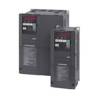
Mitsubishi Electric FR-F840-00250 Instruction Manual (940 pages)
FR-F800 series
Brand: Mitsubishi Electric
|
Category: Inverter
|
Size: 21.65 MB
Table of Contents
-
Instruction Manual
1
-
Safety Instructions
5
-
Table of Contents
13
-
1 Introduction
21
-
General Remarks
21
-
Product Checking and Accessories
23
-
Inverter Model
23
-
Accessory
24
-
How to Read the SERIAL Number
24
-
-
Component Names
25
-
Operation Steps
27
-
Related Manuals
28
-
-
2 Installation and Wiring
29
-
Peripheral Devices
29
-
Inverter and Peripheral Devices
29
-
Peripheral Devices
32
-
-
Removal and Reinstallation of the Operation Panel or the Front Covers
40
-
Installation of the Inverter and Enclosure Design
45
-
Inverter Installation Environment
45
-
Cooling System Types for Inverter Enclosure
48
-
Inverter Installation
49
-
Panel through Attachment Procedure
51
-
-
Terminal Connection Diagrams
53
-
CA Type
53
-
FM Type
55
-
CA Type (FR-F800-E)
57
-
FM Type (FR-F800-E)
59
-
-
Main Circuit Terminals
61
-
Details on the Main Circuit Terminals
61
-
Terminal Layout of the Main Circuit Terminals, Wiring of Power Supply
62
-
And the Motor
62
-
-
Applicable Cables and the Wiring Length
65
-
Earthing (Grounding) Precautions
72
-
-
Control Circuit
74
-
Details on the Control Circuit Terminals
74
-
Control Logic (Sink/Source) Change
78
-
Wiring of Control Circuit
81
-
Wiring Precautions
85
-
When Using Separate Power Supplies for the Control Circuit
86
-
When Supplying 24 V External Power to the Control Circuit
89
-
Safety Stop Function
92
-
-
Communication Connectors and Terminals
95
-
PU Connector
95
-
USB Connector
96
-
Terminal Block (Not for FR-F800-E)
98
-
-
Connection of Stand-Alone Option Units
99
-
Connection of the Brake Unit (FR-BU2)
99
-
Connection of the Brake Unit (FR-BU)
102
-
Connection of the Brake Unit (BU Type)
103
-
Connection of the High Power Factor Converter (FR-HC2)
104
-
Connection of the Power Regeneration Common Converter (FR-CV)
106
-
Connection of the Power Regeneration Converter (MT-RC)
107
-
Connection of the DC Reactor (FR-HEL)
108
-
Installing a Communication Option (FR-F800-E)
109
-
-
System Configuration for Ethernet Communication (FR-F800-E)
110
-
Ethernet Communication Overview
110
-
Ethernet Connector
111
-
Removal of the Ethernet Board
113
-
-
-
3 Precautions for Use of the Inverter
115
-
Electro-Magnetic Interference (EMI) and Leakage Currents
115
-
Leakage Currents and Countermeasures
115
-
Countermeasures against Inverter-Generated EMI
120
-
Built-In EMC Filter
123
-
-
Power Supply Harmonics
125
-
Harmonic Suppression Guidelines
126
-
-
Installation of a Reactor
130
-
Power-OFF and Magnetic Contactor (MC)
131
-
Countermeasures against Deterioration of the 400 V Class Motor Insulation
133
-
Checklist before Starting Operation
134
-
Failsafe System Which Uses the Inverter
137
-
-
4 Basic Operation
141
-
Operation Panel (FR-DU08)
141
-
Components of the Operation Panel (FR-DU08)
141
-
Basic Operation of the Operation Panel
143
-
Correspondences between Digital and Actual Characters
145
-
Changing the Parameter Setting Value
146
-
-
Monitoring the Inverter Status
147
-
Monitoring of Output Current and Output Voltage
147
-
First Monitored Item
147
-
Displaying the Set Frequency
148
-
-
Easy Operation Mode Setting (Easy Setting Mode)
149
-
Frequently-Used Parameters (Simple Mode Parameters)
151
-
Simple Mode Parameter List
151
-
-
Basic Operation Procedure (PU Operation)
153
-
Operating at the Set Frequency (Example: Operating at 30 Hz)
153
-
Using the Setting Dial Like a Potentiometer to Perform Operation
155
-
Setting the Frequency by Switches (Multi-Speed Setting)
156
-
Setting the Frequency with Analog Signals (Voltage Input)
158
-
Using an Analog Signal (Current Input) to Give a Frequency Command
160
-
-
Basic Operation Procedure (External Operation)
162
-
Using the Frequency Set by the Operation Panel
162
-
Setting the Frequency by Switches (Multi-Speed Setting) (Pr. 4 to Pr. 6)
164
-
Setting the Frequency with Analog Signals (Voltage Input)
166
-
Changing the Frequency (60 Hz, Initial Value) at the Maximum Voltage Input
167
-
(5 V, Initial Value)
167
-
-
Using an Analog Signal (Current Input) to Give a Frequency Command
168
-
Changing the Frequency (60 Hz, Initial Value) at the Maximum Current Input
169
-
(At 20 Ma, Initial Value)
169
-
-
-
Basic Operation Procedure (JOG Operation)
170
-
Performing JOG Operation Using External Signals
170
-
JOG Operation from the Operation Panel
171
-
-
-
5 Parameters
173
-
Parameter List
174
-
Parameter List (by Number)
174
-
Group Parameter Display
198
-
Parameter List (by Function Group)
200
-
-
Control Method
211
-
Changing the Control Method
213
-
Selecting the Advanced Magnetic Flux Vector Control
217
-
Selecting the PM Motor Control
220
-
-
Speed Control under PM Motor Control
225
-
Setting Procedure of PM Motor Control
226
-
Performing High-Accuracy, Fast-Response Control
227
-
Troubleshooting in the Speed Control
230
-
Torque Detection Filter
231
-
-
E) Environment Setting Parameters
232
-
Real Time Clock Function
233
-
Reset Selection/Disconnected PU Detection/Pu Stop Selection
235
-
PU Display Language Selection
239
-
Buzzer Control
239
-
PU Contrast Adjustment
239
-
Display-Off Mode
240
-
Resetting USB Host Errors
240
-
Setting Dial Potentiometer Mode/Key Lock Operation Selection
241
-
Frequency Change Increment Amount Setting
242
-
Multiple Rating Setting
243
-
Using the Power Supply Exceeding 480 V
244
-
Parameter Write Selection
244
-
Password Function
248
-
Free Parameter
252
-
Setting Multiple Parameters as a Batch
252
-
Extended Parameter Display and User Group Function
257
-
PWM Carrier Frequency and Soft-PWM Control
260
-
Inverter Parts Life Display
263
-
Maintenance Timer Alarm
267
-
Current Average Value Monitor Signal
269
-
-
F) Setting of Acceleration/Deceleration Time and Acceleration/Deceleration Pattern
273
-
Setting the Acceleration and Deceleration Time
274
-
Acceleration/Deceleration Pattern
279
-
Remote Setting Function
283
-
Starting Frequency and Start-Time Hold Function
287
-
Minimum Motor Speed Frequency
289
-
-
D) Operation Command and Frequency Command
290
-
Operation Mode Selection
291
-
Operation Mode
293
-
Startup in Network Operation Mode at Power-ON
300
-
During Communication Operation
302
-
-
Reverse Rotation Prevention Selection
311
-
Frequency Setting Via Pulse Train Input
312
-
JOG Operation
316
-
Operation by Multi-Speed Setting
318
-
-
H) Protective Function Parameter
321
-
Motor Overheat Protection (Electronic Thermal O/L Relay)
322
-
Cooling Fan Operation Selection
332
-
Earth (Ground) Fault Detection at Start
333
-
Varying the Activation Level of the Undervoltage Protective Function
333
-
Initiating a Protective Function
334
-
I/O Phase Loss Protection Selection
335
-
Retry Function
336
-
Emergency Drive (Fire Mode)
339
-
Limiting the Output Frequency (Maximum/Minimum Frequency)
348
-
Avoiding the Mechanical Resonance Points (Frequency Jump)
350
-
Stall Prevention Operation
352
-
Load Characteristics Fault Detection
361
-
Motor Overspeeding Detection
366
-
-
M) Monitor Display and Monitor Output Signal
367
-
Speed Display and Rotations Per Minute Setting
368
-
Monitor Indicator Selection Using Operation Panel or Via Communication
370
-
Monitor Display Selection for Terminals FM/CA and am
383
-
Adjusting Terminals FM/CA and am
390
-
Energy Saving Monitor
396
-
Output Terminal Function Selection
403
-
Output Frequency Detection
412
-
Output Current Detection Function
416
-
Output Torque Detection
418
-
Remote Output Function
419
-
Analog Remote Output Function
421
-
Fault Code Output Selection
424
-
Pulse Train Output of Output Power
425
-
Detection of Control Circuit Temperature
426
-
-
T) Multi-Function Input Terminal Parameters
427
-
Analog Input Selection
427
-
Analog Input Terminal (Terminal 1, 4) Function Assignment
432
-
Analog Input Compensation
433
-
Analog Input Responsiveness and Noise Elimination
436
-
Frequency Setting Voltage (Current) Bias and Gain
438
-
Bias and Gain for Voltage (Current) Setting of Stall Prevention Operation Level
445
-
Checking of Current Input on Analog Input Terminal
452
-
Input Terminal Function Selection
457
-
Inverter Output Shutoff Signal
461
-
Selecting Operation Condition of the Second Function Selection Signal (RT)
463
-
Start Signal Operation Selection
465
-
-
C) Motor Constant Parameters
469
-
Applied Motor
469
-
Offline Auto Tuning
475
-
Offline Auto Tuning for a PM Motor (Motor Constants Tuning)
488
-
Online Auto Tuning
499
-
-
A) Application Parameters
504
-
Electronic Bypass Function
505
-
Self Power Management
514
-
Traverse Function
518
-
Cleaning Function
520
-
PID Control
525
-
PID Gain Tuning
545
-
Changing the Display Increment of Numerical Values Used in PID Control
553
-
PID Pre-Charge Function
557
-
Multi-Pump Function (Advanced PID Function)
564
-
PID Control Enhanced Functions
576
-
Automatic Restart after Instantaneous Power Failure
587
-
Flying Start with an Induction Motor
587
-
-
Automatic Restart after Instantaneous Power Failure
595
-
Flying Start with an IPM Motor
595
-
-
Offline Auto Tuning for a Frequency Search
598
-
Power Failure Time Deceleration-To-Stop Function
604
-
PLC Function
611
-
Trace Function
615
-
-
N) Operation Via Communication and Its Settings
624
-
Wiring and Configuration of PU Connector
625
-
Wiring and Configuration of RS-485 Terminals
627
-
Initial Setting of Operation Via Communication
631
-
Initial Settings and Specifications of RS-485 Communication
639
-
Mitsubishi Inverter Protocol (Computer Link Communication)
641
-
Error Code
647
-
MODBUS® RTU Communication Specification
660
-
Bacnet MS/TP Protocol
678
-
Alarm History
690
-
Initial Settings and Specifications of Ethernet Communication (FR-F800-E)
694
-
MELSOFT / FA Product Connection
702
-
USB Device Communication
703
-
Automatic Connection with GOT
704
-
-
G) Control Parameters
706
-
Manual Torque Boost
707
-
Base Frequency, Voltage
709
-
Load Pattern Selection
711
-
Energy Saving Control
713
-
Adjustable 5 Points V/F
714
-
SF-PR Slip Amount Adjustment Mode
716
-
DC Injection Brake
717
-
Output Stop Function
720
-
Stop Selection
722
-
Regenerative Brake Selection and DC Feeding Mode
724
-
Regeneration Avoidance Function
732
-
Increased Magnetic Excitation Deceleration
736
-
Slip Compensation
738
-
Speed Smoothing Control
739
-
-
Parameter Clear / All Parameter Clear
740
-
Copying and Verifying Parameters on the Operation Panel
742
-
Parameter Copy
743
-
Parameter Verification
744
-
-
Copying and Verifying Parameters Using USB Memory
745
-
Checking Parameters Changed from Their Initial Values (Initial Value Change List)
749
-
Ethernet Communication (FR-F800-E)
750
-
Slmp
750
-
Communication Procedure
751
-
Modbus®/Tcp
765
-
CC-Link IE Field Network Basic (FR-F800-E)
782
-
Programming Examples
797
-
Instructions
806
-
-
Inverter-To-Inverter Link Function (FR-F800-E)
807
-
-
6 Protective Functions
813
-
Inverter Fault and Alarm Indications
813
-
Reset Method for the Protective Functions
814
-
Check and Clear of the Faults History
815
-
Check for the Faults History
815
-
Faults History Clearing Procedure
816
-
-
The List of Fault Displays
817
-
Causes and Corrective Actions
821
-
Error Message
821
-
Warning
825
-
Alarm
829
-
Fault
830
-
Other Messages
844
-
-
Check First When You Have a Trouble
845
-
Motor Does Not Start
845
-
Motor or Machine Is Making Abnormal Acoustic Noise
848
-
Inverter Generates Abnormal Noise
849
-
Motor Generates Heat Abnormally
849
-
Motor Rotates in the Opposite Direction
849
-
Speed Greatly Differs from the Setting
850
-
Acceleration/Deceleration Is Not Smooth
850
-
Speed Varies During Operation
851
-
Operation Mode Is Not Changed Properly
852
-
Operation Panel (FR-DU08) Display Is Not Operating
852
-
Motor Current Is too Large
852
-
Speed Does Not Accelerate
853
-
Unable to Write Parameter Setting
854
-
Power Lamp Is Not Lit
854
-
-
-
7 Precautions for Maintenance and Inspection
855
-
Inspection Item
855
-
Daily Inspection
855
-
Periodic Inspection
855
-
Daily and Periodic Inspection
856
-
Checking the Inverter and Converter Modules
858
-
Cleaning
859
-
Replacement of Parts
859
-
Inverter Replacement
865
-
-
Measurement of Main Circuit Voltages, Currents and Powers
866
-
Measurement of Powers
869
-
Measurement of Voltages and Use of PT
870
-
Measurement of Currents
871
-
Use of CT and Transducer
872
-
Measurement of Inverter Input Power Factor
872
-
Measurement of Converter Output Voltage (Across Terminals P and N)
872
-
Measurement of Inverter Output Frequency
872
-
Insulation Resistance Test Using Megger
873
-
Pressure Test
873
-
-
-
8 Specifications
875
-
Inverter Rating
875
-
V Class
876
-
-
Motor Rating
878
-
Premium High-Efficiency IPM Motor [MM-EFS (1500 R/Min Specification)]
878
-
Premium High-Efficiency IPM Motor [MM-EFS (3000 R/Min Specification)]
880
-
Premium High-Efficiency IPM Motor [MM-THE4 (1500 R/Min Specification)]
882
-
-
Common Specifications
884
-
Outline Dimension Drawings
886
-
Inverter Outline Dimension Drawings
886
-
Dedicated Motor Outline Dimension Drawings
895
-
-
-
A Appendix
901
-
For Customers Replacing the Conventional Model with this Inverter
901
-
Replacement of the FR-F700(P) Series
901
-
A.1 for Customers Replacing the Conventional Model with this Inverter
901
-
Replacement of the FR-F500(L) Series
902
-
-
Specification Comparison between PM Motor Control and Induction Motor Control
903
-
Parameters (Functions) and Instruction Codes under Different Control Methods
905
-
Under Different Control Methods
923
-
-
For Customers Using HMS Network Options
925
-
List of Inverter Monitored Items / Command Items
925
-
-
EC Declarations of Conformity
928
-
FR-F820/FR-F840/FR-F842 Series
928
-
A.6 EC Declarations of Conformity
928
-
-
Advertisement
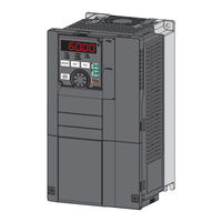
Mitsubishi Electric FR-F840-00250 Instruction Manual (660 pages)
FR-F800 series
Brand: Mitsubishi Electric
|
Category: Inverter
|
Size: 16.46 MB
Table of Contents
-
Inverter Fr-F800 Instruction Manual (Detailed)
2
-
Table of Contents
2
-
Safety Instructions
9
-
Fire Prevention
10
-
-
-
Chapter 1 Introduction
16
-
Product Checking and Accessories
18
-
Serial Number
19
-
Component Names
20
-
Operation Steps
22
-
About the Related Manuals
23
-
-
Chapter 2 Installation and Wiring
24
-
Peripheral Devices
25
-
Peripheral Devices
27
-
Removal and Reinstallation of the Operation Panel or the Front Covers
31
-
Installation of the Inverter and Enclosure Design
35
-
-
Amount of Heat Generated by the Inverter
38
-
Cooling System Types for Inverter Enclosure
39
-
Inverter Installation
40
-
Protruding the Heat Sink through a Panel
42
-
Terminal Connection Diagrams
44
-
Main Circuit
46
-
-
Control Circuit
46
-
Main Circuit Terminals
48
-
-
Main Circuit Terminal Layout and Wiring to Power Supply and Motor
49
-
Applicable Cables and Wiring Length
51
-
Earthing (Grounding) Precautions
58
-
Control Circuit
59
-
-
Control Logic (Sink/Source) Change
63
-
Wiring of Control Circuit
64
-
Wiring Precautions
67
-
When Supplying 24 V External Power to the Control Circuit
70
-
Safety Stop Function
71
-
Communication Connectors and Terminals
74
-
-
USB Connector
75
-
RS-485 Terminal Block
76
-
Connection of Stand-Alone Option Units
77
-
-
Connection of the Brake Unit (FR-BU)
79
-
Connection of the High Power Factor Converter (FR-HC2)
80
-
Connection of the Power Regeneration Common Converter (FR-CV)
81
-
Connection of the Power Regeneration Converter (MT-RC)
82
-
-
Chapter 3 Precautions for Use of the Inverter 4 5
84
-
Electro-Magnetic Interference (EMI) and Leakage Currents
85
-
Techniques and Measures for Electromagnetic Compatibility (EMC)
87
-
Built-In EMC Filter
89
-
Power Supply Harmonics
92
-
Installation of a Reactor
96
-
Power Shutdown and Magnetic Contactor (MC)
97
-
Countermeasures against Deterioration of the 400 V Class Motor Insulation
99
-
Checklist before Starting Operation
100
-
Failsafe System Which Uses the Inverter
103
-
-
-
Chapter 4 Basic Operation
106
-
Operation Panel (FR-DU08)
107
-
Basic Operation of the Operation Panel
109
-
Digital Characters and Their Corresponding Printed Equivalents
110
-
Changing the Parameter Setting Value
111
-
Monitoring the Inverter
112
-
Easy Setting of the Inverter Operation Mode
113
-
Frequently-Used Parameters (Simple Mode Parameters)
115
-
Basic Operation Procedure (PU Operation)
117
-
-
Perform PU Operation Using the Setting Dial Like a Potentiometer
118
-
Setting the Frequency with Switches (Multi-Speed Setting)
119
-
Setting the Frequency Using an Analog Signal (Voltage Input)
120
-
Setting the Frequency Using an Analog Signal (Current Input)
121
-
Basic Operation Procedure (External Operation)
123
-
-
Setting the Frequency and Giving a Start Command with Switches (Multi-Speed Setting) (Pr.4 to Pr.6)
124
-
Setting the Frequency Using an Analog Signal (Voltage Input)
125
-
-
Changing the Frequency (60 Hz, Initial Value) at the Maximum Voltage Input (5 V, Initial Value)
127
-
Setting the Frequency Using an Analog Signal (Current Input)
128
-
-
Changing the Frequency (60 Hz, Initial Value) at the Maximum Current Input (at 20 Ma, Initial Value)
129
-
Basic Operation Procedure (JOG Operation)
130
-
-
Giving a Start Command from the Operation Panel for JOG Operation
131
-
-
Chapter 5 Parameters
132
-
Parameter List
133
-
Use of a Function Group Number for the Identification of Parameters
157
-
Parameter List (by Function Group Number)
159
-
Control Method
168
-
Changing the Control Method and Mode
170
-
Selecting the Advanced Magnetic Flux Vector Control
173
-
Selecting the PM Motor Control
175
-
Speed Control under PM Motor Control
181
-
Performing High-Accuracy, Fast-Response Control (Gain Adjustment for PM Motor Control)
183
-
Troubleshooting in the Speed Control
185
-
Torque Detection Filter
186
-
E) Environment Setting Parameters
187
-
Real Time Clock Function
188
-
Reset Selection / Disconnected PU Detection / PU Stop Selection
189
-
PU Display Language Selection
192
-
Direct Setting
193
-
Frequency Change Increment Amount Setting
194
-
Multiple Rating Setting
195
-
Using the Power Supply Exceeding 480 VAC
196
-
Parameter Write Selection
197
-
Password
199
-
Free Parameter
201
-
Extended Parameter Display and User Group Function
205
-
PWM Carrier Frequency and Soft-PWM Control
208
-
Inverter Parts Life Display
209
-
Maintenance Timer Alarm
213
-
Current Average Value Monitor Signal
214
-
F) Setting of Acceleration/Deceleration Time and Acceleration/Deceleration Pattern
217
-
Control Block Diagram
218
-
-
Acceleration/Deceleration Pattern
220
-
Remote Setting Function
223
-
Starting Frequency and Start-Time Hold Function
226
-
Minimum Motor Speed Frequency at the Motor Start up
227
-
D) Operation Command and Frequency Command
229
-
Startup of the Inverter in Network Operation Mode at Power-ON
238
-
Start Command Source and Frequency Command Source During Communication Operation
240
-
Reverse Rotation Prevention Selection
246
-
JOG Operation
249
-
Operation by Multi-Speed Setting
250
-
H) Protective Function Parameter
253
-
Cooling Fan Operation Selection
259
-
Earth (Ground) Fault Detection at Start
260
-
Varying the Activation Level of the Undervoltage Protective Function
261
-
Retry Function
262
-
Emergency Drive
264
-
Limiting the Output Frequency (Maximum/Minimum Frequency)
272
-
Avoiding Machine Resonance Points (Frequency Jump)
273
-
Stall Prevention Operation
274
-
Load Characteristics Fault Detection
282
-
Motor Overspeeding Detection
286
-
M) Item and Output Signal for Monitoring
287
-
Monitor Item Selection on Operation Panel or Via Communication
289
-
Monitor Display Selection for Terminals FM/CA and am
298
-
Adjustment of Terminal FM/CA and Terminal am
303
-
Energy Saving Monitoring
307
-
Output Terminal Function Selection
313
-
Output Signal List
314
-
-
Output Frequency Detection
320
-
Output Current Detection Function
322
-
Output Torque Detection Function
324
-
Remote Output Function
325
-
Analog Remote Output Function
326
-
Fault Code Output Selection
328
-
Pulse Train Output to Announce Cumulative Output Energy
329
-
Detection of Control Circuit Temperature
330
-
T) Multi-Function Input Terminal Parameters
331
-
Analog Input Terminal (Terminal 1, 4) Function Assignment
335
-
Analog Input Compensation
336
-
Response Level of Analog Input and Noise Elimination
338
-
Frequency Setting Voltage (Current) Bias and Gain
340
-
Bias and Gain for Voltage (Current) Setting of Stall Prevention Operation Level
345
-
Checking of Current Input on Analog Input Terminal
351
-
Input Terminal Function Selection
356
-
Inverter Output Shutoff
358
-
Selecting the Condition to Activate the Second Function Selection (RT) Signal
359
-
Start Signal Operation Selection
360
-
(C) Motor Constant Parameters
363
-
Offline Auto Tuning
367
-
Offline Auto Tuning for a PM Motor (Motor Constant Tuning)
376
-
Online Auto Tuning
383
-
A) Application Parameters
387
-
Electronic Bypass Function
388
-
Self Power Management
394
-
Start Count Monitor
396
-
Traverse Function
397
-
Cleaning Function
399
-
PID Control
402
-
PID Gain Tuning
418
-
Changing the Display Increment of Numerical Values Used in PID Control
424
-
PID Pre-Charge Function
426
-
Multi-Pump Function (Advanced PID Function)
431
-
PID Control Enhanced Functions
440
-
Automatic Restart after Instantaneous Power Failure/Flying Start with an Induction Motor
447
-
Automatic Restart after Instantaneous Power Failure/Flying Start with a PM Motor
452
-
Offline Auto Tuning for a Frequency Search
455
-
Power Failure Time Deceleration-To-Stop Function
459
-
PLC Function
463
-
Trace Function
466
-
N) Communication Operation Parameters
474
-
Wiring and Configuration of RS-485 Terminals
476
-
Initial Setting of Operation Via Communication
479
-
Initial Settings and Specifications of RS-485 Communication
483
-
Mitsubishi Inverter Protocol (Computer Link Communication)
485
-
Setting Items and Set Data
494
-
-
MODBUS RTU Communication Specification
499
-
Message Format
500
-
Function Code List
502
-
-
Bacnet MS/TP Protocol
512
-
USB Device Communication
524
-
Backup/Restore
526
-
(G) Control Parameters
528
-
Base Frequency Voltage
529
-
Load Pattern Selection
531
-
Excitation Current Low-Speed Scaling Factor
532
-
Energy Saving Control
533
-
Adjustable 5 Points V/F
534
-
SF-PR Slip Amount Adjustment Mode
535
-
DC Injection Brake
536
-
Output Stop Function
537
-
Stop Selection
539
-
Regenerative Brake Selection and DC Feeding Mode
540
-
Regeneration Avoidance Function
546
-
Increased Magnetic Excitation Deceleration
548
-
Slip Compensation
549
-
Speed Smoothing Control
550
-
Parameter Clear / All Parameter Clear
552
-
5.15 Copying and Verifying Parameters on the Operation Panel
553
-
Parameter Verification
555
-
Copying and Verifying Parameters Using a USB Memory
556
-
Checking Parameters Changed from Their Initial Values (Initial Value Change List)
560
-
Chapter 6 PROTECTIVE FUNCTIONS
563
-
Reset Method for the Protective Functions
564
-
Check and Clear of the Fault History
565
-
List of Fault Displays
567
-
Causes and Corrective Actions
569
-
Check First When You Have a Trouble
586
-
Motor or Machine Is Making Abnormal Acoustic Noise
589
-
Motor Rotates in the Opposite Direction
590
-
Speed Varies During Operation
591
-
Operation Panel (FR-DU08) Display Is Not Operating
592
-
Speed Does Not Accelerate
593
-
Power Lamp Is Not Lit
594
-
-
Chapter 7 PRECAUTIONS for MAINTENANCE and
597
-
Inspection
597
-
Daily and Periodic Inspection
598
-
Checking the Inverter and Converter Modules
599
-
Cleaning
600
-
Removal and Reinstallation of the Control Circuit Terminal Block
606
-
Measurement of Main Circuit Voltages, Currents, and Powers
607
-
Measurement of Powers
609
-
Use of CT and Transducer
610
-
Insulation Resistance Test Using Megger
611
-
-
Chapter 8 SPECIFICATIONS
613
-
Inverter Rating
613
-
Motor Rating
616
-
Premium High-Efficiency IPM Motor [MM-EFS (3000 R/Min Specification)]
618
-
Premium High-Efficiency IPM Motor [MM-THE4]
619
-
Common Specifications
621
-
Outline Dimension Drawings
623
-
Dedicated Motor Outline Dimension Drawings
631
-
-
Chapter 9 APPENDIX
635
-
For Customers Replacing the Conventional Model with this Inverter
635
-
Replacement of the FR-F500(L) Series
636
-
Parameters (Functions) and Instruction Codes under Different Control Methods
639
-
For Customers Using HMS Network Options
655
-
-
Mitsubishi Electric FR-F840-00250 Instruction Manual (91 pages)
Brand: Mitsubishi Electric
|
Category: Inverter
|
Size: 7.65 MB
Table of Contents
-
Inverter Model
3
-
Inverter Placement
3
-
Installation Environment
3
-
Outline Dimensions
4
-
Terminal Connection Diagrams
5
-
Main Circuit Terminals
7
-
Terminal Layout
11
-
Control Circuit Terminal
11
-
Wiring Method
11
-
Wiring Precautions
12
-
Control Logic (Sink/Source) Change
12
-
When Supplying 24 V External Power to the Control Circuit
12
-
Safety Stop Function
13
-
Function Description
13
-
Connection Diagram
13
-
Failsafe System Which Uses the Inverter
14
-
Precautions for Use of the Inverter
15
-
Drive the Motor
16
-
Components of the Operation Panel (FR-DU08)
16
-
Basic Operation (Factory Setting)
17
-
Parameter List
18
-
Troubleshooting
23
-
Reset Method for the Protective Functions
23
-
List of Fault Displays
24
-
Specifications
25
-
Appendix 1 Instructions for Compliance with the EU Directives
27
-
EMC Directive
27
-
Appendix 2 Instructions for UL and Cul
29
-
General Precaution
29
-
Installation
29
-
Motor Overload Protection
30
-
PID Control Enhanced Functions
37
Advertisement
Mitsubishi Electric FR-F840-00250 Instruction Manual (88 pages)
Brand: Mitsubishi Electric
|
Category: Air Conditioner
|
Size: 8.08 MB
Table of Contents
-
Table of Contents
30
-
Inverter Installation and Precautions
32
-
Wiring
33
-
Basic Operation
38
-
Failsafe System Which Uses the Inverter
40
-
Precautions for Use of the Inverter
40
Mitsubishi Electric FR-F840-00250 Installation Manuallines (64 pages)
FR-F800 series
Brand: Mitsubishi Electric
|
Category: Inverter
|
Size: 3.91 MB
Table of Contents
-
Table of Contents
1
-
Fire Prevention
3
-
Installation and Instructions
7
-
Installation of the Inverter
8
-
Wiring
10
-
Terminal Layout and Wiring
18
-
Control Circuit Terminals
25
-
Terminal Layout
25
-
Wiring Method
25
-
Wiring Precautions
26
-
Connection Diagram
28
-
Function Description
28
-
-
Failsafe of the System Which Uses the Inverter
30
-
Precautions for Use of the Inverter
31
-
Basic Operation
33
-
Parameter List
35
-
Troubleshooting
50
-
Reset Method of Protective Function
51
-
List of Alarm Display
51
-
-
Specifications
53
-
Outline Dimensions
56
-
Appendix
58
-
-
Aappendix
58
Mitsubishi Electric FR-F840-00250 Installation Manuallines (64 pages)
Brand: Mitsubishi Electric
|
Category: Inverter
|
Size: 3.89 MB
Table of Contents
-
Table of Contents
1
-
Installation and Instructions
7
-
Wiring
10
-
Failsafe of the System Which Uses the Inverter
30
-
Precautions for Use of the Inverter
31
-
Basic Operation
33
-
Troubleshooting
50
-
Specifications
53
-
Aappendix
58
Advertisement
Related Products
-
Mitsubishi Electric FR-F840-00250(11K)
-
Mitsubishi Electric FR-F840-00083
-
Mitsubishi Electric FR-F840-00170
-
Mitsubishi Electric FR-F840-00470
-
Mitsubishi Electric FR-F840-00083(3.7K)
-
Mitsubishi Electric FR-F840-00170(7.5K)
-
Mitsubishi Electric FR-F840-00310(15K)
-
Mitsubishi Electric FR-F840-00930(45K)
-
Mitsubishi Electric FR-F840-00170-E2-60
-
Mitsubishi Electric FR-F840-00023-06830-E
Mitsubishi Electric Categories
![]()
Air Conditioner
Controller
![]()
Projector
Inverter
Heat Pump
More Mitsubishi Electric Manuals


 Цена за 1 шт., с НДС
Цена: 99 100.00 ₽
Работаем с юридическими и физическими лицами
Брэнд:
Mitsubishi Electric
Модель:
FR-F840-00380-2-60
Выбрать модель
Перегрузочная способность:
110% в течение 60 сек.
Подробные технические характеристики
Если у вас возникли трудности или вы сомневаетесь в своем выборе,
то позвоните нам по телефону — 8 (4932) 32-45-05.
Или закажите обратный звонок
Аналоги:

EI-9011-001H
Мощность, кВт: 1,1
Номинальный ток, А: 3,4

EI-9011-002H
Мощность, кВт: 1,5
Номинальный ток, А: 4,8

EI-9011-003H
Мощность, кВт: 2,2
Номинальный ток, А: 6,2

EI-9011-005H
Мощность, кВт: 3,7
Номинальный ток, А: 8

EI-9011-007H
Мощность, кВт: 5,5
Номинальный ток, А: 14

EI-9011-010H
Мощность, кВт: 7,5
Номинальный ток, А: 18

N700E-004SF
Мощность, кВт: 0,4
Номинальный ток, А: 3

N700E-037HF
Мощность, кВт: 3,7
Номинальный ток, А: 9,2

N700E-055HF
Мощность, кВт: 5,5
Номинальный ток, А: 7,9

N700E-075HF
Мощность, кВт: 7,5
Номинальный ток, А: 10,5

N700E-110HF
Мощность, кВт: 11
Номинальный ток, А: 15,1

N700E-150HF
Мощность, кВт: 15
Номинальный ток, А: 21,1

CIMR-VCBA0001BAA
Мощность, кВт: 0,2
Номинальный ток, А: 1,2

CIMR-VCBA0002BAA
Мощность, кВт: 0,4
Номинальный ток, А: 1,9

CIMR-VCBA0003BAA
Мощность, кВт: 0,75
Номинальный ток, А: 3,3

CIMR-VCBA0006BAA
Мощность, кВт: 1,1
Номинальный ток, А: 6

CIMR-VCBA0010BAA
Мощность, кВт: 2,2
Номинальный ток, А: 9,6

CIMR-VCBA0012BAA
Мощность, кВт: 3
Номинальный ток, А: 12

131N0191
Мощность, кВт: 11
Номинальный ток, А:
131N0193
Мощность, кВт: 15
Номинальный ток, А:
131L9872
Мощность, кВт: 22
Номинальный ток, А:
131L9873
Мощность, кВт: 30
Номинальный ток, А:
131L9867
Мощность, кВт: 5,5
Номинальный ток, А:
131N0187
Мощность, кВт: 5,5
Номинальный ток, А:

ESQ-760-4T0220G-0300P
Мощность, кВт: 22
Номинальный ток, А: 45

ESQ-760-4T0370G-0450P
Мощность, кВт: 37
Номинальный ток, А: 75

ESQ-760-4T0300G-0370P
Мощность, кВт: 30
Номинальный ток, А: 60

ESQ-760-4T0450G-0550P
Мощность, кВт: 45
Номинальный ток, А: 91

ESQ-760-4T0550G-0750P
Мощность, кВт: 55
Номинальный ток, А: 112

ESQ-760-4T0185G-0220P
Мощность, кВт: 18,5
Номинальный ток, А: 37

VFD002E21A
Мощность, кВт: 0,2
Номинальный ток, А: 1,6

VFD004E21A
Мощность, кВт: 0,4
Номинальный ток, А: 2,5

VFD004E43A
Мощность, кВт: 0,4
Номинальный ток, А: 1,5

VFD007E21A
Мощность, кВт: 0,75
Номинальный ток, А: 4,2

VFD007E43A
Мощность, кВт: 0,75
Номинальный ток, А: 2,5

VFD015E21A
Мощность, кВт: 1,5
Номинальный ток, А: 7,5

ACS55-01E-01A4-1
Мощность, кВт: 0,18
Номинальный ток, А: 1,4

ACS55-01E-01A4-2
Мощность, кВт: 0,18
Номинальный ток, А: 1,4

ACS55-01E-02A2-1
Мощность, кВт: 0,37
Номинальный ток, А: 2,2

ACS55-01E-02A2-2
Мощность, кВт: 0,37
Номинальный ток, А: 2,2

ACS55-01E-04A3-2
Мощность, кВт: 0,75
Номинальный ток, А: 4,3

ACS55-01E-07A6-2
Мощность, кВт: 1,5
Номинальный ток, А: 7,6

FCI-G3.7-4B
Мощность, кВт: 3,7
Номинальный ток, А: 8,8

FCI-P5.5-4B
Мощность, кВт: 5,5
Номинальный ток, А: 13

FCI-G5.5-4B
Мощность, кВт: 5,5
Номинальный ток, А: 13

FCI-P7.5-4B
Мощность, кВт: 7,5
Номинальный ток, А: 17

FCI-G7.5-4B
Мощность, кВт: 7,5
Номинальный ток, А: 17

FCI-G11-4BF
Мощность, кВт: 11
Номинальный ток, А: 25

FR-F840-00023-E2-60
Мощность, кВт: 0,75
Номинальный ток, А: 2,1

FR-F840-00023-2-60
Мощность, кВт: 0,75
Номинальный ток, А: 2,1

FR-F840-00038-E2-60
Мощность, кВт: 1,5
Номинальный ток, А: 3,5

FR-F840-00038-2-60
Мощность, кВт: 1,5
Номинальный ток, А: 3,5

FR-F840-00052-E2-60
Мощность, кВт: 2,2
Номинальный ток, А: 4,8

FR-F840-00052-2-60
Мощность, кВт: 2,2
Номинальный ток, А: 4,8

6SE6420-2UC11-2AA1
Мощность, кВт: 0,12
Номинальный ток, А: 0,9

6SE6420-2UC12-5AA1
Мощность, кВт: 0,25
Номинальный ток, А: 1,7

6SE6420-2UC13-7AA1
Мощность, кВт: 0,37
Номинальный ток, А: 2,3

6SE6420-2UC15-5AA1
Мощность, кВт: 0,55
Номинальный ток, А: 3

6SE6420-2UC17-5AA1
Мощность, кВт: 0,75
Номинальный ток, А: 3,9

6SE6420-2UC21-1BA1
Мощность, кВт: 1,1
Номинальный ток, А: 5,5

ATV12H018F1
Мощность, кВт: 0,18
Номинальный ток, А: 1,4

ATV12H037F1
Мощность, кВт: 0,37
Номинальный ток, А: 2,4

ATV12H075F1
Мощность, кВт: 0,75
Номинальный ток, А: 4,2

ATV12H018M2
Мощность, кВт: 0,18
Номинальный ток, А: 1,4

ATV12H037M2
Мощность, кВт: 0,37
Номинальный ток, А: 2,4

ATV12H055M2
Мощность, кВт: 0,55
Номинальный ток, А: 3,5

ESMD251X2SFA
Мощность, кВт: 0,25
Номинальный ток, А: 3,4

ESMD371X2SFA
Мощность, кВт: 0,37
Номинальный ток, А: 5

ESMD551X2SFA
Мощность, кВт: 0,55
Номинальный ток, А: 6

ESMD751X2SFA
Мощность, кВт: 0,75
Номинальный ток, А: 9

ESMD152X2SFA
Мощность, кВт: 1,5
Номинальный ток, А: 14

ESMD222X2SFA
Мощность, кВт: 2,2
Номинальный ток, А: 21

3G3MX2-A4004-E CHN
Мощность, кВт: 0,4
Номинальный ток, А: 1,8

3G3MX2-A4007-E CHN
Мощность, кВт: 0,75
Номинальный ток, А: 3,4

3G3MX2-A4022-E CHN
Мощность, кВт: 2,2
Номинальный ток, А: 5,5

3G3MX2-A4015-E CHN
Мощность, кВт: 1,5
Номинальный ток, А: 4,8

3G3MX2-A4030-E CHN
Мощность, кВт: 3
Номинальный ток, А: 7,2

3G3MX2-A4040-E CHN
Мощность, кВт: 4
Номинальный ток, А: 9,2

ADV 1.50 M420-M
Мощность, кВт: 1,5
Номинальный ток, А: 2,1

ADV 2.20 M420-M
Мощность, кВт: 2,2
Номинальный ток, А: 3,8

ADV 4.00 M420-M
Мощность, кВт: 4
Номинальный ток, А: 5,1

ADV 5.50 M420-M
Мощность, кВт: 5,5
Номинальный ток, А: 9

ADV 7.50 M420-M
Мощность, кВт: 7,5
Номинальный ток, А: 13

ADV 11.0 M420-M
Мощность, кВт: 11
Номинальный ток, А: 17

VFD007CH23A-21
Мощность, кВт: 0,75
Номинальный ток, А: 2

VFD015CH23A-21
Мощность, кВт: 1,5
Номинальный ток, А: 8

VFD022CH23A-21
Мощность, кВт: 2,2
Номинальный ток, А: 11

VFD037CH23A-21
Мощность, кВт: 3,7
Номинальный ток, А: 17

VFD055CH23A-21
Мощность, кВт: 5,5
Номинальный ток, А: 25

VFD075CH23A-21
Мощность, кВт: 7,5
Номинальный ток, А: 33

NXP 0003 2A2H1SSS
Мощность, кВт: 0,55
Номинальный ток, А: 3,7

NXP 0004 2A2H1SSS
Мощность, кВт: 0,75
Номинальный ток, А: 4,8

NXP 0007 2A2H1SSS
Мощность, кВт: 1,1
Номинальный ток, А: 6,6

NXP 0008 2A2H1SSS
Мощность, кВт: 1,5
Номинальный ток, А: 7,8

NXP 0011 2A2H1SSS
Мощность, кВт: 2,2
Номинальный ток, А: 11

NXP 0012 2A2H1SSS
Мощность, кВт: 3
Номинальный ток, А: 12,5

VT100-0R4-1B
Мощность, кВт: 0,4
Номинальный ток, А: 5,4

VT100-0R7-1B
Мощность, кВт: 0,75
Номинальный ток, А: 8,2

VT100-1R5-1B
Мощность, кВт: 1,5
Номинальный ток, А: 14

VT100-2R2-1B
Мощность, кВт: 2,2
Номинальный ток, А: 24

VT100-0R7-3B
Мощность, кВт: 0,75
Номинальный ток, А: 3,4

VT100-1R5-3B
Мощность, кВт: 1,5
Номинальный ток, А: 5

PM150A-2S-0.4B
Мощность, кВт: 0,25
Номинальный ток, А: 2,5

PM150A-2S-0.2B
Мощность, кВт: 0,18
Номинальный ток, А: 1,6

PM150A-2S-0.7B
Мощность, кВт: 0,75
Номинальный ток, А: 9,2

PM150A-2S-1.1B
Мощность, кВт: 1,1
Номинальный ток, А: 11

PM150A-2S-1.5B
Мощность, кВт: 1,5
Номинальный ток, А: 15,5

PM150A-2S-2.2B
Мощность, кВт: 2,2
Номинальный ток, А: 24
Часто задаваемые вопросы
Выбрав раздел и тематику вопроса вы увидите ответы на часто задаваемые вопросы.
-
Раздел — Покупка оборудования
-
Раздел — Предоставление услуг
-
Заказ
-
Оплата
-
Доставка
-
Возврат / Обмен
Как сделать заказ на сайте?
1. Зайдите в каталог товаров
2. Выберите нужную категорию
3. Выберите интересующий товар
4. Нажмите кнопку «Купить» заполните все обязательные поля и нажмите «Отправить заказ на обработку. Менеджер вам перезвонит в рабочее время с 9 до 18:00
5. Либо нажмите кнопку «Добавить в заказ», потом нажмите еще раз на эту же кнопку, заполните все поля в форме справа и нажмите кнопку «Отправить заказ»
Как оплатить товар?
1. Для физических лиц оплата товара осуществляется по наличному расчёту.
2. От юридических лиц мы принимаем оплату по безналичному расчёту. Счет будет
отправлен по электронной почте*.
* Отгрузка товара производится при условии поступления денежных средств (100%
предоплата за товар). Возможна отсрочка платежа (условия обсуждаются индивидуально).
В каких случаях возможен возврат и обмен товара?
Если качество Товара не соответствует техническим условиям завода-изготовителя в
течение гарантийного срока Продавец обязуется по заявленной Покупателем рекламации
бесплатно устранить недостатки Товара или заменить его новым при соблюдении
Покупателем условий гарантийной эксплуатации и установки, определенных в
инструкциях и паспорте Товара и при условии сохранения паспорта, упаковки и товарного
вида, а также при наличии всех документов, подтверждающих факт совершения покупки
(товарный или кассовый чек).
Неисправности Товара, возникшие по причине нарушения Покупателем правил
хранения и эксплуатации, установки, монтажа устраняются за его счет (по отдельному
договору)
По согласованию с Продавцом Покупателю может быть предоставлено право
самостоятельно устранить неисправность Товара, либо привлечь к устранению
неисправности третьих лиц.
Если предоставленный Товар не соответствует технической документации на Товар о
комплектности либо ассортименте, то Покупатель вправе потребовать от Продавца
доукомплектования Товара либо (в случае несоблюдения условия об ассортименте), —
замены Товара.
Рекламация по некомплектности либо нарушению условий настоящего Договора
об ассортименте Товара может быть направлена в течение 10 (десять) дней со дня
фактической передачи Товара Покупателю либо иному грузополучателю, указанному
Покупателем.
Рекламация должна быть направлена Продавцу по факсу, с описанием
неисправностей, некомплектности либо несоблюдения условия об ассортименте Товара, а
также с указанием предполагаемых компонентов Товара, необходимых для устранения
неисправностей, некомплектности либо нарушения условия об ассортименте Товара.
Как получить ваш заказ?
Важно! Вместе с товаром Вам будет предоставлен универсальный передаточный
документ. В случае необходимости предоставления каких-либо иных документов Вам
необходимо предупредить об этом Вашего личного менеджера. При получении
товара Вам необходимо проверить заказ, убедившись в отсутствии видимых
повреждений и соответствии заявленного в документах количества.
Самовывоз.
г. Иваново, ул. Батурина, д.10
Доставка по г. Иваново.
Наш курьер доставит Вам нашу продукцию в любую точку г. Иваново. Стоимость
доставки 200р
Доставка по всей России.
По России наш товар доставляют транспортные компании (DHL, DPD, EMS Почта DHL, DPD, EMS Почта
России, FedEx, Logibox, Major Express, PickPoint, Pony Express, Байкал-сервис,
Гарантпост, Деловые Линии, Желдорэкспедиция, ПЭК, Энергия и др.), стоимость и
сроки доставки рассчитываются транспортной компанией.
-
Заказ
-
Оплата
-
Сервисный центр
Как заказать услугу на сайте?
1. Зайти на страницу интересующей услуги
2. Нажать кнопку «Оставить заявку»
3. Написать свой номер телефона и нажать кнопку «Жду звонка»
Либо позвонить по номеру 8 (4932) 32-45-05 заказать интересующую услугу
Сохраняется ли гарантия на отремонтированное оборудование?
Прежде всего необходимо различать гарантийный и негарантийный случаи при выходе из строя оборудования.
Гарантия на отремонтированное оборудование распространяется только в случае, если его эксплуатация и условия эксплуатации соответствуют паспортным данным.
Что же является негарантийным случаем?
В первую очередь это окончание гарантийного срока эксплуатации.
Например, для ПЧ производства ВЕСПЕР гарантийный срок составляет 3 года.
По истечении этого срока осуществляется негарантийный ремонт.
При этом гарантия предоставляется сроком 6 месяцев на замененные в процессе ремонта элементы ПЧ.
Если после ремонта выходит из строя другой элемент ПЧ, то гарантия после ремонта в этом случае будет только на этот другой элемент.
Как осуществляется оплата выполненных работ?
«Энергосервисный центр» работает по УСН и принимает оплату от юридических лиц по безналичной форме, путем перечисления денежных средств на расчетный счет, не более чем в течение 30 дней после подписания акта о приемке выполненных работ (форма № КС-2) и справки о стоимости выполненных работ и затрат (форма № КС-3), с обязательным приложением к ним актов на скрытые работы, подписанных двумя сторонами, согласно выставленным счету и счет – фактуре.
Все счета и КП выставляются с НДС 18%.
Уставные и регистрационные документы нашей компании для формирования договоров и участия в тендерах Вы всегда можете запросить у наших менеджеров.
По согласованию с Заказчиком допускается промежуточная оплата. Размер аванса и другие услoвия обговариваются индивидуально при каждом заказе с нашими менеджерами.
Ваша компания участвует в тендерах?
Да, наша компания принимает участие в государственных и коммерческих тендерах ежедневно.
У нас богатый опыт участия в аукционах, запросах котировок, открытых конкурсах и других формах электронных торгов.
Кроме этого, мы оказывает помощь государственным, муниципальным и коммерческим заказчикам в составлении технических заданий для конкурсной документации, а также предоставляем консультационные услуги по подбору оборудования.
Есть
вопрос?![]()
Мы с радостью ответим на все
интересующие вас вопросы!
Нажатием на кнопку я даю свое
согласие на обработку персональных
данных в соответствии с указанными
здесь условиями.

![]()
г. Иваново, ул. Батурина, 10
-
Tektronix TDS7000 Series
067-0405-01 and aboveTDS7000 SeriesProbe Calibration andDeskew FixtureInstructions071-0730-03Safety SummaryTo avoid potential hazards, use this product onlyas specified.To avoid fire or personal injuryDo not operate in wet/damp conditions.Keep product surfaces clean and dry.Safety terms in this manualWARNING.These stat …
TDS7000 Series Test Equipment, 2
-
Victron Energy Quattro
Victron Energy Quattro — Quick guide operation instructions- From 2011 Quattro Inverter/charger Control switch and operational LED’s The Victron Energy Quattro is a 3000va inverter with a 100amp battery charger capacity, which is programmed by Avida for our battery configuratio …
Energy Quattro Inverter, 4
-
Katana S610M
1 KATANA S610M Inverter Specialized for Elevator Manual No other Drive is as Magical and Mystrerious as KATANA User Manual S610M Inverter Specialized for Elevator Version: A0 Editing time: Oct. 23, 2018 Effective time: …
S610M Inverter, 162
-
IO-Power Technology IOP-DAPI-24243A-2
IO-Power Technology Co., Ltd 1F,No.100, Jinzhu Rd., North Dist., Hsinchu City 30055, Taiwan 勁電科技有限公司 台灣30055新竹市北區金竹路100號1 樓Tel:+886-3-5429395 Fax:+ 886-3-5357297 http://www.io-power.com.tw http://www.io-power.com.cn e-mail: [email protected] Form No.:IOP-DOC-011-001 …
IOP-DAPI-24243A-2 Inverter, 12
-
Toshiba TOSVERT VF-nC3
Instruction ManualIndustrial InverterTOSVERT VF-nC3IIII1234567891010111112121313141415151616E6581595Read firstISafety precautions IntroductionContentsConnectionOperationsSetting parametersMain parametersOther parametersOperation with externalsignalMonitoring the operation statusMeasures to satisfy the standardsPeripher …
TOSVERT VF-nC3 Inverter, 243
-
Nordson iDry
Instruction SheetPart 7790223AE 2010 Nordson CorporationP/N 7790223AiDryr Inverter Inspection and InstallationIntroduction Use this sheet to inspect and connect a replacement iDry inverter assembly.The inverter should always be inspected before being installed to make sureall wiring is connected properly and securely.S …
iDry Inverter, 8
File Specifications:2353/2353651-800_series.pdf file (27 Aug 2023) |
Accompanying Data:
Mitsubishi Electric FR-F840-00023 Computer Hardware, Control Unit PDF Installation Manuallines (Updated: Sunday 27th of August 2023 12:02:29 PM)
Rating: 4.3 (rated by 56 users)
Compatible devices: M700VS Series, SW0DNC-MNETH-B, EMU4-BD1-MB, PV-PNS04ATL-IT, FR-S520E Series, FR-D720S-008SC, PLA-RP-BA2, MELSEC iQ-R-RD75P4.
Recommended Documentation:
Installation Manuallines (Text Version):
(Ocr-Read Summary of Contents of some pages of the Mitsubishi Electric FR-F840-00023 Document (Main Content), UPD: 27 August 2023)
-
Mitsubishi Electric FR-F840-00023 User Manual
-
Mitsubishi Electric FR-F840-00023 User Guide
-
Mitsubishi Electric FR-F840-00023 PDF Manual
-
Mitsubishi Electric FR-F840-00023 Owner’s Manuals
Recommended: 20150112 Use, Sheridan, 317455GS, JH 15T15 MMD-xxx-Axxx, CQ-CB8901U — Radio / HD
Links & Tools
-
L100 Series 200 V Class Dynamic Braking ChartABABABABL100-002NFU/E 1/4 50 150 120L100-004NFU/E 1/2 50 150 120L100-005NFE 3/4 50 150 120L100-007NFU/E 1 50 100 80 150 120L100-011NFE 1.5 50 60 60 100 80L100-015NFU/E 2 50 50 50 100 80L100-022NFU/E 3 20 50 50 100 80L100-037LFU 5 20 40 40 60 60 100 100 150 120L100-055 …
L100 Series 1
-
S100 Ethernet Module Manual i Before using the product, thank you for using our S100 Ethernet option module Safety Instruction To prevent injury and danger in advance for safe and correct use of the product, be sure to follow the Safety Instructions. The instructions are divided as ‘WARN …
CENT-S100 51
-
sCLK-OCX10 Operating instructions Rev1.1 Precaution Please read these instructions carefully before use. n Do not attempt to disassemble or modify the product. n Keep the product away from external shocks or vibrations. n Do not use damaged or peeled cables. n Do not use the product outdoors. n Product …
sCLK-OCX10 2
-
Important User Information i SV-iC5 Thank you for purchasing LG Variable Frequency Drives! SAFETY INSTRUCTIONS Always follow safety instructions to prevent accidents and potential hazards from occurring. In this manual, safety messages are classified as follows: WARNING CAUTION Throug …
SV-iC5 Series 141
Operating Impressions, Questions and Answers:
- Manuals
- Brands
- Mitsubishi Electric Manuals
- Inverter
- FR-F840-01800
Manuals and User Guides for Mitsubishi Electric FR-F840-01800. We have 6 Mitsubishi Electric FR-F840-01800 manuals available for free PDF download: Instruction Manual, Installation Manuallines
Mitsubishi Electric FR-F840-01800 Instruction Manual (940 pages)
FR-F800 series
Brand: Mitsubishi Electric
|
Category: Inverter
|
Size: 21.65 MB
Table of Contents
-
Instruction Manual
1
-
Safety Instructions
5
-
Table of Contents
13
-
1 Introduction
21
-
General Remarks
21
-
Product Checking and Accessories
23
-
Inverter Model
23
-
Accessory
24
-
How to Read the SERIAL Number
24
-
-
Component Names
25
-
Operation Steps
27
-
Related Manuals
28
-
-
2 Installation and Wiring
29
-
Peripheral Devices
29
-
Inverter and Peripheral Devices
29
-
Peripheral Devices
32
-
-
Removal and Reinstallation of the Operation Panel or the Front Covers
40
-
Installation of the Inverter and Enclosure Design
45
-
Inverter Installation Environment
45
-
Cooling System Types for Inverter Enclosure
48
-
Inverter Installation
49
-
Panel through Attachment Procedure
51
-
-
Terminal Connection Diagrams
53
-
CA Type
53
-
FM Type
55
-
CA Type (FR-F800-E)
57
-
FM Type (FR-F800-E)
59
-
-
Main Circuit Terminals
61
-
Details on the Main Circuit Terminals
61
-
Terminal Layout of the Main Circuit Terminals, Wiring of Power Supply
62
-
And the Motor
62
-
-
Applicable Cables and the Wiring Length
65
-
Earthing (Grounding) Precautions
72
-
-
Control Circuit
74
-
Details on the Control Circuit Terminals
74
-
Control Logic (Sink/Source) Change
78
-
Wiring of Control Circuit
81
-
Wiring Precautions
85
-
When Using Separate Power Supplies for the Control Circuit
86
-
When Supplying 24 V External Power to the Control Circuit
89
-
Safety Stop Function
92
-
-
Communication Connectors and Terminals
95
-
PU Connector
95
-
USB Connector
96
-
Terminal Block (Not for FR-F800-E)
98
-
-
Connection of Stand-Alone Option Units
99
-
Connection of the Brake Unit (FR-BU2)
99
-
Connection of the Brake Unit (FR-BU)
102
-
Connection of the Brake Unit (BU Type)
103
-
Connection of the High Power Factor Converter (FR-HC2)
104
-
Connection of the Power Regeneration Common Converter (FR-CV)
106
-
Connection of the Power Regeneration Converter (MT-RC)
107
-
Connection of the DC Reactor (FR-HEL)
108
-
Installing a Communication Option (FR-F800-E)
109
-
-
System Configuration for Ethernet Communication (FR-F800-E)
110
-
Ethernet Communication Overview
110
-
Ethernet Connector
111
-
Removal of the Ethernet Board
113
-
-
-
3 Precautions for Use of the Inverter
115
-
Electro-Magnetic Interference (EMI) and Leakage Currents
115
-
Leakage Currents and Countermeasures
115
-
Countermeasures against Inverter-Generated EMI
120
-
Built-In EMC Filter
123
-
-
Power Supply Harmonics
125
-
Harmonic Suppression Guidelines
126
-
-
Installation of a Reactor
130
-
Power-OFF and Magnetic Contactor (MC)
131
-
Countermeasures against Deterioration of the 400 V Class Motor Insulation
133
-
Checklist before Starting Operation
134
-
Failsafe System Which Uses the Inverter
137
-
-
4 Basic Operation
141
-
Operation Panel (FR-DU08)
141
-
Components of the Operation Panel (FR-DU08)
141
-
Basic Operation of the Operation Panel
143
-
Correspondences between Digital and Actual Characters
145
-
Changing the Parameter Setting Value
146
-
-
Monitoring the Inverter Status
147
-
Monitoring of Output Current and Output Voltage
147
-
First Monitored Item
147
-
Displaying the Set Frequency
148
-
-
Easy Operation Mode Setting (Easy Setting Mode)
149
-
Frequently-Used Parameters (Simple Mode Parameters)
151
-
Simple Mode Parameter List
151
-
-
Basic Operation Procedure (PU Operation)
153
-
Operating at the Set Frequency (Example: Operating at 30 Hz)
153
-
Using the Setting Dial Like a Potentiometer to Perform Operation
155
-
Setting the Frequency by Switches (Multi-Speed Setting)
156
-
Setting the Frequency with Analog Signals (Voltage Input)
158
-
Using an Analog Signal (Current Input) to Give a Frequency Command
160
-
-
Basic Operation Procedure (External Operation)
162
-
Using the Frequency Set by the Operation Panel
162
-
Setting the Frequency by Switches (Multi-Speed Setting) (Pr. 4 to Pr. 6)
164
-
Setting the Frequency with Analog Signals (Voltage Input)
166
-
Changing the Frequency (60 Hz, Initial Value) at the Maximum Voltage Input
167
-
(5 V, Initial Value)
167
-
-
Using an Analog Signal (Current Input) to Give a Frequency Command
168
-
Changing the Frequency (60 Hz, Initial Value) at the Maximum Current Input
169
-
(At 20 Ma, Initial Value)
169
-
-
-
Basic Operation Procedure (JOG Operation)
170
-
Performing JOG Operation Using External Signals
170
-
JOG Operation from the Operation Panel
171
-
-
-
5 Parameters
173
-
Parameter List
174
-
Parameter List (by Number)
174
-
Group Parameter Display
198
-
Parameter List (by Function Group)
200
-
-
Control Method
211
-
Changing the Control Method
213
-
Selecting the Advanced Magnetic Flux Vector Control
217
-
Selecting the PM Motor Control
220
-
-
Speed Control under PM Motor Control
225
-
Setting Procedure of PM Motor Control
226
-
Performing High-Accuracy, Fast-Response Control
227
-
Troubleshooting in the Speed Control
230
-
Torque Detection Filter
231
-
-
E) Environment Setting Parameters
232
-
Real Time Clock Function
233
-
Reset Selection/Disconnected PU Detection/Pu Stop Selection
235
-
PU Display Language Selection
239
-
Buzzer Control
239
-
PU Contrast Adjustment
239
-
Display-Off Mode
240
-
Resetting USB Host Errors
240
-
Setting Dial Potentiometer Mode/Key Lock Operation Selection
241
-
Frequency Change Increment Amount Setting
242
-
Multiple Rating Setting
243
-
Using the Power Supply Exceeding 480 V
244
-
Parameter Write Selection
244
-
Password Function
248
-
Free Parameter
252
-
Setting Multiple Parameters as a Batch
252
-
Extended Parameter Display and User Group Function
257
-
PWM Carrier Frequency and Soft-PWM Control
260
-
Inverter Parts Life Display
263
-
Maintenance Timer Alarm
267
-
Current Average Value Monitor Signal
269
-
-
F) Setting of Acceleration/Deceleration Time and Acceleration/Deceleration Pattern
273
-
Setting the Acceleration and Deceleration Time
274
-
Acceleration/Deceleration Pattern
279
-
Remote Setting Function
283
-
Starting Frequency and Start-Time Hold Function
287
-
Minimum Motor Speed Frequency
289
-
-
D) Operation Command and Frequency Command
290
-
Operation Mode Selection
291
-
Operation Mode
293
-
Startup in Network Operation Mode at Power-ON
300
-
During Communication Operation
302
-
-
Reverse Rotation Prevention Selection
311
-
Frequency Setting Via Pulse Train Input
312
-
JOG Operation
316
-
Operation by Multi-Speed Setting
318
-
-
H) Protective Function Parameter
321
-
Motor Overheat Protection (Electronic Thermal O/L Relay)
322
-
Cooling Fan Operation Selection
332
-
Earth (Ground) Fault Detection at Start
333
-
Varying the Activation Level of the Undervoltage Protective Function
333
-
Initiating a Protective Function
334
-
I/O Phase Loss Protection Selection
335
-
Retry Function
336
-
Emergency Drive (Fire Mode)
339
-
Limiting the Output Frequency (Maximum/Minimum Frequency)
348
-
Avoiding the Mechanical Resonance Points (Frequency Jump)
350
-
Stall Prevention Operation
352
-
Load Characteristics Fault Detection
361
-
Motor Overspeeding Detection
366
-
-
M) Monitor Display and Monitor Output Signal
367
-
Speed Display and Rotations Per Minute Setting
368
-
Monitor Indicator Selection Using Operation Panel or Via Communication
370
-
Monitor Display Selection for Terminals FM/CA and am
383
-
Adjusting Terminals FM/CA and am
390
-
Energy Saving Monitor
396
-
Output Terminal Function Selection
403
-
Output Frequency Detection
412
-
Output Current Detection Function
416
-
Output Torque Detection
418
-
Remote Output Function
419
-
Analog Remote Output Function
421
-
Fault Code Output Selection
424
-
Pulse Train Output of Output Power
425
-
Detection of Control Circuit Temperature
426
-
-
T) Multi-Function Input Terminal Parameters
427
-
Analog Input Selection
427
-
Analog Input Terminal (Terminal 1, 4) Function Assignment
432
-
Analog Input Compensation
433
-
Analog Input Responsiveness and Noise Elimination
436
-
Frequency Setting Voltage (Current) Bias and Gain
438
-
Bias and Gain for Voltage (Current) Setting of Stall Prevention Operation Level
445
-
Checking of Current Input on Analog Input Terminal
452
-
Input Terminal Function Selection
457
-
Inverter Output Shutoff Signal
461
-
Selecting Operation Condition of the Second Function Selection Signal (RT)
463
-
Start Signal Operation Selection
465
-
-
C) Motor Constant Parameters
469
-
Applied Motor
469
-
Offline Auto Tuning
475
-
Offline Auto Tuning for a PM Motor (Motor Constants Tuning)
488
-
Online Auto Tuning
499
-
-
A) Application Parameters
504
-
Electronic Bypass Function
505
-
Self Power Management
514
-
Traverse Function
518
-
Cleaning Function
520
-
PID Control
525
-
PID Gain Tuning
545
-
Changing the Display Increment of Numerical Values Used in PID Control
553
-
PID Pre-Charge Function
557
-
Multi-Pump Function (Advanced PID Function)
564
-
PID Control Enhanced Functions
576
-
Automatic Restart after Instantaneous Power Failure
587
-
Flying Start with an Induction Motor
587
-
-
Automatic Restart after Instantaneous Power Failure
595
-
Flying Start with an IPM Motor
595
-
-
Offline Auto Tuning for a Frequency Search
598
-
Power Failure Time Deceleration-To-Stop Function
604
-
PLC Function
611
-
Trace Function
615
-
-
N) Operation Via Communication and Its Settings
624
-
Wiring and Configuration of PU Connector
625
-
Wiring and Configuration of RS-485 Terminals
627
-
Initial Setting of Operation Via Communication
631
-
Initial Settings and Specifications of RS-485 Communication
639
-
Mitsubishi Inverter Protocol (Computer Link Communication)
641
-
Error Code
647
-
MODBUS® RTU Communication Specification
660
-
Bacnet MS/TP Protocol
678
-
Alarm History
690
-
Initial Settings and Specifications of Ethernet Communication (FR-F800-E)
694
-
MELSOFT / FA Product Connection
702
-
USB Device Communication
703
-
Automatic Connection with GOT
704
-
-
G) Control Parameters
706
-
Manual Torque Boost
707
-
Base Frequency, Voltage
709
-
Load Pattern Selection
711
-
Energy Saving Control
713
-
Adjustable 5 Points V/F
714
-
SF-PR Slip Amount Adjustment Mode
716
-
DC Injection Brake
717
-
Output Stop Function
720
-
Stop Selection
722
-
Regenerative Brake Selection and DC Feeding Mode
724
-
Regeneration Avoidance Function
732
-
Increased Magnetic Excitation Deceleration
736
-
Slip Compensation
738
-
Speed Smoothing Control
739
-
-
Parameter Clear / All Parameter Clear
740
-
Copying and Verifying Parameters on the Operation Panel
742
-
Parameter Copy
743
-
Parameter Verification
744
-
-
Copying and Verifying Parameters Using USB Memory
745
-
Checking Parameters Changed from Their Initial Values (Initial Value Change List)
749
-
Ethernet Communication (FR-F800-E)
750
-
Slmp
750
-
Communication Procedure
751
-
Modbus®/Tcp
765
-
CC-Link IE Field Network Basic (FR-F800-E)
782
-
Programming Examples
797
-
Instructions
806
-
-
Inverter-To-Inverter Link Function (FR-F800-E)
807
-
-
6 Protective Functions
813
-
Inverter Fault and Alarm Indications
813
-
Reset Method for the Protective Functions
814
-
Check and Clear of the Faults History
815
-
Check for the Faults History
815
-
Faults History Clearing Procedure
816
-
-
The List of Fault Displays
817
-
Causes and Corrective Actions
821
-
Error Message
821
-
Warning
825
-
Alarm
829
-
Fault
830
-
Other Messages
844
-
-
Check First When You Have a Trouble
845
-
Motor Does Not Start
845
-
Motor or Machine Is Making Abnormal Acoustic Noise
848
-
Inverter Generates Abnormal Noise
849
-
Motor Generates Heat Abnormally
849
-
Motor Rotates in the Opposite Direction
849
-
Speed Greatly Differs from the Setting
850
-
Acceleration/Deceleration Is Not Smooth
850
-
Speed Varies During Operation
851
-
Operation Mode Is Not Changed Properly
852
-
Operation Panel (FR-DU08) Display Is Not Operating
852
-
Motor Current Is too Large
852
-
Speed Does Not Accelerate
853
-
Unable to Write Parameter Setting
854
-
Power Lamp Is Not Lit
854
-
-
-
7 Precautions for Maintenance and Inspection
855
-
Inspection Item
855
-
Daily Inspection
855
-
Periodic Inspection
855
-
Daily and Periodic Inspection
856
-
Checking the Inverter and Converter Modules
858
-
Cleaning
859
-
Replacement of Parts
859
-
Inverter Replacement
865
-
-
Measurement of Main Circuit Voltages, Currents and Powers
866
-
Measurement of Powers
869
-
Measurement of Voltages and Use of PT
870
-
Measurement of Currents
871
-
Use of CT and Transducer
872
-
Measurement of Inverter Input Power Factor
872
-
Measurement of Converter Output Voltage (Across Terminals P and N)
872
-
Measurement of Inverter Output Frequency
872
-
Insulation Resistance Test Using Megger
873
-
Pressure Test
873
-
-
-
8 Specifications
875
-
Inverter Rating
875
-
V Class
876
-
-
Motor Rating
878
-
Premium High-Efficiency IPM Motor [MM-EFS (1500 R/Min Specification)]
878
-
Premium High-Efficiency IPM Motor [MM-EFS (3000 R/Min Specification)]
880
-
Premium High-Efficiency IPM Motor [MM-THE4 (1500 R/Min Specification)]
882
-
-
Common Specifications
884
-
Outline Dimension Drawings
886
-
Inverter Outline Dimension Drawings
886
-
Dedicated Motor Outline Dimension Drawings
895
-
-
-
A Appendix
901
-
For Customers Replacing the Conventional Model with this Inverter
901
-
Replacement of the FR-F700(P) Series
901
-
A.1 for Customers Replacing the Conventional Model with this Inverter
901
-
Replacement of the FR-F500(L) Series
902
-
-
Specification Comparison between PM Motor Control and Induction Motor Control
903
-
Parameters (Functions) and Instruction Codes under Different Control Methods
905
-
Under Different Control Methods
923
-
-
For Customers Using HMS Network Options
925
-
List of Inverter Monitored Items / Command Items
925
-
-
EC Declarations of Conformity
928
-
FR-F820/FR-F840/FR-F842 Series
928
-
A.6 EC Declarations of Conformity
928
-
-
Advertisement
Mitsubishi Electric FR-F840-01800 Instruction Manual (660 pages)
FR-F800 series
Brand: Mitsubishi Electric
|
Category: Inverter
|
Size: 16.46 MB
Table of Contents
-
Inverter Fr-F800 Instruction Manual (Detailed)
2
-
Table of Contents
2
-
Safety Instructions
9
-
Fire Prevention
10
-
-
-
Chapter 1 Introduction
16
-
Product Checking and Accessories
18
-
Serial Number
19
-
Component Names
20
-
Operation Steps
22
-
About the Related Manuals
23
-
-
Chapter 2 Installation and Wiring
24
-
Peripheral Devices
25
-
Peripheral Devices
27
-
Removal and Reinstallation of the Operation Panel or the Front Covers
31
-
Installation of the Inverter and Enclosure Design
35
-
-
Amount of Heat Generated by the Inverter
38
-
Cooling System Types for Inverter Enclosure
39
-
Inverter Installation
40
-
Protruding the Heat Sink through a Panel
42
-
Terminal Connection Diagrams
44
-
Main Circuit
46
-
-
Control Circuit
46
-
Main Circuit Terminals
48
-
-
Main Circuit Terminal Layout and Wiring to Power Supply and Motor
49
-
Applicable Cables and Wiring Length
51
-
Earthing (Grounding) Precautions
58
-
Control Circuit
59
-
-
Control Logic (Sink/Source) Change
63
-
Wiring of Control Circuit
64
-
Wiring Precautions
67
-
When Supplying 24 V External Power to the Control Circuit
70
-
Safety Stop Function
71
-
Communication Connectors and Terminals
74
-
-
USB Connector
75
-
RS-485 Terminal Block
76
-
Connection of Stand-Alone Option Units
77
-
-
Connection of the Brake Unit (FR-BU)
79
-
Connection of the High Power Factor Converter (FR-HC2)
80
-
Connection of the Power Regeneration Common Converter (FR-CV)
81
-
Connection of the Power Regeneration Converter (MT-RC)
82
-
-
Chapter 3 Precautions for Use of the Inverter 4 5
84
-
Electro-Magnetic Interference (EMI) and Leakage Currents
85
-
Techniques and Measures for Electromagnetic Compatibility (EMC)
87
-
Built-In EMC Filter
89
-
Power Supply Harmonics
92
-
Installation of a Reactor
96
-
Power Shutdown and Magnetic Contactor (MC)
97
-
Countermeasures against Deterioration of the 400 V Class Motor Insulation
99
-
Checklist before Starting Operation
100
-
Failsafe System Which Uses the Inverter
103
-
-
-
Chapter 4 Basic Operation
106
-
Operation Panel (FR-DU08)
107
-
Basic Operation of the Operation Panel
109
-
Digital Characters and Their Corresponding Printed Equivalents
110
-
Changing the Parameter Setting Value
111
-
Monitoring the Inverter
112
-
Easy Setting of the Inverter Operation Mode
113
-
Frequently-Used Parameters (Simple Mode Parameters)
115
-
Basic Operation Procedure (PU Operation)
117
-
-
Perform PU Operation Using the Setting Dial Like a Potentiometer
118
-
Setting the Frequency with Switches (Multi-Speed Setting)
119
-
Setting the Frequency Using an Analog Signal (Voltage Input)
120
-
Setting the Frequency Using an Analog Signal (Current Input)
121
-
Basic Operation Procedure (External Operation)
123
-
-
Setting the Frequency and Giving a Start Command with Switches (Multi-Speed Setting) (Pr.4 to Pr.6)
124
-
Setting the Frequency Using an Analog Signal (Voltage Input)
125
-
-
Changing the Frequency (60 Hz, Initial Value) at the Maximum Voltage Input (5 V, Initial Value)
127
-
Setting the Frequency Using an Analog Signal (Current Input)
128
-
-
Changing the Frequency (60 Hz, Initial Value) at the Maximum Current Input (at 20 Ma, Initial Value)
129
-
Basic Operation Procedure (JOG Operation)
130
-
-
Giving a Start Command from the Operation Panel for JOG Operation
131
-
-
Chapter 5 Parameters
132
-
Parameter List
133
-
Use of a Function Group Number for the Identification of Parameters
157
-
Parameter List (by Function Group Number)
159
-
Control Method
168
-
Changing the Control Method and Mode
170
-
Selecting the Advanced Magnetic Flux Vector Control
173
-
Selecting the PM Motor Control
175
-
Speed Control under PM Motor Control
181
-
Performing High-Accuracy, Fast-Response Control (Gain Adjustment for PM Motor Control)
183
-
Troubleshooting in the Speed Control
185
-
Torque Detection Filter
186
-
E) Environment Setting Parameters
187
-
Real Time Clock Function
188
-
Reset Selection / Disconnected PU Detection / PU Stop Selection
189
-
PU Display Language Selection
192
-
Direct Setting
193
-
Frequency Change Increment Amount Setting
194
-
Multiple Rating Setting
195
-
Using the Power Supply Exceeding 480 VAC
196
-
Parameter Write Selection
197
-
Password
199
-
Free Parameter
201
-
Extended Parameter Display and User Group Function
205
-
PWM Carrier Frequency and Soft-PWM Control
208
-
Inverter Parts Life Display
209
-
Maintenance Timer Alarm
213
-
Current Average Value Monitor Signal
214
-
F) Setting of Acceleration/Deceleration Time and Acceleration/Deceleration Pattern
217
-
Control Block Diagram
218
-
-
Acceleration/Deceleration Pattern
220
-
Remote Setting Function
223
-
Starting Frequency and Start-Time Hold Function
226
-
Minimum Motor Speed Frequency at the Motor Start up
227
-
D) Operation Command and Frequency Command
229
-
Startup of the Inverter in Network Operation Mode at Power-ON
238
-
Start Command Source and Frequency Command Source During Communication Operation
240
-
Reverse Rotation Prevention Selection
246
-
JOG Operation
249
-
Operation by Multi-Speed Setting
250
-
H) Protective Function Parameter
253
-
Cooling Fan Operation Selection
259
-
Earth (Ground) Fault Detection at Start
260
-
Varying the Activation Level of the Undervoltage Protective Function
261
-
Retry Function
262
-
Emergency Drive
264
-
Limiting the Output Frequency (Maximum/Minimum Frequency)
272
-
Avoiding Machine Resonance Points (Frequency Jump)
273
-
Stall Prevention Operation
274
-
Load Characteristics Fault Detection
282
-
Motor Overspeeding Detection
286
-
M) Item and Output Signal for Monitoring
287
-
Monitor Item Selection on Operation Panel or Via Communication
289
-
Monitor Display Selection for Terminals FM/CA and am
298
-
Adjustment of Terminal FM/CA and Terminal am
303
-
Energy Saving Monitoring
307
-
Output Terminal Function Selection
313
-
Output Signal List
314
-
-
Output Frequency Detection
320
-
Output Current Detection Function
322
-
Output Torque Detection Function
324
-
Remote Output Function
325
-
Analog Remote Output Function
326
-
Fault Code Output Selection
328
-
Pulse Train Output to Announce Cumulative Output Energy
329
-
Detection of Control Circuit Temperature
330
-
T) Multi-Function Input Terminal Parameters
331
-
Analog Input Terminal (Terminal 1, 4) Function Assignment
335
-
Analog Input Compensation
336
-
Response Level of Analog Input and Noise Elimination
338
-
Frequency Setting Voltage (Current) Bias and Gain
340
-
Bias and Gain for Voltage (Current) Setting of Stall Prevention Operation Level
345
-
Checking of Current Input on Analog Input Terminal
351
-
Input Terminal Function Selection
356
-
Inverter Output Shutoff
358
-
Selecting the Condition to Activate the Second Function Selection (RT) Signal
359
-
Start Signal Operation Selection
360
-
(C) Motor Constant Parameters
363
-
Offline Auto Tuning
367
-
Offline Auto Tuning for a PM Motor (Motor Constant Tuning)
376
-
Online Auto Tuning
383
-
A) Application Parameters
387
-
Electronic Bypass Function
388
-
Self Power Management
394
-
Start Count Monitor
396
-
Traverse Function
397
-
Cleaning Function
399
-
PID Control
402
-
PID Gain Tuning
418
-
Changing the Display Increment of Numerical Values Used in PID Control
424
-
PID Pre-Charge Function
426
-
Multi-Pump Function (Advanced PID Function)
431
-
PID Control Enhanced Functions
440
-
Automatic Restart after Instantaneous Power Failure/Flying Start with an Induction Motor
447
-
Automatic Restart after Instantaneous Power Failure/Flying Start with a PM Motor
452
-
Offline Auto Tuning for a Frequency Search
455
-
Power Failure Time Deceleration-To-Stop Function
459
-
PLC Function
463
-
Trace Function
466
-
N) Communication Operation Parameters
474
-
Wiring and Configuration of RS-485 Terminals
476
-
Initial Setting of Operation Via Communication
479
-
Initial Settings and Specifications of RS-485 Communication
483
-
Mitsubishi Inverter Protocol (Computer Link Communication)
485
-
Setting Items and Set Data
494
-
-
MODBUS RTU Communication Specification
499
-
Message Format
500
-
Function Code List
502
-
-
Bacnet MS/TP Protocol
512
-
USB Device Communication
524
-
Backup/Restore
526
-
(G) Control Parameters
528
-
Base Frequency Voltage
529
-
Load Pattern Selection
531
-
Excitation Current Low-Speed Scaling Factor
532
-
Energy Saving Control
533
-
Adjustable 5 Points V/F
534
-
SF-PR Slip Amount Adjustment Mode
535
-
DC Injection Brake
536
-
Output Stop Function
537
-
Stop Selection
539
-
Regenerative Brake Selection and DC Feeding Mode
540
-
Regeneration Avoidance Function
546
-
Increased Magnetic Excitation Deceleration
548
-
Slip Compensation
549
-
Speed Smoothing Control
550
-
Parameter Clear / All Parameter Clear
552
-
5.15 Copying and Verifying Parameters on the Operation Panel
553
-
Parameter Verification
555
-
Copying and Verifying Parameters Using a USB Memory
556
-
Checking Parameters Changed from Their Initial Values (Initial Value Change List)
560
-
Chapter 6 PROTECTIVE FUNCTIONS
563
-
Reset Method for the Protective Functions
564
-
Check and Clear of the Fault History
565
-
List of Fault Displays
567
-
Causes and Corrective Actions
569
-
Check First When You Have a Trouble
586
-
Motor or Machine Is Making Abnormal Acoustic Noise
589
-
Motor Rotates in the Opposite Direction
590
-
Speed Varies During Operation
591
-
Operation Panel (FR-DU08) Display Is Not Operating
592
-
Speed Does Not Accelerate
593
-
Power Lamp Is Not Lit
594
-
-
Chapter 7 PRECAUTIONS for MAINTENANCE and
597
-
Inspection
597
-
Daily and Periodic Inspection
598
-
Checking the Inverter and Converter Modules
599
-
Cleaning
600
-
Removal and Reinstallation of the Control Circuit Terminal Block
606
-
Measurement of Main Circuit Voltages, Currents, and Powers
607
-
Measurement of Powers
609
-
Use of CT and Transducer
610
-
Insulation Resistance Test Using Megger
611
-
-
Chapter 8 SPECIFICATIONS
613
-
Inverter Rating
613
-
Motor Rating
616
-
Premium High-Efficiency IPM Motor [MM-EFS (3000 R/Min Specification)]
618
-
Premium High-Efficiency IPM Motor [MM-THE4]
619
-
Common Specifications
621
-
Outline Dimension Drawings
623
-
Dedicated Motor Outline Dimension Drawings
631
-
-
Chapter 9 APPENDIX
635
-
For Customers Replacing the Conventional Model with this Inverter
635
-
Replacement of the FR-F500(L) Series
636
-
Parameters (Functions) and Instruction Codes under Different Control Methods
639
-
For Customers Using HMS Network Options
655
-
-
Mitsubishi Electric FR-F840-01800 Instruction Manual (91 pages)
Brand: Mitsubishi Electric
|
Category: Inverter
|
Size: 7.65 MB
Table of Contents
-
Inverter Model
3
-
Inverter Placement
3
-
Installation Environment
3
-
Outline Dimensions
4
-
Terminal Connection Diagrams
5
-
Main Circuit Terminals
7
-
Terminal Layout
11
-
Control Circuit Terminal
11
-
Wiring Method
11
-
Wiring Precautions
12
-
Control Logic (Sink/Source) Change
12
-
When Supplying 24 V External Power to the Control Circuit
12
-
Safety Stop Function
13
-
Function Description
13
-
Connection Diagram
13
-
Failsafe System Which Uses the Inverter
14
-
Precautions for Use of the Inverter
15
-
Drive the Motor
16
-
Components of the Operation Panel (FR-DU08)
16
-
Basic Operation (Factory Setting)
17
-
Parameter List
18
-
Troubleshooting
23
-
Reset Method for the Protective Functions
23
-
List of Fault Displays
24
-
Specifications
25
-
Appendix 1 Instructions for Compliance with the EU Directives
27
-
EMC Directive
27
-
Appendix 2 Instructions for UL and Cul
29
-
General Precaution
29
-
Installation
29
-
Motor Overload Protection
30
-
PID Control Enhanced Functions
37
Advertisement
Mitsubishi Electric FR-F840-01800 Instruction Manual (88 pages)
Brand: Mitsubishi Electric
|
Category: Air Conditioner
|
Size: 8.08 MB
Table of Contents
-
Table of Contents
30
-
Inverter Installation and Precautions
32
-
Wiring
33
-
Basic Operation
38
-
Failsafe System Which Uses the Inverter
40
-
Precautions for Use of the Inverter
40
Mitsubishi Electric FR-F840-01800 Installation Manuallines (64 pages)
FR-F800 series
Brand: Mitsubishi Electric
|
Category: Inverter
|
Size: 3.91 MB
Table of Contents
-
Table of Contents
1
-
Fire Prevention
3
-
Installation and Instructions
7
-
Installation of the Inverter
8
-
Wiring
10
-
Terminal Layout and Wiring
18
-
Control Circuit Terminals
25
-
Terminal Layout
25
-
Wiring Method
25
-
Wiring Precautions
26
-
Connection Diagram
28
-
Function Description
28
-
-
Failsafe of the System Which Uses the Inverter
30
-
Precautions for Use of the Inverter
31
-
Basic Operation
33
-
Parameter List
35
-
Troubleshooting
50
-
Reset Method of Protective Function
51
-
List of Alarm Display
51
-
-
Specifications
53
-
Outline Dimensions
56
-
Appendix
58
-
-
Aappendix
58
Mitsubishi Electric FR-F840-01800 Installation Manuallines (64 pages)
Brand: Mitsubishi Electric
|
Category: Inverter
|
Size: 3.89 MB
Table of Contents
-
Table of Contents
1
-
Installation and Instructions
7
-
Wiring
10
-
Failsafe of the System Which Uses the Inverter
30
-
Precautions for Use of the Inverter
31
-
Basic Operation
33
-
Troubleshooting
50
-
Specifications
53
-
Aappendix
58
Advertisement
Related Products
-
Mitsubishi Electric FR-F840-01160
-
Mitsubishi Electric FR-F840-01160(55K)
-
Mitsubishi Electric FR-F840-01800(75K)
-
Mitsubishi Electric FR-F840-00310
-
Mitsubishi Electric FR-F840-05470
-
Mitsubishi Electric FR-F840-04810
-
Mitsubishi Electric FR-F840-00083(3.7K)
-
Mitsubishi Electric FR-F840-00170(7.5K)
-
Mitsubishi Electric FR-F840-02600( 110K)
-
Mitsubishi Electric FR-F840-00770-E2-60
Mitsubishi Electric Categories
![]()
Air Conditioner
Controller
![]()
Projector
Inverter
Heat Pump
More Mitsubishi Electric Manuals