MY-65 4 1/2-DIGIT DIGITAL MULTIMETER
Read the Users Manual thoroughly before use.
WARRANTY
This instrument is warranted to be free from defects in material and workmanship for a period of
one year. Any instrument found defective within one year from the delivery date and returned to
the factory with transportation charges prepaid, will be repaired, adjusted, or replaced at no charge
to the original purchaser. This warranty does not cover expandable items such as batteries or fuses.
If the defect has been caused by a misuse or abnormal operating conditions, the repair will be
billed at a nominal cost.
SAFETY INFORMATION
UT30B digital multimeter has been designed according to IEC-1010 concerning electronic
measuring instruments with an overvoltage category (CATⅡ) and pollution2.
Full compliance with safety standards can be guaranteed only with test leads supplied. If necessary,
they must be replaced with the type specified in the manual.
ELECTRICAL SYMBOLS
AC (Alternating Current)
DC (Direct Current)
Important safety information. Refer to the manual.
Dangerous voltage may be present.
Earth ground
Fuse
Conforms to European Union directives
Double insulated
WARNING
To avoid possible electric shock or personal injury, follow these guidelines:
l
Do not use the meter if it is damaged. Before you use the meter, inspect the case. Pay
particular attention to the insulation surrounding the connectors
l
Inspect the test leads for damaged insulation or exposed metal. Check the test leads for
continuity. Replace damaged test leads before you use the meter.
l
Do not use the meter if it operates abnormally. Protection may be impaired. When in doubt,
have the meter serviced.
l
Do not operate the meter around explosive gas, vapor, or dust.
l
Do not apply more than the rated voltage, as marked on the meter, between terminals or
between any terminal and earth ground.
l
Before use, verify the meter’s operation by measuring a known voltage.
l
When servicing the meter, use only specified replacement parts.
l
Use with caution when working above 30V ac rms, 42V peak, or 60V dc. Such voltages pose
a shock hazard.
l
When using the probes, keep your fingers behind the finger guards on the probes.
l
Connect the common test lead before you connect the live test lead. When you disconnect
test leads, disconnect the live test lead first.
Users Manual
Table of Contents for Mastech MY-65:
-
or load to be measured. 3. When only the figure “1” is displayed on the LCD, it indicates that the voltage under measurement is over-range and the rotary switch must be set to higher range. MEASURING CURRENT 1. Connect the black test lead to the “COM” jack and the red test lead to the “mA” jack for the current up to 200mA or to the “A” jack for the current between 200mA and 20A. 2. Set the rotary switch to the desired A~ or A range and connect the test leads in series with the load under measurement. The p
-
2. Determine whether the transistor to be tested is NPN or PNP, and locate the E, B and C leads. Insert the leads of the transistor into their proper holes of the transistor testing socket. 3. The meter will show the approx. hFE value at the test condition of Ib≈10μA and Vce≈ 3.2V. CONTINUITY TEST 1. Connect the black test lead to the “COM” jack and the red test lead to the “VΩHz” jack. 2. Set the rotary switch to “ ” range and connect the test leads to the two terminals of the circuit to be tes
-
MY-65 4 1/2-DIGIT DIGITAL MULTIMETER Users Manual Read the Users Manual thoroughly before use. WARRANTY This instrument is warranted to be free from defects in material and workmanship for a period of one year. Any instrument found defective within one year from the delivery date and returned to the factory with transportation charges prepaid, will be repaired, adjusted, or replaced at no charge to the original purchaser. This warranty does not cover expandable items such as batteries or fuses. If the defec
-
l Remove the test leads from the meter before you open the battery door. l Do not operate the meter with the battery door or portions of the cover removed or loosened. l To avoid false readings, which could lead to possible electric shock or personal injury, replace the batteries as soon as the low battery indicator ( ) appears. CAUTION To avoid possible damage to the meter or to the equipment under test, follow these guidelines: l Disconnect circuit power and discharge all high-voltage capacitors before testing resistance, co
-
200mA 10µA ±(1.2%+10) 10A 1mA ±(2.5%+10) Overload protection: 250mA/250V fused (range 10A unfused) Max. input current: 10A (Can not last for more than 10 seconds.) Frequency: 40Hz~1000Hz Indication: Average (rms of sine wave) RESISTANCE Range Resolution Accuracy 200Ω 0.01Ω ±(0.5%+10) 2KΩ 0.1Ω ±(0.3%+5) 20KΩ 1Ω ±(0.3%+2) 200KΩ 10Ω ±(0.3%+2) 2MΩ 100Ω ±(0.3%+2) 20MΩ 1KΩ ±(0.5%+2) 200MΩ 10KΩ ±[ 5.0%(rdg-1000)+10 ] Overload protection: 250Vac rms Note: In range 200MΩ, it is normal th
Questions, Opinions and Exploitation Impressions:
You can ask a question, express your opinion or share our experience of Mastech MY-65 device using right now.
Описание, схема, инструкция на русском
Категория
Схемы измерительных приборов
материалы в категории
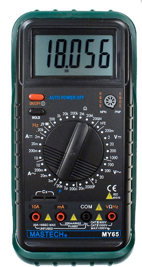
Мультиметр цифровой Mastech MY65 предназначен для измерений в электрических цепях и проверки радиоэлементов.
Пределы измерений прибора
Постоянное напряжение: 0,01 мВ … 1000 В,
Переменное напряжение: 0,1 мВ … 700 В,
Постоянный ток: 0,1 мкА … 20 А,
Переменный ток: 0,1 мкА … 20 А
Сопротивление: 0,01 Ом … 200 МОм,
Емкость: 0,1 пФ … 20 мкФ,
Частота: 1 Гц … 20 кГц,
Звуковая прозвонка: сигнал при сопротивлении менее ~50 Ом
Тест диодов: 2,7 В
Тест h21e транзисторов: 0 … 1000
Основные характеристики прибора
Переключений режимов- ручное
Разрядность шкалы- 5 знаков
Входной импеданс: ~ 10 МОм
Фиксация показаний (HOLD)
Отображение пределов измерения в соответствии с выбранным режимом
Автоотключение питания: 40 минут отсутствия активности
Индикация перегрузки: символ «1» на ЖК-дисплее
Индикатор разряда батарей
Диапазон рабочих температур: 0°С … +40°С при отн. влажности менее 80%
Диапазон температур хранения: -0°С … +60°С при отн. влажности менее 70%
Максимальное допустимое напряжение: CAT III – 1000 В, CAT IV – 600 В
Класс безопасности: CE ETL CAT.II 1000V CAT.III 600V RoHS
Предохранители: 200 мА/250В
Питание: батарея 1 шт. х 9 В тип 6F22
Размеры: 188 х 93 х 50 мм
Масса: 380 г
Масса с упаковкой: 588 г
Схема прибора
Для увеличения кликните по изображению (откроется в новом окне)
Во вложении к странице Вы можете скачать инструкцию к мультиметру Mastech MY65 на русском языке
| Файл | Описание | Размер файла: |
|---|---|---|
| 93 Кб |
Mastech MY-65 Multimeter PDF User Guides and Manuals for Free Download: Found (1) Manuals for Mastech MY-65 Device Model (Operation & User’s Manual)
More Multimeter Device Models:
-
UNI-T
UT601
1Model UT601: OPERATING MANUALTable of ContentsTitle PageOverviewUnpacking InspectionSafety InformationRules For Safe OperationInternational Electrical SymbolsThe Meter StructureFunctional ButtonsDisplay SymbolsMeasurement Operation A. Measuring Resistance B. Capacitance Measu …
UT601 Multimeter, 26
-
Southwire
32886963360
Operating Instructions14090T True RMS Multimeter with MApp™ Mobile App010 20 30 40 50 60LoZ mV AnF M kAUTO HOLD REL PEAK MAX MIN AVGAC+DCThe Bluetooth® word mark and logos are registered trademarks of Bluetooth SIG, Inc. and any use of such marks by Southwire Company, LLC is under license.TESTING EQUIPMENTÉQUIPE …
32886963360 Multimeter, 34
-
Delton
6688H
6688H DIGITAL MULTIMETER OPERATOR’S MANUAL 1. OverviewThe multimeter is characterized at slim size, portable, stable performance and anti-dropping capacity. Using 40000 counts digit & analogue bar graph LCD monitor with character 30mm high, they offer clear readings. With overall circuitry design cente …
6688H Multimeter, 2
-
Hanna Instruments
BL 983313-0
WARRANTYInstruction ManualBL 983313-0BL 983313-1Panel-MountedEC Indicators &ControllersGENERAL DESCRIPTIONSPECIFICATIONSRange 0 to 1999 µS/cmResolution 1 µS/cmAccuracy (@ 20°C/68°F) ±2% f.s.Typical EMC Deviation ±2% f.s.Probe HI 7634-00 EC/TDS probe (not included)Temp.Compensation Automatic from 5 to 50°C (4 …
BL 983313-0 Multimeter, 2
Recommended Documentation: