-
Contents
-
Table of Contents
-
Troubleshooting
-
Bookmarks
Quick Links
SIMATIC
S7-200 Programmable Controller
System Manual
This manual has the order number:
6ES7298-8FA22-8BH0
Edition 04/2002
A5E00157957-01
Preface, Contents
Product Overview
Getting Started
Installing the S7-200
PLC Concepts
Programming Concepts,
Conventions and Features
S7-200 Instruction Set
Communicating over a Network
Hardware Troubleshooting Guide
and Software Debugging Tools
Creating a Program for the
Position Module
Creating a Program for the
Modem Module
Using the USS Protocol Library to
Control a MicroMaster Drive
Using the Modbus Protocol
Library
Technical Specifications
Calculating a Power Budget
Error Codes
Special Memory (SM) Bits
S7-200 Order Numbers
Execution Times for STL
Instructions
S7-200 Quick Reference
Information
Index
1
2
3
4
5
6
7
8
9
10
11
12
A
B
C
D
E
F
G
Troubleshooting
Summary of Contents for Siemens Simatic S7-200
-
Contents
-
Table of Contents
-
Troubleshooting
-
Bookmarks
Quick Links
SIMATIC
S7-200
Programmable Controller
System Manual
This manual has the order number:
6ES7298-8FA21-8BH0
03/2000
Introducing the S7-200 Micro
PLC
Getting Started with an S7-200
Programming System
Basic Concepts for Programming
an S7-200 CPU
CPU Memory: Data Types and
Addressing Modes
CPU and Input/Output
Setting Up Communications
Hardware and Network
Communications
Conventions for S7-200
Using USS Protocol Instructions
to Communicate with Drives
Appendices
Execution Times for STL
Instructions
S7-200 Quick Reference
Information
1
2
3
4
5
6
7
8
9
10
11
A
B
C
D
E
F
G
Summary of Contents for Siemens SIMATIC S7-200
![]()
Preface, Contents
Product Overview
Getting Started
Installing the S7-200
SIMATIC
PLC Concepts
S7-200 Programmable Controller
System Manual
This manual has the order number:
6ES7298-8FA23-8BH0
Edition 05/2003
Programming Concepts,
Conventions and Features
S7-200 Instruction Set
Communicating over a Network
Hardware Troubleshooting Guide and Software Debugging Tools
Creating a Program for the Position Module
Creating a Program for the Modem Module
Using the USS Protocol Library to Control a MicroMaster Drive
Using the Modbus Protocol Library
Technical Specifications
Calculating a Power Budget
Error Codes
Special Memory (SM) Bits
S7-200 Order Numbers
Execution Times for STL
Instructions
S7-200 Quick Reference
Information
Index
1
2
3
4
5
6
7
8
9
10
11
12 A B C D E F G
A5E00212536-02

Contents
Safety Guidelines
This manual contains notices which you should observe to ensure your own personal safety, as well as to protect the product and connected equipment. These notices are highlighted in the manual by a warning triangle and are marked as follows according to the level of danger:
Danger
Danger indicates an imminently hazardous situation which, if not avoided, will result in death or serious injury.
Warning
Warning indicates a potentially hazardous situation which, if not avoided, could result in death or serious injury.
Caution
Caution used with the safety alert symbol indicates a potentially hazardous situation which, if not avoided, may result in minor or moderate injury.
Caution
Caution used without the safety alert symbol indicates a potentially hazardous situation which, if not avoided, may result in property damage.
Notice
Notice indicates a potential situation which, if not avoided, may result in an undesirable result or state.
Qualified Personnel
Only qualified personnel should be allowed to install and work on this equipment. Qualified persons are defined as persons who are authorized to commission, to ground, and to tag circuits, equipment, and systems in accordance with established safety practices and standards.
Correct Usage
Note the following:
Warning
This device and its components may only be used for the applications described in the catalog or the technical descriptions, and only in connection with devices or components from other manufacturers which have been approved or recommended by Siemens.
This product can only function correctly and safely if it is transported, stored, set up, and installed correctly, and operated and maintained as recommended.
Trademarks
SIMATICR, SIMATIC HMIR and SIMATIC NETR are registered trademarks of SIEMENS AG.
Some of other designations used in these documents are also registered trademarks; the owner’s rights may be violated if they are used by third parties for their own purposes.
Copyright Siemens AG 2003 All rights reserved
The reproduction, transmission or use of this document or its contents is not permitted without express written authority. Offenders will be liable for damages. All rights, including rights created by patent grant or registration of a utility model or design, are reserved.
Disclaimer of Liability
We have checked the contents of this manual for agreement with the hardware and software described. Since deviations cannot be precluded entirely, we cannot guarantee full agreement. However, the data in this manual are reviewed regularly and any necessary corrections included in subsequent editions. Suggestions for improvement are welcomed.
|
Siemens AG |
|
|
Bereich Automation and Drives |
|
|
Geschaeftsgebiet Industrial Automation Systems |
E Siemens AG 2003 |
|
Postfach 4848, D- 90327 Nuernberg |
Technical data subject to change. |
|
ii |
|
|
Siemens Aktiengesellschaft |
6ES7298-8FA23-8BH0 |

Preface
The S7-200 series is a line of micro-programmable logic controllers (Micro PLCs) that can control a variety of automation applications. Compact design, low cost, and a powerful instruction set make the S7-200 a perfect solution for controlling small applications. The wide variety of S7-200 models and the Windows-based programming tool give you the flexibility you need to solve your automation problems.
Audience
This manual provides information about installing and programming the S7-200 Micro PLCs and is designed for engineers, programmers, installers, and electricians who have a general knowledge of programmable logic controllers.
Scope of the Manual
The information contained in this manual pertains in particular to the following products:
—S7-200 CPU models: CPU 221, CPU 222, CPU 224, CPU 226, and CPU 226XM
—S7-200 EM 22x expansion modules
—STEP 7—Micro/WIN, version 3.2, a 32-bit programming software package for the S7-200
—STEP 7—Micro/WIN Instruction Libraries and TP-Designer for TP070, Version 1.0, a set of software tools for customers who use an S7-200 with other components, such as the TP070 Touch Panel, Modbus, or a MicroMaster drive
Standards Compliance
The SIMATIC S7-200 series meets the following standards:
—European Community (CE) Low Voltage Directive 73/23/EEC
EN 61131—2: Programmable Controllers — Equipment requirements
—European Community (CE) EMC Directive 89/336/EEC
Electromagnetic emissions standard
EN 61000—6—3: residential, commercial, and light industry EN 61000—6—4: industrial environment
Electromagnetic immunity standards EN 61000—6—2: industrial environment
—Underwriters Laboratories, Inc.
|
UL 508 Listed (Industrial Control Equipment) |
Registration number E75310 |
—Canadian Standards Association: CSA C22.2 Number 142 (Process Control Equipment)
—Factory Mutual Research: FM Class I, Division 2, Groups A, B, C, & D Hazardous Locations, T4A and Class I, Zone 2, IIC, T4
Refer to Appendix A for compliance information.
Tip
The SIMATIC S7-200 series meets the CSA standard.
The cULus logo indicates that the S7-200 has been examined and certified by Underwriters Laboratories (UL) to standards UL 508 and CSA 22.2 No. 142.
iii

Contents
Maritime Approvals
The S7-200 products are periodically submitted for special agency approvals related to specific markets and applications. This table identifies the agency and certificate number that the S7-200 products have been approved for. Not all S7-200 products in this manual have been approved for these special agency approvals. Consult your local Siemens representative if you need additional information related to the latest listing of exact approvals by part number.
|
Agency |
Certificate Number |
|
Lloyds Register of Shipping (LRS) |
99 / 20018(E1) |
|
American Bureau of Shipping (ABS) |
01—HG20020—PDA |
|
Germanischer Lloyd (GL) |
12 045 — 98 HH |
|
Det Norske Veritas (DNV) |
A—8071 |
|
Bureau Veritas (BV) |
09051 / A2 BV |
|
Nippon Kaiji Kyokai (NK) |
A—534 |
How to Use This Manual
If you are a first-time (novice) user of S7-200 Micro PLCs, you should read the entire S7-200 Programmable Controller System Manual. If you are an experienced user, refer to the table of contents or index to find specific information.
The S7-200 Programmable Controller System Manual is organized according to the following topics:
—Chapter 1 (Product Overview) provides an overview of some of the features of the S7-200 family of Micro PLC products.
—Chapter 2 (Getting Started) provides a tutorial for creating and downloading a sample control program to an S7-200.
—Chapter 3 (Installing the S7-200) provides the dimensions and basic guidelines for installing the S7-200 CPU modules and expansion I/O modules.
—Chapter 4 (PLC Concepts) provides information about the operation of the S7-200.
—Chapter 5 (Programming Concepts, Conventions, and Features) provides information about the features of STEP 7—Micro/WIN, the program editors and types of instructions (IEC 1131-3 or SIMATIC), S7-200 data types, and guidelines for creating programs.
—Chapter 6 (S7-200 Instruction Set) provides descriptions and examples of programming instructions supported by the S7-200.
—Chapter 7 (Communicating over a Network) provides information for setting up the different network configurations supported by the S7-200.
—Chapter 8 (Hardware Troubleshooting Guide and Software Debugging Tools) provides information for troubleshooting problems with the S7-200 hardware and about the STEP 7—Micro/WIN features that help you debug your program.
—Chapter 9 (Creating a Program for the Position Module) provides information about the instructions and wizard used to create a program for the EM 253 Position module.
—Chapter 10 (Creating a Program for the Modem Module) provides information about the instructions and wizard used to create a program for the EM 241 Modem module.
—Chapter 11 (Using the USS Protocol Library to Control a MicroMaster Drive) provides information about the instructions used to create a control program for a MicroMaster drive. It also provides information about how to configure the MicroMaster 3 and MicroMaster 4 drives.
—Chapter 12 (Using the Modbus Protocol Library) provides information about the instructions used to create a program that uses the Modbus protocol for communications.
—Appendix A (Technical Specifications) provides the technical information and data sheets about the S7-200 hardware.
The other appendices provide additional reference information, such as descriptions of the error codes, descriptions of the Special Memory (SM) area, part numbers for ordering S7-200 equipment, and STL instruction execution times.
iv

Preface
Additional Information and Assistance
Information about the S7-200 and STEP 7-Micro/WIN
In addition to this manual, STEP 7—Micro/WIN provides extensive online help for getting started with programming the S7-200. Included with the purchase of the STEP 7—Micro/WIN software is a free documentation CD. On this CD you can find application tips, an electronic version of this manual and other information.
Online Help
Help is only a keystroke away! Pressing F1 accesses the extensive online help for STEP 7—Micro/WIN. The online help includes useful information about getting started with programming the S7-200, as well as many other topics.
Electronic Manual
An electronic version of this S7-200 System Manual is available on the documentation CD. You can install the electronic manual onto your computer so that you can easily access the information in the manual while you are working with the STEP 7—Micro/WIN software.
Programming Tips
The documentation CD includes Programming Tips, a set of application examples with sample programs. Reviewing or modifying these examples can help you find efficient or innovative solutions for your own application. You can also find the most current version of Programming Tips on the S7-200 Internet site.
Internet: www.siemens.com/S7—200
For additional information about Siemens products and services, technical support, frequently asked questions (FAQs), product updates, or application tips, refer to the following Internet addresses:
— www.ad.siemens.de for general Siemens information
This Siemens Automation & Drives Internet site includes information about the SIMATIC product line and other products available from Siemens.
—www.siemens.com/S7—200 for S7-200 product information
The S7-200 Internet site includes frequently asked questions (FAQs), Programming Tips (application examples and sample programs), information about newly released products, and product updates or downloads.
v

Contents
Technical Assistance and Purchasing S7-200 Products
Local Siemens Sales Office or Distributor
For assistance in answering any technical questions, for training on the S7-200 products, or for ordering S7-200 products, contact your Siemens distributor or sales office. Because your sales representatives are technically trained and have the most specific knowledge about your operations, process and industry, as well as about the individual Siemens products that you are using, they can provide the fastest and most efficient answers to any problems that you might encounter.
Technical Services
The highly trained staff of the S7-200 Technical Services center is also available to help you solve any problems that you might encounter. You can call on them 24 hours a day, 7 days a week:
—For calls originating from within the United States of America
|
Local time: |
Monday to Friday 0800 to 1900 Eastern time |
|
|
Telephone: |
+1 |
800 241—4453 |
|
Fax: |
+1 |
(0) 770 740—3699 |
|
E-Mail: |
drives.support@sea.siemens.com |
—For calls originating from the Americas outside of the USA
|
Local time: |
Monday to Friday 0800 to 1900 Eastern time |
|
Telephone: |
+1 (0) 770 740—3505 |
|
Fax: |
+1 (0) 770 740—3699 |
|
E-Mail: |
drives.support@sea.siemens.com |
—For calls originating from Europe and Africa
Local time (Nuremberg): Monday to Friday 0700 to 1700
|
Telephone: |
+49 (0) 180 5050—222 |
|
Fax: |
+49 (0) 180 5050—223 |
|
E-Mail: |
techsupport@ad.siemens.de |
—For calls originating from Asia and Australia
|
Local time (Singapore): |
Monday to Friday 0830 to 1730 |
|
|
Telephone: |
+65 (0) 740—7000 |
|
|
Fax: |
+65 (0) 740—7001 |
|
|
E-Mail: |
drives.support@sae.siemens.com.sg |
vi
Contents |
||
|
1 |
Product Overview . . . . . . . . . . . . . . . . . . . . . . . . . . . . . . . . . . . . . . . . . . . . . . . . . . . . . . . . . . . . . |
1 |
|
S7-200 CPU . . . . . . . . . . . . . . . . . . . . . . . . . . . . . . . . . . . . . . . . . . . . . . . . . . . . . . . . . . . . . . . . . . . . . . . . . . |
2 |
|
|
S7-200 Expansion Modules . . . . . . . . . . . . . . . . . . . . . . . . . . . . . . . . . . . . . . . . . . . . . . . . . . . . . . . . . . . . . |
3 |
|
|
STEP 7—Micro/WIN Programming Package . . . . . . . . . . . . . . . . . . . . . . . . . . . . . . . . . . . . . . . . . . . . . . . . |
3 |
|
|
Communications Options . . . . . . . . . . . . . . . . . . . . . . . . . . . . . . . . . . . . . . . . . . . . . . . . . . . . . . . . . . . . . . . |
4 |
|
|
Display Panels . . . . . . . . . . . . . . . . . . . . . . . . . . . . . . . . . . . . . . . . . . . . . . . . . . . . . . . . . . . . . . . . . . . . . . . . |
4 |
|
|
2 |
Getting Started . . . . . . . . . . . . . . . . . . . . . . . . . . . . . . . . . . . . . . . . . . . . . . . . . . . . . . . . . . . . . . . . |
5 |
|
Connecting the S7-200 CPU . . . . . . . . . . . . . . . . . . . . . . . . . . . . . . . . . . . . . . . . . . . . . . . . . . . . . . . . . . . . |
6 |
|
|
Creating a Sample Program . . . . . . . . . . . . . . . . . . . . . . . . . . . . . . . . . . . . . . . . . . . . . . . . . . . . . . . . . . . . . |
9 |
|
|
Downloading the Sample Program . . . . . . . . . . . . . . . . . . . . . . . . . . . . . . . . . . . . . . . . . . . . . . . . . . . . . . . |
12 |
|
|
Placing the S7-200 in RUN Mode . . . . . . . . . . . . . . . . . . . . . . . . . . . . . . . . . . . . . . . . . . . . . . . . . . . . . . . . |
12 |
|
|
3 |
Installing the S7-200 . . . . . . . . . . . . . . . . . . . . . . . . . . . . . . . . . . . . . . . . . . . . . . . . . . . . . . . . . . . |
13 |
|
Guidelines for Installing S7-200 Devices . . . . . . . . . . . . . . . . . . . . . . . . . . . . . . . . . . . . . . . . . . . . . . . . . . |
14 |
|
|
Installing and Removing the S7-200 Modules . . . . . . . . . . . . . . . . . . . . . . . . . . . . . . . . . . . . . . . . . . . . . . |
15 |
|
|
Guidelines for Grounding and Wiring . . . . . . . . . . . . . . . . . . . . . . . . . . . . . . . . . . . . . . . . . . . . . . . . . . . . . |
18 |
|
|
4 |
PLC Concepts . . . . . . . . . . . . . . . . . . . . . . . . . . . . . . . . . . . . . . . . . . . . . . . . . . . . . . . . . . . . . . . . . |
21 |
|
Understanding How the S7-200 Executes Your Control Logic . . . . . . . . . . . . . . . . . . . . . . . . . . . . . . . . |
22 |
|
|
Accessing the Data of the S7-200 . . . . . . . . . . . . . . . . . . . . . . . . . . . . . . . . . . . . . . . . . . . . . . . . . . . . . . . . |
24 |
|
|
Understanding How the S7-200 Saves and Restores Data . . . . . . . . . . . . . . . . . . . . . . . . . . . . . . . . . . . |
34 |
|
|
Storing Your Program on a Memory Cartridge . . . . . . . . . . . . . . . . . . . . . . . . . . . . . . . . . . . . . . . . . . . . . . |
36 |
|
|
Selecting the Operating Mode for the S7-200 CPU . . . . . . . . . . . . . . . . . . . . . . . . . . . . . . . . . . . . . . . . . . |
37 |
|
|
Using Your Program to Save V Memory to the EEPROM . . . . . . . . . . . . . . . . . . . . . . . . . . . . . . . . . . . . |
38 |
|
|
Features of the S7-200 . . . . . . . . . . . . . . . . . . . . . . . . . . . . . . . . . . . . . . . . . . . . . . . . . . . . . . . . . . . . . . . . . |
39 |
|
|
5 |
Programming Concepts, Conventions, and Features . . . . . . . . . . . . . . . . . . . . . . . . . . . . . |
47 |
|
Guidelines for Designing a Micro PLC System . . . . . . . . . . . . . . . . . . . . . . . . . . . . . . . . . . . . . . . . . . . . . |
48 |
|
|
Basic Elements of a Program . . . . . . . . . . . . . . . . . . . . . . . . . . . . . . . . . . . . . . . . . . . . . . . . . . . . . . . . . . . . |
49 |
|
|
Using STEP 7—Micro/WIN to Create Your Programs . . . . . . . . . . . . . . . . . . . . . . . . . . . . . . . . . . . . . . . . |
51 |
|
|
Choosing Between the SIMATIC and IEC 1131—3 Instruction Sets . . . . . . . . . . . . . . . . . . . . . . . . . . . . |
53 |
|
|
Understanding the Conventions Used by the Program Editors . . . . . . . . . . . . . . . . . . . . . . . . . . . . . . . . |
54 |
|
|
Using Wizards To Help You Create Your Control Program . . . . . . . . . . . . . . . . . . . . . . . . . . . . . . . . . . . . |
56 |
|
|
Handling Errors in the S7-200 . . . . . . . . . . . . . . . . . . . . . . . . . . . . . . . . . . . . . . . . . . . . . . . . . . . . . . . . . . . |
56 |
|
|
Assigning Addresses and Initial Values in the Data Block Editor . . . . . . . . . . . . . . . . . . . . . . . . . . . . . . |
58 |
|
|
Using the Symbol Table for Symbolic Addressing of Variables . . . . . . . . . . . . . . . . . . . . . . . . . . . . . . . . |
58 |
|
|
Using Local Variables . . . . . . . . . . . . . . . . . . . . . . . . . . . . . . . . . . . . . . . . . . . . . . . . . . . . . . . . . . . . . . . . . . |
59 |
|
|
Using the Status Chart to Monitor Your Program . . . . . . . . . . . . . . . . . . . . . . . . . . . . . . . . . . . . . . . . . . . . |
59 |
|
|
Creating an Instruction Library . . . . . . . . . . . . . . . . . . . . . . . . . . . . . . . . . . . . . . . . . . . . . . . . . . . . . . . . . . . |
60 |
|
|
Features for Debugging Your Program . . . . . . . . . . . . . . . . . . . . . . . . . . . . . . . . . . . . . . . . . . . . . . . . . . . . |
60 |
vii

|
Contents |
||
|
6 |
S7-200 Instruction Set . . . . . . . . . . . . . . . . . . . . . . . . . . . . . . . . . . . . . . . . . . . . . . . . . . . . . . . . . |
61 |
|
Conventions Used to Describe the Instructions . . . . . . . . . . . . . . . . . . . . . . . . . . . . . . . . . . . . . . . . . . . . . |
63 |
|
|
S7-200 Memory Ranges and Features . . . . . . . . . . . . . . . . . . . . . . . . . . . . . . . . . . . . . . . . . . . . . . . . . . . . |
64 |
|
|
Bit Logic Instructions . . . . . . . . . . . . . . . . . . . . . . . . . . . . . . . . . . . . . . . . . . . . . . . . . . . . . . . . . . . . . . . . . . . |
66 |
|
|
Contacts . . . . . . . . . . . . . . . . . . . . . . . . . . . . . . . . . . . . . . . . . . . . . . . . . . . . . . . . . . . . . . . . . . . . . . . . . |
66 |
|
|
Coils . . . . . . . . . . . . . . . . . . . . . . . . . . . . . . . . . . . . . . . . . . . . . . . . . . . . . . . . . . . . . . . . . . . . . . . . . . . . . |
69 |
|
|
Logic Stack Instructions . . . . . . . . . . . . . . . . . . . . . . . . . . . . . . . . . . . . . . . . . . . . . . . . . . . . . . . . . . . . |
71 |
|
|
Set and Reset Dominant Bistable Instructions . . . . . . . . . . . . . . . . . . . . . . . . . . . . . . . . . . . . . . . . . . |
73 |
|
|
Clock Instructions . . . . . . . . . . . . . . . . . . . . . . . . . . . . . . . . . . . . . . . . . . . . . . . . . . . . . . . . . . . . . . . . . . . . . . |
74 |
|
|
Communications Instructions . . . . . . . . . . . . . . . . . . . . . . . . . . . . . . . . . . . . . . . . . . . . . . . . . . . . . . . . . . . . |
75 |
|
|
Network Read and Network Write Instructions . . . . . . . . . . . . . . . . . . . . . . . . . . . . . . . . . . . . . . . . . . |
75 |
|
|
Transmit and Receive Instructions (Freeport) . . . . . . . . . . . . . . . . . . . . . . . . . . . . . . . . . . . . . . . . . . |
80 |
|
|
Get Port Address and Set Port Address Instructions . . . . . . . . . . . . . . . . . . . . . . . . . . . . . . . . . . . . |
89 |
|
|
Compare Instructions . . . . . . . . . . . . . . . . . . . . . . . . . . . . . . . . . . . . . . . . . . . . . . . . . . . . . . . . . . . . . . . . . . |
90 |
|
|
Comparing Numerical Values . . . . . . . . . . . . . . . . . . . . . . . . . . . . . . . . . . . . . . . . . . . . . . . . . . . . . . . . |
90 |
|
|
Compare String . . . . . . . . . . . . . . . . . . . . . . . . . . . . . . . . . . . . . . . . . . . . . . . . . . . . . . . . . . . . . . . . . . . |
92 |
|
|
Conversion Instructions . . . . . . . . . . . . . . . . . . . . . . . . . . . . . . . . . . . . . . . . . . . . . . . . . . . . . . . . . . . . . . . . . |
93 |
|
|
Standard Conversion Instructions . . . . . . . . . . . . . . . . . . . . . . . . . . . . . . . . . . . . . . . . . . . . . . . . . . . . |
93 |
|
|
ASCII Conversion Instructions . . . . . . . . . . . . . . . . . . . . . . . . . . . . . . . . . . . . . . . . . . . . . . . . . . . . . . . |
97 |
|
|
String Conversion Instructions . . . . . . . . . . . . . . . . . . . . . . . . . . . . . . . . . . . . . . . . . . . . . . . . . . . . . . . |
101 |
|
|
Encode and Decode Instructions . . . . . . . . . . . . . . . . . . . . . . . . . . . . . . . . . . . . . . . . . . . . . . . . . . . . . |
106 |
|
|
Counter Instructions . . . . . . . . . . . . . . . . . . . . . . . . . . . . . . . . . . . . . . . . . . . . . . . . . . . . . . . . . . . . . . . . . . . . |
107 |
|
|
SIMATIC Counter Instructions . . . . . . . . . . . . . . . . . . . . . . . . . . . . . . . . . . . . . . . . . . . . . . . . . . . . . . . |
107 |
|
|
IEC Counter Instructions . . . . . . . . . . . . . . . . . . . . . . . . . . . . . . . . . . . . . . . . . . . . . . . . . . . . . . . . . . . . |
110 |
|
|
High-Speed Counter Instructions . . . . . . . . . . . . . . . . . . . . . . . . . . . . . . . . . . . . . . . . . . . . . . . . . . . . . . . . . |
112 |
|
|
Pulse Output Instruction . . . . . . . . . . . . . . . . . . . . . . . . . . . . . . . . . . . . . . . . . . . . . . . . . . . . . . . . . . . . . . . . |
126 |
|
|
Math Instructions . . . . . . . . . . . . . . . . . . . . . . . . . . . . . . . . . . . . . . . . . . . . . . . . . . . . . . . . . . . . . . . . . . . . . . |
141 |
|
|
Add, Subtract, Multiply, and Divide Instructions . . . . . . . . . . . . . . . . . . . . . . . . . . . . . . . . . . . . . . . . . |
141 |
|
|
Multiply Integer to Double Integer and Divide Integer with Remainder . . . . . . . . . . . . . . . . . . . . . . |
143 |
|
|
Numeric Functions Instructions . . . . . . . . . . . . . . . . . . . . . . . . . . . . . . . . . . . . . . . . . . . . . . . . . . . . . . |
144 |
|
|
Increment and Decrement Instructions . . . . . . . . . . . . . . . . . . . . . . . . . . . . . . . . . . . . . . . . . . . . . . . . |
145 |
|
|
Proportional/Integral/Derivative (PID) Loop Instruction . . . . . . . . . . . . . . . . . . . . . . . . . . . . . . . . . . . . . . . |
146 |
|
|
Interrupt Instructions . . . . . . . . . . . . . . . . . . . . . . . . . . . . . . . . . . . . . . . . . . . . . . . . . . . . . . . . . . . . . . . . . . . |
156 |
|
|
Logical Operations Instructions . . . . . . . . . . . . . . . . . . . . . . . . . . . . . . . . . . . . . . . . . . . . . . . . . . . . . . . . . . |
163 |
|
|
Invert Instructions . . . . . . . . . . . . . . . . . . . . . . . . . . . . . . . . . . . . . . . . . . . . . . . . . . . . . . . . . . . . . . . . . . |
163 |
|
|
AND, OR, and Exclusive OR Instructions . . . . . . . . . . . . . . . . . . . . . . . . . . . . . . . . . . . . . . . . . . . . . . |
164 |
|
|
Move Instructions . . . . . . . . . . . . . . . . . . . . . . . . . . . . . . . . . . . . . . . . . . . . . . . . . . . . . . . . . . . . . . . . . . . . . . |
166 |
|
|
Move Byte, Word, Double Word, or Real . . . . . . . . . . . . . . . . . . . . . . . . . . . . . . . . . . . . . . . . . . . . . . |
166 |
|
|
Move Byte Immediate (Read and Write) . . . . . . . . . . . . . . . . . . . . . . . . . . . . . . . . . . . . . . . . . . . . . . . |
167 |
|
|
Block Move Instructions . . . . . . . . . . . . . . . . . . . . . . . . . . . . . . . . . . . . . . . . . . . . . . . . . . . . . . . . . . . . |
168 |
|
|
Program Control Instructions . . . . . . . . . . . . . . . . . . . . . . . . . . . . . . . . . . . . . . . . . . . . . . . . . . . . . . . . . . . . |
169 |
|
|
Conditional End . . . . . . . . . . . . . . . . . . . . . . . . . . . . . . . . . . . . . . . . . . . . . . . . . . . . . . . . . . . . . . . . . . . |
169 |
|
|
Stop . . . . . . . . . . . . . . . . . . . . . . . . . . . . . . . . . . . . . . . . . . . . . . . . . . . . . . . . . . . . . . . . . . . . . . . . . . . . . |
169 |
|
|
Watchdog Reset . . . . . . . . . . . . . . . . . . . . . . . . . . . . . . . . . . . . . . . . . . . . . . . . . . . . . . . . . . . . . . . . . . . |
169 |
|
|
For—Next Loop Instructions . . . . . . . . . . . . . . . . . . . . . . . . . . . . . . . . . . . . . . . . . . . . . . . . . . . . . . . . . . |
171 |
|
|
Jump Instructions . . . . . . . . . . . . . . . . . . . . . . . . . . . . . . . . . . . . . . . . . . . . . . . . . . . . . . . . . . . . . . . . . . |
173 |
|
|
Sequence Control Relay (SCR) Instructions . . . . . . . . . . . . . . . . . . . . . . . . . . . . . . . . . . . . . . . . . . . |
174 |
viii

Contents
Shift and Rotate Instructions . . . . . . . . . . . . . . . . . . . . . . . . . . . . . . . . . . . . . . . . . . . . . . . . . . . . . . . . . . . . . 180
Shift Right and Shift Left Instructions . . . . . . . . . . . . . . . . . . . . . . . . . . . . . . . . . . . . . . . . . . . . . . . . . . 180
Rotate Right and Rotate Left Instructions . . . . . . . . . . . . . . . . . . . . . . . . . . . . . . . . . . . . . . . . . . . . . . 180
Shift Register Bit Instruction . . . . . . . . . . . . . . . . . . . . . . . . . . . . . . . . . . . . . . . . . . . . . . . . . . . . . . . . . 182
Swap Bytes Instruction . . . . . . . . . . . . . . . . . . . . . . . . . . . . . . . . . . . . . . . . . . . . . . . . . . . . . . . . . . . . . 184
String Instructions . . . . . . . . . . . . . . . . . . . . . . . . . . . . . . . . . . . . . . . . . . . . . . . . . . . . . . . . . . . . . . . . . . . . . 185
Table Instructions . . . . . . . . . . . . . . . . . . . . . . . . . . . . . . . . . . . . . . . . . . . . . . . . . . . . . . . . . . . . . . . . . . . . . . 190
Add To Table . . . . . . . . . . . . . . . . . . . . . . . . . . . . . . . . . . . . . . . . . . . . . . . . . . . . . . . . . . . . . . . . . . . . . . 190
First-In-First-Out and Last-In-First-Out . . . . . . . . . . . . . . . . . . . . . . . . . . . . . . . . . . . . . . . . . . . . . . . . 191
Memory Fill . . . . . . . . . . . . . . . . . . . . . . . . . . . . . . . . . . . . . . . . . . . . . . . . . . . . . . . . . . . . . . . . . . . . . . . 193
Table Find . . . . . . . . . . . . . . . . . . . . . . . . . . . . . . . . . . . . . . . . . . . . . . . . . . . . . . . . . . . . . . . . . . . . . . . . 194
Timer Instructions . . . . . . . . . . . . . . . . . . . . . . . . . . . . . . . . . . . . . . . . . . . . . . . . . . . . . . . . . . . . . . . . . . . . . . 197
SIMATIC Timer Instructions . . . . . . . . . . . . . . . . . . . . . . . . . . . . . . . . . . . . . . . . . . . . . . . . . . . . . . . . . 197
IEC Timer Instructions . . . . . . . . . . . . . . . . . . . . . . . . . . . . . . . . . . . . . . . . . . . . . . . . . . . . . . . . . . . . . . 202
Subroutine Instructions . . . . . . . . . . . . . . . . . . . . . . . . . . . . . . . . . . . . . . . . . . . . . . . . . . . . . . . . . . . . . . . . . 204
|
7 |
Communicating over a Network . . . . . . . . . . . . . . . . . . . . . . . . . . . . . . . . . . . . . . . . . . . . . . . . |
209 |
|
Understanding the Basics of S7-200 Network Communications . . . . . . . . . . . . . . . . . . . . . . . . . . . . . . . |
210 |
|
|
Selecting the Communications Protocol for Your Network . . . . . . . . . . . . . . . . . . . . . . . . . . . . . . . . . . . . |
214 |
|
|
Installing and Removing Communications Interfaces . . . . . . . . . . . . . . . . . . . . . . . . . . . . . . . . . . . . . . . . |
220 |
|
|
Building Your Network . . . . . . . . . . . . . . . . . . . . . . . . . . . . . . . . . . . . . . . . . . . . . . . . . . . . . . . . . . . . . . . . . . |
222 |
|
|
Creating User-Defined Protocols with Freeport Mode . . . . . . . . . . . . . . . . . . . . . . . . . . . . . . . . . . . . . . . |
227 |
|
|
Using Modems and STEP 7—Micro/WIN with Your Network . . . . . . . . . . . . . . . . . . . . . . . . . . . . . . . . . . |
229 |
|
|
Advanced Topics . . . . . . . . . . . . . . . . . . . . . . . . . . . . . . . . . . . . . . . . . . . . . . . . . . . . . . . . . . . . . . . . . . . . . . |
235 |
|
|
Configuring the RS-232/PPI Multi-Master Cable for Remote Operation . . . . . . . . . . . . . . . . . . . . . . . . . |
241 |
|
|
8 |
Hardware Troubleshooting Guide and Software Debugging Tools . . . . . . . . . . . . . . . . . |
245 |
Features for Debugging Your Program . . . . . . . . . . . . . . . . . . . . . . . . . . . . . . . . . . . . . . . . . . . . . . . . . . . . 246 Displaying the Program Status . . . . . . . . . . . . . . . . . . . . . . . . . . . . . . . . . . . . . . . . . . . . . . . . . . . . . . . . . . . 248 Using a Status Chart to Monitor and Modify the Data in the S7-200 . . . . . . . . . . . . . . . . . . . . . . . . . . . . 249 Forcing Specific Values . . . . . . . . . . . . . . . . . . . . . . . . . . . . . . . . . . . . . . . . . . . . . . . . . . . . . . . . . . . . . . . . . 250 Running Your Program for a Specified Number of Scans . . . . . . . . . . . . . . . . . . . . . . . . . . . . . . . . . . . . 250 Hardware Troubleshooting Guide . . . . . . . . . . . . . . . . . . . . . . . . . . . . . . . . . . . . . . . . . . . . . . . . . . . . . . . . 251
|
9 |
Creating a Program for the Position Module . . . . . . . . . . . . . . . . . . . . . . . . . . . . . . . . . . . . . |
253 |
Features of the Position Module . . . . . . . . . . . . . . . . . . . . . . . . . . . . . . . . . . . . . . . . . . . . . . . . . . . . . . . . . 254 Configuring the Position Module . . . . . . . . . . . . . . . . . . . . . . . . . . . . . . . . . . . . . . . . . . . . . . . . . . . . . . . . . 256 Position Instructions Created by the Position Control Wizard . . . . . . . . . . . . . . . . . . . . . . . . . . . . . . . . . 267 Sample Programs for the Position Module . . . . . . . . . . . . . . . . . . . . . . . . . . . . . . . . . . . . . . . . . . . . . . . . . 279 Monitoring the Position Module with the EM 253 Control Panel . . . . . . . . . . . . . . . . . . . . . . . . . . . . . . . 284 Error Codes for the Position Module and the Position Instructions . . . . . . . . . . . . . . . . . . . . . . . . . . . . . 286 Advanced Topics . . . . . . . . . . . . . . . . . . . . . . . . . . . . . . . . . . . . . . . . . . . . . . . . . . . . . . . . . . . . . . . . . . . . . . 288
10 Creating a Program for the Modem Module . . . . . . . . . . . . . . . . . . . . . . . . . . . . . . . . . . . . . . 297
Features of the Modem Module . . . . . . . . . . . . . . . . . . . . . . . . . . . . . . . . . . . . . . . . . . . . . . . . . . . . . . . . . . 298 Using the Modem Expansion Wizard to Configure the Modem Module . . . . . . . . . . . . . . . . . . . . . . . . . 304 Overview of Modem Instructions and Restrictions . . . . . . . . . . . . . . . . . . . . . . . . . . . . . . . . . . . . . . . . . . 308 Instructions for the Modem Module . . . . . . . . . . . . . . . . . . . . . . . . . . . . . . . . . . . . . . . . . . . . . . . . . . . . . . . 309
ix

Contents
Sample Program for the Modem Module . . . . . . . . . . . . . . . . . . . . . . . . . . . . . . . . . . . . . . . . . . . . . . . . . . 313 S7-200 CPUs that Support Intelligent Modules . . . . . . . . . . . . . . . . . . . . . . . . . . . . . . . . . . . . . . . . . . . . . 313 Special Memory Location for the Modem Module . . . . . . . . . . . . . . . . . . . . . . . . . . . . . . . . . . . . . . . . . . . 314 Advanced Topics . . . . . . . . . . . . . . . . . . . . . . . . . . . . . . . . . . . . . . . . . . . . . . . . . . . . . . . . . . . . . . . . . . . . . . 316 Messaging Telephone Number Format . . . . . . . . . . . . . . . . . . . . . . . . . . . . . . . . . . . . . . . . . . . . . . . . . . . . 318 Text Message Format . . . . . . . . . . . . . . . . . . . . . . . . . . . . . . . . . . . . . . . . . . . . . . . . . . . . . . . . . . . . . . . . . . 318 CPU Data Transfer Message Format . . . . . . . . . . . . . . . . . . . . . . . . . . . . . . . . . . . . . . . . . . . . . . . . . . . . . 320
11 Using the USS Protocol Library to Control a MicroMaster Drive . . . . . . . . . . . . . . . . . . . 321
Requirements for Using the USS Protocol . . . . . . . . . . . . . . . . . . . . . . . . . . . . . . . . . . . . . . . . . . . . . . . . . 322 Calculating the Time Required for Communicating with the Drive . . . . . . . . . . . . . . . . . . . . . . . . . . . . . 323 Using the USS Instructions . . . . . . . . . . . . . . . . . . . . . . . . . . . . . . . . . . . . . . . . . . . . . . . . . . . . . . . . . . . . . . 324 Instructions for the USS Protocol . . . . . . . . . . . . . . . . . . . . . . . . . . . . . . . . . . . . . . . . . . . . . . . . . . . . . . . . . 325 Sample Programs for the USS Protocol . . . . . . . . . . . . . . . . . . . . . . . . . . . . . . . . . . . . . . . . . . . . . . . . . . . 332 USS Execution Error Codes . . . . . . . . . . . . . . . . . . . . . . . . . . . . . . . . . . . . . . . . . . . . . . . . . . . . . . . . . . . . . 333 Connecting and Setting Up the MicroMaster Series 3 Drive . . . . . . . . . . . . . . . . . . . . . . . . . . . . . . . . . . 334 Connecting and Setting Up the MicroMaster Series 4 Drive . . . . . . . . . . . . . . . . . . . . . . . . . . . . . . . . . . 337
12 Using the Modbus Protocol Library . . . . . . . . . . . . . . . . . . . . . . . . . . . . . . . . . . . . . . . . . . . . . 339
Requirements for Using the Modbus Protocol . . . . . . . . . . . . . . . . . . . . . . . . . . . . . . . . . . . . . . . . . . . . . . 340 Initialization and Execution Time for the Modbus Protocol . . . . . . . . . . . . . . . . . . . . . . . . . . . . . . . . . . . . 340 Modbus Addressing . . . . . . . . . . . . . . . . . . . . . . . . . . . . . . . . . . . . . . . . . . . . . . . . . . . . . . . . . . . . . . . . . . . . 341 Using the Modbus Slave Protocol Instructions . . . . . . . . . . . . . . . . . . . . . . . . . . . . . . . . . . . . . . . . . . . . . 342 Instructions for the Modbus Slave Protocol . . . . . . . . . . . . . . . . . . . . . . . . . . . . . . . . . . . . . . . . . . . . . . . . 343
|
A |
Technical Specifications . . . . . . . . . . . . . . . . . . . . . . . . . . . . . . . . . . . . . . . . . . . . . . . . . . . . . . . |
347 |
|
General Technical Specifications . . . . . . . . . . . . . . . . . . . . . . . . . . . . . . . . . . . . . . . . . . . . . . . . . . . . . . . . . |
348 |
|
|
CPU Specifications . . . . . . . . . . . . . . . . . . . . . . . . . . . . . . . . . . . . . . . . . . . . . . . . . . . . . . . . . . . . . . . . . . . . |
351 |
|
|
Digital Expansion Modules Specifications . . . . . . . . . . . . . . . . . . . . . . . . . . . . . . . . . . . . . . . . . . . . . . . . . |
357 |
|
|
Analog Expansion Modules Specifications . . . . . . . . . . . . . . . . . . . . . . . . . . . . . . . . . . . . . . . . . . . . . . . . . |
363 |
|
|
Thermocouple and RTD Expansion Modules Specifications . . . . . . . . . . . . . . . . . . . . . . . . . . . . . . . . . . |
373 |
|
|
EM 277 PROFIBUS—DP Module Specifications . . . . . . . . . . . . . . . . . . . . . . . . . . . . . . . . . . . . . . . . . . . . |
385 |
|
|
EM 241 Modem Module Specifications . . . . . . . . . . . . . . . . . . . . . . . . . . . . . . . . . . . . . . . . . . . . . . . . . . . . |
397 |
|
|
EM 253 Position Module Specifications . . . . . . . . . . . . . . . . . . . . . . . . . . . . . . . . . . . . . . . . . . . . . . . . . . . |
399 |
|
|
(CP 243—1) Ethernet Module Specifications . . . . . . . . . . . . . . . . . . . . . . . . . . . . . . . . . . . . . . . . . . . . . . . |
405 |
|
|
(CP 243—1 IT) Internet Module Specifications . . . . . . . . . . . . . . . . . . . . . . . . . . . . . . . . . . . . . . . . . . . . . . |
407 |
|
|
(CP 243—2) AS—Interface Module Specifications . . . . . . . . . . . . . . . . . . . . . . . . . . . . . . . . . . . . . . . . . . . . |
410 |
|
|
Optional Cartridges . . . . . . . . . . . . . . . . . . . . . . . . . . . . . . . . . . . . . . . . . . . . . . . . . . . . . . . . . . . . . . . . . . . . |
412 |
|
|
I/O Expansion Cable . . . . . . . . . . . . . . . . . . . . . . . . . . . . . . . . . . . . . . . . . . . . . . . . . . . . . . . . . . . . . . . . . . . |
412 |
|
|
RS-232/PPI Multi-Master Cable and USB/PPI Multi-Master Cable . . . . . . . . . . . . . . . . . . . . . . . . . . . . |
413 |
|
|
Input Simulators . . . . . . . . . . . . . . . . . . . . . . . . . . . . . . . . . . . . . . . . . . . . . . . . . . . . . . . . . . . . . . . . . . . . . . . |
417 |
|
|
B |
Calculating a Power Budget . . . . . . . . . . . . . . . . . . . . . . . . . . . . . . . . . . . . . . . . . . . . . . . . . . . . |
419 |
|
C |
Error Codes . . . . . . . . . . . . . . . . . . . . . . . . . . . . . . . . . . . . . . . . . . . . . . . . . . . . . . . . . . . . . . . . . . . |
423 |
|
Fatal Error Codes and Messages . . . . . . . . . . . . . . . . . . . . . . . . . . . . . . . . . . . . . . . . . . . . . . . . . . . . . . . . |
424 |
|
|
Run-Time Programming Problems . . . . . . . . . . . . . . . . . . . . . . . . . . . . . . . . . . . . . . . . . . . . . . . . . . . . . . . |
425 |
|
|
Compile Rule Violations . . . . . . . . . . . . . . . . . . . . . . . . . . . . . . . . . . . . . . . . . . . . . . . . . . . . . . . . . . . . . . . . |
426 |
x
![]()
Contents
D Special Memory (SM) Bits . . . . . . . . . . . . . . . . . . . . . . . . . . . . . . . . . . . . . . . . . . . . . . . . . . . . . . 427
SMB0: Status Bits . . . . . . . . . . . . . . . . . . . . . . . . . . . . . . . . . . . . . . . . . . . . . . . . . . . . . . . . . . . . . . . . . . . . . 428 SMB1: Status Bits . . . . . . . . . . . . . . . . . . . . . . . . . . . . . . . . . . . . . . . . . . . . . . . . . . . . . . . . . . . . . . . . . . . . . 428 SMB2: Freeport Receive Character . . . . . . . . . . . . . . . . . . . . . . . . . . . . . . . . . . . . . . . . . . . . . . . . . . . . . . 429 SMB3: Freeport Parity Error . . . . . . . . . . . . . . . . . . . . . . . . . . . . . . . . . . . . . . . . . . . . . . . . . . . . . . . . . . . . . 429 SMB4: Queue Overflow . . . . . . . . . . . . . . . . . . . . . . . . . . . . . . . . . . . . . . . . . . . . . . . . . . . . . . . . . . . . . . . . . 429 SMB5: I/O Status . . . . . . . . . . . . . . . . . . . . . . . . . . . . . . . . . . . . . . . . . . . . . . . . . . . . . . . . . . . . . . . . . . . . . . 430 SMB6: CPU ID Register . . . . . . . . . . . . . . . . . . . . . . . . . . . . . . . . . . . . . . . . . . . . . . . . . . . . . . . . . . . . . . . . 430 SMB7: Reserved . . . . . . . . . . . . . . . . . . . . . . . . . . . . . . . . . . . . . . . . . . . . . . . . . . . . . . . . . . . . . . . . . . . . . . 430 SMB8 to SMB21: I/O Module ID and Error Registers . . . . . . . . . . . . . . . . . . . . . . . . . . . . . . . . . . . . . . . . 431 SMW22 to SMW26: Scan Times . . . . . . . . . . . . . . . . . . . . . . . . . . . . . . . . . . . . . . . . . . . . . . . . . . . . . . . . . 432 SMB28 and SMB29: Analog Adjustment . . . . . . . . . . . . . . . . . . . . . . . . . . . . . . . . . . . . . . . . . . . . . . . . . . 432 SMB30 and SMB130: Freeport Control Registers . . . . . . . . . . . . . . . . . . . . . . . . . . . . . . . . . . . . . . . . . . . 432 SMB31 and SMW32: Permanent Memory (EEPROM) Write Control . . . . . . . . . . . . . . . . . . . . . . . . . . . 433 SMB34 and SMB35: Time Interval Registers for Timed Interrupts . . . . . . . . . . . . . . . . . . . . . . . . . . . . . 433 SMB36 to SMB65: HSC0, HSC1, and HSC2 Register . . . . . . . . . . . . . . . . . . . . . . . . . . . . . . . . . . . . . . . 433 SMB66 to SMB85: PTO/PWM Registers . . . . . . . . . . . . . . . . . . . . . . . . . . . . . . . . . . . . . . . . . . . . . . . . . . 435 SMB86 to SMB94, and SMB186 to SMB194: Receive Message Control . . . . . . . . . . . . . . . . . . . . . . . 436 SMW98: Errors on the Expansion I/O Bus . . . . . . . . . . . . . . . . . . . . . . . . . . . . . . . . . . . . . . . . . . . . . . . . . 437 SMB130: Freeport Control Register (see SMB30) . . . . . . . . . . . . . . . . . . . . . . . . . . . . . . . . . . . . . . . . . . 437 SMB131 to SMB165: HSC3, HSC4, and HSC5 Register . . . . . . . . . . . . . . . . . . . . . . . . . . . . . . . . . . . . . 437 SMB166 to SMB185: PTO0, PTO1 Profile Definition Table . . . . . . . . . . . . . . . . . . . . . . . . . . . . . . . . . . . 438 SMB186 to SMB194: Receive Message Control (see SMB86 to SMB94) . . . . . . . . . . . . . . . . . . . . . . . 438 SMB200 to SMB549: Intelligent Module Status . . . . . . . . . . . . . . . . . . . . . . . . . . . . . . . . . . . . . . . . . . . . . 439
E S7-200 Order Numbers . . . . . . . . . . . . . . . . . . . . . . . . . . . . . . . . . . . . . . . . . . . . . . . . . . . . . . . . . 441 F Execution Times for STL Instructions . . . . . . . . . . . . . . . . . . . . . . . . . . . . . . . . . . . . . . . . . . . 445 G S7-200 Quick Reference Information . . . . . . . . . . . . . . . . . . . . . . . . . . . . . . . . . . . . . . . . . . . . 451 Index . . . . . . . . . . . . . . . . . . . . . . . . . . . . . . . . . . . . . . . . . . . . . . . . . . . . . . . . . . . . . . . . . . . . . . . . . . . . . . . 457
xi

Contents
xii

Product Overview
The S7-200 series of micro-programmable logic controllers (Micro PLCs) can control a wide variety of devices to support your automation needs.
The S7-200 monitors inputs and changes outputs as controlled by the user program, which can include Boolean logic, counting, timing, complex math operations, and communications with other intelligent devices. The compact design, flexible configuration, and powerful instruction set combine to make the S7-200 a perfect solution for controlling a wide variety of applications.
|
In This Chapter |
|
|
S7-200 CPU . . . . . . . . . . . . . . . . . . . . . . . . . . . . . . . . . . . . . . . . . . . . . . . . . . . . . . . . . . . . . . . . . . . . . . . . . . |
2 |
|
S7-200 Expansion Modules . . . . . . . . . . . . . . . . . . . . . . . . . . . . . . . . . . . . . . . . . . . . . . . . . . . . . . . . . . . . . |
3 |
|
STEP 7—Micro/WIN Programming Package . . . . . . . . . . . . . . . . . . . . . . . . . . . . . . . . . . . . . . . . . . . . . . . . |
3 |
|
Communications Options . . . . . . . . . . . . . . . . . . . . . . . . . . . . . . . . . . . . . . . . . . . . . . . . . . . . . . . . . . . . . . . |
4 |
|
Display Panels . . . . . . . . . . . . . . . . . . . . . . . . . . . . . . . . . . . . . . . . . . . . . . . . . . . . . . . . . . . . . . . . . . . . . . . . |
4 |
1
S7-200 Programmable Controller System Manual
|
S7-200 CPU |
||
|
1 |
||
|
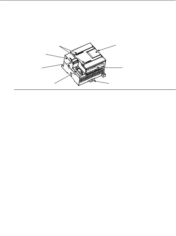
The S7-200 CPU combines a microprocessor, an integrated power supply, input circuits, and output |
||
|
circuits in a compact housing to create a powerful Micro PLC. See Figure 1-1. After you have |
||
|
downloaded your program, the S7-200 contains the logic required to monitor and control the input and |
||
|
output devices in your application. |
I/O LEDs
Status LEDs:
System Fault
RUN
STOP
Optional cartridge:
EEPROM
Real-time Clock
Battery
Communications port
Access door:
Mode selector switch (RUN/STOP) Analog adjustment potentiometer(s) Expansion port (for most CPUs)
Terminal connector
(removable on CPU 224, CPU 226 and CPU 226XM)
Clip for installation on a standard (DIN) rail
Figure 1-1 S7-200 Micro PLC
Siemens provides different S7-200 CPU models with a diversity of features and capabilities that help you create effective solutions for your varied applications. Table 1-1 briefly compares some of the features of the CPU. For detailed information about a specific CPU, see Appendix A.
|
Table 1-1 |
Comparison of the S7-200 CPU Models |
|||||
|
Feature |
CPU 221 |
CPU 222 |
CPU 224 |
CPU 226 |
CPU 226XM |
|
|
Physical size (mm) |
90 x 80 x 62 |
90 x 80 x 62 |
120.5 x 80 x 62 |
190 x 80 x 62 |
190 x 80 x 62 |
|
|
Program memory |
4096 bytes |
4096 bytes |
8192 bytes |
8192 bytes |
16384 bytes |
|
|
Data memory |
2048 bytes |
2048 bytes |
5120 bytes |
5120 bytes |
10240 bytes |
|
|
Memory backup |
50 hours typical |
50 hours typical |
190 hours typical |
190 hours typical |
190 hours typical |
|
|
Local on-board I/O |
6 In/4 Out |
8 In/6 Out |
14 In/10 Out |
24 In/16 Out |
24 In/16 Out |
|
|
Expansion modules |
0 modules1 |
2 modules1 |
7 modules1 |
7 modules1 |
7 modules1 |
|
|
High-speed counters |
||||||
|
Single phase |
4 at 30 kHz |
4 at 30 kHz |
6 at 30 kHz |
6 at 30 kHz |
6 at 30 kHz |
|
|
Two phase |
2 at 20 kHz |
2 at 20 kHz |
4 at 20 kHz |
4 at 20 kHz |
4 at 20 kHz |
|
|
Pulse outputs (DC) |
2 at 20 kHz |
2 at 20 kHz |
2 at 20 kHz |
2 at 20 kHz |
2 at 20 kHz |
|
|
Analog adjustments |
1 |
1 |
2 |
2 |
2 |
|
|
Real-time clock |
Cartridge |
Cartridge |
Built-in |
Built-in |
Built-in |
|
|
Communications |
1 RS—485 |
1 RS—485 |
1 RS—485 |
2 RS—485 |
2 RS—485 |
|
|
ports |
||||||
|
Floating-point math |
Yes |
|||||
|
Digital I/O image size |
256 (128 in, 128 out) |
|||||
|
Boolean execution |
0.37 microseconds/instruction |
|||||
|
speed |
||||||
1 You must calculate your power budget to determine how much power (or current) the S7-200 CPU can provide for your configuration. If the CPU power budget is exceeded, you may not be able to connect the maximum number of modules. See Appendix A for CPU and expansion module power requirements, and Appendix B to calculate your power budget.
2
Product Overview Chapter 1
|
S7-200 Expansion Modules |
||
|
1 |
||
|
To better solve your application requirements, the S7-200 family includes a wide variety of expansion |
||
|
modules. You can use these expansion modules to add additional functionality to the S7-200 CPU. |
||
|
Table 1-2 provides a list of the expansion modules that are currently available. For detailed information |
||
|
about a specific module, see Appendix A. |
Table 1-2 S7-200 Expansion Modules
|
Expansion Modules |
Types |
|||
|
Discrete modules |
Input |
8 x DC In |
8 x AC In |
16 x DC In |
|
Output |
4 x DC |
4 x Relays |
||
|
8 x DC Out |
8 x AC Out |
8 x Relay |
||
|
Combination |
4 x DC In / 4 x DC Out |
8 x DC In / 8 x DC Out |
16 x DC In / 16 x DC Out |
|
|
4 x DC In / 4 x Relay |
8 x DC In / 8 x Relay |
16 x DC In / 16 x Relay |
||
|
Analog modules |
Input |
4 x Analog In |
4 x Thermocouple In |
2 x RTD In |
|
Output |
2 x Analog Out |
|||
|
Combination |
4 x Analog In / 1 Analog Out |
|||
|
Intelligent modules |
Position |
Modem |
PROFIBUS-DP |
|
|
Ethernet |
Internet |
|||
|
Other modules |
AS—Interface |
|||
STEP 7-Micro/WIN Programming Package
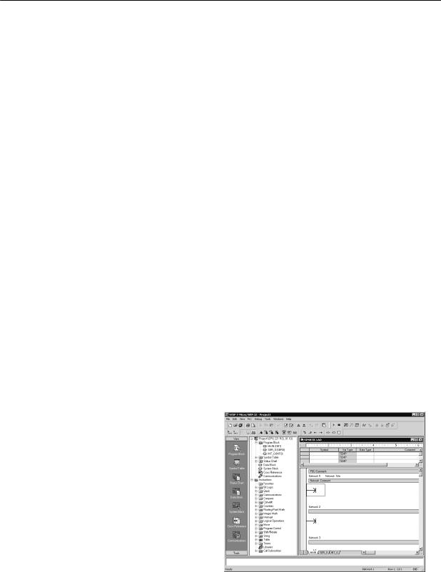
The STEP 7—Micro/WIN programming package provides a user-friendly environment to develop, edit, and monitor the logic needed to control your application. STEP 7—Micro/WIN provides three program editors for convenience and efficiency in developing the control program for your application. To help you find the information you need, STEP 7—Micro/WIN provides an extensive online help system and a documentation CD that contains an electronic version of this manual, application tips, and other useful information.
Computer Requirements
STEP 7—Micro/WIN runs on either a personal computer or a Siemens programming device, such as a PG 760. Your computer or programming device should meet the following minimum requirements:
—Operating system: Windows 95, Windows 98,
Windows 2000, Windows Me (Millennium Edition), Windows NT 4.0 (or later version),
Windows XP Professional
—At least 100M bytes of free hard disk space
—Mouse (recommended)
Figure 1-2 STEP 7—Micro/WIN
3
|
S7-200 Programmable Controller System Manual |
||||
|
Installing STEP 7-Micro/WIN |
||||
|
1 |
||||
|
Insert the STEP 7—Micro/WIN CD into the CD-ROM drive of your computer. The installation wizard starts |
||||
|
automatically and prompts you through the installation process. Refer to the Readme file for more |
||||
|
information about installing STEP 7—Micro/WIN. |
||||
|
Tip |
||||
|
To install STEP 7—Micro/WIN on a Windows NT, Windows 2000, or Windows XP Professional |
||||
|
operating system, you must log in with Administrator privileges. |
||||
Communications Options
Siemens provides two programming options for connecting your computer to your S7-200: a direct connection with a PPI Multi-Master cable, or a Communications Processor (CP) card with an MPI cable.
The PPI Multi-Master programming cable is the most common and economical method of connecting your computer to the S7-200. This cable connects the communications port of the S7-200 to the serial communications of your computer. The PPI Multi-Master programming cable can also be used to connect other communications devices to the S7-200.
Display Panels
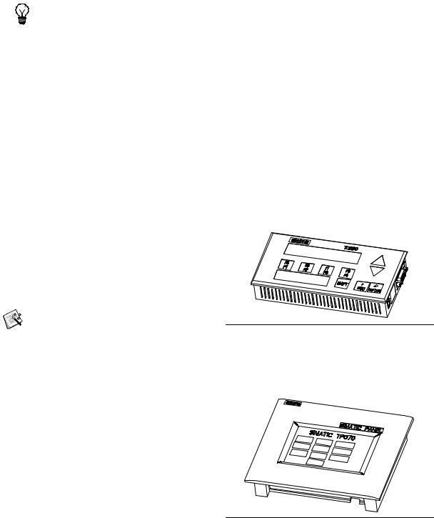
TD 200 Text Display Unit
The TD 200 is a 2-line, 20-character, text display device that can be connected to the S7-200. Using the TD 200 wizard, you can easily program your S7-200 to display text messages and other data pertaining to your application.
The TD 200 provides a low cost interface to your application by allowing you to view, monitor, and change the process variables pertaining to your application.
A separate manual describes the detailed functionality and specifications of the TD 200.
The TD 200 Configuration Wizard in
STEP 7—MicroWIN helps you configure TD 200 messages quickly and easily. To start the TD
|
TD 200 |
200 Wizard, select the Tools > TD 200 Wizard |
Figure 1-3 TD 200 Text Display Unit |
menu command.
TP070 Touch Panel Display
The TP070 is a touch panel display device that can be connected to the S7-200. This touch panel provides you with a means to customize your operator interface.
The TP070 can display custom graphics, slider bars, application variables, custom user buttons, and so forth, by means of a user-friendly touch panel.
The optional TP—Designer for TP070, Version 1.0 CD provides the TP Designer software, which is required for programming your TP070.
Figure 1-4 TP070 Touch Panel Unit
4

Getting Started
STEP 7—Micro/WIN makes it easy for you to program your S7-200. In just a few short steps using a simple example, you can learn how to connect, program, and run your S7-200.
All you need for this example is a PPI Multi-Master cable, an S7-200 CPU, and a programming device running the STEP 7—Micro/WIN programming software.
|
In This Chapter |
|
|
Connecting the S7-200 CPU . . . . . . . . . . . . . . . . . . . . . . . . . . . . . . . . . . . . . . . . . . . . . . . . . . . . . . . . . . . . |
6 |
|
Creating a Sample Program . . . . . . . . . . . . . . . . . . . . . . . . . . . . . . . . . . . . . . . . . . . . . . . . . . . . . . . . . . . . . |
9 |
|
Downloading the Sample Program . . . . . . . . . . . . . . . . . . . . . . . . . . . . . . . . . . . . . . . . . . . . . . . . . . . . . . . |
12 |
|
Placing the S7-200 in RUN Mode . . . . . . . . . . . . . . . . . . . . . . . . . . . . . . . . . . . . . . . . . . . . . . . . . . . . . . . . |
12 |
5
S7-200 Programmable Controller System Manual
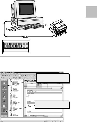
Connecting the S7-200 CPU
|
Connecting your S7-200 is easy. For this example, you only need to connect power to your S7-200 CPU |
||||
|
and then connect the communications cable between your programming device and the S7-200 CPU. |
||||
|
2 |
||||
|
Connecting Power to the S7-200 CPU |
||||
|
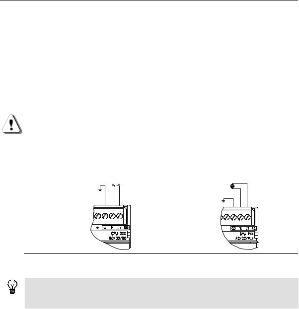
The first step is to connect the S7-200 to a power source. Figure 2-1 shows the wiring connections for |
||||
|
either a DC or an AC model of the S7-200 CPU. |
||||
|
Before you install or remove any electrical device, ensure that the power to that equipment has been |
||||
|
turned off. Always follow appropriate safety precautions and ensure that power to the S7-200 is disabled |
||||
|
before attempting to install or remove the S7-200. |
||||
|
Warning |
||||
|
Attempts to install or wire the S7-200 or related equipment with power applied could cause electric |
||||
|
shock or faulty operation of equipment. Failure to disable all power to the S7-200 and related |
||||
|
equipment during installation or removal procedures could result in death or serious injury to |
||||
|
personnel, and/or damage to equipment. |
||||
|
Always follow appropriate safety precautions and ensure that power to the S7-200 is disabled before |
||||
|
attempting to install or remove the S7-200 or related equipment. |
||||
|
24 VDC |
85 to 265 VAC |
DC Installation AC Installation
Figure 2-1 Connecting Power to the S7-200 CPU
Tip
Examples in this manual use the RS-232/PPI Multi-Master cable. The RS-232/PPI Multi-Master cable replaces the previous PC/PPI cable. A USB/PPI Multi-Master cable is also available. Refer to Appendix E for order numbers.
6
|
Getting Started |
Chapter 2 |
Connecting the RS-232/PPI Multi-Master Cable
Figure 2-2 shows an RS-232/PPI Multi-Master cable connecting the S7-200 to the programming device. To connect the cable:
1.Connect the RS-232 connector (marked “PC”) of the RS-232/PPI Multi-Master cable to the communications port of the programming device. (For this example, connect to COM 1.)
2.Connect the RS-485 connector (marked “PPI”) of the RS-232/PPI Multi-Master cable to Port 0 or Port 1 of the S7-200.
3.Ensure that the DIP switches of the RS-232/PPI Multi-Master cable are set as shown in Figure 2-2.
Programming
Device
2
S7-200
RS-232/PPI
Multi-Master Cable
|
↑1 — On |
|||||||
|
↓0 — Off |
|||||||
|
1 |
2 |
3 |
4 |
5 |
6 |
7 |
8 |
Figure 2-2 Connecting the RS-232/PPI Multi-Master Cable
Starting STEP 7-Micro/WIN
Click on the STEP 7—Micro/WIN icon to open a new project. Figure 2-3 shows a new project.
Notice the navigation bar. You can use the icons on the navigation bar to open elements of the STEP 7—Micro/WIN project.
Click on the Communications icon in the navigation bar to display the Communications dialog box. You use this dialog box to set up the communications for STEP 7—Micro/WIN.
Navigation bar
Communications icon
Figure 2-3 New STEP 7—Micro/WIN Project
7
S7-200 Programmable Controller System Manual
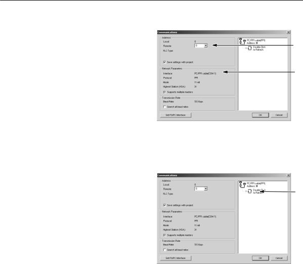
Verifying the Communications Parameters for STEP 7-Micro/WIN
|
The example project uses the default settings |
|||
|
for STEP 7—Micro/WIN and the RS-232/PPI |
|||
|
2 |
Multi-Master cable. To verify these settings: |
||
|
1. |
Verify that the address of the PC/PPI |
||
|
cable in the Communications dialog box |
|||
|
is set to 0. |
|||
|
2. |
Verify that the interface for the network |
||
|
parameter is set for PC/PPI |
|||
|
cable(COM1). |
|||
|
3. |
Verify that the transmission rate is set to |
||
|
9.6 kbps. |
If you need to change your communications parameter settings, see Chapter 7.
1.
2.
 3.
3.
Figure 2-4 Verifying the Communications Parameters
Establishing Communications with the S7-200
Use the Communications dialog box to connect with your S7-200 CPU:
1. Double-click the refresh icon in the
|
Communications dialog box. |
||
|
STEP 7—Micro/WIN searches for the |
1. |
|
|
S7-200 station and displays a CPU icon |
||
|
for the connected S7-200 station. |
||
|
2. Select the S7-200 and click OK. |
||
|
If STEP 7—Micro/WIN does not find your |
||
|
S7-200 CPU, check the settings for the |
||
|
communications parameters and repeat these |
||
|
steps. |
||
|
After you have established communications |
||
|
with the S7-200, you are ready to create and |
Figure 2-5 Establishing Communications to the S7-200 |
|
|
download the example program. |
||
8

Getting Started Chapter 2
Creating a Sample Program
|
Entering this example of a control program will help you understand how easy it is to use |
||
|
STEP 7—Micro/WIN. This program uses six instructions in three networks to create a very simple, |
||
|
2 |
||
|
self-starting timer that resets itself. |
||
|
For this example, you use the Ladder (LAD) editor to enter the instructions for the program. The |
||
|
following example shows the complete program in both LAD and Statement List (STL). The network |
||
|
comments in the STL program explain the logic for each network. The timing diagram shows the |
||
|
operation of the program. |
Example: Sample Program for getting started with STEP 7-Micro/WIN
Network 1 //10 ms timer T33 times out after (100 x 10 ms = 1 s) //M0.0 pulse is too fast to monitor with Status view.
Network 2 //Comparison becomes true at a rate that is visible with //Status view. Turn on Q0.0 after (40 x 10 ms = 0.4 s), //for a 40% OFF/60% ON waveform.
LDW>= T33, +40
=Q0.0
Network 3 //T33 (bit) pulse too fast to monitor with Status view. //Reset the timer through M0.0 after the
//(100 x 10 ms = 1 s) period.
LD T33
=M0.0
|
Timing Diagram |
current = 100 |
current = 40
T33 (bit)
M0.0
Q0.0
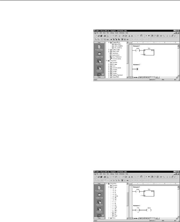
Opening the Program Editor
Click on the Program Block icon to open the program editor. See Figure 2-6.
Notice the instruction tree and the program editor. You use the instruction tree to insert the LAD instructions into the networks of the program editor by dragging and dropping the instructions from the instruction tree to the networks.
The toolbar icons provide shortcuts to the menu commands.
After you enter and save the program, you can download the program to the S7-200.
Program editor
Instruction tree
Figure 2-6 STEP 7—Micro/WIN Window
9
S7-200 Programmable Controller System Manual
Entering Network 1: Starting the Timer
When M0.0 is off (0), this contact turns on and provides power flow to start the timer. To enter the contact for M0.0:
|
2 |
1. |
Either double-click the Bit Logic icon or |
|
click on the plus sign (+) to display the bit |
||
|
logic instructions. |
||
|
2. |
Select the Normally Closed contact. |
|
|
3. |
Hold down the left mouse button and |
|
|
drag the contact onto the first network. |
||
|
4. |
Click on the “???” above the contact and |
|
|
enter the following address: M0.0 |
||
|
5. |
Press the Return key to enter the |
|
|
address for the contact. |
|
To enter the timer instruction for T33: |
Figure 2-7 Network 1 |
1.Double-click the Timers icon to display the timer instructions.
2.Select the TON (On-Delay Timer).
3.Hold down the left mouse button and drag the timer onto the first network.
4.Click on the “???” above the timer box and enter the following timer number: T33
5.Press the Return key to enter the timer number and to move the focus to the preset time (PT) parameter.
6.Enter the following value for the preset time: 100
7.Press the Return key to enter the value.
Entering Network 2: Turning the Output On
When the timer value for T33 is greater than or equal to 40 (40 times 10 milliseconds, or 0.4 seconds), the contact provides power flow to turn on output Q0.0 of the S7-200. To enter the Compare instruction:
1.Double-click the Compare icon to display the compare instructions. Select the >=I instruction (Greater-Than-Or-Equal-To-Integer ).
2.Hold down the left mouse button and drag the compare instruction onto the second network.
3.Click on the “???” above the contact and enter the address for the timer value: T33
4.Press the Return key to enter the timer number and to move the focus to the other value to be compared with the timer value.
5.Enter the following value to be compared with the timer value: 40
|
6. Press the Return key to enter the value. |
Figure 2-8 Network 2 |
To enter the instruction for turning on output Q0.0:
1.Double-click the Bit Logic icon to display the bit logic instructions and select the output coil.
2.Hold down the left mouse button and drag the coil onto the second network.
3.Click on the “???” above the coil and enter the following address: Q0.0
4.Press the Return key to enter the address for the coil.
10
Getting Started Chapter 2
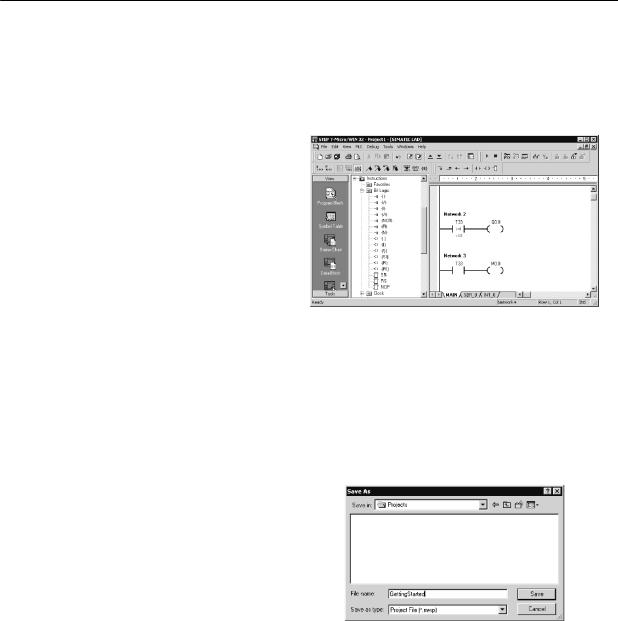
Entering Network 3: Resetting the Timer
|
When the timer reaches the preset value (100) and turns the timer bit on, the contact for T33 turns on. |
||
|
Power flow from this contact turns on the M0.0 memory location. Because the timer is enabled by a |
||
|
Normally Closed contact for M0.0, changing the state of M0.0 from off (0) to on (1) resets the timer. |
2 |
|
|
To enter the contact for the timer bit of T33: |
||
|
1. |
Select the Normally Open contact from |
|
|
the bit logic instructions. |
||
|
2. |
Hold down the left mouse button and |
|
|
drag the contact onto the third network. |
||
|
3. |
Click on the “???” above the contact and |
|
|
enter the address of the timer bit: T33 |
||
|
4. |
Press the Return key to enter the |
|
|
address for the contact. |
To enter the coil for turning on M0.0:
1. Select the output coil from the bit logic
instructions. Figure 2-9 Network 3
2.Hold down the left mouse button and drag the output coil onto the third network.
3.Double-click the “???” above the coil and enter the following address: M0.0
4.Press the Return key to enter the address for the coil.
Saving the Sample Project
After entering the three networks of instructions, you have finished entering the program. When you save the program, you create a project that includes the S7-200 CPU type and other parameters. To save the project:
1.Select the File > Save As menu command from the menu bar.
2.Enter a name for the project in the Save As dialog box.
3.Click OK to save the project.
After saving the project, you can download the program to the S7-200.
Figure 2-10 Saving the Example Program
11
|
S7-200 Programmable Controller System Manual |
||||
Downloading the Sample Program |
||||
|
Tip |
||||
|
2 |
Each STEP 7—Micro/WIN project is associated with a CPU type (CPU 221, CPU 222, CPU 224, |
|||
|
CPU 226, or CPU 226XM). If the project type does not match the CPU to which you are connected, |
||||
|
STEP 7—Micro/WIN indicates a mismatch and prompts you to take an action. If this occurs, choose |
||||
|
“Continue Download” for this example. |
||||
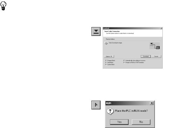
1.Click the Download icon on the toolbar or select the File > Download menu command to download the program. See Figure 2-11.
2.Click OK to download the elements of the program to the S7-200.
If your S7-200 is in RUN mode, a dialog box prompts you to place the S7-200 in STOP mode. Click Yes to place the S7-200 into STOP
mode. Figure 2-11 Downloading the Program
Placing the S7-200 in RUN Mode
For STEP 7—Micro/WIN to place the S7-200 CPU in RUN mode, the mode switch of the S7-200 must be set to TERM or RUN. When you place the S7-200 in RUN mode, the S7-200 executes the program:
1.Click the RUN icon on the toolbar or select the PLC > RUN menu command.
2.Click OK to change the operating mode of the S7-200.
When the S7-200 goes to RUN mode, the
output LED for Q0.0 turns on and off as the
S7-200 executes the program. Figure 2-12 Placing the S7-200 in RUN Mode
Congratulations! You have just completed your first S7-200 program.
You can monitor the program by selecting the Debug > Program Status menu command.
STEP 7—Micro/WIN displays the values for the instructions. To stop the program, place the S7-200 in
STOP mode by clicking the STOP icon or by selecting the PLC > STOP menu command.
12

Installing the S7-200
The S7-200 equipment is designed to be easy to install. You can use the mounting holes to attach the modules to a panel, or you can use the built-in clips to mount the modules onto a standard (DIN) rail. The small size of the S7-200 allows you to make efficient use of space.
This chapter provides guidelines for installing and wiring your S7-200 system.
|
In This Chapter |
|
|
Guidelines for Installing S7-200 Devices . . . . . . . . . . . . . . . . . . . . . . . . . . . . . . . . . . . . . . . . . . . . . . . . . . |
14 |
|
Installing and Removing the S7-200 Modules . . . . . . . . . . . . . . . . . . . . . . . . . . . . . . . . . . . . . . . . . . . . . . |
15 |
|
Guidelines for Grounding and Wiring . . . . . . . . . . . . . . . . . . . . . . . . . . . . . . . . . . . . . . . . . . . . . . . . . . . . . |
18 |
13
S7-200 Programmable Controller System Manual
Guidelines for Installing S7-200 Devices
You can install an S7-200 either on a panel or on a standard rail, and you can orient the S7-200 either horizontally or vertically.
Separate the S7-200 Devices from Heat, High Voltage, and Electrical Noise
|
3 |
As a general rule for laying out the devices of your system, always separate the devices that generate |
|
|
high voltage and high electrical noise from the low-voltage, logic-type devices such as the S7-200. |
||
When configuring the layout of the S7-200 inside your panel, consider the heat-generating devices and locate the electronic-type devices in the cooler areas of your cabinet. Operating any electronic device in a high-temperature environment will reduce the time to failure.
Consider also the routing of the wiring for the devices in the panel. Avoid placing low voltage signal wires and communications cables in the same tray with AC power wiring and high-energy, rapidly-switched DC wiring.
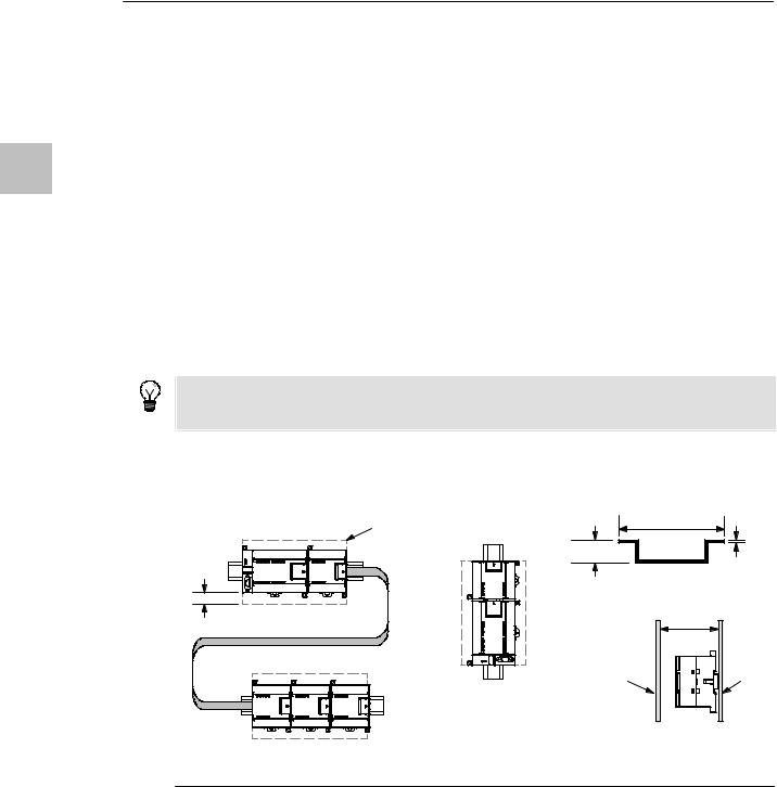
Provide Adequate Clearance for Cooling and Wiring
S7-200 devices are designed for natural convection cooling. For proper cooling, you must provide a clearance of at least 25 mm above and below the devices. Also, allow at least 75 mm of depth.
Tip
For vertical mounting, the maximum allowable ambient temperature is reduced by 10° C. Mount the S7-200 CPU below any expansion modules.
When planning your layout for the S7-200 system, allow enough clearance for the wiring and communications cable connections. For additional flexibility in configuring the layout of the S7-200 system, use the I/O expansion cable.
|
Clearance |
35 mm |
|
1 mm |
|
|
7.5 mm |
DIN Rail
25 mm
|
75 mm |
|
|
Front of the |
Mounting |
|
enclosure |
surface |
|
Vertical Panel Mounting |
Side View
Horizontal DIN Rail Mounting with Optional
Expansion Cable (limit one per system)
Figure 3-1 Mounting Methods, Orientation, and Clearance
14

|
Installing the S7-200 |
Chapter 3 |
Power Budget
All S7-200 CPUs have an internal power supply that provides power for the CPU, the expansion modules, and other 24 VDC user power requirements.
The S7-200 CPU provides the 5 VDC logic power needed for any expansion in your system. Pay careful attention to your system configuration to ensure that your CPU can supply the 5V power required by your selected expansion modules. If your configuration requires more power than the CPU can supply,
you must remove a module or select a CPU with more power capability. Refer to Appendix A for 3 information about the 5 VDC logic budget supplied by your S7-200 CPU and the 5 VDC power
requirements of the expansion modules. Use Appendix B as a guide for determining how much power (or current) the CPU can provide for your configuration.
All S7-200 CPUs also provide a 24 VDC sensor supply that can supply 24 VDC for input points, for relay coil power on the expansion modules, or for other requirements. If your power requirements exceed the budget of the sensor supply, then you must add an external 24 VDC power supply to your system. Refer to Appendix A for the 24 VDC sensor supply power budget for your particular S7-200 CPU.
If you require an external 24 VDC power supply, ensure that the power supply is not connected in parallel with the sensor supply of the S7-200 CPU. For improved electrical noise protection, it is recommended that the commons (M) of the different power supplies be connected.
Warning
Connecting an external 24 VDC power supply in parallel with the S7-200 24 VDC sensor supply can result in a conflict between the two supplies as each seeks to establish its own preferred output voltage level.
The result of this conflict can be shortened lifetime or immediate failure of one or both power supplies, with consequent unpredictable operation of the PLC system. Unpredictable operation could result in death or serious injury to personnel, and/or damage to equipment.
The S7-200 DC sensor supply and any external power supply should provide power to different points.
Installing and Removing the S7-200 Modules
The S7-200 can be easily installed on a standard DIN rail or on a panel.
Prerequisites
Before you install or remove any electrical device, ensure that the power to that equipment has been turned off. Also, ensure that the power to any related equipment has been turned off.
Warning
Attempts to install or remove S7-200 or related equipment with the power applied could cause electric shock or faulty operation of equipment.
Failure to disable all power to the S7-200 and related equipment during installation or removal procedures could result in death or serious injury to personnel, and/or damage to equipment.
Always follow appropriate safety precautions and ensure that power to the S7-200 is disabled before attempting to install or remove S7-200 CPUs or related equipment.
Always ensure that whenever you replace or install an S7-200 device you use the correct module or equivalent device.
Warning
If you install an incorrect module, the program in the S7-200 could function unpredictably.
Failure to replace an S7-200 device with the same model, orientation, or order could result in death or serious injury to personnel, and/or damage to equipment.
Replace an S7-200 device with the same model, and be sure to orient and position it correctly.
15
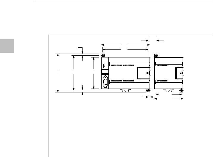
S7-200 Programmable Controller System Manual
Mounting Dimensions
The S7-200 CPUs and expansion modules include mounting holes to facilitate installation on panels. Refer to Table 3-1 for the mounting dimensions.
Table 3-1 Mounting Dimensions
|
3 |
9.5 mm* |
* Minimum spacing |
|
|
A |
between modules when |
||
|
4 mm |
hard-mounted |
||
|
B |
|||
|
Mounting holes |
|||
|
(M4 or No. |
|||
|
96 mm |
88 mm |
80 mm |

|
B |
||||||||||||||||
|
4 mm |
4 mm |
|||||||||||||||
|
A |
||||||||||||||||
|
S7-200 Module |
Width A |
Width B |
||||||||||||||
|
CPU 221 and CPU 222 |
90 mm |
82 mm |
||||||||||||||
|
CPU 224 |
120.5 mm |
112.5 mm |
||||||||||||||
|
CPU 226 and CPU 226XM |
196 mm |
188 mm |
||||||||||||||
|
Expansion modules: |
4- and 8-point DC and Relay I/O (8I, 4Q, 8Q, 4I/4Q) |
46 mm |
38 mm |
|||||||||||||
|
and Analog Out (2 AQ) |
||||||||||||||||
|
Expansion modules: |
16-point digital I/O (16I, 8I/8Q), Analog I/O (4AI, 4AI/1AQ), |
71.2 mm |
63.2 mm |
|||||||||||||
|
RTD, Thermocouple, PROFIBUS, Ethernet, Internet, |
||||||||||||||||
|
AS-Interface, |
||||||||||||||||
|
8-point AC (8I and 8Q), Position, and Modem |
||||||||||||||||
|
Expansion modules: |
32-point digital I/O (16I/16Q) |
137.3 mm |
129.3 mm |
|||||||||||||
Installing a CPU or Expansion Module
Installing the S7-200 is easy! Just follow these steps.
Panel Mounting
1.Locate, drill, and tap the mounting holes (M4 or American Standard number 8), using the dimensions in Table 3-1.
2.Secure the module(s) to the panel, using the appropriate screws.
3.If you are using an expansion module, connect the expansion module ribbon cable into the expansion port connector under the access door.
DIN Rail Mounting
1.Secure the rail to the mounting panel every 75 mm.
2.Snap open the DIN clip (located on the bottom of the module) and hook the back of the module onto the DIN rail.
3.If you are using an expansion module, connect the expansion module ribbon cable into the expansion port connector under the access door.
4.Rotate the module down to the DIN rail and snap the clip closed. Carefully check that the clip has fastened the module securely onto the rail. To avoid damage to the module, press on the tab of the mounting hole instead of pressing directly on the front of the module.
16
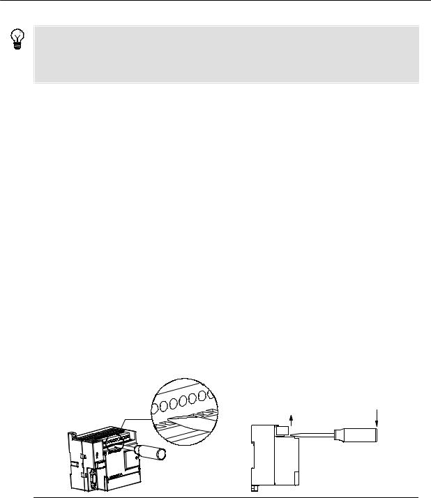
Installing the S7-200 Chapter 3
Tip
Using DIN rail stops could be helpful if your S7-200 is in an environment with high vibration potential or if the S7-200 has been installed vertically.
If your system is in a high-vibration environment, then panel-mounting the S7-200 will provide a greater level of vibration protection.
|
Removing a CPU or Expansion Module |
3 |
|
|
To remove an S7-200 CPU or expansion module, follow these steps: |
||
1.Remove power from the S7-200.
2.Disconnect all the wiring and cabling that is attached to the module. Most S7-200 CPU and expansion modules have removable connectors to make this job easier.
3.If you have expansion modules connected to the unit that you are removing, open the access cover door and disconnect the expansion module ribbon cable from the adjacent modules.
4.Unscrew the mounting screws or snap open the DIN clip.
5.Remove the module.
Removing and Reinstalling the Terminal Block Connector
Most S7-200 modules have removable connectors to make installing and replacing the module easy. Refer to Appendix A to determine whether your S7-200 module has removable connectors. You can order an optional fan-out connector for modules that do not have removable connectors. See Appendix E for order numbers.
To Remove the Connector
1.Open the connector door to gain access to the connector.
2.Insert a small screwdriver in the notch in the middle of the connector.
3.Remove the terminal connector by prying the screwdriver away from the S7-200 housing. See Figure 3-2.
Figure 3-2 Removing the Connector
To Reinstall the Connector
1.Open the connector door.
2.Align the connector with the pins on the unit and align the wiring edge of the connector inside the rim of the connector base.
3.Press down firmly to rotate the connector until it snaps into place. Check carefully to ensure that the connector is properly aligned and fully engaged.
17

S7-200 Programmable Controller System Manual
Guidelines for Grounding and Wiring
Proper grounding and wiring of all electrical equipment is important to help ensure the optimum operation of your system and to provide additional electrical noise protection for your application and the S7-200.
|
Prerequisites |
|||
|
3 |
|||
|
Before you ground or install wiring to any electrical device, ensure that the power to that equipment has |
|||
|
been turned off. Also, ensure that the power to any related equipment has been turned off. |
|||
|
Ensure that you follow all applicable electrical codes when wiring the S7-200 and related equipment. |
|||
|
Install and operate all equipment according to all applicable national and local standards. Contact your |
|||
|
local authorities to determine which codes and standards apply to your specific case. |
|||
|
Warning |
|||
|
Attempts to install or wire the S7-200 or related equipment with power applied could cause electric |
|||
|
shock or faulty operation of equipment. Failure to disable all power to the S7-200 and related |
|||
|
equipment during installation or removal procedures could result in death or serious injury to |
|||
|
personnel, and/or damage to equipment. |
|||
|
Always follow appropriate safety precautions and ensure that power to the S7-200 is disabled before |
|||
|
attempting to install or remove the S7-200 or related equipment. |
|||
|
Always take safety into consideration as you design the grounding and wiring of your S7-200 system. |
|||
|
Electronic control devices, such as the S7-200, can fail and can cause unexpected operation of the |
|||
|
equipment that is being controlled or monitored. For this reason, you should implement safeguards that |
|||
|
are independent of the S7-200 to protect against possible personal injury or equipment damage. |
|||
|
Warning |
|||
|
Control devices can fail in an unsafe condition, resulting in unexpected operation of controlled |
|||
|
equipment. Such unexpected operations could result in death or serious injury to personnel, and/or |
|||
|
damage to equipment. |
|||
|
Use an emergency stop function, electromechanical overrides, or other redundant safeguards that are |
|||
|
independent of the S7-200. |
|||
|
Guidelines for Isolation |
|||
|
S7-200 AC power supply boundaries and I/O boundaries to AC circuits are rated 1500 VAC. These |
|||
|
isolation boundaries have been examined and approved as providing safe separation between AC line |
|||
|
and low voltage circuits. |
|||
|
All low voltage circuits connected to an S7-200, such as 24V power, must be supplied from an approved |
|||
|
source that provides safe isolation from AC line and other high voltages. Such sources include double |
|||
|
insulation as defined in international electrical safety standards and have outputs that are rated as SELV, |
|||
|
PELV, Class 2, or Limited Voltage according to various standards. |
|||
|
Warning |
|||
|
Use of non-isolated or single insulation supplies to supply low voltage circuits from an AC line can |
|||
|
result in hazardous voltages appearing on circuits that are expected to be touch safe, such as |
|||
|
communications circuits and low voltage sensor wiring. |
|||
|
Such unexpected high voltages could result in death or serious injury to personnel, and/or damage to |
|||
|
equipment. |
|||
|
Only use high voltage to low voltage power converters that are approved as sources of touch safe, |
|||
|
limited voltage circuits. |
|||
18
![]()
Installing the S7-200 Chapter 3
Guidelines for Grounding the S7-200
The best way to ground your application is to ensure that all the common and ground connections of your S7-200 and related equipment are grounded to a single point. This single point should be connected directly to the earth ground for your system.
For improved electrical noise protection, it is recommended that all DC common returns be connected to the same single-point earth ground. Connect the 24 VDC sensor supply common (M) to earth ground.
|
All ground wires should be as short as possible and should use a large wire size, such as 2 mm2 |
3 |
|
|
(14 AWG). |
||
|
When locating grounds, remember to consider safety grounding requirements and the proper operation |
||
|
of protective interrupting devices. |
||
|
Guidelines for Wiring the S7-200 |
||
|
When designing the wiring for your S7-200, provide a single disconnect switch that simultaneously |
||
|
removes power from the S7-200 CPU power supply, from all input circuits, and from all output circuits. |
||
|
Provide overcurrent protection, such as a fuse or circuit breaker, to limit fault currents on supply wiring. |
||
|
You might want to provide additional protection by placing a fuse or other current limit in each output |
||
|
circuit. |
||
|
Install appropriate surge suppression devices for any wiring that could be subject to lightning surges. |
||
|
Avoid placing low-voltage signal wires and communications cables in the same wire tray with AC wires |
||
|
and high-energy, rapidly switched DC wires. Always route wires in pairs, with the neutral or common wire |
||
|
paired with the hot or signal-carrying wire. |
||
|
Use the shortest wire possible and ensure that the wire is sized properly to carry the required current. |
||
|
The connector accepts wire sizes from 2 mm2 to 0.3 mm2 (14 AWG to 22 AWG). Use shielded wires for |
||
|
optimum protection against electrical noise. Typically, grounding the shield at the S7-200 gives the best |
||
|
results. |
||
|
When wiring input circuits that are powered by an external power supply, include an overcurrent |
||
|
protection device in that circuit. External protection is not necessary for circuits that are powered by the |
||
|
24 VDC sensor supply from the S7-200 because the sensor supply is already current-limited. |
||
|
Most S7-200 modules have removable connectors for user wiring. (Refer to Appendix A to determine if |
||
|
your module has removable connectors.) To prevent loose connections, ensure that the connector is |
||
|
seated securely and that the wire is installed securely into the connector. To avoid damaging the |
||
|
connector, be careful that you do not over-tighten the screws. The maximum torque for the connector |
||
|
screw is 0.56 N-m (5 inch-pounds). |
||
|
To help prevent unwanted current flows in your installation, the S7-200 provides isolation boundaries at |
||
|
certain points. When you plan the wiring for your system, you should consider these isolation |
||
|
boundaries. Refer to Appendix A for the amount of isolation provided and the location of the isolation |
||
|
boundaries. Isolation boundaries rated less than 1500 VAC must not be depended on as safety |
||
|
boundaries. |
||
|
Tip |
||
|
For a communications network, the maximum length of the communications cable is 50 m without |
||
|
using a repeater. The communications port on the S7-200 is non-isolated. Refer to Chapter 7 for more |
||
|
information. |
||
19

S7-200 Programmable Controller System Manual
Guidelines for Suppression Circuits
You should equip inductive loads with suppression circuits to limit voltage rise when the control output turns off. Suppression circuits protect your outputs from premature failure due to high inductive switching currents. In addition, suppression circuits limit the electrical noise generated when switching inductive loads.
|
3 |
Tip |
|
The effectiveness of a given suppression circuit depends on the application, and you must verify it for |
|
|
your particular use. Always ensure that all components used in your suppression circuit are rated for |
|
|
use in the application. |
DC Outputs and Relays That Control DC Loads
The DC outputs have internal protection that is adequate for most applications. Since the relays can be used for either a DC or an AC load, internal protection is not provided.
Figure 3-3 shows a sample suppression circuit for a DC load. In most applications, the addition of a diode (A) across the inductive load is suitable, but if your application requires faster turn-off times, then the addition of a Zener diode (B) is recommended. Be sure to size your Zener diode properly for the amount of current in your output circuit.
A B (optional)
A — I1N4001 diode or equivalent
B — 8.2 V Zener for DC Outputs Output 36 V Zener for Relay Outputs Point
DC Inductive Load
Figure 3-3 Suppression Circuit for a DC Load
AC Outputs and Relays That Control AC Loads
The AC outputs have internal protection that is adequate for most applications. Since the relays can be used for either a DC or an AC load, internal protection is not provided.
Figure 3-4 shows a sample suppression circuit for an AC load. When you use a relay or AC output to switch 115 V/230 VAC loads, place resistor/capacitor networks across the AC load as shown in this figure. You can also use a metal oxide varistor (MOV) to limit peak voltage. Ensure that the working voltage of the MOV is at least 20% greater than the nominal line voltage.
Notice
.1 µ F 100 to 120 Ω
MOV
Output
Point
AC Inductive Load
Figure 3-4 Suppression Circuit for an AC Load
When relay expansion modules are used to switch 230 VAC inductive loads, the external resistor/capacitor noise suppression circuit must be placed across the AC load as shown in Figure 3-4.
20

PLC Concepts
The basic function of the S7-200 is to monitor field inputs and, based on your control logic, turn on or off field output devices. This chapter explains the concepts used to execute your program, the various types of memory used, and how that memory is retained.
|
In This Chapter |
|
|
Understanding How the S7-200 Executes Your Control Logic . . . . . . . . . . . . . . . . . . . . . . . . . . . . . . . . |
22 |
|
Accessing the Data of the S7-200 . . . . . . . . . . . . . . . . . . . . . . . . . . . . . . . . . . . . . . . . . . . . . . . . . . . . . . . . |
24 |
|
Understanding How the S7-200 Saves and Restores Data . . . . . . . . . . . . . . . . . . . . . . . . . . . . . . . . . . . |
34 |
|
Storing Your Program on a Memory Cartridge . . . . . . . . . . . . . . . . . . . . . . . . . . . . . . . . . . . . . . . . . . . . . . |
36 |
|
Selecting the Operating Mode for the S7-200 CPU . . . . . . . . . . . . . . . . . . . . . . . . . . . . . . . . . . . . . . . . . . |
37 |
|
Using Your Program to Save V Memory to the EEPROM . . . . . . . . . . . . . . . . . . . . . . . . . . . . . . . . . . . . |
38 |
|
Features of the S7-200 . . . . . . . . . . . . . . . . . . . . . . . . . . . . . . . . . . . . . . . . . . . . . . . . . . . . . . . . . . . . . . . . . |
39 |
21

S7-200 Programmable Controller System Manual
Understanding How the S7-200 Executes Your Control Logic
The S7-200 continuously cycles through the control logic in your program, reading and writing data.
The S7-200 Relates Your Program to the Physical Inputs and Outputs
|
The basic operation of the S7-200 is very simple: |
||
|
— The S7-200 reads the status of the inputs. |
||
|
— The program that is stored in the S7-200 uses these |
||
|
inputs to evaluate the control logic. As the program |
||
|
4 |
||
|
runs, the S7-200 updates the data. |
||
|
— The S7-200 writes the data to the outputs. |
||
|
Figure 4-1 shows a simple diagram of how an electrical |
||
|
relay diagram relates to the S7-200. In this example, the |
||
|
state of the switch for starting the motor is combined with |
||
|
the states of other inputs. The calculations of these states |
||
|
then determine the state for the output that goes to the |
||
|
actuator which starts the motor. |
|
Start_PB |
E_Stop |
M_Starter |
|
M_Starter |
Motor |
|
Output
Motor Starter
Input
Start / Stop Switch
Figure 4-1 Controlling Inputs and Outputs
The S7-200 Executes Its Tasks in a Scan Cycle
The S7-200 executes a series of tasks repetitively. This cyclical execution of tasks is called the scan cycle. As shown in Figure 4-2, the S7-200 performs most or all of the following tasks during a scan cycle:
—Reading the inputs: The S7-200 copies the state of
|
the physical inputs to the process-image input |
Writes to the outputs |
|
|
register. |
||
|
— Executing the control logic in the program: The |
||
|
S7-200 executes the instructions of the program and |
Perform the CPU Diagnostics |
|
|
stores the values in the various memory areas. |
Process any |
|
|
— Processing any communications requests: The |
Communications Requests |
|
|
S7-200 performs any tasks required for |
||
|
communications. |
Execute the Program |
Scan Cycle |
|
— Executing the CPU self-test diagnostics: The S7-200 |
||
|
ensures that the firmware, the program memory, and |
|
any expansion modules are working properly. |
Reads the inputs |
—Writing to the outputs: The values stored in the
|
process-image output register are written to the |
Figure 4-2 S7-200 Scan Cycle |
|
|
physical outputs. |
||
The execution of the scan cycle is dependent upon whether the S7-200 is in STOP mode or in RUN mode. In RUN mode, your program is executed; in STOP mode, your program is not executed.
22

PLC Concepts Chapter 4
Reading the Inputs
Digital inputs: Each scan cycle begins by reading the current value of the digital inputs and then writing these values to the process-image input register.
Analog inputs: The S7-200 does not update analog inputs as part of the normal scan cycle unless filtering of analog inputs is enabled. An analog filter is provided to allow you to have a more stable signal. You can enable the analog filter for each analog input point.
When analog input filtering is enabled for an analog input, the S7-200 updates that analog input once per scan cycle, performs the filtering function, and stores the filtered value internally. The filtered value is then supplied each time your program accesses the analog input.
|
When analog filtering is not enabled, the S7-200 reads the value of the analog input from the physical |
4 |
|
|
module each time your program accesses the analog input. |
||
|
Tip |
||
|
Analog input filtering is provided to allow you to have a more stable analog value. Use the analog input |
||
|
filter for applications where the input signal varies slowly with time. If the signal is a high-speed signal, |
||
|
then you should not enable the analog filter. |
||
|
Do not use the analog filter with modules that pass digital information or alarm indications in the |
||
|
analog words. Always disable analog filtering for RTD, Thermocouple, and AS-Interface Master |
||
|
modules. |
||
|
Executing the Program |
||
|
During the execution phase of the scan cycle, the S7-200 executes your program, starting with the first |
||
|
instruction and proceeding to the end instruction. The immediate I/O instructions give you immediate |
||
|
access to inputs and outputs during the execution of either the program or an interrupt routine. |
||
|
If you use interrupts in your program, the interrupt routines that are associated with the interrupt events |
||
|
are stored as part of the program. The interrupt routines are not executed as part of the normal scan |
||
|
cycle, but are executed when the interrupt event occurs (which could be at any point in the scan cycle). |
||
|
Processing Any Communications Requests |
||
|
During the message-processing phase of the scan cycle, the S7-200 processes any messages that |
||
|
were received from the communications port or intelligent I/O modules. |
||
|
Executing the CPU Self-test Diagnostics |
||
|
During this phase of the scan cycle, the S7-200 checks for proper operation of the CPU, for memory |
||
|
areas, and for the status of any expansion modules. |
||
|
Writing to the Digital Outputs |
||
|
At the end of every scan cycle, the S7-200 writes the values stored in the process-image output register |
||
|
to the digital outputs. (Analog outputs are updated immediately, independently from the scan cycle.) |
23

S7-200 Programmable Controller System Manual
Accessing the Data of the S7-200
The S7-200 stores information in different memory locations that have unique addresses. You can explicitly identify the memory address that you want to access. This allows your program to have direct access to the information. Table 4-1 shows the range of integer values that can be represented by the different sizes of data.
|
Table 4-1 |
Decimal and Hexadecimal Ranges for the Different Sizes of Data |
||||||
|
Representation |
Byte (B) |
Word (W) |
Double Word (D) |
||||
|
Unsigned Integer |
0 to 255 |
0 to 65,535 |
0 to 4,294,967,295 |
||||
|
4 |
|||||||
|
0 to FF |
0 to FFFF |
0 to FFFF FFFF |
|||||
|
Signed Integer |
—128 to +127 |
—32,768 to +32,767 |
—2,147,483,648 to +2,147,483,647 |
||||
|
80 to 7F |
8000 to 7FFF |
8000 0000 to 7FFF FFFF |
|||||
|
Real |
Not applicable |
Not applicable |
+1.175495E—38 to +3.402823E+38 (positive) |
||||
|
IEEE 32-bit Floating Point |
—1.175495E—38 to —3.402823E+38 (negative) |
||||||
To access a bit in a memory area, you specify the address, which includes the memory area identifier, the byte address, and the bit number. Figure 4-3 shows an example of accessing a bit (which is also called “byte.bit” addressing). In this example, the memory area and byte address (I = input, and 3 = byte 3) are followed by a period (“.”) to separate the bit address (bit 4).
|
I 3 . 4 |
Process-image Input (I) Memory Area |
||||||||||||||||
|
Bit of byte, or bit number: |
|||||||||||||||||
|
7 |
6 |
5 |
4 |
3 |
2 |
1 |
0 |
||||||||||
|
bit 4 of 8 (0 to 7) |
|||||||||||||||||
|
Period separates the |
Byte 0 |
||||||||||||||||
|
byte address from the bit |
Byte 1 |
||||||||||||||||
|
number |
Byte 2 |
||||||||||||||||
|
Byte address: byte 3 (the |
Byte 3 |
||||||||||||||||
|
Byte 4 |
|||||||||||||||||
|
fourth byte) |
|||||||||||||||||
|
Memory area identifier |
Byte 5 |
||||||||||||||||
|
Figure 4-3 |
Byte.Bit Addressing |
You can access data in most memory areas (V, I, Q, M, S, L, and SM) as bytes, words, or double words by using the byte-address format. To access a byte, word, or double word of data in the memory, you must specify the address in a way similar to specifying the address for a bit. This includes an area identifier, data size designation, and the starting byte address of the byte, word, or double-word value, as shown in Figure 4-4.
Data in other memory areas (such as T, C, HC, and the accumulators) are accessed by using an address format that includes an area identifier and a device number.
24
|
PLC Concepts |
Chapter 4 |
||||||||||||||||||||||||||||||
|
V |
B 100 |
V |
W 100 |
V |
D 100 |
||||||||||||||||||||||||||
|
Byte address |
Byte address |
Byte address |
|||||||||||||||||||||||||||||
|
Access to a byte size |
Access to a word size |
Access to a double word size |
|||||||||||||||||||||||||||||
|
Area identifier |
Area identifier |
Area identifier |
|||||||||||||||||||||||||||||
|
LSB |
|||||||||||||||||||||||||||||||
|
MSB |
|||||||||||||||||||||||||||||||
|
VB100 |
7 |
VB100 |
0 |
MSB |
= |
most significant bit |
|||||||||||||||||||||||||
|
Most significant byte |
Least significant byte |
LSB |
= |
least significant bit |
|||||||||||||||||||||||||||
|
MSB |
LSB |
||||||||||||||||||||||||||||||
|
VW100 |
15 |
VB100 |
8 |
7 |
VB101 |
0 |
|||||||||||||||||||||||||
|
Most significant byte |
Least significant byte |
||||||||||||||||||||||||||||||
|
4 |
|||||||||||||||||||||||||||||||
|
MSB |
LSB |
||||||||||||||||||||||||||||||
|
VD100 |
31 |
VB100 |
24 |
23 |
VB101 |
16 |
15 |
VB102 |
8 |
7 |
VB103 |
0 |
|||||||||||||||||||
|
Figure 4-4 |
Comparing Byte, Word, and Double-Word Access to the Same Address |
Accessing Data in the Memory Areas
Process-Image Input Register: I
The S7-200 samples the physical input points at the beginning of each scan cycle and writes these values to the process-image input register. You can access the process-image input register in bits, bytes, words, or double words:
|
Bit: |
I[byte address].[bit address] |
I0.1 |
|
Byte, Word, or Double Word: |
I[size][starting byte address] |
IB4 |
Process-Image Output Register: Q
At the end of the scan cycle, the S7-200 copies the values stored in the process-image output register to the physical output points. You can access the process-image output register in bits, bytes, words, or double words:
|
Bit: |
Q[byte address].[bit address] |
Q1.1 |
|
Byte, Word, or Double Word: |
Q[size][starting byte address] |
QB5 |
Variable Memory Area: V
You can use V memory to store intermediate results of operations being performed by the control logic in your program. You can also use V memory to store other data pertaining to your process or task. You can access the V memory area in bits, bytes, words, or double words:
|
Bit: |
V[byte address].[bit address] |
V10.2 |
|
Byte, Word, or Double Word: |
V[size][starting byte address] |
VW100 |
Bit Memory Area: M
You can use the bit memory area (M memory) as control relays to store the intermediate status of an operation or other control information. You can access the bit memory area in bits, bytes, words, or double words:
|
Bit: |
M[byte address].[bit address] |
M26.7 |
|
Byte, Word, or Double Word: |
M[size][starting byte address] |
MD20 |
25

S7-200 Programmable Controller System Manual
Timer Memory Area: T
The S7-200 provides timers that count increments of time in resolutions (time-base increments) of 1 ms, 10 ms, or 100 ms. Two variables are associated with a timer:
—Current value: this 16-bit signed integer stores the amount of time counted by the timer.
—Timer bit: this bit is set or cleared as a result of comparing the current and the preset value. The preset value is entered as part of the timer instruction.
You access both of these variables by using the timer address (T + timer number). Access to either the timer bit or the current value is dependent on the instruction used: instructions with bit operands access the timer bit, while instructions with word operands access the current value. As shown in Figure 4-5, the
4 Normally Open Contact instruction accesses the timer bit, while the Move Word instruction accesses the current value of the timer.
|
Format: |
T[timer number] |
T24 |
||||||||||||||||||||
|
I2.1 |
T3 |
|||||||||||||||||||||
|
MOV_W |
Current Value |
Timer Bits |
||||||||||||||||||||
|
EN |
||||||||||||||||||||||
|
T3 |
IN |
OUT |
VW200 |
T0 |
T0 |
|||||||||||||||||
|
T1 |
T1 |
|||||||||||||||||||||
|
T2 |
T2 |
|||||||||||||||||||||
|
15 (MSB) |
T3 |
0 (LSB) |
T3 |
|||||||||||||||||||
|
Accesses the current value |
Accesses the timer bit |
|||||||||||||||||||||
|
Figure 4-5 |
Accessing the Timer Bit or the Current Value of a Timer |
Counter Memory Area: C
The S7-200 provides three types of counters that count each low-to-high transition event on the counter input(s): one type counts up only, one type counts down only, and one type counts both up and down. Two variables are associated with a counter:
—Current value: this 16-bit signed integer stores the accumulated count.
—Counter bit: this bit is set or cleared as a result of comparing the current and the preset value. The preset value is entered as part of the counter instruction.
You access both of these variables by using the counter address (C + counter number). Access to either the counter bit or the current value is dependent on the instruction used: instructions with bit operands access the counter bit, while instructions with word operands access the current value. As shown in Figure 4-6, the Normally Open Contact instruction accesses the counter bit, while the Move Word instruction accesses the current value of the counter.
|
Format: |
C[counter number] |
C24 |
||||||||||||||||||||
|
I2.1 |
C3 |
|||||||||||||||||||||
|
MOV_W |
Current Value |
Counter Bits |
||||||||||||||||||||
|
EN |
||||||||||||||||||||||
|
C3 |
IN |
OUT |
VW200 |
C0 |
C0 |
|||||||||||||||||
|
C1 |
C1 |
|||||||||||||||||||||
|
C2 |
C2 |
|||||||||||||||||||||
|
15 (MSB) |
C3 |
0 (LSB) |
C3 |
|||||||||||||||||||
|
Accesses the current value |
Accesses the counter bit |
Figure 4-6 Accessing the Counter Bit or the Current Value of a Counter
26

High-Speed Counters: HC
The high-speed counters count high-speed events independent of the CPU scan. High-speed counters have a signed, 32-bit integer counting value (or current value). To access the count value for the high-speed counter, you specify the address of the high-speed counter, using the memory type (HC) and the counter number (such as HC0). The current value of the high-speed counter is a read-only value and can be addressed only as a double word (32 bits).
|
Format: |
HC[high-speed counter number] |
HC1 |
Accumulators: AC
The accumulators are read/write devices that can be used like memory. For example, you can use
accumulators to pass parameters to and from subroutines and to store intermediate values used in a 4 calculation. The S7-200 provides four 32-bit accumulators (AC0, AC1, AC2, and AC3). You can access
the data in the accumulators as bytes, words, or double words.
The size of the data being accessed is determined by the instruction that is used to access the accumulator. As shown in Figure 4-7, you use the least significant 8 or 16 bits of the value that is stored in the accumulator to access the accumulator as bytes or words. To access the accumulator as a double word, you use all 32 bits.
For information about how to use the accumulators within interrupt subroutines, refer to the Interrupt Instructions in Chapter 6.
|
Format: |
AC[accumulator number] |
AC0 |
||||
|
AC2 (accessed as a byte) |
MSB |
LSB |
||||
|
7 |
0 |
|||||
|
AC1 (accessed as a word) |
MSB |
LSB |
||||||||
|
15 |
8 |
7 |
0 |
|||||||
|
Most significant |
Least significant |
|||||||||
|
Byte 1 |
Byte 0 |
|||||||||
|
AC3 (accessed as a double word) |
||||||||||
|
MSB |
LSB |
|||||||||
|
31 |
24 |
23 |
16 |
15 |
8 |
7 |
0 |
|||
|
Most significant |
Least significant |
|||||||||
|
Byte 3 |
Byte 2 |
Byte 1 |
Byte 0 |
Figure 4-7 Accessing the Accumulators
27

S7-200 Programmable Controller System Manual
Special Memory: SM
The SM bits provide a means for communicating information between the CPU and your program. You can use these bits to select and control some of the special functions of the S7-200 CPU, such as: a bit that turns on for the first scan cycle, a bit that toggles at a fixed rate, or a bit that shows the status of math or operational instructions. (For more information about the SM bits, see Appendix D.) You can access the SM bits as bits, bytes, words, or double words:
|
Bit: |
SM[byte address].[bit address] |
SM0.1 |
|
Byte, Word, or Double Word: |
SM[size][starting byte address] |
SMB86 |
Local Memory Area: L
4 The S7-200 provides 64 bytes of local memory of which 60 can be used as scratchpad memory or for passing formal parameters to subroutines.
Tip
If you are programming in either LAD or FBD, STEP 7—Micro/WIN reserves the last four bytes of local memory for its own use. If you program in STL, all 64 bytes of L memory are accessible, but it is recommended that you do not use the last four bytes of L memory.
Local memory is similar to V memory with one major exception. V memory has a global scope while L memory has a local scope. The term global scope means that the same memory location can be accessed from any program entity (main program, subroutines, or interrupt routines). The term local scope means that the memory allocation is associated with a particular program entity. The S7-200 allocates 64 bytes of L memory for the main program, 64 bytes for each subroutine nesting level, and 64 bytes for interrupt routines.
The allocation of L memory for the main program cannot be accessed from subroutines or from interrupt routines. A subroutine cannot access the L memory allocation of the main program, an interrupt routine, or another subroutine. Likewise, an interrupt routine cannot access the L memory allocation of the main program or of a subroutine.
The allocation of L memory is made by the S7-200 on an as-needed basis. This means that while the main portion of the program is being executed, the L memory allocations for subroutines and interrupt routines do not exist. At the time that an interrupt occurs or a subroutine is called, local memory is allocated as required. The new allocation of L memory might reuse the same L memory locations of a different subroutine or interrupt routine.
The L memory is not initialized by the S7-200 at the time of allocation and might contain any value. When you pass formal parameters in a subroutine call, the values of the parameters being passed are placed by the S7-200 in the appropriate L memory locations of the called subroutine. L memory locations, which do not receive a value as a result of the formal parameter passing step, will not be initialized and might contain any value at the time of allocation.
|
Bit: |
L[byte address].[bit address] |
L0.0 |
|
Byte, Word, or Double Word: |
L[size] [starting byte address] |
LB33 |
28
![]()
Analog Inputs: AI
The S7-200 converts an analog value (such as temperature or voltage) into a word-length (16-bit) digital value. You access these values by the area identifier (AI), size of the data (W), and the starting byte address. Since analog inputs are words and always start on even-number bytes (such as 0, 2, or 4), you access them with even-number byte addresses (such as AIW0, AIW2, or AIW4). Analog input values are read-only values.
|
Format: |
AIW[starting byte address] |
AIW4 |
Analog Outputs: AQ
The S7-200 converts a word-length (16-bit) digital value into a current or voltage, proportional to the
digital value (such as for a current or voltage). You write these values by the area identifier (AQ), size of 4 the data (W), and the starting byte address. Since analog outputs are words and always start on
even-number bytes (such as 0, 2, or 4), you write them with even-number byte addresses (such as AQW0, AQW2, or AQW4). Analog output values are write-only values.
|
Format: |
AQW[starting byte address] |
AQW4 |
Sequence Control Relay (SCR) Memory Area: S
SCRs or S bits are used to organize machine operations or steps into equivalent program segments. SCRs allow logical segmentation of the control program. You can access the S bits as bits, bytes, words, or double words.
|
Bit: |
S[byte address].[bit address] |
S3.1 |
|
Byte, Word, or Double Word: |
S[size][starting byte address] |
SB4 |
Format for Real Numbers
Real (or floating-point) numbers are represented as 32-bit, single-precision numbers, whose format is described in the ANSI/IEEE 754—1985 standard. See Figure 4-8. Real numbers are accessed in double-word lengths.
For the S7-200, floating point numbers are accurate up to 6 decimal places. Therefore, you can specify a maximum of 6 decimal places when entering a floating-point constant.
|
MSB |
LSB |
||||
|
31 |
30 |
23 |
22 |
0 |
|
|
S |
Exponent |
Mantissa |
|||
Sign
Figure 4-8 Format of a Real Number
Accuracy when Calculating Real Numbers
Calculations that involve a long series of values including very large and very small numbers can produce inaccurate results. This can occur if the numbers differ by 10 to the power of x, where x > 6.
|
For example: |
100 000 000 + 1 = 100 000 000 |
29

S7-200 Programmable Controller System Manual
Format for Strings
A string is a sequence of characters, with each character being stored as a byte. The first byte of the string defines the length of the string, which is the number of characters. Figure 4-9 shows the format for a string. A string can have a length of 0 to 254 characters, plus the length byte, so the maximum length for a string is 255 bytes.
|
Length |
Character 1 |
Character 2 |
Character 3 |
Character 4 |
… |
Character 254 |
||||||||
|
Byte 0 |
Byte 1 |
Byte 2 |
Byte 3 |
Byte 4 |
Byte 254 |
|
4 |
Figure 4-9 |
Format for Strings |
Specifying a Constant Value for S7-200 Instructions
You can use a constant value in many of the S7-200 instructions. Constants can be bytes, words, or double words. The S7-200 stores all constants as binary numbers, which can then be represented in decimal, hexadecimal, ASCII, or real number (floating point) formats. See Table 4-2.
|
Table 4-2 |
Representation of Constant Values |
|||
|
Representation |
Format |
Sample |
||
|
Decimal |
[decimal value] |
20047 |
||
|
Hexadecimal |
16#[hexadecimal value] |
16#4E4F |
||
|
Binary |
2#[binary number] |
2#1010_0101_1010_0101 |
||
|
ASCII |
’[ASCII text]’ |
’Text goes between single quotes.’ |
||
|
Real |
ANSI/IEEE 754—1985 |
+1.175495E—38 (positive) |
—1.175495E—38 (negative) |
|
Tip
The S7-200 CPU does not support “data typing” or data checking (such as specifying that the constant is stored as an integer, a signed integer, or a double integer). For example, an Add instruction can use the value in VW100 as a signed integer value, while an Exclusive Or instruction can use the same value in VW100 as an unsigned binary value.
30

Addressing the Local and Expansion I/O
The local I/O provided by the CPU provides a fixed set of I/O addresses. You can add I/O points to the S7-200 CPU by connecting expansion I/O modules to the right side of the CPU, forming an I/O chain. The addresses of the points of the module are determined by the type of I/O and the position of the module in the chain, with respect to the preceding input or output module of the same type. For example, an output module does not affect the addresses of the points on an input module, and vice versa. Likewise, analog modules do not affect the addressing of digital modules, and vice versa.
Tip
Digital expansion modules always reserve process-image register space in increments of eight bits
(one byte). If a module does not provide a physical point for each bit of each reserved byte, these 4 unused bits cannot be assigned to subsequent modules in the I/O chain. For input modules, the
unused bits in reserved bytes are set to zero with each input update cycle.
Analog expansion modules are always allocated in increments of two points. If a module does not provide physical I/O for each of these points, these I/O points are lost and are not available for assignment to subsequent modules in the I/O chain.
Figure 4-10 provides an example of the I/O numbering for a particular hardware configuration. The gaps in the addressing (shown as gray italic text) cannot be used by your program.
|
CPU 224 |
4 In / 4 Out |
8 In |
4 Analog In |
8 Out |
4 Analog In |
|||||||||||||||
|
1 Analog Out |
1 Analog Out |
|||||||||||||||||||
|
I0.0 |
Q0.0 |
Module 0 |
Module 1 |
Module 2 |
Module 3 |
Module 4 |
||||||||||||||
|
I0.1 |
Q0.1 |
I2.0 |
Q2.0 |
I3.0 |
AIW0 |
AQW0 |
Q3.0 |
AIW8 |
AQW4 |
|||||||||||
|
I0.2 |
Q0.2 |
|||||||||||||||||||
|
I2.1 |
Q2.1 |
I3.1 |
AIW2 |
AQW2 |
Q3.1 |
AIW10 |
AQW6 |
|||||||||||||
|
I0.3 |
Q0.3 |
|||||||||||||||||||
|
I2.2 |
Q2.2 |
I3.2 |
AIW4 |
Q3.2 |
AIW12 |
|||||||||||||||
|
I0.4 |
Q0.4 |
|||||||||||||||||||
|
I2.3 |
Q2.3 |
I3.3 |
AIW6 |
Q3.3 |
AIW14 |
|||||||||||||||
|
I0.5 |
Q0.5 |
|||||||||||||||||||
|
I2.4 |
Q2.4 |
I3.4 |
Q3.4 |
|||||||||||||||||
|
I0.6 |
Q0.6 |
|||||||||||||||||||
|
I2.5 |
Q2.5 |
I3.5 |
Q3.5 |
|||||||||||||||||
|
I0.7 |
Q0.7 |
|||||||||||||||||||
|
I2.6 |
Q2.6 |
I3.6 |
Q3.6 |
|||||||||||||||||
|
I1.0 |
Q1.0 |
|||||||||||||||||||
|
I2.7 |
Q2.7 |
I3.7 |
Q3.7 |
|||||||||||||||||
|
I1.1 |
Q1.1 |
|||||||||||||||||||
|
I1.2 |
Q1.2 |
Expansion I/O |
||||||||||||||||||
|
I1.3 |
Q1.3 |
|||||||||||||||||||
|
I1.4 |
Q1.4 |
|||||||||||||||||||
|
I1.5 |
Q1.5 |
|||||||||||||||||||
|
I1.6 |
Q1.6 |
|||||||||||||||||||
|
I1.7 |
Q1.7 |
|||||||||||||||||||
|
Local I/O |
||||||||||||||||||||
Figure 4-10 Sample I/O Addresses for Local and Expansion I/O (CPU 224)
31

S7-200 Programmable Controller System Manual
Using Pointers for Indirect Addressing of the S7-200 Memory Areas
Indirect addressing uses a pointer to access the data in memory. Pointers are double word memory locations that contain the address of another memory location. You can only use V memory locations, L memory locations, or accumulator registers (AC1, AC2, AC3) as pointers. To create a pointer, you must use the Move Double Word instruction to move the address of the indirectly addressed memory location to the pointer location. Pointers can also be passed to a subroutine as a parameter.
The S7-200 allows pointers to access the following memory areas: I, Q, V, M, S, T (current value only), and C (current value only). You cannot use indirect addressing to access an individual bit or to access AI, AQ, HC, SM, or L memory areas.
|
4 |
To indirectly access the data in a memory address, you create a pointer to that location by entering an |
|
ampersand (&) and the memory location to be addressed. The input operand of the instruction must be |
preceded with an ampersand (&) to signify that the address of a memory location, instead of its contents, is to be moved into the location identified in the output operand of the instruction (the pointer).
Entering an asterisk (*) in front of an operand for an instruction specifies that the operand is a pointer. As shown in Figure 4-11, entering *AC1 specifies that AC1 is a pointer to the word-length value being referenced by the Move Word (MOVW) instruction. In this example, the values stored in both VB200 and VB201 are moved to accumulator AC0.
|
V199 |
AC1 |
||
|
address of VW200 |
MOVD &VW200, AC1 |
||
|
V200 |
1 2 |
Creates the pointer by moving the address of VB200 (address of the initial |
|
|
V201 |
3 4 |
byte for VW200) to AC1. |
|
|
V202 |
5 6 |
AC0 |
|
|
V203 |
7 8 |
1 2 3 4 |
MOVW *AC1, AC0 |
|
Moves the word value pointed to by AC1 to AC0. |
Figure 4-11 Creating and Using a Pointer
As shown in Figure 4-12, you can change the value of a pointer. Since pointers are 32-bit values, use double-word instructions to modify pointer values. Simple mathematical operations, such as adding or incrementing, can be used to modify pointer values.
|
V199 |
|
|
V200 |
1 2 |
|
V201 |
3 4 |
|
V202 |
5 6 |
|
V203 |
7 8 |
|
V199 |
|
|
V200 |
1 2 |
|
V201 |
3 4 |
|
V202 |
5 6 |
|
V203 |
7 8 |
AC1
address of VW200
AC0
1 2 3 4
AC1
address of VW202
AC0
5 6 7 8
MOVD &VW200, AC1
Creates the pointer by moving the address of VB200 (address of VW200’s initial byte) to AC1.
MOVW *AC1, AC0
Moves the word value pointed to by AC1 (VW200) to AC0.
+D +2, AC1
Adds 2 to the accumulator to point to the next word location.
MOVW *AC1, AC0
Moves the word value pointed to by AC1 (VW202) to AC0.
Figure 4-12 Modifying a Pointer
Tip
Remember to adjust for the size of the data that you are accessing: to access a byte, increment the pointer value by 1; to access a word or a current value for a timer or counter, add or increment the pointer value by 2; and to access a double word, add or increment the pointer value by 4.
32

PLC Concepts Chapter 4
|
Sample Program for Using an Offset to Access Data in V Memory |
||||
|
This example uses LD10 as a pointer to the address VB0. You then increment the pointer by an offset stored in VD1004. LD10 |
||||
|
then points to another address in V memory (VB0 + offset). The value stored in the V memory address pointed to by LD10 is |
||||
|
then copied to VB1900. By changing the value in VD1004, you can access any V memory location. |
||||
|
Network 1 //How to use an offset to read the value of any VB location: |
||||
|
// |
||||
|
//1. Load the starting address of the V memory to a pointer. |
||||
|
//2. Add the offset value to the pointer. |
||||
|
//3. Copy the value from the V memory location (offset) to |
||||
|
// VB1900. |
||||
|
// |
||||
|
4 |
||||
|
LD |
SM0.0 |
|||
|
MOVD &VB0, LD10 |
||||
|
+D |
VD1004, LD10 |
|||
|
MOVB |
*LD10, VB1900 |
|||
Sample Program for Using a Pointer to Access Data in a Table
This example uses LD14 as a pointer to a recipe stored in a table of recipes that begins at VB100. In this example, VW1008 stores the index to a specific recipe in the table. If each recipe in the table is 50 bytes long, you multiply the index by 50 to obtain the offset for the starting address of a specific recipe. By adding the offset to the pointer, you can access the individual recipe from the table. In this example, the recipe is copied to the 50 bytes that start at VB1500.
Network 1 //How to transfer a recipe from a table of recipes:
//— Each recipe is 50 bytes long.
//— The index parameter (VW1008) identifies the recipe
//to be loaded.
//
//1. Create a pointer to the starting address of the recipe table. //2. Convert the index of the recipe to a double-word value. //3. Multiply the offset to accommodate the size of each recipe. //4. Add the adjusted offset to the pointer.
//5. Transfer the selected recipe to VB1500 through VB1549.
|
LD |
SM0.0 |
|
MOVD |
&VB100, LD14 |
|
ITD |
VW1008, LD18 |
|
*D |
+50, LD18 |
|
+D |
LD18, LD14 |
|
BMB |
*LD14, VB1500, 50 |
33

S7-200 Programmable Controller System Manual
Understanding How the S7-200 Saves and Restores Data
The S7-200 provides a variety of safeguards to ensure that your program, the program data, and the configuration data for your S7-200 are properly retained.
The S7-200 provides a super capacitor that maintains the integrity of the RAM after power has been removed. Depending on the model of the S7-200, the super capacitor can maintain the RAM for several days.
The S7-200 provides an EEPROM to store 4 permanently all of your program, user-selected
data areas, and the configuration data.
The S7-200 also supports an optional battery cartridge that extends the amount of time that the RAM can be maintained after power has been removed from the S7-200. The battery cartridge provides power only after the super capacitor has been drained.
|
S7-200 CPU |
|||||||||||||
|
RAM: |
EEPROM: |
||||||||||||
|
maintained by the super capacitor |
|||||||||||||
|
and the optional battery cartridge |
permanent storage |
||||||||||||
|
Program block |
|||||||||||||
|
Program block |
|||||||||||||
|
System block |
|||||||||||||
|
System block |
|||||||||||||
|
V memory |
Data block |
||||||||||||
|
M memory |
|||||||||||||
|
M memory |
|||||||||||||
|
(permanent area) |
|||||||||||||
|
Timer and Counter |
|||||||||||||
|
Forced values |
|||||||||||||
|
current values |
|||||||||||||
|
Forced values |
|||||||||||||
Figure 4-13 Storage Areas of the S7-200 CPU
Downloading and Uploading the Elements of Your Project
Your project consists of three elements: the program block, the data block (optional), and the system block (optional).
Figure 4-14 shows how a project is downloaded to the S7-200.
When you download a project, the elements of a downloaded project are stored in the the RAM area. The S7-200 also automatically copies the user program, data block, and the system block to the EEPROM for permanent storage.
Program block
System block
Data block: up to the maximum
V memory range
|
S7-200 CPU |
|||
|
Program block |
|||
|
System block |
Program block |
Program block |
|
|
System block |
System block |
||
|
V memory |
Data block |
||
|
Data block |
|||
|
M memory |
M memory |
||
|
Timer and Counter |
(permanent area) |
||
|
Forced values |
|||
|
current values |
|||
|
Forced values |
|||
|
RAM |
EEPROM |
||
|
Figure 4-14 Downloading a Project to the S7-200 |
Figure 4-15 shows how a project is uploaded from the S7-200.
When you upload a project to your computer, the S7-200 uploads the system block from the RAM and uploads the program block and the data block from the EEPROM.
|
System block |
Program block |
|
Data block |
|
|
Program block |
S7-200 CPU |
|
System block |
Program block |
||||||||
|
System block |
|||||||||
|
V memory |
|||||||||
|
Data block |
|||||||||
|
M memory |
|||||||||
|
M memory |
|||||||||
|
Timer and Counter |
(permanent area) |
||||||||
|
current values |
|||||||||
|
Forced values |
|||||||||
Forced values
RAM EEPROM
Figure 4-15 Uploading a Project from the S7-200
34

Saving the Retentive M Memory Area on Power Loss
If you configured the first 14 bytes of
bit memory (MB0 to MB13) to be retentive, these bytes are permanently saved to the EEPROM in the event that the S7-200 loses power.
As shown in Figure 4-16, the S7-200 moves these retentive areas of M memory to the EEPROM.
The default setting for the first 14 bytes of
M memory is to be non-retentive. The default disables the save that normally occurs when you power off the S7-200.
|
S7-200 CPU |
|||
|
Program block |
Program block |
||
|
System block |
System block |
||
|
V memory |
Data block |
||
|
M memory |
MB0 to MB13 |
M memory |
|
|
(if configured as |
|||
|
retentive) |
(permanent area) |
||
|
Timer and Counter |
Forced values |
4 |
|
|
current values |
|||
|
Forced values |
|||
|
RAM |
EEPROM |
Figure 4-16 Saving the M Memory on Power Loss
Restoring Data After Power On
At power on, the S7-200 restores the program block and the system block from the EEPROM memory, as shown in Figure 4-17. Also at power on, the S7-200 checks the RAM to verify that the super capacitor successfully maintained the data stored in RAM memory. If the RAM was successfully maintained, the retentive areas of RAM are left unchanged.
The retentive and non-retentive areas of V memory are restored from the corresponding data block in the EEPROM. If the contents of the RAM were not maintained (such as after an extended power failure), the S7-200 clears the RAM (including both the retentive and non-retentive ranges) and sets the Retentive Data Lost memory bit (SM0.2) for the first scan cycle following power on, and then copies the data stored in the EEPROM to the RAM.
Program block
System block
V memory
M memory
Timer and Counter current values
Forced values
S7-200 CPU
Program block
System block
Data block
M memory
Forced values
Sets all other non-retentive areas of memory to 0
RAM
Program block
System block
Data block
M memory (permanent area)
Forced values
EEPROM
If the program data was successfully maintained, copies the data block to the non-retentive areas of V memory in RAM.
If the program data was NOT maintained, copies the data block and M memory (MB0 to MB13), if defined as retentive.
Figure 4-17 Restoring Data after Power On
35

S7-200 Programmable Controller System Manual
Storing Your Program on a Memory Cartridge
The S7-200 supports an optional memory cartridge that provides a portable EEPROM storage for your program. The S7-200 stores the following elements on the memory cartridge: the program block, the data block, the system block, and the forced values.
You can copy your program to the memory cartridge from the RAM only when the S7-200 is powered on and in STOP mode and the memory cartridge is installed. You can install or remove the memory cartridge while the S7-200 is powered on.
Caution
|
4 |
Electrostatic discharge can damage the memory cartridge or the receptacle on the S7-200 CPU. |
|
Make contact with a grounded conductive pad and/or wear a grounded wrist strap when you handle |
|
|
the cartridge. Store the cartridge in a conductive container. |
|
|
To install the memory cartridge, remove the plastic slot cover from the S7-200 CPU and insert the |
|
|
memory cartridge in the slot. The memory cartridge is keyed for proper installation. |
|
|
Copying Your Program to the Memory Cartridge |
After installing the memory cartridge, use the following procedure to copy the program:
1.Put the S7-200 CPU in STOP mode.
2.If the program has not already been downloaded to the S7-200, download the program.
3.Select the PLC > Program Memory Cartridge menu command to copy the program to the memory cartridge. Figure 4-18 shows the elements of the CPU memory that are stored on the memory cartridge.
4.Optional: Remove the memory cartridge and replace the cover on the S7-200.
|
System block |
Memory |
Program block |
|
|
Cartridge |
Data block |
||
|
Forced values |
|||
|
S7-200 CPU |
|
Program block |
||||||||
|
Program block |
||||||||
|
System block |
||||||||
|
System block |
||||||||
|
V memory |
||||||||
|
Data block |
||||||||
|
M memory |
||||||||
|
M memory |
||||||||
|
(permanent area) |
||||||||
|
Timer and Counter |
||||||||
|
Forced values |
||||||||
|
current values |
||||||||
Forced values
RAM EEPROM
Figure 4-18 Copying to a Memory Cartridge
Restoring the Program from a Memory Cartridge
To transfer the program from a memory cartridge to the S7-200, you must cycle the power to the S7-200 with the memory cartridge installed.
Notice
Powering on an S7-200 CPU with a blank memory cartridge or a memory cartridge that was programmed by a different model of S7-200 CPU could cause an error. Memory cartridges that were programmed by a lower model number CPU can be read by a higher model number CPU. However, the opposite is not true. For example, memory cartridges that were programmed by a CPU 221 or CPU 222 can be read by a CPU 224, but memory cartridges that were programmed by a CPU 224 are rejected by a CPU 221 or CPU 222.
Remove the memory cartridge and turn the power on for the S7-200. After power on, the memory cartridge can then be inserted and reprogrammed, if required.
36

As shown in Figure 4-19, the S7-200 performs the following tasks after you cycle power with the memory cartridge installed:
1.If the contents of the memory cartridge differ from the contents of the EEPROM, the S7-200 clears the RAM.
2.The S7-200 copies the contents of the memory cartridge to the RAM.
3.The S7-200 copies the program block, the system block, and the data block to the EEPROM.
|
Program block |
|
|
System block |
Memory |
|
Data block |
Cartridge |
|
Forced values |
Program block
System block
V memory
M memory
Timer and Counter current values
Forced values
S7-200 CPU
Program block
System block
Data block
Forced values
All other areas of memory are set to 0.
RAM
|
Program block |
|
|
System block |
|
|
Data block |
|
|
M memory |
4 |
|
(permanent area) |
|
|
Forced values |
EEPROM
Figure 4-19 Restoring from a Memory Cartridge
Selecting the Operating Mode for the S7-200 CPU
The S7-200 has two modes of operation: STOP mode and RUN mode. The status LED on the front of the CPU indicates the current mode of operation. In STOP mode, the S7-200 is not executing the program, and you can download a program or the CPU configuration. In RUN mode, the S7-200 is running the program.
—The S7-200 provides a mode switch for changing the mode of operation. You can use the mode switch (located under the front access door of the S7-200) to manually select the operating mode: setting the mode switch to STOP mode stops the execution of the program; setting the mode switch to RUN mode starts the execution of the program; and setting the mode switch to TERM (terminal) mode does not change the operating mode.
If a power cycle occurs when the mode switch is set to either STOP or TERM, the S7-200 goes automatically to STOP mode when power is restored. If a power cycle occurs when the mode switch is set to RUN, the S7-200 goes to RUN mode when power is restored.
—STEP 7—Micro/WIN allows you to change the operating mode of the online S7-200. To enable the software to change the operating mode, you must manually set the mode switch on the S7-200 to either TERM or RUN. You can use the PLC > STOP or PLC > RUN menu commands or the associated buttons on the toolbar to change the operating mode.
—You can insert the STOP instruction in your program to change the S7-200 to STOP mode. This allows you to halt the execution of your program based on the program logic. For more information about the STOP instruction, see Chapter 6.
37

S7-200 Programmable Controller System Manual
Using Your Program to Save V Memory to the EEPROM
You can save a value (byte, word, or double word) stored in any location of the V memory area to the EEPROM. A Save-to-EEPROM operation typically increases the scan time by a maximum of 5 ms. The value written by the Save operation overwrites any previous value stored in the V memory area of the EEPROM.
The Save-to-EEPROM operation does not update the data in the memory cartridge.
|
Tip |
||
|
Since the number of Save operations to the EEPROM is limited (100,000 minimum, and 1,000,000 |
||
|
4 |
||
|
typical), you should ensure that only necessary values are saved. Otherwise, the EEPROM can wear |
||
|
out and the CPU can fail. Typically, you should perform Save operations at the occurrence of specific |
||
|
events that occur rather infrequently. |
||
For example, if the scan time of the S7-200 is 50 ms and a value was saved once per scan, the EEPROM would last a minimum of 5,000 seconds, which is less than an hour and a half. On the other hand, if a value were saved once an hour, the EEPROM would last a minimum of 11 years.
Copying V Memory to the EEPROM
Special Memory Byte 31 (SMB31) commands the S7-200 to copy a value in V memory to the V memory area of the EEPROM. Special Memory Word 32 (SMW32) stores the address location of the value that is to be copied. Figure 4-20 shows the format of SMB31 and SMW32.
Use the following steps to program the S7-200 to save or write a specific value in V memory:
1.Load the V memory address of the value to be saved in SMW32.
2.Load the size of the data in SM31.0 and SM31.1, as shown in Figure 4-20.
3.Set SM31.7 to 1.
At the end of every scan cycle, the S7-200 checks SM31.7; if SM31.7 equals 1, the specified value is saved to the EEPROM. The operation is complete when the S7-200 resets SM31.7 to 0.
|
SMB31 |
Size of value to be |
|||||||||
|
7 |
0 |
|||||||||
|
saved: |
||||||||||
|
sv 0 0 |
0 0 0 s1 s0 |
00 |
— byte |
|||||||
|
01 |
— byte |
|||||||||
|
10 |
— word |
|||||||||
|
Save to EEPROM: |
11 — double word |
|||||||||
|
0 = No |
||||||||||
|
1 = Yes |
The CPU resets |
|||||||||
|
SM31.7 after each |
||||||||||
|
save operation. |
||||||||||
|
SMW32 |
||||||||||
|
15 |
V memory address |
0 |
||||||||
Specify the V memory address as an offset from V0.
Figure 4-20 SMB31 and SMW32
Do not change the value in V memory until the save operation is complete.
Sample Program: Copying V Memory to the EEPROM
This example transfers VB100 to the EEPROM. On a rising edge of I0.0, if another transfer is not in progress, it loads the address of the V memory location to be transferred to SMW32. It selects the amount of V memory to transfer (1=Byte; 2=Word; 3=Double Word or Real). It then sets SM31.7 to have the S7-200 transfer the data at the end of the scan.
The S7-200 automatically resets SM31.7 when the transfer is complete.
Network 1 //Transfer a V memory location (VB100) //to the EEPROM
|
LD |
I0.0 |
|
EU |
|
|
AN |
SM31.7 |
|
MOVW |
+100, SMW32 |
|
MOVB |
1, SMB31 |
|
S |
SM31.7, 1 |
38
 Loading…