Скрыть/показать содержание
Материал из BikesWiki, Энциклопедия японских мотоциклов
![]()
VULCAN 1600 CLASSIC VN1600 CLASSIC
Motorcycle
Service Manual
Quick Reference Guide
This quick reference guide will assist you in locating a desired topic or procedure.
•Bend the pages back to match the black tab of the desired chapter number with the black tab on the edge at each table of contents page.
•Refer to the sectional table of contents for the exact pages to locate the specific topic required.
|
General Information |
1 |
|
Periodic Maintenance |
2 |
|
Fuel System (DFI) |
3 |
|
Cooling System |
4 |
|
Engine Top End |
5 |
|
Clutch |
6 |
|
Engine Lubrication System |
7 |
|
Engine Removal/Installation |
8 |
|
Crankshaft/Transmission |
9 |
|
Wheels/Tires |
10 |
|
Final Drive |
11 |
|
Brakes |
12 |
|
Suspension |
13 |
|
Steering |
14 |
|
Frame |
15 |
|
Electrical System |
16 |
|
Appendix |
17 |

VULCAN 1600 CLASSIC
VN1600 CLASSIC
Motorcycle
Service Manual
All rights reserved. No parts of this publication may be reproduced, stored in a retrieval system, or transmitted in any form or by any means, electronic mechanical photocopying, recording or otherwise, without the prior written permission of Quality Assurance Department/Consumer Products & Machinery Company/Kawasaki Heavy Industries, Ltd., Japan.
No liability can be accepted for any inaccuracies or omissions in this publication, although every possible care has been taken to make it as complete and accurate as possible.
The right is reserved to make changes at any time without prior notice and without incurring an obligation to make such changes to products manufactured previously. See your Motorcycle dealer for the latest information on product improvements incorporated after this publication.
All information contained in this publication is based on the latest product information available at the time of publication. Illustrations and photographs in this publication are intended for reference use only and may not depict actual model component parts.
|
© 2003 Kawasaki Heavy Industries, Ltd. |
Second Edition (1) : Aug. 25, 2003 (M) |
LIST OF ABBREVIATIONS
|
A |
ampere(s) |
lb |
pound(s) |
|
ABDC |
after bottom dead center |
m |
meter(s) |
|
AC |
alternating current |
min |
minute(s) |
|
ATDC |
after top dead center |
N |
newton(s) |
|
BBDC |
before bottom dead center |
Pa |
pascal(s) |
|
BDC |
bottom dead center |
PS |
horsepower |
|
BTDC |
before top dead center |
psi |
pound(s) per square inch |
|
°C |
degree(s) Celsius |
r |
revolution |
|
DC |
direct current |
r/min, rpm |
revolution(s) per minute |
|
F |
farad(s) |
TDC |
top dead center |
|
°F |
degree(s) Fahrenheit |
TIR |
total indicator reading |
|
ft |
foot, feet |
V |
volt(s) |
|
g |
gram(s) (mass) |
W |
watt(s) |
|
h |
hour(s) |
Ω |
ohm(s) |
|
kg |
(mass) |
||
|
kgf |
(force) |
||
|
L |
liter(s) |
Read OWNER’S MANUAL before operating.

EMISSION CONTROL INFORMATION
To protect the environment in which we all live, Kawasaki has incorporated crankcase emission (1) and exhaust emission (2) control systems in compliance with applicable regulations of the United States Environmental Protection Agency and California Air Resources Board. Additionally, Kawasaki has incorporated an evaporative emission control system (3) in compliance with applicable regulations of the California Air Resources Board on vehicles sold in California only.
1. Crankcase Emission Control System
This system eliminates the release of crankcase vapors into the atmosphere. Instead, the vapors are routed through an oil separator to the inlet side of the engine. While the engine is operating, the vapors are drawn into combustion chamber, where they are burned along with the fuel and air supplied by the fuel injection system.
2. Exhaust Emission Control System
This system reduces the amount of pollutants discharged into the atmosphere by the exhaust of this motorcycle. The fuel, ignition, and exhaust systems of this motorcycle have been carefully designed and constructed to ensure an efficient engine with low exhaust pollutant levels.
The exhaust system of this model motorcycle manufactured primarily for sale in California includes a catalytic converter system.
3. Evaporative Emission Control System
Vapors caused by fuel evaporation in the fuel system are not vented into the atmosphere. Instead, fuel vapors are routed into the running engine to be burned, or stored in a canister when the engine is stopped. Liquid fuel is caught by a vapor separator and returned to the fuel tank.
The Clean Air Act, which is the Federal law covering motor vehicle pollution, contains what is commonly referred to as the Act’s «tampering provisions.»
«Sec. 203(a) The following acts and the causing thereof are prohibited…
(3)(A) for any person to remove or render inoperative any device or element of design installed on or in a motor vehicle or motor vehicle engine in compliance with regulations under this title prior to its sale and delivery to the ultimate purchaser, or for any manufacturer or dealer knowingly to remove or render inoperative any such device or element of design after such sale and delivery to the ultimate purchaser.
(3)(B) for any person engaged in the business of repairing, servicing, selling, leasing, or trading motor vehicles or motor vehicle engines, or who operates a fleet of motor vehicles knowingly to remove or render inoperative any device or element of design installed on or in a motor vehicle or motor vehicle engine in compliance with regulations under this title following its sale and delivery to the ultimate purchaser…»
NOTE
○The phrase «remove or render inoperative any device or element of design» has been generally interpreted as follows:
1. Tampering does not include the temporary removal or rendering inoperative of devices or elements of design in order to perform maintenance.
2. Tampering could include:
a.Maladjustment of vehicle components such that the emission standards are exceeded.
b.Use of replacement parts or accessories which adversely affect the performance or durability of the motorcycle.
c.Addition of components or accessories that result in the vehicle exceeding the standards.
d.Permanently removing, disconnecting, or rendering inoperative any component or element of design of the emission control systems.
WE RECOMMEND THAT ALL DEALERS OBSERVE THESE PROVISIONS OF FEDERAL LAW, THE VIOLATION OF WHICH IS PUNISHABLE BY CIVIL PENALTIES NOT EXCEEDING $10,000 PER VIOLATION.

TAMPERING WITH NOISE CONTROL SYSTEM PROHIBITED
Federal law prohibits the following acts or the causing thereof: (1) The removal or rendering inoperative by any person other than for purposes of maintenance, repair, or replacement, of any device or element of design incorporated into any new vehicle for the purpose of noise control prior to its sale or delivery to the ultimate purchaser or while it is in use, or (2) the use of the vehicle after such device or element of design has been removed or rendered inoperative by any person.
•Among those acts presumed to constitute tampering are the acts listed below:
Replacement of the original exhaust system or muffler with a component not in compliance
•with Federal regulations.
•Removal of the muffler(s) or any internal portion of the muffler(s).
•Removal of the air box or air box cover.
Modifications to the muffler(s) or air inlet system by cutting, drilling, or other means if such modifications result in increased noise levels.
Foreword
This manual is designed primarily for use by trained mechanics in a properly equipped shop. However, it contains enough detail and basic information to make it useful to the owner who desires to perform his own basic maintenance and repair work. A basic knowledge of mechanics, the proper use of tools, and workshop procedures must be understood in order to carry out maintenance and repair satisfactorily. Whenever the owner has insufficient experience or doubts his ability to do the work, all adjustments, maintenance, and repair should be carried out only by qualified mechanics.
In order to perform the work efficiently and to avoid costly mistakes, read the text, thoroughly familiarize yourself with the procedures before starting work, and then do the work carefully in a clean area. Whenever special tools or equipment are specified, do not use makeshift tools or equipment. Precision measurements can only be made if the proper instruments are used, and the use of substitute tools may adversely affect safe operation.
For the duration of the warranty period, we recommend that all repairs and scheduled maintenance be performed in accordance with this service manual. Any owner maintenance or repair procedure not performed in accordance with this manual may void the warranty.
•To get the longest life out of your vehicle: Follow the Periodic Maintenance Chart in the
•Service Manual.
Be alert for problems and non-scheduled
•maintenance.
Use proper tools and genuine Kawasaki Motorcycle parts. Special tools, gauges, and testers that are necessary when servicing Kawasaki motorcycles are introduced by the Special Tool Catalog or Manual. Genuine parts provided as spare parts are listed in the
•Parts Catalog.
Follow the procedures in this manual care-
•fully. Don’t take shortcuts.
Remember to keep complete records of maintenance and repair with dates and any new parts installed.
How to Use This Manual
In preparing this manual, we divided the product into its major systems. These systems became the manual’s chapters. All information for a particular system from adjustment through disassembly and inspection is located in a single chapter.
The Quick Reference Guide shows you all of the product’s system and assists in locating their chapters. Each chapter in turn has its own comprehensive Table of Contents.
The Periodic Maintenance Chart is located in the Periodic Maintenance chapter. The chart gives a time schedule for required maintenance operations.
If you want spark plug information, for example, go to the Periodic Maintenance Chart first. The chart tells you how frequently to clean and gap the plug. Next, use the Quick Reference Guide to locate the Periodic Maintenance chapter. Then, use the Table of Contents on the first page of the chapter to find the Spark Plug section.
Whenever you see these WARNING and CAUTION symbols, heed their instructions! Always follow safe operating and maintenance practices.

 WARNING
This warning symbol identifies special instructions or procedures which, if not correctly followed, could result in personal injury, or loss of life.
CAUTION
This caution symbol identifies special instructions or procedures which, if not strictly observed, could result in damage to or destruction of equipment.
This manual contains four more symbols (in addition to WARNING and CAUTION) which will help you distinguish different types of information.

NOTE
○This note symbol indicates points of particular interest for more efficient and convenient operation.
•Indicatesdone. a procedural step or work to be ○Indicates a procedural sub-step or how to do the work of the procedural step it follows. It
also precedes the text of a NOTE.
Indicates a conditional step or what action to take based on the results of the test or inspection in the procedural step or sub-step it follows.
In most chapters an exploded view illustration of the system components follows the Table of Contents. In these illustrations you will find the instructions indicating which parts require specified tightening torque, oil, grease or a locking agent during assembly.
![]()
GENERAL INFORMATION 1-1
General Information |
1 |
|
Table of Contents |
|
|
Before Servicing ……………………………………………………………………………………………………… |
1-2 |
|
Model Identification………………………………………………………………………………………………….. |
1-7 |
|
General Specifications……………………………………………………………………………………………… |
1-9 |
|
Unit Conversion Table ……………………………………………………………………………………………… |
1-11 |
1-2 GENERAL INFORMATION
Before Servicing
Before starting to perform an inspection service or carry out a disassembly and reassembly operation on a motorcycle, read the precautions given below. To facilitate actual operations, notes, illustrations, photographs, cautions, and detailed descriptions have been included in each chapter wherever necessary. This section explains the items that require particular attention during the removal and reinstallation or disassembly and reassembly of general parts.
Especially note the following:
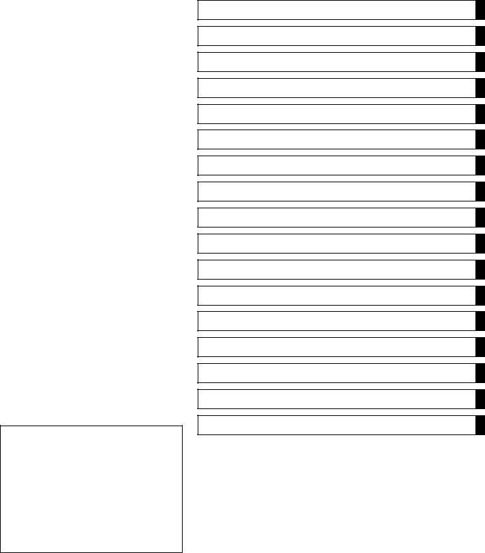
Battery Ground
Before completing any service on the motorcycle, disconnect the battery wires from the battery to prevent the engine from accidentally turning over. Disconnect the ground wire
(–) first and then the positive (+). When completed with the service, first connect the positive (+) wire to the positive (+) terminal of the battery then the negative (–) wire to the negative terminal.
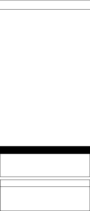
Edges of Parts
Lift large or heavy parts wearing gloves to prevent injury from possible sharp edges on the parts.
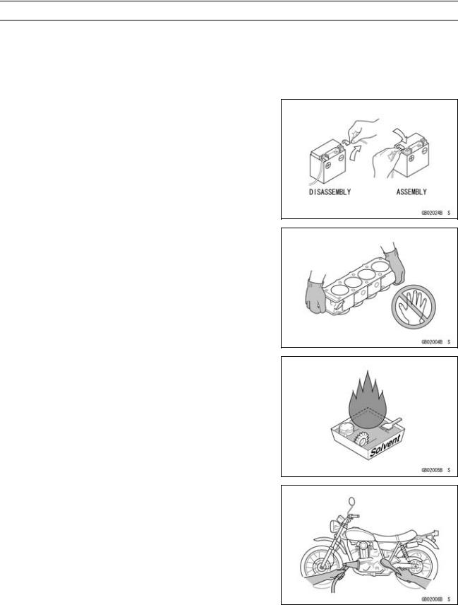
Solvent
Use a high flush point solvent when cleaning parts. High flush point solvent should be used according to directions of the solvent manufacturer.
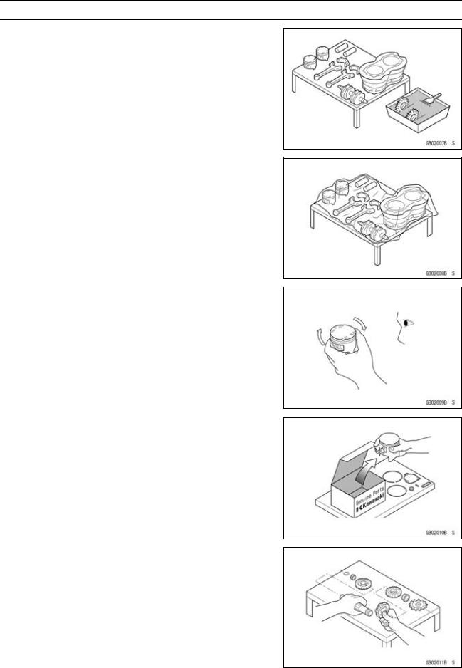
Cleaning vehicle before disassembly
Clean the vehicle thoroughly before disassembly. Dirt or other foreign materials entering into sealed areas during vehicle disassembly can cause excessive wear and decrease performance of the vehicle.
GENERAL INFORMATION 1-3
Before Servicing
Arrangement and Cleaning of Removed Parts
Disassembled parts are easy to confuse. Arrange the parts according to the order the parts were disassembled and clean the parts in order prior to assembly.
Storage of Removed Parts
After all the parts including subassembly parts have been cleaned, store the parts in a clean area. Put a clean cloth or plastic sheet over the parts to protect from any foreign materials that may collect before re-assembly.
Inspection
Reuse of worn or damaged parts may lead to serious accident. Visually inspect removed parts for corrosion, discoloration, or other damage. Refer to the appropriate sections of this manual for service limits on individual parts. Replace the parts if any damage has been found or if the part is beyond its service limit.
Replacement Parts
Replacement Parts must be KAWASAKI genuine or recommended by KAWASAKI. Gaskets, O-rings, Oil seals, Grease seals, circlips or cotter pins must be replaced with new ones whenever disassembled.
Assembly Order
In most cases assembly order is the reverse of disassembly, however, if assembly order is provided in this Service Manual, follow the procedures given.
1-4 GENERAL INFORMATION
Before Servicing
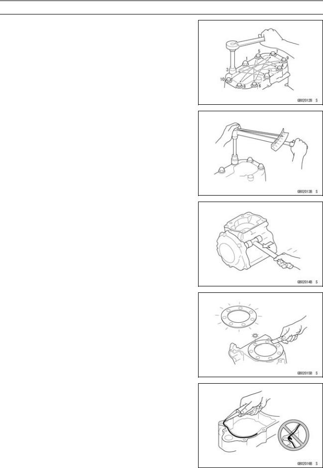
Tightening Sequence
Bolts, nuts, or screws must be tightened according to the specified sequence to prevent case warpage or deformation which can lead to malfunction. If the specified tightening sequence is not indicated, tighten the fasteners alternating diagonally.
Tightening Torque
Incorrect torque applied to a bolt, nut, or screw may lead to serious damage. Tighten fasteners to the specified torque using a good quality torque wrench.
Often, the tightening sequence is followed twice-initial tightening and final tightening with torque wrench.
Force
Use common sense during disassembly and assembly, excessive force can cause expensive or hard to repair damage. When necessary, remove screws that have a non -permanent locking agent applied using an impact driver. Use a plastic-faced mallet whenever tapping is necessary.
Gasket, O-ring
Hardening, shrinkage, or damage of both gaskets and O-rings after disassembly can reduce sealing performance. Remove old gaskets and clean the sealing surfaces thoroughly so that no gasket material or other material remains. Install new gaskets and replace used O-rings when re-assembling
Liquid Gasket, Locking Agent
For applications that require Liquid Gasket or a Locking agent, clean the surfaces so that no oil residue remains before applying liquid gasket or locking agent. Do not apply them excessively. Excessive application can clog oil passages and cause serious damage.
GENERAL INFORMATION 1-5
Before Servicing
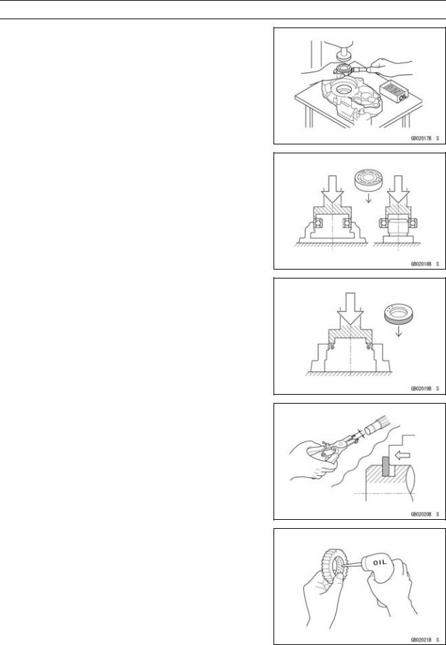
Press
For items such as bearings or oil seals that must be pressed into place, apply small amount of oil to the contact area. Be sure to maintain proper alignment and use smooth movements when installing.
Ball Bearing and Needle Bearing
Do not remove pressed ball or needle unless removal is absolutely necessary. Replace with new ones whenever removed. Press bearings with the manufacturer and size marks facing out. Press the bearing into place by putting pressure on the correct bearing race as shown.
Pressing the incorrect race can cause pressure between the inner and outer race and result in bearing damage.
Oil Seal, Grease Seal
Do not remove pressed oil or grease seals unless removal is necessary. Replace with new ones whenever removed. Press new oil seals with manufacture and size marks facing out. Make sure the seal is aligned properly when installing.
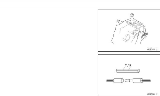
Circlips, Cotter Pins
Replace circlips or cotter pins that were removed with new ones. Install the circlip with its sharp edge facing outward and its chamfered side facing inward to prevent the clip from being pushed out of its groove when loaded. Take care not to open the clip excessively when installing to prevent deformation.
Lubrication
It is important to lubricate rotating or sliding parts during assembly to minimize wear during initial operation. Lubrication points are called out throughout this manual, apply the specific oil or grease as specified.
1-6 GENERAL INFORMATION
Before Servicing
Direction of Engine Rotation
When rotating the crankshaft by hand, the free play amount of rotating direction will affect the adjustment. Rotate the crankshaft to positive direction (clockwise viewed from output side).
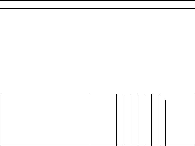
Electrical Wires
A two-color wire is identified first by the primary color and then the stripe color. Unless instructed otherwise, electrical wires must be connected to those of the same color.

GENERAL INFORMATION 1-7
Model Identification
VN1600-A1 (US, and Canada) Left Side View:
VN1600-A1 (US, and Canada) Right Side View:
 User Manual")
1-8 GENERAL INFORMATION
Model Identification
VN1600-A1 (Europe) Left Side View:
VN1600-A1 (Europe) Right Side View:
|
GENERAL INFORMATION 1-9 |
|||
|
General Specifications |
|||
|
Items |
VN1600-A1 |
||
|
Dimensions: |
|||
|
Overall length |
2 505 mm (98.62 in.) |
||
|
Overall width |
1 040 mm (40.9 in.), (AU) 990 mm (39 in.) |
||
|
Overall height |
1 130 mm (44.5 in.) |
||
|
Wheelbase |
1 680 mm (66.1 in.) |
||
|
Road clearance |
130 mm (5.12 in.) |
||
|
Seat height |
680 mm (26.8 in.) |
||
|
Dry mass |
306 kg (675 lb), (AU) 307 kg (677 lb) |
||
|
Curb mass: |
Front |
156 kg (345 lb) |
|
|
Rear |
181 kg (399 lb), (AU) 182 kg (401 lb) |
||
|
Fuel tank capacity |
20 L (5.3 US gal) |
||
|
Fuel |
Unleaded and high-octane gasoline |
||
|
(see VN1600-A1 Owner’s Manual) |
|||
|
Performance: |
|||
|
Minimum turning radius |
|||
|
3.5 m (11.5 ft) |
|||
|
Engine: |
|||
|
Type |
4-stroke, SOHC, V2-cylinder |
||
|
Cooling system |
Liquid-cooled |
||
|
Bore and stroke |
102 × 95 mm (4.02 × 3.74 in.) |
||
|
Displacement |
1 552 mL (94.70 cu in.) |
||
|
Compression ratio |
9.0 : 1 |
||
|
Maximum horsepower |
49 kW (67 PS) @ 4 700 r/min (rpm), (CA) (CAL) (US) – |
||
|
Maximum torque |
127 N·m (12.95 kgf·m, 93.7 ft·lb) @ 2 700 r/min (rpm), |
||
|
(CA) (CAL) (US) – |
|||
|
Carburetion system |
DFI (Digital Fuel Injection) System |
||
|
Starting system |
Electric starter |
||
|
Ignition system |
Battery and coil (transistorized) |
||
|
Timing advance |
Electronically advanced (digital) |
||
|
Ignition timing |
From 0° BTDC @ 950 r/min (rpm) 25° BTDC @ 4 500 |
||
|
r/min (rpm) |
|||
|
Spark plugs |
NGK DPR6EA-9 or ND X20EPR-U9 |
||
|
Cylinder numbering method |
Front to Rear, 1-2 |
||
|
Firing order |
1-2 |
||
|
Valve timing: |
|||
|
Inlet |
Open |
22° BTDC |
|
|
Close |
66° ABDC |
||
|
Duration |
268° |
||
|
Exhaust |
Open |
66° BBDC |
|
|
Close |
26° ATDC |
||
|
Duration |
272° |
||
|
Lubrication system |
Forced lubrication (wet sump) |
||
|
Engine oil: |
Type |
API SE, SF or SG class |
|
|
API SH or SJ class with JASO MA |
|||
|
Viscosity |
SAE10W-40 |
||
|
Capacity |
3.5 L (3.7US qt, when engine is completely disassembled |
||
|
and dry) |
|||

1-10 GENERAL INFORMATION
General Specifications
|
Items |
VN1600-A1 |
|
|
Drive Train: |
||
|
Primary reduction system: |
||
|
Type |
||
|
Gear |
||
|
Reduction ratio |
1.517 (85/56) |
|
|
Clutch type |
Wet multi disc |
|
|
Transmission: |
||
|
Type |
5-speed, constant mesh, return shift |
|
|
Gear ratios: |
1st |
2.500 (40/16) |
|
2nd |
1.590 (35/22) |
|
|
3rd |
1.192 (31/26) |
|
|
4th |
0.965 (28/29) |
|
|
5th |
0.781 (25/32) |
|
|
Final drive system: |
||
|
Type |
Shaft |
|
|
Reduction ratio |
2.619 (15/21 × 33/9) |
|
|
Overall drive ratio |
3.105 @ Top gear |
|
|
Final gear case oil: |
||
|
Grade |
API Service Classification: GL-5 Hypoid gear oil |
|
|
Viscosity |
||
|
SAE90 (above 5°C), SAE80 (below 5°C) |
||
|
Capacity |
200 mL (6.76 US oz) |
|
|
Frame: |
||
|
Type |
Tubular, double cradle |
|
|
Caster (rake angel) |
||
|
32° |
||
|
Trail |
168 mm (6.61 in.) |
|
|
Front tire: |
Type |
Tubeless |
|
Size |
130/90 — 16 M/C 67H |
|
|
Rear tire: |
Type |
Tubeless |
|
Size |
170/70B16 M/C 75H |
|
|
Front suspension: |
Type |
Telescopic fork |
|
Wheel travel |
150 mm (5.91 in.) |
|
|
Rear suspension: |
Type |
Swingarm |
|
Wheel travel |
95 mm (3.74 in.) |
|
|
Brake Type: |
Front |
|
|
Dual disc |
||
|
Rear |
Single disc |
|
|
Electrical Equipment: |
||
|
Battery |
Capacity |
12 V 18 Ah |
|
Headlight: |
Type |
|
|
Semi-sealed beam |
||
|
Bulb |
12 V 60/55 W (quartz-halogen) |
|
|
Tail/brake light |
12 V 5/21 W |
|
|
Alternator: |
Type |
Three-phase AC, twin rotor |
|
Rated output |
42A × 14 V @ 6 000 r/min (rpm) |
Specifications are subject to change without notice, and may not apply to every country. AU: Australia
CAL: California
CA: Canada
US: United States of America
![]()
GENERAL INFORMATION 1-11
|
Unit Conversion Table |
|||||||||||||
Prefixes for Units: |
Units of Length: |
||||||||||||
|
km |
× |
0.6214 |
= |
mile |
|||||||||
|
Prefix |
Symbol |
Power |
|||||||||||
|
m |
× |
3.281 |
= |
ft |
|||||||||
|
mega |
M |
× 1 000 000 |
|||||||||||
|
mm |
× |
0.03937 |
= |
in. |
|||||||||
|
kilo |
k |
× |
1 000 |
||||||||||
|
centi |
c |
× |
0.01 |
||||||||||
|
milli |
m |
× |
0.001 |
Units of Torque: |
|||||||||
|
micro |
µ |
× 0.000001 |
|||||||||||
|
N·m |
× |
0.1020 |
= |
kgf·m |
|||||||||
|
N·m |
× |
0.7376 |
= |
ft·lb |
|||||||||
Units of Mass: |
N·m |
× |
8.851 |
= |
in·lb |
||||||||
|
kgf·m |
× |
9.807 |
= |
N·m |
|||||||||
|
kg |
× |
2.205 |
= |
lb |
kgf·m |
× |
7.233 |
= |
ft·lb |
||||
|
g |
× |
0.03527 |
= |
oz |
kgf·m |
× |
86.80 |
= |
in·lb |
||||
Units of Volume: |
Units of Pressure: |
||||||||||||
|
L |
× |
0.2642 |
= |
gal (US) |
kPa |
× |
0.01020 |
= |
kgf/cm² |
||||
|
L |
× |
0.2200 |
= |
gal (imp) |
kPa |
× |
0.1450 |
= |
psi |
||||
|
L |
× |
1.057 |
= |
qt (US) |
kPa |
× |
0.7501 |
= |
cm Hg |
||||
|
L |
× |
0.8799 |
= |
qt (imp) |
kgf/cm² |
× |
98.07 |
= |
kPa |
||||
|
L |
× |
2.113 |
= |
pint (US) |
kgf/cm² |
× |
14.22 |
= |
psi |
||||
|
L |
× |
1.816 |
= |
pint (imp) |
cm Hg |
× |
1.333 |
= |
kPa |
||||
|
mL |
× |
0.03381 |
= |
oz (US) |
|||||||||
|
mL |
× |
0.02816 |
= |
oz (imp) |
Units of Speed: |
||||||||
|
mL |
× |
0.06102 |
= |
cu in. |
|||||||||
|
km/h |
× |
0.6214 |
= |
mph |
|||||||||
Units of Force: |
Units of Power: |
||||||||||||
|
N |
× |
0.1020 |
= |
kgf |
|||||||||
|
N |
× |
0.2248 |
= |
lb |
kW |
× |
1.360 |
= |
PS |
||||
|
kg |
× |
9.807 |
= |
N |
|||||||||
|
kW |
× |
1.341 |
= |
HP |
|||||||||
|
kg |
× |
2.205 |
= |
lb |
PS |
× |
0.7355 |
= |
kW |
||||
|
PS |
× |
0.9863 |
= |
HP |
Units of Temperature:

PERIODIC MAINTENANCE 2-1
Periodic Maintenance
|
Periodic Maintenance Chart ………….. |
2-2 |
|
Torque and Locking Agent…………….. |
2-4 |
|
Specifications ……………………………… |
2-10 |
|
Special Tools ………………………………. |
2-12 |
|
Periodic Maintenance Procedures….. |
2-13 |
|
Fuel System (DFI)……………………… |
2-13 |
|
Fuel Hose and Connection |
|
|
Inspection……………………………. |
2-13 |
|
Throttle Control System |
|
|
Inspection……………………………. |
2-13 |
|
Idle Speed Inspection ……………… |
2-14 |
|
Air Cleaner Element Cleaning…… |
2-15 |
|
Evaporative Emission Control |
|
|
System Inspection (CAL) ………. |
2-15 |
|
Cooling System…………………………. |
2-16 |
|
Radiator Hose and Connection |
|
|
Inspection……………………………. |
2-16 |
|
Coolant Change……………………… |
2-17 |
|
Engine Top End ………………………… |
2-19 |
|
Air Suction Valve Inspection …….. |
2-19 |
|
Clutch………………………………………. |
2-19 |
|
Clutch Hose and Connection |
|
|
Inspection……………………………. |
2-19 |
|
Clutch Fluid Level Inspection ……. |
2-20 |
|
Clutch Fluid Change ……………….. |
2-20 |
|
Clutch Master Cylinder Cup and |
|
|
Dust Seal Replacement ………… |
2-21 |
|
Clutch Slave Cylinder Piston Seal |
|
|
Replacement ………………………. |
2-22 |
|
Engine Lubrication System …………. |
2-23 |
|
Engine Oil Change………………….. |
2-23 |
|
Oil Filter Replacement …………….. |
2-24 |
|
Wheel/Tires………………………………. |
2-24 |
|
Tire Inspection ……………………….. |
2-24 |
|
Final Drive………………………………… |
2-25 |
|
Oil Level Inspection…………………. |
2-25 |
|
Oil Change …………………………….. |
2-26 |
|
Propeller Shaft Joint Lubrication .. |
2-26 |
|
Brakes……………………………………… |
2-27 |
|
Brake Pad Wear Inspection ……… |
2-27 |
|
Brake Hose and Connection |
|
|
Inspection……………………………. |
2-27 |
|
Brake Fluid Level Inspection…….. |
2-27 |
|
Brake Fluid Change ………………… |
2-28 |
|
Brake Master Cylinder Cup and |
|
|
Dust Seal Replacement ………… |
2-29 |
|
Caliper Piston/Dust Seals |
|
|
Replacement……………………….. |
2-29 |
|
Front Brake Light Switch |
|
|
Inspection……………………………. |
2-29 |
|
Rear Brake Light Switch |
|
|
Check/Adjustment ………………… |
2-30 |
|
Suspension………………………………. |
2-30 |
|
Front Fork Oil Leak Inspection….. |
2-30 |
|
Rear Shock Absorber Oil Leak |
|
|
Inspection …………………………… |
2-31 |
|
Swingarm Pivot Lubrication ……… |
2-31 |
|
Steering …………………………………… |
2-31 |
|
Stem Bearing Lubrication…………. |
2-31 |
|
Steering Check ………………………. |
2-31 |
|
Steering Adjustment………………… |
2-32 |
|
Electrical System ………………………. |
2-33 |
|
Spark Plug Cleaning/Inspection… |
2-33 |
|
General Lubrication …………………… |
2-33 |
|
Lubrication …………………………….. |
2-33 |
|
Nut, Bolt, and Fastener Tightness .. |
2-34 |
|
Tightness Inspection ……………….. |
2-34 |

2-2 PERIODIC MAINTENANCE
Periodic Maintenance Chart
|
The scheduled maintenance must be done in accordance with this chart to keep the motorcycle in |
|||||||||||
|
good running condition.The initial maintenance is vitally important and must not be neglected. |
|||||||||||
|
FREQUENCY |
Whichever |
1 000 km |
* ODOMETER |
||||||||
|
comes |
(600 mile) |
READING |
|||||||||
|
first |
6 000 km |
||||||||||
|
→ |
(4 000 mile) |
||||||||||
|
↓ |
12 000 km |
||||||||||
|
(7 500 mile) |
|||||||||||
|
18 000 km |
|||||||||||
|
(12 000 mile) |
|||||||||||
|
24 000 km |
|||||||||||
|
(15 000 mile) |
|||||||||||
|
30 000 km |
|||||||||||
|
(20 000 mile) |
|||||||||||
|
36 000 km |
|||||||||||
|
(24 000 mile) |
|||||||||||
|
OPERATION |
Every |
See Page |
|||||||||
|
Spark plug (e) — clean and gap † |
• |
• |
• |
• |
• |
• |
2–35 |
||||
|
Air suction valve (e) — inspect † |
• |
• |
• |
• |
• |
• |
2–20 |
||||
|
Air cleaner element (e) — clean†# |
• |
• |
• |
2–16 |
|||||||
|
Throttle control system (e) — inspect † |
• |
• |
• |
• |
• |
• |
• |
2–14 |
|||
|
Idle speed (e) — inspect † |
• |
• |
• |
• |
2–15 |
||||||
|
Fuel hoses, connections — inspect † |
• |
• |
• |
• |
• |
• |
2–14 |
||||
|
Engine oil — change # |
year |
• |
• |
• |
• |
2–24 |
|||||
|
Oil filter — replace |
• |
• |
• |
• |
2–26 |
||||||
|
Evaporative emission control system (e) |
• |
• |
• |
• |
• |
• |
• |
2–17 |
|||
|
(CAL) — inspect † |
|||||||||||
|
Final gear case oil level — inspect † |
• |
• |
• |
2–28 |
|||||||
|
Final gear case oil — change |
• |
• |
2–28 |
||||||||
|
Propeller shaft joint — lubricate |
• |
• |
2–29 |
||||||||
|
Brake pad wear — inspect † # |
• |
• |
• |
• |
• |
• |
2–29 |
||||
|
Brake light switch — inspect † |
• |
• |
• |
• |
• |
• |
• |
2–32 |
|||
|
Steering — inspect † |
• |
• |
• |
• |
• |
• |
• |
2–34 |
|||
|
Rear shock absorber oil leak — inspect † |
• |
• |
• |
2–33 |
|||||||
|
Front fork oil leak — inspect † |
• |
• |
• |
2–33 |
|||||||
|
Tire wear — inspect † |
• |
• |
• |
• |
• |
• |
2–27 |
||||
|
Swingarm pivot — lubricate |
• |
• |
2–33 |
||||||||
|
General lubrication — perform |
• |
• |
• |
2–36 |
|||||||
|
Nut, bolt, and fastener tightness — inspect † |
• |
• |
• |
• |
2–37 |
||||||
|
Brake/clutch hoses, connections — inspect † |
• |
• |
• |
• |
• |
• |
2–21, 2–29 |
||||
|
Brake/clutch fluid level — inspect † |
month |
• |
• |
• |
• |
• |
• |
• |
2–21, 2–29 |
||
|
Coolant hoses, connections — inspect † |
• |
2–18 |
|||||||||
|
Brake/clutch fluid — change |
2 years |
• |
2–22, 2–30 |
||||||||
PERIODIC MAINTENANCE 2-3
Periodic Maintenance Chart
|
FREQUENCY |
Whichever |
1 000 km |
* ODOMETER |
||||||
|
comes |
(600 mile) |
READING |
|||||||
|
first |
6 000 km |
||||||||
|
→ |
(4 000 mile) |
||||||||
|
↓ |
12 000 km |
||||||||
|
(7 500 mile) |
|||||||||
|
18 000 km |
|||||||||
|
(12 000 mile) |
|||||||||
|
24 000 km |
|||||||||
|
(15 000 mile) |
|||||||||
|
30 000 km |
|||||||||
|
(20 000 mile) |
|||||||||
|
36 000 km |
|||||||||
|
(24 000 mile) |
|||||||||
|
OPERATION |
Every |
See Page |
|||||||
|
Brake/clutch master cylinder cup and dust |
4 years |
2–23, 2–32 |
|||||||
|
seal — replace |
|||||||||
|
• |
|||||||||
|
Coolant — change |
2 years |
2–28 |
|||||||
|
Caliper piston seal and dust seal — replace |
4 years |
• |
2–32 |
||||||
|
Steering stem bearing — lubricate |
2 years |
2–34 |
|||||||
|
Clutch slave cylinder piston seal — replace |
4 years |
2–24 |
# : Service more frequently when operating in severe conditions; dusty, wet, muddy, high speed or frequent starting/stopping.
* : For higher odometer readings, repeat at the frequency interval established here.
† : Replace, add, adjust, clean, or torque if necessary.
Throttle control system inspection: Inspection of throttle grip play and throttle bore cleanliness. (CAL): California
(e): Emission Related Items

2-4 PERIODIC MAINTENANCE
Torque and Locking Agent
|
The following tables list the tightening torque |
The table below, relating tightening torque to |
|||||||||||||||||
|
for the major fasteners requiring use of a non |
thread diameter, lists the basic torque for the |
|||||||||||||||||
|
-permanent locking agent or liquid gasket. |
bolts and nuts. Use this table for only the bolts |
|||||||||||||||||
|
and nuts which do not require a specific torque |
||||||||||||||||||
|
Letters used in the “Remarks” column mean: |
value. |
All of the values are for use with dry |
||||||||||||||||
|
L: Apply a non-permanent locking agent to |
solvent-cleaned threads. |
|||||||||||||||||
|
the threads. |
Basic Torque for General Fasteners |
|||||||||||||||||
|
G: Apply grease to the threads. |
||||||||||||||||||
|
Threads |
Torque |
|||||||||||||||||
|
MO: Apply molybdenum disulfide grease oil |
||||||||||||||||||
|
solution. |
dia. (mm) |
N·m |
kgf·m |
ft·lb |
||||||||||||||
|
O: Apply oil to the threads and seating sur- |
5 |
3.4 |
4.9 |
0.35 |
0.50 |
30 |
43 in·lb |
|||||||||||
|
face. |
6 |
5.9 |
7.8 |
0.60 |
0.80 |
52 |
69 in·lb |
|||||||||||
|
S: Tighten the fasteners following the speci- |
||||||||||||||||||
|
8 |
14 |
19 |
1.4 1.9 |
10.0 |
13.5 |
|||||||||||||
|
fied sequence. |
||||||||||||||||||
|
10 |
25 |
34 |
2.6 |
3.5 |
19.0 25 |
|||||||||||||
|
SS: Apply silicone sealant. |
||||||||||||||||||
|
Si: Apply silicone grease (ex. PBC grease). |
12 |
44 |
61 |
4.5 |
6.2 |
33 |
45 |
|||||||||||
|
R: Replacement parts |
73 |
98 |
7.4 |
10.0 |
54 |
72 |
||||||||||||
|
14 |
||||||||||||||||||
|
Lh: Left-hand-threads |
16 |
115 |
155 |
11.5 |
16.0 |
83 |
115 |
|||||||||||
|
St: Stake the fasteners to prevent loosening. |
||||||||||||||||||
|
18 |
165 |
225 |
17.0 |
23.0 |
125 |
165 |
||||||||||||
|
AL: Tighten the two clamp bolts alternately |
||||||||||||||||||
|
20 |
225 |
325 |
23 |
33 |
165 |
240 |
||||||||||||
|
two times to ensure even tightening |
||||||||||||||||||
|
torque. |
||||||||||||||||||
|
Fastener |
Torque |
Remarks |
||||||||||||||||
|
N·m |
kgf·m |
ft·lb |
||||||||||||||||
|
Fuel System: |
||||||||||||||||||
|
Throttle body assy holder bolts |
11 |
1.1 |
95 |
in·lb |
Right Side |
|||||||||||||
|
Inlet manifold bolts |
12 |
1.2 |
104 in·lb |
on Cyl. Head |
||||||||||||||
|
Spark plug lead holder bolts |
11 |
1.1 |
95 |
in·lb |
Right Side |
|||||||||||||
|
ISC pipe holder bolts |
11 |
1.1 |
95 |
in·lb |
||||||||||||||
|
Air cleaner duct holder bolts |
9.8 |
1.0 |
69 |
in·lb |
Left Side |
|||||||||||||
|
Right and left air cleaner base bolts |
11 |
1.1 |
95 |
in·lb |
||||||||||||||
|
Right and left air cleaner base screws |
2.2 |
0.22 |
19 |
in·lb |
L, Lower Duct |
|||||||||||||
|
Left air cleaner cover Allen bolt |
8 |
16 |
1.6 |
12 |
||||||||||||||
|
Right air cleaner cover Allen bolt |
8 |
16 |
1.6 |
12 |
||||||||||||||
|
Right air cleaner Allen bolts |
11 |
1.1 |
95 |
in·lb |
Throttle Body |
|||||||||||||
|
Choke cable plate screw |
2.9 |
0.30 |
26 |
in·lb |
L, Throttle Body |
|||||||||||||
|
Inlet air temperature sensor nut (DFI) |
7.8 |
0.80 |
69 |
in·lb |
||||||||||||||
|
Water temperature sensor (DFI) |
18 |
1.8 |
13 |
SS |
||||||||||||||
|
Fuel pump bolts |
9.8 |
1.0 |
87 |
in·lb |
S, L |
|||||||||||||
|
Cooling System: |
||||||||||||||||||
|
Radiator hose clamp screws |
2.5 |
0.25 |
22 |
in·lb |
||||||||||||||
|
Radiator fan switch |
18 |
1.8 |
13 |
|||||||||||||||
|
Radiator fan bolts |
8.3 |
0.85 |
74 |
in·lb |
||||||||||||||
|
Water temperature switch |
7.8 |
0.80 |
69 |
in·lb |
SS |
|||||||||||||
|
Water pump impeller bolt |
8.8 |
0.90 |
78 |
in·lb |
Lh |
|||||||||||||
|
Water pump cover bolts |
11 |
1.1 |
97 |
in·lb |
||||||||||||||
|
Water pump air bleeder bolt |
11 |
1.1 |
97 |
in·lb |
||||||||||||||
|
Water pump drain bolt |
11 |
1.1 |
97 |
in·lb |
||||||||||||||
|
Water pipe bolts |
11 |
1.1 |
97 |
in·lb |

PERIODIC MAINTENANCE 2-5
Torque and Locking Agent
|
Fastener |
Torque |
Remarks |
||||||
|
N·m |
kgf·m |
ft·lb |
||||||
|
Radiator drain bolt |
7.4 |
0.75 |
65 |
in·lb |
||||
|
Water temperature sensor (DFI) |
18 |
1.8 |
13 |
SS |
||||
|
Engine Top End: |
||||||||
|
Spark plugs |
18 |
1.8 |
13 |
|||||
|
Spark plug retainer |
12 |
1.2 |
104 in·lb |
|||||
|
Air suction valve cover bolts |
7.4 |
0.75 |
65 |
in·lb |
||||
|
Chain tensioner mounting bolts |
11 |
1.1 |
95 |
in·lb |
S |
|||
|
Chain tensioner cap |
20 |
2.0 |
14 |
S |
||||
|
Chain tensioner lockbolt |
4.9 |
0.50 |
43 |
in·lb |
S |
|||
|
Timing inspection cap |
1.5 |
0.15 |
13 |
in·lb |
||||
|
Rotor bolt cap |
1.5 |
0.15 |
13 |
in·lb |
||||
|
Camshaft sprocket bolts |
15 |
1.5 |
11 |
L |
||||
|
Oil hose flange bolts |
9.8 |
1.0 |
87 |
in·lb |
||||
|
Rocker shafts |
25 |
2.5 |
18 |
|||||
|
Rocker case nuts: |
12 mm |
78 |
8.0 |
58 |
MO, S |
|||
|
8 mm |
25 |
2.5 |
18 |
S |
||||
|
Rocker case bolts |
6 mm |
8.8 |
0.90 |
78 in·lb |
S |
|||
|
Cylinder head nuts |
25 |
2.5 |
18 |
S |
||||
|
Cylinder head jacket plugs |
20 |
2.0 |
14 |
L |
||||
|
Rocker case cover bolts |
8.8 |
0.90 |
78 |
in·lb |
S |
|||
|
Camshaft chain guide bolts |
11 |
1.1 |
95 |
in·lb |
L |
|||
|
Cylinder nuts |
25 |
2.5 |
18 |
S |
||||
|
Inlet manifold bolts |
12 |
1.2 |
104 in·lb |
on Cyl. Head |
||||
|
Exhaust pipe cover clamp bolts |
6.9 |
0.70 |
61 |
in·lb |
||||
|
Chamber bolts |
29 |
3.0 |
22 |
except US, CA |
||||
|
Muffler stay mounting bolts and nuts, |
8 |
25 |
2.5 |
18 |
||||
|
Muffler bracket bolt and nut |
29 |
3.0 |
22 |
|||||
|
Clutch: |
||||||||
|
Clutch lever pivot bolt |
1.0 |
0.10 |
8.7 in·lb |
Si |
||||
|
Clutch lever pivot bolt locknut |
5.9 |
0.60 |
52 |
in·lb |
||||
|
Clutch reservoir cap crews |
1.5 |
0.15 |
13 |
in·lb |
||||
|
Clutch slave cylinder bleed valve |
7.8 |
0.80 |
69 |
in·lb |
||||
|
Clutch slave cylinder bolts |
6.9 |
0.70 |
61 |
in·lb |
L |
|||
|
Clutch hose banjo bolts |
25 |
2.5 |
18 |
|||||
|
Clutch master cylinder clamp bolts |
11 |
1.1 |
95 |
in·lb |
S |
|||
|
Starter lockout switch screws |
1.2 |
0.12 |
10 |
in·lb |
||||
|
Push rod guide bolts |
11 |
1.1 |
95 |
in·lb |
L |
|||
|
Clutch cover bolts |
11 |
1.1 |
95 |
in·lb |
||||
|
Clutch damper cover bolts (outside) |
9.8 |
1.0 |
87 |
in·lb |
L |
|||
|
Clutch cover damper plate bolts |
9.8 |
1.0 |
87 |
in·lb |
EO (tip) |
|||
|
Clutch cover damper screws |
4.9 |
0.50 |
43 in·lb |
L |
||||
|
Clutch hub nut |
147 |
15.0 |
108 |
MO |
||||

2-6 PERIODIC MAINTENANCE
Torque and Locking Agent
|
Fastener |
Torque |
Remarks |
||||
|
N·m |
kgf·m |
ft·lb |
||||
|
Engine Lubrication System: |
||||||
|
Oil filler cap |
1.5 |
0.15 |
13 |
in·lb |
||
|
Oil screen plug |
20 |
2.0 |
14 |
|||
|
Engine oil drain plug |
20 |
2.0 |
14 |
|||
|
Oil filter (cartridge type) |
18 |
1.8 |
13 |
R, EO |
||
|
Oil filter Pipe |
25 |
2.5 |
18 |
SS |
||
|
Oil pressure relief valve |
15 |
1.5 |
11 |
L |
||
|
Oil pressure switch terminal screw |
1.5 |
0.15 |
13 |
in·lb |
||
|
Oil pressure switch |
15 |
1.5 |
11 |
SS |
||
|
Oil pump mounting bolts |
11 |
1.1 |
95 |
in·lb |
||
|
Oil hose banjo bolts |
9.8 |
1.0 |
87 |
in·lb |
||
|
Oil hose flange bolt (outside) |
9.8 |
1.0 |
87 |
in·lb |
||
|
Oil pipe holder bolts (inside) |
11 |
1.1 |
95 |
in·lb |
L |
|
|
Oil pipe clamp bolts (inside) |
11 |
1.1 |
95 |
in·lb |
L |
|
|
Right & left crankcase oil nozzles |
2.9 |
0.30 |
26 |
in·lb |
× 3 |
|
|
Right crankcase oil nozzle |
2.9 |
0.30 |
26 |
in·lb |
× 1, Lh |
|
|
Oil baffle bolt |
11 |
1.1 |
95 |
in·lb |
L |
|
|
Engine Removal/Installation: |
||||||
|
Downtube bolts and nuts |
44 |
4.5 |
33 |
|||
|
Engine mounting bolts and nuts |
44 |
4.5 |
33 |
|||
|
Engine mounting bracket bolts |
25 |
2.5 |
18 |
|||
|
Engine ground terminal bolt |
7.8 |
0.80 |
69 |
in·lb |
||
|
Crankshaft/Transmission: |
||||||
|
Crankcase bolts: |
10 mm |
39 |
4.0 |
29 |
S |
|
|
8 mm |
21 |
2.1 |
15 |
S |
||
|
6 mm |
11 |
1.1 |
95 in·lb |
S |
||
|
Frame ground bracket bolt |
1.1 |
1.1 |
95 |
in·lb |
Left Crankcase |
|
|
Crankcase bearing retainer bolts |
11 |
1.1 |
95 |
in·lb |
L |
|
|
Camshaft chain guide bolts |
11 |
1.1 |
95 |
in·lb |
L |
|
|
Right, left crankcase oil nozzles |
2.9 |
0.30 |
26 |
in·lb |
× 3 |
|
|
Right crankcase oil nozzles |
2.9 |
0.30 |
26 |
in·lb |
× 1, Lh |
|
|
Oil baffle bolt |
11 |
1.1 |
95 |
in·lb |
L |
|
|
Connecting rod big end nuts |
59 |
6.0 |
43 |
MO |
||
|
Oil pressure relief valve |
15 |
1.5 |
11 |
L |
||
|
Oil filter Pipe |
25 |
2.5 |
18 |
SS |
||
|
Oil hose banjo bolts |
9.8 |
1.0 |
87 |
in·lb |
||
|
Primary gear bolt |
147 |
15.0 |
108 |
MO |
||
|
Water pump chain guide spring hook bolt |
2.9 |
0.30 |
26 |
in·lb |
||
|
Water pump chain guide bolt |
8.3 |
0.85 |
73 |
in·lb |
||
|
Idle shaft holder bolts |
8.3 |
0.85 |
73 |
in·lb |
||
|
Oil pressure switch terminal screw |
1.5 |
0.15 |
13 |
in·lb |
||
|
Oil pressure switch |
15 |
1.5 |
11 |
SS |
||
|
Oil pipe clamp bolts (inside) |
11 |
1.1 |
95 |
in·lb |
L |

PERIODIC MAINTENANCE 2-7
Torque and Locking Agent
|
Fastener |
Torque |
Remarks |
||||
|
N·m |
kgf·m |
ft·lb |
||||
|
Left balancer gear bolt |
85 |
8.7 |
63 |
MO |
||
|
Starter clutch bolt |
85 |
8.7 |
63 |
MO |
||
|
Starter clutch coupling bolts |
15 |
1.5 |
11 |
L |
||
|
Gear set lever bolt |
11 |
1.1 |
95 |
in·lb |
||
|
Shift shaft return spring pin (bolt) |
39 |
4.0 |
29 |
L |
||
|
Shift pedal clamp bolt |
25 |
2.5 |
18 |
|||
|
Shift pedal clamp bolts (VN1600–A2 ) |
30 |
3.1 |
22 |
|||
|
Rear shift lever clamp bolt |
12 |
1.2 |
104 in·lb |
|||
|
Shift rod locknuts |
11 |
1.1 |
95 |
in·lb |
(Rear: Lh) |
|
|
Shift drum bearing holder bolts |
11 |
1.1 |
95 |
in·lb |
L |
|
|
Shift drum cam screw |
15 |
1.5 |
11 |
L |
||
|
Damper cam nut (front gear) |
195 |
20 |
144 |
MO (threads) |
||
|
Push rod guide bolts |
9.8 |
1.0 |
87 |
in·lb |
L |
|
|
Wheels/Tires: |
||||||
|
Front axle clamp bolts |
20 |
2.0 |
14 |
AL |
||
|
Front axle |
108 |
11.0 |
79.6 |
S |
||
|
Rear axle nut |
108 |
11.0 |
79.6 |
|||
|
Tire air valve stem nuts |
1.5 |
0.15 |
13 |
in·lb |
||
|
Tire air valve caps |
0.15 |
0.015 |
1.3 in·lb |
|||
|
Air valve cores |
0.3 |
0.03 |
2.6 in·lb |
|||
|
Final Drive: |
||||||
|
Oil pipe banjo bolts (front gear) |
12 |
1.2 |
104 in·lb |
|||
|
Oil nozzle (front gear) |
2.9 |
0.30 |
26 |
in·lb |
||
|
Oil nozzle (front gear) |
18 |
1.8 |
13 |
|||
|
Neutral switch |
15 |
1.5 |
11 |
|||
|
Front gear case bolts: |
6 mm |
12 |
1.2 |
104 in·lb |
||
|
8 mm |
29 |
3.0 |
22 |
|||
|
Speed sensor bolt |
9.8 |
1.0 |
87 |
in·lb |
L |
|
|
Damper cam nut (front gear) |
195 |
20 |
144 |
MO (threads) |
||
|
Drive gear nut (front gear) |
265 |
27 |
195 |
MO, St |
||
|
Driven gear assy mounting bolts |
25 |
2.5 |
18 |
|||
|
Driven gear bolt (front gear) |
137 |
14 |
101 |
MO, St |
||
|
Bearing retainer bolts (front gear) |
8.8 |
0.9 |
78 |
in·lb |
L |
|
|
Final gear case drain plug |
8.8 |
0.9 |
78 |
in·lb |
||
|
Final gear case mounting nuts |
34 |
3.5 |
25 |
|||
|
Final gear case studs |
– |
– |
– |
L |
||
|
Final gear case cover bolts: |
8 mm |
23 |
2.3 |
17 |
L |
|
|
10 mm |
34 |
3.5 |
25 |
L |
||
|
Pinion gear nut (final gear) |
130 |
13 |
94 |
St, MO |
||
|
Bearing retainer bolt |
6.9 |
0.7 |
61 |
in·lb |
L |
|
|
Brakes: |
||||||
|
Caliper bleed valves |
7.8 |
0.8 |
69 |
in·lb |
||
|
Brake hose banjo bolts |
25 |
2.5 |
18 |

2-8 PERIODIC MAINTENANCE
Torque and Locking Agent
|
Fastener |
Torque |
Remarks |
||||
|
N·m |
kgf·m |
ft·lb |
||||
|
Brake lever pivot bolt |
1.0 |
0.10 |
8.7 in·lb |
|||
|
Brake lever pivot bolt locknut |
5.9 |
0.60 |
52 |
in·lb |
||
|
Front brake reservoir cap screws |
1.5 |
0.15 |
13 |
in·lb |
||
|
Front brake light switch screw |
1.2 |
0.12 |
10 |
in·lb |
||
|
Front master cylinder clamp bolts |
8.8 |
0.9 |
78 |
in·lb |
G, S |
|
|
Front caliper mounting bolts |
34 |
3.5 |
25 |
|||
|
Rear caliper mounting bolts |
34 |
3.5 |
25 |
|||
|
Rear caliper holder bolt |
64 |
6.5 |
47 |
|||
|
Brake disc bolts |
27 |
2.8 |
20 |
L |
||
|
Rear master cylinder mounting bolts |
25 |
2.5 |
18 |
|||
|
Rear master cylinder push rod locknut |
18 |
1.8 |
13 |
|||
|
Brake pedal clamp bolt |
25 |
2.5 |
18 |
|||
|
Suspension: |
||||||
|
Upper front fork clamp bolts |
20 |
2.0 |
14 |
|||
|
Lower front fork clamp bolts |
29 |
3.0 |
21 |
AL |
||
|
Front fork top plugs |
22 |
2.2 |
16 |
|||
|
Piston rod nuts or joint rod nut |
20 |
2.0 |
14 |
|||
|
Front fork bottom allen bolt |
30 |
3.1 |
22 |
L |
||
|
Front axle clamp bolts |
20 |
2.0 |
14 |
AL |
||
|
Rear shock absorber nuts |
34 |
3.5 |
25 |
|||
|
Swingarm pivot shaft |
108 |
11.0 |
79.6 |
G |
||
|
Steering: |
||||||
|
Steering stem head nut |
88 |
9.0 |
65 |
|||
|
Steering stem nut |
5 |
0.5 |
43 |
in·lb |
||
|
Handlebar clamp bolts |
34 |
3.5 |
25 |
|||
|
Handlebar holder nuts |
34 |
3.5 |
25 |
|||
|
Upper front fork clamp bolts |
20 |
2.0 |
14 |
|||
|
Lower front fork clamp bolts |
29 |
3.0 |
21 |
AL |
||
|
Turn signal light mounting nuts |
5.9 |
0.6 |
52 |
in·lb |
||
|
Frame: |
||||||
|
Downtube bolts and nuts |
44 |
4.5 |
33 |
|||
|
Footboard bracket bolts |
34 |
3.5 |
25 |
front |
||
|
Footpeg bracket bolts |
25 |
2.5 |
18 |
rear, L |
||
|
Sidestand nut |
44 |
4.5 |
33 |
|||
|
Electrical System: |
||||||
|
Spark plugs |
18 |
1.8 |
13 |
|||
|
Crankshaft sensor screws |
2.9 |
0.30 |
26 |
in·lb |
||
|
Stator lead holder screw |
9.8 |
1.0 |
87 |
in·lb |
L |
|
|
Inside stator holder bolts |
11 |
1.1 |
95 |
in·lb |
L |
|
|
Crankshaft sensor lead holder bolt |
2.9 |
0.30 |
26 |
in·lb |
L |
|
|
Alternator outer cover bolts |
6.9 |
0.70 |
61 |
in·lb |
||
|
Alternator outer cover joint bolts |
6.9 |
0.70 |
61 |
in·lb |
L |
|
|
Alternator outer cover damper bolts |
6.9 |
0.70 |
61 |
in·lb |
L |
![]()
PERIODIC MAINTENANCE 2-9
Torque and Locking Agent
|
Fastener |
Torque |
Remarks |
||||
|
N·m |
kgf·m |
ft·lb |
||||
|
Alternator outer cover assembly bolts |
6.9 |
0.70 |
61 |
in·lb |
||
|
Alternator cover bolts |
11 |
1.1 |
95 |
in·lb |
||
|
Alternator inner cover bolts |
11 |
1.1 |
95 |
in·lb |
||
|
Alternator rotor bolt |
78 |
8.0 |
58 |
MO |
||
|
Alternator stator bolts |
13 |
1.3 |
113 in·lb |
L |
||
|
Regulator/rectifier bolts |
6.5 |
0.66 |
57 |
in·lb |
||
|
Timing inspection cap |
1.5 |
0.15 |
13 |
in·lb |
||
|
Rotor bolt cap |
1.5 |
0.15 |
13 |
in·lb |
||
|
Starter motor terminal locknut |
11 |
1.1 |
95 |
in·lb |
||
|
Starter motor terminal nut |
4.9 |
0.50 |
43 |
in·lb |
||
|
Starter motor assembly bolts |
4.9 |
0.50 |
43 |
in·lb |
||
|
Starter motor mounting bolts |
11 |
1.1 |
95 |
in·lb |
||
|
Headlight rim screws |
2.9 |
0.30 |
26 |
in·lb |
||
|
Headlight unit bracket screws |
1.0 |
0.10 |
8.7 in·lb |
L |
||
|
Starter lockout switch screw |
1.2 |
0.12 |
10 |
in·lb |
||
|
Front brake light switch screw |
1.2 |
0.12 |
10 |
in·lb |
||
|
Sidestand switch bolt |
8.8 |
0.90 |
78 |
in·lb |
L |
|
|
Radiator fan switch |
18 |
1.8 |
13 |
|||
|
Radiator fan bolts |
8.3 |
0.85 |
7.4 in·lb |
|||
|
Fuel level sensor mounting bolts |
6.9 |
0.70 |
61 |
in·lb |
L |
|
|
Fuel pump mounting bolts |
9.8 |
1.0 |
87 in·lb |
S |
||
|
Water temperature switch |
7.8 |
0.80 |
69 |
in·lb |
SS |
|
|
Water temperature sensor |
18 |
1.8 |
13 |
SS |
||
|
Oil pressure switch terminal screw |
1.5 |
0.15 |
13 |
in·lb |
G |
|
|
Oil pressure switch |
15 |
1.5 |
11 |
SS |
||
|
Neutral switch |
15 |
1.5 |
11 |
|||
|
Speed sensor mounting bolt |
9.8 |
1.0 |
8.7 in·lb |
L |
||
|
Turn signal light mounting screws |
6.9 |
0.70 |
61 |
in·lb |
||
|
Turn signal light lens screws |
1.0 |
0.10 |
8.7 in·lb |
|||
|
Tail/brake light mounting nuts |
5.9 |
0.60 |
52 |
in·lb |
||
|
Tail/brake light lens screws |
1.2 |
0.12 |
10 |
in·lb |
||
|
Tail/brake light assembly screws |
1.2 |
0.12 |
10 |
in·lb |

2-10 PERIODIC MAINTENANCE
Specifications
|
Item |
Standard |
Service Limit |
|
|
Fuel System (DFI): |
|||
|
Throttle grip free play |
2 3 mm (0.08 0.12 in.) |
– – – |
|
|
Idle speed |
950 ± 50 r/min (rpm) |
– – – |
|
|
Air cleaner element |
Paper filter |
– – – |
|
|
Cooling System: |
|||
|
Coolant: |
|||
|
Type (recommended) |
Permanent type antifreeze |
– – – |
|
|
Color |
Green |
– – – |
|
|
Mixed ratio |
Soft water 50%, Coolant 50% |
– – – |
|
|
Freezing point |
|||
|
– 35°C (– 31°F) |
– – – |
||
|
Total amount |
2.3 L (2.4 US qt) |
– – – |
|
|
Engine Top End: |
|||
|
Valve clearance |
Non-adjustable (hydraulic lash adjusters) |
– – – |
|
|
Clutch: |
|||
|
Clutch fluid: |
|||
|
Grade |
DOT4 |
– – – |
|
|
Clutch lever free play |
Non-adjustable |
– – – |
|
|
Engine Lubrication System: |
|||
|
Engine oil: |
|||
|
Type |
API SE, SF or SG |
– – – |
|
|
API SH or SJ with JASO MA |
|||
|
Viscosity |
SAE 10W-40 |
– – – |
|
|
Capacity |
2.9 L (3.1 US qt, when filter is not |
– – – |
|
|
removed) |
|||
|
3.1 L (3.3 US qt, when filter is removed) |
– – – |
||
|
3.5 L (3.7 US qt, when engine is |
– – – |
||
|
completely disassembled and dry) |
|||
|
Level |
Between upper and lower level lines |
– – – |
|
|
(Wait 2 3 minutes after idling or |
|||
|
running) |
|||
|
Tires: |
|||
|
Tread depth: |
|||
|
Front |
BRIDGESTONE EXEDRA G721: |
1 mm (0.04 in.), |
|
|
4.3 mm (0.17 in.) |
(DE, AT, CH): 1.6 mm |
||
|
(0.063 in.) |
|||
|
Rear |
BRIDGESTONE EXEDRA G722: |
Up to 130 km/h (80 mph): |
|
|
7.2 mm (0.28 in.) |
2 mm (0.08 in.) |
||
|
Over 130km/h (80mph): |
|||
|
3 mm (0.1 in.) |
|||
|
Air pressure: (when cold) |
|||
|
Front |
Up to 186 kg (410 lb) load: 200 kPa |
– – – |
|
|
(2.0 kgf/cm², 28 psi) |
|||
|
Rear |
Up to 186 kg (410 lb) load: 250 kPa |
– – – |
|
|
(2.5 kgf/cm², 36 psi) |
|||

PERIODIC MAINTENANCE 2-11
Specifications
|
Item |
Standard |
Service Limit |
|
Final Drive: |
||
|
Final gear case oil: |
||
|
Grade |
API Service Classification: GL-5 hypoid |
– – – |
|
gear oil |
||
|
Viscosity |
when above 5°C (41°F) SAE90 |
– – – |
|
when below 5°C (41°F) SAE80 |
||
|
Oil level |
Filler opening bottom |
– – – |
|
Amount |
200 mL (6.76 US oz) |
– – – |
|
Propeller shaft joint grease |
20 mL (0.68 US oz), high-temperature |
– – – |
|
grease |
||
|
Brakes: |
||
|
Brake fluid |
||
|
Grade |
DOT4 |
– – – |
|
Brake pad lining thickness: |
||
|
Front |
4.5 mm (0.18 in.) |
1 mm (0.04 in.) |
|
Rear |
7.5 mm (0.295 in.) |
1 mm (0.04 in.) |
|
Brake light timing: |
||
|
Front |
Pulled ON |
– – – |
|
Rear |
ON after about 10 mm (0.39 in.) of pedal |
– – – |
|
travel |
||
|
Electrical System: |
||
|
Spark plug gap |
0.8 0.9 mm (0.031 0.035 in.) |
– – – |
|
AT: Republic of Austria |
||
|
CH: Swiss Confederation |
||
|
DE: Federal Republic of Germany |

2-12 PERIODIC MAINTENANCE
Special Tools
Steering Stem Nut Wrench : |
Attachment Jack : |
|
57001–1100 |
57001–1398 |
|
Jack : |
Filler Cap Driver : |
|
57001–1238 |
57001–1454 |

PERIODIC MAINTENANCE 2-13
Periodic Maintenance Procedures
Fuel System (DFI)
Fuel Hose and Connection Inspection
○The fuel hoses are designed to be used throughout the motorcycle’s life without any maintenance, however, if the motorcycle is not properly handled, the high pressure inside the fuel line can cause fuel to leak [A] or the hose to burst. Remove the fuel tank (see Fuel System chapter) and check the fuel hose.
Replace the fuel hose if any fraying, cracks [B] or bulges
•[C] are noticed.
Check that the hoses are securely connected and clamps
•are tightened correctly.
When installing, route the hoses according to Cable,
•Wire, and Hose Routing section in the Appendix chapter. When installing the fuel hoses, avoid sharp bending, kinking, flattening or twisting, and route the fuel hoses with a minimum of bending so that the fuel flow will not be obstructed.
 Replace the hose if it has been sharply bent or kinked.
Throttle Control System Inspection
Throttle• Grip Play Inspection
Check the throttle grip free play [A].
If the free play is incorrect, adjust the throttle cable (see below).
Throttle Grip Free Play |
||
|
Standard: |
2 3 mm (0.08 |
0.12 in.) |
•Check that the throttle grip moves smoothly from close to full open, and the throttle closes quickly and completely in all steering positions by the return spring.
If the throttle grip doesn’t return properly, check the throttle cable routing, grip free play, and cable damage. Then
•lubricate the throttle cable.
Run the engine at the idle speed, and turn the handlebar all the way to the right and left to ensure that the idle speed doesn’t change.
If the idle speed increases, check the throttle grip free play and the cable routing.
•If necessary, adjust the throttle cable as follows: ○Loosen the locknuts [A] and screw the adjusters [B] all the
way in so as to give the throttle grip plenty of play (rear view).
○Turn out the adjuster of the decelerator cable [C] until there is no play.
○Tighten the locknut against the adjuster.
○Turn the adjuster of the accelerator cable [D] until the proper amount of throttle grip free play is obtained and tighten the locknut against the adjuster.

2-14 PERIODIC MAINTENANCE
Periodic Maintenance Procedures
Throttle• Bore Cleaning
Check the throttle bore for cleanliness as follows: ○Remove the air cleaner cover Allen bolt [A] and take off
the right air cleaner cover [B]. Front [C]
○Check the throttle bores [A] at the throttle valves [B] and around them for carbon deposits by opening the valves. If any carbon accumulates, wipe the carbon off the throttle bores around the throttle valves, using a lint-free cloth [C] penetrated with a high-flash point solvent.
Front [D]
Idle• Speed Inspection
Start the engine and warm it up thoroughly.
○At first the engine will run fast to decrease warm up time (fast idle).
○Gradually the fast idle will lower to a certain RPM auto-
•matically. This is the idle speed. Check the idle speed.
Idle Speed
• Standard: 950 ± 50 r/min (rpm)
With the engine idling, turn the handlebar to both sides. If handlebar movement changes the idle speed, the throttle cables may be improperly adjusted or incorrectly routed or damaged. Be sure to correct any of these conditions before riding (see Cable, Wire, and Hose Routing section in the Appendix chapter).
 WARNING
Operation with improperly adjusted, incorrectly routed or damaged cables could result in an unsafe riding condition.
•If the idle speed is out of the specified range, adjust it. Start the engine and warm it up thoroughly.
○•Wait until fast idle speed lowers to a certain value.
Turn the adjusting screw [A] until the idle speed is correct. ○Open and close the throttle a few times to make sure that the idle speed is within the specified range. Readjust if
necessary. Front [B]

PERIODIC MAINTENANCE 2-15
Periodic Maintenance Procedures
Air Cleaner Element Cleaning
NOTE
○In dusty areas, the element should be cleaned more frequently than the recommended interval.
○After riding through rain or on muddy roads, the element should be cleaned immediately.
•Remove:
Allen Bolt and Washer [A] and Left Air Cleaner Cover [B]
Front [C]
•Remove the element [A].
•Push a clean, lint-free towel into the lower air cleaner duct to keep dirt or other foreign material from entering.
 WARNING
If dirt or dust is allowed to pass through into the throttle body assy, the throttle may become stuck, possibly causing accident.
CAUTION
If dirt gets through into the engine, excessive engine wear and possibly engine damage will occur.
•Clean the element by tapping it lightly to loosen dust.
•Blow away the remaining dust by applying compressed air [A] from the inside to the outside (from the clean side
•to the dirty side).
Visually check the element for no tears or no breaks and check the sponge gasket [B] also.
If the element or gasket has any tears or breaks, replace
•the element.
Install the left air cleaner cover.
Torque — Left Air Cleaner Cover Allen Bolt: 16 N·m (1.6 kgf·m, 12 ft·lb)
Evaporative Emission Control System Inspection (CAL)•
Inspect the canister as follows:
○Remove the left side cover (see Frame chapter). ○Remove the band [A] and take out the canister [B]. ○Visually inspect the canister for cracks and other damage.
If the canister has any cracks or bad damage, replace it with a new one.
NOTE
○The canister is designed to work well through the motorcycle’s life without any maintenance if it is used under normal conditions.

2-16 PERIODIC MAINTENANCE
Periodic Maintenance Procedures
○Run the purge hose (green) [A] above the canister breather hose (blue) [B] through the hole [C] into the tool case [D].
○Do not run these hoses side by side on the battery side of the canister. This prevents hoses from being flattened when installing the left side cover.
○Install the canister and the left side cover (see Frame chapter).
○Face the white mark [E] left as shown.
•Check the liquid/vapor separator as follows: ○Disconnect the hoses from the separator, and remove the
separator [A] from the motorcycle right side. Front [B]
○Visually inspect the separator for cracks and other damage.
If the separator has any cracks or damage, replace it with a new one.
○To prevent the gasoline from flowing into or out of the
•canister, hold the separator perpendicular to the ground. Check the hoses of the evaporative emission control system as follows:
○Check that the hoses are securely connected and clips are in position.
○Replace any kinked, deteriorated or damaged hoses. ○Route the hoses according to Cable, Wire, and Hose
Routing section in the Appendix chapter. Refer to the diagram of the evaporative emission control system in the Fuel System chapter too.
○When installing the hoses, avoid sharp bending, kinking, flattening or twisting, and route the hoses with a minimum of bending so that the emission flow will not be obstructed.
Cooling System
Radiator Hose and Connection Inspection
○The high pressure inside the radiator hose can cause coolant to leak [A] or the hose to burst if the line is not properly maintained. Visually inspect the hoses for signs of deterioration. Squeeze the hoses. A hose should not be hard and brittle, nor should it be soft or swollen.
Replace the hose if any fraying, cracks [B] or bulges [C]
•are noticed.
Check that the hoses are securely connected and clamps are tightened correctly.
Torque — Radiator Hose Clamp Screws: 2.5 N·m (0.25 kgf·m, 22 in·lb)

PERIODIC MAINTENANCE 2-17
Periodic Maintenance Procedures
Coolant Change

 WARNING
To avoid burns, do not remove the radiator cap or try to change the coolant when the engine is still hot. Wait until it cools down.
Coolant on tires will make them slippery, and can cause an accident and injury.
Since coolant is harmful to the human body, do not use for drinking.
•Place a container under the radiator drain bolt [A], then remove the drain bolt (front view).
•Remove the fuel tank (see Fuel System (DFI) chapter).
•Remove the radiator cap [A] in two steps. First turn the cap counterclockwise to the first stop. Then push and turn it further in the same direction and remove the cap.
○The coolant will drain from the radiator and engine. Front [B]
•Remove the water pump drain bolt [A]. The remaining coolant will drain from the water pump [B].
○Place a conduit under the drain hole of the pump cover. The conduit leads to a container.
Front [C]
•Remove :
Right Side Cover (see Frame chapter)
• Reserve Tank Bolts
Turn over the reserve tank [A], remove the cap [B], and
•pour the coolant into a suitable container.
•Install the reserve tank.
When filling the coolant, choose a suitable mixture ratio by referring to the coolant manufacturer’s directions.
CAUTION
Soft or distilled water must be used with the antifreeze (see Specifications in this chapter) in the cooling system.
If hard water is used in the system, it causes scale accumulation in the water passages, and considerably reduces the efficiency of the cooling system.

2-18 PERIODIC MAINTENANCE
Periodic Maintenance Procedures
Water and Coolant Mixture Ratio (when shipping) |
||
|
Soft Water |
: |
50 % |
|
Coolant |
: |
50 % |
|
Freezing Point |
: |
− 35°C (− 31°F) |
|
Total Amount |
: |
2.3 L (2.4 US qt) |
|
•Tighten the drain bolts. |
||
|
Torque — Radiator Drain Bolt: 7.4 N·m (0.75 kgf·m, 65 in·lb) |
||
|
Water Pump Drain Bolt: 11 N·m (1.1 kgf·m, 95 in·lb) |
||
|
•Fill the coolant into the radiator. |
||
|
NOTE |
||
|
Fill in the coolant slowly so that it can expel the air from |
||
|
○ |
||
|
the engine and radiator. |
||
|
•Check the cooling system for leaks. |
||
|
•Bleed the air from the water pump [A]. |
||
|
Loosen the air bleeder bolt [B] until the coolant seeps out |
||
|
○around the bolt, then tighten it. |
Torque — Water Pump Air Bleeder Bolt: 11 N·m (1.1 kgf·m, 95 in·lb)
•Tap the radiator hoses to force any air bubbles caught
•inside.
•Fill the radiator up to the filler neck [A] with coolant. Install the radiator cap.
•Fill the reserve tank up to the “F” (full) level line [A] with
•coolant and install the cap.
•Install the fuel tank (see Fuel System (DFI) chapter). Start the engine and warm it up thoroughly until the radi-
•ator fan turns on and then stop the engine.
Check the coolant level in the reserve tank several times while the engine is cooling down, and replenish as necessary.
If the coolant level is lower than the “L” level line, add coolant to the “F” level line.
CAUTION
Do not add more coolant above the “F” level line.
![]()
PERIODIC MAINTENANCE 2-19
Periodic Maintenance Procedures
Engine Top End
Air• Suction Valve Inspection
Remove the air suction valve (see Engine Top End chap-
•ter).
Visually inspect the reeds for cracks, folds, warps, heat damage or other damage.
If there is any doubt as to the condition of the reeds [A],
•replace the air suction valve as an assembly.
Check the reed contact areas [B] of the valve holder for grooves, scratches, any signs of separation from the holder or heat damage.
•If there is any doubt as to the condition of the reed contact
•areas, replace the air suction valve as an assembly.
If any carbon or other foreign particles have accumulated between the reed and the reed contact area, wash the valve assembly clean with a high-flash point solvent.
CAUTION
Do not scrape off the deposits with a scraper as this could damage the rubber, requiring replacement of the suction valve assembly.
Clutch
Clutch• Hose and Connection Inspection
The high pressure inside the clutch line can cause fluid to leak [A] or the hose to burst if the line is not properly maintained. Bend and twist the rubber hose while examining it.
Replace it if any fraying, cracks [B] or bulges [C] are no-
•ticed.
Check that the hoses are securely connected and banjo bolts are tightened correctly.
Torque — Clutch Hose Banjo Bolts: 25 N·m (2.5 kgf·m, 18
• ft·lb)
When installing the clutch hose, route the hoses according to Cable, Wire, and Hose Routing section in the Appendix chapter.
 Replace the hose if it has been sharply bent or kinked.

2-20 PERIODIC MAINTENANCE
Periodic Maintenance Procedures
Clutch• Fluid Level Inspection
•Hold the clutch fluid reservoir horizontal.
Check that the clutch fluid level of the clutch reservoir is between the lower [A] and the upper [B] level lines.
If the fluid level is lower than the lower level line, fill the reservoir to the upper level line in the reservoir.
○Since the clutch fluid is the same as the brake fluid, refer to Brake Fluid Section in the Brakes chapter for further details.
Torque — Clutch Reservoir Cap Screws: 1.5 N·m (0.15 kgf·m, 13 in·lb)
 WARNING
Change the fluid in the clutch line completely if the fluid must be refilled but the type and brand of the fluid that already is in the reservoir are unidentified. After changing the fluid, use only the same type and brand of fluid thereafter. Mixing different types and brands of fluid lowers the fluid boiling point and could cause the clutch to be ineffective. It may also cause the rubber clutch parts to deteriorate.
Clutch• Fluid Change
Level the clutch fluid reservoir and remove the reservoir
•cap.
Remove the alternator outer cover (see Electrical System chapter.) and the rubber cap from the bleed valve on the
•clutch slave cylinder.
Attach a clear plastic hose [A] to the bleed valve and run
•the other end of the hose into a container.
•Fill the reservoir with fresh fluid. Change the clutch fluid as follows.
Open [B] the bleed valve, using a wrench.
Pump the clutch lever and hold [C] it.
Close [D] the bleed valve.
Release [E] the clutch lever.
○Repeat this operation until fresh fluid comes out from the plastic hose or the color of the fluid changes.
○Check the fluid level in the reservoir often, replenishing it as necessary.
NOTE
○If the fluid in the reservoir runs completely out any time during fluid changing, the bleeding operation must be done over again from the beginning since air will have entered the line.

 WARNING
Do not mix two brands of fluid.

PERIODIC MAINTENANCE 2-21
Periodic Maintenance Procedures
•After changing the fluid, check the clutch for good clutch power and no fluid leakage.
If necessary, bleed the air from the lines (see Clutch Line
•Bleeding in the Clutch chapter).
•Remove the clear plastic hose.
•Install the reservoir cap.
Tighten the bleed valve, and install the rubber cap.
Torque — Clutch Reservoir Cap Screws: 1.5 N·m (0.15 kgf·m, 13 in·lb)
Clutch Slave Cylinder Bleed Valve: 7.8 N·m (0.80 kgf·m, 69 in·lb)
Clutch Master Cylinder Cup and Dust Seal
Replacement•
•Remove the clutch master cylinder (see Clutch chapter). Remove the reservoir cap [A] and diaphragm [B], and
•pour the clutch fluid into a container.
Unscrew the locknut [C] and pivot bolt [D], and remove
•the clutch lever [E].
Pull the dust cover [F] out of place, and remove the circlip [G].
•Special Tool — Inside Circlip Pliers: 57001-143
Pull out the primary cup [H], piston assembly [I], and return spring [J].
CAUTION
Do not remove the secondary cup [K] from the piston since removal will damage it.
•Check the parts of the clutch master cylinder (see Clutch chapter).
 If any part shows signs of damage, replace it.
•Before assembly, clean all parts including the master cylinder with clutch fluid or alcohol.
CAUTION
Use only disc brake fluid, isopropyl alcohol or ethyl alcohol, for cleaning parts. Do not use any other fluid for cleaning these parts. Gasoline, motor oil or any other petroleum distillate will cause deterioration of the rubber parts. Oil spilled on any part will be difficult to wash off completely, and will eventually deteriorate the rubber used in the cylinder.

2-22 PERIODIC MAINTENANCE
Periodic Maintenance Procedures
•Apply clutch fluid to the parts removed and to the inner
•wall of the cylinder.
Take care not to scratch the piston or the inner wall of the
•cylinder.
Install the push rod with the dust seal fitted into the groove.
○The push rod round end must be faced inwards.
Torque — Clutch Lever Pivot Bolt: 1.0 N·m (0.10 kgf·m, 8.7 in·lb)
Clutch Lever Pivot Bolt Locknut: 5.9 N·m (0.60
• kgf·m, 52 in·lb)
Install the clutch master cylinder (see Clutch chapter).
Clutch• Slave Cylinder Piston Seal Replacement
•Remove the clutch slave cylinder (see Clutch chapter). Loosen the banjo bolt [A] at the clutch pipe lower end, and
•tighten it loosely.
Unscrew the slave cylinder bolts [B] and detach the slave
•cylinder with the pipe installed from the engine.
Pump the clutch lever until the piston comes out of the
•cylinder.
Unscrew the banjo bolt and remove the slave cylinder [C].
CAUTION
Immediately wash away any clutch fluid that spills. It may damage painted surfaces.
NOTE
○If the clutch slave cylinder is removed and left alone, the piston will be pushed out by spring force.
•Remove the spring and piston seal.
CAUTION
Replace the piston seal with a new one if it was removed from the piston.
•Before assembly, apply clutch fluid to the outside of the
•piston and the piston seal. Install the piston seal as shown. Cylinder [A]
Piston [B] Piston Seal [C] Spring [D]

PERIODIC MAINTENANCE 2-23
Periodic Maintenance Procedures
Engine Lubrication System
Engine• Oil Change
Situate the motorcycle so that it is vertical after warming
•up the engine.
Remove the engine oil drain plug [A] and drain the oil.
•Remove:
Oil Screen Plug [A] (Engine right side)
•Remove the oil screen [A], the spring [B], and the washer
•[C].
Clean the oil screen with a high-flash point solvent and
•remove any particles stuck to it.
Clean the screen thoroughly whenever the engine oil is changed.
 WARNING
Clean the screen in a well-ventilated area, and take care that there is no spark or flame anywhere near the working area. Because of the danger of highly flammable liquids, do not use gasoline or low-flash point solvents.
NOTE
○While cleaning the screen, check for any metal particles
•Check the screen carefully for any damage: holes and broken wires.
•If the screen is damaged, replace it.
Be sure to put in the oil screen with the rubber gasket end inside.
Replace the screen plug O-ring with new one if it is dam- aged.that might indicate internal engine damage.
Torque — Oil Screen Plug: 20 N·m (2.0 kgf·m, 14 ft·lb)
○The oil in the filter can be drained by removing the filter (see Oil Filter Change in this section).
Replace the drain plug gasket with a new one if it is damaged.
Torque — Engine Oil Drain Plug , Oil Screen Plug: 20 N·m (2.0 kgf·m, 14 ft·lb)
Oil Filter: 18 N·m (1.8 kgf·m, 13 ft·lb)

2-24 PERIODIC MAINTENANCE
Periodic Maintenance Procedures
•Remove the oil filler cap [A] with the driver-filler cap [B] and pour in the specified type and amount of oil.
Clutch Cover [C]
Special Tool — Driver-Filler Cap: 57001–1454 Torque — Oil Filler Cap: 1.5 N·m (0.15 kgf·m, 13 in·lb)
Engine Oil |
|
|
Type: |
API SE, SF or SG class |
|
API SH or SJ class with JASO MA |
|
|
Viscosity: |
SAE 10W-40 |
|
Amount: |
2.9 L (3.1 US qt, when filter is not removed) |
|
3.1 L (3.3 US qt, when filter is removed) |
|
|
3.5 L (3.7 US qt, when engine is completely |
|
|
disassembled and dry) |
NOTE
○Although 10W-40 engine oil is the recommended oil for most conditions, the oil viscosity may need to be changed to accommodate atmospheric conditions in your riding area.
Oil• Filter Replacement
Drain the engine oil (see Engine Oil Change in this sec-
•tion).
Remove the oil filter [A] with the oil filter wrench [B] and discard the oil filter.
Special Tool — Oil Filter Wrench: 57001-1249
NOTE
○The filter has an oil filter bypass valve which can not be removed.
•Replace the oil filter with the new one.
•Apply oil to the gasket of the new filter before installation.
•Tighten the filter with the oil filter wrench.
•Pour in the specified type and amount of oil.
Torque — Oil Filter: 18 N·m (1.8 kgf·m, 13 ft·lb)
Wheel/Tires
Tire Inspection
As the tire tread wears down, the tire becomes more susceptible to puncture and failure. An accepted estimate is that 90% of all tire failures occur during the last 10% of tread life (90% worn). So it is false economy and unsafe to use the• tires until they are bald.
Remove any imbedded stones or other foreign particles
•from the tread.
Visually inspect the tire for cracks and cuts, replacing the tire in case of damage. Swelling or high spots indicate internal damage, requiring tire replacement.

7.2 mm (0.28 in.)
2 mm (0.08 in.):
Up to 130 km/h (80 mph) 3 mm (0.1 in.):
Over to 130 km/h (80 mph)
PERIODIC MAINTENANCE 2-25
Periodic Maintenance Procedures
•Measure the tread depth at the center of the tread with a depth gauge [A]. Since the tire may wear unevenly, take measurement at several places.
If any measurement is less than the service limit, replace the tire (see Wheels/Tires chapter).
Tread Depth Front:
Standard: 4.3 mm (0.17 in.) Service Limit: 1 mm (0.04 in.)
(DE, AT, CH) 1.6 mm (0.063 in.)
Rear:
Standard:
Service Limit:
•Measure the tire air pressure with an air pressure gauge [A] when the tires are cold (that is, when the motorcycle has not been ridden more than a mile during the past 3 hours.)
Adjust the tire air pressure according to the specifications if necessary.
Air Pressure (when cold) |
||
|
Front |
Up to 186 kg (410 lb) |
200 kPa (2.0 kgf/cm², 28 psi) |
|
Rear |
Up to 186 kg (410 lb) |
250 kPa (2.5 kgf/cm², 36 psi) |

 WARNING
To ensure safe handling and stability, use only the recommended standard tires for replacement, inflated to the standard pressure. Use the same manufacture’s tires on both front and rear wheels.
NOTE
○Most countries may have their own regulations requiring a minimum tire tread depth; be sure to follow them.
○Check and balance the wheel when a tire is replaced with a new one (see Wheels/Tires chapter).
Final Drive
Oil Level Inspection
WARNING
Motorcycle operation with insufficient, deteriorated, or contaminated oil causes accelerated wear and may result in seizure of the pinion and ring gears. Seizure can lock the rear wheel and skid the rear tire, with consequent less of control.
•Support the motorcycle perpendicular to the ground.
•Unscrew the filler plug [A], using the driver-filler cap [B].
Special Tool — Driver-Filler Cap: 57001–1454

2-26 PERIODIC MAINTENANCE
Periodic Maintenance Procedures
•The oil level [A] should come to the bottom of the filler opening.
If it is low, first check the final gear case for oil leakage, remedy it if necessary, and add oil through the filler opening. Use the same type and brand of oil that is already in
•the final gear case. Install the filler plug.
Oil• Change
Warm up the oil by running the motorcycle so that the oil will pick up any sediment and drain easily. Stop the
•motorcycle and turn the ignition switch OFF.
Place an oil pan beneath the final gear case, and remove the filler cap and drain plug [A].

 WARNING
When draining or filling the final gear case, be careful that no oil gets on the tire, spoke, or rim. Clean off any oil that inadvertently gets on them with a high-flash point solvent.
•After the oil has completely drained out, install the drain plug with a new gasket.
Torque — Final Gear Case Drain Plug: 8.8 N·m (0.90 kgf·m, 78 in·lb)
•Fill the final gear case with the specified oil and quantity.
Final Gear Case Oil: |
|
|
Amount: |
200 mL (6.76 US oz) |
|
Grade: |
API GL-5 hypoid gear oil |
|
Viscosity: |
When above 5°C (41°F) SAE 90 |
|
When below 5°C (41°F) SAE 80 |
NOTE
○The term “GL-5” indicates a quality and additive rating. A “GL-6” rated hypoid gear oil can also be used.
•Be sure the O-ring is in place, and install the filler plug.
Propeller• Shaft Joint Lubrication
Remove the final gear case and propeller shaft joint (see
•Final Drive chapter).
Wipe the old grease off the propeller shaft sliding joint and
•pinion joint.
Pack the propeller shaft sliding joint with 20 mL (16 grams) of high temperature grease [A].

PERIODIC MAINTENANCE 2-27
Periodic Maintenance Procedures
Brakes
Brake• Pad Wear Inspection
Check the lining thickness [A] of the pads in each caliper. If the lining thickness of either pad is less than the service limit [B], replace both pads in the caliper as a set (see Brakes chapter).
Pad Lining Thickness |
|
|
Standard: |
|
|
Front: |
4.5 mm (0.18 in.) |
|
Rear: |
7.5 mm (0.295 in.) |
|
Service Limit: |
1 mm (0.04 in.) |
Brake• Hose and Connection Inspection
Inspect the brake hose and fittings for deterioration, cracks and signs of leakage.
○The high pressure inside the brake line can cause fluid to leak [A] or the hose to burst if the line is not properly maintained. Bend and twist the rubber hose while examining it.
Replace the hose if any cracks [B] or bulges [C] are noticed.
 Tighten any loose fittings.
Brake• Fluid Level Inspection
Check that the brake fluid level in the front brake reservoir [A] is above the lower [B] level line.
NOTE
○Hold the reservoir horizontal by turning the handlebar when checking brake fluid level.
If the fluid level is lower than the lower level line, fill the reservoir to the upper level line [A] in the reservoir [B].

NOTE
○The fluid level must be checked often during the changing operation and replenished with fresh brake fluid. If the fluid in the reservoir runs out any time during the changing operation, the brakes will need to be bled since air will have entered the brake line.
2-28 PERIODIC MAINTENANCE
Periodic Maintenance Procedures
•Check that the brake fluid level in the rear brake reservoir [A] is between the upper [B] and the lower [C] level lines. If the fluid level is lower than the lower level line, fill the reservoir to the upper level line.
○Use extra heavy-duty brake fluid only from a container marked DOT4.
○Brake fluid of DOT4 is installed in the brake system when shipped.
Torque — Front Brake Reservoir Cap Screws: 1.5 N·m (0.15 kgf·m, 13 in·lb)

 WARNING
Do not mix two brands of fluid. Change the brake fluid in the brake line completely if the brake fluid must be refilled but the type and brand of the brake fluid that is already in the reservoir are unidentified. After changing the fluid, use only the same type and brand of fluid thereafter.
Brake Fluid Change
NOTE
○The procedure to change the front brake fluid is as follows. Changing the rear brake fluid is almost the same
•Level the brake fluid reservoir.
•Remove the reservoir cap [A], plate [B] and diaphragm [C]
•Remove the rubber cap from the bleed valve [A] on the
•front caliper [B].
Attach a clear plastic hose [C] to the bleed valve, and run
•the other end of the hose into a container.
•Fill the reservoir with new brake fluid.
•Temporarily install the reservoir cap. Change the brake fluid as follows:as for the front brake.
 Loading…
Материал из BikesWiki — энциклопедия японских мотоциклов
Перейти к: навигация, поиск

Kawasaki VN1600 Vulcan Classic
Ниже представлены прямые ссылки на скачку сервисной документации.
Для Kawasaki VN1600 Vulcan
- Сервисный мануал (Service Manual) на Kawasaki VN1600 Vulcan Classic
- Сервисный мануал (Service Manual) на Kawasaki VN1600 Vulcan Classic Tourer / Nomad
- Сервисный мануал (Service Manual) на Kawasaki VN1600 Vulcan Mean Streak
Обзор модели
- Kawasaki VN1600 Vulcan
Источник — «https://bikeswiki.ru/index.php?title=Kawasaki_VN1600_Vulcan:_мануалы&oldid=12680»
Категория:
- Сервисная документация
Перед вами файл pdf, где представлена инструкция (руководство) на русском для KAWASAKI VULCAN 1600 CLASSIC (2003). Вы можете скачать ее либо изучить в онлайн режиме.
Подробные сведения об инструкции:
Устройство из раздела: мотоцикл
Бренд-производитель: KAWASAKI
Наименование модели: KAWASAKI VULCAN 1600 CLASSIC (2003)
Инструкция на английском языке
Файл: pdf
Размер файла: 12,83 MB
Скачать инструкцию к HARPER HDT2-1110
ЗАГРУЗИТЬ
Просмотр инструкции онлайн
инструкцияKawasaki Vulcan 1600 Mean Streak (2004)

VULCAN 1600 MEAN STREAK
VN1600 MEAN STREAK
Motorcycle
Service Manual
2004 VULCAN 1600 MEAN STREAK, VN1600 MEAN STREAK
Motorcycle Service Manual
Part No.
99924-1321-01
KAWASAKI HEAVY INDUSTRIES,LTD.
Consumer Products & Machinery Company
Printed in Japan
Year Model
Beginning Frame No.
□ : This digit in the frame number changes from one machine
to another.
MODEL APPLICATION
2004
VN1600-B1
JKBVNKB1
□4A000001 or
JKBVNT60BBA000001
Посмотреть инструкция для Kawasaki Vulcan 1600 Mean Streak (2004) бесплатно. Руководство относится к категории Мотоциклы, 2 человек(а) дали ему среднюю оценку 9.2. Руководство доступно на следующих языках: английский. У вас есть вопрос о Kawasaki Vulcan 1600 Mean Streak (2004) или вам нужна помощь? Задайте свой вопрос здесь
![]()
Главная
| Kawasaki | |
| Vulcan 1600 Mean Streak (2004) | |
| Мотоцикл | |
| английский | |
| Руководство пользователя (PDF) |
Не можете найти ответ на свой вопрос в руководстве? Вы можете найти ответ на свой вопрос ниже, в разделе часто задаваемых вопросов о Kawasaki Vulcan 1600 Mean Streak (2004).
Как перевести мили в километры?
В чем разница между топливом E10 и E5?
Какова рекомендуемая частота замены масляного фильтра в двигателе Kawasaki?
Как часто следует менять масло в двигателе Kawasaki?
Как удалить ржавчину с устройства Kawasaki Мотоцикл?
Инструкция Kawasaki Vulcan 1600 Mean Streak (2004) доступно в русский?
Не нашли свой вопрос? Задайте свой вопрос здесь
Руководство (главы 2-7, 10, 12-14) по техническому обслуживанию и ремонту мотоциклов Kawasaki VN400A.
- Издательство: —
- Год издания: —
- Страниц: —
- Формат: PDF
- Размер: 83,7 Mb
Руководство на английском языке по техническому обслуживанию и ремонту + каталог запчастей мотоциклов Kawasaki Vulcan VN750 Ецшт.
- Издательство: Kawasaki Heavy Industries, Ltd.
- Год издания: 2000
- Страниц: 2395
- Формат: PDF
- Размер: 61,0 Mb
Руководство на английском языке по эксплуатации и техническому обслуживанию мотоциклов Kawasaki VN800/Vulcan 800 Classic.
- Издательство: Kawasaki Heavy Industries, Ltd.
- Год издания: 2001
- Страниц: 55
- Формат: PDF
- Размер: 2,1 Mb
Руководство на английском языке по техническому обслуживанию и ремонту мотоциклов Kawasaki Vulcan 800 и VN800.
- Издательство: Kawasaki Heavy Industries, Ltd.
- Год издания: —
- Страниц: 405
- Формат: PDF
- Размер: 176,2 Mb

Руководство на английском языке по техническому обслуживанию и ремонту мотоциклов Kawasaki Vulcan 900 Classic, Vulcan 900 Classic LT и VN900 Classic.
- Издательство: Kawasaki Heavy Industries, Ltd.
- Год издания: 2006
- Страниц: 588
- Формат: PDF
- Размер: 13,3 Mb
Руководство на английском языке по техническому обслуживанию и ремонту мотоциклов Kawasaki VN1500.
- Издательство: Kawasaki Heavy Industries, Ltd.
- Год издания: 1999
- Страниц: 270
- Формат: PDF
- Размер: 59,5 Mb

Руководство на английском языке по техническому обслуживанию и ремонту мотоциклов Kawasaki Vulcan 1600 Classic и VN1600 Classic.
- Издательство: Kawasaki Heavy Industries, Ltd.
- Год издания: 2003
- Страниц: 575
- Формат: PDF
- Размер: 12,8 Mb

Руководство на английском языке по техническому обслуживанию и ремонту мотоциклов Kawasaki Vulcan 1600 Mean Streak и VN1600 Mean Streak.
- Издательство: Kawasaki Heavy Industries, Ltd.
- Год издания: 2003
- Страниц: 609
- Формат: PDF
- Размер: 11,7 Mb

Руководство на английском языке по техническому обслуживанию и ремонту мотоциклов Kawasaki Vulcan 2000 и VN2000.
- Издательство: Kawasaki Heavy Industries, Ltd.
- Год издания: 2003
- Страниц: 633
- Формат: PDF
- Размер: 13,3 Mb

Перед вами файл pdf, где представлена инструкция (руководство) на русском для KAWASAKI VULCAN 1600 CLASSIC (2003). Вы можете скачать ее либо изучить в онлайн режиме.
Подробные сведения об инструкции:
Устройство из раздела: мотоцикл
Бренд-производитель: KAWASAKI
Наименование модели: KAWASAKI VULCAN 1600 CLASSIC (2003)
Инструкция на английском языке
Файл: pdf
Размер файла: 12,83 MB
Скачать инструкцию к HARPER HDT2-1110
ЗАГРУЗИТЬ
Просмотр инструкции онлайн
![]()
4-я Красноармейская, 2А
Санкт-Петербург, 190005
Email: info@lenmoto.ru
Телефон: +7 (921) 930-81-18
Телефон: +7 (911) 928-08-06
Компания ЛенМото
Запчасти, аксессуары, экипировка, тюнинг для мотоциклов, скутеров, квадроциклов, снегоходов, багги, гидроциклов, катеров и лодочных моторов.
Подпишитесь на наши новости
Подписаться