#1
![]()
Cher Tannov
-
Вконтакте:

- Пол:Мужчина
- Страна:Россия
- Город:Москва, Чер Танново
- Мото:ER-6F ’12
Отправлено 10 Март 2016 — 17:27
Инструкции по эксплуатации на русском языке:
Руководство по эксплуатации ER-6n, ER-6n ABS 2012-2016
Руководство по эксплуатации Ninja 650, Ninja 650 ABS, ER-6f, ER-6f ABS 2012-2016
Вот руководства по ремонту (на английском языке):
Руководство по ремонту ER-6n (ABS) 2006-2008
Руководство по ремонту ER-6n (ABS) 2009-2011
Руководство по ремонту ER-6n (ABS) 2012-2016
Руководство по ремонту Ninja 650R, ER-6f (ABS) 2006-2008
Руководство по ремонту Ninja 650R, ER-6f (ABS) 2009-2011
Руководство по ремонту Ninja 650R, ER-6f (ABS) 2012-2016
Руководство по ремонту Ninja 650R ER-6f (ABS) 2012-2016 на русском языке!
Часть 1-2. Технические характеристики и периодическое обслуживание
Часть 3. Система впрыска топлива (DFI)
Часть 4-5. Система охлаждения. Двигатель
Часть 6-8. Сцепление. Система смазки двигателя. Снятие/установка двигателя
Часть 9. Трансмиссия
Часть 10-11. Колёса/шины. Цепная передача
Часть 12. Тормозная система
Часть 13-15. Подвеска. Рулевое управление. Рама
Часть 16. Электрооборудование
Часть 17-18. Прокладка шлангов, тросов и кабелей. Поиск и устранение неисправностей
Каталог запчастей на русском языке!
Каталог запчастей мотоцикла ER-6f 2012
Желающие приобрести руководство и каталог в бумажном виде могут сделать это в специальной теме.
Народ, я довершил наконец одно большое дело, нарисовал схему Ерша. Адаптировал для лучшего восприятия, перевёл все надписи на русский язык. Пользуйтесь на здоровье.
Схема электрооборудования ER-6F 2012 ABS:

Для вашего удобства, та же схема, в формате .PDF доступна для скачивания по ссылке.
У меня ещё много планов впереди: перевести на русский мануал по ремонту (сделано), сделать каталог запчастей на русском языке (сделано), создать что-то вроде интерактивной карты мотоцикла с указанием наиболее популярных расходников со ссылками на магазины и ещё многое.
Это не быстрый процесс, буду выкладывать по мере готовности. Другие модели пока охватить не готов, объём работы просто колоссальный.
Сообщение отредактировал Cher Tannov: 08 Ноябрь 2020 — 08:06
Дополняю, расширяю…
- SShMeL, alllex, Валентин_Н и 9 другим это нравится
- Наверх
#2
![]()
SShMeL
SShMeL
- Пол:Мужчина
- Страна:Россия
- Город:Москва
- Мото:Ninja 650r > Ninja ZX12R + ZRX1100
Отправлено 10 Март 2016 — 20:42
Спасибо огромное за схему, очень поможет мне разобраться почему перегорает ECU предохранитель при срабатывание сигнализации. Только в схеме ты забыл расписать блок предохранителей 1 и 2 добавь пожалуйста, я в принципе и без этого обойдусь, но все же. Еще можешь выложить исходники я бы для себя поправил, так как у меня нет ABS, добавил свое дополнительное оборудование и распечатал бы на А3.
- Наверх
#3
![]()
Cher Tannov
Cher Tannov
-
Вконтакте:
- Пол:Мужчина
- Страна:Россия
- Город:Москва, Чер Танново
- Мото:ER-6F ’12
Отправлено 10 Март 2016 — 21:56
Опа!
Очень странно, описание блоков предохранителей было… Завтра поправлю. Влад, спасибо за то, что увидел упущение.
Сейчас на подходе схема мота без АВS, прошу тебя потерпеть.
Ребята, пишите, в чём ещё потребность, я буду прислушиваться.
Поправил схему, добавил описание блоков предохранителей. Обновил ссылки.
В работе ещё много проектов.
Сообщение отредактировал Cher Tannov: 15 Март 2016 — 15:50
- Наверх
#4
![]()
Wasilen
Wasilen
-
- Members
-
- 11 сообщений
Прохожий


- Пол:Мужчина
- Страна:Россия
- Город:Карасук, Новосибирской области
- Мото:Kawasaki Ninja EX650 2013
Отправлено 19 Март 2016 — 09:36
Спасибо за проделанную работу!
- Наверх
#5
![]()
Cher Tannov
Cher Tannov
-
Вконтакте:
- Пол:Мужчина
- Страна:Россия
- Город:Москва, Чер Танново
- Мото:ER-6F ’12
Отправлено 19 Март 2016 — 15:56
Пожалуйста.
Всё для вас.
Добавил в каталог запчастей ещё несколько разделов. Серьёзно переработал дизайн. Кажется, теперь каталог стал зрительно более восприимчив.
Пользуйтесь.
Кстати, если у вас есть вопросы, пожелания, предложения или дополнения, высказывайте. Да и от помощи я бы не отказался…
Сообщение отредактировал Cher Tannov: 08 Июнь 2017 — 22:38
- Валентин_Н и endorfirma это нравится
- Наверх
#6
![]()
snorky_KoLXo3HuK
snorky_KoLXo3HuK
- Пол:Мужчина
- Страна:РФ
- Город:Митино, Юбутово
- Мото:ER-6f 13 > GL 1800
Отправлено 04 Апрель 2016 — 21:55
схема просто отличная, всё видно и понятно
- Наверх
#7
![]()
Cher Tannov
Cher Tannov
-
Вконтакте:
- Пол:Мужчина
- Страна:Россия
- Город:Москва, Чер Танново
- Мото:ER-6F ’12
Отправлено 11 Май 2016 — 15:36
Братва, хорошая новость!
Я закончил перевод каталога запчастей на русский язык, выложил полную версию, пользуйтесь!
Не слабо, книжка получилась в палец толщиной:

Сообщение отредактировал Cher Tannov: 11 Май 2016 — 16:09
- SShMeL и Валентин_Н это нравится
- Наверх
#8
![]()
Dinis
Dinis
-
- Members
-
- 37 сообщений
Прохожий

- Пол:Мужчина
- Страна:Россия
- Город:Владимир
- Мото:ER-6F
Отправлено 28 Июнь 2016 — 11:34
Братва, хорошая новость!
Я закончил перевод каталога запчастей на русский язык, выложил полную версию, пользуйтесь!
Не слабо, книжка получилась в палец толщиной:
Хороший труд. Огромное спасибо!
- atomic это нравится
- Наверх
#9
![]()
Валентин_Н
Валентин_Н
- Пол:Мужчина
- Страна:Россия
- Город:Москва, Ярославский
- Мото:ER-6F ’13
Отправлено 02 Июль 2016 — 22:21
Спасибо, попробую распечатать и сверстать в переплёт на работе пока никто не видит 
- Наверх
#10
![]()
BazonXGK
BazonXGK
- Пол:Мужчина
- Страна:Россия
- Город:Севастополь
- Мото:Kawasaki Ninja EX650AF (2006г.)
Отправлено 20 Сентябрь 2016 — 16:22
Ну, что, народ, приступил я к переводу инструкции по ремонту. Быстро не ждите, объём титанический!
Идея нужная и полезная, будем ждать , удачи!
- Наверх
#11
![]()
PaulSankov
PaulSankov
-
- Members
-
- 16 сообщений
Прохожий

- Пол:Мужчина
- Страна:Россия
- Город:г. Москва
- Мото:Zx-6r 636 06, Er-6n 13
Отправлено 12 Октябрь 2016 — 00:19
Ну, что, народ, приступил я к переводу инструкции по ремонту. Быстро не ждите, объём титанический!
Бесконечно ценный материал будет, колоссальная работа предстоит! Надеюсь, что все у тебя пойдет как по маслу в этом деле!
- Наверх
#12
![]()
Валентин_Н
Валентин_Н
- Пол:Мужчина
- Страна:Россия
- Город:Москва, Ярославский
- Мото:ER-6F ’13
Отправлено 12 Октябрь 2016 — 12:47
Бесконечно ценный материал будет, колоссальная работа предстоит! Надеюсь, что все у тебя пойдет как по маслу в этом деле!
Очень круто!
Я когда каталог на запчасти распечатал и сброшюровал, на работе все автомобилисты обзавидовались…
- Наверх
#13
![]()
Cher Tannov
Cher Tannov
-
Вконтакте:
- Пол:Мужчина
- Страна:Россия
- Город:Москва, Чер Танново
- Мото:ER-6F ’12
Отправлено 03 Декабрь 2016 — 11:11
Давно я новостей не писал по теме, всё руки не доходили.
Наконец дело по переводу мануала хоть немного продвинулось.
Оказалось, что всё гораздо сложнее, чем мне представлялось сначала. Дело в том, что буржуйская система нумерации страниц и каталогизации содержания представляется мне крайне неудобной. Посудите сами, если всего в книге 500 листов, то где находится лист 4-28 или 1-18 совершенно непонятно. А вот лист 250, понятно и ежу, находится в середине. Буду перерабатывать под привычную нам нумерацию, хоть это и дополнительный объём работы.
А пока на ваш суд выношу несколько страниц мануала. Понимаю, что хвастаться пока особо нечем, но, может вы замечания какие сделаете или идею подкинете…
- BazonXGK это нравится
- Наверх
#14
![]()
vyrcnk
vyrcnk
-
Вконтакте:
- Пол:Мужчина
- Страна:Россия
- Город:Краснодар
- Мото:Honda CB1300SF Boldor 2007
Отправлено 05 Декабрь 2016 — 20:21
Хорошее дело! У меня с английским не очень. Вопрос по давлению в шинах. Неужели его раз в год проверять или через каждые 12 000 км? Может там что-то еще имелось ввиду? Встречал общие рекомендации для мотоцикла проверять перед каждым выездом. Лично мне каждый день это делать лень, хоть уже попадал. При экстренном торможении мотоцикл повел себя не так, как ожидалось. Хоть и закончилось все тогда нормально. Оказалось дело было в сниженном давлении. «На глаз» такое изменение давления не определить, а сцепные свойства, управляемость и износ могут измениться в больших пределах.
- Наверх
#15
![]()
Cher Tannov
Cher Tannov
-
Вконтакте:
- Пол:Мужчина
- Страна:Россия
- Город:Москва, Чер Танново
- Мото:ER-6F ’12
Отправлено 05 Декабрь 2016 — 22:28
Там имелось ввиду именно давление в шинах. А проверять его надо гораздо чаще. Особенно, если катаешь каждый день.
Я раз в 2-3 недели обязательно на заправках проверяюсь. И, если надо, подкачиваю (обычно изношенные баллоны плохо держат давление).
- Наверх
#16
![]()
Руслан Казанский
Руслан Казанский
-
- Читатели
- 3 сообщений

- Пол:Мужчина
- Страна:Россия
- Город:Севастополь
- Мото:Kawasaki ER6-N
Отправлено 06 Декабрь 2016 — 03:29
МЕГА-Человечище! Респект!
Отправлено с моего iPhone используя Tapatalk
- olv956 это нравится
- Наверх
#17
![]()
Cher Tannov
Cher Tannov
-
Вконтакте:
- Пол:Мужчина
- Страна:Россия
- Город:Москва, Чер Танново
- Мото:ER-6F ’12
Отправлено 01 Февраль 2017 — 18:13
Нерадостную весть я вам собираюсь сообщить. Обратил внимание, что осталось ещё 581 страница. Если я каждый день перевожу по 2 страницы, нескоро вы ещё дождётесь от меня результата.
Может имеет смысл разбить весь мануал на отдельные книги и выпускать по мере готовности? Или лучше целиком?
- Alpine это нравится
- Наверх
#18
![]()
untitled
untitled
- Пол:Мужчина
- Страна:Россия
- Город:Йошкар-Ола
- Мото:Kawasaki gpz400r, Kawasaki ER-6f
Отправлено 01 Февраль 2017 — 18:57
Может имеет смысл разбить весь мануал на отдельные книги и выпускать по мере готовности? Или лучше целиком?
Мое мнение — разбить на отдельные книги, кому нужно будет целиком, тот по завершению перевода объединит все книги в одну.
А если сделать отдельные книги по разделам, то будет проще работать с ними, т к по названию файла можно будет обратиться к тому или иному разделу.
- Наверх
#19
![]()
Cher Tannov
Cher Tannov
-
Вконтакте:
- Пол:Мужчина
- Страна:Россия
- Город:Москва, Чер Танново
- Мото:ER-6F ’12
Отправлено 10 Март 2017 — 17:28
Как обещал, выложил в доступ полностью переведённые и оформленные 1 и 2 часть мануала.
Ссылка также доступна и в первом сообщении темы.
Подустал немного…
- Everybody, SShMeL, Валентин_Н и 3 другим это нравится
- Наверх
#20
![]()
vyrcnk
vyrcnk
-
Вконтакте:
- Пол:Мужчина
- Страна:Россия
- Город:Краснодар
- Мото:Honda CB1300SF Boldor 2007
Отправлено 10 Март 2017 — 18:49
Великое и очень нужное дело! Благодарю!
- Наверх
![]()
NINJA 650R
ER-6f ABS
ER-6f
Motorcycle
Service Manual

Quick Reference Guide
This quick reference guide will assist you in locating a desired topic or procedure.
•Bend the pages back to match the black tab of the desired chapter number with the black tab on the edge at each table of contents page.
•Refer to the sectional table of contents for the exact pages to locate the specific topic required.
|
General Information |
1 |
j |
|
Periodic Maintenance |
2 |
j |
|
Fuel System (DFI) |
3 |
j |
|
Cooling System |
4 |
j |
|
Engine Top End |
5 |
j |
|
Clutch |
6 |
j |
|
Engine Lubrication System |
7 |
j |
|
Engine Removal/Installation |
8 |
j |
|
Crankshaft/Transmission |
9 |
j |
|
Wheels/Tires |
10 |
j |
|
Final Drive |
11 |
j |
|
Brakes |
12 |
j |
|
Suspension |
13 |
j |
|
Steering |
14 |
j |
|
Frame |
15 |
j |
|
Electrical System |
16 |
j |
|
Appendix |
17 |
j |

NINJA 650R
ER-6f
ER-6f ABS
Motorcycle
Service Manual
All rights reserved. No parts of this publication may be reproduced, stored in a retrieval system, or transmitted in any form or by any means, electronic mechanical photocopying, recording or otherwise, without the prior written permission of Quality Division/Consumer Products & Machinery Company/Kawasaki Heavy Industries, Ltd., Japan.
No liability can be accepted for any inaccuracies or omissions in this publication, although every possible care has been taken to make it as complete and accurate as possible.
The right is reserved to make changes at any time without prior notice and without incurring an obligation to make such changes to products manufactured previously. See your Motorcycle dealer for the latest information on product improvements incorporated after this publication.
All information contained in this publication is based on the latest product information available at the time of publication. Illustrations and photographs in this publication are intended for reference use only and may not depict actual model component parts.
|
© 2005 Kawasaki Heavy Industries, Ltd. |
First Edition (1) : Nov. 2, 2005 (M) |

EMISSION CONTROL INFORMATION
To protect the environment in which we all live, Kawasaki has incorporated crankcase emission (1) and exhaust emission (2) control systems in compliance with applicable regulations of the United States Environmental Protection Agency and California Air Resources Board. Additionally, Kawasaki has incorporated an evaporative emission control system (3) in compliance with applicable regulations of the California Air Resources Board on vehicles sold in California only.
1. Crankcase Emission Control System
This system eliminates the release of crankcase vapors into the atmosphere. Instead, the vapors are routed through an oil separator to the inlet side of the engine. While the engine is operating, the vapors are drawn into combustion chamber, where they are burned along with the fuel and air supplied by the fuel injection system.
2. Exhaust Emission Control System
This system reduces the amount of pollutants discharged into the atmosphere by the exhaust of this motorcycle. The fuel, ignition, and exhaust systems of this motorcycle have been carefully designed and constructed to ensure an efficient engine with low exhaust pollutant levels.
The exhaust system of this model motorcycle manufactured primarily for sale in California includes a catalytic converter system.
3. Evaporative Emission Control System
Vapors caused by fuel evaporation in the fuel system are not vented into the atmosphere. Instead, fuel vapors are routed into the running engine to be burned, or stored in a canister when the engine is stopped. Liquid fuel is caught by a vapor separator and returned to the fuel tank.
The Clean Air Act, which is the Federal law covering motor vehicle pollution, contains what is commonly referred to as the Act’s “tampering provisions”.
“Sec. 203(a) The following acts and the causing thereof are prohibited.
(3)(A) for any person to remove or render inoperative any device or element of design installed on or in a motor vehicle or motor vehicle engine in compliance with regulations under this title prior to its sale and delivery to the ultimate purchaser, or for any manufacturer or dealer knowingly to remove or render inoperative any such device or element of design after such sale and delivery to the ultimate purchaser.
(3)(B) for any person engaged in the business of repairing, servicing, selling, leasing, or trading motor vehicles or motor vehicle engines, or who operates a fleet of motor vehicles knowingly to remove or render inoperative any device or element of design installed on or in a motor vehicle or motor vehicle engine in compliance with regulations under this title following its sale and delivery to the ultimate purchaser…”
NOTE
○The phrase “remove or render inoperative any device or element of design” has been generally interpreted as follows.
1.Tampering does not include the temporary removal or rendering inoperative of devices or elements of design in order to perform maintenance.
2.Tampering could include.
a.Maladjustment of vehicle components such that the emission standards are exceeded.
b.Use of replacement parts or accessories which adversely affect the performance or durability of the motorcycle.
c.Addition of components or accessories that result in the vehicle exceeding the standards.
d.Permanently removing, disconnecting, or rendering inoperative any component or element of design of the emission control systems.
WE RECOMMEND THAT ALL DEALERS OBSERVE THESE PROVISIONS OF FEDERAL LAW, THE VIOLATION OF WHICH IS PUNISHABLE BY CIVIL PENALTIES NOT EXCEEDING $10 000 PER VIOLATION.

TAMPERING WITH NOISE CONTROL SYSTEM PROHIBITED
Federal law prohibits the following acts or the causing thereof. (1) The removal or rendering inoperative by any person other than for purposes of maintenance, repair, or replacement, of any device or element of design incorporated into any new vehicle for the purpose of noise control prior to its sale or delivery to the ultimate purchaser or while it is in use, or (2) the use of the vehicle after such device or element of design has been removed or rendered inoperative by any person.
Among those acts presumed to constitute tampering are the acts listed below.
•Replacement of the original exhaust system or muffler with a component not in compliance with Federal regulations.
•Removal of the muffler(s) or any internal portion of the muffler(s).
•Removal of the air box or air box cover.
•Modifications to the muffler(s) or air inlet system by cutting, drilling, or other means if such modifications result in increased noise levels.
Foreword
This manual is designed primarily for use by trained mechanics in a properly equipped shop. However, it contains enough detail and basic information to make it useful to the owner who desires to perform his own basic maintenance and repair work. A basic knowledge of mechanics, the proper use of tools, and workshop procedures must be understood in order to carry out maintenance and repair satisfactorily. Whenever the owner has insufficient experience or doubts his ability to do the work, all adjustments, maintenance, and repair should be carried out only by qualified mechanics.
In order to perform the work efficiently and to avoid costly mistakes, read the text, thoroughly familiarize yourself with the procedures before starting work, and then do the work carefully in a clean area. Whenever special tools or equipment are specified, do not use makeshift tools or equipment. Precision measurements can only be made if the proper instruments are used, and the use of substitute tools may adversely affect safe operation.
For the duration of the warranty period, we recommend that all repairs and scheduled maintenance be performed in accordance with this service manual. Any owner maintenance or repair procedure not performed in accordance with this manual may void the warranty.
To get the longest life out of your vehicle.
•Follow the Periodic Maintenance Chart in the Service Manual.
•Be alert for problems and non-scheduled maintenance.
•Use proper tools and genuine Kawasaki Motorcycle parts. Special tools, gauges, and testers that are necessary when servicing Kawasaki motorcycles are introduced by the Service Manual. Genuine parts provided as spare parts are listed in the Parts Catalog.
•Follow the procedures in this manual carefully. Don’t take shortcuts.
•Remember to keep complete records of maintenance and repair with dates and any new parts installed.
How to Use This Manual
In this manual, the product is divided into its major systems and these systems make up the manual’s chapters. The Quick Reference
Guide shows you all of the product’s system and assists in locating their chapters. Each chapter in turn has its own comprehensive Table of Contents.
For example, if you want ignition coil information, use the Quick Reference Guide to locate the Electrical System chapter. Then, use the Table of Contents on the first page of the chapter to find the Ignition Coil section.
Whenever you see these WARNING and CAUTION symbols, heed their instructions! Always follow safe operating and maintenance practices.

 WARNING
This warning symbol identifies special instructions or procedures which, if not correctly followed, could result in personal injury, or loss of life.
CAUTION
This caution symbol identifies special instructions or procedures which, if not strictly observed, could result in damage to or destruction of equipment.
This manual contains four more symbols (in addition to WARNING and CAUTION) which will help you distinguish different types of information.
NOTE
○This note symbol indicates points of particular interest for more efficient and convenient operation.
•Indicatesdone. a procedural step or work to be ○Indicates a procedural sub-step or how to do the work of the procedural step it follows. It
also precedes the text of a NOTE.
 Indicates a conditional step or what action to take based on the results of the test or inspection in the procedural step or sub-step it follows.
In most chapters an exploded view illustration of the system components follows the Table of Contents. In these illustrations you will find the instructions indicating which parts require specified tightening torque, oil, grease or a locking agent during assembly.
LIST OF ABBREVIATIONS
|
A |
ampere(s) |
lb |
pound(s) |
|
ABDC |
after bottom dead center |
m |
meter(s) |
|
AC |
alternating current |
min |
minute(s) |
|
ATDC |
after top dead center |
N |
newton(s) |
|
BBDC |
before bottom dead center |
Pa |
pascal(s) |
|
BDC |
bottom dead center |
PS |
horsepower |
|
BTDC |
before top dead center |
psi |
pound(s) per square inch |
|
°C |
degree(s) Celsius |
r |
revolution |
|
DC |
direct current |
rpm |
revolution(s) per minute |
|
F |
farad(s) |
TDC |
top dead center |
|
°F |
degree(s) Fahrenheit |
TIR |
total indicator reading |
|
ft |
foot, feet |
V |
volt(s) |
|
g |
gram(s) |
W |
watt(s) |
|
h |
hour(s) |
Ω |
ohm(s) |
|
L |
liter(s) |
COUNTRY AND AREA CODES
|
AT |
Austria |
DE |
Germany |
|
CA |
Canada |
GB |
United Kingdom |
|
CAL |
California |
US |
United States |
|
CH |
Switzerland |
WVTA |
Whole Vehicle Type Approval |
![]()
GENERAL INFORMATION 1-1
General Information |
|||
|
Table of Contents |
|||
|
1 |
|||
|
Before Servicing |
1-2 |
||
|
Model Identification………………………………………………………………………………………………….. |
1-7 |
||
|
General Specifications……………………………………………………………………………………………… |
1-10 |
||
|
Technical Information — Cassette Type Transmission ……………………………………………………. |
1-13 |
||
|
Technical Information — Inlet Air Pressure Sensor ……………………………………………………….. |
1-14 |
||
|
Technical Information – ABS (Anti – Lock Brake System)……………………………………………… |
1-15 |
||
|
Unit Conversion Table ……………………………………………………………………………………………… |
1-27 |

1-2 GENERAL INFORMATION
Before Servicing
Before starting to perform an inspection service or carry out a disassembly and reassembly operation on a motorcycle, read the precautions given below. To facilitate actual operations, notes, illustrations, photographs, cautions, and detailed descriptions have been included in each chapter wherever necessary. This section explains the items that require particular attention during the removal and reinstallation or disassembly and reassembly of general parts.
Especially note the following:
Battery Ground
Before completing any service on the motorcycle, disconnect the battery cables from the battery to prevent the engine from accidentally turning over. Disconnect the ground cable (–) first and then the positive (+). When completed with the service, first connect the positive (+) cable to the positive (+) terminal of the battery then the negative (–) cable to the negative terminal.
Edges of Parts
Lift large or heavy parts wearing gloves to prevent injury from possible sharp edges on the parts.
Solvent
Use a high-flush point solvent when cleaning parts. High -flush point solvent should be used according to directions of the solvent manufacturer.
Cleaning Vehicle before Disassembly
Clean the vehicle thoroughly before disassembly. Dirt or other foreign materials entering into sealed areas during vehicle disassembly can cause excessive wear and decrease performance of the vehicle.
GENERAL INFORMATION 1-3
Before Servicing
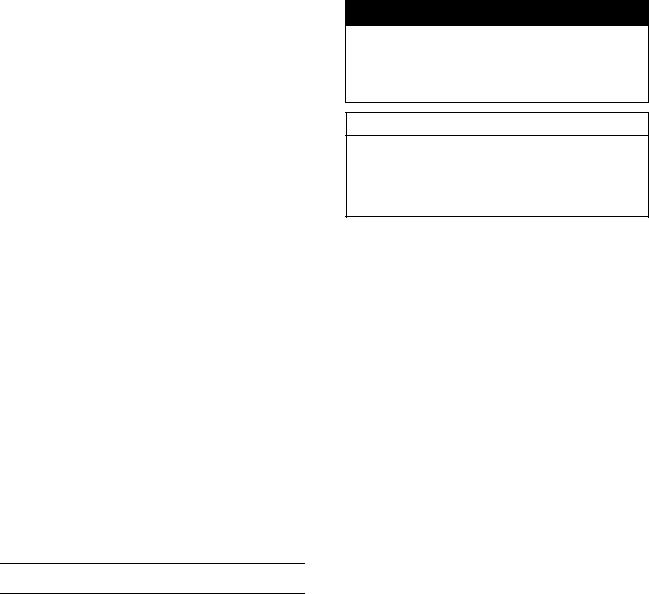
Arrangement and Cleaning of Removed Parts
Disassembled parts are easy to confuse. Arrange the parts according to the order the parts were disassembled and clean the parts in order prior to assembly.
Storage of Removed Parts
After all the parts including subassembly parts have been cleaned, store the parts in a clean area. Put a clean cloth or plastic sheet over the parts to protect from any foreign materials that may collect before re-assembly.
Inspection
Reuse of worn or damaged parts may lead to serious accident. Visually inspect removed parts for corrosion, discoloration, or other damage. Refer to the appropriate sections of this manual for service limits on individual parts. Replace the parts if any damage has been found or if the part is beyond its service limit.
Replacement Parts
Replacement parts must be KAWASAKI genuine or recommended by KAWASAKI. Gaskets, O-rings, oil seals, grease seals, circlips or cotter pins must be replaced with new ones whenever disassembled.
Assembly Order
In most cases assembly order is the reverse of disassembly, however, if assembly order is provided in this Service Manual, follow the procedures given.
1-4 GENERAL INFORMATION
Before Servicing
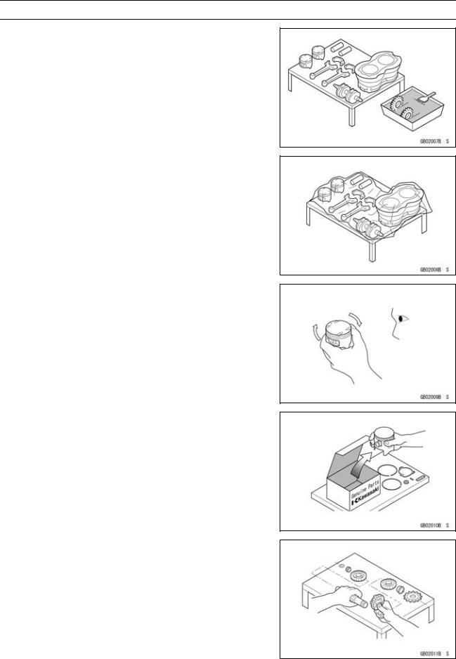
Tightening Sequence
Generally, when installing a part with several bolts, nuts, or screws, start them all in their holes and tighten them to a snug fit. Then tighten them according to the specified sequence to prevent case warpage or deformation which can lead to malfunction. Conversely when loosening the bolts, nuts, or screws, first loosen all of them by about a quarter turn and then remove them. If the specified tightening sequence is not indicated, tighten the fasteners alternating diagonally.
Tightening Torque
Incorrect torque applied to a bolt, nut, or screw may lead to serious damage. Tighten fasteners to the specified torque using a good quality torque wrench. Often, the tightening sequence is followed twice-initial tightening and final tightening with torque wrench.
Force
Use common sense during disassembly and assembly, excessive force can cause expensive or hard to repair damage. When necessary, remove screws that have a non -permanent locking agent applied using an impact driver. Use a plastic-faced mallet whenever tapping is necessary.
Gasket, O-ring
Hardening, shrinkage, or damage of both gaskets and O-rings after disassembly can reduce sealing performance. Remove old gaskets and clean the sealing surfaces thoroughly so that no gasket material or other material remains. Install new gaskets and replace used O-rings when re-assembling
Liquid Gasket, Non-permanent Locking Agent
For applications that require Liquid Gasket or a Non-permanent Locking Agent, clean the surfaces so that no oil residue remains before applying liquid gasket or non-permanent locking agent. Do not apply them excessively. Excessive application can clog oil passages and cause serious damage.

GENERAL INFORMATION 1-5
Before Servicing
Press
For items such as bearings or oil seals that must be pressed into place, apply small amount of oil to the contact area. Be sure to maintain proper alignment and use smooth movements when installing.
Ball Bearing and Needle Bearing
Do not remove pressed ball or needle unless removal is absolutely necessary. Replace with new ones whenever removed. Press bearings with the manufacturer and size marks facing out. Press the bearing into place by putting pressure on the correct bearing race as shown.
Pressing the incorrect race can cause pressure between the inner and outer race and result in bearing damage.
Oil Seal, Grease Seal
Do not remove pressed oil or grease seals unless removal is necessary. Replace with new ones whenever removed. Press new oil seals with manufacture and size marks facing out. Make sure the seal is aligned properly when installing.
Apply specified grease to the lip of seal before installing the seal.
Circlips, Cotter Pins
Replace circlips or cotter pins that were removed with new ones. Take care not to open the clip excessively when installing to prevent deformation.
1-6 GENERAL INFORMATION
Before Servicing
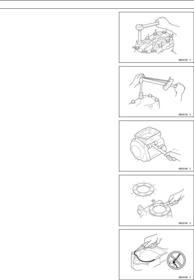
Lubrication
It is important to lubricate rotating or sliding parts during assembly to minimize wear during initial operation. Lubrication points are called out throughout this manual, apply the specific oil or grease as specified.
Direction of Engine Rotation
When rotating the crankshaft by hand, the free play amount of rotating direction will affect the adjustment. Rotate the crankshaft to positive direction (clockwise viewed from output side).
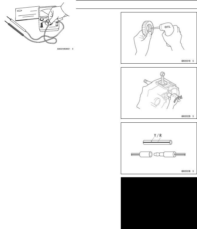
Electrical Wires
A two-color wire is identified first by the primary color and then the stripe color. Unless instructed otherwise, electrical wires must be connected to those of the same color.
Instrument
Use a meter that has enough accuracy for an accurate measurement. Read the manufacture’s instructions thoroughly before using the meter. Incorrect values may lead to improper adjustments.
GENERAL INFORMATION 1-7
Model Identification
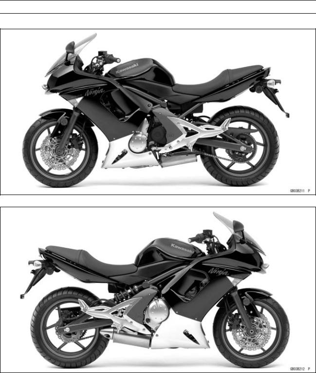
EX650A6F (United States and Canada) Left Side View
EX650A6F (United States and Canada) Right Side View
1-8 GENERAL INFORMATION
Model Identification
EX650A6F (Europe) Left Side View
EX650A6F (Europe) Right Side View
 User Manual")
GENERAL INFORMATION 1-9
Model Identification
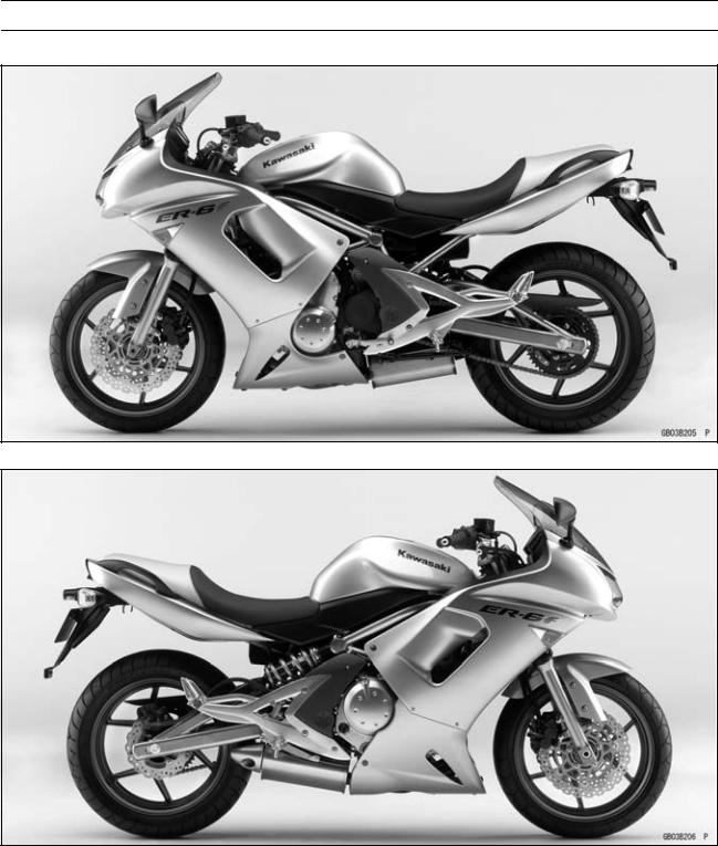
EX650B6F Left Side View
EX650B6F Right Side View
Frame Number |
Engine Number |
|

1-10 GENERAL INFORMATION
General Specifications
|
Items |
EX650A6F, EX650B6F |
|
Dimensions |
|
|
Overall Length |
2 105 mm (82.9 in.) |
|
Overall Width |
760 mm (29.9 in.) |
|
Overall Height |
1 210 mm (47.6 in.) |
|
Wheelbase |
1 410 mm (55.5 in.) |
|
Road Clearance |
145 mm (5.7 in.) |
|
Seat Height |
790 mm (31.1 in.) |
|
Dry Mass: |
|
|
EX650A6F |
178 kg (392.5 lb) |
|
(CAL) 178.5 kg (393.6 lb) |
|
|
EX650B6F |
182 kg (401.3 lb) |
|
Curb Mass: |
|
|
Front: |
|
|
EX650A6F |
101 kg (222.7 lb) |
|
EX650B6F |
103 kg (227.1 lb) |
|
Rear: |
|
|
EX650A6F |
99 kg (216.1 lb) |
|
(CAL) 99.5 kg (219.4 lb) |
|
|
EX650B6F |
101 kg (222.7 lb) |
|
Fuel Tank Capacity |
15.5 L (4.1 US gal.) |
|
Performance |
|
|
Minimum Turning Radius |
2.7 m (8.9 ft) |
|
Engine |
|
|
Type |
4-stroke, DOHC, 2-cylinder |
|
Cooling System |
Liquid-cooled |
|
Bore and Stroke |
83 × 60 mm (3.3 × 2.4 in.) |
|
Displacement |
649 cm³ (39.60 cu in.) |
|
Compression Ratio |
11.3 : 1 |
|
Maximum Horsepower |
53 kW (72 PS) @8 500 r/min (rpm), |
|
Maximum Torque |
66 N·m (6.7 kgf·m, 49 ft·lb) @7 000 r/min (rpm), |
|
Carburetion System |
FI (Fuel Injection) KEIHIN TTK38 × 2 |
|
Starting System |
Electric starter |
|
Ignition System |
Battery and coil (transistorized) |
|
Timing Advance |
Electronically advanced (digital igniter) |
|
Ignition Timing |
From 10° BTDC @1 300 r/min (rpm) to 35° BTDC @4 800 |
|
r/min (rpm) |
|
|
Spark Plug |
NGK CR9EIA-9 |
|
Cylinder Numbering Method |
Left to right, 1-2 |
|
Firing Order |
1-2 |
|
Valve Timing: |
|
|
Inlet: |
|
|
Open |
31° BTDC |
|
Close |
61° ABDC |
|
Duration |
272° |
|
GENERAL INFORMATION 1-11 |
||
|
General Specifications |
||
|
Items |
EX650A6F, EX650B6F |
|
|
Exhaust: |
||
|
Open |
50° BBDC |
|
|
Close |
30° ATDC |
|
|
Duration |
||
|
260° |
||
|
Lubrication System |
Forced lubrication (semi-dry sump) |
|
|
Engine Oil: |
||
|
Type |
API SE, SF or SG |
|
|
API SH, SJ or SL with JASO MA |
||
|
Viscosity |
SAE 10W-40 |
|
|
Capacity |
2.4 L (2.5 US qt) |
|
|
Drive Train |
||
|
Primary Reduction System: |
||
|
Type |
Gear |
|
|
Reduction Ratio |
2.095 (88/42) |
|
|
Clutch Type |
Wet multi disc |
|
|
Transmission: |
||
|
Type |
6-speed, constant mesh, return shift |
|
|
Gear Ratios: |
||
|
1st |
2.438 (39/16) |
|
|
2nd |
1.714 (36/21) |
|
|
3rd |
1.333 (32/24) |
|
|
4th |
1.111 (30/27) |
|
|
5th |
0.966 (28/29) |
|
|
6th |
0.852 (23/27) |
|
|
Final Drive System: |
||
|
Type |
Chain drive |
|
|
Reduction Ratio |
3.067 (46/15) |
|
|
Overall Drive Ratio |
5.473 @Top gear |
|
|
Frame |
||
|
Type |
Tubular, diamond |
|
|
Caster (Rake Angle) |
25° |
|
|
Trail |
106 mm (4.2 in.) |
|
|
Front Tire: |
||
|
Type |
Tubeless |
|
|
Size |
120/70 ZR17 M/C (58W) |
|
|
Rim Size |
17 × 3.50 |
|
|
Rear Tire: |
||
|
Type |
Tubeless |
|
|
Size |
160/60 ZR17 M/C (69W) |
|
|
Rim Size |
17 × 4.50 |
|
|
Front Suspension: |
||
|
Type |
Telescopic fork |
|
|
Wheel Travel |
120 mm (4.7 in.) |
|
|
Rear Suspension: |

1-12 GENERAL INFORMATION
General Specifications
|
Items |
EX650A6F, EX650B6F |
|
|
Type |
Swingarm |
|
|
Wheel Travel |
125 mm (4.9 in.) |
|
|
Brake Type: |
||
|
Front |
Dual discs |
|
|
Rear |
Single disc |
|
|
Electrical Equipment |
||
|
Battery |
12 |
V 10 Ah |
|
Headlight: |
||
|
Type |
Semi-sealed beam |
|
|
Bulb |
12 |
V 55 W × 2/55 W (Hi/Lo) |
|
Tail/Brake Light |
12 |
V 5/21 W |
|
Alternator: |
||
|
Type |
Three-phase AC |
|
|
Rated Output |
24 |
A/14 V @5 000 r/min (rpm) |
Specifications are subject to change without notice, and may not apply to every country.
GENERAL INFORMATION 1-13
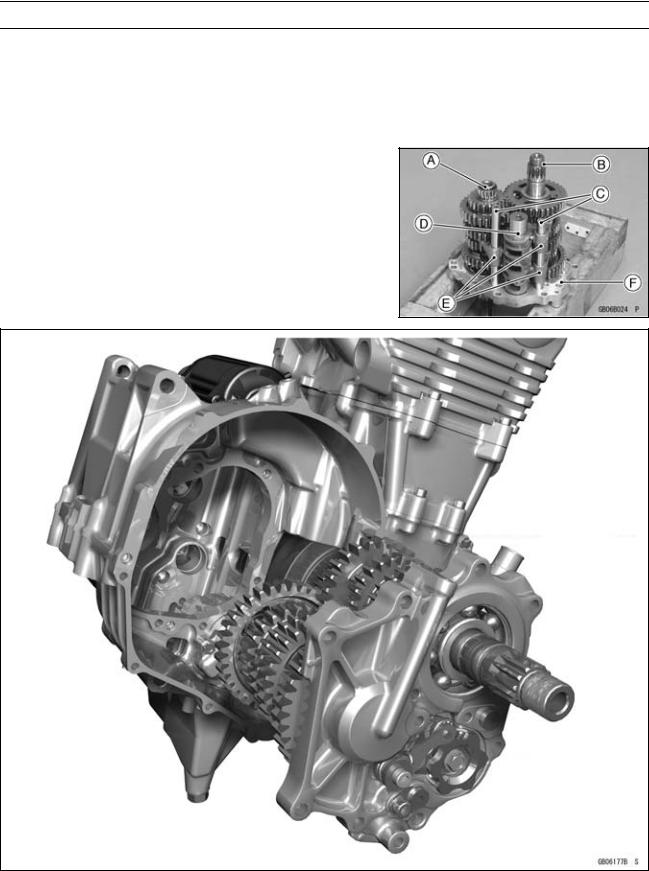
Technical Information — Cassette Type Transmission
Cassette Type Transmission
The transmission of the current model is unable to be removed without disassembling upper and lower crankcase halves.
The EX650A/B enables transmission to be removed from the right side of engine as an assy, without disassembling crankcase halves (see Transmission Assy Removal in the Crankshaft/Transmission chapter).
Transmission Assy: Drive Shaft [A] Output Shaft [B] Shift Rods [C] Shift Dram [D] Shift Forks [E]
Transmission Case [F]
1-14 GENERAL INFORMATION
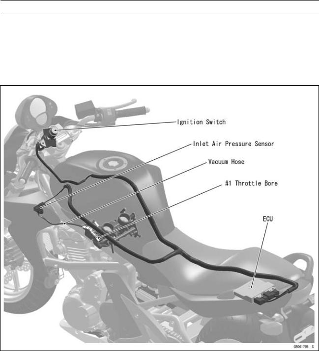
Technical Information — Inlet Air Pressure Sensor
Atmospheric pressure sensor and camshaft position sensor are not equipped with the EX650A/B. As a substitute of these sensors above, the EX650A/B recognizes atmospheric pressure and intake stroke of #1 by the signal of inlet air pressure sensor.
The ECU detects atmospheric pressure when the ignition is switched ON. While the engine is running, the ECU also presumes atmospheric pressure by analyzing the waveform of boost pressure over fixed period. The intake stroke is recognized by waveform of boost pressure, therefore the system can recognize the difference of each stroke.
GENERAL INFORMATION 1-15
Technical Information – ABS (Anti – Lock Brake System)
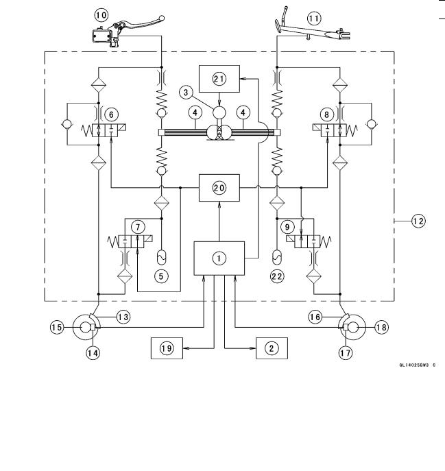
Outline
ABS controls the brake caliper fluid pressure by means of mechatronics — a combination of electronic and hydraulic control technology in order to keep the friction force between the tires and the road surfaces close to the maximum value and prevent wheel lock. But it does not operate during cruising.
ABS Total System
|
1. |
ECU |
13. |
Front Brake Caliper |
|
|
2. |
ABS Indicator Light (LED) |
14. |
Front Wheel Rotation Sensor |
|
|
3. |
Pump Motor |
15. |
Front Wheel Rotation Sensor Rotor |
|
|
4. |
Pump |
16. |
Rear Brake Caliper |
|
|
5. |
Front Reservoir |
17. |
Rear Wheel Rotation Sensor |
|
|
6. |
Front Inlet Solenoid Valve |
18. |
Rear Wheel Rotation Sensor Rotor |
|
|
7. |
Front Outlet Solenoid Valve |
19. |
ABS Kawasaki Self-diagnosis System Con- |
|
|
8. |
Rear Inlet Solenoid Valve |
nector |
||
|
9. |
Rear Outlet Solenoid Valve |
20. |
ABS Solenoid Valve Relay |
|
|
10. |
Brake Lever |
21. |
ABS Motor Relay |
|
|
11. |
Brake Pedal |
22. |
Rear Reservoir |
|
|
12. |
ABS Hydraulic Unit |
1-16 GENERAL INFORMATION
Technical Information – ABS (Anti – Lock Brake System)
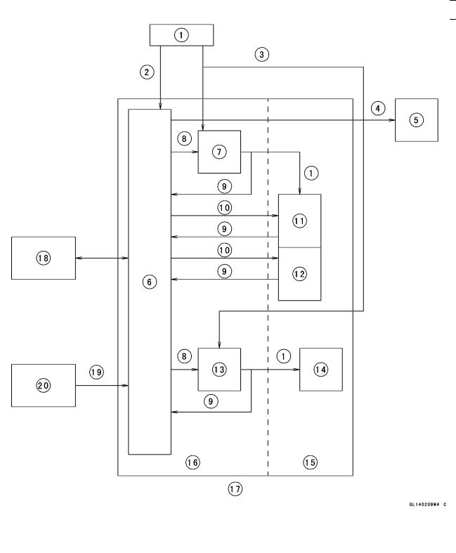
ABS System Block Diagram
|
1. |
Power Source |
12. |
Inlet Solenoid Valve |
||
|
2. |
Ignition Power Source |
13. |
ABS Motor Relay |
||
|
3. Battery Power Source |
14. |
Pump Motor |
|||
|
4. |
Indicator Light Output |
15. |
Hydraulic Unit |
||
|
5. |
ABS Indicator Light (LED) |
16. |
ABS Controller |
||
|
6. |
ECU |
17. |
ABS Hydraulic Unit |
||
|
7. |
ABS Solenoid Valve Relay |
18. |
ABS Kawasaki Self-diagnosis System Con- |
||
|
8. |
Output |
nector |
|||
|
9. |
Monitor Input |
19. |
Wheel Rotation Input |
||
|
10. |
Valve Output |
20. |
Wheel Rotation Sensor |
||
|
11. |
Outlet Solenoid Valve |
GENERAL INFORMATION 1-17
Technical Information – ABS (Anti – Lock Brake System)
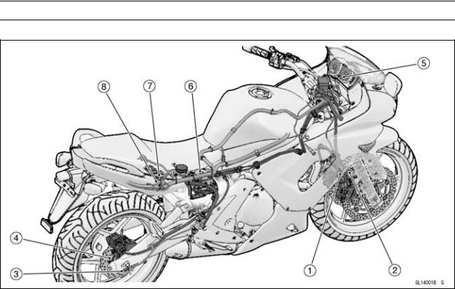
Related Parts and Function
1.Front Wheel Rotation Sensor
2.Front Wheel Rotation Sensor Rotor
3.Rear Wheel Rotation Sensor
4.Rear Wheel Rotation Sensor Rotor
5.ABS Indicator Light (LED)
6.ABS Hydraulic Unit
7.ABS Fuse Box
8.ABS Kawasaki Self-diagnosis System Connector
Wheel Rotation Sensor
The wheel rotation sensors output the rotation speed of each wheel to the ECU in the ABS hydraulic unit. The wheel rotation sensor is installed to the front fork and rear caliper bracket, and the sensor rotor is pressed into the brake disc. The number of teeth on the front and rear sensor rotor is 50.
ABS Indicator Light (LED)
The condition or the failure of the ABS system is indicated by various patterns of the ABS indicator light (LED) blinking.

1-18 GENERAL INFORMATION
Technical Information – ABS (Anti – Lock Brake System)
ABS Hydraulic Unit
The outlet and inlet solenoid valves, reservoir, pump motor, solenoid valve relay, motor relay, and ECU are built in the ABS hydraulic unit.
1.Brake Lever
2.Brake Pedal
3.Pump Motor
4.Rear Inlet Solenoid Valve
5.Rear Outlet Solenoid Valve
6.Rear Reservoir
7.Rear Caliper
8.Front Inlet Solenoid Valve
9.Front Outlet Solenoid Valve
10.Front Caliper
11.Front Reservoir
12.Orifice
13.Filter
14.Check Valve
GENERAL INFORMATION 1-19
Technical Information – ABS (Anti – Lock Brake System)
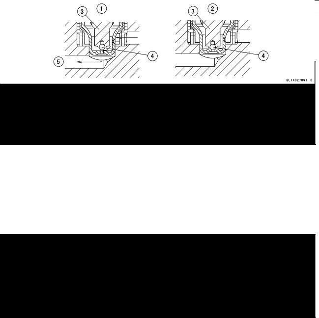
Inlet Solenoid Valve
Inlet solenoid valves control the brake pressure of each wheel by combining the operation of the outlet solenoid valve. The ECU changes the electric current in the solenoids of the inlet solenoid valve (2 way, 2 position electromagnetic valve) to move the tappet and change the fluid pressure to “Increase Mode”, “Hold Mode”, or “Decrease Mode”.
1.Increase Mode
2.Hold and Decrease Mode
3.Tappet
4.Valve Body
5.From Master Cylinder
Outlet Solenoid Valve
Outlet solenoid valves control the brake pressure of each wheel by combining the operation of the inlet solenoid valve. The ECU changes the electric current in the solenoids of the outlet solenoid valve (2 way, 2 position electromagnetic valve) to move the armature and change the fluid pressure to “Increase Mode”, “Hold Mode”, or “Decrease Mode”.
1.Decrease Mode
2.Increase and Hold Mode
3.Armature
4.Valve
5.To Reservoir
1-20 GENERAL INFORMATION
Technical Information – ABS (Anti – Lock Brake System)
Reservoir
When the passage opens between the caliper and the reservoir with the outlet solenoid valve in “Decrease Mode”, the brake fluid flows into the reservoir by pushing the piston, stays there temporarily, and then returns to the master cylinder. With the outlet solenoid valve “Increase or Hold Mode”, the pump returns the remaining brake fluid in the reservoir to the master cylinder.
1.From Outlet Solenoid Valve
2.To Pump
Pump Motor
The pump motor operates the pump, supply or return the brake fluid from the pump.
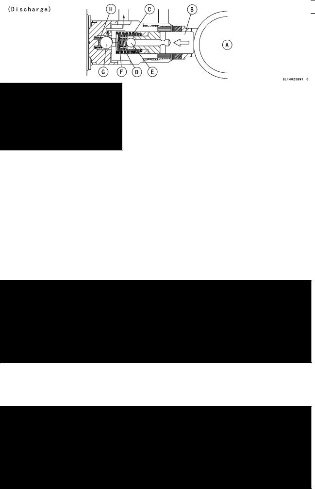
Pump
The pump operates continuously when the ABS is activated. The pump is driven by the motor and supply the brake fluid to the caliper or return the brake fluid in the reservoir to the master cylinder. The piston is reciprocated by the eccentric cam [A] on the end of the motor shaft and the pump sucks in or discharge the brake fluid.
When the pump pulls fluid in, the piston [B] is moved right by the force of the spring [C]. At this time, the spring [D] is compressed by the pressure of the brake fluid in the reservoir to open the inlet valve [E] and the brake fluid flows into the cylinder [F]. The outlet valve [G] is held closed by the force of the spring [H].
When the pump discharges the brake fluid, the inlet valve [E] is closed by the spring [D], and the piston [B] is moved left by the cam [A], producing pressure in the cylinder [F]. The pressure pushes the spring [H], opens the outlet valve [G], and the brake fluid returns to the master cylinder.
Spring [C]
![]()
GENERAL INFORMATION 1-21
Technical Information – ABS (Anti – Lock Brake System)
ABS Solenoid Valve Relay
ABS solenoid valve relay supply or intercept the power to the inlet or outlet solenoid valves.
ABS Motor Relay
ABS motor relay supply or intercept the power to the pump motor.
ECU
ECU inputs the sensor signal.
ECU calculates the wheel condition for the slip.
ECU controls the hydraulic unit.
ECU sends the actuating signals to the ABS indicator light (LED).

1-22 GENERAL INFORMATION
Technical Information – ABS (Anti – Lock Brake System)
ABS Operation
The ABS has two independent hydraulic lines, one for the front wheel and the other for the rear wheel. The front wheel system is explained here and is identical to the rear wheel system.
ABS in Action
(Increase Mode)
When the caliper fluid pressure is to be increased, first the tappet of inlet solenoid valve opens (normally open). The brake fluid flows through the valve body as shown in the diagram below to increase the brake fluid pressure in the caliper. The master cylinder pressurizes to the brake caliper directly, increasing the braking force.
1.Brake Lever
2.Front Inlet Solenoid Valve
3.Pump Motor
4.Pump
5.Front Reservoir
6.Front Outlet Solenoid Valve
7.Front Caliper

GENERAL INFORMATION 1-23
Technical Information – ABS (Anti – Lock Brake System)
(Hold Mode)
When the caliper fluid pressure is to be hold, the tappet of inlet solenoid valve closes, and the passage (master cylinder side) to the valve body is intercepted. No matter how hard the brake lever is pulled, the brake fluid pressure in the caliper is maintained at a given level.
1.Brake Lever
2.Front Inlet Solenoid Valve
3.Pump Motor
4.Pump
5.Front Reservoir
6.Front Outlet Solenoid Valve
7.Front Caliper

1-24 GENERAL INFORMATION
Technical Information – ABS (Anti – Lock Brake System)
(Decrease Mode)
When the caliper fluid pressure is to be decreased, the tappet of inlet solenoid valve closes, and the passage to the valve body is intercepted. The valve of outlet solenoid valve is opened by the operation of the armature, and the brake fluid flows to the reservoir. ECU operates pump, and the pump returns the brake fluid in the reservoir to the master cylinder. The brake fluid pressure is decreased, and the wheel is prevented from locking.
1.Brake Lever
2.Front Inlet Solenoid Valve
3.Pump Motor
4.Pump
5.Front Reservoir
6.Front Outlet Solenoid Valve
7.Front Caliper

GENERAL INFORMATION 1-25
Technical Information – ABS (Anti – Lock Brake System)
ABS Disabled (Conventional Mode)
During cruising (without braking) or in case of a malfunction with the ABS, the ECU stops operating. This is “Conventional Mode”.
When the caliper fluid pressure is to be increased, first the tappet of inlet solenoid valve opens (normally open). The brake fluid flows through the valve body as shown in the diagram below to increase the brake fluid pressure in the caliper. The master cylinder pressurizes to the brake caliper directly, increasing the braking force.
1.Brake Lever
2.Front Inlet Solenoid Valve
3.Pump Motor
4.Pump
5.Front Reservoir
6.Front Outlet Solenoid Valve
7.Front Caliper

1-26 GENERAL INFORMATION
Technical Information – ABS (Anti – Lock Brake System)
Riding Characteristics of ABS
ABS is designed to help prevent the wheels from locking up when hard brakes are applied while running straight. The ABS automatically regulates brake force. Intermittently gaining gripping force and braking force helps prevent wheel lock-up and allows stable steering control while stopping.
Brake control function is identical to that of a conventional motorcycle. The brake lever is used for the front brake and the brake pedal for the rear brake.
Although the ABS provides stability while stopping by preventing wheel lock-up, remember the following characteristics:
○ABS cannot compensate for adverse road conditions, misjudgement or improper application of brakes. You must take the same care as with motorcycles not equipped with ABS.
○ABS is not designed to shorten the braking distance. On loose, uneven or downhill surfaces, the stopping distance of a motorcycle with ABS may be longer than that of an equivalent motorcycle without ABS. Use special caution in such areas.
○ABS will help prevent wheel lock-up during straight-up braking, but it cannot control wheel slip which may be caused by braking during cornering. When turning a corner, it is better to limit braking to the light application of both brakes or not to brake at all. Reduce your speed before you get into the corner.
○The ECU integrated in the ABS compare vehicle speed with wheel speed. Since non-recommended tires can affect wheel speed, they may confuse the ECU, which can extend braking distance.

 WARNING
Use of non-recommended tires may cause malfunctioning of ABS and can lead to extended braking distance. The rider could have an accident as a result. Always use recommended standard tires for this motorcycle.
NOTE
○When the ABS is functioning, you may feel a pulsing in the brake lever or pedal. This is normal. You need not suspend applying brakes.
○Immediately after turning the ignition switch on, you may hear a click of the relay operating. This is the sound of self-checking and is quite normal.
○ABS does not function at the speed of approx. 6 km/h or below. ○ABS does not function if the battery is discharged.

GENERAL INFORMATION 1-27
Unit Conversion Table
Prefixes for Units: |
Units of Length: |
|
Prefix |
Symbol |
Power |
||
|
mega |
M |
× 1 000 |
000 |
|
|
kilo |
k |
× |
1 000 |
|
|
centi |
c |
× |
0.01 |
|
|
milli |
m |
× |
0.001 |
|
|
micro |
µ |
× 0.000001 |
Units of Mass:
|
kg |
× |
2.205 |
= |
lb |
|
g |
× |
0.03527 |
= |
oz |
Units of Volume:
|
L |
× |
0.2642 |
= |
gal (US) |
|
L |
× |
0.2200 |
= |
gal (imp) |
|
L |
× |
1.057 |
= |
qt (US) |
|
L |
× |
0.8799 |
= |
qt (imp) |
|
L |
× |
2.113 |
= |
pint (US) |
|
L |
× |
1.816 |
= |
pint (imp) |
|
mL |
× |
0.03381 |
= |
oz (US) |
|
mL |
× |
0.02816 |
= |
oz (imp) |
|
mL |
× |
0.06102 |
= |
cu in |
Units of Force:
|
N |
× |
0.1020 |
= |
kg |
|
N |
× |
0.2248 |
= |
lb |
|
kg |
× |
9.807 |
= |
N |
|
kg |
× |
2.205 |
= |
lb |
|
km |
× |
0.6214 |
= |
mile |
|
m |
× |
3.281 |
= |
ft |
|
mm |
× |
0.03937 |
= |
in |
Units of Torque:
|
N·m |
× |
0.1020 |
= |
kgf·m |
|
N·m |
× |
0.7376 |
= |
ft·lb |
|
N·m |
× |
8.851 |
= |
in·lb |
|
kgf·m |
× |
9.807 |
= |
N·m |
|
kgf·m |
× |
7.233 |
= |
ft·lb |
|
kgf·m |
× |
86.80 |
= |
in·lb |
Units of Pressure:
|
kPa |
× |
0.01020 |
= |
kgf/cm² |
|
kPa |
× |
0.1450 |
= |
psi |
|
kPa |
× |
0.7501 |
= |
cmHg |
|
kgf/cm² |
× |
98.07 |
= |
kPa |
|
kgf/cm² |
× |
14.22 |
= |
psi |
|
cmHg |
× |
1.333 |
= |
kPa |
Units of Speed:
km/h × 0.6214 = mph
Units of Power:
|
kW |
× |
1.360 |
= |
PS |
|
kW |
× |
1.341 |
= |
HP |
|
PS |
× |
0.7355 |
= |
kW |
|
PS |
× |
0.9863 |
= |
HP |
Units of Temperature:

PERIODIC MAINTENANCE 2-1
Periodic Maintenance
Table of Contents
|
Periodic Maintenance Chart ……………………………………………………………………………………… |
2-3 |
||
|
Torque and Locking Agent………………………………………………………………………………………… |
2-6 |
2 |
|
|
Specifications |
2-11 |
||
|
Special Tools ………………………………………………………………………………………………………….. |
2-13 |
||
|
Periodic Maintenance Procedures……………………………………………………………………………… |
2-14 |
||
|
Fuel System (DFI)…………………………………………………………………………………………………. |
2-14 |
||
|
Air Cleaner Element Cleaning………………………………………………………………………………. |
2-14 |
||
|
Throttle Control System Inspection……………………………………………………………………….. |
2-15 |
||
|
Engine Vacuum Synchronization Inspection…………………………………………………………… |
2-16 |
||
|
Idle Speed Inspection …………………………………………………………………………………………. |
2-18 |
||
|
Idle Speed Adjustment………………………………………………………………………………………… |
2-18 |
||
|
Fuel Hose Inspection (fuel leak, damage, installation condition) ……………………………….. |
2-19 |
||
|
Evaporative Emission Control System (California Model) …………………………………………… |
2-19 |
||
|
Evaporative Emission Control System Inspection …………………………………………………… |
2-19 |
||
|
Cooling System…………………………………………………………………………………………………….. |
2-20 |
||
|
Coolant Level Inspection……………………………………………………………………………………… |
2-20 |
||
|
Radiator Hose Damage and Installation Condition Inspection…………………………………… |
2-21 |
||
|
Air Suction System ……………………………………………………………………………………………….. |
2-21 |
||
|
Air Suction System Damage Inspection…………………………………………………………………. |
2-21 |
||
|
Engine Top End ……………………………………………………………………………………………………. |
2-21 |
||
|
Valve Clearance Inspection …………………………………………………………………………………. |
2-21 |
||
|
Valve Clearance Adjustment………………………………………………………………………………… |
2-23 |
||
|
Clutch………………………………………………………………………………………………………………….. |
2-26 |
||
|
Clutch Operation Inspection…………………………………………………………………………………. |
2-26 |
||
|
Wheels/Tires………………………………………………………………………………………………………… |
2-26 |
||
|
Air Pressure Inspection……………………………………………………………………………………….. |
2-26 |
||
|
Wheel/Tire Damage Inspection…………………………………………………………………………….. |
2-27 |
||
|
Tire Tread Wear, Abnormal Wear Inspection………………………………………………………….. |
2-27 |
||
|
Wheel Bearing Damage Inspection ………………………………………………………………………. |
2-28 |
||
|
Drive Train …………………………………………………………………………………………………………… |
2-28 |
||
|
Drive Chain Lubrication Condition Inspection …………………………………………………………. |
2-28 |
||
|
Drive Chain Slack Inspection ……………………………………………………………………………….. |
2-29 |
||
|
Drive Chain Slack Adjustment ……………………………………………………………………………… |
2-29 |
||
|
Wheel Alignment Inspection ………………………………………………………………………………… |
2-30 |
||
|
Drive Chain Wear Inspection ……………………………………………………………………………….. |
2-31 |
||
|
Chain Guide Inspection……………………………………………………………………………………….. |
2-31 |
||
|
Brake System ………………………………………………………………………………………………………. |
2-32 |
||
|
Brake Fluid Leak (Brake Hose and Pipe) Inspection ……………………………………………….. |
2-32 |
||
|
Brake Hose and Pipe Damage and Installation Condition Inspection…………………………. |
2-32 |
||
|
Brake Operation Inspection …………………………………………………………………………………. |
2-33 |
||
|
Brake Fluid Level Inspection………………………………………………………………………………… |
2-33 |
||
|
Brake Pad Wear Inspection …………………………………………………………………………………. |
2-34 |
||
|
Brake Light Switch Operation Inspection ……………………………………………………………….. |
2-34 |
||
|
Suspensions ………………………………………………………………………………………………………… |
2-35 |
||
|
Front Forks/Rear Shock Absorber Operation Inspection ………………………………………….. |
2-35 |
||
|
Front Fork Oil Leak Inspection……………………………………………………………………………… |
2-35 |
||
|
Rear Shock Absorber Oil Leak Inspection ……………………………………………………………… |
2-35 |
||
|
Steering System …………………………………………………………………………………………………… |
2-36 |
||
|
Steering Play Inspection ……………………………………………………………………………………… |
2-36 |
||
|
Steering Play Adjustment…………………………………………………………………………………….. |
2-36 |

2-2 PERIODIC MAINTENANCE
|
Steering Stem Bearing Lubrication ……………………………………………………………………….. |
2-37 |
|
Electrical System ………………………………………………………………………………………………….. |
2-37 |
|
Spark Plug Condition Inspection…………………………………………………………………………… |
2-37 |
|
Lights and Switches Operation Inspection……………………………………………………………… |
2-38 |
|
Headlight Aiming Inspection ………………………………………………………………………………… |
2-40 |
|
Sidestand Switch Operation Inspection …………………………………………………………………. |
2-41 |
|
Engine Stop Switch Operation Inspection………………………………………………………………. |
2-42 |
|
Others…………………………………………………………………………………………………………………. |
2-43 |
|
Chassis Parts Lubrication ……………………………………………………………………………………. |
2-43 |
|
Bolts, Nuts and Fasteners Tightness Inspection……………………………………………………… |
2-44 |
|
Replacement Parts ……………………………………………………………………………………………….. |
2-45 |
|
Air Cleaner Element Replacement………………………………………………………………………… |
2-45 |
|
Fuel Hose Replacement ……………………………………………………………………………………… |
2-45 |
|
Coolant Change…………………………………………………………………………………………………. |
2-46 |
|
Radiator Hose and O-ring Replacement………………………………………………………………… |
2-48 |
|
Engine Oil Change……………………………………………………………………………………………… |
2-49 |
|
Oil Filter Replacement ………………………………………………………………………………………… |
2-49 |
|
Brake Hose and Pipe Replacement………………………………………………………………………. |
2-50 |
|
Brake Fluid Change ……………………………………………………………………………………………. |
2-51 |
|
Master Cylinder Rubber Parts Replacement ………………………………………………………….. |
2-52 |
|
Caliper Rubber Parts Replacement ………………………………………………………………………. |
2-54 |
|
Spark Plug Replacement …………………………………………………………………………………….. |
2-56 |
![]()
PERIODIC MAINTENANCE 2-3
Periodic Maintenance Chart
The scheduled maintenance must be done in accordance with this chart to keep the motorcycle in good running condition.The initial maintenance is vitally important and must not be neglected.
Periodic Inspection
|
FREQUENCY |
Whichever |
* ODOMETER READING |
||||||||||||||
|
comes |
× 1 000 km |
See |
||||||||||||||
|
first |
(× 1 000 mile) |
|||||||||||||||
|
Page |
||||||||||||||||
|
1 |
6 |
12 |
18 |
24 |
30 |
36 |
||||||||||
|
INSPECTION |
Every |
(0.6) |
(4) |
(7.5) |
(12) |
(15) |
(20) |
(24) |
||||||||
|
Fuel System |
||||||||||||||||
|
Air cleaner element — clean |
• |
• |
• |
2-14 |
||||||||||||
|
Throttle control system (play, smooth |
year |
• |
• |
• |
• |
2-15 |
||||||||||
|
return, no drag) — inspect |
||||||||||||||||
|
Engine vacuum synchronization — inspect |
• |
• |
• |
2-16 |
||||||||||||
|
Idle speed — inspect |
• |
• |
• |
• |
2-18 |
|||||||||||
|
Fuel leak (fuel hose and pipe) — inspect |
year |
• |
• |
• |
• |
2-19 |
||||||||||
|
Fuel hose and pipe damage — inspect |
year |
• |
• |
• |
• |
2-19 |
||||||||||
|
Fuel hose and pipe installation condition — |
year |
• |
• |
• |
• |
2-19 |
||||||||||
|
inspect |
||||||||||||||||
|
Evaporative Emission Control System |
||||||||||||||||
|
(CAL) |
||||||||||||||||
|
Evaporative emission control system |
• |
• |
• |
• |
• |
• |
• |
2-19 |
||||||||
|
function — inspect |
||||||||||||||||
|
Cooling System |
||||||||||||||||
|
Coolant level — inspect |
• |
• |
• |
• |
2-20 |
|||||||||||
|
Coolant leak (radiator hose and pipe) — |
year |
• |
• |
• |
• |
2-21 |
||||||||||
|
inspect |
||||||||||||||||
|
Radiator hose damage — inspect |
year |
• |
• |
• |
• |
2-21 |
||||||||||
|
Radiator hose installation condition — |
year |
• |
• |
• |
• |
2-21 |
||||||||||
|
inspect |
||||||||||||||||
|
Air Suction System |
||||||||||||||||
|
Air suction system damage — inspect |
• |
• |
• |
2-21 |
||||||||||||
|
Engine Top End |
||||||||||||||||
|
Valve clearance — inspect |
Every 42 000 km (26 000 mile) |
2-21 |
||||||||||||||
|
Clutch |
||||||||||||||||
|
Clutch operation (play, disengagement, |
• |
• |
• |
• |
2-26 |
|||||||||||
|
engagement) — inspect |
||||||||||||||||
|
Wheels and Tires |
||||||||||||||||
|
Tire air pressure — inspect |
year |
• |
• |
• |
2-26 |
|||||||||||
|
Wheel/tire damage — inspect |
• |
• |
• |
2-27 |
||||||||||||
|
Tire tread wear, abnormal wear — inspect |
• |
• |
• |
2-27 |
||||||||||||
|
Wheel bearing damage — inspect |
year |
• |
• |
• |
2-28 |
|||||||||||
|
Drive Train |
||||||||||||||||
|
Drive chain lubrication condition — inspect # |
Every 600 km (400 mile) |
2-28 |
||||||||||||||
|
Drive chain slack — inspect # |
Every 1 000 km (600 mile) |
2-29 |
||||||||||||||
|
Drive chain wear — inspect # |
• |
• |
• |
2-31 |

2-4 PERIODIC MAINTENANCE
Periodic Maintenance Chart
|
FREQUENCY |
Whichever |
* ODOMETER READING |
||||||||||||
|
comes |
× 1 000 km |
See |
||||||||||||
|
first |
(× 1 000 mile) |
|||||||||||||
|
Page |
||||||||||||||
|
1 |
6 |
12 |
18 |
24 |
30 |
36 |
||||||||
|
INSPECTION |
Every |
(0.6) |
(4) |
(7.5) |
(12) |
(15) |
(20) |
(24) |
||||||
|
Drive chain guide wear — inspect |
• |
• |
• |
2-31 |
||||||||||
|
Brake System |
||||||||||||||
|
Brake fluid leak (brake hose and pipe) — |
year |
• |
• |
• |
• |
• |
• |
• |
2-32 |
|||||
|
inspect |
||||||||||||||
|
Brake hose and pipe damage — inspect |
year |
• |
• |
• |
• |
• |
• |
• |
2-32 |
|||||
|
Brake hose and pipe installation condition |
year |
• |
• |
• |
• |
• |
• |
• |
2-32 |
|||||
|
— inspect |
||||||||||||||
|
Brake operation (effectiveness, play, no |
year |
• |
• |
• |
• |
• |
• |
• |
2-33 |
|||||
|
drag) — inspect |
||||||||||||||
|
Brake fluid level — inspect |
6 months |
• |
• |
• |
• |
• |
• |
• |
2-33 |
|||||
|
Brake pad wear — inspect # |
• |
• |
• |
• |
• |
• |
2-34 |
|||||||
|
Brake light switch operation — inspect |
• |
• |
• |
• |
• |
• |
• |
2-34 |
||||||
|
Suspensions |
||||||||||||||
|
Front forks/rear shock absorber operation |
• |
• |
• |
2-35 |
||||||||||
|
(damping and smooth stroke) — inspect |
||||||||||||||
|
Front forks/rear shock absorber oil leak — |
year |
• |
• |
• |
2-35 |
|||||||||
|
inspect |
||||||||||||||
|
Steering System |
||||||||||||||
|
Steering play — inspect |
year |
• |
• |
• |
• |
2-36 |
||||||||
|
Steering stem bearings — lubricate |
2 years |
• |
2-37 |
|||||||||||
|
Electrical System |
||||||||||||||
|
Spark plug condition — inspect |
• |
• |
• |
2-37 |
||||||||||
|
Lights and switches operation — inspect |
year |
• |
• |
• |
2-38 |
|||||||||
|
Headlight aiming — inspect |
year |
• |
• |
• |
2-40 |
|||||||||
|
Sidestand switch operation — inspect |
year |
• |
• |
• |
2-41 |
|||||||||
|
Engine stop switch operation — inspect |
year |
• |
• |
• |
2-42 |
|||||||||
|
Others |
||||||||||||||
|
Chassis parts — lubricate |
year |
• |
• |
• |
2-43 |
|||||||||
|
Bolts and nuts tightness — inspect |
• |
• |
• |
• |
2-44 |
#: Service more frequently when operating in severe conditions; dusty, wet, muddy, high speed or frequent starting/stopping.
*: For higher odometer readings, repeat at the frequency interval established here.

PERIODIC MAINTENANCE 2-5
Periodic Maintenance Chart
Periodic Replacement Parts
|
FREQUENCY |
Whichever |
* ODOMETER READING |
|||||||||
|
comes |
× 1 000 km |
See |
|||||||||
|
first |
(× 1 000 mile) |
||||||||||
|
Page |
|||||||||||
|
1 |
12 |
24 |
36 |
48 |
|||||||
|
CHANGE/REPLACE ITEM |
Every |
(0.6) |
(7.5) |
(15) |
(24) |
(30) |
|||||
|
Air cleaner element # |
2 years |
2-45 |
|||||||||
|
Fuel hose |
4 years |
• |
2-45 |
||||||||
|
Coolant |
3 years |
• |
2-46 |
||||||||
|
Radiator hose and O-ring |
3 years |
• |
2-48 |
||||||||
|
Engine oil # |
year |
• |
• |
• |
• |
• |
2-49 |
||||
|
Oil filter |
year |
• |
• |
• |
• |
• |
2-49 |
||||
|
Brake hose and pipe |
4 years |
• |
2-50 |
||||||||
|
Brake fluid |
2 years |
• |
• |
2-51 |
|||||||
|
Rubber parts of master cylinder and caliper |
4 years |
• |
2-52, |
||||||||
|
2-54 |
|||||||||||
|
Spark plug |
• |
• |
• |
• |
2-56 |
#: Service more frequently when operating in severe conditions; dusty, wet, muddy, high speed or frequent starting/stopping.
*: For higher odometer readings, repeat at the frequency interval established here.

2-6 PERIODIC MAINTENANCE
Torque and Locking Agent
The following tables list the tightening torque for the major fasteners requiring use of a non-permanent locking agent or silicone sealant etc.
Letters used in the “Remarks” column mean:
AL: Tighten the two clamp bolts alternately two times to ensure even tightening torque. EO: Apply engine oil.
L: Apply a non-permanent locking agent to the threads. Lh: Left-hand threads
MO: Apply molybdenum disulfide oil solution.
(mixture of the engine oil and molybdenum disulfide grease in a weight ratio 10 : 1)
R:Replacement Parts
S:Follow the specified tightening sequence. Si: Apply silicone grease (ex. PBC grease).
SS:Apply silicone sealant.
|
Fastener |
Torque |
Remarks |
||||
|
N·m |
kgf·m |
ft·lb |
||||
|
Fuel System (DFI) |
||||||
|
Water Temperature Sensor |
12 |
1.2 |
106 in·lb |
|||
|
Speed Sensor Bolt |
7.8 |
0.80 |
69 in·lb |
L |
||
|
Fuel Pump Bolts |
9.8 |
1.0 |
87 in·lb |
L, S |
||
|
Oxygen Sensor (Europe Models) |
44.1 |
4.50 |
32.5 |
|||
|
Cooling System |
||||||
|
Radiator Hose Clamp Screws |
2.0 |
0.20 |
17 in·lb |
|||
|
Water Pump Impeller Bolt |
9.8 |
1.0 |
87 in·lb |
|||
|
Water Pump Cover Bolts |
9.8 |
1.0 |
87 in·lb |
|||
|
Water Pump Drain Bolt |
7.0 |
0.70 |
62 in·lb |
|||
|
Thermostat Housing Bolts |
9.8 |
1.0 |
87 in·lb |
|||
|
Water Temperature Sensor |
12 |
1.2 |
106 in·lb |
|||
|
Baffle Plate Bolts |
5.9 |
0.60 |
52 in·lb |
|||
|
Engine Top End |
||||||
|
Air Suction Valve Cover Bolts |
9.8 |
87 in·lb |
||||
|
1.0 |
||||||
|
Cylinder Head Cover Bolts |
9.8 |
1.0 |
87 in·lb |
|||
|
Camshaft Cap Bolts |
12 |
1.2 |
106 in·lb |
S |
||
|
Cylinder Head Bolts (M10 New Bolts) |
54 |
5.5 |
40 |
MO, S |
||
|
Cylinder Head Bolts (M10 Used Bolts) |
49 |
5.0 |
36 |
MO, S |
||
|
Cylinder Bolt (M8) |
27.5 |
2.8 |
20 |
MO, S |
||
|
Cylinder Nut (M10) |
49 |
5.0 |
36 |
MO, S |
||
|
Cylinder Head Bolts (M6) |
12 |
1.2 |
106 in·lb |
S |
||
|
Cylinder Bolts (M6) |
12 |
1.2 |
106 in·lb |
S |
||
|
Throttle Body Holder Bolts |
12 |
1.2 |
106 in·lb |
|||
|
Rear Camshaft Chain Guide Bolt |
20 |
2.0 |
15 |
L |
||
|
Camshaft Chain Tensioner Mounting Bolts |
9.8 |
1.0 |
87 in·lb |
|||
|
Camshaft Chain Tensioner Cap Bolt |
20 |
2.0 |
15 |
|||
|
Camshaft Sprocket Bolts |
15 |
1.5 |
11 |
L |
||
|
Spark Plugs |
15 |
1.5 |
11 |
|||
|
Exhaust Pipe Manifold Holder Nuts |
17 |
1.7 |
12 |
|||
|
Muffler Body Mounting Bolt (Front) |
20 |
2.0 |
15 |

PERIODIC MAINTENANCE 2-7
Torque and Locking Agent
|
Fastener |
Torque |
Remarks |
|||
|
N·m |
kgf·m |
ft·lb |
|||
|
Muffler Body Mounting Bolt (Rear) |
20 |
2.0 |
15 |
||
|
Baffle Plate Bolts |
5.9 |
0.60 |
52 in·lb |
||
|
Clutch |
|||||
|
Upper Cap on Clutch Cover |
3.9 |
0.40 |
35 in·lb |
||
|
Lower Cap on Clutch Cover |
– |
– |
– |
Hand-tighten |
|
|
Oil Filler Plug |
– |
– |
– |
Hand-tighten |
|
|
Clutch Cover Mounting Bolts |
9.8 |
1.0 |
87 in·lb |
||
|
Clutch Spring Bolts |
9.8 |
1.0 |
87 in·lb |
||
|
Clutch Hub Nut |
132 |
13.5 |
98 |
R |
|
|
Clutch Lever Clamp Bolts |
7.8 |
0.80 |
69 in·lb |
S |
|
|
Oil Pump Chain Guide Bolts |
12 |
1.2 |
106 in·lb |
L |
|
|
Clutch Cable Holder Bolts |
9.8 |
1.0 |
87 in·lb |
L |
|
|
Clutch Cable Clamp Bolt |
9.8 |
1.0 |
87 in·lb |
||
|
Engine Lubrication |
|||||
|
Engine Oil Drain Bolt |
30 |
3.0 |
22 |
||
|
Filter Plate Bolts |
9.8 |
1.0 |
87 in·lb |
L |
|
|
Oil Filter |
17.2 |
1.75 |
13 |
EO, R |
|
|
Holder Mounting Bolt |
25 |
2.5 |
18 |
L |
|
|
Oil Pan Bolts |
12 |
1.2 |
106 in·lb |
||
|
Oil Pump Chain Guide Bolts |
12 |
1.2 |
106 in·lb |
L |
|
|
Oil Pipe Plate Bolt |
9.8 |
1.0 |
87 in·lb |
L |
|
|
Oil Pressure Relief Valve |
15 |
1.5 |
11 |
L |
|
|
Oil Pressure Switch |
15 |
1.5 |
11 |
SS |
|
|
Oil Pump Cover Bolts |
9.8 |
1.0 |
87 in·lb |
L |
|
|
Lower Fairing Bracket Bolts |
12 |
1.2 |
106 in·lb |
L |
|
|
Oil Pump Sprocket Bolt |
12 |
1.2 |
106 in·lb |
L, Lh |
|
|
Oil Passage Plug |
20 |
2.0 |
15 |
L |
|
|
Oil Plate Bolts |
9.8 |
1.0 |
89 in·lb |
L |
|
|
Engine Removal/Installation |
|||||
|
Rear Engine Mounting Nuts |
44 |
4.5 |
32 |
S |
|
|
Engine Mounting Bracket Bolts |
25 |
2.5 |
18 |
S |
|
|
Front Engine Mounting Bolts |
44 |
4.5 |
32 |
S |
|
|
Crankshaft/Transmission |
|||||
|
Oil Plate Bolts |
9.8 |
1.0 |
87 in·lb |
L |
|
|
Breather Plate Bolts |
9.8 |
1.0 |
87 in·lb |
L |
|
|
Crankcase Bolts (M9, L = 113 mm) |
44 |
4.5 |
32 |
MO, S |
|
|
Crankcase Bolts (M9, L = 83 mm) |
44 |
4.5 |
32 |
MO, S |
|
|
Crankcase Bolts (M8, L = 73 mm) |
35 |
3.6 |
26 |
MO, S |
|
|
Crankcase Bolts (M8, L = 60 mm) |
35 |
3.6 |
26 |
MO, S |
|
|
Crankcase Bolts (M8, L = 110 mm) |
27.5 |
2.8 |
20 |
S |
|
|
Crankcase Bolts (M8, L = 50 mm) |
27.5 |
2.8 |
20 |
S |
|
|
Crankcase Bolts (M6) |
19.6 |
2.0 |
15 |
S |
|
|
Upper Crankcase Bolts |
27.5 |
2.8 |
20 |
S |

2-8 PERIODIC MAINTENANCE
Torque and Locking Agent
|
Fastener |
Torque |
Remarks |
||||
|
N·m |
kgf·m |
ft·lb |
||||
|
Shift Drum Bearing Holder Screw |
4.9 |
0.50 |
43 in·lb |
L |
||
|
Connecting Rod Big End Nuts |
see Text |
← |
← |
MO |
||
|
Timing Rotor Bolt |
40 |
4.1 |
30 |
|||
|
Oil Pressure Switch |
15 |
1.5 |
11 |
SS |
||
|
Oil Passage Plug |
20 |
2.0 |
15 |
L |
||
|
Gear Positioning Lever Bolt |
12 |
106 in·lb |
L |
|||
|
1.2 |
||||||
|
Shift Shaft Return Spring pin |
29 |
2.9 |
22 |
L |
||
|
Shift Drum Cam Bolt |
12 |
1.2 |
106 in·lb |
L |
||
|
Neutral Switch |
15 |
1.5 |
11 |
|||
|
Transmission Case Bolts |
20 |
2.0 |
15 |
|||
|
Shift Rod Plate Bolt |
9.8 |
1.0 |
87 in·lb |
|||
|
Neutral Switch Holder Screw |
4.9 |
0.50 |
43 in·lb |
L |
||
|
Shift Shaft Cover Bolts |
9.8 |
1.0 |
87 in·lb |
L (2) |
||
|
Shift Shaft Cover Screw |
4.9 |
0.50 |
43 in·lb |
L |
||
|
Wheels/Tires |
||||||
|
Front Axle |
108 |
11.0 |
80 |
|||
|
Front Axle Clamp Bolt |
34 |
3.5 |
25 |
|||
|
Rear Axle Nut |
108 |
11.0 |
80 |
|||
|
Final Drive |
||||||
|
Engine Sprocket Nut |
125 |
12.7 |
92 |
MO |
||
|
Rear Axle Nut |
108 |
11.0 |
80 |
|||
|
Rear Sprocket Nuts |
59 |
6.0 |
44 |
|||
|
Speed Sensor Bolt |
7.8 |
0.80 |
69 in·lb |
L |
||
|
Speed Sensor Bracket Bolts |
9.8 |
1.0 |
87 in·lb |
|||
|
Brakes |
||||||
|
Bleed Valve |
7.8 |
0.80 |
69 in·lb |
|||
|
Brake Hose Banjo Bolts |
25 |
2.5 |
18 |
|||
|
Brake Lever Pivot Bolt |
1.0 |
0.10 |
9 in·lb |
Si |
||
|
Brake Lever Pivot Bolt Locknut |
5.9 |
0.60 |
52 in·lb |
|||
|
Brake Pedal Bolt |
8.8 |
0.90 |
78 in·lb |
|||
|
Brake Pipe Joint Nuts (EX650B Models) |
18 |
1.8 |
13 |
|||
|
Front Brake Disc Mounting Bolts |
27 |
2.8 |
20 |
L |
||
|
Front Brake Light Switch Screw |
1.0 |
0.10 |
9 in·lb |
|||
|
Front Brake Reservoir Cap Screws |
1.0 |
0.10 |
9 in·lb |
|||
|
Front Caliper Mounting Bolts |
34 |
3.5 |
25 |
|||
|
Front Master Cylinder Clamp Bolts |
8.8 |
0.90 |
78 in·lb |
S |
||
|
Rear Brake Disc Mounting Bolts |
27 |
2.8 |
20 |
L |
||
|
Rear Caliper Mounting Bolts |
25 |
2.5 |
18 |
|||
|
Rear Master Cylinder Mounting Bolts |
25 |
2.5 |
18 |
|||
|
Rear Master Cylinder Push Rod Locknut |
18 |
1.8 |
13 |
|||
|
Suspension |
||||||
|
Front Axle Clamp Bolt |
34 |
3.5 |
25 |
|||
|
Front Fork Bottom Allen Bolts |
30 |
3.1 |
22 |
L |

PERIODIC MAINTENANCE 2-9
Torque and Locking Agent
|
Fastener |
Torque |
Remarks |
|||
|
N·m |
kgf·m |
ft·lb |
|||
|
Front Fork Clamp Bolts (Lower) |
20 |
2.0 |
15 |
AL |
|
|
Front Fork Clamp Bolts (Upper) |
20 |
2.0 |
15 |
||
|
Front Fork Top Plugs |
25 |
2.5 |
18 |
||
|
Rear Shock Absorber Bolt |
59 |
6.0 |
44 |
||
|
Rear Shock Absorber Nut |
59 |
6.0 |
44 |
||
|
Swingarm Pivot Shaft Nut |
108 |
11.0 |
80 |
||
|
Steering |
|||||
|
Front Fork Clamp Bolts (Lower) |
20 |
2.0 |
15 |
AL |
|
|
Front Fork Clamp Bolts (Upper) |
20 |
2.0 |
15 |
||
|
Handlebar Holder Bolts |
25 |
2.5 |
18 |
S |
|
|
Left Switch Housing Screws |
3.5 |
0.36 |
31 in·lb |
||
|
Right Switch Housing Screws |
3.5 |
0.36 |
31 in·lb |
||
|
Steering Stem Head Bolt |
108 |
11.0 |
80 |
||
|
Steering Stem Nut |
20 |
2.0 |
15 |
||
|
Frame |
|||||
|
Footpeg Stay Bolts |
34 |
3.5 |
25 |
||
|
Front Fender Bolts |
3.9 |
0.40 |
35 in·lb |
||
|
Front Fender Bracket Bolts |
8.8 |
0.90 |
78 in·lb |
L |
|
|
Front Turn Signal Light Mounting Screws |
1.2 |
0.12 |
11 in·lb |
||
|
Grab Rail Mounting Bolts |
25 |
2.5 |
18 |
||
|
Seat Lock Mounting Screws |
1.2 |
0.12 |
11 in·lb |
||
|
Sidestand Bolt |
44 |
4.5 |
32 |
||
|
Sidestand Switch Bolt |
8.8 |
0.90 |
78 in·lb |
L |
|
|
Electrical System |
|||||
|
Alternator Cover Bolts |
9.8 |
1.0 |
87 in·lb |
||
|
Alternator Lead Holding Plate Bolt |
9.8 |
1.0 |
87 in·lb |
L |
|
|
Alternator Rotor Bolt |
155 |
15.8 |
114 |
MO |
|
|
Crankshaft Sensor Bolts |
6.0 |
0.60 |
53 in·lb |
||
|
Engine Ground Cable Terminal Bolt |
9.8 |
1.0 |
87 in·lb |
||
|
Front Brake Light Switch Screw |
1.2 |
0.12 |
11 in·lb |
||
|
Front Turn Signal Light Mounting Screws |
1.2 |
0.12 |
11 in·lb |
||
|
Left Switch Housing Screws |
3.5 |
0.36 |
31 in·lb |
||
|
License Plate Light Cover Screws |
0.90 |
0.090 |
8 in·lb |
||
|
License Plate Light Mounting Screws |
1.2 |
0.12 |
11 in·lb |
||
|
Meter Screws |
1.2 |
0.12 |
11 in·lb |
||
|
Neutral Switch |
|||||
|
15 |
1.5 |
11 |
|||
|
Oil Pressure Switch |
15 |
1.5 |
11 |
SS |
|
|
Oxygen Sensor |
44.1 |
4.50 |
32.5 |
||
|
Regulator/Rectifier Bolts |
8.8 |
0.90 |
78 in·lb |
||
|
Right Switch Housing Screws |
3.5 |
0.36 |
31 in·lb |
||
|
Sidestand Switch Bolt |
8.8 |
0.90 |
78 in·lb |
L |
|
|
Spark Plugs |
15 |
1.5 |
11 |
||
|
Speed Sensor Bolt |
7.8 |
0.80 |
69 in·lb |
L |

2-10 PERIODIC MAINTENANCE
Torque and Locking Agent
|
Fastener |
Torque |
Remarks |
||||
|
N·m |
kgf·m |
ft·lb |
||||
|
Starter Motor Cable Terminal Nut |
6.0 |
0.60 |
53 in·lb |
|||
|
Starter Motor Clutch Bolts |
34 |
3.5 |
25 |
L |
||
|
Starter Motor Mounting Bolts |
9.8 |
87 in·lb |
L |
|||
|
1.0 |
||||||
|
Starter Motor Terminal Locknut |
11 |
1.1 |
97 in·lb |
|||
|
Starter Motor Through Bolts |
4.9 |
0.50 |
43 in·lb |
|||
|
Stator Coil Bolts |
12 |
1.2 |
106 in·lb |
L |
||
|
Timing Rotor Bolt |
40 |
4.1 |
30 |
|||
|
Water Temperature Sensor |
12 |
1.2 |
106 in·lb |
The table below, relating tightening torque to thread diameter, lists the basic torque for the bolts and nuts. Use this table for only the bolts and nuts which do not require a specific torque value. All of the values are for use with dry solvent-cleaned threads.
Basic Torque for General Fasteners
|
Threads Diameter |
Torque |
||||||||
|
(mm) |
N·m |
kgf·m |
ft·lb |
||||||
|
5 |
3.4 |
4.9 |
0.35 |
0.50 |
30 |
43 in·lb |
|||
|
6 |
5.9 |
7.8 |
0.60 |
0.80 |
52 |
69 in·lb |
|||
|
8 |
14 |
19 |
1.4 |
1.9 |
10.0 |
13.5 |
|||
|
10 |
25 |
34 |
2.6 |
3.5 |
19.0 |
25 |
|||
|
12 |
44 |
61 |
4.5 |
6.2 |
33 |
45 |
|||
|
14 |
73 |
98 |
7.4 |
10.0 |
54 |
72 |
|||
|
16 |
115 |
155 |
11.5 |
16.0 |
83 |
115 |
|||
|
18 |
165 |
225 |
17.0 |
23.0 |
125 |
165 |
|||
|
20 |
225 |
325 |
23.0 |
33.0 |
165 |
240 |
|
PERIODIC MAINTENANCE 2-11 |
||||
|
Specifications |
||||
|
Item |
Standard |
Service Limit |
||
|
Fuel System (DFI) |
||||
|
Throttle Grip Free Play |
2 3 mm (0.08 0.12 in.) |
– – – |
||
|
Idle Speed |
1 300 ±50 r/min (rpm) |
– – – |
||
|
Bypass Screws (Turn Out) |
0 2 1/2 (for reference) |
– – – |
||
|
Engine Vacuum |
35.3 ±1.3 kPa (265 ±10 mmHg) |
– – – |
||
|
Air Cleaner Element |
Polyurethane Foam |
– – – |
||
|
Cooling System |
||||
|
Coolant: |
||||
|
Type (recommended) |
Permanent type of antifreeze |
– – – |
||
|
Color |
Green |
– – – |
||
|
Mixed Ratio |
Soft water 50%, Coolant 50% |
– – – |
||
|
Freezing Point |
–35°C (–31°F) |
– – – |
||
|
Total Amount |
1.2 L (1.3 US qt) |
– – – |
||
|
Engine Top End |
||||
|
Valve Clearance: |
||||
|
Exhaust |
0.22 |
0.31 mm (0.0087 |
0.0122 in.) |
– – – |
|
Inlet |
0.15 |
0.21 mm (0.0059 |
0.0083 in.) |
– – – |
|
Clutch |
||||
|
Clutch Lever Free Play |
2 3 mm (0.08 0.12 in.) |
– – – |
||
|
Engine Lubrication System |
||||
|
Engine Oil: |
||||
|
Type |
API SE, SF or SG |
– – – |
||
|
API SH, SJ or SL with JASO MA |
||||
|
Viscosity |
SAE 10W-40 |
– – – |
||
|
Capacity |
1.7 L (1.8 US qt) (when filter is not |
– – – |
||
|
removed) |
||||
|
1.9 L (2.0 US qt) (when filter is removed) |
– – – |
|||
|
2.4 L (2.5 US qt) (when engine is |
– – – |
|||
|
completely dry) |
||||
|
Level |
Between upper and lower level lines |
– – – |
||
|
(after idling or running) |
||||
|
Wheels/Tires |
||||
|
Tread Depth: |
||||
|
Front |
4.3 mm (0.17 in.) |
1 mm (0.04 in.), |
||
|
(AT, CH, DE) |
||||
|
1.6 mm (0.06 in.) |
||||
|
Rear |
7.0 mm (0.28 in.) |
Up to 130 km/h (80 mph): |
||
|
2 mm (0.08 in.), |
||||
|
Over 130 km/h (80 mph): |
||||
|
3 mm (0.12 in.) |
||||
|
Air Pressure (when Cold): |
||||
|
Front |
Up to 180 kg (397 lb) load: |
– – – |
||
|
225 kPa (2.25 kgf/cm², 32 psi) |
||||
|
Rear |
Up to 180 kg (397 lb) load: |
– – – |
||
|
250 kPa (2.50 kgf/cm², 36 psi) |

2-12 PERIODIC MAINTENANCE
Specifications
|
Item |
Standard |
Service Limit |
|
Final Drive |
||
|
Drive Chain Slack |
30 40 mm (1.2 1.6 in.) |
– – – |
|
Drive Chain Wear (20-link |
317.5 318.2 mm (12.50 12.53 in.) |
323 mm (12.7 in.) |
|
Length) |
||
|
Standard Chain: |
||
|
Make |
ENUMA |
– – – |
|
Type |
EK520MVXL1 |
– – – |
|
Link |
114 links |
– – – |
|
Brakes |
||
|
Brake Fluid: |
||
|
Grade |
DOT4 |
– – – |
|
Brake Pad Lining |
||
|
Thickness: |
||
|
Front |
4.5 mm (0.18 in.) |
1 mm (0.04 in.) |
|
Rear |
5.0 mm (0.20 in.) |
1 mm (0.04 in.) |
|
Brake Light Timing: |
||
|
Front |
Pulled ON |
– – – |
|
Rear |
ON after about 10 mm (0.39 in.) of |
– – – |
|
pedal travel |
||
|
Electrical System |
||
|
Spark Plug Gap |
0.8 0.9 mm (0.03 0.04 in.) |
– – – |
 Loading…
|
|
Related Devices:
|
Types of Manuals:
The main types of Kawasaki ER-6f ABS instructions:
- User guide — rules of useing and characteristics
- Service manual — repair, diagnostics, maintenance
- Operation manual — description of the main functions of equipment
Motorcycle Instructions by Kawasaki:
-
Beta RR 125 series
INDICEINDEX1RR 125 cc ENDURO / MOTARDGrazie per la fiducia accordata e buon divertimento.Con questo manuale abbiamo voluto darle le informazioni necessarieper un corretto uso e una buona manutenzione della sua moto.RR 125 cc ENDURO / MOTARDWe would like to congratulate you on your purcase.Let us also take this opportun …
RR 125 series Motorcycle, 214
-
Buell XB9R 2003
2003 BUELL XB9R SERVICE MANUAL Part Number 99493-03Y Section 1: MaintenanceSection 2: ChassisSection 3: EngineSection 4: Fuel SystemSection 5: StarterSection 6: Drive/TransmissionSection 7: ElectricalAppendices …
XB9R 2003 Motorcycle, 566
-
Big Dog 2006 Chopper
WARNING!2006 CHOPPER OWNERS MANUALTHANKS FROM BIG DOG MOTORCYCLES for your purchase. With that purchase comes acommitment to provide you support for your handcrafted motorcycle. This Owners Manualhas been prepared to acquaint you with the care and maintenance of your motorcyclewhile providing important safety inf …
2006 Chopper Motorcycle, 100
-
MV Agusta F4 750 ORO-S-S 1+1 2000
MV AGUSTA Motor S.p.A. — After-Sales ServiceVia Nino Bixio, 8 — 21024 Cassinetta di Biandronno (VA)ITALY — Tel. ++39 0332 254.111 Fax ++39 0332 748.633www.mvagusta.it Part. No. 8A0092869Owner’s ManualProCarManuals.com …
F4 750 ORO-S-S 1+1 2000 Motorcycle, 109
-
Gilera Nexus 250 i.e.
GILERA WOULD LIKE TO THANK YOUfor choosing one of its products. We have prepared this manual to help you to get the very best from your vehicle. Please read it carefully before ridingthe vehicle for the first time. It contains information, tips and precautions for using your vehicle. It also describes features, details …
Nexus 250 i.e. Motorcycle, 96
-
Buell 2006 P3
2006 BUELL P3 SERVICE MANUAL Part Number 99492-06Y Section 1: MaintenanceSection 2: ChassisSection 3: EngineSection 4: Fuel SystemSection 5: StarterSection 6: Drive/TransmissionSection 7: ElectricalAppendix …
2006 P3 Motorcycle, 419
-
Triumph Speed Triple 1200 RR 2021
OWNER’S HANDBOOK01Speed Triple 1200 RR and Speed Triple 1200 RSThis handbook contains information on the Triumph Speed Triple 1200 RR and Speed Triple 1200 RS motorcycles.Always store this Owner’s Handbook with the motorcycle and refer to it for information whenever necessary.The information conta …
Speed Triple 1200 RR 2021 Motorcycle, 216
Руководство на немецком языке по техническому обслуживанию и ремонту мотоциклов Kawasaki ER 5 Twister с 1997 года выпуска.
- Издательство: —
- Год издания: —
- Страниц: 113
- Формат: PDF
- Размер: 84,9 Mb
Руководство на английском языке по техническому обслуживанию и ремонту мотоциклов Kawasaki ER-5.
- Издательство: Kawasaki Heavy Industries, Ltd.
- Год издания: 2004
- Страниц: 334
- Формат: PDF
- Размер: 7,1 Mb

Руководство на английском языке по техническому обслуживанию и ремонту мотоциклов Kawasaki ER-6n.
- Издательство: Kawasaki Heavy Industries, Ltd.
- Год издания: 2005
- Страниц: 537
- Формат: PDF
- Размер: 11,0 Mb

Руководство на английском языке по техническому обслуживанию и ремонту мотоциклов Kawasaki Ninja 650R/ER-6f.
- Издательство: Kawasaki Heavy Industries, Ltd.
- Год издания: 2008
- Страниц: 623
- Формат: PDF
- Размер: 7,7 Mb

Руководство по эксплуатации и техническому обслуживанию мотоциклов Kawasaki ER-6f.
- Издательство: Kawasaki Heavy Industries, Ltd.
- Год издания: 2011
- Страниц: 166
- Формат: PDF
- Размер: 5,4 Mb
Руководство по эксплуатации и техническому обслуживанию мотоциклов Kawasaki ER-6n.
- Издательство: Kawasaki Heavy Industries, Ltd.
- Год издания: 2011
- Страниц: 163
- Формат: PDF
- Размер: 6,8 Mb
