- Manuals
- Brands
- Yamaha Manuals
- Motorcycle
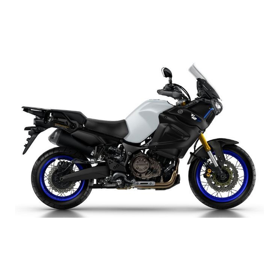
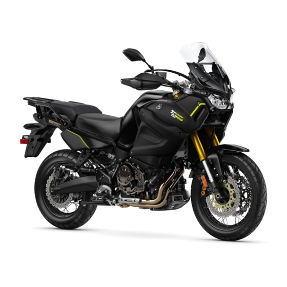
- Super Tenere ABS XT1200ZE
- Owner’s manual
-
Contents
-
Table of Contents
-
Troubleshooting
-
Bookmarks
Quick Links
OWNER’S MANUAL
XT1200ZE
Super Ténéré ABS
MOTORCYCLE
Read this manual carefully before oper-
ating this vehicle.
XT1200ZE
BP9-28199-E0
Related Manuals for Yamaha Super Tenere ABS XT1200ZE
Summary of Contents for Yamaha Super Tenere ABS XT1200ZE
-
Page 1
OWNER’S MANUAL XT1200ZE Super Ténéré ABS MOTORCYCLE Read this manual carefully before oper- ating this vehicle. XT1200ZE BP9-28199-E0… -
Page 2
EAU69362 Read this manual carefully before operating this vehicle. This manual should stay with this vehicle if it is sold. YAMAHA MOTOR ELECTRONICS CO., LTD. 1450-6, Mori, Mori-machi, Shuchi-gun, Shizuoka-ken, 437-0292 Japan DECLARATION of CONFORMITY Product: IMMOBILIZER Model: 2BS-00 Supplied by… -
Page 3
If you have any further questions, do not hesitate to contact your Yamaha dealer. The Yamaha team wishes you many safe and pleasant rides. So, remember to put safety first! Yamaha continually seeks advancements in product design and quality. There-… -
Page 4: Important Manual Information
*Product and specifications are subject to change without notice. EAU10201 XT1200ZE OWNER’S MANUAL ©2017 by Yamaha Motor Co., Ltd. 1st edition, January 2017 All rights reserved. Any reprinting or unauthorized use without the written permission of Yamaha Motor Co., Ltd.
-
Page 5: Table Of Contents
Table of contents Safety information ……1-1 Engine break-in……. 5-4 Parking……….5-5 Description ……..2-1 Left view ……….2-1 Periodic maintenance and Right view……..2-2 adjustment ……..6-1 Controls and instruments….2-3 Owner’s tool kit……. 6-2 Periodic maintenance chart for the Instrument and control functions..3-1 emission control system….
-
Page 6
Table of contents Battery ………. 6-30 Replacing the fuses…… 6-32 Replacing a headlight bulb… 6-33 Replacing an auxiliary light bulb… 6-35 Turn signal light and brake/tail light ……….. 6-37 Replacing a license plate light bulb ……….. 6-38 Troubleshooting……6-39 Troubleshooting charts….6-40 Motorcycle care and storage.. -
Page 7: Safety Information
Safety information EAU1031C an accident or equipment damage. See page 4-1 for a list of pre-operation checks. Be a Responsible Owner This motorcycle is designed to As the vehicle’s owner, you are re- carry the operator and a passen- sponsible for the safe and proper oper- ger.
-
Page 8
Safety information Many accidents involve inexperi- • The passenger should always enced operators. In fact, many op- hold onto the operator, the seat erators who have been involved in strap or grab bar, if equipped, accidents do not even have a cur- with both hands and keep both rent motorcycle license. -
Page 9
Safety information Avoid Carbon Monoxide Poisoning extra care when riding a motorcycle All engine exhaust contains carbon that has added cargo or accessories. monoxide, a deadly gas. Breathing Here, along with the information about carbon monoxide can cause head- accessories below, are some general aches, dizziness, drowsiness, nausea, guidelines to follow if loading cargo to confusion, and eventually death. -
Page 10
Genuine before using it to make sure that it Yamaha accessories, which are avail- does not in any way reduce able only from a Yamaha dealer, have ground clearance or cornering been designed, tested, and approved clearance, limit suspension travel, by Yamaha for use on your vehicle. -
Page 11
Safety information operator and may limit control torcycle, such as the frame or up- ability, therefore, such accesso- per front fork triple clamp (and not, ries are not recommended. for example, to rubber-mounted Use caution when adding electri- handlebars or turn signals, or cal accessories. -
Page 12: Description
Description EAU63371 Left view 1. Fuel tank cap (page 3-30) 2. Seat lock (page 3-33) 3. Carrier (page 3-41) 4. Final gear oil filler bolt (page 6-14) 5. Final gear oil drain bolt (page 6-14) 6. Coolant reservoir (page 6-16) 7.
-
Page 13: Right View
Description EAU63391 Right view 1. Rear brake fluid reservoir (page 6-25) 2. Electronically adjustable suspension system (page 3-37) 3. Fuses (page 6-32) 4. Owner’s tool kit (page 6-2) 5. Battery (page 6-30) 6. Engine oil filler cap (page 6-10) 7. Engine oil level check window (page 6-10) 8.
-
Page 14: Controls And Instruments
Description EAU63401 Controls and instruments 1. Clutch lever (page 3-24) 2. Left handlebar switches (page 3-23) 3. Clutch fluid reservoir (page 6-25) 4. Multi-function meter unit (page 3-10) 5. Auxiliary DC jack (page 3-45) 6. Front brake fluid reservoir (page 6-25) 7.
-
Page 15: Instrument And Control Functions
Do not grind any key or alter its cess, take the vehicle along with all shape. three keys to a Yamaha dealer to have Do not disassemble the plastic them re-registered. Do not use the key part of any key.
-
Page 16: Main Switch/Steering Lock
Instrument and control functions Keep the standard keys as well EAU10474 Main switch/steering lock as keys of other immobilizer systems away from this vehi- cle’s code re-registering key. Keep other immobilizer system keys away from the main switch as they may cause signal inter- ference.
-
Page 17
Instrument and control functions To unlock the steering EWA10062 WARNING Never turn the key to “OFF” or “LOCK” while the vehicle is moving. Otherwise the electrical systems will be switched off, which may result in loss of control or an accident. EAU10696 LOCK The steering is locked and all electrical… -
Page 18: Indicator Lights And Warning Lights
C.TEMP ˚C TIME TRIP 0:00 (page 6-10), have a Yamaha dealer check the vehicle. Even if the oil level is sufficient, the 1. Left turn signal indicator light “ ” warning light may flicker when rid- 2.
-
Page 19
If this occurs, braking. Have a Yamaha dealer have a Yamaha dealer check the on- check the brake system and electri- board diagnostic system. cal circuits as soon as possible. -
Page 20
Immobilizer system indicator do not start the engine, take the light “ ” vehicle and all 3 keys to a Yamaha When the key is turned to “OFF” and dealer to have the standard keys 30 seconds have passed, the indicator re-registered. -
Page 21: Cruise Control System
Instrument and control functions EAU59132 Cruise control system This model is equipped with a cruise control system designed to maintain a set cruising speed. The cruise control system operates only when riding in 3rd gear at speeds between about 50 km/h (31 mi/h) and 100 km/h (62 mi/h), 4th gear at speeds between about 50 km/h (31 mi/h) and 1.
-
Page 22
Instrument and control functions 2. Push the “SET–” side of the cruise you return the throttle grip, the vehicle control setting switch to activate will decelerate to the previously set the cruise control system. Your cruising speed. current traveling speed will be- come the set cruising speed. -
Page 23
Instrument and control functions When not traveling with a set cruising EWA16351 WARNING speed, if the start/engine stop switch is set to the “ ” position, the engine It is dangerous to use the resume stalls, or the sidestand is lowered, then function when the previously set the “… -
Page 24: Multi-Function Meter Unit
Instrument and control functions information display EAU80550 Multi-function meter unit setting mode 5 6 7 The select switch “ ” and the menu switch “MENU” are located on GEAR the left handlebar. These switches al- A.TEMP ˚C C.TEMP ˚C low you to control or change the set- TIME TRIP…
-
Page 25
Tachometer If a problem is detected in the fuel me- ter circuit, all display segments of the fuel meter will start flashing. If this oc- curs, have a Yamaha dealer check the vehicle. Eco indicator 1. Tachometer 2. High-r/min zone The tachometer shows the engine speed. -
Page 26
Instrument and control functions Transmission gear indicator Traction control system indicator GEAR A.TEMP ˚C C.TEMP ˚C TIME TRIP 0:00 1. Neutral indicator light “ ” 1. Traction control system indicator 2. Transmission gear indicator This indicator shows the current trac- This indicator shows the current trans- tion control mode: “1”, “2”… -
Page 27
Instrument and control functions Push the menu switch “MENU” to ECA17931 NOTICE switch the display between the follow- Be sure to wear gloves when ing functions. The display changes each time the switch is pushed. using the grip warmers. … -
Page 28
Instrument and control functions average fuel consumption instantaneous fuel consumption GEAR Odometer: TRIP-F The odometer shows the total distance traveled by the vehicle. In this case, push the select switch to rotate among the information display Tripmeters: pages in the following order; TRIP-1 TRIP-F →… -
Page 29
Instrument and control functions This timer shows the elapsed time This shows the temperature of the since the key was turned to “ON”. The coolant. The coolant temperature will maximum time that can be shown is vary with changes in the ambient tem- 99:59. -
Page 30
If there is a malfunction, “– –.–” will play flashes, and then push and hold be continuously displayed. Have a the “RESET” button for 2 seconds. Yamaha dealer check the vehicle. Setting mode After resetting the average fuel con- sumption, “_ _._” will be shown until the vehicle has traveled 1 km (0.6 mi). -
Page 31
Instrument and control functions Push and hold the menu switch Adjusting the temperature levels of the “MENU” for 2 seconds to enter the set- grip warmer settings ting mode. To exit the setting mode 1. Use the select switch to highlight and return to the normal display, push “Grip Warmer”. -
Page 32
Instrument and control functions Grip Warmer MENU Grip Warmer Hi g h Maintenance Time Trip Middle Unit Display Brightness Clock 4. Use the select switch to highlight 2. Push the menu switch “MENU”, “Middle” or “Low”, and then chan- and then push the “RESET” but- ge the setting using the same pro- ton to select the item to reset. -
Page 33
Instrument and control functions MENU MENU Grip Warmer Grip Warmer Maintenance Maintenance Time Trip Time Trip Unit Unit Display Display Brightness Brightness Clock Clock 2. Push the menu switch “MENU” to 2. Push the menu switch “MENU”. display “TIME–2” and “TIME–3”. The unit setting display will be To reset a time trip, push the “RE- shown and “km or mile”… -
Page 34
Instrument and control functions 2. Push the menu switch “MENU”, use the select switch to highlight When “km” is selected, “L/100km” or the page you want to adjust, and “km/L” can be set as the fuel con- then push the menu switch sumption units. -
Page 35
Instrument and control functions 5. Repeat the previous step to make other item changes, or if you are Brightness finished adjusting the information display page items, use the select switch to highlight “ ”, and then push the menu switch “MENU” to exit. -
Page 36: D-Mode (Drive Mode)
Instrument and control functions 6. Push the menu switch “MENU” to EAU49433 D-mode (drive mode) return to the setting mode main D-mode is an electronically controlled screen. engine performance system with two mode selections (touring mode “T” and Resetting all of the display items sports mode “S”).
-
Page 37: Handlebar Switches
Instrument and control functions EAU1234M EAU12461 Handlebar switches Turn signal switch “ ” To signal a right-hand turn, push this Left switch to “ ”. To signal a left-hand turn, push this switch to “ ”. When released, the switch returns to the cen- ter position.
-
Page 38: Clutch Lever
Instrument and control functions EAU12781 EAU12832 Cruise control switches Clutch lever See page 3-7 for an explanation of the cruise control system. EAU54231 Menu switch “MENU” This switch is used to perform selec- tions in the function display and setting mode display of the multi-function me- ter unit.
-
Page 39: Shift Pedal
Instrument and control functions EAU12872 EAU49518 Shift pedal Brake lever The brake lever is located on the right side of the handlebar. To apply the front brake, pull the lever toward the throttle grip. This model is equipped with a unified brake system.
-
Page 40: Brake Pedal
Instrument and control functions When the vehicle starts moving, EAU49483 Brake pedal the unified brake system is re-en- abled. The unified brake system does not function when the brake pedal is applied alone or before the brake lever is applied. The brake lever is equipped with a brake lever position adjusting dial.
-
Page 41: Abs
However, special tools are rear brakes independently. required, so please consult your Operate the brakes with ABS as you Yamaha dealer. would conventional brakes. If the ABS ECA16831 is activated, a pulsating sensation may NOTICE…
-
Page 42: Traction Control System
Instrument and control functions The traction control system indicator EAU58953 Traction control system light flashes when traction control has The traction control system helps engaged. You may notice slight chang- maintain traction when accelerating on es in engine and exhaust sounds when slippery surfaces, such as unpaved or the system has engaged.
-
Page 43
Instrument and control functions The traction control system mode can 4. Have a Yamaha dealer check the be changed only when the vehicle is vehicle and turn off the engine stopped. trouble warning light. Push the “TCS” button to change between modes “1”… -
Page 44: Fuel Tank Cap
Instrument and control functions EAU13075 EAU13222 Fuel tank cap Fuel Make sure there is sufficient gasoline in the tank. EWA10882 WARNING Gasoline and gasoline vapors are extremely flammable. To avoid fires and explosions and to reduce the risk of injury when refueling, follow these instructions.
-
Page 45
If the same identifier when fueling. gasoline spills on your skin, wash Your Yamaha engine has been de- with soap and water. If gasoline signed to use premium unleaded gas- spills on your clothing, change your oline with a research octane number of clothes. -
Page 46: Fuel Tank Overflow Hose
Instrument and control functions EAU79161 EAU13434 Fuel tank overflow hose Catalytic converter This model is equipped with a catalytic converter in the exhaust system. EWA10863 WARNING The exhaust system is hot after op- eration. To prevent a fire hazard or burns: …
-
Page 47: Rider Seat
Instrument and control functions The rider seat height can be ad- EAU49444 Rider seat justed to change the riding posi- tion. (See “Adjusting the rider seat To remove the rider seat height”.) 1. Insert the key into the seat lock, and then turn it counterclockwise.
-
Page 48: Adjusting The Rider Seat Height
Instrument and control functions EAU49475 Adjusting the rider seat height The rider seat height can be adjusted to one of two positions to suit the rid- er’s preference. The rider seat height was adjusted to the higher position at delivery. 1.
-
Page 49
Instrument and control functions Make sure that the rider seat is proper- ly secured before riding. 1. Rider seat height position adjuster 3. Install the rider seat height posi- tion adjuster so that the match mark is aligned with the “H” mark as shown. -
Page 50: Windshield
Instrument and control functions EAU58982 Windshield Make sure that the slide plate To suit the rider’s preference, the wind- holders are aligned with the match shield can be changed to one of four marks at the same height on both positions.
-
Page 51: Adjusting The Front And Rear Suspension
Yamaha dealer check the sus- Preload pension system. When riding with luggage or a passen- ger, use the preload adjusting function To adjust the preload to adjust the suspension system to 1. Turn the key to “ON”, start the en- match the load.
-
Page 52
Instrument and control functions GEAR GEAR 1. Menu switch “MENU” While the preload is being adjusted, 2. Select switch “ ” the information display may change as 3. Use the select switch to select the follows. If the key is turned to “OFF” or the desired preload setting pictogram. -
Page 53
Instrument and control functions GEAR GEAR GEAR HARD HARD 1. Damping force setting If the preload is adjusted repeat- 2. Damping force setting level edly, the preload setting picto- gram will flash 4 times and the preload cannot be adjusted. Wait If the preload setting was not complet- approximately 6 minutes for the ed correctly:… -
Page 54
Instrument and control functions GEAR The damping force setting can be set to 7 levels (+3, +2, +1, 0, –1, –2 and –3). “+3” is the hardest level and “–3” is the softest level. 6. Push the menu switch “MENU”. If the vehicle moves while you are ad- justing the damping force, the informa- 1. -
Page 55: Carriers
Take the shock ity of the standard carrier. absorber assembly to a Yamaha To use the additional carrier, consult a dealer for any service. Yamaha dealer. Standard carrier 1.
-
Page 56: Luggage Strap Holders
Instrument and control functions Do not exceed the standard car- EAU49491 Luggage strap holders rier capacity of 5.0 kg (11 lb). Do not exceed the additional carrier capacity of 5.0 kg (11 lb). ECA16822 NOTICE Do not lift the vehicle by either carri- 1.
-
Page 57: Sidestand
Therefore, check this system regularly and have a Yamaha dealer repair it if it does not function properly. 3-43…
-
Page 58
Does the engine start? The neutral switch may not be working correctly. The motorcycle should not be ridden until checked by a Yamaha dealer. With the engine still running: 6. Move the sidestand up. 7. Keep the clutch lever pulled. -
Page 59: Auxiliary Dc Jack
Instrument and control functions EAU49453 Auxiliary DC jack EWA14361 WARNING To prevent electrical shock or short- circuiting, make sure that the cap is installed when the auxiliary DC jack is not being used. ECA15432 NOTICE 1. Auxiliary DC jack The accessory connected to the 5.
-
Page 60: For Your Safety — Pre-Operation Checks
Do not operate the vehicle if you find any problem. If a problem cannot be corrected by the procedures provided in this manual, have the vehicle inspected by a Yamaha dealer. Before using this vehicle, check the following points:…
-
Page 61
• Tighten if necessary. Instruments, lights, • Check operation. — • Correct if necessary. signals and switches • Check operation of ignition circuit cut-off system. Sidestand switch • If system is not working correctly, have Yamaha dealer 3-43 check vehicle. -
Page 62: Operation And Important Riding Points
This model is equipped with: there is a control or function you do not a lean angle sensor to stop the en- understand, ask your Yamaha dealer. gine in case of turnover. In this EWA10272 case, turn the key “OFF” and then WARNING to “ON”…
-
Page 63: Starting The Engine
The neutral indi- the clutch lever pulled and the cator light should come on. If not, sidestand up. ask a Yamaha dealer to check the See page 3-43 for more informa- electrical circuit. tion. 3. Start the engine by pushing 1.
-
Page 64: Shifting
Operation and important riding points EAU16673 and drive train, which are not Shifting designed withstand shock of forced shifting. 1. Shift pedal 2. Neutral position Shifting gears lets you control the amount of engine power available for starting off, accelerating, climbing hills, etc.
-
Page 65: Tips For Reducing Fuel Consumption
Operation and important riding points EAU16811 EAU16842 Tips for reducing fuel con- Engine break-in sumption There is never a more important period in the life of your engine than the period Fuel consumption depends largely on between 0 and 1600 km (1000 mi). For your riding style.
-
Page 66: Parking
EAU17214 Parking cur during the engine break-in When parking, stop the engine, and period, immediately have a then remove the key from the main Yamaha dealer check the vehi- switch. cle. EWA10312 WARNING Since the engine and exhaust system can become very hot,…
-
Page 67: Periodic Maintenance And Adjustment
If you are not familiar with vehicle ser- vice, have a Yamaha dealer perform service. EWA15123 WARNING Turn off the engine when performing…
-
Page 68: Owner’s Tool Kit
If you do not have the tools or experi- ence required for a particular job, have a Yamaha dealer perform it for you.
-
Page 69: Periodic Maintenance Chart For The Emission Control System
From 50000 km (30000 mi), repeat the maintenance intervals starting from 10000 km (6000 mi). Items marked with an asterisk should be performed by a Yamaha dealer as they require special tools, data and technical skills. EAU71071…
-
Page 70: General Maintenance And Lubrication Chart
• Perform dynamic inspection Diagnostic system √ √ √ √ √ √ using Yamaha diagnostic tool. check • Check the error codes. 2 * Air filter element • Replace. Every 40000 km (24000 mi) • Check operation, fluid level and √…
-
Page 71
Periodic maintenance and adjustment ODOMETER CHECK OR READINGS MAINTENANCE JOB ITEM X 1000 km X 1000 mi • Make sure that all nuts, bolts √ √ √ √ √ 13 * Chassis fasteners and screws are properly tight- ened. Brake lever pivot √… -
Page 72
Periodic maintenance and adjustment ODOMETER CHECK OR READINGS MAINTENANCE JOB ITEM X 1000 km X 1000 mi • Check oil level and vehicle for √ √ √ √ √ oil leakage. 26 * Final gear oil √ √ √ • Change. Front and rear √… -
Page 73: Removing And Installing Cowlings
Periodic maintenance and adjustment EAU18782 Removing and installing cowl- ings The cowlings shown need to be re- moved to perform some of the mainte- nance jobs described in this chapter. Refer to this section each time a cowl- ing needs to be removed and installed. 1.
-
Page 74
Periodic maintenance and adjustment 1. Cowling B 1. Cowling C 2. Bolt 2. Nut 3. Bolt 1. Quick fastener 1. Cowling C 2. Nut To install the cowling 3. Bolt 1. Place the cowling in the original position, and then install the bolts To install the cowling and the quick fasteners. -
Page 75: Checking The Spark Plugs
The spark plugs are important engine components, which should checked periodically, preferably by a Yamaha dealer. Since heat and depos- its will cause any spark plug to slowly erode, they should be removed and checked in accordance with the peri- odic maintenance and lubrication 1.
-
Page 76: Canister
Periodic maintenance and adjustment EAU79401 EAU49506 Canister Engine oil and oil filter car- tridge The engine oil level should be checked before each ride. In addition, the oil must be changed and the oil filter car- tridge replaced at the intervals speci- fied in the periodic maintenance and lubrication chart.
-
Page 77
Periodic maintenance and adjustment 4. If the engine oil is below the mini- mum level mark, add sufficient oil of the recommended type to raise it to the correct level. Check the O-ring for damage, and re- place it if necessary. 1. -
Page 78
Tightening torque: Oil filter cartridge: 17 N·m (1.7 kgf·m, 13 lb·ft) An oil filter wrench is available at a Yamaha dealer. 11. Install the cowling. 12. Install the engine oil drain bolts 9. Apply a thin coat of clean engine… -
Page 79
Do off and have a Yamaha dealer check not use oils with a diesel speci- the vehicle. fication of “CD” or oils of a high- 17. -
Page 80: Final Gear Oil
Final gear oil The final gear case must be checked for oil leakage before each ride. If any leakage is found, have a Yamaha deal- er check and repair the vehicle. In ad- dition, the final gear oil level must be…
-
Page 81
5. Refill with the recommended final gear oil to the brim of the filler hole. Recommended final gear oil: Yamaha genuine shaft drive gear oil SAE 80W-90 API GL-5 or SAE 80 API GL-4 Hypoid gear oil Oil quantity: 0.20 L (0.21 US qt, 0.18 Imp.qt) 6. -
Page 82: Coolant
If water has been added to the coolant, have a Yamaha dealer check the anti- freeze content of the coolant as soon as possible, otherwise the effectiveness of the coolant will 1.
-
Page 83: Air Filter Element
Have a maintenance and lubrication chart. Yamaha dealer change the coolant. Have a Yamaha dealer replace the air WARNING! Never attempt to remove filter element. the radiator cap when the engine is hot.
-
Page 84: Checking The Engine Idling Speed
Yamaha dealer. Engine idling speed: 1050–1150 r/min 1. Throttle grip free play Throttle grip free play: 3.0–5.0 mm (0.12–0.20 in) Periodically check the throttle grip free play and, if necessary, have a Yamaha dealer adjust it. 6-18…
-
Page 85: Valve Clearance
Therefore, it must be adjusted by a Yamaha dealer is essential to maintain the tires in good at the intervals specified in the periodic condition at all times and replace them maintenance and lubrication chart.
-
Page 86
If the center tread depth reaches the specified limit, if the tire has a nail or glass fragments in it, or if the side- wall is cracked, have a Yamaha dealer replace the tire immediately. 1. Tire air valve 2. -
Page 87
After extensive tests, only the tires list- ed below have been approved for this model by Yamaha. Front tire: Size: 110/80R19M/C 59V Manufacturer/model: BRIDGESTONE/BW501… -
Page 88: Spoke Wheels
If any damage is poor acceleration, there may be air in found, have a Yamaha dealer re- the clutch system. If there is air in the place the wheel. Do not attempt…
-
Page 89: Checking The Brake Lever Free Play
Since the brake light switches are components of the cruise control system, they must be adjusted by a Yamaha dealer, who has the nec- essary professional knowledge and ex- perience. 1. No brake lever free play There should be no free play at the brake lever end.
-
Page 90: Checking The Front And Rear Brake Pads
If a brake pad is damaged or if the lining thickness is less than 0.8 mm (0.03 in), have a Yamaha dealer replace the brake pads as a set. 1. Brake pad wear indicator Each front brake pad is provided with…
-
Page 91: Checking The Brake Fluid Level
Specified brake fluid: brake system for leakage. If the brake DOT 4 fluid level goes down suddenly, have a Yamaha dealer check the cause before EWA16011 WARNING further riding. Improper maintenance can result in loss of braking ability.
-
Page 92: Changing The Brake And Clutch Fluids
In addition, have ed by a Yamaha dealer at the intervals the oil seals of the brake and clutch specified in the periodic maintenance master cylinders and calipers as well chart.
-
Page 93: Checking And Lubricating The Brake And Shift Pedals
Periodic maintenance and adjustment EAU44276 EAU43602 Checking and lubricating the Checking and lubricating the brake and shift pedals brake and clutch levers The operation of the brake and shift The operation of the brake and clutch pedals should be checked before each levers should be checked before each ride, and the pedal pivots should be lu- ride, and the lever pivots should be lu-…
-
Page 94: Checking And Lubricating The Centerstand And Sidestand
The operation of the centerstand and The swingarm pivots must be lubricat- sidestand should be checked before ed by a Yamaha dealer at the intervals each ride, and the pivots and metal-to- specified in the periodic maintenance metal contact surfaces should be lubri- and lubrication chart.
-
Page 95: Checking The Front Fork
If any free there is no danger of it falling play can be felt, have a Yamaha over. dealer check or repair the steer- [EWA10752] 2.
-
Page 96: Checking The Wheel Bearings
A. (See page 6-7.) hub or if the wheel does not turn This model is equipped with a VRLA smoothly, have a Yamaha dealer (Valve Regulated Lead Acid) battery. check the wheel bearings. There is no need to check the electro- lyte or to add distilled water.
-
Page 97
ECA16531 NOTICE To charge the battery Always keep the battery charged. Have a Yamaha dealer charge the bat- Storing a discharged battery can tery as soon as possible if it seems to cause permanent battery damage. have discharged. Keep in mind that the… -
Page 98: Replacing The Fuses
Periodic maintenance and adjustment EAU58963 Replacing the fuses The fuse boxes and the ABS motor fuse are located behind cowling A, and the main fuse, the cruise control fuse and the brake light fuse are located be- hind cowling B. (See page 6-7.) 1.
-
Page 99: Replacing A Headlight Bulb
4. If the fuse immediately blows again, have a Yamaha dealer check the electrical system. 1. Do not touch the glass part of the bulb. 1. Remove the headlight bulb cover by turning it counterclockwise.
-
Page 100
Periodic maintenance and adjustment 6. Install the headlight bulb cover by turning it clockwise. 7. Have a Yamaha dealer adjust the headlight beam if necessary. 1. Headlight bulb cover 2. Disconnect the headlight coupler. 1. Headlight coupler 3. Unhook the headlight bulb holder, and then remove the burnt-out bulb. -
Page 101: Replacing An Auxiliary Light Bulb
Periodic maintenance and adjustment EAU58971 Replacing an auxiliary light bulb This model is equipped with two auxil- iary lights. If an auxiliary light bulb burns out, replace it as follows. 1. Remove the windshield by remov- ing the screws. 1. Panel 2.
-
Page 102
Periodic maintenance and adjustment 1. Headlight unit 1. Auxiliary light bulb 2. Headlight unit bolt 8. Insert a new bulb into the socket. 9. Install the socket (together with the bulb) by pushing it in and turn- ing it clockwise. 10. -
Page 103: Turn Signal Light And Brake/Tail Light
This model is equipped with LED-type turn signal lights and an LED-type Tightening torque: Windshield screw: brake/tail light. 0.5 N·m (0.05 kgf·m, 0.37 lb·ft) If a turn signal light or the brake/tail light does not come on, have a Yamaha dealer check it. 6-37…
-
Page 104: Replacing A License Plate Light Bulb
Periodic maintenance and adjustment EAU49722 Replacing a license plate light bulb 1. Remove the license plate light unit bolts. 1. License plate light bulb 4. Insert a new bulb into the socket. 5. Install the socket (together with the bulb) by pushing it in, and then turning it clockwise until it stops.
-
Page 105: Troubleshooting
The following troubleshooting charts represent quick and easy procedures for checking these vital systems your- self. However, should your motorcycle require any repair, take it to a Yamaha dealer, whose skilled technicians have the necessary tools, experience, and know-how to service the motorcycle properly.
-
Page 106: Troubleshooting Charts
Check the vehicle. compression. 4. Compression The engine does not start. There is compression. Have a Yamaha dealer check the vehicle. Operate the electric starter. There is no Have a Yamaha dealer check the vehicle. compression. 6-40…
-
Page 107
Start the engine. If the engine overheats again, The coolant level is have a Yamaha dealer check and repair the cooling system. If coolant is not available, tap water can be temporarily used instead, provided that it is changed to the recommended coolant as soon as possible. -
Page 108: Motorcycle Care And Storage
Rust and corrosion can develop matte colored finished parts. Be even if high-quality components are sure to consult a Yamaha dealer for used. A rusty exhaust pipe may go un- advice on what products to use be- noticed on a car, however, it detracts fore cleaning the vehicle.
-
Page 109
Motorcycle care and storage structed. Also, thoroughly rinse compounds for plastic may the area off with water, immedi- leave scratches on the wind- ately dry it, and then apply a cor- shield. Test the product on a rosion protection spray. small hidden part of the wind- … -
Page 110
3. To prevent corrosion, it is recom- Consult a Yamaha dealer for ad- mended to apply a corrosion pro- vice on what products to use. tection spray metal, … -
Page 111: Storage
Motorcycle care and storage der head so that the electrodes EAU49592 Storage are grounded. (This will limit sparking during the next step.) Short-term d. Turn the engine over several Always store your motorcycle in a cool, times with the starter. (This will dry place and, if necessary, protect it coat the cylinder walls with oil.) against dust with a porous cover.
-
Page 112
Motorcycle care and storage Make any necessary repairs before storing the motorcycle. -
Page 113: Specifications
Final gear oil: 2250 mm (88.6 in) Overall width: Type: 980 mm (38.6 in) Yamaha genuine shaft drive gear oil SAE Overall height: 80W-90 API GL-5 or SAE 80 API GL-4 1410/1470 mm (55.5/57.9 in) Hypoid gear oil Seat height: Quantity: 845/870 mm (33.3/34.3 in)
-
Page 114
Specifications 2nd: Front wheel: 2.063 (33/16) Wheel type: 3rd: Spoke wheel 1.571 (33/21) Rim size: 4th: 19M/C x MT2.50 1.250 (30/24) Rear wheel: 5th: Wheel type: 1.042 (25/24) Spoke wheel 6th: Rim size: 0.929 (26/28) 17M/C x MT4.00 Chassis: Unified brake system: Frame type: Operation: Backbone… -
Page 115
Specifications Battery: Terminal fuse 1: 3.0 A Model: Headlight fuse: YTZ12S 20.0 A Voltage, capacity: Brake light fuse: 12 V, 11.0 Ah (10 HR) 1.0 A Headlight: Signaling system fuse: Bulb type: 7.5 A Halogen bulb Ignition fuse: Bulb wattage: 20.0 A Headlight: Parking lighting fuse:… -
Page 116: Consumer Information
Yamaha dealer. area. VEHICLE IDENTIFICATION NUMBER: EAU26442 Engine serial number…
-
Page 117: Diagnostic Connector
Consumer information the space provided. This information EAU69910 Diagnostic connector will be needed when ordering spare parts from a Yamaha dealer. 1. Diagnostic connector The diagnostic connector is located as shown.
-
Page 118: Vehicle Data Recording
Vehicle status and engine perfor- mance data Fuel-injection and emission-relat- ed data Yamaha will not disclose this data to a third party except: With the consent of the vehicle owner Where obligated by law …
-
Page 119: Index
Index Fuel tank cap ……..3-30 Fuel tank overflow hose……3-32 ABS …………3-27 Fuses, replacing……..6-32 ABS warning light……..3-5 Air filter element ……..6-17 Auxiliary DC jack ……..3-45 Handlebar switches ……3-23 Auxiliary light bulb, replacing ….6-35 Hazard switch ……..
-
Page 120
Index Suspension, adjusting the front and rear ………….3-37 Swingarm pivots, lubricating ….6-28 Throttle grip and cable, checking and lubricating………..6-26 Throttle grip free play, checking …6-18 Tires …………6-19 Tool kit …………6-2 Traction control system ……3-28 Traction control system indicator light …3-5 Troubleshooting……..6-39 Troubleshooting charts……6-40 Turn signal indicator lights……3-4… -
Page 122
Original instructions PRINTED ON RECYCLED PAPER PRINTED IN JAPAN 2017.02-0.3×1 CR…

Тема: Мануалы, каталоги (Прочитано 22773 раз)
Yamaha XT1200Z Super Tenere
Эксплуатационный мануал, 2010 г.в., PDF 3 Мб — скачать
Сервис мануал, 2010 г.в., PDF 35 Мб — скачать
Каталог запчастей, 2010 г.в., PDF 2 Мб — скачать
Для просмотра рекомендуется программа Foxit Reader

Записан
Записан
« Последнее редактирование: 19 Май 2015, 09:13:17 от Spinoza »
Записан
Держите переведённую мной схему электропроводки с описанием на русском Yamaha XT1200Z. Распечатайте на одном листе с обеих сторон, положите в файл и уберите в бумажник. «Пусть будет на всякий».
https://cloud.mail.ru/public/59dB/doNpc5hp3
Записан
А что это значит, «девка хоть куда»?
Отлично!
Большое спасибо 
Записан
Записан
Принимаются (в личку) любые пожелания по неточностям перевода и опечаткам, а также благодарности. =)
Нифига, здесь напишу.
Огромное, человеческое, спасибо!!!
Записан
Руководство по обслуживанию xt1200z на русском http://file.sampo.ru/46fjkn/
файл не найден
можно перезалить или на почту
Greco-roman(cобака)точкаru
Записан
Всем добрый день. Купил XT1200ZE 2016 г.в. Подскажите где скачать Сервис мануал ? Заранее благодарен.
Записан
Первое сообщение Хан Соло
Yamaha XT1200Z Super Tenere
Эксплуатационный мануал, 2010 г.в., PDF 3 Мб — скачать
Сервис мануал, 2010 г.в., PDF 35 Мб — скачать
Каталог запчастей, 2010 г.в., PDF 2 Мб — скачать
Для просмотра рекомендуется программа Foxit Reader
Записан
мануал на русском ссылка не активна
Записан
Руководство по обслуживанию, которое на русском — это не тоже самое, что и сервис-мануал. Это книжечка, описывающая вкратце куда вставлять ключ, в какую дырку сколько бензину заливать, какой кнопкой дудеть, первая — вниз, и прочие секреты. Себе я ее не сохранял.
Записан
Записан
Записан
« Последнее редактирование: 15 Май 2017, 21:32:23 от Nikolos »
Записан
Скрыть/показать содержание
Материал из BikesWiki, Энциклопедия японских мотоциклов
- Manuals
- Brands
- Yamaha Manuals
- Motorcycle
- Super Tenere ES 2022
- Owner’s manual
-
Contents
-
Table of Contents
-
Troubleshooting
-
Bookmarks
Quick Links
OWNER’S MANUAL
Super Ténéré ES
MOTORCYCLE
Read this manual carefully before oper-
ating this vehicle.
XTZ12EN
XTZ12ENC
LIT-11626-35-54
BP9-28199-14
Related Manuals for Yamaha Super Tenere ES 2022
Summary of Contents for Yamaha Super Tenere ES 2022
-
Page 1
OWNER’S MANUAL Super Ténéré ES MOTORCYCLE Read this manual carefully before oper- ating this vehicle. XTZ12EN XTZ12ENC LIT-11626-35-54 BP9-28199-14… -
Page 2
EAU10045 Operating, servicing and maintaining a passenger vehicle or off-road vehicle can expose you to chemicals including engine exhaust, carbon monoxide, phthalates, and lead, which are known to the State of California to cause cancer and birth defects or other reproductive harm. To minimize exposure, avoid breathing exhaust, do not idle the engine except as necessary, service your vehicle in a well-ventilated area and wear gloves or wash your… -
Page 3
EAU10084 Congratulations on your purchase of the Yamaha XTZ12EN / XTZ12ENC. This model is the result of Yamaha’s vast experience in the production of fine sporting, touring, and pacesetting racing machines. It represents the high degree of crafts- manship and reliability that have made Yamaha a leader in these fields. -
Page 4
*Product and specifications are subject to change without notice. EAU10194 XTZ12EN / XTZ12ENC OWNER’S MANUAL ©2022 by Yamaha Motor Corporation, U.S.A. 1st edition, October 2021 All rights reserved. Any reprinting or unauthorized use without the written permission of Yamaha Motor Corporation, U.S.A. -
Page 5: Table Of Contents
Table of contents Location of important labels….1-1 Engine break-in……. 6-5 Parking……….6-6 Safety information ……2-1 Periodic maintenance and Description ……..3-1 adjustment ……..7-1 Left view ……….3-1 Tool kit ……….7-2 Right view……..3-2 Periodic maintenance chart for the Controls and instruments….3-3 emission control system….
-
Page 6
Vehicle data recording….10-4 Reporting safety defects ….10-5 Motorcycle noise regulation ..10-6 Maintenance record ….. 10-7 YAMAHA MOTOR CORPORATION, U.S.A. 2020 AND LATER MODEL STREET & DUAL-PURPOSE MOTORCYCLE LIMITED WARRANTY ……10-8 YAMAHA EXTENDED SERVICE (Y.E.S.) ……..10-10 Index……….11-1… -
Page 7: Location Of Important Labels
Read and understand all of the labels on your vehicle. They contain important in- formation for safe and proper operation of your vehicle. Never remove any labels from your vehicle. If a label becomes difficult to read or comes off, a replacement label is available from your Yamaha dealer. 2 3,4…
-
Page 8
Location of important labels WARNING TIRE INFORMATION Co ld t ire normal pres s ure s ho u l d be s e t as foll ow s. • Up to 90 kg (1 98 l bs ) l oad FRONT : 225 k Pa, (2. -
Page 9
Location of important labels NOTICE Do not lift here, carrier may be damaged. 23P-2815T-11 WARNING NEVER ride as a passenger if the passenger seat and grips are removed. 23P-2816J-11… -
Page 10: Safety Information
Safety information EAU1031C an accident or equipment damage. See page 5-1 for a list of pre-operation checks. Be a Responsible Owner This motorcycle is designed to As the vehicle’s owner, you are re- carry the operator and a passen- sponsible for the safe and proper oper- ger.
-
Page 11
Safety information Many accidents involve inexperi- • The passenger should always enced operators. In fact, many op- hold onto the operator, the seat erators who have been involved in strap or grab bar, if equipped, accidents do not even have a cur- with both hands and keep both rent motorcycle license. -
Page 12
Safety information Avoid Carbon Monoxide Poisoning extra care when riding a motorcycle All engine exhaust contains carbon that has added cargo or accessories. monoxide, a deadly gas. Breathing Here, along with the information about carbon monoxide can cause head- accessories below, are some general aches, dizziness, drowsiness, nausea, guidelines to follow if loading cargo to confusion, and eventually death. -
Page 13
Genuine does not in any way reduce Yamaha accessories, which are avail- ground clearance or cornering able only from a Yamaha dealer, have clearance, limit suspension travel, been designed, tested, and approved steering travel or control opera- by Yamaha for use on your vehicle. -
Page 14
Safety information operator and may limit control torcycle, such as the frame or up- ability, therefore, such accesso- per front fork triple clamp (and not, ries are not recommended. for example, to rubber-mounted Use caution when adding electri- handlebars or turn signals, or cal accessories. -
Page 15: Description
Description EAU63371 Left view 1. Fuel tank cap (page 4-28) 2. Seat lock (page 4-31) 3. Carrier (page 4-39) 4. Final gear oil filler bolt (page 7-14) 5. Final gear oil drain bolt (page 7-14) 6. Coolant reservoir (page 7-16) 7.
-
Page 16: Right View
Description EAU63391 Right view 1. Rear brake fluid reservoir (page 7-25) 2. Electronically adjustable suspension system (page 4-35) 3. Fuses (page 7-32) 4. Tool kit (page 7-2) 5. Battery (page 7-30) 6. Engine oil filler cap (page 7-10) 7. Engine oil level check window (page 7-10) 8.
-
Page 17: Controls And Instruments
Description EAU63401 Controls and instruments 9,10 1. Clutch lever (page 4-23) 2. Left handlebar switches (page 4-21) 3. Clutch fluid reservoir (page 7-25) 4. Multi-function meter unit (page 4-8) 5. Auxiliary DC jack (page 4-41) 6. Front brake fluid reservoir (page 7-25) 7.
-
Page 18: Instrument And Control Functions
Instrument and control functions EAU10462 EAU10696 Main switch/steering lock LOCK The steering is locked and all electrical systems are off. The key can be re- moved. To lock the steering LOCK The main switch/steering lock controls the ignition and lighting systems, and is used to lock the steering.
-
Page 19: Indicator Lights And Warning Lights
Instrument and control functions From the “LOCK” position, push the EAU4939G Indicator lights and warning key and turn it to “OFF”. lights EAU59680 (Parking) The hazard lights and turn signal lights can be turned on, but all other electri- GEAR cal systems are off.
-
Page 20
To prevent en- if a problem is detected in the engine. gine damage, replenish the engine oil If this occurs, have a Yamaha dealer as soon as possible. check the self-diagnosis system. (See Even if the oil level is sufficient, the page 4-20.) -
Page 21: Cruise Control System
The cruise control system operates ble wheel lock during emergency only when riding in 3rd gear at speeds braking. Have a Yamaha dealer between about 50 km/h (31 mi/h) and check the brake system and electri- 100 km/h (62 mi/h), 4th gear at speeds cal circuits as soon as possible.
-
Page 22
Instrument and control functions 2. Push the “SET–” side of the cruise control setting switch to activate the cruise control system. Your current traveling speed will be- come the set cruising speed. The cruise control setting indicator light “SET” will come on. 1. -
Page 23
Instrument and control functions you return the throttle grip, the vehicle EWA16351 WARNING will decelerate to the previously set cruising speed. It is dangerous to use the resume function when the previously set Deactivating the cruise control sys- cruising speed is too high for current conditions. -
Page 24
If this occurs, turn the used to adjust the set cruising cruise control system off and have a speed. To reduce the traveling Yamaha dealer check it. speed, apply the brakes. When ECA11591 the brakes are applied, the cruise… -
Page 25: Multi-Function Meter Unit
Instrument and control functions information display EAU83211 Multi-function meter unit setting mode self-diagnosis device 5 6 7 The select switch “ ” and the GEAR menu switch “MENU” are located on A.TEMP ˚F C.TEMP ˚F the left handlebar. These switches al- TIME TRIP 0:00 low you to control or change the set-…
-
Page 26
Tachometer If a problem is detected in the fuel me- ter circuit, all display segments of the fuel meter will start flashing. If this oc- curs, have a Yamaha dealer check the vehicle. Eco indicator 1. Tachometer 2. High-r/min zone The tachometer shows the engine speed. -
Page 27
Instrument and control functions Transmission gear indicator Traction control system indicator GEAR A.TEMP ˚F C.TEMP ˚F TIME TRIP 0:00 1. Neutral indicator light “ ” 1. Traction control system indicator 2. Transmission gear indicator This indicator shows the current trac- This indicator shows the current trans- tion control mode: “1”, “2”… -
Page 28
Instrument and control functions Push the menu switch “MENU” to ECA17932 NOTICE switch the display between the follow- Be sure to wear gloves when ing functions. The display changes each time the switch is pushed. using the grip warmers. … -
Page 29
Instrument and control functions Odometer: GEAR mile 1300 The odometer shows the total distance traveled by the vehicle. TRIP-F mile Tripmeters: In this case, push the select switch to TRIP-1 mile rotate among the information display pages in the following order; TRIP-F →… -
Page 30
Instrument and control functions This timer shows the elapsed time This shows the temperature of the since the key was turned to “ON”. The coolant. The coolant temperature will maximum time that can be shown is vary with changes in the ambient tem- 99:59. -
Page 31
If there is a malfunction, “– –.–” will play flashes, and then push and hold be continuously displayed. Have a the “RESET” button for 2 seconds. Yamaha dealer check the vehicle. Setting mode After resetting the average fuel con- sumption, “_ _._” will be shown until the vehicle has traveled 1 km (0.6 mi). -
Page 32
Instrument and control functions Push and hold the menu switch Adjusting the temperature levels of the “MENU” for 2 seconds to enter the set- grip warmer settings ting mode. To exit the setting mode 1. Use the select switch to highlight and return to the normal display, push “Grip Warmer”. -
Page 33
Instrument and control functions Grip Warmer MENU Grip Warmer Hi g h Maintenance Time Trip Middle Unit Display Brightness Clock 4. Use the select switch to highlight 2. Push the menu switch “MENU”, “Middle” or “Low”, and then and then push the “RESET” but- change the setting using the same ton to select the item to reset. -
Page 34
Instrument and control functions MENU MENU Grip Warmer Grip Warmer Maintenance Maintenance Time Trip Time Trip Unit Unit Display Display Brightness Brightness Clock Clock 2. Push the menu switch “MENU” to 2. Push the menu switch “MENU”. display “TIME–2” and “TIME–3”. The unit setting display will be To reset a time trip, push the “RE- shown and “km or mile”… -
Page 35
Instrument and control functions 2. Push the menu switch “MENU”, use the select switch to highlight When “km” is selected, “L/100km” or the page you want to adjust, and “km/L” can be set as the fuel con- then push the menu switch sumption units. -
Page 36
Instrument and control functions 5. Repeat the previous step to make other item changes, or if you are Brightness finished adjusting the information display page items, use the select switch to highlight “ ”, and then push the menu switch “MENU” to exit. -
Page 37
3. Use the select switch to highlight play will indicate an error code. If this “YES”, and then push the menu occurs, note the code number and switch “MENU”. have a Yamaha dealer check the vehi- cle. ECA11591 All Reset NOTICE… -
Page 38: D-Mode (Drive Mode)
Instrument and control functions EAU49433 EAU1234M D-mode (drive mode) Handlebar switches D-mode is an electronically controlled Left engine performance system with two mode selections (touring mode “T” and sports mode “S”). Push the drive mode switch “MODE” to switch between modes. (See page 4-22 for an explanation of the drive mode switch.) 1.
-
Page 39
Instrument and control functions When the switch is set to high beam, ECA10062 NOTICE both headlights come on. Do not use the hazard lights for an extended length of time with the en- EAU12461 Turn signal switch “ ” gine not running, otherwise the bat- To signal a right-hand turn, push this tery may discharge. -
Page 40: Clutch Lever
Instrument and control functions EAU12833 EAU12876 Clutch lever Shift pedal 1. Clutch lever 1. Shift pedal 2. Clutch lever position adjusting dial The shift pedal is located on the left 3. Match mark side of the motorcycle. To shift the 4.
-
Page 41: Brake Lever
Instrument and control functions EAU4951B Brake lever UBS does not function until the vehicle starts moving. However, after coming to a stop while apply- ing the brake lever, UBS will re- main engaged. As UBS applies only a portion of the rear brake, depress the brake pedal when stopping on a steep or slippery slope.
-
Page 42: Brake Pedal
Instrument and control functions EAU49484 EAU73181 Brake pedal This model’s anti-lock brake system (ABS) features a dual electronic control system, which acts on the front and rear brakes independently. Operate the brakes with ABS as you would conventional brakes. If the ABS is activated, a pulsating sensation may be felt at the brake lever or brake ped- al.
-
Page 43: Traction Control System
However, special tools are wet roads. If sensors detect that the required, so please consult your rear wheel is starting to slip (uncon- Yamaha dealer. trolled spinning), the traction control ECA16831 system assists by regulating engine NOTICE…
-
Page 44
Instrument and control functions “TCS OFF”: The traction control tem off. Push the button again to return system is turned off. The system to the previously selected mode “1” or may also be automatically dis- “2”. abled in some riding conditions (see “Resetting”… -
Page 45: Fuel Tank Cap
Instrument and control functions ting, the motorcycle may still be ridden; EAU13076 Fuel tank cap however, have a Yamaha dealer check the motorcycle as soon as possible. 1. Fuel tank cap lock cover 2. Unlock. To open the fuel tank cap…
-
Page 46: Fuel
1. Fuel tank filler tube 2. Maximum fuel level Your Yamaha engine has been de- signed to use premium unleaded gas- oline with a pump octane number 4-29…
-
Page 47: Fuel Tank Breather Hose And Overflow Hose
10% (E10). Gas- ohol containing methanol is not 1. Fuel tank breather hose and overflow hose recommended by Yamaha because it Before operating the vehicle: can cause damage to the fuel system Check each hose connection.
-
Page 48: Catalytic Converter
Instrument and control functions EAU13434 EAU49445 Catalytic converter Rider seat This model is equipped with a catalytic converter in the exhaust system. To remove the rider seat 1. Insert the key into the seat lock, EWA10863 WARNING and then turn it counterclockwise. The exhaust system is hot after op- eration.
-
Page 49: Adjusting The Rider Seat Height
Instrument and control functions The rider seat height can be ad- EAU49476 Adjusting the rider seat height justed. See the following section. The rider seat height can be adjusted to one of two positions. At factory as- sembly the rider seat height is set to the high position.
-
Page 50
Instrument and control functions 3. Install the rider seat height posi- tion adjuster so that the match mark is aligned with the “H” mark as shown. 1. Rider seat height position adjuster 2. “L” mark 3. Match mark 4. Insert the projection on the rear of 1. -
Page 51: Windshield
Instrument and control functions EAU58982 Windshield Make sure that the slide plate To suit the rider’s preference, the wind- holders are aligned with the match shield can be changed to one of four marks at the same height on both positions.
-
Page 52: Adjusting The Front And Rear Suspension
• If the suspension system warn- WARNING ing light remains on, have a Be sure to stop the vehicle before Yamaha dealer check the vehi- making any setting changes to the cle. multi-function meter unit. Changing settings while riding can distract the…
-
Page 53
Instrument and control functions GEAR GEAR 1. Menu switch “MENU” While the preload is being adjusted, 2. Select switch “ ” the information display may change as 3. Use the select switch to select the follows. If the main switch is turned off or desired preload setting pictogram. -
Page 54
Instrument and control functions GEAR GEAR GEAR HARD HARD 1. Damping force setting If the preload is adjusted repeat- 2. Damping force setting level edly, the preload setting picto- gram will flash 4 times and the preload cannot be adjusted. Wait If the preload setting was not complet- approximately 6 minutes for the ed correctly:… -
Page 55
Instrument and control functions GEAR The damping force setting can be set to 7 levels (+3, +2, +1, 0, –1, –2 and –3). “+3” is the hardest level and “–3” is the softest level. 6. Push the menu switch. If the vehicle moves while you are ad- justing the damping force, the informa- 1. -
Page 56: Carriers
Take the shock ity of the standard carrier. absorber assembly to a Yamaha To use the additional carrier, consult a dealer for any service. Yamaha dealer. Standard carrier 1.
-
Page 57: Luggage Strap Holders
Instrument and control functions Do not sit on and never ride with EAU84680 Luggage strap holders a passenger on the standard or additional carrier. Do not exceed the standard car- rier capacity of 5.0 kg (11 lb). Do not exceed the additional carrier capacity of 5.0 kg (11 lb).
-
Page 58: Auxiliary Dc Jack
Instrument and control functions 5. Turn the main switch on, and start EAU49454 Auxiliary DC jack the engine. (See page 6-2.) 6. Turn the accessory on. EWA14361 WARNING To prevent electrical shock or short- circuiting, make sure that the cap is installed when the auxiliary DC jack is not being used.
-
Page 59: Sidestand
Therefore, check this system regularly and have a Yamaha dealer repair it if it does not function properly. 4-42…
-
Page 60
6. Push the start switch. Does the engine start? The neutral switch may not be working. The motorcycle should not be ridden until checked by a Yamaha dealer. With the engine still running: 7. Move the sidestand up. 8. Pull the clutch lever. -
Page 61: For Your Safety — Pre-Operation Checks
Do not operate the vehicle if you find any problem. If a problem cannot be corrected by the procedures provided in this manual, have the vehicle inspected by a Yamaha dealer. Before using this vehicle, check the following points:…
-
Page 62
• Tighten if necessary. Instruments, lights, • Check operation. — • Correct if necessary. signals and switches • Check operation of ignition circuit cut-off system. Sidestand switch • If system is not working correctly, have Yamaha dealer 4-42 check vehicle. -
Page 63: Operation And Important Riding Points
This model is equipped with: there is a control or function you do not a lean angle sensor to stop the en- understand, ask your Yamaha dealer. gine in case of a turnover. In this EWA10272 case, the display will indicate error…
-
Page 64: Starting The Engine
The neutral indi- the clutch lever pulled and the cator light should come on. If not, sidestand up. ask a Yamaha dealer to check the See page 4-42 for more informa- electrical circuit. tion. 3. Start the engine by pushing 1.
-
Page 65: Shifting
Operation and important riding points Always use the clutch while EAU16675 Shifting changing gears to avoid dam- aging the engine, transmission, and drive train, which are not designed withstand shock of forced shifting. EAU16682 To start out and accelerate 1.
-
Page 66
Operation and important riding points 3. When the motorcycle reaches 25 Shift up points: km/h (16 mph), the engine is about 1st → 2nd: 20 km/h (12 mph) 2nd → 3rd: 30 km/h (19 mph) to stall or runs roughly, pull the 3rd →… -
Page 67: Engine Break-In
There is never a more important period period, immediately have a in the life of your engine than the period Yamaha dealer check the vehi- between 0 and 1600 km (1000 mi). For cle. this reason, you should read the fol- lowing material carefully.
-
Page 68: Parking
Operation and important riding points EAU17214 Parking When parking, stop the engine, and then remove the key from the main switch. EWA10312 WARNING Since the engine and exhaust system can become very hot, park in a place where pedestri- ans or children are not likely to touch them and be burned.
-
Page 69: Periodic Maintenance And Adjustment
If you are not familiar with vehicle ser- vice, have a Yamaha dealer perform service. EWA15123 WARNING Turn off the engine when performing…
-
Page 70: Tool Kit
However, a torque wrench and other tools are necessary to perform certain maintenance work correctly. If you do not have the tools or experi- ence required for a particular job, have your Yamaha dealer perform it for you.
-
Page 71: Periodic Maintenance Chart For The Emission Control System
From 24000 mi (37000 km) or 36 months, repeat the maintenance intervals starting from 8000 mi (13000 km) or 12 months. Items marked with an asterisk require special tools, data and technical skills, have a Yamaha dealer perform the service. EAU63292 Periodic maintenance chart for the emission control system…
-
Page 72: General Maintenance And Lubrication Chart
• Perform dynamic inspection Diagnostic system √ √ √ √ √ √ using Yamaha diagnostic tool. check • Check the error codes. 2 * Air filter element • Replace. Every 24000 mi (37000 km) • Check operation, fluid level, √…
-
Page 73
Periodic maintenance and adjustment ROUTINE INITIAL ODOMETER READINGS 1000 mi ITEM 1000 km month • Check all chassis fitting and √ √ √ √ √ 13 * Chassis fasteners fasteners. • Correct if necessary. Brake lever pivot √ √ √ √… -
Page 74
Periodic maintenance and adjustment ROUTINE INITIAL ODOMETER READINGS 1000 mi ITEM 1000 km month Lights, signals and • Check operation. √ √ √ √ √ √ 28 * switches • Adjust headlight beam. EAU38441 Air filter • This model’s air filter is equipped with a disposable oil-coated paper ele- ment, which must not be cleaned with compressed air to avoid damaging •… -
Page 75: Removing And Installing Cowlings
Periodic maintenance and adjustment EAU18782 Removing and installing cowl- ings The cowlings shown need to be re- moved to perform some of the mainte- nance jobs described in this chapter. Refer to this section each time a cowl- ing needs to be removed and installed. 1.
-
Page 76
Periodic maintenance and adjustment 1. Cowling B 1. Cowling C 2. Bolt 2. Nut 3. Bolt 1. Quick fastener 1. Cowling C 2. Nut To install the cowling 3. Bolt 1. Place the cowling in the original position, and then install the bolts To install the cowling and the quick fasteners. -
Page 77: Checking The Spark Plugs
The spark plugs are important engine components, which should checked periodically, preferably by a Yamaha dealer. Since heat and depos- its will cause any spark plug to slowly erode, they should be removed and checked in accordance with the peri- odic maintenance and lubrication 1.
-
Page 78: Canister (For California)
Periodic maintenance and adjustment EAU83010 EAU49508 Canister (for California) Engine oil The engine oil level should be checked regularly. In addition, the oil must be changed and the oil filter cartridge re- placed at the intervals specified in the periodic maintenance chart. Recommended engine oil: See page 9-1.
-
Page 79
Periodic maintenance and adjustment through the engine oil level check To change the engine oil (and filter) window located at the bottom- 1. Start the engine and allow it to idle right side of the crankcase. for a few minutes to warm up the oil, and then stop the engine. -
Page 80
11. Install the engine oil drain bolts and their new gasket, and then An oil filter wrench is available at a tighten the bolts to the specified Yamaha dealer. torques. 8. Apply a thin coat of clean engine Tightening torques:… -
Page 81: Why Yamalube
15. Stop the engine, wait a few min- EAU85450 Why Yamalube utes for the oil level to settle, and YAMALUBE oil is a Genuine YAMAHA then check the oil level one last Part born of the engineers’ passion time. NOTICE: Do not operate…
-
Page 82: Final Gear Oil
Final gear oil The final gear case must be checked for oil leakage before each ride. If any leakage is found, have a Yamaha deal- er check and repair the vehicle. In ad- dition, the final gear oil level must be…
-
Page 83
5. Refill with the recommended final gear oil to the brim of the filler hole. Recommended final gear oil: Yamaha genuine shaft drive gear oil SAE 80W-90 API GL-5 or SAE 80 API GL-4 Hypoid gear oil Oil quantity: 0.20 L (0.21 US qt, 0.18 Imp.qt) 6. -
Page 84: Coolant
0.26 L (0.27 US qt, 0.23 Imp.qt) Radiator (including all routes): 1.83 L (1.93 US qt, 1.61 Imp.qt) If genuine Yamaha coolant is not avail- able, use an ethylene glycol antifreeze 1. Coolant reservoir cap containing corrosion inhibitors for alu- minum engines and mix with distilled 4.
-
Page 85: Air Filter Element
WARNING! Never attempt to remove The air filter element must be replaced the radiator cap when the engine is at the intervals specified in the periodic hot. [EWA10382] maintenance and lubrication chart. Have a Yamaha dealer replace the air filter element. 7-17…
-
Page 86: Checking The Engine Idling Speed
Yamaha dealer. Engine idling speed: 1050–1150 r/min 1. Throttle grip free play Throttle grip free play: 3.0–5.0 mm (0.12–0.20 in) Periodically check the throttle grip free play and, if necessary, have a Yamaha dealer adjust it. 7-18…
-
Page 87: Valve Clearance
To prevent this from occurring, have your Yamaha dealer check and adjust Tire air pressure the valve clearance at regular intervals. The tire air pressure should be checked and, if necessary, adjusted before each ride.
-
Page 88
Periodic maintenance and adjustment the sidewall is cracked, contact a Cold tire air pressure: Yamaha dealer immediately and have Up to 90 kg (198 lb) load: the tire replaced. Front: 225 kPa (2.25 kgf/cm², 33 psi) Rear: Minimum tire tread depth (front and 250 kPa (2.50 kgf/cm², 36 psi) -
Page 89
After extensive tests, only the tires list- ed below have been approved for this model by Yamaha. Front tire: Size: 110/80R19M/C 59V Manufacturer/model: BRIDGESTONE/BW-501… -
Page 90: Spoke Wheels
If there is air in the Check the spokes for looseness. If hydraulic system, have a Yamaha deal- any loose spokes are found, have er bleed the system before operating the wheel adjusted by your the motorcycle.
-
Page 91: Checking The Brake Lever Free Play
Yamaha dealer. 1. No brake lever free play There should be no free play at the brake lever end. If there is free play, have a Yamaha dealer inspect the brake system. EWA14212 WARNING A soft or spongy feeling in the brake lever can indicate the presence of air in the hydraulic system.
-
Page 92: Checking The Front And Rear Brake Pads
If a brake pad is damaged or if the lining thickness is less than 0.8 mm (0.03 in), have a Yamaha dealer replace the brake pads as a set. 1. Brake pad wear indicator Each front brake pad is provided with…
-
Page 93: Checking The Brake Fluid Level
Specified brake fluid: brake system for leakage. If the brake DOT 4 fluid level goes down suddenly, have a Yamaha dealer check the cause before EWA16011 WARNING further riding. Improper maintenance can result in loss of braking ability.
-
Page 94: Changing The Brake And Clutch Fluids
In addition, have ed by a Yamaha dealer at the intervals the oil seals of the brake and clutch specified in the periodic maintenance master cylinders and calipers as well chart.
-
Page 95: Checking And Lubricating The Brake And Shift Pedals
Periodic maintenance and adjustment EAU91490 EAU43602 Checking and lubricating the Checking and lubricating the brake and shift pedals brake and clutch levers The operation of the brake and shift The operation of the brake and clutch pedals should be checked before each levers should be checked before each ride, and the pedal pivots should be lu- ride, and the lever pivots should be lu-…
-
Page 96: Checking And Lubricating The Centerstand And Sidestand
The operation of the centerstand and The swingarm pivots must be lubricat- sidestand should be checked before ed by a Yamaha dealer at the intervals each ride, and the pivots and metal-to- specified in the periodic maintenance metal contact surfaces should be lubri- and lubrication chart.
-
Page 97: Checking The Front Fork
If any free there is no danger of it falling play can be felt, have a Yamaha over. dealer check or repair the steer- [EWA10752] 2.
-
Page 98: Checking The Wheel Bearings
A. (See page 7-7.) hub or if the wheel does not turn This model is equipped with a VRLA smoothly, have a Yamaha dealer (Valve Regulated Lead Acid) battery. check the wheel bearings. There is no need to check the electro- lyte or to add distilled water.
-
Page 99
ECA16531 NOTICE To charge the battery Always keep the battery charged. Have a Yamaha dealer charge the bat- Storing a discharged battery can tery as soon as possible if it seems to cause permanent battery damage. have discharged. Keep in mind that the… -
Page 100: Replacing The Fuses
Periodic maintenance and adjustment EAU58963 Replacing the fuses The fuse boxes and the ABS motor fuse are located behind cowling A, and the main fuse, the cruise control fuse and the brake light fuse are located be- hind cowling B. (See page 7-7.) 1.
-
Page 101: Replacing A Headlight Bulb
4. If the fuse immediately blows again, have a Yamaha dealer check the electrical system. 1. Do not touch the glass part of the bulb. 1. Remove the headlight bulb cover by turning it counterclockwise.
-
Page 102
Periodic maintenance and adjustment 6. Install the headlight bulb cover by turning it clockwise. 7. Have a Yamaha dealer adjust the headlight beam if necessary. 1. Headlight bulb cover 2. Disconnect the headlight coupler. 1. Headlight coupler 3. Unhook the headlight bulb holder, and then remove the burnt-out bulb. -
Page 103: Replacing An Auxiliary Light Bulb
Periodic maintenance and adjustment EAU58971 Replacing an auxiliary light bulb This model is equipped with two auxil- iary lights. If an auxiliary light bulb burns out, replace it as follows. 1. Remove the windshield by remov- ing the screws. 1. Panel 2.
-
Page 104
Periodic maintenance and adjustment 1. Headlight unit 1. Auxiliary light bulb 2. Headlight unit bolt 8. Insert a new bulb into the socket. 9. Install the socket (together with the bulb) by pushing it in and turn- ing it clockwise. 10. -
Page 105: Turn Signal Light And Brake/Tail Light
This model is equipped with LED-type turn signal lights and an LED-type Tightening torque: Windshield screw: brake/tail light. 0.5 N·m (0.05 kgf·m, 0.37 lb·ft) If a turn signal light or the brake/tail light does not come on, have a Yamaha dealer check it. 7-37…
-
Page 106: Replacing A License Plate Light Bulb
Periodic maintenance and adjustment EAU49722 Replacing a license plate light bulb 1. Remove the license plate light unit bolts. 1. License plate light bulb 4. Insert a new bulb into the socket. 5. Install the socket (together with the bulb) by pushing it in, and then turning it clockwise until it stops.
-
Page 107: Troubleshooting
The following troubleshooting charts represent quick and easy procedures for checking these vital systems your- self. However, should your motorcycle require any repair, take it to a Yamaha dealer, whose skilled technicians have the necessary tools, experience, and know-how to service the motorcycle properly.
-
Page 108: Troubleshooting Charts
Check the vehicle. compression. 4. Compression The engine does not start. There is compression. Have a Yamaha dealer check the vehicle. Operate the electric starter. There is no Have a Yamaha dealer check the vehicle. compression. 7-40…
-
Page 109
Start the engine. If the engine overheats again, The coolant level is have a Yamaha dealer check and repair the cooling system. If coolant is not available, tap water can be temporarily used instead, provided that it is changed to the recommended coolant as soon as possible. -
Page 110: Motorcycle Care And Storage
Be of many components. Washing, clean- sure to consult a Yamaha dealer for ing, and polishing will also give you a advice on what products to use be- chance to inspect the condition of the fore cleaning the vehicle.
-
Page 111
Motorcycle care and storage harsh chemicals, including Washing strong acidic wheel cleaners, 1. Rinse off any degreaser and spray especially on spoke or magne- down the vehicle with a garden sium wheels. hose. Use only enough pressure harsh chemicals, abrasive to do the job. -
Page 112
Motorcycle care and storage 9. If the headlight lens has fogged After washing 1. Dry the vehicle with a chamois or up, start the engine and turn on absorbent towel, preferably mi- the headlight to help remove the crofiber terrycloth. moisture. -
Page 113: Storage
Motorcycle care and storage 5. For vehicles with a carburetor: To EAU84141 Storage prevent fuel deposits from build- Always store the vehicle in a cool, dry ing up, drain the fuel in the carbu- place. If necessary, protect it against retor float chamber into a clean dust with a porous cover.
-
Page 114
Motorcycle care and storage 8. Check and correct the tire air pressure, and then lift the vehicle so that all wheels are off the ground. Otherwise, turn wheels a little once a month in or- der to prevent the tires from be- coming degraded in one spot. -
Page 115: Specifications
3.40 L (3.59 US qt, 2.99 Imp.qt) Engine: Final gear oil: Combustion cycle: Type: 4-stroke Yamaha genuine shaft drive gear oil SAE Cooling system: 80W-90 API GL-5 or SAE 80 API GL-4 Liquid cooled Hypoid gear oil Valve train: Quantity: DOHC 0.20 L (0.21 US qt, 0.18 Imp.qt)
-
Page 116
Specifications 2nd: Battery: 2.063 (33/16) Model: 3rd: YTZ12S 1.571 (33/21) Voltage, capacity: 4th: 12 V, 11.0 Ah (10 HR) 1.250 (30/24) Headlight: 5th: Bulb type: 1.042 (25/24) Halogen bulb 6th: Bulb wattage: 0.929 (26/28) Headlight: Front tire: H7, 55.0 W Type: Brake/tail light: Tubeless… -
Page 117: Consumer Information
These identification numbers are need- ed when registering the vehicle with the authorities in your area and when ordering spare parts from a Yamaha dealer. 1. Vehicle identification number VEHICLE IDENTIFICATION NUMBER: The vehicle identification number is stamped into the steering head pipe.
-
Page 118
This information illustration. This label shows specifica- will be needed when ordering spare tions related to exhaust emissions as parts from a Yamaha dealer. required by federal law, state law and Environment Canada. EAU26382 Key identification number 1. -
Page 119: Diagnostic Connector
Consumer information EAU69910 Diagnostic connector 1. Diagnostic connector The diagnostic connector is located as shown. 10-3…
-
Page 120: Vehicle Data Recording
Privacy Policy. Privacy Policy https://yamaha-motor.com/ privacy-policy Yamaha will not disclose this data to a third party except in the following cas- es. In addition, Yamaha may provide vehicle data to a contractor in order to outsource services related to the han- dling of vehicle data.
-
Page 121: Reporting Safety Defects
If you believe that your vehicle has a defect which could cause a crash or could cause injury or death, you should immediately inform the National Highway Traffic Safety Administration (NHTSA) in addition to notifying Yamaha Motor Corpora- tion, U.S.A. If NHTSA receives similar complaints, it may open an investigation, and if it finds that a safety defect exists in a group of vehicles, it may order a recall and remedy campaign.
-
Page 122: Motorcycle Noise Regulation
Consumer information EAU26561 Motorcycle noise regulation TAMPERING WITH NOISE CONTROL SYSTEM PROHIBITED: Federal law prohibits the following acts or the causing thereof: (1) The removal or rendering inoperative by any person other than for purposes of maintenance, re- pair, or replacement of any device or element of design incorporated into any new vehicle for the purpose of noise control prior to its sale or delivery to the ultimate purchaser or while it is in use or (2) the use of the vehicle after such device or el- ement of design has been removed or rendered inoperative by any person.
-
Page 123: Maintenance Record
Consumer information EAU63481 Maintenance record Copies of work orders and/or receipts for parts purchased and installed on your vehicle will be required to document that maintenance has been completed in ac- cordance with the emissions warranty. The chart below is printed only as a re- minder that maintenance work is required.
-
Page 124: Yamaha Motor
1. Operate and maintain the motorcycle as specified in the appropriate Owner’s Manual, and 2. Give notice to an authorized Yamaha motorcycle dealer of any and all apparent defects within ten (10) days after discovery, and make the machine available at that time for inspection and repairs at such dealer’s place of business.
-
Page 125
CUSTOMER SERVICE If your machine requires warranty service, you must take it to any authorized Yamaha motorcycle dealer within the continental United States. Be sure to bring your warranty registration card or other valid proof of the original date of purchase. If a question or problem arises regarding the warranty, first contact the owner of the dealership. -
Page 126: Yamaha Extended Service (Y.e.s.)
• Y.E.S. is flexible. You choose the plan that’s right for you: 12 months, 24 months, 36 months or, on certain models, even 48 months beyond your warranty period. • Y.E.S. is designed and administered by the same Yamaha people who handle your warranty – and it shows in the comprehensive coverage benefits. There are no mileage limitations.
-
Page 127
Yamaha Limited Warranty expires. A special note: If visiting your dealer isn’t convenient, contact Yamaha with your VIN number and we’ll be happy to help you get the Y.E.S. coverage you need. Yamaha Service Marketing P.O. -
Page 128: Index
Index ABS…………4-25 Handlebar switches……4-21 ABS warning light ……..4-3 Hazard switch……..4-22 Air filter element ……..7-17 Headlight bulb, replacing ….. 7-33 Auxiliary DC jack……..4-41 High beam indicator light ……. 4-2 Auxiliary light bulb, replacing….7-35 Horn switch ………. 4-22 Battery ……….7-30 Identification numbers……
-
Page 129
Index Suspension, adjusting the front and rear …………. 4-35 Suspension system warning light ..4-4 Swingarm pivots, lubricating….7-28 Throttle grip and cable, checking and lubricating ………. 7-26 Throttle grip free play, checking… 7-18 Tires…………7-19 Tool kit………… 7-2 Traction control system……4-26 Traction control system indicator light… -
Page 131
Genuine Yamaha Accessories – Yamaha only offers accessories that meet our high standards for quality and performance. Buy with confidence, knowing your Genuine Yamaha Accessories will fit right and perform right – right out of the box. Yamalube – Take care of your Yamaha with legendary Yamalube oils, lubricants, and care products. -
Page 132
PRINTED IN JAPAN 2021.10-0.3×1 CR (E)
(Ocr-Read Summary of Contents of some pages of the Yamaha SUPER TENERE XT1200Z Document (Main Content), UPD: 23 March 2023)
-
38, Yamaha SUPER TENERE XT1200Z INSTRUMENT AND CONTROL FUNCTIONS 3-23 3 TIP The fuel tank cap cannot be closed un- less the key is in the lock. In addition, the key cannot be removed if the cap is not properly closed and locked. WARNING EWA11091 Make sure that the fuel tank cap is properly closed after filling fuel. Leaking fuel is a fire hazard. EAU13221 Fuel Make sure there is sufficient gasoline in the tank. WARNING EWA10881 Gasoline and gasol…
-
51, Yamaha SUPER TENERE XT1200Z FOR YOUR SAFETY – PRE-OPERATION CHECKS 4-2 4 Rear brake • Check operation. • If soft or spongy, have Yamaha dealer bleed hydraulic system. • Check brake pads for wear. • Replace if necessary. • Check fluid level in reservoir. • If necessary, add recommended brake fluid to specified level. • Check hydraulic system for leakage. 6-21, 6-22 Clutch • Check operation. • If soft or spongy, have Yamaha dealer bleed hydra…
-
85, PERIODIC MAINTENANCE AND ADJUSTMENT 6-29 6 is turned to “OFF”, then con- nect the positive lead before connecting the negative lead. [ECA16840] 4. After installation, make sure that the battery leads are properly con- nected to the battery terminals. NOTICE ECA16530 Always keep the battery charged. Storing a discharged battery can cause permanent battery damage. EAU49581 Replacing the fuses The fuse boxes and the ABS motor fuse are located behind co…
-
79, PERIODIC MAINTENANCE AND ADJUSTMENT 6-23 6 fluid and may result in vapor lock, and dirt may clog the ABS hydrau- lic unit valves. ● Brake fluid may deteriorate paint- ed surfaces or plastic parts. Al- ways clean up spilled fluid immediately. ● As the brake pads wear, it is nor- mal for the brake fluid level to grad- ually go down. However, if the brake fluid level goes down sud- denly, have a Yamaha dealer check the cause. EAU22751 Chang…
-
100, SPECIFICATIONS 8-2 8 Secondary reduction ratio: 2.987 (21/25 x 32/9) Transmission type: Constant mesh 6-speed Operation: Left foot operation Gear ratio: 1st: 2.769 (36/13) 2nd: 2.063 (33/16) 3rd: 1.571 (33/21) 4th: 1.250 (30/24) 5th: 1.042 (25/24) 6th: 0.929 (26/28) Chassis: Frame type: Backbone Caster angle: 28.00 ° Trail: 126 mm (5.0 in) Front tire: Type: Tubeless Size: 110/80R19M/C 59V Manufacturer/model: BRIDGESTONE/BW501 Manufacturer/model: METZELER/TOURANCE EXP C Rear tire: Typ…
-
45, INSTRUMENT AND CONTROL FUNCTIONS 3-30 3 Rebound damping force To increase the rebound damping force and thereby harden the rebound damp- ing, turn the adjusting knob in direction (a). To decrease the rebound damping force and thereby soften the rebound damping, turn the adjusting knob in di- rection (b). TIP To obtain a precise adjustment, it is ad- visable to check the actual total number of click…
-
92, PERIODIC MAINTENANCE AND ADJUSTMENT 6-36 6 EAU25871 Troubleshooting Although Yamaha motorcycles receive a thorough inspection before shipment from the factory, trouble may occur dur- ing operation. Any problem in the fuel, compression, or ignition systems, for example, can cause poor starting and loss of power. The following troubleshooting charts represent quick and easy procedures for checking these vital systems your- self. However, should your motorcycle require any repair, take it to a Y…
-
54, Yamaha SUPER TENERE XT1200Z OPERATION AND IMPORTANT RIDING POINTS 5-2 5 NOTICE ECA11833 If a warning or indicator light does not come on initially when the key is turned to “ON”, or if a warning or in- dicator light remains on, see page 3-4 for the corresponding warning and indicator light circuit check. 2. Shift the transmission into the neu- tral position. The neutral indicator light should come on. If not, ask a Yamaha dealer to check the elec- trical circuit. 3. Start the engine by pushing the start…
-
49, INSTRUMENT AND CONTROL FUNCTIONS 3-34 3 EAU49451 Auxiliary DC jack NOTICE ECA15431 The accessory connected to the auxiliary DC jack should not be used with the engine turned off, and the load must never exceed 30 W (2.5 A), otherwise the fuse may blow or the battery may discharge. WARNING EWA14360 To prevent electrical shock or short- circuiting, make sure that the cap is installed when the auxiliary DC jack is not being used. This vehicle is equipped with an auxilia- ry DC jack. A…
-
21, INSTRUMENT AND CONTROL FUNCTIONS 3-6 3 Display Conditions What to do Under 39 °C (Under 103 °F) Message “Lo” is displayed. OK. Go ahead with riding. 40–116 °C (104–242 °F) Coolant temperature is dis- played. OK. Go ahead with riding. 117–120 °C (243–248 °F) Message “HI” flashes. Stop the vehicle and allow it to idle until the coolant temperature goes down. Above 121 °C (Ab…
-
62, PERIODIC MAINTENANCE AND ADJUSTMENT 6-6 6 20 * Rear suspension re- lay arm and con- necting arm pivoting points • Check operation. √√√√ 21 Engine oil • Change. • Check oil level and vehicle for oil leakage. √√√√√√ 22 Engine oil filter car- tridge • Replace. √√√ 23 * Cooling system • Check coolant level and vehicle for coolant leakage. √√√√√ • Change. Every 3 years 24 Final gear oil • Che…
-
88, Yamaha SUPER TENERE XT1200Z PERIODIC MAINTENANCE AND ADJUSTMENT 6-32 6 5. Connect the headlight coupler. 6. Install the headlight bulb cover by turning it clockwise. 7. Have a Yamaha dealer adjust the headlight beam if necessary. EAU24181 Tail/brake light This model is equipped with an LED- type tail/brake light. If the tail/brake light does not come on, have a Yamaha dealer check it. EAU24204 Replacing a turn signal light bulb 1. Remove the tur…
-
24, INSTRUMENT AND CONTROL FUNCTIONS 3-9 3 settings while riding can distract the operator and increase the risk of an accident. The multi-function meter unit is equipped with the following: ● a speedometer ● a tachometer ● an odometer ● two tripmeters (which show the distance traveled since they were last set to zero) ● a fuel reserve tripmeter (which shows the distance traveled since the last segment of the fuel meter started flashing)…
-
8, 1-1 1 SAFETY INFORMATION EAU10318 Be a Responsible Owner As the vehicle’s owner, you are respon- sible for the safe and proper operation of your motorcycle. Motorcycles are single-track vehicles. Their safe use and operation are de- pendent upon the use of proper riding techniques as well as the expertise of the operator. Every operator should know the following requirements before riding this motorcycle. He or she should: ● Obtain t…
-
84, PERIODIC MAINTENANCE AND ADJUSTMENT 6-28 6 EAU34225 Battery The battery is located behind cowling A. (See page 6-8.) This model is equipped with a VRLA (Valve Regulated Lead Acid) battery. There is no need to check the electro- lyte or to add distilled water. However, the battery lead connections need to be checked and, if necessary, tightened. WARNING EWA10760 ● Electrolyte is poisonous and dangerous since it contains sul- furic acid, w…
-
46, INSTRUMENT AND CONTROL FUNCTIONS 3-31 3 EAU49701 Carriers This motorcycle is equipped with a standard carrier, and with an additional carrier, located under the passenger seat. This additional carrier extends the loading surface and the loading capac- ity of the standard carrier. To use the additional carrier, consult a Yamaha dealer. Standard carrier Additional carrier WARNING EWA15481 ● Do not e…
-
91, PERIODIC MAINTENANCE AND ADJUSTMENT 6-35 6 supported. NOTICE: Be careful not to pull the headlight leads. [ECA16810] 5. Remove the auxiliary light socket (together with the bulb) by turning the socket counterclockwise. 6. Remove the burnt-out bulb by pull- ing it out. 7. Insert a new bulb into the socket. 8. Install the auxiliary light socket (to- gether with the bulb) by pushing it in and turning it clockwise. 9. Install the headlight …
-
53, OPERATION AND IMPORTANT RIDING POINTS 5-1 5 EAU15951 Read the Owner’s Manual carefully to become familiar with all controls. If there is a control or function you do not understand, ask your Yamaha dealer. WARNING EWA10271 Failure to familiarize yourself with the controls can lead to loss of con- trol, which could cause an accident or injury. EAU48710 TIP This model is equipped with: ● a lean angle sensor to stop the en- gine in case of a turnover. In this cas…