
- Manuals
- Brands
- Yamaha Manuals
- Motorcycle
- XJR1300
- Owner’s manual
-
Contents
-
Table of Contents
-
Troubleshooting
-
Bookmarks
Quick Links
OWNER’S MANUAL
XJR1300
5WM-28199-E1
Related Manuals for Yamaha XJR1300
Summary of Contents for Yamaha XJR1300
-
Page 1
OWNER’S MANUAL XJR1300 5WM-28199-E1… -
Page 2
EAU26941 DECLARATION of CONFORMITY Company: MORIC CO., LTD. Address: 1450-6 Mori Mori-Machi Shuchi-gun Shizuoka 437-0292 Japan Hereby declare that the product: Kind of equipment: IMMOBILIZER Type-designation: 5SL-00, 5VS-00, 5VX-00, 3HT-00, 5UX-00, 5UX-10, 5KS-00 and 5KS-10 is in compliance with following norm(s) or documents: R&TTE Directive(1999/5/EC) EN300 330-2 v1.1.1(2001-6), EN60950(2000) Two or Three-Wheel Motor Vehicles Directive(97/24/EC: Chapter 8, EMC) -
Page 3
Yamaha a reputation for dependability. Please take the time to read this manual thoroughly, so as to enjoy all advantages of your XJR1300. The owner’s manual does not only instruct you in how to operate, inspect and maintain your motorcycle, but also in how to safeguard yourself and others from trouble and injury. -
Page 4: Important Manual Information
This manual should be considered a permanent part of this motorcycle and should remain with it even if the motorcycle is subsequently sold. Yamaha continually seeks advancements in product design and quality. Therefore, while this manual contains the most current product information available at the time of printing, there may be minor discrepancies between your motorcycle and this manual.
-
Page 5
IMPORTANT MANUAL INFORMATION EAU10200 XJR1300 OWNER’S MANUAL ©2003 by Yamaha Motor Co., Ltd. 1st edition, September 2003 All rights reserved. Any reprinting or unauthorized use without the written permission of Yamaha Motor Co., Ltd. is expressly prohibited. Printed in Japan. -
Page 6: Table Of Contents
TABLE OF CONTENTS SAFETY INFORMATION ….1-1 Adjusting the front fork ….3-16 Adjusting the engine idling Adjusting the shock absorber speed ……..6-12 DESCRIPTION ……..2-1 assemblies …….. 3-17 Adjusting the throttle cable free Left view ……….2-1 Luggage strap holders ….3-18 play ………..
-
Page 7
TABLE OF CONTENTS Checking the steering ….6-25 Checking the wheel bearings ..6-26 Battery ……….6-26 Replacing the fuses ……6-28 Replacing the headlight bulb ..6-29 Replacing a tail/brake light bulb …6-30 Replacing a turn signal light bulb ………..6-30 Replacing the auxiliary light bulb ………..6-31 Front wheel ……..6-32 Rear wheel ……..6-33… -
Page 8: Safety Information
SAFETY INFORMATION EAU10250 AND/OR WHEN MADE NECES- • Ride where other motorists can SARY BY MECHANICAL CONDI- see you. Avoid riding in another MOTORCYCLES SINGLE TIONS. motorist’s blind spot. TRACK VEHICLES. THEIR SAFE USE Many motorcycle accidents in- AND OPERATION ARE DEPENDENT Safe riding volve inexperienced operators.
-
Page 9
Modifications made to this motorcycle other motorists can see you. the single most critical factor in the pre- not approved by Yamaha, or the re- The posture of the operator and vention or reduction of head injuries. moval of original equipment, may ren- passenger is important for proper Always wear an approved helmet. -
Page 10
Since Yamaha cannot should be kept to a minimum. 203 kg (448 lb). When loading within test all other accessories that may be •… -
Page 11
SAFETY INFORMATION Gasoline and exhaust gas • Do not park the motorcycle on a GASOLINE IS HIGHLY FLAMMA- slope or soft ground, otherwise it BLE: may fall over. • Always turn the engine off when • Do not park the motorcycle near refueling. -
Page 12: Description
DESCRIPTION EAU10410 Left view 1. Clutch fluid reservoir (page 6-18) 2. Fuel cock (page 3-13) 3. Shock absorber assembly spring preload adjusting ring (page 3-17) 4. Luggage strap holder (page 3-18) 5. Seat lock/helmet holder (page 3-14/page 3-15) 6. Throttle stop screw (page 6-12) 7.
-
Page 13: Right View
DESCRIPTION EAU10420 Right view 1. Tail/brake light (page 6-30) 12.Headlight (page 6-29) 2. Luggage strap holder (page 3-18) 13.Engine oil filler cap (page 6-8) 3. Shock absorber assembly spring preload adjusting ring (page 3-17) 14.Engine oil level check window (page 6-8) 4.
-
Page 14: Controls And Instruments
DESCRIPTION EAU10430 Controls and instruments 1. Clutch lever (page 3-9) 2. Left handlebar switches (page 3-7) 3. Starter (choke) lever (page 3-14) 4. Speedometer (page 3-5) 5. Multi-function display (page 3-6) 6. Tachometer (page 3-5) 7. Right handlebar switches (page 3-7) 8.
-
Page 15: Instrument And Control Functions
Do not expose any key to exces- a Yamaha dealer to have them re-reg- sively high temperatures. istered. Do not use the key with the red Do not place any key close to bow for driving.
-
Page 16: Main Switch/Steering Lock
INSTRUMENT AND CONTROL FUNCTIONS EAU10471 EAU33590 To lock the steering Main switch/steering lock All electrical circuits are supplied with power; the meter lighting, taillight and auxiliary light come on, and the engine can be started. The key cannot be re- moved.
-
Page 17: Indicator And Warning Lights
INSTRUMENT AND CONTROL FUNCTIONS To unlock the steering EAU10920 EAU11001 (Parking) Indicator and warning lights The steering is locked, the taillight and auxiliary light are on, and the hazard light can be turned on, but all other electrical systems are off. The key can be removed.
-
Page 18
This warning light comes on when the Make sure there are no other immobi- Yamaha dealer check the electrical cir- engine oil level is low. lizer keys close to the main switch, and cuit. -
Page 19: Speedometer
Do not operate the engine in the ta- If the tachometer displays such an error chometer red zone. code, note the circuit-specific number Red zone: 9500 r/min and above of r/min, and then have a Yamaha deal- er check the vehicle.
-
Page 20: Multi-Function Display
INSTRUMENT AND CONTROL FUNCTIONS ECA10040 EAU33572 Multi-function display NOTE: CAUTION: Be sure to turn the key to “ON” before When the tachometer displays an er- using the “SELECT” and “RESET” but- ror code, the vehicle should be tons. checked as soon as possible in or- der to avoid engine damage.
-
Page 21: Anti-Theft Alarm (Optional)
Contact a Yamaha dealer for symbol “ ” will flash. If this occurs, more information. have a Yamaha dealer check the elec- trical circuit. Clock mode To set the clock: 1. Turn the key to “ON”.
-
Page 22
INSTRUMENT AND CONTROL FUNCTIONS Right position. To cancel the turn signal EAU12731 Hazard switch “ ” lights, push the switch in after it has re- With the key in the “ON” or “ ” posi- turned to the center position. tion, use this switch to turn on the haz- ard light (simultaneous flashing of all EAU12500… -
Page 23: Clutch Lever
INSTRUMENT AND CONTROL FUNCTIONS EAU12830 EAU12870 Clutch lever Shift pedal 1. Clutch lever position adjusting dial 2. Arrow mark 1. Clutch lever 1. Shift pedal The clutch lever is equipped with a The clutch lever is located at the left The shift pedal is located on the left clutch lever position adjusting dial.
-
Page 24: Brake Lever
INSTRUMENT AND CONTROL FUNCTIONS EAU26822 The brake lever is equipped with a po- EAU12941 Brake lever Brake pedal sition adjusting dial. To adjust the dis- tance between the brake lever and the handlebar grip, turn the adjusting dial while holding the lever pushed away from the handlebar grip.
-
Page 25: Fuel Tank Cap
INSTRUMENT AND CONTROL FUNCTIONS EAU13070 EAU13210 Fuel tank cap NOTE: Fuel The fuel tank cap cannot be closed un- less the key is in the lock. In addition, the key cannot be removed if the cap is not properly closed and locked. EWA11090 WARNING Make sure that the fuel tank cap is…
-
Page 26: Fuel Tank Breather Hose
Your Yamaha engine has been de- signed to use regular unleaded gaso- line with a research octane number of 91 or higher. If knocking (or pinging) oc-…
-
Page 27: Catalytic Converter
INSTRUMENT AND CONTROL FUNCTIONS EAU13440 EAU13570 Catalytic converter Fuel cock This vehicle is equipped with a catalytic The fuel cock supplies fuel from the converter in the muffler. tank to the carburetors while also filter- ing it. EWA10860 WARNING The fuel cock lever positions are ex- plained as follows and shown in the il- The exhaust system is hot after op- eration.
-
Page 28: Starter (Choke) Lever
INSTRUMENT AND CONTROL FUNCTIONS EAU13590 EAU13900 Starter (choke) lever “ ” Seat To remove the seat 1. Insert the key into the seat lock, and then turn it as shown. 1. Arrow mark positioned over “PRI” 1. Starter (choke) lever “ ”…
-
Page 29: Helmet Holder
3. Remove the key. This storage compartment is designed key as shown. NOTE: to hold an optional genuine Yamaha U- To lock the helmet holder, turn the key Make sure that the seat is properly se- LOCK. (Other locks may not fit.) When to the original position, and then re- cured before riding.
-
Page 30: Adjusting The Front Fork
INSTRUMENT AND CONTROL FUNCTIONS When washing the motorcycle, be EAU14720 Adjusting the front fork NOTE: careful not to let any water enter the Align the appropriate groove on the ad- This front fork is equipped with spring storage compartment. justing mechanism with the top of the preload adjusting bolts.
-
Page 31: Adjusting The Shock Absorber Assemblies
INSTRUMENT AND CONTROL FUNCTIONS EAU14900 Setting: Adjusting the shock absorber Minimu (soft) / standard assemblies Each shock absorber assembly is equipped with a spring preload adjust- ing ring. ECA10100 Medium CAUTION: Never attempt to turn an adjusting mechanism beyond the maximum or 1.
-
Page 32: Luggage Strap Holders
(See further down for an explanation of Always have a Yamaha dealer 1. Luggage strap holder the ignition circuit cut-off system.) service the shock absorbers. There are four luggage strap holders,…
-
Page 33: Ignition Circuit Cut-Off System
INSTRUMENT AND CONTROL FUNCTIONS below and have a Yamaha dealer re- EAU15321 Ignition circuit cut-off system pair it if it does not function proper- The ignition circuit cut-off system (com- prising the sidestand switch, clutch switch and neutral switch) has the fol- lowing functions.
-
Page 34
5. Push the start switch. Does the engine start? The neutral switch may be defective. The motorcycle should not be ridden until checked by a Yamaha dealer. With the engine still running: 6. Move the sidestand up. 7. Keep the clutch lever pulled. -
Page 35: Pre-Operation Checks
PRE-OPERATION CHECKS EAU15591 The condition of a vehicle is the owner’s responsibility. Vital components can start to deteriorate quickly and unexpectedly, even if the vehicle remains unused (for example, as a result of exposure to the elements). Any damage, fluid leakage or loss of tire air pressure could have serious consequences.
-
Page 36: Pre-Operation Check List
• If necessary, add recommended fluid to specified level. • Check hydraulic system for leakage. • Make sure that operation is smooth. • Check cable free play. Throttle grip 6-12, 6-22 • If necessary, have Yamaha dealer adjust cable free play and lubricate cable and grip housing.
-
Page 37
Chassis fasteners — • Tighten if necessary. Instruments, lights, signals • Check operation. — and switches • Correct if necessary. • Check operation of ignition circuit cut-off system. Sidestand switch 3-18 • If system is defective, have Yamaha dealer check vehicle. -
Page 38: Operation And Important Riding Points
Become thoroughly familiar following conditions must be met: Yamaha dealer check the electrical cir- The transmission is in the neutral with all operating controls and cuit. position. their functions before riding.
-
Page 39: Starting A Warm Engine
“ON”, or if it does not go off after starting the en- gine with sufficient engine oil, have a Yamaha dealer check the electrical circuit. 6. After starting the engine, move the 1. Shift pedal starter (choke) back halfway.
-
Page 40: Tips For Reducing Fuel Consumption
OPERATION AND IMPORTANT RIDING POINTS ECA10260 EAU16800 Shift up points: Tips for reducing fuel CAUTION: 1st → 2nd: 23 km/h (14 mi/h) consumption 2nd → 3rd: 36 km/h (22 mi/h) Even with the transmission in 3rd → 4th: 50 km/h (31 mi/h) Fuel consumption depends largely on the neutral position, do not 4th →…
-
Page 41: Engine Break-In
ECA10380 period, immediately have a CAUTION: Yamaha dealer check the vehi- EAU17091 Never park in an area where there cle. 0–1000 km (0–600 mi) are fire hazards such as grass or Avoid prolonged operation above 4000 other flammable materials.
-
Page 42: Periodic Maintenance And Minor Repair
If you are not familiar with mainte- certain maintenance work correctly. nance work, have a Yamaha dealer do it for you. NOTE: If you do not have the tools or experi- ence required for a particular job, have a Yamaha dealer perform it for you.
-
Page 43: Periodic Maintenance And Lubrication Chart
The annual checks must be performed every year, except if a kilometer-based maintenance is performed in- stead. From 50000 km, repeat the maintenance intervals starting from 10000 km. Items marked with an asterisk should be performed by a Yamaha dealer as they require special tools, data and technical skills. ODOMETER READING (× 1000 km)
-
Page 44
PERIODIC MAINTENANCE AND MINOR REPAIR ODOMETER READING (× 1000 km) ANNUAL ITEM CHECK OR MAINTENANCE JOB CHECK √ √ √ √ √ • Check for cracks or damage. 9 * Brake hoses • Replace. Every 4 years √ √ √ √… -
Page 45
PERIODIC MAINTENANCE AND MINOR REPAIR ODOMETER READING (× 1000 km) ANNUAL ITEM CHECK OR MAINTENANCE JOB CHECK • Change. √ √ √ √ √ √ Engine oil • Check oil level and vehicle for oil leakage. √ √ √ Engine oil filter element • Replace. Front and rear brake √… -
Page 46: Removing And Installing Panels
PERIODIC MAINTENANCE AND MINOR REPAIR EAU18771 Removing and installing panels The panels shown need to be removed to perform some of the maintenance jobs described in this chapter. Refer to this section each time a panel needs to be removed and installed. 1.
-
Page 47
PERIODIC MAINTENANCE AND MINOR REPAIR ECA12830 EAU19192 Panel C CAUTION: The area shown is not a storage To remove the panel compartment. Placing items here Remove the bolts, and then take the could block the air intake resulting panel off. in poor engine performance or en- gine damage. -
Page 48: Checking The Spark Plugs
1. Spark plug cap 1. Spark plug gap problems yourself. Instead, have a 2. Remove the spark plug as shown, Yamaha dealer check the vehicle. Spark plug gap: with the spark plug wrench includ- 0.8–0.9 mm (0.031–0.035 in) ed in the owner’s tool kit.
-
Page 49: Engine Oil And Oil Filter Element
PERIODIC MAINTENANCE AND MINOR REPAIR 2. Clean the surface of the spark plug EAU19691 Engine oil and oil filter NOTE: gasket and its mating surface, and The engine oil should be between the element then wipe off any grime from the minimum and maximum level marks.
-
Page 50
PERIODIC MAINTENANCE AND MINOR REPAIR 2. Place an oil pan under the engine 8. Install the oil filter element cover by to collect the used oil. aligning the projection on the cover 3. Remove the engine oil filler cap with the slot in the crankcase, in- and drain bolt to drain the oil from stalling the bolt, then tightening it the crankcase. -
Page 51: Cleaning The Air Filter Element
If the oil level warning light flickers 3.35 L (3.54 US qt) (2.95 Imp.qt) 1. Air filter case cover or remains on, immediately turn the 2. Screw engine off and have a Yamaha dealer ECA11620 CAUTION: 4. Pull the air filter element out. check the vehicle.
-
Page 52: Adjusting The Carburetors
Therefore, most carbu- air filter case. retor adjustments should be left to a The engine should never be op- Yamaha dealer, who has the neces- erated without the air filter ele- sary professional knowledge and expe- ment installed, otherwise the rience.
-
Page 53: Adjusting The Engine Idling Speed
Yamaha dealer make the adjustment. sary, have a Yamaha dealer adjust it. screw in direction (a). To decrease the engine idling speed, turn the screw in direction (b).
-
Page 54: Adjusting The Valve Clearance
250 kPa (36 psi) (2.50 kgf/cm²) Rear: from occurring, the valve clearance regarding the specified tires. 250 kPa (36 psi) (2.50 kgf/cm²) must be adjusted by a Yamaha dealer 90–203 kg (198–448 lb): at the intervals specified in the periodic Tire air pressure Front: maintenance and lubrication chart.
-
Page 55
Tire information glass fragments in it, or if the sidewall is weight evenly on both sides. cracked, have a Yamaha dealer re- Adjust the suspension and tire place the tire immediately. air pressure with regard to the load. -
Page 56
Tire air valve: tires listed below have been ap- TR412 proved this model Valve core: Yamaha Motor Co., Ltd. #9000A (original) Always make sure that the valve EWA10600 caps are securely installed to WARNING prevent air pressure leakage. This motorcycle is fitted with super- Use only the tire valves and high-speed tires. -
Page 57: Cast Wheels
If the clutch fore each ride. If any damage is lever free play does become excessive, found, have a Yamaha dealer re- and shifting becomes rough or clutch place the wheel. Do not attempt slippage occurs, causing poor acceler-…
-
Page 58: Rear Brake Light Switch Adjustment
PERIODIC MAINTENANCE AND MINOR REPAIR the braking performance, which may EAU22290 3. Install the panel. Rear brake light switch result in loss of control and an acci- adjustment dent. 1. Rear brake light switch 2. Rear brake light switch adjusting nut The rear brake light switch, which is ac- tivated by the brake pedal, is properly adjusted when the brake light comes…
-
Page 59: Checking The Front And Rear Brake Pads
If a brake pad has worn to the point that the wear indicator groove has almost disappeared, have a Yamaha dealer replace the brake pads as a set. 1. Brake pad wear indicator groove 1. Minimum level mark…
-
Page 60
However, if the brake fluid level goes down sud- 1. Minimum level mark DOT 4 brake fluid denly, have a Yamaha dealer Insufficient brake fluid may allow air to check the cause. Refill with the same type of brake enter the brake or clutch systems, pos- fluid. -
Page 61: Changing The Brake And Clutch Fluids
20.0–30.0 mm (0.79–1.18 in) clutch fluids The drive chain slack should be checked before each ride and adjusted Have a Yamaha dealer change the 5. If the drive chain slack is incorrect, if necessary. brake and clutch fluids at the intervals adjust it as follows.
-
Page 62: Lubricating The Drive Chain
PERIODIC MAINTENANCE AND MINOR REPAIR EAU23020 Tightening torque: Lubricating the drive chain Axle nut: The drive chain must be cleaned and 150 Nm (15.0 m·kgf, 108 ft·lbf) lubricated at the intervals specified in the periodic maintenance and lubrica- tion chart, otherwise it will quickly wear out, especially when riding in dusty or wet areas.
-
Page 63: Checking And Lubricating The Cables
If a cable is damaged periodic maintenance chart. or does not move smoothly, have a Yamaha dealer check or replace it. Recommended lubricant: Engine oil EWA10720 WARNING…
-
Page 64: Checking And Lubricating The Brake And Shift Pedals
PERIODIC MAINTENANCE AND MINOR REPAIR EAU23131 EAU23140 Recommended lubricant: Checking and lubricating the Checking and lubricating the Lithium-soap-based grease (all-pur- brake and shift pedals brake and clutch levers pose grease) Brake lever Clutch lever The operation of the brake and shift pedals should be checked before each The operation of the brake and clutch ride, and the pedal pivots should be lu-…
-
Page 65: Checking And Lubricating The Centerstand And Sidestand
Lithium-soap-based grease (all-pur- centerstand and sidestand If the centerstand or sidestand does pose grease) not move up and down smoothly, have a Yamaha dealer check or re- pair it. Recommended lubricant: Lithium-soap-based grease (all-pur- pose grease) The operation of the centerstand and…
-
Page 66: Checking The Front Fork
Securely support the vehicle so that fork does not operate smoothly, damage and excessive oil leakage. there is no danger of it falling over. have a Yamaha dealer check or re- pair it. To check the operation 2. Hold the lower ends of the front 1.
-
Page 67: Checking The Wheel Bearings
If there is play in the wheel hub or if the wheel does not turn smoothly, have a Yamaha dealer check the wheel bearings. 1. Negative battery terminal 2. Positive battery terminal…
-
Page 68
Storing a discharged battery can cause permanent To charge the battery battery damage. Have a Yamaha dealer charge the bat- To charge a sealed-type (MF) tery as soon as possible if it seems to battery, a special (constant-volt- have discharged. Keep in mind that the age) battery charger is required. -
Page 69: Replacing The Fuses
4. If the fuse immediately blows If a fuse is blown, replace it as follows. again, have a Yamaha dealer 1. Turn the key to “OFF” and turn off check the electrical system. the electrical circuit in question.
-
Page 70: Replacing The Headlight Bulb
PERIODIC MAINTENANCE AND MINOR REPAIR EAU23792 EWA10790 Replacing the headlight bulb WARNING This model is equipped with a quartz Headlight bulbs get very hot. There- bulb headlight. If the headlight bulb fore, keep flammable products away burns out, replace it as follows. from a lit headlight bulb, and do not 1.
-
Page 71: Replacing A Tail/Brake Light Bulb
6. Install the headlight unit by install- clockwise. ing the screws. 7. Have a Yamaha dealer adjust the headlight beam if necessary. 1. Screw 2. Remove the defective bulb by pushing it in and turning it counter- 1.
-
Page 72: Replacing The Auxiliary Light Bulb
PERIODIC MAINTENANCE AND MINOR REPAIR EAU33541 Replacing the auxiliary light bulb If the auxiliary light bulb burns out, re- place it as follows. 1. Remove the headlight unit by re- moving the screws. 1. Turn signal light bulb 1. Auxiliary light bulb socket 3.
-
Page 73: Front Wheel
2. Insert the wheel axle. EWA10820 3. Install the brake calipers by install- WARNING ing the bolts. It is advisable to have a Yamaha NOTE: dealer service the wheel. Make sure that there is enough space Securely support the motor-…
-
Page 74: Rear Wheel
EAU25160 To remove the rear wheel EWA10820 WARNING It is advisable to have a Yamaha dealer service the wheel. Securely support the motor- cycle so that there is no danger of it falling over.
-
Page 75
PERIODIC MAINTENANCE AND MINOR REPAIR 5. Loosen the locknuts, and then turn 8. Remove the brake caliper bracket 7. Tighten the axle nut, brake caliper the drive chain slack adjusting bolt and the wheel. bolts and brake torque rod nut to on each side of the swingarm fully the specified torques. -
Page 76: Troubleshooting
However, should your motorcycle require any repair, take it to a Yamaha dealer, whose skilled technicians have the necessary tools, experience, and know-how to service the motorcycle properly.
-
Page 77: Troubleshooting Chart
Remove the spark plugs and check the electrodes. The engine does not start. Have a Yamaha dealer check the vehicle. Check the battery. 4. Battery The engine turns over The battery is good.
-
Page 78: Motorcycle Care And Storage
MOTORCYCLE CARE AND STORAGE EAU26040 ucts onto seals, gaskets, sprock- cleaning products, solvent or Care ets, the drive chain and wheel thinner, fuel (gasoline), rust re- While the open design of a motorcycle axles. Always rinse the dirt and de- movers or inhibitors, brake flu- reveals the attractiveness of the tech- greaser off with water.
-
Page 79
MOTORCYCLE CARE AND STORAGE After normal use ECA10790 4. To prevent corrosion, it is recom- CAUTION: Remove dirt with warm water, a mild mended to apply a corrosion pro- detergent, and a soft, clean sponge, tection spray metal, Do not use warm water since it in- and then rinse thoroughly with clean including chrome- and nickel-plat- creases the corrosive action of the… -
Page 80: Storage
NOTE: and spark plugs. To prevent corrosion, avoid Consult a Yamaha dealer for advice on b. Pour a teaspoonful of engine oil damp cellars, stables (because what products to use. into each spark plug bore.
-
Page 81
MOTORCYCLE CARE AND STORAGE EWA10950 than 30 °C (90 °F)]. For more in- WARNING formation on storing the battery, To prevent damage or injury from see page 6-26. sparking, make sure to ground the NOTE: spark plug electrodes while turning Make any necessary repairs before the engine over. -
Page 82: Specifications
SPECIFICATIONS Dimensions: Engine oil: Carburetor: Overall length: Type: Manufacturer: 2175 mm (85.6 in) SAE10W30 or SAE10W40 or SAE15W40 MIKUNI Overall width: or SAE20W40 or SAE20W50 Type x quantity: 775 mm (30.5 in) BSR37 x 4 Overall height: Spark plug(s): -20 -10 10 20 30 40 50 ˚C 1115 mm (43.9 in) Manufacturer/model:…
-
Page 83
SPECIFICATIONS 3rd: Tire air pressure (measured on cold Recommended fluid: 33/21 (1.571) DOT 4 tires): 4th: Rear brake: Loading condition: 31/24 (1.292) Type: 0–90 kg (0–198 lb) 5th: Single disc brake Front: 29/26 (1.115) Operation: 250 kPa (36 psi) (2.50 kgf/cm²) Chassis: Right foot operation Rear:… -
Page 84
SPECIFICATIONS Headlight: Parking lighting fuse: 10.0 A Bulb type: Backup fuse: Halogen bulb 10.0 A Bulb voltage, wattage x quantity: Headlight: 12 V, 60 W/55.0 W × 1 Tail/brake light: 12 V, 5.0/21.0 W × 2 Front turn signal light: 12 V, 21.0 W ×… -
Page 85: Consumer Information
Record the key identification number, vehicle identification number and mod- el label information in the spaces pro- vided below for assistance when ordering spare parts from a Yamaha dealer or for reference in case the vehi- cle is stolen. KEY IDENTIFICATION NUMBER: 1.
-
Page 86
1. Model label The model label is affixed to the frame under the seat. (See page 3-14.) Record the information on this label in the space provided. This information will be needed when ordering spare parts from a Yamaha dealer. -
Page 87
INDEX Engine stop switch ……..3-8 Air filter element, cleaning ….6-10 Oil level warning light ……3-4 Anti-theft alarm (optional) ……. 3-7 Front and rear brake pads, checking ..6-18 Auxiliary light bulb, replacing ….6-31 Front fork, adjusting ……3-16 Panels, removing and installing ….6-5 Front fork, checking…….6-25 Parking………… -
Page 88
INDEX Throttle grip and cable, checking and lubricating ……….. 6-22 Tires …………6-13 Tool kit ………… 6-1 Troubleshooting ……..6-35 Troubleshooting chart ……6-36 Turn signal indicator lights …… 3-3 Turn signal light bulb, replacing …. 6-30 Turn signal switch ……..3-8 Valve clearance, adjusting …. -
Page 90
YAMAHA MOTOR CO., LTD. PRINTED ON RECYCLED PAPER PRINTED IN JAPAN 2003.09-0.4×1 CR…
![]()
4-я Красноармейская, 2А
Санкт-Петербург, 190005
Email: info@lenmoto.ru
Телефон: +7 (921) 930-81-18
Телефон: +7 (911) 928-08-06
Компания ЛенМото
Запчасти, аксессуары, экипировка, тюнинг для мотоциклов, скутеров, квадроциклов, снегоходов, багги, гидроциклов, катеров и лодочных моторов.
Подпишитесь на наши новости
Подписаться
- About
- Blog
- Projects
- Help
-
Donate
Donate icon
An illustration of a heart shape - Contact
- Jobs
- Volunteer
- People
Bookreader Item Preview
texts
Yamaha XJR 1300 (1999 — 2003) Service Manual
- Topics
- brake, clutch, rear, switch, cylinder, replace, valve, oil, checking, refer, engine oil, pocket tester, brake fluid, front fork, master cylinder, turn signal, front brake, rear brake, main switch, drive chain
- Collection
- yamaha_bike_manuals; manuals; additional_collections
- Language
- English
- Addeddate
- 2012-11-20 07:42:33
- Identifier
- printermanual-yamaha-xjr-1300-1999—2003-service-manual
- Identifier-ark
- ark:/13960/t49p4bd4j
- Ocr
- ABBYY FineReader 8.0
- Ppi
- 600
comment
Reviews
There are no reviews yet. Be the first one to
write a review.
8,683
Views
2
Favorites
DOWNLOAD OPTIONS
Uploaded by
Jason Scott
on
SIMILAR ITEMS (based on metadata)

- Manuals
- Brands
- Yamaha Manuals
- Motorcycle
- XJR1300 2007
- Service manual
-
Contents
-
Table of Contents
-
Troubleshooting
-
Bookmarks
Related Manuals for Yamaha XJR1300 2007
Summary of Contents for Yamaha XJR1300 2007
-
Page 1
2007 XJR1300(W) SERVICE MANUAL 5WM-28197-E0… -
Page 3
EAS20040 XJR1300(W) 2007 SERVICE MANUAL ©2007 by Yamaha Motor Co., Ltd. First edition, February 2007 All rights reserved. Any reproduction or unauthorized use without the written permission of Yamaha Motor Co., Ltd. is expressly prohibited. -
Page 4
EAS20070 NOTICE This manual was produced by the Yamaha Motor Company, Ltd. primarily for use by Yamaha dealers and their qualified mechanics. It is not possible to include all the knowledge of a mechanic in one man- ual. Therefore, anyone who uses this book to perform maintenance and repairs on Yamaha vehicles should have a basic understanding of mechanics and the techniques to repair these types of vehicles. -
Page 5
EAS20090 HOW TO USE THIS MANUAL This manual is intended as a handy, easy-to-read reference book for the mechanic. Comprehensive explanations of all installation, removal, disassembly, assembly, repair and check procedures are laid out with the individual steps in sequential order. The manual is divided into chapters and each chapter is divided into sections. -
Page 6: Symbols
EAS20100 1. Serviceable with engine mounted SYMBOLS 2. Filling fluid The following symbols are used in this manual 3. Lubricant for easier understanding. 4. Special tool NOTE: 5. Tightening torque The following symbols are not relevant to every 6. Wear limit, clearance vehicle.
-
Page 7: Table Of Contents
EAS20110 TABLE OF CONTENTS GENERAL INFORMATION SPECIFICATIONS PERIODIC CHECKS AND ADJUSTMENTS CHASSIS ENGINE FUEL SYSTEM ELECTRICAL SYSTEM TROUBLESHOOTING…
-
Page 9: General Information
GENERAL INFORMATION IDENTIFICATION ………………1-1 VEHICLE IDENTIFICATION NUMBER ……….. 1-1 MODEL LABEL………………1-1 FEATURES………………..1-2 OUTLINE OF THE FI SYSTEM …………… 1-2 FI SYSTEM………………..1-3 IMMOBILIZER SYSTEM …………….. 1-4 INSTRUMENT FUNCTION …………..1-5 IMPORTANT INFORMATION …………… 1-8 PREPARATION FOR REMOVAL AND DISASSEMBLY……1-8 REPLACEMENT PARTS……………..
-
Page 10: Identification
IDENTIFICATION EAS20130 IDENTIFICATION EAS20140 VEHICLE IDENTIFICATION NUMBER The vehicle identification number “1” is stamped into the right side of the steering head pipe. EAS20150 MODEL LABEL The model label “1” is affixed to the frame. This information will be needed to order spare parts.
-
Page 11: Features
FEATURES EAS20170 FEATURES EAS5UXB014 OUTLINE OF THE FI SYSTEM The main function of a fuel supply system is to provide fuel to the combustion chamber at the optimum air-fuel ratio in accordance with the engine operating conditions and the atmospheric temperature. In the conventional carburetor system, the air-fuel ratio of the mixture that is supplied to the combustion chamber is created by the volume of the intake air and the fuel that is metered by the jet used in the respective carburetor.
-
Page 12: Fi System
FEATURES EAS5UXB016 FI SYSTEM The fuel pump delivers fuel to the fuel injector via the fuel filter. The pressure regulator is installed in the fuel rail, and maintains the fuel pressure that is applied to the fuel injector at 387 – 397 kPa (3.87 –…
-
Page 13: Immobilizer System
FEATURES EAS5UXB016 IMMOBILIZER SYSTEM To help prevent theft, the XJR1300 is equipped with an “immobilizer system” that electronically pre- vents engine starting. The key has a built-in microchip transponder that disables illegal duplicate keys by dual checking of code between key and immobilizer unit and between immobilizer unit and ECU, thereby improving se- curity.
-
Page 14: Instrument Function
FEATURES Odometer and trip meter modes EAS5UXB003 INSTRUMENT FUNCTION Multi-function display EWA5UXB001 WARNING Be sure to stop the motorcycle before mak- ing any setting change to the multi-function display. 1. Odometer/Trip meter/Fuel trip meter Pushing the “SELECT” button switches the dis- play between the odometer mode “ODO”…
-
Page 15
FEATURES Fuel meter Self-diagnosis devices 1. Error code display 1. Fuel level warning indicator 2. Fuel meter This model is equipped with a self-diagnosis de- vice for various electrical circuits. The fuel meter indicates the amount of fuel in the If any of those circuits are defective, the engine fuel tank. -
Page 16
FEATURES ECA5UXB016 CAUTION: If the multi-function display indicates an er- ror code, the vehicle should be checked as soon as possible in order to avoid engine damage. -
Page 17: Important Information
Oil bearings liberally when installing, if appropri- EAS20200 ate. REPLACEMENT PARTS Use only genuine Yamaha parts for all replace- ments. Use oil and grease recommended by Yamaha for all lubrication jobs. Other brands may be similar in function and appearance, but…
-
Page 18: Circlips
IMPORTANT INFORMATION ECA13300 CAUTION: Do not spin the bearing with compressed air because this will damage the bearing surfac- 1. Bearings EAS20240 CIRCLIPS Before reassembly, check all circlips carefully and replace damaged or distorted circlips. Al- ways replace piston pin clips after one use. When installing a circlip “1”, make sure the sharp-edged corner “2”…
-
Page 19: Checking The Connections
CHECKING THE CONNECTIONS EAS20250 CHECKING THE CONNECTIONS Pocket tester 90890-03112 Check the leads, couplers, and connectors for Analog pocket tester stains, rust, moisture, etc. YU-03112-C 1. Disconnect: Lead NOTE: Coupler If there is no continuity, clean the terminals. Connector When checking the wire harness, perform 2.
-
Page 20: Special Tools
SPECIAL TOOLS EAS20260 SPECIAL TOOLS The following special tools are necessary for complete and accurate tune-up and assembly. Use only the appropriate special tools as this will help prevent damage caused by the use of inappropriate tools or improvised techniques. Special tools, part numbers or both may differ depending on the country. When placing an order, refer to the list provided below to avoid any mistakes.
-
Page 21
SPECIAL TOOLS Reference Tool name/Tool No. Illustration pages Pocket tester 1-10, 5-31, 90890-03112 5-35, 6-8, 7-83, 7-85, 7-86, Analog pocket tester 7-90, 7-91, YU-03112-C 7-93, 7-94, 7-95, 7-96, 7-97, 7-98, 7-99 Timing light 3-11 90890-03141 Inductive clamp timing light YU-03141 Digital circuit tester 6-8, 6-10 90890-03174… -
Page 22
5-20 90890-04101 Valve lapping tool YM-A8998 Tappet adjusting tool 90890-04110 Valve adjustment tool YM-33966 Ignition checker 7-92 90890-06754 Opama pet-4000 spark checker YM-34487 Yamaha bond No. 1215 (Three Bond 5-63 No.1215®) 90890-85505 Digital tachometer 3-7, 3-9, 3-11 90890-06760 YU-39951-B 1-13… -
Page 23: Specifications
SPECIFICATIONS GENERAL SPECIFICATIONS …………..2-1 ENGINE SPECIFICATIONS …………….2-2 CHASSIS SPECIFICATIONS ……………. 2-9 ELECTRICAL SPECIFICATIONS …………..2-12 TIGHTENING TORQUE…………….. 2-15 GENERAL TIGHTENING TORQUE SPECIFICATIONS ……2-15 ENGINE ………………..2-15 CHASSIS ………………..2-18 LUBRICATION POINTS AND LUBRICANT TYPES ……..2-21 ENGINE ………………..2-21 CHASSIS ………………..
-
Page 24: General Specifications
GENERAL SPECIFICATIONS EAS20280 GENERAL SPECIFICATIONS Model Model 5WMG (EUR) 5WMJ (OCE) Dimensions Overall length 2175 mm (85.6 in) Overall width 765 mm (30.1 in) Overall height 1115 mm (43.9 in) Seat height 795 mm (31.3 in) Wheelbase 1500 mm (59.1 in) Ground clearance 125 mm (4.92 in) Minimum turning radius…
-
Page 25: Engine Specifications
ENGINE SPECIFICATIONS EAS20290 ENGINE SPECIFICATIONS Engine Engine type Air cooled 4-stroke, DOHC Displacement 1251.0 cm Cylinder arrangement Forward-inclined parallel 4-cylinder Bore × stroke 79.0 × 63.8 mm (3.11 × 2.51 in) Compression ratio 9.70 :1 Standard compression pressure (at sea level) 1050 kPa/400 r/min (149.3 psi/400 r/min) (10.5 kgf/cm /400 r/min)
-
Page 26
ENGINE SPECIFICATIONS Volume 33.90–34.70 cm (2.07–2.12 cu.in) Warpage limit 0.20 mm (0.0079 in) Camshaft Drive system Chain drive (center) Camshaft cap inside diameter 25.000–25.021 mm (0.9843–0.9851 in) Camshaft journal diameter 24.967–24.980 mm (0.9830–0.9835 in) Camshaft-journal-to-camshaft-cap clearance 0.020–0.054 mm (0.0008–0.0021 in) Camshaft lobe dimensions Intake A 35.849–35.949 mm (1.4114–1.4153 in) -
Page 27
ENGINE SPECIFICATIONS Valve seat width C (intake) 0.90–1.10 mm (0.0354–0.0433 in) Valve seat width C (exhaust) 0.90–1.10 mm (0.0354–0.0433 in) Valve margin thickness D (intake) 0.80–1.20 mm (0.0315–0.0472 in) Valve margin thickness D (exhaust) 0.80–1.20 mm (0.0315–0.0472 in) Valve stem diameter (intake) 5.475–5.490 mm (0.2156–0.2161 in) Limit 5.445 mm (0.2144 in) -
Page 28
ENGINE SPECIFICATIONS kgf) Installed compression spring force (exhaust) 61.70–72.50 N (13.87–16.30 lbf) (6.29–7.39 kgf) 2.5 °/1.7 mm (2.5 °/0.067 in) Spring tilt (intake) 2.5 °/1.7 mm (2.5 °/0.067 in) Spring tilt (exhaust) Winding direction (intake) Clockwise Winding direction (exhaust) Clockwise Outer spring Free length (intake) 41.10 mm (1.62 in) -
Page 29
ENGINE SPECIFICATIONS Piston Piston-to-cylinder clearance 0.015–0.040 mm (0.0006–0.0016 in) Limit 0.15 mm (0.0059 in) Diameter D 78.970–78.985 mm (3.1090–3.1096 in) Height H 5.0 mm (0.20 in) Offset 1.00 mm (0.0394 in) Offset direction Intake side Piston pin bore inside diameter 18.004–18.015 mm (0.7088–0.7093 in) Limit 18.045 mm (0.7104 in) -
Page 30
ENGINE SPECIFICATIONS Dimensions (B × T) 1.20 × 3.00 mm (0.05 × 0.12 in) End gap (installed) 0.35–0.50 mm (0.0138–0.0197 in) Limit 0.75 mm (0.0295 in) Ring side clearance 0.030–0.070 mm (0.0012–0.0028 in) Limit 0.100 mm (0.0039 in) Oil ring Dimensions (B ×… -
Page 31
ENGINE SPECIFICATIONS Transmission Transmission type Constant mesh 5-speed Primary reduction system Spur gear Primary reduction ratio 98/56 (1.750) Secondary reduction system Chain drive Secondary reduction ratio 38/17 (2.235) Operation Left foot operation Gear ratio 40/14 (2.857) 36/18 (2.000) 33/21 (1.571) 31/24 (1.292) 29/26 (1.115) Main axle runout limit… -
Page 32: Chassis Specifications
CHASSIS SPECIFICATIONS EAS20300 CHASSIS SPECIFICATIONS Chassis Frame type Double cradle 25.30 ° Caster angle Trail 100.0 mm (3.94 in) Front wheel Wheel type Cast wheel Rim size 17M/C x MT3.50 Rim material Aluminum Wheel travel 130.0 mm (5.12 in) Radial wheel runout limit 1.0 mm (0.04 in) Lateral wheel runout limit 0.5 mm (0.02 in)
-
Page 33
CHASSIS SPECIFICATIONS Brake disc deflection limit 0.10 mm (0.0039 in) Brake pad lining thickness (inner) 5.5 mm (0.22 in) Limit 0.5 mm (0.02 in) Brake pad lining thickness (outer) 5.5 mm (0.22 in) Limit 0.5 mm (0.02 in) Master cylinder inside diameter 15.00 mm (0.59 in) Caliper cylinder inside diameter 30.23 mm (1.19 in) -
Page 34
CHASSIS SPECIFICATIONS Maximum Compression damping adjusting positions Minimum Standard Maximum Rear suspension Type Swingarm Spring/shock absorber type Coil spring/gas-oil damper Rear shock absorber assembly travel 91.0 mm (3.58 in) Spring free length 205.0 mm (8.07 in) Installed length 186.0 mm (7.32 in) Optional spring available Enclosed gas/air pressure (STD) 1200 kPa (170.7 psi) (12.0 kgf/cm… -
Page 35: Electrical Specifications
ELECTRICAL SPECIFICATIONS EAS20310 ELECTRICAL SPECIFICATIONS Ignition system Ignition system Transistorized coil ignition (digital) Advancer type Digital 5.0 °/1070 r/min Ignition timing (B.T.D.C.) Engine control unit Model/manufacturer TBDF55/DENSO Transistorized coil ignition 248–372 Ω Crankshaft position sensor resistance Ignition coil Model/manufacturer 83R/MORIC Minimum ignition spark gap 6.0 mm (0.24 in) 1.92–2.88 Ω…
-
Page 36
ELECTRICAL SPECIFICATIONS 12 V, 1.7 W × 2 Turn signal indicator light 12 V, 1.7 W × 1 Oil level warning light 12 V, 1.7 W × 1 High beam indicator light 12 V, 1.7 W × 1 Engine trouble warning light Immobilizer system indicator light Electric starting system System type… -
Page 37
ELECTRICAL SPECIFICATIONS Fuel injection system fuse 15.0 A Backup fuse 7.5 A Spare fuse 15.0 A Spare fuse 7.5 A 2-14… -
Page 38: Tightening Torque
TIGHTENING TORQUE EAS20320 TIGHTENING TORQUE EAS20330 GENERAL TIGHTENING TORQUE SPECIFICATIONS This chart specifies tightening torques for stan- dard fasteners with a standard ISO thread pitch. Tightening torque specifications for special com- ponents or assemblies are provided for each chapter of this manual. To avoid warpage, tight- en multi-fastener assemblies in a crisscross pat- A.
-
Page 39
TIGHTENING TORQUE Thread Item Q’ty Tightening torque Remarks size Timing chain guide stopper 2 bolt 10 Nm (1.0 m•kg, 7.2 ft•lb) OIL pump asembly screw 7 Nm (0.7 m•kg, 5.1 ft•lb) Oil pump bolt 10 Nm (1.0 m•kg, 7.2 ft•lb) Oil strainer housing bolt 10 Nm (1.0 m•kg, 7.2 ft•lb) Oil filter bolt… -
Page 40
TIGHTENING TORQUE Thread Item Q’ty Tightening torque Remarks size Cover 2 screw 3 Nm (0.3 m•kg, 2.2 ft•lb) Cover 1 bolt 10 Nm (1.0 m•kg, 7.2 ft•lb) Clutch cover bolt 10 Nm (1.0 m•kg, 7.2 ft•lb) Cover screw 4 Nm (0.4 m•kg, 2.9 ft•lb) Crankcase bolt 12 Nm (1.2 m•kg, 8.7 ft•lb) Crankcase bolt… -
Page 41: Chassis
TIGHTENING TORQUE Thread Item Q’ty Tightening torque Remarks size Speed sensor screw 10 Nm (1.0 m•kg, 7.2 ft•lb) Fuel rail screw 5 Nm (0.5 m•kg, 3.6 ft•lb) Pressure regulator 4 Nm (0.4 m•kg, 2.9 ft•lb) EAS20350 CHASSIS Thread Item Q’ty Tightening torque Remarks size…
-
Page 42
TIGHTENING TORQUE Thread Item Q’ty Tightening torque Remarks size Damper rod assembly 23 Nm (2.3 m•kg, 17 ft•lb) Rear shock absorber lower bolt 23 Nm (2.3 m•kg, 17 ft•lb) Rear shock absorber upper bolt 30 Nm (3.0 m•kg, 22 ft•lb) Seal guard bolt 7 Nm (0.7 m•kg, 5.1 ft•lb) Chain case bolt… -
Page 43
TIGHTENING TORQUE Thread Item Q’ty Tightening torque Remarks size Front brake caliper bolt 40 Nm (4.0 m•kg, 29 ft•lb) Front brake disc bolt 18 Nm (1.8 m•kg, 13 ft•lb) Front caliper bleed screw 6 Nm (0.6 m•kg, 4.3 ft•lb) Front brake hose union bolt 30 Nm (3.0 m•kg, 22 ft•lb) Tension bar bolt and nut 23 Nm (2.3 m•kg, 17 ft•lb) -
Page 44: Lubrication Points And Lubricant Types
LUBRICATION POINTS AND LUBRICANT TYPES EAS20360 LUBRICATION POINTS AND LUBRICANT TYPES EAS20370 ENGINE Lubrication point Lubricant Oil seal lips All O-ring Bearings Crankshaft big end Crankshaft journals Con rod bolt Piston surfaces Piston pins Valve stems (intake and exhaust) Valve stem ends (intake and exhaust) Valve lifter surfaces Camshaft lobes and camshaft journals Oil pump rotors (inner and outer) and oil pump shaft…
-
Page 45: Chassis
LUBRICATION POINTS AND LUBRICANT TYPES Lubrication point Lubricant Push rod Yamaha bond No. 1215 Crankcase mating surface (Three Bond No. 1215®) Yamaha bond No. 1215 Cylinder head cover gasket (Three Bond No. 1215®) Cylinder head plug Yamaha bond No. 1215 Breather grommet (Three Bond No.
-
Page 46
LUBRICATION POINTS AND LUBRICANT TYPES Lubrication point Lubricant Swingarm head pipe bearing Swingarm head pipe left/right thrust cover oil seal lip Engine bracket bearing Crankcase rear end left side bearing 2-23… -
Page 47
LUBRICATION POINTS AND LUBRICANT TYPES 2-24… -
Page 48: Lubrication Diagrams
LUBRICATION DIAGRAMS EAS28860 LUBRICATION DIAGRAMS 2-25…
-
Page 49
LUBRICATION DIAGRAMS 1. Relief valve 2. Bypass valve 3. Oil filter element 4. Oil pump 5. Camshaft (intake) 6. Camshaft (exhaust) 7. Oil strainer housing 8. Oil strainer 2-26… -
Page 50
LUBRICATION DIAGRAMS 2-27… -
Page 51
LUBRICATION DIAGRAMS 1. Drive axle 2. Push rod 3. Main axle 4. Camshaft 5. Crankshaft 2-28… -
Page 52
LUBRICATION DIAGRAMS 2-29… -
Page 53
LUBRICATION DIAGRAMS 1. Nozzle 2. Bypass valve 3. Oil filter element 4. Relief valve 2-30… -
Page 54: Cable Routing
CABLE ROUTING EAS20430 CABLE ROUTING 2-31…
-
Page 55
CABLE ROUTING K. Apply protective film to the frame side. (Left 1. Clutch hose side only) 2. Gusset L. Fasten the seat lock cable to the seat rail with a 3. Protector band. Face the band clasp downwards and the 4. -
Page 56
CABLE ROUTING 2-33… -
Page 57
CABLE ROUTING I. Route the fuel tank drain hose and fuel tank 1. Reservoir tank breather hose (total of 2 hoses) through the 2. Speed sensor lead engine cable guide. 3. Starter motor cable J. Fasten together with a band, the generator 4. -
Page 58
CABLE ROUTING 2-35… -
Page 59
CABLE ROUTING I. Route the sub harness past the front side of the 1. Throttle cable starting circuit cutoff relay. 2. Ignition coil #1, #4 J. Fasten the wire harness to the seat rail immedi- 3. Horn (right side) ately to the back of the seat rail side cover 4. -
Page 60
CABLE ROUTING 2-37… -
Page 61
CABLE ROUTING 1. Meter leads 2. Handle crown 3. Left handlebar switch lead 4. Clutch hose 5. Left front flasher lead 6. Immobilizer unit lead 7. Left main switch lead 8. Atmospheric temperature sensor lead 9. Wire harness 10. Right front flasher lead 11. -
Page 62
CABLE ROUTING 2-39… -
Page 63
CABLE ROUTING 1. Sub-wire harness 2. Vacuum hose 3. Fuel injector coupler 4. Fuel hoses 5. Throttle body (12P) coupler 6. Wire harness 7. Intake air pressure sensor 8. Sub-throttle motor lead 9. Engine temperature sensor lead 10. ISC motor lead 11. -
Page 64
CABLE ROUTING 2-41… -
Page 65
CABLE ROUTING 1. Vacuum hose 1 2. Vacuum hose 2 3. Fuel hose 1 4. Fuel hose 2 5. Engine temperature sensor 6. ISC motor 7. Sub-throttle position sensor 8. Sub-throttle motor 9. Joint 10. Plug 11. Intake air pressure sensor 12. -
Page 66
CABLE ROUTING 2-43… -
Page 67
CABLE ROUTING 1. Breather assembly 2. Fuel return hose 3. Breather hose 1 4. Clip 5. Fuel hoses 6. Pressure regulator 7. Breather hose 2 8. Vacuum hose 9. Air induction system hose A. Direct the claw of the clip upwards on the left of the vehicle. -
Page 68
CABLE ROUTING 2-45… -
Page 69
CABLE ROUTING 1. Fuel pump Comp. 2. Clamp 3. Pipe 2 4. Pipe 4 5. Rollover valve 6. Fuel hoses 7. Pipe 5 8. Clamp 9. Pipe 3 10. Plug 11. Fuel hose 2 12. Fuel hose 1 13. Frame 14. -
Page 70
CABLE ROUTING 2-47… -
Page 71: Periodic Checks And Adjustments
PERIODIC CHECKS AND ADJUSTMENTS PERIODIC MAINTENANCE …………….3-1 INTRODUCTION ………………3-1 GENERAL MAINTENANCE AND LUBRICATION CHART ….. 3-1 ENGINE ………………….3-4 ADJUSTING THE VALVE CLEARANCE ……….3-4 SYNCHRONIZING THE THROTTLE BODIES……..3-6 ADJUSTING THE EXHAUST GAS VOLUME ……… 3-8 CHECKING THE ENGINE IDLING SPEED ……….3-9 ADJUSTING THE THROTTLE CABLE FREE PLAY ……
-
Page 72
LUBRICATING THE REAR SUSPENSION……….3-32 ELECTRICAL SYSTEM…………….. 3-33 CHECKING AND CHARGING THE BATTERY ……..3-33 CHECKING THE FUSES ……………. 3-33 REPLACING THE HEADLIGHT BULB………… 3-33 ADJUSTING THE HEADLIGHT BEAM ……….. 3-33… -
Page 73: Periodic Maintenance
The annual checks must be performed every year, except if a kilometer-based maintenance is performed instead. From 50000 km, repeat the maintenance intervals starting from 10000 km. Items marked with an asterisk should be performed by a Yamaha dealer as they require special tools, data and technical skills. ODOMETER READING (× 1000 km)
-
Page 74
PERIODIC MAINTENANCE ODOMETER READING (× 1000 km) ANNUA ITEM CHECK OR MAINTENANCE JOB CHECK Check chain slack, alignment and condition. Drive chain Adjust and lubricate chain with Every 1000 km and after washing the vehicle or riding in the rain a special O-ring chain lubri- cant thoroughly. -
Page 75
PERIODIC MAINTENANCE EAS36771 NOTE: Air filter This model’s air filter is equipped with a disposable oil-coated paper element, which must not be cleaned with compressed air to avoid damaging it. The air filter element needs to be replaced more frequently when riding in unusually wet or dusty areas. -
Page 76: Engine
ENGINE EAS20470 ENGINE EAS20490 ADJUSTING THE VALVE CLEARANCE The following procedure applies to all of the valves. NOTE: Valve clearance adjustment should be made on a cold engine, at room temperature. When the valve clearance is to be measured or adjusted, the piston must be at top dead center 2.
-
Page 77
ENGINE Cylinder #2 180° Cylinder #4 360° Cylinder #3 540° LLLLLLLLLLLLLLLLLLLLLLLLLLLLLLLL 3. Adjust: Valve clearance MMMMMMMMMMMMMMMMMMMMMMMMMMMMMMMM NOTE: a. Align the intake and exhaust valve lifter slots If the valve clearance is incorrect, record the with each other. measured reading. b. Install the tappet adjusting tool “1” between Measure the valve clearance in the following the camshaft and the valve lifter “2”. -
Page 78: Synchronizing The Throttle Bodies
ENGINE f. Round off the original valve pad number ac- cording to the following table. Last digit Available valve pads 0 or 2 EXAMPLE: When the valve pad installed was 248 (thick- ness 2.48 mm) d. Remove the valve pad “4” from the valve lift- Applied number = 250 er.
-
Page 79
ENGINE 1. Stand the vehicle on a level surface. Engine idling speed NOTE: 970–1170 r/min Place the vehicle on the center stand. 7. Adjust: 2. Remove: SYNCHRONIZING THE THROTTLE BOD- FUEL TANK Refer to “FUEL TANK” on page 6-1. Vacuum hose “1” MMMMMMMMMMMMMMMMMMMMMMMMMMMMMMMM a. -
Page 80: Adjusting The Exhaust Gas Volume
ENGINE Refer to “ADJUSTING THE THROTTLE CA- BLE FREE PLAY” on page 3-9. Throttle cable free play 3.0–5.0 mm (0.12–0.20 in) 11.Install: FUEL TANK Refer to “FUEL TANK” on page 6-1. EAS20600 ADJUSTING THE EXHAUST GAS VOLUME NOTE: NOTE: The selected cylinder number appears on the Be sure to set the CO density level to standard, clock LCD.
-
Page 81: Checking The Engine Idling Speed
ENGINE EAS20590 CHECKING THE ENGINE IDLING SPEED NOTE: Prior to checking the engine idling speed, the throttle body synchronization should be adjusted properly, the air filter element should be clean, and the engine should have adequate compres- sion. 1. Start the engine and let it warm up until it reaches specified oil temperature.
-
Page 82: Checking The Spark Plugs
ENGINE Manufacturer/model NGK/DPR8EA-9 LLLLLLLLLLLLLLLLLLLLLLLLLLLLLLLL MMMMMMMMMMMMMMMMMMMMMMMMMMMMMMMM 4. Check: Handlebar side Electrode “1” a. Loosen the locknut “1”. Damage/wear → Replace the spark plug. b. Turn the adjusting nut “2” in direction “a” or Insulator “2” “b” until the specified throttle cable free play Abnormal color →…
-
Page 83: Checking The Ignition Timing
ENGINE 8. Connect: Spark plug Spark plug cap EAS20700 CHECKING THE IGNITION TIMING NOTE: Prior to checking the ignition timing, check the wiring connections of the entire ignition system. Make sure all connections are tight and free of corrosion. NOTE: 1.
-
Page 84: Checking The Engine Oil Level
ENGINE c. If the compression pressure is above the Compression gauge maximum specification, check the cylinder 90890-03081 head, valve surfaces and piston crown for Engine compression tester carbon deposits. YU-33223 Carbon deposits → Eliminate. Extension d. If the compression pressure is below the min- 90890-04082 imum specification, pour a teaspoonful of en- gine oil into the spark plug bore and measure…
-
Page 85: Changing The Engine Oil
ENGINE ECA13360 CAUTION: Engine oil also lubricates the clutch and the wrong oil types or additives could cause clutch slippage. Therefore, do not add any chemical additives or use engine oils with a grade of CD or higher and do not use oils labeled “ENERGY CONSERVING II”.
-
Page 86: Measuring The Engine Oil Pressure
ENGINE d. Install the new oil filter element, oil filter ele- 8. Install: ment cover and union bolt. O-ring Engine oil filler cap NOTE: Align the projection on the oil filter case with 9. Start the engine, warm it up for several min- utes, and then turn it off.
-
Page 87: Adjusting The Clutch Lever
ENGINE Engine oil pressure Possible causes Leaking oil pas- sage Faulty oil filter Above specification Oil viscosity too high 7. Remove: Pressure gauge Oil pressure adapter 5. Install: 8. Install: Oil pressure gauge “1” Main gallery bolt Adapter “2” Main gallery bolt 12 Nm (1.2 m•kg, 8.7 ft•lb) Pressure gauge 90890-03153…
-
Page 88: Bleeding The Hydraulic Clutch System
ENGINE NOTE: Place the vehicle on a suitable stand. the system was disassembled, a clutch hose was loosened or removed, 2. Check: the clutch fluid level is very low, Clutch fluid level clutch operation is faulty. Below the minimum level mark “a” → Add the NOTE: recommended clutch fluid to the proper level.
-
Page 89: Replacing The Air Filter Element
ENGINE h. Tighten the bleed screw and then release the Side cover (right) clutch lever. Refer to “GENERAL CHASSIS” on page 4-1. i. Repeat steps (e) to (h) until all of the air bub- bles have disappeared from the clutch fluid in the plastic hose.
-
Page 90: Checking The Crankcase Breather Hose
ENGINE Cracks/damage → Replace. 1. Check: Loose connection → Connect properly. Exhaust pipe Muffler ECA14940 CAUTION: Cracks/damage → Replace. Make sure the fuel tank breather hose is Gasket Exhaust gas leaks → Replace. routed correctly. 2. Check: Tightening torque Exhaust pipe nut “1” 25 Nm (2.5 m•kg, 18 ft•lb) Exhaust pipe bolt “2”…
-
Page 91: Adjusting The Exup Cables
ENGINE MMMMMMMMMMMMMMMMMMMMMMMMMMMMMMMM a. Turn the main switch to “ON”. b. Check the EXUP pully position. c. Remove right side cover d. Loosen both locknuts “1”. e. Turn both adjusting bolts “2” to adjust free play in EXUP cable. Direction “a” Increase EXUP cable free play Direction “b”…
-
Page 92: Chassis
CHASSIS EAS21140 CHASSIS Brake pedal position 40.0 mm (1.57 in) EAS21160 ADJUSTING THE FRONT BRAKE 1. Adjust: Brake lever position (distance “a” from the throttle grip to the brake lever) NOTE: While pushing the clutch lever forward, turn the adjusting dial “1” until the clutch lever is in the desired position.
-
Page 93: Checking The Brake Fluid Level
CHASSIS system. Air in the brake system will consid- tion, leading to poor brake performance. erably reduce braking performance and When refilling, be careful that water does could result in loss of control and possibly not enter the brake fluid reservoir. Water an accident.
-
Page 94: Checking The Front Brake Hoses
CHASSIS 2. Check: EAS21280 CHECKING THE FRONT BRAKE HOSES Brake hose clamp The following procedure applies to all of the Loose → Tighten the clamp bolt. brake hoses and brake hose clamps. 3. Hold the vehicle upright and apply the brake 1.
-
Page 95: Bleeding The Hydraulic Brake System
CHASSIS LLLLLLLLLLLLLLLLLLLLLLLLLLLLLLLL EAS21350 BLEEDING THE HYDRAULIC BRAKE SYSTEM EWA13100 WARNING Bleed the hydraulic brake system whenever: the system is disassembled. a brake hose is loosened, disconnected or A. Front replaced. B. Rear the brake fluid level is very low. brake operation is faulty. d.
-
Page 96: Adjusting The Shift Pedal
CHASSIS EAS21390 ADJUSTING THE DRIVE CHAIN SLACK LLLLLLLLLLLLLLLLLLLLLLLLLLLLLLLL NOTE: The drive chain slack must be checked at the EAS21380 tightest point on the chain. ADJUSTING THE SHIFT PEDAL NOTE: ECA13550 CAUTION: The shift pedal position is determined by the in- A drive chain that is too tight will overload stalled shift rod length “a”.
-
Page 97: Lubricating The Drive Chain
CHASSIS EAS21510 Direction “a” CHECKING AND ADJUSTING THE Drive chain is tightened. STEERING HEAD Direction “b” 1. Stand the vehicle on a level surface. Drive chain is loosened. EWA13120 WARNING Securely support the vehicle so that there is no danger of it falling over. NOTE: Place the vehicle on a suitable stand so that the front wheel is elevated.
-
Page 98: Checking The Front Fork
CHASSIS NOTE: Set the torque wrench at a right angle to the steering nut wrench. Steering nut wrench 90890-01403 Spanner wrench YU-33975 Lower ring nut (initial tightening torque) 52 Nm (5.2 m•kg, 38 ft•lb) LLLLLLLLLLLLLLLLLLLLLLLLLLLLLLLL 5. Install: Upper bracket Refer to “STEERING HEAD” on page 4-50. Handlebar Refer to “HANDLEBAR”…
-
Page 99: Adjusting The Front Forks
CHASSIS EAS21580 ADJUSTING THE FRONT FORKS The following procedure applies to both of the front fork legs. EWA13150 WARNING Always adjust both front fork legs evenly. Uneven adjustment can result in poor han- dling and loss of stability. Securely support the motorcycle so that there is no danger of it falling over.
-
Page 100: Adjusting The Rear Shock Absorber Assembly
CHASSIS there is no danger of it falling over. Always adjust both rear shock absorber as- LLLLLLLLLLLLLLLLLLLLLLLLLLLLLLLL semblies evenly. Uneven adjustment can Compression damping result in poor handling and loss of stability. ECA13590 Spring preload CAUTION: ECA13590 Never go beyond the maximum or minimum CAUTION: adjustment positions.
-
Page 101
CHASSIS Rebound damping Minimum (soft) 36 click(s) out* Standard 10 click(s) out* Maximum (hard) 1 click(s) out* *With the adjusting knob fully turned d. Tighten the bleed screw. Lock screw 0.1 Nm (0.01 m•kg, 0.07 ft•lb) ECA5UXB004 CAUTION: Do not strike to insert with unreasonable force a flat head screwdriver in the spring seat adjustment hole. -
Page 102: Checking The Tires
CHASSIS Tire air pressure (measured on cold tires) Loading condition 0–90 kg (0–198 lb) Front 250 kPa (36 psi) (2.50 kgf/cm (2.50 bar) Rear 250 kPa (36 psi) (2.50 kgf/cm (2.50 bar) Loading condition 90–205 kg (198–452 lb) Front LLLLLLLLLLLLLLLLLLLLLLLLLLLLLLLL 250 kPa (36 psi) (2.50 kgf/cm (2.50 bar) EAS21660…
-
Page 103
Ltd. for this model. The front and rear tires should always be by the same manufacturer and of the same design. No guarantee con- cerning handling characteristics can be giv- en if a tire combination other than one approved by Yamaha is used on this vehicle. 3-31… -
Page 104: Checking The Wheels
CHASSIS EAS21670 EAS21710 CHECKING THE WHEELS LUBRICATING THE PEDAL The following procedure applies to both of the Lubricate the pivoting point and metal-to-metal wheels. moving parts of the pedal. 1. Check: Recommended lubricant Wheel Lithium-soap-based grease Damage/out-of-round → Replace. EWA13260 EAS21720 WARNING LUBRICATING THE SIDESTAND…
-
Page 105: Electrical System
ELECTRICAL SYSTEM EAS21750 ELECTRICAL SYSTEM EAS21760 CHECKING AND CHARGING THE BATTERY Refer to “ELECTRICAL COMPONENTS” on page 7-79. EAS21770 CHECKING THE FUSES Refer to “ELECTRICAL COMPONENTS” on page 7-79. 4. Install: EAS21780 REPLACING THE HEADLIGHT BULB Headlight bulb 1. Disconnect: Secure the new headlight bulb with the head- Headlight unit “1”…
-
Page 106
ELECTRICAL SYSTEM LLLLLLLLLLLLLLLLLLLLLLLLLLLLLLLL 2. Adjust: Headlight beam (horizontally) MMMMMMMMMMMMMMMMMMMMMMMMMMMMMMMM a. Turn the adjusting screw “2” in direction “a” or “b”. Direction “a” Headlight beam moves to the right. Direction “b” Headlight beam moves to the left. LLLLLLLLLLLLLLLLLLLLLLLLLLLLLLLL 3-34… -
Page 107
CHASSIS GENERAL CHASSIS………………4-1 FRONT WHEEL………………… 4-2 REMOVING THE FRONT WHEEL…………4-4 DISASSEMBLING THE FRONT WHEEL ……….4-4 CHECKING THE FRONT WHEEL …………4-4 ASSEMBLING THE FRONT WHEEL …………4-5 ADJUSTING THE FRONT WHEEL STATIC BALANCE ……4-5 INSTALLING THE FRONT WHEEL (DISC) ……….4-6 REAR WHEEL ……………….. -
Page 108
HANDLEBAR ………………..4-38 REMOVING THE HANDLEBAR ………….. 4-39 CHECKING THE HANDLEBAR ………….. 4-39 INSTALLING THE HANDLEBAR …………4-39 FRONT FORK………………..4-41 REMOVING THE FRONT FORK LEGS ……….4-44 DISASSEMBLING THE FRONT FORK LEGS ……..4-44 CHECKING THE FRONT FORK LEGS ……….4-45 ASSEMBLING THE FRONT FORK LEGS ………. -
Page 109
GENERAL CHASSIS EAS21830 GENERAL CHASSIS Removing the passenger seat and side cover 30 Nm (3.0 m kg, 22 ft • • Order Job/Parts to remove Q’ty Remarks Seat Side cover (left/right) Grab bar Rear fender cover For installation, reverse the removal proce- dure. -
Page 110
FRONT WHEEL EAS21870 FRONT WHEEL Removing the front wheel and brake discs 72 Nm (7.2 m kg, 52 ft • • 20 Nm (2.0 m kg, 15 ft • • 18 Nm (1.8 m kg, 13 ft • • 40 Nm (4.0 m kg, 29 ft •… -
Page 111
FRONT WHEEL Disassembling the front wheel Order Job/Parts to remove Q’ty Remarks Oil seal Bearing Spacer Oil seal Bearing For assembly, reverse the disassembly pro- cedure. -
Page 112: Front Wheel
FRONT WHEEL EAS21900 NOTE: REMOVING THE FRONT WHEEL To prevent damaging the wheel, place a rag “2” 1. Stand the vehicle on a level surface. between the screwdriver and the wheel surface. EWA13120 WARNING Securely support the vehicle so that there is no danger of it falling over.
-
Page 113: Assembling The Front Wheel
FRONT WHEEL Radial wheel runout limit 1.0 mm (0.04 in) Lateral wheel runout limit 0.5 mm (0.02 in) LLLLLLLLLLLLLLLLLLLLLLLLLLLLLLLL EAS21970 ADJUSTING THE FRONT WHEEL STATIC BALANCE 4. Check: NOTE: Wheel bearings Front wheel turns roughly or is loose → Re- After replacing the tire, wheel or both, the front wheel static balance should be adjusted.
-
Page 114: Installing The Front Wheel (Disc)
FRONT WHEEL LLLLLLLLLLLLLLLLLLLLLLLLLLLLLLLL 4. Check: Front wheel static balance MMMMMMMMMMMMMMMMMMMMMMMMMMMMMMMM a. Turn the front wheel and make sure it stays at each position shown. f. Repeat steps (d) through (f) several times un- til all the marks come to rest at the same spot. g.
-
Page 115
FRONT WHEEL 3. Install: Right brake caliper Left brake caliper Brake caliper bolt 40 Nm (4.0 m•kg, 29 ft•lb) EWA13530 WARNING Proper brake hose routing is essential to in- sure safe vehicle operation. Refer to “CA- BLE ROUTING” on page 2-31. -
Page 116: Rear Wheel
REAR WHEEL EAS22020 REAR WHEEL Removing the rear wheel 150 Nm (15.0 m kg, 109 ft • • Order Job/Parts to remove Q’ty Remarks Chain adjuster Washers Left chain puller Wheel axle Right chain puller Rear wheel assembly Spacer (left) Spacer (right) For installation, reverse the removal proce- dure.
-
Page 117
REAR WHEEL Removing the brake disc and rear wheel sprocket 23 Nm (2.3 m kg, 17 ft • • 69 Nm (6.9 m kg, 50 ft • • Order Job/Parts to remove Q’ty Remarks Brake disc Rear wheel sprocket Rear wheel drive hub Rear wheel drive hub damper Oil seal Bearing… -
Page 118
REAR WHEEL Disassembling the rear wheel Order Job/Parts to remove Q’ty Remarks Oil seal Bearing Spacer Bearing For assembly, reverse the disassembly pro- cedure. 4-10… -
Page 119: Removing The Rear Wheel (Disc)
REAR WHEEL EAS22040 EAS22080 REMOVING THE REAR WHEEL (DISC) DISASSEMBLING THE REAR WHEEL 1. Stand the vehicle on a level surface. 1. Remove: EWA13120 Oil seals WARNING Wheel bearings Securely support the vehicle so that there is Refer to “DISASSEMBLING THE FRONT no danger of it falling over.
-
Page 120: Assembling The Rear Wheel
REAR WHEEL ter, and knock in the bearing. ECA5UXB005 CAUTION: Do not tap in the bearing at an angle. NOTE: Knock in the bearing so that dimension “a” is 7 mm, as in the illustration. a. Tooth face b. Correct 1.
-
Page 121
REAR WHEEL Wheel axle nut 150 Nm (15.0 m•kg, 109 ft•lb) 3. Adjust: Drive chain slack Refer to “ADJUSTING THE DRIVE CHAIN SLACK” on page 3-24. Drive chain slack 20.0–30.0 mm (0.79–1.18 in) 4-13… -
Page 122: Front Brake
FRONT BRAKE EAS22210 FRONT BRAKE Removing the front brake pads Order Job/Parts to remove Q’ty Remarks Clip Pad pin Pad support Brake pad/Brake pad shim For installation, reverse the removal proce- dure. 4-14…
-
Page 123
FRONT BRAKE Removing the front brake master cylinder 10 Nm (1.0 m kg, 7.2 ft • • 30 Nm (3.0 m kg, 22 ft • • Order Job/Parts to remove Q’ty Remarks Refer to “BLEEDING THE HYDRAULIC Drain the brake fluid BRAKE SYSTEM”… -
Page 124
FRONT BRAKE Disassembling the front brake master cylinder Order Job/Parts to remove Q’ty Remarks Master cylinder boots Circlip Master cylinder kit Spring For assembly, reverse the disassembly pro- cedure. 4-16… -
Page 125
FRONT BRAKE Removing the front brake caliper 40 Nm (4.0 m kg, 29 ft • • 30 Nm (3.0 m kg, 22 ft • • Order Job/Parts to remove Q’ty Remarks Refer to “BLEEDING THE HYDRAULIC Drain the brake fluid BRAKE SYSTEM”… -
Page 126
FRONT BRAKE Disassembling the front brake caliper 6 Nm (0.6 m kg, 4.3 ft ¥ ¥ Order Job/Parts to remove Q’ty Remarks Clip Pad pin Pad support Brake pad/Brake pad shim Brake caliper piston Brake caliper dust seal Brake caliper piston seal Bleed screw For assembly, reverse the disassembly pro- cedure. -
Page 127: Introduction
FRONT BRAKE EAS22220 INTRODUCTION EWA14100 WARNING Disc brake components rarely require disas- sembly. Therefore, always follow these pre- ventive measures: Never disassemble brake components un- less absolutely necessary. If any connection on the hydraulic brake system is disconnected, the entire brake system must be disassembled, drained, cleaned, properly filled, and bled after reas- sembly.
-
Page 128: Replacing The Front Brake Pads
FRONT BRAKE 5. Adjust: Brake disc deflection MMMMMMMMMMMMMMMMMMMMMMMMMMMMMMMM a. Remove the brake disc. b. Rotate the brake disc by one bolt hole. c. Install the brake disc “1”. NOTE: Tighten the brake disc bolts in stages and in a crisscross pattern. Brake disc bolt 2.
-
Page 129: Removing The Front Brake Calipers
FRONT BRAKE 6. Check: Brake lever operation Soft or spongy feeling → Bleed the brake system. Refer to “BLEEDING THE HYDRAULIC BRAKE SYSTEM” on page 3-23. EAS22300 REMOVING THE FRONT BRAKE CALIPERS The following procedure applies to both of the brake caliper.
-
Page 130: Checking The Front Brake Caliper
FRONT BRAKE a piece of wood “a”. replace the dust seals and piston seals. b. Blow compressed air into the brake hose joint opening “b” to force out the left side piston from the brake caliper. EWA5UXB002 WARNING Never try to pry out the brake caliper piston. 2.
-
Page 131: Installing The Front Brake Calipers
FRONT BRAKE 2. Install: Brake caliper Brake hose holder Brake caliper bolt 40 Nm (4.0 m•kg, 29 ft•lb) Refer to “REPLACING THE FRONT BRAKE PADS” on page 4-20. 3. Add the recommended brake fluid to the proper level. Brake master cylinder reservoir 3.
-
Page 132: Removing The Front Brake Master Cylinder
FRONT BRAKE (brake master cylinder body) Obstruction→Blow out with compressed air. 6. Check: Brake lever operation Soft or spongy feeling → Bleed the brake 2. Check: system. Brake master cylinder kit “1” Damage/scratches/wear → Replace. Refer to “BLEEDING THE HYDRAULIC BRAKE SYSTEM”…
-
Page 133: Assembling The Front Brake Master Cylinder
FRONT BRAKE First, tighten the upper bolt, then the lower bolt. EAS22520 ASSEMBLING THE FRONT BRAKE MASTER 2. Install: CYLINDER Copper washers EWA13520 Brake hose WARNING Union bolt Before installation, all internal brake com- ponents should be cleaned and lubricated Brake hose union bolt with clean or new brake fluid.
-
Page 134
FRONT BRAKE vapor lock. ECA13540 CAUTION: Brake fluid may damage painted surfaces and plastic parts. Therefore, always clean up any spilt brake fluid immediately. 4. Bleed: Brake system Refer to “BLEEDING THE HYDRAULIC BRAKE SYSTEM” on page 3-23. 5. Check: Brake fluid level Below the minimum level mark “a”… -
Page 135: Rear Brake
REAR BRAKE EAS22550 REAR BRAKE Removing the rear brake pads 40 Nm (4.0 m kg, 29 ft • • 6 Nm (0.6 m kg, 4.3 ft • • Order Job/Parts to remove Q’ty Remarks Rear brake caliper Clip Pad pin Pad support Brake pad Brake caliper shim…
-
Page 136
REAR BRAKE Removing the rear brake master cylinder 30 Nm (3.0 m kg, 22 ft • • 30 Nm (3.0 m kg, 22 ft • • 23 Nm (2.3 m kg, 17 ft • • Order Job/Parts to remove Q’ty Remarks Refer to “BLEEDING THE HYDRAULIC Drain the brake fluid… -
Page 137
REAR BRAKE Disassembling the rear brake master cylinder Order Job/Parts to remove Q’ty Remarks Brake master cylinder boots Circlip Brake master cylinder kit Spring For assembly, reverse the disassembly pro- cedure. 4-29… -
Page 138
REAR BRAKE Removing the rear brake caliper 30 Nm (3.0 m kg, 22 ft • • 40 Nm (4.0 m kg, 29 ft • • Order Job/Parts to remove Q’ty Remarks Refer to “BLEEDING THE HYDRAULIC Drain the brake fluid BRAKE SYSTEM”… -
Page 139
REAR BRAKE Disassembling the rear brake caliper 6 Nm (0.6 m kg, 4.3 ft • • Order Job/Parts to remove Q’ty Remarks Clip Pad pin Pad support Brake pad/Brake pad shim Brake caliper piston Brake caliper dust seal Brake caliper piston seal Bleed screw For assembly, reverse the disassembly pro- cedure. -
Page 140: Introduction
REAR BRAKE EAS22560 INTRODUCTION Brake disc thickness limit 4.5 mm (0.18 in) EWA14100 WARNING Disc brake components rarely require disas- 5. Adjust: Brake disc deflection sembly. Therefore, always follow these pre- ventive measures: Refer to “CHECKING THE FRONT BRAKE DISC” on page 4-19. Never disassemble brake components un- less absolutely necessary.
-
Page 141: Removing The Rear Brake Caliper
REAR BRAKE 4. Install: 6. Check: Brake pad shims Brake pedal operation Soft or spongy feeling → Bleed the brake (onto the brake pads) Brake pads system. Pad support Refer to “BLEEDING THE HYDRAULIC BRAKE SYSTEM” on page 3-23. NOTE: Always install new brake pads, brake pad shims, EAS22590 and a brake pad spring as a set.
-
Page 142: Checking The Rear Brake Caliper
REAR BRAKE MMMMMMMMMMMMMMMMMMMMMMMMMMMMMMMM EWA13610 WARNING a. Secure the right side brake caliper piston with Whenever a brake caliper is disassembled, a waste cloth. replace the brake caliper piston/dust seals. b. Blow compressed air into the brake hose joint opening to force out the left side piston from EAS22650 the brake caliper.
-
Page 143: Removing The Rear Brake Master Cylinder
REAR BRAKE the brake fluid and could cause vapor lock. Brake hose union bolt ECA13540 30 Nm (3.0 m•kg, 22 ft•lb) CAUTION: Brake fluid may damage painted surfaces EWA13530 WARNING and plastic parts. Therefore, always clean up Proper brake hose routing is essential to in- any spilt brake fluid immediately.
-
Page 144: Checking The Rear Brake Master Cylinder
REAR BRAKE Cracks/damage/wear → Replace. container under the master cylinder and the end of the brake hose. EAS22710 CHECKING THE REAR BRAKE MASTER CYLINDER 1. Check: Brake master cylinder “1” Damage/scratches/wear → Replace. Brake fluid delivery passages “2” (brake master cylinder body) Obstruction→Blow out with compressed air.
-
Page 145
REAR BRAKE sure safe vehicle operation. Refer to “CA- and plastic parts. Therefore, always clean up BLE ROUTING” on page 2-31. any spilt brake fluid immediately. ECA14160 3. Bleed: CAUTION: Brake system When installing the brake hose onto the Refer to “BLEEDING THE HYDRAULIC brake master cylinder, make sure the brake BRAKE SYSTEM”… -
Page 146: Handlebar
HANDLEBAR EAS22840 HANDLEBAR Removing the handlebar 10 Nm (1.0 m kg, 7.2 ft 10 Nm (1.0 m kg, 7.2 ft • • • • 26 Nm (2.6 m kg, 19 ft • • 26 Nm (2.6 m kg, 19 ft •…
-
Page 147: Removing The Handlebar
HANDLEBAR EAS22860 REMOVING THE HANDLEBAR 1. Stand the vehicle on a level surface. EWA13120 WARNING Securely support the vehicle so that there is no danger of it falling over. 2. Remove: Handlebar grip “1” NOTE: Blow compressed air between the handlebar EAS22930 and the handlebar grip, and gradually push the INSTALLING THE HANDLEBAR…
-
Page 148
HANDLEBAR 3. Install: 6. Install: Handlebar grip Left handlebar switch “1” MMMMMMMMMMMMMMMMMMMMMMMMMMMMMMMM NOTE: a. Apply a thin coat of rubber adhesive onto the Align the projection on the left handlebar switch left end of the handlebar. with the hole “a” on the handlebar. b. -
Page 149: Front Fork
FRONT FORK EAS22950 FRONT FORK Removing the front fork legs 30 Nm (3.0 m kg, 22 ft • • 23 Nm (2.3 m kg, 17 ft • • 23 Nm (2.3 m kg, 17 ft • • 7 Nm (0.7 m kg, 5.1 ft •…
-
Page 150
FRONT FORK Disassembling the front fork legs 23 Nm (2.3 m kg, 17 ft • • 20 Nm (2.0 m kg, 15 ft • • 23 Nm (2.3 m kg, 17 ft • • Order Job/Parts to remove Q’ty Remarks Cap bolt O-ring Valve stem lock nut… -
Page 151
FRONT FORK Disassembling the front fork legs 23 Nm (2.3 m kg, 17 ft • • 20 Nm (2.0 m kg, 15 ft • • 23 Nm (2.3 m kg, 17 ft • • Order Job/Parts to remove Q’ty Remarks For assembly, reverse the disassembly pro- cedure. -
Page 152: Removing The Front Fork Legs
FRONT FORK Nut “1” EAS22960 REMOVING THE FRONT FORK LEGS Spring guide “2” The following procedure applies to both of the Push rod “3” front fork legs. Spacer “4” 1. Stand the vehicle on a level surface. Front fork spring EWA13120 WARNING Securely support the vehicle so that there is…
-
Page 153: Checking The Front Fork Legs
FRONT FORK Damper rod assembly Tapered spindle “3” Spring “4” NOTE: Damper rod assembly “5” While holding the damper rod with the damper rod holder “2”, loosen the damper rod assembly bolt. Damper rod holder 90890-01513 EAS23010 CHECKING THE FRONT FORK LEGS The following procedure applies to both of the front fork legs.
-
Page 154: Assembling The Front Fork Legs
FRONT FORK NOTE: When assembling the front fork leg, be sure to replace the following parts: Slide metal Piston metal Oil seal Dust seal Before assembling the front fork leg, make sure all of the components are clean. 1. Install: 3.
-
Page 155
FRONT FORK 5. Install: 4. Install: Stopper ring Slide metal “1” Dust seal “1” Oil seal washer “2” (with the fork seal driver “2” and attachment Oil seal “3” “3”) (with the fork seal driver “4” and attachment “5”) Frok seal driver weight 90890-01367 Frok seal driver weight Replacement hammer… -
Page 156
FRONT FORK 8. Fill the fork oil with the specified amount of minutes until the oil has settled and the air the recommended. bubbles have dispersed. Front fork leg ECA5UXB007 CAUTION: Recommended oil Be sure to fill to the top of the inner tube with Suspension oil 01 or equivalent fork oil and remove air. -
Page 157: Installing The Front Fork Legs
FRONT FORK Refer to “ADJUSTING THE FRONT FORKS” bracket pinch bolts. on page 3-27. NOTE: c. Measure the distance from the adjuster “5” Check that the top end of the inner tube is level bottom end to the adjuster “6” bottom end. with the upper bracket’s top end.
-
Page 158: Steering Head
STEERING HEAD EAS23090 STEERING HEAD Remove headlight and meters 7 Nm (0.7 m kg, 5.1 ft • • 7 Nm (0.7 m kg, 5.1 ft • • 10 Nm (1.0 m kg, 7.2 ft • • 10 Nm (1.0 m kg, 7.2 ft •…
-
Page 159
STEERING HEAD Removing the lower bracket 110 Nm (11.0 m kg, 80 ft • • 52 Nm (5.2 m kg, 38 ft • • Return fully 18 Nm (1.8 m kg, 13 ft • • 40 Nm (4.0 m kg, 29 ft •… -
Page 160: Removing The Lower Bracket
STEERING HEAD 3. Replace: EAS23100 REMOVING THE LOWER BRACKET Bearings 1. Stand the vehicle on a level surface. Bearing races EWA13120 MMMMMMMMMMMMMMMMMMMMMMMMMMMMMMMM WARNING a. Remove the bearing races from the steering Securely support the vehicle so that there is head pipe with a long rod “1” and hammer. no danger of it falling over.
-
Page 161
STEERING HEAD Lower bearing Bearing races Recommended lubricant Lithium-soap-based grease 2. Install: Lower ring nut “1” Rubber washer “2” Upper ring nut “3” Lock washer “4” Refer to “CHECKING AND ADJUSTING THE STEERING HEAD” on page 3-25. 3. Install: Upper bracket Steering stem nut Steering stem nut 110 Nm (11.0 m•kg, 80 ft•lb) -
Page 162: Rear Shock Absorber Assembly
REAR SHOCK ABSORBER ASSEMBLY EAS23160 REAR SHOCK ABSORBER ASSEMBLY Removing the rear shock absorber assembly 23 Nm (2.3 m kg, 17 ft • • 23 Nm (2.3 m kg, 17 ft • • 30 Nm (3.0 m kg, 22 ft •…
-
Page 163: Handling The Rear Shock Absorber And Gas Cylinder
REAR SHOCK ABSORBER ASSEMBLY EAS23170 EAS23220 HANDLING THE REAR SHOCK ABSORBER REMOVING THE REAR SHOCK ABSORBER AND GAS CYLINDER ASSEMBLY EWA13750 1. Stand the vehicle on a level surface. WARNING EWA13120 WARNING This rear shock absorber and gas cylinder contain highly compressed nitrogen gas. Securely support the vehicle so that there is Before handling the rear shock absorber or no danger of it falling over.
-
Page 164: Installing The Rear Shock Absorber Assembly
REAR SHOCK ABSORBER ASSEMBLY EAS23320 INSTALLING THE REAR SHOCK ABSORBER ASSEMBLY 1. Install: Rear shock absorber assembly NOTE: With the rear shock absorber assembly, tighten in the order: left/right lower bolts, then upper bolts. Rear shock absorber assembly lower bolt 30 Nm (3.0 m•kg, 22 ft•lb) Rear shock absorber assembly upper bolt…
-
Page 165: Swingarm
SWINGARM EAS23330 SWINGARM Removing the swingarm 23 Nm (2.3 m kg, 17 ft • • 10 Nm (1.0 m kg, 7.2 ft • • 7 Nm (0.7 m kg, 5 ft • • 125 Nm (12.5 m kg, 90 ft •…
-
Page 166: Removing The Swingarm
SWINGARM EAS23340 REMOVING THE SWINGARM 1. Stand the vehicle on a level surface. EWA13120 WARNING Securely support the vehicle so that there is no danger of it falling over. NOTE: Place the vehicle the suitable stand so that the rear wheel is elevated. 2.
-
Page 167
SWINGARM Spacers Oil seals Thrust cover Swingarm Pivot shaft 3. Install: Rear shock absorber assembly Rear wheel Refer to “REAR SHOCK ABSORBER AS- SEMBLY” on page 4-54 and “REAR WHEEL” on page 4-8. 4. Adjust: Drive chain slack Refer to “ADJUSTING THE DRIVE CHAIN SLACK”… -
Page 168: Chain Drive
CHAIN DRIVE EAS23400 CHAIN DRIVE Removing the drive chain 85 Nm (8.5 m kg, 62 ft • • Order Job/Parts to remove Q’ty Remarks Loosen Drive sprocket nut Refer to “ENGINE REMOVAL” on page 5-1. Refer to “REAR SHOCK ABSORBER Rear shock absorber ASSEMBLY”…
-
Page 169: Removing The Drive Chain
CHAIN DRIVE EAS23410 REMOVING THE DRIVE CHAIN 1. Stand the vehicle on a level surface. EWA13120 WARNING Securely support the vehicle so that there is no danger of it falling over. NOTE: Place the vehicle on a suitable stand so that the rear wheel is elevated.
-
Page 170: Checking The Drive Sprocket
CHAIN DRIVE c. Remove the drive chain from the kerosene Drive chain and completely dry it. Recommended lubricant ECA5C11003 Engine oil or chain lubricant CAUTION: suitable for O-ring chains This vehicle has a drive chain with small rub- ber O-rings “1” between the drive chain side EAS23460 plates.
-
Page 171
ENGINE ENGINE REMOVAL ………………5-1 INSTALLING THE ENGINE…………..5-4 CAMSHAFTS………………..5-5 REMOVING THE CAMSHAFTS………….. 5-7 CHECKING THE CAMSHAFTS ………….. 5-7 CHECKING THE TIMING CHAIN AND CAMSHAFT SPROCKET..5-9 CHECKING THE TIMING CHAIN GUIDES ……….5-9 CHECKING THE TIMING CHAIN TENSIONER……..5-9 INSTALLING THE CAMSHAFTS ………… -
Page 172
CHECKING THE CLUTCH BOSS …………5-46 CHECKING THE PRESSURE PLATE ………… 5-46 CHECKING THE CLUTCH PUSH RODS ……….5-46 INSTALLING THE CLUTCH …………..5-46 DISASSEMBLING THE CLUTCH MASTER CYLINDER ……5-48 CHECKING THE CLUTCH MASTER CYLINDER……..5-48 ASSEMBLING THE CLUTCH MASTER CYLINDER ……5-48 INSTALLING THE CLUTCH MASTER CYLINDER……… -
Page 173
INSTALLING THE CRANKSHAFT …………5-76 TRANSMISSION……………….. 5-77 CHECKING THE SHIFT FORKS…………. 5-81 CHECKING THE SHIFT FORKS…………. 5-81 CHECKING THE TRANSMISSION …………5-81 INSTALLING THE SHIFT FORKS AND SHIFT DRUM ……5-82 INSTALLING THE TRANSMISSION …………5-82… -
Page 174: Engine Removal
ENGINE REMOVAL EAS23710 ENGINE REMOVAL Removing the exhaust pipe 10 Nm (1.0 m kg, 7.2 ft • • 12 Nm (1.2 m kg, 8.7 ft • • 20 Nm (2.0 m kg, 15 ft • • 20 Nm (2.0 m kg, 15 ft •…
-
Page 175
ENGINE REMOVAL Removing the starter motor, generator and drive chain 10 Nm (1.0 m kg, 7.2 ft • • 85 Nm (8.5 m kg, 62 ft • • 10 Nm (1.0 m kg, 7.2 ft • • 25 Nm (2.5 m kg, 18 ft •… -
Page 176
ENGINE REMOVAL Removing the engine 48 Nm (4.8 m kg, 35 ft • • 48 Nm (4.8 m kg, 35 ft • • 88 Nm (8.8 m kg, 64 ft • • 88 Nm (8.8 m kg, 64 ft • •… -
Page 177: Installing The Engine
ENGINE REMOVAL 3. Install: EAS23720 INSTALLING THE ENGINE Shift arm “1” 1. Install: Engine bracket bolt (rear upper) “1” Shift arm mounting bolt 10 Nm (1.0 m•kg, 7.2 ft•lb) Engine bracket bolt (rear upper) “2” Engine mounting nut (rear upper) “3” NOTE: Engine bracket bolt (front) “4”…
-
Page 178
CAMSHAFTS EAS23760 CAMSHAFTS Removing the cylinder head cover 10 Nm (1.0 m kg, 7.2 ft • • 10 Nm (1.0 m kg, 7.2 ft • • Order Job/Parts to remove Q’ty Remarks Refer to “AIR INDUCTION SYSTEM” on Air induction system page 6-13. -
Page 179: Camshafts
CAMSHAFTS Removing the camshafts 12 Nm (1.2 m kg, 8.7 ft • • 20 Nm (2.0 m kg, 15 ft • • 18 Nm (1.8 m kg, 13 ft • • 10 Nm (1.0 m kg, 7.2 ft • • 20 Nm (2.0 m kg, 15 ft •…
-
Page 180: Removing The Camshafts
CAMSHAFTS EAS23810 REMOVING THE CAMSHAFTS 1. Remove: Timing plate cover 2. Align: “T” mark on timing plate (align with crankshaft position sensor station- ary pointer) MMMMMMMMMMMMMMMMMMMMMMMMMMMMMMMM a. Turn the crankshaft clockwise. b. When piston #1 is at TDC on the compres- 6.
-
Page 181
CAMSHAFTS Camshaft lobe dimension limit Intake A 35.849–35.949 mm (1.4114–1.4153 in) Limit 35.749 mm (1.4074 in) Intake B 28.010–28.110 mm (1.1023–1.1067 in) Limit 27.910 mm (1.0988 in) 4. Measure: Exhaust A Camshaft-journal-to-camshaft-cap clearance 35.950–36.050 mm Out of specification → Measure the camshaft (1.4154–1.4193 in) Limit journal diameter. -
Page 182: Checking The Timing Chain And Camshaft Sprocket
CAMSHAFTS a. Tooth face b. Correct LLLLLLLLLLLLLLLLLLLLLLLLLLLLLLLL 1. Timing chain roller 5. Measure: 2. Camshaft sprockets Camshaft journal diameter “a” Out of specification → Replace the camshaft. EAS23950 CHECKING THE TIMING CHAIN GUIDES Within specification → Replace the cylinder 1. Check: head and the camshaft caps as a set.
-
Page 183
CAMSHAFTS d. Install the camshaft caps “3”. 2. Install: Intake camshaft NOTE: Make sure each camshaft cap is installed in its Exhaust camshaft original place. Refer to the identification marks MMMMMMMMMMMMMMMMMMMMMMMMMMMMMMMM as follows: a. Turn the crankshaft clockwise. “I”:Intake b. When piston #1 is at TDC on the compres- “E”:Exhaust sion stroke, align the “T”… -
Page 184
CAMSHAFTS Camshaft cap bolt 12 Nm (1.2 m•kg, 8.7 ft•lb) NOTE: Tighten the camshaft cap bolts in a crisscross pattern, working from the inside out. LLLLLLLLLLLLLLLLLLLLLLLLLLLLLLLL 3. Install: Timing chain guide (exhaust side) 4. Install: LLLLLLLLLLLLLLLLLLLLLLLLLLLLLLLL Timing chain tensioner 5. Turn: Timing chain tensioner gasket Crankshaft MMMMMMMMMMMMMMMMMMMMMMMMMMMMMMMM… -
Page 185
CAMSHAFTS Refer to “ADJUSTING THE VALVE CLEAR- ANCE” on page 3-4. 10.Install: Timing plate cover 5-12… -
Page 186: Cylinder Head
CYLINDER HEAD EAS24100 CYLINDER HEAD Removing the cylinder head 35 Nm (3.5 m kg, 25 ft 10 Nm (1.0 m kg, 7.2 ft • • • • 10 Nm (1.0 m kg, 7.2 ft • • 10 Nm (1.0 m kg, 7.2 ft •…
-
Page 187: Removing The Cylinder Head
CYLINDER HEAD Damage/scratches → Replace. EAS24120 REMOVING THE CYLINDER HEAD 3. Measure: 1. Remove: Cylinder head warpage Cylinder head nuts Out of specification → Resurface the cylinder NOTE: head Loosen the nuts in the proper sequence as shown. Warpage limit 0.20 mm (0.0079 in) Loosen each nut 1/2 of a turn at a time.
-
Page 188
CYLINDER HEAD 2. Install: Cylinder head NOTE: Pass the timing chain through the timing chain cavity. 3. Tighten: Cylinder head nuts Cylinder head nuts 35 Nm (3.5 m•kg, 25 ft•lb) NOTE: Lubricate the cylinder head nuts with engine oil. Tighten the cylinder head nuts in the proper tightening sequence as shown and torque them in two stages. -
Page 189: Valves And Valve Springs
VALVES AND VALVE SPRINGS EAS24270 VALVES AND VALVE SPRINGS Removing the valves and valve springs 1 2 3 Order Job/Parts to remove Q’ty Remarks Cylinder head Refer to “CYLINDER HEAD” on page 5-13. Valve pad Valve lifter Valve cotter Valve spring retainer Valve spring (inner) Valve spring (outer) Intake valve…
-
Page 190: Removing The Valves
VALVES AND VALVE SPRINGS EAS24280 REMOVING THE VALVES The following procedure applies to all of the valves and related components. NOTE: Before removing the internal parts of the cylin- der head (e.g., valves, valve springs, valve seats), make sure the valves properly seal. 1.
-
Page 191: Checking The Valves And Valve Guides
VALVES AND VALVE SPRINGS so that it can be reinstalled in its original place. 2. Replace: Valve guide NOTE: EAS24290 To ease valve guide removal and installation, CHECKING THE VALVES AND VALVE and to maintain the correct fit, heat the cylinder GUIDES head to 100°C in an oven.
-
Page 192: Checking The Valve Seats
VALVES AND VALVE SPRINGS Valve stem end Mushroom shape or diameter larger than the body of the valve stem → Replace the valve. 5. Measure: Valve margin thickness “a” Out of specification → Replace the valve. Valve margin thickness “a” 0.8 mm–1.2 mm (0.0315–0.0472 in) c.
-
Page 193
VALVES AND VALVE SPRINGS 2. Check: NOTE: Valve seat After replacing the cylinder head or replacing the Pitting/wear → Replace the cylinder head. valve and valve guide, the valve seat and valve 3. Measure: face should be lapped. Valve seat width “a” MMMMMMMMMMMMMMMMMMMMMMMMMMMMMMMM Out of specification →… -
Page 194: Checking The Valve Springs
VALVES AND VALVE SPRINGS 1. Measure: Valve spring free length “a” Out of specification → Replace the valve spring. Valve spring free length Inner Free length (intake) 39.65 mm (1.56 in) Free length (exhaust) 39.65 mm (1.56 in) Outer e. Apply a fine lapping compound to the valve Free length (intake) face and repeat the above steps.
-
Page 195: Checking The Valve Lifters
VALVES AND VALVE SPRINGS b. Installed length EAS24340 INSTALLING THE VALVES 3. Measure: The following procedure applies to all of the Valve spring tilt “a” valves and related components. Out of specification → Replace the valve 1. Deburr: spring. Valve stem end (with an oil stone) Spring tilt limit Inner…
-
Page 196
VALVES AND VALVE SPRINGS NOTE: Recommended lubricant Make sure each valve is installed in its original Molybdenum disulfide oil place. Install the valve spring with the larger pitch “a” facing up. 7. Install: Valve pad Valve lifter a. Larger pitch NOTE: b. -
Page 197: Cylinder And Piston
CYLINDER AND PISTON EAS24370 CYLINDER AND PISTON Removing the cylinder and piston 20 Nm (2.0 m kg, 15 ft • • Order Job/Parts to remove Q’ty Remarks Cylinder head Refer to “CYLINDER HEAD” on page 5-13. Cylinder Dowel pin Cylinder gasket Piston pin clip Piston pin Piston…
-
Page 198: Removing The Piston
CYLINDER AND PISTON Vertical scratches → Rebore or replace the EAS24380 REMOVING THE PISTON cylinder, and replace the piston and piston 1. Remove: rings as a set. Piston pin clips “1” 2. Measure: Piston pin “2” Piston-to-cylinder clearance Piston “3” MMMMMMMMMMMMMMMMMMMMMMMMMMMMMMMM ECA13810 a.
-
Page 199: Checking The Piston Rings
CYLINDER AND PISTON piston ring side clearance Top ring Ring side clearance 0.045–0.080 mm (0.0018–0.0032 Limit 0.100 mm (0.0039 in) 2nd ring Ring side clearance 0.030–0.070 mm (0.0012–0.0028 b. 5 mm (0.20 in) from the bottom edge of the piston Limit 0.100 mm (0.0039 in) Piston diameter “D”…
-
Page 200: Checking The Piston Pin
CYLINDER AND PISTON piston ring end gap Top ring End gap (installed) 0.20–0.35 mm (0.0079–0.0138 in) Limit 0.60 mm (0.0236 in) 2nd ring End gap (installed) 0.35–0.50 mm (0.0138–0.0197 in) Limit 0.75 mm (0.0295 in) 4. Calculate: Oil ring Piston-pin-to-piston-pin-bore clearance End gap (installed) Out of specification →…
-
Page 201
CYLINDER AND PISTON A. Exhaust side B. Intake side 3. Install: Cylinder gasket “1” Dowel pins “2” 2. Install: Piston “1” Piston pin “2” Piston pin clips “3” NOTE: Apply engine oil the piston pin. Make sure the arrow mark “a” on the piston points towards the exhaust side of the engine. -
Page 202
CYLINDER AND PISTON 4. Lubricate: Piston Piston rings Cylinder (Apply recommended lubricant) Recommended lubricant Engine oil 5. Offset: Piston ring end gap a. Top ring b. Lower oil ring rail c. Upper oil ring rail d. 2nd ring A. Forward 6. -
Page 203: Generator
GENERATOR EAS24480 GENERATOR Generator Disassembly 7 Nm (0.7 m kg, 5 ft • • 25 Nm (2.5 m kg, 18 ft • • Order Job/Parts to remove Q’ty Remarks “ENGINE REMOVAL” on page Refer to Generator End cover Brush holder Regulator Rectifier cover Rectifier…
-
Page 204: Checking The Generator
GENERATOR EAS5UXB004 CHECKING THE GENERATOR Brush use limit 4.7mm (0.19 in) 1. Remove: Brush spring force End cover 5.10–5.69 N (18.36–20.48 oz) 2. Measure: (520–580 gf) Stator coil resistance Out of specification → Replace the stator coil. MMMMMMMMMMMMMMMMMMMMMMMMMMMMMMMM Stator coil resistance a.
-
Page 205
GENERATOR b. Measure the stator coil resistances. LLLLLLLLLLLLLLLLLLLLLLLLLLLLLLLL 5-32… -
Page 206: Timing Plate
TIMING PLATE EAS5UXB001 TIMING PLATE Removing the timing plate 45 Nm (4.5 m kg, 33 ft • • 4 Nm (0.4 m kg, 2.9 ft • • 7 Nm (0.7 m kg, 5.1 ft • • Order Job/Parts to remove Q’ty Remarks “GENERAL CHASSIS”…
-
Page 207: Electric Starter
ELECTRIC STARTER EAS24780 ELECTRIC STARTER Disassembling the starter motor Order Job/Parts to remove Q’ty Remarks Starter motor Refer to “ENGINE REMOVAL” on page 5-1. Front bracket Washer kit Rear bracket Washer kit Brush holder/Brush1 Armature coil Stator assembly For assembly, reverse the disassembly pro- cedure.
-
Page 208: Checking The Starter Motor
ELECTRIC STARTER EAS24790 MMMMMMMMMMMMMMMMMMMMMMMMMMMMMMMM CHECKING THE STARTER MOTOR a. Measure the resistance “1” and mica “2” re- 1. Check: sistance with the pocket tester. Commutator Dirt → Clean with 600 grit sandpaper. Pocket tester 2. Measure: 90890-03112 Analog pocket tester Commutator diameter “a”…
-
Page 209: Assembling The Starter Motor
ELECTRIC STARTER Brush spring force 7.65–10.01 N (27.54–36.03 oz) (780–1021 gf) EAS24810 INSTALLING THE STARTER MOTOR 1. Install: Starter motor Starter motor bolts 7. Check: Gear teeth Starter motor Damage/wear → Replace the gear. 10 Nm (1.0 m•kg, 7.2 ft•lb) EAS24800 2.
-
Page 210: Clutch
CLUTCH EAS25060 CLUTCH Removing the crankcase cover 10 Nm (1.0 m kg, 7.2 ft • • Order Job/Parts to remove Q’ty Remarks Drain the engine oil. Refer to “ENGINE” on page 3-4. Crankcase cover (right) Crankcase cover gasket (right) Dowel pin For installation, reverse the removal proce- dure.
-
Page 211
CLUTCH Removing the clutch 70 Nm (7.0 m kg, 51 ft • • 8 Nm (0.8 m kg, 5.8 ft • • Order Job/Parts to remove Q’ty Remarks Pressure plate 2 Clutch spring Clutch spring seat Pressure plate 1 Short clutch push rod Ball Long clutch push rod O-ring… -
Page 212
CLUTCH Removing the clutch 70 Nm (7.0 m kg, 51 ft • • 8 Nm (0.8 m kg, 5.8 ft • • Order Job/Parts to remove Q’ty Remarks Thrust plate Spacer Bearing Primary driven gear For installation, reverse the removal proce- dure. -
Page 213
CLUTCH Removing the clutch master cylinder 10 Nm (1.0 m kg, 7.2 ft • • 30 Nm (3.0 m kg, 22 ft • • Order Job/Parts to remove Q’ty Remarks Drain the clutch fluid Refer to “ENGINE” on page 3-4. Clutch lever Clutch switch lead Clutch switch… -
Page 214
CLUTCH Disassembling the clutch master cylinder Order Job/Parts to remove Q’ty Remarks Master cylinder boot Circlip Master cylinder kit Spring For assembly, reverse the disassembly pro- cedure. 5-41… -
Page 215
CLUTCH Removing the clutch release cylinder 30 Nm (3.0 m kg, 22 ft • • 10 Nm (1.0 m kg, 7.2 ft • • Order Job/Parts to remove Q’ty Remarks Drain the clutch fluid Refer to “ENGINE” on page 3-4. Clutch release cylinder bolt (long)/(short) Clutch hose union bolt Copper washer… -
Page 216
CLUTCH Disassembling the clutch release cylinder Order Job/Parts to remove Q’ty Remarks Clutch release cylinder Piston seals Clutch release cylinder piston Piston seals Spring For assembly, reverse the disassembly pro- cedure. 5-43… -
Page 217: Removing The Clutch
CLUTCH EAS25070 REMOVING THE CLUTCH 1. Straighten the lock washer tab. 2. Loosen: Clutch boss nut “1” NOTE: While holding the clutch boss “3” with the uni- versal clutch holder “2”, loosen the clutch boss nut. There is a built-in damper between the clutch boss “3”…
-
Page 218: Checking The Clutch Plates
CLUTCH Damage → Replace. 2. Check: Clutch spring seat Damage → Replace. 3. Measure: Clutch spring free height Out of specification → Replace the clutch spring plate. Clutch spring height 6.78 mm (0.27 in) Limit 6.40 mm (0.25 in) A. Friction plate 1 (narrow) B.
-
Page 219: Checking The Clutch Boss
CLUTCH EAS25160 CHECKING THE CLUTCH BOSS Long clutch push rod bending limit 1. Check: 0.3 mm (0.0118 in) Clutch boss splines Damage/pitting/wear → Replace the clutch boss. NOTE: Pitting on the clutch boss spline will cause errat- ic clutch operation. EAS25250 INSTALLING THE CLUTCH 1.
-
Page 220
CLUTCH 3. Install: NOTE: Friction plate 1 (narrow) “1” Insert the rounded end of the long clutch push Spring seat plate “2” rod into the clutch boss first. Spring “3” Clutch plate “4” Wire circlip “5” NOTE: Install spring “3” as shown in the illustration. 7. -
Page 221: Disassembling The Clutch Master Cylinder
CLUTCH Recommended clutch component replacement schedule Every two years and Clutch fluid whenever the clutch is dis- assembled 1. Check: Clutch master cylinder body “1” Cracks/damage → Replace the clutch mas- ter cylinder. Clutch fluid delivery passage “2” (clutch master cylinder body) Obstruction →…
-
Page 222: Installing The Clutch Master Cylinder
CLUTCH with clean or new clutch fluid. Clutch hose union bolt Never use solvents on internal clutch com- 30 Nm (3.0 m•kg, 22 ft•lb) ponents as they will cause the piston seals to swell and distort. EWA13360 Whenever a clutch master cylinder is dis- WARNING assembled, replace the piston seals.
-
Page 223: Disassembling The Clutch Release Cylinder
CLUTCH is already in the system. Mixing clutch flu- ids may result in a harmful chemical reac- tion, leading to poor clutch performance. When refilling, be careful that water does not enter the clutch fluid reservoir. Water will significantly lower the boiling point of the clutch fluid and could cause vapor lock.
-
Page 224: Assembling The Clutch Release Cylinder
CLUTCH Clutch hose union bolt 30 Nm (3.0 m•kg, 22 ft•lb) EWA13360 WARNING Proper clutch hose routing is essential to in- sure safe motorcycle operation. Refer to “CABLE ROUTING” on page 2-31. EAS25340 ASSEMBLING THE CLUTCH RELEASE CYLINDER EWA5UXB007 WARNING Before installation, all internal clutch com- ponents must be cleaned and lubricated with clean or new clutch fluid.
-
Page 225
CLUTCH 3. Bleed: Clutch system Refer to “BLEEDING THE HYDRAULIC CLUTCH SYSTEM” on page 3-16. 4. Check: Clutch fluid level Below the minimum level mark “a” → Add the recommended clutch fluid to the proper level. Refer to “CHECKING THE CLUTCH FLUID LEVEL”… -
Page 226: Oil Pump
OIL PUMP EAS24910 OIL PUMP Removing the oil pump 4 Nm (0.4 m kg, 2.9 ft • • 10 Nm (1.0 m kg, 7.2 ft • • Order Job/Parts to remove Q’ty Remarks Clutch Refer to “CLUTCH” on page 5-37. Oil pump drive gear Collar Washer…
-
Page 227
OIL PUMP Disassembling the oil pump 7 Nm (0.7 m kg, 5.2 ft • • Order Job/Parts to remove Q’ty Remarks Rotor housing Inner rotor Outer rotor Dowel pin Dowel pin Housing Inner rotor Outer rotor Dowel pin Pump shaft Pump cover For installation, reverse the removal proce- dure. -
Page 228: Disassembling The Oil Pump
OIL PUMP EAS24950 DISASSEMBLING THE OIL PUMP 1. Remove: Screw Oil pump drive gear “1” Oil pump driven gear “2” Oil pump housing “3” Oil pump housing cover “4” EAS24960 CHECKING THE OIL PUMP 1. Check: 1. Inner rotor Oil pump drive gear “1” 2.
-
Page 229: Installing The Oil Pump
OIL PUMP Recommended lubricant Engine oil 2. Install: Oil pump shaft “1” (to the oil pump cover “2”) Pin “3” Inner rotor “4” Outer rotor “5” Pin “6” Oil pump housing “7” Oil pump cover screw 7 Nm (0.7 m•kg, 5.1 ft•lb) NOTE: When installing the inner rotor, align the pin “3”…
-
Page 230: Shift Shaft
SHIFT SHAFT EAS25410 SHIFT SHAFT Removing the shift shaft and stopper lever 10 Nm (1.0 m kg, 7.2 ft • • Order Job/Parts to remove Q’ty Remarks Oil pump Refer to “OIL PUMP” on page 5-53. Drive sprocket cover Refer to “ENGINE REMOVAL” on page 5-1. Circlip Plate washer Shift shaft…
-
Page 231: Checking The Shift Shaft
SHIFT SHAFT EAS25420 CHECKING THE SHIFT SHAFT 1. Check: Shift shaft “1” Shift shaft lever Bends/damage/wear → Replace. Shift shaft lever spring Damage/wear → Replace. EAS25430 CHECKING THE STOPPER LEVER 1. Check: Stopper lever “1” 2. Install: Bends/damage → Replace. Washer “1”…
-
Page 232: Oil Pan
OIL PAN EAS5UXB002 OIL PAN REMOVING THE OIL PAN 10 Nm (1.0 m kg, 7.2 ft • • 10 Nm (1.0 m kg, 7.2 ft • • Order Job/Parts to remove Q’ty Remarks “ENGINE REMOVAL” on page Refer to Engine Oil level switch/O-ring Oil pan Dowel pin…
-
Page 233: Removing The Oil Pan
OIL PAN “a” facing forward. EAS5UXB005 REMOVING THE OIL PAN 1. Remove: Oil level switch Oil pan Gasket Dowel pins EAS24970 CHECKING THE RELIEF VALVE 1. Check: Relief valve body “1” Relief valve “2” Spring “3” 2. Install: Cover “4” Oil strainer “1”…
-
Page 234: Crankcase
CRANKCASE EAS25540 CRANKCASE Separating the crankcase 12 Nm (1.2 m kg, 8.7 ft • • 35 Nm (3.5 m kg, 25 ft • • 24 Nm (2.4 m kg, 17 ft • • 35 Nm (3.5 m kg, 25 ft •…
-
Page 235: Disassembling The Crankcase
Obstruction → Blow out with compressed air. EAS25650 ASSEMBLING THE CRANKCASE 1. Lubricate: Crankshaft journal bearings (with the recommended lubricant) Recommended lubricant Engine oil 2. Apply: Yamaha bond No. 1215 (Three Bond No. 1215®) (onto the crankcase mating surfaces) 5-62…
-
Page 236
CRANKCASE Yamaha bond No. 1215 (Three Bond No.1215®) 90890-85505 NOTE: Apply a thin, even layer of Yamaha Bond 1215 to the upper crankcase No application required “1”(slanted line sec- tion) Apply all around the top and bottom case tight- ening bolts (star mark “a”) “2”… -
Page 237
CRANKCASE M10×50mm bolt “16”, “17” M6 ×110mm bolt “18” M6 ×95mm bolt “19”, “ 21” M6 ×40mm bolt “20”, “ 23” M6 ×50mm bolt “22”, “ 26” M6 ×65mm bolt “25”, “ 37” M6 ×30mm bolt “27” M8×55mm bolt “28”, “30” M6 ×125mm bolt “24”… -
Page 238: Starter Clutch
STARTER CLUTCH EAS24550 STARTER CLUTCH Removing the starter clutch 10 Nm (1.0 m kg, 7.2 ft • • 10 Nm (1.0 m kg, 7.2 ft • • Order Job/Parts to remove Q’ty Remarks Separate Crankcase Refer to “CRANKCASE” on page 5-61. Bearing housing O-ring Oil seal…
-
Page 239: Checking The Starter Clutch
STARTER CLUTCH EAS24570 CHECKING THE STARTER CLUTCH 1. Check: Starter clutch rollers “1” Damage/wear → Replace. Starter clutch gear “2” Starter clutch drive gear “3” Starter clutch idle gear “4” Burrs/chips/roughness/wear → Replace the defective part(s). LLLLLLLLLLLLLLLLLLLLLLLLLLLLLLLL EAS24580 CHECKING THE STARTER CLUTCH SHAFT 1.
-
Page 240
STARTER CLUTCH 5-67… -
Page 241: Crankshaft Assembly
CRANKSHAFT ASSEMBLY EAS25970 CRANKSHAFT ASSEMBLY Removing the crankshaft assembly Order Job/Parts to remove Q’ty Remarks Refer to “STARTER CLUTCH” on page Starter clutch 5-65. Crankshaft assembly Oil seal (left) Cover Timing chain HY-VO chain Crankshaft plane bearing Upper guide For installation, reverse the removal proce- dure.
-
Page 242
CRANKSHAFT ASSEMBLY Removing the connecting rod 36 Nm (3.6 m kg, 26 ft • • Order Job/Parts to remove Q’ty Remarks Connecting bolt Connecting rod Connecting rod cap Connecting rod bearing For installation, reverse the removal proce- dure. 5-69… -
Page 243: Removing The Crankshaft Assembly
CRANKSHAFT ASSEMBLY EAS25980 REMOVING THE CRANKSHAFT ASSEMBLY 1. Remove: Crankshaft assembly “1” Crankshaft journal upper bearings (from the upper crankcase) NOTE: Identify the position of each crankshaft journal lower bearing so that it can be reinstalled in its original place. 2.
-
Page 244
CRANKSHAFT ASSEMBLY Crankcase bolt “1”–“15”, “28”, “30”(M8) 24 Nm (2.4 m•kg, 17 ft•lb) Crankcase bolt “16”17“, ”32“, ”34“(M10) 35 Nm (3.5 m•kg, 25 ft•lb) Crankcase bolt “18”–“27”, “29”, “31” “35”–“37” (M6) 12 Nm (1.2 m•kg, 8.7 ft•lb) NOTE: d. Put a piece of Plastigauge® “2” on each Tighten the bolts in the tightening sequence crankshaft journal. -
Page 245
CRANKSHAFT ASSEMBLY of the bearings. 16 1412 11 13 15 17 283032 33 34 35 36 A. Upper crankcase B. Lower crankcase g. Remove the lower crankcase and the crank- shaft journal lower bearings. h. Measure the compressed Plastigauge® width “e” on each crankshaft journal. If the crankshaft-journal-to-crankshaft-jour- nal-bearing clearance is out of specification, select replacement crankshaft journal bear-… -
Page 246
CRANKSHAFT ASSEMBLY 4. Measure: d. Assemble the connecting rod halves. Crankshaft pin-to-big end bearing clearance NOTE: Out of specification → Replace the big end Do not move the connecting rod and crank- bearings. shaft until the clearance measurement has been completed. Crankshaft pin-to-big end bearing Lubricate the bolt threads and nut seats with clearance… -
Page 247: Checking The Hy-Vo Chain
CRANKSHAFT ASSEMBLY Bearing color code Blue Black Brown EAS26110 CHECKING THE HY-VO CHAIN 1. Check: HY-VO chain “1” Damage/stiffness → Replace the HY-VO LLLLLLLLLLLLLLLLLLLLLLLLLLLLLLLL chain and sprockets as a set. 5. Select: Big end bearings (P –P NOTE: The numbers “A” stamped into the crankshaft web and the numbers “1”…
-
Page 248: Installing The Crankshaft Journal Bearing
CRANKSHAFT ASSEMBLY 4. Align: Bolt heads “1” (with the connecting rod caps) NOTE: Align the projections “a” on the big end bear- ings with the notches “b” in the connecting rod and connecting rod cap. 5. Tighten: Be sure to reinstall each big end bearing in its Connecting rod nuts original place.
-
Page 249: Installing The Crankshaft
CRANKSHAFT ASSEMBLY crankcase, fasten it with a wire. EAS26200 INSTALLING THE CRANKSHAFT 1. Install: Crankshaft journal upper bearings (into the upper crankcase) NOTE: Align the projections “a” on the crankshaft jour- nal upper bearings with the notches “b” in the upper crankcase.
-
Page 250: Transmission
TRANSMISSION EAS26240 TRANSMISSION REMOVING THE TRANSMISSION Order Job/Parts to remove Q’ty Remarks Separate Crankcase Refer to “CRANKCASE” on page 5-61. Main axle assembly Oil seal Bearing Drive axle assembly Collar O-ring Oil seal Circlip Bearing For installation, reverse the removal proce- dure.
-
Page 251
TRANSMISSION Removing the shift drum assembly Order Job/Parts to remove Q’ty Remarks Shift fork guide bar Shift fork 1 (L) Shift fork 2 (C) Shift fork 3 (R) Stopper plate Shift cam For installation, reverse the removal proce- dure. 5-78… -
Page 252
TRANSMISSION Disassembling the transmission Order Job/Parts to remove Q’ty Remarks Plate washer 1st wheel gear/Collar Plate washer 4th wheel gear Circlip Plate washer 3rd wheel gear/Collar Plate washer 5th wheel gear Circlip Plate washer 2nd wheel gear/Collar Drive axle 2nd Pinion gear 5th Pinion gear/Collar Plate washer 3rd Pinion gear… -
Page 253
TRANSMISSION Disassembling the transmission Order Job/Parts to remove Q’ty Remarks For installation, reverse the removal proce- dure. 5-80… -
Page 254: Checking The Shift Forks
TRANSMISSION EAS26260 CHECKING THE SHIFT FORKS The following procedure applies to checks and adjustments of all shift fork related parts. 1. Check: Shift fork cam follower “1” Shift fork pawl “2” Bends/damage/scoring/wear → Replace the shift fork. EAS26300 CHECKING THE TRANSMISSION 1.
-
Page 255: Installing The Shift Forks And Shift Drum
TRANSMISSION 4. Check: EAS26350 INSTALLING THE TRANSMISSION Transmission gear engagement 1. Install: (each pinion gear to its respective wheel Main axle assembly “1” gear) Rough operation → Reassemble the trans- Drive axle assembly “2” mission axle assemblies. 5. Check: Transmission gear movement Rough movement →…
-
Page 256
TRANSMISSION 2. Check: Transmission gear movement Rough movement → Repair. NOTE: Oil each gear, shaft, and bearing thoroughly. 5-83… -
Page 257
FUEL SYSTEM FUEL TANK………………..6-1 REMOVING THE FUEL TANK …………..6-2 REMOVING THE FUEL PUMP …………… 6-2 CHECKING THE FUEL PUMP BODY…………. 6-2 INSTALLING THE FUEL PUMP ………….. 6-2 INSTALLING THE FUEL TANK…………… 6-2 THROTTLE BODIES ………………6-4 CHECKING THE INJECTORS …………..6-7 CHECKING THE THROTTLE BODIES ……….. -
Page 258: Fuel Tank
FUEL TANK EAS26620 FUEL TANK Removing the fuel tank 19 Nm (1.9 m kg, 14 ft • • 4 Nm (0.4 m kg, 2.9 ft • • Order Job/Parts to remove Q’ty Remarks Refer to “GENERAL CHASSIS” on page Seat/side cover (right/left) 4-1.
-
Page 259: Removing The Fuel Tank
FUEL TANK Contaminants → Clean the fuel pump pas- EAS26630 REMOVING THE FUEL TANK sage. 1. Extract the fuel in the fuel tank through the Rust/scratches/wear→Replace fuel fuel tank cap with a pump. pump assembly. 2. Remove: Fuel return hose EAS26710 INSTALLING THE FUEL PUMP Fuel hose…
-
Page 260
FUEL TANK fuel hose end in the direction of the arrow. -
Page 261: Throttle Bodies
THROTTLE BODIES EAS26970 THROTTLE BODIES Removing the throttle bodies 4 Nm (0.4 m kg, 2.9 ft • • 7 Nm (0.7 m kg, 5.1 ft • • 4 Nm (0.4 m kg, 2.9 ft • • 3 Nm (0.3 m kg, 2.2 ft •…
-
Page 262
THROTTLE BODIES Removing the throttle bodies 4 Nm (0.4 m kg, 2.9 ft • • 7 Nm (0.7 m kg, 5.1 ft • • 4 Nm (0.4 m kg, 2.9 ft • • 3 Nm (0.3 m kg, 2.2 ft •… -
Page 263
THROTTLE BODIES Removing the fuel hoses and injectors 4 Nm (0.4 m kg, 2.9 ft • • 5 Nm (0.5 m kg, 3.6 ft • • 5 Nm (0.5 m kg, 3.6 ft • • Order Job/Parts to remove Q’ty Remarks Fuel return hose Fuel hose 1/fuel hose 2… -
Page 264: Checking The Injectors
THROTTLE BODIES EAS26980 CHECKING THE INJECTORS 1. Check: Injectors Damage → Replace. EAS26990 CHECKING THE THROTTLE BODIES 1. Check: Throttle bodies Rust/scratches/wear→Replace the throttle body assembly. d. Connect the pressure gauge “3” and adapter 2. Check: “4” to the fuel injection pipe. Fuel passages Contaminants →…
-
Page 265: Adjusting The Throttle Position Sensor
THROTTLE BODIES Vacuum pressure increase → → → → Fuel pressure too low. Vacuum pressure decrease → → → → Fuel pressure too high. Faulty → Replace the pressure regulator. LLLLLLLLLLLLLLLLLLLLLLLLLLLLLLLL EAS27020 ADJUSTING THE THROTTLE POSITION g. After adjusting the throttle position sensor an- SENSOR gle, tighten the throttle position sensor bolt.
-
Page 266
THROTTLE BODIES d. Check the sub-throttle position sensor overall resistance . Out of specification → Replace the sub-throt- tle position sensor. Resistance 4.0–6.0 kΩ e. Connect the pocket tester (Ω × 1k) to the throttle position sensor as shown. Tester positive lead → → → → c. -
Page 267: Checking The Sub-Throttle Servo Motor
THROTTLE BODIES Sub-throttle position sensor out- put voltage 0.91–1.01 V i. Loosen the sub-throttle position sensor bolt. j. Adjust the sub-throttle position sensor angle so that the output voltage is within the speci- fied range. k. After adjusting the sub-throttle position sen- sor angle, tighten the sub-throttle position sensor bolt.
-
Page 268: Fuel Supply System Air Bleeding
THROTTLE BODIES sub-throttle servo motor. b. Execute diagnostic mode, and make a visual inspection of sub-throttle valve operation (Code No. 56). Operate the sub-throttle valve in the full open direction for five seconds, stop for two seconds, and operate in the full close direction for five seconds.
-
Page 269
THROTTLE BODIES 6-12… -
Page 270: Air Induction System
AIR INDUCTION SYSTEM EAS27040 AIR INDUCTION SYSTEM 6-13…
-
Page 271
AIR INDUCTION SYSTEM 1. Air filter case 2. Air induction system hose (Air filter case—Air cut-off valve) 3. Air cut-off valve 4. Air induction system hose (Air cut-off valve—Cyl- inder head) 5. Exhaust port 6-14… -
Page 272
AIR INDUCTION SYSTEM Removing the air cut-off valve assembly and hoses 10 Nm (1.0 m kg, 7.2 ft • • 4 Nm (0.4 m kg, 2.9 ft • • Order Job/Parts to remove Q’ty Remarks Fuel tank Refer to “FUEL TANK” on page 6-1. Spark plug cap Air induction system solenoid coupler Disconnect. -
Page 273: Checking The Air Induction System
AIR INDUCTION SYSTEM EAS27060 EAS27070 CHECKING THE AIR INDUCTION SYSTEM INSTALLING THE AIR INDUCTION SYSTEM Air induction system 1. Install: The air induction system burns unburned ex- Reed valves haust gases by injecting fresh air (secondary air) Reed valve stoppers into the exhaust port, reducing the emission of 2.
-
Page 274
AIR INDUCTION SYSTEM 6-17… -
Page 275
ELECTRICAL SYSTEM IGNITION SYSTEM ………………7-1 CIRCUIT DIAGRAM …………….7-1 TROUBLE SHOOTING …………….7-3 ELECTRIC STARTING SYSTEM …………..7-5 CIRCUIT DIAGRAM …………….7-5 STARTING CIRCUIT CUT-OFF SYSTEM OPERATION ……7-7 TROUBLE SHOOTING …………….7-9 CHARGING SYSTEM………………7-11 CIRCUIT DIAGRAM …………….7-11 TROUBLE SHOOTING ……………. -
Page 276
CHECKING AND CHARGING THE BATTERY ……..7-87 CHECKING THE RELAYS …………..7-90 CHECKING THE TURN SIGNAL RELAY ……….7-90 CHECKING THE DIODE …………….. 7-91 CHECKING THE IGNITION SPARK GAP……….7-92 CHECKING THE SPARK PLUG CAPS……….. 7-93 CHECKING THE IGNITION COIL …………7-93 CHECKING THE CRANKSHAFT POSITION SENSOR…… -
Page 278: Ignition System
IGNITION SYSTEM EAS27090 IGNITION SYSTEM EAS27110 CIRCUIT DIAGRAM…
-
Page 279
IGNITION SYSTEM 2. Main switch 3. Ignition fuse 4. Main fuse 7. Battery 13. Engine stop switch 15. Relay unit 16. Neutral switch 17. Sidestand switch 19. Ignition coil 1 20. Ignition coil 2 29. Crankshaft position sensor 30. Lean angle sensor 38. -
Page 280: Trouble Shooting
IGNITION SYSTEM EAS27140 TROUBLE SHOOTING The ignition system fails to operate. (no spark or intermittent spark). NOTE: Before troubleshooting, remove the following part(s): 1.Seat 2.Fuel tank 3.Headlight unit 4.Left side cover 1. Check the fuse (Main fuse, Ignition fuse) NG→ Replace the fuse(s).
-
Page 281
IGNITION SYSTEM 10.Check the sidestand switch. Refer to NG→ Replace the sidestand switch. “CHECKING THE SWITCHES” on page 7-81 OK↓ 11.Check the clutch switch. Refer to NG→ Replace the clutch switch. “CHECKING THE SWITCHES” on page 7-81 OK↓ 12.Check the relay unit (starting circuit Replace the relay unit (starting circuit cut-off cut-off relay). -
Page 282: Electric Starting System
ELECTRIC STARTING SYSTEM EAS27160 ELECTRIC STARTING SYSTEM EAS27170 CIRCUIT DIAGRAM…
-
Page 283
ELECTRIC STARTING SYSTEM 2. Main switch 3. Ignition fuse 4. Main fuse 7. Battery 8. Starter relay 9. Starter motor 13. Engine stop switch 14. Start switch 15. Relay unit 16. Neutral switch 17. Sidestand switch 65. Clutch switch… -
Page 284: Starting Circuit Cut-Off System Operation
ELECTRIC STARTING SYSTEM EAS27180 STARTING CIRCUIT CUT-OFF SYSTEM OPERATION If the engine stop switch is set to “ ” and the main switch is set to “ON” (both switches are closed), the starter motor can only operate if at least one of the following conditions is met: The transmission is in neutral (the neutral switch is closed).
-
Page 285
ELECTRIC STARTING SYSTEM a. WHEN THE TRANSMISSION IS IN NEUTRAL b. WHEN THE SIDESTAND IS UP AND THE CLUTCH LEVER IS PULLED TO THE HANDLEBAR 1. Battery 2. Main 3. Main switch 4. Ignition 5. Engine stop switch 6. Starting circuit cut-off relay 7. -
Page 286: Trouble Shooting
ELECTRIC STARTING SYSTEM EAS27190 TROUBLE SHOOTING The starter motor fails to turn. NOTE: Before troubleshooting, remove the following part(s): 1.Seat 2.Fuel tank 3.Headlight unit 1. Check the fuse (Main fuse, Ignition fuse) NG→ Replace the fuse(s). Refer to “CHECKING THE FUSES” on page 7-86 OK↓…
-
Page 287
ELECTRIC STARTING SYSTEM OK↓ 11.Check the clutch switch. Refer to NG→ Replace the clutch switch. “CHECKING THE SWITCHES” on page 7-81 OK↓ 12.Check the start switch. Refer to NG→ Replace the right handlebar switch. “CHECKING THE SWITCHES” on page 7-81 OK↓… -
Page 288: Charging System
CHARGING SYSTEM EAS27200 CHARGING SYSTEM EAS27210 CIRCUIT DIAGRAM 7-11…
-
Page 289
CHARGING SYSTEM 1. Generator 2. Main switch 4. Main fuse 7. Battery 7-12… -
Page 290: Trouble Shooting
CHARGING SYSTEM EAS27230 TROUBLE SHOOTING The battery is not being charged. NOTE: Before troubleshooting, remove the following part(s): 1.Seat 2.Fuel tank 3.Headlight unit 1. Check the fuse (Main fuse) NG→ Replace the fuse. Refer to “CHECKING THE FUSES” on page 7-86 OK↓…
-
Page 291
CHARGING SYSTEM 7-14… -
Page 292: Lighting System
LIGHTING SYSTEM EAS27240 LIGHTING SYSTEM EAS27250 CIRCUIT DIAGRAM 7-15…
-
Page 293
LIGHTING SYSTEM 2. Main switch 3. Ignition fuse 4. Main fuse 7. Battery 38. ECU 41. Meter light 44. Multi-function display 50. High beam indicator 53. Tail/brake light 54. Licence light 60. Pass switch 61. Dimmer switch 68. Headlight relay 69. -
Page 294: Trouble Shooting
LIGHTING SYSTEM EAS27260 TROUBLE SHOOTING Any of the following fail to light: Headlight, high beam indicator light, taillight, license plate light or meter light. NOTE: Before troubleshooting, remove the following part(s): 1.Seat 2.Fuel tank 3.Headlight unit 1. Check the each bulbs and bulb sockets condition.
-
Page 295
LIGHTING SYSTEM 7-18… -
Page 296: Signaling System
SIGNALING SYSTEM EAS27270 SIGNALING SYSTEM EAS27280 CIRCUIT DIAGRAM 7-19…
-
Page 297
SIGNALING SYSTEM 2. Main switch 3. Ignition fuse 4. Main fuse 7. Battery 12. Front brake switch 15. Relay unit 16. Neutral switch 18. Fuel pump 31. Speed sensor 38. ECU 42. Speedometer 43. Tachometer 44. Multi-function display 45. Oil level warning light 47. -
Page 298: Trouble Shooting
SIGNALING SYSTEM EAS27290 TROUBLE SHOOTING Any of the following fail to light: Flasher light, brake light and indicator light. The horn fails to sound. NOTE: Before troubleshooting, remove the following part(s): 1.Seat 2.Fuel tank 3.Headlight unit 1. Check the fuse (Main, ignition, signal, taillight) NG→…
-
Page 299
SIGNALING SYSTEM The tail/brake light fails to come on. 1. Check the brake light switch. Refer to NG→ Replace the brake light switch “CHECKING THE SWITCHES” on page 7-81 OK↓ 2. Check the entire signaling system’s Properly connect or repair the signaling sys- wiring. -
Page 300
SIGNALING SYSTEM The neutral indicator light fails to come on. 1. Check the neutral indicator light bulb Replace the neutral indicator light bulb, socket and socket. NG→ Refer to “CHECKING THE BULBS or both. AND BULB SOCKETS” on page 7-85 OK↓… -
Page 301
SIGNALING SYSTEM The speedometer fails to operate. 1. Check the speed sensor. Refer to NG→ Replace the speed sensor. “CHECKING THE SPEED SENSOR” on page 7-96 OK↓ 2. Check the entire signaling system’s Properly connect or repair the signaling sys- wiring. -
Page 302: Fuel Injection System
FUEL INJECTION SYSTEM EAS27330 FUEL INJECTION SYSTEM EAS27340 CIRCUIT DIAGRAM 7-25…
-
Page 303
FUEL INJECTION SYSTEM 2. Main switch 3. Ignition fuse 4. Main fuse 5. Backup fuse 6. EFI fuse 7. Battery 13. Engine stop switch 14. Start switch 15. Relay unit 16. Neutral switch 17. Sidestand switch 18. Fuel pump 19. Ignition coil 1 20. -
Page 304: Ecu Self-Diagnostic Function
FUEL INJECTION SYSTEM EAS27350 ECU SELF-DIAGNOSTIC FUNCTION The ECU is equipped with a self-diagnostic function in order to ensure that the fuel injection system is operating normally. If this function detects a malfunction in the system, it immediately operates the en- gine under substitute characteristics and illuminates the engine trouble warning light to alert the rider that a malfunction has occurred in the system.
-
Page 305: Fail-Safe Actions (Substitute Characteristics Operation Control)
FUEL INJECTION SYSTEM EAS27390 FAIL-SAFE ACTIONS (SUBSTITUTE CHARACTERISTICS OPERATION CONTROL) If the ECU detects an abnormal signal from a sensor while the vehicle is being driven, the ECU illumi- nates the engine trouble warning light and provides the engine with alternate operating instructions that are appropriate for the type of malfunction.
-
Page 306
FUEL INJECTION SYSTEM Fault Able / Able / code Item Symptom unable to unable to start drive Intake air pres- sure sensor 2 Intake air pressure sensor-open or short circuit is Able Able (open or detected. short-circuit) Intake air pres- Intake air pressure sensor-pipe system malfunction sure sensor 2 Able… -
Page 307
FUEL INJECTION SYSTEM Fault Able / Able / code Item Symptom unable to unable to start drive Impos- Impos- Fuel system sible, sible, voltage Voltage supplied to the fuel injector and fuel pump dependi dependi (monitor volt- is not normal. ng on ng on age) -
Page 308
FUEL INJECTION SYSTEM Fault Able / Able / code Item Symptom unable to unable to start drive ECU internal malfunction Non-registered data has been received from the Er-4 *Able *Able (input signal meter. error) *If multiple malfunctions have been detected for the ECU or immobilizer unit, you may not be able to start or drive the vehicle. -
Page 309: Troubleshooting Method
FUEL INJECTION SYSTEM The engine operation is not normal but the EAS27400 TROUBLESHOOTING METHOD engine trouble warning light does not come The engine operation is not normal and the 1. Check the operation of following sensors and engine trouble warning light comes on. actuators in the Diagnostic mode.
-
Page 310
FUEL INJECTION SYSTEM NOTE: The diagnostic monitoring code number ap- pears on the clock LCD (01–70). To decrease the selected diagnostic monitor- ing code number, press the RESET button. Press the RESET button for 1 second or longer to automatically decrease the diagnostic mon- itoring code numbers. -
Page 311
FUEL INJECTION SYSTEM Diagnostic monitoring code table Fault Diagnostic code Symptom Probable cause of malfunction code No. Open circuit in wire harness. Defective crankshaft position sensor. No normal signals are Faulty timing plate. received from the crank- — Malfunction in ECU. shaft position sensor. -
Page 312
FUEL INJECTION SYSTEM Fault Diagnostic code Symptom Probable cause of malfunction code No. Open circuit in wire harness. No normal signal is Defective O sensor. received from the O sen- — Malfunction in ECU. sor. Improperly installed O sensor. Open or short circuit in wire harness. Intake air pressure sensor Defective intake vacuum sensor 2. -
Page 313
FUEL INJECTION SYSTEM Fault Diagnostic code Symptom Probable cause of malfunction code No. Open circuit in wire harness. No normal signals are received from the speed Defective speed sensor. sensor. Malfunction in ECU. Open circuit in wire harness. Open or short circuit is detected in the neutral Defective neutral switch. -
Page 314
FUEL INJECTION SYSTEM Sensor operation table Switch the meter display from the regular mode to the diagnostic mode. To switch the display, refer to “DIAGNOSTIC MONITORING MODE”. Diagnostic Item Meter display Checking method code No. Throttle angle Fully closed position 15–18 Check with throttle fully closed. -
Page 315
FUEL INJECTION SYSTEM Diagnostic Item Meter display Checking method code No. EEPROM fault cylinder dis- — play No history History exists 01–04 (display defective cyl- inder number) (If more than one cylinder is defective, the display alternates every two sec- onds to show all the detected cylinder num- bers. -
Page 316
FUEL INJECTION SYSTEM Diagnostic Item Meter display Checking method code No. Malfunction history code — re-display No malfunction code Malfunction code exists Fault detection code 24 (If code numbers more than one are detected, the display alternates every two seconds to show all the detected code numbers. -
Page 317
FUEL INJECTION SYSTEM Diagnostic Item Actuation Checking method code No. Actuates the air induction system solenoid five times at one-second intervals. Illuminates the engine trou- Check the operating sound Air induction system sole- ble warning light light. of the air induction system noid (Light OFF: Air induction sys- solenoid five times. -
Page 318: Troubleshooting Details
FUEL INJECTION SYSTEM EAS27480 TROUBLESHOOTING DETAILS This section describes the measures per fault code number displayed on the meter. Carry out check and maintenance on items or components that could be a cause of malfunction in accordance with the order. When the check and maintenance of malfunctioned part is completed, restore the meter display ac- cording to the “Reinstatement method”.
-
Page 319
FUEL INJECTION SYSTEM Fault code No. Symptom Intake air pressure sensor 1 open or short circuit detected. Diagnostic code No. Intake air pressure sensor 1 Reinstatement Order Item/components and probable cause Check or maintenance job method When error code Nos. 13 and 14 are displayed simultaneously, first check and repair No.13. -
Page 320
FUEL INJECTION SYSTEM Intake air pressure sensor 1hose system malfunction (clogged Fault code No. Symptom or detached hose). Diagnostic code No. Intake air pressure sensor 1 Reinstatement Order Item/components and probable cause Check or maintenance job method When error code Nos. 13 and 14 are displayed simultaneously, first check and repair No.13. -
Page 321
FUEL INJECTION SYSTEM Fault code No. Symptom Throttle position sensor-open or short circuit detected. Diagnostic code No. Throttle position sensor Reinstatement Order Item/components and probable cause Check or maintenance job method When error code Nos. 15 and 16 are displayed simultaneously, first check and repair No.15. -
Page 322
FUEL INJECTION SYSTEM Fault code No. Symptom Stuck throttle position sensor detected. Diagnostic code No. Throttle position sensor Reinstatement Order Item/components and probable cause Check or maintenance job method When error code Nos. 15 and 16 are displayed simultaneously, first check and repair No.15. -
Page 323
FUEL INJECTION SYSTEM Fault code No. Symptom EXUP servo motor is stuck. Diagnostic code No. EXUP servo motor Reinstatement Order Item/components and probable cause Check or maintenance job method When error code Nos. 17 and 18 are displayed simultaneously, first check and repair No.17. -
Page 324
FUEL INJECTION SYSTEM Open circuit is detected in the input line from the sidestand Fault code No. Symptom switch to the ECU. Diagnostic code No. Sidestand switch Reinstatement Order Item/components and probable cause Check or maintenance job method Connections. Execute the diagnostic monitor- If the transmis- Main wire harness ECU coupler sion is in gear,… -
Page 325
FUEL INJECTION SYSTEM Fault code No. Symptom Intake air temperature sensor-open or short circuit detected. Diagnostic code No. Intake air temperature sensor Reinstatement Order Item/components and probable cause Check or maintenance job method When error code Nos. 22 and 37 are displayed simultaneously, first check and repair No.22. -
Page 326
FUEL INJECTION SYSTEM Fault code No. Symptom sensor open or short circuit detected. Diagnostic code No. — — Reinstatement Order Item/components and probable cause Check or maintenance job method Installed condition of O sensor. Check for looseness or pinch- Engine starts and races after ing. -
Page 327
FUEL INJECTION SYSTEM Fault code No. Symptom Intake air pressure sensor 2 open or short circuit detected. Diagnostic code No. Intake air pressure sensor 2 Reinstatement Order Item/components and probable cause Check or maintenance job method When error code Nos. 25 and 37 are displayed simultaneously, first check and repair No.25. -
Page 328
FUEL INJECTION SYSTEM Intake air pressure sensor 2 hose system malfunction (clogged Fault code No. Symptom or detached hose). Diagnostic code No. Intake air pressure sensor 2 Reinstatement Order Item/components and probable cause Check or maintenance job method When error code Nos. 26 and 37 are displayed simultaneously, first check and repair No.26. -
Page 329
FUEL INJECTION SYSTEM Fault code No. Symptom Engine temperature sensor-open or short circuit detected. Diagnostic code No. Engine temperature sensor Reinstatement Order Item/components and probable cause Check or maintenance job method When error code Nos. 28 and 37 are displayed simultaneously, first check and repair No.28. -
Page 330
FUEL INJECTION SYSTEM Malfunction detected in the primary lead of the ignition coil (#1 Fault code No. Symptom and #4). Diagnostic code No. Ignition coil (#1 and #4) Reinstatement Order Item/components and probable cause Check or maintenance job method Connection. Check the coupler for any pins Starting the Ignition coil (#1/#4) primary lead… -
Page 331
FUEL INJECTION SYSTEM Fault code No. Symptom Engine speed is high when the engine is idling. Diagnostic code No. ISC (idle speed control) valve Reinstatement Order Item/components and probable cause Check or maintenance job method When error code Nos. 15 and 37 are displayed simultaneously, first check and repair No.15. -
Page 332
FUEL INJECTION SYSTEM Fault code No. Symptom Engine speed is high when the engine is idling. Diagnostic code No. ISC (idle speed control) valve Reinstatement Order Item/components and probable cause Check or maintenance job method EFI fuse Check the EFI fuse. Starting the “CHECKING THE FUS- Refer to… -
Page 333
FUEL INJECTION SYSTEM Fault code No. Symptom Injector-open circuit detected 36/37/38/ Diagnostic code No. Injector #1/#2/#3/#4 Reinstatement Order Item/components and probable cause Check or maintenance job method Connections. Check the coupler for any pins Start the Fuel injector coupler engine. that may have pulled out. -
Page 334
FUEL INJECTION SYSTEM A. No normal signals are received from the speed sensor. Fault code No. Symptom B. Open or short circuit is detected in the neutral switch. Speed sensor Diagnostic code No. Neutral switch Reinstatement Order Item/components and probable cause Check or maintenance job method Installed condition of speed sensor… -
Page 335
FUEL INJECTION SYSTEM A. No normal signals are received from the speed sensor. Fault code No. Symptom B. Open or short circuit is detected in the neutral switch. Speed sensor Diagnostic code No. Neutral switch Reinstatement Order Item/components and probable cause Check or maintenance job method Installed condition of neutral switch… -
Page 336
FUEL INJECTION SYSTEM Fault code No. Symptom Supplied power to the fuel injector and fuel pump is not normal. Diagnostic code No. Fuel system voltage Reinstatement Order Item/components and probable cause Check or maintenance job method Connections. Check the coupler for any pins Starting the Starting circuit cut-off relay coupler engine and… -
Page 337
FUEL INJECTION SYSTEM Fault code No. Symptom Power supply to the ECU is not normal. Diagnostic code No. — — Reinstatement Order Item/components and probable cause Check or maintenance job method Connections. Check the coupler for any pins Starting the Wire harness ECU coupler engine and that may have pulled out. -
Page 338
FUEL INJECTION SYSTEM Fault code No. Symptom Sub-throttle position sensor-open or short circuit detected. Diagnostic code No. Sub-throttle servo motor Reinstatement Order Item/components and probable cause Check or maintenance job method When error code Nos. 47 and 48 are displayed simultaneously, first check and repair No.47. -
Page 339
FUEL INJECTION SYSTEM Fault code No. Symptom Sub-throttle servo motor is stuck. Diagnostic code No. Sub-throttle servo motor Reinstatement Order Item/components and probable cause Check or maintenance job method When error code Nos. 47 and 48 are displayed simultaneously, first check and repair No.47. -
Page 340
FUEL INJECTION SYSTEM Fault code No. Er-1 Symptom No signals are received from the ECU. Diagnostic code No. — — Reinstatement Order Item/components and probable cause Check or maintenance job method Connections. Check the coupler for any pins Reinstated Wire harness ECU coupler automatically that may have pulled out. -
Page 341
FUEL INJECTION SYSTEM Fault code No. Er-3 Symptom Data from the ECU cannot be received correctly. Diagnostic code No. — — Reinstatement Order Item/components and probable cause Check or maintenance job method Connections. Check the coupler for any pins Reinstated Wire harness ECU coupler automatically that may have pulled out. -
Page 342: Fuel Pump System
FUEL PUMP SYSTEM EAS27580 FUEL PUMP SYSTEM EAS27590 CIRCUIT DIAGRAM 7-65…
-
Page 343
FUEL PUMP SYSTEM 2. Main switch 3. Ignition fuse 4. Main fuse 5. EFI fuse 7. Battery 13. Engine stop switch 15. Relay unit 18. Fuel pump 38. ECU 7-66… -
Page 344: Trouble Shooting
FUEL PUMP SYSTEM EAS27600 TROUBLE SHOOTING The fuel pump fails to operate. NOTE: Before troubleshooting, remove the following part(s): 1.Seat 2.Side cover (right) 3.Headlight unit 1. Check the fuse (Main fuse, ignition fuse, EFI fuse) NG→ Replace the fuse(s). Refer to “CHECKING THE FUSES”…
-
Page 345
FUEL PUMP SYSTEM 7-68… -
Page 346: Immobilizer System
IMMOBILIZER SYSTEM EAS27640 IMMOBILIZER SYSTEM EAS27650 CIRCUIT DIAGRAM 7-69…
-
Page 347
IMMOBILIZER SYSTEM 2. Main switch 3. Ignition fuse 4. Main fuse 5. Backup fuse 7. Battery 38. ECU 40. Immobilizer system warning light 44. Multi-function display 71. Immobilizer unit 7-70… -
Page 348: General Information
IMMOBILIZER SYSTEM EAS27671 GENERAL INFORMATION This vehicle is equipped with an immobilizer system to help prevent theft by re-registering codes in the standard keys. This system consists of the following: a code re-registering key (with a red bow) two standard keys (with a black bow) that can be re-registered with new codes a transponder (installed in the red key bow) an immobilizer unit the ECU…
-
Page 349
IMMOBILIZER SYSTEM Parts to be replaced Main switch/ Key registration immobilizer unit Accessory requirement Standard lock* and Main Immobilize switch r unit √ Standard key is lost New standard key All keys have been Code re-registering √ √ √ √ lost (including code key and standard re-registering key) -
Page 350
IMMOBILIZER SYSTEM Standby mode: d. LED goes off a. Main switch “ON”. e. Standby mode ON b. Main switch “OFF”. f. Standby mode OFF c. LED lights Standard key registration: Standard key registration is required when a standard key is lost and needs to be replaced, or when the code re-registering key is re-registered after the immobilizer unit or ECU are replaced. -
Page 351
IMMOBILIZER SYSTEM Standard key registration h. Standard key (2nd) a. Main switch “ON”. i. Registration mode b. Main switch “OFF”. c. LED lights A. Standard key (2nd) registration com- d. LED goes off plete e. Within 5 seconds B. When the 2nd standard key registration f. -
Page 352: Trouble Shooting
IMMOBILIZER SYSTEM EAS27701 TROUBLE SHOOTING When the main switch is turned “ON”, the immobilizer system light goes on or flashes. 1. Check the fuse (Main, ignition and back up) NG→ Replace the fuse. Refer to “CHECKING THE FUSES” on page 7-86 OK↓…
-
Page 353: Self-Diagnosis Fault Code Indication
IMMOBILIZER SYSTEM EAS27721 SELF-DIAGNOSIS FAULT CODE INDICATION When a system failure occurrs, the error code number is indicated in the LCD display of meter and the immobilizer system indicator light blinks at the same time. The pattern of blinking also shows the error code.
-
Page 354
IMMOBILIZER SYSTEM Fault Part Symptom Cause Action code IMMOBILIZER Key code registra- Same standard key was Register another UNIT tion malfunction. attempted to be regis- standard key. tered two consecutive times. Undefinition code is Noise interference or Check the wire received. -
Page 355
IMMOBILIZER SYSTEM 7-78… -
Page 356: Electrical Components
ELECTRICAL COMPONENTS EAS27970 ELECTRICAL COMPONENTS EAS5UXB011 7-79…
-
Page 357
ELECTRICAL COMPONENTS 1. Main switch 2. Fuel pump 3. Headlight relay 4. Starting circuit cut-off relay 5. Starter relay 6. ECU 7. Negative battery lead 8. Battery 9. Turn signal relay 10. Neutral switch 11. Neutral switch lead 12. Sidestand switch 13. -
Page 358: Checking The Switches
ELECTRICAL COMPONENTS EAS27980 CHECKING THE SWITCHES B/ Y L/ Y L / B Br/W R / Y B / Y L / Y R/W L/W G/Y (Br) (Br) 7-81…
-
Page 359
ELECTRICAL COMPONENTS 1. Main switch 2. Front brake switch 3. Engine stop switch 4. Starter switch 5. Rear brake switch 6. Fuse 7. Clutch switch 8. Horn switch 9. Dimmer switch 10. Pass switch 11. Turn signal switch 12. Hazard switch 13. -
Page 360
ELECTRICAL COMPONENTS Check each switch for continuity with the pocket tester. If the continuity reading is incorrect, check the wiring connections and if necessary, replace the switch. ECA14370 CAUTION: Never insert the tester probes into the coupler terminal slots “a”. Always insert the probes from the opposite end of the coupler, taking care not to loosen or damage the leads. -
Page 361
ELECTRICAL COMPONENTS Br R 7-84… -
Page 362
ELECTRICAL COMPONENTS Checking the condition of the bulbs EAS27990 CHECKING THE BULBS AND BULB The following procedure applies to all of the SOCKETS bulbs. NOTE: 1. Remove: Do not check any of the lights that use LEDs. Bulb EWA13320 Check each bulb and bulb socket for damage or WARNING wear, proper connections, and also for continu- Since the headlight bulb gets extremely hot,… -
Page 363: Checking The Fuses
ELECTRICAL COMPONENTS check the continuity. NOTE: Set the pocket tester selector to “Ω × 1”. Pocket tester 90890-03112 Analog pocket tester YU-03112-C b. If the pocket tester indicates “∞”, replace the fuse. Checking the condition of the bulb sockets The following procedure applies to all of the bulb sockets.
-
Page 364: Checking And Charging The Battery
ELECTRICAL COMPONENTS 4. Install: to check the charge state of the battery by mea- SEAT suring the specific gravity of the electrolyte. Refer to “GENERAL CHASSIS” on page 4-1. Therefore, the charge of the battery has to be checked by measuring the voltage at the battery EAS28030 terminals.
-
Page 365
ELECTRICAL COMPONENTS be done with the battery mounted on the vehicle, disconnect the negative battery lead from the battery terminal.) To reduce the chance of sparks, do not plug in the battery charger until the battery charger leads are connected to the battery. Before removing the battery charger lead clips from the battery terminals, be sure to turn off the battery charger. -
Page 366
ELECTRICAL COMPONENTS NOTE: NOTE: Set the charging voltage at 16–17 V.If the setting If the current is lower than the standard charging is lower, charging will be insufficient. If too high, current written on the battery, This type of bat- the battery will be over-charged. -
Page 367: Checking The Relays
ELECTRICAL COMPONENTS EAS28040 CHECKING THE RELAYS Result Continuity (between “3” and Check each switch for continuity with the pocket “4”) tester. If the continuity reading is incorrect, re- place the relay. Relay unit (fuel pump) Pocket tester 90890-03112 Analog pocket tester YU-03112-C 1.
-
Page 368: Checking The Diode
ELECTRICAL COMPONENTS Flasher relay input voltage DC 12V MMMMMMMMMMMMMMMMMMMMMMMMMMMMMMMM a. Connect the pocket tester (DC 20 V) to the Br/W flasher relay terminal. Pocket tester 90890-03112 Analog pocket tester YU-03112-C b. Set the main switch to “ON”. c. Measure flasher relay applied voltage. Positive tester probe →…
-
Page 369: Checking The Ignition Spark Gap
ELECTRICAL COMPONENTS MMMMMMMMMMMMMMMMMMMMMMMMMMMMMMMM Continuity a. Disconnect the starting circuit cut-off relay Positive tester lead → Sky blue from the wire harness. “1” Negative tester lead → Sky blue/ b. Connect the pocket tester (Ω × 1) to the relay White “2” unit coupler as shown.
-
Page 370: Checking The Spark Plug Caps
ELECTRICAL COMPONENTS c. Measure the spark plug cap resistance. LLLLLLLLLLLLLLLLLLLLLLLLLLLLLLLL EAS28100 CHECKING THE IGNITION COIL The following checking procedure applies to all of the ignition coils. 1. Check: Primary coil resistance Out of specification → Replace. 1. Ignition checker Primary coil resistance 2.
-
Page 371: Checking The Crankshaft Position Sensor
ELECTRICAL COMPONENTS tion coil. Positive tester probe → b. Connect the pocket tester (Ω × 1k) to the ig- Gray “1” nition coil as shown. Negative tester probe → Black “2” Pocket tester 90890-03112 Analog pocket tester YU-03112-C Negative tester probe → High tension code “1”…
-
Page 372: Checking The Horn
ELECTRICAL COMPONENTS 2. Check: Horn sound Faulty sound → Adjust or replace. MMMMMMMMMMMMMMMMMMMMMMMMMMMMMMMM a. Connect a battery (12 V) to the horn. b. Turn the adjusting screw in direction “a” or “b” until the specified horn sound is obtained. c. Turn the lean angle sensor to 65°. d.
-
Page 373: Checking The Engine Temperature Sensor
ELECTRICAL COMPONENTS b. Measure the oil level gauge resistance. LLLLLLLLLLLLLLLLLLLLLLLLLLLLLLLL EAS28210 CHECKING THE ENGINE TEMPERATURE SENSOR 1. Remove: Engine temperature sensor (From intake manifold) EWA14140 b. Immerse the engine temperature sensor in a WARNING container filled with coolant “2”. Handle the engine temperature sensor with NOTE: special care.
-
Page 374: Checking The Throttle Position Sensor
ELECTRICAL COMPONENTS Positive tester probe → White/Yellow “1” Negative tester probe → B/L Y Black/blue “2” L W/Y b. Check the throttle position sensor resistance. Out of specification → Replace the throttle position sensor. Resistance 4.0–6.0 kΩ b. Set the main switch to “ON”. c.
-
Page 375: Checking The Ai System Solenoid
ELECTRICAL COMPONENTS Br/B Br/B R/W c. Measure the AI system solenoid resistance. b. Move the fuel sender float to the empty “3” and full “4” positions. LLLLLLLLLLLLLLLLLLLLLLLLLLLLLLLL EAS28410 CHECKING INTAKE AIR PRESSURE SENSORS 1 AND 2 1. Check: Intake air pressure sensor output voltage Out of specification →…
-
Page 376: Checking The Intake Air Temperature Sensor
ELECTRICAL COMPONENTS Pocket tester 90890-03112 Analog pocket tester YU-03112-C L P/W B/L Positive tester probe → Brown/white “1” Negative tester probe → Black/blue “2” L Gy/W B/L Br/W B/L A. Intake air pressure sensor 1 B. Intake air pressure sensor 2 b.
-
Page 377: Troubleshooting
TROUBLESHOOTING TROUBLESHOOTING………………. 8-1 GENERAL INFORMATION …………..8-1 STARTING FAILURES …………….8-1 INCORRECT ENGINE IDLING SPEED ……….8-1 POOR MEDIUM-AND-HIGH-SPEED PERFORMANCE ……8-2 FAULTY GEAR SHIFTING …………..8-2 SHIFT PEDAL DOES NOT MOVE …………8-2 JUMPS OUT OF GEAR…………….8-2 FAULTY CLUTCH ………………. 8-2 OVERHEATING ………………
-
Page 378: Troubleshooting
TROUBLESHOOTING Discharged battery EAS28450 TROUBLESHOOTING Faulty battery 2. Fuses EAS28460 GENERAL INFORMATION Blown, damaged or incorrect fuse Improperly installed fuse NOTE: The following guide for troubleshooting does not 3. Spark plug cover all the possible causes of trouble. It should Incorrect spark plug gap Incorrect spark plug heat range be helpful, however, as a guide to basic trouble-…
-
Page 379: Poor Medium-And-High-Speed Performance
TROUBLESHOOTING Discharged battery Shift forks Faulty battery Worn shift fork 2. Spark plug Shift drum Incorrect spark plug gap Incorrect axial play Incorrect spark plug heat range Worn shift drum groove Fouled spark plug Transmission Worn or damaged electrode Worn gear dog Insulator damage EAS28570 Faulty spark plug cap…
-
Page 380: Poor Braking Performance
TROUBLESHOOTING 2. Air filter Incorrect connection Clogged air filter element Improperly grounded circuit Chassis Poor switch contacts (main switch) 1. Brake Burnt-out headlight bulb Dragging brake Headlight bulb burnt out Electrical system Wrong headlight bulb 1. Spark plug Faulty battery Incorrect spark plug gap Faulty rectifier/regulator Incorrect spark plug heat range…
-
Page 381
EAS28740 49.Left turn signal indicator light EAS28750 XJR1300(W) 2007 COLOR CODE 50.High beam indicator WIRING DIAGRAM Black 51.Oil level switch 1.Generator 52.Rear brake switch Brown 2.Main switch 53.Tail/brake light Chocolate 3.Ignition fuse 54.Licence light Dark green 4.Main fuse 55.Front left turn signal light Green 56.Front right turn signal light 5.Backup fuse… -
Page 384
YAMAHA MOTOR CO., LTD. 2500 SHINGAI IWATA SHIZUOKA JAPAN… -
Page 385
XJR1300(W) 2007 SCHEMA ELETTRICO XJR1300(W) 2007 XJR1300(W) 2007 DIAGRAMA ELÉCTRICO DE LA WIRING DIAGRAM SCHÉMA DE CÂBLAGE SCHALTPLAN XJR1300(W) 2007 XJR1300(W) 2007… -
Page 386
XJR1300(W) 2007 SCHEMA ELETTRICO XJR1300(W) 2007 XJR1300(W) 2007 DIAGRAMA ELÉCTRICO DE LA WIRING DIAGRAM SCHÉMA DE CÂBLAGE SCHALTPLAN XJR1300(W) 2007 XJR1300(W) 2007…
![]()
Thank you for purchasing an e-book through Korn’s Bookshop. If you have any problems or questions you can get in touch with me via email on books@kornel.com. I hope you are satisfied with your purchase and enjoy your book, happy reading!
Check out my other great books by visiting Korn’s Bookshop on eBay.
Please note:
You may not copy, reproduce or redistribute this e-book in any form for commercial purposes. You are hereby granted a licence to read, store and print this book for personal use only. If you think you may have purchased this book from an unauthorised source either on eBay or elsewhere please contact me for clarification. Kornel Lambert (eBay ID ‘korn_london’) is the only permitted distribution agent for these books. Help stamp out piracy!
EAS00002
NOTICE
This manual was written by the Yamaha Motor Company primarily for use by Yamaha dealers and their qualified mechanics. It is not possible to put an entire mechanic’s education into one manual, so it is assumed that persons using this book to perform maintenance and repairs on Yamaha motorcycle has a basic understanding of the mechanical concepts and procedures inherent in motorcycle repair technology. Without such knowledge, attempted repairs or service to this model may render it unfit to use and/or unsafe.
Yamaha Motor Cmpany, Ltd. is continually striving to improve all models manufactured by Yamaha. Modifications and significant changes in specifications or procedures will be forwarded to all Authorized yamaha dealers and will, where applicable, appear in future editions of this manual.
NOTE:
PARTICURARLY IMPORTANT INFORMATION
This materials distinguished by the following notation.
|
The Safety Alert Symbol means ATTENTION! BECOME ALERT! YOUR |
||||
|
SAFETY IS INVOLVED! |
||||
|
Failure to follow WARNING instructions could result in severe injury or death to |
||||
|
the motorcycle operator, a bystander or |
||||
|
a person checking or repairing the mo- |
||||
|
torcycle. |
||||
|
A CAUTION indicates special precautions that must be taken to avoid damage |
||||
|
CAUTION: |
||||
|
to the motorcycle. |
||||
|
NOTE: |
||||
|
A NOTE provides key information to make procedures easier or clearer. |
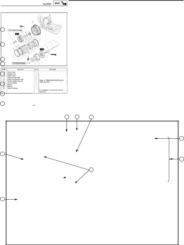
EAS00007
HOW TO USE THIS MANUAL
This manual is intended as a handy, easy-to-read reference book for the mechanic. Comprehensive explanations of all installation, removal, disassembly, assembly, repair and check procedures are laid out with the individual steps in sequential order.
1The manual is divided into chapters. An abbreviation and symbol in the upper right corner of each page indicate the current chapter.
Refer to ªSYMBOLSº.
2Each chapter is divided into sections. The current section title is shown at the top of each page, except in Chapter 3 (ªPERIODIC CHECKS AND ADJUSTMENTSº), where the sub-section title(-s) appears.
3Sub-section titles appear in smaller print than the section title.
4To help identify parts and clarify procedure steps, there are exploded diagrams at the start of each removal and disassembly section.
5Numbers are given in the order of the jobs in the exploded diagram. A circled number indicates a disassembly step.
6Symbols indicate parts to be lubricated or replaced.
Refer to ªSYMBOLSº.
7A job instruction chart accompanies the exploded diagram, providing the order of jobs, names of parts, notes in jobs, etc.
8Jobs requiring more information (such as special tools and technical data) are described sequentially.
2 1 4
3
5
8
 6
6
7
|
GEN |
SPEC |
|
|
INFO |
||
|
3 |
4 |
|
|
CHK |
ENG |
|
|
ADJ |
||
|
5 |
6 |
|
|
CARB |
CHAS |
|
|
7 |
8 |
|
|
ELEC |
TRBL |
|
|
SHTG |
||
|
9 |
10 |
|
11 |
12 |
|
|
13 |
14 |
|
|
15 |
16 |
|
|
17 |
18 |
19 |
|
20 |
21 |
22 |
|
23 |
24 |
EAS00009
SYMBOLS
The following symbols are not relevant to every vehicle.
Symbols 1 to 8 indicate the subject of each chapter.
1General information
2Specifications
3Periodic checks and adjustments
4Engine
5Carburetor(-s)
6Chassis
7Electrical system
8Troubleshooting
Symbols 9 to 16 indicate the following.
9 Serviceable with engine mounted
10Filling fluid
11Lubricant
12Special tool
13Tightening torque
14Wear limit, clearance
15Engine speed
16Electrical data
Symbols 17 to 22 in the exploded diagrams indicate the types of lubricants and lubrication points.
17Engine oil
18Gear oil
19Molybdenum disulfide oil
20Wheel bearing grease
21Lithium soap base grease
22Molybdenum disulfide grease
Symbols 23 to 24 in the exploded diagrams indicate the following:
23Apply locking agent (LOCTITE )
24Replace the part

EAS00013
INDEX
|
GENERAL INFORMATION |
|||||
|
GEN |
1 |
||||
|
INFO |
|||||
|
SPECIFICATIONS |
|||||
|
SPEC |
2 |
||||
|
PERIODIC INSPECTION AND |
|||||
|
CHK |
3 |
||||
|
ADJUSTMENTS |
|||||
|
ADJ |
|||||
|
ENGINE OVERHAUL |
|||||
|
ENG |
4 |
||||
|
CARBURETORS |
|||||
|
CARB |
5 |
||||
|
CHASSIS |
|||||
|
CHAS |
6 |
||||
|
ELECTRICAL |
|||||
|
ELEC |
7 |
||||
|
TROUBLESHOOTING |
|||||
|
TRBL |
8 |
||||
|
SHTG |
INFOGEN 1
GEN
INFO
CHAPTER 1.
GENERAL INFORMATION
MOTORCYCLE IDENTIFICATION . . . . . . . . . . . . . . . . . . . . . . . . . . . . . . . 1-1 VEHICLE IDENTIFICATION NUMBER . . . . . . . . . . . . . . . . . . . . . . . . . 1-1 MODEL CODE . . . . . . . . . . . . . . . . . . . . . . . . . . . . . . . . . . . . . . . . . . . . . 1-1
IMPORTANT INFORMATION . . . . . . . . . . . . . . . . . . . . . . . . . . . . . . . . . . . . 1-2 PREPARATION FOR REMOVAL AND DISASSEMBLY . . . . . . . . . . 1-2 REPLACEMENT PARTS . . . . . . . . . . . . . . . . . . . . . . . . . . . . . . . . . . . . . 1-2 GASKETS, OIL SEALS AND O-RINGS . . . . . . . . . . . . . . . . . . . . . . . . 1-2 LOCK WASHERS/PLATES AND COTTER PINS . . . . . . . . . . . . . . . . 1-3 BEARINGS AND OIL SEALS . . . . . . . . . . . . . . . . . . . . . . . . . . . . . . . . . 1-3 CIRCLIPS . . . . . . . . . . . . . . . . . . . . . . . . . . . . . . . . . . . . . . . . . . . . . . . . . . 1-3
CHECKING OF THE CONNECTIONS . . . . . . . . . . . . . . . . . . . . . . . . . . . . 1-4
SPECIAL TOOLS . . . . . . . . . . . . . . . . . . . . . . . . . . . . . . . . . . . . . . . . . . . . . . 1-5
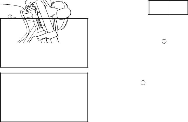
GEN
MOTORCYCLE IDENTIFICATION INFO
EAS00014
GENERAL INFORMATION
MOTORCYCLE IDENTIFICATION
EAS00017
VEHICLE IDENTIFICATION NUMBER (For E)
The vehicle identification number 1 is stamped into the right side of the steering head.
EAS00018
MODEL CODE
The model code label 1 is affixed to the frame. This information will be needed to order spare parts.
1-1
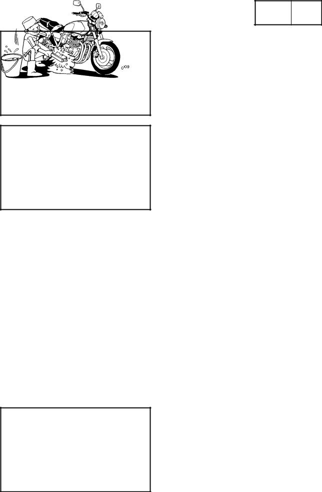
GEN
IMPORTANT INFORMATION INFO
EAS00020
IMPORTANT INFORMATION
PREPARATION FOR REMOVAL AND DIS-
ASSEMBLY
1.Before removal and disassembly, remove all dirt, mud, dust, and foreign material.
2.Use only the proper tools and cleaning equipment.
Refer to ªSPECIAL TOOLSº.
3.When disassembling, always keep mated parts together. This includes gears, cylinders, pistons and other parts that have been ªmatedº through normal wear. Mated parts must always be reused or replaced as an assembly.
4.During disassembly, clean all of the parts and place them in trays in the order of disassembly. This will speed up assembly and allow for the correct installation of all parts.
5.Keep all parts away from any source of fire.
EAS00021
REPLACEMENT PARTS
Use only genuine Yamaha parts for all replacements. Use oil and grease recommended by Yamaha for all lubrication jobs. Other brands may be similar in function and appearance, but inferior in quality.
EAS00022
GASKETS, OIL SEALS AND O-RINGS
1.When overhauling the engine, replace all gaskets, seals and O-rings. All gasket surfaces, oil seal lips and O-rings must be cleaned.
2.During reassembly, properly oil all mating parts and bearings and lubricate the oil seal lips with grease.
1-2
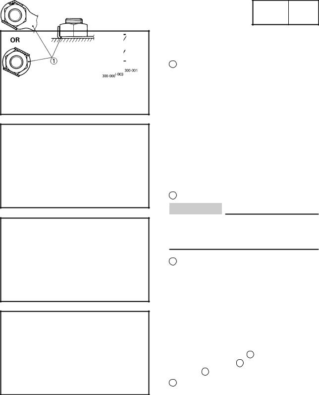
GEN
IMPORTANT INFORMATION INFO
EAS00023
LOCK WASHERS/PLATES AND COTTER PINS
After removal, replace all lock washers/plates 1 and cotter pins. After the bolt or nut has been tightened to specification, bend the lock washer tabs and the cotter pin ends along a flat of the bolt or nut.
EAS00024
BEARINGS AND OIL SEALS
1. Install bearings and oil seals so that the manufacturer’s marks or numbers are visible. When installing oil seals, lubricate the oil seal lips with a light coat of lithium soap base grease. Oil bearings liberally when installing, if appropriate.
1 Oil seal
CAUTION:
Do not spin the bearing with compressed air because this will damage the bearing surfaces.
1 Bearing
EAS00025
CIRCLIPS
Before reassembly, check all circlips carefully and replace damaged or distorted circlips. Always replace piston pin clips after one use. When installing a circlip 1 , make sure that the sharp-edged corner 2 is positioned opposite the thrust 3 that the circlip receives.
4 Shaft
1-3
![]()
GEN
CHECKING THE CONNECTIONS INFO
EAS00026
CHECKING THE CONNECTIONS
Check the leads, couplers, and connectors for stains, rust, moisture, etc.
1.Disconnect:
lead
coupler
connector
2.Check:
lead
coupler
connector
Moisture Dry with an air blower. Rust/stains Connect and disconnect several times.
3.Check:
all connections
Loose connection Connect properly.
NOTE:
If the pin 1 on the terminal is flattened, bend it up.
4.Connect:
lead
coupler
connector
NOTE:
Make sure that all connections are tight.
5.Check:
continuity
(with a pocket tester)
Pocket tester 90890-03112
NOTE:
If there is no continuity, clean the terminals.
When checking the wire harness, perform steps (1) to (3).
As a quick remedy, use a contact revitalizer available at most part stores.
1-4
GEN
SPECIAL TOOLS INFO
EB104000
SPECIAL TOOLS
The following special tools are necessary for complete and accurate tune-up and assembly.
Use only the appropriate special tools as this will help prevent damage caused by the use of inappropriate tools or improvised techniques.
When placing an order, refer to the list provided below to avoid any mistakes.
|
Tool No. |
Tool name/Function |
Illustration |
|
90890-01268 |
Exhaust & steering nut wrench |
|
|
90890-01403 |
Ring nut wrench |
|
|
This tools are used to loosen and tighten |
||
|
the steering ring nut. |
||
|
90890-01304 |
Piston pin puller |
|
|
This tool is used to remove the piston pins. |
||
|
90890-01312 |
Fuel level gauge |
|
|
This tool is used to measure the fuel level in |
||
|
the float chamber. |
||
|
90890-01367 |
Fork seal driver weight |
|
|
90890-01374 |
Fork seal driver attachment (ù43) |
|
|
These tools are used when installing the |
||
|
fork seal. |
||
|
90890-01326 |
T-handle |
|
|
90890-01327 |
Damper rod holder |
|
|
These tools are used to hold the damper |
||
|
rod assembly when loosening or tightening |
||
|
the damper rod assembly bolt. |
||
|
90890-03081 |
Compression gauge |
|
|
90890-04082 |
Adapter |
|
|
These tools are used to measure engine |
||
|
compression. |
||
|
90890-03094 |
Vacuum gauge |
|
|
This guide is used to synchronize the car- |
||
|
buretors. |
||
|
90890-03112 |
Pocket tester |
|
|
This tool is used to check the electrical sys- |
||
|
tem. |
||
1-5
|
SPECIAL TOOLS |
GEN |
|||||
|
INFO |
||||||
|
Tool No. |
Tool name/Function |
Illustration |
||||
|
90890-03113 |
Engine tachometer |
|||||
|
This tool is used to check engine speed. |
||||||
|
90890-03141 |
Timing light |
|||||
|
This tool is used to check the ignition tim- |
||||||
|
ing. |
||||||
|
90890-03158 |
Carburetor angle driver |
|||||
|
This tool is used to turn the pilot screw |
||||||
|
when adjusting the engine idling speed. |
||||||
|
90890-04016 |
Valve guide reamer, remover and installer |
|||||
|
(5.5 mm) |
||||||
|
These tools are used to rebore, remove and |
||||||
|
install the valve guide. |
||||||
|
90890-04019 |
Valve spring compressor |
|||||
|
This tool is used to remove or install the |
||||||
|
valve assemblies. |
||||||
|
90890-03153 |
Oil pressure gauge |
|||||
|
90890-03124 |
Oil pressure adaptor B |
|||||
|
These tools are used to measure the engine |
||||||
|
oil pressure. |
||||||
|
90890-04086 |
Clutch holding tool |
|||||
|
This tool is used to hold the clutch boss |
||||||
|
when removing or installing the clutch boss |
||||||
|
nut. |
||||||
|
90890-04101 |
Valve lapper |
|||||
|
This tool is used for removing and installing |
||||||
|
the valve lifter and for lapping the valve. |
||||||
|
90890-04110 |
Tappet adjusting tool |
|||||
|
This tool is necessary to replace valve ad- |
||||||
|
justing pads. |
||||||
1-6
|
SPECIAL TOOLS |
GEN |
|||||
|
INFO |
||||||
|
Tool No. |
Tool name/Function |
Illustration |
||||
|
90890-06754 |
Ignition checker |
|||||
|
This tool is used to check the ignition sys- |
||||||
|
tem components. |
||||||
|
90890-85505 |
Yamaha bond No. 1215 |
|||||
|
This bond is used to seal two mating sur- |
||||||
|
faces (e.g., crankcase mating surfaces). |
||||||
1-7
SPEC 2
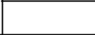
SPEC 


CHAPTER 2.
SPECIFICATIONS
GENERAL SPECIFICATIONS . . . . . . . . . . . . . . . . . . . . . . . . . . . . . . . . . . . 2-1
MAINTENANCE SPECIFICATIONS . . . . . . . . . . . . . . . . . . . . . . . . . . . . . . 2-4 ENGINE . . . . . . . . . . . . . . . . . . . . . . . . . . . . . . . . . . . . . . . . . . . . . . . . . . . 2-4 CHASSIS . . . . . . . . . . . . . . . . . . . . . . . . . . . . . . . . . . . . . . . . . . . . . . . . . . 2-14 ELECTRICAL . . . . . . . . . . . . . . . . . . . . . . . . . . . . . . . . . . . . . . . . . . . . . . 2-18
CONVERSION TABLE . . . . . . . . . . . . . . . . . . . . . . . . . . . . . . . . . . . . . . . . . . 2-20
GENERAL TIGHTENING TORQUES . . . . . . . . . . . . . . . . . . . . . . . . . . . . . 2-20
LUBRICATION POINT AND GRADE OF LUBRICANT . . . . . . . . . . . . . 2-21 ENGINE . . . . . . . . . . . . . . . . . . . . . . . . . . . . . . . . . . . . . . . . . . . . . . . . . . . 2-21 CHASSIS . . . . . . . . . . . . . . . . . . . . . . . . . . . . . . . . . . . . . . . . . . . . . . . . . . 2-22
LUBRICATION DIAGRAMS . . . . . . . . . . . . . . . . . . . . . . . . . . . . . . . . . . . . . 2-23
CABLE ROUTING . . . . . . . . . . . . . . . . . . . . . . . . . . . . . . . . . . . . . . . . . . . . . 2-26
|
GENERAL SPECIFICATIONS |
SPEC |
|||
|
SPECIFICATIONS |
||||
|
GENERAL SPECIFICATIONS |
||||
|
Model |
XJR1300(L) |
|||
|
Model code: |
5EA2/5EA3/5EA4 |
|||
|
Dimensions: |
||||
|
Overall length |
2175 mm (GB) (D) (NL) (B) (F) (E) (P) (I) (GR) |
|||
|
(SF) (AUS) |
||||
|
2250 mm (N) (SF) (G) (A) |
||||
|
Overall width |
775 mm |
|||
|
Overall height |
1115 mm |
|||
|
Seat height |
775 mm |
|||
|
Wheelbase |
1500 mm |
|||
|
Minimum ground clearance |
120 mm |
|||
|
Minimum turning radius |
2800 mm |
|||
|
Basic weight: |
||||
|
With oil and full fuel tank |
253 kg |
|||
|
Engine: |
||||
|
Engine type |
Air-cooled 4-stroke, DOHC |
|||
|
Cylinder arrangement |
Forward-inclined parallel 4-cylinder |
|||
|
Displacement |
1250 cm3 |
|||
|
Bore stroke |
79.0 63.8 mm |
|||
|
Compression ratio |
9.7: 1 |
|||
|
Compression pressure (STD) |
1050 kPa (10.5 kg/cm2,10.5 bar) at 400 r/min |
|||
|
Starting system |
Electric starter |
|||
|
Lubrication system: |
Wet sump |
|||
|
Oil type or grade: |
SE or higher grade |
|||
|
Engine oil |
|
Engine oil |
|
|
Periodic oil change |
3.0 L |
|
With oil filter replacement |
3.35 L |
|
Total amount |
4.2 L |
|
Oil cooler capacity (including all routes) |
0.2 L |
|
Air filter: |
Dry type element |
|
Fuel: |
|
|
Type |
Regular unleaded gasoline |
|
Fuel tank capacity |
21 L |
|
Fuel reserve amount |
4.5 L |
2-1

|
GENERAL SPECIFICATIONS |
SPEC |
|||||
|
Model |
XJR1300(L) |
|||||
|
Carburetor: |
||||||
|
Type/quantity |
BS36/4 |
|||||
|
Manufacturer |
MIKUNI |
|||||
|
Spark plug: |
||||||
|
Type quantity |
DPR8EA-9/X24EPR-U9 4 |
|||||
|
Manufacturer |
NGK/DENSO |
|||||
|
Spark plug gap |
0.8 X 0.9 mm |
|||||
|
Clutch type: |
Wet, multiple-disc |
|||||
|
Transmission: |
||||||
|
Primary reduction system |
Spur gear |
|||||
|
Primary reduction ratio |
98/56 (1.750) |
|||||
|
Secondary reduction system |
Chain drive |
|||||
|
Secondary reduction ratio |
38/17 (2.235) |
|||||
|
Transmission type |
Constant mesh 5-speed |
|||||
|
Operation |
Left foot operation |
|||||
|
Gear ratio 1st |
40/14 (2.857) |
|||||
|
2nd |
36/18 (2.000) |
|||||
|
3rd |
33/21 (1.571) |
|||||
|
4th |
31/24 (1.292) |
|||||
|
5th |
29/26 (1.115) |
|||||
|
Chassis: |
||||||
|
Frame type |
Double cradle |
|||||
|
Caster angle |
25.5 |
|||||
|
Trail |
100 mm |
|||||
|
Tire: |
||||||
|
Type |
Tubeless |
|||||
|
Size |
front |
120/70ZR17 (58W) |
||||
|
rear |
180/55ZR17 (73W) |
|||||
|
Manufacturer |
front |
MICHELIN/DUNLOP/BRIDGESTONE |
||||
|
rear |
MICHELIN/DUNLOP/BRIDGESTONE |
|||||
|
Type |
front |
MACADAM 90X/D207F/BT57F |
||||
|
rear |
MACADAM 90X/D207/BT57R |
|||||
|
Tire pressure (cold tire): |
||||||
|
Maximum load-except motorcycle |
207 kg |
|||||
|
Loading condition A * |
0 X 90 kg |
|||||
|
front |
250 kPa (2.5 kg/cm2, 2.5 bar) |
|||||
|
rear |
250 kPa (2.5 kg/cm2, 2.5 bar) |
|||||
|
Loading condition B * |
90 X 207 kg |
|||||
|
front |
250 kPa (2.5 kg/cm2, 2.5 bar) |
|||||
|
rear |
290 kPa (2.9 kg/cm2, 2.9 bar) |
|||||
|
High-speed riding |
250 kPa (2.5 kg/cm2, 2.5 bar) |
|||||
|
front |
||||||
|
rear |
290 kPa (2.9 kg/cm2, 2.9 bar) |
*Load is the total weight of cargo, rider, passenger, and accessories.
2-2
|
GENERAL SPECIFICATIONS |
SPEC |
||||||
|
Model |
XJR1300(L) |
||||||
|
Brake: |
|||||||
|
Front brake |
type |
Dual disc brake |
|||||
|
operation |
Right hand operation |
||||||
|
Rear brake |
type |
Single disc brake |
|||||
|
operation |
Right foot operation |
||||||
|
Suspension: |
|||||||
|
Front suspension |
Telescopic fork |
||||||
|
Rear suspension |
Swingarm |
||||||
|
Shock absorber: |
|||||||
|
Front shock absorber |
Coil spring/Oil Damper |
||||||
|
Rear shock absorber |
Coil spring/Gas-oil damper |
||||||
|
Wheel travel: |
|||||||
|
Front wheel travel |
130 mm |
||||||
|
Rear wheel travel |
110 mm |
||||||
|
Electrical: |
|||||||
|
Ignition system |
T.C.I. (Digital) |
||||||
|
Generator system |
A.C. generator |
||||||
|
Battery type |
GT14B-4 |
||||||
|
Battery capacity |
12 |
V 12AH |
|||||
|
Headlight type: |
Halogen bulb |
||||||
|
Bulb wattage quantity: |
|||||||
|
Headlight |
12 V 60 W/55 W 1 |
||||||
|
Auxiliary light |
12 |
V 4 W 1 |
|||||
|
Tail/brake light |
12 |
V 5 W/21 W 2 |
|||||
|
Flasher light |
12 |
V 21 W 4 |
|||||
|
Meter light |
12 |
V 1.7 W 4 |
|||||
|
Neutral indicator light |
12 |
V 1.7 W 1 |
|||||
|
High beam indicator light |
12 |
V 3.4 W 1 |
|||||
|
Oil level indicator light |
12 |
V 1.7 W 1 |
|||||
|
Turn indicator light |
12 |
V 1.7 W 2 |
|||||
2-3
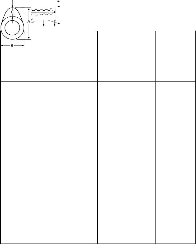
|
MAINTENANCE SPECIFICATIONS |
SPEC |
|||
|
MAINTENANCE SPECIFICATIONS |
||||
|
ENGINE |
||||
|
Model |
Standard |
Limit |
||
|
Cylinder head: |
||||
|
Warp limit |
0.1 mm |
|
Cylinder: |
||
|
Bore size |
79.00 79.01 mm |
|
|
Taper limit |
0.05 mm |
|
|
Out of round limit |
0.05 mm |
|
|
Wear limit |
79.1 mm |
|
|
Camshaft: |
||
|
Drive method |
Chain drive (Center) |
|
|
Cam cap inside diameter |
25.000 25.021 mm |
|
|
Camshaft outside diameter |
24.967 24.980 mm |
|
|
Shaft-to-cap clearance |
0.020 0.054 mm |
|
|
Cam dimensions |
|
Intake |
ªAº |
35.95 36.05 mm |
35.85 mm |
|
ªBº |
28.248 28.348 mm |
28.15 mm |
|
|
ªCº |
7.95 8.05 mm |
||
|
Exhaust |
ªAº |
35.95 36.05 mm |
35.85 mm |
|
ªBº |
28.248 28.348 mm |
28.15 mm |
|
|
ªCº |
7.95 8.05 mm |
||
|
Camshaft runout limit |
0.03 mm |
2-4
![]()
|
MAINTENANCE SPECIFICATIONS |
SPEC |
|||
|
Model |
Standard |
Limit |
||
|
Cam chain: |
||||
|
Cam chain type/No. of links |
79RH2015/156 |
|||
|
Cam chain adjustment method |
Automatic |
|||
|
Valve, valve seat, valve guide: |
||||
|
Valve clearance (cold) |
IN |
0.11 0.15 mm |
||
|
EX |
0.16 0.20 mm |
|||
|
Valve dimensions: |
|
Head Dia. |
Face Width |
Seat Width |
Margin Thickness |
|
|
ªAº head diameter |
IN |
28.9 29.1 mm |
||
|
EX |
24.9 25.1 mm |
|||
|
ªBº face width |
IN |
1.98 2.55 mm |
||
|
EX |
1.98 2.55 mm |
|||
|
ªCº seat width |
IN |
0.9 1.1 mm |
||
|
EX |
0.9 1.1 mm |
|||
|
ªDº margin thickness |
IN |
0.8 1.2 mm |
||
|
EX |
0.8 1.2 mm |
|||
|
Stem outside diameter |
IN |
5.475 5.490 mm |
5.445 mm |
|
|
EX |
5.460 5.475 mm |
5.43 mm |
||
|
Guide inside diameter |
IN |
5.500 5.512 mm |
5.552 mm |
|
|
EX |
5.500 5.512 mm |
5.552 mm |
||
|
Stem-to-guide clearance |
IN |
0.010 0.037 mm |
0.08 mm |
|
|
EX |
0.025 0.052 mm |
0.1 mm |
||
|
Stem runout limit |
0.01 mm |
|
Valve seat width |
IN |
0.9 1.1 mm |
1.6 mm |
|
EX |
0.9 1.1 mm |
1.6 mm |
2-5
|
MAINTENANCE SPECIFICATIONS |
SPEC |
||||
|
Model |
Standard |
Limit |
|||
|
Valve spring: |
|||||
|
Inner spring |
|||||
|
Free length |
IN |
39.65 mm |
37.5 mm |
||
|
EX |
39.65 mm |
37.5 mm |
|||
|
Set length (valve closed) |
IN |
32.8 mm |
|||
|
EX |
32.8 mm |
||||
|
Compressed pressure (installed) |
IN |
61.7 72.5 N (6.29 7.39 kg) |
|||
|
EX |
61.7 72.5 N (6.29 7.39 kg) |
||||
|
Tilt limit |
IN |
2.5 /1.7 mm |
|||
|
EX |
2.5 /1.7 mm |
|
Direction of winding (top view) |
IN |
Clockwise |
|
|
EX |
Clockwise |
||
|
Outer spring |
|||
|
Free length |
IN |
41.1 mm |
39 mm |
|
EX |
41.1 mm |
39 mm |
|
|
Set length (valve closed) |
IN |
34.8 mm |
|
|
EX |
34.8 mm |
||
|
Compressed pressure (installed) |
IN |
130.4 154.0 N (13.3 15.7 kg) |
|
|
EX |
130.4 154.0 N (13.3 15.7 kg) |
||
|
Tilt limit |
IN |
2.5 /1.7 mm |
|
|
EX |
2.5 /1.7 mm |
||
|
Direction of winding (top view) |
IN |
Counterclockwise |
|
|
EX |
Counterclockwise |
||
|
Piston: |
|||
|
Piston to cylinder clearance |
0.015 0.040 mm |
0.15 mm |
|
|
Piston size ªDº |
78.970 78.985 mm |
|
Measuring point ªHº |
2 mm |
|
|
Piston off-set |
1 mm |
|
|
Piston off-set direction |
IN side |
|
|
Piston pin bore inside diameter |
18.004 18.015 mm |
|
|
Piston pin outside diameter |
17.991 18.000 mm |
2-6
|
MAINTENANCE SPECIFICATIONS |
SPEC |
|||
|
Model |
Standard |
Limit |
Piston rings:
Top ring:
|
Type |
Barrel |
|
|
Dimensions (B T) |
1.00 3.05 mm |
|
|
End gap (installed) |
0.20 0.35 mm |
0.6 mm |
|
Side clearance (installed) |
0.045 0.080 mm |
0.1 mm |
2nd ring:
|
Type |
Taper |
|
|
Dimensions (B T) |
1.2 3.0 mm |
|
|
End gap (installed) |
0.35 0.50 mm |
0.75 mm |
|
Side clearance (installed) |
0.03 0.07 mm |
0.1 mm |
Oil ring:
|
Dimensions (B T) |
2.5 2.9 mm |
|
|
End gap (installed) |
0.2 0.5 mm |
|
|
Side clearance |
0.050 0.155 mm |
|
|
Connecting rod: |
||
|
Oil clearance |
0.017 0.040 mm |
0.08 mm |
|
Crankshaft: |
|
Crank width ªAº |
62.25 63.85 mm |
|
|
Assembly width ªBº |
382.0 383.2 mm |
|
|
Runout limit ªCº |
0.02 mm |
|
|
Big end side clearance ªDº |
0.160 0.262 mm |
0.5 mm |
|
Journal oil clearance |
0.030 0.064 mm |
0.09 mm |
2-7

|
MAINTENANCE SPECIFICATIONS |
SPEC |
|||
|
Model |
Standard |
Limit |
||
|
Clutch: |
||||
|
Friction plate thickness |
2.9 3.1 mm |
2.8 mm |
||
|
Quantity |
8 pcs |
|||
|
Clutch plate thickness |
1.9 2.1 mm |
0.1 mm |
||
|
<Warp limit> |
||||
|
Quantity |
7 pcs |
|||
|
Clutch spring height |
6 mm |
|||
|
Quantity |
1 pc |
|||
|
Clutch housing thrust clearance |
0 0.2 mm |
|||
|
Clutch housing radial clearance |
0.004 0.048 mm |
0.1 mm |
||
|
Clutch release method |
Hydraulic inner push |
|||
|
Push rod bending limit |
0.3 mm |
|||
|
Transmission: |
||||
|
Main axle deflection limit |
0.06 mm |
|||
|
Drive axle deflection limit |
0.06 mm |
|||
|
Shifter: |
||||
|
Shifter type |
Guide bar |
|||
|
Guide bar bending limit |
0.1 mm |
|||
|
Carburetor: |
||||
|
I.D. mark |
5EA1 10 |
|||
|
Main jet |
(M.J) |
#95 |
||
|
Main air jet |
(M.A.J) |
#45 |
||
|
Jet needle |
(J.N) |
5D96-2 |
||
|
Needle jet |
(N.J) |
Y-2 |
||
|
Pilot jet |
(P.A.J.1) |
#127.5 |
||
|
Pilot outlet |
(P.O) |
0.85 |
||
|
Pilot jet |
(P.J) |
#40 |
||
|
Bypass 1 |
(B.P.1) |
0.9 |
||
|
Bypass 2 |
(B.P.2) |
1.0 |
||
|
Bypass 3 |
(B.P.3) |
0.8 |
||
|
Pilot screw |
(P.S) |
1-1/2 |
||
|
Valve seat size |
(V.S) |
2.3 |
||
|
Starter jet |
(G.S.1) |
#32.5 |
||
|
Starter jet |
(G.S.2) |
0.6 |
||
|
Throttle valve size |
(Th.V) |
#125 |
||
|
Float height |
(F.H) |
21.3 23.3 mm |
||
|
Fuel level (using special tool) |
3.5 4.5 mm |
|||
|
Engine idle speed |
1000 1100 r/min |
|||
|
Intake vacuum |
31.3 kPa (235 mmHg) |
2-8

|
MAINTENANCE SPECIFICATIONS |
SPEC |
||||
|
Model |
Standard |
Limit |
|||
|
Lubrication system: |
|||||
|
Oil filter type |
Paper type |
||||
|
Oil pump type |
Trochoid type |
||||
|
Tip clearance |
0.12 0.17 mm |
0.2 mm |
|||
|
Housing and rotor clearance |
0.03 0.08 mm |
0.15 mm |
|||
|
Side clearance |
0.03 0.08 mm |
0.15 mm |
|||
|
Bypass valve setting pressure |
180 220 kPa |
||||
|
(1.8 2.2 kg/cm2, 1.8 2.2 bar) |
|||||
|
Relief valve operating pressure |
480 580 kPa |
||||
|
(4.8 5.8 kg/cm2, 4.8 5.8 bar) |
|||||
|
Oil pressure (hot) |
80 kPa (0.8 kg/cm2, 0.8 bar) |
||||
|
at 1000 r/min |
|||||
|
Pressure check location |
MAIN GALLERY |
2-9
|
MAINTENANCE SPECIFICATIONS |
SPEC |
||||||||||
|
Tightening torques |
|||||||||||
|
Thread |
Tightening |
||||||||||
|
Part to be tightened |
Part name |
Q’ty |
torque |
Remarks |
|||||||
|
size |
|||||||||||
|
Nm |
m kg |
||||||||||
|
Camshaft cap |
Bolt |
M6 |
1.0 |
18 |
12 |
1.2 |
|||||
|
Oil gallery bolt |
Screw |
M6 |
1.0 |
1 |
7 |
0.7 |
|||||
|
Spark plug |
± |
M12 |
1.25 |
4 |
18 |
1.8 |
|||||
|
Cylinder head |
Cap nut |
M10 |
1.25 |
12 |
35 |
3.5 |
|||||
|
Cylinder head cover |
Bolt |
M6 |
1.0 |
8 |
10 |
1.0 |
|||||
|
Cylinder |
Stud bolt |
M8 1.25 |
1 |
8 |
0.8 |
||||||
|
Cylinder |
Nut |
M8 1.25 |
3 |
20 |
2.0 |
||||||
|
Cylinder |
Nut |
M6 |
1.0 |
6 |
10 |
1.0 |
|||||
|
Connecting rod |
Nut |
M8 0.75 |
8 |
36 |
3.6 |
||||||
|
Cam sprocket |
Bolt |
M7 |
1.0 |
4 |
20 |
2.0 |
|||||
|
Timing chain tensioner |
Bolt |
M6 |
1.0 |
2 |
10 |
1.0 |
|||||
|
Timing chain tensioner cap bolt |
Bolt |
M11 1.0 |
1 |
20 |
2.0 |
||||||
|
Chain guide (upper) |
Bolt |
M6 |
1.0 |
4 |
10 |
1.0 |
|||||
|
Chain guide (intake) |
Plug |
M10 |
1.25 |
1 |
10 |
1.0 |
|||||
|
Oil pump |
Screw |
M6 |
1.0 |
2 |
10 |
1.0 |
|||||
|
Oil pump |
Bolt |
M6 |
1.0 |
3 |
10 |
1.0 |
|||||
|
Oil strainer housing |
Bolt |
M6 |
1.0 |
2 |
10 |
1.0 |
|||||
|
Oil filter case |
Union bolt |
M20 1.5 |
1 |
15 |
1.5 |
||||||
|
Oil pan |
Bolt |
M6 |
1.0 |
17 |
10 |
1.0 |
|||||
|
Drain bolt (engine oil) |
Plug |
M14 1.5 |
1 |
43 |
4.3 |
||||||
|
Oil gallery blind plug |
Plug |
M16 1.5 |
1 |
8 |
0.8 |
||||||
|
Drain filter |
Screw |
M5 |
0.8 |
1 |
7 |
0.7 |
|||||
|
Oil delivery pipe (oil pan) |
Bolt |
M6 |
1.0 |
4 |
10 |
1.0 |
|||||
|
Oil delivery pipe (oil cooler) |
Bolt |
M6 |
1.0 |
4 |
10 |
1.0 |
|||||
|
Oil cooler |
Bolt |
M6 |
1.0 |
2 |
10 |
1.0 |
|||||
|
Oil cooler cover |
Bolt |
M6 |
1.0 |
4 |
8 |
0.8 |
|||||
|
Oil delivery pipe (clamp) |
Bolt |
M6 |
1.0 |
1 |
10 |
1.0 |
|||||
|
Intake manifold |
Bolt |
M6 |
1.0 |
8 |
10 |
1.0 |
|||||
|
Air filter case cap |
Bolt |
M5 |
0.8 |
4 |
5 |
0.5 |
|||||
|
Air filter case |
Bolt |
M6 |
1.0 |
3 |
7 |
0.7 |
|||||
|
Exhaust pipe |
Nut |
M8 1.25 |
8 |
25 |
2.5 |
||||||
|
Muffler and stay |
Bolt |
M8 1.25 |
2 |
20 |
2.0 |
||||||
|
Exhaust chamber |
Bolt |
M10 |
1.25 |
1 |
25 |
2.5 |
|||||
|
Exhaust pipe and exhaust chamber |
Screw |
M8 1.25 |
4 |
20 |
2.0 |
||||||
|
Exhaust chamber and muffler |
Bolt |
M8 1.25 |
2 |
20 |
2.0 |
||||||
|
Exhaust pipe blind plug (CO test) |
Bolt |
M6 |
1.0 |
4 |
10 |
1.0 |
|||||
|
Bearing holder (main axle) |
Screw |
M6 |
1.0 |
3 |
12 |
1.2 |
|||||
|
Timing plate cover |
Bolt |
M6 |
1.0 |
4 |
7 |
0.7 |
|||||
|
Crankcase cover (right) |
Screw |
M5 |
0.8 |
2 |
4 |
0.4 |
|||||
|
Clutch cover |
Bolt |
M6 |
1.0 |
11 |
10 |
1.0 |
|||||
|
Drive sprocket cover |
Bolt |
M6 |
1.0 |
3 |
10 |
1.0 |
|||||
|
Clutch release cylinder |
Bolt |
M6 |
1.0 |
3 |
10 |
1.0 |
|||||
|
Crankcase |
Bolt |
M6 |
1.0 |
16 |
12 |
1.2 |
|||||
2-10
|
MAINTENANCE SPECIFICATIONS |
SPEC |
||||||||||
|
Thread |
Tightening |
||||||||||
|
Part to be tightened |
Part name |
Q’ty |
torque |
Remarks |
|||||||
|
size |
|||||||||||
|
Nm |
m kg |
||||||||||
|
Crankcase |
Bolt |
M8 1.25 |
17 |
24 |
2.4 |
||||||
|
Crankcase |
Bolt |
M10 |
1.25 |
5 |
35 |
3.5 |
|||||
|
Main gallery |
Plug |
M20 1.5 |
3 |
12 |
1.2 |
||||||
|
Oil buffle plate |
Bolt |
M5 |
0.8 |
3 |
4 |
0.4 |
|||||
|
Stopper plate |
Bolt |
M6 |
1.0 |
1 |
10 |
1.0 |
|||||
|
Bearing housing |
Screw |
M6 |
1.0 |
3 |
10 |
1.0 |
|||||
|
HY-VO chain guide |
Bolt |
M6 |
1.0 |
2 |
10 |
1.0 |
|||||
|
Clutch boss |
Nut |
M20 1.5 |
1 |
70 |
7.0 |
||||||
|
Clutch pressure plate |
Bolt |
M6 |
1.0 |
6 |
8 |
0.8 |
|||||
|
Push lever comp. |
Bolt |
M6 |
1.0 |
2 |
10 |
1.0 |
|||||
|
Drive sprocket |
Nut |
M22 1.5 |
1 |
85 |
8.5 |
||||||
|
Shift shaft stopper |
Screw |
M8 1.25 |
1 |
22 |
2.2 |
||||||
|
Stopper plate |
Screw |
M6 |
1.0 |
2 |
7 |
0.7 |
|||||
|
(Starter clutch idle gear shaft) |
|||||||||||
|
Stopper lever |
Bolt |
M6 |
1.0 |
1 |
10 |
1.0 |
|||||
|
Side plate |
Screw |
M5 |
0.8 |
1 |
4 |
0.4 |
|||||
|
Shift arm |
Bolt |
M6 |
1.0 |
1 |
10 |
1.0 |
|||||
|
Shift lod |
Nut |
M6 |
1.0 |
2 |
8 |
0.8 |
|||||
|
A.C. generator |
Bolt |
M8 1.25 |
2 |
25 |
2.5 |
||||||
|
Oil level sensor |
Bolt |
M6 |
1.0 |
2 |
10 |
1.0 |
|||||
|
Rotor |
Bolt |
M10 |
1.25 |
1 |
45 |
4.5 |
2-11
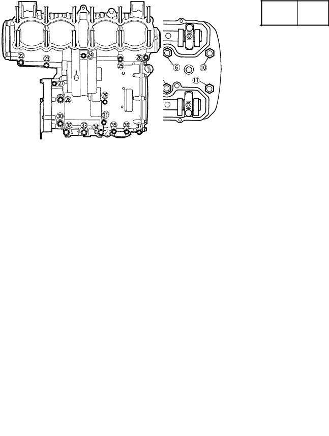
MAINTENANCE SPECIFICATIONS SPEC 
Tightening sequence
Cylinder head
Crankcase
2-12
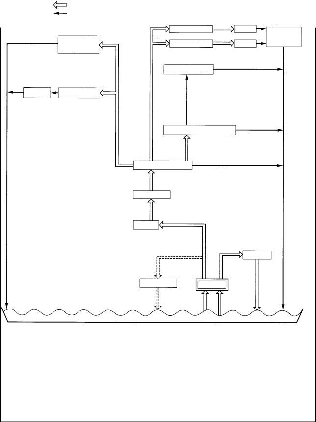
|
MAINTENANCE SPECIFICATIONS |
SPEC |
||||
|
Model |
XJR1300(L) |
||||
Lubrication chart:
Pressure feed
Splashed
|
Ex. camshaft |
Lifter |
Timing |
||
|
Generator |
IN. camshaft |
Lifter |
chain area |
|
|
shaft |
||||
|
Piston, Cylinder |
||||
|
Clutch |
Transmission |
Connecting rod bearing
Crankshaft bearings
Main gallery
Oil filter
Oil cooler
Oil pan/Oil strainer
2-13

|
MAINTENANCE SPECIFICATIONS |
SPEC |
|||||
|
CHASSIS |
||||||
|
Model |
Standard |
Limit |
||||
|
Steering system: |
||||||
|
Steering bearing type |
Angular bearing |
|||||
|
Front suspension: |
||||||
|
Front fork travel |
130 mm |
|||||
|
Fork spring free length |
407.3 mm |
395 mm |
||||
|
Fitting length |
363.3 mm |
|||||
|
Collar length |
150 mm |
|||||
|
Spring rate |
(K1) |
4.9 N/mm (0.5 kg/mm) |
||||
|
(K2) |
8.8 N/mm (0.9 kg/mm) |
|||||
|
Stroke |
(K1) |
0 83 mm |
||||
|
(K2) |
83 130 mm |
|||||
|
Optional spring |
No |
|||||
|
Oil capacity |
538 cm3 |
|||||
|
Oil level |
137 mm |
|||||
|
Oil grade |
Fork oil 10W or equivalent |
|||||
|
Rear suspension: |
||||||
|
Shock absorber travel |
88 mm |
|||||
|
Spring free length |
210 mm |
206 mm |
||||
|
Fitting length |
190 mm |
|||||
|
Spring rate |
(K1) |
20.6 N/mm (2.1 kg/mm) |
||||
|
(K2) |
31.4 N/mm (3.2 kg/mm) |
|||||
|
Stroke |
(K1) |
0 50 mm |
||||
|
(K2) |
50 88 mm |
|||||
|
Front wheel: |
||||||
|
Type |
Cast wheel |
|||||
|
Rim size |
17 MT3.50 |
|||||
|
Rim material |
Aluminum |
|||||
|
Rim runout limit |
radial |
1 mm |
||||
|
lateral |
0.5 mm |
|||||
|
Rear wheel: |
||||||
|
Type |
Cast wheel |
|||||
|
Rim size |
17 MT5.50 |
|||||
|
Rim material |
Aluminum |
|||||
|
Rim runout limit |
radial |
1 mm |
||||
|
lateral |
0.5 mm |
|||||
|
Drive chain: |
||||||
|
Type/manufacturer |
50ZVM/DAIDO |
|||||
|
No. of links |
110 |
|||||
|
Chain free play |
20 30 mm |
|||||
2-14
![]()
|
MAINTENANCE SPECIFICATIONS |
SPEC |
|||
|
Model |
Standard |
Limit |
||
|
Front disc brake: |
||||
|
Type |
Dual |
|||
|
Disc outside diameter thickness |
298 5 mm |
|||
|
Disc deflection limit |
0.2 mm |
|||
|
Pad thickness |
5.5 mm |
0.5 mm |
|
Master cylinder inside diameter |
14 mm |
|
|
Caliper cylinder inside diameter |
30.2 mm and 27 mm |
|
|
Brake fluid type |
DOT #4 |
|
|
Rear disc brake: |
||
|
Type |
Single |
|
|
Disc outside diameter thickness |
267 5 mm |
|
|
Disc deflection limit |
0.15 mm |
|
|
Pad thickness |
5.5 mm |
0.5 mm |
|
Master cylinder inside diameter |
12.7 mm |
|
|
Caliper cylinder inside diameter |
42.85 mm |
|
|
Brake fluid type |
DOT #4 |
|
|
Brake lever & brake pedal: |
||
|
Brake pedal position |
45 mm |
|
Throttle grip free play |
3 5 mm |
2-15

|
MAINTENANCE SPECIFICATIONS |
SPEC |
||||||||||
|
Tightening torques |
|||||||||||
|
Tightening |
|||||||||||
|
Part to be tightened |
Part name |
Thread size |
Q’ty |
torque |
Remarks |
||||||
|
Nm |
m kg |
||||||||||
|
Handle crown and inner tube |
Bolt |
M8 1.25 |
2 |
30 |
3.0 |
||||||
|
Handle crown and steering stem |
Nut |
M22 1.0 |
1 |
110 |
11.0 |
||||||
|
Handle crown and handlebar holder |
Nut |
M10 |
1.25 |
2 |
40 |
4.0 |
|||||
|
(lower) |
|||||||||||
|
Upper handlebar holder |
Bolt |
M8 1.25 |
4 |
23 |
2.3 |
||||||
|
Lower bracket and inner tube |
Bolt |
M8 1.25 |
4 |
23 |
2.3 |
||||||
|
Steering stem and ring nut |
Nut |
M25 1.0 |
1 |
18 |
1.8 |
See ªNOTEº |
|||||
|
Front master cylinder and holder |
Bolt |
M6 |
1.0 |
2 |
10 |
1.0 |
|||||
|
Front brake hose union bolt |
Bolt |
M10 |
1.25 |
1 |
30 |
3.0 |
|||||
|
Meter |
Nut |
M6 |
1.0 |
2 |
7 |
0.7 |
|||||
|
Headlight stay (lower) |
Bolt |
M6 |
1.0 |
2 |
10 |
1.0 |
|||||
|
Grip end |
± |
M16 1.5 |
2 |
26 |
2.6 |
||||||
|
Front turn signal lights |
Nut |
M12 |
1.25 |
2 |
7 |
0.7 |
|||||
|
Front fender and front fork |
Bolt |
M6 |
1.0 |
4 |
7 |
0.7 |
|||||
|
Headlight stay and upper cover |
Cap nut |
M6 |
1.0 |
4 |
7 |
0.7 |
|||||
|
Engine stay (front) and frame |
Bolt |
M8 1.25 |
4 |
30 |
3.0 |
||||||
|
Engine mount (front) |
Nut |
M10 |
1.25 |
2 |
64 |
6.4 |
|||||
|
(rear-upper) |
Nut |
M10 |
1.25 |
1 |
55 |
5.5 |
|||||
|
Engine stay (rear-upper) and frame |
Bolt |
M10 |
1.25 |
2 |
48 |
4.8 |
|||||
|
Engine stay (rear-upper) and frame |
Bolt |
M12 |
1.25 |
2 |
88 |
8.8 |
|||||
|
Engine stay (rear-lower) |
Nut |
M10 |
1.25 |
2 |
64 |
6.4 |
|||||
|
Frame and down tube |
Nut and Bolt |
M8 1.25 |
4 |
26 |
2.6 |
||||||
|
Pivot shaft |
Nut |
M18 1.5 |
1 |
125 |
12.5 |
||||||
|
Rear shock absorber and frame |
Bolt |
M8 1.25 |
1 |
23 |
2.3 |
||||||
|
Rear shock absorber and swing arm |
Bolt |
M10 |
1.25 |
1 |
30 |
3.0 |
|||||
|
Drive chain guide and swing arm |
Bolt |
M6 |
1.0 |
1 |
7 |
0.7 |
|||||
|
Chain case and swing arm |
Screw |
M6 |
1.0 |
2 |
7 |
0.7 |
|||||
|
Fuel tank |
Bolt |
M8 1.25 |
1 |
19 |
1.9 |
||||||
|
Fuel tank cap |
Screw |
M5 |
0.8 |
4 |
6 |
0.6 |
|||||
|
Fuel cock |
Screw |
M6 |
1.0 |
2 |
7 |
0.7 |
|||||
|
Seat lock |
Nut |
M6 |
1.0 |
2 |
7 |
0.7 |
|||||
|
Fuel sender |
Bolt |
M5 |
0.8 |
4 |
4 |
0.4 |
|||||
|
Side cover and frame |
Screw |
M6 |
1.0 |
2 |
7 |
0.7 |
|||||
|
Tail light |
Nut |
M6 |
1.0 |
3 |
7 |
0.7 |
|||||
|
Rear fender and frame |
Bolt |
M6 |
1.0 |
4 |
7 |
0.7 |
|||||
|
Rear fender cover and cover |
Screw |
M5 |
0.8 |
2 |
4 |
0.4 |
|||||
|
Rear fender cover and frame |
Screw |
M6 |
1.0 |
2 |
7 |
0.7 |
|||||
|
Grab bar |
Bolt |
M8 1.25 |
4 |
30 |
3.0 |
||||||
|
Ignitor |
Screw |
M6 |
1.0 |
2 |
7 |
0.7 |
|||||
|
Rear turn signal light and rear fender |
Nut |
M12 |
1.25 |
2 |
4 |
0.4 |
|||||
2-16

|
MAINTENANCE SPECIFICATIONS |
SPEC |
|||||||||
|
Tightening |
||||||||||
|
Part to be tightened |
Part name |
Thread size |
Q’ty |
torque |
Remarks |
|||||
|
Nm |
m kg |
|||||||||
|
Hook |
Screw |
M6 |
1.0 |
2 |
7 |
0.7 |
||||
|
Helmet holder |
Bolt |
M6 |
1.0 |
2 |
13 |
1.3 |
||||
|
Tail light bracket |
Bolt |
M8 1.25 |
4 |
30 |
3.0 |
|||||
|
Side stand |
Bolt |
M10 |
1.25 |
1 |
40 |
4.0 |
||||
|
Side stand |
Nut |
M10 |
1.25 |
1 |
40 |
4.0 |
||||
|
Side stand switch |
Screw |
M5 |
0.8 |
2 |
4 |
0.4 |
||||
|
Footrest bracket |
Bolt |
M8 1.25 |
4 |
28 |
2.8 |
|||||
|
Rear footrest bracket |
Bolt |
M8 1.25 |
4 |
28 |
2.8 |
|||||
|
Footrest and footrest bracket |
Bolt |
M10 |
1.25 |
2 |
55 |
5.5 |
||||
|
Rear brake reservoir tank |
Screw |
M6 |
1.0 |
1 |
5 |
0.5 |
||||
|
Rear master cylinder and bracket |
Bolt |
M8 1.25 |
2 |
23 |
2.3 |
|||||
|
Center stand |
Nut and Bolt |
M10 |
1.25 |
2 |
41 |
4.1 |
||||
|
Front wheel axle |
± |
M16 1.5 |
1 |
73 |
7.3 |
|||||
|
Front wheel axle pinch bolt |
Bolt |
M8 |
1.0 |
1 |
19 |
1.9 |
||||
|
Front brake caliper and front fork |
Bolt |
M10 |
1.25 |
4 |
40 |
4.0 |
||||
|
Front brake disk and hub |
Bolt |
M8 1.25 |
12 |
20 |
2.0 |
|||||
|
Front brake caliper and bleed screw |
± |
M8 1.25 |
2 |
6 |
0.6 |
|||||
|
Front brake hose |
Union bolt |
M10 |
1.25 |
2 |
30 |
3.0 |
||||
|
Tensionbar and swingarm |
Nut and bolt |
M8 1.25 |
2 |
23 |
2.3 |
|||||
|
Driven sprocket and hub |
Nut |
M8 1.25 |
6 |
60 |
6.0 |
|||||
|
Chain puller |
Nut |
M8 1.25 |
2 |
16 |
1.6 |
|||||
|
Rear brake caliper and caliper bracket |
Bolt |
M10 |
1.25 |
2 |
40 |
4.0 |
||||
|
Rear wheel axle |
Nut |
M18 1.5 |
1 |
150 |
15.0 |
|||||
|
Rear brake hose |
Union bolt |
M10 |
1.25 |
2 |
30 |
3.0 |
||||
|
Rear brake caliper and bleed screw |
± |
M8 1.25 |
1 |
6 |
0.6 |
|||||
|
Rear brake disc and hub |
Bolt |
M8 1.25 |
6 |
20 |
2.0 |
|||||
NOTE:
1.First, tighten the ring nut approximately 52 Nm (5.2 m kg) by using the torque wrench, then loosen the ring nut one turn.
2.Retighten the ring nut to specification.
2-17

|
MAINTENANCE SPECIFICATIONS |
SPEC |
||||
|
ELECTRICAL |
|||||
|
Model |
Standard |
Limit |
|||
|
Voltage: |
12 V |
||||
|
Ignition system: |
|||||
|
Ignition timing (B.T.D.C.) |
5 /1050 r/min |
||||
|
Advanced timing (B.T.D.C.) |
50 /5000 r/min |
||||
|
Advancer type |
TPS & Electrical type |
||||
|
T.C.I.: |
248 372 Ω/W/R-W/G |
||||
|
Pickup coil resistance/color |
|||||
|
T.C.I. unit model/manufacturer |
5EA20/YAMAHA |
||||
|
Ignition coil: |
|||||
|
Model/manufacturer |
83R/YAMAHA |
||||
|
Minimum spark gap |
6 mm |
||||
|
Primary winding resistance |
1.9 2.9 Ω |
||||
|
Secondary winding resistance |
9.5 14.3 kΩ |
||||
|
Spark plug cap: |
|||||
|
Type |
Resin type |
||||
|
Resistance |
10 kΩ |
||||
|
Charging system: |
|||||
|
Type |
A.C. generator |
||||
|
Model/manufacturer |
B3G-B/DENSO |
||||
|
Normal output |
13.5 V 28 A/3000 r/min |
||||
|
Rotor coil resistance |
2.8 3.0 Ω |
||||
|
Stator coil resistance |
0.19 0.21 Ω |
||||
|
Brush overall length |
13.7 mm |
4.7 mm |
|||
|
Spring force |
5.10 5.69 N (0.52 0.58 kg) |
||||
|
Voltage regulator: |
|||||
|
Type |
Semi-conductor, field control type |
||||
|
Model/manufacturer |
B3G-B/DENSO |
||||
|
No load regulated voltage |
14.2 14.8 V |
||||
|
Electric starter system: |
|||||
|
Type |
Constant mesh type |
||||
|
Starter motor: |
|||||
|
Model/manufacturer |
SM-13/MITSUBA |
||||
|
Output |
0.65 kW |
||||
|
Brush overall length |
10 mm |
5 mm |
|||
|
Spring force |
7.65 10.01 N (0.780 1.021 kg) |
||||
|
Commutator diameter |
28 mm |
27 mm |
|||
2-18

|
MAINTENANCE SPECIFICATIONS |
SPEC |
|||
|
Model |
Standard |
Limit |
||
|
Mica undercut |
0.7 mm |
|||
|
Starter relay: |
||||
|
Model/manufacturer |
MS5E-491/JIDECO |
|||
|
Amperage rating |
100 A |
|||
|
Coil winding resistance |
4.2 4.6 Ω |
|||
|
Horn: |
||||
|
Type |
Plane type |
|||
|
Quantity |
2 pcs |
|||
|
Model/manufacturer |
YF12/NIKKO |
|||
|
Maximum amperage |
3 A |
|||
|
Flasher relay: |
||||
|
Type |
Full transistor type |
|||
|
Model/manufacturer |
FE246BH/DENSO |
|||
|
Self cancelling device |
No |
|||
|
Flasher frequency |
75 95 cyl/min |
|||
|
Oil level switch: |
||||
|
Model/manufacturer |
5G2/DENSO |
|||
|
Fuel gauge: |
||||
|
Model/manufacturer |
4 KG/NIPPON SEIKI |
|||
|
Sender unit resistance |
full |
4 10 Ω |
||
|
empty |
90 100 Ω |
|||
|
Starting circuit cut-off relay: |
||||
|
Model/manufacturer |
G8R-30Y-J/OMRON |
|||
|
Coil winding resistance |
162 198 Ω |
|||
|
Diode |
Yes |
|||
|
Oil level switch relay: |
||||
|
Model/manufacturer |
G8D-117Y-2/OMRON |
|||
|
Circuit breaker: |
||||
|
Type |
Fuse |
|||
|
Amperage for individual circuit Q’ty |
||||
|
MAIN |
30 A 1 |
|||
|
HEAD LIGHT |
15 A 1 |
|||
|
SIGNAL |
15 A 1 |
|||
|
IGNITION |
7.5 A 1 |
|||
|
Reserve |
30 A 1 |
|||
|
15 A 1 |
||||
|
7.5 A 1 |
2-19

|
CONVERSION TABLE/ |
SPEC |
||
|
GENERAL TORQUE SPECIFICATIONS |
|||
EAS00028
CONVERSION TABLE
All specification data in this manual are listed in SI and METRIC UNITS.
Use this table to convert METRIC unit data to IMPERIAL unit data.
|
Ex. |
||||||
|
METRIC |
MULTIPLIER |
IMP |
||||
|
** mm |
x |
0.03937 |
= |
** in |
||
|
2 mm |
x |
0.03937 |
= |
0.08 in |
||
|
CONVERSION TABLE |
||||||
|
METRIC TO IMP |
||||||
|
Known |
Multiplier |
Result |
||||
|
m kg |
7.233 |
ft lb |
||||
|
Torque |
m kg |
86.794 |
in lb |
|||
|
cm kg |
0.0723 |
ft lb |
||||
|
cm kg |
0.8679 |
in lb |
||||
|
Weight |
kg |
2.205 |
lb |
|||
|
g |
0.03527 |
oz |
||||
|
km/hr |
0.6214 |
mph |
||||
|
km |
0.6214 |
mi |
||||
|
Distance |
m |
3.281 |
ft |
|||
|
m |
1.094 |
yd |
||||
|
cm |
0.3937 |
in |
||||
|
mm |
0.03937 |
in |
||||
|
cc (cm3) |
0.03527 |
oz (IMP liq.) |
||||
|
Volume/ |
cc (cm3) |
0.06102 |
cu in |
|||
|
Capacity |
lt (liter) |
0.8799 |
qt (IMP liq.) |
|||
|
It (liter) |
0.2199 |
gal (IMP liq.) |
||||
|
kg/mm |
55.997 |
lb/in |
||||
|
Miscella- |
kg/cm2 |
psi (lb/in2) |
||||
|
14.2234 |
||||||
|
neous |
Centigrade |
Fahrenheit ( F) |
||||
|
9/5 ( C) + 32 |
||||||
EAS00029
GENERAL TIGHTENING TORQUES
This chart specifies tightening torques for standard fasteners with a standard ISO thread pitch. Tightening torque specifications for special components or assemblies are provided for each chapter of this manual. To avoid warpage, tighten multi-fastener assemblies in a crisscross pattern and progressive stages until the specified tightening torque is reached. Unless otherwise specified, tightening torque specifications require clean, dry threads. Components should be at room temperature.
A:Distance across flats
B:Outside thread diameter
|
A |
B |
General specifications |
||
|
torques |
||||
|
(Nut) |
(Bolt) |
|||
|
Nm |
m kg |
|||
|
10 mm |
6 mm |
6 |
0.6 |
|
|
12 mm |
8 mm |
15 |
1.5 |
|
|
14 mm |
10 mm |
30 |
3.0 |
|
|
17 mm |
12 mm |
55 |
5.5 |
|
|
19 mm |
14 mm |
85 |
8.5 |
|
|
22 mm |
16 mm |
130 |
13.0 |
|
2-20

LUBRICATION POINT AND GRADE OF LUBRICANT SPEC 
LUBRICATION POINT AND GRADE OF LUBRICANT
ENGINE
|
Lubrication Point |
Symbol |
|
Oil seal lips |
|
|
O-ring |
|
|
Bearing |
|
|
Piston surface |
|
|
Piston pin |
|
|
Crankshaft pin |
|
|
Crankshaft journal/big end |
|
|
Connecting rod bolt/nut |
|
|
Camshaft cam lobe/journal |
|
|
Valve stem (IN, EX) |
|
|
Valve stem end (IN, EX) |
|
|
Valve lifter |
|
|
Oil pump rotor (inner/outer), housing |
|
|
Oil strainer assembly |
|
|
Starter idle gear inner surface |
|
|
Starter wheel gear inner surface |
|
|
Starter clutch (outer/roller) |
|
|
Crankcase cover (push rod hole) |
|
|
Primary drive gear/damper |
|
|
Transmission gear (wheel/pinion) |
|
|
Shift cam |
|
|
Shift fork/guide bar |
|
|
Shift shaft assembly |
|
|
Crankcase mating surfaces |
Yamaha bond No. 1215 |
|
Blind plug and oil seal (crankcase main gallery) |
Yamaha bond No. 1215 |
2-21

LUBRICATION POINT AND GRADE OF LUBRICANT SPEC 
CHASSIS
Steering bearing (upper/lower) and bearing cover lip
Front wheel oil seal (left/right)
Rear wheel oil seal (left/right)
Clutch hub fitting area
Rear brake pedal shaft
Shift pedal
Centerstand sliding surface
Sidestand sliding surface
Tube guide (throttle grip) inner surface
Brake lever bolt, sliding surface
Clutch lever bolt, sliding surface
Rear footrest pivot
Swingarm pivot bearing
Swingarm pivot shaft outer surface
Swingarm thrust cover lip
2-22

LUBRICATION DIAGRAMS SPEC 
LUBRICATION DIAGRAMS
1Camshaft (intake)
2Camshaft (exhaust)
3Main gallery
4Oil strainer
5Oil pump
6Main axle
7Crankshaft
2-23

LUBRICATION DIAGRAMS SPEC 
1Oil cooler
2Starter clutch
3Main axle
4Drive axle
5Oil pump
6Oil pan
7Relief valve
8Main gallery
2-24
![]()
LUBRICATION DIAGRAMS SPEC 
1Camshaft
2Crankshaft
3Oil pump
4Oil filter
2-25

|
CABLE ROUTING |
SPEC |
||||||
|
CABLE ROUTING |
|||||||
|
1 |
Starter motor cable |
9 |
Throttle position sensor |
A Fasten the wireharness to the |
|||
|
2 |
Battery negative (±) lead |
10 |
Ignition coil lead (#2, 3) |
seat rail with a plastic band. Make |
|||
|
3 |
Battery negative (±) lead con- |
11 |
Throttle cable |
sure that the end of band down |
|||
|
nector |
12 |
Engine ground lead |
ward. |
||||
|
4 |
AC generator connector |
13 |
Air ventilation hose |
B Align the white tape on the wire- |
|||
|
5 |
Rear brake switch lead connec- |
14 |
Rear brake switch |
harness with a plastic band and |
|||
|
tor |
15 |
Starting circuit cutoff relay |
fasten them to the seat real. |
||||
|
6 |
Neutral lead |
Make sure that the end of band |
|||||
|
7 |
Pickup lead |
down ward. |
|||||
|
8 |
Sidestand switch lead |
C Fasten the wireharness with the |
|||||
|
steel clamp on the frame. |
|||||||
2-26

DRoute the wireharness and starter motor cable in front of the reservoir tank bracket and the battery negative (±) lead behind the reservoir tank bracket. And fasten them with a plastic band.
EFasten the wireharness, neutral lead, sidestand switch lead, pickup coil lead, AC generator lead and rear brake switch lead to the frame with a plastic band. Make sure that the end of band forward of motorcycle.
CABLE ROUTING SPEC 
F Fasten the wireharness to the frame with a plastic band. Make sure that the end of band down ward.
G Insert the plastic band through the hole of plastic panel and then fasten the throttle cables with it. Make sure that the end of band inside of motorcycle.
H Fasten the wireharness to the frame with a plastic band. Make sure that the end of band down ward.
I Fasten the high tension cables and throttle cables with a plastic clamp.
JRoute the air ventilation hoses, air filter case drain hose, fuel tank drain hose and fuel tank bre-
ather hose through the engine guide.
K Fasten the AC generator lead, pick-up coil lead, sidestand switch lead and starter motor cable with a plastic band.
2-27

CABLE ROUTING SPEC 
LRoute the wireharness and starter motor cable behind the side cover bracket and fasten them with a plastic band at front of the
bracket.
MAlign the white paint marks of the fuel tank drain hose, fuel tank breather hose and air filter case
drain hose.
NTouch the brake pipe to the brake caliper stopper.
2-28

CABLE ROUTING SPEC 
|
1 |
Clutch hose |
A Insert the plastic band through |
|
2 |
Starter cable |
the hole of plastic panel and then |
|
3 |
Air filter case drain hose |
fasten the clutch hose with it. |
|
4 |
Frame ground |
Make sure that the end of band |
|
5 |
Flasher relay connector |
inside of motorcycle. |
|
6 |
Oil light relay connector |
B To headlight lower hole. |
|
7 |
Igniter unit connectors |
C Route the wireharness and start- |
|
8 |
Starter motor |
er cable through the guide. |
|
9 |
AC generator |
D Connect the ignition lead with |
|
10 |
Sidestand switch |
white marking tape to the ignition |
|
11 |
Sidestand switch lead |
coil (#1, 4). |
|
12 |
Ignition coil lead (#1, 4) |
E Fasten the high tension cables (#1, 2) with a plastic clamp. Position the clamp at 50 ± 80 mm above the high tension cable number.
F Fasten the horn lead to the frame with a plastic band. Make sure that the end of band down ward.
GInstall the frame ground and igniter unit together with screw.
2-29

H Fasten the seat lock cable to the seat real with a plastic band. Make sure that the end of band down ward.
IRoute the air filter case drain hose over the starter motor to
right side of motorcycle.
JPosition the clutch pipe parallel with the oil filter cover.
CABLE ROUTING SPEC 
KFasten the sidestand switch lead with steel clamp on the frame and then route it between the pickup cover, oil filter cover, AC
generator and starter motor to the right side of motorcycle.
LFasten the clutch hose with steel clamp on the frame.
MClamp the gromet on the clutch hose with wire holder on the frame.
N Route the speedometer cable through the guide.
OTouch the brake pipe to the brake caliper stopper.
PTouch the brake pipe to the brake hose joint.
2-30

|
CABLE ROUTING |
SPEC |
|||||||
|
1 |
Throttle cables |
12 |
Starter relay |
24 |
Taillight lead |
|||
|
2 |
Ignition coil (#2, 3) |
13 |
Seat lock cable |
25 |
Starter cable |
|||
|
3 |
Throttle position sensor |
14 |
Seat lock |
|||||
|
4 |
Neutral switch connector |
15 |
Battery positive (+) lead |
A |
Position the horn (high) to right |
|||
|
5 |
Pickup coil connector |
16 |
Fuse box |
side. |
||||
|
6 |
Sidestand switch connector |
17 |
Starter relay connector |
B |
Fasten the throttle cable (front |
|||
|
7 |
Battery |
18 |
Flasher relay |
side) to the frame with a plastic |
||||
|
8 |
Reservoir tank |
19 |
Oil light relay |
clamp. |
||||
|
9 |
Battery negative (±) lead |
20 |
Igniter unit |
C |
Fasten the throttle position sen- |
|||
|
10 |
Starting circuit cutoff relay |
21 |
Fuel sender connector |
sor with steel clamp on the car- |
||||
|
11 |
Battery positive (+) lead connec- |
22 |
Starter cable |
buretor (#4). |
||||
|
tor |
23 |
Ignition coil (#1, 4) |
D |
To fuel sender. |
||||
2-31

EConnect the fuel sender connector, neutral switch connector, pickup coil connector and sidestand switch connector above the air filter case.
FRoute the battery negative (±) lead inside of the reservoir tank bracket and under the reservoir tank and then connect it.
CABLE ROUTING SPEC 
G Fasten the battery positive (+) lead and battery positive (+) lead connector on the groove of the battery with the battery rubber band.
H Position the starter motor cable at 45 degree out side of the motorcycle.
I Position the wireharness, taillight lead and rear turn signal light leads (left and right) between the taillight bracket and rear fender rib.
J Position the seat lock cable inside under the seat lock bracket.
K Fasten the wireharness to the frame with a plastic band. Make sure that the end of band down ward.
LRoute the starter cable between the throttle cables.
M Fasten the wireharness, starter cable to the frame with a plastic band. Make sure that end of band down ward.
2-32

CABLE ROUTING SPEC 
NFasten the wireharness, taillight lead and rear turn signal light leads (left and right) with steel clamp on the frame make sure that the end of clamp forward.
ORoute the rear turn signal light leads (left and right) through the each holes of the rear fender.
PTouch the starter cable to the stopper and position it vertical of the motorcyle.
2-33

CABLE ROUTING SPEC 
1Meter leads
2Main switch lead
3Starter cable
4Handlebar switch lead (left)
5Clutch hose
6Brake hose
7Handlebar switch lead (right)
ARoute the throttle cables through the guide on the headlight stay.
BRoute the meter leads, main switch lead into the upper hole of the headlight body.
CRoute the handlebar switch lead (left) inside of the clutch hose. Fasten the handlebar switch lead (left), clutch hose and starter cable with a plastic band.
DRoute the handlebar switch lead (left) and front turn signal light lead (left) into the left under hole of the headlight body.
ERoute the front turn signal light leads (left and right) in front of
the headlight stay.
F Route the speedometer cable through the guide on the headlight stay.
G To front brake master cylinder.
2-34
 Loading…