- Manuals
- Brands
- Suzuki Manuals
- Motorcycle
- GSX-R1000
- Service manual
-
Contents
-
Table of Contents
-
Troubleshooting
-
Bookmarks
Quick Links
GSX-R1000
Service
Manual
*99500-39271-03E*
* 9 9 5 0 0 — 3 9 2 7 1 — 0 3 E *
Related Manuals for Suzuki GSX-R1000
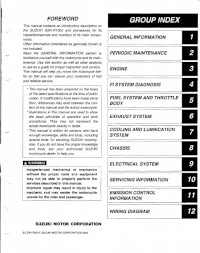
Summary of Contents for Suzuki GSX-R1000
-
Page 1
GSX-R1000 Service Manual *99500-39271-03E* * 9 9 5 0 0 — 3 9 2 7 1 — 0 3 E *… -
Page 2
System and Fuel System be thoroughly reviewed before any type of service work is performed. Further information concerning the EPA emission regulations and U.S. Suzuki’s emission control program can be found in the U.S. SUZUKI EMISSION CONTROL PROGRAM MANUAL/SERVICE BULLETIN. -
Page 4
SUPPLEMENTS GSX-R1000K6 WIRING DIAGRAM… -
Page 51
2-30 PERIODIC MAINTENANCE CHASSIS BOLTS AND NUTS Tighten initially at 1 000 km (600 miles, 2 months) and every 6 000 km (4 000 miles, 12 months) thereafter. Check that all chassis bolts and nuts are tightened to their specified torque. (Refer to page 2-31 for the loca- tions of the following nuts and bolts on the motorcycle.) Item N•m… -
Page 373: Reassembly And Installation
8-44 CHASSIS REASSEMBLY AND INSTALLATION Reassemble and install the rear wheel in the reverse order of removal and disassembly. Pay attention to the following points: Left Right 100 N·m (10.0 kgf-m, 72.5 lb-ft) 35 N·m 60 N·m (3.5 kgf-m, 25.5 lb-ft) (6.0 kgf-m, 43.5 lb-ft) E-02, 19, 24 25 N·m…
-
Page 376
CHASSIS 8-47 • Tighten the sprocket mounting nuts to the specified torque. Rear sprocket nut: 60 N·m (6.0 kgf-m, 43.5 lb-ft) NOTE: Stamped mark A on the sprocket should face outside. • Install the collar 2. BRAKE DISC • Apply THREAD LOCK to the disc bolts and tighten them to the specified torque. -
Page 455
9-36 ELECTRICAL SYSTEM HEADLIGHT BEAM ADJUSTMENT • Adjust the headlight beam. NOTE: * Use a screw driver + for adjuster A, B and C. * To adjust the headlight beam, adjust the beam horizontally first, then adjust vertically. A: Horizontal adjuster (Low beam) B: Vertical adjuster (Low beam) C: Horizontal adjuster (High beam) D: Vertical adjuster (High beam) -
Page 508
SERVICING INFORMATION 10-47 CHASSIS N·m kgf-m lb-ft ITEM Steering stem head nut 65.0 Steering stem lock-nut 65.0 Steering damper bolt and nut 16.5 Front fork upper clamp bolt 16.5 Front fork lower clamp bolt 16.5 Front fork cap bolt 16.5 Front fork inner rod lock-nut 21.0 Front fork damper rod bolt… -
Page 532
GSX-R1000K6… -
Page 533: Specifications
SPECIFICATIONS DIMENSIONS AND DRY MASS Overall length ………………2 030 mm (79.9 in) Overall width………………710 mm (28.0 in) Overall height ………………1 130 mm (44.5 in) Wheelbase ………………1 405 mm (55.3 in) Ground clearance…………….130 mm (5.1 in) Seat height ………………
-
Page 534: Service Data
SERVICE DATA VALVE + VALVE GUIDE Unit: mm (in) ITEM STANDARD LIMIT Valve diam. — (1.18) — (0.94) Valve clearance (when cold) 0.10 – 0.20 — (0.004 – 0.008) 0.20 – 0.30 — (0.008 – 0.012) Valve guide to valve stem 0.010 –…
-
Page 535
ITEM STANDARD LIMIT Camshaft runout 0.10 — (0.004) Cam chain pin (at arrow “3”) 14th pin — Cylinder head distortion 0.20 — (0.008) CYLINDER + PISTON + PISTON RING Unit: mm (in) ITEM STANDARD LIMIT Compression pressure 1 300 – 1 700 kPa 1 000 kPa (13 –… -
Page 536: Oil Pump
CONROD + CRANKSHAFT Unit: mm (in) ITEM STANDARD LIMIT Conrod small end I.D. 15.010 – 15.018 15.040 (0.5909 – 0.5913) (0.5921) Conrod big end side clearance 0.10 – 0.20 0.30 (0.004 – 0.008) (0.012) Conrod big end width 19.95 – 20.00 —…
-
Page 537
CLUTCH Unit: mm (in) ITEM STANDARD LIMIT Clutch lever play 10 – 15 — (0.4 – 0.6) Clutch release screw 1/2 turn back — Drive plate thickness 2.72 – 2.88 2.42 No. 1, 2 and 3 (0.107 – 0.113) (0.095) Drive plate claw width 13.85 –… -
Page 538
THERMOSTAT + RADIATOR + FAN + COOLANT ITEM STANDARD/SPECIFICATION NOTE Thermostat valve opening temper- Approx. 82 °C (180 °F) — ature Thermostat valve lift 8 mm (0.31 in) and over at 95 °C (203 °F) — ECT sensor resistance 20 °C Approx. -
Page 539
FI SENSORS ITEM SPECIFICATION NOTE CMP sensor resistance 0.9 – 1.7 kΩ CMP sensor peak voltage 0.5 V and more When cranking 142 – 194 Ω CKP sensor resistance CKP sensor peak voltage 0.5 V and more When cranking IAP sensor input voltage 4.5 –… -
Page 540: Throttle Body
THROTTLE BODY ITEM SPECIFICATION Bore size 44 mm I.D. No. 41G1 (For E-33), 41G0 (For the others) Idle r/min 1 150 ± 100 r/min Fast idle r/min 1 400 – 2 000 r/min (When cold engine) Throttle cable play 2.0 – 4.0 mm (0.08 –…
-
Page 541
WATTAGE Unit: W STANDARD/SPECIFICATION ITEM E-03, 28, 33 Others ← Headlight ← ← Position/Parking light 5 × 2 ← Brake light/Taillight ← Turn signal light 21 × 4 ← License plate light ← Combination meter light ← Turn signal indicator light ←… -
Page 542
ITEM STANDARD LIMIT Wheel rim runout Axial — (0.08) Radial — (0.08) Wheel rim size Front 17 M/C × MT 3.50 — Rear 17 M/C × MT 6.00 — Wheel axle runout 0.25 Front — (0.010) 0.25 Rear — (0.010) TIRE ITEM STANDARD… -
Page 543
(8.86) Front fork oil level (without spring, — outer tube fully compressed) (3.98) Front fork oil type SUZUKI FORK OIL L01 or an equivalent fork oil — Front fork oil capacity (each leg) 510 ml — (17.2/17.9 US/Imp oz) Front fork spring adjuster 4 th groove from top —… -
Page 544
BATTERY HOLDER CUSHION RUBBER INSTALLATION Forward – 13 –… -
Page 547
Prepared by 2005 Part No. 99500-39271-03E Printed in U.S.A. -
Page 548
Printed in USA K5 K6…
Скрыть/показать содержание
Материал из BikesWiki, Энциклопедия японских мотоциклов
- Manuals
- Brands
- Suzuki Manuals
- Motorcycle
- 2002 GSX-R1000
Manuals and User Guides for Suzuki 2002 GSX-R1000. We have 1 Suzuki 2002 GSX-R1000 manual available for free PDF download: Service Manual

Suzuki 2002 GSX-R1000 Service Manual (446 pages)
Brand: Suzuki
|
Category: Motorcycle
|
Size: 52.2 MB
Table of Contents
-
Foreword
3
-
Group Index
3
-
How to Use this Manual
4
-
To Locate What You Are Looking for
4
-
Component Parts and Work to be Done
4
-
Symbol (for USA)
5
-
Symbol (for the Other Countries)
6
-
Abbreviations Used in this Manual
7
-
SAE-To-Former Suzuki Term (Only for USA)
9
-
General Information
11
-
Contents
11
-
Warning/Caution/Note
12
-
General Precautions
12
-
Suzuki GSX-R1000K1 (2001-Model) View
14
-
Serial Number Location
14
-
Fuel, Oil and Engine Coolant Recommendation
15
-
Engine Oil
15
-
Brake Fluid
15
-
Front Fork Oil
15
-
Anti-Freeze/Engine Coolant
16
-
Liquid Amount of Water/Engine Coolant
16
-
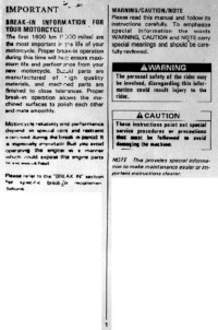
Break-In Procedures
16
-
Cylinder Identification
16
-
Information Labels
17
-
Specifications
18
-
Dimensions and Dry Mass
18
-
Capacities
19
-
Electrical
19
-
Country and Area Codes
20
-
Periodic Maintenance
21
-
Periodic Maintenance Schedule
22
-
Periodic Maintenance Chart
22
-
Lubrication Points
23
-
Maintenance and Tune-Up Procedures
24
-
Air Cleaner
24
-
Heat Range
25
-
Carbon Deposits
25
-
Spark Plug Gap
26
-
Electrode’s Condition
26
-
Spark Plug and Ignition Coil/Plug Cap Installation
26
-
Valve Clearance
27
-
Valve Clearance Adjustment
29
-
Intake Side
30
-
Exhaust Side
31
-
Engine Oil and Oil Filter
32
-
Engine Oil Replacement
32
-
Oil Filter Replacement
33
-
Exhaust Control Valve
33
-
Fuel Hose
34
-
Engine Idle Speed
34
-
Throttle Cable Play
35
-
Minor Adjustment
35
-
Major Adjustment
36
-
Clutch
36
-
Cooling System
37
-
Engine Coolant Level Check
37
-
Engine Coolant Change
37
-
Air Bleeding the Cooling Circuit
38
-
Radiator Hoses
38
-
Drive Chain
39
-
Checking
39
-
Adjusting
40
-
Cleaning and Lubricating
40
-
Brake Fluid Level Check
41
-
Brake Pads
41
-
Front Brake
41
-
Rear Brake
42
-
Brake Pedal Height
42
-
Brake Light Switch
42
-
Air Bleeding from Brake Fluid Circuit
43
-
Tire Tread Condition
44
-
Steering
45
-
Front Fork
45
-
Rear Suspension
45
-
Exhaust Pipe Bolt and Nut
46
-
Chassis Bolts and Nuts
47
-
Compression Pressure Check
49
-
Compression Test Procedure
49
-
Low Oil Pressure
50
-
High Oil Pressure
50
-
Oil Pressure Test Procedure
50
-
Engine
51
-
Engine Components Removable with the Engine in Place
52
-
Engine Center
52
-
Engine Right Side
52
-
Engine Left Side
52
-
Engine Removal
53
-
Oil Cooler
54
-
Radiator
54
-
Exhaust Pipe and Muffler
56
-
Electric Parts
56
-
Engine Sprocket and Gear Shift Lever
58
-
Engine Mounting
59
-
Engine Installation
61
-
Engine Disassembly
65
-
Starter Motor
65
-
Pair Valve
65
-
Cylinder Head Cover
65
-
Camshafts
66
-
Cylinder Head
67
-
Oil Pump
70
-
Gear Shift System
70
-
Starter Idle Gear
71
-
Starter Clutch
72
-
Cam Chain, Cam Chain Tensioner, Cam Chain Guide
72
-
CKP Sensor Inspection
72
-
Generator Cover
73
-
Generator Rotor
73
-
Gear Position Switch
74
-
Breather Cover
74
-
Oil Filter
74
-
Oil Pan
74
-
Oil Pressure Regulator
75
-
Oil Pressure Switch
75
-
Oil Strainer
75
-
Lower Crank Case
75
-
Middle Crankcase
76
-
Balancer Shaft
76
-
Crankshaft
76
-
Piston and Conrod
77
-
Engine Components Inspection and Service
78
-
Pair Reed Valve
78
-
Pair Control Valve
78
-
Cam Position Sensor
79
-
Camshaft Identification
79
-
Cam Wear
79
-
Camshaft Journal Wear
80
-
Camshaft Runout
81
-
Cam Sprocket
81
-
Cam Chain Tension Adjuster
81
-
Cam Chain Guide
81
-
Cylinder Head and Valve
82
-
Valve and Valve Spring Disassembly
82
-
Cylinder Head Distortion
83
-
Valve Stem Runout
83
-
Valve Head Radial Runout
83
-
Valve Face Wear
83
-
Valve Stem Deflection
84
-
Valve Stem Wear
84
-
Valve Guide Servicing
85
-
Valve Seat Width Inspection
86
-
Valve Seat Servicing
86
-
Initial Seat Cut
87
-
Top Narrowing Cut
87
-
Botton Harrowing Cut
87
-
Final Seat Cut
88
-
Valve Stem End Condition
89
-
Valve Spring
89
-
Valve and Valve Spring Reassembly
90
-
Intake Pipe
91
-
Water Bypass Union
91
-
Clutch Drive Plates Inspection
92
-
Clutch Driven Plates Inspection
92
-
Clutch Spring Inspection
92
-
Clutch Bearing Inspection
92
-
Inspection
93
-
Gearshift System
94
-
Gearshift Shaft/Gearshift Arm Disassembly
94
-
Gearshift Shaft/Gearshift Arm Reassembly
94
-
Transmission
96
-
Reassembly
97
-
Transmission Parts Location
98
-
Cylinder Distortion
99
-
Cylinder Bore
99
-
Piston and Piston Ring
100
-
Piston Diameter
100
-
Piston to Cylinder Clearance
100
-
Pinton Pins and Pin Bore
100
-
Piston Ring to Groove Clearance
101
-
Piston Ring Free End Gap and Piston Ring End Gap
101
-
Piston Ring Reassembly
102
-
Lower Crankcase
103
-
Gearshift Fork and Gearshift Cam
103
-
Gearshift Fork to Groove Clearance
103
-
Gearshift Fork Groove Width
103
-
Bearing Removal
104
-
Installation
105
-
Oil Jet
107
-
Removal
107
-
Inspection and Cleaning
107
-
Plugs
108
-
Balancer Shaft Journal Bearing
109
-
Selection
109
-
Crankshaft Runout
111
-
Conrod Small End I.D.
111
-
Conrod Big End Side Clearance
111
-
Conrod-Crank Pin Bearing Inspection
112
-
Conrod-Crank Pin Bearing Selection
112
-
Crankshaft Journal Bearing
114
-
Crankshaft Thrust Bearing
116
-
Crankshaft Thrust Clearance Adjustment
116
-
Thrust Bearing Selection Table
117
-
Engine Reassembly
118
-
Crankcase
121
-
Cam Chain Drive Sprocket
132
-
Cam Chain Tensioner and Cam Chain Guide
132
-
Started Idle Gear
133
-
FI System/Intake Air System/Exhaust System
150
-
Precautions in Servicing
152
-
Connector/Coupler
152
-
Fuse
153
-
Ecm/Various Sensors
153
-
Electrical Circuit Inspection Procedure
154
-
Open Circuit Heck
154
-
Continuity Check
155
-
Voltage Check
156
-
Short Circuit Check (Wire Harness to Ground)
156
-
Using Testers
157
-
FI System Technical Feature
158
-
Injection Time (Injection Volume)
158
-
Compensation of Injection Time (Volume)
159
-
Injection Stop Control
159
-
Fuel Delivery System
160
-
Fuel Pump
161
-
Fuel Pressure Regulator
162
-
Fuel Injector
162
-
Fuel Pump Control System
163
-
ECM (FI Control Unit)
164
-
Injection Timing
165
-
Intake Air Pressure Sensor (IAP Sensor)
166
-
Throttle Position Sensor (TP Sensor)
166
-
Crankshaft Position Sensor (CKP Sensor)
167
-
Camshaft Position Sensor (CMP Sensor)
167
-
Intake Air Temperature Sensor (IAT Sensor)
167
-
Engine Coolant Temperature Sensor (ECT Sensor)
168
-
Atmospheric Pressure Sensor (AP Sensor)
168
-
Tip Oven Sensor (to Sensor)
169
-
Secondary Throttle Position Sensor (STP Sensor)
169
-
Intake Air System
170
-
Secondary Throttle Control System
170
-
Operation
171
-
Exhaust Control System
172
-
FI System Parts Location
174
-
FI System Diagram
176
-
FI System Wiring Diagram
177
-
Self-Diagnosis Function
178
-
User Mode
178
-
Dealer Mode
179
-
Fail-Safe Function
181
-
FI System Troubleshooting
182
-
Self-Diagnostic Procedure
183
-
Self-Diagnosis Reset Procedure
183
-
Malfunction Code and Defective Condition
184
-
«C12» CMP Sensor Circuit Malfunction
186
-
«C12» CKP Sensor Circuit Malfunction
187
-
«C13» IAP Sensor Circuit Malfunction
188
-
Output Voltage
189
-
«C14» TP Sensor Circuit Malfunction
190
-
«C15» ECT Sensor Circuit Malfunction
192
-
«C21» IAT Sensor Circuit Malfunction
193
-
«C22» AP Sensor Circuit Malfunction
194
-
«C23» to Sensor Circuit Malfunction
196
-
«C24», «C25», «C26» or «C27» Ignition System Malfunction
197
-
«C28» STV Actuatoor Circuit Malfunction
197
-
«C29» STP Sensor Circuit Malfunction
198
-
«C31» Gear Position (GP) Switch Circuit Malfunction
200
-
«C32», «C33», «C34» or «C35» Fuel Injector Malfunction
201
-
«C41» FP Relay Circuit Malfunction
202
-
«C42» IG Switch Circuit Malfunction
202
-
«C46» EXCV Actuator Circuit Malfunction
203
-
Fuel System
206
-
Fuel Tank Lift-Up
206
-
Fuel Tank Removal
206
-
Fuel Tank Installation
206
-
Fuel Pressure Inspection
207
-
Fuel Pump Inspection
208
-
Fuel Discharge Amount Inspection
208
-
Fuel Pump Relay Inspection
210
-
Fuel Pump and Fuel Filter Removal Construction
210
-
Fuel Mesh Filter Inspection and Cleaning
212
-
Fuel Pump and Fuel Mesh Filter Installation
212
-
Throttle Body Construction
215
-
Air Cleaner Box
216
-
Throttle Body
217
-
Throttle Body Disassembly
218
-
Throttle Body Cleaning
219
-
Throttle Body Reassembly
220
-
Wire Color
221
-
Throttle Body Installation
222
-
STP Sensor Adjustment
223
-
Throttle Body Clamp Position
223
-
Fuel Injector Inspection
224
-
Fuel Injector Removal
224
-
Fuel Injector Installation
224
-
Fast Idle Adjustment
224
-
Throttle Valve Synchronization
225
-
Calibrating each Gauge
225
-
Throttle Position Sensor (TPS) Setting
228
-
Throttle Cable Adjustment
228
-
EXCVA (Exhaust Control Valve Actuator) and EXCV (Exhaust Control Valve)
229
-
EXCVA Removal
229
-
EXCVA Installation
230
-
EXCV Cable Replacement
231
-
EXCVA Adjustment
233
-
EXCV Removal
236
-
EXCV Inspection
236
-
EXCV Installation
237
-
IAP Sensor Inspection/Removal/Installation
239
-
TP Sensor Inspection/Removal/Installation
239
-
CMP Sensor Inspection/Removal/Installation
239
-
IAT Sensor Inspection/Removal/Installation
239
-
ECT Sensor Inspection/Removal/Installation
240
-
AP Sensor Inspection/Removal/Installation
240
-
TO Sensor Inspection/Removal/Installation
240
-
STP Sensor Inspection/Removal/Installation
240
-
Cooling and Lubrication System
241
-
Engine Coolant
242
-
Cooling Circuit Inspection
243
-
Radiator and Water Hoses
244
-
Radiator Removal
244
-
Radiator Cap Inspection
244
-
Radiator Inspection and Cleaning
244
-
Radiator Remounting
245
-
Water Hose Inspection
245
-
Cooling Fan
246
-
Cooling Fan Thermo-Switch
246
-
Cooling Fan Control Relay
247
-
Engine Coolant Temperature Sensor
248
-
Temperature Sensor Specification
248
-
Thermostat
249
-
Water Pump
251
-
Removal and Disassembly
251
-
Bearing
254
-
Mechanical Seal
254
-
Oil Seal
254
-
Seal Washer
254
-
Reassembly and Installation
255
-
Lubrication System
258
-
Engine Lubrication System Chart
260
-
Engine Lubrication System
261
-
Chassis
264
-
Exterior Parts
266
-
Fastener Removal and Reinstallation
266
-
Screen
266
-
Body Cowling Cover and Lower Bracket Cover
267
-
Right and Left under Cowlings
267
-
Body Cowling
268
-
Remounting
268
-
Right and Left Air Intake Pipes
269
-
Cowling Brace
269
-
Front Seat
270
-
Rear Seat and Seat Tail Cover
270
-
Frame Cover
270
-
Front Wheel Construction
271
-
Axle Shaft
273
-
Wheel Bearings
273
-
Reassembly and Remounting
274
-
Brake Disc
275
-
Spacer Nut
276
-
Brake Caliper
276
-
Front Axle
276
-
Front Fork Construction
277
-
Inner and Outer Tubes
280
-
Fork Spring
280
-
Damper Rod
281
-
Oil Seal and Dust Seal
281
-
Damper Rod Bolt
282
-
Fork Oil
283
-
Front Fork Inner Rod Lock Nut
284
-
Front Fork Cap Bolt
284
-
Suspension Settings
286
-
Spring Pre-Load Adjustment
286
-
Damping Force Adjustment
286
-
Standard Front Suspension Setting
286
-
Steering Damper Construction
287
-
Steering Construction
288
-
Outer Race
290
-
Inner Race
290
-
Stem Nut
291
-
Front Fork and Steering Stem Upper Bracket
292
-
Steering Tension Adjustment
292
-
Handlebar Construction
293
-
Right Handlebar
293
-
Left Handlebar
293
-
Rear Wheel Construction
296
-
Rear Axle
298
-
Wheel Damper
298
-
Sprocket
298
-
Bearings
299
-
Dust Seals
302
-
Rear Shock Absorber Construction
304
-
Rear Shock Absorber Disposal
306
-
Gas Pressure Release
306
-
Suspension Setting
307
-
Damping Force Adjustment (Rebound Side, Compression Side)
307
-
Standard Suspension Setting
307
-
Rear Suspension Construction
308
-
Spacer
311
-
Swingarm Bearing
311
-
Cushion Lever Bearing
312
-
Cushion Lever and Cushion Lever Rods
312
-
Swingarm Pivot Shaft
312
-
Chain Buffer
312
-
Swingarm Pivot Thrust Clearance Adjustment
315
-
Shock Absorber and Cushion Lever Mounting Nut
316
-
Torque Link
316
-
Final Inspection and Adjustment
316
-
Front Brake Construction
317
-
Brake Pad Replacement
318
-
Brake Fluid Replacement
318
-
Caliper Removal and Disassembly
319
-
Caliper Inspection
320
-
Caliper Reassembly and Remounting
320
-
Piston Seal
320
-
O-Ring
320
-
Brake Disc Inspection
321
-
Master Cylinder Removal and Disassembly
322
-
Master Cylinder Inspection
323
-
Master Cylinder Reassembly and Remounting
323
-
Rear Brake Construction
325
-
Cylinder, Piston and Cup Set
330
-
Tire Removal
331
-
Wheel Inspection
331
-
Tire Inspection
331
-
Valve Inspection
332
-
Valve Installation
332
-
Tire Installation
332
-
Balancer Weight
333
-
Drive Chain Cutting
334
-
Drive Chain Connecting
335
-
Joint Plate Installation
335
-
Joint Pin Staking
336
-
Electrical System
339
-
Cautions in Servicing
340
-
Connector
340
-
Coupler
340
-
Clamp
340
-
Connecting the Battery
341
-
Wiring Procedure
341
-
Using the Multi Circuit Tester
341
-
Location of Electrical Components
342
-
Charging System
344
-
Battery Current Leakage
345
-
Regulated Voltage
346
-
Generator Coil Resistance
346
-
Generator No-Load Performace
346
-
Regulator/Rectifier
347
-
Starter System and Side-Stand/Ignition Interlock System
348
-
Starter Motor Removal and Disassembly
349
-
Starter Motor Inspection
350
-
Commutator
350
-
Armature Coil Inspection
350
-
Starter Motor Reassembly
350
-
Starter Relay Inspection
351
-
Side Stand/Ignition Interlock System Parts Inspection
352
-
Side-Stand Switch
352
-
Turn Signal/Side-Stand Relay
354
-
Side-Stand Relay Inspection
354
-
Diode Inspection
354
-
Ignition System
355
-
Ignition Coil Primary Peak Voltage
357
-
Ignition Coil/Plug Cap Resistance
358
-
CKP Sensor Peak Voltage
359
-
CKP Sensor Resistance
360
-
Combination Meter
361
-
LED (Light Emitting Diode)
361
-
Stepping Motor
363
-
Engine Coolant Temperature Meter and Indicator
364
-
Fuel Level Indicator Switch Inspection
365
-
Fuel Level Indicator Light Inspection
365
-
Fuel Level Resistor Inspection
365
-
Speedometer Sensor
366
-
Oil Pressure Indicator
366
-
Lamps
367
-
Headlight, Brake Light/Taillight and Turn Signal Light
367
-
Headlight Beam Adjustment
367
-
Relays
368
-
Ignition Switch Removal
368
-
Battery Specifications
370
-
Initial Charging
370
-
Filling Electrolyte
370
-
Servicing
371
-
Recharging Operation
372
-
Servicing Information
373
-
Troubleshooting
374
-
FI System Malfunction Code and Defective Condition
374
-
Radiator (Cooling System)
381
-
Brakes
383
-
Battery
385
-
Wiring Harness Routing
386
-
Inside of the Body Cowling
386
-
Cable Routing
389
-
Fuel Tank Drain Hose Routing
390
-
Cooling System Hose Routing
391
-
Front Brake Hose Routing
392
-
Rear Brake Hose Routing
393
-
Pair (Air Supply) System Hose Routing
394
-
Fuel Tank Set-Up
395
-
Cowling Set-Up
396
-
Frame Cover Set-Up
397
-
Heat Shield Set-Up
397
-
Side-Stand Set-Up
398
-
Gearshift Pedal Set-Up
398
-
Seat Lock Cable Routing
399
-
Front Fender Set-Up
399
-
Special Tools
400
-
Tightening Torque
403
-
FI System and Intake Air System
404
-
Tightening Torque Chart
406
-
Service Data
407
-
Valve + Guide
407
-
Camshaft + Cylinder Head
407
-
Cylinder + Piston + Piston Ring
408
-
Conrod + Crankshaft
409
-
Balancer
409
-
Transmission + Drive Chain
410
-
Thermostat + Radiator + Fan + Coolant
410
-
Injector + Fuel Pump + Fuel Pressure Regulator
411
-
FI Sensors + Secondary Throttle Valve Actuator
411
-
Wattage
413
-
Brake + Wheel
413
-
Tire
414
-
Suspension
414
-
Fuel + Oil
415
-
Emission Control Information
417
-
Fuel Injection System
418
-
Evaporative Emission Control System (Only for E-33)
418
-
Canister Hose Routing (Only for E-33)
419
-
Canister
420
-
Tank Pressure Control Valve
420
-
Pair (Air Supply) System Diagram
421
-
Pair (Air Supply) System Inspecting
423
-
GSX-R1000K2 (’02-Model)
424
-
Drive Train
429
-
Tightening Torque for Cam Chain Tension Adjuster Cap
435
-
Fuel Pump and Fuel Level Indicator Switch
436
-
Fast Idle
437
-
Wiring Diagram (’01) for E-03, 28, 33
439
-
Wiring Diagram (’01) for E-19
440
-
Wiring Diagram (’01) for E-24
441
-
Wiring Diagram (’02) for E-03, 28, 33
442
-
Wiring Diagram (’02) for E-24
443
-
Wiring Diagram (’02) for the Others
444
-
Wire Harness Routing
445
Advertisement
Advertisement
Related Products
-
Suzuki 2002 GSX-R600
-
Suzuki 2002 DL1000K2
-
Suzuki 2001 GSX-R1000
-
Suzuki 2007 SV650SK7
-
Suzuki 2007 SV650AK7
-
Suzuki 2004 DL650K4
-
Suzuki 2004 GSX-R600
-
Suzuki 2006 gsxr 600
-
Suzuki 2005 DL650K5
-
Suzuki 2006 DL650K6
Suzuki Categories
Motorcycle
Automobile
Motorcycle Accessories
Musical Instrument
Offroad Vehicle
More Suzuki Manuals
Service Manual for L7 Suzuki GSX-R 1000 2017 motorcycles. Service Manual Suzuki GSX-R, a great reference for the repair and maintenance.
Service Manual, fix motorcycle yourself with a repair manual.
Content 2017 Suzuki GSX-R 1000 L7 Service Manual
General Information
General precautions
Serial number location
Fuel, oil and engine coolant recommendation
Break-in procedures
Cylinder Identification
Information labels
Specifications
Country or area
Periodic Maintenance
Periodic maintenance schedule
Maintenance and tune-up procedures
Compression pressure check
Oil pressure check
Engine
Engine Removal and Installation
Crankshaft / Cylinder Head
Cylinder / Piston
Clutch
Engine Lubrication System
Starter system / Signal generator
Generator
Gearshift Linkage
Crankcase / Transmission / Crankshaft / Conrod
Fuel Injection / Air intake
FI System Technical Features
Intake Air System
FI System Parts Location
FI System Diagram
FI System Wiring Diagram
Self-Diagnosis Function
Fail-Safe Function
FI System Troubleshooting
Fuel System
Throttle Body and STV Actuator
Sensors
Cooling and Lube system
Cooling Circuit
Engine Coolant
Radiator and Water Hoses
Cooling Fan
Cooling Fan Thermo-Switch
Engine Coolant Temperature Gauge
Thermostat
Water Pump
Lubrication System
Chassis
Exterior Parts
Front Wheel
Front Fork
Steering
Rear Wheel
Rear Suspension
Front Brake
Rear Brake
Tire and Wheel
Electrical System
Cautions in Servicing
Location of Electrical Components
Charging System
Starter System and Side-Stand / Ignition
Interlock System
Ignition System
Combination Meter
Lamps
Switches
Relay
Battery
Servicing Information
Troubleshooting
Wiring Diagram
Wire Harness, Cable and Hose Routing
Fuel Tank Set-up
Cowling Set-up
Heat Shield Set-up
Side-stand Set-up
Gearshift Pedal Set-up
Fairing and Frame Cover Set-up
Special Tools
Tightening Torque
Service Data
Emission Control Information
Fuel Injection System
Evaporative Emission Control System
Canister Hose Routing
Evaporative Emission Control System Inspection
Pair (Air Supply) System Diagram
Pair (Air Supply) System Hose Routing
Pair (Air Supply) System Inspection
Wiring Diagram
Руководство на английском языке по эксплуатации и техническому обслуживанию мотоциклов Suzuki GSX-R250.
- Издательство: Suzuki Motor Corporation
- Год издания: —
- Страниц: 22
- Формат: PNG
- Размер: 6,2 Mb
Руководство на английском языке по ремонту мотоциклов Suzuki GSX-R400.
- Издательство: Suzuki Motor Corporation
- Год издания: —
- Страниц: 246
- Формат: PDF
- Размер: 22,3 Mb
Руководство на английском языке по ремонту мотоциклов Suzuki GSX-R600 1997-2000 годов выпуска.
- Издательство: Suzuki Motor Corporation
- Год издания: —
- Страниц: 429
- Формат: PDF
- Размер: 48,5 Mb
Руководство на английском языке по ремонту мотоциклов Suzuki GSX-R600 2001-2002 годов выпуска.
- Издательство: Suzuki Motor Corporation
- Год издания: —
- Страниц: 399
- Формат: PDF
- Размер: 41,8 Mb
Руководство на английском языке по ремонту мотоциклов Suzuki GSX-R600.
- Издательство: Suzuki Motor Corporation
- Год издания: 2003
- Страниц: 466
- Формат: PDF
- Размер: 48,9 Mb
Руководство на английском языке по ремонту мотоциклов Suzuki GSX-R600.
- Издательство: Suzuki Motor Corporation
- Год издания: 2006
- Страниц: 517
- Формат: PDF
- Размер: 45,9 Mb
Руководство на английском языке по ремонту мотоциклов Suzuki GSX-R750.
- Издательство: Suzuki Motor Corporation
- Год издания: 1995
- Страниц: 558
- Формат: PDF
- Размер: 188,3 Mb
Руководство на английском языке по ремонту мотоциклов Suzuki GSX-R750 2000-2002 годов выпуска.
- Издательство: Suzuki Motor Corporation
- Год издания: —
- Страниц: 498
- Формат: PDF
- Размер: 142,6 Mb
Руководство на английском языке по ремонту мотоциклов Suzuki GSX-R750.
- Издательство: Suzuki Motor Corporation
- Год издания: 2004
- Страниц: 471
- Формат: PDF
- Размер: 40,8 Mb
Руководство на английском языке по ремонту мотоциклов Suzuki GSX-R750.
- Издательство: Suzuki Motor Corporation
- Год издания: 2006
- Страниц: 522
- Формат: PDF
- Размер: 46,0 Mb
Руководство на английском языке по техническому обслуживанию и ремонту мотоциклов Suzuki GSX600F Katana, GSX750F Katana, GSX1100F Katana 1988-1996 годов выпуска и GSX-R750, GSX-R1100 1985-1992 годов выпуска.
- Издательство: Haynes Publishing
- Год издания: —
- Страниц: 256
- Формат: PDF
- Размер: 37,5 Mb
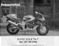
Руководство на французском языке по техническому обслуживанию и ремонту мотоциклов Suzuki GSX-R750T 1996 года выпуска.
- Издательство: —
- Год издания: —
- Страниц: 86
- Формат: PDF
- Размер: 43,1 Mb
Руководство на английском языке по ремонту мотоциклов Suzuki GSX-R750W.
- Издательство: Suzuki Motor Corporation
- Год издания: 1992
- Страниц: 352
- Формат: PDF
- Размер: 50,6 Mb
Руководство на английском языке по ремонту мотоциклов Suzuki GSX-R1000.
- Издательство: Suzuki Motor Corporation
- Год издания: 2000
- Страниц: 424
- Формат: PDF
- Размер: 211,4 Mb
Руководство на английском языке по ремонту мотоциклов Suzuki GSX-R1000.
- Издательство: Suzuki Motor Corporation
- Год издания: 2003
- Страниц: 460
- Формат: PDF
- Размер: 18,8 Mb
Руководство на английском языке по ремонту мотоциклов Suzuki GSX-R1000.
- Издательство: Suzuki Motor Corporation
- Год издания: 2007
- Страниц: 549
- Формат: PDF
- Размер: 48,8 Mb
Руководство на английском языке по эксплуатации и техническому обслуживанию мотоциклов Suzuki GSX-R1100.
- Издательство: Suzuki Motor Corporation
- Год издания: 1988
- Страниц: 90
- Формат: PDF
- Размер: 38,1 Mb
Руководство на английском языке по ремонту мотоциклов Suzuki GSX-R1100.
- Издательство: Suzuki Motor Corporation
- Год издания: 1986
- Страниц: 295
- Формат: PDF
- Размер: 105,4 Mb
Руководство на английском языке по ремонту мотоциклов Suzuki GSX-R1100.
- Издательство: Suzuki Motor Corporation
- Год издания: 1990
- Страниц: 358
- Формат: PDF
- Размер: 50,7 Mb
Руководство на английском языке по ремонту мотоциклов Suzuki GSX-R1100W.
- Издательство: Suzuki Motor Corporation
- Год издания: 1992
- Страниц: 380
- Формат: PDF
- Размер: 52,8 Mb
Руководство на английском языке по ремонту мотоциклов Suzuki GSX-R1300R.
- Издательство: Suzuki Motor Corporation
- Год издания: 2007
- Страниц: 663
- Формат: PDF
- Размер: 26,9 Mb
