Руководство на английском языке по техническому обслуживанию и ремонту гидроциклов Sea-Doo модели 5802.
- Год издания: 1989
- Страниц: 173
- Формат: PDF
- Размер: 30,9 Mb
Руководство на английском языке по техническому обслуживанию и ремонту гидроциклов Sea-Doo моделей 5803-5810 (GT).
- Год издания: 1989
- Страниц: 194
- Формат: PDF
- Размер: 27,5 Mb
Руководство на английском языке по техническому обслуживанию и ремонту гидроциклов Sea-Doo моделей 5804 SP, 5811 GT и 5850 XP.
- Год издания: 1991
- Страниц: 224
- Формат: PDF
- Размер: 31,6 Mb
Руководство на английском языке по техническому обслуживанию и ремонту гидроциклов Sea-Doo моделей SP 5805/GTS 5812/XP 5851/GTX 5860.
- Год издания: 1992
- Страниц: 286
- Формат: PDF
- Размер: 45,5 Mb
Руководство на английском языке по техническому обслуживанию и ремонту гидроциклов Sea-Doo моделей SP 5806/SPX 5807/SPI 5808/GTS 5813/Explorer 5820/XP 5852/GTX 5861.
- Год издания: 1993
- Страниц: 305
- Формат: PDF
- Размер: 53,1 Mb
Руководство на английском языке по техническому обслуживанию и ремонту гидроциклов Sea-Doo моделей GTS 5814/Explorer 5821/XP 5854/GTX 5862/SP 5870/SPX 5871/SPI 5872.
- Год издания: 1994
- Страниц: 320
- Формат: PDF
- Размер: 67,3 Mb
Руководство на английском языке по техническому обслуживанию и ремонту гидроциклов Sea-Doo моделей GTS 5815/XP 5857/GTX 5863/SP 5873/SPX 5874/SPI 5875.
- Год издания: 1995
- Страниц: 618
- Формат: PDF
- Размер: 58,3 Mb
Сборник руководств на английском языке по техническому обслуживанию и ремонту гидроциклов Sea-Doo моделей GSX 5620/GTX 5640/GTS 5817/GTI 5865/GTI 5866/SP 5876/SPX 5877/SPI 5878/HX 5881.
- Год издания: 1996
- Страниц: 39/316
- Формат: PDF
- Размер: 20,3 Mb
Руководство на английском языке по техническому обслуживанию и ремонту гидроциклов Sea-Doo моделей GS 5621/GSI 5622/GSX 5624/GTI 5641/GTX 5642/SPX 5661/XP 5662/GTS 5818/SPX 5834/SP 5879/HX 5882.
- Год издания: 1997
- Страниц: 372
- Формат: PDF
- Размер: 51,4 Mb
Сборник руководств на английском языке по техническому обслуживанию и ремонту гидроциклов Sea-Doo моделей GS 5626/GS 5844/GSX Limited 5629/GSX Limited 5845/GTI 5836/GTI 5841/GTS 5819/GTX 5837/GTX 5842/GTX RFI 5666/GTX RFI 5843/SPX 5636/SPX 5839/XP 5665/XP5667.
- Год издания: 1998
- Страниц: 47/56/426
- Формат: PDF
- Размер: 102,4 Mb
Руководство на английском языке по техническому обслуживанию и ремонту гидроциклов Sea-Doo моделей GS 5846/GS 5847/GSX Limited 5848/GSX Limited 5849/GSX RFI 5637/GSX RFI 5638/GTS 5883/GTX Limited 5888/GTX Limited 5889/GTX RFI 5886/GTX RFI 5887/SPX 5636/SPX 5828/XP Limited 5868/XP Limited 5869.
- Год издания: 1999
- Страниц: 496
- Формат: PDF
- Размер: 85,7 Mb
Руководство на английском языке по техническому обслуживанию и ремонту гидроциклов Sea-Doo моделей GS 5644/GSX RFI 5645/GTI 5647/GTX 5653/GTX RFI 5648/GTX RFI 5515/XP 5651.
- Год издания: 2000
- Страниц: 456
- Формат: PDF
- Размер: 57,7 Mb
Руководство на английском языке по техническому обслуживанию и ремонту гидроциклов Sea-Doo моделей GTX DI 5649/RX 5513/RX DI 5646.
- Год издания: 2000
- Страниц: 351
- Формат: PDF
- Размер: 50,2 Mb
Руководство на английском языке по техническому обслуживанию и ремонту гидроциклов Sea-Doo моделей GS 5519/GTI 5523/GTS 5521/GTX 5527/GTX 5538/GTX DI 5529/GTX DI 5541/GTX RFI 5525/GTX RFI 5555/RX 5533/RX 5543/RX DI 5535/RX DI 5537/XP 5531.
- Год издания: 2001
- Страниц: 561
- Формат: PDF
- Размер: 75,3 Mb
Руководство на английском языке по техническому обслуживанию и ремонту гидроциклов Sea-Doo моделей GTI 5558-5559/GTI California 6116/GTI LE 5560-5561/GTI LE California 6117/GTX 5587-5588/GTX 4-TEC 5573-5574, 5593-5594/GTX DI 5563-5564, 5595-5596/GTX RFI 5565-5566/LRV DI 5460/RX 5579-5582/RX DI 5583-5586, 5591-5592/XP 5577-5578.
- Год издания: 2002
- Страниц: 557+505
- Формат: PDF
- Размер: 69,0 Mb
Руководство на английском языке по техническому обслуживанию и ремонту гидроциклов Sea-Doo моделей GTI/GTI LE/GTI LE RFI/GTX 4-TEC/GTX DI/LRV DI/RX DI/XP DI.
- Год издания: 2003
- Страниц: 779
- Формат: PDF
- Размер: 52,3 Mb
Сборник руководств на английском языке по техническому обслуживанию и ремонту гидроциклов Sea-Doo моделей 3D RFI/GTI/GTI LE/GTI LE RFI/GTX 4-TEC/GTX Supercharged/GTX Limited Supercharged/GTX Wakeboard Edition/RXP 4-TEC Supercharged/XP Di.
- Год издания: 2004
- Страниц: 89/801
- Формат: PDF
- Размер: 68,0 Mb
Руководство на английском языке по техническому обслуживанию и ремонту гидроциклов Sea-Doo с двухтактными двигателями.
- Год издания: 2005
- Страниц: 391
- Формат: PDF
- Размер: 39,5 Mb
Руководство на английском языке по техническому обслуживанию и ремонту гидроциклов Sea-Doo моделей 4-TEC.
- Год издания: 2005
- Страниц: 314
- Формат: PDF
- Размер: 27,0 Mb
Руководство на английском языке по техническому обслуживанию и ремонту двигателей Rotax моделей 717 и 787 RFI гидроциклов Sea-Doo.
- Год издания: 2005
- Страниц: 117
- Формат: PDF
- Размер: 6,9 Mb
Руководство на английском языке по техническому обслуживанию и ремонту двигателей Rotax модели 1503 4-TEC гидроциклов Sea-Doo.
- Год издания: 2005
- Страниц: 124
- Формат: PDF
- Размер: 19,6 Mb
Руководство на английском языке по техническому обслуживанию и ремонту гидроциклов Sea-Doo моделей 4-TEC.
- Год издания: 2006
- Страниц: 403
- Формат: PDF
- Размер: 94,9 Mb
Руководство на английском языке по техническому обслуживанию и ремонту гидроциклов Sea-Doo моделей 4-TEC.
- Год издания: 2007
- Страниц: 407
- Формат: PDF
- Размер: 50,9 Mb
Руководство на английском языке по техническому обслуживанию и ремонту гидроциклов Sea-Doo моделей 4-TEC.
- Год издания: 2008
- Страниц: 555
- Формат: PDF
- Размер: 50,9 Mb
Руководство на английском языке по техническому обслуживанию и ремонту гидроциклов Sea-Doo моделей GTX Limited IS 255 и RXT IS 255.
- Год издания: 2009
- Страниц: 555
- Формат: PDF
- Размер: 43,2 Mb
Дополнение к руководству на английском языке по техническому обслуживанию и ремонту гидроциклов Sea-Doo моделей 4-TEC.
- Год издания: 2009
- Страниц: 60
- Формат: PDF
- Размер: 19,8 Mb
Руководство на английском языке по техническому обслуживанию и катеров Sea-Doo моделей Challenger, Speedster и Sportster.
- Год издания: 1996
- Страниц: 274
- Формат: PDF
- Размер: 14,5 Mb
- Manuals
- Brands
- Sea-doo Manuals
- Boat
- 2001 XP
Manuals and User Guides for Sea-doo 2001 XP. We have 4 Sea-doo 2001 XP manuals available for free PDF download: Shop Manual, Operator’s Manual
Sea-doo 2001 XP Shop Manual (456 pages)
2000 Sea-Doo
Brand: Sea-doo
|
Category: Boat
|
Size: 60.54 MB
Table of Contents
-
Table of Contents
20
-
Safety Notice
6
-
Air Intake
7
-
Jet Pump
7
-
Technical Data
8
-
Hull Identification Number
9
-
General Information
13
-
Tightening Torques
18
-
Table of Contents
20
-
-
Exhaust System
7
-
Cooling System
7
-
Fuel System
7
-
-
Mandatory Service Tools
21
-
Engine
21
-
Cooling/Fuel/Oil Systems
24
-
Propulsion System
25
-
Workshop
26
-
-
Optional Service Tools
27
-
Engine
27
-
Cooling/Fuel/Oil Systems
30
-
Propulsion System
31
-
Watercraft Handling
32
-
-
Service Products
33
-
-
Table of Contents
37
-
Periodic Inspection Chart
38
-
Flushing and Lubrication
39
-
General
39
-
Procedure
39
-
-
Water-Flooded Engine
43
-
General
43
-
Procedure
43
-
-
Storage
46
-
Cooling System Flushing and Engine Internal Lubrication
47
-
Anticorrosion Treatment
48
-
Troubleshooting Chart
51
-
-
-
Table of Contents
57
-
Leak Test
58
-
General
58
-
Preparation
58
-
Testing Procedure
58
-
Engine Cooling System
58
-
Engine Leakage Diagnostic Flow Chart
63
-
-
Removal and Installation
65
-
General
65
-
Electrical Connections
65
-
Engine Removal
65
-
Drive System
66
-
Cleaning
69
-
Installation
69
-
-
Magneto System
74
-
Disassembly
77
-
Cleaning
83
-
Assembly
83
-
Magneto Flywheel
85
-
-
Top End
88
-
General
91
-
Rave System
91
-
Disassembly
94
-
Cleaning
101
-
Inspection
101
-
Assembly
104
-
Cylinder Head
111
-
Adjustment
112
-
Combustion Chamber Volume Measurement
112
-
-
Bottom End
114
-
Disassembly
117
-
Cleaning
124
-
Inspection
124
-
Assembly
129
-
-
Rotary Valve
136
-
General
137
-
Inspection on Watercraft
137
-
Disassembly
138
-
Cleaning
140
-
Inspection
140
-
Assembly
141
-
Rotary Valve Timing
144
-
-
Exhaust System
146
-
Removal
149
-
Exhaust Manifold
152
-
Tuned Pipe Repair
153
-
Installation
154
-
-
-
Table of Contents
158
-
Circuit, Components and Care
159
-
Circuit
166
-
Components
170
-
Water Flow Regulator Valve
171
-
Care
173
-
Towing the Watercraft in Water
174
-
-
-
Table of Contents
175
-
Fuel Circuit
177
-
General
182
-
Removal
182
-
Fuel Filter
182
-
Fuel Tank
185
-
Inspection
186
-
Assembly
187
-
Fuel System Pressurization
187
-
-
Air Intake
189
-
Removal
192
-
Assembly
193
-
-
Carburetor
195
-
General
196
-
Removal
196
-
Cleaning
197
-
Disassembly and Inspection
197
-
Assembly
199
-
Installation
201
-
Adjustments
202
-
-
-
Section 06 Fuel System Subsection 05 (Fuel Injection) Fuel Injection 0
208
-
Fuel Injection
208
-
Introduction
209
-
Air Induction
209
-
Fuel Delivery
209
-
Fuel Injectors
210
-
Electronic Management
211
-
Electronic Control Unit (Ecu)
211
-
-
Diagnostic Procedures
213
-
Fault Code Tables
214
-
Throttle Body
216
-
-
Component Inspection
216
-
Air Induction System
216
-
Fuel Delivery
216
-
Electronic Management
218
-
Throttle Position Sensor (Tps)
218
-
Air Temperature Sensor (Ats)
220
-
Water Temperature Sensor (Wts)
220
-
Rave Solenoid
222
-
Rfi Sensors Resistance Values
223
-
Spark Plug Inspection
224
-
-
Troubleshooting Summary
224
-
Engine Does Not Start
224
-
Engine Starts but Runs Poorly
224
-
Engine Starts but Stalls after Approximately 30 Seconds
224
-
Engine Cannot Reach Maximum Revolutions
224
-
-
Adjustment
225
-
Throttle Position Sensor (Tps)
225
-
-
Removal and Installation
226
-
Throttle Position Sensor (Tps)
226
-
Air Temperature Sensor (Ats)
226
-
Air Pressure Sensor (Aps)
226
-
Water Temperature Sensor (Wts)
226
-
Crankshaft Position Sensor (Cps)
226
-
Fuel Pump Assembly
226
-
Fuel Injector
227
-
-
-
Table of Contents
228
-
Oil Injection System
229
-
General
236
-
Oil System Pressurization
236
-
Oil Filter
236
-
-
Oil Injection Pump
237
-
Oil Pump Identification
240
-
Removal
240
-
Disassembly
240
-
Cleaning
240
-
Assembly
240
-
Adjustment
241
-
Checking Operation
243
-
-
-
Table of Contents
245
-
Ignition System
246
-
General
246
-
Ignition Coil
247
-
Multi-Purpose Electronic Module (Mpem)
248
-
Ignition Timing
251
-
Ignition System Testing Procedure
258
-
Spark Plugs
262
-
-
-
Charging System
266
-
General
266
-
Testing Procedure
266
-
Battery
269
-
Troubleshooting
269
-
Battery Installation
274
-
-
-
Starting System
275
-
General
278
-
Starting System Troubleshooting
279
-
Starter Removal
280
-
Starter Disassembly
280
-
Cleaning
282
-
Parts Inspection
283
-
Starter Assembly
283
-
Starter Installation
285
-
Starter Specification
287
-
-
Instruments and Accessories
288
-
General
288
-
Inspection
288
-
-
Digitally Encoded Security System
298
-
General
298
-
-
-
Table of Contents
301
-
Jet Pump
302
-
General
303
-
Jet Pump Inspection on Watercraft
303
-
Removal
306
-
Disassembly
307
-
Cleaning
310
-
Parts Inspection
310
-
Assembly
313
-
Pump Pressurization
320
-
Installation
321
-
Steering Cable
322
-
-
Drive System
323
-
General
326
-
Removal
326
-
Inspection
330
-
Assembly
331
-
Installation
333
-
Lubrication
336
-
-
Reverse System
337
-
General
338
-
Disassembly
338
-
Shift Lever
338
-
Assembly
339
-
Reverse Gate
339
-
Adjustment
341
-
Disassembly
344
-
Inspection
345
-
Assembly
345
-
Adjustment
347
-
-
Variable Trim System
348
-
General
349
-
Removal
349
-
Disassembly
349
-
Inspection
350
-
Assembly
350
-
Installation
350
-
Adjustment
351
-
-
-
Table of Contents
352
-
Steering System
353
-
Removal and Installation
354
-
Disassembly
358
-
Assembly
361
-
Disassembly
364
-
Assembly
367
-
-
Adjustable Steering
369
-
Disassembly
370
-
Assembly
374
-
-
Alignment
376
-
-
Table of Contents
378
-
Direct Action Suspension
379
-
Removal
380
-
Inspection
381
-
Assembly
381
-
-
-
Adjustment and Repair/Adjustment and Repair
382
-
Adjustment and Repair
383
-
Seat Adjustment
397
-
Storage Compartment Cover Adjustment
398
-
Access Panel Adjustment
399
-
Inlet Grate
399
-
Riding Plate
399
-
Jet Pump Support
401
-
Deflector
402
-
Drain Plug Installation
402
-
Seat Removal
403
-
Bumper Replacement
404
-
Seat Cover Replacement
404
-
Baffle Sealing
405
-
Engine Compartment Cover Removal
405
-
Sponson Replacement
405
-
Decals Replacement
406
-
Hull and Body Repair
406
-
Tools and Materials List
409
-
Thru-Hull Fitting Installation
410
-
Wire Color Codes
436
-
Packard Connector
437
-
-
Advertisement
Sea-doo 2001 XP Shop Manual (372 pages)
1997 SeaDoo
Brand: Sea-doo
|
Category: Boat
|
Size: 53.86 MB
Table of Contents
-
Table of Contents
4
-
Section
5
-
Table of Contents
5
-
Safety Notice
5
-
Hull Identification Number
6
-
General Information
10
-
-
-
-
Table of Contents
11
-
Periodic Inspection Chart
12
-
Flushing and Lubrication
13
-
General
13
-
Procedure
13
-
-
04
19
-
General
17
-
Procedure
17
-
Water-Flooded Engine
17
-
Fuel System
19
-
-
05
20
-
06
20
-
07
20
-
Storage
19
-
Propulsion System
20
-
Troubleshooting Chart
23
-
-
-
-
Table of Contents
26
-
Leak Test
28
-
General
28
-
Preparation
28
-
Testing Procedure
28
-
Engine Leakage Diagnostic Flow Chart
33
-
Engine Removal
34
-
General
34
-
Removal and Installation
34
-
Cleaning
37
-
Installation
37
-
Magneto System
40
-
General
42
-
Removal
42
-
Cleaning
45
-
Disassembly
45
-
Assembly
47
-
Installation
48
-
-
01
69
-
02
69
-
03
69
-
Top End
50
-
General
52
-
Disassembly
54
-
Cleaning
56
-
Inspection
57
-
Assembly
60
-
Cylinder Head
66
-
Adjustment
67
-
Combustion Chamber Volume Measurement
67
-
Bottom End
69
-
Crankshaft Misalignment and Deflection
71
-
Disassembly
72
-
Cleaning
75
-
Inspection
75
-
Assembly
77
-
Rotary Valve
82
-
General
83
-
Inspection on Watercraft
83
-
Rotary Valve Timing
91
-
Exhaust System
93
-
Tuned Pipe Removal
96
-
Exhaust Manifold Removal
98
-
Muffler Removal
98
-
Tuned Pipe Repair
98
-
Installation
99
-
Engine Cooling System
115
-
-
-
-
Table of Contents
117
-
Fuel Circuit
118
-
General
123
-
Fuel Filter
124
-
Removal
124
-
Inspection
126
-
Assembly
127
-
Fuel System Pressurization
127
-
Air Intake
129
-
Assembly
130
-
Removal
130
-
-
Carburetors
132
-
General
134
-
Removal
134
-
Cleaning
135
-
Disassembly and Inspection
135
-
Assembly
136
-
Installation
139
-
Adjustments
140
-
Throttle Cable
140
-
-
-
-
Table of Contents
143
-
Oil Injection System
144
-
General
147
-
Oil System Pressurization
147
-
Oil Injection Pump
148
-
Assembly
150
-
Cleaning
150
-
Disassembly
150
-
Removal
150
-
Adjustments
151
-
Checking Operation
153
-
-
-
-
Table of Contents
154
-
Ignition System
155
-
General
155
-
Ignition Timing Procedure
158
-
Bombardier Ignition Tester
165
-
Ignition System Testing Procedure
165
-
Spark Plugs
170
-
Charging System
173
-
General
173
-
Testing Procedure
173
-
Battery
176
-
-
Starting System
182
-
General
184
-
Starting System Troubleshooting
185
-
Cleaning
186
-
Starter Disassembly
186
-
Starter Removal
186
-
Parts Inspection
187
-
Starter Assembly
187
-
Starter Installation
189
-
Starter Specification
190
-
-
Instruments and Accessories
191
-
General
191
-
Inspection
191
-
-
Digitally Encoded Security System
200
-
General
200
-
-
-
-
Table of Contents
203
-
Jet Pump
204
-
General
205
-
Jet Pump Inspection on Watercraft
205
-
Removal
207
-
Disassembly
209
-
Cleaning
211
-
Parts Inspection
212
-
Assembly
214
-
Installation
221
-
Pump Pressurization
221
-
Steering Cable
223
-
Drive System
224
-
General
227
-
Removal
227
-
Disassembly
231
-
Parts Inspection
231
-
Assembly
232
-
Lubrication
237
-
-
Reverse System
238
-
Disassembly
239
-
General
239
-
Assembly
240
-
Reverse Gate
240
-
Shift Lever
241
-
Adjustments
242
-
Disassembly
245
-
Inspection
245
-
Assembly
246
-
Adjustment
247
-
-
Variable Trim System
248
-
Manual Trim
248
-
Assembly and Installation
249
-
Disassembly
249
-
Removal
249
-
-
Electric Trim
250
-
Disassembly
251
-
General
251
-
Inspection
251
-
Removal
251
-
Assembly
252
-
Installation
252
-
Adjustment
253
-
-
-
-
Table of Contents
254
-
Sp and Spx Models
255
-
Removal and Installation
256
-
Steering Alignment
259
-
Gts Model
260
-
Removal and Installation
261
-
Steering Alignment
264
-
-
Gs, Gsi, Gsx, Gti and Gtx Models
265
-
Disassembly
266
-
Assembly
268
-
Steering Alignment
269
-
-
Hx and Xp Models
270
-
Removal
271
-
Assembly and Installation
272
-
Disassembly
272
-
Steering Alignment
274
-
-
-
-
Table of Contents
277
-
Adjustment and Repair/Adjustment and Repair
281
-
08
340
-
09
340
-
10
340
-
11
340
-
12
340
-
Alignment
275
-
Direct Action Suspension
278
-
Disassembly
279
-
Assembly
280
-
Inspection
280
-
Adjustment and Repair
282
-
Seat Adjustment
296
-
Access Panel Adjustment
298
-
Storage Compartment Cover Adjustment
298
-
Inlet Grate Removal
299
-
Riding Plate
299
-
Jet Pump Support
300
-
Deflector
302
-
Drain Plug Installation
302
-
Seat Removal
302
-
Seat Cover Replacement
303
-
Bumper Replacement
304
-
Sponson Replacement
304
-
Baffle Sealing (Gts Model)
305
-
Decals Replacement
305
-
Hood Removal
305
-
Hull and Body Repair
306
-
Tools and Materials List
308
-
Hull Insert Repair
309
-
Wire Color Codes
340
-
Wiring Diagrams
340
-
-
-
Sea-doo 2001 XP Operator’s Manual (124 pages)
2001 jetski
Brand: Sea-doo
|
Category: Boat
|
Size: 8.91 MB
Table of Contents
-
Table of Contents
4
-
Foreword
7
-
Safety Measures
8
-
General
8
-
Operation
8
-
Maintenance
10
-
-
List of Distributors
11
-
Bombardier Limited Warranty North America: Sea-Doo Watercraft
12
-
Bombardier International Limited Warranty: Sea-Doo Watercraft
14
-
Registration Number Location
16
-
Location of the Important Labels
17
-
Identification Numbers
27
-
Hull
27
-
Engine
28
-
-
Controls, Components and Instruments Location
29
-
Controls, Components and Instruments Functions
35
-
Safety Lanyard (Engine Cut-Off Cord)
35
-
Handlebar
36
-
Throttle Lever
36
-
Engine Start/Stop Button
36
-
Variable Trim System Button (VTS) (if so Equipped)
36
-
Variable Trim System (VTS) Gauge (if so Equipped)
37
-
Choke Lever
37
-
Shift Lever (if so Equipped)
37
-
Fuel Gauge/Low Oil Warning Light (if so Equipped)
38
-
Speedometer (if so Equipped)
38
-
Tachometer (if so Equipped)
38
-
Information Center Gauge/Buttons (if so Equipped)
38
-
Glove Box
42
-
Fuel Tank Valve
42
-
Fuel Tank Cap
42
-
Oil Injection Reservoir Cap
43
-
Front Storage Compartment Cover
43
-
Front Storage Compartment Cover Latch
45
-
Front Storage Compartment Cover Hinge/Locking Mechanism
45
-
Front Storage Compartment Cover Lock (if so Equipped)
45
-
Storage Compartment/Engine Cover Latches (if so Equipped)
45
-
Tool Kit
46
-
Air Intake Opening
46
-
Seat Strap
46
-
Seat Latch
46
-
Seat Extension Latch (if so Equipped)
48
-
Rear Grab Handle
48
-
Rear Storage Basket (if so Equipped)
48
-
Rear Access Cover (if so Equipped)
48
-
Bow and Stern Eyelets
48
-
Mooring Cleats
49
-
Fender Cleats (if so Equipped)
49
-
Footboard
49
-
Boarding Pads
49
-
Boarding Platform
49
-
Boarding Step (if so Equipped)
49
-
Cooling System Bleed Outlet
50
-
Flushing Connector (if so Equipped)
50
-
Bilge Drain Plugs
51
-
Automatic Bilge Pump (if so Equipped)
51
-
Jet Pump Nozzle
51
-
Reverse Gate (if so Equipped)
51
-
Jet Pump Water Intake
52
-
Fuses
52
-
Battery
52
-
-
Fuel and Lubrication
53
-
Fueling Procedure
53
-
Recommended Fuel
54
-
Recommended Oil
54
-
Oil Injection System
55
-
-
Break-In Period
56
-
10-Hour Inspection
56
-
-
Pre-Operation Checks
57
-
Hull
58
-
Jet Pump Water Intake
58
-
Bilge
58
-
Battery
58
-
Fuel Tank and Oil Reservoir
58
-
Engine Compartment
58
-
Steering System
58
-
Throttle System
59
-
Shifter System
59
-
VTS (Variable Trim System) (if so Equipped)
59
-
Storage Compartment Covers and Seat
59
-
Safety Lanyard and Engine Start/Stop Button
59
-
-
Operating Instructions
60
-
Principle of Operation
60
-
Boarding the Watercraft
65
-
Starting
67
-
Rough Water or Poor Visibility Operation
68
-
Crossing Waves
68
-
Stopping/Docking
69
-
Beaching
69
-
Shutting off the Engine
69
-
-
Post-Operation Care
70
-
General Care
70
-
Additional Care for Foul Water or Salt Water
70
-
Cooling System Flushing and Engine Internal Lubrication
70
-
Anticorrosion Treatment
73
-
-
Special Procedures
74
-
Monitoring System
74
-
Limp Home Mode
74
-
Engine Overheating
74
-
Jet Pump Water Intake and Impeller Cleaning
74
-
Capsized Watercraft
76
-
Submerged Watercraft
76
-
Water-Flooded Engine
76
-
Fuel-Flooded Engine
77
-
Out of Fuel
78
-
Towing the Watercraft in Water
78
-
Low-Charge Battery Condition
79
-
-
Maintenance
80
-
Engine Emissions Information
80
-
Lubrication
81
-
Periodic Inspection
83
-
Periodic Inspection Chart
84
-
Throttle and Choke Cable Inspection
86
-
Carburetor Adjustment
86
-
Fuel Injection System
86
-
Fuel and Oil Filters
86
-
Steering Alignment
86
-
VTS Adjustment (if so Equipped)
87
-
Vacuum Bailer Pick-Ups
87
-
Fuses
87
-
General Inspection and Cleaning
89
-
-
Trailering, Storage and Pre-Season Preparation
90
-
Trailering
90
-
Storage
90
-
Pre-Season Preparation
99
-
-
Troubleshooting
101
-
Engine Overheats
103
-
Engine Continually Backfires
103
-
Engine Lacks Acceleration or Power
104
-
-
Specifications
105
-
Si Metric Information
119
-
Abbreviations Used in this Manual
120
-
Change of Address
121
-
Change of Address
122
-
Advertisement
Sea-Doo 2001 XP Operator’s Manual (105 pages)
Jetski SeaDoo 1997
Brand: Sea-Doo
|
Category: Boat
|
Size: 3.67 MB
Table of Contents
-
Table of Contents
4
-
Foreword
6
-
Safety Warning
7
-
List of Distributors
10
-
North America
10
-
-
The 1997 Bombardier Watercraft Limited Warranty (North America)
11
-
Registration Number Location
13
-
Location of the Important Labels
16
-
Watercraft Identification
25
-
Hull Identification Number
25
-
Engine Identification Number
26
-
-
Component Functions
27
-
Fuel and Lubrication
48
-
Fueling Procedure
48
-
Recommended Fuel
48
-
Recommended Oil
48
-
Oil Injection System
49
-
-
Break-In Period
50
-
Engine
50
-
10-Hour Inspection
50
-
-
Pre-Operation Checks
52
-
Hull
52
-
Jet Pump Water Intake
52
-
Bilge
53
-
Battery
53
-
Fuel and Oil Reservoirs
53
-
Engine Compartment
53
-
Fire Extinguisher
53
-
Steering and Throttle Systems
53
-
Reverse System (GTS/GTI/GTX Models)
53
-
Variable Trim System (SPX/GSI/GSX/XP Models)
53
-
Safety Lanyard and Engine Start/Stop Button
53
-
Clothing
54
-
-
Operating Instructions
55
-
Principle of Operation
55
-
Boarding from a Dock or in Shallow Water
58
-
Starting the Engine
59
-
Boarding in Deep Water
60
-
Rough/Choppy Water Operation
62
-
Crossing Waves
62
-
Stopping/Docking
62
-
Beaching
62
-
Shutting off the Engine
63
-
-
Post-Operation Care
64
-
General Care
64
-
Additional Care for Foul Water or Salt Water
64
-
Cooling System Flushing and Engine Internal Lubrication
64
-
-
Special Procedures
68
-
Engine Overheating
68
-
Jet Pump Water Intake and Impeller Cleaning
68
-
Capsized Watercraft
69
-
Submerged Watercraft
69
-
Towing the Watercraft in Water
70
-
Low-Charge Battery Condition
70
-
-
Maintenance
71
-
Lubrication
71
-
Periodic Inspection
73
-
Periodic Inspection Chart
74
-
Throttle and Choke Cable Inspection
75
-
Carburetor Adjustment
75
-
Fuel and Oil Filters
75
-
Steering Alignment
75
-
VTS Adjustment (SPX/GSI/GSX/XP Models)
75
-
Vacuum Bailer Pick-Ups
76
-
Water Tank Trap Drains (GTS Model)
77
-
Fuses
77
-
General Inspection and Care
79
-
-
Transportation, Storage and Pre-Season Preparation
80
-
Transportation
80
-
Storage
80
-
Pre-Season Preparation
83
-
-
Troubleshooting
85
-
Engine Overheats
86
-
Engine Continually Backfires
86
-
Engine Lacks Acceleration or Power
86
-
-
Specifications
88
-
Si Metric Information
100
-
Other Publications Available
101
-
Change of Address
103
Advertisement
Related Products
-
Sea-doo 2001 GS
-
Sea-doo 2001 GTX
-
Sea-doo 2001 RX
-
Sea-doo 2001 GTS
-
Sea-doo 2001 LRV
-
Sea-doo 2001 GTI
-
Sea-doo 2004 GTX 4-TEC Supercharged 6159
-
Sea-doo 2005 GTX
-
Sea-doo 2006 GTX
-
Sea-doo 2005 4-Tec Series
Sea-doo Categories
Boat
Scooter
Boating Equipment
Toy
Marine Equipment
More Sea-doo Manuals

Если хотите разместить ссылку на Гидрик.ру — Клуб любителей гидроциклов и другой техники для активного отдыха, используйте этот HTML-код:
Всего 0 посетителей :: 0 зарегистрированных, 0 скрытых и 0 гостей
Сейчас этот форум просматривают: нет зарегистрированных пользователей и 0 гостей
МАНУАЛЫ БОМБАРДЬЕ выкладываем тут
| Автор | Сообщение | |||||
|---|---|---|---|---|---|---|
|
Заголовок сообщения: МАНУАЛЫ БОМБАРДЬЕ выкладываем тут СообщениеДобавлено: 16 апр 2009, 22:03 |
||||||
Имя: Дмитрий |
Качайте на здоровье! http://www.greenhulk.net/forums/showthread.php?t=62613 _________________ Последний раз редактировалось КватрОвый 27 июн 2011, 20:00, всего редактировалось 2 раза. |
|||||
| Вернуться к началу |
Профиль Ответить с цитатой |
|||||
|
КватрОвый |
Заголовок сообщения: СообщениеДобавлено: 16 апр 2009, 22:08 |
|||
Имя: Дмитрий |
||||
| Вернуться к началу | ||||
|
КватрОвый |
Заголовок сообщения: СообщениеДобавлено: 22 апр 2009, 19:43 |
|||
Имя: Дмитрий |
||||
| Вернуться к началу | ||||
|
Andman |
Заголовок сообщения: СообщениеДобавлено: 02 дек 2010, 02:06 |
|||
Имя: Андрей |
||||
| Вернуться к началу | ||||
|
Brightside |
Заголовок сообщения: СообщениеДобавлено: 18 янв 2011, 09:45 |
|
|
А на Bombardier XP 2002 года на русском нет мануала? (На английском у меня уже есть) |
| Вернуться к началу | |
|
Вячеслав |
Заголовок сообщения: СообщениеДобавлено: 01 мар 2011, 14:05 |
|||
Имя: Вячеслав |
Дополнения к мануалу по моделям SEA DOO HX и XP800 1995 года, на английском языке. Если надо пишите вышлю на маил (не знаю как на сайте разрешение pdf выставлять). |
|||
| Вернуться к началу | ||||
|
Andman |
Заголовок сообщения: СообщениеДобавлено: 01 мар 2011, 23:43 |
|||
Имя: Андрей |
высылай мне info@ как сайт _________________ www.Gidrik.ru |
|||
| Вернуться к началу | ||||
|
Александр Владимирович |
Заголовок сообщения: СообщениеДобавлено: 20 май 2011, 20:14 |
|||
Откуда: Астрахань |
||||
| Вернуться к началу | ||||
|
Александр Владимирович |
Заголовок сообщения: СообщениеДобавлено: 27 май 2011, 09:47 |
|||
Откуда: Астрахань |
||||
| Вернуться к началу | ||||
|
Константин GTI 130 |
Заголовок сообщения: СообщениеДобавлено: 20 июн 2011, 20:48 |
|
Откуда: г. Магнитогорск Челябинская обл. |
Товарисщи |
| Вернуться к началу | |
|
Raider |
Заголовок сообщения: СообщениеДобавлено: 23 июн 2011, 20:42 |
|||
Имя: Юрий |
||||
| Вернуться к началу | ||||
|
Andman |
Заголовок сообщения: СообщениеДобавлено: 24 июн 2011, 21:54 |
|||
Имя: Андрей |
||||
| Вернуться к началу | ||||
|
КватрОвый |
Заголовок сообщения: СообщениеДобавлено: 27 июн 2011, 20:04 |
|||
Имя: Дмитрий |
_________________ |
|||
| Вернуться к началу | ||||
|
MotoGosha |
Заголовок сообщения: СообщениеДобавлено: 06 июл 2011, 01:06 |
|||
Имя: Георгий |
СПАСИБО! Я всё нашёл. |
|||
| Вернуться к началу | ||||
Кто сейчас на конференции |
|
Сейчас этот форум просматривают: нет зарегистрированных пользователей и 0 гостей |
| Вы не можете начинать темы Вы не можете отвечать на сообщения Вы не можете редактировать свои сообщения Вы не можете удалять свои сообщения Вы не можете добавлять вложения |
- Manuals
- Brands
- BRP Manuals
- Boat
- Sea-Doo RXP Series
- Shop manual
-
Contents
-
Table of Contents
-
Troubleshooting
-
Bookmarks
Related Manuals for BRP Sea-Doo RXP Series
Summary of Contents for BRP Sea-Doo RXP Series
-
Page 1
2022 Shop Manual RXP™ Series… -
Page 2
All rights reserved. No parts of this manual may be reproduced in any form without the prior written permission of Bombardier Recreational Products Inc. 2022 Bombardier Recreational Products Inc. © Printed in Canada Technical Publications Bombardier Recreational Products Inc. Valcourt QC Canada ®… -
Page 3: Table Of Contents
TABLE OF CONTENTS SAFETY NOTICE ………………… . . VII IMPORTANT SAFETY PRECAUTIONS .
-
Page 4
TABLE OF CONTENTS 02 ENGINE (cont’d) (cont’d) 04 – COOLING SYSTEM — VEHICLE PROCEDURES………………..48 . -
Page 5
TABLE OF CONTENTS 05 ELECTRICAL SYSTEM 01 – POWER DISTRIBUTION AND GROUNDS …………..95 GENERAL . -
Page 6
TABLE OF CONTENTS 05 ELECTRICAL SYSTEM (cont’d) (cont’d) 07 – ACCESSORIES PROCEDURES………………..133 . -
Page 7
TABLE OF CONTENTS 06 STEERING AND PROPULSION (cont’d) (cont’d) 03 – JET PUMP (cont’d) PROCEDURES ………………..175 IMPELLER . -
Page 8
TABLE OF CONTENTS 08 TECHNICAL SPECIFICATIONS 01 – VEHICLE ………………….231 09 WIRING DIAGRAM 01 –… -
Page 9: Safety Notice
When ordering parts always refer to the specific The use of BRP parts is most strongly recom- model PARTS CATALOG mended when considering replacement of any component.
-
Page 10
We cannot, however, warn you of every conceivable hazard that can arise in performing the service and repair procedures depicted in BRP manuals. Only you can decide whether or not you should perform a given task. VIII 219101039-002… -
Page 11: Introduction
Due to late changes, there may be some differ- ences between the manufactured product and the description and/or specifications in this document. BRP reserves the right at any time to discontinue or change specifications, designs, features, mod- els or equipment without incurring obligation.
-
Page 12: Manual Information
INTRODUCTION ENGINE EMISSIONS When servicing any vehicle; adjustments must be kept within published factory specifications. Re- INFORMATION placement or repair of any emission related com- Manufacturer’s Responsibility ponent must be executed in a manner that main- tains emission levels within the applicable certifi- Manufacturers of engines must determine the cation standards.
-
Page 13
INTRODUCTION Other common terms used in the marine indus- Each section is divided into various subsections, try are the BOW (front of the watercraft), and the and again, each subsection has one or more divi- STERN (rear of the watercraft). sions. -
Page 14
INTRODUCTION TYPICAL PAGE Section 03 ENGINE Section 03 ENGINE Subsection 09 (MAGNETO SYSTEM) Subsection 09 (MAGNETO SYSTEM) Tittle in bold indicates category GENERAL GENERAL of information to be carried out. NOTE: The following procedures can be done NOTE: The following procedures can be done without removing the engine. -
Page 15
INTRODUCTION TIGHTENING TORQUE Tighten fasteners to the torque specified in the exploded view(s) and/or in the written procedure. When a torque is not specified, the torque normally recommended for a specific fastener should be used. Refer to the following table. WARNING Torque wrench tightening specifications must be strictly adhered to. -
Page 16: Fastener Information
INTRODUCTION FASTENER INFORMATION Threadlocker Application for Uncovered Holes (Bolts and Nuts) NOTICE Most fasteners are metric. Mis- matched or incorrect fasteners could cause damage to the vehicle. SELF-LOCKING FASTENER PROCEDURE A00A3LA 1. Apply here 2. Do not apply 1. Clean threads (bolt and nut) with solvent. TYPICAL —…
-
Page 17
INTRODUCTION Threadlocker Application for 5. Apply several drops on bolt threads. Pre-Assembled Parts 6. Tighten as required. Threadlocker Application for Stud Installation in Blind Holes lmr2007-040-005_a A00A3OA 1. On stud threads 2. On threads and in the hole 1. Apply here 3. -
Page 18
INTRODUCTION Gasket Compound Application NOTE: If it is difficult to readjust, heat screw with a soldering iron (232°C (450°F)). Application for Stripped Thread Repair A00A3QA 1. Release agent 2. Stripped threads 3. Form-A-Thread lmr2007-040-006_a 4. Tapes 5. Cleaned bolt 1. Proper strength Loctite 6. -
Page 19
INTRODUCTION 3. Apply a strip of proper strength Loctite on lead- ing edge of outer metallic gasket diameter. NOTE: Any Loctite product can be used here. A low strength liquid is recommended as normal strength and gap are required. 4. Install according to standard procedure. 5. -
Page 20
XVIII 219101039-002… -
Page 21
SERVICE TOOLS INDEX ALIGNMENT SHAFT ADAPTER DIAGNOSTIC HARNESS ECM TERMINAL REMOVER 3.36 (P/N 529 035 719) (P/N 529 036 384) (P/N 529 036 174) Page: 21 ALIGNMENT SHAFT SUPPORT Page: 104 (P/N 529 035 506) FLOATING RING TOOL (TYPE II) Page: 70, 86, 106, 119, 164 (P/N 529 036 116) DRIVE SHAFT C-CLIP REMOVER… -
Page 22
SERVICE TOOLS INDEX FUEL HOSE ADAPTER IMPELLER SHAFT BEARING TOOL PRESSURE GAUGE (P/N 529 036 396) (P/N 529 036 168) (P/N 529 036 395) Page: 80 Page: 169 FUEL PUMP MODULE SOCKET IMPELLER SHAFT PUSHER (P/N 529 036 125) (P/N 529 035 955) Page: 80 PTO SUPPORT TOOL (P/N 529 035 842) -
Page 23
SERVICE TOOLS INDEX SUCTION PUMP (P/N 529 035 880) Page: 14 TEST CAP (P/N 529 035 991) Page: 47 VACUUM/PRESSURE PUMP (P/N 529 021 800) Page: 47, 53, 76, 170 VENTED CAP TEST ADAPTER (THREADED) (P/N 529 036 243) Page: 79… -
Page 25: Maintenance
EPA Regulation — Canadian and USA Vehicles A repair shop or person of the owner’s choosing may maintain, replace, or repair emission control devices and systems. These instructions do not require components or service by BRP or authorized Sea-Doo dealers.
-
Page 26
Section 01 MAINTENANCE Subsection 01 (PERIODIC MAINTENANCE SCHEDULE) EVERY YEAR AT PRESEASON OR 100 HOURS OF OPERATION (WHICHEVER COMES FIRST) Visually inspect area around carbon ring and drive shaft rubber boot for the following signs of failure: black carbon dust and water sprays (more frequently when using PWC in dirty water) Inspect impeller and boot Visually inspect impeller and wear ring for deep scratches, nicks and grooves Remove impeller cover and inspect for signs of water intrusion… -
Page 27: Storage Procedure
Section 01 MAINTENANCE Subsection 02 (STORAGE PROCEDURE) STORAGE PROCEDURE SERVICE PRODUCTS Description Part Number Page 219 700 304 ……… 8–9 ANTICORROSION SPRAY …………. 779183 ……….7 FUEL STABILIZER (EUR) …………… 779171 ……….7 FUEL STABILIZER …………….. 779224 ……… 7–9 LUBRICANT AND ANTI-CORROSIVE (EUR) ……… 779168 ………
-
Page 28: Electrical System
Section 01 MAINTENANCE Subsection 02 (STORAGE PROCEDURE) 2. Remove ignition coils and spark plugs. Refer IGNITION SYSTEM subsection for details on removing the spark plugs and ignition coils. 3. Spray anti-corrosive lubricant or an equivalent product into each spark plug hole. SERVICE PRODUCT LUBRICANT AND Scandinavia…
-
Page 29: Body And Hull
BODY AND HULL Cleaning the Body and Hull CARE AND REPAIR ONLINE Refer to appropriate BOOKLET on www.operatorsguides.brp.com. Replace damaged labels/decals. Repairing the Body or Hull If any repair are required, refer to appropriate CARE AND REPAIR ONLINE BOOKLET www.operatorsguides.brp.com.
-
Page 31: Preseason Preparation
Section 01 MAINTENANCE Subsection 03 (PRESEASON PREPARATION) PRESEASON PREPARATION Proper vehicle preparation is necessary after the winter months or when a watercraft has not been used during 4 months. Any worn, broken or damaged parts found must be replaced. MAINTENANCE SCHEDULE Using the , perform EVERY 100 HOURS OR 1 YEAR…
-
Page 33: Special Procedures
Section 01 MAINTENANCE Subsection 04 (SPECIAL PROCEDURES) SPECIAL PROCEDURES SERVICE TOOLS Description Part Number Page 529 032 500 ……….. 14 LARGE HOSE PINCHER…………..529 035 880 ……….. 14 SUCTION PUMP …………….GENERAL WATER-FLOODED ENGINE Refer to the following special procedures accord- If the engine is flooded with water, it must be ser- ing to the specific event.
-
Page 34
5. Remove the oil filter cap and the oil filter. Refer LUBRICATION SYSTEM to appropriate subsec- 1. Connect the vehicle to the BRP diagnostic soft- tion. ware (BUDS2) to monitor the coolant temper- ature. Coolant temperature must exceed 80°C 6. Again, siphon the contaminated oil from the oil (176°F) in order for the water to boil out. -
Page 35: Drowned Mode
Section 01 MAINTENANCE Subsection 04 (SPECIAL PROCEDURES) To activate DROWNED MODE, proceed as per fol- WARNING lowing steps. Certain components in the engine compart- 1. Install the tether cord cap on the engine cut out ment may be very hot. Direct contact may re- switch.
-
Page 37: Engine
Section 02 ENGINE Subsection 01 (ENGINE REMOVAL AND INSTALLATION) REFER TO ENGINE REMOVAL AND INSTALLATION 219101039-004…
-
Page 39: Air Intake System
Section 02 ENGINE Subsection 02 (AIR INTAKE SYSTEM) AIR INTAKE SYSTEM 2.5 ± 0.5 N•m (22 ± 4 lbf•in) 2.5 ± 0.5 N•m (22 ± 4 lbf•in) 1.7 ± 0.2 N•m (15 ± 2 lbf•in) 4 ± 1 N•m (35 ± 9 lbf•in) 1.7 ±…
-
Page 40: Engine
Section 02 ENGINE Subsection 02 (AIR INTAKE SYSTEM) PROCEDURES AIR INTAKE SILENCER Removing the Air Intake Silencer 1. Remove the seats, storage compartment cover BODY and engine service cover. Refer to sub- section. 2. Remove partitions. 219101005-009-004 4. Separate from air intake silencer and set aside the following components.
-
Page 41
Section 02 ENGINE Subsection 02 (AIR INTAKE SYSTEM) 219101005-008-017 219101005-008-009 9. Remove coolant hose from coolant reservoir. 219101005-009-006 7. Disconnect both ECM connectors. 219101005-009-009 10. Unclip coolant reservoir and set aside. 11. Loosen clamps to separate air intake silencer from engine. 219101005-008-011 8. -
Page 42
Section 02 ENGINE Subsection 02 (AIR INTAKE SYSTEM) Release all retaining tabs. Separate upper and lower sections. Assembling the Air Intake Silencer Install the inlet tubes. Ensure each end is properly attached. 219101005-009-008 12. Detach the retaining straps. 219101005-009-013 Install baffle tab into air intake silencer slots. 219101005-008-014 13. -
Page 43: Air Intake Tube
Section 02 ENGINE Subsection 02 (AIR INTAKE SYSTEM) Installing the Air Intake Silencer The installation is the reverse of the removal pro- cedure. However, pay attention to the following. Refer to exploded view for tightening torque spec- ifications. Ensure wiring harness and fuel hoses are properly routed.
-
Page 44
Section 02 ENGINE Subsection 02 (AIR INTAKE SYSTEM) Installing the Air Intake Tube The installation is the reverse of the removal pro- cedure. However pay attention to the following. Refer to exploded view for tightening torque spec- ifications. Install new locking ties. Make sure air intake tube is perfectly inserted into air intake hoses before tightening the clamps. -
Page 45: Exhaust System
Section 02 ENGINE Subsection 03 (EXHAUST SYSTEM) EXHAUST SYSTEM SERVICE TOOLS Description Part Number Page 295 500 473 ……….. 32 FLUSHING CONNECTOR ADAPTER ……….SERVICE PRODUCTS Description Part Number Page 293 800 038 ……….. 34 LOCTITE 518 …………….. 296 000 406 ……….. 37 P80 GRIP-IT ……………….
-
Page 46: General
Section 02 ENGINE Subsection 03 (EXHAUST SYSTEM) GENERAL WARNING Perform these operations in a well ventilated SYSTEM DESCRIPTION area. Certain components in the engine compartment may be very hot. Direct con- The exhaust system is cooled by water provided tact may result in skin burn. Do not touch by a pressurized area in the jet pump (open loop any electrical part or jet pump area when system).
-
Page 47: Procedures
Section 02 ENGINE Subsection 03 (EXHAUST SYSTEM) NOTICE Always start the engine before EGTS RESISTANCE TEST opening the water tap. Open water tap im- EGTS PIN MEASUREMENT mediately after engine is started to prevent overheating. Never run engine without sup- EGTS Refer to plying water to the exhaust system when…
-
Page 48: Muffler
Section 02 ENGINE Subsection 03 (EXHAUST SYSTEM) EGTS RESISTANCE CHART TIGHTENING TORQUE TEMPERATURE RESISTANCE (OHMS) 16 N•m ± 2 N•m EGTS (142 lbf•in ± 18 lbf•in) °C °F NOMINAL HIGH — 30 — 22 12600 11800 13400 5. Install the EGTS connector. — 20 11400 11000…
-
Page 49
Section 02 ENGINE Subsection 03 (EXHAUST SYSTEM) 3. Insert the muffler in hull. 4. Align the rubber adaptor flange with the ex- haust manifold. Rotate and move muffler so that the rubber adaptor notch fits into the ex- haust manifold slot. 5. -
Page 50: Exhaust Hoses
Section 02 ENGINE Subsection 03 (EXHAUST SYSTEM) EXHAUST HOSES Rear Exhaust Hose Removing the Rear Exhaust Hose Remove the resonator. Refer to procedure in this subsection. Loosen clamp securing the rear exhaust hose to the exhaust fitting. 219101005-011-010 1. Muffler 2.
-
Page 51: Resonator
Section 02 ENGINE Subsection 03 (EXHAUST SYSTEM) RESONATOR Removing the Resonator Remove the muffler. See the procedure in this subsection. INTERCOOLER Remove the intercooler. Refer to subsection. 219101005-011-015 219101039-006-002 smr2016-012-014_a Inspecting the Resonator Inspect parts condition paying attention for defor- mation, cracks or other damage.
-
Page 52
Section 02 ENGINE Subsection 03 (EXHAUST SYSTEM) After installation, ensure there is no water or ex- haust gas leak when the engine is running. Test run the engine while supplying water to the ex- haust system. NOTICE Never run engine without supplying water to the exhaust system when watercraft is out of water. -
Page 53: Cooling System — Vehicle
Section 02 ENGINE Subsection 04 (COOLING SYSTEM — VEHICLE) COOLING SYSTEM — VEHICLE SERVICE TOOLS Description Part Number Page 295 000 070 ……….. 48 OETIKER PLIER …………….529 035 991 ……….. 47 TEST CAP ………………529 021 800 ……….. 47 VACUUM/PRESSURE PUMP …………
-
Page 54
Section 02 ENGINE Subsection 04 (COOLING SYSTEM — VEHICLE) Cooling system (Open loop without intercooler) 219101005-015-002 TYPICAL 1. Water enters system 2. Water enters the exhaust manifold 3. Water exits the exhaust manifold 4. Water exits system 219101005-015… -
Page 55
Section 02 ENGINE Subsection 04 (COOLING SYSTEM — VEHICLE) Cooling system (Open loop with intercooler) 219101005-015-003 TYPICAL 5. Water exits the intercooler 1. Water enters system 6. Water exits system 2. Water enters the exhaust manifold 7. Bleed hose from intercooler 3. -
Page 56
Section 02 ENGINE Subsection 04 (COOLING SYSTEM — VEHICLE) Cooling System (Closed loop) 3.5 ± 0.5 N•m (31 ± 4 lbf•in) 4 ± 1 N•m (35 ± 9 lbf•in) 1.7 ± 0.2 N•m (15 ± 2 lbf•in) 4 ± 1 N•m (35 ±… -
Page 57
Section 02 ENGINE Subsection 04 (COOLING SYSTEM — VEHICLE) Cooling System (Open loop without intercooler) 1.7 ± 0.2 N•m (15 ± 2 lbf•in) 1.7 ± 0.2 N•m (15 ± 2 lbf•in) 219101005-015-101 219101005-015… -
Page 58
Section 02 ENGINE Subsection 04 (COOLING SYSTEM — VEHICLE) Cooling System (Open loop with intercooler) 1.7 ± 0.2 N•m (15 ± 2 lbf•in) 1.7 ± 0.2 N•m (15 ± 2 lbf•in) 219101005-015-102 219101005-015… -
Page 59: General
Section 02 ENGINE Subsection 04 (COOLING SYSTEM — VEHICLE) GENERAL NOTICE Never start the engine without coolant in the cooling system, some engine parts can be damaged. MAINTENANCE ENGINE COOLANT WARNING To avoid potential burns, do not remove the coolant tank cap or loosen the ride plate drain plug if the engine is hot.
-
Page 60
Section 02 ENGINE Subsection 04 (COOLING SYSTEM — VEHICLE) Remove seats. Refill cooling system as described below. Remove engine service cover. Refilling the System Install a drain pan underneath the ride plate. Watercraft should be level, engine cold and drain Unscrew the drain plug on ride plate. -
Page 61: Inspection
Section 02 ENGINE Subsection 04 (COOLING SYSTEM — VEHICLE) NOTICE Never run engine longer than 2 min- utes. Drive line seal has no cooling when wa- tercraft is out of water. Repeat this run-stop cycle 2-3 times until thermo- stat opens and stop engine. smr2009-024-103_a TYPICAL 1.
-
Page 62: Engine (Cont’d)
Section 02 ENGINE Subsection 04 (COOLING SYSTEM — VEHICLE) ENGINE OVERHEATING 1. Low coolant level. — Refill and check for leaks (coolant leaking out of engine leak indicator hole, hoses or clamps missing/defective, cylinder head gaskets leaks, ride plate leaking, etc.). Repair or replace. 2.
-
Page 63
Section 02 ENGINE Subsection 04 (COOLING SYSTEM — VEHICLE) RTX20_1630-004_003_a TIGHTENING TORQUE 3.5 N•m ± 0.5 N•m Gear clamp (31 lbf•in ± 4 lbf•in) 219101005-015… -
Page 65: Intercooler
Section 02 ENGINE Subsection 05 (INTERCOOLER) INTERCOOLER SERVICE TOOLS Description Part Number Page 529 032 500 ……….. 53 LARGE HOSE PINCHER…………..529 021 800 ……….. 53 VACUUM/PRESSURE PUMP …………13.7 ± 1 N•m (121 ± 9 lbf•in) 4 ± 1 N•m (35 ±…
-
Page 66: Maintenance
Section 02 ENGINE Subsection 05 (INTERCOOLER) MAINTENANCE Sacrificial Anode maintenance Inspect and replace sacrificial anode according to INTERCOOLER FLUSHING MAINTENANCE SCHEDULE subsection. Flushing the intercooler with fresh water is essen- INTERCOOLER tial to neutralize corroding effects of salt or other chemical products present in water.
-
Page 67
Section 02 ENGINE Subsection 05 (INTERCOOLER) 219100893-014-002_a 1. Intercooler water outlet fitting 2. Intercooler water inlet fitting 3. Intercooler bleeding hose fitting 3. Let water soak in intercooler for a couple of 219101005-016-003 MANY PARTS REMOVED FOR CLARITY PURPOSE hours. Occasionally, shake the intercooler to 1. -
Page 68
Section 02 ENGINE Subsection 05 (INTERCOOLER) 219101005-016-006 Installing the Intercooler 219101005-016-004 The installation is the reverse of the removal pro- 5. Disconnect intercooler water hoses and inter- cedure. However, pay attention to the following. cooler bleed hose. Refer to exploded view for tightening torque spec- ifications. -
Page 69: Electronic Management Systems
Section 03 ELECTRONIC MANAGEMENT SYSTEMS Subsection 01 (ENGINE MANAGEMENT SYSTEM (EMS)) ENGINE MANAGEMENT SYSTEM (EMS) IGN-3 IGN-2 INJ-3 IGN-1 INJ-2 INJ-1 CAPS MAPTS 219101039-008-100_a 219101039-008…
-
Page 70: General
Section 03 ELECTRONIC MANAGEMENT SYSTEMS Subsection 01 (ENGINE MANAGEMENT SYSTEM (EMS)) GENERAL Engine Control Module (ECM) SYSTEM DESCRIPTION An engine management system (EMS) is used to ensure a high power output with cleaner combus- tion. There are 6 main systems that interact with the engine management system: 1.
-
Page 71
Section 03 ELECTRONIC MANAGEMENT SYSTEMS Subsection 01 (ENGINE MANAGEMENT SYSTEM (EMS)) Limp Home Mode The ECM may automatically set the engine in LIMP HOME MODE using default parameters when certain major faults are detected. For more information, refer to DIAGNOSTIC AND FAULT CODES Diagnostic Mode The ECM features a self-diagnostic mode that is… -
Page 73: Controller Area Network (Can)
Section 03 ELECTRONIC MANAGEMENT SYSTEMS Subsection 02 (CONTROLLER AREA NETWORK (CAN)) CONTROLLER AREA NETWORK (CAN) A-13 A-14 219101005-019-001 CAN BUS DIAGRAM GENERAL CONTROLLER AREA NETWORK (CAN) The CAN protocol is an ISO standard for serial data communication. The ECM forms a network with other components linked with the CAN bus.
-
Page 74: Troubleshooting
Subsection 02 (CONTROLLER AREA NETWORK (CAN)) TROUBLESHOOTING DIAGNOSTIC TIPS Check the fault codes using the BRP diagnostic software (BUDS2) as a first troubleshooting step. Make sure the modules are powered before testing CAN. CAN Communication Problems The following chart gives some symptoms and behaviors relative to the CAN component in cause. The list is not exhaustive, only the most significant items are given to help in troubleshooting.
-
Page 75: Communication Tools
– Check USB connection between MPI card TROUBLESHOOTING Light is and PC computer. Refer to the BRP BUDS chart to ensure you are – Check USB operation on computer (hardware or Windows drivers). using the appropriate hardware and tools. COMMUNICATION PROBLEMS –…
-
Page 76
Section 03 ELECTRONIC MANAGEMENT SYSTEMS Subsection 03 (COMMUNICATION TOOLS) COMMUNICATION PROBLEM (CAN) STATUS WHAT TO DO – BUDS2 does not communicate with the vehicle. – Check connections from computer to vehicle. Light is – Check if BUDS2. is started. – Check if vehicle is powered: is cluster turned ON? If it is not ON, install the tether cord cap (D.E.S.S. -
Page 77: Diagnostic And Fault Codes
Section 03 ELECTRONIC MANAGEMENT SYSTEMS Subsection 04 (DIAGNOSTIC AND FAULT CODES) DIAGNOSTIC AND FAULT CODES GENERAL INFORMATION CENTER MONITORING MODE and SET switch MONITORING SYSTEM Cruise switch This system monitors the electronic components of the EMS (engine management system), iBR, information center and other components of the electrical system to detect if they are faulty or de- Fuel level sensor…
-
Page 78
Section 03 ELECTRONIC MANAGEMENT SYSTEMS Subsection 04 (DIAGNOSTIC AND FAULT CODES) This mode allows the rider to return home which When this mode is active, LIMP HOME MODE would otherwise not be possible. will be displayed in the information center. Indicator Lights and Message Display Information The fault indicators and messages displayed in the information center will inform you of a particular con- dition or if an anomaly occurs. -
Page 79
Section 03 ELECTRONIC MANAGEMENT SYSTEMS Subsection 04 (DIAGNOSTIC AND FAULT CODES) Beeper Signals When one of the below conditions occurs, the monitoring system emits the following beep signals. BEEPER CODES DESCRIPTION Bad D.E.S.S. system connection. Reinstall tether cord cap correctly on the engine cut-off switch. Wrong D.E.S.S. -
Page 80: Fault Codes
Refer to subsection. For more information pertaining to the faults code status and report, refer to BUDS2 online help. How to Find Fault Code Descriptions Connect the vehicle to the BRP diagnostic soft- COMMUNICATION ware (BUDS2). Refer to TOOLS subsection.
-
Page 81: Fuel System
Section 04 FUEL SYSTEM Subsection 01 (INTELLIGENT THROTTLE CONTROL (iTC)) INTELLIGENT THROTTLE CONTROL (iTC) SERVICE TOOLS Description Part Number Page 529 036 384 ……….. 70 DIAGNOSTIC HARNESS …………… 529 035 868 ……….. 71 FLUKE 115 MULTIMETER …………GENERAL The throttle lever operates the throttle accelera- tor sensor (TAS).
-
Page 82
Section 04 FUEL SYSTEM Subsection 01 (INTELLIGENT THROTTLE CONTROL (iTC)) When throttle is applied, the engine will progres- sively accelerate to an operating range whereby full power eventually becomes available. If the en- gine is throttled down sufficiently and for a long enough period of time, engine power and acceler- ation will again be reduced. -
Page 83: Operating Modes
Section 04 FUEL SYSTEM Subsection 01 (INTELLIGENT THROTTLE CONTROL (iTC)) OPERATING MODES Default riding mode Sport mode ECO mode Speed Limiter mode Slow speed mode Ski mode Learning key modes X = Indicates a standard feature — = See your Sea-Doo dealer for availability. N.A.
-
Page 84: Mode/Speed Control Switch
Section 04 FUEL SYSTEM Subsection 01 (INTELLIGENT THROTTLE CONTROL (iTC)) 5. Measure the voltage readings on the installed diagnostic harness connector as follows. Refer to wiring diagram for details. IDLE WIDE OPEN 20-PIN CONNECTOR POSITION POSITION VOLTAGE (VDC) 14 (BK) 4.9 — 5.1 (VI/BU) 14 (BK)
-
Page 85
POSITION If Mode/Speed Control switches do not allow the CONNECTOR selection, test the switches as follows: Both switches ± 2.4 Vdc – Connect the vehicle to the BRP diagnostic soft- released ware (BUDS2). Refer to COMMUNICATION Speed Control TOOLS subsection. -
Page 86
Section 04 FUEL SYSTEM Subsection 01 (INTELLIGENT THROTTLE CONTROL (iTC)) NOTE: Remember that each diode should drop approximately 0.6 Vdc when positively biassed, and read as an OL (open circuit) when negatively biassed (leads reversed). If, when measuring between pins 16 and 2 an OL is obtained with both positive and negative diode biassing, test the wiring harness continu- ity between the gauge and switch assembly. -
Page 87: Fuel Tank And Fuel Pump
Section 04 FUEL SYSTEM Subsection 02 (FUEL TANK AND FUEL PUMP) FUEL TANK AND FUEL PUMP SERVICE TOOLS Description Part Number Page 529 036 384 ……….. 86 DIAGNOSTIC HARNESS …………… 529 036 166 ……….. 76 ECM ADAPTER TOOL…………..529 035 868 ……….. 76 FLUKE 115 MULTIMETER …………
-
Page 88
Section 04 FUEL SYSTEM Subsection 02 (FUEL TANK AND FUEL PUMP) 5.5 ± 0.5 N•m (49 ± 4 lbf•in) 1.2 ± 0.2 N•m (11 ± 2 lbf•in) 60 ± 7 N•m (44 ± 5 lbf•ft) 5.5 ± 0.5 N•m (49 ± 4 lbf•in) 5.5 ±… -
Page 89
Section 04 FUEL SYSTEM Subsection 02 (FUEL TANK AND FUEL PUMP) FUEL SYSTEM DIAGNOSTIC FLOW CHART Fuel pressure is Fuel pressure more Fuel pressure less within specifications than 400 kPa (58 PSI) than 359 kPa (52 PSI) Fuel pressure less Fuel pressure more Fuel pressure is than 359 kPa (52 PSI) -
Page 90: General
Section 04 FUEL SYSTEM Subsection 02 (FUEL TANK AND FUEL PUMP) GENERAL WARNING When the repair is completed, ensure that The following tools are required to test most of hoses and connections from fuel rail to the the electrical parts. fuel pump are properly secured.
-
Page 91
The pressurized fuel is pushed through an upper outlet filter to the fuel rail. NOTE: BRP is the only supplier of the vented fuel Excess fuel pressure generated by the pump is tank cap. There is no equivalent vented fuel tank routed from the upper filter back to the pump can- cap available on the market today. -
Page 92: Inspection
Section 04 FUEL SYSTEM Subsection 02 (FUEL TANK AND FUEL PUMP) INSPECTION Fuel Filters FUEL TANK LEAK TEST WARNING Always carry out a fuel tank leak test when- ever the fuel tank shows signs of wear or damage which may cause a leak, or when the fuel pump has been removed or replaced, or if you suspect a leak.
-
Page 93: Fuel Tank Cap Leak Test
Section 04 FUEL SYSTEM Subsection 02 (FUEL TANK AND FUEL PUMP) To locate a leak, check for a fuel smell or leaking fuel. If a leak is not visible, spray a soapy water solu- tion on components to ease locating the leak(s); bubbles will indicate the leak location(s).
-
Page 94: Fuel System High Pressure Leak Test
Section 04 FUEL SYSTEM Subsection 02 (FUEL TANK AND FUEL PUMP) Squeeze the vacuum/pressure pump handle to ap- 2. Ensure hoses and fittings are not leaking. Re- ply pressure to the check valve of fuel tank cap pair any leak. and observe the pressure rise.
-
Page 95: Procedures
2. Inspect all clamps for tightness. Replacing the Fuel Hose When replacing fuel hoses, be sure to use hoses and clamps as available from BRP parts depart- smr2009-031-019_a ment. This will ensure continued proper and safe FUEL PUMP PRESSURE TEST operation.
-
Page 96: Fuel Pump
Section 04 FUEL SYSTEM Subsection 02 (FUEL TANK AND FUEL PUMP) WARNING – Never use a hose pincher on high pressure hoses. – Never change the routing of a fuel hose. – Always reinstall the corrugated protective tubing on fuel hoses. –…
-
Page 97
Section 04 FUEL SYSTEM Subsection 02 (FUEL TANK AND FUEL PUMP) FUEL PUMP INPUT VOLTAGE TEST TEST PROBES VOLTAGE Pin B Battery ground Battery voltage (+ probe) (- probe) 219100893-021-001_a 5. If test succeeded, the fuel pump, its fuse and its wiring harness are good. -
Page 98
Section 04 FUEL SYSTEM Subsection 02 (FUEL TANK AND FUEL PUMP) NOTICE Ensure the fuel pump does not turn while unscrewing the retaining nut. smr2012-027-011_c If there is an open circuit to FB-F2, repair smr2009-031-022_a 1. Fuel pump module socket wiring/connector between fuel pump and fuse 2. -
Page 99: Fuel Filter
Section 04 FUEL SYSTEM Subsection 02 (FUEL TANK AND FUEL PUMP) 3. Align arrow on top of fuel pump module with index mark on top of fuel tank or fuel sensor accuracy will be affected. NOTE: Index mark and arrow locations are high- lighted for clarity in following illustration.
-
Page 100: Fuel Level Sensor
Fuel gauge displays – Low battery voltage nector. wrong level – Fuel level sensor fault Fuel Level Sensor Resistance Test at Connect vehicle to BRP diagnostic software Information Center (BUDS2). Refer to DIAGNOSTIC AND FAULT CODES subsection. 1. Disconnect information center (digital display) INFORMATION CENTER connector.
-
Page 101
Section 04 FUEL SYSTEM Subsection 02 (FUEL TANK AND FUEL PUMP) NOTICE Pull connector lock out. Do not twist If readings are out of specifications, perform the FUEL LEVEL SENSOR RESISTANCE TEST AT the screwdriver. FUEL PUMP If an open circuit is measured, carry out a conti- nuity test of the wiring from the information cen- ter to the 20-pin steering connector, and from the 20-pin steering connector to the fuel pump mod-… -
Page 102
Section 04 FUEL SYSTEM Subsection 02 (FUEL TANK AND FUEL PUMP) 3. Disconnect the fuel level sensor connector from the fuel pump module upper flange. smr2012-027-011_d FUEL LEVEL SENSOR RESISTANCE TEST smr2008-022-021_a If readings are out of specifications, replace sen- 1. -
Page 103
Section 04 FUEL SYSTEM Subsection 02 (FUEL TANK AND FUEL PUMP) smr2008 022-023_a smr2008-022-028_a 1. Pressure regulator 1. Do not remove pressure regulator cover at locking tabs 2. Pressure regulator locking tab 2. Pressure regulator cover 3. Pressure regulator housing 7. -
Page 104
Section 04 FUEL SYSTEM Subsection 02 (FUEL TANK AND FUEL PUMP) Installing the Fuel Level Sensor Installation is the reverse of the removal proce- dure however, pay attention to the following. 1. Ensure fuel level sensor locking pins are prop- erly engaged into the fuel pump reservoir. -
Page 105: Fuel Tank
Section 04 FUEL SYSTEM Subsection 02 (FUEL TANK AND FUEL PUMP) FUEL 6. Reinstall the fuel pump module. Refer to PUMP INSTALLATION in this subsection. FUEL TANK Draining the Fuel Tank Remove fuel tank cap and siphon gas into an ap- proved fuel container.
-
Page 106
Section 04 FUEL SYSTEM Subsection 02 (FUEL TANK AND FUEL PUMP) Installation the Fuel Tank The installation is the reverse of the removal pro- cedure. However, pay attention to the following. 1. Reinstall fuel pump if it was removed. Refer to FUEL PUMP in this subsection. -
Page 107
Section 04 FUEL SYSTEM Subsection 02 (FUEL TANK AND FUEL PUMP) TIGHTENING TORQUE Filler hose retaining 3.5 N•m ± .5 N•m clamps (31 lbf•in ± 4 lbf•in) 5.5 N•m ± .5 N•m Retaining screw (49 lbf•in ± 4 lbf•in) 8. Reinstall all other removed parts. Refer to their subsections. -
Page 109: Electrical System
Section 05 ELECTRICAL SYSTEM Subsection 01 (POWER DISTRIBUTION AND GROUNDS) POWER DISTRIBUTION AND GROUNDS GENERAL OVERVIEW The battery is the primary source of power for the electrical system, it is recharged by the magneto. Some components are permanently connected to the battery (unswitched) while some require a re- lay or switch to be closed (switched).
-
Page 111: Wiring Harness And Connectors
Section 05 ELECTRICAL SYSTEM Subsection 02 (WIRING HARNESS AND CONNECTORS) WIRING HARNESS AND CONNECTORS SERVICE TOOLS Description Part Number Page 529 036 384 ……… 106 DIAGNOSTIC HARNESS …………… 529 036 166 ……… 104 ECM ADAPTER TOOL…………..529 036 175 ……… 104 ECM TERMINAL REMOVER 2.25……….
-
Page 112
Section 05 ELECTRICAL SYSTEM Subsection 02 (WIRING HARNESS AND CONNECTORS) Main Harness BRLS HIC2 HIC1 ECMB BAT+ EGTS BAT- 219101039-011-100_a 219101039-011… -
Page 113
Section 05 ELECTRICAL SYSTEM Subsection 02 (WIRING HARNESS AND CONNECTORS) Sound System Option SSIC 219101039-011-101_a 219101039-011… -
Page 114: General
Section 05 ELECTRICAL SYSTEM Subsection 02 (WIRING HARNESS AND CONNECTORS) GENERAL ACRONYM DESCRIPTION ACRONYM DESCRIPTION Accessories Harness Inter Connector to Engine Amplifier HIC1 Harness Inter Connector to Steering 1 BAT+ Battery + HIC2 Harness Inter Connector to Steering 2 BAT- Battery — Intelligent Braking and Reverse Bluetooth Radio Control…
-
Page 115: Procedures
Section 05 ELECTRICAL SYSTEM Subsection 02 (WIRING HARNESS AND CONNECTORS) PROCEDURES WARNING When disassembling any connector for re- pair or replacement on the vehicle, always disconnect the battery to ensure all electrical power is removed and prevent any possi- CHARGING bility of a short circuit.
-
Page 116: Ecm Connector (Molex)
Section 05 ELECTRICAL SYSTEM Subsection 02 (WIRING HARNESS AND CONNECTORS) The engine wiring harness connector is con- nected to ECM connector «A». The vehicle wiring harness connector is connected to ECM connec- tor «B». Each ECM connector has 48 pins however, con- nectors «A»…
-
Page 117
Section 05 ELECTRICAL SYSTEM Subsection 02 (WIRING HARNESS AND CONNECTORS) 3. As you push the connector onto the ECM, ro- tate the connector locking cam until it snaps locked. smr2009-045-012_a CONNECTOR LOCKING CAM ROTATION TO RELEASE 4. Pull connector off ECM. smr2009-045-011_b 1. -
Page 118
Section 05 ELECTRICAL SYSTEM Subsection 02 (WIRING HARNESS AND CONNECTORS) NOTE: A “defective ECM module” could possi- REQUIRED TOOLS bly be repaired simply by disconnecting and recon- necting it. ECM TERMINAL REMOVER 2.25 (P/N 529 036 175) NOTICE Do not apply any lubricant product to the pins of the ECM connector. -
Page 119: Ds, Sts, Fp, Tas, Brls, Fb, Msl, Msr Connectors (Delphi/Packard)
Section 05 ELECTRICAL SYSTEM Subsection 02 (WIRING HARNESS AND CONNECTORS) smr2009-045-015_a NOTICE Before installing terminals in the connectors, ensure all terminals are properly crimped on the wires. After installation of the wire terminals in the connectors, ensure they smr2009-045-027_a are properly locked by gently pushing on them NOTICE Before installing wire terminals in as if to extract them.
-
Page 120: Acc, Ssic, Hic, Hic1,Hic2 (Molex)
Section 05 ELECTRICAL SYSTEM Subsection 02 (WIRING HARNESS AND CONNECTORS) smr2009-045-024_a 1. Unlock here 3. Gently pull on the wire to extract the pin out the back of the connector. smr2014-030-012_a 1. Female connector pin-out (sockets) Disconnecting the Connector Pull back the red secondary lock from the connec- tor latch lever.
-
Page 121
Section 05 ELECTRICAL SYSTEM Subsection 02 (WIRING HARNESS AND CONNECTORS) NOTICE Extracting the Pin (Male Connector) Attempting to probe the connector without using the diagnostic connector may 1. Using a pair of thin long nose pliers, pull the damage the connector pins, or even cause a pin locator out to the detent position (approxi- short circuit if testing an energized circuit. -
Page 122: Voltage Regulator/Rectifier Connector (Furukawa)
Section 05 ELECTRICAL SYSTEM Subsection 02 (WIRING HARNESS AND CONNECTORS) VOLTAGE REGULATOR/RECTIFIER CONNECTOR (FURUKAWA) Removing the Terminal 1. Remove the secondary lock (plastic insert). smr2014-045-004_a TYPICAL — PIN INSERTION 1. Notch 2. Stepped portion towards notch 4. Push the pin in until the pin lock engages the pin.
-
Page 123: Battery Cables
Section 05 ELECTRICAL SYSTEM Subsection 02 (WIRING HARNESS AND CONNECTORS) A32E2RA INSTALLATION OF TERMINAL Follow the instructions provided with the crimping tool to select the proper position of the tool. NOTE: Different wires require different crimping pliers settings, so make sure to follow the instruc- tion supplied with the tool.
-
Page 124: Splices Repair Procedure
Section 05 ELECTRICAL SYSTEM Subsection 02 (WIRING HARNESS AND CONNECTORS) Install the protective heat shrink rubber tube on the terminal. Heat the heat shrink rubber tube us- ing the heat gun so that it grasps the wire and the terminal. NOTICE Make sure that the protective heat shrink rubber tube has been properly installed…
-
Page 125
Section 05 ELECTRICAL SYSTEM Subsection 02 (WIRING HARNESS AND CONNECTORS) 2. Locate the shrink tube protecting the defective splice. mbg2008-021-118_a 1. Broken wire 2. Splice mmr2010-043-001_a 1. Shrink tube 5. Strip wire insulation at the end of broken wire. 6. Strip wire insulation below the splice. 3. -
Page 126
Section 05 ELECTRICAL SYSTEM Subsection 02 (WIRING HARNESS AND CONNECTORS) 12. Reinstall wires into protector tube. NOTE: Always perform a solder on a bigger wire (lower gage). 219101039-011… -
Page 127: Charging System
Section 05 ELECTRICAL SYSTEM Subsection 03 (CHARGING SYSTEM) CHARGING SYSTEM SERVICE TOOLS Description Part Number Page 529 035 983 ……… 116 SPRING INSTALLER/REMOVER ……….. GENERAL SYSTEM DESCRIPTION The purpose of the charging system is to maintain the battery at a full state of charge and to provide the electrical system with the required electrical power for normal vehicle operation.
-
Page 128: Troubleshooting
Section 05 ELECTRICAL SYSTEM Subsection 03 (CHARGING SYSTEM) NOTE: It is good practice to check for fault codes using the BRP diagnostic software (BUDS2) as a DIAGNOSTIC first troubleshooting step. Refer to AND FAULT CODES subsection. Testing Output Voltage Using BUDS2 Connect the vehicle to BRP diagnostic software (BUDS2).
-
Page 129: Procedures
Section 05 ELECTRICAL SYSTEM Subsection 03 (CHARGING SYSTEM) Voltage Regulator/Rectifier Location 3. Worn or faulty battery (sulfated, fretting, shorted plates or cell, damaged casing, loose post). — Test BATTERY VOLTAGE (LOAD APPLIED). — Replace battery. 4. Burnt fuse(s) or faulty rectifier. — First check fuse(s).
-
Page 130: Battery
Section 05 ELECTRICAL SYSTEM Subsection 03 (CHARGING SYSTEM) Installing the Voltage Regulator/Rectifier The installation is the reverse of the removal pro- cedure. BATTERY 219101005-027-005 1. Remove strap. 2. Disconnect battery posts. 3. Bend the superior battery support rearwards until the battery can be removed. mmr2016-026-003 Battery Location sbl2020-001-034…
-
Page 131
Section 05 ELECTRICAL SYSTEM Subsection 03 (CHARGING SYSTEM) NOTICE – Check casing, cables, clamps, and case for ob- Battery storage is critical for battery vious damage or loose connections. life. Regularly charging the battery during storage will prevent cell sulfation. Keeping the –… -
Page 132
Section 05 ELECTRICAL SYSTEM Subsection 03 (CHARGING SYSTEM) For best results, battery should be charged when NOTE: Some chargers have a polarity protec- it is at room temperature. A battery that is cold tion feature which prevents charging unless the may not accept current for several hours after charger leads are connected to the correct battery charging has begun. -
Page 133: Starting System
If the ECM recognizes a valid D.E.S.S. key, it al- NOTE: It is a good practice to check for fault lows engine cranking by providing the ground to codes using the BRP diagnostic software the starter solenoid when the START/STOP but- (BUDS2) as a first troubleshooting step. Refer to ton is pressed and held.
-
Page 134: Diagnostic Guidelines
Section 05 ELECTRICAL SYSTEM Subsection 04 (STARTING SYSTEM) DIAGNOSTIC GUIDELINES 2. Discharged/weak battery — Recharge and test. Refer to CHARGING SYSTEM NOTHING HAPPENS WHEN START/STOP subsection. BUTTON PRESSED 3. Low voltage from starter solenoid 1. Battery not connected — Carry out a TESTING THE SOLENOID (DY- — Connect battery.
-
Page 135: Starter Solenoid
Section 05 ELECTRICAL SYSTEM Subsection 04 (STARTING SYSTEM) Install ECM adapter tool on ECM harness connec- CONTINUITY TEST OF START/STOP tor «B». SWITCH CIRCUIT Set the multimeter to . DIAGNOSTIC SWITCH HARNESS RESISTANCE Press and hold the START/STOP switch and test POSITION CONNECTOR for continuity of the switch circuit as per following…
-
Page 136
Section 05 ELECTRICAL SYSTEM Subsection 04 (STARTING SYSTEM) 3.2 Install a rubber band to hold lever in full SOLENOID INPUT VOLTAGE TEST throttle position. (SOLENOID COIL) 4. Set multimeter to Vdc. VOLTAGE TEST PROBES READING 5. Crank engine. Pin A Battery ground Battery voltage 6. -
Page 137
Section 05 ELECTRICAL SYSTEM Subsection 04 (STARTING SYSTEM) SOLENOID DYNAMIC TEST (ENGINE CRANKING) TEST PROBES VOLTAGE (DC) Solenoid Solenoid 0.2 Vdc max. battery post starter post 219101005-028-004 4. Disconnect solenoid cables. smr2009-034-010_c 1. Starter motor 2. Starter solenoid If test failed, replace solenoid. If all solenoid dynamic tests are as specified, re- place starter. -
Page 138: Starter
Section 05 ELECTRICAL SYSTEM Subsection 04 (STARTING SYSTEM) Installing the Solenoid The installation is the reverse of the removal pro- cedure. STARTER PTO HOUSING, For starter information, refer to MAGNETO AND STARTER subsection. 219101005-028…
-
Page 139: Rfid Digitally Encoded Security System (Rf D.e.s.s.)
The D.E.S.S. key is quite flexible: – Up to 8 D.E.S.S. keys may be programmed in 2. Engine stop switch is in OFF position (if the ECM memory using the BRP diagnostic equipped) system (BUDS2) The keys can also be erased 3.
-
Page 140: Procedures
219101039-013-001 engine. 2. Click on Erase Key. After approximately 10 seconds the following Programming D.E.S.S. Keys message will appear. 1. Connect the vehicle to the BRP diagnostic soft- The key is now erased. COMMUNICATION ware (BUDS2). Refer to TOOLS subsection.
-
Page 141
Section 05 ELECTRICAL SYSTEM Subsection 05 (RFID DIGITALLY ENCODED SECURITY SYSTEM (RF D.E.S.S.)) SPECIFICATIONS DIAGNOSTIC D.E.S.S. KEY READING WITH D.E.S.S. KEY HARNESS RFID CONNECTOR PIN INSTALLED AND Removed 3.3 Vdc Probe between ELECTRICAL SYSTEM pins 11 and 13 (WAKE-UP OR ON) Installed 0 Vdc ECM ground… -
Page 143: Information Center (Digital Display)
BRP diagnostic software (BUDS2). Check CHECK ENGINE component faults codes and perform recommended malfunction actions. — Connect the vehicle to the BRP diagnostic Important engine management software (BUDS2). Check faults codes and LIMP HOME MODE component or perform recommended actions.
-
Page 144: Troubleshooting
WHAT TO DO LAMP(S) — Check for oil leaks. NONE Low oil pressure — Check and adjust the engine oil. Variable messages — Connect the vehicle to the BRP diagnostic software (BUDS2) for proper diagnostic. TROUBLESHOOTING PROCEDURES DIAGNOSTIC TIPS DIGITAL DISPLAY…
-
Page 145
Testing the Digital Display CAN Circuit If the digital display was replaced, connect the ve- 1. Remove the seats for access to the DLC (Diag- hicle to the BRP diagnostic software (BUDS2) and BODY nostic Link Connector). Refer to subsec- apply any available updates. -
Page 146
Section 05 ELECTRICAL SYSTEM Subsection 06 (INFORMATION CENTER (DIGITAL DISPLAY)) When updates are completed, perform the follow- ing: – Transfer the vehicle mileage as described in HICLE MILEAGE TRANSFER – Change settings as per customer preferences (language and units) as described in SETTING LANGUAGE AND UNITS OF MEASUREMENT Vehicle Mileage Transfer… -
Page 147: Accessories
Section 05 ELECTRICAL SYSTEM Subsection 07 (ACCESSORIES) ACCESSORIES GENERAL PROCEDURES WIRING DIAGRAM Refer to subsection for diag- REMOVING AND INSTALLING nostic tips on troubleshooting electrical problems. THE SOUND SYSTEM NOTE: The accessory circuit stays ON for a period of up to 60 minutes after the engine is turned OFF BODY Refer to subsection.
-
Page 148
Section 05 ELECTRICAL SYSTEM Subsection 07 (ACCESSORIES) INPUT VOLTAGE TEST AT SOUND SYSTEM CONNECTOR PROBE VOLTAGE Pin 1 (Hot at Pin 3 all times) (Permanent Battery voltage Pin 2 (Hot with ground) main relay on) Repair wiring and connectors as required. 219101005-031… -
Page 149: Steering And Propulsion
Section 06 STEERING AND PROPULSION Subsection 01 (STEERING SYSTEM) STEERING SYSTEM SERVICE PRODUCTS Description Part Number Page 293 800 060 ……… 138 LOCTITE 243 (BLUE)…………..296 000 406 ……… 144 P80 GRIP-IT ………………. 779231 ……… 141, 146 SYNTHETIC GREASE (EUR) …………779162 ………
-
Page 150
Section 06 STEERING AND PROPULSION Subsection 01 (STEERING SYSTEM) STEERING COLUMN 0.8 ± 0.1 N•m (8 ± 1 lbf•in) 9 ± 1 N•m (80 ± 9 lbf•in) 24.5 ± 3.5 N•m (18 ± 3 lbf•ft) 9 ± 1 N•m (80 ± 9 lbf•in) 24.5 ±… -
Page 151: Adjustment
Section 06 STEERING AND PROPULSION Subsection 01 (STEERING SYSTEM) ADJUSTMENT 3. Slide the cable lock toward the bottom of wa- tercraft. ADJUSTING THE ALIGNMENT OF THE STEERING Remove the seat. 1. Raise the iBR gate by activating the iBR over- ride function.
-
Page 152: Procedures
Section 06 STEERING AND PROPULSION Subsection 01 (STEERING SYSTEM) 5. Slide back the cable lock in place. SERVICE PRODUCT LOCTITE 243 (BLUE) (P/N 293 800 060) Install handlebar grip screw. Torque handlebar grip screw to specification. TIGHTENING TORQUE 7 N•m ± 1 N•m Handlebar grip screw (62 lbf•in ±…
-
Page 153: Handlebar
Section 06 STEERING AND PROPULSION Subsection 01 (STEERING SYSTEM) Installing the Handlebar Switch Housing Installation is the reverse of the removal proce- dure. However, pay attention to the following. 1. Tighten lower housing cover screw to specifica- tion. TIGHTENING TORQUE 2 N•m ±…
-
Page 154: Handlebar Extension
Section 06 STEERING AND PROPULSION Subsection 01 (STEERING SYSTEM) Installing the Handlebar The installation is the reverse of the removal pro- cedure. However, pay attention to the following. Align the handlebar hole with the extension re- cess. 219101039-015-012 219101039-015-022 HANDLEBAR EXTENSION 219101039-015-013_a 219101039-015-020 Replacing the Handlebar Extension…
-
Page 155: Throttle And Ibr Levers
Section 06 STEERING AND PROPULSION Subsection 01 (STEERING SYSTEM) The installation is the reverse of the removal pro- SERVICE PRODUCT cedure. However, pay attention to the following. SYNTHETIC GREASE Scandinavia Refer to the exploded view for the proper tighten- (EUR) (P/N 779231) ing torques.
-
Page 156
Section 06 STEERING AND PROPULSION Subsection 01 (STEERING SYSTEM) 219101005-032-001 TYPICAL 219100893-028-019_a 1. Steering cable 2. Jam nut 3. Ball joint 4. Remove half-rings retaining screws. 219101005-032-002 TYPICAL 2. At rear of the watercraft, disconnect ball joint from jet pump nozzle arm. 219100893-028-020_a 5. -
Page 157
Section 06 STEERING AND PROPULSION Subsection 01 (STEERING SYSTEM) 219101005-032-011 TYPICAL — STEERING SUPPORT TUNNEL TIP : Remove steering support from console to ease procedure. Refer to procedure in this sub- section. 219100893-028-021_a 7. Remove the adjusting nut from the new steer- ing cable. -
Page 158
Section 06 STEERING AND PROPULSION Subsection 01 (STEERING SYSTEM) 14. Secure the sheath front end using a locking tie near the battery. 15. Secure the cable clip using a locking tie on top of the air intake silencer. 219101039-015-024 219100893-028-023_a 1. -
Page 159: Steering Column
Section 06 STEERING AND PROPULSION Subsection 01 (STEERING SYSTEM) Adjusting the Steering Cable 1. Steering cable adjustment is required only if: – A steering cable end ball joint has been re- placed or loosened/tightened. – Steering cable adjustment nut has been loos- ened/tightened.
-
Page 160
Section 06 STEERING AND PROPULSION Subsection 01 (STEERING SYSTEM) sbl2020-001-024 219101005-032-008 TYPICAL 4. Pull steering column out of its support. Replace any damaged or worn parts. Inspecting the Steering Column Installing the Steering Column Check steering column for: The installation is the reverse of the removal pro- –… -
Page 161: Steering Column Support
Section 06 STEERING AND PROPULSION Subsection 01 (STEERING SYSTEM) Installing the Steering Column TIGHTENING TORQUE Support 14 N•m ± 1 N•m Steering column arm The installation is the reverse of the removal pro- screws (124 lbf•in ± 9 lbf•in) cedure. However, pay attention to the following. NOTICE Ensure the head of the screws TIGHTENING TORQUE…
-
Page 163: Ibr, Reverse And Vts
Section 06 STEERING AND PROPULSION Subsection 02 (iBR, REVERSE AND VTS) iBR, REVERSE AND VTS SERVICE TOOLS Description Part Number Page 529 036 384 ……… 164 DIAGNOSTIC HARNESS …………… 529 036 379 ……… 160 IBR NUT SOCKET…………….SERVICE PRODUCTS Description Part Number Page 296 000 309 ………
-
Page 164
Section 06 STEERING AND PROPULSION Subsection 02 (iBR, REVERSE AND VTS) VTS TRIM RING AND NOZZLE 5 ± 1 N•m 27 ± 1 N•m (44 ± 9 lbf•in) (20 ± 1 lbf•ft) 5 ± 1 N•m (44 ± 9 lbf•in) 27 ±… -
Page 165
Section 06 STEERING AND PROPULSION Subsection 02 (iBR, REVERSE AND VTS) iBR GATE 7 ± 1 N•m (62 ± 9 lbf•in) Loctite 5150 27 ± 1 N•m (20 ± 1 lbf•ft) 7 ± 1 N•m (62 ± 9 lbf•in) 6 ± 1 N•m (53 ±… -
Page 166: General
Section 06 STEERING AND PROPULSION Subsection 02 (iBR, REVERSE AND VTS) GENERAL During assembly/installation, use torque values and service products as indicated in the exploded view. Clean threads before applying a thread locker. Re- fer to SELF-LOCKING FASTENERS LOCTITE APPLICATION at the beginning of this manual for complete procedure.
-
Page 167
Section 06 STEERING AND PROPULSION Subsection 02 (iBR, REVERSE AND VTS) 219100893-029-005_b 219100893-029-003_a REVERSE 219100893-029-004_a FORWARD 219100893-029-007_a iBR ACTUATOR AIR CHAMBER MOVEMENT NOTE: The iBR gate will move when commanded by the iBR lever only if the engine is running. For maintenance purposes, the iBR OVERRIDE func- tion available through the gauge can be used to electrically move the gate to the desired position. -
Page 168
Section 06 STEERING AND PROPULSION Subsection 02 (iBR, REVERSE AND VTS) Every time the iBR gate moves when commanded When the iBR lever is pulled in to engage the re- by the iBR lever, engine RPM is momentarily re- verse, the following occurs: duced to idle speed as the gate moves. -
Page 169: System Description (Vts)
Section 06 STEERING AND PROPULSION Subsection 02 (iBR, REVERSE AND VTS) SYSTEM DESCRIPTION (VTS) Using the VTS Button (LH Side of Handlebar) The VTS system is actually part of the iBR system. Press the UP or DOWN arrow button to change It provides watercraft pitch trim adjustments by the VTS setting.
-
Page 170: Adjustment
Section 06 STEERING AND PROPULSION Subsection 02 (iBR, REVERSE AND VTS) Connect the vehicle to the BRP diagnostic soft- ware (BUDS2). In BUDS2, go to: – Flash page – iBR button VALID FIRMWARE Select the update file in the UPDATES window and click when prompted.
-
Page 171: Maintenance
– Make sure battery connections are clean and within one minute of the engine starting. tight. – Connect the vehicle to the BRP diagnostic soft- 1. Connect a water hose to the watercraft to pro- ware (BUDS2) to check for iBR system or CAN vide exhaust system cooling when operating bus related fault codes.
-
Page 172: Procedures
Section 06 STEERING AND PROPULSION Subsection 02 (iBR, REVERSE AND VTS) NOTE: If iBR gate is not in the neutral position be- fore the engine start, it will move to the neutral position on engine start up. 2. Depress the throttle lever slightly, then release it.
-
Page 173: Ibr Actuator
Section 06 STEERING AND PROPULSION Subsection 02 (iBR, REVERSE AND VTS) Testing iBR Actuator Motor Current 1. Connect the vehicle to the BRP diagnostic soft- ware (BUDS2). 2. In BUDS2, go to: – Measurements page – iBR button 3. Note the Gate Position (°) indication.
-
Page 174
Section 06 STEERING AND PROPULSION Subsection 02 (iBR, REVERSE AND VTS) 219100893-029-008_a 1. Actuator retaining screw smr2016-036-020 9. Remove iBR actuator and air chamber. 4. Remove connecting arm pin and screw. Installing the iBR Actuator NOTICE Failure to adhere to the sequence in the following steps will cause the iBR air cham- ber to rupture or burst and cause premature failure of the iBR actuator. -
Page 175: Ibr Reverse Gate
Section 06 STEERING AND PROPULSION Subsection 02 (iBR, REVERSE AND VTS) 4. If the same actuator is reinstalled, clean all residues of sealing compound near the threaded area. 5. Apply Loctite 5900 on actuator, between actu- ator housing and threads, as shown in the ex- ploded view.
-
Page 176: Connecting Arm
Section 06 STEERING AND PROPULSION Subsection 02 (iBR, REVERSE AND VTS) NOTICE Allow 24 hours for thread locker on retaining screws to cure iBR AUTO-CALIBRATION Perform procedure. CONNECTING ARM smr2016-036-045 5. Remove connecting arm. Installing the Connecting Arm Use iBR override function to move iBR actuator to the full down setting.
-
Page 177: Actuator Output Shaft
Section 06 STEERING AND PROPULSION Subsection 02 (iBR, REVERSE AND VTS) smr2016-036-045 smr2016-036-048_a 3. Position the bellows over the connecting arm. 5. Reinstall other removed parts. IBR AUTO-CALIBRATION Perform procedure. ACTUATOR OUTPUT SHAFT Removing the Actuator Output Shaft 1. Remove the connecting arm. 2.
-
Page 178: Vts Trim Ring
Section 06 STEERING AND PROPULSION Subsection 02 (iBR, REVERSE AND VTS) VTS TRIM RING NOTE: When moving BRLS lever, the BRLS per- centage should increase or decrease in a steady linear fashion. If BUDS2 does not show BRLS percentage mov- ing or if reading is erratic: –…
-
Page 179: Testing Can Communication
Section 06 STEERING AND PROPULSION Subsection 02 (iBR, REVERSE AND VTS) TESTING CAN COMMUNICATION CAN WIRE RESISTANCE TEST ACTUATOR SPECIFIED CONNECTOR CONNECTOR RESISTANCE iBR-3 DLC-1 iBR-4 DLC-2 219101039-016-001_a 219101005-033-006 Refer to procedure in this subsection for pinouts. 219101039-016-002 CONTROLLER AREA NETWORK (CAN) Refer to subsection for additional information.
-
Page 181: Jet Pump
Section 06 STEERING AND PROPULSION Subsection 03 (JET PUMP) JET PUMP SERVICE TOOLS Description Part Number Page 529 035 956 ……… 169 IMPELLER REMOVER/INSTALLER ……….529 036 168 ……… 169 IMPELLER SHAFT BEARING TOOL ……….529 035 955 ……… 169 IMPELLER SHAFT PUSHER…………
-
Page 182
Section 06 STEERING AND PROPULSION Subsection 03 (JET PUMP) 26 ± 2 N•m (19 ± 1 lbf•ft) Loctite 518 9 ± 1 N•m (80 ± 9 lbf•in) Loctite 438 Triple guard grease Loctite 767 (antiseize 12 ± 1 N•m lubricant) (106 ±… -
Page 183: General
Section 06 STEERING AND PROPULSION Subsection 03 (JET PUMP) GENERAL The following tools are required to perform the in- stallation and removal of impeller related compo- nents. REQUIRED TOOLS IMPELLER SHAFT PUSHER (P/N 529 035 955) IMPELLER smr2007-028-001_a TYPICAL — UNDERNEATH HULL REMOVER/INSTALLER 1.
-
Page 184: Leak Test
Section 06 STEERING AND PROPULSION Subsection 03 (JET PUMP) smr2016-037-015_a smr2008-029-005 TYPICAL — MEASURING IMPELLER SHAFT RADIAL PLAY TYPICAL 1. Dial gauge 2. Measure close to impeller hub end 4. Pressurize pump. RADIAL PLAY LEAK TEST PRESSURE 0.5 mm (.02 in) Maximum 70 kPa (10 PSI) Excessive play can come either from worn bearing 5.
-
Page 185: Procedures
Section 06 STEERING AND PROPULSION Subsection 03 (JET PUMP) PROCEDURES NOTE: Whenever removing a part, visually check for damage such as: corrosion, cracks, split, break, porosity, cavitation, deformation, distor- tion, heating discoloration, wear pattern, defec- tive plating, missing or broken balls in ball bearing, water damage diagnosed by black-colored spots on metal parts, etc.
-
Page 186: Pump Plate
Section 06 STEERING AND PROPULSION Subsection 03 (JET PUMP) 4. Ensure the neoprene seal is in good condition. Replace as required. smr2016-037-005_a 4. Pull back jet pump housing to remove it from the pump support. It may be necessary to wig- gle it slightly as you pull back on the pump.
-
Page 187: Loctite 518
Section 06 STEERING AND PROPULSION Subsection 03 (JET PUMP) smr2016-037-007_b 1. Neoprene seal Install new O-rings then slide water outlet adapter onto pump. 219100893-030-002_a 1. Install new O-rings 2. O-rings (with tabs) Generously apply grease on drive shaft splines. SERVICE PRODUCT TRIPLE-GUARD GREASE (P/N 508298) Install jet pump.
-
Page 188: Impeller Cover
Section 06 STEERING AND PROPULSION Subsection 03 (JET PUMP) SERVICE PRODUCTS LUBRICANT AND Scandinavia ANTI-CORROSIVE (EUR) (P/N 779224) LUBRICANT AND All other countries ANTI-CORROSIVE (P/N 779168) IMPELLER COVER Removing the Impeller Cover smr2016-037-012_a 1. Cover O-rings 1. Remove the jet pump housing. 2.
-
Page 189: Jet Pump
Section 06 STEERING AND PROPULSION Subsection 03 (JET PUMP) sdd2009-001-114_c 1. Align mark with top fin smr2016-037-014_a NOTE: Cover can only be installed in one position 1. Impeller boot 2. Impeller O-ring as screw holes are not located symmetrically. LEAK TEST Perform a leak test.
-
Page 190: Loctite 767 (Anti-Seize Lubricant)
Section 06 STEERING AND PROPULSION Subsection 03 (JET PUMP) smr2009-006-006_b TYPICAL 6. To pull impeller out of the pump, apply a rotating movement as you pull on the impeller. F19J06A Installing the Impeller TYPICAL 1. Unscrew clockwise 1. Mount the flat sides of the impeller shaft in a vise.
-
Page 191: Wear Ring
Section 06 STEERING AND PROPULSION Subsection 03 (JET PUMP) smr2009-006-002_b TYPICAL smr2009-006-007 1. Antiseize lubricant TYPICAL 3. Apply Lubricant and anti-corrosive on the wear 5. Mount the impeller remover/installer in impeller ring surface. splines. SERVICE PRODUCTS 6. Tighten impeller to specification. LUBRICANT AND NOTICE Never use an impact wrench to…
-
Page 192: Loctite 243 (Blue)
Section 06 STEERING AND PROPULSION Subsection 03 (JET PUMP) 3. On models equipped with the 230 engine, re- Method Using a Freezer move screws securing the wear ring. While the housing is still cold, insert the new wear ring (previously placed in the freezer) in the hous- ing.
-
Page 193: Impeller Shaft, Bearing And Seals
Section 06 STEERING AND PROPULSION Subsection 03 (JET PUMP) IMPELLER SHAFT, BEARING AND SEALS Removing the Impeller Shaft, Bearing and Seals Removing the Shaft IMPELLER 1. Remove impeller. Refer to in this subsection. 2. Use the impeller shaft pusher tool to press im- peller shaft out of pump housing.
-
Page 194
Section 06 STEERING AND PROPULSION Subsection 03 (JET PUMP) Installing the Impeller Shaft and Seals NOTE: Ensure there is no O-ring in pump housing on the cover side. 1. From the outlet side of pump, press impeller shaft assembly into housing using the Impeller shaft bearing tool. -
Page 195
Section 06 STEERING AND PROPULSION Subsection 03 (JET PUMP) 6. Apply 5 g (.2 oz) of grease on bearing. SERVICE PRODUCT JET PUMP BEARING GREASE (P/N 293 550 032) 219100959-021-005 1. Toward impeller F18J12A TYPICAL 7. Apply 11 g (.4 oz) of grease inside NEW double lip seal and in the seal lips. -
Page 196
Section 06 STEERING AND PROPULSION Subsection 03 (JET PUMP) 12. Before installing any other parts, pressurize jet pump to insure proper seal installation. Refer LEAK TEST in this subsection. 13. Install impeller. Refer to IMPELLER in this subsection. 14. Mount in a vise the impeller remover/installer. F18J14B TYPICAL 1. -
Page 197
Section 06 STEERING AND PROPULSION Subsection 03 (JET PUMP) smr2009-006-009_b smr2009-006-017_a TYPICAL 18. Apply 30 g (1.1 oz) of grease around nut. 1. O-rings 20. Install the impeller cover. Refer to IMPELLER SERVICE PRODUCT COVER in this subsection. JET PUMP BEARING GREASE (P/N 293 550 032) smr2009-006-018 219100959-021-006 1. -
Page 199: Drive Shaft
Section 06 STEERING AND PROPULSION Subsection 04 (DRIVE SHAFT) DRIVE SHAFT SERVICE TOOLS Description Part Number Page 529 036 026 ……… 186 DRIVE SHAFT C-CLIP REMOVER ……….529 036 116 ……… 186 FLOATING RING TOOL (TYPE II) ……….529 035 842 ……… 187, 190 PTO SUPPORT TOOL …………..
-
Page 200: Procedures
Section 06 STEERING AND PROPULSION Subsection 04 (DRIVE SHAFT) PROCEDURES DRIVE SHAFT Accessing the Drive Shaft Remove the seat and engine service cover. Refer BODY subsection. Removing the Drive Shaft NOTE: Ensure jet pump is installed before begin- ning this procedure. 1.
-
Page 201: Pto Support Tool
Section 06 STEERING AND PROPULSION Subsection 04 (DRIVE SHAFT) F18I0OA TYPICAL 1. Largest opening on PTO seal side smr2011-036-031_a TYPICAL 1. Telltale groove 2. Lubricate this area A. 18 mm (11/16 in) smr2011-036-030_a 9. Remove the floating ring tool. TYPICAL 1.
-
Page 202
Section 06 STEERING AND PROPULSION Subsection 04 (DRIVE SHAFT) F18C02A TYPICAL 1. Largest opening here 2. Floating ring F18I04A 3. PTO seal support tool 4. Remove circlip 1. Insert in groove of PTO seal assembly NOTICE 14. Remove the floating ring tool. Strictly follow this procedure other- wise damage to component might occur. -
Page 203
Section 06 STEERING AND PROPULSION Subsection 04 (DRIVE SHAFT) Inspect condition of drive shaft splines. If splines Floating Ring are damaged, replace drive shaft and check Inspect condition of O-rings and contact surface splines of impeller and PTO housing. of floating ring. With your finger nail, feel machined surface of Replace as required. -
Page 204
Section 06 STEERING AND PROPULSION Subsection 04 (DRIVE SHAFT) REQUIRED TOOL PTO SUPPORT TOOL (P/N 529 035 842) Apply a thin coat of Grip-it on the floating ring O-rings. Do not get grease on floating ring con- tact surface. SERVICE PRODUCT P80 GRIP-IT (P/N 296 000 406) F18I0EA CORRECT POSITION… -
Page 205: Drive Shaft Bellows
Section 06 STEERING AND PROPULSION Subsection 04 (DRIVE SHAFT) F18I02A TYPICAL Maintain PTO seal assembly in the proper position F18I0JA and tap shaft end until it bottoms against engine. IMPROPER INSTALLATION At this time, the telltale groove MUST NOT be vis- 1.
-
Page 206: Carbon Ring
Section 06 STEERING AND PROPULSION Subsection 04 (DRIVE SHAFT) Loosen gear clamp holding bellows, then carefully pull bellows and carbon ring from hull insert. 219100893-031-002_a TYPICAL 1. Loosen this clamp 2. Drive shaft bellows Installing the Drive Shaft Bellows The installation is the reverse of the removal pro- cedure.
-
Page 207: Body And Hull
Section 07 BODY AND HULL Subsection 01 (BODY) BODY SERVICE PRODUCTS Description Part Number Page 413 705 800 ……… 199 LOCTITE 414 …………….. 293 800 066 ……… 201, 209 LOCTITE 5900 …………….BODY PARTS NOMENCLATURE 219101039-017-100_a 1. Storage compartment cover 2.
-
Page 208
Section 07 BODY AND HULL Subsection 01 (BODY) STORAGE COMPARTMENT COVER 2.5 ± 0.5 N•m (22 ± 4 lbf•in) 4.5 ± 0.5 N•m (40 ± 4 lbf•in) 2.8 ± 0.2 N•m (25 ± 2 lbf•in) 219101039-017-101_a 219101039-017… -
Page 209
Section 07 BODY AND HULL Subsection 01 (BODY) 2.8 ± 0.2 N•m (25 ± 2 lbf•in) 4 ± 1 N•m (35 ± 9 lbf•in) 4.5 ± 0.5 N•m 5.5 ± 0.5 N•m (40 ± 4 lbf•in) (49 ± 4 lbf•in) 4.5 ±… -
Page 210
Section 07 BODY AND HULL Subsection 01 (BODY) 11.5 ± 1.5 N•m 4.5 ± 0.5 N•m (102 ± 3 lbf•in) (40 ± 4 lbf•in) 4.5 ± 0.5 N•m 4.5 ± 0.5 N•m (40 ± 4 lbf•in) (40 ± 4 lbf•in) 4.5 ±… -
Page 211: Procedures
DECALS AND CARPETS ACRYLIC SUR- For information and repair, refer to FACE — CARE AND REPAIR booklet at www.oper- atorsguides.brp.com. Molded Carpet The installation is the reverse of the removal pro- cedure. However, pay attention to the following. NOTICE When reinstalling the molded carpet…
-
Page 212
Section 07 BODY AND HULL Subsection 01 (BODY) 219101039-017-003 219101005-035-004 Storage Compartment Cover Latch 3. Separate inner and outer shells. 1. Open storage compartment cover. 2. Lift the rear tab. An appropriate tool might be required to ease lifting. 3. Slide the latch. 4. -
Page 213: Gauge Panel
Section 07 BODY AND HULL Subsection 01 (BODY) 219101039-017-017_a 219101005-035-713 TIGHTENING SEQUENCE GAUGE PANEL Installing the Storage Compartment Cover Removing the Gauge Panel The installation is the reverse of the removal pro- 1. Open storage compartment cover. cedure. However, pay attention to the following. 2.
-
Page 214: Lateral Trim Panel
Section 07 BODY AND HULL Subsection 01 (BODY) LATERAL TRIM PANEL GRILLE Installing the Gauge Panel The installation is the reverse of the removal pro- Removing the Lateral Trim Panel Grille cedure. However, pay attention to the following. 1. Remove the lateral trim panel. TIGHTENING TORQUE 2.
-
Page 215: Mirrors
Section 07 BODY AND HULL Subsection 01 (BODY) TIGHTENING TORQUE 4.5 N•m ± 0.5 N•m (40 lbf•in ± 4 lbf•in) Mirror support screws LOCTITE 5900 (P/N 293 800 066) 4.5 N•m ± 0.5 N•m Gauge panel screws (40 lbf•in ± 4 lbf•in) MIRRORS Replacing the Mirror Cover 219101005-035-010…
-
Page 216: Console
Section 07 BODY AND HULL Subsection 01 (BODY) Installing the Console 4. Properly clean mirror support surface of any glue residue. The installation is the reverse of the removal pro- 5. Perform a flame treatment. cedure. However, pay attention to the following. 6.
-
Page 217: Seat
The procedure is the same for the single seat and seat end cover. the two passenger seats unless otherwise speci- fied. Cleaning the Seat ACRYLIC SURFACE — For information, refer to CARE AND REPAIR booklet at www.operators- guides.brp.com. Removing the Seat Single Seat 1. Remove the seat saddle. 219101039-017…
-
Page 218
Section 07 BODY AND HULL Subsection 01 (BODY) 219101039-017-015_a 219101039-017-030_a SEAT END COVER SEAT CROSS CUT 1. Seat tab 2. Console 219101039-017-027_a PASSENGER SEAT 219101039-017-029 SEAT CROSS CUT — LATCH HANDLE 3. Pull the latch handle up and remove the seat from the watercraft. -
Page 219: Seat Saddle
Section 07 BODY AND HULL Subsection 01 (BODY) 219101039-017-016_a 219101039-017-026_a SINGLE SEAT COVER 219101039-017-014_a 219101039-017-028_a 2. Change saddle pins location in the seat. PASSENGER SEAT 3. Latch the saddle to the seat end cover. CAUTION Ensure the seat is properly locked onto the pin.
-
Page 220
Section 07 BODY AND HULL Subsection 01 (BODY) Rear Bumper 1. Remove corner bumper retaining screws. 219101005-035-028 1. Rear corner bumper retaining screws 219100893-032-008_a 2. Remove both corner bumpers. TYPICAL 4. Remove rear bumper from vehicle. Side Bumpers 1. Remove front and rear bumpers. 2. -
Page 221: Ventilation Duct
Section 07 BODY AND HULL Subsection 01 (BODY) 219100893-032-712_a 219101005-035-701 TYPICAL Tighten bumper retaining screws to specifica- Installing the Bumper tion as per the tightening sequence. Refer to exploded view. The installation is the reverse of the removal pro- cedure. However, pay attention to the following. TIGHTENING TORQUE Install side and rear bumpers starting with the bot- 4.5 N•m ±…
-
Page 222: Premium Audio System (If Equipped)
Section 07 BODY AND HULL Subsection 01 (BODY) 219101039-017-018_a 219101005-035-016 1. Light contact TYPICAL 2. Flush with mirror support Step 1: Remove fasteners Step 2: Slide speaker PREMIUM AUDIO SYSTEM (IF EQUIPPED) Removing the Premium Audio System The procedure is the same for both sides. 1.
-
Page 223: Engine Service Cover
Section 07 BODY AND HULL Subsection 01 (BODY) SERVICE PRODUCT LOCTITE 5900 (P/N 293 800 066) TIGHTENING TORQUE Premium Audio System 6.5 N•m ± 0.5 N•m screws (58 lbf•in ± 4 lbf•in) ENGINE SERVICE COVER 219101005-035-032 Installing the Engine Service Cover The installation is the reverse of the removal pro- cedure.
-
Page 225: Hull
HULL SERVICE PRODUCTS Description Part Number Page 293 110 001 ……215, 217–218, BRP HEAVY DUTY CLEANER …………220, 223, 225–227 296 000 309 ……… 220, 227 CLEAR SILICONE SEALANT …………293 800 066 ……215, 217–218, LOCTITE 5900 …………….
-
Page 226
Section 07 BODY AND HULL Subsection 02 (HULL) 219101039-018-100 219101039-018… -
Page 227
Section 07 BODY AND HULL Subsection 02 (HULL) 14.5 ± 1.5 N•m (128 ± 13 lbf•in) 8 ± 1 N•m (71 ± 9 lbf•in) Loctite 5900 10 ± 1 N•m (89 ± 9 lbf•in) Loctite 5900 5.5 ± 0.5 N•m (49 ±… -
Page 228
Section 07 BODY AND HULL Subsection 02 (HULL) 27 ± 1 N•m (20 ± 1 lbf•ft) 27 ± 1 N•m 29 ± 1 N•m (20 ± 1 lbf•ft) (21 ± 1 lbf•ft) 29 ± 1 N•m (21 ± 1 lbf•ft) Refer to Refer to tightening… -
Page 229: Procedures
1. Front AND REPAIR Hull booklet online at 2. Rear OPERATORSGUIDES.BRP.COM 3. Tighten screws as per tightening procedure. Ride plate BRP HEAVY DUTY CLEANER TIGHTENING PROCEDURE (P/N 293 110 001) Inlet grate First step (1-3) Hand tighten INLET GRATE Installing the Inlet Grate Second step 27 N•m ±…
-
Page 230: Ride Plate
Section 07 BODY AND HULL Subsection 02 (HULL) 9. Remove and discard the screws. 219101039-018-008_a TIGHTENING SEQUENCE 219101039-018-003 RIDE PLATE 10. Install a low height hydraulic bottle jack and 2 steel plates between ride plate and hull as per Removing the Ride Plate following illustration.
-
Page 231
ACRYLIC SURFACE — CARE Refer to AND REPAIR Hull booklet online at OPERATORSGUIDES.BRP.COM BRP HEAVY DUTY CLEANER Ride plate (P/N 293 110 001) Installing the Ride Plate 1. Install both hose fittings on the ride plate with new O-ring. Tighten to specification. -
Page 232: Jet Pump Support
Hull AND REPAIR booklet online at 2. Disconnect hoses from jet pump support. OPERATORSGUIDES.BRP.COM Jet pump BRP HEAVY DUTY CLEANER support (P/N 293 110 001) Installing the Jet Pump Support 1. Make sure sealant contact areas are clean and dry.
-
Page 233: Thru-Hull Fitting
Section 07 BODY AND HULL Subsection 02 (HULL) smr2017-332-019_a 219101005-036-010 GAP BETWEEN JET PUMP SUPPORT AND HULL SEALANT APPLICATION 3. Insert the studs in the jet pump support square holes. 4. Slide the alignment shims on the studs. 5. Position the jet pump support against the hull. 6.
-
Page 234: Fixed Rear Sponsons
AND REPAIR Hull booklet online at card screws OPERATORSGUIDES.BRP.COM BRP HEAVY DUTY CLEANER Thru-hull (P/N 293 110 001) NOTE: Use only a clean, dry, oil free filtered air supply for dusting and drying parts or hull. Installing the Thru-Hull Fitting 1.
-
Page 235: Bailers
Section 07 BODY AND HULL Subsection 02 (HULL) smr2017-332-010_a 219101005-036-012 TYPICAL Check if the hole on each bailer hose elbow fitting 4. Insert a bolt with washer through each hole and is obstructed. Clean elbow fittings if necessary. install the sponson against the hull. 5.
-
Page 236: Bow And Stern Eyelets
Section 07 BODY AND HULL Subsection 02 (HULL) 219101039-018-005 smr2017-332-013 TYPICAL Removing the Drain Plug Neck 2. Pull eyelet off the hull. 1. Remove the drain neck retaining screws. Installing Eyelets The installation is the reverse of the removal pro- cedure.
-
Page 237
AND REPAIR booklet online at steel plates between ride plate and hull as per OPERATORSGUIDES.BRP.COM following illustration. BRP HEAVY DUTY CLEANER Ride plate (P/N 293 110 001) Installing the Ride Plate 1. Install both hose fittings on the ride plate with new O-ring. -
Page 238: Jet Pump Support
Section 07 BODY AND HULL Subsection 02 (HULL) 219101039-018-002 219101005-036-006 3. Position ride plate on hull and thread new GAP BETWEEN RIDE PLATE AND HULL screws by hand. 4. Position inlet grate and thread new screws 5 INLET GRATE turns by hand. Refer to in this subsection.
-
Page 239
6. Inside the hull, thread all 4 retaining nuts. ACRYLIC SURFACE — CARE Refer to 7. Tighten retaining nuts to the specified torque Hull AND REPAIR booklet online at and sequence. OPERATORSGUIDES.BRP.COM Jet pump BRP HEAVY DUTY CLEANER support (P/N 293 110 001) 219101039-018… -
Page 240: Thru-Hull Fitting
ACRYLIC SURFACE — CARE Hull AND REPAIR booklet online at OPERATORSGUIDES.BRP.COM BRP HEAVY DUTY CLEANER Thru-hull (P/N 293 110 001) NOTE: Use only a clean, dry, oil free filtered air supply for dusting and drying parts or hull. Installing the Thru-Hull Fitting 1.
-
Page 241: Fixed Rear Sponsons
ACRYLIC SURFACE — CARE Refer to AND REPAIR Hull booklet online at OPERATORSGUIDES.BRP.COM BRP HEAVY DUTY CLEANER Sponson (P/N 293 110 001) 2. Apply clear silicone sealant on back side of sponson around screw holes. SERVICE PRODUCT CLEAR SILICONE SEALANT (P/N 296 000 309)
-
Page 242: Bailers
Section 07 BODY AND HULL Subsection 02 (HULL) 219101039-018-004_a 6. Tighten screws to specification. smr2005-005-001_a TIGHTENING TORQUE TYPICAL 1. Elbow fitting holes 17.5 N•m ± 1 N•m Sponson retaining screw (155 lbf•in ± 9 lbf•in) NOTE: When repositioning the bailer hose el- bows, attach them at the highest available point on the exhaust hose.
-
Page 243: Bow And Stern Eyelets
Section 07 BODY AND HULL Subsection 02 (HULL) Installing Eyelets The installation is the reverse of the removal pro- cedure. However, pay attention to the following. TIGHTENING TORQUE 14.5 N•m ± 1.5 N•m Eyelet retaining nuts (128 lbf•in ± 13 lbf•in) 219101039-018-006 Installing the Drain Plug Neck The installation is the reverse of the removal pro-…
-
Page 245: Technical Specifications
VEHICLE COOLING SYSTEM Type Closed loop cooling system Ethylene-glycol / distilled water mix (50%/50%) Use BRP extended life pre-mixed Coolant coolant or a low silicate coolant specially formulated for internal combustion aluminum engines Cooling system capacity 5.5 L (5.81 qt (U.S. liq.)) total…
-
Page 246
Section 08 TECHNICAL SPECIFICATIONS Subsection 01 (VEHICLE) STEERING Fixed Steering Steering nozzle pivoting angle 22° PROPULSION Type Axial flow single stage Jet pump Jet pump bearing grease (P/N 293 Grease type 550 032) Rotation (seen from rear) Counterclockwise Pitch 13.5°/24° Impeller 161 mm ±… -
Page 247
Section 08 TECHNICAL SPECIFICATIONS Subsection 01 (VEHICLE) DIMENSIONS 345.1 cm (135.9 in) Overall length Overall width 125.5 cm (49.4 in) Overall height 115 cm (45.3 in) MATERIALS Impeller material Stainless steel Impeller housing/stator Aluminum/aluminum Hull / deck CM-TEC process, composite Inlet grate Aluminum Steering cover… -
Page 249: Wiring Diagram
Section 09 WIRING DIAGRAM Subsection 01 (WIRING DIAGRAM INFORMATION) WIRING DIAGRAM INFORMATION GENERAL Terminal Identification on Connector On the wiring diagram, a letter or a digit is used to WIRING DIAGRAM LOCATION identify the terminal position in a connector. The wiring diagrams are in the back cover pocket. WIRING DIAGRAM CODES Wire Color Codes smr2015-009-002_a…
-
Page 250
Section 09 WIRING DIAGRAM Subsection 01 (WIRING DIAGRAM INFORMATION) smr2015-009-003_a TYPICAL 1. Connector location 2. Wire pin location in connector Connectors Linked by a Dashed Line Connectors may be divided into segments linked by dashed lines, however, some segments of the smr2012-047-004_a same connector may be found elsewhere on the TYPICAL…
16.10.2013 10:50 133976 2014 Sea-Doo SPARK DTC Table.pdf
16.10.2013 10:45 1301025 Air intake system.pdf
16.10.2013 10:45 3831755 Body.pdf
16.10.2013 10:43 628873 Charging system.pdf
16.10.2013 10:50 776273 Communication Tools and BUDS.pdf
16.10.2013 10:44 1089791 Connector Information.pdf
16.10.2013 10:51 91795 Controller Area Network (CAN).pdf
16.10.2013 10:48 1722011 Cooling System.pdf
16.10.2013 10:51 2246938 Cylinder Block.pdf
16.10.2013 10:47 2664755 Cylinder Head.pdf
16.10.2013 10:44 734406 DIA-14-4T-903-2013-04-23.pdf
16.10.2013 10:44 636581 DIA-14-4TSI-903-2013-04-23.pdf
16.10.2013 10:50 447996 Diagnostic and Fault Codes.pdf
16.10.2013 10:44 545569 Drive Shaft.pdf
16.10.2013 10:43 4226224 Electronic Fuel Injection EFI.pdf
16.10.2013 10:51 247422 Engine Management System.pdf
16.10.2013 10:47 1521605 Engine removal and installation.pdf
16.10.2013 10:48 1768525 Exhaust System.pdf
16.10.2013 10:47 1845847 Fuel Tank and Fuel Pump.pdf
16.10.2013 10:45 4233222 Hull.pdf
16.10.2013 10:51 14519 iControl System.pdf
16.10.2013 10:50 618866 Ignition system.pdf
16.10.2013 10:50 878416 Intelligent Throttle Control (iTC).pdf
16.10.2013 10:43 2920589 Jet Pump.pdf
16.10.2013 10:46 1893176 Lubrication System.pdf
16.10.2013 10:46 1354859 Magneto and Starter.pdf
16.10.2013 10:43 936542 Multifunction Gauge.pdf
16.10.2013 10:51 548151 Periodic Maintenance Procedures.pdf
16.10.2013 10:52 38704 Periodic Maintenance Schedule.pdf
16.10.2013 10:43 267222 Power Distribution and Grounds.pdf
16.10.2013 10:47 52747 Preseason Preparation.pdf
05.12.2013 11:46 773527 Spark Hull Repair.pdf
26.11.2013 12:56 419842 Spark Special Tools.pdf
16.10.2013 10:47 112052 Special procedures.pdf
16.10.2013 10:42 573755 Starting System.pdf
16.10.2013 10:42 1815963 Steering and OTAS Systems.pdf
16.10.2013 10:51 165380 Storage procedure.pdf
16.10.2013 10:44 44511 Technical specifications.pdf
16.10.2013 10:45 850580 Timing Chain.pdf
16.10.2013 10:44 278203 Wiring Diagram Information.pdf

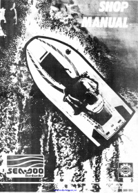


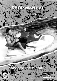





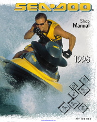
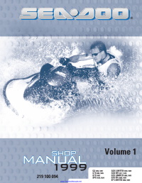



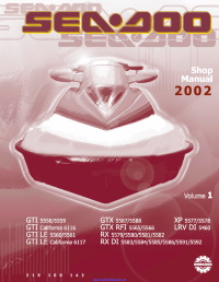




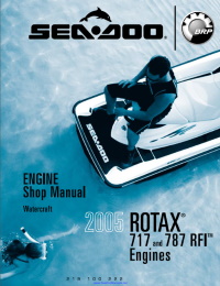











 доброго времени суток! Будьте добры подгоните мануал на русском на GTI 130