- Manuals
- Brands
- Man Manuals
- Engine
- D 2866 E
- Operating instructions manual
-
Contents
-
Table of Contents
-
Bookmarks
Quick Links
Operating Instructions
Diesel Engine
D 2866 E
D 2866 TE
D 2866 LE
D 2866 LXE
Related Manuals for Man D 2866 E
Summary of Contents for Man D 2866 E
-
Page 1
Operating Instructions Diesel Engine D 2866 E D 2866 TE D 2866 LE D 2866 LXE… -
Page 3
It is imperative and in your own interest to entrust your MAN Local Service Centre with the removal of any disturbances and with the performance of checking, setting, and re- pair work. -
Page 4: Table Of Contents
Index Declaration …………. . . Nameplates .
-
Page 5: Declaration
In accordance with Article 4, paragraph 2, in conjunction with Appendix II, section B, of Directive 89/392/EEC, version 93/44/EEC MAN Nutzfahrzeuge Aktiengesellschaft, hereby declares that the engine described below is destined for installation in a machine as defined in the EC directive on machines.
-
Page 6: Nameplates
In all your correspondence please always quote engine model, serial number and job number (Order number). Enter 14-digit serial number (is used in the MAN Nutzfahrzeuge Aktiengesellschaft spare parts catalog to distinguish between spare parts). Motor-Nr. / Engine No. NI/II Enter 14-digit engine serial number.
-
Page 7: Safety Regulations
D Do not touch the engine with bare hands when it is warm from operation – risk of burns. D Exhaust gases are toxic. Comply with the instructions for the installation of MAN Die- sel engines which are to be operated in enclosed spaces. Ensure that there is ad- equate ventilation and air extraction.
-
Page 8
Safety regulations During maintenance and care D Always carry out maintenance work when the engine is switched off. If the engine has to be maintained while it is running, e.g. changing the elements of change-over filters, remember that there is a risk of scalding. Do not get too close to rotating parts. D Change the oil when the engines is warm from operation. -
Page 9
If faults occur, find the cause immediately and have it eliminated in order to prevent more serious damage. Use only genuine MAN spare parts. MAN will accept no responsibility for damage result- ing from the installation of other parts which are supposedly “just as good”. -
Page 10
Safety regulations D Comply with instructions for operation of the alternator. See “Commissioning and oper- ation”. D Do not let the raw water pump run dry. If there is a risk of frost, drain the pump when the engine is switched off. Regulations designed to prevent pollution Engine oil and filter elements / cartridges, fuel/fuel filter D Take old oil only to an old oil collection point. -
Page 11
Safety regulations D After washing apply a fatty skin cream to the skin. D Change oil-soaked clothing and shoes. D Do not put oily rags into your pockets. Ensure that used engine oil is disposed of properly – Engine oil can endanger the water supply – For this reason do not let engine oil get into the ground, waterways, the drains or the sewers. -
Page 12: Technical Information
Technical information Engine views D 2866 E…
-
Page 13
Technical information 1 Tensioning pulley 2 Water pump 3 Oil filler neck 4 Tandem fuel filter 5 Oil separator valve for crankcase breather 6 Fuel lift pump with prestrainer 7 Injection pump 8 Oil drain plug 9 Oil dipstick 10 Alternator 11 Oil cooler 12 Oil filter 13 Starter motor… -
Page 14
Technical information Engine views D 2866 TE… -
Page 15
Technical information 1 Tensioning pulley 2 Water pump 3 Oil filler neck 4 Oil separator valve for crankcase breather 5 Tandem fuel filter 6 Fuel lift pump with prestrainer 7 Injection pump 8 Oil drain plug 9 Oil dipstick 10 Oil cooler 11 Oil filter 12 Turbocharger 13 Starter motor… -
Page 16
Technical information Engine views D 2866 LE, LXE… -
Page 17
Technical information 1 Oil filler neck 2 Oil separator valve for crankcase breather 3 Tandem fuel filter 4 Fuel lift pump with prestrainer 5 Injection pump 6 Oil dipstick 7 Alternator 8 Water pump 9 Tensioning pulley 10 Oil filter 11 Water drain plug 12 Oil drain plug 13 Turbocharger… -
Page 18: Engines
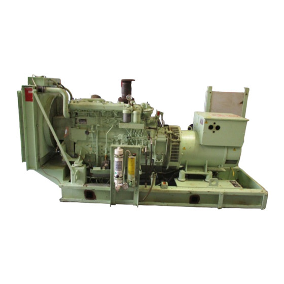
Technical information Engines The engines D 2866 E / TE / LE / LXE are in-line vertical liquid-cooled 6-cylinder four- stroke Diesel engines with direct injection. D 2866 E is a naturally aspirated engine. D 2866 TE is turbocharged, and D 2866 LE / LXE are turbocharged and intercooled.
-
Page 19
Technical information Engine timing Camshaft, oil pump and injection pump are driven by a gear train arranged at the fly- wheel end. 1 Crankshaft gear 4 Camshaft drive gear 2 Oil pump drive gear 5 Idler gear 3 Oil pump impeller gears 6 Injection pump drive gear The crankshaft gear and camshaft gear are match-marked by “1”… -
Page 20: Engine Lubrication
Technical information Engine lubrication The engine is equipped with force-feed lubrication. The pressure is produced by a gear pump whose drive gear is in direct mesh with the crankshaft gear at the flywheel end. The oil pump draws the oil from the oil sump and delivers it through the oil cooler and oil filter to the main distributor gallery and from there to the main bearings, big-end bearings and camshaft bearings as well as to the small-end bearings and the rocker arms.
-
Page 21
Technical information The injection pump and the turbocharger are also connected to the engine lubricating system. The cylinder walls and timing gears are splash-lubricated. Each cylinder has an oil jet provided for cooling the underside of the pistons. The lube oil is cleaned in a full-flow oil filter. Depending on the agreed extent of delivery and the design of the engine, the lube oil cir- cuit can be equipped with oil pressure monitors (advance warning and cut-off function) which shut the engine down in the event of a sudden loss of pressure. -
Page 22: Fuel System
Technical information Fuel system The fuel is delivered by the fuel lift pump via the fuel filter to the injection pump and from there to the injectors. The fuel is sprayed into the cylinder through four-hole nozzles fitted in screw-fit injectors in the cylinder heads.
-
Page 23: Turbocharger
Technical information Fuel filters Before entering the suction chamber of the injection pump, the fuel is cleaned in a two- stage, parallel or changeover filter. Turbocharger (D 2866 TE, LE, LXE) The exhaust gases of the engine are passed through the turbine rotor of the turbochar- ger.
-
Page 24: Intercooler
Technical information Intercooler (D 2866 LE, LXE) Before entering the cylinders the combustion air compressed in the turbocharger is passed through a heat exchanger (intercooler). Heat removal in the cooler is either by air (air-to-air intercooler) or, in case of the marine application, by means of seawater (air-to-water intercooler) delivered by the raw water pump.
-
Page 25: Electrical Equipment
Technical information Electrical equipment Alternator The alternator is fitted with integral silicon rectifiers. A transistorized regulator mounted on the alternator limits the alternator voltage. The al- ternator should not be operated except with the regulator and battery connected in circuit to avoid damage to the rectifier and regulator.
-
Page 26: Commissioning And Operation
“Technical Information down lever to “stop” at the same time for the installation of MAN Diesel en- until the oil pressure warning light goes gines”. out and the oil pressure gauge shows a pressure.
-
Page 27: Starting
Commissioning and operation Raw water pump Running in Do not let raw water pump run dry. It is recommended that new or overhauled Make sure that all valves / cocks in the engines should not be operated at a load raw water circuit are open.
-
Page 28: Shutting Down
Temporary anti-corrosion protection ac- into contact! cording to MAN works norm M 3069 is re- D Do not operate the alternator without quired for engines which are to be put out battery connection! of service for fairly long periods.
-
Page 29: Maintenance And Care
Maintenance and care Engine lubrication Oil level Check the oil level in the engine sump daily with a dipstick. The level should be between the two notches cut into the dip- stick and should never be allowed to drop below the lower notch. Caution: Do not add so much engine oil that the 1 Oil filler neck on valve cover…
-
Page 30
Maintenance and care Observe positions of selector lever! Continuous operation (both filter halves in operation) Right-hand filter cut out Left-hand filter cut out 1 Oil drain plug 2 Oil filter bowl Caution: 3 Tie screw Do not leave selector lever in any in- 4 Filter cartridge termediate position because this 5 Gasket… -
Page 31: Fuel System
Maintenance and care Fuel system Fuel lift pump The fuel lift pump is operated by the injec- Fuel tion pump camshaft via the roller tappet. If Diesel fuel which contains moisture is used the injection system and the cylinder Strainer liners / pistons will be damaged.
-
Page 32
Maintenance and care Two-stage fuel filter Parallel fuel filter with filter cartridges (replaced by parallel fuel filter) (replaced by parallel filter with inter- changeable filter) In two filter housings connected in series the fuel first passes through a felt tube el- The fuel passes through two filter el- ement and then through a paper element. -
Page 33
Maintenance and care Parallel fuel filter with interchangeable Change-over fuel filter with filter car- filter tridges (replaced by change-over fuel filter with The fuel flows through two parallel filters. interchangeable filter) Where the changeover-type filter is in- stalled, the servicing procedure is for the filter side requiring to be shut off with the engine running. -
Page 34
Maintenance and care Change-over fuel filter with inter- Caution: changeable filter Do not leave selector lever in any in- termediate position because this would be liable to interfere with fuel supply. If in doubt stop the engine to change the fuel filter. Continuous operation (both filter halves in operation) -
Page 35
Maintenance and care Injector maintenance Removal, dismantling and cleaning (by authorized specialist personnel) Unscrew delivery pipe at nozzle holder and at the injection pump. Remove leak-off pipe. Release union screw of nozzle holder with special wrench. Remove nozzle holder with gasket from the cylinder head. -
Page 36
Maintenance and care Before reassembly thoroughly wash Caution: nozzle body and needle in clean test oil. Do not hold your hands under the fuel jet, as there is a risk of injury. Do not Hold the needle at the pintle end only; to inhale the atomised fuel. -
Page 37: Cooling
See Publication “Fuels, Lubricants and Coolants for MAN Diesel Engines”. Filling-in of coolant (only when engine has cooled down) D Fill in the coolant slowly…
-
Page 38
HENKEL a) Drain coolant P3-begesol. This cleansing agent is avail- b) Open thermostats positively (use short- able from MAN in 10-kg cans under Part circuit inserts), so that the entire cool- No. 09.21002-0164. ant circuit is flushed in the cleaning… -
Page 39
Maintenance and care d) Warm up engine under load. After a D Drain the pickling fluid, fill the system temperature of 60°C is reached, run with tap water, and run the engine at engine for a further 15 minutes idle for 5 minutes to flush out all fluid; e) Drain cleaning fluid then drain the water f) Repeat steps c) and d) -
Page 40
Maintenance and care D Fill the container with undiluted original Filler caps and working valves of cool- pickling fluid at room temperature (Lith- ing system solventsäure or engine pickling fluid The rubber gaskets of the filler caps and RB-06) until the tube bundle is com- working valves (negative pressure and pletely immersed positive pressure valves) of the cooling… -
Page 41: Turbocharger
Maintenance and care Turbocharger This precaution will enable any wear of the bearings to be detected in good time before serious damage is caused to the Maintenance rotor and bearings. (by authorized specialist personnel) The turbochargers do not call for any spe- Measuring of axial clearance cific maintenance.
-
Page 42: Intercooler
Maintenance and care Intercooler Maintenance (by authorized specialist personnel) In order to maintain the heat transfer effi- ciency of the intercooler, it is necessary to clean it at regular intervals which depend on the quality of the coolant used. For this purpose, dismantle the inter- cooler.
-
Page 43: Air Cleaner
Maintenance and care Air cleaner Fouling Indicator As the degree of clogging increases the Dry air cleaner red indicator becomes more and more vis- ible in the transparent section of the air cleaner. If the fouling indicator remains engaged, i.e. it still shows completely red even with the engine shut down, the filter cartridge must be cleaned or replaced.
-
Page 44
Maintenance and care Changing the filter cartridge Blowing out (wear goggles) To do this fit a pipe to the compressed air Caution: gun. The end of the pipe should be bent No dust must get to the clear air end. by approx. -
Page 45
Maintenance and care Viscous air cleaner On no account re-use damaged car- tridges. If in doubt fit a new cartridge. Safety cartridge The maintenance intervals for filters de- When the main cartridge is being serviced pend on the respective operating condi- the safety cartridge remains in the filter tions. -
Page 46: Checking And Setting
Checking and setting To check and set the start of deliv- The pointer should then be aligned such that its measuring edge exactly coincides ery with start of delivery marker with the “OT” mark on the scale disc. on injection pump hub (by authorized specialist personnel) In order to enable the engine to be rotated manually during adjustments, there is a…
-
Page 47
Checking and setting Setting start of delivery To check and set the start of deliv- ery with start of delivery indicator Correct start of delivery by turning the in the governor housing pump hub in the slotted holes of the drive (by authorized specialist personnel) gear. -
Page 48
Checking and setting The pointer should then be aligned such Connect up power supply of light signal that its measuring edge exactly coincides transmitter (red terminal = +). Turn engine with the “OT” mark on the scale disc. by hand so that piston in cylinder no. 1 in the compression stroke comes close to In order to enable the engine to be rotated the start of delivery. -
Page 49
Checking and setting Setting start of delivery Note: If only lamp (B) comes on during this test the engine has been turned past the start of delivery. In this case turn the engine back and repeat the proce- dure. b. Sleeve If a light signal transmitter is not available, good measurement results can also be achieved with a plug-in receptacle. -
Page 50: To Check And Adjust Valve Clearance
Checking and setting To check and adjust valve clear- ance (by authorized specialist personnel) The valve clearance for new and over- hauled engines should be checked after the first 10 to 20 hours of operation. Then it should be adjusted every 400 hours of operation.
-
Page 51
Checking and setting Retightening cylinder head bolts Remove the sticker “First retightening of cylinder head bolts …” and attach the on new engines sticker “Second retightening of cylinder (engine cold or warm) head bolts …” to show that the cylinder by authorized specialist personnel head bolts have been retightened for the second time. -
Page 52
Checking and setting Tightening cylinder head bolts Retightening cylinder head bolts after a repair after repairs (engine cold) (engine cold or warm) by authorized specialist personnel by authorized specialist personnel Before inserting the cylinder head bolts oil After the first 10 to 20 hours of operation them with engine oil on the thread (not to after a repair turn the cylinder head bolts the bore) and coat the contact face of the… -
Page 53: V-Belts
Checking and setting Re-using old cylinder head bolts V-belts Checking The tension of the V-belts should be Before re-using old cylinder head bolts checked after every 200 hours of oper- check them as follows: ation. Length Change the V-belts if necessary During tightening the bolts are intention- If, in the case of a multiple belt drive, wear ally stressed beyond the yield point and…
-
Page 54
Checking and setting Tension and / or replace V-belts D Slowly depress pad  until the spring can be heard to disengage. This will Water pump – Alternator cause the indicator to move upwards D Remove fixing bolts À If pressure is maintained after the spring D Remove lock-nut Á… -
Page 55
Notes …………………………………………………………………………………………………………………………………………………………………………………………………………………………………………………………………………………………………………………………………………………………………………………………………………………………………………………………………………………………………………………………………………………………………………………………………………………………………………………………………………………………………… -
Page 56: Technical Data
Technical data Model D 2866 E Design in-line vertical Cycle 4-stroke Diesel Combustion system Direct injection Number of cylinders Bore 128 mm Stroke 155 mm Swept volume 11 967 cm Compression ratio 17.5 : 1 Rating see engine nameplate Firing order 1–5–3–6–2–4…
-
Page 57
Technical data Engine lubrication Force feed Oil capacity in oil sump (litres) min. max. Deep 12 l 18 l Shallow 14 l 20 l For 30° tilt 12 l 18 l Oil pressure during operation (depend- monitored by oil pressure monitors or dis- ing on oil temperature, oil viscosity plays class and engine rpm) -
Page 58
Technical data Model D 2866 TE Design in-line vertical Cycle 4-stroke Diesel with turbocharger Combustion system Direct injection Turbocharging Turbocharger Number of cylinders Bore 128 mm Stroke 155 mm Swept volume 11 967 cm Compression ratio 15.5 : 1 Rating see engine nameplate Firing order 1–5–3–6–2–4… -
Page 59
Technical data Engine lubrication Force feed Oil capacity in oil sump (litres) min. max. Deep 12 l 18 l Shallow 14 l 20 l For 30° tilt 12 l 18 l Oil pressure during operation (depend- monitored by oil pressure monitors or dis- ing on oil temperature, oil viscosity plays class and engine rpm) -
Page 60
Technical data Model D 2866 LE, LXE Design in-line vertical Cycle 4-stroke Diesel with turbocharger and in- tercooler Combustion system Direct injection Turbocharging Turbocharger with intercooler Number of cylinders Bore 128 mm Stroke 155 mm Swept volume 11 967 cm Compression ratio D 2866 LE 15.5 : 1… -
Page 61
Technical data Injection timer Automatic centrifugal type in camshaft drive gear Injectors 4-orifice nozzles Opening pressure of injector Injector + injection nozzle New nozzle holder: Used nozzle holder: 51.10101-7274 220 + 8 bar 220 + 8 bar 51.10101-7290 235 + 8 bar 220 + 8 bar 51.10101-7338 295 + 8 bar… -
Page 62: Index
Index Air cleaner ……22, 41–43 Nameplates ……. Alternator .
-
Page 64
MAN Nutzfahrzeuge Aktiengesellschaft Vogelweiherstraße 33 D–90441 Nürnberg Printed in Germany 51.99493–8264…
![]() Скачать бесплатно руководства по ремонту автомобилей в PDF формате
Скачать бесплатно руководства по ремонту автомобилей в PDF формате
Электронные книги : Руководства по ремонту, советы по эксплуатации, ремонту двигателей и электрооборудования, технические характеристики различных марок автомобилей
Скачать бесплатно электронные книги , инструкции и руководства по ремонту автомобилей, книги по ремонту и эксплуатации автомобилей, и другие автокниги, а также автокаталоги, карты, атласы, учебные пособия для подготовки водителей, CD диски по автомобильной тематике, каталоги запчастей для автомобилей, автокниги по ремонту, эксплуатации и обслуживанию автомобилей, как российских, так и зарубежных производителей, издательств технической литературы, таких как Третий Рим, Арус, Монолит, Мир Автокниг, За рулем, Легион Автодата
Acura, Alfa Romeo, Audi, Beifan Benchi, BMW, Buick, BYD, Cadillac, Chery, Chevrolet, Chrysler, Citroen, Dacia, Dadi, Daewoo, DAF, Daihatsu, Derways, Dodge, Dong Feng, FAW, Fiat, Ford, Foton, Freightliner, Geely, GMC, Great Wall, Groz, Hania, Hino, Holden, Honda, HOWO, Hummer, Hyundai, Infiniti, International, Iran, Isuzu, Iveco, Jeep, Kenworth, Kia, Lancia, Land Rover, Range Rover, Lexus, Lifan, Lincoln, MAN, Maxus, Mazda, Mercedes-Benz, Mercury, Mini, Mitsubishi, Nissan, Oldsmobile, Opel, Peterbilt, Peugeot, Plymouth, Pontiac, Porsche, Renault, Rover, Saab, Samsung, Saturn, Scania, Scion, Seat, Setra, Shaanxi, Skoda, SsangYong, Subaru, Suzuki, TagAZ, Tata, Toyota, VolksWagen, Volvo, Vortex, ZAZ, АЗЛК, Москвич, ВАЗ, Lada, ГАЗ, Донинвест, ЗИЛ, Иж, КамАЗ, КрАЗ, ЛиАЗ, ЛуАЗ, МАЗ, МЗКТ, ПАЗ, УАЗ, УРАЛ
Книга: MAN TGX / TGS дизель с 2007 г.в., ремонт, эксплуатация, техническое обслуживание
Руководство по эксплуатации и техническому обслуживанию грузовых автомобилей Man TGX / TGS с 2007 года выпуска с дизельными двигателями D20; D26; D28.
Книга: MAN TGX / TGS дизель с 2007 г.в., эксплуатация, каталог деталей
Руководство по эксплуатации + каталог деталей MAN TGX / TGS с двигателями D2066 и D2676 EURO 4/5.
Книга: MAN TGL / TGM дизель с 2005 г.в., ремонт, эксплуатация, техническое обслуживание
Руководство по эксплуатации и техническому обслуживанию грузовых автомобилей Man TGL / TGM с 2005 года выпуска с дизельными двигателями D0834; D0836.
Книга: MAN TGA дизель с 2000 / 2005 г.в., ремонт, эксплуатация, техническое обслуживание
Руководство по эксплуатации и техническому обслуживанию грузовых автомобилей Man TGA с 2000 года выпуска с дизельными двигателями D2066; D2865; D2866; D2876.
Книга + CD: MAN TGA дизель с 2000 г.в., ремонт, эксплуатация, техническое обслуживание + каталог деталей
Подробный комплект материалов по ремонту и обслуживанию автомобиля MAN TGA с 2000 года выпуска с дизельными моторами: 6.9D, 10.5D, 12.0D, 12.4D, 12.8D, 18.3D л.
Книга: MAN L2000 / LE2000 / M2000L / M2000M / ME2000 / F90 / M90 / F2000 дизель ремонт, эксплуатация, техническое обслуживание
Самое подробное пособие по ремонту и техническому обслуживанию грузовых автомобилей Man L2000 / LE2000 / M2000L / M2000M / ME2000 / F90 / M90 / F2000 с дизельными двигателями D02, D08, D25, D28.
Книга: MAN 19 дизель ремонт, техническое обслуживание
Руководство по ремонту и техническому обслуживанию грузовых автомобилей Man модели 19.292, 19.332, 19.362 с двигателями объемом 12 литров.
Книга: MAN 19 дизель ремонт, техническое обслуживание
Руководство по ремонту и техническому обслуживанию грузовых автомобилей Man модели 19.292, 19.332, 19.362 с двигателями объемом 12 литров.
Книга: MAN M90 / M2000 дизель ремонт, эксплуатация, техническое обслуживание
Руководство по ремонту и эксплуатации грузовых автомобилей MAN M90 / M2000. Каталог деталей двигателей.
Книга: MAN M90 / M2000 дизель устройство каталог деталей
Руководство по устройству грузовых автомобилей MAN M90 / M2000. Каталог деталей.
Книга: MAN F90 / F2000 дизель устройство каталог деталей
Руководство по устройству грузовых автомобилей MAN F90 / F2000. Книга содержит каталог деталей и сборочных единиц автомобиля.
Книга: MAN F90 / F2000 дизель ремонт, эксплуатация, техническое обслуживание
Руководство по ремонту и эксплуатации грузовых автомобилей MAN F90 / F2000. Электросхемы.
Книга: MAN TGA дизель 2000-2008 г.в., ремонт, техническое обслуживание электросхемы
Руководство по ремонту и техническому обслуживанию грузовых автомобилей Man TGA 2000-2008 годы выпуска. В книге представлены подробные электрические схемы.
Книга: MAN TGL дизель эксплуатация, техническое обслуживание каталог деталей
Руководство по эксплуатации и техническому обслуживанию автомобилей MAN TGL. Книга содержит каталог деталей и сборочных единиц автомобиля, включая двигатели MAN D0834 и MAN D0836 различных модификаций.
Книга: MAN TGA дизель эксплуатация, каталог деталей
Руководство по эксплуатации и техническому обслуживанию автомобилей Man TGA. Книга содержит каталог деталей и сборочных единиц автомобиля. В книге представлена инструкция по эксплуатации Man TG-A, а также рекомендации по техническому обслуживанию автомобиля.
Книга: MAN L2000 дизель рем
Руководство по ремонту грузового автомобиля MAN L2000.
Книга: MAN M90 дизель эксплуатация,
Руководство по эксплуатации грузовых автомобилей MAN M90.
Книга: MAN M90 дизель ремонт, Часть 2
В издании описывается ремонт сцепления, КПП, мостов, рулевого управления, тормозной системы, подвесок, электрооборудования и кузова устанавливающихся на автомобили MAN M90.
Книга: MAN M90 дизель ремонт, Часть 1
В издании описывается ремонт дизельных двигателей серии DO 826 (F, FO1, TF, LF01, LF, LF02) устанавливающихся на автомобили MAN M90.
Книга: MAN F90 / F2000 дизель ремонт, техническое обслуживание
Руководство по ремонту грузовых автомобилей Man F 90 / F 2000 серий 19.273, 293, 323, 343, 373, 403, 423, 463, 23.343, 26.373, 403, 423, 463, с двигателями D2555, D2556, D2565, D2566, D2865, D2866, D2876 рабочим объемом 9,2; 9,5; 11,0; 11,4; 12,0; 12,8 л.
Книга: MAN TGA дизель рем
Руководство по ремонту грузовых автомобилей MAN TG-A.
Книга: MAN TGA дизель эксплуатация,
Руководство по эксплуатации и техническому обслуживанию грузовых автомобилей Man TGA.
Книга: MAN TGL дизель эксплуатация, техническое обслуживание
Руководство по эксплуатации и техническому обслуживанию грузовых автомобилей MAN TGL.
Книга: MAN F2000 дизель эксплуатация, техническое обслуживание
Руководство по эксплуатации и обслуживанию нескольких выпусков большегрузных автомобилей фирмы MAN третьего (и частично 4-го) поколения, тяжелой серии F-2000, подробно описано техническое обслуживание всех систем, даны рекомендации по поиску возможных неисправностей ряда систем.
Книга: MAN M2000 дизель рем
Руководство по ремонту грузовых автомобилей MAN M 2000 с двигателя D0824 LFL06, D0826 LFL03, LFL09, LF15, LF17 рабочим объемом 4,6 и 6,9 л
36,5 Мб
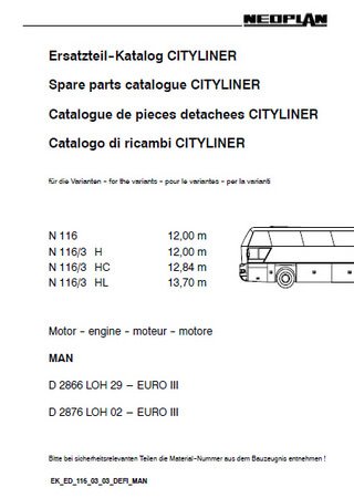
Каталог запчастей автобусов Neoplan N116 (3H, 3HC, 3HL)
Формат: pdf
-
Год:
2002
-
Страниц:
645
-
Язык:
английский, немецкий, французский, итальянский
-
Размер:
36,5 Мб
-
Категории:
Двигатели MAN

106 Мб
Руководство по эксплуатации автобуса ЛиАЗ-621321
Формат: pdf
-
Год:
2011
-
Страниц:
401
-
Язык:
русский
-
Размер:
106 Мб
-
Категории:
Двигатели MAN
4,83 Мб
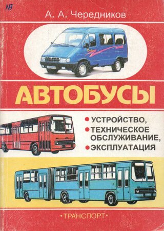
Автобусы Ikarus 260, Ikarus 280, ЛиАЗ-5256, ПАЗ-3205,
Формат: djvu
-
Год:
1999
-
Страниц:
217
-
Язык:
русский
-
Размер:
4,83 Мб
-
Категории:
Двигатели MAN
7,13 Мб
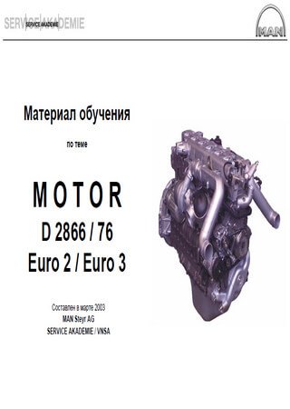
Двигатели MAN D2866 и MAN D2876: Руководство по
Формат: pdf
-
Год:
2003
-
Страниц:
210
-
Язык:
русский
-
Размер:
7,13 Мб
-
Категории:
Двигатели MAN

4,1 Мб
Двигатели MAN D2862 и MAN D2868: Руководство по
Формат: pdf
-
Год:
2011
-
Страниц:
132
-
Язык:
английский
-
Размер:
4,1 Мб
-
Категории:
Двигатели MAN
1,29 Мб
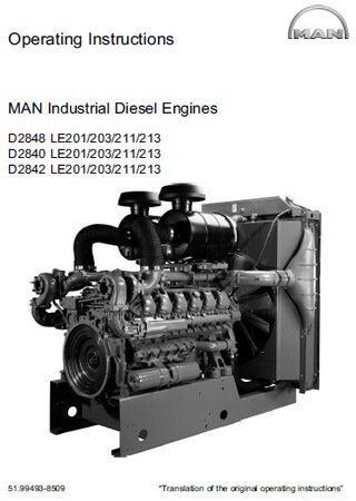
Двигатели MAN D2848, D2840, D2842: Руководство по
Формат: pdf
-
Год:
2011
-
Страниц:
100
-
Язык:
английский
-
Размер:
1,29 Мб
-
Категории:
Двигатели MAN
7,68 Мб
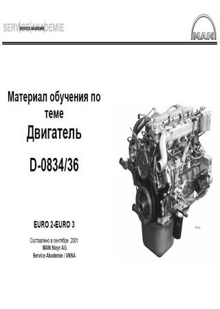
Двигатели MAN D0834 и MAN D0836: Руководство по
Формат: pdf
-
Год:
2004
-
Страниц:
156
-
Язык:
русский
-
Размер:
7,68 Мб
-
Категории:
Двигатели MAN

78,9 Мб
Автобусы Ikarus 250, 256, 260, 280: Руководство по
Формат: pdf
-
Год:
1990
-
Страниц:
268
-
Язык:
русский
-
Размер:
78,9 Мб
-
Категории:
Двигатели MAN

4,77 Мб
Руководство по ремонту и эксплуатации автобусов Ikarus 180,
Формат: djvu
-
Год:
1987
-
Страниц:
207
-
Язык:
русский
-
Размер:
4,77 Мб
-
Категории:
Двигатели MAN

6,44 Мб
Автобусы Ikarus 180, 250, 255, 260, 280, 556: Руководство
Формат: djvu
-
Год:
1976
-
Страниц:
289
-
Язык:
русский
-
Размер:
6,44 Мб
-
Категории:
Двигатели MAN

8,41 Мб
Руководство по ремонту грузовых автомобилей MAN M2000
Формат: pdf
-
Год:
2005
-
Страниц:
201
-
Язык:
русский
-
Размер:
8,41 Мб
-
Категории:
Двигатели MAN
49,1 Мб
Руководство по ремонту автомобилей MAN F90, F2000
Формат: pdf
-
Год:
2004
-
Страниц:
194
-
Язык:
русский
-
Размер:
49,1 Мб
-
Категории:
Двигатели MAN
Издание поможет владельцу автотехники MAN, подробно и грамотно рассказав о том, как устроены основные узлы и агрегаты некоторых моделей, которые входят в серии MAN-F90 и F2000.
-
Page 1
Operating Instruction MAN Industrial Gas Engines E3268 LE212/222 / E3262 LE202/212 MAN Engines A Division of MAN Truck & Bus… -
Page 3
Operating Instruction MAN Industrial Gas Engines E3268 LE212, E3268 LE222 E3262 LE202, E3262 LE212 “Translation of the original instruction” 51.99587-8006 Version 05… -
Page 4: Information And Copyright
Information and Copyright Subject to change without notice. Reprinting, copying or translation, even of extracts, is not allowed without written permission from MAN. All rights under the copyright law are strictly reserved by MAN. 2016 MAN Truck & Bus AG Vogelweiherstrasse 33 90441 Nürnberg…
-
Page 5: Table Of Contents
…………… . 2.11 Weight data E3268 LE212/LE222 .
-
Page 6
…………Engine views E3268 LE212 . -
Page 7
……..10.4.1 Commissioning of preserved engines to MAN Works Standard M 3069 . -
Page 8
…………. . . 12.1 Installation drawing E3268 LE212/LE222 . -
Page 9: Foreword
Only use genuine MAN spare parts and accessories or ones that have been approved by MAN. Only the genuine spare parts approved by us have been tested by us and therefore meet the requirements for use of the engine.
-
Page 10: Symbol Explanation
Foreword 1.2 Symbol explanation Warnings Warnings are indicated by symbols in these instructions. The warnings are preceded by signal words which indicate the extent of the danger. Always heed these warnings and act prudently to prevent accidents, injuries and property damage. DANGER Describes an immediately dangerous situation that will lead to serious injury or death if it is not avoided.
-
Page 11: Limitation Of Liability
Treat the Installation and Operating Instructions confidentially. They are aimed solely at persons who deal with the engine. The instructions may not be passed to third parties without written approval from MAN. User tip The information, texts, drawings, illustrations and other depictions are all protected by copyright and are subject to industrial property rights.
-
Page 12: Spare Parts
Spare parts and accessories must either be MAN genuine parts or parts that have been specifically appro ved by MAN. The reliability, safety and suitability of these parts have been established specifically for the engines.
-
Page 13: Warranty Provisions
Valid are the commitments agreed upon in the delivery contract and the General Terms and Conditions of MAN and the law applicable at the time of contracting arrangements. Failure to follow these instructions and any operating instructions provided by suppliers invalidates the war…
-
Page 14
Foreword Carefully read these Operating Instructions before starting any work! This is especially valid for the chapter on General Safety Instructions and the safety instructions in each of the chapters. -
Page 15: General Safety Instructions
Any other use is considered as «non-intended». MAN is not liable for any damage resulting from non-intended use. The risk is entirely borne by the opera tor. Intended use also includes compliance with the country-specific, local environmental regulations.
-
Page 16: Content Of The Installation And Operating Instructions
MAN. If changes are made without the written consent of MAN, the guarantee or warranty obligation for MAN is no longer valid for damage and defects which are based on these unauthorised changes. Furthermore MAN assumes no liability for any damage caused as a result of unauthorised changes.
-
Page 17: Personnel Requirements
General Safety Instructions 2.5 Personnel requirements 2.5.1 Qualifications WARNING Risk of injury if personnel is not sufficiently qualified Improper handling can result in significant personal injury and property damage. For this reason: S Specific activities must only be performed by those persons who are named in the respective chapters in these Operating Instructions.
-
Page 18: Personal Protective Equipment
General Safety Instructions 2.6 Personal protective equipment Wearing personal protective equipment is necessary to minimise the health risks when working. S The required personal protective equipment for the relevant job must always be worn while working. S All signs pertaining to personal protective equipment in the working area must be followed. Protective Clothing Close-fitting clothing with low initial tear strength, with narrow sleeves and with no pro…
-
Page 19: Particular Dangers
General Safety Instructions 2.7 Particular dangers The following section describes residual risks which have been identified. S Observe the safety instructions listed here and the warnings in the other chapters of these instructions in order to reduce health hazards and avoid dangerous situations. Electrical Current DANGER Danger to life due to electrical voltage…
-
Page 20
General Safety Instructions Exhaust gases WARNING Health risk due to leaking exhaust system Exhaust gases can damage health. For this reason: S Immediately stop and repair machines with leaking exhaust systems. S Ensure sufficient ventilation. Highly Flammable Substances — Gaseous Fuels, Oils and Grease WARNING Risk of injury due to highly inflammable materials Highly inflammable materials, liquids or gases catch fire easily. -
Page 21
General Safety Instructions Hot Surfaces CAUTION Risk of burns due to hot surfaces Touching hot components causes burns. For this reason: S When performing any work in the vicinity of hot components always wear protective clothing and protective gloves. S Before starting any work ensure that all components have cooled down to ambient temperature. Noise WARNING Hearing damage due to noise… -
Page 22: Safety Equipment
General Safety Instructions 2.8 Safety equipment The operator must have the following safety equipment in place: Before the engine is placed into operation, install the emergency-off equipment and connect it into the safety chain of the system. Connect the emergency-off equipment so that dangerous situations to people and property are avoided in case the its power supply is interrupted or is turned back on after an interruption.
-
Page 23: Response To Danger And Accidents
General Safety Instructions 2.9 Response to danger and accidents Preventative Measures S Always be prepared for an accident! S Keep first aid equipment (first aid kit, blankets, etc.) and fire extinguishers at hand. S Regularly check first-aid equipment and fire extinguishers for completeness and correct functioning. S Familiarise the personnel with the emergency, first aid and rescue equipment.
-
Page 24: Signs
General Safety Instructions 2.10 Signs WARNING Risk of injury due to illegible symbols Labels and symbols get dirty over time, rendering them illegible. For this reason: S Always keep the safety, warning and operational signs in good legible condition. S Clean or replace illegible safety, warning and operational signs. The following symbols should be installed in the immediate vicinity of the hazard area.
-
Page 25: Weight Data E3268 Le212/Le222
General Safety Instructions 2.11 Weight data E3268 LE212/LE222 Ensure that suitable lifting gear is used for handling the engine and the engine parts listed in the table. Part Weight (kg) Oil pan 95l Crankcase Crankshaft Flywheel housing Flywheel Exhaust turbocharger 1500 rpm…
-
Page 26: Environmental Protection
General Safety Instructions 2.12 Environmental protection ENVIRONMENTAL NOTE Risk of environmental pollution due to incorrect handling of service products Serious environmental damage can result. For this reason: S Follow the safety instructions. S Take suitable measures immediately if environmentally hazardous substances escape into the envi ronment.
-
Page 27: Engine Model Plate
Engine Model Plate Engine model plate Always quote the engine type , engine num and factory number/order number in all enquiries and communications. Before the engine is first commissioned, you should therefore check the relevant data on the engine model plates and enter it below. The engine model plates are attached to the crankcase.
-
Page 28: Explanation Of Motor-Nr./Engine No. (Engine Identification Number)
Engine Model Plate 3.1 Explanation of Motor-Nr./Engine No. (engine identification number) Class identifier (assignment) Motor-Nr./Engine No. XXXX XXXX 1 Model number after model code 2 Day of assembly (determined internally at factory) 3 Assembly sequence (consecutive number on day of assembly) 4 Production- and equipment-specific data 3.2 Explanation of model designation Model designation…
-
Page 29: Design And Function
4.2 Engine design and engine equipment Engines E3268 LE212, E3268LE222 and E3262 LE202, E3262 LE212 are 8- or 12-cylinder gas engines with turbocharger and mixture cooling. Split crankcase, wet cylinder liners made of highly wear-resistant special centrifugal casting, aluminium piston with cooling duct for piston cooling.
-
Page 30
Design and Function Flywheel housing and flywheel The flywheel housing as a connection to SAE1. Different flywheel versions can be supplied, depending on the type of application. Starter The electric starter is of two-pin, insulated design. The starter can be mounted on the left or right of the en gine. -
Page 31: Engine Views E3262 Le202
Design and Function 4.3 Engine views E3262 LE202 4.3.1 Front left view Vent housing for coolant Oil drain plug Data acquisition Protective cover for crankshaft Throttle valve and vibration damper Exhaust turbocharger Oil filter Oil pan Oil separator Carefully read these Operating Instructions before starting any work! This is especially valid for the chapter on General Safety Instructions and the safety instructions in each of the chapters.
-
Page 32: Front Right View
User tip The gas supply line — consisting of ball cock, gas filter, solenoid valves, gas pressure regulator, gas mi xer and air filter — is not supplied by MAN. Carefully read these Operating Instructions before starting any work! This is especially valid for the chapter on General Safety Instructions…
-
Page 33: Engine Views E3268 Le212
Design and Function 4.4 Engine views E3268 LE212 4.4.1 Front left view Oil separator Oil pan Vent housing for coolant Oil drain plug Data acquisition Protective cover for crankshaft Throttle valve and vibration damper Exhaust turbocharger Oil filter Carefully read these Operating Instructions before starting any work! This is especially valid for the chapter on General Safety Instructions and the safety instructions in each of the chapters.
-
Page 34: Front Right View
User tip The gas supply line — consisting of ball cock, gas filter, solenoid valves, gas pressure regulator, gas mi xer and air filter — is not supplied by MAN. Carefully read these Operating Instructions before starting any work! This is especially valid for the chapter on General Safety Instructions…
-
Page 35: Transport, Packaging And Storage
Transport, Packaging and Storage Transport, packaging and storage It is absolutely necessary to observe the “Installation Instructions” for the installation and commissioning of a new or reconditioned engine. User tip Installation and commissioning is only to be performed by the employees of the manufacturer of the entire system or by manufacturer authorised personnel.
-
Page 36
Transport, Packaging and Storage Off-Centre Point of Gravity WARNING Danger to life due to incorrect handling of transported item Transported item can swing out, tilt and/or drop. For this reason: S Use the crane hook lugs solely for transporting the engine without attachments (without alternator). S Observe the information and markings on the package concerning centre of gravity. -
Page 37: Transport Inspection
Transport, Packaging and Storage 5.3 Transport inspection Check the delivery for missing items and for damage from transport. If external signs of transport damage are apparent: S Do not accept delivery or only accept under written protest. S List scope of damage on the transport documents or on the transportation company’s packaging slip. S Initiate a claims process.
-
Page 38: Transport
Transport, Packaging and Storage 5.4 Transport DANGER Falling loads (weight 2000kg!) can lead to serious accidents For this reason: S Use sufficiently dimensioned crane lifting gear for lifting an engine! Ropes and chains must exert vertical tension (tolerance 5_) on the crane hooks. Crane lifting gear, ropes and chains must be in perfect condition.
-
Page 39
Transport, Packaging and Storage Attachment points E3262 LE202, E3262 LE212 For lifting the engine, 3 crane hook lugs are attached to the engine. Carefully read these Operating Instructions before starting any work! This is especially valid for the chapter on General Safety Instructions and the safety instructions in each of the chapters. -
Page 40
Transport, Packaging and Storage Attachment points E3268 LE212, E3268 LE222 For lifting the engine, 3 crane hook lugs are attached to the engine. Carefully read these Operating Instructions before starting any work! This is especially valid for the chapter on General Safety Instructions… -
Page 41
Transport, Packaging and Storage Transport with Crane The engine can be transported with a crane under the following conditions. S The crane and the lifting equipment must be designed for the weight of the engine. S Ropes and chains must not exert diagonal pull on the crane hooks. S The operator must be qualified for operating the crane. -
Page 42: Packaging
Transport, Packaging and Storage 5.5 Packaging Packaging The individual packages are packed in accordance with the expected conditions of transport. The purpose of the packaging is to protect the components from transport damage, corrosion and other damage. For this reason do not unpack components until shortly before they are to be assembled. Handling Packing Material Dispose of packing material according to the valid local and statutory regulations.
-
Page 43: Installation And Commissioning
S Safety Shoes S Safety Gloves 6.2 Safety instructions Personnel S The installation and commissioning may only be performed by MAN employees or by MAN-trained quali fied personnel. WARNING Danger caused by faulty installation and commissioning! Installation and commissioning require trained qualified personnel with sufficient experience. Faulty in…
-
Page 44: Engine Installation
Installation and Commissioning 6.3 Engine installation 6.3.1 Interfaces between engine and plant Coolant connections on charge mixture cooler Engine mounting Exhaust turbocharger Coolant inlet Intake manifold Coolant outlet Exhaust turbocharger Mount exhaust system, see page 49 Mount gas inlet, see page 48 Connect cooling system, see page 47 Carefully read these Operating Instructions before starting any work! This is especially valid for the chapter on General Safety Instructions…
-
Page 45
Installation and Commissioning Exhaust turbocharger Flywheel Exhaust turbocharger Gas inlet When installing the engine, perform the following assembly work on the interfaces between engine and plant: Mount exhaust system, see Installation Instructions Mount alternator, see page 45 Connect gas inlet, see page 48 Carefully read these Operating Instructions before starting any work! This is especially valid for the chapter on General Safety Instructions and the safety instructions in each of the chapters. -
Page 46: Installation Instructions
Installation Instructions Only general engine installation instructions can be given in this chapter. More detailed information can be found in the “Installation Instructions for MAN Industrial Gas Engines”. These instructions can be obtained from MAN, see page 2 for contact address.
-
Page 47: Completion Of The Engine And Assembly Of The Drive System
Installation and Commissioning 6.4 Completion of the engine and assembly of the drive system When installing the engine, ensure that there is enough space to perform the regular maintenance work specified in the maintenance schedule. 6.4.1 Mounting an alternator on the flywheel housing Flywheel The connection dimensions of the flywheel indicated on the installation drawing.
-
Page 48: Checking Crankshaft Axial Clearance
Installation and Commissioning 6.4.2 Checking crankshaft axial clearance NOTE The engines’ crankshaft axial clearance specified in the design must not be reduced under any circum stances as a result of mounting clutches or other attachments. For this reason: S It is essential to determine the crankshaft axial clearance using a dial gauge held on a magnetic stand before and after flange-mounting any attachments.
-
Page 49: Connecting The Cooling System
Installation and Commissioning 6.5 Connecting the cooling system 6.5.1 Connecting the engine cooling The installation drawing provides information about the connections. S Connect the coolant outlet S Connect the coolant inlet Carefully read these Operating Instructions before starting any work! This is especially valid for the chapter on General Safety Instructions and the safety instructions in each of the chapters.
-
Page 50: Mounting The Gas Inlet
Installation and Commissioning 6.6 Mounting the gas inlet Both cylinder banks merge into a central gas inlet. The dimensions of the flange for connecting the plant-side gas inlet can be found on the installation drawing, see page 97. Carefully read these Operating Instructions before starting any work! This is especially valid for the chapter on General Safety Instructions and the safety instructions in each of the chapters.
-
Page 51: Mounting The Exhaust System
Installation and Commissioning 6.7 Mounting the exhaust system 6.7.1 Exhaust gas outlet on engine The dimensions of the flange for connecting the plant-side exhaust system can be found on the in stallation drawing, see page 97. S Connect the exhaust system to the flange the exhaust turbocharger(s).
-
Page 52: Connecting The Exhaust System To The Engine
Installation and Commissioning 6.7.2 Connecting the exhaust system to the engine Flexible connecting elements which allow engine movements due to the flexible engine mounting and decouple the engine from the exhaust system in terms of vibration must be installed between the engine and the exhaust system.
-
Page 53: Connecting The Electrical System
Batteries Separate batteries for the starter must be provided for each engine. 6.8.1 Starter All MAN industrial gas engines have two-pole starters. The starter battery’s positive lead must therefore be fed back to terminal 30 of the starter , the starter battery’s negative lead to…
-
Page 54: Torques For Screw And Bolt Connections To Works Standard M 3059
Installation and Commissioning 6.9 Torques for screw and bolt connections to Works Standard M 3059 Screws and bolts / nuts with external‐ or internal hex, head without collar or flange Thread size Strength classes / tightening torques in Nm x pitch for 8.8 / 8 for 10.9 / 10 for 12.9 / 12…
-
Page 55: First Commissioning
Incorrectly performed first commissioning results in operating faults that lead to total loss of the engine. For this reason: S Commissioning may only be performed by personnel authorised by MAN Nuremberg. WARNING Danger to life due to non-functioning safety equipment For this reason: S Before commencing work, check that all safety equipment is functioning and correctly installed.
-
Page 56: Commissioning
In order to obtain a correct gas/air mixture, the intake air in the engine compartment must be at a tempera ture of between 10_C and 30_C. The gas must not contain any condensation when it enters the gas mixer, see “MAN data sheet — Minimum requirement on the quality of gas for MAN gas engines».
-
Page 57: Adding Coolant
Coolant must be filled according to the filling specifications of the BHKW (combined heat and power plant) manufacturer. For suitable antifreeze agents see approved Fuels, Lubricants and Coolants according to MAN 324 NF and MAN 248. Coolant may only be filled at the filler neck.
-
Page 58: Filling Engine Oil
Installation and Commissioning 6.11.3 Filling Engine Oil NOTE Risk of damage due to incorrect oil quantity Engine damage For this reason: S Never add more than the indicated oil quantity. S Ensure that the oil level is correct. S Observe the min./max. mark on the oil dipstick. 1.
-
Page 59: Operation And Use
Operation Operation and use 7.1 Requirements Before starting any work read and observe the General Safety Instructions and the safety information in this chapter. Strictly observe these instructions and act prudently to avoid accidents, personal injury and property damage. Personal Protective Equipment The following protective equipment must be worn: S Protective Clothing S Safety Shoes…
-
Page 60: Preparations Prior To Operation
S Keep fire extinguishers at hand. S Immediately report any suspicious substances, fluids or gases to the person in charge. 1. Check the gas quality, also see “MAN data sheet — Minimum requirements on gas quality for MAN gas engines».
-
Page 61: Checking The Coolant
S Undo the cap with safety valve carefully. S Drain the pressure. S Open the cap carefully. User tip The cooling system is not included in MAN’s scope of delivery. Check the coolant level as indicated in the manufacturer’s operating instructions. 7.3.3 Topping up the coolant…
-
Page 62: Check Engine Oil Level
Operation 7.3.4 Check Engine Oil Level NOTE Ensure that all of the engine’s oil supply has collected in the oil pan For this reason: S Perform the oil level check with the engine in a horizontal position, having waited around 5 minutes after stopping the machine.
-
Page 63: Topping Up The Engine Oil
Operation 7.3.5 Topping up the engine oil NOTE Risk of damage due to incorrect oil quantity Engine damage For this reason: S Never add more than the indicated oil quantity. S Ensure that the oil level is correct. S Observe the min./max. mark on the oil dipstick. ENVIRONMENTAL NOTE Take care not to spill engine oil when adding it.
-
Page 64: Operation
Operation 7.4 Operation WARNING Risk of injury due to mechanical movements, gases and noise During operation there is a risk of injury due to movements on the engine and the engine emissions. For this reason: S Access to operating room is only allowed for maintenance/repairs. S Access to operating room is prohibited when engine is running.
-
Page 65: Operation Monitoring System
Operation When the rated speed has been reached, the plant can then be operated under load. Acceleration of the engine from 0% to 100% is made over a time interval of 3 minutes. This minimises the thermal load on the engine block. The oil gauge must display lubrication oil pressure.
-
Page 66: Data Storage Box
Operation 7.4.5 Data storage box The data storage box supplies engine operating parameters that can be visualised on display devices via a CAN interface. The display devices are not included in the scope of delivery. The engine operating parame ters can be saved in an Excel file. The following engine parameters can be called up via the CAN interface: S Engine oil temperature left and right S Engine oil pressure left and right…
-
Page 67: Maintenance And Care
Liability of material defects is terminated if non-approved fluids and lubricants are used. For this reason: S Only use approved fuels, lubricants and coolants (see “Fuels, Lubricants and Coolants for MAN Indus trial and Marine Diesel Engines» publication). Carefully read these Operating Instructions before starting any work! This is especially valid for the chapter on General Safety Instructions and the safety instructions in each of the chapters.
-
Page 68: Maintenance Schedule
Maintenance and Care ENVIRONMENTAL NOTE Coolants S Antifreeze and mixtures of antifreeze and water are to be handled as hazardous waste. When dispo sing of used coolant observe the regulations of the local authorities. Engine Oil S Oil is not allowed to enter bodies of water or the ground! Collect use oil carefully and dispose of it at an approved collection point or depot.
-
Page 69: Maintenance Schedule For Natural-Gas Operation
Maintenance and Care 8.3.1 Maintenance schedule for natural-gas operation Interval after Service Scope of maintenance operations operating hours performed at 1500 rpm Stamp/Signature 20-50 or after commissioning and R2, R3 1600 2400 3200 4000 4800 5600 6400 7200 8000 8800 9600 10,400 11,200…
-
Page 70
Maintenance and Care Interval after Service Scope of maintenance operations operating hours performed at 1500 rpm Stamp/Signature 27,200 28,000 28,800 29,600 30,000 30,400 31,200 32,000 32,800 33,600 34,400 35,200 36,000 36,800 37,600 38,400 39,200 40,000 40,800 41,600 42,400 43,200 44,000 44,800 45,000 45,600… -
Page 71
S Replace cylinder heads S Recondition engine *) The engine oil service life is to be determined according to MAN Works Standard M 3271-2 using regu lar oil analysis depending on the operating conditions and the engine oil used. Oil analysis table… -
Page 72: Maintenance Schedule For Special Gas Operation
Maintenance and Care 8.3.2 Maintenance schedule for special gas operation Interval after Service Scope of maintenance operations operating hours performed at 1500 rpm Stamp/Signature 20-50 or after commissioning and R2, R3 1200 1600 2000 2400 2800 3200 3600 4000 4400 4800 5200 5600…
-
Page 73
Maintenance and Care Interval after Service Scope of maintenance operations operating hours performed at 1500 rpm Stamp/Signature 15600 16000 16400 16800 17200 17600 18000 18400 18800 19200 19600 20000 20400 20800 21200 21600 22000 22400 22800 23200 23600 24000 24400 24800 25000 25200… -
Page 74
Maintenance and Care Interval after Service Scope of maintenance operations operating hours performed at 1500 rpm Stamp/Signature 27200 27600 28000 28400 28800 29200 29600 30000 30400 30800 31200 31600 32000 32400 32800 33600 34000 34400 35200 35600 36000 36800 37600 38000 38400 38800… -
Page 75
Maintenance and Care Interval after Service Scope of maintenance operations operating hours performed at 1500 rpm Stamp/Signature 45600 46000 46400 46800 47200 47600 48000 48400 48800 49200 49600 50000 50400 50800 51200 51600 52000 52400 52600 53000 53400 53800 53200 53600 54000 54400… -
Page 76
S Replace cylinder heads S Recondition engine *) The engine oil service life is to be determined according to MAN Works Standard M 3271-2 using regu lar oil analysis depending on the operating conditions and the engine oils used. Regular analysis of the oil is to be made for fluctuating gas compositions… -
Page 77: Maintenance Work
Maintenance and Care 8.4 Maintenance work 8.4.1 Engine oil change WARNING Risk of injury due to hot oil Engine oil gets hot during operation and causes scalding if touched. For this reason: S Only touch the oil drain screws using protective gloves. User tip Use a container with a capacity of at least 100 litres for the oil change.
-
Page 78
Maintenance and Care Change Oil Filter Element 1. Unscrew oil filter cover with O-ring and oil filter insert and then remove. 2. Remove oil filter insert and O-ring from oil filter cover 3. Clean oil filter cover 4. Fit new O-ring on oil filter cover 5. -
Page 79
Maintenance and Care Filling Engine Oil NOTE Risk of damage due to incorrect oil quantity Engine damage For this reason: S Never add more than the indicated oil quantity. S Ensure that the oil level is correct. S Observe the min./max. mark on the oil dipstick. NOTE Risk of damage due to lack of oil pressure Engine damage… -
Page 80
Maintenance and Care Check Engine Oil Level NOTE Ensure that all of the engine’s oil supply has collected in the oil pan For this reason: S Perform the oil level check with the engine in a horizontal position, having waited around 5 minutes after stopping the machine. -
Page 81: Changing The Coolant
Maintenance and Care 8.4.2 Changing the coolant WARNING Risk of injury due to hot fluid Coolant gets hot during operation and causes scalding if touched. For this reason: S Only touch the coolant drain screw using protective gloves. User tip Use a container with a capacity of at least 100 litres for the coolant change.
-
Page 82
Fill the cooling system of the engine with a mixture of tap water and ethylene glycol antifreeze agent or an ticorrosion agent. For suitable antifreeze agents see approved Fuels, Lubricants and Coolants according to MAN 324 NF and MAN 248. -
Page 83: Faults
The following chapter describes the possible faults which can occur and the work to correct them. For those faults that cannot be rectified by the following information, contact the manufacturer of the entire system or MAN Service. 9.1 Requirements Before starting any work read and observe the General Safety Instructions and the safety information in this chapter.
-
Page 84: Troubleshooting Chart
Faults 9.3 Troubleshooting chart Fault Possible cause Remedy D Shutoff solenoid valve of gas supply Engine does not start closed/does not open D Zero pressure regulator of gas supply not correctly set or faulty D Air filter clogged D Exhaust clogged (exhaust back pressure too high) D Electric circuit interrupted D Set main switch to «on»…
-
Page 85
Faults Fault Possible cause Remedy D Spark plug faulty Engine does not start D Ignition cable faulty or starts poorly in cold D Ignition coil faulty condition D Ignition timing incorrectly set D Remedy from manufacturer ser D Starter turns slowly vice D Battery with insufficient charge or damaged… -
Page 86
Faults Fault Possible cause Remedy D Air filter clogged Poor performance D Exhaust pipe clogged D Air intake pipe leaks D Charge mixture cooler dirty/leaks D Charge mixture ducting leaks D Turbocharger leaks, faulty, dirty D Insufficient compression in cylinder or D Remedy from manufacturer ser… -
Page 87
Faults Fault Possible cause Remedy D Lube-oil quality does not meet the regu D See «Fuels, Lubricants and Coo Lube-oil consumption too high lations lants…» D Oil level in oil pan too high D Check whether the guide tube is correctly installed and the cor… -
Page 88
Faults Starter Fault Possible cause Remedy To be repaired by a vehicle elec trician or by the manufacturer service D Pinion gear does not D Battery has insufficient charge D Terminal is loose, oxidised, poor turn or turns slowly connection to ground D Starter terminal or carbon brushes are short circuited to ground D Carbon brushes stick or have poor con… -
Page 89: Decommissioning And Recommissioning
Decommissioning and recommissioning Decommissioning and recommissioning 10.1 Requirements Personal Protective Equipment The following protective equipment must be worn: S Protective Clothing S Safety Shoes S Safety Gloves 10.2 Safety instructions Personnel Decommissioning and recommissioning of the engine may only be performed by trained and qualified per sonnel.
-
Page 90: Temporary Decommissioning Of An Engine
Decommissioning and recommissioning 10.3 Temporary decommissioning of an engine Temporary anticorrosion protection according to MAN Works Standard M 3069 is required if an engine is decommissioned, depending on the duration. The Works Standard can be obtained from our After-Sales Service department at the Nuremberg plant.
-
Page 91: Recommissioning Of Decommissioned Engines
Decommissioning and recommissioning 10.4 Recommissioning of decommissioned engines 10.4.1 Commissioning of preserved engines to MAN Works Standard M 3069 1. Remove external preservation. Never use a high pressure cleaner for this. 2. Remove caps from intake and exhaust openings. 3. Check cooling system; add antifreeze according to the Fuels, Lubricants and Coolants list (see “Fuels, Lubricants and Coolants…»);…
-
Page 92
Decommissioning and recommissioning Carefully read these Operating Instructions before starting any work! This is especially valid for the chapter on General Safety Instructions and the safety instructions in each of the chapters. -
Page 93: Technical Data
Technical Data Technical data 11.1 Dimensions and weight 11.1.1 E3268 LE212/LE222 Specification Value Unit Weight (dry) E3268 1432 LE212/LE222 1372 1245 1470 11.1.2 E3262 LE202/LE212 Specification Value Unit Weight (dry) E3262 1849 LE202/LE212 1748 1243 1500 11.2 Installation location and space requirements Observe these installation instructions.
-
Page 94: Engine Data
Technical Data 11.3 Engine data 11.3.1 E3268 LE212/LE222 Engine model E3268 LE212/LE222 Design V 90 Operating Principle 4-stroke petrol/gas engine charged with mixturecooling Number of cylinders Bore 132 mm Stroke 157 mm Displacement 17,188 cc Compression E3268 LE212 12 : 1…
-
Page 95
Technical Data Ignition timing — crank angle Natural gas operation Biogas operation before TDC E3268 LE 212 1500 rpm — German Technical 18$1 Instructions on Air Quality Con trol E3268 LE 222 20 1 1800 rpm — German Technical Instructions on Air Quality Con… -
Page 96: E3262 Le202/Le212
The output figures apply to operation with natural gas with a calorific value of 10 kWh/m and a me thane number > 80. If the calorific value is lower, the output will be reduced accordingly. Consultation with MAN required. Output if German Technical In structions on Air Quality Control…
-
Page 97
Technical Data Ignition timing — crank angle Natural gas operation Biogas operation before TDC E3262 LE 202 16 1 20 1 1500 rpm — German Technical Instructions on Air Quality Con trol 20 1 20 1 1800 rpm — German Technical Instructions on Air Quality Con… -
Page 98
Technical Data Carefully read these Operating Instructions before starting any work! This is especially valid for the chapter on General Safety Instructions and the safety instructions in each of the chapters. -
Page 99: Installation Drawing
MAN Industrial Gas Engines E3268 LE212/LE222, E3262 LE202/LE212 Installation drawing Installation drawing 12.1 Installation drawing E3268 LE212/LE222 Carefully read these Operating Instructions before starting any work! This is especially valid for the chapter on General Safety Instructions and the safety instructions in each of the chapters.
-
Page 100
MAN Industrial Gas Engines E3268 LE212/LE222, E3262 LE202/LE212 Installation drawing Carefully read these Operating Instructions before starting any work! This is especially valid for the chapter on General Safety Instructions and the safety instructions in each of the chapters. -
Page 101
MAN Industrial Gas Engines E3268 LE212/LE222, E3262 LE202/LE212 Installation drawing Carefully read these Operating Instructions before starting any work! This is especially valid for the chapter on General Safety Instructions and the safety instructions in each of the chapters. -
Page 102
MAN Industrial Gas Engines E3268 LE212/LE222, E3262 LE202/LE212 Installation drawing Carefully read these Operating Instructions before starting any work! This is especially valid for the chapter on General Safety Instructions and the safety instructions in each of the chapters. -
Page 103
MAN Industrial Gas Engines E3268 LE212/LE222, E3262 LE202/LE212 Installation drawing Carefully read these Operating Instructions before starting any work! This is especially valid for the chapter on General Safety Instructions and the safety instructions in each of the chapters. -
Page 104
MAN Industrial Gas Engines E3268 LE212/LE222, E3262 LE202/LE212 Installation drawing Carefully read these Operating Instructions before starting any work! This is especially valid for the chapter on General Safety Instructions and the safety instructions in each of the chapters. -
Page 105: Installation Drawing E3262 Le202/Le212
MAN Industrial Gas Engines E3268 LE212/LE222, E3262 LE202/LE212 Installation drawing 12.2 Installation drawing E3262 LE202/LE212 Carefully read these Operating Instructions before starting any work! This is especially valid for the chapter on General Safety Instructions and the safety instructions in each of the chapters.
-
Page 106
MAN Industrial Gas Engines E3268 LE212/LE222, E3262 LE202/LE212 Installation drawing Carefully read these Operating Instructions before starting any work! This is especially valid for the chapter on General Safety Instructions and the safety instructions in each of the chapters. -
Page 107
MAN Industrial Gas Engines E3268 LE212/LE222, E3262 LE202/LE212 Installation drawing Carefully read these Operating Instructions before starting any work! This is especially valid for the chapter on General Safety Instructions and the safety instructions in each of the chapters. -
Page 108
MAN Industrial Gas Engines E3268 LE212/LE222, E3262 LE202/LE212 Installation drawing Carefully read these Operating Instructions before starting any work! This is especially valid for the chapter on General Safety Instructions and the safety instructions in each of the chapters. -
Page 109
MAN Industrial Gas Engines E3268 LE212/LE222, E3262 LE202/LE212 Installation drawing Carefully read these Operating Instructions before starting any work! This is especially valid for the chapter on General Safety Instructions and the safety instructions in each of the chapters. -
Page 110
MAN Industrial Gas Engines E3268 LE212/LE222, E3262 LE202/LE212 Installation drawing Carefully read these Operating Instructions before starting any work! This is especially valid for the chapter on General Safety Instructions and the safety instructions in each of the chapters. -
Page 111
MAN Industrial Gas Engines E3268 LE212/LE222, E3262 LE202/LE212 Installation drawing Carefully read these Operating Instructions before starting any work! This is especially valid for the chapter on General Safety Instructions and the safety instructions in each of the chapters. -
Page 112
MAN Industrial Gas Engines E3268 LE212/LE222, E3262 LE202/LE212 Installation drawing Carefully read these Operating Instructions before starting any work! This is especially valid for the chapter on General Safety Instructions and the safety instructions in each of the chapters. -
Page 113: Indices
Indices 13Indices Carefully read these Operating Instructions before starting any work! This is especially valid for the chapter on General Safety Instructions and the safety instructions in each of the chapters.
-
Page 114: Abbreviations
Indices 13.1 Abbreviations ..Amps ..Maximum ..Amp hours ..Minutes bzw..Respectively .
-
Page 115: List Of Keywords
Indices 13.2 List of keywords Air filter ……..Gas filter .
-
Page 116
Indices Recommissioning of decommissioned Technical data ……engines ……..Temporary decommissioning . -
Page 118
MAN Truck & Bus AG Vogelweiherstraße 33 90441 Nuremberg Germany man-engines@man.eu www.man-engines.com MAN Truck & Bus – a member of the MAN Group…