-
Contents
-
Table of Contents
-
Troubleshooting
-
Bookmarks
Quick Links
O p e r a t i o n M a n u a l
Models: 255
Twin Alternating
Twin Parallel
Single with Remote
Regeneration Start
Multi-Single Tank with
Lockout
Logix 764
Related Manuals for Autotrol Logix 764
Summary of Contents for Autotrol Logix 764
-
Page 1
Logix 764 O p e r a t i o n M a n u a l Models: 255 Twin Alternating Twin Parallel Single with Remote Regeneration Start Multi-Single Tank with Lockout… -
Page 2: Table Of Contents
Table of Contents Safety Information ……….3 How To Use This Manual .
-
Page 3: Safety Information
Safety Information • This water conditioner’s control valve conforms to UL/ Do not allow this water conditioning system to CE Standards. Generic valves were tested and certified freeze. Damage from freezing will void this water for compliance as verified by the agency listing. conditioning system’s warranty.
-
Page 4: How To Use This Manual
Training in the 764 series control and the 255 valve. Note: Helpful hint to simplify procedure. • Knowledge of water conditioning and how to The Logix 764 control can be installed on several type determine proper control settings. valves that can have twin alternating, twin parallel or •…
-
Page 5
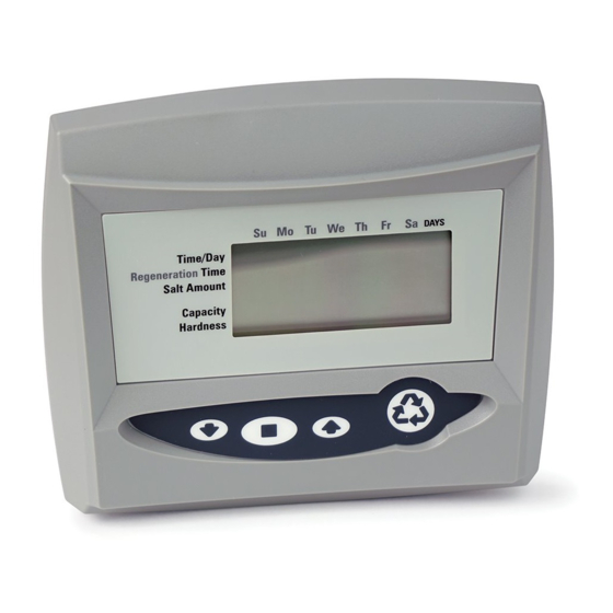
LCD Display SU MO TU WE TH FR SA Time/Day Regeneration Time Salt Amount Front Capacity x100 Hardness Lbs/ft³ Down Button Manual Regen Button No-Salt Detector Set Button Up Button (Chlorine Generator) AC Adapter Connection (low voltage) Multi Single Tank Input Back Lockout &… -
Page 6
Location Selection Location of a water conditioning system is important. The following conditions are required: • Level platform or floor. • Room to access equipment for maintenance and adding regenerant (salt) to tank. • Ambient temperatures over 34 F (1 C) and below F (49 •… -
Page 7: Outdoor Locations
Outdoor Locations When the water conditioning system is installed outdoors, several items must be considered. • Moisture – The valve and control are designed for use in NEMA 3 locations. Falling water should not affect performance. The system is not designed to withstand extreme humidity or water spray from below.
-
Page 8
Unconditioned water in Conditioned water out Figure 6 Typical Plumbing for Twin Tank Systems. Unit in Service Unit in Bypass Figure 7… -
Page 9: Location Selection
Installation All plumbing must conform to local codes. The two flowing from a heat source to the conditioners is to tanks should be plumbed to an interconnecting install an expandable accumulator tank before the hot manifold, Figure-6. It is highly recommended that water heater.
-
Page 10: Brine Line Connection
of the loop is level with the drain line connection. This will provide an adequate siphon trap.Where a drain empties into an overhead sewer line, a sink-type trap must be used. Secure the end of the drain line to prevent it from moving (Figure-11). Brine Line Connection It is recommended that separate brine lines be used for each tank.
-
Page 11: Electrical Connection
Electrical Connection Caution: This valve and control are for dry location use only unless used with a Listed Class 2 power supply suitable for outdoor use. The 764 Series control operates on a 12-volt alternating current power supply. This requires use of the Pentair Water supplied AC adapter.
-
Page 12: Disinfection Of Water Conditioning Systems
Disinfection of Water Conditioning Systems The materials of construction in the modern water Calcium Hypochlorite conditioning system will not support bacterial growth, Calcium hypochlorite, 70% available chlorine, is nor will these materials contaminate a water supply. available in several forms including tablets and During normal use, a conditioner may become fouled granules.
-
Page 13: System Operation
System Operation Treated Water (Downflow) Repressurization – Cycle C4 Untreated water is conditioned as it flows through Pressure is balanced in the valve before continuing the resin bed and up the riser. the regeneration. Backwash (Upflow) – Cycle C1 Fast Rinse (Downflow) — Cycle C5 Flow is reversed by the control valve, directed Water passes through the resin bed and up down the riser, up through the resin bed and sent…
-
Page 14: Camshaft Cycle Positions
Camshaft Cycle Positions Valve Disc Location/Function The front end of the camshaft has an indicator cup. The 6 Backwash/Drain cup has slots in the outer edge and cycle numbers on 5 Rinse Drain the inside face (Figure-12). Wiring Remove the cover and look over the top of the 764 Breakouts control to view the cycle numbers.
-
Page 15: Display Icons & Cursors
Display Icons & Cursors WE TH FR SA DAYS SU MO TU Time/Day Regeneration Time Salt Amount If your Logix 764 controller was purchased as a filter control, the overlay will show: Time/Day, Capacity x100 Backwash Time, Backwash Length Hardness and Capacity.
-
Page 16: Keypad — Buttons
24. Cycle (C). The number displayed by #23 is the P r o g r a m m i n g C o n v e n t i o n s current cycle in the regeneration sequence. The 700 series controller is programmed using the 25.
-
Page 17: Placing Water Conditioning System Into Operation
When water flows steady from the faucet, the they differ from previous valve instructions. tank(s) are purged. Note: All Logix 764 controls will be shipped in the 4. Turn off the faucet then turn off the incoming water service (treated water) position. Do not rotate the supply.
-
Page 18
These cam movements may take up to 5 minutes. T a b l e 2 Resin Volume — 0.25 ft and 5 Liter Steps Resin Volume Tank Dia Injector Metric (inches) 0.25 0.50 0.75 1.00 1.25 1.50 1.75 2.00 2.25 2.50 2.75 3.00… -
Page 19: Level L Programming — 764 Control With 255 Valve, 8 Cycle Conditioner
Level l Programming — 764 Control with 255 Valve, 8 Cycle Conditioner Screen Buttons to Description Range Press SU MO TU WE TH FR SA DAYS Time/Day Regeneration Time Cubic feet: 0.25 then Resin Volume Salt Amount Select correct resin volume press Capacity 3.00…
-
Page 20: Quick Cycling The Control 255L And 255P
255 Alternating and parallel tank systems have one A. Quick cycle the control to the C2 regenerant Logix 764 control that is mounted on tank 1. Tank 2 has draw/slow rinse position . a blank faceplate and the valve is controlled by the Logix 764 control on tank 1.
-
Page 21: Quick Cycling The Control For 255A Systems
10. Finally, turn on a faucet plumbed after the water conditioner. Run the faucet until the water runs clear. 255 Alternating tank systems have one Logix 764 control that is mounted on tank 1. Tank 2 has a blank 11. Add the appropriate amount of regenerant to faceplate and the tank 2 valve is controlled by the Logix regenerant tank.
-
Page 22
Tank 2 moves through cycles: 4. Turn on a faucet plumbed after the water conditioner. Run the faucet until the water runs C1 — Backwash clear. As water enters the tank, air will be forced out 5. Add water to the regenerant tanks. the drain line. -
Page 23: In Service Display
• Time of Day: Includes PM indicator. Can be set to Note: The faucet icon is displayed on all the Logix 764 display as a 24-hour clock. See Level ll controls when there is flow. The 764 will show the…
-
Page 24: Level Ii Programming — P Values
Depends on value entered in P16 (not used for Capacity alternating mode) 0 = internal magnum NHWB, 1, 6 = 1″ Autotrol turbine 2, 7 = 2″ Autotrol turbine 3 = User defined K-factor Flow sensor select 4 = User defined Pulse Equivalent 5 = Internal Magnum HWB Values 6 &…
-
Page 25: Programming The Lockout Feature
Programming the Lockout Feature All Level I parameters can be locked out when the control is in Level ll programming. Simply press the REGEN button during Level ll programming and a Lock Icon will appear indicating that the specific setting has been locked out.
-
Page 26
Salt Setting The default P6 salt setting is set at 9 lbs/cu ft. Under normal circumstances this setting will provide the correct system capacity. This setting may be adjusted to change the exchange capacity. T a b l e 4 E x c h a n g e C a p a c i t y 2 5 5 V a l v e Exchange Exchange… -
Page 27: Level Lll Cycle Programming — C Values
Level lll Cycle Programming – C Values Several Level III program parameters can be adjusted to fine-tune a valve operation for non-standard Note: The control must by in the treated water position applications. Typically these parameters will not need to to change settings.
-
Page 28: Level Iv Viewing History — H Values
Level IV Viewing History — H Values Historical information can be viewed by pressing the SET and DOWN buttons simultaneously, with the 764 control in the home position. Release both buttons when the control displays an “H” value. Press the UP or DOWN buttons to navigate to each setting.
-
Page 29: Program Reset
Program Reset The 764 control can be reset to original factory parameters when viewing the H0 parameter. Press and hold the SET button for three seconds while H0 is displayed. Release the button. All settings except for Time of Day and Day of Week will be reset. The 764 Logix control will now display the valve and system type.
-
Page 30: Manual Regeneration Options
Manual Regeneration Options Refill First Option Double Immediate Manual Regeneration Refill First is only available for single tank “L” and twin Back-to-Back manual regenerations are initiated by parallel “P” models. pressing and holding the REGEN button for three seconds while the control is in the regenerating mode. The 764 control allows users to select when the refill A solid x2 icon next to the regeneration icon will appear cycle occurs.
-
Page 31: Regeneration Modes For Parallel Systems
Regeneration Modes for Parallel Systems Parameter P16 is used to determine the method for demand initiated regeneration. Four regeneration modes are possible. • P16 = 0, Delayed Regeneration with a Smart T a b l e 7 T P 1 6 = 0 Reserve Regenerations will start only at the Time of Flow Continuous…
-
Page 32: Wiring Diagrams
Wiring Diagrams Connecting the Logix 764 Twin Alternating or Parallel Controls The twin sensor and extension cables are used for twin unit parallel and alternating applications. Four standard connections are required for operation; the power transformer, the flow sensor, motor/optical sensor, and the connection between tank 1 and tank 2 controls.
-
Page 33
Connecting the Logix 764 Multi Single Tank Control Logix 764 control on Tank 1 Repeat for all remaining tanks Logix 764 control Logix 764 control on Tank 2 on Tank 3 Note: Cable PN 3020228 sold separately. Figure 17… -
Page 34: Parts Lists
Parts Lists 255 Exploded View & Parts List…
-
Page 35
Part Part Item Description Qty. Item Description Qty. Number 3014650 764 Series Control 1000269 Injector Cap with O-Ring 0.33 Refill Ball & Cone Type Flow 1244650 Valve Assembly w/o Flow Controls 1243511 Controller 1235340 Top Plate Air Check Kit 1234170 Screw, Top Plate 1032416 3/8 –inch male 1235341… -
Page 36: Bypass Valve And Turbine Adapter
Bypass Valve and Turbine Adapter Bypass Inlet Drain Outlet Turbine Adapter Part Item Description Qty. 1040769 256 Bypass 1034301 Kit, 256 Rotor Replacement 1034302 Kit, 256 Rotor Seals (2), O-Rings (4), Clips (2) 1032347 Assy, Adapter 1-inch Turbine included with 255A, P and L valves N o t S h o w n…
-
Page 37: Manifold Kits
Manifold Kits Part Part Description Qty. Description Qty. 3019931 255 Manifold Kit, 1-in, PVC w/256 Bypass 3019932 764 Manifold Kit, 1-in PVC w/No Bypass Kit Includes: Kit Includes: Pipe Fitting, Tee, 1-in Pipe Fitting, Tee, 1-in Pipe Fitting, Elbow, Sch 40, 1-in, PVC Pipe Fitting, Elbow, Sch 40, 1-in, PVC Pipe Fitting, Sch 40, 1-in, Str Elbow, PVC Pipe Fitting, Sch 40, 1-in, Str Elbow, PVC…
-
Page 38: Troubleshooting
Troubleshooting 764 Controller – Error Codes & 255 ”L” with Check Salt Light Problem Possible Cause Solution ERR 1 is displayed. Program settings have been corrupted. Press any key and reprogram Level I settings. Controller on tank 1 does not know the Wait for two minutes for the controller to return to position of the camshaft.
-
Page 39
System Troubleshooting Problem Possible Cause Solution a. Uncontrolled refill flow rate. a. Remove refill flow control to clean ball and seat. b. Air Leak in regenerant line to air b. Check all connections in regenerant line check. for leaks. Regenerant tank overflow. c. -
Page 40
2008 Pentair Residential Filtration, LLC © P/N 3019624 Rev B…
(Ocr-Read Summary of Contents of some pages of the GE Logix 764 Document (Main Content), UPD: 08 September 2023)
-
40, GE Logix 764 38 Regeneration Modes for Parallel Systems Parameter P16 is used to determine the method for demand initiated regeneration. Four regeneration modes are possible. • P16 = 0, Delayed Regeneration with a Smart Reserve Regenerations will start only at the Time of Regeneration entered in P2. A tank is regenerated if the capacity remaining in that tank is below the minimum required capacity needed to meet the next days calculated water usage requiremen…
-
3, Table of Contents Table of Contents . . . . . . . . . . . . . . . . . . . . . . . . . . . . . . . . . . . . . . . . . . . . . . . . . . . . . . . . . . . . 1 Safety Information . . . . . . . . . . . . . . . . . . . . . . . . . . . . . . . . . . . . . . . . . . . . . . . . . . . . . . . . . . . 3 Installation Profile Summary . . . . . . . . . . . . . . . . . . . . . . . . . . . . . . . . . . . . . . . . . . . . . . . . . .4 How To Use This Manual . . . . . . . . . .…
-
24, GE Logix 764 22 Figure 26 B1B2 12 3 4 56 Pilot Screen Untreated Water Treated Water Plugged Injector Pilot Valves Inlet Tank Top Drain 1 Tank Bottom Outlet 2 Backwash Water Regenerant Magnum 3-Cycle Filter: No Unfiltered Water Bypass Service Cycle Aux. Pilot Output Media Tank 4 3 Pilot Drain No Unfiltered Water Bypass 654321B2B1 Service Backwash Fast Rinse OPEN OPEN OPENCLSD CLSDCLSDCLSD OPEN OPEN CL…
-
8, 6 Figure 2 764 Controller Identification Figure 3 Remote Start/Multi-Tank Lockout Cable Figure 4 Twin Sensor Cable Figure 5 Twin Cable Extension Location Selection Location of a water conditioning system is important. The following conditions are required: • Level platform or floor. • Room to access equipment for maintenance and adding regenerant (salt) to tank. • Ambient temperatures over 34 o F (…
-
19, 17 Camshaft Cycle Positions The front end of the camshaft has an indicator cup. The cup has slots in the outer edge and cycle numbers on the inside face. Remove the cover and look over the top of the 764 control to view the cycle numbers. The number in the opening, (Figure 20) indicates the current cycle position of the control valve. The corresponding slot for the number is positioned at the optical sensor, which is rotated approximately …
-
60, 58 Installation Adapter Kits Adapters-Magnum IT Item Part Number Description Not Shown 1040782 Magnum IT Adapter Kit — Brass NPT for inlet, outlet, drain Not Shown 1040783 Magnum IT Adapter Kit — Brass BSP for inlet, outlet, drain Not Shown 1040784 Magnum IT Adapter Kit — CPVC for inlet, outlet, drain Not Shown 1040786 2-inch NPT Brass Adapter with Zinc Diecast Nut (24 Pack) Not Shown 1040787 2-inch BSP Brass Adapter with Zinc Diecast…
-
36, 34 Programming the Lockout Feature All Level I parameters can be locked out when the control is in Level ll programming. Simply press the REGEN button during Level ll programming and a Lock Icon will appear indicating that the specific setting has been locked out. When locked out, the setting cannot be adjusted. To disable the Lock Out Feature, press the REGEN button when in Level ll. The lock icon will not b…
-
16, 14 Figure 18 Magnum Valve Installation Guide (Top Mount) Before the installation of the internal distribution system and loading of the media into the tank, the Magnum valve must be temporarily installed onto the tank. This will ensure that correct alignment of the inlet and outlet piping once the internals are installed and the media is loaded onto the tank. 1. Install tank O-ring into the tank adapter section at the bott…
-
56, 54 Magnum Valve Cartridges NOTE:Items 1 and 3 are identical valve cartridges. Item Part Number Description 1 1000366 Drain Valve Cartridge, Single Seat — Spring Assisted 2 1000365 Rinse Valve Cartridge, Double Seat — Spring Assisted 3 1000366 No Hardwater Bypass Valve Cartridge, Single Seat — Spring Assisted 4 1000336 Hardwater Bypass Cap 5 1000317 Inlet Valve Cartridge, Double Seat — No Spring Assist 6 1010157 O-Ring 7 1010158 O-Ri…
-
43, GE Logix 764 41 Troubleshooting 764 Controller – Error Codes & 298 ”L” with Check Salt Light Problem Possible Cause Solution ERR 1 is displayed. Program settings have been corrupted. Press any key and reprogram Level I settings. ERR 3 is displayed. Controller on tank 1 does not know the position of the camshaft. Camshaft should be rotating to find Home position. Wait for two minutes for the cont…
-
28, 26 Placing Water Conditioning System Into Operation After you have performed the installation steps, the conditioner will need to be placed into operation. Follow these steps carefully, (pages 26 to 31) as they differ from previous Autotrol valve instructions. Note: All Logix 764 controls will be shipped in the service (treated water) position. Check to see that the camshaft is aligned to service position. See Figure 7 on page 8 for proper control/camshaft alignment…
-
41, 39 Wiring Diagrams Connecting the Logix 764 Twin Alternating or Parallel Controls The twin sensor and extension cables are used for twin unit parallel and alternating applications. Four standard connections are required for operation; the power AC adapter, the flow sensor, motor/optical sensor, and the connection between tank 1 and tank 2 controls. Figure 31 outlines these standard features. Fig…
-
15, 13 General Installation Information Please review the following items thoroughly to ensure an efficient and safe installation of the water treatment system. The typical installation line drawings for the Magnum valves are shown in Figure 19. WARNING: Filter media may need to be properly conditioned before the filter is placed into full operation. Consult the original equipment manufacturer for proper procedure. Operating…
-
52, 50 Drain Line Flow Control Table 12 Drain Line Flow Controls (5 gpm — 40 gpm) NOTE: Drain Line Flow Controls above 40 gpm require external control installed in drain line. Part Number Flow Control Disk Insert 1 Insert 2 Insert 3 Insert 4 gpm m 3 /h 1040720 5 1.135 Blue Black Black Black 1040721 6 1.362 Red Black Black Black 1040722 7 1.589 Brown Black Black Black 1040723 8 1.816 Green Black Black Black 1040724 9 2.043 White Black Black Black 1040725 10 2…
-
55, 53 Replacement Components: Logix Magnum Conditioner/Filters Camshaft and Pilot Valve Assembly * Single tank camshaft allows the unit to go into Service during Refill. 1 2 3 4 5 6 7 8 2 Table 14Assembly Parts Item Number Part Number Description 1 1005953 Screw, Pillow Block 2 1000589 Pillow Block 3* 1001751 1267726 Logix Multi Tank Camshaft, “A”, “P”, or “L” Types Logix Single Tank Magnum Camshaft, “L” Types …
-
9, 7 Outdoor Locations When the water conditioning system is installed outdoors, several items must be considered. • Moisture – The valve and control are rated for NEMA 3 locations. Falling water should not affect performance. The system is not designed to withstand extreme humidity or water spray from below. Examples are: constant heavy mist, near corrosive environment, or upwards spray from sprinkler. Caution: …
3.0
Rated 3 out of 5
3 out of 5 stars (based on 1 review)
Your overall rating
PENTAIR AUTOTROL LOGIX 764 (01) PDF MANUAL
Click here to download PENTAIR AUTOTROL LOGIX 764 (01) PDF MANUAL
PENTAIR AUTOTROL LOGIX 764 (01) PDF MANUAL
FREE ENGLISH PDF
OPERATING INSTRUCTIONS
USER GUIDE – USER MANUAL
OWNER GUIDE – OWNER MANUAL
REFERENCE GUIDE – REFERENCE MANUAL
INSTRUCTION GUIDE – INSTRUCTION MANUAL
Your overall rating
- YouTube
PENTAIR AUTOTROL LOGIX 764 (01) PDF MANUAL
PENTAIR AUTOTROL LOGIX 764 (01) PDF MANUAL
Table of Contents for Logix 764:
-
54 Es
-
22 En
-
59 Es
-
63 Es
-
46 Es p.48 p.49 p.50 p.50 p.51 p.52 p.52 p.54 p.55 p.55 p.56 p.57 p.57 p.57 p.57 p.57 p.57 p.58 p.58 p.58 p.59 p.59 p.59 p.60 p.60 p.60 p.60 p.61 p.61 p.61 p.61 p.62 p.62 p.63 p.63 p.64
-
50 Es
-
13 En
-
28 Fr
-
77 De
-
58 Es
-
42 Fr
-
Operation Manual Twing Alternating and Twin Parallel Manuel d’utilisation Systèmes Duplex alternés et parallèles Manual de Puesta en Marcha Sistema Duplex Alternante o Paralelo Steuerung Bedienungshandbuch Duplex Wechselbetrieb -und Parallelanlagen 2 24 46 66 LLOOGGIIXX 776644 255 • 278 (Performa CV) • 298 (Magnum IT) De Es Fr En
-
40 Fr
-
81 De
-
20 En
Questions, Opinions and Exploitation Impressions:
You can ask a question, express your opinion or share our experience of Logix 764 device using right now.