ВЛАДЕЛЬЦАМ
РУКОВОДСТВА ДЛЯ ВЛАДЕЛЬЦА
Ознакомьтесь со всеми функциями и эксплуатационными особенностями автомобиля Lexus в онлайн-версии руководства.
РУКОВОДСТВА ДЛЯ ВЛАДЕЛЬЦА LEXUS UX
РУКОВОДСТВА ДЛЯ ВЛАДЕЛЬЦА LEXUS NX
РУКОВОДСТВА ДЛЯ ВЛАДЕЛЬЦА LEXUS RX
РУКОВОДСТВА ДЛЯ ВЛАДЕЛЬЦА LEXUS GX
РУКОВОДСТВА ДЛЯ ВЛАДЕЛЬЦА LEXUS LX
РУКОВОДСТВА ДЛЯ ВЛАДЕЛЬЦА LEXUS ES
РУКОВОДСТВА ДЛЯ ВЛАДЕЛЬЦА LEXUS LS
РУКОВОДСТВА ДЛЯ ВЛАДЕЛЬЦА LEXUS LC
ПОЧЕМУ ВАЖНО ПРОХОДИТЬ ОБСЛУЖИВАНИЕ У ОФИЦИАЛЬНОГО ДИЛЕРА?
-
ЭКСПЕРТНЫЙ ПОДХОД
Профессионализм специалистов достигается благодаря специальной системе обучения на базе ООО «Тойота Мотор»: все сотрудники дилерского центра проходят тренинги и регулярные переаттестации.
-
СТАНДАРТЫ ГОСТЕПРИИМСТВА
Ваша уверенность в качестве услуг и премиальном обслуживании – основной приоритет, поэтому мы гарантируем максимальный комфорт при посещении дилерских центров.
-
ВЫГОДНЫЕ РЕШЕНИЯ
Программы Lexus позволяют экономить на обслуживании автомобиля и при этом гарантированно получить качественный сервис, продлевающий безупречную надежность вашего автомобиля.
инструкцияLexus IS 300 (2018)

IS350 AWD/IS350/IS300 AWD/IS300_U(OM53E34U)
Pictorial index
Search by illustration
1
For safety
and security
Make sure to read through them
2
Instrument cluster
How to read the gauges and meters, the variety of
warning lights and indicators, etc.
3
Operation of each
component
Opening and closing the doors and windows,
adjustment before driving, etc.
4
Driving
Operations and advice which are necessary for driving
5
Lexus Display
Audio system
Operating the Lexus Display Audio system
6
Interior features
Usage of the interior features, etc.
7
Maintenance
and care
Caring for your vehicle and maintenance procedures
8
When trouble
arises
What to do in case of malfunction or emergency
9
Vehicle
specifications
Vehicle specifications, customizable features, etc.
10
For owners
Reporting safety defects for U.S. owners, and seat belt
and SRS airbag instructions for Canadian owners
Index
Search by symptom
Search alphabetically
Посмотреть инструкция для Lexus IS 300 (2018) бесплатно. Руководство относится к категории автомобили, 1 человек(а) дали ему среднюю оценку 6.1. Руководство доступно на следующих языках: английский. У вас есть вопрос о Lexus IS 300 (2018) или вам нужна помощь? Задайте свой вопрос здесь
- 2018 IS350, IS300 Owner’s Manual (OM53E34U)
Главная
Не можете найти ответ на свой вопрос в руководстве? Вы можете найти ответ на свой вопрос ниже, в разделе часто задаваемых вопросов о Lexus IS 300 (2018).
Как перевести мили в километры?
1 миля равна 1,609344 километрам, а 1 километр — 0,62137119 милям.
Где я могу узнать идентификационный номер транспортного средства Lexus?
Место размещения идентификационного номера транспортного средства зависит от марки и типа транспортного средства. Номер может быть выбит на раме транспортного средства или указан на номерном знаке. Чтобы узнать место расположения идентификационного номера транспортного средства лучше всего ознакомиться с руководством по эксплуатации Lexus IS 300 (2018).
Что такое идентификационный номер транспортного средства (VIN)?
Идентификационный номер транспортного средства — уникальный для каждого транспортного средства идентификационный номер. Аббревиатура VIN расшифровывается как «Vehicle Identification Number» (Идентификационный номер транспортного средства).
Когда транспортному средству Lexus требуется техническое обслуживание?
Регулярное техническое обслуживание необходимо всем транспортным средствам. С информацией о том, как часто необходимо проходить техническое обслуживание и чему именно стоит уделять особое внимание можно ознакомиться в инструкции по техническому обслуживанию. Как правило, транспортное средство требует технического обслуживания каждые 2 года или 30 000 километров пробега.
Когда следует заменять тормозную жидкость на Lexus?
Тормозную жидкость рекомендуется менять каждые два года.
В чем разница между топливом E10 и E5?
В топливе E10 содержится до десяти процентов этанола, в то время как в E5 содержится менее пяти процентов. Соответственно, топливо E10 менее вредит окружающей среде.
Одна или несколько дверей не открываются изнутри. Что мне делать?
Скорее всего, замок оснащен защитой от детей и поэтому не может быть открыт изнутри. Процедура открытия замка с защитой от детей зависит от марки и типа замка.
Автомобильный радиоприемник не включается, что делать?
Если автомобильный радиоприемник не включен, на него не будет подаваться питание. Убедитесь, что красный провод подключен к контактному источнику питания, а желтый провод — к источнику питания постоянной мощности.
Инструкция Lexus IS 300 (2018) доступно в русский?
К сожалению, у нас нет руководства для Lexus IS 300 (2018), доступного в русский. Это руководство доступно в английский.
Не нашли свой вопрос? Задайте свой вопрос здесь
Need a manual for your Lexus IS 300 (2003)? Below you can view and download the PDF manual for free. There are also frequently asked questions, a product rating and feedback from users to enable you to optimally use your product. If this is not the manual you want, please contact us.
Is your product defective and the manual offers no solution? Go to a Repair Café for free repair services.
Manual

Rating
Let us know what you think about the Lexus IS 300 (2003) by leaving a product rating. Want to share your experiences with this product or ask a question? Please leave a comment at the bottom of the page.
Are you satisfied with this Lexus product?
Yes No
Be the first to rate this product
0 votes
Frequently Asked Questions
Our support team searches for useful product information and answers to frequently asked questions. If you find an inaccuracy in our frequently asked questions, please let us know by using our contact form.
My car has a timing chain, what is the replacement interval for it? Verified
With normal use, a timing chain should last the entire lifespan of the car and does not need to be replaced.
This was helpful (2409)
I can’t open one or more of the doors from the inside, why is that? Verified
The child safety lock is probably activated. This can often be deactivated with a mechanism in the door.
This was helpful (761)
How often should I change my oil? Verified
Almost every car has its own exact guideline, but in general it’s wise to change your oil every 10.000 to 15.000 kilometers or once every year. Polluted oil can cause serious damage to the engine over time.
This was helpful (643)
When should the airbag on the side of the passenger seat be switched off? Verified
When driving with a child in a car seat on the passenger seat, the airbag on that side should be switched off. This is also advisable for children up to 12 years old that take place in the passenger seat. This is to prevent injuries in case of an accident.
This was helpful (582)
The car keys won’t unlock the car from a distance anymore, why is that? Verified
Car keys that can unlock from a distance generally work with a battery. When it runs out, the key won’t work anymore. Replace the battery and try again.
This was helpful (575)
Will a lower tire pressure result in more grip when driving in the snow? Verified
No, although the tires will have more surface in contact with the road with a lower pressure, it will nevertheless result in less stability. Always drive with the correct tire pressure!
This was helpful (330)
I filled my car with the wrong fuel, what should I do? Verified
Do not drive! It does not matter wether you put diesel in a gasoline car or gasoline in a diesel car. In both cases it can cause damage to the enige and/or other parts of the car. Contact roadside assistance.
This was helpful (219)
Where can I find the VIN number of my car? Verified
This can vary between brands and models, but on many cars the VIN number can be found on the door jamb, under the hood or on the metal flooring at the front seat.
This was helpful (184)
How often should I replace the blades on my windscreen wipers? Verified
It’s advisable to replace the wiper blades at least once a year. Signs that the blades need to be replaced are streaking, leaving a haze, making noise or the rubber coming off.
This was helpful (160)
How many miles is one kilometer? Verified
One kilometer equals 0,621 mile. Ten kilometers makes 6,21 miles. One mile equals 1,609 kilometer. Ten miles makes 16,09 kilometers.
This was helpful (137)
What is the VIN number? Verified
VIN stands for Vehicle Identification Number and is a unique number that every car has. This makes the car indentifyable after for example a crash or in the case of a recall. It also allows a car to be identified in the case the number plates are missing.
This was helpful (135)
Can I use the windscreen wipers while there is ice on the windscreen? Verified
No, this is not advisable. Ice is sharp and can damage the rubber on the wiper blades.
This was helpful (132)
What is the service interval for my Lexus? Verified
Lexus advises to have your car checked every 15.000 kilometers or every year at a certified dealership.
This was helpful (6)
![]()
IN-1
INTRODUCTION — HOW TO USE THIS MANUAL
HOW TO USE THIS MANUAL
IN00U-90
GENERAL INFORMATION
1.INDEX
An INDEX is provided on the first page of each section to guide you to the item to be repaired. To assist you in finding your way through the manual, the Section Title and major heading are given at the top of every page.
2.GENERAL DESCRIPTION
At the beginning of each section, a General Description is given that pertains to all repair operations contained in that section.
Read these precautions before starting any repair task.
3.TROUBLESHOOTING
TROUBLESHOOTING tables are included for each system to help you diagnose the problem and find the cause. The fundamentals of how to proceed with troubleshooting are described on page IN-22 .
Be sure to read this before performing troubleshooting.
4.PREPARATION
Preparation lists the SST (Special Service Tools), recommended tools, equipment, lubricant and SSM (Special Service Materials) which should be prepared before beginning the operation and explains the purpose of each one.
5.REPAIR PROCEDURES
Most repair operations begin with an overview illustration. It identifies the components and shows how the parts fit together.
Example:
|
Filler Cap |
||||||||||||||||||||||
|
Float |
Clevis Pin |
|||||||||||||||||||||
|
Reservoir Tank |
Gasket |
Clip |
||||||||||||||||||||
|
Boot |
||||||||||||||||||||||
|
Grommet |
||||||||||||||||||||||
|
Slotted Spring Pin |
||||||||||||||||||||||
|
12 (120, 9) |
||||||||||||||||||||||
|
Clevis |
||||||||||||||||||||||
|
15 (155, 11) |
||||||||||||||||||||||
|
Snap Ring |
||||||||||||||||||||||
|
Washer |
Lock Nut |
|||||||||||||||||||||
|
Push Rod |
||||||||||||||||||||||
|
Piston |
||||||||||||||||||||||
|
Cylinder |
||||||||||||||||||||||
|
N´m (kgf´cm, ft´lbf) |
: Specified torque |
|||||||||||||||||||||
|
Non-reusable part |
N17080 |
|||||||||||||||||||||
2005 LEXUS IS300 (RM1140U)

IN-2
INTRODUCTION — HOW TO USE THIS MANUAL
The procedures are presented in a step-by-step format:
The illustration shows what to do and where to do it.
The task heading tells what to do.
The detailed text tells how to perform the task and gives other information such as specifications and warnings.
Example:
Illustration: what to do and where
Task heading : what to do
21. CHECK PISTON STROKE OF OVERDRIVE BRAKE
(a)Place SST and a dial indicator onto the overdrive brake piston as shown in the illustration.
SST 09350-30020 (09350-06120)
|
Set part No. |
Component part No. |
Detailed text : how to do task
(b)Measure the stroke applying and releasing the compressed air (392 785 kPa, 4 8 kgf/cm2 or 57 114 psi) as shown in the illustration.
Piston stroke: 1.40 1.70 mm (0.0551 0.0669 in.)
Specification
This format provides the experienced technician with a FAST TRACK to the information needed. The upper case task heading can be read at a glance when necessary, and the text below it provides detailed information. Important specifications and warnings always stand out in bold type.
6.REFERENCES
References have been kept to a minimum. However, when they are required you are given the page to refer to.
7.SPECIFICATIONS
Specifications are presented in bold type throughout the text where needed. You never have to leave the procedure to look up your specifications. They are also found in Service Specifications section for quick reference.
|
8. |
CAUTIONS, NOTICES, HINTS: |
|
CAUTIONS are presented presented in bold type, and indicate there is a possibility of injury to you or |
|
|
other people. |
|
|
NOTICES are also presented in bold type, and indicate the possibility of damage to the components |
|
|
being repaired. |
|
|
HINTS are separated from the text but do not appear in bold. They provide additional information to |
|
|
help you perform the repair efficiently. |
|
|
9. |
SI UNIT |
The UNITS given in this manual are primarily expressed according to the SI UNIT (International System of Unit), and alternately expressed in the metric system and in the English System.
Example:
Torque: 30 N´m (310 kgf´cm, 22 ft´lbf)
2005 LEXUS IS300 (RM1140U)
IN-3
INTRODUCTION — IDENTIFICATION INFORMATION
IDENTIFICATION INFORMATION
IN04P-27
VEHICLE IDENTIFICATION AND
ENGINE SERIAL NUMBER
|
1. |
VEHICLE IDENTIFICATION NUMBER |
||
|
The vehicle identification number is stamped on the vehicle |
|||
|
identification number plate and the certification label, as shown |
|||
|
A |
in the illustration. |
||
|
A: Vehicle Identification Number Plate |
|||
|
B: Certification Label |
|||
|
B |
|||
|
B12091 |
|||
|
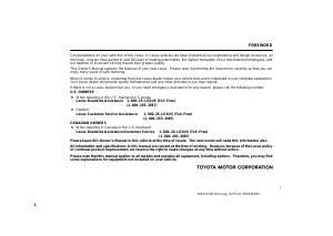
2. |
ENGINE SERIAL NUMBER |
||
|
2JZ-GE |
|||
|
The engine serial number is stamped on the engine block, as |
|||
|
shown in the illustration. |
B12487
2005 LEXUS IS300 (RM1140U)
IN-4
INTRODUCTION — REPAIR INSTRUCTIONS
FI1066
Seal Lock Adhesive
Z11554
REPAIR INSTRUCTIONS
IN0DC-15
GENERAL INFORMATION
BASIC REPAIR HINT
(a)Prevent damage and maintain vehicle cleanliness by protective covering on the fender, seat and floor.
(b)During disassembly, line up parts in the order they were removed to facilitate reassembly.
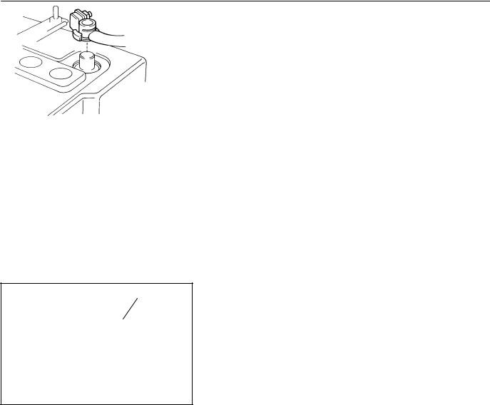
(c)Installation and removal of battery terminal:
(1)Before performing electrical work, disconnect the negative (-) terminal cable from the battery.
(2)If it is necessary to disconnect the battery for inspection or repair, first disconnect the negative (-) terminal cable.
(3)To prevent damage to the battery terminal when disconnecting the terminal cable, loosen the cable nut and raise the cable straight up. Do not twist or pry the cable off.
(4)Clean the battery terminals and cable ends with a clean shop rag. Do not scrape them with a file or other abrasive objects.
(5)Install the cable ends to the battery terminals after loosening the nut, and tighten the nut after installation. Do not use a hammer to tap the cable ends onto the terminals.
(6)Be sure the cover for the positive (+) terminal is properly in place.
(d)Check hose and wiring connectors to make sure that they are connected securely and correctly.
(e)Non-reusable parts:
(1)Always replace cotter pins, gaskets, O-rings, oil seals, etc. with new ones.
(2)Non-reusable parts are indicated in component illustrations by the º º symbols.
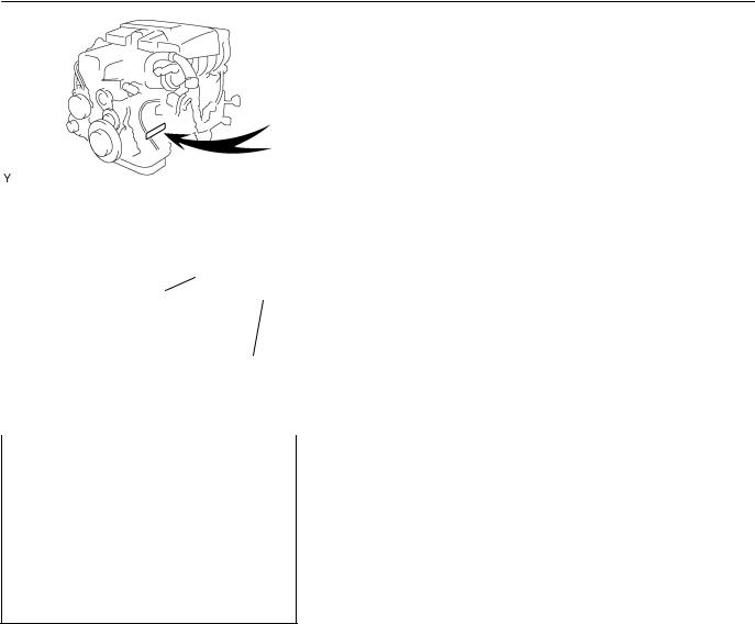
(f)Precoated parts
Precoated parts are bolts, nuts, etc. that are coated with a seal lock adhesive at the factory.
(1)If a precoated part is retightened, loosened or move caused to in any way, it must be recoated with the specified adhesive.
(2)When reusing precoated parts, clean off the old adhesive and dry with compressed air. Then apply new seal lock adhesive to the bolt, nut or threads.
2005 LEXUS IS300 (RM1140U)
IN-5
INTRODUCTION — REPAIR INSTRUCTIONS
(3)Precoated parts are indicated in component illustrations by the º º symbols.
(g)When necessary, use a sealer on gaskets to prevent leaks.
(h)Carefully observe all specifications for bolt tightening torques. Always use a torque wrench.
(i)Use of special service tools (SST) and special service materials (SSM) may be required, depending on the nature of the repair. Be sure to use SST and SSM where specified and follow the proper work procedure. A list of SST and SSM can be found in the Preparation section in this manual.
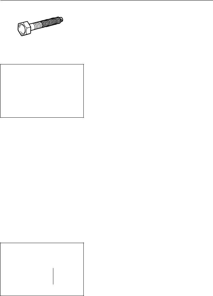
|
Medium Current Fuse and High Current Fuse |
(j) When replacing fuses, be sure the new fuse has the cor- |
|
|
rect amperage rating. DO NOT exceed the rating or use |
||
|
Equal Amperage Rating |
||
|
one with a lower rating. |
BE1367
|
Illustration |
Symbol |
Part Name |
Abbreviation |
|
FUSE |
FUSE |
||
|
MEDIUM CURRENT FUSE |
M-FUSE |
||
|
HIGH CURRENT FUSE |
H-FUSE |
||
|
FUSIBLE LINK |
FL |
||
|
CIRCUIT BREAKER |
CB |
||
|
V00076 |
|||
|
2005 LEXUS IS300 (RM1140U) |
IN-6
INTRODUCTION — REPAIR INSTRUCTIONS
WRONG CORRECT
IN0253
WRONG CORRECT
IN0252
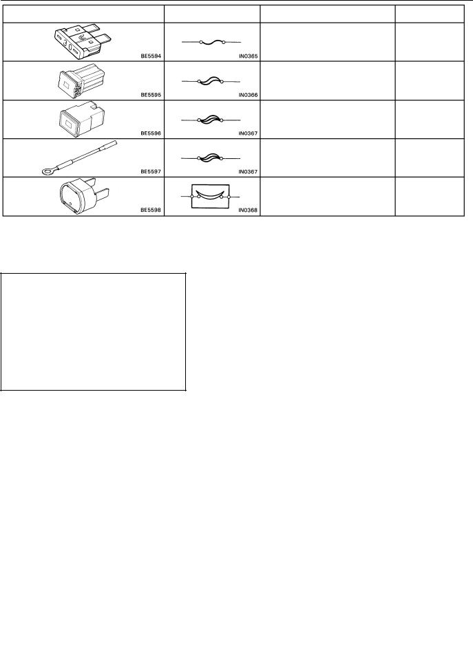
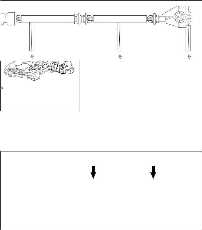
(k)Care must be taken when jacking up and supporting the vehicle. Be sure to lift and support the vehicle at the proper locations (see page IN-8 ).
Release the parking brake on a level surface and shift to in Neutral or N range.
When jacking up the front wheels of the vehicle, at first place chocks behind the rear wheels.
When jacking up the rear wheels of the vehicle, place chocks in front of the front wheels.
When jacking up only the front or rear wheels, set rigid racks and place chocks on front and behind the wheels in contact with the ground.
After the vehicle is jacked up, be sure to support it on rigid racks. It is extremely dangerous to do any work on a vehicle raised on a jack alone, even for a small job that can be finished quickly.
(l)Observe the following precautions to avoid damage to the
following parts:
(1)Do not open the cover or case of the ECU unless absolutely necessary. (Static electricity transmitted through human touch may destroy the IC.)
(2)To disconnect vacuum hoses, pull off the end of the hose, not the middle.
(3)To pull apart electrical connectors, pull on the connector itself, not the wires.
(4)Be careful not to drop electrical components, such as sensors or relays. If they are dropped on a hard floor, they should be replaced and not reused.
(5)When steam cleaning an engine, protect the electronic components, air filter and emission-related components from water.
(6)Never use an impact wrench to remove or install temperature switches or temperature sensors.
(7)When checking continuity at the wire connector, insert the tester probe carefully to prevent terminals from bending.
(8)When using a vacuum gauge, never force the hose onto a connector that is too large. Use a step-down adapter for adjustment. Once the hose has been stretched, it may leak air.
2005 LEXUS IS300 (RM1140U)
IN-7
INTRODUCTION — REPAIR INSTRUCTIONS
|
Example |
(m) |
Installation and removal of vacuum hose: |
|
|
(1) When disconnecting vacuum hoses, use tags to |
|||
|
identify where they should be reconnected to. |
|||
|
(2) After completing a job, double check that the vacu- |
|||
|
um hoses are properly connected. A label under the |
|||
|
hood shows the proper layout. |
|||
|
(n) |
Unless otherwise stated, all resistance should be mea- |
||
|
sured at an ambient temperature of 20°C (68°F). Mea- |
|||
|
IN0002 |
surement should be made after the engine has cooled |
||
|
down. If measured at high temperatures immediately af- |
|||
|
ter the vehicle has been running, resistance may be out- |
|||
|
side specifications. |
2005 LEXUS IS300 (RM1140U)
IN-8
INTRODUCTION — REPAIR INSTRUCTIONS
IN04O-16
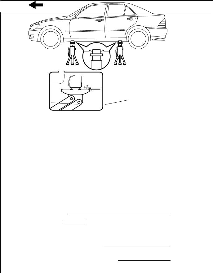
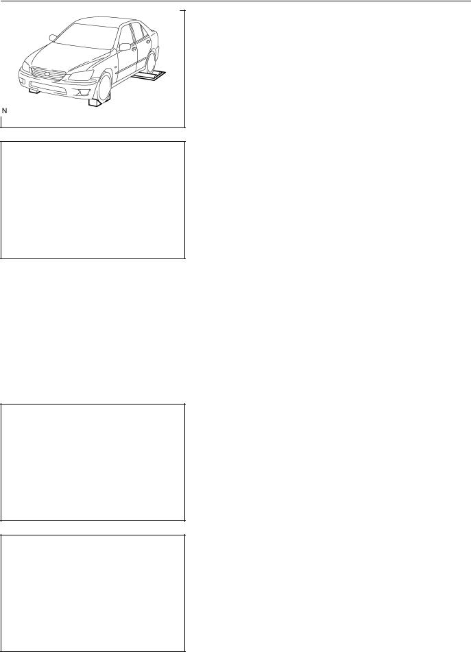
VEHICLE LIFT AND SUPPORT LOCATIONS
Engine Under Cover No. 2
Front Suspension Member
NOTICE:
Never place the engine under cover No. 2 on the garage jack.
JACK POSITION
Front
Rear
CAUTION :
Front suspension member
Differential carrier
When jacking-up the front and rear, make sure the vehicle is not carrying any extra weight.
PANTOGRAPH JACK POSITION
SUPPORT POSITION
Safety stand and swing arm type lift
I19098
2005 LEXUS IS300 (RM1140U)
IN-9
INTRODUCTION — REPAIR INSTRUCTIONS
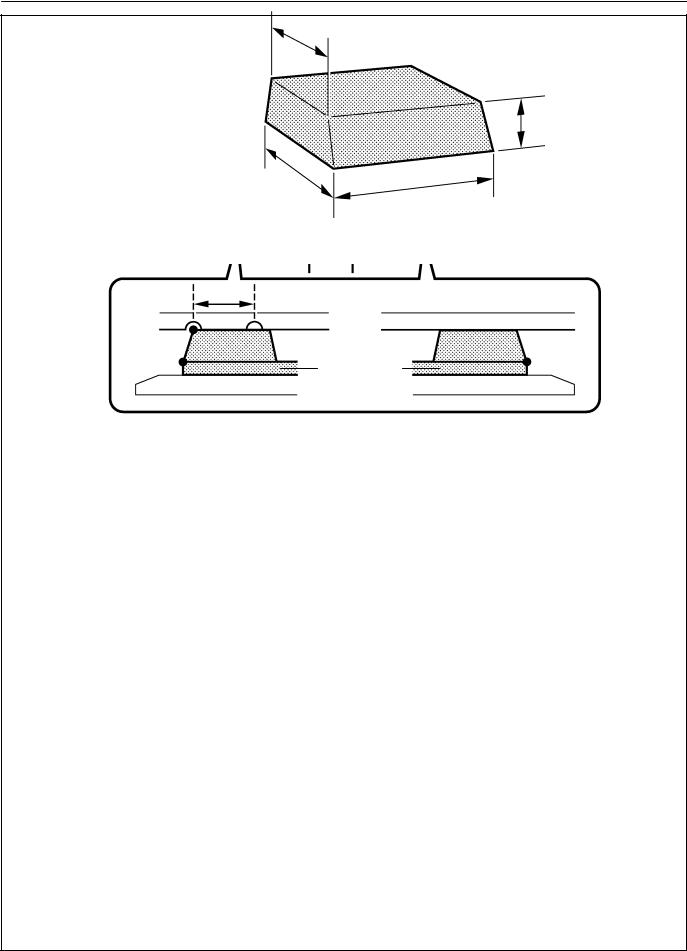
Plate type lift
L
B
Attachment
A C
HINT :
Right and left set position Front and rear set position
Place the vehicle over the center of the lift.
When using attachments, place the one for front side vertically and the one for rear side horizontally to the vehicle.
Align the cushion gum ends of the plate with the attachment lower ends (A, C).
Align the attachment upper end (B) with the rocker flange front side notch.
NOTICE :
Check the interference of the attachment with the front floor cover when placing the attachment on the plate.
|
Attachment dimensions |
85 mm (3.35 in.) |
70 mm (2.76 in.)
100 mm (3.94 in.)
200 mm (7.87 in.)
I19099
2005 LEXUS IS300 (RM1140U)
IN-10
INTRODUCTION — FOR ALL OF VEHICLES
FOR ALL OF VEHICLES
IN0KE-01
PRECAUTION
1.FOR VEHICLES EQUIPPED WITH SRS AIRBAG AND SEAT BELT PRETENSIONER
(a)The LEXUS IS300 is equipped with an Supplemental Restraint System (SRS), such as the driver airbag, front passenger airbag assembly, side airbag assembly, curtain shield airbag assembly and seat belt pretensioners.
Failure to carry out service operations in the correct sequence could cause the supplemental restraint system to unexpectedly deploy during servicing, possibly leading to a serious accident.
Further, if a mistake is made in servicing the supplemental restraint system, it is possible the SRS may fail to operate when required. Before servicing (including removal or installation of parts, inspection or replacement), be sure to read the following items carefully, then follow the correct procedure described in this manual.
(b)GENERAL NOTICE
(1)Malfunction symptoms of the SRS are difficult to confirm, so the diagnostic trouble codes become the most important source of information when troubleshooting. When troubleshooting the supplemental restraint system, always check the diagnostic trouble codes before disconnecting the battery (see page DI-607 ).
(2)Work must be started after 90 seconds from the time the ignition switch is turned to the LOCK position and the negative (-) terminal cable is disconnected from the battery.
(The supplemental restraint system is equipped with a back-up power source so that if work is started within 90 seconds of disconnecting the negative (-) terminal cable from the battery, the SRS may deploy.)
When the negative (-) terminal cable is disconnected from the battery, memory of the clock and audio systems will be cancelled. So before starting work, make a record of the contents memorized by the each memory system. Then when work is finished, reset the clock and audio systems as before. To avoid erasing the memory of each memory system, never use a back-up power supply from another battery.
2005 LEXUS IS300 (RM1140U)
![]()
IN-1 1
INTRODUCTION — FOR ALL OF VEHICLES
(3)Even in cases of a minor collision where the SRS does not deploy, the steering wheel pad (see page RS17), front passenger airbag assembly (see page RS31), side airbag assembly (see page RS-44 ), curtain shield airbag assembly (see page RS-58 ), front airbag sensor (see page RS-74 ), side and curtain shield airbag sensor assembly (see page RS-79 ) and seat belt pretensioner (see page BO-220 ) should be inspected.
(4)Never use SRS parts from another vehicle. When replacing parts, replace them with new parts.
(5)Before repairs, remove the airbag sensor if shocks are likely to be applied to the sensor during repairs.
(6)Never disassemble and repair the steering wheel pad, front passenger airbag assembly, side airbag assembly, curtain shield airbag assembly, front airbag sensor, side and curtain shied airbag sensor assembly or seat belt pretensioner.
(7)Replace if the airbag sensor, steering wheel pad, front passenger airbag assembly, side airbag assembly, curtain shield airbag assembly, front airbag sensor assembly or seat belt pretensioner if it has been dropped, or if there are cracks, dents or other defects in its case, bracket or connector.
(8)Do not directly expose the steering wheel pad, front passenger airbag assembly, side airbag assembly, curtain shield airbag assembly, front airbag sensor, side and curtain shied airbag sensor assembly or seat belt pretensioner to hot air or flames.
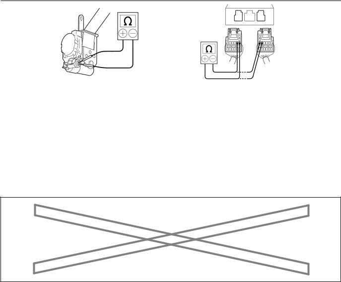
(9)Use a voltmeter/ohmmeter with high impedance (10 kΩ/V minimum) for troubleshooting of the electrical
circuit.
(10)Information labels are attached to the periphery of the SRS components. Follow the instructions on the labels.
(11)After work on the SRS is completed, check the SRS warning light (see page DI-607 ).
(c)SPIRAL CABLE (in Combination Switch)
The steering wheel must be fitted correctly to the steering column with the spiral cable at the neutral position, otherwise cable disconnection and other troubles may result. Refer to SR-25 of this manual concerning correct steering wheel installation.
Marks
F01322
2005 LEXUS IS300 (RM1140U)
IN-12
INTRODUCTION — FOR ALL OF VEHICLES
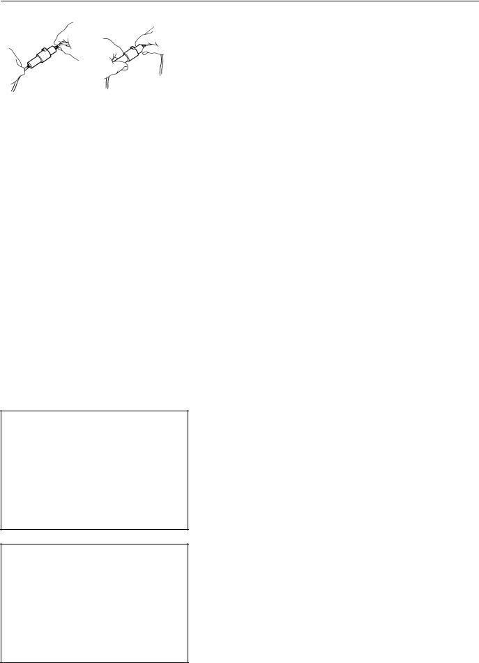
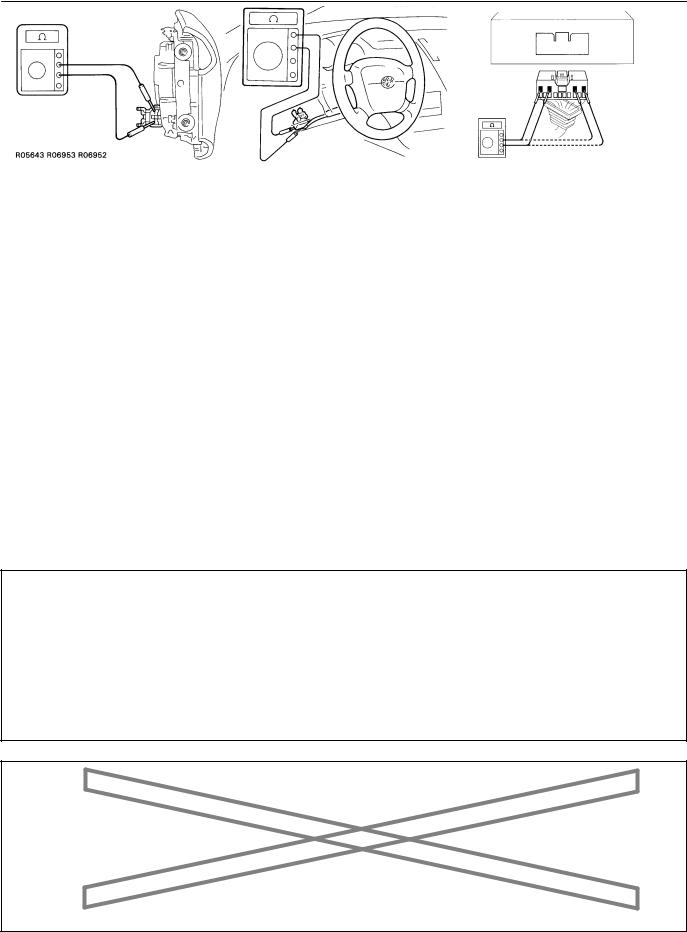
(d)STEERING WHEEL PAD (with Airbag)
(1)When removing the steering wheel pad or handling a new steering wheel pad, it should be placed with the pad top surface facing up see illustration below. Storing the pad with its metallic surface facing upward may lead to a serious accident if the airbag inflates. In addition, do not store a steering wheel pad on top of one another.
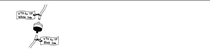
(2)Never measure the resistance of the airbag squib. This may cause the airbag to deploy, which is could cause serious injury.
(3)Grease or detergents of any kind should not be applied to the steering wheel pad.
(4)Store the steering wheel pad where the ambient temperature remains below 93°C (200°F), has low humidity and is away from electrical noise.
(5)Before using an electric welder, first disconnect the airbag connector (the connector is yellow and has 4 pins) under the steering column near the combination switch connector.
(6)As a safety measure, always deploy airbags using an SST before disposal (see page RS-17 ). Deploy airbags in a safe place away from electrical noise.
Example:
|
B17163 |
|||
|
Example: |
|||
|
NEVER USE AN OHMMETER ON AN AIRBAG OR PRETENSIONER |
Z13950 |
||
|
2005 LEXUS IS300 |
(RM1140U) |
||
|
Author : |
Date : |
12 |
IN-13
INTRODUCTION — FOR ALL OF VEHICLES
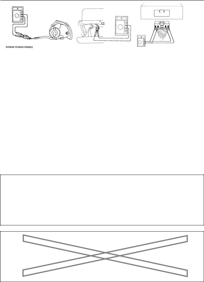
(e)FRONT PASSENGER AIRBAG ASSEMBLY
(1)Always store a removed or new front passenger airbag assembly with the airbag deployment direction facing up.
Storing the airbag assembly with the airbag deployment direction facing down could cause a serious accident if the airbag inflate.
(2)Never measure the resistance of the airbag squib. This may cause the airbag to deploy, which is could cause serious injury.
(3)Grease or detergents of any kind should not be applied to the steering wheel pad.
(4)Store the steering wheel pad where the ambient temperature remains below 93°C (200°F), has low humidity and is away from electrical noise.
(5)Before using an electric welder, first disconnect the airbag connector (the connector is yellow and has 4 pins) under the steering column near the combination switch connector.
(6)As a safety measure, always deploy airbags using an SST before disposal (see page RS-31 ). Deploy airbags in a safe place away from electrical noise.
Example:
|
H15183 B11669 |
B17162 |
||
|
Example: |
|||
|
NEVER USE AN OHMMETER ON AN AIRBAG OR PRETENSIONER |
Z13951 |
||
|
2005 LEXUS IS300 |
(RM1140U) |
||
|
Author : |
Date : |
13 |
IN-14
|
INTRODUCTION — |
FOR ALL OF VEHICLES |
|||
|
(f) SIDE AIRBAG ASSEMBLY |
||||
|
(1) |
Always store a removed or new side airbag assem- |
|||
|
bly with the airbag deployment direction facing up. |
||||
|
Storing the airbag assembly with the airbag deploy- |
||||
|
ment direction facing down could cause a serious |
||||
|
accident if the airbag inflates. |
||||
|
(2) |
Never measure the resistance of the airbag squib. |
|||
|
This may cause the airbag to deploy, which could |
||||
|
cause serious injury. |
||||
|
(3) |
Grease or detergents of any kind should not be ap- |
|||
|
plied to the steering wheel pad. |
||||
|
(4) |
Store the steering wheel pad where the ambient |
|||
|
temperature remains below 93°C (200°F), has low |
||||
|
humidity and is away from electrical noise. |
||||
|
(5) |
Before using an electric welder, first disconnect the |
|||
|
airbag connector (the connector is yellow and has |
||||
|
2 pins) under the steering column near the com- |
||||
|
bination switch connector. |
||||
|
(6) |
As a safety measure, always deploy airbags using |
|||
|
an SST before disposal (see page RS-44 ). Deploy |
||||
|
airbags in safe place away from electrical noise. |
||||
|
Example: |
||||
|
CORRECT |
WRONG |
|||
|
B17197 |
||||
|
Example: |
||||
|
NEVER USE AN OHMMETER ON AN AIRBAG OR PRETENSIONER |
B01546 |
|||
|
2005 LEXUS IS300 (RM1140U) |

IN-15
INTRODUCTION — FOR ALL OF VEHICLES
(g)CURTAIN SHIELD AIRBAG ASSEMBLY
(1)Always store a removed or new side airbag assembly with the airbag deployment direction facing up. Storing the airbag assembly with the airbag deployment direction facing down could cause a serious
accident if the airbag inflates.
NOTICE:
Plastic bag is not re-useable. CAUTION:
Never disassemble the curtain shield airbag assembly.
(2)Never measure the resistance of the airbag squib. This may cause the airbag to deploy, which could cause serious injury.
(3)Grease or detergents of any kind should not be applied to the curtain shield airbag assembly.
(4)Store the steering wheel pad where the ambient temperature remains below 93°C (200°F), has low humidity and is away from electrical noise.
(5)Before using an electric welder, first disconnect the airbag connector (the connector is yellow and has 2 pins) under the steering column near the combination switch connector.
(6)As a safety measure, always deploy airbags using an SST before disposal (see page RS-59 ). Deploy airbags in a safe place away from electrical noise.
|
Example: |
|
|
NEVER USE AN OHMMETER ON AN AIRBAG OR PRETENSIONER |
B08605 |
|
H12059R06952 |
2005 LEXUS IS300 (RM1140U)
IN-16
INTRODUCTION — FOR ALL OF VEHICLES
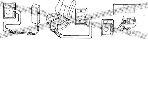
(h)SEAT BELT PRETENSIONER
(1)Never measure the resistance of the seat belt pretensioner. This may cause the seat belt pretensioner to activate, which could cause serious injury.
(2)Never disassemble the seat belt pretensioner.
(3)Never install the seat belt pretensioner in another vehicle.
(4)Store the seat belt pretensioner where the ambient temperature remains below 80°C (176°F), has low humidity and is away from electrical noise.
(5)Before using an electric welder, first disconnect the connector (the connector is yellow and has 2 pins).
(6)As a safety measure, always activate the seat belt pretensioner before disposal (see page BO-220 ). Activate the pretensioner in safe place away from electrical noise.
(7)The seat belt pretensioner becomes hot after activation. Allow it to cool before disposing. Never use water to cool seat belt pretensioner.
|
Example: |
|
|
NEVER USE OHMMETER ON AN AIRBAG OR PRETENSIONER |
B02121 |
2005 LEXUS IS300 (RM1140U)

IN-17
INTRODUCTION — FOR ALL OF VEHICLES
(i)AIRBAG SENSOR ASSEMBLY
(1)If an airbag sensor assembly has been involved in a collision where its SRS has deployed, do not reuse it.
(2)The connectors to the airbag sensor assembly should be connected or disconnected with the sensor mounted on the floor. Failure to do so could cause undesired deployment of the SRS.
(3)To avoid serious injury, servicing the SRS must be started 90 seconds after:
The ignition switch is turned to the LOCK position.
The negative (-) terminal cable is discon-
nected from the battery.
Even if only loosening the set bolts of the airbag sensor assembly, you must follow the above guidelines.
(j)WIRE HARNESS AND CONNECTOR
The SRS wire harness is integrated with the instrument panel wire harness assembly. All the connectors in the system are a standard yellow color. If the SRS wire harness becomes disconnected or the connector becomes broken, etc., repair or replace it as shown on page RS-82 .
2005 LEXUS IS300 (RM1140U)

IN-18
INTRODUCTION — FOR ALL OF VEHICLES
2. FOR VEHICLES EQUIPPED WITH A CATALYTIC CONVERTER CAUTION:
If large amount of unburned gasoline flows into the converter, it may overheat and create a fire hazard. To prevent this, observe the following precautions and explain them to your customer.
(a)Use only unleaded gasoline.
(b)Avoid prolonged idling.
Avoid running the engine at idle speed for more than 20 minutes.
(c)Avoid spark jump test.
(1)Perform spark jump test only when absolutely necessary. Perform this test as rapidly as possible.
(2)While testing, never race the engine.
(d)Avoid prolonged engine compression measurement.
Engine compression tests must be done as rapidly as possible.
(e)Do not run engine when fuel tank is nearly empty.
This may cause the engine to misfire and create an extra load on the converter.
(f)Avoid coasting with ignition turned off.
(g)Do not dispose of used catalyst along with parts contaminated with gasoline or oil.
3.IF VEHICLE IS EQUIPPED WITH MOBILE COMMUNICATION SYSTEM
For vehicles with mobile communication systems such as two-way radios and cellular telephones, observe the following precautions.
(1)Install the antenna as far as possible away from the ECU and sensors of the vehicle’s electronic system.
(2)Install the antenna feeder at least 20 cm (7.87 in.) away from the ECU and sensors of the vehicle’s electronic systems. For details about ECU and sensors locations, refer to the section on the applicable component.
(3)Avoid winding the antenna feeder together with other wiring as much as possible, and also avoid running the antenna feeder parallel with other wire harnesses.
(4)Check that the antenna and feeder are correctly adjusted.
(5)Do not install powerful mobile communications system.
4.FOR USING OBD II SCAN TOOL OR HAND-HELD TESTER
CAUTION:
Observe the following items for safety reasons:
Before using the OBD II scan tool or hand-held tester, the OBD II scan tool’s instruction book or hand-held tester’s operator manual should be read thoroughly.
Be sure to route all cables securely when driving with the OBD II scan tool or hand-held tester connected to the vehicle. (i.e. Keep cables away from feet, pedals, steering wheel and shift lever.)
Two persons are required when test driving with the OBD II scan tool or hand-held tester, one person to drive the vehicle and the other person to operate the OBD II scan tool or hand-held tester.
5. FOR VEHICLES EQUIPPED WITH TRACTION CONTROL (TRAC) SYSTEM NOTICE:
When using a 2-wheel drum tester such as a speedometer tester or chassis dynamometer, etc., or jacking up the rear wheels and driving the wheels, always push in the TRAC cut switch and turn the TRAC system OFF.
2005 LEXUS IS300 (RM1140U)
IN-19
INTRODUCTION — FOR ALL OF VEHICLES
(a)Press the TRAC cut switch.
(b)Check that the TRAC system is turned OFF by the TRAC cut switch.
HINT:
The SLIP indicator light should be always ON immediately after the engine is restarted.
F12327
(c)Begin measurements.
(d)Press the TRAC cut switch to turn the TRAC to the operative mode and check that the TRAC OFF indicator light goes off.
HINT:
The SLIP indicator light blinks when the TRAC system is operational.
B07101
6.FOR VEHICLES EQUIPPED WITH VEHICLE SKID CONTROL (VSC) SYSTEM
NOTICE:
When using 2-wheel drum tester such as a speedometer tester or chassis dynamometer, etc., or jacking up the front wheels and driving the wheels, always push in the VSC OFF switch to turn the VSC system OFF.
(a)Press the VSC OFF switch.
(b)Check that the VSC OFF indicator light comes ON.
HINT:
The VSC OFF indicator light should be always OFF when the engine is restarted.
B15256
(c)Begin measurements.
(d)Press the VSC OFF switch again to change the VSC system to operational condition and check that the VSC OFF indicator light goes off.
HINT:
The SLIP indicator light blinks and the VSC buzzer sounds when the VSC system is operational.
B07101
2005 LEXUS IS300 (RM1140U)
IN-20
INTRODUCTION — FOR ALL OF VEHICLES
7.FOR VEHICLES EQUIPPED WITH LIMITED SLIP DIF-
FERENTIAL
(a)Never apply driving force when RH or LH rear wheel only is touching the ground.
(b)During service/rectification work never spin (race) the RH or LH rear wheel only such as with ON-The-Car type wheel balancer, both rear wheels must be off the ground.
HINT:
In case of the above, due to the construction of the LSD the driving force is transmitted to the opposite wheel and therefore it is possible for the vehicle to start suddenly if only one rear wheel is off the ground. Furthermore it could result in component damage to the LSD due to the loads acting on it.
Always raise both rear wheels off the ground and support the vehicle on suitable safety stand.
B07102
8.INSPECTION AND ADJUSTMENT OF JOINT ANGLE
DURING REMOVAL AND INSTALLATION OF PROPELLER SHAFT
When performing operations which involve the removal and installation of the propeller shaft, always check the joint angle. Make adjustments if necessary (see page PR-1 1).
|
No. 2 Joint |
No. 3 Joint |
|
A — B = — 1°21′ ± 30′ |
B — C = 2°18′ ± 30′ |
A B C
B07659
2005 LEXUS IS300 (RM1140U)
|
INTRODUCTION — HOW TO TROUBLESHOOT ECU CONTROLLED |
IN-21 |
|
SYSTEMS |
HOW TO TROUBLESHOOT ECU CONTROLLED SYSTEMS
IN04S-45
GENERAL INFORMATION
A large number of ECU controlled systems are used in the LEXUS IS300. In general, ECU controlled systems are considered to be a very intricate, requiring a high level of technical knowledge to troubleshoot. However, following the problem checking procedures of the ECU controlled system’s circuits carefully is not complex. If you have an adequate understanding of the system and a basic knowledge of electricity, accurate diagnosis and necessary repair can be performed.
This manual emphasizes the above standpoint to help service technicians perform accurate and effective troubleshooting. Detailed information on major ECU controlled systems in this vehicle are outlined below:
|
System |
Page |
|
|
1. |
Engine |
DI-1 |
|
2. |
Automatic Transmission |
DI-335 |
|
3. |
ABS with EBD & BA & TRAC System |
DI-435 |
|
4. |
ABS with EBD & BA & TRAC & VSC System |
DI-505 |
|
5. |
Supplemental Restraint System |
DI-605 |
|
6. |
Theft Deterrent System |
DI-776 |
|
7. |
Cruise Control System |
DI-818 |
|
8. |
Engine Immobiliser System |
DI-849 |
|
9. |
Combination Meter System |
DI-870 |
|
10.Body Control System |
DI-893 |
|
|
11.Multiplex Communication System |
DI-949 |
|
|
12.LEXUS Navigation System |
DI-979 |
|
|
13.Air Conditioning System |
DI-1009 |
|
FOR USING OBDII SCAN TOOL OR HAND-HELD TESTER
Before using the scan tool or tester, the scan tool’s instruction book or tester’s operator manual should be read thoroughly.
If the scan tool or tester cannot communicate with ECU controlled systems when you have connected the cable of the scan tool or tester to DLC3, turned the ignition switch ON and operated the scan tool, there is a problem on the vehicle side or tool side.
(1)If communication is normal when the tool is connected to another vehicle, inspect the diagnosis data link line (Bus line) or ECU power circuit of the vehicle.
(2)If communication is still not possible when the tool is connected to another vehicle, the problem is probably in the tool itself, so perform the Self Test procedures outlined in the Tester Operator’s Manual.
2005 LEXUS IS300 (RM1140U)
|
IN-22 |
INTRODUCTION — HOW TO TROUBLESHOOT ECU CONTROLLED |
|
SYSTEMS |
IN04T-22
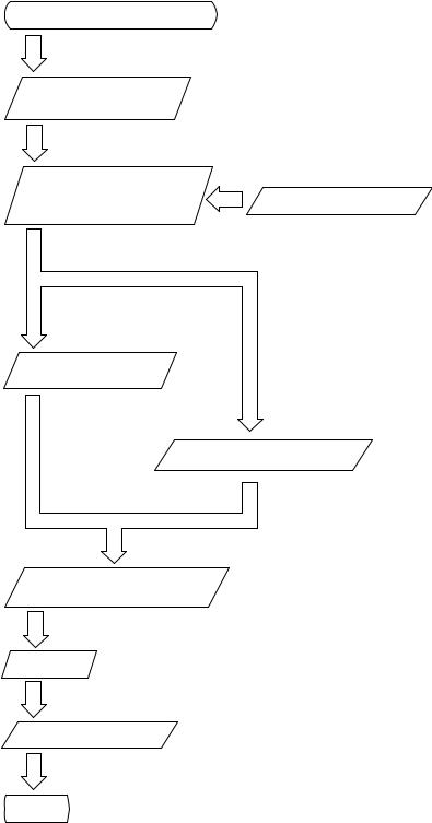
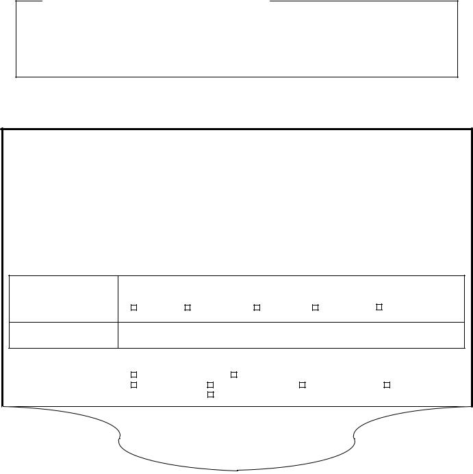
HOW TO PROCEED WITH TROUBLESHOOTING
Carry out troubleshooting in accordance with the procedure below. Only a basic procedure is shown. Details in the Diagnostics section show the most effective methods for each circuit. Confirm troubleshooting procedures first for the relevant circuit before beginning troubleshooting of that circuit.
Vehicle Brought to Workshop
1
1Customer Problem Analysis
2Symptom Confirmation and Diagnostic Trouble Code Check
Ask the customer about the conditions and the environment in which the problem occurred.
3
Symptom Simulation
2, 3
Confirm the symptoms and the problem conditions, and check the diagnostic trouble codes.
(When the problem symptoms do not appear during confirmation, use the symptom simulation method described later on.)
Diagnostic Trouble
Code Chart
5
Problem Symptoms Table
Circuit Inspection or Parts Inspection
Repair
Confirmation Test
End
4, 5, 6
Check the results obtained in Step 2. Confirm
the inspection procedure for the system or the part that should be checked using the diagnostic trouble code chart or the problem symptoms table.
7
Check and repair the affected system or part in accordance with the instructions in Step 6.
8
After completing repairs, confirm that the problem has been eliminated.
(To be absolutely sure the problem no longer exists, perform the confirmation test under the same conditions and environment as when it occurred the first time.)
2005 LEXUS IS300 (RM1140U)
|
INTRODUCTION — HOW TO TROUBLESHOOT ECU CONTROLLED |
IN-23 |
|
SYSTEMS |
1.CUSTOMER PROBLEM ANALYSIS
The 5 items in the table below are important points in the problem analysis:
In troubleshooting, the problem symptoms must be confirmed accurately. Preconceptions should be discarded in order to give an accurate judgement. To ascertain what the problem symptoms are, it is extremely important to ask the customer about the problem and the conditions at the time it occurred.
Important Points in the Customer Problem Analysis
What —— Vehicle model, system name
When —— Date, time, occurrence frequency
Where —— Road conditions
Under what conditions? —— Running conditions, driving conditions, weather conditions
How did it happen? —— Problem symptoms
(Sample) Supplemental restraint system check sheet.
CUSTOMER PROBLEM ANALYSIS CHECK
|
SUPPLEMENTAL RESTRAINT SYSTEM Check Sheet |
Inspector’s |
|||||||||||
|
Name |
||||||||||||
|
VIN |
||||||||||||
|
Customer’s Name |
Production Date |
/ |
/ |
|||||||||
|
Licence No. |
||||||||||||
|
Date Vehicle Brought In |
/ |
/ |
Odometer Reading |
km |
||||||||
|
miles |
||||||||||||
|
Date Problem First Occurred |
/ |
/ |
||||||||||
|
Weather |
Fine |
Cloudy |
Rainy |
Snowy |
Other |
|||||||
|
Temperature |
Approx. |
|||||||||||
|
Starting |
Idling |
|||||||||||
|
Vehicle Operation |
Driving |
[ Constant speed |
Acceleration |
Deceleration |
||||||||
|
Other |
] |
|||||||||||
2005 LEXUS IS300 (RM1140U)

|
IN-24 |
INTRODUCTION — HOW TO TROUBLESHOOT ECU CONTROLLED |
|
SYSTEMS |
2. SYMPTOM CONFIRMATION AND DIAGNOSTIC TROUBLE CODE CHECK
The diagnostic system in the LEXUS IS300 fulfills various functions.
The first function is the Diagnostic Trouble Code (DTC) Check. In a DTC Check,a previous malfunction’s DTC can be checked by a technician during troubleshooting. (A DTC is a code stored in the ECU memory whenever a malfunction in the signal circuits to the ECU occurs.)
Another function is the Input Signal Check, which checks if the signals from various switches are sent to the ECU correctly. By using these check functions, the problem areas can be narrowed down and troubleshooting is more effective. Diagnostic functions are incorporated in the following systems in the LEXUS IS300.
|
Diagnostic Trouble |
Input Signal Check |
Diagnostic Test |
|
System |
(Sensor Check) |
Mode (Active Test) |
|
Code Check |
Engine
(with Check Mode)
Automatic Transmission
(with Check Mode)
ABS with EBD & BA & TRAC System
ABS with EBD & BA & TRAC & VSC System
Supplemental Restraint System
Theft Deterent System
Cruise Control System
Engine Immobiliser System
Combination Meter System
Body Control System
Multiplex Communication System
LEXUS Navigation System
Air Conditioning System
2005 LEXUS IS300 (RM1140U)

|
INTRODUCTION — HOW TO TROUBLESHOOT ECU CONTROLLED |
IN-25 |
|
SYSTEMS |
In diagnostic trouble code check, it is very important to determine whether the problem indicated by the diagnostic trouble code is still occurring or occurred in the past but returned to normal at present. In addition, it must be checked in the problem symptom check whether the malfunction indicated by the diagnostic trouble code is directly related to the problem symptom or not. For this reason, the diagnostic trouble codes should be checked before and after the symptom confirmation to determine the current conditions, as shown in the table below. If this is not done, it may, depending on the case, result in unnecessary troubleshooting for normally operating systems, thus making it more difficult to locate the problem, or in repairs not pertinent to the problem. Therefore, always follow the procedure in correct order and perform the diagnostic trouble code check.
DIAGNOSTIC TROUBLE CODE CHECK PROCEDURE
|
Diagnostic Trouble |
Confirmation |
Diagnostic Trouble |
Problem Condition |
|
|
Code Check (Make a |
||||
|
of Symptoms |
Code Check |
|||
|
note of and then clear) |
||||
|
Diagnostic Trouble |
Problem symptoms |
Same diagnostic |
Problem is still occurring in the diagnostic |
|
|
Code Display |
exist |
trouble code is |
circuit |
|
|
displayed |
||||
|
Normal code is |
The problem is still occurring in a place |
|||
|
displayed |
other than in the diagnostic circuit |
|||
|
(The diagnostic trouble code displayed |
||||
|
first is either for a past problem or it is a |
||||
|
secondary problem) |
||||
|
No problem |
The problem occurred in the diagnostic |
|||
|
symptoms exist |
circuit in the past |
|||
|
Normal Code Display |
Problem symptoms |
Normal code is |
The problem is still occurring in a place |
|
|
exist |
displayed |
other than in the diagnostic circuit |
||
|
No problem |
Normal code is |
The problem occurred in a place other |
||
|
symptoms exist |
displayed |
than in the diagnostic circuit in the past |
||
2005 LEXUS IS300 (RM1140U)
|
IN-26 |
INTRODUCTION — HOW TO TROUBLESHOOT ECU CONTROLLED |
|
SYSTEMS |
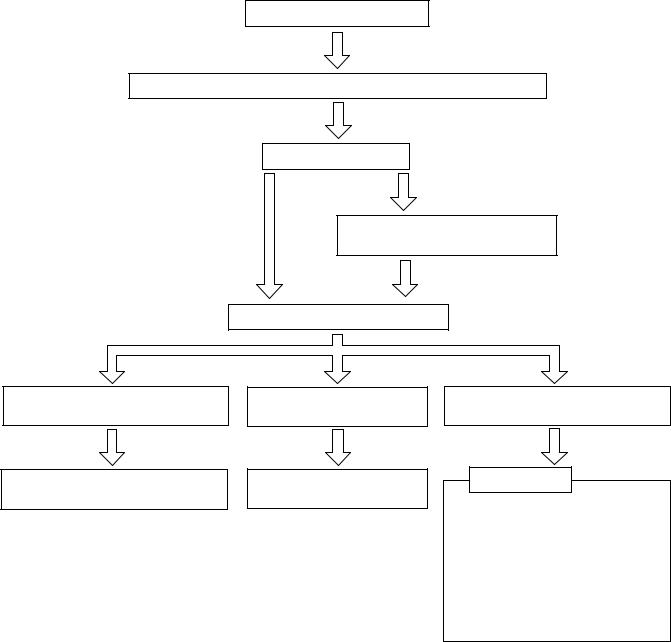
Taking into account the points on the previous page, a flow chart showing how to proceed with troubleshooting using the diagnostic trouble code check is shown below. This flow chart shows how to utilize the diagnostic trouble code check effectively, then by carefully checking the results, indicates how to proceed either to diagnostic trouble code troubleshooting or to troubleshooting of problem symptoms table.
Diagnostic trouble code check
Making a note of and clearing of the diagnostic trouble codes displayed
Symptom confirmation
|
Problem symptoms |
No problem symptoms |
|
|
exist |
||
|
exist |
||
|
Simulation test using the symptom |
||
|
simulation methods |
Diagnostic trouble code check
Diagnostic trouble code displayed
Problem symptoms exist
Troubleshooting of problem indicated by diagnostic trouble code
Normal code displayed
Problem symptoms exist
Troubleshooting of each problem symptom
Normal code displayed
No problem symptoms exist
System Normal
If a diagnostic trouble code was displayed in the initial diagnostic trouble code check, it indicates that the trouble may have occurred in a wire harness or connector in that circuit in the past. Therefore, check the wire harness and connectors (see page IN-33 ).
2005 LEXUS IS300 (RM1140U)
|
INTRODUCTION — HOW TO TROUBLESHOOT ECU CONTROLLED |
IN-27 |
|
SYSTEMS |
3.SYMPTOM SIMULATION
The most difficult case in troubleshooting is when no problem symptoms occurring. In such cases, a thorough customer problem analysis must be carried out. Then simulate a simulation of the same or similar conditions and environment in which the problem occurred in the customer’s vehicle should be carried out. No matter how much skill or experience a technician has, troubleshooting without confirming the problem symptoms will lead to something important in the repair operation being overlooked and lead to mistakes or delays in repairs.
For example:
With a problem that only occurs when the engine is cold, or occurs as result of vibration caused by road during driving, the problem can never be determined as long as the symptoms are being checked on stationary vehicle or a vehicle with a warmed-up engine.
Vibration, heat or water penetration (moisture) is difficult to reproduce. The symptom simulation tests below are effected substitutes for the conditions and can be applied on a stationary vehicle.
Important Points in the Symptom Simulation Test:
In the symptom simulation test, the problem symptoms as well as problem area or parts must be confirmed. First, narrow down the possible problem circuits according to the symptoms. Then, connect the tester and carry out the symptom simulation test, judging whether the circuit being tested is defective or normal, and also confirming the problem symptoms at the same time. Refer to the problem symptoms table for each system to narrow down the possible causes of the symptom.
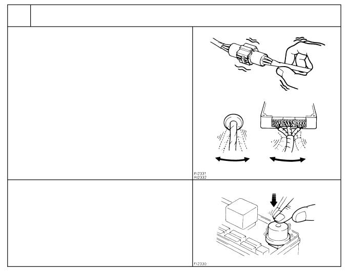
1 VIBRATION METHOD: When vibration seems to be the major cause.
CONNECTORS
Slightly shake the connector vertically and horizontally.
Shake Slightly
WIRE HARNESS
Slightly shake the wire harness vertically and horizontally. The connector joint, fulcrum of the vibration, and body through portion are the major areas that should be checked thoroughly.
PARTS AND SENSOR
Apply slight vibration with a finger to the part of the sensor considered to be the cause of the problem and check whether or not the malfunction occurs.
HINT:
Applying strong vibration to relays may result in open relays.
Swing Slightly
Vibrate Slightly
V07268
2005 LEXUS IS300 (RM1140U)
|
IN-28 |
INTRODUCTION — HOW TO TROUBLESHOOT ECU CONTROLLED |
|
SYSTEMS |
2 HEAT METHOD: When the problem seems to occur when the suspect area is heated.
Heat the component that is the likely cause of the malfunction with a hair dryer or similar device. Check whether or not if the
malfunction occurs.
Malfunction
NOTICE:
(1)Do not heat to more than 60°C (140°F). (Exceeding this temperature may damage components.)
(2)Do not apply heat directly to parts in the ECU.
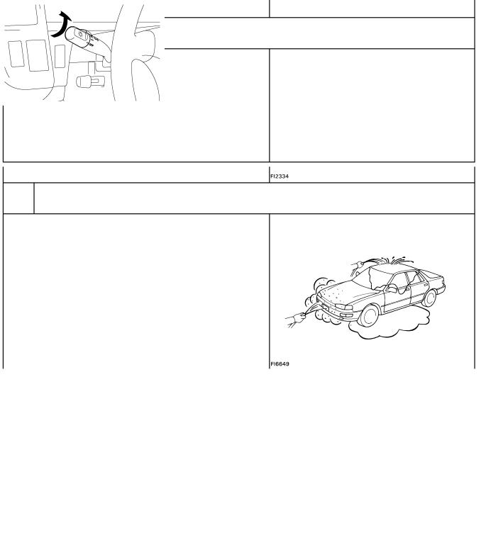
3 WATER SPRINKLING METHOD: When the malfunction seems to occur on a rainy day or in a high-humidity condition.
Sprinkle water onto the vehicle and check whether or not if the malfunction occurs.
NOTICE:
(1)Never sprinkle water directly into the engine compartment. Indirectly change the temperature and humidity by applying water spray onto the front of the radiator.
(2)Never apply water directly onto electronic components.
HINT:
If a vehicle is subject to water leakage, the leaked water may damage the ECU. When testing a vehicle with a water leakage problem, special caution must be taken.
4 OTHER: When a malfunction seems to occur when electrical load is excessive.
|
Turn on all electrical loads including the heater blower, head |
ON |
|
lights, rear window defogger, etc. and check to see if the mal- |
|
|
function occurs. |
B02389
B02390
2005 LEXUS IS300 (RM1140U)
|
INTRODUCTION — HOW TO TROUBLESHOOT ECU CONTROLLED |
IN-29 |
|
SYSTEMS |
4.DIAGNOSTIC TROUBLE CODE CHART
Use Diagnostic Trouble Codes (DTCs) (from the DTC checks) in the table below to determine the trouble area and proper inspection procedure. The engine diagnostic trouble code chart is shown below as an example.
DTC No.
Indicates the diagnostic trouble code.
Page or Instructions
Indicates the page where the inspection procedure for each circuit is to be found, or gives instructions for checking and repairs.
Trouble Area
Indicates the suspect area of the problem.
Detection Item
Indicates the system of the problem or contents of the problem.
DTC CHART (SAE Controlled)
HINT:
Parameters listed in the chart may not be exactly the same as your reading due to the type of instrument or other factors.
If a malfunction code is displayed during the DTC check mode, check the circuit for that code listed in the table below. For details of each code, refer to the ºSee pageº under the ºDTC No.º in the DTC chart.
|
DTC No. |
Detection Item |
Trouble Area |
MIL* |
Memory |
||
|
(See page) |
||||||
|
P0100 |
Open or short in mass air flow meter circuit |
|||||
|
Mass Air Flow Circuit Malfunction |
Mass air flow meter |
|||||
|
(DI-24) |
||||||
|
ECM |
||||||
|
P0101 |
Mass Air Flow Circuit |
Mass air flow meter |
||||
|
(DI-28) |
Range/ Performance Problem |
|||||
|
Open or short in intake air temp. sensor |
||||||
|
P0110 |
Intake Air Temp. Circuit |
circuit |
||||
|
(DI-29) |
Malfunction |
Intake air temp. sensor |
||||
|
ECM |
||||||
|
P0115 |
Engine Coolant Temp. |
Open or short in engine coolant temp. sensor circuit |
||||
|
Engine coolant temp. sensor |
||||||
|
(DI-33) |
Circuit Malfunction |
|||||
|
ECM |
||||||
|
P0116 |
Engine Coolant Temp. |
Engine coolant temp. sensor |
||||
|
(DI-37) |
Circuit Range/ Performance Problem |
Cooling system |
||||
|
Throttle/ Pedal Position Sensor/Switch |
Open or short in throttle position sensor circuit |
|||||
|
Throttle position sensor |
||||||
|
ºAº Circuit Malfunction |
||||||
|
ECM |
||||||
|
Throttle/ Pedal Position Sensor/ Switch |
||||||
|
ºAº Circuit Range / Performance Prob- |
Throttle position sensor |
|||||
|
lem |
||||||
2005 LEXUS IS300 (RM1140U)
|
IN-30 |
INTRODUCTION — HOW TO TROUBLESHOOT ECU CONTROLLED |
|
SYSTEMS |
5.PROBLEM SYMPTOMS TABLE
The suspected circuits or parts for each problem symptom are shown in the table below. Use this table to troubleshoot when, during a DTC check, a ºNormalº code is displayed in the diagnostic trouble code check but the problem is still occurring. Numbers in the table show the inspection order in which the circuits or parts should be checked.
HINT:
In some cases, a problem is not detected by the diagnostic system even though a problem symptom is present. It is possible that the problem is occurring outside the detection range of the diagnostic system, or that the problem is occurring in a completely different system.
Page
Indicates the page where the flow chart for each circuit is located.
Circuit Inspection, Inspection Order
Indicates the circuit which needs to be checked for a problem symptom.
|
Problem Symptom |
Circuit or Part Name |
|
Indicates the circuit or part which needs to be checked. |
PROBLEM SYMPTOMS TABLE
|
Symptom |
Suspect Area |
See page |
|||||||
|
Engine does not crank (Does not start) |
1. Starter and starter relay |
ST-2 |
|||||||
|
ST-17 |
|||||||||
|
1. ECM power source circuit |
DI-147 |
||||||||
|
No initial combustion (Does not start) |
2. Fuel pump control circuit |
DI-151 |
|||||||
|
3. Engine control module (ECM) |
IN-29 |
||||||||
|
No complete combustion (Does not start) |
1. Fuel pump control circuit |
DI-151 |
|||||||
|
1. Starter signal circuit |
DI-144 |
||||||||
|
Engine cranks normally (Difficult to start) |
2. Fuel pump control circuit |
DI-151 |
|||||||
|
3. Compression |
EM-3 |
||||||||
|
Cold engine (Difficult to start) |
1. |
Starter signal circuit |
DI-144 |
||||||
|
DI-151 |
|||||||||
|
2. |
Fuel pump control circuit |
||||||||
|
Hot engine |
1. |
Starter signal circuit |
DI-144 |
||||||
|
2. |
Fuel pump control circuit |
DI-151 |
|||||||
|
High engine idle speed (Poor idling) |
1. |
A/C signal circuit (Compressor circuit) |
AC-88 |
||||||
|
2. |
ECM power source circuit |
||||||||
|
idling) |
1. |
A/C signal circuit |
|||||||
|
2. |
Fuel pump control circuit |
||||||||
|
1. Compression |
|||||||||
|
2. |
Fuel pump control circuit |
||||||||
2005 LEXUS IS300 (RM1140U)
![]()
|
INTRODUCTION — HOW TO TROUBLESHOOT ECU CONTROLLED |
IN-31 |
|
SYSTEMS |
6.CIRCUIT INSPECTION
How to read and use each page is shown below.
Diagnostic Trouble Code No. and Detection Item
Circuit Description
The major role and operation of the circuit and its component parts are explained.
|
DTC |
P0325 |
Knock Sensor 1 Circuit Malfunction |
|
CIRCUIT DESCRIPTION
Knock sensor is fitted to the cylinder block to detect engine knocking. This sensor contains a piezoelectric element which generates a voltage when it becomes deformed, which occurs when the cylinder block vibrates due to knocking. If engine knocking occurs, ignition timing is retarded to suppress it.
|
DTC No. |
DTC Detecting Condition |
Trouble Area |
|
|
No knock sensor 1 signal to ECM with engine speed, |
Open or short in knock sensor1 circuit |
||
|
P0325 |
Knock sensor 1 (looseness) |
||
|
1,200 rpm or more. |
|||
|
ECM |
If the ECM detects the above diagnosis conditions, it operates the fall safe function in which the corrective retard angle value is set to the maximum value.
WIRING DIAGRAM
ECM
Knock Sensor 1
E1
Indicates the diagnostic trouble code (DTC), (DTC) set parameter and suspect area of the problem.
Wiring Diagram
This is a wiring diagram of the circuit.
Use this diagram together with an ELECTRICAL WIRING DIAGRAM to thoroughly understand the circuit.
Wire colors are indicated by an alphabetical code: B = Black; L = Blue; R = Red; BR = Brown;
LG = Light Green; V = Violet; G = Green;
O = Orange; W = White; GR = Gray; P = Pink; Y = Yellow; SB = Sky Blue.
The first letter indicates the basic wire color and the second letter indicates the color of the stripe.
V08423
2005 LEXUS IS300 (RM1140U)

|
IN-32 |
INTRODUCTION — HOW TO TROUBLESHOOT ECU CONTROLLED |
|
SYSTEMS |
Indicates the position of the ignition switch during the check.
|
Ignition Switch LOCK (OFF) |
Ignition Switch ON |
|
START |
ACC |
|
Ignition Switch START |
Ignition Switch ACC |
Inspection Procedure
Use the inspection procedure to determine if the circuit is normal or abnormal. If it is abnormal, use it to determine whether the problem is located in the sensors, actuators, wire harness or ECU.
INSPECTION PROCEDURE
1 Check continuity between terminal KNK of ECM connector and body ground.
|
LOCK |
PREPARATION: |
||
|
KNK |
(a) Remove the glove compartment (See page SF-68). |
||
|
(b) Disconnect the E6 connector of ECM. |
|||
|
CHECK: |
|||
|
Measure resistance between terminal KNK of ECM connector |
|||
|
and body ground. |
|||
|
E6 Connector |
OK: |
||
|
AB0117 |
Resistance: 1 MΩ or higher |
||
|
A00265 |
A00255 |
||
|
OK |
Go to step 3. |
||
|
NG |
2 Check knock sensor (See page SF-61).
Indicates the place to check the voltage or resistance.
Indicates the connector position to checked (from the front or back side).
Wire Harness
Check from the connector back side (with harness).
Check from the connector front side (without harness). In this case, care must be taken not to bend the terminals.
|
Indicates the condition of the connector of ECU during the check. |
KNK |
|
KNK |
|
E6 Connector |
E6 Connector |
Connector being checked is connected.
Connector being checked is disconnected.
V08425
2005 LEXUS IS300 (RM1140U)

IN-2
INTRODUCTION — HOW TO USE THIS MANUAL
The procedures are presented in a step-by-step format:
The illustration shows what to do and where to do it.
The task heading tells what to do.
The detailed text tells how to perform the task and gives other information such as specifications and warnings.
Example:
Illustration: what to do and where
Task heading : what to do
21. CHECK PISTON STROKE OF OVERDRIVE BRAKE
(a)Place SST and a dial indicator onto the overdrive brake piston as shown in the illustration.
SST 09350-30020 (09350-06120)
|
Set part No. |
Component part No. |
Detailed text : how to do task
(b)Measure the stroke applying and releasing the compressed air (392 785 kPa, 4 8 kgf/cm2 or 57 114 psi) as shown in the illustration.
Piston stroke: 1.40 1.70 mm (0.0551 0.0669 in.)
Specification
This format provides the experienced technician with a FAST TRACK to the information needed. The upper case task heading can be read at a glance when necessary, and the text below it provides detailed information. Important specifications and warnings always stand out in bold type.
6.REFERENCES
References have been kept to a minimum. However, when they are required you are given the page to refer to.
7.SPECIFICATIONS
Specifications are presented in bold type throughout the text where needed. You never have to leave the procedure to look up your specifications. They are also found in Service Specifications section for quick reference.
|
8. |
CAUTIONS, NOTICES, HINTS: |
|
CAUTIONS are presented presented in bold type, and indicate there is a possibility of injury to you or |
|
|
other people. |
|
|
NOTICES are also presented in bold type, and indicate the possibility of damage to the components |
|
|
being repaired. |
|
|
HINTS are separated from the text but do not appear in bold. They provide additional information to |
|
|
help you perform the repair efficiently. |
|
|
9. |
SI UNIT |
The UNITS given in this manual are primarily expressed according to the SI UNIT (International System of Unit), and alternately expressed in the metric system and in the English System.
Example:
Torque: 30 N´m (310 kgf´cm, 22 ft´lbf)
2005 LEXUS IS300 (RM1140U)
IN-38
|
INTRODUCTION — TERMS |
||
TERMS |
||
|
IN04Q-24 |
||
|
ABBREVIATIONS USED IN THIS MANUAL |
||
|
Abbreviations |
Meaning |
|
|
ABS |
Anti-Lock Brake System |
|
|
AC |
Alternating Current |
|
|
ACC |
Accessory |
|
|
ACIS |
Acoustic Control Induction System |
|
|
ACSD |
Automatic Cold Start Device |
|
|
A.D.D. |
Automatic Disconnecting Differential |
|
|
A/F |
Air-Fuel Ratio |
|
|
AHC |
Active Height Control Suspension |
|
|
ALR |
Automatic Locking Retractor |
|
|
ALT |
Alternator |
|
|
AMP |
Amplifier |
|
|
ANT |
Antenna |
|
|
APPROX. |
Approximately |
|
|
A/T |
Automatic Transmission (Transaxle) |
|
|
ATDC |
After Top Dead Center |
|
|
ATF |
Automatic Transmission Fluid |
|
|
AUTO |
Automatic |
|
|
AUX |
Auxiliary |
|
|
AVG |
Average |
|
|
AVS |
Adaptive Variable Suspension |
|
|
BA |
Brake Assist |
|
|
BACS |
Boost Altitude Compensation System |
|
|
BAT |
Battery |
|
|
BDC |
Bottom Dead Center |
|
|
B/L |
Bi-Level |
|
|
B/S |
Bore-Stroke Ratio |
|
|
BTDC |
Before Top Dead Center |
|
|
BVSV |
Bimetallic Vacuum Switching Valve |
|
|
Calif. |
California |
|
|
CB |
Circuit Breaker |
|
|
CCo |
Catalytic Converter For Oxidation |
|
|
CD |
Compact Disc |
|
|
CF |
Cornering Force |
|
|
CG |
Center Of Gravity |
|
|
CH |
Channel |
|
|
COMB. |
Combination |
|
|
CPE |
Coupe |
|
|
CPS |
Combustion Pressure Sensor |
|
|
CPU |
Central Processing Unit |
|
|
CRS |
Child Restraint System |
|
|
CTR |
Center |
|
|
C/V |
Check Valve |
|
|
2005 LEXUS IS300 (RM1140U) |
IN-39
|
INTRODUCTION — TERMS |
||
|
CV |
Control Valve |
|
|
CW |
Curb Weight |
|
|
DC |
Direct Current |
|
|
DEF |
Defogger |
|
|
DFL |
Deflector |
|
|
DIFF. |
Differential |
|
|
DIFF. LOCK |
Differential Lock |
|
|
D/INJ |
Direct Injection |
|
|
DLI |
Distributorless Ignition |
|
|
DOHC |
Double Overhead Camshaft |
|
|
DP |
Dash Pot |
|
|
DS |
Dead Soak |
|
|
DSP |
Digital Signal Processor |
|
|
ECAM |
Engine Control And Measurement System |
|
|
ECD |
Electronic Controlled Diesel |
|
|
ECDY |
Eddy Current Dynamometer |
|
|
ECU |
Electronic Control Unit |
|
|
ED |
Electro-Deposited Coating |
|
|
EDU |
Electronic Driving Unit |
|
|
EDIC |
Electric Diesel Injection Control |
|
|
EFI |
Electronic Fuel Injection |
|
|
E/G |
Engine |
|
|
EGR-VM |
EGR-V acuum Modulator |
|
|
ELR |
Emergency Locking Retractor |
|
|
ENG |
Engine |
|
|
ESA |
Electronic Spark Advance |
|
|
ETCS |
Electronic Throttle Control System |
|
|
EVAP |
Evaporator |
|
|
E-VR V |
Electric Vacuum Regulating Valve |
|
|
EXH |
Exhaust |
|
|
FE |
Fuel Economy |
|
|
FF |
Front-Engine Front-Wheel-Drive |
|
|
F/G |
Fuel Gauge |
|
|
FIPG |
Formed In Place Gasket |
|
|
FL |
Fusible Link |
|
|
F/P |
Fuel Pump |
|
|
FPU |
Fuel Pressure Up |
|
|
Fr |
Front |
|
|
FR |
Front-Engine Rear-Wheel-Drive |
|
|
F/W |
Flywheel |
|
|
FW/D |
Flywheel Damper |
|
|
FWD |
Front-Wheel-Drive |
|
|
GAS |
Gasoline |
|
|
GND |
Ground |
|
|
HAC |
High Altitude Compensator |
|
|
H/B |
Hatchback |
|
|
2005 LEXUS IS300 |
(RM1140U) |
IN-40
|
INTRODUCTION — TERMS |
||
|
H-FUSE |
High Current Fuse |
|
|
HI |
High |
|
|
HID |
High Intensity Discharge (Head Lamp) |
|
|
HSG |
Housing |
|
|
HT |
Hard Top |
|
|
HWS |
Heated Windshield System |
|
|
IAC |
Idle Air Control |
|
|
IC |
Integrated circuit |
|
|
IDI |
Indirect Diesel Injection |
|
|
IFS |
Independent Front Suspension |
|
|
IG |
Ignition |
|
|
IIA |
Integrated Ignition Assembly |
|
|
IN |
Intake (Manifold, Valve) |
|
|
INT |
Intermittent |
|
|
I/P |
Instrument Panel |
|
|
IRS |
Independent Rear Suspension |
|
|
J/B |
Junction Block |
|
|
J/C |
Junction Connector |
|
|
KD |
Kick-Down |
|
|
LAN |
Local Area Network |
|
|
LB |
Liftback |
|
|
LCD |
Liquid Crystal Display |
|
|
LED |
Light Emitting Diode |
|
|
LH |
Left-Hand |
|
|
LHD |
Left-Hand Drive |
|
|
L/H/W |
Length, Height, Width |
|
|
LLC |
Long-Life Coolant |
|
|
LNG |
Liquified Natural Gas |
|
|
LO |
Low |
|
|
LPG |
Liquified Petroleum Gas |
|
|
LSD |
Limited Slip Differential |
|
|
LSP & PV |
Load Sensing Proportioning And Bypass Valve |
|
|
LSPV |
Load Sensing Proportioning Valve |
|
|
MAX. |
Maximum |
|
|
MIC |
Microphone |
|
|
MIL |
Malfunction Indicator Lamp |
|
|
MIN. |
Minimum |
|
|
MP |
Multipurpose |
|
|
MPX |
Multiplex Communication System |
|
|
M/T |
Manual Transmission (Transaxle) |
|
|
MT |
Mount |
|
|
MTG |
Mounting |
|
|
N |
Neutral |
|
|
NA |
Natural Aspiration |
|
|
No. |
Number |
|
|
O/D |
Overdrive |
|
|
2005 LEXUS IS300 |
(RM1140U) |
IN-41
|
INTRODUCTION — TERMS |
||
|
OEM |
Original Equipment Manufacturing |
|
|
OHC |
Overhead Camshaft |
|
|
OHV |
Overhead Valve |
|
|
OPT |
Option |
|
|
O/S |
Oversize |
|
|
P & BV |
Proportioning And Bypass Valve |
|
|
PCS |
Power Control System |
|
|
PCV |
Positive Crankcase Ventilation |
|
|
PKB |
Parking Brake |
|
|
PPS |
Progressive Power Steering |
|
|
PS |
Power Steering |
|
|
PTO |
Power Take-Of f |
|
|
R & P |
Rack And Pinion |
|
|
R/B |
Relay Block |
|
|
RBS |
Recirculating Ball Type Steering |
|
|
R/F |
Reinforcement |
|
|
RFS |
Rigid Front Suspension |
|
|
RRS |
Rigid Rear Suspension |
|
|
RH |
Right-Hand |
|
|
RHD |
Right-Hand Drive |
|
|
RLY |
Relay |
|
|
ROM |
Read Only Memory |
|
|
Rr |
Rear |
|
|
RR |
Rear-Engine Rear-Wheel Drive |
|
|
RWD |
Rear-Wheel Drive |
|
|
SDN |
Sedan |
|
|
SEN |
Sensor |
|
|
SICS |
Starting Injection Control System |
|
|
SOC |
State Of Charge |
|
|
SOHC |
Single Overhead Camshaft |
|
|
SPEC |
Specification |
|
|
SPI |
Single Point Injection |
|
|
SRS |
Supplemental Restraint System |
|
|
SSM |
Special Service Materials |
|
|
SST |
Special Service Tools |
|
|
STD |
Standard |
|
|
STJ |
Cold-Start Fuel Injection |
|
|
SW |
Switch |
|
|
SYS |
System |
|
|
T/A |
Transaxle |
|
|
TACH |
Tachometer |
|
|
TBI |
Throttle Body Electronic Fuel Injection |
|
|
TC |
Turbocharger |
|
|
TCCS |
TOYOTA Computer-Controlled System |
|
|
TCV |
Timing Control Valve |
|
|
TDC |
Top Dead Center |
|
|
2005 LEXUS IS300 |
(RM1140U) |
IN-42
|
INTRODUCTION — TERMS |
||
|
TEMP. |
Temperature |
|
|
TEMS |
TOYOTA Electronic Modulated Suspension |
|
|
TIS |
Total Information System For Vehicle Development |
|
|
T/M |
Transmission |
|
|
TMC |
TOYOTA Motor Corporation |
|
|
TMMK |
TOYOTA Motor Manufacturing Kentucky, Inc. |
|
|
TRAC |
Traction Control System |
|
|
TURBO |
Turbocharger |
|
|
U/D |
Underdrive |
|
|
U/S |
Undersize |
|
|
VCV |
Vacuum Control Valve |
|
|
VENT |
Ventilator |
|
|
VIN |
Vehicle Identification Number |
|
|
VPS |
Variable Power Steering |
|
|
VSC |
Vehicle Skid Control |
|
|
VSV |
Vacuum Switching Valve |
|
|
VTV |
Vacuum Transmitting Valve |
|
|
w/ |
With |
|
|
WGN |
Wagon |
|
|
W/H |
Wire Harness |
|
|
w/o |
Without |
|
|
1st |
First |
|
|
2nd |
Second |
|
|
2WD |
Two Wheel Drive Vehicle (4×2) |
|
|
4WD |
Four Wheel Drive Vehicle (4×4) |
2005 LEXUS IS300 (RM1140U)

IN-43
INTRODUCTION — TERMS
IN03Q-04
GLOSSARY OF SAE AND LEXUS TERMS
This glossary lists all SAE-J1930 terms and abbreviations used in this manual in compliance with SAE recommendations, as well as their LEXUS equivalents.
|
SAE |
SAE TERMS |
LEXUS TERMS |
|
|
ABBREVIATIONS |
( )—ABBREVIATIONS |
||
|
A/C |
Air Conditioning |
Air Conditioner |
|
|
ACL |
Air Cleaner |
Air Cleaner, A/CL |
|
|
AIR |
Secondary Air Injection |
Air Injection (AI) |
|
|
AP |
Accelerator Pedal |
— |
|
|
B+ |
Battery Positive Voltage |
+B, Battery Voltage |
|
|
BARO |
Barometric Pressure |
HAC |
|
|
CAC |
Charge Air Cooler |
Intercooler |
|
|
CARB |
Carburetor |
Carburetor |
|
|
CFI |
Continuous Fuel Injection |
— |
|
|
CKP |
Crankshaft Position |
Crank Angle |
|
|
CL |
Closed Loop |
Closed Loop |
|
|
CMP |
Camshaft Position |
Cam Angle |
|
|
CPP |
Clutch Pedal Position |
— |
|
|
CTOX |
Continuous Trap Oxidizer |
— |
|
|
CTP |
Closed Throttle Position |
LL ON, Idle ON |
|
|
DFI |
Direct Fuel Injection |
Direct Injection (DI) |
|
|
DI |
Distributor Ignition |
— |
|
|
DLC1 |
Data Link Connector 1 |
1: Check Connector |
|
|
DLC2 |
Data Link Connector 2 |
2: Total Diagnosis Comunication Link (TDCL) |
|
|
DLC3 |
Data Link Connector 3 |
3: OBD II Diagnostic Connector |
|
|
DTC |
Diagnostic Trouble Code |
Diagnostic Code |
|
|
DTM |
Diagnostic Test Mode |
— |
|
|
ECL |
Engine Coolant Level |
— |
|
|
ECM |
Engine Control Module |
Engine ECU (Electronic Control Unit) |
|
|
ECT |
Engine Coolant Temperature |
Coolant Temperature, Water Temperature (THW) |
|
|
Electrically Erasable Programmable Read Only Memory |
|||
|
EEPROM |
Electrically Erasable Programmable Read Only Memory |
(EEPROM), |
|
|
Erasable Programmable Read Only Memory (EPROM) |
|||
|
EFE |
Early Fuel Evaporation |
Cold Mixture Heater (CMH), Heat Control Valve (HCV) |
|
|
EGR |
Exhaust Gas Recirculation |
Exhaust Gas Recirculation (EGR) |
|
|
EI |
Electronic Ignition |
TOYOTA Distributor-less Ignition (TDI) |
|
|
EM |
Engine Modification |
Engine Modification (EM) |
|
|
EPROM |
Erasable Programmable Read Only Memory |
Programmable Read Only Memory (PROM) |
|
|
EVAP |
Evaporative Emission |
Evaporative Emission Control (EVAP) |
|
|
FC |
Fan Control |
— |
|
|
FEEPROM |
Flash Electrically Erasable Programmable |
— |
|
|
Read Only Memory |
|||
|
FEPROM |
Flash Erasable Programmable Read Only Memory |
— |
|
|
FF |
Flexible Fuel |
— |
|
|
FP |
Fuel Pump |
Fuel Pump |
|
|
GEN |
Generator |
Alternator |
|
|
GND |
Ground |
Ground (GND) |
|
|
2005 LEXUS IS300 |
(RM1140U) |
IN-44
|
INTRODUCTION — |
TERMS |
||
|
HO2S |
Heated Oxygen Sensor |
Heated Oxygen Sensor (HO2S) |
|
|
IAC |
Idle Air Control |
Idle Speed Control (ISC) |
|
|
IAT |
Intake Air Temperature |
Intake or Inlet Air Temperature |
|
|
ICM |
Ignition Control Module |
— |
|
|
IFI |
Indirect Fuel Injection |
Indirect Injection (IDL) |
|
|
IFS |
Inertia Fuel-Shutoff |
— |
|
|
ISC |
Idle Speed Control |
— |
|
|
KS |
Knock Sensor |
Knock Sensor |
|
|
MAF |
Mass Airflow |
Air Flow Meter |
|
|
MAP |
Manifold Absolute Pressure |
Manifold Pressure |
|
|
Intake Vacuum |
|||
|
Electric Bleed Air Control Valve (EBCV) |
|||
|
MC |
Mixture Control |
Mixture Control Valve (MCV) |
|
|
Electric Air Control Valve (EACV) |
|||
|
MDP |
Manifold Differential Pressure |
— |
|
|
MFI |
Multiport Fuel Injection |
Electronic Fuel Injection (EFI) |
|
|
MIL |
Malfunction Indicator Lamp |
Check Engine Lamp |
|
|
MST |
Manifold Surface Temperature |
— |
|
|
MVZ |
Manifold Vacuum Zone |
— |
|
|
NVRAM |
Non-Volatile Random Access Memory |
— |
|
|
O2S |
Oxygen Sensor |
Oxygen Sensor, O2 Sensor (O2S) |
|
|
OBD |
On-Board Diagnostic |
On-Board Diagnostic System (OBD) |
|
|
OC |
Oxidation Catalytic Converter |
Oxidation Catalyst Convert (OC), CCo |
|
|
OL |
Open Loop |
Open Loop |
|
|
PAIR |
Pulsed Secondary Air Injection |
Air Suction (AS) |
|
|
PCM |
Powertrain Control Module |
— |
|
|
PNP |
Park/Neutral Position |
— |
|
|
PROM |
Programmable Read Only Memory |
— |
|
|
PSP |
Power Steering Pressure |
— |
|
|
PTOX |
Periodic Trap Oxidizer |
Diesel Particulate Filter (DPF) |
|
|
Diesel Particulate Trap (DPT) |
|||
|
RAM |
Random Access Memory |
Random Access Memory (RAM) |
|
|
RM |
Relay Module |
— |
|
|
ROM |
Read Only Memory |
Read Only Memory (ROM) |
|
|
RPM |
Engine Speed |
Engine Speed |
|
|
SC |
Supercharger |
Supercharger |
|
|
SCB |
Supercharger Bypass |
E-ABV |
|
|
SFI |
Sequential Multiport Fuel Injection |
Electronic Fuel Injection (EFI), Sequential Injection |
|
|
SPL |
Smoke Puff Limiter |
— |
|
|
SRI |
Service Reminder Indicator |
— |
|
|
SRT |
System Readiness Test |
— |
|
|
ST |
Scan Tool |
— |
|
|
TB |
Throttle Body |
Throttle Body |
|
|
TBI |
Throttle Body Fuel Injection |
Single Point Injection |
|
|
Central Fuel Injection (Ci) |
|||
|
TC |
Turbocharger |
Turbocharger |
|
|
TCC |
Torque Converter Clutch |
Torque Converter |
|
|
2005 LEXUS IS300 |
(RM1140U) |
IN-45
|
INTRODUCTION — |
TERMS |
||
|
TCM |
Transmission Control Module |
Transmission ECU, ECT ECU |
|
|
TP |
Throttle Position |
Throttle Position |
|
|
TR |
Transmission Range |
— |
|
|
TVV |
Thermal Vacuum Valve |
Bimetallic Vacuum Switching Valve (BVSV) |
|
|
Thermostatic Vacuum Switching Valve (TVSV) |
|||
|
Three-Way Catalytic (TWC) |
|||
|
TWC |
Three-Way Catalytic Converter |
Manifold Converter |
|
|
CCRO |
|||
|
TWC+OC |
Three-Way + Oxidation Catalytic Converter |
CCR + CCo |
|
|
VAF |
Volume Airflow |
Air Flow Meter |
|
|
VR |
Voltage Regulator |
Voltage Regulator |
|
|
VSS |
Vehicle Speed Sensor |
Vehicle Speed Sensor |
|
|
WOT |
Wide Open Throttle |
Full Throttle |
|
|
WU-OC |
Warm Up Oxidation Catalytic Converter |
— |
|
|
WU-TWC |
Warm Up Three-Way Catalytic Converter |
— |
|
|
3GR |
Third Gear |
— |
|
|
4GR |
Fourth Gear |
— |
|
2005 LEXUS IS300 (RM1140U)

AC-1
AIR CONDITIONING — AIR CONDITIONING SYSTEM
AIR CONDITIONING SYSTEM
AC15I-04
PRECAUTION
1.DO NOT HANDLE REFRIGERANT IN AN ENCLOSED AREA OR NEAR AN OPEN FLAME
2.ALWAYS WEAR EYE PROTECTION
AC2810
3.BE CAREFUL NOT TO GET LIQUID REFRIGERANT IN YOUR EYES OR ON YOUR SKIN
If liquid refrigerant gets in your eyes or on your skin.
(a)Wash the area with lots of cool water.
CAUTION:
Do not rub your eyes or skin.
(b)Apply clean petroleum jelly to the skin.
(c)Go immediately to a physician or hospital for professional
treatment.
4.NEVER HEAT CONTAINER OR EXPOSE IT TO NAKED FLAME
5.BE CAREFUL NOT TO DROP CONTAINER AND NOT TO APPLY PHYSICAL SHOCKS TO IT
6.DO NOT OPERATE COMPRESSOR WITHOUT
ENOUGH REFRIGERANT IN REFRIGERANT SYSTEM
If there is not enough refrigerant in the refrigerant system oil lubrication will be insufficient and compressor burnout may occur, so take care to avoid this, necessary care should be taken.
7.DO NOT OPEN HIGH PRESSURE MANIFOLD VALVE
WHILE COMPRESSOR IS OPERATING
If the high pressure valves opened, refrigerant flows in the reverse direction and could cause the charging cylinder to rupture, so open and close the only low pressure valve.
8.BE CAREFUL NOT TO OVERCHARGE SYSTEM WITH
REFRIGERANT
If refrigerant is overcharged, it causes problems such as insufficient cooling, poor fuel economy, engine overheating etc.
2005 LEXUS IS300 (RM1140U)

AC-2
AIR CONDITIONING — AIR CONDITIONING SYSTEM
9.SUPPLEMENTAL RESTRAINT SYSTEM (SRS)
The LEXUS IS300 is equipped with an SRS (Supplemental Restraint System) such as the driver, passenger and side airbag. Failure to carry out service operations in the correct sequence could cause the SRS to unexpectedly deploy during servicing, possibly leading to a serious accident. Before servicing (including removal or installation of parts, inspection or replacement), be sure to read the precautionary notices in the RS section.
2005 LEXUS IS300 (RM1140U)

AC-10
AIR CONDITIONING — AIR CONDITIONING SYSTEM
AC15K-05
Quick Disconnect
Adapter
Charging
Hose
Service Valve
N13795
Vacuum Pump
Vacuum Pump Adapter
N13794
Manifold
Gauge
Set
Low Pressure
Service Valve
High Pressure
Service Valve
Vacuum Pump Adapter
N13791
EVACUATING
1.CONNECT QUICK DISCONNECT ADAPTER TO CHARGING HOSES
2.REMOVE CAPS FROM SERVICE VALVES ON REFRIGERANT LINES
3.SET ON MANIFOLD GAUGE SET
(a)Close both hand valves of manifold gauge set.
(b)Connect the quick disconnect adapters to the service valves.
4.EVACUATE AIR FROM REFRIGERATION SYSTEM
(a)Connect the vacuum pump adapter to the vacuum pump.
(b)Connect the center hose of the manifold gauge set to the vacuum pump adapter.
(c)Open both the high and low hand valves and run the vacuum pump.
(d)After 10 minutes or more, check that the low pressure
gauge indicates 750 mmHg (30 in. Hg) or more.
HINT:
If the reading is 750 mmHg (30 in. Hg) or more, close both hand valves of manifold gauge set and stop the vacuum pump. Check the system for leaks and repair if necessary.
(e)Close both the high and low hand valves and stop the vacuum pump.
(f)Leave the system in this condition for 5 minutes or more and check that there is no gauge indicator.
2005 LEXUS IS300 (RM1140U)

AC-1 1
AIR CONDITIONING — AIR CONDITIONING SYSTEM
AC25K-02
Push
Air
Low Pressure
Service Valve
High Pressure
Service Valve
Charging Cylinder
CHARGING
1. INSTALL CHARGING CYLINDER
HINT:
When handling the charging cylinder, always follow the directions given in the instruction manual.
(a)Charge the proper amount of refrigerant into the charging cylinder.
(b)Connect the center hose to the charging cylinder.
CAUTION:
Do not open both high and low hand valves of manifold gauge set.
(c)Open the valve of charging cylinder.
(d)Press the valve core on the side of manifold gauge and expel the air inside of the center hose.
N13793
2.INSPECT REFRIGERATION SYSTEM FOR LEAKS
(a)Open the high pressure hand valve and charge refrigerant.
(b)When the low pressure gauge indicates 98 kPa
(1 kgf/cm2, 14 psi) close the high pressure hand valve.
(c)Using a gas leak detector, check the system for leakage. If leak is found, repair the faulty component or connection.
CAUTION:
Use the refrigerant recovery/ recycling machine to recover the refrigerant whenever replacing parts.
Gas Leak
Detector
N13792
2005 LEXUS IS300 (RM1140U)

AC-12
AIR CONDITIONING — AIR CONDITIONING SYSTEM
Low Pressure
Service Valve
High Pressure
Service Valve
N13790
Properly
Charged
Insufficiently
Charged
I11031
3.CHARGE REFRIGERANT INTO REFRIGERATION
SYSTEM
If there is no leak after refrigerant leak check charge, the proper amount of refrigerant in to refrigeration system.
CAUTION:
Never run the engine when charging the system through the high pressure side.
Do not open the low pressure hand valve when the
system is being charged with liquid refrigerant.
(a)Open he high pressure hand valve fully.
(b)Charge specified amount of refrigerant, then close the high pressure hand valve.
HINT:
A fully charged system is indicated by the sight glass being free of any bubbles.
(c)Charge partially refrigeration system with refrigerant.
(1)Set vehicle in these conditions:
Running engine at 1,500 rpm
Blower speed control set at ºHIº
Temperature control set at ºMAX. COOLº position
Air inlet control set at ºRECIRCº
Fully open doors (Sliding roof : closed)
(2)Open the low pressure hand valve.
CAUTION:
Do not open the high pressure hand valve.
(3)Charge refrigerant until bubbles disappear and check the pressure on the gauge through the sight glass.
2005 LEXUS IS300 (RM1140U)

AC-13
AIR CONDITIONING — AIR CONDITIONING SYSTEM
AC15M-03
LOCATION
Condenser Fan
Compressor
Condenser
Water Temperature Switch
Solar Sensor
|
Expansion Valve |
Room Temperature |
|
Evaporator |
Sensor |
Air Outlet
Evaporator Servomotor
Temperature
Sensor
Engine Room Relay Block
No. 2 Cooling Fan Relay
No. 3 Cooling Fan Relay
Magnetic Clutch Relay
Passenger Side Junction BlockHeater Main Relay
A/C Control
Assembly
Air Inlet
Servomotor
|
Heater Radiator |
Air Refiner Filter |
Blower Motor Control Relay
Air Mix Servomotor
Blower Motor
I18050
2005 LEXUS IS300 (RM1140U)

AC-14
AIR CONDITIONING — TROUBLESHOOTING
TROUBLESHOOTING
AC20D-03
PROBLEM SYMPTOMS TABLE
Use the table below to help you find the cause of the problem. The numbers indicate the priority of the likely cause of the problem. Check each part in order If necessary , replace these parts.
|
Symptom |
Suspect Area |
See page |
||
|
Whole functions of A/C system do not operate |
1. |
A.C Fuse |
— |
|
|
2. |
A/C control assembly |
AC-79 |
||
|
1. |
Heater main relay |
AC-69 |
||
|
2. |
Blower motor |
AC-55 |
||
|
No blower operation |
3. |
Blower motor control relay |
AC-56 |
|
|
4. |
A/C control assembly |
AC-79 |
||
|
5. |
Wire harness |
— |
||
|
1. |
Blower motor |
AC-55 |
||
|
No blower control |
2. |
Blower motor control relay |
AC-56 |
|
|
3. |
A/C control assembly |
AC-79 |
||
|
4. |
Wire harness |
— |
||
|
Insufficient air out |
1. |
Blower motor |
AC-55 |
|
|
1. |
Refrigerant volume |
AC-3 |
||
|
2. |
Drive belt |
AC-16 |
||
|
3. |
Refrigerant pressure |
AC-3 |
||
|
4. |
Compressor |
AC-38 |
||
|
5. |
Pressure switch |
AC-66 |
||
|
No cool air comes out |
6. |
Igniter circuit |
— |
|
|
7. |
Air mix servomotor |
AC-30 |
||
|
8. |
Room temp. sensor |
AC-62 |
||
|
9. |
Ambient temp. sensor |
AC-63 |
||
|
10.A/C control assembly |
AC-79 |
|||
|
11.Wire harness |
— |
|||
|
1. |
Engine coolant volume |
— |
||
|
2. |
Air mix servomotor |
AC-30 |
||
|
No warm air comes out |
3. |
Ambient temp. sensor |
AC-63 |
|
|
4. |
Room temp. sensor |
AC-62 |
||
|
5. |
A/C control assembly |
AC-79 |
||
|
6. |
Heater radiator |
AC-30 |
||
|
1. |
Refrigerant volume |
AC-3 |
||
|
2. |
Engine coolant volume |
— |
||
|
3. |
Drive belt |
AC-16 |
||
|
4. |
Refrigerant pressure |
AC-3 |
||
|
5. |
Condenser fan |
AC-72 |
||
|
6. |
Ambient temp. sensor |
AC-63 |
||
|
7. |
Evaporator temp. sensor |
AC-64 |
||
|
Out put air is warmer or cooler than the set temperature or re- |
8. |
Solar sensor |
AC-61 |
|
|
sponse is slow |
9. |
Air mix servomotor |
AC-30 |
|
|
10.Compressor |
AC-38 |
|||
|
11.Condenser |
AC-47 |
|||
|
12.Evaporator |
AC-30 |
|||
|
13.Heater radiator |
AC-30 |
|||
|
14.Expansion valve |
AC-52 |
|||
|
15.A/C control assembly |
AC-79 |
|||
|
16.Wire harness |
— |
|||
|
No temperature control |
1. |
Air mix servomotor |
AC-30 |
|
|
2. |
A/C control assembly |
AC-79 |
||
2005 LEXUS IS300 (RM1140U)
|
AC-15 |
||||
|
AIR CONDITIONING |
— TROUBLESHOOTING |
|||
|
1. |
Air inlet servomotor |
AC-57 |
||
|
No air inlet control |
2. |
A/C control assembly |
AC-79 |
|
|
3. |
Wire harness |
— |
||
|
1. |
Air outlet servomotor |
AC-59 |
||
|
No mode control |
2. A/C control assembly |
AC-79 |
||
|
3. |
Wire harness |
— |
||
|
No engine idle-up when A/C switch ON |
1. |
A/C control assembly |
AC-79 |
|
|
2. |
Wire harness |
— |
||
|
Set temperature value does not match up with operation of tem- |
1. |
A/C control assembly |
AC-79 |
|
|
perature control switch |
||||
|
Brightness does not change when light control switch is turned |
1. |
Headlight and taillight system |
BE-31 |
|
|
2. |
A/C control assembly |
AC-79 |
||
2005 LEXUS IS300 (RM1140U)

AC-16
AIR CONDITIONING — DRIVE BELT
DRIVE BELT
AC37T-01
ON-VEHICLE INSPECTION
1. INSPECT DRIVE BELT’S INSTALLATION CONDITION
Check that the drive belt fits properly in the ribbed grooves.
CH0086
2.INSPECT DRIVE BELT TENSION
Check that the arrow mark on the belt tensioner falls within area ºAº of the scale.
If it is out side area ºAº, replace the drive belt. HINT:
When a new belt is installed, it should be lie within area B.
P10652
2005 LEXUS IS300 (RM1140U)
 Loading…
- 13542

Руководство по эксплуатации на Лексус Is300 третье поколение с 2017 года кузов XE30 с двигателем 8AR-FTS и автоматической коробкой передач
Характеристики Lexus IS
Тип привода Задний
Тип кузова Седан
Тип трансмиссии АКПП 8
Клиренс (высота дорожного просвета), мм 135
Максимальная скорость, км/ч 230
Габариты кузова (Д x Ш x В), мм 4680 x 1810 x 1430
Колесная база, мм 2800
Минимальный радиус разворота, м 5.2
Ширина передней колеи, мм 1535
Ширина задней колеи, мм 1550
Передний свес 845
Задний свес 1035
Масса, кг 1665
Максимальная грузоподъёмность 460
Допустимая полная масса, кг 2125
Объем топливного бака, л 66
Объем багажника, л 480
Марка двигателя 8AR-FTS
Максимальная мощность, л.с. (кВт) при об./мин. 245 (180) / 5800
Максимальный крутящий момент, Н*м (кг*м) при об./мин. 350 (36) / 4400
Тип двигателя Рядный, 4-цилиндровый
Доп. информация о двигателе непосредственный впрыск топлива, DOHC, VVT-i
Используемое топливо Бензин АИ-95
Степень сжатия 10
Диаметр цилиндра, мм 86
Ход поршня, мм 86
Тип нагнетателя Турбина
Экологический тип двигателя Евро-6
Выброс CO2, г/км 167
Количество клапанов на цилиндр 4
Удельная мощность, кг/л.с. 6.80
Расход топлива в городском цикле, л/100 км 9.2
Расход топлива за городом, л/100 км 5.8
Расход топлива в смешанном цикле, л/100 км 7,0
Передняя подвеска Независимая, на двойных поперечных рычагах
Задняя подвеска Независимая, многорычажная
Передние тормоза Дисковые вентилируемые
Задние тормоза Дисковые вентилируемые
Заправочные объемы Лексус Is 8AR-FTS
Моторное масло 4,6л 0w20
Система охлаждения 7,8 литра — Интеркулер 3литра
Свечи зажигания NGK DILFR7K9G
Автомат 8,7Л ATW WS
Дифференциал 1,35л 75W85 GL5
Формат PDF
Язык Русский
Автор Лексус
Лексус IS300 Руководство
Добавлять комментарии могут только зарегистрированные пользователи.
[
Регистрация
|
Вход
]