-
Contents
-
Table of Contents
-
Bookmarks
Quick Links
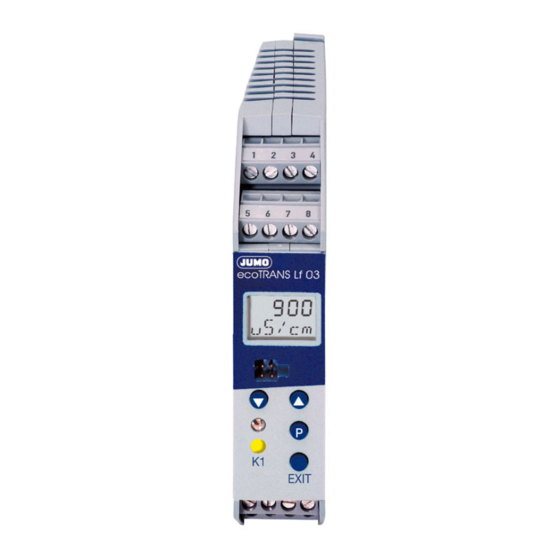
ecoTRANS Lf 03
Transmitter /
Switching Device
for Conductivity
Type 202732
B 20.2732.0
Operating Manual
02.05/00429233
Related Manuals for JUMO ecoTRANS Lf 03
Summary of Contents for JUMO ecoTRANS Lf 03
-
Page 1
Lf 03 Transmitter / Switching Device for Conductivity Type 202732 B 20.2732.0 Operating Manual 02.05/00429233… -
Page 3: Table Of Contents
Notes ……… . 5 Identifying the instrument version .
-
Page 4
Display and LED messages ….. . . 59 12.1 Operating states of the JUMO ecoTrans Lf 03 ….59 12.2 Underrange . -
Page 5: Notes
1 Notes All necessary settings are described in this Operating Manual. However, if any difficulties should still arise during start-up, please do not carry out any manipulations on the unit. You could endanger your rights under the instrument warranty! Please contact the nearest subsidiary or the head office in such a case.
-
Page 6: Identifying The Instrument Version
The supply voltage must correspond to the voltage given on the nameplate. 2.1 Type designation (1) Basic type 202732 JUMO ecoTRANS Lf 03, Microprocessor transmitter / switching device for conductivity (freely programmable ranges) (2) Output I (conductivity / resistivity) analog signal output, freely programmable…
-
Page 7: Installation
3 Installation °C £ 75 4 Electrical connection The choice of cable, the installation, the fusing and the electrical connection must conform to the requirements of VDE 0100 “Regulations on the Installation of Power Circuits with Nominal Voltages below 1000 V” or the appropriate local regulations. The electrical connection must only be carried out by qualified personnel.
-
Page 8
The load circuit must be fused for the maximum relay current, in order to prevent the output relay contacts becoming welded in the event of a short circuit. Do not connect any additional loads to the screw terminals for the supply of the instrument. Any electrical connection other than that specified in the connection diagram may result in the destruction of the instrument. -
Page 9
Terminal assignment EXIT Outputs Terminals Symbol Analog signal output for conductivity (electrically isolated) Analog signal output for temperature (electrically isolated) -
Page 10
common Relay n.c. (break) n.o. (make) Ö Open-collector output 1 (electrically isolated) Open-collector output 2 (electrically isolated) Measurement Terminals Symbol inputs Conductivity outer electrode, cell on coaxial cells inner electrode, on coaxial cells Resistance temperature sensor thermometer in 2-wire circuit Resistance temperature sensor thermometer… -
Page 11
Supply Terminals Symbol Supply voltage (with reverse- polarity protection) Connection of the conductivity cell Conductivity cell JUMO (JUMO types) ecoTRANS Lf 03 Plug-in head Attached cable Outer electrode white Inner electrode brown Temperature yellow compensation green… -
Page 12: Commissioning
Note After initializing the controller, the output signal is 0 V or 0 mA. The logic outputs or relays are in the quiescent state (inactive). After approx. 2 sec, the JUMO ecoTRANS Lf 03 operates according to its configuration.
-
Page 13: Setting / Altering The Instrument Functions
6 Setting / altering the instrument functions Alterations can be carried out in the setup program or from the keys of the JUMO ecoTRANS Lf 03. 6.1 Actual-value display The actual value is displayed either in the — static mode or in the…
-
Page 14: Operation
6.2 Operation The operation of the instrument is arranged on levels. The access to all levels (exception: operator level) is protected by different codes At the operator level (USER), all parameters can be viewed or altered in accordance with the user rights (see enabling level).
-
Page 15
— In order to alter a parameter, it must be enabled at the enabling level (set from “rEAd” to “Edit”). — Press the UP or DOWN key to increase or decrease the value. — Accept the value by pressing the P key. — Use the EXIT key to cancel the entry and change to the next- higher level. -
Page 16: Level Selection
6.4 Level selection see Chapter 6.5 “The operator level (USER)”, page 17 see Chapter 6.6 “The administrator level (ADMIN)”, page 18 see Chapter 6.7 “The enabling level (RIGHT)”, page 19 see Chapter 6.8 “The calibration level (CALIB)”, page 20 or time-out (automatic return after 60 sec without operator action)
-
Page 17: The Operator Level (User)
6.5 The operator level (USER)
-
Page 18: The Administrator Level (Admin)
6.6 The administrator level (ADMIN)
-
Page 19: The Enabling Level (Right)
6.7 The enabling level (RIGHT) Parameters at the operator level (USER) Value is shown can be altered EDIT READ…
-
Page 20: The Calibration Level (Calib)
6.8 The calibration level (CALIB) see Chapter 8 “Calibration”, page 41. see Chapter 8.4 “Calibrating the temperature coefficient using automatic temperature measurement”, page 44 or Chapter 8.5 “Calibrating temperature coefficient using manual temperature entry”, page 47. see Chapter 8.6 “Calibrating the relative cell constant”, page 49. The time-out function is not active during calibration!
-
Page 21: Setting Ranges
7 Setting ranges 0 — 1 µS to 0 — 200 mS, depending on the cell constant Unit 0 = S/cm 1 = mho/cm Cell Range constant 0 – 1.000 µS/cm 0 – 1.000 µmho/cm 0 – 2.00 µS/cm 0 – 2.00 µmho/cm 0.01 0 –…
-
Page 22
Unit 2 = kΩ*cm 3 = MΩ*cm Cell Range constant 1000 – 9999 kΩ*cm 1.00 – 99.99 MΩ*cm 500 – 9999 kΩ*cm 0.50 – 50.00 MΩ*cm 0.01 200 – 9999 kΩ*cm 0.20 – 20.00 MΩ*cm 50 – 2500 kΩ*cm 0.05 – 2.50 MΩ*cm 200 –… -
Page 23: Configurable Parameters
8 Configurable parameters…
-
Page 41: Calibration
8 Calibration 8.1 General The cell constants of conductivity cells stray somewhat depending on the type and additionally change during operation (due to deposits such as lime, or as a result of wear). This results in a change of the output signal from the cell. It is therefore necessary that the user is able to compensate for the deviations of the cell constant from the nominal value, either by manual entry or an automatic calibration of the cell constant K…
-
Page 42: Activating The Calibration Mode
8.2 Activating the calibration mode The setup interface and the measurement inputs for conductivity and temperature are not electrically isolated. This means that, in unfavorable conditions, equalizing currents may flow when the PC interface is connected. These equalizing currents may result in damage to the devices connected.
-
Page 43: Selecting The Calibration Procedure
or Chapter 6.8 “The calibration level (CALIB)”, page 20 The code for enabling the calibration mode is: Start the calibration in the setup program. 8.3 Selecting the calibration procedure Calibrating the temperature coefficient Confirm selection with continue with Chapter 8.4 “Calibrating the temperature coefficient using automatic temperature measurement”, page 44 Chapter 8.5 “Calibrating the temperature coefficient using manual temperature entry”, page 47…
-
Page 44: Calibrating The Temperature Coefficient Using Automatic Temperature Measurement
8.4 Calibrating the temperature coefficient using automatic temperature measurement Note During calibration, the reference temperature and the working temperature can be approached in any sequence. Immerse the conductivity cell and the temperature sensor in the medium to be measured. blinks The currently measured temperature is displayed.
-
Page 45
— the current value can be accepted immediately by pressing the key (for less than 1 second). — When the first calibration point has been accepted, the lower line will show NEXT. Press the key. Temper the medium to be measured to the working temperature. — The LC display shows the temperature in the upper line, and the uncompensated conductivity in the line below. -
Page 46
discard it by pressing the EXIT key. — The instrument will now show the currently present conductivity (the actual value). Note Possible errors: 2 identical calibration points or temperature coefficient larger than 5.5% — The instrument indicates an error. After pressing the key or EXIT, the selected calibration procedure is shown (see Chapter 8.3 “Selecting the calibration procedure”, page 43). -
Page 47: Calibrating The Temperature Coefficient Using Manual Temperature Entry
8.5 Calibrating the temperature coefficient using manual temperature entry Note During calibration, the reference temperature and the working temperature can be approached in any sequence. Immerse the conductivity cell and the temperature sensor in the medium to be measured. blinks WORK.T shows you that the working temperature that will be used later on has to be entered.
-
Page 48
— When the first calibration point has been accepted, NEXT will be shown in the bottom line. Press Temper the medium to the working temperature. — The uncompensated conductivity is shown in the bottom line in the LC display. The current value can be accepted immediately by pressing (for less than 1 second). -
Page 49: Calibrating The Relative Cell Constant
Note Possible errors: 2 identical calibration points or temperature coefficient larger than 5.5% — The instrument indicates an error. After pressing the key or EXIT, the selected calibration procedure is shown. 8.6 Calibrating the relative cell constant General Because of manufacturing variations, each conductivity cell has a real cell constant which deviates slightly from the ideal nominal cell constant.
-
Page 50
Immerse the conductivity cell into a solution with a known conductivity. approx. 3 sec — The uncompensated conductivity of the reference solution (actual value) and CAL.C are shown in alternation. As soon as the value displayed is stable: press (for less than 1 second). -
Page 51
outside 20 — 500%. < 20% Conductivity = 0 > 500% The instrument indicates an error. After pressing or EXIT, the selected calibration procedure is shown (see Chapter 8.3 “Selecting the calibration procedure”, page 43). The latest valid measurement continues to be active. -
Page 52: Analog Output
9 Analog output The analog outputs are configured at the operator level (USER) or the administrator level (ADMIN) in CO.OUT (conductivity output) TE.OUT (temperature output) see Chapter 6.5 “The operator level (USER)”, page 17. 9.1 Response during calibration You can choose between “following” or “unchanged” (constant). 9.2 Response of the output signal in fault condition Depending on the configuration, the output signal can adopt the LOW or HIGH condition in the event of a fault.
-
Page 53: Response Of The Output Signal On Leaving The Scaling Range
10 — 2 V 1.8 V 9.4 Manual operation of the analog output The JUMO ecoTRANS Lf 03 can output a constant analog signal, for test purposes or commissioning, see also Chapter 10.2 “Manual operation of the relay outputs”, page 54.
-
Page 54: Relay Output / Open-Collector
10 Relay output / open-collector 10.1 Response of the relay Depending on the setting, the JUMO ecoTRANS Lf 03 monitors a limit, similar to a limit comparator (LK), as a MAX LK or MIN LK. The hysteresis is asymmetric with respect to the limit.
-
Page 55
“-” means the corresponding output is not in manual mode. 1st place: analog output for conductivity 2nd place: analog output for temperature 3rd place: logic output 1 4th place: logic output 2 (if available) In the example above, the analog temperature output is in manual mode, all other outputs are not. -
Page 56: Response Of The Relay During Calibration
10.3 Response of the relay during calibration The parameter USER / BIN.1 (or BIN.2) / CAL.1 (or CAL.2) can be used to set the relay response to: relay inactive relay active relay unchanged (during calibration, the relay remains at the status that was valid before the start of the calibration) 10.4 Pulse function of the relay output The limit comparator is reset after an adjustable pulse time.
-
Page 57: The Usp Contact (For High-Purity Water)
USP <645>. If, at a given temperature, the conductivity of the water is higher than specified in the USP table, the USP contact of the JUMO ecoTRANS Lf 03 will switch. The limits are defined in steps; at 8°C, for example, a value of 5°C is applied.
-
Page 58: Usp Pre-Alarm
If the conductivity exceeds the value for the corresponding temperature, the configured contact will switch. 11.1 USP pre-alarm The USP pre-alarm switches before the water quality reaches the set limit. The parameter: USER / BIN.1 / S.USP1 (0 — 100) can be used to define a margin between pre-alarm and USP limit, as a percentage value referred to the active limit.
-
Page 59: Display And Led Messages
12 Display and LED messages 12.1 Operating states of the JUMO ecoTrans Lf 03 Two LEDs indicate the operating states Device status LED red (top) LED yellow (bottom) Normal operation on, when LK1 is active Error blinks on, when LK1 is…
-
Page 60: Short Circuit
12.5 Short circuit 12.6 Initialization of dependent parameters After altering one parameter, other dependent parameters are altered automatically. Please check all dependent parameters! 12.7 Calibration timer has run down In accordance with the specifications (of the plant manufacturer, for example), calibration of the cell constant and/or of the temperature coefficient should be carried out.
-
Page 61: Operation Via Setup Interface
– Windows 2000 ® – Windows XP ® – Windows NT 4.0 or higher JUMO ecoTRANS Lf 03 PC interface cable EXIT JUMO PC setup software multilingual D / GB / F Caution The setup interface and the measurement inputs for conductivity and temperature are not electrically isolated.
-
Page 62: Operation Through Setup
A double-click on the text will call up the corresponding editing window. Customized linearization for the temperature probe A table for 30 value pairs can be used to adapt any temperature probe to the temperature input of the JUMO ecoTRANS Lf 03.
-
Page 63: Technical Data
14 Technical data Conductivity input Electrolytic conductivity cells with the cell constants 0.01; 0.1; 1.0; 3.0; 10.0 (2-electrode principle). The cell constant can be adjusted over the range 20 — 500%. Lead compensation, conductivity input The effect of long cables can be compensated on ranges larger than about 20 mS/cm by entering the lead resistance, within the range from 0.00 to 99.99 Ω.
-
Page 64
A parallel resistor with 8.2 kΩ is required! — NTC 2K25 measuring range: 0 to +150°C resistance: 2.25 kΩ at 25°C A parallel resistor with 8.2 kΩ is required! — KTY11-6 measuring range: -10 to +150°C resistance: 2 kΩ at 25°C — All temperature probes can be connected in 2-, 3- or 4-wire circuit. -
Page 65
Open-collector output contact rating: 100 mA, 35 V DC with resistive load, voltage drop in the switched state ≤ 1.2V, not short-circuit proof A/D converter resolution 14 bit Sampling time 500 msec = 2 measurements per second Ambient temperature error ≤… -
Page 66: Environment / Waste Disposal
DIN rail mounting: PC (polycarbonate) Mounting on a 35 x 7.5 mm DIN rail to EN 60 715 Operating position unrestricted Weight approx. 150g 15 Environment / waste disposal Faulty devices can be returned to JUMO for proper disposal.
-
Page 1
Lf 03 Transmitter / Switching Device for Conductivity Type 202732 B 20.2732.0 Operating Manual 02.05/00429233… -
Page 3: Table Of Contents
Notes ……… . 5 Identifying the instrument version .
-
Page 4
Display and LED messages ….. . . 59 12.1 Operating states of the JUMO ecoTrans Lf 03 ….59 12.2 Underrange . -
Page 5: Notes
1 Notes All necessary settings are described in this Operating Manual. However, if any difficulties should still arise during start-up, please do not carry out any manipulations on the unit. You could endanger your rights under the instrument warranty! Please contact the nearest subsidiary or the head office in such a case.
-
Page 6: Identifying The Instrument Version
The supply voltage must correspond to the voltage given on the nameplate. 2.1 Type designation (1) Basic type 202732 JUMO ecoTRANS Lf 03, Microprocessor transmitter / switching device for conductivity (freely programmable ranges) (2) Output I (conductivity / resistivity) analog signal output, freely programmable…
-
Page 7: Installation
3 Installation °C £ 75 4 Electrical connection The choice of cable, the installation, the fusing and the electrical connection must conform to the requirements of VDE 0100 “Regulations on the Installation of Power Circuits with Nominal Voltages below 1000 V” or the appropriate local regulations. The electrical connection must only be carried out by qualified personnel.
-
Page 8
The load circuit must be fused for the maximum relay current, in order to prevent the output relay contacts becoming welded in the event of a short circuit. Do not connect any additional loads to the screw terminals for the supply of the instrument. Any electrical connection other than that specified in the connection diagram may result in the destruction of the instrument. -
Page 9
Terminal assignment EXIT Outputs Terminals Symbol Analog signal output for conductivity (electrically isolated) Analog signal output for temperature (electrically isolated) -
Page 10
common Relay n.c. (break) n.o. (make) Ö Open-collector output 1 (electrically isolated) Open-collector output 2 (electrically isolated) Measurement Terminals Symbol inputs Conductivity outer electrode, cell on coaxial cells inner electrode, on coaxial cells Resistance temperature sensor thermometer in 2-wire circuit Resistance temperature sensor thermometer… -
Page 11
Supply Terminals Symbol Supply voltage (with reverse- polarity protection) Connection of the conductivity cell Conductivity cell JUMO (JUMO types) ecoTRANS Lf 03 Plug-in head Attached cable Outer electrode white Inner electrode brown Temperature yellow compensation green… -
Page 12: Commissioning
Note After initializing the controller, the output signal is 0 V or 0 mA. The logic outputs or relays are in the quiescent state (inactive). After approx. 2 sec, the JUMO ecoTRANS Lf 03 operates according to its configuration.
-
Page 13: Setting / Altering The Instrument Functions
6 Setting / altering the instrument functions Alterations can be carried out in the setup program or from the keys of the JUMO ecoTRANS Lf 03. 6.1 Actual-value display The actual value is displayed either in the — static mode or in the…
-
Page 14: Operation
6.2 Operation The operation of the instrument is arranged on levels. The access to all levels (exception: operator level) is protected by different codes At the operator level (USER), all parameters can be viewed or altered in accordance with the user rights (see enabling level).
-
Page 15
— In order to alter a parameter, it must be enabled at the enabling level (set from “rEAd” to “Edit”). — Press the UP or DOWN key to increase or decrease the value. — Accept the value by pressing the P key. — Use the EXIT key to cancel the entry and change to the next- higher level. -
Page 16: Level Selection
6.4 Level selection see Chapter 6.5 “The operator level (USER)”, page 17 see Chapter 6.6 “The administrator level (ADMIN)”, page 18 see Chapter 6.7 “The enabling level (RIGHT)”, page 19 see Chapter 6.8 “The calibration level (CALIB)”, page 20 or time-out (automatic return after 60 sec without operator action)
-
Page 17: The Operator Level (User)
6.5 The operator level (USER)
-
Page 18: The Administrator Level (Admin)
6.6 The administrator level (ADMIN)
-
Page 19: The Enabling Level (Right)
6.7 The enabling level (RIGHT) Parameters at the operator level (USER) Value is shown can be altered EDIT READ…
-
Page 20: The Calibration Level (Calib)
6.8 The calibration level (CALIB) see Chapter 8 “Calibration”, page 41. see Chapter 8.4 “Calibrating the temperature coefficient using automatic temperature measurement”, page 44 or Chapter 8.5 “Calibrating temperature coefficient using manual temperature entry”, page 47. see Chapter 8.6 “Calibrating the relative cell constant”, page 49. The time-out function is not active during calibration!
-
Page 21: Setting Ranges
7 Setting ranges 0 — 1 µS to 0 — 200 mS, depending on the cell constant Unit 0 = S/cm 1 = mho/cm Cell Range constant 0 – 1.000 µS/cm 0 – 1.000 µmho/cm 0 – 2.00 µS/cm 0 – 2.00 µmho/cm 0.01 0 –…
-
Page 22
Unit 2 = kΩ*cm 3 = MΩ*cm Cell Range constant 1000 – 9999 kΩ*cm 1.00 – 99.99 MΩ*cm 500 – 9999 kΩ*cm 0.50 – 50.00 MΩ*cm 0.01 200 – 9999 kΩ*cm 0.20 – 20.00 MΩ*cm 50 – 2500 kΩ*cm 0.05 – 2.50 MΩ*cm 200 –… -
Page 23: Configurable Parameters
8 Configurable parameters…
-
Page 41: Calibration
8 Calibration 8.1 General The cell constants of conductivity cells stray somewhat depending on the type and additionally change during operation (due to deposits such as lime, or as a result of wear). This results in a change of the output signal from the cell. It is therefore necessary that the user is able to compensate for the deviations of the cell constant from the nominal value, either by manual entry or an automatic calibration of the cell constant K…
-
Page 42: Activating The Calibration Mode
8.2 Activating the calibration mode The setup interface and the measurement inputs for conductivity and temperature are not electrically isolated. This means that, in unfavorable conditions, equalizing currents may flow when the PC interface is connected. These equalizing currents may result in damage to the devices connected.
-
Page 43: Selecting The Calibration Procedure
or Chapter 6.8 “The calibration level (CALIB)”, page 20 The code for enabling the calibration mode is: Start the calibration in the setup program. 8.3 Selecting the calibration procedure Calibrating the temperature coefficient Confirm selection with continue with Chapter 8.4 “Calibrating the temperature coefficient using automatic temperature measurement”, page 44 Chapter 8.5 “Calibrating the temperature coefficient using manual temperature entry”, page 47…
-
Page 44: Calibrating The Temperature Coefficient Using Automatic Temperature Measurement
8.4 Calibrating the temperature coefficient using automatic temperature measurement Note During calibration, the reference temperature and the working temperature can be approached in any sequence. Immerse the conductivity cell and the temperature sensor in the medium to be measured. blinks The currently measured temperature is displayed.
-
Page 45
— the current value can be accepted immediately by pressing the key (for less than 1 second). — When the first calibration point has been accepted, the lower line will show NEXT. Press the key. Temper the medium to be measured to the working temperature. — The LC display shows the temperature in the upper line, and the uncompensated conductivity in the line below. -
Page 46
discard it by pressing the EXIT key. — The instrument will now show the currently present conductivity (the actual value). Note Possible errors: 2 identical calibration points or temperature coefficient larger than 5.5% — The instrument indicates an error. After pressing the key or EXIT, the selected calibration procedure is shown (see Chapter 8.3 “Selecting the calibration procedure”, page 43). -
Page 47: Calibrating The Temperature Coefficient Using Manual Temperature Entry
8.5 Calibrating the temperature coefficient using manual temperature entry Note During calibration, the reference temperature and the working temperature can be approached in any sequence. Immerse the conductivity cell and the temperature sensor in the medium to be measured. blinks WORK.T shows you that the working temperature that will be used later on has to be entered.
-
Page 48
— When the first calibration point has been accepted, NEXT will be shown in the bottom line. Press Temper the medium to the working temperature. — The uncompensated conductivity is shown in the bottom line in the LC display. The current value can be accepted immediately by pressing (for less than 1 second). -
Page 49: Calibrating The Relative Cell Constant
Note Possible errors: 2 identical calibration points or temperature coefficient larger than 5.5% — The instrument indicates an error. After pressing the key or EXIT, the selected calibration procedure is shown. 8.6 Calibrating the relative cell constant General Because of manufacturing variations, each conductivity cell has a real cell constant which deviates slightly from the ideal nominal cell constant.
-
Page 50
Immerse the conductivity cell into a solution with a known conductivity. approx. 3 sec — The uncompensated conductivity of the reference solution (actual value) and CAL.C are shown in alternation. As soon as the value displayed is stable: press (for less than 1 second). -
Page 51
outside 20 — 500%. < 20% Conductivity = 0 > 500% The instrument indicates an error. After pressing or EXIT, the selected calibration procedure is shown (see Chapter 8.3 “Selecting the calibration procedure”, page 43). The latest valid measurement continues to be active. -
Page 52: Analog Output
9 Analog output The analog outputs are configured at the operator level (USER) or the administrator level (ADMIN) in CO.OUT (conductivity output) TE.OUT (temperature output) see Chapter 6.5 “The operator level (USER)”, page 17. 9.1 Response during calibration You can choose between “following” or “unchanged” (constant). 9.2 Response of the output signal in fault condition Depending on the configuration, the output signal can adopt the LOW or HIGH condition in the event of a fault.
-
Page 53: Response Of The Output Signal On Leaving The Scaling Range
10 — 2 V 1.8 V 9.4 Manual operation of the analog output The JUMO ecoTRANS Lf 03 can output a constant analog signal, for test purposes or commissioning, see also Chapter 10.2 “Manual operation of the relay outputs”, page 54.
-
Page 54: Relay Output / Open-Collector
10 Relay output / open-collector 10.1 Response of the relay Depending on the setting, the JUMO ecoTRANS Lf 03 monitors a limit, similar to a limit comparator (LK), as a MAX LK or MIN LK. The hysteresis is asymmetric with respect to the limit.
-
Page 55
“-” means the corresponding output is not in manual mode. 1st place: analog output for conductivity 2nd place: analog output for temperature 3rd place: logic output 1 4th place: logic output 2 (if available) In the example above, the analog temperature output is in manual mode, all other outputs are not. -
Page 56: Response Of The Relay During Calibration
10.3 Response of the relay during calibration The parameter USER / BIN.1 (or BIN.2) / CAL.1 (or CAL.2) can be used to set the relay response to: relay inactive relay active relay unchanged (during calibration, the relay remains at the status that was valid before the start of the calibration) 10.4 Pulse function of the relay output The limit comparator is reset after an adjustable pulse time.
-
Page 57: The Usp Contact (For High-Purity Water)
USP <645>. If, at a given temperature, the conductivity of the water is higher than specified in the USP table, the USP contact of the JUMO ecoTRANS Lf 03 will switch. The limits are defined in steps; at 8°C, for example, a value of 5°C is applied.
-
Page 58: Usp Pre-Alarm
If the conductivity exceeds the value for the corresponding temperature, the configured contact will switch. 11.1 USP pre-alarm The USP pre-alarm switches before the water quality reaches the set limit. The parameter: USER / BIN.1 / S.USP1 (0 — 100) can be used to define a margin between pre-alarm and USP limit, as a percentage value referred to the active limit.
-
Page 59: Display And Led Messages
12 Display and LED messages 12.1 Operating states of the JUMO ecoTrans Lf 03 Two LEDs indicate the operating states Device status LED red (top) LED yellow (bottom) Normal operation on, when LK1 is active Error blinks on, when LK1 is…
-
Page 60: Short Circuit
12.5 Short circuit 12.6 Initialization of dependent parameters After altering one parameter, other dependent parameters are altered automatically. Please check all dependent parameters! 12.7 Calibration timer has run down In accordance with the specifications (of the plant manufacturer, for example), calibration of the cell constant and/or of the temperature coefficient should be carried out.
-
Page 61: Operation Via Setup Interface
– Windows 2000 ® – Windows XP ® – Windows NT 4.0 or higher JUMO ecoTRANS Lf 03 PC interface cable EXIT JUMO PC setup software multilingual D / GB / F Caution The setup interface and the measurement inputs for conductivity and temperature are not electrically isolated.
-
Page 62: Operation Through Setup
A double-click on the text will call up the corresponding editing window. Customized linearization for the temperature probe A table for 30 value pairs can be used to adapt any temperature probe to the temperature input of the JUMO ecoTRANS Lf 03.
-
Page 63: Technical Data
14 Technical data Conductivity input Electrolytic conductivity cells with the cell constants 0.01; 0.1; 1.0; 3.0; 10.0 (2-electrode principle). The cell constant can be adjusted over the range 20 — 500%. Lead compensation, conductivity input The effect of long cables can be compensated on ranges larger than about 20 mS/cm by entering the lead resistance, within the range from 0.00 to 99.99 Ω.
-
Page 64
A parallel resistor with 8.2 kΩ is required! — NTC 2K25 measuring range: 0 to +150°C resistance: 2.25 kΩ at 25°C A parallel resistor with 8.2 kΩ is required! — KTY11-6 measuring range: -10 to +150°C resistance: 2 kΩ at 25°C — All temperature probes can be connected in 2-, 3- or 4-wire circuit. -
Page 65
Open-collector output contact rating: 100 mA, 35 V DC with resistive load, voltage drop in the switched state ≤ 1.2V, not short-circuit proof A/D converter resolution 14 bit Sampling time 500 msec = 2 measurements per second Ambient temperature error ≤… -
Page 66: Environment / Waste Disposal
DIN rail mounting: PC (polycarbonate) Mounting on a 35 x 7.5 mm DIN rail to EN 60 715 Operating position unrestricted Weight approx. 150g 15 Environment / waste disposal Faulty devices can be returned to JUMO for proper disposal.
8.5
temperature entry . . . . . . . . . . . . . . . . . . . . . . . . . . . . . . . . . . . . . . . 47
8.6
9
Analog output . . . . . . . . . . . . . . . . . . . . . . . . . . . . . . . . . . 52
9.1
9.2
9.3
scaling range . . . . . . . . . . . . . . . . . . . . . . . . . . . . . . . . . . . . . . . . . . 53
9.4
10
11
11.1 USP pre-alarm . . . . . . . . . . . . . . . . . . . . . . . . . . . . . . . . . . . . . . . . . 58
12
12.2 Underrange . . . . . . . . . . . . . . . . . . . . . . . . . . . . . . . . . . . . . . . . . . . . 59
12.3 Overrange . . . . . . . . . . . . . . . . . . . . . . . . . . . . . . . . . . . . . . . . . . . . . 59
12.4 Probe break . . . . . . . . . . . . . . . . . . . . . . . . . . . . . . . . . . . . . . . . . . . 59
12.5 Short circuit . . . . . . . . . . . . . . . . . . . . . . . . . . . . . . . . . . . . . . . . . . . 60
13
14
Technical data . . . . . . . . . . . . . . . . . . . . . . . . . . . . . . . . . . 63
15
. . . . . . . . . . . . . . . . . . . . . . . . . . . . . . . . . . . . . . . . . . . 56
. . . . . . . . . . . . . . . . . . . . . . . . 49
. . . . . . . . . . . . . . . . . . . . . . . . . . . . 60
39
9 Calibration
9.1 General information
The zero point (intercept) and slope of pH sensors stray from copy to copy. During the service life of the sensor, up to the time it must be replaced by a new sensor, the zero point and slope change. To allow for precise measurements, the transmitter must be adjusted
(calibrated) to the current sensor parameters. The calibration is performed using buffer solutions.
Only the zero point needs to be calibrated for redox sensors.
9.1.1 When is calibration required?
The electrochemical sensors should be cleaned and the transmitter should be calibrated at regular intervals (depending on the measuring medium)!
With the correct wiring of device and sensor, and correct configuration of the device, a measurement without calibration should be possible.
If this is not the case, influencing factors such as short circuit, open circuit, EMC and flow conditions should also be considered.
9.2 Activating and starting calibration mode
During the calibration process, the display flashes.
The analog outputs respond as they were calibrated on the USER LEVEL / ANALOG OUTPUT x /
FOR CALIBRATION.
The response of the relay depends on the configuration of the switching output!
40
Calibration can be cancelled at any time with the EXIT key. Old calibration data will not be lost.
Calibration is performed using the instrument keys.
The zero point and slope of a sensor can also be entered manually. This should only be done in exceptional cases. Some sensors come with a test report that specifies the zero point and slope. These values simply provided documentation that the sensor was in proper condition upon delivery. Since these values change during storage, they are not suitable for manual entry. We always advise performing calibration with buffer solutions.
The timeout function is not active during calibration!
9.2.1 Starting calibration from the calibration level «CALIB»
Use the menu to switch to the calibration level (see
Section 7.4 «Selecting levels», page 20 and Section
7.8 «Calibration level (CALIB)», page 24).
✱
P
Press and hold (for more than 2 sec) / then select CALIB.
✱
P
Press and hold (for less than 1 sec) / then enter code 110.
✱ Confirm with
P
,
continue with Section 9.4 «One-point or two-point calibration», page 43.
9.2.2 Starting calibration with the hot key (rapid access)
Activation of the calibration mode by rapid access must be previously enabled:
P
> Press and hold for 2 seconds / Set ADMIN / CAL /
CA.LVL to 1.
✱ Press the
P
and keys,
continue with Section 9.4 «One-point or two-point calibration», page 43.
41
9.3 Canceling calibration and error messages
Calibration can be cancelled at any time with the EXIT key. Old calibration data will not be lost.
During the calibration process, the transmitter calculates the electrode parameters zero point and if applicable slope. If the calculated values fall outside the permissible parameter limits, an error message is generated.
For the permitted value ranges of parameters NULL and SLOPE see
Section 8.1.1 «Measurement input — main value (submenu «PH»)», page 26.
9.3.1 Zero point error
Parameter limits for NULL have been violated.
9.3.2 Slope error
Parameter limits for SLOPE have been violated.
9.3.3 General error during calibration
42
The parameter limits for NULL and SLOPE have been violated and/ or the two calibration points Ref.1 and Ref.2 are too close to each other.
For two-point calibration of a pH sensor, the minimum spacing is
2 pH.
For two-point calibration of a redox sensor, the minimum spacing is
2 mV.
The greater the spacing, the more accurate the calibration.
9.3.4 Acknowledging errors
✱ Press the
P
keys or EXIT.
The error message is deleted.
The faulty parameters NULL and/or SLOPE are not saved.
The instrument continues working with old calibration data.
9.3.5 Additional measures
✱ Check the quality and condition (age) of the buffer solutions.
✱ Check whether the sensor is dirty or needs to be replaced.
✱ Check whether the sensor plug is moist or the wiring is faulty.
✱ Observe the minimum spacings for buffer or reference values.
9.4 One-point or two-point calibration
For one-point calibration, the transmitter is only adjusted to the zero point of the sensor.
In two-point calibration the transmitter is adjusted to both the zero point of the sensor and its slope. We expressly recommend twopoint calibration!
9.4.1 Selecting one-point calibration
Select CAL I-PT.
For more details see Section 9.5.1 «One-point calibration (zero point)», page 44.
43
9.4.2 Selecting two-point calibration
Press the key and select CAL 2-PT.
For more details see Section 9.5.2 «Two-point calibration (zero point and slope)», page 45.
9.5 Calibrating a pH measurement chain
9.5.1 One-point calibration (zero point)
✱ Confirm the selection with
P
.
Display or editing option of the buffer temperature.
✱ Confirm the selection with
P
.
The first reference value is then measured.
✱ Wait until the measurement value has stabilized.
Confirm the measurement value with
P
.
44
Flashing
✱ Enter the actual buffer value with
or and confirm with
P
.
The calculated zero point of the measurement chain appears.
✱ Accept the value with
P
or press
EXIT
to cancel the calibration.
The instrument goes into measurement mode.
If an error message appears, see Section 9.3
«Canceling calibration and error messages», page 42.
9.5.2 Two-point calibration (zero point and slope)
Calibrate zero point and slope.
The buffer solutions (reference solutions) used for calibration must differ by at least 2 pH!
During the calibration, the temperature of the two buffer solutions must be identical and remain constant!
45
✱ Confirm the selection with
P
.
Display and editing option of the buffer temperature.
✱ Confirm the selection with
P
.
The first reference value is then measured.
✱ Immerse the measurement chain in the first buffer (for example pH 7.00)
✱ Wait until the measurement value has stabilized.
Confirm the measurement value with
P
.
Flashing
✱ Enter the actual buffer value with
or and confirm with
P
.
46
✱ Remove the measurement chain from the first buffer and rinse with distilled water.
✱ Immerse the measurement chain in the second buffer (for example pH 4.00)
✱ Wait until the measurement value has stabilized.
Confirm the measurement value with
P
.
Flashing
✱ Enter the actual buffer value with
or and confirm with
P
.
The calculated zero point (top line) and the calculated slope (bottom line) appear.
✱ Accept the values with
P
or press
EXIT
to cancel the calibration.
The instrument goes into measurement mode.
If an error message appears, see Section 9.3
«Canceling calibration and error messages», page 42.
47
9.6 pH antimony measurement chain
Antimony measurement chains are calibrated similarly to «normal»
pH measurement chains, see Section 9.5 «Calibrating a pH measurement chain», page 44.
9.7 Redox measurement chain
9.7.1 General information
The instrument offers two calibrating options for adjusting it to the redox measurement chain.
— One-point calibration
If «mV» was configured as UNIT.
— Two-point calibration
If «%» was configured as UNIT.
The display flashes during calibration.
The analog outputs respond the same way as on
USER LEVEL / ANALOG OUTPUT x / FOR
CALIBRATION.
The response of the relay depends on the configuration of the switching output!
)
9.7.2 One-point calibration (recommended calibration)
Calibration of the zero point.
✱ Confirm the selection with
P
.
✱ Rinse off the measurement chain with distilled water or clean if necessary (see operating instructions for electrode).
✱ Immerse the measurement chain in the test solution (e.g. 468 mV).
48
The reference value is then measured.
✱ Wait until the measurement value has stabilized.
✱ Confirm the measurement value with
P
.
Flashing
✱ Enter the actual buffer value with
or and confirm with
P
.
The calculated zero point of the measurement chain appears.
Accept the value with
P
or press
EXIT
to cancel the calibration.
The instrument goes into measurement mode.
If an error message appears, see Section 9.3
«Canceling calibration and error messages», page 42.
49
)
9.7.3 Two-point calibration
In this type of calibration the display range can be scaled freely from
0 to 100%.
Example:
A span of -10 mV … +1000 mV can be scaled to 0 … 100% werden.
The zero point can fall within the range of
-999 … +999 mV.
Two different reference fluids must be used for the calibration. The redox voltage of a measurement solution is not temperature-dependent!
Confirm the selection with
P
.
The first reference value is then measured.
✱ Immerse the measurement chain in the first solution (for example
59 mV)
✱ Wait until the measurement value has stabilized.
Confirm the measurement value with
P
.
Flashing
50
✱ Enter the desired value with
or (for example 20) and confirm with
P
.
✱ Remove the measurement chain from the first solution and rinse with distilled water.
✱ Immerse the measurement chain in the second solution (for example 295 mV).
✱ Wait until the measurement value has stabilized.
Confirm the measurement value with
P
.
Flashing
✱ Enter the desired value with
or (for example 80) and confirm with
P
.
✱ The calculated zero point (top line in mV) and the calculated slope (bottom line) appear.
Accept the values with
P
or press
EXIT
to cancel the calibration.
The instrument goes into measurement mode.
If an error message appears, see Section 9.3
«Canceling calibration and error messages», page 42.
51
10 Analog output
Analog outputs are configured on the user level
(USER) or on the administrator level (ADMIN) in
PH.OUT (pH or redox output) and TE.OUT
(temperature output); see Section 7.5 «User level
(USER)», page 21.
10.1 Behavior of the output signal during calibration
Two options are possible, «Concurrent» and «Unchanged»
(constant).
10.2 Behavior of the output signal in case of error
If one of the following errors occurs, the output signal assumes the
defined status (see Section 10.3 «Output signal in case of error», page 53):
Analog output of pH value / redox voltage with non-active temperature compensation
— Underrange pH value / redox voltage
— Overrange pH value / redox voltage
Analog output of pH value / redox voltage with active temperature compensation
— Underrange pH value / redox voltage
— Overrange pH value / redox voltage
— Underrange temperature
— Overrange temperature
Analog output — temperature
— Underrange temperature
— Overrange temperature
52
10.3 Output signal in case of error
Depending on the configuration, the output signal may assume the
«LOW» or «HIGH» state in case of error.
Output signal nominal
0…20 mA
4…20 mA
0…10 V
2…10 V
Output signal
HIGH
22.0 mA
22.0 mA
10.7 V
10.7 V
Output signal
LOW
0 mA
3.4 mA
0 V
1.4 V
10.4 Output signal when leaving the scaling range
When leaving the scaling range, the output returns a proportional signal up to a defined limit (in compliance with NAMUR NE43). The limits are listed in the table below:
Value below scaling range
0.0 mA
3.8 mA
0.0 V
20.5 mA
20.5 mA
10.2 V
1.8 V
10.2 V
In the scaling range
0…20 mA
4…20 mA
0…10 V
20…0 mA
20…4 mA
10…0 V
2…10 V
10…2 V
Scaling range was exceeded
20.5 mA
20.5 mA
10.2 V
0.0 mA
3.8 mA
0.0 V
10.2 V
1.8 V
10.5 Manual mode of the analog output
For test purposes or startup, a constant analog signal can be generated by the instrument
(see also Section 11.3 «Manual mode of the relay output», page
57).
After a power supply failure, manual mode is deactivated.
53
11 Relay output
11.1 Relay behavior
Depending on the setting, the JUMO ecoTRANS pH 03 monitors a limit value.
11.2 Binary output 1 (submenu «BIN.1»)
Setting options
0
= No function (default setting)
1 = Window contact main value (active inside a window)
2 = Window contact main value (active outside a window)
3 = Max contact main value (normally open (NO), similar to LK7)
4 = Min contact main value (normally closed (NC), similar to LK8)
5 = Window contact temperature (active inside a window)
6 = Window contact temperature (active outside a window)
7 = Max contact temperature (normally open (NO), similar to
LK7)
8 = Min contact temperature (normally closed (NC), similar to
LK8)
9 = Error output (every device error causes the relay to switch)
10 = Calibration timer elapsed
54
Contact function for settings 1 and 5
Hysteresis
HYS.1.
On
Off
Distance
DST.1
Switching point
ALAR.1
Contact function for settings 2 and 6
Hysteresis
HYS.1.
On pH
Off
Distance
DST.1
Switching point
ALAR.1
pH
55
Contact function for settings 3 and 7
Hysteresis
HYS.1.
On
Off
Switching point
ALAR.1
pH
Contact function for settings 4 and 8
Hysteresis
HYS.1.
On
Off
Switching point
ALAR.1
pH
56
11.3 Manual mode of the relay output
For test purposes or when starting up systems, a constant signal can be generated by the transmitter.
Manual mode can be set with parameter: USER / BIN.1 / SIM.1 to
0
1
2
= inactive
= active => LED «K1» is lit
= No manual mode.
Indication of manual mode
About 3
If one of the outputs is in manual mode, this is indicated in the change to process value display by an «S» or «-«.
S The relevant output is in manual mode.
The relevant output is not in manual mode.
1 2 3
1st place Analog output — pH/redox voltage
2nd place Analog output — temperature
3rd place Binary output 1
In the example above, the analog temperature output is in manual mode. No other outputs are in manual mode.
When the user exits manual mode, the output signal immediately assumes the value proportional to the pH value/redox voltage or the temperature process value.
57
After «Supply voltage On» manual mode is always deactivated.
11.4 Behavior of the relay during calibration
The behavior of the relay with the parameter:
USER / BIN.1 / CAL.1 set to
0 = Relay inactive
1 = Relay active
2 = Relay unchanged
(during calibration the relay status remains set to the status that was valid before the calibration process)
11.5 Pulse function of the relay output
The limit comparator is reset after an adjustable «pulse time.» The parameter for this is: USER / BIN.1 / T.PUL1 .
It can be set from 0 = 0 seconds (no pulse function) to 999 = 999 seconds.
LED «K1» is lit red as long as the switching condition is met.
No OFF delay is possible in pulse mode.
58
Triggering condition is longer than pulse duration
Triggering condition
On
Off
Time
Pulse contact
On
Off
Time
Pulse duration
T.PUL1
Triggering condition is shorter than pulse duration
Triggering condition
On
Off
Time
Pulse contact
On
Off
Time
Pulse duration
T.PUL1
59
11.6 Behavior of the relay in case of error
The behavior of the relay can be adjusted with the following parameters:
USER / BIN.1 and ERR.1 set to
0 = Relay inactive
1 = Relay active
2 = Relay unchanged
(«frozen»: the relay status remains set to the status that was valid before the error)
Function pH value redox voltage
Underrange
Overrange
Temperature
Underrange
Overrange
Limit comparator pH/redox voltage without temperature compensation
Limit comparator pH/redox voltage with temperature compensation
Limit comparator temperature
Calibration timer elapsed
Error output x x x x x x x x x x x x x x x x
11.7 Error detection
The relay output is active for the following errors:
Limit comparator for pH value/redox voltage with non-active temperature compensation
— Underrange pH value/redox voltage
— Overrange pH value/redox voltage
60
Limit comparator of pH value/redox voltage with active temperature compensation
— Underrange pH value/redox voltage
— Overrange pH value/redox voltage
— Underrange temperature
— Overrange temperature
Limit comparator — temperature
— Underrange temperature
— Overrange temperature
Calibration timer
— Timeout
61
12 Display and LED messages
12.1 Operating states of JUMO ecoTrans pH 03
Two LED indicate operating states
Instrument status Red LED (top)
Normal mode Off
Error
Initialization
Flashing
Off
12.2 Underrange
Yellow LED (bottom)
On if LC1 is active
On if LC1 is active
Off
Value is below lower measurement range limit (ORP means redox).
12.3 Overrange
Measurement range exceeded (ORP means redox).
12.4 Broken sensor
Broken sensor, wrong or no temperature sensor connected;
see Section 8.1.2 «Measurement input — temperature
(submenu «TEMP»)», page 28.
62
If no automatic temperature compensation or temperature measurement is required parameter SENS.T must be set
accordingly; see Section 8.1.2 «Measurement input — temperature (submenu «TEMP»)», page 28.
12.5 Short-circuit
12.6 Initialization of dependent parameters
After a parameter has been changed, other dependent parameters are automatically changed.
Please check all dependent parameters!
12.7 Calibration timer elapsed
Depending on specifications (for example of the equipment manufacturer), calibration of the measurement chain should be performed.
After a correct calibration, the calibration timer is reset and automatically restarted.
63
13 Operation via setup interface
(1)
(4)
(2)
P
K1
EXIT
(3)
(1) JUMO ecoTRANS pH 03
(2) PC interface line (optional accessory)
(3) JUMO PC setup software, multilingual D / GB / F (optional accessory)
(4) PC or Notebook with USB interface operating system: Windows 2000
®
,
NT
®
4.0 and up, Windows Vista
®
Windows XP
® or Windows
64
13.1 Operation with PC setup program
(1)
(3)
(2)
(1) Navigation tree
The navigation tree provides fast access (double click) to individual setting options.
(2) Diagnostics window
As soon as a connection is established with an instrument, current data is displayed here.
(3) Working area
Clicking the arrow ( ) shows possible settings.
Double clicking the text opens the appropriate editing window.
65
14 Technical data
Inputs
Analog input 1 (pH / redox)
— Electrodes
— Glass or metal electrodes with isolated reference electrode
— Antimony electrode
Measurement ranges for pH / redox
-2 … 16 pH or
-1500 … +1500 mV
Accuracy for pH / redox
± 1% of the measurement range
Analog input 2 (temperature)
— Resistance thermometer Pt100 or Pt1000
The temperature sensor can be connected in a 2-wire circuit.
Measurement display can be switched between °C / °F
Temperature offset for analog input 2
A process value can be corrected by an offset in the range from —
20 … +20°C.
Temperature measurement range
-10 … +150°C or 14 … 302°F
Deviation from characteristic temperature curve
for Pt 100 / Pt 1000:
≤
1.5 K
Outputs
Two analog outputs:
Freely configurable:
0(2) … 10V
10 … (2)0V
R load
R load
≥
2 k
Ω
or
≥
2 k
Ω
or else
66
0(4) … 20mA R load
20 … (4)0mA R load
≤
400
Ω or
≤
400
Ω galvanically isolated from inputs:
Δ
U
≤
30V AC or
Δ
U
≤
50 V DC
Scope of scaling at least 10% of the scope of the measurement range
deviation from the characteristic curve of the output signal
≤
0.075% of the measurement range
Relay output:
Switching contact switching capacity: 8 A, 250 V AC or 8 A, 24 V DC with resistive load contact life: > 100,000 operations at normal load
Key general parameters
A/D converter
14-bit resolution
Sampling time
500ms = 2 measurements / second
Effect of ambient temperature
≤
0.6% / 10 K
Measuring circuit monitoring
Input 1(main value): out-of-range
Input 2 (temperature): out-of-range, sensor short circuit, broken sensor.
In case of error, the outputs assume a defined
(configurable) state.
Data backup
EEPROM
67
Supply
DC 20 … 30 V, residual ripple<5%, power consumption
≤
4 W, with reverse polarity protection.
Operates only on SELV or PELV circuits.
Electrical connection
Screw terminals up to 2.5 mm
2
Operating temperature range
0 … +50°C
Functional temperature range
-10 … +60°C
Storage temperature range
-20 … +75°C
Climatic rating
Rel. humidity
≤
75% no condensation
Enclosure protection (complies with EN 60 529)
IP 20
Electrical safety
Complies with EN 61 010 air gaps and creep zones for
— Overvoltage category II
— Pollution degree 2
Electromagnetic compatibility
Complies with EN 61 326
Interference immunity:To industrial requirements
Interference emission:Class B
Enclosure
DIN rail enclosure made of PC (polycarbonate)
68
Mounting
On DIN rail 35mm x 7.5mm to DIN EN 60 715
Installation position
Any
Weight
Approx. 150g
15 Environment/disposal
Defective instruments can be sent to JUMO for proper disposal.
69
70
JUMO GmbH & Co. KG
Street address:
Moritz-Juchheim-Straße 1
36039 Fulda, Germany
Delivery address:
Mackenrodtstraße 14
36039 Fulda, Germany
Postal address:
36035 Fulda, Germany
Phone: +49 661 6003-0
Fax: +49 661 6003-607
Email: [email protected]
Internet: www.jumo.net
JUMO Instrument Co. Ltd.
JUMO House
Temple Bank, Riverway
Harlow, Essex CM 20 2DY, UK
Phone: +44 1279 63 55 33
Fax: +44 1279 62 50 29
Email: [email protected]
Internet: www.jumo.co.uk
JUMO Process Control, Inc.
6733 Myers Road
East Syracuse, NY 13057, USA
Phone: +1 315 437 5866
Fax: +1 315 437 5860
Email: [email protected]
Internet: www.jumousa.com
(Ocr-Read Summary of Contents of some pages of the JUMO ecoTRANS Lf 03 Document (Main Content), UPD: 19 March 2023)
-
51, 51 outside 20 — 500%. ✱ The instrument indicates an error. After pressing or EXIT, the selected calibration procedure is shown (see Chapter 8.3 “Selecting the calibration procedure”, page 43). The latest valid measurement continues to be active. < 20% Conductivity = 0 > 500% P
… -
28, 28 8.1.2 Measurement input for temperature (submenu TEMP) Parameter Display Setting range 1 Probe type SENS 0 = Manual temperature entry 1 = Pt100 2 = Pt1000 3 = NTC 2 kΩ 4 = KTY-10/11-6 5 = NTC 2.25 kΩ 6 = customer-specific Connection type of temperature sensor WIRE 2 = 2-wire 3 = 3-wire 4 = 4-wire Filter constant temperature (2nd order filter) DF.TE 0—2—99 seconds Temperature unit UNIT.T 0 = °C 1 = °F 1 The default setting is shown bold.
… -
46, 46 discard it by pressing the EXIT key. — The instrument will now show the currently present conductivity (the actual value). Note Possible errors: 2 identical calibration points or temperature coefficient larger than 5.5% — The instrument indicates an error. ✱ After pressing the key or EXIT, the selected calibration procedure is shown (see Chapter 8.3 “Selecting the calibration procedure”, page 43). or P
… -
5, 5 1 Notes All necessary settings are described in this Operating Manual. However, if any difficulties should still arise during start-up, please do not carry out any manipulations on the unit. You could endanger your rights under the instrument warranty! Please contact the nearest subsidiary or the head office in such a case. Please read this operating manual before starting up the instrument. Keep the manual in a place which is acces…
-
53, 53 9.3 Response of the output signal on leaving the scaling range On leaving the scaling range, the output will, up to a defined limit, produce a proportional signal (as per NAMUR NE43). These limits are listed in the table below: 9.4 Manual operation of the analog output The JUMO ecoTRANS Lf 03 can output a constant analog signal, for test purposes or commissioning, see also Chapter 10.2 “Manual operation of the relay o…
-
20, JUMO ecoTRANS Lf 03 20 6.8 The calibration level (CALIB) 1 see Chapter 8 “Calibration”, page 41. 2 see Chapter 8.4 “Calibrating the temperature coefficient using automatic temperature measurement”, page 44 or Chapter 8.5 “Calibrating the temperature coefficient using manual temperature entry”, page 47. 3 see Chapter 8.6 “Calibrating the relative cell constant”, page 49. The time-out function is not active during calibration!
… -
39, JUMO ecoTRANS Lf 03 39 Start value for scaling SCL.TE -10.0 to 224°C or 14 to 437°F Note Setting range and default setting depend on the selected temperature unit UNIT.T. Between the scaling start value SCL.TE and the scaling end value SCH.TE there must be a difference of at least 10% of the measuring range. End value for scaling SCH.TE 16 to 250.0°C or 59 to 482°F Note Setting range and default setting depend on the selected temperature unit UNIT.T. Between the scaling start value SCL.TE and the s…
-
14, 14 6.2 Operation The operation of the instrument is arranged on levels. The access to all levels (exception: operator level) is protected by different codes 2 . At the operator level (USER), all parameters can be viewed or altered in accordance with the user rights 1 (see enabling level). At the calibration level (CALIB), the cell constant and/or temperature coefficient can be calibrated. At the enabling level (RIGHT), the use…
-
11, JUMO ecoTRANS Lf 03 11 Connection of the conductivity cell Supply Terminals Symbol Supply voltage (with reverse- polarity protection) L- L + Conductivity cell (JUMO types) JUMO ecoTRANS Lf 03 Plug-in head Attached cable Outer electrode white 14 Inner electrode 2 brown 13 Temperature compensation 1 3 yellow green 9 12 L- L+ -+
… -
24, 24 8.1 Inputs 8.1.1 Measurement input for conductivity (submenu CON) Parameter Display Setting range 1 Measurement ranges with nominal cell constant RANGE 01 = 0 – 1 µS/cm K = 0.01 1 / cm 02 = 0 – 2 µS/cm K = 0.01 1 / cm 03 = 0 – 5 µS/cm K = 0.01 1 / cm 04 = 0 – 20 µS/cm K = 0.01 1 / cm 05 = 0 – 5 µS/cm K = 0.1 1 / cm 06 = 0 – 20 µS/cm K = 0.1 1 / cm 07 = 0 – 200 µS/cm K = 0.1 1 / cm 08 = 0 – 1000 µS/cm K = 0.1 1 / cm 09 = 0 – 5…
-
23, 23 The parameters can be set through the setup program or on the instrument. When altering one parameter, it may be necessary to adjust other parameters as well, because some parameters are affected by others. Example: When altering the measuring range, the display format, setpoints and other parameters will also be adjusted. During internal parameter adjustment, the display will show: 8 Configurable parameters
… -
45, 45 — the current value can be accepted immediately by pressing the key (for less than 1 second). — When the first calibration point has been accepted, the lower line will show NEXT. ✱ Press the key. ✱ Temper the medium to be measured to the working temperature. — The LC display shows the temperature in the upper line, and the uncompensated conductivity in the line below. — The conductivity value will be accepted automatic…
-
59, 59 12 Display and LED messages 12.1 Operating states of the JUMO ecoTrans Lf 03 Two LEDs indicate the operating states 12.2 Underrange Below measuring range 12.3 Overrange Above measuring range 12.4 Probe break Device status LED red (top) LED yellow (bottom) Normal operation off on, when LK1 is active Error blinks on, when LK1 is active Initialization off off or or
… -
50, 50 ✱ Immerse the conductivity cell into a solution with a known conductivity. — The uncompensated conductivity of the reference solution (actual value) and CAL.C are shown in alternation. ✱ As soon as the value displayed is stable: press (for less than 1 second). ✱ Enter the actual conductivity of the reference solution (setpoint) with the or key. ✱ Press (for less than 1 second). — The relative cell constant that was calculated is displayed. ✱…
-
27, 27 Lead compensation for conductivity RO.CON 0.00 — 99.99 Ω Note The effect of long cables for the measuring ranges above approx. 20 mS/cm can be compensated by entering the lead resistance. Actual-value correction for conductivity (offset) OF.CON Setting range and representation of numbers depend on the measuring range. 0.00 mS/cm Note Zero-point errors caused by the system can be compensated. Parameter Display Setting range 1 1 The default setting is shown bold.
… -
9, 9 Terminal assignment Outputs Terminals Symbol I Analog signal output for conductivity (electrically isolated) 5 6 + — II Analog signal output for temperature (electrically isolated) 7 8 + — P K1 EXIT 4321 5876 13 L-L+14 9121110 56 +- 78 +-
…